
2012 City of Fort Collins Citizen Survey - City of Fort Collins, CO

DRAINAGE CRITERIA MANUAL (V. 2) CULVERTS
CULVERTS
CONTENTS
Section Page CU
1.0 INTRODUCTION AND OVERVIEW ................................................................................................ 1 1.1 Required Design Information.............................................................................................. 3
1.1.1 Discharge............................................................................................................... 4 1.1.2 Headwater ............................................................................................................. 4 1.1.3 Tailwater ................................................................................................................ 5 1.1.4 Outlet Velocity........................................................................................................ 5
2.0 CULVERT HYDRAULICS................................................................................................................ 6 2.1 Key Hydraulic Principles ..................................................................................................... 6
2.1.1 Energy and Hydraulic Grade Lines........................................................................ 6 2.1.2 Inlet Control ........................................................................................................... 8 2.1.3 Outlet Control......................................................................................................... 9
2.2 Energy Losses .................................................................................................................. 10 2.2.1 Inlet Losses.......................................................................................................... 10 2.2.2 Outlet Losses....................................................................................................... 11 2.2.3 Friction Losses..................................................................................................... 11
3.0 CULVERT SIZING AND DESIGN.................................................................................................. 12 3.2 Use of Capacity Charts..................................................................................................... 13 3.3 Use of Nomographs.......................................................................................................... 13 3.4 Computer Applications, Including Design Spreadsheet ................................................... 15 3.5 Design Considerations...................................................................................................... 15
3.5.1 Design Computation Forms................................................................................. 15 3.5.2 Invert Elevations .................................................................................................. 15 3.5.3 Culvert Diameter.................................................................................................. 16 3.5.4 Limited Headwater............................................................................................... 16
3.6 Culvert Outlet.................................................................................................................... 16 3.7 Minimum Slope ................................................................................................................. 16
4.0 CULVERT INLETS ........................................................................................................................ 21 4.1 Projecting Inlets ................................................................................................................ 22
4.1.1 Corrugated Metal Pipe......................................................................................... 23 4.1.2 Concrete Pipe ...................................................................................................... 23
4.2 Inlets with Headwalls ........................................................................................................ 23 4.2.1 Corrugated Metal Pipe......................................................................................... 24 4.2.2 Concrete Pipe ...................................................................................................... 24 4.2.3 Wingwalls............................................................................................................. 24 4.2.4 Aprons 24
4.3 Special Inlets .................................................................................................................... 25 4.3.1 Corrugated Metal Pipe......................................................................................... 26 4.3.2 Concrete Pipe ...................................................................................................... 26 4.3.3 Mitered Inlets ....................................................................................................... 26 4.3.4 Long Conduit Inlets.............................................................................................. 26
4.4 Improved Inlets ................................................................................................................. 27 5.0 INLET PROTECTION .................................................................................................................... 28
5.1 Debris Control ................................................................................................................... 28 5.2 Buoyancy .......................................................................................................................... 28
07/2001 CU-1 Urban Drainage and Flood Control District

CULVERTS DRAINAGE CRITERIA MANUAL (V. 2)
6.0 OUTLET PROTECTION ................................................................................................................ 30 6.1 Local Scour....................................................................................................................... 30 6.2 General Stream Degradation............................................................................................ 30
7.0 GENERAL CONSIDERATIONS .................................................................................................... 32 7.1 Culvert Location................................................................................................................ 32 7.2 Sedimentation................................................................................................................... 32 7.3 Fish Passage .................................................................................................................... 33 7.4 Open Channel Inlets ......................................................................................................... 33 7.5 Transitions ........................................................................................................................ 33 7.6 Large Stormwater Inlets.................................................................................................... 33
7.6.1 Gratings ............................................................................................................... 34 7.6.2 Openings ............................................................................................................. 34 7.6.3 Headwater ........................................................................................................... 34
7.7 Culvert Replacements ...................................................................................................... 34 7.8 Fencing for Public Safety.................................................................................................. 34
8.0 TRASH/SAFETY RACKS .............................................................................................................. 35 8.1 Collapsible Gratings.......................................................................................................... 36 8.2 Upstream Trash Collectors ............................................................................................... 36
9.0 DESIGN EXAMPLE ....................................................................................................................... 37 9.1 Culvert Under an Embankment ........................................................................................ 37
10.0 CHECKLIST................................................................................................................................... 43 11.0 CAPACITY CHARTS AND NOMOGRAPHS................................................................................. 44 12.0 REFERENCES .............................................................................................................................. 58
Tables
Table CU-1—Inlet Coefficients For Outlet Control ..................................................................................... 21
Figures
Figure CU-1—Definition of Terms for Closed Conduit Flow......................................................................... 6 Figure CU-2—Definition of Terms for Open Channel Flow .......................................................................... 7 Figure CU-3—Inlet Control—Unsubmerged Inlet ......................................................................................... 8 Figure CU-4—Inlet Control—Submerged Inlet ............................................................................................. 9 Figure CU-5—Outlet Control—Partially Full Conduit.................................................................................. 10 Figure CU-6—Outlet Control—Full Conduit ............................................................................................... 10 Figure CU-7—Culvert Capacity Chart—Example....................................................................................... 17 Figure CU-8—Design Computation for Culverts—Blank Form .................................................................. 18 Figure CU-9—Inlet Control Nomograph—Example.................................................................................... 19 Figure CU-10—Outlet Control Nomograph—Example............................................................................... 20 Figure CU-11—Common Projecting Culvert Inlets..................................................................................... 22 Figure CU-12—Inlet With Headwall and Wingwalls ................................................................................... 23 Figure CU-13—Typical Headwall-Wingwall Configurations ....................................................................... 25 Figure CU-14—Side-Tapered and Slope-Tapered Improved Inlets ........................................................... 27
CU-2 07/2001 Urban Drainage and Flood Control District

DRAINAGE CRITERIA MANUAL (V. 2) CULVERTS
Figure CU-15—Design Computation Form for Culverts—Example 9.1 ..................................................... 39 Figure CU-16—Headwater Depth for Concrete Pipe Culverts with Inlet Control—Example 9.1 ............... 40 Figure CU-17—Head for Concrete Pipe Culverts Flowing Full (n = 0.012)—Example 9.1........................ 41 Figure CU-18—Culvert Capacity Standard Circular Corrugated Metal Pipe Headwall
Entrance 18” to 36” ........................................................................................................... 45 Figure CU-19—Culvert Capacity Standard Circular Corrugated Metal Pipe Headwall
Entrance 36” to 66” ........................................................................................................... 46 Figure CU-20—Culvert Capacity Standard Circular Corrugated Metal Pipe
Projecting Entrance 18” to 36”.......................................................................................... 47 Figure CU-21—Culvert Capacity Standard Circular Corrugated Metal Pipe
Projecting Entrance 36” to 66”.......................................................................................... 48 Figure CU-22—Culvert Capacity Circular Concrete Pipe Square-Edged Entrance 18” to 66” .................. 49 Figure CU-23—Culvert Capacity Circular Concrete Pipe Square-Edged Entrance 60” to 180” ................ 50 Figure CU-24—Culvert Capacity Circular Concrete Pipe Groove-Edged Entrance 18” to 66” .................. 51 Figure CU-25—Culvert Capacity Circular Concrete Pipe Groove-Edged Entrance 60” to 180” ................ 52 Figure CU-26—Headwater Depth for Corrugated Metal Pipe Culverts With Inlet Control ......................... 53 Figure CU-27—Headwater Depth for Concrete Pipe Culverts With Inlet Control ...................................... 54 Figure CU-28—Headwater Depth for Circular Pipe Culverts With Beveled Ring Inlet Control .................. 55 Figure CU-29—Head for Standard Corrugated Metal Pipe Culverts Flowing Full n = 0.024 ..................... 56 Figure CU-30—Head for Concrete Pipe Culverts Flowing Full n = 0.012 .................................................. 57
Photographs
Photograph CU-1—Public safety considerations for long culverts should be accounted for with culvert designs such as with this collapsible trash rack at a park-like location................... 2
Photograph CU-2—Culverts can be designed to provide compatible upstream conditions for desirable wetland growth. ......................................................................................... 2
Photograph CU-3—Culverts can be integrated into the urban landscape without negative visual impact. ................................................................................................................................... 2
Photograph CU-4—Public safety features such as the rack at the entrance to an irrigation ditch and the railing on the wingwalls must be considered. ............................................................ 4
Photograph CU-5—Energy dissipation and outlet protection are essential to promote channel stability. ............................................................................................................................ 31
Photograph CU-6—Small trash racks at culvert entrance will increase the risk of entrance plugging. ..... 35
07/2001 CU-3 Urban Drainage and Flood Control District


DRAINAGE CRITERIA MANUAL (V. 2) CULVERTS
1.0 INTRODUCTION AND OVERVIEW
The function of a culvert is to convey surface water across a highway, railroad, or other embankment. In
addition to the hydraulic function, the culvert must carry construction, highway, railroad, or other traffic
and earth loads. Therefore, culvert design involves both hydraulic and structural design considerations.
The hydraulic aspects of culvert design are set forth in this chapter.
Culverts are available in a variety of sizes, shapes, and materials. These factors, along with several
others, affect their capacity and overall performance. Sizes and shapes may vary from small circular
pipes to extremely large arch sections that are sometimes used in place of bridges.
The most commonly used culvert shape is circular, but arches, boxes, and elliptical shapes are used, as
well. Pipe arch, elliptical, and rectangular shapes are generally used in lieu of circular pipe where there is
limited cover. Arch culverts have application in locations where less obstruction to a waterway is a
desirable feature, and where foundations are adequate for structural support. Box culverts can be
designed to pass large flows and to fit nearly any site condition. A box or rectangular culvert lends itself
more readily than other shapes to low allowable headwater situations since the height may be decreased
and the span increased to satisfy the location requirements.
The material selected for a culvert is dependent upon various factors, such as durability, structural
strength, roughness, bedding condition, abrasion and corrosion resistance, and water tightness. The
more common culvert materials used are concrete and steel (smooth and corrugated).
Another factor that significantly affects the performance of a culvert is its inlet configuration. The culvert
inlet may consist of a culvert barrel projecting from the roadway fill or mitered to the embankment slope.
Other inlets have headwalls, wingwalls, and apron slabs or standard end sections of concrete or metal.
A careful approach to culvert design is essential, both in new land development and retrofit situations,
because culverts often significantly influence upstream and downstream flood risks, floodplain
management and public safety (Photograph CU-1). Culverts can be designed to provide beneficial
upstream conditions (Photograph CU-2) and to avoid negative visual impact (Photograph CU-3).
07/2001 CU-1 Urban Drainage and Flood Control District

CULVERTS DRAINAGE CRITERIA MANUAL (V. 2)
Photograph CU-1—Public safety considerations for long culverts should be accounted for with culvert designs such as with this collapsible trash rack at a park-like location.
Photograph CU-2—Culverts can be designed to provide compatible upstream conditions for desirable wetland growth.
Photograph CU-3—Culverts can be integrated into the urban landscape without negative visual impact.
The information and references necessary to design culverts according to the procedure given in this
chapter can be found in Hydraulic Design of Highway Culverts, Hydraulic Design Series No. 5 (FHWA
1985). Some of the charts and nomographs from that publication covering the more common
requirements are given in this chapter. Nomographs and charts covering the range of applications
CU-2 07/2001 Urban Drainage and Flood Control District

DRAINAGE CRITERIA MANUAL (V. 2) CULVERTS
commonly encountered in urban drainage are contained in Section 11.0. For special cases and larger
sizes, the FHWA publication should be used.
1.1 Required Design Information
The hydraulic design of a culvert essentially consists of an analysis of the required performance of the
culvert to convey flow from one side of the roadway (or other kind of embankment, such as a railroad) to
the other. The designer must select a design flood frequency, estimate the design discharge for that
frequency, and set an allowable headwater elevation based on the selected design flood and headwater
considerations. These criteria are typically dictated by local requirements although state and federal
standards will apply to relevant highway projects. The culvert size and type can be selected after the
design discharge, controlling design headwater, slope, tailwater, and allowable outlet velocity have been
determined.
The design of a culvert includes a determination of the following:
• Impacts of various culvert sizes and dimensions on upstream and downstream flood risks,
including the implications of embankment overtopping.
• How will the proposed culvert/embankment fit into the relevant major drainageway master plan,
and are there multipurpose objectives that should be satisfied?
• Alignment, grade, and length of culvert.
• Size, type, end treatment, headwater, and outlet velocity.
• Amount and type of cover.
• Public safety issues, including the key question of whether or not to include a safety/debris rack
(Photograph CU-4).
• Pipe material.
• Type of coating (if required).
• Need for fish passage measures, in specialized cases.
• Need for protective measures against abrasion and corrosion.
• Need for specially designed inlets or outlets.
• Structural and geotechnical considerations, which are beyond the scope of this chapter.
07/2001 CU-3 Urban Drainage and Flood Control District

CULVERTS DRAINAGE CRITERIA MANUAL (V. 2)
Photograph CU-4—Public safety features such as the rack at the entrance to an irrigation ditch and the railing on the wingwalls must be considered.
1.1.1 Discharge The discharge used in culvert design is usually estimated on the basis of a preselected storm recurrence
interval, and the culvert is designed to operate within acceptable limits of risk at that flow rate. The
design recurrence interval should be based on the criteria set forth in the POLICY chapter of this Manual.
Specifically, refer to Tables DP-1 through DP-3 for street overtopping criteria.
1.1.2 Headwater Culverts generally constrict the natural stream flow, which causes a rise in the upstream water surface.
The elevation of this water surface is termed headwater elevation, and the total flow depth in the stream
measured from the culvert inlet invert is termed headwater depth.
In selecting the design headwater elevation, the designer should consider the following:
• Anticipated upstream and downstream flood risks, for a range of return frequency events.
• Damage to the culvert and the roadway.
• Traffic interruption.
• Hazard to human life and safety.
• Headwater/Culvert Depth (HW/D) ratio.
• Low point in the roadway grade line.
• Roadway elevation above the structure.
• Elevation at which water will flow to the next cross drainage.
CU-4 07/2001 Urban Drainage and Flood Control District

DRAINAGE CRITERIA MANUAL (V. 2) CULVERTS
• Relationship to stability of embankment that culvert passes through.
The headwater elevation for the design discharge should be consistent with the freeboard and
overtopping criteria in the POLICY chapter of this Manual (Tables DP1 through DP-3). The designer
should verify that the watershed divides are higher than the design headwater elevations. In flat terrain,
drainage divides are often undefined or nonexistent and culverts should be located and designed for the
least disruption of the existing flow distribution.
1.1.3 Tailwater Tailwater is the flow depth in the downstream channel measured from the invert at the culvert outlet. It
can be an important factor in culvert hydraulic design because a submerged outlet may cause the culvert
to flow full rather than partially full.
A field inspection of the downstream channel should be made to determine whether there are
obstructions that will influence the tailwater depth. Tailwater depth may be controlled by the stage in a
contributing stream, headwater from structures downstream of the culvert, reservoir water surface
elevations, or other downstream features.
1.1.4 Outlet Velocity The outlet velocity of a highway culvert is the velocity measured at the downstream end of the culvert,
and it is usually higher than the maximum natural stream velocity. This higher velocity can cause
streambed scour and bank erosion for a limited distance downstream from the culvert outlet. Permissible
velocities at the outlet will depend upon streambed type, and the kind of energy dissipation (outlet
protection) that is provided.
If the outlet velocity of a culvert is too high, it may be reduced by changing the barrel roughness. If this
does not give a satisfactory reduction, it may be necessary to use some type of outlet protection or
energy dissipation device. Most culverts require adequate outlet protection, and this is a frequently
overlooked issue during design.
Variations in shape and size of a culvert seldom have a significant effect on the outlet velocity. Slope and
roughness of the culvert barrel are the principal factors affecting the outlet velocity.
07/2001 CU-5 Urban Drainage and Flood Control District
CULVERTS DRAINAGE CRITERIA MANUAL (V. 2)
2.0 CULVERT HYDRAULICS
2.1 Key Hydraulic Principles
For purposes of the following review, it is assumed that the reader has a basic working knowledge of
hydraulics and is familiar with the Manning’s, continuity and energy equations, which were presented in
the MAJOR DRAINAGE chapter (terms are defined in that chapter):
2/13/2491 SARn.Q = (CU-1)
2211 AvAvQ == (CU-2)
constantlosses2
2
=+++ zpg
vγ
(CU-3)
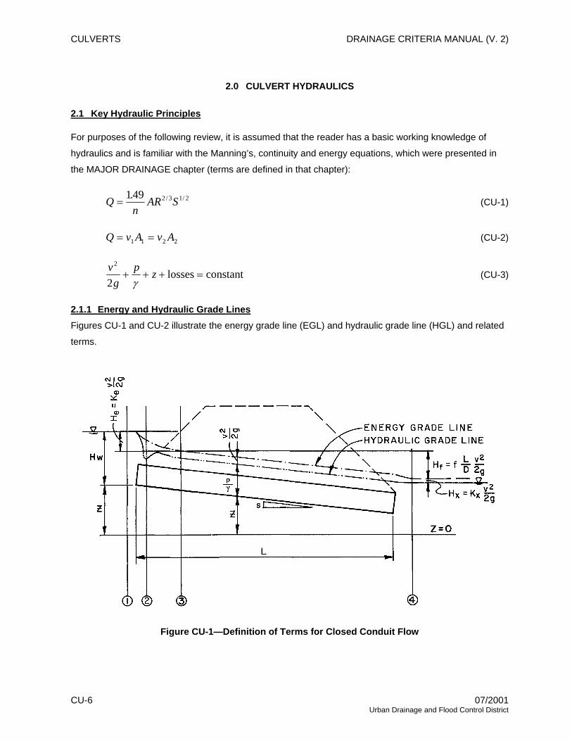
2.1.1 Energy and Hydraulic Grade Lines Figures CU-1 and CU-2 illustrate the energy grade line (EGL) and hydraulic grade line (HGL) and related
terms.
Figure CU-1—Definition of Terms for Closed Conduit Flow
CU-6 07/2001 Urban Drainage and Flood Control District
DRAINAGE CRITERIA MANUAL (V. 2) CULVERTS
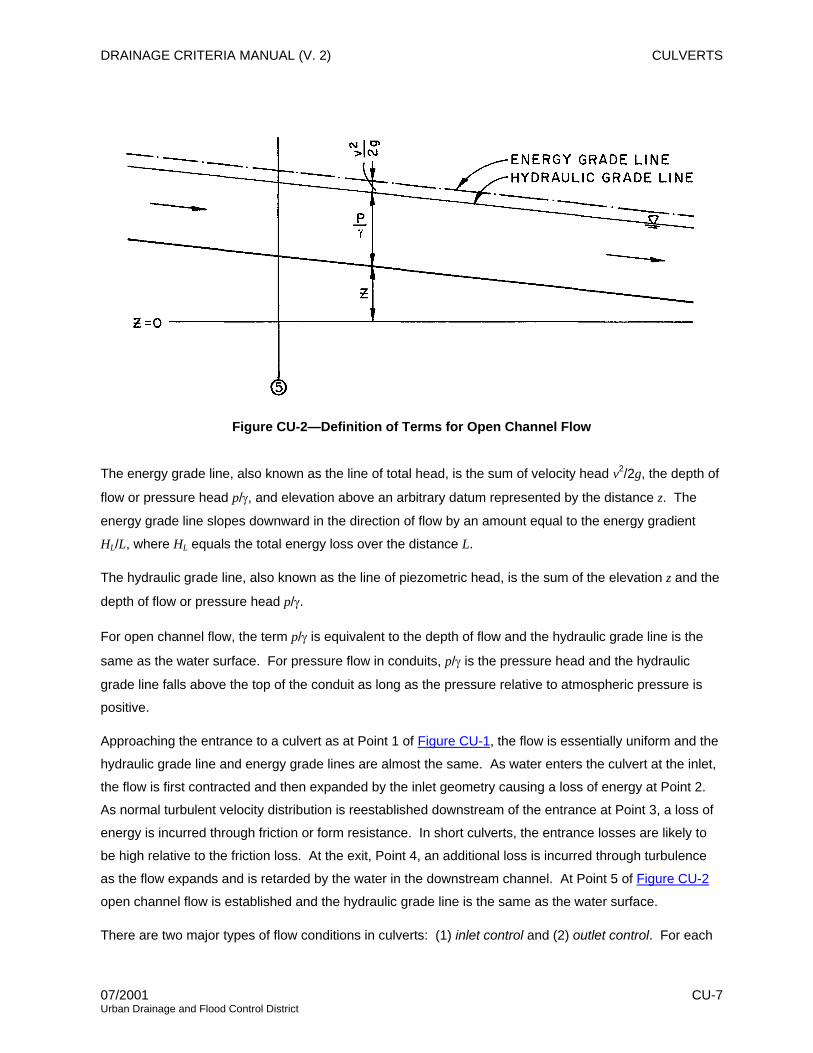
Figure CU-2—Definition of Terms for Open Channel Flow
The energy grade line, also known as the line of total head, is the sum of velocity head v2/2g, the depth of
flow or pressure head p/γ, and elevation above an arbitrary datum represented by the distance z. The
energy grade line slopes downward in the direction of flow by an amount equal to the energy gradient
HL/L, where HL equals the total energy loss over the distance L.
The hydraulic grade line, also known as the line of piezometric head, is the sum of the elevation z and the
depth of flow or pressure head p/γ.
For open channel flow, the term p/γ is equivalent to the depth of flow and the hydraulic grade line is the
same as the water surface. For pressure flow in conduits, p/γ is the pressure head and the hydraulic
grade line falls above the top of the conduit as long as the pressure relative to atmospheric pressure is
positive.
Approaching the entrance to a culvert as at Point 1 of Figure CU-1, the flow is essentially uniform and the
hydraulic grade line and energy grade lines are almost the same. As water enters the culvert at the inlet,
the flow is first contracted and then expanded by the inlet geometry causing a loss of energy at Point 2.
As normal turbulent velocity distribution is reestablished downstream of the entrance at Point 3, a loss of
energy is incurred through friction or form resistance. In short culverts, the entrance losses are likely to
be high relative to the friction loss. At the exit, Point 4, an additional loss is incurred through turbulence
as the flow expands and is retarded by the water in the downstream channel. At Point 5 of Figure CU-2
open channel flow is established and the hydraulic grade line is the same as the water surface.
There are two major types of flow conditions in culverts: (1) inlet control and (2) outlet control. For each
07/2001 CU-7 Urban Drainage and Flood Control District

CULVERTS DRAINAGE CRITERIA MANUAL (V. 2)
type of control, a different combination of factors is used to determine the hydraulic capacity of a culvert.
The determination of actual flow conditions can be difficult; therefore, the designer must check for both
types of control and design for the most adverse condition.
2.1.2 Inlet Control A culvert operates with inlet control when the flow capacity is controlled at the entrance by these factors:
• Depth of headwater
• Cross-sectional area
• Inlet edge configuration
• Barrel shape
When a culvert operates under inlet control, headwater depth and the inlet edge configuration determine
the culvert capacity with the culvert barrel usually flowing only partially full.
Inlet control for culverts may occur in two ways. The least common occurs when the headwater depth is
not sufficient to submerge the top of the culvert and the culvert invert slope is supercritical as shown in
Figure CU-3.
Figure CU-3—Inlet Control—Unsubmerged Inlet
The most common occurrence of inlet control is when the headwater submerges the top of the culvert
(Figure CU-4), and the pipe does not flow full. A culvert flowing under inlet control is defined as a
hydraulically short culvert.
CU-8 07/2001 Urban Drainage and Flood Control District

DRAINAGE CRITERIA MANUAL (V. 2) CULVERTS
Figure CU-4—Inlet Control—Submerged Inlet
For a culvert operating with inlet control, the roughness, slope, and length of the culvert barrel and outlet
conditions (including tailwater) are not factors in determining culvert hydraulic performance.
2.1.3 Outlet Control If the headwater is high enough, the culvert slope sufficiently flat, and the culvert sufficiently long, the
control will shift to the outlet. In outlet control, the discharge is a function of the inlet losses, the
headwater depth, the culvert roughness, the culvert length, the barrel diameter, the culvert slope, and
sometimes the tailwater elevation.
In outlet control, culvert hydraulic performance is determined by these factors:
• Depth of headwater
• Cross-sectional area
• Inlet edge configuration
• Culvert shape
• Barrel slope
• Barrel length
• Barrel roughness
• Depth of tailwater
Outlet control will exist under two conditions. The first and least common is that where the headwater is
insufficient to submerge the top of the culvert, and the culvert slope is subcritical (Figure CU-5). The most
common condition exists when the culvert is flowing full (Figure CU-6). A culvert flowing under outlet
control is defined as a hydraulically long culvert.
07/2001 CU-9 Urban Drainage and Flood Control District

CULVERTS DRAINAGE CRITERIA MANUAL (V. 2)
Figure CU-5—Outlet Control—Partially Full Conduit
Figure CU-6—Outlet Control—Full Conduit
Culverts operating under outlet control may flow full or partly full depending on various combinations of
the above factors. In outlet control, factors that may affect performance appreciably for a given culvert
size and headwater are barrel length and roughness, and tailwater depth.
2.2 Energy Losses
In short conduits, such as culverts, the form losses due to the entrance can be as important as the friction
losses through the conduit. The losses that must be evaluated to determine the carrying capacity of the
culverts consist of inlet (or entrance) losses, friction losses and outlet (or exit) losses.
2.2.1 Inlet Losses For inlet losses, the governing equations are:
gHCAQ 2= (CU-4)
gvKH ee 2
2
= (CU-5)
CU-10 07/2001 Urban Drainage and Flood Control District

DRAINAGE CRITERIA MANUAL (V. 2) CULVERTS
where:
Q = flow rate or discharge (cfs)
C = contraction coefficient (dimensionless)
A = cross-sectional area (ft2)
g = acceleration due to gravity, 32.2 (ft/sec2)
H = total head (ft)
He = head loss at entrance (ft)
Ke = entrance loss coefficient
v = average velocity (ft/sec)
2.2.2 Outlet Losses For outlet losses, the governing equations are related to the difference in velocity head between the pipe
flow and that in the downstream channel at the end of the pipe.
2.2.3 Friction Losses Friction head loss for turbulent flow in pipes flowing full can be determined from the Darcy-Weisbach
equation.
⎟⎟⎠
⎞⎜⎜⎝
⎛⎟⎠⎞
⎜⎝⎛=
gv
DLfH f 2
2
(CU-6)
where:
Hf = frictional head loss (ft)
f = friction factor (dimensionless)
L = length of culvert (ft)
D = Diameter of culvert (ft)
v = average velocity (ft/sec)
g = acceleration due to gravity, 32.2 (ft/sec2)
The friction factor has been determined empirically and is dependent on relative roughness, velocity, and
barrel diameter. Moody diagrams can be used to determine the friction factor. The friction losses for
culverts are often expressed in terms of Manning’s n, which is independent of the size of pipe and depth
of flow. Another common formula for pipe flow is the Hazen-Williams formula. Standard hydraulic texts
should be consulted for limitations of these formulas.
07/2001 CU-11 Urban Drainage and Flood Control District

CULVERTS DRAINAGE CRITERIA MANUAL (V. 2)
3.0 CULVERT SIZING AND DESIGN
FHWA (1985) Hydraulic Design Series No. 5, Hydraulic Design of Highway Culverts, provides valuable
guidance for the design and selection of drainage culverts. This circular explains inlet and outlet control
and the procedure for designing culverts. Culvert design basically involves the trial and error method:
1. Select a culvert shape, type, and size with a particular inlet end treatment.
2. Determine a headwater depth from the relevant charts for both inlet and outlet control for the
design discharge, the grade and length of culvert, and the depth of water at the outlet (tailwater).
3. Compare the largest depth of headwater (as determined from either inlet or outlet control) to the
design criteria. If the design criteria are not met, continue trying other culvert configurations until
one or more configurations are found to satisfy the design parameters.
4. Estimate the culvert outlet velocity and determine if there is a need for any special features such
as energy dissipators, riprap protection, fish passage, trash/safety rack, etc.
3.1 Description of Capacity Charts
Figure CU-7 is an example of a capacity chart used to determine culvert size. Refer to this figure in the
following discussion.
Each chart contains a series of curves, which show the discharge capacity per barrel in cfs for each of
several sizes of similar culvert types for various headwater depths in feet above the invert of the culvert at
the inlet. The invert of the culvert is defined as the low point of its cross section.
Each size is described by two lines, one solid and one dashed. The numbers associated with each line
are the ratio of the length, L, in feet, to 100 times the slope, s, in feet per foot (ft/ft) (100s). The dashed
lines represent the maximum L/(100s) ratio for which the curves may be used without modification. The
solid line represents the division between outlet and inlet control. For values of L/(100s) less than that
shown on the solid line, the culvert is operating under inlet control and the headwater depth is determined
from the L/(100s) value given on the solid line. The solid-line inlet-control curves are plotted from model
test data. The dashed-line outlet-control curves were computed for culverts of various lengths with
relatively flat slopes. Free outfall at the outlet was assumed; therefore, tailwater depth is assumed not to
influence the culvert performance.
For culverts flowing under outlet control, the head loss at the entrance was computed using the loss
coefficients previously given, and the hydraulic roughness of the various materials used in culvert
construction was taken into account in computing resistance loss for full or part-full flow. The Manning’s n
values used for each culvert type ranged from 0.012 to 0.032.
CU-12 07/2001 Urban Drainage and Flood Control District

DRAINAGE CRITERIA MANUAL (V. 2) CULVERTS
Except for large pipe sizes, headwater depths on the charts extend to 3 times the culvert height. Pipe
arches and oval pipe show headwater up to 2.5 times their height since they are used in low fills. The
dotted line, stepped across the charts, shows headwater depths of about twice the barrel height and
indicates the upper limit of restricted use of the charts. Above this line the headwater elevation should be
checked with the nomographs, which are described in Section 3.3.
The headwater depth given by the charts is actually the difference in elevation between the culvert invert
at the entrance and the total head; that is, depth plus velocity head for flow in the approach channel. In
most cases, the water surface upstream from the inlet is so close to this same level that the chart
determination may be used as headwater depth for practical design purposes. Where the approach
velocity is in excess of 3.0 ft/sec, the velocity head must be subtracted from the curve determination of
headwater to obtain the actual headwater depth.
3.2 Use of Capacity Charts
1. The procedure for sizing the culvert is summarized below. Data can be tabulated in the Design
Computation Form shown in Figure CU-8.
2. List design data: Q = flow or discharge rate (cfs), L = length of culvert (ft), allowable Hw =
headwater depth (ft), s = slope of culvert (ft/ft), type of culvert barrel, and entrance.
3. Compute L/(100s).
4. Enter the appropriate capacity chart in Section 11.0 with the design discharge, Q.
5. Find the L/(100s) value for the smallest pipe that will pass the design discharge. If this value is
above the dotted line in Figure CU-7, use the nomographs to check headwater conditions.
6. If L/(100s) is less than the value of L/(100s) given for the solid line, then the value of Hw is the
value obtained from the solid line curve. If L/(100s) is larger than the value for the dashed outlet
control curve, then special measures must be taken, and the reader is referred to Hydraulic
Design of Highway Culverts (FHWA 1985).
7. Check the Hw value obtained from the charts with the allowable Hw. If the indicated Hw is greater
than the allowable Hw, then try the Hw elevation from the next largest pipe size.
3.3 Use of Nomographs
Examples of two nomographs for designing culverts are presented in Figures CU-9 and CU-10. The use
of these nomographs is limited to cases where tailwater depth is higher than the critical depth in the
culvert. The advantage of the capacity charts over the nomographs is that the capacity charts are direct
where the nomographs are trial and error. The capacity charts can be used only when the flow passes
07/2001 CU-13 Urban Drainage and Flood Control District
CULVERTS DRAINAGE CRITERIA MANUAL (V. 2)
through critical depth at the outlet. When the critical depth at the outlet is less than the tailwater depth,
the nomographs must be used; however, both give the same results where either of the two methods may
be used. The procedure for design requires the use of both nomographs and is as follows (refer to
Figures CU-9 and CU-10):
1. List design data: Q (cfs), L (ft), invert elevations in and out (ft), allowable Hw (ft), mean and
maximum flood velocities in natural stream (ft/sec), culvert type and entrance type for first
selection.
2. Determine a trial size by assuming a maximum average velocity based on channel considerations
to compute the area, A = Q/V.
3. Find Hw for trial size culvert for inlet control and outlet control. For inlet control, Figure CU-9,
connect a straight line through D and Q to scale (1) of the Hw/D scales and project horizontally to
the proper scale, compute Hw and, if too large or too small, try another size before computing Hw
for outlet control.
4. Next, compute the Hw for outlet control, Figure CU-10. Enter the graph with the length, the
entrance coefficient for the entrance type, and the trial size. Connect the length scale and the
culvert size scale with a straight line, pivot on the turning line, and draw a straight line from the
design discharge on the discharge scale through the turning point to the head scale (head loss,
H). Compute Hw from the equation:
LshHHw o −+= (CU-7)
where:
Hw = headwater depth (ft)
H = head loss (ft)
ho = tailwater depth or elevation at the outlet of a depth equivalent to the location of the
hydraulic grade line (ft)
L = length of culvert (ft)
s = slope of culvert (ft/ft)
For Tw greater than or equal to the top of the culvert, ho = Tw, and for Tw less than the top of the
culvert:
( )2
Ddh c
o+
= or Tw (whichever is greater) (CU-8)
CU-14 07/2001 Urban Drainage and Flood Control District

DRAINAGE CRITERIA MANUAL (V. 2) CULVERTS
where:
dc = critical depth (ft)
Tw = tailwater depth (ft)
If Tw is less than dc, the nomographs cannot be used, see Hydraulic Design of Highway Culverts
(FHWA 1985) for critical depth charts.
5. Compare the computed headwaters and use the higher Hw to determine if the culvert is under
inlet or outlet control. If outlet control governs and the Hw is unacceptable, select a larger trial
size and find another Hw with the outlet control nomographs. Since the smaller size of culvert
had been selected for allowable Hw by the inlet control nomographs, the inlet control for the
larger pipe need not be checked.
3.4 Computer Applications, Including Design Spreadsheet
Although the nomographs discussed in this chapter are still used, engineers are increasingly designing
culverts using computer applications. Among these applications are the FHWA’s HY8 Culvert Analysis
(Ginsberg 1987) and numerous proprietary applications. In addition, the District has developed
spreadsheets to aid in the sizing and design of culverts. Both the UD-Culvert Spreadsheet application
and FHWA’s HY8 Culvert Analysis (Version 6.1) are located on the CD-ROM version of this Manual.
3.5 Design Considerations
Due to problems arising from topography and other considerations, the actual design of a culvert
installation is more difficult than the simple process of sizing culverts. The information in the procedure
for design that will be given is a guide to design since the problems encountered are too varied and too
numerous to be generalized. However, the actual process presented should be followed to insure that
some special problem is not overlooked. Several combinations of entrance types, invert elevations, and
pipe diameters should be tried to determine the most economic design that will meet the conditions
imposed by topography and engineering.
3.5.1 Design Computation Forms The use of design computation forms is a convenient method to use to obtain consistent designs and
promote cost-effectiveness. An example of such a form is Figure CU-8.
3.5.2 Invert Elevations After determining the allowable headwater elevation, the tailwater elevation, and the approximate length,
invert elevations must be assumed. Scour is not likely in an artificial channel such as a roadside ditch or
a major drainage channel when the culvert has the same slope as the channel. To reduce the chance of
failure due to scour, invert elevations corresponding to the natural grade should be used as a first trial.
07/2001 CU-15 Urban Drainage and Flood Control District

CULVERTS DRAINAGE CRITERIA MANUAL (V. 2)
For natural channels, the flow conditions in the channel upstream from the culvert should be investigated
to determine if scour will occur.
3.5.3 Culvert Diameter After the invert elevations have been assumed and using the design computation forms (e.g., Figure CU-
8), the capacity charts (e.g., Figure CU-7), and the nomographs, the diameter of pipe that will meet the
headwater requirements should be determined. Since small diameter pipes are often plugged by
sediment and debris, it is recommended that pipe smaller than 18 inches not be used for any drainage
where this Manual applies. Since the pipe roughness influences the culvert diameter, both concrete and
corrugated metal pipe should be considered in design, if both will satisfy the headwater requirements.
3.5.4 Limited Headwater If there is insufficient headwater elevation to obtain the required discharge, it is necessary to oversize the
culvert barrel, lower the inlet invert, use an irregular cross section, or use any combination of the
preceding.
If the inlet invert is lowered, special consideration must be given to scour. The use of gabions or concrete
drop structures, riprap, and headwalls with apron and toe walls should be investigated and compared to
obtain the proper design.
3.6 Culvert Outlet
The outlet velocity must be checked to determine if significant scour will occur downstream during the
major storm. If scour is indicated (and this will normally be the case), refer to Section 7.0 of the MAJOR
DRAINAGE chapter (“Protection Downstream of Culverts”) and to the HYDRAULIC STRUCTURES
chapter for guidance on outfall protection. District maintenance staff have observed that inadequate
culvert outlet protection is one of the more common problems within the District. Short-changing outlet
protection is no place to economize during design and construction because downstream channel
degradation can be significant and the culvert outlet can be undermined.
3.7 Minimum Slope
To minimize sediment deposition in the culvert, the culvert slope must be equal to or greater than the
slope required to maintain a minimum velocity as described in the MAJOR DRAINAGE and
STREETS/INLETS/STORM SEWERS chapters. The slope should be checked for each design, and if the
proper minimum velocity is not obtained, the pipe diameter may be decreased, the slope steepened, a
smoother pipe used, or a combination of these may be used.
CU-16 07/2001 Urban Drainage and Flood Control District

DRAINAGE CRITERIA MANUAL (V. 2) CULVERTS
Figure CU-7—Culvert Capacity Chart—Example
07/2001 CU-17 Urban Drainage and Flood Control District

CULVERTS DRAINAGE CRITERIA MANUAL (V. 2)
Figure CU-8—Design Computation for Culverts—Blank Form
CU-18 07/2001 Urban Drainage and Flood Control District

DRAINAGE CRITERIA MANUAL (V. 2) CULVERTS
Figure CU-9—Inlet Control Nomograph—Example
07/2001 CU-19 Urban Drainage and Flood Control District

CULVERTS DRAINAGE CRITERIA MANUAL (V. 2)
Figure CU-10—Outlet Control Nomograph—Example
CU-20 07/2001 Urban Drainage and Flood Control District

DRAINAGE CRITERIA MANUAL (V. 2) CULVERTS
4.0 CULVERT INLETS
A fact often overlooked is that a culvert cannot carry any more water than can enter the inlet. Frequently
culverts and open channels are carefully designed with full consideration given to slope, cross section,
and hydraulic roughness, but without regard to the inlet limitations. Culvert designs using uniform flow
equations rarely carry their design capacity due to limitations imposed by the inlet.
The design of a culvert, including the inlet and the outlet, requires a balance between cost, hydraulic
efficiency, purpose, and topography at the proposed culvert site. Where there is sufficient allowable
headwater depth, a choice of inlets may not be critical, but where headwater depth is limited, where
erosion is a problem, or where sedimentation is likely, a more efficient inlet may be required to obtain the
necessary discharge for the culvert.
The primary purpose of a culvert is to convey flows. A culvert may also be used to restrict flow, that is, to
discharge a controlled amount of water while the area upstream from the culvert is used for detention
storage to reduce a storm runoff peak. For this case, an inefficient inlet may be the most desirable
choice.
The inlet types described in this chapter may be selected to fulfill either of the above requirements
depending on the topography or conditions imposed by the designer. The entrance coefficient, Ke, as
defined by Equation CU-5, is a measure of the hydraulic efficiency at the inlet, with lower valves indicating
greater efficiency. Inlet coefficients recommended for use are given in Table CU-1.
Table CU-1—Inlet Coefficients For Outlet Control
Type of Entrance Entrance Coefficient, Ke 1. Pipe entrance with headwall Grooved edge 0.20 Rounded edge (0.15D radius) 0.15 Rounded edge (0.25D radius) 0.10 Square edge (cut concrete and CMP) 0.40 2. Pipe entrance with headwall & 45° wingwall Grooved edge 0.20 Square edge 0.35 3. Headwall with parallel wingwalls spaced 1.25D apart Grooved edge 0.30 Square edge 0.40 4. Special inlets—see Section 4.3 5. Projecting Entrance Grooved edge 0.25 Square edge 0.50 Sharp edge, thin wall 0.90
07/2001 CU-21 Urban Drainage and Flood Control District

CULVERTS DRAINAGE CRITERIA MANUAL (V. 2)
4.1 Projecting Inlets
Projecting inlets vary greatly in hydraulic efficiency and adaptability to requirements with the type of pipe
material used. Figure CU-11 illustrates this type of inlet.
Figure CU-11—Common Projecting Culvert Inlets
The primary advantage of projecting inlets is relatively low cost. Because projecting inlets are susceptible
to damage due to maintenance of embankment and roadways and due to accidents, the adaptability of
this type of entrance to meet the engineering and topographical demands varies with the type of material
used.
Corrugated metal pipe projecting inlets have limitations which include low efficiency, damage which may
result from maintenance of the channel and the area adjacent to the inlet, and restrictions on the ability of
maintenance crews to work around the inlet. The hydraulic efficiency of concrete-grooved or bell-end
pipe is good and, therefore, the only restriction placed on the use of concrete pipe for projecting inlets is
CU-22 07/2001 Urban Drainage and Flood Control District
DRAINAGE CRITERIA MANUAL (V. 2) CULVERTS
the requirement for maintenance of the channel and the embankment surrounding the inlet. Where
equipment will be used to maintain the embankment around the inlet, it is not recommended that a
projecting inlet of any type be used.
4.1.1 Corrugated Metal Pipe A projecting entrance of corrugated metal pipe is equivalent to a sharp-edged entrance with a thin wall
and has an entrance coefficient of about 0.9.
4.1.2 Concrete Pipe Bell-and-spigot concrete pipe or tongue-and-groove concrete pipe with the bell end or grooved end used
as the inlet section are quite efficient hydraulically, having an entrance coefficient of about 0.25. For
concrete pipe that has been cut, the entrance is square edged, and the entrance coefficient is about 0.5.
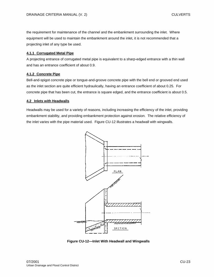
4.2 Inlets with Headwalls
Headwalls may be used for a variety of reasons, including increasing the efficiency of the inlet, providing
embankment stability, and providing embankment protection against erosion. The relative efficiency of
the inlet varies with the pipe material used. Figure CU-12 illustrates a headwall with wingwalls.
Figure CU-12—Inlet With Headwall and Wingwalls
07/2001 CU-23 Urban Drainage and Flood Control District

CULVERTS DRAINAGE CRITERIA MANUAL (V. 2)
4.2.1 Corrugated Metal Pipe Corrugated metal pipe in a headwall is essentially a square-edged entrance with an entrance coefficient
of about 0.4. The entrance losses may be reduced by rounding the entrance. The entrance coefficient
may be reduced to 0.15 for a rounded edge with a radius equal to 0.15 times the culvert diameter, and to
0.10 for rounded edge with a radius equal to 0.25 times the diameter of the culvert.
4.2.2 Concrete Pipe For tongue-and-groove or bell-end concrete pipe, little increase in hydraulic efficiency is realized by
adding a headwall. The primary reason for using headwalls is for embankment protection and for ease of
maintenance. The entrance coefficient is equal to about 0.2 for grooved and bell-end pipe, and equal to
0.4 for cut concrete pipe.
4.2.3 Wingwalls Wingwalls are used where the side slopes of the channel adjacent to the entrance are unstable and
where the culvert is skewed to the normal channel flow. Little increase in hydraulic efficiency is realized
with the use of wingwalls, regardless of the pipe material used and, therefore, the use should be justified
for reasons other than an increase in hydraulic efficiency. Figure CU-13 illustrates several cases where
wingwalls are used. For parallel wingwalls, the minimum distance between wingwalls should be at least
1.25 times the diameter of the culvert pipe.
4.2.4 Aprons If high headwater depths are to be encountered, or if the approach velocity of the channel will cause
scour, a short channel apron should be provided at the toe of the headwall. This apron should extend at
least one pipe diameter upstream from the entrance, and the top of the apron should not protrude above
the normal streambed elevation.
Culverts with wingwalls should be designed with a concrete apron extending between the walls. Aprons
must be re
inforced to control cracking. As illustrated in Figure CU-13, the actual configuration of the wingwalls
varies according to the direction of flow and will also vary according to the topographical requirement
placed upon them.
For conditions where scour may be a problem due to high approach velocities and special soil conditions,
such as alluvial soils, a toe wall is often desirable for apron construction.
CU-24 07/2001 Urban Drainage and Flood Control District

DRAINAGE CRITERIA MANUAL (V. 2) CULVERTS
Figure CU-13—Typical Headwall-Wingwall Configurations
4.3 Special Inlets
There is a great variety of inlets other than the common ones described. Among these are special end-
sections, which serve as both outlets and inlets and are available for both corrugated metal pipe and
concrete pipe. Because of the difference in requirements due to pipe materials, the special end-sections
will be discussed independently according to pipe material, and mitered inlets will also be considered.
07/2001 CU-25 Urban Drainage and Flood Control District
CULVERTS DRAINAGE CRITERIA MANUAL (V. 2)
4.3.1 Corrugated Metal Pipe Special end-sections for corrugated metal pipe add little to the overall cost of the culvert and have the
following advantages:
1. Less maintenance around the inlet.
2. Less damage from maintenance work and from accidents compared to a projecting entrance.
3. Increased hydraulic efficiency. When using design charts, as discussed in Section 3.0, charts for
a square-edged opening for corrugated metal pipe with a headwall may be used.
4.3.2 Concrete Pipe As in the case of corrugated metal pipe, these special end-sections may aid in increasing the
embankment stability or in retarding erosion at the inlet. They should be used where maintenance
equipment must be used near the inlet or where, for aesthetic reasons, a projecting entrance is
considered too unsightly.
The hydraulic efficiency of this type of inlet is dependent on the geometry of the end-section to be used.
Where the full contraction to the culvert diameter takes place at the first pipe section, the entrance
coefficient, Ke, is equal to 0.5, and where the full contraction to the culvert diameter takes place in the
throat of the end-section, the entrance coefficient, Ke, is equal to 0.25.
4.3.3 Mitered Inlets The use of this entrance type is predominantly with corrugated metal pipe and its hydraulic efficiency is
dependent on the construction procedure used. If the embankment is not paved, the entrance, in
practice, usually does not conform to the side slopes, giving essentially a projecting entrance with Ke =
0.9. If the embankment is paved, a sloping headwall is obtained with Ke = 0.60 and, by beveling the
edges, Ke = 0.50.
Uplift is an important factor for this type entrance. It is not good practice to use unpaved embankment
slopes where a mitered entrance may be submerged to an elevation one-half the diameter of the culvert
above the top of the pipe.
4.3.4 Long Conduit Inlets Inlets are important in the design of culverts for road crossings and other short sections of conduit;
however, they are even more significant in the economical design of long culverts and pipes. Unused
capacity in a long conduit will result in wasted investment. Long conduits are costly and require detailed
engineering, planning, and design work. The inlets to such conduits are extremely important to the
functioning of the conduit and must receive special attention.
Most long conduits require special inlet considerations to meet the particular hydraulic characteristics of
CU-26 07/2001 Urban Drainage and Flood Control District

DRAINAGE CRITERIA MANUAL (V. 2) CULVERTS
the conduit. Generally, on larger conduits, hydraulic model testing will result in better and less costly inlet
construction.
4.4 Improved Inlets
Inlet edge configuration is one of the prime factors influencing the performance of a culvert operating
under inlet control. Inlet edges can cause a severe contraction of the flow, as in the case of a thin edge,
projecting inlet. In a flow contraction, the effective cross-sectional area of the barrel may be reduced to
about one-half of the actual available barrel area. As the inlet configuration is improved, the flow
contraction is reduced, thus improving the performance of the culvert.
A tapered inlet is a flared culvert inlet with an enlarged face section and a hydraulically efficient throat
section. Tapered inlets improve culvert performance by providing a more efficient control section (the
throat). However, tapered inlets are not recommended for use on culverts flowing under outlet control
because the simple beveled edge is of equal benefit. The two most common improved inlets are the
side-tapered inlet and the slope-tapered inlet (Figure CU-14). FHWA (1985) Hydraulic Design of Highway
Culverts provides guidance on the design of improved inlets.
Figure CU-14—Side-Tapered and Slope-Tapered Improved Inlets
07/2001 CU-27 Urban Drainage and Flood Control District

CULVERTS DRAINAGE CRITERIA MANUAL (V. 2)
5.0 INLET PROTECTION
Inlets on culverts, especially on culverts to be installed in live streams, should be evaluated relative to
debris control and buoyancy. These topics are addressed in this section, while broader discussion of the
advantages and disadvantages of trash/safety racks is provided in Section 8.0.
5.1 Debris Control
Accumulation of debris at a culvert inlet can result in the culvert not performing as designed. The
consequences may be damages from inundation of the road and upstream property. The designer has
three options for coping with the debris problem:
1. Retain the debris upstream of the culvert.
2. Attempt to pass the debris through the culvert.
3. Install a bridge.
If the debris is to be retained by an upstream structure or at the culvert inlet, frequent maintenance may
be required. The design of a debris control structure should include a thorough study of the debris
problem.
The following are among the factors to be considered in a debris study:
• Type of debris
• Quantity of debris
• Expected changes in type and quantity of debris due to future land use
• Stream flow velocity in the vicinity of culvert entrance
• Maintenance access requirements
• Availability of storage
• Maintenance plan for debris removal
• Assessment of damage due to debris clogging, if protection is not provided
Hydraulic Engineering Circular No. 9, Debris Control Structures (FHWA 1971), should be used when
designing debris control structures.
5.2 Buoyancy
The forces acting on a culvert inlet during flows are variable and indeterminate. When a culvert is
CU-28 07/2001 Urban Drainage and Flood Control District

DRAINAGE CRITERIA MANUAL (V. 2) CULVERTS
functioning with inlet control, an air pocket begins just inside the inlet that creates a buoyant effect when
the inlet is submerged. The buoyancy forces increase with an increase in headwater depth under inlet
control conditions. These forces, along with vortexes and eddy currents, can cause scour, undermine
culvert inlets, and erode embankment slopes, thereby making the inlet vulnerable to failure, especially
with deep headwater.
In general, installing a culvert in a natural stream channel constricts the normal flow. The constriction is
accentuated when the capacity of the culvert is impaired by debris or damage.
The large unequal pressures resulting from inlet constriction are in effect buoyant forces that can cause
entrance failures, particularly on corrugated metal pipe with mitered, skewed, or projecting ends. The
failure potential will increase with steepness of the culvert slope, depth of the potential headwater,
flatness of the fill slope over the upstream end of the culvert, and the depth of the fill over the pipe.
Anchorage at the culvert entrance helps to protect against these failures by increasing the deadload on
the end of the culvert, protecting against bending damage, and by protecting the fill slope from the
scouring action of the flow. Providing a standard concrete headwall or endwall helps to counteract the
hydrostatic uplift and to prevent failure due to buoyancy.
Because of a combination of high head on the outside of the inlet and the large region of low pressure on
the inside of the inlet due to separation, a large bending moment is exerted on the end of the culvert,
which may result in failure. This problem has been noted in the case of culverts under high fills, on steep
slopes, and with projecting inlets. Where upstream detention storage requires headwater depth in excess
of 20 feet, reducing the culvert size is recommended rather than using the inefficient projecting inlet to
reduce discharge.
07/2001 CU-29 Urban Drainage and Flood Control District

CULVERTS DRAINAGE CRITERIA MANUAL (V. 2)
6.0 OUTLET PROTECTION
Scour at culvert outlets is a common occurrence. It must be accounted for, as discussed below and in
the HYDRAULIC STRUCTURES and MAJOR DRAINAGE chapters. The natural channel flow is usually
confined to a lesser width and greater depth as it passes through a culvert barrel. An increased velocity
results with potentially erosive capabilities as it exits the barrel. Turbulence and erosive eddies form as
the flow expands to conform to the natural channel. However, the velocity and depth of flow at the culvert
outlet and the velocity distribution upon reentering the natural channel are not the only factors that need
consideration.
The characteristics of the channel bed and bank material, velocity, and depth of flow in the channel at the
culvert outlet, and the amount of sediment and other debris in the flow are all contributing factors to scour
potential. Due to the variation in expected flows and the difficulty in evaluating some of these factors,
scour prediction is not a very exact science.
Scour in the vicinity of a culvert outlet can be classified into two separate types called local scour and
general stream degradation.
6.1 Local Scour
Local scour is typified by a scour hole produced at the culvert outlet. This is the result of high exit
velocities, and the effects extend only a limited distance downstream.
Coarse material scoured from the circular or elongated hole is deposited immediately downstream, often
forming a low bar. Finer material is transported further downstream. The dimensions of the scour hole
change due to sedimentation during low flows and the varying erosive effects of storm events. The scour
hole is generally deepest during passage of the peak flow. Methods for predicting scour hole dimensions
are found in Hydraulic Design of Energy Dissipators for Culverts and Channels (FHWA 1983 and 2000).
6.2 General Stream Degradation
General stream degradation is a phenomenon that is independent of culvert performance. Natural
causes produce a lowering of the streambed over time. The identification of a degrading stream is an
essential part of the original site investigation. This subject is discussed in the MAJOR DRAINAGE
chapter.
Both local and general scour can occur simultaneously at a culvert outlet. Protection against scour at
culvert outlets varies from limited riprap placement to complex and expensive energy dissipation devices
(Photograph CU-5). At some locations, use of a rougher culvert material may alleviate the need for a
special outlet protection device. Pre-formed scour holes (approximating the configuration of naturally
formed holes) dissipate energy while providing a protective lining to the streambed.
CU-30 07/2001 Urban Drainage and Flood Control District

DRAINAGE CRITERIA MANUAL (V. 2) CULVERTS
Photograph CU-5—Energy dissipation and outlet protection are essential to promote channel stability.
As discussed in the HYDRAULIC STRUCTURES chapter and in Section 7.0 of the MAJOR DRAINAGE
chapter, riprapped channel expansions and concrete aprons protect the channel and redistribute or
spread the flow. Barrel outlet expansions operate in a similar manner. Headwalls and cutoff walls protect
the integrity of the fill. When outlet velocities are high enough to create excessive downstream problems,
consideration should be given to more complex energy dissipation devices. These include hydraulic jump
basins, impact basins, drop structures, and stilling wells. Design information for the general types of
energy dissipators is provided in the MAJOR DRAINAGE and HYDRAULIC STRUCTURES chapters of
this Manual and in Hydraulic Design of Energy Dissipators for Culverts and Channels (FHWA 1983 and
2000).
07/2001 CU-31 Urban Drainage and Flood Control District

CULVERTS DRAINAGE CRITERIA MANUAL (V. 2)
7.0 GENERAL CONSIDERATIONS
7.1 Culvert Location
Culvert location is an integral part of the total design. The main purpose of a culvert is to convey
drainage water across the roadway section expeditiously and effectively. The designer should identify all
live stream crossings, springs, low areas, gullies, and impoundment areas created by the new roadway
embankment for possible culvert locations. Note that environmental permitting constraints will often apply
for new culverts or retrofits, such as a Section 404 permit that regulates construction activities in
jurisdictional wetlands and “Waters of the United States.”
Culverts should be located on existing stream alignments and aligned to give the stream a direct entrance
and a direct exit. Abrupt changes in direction at either end may retard the flow and make a larger
structure necessary. If necessary, a direct inlet and outlet may be obtained by means of a channel
change, skewing the culvert, or a combination of these. The choice of alignment should be based on
economics, environmental concerns, hydraulic performance, and/or maintenance considerations.
If possible, a culvert should have the same alignment as its channel. Often this is not practical and where
the water must be turned into the culvert, headwalls, wingwalls, and aprons with configurations similar to
those in Figure CU-13 should be used as protection against scour and to provide an efficient inlet.
7.2 Sedimentation
Deposits usually occur within the culvert barrels at flow rates smaller than the design flow. The deposits
may be removed during larger floods dependent upon the relative transport capacity of flow in the stream
and in the culvert, compaction and composition of the deposits, flow duration, ponding depth above the
culvert, and other factors.
Culvert location in both plan and profile is of particular importance to the maintenance of sediment-free
culvert barrels. Deposits occur in culverts because the sediment transport capacity of flow within the
culvert is often less than in the stream.
Deposits in culverts may also occur due to the following conditions:
• At moderate flow rates the culvert cross section is larger than that of the stream, so the flow
depth and sediment transport capacity is reduced.
• Point bars form on the inside of stream bends. Culvert inlets placed at bends in the stream will
be subject to deposition in the same manner. This effect is most pronounced in multiple-barrel
culverts with the barrel on the inside of the curve often becoming almost totally plugged with
sediment deposits.
CU-32 07/2001 Urban Drainage and Flood Control District

DRAINAGE CRITERIA MANUAL (V. 2) CULVERTS
• Abrupt changes to a flatter grade in the culvert or in the channel adjacent to the culvert will induce
sedimentation. Gravel and cobble deposits are common downstream from the break in grade
because of the reduced transport capacity in the flatter section.
7.3 Fish Passage
At some culvert locations, the ability of the structure to accommodate migrating fish is an important design
consideration. For such sites, state fish and wildlife agencies (such as the Colorado Division of Wildlife)
should be consulted early in the roadway planning process. Some situations may require the
construction of a bridge to span the natural stream. However, culvert modifications can often be
constructed to meet the design criteria established by the fish and wildlife agencies.
7.4 Open Channel Inlets
Entrances to open channels often require the same careful planning and design as is needed for culverts
and long conduits if the necessary hydraulic balance is to be achieved. The energy grade line should be
analyzed by the designer to insure proper provision for balanced energy conversion, velocity control,
energy loss, and other factors controlling the downstream flow. Channel confluences, in particular,
require careful hydraulic design to eliminate scour, reduce oscillating waves, and minimize upstream
backwater effects.
7.5 Transitions
Transitions from pipe flow to open channels, between different rigid channels, and from slow flow to
supercritical flow must be designed using the concepts of conservation of energy and open channel
hydraulics. Primarily, a transition is necessary to change the shape or cross section of flowing water.
Normally, the designer will have as an objective the avoidance of excessive energy losses, cross waves,
and turbulence. It is also necessary to provide against scour and overtopping.
Supercritical flow transitions must receive more attention than is usually due subcritical flow transitions.
Care must be taken to insure against unwanted hydraulic jumps or velocities causing critical depth.
Froude numbers between 0.9 and 1.1 should be avoided.
In general, the rate at which the flow prism may be changed should not exceed perhaps 5 to 12½
degrees, depending upon velocity. Sharp angles should be avoided. The water surface hydraulic grade
line should normally be smooth. Transition structure drawings are provided in the HYDRAULIC
STRUCTURES chapter.
7.6 Large Stormwater Inlets
The functioning of large stormwater inlets, which collect major storm surface runoff at points of
07/2001 CU-33 Urban Drainage and Flood Control District

CULVERTS DRAINAGE CRITERIA MANUAL (V. 2)
concentration, is dependent upon careful planning and design. Due regard must be given to debris, hail,
and safety hazards.
7.6.1 Gratings The design of gratings should focus on (1) public safety, (2) hydraulic function and (3) debris control. See
Section 8.0 of this chapter for further discussion.
7.6.2 Openings The hydraulic openings for large storm inlets need to be designed in general accordance with the guides
given in Section 4.0. Inadequate openings are easily plugged when needed most, and give a false sense
of security. Clear vertical openings should be at least 6 inches. For greater inlet flows, the length of
opening needed may be so large that special design approaches are needed for shape and function.
7.6.3 Headwater The required headwater over large inlets must be computed and kept within acceptable limits to avoid
excessive ponding on streets and damage to adjacent property.
7.7 Culvert Replacements
When installing or replacing an existing culvert, careful consideration should be taken to ensure that
upstream and downstream property owners are not adversely affected by the new hydraulic conditions.
The potential upstream flooding impacts associated with the backwater from the calculated headwater
depth must be considered and the determination of the available headwater should take into account the
area inundated at the projected water surface elevation. If a culvert is replaced by one with more
capacity, the downstream effects of the additional flow must be factored into the analysis. Assuring
consistency with existing major drainageway master plans and/or outfall studies is important.
7.8 Fencing for Public Safety
Culverts are frequently located at the base of steep slopes. Large box culverts, in particular, can create
conditions where there is a significant drop, which poses risk to the public. In such cases, fencing
(guardrails) is recommended for public safety.
CU-34 07/2001 Urban Drainage and Flood Control District

DRAINAGE CRITERIA MANUAL (V. 2) CULVERTS
8.0 TRASH/SAFETY RACKS
The use of trash/safety racks at inlets to culverts and long underground pipes should be considered on a
case-by-case basis. While there is a sound argument for the use of racks for safety reasons, field
experience has clearly shown that when the culvert is needed the most, that is, during the heavy runoff,
trash racks often become clogged and the culvert is rendered ineffective. A general rule of thumb is that
a trash/safety rack will not be needed if one can clearly “see daylight” from one side of the culvert to the
other, if the culvert is of sufficient size to pass a 48" diameter object and if the outlet is not likely to trap or
injure a person. By contrast, at entrances to longer culverts and long underground pipes and for culverts
not meeting the above-stated tests, a trash/safety rack is necessary.
The trash/safety rack design process is a matter of fully considering the safety hazard aspects of the
problem, defining them clearly, and then taking reasonable steps to minimize these hazards while
protecting the integrity of the water carrying capability of the culvert (see Photograph CU-6 for an
example of how not to do it).
Photograph CU-6—Small trash racks at culvert entrance will increase the risk of entrance plugging.
In reviewing potential hazards to the public of a possibility of a person being swept into the culvert, it is
also necessary to consider depth and velocity of upstream flow, the local currents in the vicinity of the
culvert entrance, the general character of the neighborhood and whether it has residential population
nearby, the length and size of the culvert, and other factors affecting safety and culvert capacity.
Furthermore, in the event that someone was carried to the culvert with the storm runoff, the exposure
hazard may in some cases be even greater if the person is pinned to the grating by the hydraulic
pressures of the water rather than being carried through the culvert. Large, oversized racks positioned
well in front of the culvert entrance can reduce the risk of pinning.
07/2001 CU-35 Urban Drainage and Flood Control District

CULVERTS DRAINAGE CRITERIA MANUAL (V. 2)
Where debris potential and/or public safety indicate that a rack is required, if the pipe diameter is more
than 24 inches, the rack's open surface area must be, at the absolute minimum, at least four times larger.
For smaller pipes, the factor increases significantly as suggested by Figure 7 in the "Typical Structural
BMP Details" chapter of Volume 3 of this Manual. For culverts larger than 24 inches (i.e., in the smallest
dimension), in addition to the trash rack having an open area larger than four times the culvert entrance,
the average velocities at the rack's face shall be less than 2.0 feet per second at every stage of flow
entering the culvert. The rack needs to be sloped no steeper than 3H:IV (the flatter the better) and have
a clear opening at the bottom of 9 to 12 inches to permit debris at lower flows to go through. The bars on
the face of the rack should be generally paralleling the flow and be spaced to provide 4½- to 5-inch clear
openings between them. Transverse support bars need to be as few as possible, but sufficient to keep
the rack from collapsing under full hydrostatic loads.
The District strongly recommends against the installation of trash racks at culvert outlets, because debris
or a person carried into the culvert will impinge against the rack, thus leading to pressurized conditions
within the culvert, virtually destroying its flow capacity and creating a greater hazard to the public or a
person trapped in the culvert than not having one.
8.1 Collapsible Gratings
The District does not recommend the use of collapsible gratings. On larger culverts where a collapsible
grating is deemed necessary by a local jurisdiction or an engineer, such gratings must be carefully
designed from the structural standpoint so that collapse is achieved with a hydrostatic load of perhaps
one-half of the maximum backwater head allowable. Collapse of the trash rack should be such that it
clears the waterway opening adequately to permit the inlet to function properly without itself contributing
to potential plugging of the culvert.
8.2 Upstream Trash Collectors
Where a safety hazard exists, a large trash rack situated diagonally across a stream a reasonable
distance upstream from the culvert inlet offers an alternative. This type of rack may consist of a series of
vertical pipes or posts embedded in the approach channel bottom with horizontal bars to deflect the
debris to one side. If partial blocking of a properly designed rack occurs, it should be designed so that the
backwater flow over the top of the rack is minimal. The rack must not cause the water to rise higher than
the maximum allowable flood elevation. A trash rack at the culvert entrance can then provide a backup
for safety.
CU-36 07/2001 Urban Drainage and Flood Control District

DRAINAGE CRITERIA MANUAL (V. 2) CULVERTS
9.0 DESIGN EXAMPLE
The following example problem illustrates the culvert design procedures using the FHWA nomographs
and using UD-Culvert Spreadsheet application.
9.1 Culvert Under an Embankment
Given: Q5-yr = 20 cfs, Q100-yr = 35 cfs, L = 95 feet
The maximum allowable headwater elevation is 5288.5. The natural channel invert elevations are 5283.5
at the inlet and 5281.5 at the outlet. The tailwater depth is computed as 2.5 feet for the 5-year storm, and
3.0 feet for the 100-year storm.
Solution:
Step 1. Fill in basic data (Figure CU-15)
Q5-yr = discharge for 5-year storm
Q100-yr = discharge for 100-year storm
Headwater and tailwater elevations
Step 2. Set invert elevations at natural channel invert elevations to avoid scour. Compute s
and L/(100s).
Step 3. Start with an assumed culvert size for the 5-year storm by adopting a velocity of 6.5
ft/sec. In this case, first size is estimated by adopting a velocity of 6.5 ft/sec and computing A =
20/6.5 = 3.1 ft², giving a culvert diameter, D = 24 inches.
Step 4. For this example, two inlets are considered: square edge with headwall (Ke = 0.4) and
groove end with headwall (Ke = 0.2). Also, assume concrete pipe will be used with a Manning’s n
of 0.012 (Note: the District recommends a minimum n of 0.013; however, 0.012 is used in this
example to correspond to the FHWA nomograph.)
Step 5. Using the inlet control nomograph (Figure CU-16), the ratio of the headwater depth to
the culvert diameter (Hw/D) is 1.47 for the square edge and 1.32 for the groove end. Thus, the
inlet control headwater depths are 2.94 feet and 2.64 feet, respectively.
Step 6. The outlet control headwater depth is determined using the method described in
Section 3.0. The head is determined from the nomograph (Figure CU-17). The resulting outlet
control headwater depths are 2.13 feet for the square edge and 1.90 feet for the grove end inlet.
Step 7. Comparing the headwater depths for inlet control (2.94 feet and 2.64 feet) and outlet
07/2001 CU-37 Urban Drainage and Flood Control District

CULVERTS DRAINAGE CRITERIA MANUAL (V. 2)
control (2.13 feet and 1.90 feet) shows that the culvert is inlet controlled with either inlet
configuration. Furthermore, the calculated headwater depths are less than the allowable
headwater depth. These results can also be determined using the UD-Culvert Spreadsheet.
Step 8. The next step is to evaluate the culvert for the 100-year flow of 35 cfs and tailwater
depth of 3.0 feet. Using the same procedure, the culvert continues to be inlet controlled with the
square-edge inlet and switches to outlet control with the more efficient groove-end inlet.
However, both of the calculated headwater depths exceed the allowable headwater depth and,
consequently, are not viable alternatives.
Step 9. Increase the pipe diameter to 27 inches and repeat the process. The resulting
headwater depths are less than the allowable.
Step 10. Compute outlet velocities for each acceptable alternate.
Step 11. Compute cost for each alternate.
Step 12. Make recommendations.
CU-38 07/2001 Urban Drainage and Flood Control District
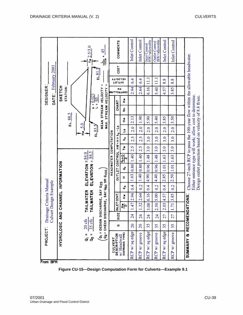
DRAINAGE CRITERIA MANUAL (V. 2) CULVERTS
Figure CU-15—Design Computation Form for Culverts—Example 9.1
07/2001 CU-39 Urban Drainage and Flood Control District

CULVERTS DRAINAGE CRITERIA MANUAL (V. 2)
5-YR
100-YR
Figure CU-16—Headwater Depth for Concrete Pipe Culverts with Inlet Control—Example 9.1
CU-40 07/2001 Urban Drainage and Flood Control District

DRAINAGE CRITERIA MANUAL (V. 2) CULVERTS
100-YR
R5-Y
Figure CU-17—Head for Concrete Pipe Culverts Flowing Full (n = 0.012)—Example 9.1
07/2001 CU-41 Urban Drainage and Flood Control District

CULVERTS DRAINAGE CRITERIA MANUAL (V. 2) CULVERTS DRAINAGE CRITERIA MANUAL (V. 2)
CU-42 07/2001 Urban Drainage and Flood Control District
CU-42 07/2001 Urban Drainage and Flood Control District

DRAINAGE CRITERIA MANUAL (V. 2) CULVERTS
10.0 CHECKLIST
Criterion/Requirement
Culvert diameter should be at least 18 inches.
Evaluate the effects of the proposed culvert on upstream and downstream water surface elevations.
When retrofitting or replacing a culvert, evaluate the changes in the upstream and downstream flood hazard.
Review any proposed changes with local, state, and federal regulators.
When a culvert is sized such that the overlying roadway overtops during large storms, check the depth of cross flow with Table DP-3 in the POLICY chapter.
Provide adequate outlet protection in accordance with the energy dissipator discussion in the MAJOR DRAINAGE and HYDRAULIC STRUCTURES chapters.
07/2001 CU-43 Urban Drainage and Flood Control District

CULVERTS DRAINAGE CRITERIA MANUAL (V. 2)
11.0 CAPACITY CHARTS AND NOMOGRAPHS
Capacity charts and nomographs covering the range of applications commonly encountered in urban
drainage are contained in this section. These charts are from the FHWA Hydraulic Design Series No. 5
(FHWA 1985), which also contains detailed instructions for their use. For situations beyond the range
covered by these charts, reference should be made to the original publications.
CU-44 07/2001 Urban Drainage and Flood Control District
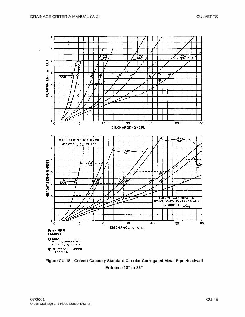
DRAINAGE CRITERIA MANUAL (V. 2) CULVERTS
Figure CU-18—Culvert Capacity Standard Circular Corrugated Metal Pipe Headwall Entrance 18” to 36”
07/2001 CU-45 Urban Drainage and Flood Control District

CULVERTS DRAINAGE CRITERIA MANUAL (V. 2)
Figure CU-19—Culvert Capacity Standard Circular Corrugated Metal Pipe Headwall Entrance 36” to 66”
CU-46 07/2001 Urban Drainage and Flood Control District

DRAINAGE CRITERIA MANUAL (V. 2) CULVERTS
Figure CU-20—Culvert Capacity Standard Circular Corrugated Metal Pipe Projecting Entrance 18” to 36”
07/2001 CU-47 Urban Drainage and Flood Control District

CULVERTS DRAINAGE CRITERIA MANUAL (V. 2)
Figure CU-21—Culvert Capacity Standard Circular Corrugated Metal Pipe Projecting Entrance 36” to 66”
CU-48 07/2001 Urban Drainage and Flood Control District

DRAINAGE CRITERIA MANUAL (V. 2) CULVERTS
Figure CU-22—Culvert Capacity Circular Concrete Pipe Square-Edged Entrance 18” to 66”
07/2001 CU-49 Urban Drainage and Flood Control District

CULVERTS DRAINAGE CRITERIA MANUAL (V. 2)
Figure CU-23—Culvert Capacity Circular Concrete Pipe Square-Edged Entrance 60” to 180”
CU-50 07/2001 Urban Drainage and Flood Control District

DRAINAGE CRITERIA MANUAL (V. 2) CULVERTS
Figure CU-24—Culvert Capacity Circular Concrete Pipe Groove-Edged Entrance 18” to 66”
07/2001 CU-51 Urban Drainage and Flood Control District

CULVERTS DRAINAGE CRITERIA MANUAL (V. 2)
Figure CU-25—Culvert Capacity Circular Concrete Pipe Groove-Edged Entrance 60” to 180”
CU-52 07/2001 Urban Drainage and Flood Control District

DRAINAGE CRITERIA MANUAL (V. 2) CULVERTS
Figure CU-26—Headwater Depth for Corrugated Metal Pipe Culverts With Inlet Control
07/2001 CU-53 Urban Drainage and Flood Control District

CULVERTS DRAINAGE CRITERIA MANUAL (V. 2)
Figure CU-27—Headwater Depth for Concrete Pipe Culverts With Inlet Control
CU-54 07/2001 Urban Drainage and Flood Control District

DRAINAGE CRITERIA MANUAL (V. 2) CULVERTS
Figure CU-28—Headwater Depth for Circular Pipe Culverts With Beveled Ring Inlet Control
07/2001 CU-55 Urban Drainage and Flood Control District

CULVERTS DRAINAGE CRITERIA MANUAL (V. 2)
Figure CU-29—Head for Standard Corrugated Metal Pipe Culverts Flowing Full n = 0.024
CU-56 07/2001 Urban Drainage and Flood Control District

DRAINAGE CRITERIA MANUAL (V. 2) CULVERTS
Figure CU-30—Head for Concrete Pipe Culverts Flowing Full n = 0.012
07/2001 CU-57 Urban Drainage and Flood Control District

CULVERTS DRAINAGE CRITERIA MANUAL (V. 2)
12.0 REFERENCES
American Concrete Pipe Association. 2000. Concrete Pipe Design Manual. Irving, TX: American
Concrete Pipe Association.
Chow, V.T. 1959. Open Channel Hydraulics. New York: McGraw-Hill Book Company, Inc.
Ginsberg, A. 1987. HY8 Culvert Analysis Microcomputer Program Applications Guide. Washington, DC:
U.S. Department of Transportation, Federal Highway Administration.
King, H.W. and E.F. Brater 1976. Handbook of Hydraulics. New York: McGraw-Hill Book Company.
U.S. Bureau of Reclamation. 1960. Design of Small Dams. Denver, CO: Bureau of Reclamation.
U.S. Federal Highway Administration (FHWA). 1965. Hydraulic Charts for the Selection of Highway
Culverts. Hydraulic Engineering Circular No. 5. Washington, DC: U.S. Department of
Transportation, Federal Highway Administration.
———. 1971. Debris Control Structures. Hydraulic Engineering Circular No. 9. Washington, DC: U.S.
Department of Transportation, Federal Highway Administration.
———. 1972a. Capacity Charts for the Hydraulic Design of Highway Culverts. Hydraulic Engineering
Circular No. 10. Washington, DC: U.S. Department of Transportation, Federal Highway
Administration.
———. 1972b. Hydraulic Design of Improved Inlets for Culverts. Hydraulic Engineering Circular No. 13.
Washington, DC: U.S. Department of Transportation, Federal Highway Administration.
———. 1983. Hydraulic Design of Energy Dissipators for Culverts and Channels. Hydraulic Engineering
Circular No. 14. Washington, DC: U.S. Department of Transportation, Federal Highway
Administration.
———. 1985. Hydraulic Design of Highway Culverts. Hydraulic Design Series No. 5. Washington, DC:
U.S. Department of Transportation, Federal Highway Administration.
———. 1996. Federal Lands Highway Project Development and Design Manual. 1996 Metric Revision.
FHWA-DF-88-003. Washington, DC: U.S. Department of Transportation, Federal Highway
Administration.
———. 2000. Hydraulic Design of Energy Dissipators for Culverts and Channels. Hydraulic Engineering
Circular No. 14M. Washington, DC: U.S. Department of Transportation, Federal Highway
Administration.
CU-58 07/2001 Urban Drainage and Flood Control District