Cryogenic Magnetic Screening...
36
GRAVITY PROBE-B MAGNETIC SCREENING PLAN PROCEDURE P0080 Authors: J. Mester and J.M. Lockhart September 5, 1997 Approved: ___________________________ John Mester, Magnetics Manager Approved: ___________________________ J.M. Lockhart, Chair of Magnetics Committee Approved: ___________________________ John Turneaure, Hardware Manager Approved: ___________________________ Ben Taller, GP-B Quality Assurance
Transcript of Cryogenic Magnetic Screening...
GRAVITY PROBE-B
MAGNETIC SCREENING PLAN
PROCEDURE P0080
Authors: J. Mester and J.M. Lockhart September 5, 1997
Approved: ___________________________
John Mester, Magnetics Manager
Approved: ___________________________
J.M. Lockhart, Chair of Magnetics Committee
Approved: ___________________________
John Turneaure, Hardware Manager
Approved: ___________________________
Ben Taller, GP-B Quality Assurance
2
1.0 INTRODUCTION
1.1 Scope
This procedure provides detailed instructions for measuring magnetic fields produced by small to
moderate size test items at room temperature and at cryogenic temperatures. Three different sets
of test apparatus are used at GP-B's Stanford Magnetics Lab, depending on the size of the part and
the temperature at which the test is to be conducted. These facilities are suitable for cryogenic tests
of parts which can fit the 4 inch maximum bore of the large-scale cryogenic screening facility and
for room temperature tests of parts with diameters smaller than the 6 inch active measurement
volume of the SQUID Gradiometer Facility.
Parts and materials going into magnetic zones 1, 2, 3, 4 and SP will be magnetically screened using
this procedure on a 100% basis except those items that are too large for this equipment. Test items
exceeding the size limitation will be tested in the Magnetic Standards Laboratory located at NASA
Ames. The NASA facility contains equipment for magnetization, demagnetization and
measurement meeting GP-B requirements. Tests at AMES are to be scheduled at least five days in
advance, to assure availability.
1 .2 TEST OBJECTIVES
The prime objective of magnetic screening is to prevent the introduction into the GB-P instrument
of any magnetic sources that could degrade its accuracy to the extent that the fundamental
requirements of T003 could not be met.
1 .3 TEST APPROACH
As discussed in the Magnetic Control Plan (P0057), magnetic screening of two basic types is
performed - screening of lot samples of materials to be used for science instrument parts and final
magnetic screening of finished parts and assemblies.
Materials and parts for use in magnetics zones 1 and 2 will be screened at cryogenic temperatures
(2-10 K) while materials and samples for other zones may be screened at cryogenic temperature or
at room temperature.
Material samples are tested in the MPMS instrument described in the next section. Finished parts
will be tested in the MPMS, the large scale cryogenic screening facility, the SQUID gradiometer
facility, or a room temperature fluxgate facility as specified in the Magnetic Control Plan, P0057.
Separate procedures are given below for each of these systems.
3
Some finished parts may be screened after having been demagnetized. In that case, exposure of the
part to polarizing fields will be limited to 2 Gauss. A separate section of each procedure is included
for screening of demagnetized parts.
Magnetic screening is initiated by a subsystem REE 's filling out the upper portion of the Magnetic
Test Form (shown in Appendix A) and submitting it along with the corresponding part to the
Magnetics Lab. The REE is to indicate the Magnetic Zone in which the part will be used, and for
Zone 1 parts, the minimum distance of the part from a gyro surface. At the conclusion of the
screening measurements, a copy of the report is returned to the REE indicating the test results and
the pass/fail status of the part.
1.4 TEST APPARATUS.
The cryogenic test apparatus consists of a Quantum Design Model MPMS Superconducting
Susceptometer System and a Stanford-built Large Scale Cryogenic Screening Facility which
employs superconducting pickup loops and superconducting magnetometers.
The room temperature SQUID Gradiometer Facility consists of an ITE Model "Cryotron" SQUID
Gradiometer, a two-axis Helmholtz coil system with associated control electronics, a rotating
platform, and a chart recorder.
The Room Temperature Fluxgate Screening Facility consists of nine items of equipment: (1) Six-
Layer Ferromagnetic Shield and Stand. Eight inch diameter bore. (2) Fluxgate Vector
Magnetometer, Applied Physics Systems, Model AP5428C Magnetometer System with Axial
Probe, Model APS460. (3) Low Pass Electronic Filter, Wavetek Corp. Model 452, one to three
hertz bandwidth, or equivalent fixed filter, optional. (4) Strip Chart Recorder, Kip and Zonen
Model BD111. (5) DC Magnetizer, Annular Air Core Coil, eight inch bore, nominal 100 gauss,
12V drive. (6) AC Demagnetizer, 60 Hz, 120V, Realistic High Power Tape Eraser, Cat 44-2333.
(7) Non-Magnetic Table, 42" W, 30" D, 36" H. White finish. (8) Seven layer Ferromagnetic
Shield, 11" bore. (9) Indicator, Permeability; Low-Mu (Go-No-Go) Mil-I-17214B. # 3528.
2.0 APPLICABLE DOCUMENTS
GP-B Magnetic Control Plan, P0057; GP-B Magnetic Etching Procedure, P0109.
3.0 CALIBRATION, CERTIFICATION, AND GENERAL PROCEDURE
3.1 CALIBRATION
The test equipment is calibrated using a combination of test samples and calibrated primary
instruments. The MPMS system is calibrated according to manufacturer instructions using the Pd-

4
135 Palladium susceptibility standard. This standard was tested by the manufacturer against NBS
Standard Reference Material 765 samples supplied by NIST.
The Large Scale Cryogenic Screening Facility and the SQUID Gradiometer Facility are calibrated
using a standard current loop in conjuction with a calibrated ammeter. The Room Temperature
Fluxgate System is calibrated by E.J. Iufer and Associates using standards equipment located at the
NASA-Ames Magnetics Lab.
Detailed calibration procedures for the electronic balance (used with MPMS), the Large Scale
Cryogenic Screening Facility, and the SQUID Gradiometer Facility are given as Appendices B,C,
and D respectively. These procedures also give the calibration intervals for each type of calibration.
Testing shall not be performed if any of the instruments used for data have calibration stickers that
are expired.
3.2 PERSONNEL CERTIFICATION
The GP-B Magnetics Manager shall publish a list of personnel authorized to operate the cryogenic
screening equipment and the room temperature magnetic screening equipment. Only those
personnel named in this list may perform magnetic screening of GP-B test items. Recertification
shall be required on a six month interval. Appendix E gives the current list of certified personnel
for each screening facility.
3.4 TEST SETUP
The Test Conductor shall determine that necessary equipment (including, as needed, chart paper,
recorder, chart labels, pens, Magnetic Screening Report forms, rubber stamps, test procedures and
test items) are available at the start of testing. The Test Conductor shall also verify that equipment
calibration stickers have not expired.
The Test Conductor shall verify that each test item is properly identified, INCLUDING
REVISION NUMBER, before starting magnetic testing. Parts of identical appearing lots may be
made of different materials and may have different magnetic properties and may be used in
different magnetic zones. All parts of a given lot shall be tested before starting a second lot.

5
4.0 Detailed Procedure for MPMS Screening
1. Weigh sample on electronic balance and record mass to nearest 0.01 gram on magnetic report.
2. Prepare the sample as described in the sample preparation guidelines and insert sample into
capsule (use cleanroom gloves at all times when handling samples). Punch holes in top and bottom
of capsule for venting.
3. Place the sample in the middle of the plastic tube on the sample rod so that the center of the
sample aligns with the reference mark on the rod storage area, then lower the sample cover tube
until it stops. The sample tube should be completely within the cover.
4. Crack open and reclose the sample chamber valve on the MPMS to vent the airlock vacuum.
Remove the airlock plug.
5. Lower the sample rod assembly into the airlock with the white mark facing forward and dog
down. Initiate an airlock purge cycle.
6. When the purge cycle is complete and the green "ready" lamp is lit, open the sample chamber
valve and slowly lower the sample rod into measurement position (2-3 min. to lower). Clamp the
rod to the transport mechanism.
7. Update the sample number and description on the computer screen under the "Collect Data"
menu and check the following MPMS settings:
Temp. mode: Undercool off
Mag. mode: Oscillate
# Data Pts.: 30
Rdgs. per pt. 30
Averaging 2 scans
Scan length 8.0 cm
Algorithm Iterative regular
Long. Autorange On
Hardcopy On
8. When sample is in measurement position, clamp sample to manipulator, set a 100.0 Gauss
indicated field (actual field of 33 Gauss), and run a validate operation.
9. Check that sample response is centered on the 4.0 cm mark and, if necessary, readjust sample
position until proper centering is achieved. (Moving the rod up moves the plot peak to the left.)

6
10. From the "Collect Data" menu, execute the sequence "JL1194". This sequence will set the
applied field to 33 Gauss, measure the moment at 10 K and then at 2 K, and then will set a zero
applied field and measure the moment at 2 K and 10 K. Finally, it will set the temperature to 30 K.
11. When the sequence is complete ("Execution Halted Normally" is displayed), unclamp the
sample rod from the manipulator and slowly raise the rod (over 2-3 minutes) until the sample tube
is in the airlock. Close the sample chamber valve.
12. Release the sample rod and remove it. Replace the airlock plug and initiate an airlock purge.
13. Slide the glass tube up the sample rod and remove the sample capsule. Place to capsule in a
plastic bag with it's file name (for material coupons) and file the sample. For finished parts, place
the part is a plastic bag and return to person who requested test.
14. Staple the four printouts from the test of each item to the magnetic report. Complete
appropriate entries on the Magnetic Test Form, sign the operator name field of the report, and
forward the report package to the Magnetics Manager or his designee.
When done for the day, make certain the temperature is left at 30K and the magnetic field is left at
0.
4.1 Detailed Procedure for MPMS Screening of Demagnetized Parts
Demagnetized parts shall be screened as in section 4.0 except that the exposure to magnetic fields
shall be limited to 2.0 Gauss. This is accomplished by using only a 2.0 Gauss field (6.0 Gauss
indicated) in the validation step, step 8, and by using measurement sequence JM1197 in step 10.

7
5.0 Detailed Magnetic Screening Procedure for LARGE CRYOGENIC SCREENING APPARATUS
5.1 General Directions
CAUTION: Do not allow the sample rod or baffle rod to be sucked in.
Keep the sample rod or baffle rod clamped tight when not moving
Insert a brass screw or pin into the sample rod or baffle rod end whenever possible.
Settings for Quantum Design Model 5000 SQUID Controller
1. Use Channel 3.
2. Set Range to 5S.
3. Set Reset to OFF.
4. Set Select to 1K
Chart Recorder
1. Set CHART SPEED to 2 cm/min.
2. Set RANGE to 1V, 200mV, or 100 mV as required.
Transport Mechanism
1. Push - , 1, and the up arrow twice to move the sample down.
2. Push 1 and the up arrow twice to move the sample up.
5.2 Sample Measurement
0. Check probe calibration by applying a current to probe Helmholtz coil and monitoring SQUID response.
10µA in Helmholtz coil should produce a 1.32 V SQUID signal on the 5 and 5s control ranges. (Primary
system calibration is performed periodically using a small movable dipole current loop.)
1. Hold the baffle rod with one hand and loosen the rod clamp and compression nut with the other hand.
2. Withdraw baffle approximately 12 inches and tighten the rod clamp and compression nut.
3. Remove the pin from the end of the baffle rod.
4. Hold the baffle rod with one hand and loosen the rod clamp and compression nut with the other hand.
8
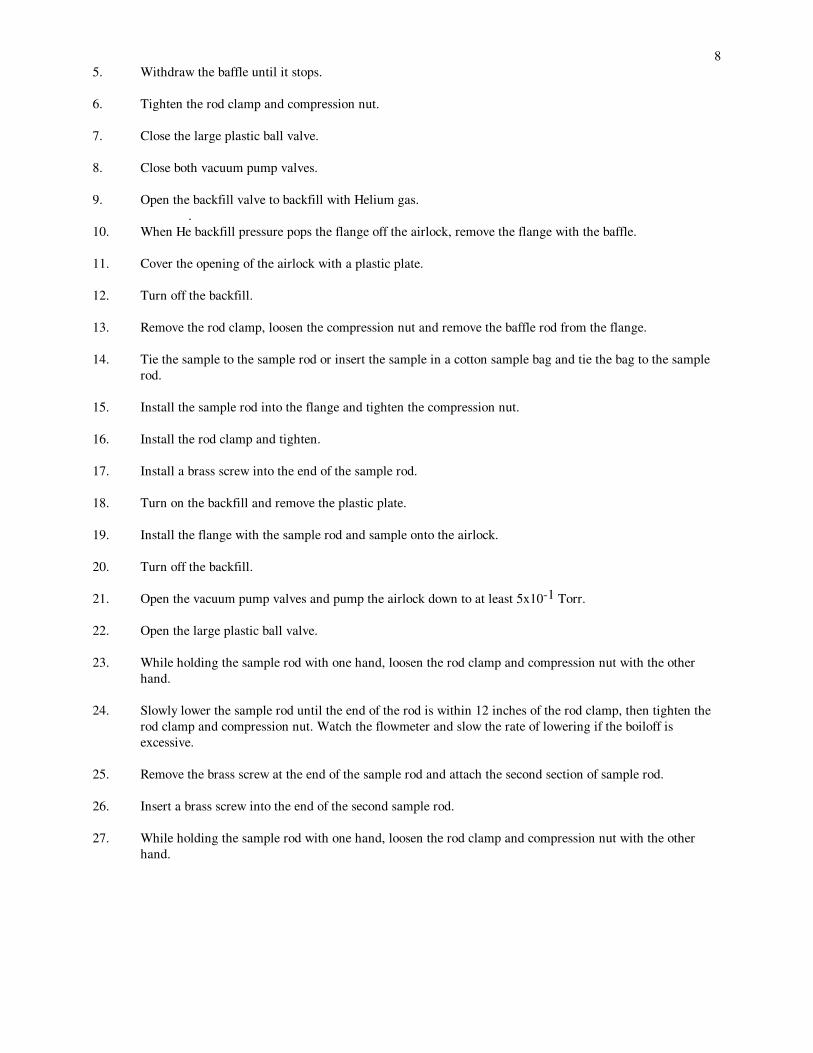
5. Withdraw the baffle until it stops.
6. Tighten the rod clamp and compression nut.
7. Close the large plastic ball valve.
8. Close both vacuum pump valves.
9. Open the backfill valve to backfill with Helium gas.
.
10. When He backfill pressure pops the flange off the airlock, remove the flange with the baffle.
11. Cover the opening of the airlock with a plastic plate.
12. Turn off the backfill.
13. Remove the rod clamp, loosen the compression nut and remove the baffle rod from the flange.
14. Tie the sample to the sample rod or insert the sample in a cotton sample bag and tie the bag to the sample
rod.
15. Install the sample rod into the flange and tighten the compression nut.
16. Install the rod clamp and tighten.
17. Install a brass screw into the end of the sample rod.
18. Turn on the backfill and remove the plastic plate.
19. Install the flange with the sample rod and sample onto the airlock.
20. Turn off the backfill.
21. Open the vacuum pump valves and pump the airlock down to at least 5x10⁻¹ Torr.
22. Open the large plastic ball valve.
23. While holding the sample rod with one hand, loosen the rod clamp and compression nut with the other
hand.
24. Slowly lower the sample rod until the end of the rod is within 12 inches of the rod clamp, then tighten the
rod clamp and compression nut. Watch the flowmeter and slow the rate of lowering if the boiloff is
excessive.
25. Remove the brass screw at the end of the sample rod and attach the second section of sample rod.
26. Insert a brass screw into the end of the second sample rod.
27. While holding the sample rod with one hand, loosen the rod clamp and compression nut with the other
hand.

9
28. Continue to lower the sample rod until the end of the second sample rod is below the transport
mechanism. Watch the flowmeter and slow the rate of lowering if the boiloff is excessive.
29. Tighten the rod clamp and compression nut on the sample rod.
30. Remove the brass screw from the end of the second sample rod and attach the third section of sample rod
(this section should be connected to the transport mechanism).
31. Make sure the compression nut on the transport mechanism is loose, then lower the transport mechanism.
32. While holding the sample rod with one hand, loosen the rod clamp and compression nut with the other
hand.
33. Lower the sample rod until the end of the sample rod is 7 inches above the compression nut of the
transport mechanism. Watch the flowmeter and slow the rate of lowering if the boiloff is excessive.
34. Tighten the rod clamp and compression nut on the sample rod.
35. Tighten the transport mechanism compression nut.
36. Loosen the rod clamp and compression nut on the sample rod.
37. Record the date, run number, sample, part number, request number, and voltage range on the chart.
38. Remove the pen cap, lower the pen and turn on the chart drive.
39. Record the direction the transport mechanism will be moving on the chart.
40. Verify that the rod clamp and compression nut are loose.
41. Run the transport mechanism (sample) up.
42. Observe the plot and adjust the voltage range of the chart recorder if necessary.
43. If the SQUID Controller needs to be reset, turn off the chart recorder input until the voltage has stabilized.
This will prevent the chart pen drive mechanism from being damaged.
44. Continue running the transport mechanism up and down, recording the voltage peaks of the sample and
direction of travel until the readings are consistent.
45. It may help to introduce some exchange gas to increase the cooling rate of the sample. Pressure may be
increased to 5x10⁻¹ Torr by backfilling with helium gas.
46. When the readings are consistent, run the transport mechanism up, stop the chart, lift and cap the pen.
47. Tighten the rod clamp and compression nut .
48. Loosen the compression nut on the transport mechanism.

10
49. Unscrew the top sample rod and store it on the transport mechanism base.
50. Insert a brass screw into the end of the sample rod.
51. While holding the sample rod with one hand, loosen the rod clamp and compression nut with the other
hand.
52. Withdraw the sample rod a few inches at a time, pausing to tighten the rod clamp and compression nut
and allow the sample rod to warm up.
53. Continue this process until the joint of the first and second sample rods is approximately 12 inches above
the rod clamp.
54. Remove the second sample rod and insert a brass screw into the end of the first sample rod.
55. Continue to withdraw the sample rod a few inches at a time, pausing to tighten the compression nut and
rod clamp and allow the rod warm up until the sample rod is fully withdrawn.
56. Close the large plastic ball valve.
57. Close the vacuum pump valves.
58. Backfill the airlock with Helium gas.
59. When the backfill pressure pops the flange off the airlock, remove the flange with the sample rod.
60. Cover the opening with a plastic plate and turn off the backfill.
61. If no more samples are to be run, reinstall the baffle.
62. Remove the screw and rod clamp from the sample rod.
63. Loosen the compression nut and remove the sample rod from the flange.
64. Remove and store the sample.
65. Install the baffle rod into the flange and tighten the compression nut.
66. Install and tighten the rod clamp on the baffle rod.
67. Turn on the backfill.
68. Remove the plastic plate.
69. Install the flange with the baffle onto the airlock.
70. Turn off the backfill.
71. Open the vacuum pump valves to pump down the airlock.

11
72. When the pressure is less than 5x10⁻¹ Torr, open the large plastic ballvalve.
73. With one hand holding the baffle rod, loosen the compression nut and rod clamp with the other hand.
74. Carefully lower the baffle rod until the end is approximately 12 inches above the rod clamp.
75. Tighten the rod clamp and compression nut and install a pin in the end of the baffle rod.
76. With one hand holding the baffle rod, loosen the rod clamp and compression nut with the other hand.
77. Lower the baffle rod until the end is within 1 inch of the rod clamp.
78. Tighten the rod clamp and compression nut.
79. Recheck probe calibration by applying a current to probe Helmholtz coil and monitoring SQUID response.
80. Complete appropriate entries on the Magnetic Test Form, sign the operator name field of
the report, and forward the report package to the Magnetics Manager or his designee.
5.3 Post Measurement checklist.
1. Baffle installed.
2. Liquid helium level O.K.
3. Liquid helium level meter sample interval set at 3 minutes.
4. Fill hole plugged.
5. Liquid helium level dipstick lowered.
6. Helium gas cylinder valved off.
7. Liquid nitrogen level O.K.
8. Liquid nitrogen valve on.
9. Liquid nitrogen fill power on.
10. Auto dialer on.
5.4 Detailed Procedure for Screening of Demagnetized Parts Using the Large Scale
Cryogenic Screening Facility
The procedure of section 5.1 - 5.3 shall be followed with the added provision that the part shall be
protected at all times from any exposure to magnetic fields larger than 2.0 Gauss.

12
6.0 Detailed Magnetic Screening Procedure for SQUID Gradiometer 1. Check SQUID operation. If required,tune SQUID as specified in the ITE Cryotron operation manual. 2. Check Gradiometer balance by applying 1 gauss peak to peak field at 1-5 Hz in each direction in the Helmholtz coil nulling system. If needed, balance as specified in the ITE Cryotron operation manual. 3. Apply DC current in the Helmholtz coil nulling system to null ambient field. (about 1.52 Amps in vertical coils; .51 amps in NS coils; and .02 Amps in EW coils) Measure field with 3 axis Fluxgate magnetometer and tune currents as required to minimize central field. 4. Put low pass filter on Gradiometer control electronics unit to 60 Hz. 5. Turn on comb filter. 6. Check Gradiometer calibration by applying current to calibration loop positioned on dewar tail approximately 1 cm from bottom of dewar.
With all gain settings at 1, 10 µAmp (10-5A) in calibration loop should yield a Gradiometer output response of .75 volt. (Primary system calibration is performed periodically using a small movable dipole current loop.)
7. Connect output of Gradiometer control electronics to O-Scope and to dual
stage low pass filter with first stage set at 10 Hz second stage set at 1 Hz.
8. Connect output of filter to channel 1 of data logger (chart recorder or PC with Data Shuttle ADC).
9. If test sample is smaller then about 20cm on a side, place sample on
turntable and adjust height so that top of sample will be within 0.5 cm of dewar tail.
10. Connect turntable cam switch output to channel 2 of data logger and turn on turntable (speed set to ~ 2 RPM). 11. Choose gain setting of Gradiometer control electronics to give large, stable, on scale signal. 12. Cycle turntable several times to achieve measurements with good signal to noise. 13. Samples with smallest dimension >1cm should be remeasured with other sides positioned closest to Gradiometer dewar tail . 14. Samples too large to fit on turntable may be placed on sample positioning cart and moved beneath dewar.
15. Complete appropriate entries on the Magnetic Test Form, sign the operator name field of
the report, and forward the report package to the Magnetics Manager or his designee.

13
6.1 Detailed Procedure for Screening of Demagnetized Parts Using the SQUID Gradiometer
Facility
The procedure of section 6.0 shall be followed with the added provision that the part shall be
protected at all times from any exposure to magnetic fields larger than 2.0 Gauss.

14
7.0 Detailed Procedure for Room Temperature Magnetic Screening Using Fluxgate System
7.1 SET-UP AND START OF DAY SELF-CALIBRATION
Note: The self-calibration need not be repeated because power is turned off during the day. Self-
calibration must be performed at the beginning of each operating day.
Recorder: set VOLTS control on CHECK, Chart switch off
Recorder: turn power on.
Magnetometer: turn power on.
Note: Magnetometer self initializes to DC OFFSET OFF and Range 2000, DC mode ON when
powered on.
Low Pass Filter: Set gain 0 db Low Pass RC, line operation, 500 x O.01 (5 Hz) corner frequency
on model 3342 filter or bypass filter.
Sensor: Verify magnetometer sensor is in its mount.
Magnetometer: Select COARSE DC OFFSET
Magnetometer: Null Magnetometer display to within one least significant digit (LSD) using
primarily the OFFSET control then the ZERO vernier.
Recorder: select recorder scale 10 volts full scale (10 inches)
Recorder: move pen to mid scale (5 inch position using ZERO control
Annotate chart with date time, operator's name and the words: START CALIBRATION
Recorder: select speed not greater than 8 in/min, turn on chart
Magnetometer renull to 000 within one LSD
Recorder: Reset to midscale within 1/4 division
Stop recorder chart after it has moved about one inch
Magnetometer: Obtain display of + 1000 within one LSD using DC OFFSET control.

15
Recorder: Turn on.
Stop recorder chart after it has moved about one inch
Magnetometer: renull to 000 within one LSD
Recorder: Turn on
Stop recorder chart after it has moved about one inch
Magnetometer: Obtain display of -1000 within one LSD using DC OFFSET control.
Recorder: Turn on
Stop recorder chart after it has moved about one inch
Magnetometer: renull to 000 within one LSD
Recorder: Turn on
Stop recorder chart after it has moved about one inch
Annotate chart with the words: END CALIBRATION
Analyze Chart. If both the right and left pen deflections were 50 +/- 1/2 divisions, proceed with
screening. If not, service may be required since neither the gain of the magnetometer or the
recorder have external adjustments.
Cut chart containing the calibration into a sheet 8 1/2" by 11 " and permanently file in binder
labeled Daily Calibrations. Sheet may be longer if cutting would result in loss of data.
7.2 SET-UP FOR ROOM TEMPERATURE Fluxgate TESTING
Sensor: Verify sensor is positioned properly in its mount
Low Pass Filter power on. Use 1 Hz low pass setting for zone 1 and 2 screening.
Higher settings or filter bypass may be used for other zones at the option of the test conductor.
NOTE: DEPENDING OF TYPE OF FILTER USED, THE FILTER MAY NOT HAVE A GAIN
OF ONE AT DC. IF SUCH IS THE CASE, THE END-TO-END CALIBRATION IS TO BE
REPEATED IF THE FILTER STATUS (IN OR OUT) CHANGES AFTER THE INITIAL
CALIBRATION.

16
Magnetometer: power on, Range 2000, null display.
Recorder: chart off, speed 2 in/min, VOLTS in ZERO CHECK position.
Identify test items and post information to GP-B data sheet
Verify that bags containing test items do not have staples or other sources of magnetic
contamination (including tags, etc.).
7.3 TEST ITEM MAGNETIZATION
NOTE: If several separate test items will be run, all items may be magnetized before any are
measured.
CAUTION: BOTH THE MAGNETIZER AND DEMAGNETIZER ARE NOT DESIGNED FOR
CONTINUOUS OPERATION AND CAN OVERHEAT IF LEFT ON BETWEEN ACTUAL
USE.
CAUTION: THE LARGE MAGNETIC FIELDS PRODUCED BY THE MAGNETIZER AND
THE DEMAGNETIZER CAN DAMAGE WATCHES AND ERASE THE MAGNETIC CODE
ON BADGES AND CREDIT CARDS. MAINTAIN A SEPARATION DISTANCE OF AT
LEAST TWO FEET FROM SUCH SENSITIVE ITEMS.
DC Magnetizing Coil; turn on using toggle switch on coil rim.
Pass test item completely through the center of the coil or, if the item is too large, across the face
of the coil at a distance of one inch and at a speed of about one foot a second.
Turn off coil
Repeat the last three steps for each test item.
7.4 PREPARE EQUIPMENT FOR MAGNETIC FIELD MEASUREMENT
Magnetometer: beginning with RANGE 2000, null display using COARSE DC OFFSET, then
select RANGE 200 and renull, select RANGE 20 and renull, select Range 2. Then select FINE DC
OFFSET and renull to 000 +/- 5 LSD using the ZERO vernier.
Recorder: Select speed 8 in/min, scale 1 volt full scale.
Recorder: move pen to mid scale using ZERO control

17
7.5 PREPARE OPERATOR FOR MAGNETIC FIELD MEASUREMENT
NOTE: Test item will be hand-held during the screening measurement. Magnetic sources on the
operator's hands and arms, badges, items in shirt pocket must be removed.
Recorder: turn on chart
Place hand and arm in shield and simulate the manipulation of test item within a inch of the sensor
empty handed. While this motion is in progress, watch the recorder to see if there is any correlation
between pen movement and hand motion.
If any pen response is observed in the previous step, remove personal metallic items and repeat test
until no correlated pen motion is observed.
Recorder: turn off chart
7.6 TEST ITEM MAGNETIC FIELD MEASUREMENT (MAGNETIZED)
Magnetometer: verify RANGE 2, display 000 +/- 5 LSD, zero as required.
Recorder: verify pen is at mid-scale, zero as required
Recorder: select scale 1 volt full scale, chart speed 8 in/min, reset to midscale with recorder zero
control
Annotate the chart with: with the words START SEQ #.
Prepare to place test item in test volume
Recorder: turn chart on
If test item is for zone 1 or 2 place test item as close as possible to sensor and rotate for maximum
pen deflection; do not touch sensor in this process. Once this orientation is found, withdraw the
item then mark the chart with the word "OUT' and indicate with a dash at the point in the ink trace
corresponding to the moment of withdrawal. Repeat test two more times or more to get
consistent results. For test items in zones other than 1 and 2, measure at a distance of not more
than one inch.
For small parts, testing a large quantity is preferred to testing single items. Parts should be closely
packed and the assembly should not exceed one inch in diameter.
18
NOTE: The response time of the test equipment is slow. When long items are measured (such as
tubing), the speed of transit over the sensor should be such as to allow the recorder to fully
respond. The speed is satisfactory when going more slowly does not increase the pen deflection.
Recorder: chart off, VOLTS control to ZERO CHECK
Recorder: Turn on, run out about one inch of chart
Recorder: Turn off
Examine chart; if any deflection is observable, verify that it is due to test item and not to sources
associated with the person of the operator using the Prepare Operator procedure above. Fill out a
magnetic screening Test Data Label and attach near annotation either before or after chart passes
through rollers.
NOTE: With magnetometer on scale 2 and recorder on scale 1 volt, the sensitivity of the strip
chart is two microgauss per small division.
NOTE: If the deflection is greater than about 2/3rds the range of the strip chart recorder, change
the range of the magnetometer to 20 or higher and repeat test. Do not change the range of the
recorder.
On scale 20 the recorder sensitivity is 20 microgauss per division.
Complete data entries in data log. It is your responsibility to post the correct magnetic zone
designation. If in doubt refer to the test item drawing.
To interpret the strip chart response: measure the distance in chart divisions, between the point on
the pen trace that corresponds to the part being next to the sensor and the point on the trace
corresponding to the exit of the test item from the sensor shield can. To calculate the value in
microgauss, multiply the number of divisions by 2 for the 2 mG range, or 20 if 20 mG range is
used, etc. The number of divisions is measured from the chart trace baseline (test item "OUT") to
the peak deflection corresponding to the test item being "IN".
TEST ITEMS IN MAGNETIC ZONE 1 OR 2 HAVING FIELDS GREATER THAN ONE
(1) MICROGAUSS SHALL BE CONSIDERED AS FAILED.
TEST ITEMS IN MAGNETIC ZONES 3-4 HAVING FIELDS GREATER THAN THREE (3)
MICROGAUSS SHALL BE CONSIDERED AS FAILED.
IF A TEST ITEM IN MAGNETIC ZONE SP MEASURES 30 MICROGAUSS OR LESS IT IS
LOGGED AS PASSED.

19
If it measures more than 30 microgauss and it is stainless steel then test it with the Permeability
Indicator using Insert number 1.15 only, in accordance with the procedural guideline attached.
IF THE MAGNETIC ZONE SP TEST ITEM IS COMPOSED OF A SINGLE PIECE OF
MATERIAL AND IF ANY SURFACE IS LESS THAN 1.15, LOG THE ITEM AS PASSED.
If the magnetic zone SP test item is composed of two or more pieces of material welded or
otherwise fastened together, test each piece as above.
In those cases where the MIL-I-1721 permeability indicator cannot reach surfaces to be tested, a
Dip Needle may be substituted. A clear indication of attraction of the needle to the part will be
interpreted as failing the pass/fail criterion for permeability testing.
IF ANY SURFACE OF EVERY PIECE IS LESS THAN 1 .15, THEN LOG THE ITEM AS
PASSED. IN DECIDING PASS OR FAIL, THE RESULTS OF THE PERMEABILITY TEST
OVERRULE THE RESULTS OF THE MAGNETOMETER TEST BUT BOTH
TESTS ARE NEEDED.
7.7 TEST ITEM DEMAGNETIZATlON
NOTE: The demagnetization process can fail if the power to the demagnetizer is turned off while it
is still in the vicinity of the test item. Verify LED pilot lamp remains on during this process.
Internal safety switch can abort test unexpectedly.
CAUTION: KEEP DEMAGNETIZER AWAY FROM WATCHES, BADGES, ETC.
Place test item(s) on the non-magnetic table.
AC Demagnetizer: turn on the hand-held demagnetizer and pass it as close as possible to all
surfaces of the test item. Then move the demagnetizer a distance of not less than four (4) feet from
the test item and turn it off.
7.8 TEST ITEM MAGNETIC FIELD MEASUREMENT (DEMAGNETIZED)
Magnetometer: verify range 2, display 000 +/- 5 LSD, zero as required.
Recorder verify pen is at mid scale, zero as required.
Recorder: select scale 1 volt full scale, chart speed 8 in/min, reset to midscale with recorder's zero
control
Annotate the chart: with the words: DEMAGNETIZED

20
Prepare to place test item in test volume
Recorder turn chart on
If test item is for zone 1 or 2 place test item as close as possible to sensor and rotate for maximum
pen deflection; do not touch sensor in this process. Once this orientation is found, withdraw the
item then mark the chart with the word "OUT' and indicate with a dash at the point in the ink trace
corresponding to the moment of withdrawal. Repeat test two more times or more to get consistent
results. For test items in zones other than 1 or 2, measure at a distance of not more than one inch.
Recorder: chart off, VOLTS control to ZERO CHECK
Annotate chart with words: END SEQ#........
Examine chart; if any deflection is observable, verify that it is due to test item and not due to
sources associated with the person of the operator using the Prepare Operator procedure above.
Repeat the demagnetization process if a deflection is observed.
Annotate each repeat with: seq # and repeat 1, 2 etc.
Complete data log. If sample passed, place a completed label on or in test item bag, fill out top
line, use lower portion to enter "PASSED" only.
Complete appropriate entries on the Magnetic Test Form, sign the operator name field of the
report, and forward the report package to the Magnetics Manager or his designee.
If the event that several test items are ready for test, proceed with their measurement using steps
beginning with those following the heading TEST ITEM MAGNETIC FIELD MEASUREMENT
(DEMAGNETIZED).
At completion of all test operations, turn recorder VOLT control to ZERO CHECK and then chart
OFF.
Turn off all equipment and turn off master switch mounted in non-magnetic table.
7.9 Instructions for Completing GP-B Room Temperature MAGNETIC TEST DATA LOG
1. Sequence #: Enter the next number in sequence.
2. Part Name: Enter the name of the part or its description if name is not available.
3. Part No.: Enter part number if available otherwise use drawing number.

21
4. Shop Order #: Enter shop order, OP order number, or L number and weight in grams if test
item is a material sample.
5. Mag Zone: Enter the part's magnetic control zone. i.e., 1,2, 3, 4, SP.
6. Quantity: Enter the quantity of parts test tested together.
7. µG Mag: Enter the field, in microgauss, of the magnetized part(s).
8. µG Dmag: Enter the field, in microgauss, of the part(s) after demagnetization.
9. µG Mag: Enter the field, in microgauss, when magnetized and after cleaning.
10. µG Dmag: Enter the field, in microgauss, when demagnetized after cleaning.
11. Relative Permeability: Enter value of permeability if measured.
12. P/F: Enter P for pass or F for fail.
13. Date: Enter date of test: month, day, year.
14. Enter initials of person conducting test.

22
8.0 FAILED TEST ITEMS
Test items of non-magnetic material can fail due to surface contamination. Parts to be tested
should be furnished in a clean condition. If failure due to surface contamination is suspected, the
REE may wish to have the part chemically etched and then request a magnetic retest. For minor
contamination, the following cleaning process is recommended: Scrub with Scotch Brite or with a
nylon bristle brush and soapy water solution consisting of one (1) tablespoon of Alconox detergent
in one (1) gallon of de-ionized water. Rinse item completely with de-ionized water.
A test item which fails magnetic screening after re-cleaning as described above shall either be
scrapped or be forwarded via a Magnetic Screening Waiver to the Magnetic Committee for
detailed consideration if it is felt that the part might meet top-level magnetic requirements even
though screening zone criteria were not met.
9.0 LARGE TEST ITEMS
Test items which are too large to be tested at Stanford shall be transported to the magnetic test
facilities located at NASA-Ames Research Center, Moffett Field. The above room temperature
fluxgate procedure shall apply to the NASA facilities and instruments as well as to the sequence of
tests, with the exception that the ferromagnetic shield is replaced by the NASA-Ames 20-foot
Helmholtz coil set. Contact Ernie Iufer, (650) 960-3596 for scheduling.
10.0 DATA DISTRIBUTION
The originals of cryogenic screening test result sheets, with all appropriate entries complete and
signed by the test conductor, shall be forwarded to the Magnetics Manager on the same day that
the test is completed. Originals of associated MPMS plots, SQUID Gradiometer recorder charts,
Large Scale Screening Facility recorder charts, and fluxgate recorder charts shall be attached to the
test results sheets.
After review and approval (sign-off) by the Magnetic Manager or his designee, originals of the GP-
B data sheets shall be filed along with the associated plots or charts in order and archived in a file
cabinet reserved for that purpose and the test results shall be entered into the computer database.

23
Appendix A - Magnetic Test Form
AVAILABLE IN HARD COPY FILE

24
Appendix B- Calibration Procedure for MPMS Electronic Balance Calibration of A&D Model EK120Electronic Balance
MFG by:
A&D Company Limited
3-23-14 Higashi-Ikebukuo
Toshim-ku, Tokyo 170
JAPAN
Overview
Primary system calibration is accomplished using a standard mass, described below.
Primary Calibration is performed on a monthly basis.
Standard Mass
A 1 gm standard mass is used, specified by manufacturer to be accuarate to 1%.
MFG by:
Ohaus Corporation
29 Hanover Road
Florham Park, NJ 07932
Calibration Procedure
Ensure that balance has been on for a least 30 min for system stability.
Tare the balance, reading should then be 0.00 ± 0.01 gm.
Place 1 gm standard mass on balance sample plate, record reading.
Remove 1 gm standard mass, record reading.
25
Appendix C - Calibration Procedure for Large Scale Cryogenic
Screening Facility
Overview
Primary system calibration is accomplished using a calibration coil, described below. The coil is installed in the
probe in the same manner as a test sample and energized using a calibrated BTI 1802 current supply. Current is
measured using a calibrated HP Digital Multimeter Model 34401A. System output is readout though a Quantum
Design model 5000 dc SQUID Controller using a calibrated HP Digital Voltmeter Model 3457A.
Primary Calibration is performed on a yearly basis. Secondary calibration, described in the test procedure, is
performed during each measurement cycle.
Calibration Coil
A .018” wide by .015" deep circumferential groove was machined near one end of a .375" diameter by 7" long G-10
fiberglass rod and another groove of the same dimensions machined along its axis. The calibration coil consists of
one turn of .005" insulated phosphor bronze wire placed in the groove near the end of the rod with the rest of the
wire twisted to form a twisted pair 11 feet long. The first few inches of twisted pair is secured with adhesive in the
groove along the axis of the rod. The end of the twisted pair is attached to two terminals of a 10 pin Alpha
connector. A 1/4-20 nylon stud is threaded into the end of the G-10 rod opposite the calibration coil. A .005" thick
by 4" diameter disk of mylar with a .25" hole was placed over the stud. A slit in the mylar allows the twisted pair to
feed through the mylar disc.
Calibration Procedure
Prepare the Probe as described in the testing procedure, with SQUID Controller output connected to the HP
Voltmeter.
Attach the Calibration Coil onto a 4' long G-10 sample transport rod.
Loosely coil the twisted pair around the sample transport rod, to insure that it can extend approximately 116" into
the probe.
Insert the top of the sample transport rod through the fitting in the 4” probe flange.
Connect the Alpha connector to the connector on the bottom of the 4” probe flange.
Slowly lower the first sample transport rod as is done in inserting a test sample, connecting in turn two more 4' long
sample transport rods.
Continue lowering until the bottom of the calibration coil is approximately 2 inches from the bottom of the probe.
Attach the top sample transport rod to the transport mechanism.
Connect the BTI current supply to probe connector, monitoring the current with the HP Multimeter.
With zero current input, cycle the transport mechanism up and down several times recording the SQUID output.
This should give a negligible signal due to the remanent moment of the calibration coil.

26
Apply a 0.1 mA current to the cal coil, cycle the transport mechanism up and down several times recording the
SQUID output.
Apply a 1.0 mA current to the cal coil, cycle the transport mechanism up and down several times recording the
SQUID output.
Apply a 2.0 mA current to the cal coil, cycle the transport mechanism up and down several times recording the
SQUID output.
Apply a -2.0 mA current to the cal coil, cycle the transport mechanism up and down several times recording the
SQUID output.
Apply a -0.1 mA current to the cal coil, cycle the transport mechanism up and down several times recording the
SQUID output.
Apply 0 mA current to the cal coil, cycle the transport mechanism up and down several times recording the SQUID
output.

27
Appendix E - Calibration Procedure for SQUID Gradiometer
Facility
Overview
Primary system calibration is accomplished using a calibration coil, described below. The coil is mounted on the
sample turntable in the same manner as a test sample and energized using a calibrated BTI 1802 current supply.
Current is measured using a calibrated HP Digital Multimeter Model 34401A. System output is readout though ITE
Cryotron model 502 SQUID Controller using a calibrated HP Digital Voltmeter Model 3457A.
Primary Calibration is performed 4 times per year.
Calibration Coil
The calibration coil consists of two turns of 0.005" insulated phosphor bronze wire with loop diameter of 0.887 cm
wound on a polycarbonate former. Twisted pair leads extend from the loop for 5 feet terminated in a BNC
connector.
The transfer function is 1.26 x10⁻¹ cgs-emu per ampere.
Calibration Procedure
Prepare the Gradiometer System as described in the testing procedure, with SQUID Controller output connected to
the HP Voltmeter. Set gain 1 = 1, CF =1, Gain 2 =1.
Mount the Calibration Coil on the sample turntable by sliding the former through the mounting hole.
Position the coil to be 1 cm below the dewar tail..
Connect the BTI current supply to coil connector, monitoring the current with the HP Multimeter.
With zero current input, start the sample turntable, record the Gradiometer output. This should give a negligible
signal due to the remanent moment of the calibration coil.
Apply a 3.0 mA current to the cal coil, start the sample turntable, record the Gradiometer output over 5 revolutions.
Apply a -3.0 mA current to the cal coil, start the sample turntable, record the Gradiometer output over 5 revolutions.
Position the coil to be 2 cm below the dewar tail..
Apply a 3.0 mA current to the cal coil, start the sample turntable, record the Gradiometer output over 5 revolutions.
Apply a -3.0 mA current to the cal coil, start the sample turntable, record the Gradiometer output over 5 revolutions.

28
Appendix F - List of Certified Magnetic Screening Personnel
Certification Renewal Dates
LARGE CRYOGENIC SCREENING APPARATUS
Dean Yon 3/1/98 and at 6-month periods thereafter
John Mester 3/1/98 and at 6-month periods thereafter
MPMS SUSCEPTOMETER
Grace Brauer 3/1/98 and at 6-month periods thereafter
Dean Yon 3/1/98 and at 6-month periods thereafter
John Mester 3/1/98 and at 6-month periods thereafter
Jim Lockhart 3/1/98 and at 6-month periods thereafter
SQUID GRADIOMETER SYSTEM
Grace Brauer 3/1/98 and at 6-month periods thereafter
Dean Yon 3/1/98 and at 6-month periods thereafter
John Mester 3/1/98 and at 6-month periods thereafter
Jim Lockhart 3/1/98 and at 6-month periods thereafter
Ernest Iufer 3/1/98 and at 6-month periods thereafter
Bud Swihart 3/1/98 and at 6-month periods thereafter
FLUXGATE MAGNETOMETER
Dean Yon 3/1/98 and at 6-month periods thereafter
John Mester 3/1/98 and at 6-month periods thereafter
Jim Lockhart 3/1/98 and at 6-month periods thereafter
Ernest Iufer 3/1/98 and at 6-month periods thereafter

29
Appendix F - Probe and Dewar Service Procedures
A. SQUID Gradiometer Liquid Helium Transfer Procedure 1. Turn off the Gradiometer control electronics unit. 2. Unplug and remove preamp electronics box from the Gradiometer. 3. Unplug and remove the helium level sensor cable from the SQUID Gradiometer. 4. Disconnect the vent line from the flow meter. 5. Move the SQUID Gradiometer to the wood stand in the mu metal shield. 6. If the dewar is warm or the vacuum has gone soft, the dewar must be vented and pumped out. Refer to Dewar Pump Out Procedure before proceeding. 7. Set up a liquid helium dewar with a transfer tube adapter, helium gas bottle with regulator and tubing, and transfer tube with extension. 8. Connect the liquid helium level gauge to the SQUID Gradiometer. 9. Turn on the helium level gauge. 10. Open the vent valve, close the 1 PSI vent valve and open the top valve on the liquid helium dewar. 11. Using the electronic helium level dipstick, measure the amount of liquid helium in the dewar. Approximately 7 inches will provide the required 20 to 30 liters to fill the Gradiometer. 12. Insert the transfer tube into the liquid helium dewar so that the end is one half inch from the bottom. Support the free end of the transfer tube with a rope through a pulley suspended from the ceiling. 13. Close the vent valve. 14. Connect the brass extension to the output end of the transfer tube. 15. Open the helium gas valves at the helium gas bottle and regulator and connect the tubing to the transfer tube adapter on the liquid helium dewar. 16. Open the valve on the transfer tube adapter to pressurize the liquid helium dewar to 1 PSI. When liquid begins to flow from the transfer tube, turn off the pressurizing valve and open the vent valve. 17. When the pressure in the dewar drops to near zero, close the vent valve. 18. Remove the baffle from the fill port on the SQUID Gradiometer and slowly insert the transfer tube. Support the transfer tube so that the end of the tube is approximately one inch from the bottom. 19. Adjust the pressurizing valve to transfer at approximately 0.5 PSI.
30 20. The dewar is full when the helium level gauge reads 55-60%. 21. Turn off the helium level gauge. 22. Turn off the pressurizing valve at the transfer tube adapter and open the vent valve. 23. Remove the transfer tube from the SQUID Gradiometer and replace the baffle. 24. Remove the extension from the output end of the transfer tube. 25. Remove the transfer tube from the liquid helium dewar. 26. Close the top and vent valves, and open the 1 PSI vent valve on the liquid helium dewar. 27. Turn off the valves at the helium gas bottle and regulator. 28. Disconnect the tubing from the transfer tube adapter. 29. Disconnect the helium level gauge from the SQUID Gradiometer. 30. When the frost has melted and the SQUID Gradiometer is dry, move it back to it's test stand and reconnect the helium level gauge, vent line, pre amp electronics box and cable. 31. Turn on the Gradiometer control electronics and check that the SQUID will fluxlock, B. SQUID Gradiometer Dewar Pump Out Procedure 1. Carefully open the pump out valve. Support the valve body with a wrench to prevent breaking off the valve. 2. Connect a vacuum pump to the pump out valve with a rubber hose. 3. Turn on the vacuum pump and pump for 20 minutes. 4. Turn off the vacuum pump and vent the pump out line. 5. Reattach the vacuum line and continue pumping until the pressure reaches 30 millitorr or better. 6. Gently close the vent valve while supporting the body of the valve with a wrench. 7. Turn off and disconnect the vacuum pump. C. LARGE CRYOGENIC SCREENING APPARATUS Probe Installation Procedure
Before starting, have an adequate supply of liquid helium and helium gas. I.) Probe Preparation 1. Remove the 4" top flange.
31 2. Remove the section containing the large plastic ball valve by separating the flanges below the ball valve. 3. Inspect the interior of the probe for moisture and other contamination. 4. Remove any foreign material; sample rod, parts, tape, dirt, etc. 5. Dry the interior of the probe by lowering a rag or sponge attached to a string into the probe. 6. Squirt ethyl alcohol into the probe, coating the sides and bottom. 7. Dry the interior of the probe by lowering a wad of Kimwipes wrapped around a soft weight ( a partially used roll of tape) attached to a string. Repeat as many times as necessary. 8. When the interior is dry, reattach the section containing the ball valve. Use a new copper gasket and make sure the bolts are lubricated. 9. Install the 4" top flange and insert a plug into the Ultra-Torr fitting. 10. Connect the probe to the red cable hoist. Connect the U-bolt directly under the pulley for maximum height. 11. Move the probe to the Low-Field Dewar using the red overhead hoist. 12. Connect the vacuum pump to the upper valve (support the pump line) and proceed to pump down the probe. Check for vacuum leaks. 13. When the probe has reached it's maximum vacuum, valve off the pump and backfill with helium. 14. Turn off the backfill and resume pumping on the probe until the pressure reaches 0.5 Torr. 15. Turn off the pump valves, turn off the pump and disconnect the pump line from the probe. 16. Remove the bottom plate from the probe airlock. 17. Connect a helium line to the Ultra-Torr fitting on the probe 8 1/2" flange and turn on the helium gas to purge the probe airlock. Purge for at least 1/2 hour. II) Dewar Preparation 1. Fill the dewar with liquid helium. 2. Lower the dewar so that the top flange is 1" below floor level. 3. Connect a helium gas line to the valve on the top flange of the dewar. 4. Turn on the helium gas to the dewar to insure positive helium gas pressure (as indicated by the exhaust flow meter).

32 5. Remove the 8 1/2" baffle set in the low-field dewar and replace with a cover plate. 6. Move the probe so that it is directly over the low-field dewar. 7. Remove the cover plate from the low-field dewar and immediately lower the probe airlock on to the dewar. 8. Clamp the probe airlock to the low-field dewar with a Marmon clamp. 9. Turn off the probe airlock purge. 10. Remove the probe airlock purge fitting and replace with a plug. 11. Remove the top probe airlock Marmon clamp. 12. Raise the probe 1/16" and remove the three stainless steel ears from the top probe flange. III) Probe Installation 1. Slowly lower the probe into the low-field dewar. Constantly monitor the probe for freedom of movement and the flow meter for excessive boiloff. 2. Turn off the helium gas to the dewar. 3. When the probe 8 1/2" flange is more than 20" below the top of the top airlock, stop lowering the probe and unclamp the top airlock. 4. Separate the top airlock section and lift it up close to the hoist and secure it with a rope passing over the red hoist I beam. 5. Continue lowering the probe slowly and monitor the probe for freedom of movement and the flow meter for excessive boiloff. 6. When the probe flange is more than 20" below the top of the second airlock, stop lowering the probe and unclamp the second airlock. 7. Separate the second airlock section and lift it up to engage the top airlock section. Clamp the second airlock section to the top airlock section. 8. Continue lowering the probe slowly and monitor the probe for freedom of movement and the flow meter for excessive boiloff. 9. When the probe flange is more than 20" below the top of the third airlock, stop lowering the probe and unclamp the third airlock. 10. Lift the third airlock section up to engage the second airlock section and clamp them together. 11. Continue lowering the probe slowly and monitor the probe for freedom of movement and the flow meter for excessive boiloff. 12. Rotate the probe to a convenient orientation.

33 13. When the probe has seated into the 5" high airlock section on the dewar, the probe flange will be 20" below the top of the fourth airlock section. 14. Unclamp and remove the fourth airlock section. 15. Disconnect the hoist from the probe. 16. Move the hoist away from the dewar. 17. Attach the plate with the three turnbuckles to the hoist. 18. Raise the hoist to engage the three turnbuckles with the bottom of the third airlock section. 19. Lower the airlock sections. 20. Remove and store the airlock sections and the plate with the three turnbuckles. 21. Install the handle on the ball valve. 22. Install the backfill line to the probe. 23. Close the ball valve. 24. Turn on the backfill. 25. Remove the 4" top flange from the probe and install the extension section with the vacuum pump fitting. 26. Insert the 4" baffle set onto the 4" top flange and install the assembly onto the probe. Install the rod clamp on the baffle rod. 27. Connect the vacuum pump line to the probe (support the line). 28, Turn on the vacuum pump and open the vacuum pump valves. 29. When the pressure in the probe airlock reaches 1 x 10⁻¹, open the ball valve and lower the baffles. Tighten the rod clamp and the Ultra-Torr nut to prevent the rod from being sucked into the probe. Insert a pin through the end of the rod for an extra measure of safety. 30. Install the transport mechanism and hook up the power cables. 31. Turn on the transport controller. 32. Install the sample rod into the transport mechanism. 33. Connect the SQUID cable. 34. Check the helium level and refill if necessary. 35. Check the gas supply and replace if necessary. revised 12-16-94
34
D. LARGE CRYOGENIC SCREENING APPARATUS Probe Removal Procedure
Before starting, have an adequate supply of liquid helium and helium gas.
I.) Probe Preparation
1. Fill the low field dewar with liquid helium.
2. Remove the sample rod transport mechanism.
3. Withdraw the baffle.
4. Close the large plastic ball valve and the valve at the vacuum pump.
5. Backfill the 4" sample airlock above the plastic ball valve with helium gas.
6. Remove the 4" flange with the baffle assembly.
7. Remove the baffle assembly from the 4" flange and install a plug in the Ultra-Torr fitting.
8. Disconnect the vacuum pump line from the 4' sample airlock.
9. Remove one section of the vacuum pump line and replace it with a section that terminates with a 1/4"
Swagelock fitting.
10. Remove the top 4" diameter sample airlock section.
11. Install the 4" flange onto the remaining 4" airlock section.
12. Turn off the helium supply valve and remove the backfill line.
13. Connect the vacuum pump line to the backfill valve.
14. Open the pump valve and pump down the 4" airlock.
15. If there are no leaks, open the large plastic ball valve to pump down the probe.
16. Remove the handle to the large plastic ball valve.
17. Lower the dewar so the flange of the dewar is 1" below the floor.
18. Take three 8 1/2" diameter airlock sections and clamp them to each other with Marmon clamps. Assemble
the sections so the topmost section has a large Ty-Wrap and a rope attached to it.
19. Attach the airlock sections to the red cable hoist using the plate with three turnbuckles.
20. Raise the airlock sections.
21. Tie the top airlock section to the hoist beam with a rope.
35
22. Close the backfill and vacuum pump valves.
23. Remove the vacuum pump line.
24. Turn off the vacuum pump.
25. Install and clamp an 8 1/2" diameter airlock section onto the dewar.
26. Connect the hoist to the three lifting cables on the probe.
27. Connect a backfill line to the dewar.
28. Turn on the backfill.
II.) Probe Removal
29. Slowly lift the probe, maintaining positive pressure in the dewar as indicated by the flow meter.
30. Monitor the pressure in the probe as it is being withdrawn. Release excessive backpressure by opening
the backfill valve.
31. As the probe approaches the top of the first 8 1/2" airlock section, unclamp and lower the next airlock
section and clamp it to the first section.
32. Continue withdrawing the probe through the second 8 1/2" airlock section while monitoring the pressure
in the dewar and the pressure in the probe.
33. Continue this procedure until all four 8 1/2" airlock sections have been lowered and clamped.
34. When the probe flange nears the top of the last airlock section, attach the three stainless steel ears.
35. Install a Marmon clamp on the top 8 1/2" airlock section and three stainless steel ears.
36. Prepare to install a cover plate on the dewar.
37. Remove the clamp from the lowest 8 1/2" airlock section.
38. Lift the airlock and probe off the dewar and quickly cover the dewar.
39. Place a cover plate over the bottom of the 8 1/2" airlock and install a Marmon clamp.
40. Move the probe to a secure place.
41. Remove the cover plate from the dewar and install the 8 1/2" baffle and airlock set.
42. Lower the baffle into the dewar.
43. Remove the 8 1/2" baffle airlock.
44. Install the clamping ring on the baffle flange.

36
45. Install a Marmon clamp on the baffle flange.
46. Turn off the backfill.
47. Fill with liquid helium if necessary.