GDS OPERATING PROCEDURE - Gravity Probe...
21
SU/GP-B P0886 Rev A 4 September, 2002 STANFORD UNIVERSITY W.W. HANSEN EXPERIMENTAL PHYSICS LABORATORY GRAVITY PROBE B, RELATIVITY GYROSCOPE EXPERIMENT STANFORD, CALIFORNIA 94305-4085 GDS OPERATING PROCEDURE Caution: This procedure contains hazardous operations P0886 Rev A 13 September, 2002 PREPARED S. Buchholz, Prepared by Date APPROVED K. Bower, GMA Engineer Date APPROVED C. Gray, GMA REE Date APPROVED Harv Moskowitz, LMSSC Safety Engineer Date APPROVED D. Ross, Quality Assurance Date APPROVED R. Brumley, Hardware Manager Date
Transcript of GDS OPERATING PROCEDURE - Gravity Probe...
SU/GP-B P0886 Rev A 4 September, 2002
STANFORD UNIVERSITY
W.W. HANSEN EXPERIMENTAL PHYSICS LABORATORY
GRAVITY PROBE B, RELATIVITY GYROSCOPE EXPERIMENT
STANFORD, CALIFORNIA 94305-4085
GDS OPERATING PROCEDURE
Caution: This procedure contains hazardous operations
P0886 Rev A
13 September, 2002
PREPARED
S. Buchholz, Prepared by Date
APPROVED
K. Bower, GMA Engineer Date
APPROVED
C. Gray, GMA REE Date
APPROVED
Harv Moskowitz, LMSSC Safety Engineer Date
APPROVED
D. Ross, Quality Assurance Date
APPROVED
R. Brumley, Hardware Manager Date

P0886 Rev. A
2 of 21 pages
REVISION HISTORY
Rev Date Comments
- 09/04/02
A 09/013/02 Multiple changes to procedure to include manual valve torques, correct
GMA launch configuration and other minor corrections. (ECO # 1385)
P0886 Rev. A
3 of 21 pages
TABLE OF CONTENTS
A SCOPE 4
B SAFETY 4
C. QUALITY ASSURANCE 4
C.1 QA Notification 4
C.2 Red-line Authority 4
C.3 Discrepancies 4
D TEST PERSONNEL 5
E REQUIREMENTS 5
E.1. Electrostatic Discharge Requirements 5
E.2. Lifting Operation Requirements 5
E.3. Hardware/Software Requirements 5
E.4. Instrument Pretest Requirements 5
E.5. Configuration Requirements 5
E.6. Optional Non-flight Configurations 5
E.7. Verification/ Success Criteria 6
E.8. Constraints and Restrictions 6
F. REFERENCE DOCUMENTS 6
F.1. Drawings 6
F.2. Supporting documentation 6
F.3. Additional Procedures 6
G. OPERATIONS 6
G.1. Verify Appropriate QA Notification 6
G.2 Setup of GDS 6
G.3 Particle and Leak Check of GDS Manifold to GMA 7
G.4 GMA Gas Fill Preparations (Gas Purity Test) 8
G.5 GMA Regulator Lock-Up 9
G.6 GMA Gas Fill 12
G.7 Disconnect GDS 13
G.8 Diagrams 15 Figure #1 15 Figure #2 16 Figure #3 17
H PROCEDURE COMPLETION 18
H.1 Completion Table 18
H.2 Pressure Sensor Record 19
H.3 Procedure Sign Off 20
P0886 Rev. A
4 of 21 pages
A SCOPE
This procedure defines how to operate the Gas Delivery System (GDS) for use with flight and flight-like Gas Management Assembly (GMA). It will cover the setting of pressures, valve operations for filling external systems and gas sample checks. All precautions will be made to insure that the GDS and GMA gas paths stays as clean as possible. Upon completion of this operation, the GMA will be in configuration for launch.
B SAFETY
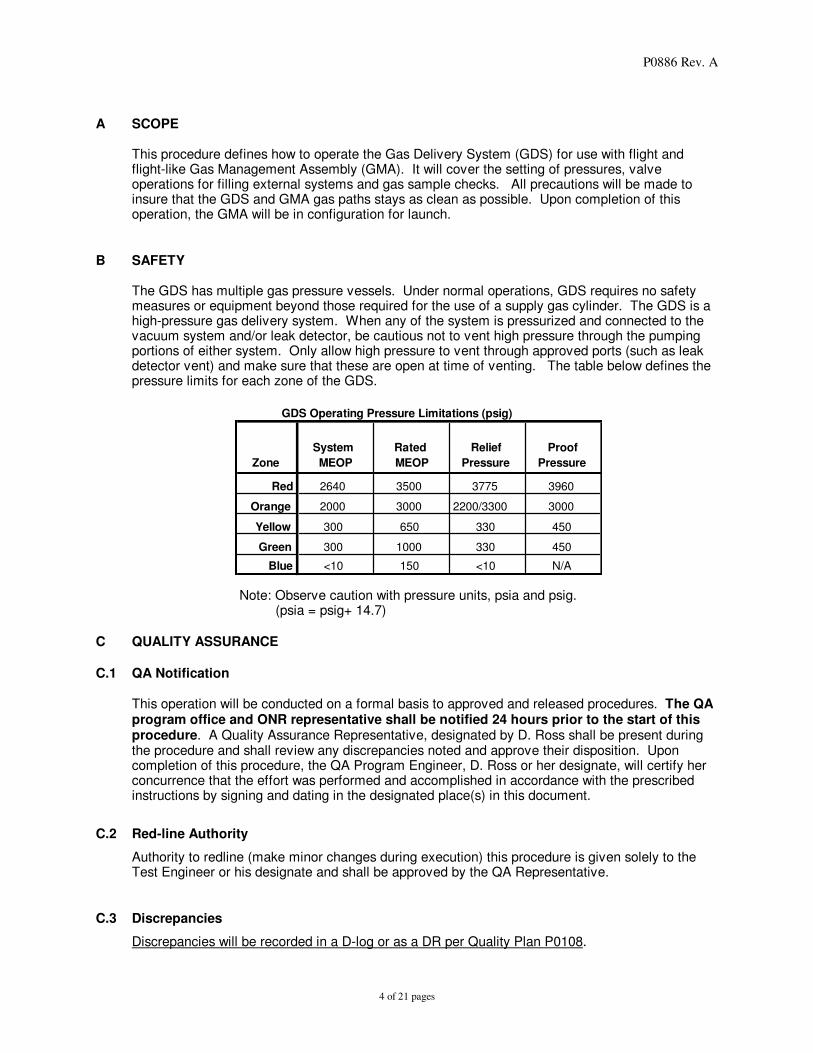
The GDS has multiple gas pressure vessels. Under normal operations, GDS requires no safety measures or equipment beyond those required for the use of a supply gas cylinder. The GDS is a high-pressure gas delivery system. When any of the system is pressurized and connected to the vacuum system and/or leak detector, be cautious not to vent high pressure through the pumping portions of either system. Only allow high pressure to vent through approved ports (such as leak detector vent) and make sure that these are open at time of venting. The table below defines the pressure limits for each zone of the GDS.
GDS Operating Pressure Limitations (psig)
Zone
System
MEOP
Rated
MEOP
Relief
Pressure
Proof
Pressure
Red 2640 3500 3775 3960
Orange 2000 3000 2200/3300 3000
Yellow 300 650 330 450
Green 300 1000 330 450
Blue <10 150 <10 N/A
Note: Observe caution with pressure units, psia and psig.
(psia = psig+ 14.7)
C QUALITY ASSURANCE
C.1 QA Notification
This operation will be conducted on a formal basis to approved and released procedures. The QA program office and ONR representative shall be notified 24 hours prior to the start of this procedure. A Quality Assurance Representative, designated by D. Ross shall be present during the procedure and shall review any discrepancies noted and approve their disposition. Upon completion of this procedure, the QA Program Engineer, D. Ross or her designate, will certify her concurrence that the effort was performed and accomplished in accordance with the prescribed instructions by signing and dating in the designated place(s) in this document.
C.2 Red-line Authority
Authority to redline (make minor changes during execution) this procedure is given solely to the Test Engineer or his designate and shall be approved by the QA Representative.
C.3 Discrepancies
Discrepancies will be recorded in a D-log or as a DR per Quality Plan P0108.
P0886 Rev. A
5 of 21 pages
D TEST PERSONNEL
The Test Engineer shall be Ken Bower or an alternate that he shall designate. The Engineer has overall responsibility for the implementation of this procedure and shall sign off the completed procedure and relevant sections within it.
E REQUIREMENTS
E.1 Electrostatic Discharge Requirements
N/A
E.2 Lifting Operation Requirements
N/A
E.3 Hardware/Software Requirements GDS
ECU Flight Equivalent, Flight ECU, or Manual Latch Valve Control Box
(Note: The procedures will always call for an ‘ECU command’ to open GMA
valves but it can be replaced by any of the above equivalents.)
Interface cables from ECU to GMA/ Gas Flow Mock GMA (G-Mock)
Research Grade Helium Supply: four bottles on the GDS cart and one for leak detection spraying.
GMA or G-Mock
High and Low Pressure Manifold Hardware to connect GMA/G-Mock to GDS
Mensor High Resolution Pressure Transducers attached to manifold
3500 psia digital pressure sensor
Calibration Date: _____________ S/N: ______________ Model #: ______________
500psia digital pressure sensor
Calibration Date: _____________ S/N: ______________ Model #: ______________
Leak detector, Alcatel (or alternate), internally calibrated
Hand held particle counter (sensitive to 0.50 microns or better)
Calibration Date: _____________ S/N: ______________ Model #: ______________
Clean room bags
Alcatel Dry Pump / Turbo Pump Cart (or equivalent)
E.4 Instrument Pretest Requirements
All test equipment used to verify test data is required to be “in calibration.” E.5 Configuration Requirements
The GDS has passed the Acceptance Test and ‘Initial Gas Purity Tests’ (99.9995% He). E.6 Optional Non-flight Configurations

P0886 Rev. A
6 of 21 pages
N/A E.7 Verification/ Success Criteria
Individual quantities should be able to be within tolerances set out in individual procedure sections. E.8 Constraints and Restrictions
N/A
F REFERENCE DOCUMENTS F.1 Drawings
GDS Drawing – Advanced Micropolish Inc (AMI) Dwg # STN-103-ASM GDS Schematic, GP-B Dwg. Number 26278 G-Mock Drawing GMA Schematic, GP-B Dwg. Number 26273
F.2 Supporting documentation
N/A F.3 Additional Procedures
ECU operations as applicable.
G OPERATIONS
G.1 Verify Appropriate QA Notification
QA Notified__________________ ONR Notified___________________ (Date & Time) (Date & Time)
G.2 Setup of GDS
Started on: _______________ WARNING
HELIUM USED IN THE GRAVITY PROBE-B PROGRAM REPRESENTS A HAZARDOUS MATERIAL
FOR THE PERSONNEL INVOLVED IN THE TESTING AND CRYOGENIC SYSTEM OPERATIONS.
EXTREME CARE SHOULD BE USED WHEN WORKING AROUND OR WITH HELIUM
G.2.1 Verify pressure relief systems are installed and all associated cutoff valves are open. G.2.2 Verify GDS supply cylinders have sufficient Helium to complete required operations. (Minimum
of two full Air Products (AP) BIP's 2640 psig cylinders are required to fill the GMA to 2000psia) G.2.3 Verify that all GDS valves (except those noted in G2.1) and He supply valves are closed and all
GDS ports are sealed. Open the GDS sample bottle valves. The sample bottle valves remain open at all times unless stated otherwise.
G.2.4 Verify that the GDS is at a positive pressure of Helium. Record PT-2______ PT-3 ______ G.2.5 Connect the ECU (or equivalent control device) to the GMA and start it up.

P0886 Rev. A
7 of 21 pages
G.2.6 Start Null Script software to control the GMA solenoid valves. The GMA valves will then be in “launch”, “sleep”, or “unchanged” configuration, determined by the Test Director. Record configuration here: ______________ (If “unchanged” Is the configuration chosen, attach a configuration description). Make note of all problems in a Discrepancy Log.
G.2.7 Record the starting pressure of the He supply bottles:
#1 _________ #2 _________ #3_________ #4 _________
G.3 Particle and Leak Check of GDS Manifold to GMA
Started on: _______________
Note: Mark off each step of this section as it is completed.
G.3.1 Open one He supply bottle (bottle #_____ ), the corresponding GDS supply valve (V-1, V-2, V-
3 or V-4) and V-6. (Fig. 2)
G.3.2 Open GDS valves V-13, V-14, V-17, and V-24. Set pressure regulator PR-1 to a low-pressure
(<150 psig) then open valve V-8. Uncap high-pressure outlet. Set flow between 5-10 lpm
(about 0.25 scfm).
G.3.3 Connect high-pressure manifold hardware to GDS high -pressure outlet. (Fig. 1)
G.3.4 Close GDS valve V-24 and open valve V-25. Set pressure regulator PR-2 to a low-pressure
(<150 psig) then open valve V-26. Uncap low-pressure outlet. Set flow between 5-10 lpm (about
0.25 scfm).
G.3.5 Connect low pressure manifold hardware to GDS low -pressure outlet.
G.3.6 Close GDS valve V-25.
G.3.7 Open valve V-24. Fashion a clean room bag into an air trap with small openings at either end.
G.3.8 Affix the clean room bag to the high-pressure outlet of the manifold. Gas should slightly inflate
the air trap.
G.3.9 Insert particle counter inlet loosely into other end of bag.
G.3.10 Allow gas to flow for at least 5 minutes to purge line.
G.3.11 Take five one-minute samples. Average number of 0.5 micron or greater particles should be
less than 5 per cubic foot. Samples @ MV1) : #1 __ #2 __ #3 __ #4__ #5 __
G.3.12 Remove particle counter and gas trap and do not shut off the gas flow.
G.3.13 Initial here to verify test pass for the high-pressure outlet ________.
G.3.14 Open GDS valve V-25 and repeat steps G.3.7 to G3.12 for the low-pressure outlets.
Samples - @ MV2): #1 __ #2 __ #3 __ #4__ #5 __ ; @MV3 :#1 __ #2 __ #3 __ #4__ #5 __ ; @ MV4 : #1 __ #2 __ #3 __ #4__ #5 __ Note: If there is insufficient flow, close valve V-24 during low-pressure outlet particle check.
G.3.15 Initial here to verify test pass for the three low-pressure outlets ________.
G.3.16 Connect manifold to GMA. Use a conical seal in each connection (part #C33934-004). Verify
that positive flow is maintained during mating. (Open valve V-24 if required).
Connections torqued to 120 + 10 in-lbs and recorded in valve cycle log sheet. TORQUE @: MV1______, MV2_______, MV3 ______, MV4_________ QUALITY_____________
P0886 Rev. A
8 of 21 pages
G.3.17 Vent pressure through CV-1 by doing the following: Close GDS supply valve (V-1, V-2, V-3 or V-
4). Set PR-1 and PR-2 (CW to open) to minimum flows. Crack open valve V-29 (CCW to
open) and slowly release pressure to a nominal 10 psig. Close valve V-29.
G.3.18 Connect leak detector to the GDS RGA connection. Ensure the leak detector has been tuned
and calibrated. Calibration Date ________ Calibration Value ________
G.3.19 Start leak detector. Open GDS valves V-9 and V-11, wait for the GDS pump to evacuate the
GDS (<5x10^-3 torr), close V-10, then open GDS valve V-22. Verify that all GDS pressure
sensors read 0 psia once leak detector goes into test mode. Record background leak rate
________.
G.3.20 Using a small flow from the leak test supply bottle, spray helium around the GDS to GMA
manifold hardware. Watch for leak rate spikes that would indicate leaks.
G.3.21 Fix any leaks that are found and repeat step G.3.17 as necessary. Record any discrepancies in
a discrepancy log.
G.3.22 Close GDS valves V-9, V-11 and V-22. Shut down leak detector.
G.3.23 Record completion of leak test on line 1 of Section H.1. QUALITY____________
G.4 GMA Gas Fill Preparations (Gas Purity Test)
Started on: _______________
Note: Mark off each step of this section as it is completed.
G.4.1 Open/verify open GDS valves V-8, V-13, V-14, V-15, V-16, V-17, V-21, V-23, V-24, V-25 and V-
26. Close/verify closed GDS valves V-1, V-2, V-3, V-4, V-5, V-6, V-7, V-9, V-10, V-11, V-12, V-
18, V-19, V-20, V-22, V-27, V-28, V-29 and V-30.
G.4.2 Verify that GDS pressure sensors PT-2 and PT-3 all are <10 psig. Start GDS vacuum pump,
open valves V-9, V-10 and V-11 and evacuate GDS.
G.4.3 Verify that GDS and supply manifold are under vacuum (< 5x10^-3 torr @ VT-1) before
pressurizing.
G.4.4 Close GDS valves V-8, V-9, V-10, V-11, V-13 and V-26.
G.4.5 Open one He supply bottle (bottle #_____ ), the corresponding GDS supply valve (V-1, V-2, V-
3 or V-4) and V-6.
G.4.6 Set regulator PR-1 to ≥700 psig and crack open valve V-8 to allow the pressure to rise slowly.
G.4.7 Close the valves on GDS sample bottle #1.
G.4.8 Close the helium supply bottle and the corresponding GDS valve (V-1, V-2, V-3 or V-4).
G.4.9 Vent pressure through CV-1 by doing the following: Open GDS valve V-13. Set PR-1 and PR-2
(CW to open) to minimum flows. Open valve V-29. Crack open valve V-26 (CCW to open) and
slowly release pressure then close valve V-29.
G.4.10 Close and lock GDS valves V-15 and V-16. Remove sample bottle #1, cap the ends of the
bottle and ports. Send sample to vendor for analysis. (If gas sample does not require vendor

P0886 Rev. A
9 of 21 pages
analysis, do not remove.) Turn off GDS vacuum pump if desired.
QUALITY____________
Note: If any configuration of the GDS manifold has been opened to atmosphere or Helium Supply bottles have been changed, sample results must be verified by a qualified gas analysis vendor before proceeding. Helium gas composite shall be 99.9995% or better.

P0886 Rev. A
10 of 21 pages
G.5 GMA Regulator Lock-Up
Started on: _______________
Note: Mark off each step of this section as it is completed. G.5.1 Verify section G.2 is complete, the ECU (or equivalent control device) is ready and the GMA
valves are in a launch configuration.
G.5.2 Measure GMA system pressures and record values in Section H.2.
G.5.3 Verify all GDS valves and regulators are closed, except the relief cutoff valves (V-21, V-23, RV-
1 and RV-3).
G.5.4 Connect the Alcatel Turbo Pump Cart and valve manifold to the GMA non-propulsive vent port.
Verify valves VV-1 and VV-2 are closed.
G.5.5 If GMA Zones II, III, IV or V (Figure #3) are all at a vacuum (< 5x10⁻³ torr) then go to step
G.5.10.
G.5.6 If GMA Zones II, III, IV or V is > 50 psig then the pressure must be vented by doing the following:
Enter ECU command to open GMA valves V3, V4, V-5, V-6 and V29. Open VV-1 and vent until
GMA pressure is <50 psig. Close VV-1.
G.5.7 Turn on Alcatel Turbo Pump and then open valve VV-2 to evacuate.
G.5.8 Close VV-2. Turn off Alcatel Turbo pump if desired.
G.5.9 Enter ECU command to close GMA valves V3, V4, V5, V6 and V29.
G.5.10 Record all GMA pressure sensors and enter values in Section H.2.
G.5.11 Enter ECU command to open GMA valves V1 and V2.
G.5.12 If GMA sensor P1 indicates < 270 psia then go to step G.5.20.
G.5.13 If GMA sensor P1 indicates 300 psia (+ 30) then go to step G.5.30
G.5.14 If GMA sensor P1 indicates > 330 psia then continue. (Excess pressure must be bled through
the GMA vent.)
G.5.15 Enter ECU command to open GMA valvesV3, V4, V5, V6 and V29.
G.5.16 Open VV-1 and slowly bleed gas until desire pressure is obtained then close VV-1.
G.5.17 Enter ECU command to close GMA valves V1, V2, V3, V4, V5, V6 and V29.
G.5.18 Record all GMA pressure sensors and enter values in Section H.2.
G.5.19 Go to step G.5.30.
G.5.20 If the GDS is at a positive pressure (> 20 psig) then it must be vented through CV-1 by doing the
following: Verify GDS valve V-6 is closed. Open GDS valves V-8, V-13 and V-26. Set PR-1
and PR-2 (CW to open) to minimum flows. Crack open valve V-29 (CCW to open) and slowly
release pressure. Close GDS valve V-29.
G.5.21 Start GDS vacuum pump, open GDS valves V-9, V-10 and V-11 and evacuate GDS.
G.5.22 Open GDS valves V-24 and V-25.
G.5.23 Verify the GDS and supply manifold are under vacuum (< 5x10^-3 torr @VT-1).
G.5.24 Close GDS valves V-8, V-9, V-10, V-11, V-13 and V-25.
P0886 Rev. A
11 of 21 pages
G.5.25 Open one He supply bottle (bottle #_____ ), the corresponding GDS supply valve (V-1, V-2, V-
3 or V-4) and V-6. Set regulator PR-1 to 300 psia (285 psig). Crack open valve V-8 and allow
the pressure to rise slowly.
G.5.26 Slowly open GMA valves MV1 (record in valve cycle log sheet) and enter ECU command to
open GMA valves V1 and V2. There might be some settling time required (15 minutes) before
verification of the final pressure.
G.5.27 Enter ECU command to close GMA valves V1 and V2.
G.5.28 Close GMA valve MV1 (Torqued to 40 + 5 in-lbs and recorded in valve cycle log sheet) and
GDS valve V-24. TORQUE:________________ QUALITY____________
G.5.29 Record all GMA pressure sensors and enter values in Section H.2.
G.5.30 On lines 2 and 3 of Section H.1 record completion of gas fill and final pressures
G.5.31 If the GDS is at a positive pressure (> 20 psig) then it must be vented through CV-1 by doing the
following: Close GDS valve V-6. Open GDS valve V-13. Set PR-1 and PR-2 (CW to open) to
minimum flows. Crack open GDS valve V-29 (CCW to open) and slowly release pressure.
Close GDS valve V-29.
G.5.32 Start GDS vacuum pump, open GDS valves V-9, V-10, V-11, V-25 and V-26 (if not already
open) and evacuate.
G.5.33 Verify the GDS and supply manifold are under vacuum (< 5x10^-3 torr @ VT-1).
G.5.34 Close GDS valves V-8, V-9, V-10, V-11 and V-26.
G.5.35 Open one He supply bottle (bottle #_____ ), the corresponding GDS supply valve (V-1, V-2, V-
3 or V-4) and V-6. Open GDS valve V-6 and set regulator PR-1 to 500 psig and crack open
valve V-8 to allow the pressure to rise slowly.
G.5.36 Set regulator PR-2 to 50 psig (+ 10) and crack open valve V-26 and allow the pressure to rise
slowly to 50 psig.
G.5.37 Slowly open GMA valves MV3 and MV4 (record each in valve cycle log sheet).
G.5.38 Increase PR-2 setting to 285 psig (300 psia) (+ 30) but limit increase to <100 psi/minute. Verify
final pressure with the Mensor.
G.5.39 Close GMA valves MV3 and MV4 (Torqued to 40 + 5 in-lbs and recorded in valve cycle log
sheet).
TORQUE:________________ QUALITY____________
On lines 4 and 5 of Section H.1 record completion of gas fill and final pressures. Record all
GMA pressure sensors and enter values in Section H.2
G.5.40 Vent pressure through CV-1 by doing the following: Close GDS valve V-6. Set PR-1 and PR-2
(CW to open) to minimum flows. Crack open valve V-29 (CCW to open) and slowly release
pressure. Close GDS valve V-29.
G.5.41 Open GDS valves V-9, V-10 and V-11 and evacuate GDS.
G.5.42 Verify the GDS and supply manifold are under vacuum (< 10^-3 torr @ VT-1) before
pressurizing.
G.5.43 Close GDS valves V-8, V-9, V-10, V-11 and V-26.

P0886 Rev. A
12 of 21 pages
G.5.44 Open GDS valve V-6 and set regulator PR-1 to 500 psig and crack open valve V-8 to allow the
pressure to rise slowly.
G.5.45 Set regulator PR-2 to 50 psig and crack open valve V-26 and allow the pressure to rise slowly to
50 psig.
G.5.46 Open GMA valve MV2 (record in valve cycle log sheet).
G.5.47 Enter ECU command to open GMA valves V3, V4, V5 and V6.
G.5.48 Increase PR-2 setting to 285 psig (300 psia) (+ 30) but limit increase to <100 psi/minute. Verify
final pressure with the Mensors.
G.5.49 Enter ECU command to close GMA valves V3, V4, V5, V6 and close the GMA valve MV2
(Torqued to 40 +5 in-lbs and recorded in valve cycle log sheet). On lines 12 to 14 of Section H.1
record completion of gas fill and final pressures.
G.5.50 Record all GMA pressure sensors and enter values in Section H.2.
G.5.51 Vent pressure through CV-1 by doing the following: Close GDS valve V-6. Set PR-1 and PR-2
(CW to open) to minimum flows. Crack open valve V-29 (CCW to open) and slowly release
pressure. Close GDS valve and V-29.
Note: The following procedures (G5.52 to G5.58) are optional depending if GMA Zone V
requires evacuation.
G.5.52 Enter ECU command to open GMA valve V29.
G.5.53 Open VV-1 and release the pressure in Zone V. Close VV-1
G.5.54 Turn on Alcatel Turbo Pump and then open valve VV-2.
G.5.55 Verify the GMA Zone V is under vacuum (read GMA sensor P6).
G.5.56 Enter ECU command to close GMA valve V29 and close VV-2.
G.5.57 On line14 of Section H.1 record completion of gas fill and final pressures.
G.5.58 Record all GMA pressure sensors and enter values in Section H.2.
Note: The following procedures (G5.59 to G5.66) are optional depending if GMA Zone VI
requires evacuation.
G.5.59 Connect GMA outlets S1, S2, S3, S4 and P1A to a vacuum source and start pump.
G.5.60 Enter ECU command to close GMA valves V7, V8, V11, V12, V15, V16, V19, V20, V23, and
V24.
G.5.61 Enter ECU command to open GMA valves V9, V10, V13, V14, V17, V18, V19, V21, V22, and
V26.
G.5.62 Evacuate GMA outlets.
G.5.63 Verify the GMA is under vacuum (< 10^-3 torr @ vacuum source)
G.5.64 Enter ECU command to close GMA valves V9, V10, V13, V14, V17, V18, V21, V22, V25 and
V26.
G.5.65 On lines 6 to 11 of Section H.1 record completion of gas fill and final pressures.
G.5.66 Record all GMA pressure sensors and enter values in Section H.3. QUALITY____________

P0886 Rev. A
13 of 21 pages
G.6 GMA Pressure Vessel Fill
Started on: _______________
Note: Mark off each step of this section as it is completed.
G.6.1 Verify section G.2 is complete, the ECU (or equivalent control device) is ready and the GMA
valves are in a launch configuration.
G.6.2 Verify that GDS valves V-13, V-14, V-17, V-18, V-19, V-21, V-23 and V-24 are open.
G.6.3 Open one He supply bottle (bottle #_____ ), the corresponding GDS supply valve (V-1, V-2, V-
3 or V-4) and V-6.
G.6.4 If the GDS is at a positive pressure (> 20 psig) then it must be vented through CV-1 by doing the
following: Open GDS valves V-8 and V-26. Set PR-1 and PR-2 (CW to open) to minimum flows.
Crack open valve V-29 (CCW to open) and slowly release pressure. Close GDS valve and V-29.
G.6.5 Open GDS valves V-9, V-10 and V-11. Evacuate GDS and supply manifold.
G.6.6 Verify that GDS and supply manifold are under vacuum (< 5x10^-3 torr @ VT-1) before
pressurizing.
G.6.7 Close GDS valve V-9, V-10 and V-11
G.6.8 Set regulator PR-1 to 285 psig (+ 30) and crack open valve V-8 to allow the pressure to rise
slowly.
Note: If the GMA tank pressures are known to not equal 285 psig (+ 30), the Test Director shall
designate a different starting pressure. _________
G.6.9 Slowly open GMA valve MV1 (record in valve cycle log sheet). Close GDS valve V-21.
G.6.10 Increase pressure at PR-1 up to a nominal expected 2200 psig but limit increase to <100
psi/minute (Actual fill pressure to be determined by Test Director _________). There might be
some settling time required (15 minutes) before verification of the final pressure. Verify final
pressure with the Mensor. (Note: If the GMA bottle temperature increases more than 10° C, stop
fill process and wait for the temperature to decrease below the 10° delta.)
G.6.11 Close GMA valve MV1 (Torqued to 40 + 5 in-lbs and recorded in valve cycle log sheet).
TORQUE:________________ QUALITY____________ G.6.12 Vent pressure through GDS CV-1 by doing the following: Close GDS valve V-6. Set PR-1 and
PR-2 (CW to open) to minimum flows. Open valves V-29. Crack open valve V-26 (CCW to
open) and slowly release pressure. Close GDS valves V-8, V-26 and V-29.
G.6.13 Open valves V-9, V-10 and V-11 and evacuate GDS.
G.6.14 Verify the GDS and supply manifold are under vacuum (< 5x10^-3 torr @ VT-1) before
pressurizing.
G.6.15 Close GDS valves V-8, V-9, V-10, V-11, V-13 and V-26. Turn off GDS vacuum pump if desired.
Wait period – Approval from Test Director required before continuing ______. G.6.16 Slowly open GMA valve MV1 (record in valve cycle log sheet) and back fill GDS sample bottle
#2 to equilibrium (approximately 1880 psia, actual final pressure to be determined by Test
Director ____________). Verify pressure with the 3500 psi Mensor. If pressure is greater than
P0886 Rev. A
14 of 21 pages
desired final pressure, carefully vent surplus pressure through the following sequence of GDS
valves as required: V-14, V-13, PR-2 (set to <50 psig), V-26, V-29, and CV-1. Record final
pressure ___________.
G.6.17 Close GMA valve MV1 (Torqued to 40 + 5 in-lbs and recorded in valve cycle log sheet) and GDS
sample bottle #2 valves. TORQUE:________________ QUALITY____________
G.6.18 Vent pressure through CV-1 by doing the following: Set PR-1 and PR-2 (CW to open) to
minimum flows. Open valves V-13 and V-29. Crack open valve V-26 (CCW to open) and slowly
release pressure. Close GDS valves V-26 and V-29.
G.6.19 Close and lock GDS valves V-18 and V-19.
G.6.20 Remove sample bottle #2, cap the ends of the bottle and ports. Send to vendor for analysis. (If
gas sample does not require vendor analysis, do not remove.)
G.6.21 On line 15 of Section H.1 record completion of gas fill and final pressure. QUALITY________
G.7 Disconnect GDS
Started on: _______________ Note: Mark off each step of procedure as it is completed.
G.7.1 Verify all GMA valves MV1, MV2, MV3 and MV4 are closed and torqued (Torqued to 40 + 5 in-
lbs and recorded in valve cycle log sheet). TORQUE: MV1______, MV2_______, MV3 ______,
MV4_________ QUALITY____________
G.7.2 Verify GDS valves V-1, V-2, V-3, V-4, V-6, V-13, V-14, V-17, V-21, V-23, V-24, V-25 and V-26
are open. All other GDS valves are closed.
G.7.3 Record the final pressure of the He supply bottles:
#1 _________ #2 _________ #3_________ #4 _________
G.7.4 Set regulator PR-1 and PR-2 to a low-pressure (<150 psig) then open valve V-8 to set flow
between 5-10 lpm (about 0.25 scfm).
G.7.5 Disconnect manifold from GMA.
G.7.6 Cap and seal all GMA fill and drain valve ports. Use a conical seal in each port. (part #C33934-
004). (Caps torqued to 120 + 10 in-lbs and recorded in valve cycle log sheet)
TORQUE @: MV1______, MV2_______, MV3 ______, MV4_________
QUALITY____________
G.7.7 Disconnect manifold from GDS.
G.7.8 Verify that all GDS purge gas connections are capped and all relief/check valves are enabled.
G.7.9 Close GDS valves V-24, V-25 and V-26.
G.7.10 Close He supply bottle(s).
G.7.11 Set regulator PR-1 and PR-2 to minimum flows.
G.7.12 Vent GDS to 5 psig (+2 psig): Open GDS valve V-26 and crack open valve V-29 (CCW to open)
and slowly release pressure to 5 psig. Close GDS valve V-29.
G.7.13 Close all GDS valves.
G.7.14 Removed any Ground Support Hardware (GSE) hardware as required.
P0886 Rev. A
15 of 21 pages
G.7.15 Sign off on line 16 of Section H.1 to verify that the GDS is safe and back-filled with Helium to 5
psig.

P0886 Rev. A
16 of 21 pages
G.8. Diagrams
GDS Manifold SketchSJBAug. 27, 2002
P
P
500 psi Mensor
3500 psi Mensor
0.003 MicronFilters
Regulator Interstage
Port (MV3)
ServicePort (MV2)
AlcatelDry
Pump
GMA Vent
Line
GDSLow-Pressure
Outlet
High-PressureOutlet
GMA
Gas Fill
Port (MV1)
Regulator
InterstagePort (MV4)
To ProbeInlets
VV1
VV2
CV2
High-PressureManifold
Low-Pressure Manifold
Figure 1

P0886 Rev. A
17 of 21 pages
G.8. Diagrams
Pl
V-1 V-2 V-3 V-4V-5
V-7 V-9V-13
V-8
V-6
PR-1
RV-1
V-10V-11
RV-3
V-28
V-27
V-29
V-30V-12
PR-2 V-26
V-25
V-24
V-19
V-17V-14
V-16
V-18V-15
H2O
O2
GASANALYZERS
CV-1
VACUUM
PUMPVT
VT-1
V-23
RGACONNECTION
PT-1PT-2
PURGE GAS
CONNECTION
PT PT PT PT
PI-1 PI-2 PI-3 PI-4
PURGE GAS
CONNECTION
PI-5 PI-6
PI-7 PI-8
SET@3300 psig
SET@2200 psig
SET@10 psig
SET@330 psig
He He He He
F-2
F-1
PR-3
PR-4
GAS DELIVERY SYSTEM (GDS)
RV-2 RV-4
SJB
PT
V-20
PT
V-21 V-22
GMA
Gas Supply : Red
Vacuum Inlet : Blue
Analysis : GreenGas Outlet (Low Pressure) : Yellow
Gas Output (High Pressure) : Orange
Max Pressure @Sta : 3500 psi
Max Pressure @ other:2640 ps i
Sept. 4, 2002
#2
PTPT-3
20 psig
20 psig
PlPl
Pl
#1
RV-3 CUTOFF
RV_1 CUTOFF
Blue Zone
Yellow Zone
Green Zone
Orange ZoneRed Zone
25-4000 psig
5-550 psig
M
Figure 2
P0886 Rev. A
18 of 21 pages
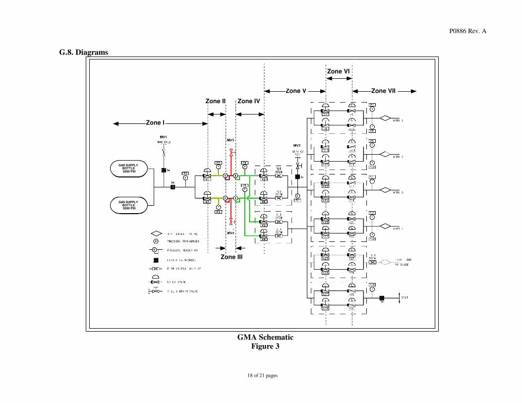
G.8. Diagrams
Zone II Zone IV
Zone III
Zone VI
Zone I
Zone V Zone VII
GAS SUPPLYBOTTLE2000 PSI
GAS SUPPLYBOTTLE2000 PSI
GMA Schematic
Figure 3

P0886 Rev. A
19 of 21 pages
H
H.1 PROCEDURE COMPLETION
Final Completed QA
No. Section Task Details Pressure Date Initial Approval Comments
1 G.3 GDS leak test passed Better than 1x10^-8 sccs external leak rate
2 G.5 GDS fill of GMA between V1 and R1 (Zone II) Pressure @300 psia (-0/+50psi)
3 G.5 GDS fill of GMA between V2 and R2 (Zone II) Pressure @300 psia (-0/+50psi)
4 G.5 GDS fill of GMA between R1 regulators (Zone III)
Pressure @300 psia (-0/+30psi)
5 G.5 GDS fill of GMA between R2 regulators (Zone III)
Pressure @300 psia (-0/+30psi)
6 G.5 GDS fill of GMA between V7/V8 and S1 Pressure @0 psia
7 G.5 GDS fill of GMA between V11/V12 and S2 Pressure @0 psia
8 G.5 GDS fill of GMA between V15/V16 and S3 Pressure @0 psia
9 G.5 GDS fill of GMA between V19/V20 and S4 Pressure @0 psia
10 G.5 GDS fill of GMA between V23/V24 and Probe Pressure @0 psia
11 G.5 GDS fill of GMA between V27/V28 and Vent Pressure @0 psia
12 G.5 GDS fill of GMA between R1 andV3/V5(Zone IV)
Pressure @300 psia (-0/+30psi)
13 G.5 GDS fill of GMA between R2 andV4/V6(Zone IV)
Pressure @300 psia (-0/+30psi)
14 G.5 GDS fill of GMA between V3 to V6 andV9/V10, V13/ V14..etc (Zone V)
Pressure @300 psia (-0/+30psi)
15 G.6 GDS fill of GMA between gas supply bottles and V1/V2 (Zone I)
Pressure @1880 or designated __________ psia (-0/ +100psi)
16 G.7 GDS backfilled with Helium To 5 psig (-0/+5psi)

P0886 Rev. A
20 of 21 pages
H.2 Pressure Sensor Log
GMA Sensors Counts Manifold Mensors GDS
Sect: Step Time P1 P2 P3 P4 P5 P6 P7 P8 P9 P10 P11 P12 P13 P14
500 psi
3500 psi PT1 PT2 PT3

P0886 Rev. A
21 of 21 pages
H.3 Procedure Sign Off
The results obtained in the performance of this procedure are acceptable:
______________________________ date: ________ Test Director/GMA Engineer
Discrepancies if any: Approved: __________________ date: ________ C. Gray, GMA REE Approved: __________________________ date: ________ QA Representative Approved: __________________________ date: ________ D. Ross, QA