CREEP-FATIGUE DAMAGE DEVELOPMENT DURING SERVICE · PDF fileCREEP-FATIGUE DAMAGE DEVELOPMENT...
10
CREEP-FATIGUE DAMAGE DEVELOPMENT DURING SERVICE-CYCLE THERMO-MECHANICAL FATIGUE TESTS OF 1CrMoV ROTOR STEEL Stuart R Holdsworth ¥ , Edoardo Mazza § & Arnd Jung ¤ ¥ ALSTOM Power, Rugby CV21 2NH, UK § ETH Zurich, CH-8092 ¤ ALSTOM Power, CH-5401 Baden [email protected] ABSTRACT Service-cycle thermo-mechanical fatigue (TMF) tests have been performed on a 1CrMoV steam turbine rotor steel, with unexpected consequences in terms of the observed deformation and damage development characteristics. The tests were conducted on two heats of the rotor steel using service-like cycles without and with hold times at peak temperature. The temperature and mechanical strain control profiles of the cycles were devised to represent conditions which could occur at critical locations in a high temperature steam turbine rotor during operation, both with respect to shape and transient-rate. Details of the service cycle TMF test control regime are described. A key feature of all the tests was the development of necking due to ratchetting, despite the control of mechanical strain. Clues to the experimental cause of the effect are given in this paper. A more detailed analytical explanation is provided in a companion paper in the conference proceedings. The observations question what are currently regarded as acceptable temperature control limits for TMF testing. The local deformation phenomenon had a significant influence on the fatigue and creep damage development characteristics exhibited by the two steels, as revealed by a comprehensive post-test inspection activity. A range of physical damage mechanisms were encountered, ranging from fatigue-dominated to creep-dominated, and these are rationalised with reference to a creep-fatigue damage summation diagram for the steam turbine material. INTRODUCTION Critical locations in steam turbine rotors may be subject to the combined influences of cyclic damage arising from strain transients generated during start-up and shut-down and creep damage resulting from primary (directly applied) and secondary (self equilibrating) stresses during operation. Traditionally, the risk of thermal fatigue cracking at such locations has been assessed using the results from isothermal tests conducted at (or close to) the peak operating temperature (e.g. [1-4]). 1CrMoV steel is widely used for HP/IP steam turbine rotors operating at temperatures up to ∼565°C, and there is an extensive knowledge base covering isothermally determined LCF and cyclic/hold properties of the steel (e.g. [5-9]). One purpose of performing the service-cycle thermo-mechanical fatigue (TMF) tests described in the following paper was to understand the practical implications of applying such an approach to an anisothermal service situation. Prior to the present study, there was only limited experience of TMF testing 1CrMoV rotor steel. A Japanese study had shown that creep-fatigue endurances resulting from out-of-phase
Transcript of CREEP-FATIGUE DAMAGE DEVELOPMENT DURING SERVICE · PDF fileCREEP-FATIGUE DAMAGE DEVELOPMENT...

CREEP-FATIGUE DAMAGE DEVELOPMENT DURING SERVICE-CYCLE THERMO-MECHANICAL FATIGUE TESTS OF 1CrMoV ROTOR STEEL
Stuart R Holdsworth ¥, Edoardo Mazza § & Arnd Jung ¤
¥ ALSTOM Power, Rugby CV21 2NH, UK § ETH Zurich, CH-8092
¤ ALSTOM Power, CH-5401 Baden [email protected]
ABSTRACT Service-cycle thermo-mechanical fatigue (TMF) tests have been performed on a 1CrMoV steam turbine rotor steel, with unexpected consequences in terms of the observed deformation and damage development characteristics.
The tests were conducted on two heats of the rotor steel using service-like cycles without and with hold times at peak temperature. The temperature and mechanical strain control profiles of the cycles were devised to represent conditions which could occur at critical locations in a high temperature steam turbine rotor during operation, both with respect to shape and transient-rate. Details of the service cycle TMF test control regime are described.
A key feature of all the tests was the development of necking due to ratchetting, despite the control of mechanical strain. Clues to the experimental cause of the effect are given in this paper. A more detailed analytical explanation is provided in a companion paper in the conference proceedings. The observations question what are currently regarded as acceptable temperature control limits for TMF testing.
The local deformation phenomenon had a significant influence on the fatigue and creep damage development characteristics exhibited by the two steels, as revealed by a comprehensive post-test inspection activity. A range of physical damage mechanisms were encountered, ranging from fatigue-dominated to creep-dominated, and these are rationalised with reference to a creep-fatigue damage summation diagram for the steam turbine material. INTRODUCTION Critical locations in steam turbine rotors may be subject to the combined influences of cyclic damage arising from strain transients generated during start-up and shut-down and creep damage resulting from primary (directly applied) and secondary (self equilibrating) stresses during operation. Traditionally, the risk of thermal fatigue cracking at such locations has been assessed using the results from isothermal tests conducted at (or close to) the peak operating temperature (e.g. [1-4]). 1CrMoV steel is widely used for HP/IP steam turbine rotors operating at temperatures up to ∼565°C, and there is an extensive knowledge base covering isothermally determined LCF and cyclic/hold properties of the steel (e.g. [5-9]). One purpose of performing the service-cycle thermo-mechanical fatigue (TMF) tests described in the following paper was to understand the practical implications of applying such an approach to an anisothermal service situation.
Prior to the present study, there was only limited experience of TMF testing 1CrMoV rotor steel. A Japanese study had shown that creep-fatigue endurances resulting from out-of-phase
300↔550°C TMF cycles were similar to those for isothermal tests at 550°C, for the same mechanical strain range. Endurances resulting from in-phase 300↔550°C TMF cycles were longer than those from equivalent isothermal tests at strain ranges below 1% [10]. This evidence appeared to confirm the belief that the current practice of using isothermal test data to predict service behaviour was conservative. However, in a second study employing temperature acceleration to enhance the effect of 10 minute hold times by means of in-phase 300↔667°C TMF tests, endurances were lower than the equivalent isothermal tests, with necking and off-centre barrelling experienced at high strain ranges (up to 9%) [11].
The new tests involve 350↔565°C TMF cycles comprising both in-phase and out-of-phase components with characteristics which more closely represent the thermo-mechanical strain histories experienced by rotor features in practice. Two unexpected features of the present study were the development during the course of the service-cycle TMF tests of i) testpiece necking (despite the adoption of a practically relevant strain range and thermal cycle) and ii) apparently non-interacting creep and fatigue damage for one of the steel heats. The following paper considers these features further. The results of analytical studies performed to underpin the explanations for the observed behaviour are considered elsewhere [12-14]. EXPERIMENTAL DETAIL Materials Tests were performed on two heats of 1CrMoV rotor steel. The chemical compositions and mechanical properties of the two production forgings are summarised in Table 1. Both steels were oil quenched from 950/970°C and tempered at 695/700°C. The ambient monotonic yield and tensile strength properties of Heat-1 were higher than those of Heat-2.
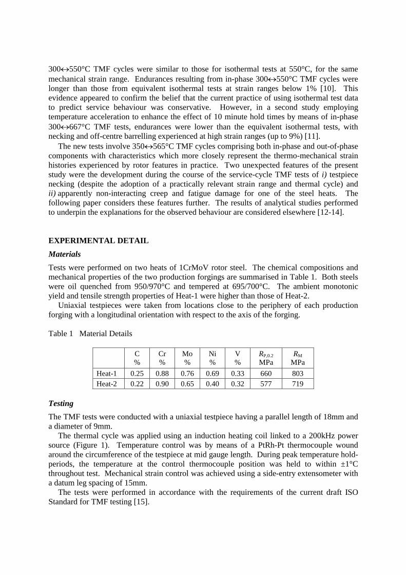
Uniaxial testpieces were taken from locations close to the periphery of each production forging with a longitudinal orientation with respect to the axis of the forging. Table 1 Material Details
C %
Cr %
Mo %
Ni %
V %
RP,0.2 MPa
RM MPa
Heat-1 0.25 0.88 0.76 0.69 0.33 660 803 Heat-2 0.22 0.90 0.65 0.40 0.32 577 719
Testing The TMF tests were conducted with a uniaxial testpiece having a parallel length of 18mm and a diameter of 9mm.
The thermal cycle was applied using an induction heating coil linked to a 200kHz power source (Figure 1). Temperature control was by means of a PtRh-Pt thermocouple wound around the circumference of the testpiece at mid gauge length. During peak temperature hold-periods, the temperature at the control thermocouple position was held to within ±1°C throughout test. Mechanical strain control was achieved using a side-entry extensometer with a datum leg spacing of 15mm.
The tests were performed in accordance with the requirements of the current draft ISO Standard for TMF testing [15].

Figure 1 View of testing arrangement (temperature control is by means of spring loaded
thermocouple at middle of gauge length)
-1.8
-1.6
-1.4
-1.2
-1.0
-0.8
-0.6
-0.4
-0.2
0.0
0 50 100TIME, mins
STR
AIN
, %
0
100
200
300
400
500
600
TEM
PE
RA
TUE
, o C
14
6 1
5
32 -1.8
-1.6
-1.4
-1.2
-1.0
-0.8
-0.6
-0.4
-0.2
0.0
300 400 500 600
TEMPERATURE, oC
STR
AIN
, %
6
4,5
32
1
Figure 2 Service-like thermo-mechanical fatigue cycles (NB: the times given are those for
Cycle-1) TMF Cycle Types Three service-cycle types were applied, with the same cycle shape (Figure 2). In each case the mechanical strain range was 1.4% and the temperature varied between 350 and 565°C.
For all cycle types, the mechanical strain was ramped from -0.2% to -1.6% (1-2), was held at -1.6% (2-3) and was then ramped to -0.4% (3-4) while the temperature was increased from 350 to 565°C (3-4). The time to 565°C (1-4) was 50 minutes for Cycle-1, and 15 minutes for Cycle-2 and Cycle-3 (Table 2).
In the case of Cycle-2, there was no hold time at the peak temperature (4-5), whereas for Cycle-1 and Cycle-3 there were hold times at 565°C of 60 and 160 minutes respectively.
testpiece
Induction heating coil
control thermocouple
side-entry extensometer legs
The mechanical strain was increased from -0.4% to -0.2%, as the temperature was reduced from 565 to 530°C (5-6), and held at -0.2% as the temperature was returned to 350°C (6-1). Table 2 Details of TMF Service-Cycles
POSITION TEMP STRAIN CYCLE-1 CYCLE-2 CYCLE-3 IN CYCLE oC % min min min
1 350 -0.2 0 0 0 2 393 -1.6 10 5 1 5 1
3 522 -1.6 40 10 2 10 2
4 565 -0.4 50 15 15 5 565 -0.4 110 15 185 6 530 -0.2 120 20 190 1 350 -0.2 130 30 200
1 421°C, 2 493°C
0.0
0.1
0.2
0.0 0.5 1.0
ENDURANCE FRACTION
AR
EA
RE
DU
CTI
ON
Heat-1, Cycle-1
Heat-1, Cycle-2
Heat-1, Cycle-3
Heat-2, Cycle-1
Heat-2, Cycle-2
Heat-2, Cycle-3
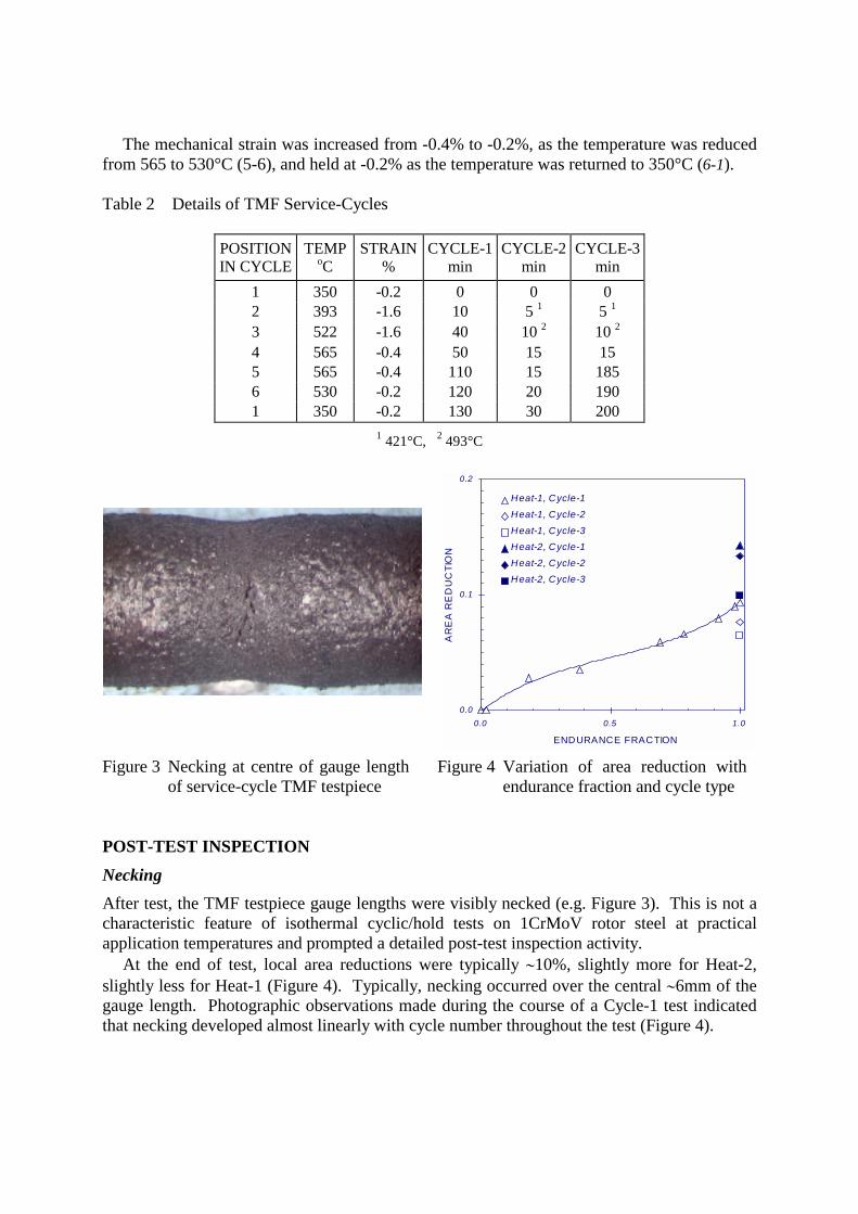
Figure 3 Necking at centre of gauge length of service-cycle TMF testpiece
Figure 4 Variation of area reduction with endurance fraction and cycle type
POST-TEST INSPECTION Necking After test, the TMF testpiece gauge lengths were visibly necked (e.g. Figure 3). This is not a characteristic feature of isothermal cyclic/hold tests on 1CrMoV rotor steel at practical application temperatures and prompted a detailed post-test inspection activity.
At the end of test, local area reductions were typically ∼10%, slightly more for Heat-2, slightly less for Heat-1 (Figure 4). Typically, necking occurred over the central ∼6mm of the gauge length. Photographic observations made during the course of a Cycle-1 test indicated that necking developed almost linearly with cycle number throughout the test (Figure 4).

Fatigue Damage
At the end of test, small transgranular fatigue cracks typically to a depth of ∼50µm were distributed almost uniformly along the parallel length of the testpiece. Deeper transgranular cracks were also observed, but only within the central necked section of the gauge length (e.g. Figure 5). Quantitative measurement details of the fatigue damage assessment have been reported elsewhere [16].
Figure 5 Fatigue-dominated cracking in Heat-1 (TMF Cycle-2 test)
Figure 6 Creep-dominated cracking in Heat-2 (TMF Cycle-3 test) Creep Damage As a generality, the creep damage observed in the post-test inspected TMF testpieces occurred on prior austenite grain boundaries. Significantly, creep damage was not distributed uniformly along the entire parallel length of these service-cycle TMF testpieces. Quantitative measurement details of the creep damage assessment have been reported elsewhere [16].
Creep damage was mainly concentrated in a ∼7mm diameter x ∼10mm long central core in the testpiece gauge section. The intensity of the damage was greatest in those testpieces subject to Cycle-1 and Cycle-3 transients, and in particular the latter (with a 3h hold time at
2mm 75µm
2mm 100µm

565°C, Figure 6). For a given cycle type, creep damage was more developed in Heat-2 testpieces relative to Heat-1 testpieces. Crack Development The way in which cracking developed was significantly different for the two heats [16]. In the case of Heat-1, crack development was always from the surface, being fatigue-dominated in the Cycle-2 testpiece (e.g. Figure 5), close to fatigue dominated in the Cycle-1 testpiece and by creep-fatigue interaction in the Cycle-3 testpiece. In contrast for Heat-2, cracking originated at the surface and propagated by creep-fatigue in the Cycle-2 testpiece (Figure 7), but developed internally in Cycle-1 and Cycle-3 testpieces (e.g. Figure 6).
Figure 7 Creep-fatigue cracking in Heat-2 (TMF Cycle-2 test) DISCUSSION Testpiece Necking
Necking of the order of magnitude observed in the service-cycle TMF tests (∼10%) is not commonly experienced in cyclic/hold tests on 1CrMoV rotor steel at temperatures of ∼500-550°C. Published experience of isothermal cyclic/hold tests with hold times up to 16h does not acknowledge the presence of necking at crack initiation [5-9].
Significant necking has previously been observed during in-phase 300↔667°C TMF tests on a 1CrMoV steel, but notably the peak temperature was within 30°C of the tempering temperature of the alloy and mechanical strain ranges were up to 9% [11]. In such circumstances, the incidence of necking is not surprising.
There is a notable difference between the temperature control specified for isothermal LCF tests and TMF tests. In the case of isothermal tests, a temperature gradient over the gauge length of the testpiece of ≤3°C is permitted for temperatures up to 600°C, although limits for creep-fatigue tests of ≤±1°C are recommended (e.g. [17]). This compares with a permissible gradient of ≤±0.01.T in TMF tests [15], or within 11°C at the peak test temperature in the case of these service-cycle 350↔565°C tests. It has been demonstrated by analysis that the observed gradient of ∼11°C at the gauge length extremities in these TMF tests can lead to ratcheting and consequent necking in a 1CrMoV rotor steel [12,14].
2mm 40µm

For a given nominal mechanical strain range, the observed necking leads to a significant reduction in the Heat-2 endurances in Cycle-1 and in particular Cycle-3 TMF tests relative to those observed in equivalent isothermal tests at the maximum test temperature (Figure 8). The reduction is apparent but not as great in the Heat-1 TMF tests. The respective endurances are rationalised by assessing the TMF test data as a function of local mechanical strain range [12,14].
The direct application of the endurance results from these service-cycle TMF tests to practical circumstances requires some care in view of the complexities introduced by the necking arising from the high but apparently acceptable temperature gradient [12,14]. For Heat-2 in particular, the evidence indicates that necking is responsible not only for locally increasing the magnitude of the cyclic strain but also for influencing the damage mechanism (Figure 8). It is almost certain that these complications would not have arisen in the absence of a high gauge-length temperature gradient.
0.1
1
10
10 100 1,000
CYCLES TO INITIATION
STR
AIN
RA
NG
E, %
TMF Cycle-2
TMF Cycle-1
TMF Cycle-3
1CrMoV Rotor Steel
LCF/Heat-2/565 o CFatigue dominated
cracking
Cyclic/hold(1h)/Heat-2/565 o CCreep-fatigue cracking
Heat-1 - small symbolsHeat-2 - large symbols
Open points - fatigue dom inated crackingLight filled points - creep-fatigue interactionSolid points - creep dom inated cracking
Figure 8 Comparison of endurances and cracking mechanisms resulting from service-cycle
TMF and isothermal LCF and cyclic/hold tests for 1CrMoV steels Damage Development The development of creep-fatigue damage in isothermal cyclic/hold tests on 1CrMoV rotor steel depends on temperature, strain range, hold time and the creep ductility of the material [5-9]. In the absence of a significant hold time, crack initiation and growth is fatigue-dominated, even at temperatures of ∼538-565°C (e.g. Figure 5). With increasing hold time and decreasing strain range, the creep damage condition within the testpiece becomes increasingly influential, to the limit beyond which crack development becomes fully creep-dominated (e.g. Figure 6). At intermediate hold times and strain ranges, fatigue cracking interacts with creep damage resulting in accelerated crack growth (e.g. Figure 7). The extent of any interaction is likely to increase with decreasing creep ductility [7].

In the service-cycle TMF tests, the crack development characteristics of Heat-1 are notably different to those of Heat-2, for a given cycle type (Figure 8). In Heat-1 tests with hold time at peak temperature, crack development is by a creep-fatigue interaction mechanism whereas in Heat-2 tests with hold time, crack development is creep-dominated. In comparable isothermal cyclic/hold tests of Heat-2 at 550°C (e.g. [6,9]), crack development occurs by a creep-fatigue interaction mechanism. It is speculated, but still to be confirmed, that the creep ductility of Heat-2 is sufficiently lower than that of Heat-1 to result in the observed damage mechanism change as a consequence of the local change in stress state due to necking.
0.0
0.2
0.4
0.6
0.8
1.0
1.2
0.0 0.2 0.4 0.6 0.8 1.0 1.2
CREEP DAMAGE FRACTION
CYC
LIC
DA
MA
GE
FR
AC
TIO
N
Cycle 2
Cycle 1
Cycle 3
Heat-1 - small symbolsHeat-2 - large symbols
Open points - fatigue dom inated crackingLight filled points - creep-fatigue interactionSolid points - creep dominated crack ing
1CrMoV Rotor Steel
Damage summationlocus [9]
Figure 9 Creep-fatigue damage summation diagram The TMF test results summarised in Figure 8 are re-plotted in a creep-fatigue damage
summation diagram in Figure 9. In this data comparison, cyclic damage fractions are determined with respect to the respective Cycle-2 endurances for the two heats. Creep damage fractions are based on strain (ductility exhaustion) fractions [9], determined from the strains accumulated during the respective Cycle-1 and Cycle-3 peak temperature hold times, and assuming upper and lower bound ductility properties respectively for Heat-1 and Heat-2 to represent the circumstances postulated above. The limiting damage summation locus shown in Figure 9 was established using isothermal LCF and cyclic/hold test data for Heat-2 [9]. By assuming a significant difference in creep ductility properties, it is possible to account for a difference in interaction characteristics between the two heats in these service cycle TMF tests (and for a difference in interaction characteristics for Heat-2, as determined in isothermal tests at 550°C [9] and the 350↔565°C TMF tests). Interestingly however, even

this analysis does not predict the observed creep dominated cracking in the Heat-2 Cycle-1 and Cycle-2 tests (i.e. creep damage fractions close to unity). CONCLUSIONS A series of service-cycle thermo-mechanical fatigue tests have been performed on two 1CrMoV rotor steels. Two unexpected features of the results from these tests were the development during the course of test of i) testpiece necking and ii) apparently non-interacting creep and fatigue damage for one heat of the steel. Both features are attributed to the magnitude of the temperature gradient along the testpiece gauge length at peak temperature during TMF cycling. REFERENCES 1 Timo, D.P., 1969, 'Designing turbine components for low-cycle fatigue', Proc. Int. Conf.
on Thermal Stresses and Fatigue, Berkeley, 453. 2 Mayer, K-H. & Tremmel, D., 1979, 'The thermal fatigue of components in steam power
plant', Proc. Int. DVM Symp. on Low Cycle Fatigue Strength and Elasto-Plastic Behaviour of Materials, Stuttgart, Oct-8/9.
3 Härkegard, G., 1984, 'Designing steam turbines for transient thermal loading', Proc. Int. Conf. on High Temperature Structural Design, ESIS 12, Mech. Eng. Publ., London, 21.
4 Dawson, R.A.T., 1989, 'Monitoring and control of thermal stress and component life expenditure in steam turbines', Proc. Intern. Conf. on Modern Power Stations, AIM, Liège, September.
5 Bhongbhibhat, S., 1979, 'Untersuchungen über das werkstoffverhalten in Gebiet der Zeitfestigkeit zur Erstellung von Berechnungsunterlagen für überwiegend thermisch beanspruchte Bauteille', Techn.-wiss. Ber. MPA Stuttgart, Heft 79-02.
6 Thomas, G. Dawson, R.A.T, 1980, 'The effect of dwell period and cycle type on high strain fatigue properties of 1CrMoV rotor forgings at 500-550°C', Proc. I.Mech.E. Conf. on Engineering Aspects of Creep, Sheffield, Paper C335/80.
7 Miller, D.A., Priest, R.H. & Ellison, E.G., 1984, 'A review of material response and life prediction techniques under fatigue-creep loading conditions', High Temperature Materials and Processes, 6(3,4), 155-194.
8 Bicego, V., Fossati, C. & Ragazzoni, S., 1988, 'Low cycle fatigue characterisation of a HP-IP steam turbine rotor', in Low Cycle Fatigue, ASTM STP 942, 1237-1260.
9 Holdsworth, S.R., 1996, 'Prediction of creep-fatigue behaviour at stress concentrations in 1CrMoV rotor steel', Proc. Conf. on Life Assessment and Life Extension of Engineering Plant, Structures and Components, Churchill College, Cambridge, 09/96.
10 Kuwabara, K. & Nitta, A., 1977, 'Isothermal and thermal fatigue strength of CrMoV steel for turbine rotors', CRIEPI Report E277005.
11 Westwood, H.J. & Lee, W.K., 1981, 'Creep-fatigue crack initiation in ½CrMoV steel', Proc. Int. Conf. on Creep and Fracture of Engng. Mat. and Struct., Swansea, Pineridge Press, 517-30.

12 Colombo, F., Masserey, B., Mazza, E. & Holdsworth, S.R., 2003, 'Service-like thermo-mechanical fatigue tests for the lifetime assessment of turbine components', Proc. Conf. on The Mechanical Behaviour of Materials, ICM9, Geneva, 25-29/05/03.
13 Colombo, F., Masserey, B., Mazza, E. & Holdsworth, S.R., 2003, 'Simple modelling of the constitutive behaviour of a 1%CrMoV rotor steel in service-like thermo-mechanical fatigue tests', Materials at High Temperature, 20(1).
14 Masserey, B., Colombo, F., Mazza, E. & Holdsworth, S.R., 2003, 'Endurance analysis of a 1%CrMoV rotor steel in service-like thermo-mechanical fatigue tests', Fatigue & Fracture of Engineering Materials & Structures, submitted for publication.
15 ISO/TC164/SC5/WG9, 2002, 'Thermo-mechanical fatigue testing method', Working Document.
16 Holdsworth, S.R., Mazza, E. & Jung, A., 2003, 'The Response of 1CrMoV Rotor Steel to Service-Cycle Thermo-Mechanical Fatigue Testing', ASTM J. Test & Evaluation, submitted for publication.
17 PrEN3988, 1995, 'Test methods for metallic materials - Constant amplitude strain-controlled low cycle fatigue testing'.