CRACK PROPAGATION ANALYSIS IN QUASI-BRITTLE MATERIALS USING … · CRACK PROPAGATION ANALYSIS IN...
16
SIMMEC/EMMCOMP 2014 XI Simpósio de Mecânica Computacional II Encontro Mineiro de Modelagem Computacional Juiz De Fora, MG, 28-30 de Maio De 2014 CRACK PROPAGATION ANALYSIS IN QUASI-BRITTLE MATERIALS USING THE BOUNDARY ELEMENT METHOD AND SUB-REGION TECHNIQUE Sérgio Gustavo Ferreira Cordeiro [email protected] Master student on Structural Engineering, University of São Paulo, School of Engineering of São Carlos, Department of Structural Engineering. Av. Trabalhador São Carlense, 400, CEP. 13.566-590, São Carlos-SP, Brazil. Edson Denner Leonel [email protected] Assistant Professor, University of São Paulo, School of Engineering of São Carlos, Department of Structural Engineering. Av. Trabalhador São Carlense, 400, CEP. 13.566-590, São Carlos-SP, Brazil. Abstract. The present work deals the development of a numerical model for structural analysis of nonhomogeneous solids considering cohesive discontinuities along its interfaces. The numerical method adopted is the Boundary Element Method (BEM), through its singular and hyper–singular integral equations. Due to the mesh dimensionality reduction provided by BEM, this method is robust and accurate for analyzing the fracture process in solids, as all physical nonlinearities occurs along body’s boundaries. Nonhomogeneous structures are modelled considering the sub-region technique, in which both equilibrium of forces and compatibility of displacements are enforced along interfaces. The crack propagation is represented by the fictitious crack model, in which the residual resistance of the region ahead the crack tip is represented by cohesive tractions. It leads to a nonlinear problem relating the tractions at cohesive cracks with its crack opening displacements. The implemented formulation is applied to analysis of two examples. The numerical responses achieved are compared against analytical solutions available in literature in order to shown the robustness and accuracy of the formulation. Keywords. Cohesive crack, Non-linear analysis, Fracture mechanics, Boundary Element Method.
Transcript of CRACK PROPAGATION ANALYSIS IN QUASI-BRITTLE MATERIALS USING … · CRACK PROPAGATION ANALYSIS IN...

SIMMEC/EMMCOMP 2014 XI Simpósio de Mecânica Computacional II Encontro Mineiro de Modelagem Computacional Juiz De Fora, MG, 28-30 de Maio De 2014
CRACK PROPAGATION ANALYSIS IN QUASI-BRITTLE MATERIALS USING THE BOUNDARY ELEMENT METHOD AND
SUB-REGION TECHNIQUE
Sérgio Gustavo Ferreira Cordeiro
Master student on Structural Engineering, University of São Paulo, School of Engineering of São Carlos, Department of Structural Engineering. Av. Trabalhador São Carlense, 400, CEP. 13.566-590, São Carlos-SP, Brazil.
Edson Denner Leonel
Assistant Professor, University of São Paulo, School of Engineering of São Carlos, Department of Structural Engineering. Av. Trabalhador São Carlense, 400, CEP. 13.566-590, São Carlos-SP, Brazil.
Abstract. The present work deals the development of a numerical model for structural analysis of nonhomogeneous solids considering cohesive discontinuities along its interfaces. The numerical method adopted is the Boundary Element Method (BEM), through its singular and hyper–singular integral equations. Due to the mesh dimensionality reduction provided by BEM, this method is robust and accurate for analyzing the fracture process in solids, as all physical nonlinearities occurs along body’s boundaries. Nonhomogeneous structures are modelled considering the sub-region technique, in which both equilibrium of forces and compatibility of displacements are enforced along interfaces. The crack propagation is represented by the fictitious crack model, in which the residual resistance of the region ahead the crack tip is represented by cohesive tractions. It leads to a nonlinear problem relating the tractions at cohesive cracks with its crack opening displacements. The implemented formulation is applied to analysis of two examples. The numerical responses achieved are compared against analytical solutions available in literature in order to shown the robustness and accuracy of the formulation.
Keywords. Cohesive crack, Non-linear analysis, Fracture mechanics, Boundary Element Method.
Crack propagation analysis in quasi-brittle materials using the boundary element method and sub-region technique
SIMMEC/EMMCOMP 2014 XI Simpósio de Mecânica Computacional e II Encontro Mineiro de Modelagem Computacional ABMEC, Juiz de Fora, MG, 28-30 de maio de 2014
1 INTRODUCTION
Crack propagation is the main reason of collapse of concrete structures (Carmona Filho and Marega, 1988). In this context, the present work aims to develop a numerical model capable to simulate crack growth in concrete structures in order to prevent such type of failure. As presented on nonlinear fracture mechanics theory, during the crack propagation phenomenon appears a region ahead the crack tip where inelastic processes occurs. This zone is known in literature as Inelastic Process Zone (IPZ). Based on the approach applied to the balance of energy, two different groups of models can be adopted for modelling such zone. The first group is called equivalent elastic crack models and the other group fictitious crack model. Both of them are capable to provide good approaches for the fracture phenomena in quasi-brittle materials (Planas & Elices, 1990). In the present work, the fictitious crack model is adopted and the residual resistance of the material is represented by cohesive tractions. This model was introduced by Hillerborg et al. (1976) and it represents the IPZ as illustrated in Figure 1.
Figure 1. IPZ modelled by a fictitious crack (Chen et al, 1999; Panzeca et al, 2008)
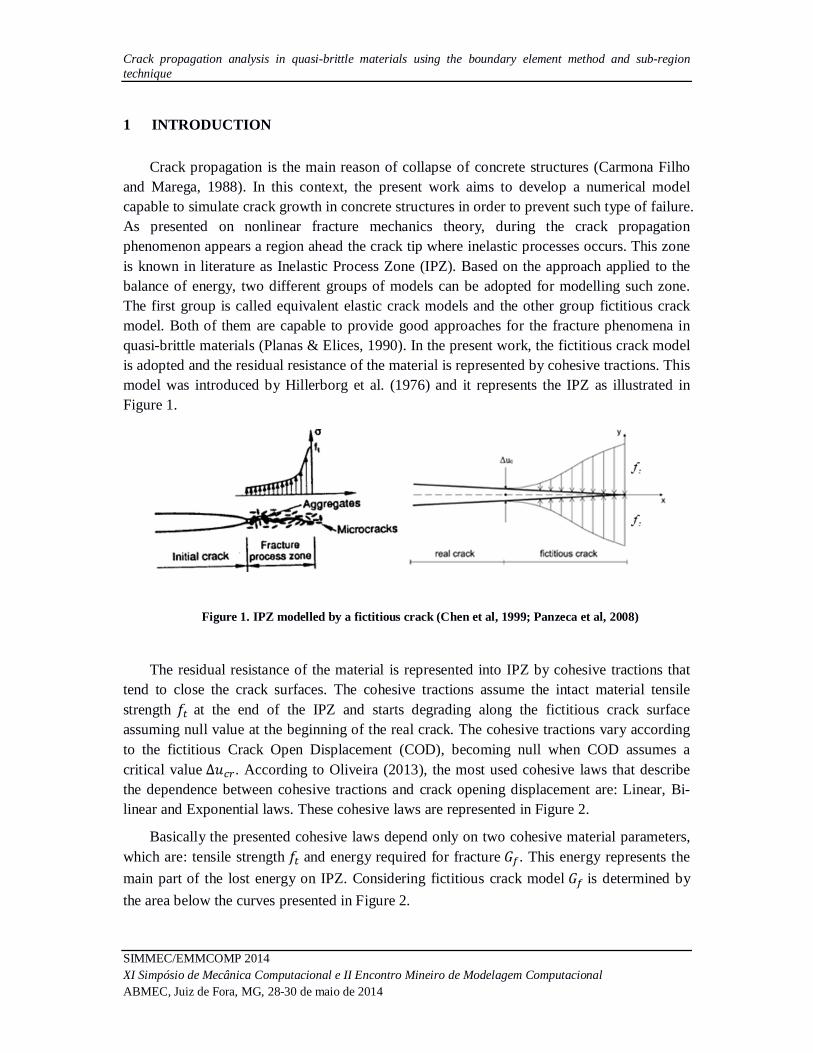
The residual resistance of the material is represented into IPZ by cohesive tractions that tend to close the crack surfaces. The cohesive tractions assume the intact material tensile strength 푓 at the end of the IPZ and starts degrading along the fictitious crack surface assuming null value at the beginning of the real crack. The cohesive tractions vary according to the fictitious Crack Open Displacement (COD), becoming null when COD assumes a critical value ∆푢 . According to Oliveira (2013), the most used cohesive laws that describe the dependence between cohesive tractions and crack opening displacement are: Linear, Bi-linear and Exponential laws. These cohesive laws are represented in Figure 2.
Basically the presented cohesive laws depend only on two cohesive material parameters, which are: tensile strength 푓 and energy required for fracture 퐺 . This energy represents the main part of the lost energy on IPZ. Considering fictitious crack model 퐺 is determined by the area below the curves presented in Figure 2.
Sergio G.F. Cordeiro, Edson D. Leonel
SIMMEC/EMMCOMP 2014 XI Simpósio de Mecânica Computacional e II Encontro Mineiro de Modelagem Computacional
ABMEC, Juiz de Fora, MG, 28-30 de maio de 2014
Figure 2. Cohesive laws.
Mechanical problems involving crack propagation are complex enough to be solved by analytical approaches. Therefore, numerical methods are required in order to determine a solution, even approximated, for these problems. Among the huge class of numerical techniques, the Boundary Element Method (BEM) is recognized as a robust and efficient numerical technique for modelling fracture mechanics problems. The mesh dimensionality reduction provided by BEM allows the remeshing procedure, as cracks grow, a simple task. Moreover, the update process of algebraic equations during crack propagation is not a hard task, as new kernels appear only on the new elements.
Several works can be found in literature relating cohesive crack modelling to BEM as presented in Chen et al, 1999; Panzeca et al, 2008; Leonel et al, 2010; Ferreira et al, 2011 and Oliveira, 2013. Considering BEM, singular and hyper singular integral equations can be applied to solve fracture problems. These equations were used in this work and are represented below with no body forces.
푐 (푠)푢 (푠) + ∫ 푝 ∗(푠,푓)푢 (푓)푑훤 = ∫ 푢 ∗(푠, 푓)푝 (푓)푑훤 (1)
푐 (푠)푝 (푠) + ∫ 푆 (푠, 푓)푢 (푓)푑훤 = ∫ 퐷 (푠,푓)푝 (푓)푑훤 (2)
where:
푆: Source point;
푓: Field point;
푢 (푓/푠): Displacements at the field/source boundary points;
푝 (푓/푠): Tractions at the field/source boundary points;
푢 ∗(푠,푓),푝 ∗(푠, 푓): Fundamental solutions of displacements and tractions;
푆 (푠, 푓),퐷 (푠, 푓): Fundamental solutions derivatives with respect to the 푘 direction.

Crack propagation analysis in quasi-brittle materials using the boundary element method and sub-region technique
SIMMEC/EMMCOMP 2014 XI Simpósio de Mecânica Computacional e II Encontro Mineiro de Modelagem Computacional ABMEC, Juiz de Fora, MG, 28-30 de maio de 2014
Equations 1 and/or 2 have to be evaluated along the body’s boundaries. After applying shape functions in order to approximate displacements and tractions, the kernels presented in these equations allow the algebraic representation of the problem. The integration of kernels 푝 ∗(푠,푓) and 푆 (푠,푓) allow obtain H matrix whereas the integration of 푢 ∗(푠,푓) and 퐷 (푠,푓) G matrix, (Brebbia & Dominguez, 1989). The system of algebraic equations involves known and unknown values on the body’s boundaries and can be represented as follows:
[퐻]{푈} = [퐺]{푃} (3)
Considering that Neumann and Dirichlet conditions are applied into boundary collocation points, the final system of equations is obtained by storing all unknown boundary values into a vector 푥 positioned at the left hand side of Eq.(4).
[퐴]{푥} = [퐵]{푓} (4)
The kernels presented in Eq.(1) and Eq.(2) are evaluated using numerical integration
approach. Since these kernels contain singular functions, the integrations at the elements containing the singularity are carried out with the singularity subtraction method (Kzam, 2009). Once the BEM hypersingular formulation is not defined for continuous elements, the performed analysis involving this integral equation require only discontinuous elements.
In this paper Eq. (1) and Eq.(2) are applied to analysis of crack propagation in quasi-brittle materials. The cracks are modelled using the fictitious crack model, which is widely used in the domain of fracture mechanics. This approach leads to a nonlinear problem, which is solved using a Newton-Raphson method. The cracks are numerically represented by BEM by the sub-region technique. This approach enforces equilibrium of forces and compatibility of displacements along interfaces. When the normal traction along the interface is bigger than the tensile resistance of the material, crack growth is assumed to occur. Its mechanical behaviour is governed by the cohesive laws already presented. The implemented formulation is applied to analysis of two fracture problems. The results obtained by the numerical model are compared with analytical responses in order to prove the robustness and accuracy of this model.
2 BEM FORMULATION FOR NONHOMOGENEOUS DOMAINS
In order to simulate the mechanical behaviour of nonhomogeneous media the sub-region BEM technique, first introduced by Rizzo and Shippy (1968), can be applied. This technique is widely known in literature as presented by (Péres-Gavilán & Aliabadi, 2001; Gao et al, 2007 and Zito et al, 2011). In this approach, the nonhomogeneous system is divided into a
Sergio G.F. Cordeiro, Edson D. Leonel
SIMMEC/EMMCOMP 2014 XI Simpósio de Mecânica Computacional e II Encontro Mineiro de Modelagem Computacional
ABMEC, Juiz de Fora, MG, 28-30 de maio de 2014
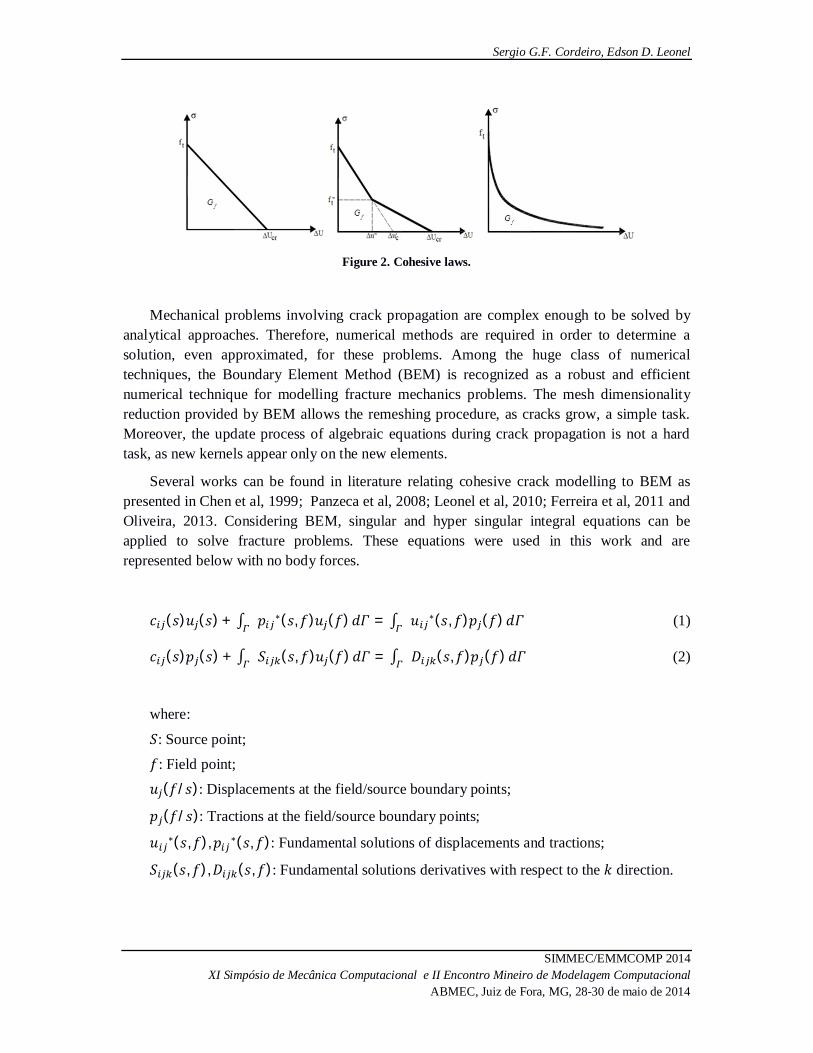
finite amount of homogeneous sub-regions interconnected by interfaces. Figure 3 illustrates a simple case of this situation in which a system was divided into two sub-regions.
Figure 3. Multi regions BEM applied for non-homogeneous domains (Chen et al, 1999).
As previously presented, analyses involving singular and hyper-singular integral representations are performed using Eq.(1) and Eq.(2). When multi domains are analysed, these equations have to be applied at each sub-domain individually. Then, the classical BEM system of algebraic equations can be obtained for each sub-region 푖 of the nonhomogeneous domain as follows:
[퐻 ]{푢 } = [퐺 ]{푝 } (3)
As the kernels [퐻 ] and [퐺 ] are evaluated, different strategies can be performed in solving the nonhomogeneous Boundary Value Problem. The first step concerns the assembling of matrixes of each sub-region 푖 into a global system of equations, as presented in Eq. (4).
퐻 00 퐻
⋯ 0⋯ 0
⋮ ⋮0 0
⋱ ⋮⋯ 퐻
푢푢⋮푢
=
퐺 00 퐺
⋯ 0⋯ 0
⋮ ⋮0 0
⋱ ⋮⋯ 퐺
푝푝⋮푝
(4)
Where 푛 represents the number of the sub-region used for the nonhomogeneous media discretization.
This global system cannot be solved directly just by imposing the boundary conditions of the problem because at the interface neither tractions nor displacements values are known. Therefore it is necessary to enforce the compatibility of displacements and equilibrium of forces along all interfaces. These conditions can be written as follows:

Crack propagation analysis in quasi-brittle materials using the boundary element method and sub-region technique
SIMMEC/EMMCOMP 2014 XI Simpósio de Mecânica Computacional e II Encontro Mineiro de Modelagem Computacional ABMEC, Juiz de Fora, MG, 28-30 de maio de 2014
푢 = 푢
푝 = −푝 (5)
The compatibilities conditions coupled to the boundary conditions can be imposed on the
global system of equations. By performing a convenient change on the columns of matrices H and G, known variables are placed at the right hand side of this system whereas unknown variables are placed at left hand side. This system can be presented as follows:
[A]{푥} = [B] 푓̅ (6)
Once 푓̅ is the vector of know boundary values, the system can be solved and the unknowns determined. In order to consider the nonlinear analysis of cohesive crack propagation at interfaces, a finite amount of elastic problems must be solved iteratively following the Newton-Raphson approach. At each iteration, the boundary and compatibility conditions of the problem may change. In order to deal these changes, a double storage strategy was adopted. The kernels of the global system presented in Eq. (4) are built just once and it is stored until the end of analysis. Then, the final system presented in Eq. (6) is reconstructed at each iteration in order to consider all change on boundary conditions observed.
3 COUPLING THE COHESIVE CRACK MODEL AT INTERFACES
In the present work, the cohesive crack model is coupled to BEM sub-region to the simulation of crack growth in quasi-brittle materials. Considering elastic analyses, the compatibility conditions are enforced for displacements and tractions along all interfaces in order to solve the problem. Therefore, in these cases, the elastic structure response is verified independently of the interface solicitation intensity. On the other hand, in the developed formulation, the interfaces are assumed to have a tensile strength limit. Therefore, until this limit, the interfaces mechanical responses follow the Hooke law as well as the entire domain. After the stress hit this limit at some interface portion, the material starts its mechanical degradation process. The interface ends its linear elastic behaviour and starts the cohesive crack approach.
The cohesive interfaces parameters 푓 and 퐺 are required by cohesive laws to model the mechanical behaviour of interfaces. In order to perform the mechanical analysis of nonhomogeneous domains containing cohesive interfaces it is required to apply the load into increments. Therefore, using singular and/or hyper singular BEM formulation it is possible obtain the increments of displacements and tractions along body’s boundaries. The incremental analysis procedure cumulates these incremental solutions until the strength interface linear elastic limit as follows:

Sergio G.F. Cordeiro, Edson D. Leonel
SIMMEC/EMMCOMP 2014 XI Simpósio de Mecânica Computacional e II Encontro Mineiro de Modelagem Computacional
ABMEC, Juiz de Fora, MG, 28-30 de maio de 2014
푢 = 푢 + ∆푢
푝 = 푝 + ∆푝 (5)
For each cumulated increment, the normal tractions at the interface must be compared
with the tensile strength at all interface coupled nodes. Since the BEM incremental solution is written with respect to the global coordinate system, the cumulated interface traction solution must be rotated with respect to the interface normal outward vector before this evaluation. Figure 4 illustrates this rotation along interfaces.
Figure 4. Rotated interface tractions.
By proceeding the solution and the accumulation procedure, in a certain incremental step,
the rotated tractions can become superior to the limit at some coupled interface nodes. As this cohesive interface cannot support such level of stress, some corrections are required. These corrections came from the cohesive crack model which prescribes it through a sum of a finite amount of linear problems in which the non-equilibrated stresses are reapplied at the structure. In other words, the nonlinear system of equations is solved using the classical Newton-Raphson approach. In order to better describe this procedure, the Boundary Value Problem described in Figure 5 is presented, which involves a nonhomogeneous domain divided by a cohesive interface.
Figure 5. Nonhomogeneous Boundary Value Problem.

Crack propagation analysis in quasi-brittle materials using the boundary element method and sub-region technique
SIMMEC/EMMCOMP 2014 XI Simpósio de Mecânica Computacional e II Encontro Mineiro de Modelagem Computacional ABMEC, Juiz de Fora, MG, 28-30 de maio de 2014
For the presented problem, in the incremental step in which the linear limit is exceeded, the hypothetical stress distribution at the interface without considering the cohesive corrections is presented in Figure 6. The distribution considers the accumulated solution and the stress exceeding can be observed at the most inferior region of the interface.
Figure 6. Hypothetical stress distribution without cohesive corrections.
Since the interface is not capable to deal such stress distribution, the stress field on the solid must find a new equilibrated distribution. In order to achieve this new distribution state, the cohesive corrections should be also accumulated during the solution. The first cohesive correction can be achieved reapplying the non-equilibrated stresses in the structure by splitting the sub-regions. Therefore, the COD at the fictitious crack are obtained and the mechanical degradation process of the corresponding interface is proceeded. For the achievement of the new equilibrated condition it is still necessary to consider that, at the fictitious crack or degraded interface part, the tensile strength is not the initial 푓 . Then, the updated tensile resistance has to be considered and another non-equilibrated stresses that must be reapplied on the structure improving the COD at the fictitious crack and, consequently, improving the mechanical degradation. The iterative cohesive process continues until the non-equilibrated stresses become small enough to be considered as negligible according to a stop criterion. Figure 7 illustrates this iterative procedure that accounts the corrections on the stress distribution.
It is important to mention that the reapplication of exceeding stresses on the correction problems considers that mechanical degradated interface nodes must be disconnected and then the Neumann conditions are prescribed. With respect to the interface strength degradation, the three cohesive laws previously presented are adopted for performing such process. After finishing the cohesive corrections, a new load increment can be proceeded. Again, the cohesive corrections are necessary. It’s also important to mention that when the residual strength of an interface portion gets over the real crack grows. Then, considering a given load increment in which a portion of the interface are totally degradatd, the interface can be divided in three parts: S, CZ and CC as illustrated in Figure 8. The three interface regions are S: Non-degradated material (Connected interface), CZ: Cohesive zone (Fictitious crack) and CC: Cracked material (real crack).

Sergio G.F. Cordeiro, Edson D. Leonel
SIMMEC/EMMCOMP 2014 XI Simpósio de Mecânica Computacional e II Encontro Mineiro de Modelagem Computacional
ABMEC, Juiz de Fora, MG, 28-30 de maio de 2014
Figure 7. Iterative cohesive corrections.
Figure 8. Cohesive interface division (Chen et al., 1999 - Adopted).
Besides the previous discussions, one geometric interpretation of the cohesive crack model is presented in figure 9 considering linear cohesive law and constant operator for the iterative procedure.
Figure 9. Geometric interpretation of the cohesive crack model (Oliveira, 2013).

Crack propagation analysis in quasi-brittle materials using the boundary element method and sub-region technique
SIMMEC/EMMCOMP 2014 XI Simpósio de Mecânica Computacional e II Encontro Mineiro de Modelagem Computacional ABMEC, Juiz de Fora, MG, 28-30 de maio de 2014
According to this figure, when the elastic stress gets superior to the interface strength limit 푓 (Point A) the stress exceeding, ∆휎( ) , is reapplied in the structure in the sense of spiting the material (straight BC). Then, with the first fictitious COD,∆푤 , the material degradation can proceed (straight CD) and the next stress exceeding, ∆휎( ), are computed and reapplied into the structure. The iterative procedure goes on until the stress exceeding became small enough to be neglected according to a stop criterion. The last issue still relevant about the develop formulation concerns the stopping criterion for the iterative process. The criterion adopted evaluates the sum of the stress exceeding squares in the set of 푛 degradated interface nodes at a given cohesive iteration as shown the following equation:
∆푃 = ∆푃 + ∆푃 + ⋯+ ∆푃 (6)
The ∆푃 square root is proceeded and compared with a given tolerance adopted as an input data for the analysis. The criterion can be that announced as:
If ∆푃 > 푇표푙푒푟푎푛푐푒: Reapply stress excess in the structure.
If ∆푃 < 푇표푙푒푟푎푛푐푒: End of iterative process.
4 APPLICATIONS
In this topic some applications using the developed nonlinear BEM formulation are presented. The problems considered were analysed using singular and hyper-singular integral representations of BEM. Moreover, three cohesive laws were adopted to describe the interface behaviour after the elastic limit. Two dimensional analyses were performed numerically considering plane stress state and a null Poisson’s ratio. Therefore, the numerical results could be compared with one-dimensional analytical solution.
4.1 Homogeneous tensiled plate discretized into two sub regions
The first example deals a homogeneous tensiled domain with one cohesive interface which separates the domain into two sub-regions. Displacements in x direction were prescribed in both vertical external boundaries of the domain. The analyses were performed considering that the interface has an initial strength 푓 = 3푀푃푎 and the energy required to fracture is 퐺 = 15퐾푁/푚. Figure 10 illustrates the problem analysed with its geometry and boundary conditions.
The cohesive analyses were performed using 25 load steps. The adopted tolerance to convergence was 10 퐾푃푎. In order to solve the problem, the domain was modelled using two sub-regions, which were discretised with four linear discontinuous boundary elements. The three cohesive laws were considered for the degradation of the interface tensile strength and both singular and hypersingular BEM formulation were applied

Sergio G.F. Cordeiro, Edson D. Leonel
SIMMEC/EMMCOMP 2014 XI Simpósio de Mecânica Computacional e II Encontro Mineiro de Modelagem Computacional
ABMEC, Juiz de Fora, MG, 28-30 de maio de 2014
Figure 10. Homogeneous tensile plate discretized in two sub regions.
The graphic illustrated in Figure 11 presents the incremental stress results at the interface
considering the three cohesive law behaviours. Moreover, the numerical results were compared against the analytical responses.
Figure 11. Interface stress answers for each BEM formulations.
According to this graphics, it can be observed good agreement among numerical and
analytical solutions considered.
4.2 Homogeneous tensiled plate model with four sub-regions
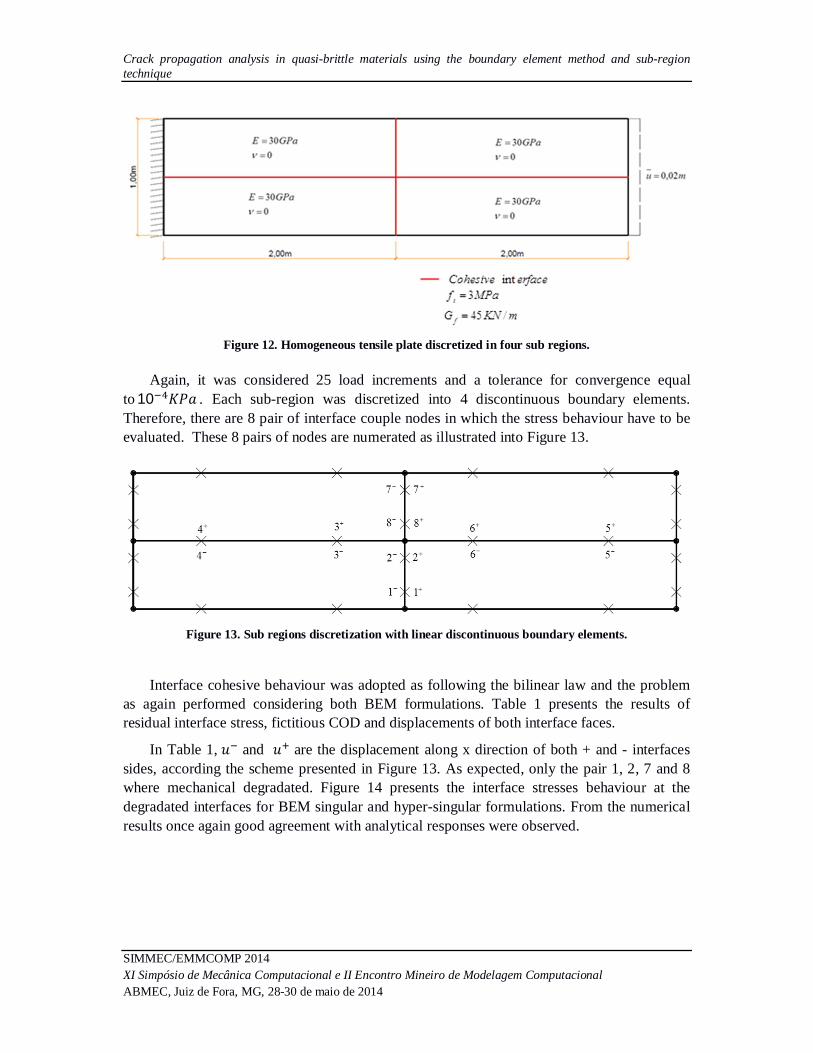
A second example was performed considering the same geometry, elastic parameters and boundary conditions of the previous one. The discretisation considers four sub-regions which divide the analysis into four interfaces. Figure 12 illustrates the problem presenting also the cohesive interface parameters.
Crack propagation analysis in quasi-brittle materials using the boundary element method and sub-region technique
SIMMEC/EMMCOMP 2014 XI Simpósio de Mecânica Computacional e II Encontro Mineiro de Modelagem Computacional ABMEC, Juiz de Fora, MG, 28-30 de maio de 2014
Figure 12. Homogeneous tensile plate discretized in four sub regions.
Again, it was considered 25 load increments and a tolerance for convergence equal
to 10 퐾푃푎 . Each sub-region was discretized into 4 discontinuous boundary elements. Therefore, there are 8 pair of interface couple nodes in which the stress behaviour have to be evaluated. These 8 pairs of nodes are numerated as illustrated into Figure 13.
Figure 13. Sub regions discretization with linear discontinuous boundary elements.
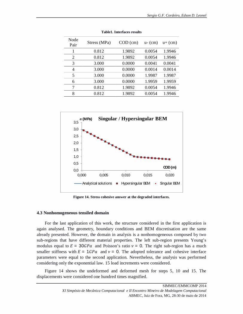
Interface cohesive behaviour was adopted as following the bilinear law and the problem as again performed considering both BEM formulations. Table 1 presents the results of residual interface stress, fictitious COD and displacements of both interface faces.
In Table 1, 푢 and 푢 are the displacement along x direction of both + and - interfaces sides, according the scheme presented in Figure 13. As expected, only the pair 1, 2, 7 and 8 where mechanical degradated. Figure 14 presents the interface stresses behaviour at the degradated interfaces for BEM singular and hyper-singular formulations. From the numerical results once again good agreement with analytical responses were observed.
Sergio G.F. Cordeiro, Edson D. Leonel
SIMMEC/EMMCOMP 2014 XI Simpósio de Mecânica Computacional e II Encontro Mineiro de Modelagem Computacional
ABMEC, Juiz de Fora, MG, 28-30 de maio de 2014
Table1. Interfaces results
Node Pair Stress (MPa) COD (cm) u- (cm) u+ (cm)
1 0.812 1.9892 0.0054 1.9946 2 0.812 1.9892 0.0054 1.9946 3 3.000 0.0000 0.0041 0.0041 4 3.000 0.0000 0.0014 0.0014 5 3.000 0.0000 1.9987 1.9987 6 3.000 0.0000 1.9959 1.9959 7 0.812 1.9892 0.0054 1.9946 8 0.812 1.9892 0.0054 1.9946
Figure 14. Stress cohesive answer at the degraded interfaces.
4.3 Nonhomogeneous tensiled domain
For the last application of this work, the structure considered in the first application is again analysed. The geometry, boundary conditions and BEM discretisation are the same already presented. However, the domain in analysis is a nonhomogeneous composed by two sub-regions that have different material properties. The left sub-region presents Young’s modulus equal to 퐸 = 30퐺푃푎 and Poisson’s ratio 휈 = 0. The right sub-region has a much smaller stiffness with 퐸 = 1퐺푃푎 and 휈 = 0. The adopted tolerance and cohesive interface parameters were equal to the second application. Nevertheless, the analysis was performed considering only the exponential law. 15 load increments were considered.
Figure 14 shows the undeformed and deformed mesh for steps 5, 10 and 15. The displacements were considered one hundred times magnified.
0,0
0,5
1,0
1,5
2,0
2,5
3,0
3,5
0,000 0,005 0,010 0,015 0,020
σ (MPa)
COD (m)
Singular / Hypersingular BEM
Analytical solutions Hypersingular BEM Singular BEM

Crack propagation analysis in quasi-brittle materials using the boundary element method and sub-region technique
SIMMEC/EMMCOMP 2014 XI Simpósio de Mecânica Computacional e II Encontro Mineiro de Modelagem Computacional ABMEC, Juiz de Fora, MG, 28-30 de maio de 2014
Figure 14. Deformed mesh evolution.
Based on the results presented in Figure 14, it is possible to observe the higher flexibility of the right sub-region. However, at the final load step, both sub-regions tend to get back to the original undeformed shape. It happens because the interface strength is almost totally degradated. Therefore, the cohesive interactions are not strong enough anymore to keep both sub-regions coupled. The interface cohesive behaviour is presented in Figure 15 together with the analytical solution.
Figure 15. Interface cohesive stress behaviour.
Again, good results were obtained by the nonlinear BEM formulation implemented. Finally it is worth to mention that the cohesive curve behaviour does not depend on the sub-regions elastic parameters. This behaviour only depends on the interface cohesive parameters 푓 and 퐺 .
0,0
0,5
1,0
1,5
2,0
2,5
3,0
3,5
0,000 0,005 0,010 0,015 0,020
σ (MPa)
COD (m)
Singular / Hypersingular
Analytical solution Singular BEM Hypersingular BEM

Sergio G.F. Cordeiro, Edson D. Leonel
SIMMEC/EMMCOMP 2014 XI Simpósio de Mecânica Computacional e II Encontro Mineiro de Modelagem Computacional
ABMEC, Juiz de Fora, MG, 28-30 de maio de 2014
5 CONCLUSIONS
This work addressed the analysis of crack growth in quasi-brittle materials using BEM. A short review on nonlinear fracture mechanics is presented as well as cohesive laws. In addition to that, the fictitious crack model, presented in fracture mechanics theory, is coupled to BEM algebraic equations. The bodies analysed are represented using the sub-region technique. The cracks are assumed to growth along the interfaces of the analysed domains. Therefore, the implemented formulation allows the analysis of crack growth in nonhomogeneous domains.
Two applications are considered in this work and the numerical responses achieved by BEM are compared against analytical solutions available in literature. According to the presented applications, the developed BEM formulation was capable to represent the interface nonlinear stress behaviour, which is simulated using cohesive approach. Assuming analytical solutions as reference, both BEM integral representations provided accurate results for the three cohesive laws considered. Therefore, homogeneous and nonhomogeneous media can be consistently analysed by the implemented numerical model.
Acknowledgements
Sponsorship of this research project by the CAPES is greatly appreciated. This research is a part of the activities scheduled by the research project IRSES PIRSES-GA-2009-246977.
REFERENCES
Brebbia, C. A., & Dominguez, J., 1989. Boundary Elements: An introductory Course. McGraw Hill.
Carmona Filho, A., & Maregá, A., 1988. Retrospectiva da Patologia no Brasil: Estudo Estatístico. Jornadas em Espanol y Portugues sobre Estructuras y Materiales, vol. 88, pp. 100–123.
Chen, T., Wang, B., Cen, Z., & Wu, Z., 1999. A symmetric Galerkin multi-zone boundary element method for cohesive crack growth. Engineering Fracture Mechanics, vol. 63, pp. 591–609.
Ferreira, M. D. C., Venturini, W. S., & Hild, F., 2011. On the analysis of notched concrete beams: From measurement with digital image correlation to identification with Boundary Element Method of a cohesive model. Engineering Fracture Mechanics, vol. 78, pp. 71–84.
Gao, X-W., Guo, L., & Zhang, C., 2007. Three steps multi-domain BEM solver for nonhomogeneous material problems. Engineering Analysis with Boundary Elements, vol. 31, pp. 965–973.

Crack propagation analysis in quasi-brittle materials using the boundary element method and sub-region technique
SIMMEC/EMMCOMP 2014 XI Simpósio de Mecânica Computacional e II Encontro Mineiro de Modelagem Computacional ABMEC, Juiz de Fora, MG, 28-30 de maio de 2014
Hillerborg, A., Modeer, M., & Petersson, P-E., 1976. Analysis of crack formation and crack growth in concrete by means of fracture mechanics and finite elements. Cement and Concrete Research, vol. 6, pp. 773–782.
Kzam, A. K. L., 2009. Formulação Dual em Mecânica da Fratura Utilizando Elementos de Contornos Curvos de Ordem. Masters dissertation, São Paulo University/São Carlos.
Leonel, E. D., & Venturini, W. S., 2010. Dual Boundary Element formulation applied to analysis of multi-fractured domains. Engineering Analysis with Boundary Elements, vol. 34, pp. 1092–1099.
Oliveira, H. L., 2013. Uma formulação alternative do Método dos Elementos de Contorno aplicada à análise da propagação de fissuras em materiais quase frágeis. Masters dissertation, São Paulo University/São Carlos.
Panzeca, T., Zito, l., & Terravecchia, S., 2008. Internal spring distribution for quasi-brittle fracture via Symmetric Boundary Element Method. European Journal of Mechanics A/Solids, vol. 28, pp. 354–367.
Péres-Gavilán, J. J., & Aliabadi, M H., 2001. A symmetric Galerkin BEM for multi-connected bodies: A new approach. Engineering Analysis with Boundary Elements, vol. 25, pp. 633–638.
Planas, J., & Elices, M., 1990. Fracture Criteria for concrete: Methematical approaximations and experimental validation. Engineering Fracture Mechanics, V. 35ornadas em Espanol y Portugues sobre Estructuras y Materiales, vol. 35, n. 1,2,3.
Rizzo, F. J., & Shippy, D. F., 1968. A formulation and solution procedure for the general non-homogeneous elastic inclusion problem. In International Journal of Solids and Structures, vol. 25, n. 1, pp. 1161-1179.
Zito, l., Panzeca, T., & Terravecchia, S., 2011. Displacement approach with external variables only for multi-domain analysis via symmetric BEM. European Journal of Mechanics A/Solids, vol. 30, pp. 82–94.


![A hybrid XFEM - Phase Field (Xfield) method for crack ... · A hybrid XFEM - Phase Field (Xfield) method for crack propagation in brittle materials BIANCA GIOVANARDI], ANNA SCOTTI](https://static.fdocuments.in/doc/165x107/5ade1d027f8b9a595f8db44e/a-hybrid-xfem-phase-field-xfield-method-for-crack-hybrid-xfem-phase-field.jpg)