CPX-E-CEC-PN DESC C 2017-06 8071205g1 - festo.com · 2 Function 6 Festo – GDCC-CPX-E-CEC-PN-EN...
26
CPX-E-System CPX-E-CEC-...-PN Description Function Commissioning Parameterisation 8071203 2017-06 [8071205]
-
Upload
nguyendang -
Category
Documents
-
view
222 -
download
0
Transcript of CPX-E-CEC-PN DESC C 2017-06 8071205g1 - festo.com · 2 Function 6 Festo – GDCC-CPX-E-CEC-PN-EN...

CPX-E-System
CPX-E-CEC-...-PN
Description
Function
Commissioning
Parameterisation
8071203
2017-06
[8071205]

CPX-E-CEC-...-PN
2 Festo – GDCC-CPX-E-CEC-PN-EN – 2017-06 –
Original instructions
GDCC-CPX-E-CEC-PN-E N
PI PROFIBUS PROFINET®, Modbus®, EtherCAT®, Windows®, CODESYS®, SoftMotion® are registered trademarks of
the respective trademark owners in certain countries.
Symbols used:
Note
Material damage or loss of function
Recommendations, tips, references to other documentation
CPX-E-CEC-...-PN
Festo – GDCC-CPX-E-CEC-PN-EN – 2017-06 – English 3
Table of Contents – CPX-E-CEC-...-PN
1 About this document 4. . . . . . . . . . . . . . . . . . . . . . . . . . . . . . . . . . . . . . . . . . . . . . . . . . . . . . . . . . . . . . . . . . . . .
1.1 Further applicable documents 4. . . . . . . . . . . . . . . . . . . . . . . . . . . . . . . . . . . . . . . . . . . . . . . . . . . . . . . . . . . . . .
1.2 Target group 4. . . . . . . . . . . . . . . . . . . . . . . . . . . . . . . . . . . . . . . . . . . . . . . . . . . . . . . . . . . . . . . . . . . . . . . . . . . .
1.3 Product version 4. . . . . . . . . . . . . . . . . . . . . . . . . . . . . . . . . . . . . . . . . . . . . . . . . . . . . . . . . . . . . . . . . . . . . . . . .
1.4 Product labelling 5. . . . . . . . . . . . . . . . . . . . . . . . . . . . . . . . . . . . . . . . . . . . . . . . . . . . . . . . . . . . . . . . . . . . . . . .
1.5 Specified standards 5. . . . . . . . . . . . . . . . . . . . . . . . . . . . . . . . . . . . . . . . . . . . . . . . . . . . . . . . . . . . . . . . . . . . . .
2 Function 6. . . . . . . . . . . . . . . . . . . . . . . . . . . . . . . . . . . . . . . . . . . . . . . . . . . . . . . . . . . . . . . . . . . . . . . . . . . . . . .
2.1 General remarks 6. . . . . . . . . . . . . . . . . . . . . . . . . . . . . . . . . . . . . . . . . . . . . . . . . . . . . . . . . . . . . . . . . . . . . . . . .
2.1.1 Crossover detection (auto MDI/MDI-X) 6. . . . . . . . . . . . . . . . . . . . . . . . . . . . . . . . . . . . . . . . . . . . . . . .
2.2 PROFINET IO 6. . . . . . . . . . . . . . . . . . . . . . . . . . . . . . . . . . . . . . . . . . . . . . . . . . . . . . . . . . . . . . . . . . . . . . . . . . . .
2.2.1 Device description file 6. . . . . . . . . . . . . . . . . . . . . . . . . . . . . . . . . . . . . . . . . . . . . . . . . . . . . . . . . . . . .
2.2.2 Identification & maintenance (I&M) 6. . . . . . . . . . . . . . . . . . . . . . . . . . . . . . . . . . . . . . . . . . . . . . . . . . .
2.3 Internal address assignment 7. . . . . . . . . . . . . . . . . . . . . . . . . . . . . . . . . . . . . . . . . . . . . . . . . . . . . . . . . . . . . . .
2.4 Product overview 7. . . . . . . . . . . . . . . . . . . . . . . . . . . . . . . . . . . . . . . . . . . . . . . . . . . . . . . . . . . . . . . . . . . . . . . .
2.4.1 Product design 7. . . . . . . . . . . . . . . . . . . . . . . . . . . . . . . . . . . . . . . . . . . . . . . . . . . . . . . . . . . . . . . . . . .
2.5 LED display components 8. . . . . . . . . . . . . . . . . . . . . . . . . . . . . . . . . . . . . . . . . . . . . . . . . . . . . . . . . . . . . . . . . .
2.6 Control components 8. . . . . . . . . . . . . . . . . . . . . . . . . . . . . . . . . . . . . . . . . . . . . . . . . . . . . . . . . . . . . . . . . . . . . .
2.6.1 Run/stop switch 8. . . . . . . . . . . . . . . . . . . . . . . . . . . . . . . . . . . . . . . . . . . . . . . . . . . . . . . . . . . . . . . . . .
2.7 Connecting components 9. . . . . . . . . . . . . . . . . . . . . . . . . . . . . . . . . . . . . . . . . . . . . . . . . . . . . . . . . . . . . . . . . .
2.7.1 Power supply 9. . . . . . . . . . . . . . . . . . . . . . . . . . . . . . . . . . . . . . . . . . . . . . . . . . . . . . . . . . . . . . . . . . . . .
2.7.2 Network connections 9. . . . . . . . . . . . . . . . . . . . . . . . . . . . . . . . . . . . . . . . . . . . . . . . . . . . . . . . . . . . . .
2.7.3 Memory card slot [Card] 10. . . . . . . . . . . . . . . . . . . . . . . . . . . . . . . . . . . . . . . . . . . . . . . . . . . . . . . . . . . .
2.7.4 USB interface [USB] 10. . . . . . . . . . . . . . . . . . . . . . . . . . . . . . . . . . . . . . . . . . . . . . . . . . . . . . . . . . . . . . .
2.8 Additional functions 11. . . . . . . . . . . . . . . . . . . . . . . . . . . . . . . . . . . . . . . . . . . . . . . . . . . . . . . . . . . . . . . . . . . . . .
2.8.1 FTP server 11. . . . . . . . . . . . . . . . . . . . . . . . . . . . . . . . . . . . . . . . . . . . . . . . . . . . . . . . . . . . . . . . . . . . . . .
2.8.2 Web server 11. . . . . . . . . . . . . . . . . . . . . . . . . . . . . . . . . . . . . . . . . . . . . . . . . . . . . . . . . . . . . . . . . . . . . .
2.8.3 Temperature sensor 11. . . . . . . . . . . . . . . . . . . . . . . . . . . . . . . . . . . . . . . . . . . . . . . . . . . . . . . . . . . . . . .
2.8.4 Real-time clock 11. . . . . . . . . . . . . . . . . . . . . . . . . . . . . . . . . . . . . . . . . . . . . . . . . . . . . . . . . . . . . . . . . . .
2.9 Diagnostics options 12. . . . . . . . . . . . . . . . . . . . . . . . . . . . . . . . . . . . . . . . . . . . . . . . . . . . . . . . . . . . . . . . . . . . . .
2.9.1 LED indicators 13. . . . . . . . . . . . . . . . . . . . . . . . . . . . . . . . . . . . . . . . . . . . . . . . . . . . . . . . . . . . . . . . . . . .
2.9.2 Diagnostics via EtherCAT 15. . . . . . . . . . . . . . . . . . . . . . . . . . . . . . . . . . . . . . . . . . . . . . . . . . . . . . . . . . .
2.9.3 Diagnostics via web server 19. . . . . . . . . . . . . . . . . . . . . . . . . . . . . . . . . . . . . . . . . . . . . . . . . . . . . . . . . .
3 Parameterisation 20. . . . . . . . . . . . . . . . . . . . . . . . . . . . . . . . . . . . . . . . . . . . . . . . . . . . . . . . . . . . . . . . . . . . . . . .
A Technical data 21. . . . . . . . . . . . . . . . . . . . . . . . . . . . . . . . . . . . . . . . . . . . . . . . . . . . . . . . . . . . . . . . . . . . . . . . . .
B Terminology 23. . . . . . . . . . . . . . . . . . . . . . . . . . . . . . . . . . . . . . . . . . . . . . . . . . . . . . . . . . . . . . . . . . . . . . . . . . . .
Index 24. . . . . . . . . . . . . . . . . . . . . . . . . . . . . . . . . . . . . . . . . . . . . . . . . . . . . . . . . . . . . . . . . . . . . . . . . . . . . . . . . . . . . .

1 About this document
4 Festo – GDCC-CPX-E-CEC-PN-EN – 2017-06 – English
1 About this document
This document describes the function and parameterisation of the product stated in the title. Safe use of the
product is described in a separate document � 1.1 Further applicable documents.
1.1 Further applicable documents
Document Content
Description of system CPX-E (CPX-E-SYS) Detailed description of the system CPX-E
Instructions for use of system CPX-E (CPX-E-SYS) Instructions and important notes on mounting,
electrical installation and maintenance tasks for a
system CPX-E
Instructions for use of controller CPX-E-CEC Instructions and important notes on the use and safe
usage of the product
Documentation for the components in the system CPX-E
and the connected peripherals
Information on use of the components
Online help for CoDeSys V3 Detailed information on using the product with
CoDeSys�V3 and the Festo extensions.
Tab. 1.1
For all available product documentation � www.festo.com/pk.
1.2 Target group
This document is intended for qualified specialised personnel. Experience with electrical control systems is required
in order to understand this documentation.
1.3 Product version
This document refers to the following product versions:
Product Programming Version number
CPX-E-CEC-C1-PN With CoDeSys V3 Revision 01 and above
CPX-E-CEC-M1-PN With CoDeSys V3 and SoftMotion Revision 01 and above
Tab. 1.2
The product version can be identified from the product label or with the help of appropriate software from Festo.
Appropriate software for identifying the product version can be found in the Festo Support Portal
� www.festo.com/sp.
Information on using the software can be found in the integrated Help function.
There may be an updated version of this document for these or later product versions.
� Check whether a corresponding version of this document is available � www.festo.com/sp.

1 About this document
Festo – GDCC-CPX-E-CEC-PN-EN – 2017-06 – English 5
1.4 Product labelling
The product label is located on the left-hand side of the module. Scanning the printed Data Matrix Code with an
appropriate device opens the Festo Support Portal with the relevant documents for the product. Alternatively, the
Product Key (11-character alphanumeric code on the product label) can be entered in the Support Portal search box.
1 Designation2 Part number/serial number3 Revision status4 MAC ID5 Data Matrix Code6 Product Key7 Certifications/warning symbols8 Terminal allocation
1
2
3
4
5
7
6
8
Fig. 1.1
1.5 Specified standards
Version
EN 60529:2013-10 IEC 60204-1:2014-10
EN 61000-6-2:2009-04 IEC 61158:2014-07
EN 61000-6-4:2011-09 IEC 61784:2014-08
NE 21:2012-05 IEC 61918:2013-08
Tab. 1.3
2 Function
6 Festo – GDCC-CPX-E-CEC-PN-EN – 2017-06 – English
2 Function
2.1 General remarks
The product is intended for operation as a controller in a system CPX-E and can be programmed with CoDeSys in
accordance with IEC�61131-3. Communication with a higher-order controller takes place via PROFINET IO network
with real-time protocol (RT). Modbus/TCP and standard Ethernet (TCP/IP) are also supported. Communication with
a PC takes place via one of two network connections (Ethernet), which is connected to the controller by an
integrated switch.
The integrated switch supports both star and line topology and enables the division of the network into
segments. With the use of additional switches and routers, the network can be divided into additional
segments. This makes it possible to structure the network and achieve greater network expansion.
2.1.1 Crossover detection (auto MDI/MDI-X)
The product supports crossover detection (auto MDI/MDI-X), so both patch cables and crossover cables can
optionally be used.
When using patch cables and crossover cables in the network, crossover detection must be activated
in�the higher-order controller.
2.2 PROFINET IO
2.2.1 Device description file
Configuration in the software for the higher-order PROFINET controller uses a device description file (GSDML file).
This contains all the information required to parameterise the system CPX-E via control software
(e.g.�Siemens�STEP 7).
The device description file is available on the Festo Support Portal (� www.festo.com/sp).
2.2.2 Identification & maintenance (I&M)
The “Identification & maintenance” (I&M) function serves as an electronic product label for the controller as
PROFINET IO device and offers uniform, manufacturer-independent access to device-specific information online.
2 Function
Festo – GDCC-CPX-E-CEC-PN-EN – 2017-06 – English 7
2.3 Internal address assignment
In addition to the controller CPX-E-CEC, a maximum of 10 modules is permitted in one system CPX-E. The address
space of a system CPX-E is limited. The controller provides the system CPX-E with a maximum address space of
64 bytes for inputs and 64 bytes for outputs.
The internal addresses for the inputs and outputs of the system CPX-E are assigned automatically.
Module Address assignment
CPX-E-16DI 2 byte inputs
CPX-E-8DO 1 byte outputs
CPX-E-4AI 8 byte inputs
CPX-E-4AO 8 byte outputs
CPX-E-4IOL Max. 32 byte inputs and 32 byte outputs
CPX-E-1CI 12 byte inputs and 2 byte outputs
Fig. 2.1
2.4 Product overview
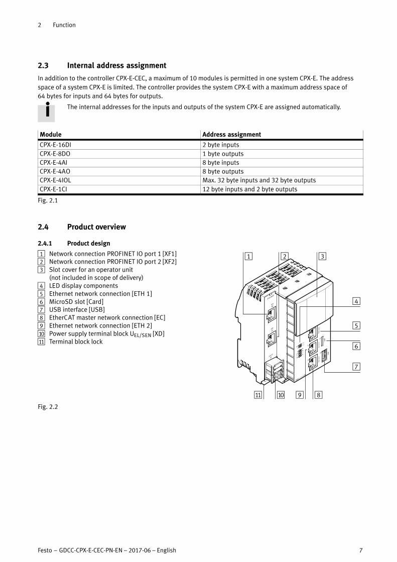
2.4.1 Product design
1 Network connection PROFINET IO port 1 [XF1]2 Network connection PROFINET IO port 2 [XF2]3 Slot cover for an operator unit
(not included in scope of delivery)4 LED display components5 Ethernet network connection [ETH�1]6 MicroSD slot [Card]7 USB interface [USB]8 EtherCAT master network connection [EC]9 Ethernet network connection [ETH�2]aJ Power supply terminal block UEL/SEN [XD]aA Terminal block lock
89aJaA
4
5
6
7
1 2 3
Fig. 2.2
2 Function
8 Festo – GDCC-CPX-E-CEC-PN-EN – 2017-06 – English
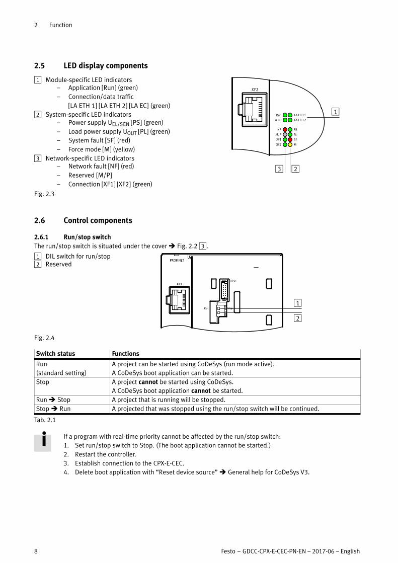
2.5 LED display components
1 Module-specific LED indicators– Application [Run] (green)
– Connection/data traffic
[LA�ETH�1] [LA�ETH�2] [LA�EC] (green)
2 System-specific LED indicators– Power supply UEL/SEN [PS] (green)
– Load power supply UOUT [PL] (green)
– System fault [SF] (red)
– Force mode [M] (yellow)
3 Network-specific LED indicators– Network fault [NF] (red)
– Reserved [M/P]
– Connection [XF1] [XF2] (green)
23
1
Fig. 2.3
2.6 Control components
2.6.1 Run/stop switch
The run/stop switch is situated under the cover � Fig. 2.2�3.
1 DIL switch for run/stop2 Reserved
1
2
Fig. 2.4
Switch status Functions
Run
(standard setting)
A project can be started using CoDeSys (run mode active).
A CoDeSys boot application can be started.
Stop A project cannot be started using CoDeSys.
A CoDeSys boot application cannot be started.
Run � Stop A project that is running will be stopped.
Stop � Run A projected that was stopped using the run/stop switch will be continued.
Tab. 2.1
If a program with real-time priority cannot be affected by the run/stop switch:
1. Set run/stop switch to Stop. (The boot application cannot be started.)
2. Restart the controller.
3. Establish connection to the CPX-E-CEC.
4. Delete boot application with “Reset device source” � General help for CoDeSys V3.

2 Function
Festo – GDCC-CPX-E-CEC-PN-EN – 2017-06 – English 9
2.7 Connecting components
2.7.1 Power supply
Port [XD]1) Signal
0 +24 V DC power supply UEL/SEN
1
2 0 V DC power supply UEL/SEN
3
1) Ports XD.0 and XD.1 and ports XD.2 and XD.3, respectively, are connected to each other in the terminal block.
Tab. 2.2
2.7.2 Network connections
The network connections are designed as RJ45 sockets.
Network connections CPX-E-CEC-...-PN function
[XF1] PROFINET IO port 1
[XF2] PROFINET IO port 2
[ETH�1] Ethernet interfaces for connecting a programming unit,
PC or operator unit CDPX[ETH�2]
[EC] EtherCAT master
Tab. 2.3
The network connections ETH1 and ETH2 are connected to the controller via a switch.
2 Function
10 Festo – GDCC-CPX-E-CEC-PN-EN – 2017-06 – English
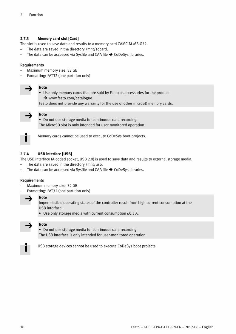
2.7.3 Memory card slot [Card]
The slot is used to save data and results to a memory card CAMC-M-MS-G32.
– The data are saved in the directory /mnt/sdcard.
– The data can be accessed via Sysfile and CAA file � CoDeSys libraries.
Requirements
– Maximum memory size: 32 GB
– Formatting: FAT32 (one partition only)
Note
� Use only memory cards that are sold by Festo as accessories for the product
� www.festo.com/catalogue.
Festo does not provide any warranty for the use of other microSD memory cards.
Note
� Do not use storage media for continuous data recording.
The MicroSD slot is only intended for user-monitored operation.
Memory cards cannot be used to execute CoDeSys boot projects.
2.7.4 USB interface [USB]
The USB interface (A-coded socket, USB 2.0) is used to save data and results to external storage media.
– The data are saved in the directory /mnt/usb.
– The data can be accessed via Sysfile and CAA file � CoDeSys libraries.
Requirements
– Maximum memory size: 32 GB
– Formatting: FAT32 (one partition only)
Note
Impermissible operating states of the controller result from high current consumption at the
USB�interface.
� Use only storage media with current consumption 0.5 A.
Note
� Do not use storage media for continuous data recording.
The USB interface is only intended for user-monitored operation.
USB storage devices cannot be used to execute CoDeSys boot projects.

2 Function
Festo – GDCC-CPX-E-CEC-PN-EN – 2017-06 – English 11
2.8 Additional functions
2.8.1 FTP server
The controller provides an FTP server.
Data can only be accessed via the directory: /mnt/ftp.
2.8.2 Web server
The integrated web server provides read access to the key parameters and diagnostic functions of the system CPX-E
� 2.9.3 Diagnostics via web server.
2.8.3 Temperature sensor
The controller has a sensor to measure the internal temperature.
Reading the current temperature:
– via CoDeSys using the function block “GetTemperature” � Festo_General_3 library
– via the web server of the controller � 2.9.3 Diagnostics via web server – menu “System” --> “Information”
2.8.4 Real-time clock
The controller has a real-time clock, which can be set or read with the aid of CoDeSys function blocks:
– for run-time of CoDeSys projects � CoDeSys library SysTimeRtc
– in online mode with the aid of the PLC shell � CoDeSys V3

2 Function
12 Festo – GDCC-CPX-E-CEC-PN-EN – 2017-06 – English
2.9 Diagnostics options
The module supports various diagnostics options, depending on the configuration and parameterisation of the
system CPX-E.
Diagnostics option Description Detailed information
LED display components
System-specific System status and errors are displayed
directly on the module via LED indicators.
� Instructions for use of system
CPX-E
� Description of system CPX-E
Module-specific Information about CoDeSys programs,
Ethernet and EtherCAT connections is
displayed directly on the module via LED
indicators.
� 2.9.1
Network-specific Status and errors in the PROFINET IO network
are displayed directly on the module via LED
indicators.
� 2.9.1
Festo Software Malfunctions or errors are displayed directly
on a PC, meaning that diagnostics is also
possible from a higher automation level.
� Online help for software
EtherCAT Diagnostics as part of the EtherCAT function
via the network.
Detailed module- and channel-related error
detection by means of control software.
� 2.9.2
Web servers Diagnostics via web server. � 2.9.3
Tab. 2.4
Further diagnostic options using CoDeSys can be found in the online help for the CPX-E-CEC.
2 Function
Festo – GDCC-CPX-E-CEC-PN-EN – 2017-06 – English 13
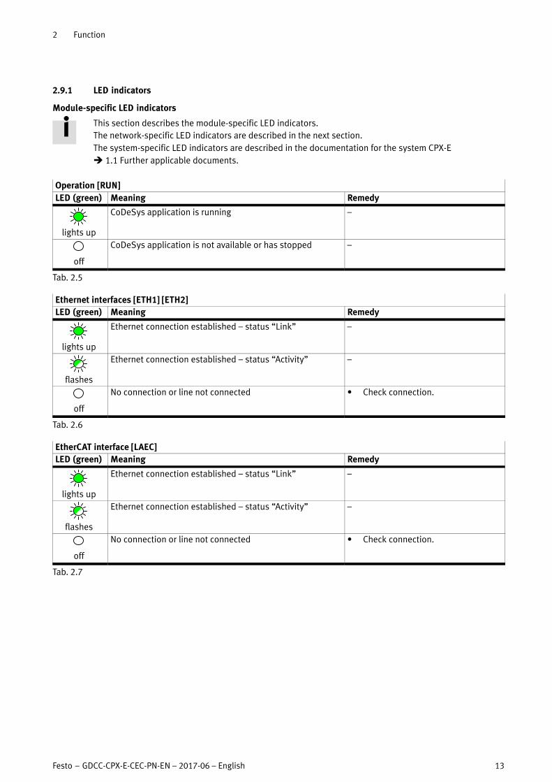
2.9.1 LED indicators
Module-specific LED indicators
This section describes the module-specific LED indicators.
The network-specific LED indicators are described in the next section.
The system-specific LED indicators are described in the documentation for the system CPX-E
� 1.1 Further applicable documents.
Operation [RUN]
LED (green) Meaning Remedy
lights up
CoDeSys application is running –
off
CoDeSys application is not available or has stopped –
Tab. 2.5
Ethernet interfaces [ETH1] [ETH2]
LED (green) Meaning Remedy
lights up
Ethernet connection established – status “Link” –
flashes
Ethernet connection established – status “Activity” –
off
No connection or line not connected � Check connection.
Tab. 2.6
EtherCAT interface [LAEC]
LED (green) Meaning Remedy
lights up
Ethernet connection established – status “Link” –
flashes
Ethernet connection established – status “Activity” –
off
No connection or line not connected � Check connection.
Tab. 2.7

2 Function
14 Festo – GDCC-CPX-E-CEC-PN-EN – 2017-06 – English
Network-specific LED indicators
This section describes the network-specific LED indicators for PROFINET IO.
The module-specific LED indicators are described in the previous section.
The system-specific LED indicators are described in the documentation for the system CPX-E
� 1.1 Further applicable documents.
Network fault [NF]
LED (red) Meaning Remedy
flashes
Network connection not OK
Possible causes:
Device name not correct � Check device name.
No connection to master � Switch on master.
Incorrect configuration � Correct MAC addresses for fieldbus
interface.
PROFINET IO controller defective � Repair controller.
Network connection interrupted,
short-circuited or disturbed
� Check network connection.
off
Network connection to PROFINET IO controller
active, no network error
–
Tab. 2.8
Connection status [XF1], [XF2]
LED (green) Meaning Remedy
lights up
PROFINET IO connection established –
status�“Link”
–
flashes
Locating module when both LEDs are flashing
at the same intervals e.g. for error finding or
during configuration.
–
off
No connection to the respective port or line
not connected
� Check network connection.
Tab. 2.9

2 Function
Festo – GDCC-CPX-E-CEC-PN-EN – 2017-06 – English 15
2.9.2 Diagnostics via EtherCAT
The availability of diagnostic information via the EtherCAT network depends on the settings of the
connected EtherCAT devices.
Diagnostics via SDO access
Diagnostic information can be requested from lower-order EtherCAT devices using SDO access.
Diagnostics via diagnostics history
The most recent diagnostic messages from lower-order EtherCAT devices can be displayed via the diagnostics
object�0x10F3. An error message referenced with a code is displayed for every event (warning, error, information).
A�bus node CPX-FB37, for example, provides 20 diagnostic messages.
The diagnostic messages are converted via the ESI file and can then be evaluated by the CoDeSys application.
Structure of diagnostics object 0x10F3
Index (hex) Sub-index Description Data type Values Access1)
0x10F3 0 Diagnostics history U8 RO
1 Maximum messages U8 20 RO
2 Newest message U8 RO
3 Newest acknowledged message U8 RW
4 New message available BOOL RO P
5 Flags U16 0x0000 RW
6 … 70 Sub-index 006 … 070 BYTE [23] RO
1) RO = read only; RW = read/write; RO P = read only (PDO mappable)
Tab. 2.10
The diagnostic messages for the lower-order EtherCAT device are stored in the diagnostics history.
02 00 00 E1 02 02 02 37 1F C5 9D 61 31 00 00 00 05 00 02 05 00 80
1 2 3 4 5 6 7 8
Sample diagnostic message:
The individual values of the diagnostic message are explained below.
Values of diagnostic message
Name1) Value from example (hex) Explanation
1 Diag Code 02 00 00 E1 CPX-E error number (2 = short circuit)2)
E1 = CPX-E error number
E8 = Error code to DS401
2 Flags 02 02 Number of parameters in the diagnostic message (2)
and diagnostics type 2 (error message)
3 Text-ID 02 37 Reference to ESI file with the clear text of the
diagnostic message (<TextId>#x3702)
4 Time Stamp 1F C5 9D 61 31 00 00 00 Local timestamp
(time since controller start)
5 Flags Parameter 1 05 00 Type of parameter 1 (UNSIGNED8)
6 Parameter 1 02 CPX module number
7 Flags Parameter 2 05 00 Type of parameter 2 (UNSIGNED8)
8 Parameter 2 80 Channel 80h (channel 128d)
1) To ETG.1020
2) See “Description of system CPX-E”
Tab. 2.11
Text-IDs 3700h ... 37FFh correspond to CPX error numbers (0 ... 255). You can find more information in the
“Description of system CPX-E” � 1.1 Further applicable documents.
2 Function
16 Festo – GDCC-CPX-E-CEC-PN-EN – 2017-06 – English
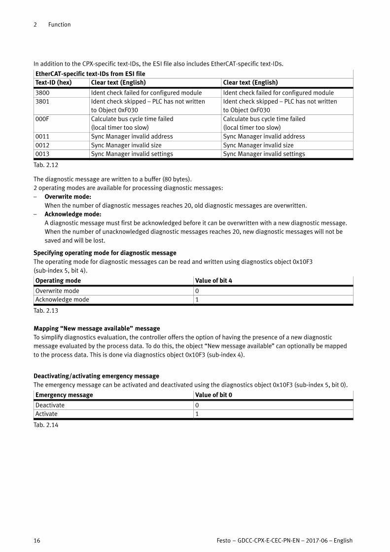
In addition to the CPX-specific text-IDs, the ESI file also includes EtherCAT-specific text-IDs.
EtherCAT-specific text-IDs from ESI file
Text-ID (hex) Clear text (English) Clear text (English)
3800 Ident check failed for configured module Ident check failed for configured module
3801 Ident check skipped – PLC has not written
to�Object 0xF030
Ident check skipped – PLC has not written
to�Object 0xF030
000F Calculate bus cycle time failed
(local timer too slow)
Calculate bus cycle time failed
(local timer too slow)
0011 Sync Manager invalid address Sync Manager invalid address
0012 Sync Manager invalid size Sync Manager invalid size
0013 Sync Manager invalid settings Sync Manager invalid settings
Tab. 2.12
The diagnostic message are written to a buffer (80 bytes).
2 operating modes are available for processing diagnostic messages:
– Overwrite mode:
When the number of diagnostic messages reaches 20, old diagnostic messages are overwritten.
– Acknowledge mode:
A diagnostic message must first be acknowledged before it can be overwritten with a new diagnostic message.
When the number of unacknowledged diagnostic messages reaches 20, new diagnostic messages will not be
saved and will be lost.
Specifying operating mode for diagnostic message
The operating mode for diagnostic messages can be read and written using diagnostics object 0x10F3
(sub-index 5,�bit 4).
Operating mode Value of bit 4
Overwrite mode 0
Acknowledge mode 1
Tab. 2.13
Mapping “New message available” message
To simplify diagnostics evaluation, the controller offers the option of having the presence of a new diagnostic
message evaluated by the process data. To do this, the object “New message available” can optionally be mapped
to the process data. This is done via diagnostics object 0x10F3 (sub-index 4).
Deactivating/activating emergency message
The emergency message can be activated and deactivated using the diagnostics object 0x10F3 (sub-index 5, bit 0).
Emergency message Value of bit 0
Deactivate 0
Activate 1
Tab. 2.14

2 Function
Festo – GDCC-CPX-E-CEC-PN-EN – 2017-06 – English 17
Emergency message
If there is an error, the system CPX-E will transmit an emergency message which consists of the following:
Structure of emergency message
Byte 0 Byte 1 Byte 2 Byte 3 Byte 4 Byte 5 Byte 6 Byte 7
Error code1) Error register Status bits CPX-E module
number
CPX-E error
number
Reserved Additional
error
information2)Index 1001 Index 1002 (Manufacturer status register)2)
1) In accordance with DS301/DS401
2) Device-typical error messages
Tab. 2.15
Structure of emergency message – Error code (byte 1, byte 0)
Byte 1 Byte 0 Explanation
00 00 No error
10 00 General error
23 20 Short circuit at the outputs
23 30 Load dump (wire break)
31 20 Input voltage too low
33 20 Output voltage too low
50 00 Hardware errors (all errors , 128)
Tab. 2.16
Structure of emergency message – Error register (byte 2)
Bit Meaning Explanation
0 Generic error Bit is set for each error
1 Current Short circuit/overload in sensor supply (SCS)
Short circuit/overload at outputs (SCO)
2 Voltage Undervoltage at outputs (UOUT)
Load voltage failure at output module or input module
3 – –
4 Communication error Node guard, heart beat, fieldbus-specific only
5 … 6 – –
7 Manufacturer specific Wire break, other error
Tab. 2.17
Structure of emergency message – Status bits (byte 3)
Bit Meaning Explanation
0 Error at valve Module type in which an error has occurred
1 Error at output
2 Error at input
3 Error on analogue or
function module
4 Undervoltage Error type
5 Short circuit/overload
6 Wire break
7 Other error
Tab. 2.18

2 Function
18 Festo – GDCC-CPX-E-CEC-PN-EN – 2017-06 – English
Structure of emergency message – CPX-E module number (byte 4)
Bit Meaning Explanation
0 … 7 CPX-E module number Number of the module with diagnostic message
Tab. 2.19
Structure of emergency message – CPX-E error number (byte 5)
Bit Meaning Explanation
0 … 7 CPX-E error number CPX-E error number1)
1) � “Description of system CPX-E”
Tab. 2.20
Structure of emergency message – Additional error information (byte 7)
Bit Meaning Explanation
0 … 7 Additional error informa
tion
For example:
– Node ID with Heart Beat error (which participant has caused the
Time�out?)
– Channel number of the first channel with error
Tab. 2.21

2 Function
Festo – GDCC-CPX-E-CEC-PN-EN – 2017-06 – English 19
2.9.3 Diagnostics via web server
Note
Diagnostics via the web server can affect the real-time response of the CoDeSys application.
1. Connect PC to controller via the network.
2. Adjusts network settings.
3. Open the IP address of the controller in a web browser.
IP address of controller: 192.168.2.1 (factory setting)
The IP address of the controller can be read from the controller using suitable software
� CoDeSys – scan Festo devices or � Festo Field Device Tool (FFT).
Fig. 2.5
The following pages are available:
CPX
Terminal
– Module configuration of the system CPX-E
– Module addressing of the system CPX-E
CI (communication interface)
– Execute commands on the CPX-E-CEC
System
– Diagnostics information
– Information about the controller and current parameters
– Information about the controller manufacturer
CoDeSys
– Information about the CoDeSys licence for the controller
3 Parameterisation
20 Festo – GDCC-CPX-E-CEC-PN-EN – 2017-06 – English
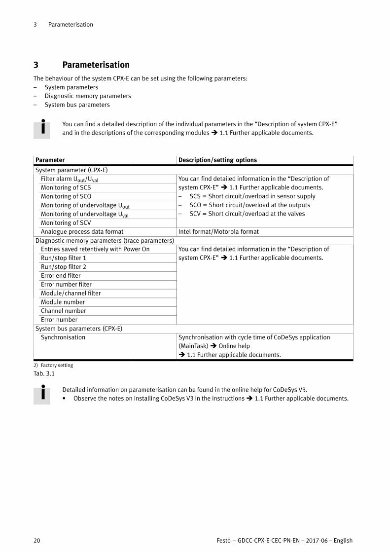
3 Parameterisation
The behaviour of the system CPX-E can be set using the following parameters:
– System parameters
– Diagnostic memory parameters
– System bus parameters
You can find a detailed description of the individual parameters in the “Description of system CPX-E”
and�in the descriptions of the corresponding modules � 1.1 Further applicable documents.
Parameter Description/setting options
System parameter (CPX-E)
Filter alarm Uout/Uval You can find detailed information in the “Description of
system�CPX-E” � 1.1 Further applicable documents.
– SCS = Short circuit/overload in sensor supply
– SCO = Short circuit/overload at the outputs
– SCV = Short circuit/overload at the valves
Monitoring of SCS
Monitoring of SCO
Monitoring of undervoltage Uout
Monitoring of undervoltage Uval
Monitoring of SCV
Analogue process data format Intel format/Motorola format
Diagnostic memory parameters (trace parameters)
Entries saved retentively with Power On You can find detailed information in the “Description of
system�CPX-E” � 1.1 Further applicable documents.Run/stop filter 1
Run/stop filter 2
Error end filter
Error number filter
Module/channel filter
Module number
Channel number
Error number
System bus parameters (CPX-E)
Synchronisation Synchronisation with cycle time of CoDeSys application
(MainTask) � Online help
� 1.1 Further applicable documents.
2) Factory setting
Tab. 3.1
Detailed information on parameterisation can be found in the online help for CoDeSys V3.
� Observe the notes on installing CoDeSys V3 in the instructions � 1.1 Further applicable documents.

A Technical Data
Festo – GDCC-CPX-E-CEC-PN-EN – 2017-06 – English 21
A Technical data
General
Feature Specification/value
General technical data, system CPX-E Description of system CPX-E
(� 1.1 Further applicable documents).
Dimensions (length x width x height1)) [mm] 124.3 x 75.9 x 82.5
Product weight2) [g] 288
Mounting position Vertical/horizontal
Ambient temperature [°C] –5 … +60 (–5 … +50)3)
Storage temperature [°C] –20 … +70
Air humidity [%] 0 … 95
Assigned address space (inputs/outputs)
Without diagnostics [bit] –/–
With status bits [bit] 8/–
With I/O diagnostics interface [bit] 16/16
Module code/submodule code (CPX-E-specific)
CPX-E-CEC-C1-PN 222/100
CPX-E-CEC-M1-PN 222/101
Module identification E-CEC
Degree of protection to EN 60529 IP20
Protection against electric shock (protection against
direct and indirect contact to IEC 60204-1)
Through the usage of PELV circuits
(protective�extra-low voltage)
Electromagnetic compatibility To EN 61000-6-2/-4 and NE 21
CE marking (see declaration of conformity
� www.festo.com)
To EU EMC Directive
To EC Machinery Directive
The device is intended for use in an industrial
environment. Measures for interference
suppression may be required in residential areas.
1) Including cover (� Fig. 2.2�3), without linking
2) Including linking
3) With horizontal mounting position
Tab. A.1
Power supply
Feature Specification/value
Power supply for electronics/sensors (UEL/SEN) [V DC] 24 ± 25 %
Intrinsic current consumption at nominal operating voltage [mA] 130
Reverse polarity protection 24 V UEL/SEN against 0 V UEL/SEN Yes
Mains buffering time [ms] 20
Tab. A.2
A Technical Data
22 Festo – GDCC-CPX-E-CEC-PN-EN – 2017-06 – English
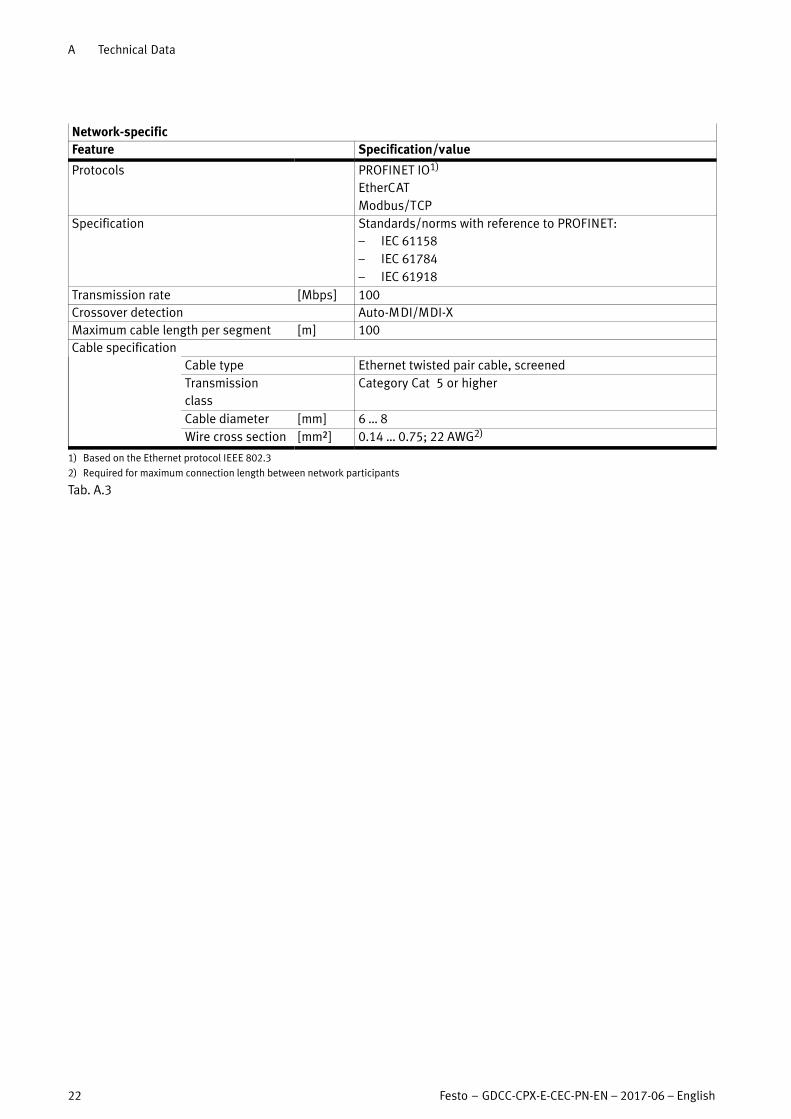
Network-specific
Feature Specification/value
Protocols PROFINET IO1)
EtherCAT
Modbus/TCP
Specification Standards/norms with reference to PROFINET:
– IEC 61158
– IEC 61784
– IEC 61918
Transmission rate [Mbps] 100
Crossover detection Auto-MDI/MDI-X
Maximum cable length per segment [m] 100
Cable specification
Cable type Ethernet twisted pair cable, screened
Transmission
class
Category Cat� 5 or higher
Cable diameter [mm] 6 … 8
Wire cross section [mm²] 0.14 … 0.75; 22 AWG2)
1) Based on the Ethernet protocol IEEE 802.3
2) Required for maximum connection length between network participants
Tab. A.3

B Terminology
Festo – GDCC-CPX-E-CEC-PN-EN – 2017-06 – English 23
B Terminology
Term/abbreviation Description
Device description file Protocol-specific file for configuring the associated device with the aid of the
software for the higher-order controller. The file contains all the information
required to parameterise the system CPX-E.
DIL switch Switches consisting of several switch elements with which settings can be made
(dual in-line).
ESI EtherCAT slave information
GSDML file Device description file for PROFINET (Generic Station Description Markup
Language)
I/O Input and output
I/O diagnostic interface Network-independent diagnostic interface at I/O level, which enables access to
the internal data of the system CPX-E.
I/O module Collective term for the modules that provide analogue or digital inputs/outputs.
Modules CPX-E Collective term for the various modules which can be incorporated in a system
CPX-E.
PLC Programmable logic controller
Status bits Internal status information (common diagnostic messages) of the system CPX-E,
provided as input signals via the network.
System CPX-E Complete system consisting of modules CPX-E.
Tab. B.1 Terms and abbreviations
CPX-E-CEC-...-PN
24 Festo – GDCC-CPX-E-CEC-PN-EN – 2017-06 – English
Index
A
Abbreviations, 23
Address assignment, 7
Analogue process value representation, 20
C
Connection status, 14
Crossover detection (auto MDI/MDI-X), 6
D
Device description file , 6
Diagnostic memory parameters, 20
Diagnostics history, 15
Diagnostics options, 12
– LED indicators, 13, 14
– via EtherCAT, 15
Diagnostics via EtherCAT, 15
– Diagnostics history, 15
– Emergency message, 17
– SDO access, 15
E
Emergency message, 17
F
Filter alarm, 20
G
GSDML file, 6
I
Identification & maintenance, 6
L
LED indicators, 13
– Connection status, 14
– Module-specific, 13
– Network error, 14
– Network-specific, 14
N
Network error, 14
P
Parameters, 20
– Diagnostic memory, 20
– System, 20
– System bus, 20
S
SCO monitoring, 20
SCS monitoring, 20
SCV monitoring, 20
SDO access, 15
Synchronisation, 20
System bus parameters, 20
– Synchronisation, 20
System parameters
– Analogue process value representation, 20
– Filter alarm, 20
– SCO monitoring, 20
– SCS monitoring, 20
– SCV monitoring, 20
– Undervoltage monitoring, 20
System parameters (CPX-E-specific), 20
T
Terminology, 23
U
Undervoltage monitoring, 20
W
Web servers, 11


Reproduction, distribution or sale of this document or communication ofits contents to others without express authorization is prohibited. Offenders will be liable for damages. All rights reserved in the event that a patent, utility model or design patent is registered.
Copyright:Festo AG & Co. KGRuiter Straße 8273734 EsslingenGermany
Phone:+49 711 347-0
Fax:+49 711 347-2144
e-mail:[email protected]
Internet:www.festo.com