
CPC2 PROGRAMMING MANUAL - Finetech · 2018-07-03 · BS402i001 4 ©1998-2015 Finetech Medical Ltd....
36
BS402i001 Finetech-Brindley Sacral Anterior Root Stimulator CPC2 PROGRAMMING MANUAL (Section 1: BS401- Notes for Surgeons and Physicians) Section 2: BS402 – CPC2 Programming Manual (Section 3: FTM1055 – Repair Surgery Instructions) This programming instruction manual covers methods of programming the digital controller (CPC2). March 2015 Copyright © 1998-2015 Finetech Medical Limited, United Kingdom. All rights reserved. This manual MUST be read and understood by all relevant persons prior to using the Finetech-Brindley Sacral Anterior Root Stimulator (SARS) and should be read in conjunction with the other sections.
Transcript of CPC2 PROGRAMMING MANUAL - Finetech · 2018-07-03 · BS402i001 4 ©1998-2015 Finetech Medical Ltd....

BS402i001
Finetech-Brindley Sacral Anterior Root Stimulator
CPC2 PROGRAMMING MANUAL
(Section 1: BS401- Notes for Surgeons and Physicians)
Section 2: BS402 – CPC2 Programming Manual
(Section 3: FTM1055 – Repair Surgery Instructions)
This programming instruction manual covers methods of programming the digital controller (CPC2).
March 2015
Copyright © 1998-2015 Finetech Medical Limited, United Kingdom. All rights reserved.
This manual MUST be read and understood by all relevant persons prior to using the Finetech-Brindley Sacral Anterior Root Stimulator (SARS) and should be read in conjunction
with the other sections.

BS402i001 2 ©1998-2015 Finetech Medical Ltd.
Section 2: CPC2 PROGRAMMING MANUAL
1. INTRODUCTION ............................................................................................ 4
1.1 Stimulation Parameters .............................................................................. 4
1.2 Operating Modes ....................................................................................... 4
2. PARAMETERS .............................................................................................. 4
2.1.1 General Parameters ........................................................................................ 4
2.2 Interleave Pulses ....................................................................................... 6
3. PARAMETER ADJUSTMENT ....................................................................... 7
3.1 Program Using the Buttons ........................................................................ 7
3.2 Program Using a PC (SARLINK-2) ............................................................ 9
4. EQUIPMENT REQUIRED ............................................................................ 15
5. PARAMETER SETUP/ADJUSTMENT PROCEDURE ................................ 16
5.1 Cystometry ............................................................................................... 16
5.2 Preparing for the Tests ............................................................................ 17
5.3 Initial Testing ............................................................................................ 18
5.4 Setting a Micturition Stimulation Programme (Typically Mode 1) ............. 20
5.5 Setting a Defaecation Stimulation Programme (Typically Mode 2) .......... 23
5.6 Setting an Erection Programme (Typically Mode 3) ................................. 24
6. ADJUSTMENT CHARTS ............................................................................. 25
6.1 Adjusting Bladder Pressure ..................................................................... 26
6.2 Post Void Residuals ................................................................................. 28
6.3 Urine Flow ................................................................................................ 29
6.4 Bowel Mode ............................................................................................. 30
7. PROBLEMS AND ERROR CODES ............................................................ 31
8. GRAPHICAL SYMBOLS ............................................................................. 32
9. DECLARATION OF CONFORMITY ............................................................ 33
10. FORMS ........................................................................................................ 34
11. INDEX .......................................................................................................... 35
12. NOTES ......................................................................................................... 36

© 1998-2015 Finetech Medical Ltd. 3 BS402i001
Need help? If you need advice about any aspect of the Finetech-Brindley SARS please:
email us at [email protected] contact us or your distributor via our website www.finetech-medical.co.uk telephone us on +44 (0)1707 330942
Key to Symbols used in this Programming Manual
Contra-indications These notes describe situations where you should not use the Finetech-Brindley SARS.
Warnings and Cautions Make sure that you understand these notes before using the Finetech-Brindley SARS.
Important Note This symbol appears next to points to remember about the Finetech-Brindley SARS.
The Finetech-Brindley SARS has been manufactured in the United Kingdom since 1982 by: Finetech Medical Ltd 13 Tewin Court Welwyn Garden City Hertfordshire AL7 1AU United Kingdom
C
0086 Authorisation first issued:
10th April, 1996
+44 (0)1707 330942 +44 (0)1707 334143 www.finetech-medical.co.uk
BS402i001 4 ©1998-2015 Finetech Medical Ltd.
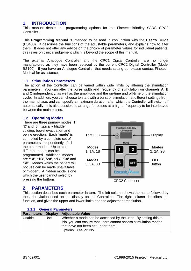
1. INTRODUCTION This manual details the programming options for the Finetech-Brindley SARS CPC2 Controller. This Programming Manual is intended to be read in conjunction with the User’s Guide (BS400). It describes the functions of the adjustable parameters, and explains how to alter them. It does not offer any advice on the choice of parameter values for individual patients; this relies on clinical judgement which is beyond the scope of this manual. The external Analogue Controller and the CPC1 Digital Controller are no longer manufactured as they have been replaced by the current CPC2 Digital Controller (Model BS100). If you have an Analogue Controller that needs setting up, please contact Finetech Medical for assistance. 1.1 Stimulation Parameters The action of the Controller can be varied within wide limits by altering the stimulation parameters. You can alter the pulse width and frequency of stimulation on channels A, B and C independently, as well as the amplitude and the on-time and off-time of the stimulation cycle. In addition, you can choose to start with a burst of stimulation at different settings from the main phase, and can specify a maximum duration after which the Controller will switch off automatically. It is also possible to arrange for pulses at a higher frequency to be interleaved between the main pulses. 1.2 Operating Modes There are three primary modes ‘1’, ‘2’ and ‘3’; typically bladder voiding, bowel evacuation and penile erection. Each ‘mode’ is controlled by a complete set of parameters independently of all the other modes. Up to nine different modes can be programmed. Additional modes are ‘1A’, ‘1B’, ‘2A’, ‘2B’, ‘3A’ and ‘3B’. Modes which the patient will not use can be made unavailable or ‘hidden’. A hidden mode is one which the user cannot select by pressing the buttons.
2. PARAMETERS This section describes each parameter in turn. The left column shows the name followed by the abbreviation used on the display on the Controller. The right column describes the function, and gives the upper and lower limits and the adjustment resolution.
2.1.1 General Parameters
Parameters Display Adjustable Value Usable Use Whether a mode can be accessed by the user. By setting this to
‘No’ you can ensure that users cannot access stimulation modes that have not been set up for them. Options; ‘Yes’ or ‘No’
Display
Modes 1, 1A, 1B
OFF Button
Modes 2, 2A, 2B
Modes 3, 3A, 3B
Test LED
CPC2 Controller
© 1998-2015 Finetech Medical Ltd. 5 BS402i001
Parameters Display Adjustable Value Limit Lim The time (in seconds) from the start of the main stimulation until the
stimulator switches itself off. (The user may still switch off at any time by pressing the ‘0’ button). The value 0 indicates that there is no time limit, the stimulator output will continue until the user switches it off or until the battery is exhausted. Minimum 0 s = No Limit; continuous output. Maximum 2500 s Increment 10 s
On-time On The period of time (in seconds) within each cycle for which the output pulses are being applied. Also known as the ‘mark’ time. Minimum 0.0 s = No stimulation output Maximum 51 s Increment 0.2 s
Off-time Off The period of time (in seconds) within each cycle for which the output pulses are not being applied. Also known as the ‘space’ time. Minimum 0.0 s = Continuous stimulation when On-time > 0. Maximum 51 s Increment 0.2 s Note: If Off-time is zero then the On-time is ignored and output is continued if On-time is greater than zero.
Amplitude AmpA AmpB AmpC
The amplitude of the transmitter drives voltage for each main stimulation channel. Minimum 10 V Maximum 40 V Increment 5 V
Pulse Width PW A PW B PW C
The width, in microseconds, of the output pulse in the main stage of stimulation. Adjustable for each channel individually. Minimum 0 µs Maximum 720µs Increment 4µs
Frequency Fr A Fr B Fr C
The pulse repetition frequency, in Hertz, in the main stage of stimulation. Adjustable for each channel individually. Minimum 2 Hz Maximum 53 Hz Increment 2, 3, 4, 5, 6, 7, 8, 9, 10, 11, 12, 13, 14, 15, 16, 17, 18, 19, 20, 21, 22, 23, 25, 26, 28, 30, 32, 35, 38, 42, 47 and 53 Hz.
Interleave number (Advanced setting)
I# A I# B I# C
The number of additional pulses to be delivered at equally spaced periods between the main pulses on a particular output channel. Interleaved pulses are entirely optional and would normally be set to zero. Minimum 0 Maximum 2 Increment 1
Interleave pulse width
IPW A IPW B IPW C
The pulse width of the interleaved pulses. Adjustable for each channel individually. Minimum 0 µs Maximum 720 µs Increment 4 µs

BS402i001 6 ©1998-2015 Finetech Medical Ltd.
Parameters Display Adjustable Value Pre-fatigue duration
PDur The duration, in seconds of the pre-fatigue stage of the stimulation. Pre-fatigue is entirely optional. By setting this parameter to zero, stimulation will proceed immediately to the main stage and all other pre-fatigue parameters are ignored. Pre-fatigue stimulation is always continuous. Minimum 0 s (i.e. no Pre-fatigue stimulation) Maximum 240 s (4 minutes) Increment 1 s
Pre-fatigue amplitude
PA A PA B PA C
The amplitude of the transmitter drives voltage for each of the pre-fatigue stimulation channel. Minimum 10 V Maximum 40 V Increment 5 V
Pre-fatigue pulse width
PPW A PPW B PPW C
The width of the pulses in the pre-fatigue stage of stimulation for each output channel. Minimum 0 µs Maximum 720 µs Increment 4 µs
Pre-fatigue frequency
PF A PF B PF C
The frequency, in Hertz, of the pre-fatigue stimulation for each output channel. Minimum 2 Hz Maximum 53 Hz Increment 2, 3, 4, 5, 6, 7, 8, 9, 10, 11, 12, 13, 14, 15, 16, 17, 18, 19, 20, 21, 22, 23, 25, 26, 28, 30, 32, 35, 38, 42, 47 and 53 Hz.
2.2 Interleave Pulses The ‘interleave’ facility enables you to modify the physiological action of the stimulation by inserting one or two additional pulses between successive normal pulses. The additional pulses may have a different width and amplitude from the normal pulses. You can, for example, alternate pulses of high amplitude and low width with pulses of low amplitude and greater width.
Limits on Frequency When single interleave pulses are used, the overall frequency is twice the main frequency; when double interleave pulses are used, the overall frequency is three times the main frequency. Because of internal timing constraints, the interleave facility cannot be used with all available frequencies. If you set the Interleave Number parameter to a number that is not available at the selected frequency, then the actual frequency will be rounded to the next lower frequency which does accommodate the required interleave number. For example, if the main frequency is 30Hz, then the option of having two interleaved pulses is not available. If you request two interleave pulses, then the actual frequency of the main pulses will be rounded down to 28Hz; the overall frequency will be 84Hz. This rounding will be done when the stimulator actually starts running; the stored parameter will not be affected, and will still be displayed as 30Hz. Power Limit There is a limit to the total power the Controller can deliver to the Transmitter Block. The higher frequencies can only be used if the Amplitude and Pulse Width parameters are relatively low.
Note This facility is available only in the main stage of stimulation, not the pre-fatigue stage.
© 1998-2015 Finetech Medical Ltd. 7 BS402i001
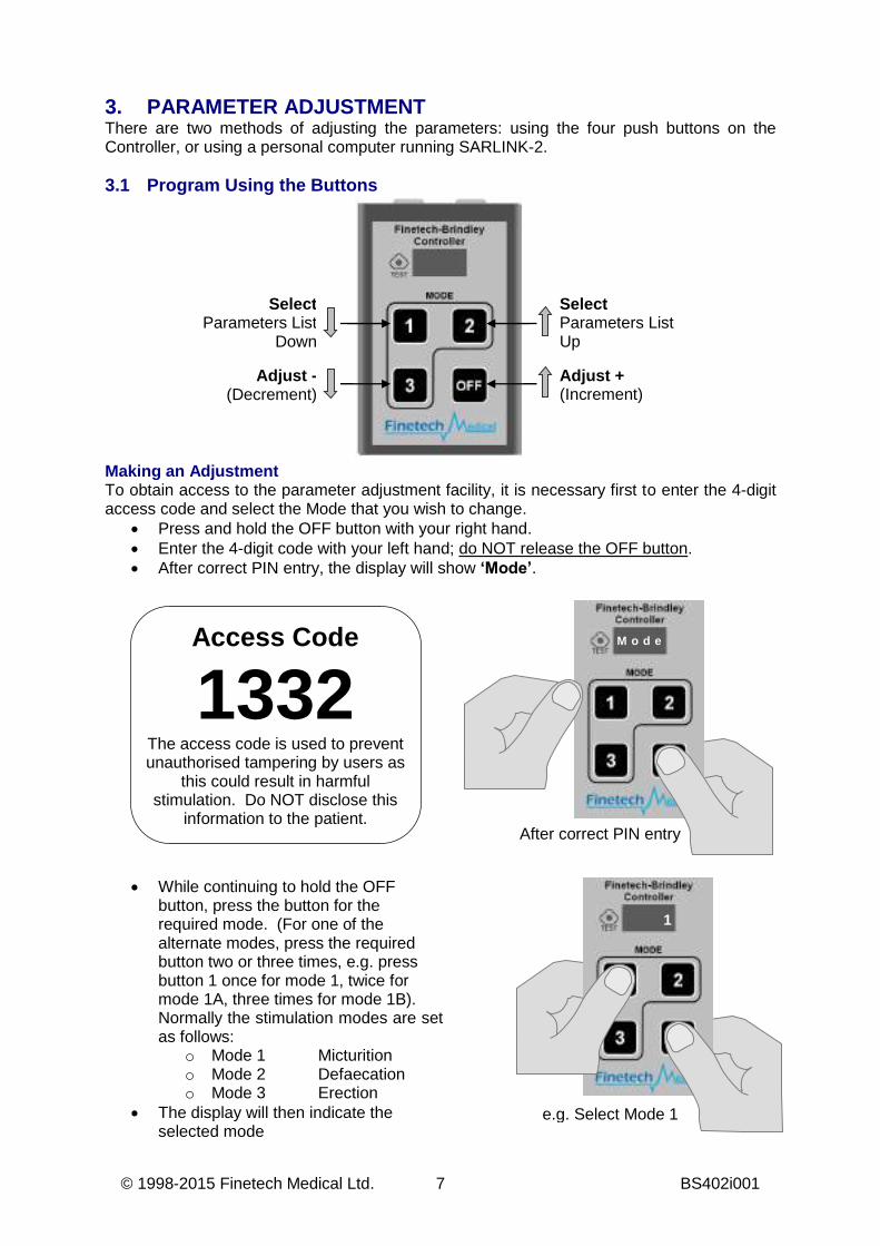
3. PARAMETER ADJUSTMENT There are two methods of adjusting the parameters: using the four push buttons on the Controller, or using a personal computer running SARLINK-2. 3.1 Program Using the Buttons
Making an Adjustment To obtain access to the parameter adjustment facility, it is necessary first to enter the 4-digit access code and select the Mode that you wish to change.
Press and hold the OFF button with your right hand. Enter the 4-digit code with your left hand; do NOT release the OFF button. After correct PIN entry, the display will show ‘Mode’.
While continuing to hold the OFF button, press the button for the required mode. (For one of the alternate modes, press the required button two or three times, e.g. press button 1 once for mode 1, twice for mode 1A, three times for mode 1B). Normally the stimulation modes are set as follows:
o Mode 1 Micturition o Mode 2 Defaecation o Mode 3 Erection
The display will then indicate the selected mode
1
e.g. Select Mode 1
After correct PIN entry
M o d e
Select Parameters List
Down
Adjust + (Increment)
Select Parameters List Up
Adjust - (Decrement)
Access Code
1332 The access code is used to prevent unauthorised tampering by users as
this could result in harmful stimulation. Do NOT disclose this
information to the patient.
BS402i001 8 ©1998-2015 Finetech Medical Ltd.
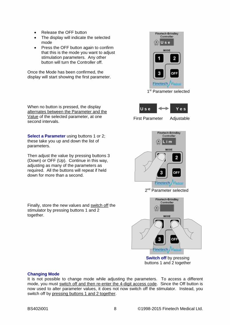
Release the OFF button The display will indicate the selected
mode Press the OFF button again to confirm
that this is the mode you want to adjust stimulation parameters. Any other button will turn the Controller off.
Once the Mode has been confirmed, the display will start showing the first parameter.
When no button is pressed, the display alternates between the Parameter and the Value of the selected parameter, at one second intervals.
Select a Parameter using buttons 1 or 2; these take you up and down the list of parameters. Then adjust the value by pressing buttons 3 (Down) or OFF (Up). Continue in this way, adjusting as many of the parameters as required. All the buttons will repeat if held down for more than a second.
Finally, store the new values and switch off the stimulator by pressing buttons 1 and 2 together.
Changing Mode It is not possible to change mode while adjusting the parameters. To access a different mode, you must switch off and then re-enter the 4-digit access code. Since the Off button is now used to alter parameter values, it does not now switch off the stimulator. Instead, you switch off by pressing buttons 1 and 2 together.
First Parameter Adjustable Value
Y e s U s e
L i m
2nd Parameter selected
Switch off by pressing buttons 1 and 2 together
1st Parameter selected
U s e
© 1998-2015 Finetech Medical Ltd. 9 BS402i001
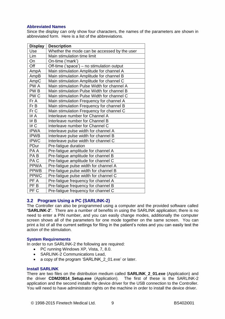
Abbreviated Names Since the display can only show four characters, the names of the parameters are shown in abbreviated form. Here is a list of the abbreviations.
Display Description Use Whether the mode can be accessed by the user Lim Main stimulation time limit On On-time (‘mark’) Off Off-time (‘space’) – no stimulation output AmpA Main stimulation Amplitude for channel A AmpB Main stimulation Amplitude for channel B AmpC Main stimulation Amplitude for channel C PW A Main stimulation Pulse Width for channel A PW B Main stimulation Pulse Width for channel B PW C Main stimulation Pulse Width for channel C Fr A Main stimulation Frequency for channel A Fr B Main stimulation Frequency for channel B Fr C Main stimulation Frequency for channel C I# A Interleave number for Channel A I# B Interleave number for Channel B I# C Interleave number for Channel C IPWA Interleave pulse width for channel A IPWB Interleave pulse width for channel B IPWC Interleave pulse width for channel C PDur Pre-fatigue duration PA A Pre-fatigue amplitude for channel A PA B Pre-fatigue amplitude for channel B PA C Pre-fatigue amplitude for channel C PPWA Pre-fatigue pulse width for channel A PPWB Pre-fatigue pulse width for channel B PPWC Pre-fatigue pulse width for channel C PF A Pre-fatigue frequency for channel A PF B Pre-fatigue frequency for channel B PF C Pre-fatigue frequency for channel C
3.2 Program Using a PC (SARLINK-2) The Controller can also be programmed using a computer and the provided software called ‘SARLINK-2’. There are a number of benefits in using the SARLINK application; there is no need to enter a PIN number, and you can easily change modes, additionally the computer screen shows all of the parameters for one mode together on the same screen. You can print a list of all the current settings for filing in the patient’s notes and you can easily test the action of the stimulation. System Requirements In order to run SARLINK-2 the following are required:
PC running Windows XP, Vista, 7, 8.0. SARLINK-2 Communications Lead, a copy of the program ‘SARLINK_2_01.exe’ or later.
Install SARLINK There are two files on the distribution medium called SARLINK_2_01.exe (Application) and the driver CDM20814_Setup.exe (Application). The first of these is the SARLINK-2 application and the second installs the device driver for the USB connection to the Controller. You will need to have administrator rights on the machine in order to install the device driver.
BS402i001 10 ©1998-2015 Finetech Medical Ltd.
Step 1: To install SARLINK-2, copy the two files into a folder on your hard drive. We recommend that this folder is C:\Program Files\SARLINK-2. Note that this must be a folder where all users of the program have write permission. Step 2: Double-click on CDM20814_Setup to install the device driver for the Controller connection (you may need to do this twice to get it to run). Wait for the task to complete. Step 3: You can create a short cut on your desk top to run the program. Right click on SARLINK_2_01.exe and select ‘Create Shortcut’ from the drop down menu. Step 4: Move ‘Shortcut to SARLINK_2_01.exe’ to your Desktop. You can move the shortcut by clicking and dragging it to your Desktop or using the cut and paste method. It is necessary to set the program up to use the filing system on a particular installation. This is done as follows:
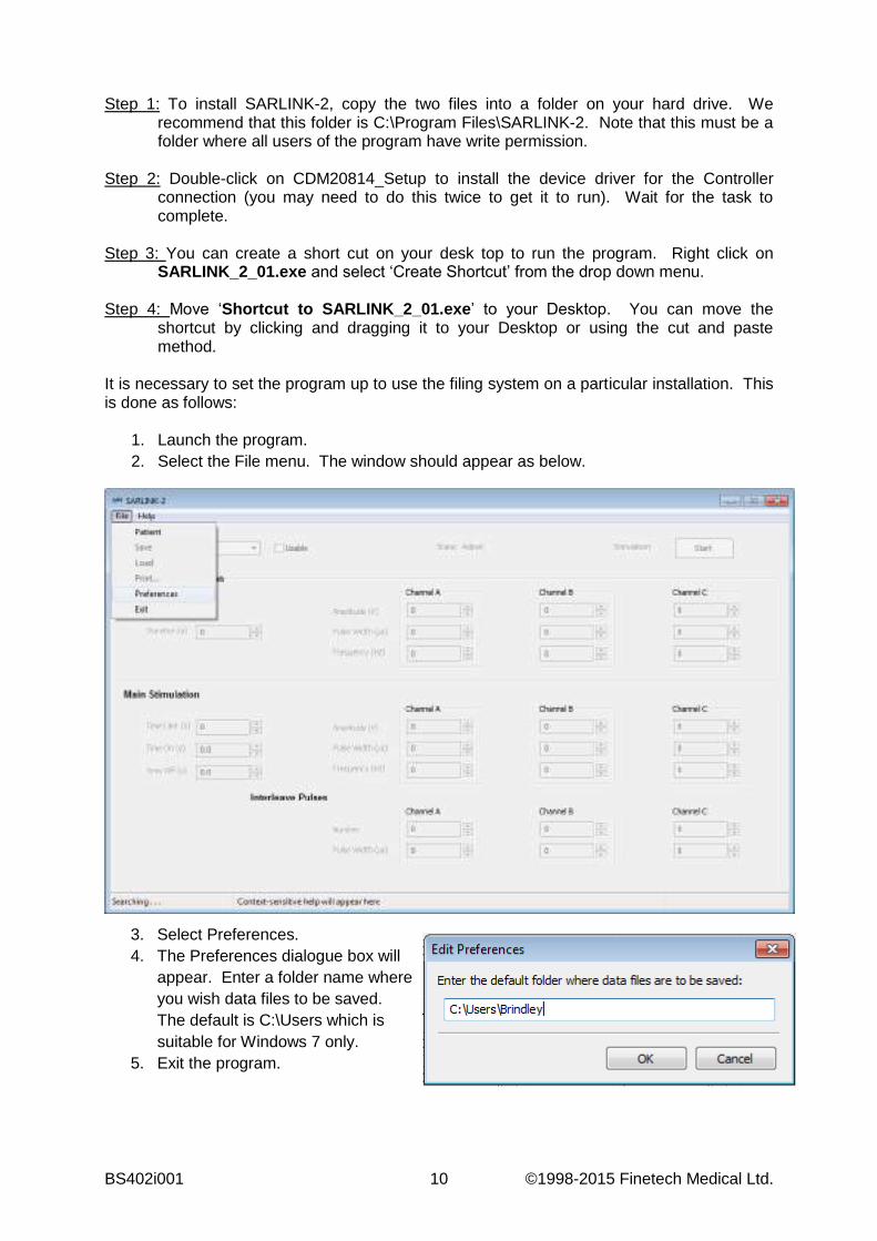
1. Launch the program. 2. Select the File menu. The window should appear as below.
3. Select Preferences. 4. The Preferences dialogue box will
appear. Enter a folder name where you wish data files to be saved. The default is C:\Users which is suitable for Windows 7 only.
5. Exit the program.
© 1998-2015 Finetech Medical Ltd. 11 BS402i001
Launching SARLINK-2
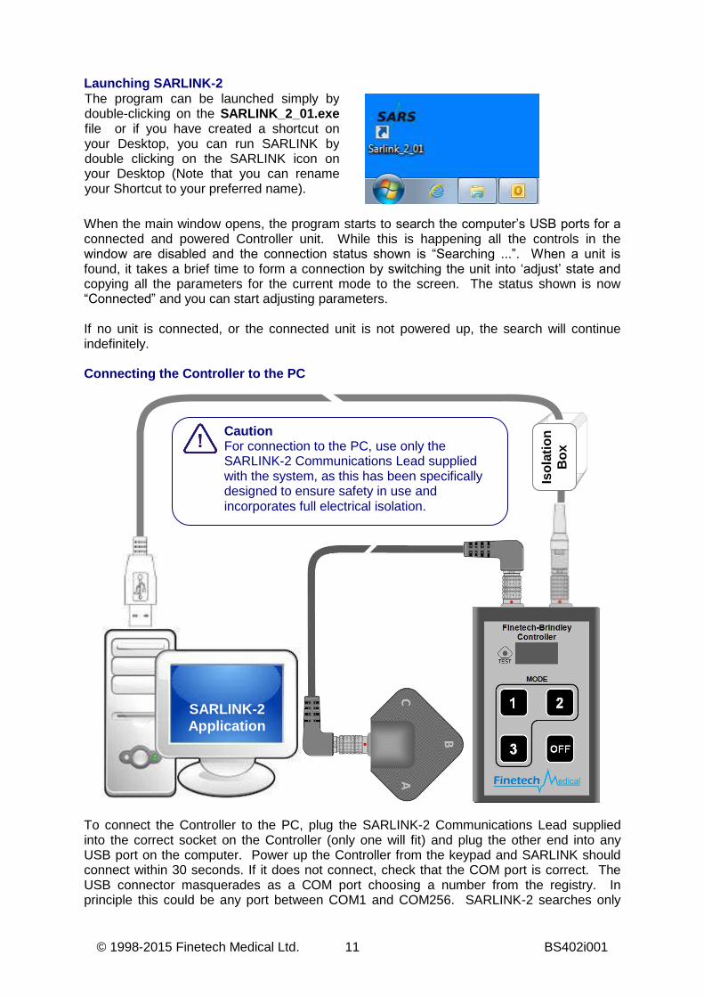
When the main window opens, the program starts to search the computer’s USB ports for a connected and powered Controller unit. While this is happening all the controls in the window are disabled and the connection status shown is “Searching ...”. When a unit is found, it takes a brief time to form a connection by switching the unit into ‘adjust’ state and copying all the parameters for the current mode to the screen. The status shown is now “Connected” and you can start adjusting parameters. If no unit is connected, or the connected unit is not powered up, the search will continue indefinitely. Connecting the Controller to the PC
To connect the Controller to the PC, plug the SARLINK-2 Communications Lead supplied into the correct socket on the Controller (only one will fit) and plug the other end into any USB port on the computer. Power up the Controller from the keypad and SARLINK should connect within 30 seconds. If it does not connect, check that the COM port is correct. The USB connector masquerades as a COM port choosing a number from the registry. In principle this could be any port between COM1 and COM256. SARLINK-2 searches only
The program can be launched simply by double-clicking on the SARLINK_2_01.exe file or if you have created a shortcut on your Desktop, you can run SARLINK by double clicking on the SARLINK icon on your Desktop (Note that you can rename your Shortcut to your preferred name).
Is
ola
tio
n
Bo
x
SARLINK-2 Application
Caution For connection to the PC, use only the SARLINK-2 Communications Lead supplied with the system, as this has been specifically designed to ensure safety in use and incorporates full electrical isolation.
BS402i001 12 ©1998-2015 Finetech Medical Ltd.
ports COM1 – COM32. Hence, if your USB device driver has chosen a number above 32 SARLINK-2 will never find it.
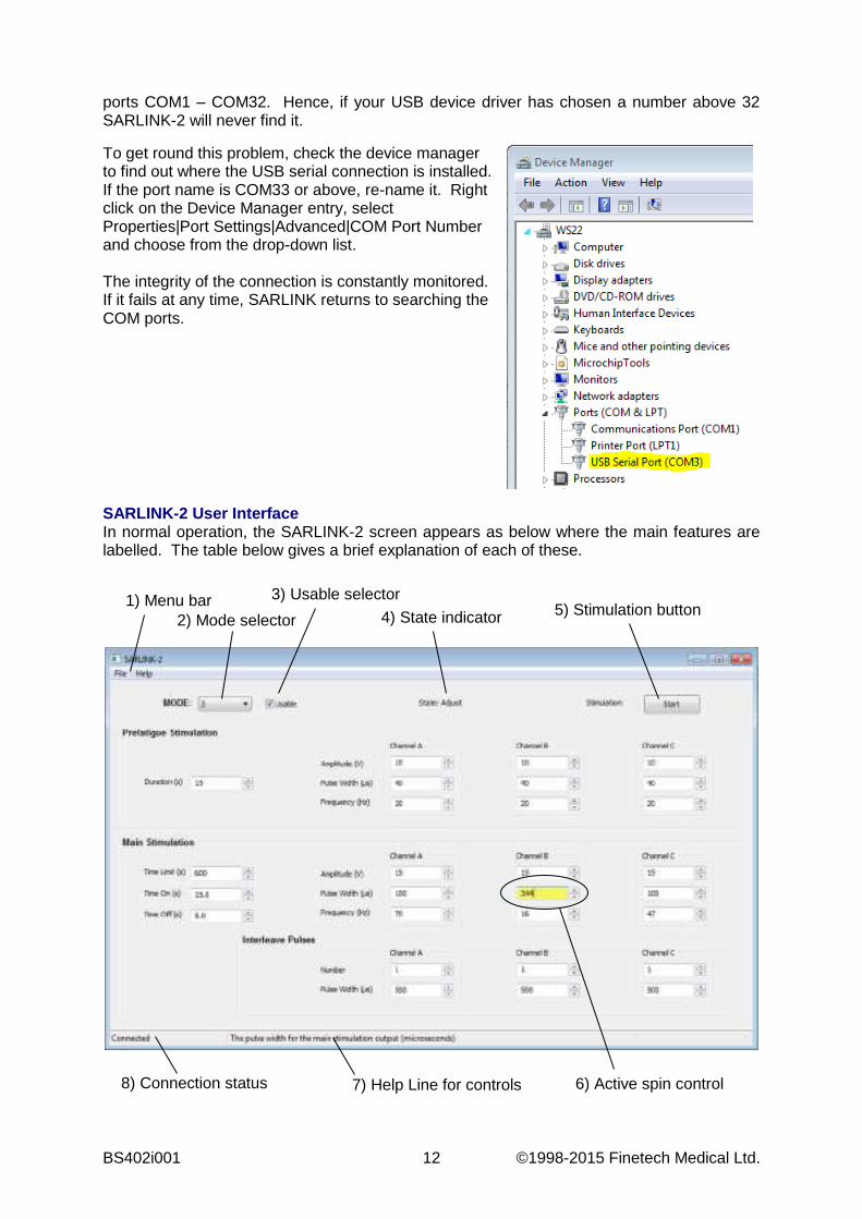
SARLINK-2 User Interface In normal operation, the SARLINK-2 screen appears as below where the main features are labelled. The table below gives a brief explanation of each of these.
1) Menu bar 2) Mode selector
3) Usable selector 4) State indicator
5) Stimulation button
8) Connection status
7) Help Line for controls 6) Active spin control
To get round this problem, check the device manager to find out where the USB serial connection is installed. If the port name is COM33 or above, re-name it. Right click on the Device Manager entry, select Properties|Port Settings|Advanced|COM Port Number and choose from the drop-down list. The integrity of the connection is constantly monitored. If it fails at any time, SARLINK returns to searching the COM ports.

© 1998-2015 Finetech Medical Ltd. 13 BS402i001
1 Menu bar The File menu gives you access to the following functions: Patient: Enter patient data Save: Save the set-up data to a file Load: Load some set-up data from a file Print. . .: Print out the set-up data Preferences: Edit the preferences Exit: Close the program
The Help menu displays the version of the program and contact details for Finetech Medical.
2 Mode selector The mode selector enables you to pick one of the nine available modes of operation. Click on the triangle at the right to see the full list. The current mode is the one displayed in the control.
3 Usable selector This check box sets the value of the “use” parameter. When it is clear the current mode is unusable by the patient and you will not be able to adjust any of the parameters on screen.
4 State indicator The current state of the Controller is shown here. The state will be one of:
Adjust Pausing Pre-fatigue Main stimulation Error
The Error state is shown in red for emphasis. 5 Stimulation button Click here to move the Controller out of ‘Adjust’ state and into its
stimulation sequence. 6 Active spin
control These controls enable you to adjust the parameters. The active one is coloured yellow; the Controller display will also be showing this parameter. See “How to adjust a parameter” below for details.
7 Help Line for Controls
Help text relevant to each control appears in this box. Spin controls only show their help text when they are active.
8 Connection status This box tells you what the state of your connection to the Controller is. It can be one of:
Searching . . . Connecting . . . Connected Busy . . .
Changing the Mode When SARLINK-2 connects to a Controller, the mode shown on the screen is the one that was selected from the keypad when the unit was switched on. You can change this at any time (except when the unit is delivering stimulation) by choosing another mode from the drop-down list in the Mode Selector (2). You cannot change it from the Controller itself. When you select a new mode, the screen is refreshed with the data for that mode. The Controller is set at the first parameter so that the display reads “Use” alternating with the setting, “Yes” or “No”. The screen focus is on the Usable Selector (3). Enabling the Mode Having selected the mode you wish to set up, it is necessary to enable it before you can adjust any of the associated parameters. Of course, it may already be enabled in which case the Usable Selector (3) will be checked and all the spin controls enabled. A mode that is set up and then disabled will retain all its settings. To make it available to a patient at a later date it is only necessary to switch ‘Use’ to ‘Yes’ on the Controller.

BS402i001 14 ©1998-2015 Finetech Medical Ltd.
How to Adjust a Parameter The numerical parameters are adjusted by the so-called ‘spin controls’ of which there are twenty-eight on the screen. They are grouped according to the feature they affect, pre-fatigue at the top, main stimulation in the middle and interleave pulses at the bottom. Select any one of these by clicking on it and it becomes ‘active’ i.e. it shifts the display on the Controller to show the same parameter. The background colour of the number then becomes yellow. You can also select parameters with the TAB key or buttons 1 and 2 on the Controller. You have a number of options for changing the value of the parameter:
(a) By clicking on the raise and lower buttons to the right of the number; (b) By using the ‘i’ (or ‘I’) key to increase the value. The ‘d’ (or ‘D’ key) to decrease it; (c) By typing a new value directly into the control; (d) By using the buttons on the Controller keypad; button 3 decreases the value and the
‘OFF’ button increases it.
When you alter a parameter using options (a) or (b) it will step through an allowed range of values between the minimum and the maximum with the specified increment (or decrement). It is not possible to enter illegal values in this way. Further, these options are tightly-coupled to the Controller. Any change made on the screen will immediately appear on the Controller display. Parameter values entered directly by typing (option (c)) are not sent to the Controller until you hit either the RETURN or TAB keys or click somewhere else in the SARLINK window. As a result, what you see on the SARLINK screen may differ from what is on the Controller display. To emphasise this difference, the numbers are shown in red. Any value may be typed but before being sent to the Controller it will be altered to the nearest allowed value, be it the minimum, maximum or anything in between. A control remains active if you enter RETURN after changing the data. If you enter TAB this simultaneously accepts the data and steps you on to the next control. To scrap any changes you have made before accepting them, remove everything from the box and hit TAB or RETURN with it empty. This will cause SARLINK to retrieve the current setting from the Controller and write that to the screen. If any parameter is altered through the Controller keypad (option (d)), the definitive value is the one in the Controller. It is this value that will be saved or printed when these tasks are performed. Delivering Stimulation Click the ‘Start’ button (5) at any time and the Controller will jump out of ‘Adjust’ state and behave as if it had just been switched on. You will see the State Indicator (4) change to ‘Pausing’. The Controller will step through its program automatically but changes of phase can be forced by clicking this button again. As you do so the label changes from ‘Start’ to ‘Next’ and finally, ‘Stop’. If the state indicator shows ‘Error’ you can clear the condition by clicking on this button to return the unit to ‘Adjust’.
© 1998-2015 Finetech Medical Ltd. 15 BS402i001
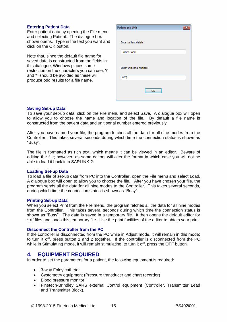
Entering Patient Data Enter patient data by opening the File menu and selecting Patient. The dialogue box shown opens. Type in the text you want and click on the OK button. Note that, since the default file name for saved data is constructed from the fields in this dialogue, Windows places some restriction on the characters you can use. ‘/’ and ‘\’ should be avoided as these will produce odd results for a file name.
Saving Set-up Data To save your set-up data, click on the File menu and select Save. A dialogue box will open to allow you to choose the name and location of the file. By default a file name is constructed from the patient data and unit serial number entered previously. After you have named your file, the program fetches all the data for all nine modes from the Controller. This takes several seconds during which time the connection status is shown as “Busy”. The file is formatted as rich text, which means it can be viewed in an editor. Beware of editing the file; however, as some editors will alter the format in which case you will not be able to load it back into SARLINK-2. Loading Set-up Data To load a file of set-up data from PC into the Controller, open the File menu and select Load. A dialogue box will open to allow you to choose the file. After you have chosen your file, the program sends all the data for all nine modes to the Controller. This takes several seconds, during which time the connection status is shown as “Busy”. Printing Set-up Data When you select Print from the File menu, the program fetches all the data for all nine modes from the Controller. This takes several seconds during which time the connection status is shown as “Busy”. The data is saved in a temporary file. It then opens the default editor for *.rtf files and loads this temporary file. Use the print facilities of the editor to obtain your print. Disconnect the Controller from the PC If the controller is disconnected from the PC while in Adjust mode, it will remain in this mode; to turn it off, press button 1 and 2 together. If the controller is disconnected from the PC while in Stimulating mode, it will remain stimulating; to turn it off, press the OFF button. 4. EQUIPMENT REQUIRED In order to set the parameters for a patient, the following equipment is required:
3-way Foley catheter Cystometry equipment (Pressure transducer and chart recorder) Blood pressure monitor Finetech-Brindley SARS external Control equipment (Controller, Transmitter Lead
and Transmitter Block).
BS402i001 16 ©1998-2015 Finetech Medical Ltd.
Optional equipment includes:
PC with SARLINK-2 software SARLINK-2 Communications Lead Printer
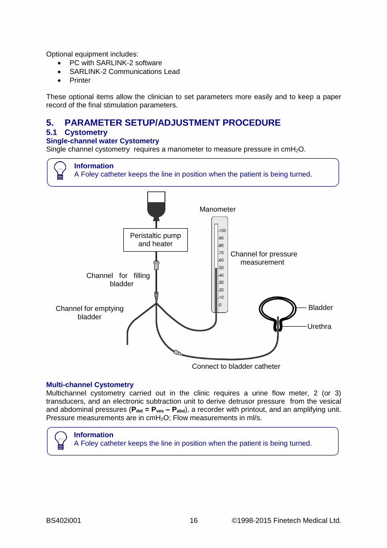
These optional items allow the clinician to set parameters more easily and to keep a paper record of the final stimulation parameters. 5. PARAMETER SETUP/ADJUSTMENT PROCEDURE 5.1 Cystometry Single-channel water Cystometry Single channel cystometry requires a manometer to measure pressure in cmH2O.
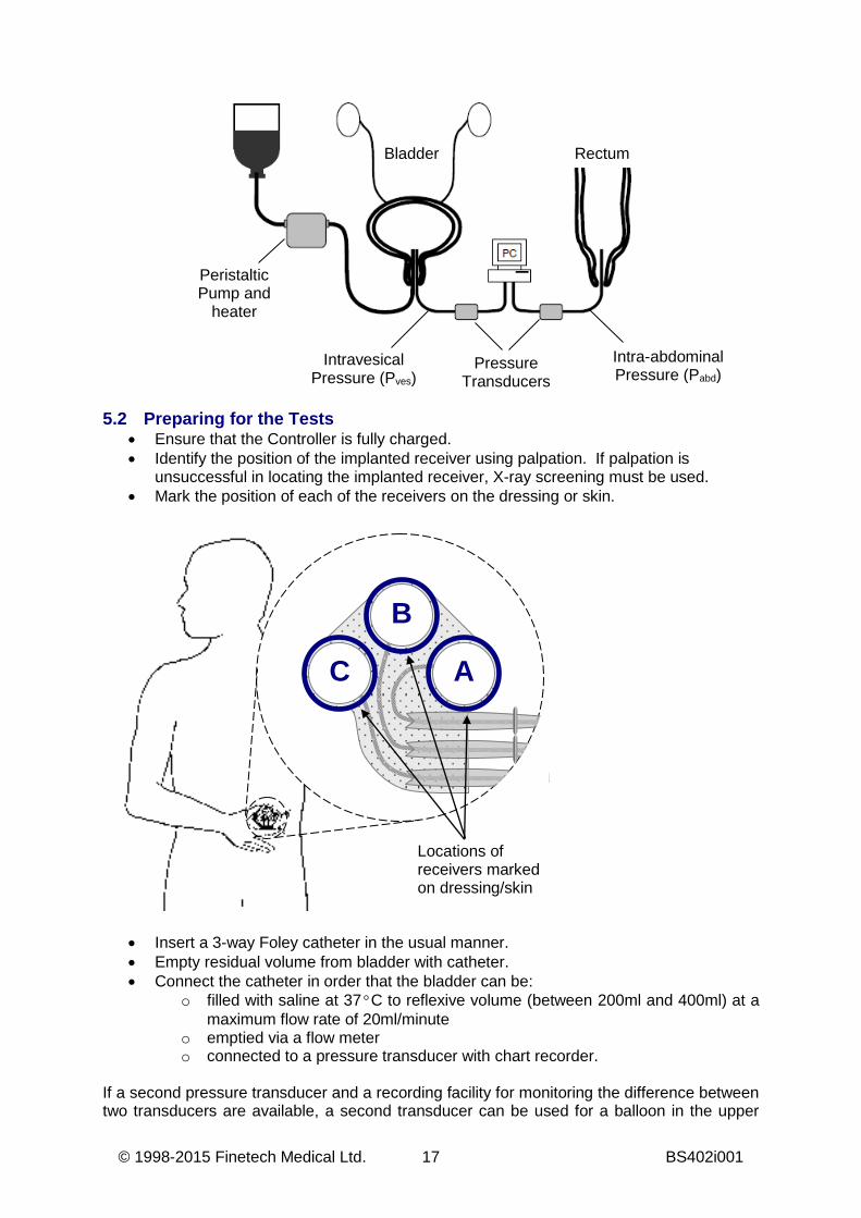
Multi-channel Cystometry Multichannel cystometry carried out in the clinic requires a urine flow meter, 2 (or 3) transducers, and an electronic subtraction unit to derive detrusor pressure from the vesical and abdominal pressures (Pdet = Pves – Pabd), a recorder with printout, and an amplifying unit. Pressure measurements are in cmH2O; Flow measurements in ml/s.
Information A Foley catheter keeps the line in position when the patient is being turned.
Information A Foley catheter keeps the line in position when the patient is being turned.
Connect to bladder catheter
Channel for pressure measurement
Channel for filling bladder
Channel for emptying bladder
Bladder
Urethra
Manometer
Peristaltic pump and heater
© 1998-2015 Finetech Medical Ltd. 17 BS402i001
5.2 Preparing for the Tests
Ensure that the Controller is fully charged. Identify the position of the implanted receiver using palpation. If palpation is
unsuccessful in locating the implanted receiver, X-ray screening must be used. Mark the position of each of the receivers on the dressing or skin.
Insert a 3-way Foley catheter in the usual manner. Empty residual volume from bladder with catheter. Connect the catheter in order that the bladder can be:
o filled with saline at 37°C to reflexive volume (between 200ml and 400ml) at a maximum flow rate of 20ml/minute
o emptied via a flow meter o connected to a pressure transducer with chart recorder.
If a second pressure transducer and a recording facility for monitoring the difference between two transducers are available, a second transducer can be used for a balloon in the upper
Bladder Rectum
Peristaltic Pump and
heater
Pressure Transducers
Intravesical Pressure (Pves)
Intra-abdominal Pressure (Pabd)
Locations of receivers marked on dressing/skin
B
A C
BS402i001 18 ©1998-2015 Finetech Medical Ltd.
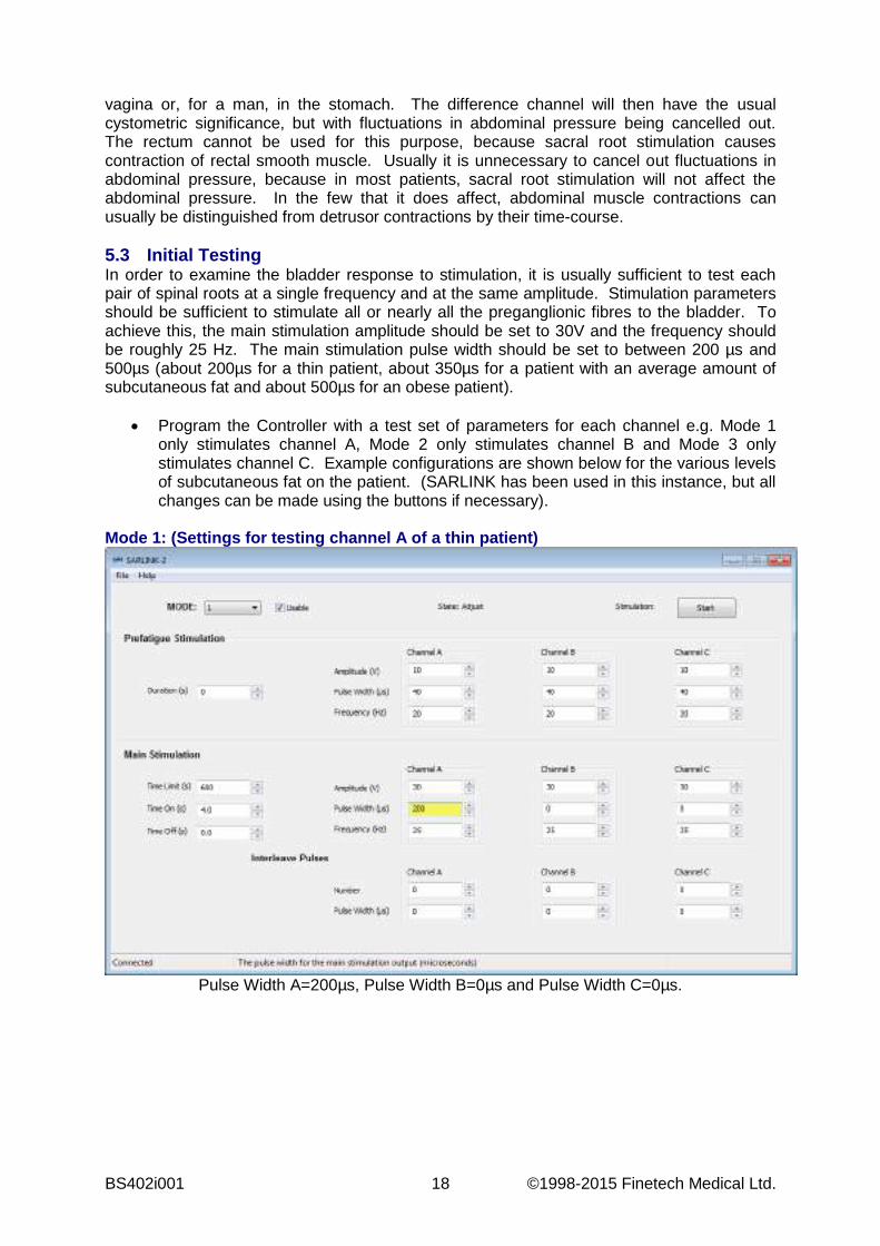
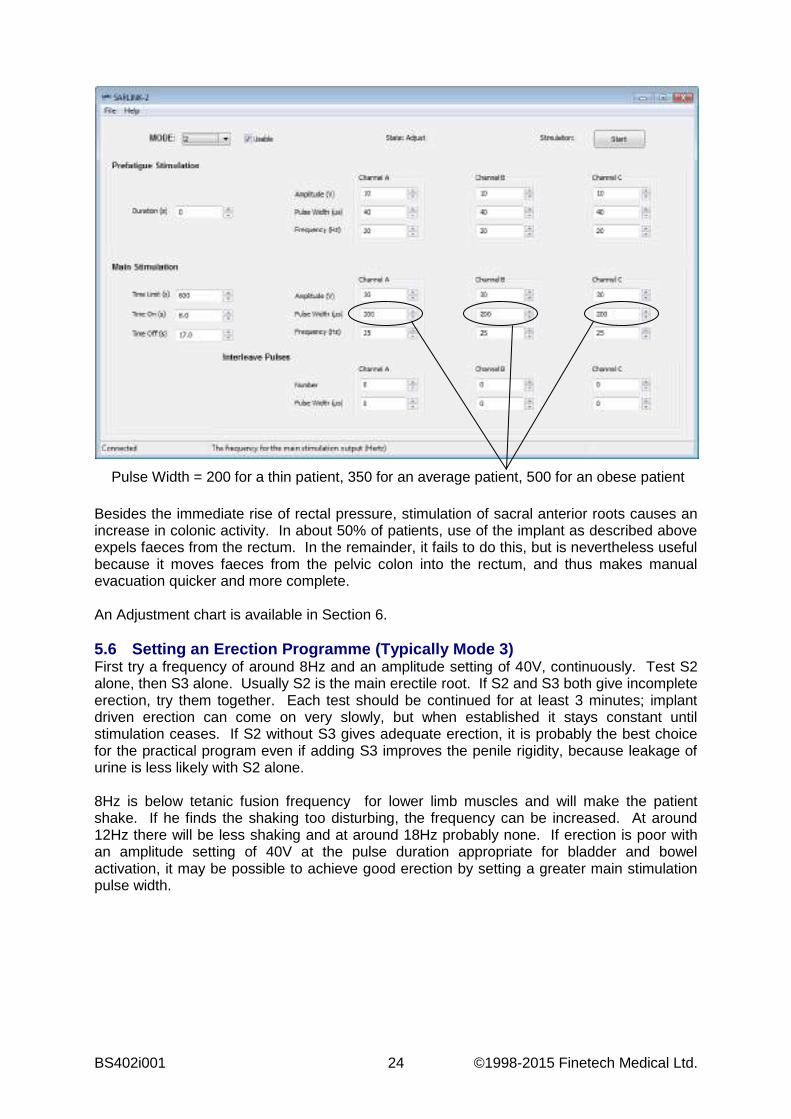
vagina or, for a man, in the stomach. The difference channel will then have the usual cystometric significance, but with fluctuations in abdominal pressure being cancelled out. The rectum cannot be used for this purpose, because sacral root stimulation causes contraction of rectal smooth muscle. Usually it is unnecessary to cancel out fluctuations in abdominal pressure, because in most patients, sacral root stimulation will not affect the abdominal pressure. In the few that it does affect, abdominal muscle contractions can usually be distinguished from detrusor contractions by their time-course. 5.3 Initial Testing In order to examine the bladder response to stimulation, it is usually sufficient to test each pair of spinal roots at a single frequency and at the same amplitude. Stimulation parameters should be sufficient to stimulate all or nearly all the preganglionic fibres to the bladder. To achieve this, the main stimulation amplitude should be set to 30V and the frequency should be roughly 25 Hz. The main stimulation pulse width should be set to between 200 µs and 500µs (about 200µs for a thin patient, about 350µs for a patient with an average amount of subcutaneous fat and about 500µs for an obese patient).
Program the Controller with a test set of parameters for each channel e.g. Mode 1 only stimulates channel A, Mode 2 only stimulates channel B and Mode 3 only stimulates channel C. Example configurations are shown below for the various levels of subcutaneous fat on the patient. (SARLINK has been used in this instance, but all changes can be made using the buttons if necessary).
Mode 1: (Settings for testing channel A of a thin patient)
Pulse Width A=200µs, Pulse Width B=0µs and Pulse Width C=0µs.

© 1998-2015 Finetech Medical Ltd. 19 BS402i001
Mode 2: (Settings for testing channel B of an average patient)
Pulse Width A=0µs, Pulse Width B=352µs and Pulse Width C=0µs.
Mode 3: (Settings for testing channel C of an overweight patient)
Pulse Width A=0µs, Pulse Width B=0µs and Pulse Width C=500µs.
Fill the bladder with the patient’s reflexive volume (typically 150-200ml) of warmed
saline. Connect the Transmitter Block to the Controller using the Transmitter Lead Press button ‘1’ on the Controller to activate Mode ‘1’.
BS402i001 20 ©1998-2015 Finetech Medical Ltd.
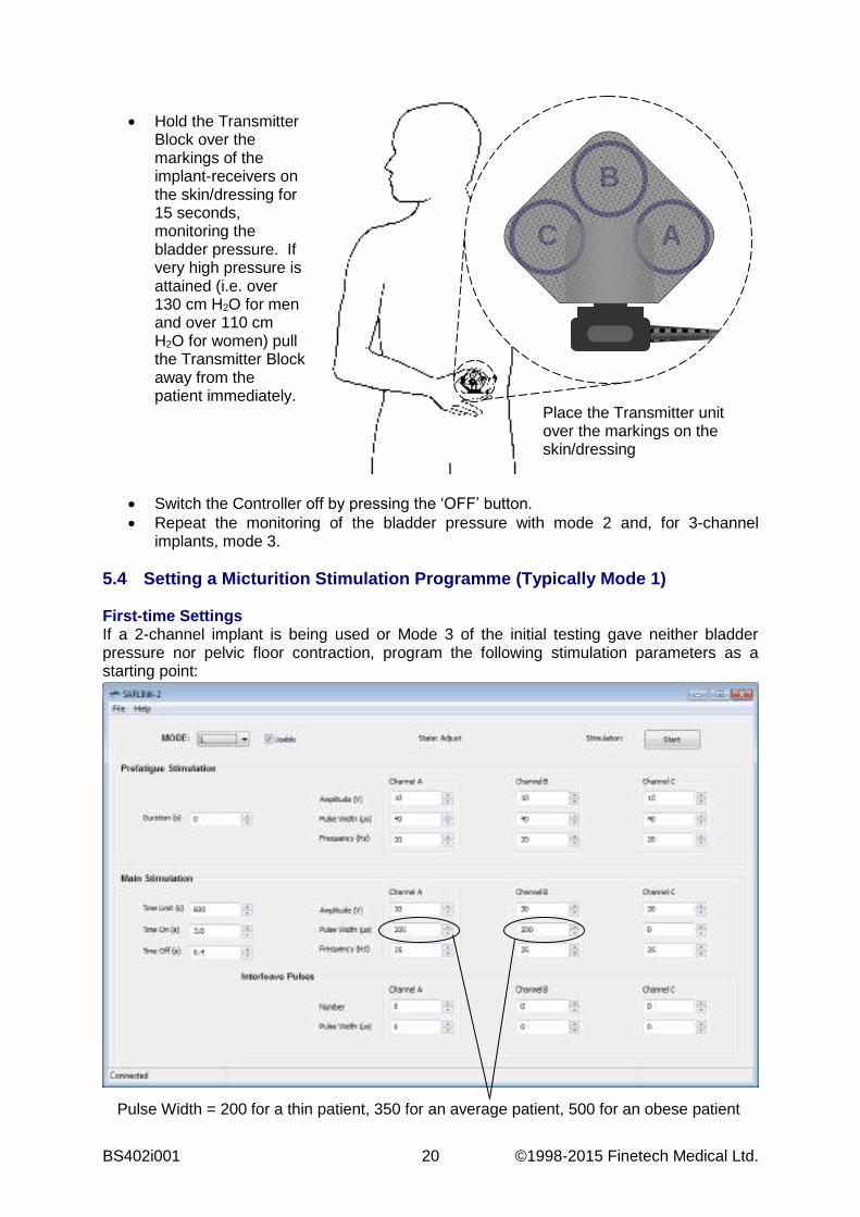
Hold the Transmitter
Block over the markings of the implant-receivers on the skin/dressing for 15 seconds, monitoring the bladder pressure. If very high pressure is attained (i.e. over 130 cm H2O for men and over 110 cm H2O for women) pull the Transmitter Block away from the patient immediately.
Switch the Controller off by pressing the ‘OFF’ button. Repeat the monitoring of the bladder pressure with mode 2 and, for 3-channel
implants, mode 3. 5.4 Setting a Micturition Stimulation Programme (Typically Mode 1) First-time Settings If a 2-channel implant is being used or Mode 3 of the initial testing gave neither bladder pressure nor pelvic floor contraction, program the following stimulation parameters as a starting point:
Place the Transmitter unit over the markings on the skin/dressing
B
A C
Pulse Width = 200 for a thin patient, 350 for an average patient, 500 for an obese patient
© 1998-2015 Finetech Medical Ltd. 21 BS402i001
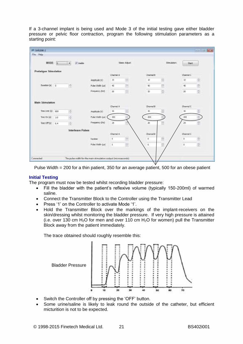
If a 3-channel implant is being used and Mode 3 of the initial testing gave either bladder pressure or pelvic floor contraction, program the following stimulation parameters as a starting point:
Initial Testing The program must now be tested whilst recording bladder pressure:
Fill the bladder with the patient’s reflexive volume (typically 150-200ml) of warmed saline.
Connect the Transmitter Block to the Controller using the Transmitter Lead Press ‘1’ on the Controller to activate Mode ‘1’. Hold the Transmitter Block over the markings of the implant-receivers on the
skin/dressing whilst monitoring the bladder pressure. If very high pressure is attained (i.e. over 130 cm H2O for men and over 110 cm H2O for women) pull the Transmitter Block away from the patient immediately.
The trace obtained should roughly resemble this:
Switch the Controller off by pressing the ‘OFF’ button. Some urine/saline is likely to leak round the outside of the catheter, but efficient
micturition is not to be expected.
Pulse Width = 200 for a thin patient, 350 for an average patient, 500 for an obese patient
Bladder Pressure
BS402i001 22 ©1998-2015 Finetech Medical Ltd.
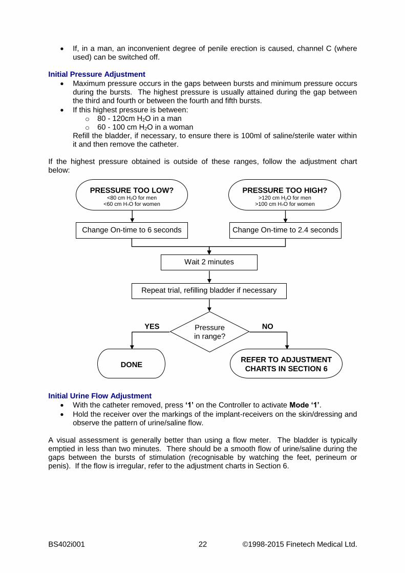
If, in a man, an inconvenient degree of penile erection is caused, channel C (where used) can be switched off.
Initial Pressure Adjustment
Maximum pressure occurs in the gaps between bursts and minimum pressure occurs during the bursts. The highest pressure is usually attained during the gap between the third and fourth or between the fourth and fifth bursts.
If this highest pressure is between: o 80 - 120cm H2O in a man o 60 - 100 cm H2O in a woman
Refill the bladder, if necessary, to ensure there is 100ml of saline/sterile water within it and then remove the catheter.
If the highest pressure obtained is outside of these ranges, follow the adjustment chart below:
Initial Urine Flow Adjustment
With the catheter removed, press ‘1’ on the Controller to activate Mode ‘1’. Hold the receiver over the markings of the implant-receivers on the skin/dressing and
observe the pattern of urine/saline flow.
A visual assessment is generally better than using a flow meter. The bladder is typically emptied in less than two minutes. There should be a smooth flow of urine/saline during the gaps between the bursts of stimulation (recognisable by watching the feet, perineum or penis). If the flow is irregular, refer to the adjustment charts in Section 6.
PRESSURE TOO LOW? <80 cm H2O for men
<60 cm H2O for women
PRESSURE TOO HIGH? >120 cm H2O for men
>100 cm H2O for women
Change On-time to 6 seconds Change On-time to 2.4 seconds
Wait 2 minutes
Repeat trial, refilling bladder if necessary
Pressure in range?
DONE
REFER TO ADJUSTMENT CHARTS IN SECTION 6
YES NO
© 1998-2015 Finetech Medical Ltd. 23 BS402i001
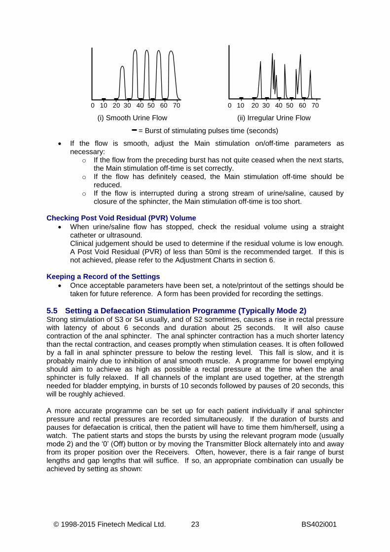
If the flow is smooth, adjust the Main stimulation on/off-time parameters as
necessary: o If the flow from the preceding burst has not quite ceased when the next starts,
the Main stimulation off-time is set correctly. o If the flow has definitely ceased, the Main stimulation off-time should be
reduced. o If the flow is interrupted during a strong stream of urine/saline, caused by
closure of the sphincter, the Main stimulation off-time is too short. Checking Post Void Residual (PVR) Volume
When urine/saline flow has stopped, check the residual volume using a straight catheter or ultrasound. Clinical judgement should be used to determine if the residual volume is low enough. A Post Void Residual (PVR) of less than 50ml is the recommended target. If this is not achieved, please refer to the Adjustment Charts in section 6.
Keeping a Record of the Settings Once acceptable parameters have been set, a note/printout of the settings should be
taken for future reference. A form has been provided for recording the settings. 5.5 Setting a Defaecation Stimulation Programme (Typically Mode 2) Strong stimulation of S3 or S4 usually, and of S2 sometimes, causes a rise in rectal pressure with latency of about 6 seconds and duration about 25 seconds. It will also cause contraction of the anal sphincter. The anal sphincter contraction has a much shorter latency than the rectal contraction, and ceases promptly when stimulation ceases. It is often followed by a fall in anal sphincter pressure to below the resting level. This fall is slow, and it is probably mainly due to inhibition of anal smooth muscle. A programme for bowel emptying should aim to achieve as high as possible a rectal pressure at the time when the anal sphincter is fully relaxed. If all channels of the implant are used together, at the strength needed for bladder emptying, in bursts of 10 seconds followed by pauses of 20 seconds, this will be roughly achieved. A more accurate programme can be set up for each patient individually if anal sphincter pressure and rectal pressures are recorded simultaneously. If the duration of bursts and pauses for defaecation is critical, then the patient will have to time them him/herself, using a watch. The patient starts and stops the bursts by using the relevant program mode (usually mode 2) and the ‘0’ (Off) button or by moving the Transmitter Block alternately into and away from its proper position over the Receivers. Often, however, there is a fair range of burst lengths and gap lengths that will suffice. If so, an appropriate combination can usually be achieved by setting as shown:
0 10 20 30 40 50 60 70
(i) Smooth Urine Flow (ii) Irregular Urine Flow
= Burst of stimulating pulses time (seconds)
0 10 20 30 40 50 60 70
BS402i001 24 ©1998-2015 Finetech Medical Ltd.
Besides the immediate rise of rectal pressure, stimulation of sacral anterior roots causes an increase in colonic activity. In about 50% of patients, use of the implant as described above expels faeces from the rectum. In the remainder, it fails to do this, but is nevertheless useful because it moves faeces from the pelvic colon into the rectum, and thus makes manual evacuation quicker and more complete. An Adjustment chart is available in Section 6. 5.6 Setting an Erection Programme (Typically Mode 3) First try a frequency of around 8Hz and an amplitude setting of 40V, continuously. Test S2 alone, then S3 alone. Usually S2 is the main erectile root. If S2 and S3 both give incomplete erection, try them together. Each test should be continued for at least 3 minutes; implant driven erection can come on very slowly, but when established it stays constant until stimulation ceases. If S2 without S3 gives adequate erection, it is probably the best choice for the practical program even if adding S3 improves the penile rigidity, because leakage of urine is less likely with S2 alone. 8Hz is below tetanic fusion frequency for lower limb muscles and will make the patient shake. If he finds the shaking too disturbing, the frequency can be increased. At around 12Hz there will be less shaking and at around 18Hz probably none. If erection is poor with an amplitude setting of 40V at the pulse duration appropriate for bladder and bowel activation, it may be possible to achieve good erection by setting a greater main stimulation pulse width.
Pulse Width = 200 for a thin patient, 350 for an average patient, 500 for an obese patient

© 1998-2015 Finetech Medical Ltd. 25 BS402i001
6. ADJUSTMENT CHARTS This section contains flow charts to assist in modifying stimulation parameters in three key sections:
Adjusting bladder pressure o Pressure too High o Pressure too Low
Adjusting Post Void Residuals (PVR) Adjusting urine flow Adjusting bowel mode
BS402i001 26 ©1998-2015 Finetech Medical Ltd.
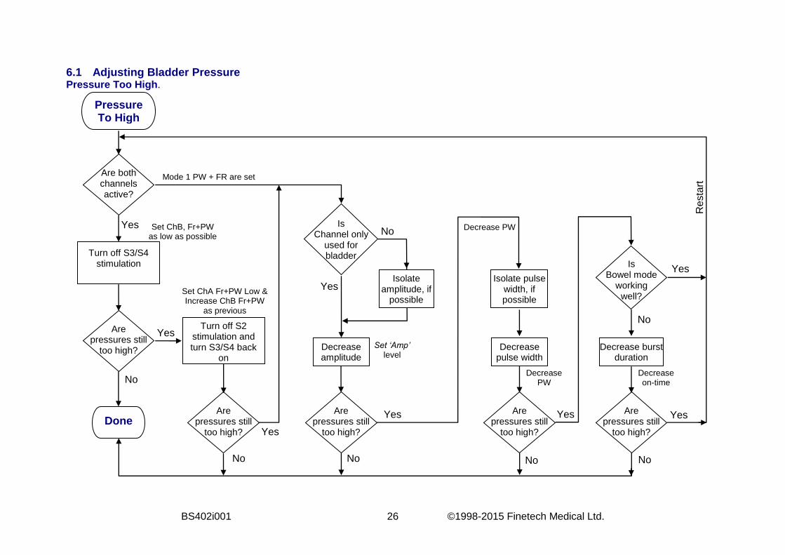
6.1 Adjusting Bladder Pressure Pressure Too High.
Pressure To High
Are both channels active?
Turn off S3/S4 stimulation
Are pressures still
too high?
Are pressures still
too high?
Turn off S2 stimulation and turn S3/S4 back
on
Yes
Yes
Are pressures still
too high?
Decrease amplitude
Isolate pulse width, if possible
Decrease pulse width
Are pressures still
too high?
Are pressures still
too high?
Is Bowel mode
working well?
Is Channel only
used for bladder
Decrease burst duration
Yes
No
Yes
No
Yes Done
No
Isolate amplitude, if
possible
No No No
Yes
Yes
No
Res
tart
Decrease on-time
Decrease PW
Set ‘Amp’ level
Decrease PW Set ChB, Fr+PW as low as possible
Set ChA Fr+PW Low & Increase ChB Fr+PW
as previous
Mode 1 PW + FR are set
Yes
© 1998-2015 Finetech Medical Ltd. 27 BS402i001
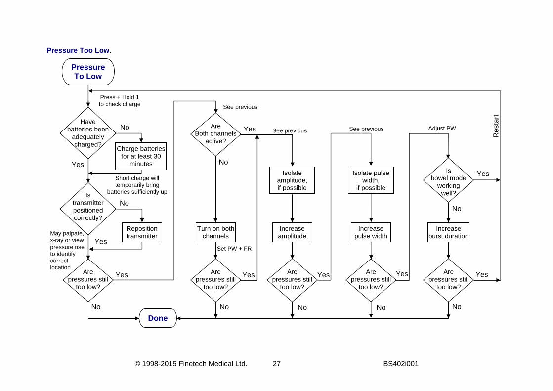
Pressure Too Low.
Pressure To Low
Is transmitter positioned correctly?
Are pressures still
too low?
Have batteries been
adequately charged?
Charge batteries for at least 30
minutes Yes
No
Yes
No
Reposition transmitter
No
Are Both channels
active?
Turn on both channels
Are pressures still
too low?
Are pressures still
too low?
Are pressures still
too low?
Are pressures still
too low?
Increase amplitude
Increase pulse width
Increase burst duration
Isolate amplitude, if possible
Isolate pulse width,
if possible
Is bowel mode
working well?
Yes
No
No No No
Yes
Yes
Yes
No
Res
tart
No
Yes Yes Yes
Press + Hold 1 to check charge
Short charge will temporarily bring
batteries sufficiently up
May palpate, x-ray or view pressure rise to identify correct location
See previous
See previous See previous Adjust PW
Set PW + FR
Done
BS402i001 28 ©1998-2015 Finetech Medical Ltd.
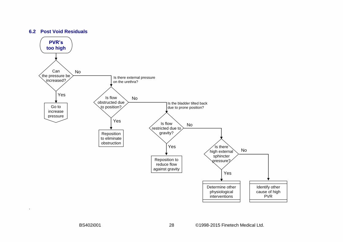
6.2 Post Void Residuals
.
PVR’s too high
Can the pressure be
increased?
Is flow obstructed due
to position?
Is flow restricted due to
gravity?
Is there high external
sphincter pressure?
Reposition to eliminate obstruction
Reposition to reduce flow
against gravity
Determine other physiological interventions
Identify other cause of high
PVR
Go to increase pressure
No
Yes
Yes
Yes
Yes
No
No
No
Is there external pressure on the urethra?
Is the bladder tilted back due to prone position?
© 1998-2015 Finetech Medical Ltd. 29 BS402i001
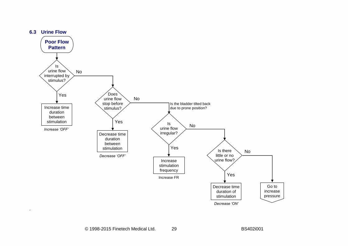
6.3 Urine Flow
.
Poor Flow Pattern
Is urine flow
interrupted by stimulus?
Does urine flow
stop before stimulus?
Is urine flow irregular?
Is there little or no urine flow?
Increase time duration between
stimulation
Increase stimulation frequency
No
Yes
Yes
Yes
Yes
No
No
No
Increase ‘OFF’
Is the bladder tilted back due to prone position?
Decrease time duration between
stimulation
Decrease time duration of stimulation
Go to increase pressure
Decrease ‘OFF’
Increase FR
Decrease ‘ON’
BS402i001 30 ©1998-2015 Finetech Medical Ltd.
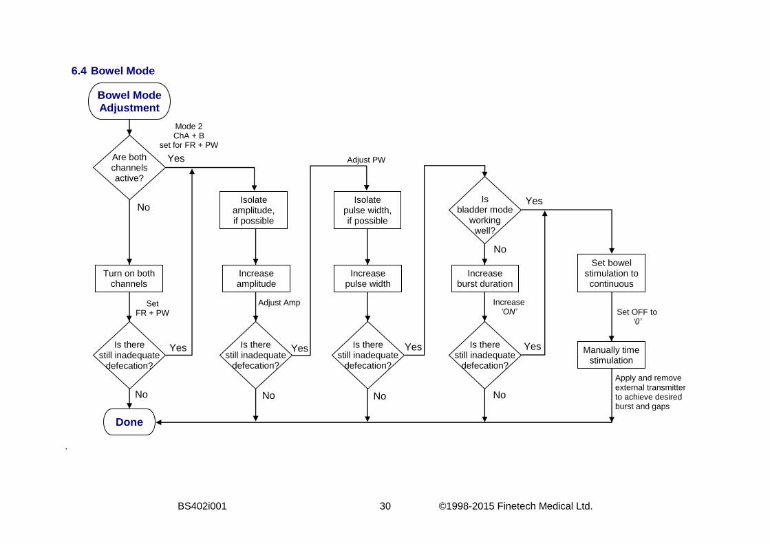
6.4 Bowel Mode
.
Bowel Mode Adjustment
Are both channels active?
Turn on both channels
Increase amplitude
Increase pulse width
Increase burst duration
Isolate amplitude, if possible
Isolate pulse width, if possible
Is there still inadequate
defecation?
Is there still inadequate
defecation?
Is there still inadequate
defecation?
Is there still inadequate
defecation?
Done
Is bladder mode
working well?
Manually time stimulation
Yes
No
No No No
No
Yes
Yes Yes Yes
Set bowel stimulation to continuous
Set FR + PW
Mode 2 ChA + B
set for FR + PW
Adjust PW
Increase ‘ON’ Set OFF to
‘0’
Apply and remove external transmitter to achieve desired burst and gaps
Adjust Amp
Yes
No

© 1998-2015 Finetech Medical Ltd. 31 BS402i001
7. PROBLEMS AND ERROR CODES If the Controller detects an error it will immediately stop stimulation and display an error code. The meaning of the various error codes is shown below, along with the action which should be taken. Error Code Action E 1 - battery flat Put Controller on charge. E 2 - low output current Check that Transmitter Lead is not damaged and is
properly connected to the Transmitter Block and Controller.
E 3 - current after end of pulse Internal fault - return to supplier. E 4 – high output current The requested level of stimulation is too high - you must
reduce overall output amplitudes. E 5 - HT supply under-voltage Internal fault - return to supplier. E 6 - HT supply failure Internal fault - return to supplier. E 7 - HT supply over-voltage This can occur if Modes are switched too quickly. Turn off
and try desired Mode again. If problem persists return to supplier.
E 8 - assertion failure Internal fault - return to supplier. E 9 – power reset This error code is not display but log every there is an
incorrect shut down of the controller. This can be view through SARLINK-2.
E 10 –battery charger faults Internal fault - return to supplier. Battery Protection Circuit The Lithium-Ion battery used in the Controller has an electronic protection circuit built into it. This protects against over discharging the battery. If this is activated the battery will switch itself off and the Controller will not respond to any button presses. In order to reset the protection circuit, the Controller must be briefly put on charge.
BS402i001 32 ©1998-2015 Finetech Medical Ltd.
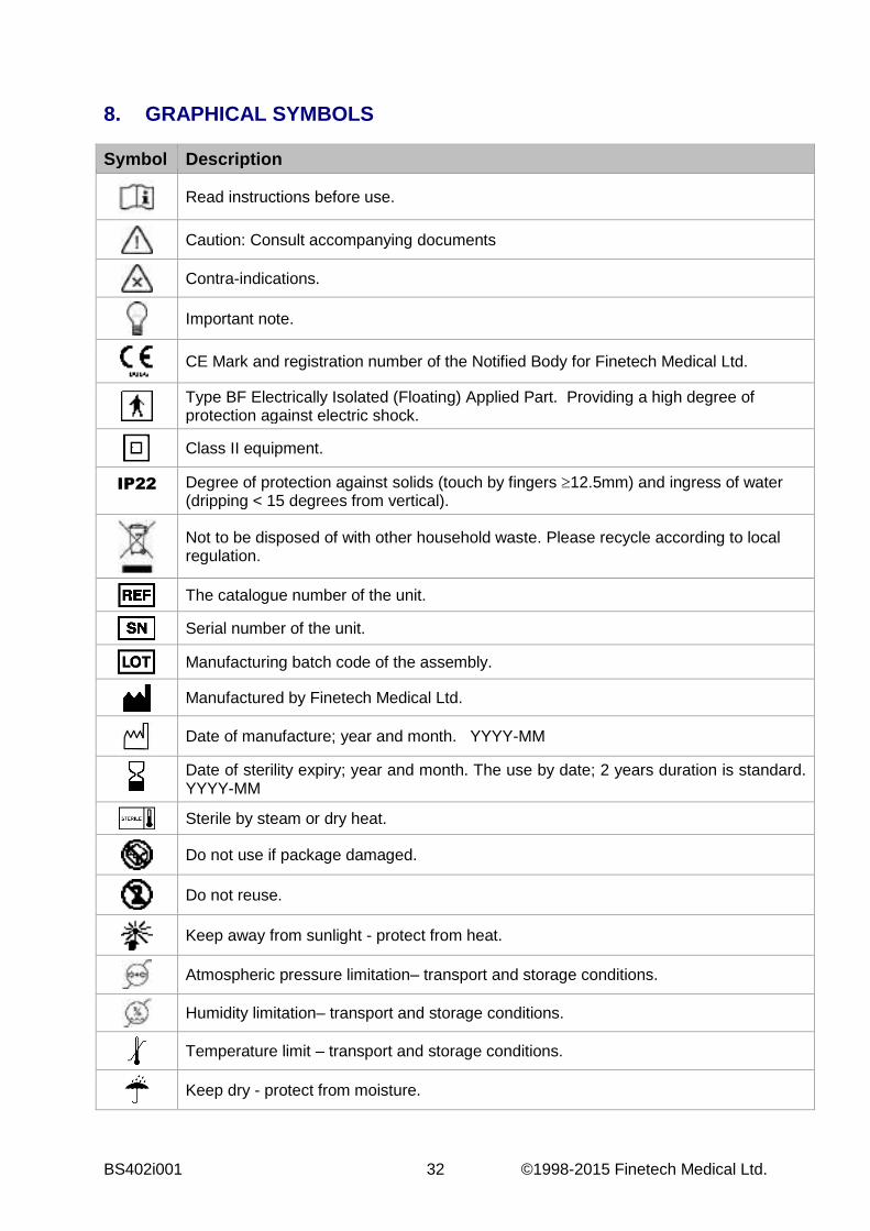
8. GRAPHICAL SYMBOLS
Symbol Description
Read instructions before use.
Caution: Consult accompanying documents
Contra-indications.
Important note.
CE Mark and registration number of the Notified Body for Finetech Medical Ltd.
Type BF Electrically Isolated (Floating) Applied Part. Providing a high degree of protection against electric shock.
Class II equipment.
IP22 Degree of protection against solids (touch by fingers 12.5mm) and ingress of water (dripping < 15 degrees from vertical).
Not to be disposed of with other household waste. Please recycle according to local regulation.
The catalogue number of the unit.
Serial number of the unit.
Manufacturing batch code of the assembly.
Manufactured by Finetech Medical Ltd.
Date of manufacture; year and month. YYYY-MM
Date of sterility expiry; year and month. The use by date; 2 years duration is standard. YYYY-MM
Sterile by steam or dry heat.
Do not use if package damaged.
Do not reuse.
Keep away from sunlight - protect from heat.
Atmospheric pressure limitation– transport and storage conditions.
Humidity limitation– transport and storage conditions.
Temperature limit – transport and storage conditions.
Keep dry - protect from moisture.

© 1998-2015 Finetech Medical Ltd. 33 BS402i001
9. DECLARATION OF CONFORMITY Finetech Medical declares that this product is in conformity with the essential requirements of Active Implantable Medical Devices Directive 90/385/EEC. For additional information, contact Finetech Medical.

BS402i001 34 ©1998-2015 Finetech Medical Ltd.
10. FORMS
FINETECH BRINDLEY STIMULATOR SETTINGS Patient Name:
Surgery Date: Hospital No: Etiology:
Implant Type:
Extradural [ ] Intrathecal [ ]
2 channel [ ] 3 channel [ ]
Clinician:
User Guide: BS400 Surgical Procedure Manual: BS401
Implant S/N:
Controller S/N:
Mode(s) available to user: 1 [ ] 1A [ ] 1B [ ] 2 [ ] 2A [ ] 2B [ ] 3 [ ] 3A [ ] 3B [ ] Mode (1, 1A, 1B, 2, 2A, 2B, 3, 3A, 3B)
Time limit (sec)
On time (sec)
Off time (sec)
Amplitude (10 to 40)
Channel A B C A B C A B C Pulse width (s)
Frequency (Hz)
Interleave Number (0 to 2)
Pulse width (µs)
Pre-fatigue Duration (s)
Amplitude (10 to 40)
Pulse width (µs)
Frequency (Hz)
© 1998-2015 Finetech Medical Ltd. 35 BS402i001
11. INDEX Abdominal muscle contractions .......... 18
Abdominal pressure ..................... 16, 18
Access code ......................................... 7
Anal sphincter contraction .................. 23
Bladder pressure high .................. 22, 26
Bladder pressure low .......................... 27
Bladder voiding .................................... 4
Bowel evacuation ................................. 4
Bowel mode ....................................... 30
Communications Lead .................... 9, 16
Controller................ 8, 15, 18, 19, 21, 31
Cystometry ......................................... 16
Detrusor contractions ......................... 18
Detrusor pressure ............................... 16
Erection program ................................ 24
Error codes ......................................... 31
Flow meter ......................................... 22
Frequency limits ................................... 6
Implantable Receiver-Stimulator ......... 20
Interleave number ................................ 6
Interleave pulses .................................. 6
Maximum duration ............................... 4
Mode change ....................................... 8
Modes .................................................. 4
Parameter abbreviations ...................... 9
Parameter adjustment .......................... 7
Parameters .......................................... 4
Patient shake ..................................... 24
Penile erection ..................................... 4
PIN (number) ....................................... 7
Power limit ........................................... 6
Preganglionic fibres ........................... 18
Rectal pressure ............................ 23, 24
Residual volume .......................... 23, 28
SARLINK ............................................. 9
Stimulation parameters ........................ 4
Tetanic fusion frequency .................... 24
Transmitter Block ........ 15, 19, 21, 23, 31
Transmitter Lead ............... 15, 20, 21, 31
Urine flows ......................................... 29
Vesical pressure ................................ 16

BS402i001 36 ©1998-2015 Finetech Medical Ltd.
12. NOTES


![[FINETECH JAPAN] Exhibitors & Products Catalogue 2016](https://static.fdocuments.in/doc/165x107/579075531a28ab6874b40f6c/finetech-japan-exhibitors-products-catalogue-2016.jpg)


