COVER I (TECHNICAL BID)
154
CONRACTOR SENIOR MANAGER (CIVIL) ODISHA CONSTRUCTION CORPORATION LTD. (A Govt. of Odisha Undertaking) Gopabandhu Nagar, Unit-VIII, Bhubaneswar. COVER – I (TECHNICAL BID) (ITEM RATE TENDER) Tender Call Notice No. 01 , dt. 23.10.2019 “Construction of spillway of Kanupur Spillway Project (Balance Work)” Managing Director, OCC Ltd. Bhubaneswar NAME OF WORK
Transcript of COVER I (TECHNICAL BID)

0
CONRACTOR SENIOR MANAGER (CIVIL)
ODISHA CONSTRUCTION CORPORATION LTD.
(A Govt. of Odisha Undertaking) Gopabandhu Nagar, Unit-VIII, Bhubaneswar.
COVER – I
(TECHNICAL BID)
(ITEM RATE TENDER)
Tender Call Notice No. 01 , dt. 23.10.2019
“Construction of spillway of Kanupur Spillway
Project (Balance Work)”
Managing Director,
OCC Ltd. Bhubaneswar
NAME OF WORK

1
CONRACTOR SENIOR MANAGER (CIVIL)
PARTICULARS OF TENDER
1 Name of work: Construction of spillway of Kanupur Spillway Project (Balance Work)
2 Approximate value of the work:
Rs.15,80,00,000.00 (Excluding cost of Cement, Steel & GST)
3 E.M.D Rs. 15,80,000.00
4 Period of Completion 6 (Six) Calendar months
5 Class of Contractor C-I enlisted Contractor of OCC Ltd.
6 Cost of Bid Documents Rs. 11,800 including GST
7 Availability of Tender in OCCL website.
From 23.10.2019, 10.00 AM to 13.11.2019, 5.00 PM
8 Submission of Bid in the Drop Box
From 23.10.2019, 10.00 AM to 13.11.2019, 5.00 PM during office hours
9 Opening of Technical Bid (Cover-I) submitted in the drop box-
14.11.2019 at 11.30 AM at Head Office, OCC Ltd, Bhubaneswar.
10 Date of opening of Financial Bid (Cover-II)
To be intimated to qualified bidders after evaluation of Technical Bid by registered post/Speed Post/E-mail.
2
CONRACTOR SENIOR MANAGER (CIVIL)
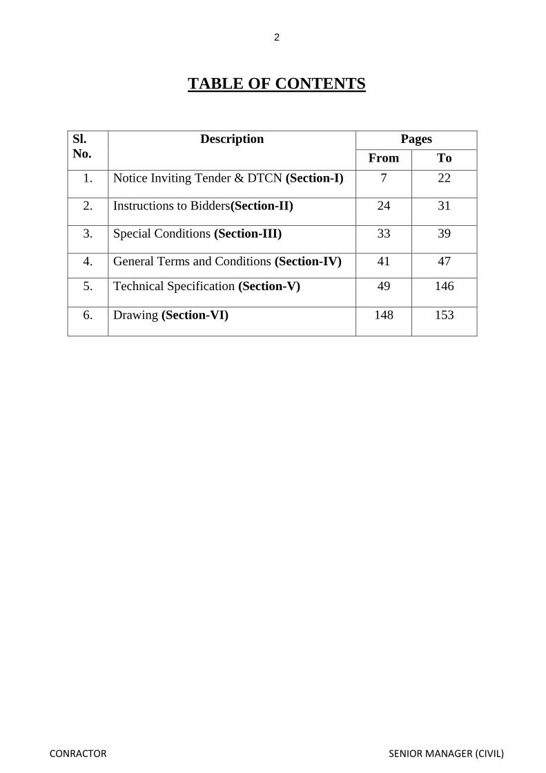
TABLE OF CONTENTS
Sl.
No.
Description Pages
From To
1. Notice Inviting Tender & DTCN (Section-I) 7 22
2. Instructions to Bidders(Section-II) 24 31
3. Special Conditions (Section-III) 33 39
4. General Terms and Conditions (Section-IV) 41 47
5. Technical Specification (Section-V) 49 146
6. Drawing (Section-VI) 148 153

3
CONRACTOR SENIOR MANAGER (CIVIL)
1. DETAILS OF DEMAND DRAFTS SUBMITTED BY THE BIDDER WITH THE TECHNICAL BID (COVER-I)
(DETAILS TO BE FILLED IN BY THE BIDDER)
A. DETAILS OF TENDER PAPER COST SUBMITTED BY THE BIDDER
Tender Paper cost Rs._________________
(Rupees________________________________________________________
_____) only vide A/C Payee Demand Draft No.________________________
Dated_________________issued by _________________________________
Bank,_______________________________Branch in favour of “ Odisha
Construction Corporation Ltd” payable at Bhubaneswar.
B. DETAILS OF EARNEST MONEY DEPOSIT (EMD) SUBMITTED BY THE BIDDER
EMD amounting Rs________________
(Rupees________________________________________________________
_____) only vide A/C Payee Demand Draft No.________________________
Dated_________________issued by _________________________________
Bank,_______________________________Branch in favour of “ Odisha
Construction Corporation Ltd” payable at Bhubaneswar.
Full signature of “Bidder” with seal

4
CONRACTOR SENIOR MANAGER (CIVIL)
2. Particulars of the Bidder (Details to be filled in by the bidder in all respect in the blank space otherwise
his tender will not be considered.)
FORM – A
1. Name of Tenderer ………………………………………………
2. Nationality of Tenderer ………………………………………………
3. Office Address ………………………………………………
………………………………………………..
4. Telephone No.
Land phone ……………………………………………….
Mobile ……………………………………………….
Fax No ……………………………………………….
e-mail id ………………………………………………
5. Location of establishment ………………………………………………
6. The tenderer is
a. An individual
b. A proprietary firm
c. A limited company or limited corporation
d . A member of a group of companies (If yes, give names, address and present description of other companies. e. A subsidiary of large organization
(If yes, give names, address of the present organization)
f. If the company is subsidiary state what involvement if any, will the parent company have in the
project.
Attach the organization chart showing the structure of the organization including the names of the
Directors position of officer.
7. Number of year of experience
a. As a prime Contractor
I In own country
II Other country (specify country)

5
CONRACTOR SENIOR MANAGER (CIVIL)
3. OTHER STATUTORY DOCUMENTS SUBMITTED :- (Please write the GST / PAN
/ EPF No. etc. in the relevant box and attach the certified copies of the
documents)
i. GST Registration No.
ii. P.A.N. No.
iii. EPF No.
iv. Labour License No.
v. OCCL Enlistment No. - Valid upto-
vi. Any other documents. ( As per
Tender Call Notice)
Full signature of the “Bidder” with date and seal

6
CONRACTOR SENIOR MANAGER (CIVIL)
SECTION-I
NOTICE INVITING TENDER
&
DETAILED TENDER CALL NOTICE
7
CONRACTOR SENIOR MANAGER (CIVIL)
ODISHA CONSTRUCTION CORPORATION LTD. (A Govt. of Odisha Undertaking)
Gopabandhu Nagar, Unit-VIII, Bhubaneswar.
DIST-Khordha-751012, Tel-0674-2562020, e-mail:[email protected]
(GSTIN-21AAACO2571K2ZM)
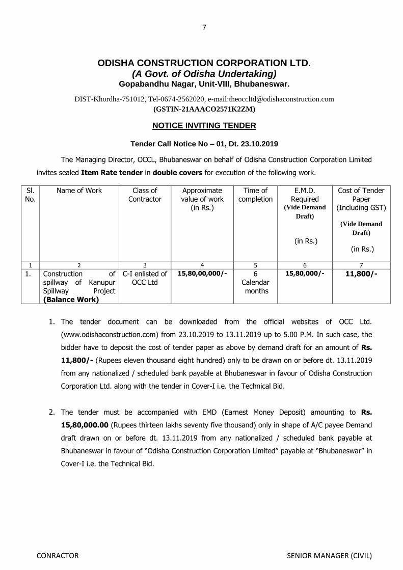
NOTICE INVITING TENDER
Tender Call Notice No – 01, Dt. 23.10.2019
The Managing Director, OCCL, Bhubaneswar on behalf of Odisha Construction Corporation Limited
invites sealed Item Rate tender in double covers for execution of the following work.
Sl.No.
Name of Work Class of Contractor
Approximate value of work
(in Rs.)
Time of completion
E.M.D. Required
(Vide Demand
Draft)
(in Rs.)
Cost of Tender Paper
(Including GST)
(Vide Demand
Draft)
(in Rs.)
1 2 3 4 5 6 7
1. Construction of spillway of Kanupur Spillway Project (Balance Work)
C-I enlisted of OCC Ltd
15,80,00,000/- 6 Calendar months
15,80,000/- 11,800/-
1. The tender document can be downloaded from the official websites of OCC Ltd.
(www.odishaconstruction.com) from 23.10.2019 to 13.11.2019 up to 5.00 P.M. In such case, the
bidder have to deposit the cost of tender paper as above by demand draft for an amount of Rs.
11,800/- (Rupees eleven thousand eight hundred) only to be drawn on or before dt. 13.11.2019
from any nationalized / scheduled bank payable at Bhubaneswar in favour of Odisha Construction
Corporation Ltd. along with the tender in Cover-I i.e. the Technical Bid.
2. The tender must be accompanied with EMD (Earnest Money Deposit) amounting to Rs.
15,80,000.00 (Rupees thirteen lakhs seventy five thousand) only in shape of A/C payee Demand
draft drawn on or before dt. 13.11.2019 from any nationalized / scheduled bank payable at
Bhubaneswar in favour of “Odisha Construction Corporation Limited” payable at “Bhubaneswar” in
Cover-I i.e. the Technical Bid.
8
CONRACTOR SENIOR MANAGER (CIVIL)
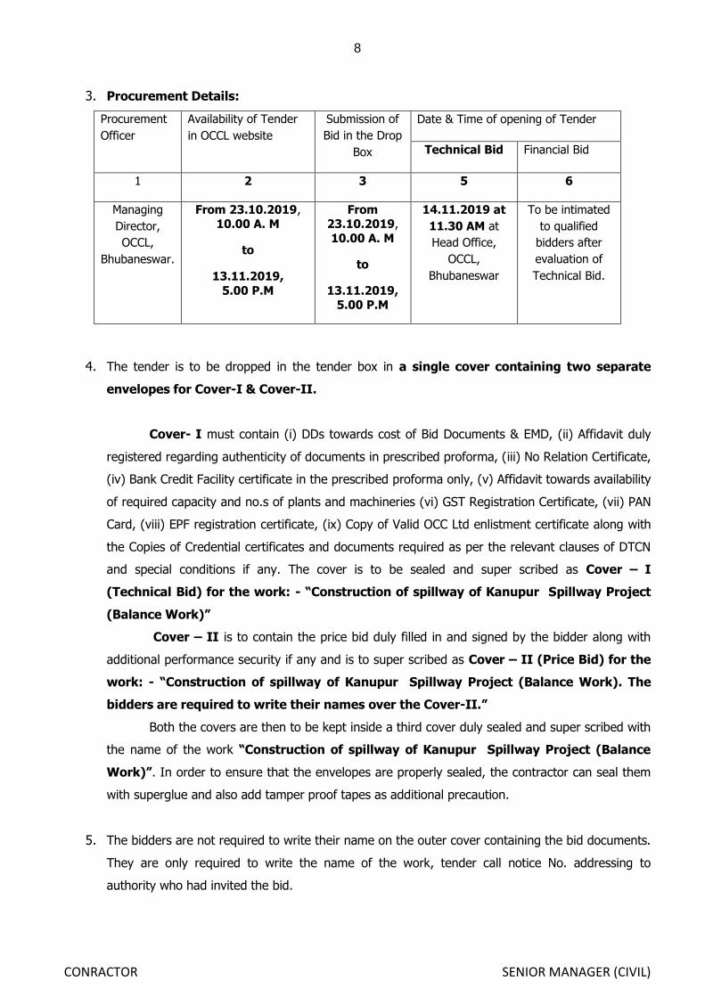
3. Procurement Details:
Procurement
Officer
Availability of Tender
in OCCL website
Submission of
Bid in the Drop
Box
Date & Time of opening of Tender
Technical Bid Financial Bid
1 2 3 5 6
Managing
Director,
OCCL,
Bhubaneswar.
From 23.10.2019, 10.00 A. M
to
13.11.2019,
5.00 P.M
From 23.10.2019,
10.00 A. M
to
13.11.2019, 5.00 P.M
14.11.2019 at
11.30 AM at
Head Office,
OCCL,
Bhubaneswar
To be intimated
to qualified
bidders after
evaluation of
Technical Bid.
4. The tender is to be dropped in the tender box in a single cover containing two separate
envelopes for Cover-I & Cover-II.
Cover- I must contain (i) DDs towards cost of Bid Documents & EMD, (ii) Affidavit duly
registered regarding authenticity of documents in prescribed proforma, (iii) No Relation Certificate,
(iv) Bank Credit Facility certificate in the prescribed proforma only, (v) Affidavit towards availability
of required capacity and no.s of plants and machineries (vi) GST Registration Certificate, (vii) PAN
Card, (viii) EPF registration certificate, (ix) Copy of Valid OCC Ltd enlistment certificate along with
the Copies of Credential certificates and documents required as per the relevant clauses of DTCN
and special conditions if any. The cover is to be sealed and super scribed as Cover – I
(Technical Bid) for the work: - “Construction of spillway of Kanupur Spillway Project
(Balance Work)”
Cover – II is to contain the price bid duly filled in and signed by the bidder along with
additional performance security if any and is to super scribed as Cover – II (Price Bid) for the
work: - “Construction of spillway of Kanupur Spillway Project (Balance Work). The
bidders are required to write their names over the Cover-II.”
Both the covers are then to be kept inside a third cover duly sealed and super scribed with
the name of the work “Construction of spillway of Kanupur Spillway Project (Balance
Work)”. In order to ensure that the envelopes are properly sealed, the contractor can seal them
with superglue and also add tamper proof tapes as additional precaution.
5. The bidders are not required to write their name on the outer cover containing the bid documents.
They are only required to write the name of the work, tender call notice No. addressing to
authority who had invited the bid.

9
CONRACTOR SENIOR MANAGER (CIVIL)
6. The bid must be dropped in the Tender Box kept in the conference Hall (1st Floor) of the
Corporate Office of OCC Ltd., Unit-VIII, Gopabandhu Nagar, Bhubaneswar on or before 5:00 PM of
13.11.2019. Bid will be opened on 14.11.2019 at 11.30 AM in the same venue in presence of the
bidders or their authorized representatives who wish to remain present. If there will be a public
holiday on the last date of receipt & opening of the tenders as specified above, the tender
documents shall be received & opened on the next working day at the same time & venue. Date
time and place of opening of cover- II (Price Bid) shall be intimated subsequently to those bidders
who will be found eligible after evaluation of Technical Bid through Speed Post/ e-mail.
7. Bid validity of the Tender is for a period of 90 (ninety) days from the last date of submission of
bid. Conditional bid is subjected to forfeiture of EMD/Bid Security. If any bidder withdraws his Bid/
Tender before the said period or makes any modification in the terms and condition of the bid, the
EMD deposited at the time of submission of tender/bid shall stand forfeited. Validity of tenders can
also be extended if required without any monetary compensation.
8. No Engineer of Gazetted rank or other Gazetted Officer employed in Engineering or Administrative
duties in any Engineering Department of the State Government/Corporation is allowed to work as
a Contractor for a period of two years after his retirement from Government Service/Corporation
service, without Government/Corporation permission.
9. The affidavits towards genuineness of all documents, availability of plants and machineries, the No
Relationship Certificate is to be submitted with the bid in prescribed proforma as annexed in the
Bid Document.
10. The bidders not registered under GST in Odisha are required to submit an undertaking in the
form of an affidavit that, they are not registered under GST act in the state of Odisha as they have
not started any business in the state and they have no liabilities under the said Act. The successful
bidders have to produce their documents regarding GST registration in the state of Odisha before
drawal of the agreement.
11. Additional Performance Security shall be put inside the Cover – II, if the amount quoted is less
than the amount put to tender. In such an event, the bidder who has quoted less bid price/rates
than the amount put to tender, shall have to furnish exact amount of differential cost i.e.
estimated cost put to tender minus the quoted amount as Additional Performance Security (APS)
in shape of Term Deposit Receipt pledged in favour of Odisha Construction Corporation Limited/
Bank Guarantee in prescribed format annexed in favour of Odisha Construction Corporation
Limited from any nationalized/scheduled bank in India counter guaranteed by its local branch at
Bhubaneswar failing which the tender will not be considered.

10
CONRACTOR SENIOR MANAGER (CIVIL)
12. The bidders have to quote the Rates against each item excluding cost of cement and Steel and
GST (Goods and Service Tax). GST as applicable will be paid extra.
13. The bidder may be asked in email/letters to clarify on the documents as submitted in the
Technical Bid. If necessary, with respect to any doubts or illegible documents, the authority
inviting bid reserves the right to accept any additional document.
14. Joint venture is not allowed.
15. Authority reserves the right to reject / Cancel the tender without assigning any reason thereof.
16. Any dispute arising out of the above tender call notice shall be subject to Jurisdiction of Hon‟ble
High Court of Orissa at Cuttack and their subordinate Courts at Bhubaneswar only.
Managing Director

11
CONRACTOR SENIOR MANAGER (CIVIL)
ODISHA CONSTRUCTION CORPORATION LTD.
(A Govt. of Odisha Undertaking) Gopabandhu Nagar, Unit-VIII, Bhubaneswar.
DETAILED TENDER CALL NOTICE
1. The Managing Director, OCCL, Bhubaneswar on behalf of Odisha Construction Corporation Limited
invites sealed Item Rate tender in double covers for execution of the work, “Construction of
spillway of Kanupur Spillway Project (Balance Work).” Enlisted C-I contractors of OCC Ltd can
submit the bid in the Drop Box as specified in the NIT.
2. The tender document can be downloaded from the official websites of OCC Ltd.
(www.odishaconstruction.com) from 23.10.2019 to 13.11.2019 up to 5.00 P.M. In such case, the
bidder have to deposit the cost of tender paper as above by demand draft for an amount of Rs.
11,800/- (Rupees eleven thousand eight hundred) only to be drawn on or before dt. 13.11.2019
from any nationalized / scheduled bank payable at Bhubaneswar in favour of Odisha Construction
Corporation Ltd. along with the tender.
3. The actual value of the work tendered is Rs.15,68,97,973.00 (excluding cost of cement,
steel & GST)
4. No tenderer will be permitted to furnish their bid in their own manuscript.
5. BID SECURITY:
(i) The tender must be accompanied with EMD (Earnest Money Deposit) amounting to Rs.
15,80,000.00 (Rupees fifteen lakhs eighty thousand) only in shape of A/C payee Demand draft
drawn on or before dt. 13.11.2019 from any nationalized / scheduled bank payable at
Bhubaneswar in favour of “Odisha Construction Corporation Limited” payable at “Bhubaneswar”.
(ii) The Bid shall be declared non-responsive and shall be rejected, if submitted without an acceptable
Bid Security.
(iii) The Bid Security of the successful bidder will be discharged when the bidder has signed the
Agreement and furnished the required Performance Security and Additional Performance security if
any.
The Bid Security may be forfeited
If the bidder withdraws the bid after opening of the bid but within the period of validity.
If the Bidder seeks any revision of rates or backs out of the bid claiming for not having
referred to any or all documents provided in the Bid by the Officer Inviting the Bids.
In the case of a successful bidder, if the bidder fails within the specified time limit to (a)
Sign the Agreement; or (b) Furnish the required Performance Security including additional
performance security if any.
12
CONRACTOR SENIOR MANAGER (CIVIL)
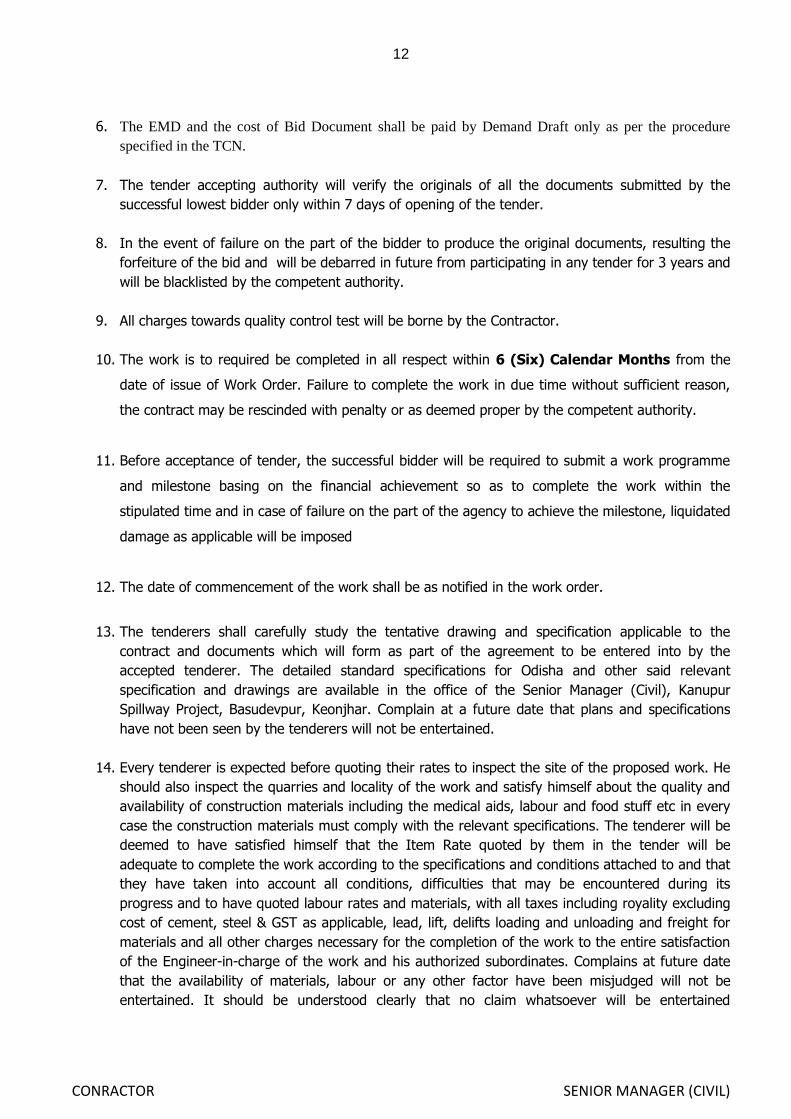
6. The EMD and the cost of Bid Document shall be paid by Demand Draft only as per the procedure
specified in the TCN.
7. The tender accepting authority will verify the originals of all the documents submitted by the
successful lowest bidder only within 7 days of opening of the tender.
8. In the event of failure on the part of the bidder to produce the original documents, resulting the
forfeiture of the bid and will be debarred in future from participating in any tender for 3 years and
will be blacklisted by the competent authority.
9. All charges towards quality control test will be borne by the Contractor.
10. The work is to required be completed in all respect within 6 (Six) Calendar Months from the
date of issue of Work Order. Failure to complete the work in due time without sufficient reason,
the contract may be rescinded with penalty or as deemed proper by the competent authority.
11. Before acceptance of tender, the successful bidder will be required to submit a work programme
and milestone basing on the financial achievement so as to complete the work within the
stipulated time and in case of failure on the part of the agency to achieve the milestone, liquidated
damage as applicable will be imposed
12. The date of commencement of the work shall be as notified in the work order.
13. The tenderers shall carefully study the tentative drawing and specification applicable to the
contract and documents which will form as part of the agreement to be entered into by the
accepted tenderer. The detailed standard specifications for Odisha and other said relevant
specification and drawings are available in the office of the Senior Manager (Civil), Kanupur
Spillway Project, Basudevpur, Keonjhar. Complain at a future date that plans and specifications
have not been seen by the tenderers will not be entertained.
14. Every tenderer is expected before quoting their rates to inspect the site of the proposed work. He
should also inspect the quarries and locality of the work and satisfy himself about the quality and
availability of construction materials including the medical aids, labour and food stuff etc in every
case the construction materials must comply with the relevant specifications. The tenderer will be
deemed to have satisfied himself that the Item Rate quoted by them in the tender will be
adequate to complete the work according to the specifications and conditions attached to and that
they have taken into account all conditions, difficulties that may be encountered during its
progress and to have quoted labour rates and materials, with all taxes including royality excluding
cost of cement, steel & GST as applicable, lead, lift, delifts loading and unloading and freight for
materials and all other charges necessary for the completion of the work to the entire satisfaction
of the Engineer-in-charge of the work and his authorized subordinates. Complains at future date
that the availability of materials, labour or any other factor have been misjudged will not be
entertained. It should be understood clearly that no claim whatsoever will be entertained

13
CONRACTOR SENIOR MANAGER (CIVIL)
afterwards on the plea of non availability of proper quantity and quality of materials including food
stuff or for any other reason.
15. Each tenderer must quote a definite Item Rate against each item of the work in the BoQ,
which will be included in the contract. Tenders containing indefinite terms such as estimated rates
will not be considered.
16. If the rate quoted by the bidder is less than 15% of the tendered amount
(Rs. Rs.15,68,97,973.00) then such a bid shall be rejected and the tender shall be finalized
basing on merits of rest of the bids. But if the total amount (considering the summation of all
quoted items) of more than one bidders are found to be same which is not less than 15% of
the amount put to tender, the tender accepting authority will finalize the tender through a
transparent lottery system, where all bidders/their authorized representatives and the
authorized officers of the Corporation will remain present.
17. Sample of coarse aggregates and fine aggregates to be used for the work are to be collected and
deposited quoting the name of the quarry under dated initials of the tenderer and Senior Manager
(Civil) in charge of the work in the office of the respective quality control division of Department of
Water Resources, Odisha before procurement for testing and acceptance. All the charges of
quality control test of materials will be borne by the Contractor.
18. The bidder shall sign on all statements, documents, certificates submitted by him/them. If any of
the information furnished by the bidder is found to be false /fabricated/ bogus, his EMD/ Bid
Security shall stand forfeited and the bidder is liable to be blacklisted.
19. The tender is to be dropped in the tender box in a single cover containing two separate
envelopes for Cover-I & Cover-II.
Cover- I must contain (i) DDs towards cost of Bid Documents & EMD, (ii) Affidavit duly
registered regarding authenticity of documents in prescribed proforma, (iii) No Relation Certificate,
(iv) Bank Credit Facility certificate in the prescribed proforma only, (v) Affidavit towards availability
of required capacity and no.s of plants and machineries (vi) GST Registration Certificate, (vii) PAN
Card, (viii) EPF registration certificate, (ix) Copy of Valid OCC Ltd enlistment certificate along with
the Copies of Credential certificates and documents required as per the relevant clauses of DTCN
and special conditions if any. The cover is to be sealed and super scribed as Cover – I
(Technical Bid) for the work: - “Construction of spillway of Kanupur Spillway Project
(Balance Work)”
Cover – II is to contain the price bid duly filled in and signed by the bidder along with
additional performance security if any and is to super scribed as Cover – II (Price Bid) for the
work: - “Construction of spillway of Kanupur Spillway Project (Balance Work). The
bidders are required to write their names over the Cover-II.”
14
CONRACTOR SENIOR MANAGER (CIVIL)
Both the covers are then to be kept inside a third cover duly sealed and super scribed with
the name of the work, “Construction of spillway of Kanupur Spillway Project (Balance
Work)” ; Tender Call Notice No., addressing to the tender inviting authority. In order to ensure
that the envelopes are properly sealed, the contractor can seal them with superglue and also add
tamper proof tapes as additional precaution.
20. The tender containing extraneous condition not covered by the tender call notice are liable for
rejection and tender should be strictly in accordance with the tender call notice, any change in the
wording will not be accepted.
21. Items of work not covered by the tender notice (BoQ) shall be paid at the mutually agreed rate
within the current schedule of rates of the state and those not covered by the said schedule rates
will be paid, on actual analysis approved by the competent authorities.
22. On no account the contract work should be sublet to any sub contractor without the prior approval
of the competent authority. In such an event, the contract may be rescinded with penalty as will
be deemed proper as per decision of the competent authority.
23. Letter etc, for raising and lowering the rates or dealing with any point in connection with the
tender will not be considered.
24. Schedule of Quantity accompanies tender notice:- It shall be definitely understood that the
Corporation does not accept any responsibility for the correctness and completeness of this
schedule and this schedule is liable for alternations or omissions, deductions or additions as set
forth in the condition of contract and such omission, deductions additions or alternations shall in
no way invalidate the contract and no extra monetary compensation will be entertained.
25. The authority reserves the right to make such increase or decrease in the quantity of items of
works mentioned in the schedule attached to the tender call notice as may be considered
necessary for the satisfactory completion of the work. All such increase or decrease shall in no
way invalidate the rates. The Contractor shall not be entitled for any compensation on this
account, except extension of time wherever considered necessary.
26. All taxes, such as income tax, labour cess, fees, royalties payable under the local rule excluding
GST as applicable will be borne by the Contractor. No compensation towards idle labour shall be
paid. GST will be paid to the contractor as per the prevailing rules.
27. The Earnest Money Deposit submitted during participation of tender will be retained in the case of
successful tender and will be dealt with as per the terms and conditions of the O.P.W.D. code and

15
CONRACTOR SENIOR MANAGER (CIVIL)
will not carry any interest. The Bid Security of the successful bidder will be discharged when the
bidder has signed the Agreement and furnished the required Performance Security and Additional
Performance security if any.
28. The work may be splitted up and distributed among several Contractors, if considered necessary
on the emergency of the circumstances of the work and the Contractor is not entitled to any
compensation on this account.
29. The Corporation reserves the right of authority to reject any or all tenders received without
assigning any reason whatsoever.
30. That for the purpose of jurisdiction in the event of any dispute if any, the contract would be
deemed to have been entered in to within the State of Odisha and it is agreed that neither party
to the contract will be competent to bring a suit in regard to the matter by this contract at any
place outside the State of Odisha.
31. The tenderer whose tender is selected for acceptance shall within a period of seven days upon
intimation being given to him for acceptance of his tender required to deposit the Initial
Security Deposit in the form of Demand Draft/Term Deposit Receipt of any nationalized or
schedule Bank. The TDR shall be duly pledged in favour of the Odisha Construction Corporation
Limited and in no other form (which including the amount already deposited as earnest money)
shall be 2% of the value of the tendered amount and sign agreement in the required P.W.D.
Form for the fulfillment of the contract in the concerned project office of OCC Ltd or as directed.
The award of Contract letter shall be intimated to the successful bidder through speed post / e-
mail. The security deposit together with the earnest money and the amount withheld according to
the provision of F2 agreement shall be retained as security for the due fulfillment of this contract.
Failure to enter in to the required agreement and to deposit the ISD as above shall entail
forfeiture of the EMD. No tender shall be finally accepted until the required amount of ISD is
deposited. The written agreement to be entered in between the Contractor and the OCC Ltd shall
be the foundation of the rights of both the Contractor and the OCC Ltd and the contract shall be
deemed to be incomplete until the agreement has first been signed by the Contractor and then by
the proper officer authorized to enter into the contract on behalf of the Odisha Construction
Corporation Limited. The security deposits deducted from the bills will be refunded one year after
satisfactory completion of the work and payment of the final bill whichever is later subject to the
condition that no defect is noticed in the work and will not carry any interest.

16
CONRACTOR SENIOR MANAGER (CIVIL)
32. Under section 12 of contract labour (Regulation and Abolition Act 1970) the Contractor who
undertakes execution of work through labour, should produce valid license from licensing authority
of labour department (Labour license) before commencement of the work.
33. The Contractor shall be liable to fully indemnify the OCC Ltd of any compensation under workmen
compensation Act VIII of 1993 on account of the workmen employed by the Contractor and full
amount of compensation paid by OCCL will be recovered from the Contractor.
34. Tenderers are required to abide by the fair wages clause as per the prevailing rates of Govt. of
Odisha and will not pay less than the fair wages fixed by Govt., to the labours engaged by him for
the work.
35. In case of any complaint by the labourers working about the nonpayment of wages as per
prevailing minimum wages Act, the Senior Manager (Civil) will have the right to investigate and if
the Contractor is found to be at fault, the Senior Manager (Civil) may recover such amount from
the Contractor‟s dues and pay such amount to the labourers directly under intimation to the local
Labour Office of the Govt. The decision of the Senior Manager (Civil) is final and binding on the
Contractor.
36. The Contractor will have to submit the monthly return of labourer all categories employed by him
on the work to the District Labour Officer & the Senior Manager (Civil) in charge of the work.
37. The Contractor should keep himself in touch with the Engineer-in-charge for smooth execution of
the work and arrange adequate labour depending on the workload and working space available.
No claim for detention for labour on any account will be entertained.
38. No compensation will be paid by the OCC Ltd for any damage done by rain, flood, cyclone, tide or
by any other natural calamities during the execution of the work.
39. It should be understood clearly that no claim what-so-ever will be entertained in regard to extra
items of work or extra quantity of any item besides agreement quantity and amount, unless
written order is obtained from the Engineer-in-charge and rates settled before the extra items of
work or extra quantity of any item of work is taken up.
40. The tenderers shall have to abide by the C.P.W.D. safety code rules introduced by the Govt. of
India, Ministry of works Housing and supply in their standing order No.44150 dt.25.01.1957, which
can be seen in the Office of the Senior Manager (Civil) in charge of the office on working day,
during office hours.

17
CONRACTOR SENIOR MANAGER (CIVIL)
41. The tenderers shall bear various incidentals sundries and contingencies necessitated by the work
in full within the following or similar category.
42. (a) Rent, Royalties and other charges of materials etc, all other taxes excluding GST as applicable,
ferry tools, conveyance charges and other cost on account of land and building & temporary
electric connection to worksite as well as maintenance of coffer dam, service road, diversion road
till completion of work required by the tenderer for collection of materials, storage, housing of
staff or other purpose of the work. No tenderer will however be liable to pay for temporary
occupation of land owned by Govt. at the site of the work.
(b) Labour camps or hutments necessary to a suitable scale including conservancy and
sanitary arrangements there in to the satisfaction of the local health authorities.
(c) Suitable water supply including pipe water supply wherever available for the staff and
labour as well as for the work will be provided.
(d) Fees and duties levied by the canal or water supply authorities are payable by the
contractor.
(e) Suitable equipment and wearing apparatus for the labour engaged in risky operations and
medical aid to the labourer engaged for the work.
(f) Suitable fencing, barriers, signals including paraffin and electric signals where necessary at
work and approaches in order to protect public and employees form accident.
(g) Compensation including cost of any suit for injury to persons or property due to neglect of
any precautions also becomes payable due to operation as per the prevailing workmen
compensation Act.
(h) The Contractor has to arrange adequate lighting arrangement for the work wherever
necessary at his own cost.
43. All preliminary works such as survey, site clearance, vats, mixing platforms etc. are to be done by
the Contractor at his own cost. No payment will be made for bench marks, Level pillars, profiles,
benching and leveling the ground wherever required. The Item Rates to be quoted should be for
finished items of work inclusive of carriage of all materials and incidental items of works.
44. After the work is finished all surplus materials & debris should be removed clear away from the
site of the work as directed by the Engineer-in-charge. Preliminary work such as vats, mixing
platforms etc. should be dismantled and all materials removed from the site and premises left neat
and clean and this should be inclusive of the rates.
45. If any further necessary information is required Senior Manager (Civil) in charge of the work will
furnish such, but it must be clearly understood that the tender must be received in order and
according to instruction.

18
CONRACTOR SENIOR MANAGER (CIVIL)
46. In case of delay in acquisition of land no compensation will be admissible but extension of time
will be allowed.
47. The OCC Ltd will have the right to supply at any time in the interest of the work any departmental
materials to be used in the work and the Contractor shall use such materials at the stock issue
rate by the OCC Ltd or market rate whichever is higher.
48. Over and above these conditions including the Technical specifications the items conditions, rules
and regulations and specification laid down in relevant IS codes are also binding on the part of the
Contractor.
49. No Relation Certificate.
The Contractor shall have to furnish certificate along with the tender to the effect that they are
not related to any officer of Govt. of Odisha/OCCL in the rank to an Asst. Executive Engineer and
above and any officer of the rank of Under Secy. and above in the W.R. Department. If the fact
subsequently proved to be false the contract will be rescinded. The earnest money and the total
security will be forfeited and shall be liable to make good the loss or damage, resulting from such
cancellation. (The proforma for no relation certificate is contained in a separate sheet of
I.T.B. in Annexure-B).
50. The Contractor shall sign as a token of final acceptance of the plans, sections and agreements for
the work prior to take up the work for execution.
51. The Contractor is to supply necessary labour and materials for the purpose of alignment laying
whenever required at his own cost.
52. The Contractor should arrange all the plants, machineries, tools and tackles as may be required
for the efficient execution of work at their own cost. The running charges of such plant and cost of
consumables and conveyance are to be borne by the Contractor.
53. In the event of delay in supply of approved drawings reasonable extension of time will be granted
on the application of the Contractor. But no claim for monetary compensation will be entertained
under any circumstance.
54. Under no circumstance, Interest chargeable for the dues or any additional dues if any payable for
the work.
55. Conditional tenders will not be accepted.
56. The EMD will be forfeited, if the tenderer backs out from offer before acceptance of the tender by
the competent authorirty as concurred in by Law Dept & Finance Dept. in their UOR No. 848/L dt.
31.5.97 & UOR No. 202/WFD dt. 6.3.98 respectively (Works Dept. Memo No. 9101/Clt, dtd.

19
CONRACTOR SENIOR MANAGER (CIVIL)
30.3.98) also the EMD will be forfeited if the tenderer fails to sign the agreement after acceptance
and not willing to deposit the required ISD and Additional Performance Security, if any for the
unbalanced tender amount offered by the bidder.
57. If L1 bidder does not turn up for drawl of agreement after finalization of the tender, then they
shall be debarred from participation in bidding for any other tender for three years and action will
be taken to blacklist the Contractor. In that case, the L2 bidder, if fulfils other required criteria
would be called for drawl of agreement for execution of work subject to the condition that L2
bidder negotiates at par with the rate quoted by the L1 bidder otherwise the tender will be
cancelled. In case a Contractor is black listed, it will be widely published and intimated to all
departments of Govt. and also to Govt. of India agencies working in the State.
58. When in response to a notice calling for tenders, only a single tender is received in the first time,
the tender shall be cancelled without opening of the bid and fresh tender will be invited publicly. If
single tender is received even after retendering, then the approval of the next higher authority
should be obtained, if the tender is otherwise in order and acceptable.
59. Protection against flood: The Contractor shall make his own arrangement at his cost to shift the
machineries, equipment‟s, materials, labourer and departmental machineries if hired by the
Contractor to a safe place prior to flood. The work shall have to be resumed after the work site is
normal after flood. No extension of time for the completion of the work may be considered by the
Department/Corporation if the discontinuance of the work is beyond the reasonable attempts of
the Contractor to such eventualities.
60. The debris, sand and other materials, accumulated in the work area during flood shall be removed
by the Contractor as required for continuing the work at their own cost. By any chance, if any
excavated portion that could not be filled up with concrete by the Contractor, gets filled up during
the monsoon period with earth, such removal will not be paid again. The Contractor will have to
re-excavate the same at their own cost.
It shall be distinctly understood that, it is entirely the responsibility of the Contractor to make such
arrangements may be required from time to time to protect the men, machinery, materials and
the work under progress and work for which the measurements were recorded and payment
made, against any damages either during working season or during the flood. The department
accepts no liability, what so ever for any damage or loss of men, materials, machinery and type of
hindrance caused to the progress of work.
The Contractor should provide at his own cost adequate protection measures to the completed
works at the end of working season or work in progress against such eventuality till completion
and handing over the entire work to the Department/OCCL.

20
CONRACTOR SENIOR MANAGER (CIVIL)
61. Dewatering from the foundation for dams, spillways, abutment, work sites etc., Silt clearance and
watering for consolidation in roads embankments wherever necessary during execution will have
to be done by the Contractor and no extra payment beyond the provision made in the item
rate will be paid to the job worker towards dewatering & clearance of slush and muck.
The item rates quoted by the job worker is deemed to be inclusive of the cost towards the above
provision.
62. Tax deducted as source (Income Tax) as applicable over the gross amount of the bill is to be
deducted from the Contractors bill towards income tax & as amended from time to time.
63. (a) The bidders have to quote the Item Rate excluding the cost of cement, Steel and GST (Goods
and Service Tax).
(b) The Item Rate quoted by the Contractor in the tender for works shall exclude GST that may
be levied on turnover on works contract according to the Laws and Regulations as applicable & as
amended from time to time.
(c) GST as applicable on works contract will be deposited by the Contractor after passing of each
bill and the Contractor is to intimate to the Corporation subsequently.
(d) TDS on works contract as applicable towards GST will be deducted from the bill and credited
to Govt. account by the Corporation.
(e) 1% (One Percent) of the gross amount of the bill will be deducted from the Contractor bill
towards labour Cess as per Odisha building and other construction workers (RE & CS) rules 2002
and Amendment during 2008 and as amended by Govt. from time to time.
64. The amount of royalty of different materials as utilized by the Contractor in the work will be
recovered from their bill, basing on the rate fixed by the Govt. or as amended from time to time
during the period of execution.
65. Additional Performance Security shall be put inside the Cover – II, if the amount quoted is less
than the amount put to tender. In such an event, the bidder who has quoted less bid price/rates
than the amount put to tender, shall have to furnish exact amount of differential cost i.e.
estimated cost put to tender minus the quoted amount as Additional Performance Security (APS)
in shape of Term Deposit Receipt pledged in favour of Odisha Construction Corporation Limited/
Bank Guarantee in prescribed format annexed in favour of Odisha Construction Corporation
Limited from any nationalized/scheduled bank in India counter guaranteed by its local branch at
Bhubaneswar failing which the tender will not be considered.
66. The bidder may be asked in writing (in their registered e-mail ids) to clarify on the submitted
documents put in the Technical Bid i.e. Cover-I, if necessary with respect to any doubts or illegible
documents. The authority inviting bid reserves the right to accept any additional document.

21
CONRACTOR SENIOR MANAGER (CIVIL)
67. The Contractors would be responsible for procurement of materials other than Cement and Steel
confirming to the required specification from authorized sources and voluntarily disclose the
source of procurement. Besides the bidder would be required to submit the details of quarry for
procurement while submitting the bills.
68. Miscellaneous:
(a) The Corporation will have the right to inspect the scaffolding and centering made for the work
and reject partly or fully such structures if found defective in the opinion of the Engineer-in-
charge.
(b) Shuttering and centering shall be made with steel material the inside of which shall be lined
with suitable sheeting and make the suttering leak proof and water tight and to obtain a good
finished concrete surface as per the item specified in the BoQ as well as to get a good aesthetic
view of the exposed concrete surface.
69. Tenderers are also required to go through each clause of F2 form carefully in addition to the
clause mentioned herein before submission of their bid.
70. All the forms and Annexure „A‟ to „D‟ attached to section 2 of this ITB must be filled in properly
along with the authenticated documentary evidence required therein, failing which the bid shall be
treated as „Non-responsive‟ and be rejected.
71. If a Contractor removes any Govt. material or stores supplied to him from the site of the work in
contraception of the provision of this clause with a view to dispose of the same dishonestly, they
shall be in addition to any other liability civil or criminal arising out of this contract be liable to pay
penalty equivalent to 5 (five) times of the price of the materials cost. The penalty so imposed shall
be recoverable at any time from the sum that may be due then or at any time thereafter become
due to the Contractor or from their security deposit or from their other available dues with the
Department / OCCL.
72. GENERAL INSTRUCTION TO CONTRACTORS as per DoWR letter No.20415 dt.14.09.2015
(i) Any agency or Contractor executing a work should be aware about the local festivals like
Makar Sankranti, Raja Sankranti ,Chaiti Parab, Danda Nata or any such festivals which may
effect the work schedule. Therefore, the Contractor should engage more work forces during
working period available at their disposal to complete the work as per schedule.
(ii) In the peak summer season, working hour is curtailed by the Labour Department to avoid
exposure to personnel to the scorching sun and heat. It is the duty of the agency to increase
the number of work force and to employ the existing work force during morning and afternoon
hours as per Government orders.
(iii) Rainfall is a normal occurrence during monsoon in Odisha. So, unless there is unusually heavy
rainfall resulting in a declared calamity, the Contractor is not eligible for any extension of time.
The Contractor should plan the deployment of workforce and machinery, so as to complete the
work as per schedule considering ordinary vagaries of nature. The same applies for borrow

22
CONRACTOR SENIOR MANAGER (CIVIL)
area ponding also. The Contractor should foresee possible ponding of borrow area in monsoon
and like wise lift more quantity of soil/ other materials during dry period, so as to complete
the work as per schedule.
(iv) The Contractor should take up the work with due diligence in the acquired land without
waiting for acquisition of entire land. This should be completed in proportionally less period
depending on the quantum of available work front.
(v) The Agency should plan his work programme and mobilize men and machineries considering
the canal closure programme of a particular system or area. Khariff / Rabi closure can‟t be
imposed arbitrarily on the farmers as per the convenience of the agency. Closure of canal for
the interest of work will be solely at the discretion of the Engineer-in- charge and can‟t be
claimed as a matter of right.
(vi) There will be always be standing crop before harvesting season as per crop schedule and this
fact has to be clearly understood by the agency. Extension of time on this ground may not be
considered by the Division officer.
(vii) Only the day(s) of elections to the Local Bodies / Assembly / Parliament will be treated as non
working day(s)
73. Definitions In the contract (as hereinafter defined) the following words and expressing will have the meanings
here by assigned to them.
a) Approved / Approval – Means approved / approval in writing.
b) Construction Plant – Means all equipments, appliances or a thing of whatsoever nature
required for the execution, or completion, maintenance of the works or temporary works but
does not include materials or other things intended to form or forming part of the permanent
work.
c) Contract – Means the instruction and information for tenderers General and Special conditions
of the contract, Technical specification, drawings, tender (including the schedule of quantities
and tender prices) the formal agreement and all agenda and attachment related to the above.
d) Contractor – Means the particular person, firm or corporation with whom the contract has
been made for executing the work.
e) Drawing – Means the drawing referred to in the specifications any modifications of such
drawings approved in writing by the Senior Manager (Civil) in charge of the work and such
other drawings are may from time to time be furnished or approved in writing by the
Engineer-in- charge.
f) Engineer-in-charge – Means the Senior Manager (Civil) -in-charge of the work specified or
parts of the works under the contract or such other OCC Ltd. assistants of sub-ordinates to
whom the Senior Manager (Civil), may have delegated certain duties acting separately within
the scope of particular duties entrusted to them.
g) Government – Means Government of Odisha, Department of Water Resources.
h) I.S.S./ B.I.S – Means Indian Standard Specification/ Bureau of Indian Standard.
i) Temporary Works – Means all temporary works of every kind required for the performance of
the contract.
j) Specification – Whenever the term Specification is used, apart from a specified standard
specification, it shall mean the specification or plan prepared for a particular site as instructed
to the Contractor in executing that item of work.

23
CONRACTOR SENIOR MANAGER (CIVIL)
SECTION-II
INSTRUCTION TO BIDDERS

24
CONRACTOR SENIOR MANAGER (CIVIL)
INSTRUCTIONS TO BIDDERS
i. The information required as per bid documents may be provided in the specified format annexed
to the bid document.
a. If the intending tenderer is an individual, the documents shall be signed by the individual
above his full type written name and current address for correspondence with mail id.
b. If the intending tenderer is a proprietary firm, it shall be signed by the proprietor above his
full name and with his current address for correspondence with mail id.
c. If the intending tenderer is a firm in partnership, it shall be signed by a partner holding the
power of attorney for the firm in partnership in which case a certified copy of power of
attorney shall accompany in the pre-qualification documents.
d. If the intending tenderer is a limited company or Corporation, it shall be signed by a duly
authorized person holding the power of attorney in which case certified copy of power of
attorney shall accompany.
2.7 All witness and sureties shall be of person of status and probity and their full names, occupation
and address shall be stated below their signatures.
2.8 There is no provision for payment of Price Escalation.
3. Opening of Technical Bid Document.
The tender documents will be opened on dated 14.11.2019 at 10.30 AM in the Corporate office
of Odisha Construction Corporation Limited, at Gopabandhu Nagar, Unit-VIII, Bhubaneswar in the
presence of tenderers or their authorized representative, who wish to be present.
4. Minimum Qualifying Criteria
A. (a) ANNUAL TURN-OVER
To qualify for award of the contract, each bidder in its name should have in
the last five years (from FY 2014-15 to FY 2018-19) achieved a minimum annual
turnover (in all classes of Civil Engineering Construction works only) of Rs. 47.10 Crores
at 2019-20 price level in any one financial year (Attested copy of certificate to be
produced from the statutory auditor of the last financial year). Weightage of 10% per year
shall be given on financial turnover of the previous years to bring them to the price level of
current financial year i.e. 2019-20.
Note: The attested copies of certificate towards Annual Turnover (in all classes of Civil
Engineering Construction works only) from statutory auditor who has audited the
Profit-loss account of the last financial year of the bidder shall only be
considered.
(c) SATSFACTORY COMPLETION OF SIMILAR MAJOR ITEMS OF WORK
To qualify for award of the contract, the bidder should have executed the following
minimum quantities in any one financial year (in different years separately) during the last
5 years i.e. from FY 2014-15 to FY 2018-19 and including current financial year i.e. FY
2019-20:-
Qualifying Quantity
1. Earthwork in cutting & filling using Borrow Earth = 72000 cum
2. Concrete work = 33900 cum

25
CONRACTOR SENIOR MANAGER (CIVIL)
3. Steel Reinforcement = 4900 Qntl.
4. Centering and Shuttering = 12800 Sqm
i. The quantity means the sum total of similar items in all works executed in one FY.
ii. These items might have been executed in different years separately, in last 5 years
including the FY of invitation of tender.
The bidder should submit self-attested copy of certificate of authenticity in the enclosed bidding documents from the concerned Executive Engineer/competent Officer-in-charge of execution regarding execution of major items of works during last 5 years. Last 5 years means: 5 years prior to the financial year of invitation of Tender and current financial year.
B. Availability of Plant & Machinery :
The bidder should produce documentary evidence regarding availability of the
following key plant, machineries and equipments in good working condition required
for execution of the work (either owned in his name or obtained on hire purchase
scheme or by hiring from the reputed firms/contractors‟ firms). If the machineries are to
be procured for specific period for completion of the work on lease / rental basis, then a
copy of MOU/ Affidavit must be attached..In case of hiring machineries by making
MoU with the machine owner, the proof of ownership of the MoU partnership must be
attached. The contractor should attach an affidavit that the plant and
machineries/equipments are free and will be available during execution of the work.
Sl.No. Name of the
equipment
Capacity Minimum Number
required
1 Excavator 0.90 cum bucket capacity & above 03
2 Hywa 15 Cum & above 10
3 Dozer BD 65 01
4 Vibratory Roller 8 Tonne & above operating weight 01
5 Concrete Batching Plant 30 Cum/Hr. & above 02
6 Transit Mixer 6 Cum and above 04
7 Concrete Pump 20 Cum / Hr. & above 02
8 Concrete Vibrator 40 mm needle and above 06
9 Diesel Generator 125 KVA & above 02
10 Compresor 450 CFM & above 01
11 Stone Crusher 150 TPH 01
12 Steel shutter plate different sizes 1500
13 Tower Crane 6 T and above 01
14 Boom Placer S 36 and above 02
D. Contractor / SUB-Contractor’S EXPERIENCE
Experience Certificate issued by the Executive Engineer to State / central PSUs and Their Sub-contractor/Jobworker & Experience Certificates issued by the State / central PSUs to their Sub-Contractor, shall be taken into consideration, while examining the qualifying criteria. The Experience Certificate issued by the State / central PSUs must carry counter signature of the concerned Engineer-in-Charge not below the rank of Executive Engineer. In that case, both the original State / central PSU and the authorized Sub-Contractor will be treated at par as prime Contractor.

26
CONRACTOR SENIOR MANAGER (CIVIL)
E. BID CAPACITY
Bidders will be qualified only if their available bid capacity at the time of bidding is more than the total estimated cost (Rs. 15.77 Crores) of the work. The available bid capacity will be calculated as under: - Assessed Available Bid Capacity = (A*N*2 - B), where, A = Maximum value of works executed in any one financial year during the last five
years (updated to the current price level). The rate of inflation may be taken as 10 percent per year (escalation factor) which will take in to account for the completed works as well as works in progress.
B = Value at Current Price Level of the existing commitments and ongoing works to be completed during the next 6 months. Affidavit towards existing commitment must be furnished.
N = Number of years prescribed for completion of the works for which the bids are invited. (6/12=0.5 Years for the present work) Note: The statement showing the value of existing commitments and ongoing
works as well as stipulated period of completion remaining for each of the works listed should be countersigned by the Engineer-in-Charge not below the rank of Executive Engineer.
5. Joint Venture is not allowed.
6. Final Decision making authority The Managing Director of the Corporation is the competent authority who
reserves the right to accept or reject or disqualify any of the tender without assigning any reasons thereof and his decision shall be final and binding on all the bidders.
7. ISSUE OF ADDENDA / CORRIGENDA/ CANCELLATION NOTICE:
The Officer inviting the tender may publish any addendum / corrigendum/ cancellation of
tender in the notice board and in the web-sites www.odishaconstruction.com and such
notice shall form part of the bidding documents.
MANAGING DIRECTOR

27
CONRACTOR SENIOR MANAGER (CIVIL)
ANNEXURE-A
(AFFIDAVIT)
(To be submitted in original in legal stamp paper duly registered)
1. The undersigned hereby certifies that, all the statements made in the required attachments are
true and correct.
2. The undersigned also hereby certify that, neither our firm _____________________ nor
any of its construction partners have abandoned any road/bridge/irrigation/Buildings or other
project work in India nor any contract awarded to us for such works have been rescinded during
the last five years prior to the date of this bid.
3. The undersigned hereby authorized and request (s) bank, firm or Corporation to furnish pertinent
information as deemed necessary and as requested by the Corporation to verify this statement or
regarding my (our) competency and general reputation.
4. The undersigned understands and agrees that further qualifying information may be requested
and agree to furnish any such information at the request of the Corporation.
(Signed by an Authorized of the firm)
Title of Officer
Name of Firm
Date.

28
CONRACTOR SENIOR MANAGER (CIVIL)
ANNEXURE-B
CERTIFIACATE OF NO-RELATIONSHIP
I/We hereby certify that I/We am/are not related to any officer of Govt. of Odisha/OCC Ltd of the
rank of Asst. Executive Engineer and above and any officer of the rank of Under Secretary and above in
the W.R. Department. I/We am/are aware that if the facts subsequently proved to be false my/our contact
will be rescinded with forfeiture of EMD & security deposit and I/We shall be liable to make good the loss
or damage resulting from such cancellation.
I/We also note that, non- submission of this certificate will render my/our tender liable for
rejection.
Signature with seal of the Contractor
Name ________________________________________
Address ______________________________________
_____________________________________________
Date :________________________________________

29
CONRACTOR SENIOR MANAGER (CIVIL)
ANNEXURE-C
UNDERTAKING
I/We do hereby undertake that I/We have visited the site, collected the information
about the work to be undertaken, availability of sand and rock products suitable for the work
from the approved designated quarry and accordingly I/We have offered our rates. No extra
claim what-so-ever will be claimed during execution of the work over and above my/our
quoted rates.
Signature with seal of the Contractor
ANNEXURE-D

30
CONRACTOR SENIOR MANAGER (CIVIL)
BANK GUARANTEE FOR ADDITIONAL PERFORMANCE SECURITY (APS)
To
--------------------------------------------- (name of Employer)
WHEREAS the bid of ---------------------------------------- (name and address of Contractor)
(hereinafter called “the Contractor”) has been accepted vide letter of acceptance (LoA) No.
_____________ dated __________________ of Odisha Construction Corporation Ltd., -----------------------
------------------- to execute the work ___________________ [name of work] (hereinafter called “the
contract”)
AND WHEREAS it has been stipulated by you for the said Contract that the Contractor shall furnish
you with a Bank Guarantee by a Nationalized/Scheduled Bank in India, counter guaranteed by its local
branch at Bhubaneswar towards Additional Performance Security (APS), for compliance with his
obligations in accordance with the conditions of Contract.
AND WHEREAS we have agreed to give the Contractor such a Bank Guarantee.
NOW THEREFORE we hereby affirm that we are the Guarantors and responsible to you, on behalf
of the Contractor, up to a total of Rs _________________ [amount of guarantee]
_______________________ [in words], such sum being payable in the types and proportions of
currencies in which the contract price is payable, and we undertake to pay you upon your first written
demand declaring the Contractor to be in default under the contract and without cavil or argument, any
sum or sums within the limits of ________________________________ [amount of guarantee] as
aforesaid without your needing to prove or to show grounds or reasons for your demand for the sum
specified therein.
We hereby waive the necessity of your demanding the said debt from the Contractor before
presenting us with the demand.
We further agree that no change or addition to or other modification of the terms of the Contract
or of the Works to be performed there under or of any of the contract documents which may be made
between you and the Contractor shall in any way release us from any liability under this guarantee, and
we hereby waive notice of any such change, addition or modification.
This guarantee shall be valid up to _____________ day of __________ 20 _______ i.e. up to 3
(three) months beyond the date stipulated for completion of work. We also agree for extension of this

31
CONRACTOR SENIOR MANAGER (CIVIL)
guarantee for a further period in response to the Employer‟s written request for such extension, which
should be presented to us before the expiry of the guarantee.
We ______________________ (Name of Bank) hereby also undertake to have it counter
guaranteed by our local branch at Bhubaneswar, ______________________________ (name and address
of Local Branch at Bhubaneswar, Odisha).
(Signature of the authorized officer of the Bank)
……..………………………………………..
……..………………………………………..
Name and designation of the officer
.……..……………………………………….
Seal, name & address of the Bank and address of the Branch
We_______________________ (name and address of Local Branch at Bhubaneswar, Odisha) are
liable to pay the guaranteed amount or any part thereof under this Bank Guarantee depending on the
filing of claim and only if it is served upon to us by the employer at our Bhubaneswar Branch by a written
claim or demand and received by us at our Bhubaneswar branch on or before Dt.
________________(subject to further extension on the Employer‟s written request for such extension
before expiry of this guarantee), otherwise bank shall be discharged of all liabilities under this guarantee
thereafter.
(Signature of the authorized officer of the Bank)
……..………………………………………..
……..………………………………………..
Name and designation of the officer
.……..……………………………………….
Seal, name & address of the Bank and address of the
Branch
32
CONRACTOR SENIOR MANAGER (CIVIL)
SECTION-III
SPECIAL CONDITION OF CONTRACT

33
CONRACTOR SENIOR MANAGER (CIVIL)
SPECIAL CONDITIONS OF CONTRACT
1. The contractor is to supply labour for giving section and profiles. All materials necessary for such
work will be supplied by the Contractor at his own cost (except cement and steel) and
responsibility and profiles are to be maintained till the work is completed.
2. The job worker has to visit the site to ascertain the arrangements required for the balance work of
the Spillway, to collect adequate information towards availability of sand and rock products of
required quality before submission of bid. The bidder has to furnish an undertaking towards
the above.
3. The offer submitted by the Contractor will remain valid till finalization of the award of the work. He
is not entitled to withdraw his offer during the period of consideration of his offer. Withdrawal of
offer prior to finalization of the tender will entail forfeiture of EMD.
4. The Contractor shall furnish the postal address of his site office as well as his permanent
registered office along with Phone numbers (both Landline & Mobile) and valid e-mail id. Any
notice shall be deemed to have been served if it is delivered to his authorized agent/representative
at site or sent by Registered Post or sent by e-mail to the said site office.
5. The Contractor shall arrange to obtain drawings and specification of the work from the Senior
Manager‟s Office. He has to carry out the work at the agreement rates including any
additions/alternations in drawings/specifications as may be instructed by the Engineer-in-Charge
during course of execution of the work.
6. The Contractor will install display board at his cost mentioning information about the work at
worksite after drawal of the agreement.
7. The work has to be executed strictly as per drawings and specifications. The Contractor has to
engage technical persons to assist the corporation for taking initial levels, final levels, giving layout
and to supervise day-to-day work.
8. Required Engineering personnel for day-to-day supervision of works will be provided by the
Contractor. Engineering personnel of OCCL will monitor the quality and progress of work and will
do check measurement for payment.
9. The quantities mentioned against each item of work are subject to variations. Such variations shall
not vitiate the contract. The rates quoted shall apply for increased or decreased quantities of
different items.
10. Cement & Steel will be supplied by OCC Ltd.
11. PERIOD OF COMPLETION:

34
CONRACTOR SENIOR MANAGER (CIVIL)
This work is to be completed in all respect within 6 (Six) calendar months from the date of issue
of work order. The Contractor, whose tender is accepted must submit a programme of work within
7(Seven) days after issue of work order for approval of the Engineer-in-Charge. The Contractor will
execute the work strictly as per the programme submitted by him, failing which action will be taken by the
Senior Manager as per clauses indicated in the general terms and conditions of OCCL
12. OCCL shall provide Temporary Bench Mark (T.B.M.) at convenient location. The Contractor has to
establish at his cost sufficient Nos. of temporary B.Ms. for smooth execution and measurement of
work.
13. Due to non-issue of design and drawings by the client in time and any hindrances caused due to
non-settlement of rehabilitation and resettlement problems by the client which may likely to affect
the progress of work or stoppage of work, the Contractor shall have no right to claim any
compensation in whatsoever manner from OCCL. The Senior Manager (Civil) in-charge of the work
may direct the Contractor to suspend the work or any part of the work temporarily for any period
as may be necessary. This temporary suspension shall not vitiate the contract and the Contractor
shall not be entitled to any claim on account of such temporary closure. However this temporary
suspension period will be considered towards extension of time for completion of the work.
14. All materials required for the work shall be approved by the Engineer-in-Charge before use in the
work. The contractor must extend necessary co-operation for sampling and testing of materials by
OCCL/client. However, testing charges shall be borne by the Contractor.
15. The Contractor has to obey all rules and regulations for movement of transport vehicles in main
roads, village roads, in factory and colony areas. He has to obtain necessary permission from the
concerned authorities at his cost and risk. Necessary permission/license for borrowing earth from
borrow areas whether Government or private will be borne at his own risk and cost. The rate
quoted is inclusive of such expenditure.
16. The Contractor shall allow the quality control organization to take as many samples as may be
required by them during course of execution of different items of works. He shall also extend
necessary co-operation to carry out any number of field tests as may be necessary. Any portion of
work or material rejected by Quality Control Organization/ Department shall be treated to have
been finally rejected by the Engineer-in-Charge.
17. Maintenance of the work during construction and during the Defect Liability Period of 1 (one)
year after completion of the work is the responsibility of the Contractor.
18. The Contractor shall display notice both in English and Oriya indicating prevailing wages of
different categories of labour in a conspicuous place. He shall also maintain wage book of each
worker and shall issue wage cards in the prescribed forms to different workers.

35
CONRACTOR SENIOR MANAGER (CIVIL)
19. Payment for the work done by the Contractor shall be based on actual field measurement. The
Contractor or his authorized representative shall be present at the time of recording the
measurement at each stage and sign the field level book and measurement book as token of
acceptance.
The payment for the quantity of different items executed by the Contractor shall in no case
exceed the quantity admitted by the Department for the respective items and certified / paid to
OCCL.
20. Statutory deductions, such as security deposit, income tax including surcharge, hire charges of
machineries, cost of materials, EPF contribution, labour clearance etc. shall be deducted from the
R/A bills. If the Contractor fails to submit the receipt in support of payments towards royalty, cess,
tolls and other taxes, the same shall also be deducted from the R/A bills.
21. SAFETY PROVISIONS:
The Contractor shall at his own expenses arrange for the safety during construction as required
including the provisions in the safety manual published by the Central Water and Power
Commission, New Delhi (January‟1962) edition). In case the Contractor fails to make such
arrangement, the corporation shall be entitled to cause them to be provided and to recover the
cost thereof from the Contractor. For failure to comply with the provision of the safety manual, the
Contractor shall without prejudice to any other liability pay to the Corporation a sum not
exceeding rupees five hundred per day for each day of default.
22. ACCIDENTS :
It shall be the Contractor‟s responsibility to protect against accidents on the works. He shall
indemnify the corporation against any claims for damage or for injury to person/ machineries/
transport/ vehicle property resulting from any in the course of work and also under the provision
of the workmen‟s compensation Act.
On the occurrences of an accident arising out of the works which results in death or which
is so serious as to be likely to result in death, the Contractor shall within twenty four hours of such
accident report in writing to the Senior Manager (Civil) in charge of the work stating the fact
clearly and in sufficient details the circumstances of such accidents and the subsequent action. All
other accidents on the works involving injuries to persons of damage to property other than that
of the Contractor shall be promptly reported to the Senior Manager stating clearly and in sufficient
details the facts and circumstances against all loss or damage resulting directly or indirectly from
the Contractor failure to confirm to the provisions of the said act in regard to such accidents. In
the event of an accident in respect of which compensation may become payable under the
workmen‟s compensation Act including all modifications thereof. The Senior Manager (Civil) in

36
CONRACTOR SENIOR MANAGER (CIVIL)
charge of the work may retain such compensation amount, out of any money due and payable to
the Contractor such sum or sums of money as may be in opinion of the Senior Manager be
sufficient to meet such liability. On receipt of award from the Labour Commissioner in regard to
quantum of compensation, the difference in amount will be reimbursed or recovered from the
Contractor
23. WAGES :
Wages shall have the same meaning as defined in the payment of wages Act and include
time and piece rate wages, if any.
(i) Display of notices regarding wages etc.
The Contractor shall :
(a) Before he commences his work, continue to display and correctly maintain in a clean and
legible condition in conspicuous places on the work, notices in English and in the local
India language spoken by the majority of the workers, giving the rates of wages
prescribed by the State Public Department/Electricity Department for the district which the
work is done.
(b) Send a copy of such notice to be Engineer-in-Charge of the work.
(ii) Payment of wages :
(a) Wages due to every workers shall be paid to him / her directly.
(b) All wages shall have to be paid in current coin or currency or in both.
(iii) Fixing of wages period :
(a) The Contractor shall fix the wage period in respect of which the wages are payable.
(b) No wage period shall exceed one month.
(c) Wages of every workman employed on the contract shall be paid before the expiry of ten
days, after the last day of the wage period in respect of which the wages are payable.
(d) When the employment of any worker is terminated by or on behalf of the Contractor, the
wages earned by him shall be paid before the expiry of the day succeeding the one on
which his employment is terminated.
(e) All payments of wages shall be made on a working day.
(iv) Wage book and wage cards etc. :
(a) The Contractor shall maintain a wage book of each worker in such as may be convenient,
but the same shall include the following particulars.
(b) Rate of daily/monthly wages.
(c) Nature of work on which employed.
(d) Total No. of days working during each wage period.

37
CONRACTOR SENIOR MANAGER (CIVIL)
(e) Total amount payable for the work during each wage period.
(f) All deductions made from the wages with an indication in each case of ground for which
the deduction(s) is/are made.
(g) Wage actually paid for each period.
24. During excavation of cut-off-trench and other components, shoring, shuttering including cost, carriage of materials including all taxes and cost of dewatering is to be borne by the contractor. Quantities calculated as per the design section only will be considered for payment. Dewatering from the foundation trenches including and running charges of pump and coffer dam if required will be borne by the contractor.
25. It must be definitely understood that the Corporation / Government do not accept any
responsibility for the correctness and completeness of the trial borings shown in the cross sections.
26. Excavated materials and debris unused in the area are to be removed from the site by the
contractor at his own cost and responsibility as per the direction of Engineer-in-charge.
27. All measurement for earthwork excavation will be taken by section measurement. The bidder is to sign the longitudinal section and cross section of existing ground level before starting execution of the work. Final levels will be taken after completion of the work in all respects.
28. The work will be executed as per approved drawing, design and B.I.S. specification and as per the instruction of Engineer-in-charge.
29. No claim whatsoever on account of interest will be entertained under any circumstances.
30. The Contractor will remain responsible to arrange all mechanical means whenever required to complete the work in time at his own cost.
31. Unutilized earth, moorum, metal, chips, sand and stones outside the specific alignment or
away from the working area will not be taken into consideration for measurement.
32. Any damage caused to the work due to any cause except major natural calamity whatsoever during the execution will be made good by the contractor until it is handed over to the Department in complete shape.
33. The quantities provided in the tender schedule are tentative which is likely to vary during
execution as directed by the Engineer-in- charge. Before starting the work, the initial levels will be taken which are to be accepted by the contractor. The final bill be paid on level sections only.
34. Borrow earth for the Embankment is the responsibility of the Contractor. The type of soil to be
used in the embankment is to be got approved by the Engineer-in- Charge before use.
35. If use of explosives is necessary for the purpose of blasting of rock required at any stage of the execution, the contractor is to obtain necessary blasting area license from the appropriate authorities and procure the explosives and store them at his own responsibility and arrange in the work sites. The procurement and storage of the explosives is the sole responsibility of the contractor. The contractor shall abide by all the laws of explosive act.
36. No extra cost is to be paid to the contractor towards construction of coffer dam, diversion
channel, approach road & haul road required for execution of work. The approach road / haul road to work site will be maintained by the contractor till completion of the work.

38
CONRACTOR SENIOR MANAGER (CIVIL)
37. The detail specification enclosed with the tender papers for different item of work should be strictly adhered to during course of execution of work.
38. If departmental land is available, the contractor will be allowed to use the same for accommodation of his labourers, stores and machineries free of rent. If department land is not available the contractor will make his own arrangement for land for such requirement at his own cost.
39. The bidder should obtain equipment for the work. However, some equipment if available in the corporation will be given on hire and condition to be fixed by the Engineer-in-charge. Time for charging of cost of hire will be reckoned from the date on which equipment will be handed over to the contractor to the date of its return to the corporation, after the work is completed or the contract is rescinded, or when the contractor does not require the same. The daily hire charges of the machineries will be realized from the contractor‟s bill on the basis of each day the machines will be under his custody. The contractor will return the equipment in perfect running condition as it was at the time of issue. While the departmental machineries given on hire are with the contractor, compensation towards any loss or damage of the same shall be paid by the contractor to make good the loss or damage. The amount of compensation will be decided by the Engineer-in – charge. The contractor shall not remove the equipment from the site while the same is in his custody. If any equipment or any part thereof is required to be sent out from the site for repair or otherwise, written permission from the Engineer-in-charge shall be taken. The contractor should maintain repair, overhaul and the equipment with due diligence and care. Proper grades of fuel, oil and lubricants should be used. Only good and genuine parts should be used. The equipment shall be made available for inspection by the Engineer-in-charge or other competent authority. If the equipments are not maintained, repaired or used properly, the contractor is liable to pay compensation to the department towards the damage caused to the equipment for improper use. The amount of compensation shall be assessed by the Engineer-in-charge which will be final.
40. The quantity mentioned can be increased or reduced to the extent of 10% for individual items subject to a maximum of 5% over the estimated cost. If it exceeds the limit stated above, prior approval of competent authority is mandatory before making any payment.
41. The period of completion is fixed as 6 calender months and cannot be altered except in case of exceptional circumstances with due approval of next higher authority / Client Department.
42. Royalty for stone products, sand and Borrow earth are to be recovered from the contractor‟s bill as per prevailing Govt. Notification.
43. Testing of reinforcement bar and concrete works.
(i) If, in the opinion of the Engineer-in-Charge of the work, the reinforcement bars to be
used in the work requires testing in order to confirm its technical specification, the same shall be tested either in the Department laboratory or in any other authorized laboratory as referred by the Engineer-in-Charge at the cost of the contractor. The contractor shall bear all the cost towards supply of required samples, transportation and testing charges. The decision of the Engineer-in-Charge on this aspect is final and binding on the contactor.
(ii) All the testing of concrete works shall be carried out as per the direction of the engineer-in-charge or his authorized field functionaries and in case of any dispute arises on this aspect, the decision of the Engineer-in-Charge is final and binding on the contractor. Testing of all the concrete works of all grade required for structures, Cement Concrete lining and in any other construction activities of the work shall be tested in the Department Laboratory at the cost of the contractor. The contractor shall supply all the required samples at his own cost including transportation and bear all the testing charges of the concrete. The cost for the testing as charged by the CRO, Quality Control Division, of the respective division of the Department of Water Resources shall be final and binding on the contractor. If, in the opinion of the engineer-in-charge a Field Laboratory for

39
CONRACTOR SENIOR MANAGER (CIVIL)
acceleration of testing of concrete is required, the contractor shall install it at the work site at his own cost with all the required machineries and equipments as per the direction of the engineer-in-charge and cement testing work shall be carried out in the Field Laboratory under the direct supervision of the Field functionaries of the Quality Control Division, Basudevpur under guidance of the CC, Quality Control Division, Basudevpur, Dist- keonjhar, Odisha.

40
CONRACTOR SENIOR MANAGER (CIVIL)
SECTION-IV
GENERAL TERMS & CONDITIONS

41
CONRACTOR SENIOR MANAGER (CIVIL)
General terms and conditions
1. DEFINATIONS
(i) “CORPORATION” means “ODISHA CONSTRUCTION CORPORATION LTD. (“OCCL” in
short)” with registered office at Unit-8, Gopabandhunagar, Bhubaneswar – 751 012 (Odisha)
represented through its Managing Director or any other officer as designated by the “Corporation”
from time to time.
(ii) “ENGINEER-IN-CHARGE” means the qualified engineer deployed by the “Corporation” at work site for the work including the Senior Manager (Civil) “OCCL”. Kanupur Spillway Projects, Dist. - Keonjhar (Odisha).
(iii) “CONTRACTOR” means the enlisted person/firm/organization having men, machinery, materials etc. to execute the work satisfactorily as per scope indicated herein within stipulated period.
(iv) “CLIENT” means the State Govt. in DoWR from whom “OCCL” has received the work for execution.
2. AGREEMENT The “Contractor” shall enter into an agreement with the “Engineer-in-Charge” in the format on
requisite value of stamp paper prescribed for the purpose by the “Corporation” within a stipulated
period to be specified by the “Engineer-in-Charge” failing which, the EMD and ISD shall be forfeited.
The work may be awarded in favour of some other agency at the discretion of the “Corporation”.
3. RATE
The rate quoted by the quotationer is to be indicated in Rupees which shall be valid for the full
period of execution or till completion of work, whichever is later. No escalation or price variation in
whatsoever form shall be entertained. The rates quoted by the “Contractors” should be firm for the
entire period of execution or till completion of work, whichever is later.
The “Contractor” shall quote the rates to complete the works as per specifications inclusive of
all transportation, handling, loading, unloading, lift, de-lift, royalty, taxes, duties, levies, incidental
expenses etc. that will be applicable on the work to be executed by him. No claim in this regard in
whatsoever form shall be entertained. However, the applicable rates of taxes, duties, royalty etc. shall
be indicated separately by the quotationers in the bill of quantities.
4. PAYMENT TERMS (j) No advance, price escalation and price adjustment shall be paid for the work. The rates shall
remain firm through out the full period of execution or till completion of work, whichever is later.

42
CONRACTOR SENIOR MANAGER (CIVIL)
i) The payment to the “Contractor” shall be limited to the measurements taken and accepted by the client. The “Contractor” can not raise any dispute over the measurements allowed by the “Engineer-in-Charge” for the purpose of payment.
ii) The “Contractor” will bear the full cost of rectification or replacement of works required as per direction of “Client” or “Engineer-in-Charge”.
iii) Any penalty levied by “Client” on “OCCL” due to delay in work will be borne by the “Contractor” in full, if the “Contractor” is responsible for delay.
5. INTIAL SECURITY DEPOSIT (ISD)
The “Contractor” shall deposit Initial Security Deposit (ISD) at the rate of 2(Two) % of the
work/agreement value on receipt of letter of intent of work within a period of 15 days from the date of
issue but before execution of agreement. After receipt of the full ISD, the EMD received along with
the Quotation shall be returned.
If the tenderer desires, the EMD can be converted to ISD and the balance amount of ISD has
to be deposited. If the “Contractor” fails to deposit such initial security within the stipulated date, the
EMD of the “Contractor” shall be forfeited and the work may be awarded in favour of some other
agency at the discretion of the “Corporation”. The ISD will be released after completion of the work
and settlement of the final bill of the contractor.
6. SECURITY DEPOSIT (SD)
The Security Deposit (SD) at the rate of 5 (Five) % shall be deducted on the gross amount of
each bill of the “Contractor”. The security will be released after 6(Six) months of completion of the
work or settlement of final bill of the “OCC Ltd.”, whichever is later, if no defect in the work is noticed
and material account as well as all disputes including compliance of labour rules, ESI rules etc. are
settled.
8. WITH HELD AMOUNT FOR EPF, FPF AND ESI DUES
2(Two)% shall be deducted and kept withheld from R.A. bills of the “Contractor” towards EPF,
FPF and ESI dues. If the “Contractor” produces clearance in support of deposit of EPF, FPF and ESI
dues with the concerned authority within 3(Three) months from the end of each financial year, the
above-withheld amount shall be released. Otherwise, the “Corporation” shall deposit the same with
Provident Fund Authority and ESI Authority. Defects, if any, shall be recovered from the “Contractor”.
9. INCOME TAX, GST, OTHER TAXES, DUTIES, LEVIES ETC.
Income tax at the prevailing rate from time to time will be deducted from each bill of the
“Contractor” and shall be deposited with Income Tax Authorities. The contractor have to quote the
item rate excluding GST (Goods and Service Tax). However, the GST @12% for the work will be
shared by OCC Ltd and the contractor as per the components of different types of materials utilized in
the work. Any other taxes, duties, royalties, levies etc. as applicable from time to time shall also be
deducted.
In case of increase in rates of royalty and taxes or imposition of duties after opening of
quotations, the same will also be deducted from the bills of the contractor and the differential amount
of royalty and taxes due to increase in rates/imposition shall be reimbursed to thecontractor on
production of supporting documents in original.

43
CONRACTOR SENIOR MANAGER (CIVIL)
In case of decrease in rates of royalty and taxes after opening of quotations, the same in
decreased rates will be deducted from the bills of thecontractor and the differential amount of royalty
and taxes due to decrease in rates shall also be deducted by the “Corporation” from the bills of
contractor, which will be retained by the “Corporation”.
10. ELECTRICITY Electricity required for execution of the work by the “Contractor” for ““OCCL”” shall be provided
by the “Corporation” at one point only from where, the “Contractor” shall arrange further distribution
with his own materials and labour. The energy charges as per actual shall be deducted from the bills
of the. “Contractor”. In case of power failure, alternative arrangements shall be made by the
“Contractor” for continuity of production of coarse aggregates.
11. MEASUREMENT OF WORK
The quantity of work executed shall be measured and payment made once in a month or on
completion of work or on termination of the agreement, when final measurement will be made and
account will be adjusted accordingly. The decision of the “Engineer-in-Charge” regarding the rates,
progress, measurement and quality of the work shall be final and binding on the “Contractor”.
12. PAYMENT TO WORKMEN
The “Contractor” should maintain job register and payment rolls of their workmen and get
those checked by the “Engineer-in-Charge” or his authorized representative from time to time. The
payment to the workers/ supervisory staff shall be made by the “Contractor” in the presence of the
owner and/or “Engineer-in-Charge” or his authorized representative. The paid pay roll register shall
be signed by the “Engineer-in-Charge” or his authorized representative as a token of disbursement.
The copies of paid pay roll shall be submitted to the “Engineer-in-Charge” within a period of
7(Seven) days from the date of payment failing which no further payment to the “Contractor” shall
be released.
13. WORKMEN COMPENSATION In case of any loss due to accident arising during/in connection with execution of the contract,
the “Contractor” will pay compensation to his workmen. The “Contractor” will be fully responsible for
his workmen as per workmen’s compensation act and labour laws in force during entire period of
execution of contract. In case, the “Contractor” fails to do so, the “Corporation” may pay the same and
recover the same from the bills/ dues of the “Contractor”.
14. INFORMATION OF WORKMEN The “Contractor” will make his own arrangements for procurement of labour and shall furnish
all information of workmen employed by him like name, father’s name, full permanent address, sex
and age to the “Engineer-in-Charge” along with the pay.
15. STATUTORY REQUIREMENTS
The “Contractor” shall comply all statutory requirements applicable at site of work such as
minimum wage act, labour act, factory act, workmen’s compensation act, provident fund rules,
employee’s state insurance rules etc. A certificate to this effect shall be enclosed by the “Contractor”
with each Running Account Bill for payment.
16. MINIMUM AGE OF WORKMEN
The “Contractor” shall not employ any person, who is below the age of 18 (Eighteen) years or
unfit for the tendered items. The “Engineer-in-Charge” shall have right to decide, whether any labour
employed by the “Contractor” is below the age of 18(Eighteen) years or unfit and refuse to allow any
labour, whom he decides to be below the age of 18 years or unfit for any other reason.

44
CONRACTOR SENIOR MANAGER (CIVIL)
17. LABOUR LICENCE
The “Contractor” has to obtain valid labour license and maintain all records at his own cost as
per the conditions laid down in the labour rules in vogue and amended from time to time.
18. MINIMUM WAGE ACT The “Contractor” shall pay wages of each labour at the rate not less than the wages as per
Minimum Wages Act in force and as may be amended from time to time. The “Engineer-in-Charge”
has the right to enquire into and decide on any complaint of the Labourers relating to non-payment or
less payment of wages to them and his decision will be final and binding on the “Contractor”.
19. NON-PAYMENT OF DUES OF LABOURERS If the “Contractor” fails to pay the dues of Labourers engaged by him for this work in time, the
same shall be paid by the “Engineer-in-Charge” directly to the deserving workers. The expenditure so
incurred on account of non-payment or less payment shall be recovered from the bills or any other
dues of the “Contractor”.
20. PROVIDEND FUND (PF) Employees Provident Fund., wherever applicable, shall be payable by the “Contractor” as per
the Provident Fund Rules in force and shall keep the “Corporation” indemnified for it. He should get
the registration number for this from the Regional Provident Fund Commissioner, Orissa. The
contractor shall produce the records in support of payment of EPF/FPF dues to the “Engineer-in-
Charge” for check and record by the “Engineer-in-Charge”.
21. EMPLOYEES STATE INSURANCE SCHEME (ESI) The Employees State Insurance Scheme (ESI), wherever applicable, shall be payable by the
“Contractor” as per the E.S.I. Rules in force and shall keep the “Corporation” indemnified for it. He
should get the Registration Number for this from the E.S.I. Dept., Orissa. The contractor shall
produce the records in support of payment of ESI dues to the “Engineer-in-Charge” for check and
record.
22. WORKMEN INSURANCE
The workmen insurance shall be the responsibility of the “Contractor”. He shall produce the
records in support of workmen insurance to the “Engineer-in-Charge” for check and record.
23. HUTMENTS/TEMPORARY ACCOMMODATION
The “Contractor” has to arrange hutments/temporary accommodation for his own Labourers/
workmen at the work site at his own cost.
24. IDLE LABOUR “OCCL” will not be held responsible for idle Labourers of the “Contractor” for any reason,
whatsoever and no claim on this account will be entertained.
25. WORKING IN SHIFTS If necessary, the “Contractor” may be asked to work in two (2) or 3(three) shifts. Normally, the
work shall be executed in shifts. The “Contractor” may, if required, have to engage the workmen on
overtime to complete the work in scheduled time. The overtime cost shall be borne by the
“Contractor”.
26. CLAIMS AND LIABITIES All claims/liabilities etc. arising out of Explosives act and labour laws shall be borne by the
“Contractor” and he shall keep the “Corporation” indemnified against them and also in case of injuries
or death of Labourer(s) resulting from accidents during the execution of the work. In case the

45
CONRACTOR SENIOR MANAGER (CIVIL)
“Corporation” will have to pay for any such claims under Workmen’s Compensation Act, the same
shall be adjusted from the pending bills/dues of the “Contractor” or shall be recovered otherwise as
per law from him.
27. SAFETY The “Contractor” should abide by the safety laws and rules of statutory bodies, “Corporation”
and owner as per directions of “Engineer-in-Charge” and Safety Officers inspecting from time to time.
28. WATCH AND WARD
The “Contractor” shall arrange watch and ward and safety of the site of work, constructed
structures, machinery, vehicles, equipments, tools, tackles, consumables, cement, steel materials etc.
of the “Corporation” and owner at his own cost.
29. AUTHORISED PERSON
The “Contractor” may in writing authorize his power of attorney holder or any other person to
draw materials, avail facilities, attend measurements etc. during the course of execution of work. All
liabilities created by the authorized person of the “Contractor” by way of loss of materials drawn,
amenities availed, unpaid wages created etc. shall be considered as the liabilities of the “Contractor”
and such liabilities shall be made good by the “Contractor” or it shall be recovered from the
bill/payment due to him.
30. SPLITTING UP OF WORK
The authority reserves the right to split up the work amongst various “Contractors” and
increase or decrease the quantity of work mentioned in the quotation document without assigning any
reason thereof and no claim whatsoever will be entertained on this account. The quantity as per
agreement may also increase or decrease as per actuals.
If “Corporation” desires, different agencies can be engaged at a single site of work for which
each agency is to co-operate so that other agency does not face any difficulty in engagement of his
machinery, equipments, vehicles etc.
31. BREACH OF CONTRACT The ISD including EMD, SD and additional SD are liable to be forfeited in the event of breach
of contract and the agreement shall be terminated. The dues of the “Corporation” including due of
Labourers/workmen and other statutory payable liabilities payable by the “Corporation” as principal
employer shall be cleared by the “Contractor”. The decision of the “Engineer-in-Charge” in this regard
shall be final and binding on the “Contractor”. The amount remaining as outstanding against the
“Contractor” after adjustment of his dues shall be payable by him to “OCCL”. If necessary, legal
action may be taken for recovery of the dues of the “Corporation” including labour and statutory dues
to be cleared by the “Corporation” as principal employer and “OCCL” reserves the right to recover the
payable amount from the “Contractor” from works done by his under any other organization or from
his properties.
32. TERMINATION OF CONTRACT
The “Engineer-in-Charge” may put an end to the agreement at his option at any time due to
(a) Bad workmanship (b) Dis-proportionate progress (c) Non-compliance of labour rules or (d) Any
other reason. The decision of the “Engineer-in-Charge” is final in this respect and no claim on this

46
CONRACTOR SENIOR MANAGER (CIVIL)
account will be entertained. “OCCL” also reserves the right to take expert measurements, if the
“Contractor” does not co-operate in taking final measurements after termination of contract.
33. RESPONSIBILITY OF CONTRACTOR
The work shall be completed by the “Contractor” in all respect within the stipulated period of
completion and the responsibility of the “Contractor” shall cease only, when the items are fully
accepted by the owner after erection at project site.
34. PROGRESS OF WORK AND PENALTY The “Contractor” will achieve the desired progress as per programme.. If the “Contractor” fails
to achieve the contracted quantity every month as per programme, penalty at the following rates shall
be imposed.
Sl. No. Failure percentage (%) Penalty percentage (%)
(i) Less than 10(Ten)% 1(One)% of value of defaulted quantity
(ii) Above10 (Ten)% and up to 20(Twenty)% 2(Two)% of value of defaulted quantity
(iii) Above 20(Twenty)% and up to 30(Thirty)% 5(Five)% of value of defaulted quantity
(iv) Above 30(Thirty)% To be asked to demobilize with penalty
equivalent to 10(Ten)% of value of defaulted
quantity. The “Engineer-in-Charge” will off-
load the work and get the work done through
any other agency or of its own at the risk and
cost of the “Contractor”. No claim will be
allowed to the “Contractor” in this regard.
35. REJECTION DUE TO BAD WORKMANSHIP The rejection due to bad workmanship shall be charged to the “Contractor” at a cost of rejected items plus 20(Twenty) %.
36. QUALITY ASSURANCE AND QUALITY CONTROL Quality Assurance/Quality Control Plan shall be prepared before commencement of site
activities and shall be followed maintaining stage-wise up-to-date record of the work.
37. SITE VISIT The “Contractor”, interested to participate in the Quotation, should visit the site of work and
get himself acquainted with site conditions and tendered work before submitting the Quotation.
38. DEVIATION OF PROVISIONS IN AGREEMENT The “Contractor” will not vary or deviate from the provisions in the agreement without
obtaining prior permission in writing from the “Corporation”.
39. RIGHT OF THE “CORPORATION” The “Corporation” reserves the right to cancel a particular quotation call or all quotation calls
without assigning any reason thereof. The items can be splitted among two or more tenderers at any
stage. The offer of any quotationer or all may be cancelled without assigning any reason thereof. The
requirement shown in any quotation call notice are only indicative and may vary.

47
CONRACTOR SENIOR MANAGER (CIVIL)
40. APPROACH ROAD, HAUL ROAD ETC.
The approach road, haul road etc. if required, at site of work are to be constructed and maintained by
the “Contractor” at his cost.
41. SUB-LETTING
The work under any agreement shall not be assigned or sublet to any body by the “Job
Worker”. If the “Contractor” shall assign or sublet or attempt to do so, the “Engineer-in-
Charge” shall terminate the agreement and shall get the work done through any other agency or
of its own at the risk and cost of the “Contractor”. No claim will be allowed to the “Contractor”
in this regard. “OCCL” reserves the right to have access also to units of the “Contractor” to
verify, if works are actually executed by him.
42. EXECUTION OF EXTRA ITEMS AND EXTRA QUANTITIES
All extra items are to be executed by the “Contractor” at mutually agreed rates. All extra
quantities are to be executed at agreement rates. If required, the “Contractor” has to furnish the
working analysis as per actuals to arrive at the extra items rates.
43. FORCE MAJEURE:
Neither party shall be liable to the other for any loss or damage occasioned by or arising out of
acts of God such as unprecedented flood, volcanic eruption, earthquake or other convulsion of nature
and other acts such as but not restricted to invasion, the act of foreign countries, hostilities, or war-
like operations before or after declaration of war, rebellion, military or unurped power which prevent
performance of the contract and which could not be foreseen or avoided by a prudent person.
44. JURISDICTION
For all liabilities created under the various contractual obligations/impositions under this
agreement, the “Contractor” undertakes not to raise any dispute or litigations in connection there with
and shall make all endeavors to resolve all disputes amicably through conciliation and in all such
cases, the decision of the Managing Director, “OCCL” shall be final and binding on the “Corporation”
as well as on the “Contractor” failing which all such disputes arising out of the agreement shall be
subject to jurisdiction of Hon’ble High Court of Orissa at Cuttack and their sub-ordinate courts at
Bhubaneswar only. Both the parties agree by mutual consent that any dispute relating to this
agreement is barred from arbitration.
45.EMPTY CEMENT BAGS AND SCRAP STEEL MATERIAL/CUT PIECE RODS
The cost of empty cement bags against cement issued by “OCCL” shall be deducted by “OCCL”
from the bills/dues of the “Contractor” @Rs.2.93(Rupees two and paise ninety three)only per bag.
The scrap steel material/cut piece rods generated during execution of work out of steel materials
issued by “OCCL” shall be the property of the “Corporation”. It is the responsibility of the Contractor”
to collect and stack them at proper location/locations as per direction of the Engineer-in-Charge”. The
“Contractor “shall be responsible for return of the same. An unaccounted loss of 0.5% shall be
allowed. Balance has to be returned to the “Corporation”. In case of non-return of the same,the cost
as decided by the “Engineer-in-Charge “shall be recovered from the “Contractor”.
48
CONRACTOR SENIOR MANAGER (CIVIL)
SECTION-V TECHNICAL SPECIFICATION

49
CONRACTOR SENIOR MANAGER (CIVIL)
SECTION – 1
GENERAL INFORMATION
1.0 General Information & Scope of Work
1.1 Description of work to be executed:
Name of the work: Construction of spillway of Kanupur Spillway Project (Balance Work)
1.2 Location of work site:
The work site is located near village Basudevpur about 60 Km from keonjhar town, Dist-
Keionjhar & 500 mtr from NH 520.
1.3 Transport communication facilities.
The contractor has to make arrangement at his own cost to transport all his construction equipments,
construction materials and labour to work site, as stated via above root.
1.4 Climate :
The project area has moderate climate with mean temperature from 180C to 42
0C during summer
month. The rainy season is generally confined to four months from 16th June to 15
th October during
which about 70% of the total annual precipitation is received.
1.5 Availability of Labour:
Both Semi-Skilled & unskilled labour required for the work are available in project area and it is
preferable to engage local labourer, However the Contractor must make his own arrangements for
labour / machineries / equipments.
1.6 Nearest Town:
The nearest town to the work site is Keonjhar.
1.7. Availability of Petrol, Diesel and other lubricants:
Nearest petrol pump is at Basudevpur, 1 km away from work site.
1.8 Electric Supply:
The Contractor shall make his own arrangement for providing electric supply to worksite at his own
cost if so required by him.
1.9 Observation of Rules:
The Contractor shall take precaution to ensure safety to the workers. The department will not take any
responsibility for accident if any that may occur during the period of execution. The Contactor shall
take immediate action to rectify the defects, immediately if any during the period of execution pointed
out by the Department. Labour license most be produced before the starting of work.
50
CONRACTOR SENIOR MANAGER (CIVIL)
1.10 Housing Facilities:
Private house may or may not available in the vicinity of the work site. The Contractor shall make his
own arrangement for housing of the labours, workers and staff at the work site.
1.11 Medical Aid:
The nearest Health Centre available at Basudevpur, Dist- Keonjhar. However, the Contractor shall
make first aid arrangement at his own cost in accordance with rule and regulations of prevailing Labour
Act.
1.12 Post, Telegraph & Telephones:
Post, Telephones, & Fax are available at Basudevpur.
1.13 Local Roads:
The existing available approach road to the work site can be used by the contractor. The contractor shall
however construct and maintain the connecting roads in the working areas including drainage, sanitary
etc. at his own cost. The contractor shall construct haul road and other approach road as maybe
necessary for proper execution of the work at his own cost.
1.14 General Information:
1.14.1 The information and the data related to work site conditions described above represents the site
condition in general and for information of the bidders/contractors. The department does not guarantee
the reliabilities or accuracy of any other data. The Contractor shall undertake at his expense such studies
as are necessary to assess the reliabilities and accuracy of information presented.
1.14.2 It shall be presumed that the bidder / contractor visits sites of proposed works at his expense and satisfy
himself as to the nature and location of work and local condition in general and particularly about the
availability of construction materials electricity supply, water supply, storage and handling of materials,
disposal of soil, road communication, availability of labour and other related matters, planning for
execution etc. before quoting his rates for different items of work. The department therefore will not
bear any responsibility for any interpretation or conclusion made by the contractor in respect of site
condition and consequence thereof.

51
CONRACTOR SENIOR MANAGER (CIVIL)
1.15 Sources of Fund :
Executive Engineer, kanupur spillway Division, Basudevpur, Dist- keonjhar, Odisha under
Water Resources Department.
SECTION-2
CLEARING OF SITE
2.1 Cleaning and Grubbing.
The portion of the right of way, where required for constructing the work under these specifications
including borrow area, submergence area, shall be cleared of all plants, bushes, rubbish and other
objectionable matters. The timber and other useful materials should be stacked as directed by the
Engineer-in-charge and handed over to the Department. Trees designated by the Employer shall not be
cut and shall be protected from injury. After handing over useful material to department the waste
material shall be disposed off and removed from the site of work before the date of completion of the
contract as approved by the Employer. The clearing operation shall be in accordance with clause 3.1,
3.1.1, 3.2 and 3.3 of IS 4701-1982 Indian code of practice for earthwork. Surface boulders either loose
or partly embedded in the ground will have to be removed and stacked as directed.
2.2 Site Drainage and diversion and care of the river flows.
The Contractor shall handle all flows from natural drainage channels intercepted by the work. He shall
perform any additional excavation and grading for drainage as directed and provide and maintain any
temporary construction required to by pass or otherwise cause the flows to be harmless to the work and
property. The contractor should design and construct the required coffer dams to divert the flows during
execution. He should submit the design of the cofferdams and the diversion plans of the river flows and
work progress schedule. They shall be submitted to the Engineer-in-charge for approval. When the
temporary construction is no longer needed and prior to acceptance of the work the contractor shall
remove the temporary construction and restore the site to its original condition as approved by the
Engineer. The cost of all works and materials required for the above work shall be included by the
bidder in the unit prices quoted in bill of quantities and no separate payment will be made for the same.
SECTION-3
EXCAVATION FOR SPILLWAY
3.1 General.
a) The work to be done under these specifications shall consist of furnishing all tools, constructional
plant, labour, materials and other things required for excavation in all strata, conveyance and disposal
of the excavated materials, leads and lifts, temporary work for performance of all the operations
connected with the work embraced under the contract as will secure a satisfactory quantity of work.

52
CONRACTOR SENIOR MANAGER (CIVIL)
b) Construction and maintenance of diversions in case diversion of streams where they were
disturbed due to excavation of dam / barrage and appurtenant works and for construction of
structures.
The list of I.S codes and other publications applicable to this section is given below.
The abbreviations, OSS, IS, IRC, B.S, ASTM shall be considered to have the following
meanings.
OSS - Odisha Standard Specification
I.S - Indian Standard of the Bureau of Indian Standards
IRC - Indian Roads Congress
B.S - British Standards
ASTM - American Standard of the American Society of Testing Materials.
Earthwork:
Sl. No. I.S. Number Short Title
01. IS:4701-1982 Code of practice of earth work on canal.
02. IS:3764-4966 Safety code for excavation work
03. IS:1200(Part-I)-1974 Measurement of building and Civil Engineering
works.
04. IS:2720(Part-2)-1973 Method of test for soils part-2. Determination of
water content.
05. IS:3701-1968 Safety code for excavation works.
06. IS”3698(Part-I)-1966 Safety code for scaffolding
07. IS:3696(Part-B)-1966 Safety code for ladders
08. IS:4082-1077 Recommendation of stacking and storage of
construction materials at site.
In addition to the above IS codes, the specifications of OSS and manual for Quality control and
inspection shall also be complied with
3.2 Planning
a) Priority to the commencement of work, all relevant data shall be collected by the Contractor and
drawings prepared by him showing the location of the excavation, spoil deposition and filling.
b) The contractor shall present his planning of the work along with required details to the Engineer atleast
15 days before starting the work.

53
CONRACTOR SENIOR MANAGER (CIVIL)
3.3 Setting out works
a) The contractor shall be responsible for the correct setting out of all works and its execution at his
cost. The contractor shall execute the work true to alignment, grade and levels as shown in the
drawings and as directed by the Engineer and shall check these at frequent intervals. The
contractor shall provide all facilities like labour and instruments and shall cooperate with the
Engineer to check all alignments, grade, levels and dimensions. Such checking shall not absolve
the contractor of his own responsibility of maintaining the accuracy of the works.
b) The contractor shall establish sufficient number of reference bench marks facilitating setting out
of works and taking levels for purpose of measurements.
c) Prior to commencement of work, the Contractor shall erect additional permanent bench marks,
reference lines, reference points and check profiles at convenient locations approved by the
Engineer. The bench mark stones shall be of 900mmx225mmx150mm size with 450mm
embedded under firm ground in concrete and 150mm projecting above ground. The Word „BM‟
showing value of RL shall be conspicuously carved and painted.
d) The contractor shall take all precautions to see that the lines, points and bench marks are not
disturbed by his work and shall make good of any such damage.
3.4 Clearing the site
The provisions of Section 3 on Clearing of Site shall apply
3.5 Recording of working levels for soils & rocks.
a) The area required for dams/barrage and appurtenant works shall be cleared in accordance with the
provisions of section 3. Measurements for soils and rocks will be based on levels. Initially on
handing over site, net levels shall be taken at 2.5m or less interval as directed by the Engineer. The
levels will be entered in field books and plotted in cross section sheets by the contractor in the
presence of Engineer-in-charge or his representative. The contractor shall write a certificate
“accepted the pre levels recorded on and sign at the end of levels in the level field book in token of
acceptance
b) After stripping and prior to commencement of excavation cross sectional levels of the stripped surface
shall be taken at the same locations and intervals and certificates as mentioned in (a) above shall be
recorded.
At the earliest, cross sectional profiles taken after stripping shall be prepared duly plotting the pre levels
and the contractor‟s signature shall be obtained on these cross section sheets. These cross sections called
initial cross sections duly signed by the contractor and Engineer shall be preserved. Measurement of
quantity will be based on these levels only. All linear dimensions shall be measured in metres to the
nearest 0.01m; areas shall be computed in square meters nearest to 0.01 square metre. However, in case

54
CONRACTOR SENIOR MANAGER (CIVIL)
of rock excavation occurring in bed or sides, the actual quantity of rock shall be arrived at by taking
block levels at 2.5m intervals all along the entire area of bed and sides.
c) No separate payment will be made to the contractor for the materials and labour provided for
taking the cross sectional levels.
3.6 Earthwork Excavation for Spillway foundation.
Classification of excavated materials:
All materials involved in excavation shall be classified and got approved by the Engineer into the
following groups.
a) All Kinds of soils
This shall comprise ordinary soils such as vegetable or organic soil turf, sand, silt, clay, mud, peat,
black cotton soil, soft shale or loose moorum and hard soils such as stiff black cotton soil,, stiff
clay, compressed hard gravel, stoney earth, stone matrix, soft disintegrated rock removable by pick
axes and crow bars, boulders not exceeding 300mm in any direction and mixture of these and
similar material.
b) Hard Disintegrated Rock not requiring blasting.
Hard disintegrated rock not requiring blasting, hard disintegrated rock or soft rock or conglomerate
rock and hard lime kankar removable by pick axes and crow bars.
c) Rock Requiring Blasting.
i) Fissured and fractured rock and boulders of size more than 0.30 cum upto 3 cum in size
requiring ordinary blasting
ii) Fissured and fractured rock and boulders of size more than 0.03 cum upto 3 cum in size
requiring restricted blasting using Jack Hammer with controlled charge.
iii) Hard rock, sheet rock and boulders more than 3 cum size requiring blasting with ordinary
blasting.
iv) Hard rock , sheet rock and boulders more than 3 cum size requiring restricted blasting using Jack
hammer with controlled charge.
3.6.1 Excavation of Foundation
Before any of the work for the excavation of foundation is taken up, all loose rock, semi-detached rock in or
close to the area to be excavated that is liable to fall or otherwise injure the workmen or the works shall be
stripped. The method used shall be such as not to shatter or render unsuitable or unsafe any rock that was
originally sound and safe. Any material not requiring removal as contemplated therein, but which may later
become loosened or unsuitable shall be promptly and satisfactorily removed.
a) Excavation in all soils.
Overburden excavation shall include removal of all material other than rock excavation. The
overburden excavation shall include earth, gravel, hard and compact material such as cemented gravel
and soft disintegrated rock and also all boulders and detached pieces of rock measuring 0.03 cum or
less in volume.

55
CONRACTOR SENIOR MANAGER (CIVIL)
b) Rock excavation.
Rock excavation shall include rock in place which cannot be excavated until loosened by blasting,
barring or wedging and also all boulders or detached pieces of solid rock more than one cubic meter in
volume.
The excavation shall be made to sufficient depth to secure foundation on sound rock, free from
weathered material, open seams or other objectionable defects. All necessary precautions shall be taken
to preserve the rock below and beyond the lines or excavation in the soundest possible condition. The
rock excavation shall be done by controlled blasting using Jack hammer holes of 32mm dia or less with
little charge such that the blasting done will neither open up seams nor crack the rocks beyond
prescribed limit.
The firing of system of blasts shall be controlled by the use of delay detonators. As excavation approaches
its final lines, the depth of holes for blasting and amount of explosives used for hole shall be progressively
reduced and excavation shall be done by controlled blasting. Whenever further blasting is liable to injure the
concrete it is to be discontinued and the excavation for final 0.5m completed by wedging, barring, chiseling,
line drilling and broaching or other suitable methods.
No blasting shall be done within 15 meters of any permanent structure. Where blasting would create a
hazard to existing structures for installation, rock excavation shall be performed by methods other than
blasting. The general excavation will be to levels and shapes shown in the relevant approved drawings. The
foundation levels are based on indication of preliminary borings and are subject to changes as per actual site
conditions warrant. Before starting concrete or masonry work, as large an area as possible should be exposed
for inspection and test, so that a nearby section excavated later should not disclose that the former section
should have been taken to lower depth.
After excavation of hard rocks , 70% recovery shall be taken into account in case of blasting and
50% in case of excavation by rock breakers. Recovered excavated hard rocks shall be issued to the
contractor at the current Schedule of Rates.
c) Line drilling for rock excavation.
Where vertical or square faces of rock are required in portions of the work. Such faces of excavation shall be
formed by line drilling and broaching. The diameter and spacing of the holes for line drilling shall be subject to
approval. The spacing of the drill holes shall be sufficiently close to ensure that rock will break along the
designed lines. No blasting will be permitted in the holes along the sides of the excavation but light blasting
will be permitted in areas adjacent to the holes provided that where further blasting might injure the rock upon
or adjacent to which concrete is to be placed, the use of explosives shall be discontinued and excavation
completed by wedging, barring or other suitable methods. Wagon drills shall not be used as it may disturb the
rock structure.
d) Preparation of foundation - initial
After completion of rough excavation of foundation, scaling and trimming operations for the final removal of
all shabby weathered and dummy rock and loosened mass shall be done by chiseling, picking, wedging and
barring. The final foundation surface shall present a rough outline to provide added resistance to sliding and all
smooth surfaces shall be roughened. The final surface shall be free from steep angles and sharp projections.
Neither along the dam/barrage nor across, shall the foundation have a slope exceeding the angle of friction of
concrete on rock. Where slopes are steep the rock shall be benched to give a downward slope towards upstream
of about 1:10.
The foundation surface after cleaning out should be sounded by striking with hammer and portions which do not
return a solid ringing sound shall be chiseled out. Sprinkling the area with water will indicate the joints in rock

56
CONRACTOR SENIOR MANAGER (CIVIL)
from the water lines which cling to the cleavages after the area has partially dried up. Such portions shall be tested
for soundness and rectified where necessary.
3.6.2 Tolerance in excavation.
Measurements for soils and rocks will be based on levels. Initially on handing over the site, net levels
shall be taken at 2.50 m or less interval as desired by the Engineer. The levels will be plotted in a cross
section sheet and average level arrived at for purpose of determining the quantity of excavation. The
contractor should sign the cross section sheets in token of his acceptance.
i. For excavation in rock a tolerance of 15cm beyond the profile will however be permitted. No
extra payment will be made for the excavation beyond the designed profile. The over breakages
within the tolerance limit of 15 cm shall be refilled with C.C M20 grade specified for
foundations. No extra payment for filling such over breakage shall be allowed.
3.6.3 SPOILS
The excavated spoil in soils and hard rock is to be deposited outside the working area at suitable
location in consultation with the Engineer.
3.6.4 Hard rock boulders of size greater than 0.03 cum. shall be stacked. The stack shall be closely packed with minimum
voids and 40% will be deducted from the stack measurements to obtain solid measurements (this is subject to increase
in the case of loose packing).
3.6.5 The excavated material shall be stacked within the area approved by the Engineer - in - charge. If the
excavated material is deposited in unauthorized land, such work will not be measured for payment
unless suitable action as may be directed by the Engineer - in - charge is taken by the contractor. In
additional to non - payment of such work suitable amounts as directed by the Engineer - in - charge will
be recovered from the Contractor as directed towards any extra cost which may have to bear on
account of the Contractors un-authorized action.
3.6.6 USE OF EXCAVATED MATERIALS
All the materials available from excavation will be the property of Govt. and shall be disposed as directed
by the Engineer - in - charge. The Material of approved quality may be used by the Contractor in the item of
work included in Schedule of requirement of the tender or on ancillary for preparatory work free of charge.
Prior approval of the Engineer - in - charge for such free use shall however be taken.
3.6.7 No re-handling of excavated material due to injudicious selection of the place for dumping will be paid
for.
3.6.8 Blasting executed by Contractor in connection with the works shall be carried out in the manner
described under “Blasting operations – Instructions to contractors” Controlled blasting shall be carried
out where desired in the manner as directed.
3.6.9 In conducting blasting operations, proper precautions shall be taken for protection of persons, the work
and property. All Government laws and regulations relating to the design and location of powder
magazines, transportation and handling of explosives and other measures enacted for the prevention of
accidents at powder magazines shall be followed.
3.7 MEASUREMENT
3.7.1 All linear measurement shall be in meters correct to 0.02 of a meter and volumes worked out in cubic
meters correct to 0.01 of a cubic metre.
3.7.2 The measurements for the foundation excavation shall be made according to the sections shown on the
drawings or to such other sections including stepping and slopping back as authorized by the Engineer.

57
CONRACTOR SENIOR MANAGER (CIVIL)
3.7.3 In case of excavation in rock, when measurement is not directly possible from section it may be arrived
at by measuring volume from stacks of the excavated rock. All original works shall be measured by
levels.
3.7.4 The Level books, the section sheets (in which the levels are plotted) and the calculation sheets shall be
treated as adjuncts to the measurement books.
SECTION - 4
DRILLING & PRESSURE GROUTING IN DAM / SPILLWAY FOUNDATION
4.1 Treatment of foundation – concrete /masonry
4.1.1 General
Low pressure blanket of grouting and high pressure curtain grouting together with drainage holes
drilling subsequent to high pressure grouting shall constitute the foundation treatment for the masonry
spillway/dam/barrage. Blanket grouting, required to seal and consolidate the foundation near the
surface, shall be performed generally in the upstream third of the foundation area and in other areas if
considered necessary. These holes are designated in drawings as „B‟ holes. Curtain grouting aims at
effecting a deeper seal in the foundation along the upstream edge of the structure to reduce uplift
pressures and seepage. The curtain holes are designated in the drawings as „A‟ holes.
The list of IS codes applicable:
i) IS 6066-1984 Recommendations of pressure grouting of rock foundation in river valley project.
ii) IS 54410-1986 Code of practice for portable pneumatic drilling machine.
iii) IS 2529-1973 Code of practice for in-situ permeability test.
The work of drilling and grouting shall include, but may not be limited to the following:
4.1.1.1 Surface treatment like cleaning etc.
4.1.1.2 Exploratory work consisting of test drilling and grouting to determine the size, depth and spacing of
holes and then grout intake etc., for deciding on the detailed grouting programme.
4.1.1.3 Causing of drill holes as required, drilling washing and testing as required by the conditions
encountered at the site and grouting the rock (both low and high pressure) in the area.
4.1.1.4 Installation and maintenance of special recording instruments required for the work covered by this
section.
4.1.1.5 Clean up the grouting area:
A curtain grout and drainage holes will be drilled with standard rotary drilling equipment. Plug or non-
coring bits may also be used. Where blanket grouting is to be done from the foundation surface, or from
levelling course concrete through embedded pipes in rock which does not produce mud slurries percussion
drilling in lieu of rotary drilling may be used for holes upto 10m depth. Exploratory and grout holes shall
not deviate from the required direction by more than one percent of the length of the hole, as measured at
the point of maximum penetration.
During drilling, testing and grouting operations the rock surface in the grout area and the
surrounding 10m strip shall be kept clean and free of oil, grease, drill cuttings, much, grout, cement,
pozzolana, excess water or any kind of waste.
Appearance of grout from any of the cracks, openings, cavities or drilled holes of any type in the
grouting area shall be watched for. All open drill holes, cleaned out faults, cavities and larger cracks in

58
CONRACTOR SENIOR MANAGER (CIVIL)
the bed rock or concrete surface shall be protected at all times during the progress of the work from
becoming plugged or filled with oil, grease, drill cutting, much, grout, cement or any kind of waste.
4.1.2 Definitions.
For the purpose of work to be performed under this section the following definitions shall apply.
A „Zone‟ means a series of adjacent rock strata having similar characteristics.
A „Section‟ means a partial or complete depth of hole for drilling or grouting purposes within any given
zone.
An „Exploratory hole‟ means any hole drilled in any material for the purpose of investigation and which
subsequently may be used for grouting the bedrock. Exploratory holes may include holes drilled for testing of any
kind.
A “Grout hole” means hole drilled in rock and used for injection of grout mixture under pressure for the
sealing of permeable zones in the bed rock.
“Rotary Drilling” means the operation of drilling a hole in rock by continuously rotating a drill bit under
pressure against the rock surface.
“Core drilling” means the operation of rotary drilling a hole in rock using a hollow cylindrical bit
during which rock core is sought to be recovered continuously from the hole.
“Percussion drilling” means the operation of drilling a hole in rock using bits which are hammered against the
rock surface with rotating movement.
4.1.3 General Programme
The general extent and typical details of the drilling and grouting works are shown on the specification
drawings. The upper portion of the surface bed rock will require to be blanket grouted through holes
which are not less than 35mm in diameter arranged on a 3m by 6m grid and to a depth generally
ranging between 9m and 12m.
The actual number and spacing of the holes and the pressure to be used for grouting injections will depend upon
the nature of the rock as disclosed by the foundation excavation, the results of water pressure, grouting acceptance
and other tests, and the results of the progressive grouting operation itself. The procedure for grouting will be
subject to modifications determined as above. “Stage drilling and grouting” is defined as any complete cycle of
drilling, cleaning and pressure grouting regardless of the depth of hole drilling or grouted during any such
complete operation. The number and depth of stages of drilling and grouting required to complete any hole will
vary with the foundation conditions encountered.
The pattern of drilling and grouting shall be as per the recommendations of the geologist of Geological
Survey of India.
The “stage” grouting method specified above involves the placement of grout by drilling and grouting
in successive operations in accordance with the following general procedure.
4.1.3.1 Certain holes for foundation grouting shall be drilled to comparatively shallow depths which will be governed by
the foundation conditions.
4.1.3.2 The holes thus drilled shall be washed and pressure tested and then grouted, except that when pressure testing
indicates a relatively tight hole, the grouting of the hole may be omitted for that stage and the hole may be left
open for drilling and grouting in the next stage.
4.1.3.3 The excess grout shall be removed from the holes by washing or by other methods before it has set
sufficiently.
4.1.3.4 After an interval of 48 hours the holes not already drilled to their limiting depth shall be deepened.

59
CONRACTOR SENIOR MANAGER (CIVIL)
4.1.3.5 The holes thus deepened shall again be washed and pressure tested, if required, and then be
grouted.
4.1.3.6 Again the excess grout shall be removed from the holes as described above.
4.1.3.7 The process of successively drilling to additional depths and grouting in stages dictated by the field
condition shall be repeated until all the set of holes shall be completely drilled and grouted over such
sections of the foundation areas as may be found to be necessary. As the construction work progresses, the
development of leakage or the conditions of the surrounding foundations may indicate that parts of the
foundations already grouted may require additional grouting. In such cases even additional holes for
grouting shall be drilled and grouted.
4.1.3.8 The process of successively drilling to additional depths and grouting at higher pressures in stages
for the first set of holes and then for succeeding intermediate sets of holes shall be repeated for the
second and subsequent zones of that section. Other sections shall be grouted in a like manner until
grouting of the foundation is completed to satisfaction.
The drilling and grouting of the high pressure curtain holes shall be done in the rock through the M.S
Pipes embedded in concrete, from the foundation gallery. Requirement as to depth and spacing of holes
as shown on the drawings are approximate and subject to revision during the work of drilling, testing
and grouting. It is, however, anticipated that the holes will be drilled at approximately 3m. spacing and
to an average depth as shown in drawing or as directed by Engineer. The diameter of any grout hole
shall not be less than 45mm and the hole shall be drilled to varying depths and at inclinations as shown
in the drawings.
It is essentially that a exploratory drilling and pressure testing programme be performed early in the work ,
which, together with the first blanket grouting results and the detailed geology of the area, may indicate
that an increase or decrease in the hole spacing and/or drilling of holes inclined to the vertical may be
required through out or in localized areas of the foundation. In such a case, adjustment of hole spacing will
be necessary. It is anticipated that the bulk of the drilling of the grout holes will be done to full depth in one
operation normally. However, if during drilling of any grout hole, the drill water is lost during the drilling
operation, the drilling shall be stopped and the hole grouted before drilling is resumed. Upon completion of
drilling a hole it shall be temporarily capped or otherwise protected from entry of foreign matter until
grouting operations require it to be opened. These will be removed and the holes refilled as soon as they
are no longer required.
4.1.4 Washing of Holes.
4.1.4.1 General
On completion of drilling of a hole and before water testing or grouting of any stage of a hole is begun
the hole shall be washed under pressure with water until the return water becomes clear and no drill
cuttings, rock fragment or any other solid materials are found in the water. If it is found that the hole
cannot be cleaned with water only under pressure even after a reasonable length of time, it shall be
washed with alternating jets of air and water under pressure, injected through a hose or a pipe lowered to
the bottom of the hole. Washing of holes shall be a routine part of all drilling in rock.
4.1.4.1.1 Special washing
The result of routine washing may, in many cases, indicate that special washing procedures are
required in order to remove more extensive deposits of “loose materials from tissues, fractures or
other zones of loose or clayey material intercepted by the grout holes. When such a special washing
programme is required, at least the nearest two holes in advance of each such hole shall be
completely drilled for the same stage and the adjacent holes washed to facilitate flushing out of any
intervening clay or silt seams or fractures. All intercepted rock seams and crevices containing

60
CONRACTOR SENIOR MANAGER (CIVIL)
washable material shall be washed with alternating water and air under pressure to remove as much
of these materials as possible. If practicable, such material shall be ejected from one or more holes
by introducing water under pressure through an adjacent hole. In no case shall such pressure exceed
the maximum allowed.
4.1.5 Pressure Testing of Holes
During the drilling of holes, or after drilling is completed, or during or after grouting, holes as required
shall be water pressure tested. In all grout holes when abnormal gain or loss of drill water is observed or
caving of the hole or binding of the bit occurs during drilling or the drill rods fall suddenly as through
an open crack or cavity, it may be required that drilling be discontinued and the hole pressure tested.
The procedure for water pressure testing shall be as specified herein. If a hole is drilled to full depth, the
section of the hole to be tested shall be isolated by sealing it with double packers attached to a
perforated steel pipe and lowered into the hole. If stage drilling method is used, a single packer shall be
used to isolate the section to be tested. Water shall then be pumped into the test section under pressure
and for periods, specified herein.
The time, pressures and quantities of water used for testing a section of a hole shall be recorded. The
length of test section shall be measured parallel to the direction of hole. Holes shall be tested in 5 to 15
feet long sections. The pressure testing apparatus shall be subject to periodic tests for accuracy and
satisfactory operation.
The pressure test shall be performed in one continuous operation using the following steps of pressure
and times.
Step No. Pressure (P) psi Elapsed Time, Minutes
1 1/3 P 5
2 2/3 P 5
3 P 10
4 2/3 P 5
5 1/3 P 5
The pressure P shall be determined, depending on geological conditions and on the depth of the upper
packer. However, this pressure need not exceed a maximum of 150 psi at the gauge. After steps no.4
and 5 the valve shall be closed and the pressure drop observed and recorded for a minimum period of 3
minutes in each instance.
A desirable degree of impermeability is considered to exist when the leakage obtained by applying a
water test to a section of a hole drilled is less than two Lugeons (L) i.e 2 liter/meter/min of hole tested
when a pressure of 10 Kg/cm2 at the gauge point is applied for a period of 10 minutes.
4.1.6 Pipe for foundation grouting
4.1.6.1 Low Pressure Grout Holes: As soon as the drilling of a pattern is completed and all holes blown
clear of muck, standard 65mm, 450mm diameter black iron pipe, long or more, as the rock
conditions may require, shall be anchored in the drill hole with grout, mortar or lead wool, or other
suitable material for making connection for grouting. The upper ends of all pipes shall be threaded
and a coupling installed for convenience in making grout connections and each coupling shall be

61
CONRACTOR SENIOR MANAGER (CIVIL)
fitted with a standard cast-iron plug which will be screwed in loosely to prevent the entrance of
debris or concrete.
Where permitted by the conditions of rock, grout-hole connections may also be made directly to the
hole by means of a mechanical or a pneumatic expander without the use of embedded pipe.
In case blanket grouting is done after the base concrete, the MS Pipe will be embedded in the
concrete while laying as per grouting pattern specified. Then the drilling shall be done through
these pipes and grouted.
4.1.6.2 High pressure Grout Holes: Standard 75 mm, Black steel pipe shall be used wherever embedded
pipe is specified for grout holes and also in foundation work over springs, crevices, seams and
other spots disclosing foundation defects and elsewhere if required. Pipes and fittings that are
embedded in concrete shall be thoroughly cleaned and held firmly in position and protected from
damage while concrete is being built around them. The pipes for the high pressure grout holes shall
be over 1m. high from the foundation gallery level and preferably upto the foundation rock so that
where drilling is done later on, difficulties in keeping to the specified inclination may be avoided.
4.1.7 Grout materials and procedures.
4.1.7.1 Materials
4.1.7.1.1 General: Grout shall be composed of Portland cement and water or Portland cement, pozzolana,
and water. It is possible that in special cases, the addition of sand may also be required.
4.1.7.1.2 Cement: Cement shall, unless otherwise specified, conform to the Indian standard specifications,
IS:263-1958 for ordinary Portland cement. The cement shall be free from lumps. Any cement
which is found to contain lumps for foreign matter of nature and in amounts detrimental to the
results of the work shall be rejected.
4.1.7.1.3 Water: Water shall be clean and free from injurious amounts of deleterious substances such as but
not limited to sewage, soil, acid, alkali, salts and organic matter.
4.1.7.1.4 Pozzolana: Pozzolana shall satisfy all the requirements of IS:1727-1960.
4.1.7.1.5 Sand: Sand, which is used as a filter, shall consist of hard dense durable uncoated rock fragments and
shall conform to the relevant specification under I.S 383-1963 shall apply. The methods of testing for
sand as specified in IS 2386-1963 shall apply. The sand shall remain in free draining storage for at
least 72 hours prior to use.
4.1.7.2 Grouting procedure:
The water cement ratio of the grout will be varied to meet the characteristics of each hole as
revealed by the grouting operation and will range between 10:1 and 2:1 by volume. In general, if
the pressure tests indicate a tight hole, grouting shall be started with a thin mix. If an open hole
condition exists as determined by loss of drill water or inability to build up pressure during washing
operations, then grouting shall be started with a thick mix and with the grout pump operating as
nearly as practicable at constant speed, the ratio will be decreased or sand added, if necessary, until
the required pressure has been reached. When the pressure tends to rise too high, the water cement
ratio shall be increased. If necessary, to relieve permeable stoppage, periodic applications of water
under pressure shall be made. Under no conditions shall pressure or rate of pumping be increased
suddenly as either may promote stoppage. As injection shall be continued (unless prevented by
leakage) in any hole until, at the limiting grout pressure there is a negligible grout consumption.

62
CONRACTOR SENIOR MANAGER (CIVIL)
A useful rule is to stop pumping when the grout consumption is less than 1.5 lugeon at pressure upto 3.5
Kg/cm2 and 2 Lugeon at pressure between 3.5Kg/cm
2 and 10.5 Kg/cm
2. For pressure above 14 Kg/cm
2
the grouting pressure shall be maintained for such reasonable time as to ensure that the foundation has
been satisfactorily grouted. Should grout leaks develop, such leaks shall be caulked promptly. If, due to
size and continuity of fractures, it is found impossible to reach the required pressure after pumping
reasonable volume of grout at the minimum workable water cement ratio, the speed of pumping shall be
reduced. Following such reduction in pumping speed, if the desired result is not obtained, grouting the
hole will be discontinued. In such event, the hole shall be cleaned, the grout allowed to set, and
additional drilling and grouting shall then be done in this hole or in the adjacent area as determined in
the field until the desired resistance is built up.
All pressure grouting operations shall be performed in the presence of a responsible Engineer in
charge of grouting. After the grouting of any stage of a hole is finished the pressure shall be
maintained by means of stop cock or other suitable devices, until the grout has set to the extent that
it will be retained in the hole. The arrangement of the grouting equipment shall be such as to
provide a continuous circulation of grout throughout the system and permit accurate pressure
control at the hole by operation of valve on the grout return line, regardless of how small the grout
intake may be. The fouling of equipment and lines shall be prevented, by constant circulation of
grout, and periodic flushing out of the system with water. Flushing will be done with the grout
intake valve closed, the water supply valve open and the pump running at full speed.
4.1.7.3 Grout pressure and methods of applying grout:
The pressure should be as high as practicable but controlled to avoid disturbance to rock structure.
It is expected that in general grout pressure may go up to 7.0 Kg/cm2 for consideration grouting and
high pressure grouting. Grouting pressure must be properly and carefully varied to suit the depth of
the holes, distance from exposed rock surface, and character of rock with reference to
open joints, seams etc. The highest possible pressure consistent with safety, speedy work and the
largest possible coverage, as determined by pressure testing and check leveling during grouting
should be used. Where deemed necessary, the upper seams shall be grouted in advance of the
regular programme in order to permit the use of increased pressure on the lower seams.
In general, where stage grouting is to be adopted, it may be necessary or desirable, depending on
site conditions to use different grouting pressure for grouting different sections of the grout hole,
especially those of the high pressure grout holes. The grouting shall then be performed by attaching
a packer to the end of the grout supply pipe, lowering the grout supply pipe into the hole to the top
of the bottom section, grouting at the required pressure and allowing the packer to remain in place
until there is no back pressure, withdrawing the grout supply pipe to the top of the next higher
sections at the specified pressure until the entire hole is performed without the use of a packer. The
packers shall be designed so that they can be expanded to seal the drill holes at the specified
elevations, and when expanded, shall be capable of withstanding without leakage, for a period of 5
minutes, water pressure equal to the maximum grout pressures to be used.
High pressure grouting will not be started until all concrete required within a radius of 60m. has been
placed to a height of not less than 25m. A primary series of holes above 6m to 10m apart (according to
site conditions) shall first be treated to a depth of at least two stages over a reasonable length of curtain
which should not be less than 20m. A secondary series of holes spaced midway between the primary
series shall then be treated to the same depth. Water tests shall be made on a third series of holes
midway between the primary and secondary series and compared with those made on the treated holes
prior to injection to determine the efficiency of previous injections, the holes are then used for injection
if they fail to pass the permeability requirements, when tertiary holes to be grouted through isolated

63
CONRACTOR SENIOR MANAGER (CIVIL)
holes may require grouting. But if the majority of the tertiary holes are required to be grouted, a fourth
series of holes shall be drilled, tested and grouted if necessary.
In order to detect any movement or upheaval of the foundation rock due to excessive grout pressure
upheaval or deformation, gauges shall be installed, prior to grouting operations, if so directed, at
frequent intervals over areas where shallow grouting is required, and at 60m intervals for curtain
grouting throughout the length of drainage gallery in the base of the dam/barrage. For this purpose, one
inch diameter pipe shall be anchored by grouting to the bottom of the holes, drilled ten feet deeper than
the proposed grout holes. Above the anchorage, the pipe shall be encased in a 5 cm asphalt dipped fibre
conduit and the holes filled up with lean mortar. An iron yoke of bridge shall be anchored to the
surrounding rock or concrete. Measuring tips shall be set at the top of the pipe and on the underside of
the yoke. The gaps between the tips shall be frequently measured with a thickness gauge during grouting
operations. For any progressive upheaval greater than 0.025 cm the pressure shall be reduced and
grouting operations continued thereafter. If necessary, the pressure shall be relieved by allowing the
grout to flow out of the holes until the gauge shows the settlement has ceased before continuing the
operations.
4.1.7.4. Records of Grouting
Drilling, pressure washing, pressure testing and grouting records shall be kept neatly and
systematically as the work proceeds. The exact location of all holes with reference to the axis and
chainages along the dam shall be recorded and an accurate log of all operations kept. Record maps
and sections shall be completed showing all subsurface conditions as found and corrected by
grouting operations. Representative cores shall be suitably boxed and referenced. All information
regarding the grouting, amount of grout taken effects observed in the surrounding holes of rock etc.
may be kept under the following heads.
a. Hole number
b. Type of hole and method of drilling
c. Position, chain age with distance upstream or downstream of the axis line.
d. Top level and depth
e. Date and time of commencement of grouting
f. Date of completion
g. Quantity of cement consumed
h. Observations during grouting, concerning behaviour of holes under air and water pressure,
appearance of wash water, quantity and proportion of grout used, time and pressure of grouting,
application and retention of grout pressure, connection to and effect on adjacent holes, method
of application of grout stage grouting and etc. and other conditions noted while drilling and
grouting, to enable compilation of complete geophysical record of the foundation.
4.1.8 Drainage
4.1.8.1 General: Foundation drainage for the concrete dam will be provided by a line of holes drilled from
the foundation gallery into the foundation rock at approximately 3m center to center and about 25m
deep or as directed by the Engineer through 100 mm dia. pipes embedded in the concrete portion.
Drainage holes shall not be drilled until all adjacent grout holes within a minimum distance of 45m.
have been drilled and grouted. The bottom of each drainage hole shall have a nominal diameter of
7.5cm if after a given area is grouted and drilled for drainage, it is found necessary to drill and
grout additional grout holes, previously drilled hoes may be required to be opened by re-drilling to
secure satisfactory drainage.

64
CONRACTOR SENIOR MANAGER (CIVIL)
4.1.9 Internal Drainage by formed Drains:
The internal drainage of spillway dam and non-overflow dam blocks shall be provided by means of 200 mm.
diameter precast vertical drains discharging into the foundation gallery. The location of these precast drains
will be as shown in the drawings. In the event that any drain hole becomes clogged or obstructed during the
progress of the work, it shall be completely opened up. The top of each vertical drain hole shall be sealed
with concrete capping and the bottom of each vertical drain hole shall be connected to the foundation gallery
by standard black pipe and elbows as per approved drawing.
4.1.10 Measurement and payment.
No separate payment will be made for this item.
SECTION - 5
DRILLING & BLASTING
5.1 GENERAL
Blasting where required will be permitted only when proper precautions have been taken for the
protection of persons and properly in accordance with IS 4081-1967 (Indian standard specification for
safety code for blasting and related drilling operations). While carrying out excavation, adequate
precautions in accordance with IS 3764-1966 (Indian standard specifications for safety code for
excavation work) shall be taken.
Explosives such as gelatin, detonators and fuse coils etc. required for the rock blasting are to be
procured by the contractor at his own cost. The contractor has to purchase the blasting materials
mentioning the name of work and name of the contractor. The materials without mentioning the above
two names on the bill will not be accepted. It shall be the responsibility of the contractor to store the
explosives purchased by him in accordance with the rules of the Explosives act and other rules framed
by Government of India. He should possess/acquire proper license for transport of explosives,
possession and use of explosives and short fires as per Revised act, 1963.
He shall also furnish the following details.
Capacity License No. and date Validity period.
The contractor shall acquaint himself with all the applicable laws and regulations concerning storing,
handling and use of explosives. All such laws, regulations and rules, as prevalent from time to time
shall be binding upon the contractor.
The provisions detailed in the specifications supplementary to the above laws, rules and regulations, are
also applicable. Further, the engineer may issue modifications, alterations and new instructions from
time to time. The contractor shall comply with the same without these being made a cause for any
claims.
A list of I.S. Codes applicable is furnished below.
IS 4081-1986 – Safety code of blasting and related drilling operations.
IS 3764-1966: Safety code for excavation work.
In addition to the above I.S codes, and manual for quality control and inspection shall also be complied
with.

65
CONRACTOR SENIOR MANAGER (CIVIL)
5.2 MATERIALS:
All the material such as explosives, detonators, fuse coils, tamping materials etc. that are proposed to be
used in the blasting operations shall have the prior approval of the Employer. Only explosives of
required make and strength are to be used.
Black powder and safe explosive shall be used wherever possible. Explosives with nitroglycerine shall
be used where the above explosives are not effective.
The use of fuse with only one protection coat is prohibited. The fuse shall be sufficiently water resistant
as to be unaffected when immersed in water for thirty minutes. Rate of burning of the fuse shall be
uniform and not less than 4(four) seconds per 26 millimeters of length with 10% (ten percent) tolerance
on either side. The fuse known as instantaneous fuse shall not be used.
The fuse shall be inspected before use and the moist, damaged or broken ones discarded. The rate of
burning of all new types of fuses shall be examined. When they have been in stock for a long time they
shall be treated before use. The detonators used shall be capable of producing effective blasting of the
explosives.
5.3 PERSONNEL:
Excavation by blasting will be permitted only under the personal supervision of competent and licensed
persons and trained workmen employed by the contractor at his cost. All Supervisors and workmen in-
charge of make-up, handling, storage and blasting work shall be adequately insured by the contractor.
The person in-charge of the explosive magazine shall be very reliable and his deployment shall be
approved by the Employer.
The contractor shall make sure that his supervisor workmen are fully conversant with all the rules to be
observed in storing, handling and use of the explosives. It shall be assured that the supervisor in-charge
is thoroughly acquainted with all the details of handling and blasting operations.
5.4 STORAGE OF EXPLOSIVES.
The contractor shall build a magazine or make suitable permanent arrangements at his cost for safe
storage of explosives. Contractor shall provide portable magazine for carrying the explosives to work-
spot from the magazine at his cost. The site of the magazine, its capacity and design shall be subject to
approval by the Inspector of Explosives before construction is taken up. As a rule, explosives should be
stored in a clean, dry, well ventilated, bullet proof and fire proof building in an isolated site.
The contractor shall provide armed guard security of required numbers for explosive magazines or
while transporting to work site as per rules in force at his cost.
The explosives detonators and fuse coils shall each be separately stored.
A careful and day to day account of explosives shall be kept by the contractor in a register in a manner
prescribed by the employer. The employer may also pay surprise visits to the storage magazine. In case
of any unaccounted storage of the explosives or if the account is not found to have been maintained in a
manner prescribed by the engineer, the contractor shall be liable to be penalized in which case he shall
not be entitled to any compensation for the losses etc. the action taken under this clause shall be in
addition to that which might be taken by the competent civil authorities in the court of law.
The magazine shall at all times be kept scrupulously clean.
No unauthorized person should at any time be admitted inside the magazine. A notice shall be hung
near the storage prohibiting entrance of unauthorized persons.

66
CONRACTOR SENIOR MANAGER (CIVIL)
The magazine on no account be opened during or on the approach of a thunder storm and no person
shall remain in the vicinity of the magazine during such period.
Magazine shoes without nails shall at all times be kept in the magazine and a wooden tub or cement
trough about 300 millimeters high and 450 millimeters in diameter filled with water shall be fixed near
the door of the magazine.
Persons entering the magazine must put on the magazine shoes which shall be provided by the
contractor for the purpose and be careful.
i)not to put their feet on the clear floor unless they have the magazine shoes on;
ii)not to allow the magazine shoes to touch ground outside the clean floor
iii)not to allow any dirt or grit to fall on the clean floor.
Persons with bare foot shall, before entering the magazine, dip their feet in water and then step directly
from tub over the barrier (if there be one) on the clean floor.
A brush or broom shall be kept in the lobby of the magazine, for cleaning the magazine on each
occasion when it is opened for the receipt, delivery or inspection of explosives. No matches or
inflammatory materials shall be allowed in the magazine. Light shall be obtained from the electric
storage battery lantern.
No person having articles of steel or iron on him shall be allowed to enter the magazine.
Only cotton, rags, waste and articles liable to spontaneous ignition shall not be allowed inside the
magazine.
Workmen shall be examined before they enter the magazine to see that they have none of the prohibited
articles on them.
No tools or implements other than those made of copper, brass, gun metal or wood shall be allowed
inside the magazine. All tools shall be used with extreme gentleness and care.
Boxes of explosives shall not be thrown down or damaged along the floor and shall be stacked on
wooden trestles.
Where there are white ants, the legs of trestles should rest in shallow copper, lead or brass bowls
containing water. Open boxes of dynamite shall never be exposed to the direct rays of the sun. Empty
boxes or loose packing materials shall not be kept inside the magazine. Magazines shall be inspected at
least twice a year by an officer representing the Engineer.
He shall see that all the rules are strictly complied with. The magazine shall have a lightning conductor
which should be got tested at least once a year. The contractor shall comply with all the
recommendations made by the officer testing the lightning conductor and also rectify the defects
notified to him within 15 days failing which the engineer shall be entitled to comply with the same at
the contractor‟s expense which shall not be open to question. The engineer may take any action that he
may consider fit at the cost of the contractor.
The following shall be hung in the lobby of the magazine.
a. A copy of rules both in English and in the languages which the workers concerned are familiar
with.
b. A statement showing the stock in the magazine on that day.
c. A certificate showing the last date of testing of the lightning conductor.
d. A notice stating “smoking is strictly prohibited”.

67
CONRACTOR SENIOR MANAGER (CIVIL)
5.5 USE OF EXPLOSIVES.
For the transport of the explosives and detonators between the store and the site, closed and strong
containers made of soft materials such as timber, zinc, copper, leather shall be used.
Explosives and detonators shall be carried in separate boxes. For the conveyance of primer, special
container shall be used.
The boxes and containers used, shall be kept closed. Explosive shall be stored and used chronologically
earlier received shall be used first. A make up house shall be provided at each working place in which
cartridges will be made up by competent and licensed men as required for the work. The make-up
house shall be separated from other buildings. Only electric storage battery lamps shall be used in this
house.
No smoking shall be allowed in the make-up house or generally while dealing with explosives.
5.6 DISPOSAL OF DETERIORATED EXPLOSIVES.
All deteriorated explosives shall be disposed off in an approved manner; the quantity of the deteriorated
explosives to be disposed off shall be intimated to the engineer prior to its disposal.
5.7 PREPARATION OF PRIMERS.
The primers shall not be prepared near open flames or fire. The work of preparation of primers shall
always be entrusted to the same personnel. Primers shall be used as early as possible after they are
ready.
5.8 CHARGING OF HOLES.
The work of charging of holes shall not commence before all the drilling work at the site is completed
and the contractor‟s supervisor shall satisfy himself to that effect by actual inspection. While charging,
open lamps shall be kept away. For charging with powered explosives, a naked flame shall not be
allowed. Only wooden tamping rods, without any kind of metal on the rod shall be allowed to be used.
The tamping rods shall have cylindrical ends. Bore hole must be of such size that the cartridge can
easily pass down them. They shall not however be too big.
Only one cartridge shall be inserted at a time and gently pressed into the hole with the tamping rods.
The sand, clay or other tamping materials used for filling the holes completely shall not be tamped too
hard.
5.9 BLASTING.
Blasting shall be carried during the fixed hours of the day which shall have the approval of the
engineer. The hours once fixed shall not be altered without prior written approval of the engineer.
The site of blasting operation shall be prominently demarcated by red danger flags. The order to fire
shall be given only by the contractor‟s supervisor in-charge of the work and this order shall be given
only after giving the warning signal three times, so as to enable all the labour watchmen etc. to reach
safe shelters.
Whistle/ bugle with distinctive note shall be used to give the warning signals. The bugle shall not be
used for any other purpose. All the labour shall be made acquainted with the sound of the bugle and
shall be strictly warned to leave their work immediately at the first warning signal; and to move for safe
shelters. They are not to leave the shelters until all clear signal has been given.
All the roads and footpaths leading to the blasting area shall be watched.
In special cases, suitable extra precautions shall be taken. The Engineer may however permit blasting
for under ground excavation, without restriction of fixed time, provided that he is satisfied that proper

68
CONRACTOR SENIOR MANAGER (CIVIL)
precautions are taken to give sufficient warning to all concerned and that the work of other agencies on
the site is not hampered. For lighting the ruse, a lamp with a strong flame such as carbide lamp shall be
used.
The contractor‟s supervisor shall watch the required time for firing of the fuses and shall see that all the
workmen are under safe shelters in good time.
5.10 ELECTRICAL FIRING.
Only the contractor‟s supervisor in-charge shall possess key of the exploder and short firing accessories
and he shall keep it always with himself. Special apparatus shall be used as a source of current for the
blasting operations; power lines shall not be tapped for the purpose.
The detonators shall be checked before use. For blast in series, only detonators of the same
manufacturer and of the same group of electrical resistance shall be used. Such of the electrical lines as
could constitute danger for work of charging shall be removed from the site. The firing cables shall
have a proper, insulating cover so as to avoid short circuiting due to contact with water, metallic parts
or rock.
The firing cables shall be connected to source of current only when nobody is in the area of blasting.
Before firing, the circuit shall be checked by a suitable apparatus. After firing with or without an actual
blast, the contact between the firing cable and the source of current shall be cut off before any one is
allowed to leave the shelters. During storm/rain , the blasting operations shall be suspended.
5.11 PRECAUTIONS AFTER BLASTING.
After the blast, the contractor‟s supervisor must carefully inspect the work and satisfy himself that all
the charges have exploded. After the blast has taken place in the underground works, workmen shall not
be allowed to go to the place till all the toxic gases are evacuated from the face.
MISFIRES:- If it is suspected that part of the blast has failed to fire or is delayed, sufficient time shall
be allowed to elapse before entering the danger zone. When fuse and blasting caps are used, a safe time
should be allowed and then the contractor‟s supervisor alone shall leave the shelter to see the misfire.
None of the drillers are to work near this hole until one of the two following operations has been carried
out by supervisor.
Either: i) Supervisor should very carefully (when the tamping is of damp clay) extract the tamping with
a wooden scraper or jet of water or compressed air (using pipe or soft material) and withdraw the fuse
with the primer and detonator attached after which a fresh primer and detonator with fuse should be
placed in this hole and fired out
Or (ii) the hole may be cleared of 300mm, of capping and the direction then be ascertained by placing a
stick in the hole. Another hole may be drilled at least 226mm away, and parallel to it. Then balance of
the cartridge and detonators shall be removed.
Before leaving his work, the contractor‟s supervisor should inform the supervisor of the relieving shift
of any case of misfires and should point out the position with red cross denoting the same, also stating
what action if any, he has taken in the matter. A register of misfires and their locations and how they
are dealt with shall be maintained by the contractor.

69
CONRACTOR SENIOR MANAGER (CIVIL)
The contractor‟s supervisor should also at once report at the contractor‟s office all cases of misfires, the
cause of the same and what steps were taken in connection there with.
The names of the day and night shift supervisors of the contractor must be noted daily in the
contractor‟s office. If misfire has been found to be due to a defective detonator, or dynamite, the whole
quantity of box from which the defective article was taken must be returned to the contractor‟s office
for inspection, and shall be disposed off.
Drilling holes not completely exploded by blasting shall not be permitted.
The contractor should produce his firer‟s license and furnish the particulars in the following format.
Sl. No. Name Firer‟s license
No.& date.
Validity period.
Blasting operation, when considered necessary shall be resorted to only with the written permission of
the Engineer. Prior inspection shall be carried out for the safety of the public and property. Blasting
operations in the proximity of overhead power lines, communication lines, utility lines or other
structures shall not be carried out until the operator or the owner or both of such lines have been
notified and precautionary measures deemed necessary have been taken.
SECTION - 6
STEEL REINFORCEMENT
6.1 GENERAL
a. The section covers specifications for providing steel reinforcement to Dams/barrages and ancillary
works and the contractor has to make his own arrangements for the procurement of tested mild steel
and H.Y.S.D. Bars required for the work only from the reputed manufacturers. Necessary I.S.I. test
certificates are to be produced to Engineer before use in work. Steel bars shall be stored in such a
way as to avoid distortion and to prevent deterioration by corrosion. The Contractor shall make his
own arrangements for transportation and storage.
b. High yield strength deformed bars shall conform to I.S:1786-1985,
The diameter and weight of plain and HYSD steel bars shall be as follows.
Sl. No Diameter of rod Sectional weight in Kilogram per running
meter both for plain and HYSD steel.
1 6 Millimeters 0.22
2. 8 Millimeters 0.39
3. 10 Millimeters 0.62
4. 12 Millimeters 0.89

70
CONRACTOR SENIOR MANAGER (CIVIL)
5. 14 Millimeters 1.21
6. 16 Millimeters 1.58
7. 18 Millimeters 2.00
8. 20 Millimeters 2.47
9. 22 Millimeters 2.98
10. 25 Millimeters 3.85
11. 28 Millimeters 4.83
12. 32 Millimeters 6.31
13. 36 Millimeters 7.99
14. 40 Millimeters 9.86
15. 42 Millimeters 10.88
NOTE : If any rods other than those specified above are used, the weights shall be as per standard steel tables.
c. The work shall consist of shaping and placing reinforcement in conformity to the shape and
dimensions shown on the drawings and as specified in the specifications, including cutting,
bending, clearing, wedging, placing, binding and fixing in position. A list of IS codes applicable is
furnished below:
List of IS Codes:
IS:456-1978/2000 Code of practice for plain and reinforced concrete
IS:1786-1985 Specification for High strength deformed steel bars and wires for
concrete reinforcement.
IS:432-1982 (Part-I) Specifications for mild steel and medium tensile steel bars for concrete
reinforcement and hard drawn steel wire.
IS-280-1978 Mild steel wire for general engineering purposes.
IS-2502-1963 Code of practice for bending and fixing of bars for concrete
reinforcement.
IS:9417-1989 Recommendations for welding cold worked bars for reinforced
concrete construction
IS:2751-1979 Welding of mild steel plain and deformed bars for reinforced
construction
IS:814-1991 Covered electrodes for manual metal arc welding of carbon and
carbon manganese steel.
IS:1278-1972 Filer rods and wires and gas welding.
In addition to the above Indian Standard codes, the specifications of OSS and manual for quality control
and inspection shall also be complied with.
71
CONRACTOR SENIOR MANAGER (CIVIL)
6.2 Material
i. a. Steel shall be clean and free from loose rust or loose mill scale and other objectionable foreign
substances at the time of fixing in position and subsequent concreting.. The fact that early stage rust has no
detrimental effect on bond shall not be used as excuse of careless handling and storage of steel.
b. The contractor shall procure high yield strength deformed bars, conforming to IS:1786-1985.
c. The reinforcement bars used by the contractor shall be in accordance with the Section 5.1.
ii. Cutting, Bending and binding of reinforcement.
a. Reinforcement steel shall conform accurately to the dimensions given in the bar bending
schedules shown on relevant drawings.
b. Bars shall be bent cold to the specified shape and dimensions by a bar bender by hand or power
to attain proper radius of bends as shown in drawings or as directed by the Engineer. Heating of
reinforcement bars to facilitate bending will not normally be permitted. When, however, such
heating is permitted in the case of large diameter bars, the temperature of the steel shall not
exceed the temperature corresponding to a cherry red colour.
c. Bars shall not be bent or straightened in a manner that will injure the material
d. Bars bent during the transport or handling shall be straightened before being used on work, they
shall not be heated to facilitate bending.
6.3 Placing of reinforcement.
a. Before the reinforcement is placed, the surface of the bars and the surfaces of any metal bar
supports shall be cleaned of the rust, loose mill scale, dirt, grease and other objectionable foreign
substances.
b. All reinforcing bars shall be accurately placed in exact position shown on the drawing, and shall be
securely held in position during placing of concrete by annealed binding wire, and by using stays,
blocks or metal chairs, spacers, metal hangers, supporting wires or other approved devices at
sufficiently close intervals so that they will not sag between supports, nor be displaced during
concreting or by any operation of the work.
c. Wire for binding reinforcement shall be soft and annealed mild steel of 16 SWG and shall conform
to IS:280-1978.
d. The contractor shall also ensure that there is no disturbance caused to the reinforcing bars already
placed in concrete.
e. All devices used for positioning shall be of non-corrodible material. Metal supports shall not extend
to the surface of the concrete, except where shown on the drawings. Pieces of broken stone or brick
and wooden blocks shall not be used. Where portions of such supports will be exposed on concrete
surfaces designated to receive F2 or F3 finish, the exposed portion of support shall be galvanized or
coated with other corrosion resistant material without which the concreting will not be permitted.
Such supports shall not be exposed on surfaces designated to receive F4 finish unless otherwise
shown on the drawings.
f. Placing of reinforcement bars on layers of freshly laid concrete, as work progresses, for adjusting
bar spacing shall not be allowed.
g. Layers of bars shall be separated by spacer bars, pre-cast blocks or other approved devices.

72
CONRACTOR SENIOR MANAGER (CIVIL)
h. Reinforcement after being placed in position shall be maintained in a clean condition until
completely embedded in concrete. Special care shall be taken to prevent any displacement of
reinforcement in concrete already placed.
i. To protect reinforcement from corrosion, concrete cover shall be provided as indicated on the
drawings. All bars protruding from concrete and to which other bars are to be spliced and which are
likely to be exposed for an indefinite period shall be protected by a thick coat of neat cement grout.
j. Bars crossing each other, where required, shall be secured by binding wire (annealed) or size not
less than 1mm dia and conforming to IS:280-1978 in such a manner that they do not slip over each
other at the time of fixing and concreting.
k. As far as possible, bars of full length shall be used. In case this is not possible, overlapping of bars
shall be done as directed by Engineer-in-Charge. When practicable, overlapping bars shall not
touch each other, but be kept apart by25 mm or 1 ¼ times the maximum size of the coarse
aggregate which is greater, by concrete between them. Where not feasible, overlapping bars shall
be bound with annealed steel wire, not less than 1mm thickness twisted tight. The overlaps shall be
staggered for different bars and located at points, along the span where neither shear nor bending
moment is maximum.
l. The minimum allowable clearance between parallel round bars shall not be less than 1 ½ times the
diameter of the large bars and for square bars shall not be less than twice the side dimensions of the
larger bars or 1½ times the maximum size of aggregate, whichever is greater.
m. Dissimilar diameter rods should not be joined together.
6.4 Splicing
a. Where it is necessary to splice reinforcement ,the splices shall be made by lapping or by welding or
by mechanical means.
When permitted or specified on the drawings, joints of reinforcement bars shall be butt welded so
as to transmit their full strength. Welding of bars shall be done as directed by the Employer and
conforming with requirements of clause 11.4 of IS:456-1978.
If it is proposed to use welded splices in reinforcing bars, the equipment, the material and all
welding and testing procedures shall be subject to the approval of the Employer. The contractor
shall also carryout test welds as required by the Employer. No extra rate will be paid for welding
reinforcement and test-welds, as bid price is inclusive of this item.
For welded splices for reinforcing bars conforming to IS:1786-1985 welding shall be done in
accordance with IS:9417-1979. For reinforcing bars conforming to IS:432(PartI)-1982 welding
shall be done in accordance with IS:2751-1979. Electrodes for manual metal arc welding shall
conform to IS:814(Part-I)-1974 and IS:814(Part-II)-1974. Mild steel filler rods for Oxy-acetylene
welding shall conform to IS:1278-1972, provided they are capable of giving a minimum butt weld
tensile strength of 41 Kg/mm2.
Only electric arc welding using a process which excludes air from the molten metal and conforms
to any or all other special provisions for the work shall be accepted. Suitable means shall be
provided for holding the bars securely in position during welding. It must be ensured that no voids
are left in welding and when welding is done in two or three steps, previous surfaces shall be

73
CONRACTOR SENIOR MANAGER (CIVIL)
cleaned well. Ends of bars shall be cleaned of all iron scale, rust, grease, paint and other foreign
matter before welding.
b. Reinforcing bars of 28 mm in diameter and larger may be connected by butt welding provided that
lapped splices will be permitted if found to be more practical than butt welding and if lapping does
not encroach on cover limitation or hinder concrete or reinforcement placing.
c. Reinforcing bars 25mm in diameter and less may be either lapped or butt welded, whichever is the
most practicable.
Butt welding of reinforcing bars shall be performed either by the gas pressure or flash pressure
welding process or by the electric arc methods under cover from weather.
Welded pieces of reinforcement shall be tested at the rate of 0.5% of total number of joints welded.
Specimen shall be taken from the actual site of work. Strength of the weld provided shall be at least
25% higher than the strength of bars.
d. Welded joints or splices shall preferably be located at points where steel will not be subject to more
than 75% of the maximum permissible stresses and welds so staggered that at any section not more
than 20% of rods are welded. Approval of such additional splices will generally be restricted to
splices not closer than 8 metres in horizontal bars or 4 meters in vertical bars measured between
mid point of laps.
6.5 Coupling of bars.
Wherever indicated on the drawings or desired by the Engineer-in-Charge to use mechanical couplings
for reinforcing bars, bars shall be joined by couplings which shall have a cross sections sufficient to
transmit the full strength of bars. The ends of bars that are joined by couplings shall be upset for
sufficient length, so that the effective cross section at the base of threads is not less than the normal
cross section of the bars. The threads shall be standard with worm threads. Steel for couplings shall
conform to IS:226. The contractor shall submit samples of the proposed coupling to the Engineer for
approval not les than 60 days prior to their proposed use.
6.6 Care of placed reinforcement and concrete
Where reinforcement bars at construction joints and afterwards are bent back into their original
position, care shall be taken to ensure that at no time the radius of the bend is less than 6 x diameter for
deformed bars and 4 x diameter for plain mild steel bars. Care shall also be taken, when bending such
bars, to ensure that the concrete around the bars is not damaged.
As specified in clause 11.3 of IS:456-1978 unless otherwise specified by the Engineer-in-Charge,
reinforcement shall be placed within the following tolerances.
i. For effective depth 200 mm or less = + 10mm
ii. For effective depth more than 200mm = + 15mm
The cover shall in no case be reduced by more than one third of specified cover or 5mm which ever is
less.
a. The dowels shall be of the same HYSD bars of grade F2 415 conforming to IS-1786-1985 as
used for reinforcement
74
CONRACTOR SENIOR MANAGER (CIVIL)
b. Details for dowels shall be as shown on the drawings or as directed by the Engineer.
c. Dowels shall be placed in the concrete where shown on the drawings or where directed and will
be inspected for compliance with requirements as to size, shape, length, position and quantity
after they have been placed but before being covered by concrete.
d. Before the dowels are embedded in concrete, the surfaces of dowels shall be cleaned of all dirt,
grease or other foreign substances which in the opinion of the Engineer are objectionable.
e. The dowels shall be accurately placed and secured in position so that they will not be displaced
during the placing of the concrete.
6.7 INSPECTION BEFORE CONCRETING :
No concreting shall be started unless the reinforcement as laid is finally checked and certified by the
Engineer-in-charge or his authorized representative, Before starting the concreting the contractor shall
make certain that the measurements of the reinforcement placed in have been recorded and that the
Engineer-in-charge certifies corrections of reinforcement used. Failure to do so may mean no payment
or payment at the discretion of the Engineer-in-charge for the reinforcement concrete.
SECTION – 7
CONCRETE
(Excluding Framework, Reinforcement and Joints)
7.1 SCOPE OF WORK
(1) The work under this section includes all concrete works in Dams, Spillways, Head Regulators
etc. covering the ingredient materials, testing and services related to the concrete work to be
carried out by the contractor under this contract.
(2) The concrete work shall be performed to the dimensions as shown on the construction drawings
or as otherwise directed by the Engineer-in-charge. Lift drawings for each pour showing all
embedment, lines and levels shall be prepared by the contractor.
(3) The contractor shall cooperate with all other contractors and organizations related to the
construction of permanent works where the materials or equipment is to be fixed to or embedded
in the concrete structures.
(4) Form work, reinforcement and concrete are covered separately in other sections of this
specification.
(5) The approval given by the Engineer-in-charge to the contractor‟s plants and equipment or their
operation or of any construction methods shall not relieve the contractor of his full responsibility
for the proper and safe execution of concrete work or any obligations under this contract.
7.2 STANDARDS
1) Unless otherwise specified, the standard and recommendations of Indian Standards Code of
Practices shall be followed in respect of all materials, equipment and performances.

75
CONRACTOR SENIOR MANAGER (CIVIL)
2) The following Indian standards are specifically mentioned.
1. IS: 269-1976 Ordinary and low heat Portland cement (third revision) (with amendment No. 1
to 5)
2. IS: 383-1970 Coarse and fine aggregates from natural sources concrete (second revision)
(Reaffirmed 1980)
3. IS: 456-1978 Code of practice for plain and reinforced concrete (third revision) Amendment
No.1
4. IS: 455-1976 Portland slang cement (third revision) (with amendment No. 1 to 5)
5. IS: 457-1957 Code of practice for general construction of plain and reinforced concrete for
dams and other massive structures.
6. IS: 460-1985 Test Sieves Part 1 to 3
7. IS: 516-1959 Methods of test for strength of concrete (with amendment No.1)
8. IS: 650-1966 Standard sand for resting of cement (first revision) (with amendments No. 1 &
2) (Reaffirmed 1980)
9. IS: 883-1970 Code of practice for design of concrete member in bulking (Third Revision)
10. IS: 1999-1959 Methods of sampling and analysis of concrete
11. IS: 1489-1976 Portland pozzolana cement (Second revision) (With amendments NO. 1 to 5)
12. IS: 1791-1985 General requirements for batch concrete mixers (Second revision)
13. IS: 2506-1985 General requirement for concrete vibrator screed board type (first revision)
14. IS: 2722-1964 Portable swing weigh batchers for concrete (Single and double bucket type.
15. IS: 3085-1965 Methods of test for permeability of cement mortar and concrete (Re-affirmed
1980)
16. IS: 3558-1983 Code of practice for use of immersion vibrators for consolidating concrete
(first revision)
17. IS: 3873-1978 Code of practice of laying in-situ cement concrete lining on canals (First
revision)
18. IS: 4031-1968 Methods of physical tests for hydraulic cement (Reaffirmed 1980)
19. IS: 4032-1985 Method of chemical analysis of hydraulic cement (first Revision)
20. IS: 4656-1968 Form vibrators for concrete
21. IS: 4845-1968 Definition and terminology relating to hydraulic cement (Reaffirmed 1980)
22. IS: 4634-1968 Method for testing performance of batch type concrete mixers
23. IS: 4925-1968 Concrete batching and mixing plant.
24. IS: 4926-1976 Ready-mixed concrete (first revision)
25. IS: 5512-1983 Flow table for use in tests of hydraulic cement and pozzolanic materials (first
revision)
26. IS: 5513-1976 Vicat apparatus (first revision with amendment NO.1)
27. IS: 5515-1983 Compacting factor apparatus (first revision)

76
CONRACTOR SENIOR MANAGER (CIVIL)
28. IS: 5640-1970 Method of test for determination of aggregate impact value of soft coarse
aggregate
29. IS: 5816-1970 Splitting tensile strength of concrete – Method of Test
30. IS: 5889-1970 Vibratory plate compactor (with amendment No.1)
31. IS: 5829-1970 Concrete transit mixers and agitators.
32. IS: 6461 Glossary of terms relating to cement concrete
Part I to XII
33. IS: 6923-1973 Method of test for performance of screed board concrete vibrator.
34. IS: 6925-1973 Method of test for determination of water soluble chlorides in concrete
admixtures.
35. IS: 7245-1974 Concrete pavers.
36. IS: 7320-1974 Rapid hardening Portland cement (first revision with amendment No.1 & 2)
37. IS: 7861 Part 1 &2 Code of practice for extreme weather concreting
38. IS: 8043-1978 Hydrophobic Portland cement (first revision with Amendments No. 1 & 2)
39. IS: 8112-1967 High Strength Ordinary Portland Cement (with amendments No. 1 to 4)
40. IS: 8142-1978 Method of test of determining setting time of concrete by penetration
resistance.
41. IS: 8989-1978 Safety code for erection of concrete framed structures.
42. IS: 9017-1978 Method of making curing and determination of compressive strength of
concrete test specimens.
43. IS: 9077-1979 Code of practice for corrosion protection of steel reinforcement in RB & BCC
Construction.
44. IS: 9103-1979 Ad mixtures of concrete
45. IS: 9284-1979 Method of test for abrasion resistance of concrete
46. SP: 16 (S & T) Design aids for reinforced concrete to IS: 456-2000
In addition to the above relevant Indian Standard following other publications shall also
apply in case of wanting specification Indian Standard.
Other Publications :
1. USBR Concrete Manual (Eight edition revised print 1981)
2. ASTM C-156-80 water retention test.
3. ASTM C-30981 Type-2 Liquid membrane – Forming
compound for curing concrete.
4. ASTM C-491-90 Water reducing agents
5. ASTM C-494 – Type D water reducing agent and set
retarder.
6. ASTM E-97 light reflectance test.

77
CONRACTOR SENIOR MANAGER (CIVIL)
7. IRC codes Standard specifications and code of practice for Road bridges (Section-I, II ,
III, VII etc)
8. Govt. of Odisha quality control and field instruction manual (1989) I & P Dept.
Other BSI codes relevant to the work, but not mentioned above, shall also be followed.
7.3 SUBMITTALS
7.3.1 Submittals Before Construction
1) Submittals listed herein are related to items, which require the consent of the Engineer-in-charge
and are to be submitted by the Contractor before the appropriate work may proceed.
2) Within 28 days from the date of issue of Notification of Award, but before procuring or
mobilizing to the site the equipment, the contractor shall submit to the Engineer-in-charge
updated and detailed plans and descriptions, consistent with those submitted with his Tender and
any subsequent amendments and additions agreed to by the Engineer-in-charge and the
contractor, including but not limited to the following:
a) Aggregates Processing Plant:
Description, flow diagrams and drawings in sufficient details to indicate layout, type and
capacity of crushing, screening , washing, conveying and other aggregate processing and
handling equipment.
b) Batching Plant
Description, flow diagrams and drawings of the plants, and details of the equipment the
contractor intends to use, to determine and control the quantity of each separate concrete
ingredient and mixing thereof into uniform mixture.
c) Transport and Placing of Concrete.
Full details of the equipment and methods for transporting the concrete from the concrete
plant to the final point of placing including numbers, type and capacity of transport vehicles,
concrete pumps, vibrators, and details of standby plants to be installed.
b) Mode and methodology of concrete compaction and concrete curing.
c) Sampling and Testing of Materials: List and details of equipment of sampling and
testing, detailed program for quality control of concrete work and qualification and
experience of the proposed personnel.
d) Foundation and surface preparation equipment.
3) At least 56 days in advance of any concrete work being carried out at the site, the contractor shall
submit to the Engineer-in-charge following notifications based on the results of the preliminary
material testing:
a) Notification on the quantity of cement required ,brand of cement to be used on approval of
Engineer-in-Charge and the proposed schedule of shipment and storage.
b) Notification of the source, analysis, method of delivery and storage of water for concrete
manufacture.
c) Notification of any admixtures which the contractor proposes to use, manufacturers thereof,
and information about the chemical names of the principal ingredients and the effects of
under or over dosage. Should the contractor intend to use an accelerator in any concrete work

78
CONRACTOR SENIOR MANAGER (CIVIL)
for his own convenience, he shall give full details of the type, dosage, influence on
construction, and the cost savings involved.
d) Details of the materials for formwork and surface finishes, treatment of construction joints,
and construction techniques which the contractor proposes to use in order to achieve the
required concrete surfaces and allowable tolerances.
e) Details of special additives like silica fume & steel fibres for production of high performance
concrete.
f) Details of curing methodology
7.3.2 Submittals During Construction
a. Contractor shall provide the Engineer-in-charge with a weekly placing schedule giving the
detailed location of the pours, the approximate extent of pours, and the date on which the
concrete will be placed. This weekly programme of concrete placement shall be submitted to the
Engineer-in-charge for his acceptance at least 2 days prior to the commencement of the week.
b. Before commencement of the concrete placement the contractor shall prepare a checklist
regarding all preparations for the specified work such as cleaning and treating rock surfaces and
foundations, formwork, reinforcement, embedding, instrumentation and submit this list to the
Engineer-in-charge, who after his satisfaction about the work preparations will permit the
contractor in writing to commence concrete placement.
c. The contractor shall keep and make available to the Engineer-in-charge records of the date
,quantity and storage location of each delivery and shall provide facilities for checking the stock
of cement.
d. During the performance of the concrete work, the contractor shall keep a diary where he shall
record the construction procedures related to concreting. This diary shall be made available to the
Engineer-in-charge upon request. The records shall contain at least the following.
g) Commencement and termination of concreting of various parts of the structures.
h) Quantities and quality of aggregates and cement provided and the storage from which they
were drawn.
i) Temperature of air, water and concrete.
j) Meteorological conditions
k) Sampling and testing performed and summary of results.
l) Personnel employed during various stages of the concreting operation and name of the
responsible inspector or foreman.
m) Equipment used.
n) Any special material or procedures employed.
e. The Engineer-in-charge reserves the right to require any additional information deemed necessary
to be included in the submitted documents.
7.4 CONSTITUENTS OF CONCRETE
7.4.1 Cement
(1) Cement shall be ordinarily Portland cement conforming to IS:269 or low heat- low alkali Portland
pozzolana cement (PPC) conforming to IS:1489 or Grade 43 conforming to IS:8112 or Grade 52

79
CONRACTOR SENIOR MANAGER (CIVIL)
cement conforming to IS:12269 depending upon the use and type of structure. If required slag
cement may also be used.
(2) Cement, which does not comply with, relevant IS code or is damaged in consignment, handling
or storage shall be promptly removed from the site.
(3) All facilities for transport and storage of cement shall be subject to approval of Engineer-in-
charge and shall be such that easy access for inspection is assured.
(4) Bulk cement shall be transported from the port or factory to the site in adequately designed
weather tight trucks, or other means where cement will be protected from exposure to moisture.
Immediately upon receipt at the site, cement shall be stored in a dry, weather-tight and properly
ventilated structure with adequate provisions for the prevention of absorption of moisture, and
constructed in such a way that there will be no dead storage. The vents of the bins and silos shall
be equipped with dust collectors to reduce loss of cement during handling and inconvenience to
the personnel.
(5) Cement bags shall be stored in weatherproof buildings with a raised, well-ventilated wooden
floor, and placed so that each consignment can be segregated if required and used in order of its
age. Bags shall not be stacked more than 1.5 m high. Cement shall not be stored outdoors, except
for immediate use, and in such event shall be protected during storage and handling by
waterproof covers and a raised floor. Unused cement shall be placed back into the storage
buildings.
(6) Cement shall be preferably used in same order in which it has been received at the site. Storage of
cement shall be limited to 90 days in bags and 150 days in bulk. Cement that has been in storage
for longer than these periods or which may have absorbed moisture shall not be used unless it has
been re-tested by the Contractor and approved by the Engineer-in-charge. Cement that has
become lumpy shall not be used. The cements coming from different factories or of different
makes shall be stored separately.
(7) The temperature of cement upon arrival to the Site shall not exceed 700C and when entering the
mixers shall not exceed 500C unless otherwise approved.
(8) Fly ash (pozzolana) shall not be allowed to be mixed with cement at place other than
factory/manufacturing unit. Fly ash (pozolana) mixed at factory shall conform to IS:3812 and
IS:1344.
7.4.2 Aggregate
7.4.2.1 General
(1) Unless otherwise specified, concrete aggregates shall conform to the requirements of IS:456 and
IS:383. They shall be tested in accordance with the provisions of IS:2386
(2) Aggregate shall consist of clean, hard, dense, durable and uncoated materials and shall have
stable moisture content and grading when delivered to the batching plant. Aggregates shall not
contain substances, which may impair the quality of the concrete, attack reinforcing steel or
reduce bond. The following substances are regarded as being harmful; loam, clay, pieces with
large cavities, foam-like or vitreous pieces and organic materials such as topsoil, roots, wood,
coal, lignite etc. In doubtful cases the effects of harmful substances shall be established by tests.
(3) Use of aggregates containing minerals which can cause alkali reactivity beyond acceptable limits
will not be permitted. Presence of such minerals in the stones will be determined by testing.
(4) The shape of the particles shall be generally spherical or cubical. The amount of flat or elongated
particles shall not exceed 25% by weight. A flat or elongated particle is defined as one in which

80
CONRACTOR SENIOR MANAGER (CIVIL)
the width to thickness, respectively length to width ratio is greater than 3. Rock, which breaks
down into such shape, regardless of the type of processing equipment used, will not be approved
for use in the production of aggregates.
(5) The contractor shall make provisions for crushing and processing of material in accordance with
recommendations contained in IS:383 to meet the gradation and other requirements of these
specifications, in order to obtain the total amount of aggregate required for concrete manufacture.
Crushing, screening and washing operations, beneficiation of aggregates and blending of crushed
and natural aggregates shall at all time be subject to the consent of the Engineer-in-charge.
(6) The handling, transporting and stockpiling of aggregates shall be such that there will be a
minimum amount of fines resulting from breakage and abrasion of material resulting from free
fall and improper handling. Excess in any of fine or coarse aggregate sizes shall be disposed of in
approved manner.
(7) The contractor shall remove all rejected aggregate from the site.
7.4.2.2 Fine Aggregates.
(1) The term „fine aggregate‟ is used to designate aggregate in which the maximum size of particles
is 4.75mm.Sand obtained from natural sources like river shall be used as fine aggregate. Fine
aggregates shall be tested for their gradation, specific gravity, water absorption, fineness
modulus, soundness, petrography analysis, deleterious constituent and alkali aggregate reactivity
to assess the suitability.
(2) The gradation of fine aggregate shall conform to specifications of IS 383 and the sand shall not
fall into grading zone I and IV.
(3) The percentage of deleterious substance in the fine aggregate shall conform to IS:383, except that
the fine aggregate shall contain not more than 0.1% by weight of deleterious (reactive) ferrous
sulphide. The total percentage of deleterious substance must not exceed 5% by weight.
(4) Fine aggregate having specific gravity of less than 2.6 shall be rejected. Fine aggregates, when
subjected to soundness test with a solution of sodium sulphate, after five cycles of tests, shall not
suffer a loss of weight in excess of 10 percent.
(5) Fineness modulus of fine aggregate shall be 2.1 to 3
(6) Fine aggregate, upon delivery to the batching plant, shall have uniform and stable moisture
content. The Bulk age of sand shall be less than 20%.
(7) Sand shall be free from harmful quantity of organic impurities as per IS 2386 Part II. Sand that
are producing a color (obtained by dissolving 9 grams of chemically pure Terric Chloride and 1
gram of CP Cobalt in 100 ml of water to which one-third ml of Hydrochloric Acid has been
added) darker than the standard in the test (Organic test for organic impurities) shall be rejected.
7.4.2.3 Coarse Aggregates
(1) The term “coarse aggregate” is used to designate aggregate which is retained on sieve opening
4.75mm. The coarse aggregate shall be well graded and its gradation will be decided based on the
laboratory tests to obtain dense mass of concrete. The gradation will be approved by the
Engineer-in-charge before production of the concrete.
(2) The coarse aggregate shall be tested for gradation, specific gravity, water absorption, impact and
abrasion values, soundness, spectrographic analysis, deleterious constituent, flakiness and
elongation indices and alkali aggregate reactivity as per IS 2386-1963(Part I to VIII) and other
relevant standards.

81
CONRACTOR SENIOR MANAGER (CIVIL)
(3) Coarse aggregates shall be stored separately in stockpiles or bins in such a manner to avoid
intermixing of different size of aggregates. The storing shall be done in following sizes.
5-10 mm
10-20 mm
20-40 mm
40-80 mm
80-150 mm
(4) The percentage of deleterious substance in the coarse aggregate shall conform to IS:383 except
that the coarse aggregate shall contain not more than 0.3% by weight of deleterious (reactivity)
ferrous sulphide. The total deleterious material shall not exceed 5% by weight.
(5) Coarse aggregate shall have a loss not more than 40% as determined by Los Angeles Abrasion
test as specified in IS:2386 (Part IV). However in extreme cases, because of non-availability of
such aggregate in near vicinity the Engineer-in-charge may allow aggregates having this value as
50%.
(6) When subjected to sodium sulphate soundness test, course aggregate shall not suffer a loss of
weight in excess of 12% after five cycles.
(7) Coarse aggregate shall be hard, dense, durable, nun coated rock fragments. Rock having an
absorption greater than 3% or specific gravity less than 2.5 shall not be used.
(8) Aggregate delivered to the batching plant shall have uniform and stable moisture content.
7.4.2.4 The nominal maximum aggregate size in relation to the structure dimension shall be fixed as per IS 456
& IS 457 and as per the approved drawing. Coarse aggregate shall be well graded and shall
conform to the grading specified in Table II of IS 383.
7.4.2.5 Aggregate storage.
(1) Aggregates shall be stored in a manner so that each size of aggregate is separate in free-draining
piles in a manner that reduces breakage, deterioration, contamination and segregation to a
minimum. Each grade of aggregates is to be stored separately. Storage arrangements shall be
subject to acceptance by the Engineer-in-charge.
(2) The Contractor shall maintain sufficient aggregate storage at the site at all times to permit
continuous placement of concrete in accordance with the contractual time schedule.
(3) The moisture content of aggregates shall be controlled as far as practicable, by wetting the
stockpiles and by adequate drainage. All aggregate shall remain in a free-draining stockpile for at
least 12 hours prior to use. To minimize moisture variation, the height of the stock piles shall be
kept 1.25m to 1.5m and the lowest layer of about 30cm height shall be used as drainage layer and
not used till end. Fine aggregates of the bottom 30cm layer shall not be used for concrete.
7.4.3 Water
(1) A reliable and adequate water supply shall be installed and maintained by the contractor for
washing of aggregates, manufacturing and curing of concrete The water shall be clean and free

82
CONRACTOR SENIOR MANAGER (CIVIL)
from harmful quantities of oil, acids, alkalils, sugar, salt, silt and other organic matters and shall
conform to IS:456.
(2) Permissible limit of Solids in water shall conform to Table I of IS 456.Water shall contain not
more than 200mg/l of organic,3000mg/l of inorganic, 400 mg/l of sulphates (SO3), 500 mg/l of
chlorides (Cl), and 2000mg/l of suspended matter.
(3) Adequate water storage shall be provided at the batching plant to ensure smooth concrete
production.
(4) Contractor shall familiarize himself with source and quality of water available. Attention is drawn
to the possible requirement of settling pond and other facilities that he may be required to
provide.
7.4.4 Admixtures
(1) Admixtures shall be proposed by the contractor and shall be used only upon written approval of
the Engineer-in-charge. Only admixtures, with satisfactory evidence that its use does not
adversely affect the properties of concrete particularly its strength, volume changes, durability,
and has no harmful effect on the reinforcement, shall be permitted. All admixtures shall be
manufactured by a reputed company(ies), supported by a fully staffed technical service
organization and research group.
(2) The contractor may use the following admixtures when required with the approval of the
Engineer-in-charge.
a) High-range water-reducing admixtures (HRWRA)/ Super plasticizer to improve
workability without reducing the strength or durability of the mix.
b) Air-entraining agent,
c) Non-shrink agent,
d) Accelerating agent in the concrete, mortar or grout to increase the rate of hydration,
shorten the setting time or increase the rate of hardening or strength development
(3) Admixtures shall comply with the provisions of IS:9103 or in case of lack of corresponding IS,
the ASTM specifications C494 and C260.
(4) Admixtures shall be stored and handled so as to avoid contamination or damage to their
properties by temperature or moisture changes or other influences.
(5) The quantity of admixture and the method of mixing shall be strictly in accordance with the
manufacturer‟s printed instructions or as required to produce specified results as established by
mix design whichever is less, and approved by the Engineer-in-charge. No excess admixtures
shall be used for getting more workability than functional requirement of structure. The
contractor shall be liable for penalty for such overuse of admixture. No payments shall be made
for the concrete produced in case of such overuse of admixture.
(6) The contractor shall be held liable for any damages and difficulties resulting from the selection
and use of admixtures such as delay in concrete placing or damage to concrete during forms
removal and shall not be entitled to any time extension or claims resulting there from.
7.5 CONCRETE MIX DESIGN
(1) Denomination of concrete classes is based on the nominal cube compressive strength in Newton
per square mm and maximum aggregate size, e.g. M20A20

83
CONRACTOR SENIOR MANAGER (CIVIL)
(2) The cube compressive strength is defined as the strength as measured at 28 days. The strength
shall comply with the requirements of IS:456.
(3) The specific class of concrete to be used in each area will be shown on the Approved
Construction Drawings or as designated by Engineer-in-charge.
(4) At least 4 months prior to commencement of any concreting of permanent works, the contractor
shall start the testing of materials, propose the composition of concrete mixes and prepare trial
mix of each of the proposed concrete class. The contractor shall prepare the trial mixes using the
cement, water, aggregates and admixtures intended for the work and which conform to the
requirements specified in this section.
(5) Contractor shall determine, in accordance with IS standards and/or ACI Manual of Concrete
Practice, the mix proportions for the designated classes of concrete. In proportioning concrete the
quantity of both cement and aggregate shall be determined by weight. Water shall be either
measured in volume in calibrated tank or by weight. The proportion of ingredients shall be such
that concrete has adequate workability for conditions prevailing at work in question and can be
properly compacted. The contractor shall submit the test reports to the Engineer-in-charge for
approval.

84
CONRACTOR SENIOR MANAGER (CIVIL)
7.6 QUALITY CONTROL
7.6.1 General
(1) The contractor shall be completely responsible for performing detailed quality control program
during the execution of the work. This quality assurance program shall be subject to inspection
and checking by the Engineer-in-charge or his authorized representative.
(2) The Contractor shall keep records of test results, which shall be presented to the Engineer-in-
charge upon request.
(3) Should the Contractor wish to change his approved testing program he shall notify the Engineer-
in-charge of these changes 2 weeks in advance.
(4) Besides Contractor‟s testing program the Engineer-in-charge will make control test to the extent
as he deems necessary. The Contractor shall give all required assistance in sampling and provide
for the proper storage and transport of the specimens to be tested by the Engineer-in-charge.
7.6.2 Site Laboratory
(1) The Contractor shall build, equip and operate the site laboratory in which the tests included in the
Quality Control Programme will be carried out. In some cases where special tests are required,
they will be made in other specialized laboratories after approval by the Engineer-in-charge.
(2) The laboratory shall be equipped with all the necessary equipment to carry out the tests indicated
below.
a) Tests on aggregates as per IS 2386 (Parts I,II,III,IV)
- Sieve analysis
- Compressive strength
- Specific gravity
- Water absorption
- Flakiness
- Sand equivalent
- Soundness and organic matter
- Los Angeles abrasion
- Impact test
b) Tests on cement
- Equivalent alkaline content (IS 4032)
- Specific Blaine surface (IS 4031(6) )
- Standard Mortar Compressive
Strength (IS 4031(6))
- Shrinkage (IS 4031 (10)
- Setting time (IS 4031(5))
(c) Tests on fresh concrete
- Consistency through slump test (IS 1199)

85
CONRACTOR SENIOR MANAGER (CIVIL)
- Workability
(d) Tests on hardened concrete
- Compressive strength on all classes of concrete (IS 516)
- Shrinkage (IS 4031(10))
7.6.3 Concrete Sampling and Testing
7.6.3.1 Aggregates
(1) Aggregate samples shall be taken from silos at the batching plant or from the conveyor belt.
(2) The sampling shall be done at the frequency of one every 1,000 m3 of produced concrete
(cumulative of all concrete classes) and once a week at minimum.
(3) The following tests will be carried out.
- Sieve analysis
- Sand equivalent
- Cleanliness of gravel
- Flakiness of gravel
- Los Angeles abrasion
7.6.3.2 Cement.
(1) Quality control of cement shall first take place at the cement factory. This will be exercised by
the factory itself under the supervision and the follow-up of the owner. The quality control
program at site will be established jointly with the contractor and shall be submitted for the
approval of the Engineer-in-charge.
(2) The following tests will be carried out at both laboratories of the factory and the contractor and
compared.
- Setting time,
- Expansion
- Specific Blaine surface
- Equivalent alkali content
- Standard mortar compressive strength
(3) Furthermore, each week, a sample of cement shall be taken at the batching plant and the
following tests shall be carried out.
- Setting time,
- Specific Blaine surface,
- Standard mortar compressive strength at 3, 7 and 28 days.
7.6.3.3 Admixtures.
(1) Admixtures to be used for concrete production shall be tested for their suitability with the cement
and other materials under actual working conditions. Each shipment of admixtures shall be tested
for density and dry extract.

86
CONRACTOR SENIOR MANAGER (CIVIL)
(2) Admixtures older than 12 months after their manufacturing, shall be tested for deterioration.
(3) Total lot of admixtures from which the tested sample failed the criteria, shall be rejected.
7.6.3.4 Water
A sample of water will be taken from the concrete batch plant every 3 months and submitted to
chemical analysis as described in IS 3025-1964.
7.6.3.5 Fresh Concrete
(1) A random sampling shall be adopted. Sampling should cover all mixing units and spread over the
entire period of concreting.
(2) Minimum frequency of sampling of concrete of each grade shall be as per IS 456-2000.
(3) Three test specimens shall be made from each sample as described in IS 456.
(4) The test strength of samples shall be average of three specimens. Individual variations shall not
be more than 15 percent of the average.
7.6.3.6 Hardened Concrete
(1) Set of six samples for compressive strength tests at 7 and 28 days will be taken and tested for
each part of the work, being defined as per the volume poured in one concreting operation.
(2) Compressive strength specimens shall be prepared by the Contractor and shall be performed in
accordance with Indian Standards and Code of Practice.
7.6.3.7 Analysis of Results.
(1) The test results will include the different components analysis, the values obtained on fresh and
hardened concrete and the characteristics of the corresponding batch given by the printer of the
batching plant.
(2) The contractor shall present regularly to the Engineer-in-charge a synthesis of all the results in
the form of tables, charts, statistical analysis (weekly and monthly reports).
7.6.3.8 Concrete Plant
Monthly checks, or when requested by the Engineer-in-charge of the concrete plant‟s weigh-batching
accuracy, including the accuracy of any admixture dispenser, shall be made by the contractor in the
presence of the Engineer-in-charge. When checked by standard weights and volumes , its accuracy shall
be within 0.5% or as specified by the manufacturer.
7.7 ACCEPTANCE CRITERIA
(1) The acceptance criteria for hardened concrete shall be as per IS:456.About 20% of the cubes cast
for each day may have values less than the specified strength provided that the lowest value is not
less than 85% of the specified strength.
(2) If analysis of test cube results indicates poorer concrete in the structure as per the acceptance
criteria of IS:456, the Engineer-in-charge will order the contractor to provide core tests. Location
and number of cores will be decided by the Engineer-in-charge. The contractor shall take out the
specified sizes of cores from the structure.
(3) In case the concrete cores fail to meet the specifications and the Engineer-in-charge is not
satisfied with various tests results and quality, he will then instruct the Contractor for removal or
subsequent suitable strengthening measures for such works at no extra cost. Wherever necessary
the Engineer-in-Charge may make necessary changes in the proportion of mix and the contractor

87
CONRACTOR SENIOR MANAGER (CIVIL)
shall have to effect these changes and shall not be entitled to any compensation on account of
such changes.
7.8 BATCHIING AND MIXING
7.8.1 General
(1) The contractor shall furnish the plant lay out and the method of concrete production,
transportation and placing to the Engineer-in Charge. The contractor shall provide, operate, and
maintain at the site automatic batching equipment to determine and control the quantity of each
individual material entering the concrete. Batching equipment shall be designed for such
capacities, which will permit performance of the concrete work in accordance with Contractual
Construction Program.
(2) Water, cement, admixtures, fine aggregate and coarse aggregates shall be measured separately
and not cumulatively. The accuracy of the measuring devices shall be maintained so that the
indicated measure does not vary by more than 1 percent from true measure throughout their range
of use. The devices shall be capable of being operated to control the delivery of materials so that
the combined inaccuracies in feeding and measuring do not exceed the following limits.
Material Percent
(by weight)
Cement 1
Water 1
Aggregates 3
Admixtures 1
7.8.2 Batching Equipment.
(1) At the batching plant, standard certified test weights shall be provided and such other auxiliary
equipment as may be necessary to check the operating performance of each scale of other
measuring devices. When required by the Engineer-in-charge, operator shall make these tests in
his presence. Unless otherwise required by the Engineer-in-charge, check tests of equipment used
for measuring water, cement, aggregate and admixtures shall be made at least every week. After
completion of each check test, operator shall report the results to the Engineer-in-charge and
make such adjustment, repairs or replacement as the Engineer-in-charge deems necessary to
secure satisfactory performance before further use of the measuring devices.
(2) The batching equipment shall be so constructed and arranged that the sequence and timing of the
batcher discharge gates can be controlled to produce an intermixing of the aggregate, water and
cementing materials, as the materials pass through the charging hopper into the mixer. The
batching controls shall be so interlocked that a new batching cycle cannot be started until all the
weighing hoppers are completely empty.
(3) The operating mechanism in the water measuring device shall be such that no leakage will occur
when the valves are closed and the discharge valve cannot be opened until the filling valve is
closed.
(4) The dispensing device for adding admixtures shall be interlocked with the batching and
discharging operation of the water so that the batching and discharging of the admixtures will be
automatic. The device shall be capable of permitting the quantity of admixture being batched to

88
CONRACTOR SENIOR MANAGER (CIVIL)
be adjusted should this prove necessary, and shall be equipped with a suitable warning device to
indicate when the level in the reservoir tank is low.
(5) The batching equipment shall include an accurate recorder for providing a continuous visible
record of the measurement of each separate material, including all added water and admixture.
(6) The measuring and recording equipment shall be supported on foundations independent of those
for the mixing plant to prevent them from being affected by vibration.
(7) Effective communication system including telephone shall be provided between the concrete
plant and the point of placement at all times, and such facilities shall also be available at either
location for use by the Engineer-in-charge as required.
(8) Volume batching will not be permitted.
7.8.3 Mixing
(1) Concrete shall be mixed in power driven stationary batch mixer of approved type and size. They
shall be kept clean and in proper working order. The mixing blades in the drum shall be replaced
when worn by 10% of their design dimensions.
(2) The batching plant shall be provided with a bypass such that the mix materials can be discharged
directly into a transit mixer drum. This bypass is to be used only in emergency and with
permission of the Engineer-in-charge.
(3) The mixing equipment shall be capable of combining the aggregate, cementing materials, water
and other ingredients, within the time specified, into a thoroughly mixed and uniform mass, and
of discharging the mixture without segregation.
(4) The mixers shall be so charged that some water will enter in advance of cement and aggregate
and all materials shall continue to flow in as rapidly as possible. The construction of the mixers
should prevent loss of materials during charging.
(5) The mixers shall not be charged beyond their rated capacities and the entire contents of the mixer
shall be discharged before recharging.
(6) Unless otherwise authorized by the Engineer-in-charge for mixers of 1m³ capacity or less, the
mixing of each batch shall continue for not less than 1.25 minutes as specified in IS:457 (but not
more than 5 minute when mixing air-entrained concrete) after all materials, except the full
amount of water, are in the mixer. For mixers of larger capacity, the minimum mixing time will
be increased by 15 seconds for each additional 0.5m3.
(7) The mixing time shall be increased when, in the opinion of the Engineer-in-charge, the charging
and mixing operations fail to result in the required uniformity of composition and consistency
within the batch and from batch to batch.
(8) Each mixer shall be equipped with a mechanically or electrically operated timing and signaling
device for indicating and assuring the completion of the required mixing period and for counting
the batches.
(9) Should a mixer at any time prove unsatisfactory, it shall be replaced or its use discontinued until
it is made satisfactory.
(10) Each mixer shall be cleaned after each period of continuous operation and shall be maintained in
such a condition that the mixing action will not be impaired.

89
CONRACTOR SENIOR MANAGER (CIVIL)
(11) On no account shall any addition be made to any component of a concrete batched, once that
batch has been mixed and discharged from the mixer, whether for the purpose of retempering or
for any other reason.
(12) Batching and mixing of concrete shall not commence unless due notice, at least 24 hours in
advance, has been given to the Engineer-in-charge and written approval has been obtained for the
placing arrangements, and for the preparation and accuracy of the part of the works in which
concrete is to be placed.
7.9 HOT AND COLD WEATHER CONCRETING
(1) Hot weather and Cold weather concreting shall be done as per IS 7861 Part I and Part II. The
maximum temperature developed after placement should not be higher than 400C and the
concreting shall be temporarily suspended during excessive hot weather when the temperature
inside the form work exceeds 63°C or the condition is such that the concrete can not be placed at
the required temperature.
(2) Whenever required, the ingredients of concrete and the exposed surface of fresh or green
concrete shall be adequately shaded from direct rays of the sun and protected against premature
setting. The exposed faces may be kept under fine spray of water.
(3) Concreting shall be done at night during hot weather.
(4) For mass concrete in spillway and dam/barrage, the maximum lift height shall be 1.5m.
7.10 CONVEYING
(1) The method and facilities for concrete transport shall be selected by the contractor within the
limitations of these specifications, and he shall be responsible for adequacy and suitability of the
transporting system. The time elapse between mixing and the initial set of the concrete shall be
taken into consideration. All methods used shall be reviewed by the Engineer-in-charge.
(2) The concrete transporting methods and facilities shall be such that will prevent segregation of
coarse aggregate, excessive loss of slump and loss of ingredients. Equipment such as transit
mixers, buckets, cars, conveyers and pumping equipment which may be used for conveying
concrete, shall be of such size, design and condition as to ensure an even and adequate supply of
concrete at the placement area. All equipment shall be kept clean and in good working condition.
(3) The use of chutes to convey concrete will not be permitted, except that chutes less than 3m in
total length may be used immediately adjacent to or in the forms with acceptance of the
Engineer-in-charge. Where chutes are used, they shall be so constructed and arranged as to
permit continuous flow of the concrete without separation of the ingredients.
(4) There shall be no vertical drop greater than 1.5m, except where equipment, satisfactory to the
Engineer-in-charge, is used to confine and control the falling concrete.
(5) Concrete may be dropped through flexible elephant-trunk chutes, provided methods are used at
the lower end to retard the speed of the falling concrete and prevent it from segregation. Where it
is necessary to drop concrete from more than 1.5m it shall fall into a hopper with a capacity of
1m3 more than the total capacity of the full trunk.
(6) All conveying plant shall be supported independently of the forms, except as specifically
permitted by the Engineer-in-charge.
(7) The conveying plant shall be kept free from hardened concrete and foreign materials, and shall be
cleaned at frequent intervals.
7.11 DRILLING HOLES AND GROUTING ANCHOR BARS IN ROCK.

90
CONRACTOR SENIOR MANAGER (CIVIL)
In case of rock foundation, as shown in the approved drawings or as directed by the Engineer-in-
Charge, holes shall be drilled into the rock to receive bars for anchoring concrete structures or parts
thereof to the rock. The types and dispersions of the anchor bars and the locations, diameters and
depths of the anchor bar holes shall be as shown on the drawings or as directed. The diameter of each
hole shall not be less than 1 ½ times the largest transverse dimension of the bar specified for that hole
subject to a minimum of 12mm over the bar diameter. Anchor bars shall be cleaned thoroughly before
being placed. The holes shall be washed out and cleaned thoroughly and shall then be completely and
compactly filled with grout of proper proportions. Each anchor bar shall be forced into place to full
depth immediately after the grout has been placed and shall then be rapped or vibrated until the entire
embedded surface of the bars is in intimate contact with the grout. Special care shall be taken to prevent
any movement of bars after they have been placed till the grout has adequately hardened. Alternatively
the insertion of the anchor bar into the fresh grout filled hole may be carried out immediately prior to
placement of concrete in the location, the hardened concrete will then prevent undesirable vibration
being imparted to the anchor bar and lead to avoidance of separation.
7.11.1 PLACING ANCHORS IN CONCRETE
Anchor bolts, structural shapes, plates and bearings required in connection with the installation of gates.
Gate hoists and operating machinery shall be placed in concrete as shown on the drawings or as found
necessary. Wherever practicable, anchors shall be installed before the concrete is placed and except as
otherwise provided drilling for the installation of anchors in the concrete will not be permitted. Where
the installation of anchors prior to placing the concrete is not practicable, satisfactory formed openings
shall be provided and the anchors shall be grouted in to the openings later. Anchor bolts for machine
may be placed in approved pipe sleeves to facilitate installation of machinery and the sleeves shall be
completely filled with grout after the locations of the holes are finally determined.
7.12 PLACING
7.12.1 General
(1) Contractor shall place concrete in a given location only after the Engineer-in-charge has agreed
with the placement of such concrete. All concrete shall be placed in presence of the Engineer-in-
charge. Concrete placed without prior knowledge and approval of the Engineer-in-charge may be
required to be removed and replaced at contractor‟s cost.
(2) The contractor shall furnish, install, maintain and operate a telephone system or radio, linking the
points of placing concrete with the concrete batching and mixing plant. These facilities shall also
be available to the Engineer-in-charge at all times.
(3) When placing the concrete by pumping, direct communication shall be maintained between the
concrete placing crew and the pump operator.
(4) In order to reduce bleeding, slump shall not be higher than necessary to achieve proper placement
and consolidation. Concrete shall be placed before initial set has occurred, initial set time being
determined in the laboratory.
(5) No concrete shall be placed when the atmospheric conditions are, in the opinion of the Engineer-
in-charge, such that proper placing and hardening of the concrete are not guaranteed. Specifically,
the contractor shall have the responsibility for meeting the hot and cold weather concreting
requirements and for postponing concreting whenever such requirements cannot be met or, based
on weather forecast, probably cannot be met. Even if the above requirements are fulfilled, the
contractor has the responsibility of delivering concrete product that meets specified requirement.

91
CONRACTOR SENIOR MANAGER (CIVIL)
7.12.2 Preparation for concrete placing.
(1) Concrete shall not be placed until all formwork, installation or embedded parts, reinforcing steel,
and surfaces against which concrete is to be cast have been accepted by the Engineer-in-charge.
(2) All surfaces of form and embedded items that have become encrusted with dried material from
concrete previously placed shall be cleaned of all such material before the surrounding adjacent
concrete is placed.
(3) Concrete shall not be placed in any structure until all water entering the space to be filled with
concrete has been properly cut off or diverted by pipes, or by other means, and carried out of the
forms clear of the work. Water shall not be allowed to stand on any concrete surface until it has
attained its final set. Water flow over the concrete, which may injure the surface finish will not be
allowed.
(4) Pipes, conduits, dowels and other items to be embedded in concrete shall be so positioned and
supported prior to placement of concrete to be stable and provide sufficient clearance (50mm
min.) between said items and steel reinforcement to allow proper concreting. Securing such items
in position by wiring or welding to reinforcement will not be permitted.
(5) Where excavated surfaces which are to form the foundations for structural concrete, are
absorptive or likely to become otherwise unsuitable, or where shown on the Construction
Drawings, the contractor shall place a „blinding course‟ consisting of a layer of Class M10 or
M15 concrete 50 to 100 mm. Thick, as directed by Engineer-in-charge, uniformly over the
foundation such that the upper surface is at grade elevation. Blinding concrete shall be placed
before installing reinforcement or formwork.
(6) Immediately before concreting, the forms and all other surfaces which will be in contact with the
fresh concrete shall be cleaned of all loose material and debris including shavings, wood chips,
sawdust, pieces of wire, nails, fragments of hardened concrete and mortar. Clean-out holes which
may be needed for this purpose shall subsequently be securely closed in order to obtain the
required surface finish.
(7) The use of compressed air for cleaning will be allowed only if adequate precautions are taken to
avoid the deposition of suspended oil or construction joint surfaces, reinforcement or other items
which are to be bonded to concrete.
(8) The contractor shall provide such personnel and equipment so that the performance of the
concrete work is in a satisfactory manner. The transporting and placing equipment shall be clean
and in good condition, adequate, and properly arranged to proceed with the placing without
undue delays. The number and condition of vibrators for use and standby shall be ample for the
requirements during placement. The lighting system shall be sufficient to illuminate the inside of
the forms when concrete is placed at night.
(9) The contractor shall have protective coverings available for fresh concrete surfaces if there is a
possibility of rain or hail.
(10) Rock surfaces against which concrete is to be placed shall be clean and free from oil, standing or
running water, mud, loose rock, objectionable coating, debris, and loose or unsound fragment.
Faults, fissures and seams shall be cleaned to sound rock, and if directed, backfilled with dental
concrete, shotcrete or dry-pack as appropriate.

92
CONRACTOR SENIOR MANAGER (CIVIL)
(11) Immediately before concrete is placed, all surfaces shall be cleaned thoroughly by the use of high
velocity air-water jets, sweeping with brooms, wet stand blasting, bush-hammering, or other
satisfactory means including combinations of the above.
(12) Rock surface against which concrete is to be placed shall be kept wet for at least 12 hours during
the 24 hour period prior to placing concrete and shall be in a damp condition at the time of
placing, with all pools of water removed.
(13) Foundation of porous or free draining material shall be thoroughly compacted by flushing and
subsequent tamping or rolling, if necessary. The finished foundation surface shall then be
blanketed with a layer of tar paper or closely woven burlap carefully lapped and fastened down
along the seems so as to prevent the loss of mortar from concrete.
(14) Before any concrete is cast against previously placed concrete the surface of the old concrete
shall be prepared as described in sub-section “Construction Joints”.
(15) If concreting is not started within 24 hours of the approval being given, it shall have to be
obtained again
7.12.3 Placing and Compaction.
(1) Concrete shall be carefully placed in designated position. Where dense reinforcement or deep
forms may cause segregation of concrete while placing, suitable methods shall be used to prevent
segregation. The free fall of concrete shall not exceed 1.5m.
(2) Concrete shall be placed directly in its permanent position and shall not be worked along the
forms to that position. Vibrations shall not be used to move concrete laterally.
(3) The addition of water into concrete after batching to compensate for stiffening of the concrete
before placing shall not be permitted.
(4) All concrete, with exception of concrete tunnel lining, shall be placed in continuous
approximately horizontal layers. The size of the concrete lift shall be as shown on the
construction drawings. The lift height shall generally not exceed 1.5m. The thickness of the
layers shall not exceed 500mm for mass concrete, and for structural and all other concrete. Each
layer shall be soft when a new layer is placed upon it so that no seams or planes of weakness
within the section can form, and the two layers shall be made monolithic by penetration of
vibrators.
(5) The Engineer-in-charge reserves the right to order a reduced thickness of layers where the layers
as stated above cannot be placed in accordance with the requirements of these specification.
(6) Time interval between successive lifts of mass concrete shall be determined by the Engineer-in-
charge. Nevertheless a minimum of 72 hours shall elapse between successive lifts.
(7) No concrete shall be placed under water except where shown on the Construction Drawings or
specifically so required by the Engineer-in-charge. No concrete shall be placed in running water.
Water shall not be allowed to rise over freshly poured concrete until final set has been achieved.
(8) Each layer of concrete shall be consolidated to the maximum practicable density, be free from
pockets of coarse aggregate, completely fill all recesses in forms and around embedded parts, and
be free of all voids. The concrete shall be compacted and worked into all corners and angles of
the forms, around reinforcement and embedded items without permitting the component concrete
materials to segregate.
(9) No layer of concrete shall be placed until the previous layer in the same lift has been thoroughly
consolidated. Each layer of concrete within a lift shall be covered with fresh concrete as soon as

93
CONRACTOR SENIOR MANAGER (CIVIL)
possible, but certainly within the period when the lower layer is still capable of being revibrated
so that successive layers can be thoroughly worked together.
(10) The maximum permissible time between the placing successive layers in a pour shall not exceed
initial setting time of cement or 45 minutes, whichever is less, and shall be reduced to suit the
temperature, humidity and job conditions. Concrete shall not be piled up in the forms in a manner
that causes movement of the unconsolidated concrete, or permits mortar to escape from the
coarse aggregate.
(11) Treatment of Cold Joint
In placing the concrete, delay may occur resulting in cold joints within a lift. When placement is
resumed while concrete is still green and not fully hardened ( and therefore capable of ready
bonding) ,all laitance shall be removed by scrubbing the wet surface with wire or bristle brushed
off with a hand pick, care being taken to avoid dislodgement of any particle of coarse aggregate.
The surfaces shall then be thoroughly wetted, all free water removed and then coated with neat
cement grout. The first layer of the concrete to be placed on this surface shall not exceed 160mm
in thickness and shall be well rammed against old work, particular attention being given to
corners.
(12) Concrete shall be consolidated with the aid of approved immersion type mechanical vibrators
complying with IS:2505 or electric or air driven vibrators operating at speed of at least 7,000
cycles/minute when immersed in the concrete. The vibrating equipment shall at all times be
adequate in number of units and power to penetrate concrete when it is being placed, to the
satisfaction of the Engineer-in-charge. Vibrators with flexible operating shafts shall be used for
reinforced concrete and for concrete in restricted forms. At least one extra vibrator in working
condition shall be constantly on hard at each point of placement for emergency use.
(13) Application of the vibrators shall be made systematically and at such intervals that the zones of
influence overlap and the concrete is properly compacted.
(14) Every vibrator shall be operated in a near vertical position and the vibrating head shall be allowed
to penetrate under the action of its own weight. In consolidating each layer of concrete, the
vibrating head shall be allowed to penetrate and vibrate the concrete in the upper portion of the
underlying layers. Extreme care shall be taken to ensure that the vibrators do not touch or disturb
the reinforcing, embedded steel or forms.
(15) To ensure even and dense surfaces which are free from aggregate pockets, honeycombing or air
holes, it may be necessary to supplement internal vibration with hand-spading along the
boundaries of the concrete and around embedded part while the concrete is plastic under the
vibratory action. Should slip forms be used, the equipment and methods shall be such that the
finished concrete will be well consolidated and homogeneous.
(16) Form vibrators shall not be used unless the forms are designed for form vibration and unless
specifically authorized by the Engineer-in-charge.
7.12.4. Pumping Concrete.
(1) Positive displacement pumping or other approved methods may be used to place concrete in
locations approved by the Engineer-in-charge. The type and arrangement of equipment shall be
subject to approval and the equipment shall be operated only by experienced persons. Pneumatic
placing will not be allowed.
(2) The equipment and its method of operation shall allow the concrete to enter the forms at a lower
velocity.

94
CONRACTOR SENIOR MANAGER (CIVIL)
(3) Concrete pumps and auxiliary equipment shall be in good condition and shall be maintained as
such throughout the duration of the work. Thorough washing down of all parts that come in
contact with concrete shall be performed after each concreting operation.
(4) Pump lines shall consist of rigid steel pipe or flexible pipe made of rubber, spiral-wound flexible
metal or plastic, or combination of both. Use of aluminum pipe for pump lines shall not be
permitted. Couplings shall be leak proof and strong enough to withstand handling during erection
and poor support along the lines. They shall provide a full internal cross section with no
constrictions of the smooth flow of concrete.
(5) Immediately prior to the start of all concrete pumping, the pump and pump lines shall be primed
by pumping an approved grout mixture through the equipment.
(6) Concrete pumping operations shall be planned in such a way that concrete does not set before the
succeeding layer is placed thereon. An adequate supply of fresh concrete shall be provided at all
times.
7.12.5 Concrete in Blockouts, Second Stage in Restricted Locations, etc.
(1) All concrete required to be placed in block outs to permit the installation and adjustment of
mechanical and other equipment, around formed holes and second stage concrete in other
locations shall be included in respective concrete as described in these specification.
(2) The concrete surfaces of block outs and first stage concrete at other locations shall be chipped
and roughened as described herein before second stage concrete is placed at such locations.
(3) Exceptional care shall be taken to place concrete in block outs in order to ensure satisfactory
bond with concrete previously placed and to secure complete contact with all metal works in the
block outs.
(4) The roughening of the first stage concrete surfaces shall be attained by chipping or sand blasting
as approved by the Engineer-in-charge and in such a manner as not to loosen, crack or shatter any
part of concrete beyond the roughened surfaces.
(5) After being roughened, the surfaces of concrete shall be cleaned thoroughly of loose fragments,
dirt and the objectionable substances and shall be sound and hard to ensure good mechanical
bond between the existing and new concrete.
(6) Second stage concrete shall be placed in lifts of not more than 3.0m and concrete placement rate
shall not exceed 1.5m per hour except as otherwise approved by the Engineer-in-charge.
7.13 FINISHING OF CONCRETE
7.13.1 General
(1) The quality of the surface finish shall be in accordance with the requirements for the particular
class of finish specified hereunder. The finished surfaces of concrete shall be free from areas of
honeycombs, segregation, loss of cement or fine material, from damage due to stripping of forms,
from bolt holes, abrupt irregularities caused by movement of forms or components, loose knots
and similar features and bulges or depressions in the general plane of the surface.
(2) Only one type of formwork shall be used for all parts of a concrete structure which is visible from
any direction.
(3) The classes of finish shall be as shown on the construction drawings or as directed by Engineer-
in-charge.
95
CONRACTOR SENIOR MANAGER (CIVIL)
7.13.2 Bush Hammer Finish
Bush hammer finish shall be applied on the surfaces when required by the Engineer-in-charge, But
hammering shall not commence until at least one month after placement of concrete. The tool used for
bush hammering shall be electrically driven and have a head 3 cm2 with 16pyramid shaped teeth. The
surfaces shall be finished at a rate of 250 to 400 cm2/ minute indenting the concrete surface
approximately 2 mm.
7.14 CONSTRUCTION JOINTS IN CONCRETE STRUCTURES
(1) Construction joints are defined as concrete surfaces on or against which concrete is to be placed
and to which new concrete is to adhere and which have become so rigid that the new concrete
cannot be incorporated integrally with that previously placed.
(2) Construction joints shall be located in the position shown on the construction drawings or as
required by the Engineer-in-charge and the contractor shall not be permitted to form any
additional joints or deviate from the joints indicated on the Drawings, without the written
authorization of the Engineer-in-charge. Necessary re-arrangement of steel reinforcement arising
from such modifications shall be to the contractor‟s debit.
(3) Horizontal construction joints shall be arranged, wherever possible, to coincide with joints in the
formwork.
(4) Joints at exposed surfaces of concrete shall be straight and continuous. Feather-edged
construction joints will not be permitted.
(5) The faces of vertical joints shall be shuttered with expanded metal or other approved rough
materials. The expanded metal shall be removed as far as possible before the adjacent lift is
poured. If required, the surface shall be cleaned by wet sandblasting and roughened by light
bush-hammering.
(6) The surface of construction joints upon or against which new concrete is to be placed and to
which new concrete is to adhere shall be clean, rough and free of water when covered with fresh
concrete. The laitance, loose or defective concrete and foreign material shall be removed from the
surface of existing concrete. The previous concrete lift shall be saturated by water but surface dry
when the successive lift is placed.
(7) The surface of the hardened concrete shall be cleaned and roughened by wet-sandblasting and
washing thoroughly with air-water jet. Care shall be taken to prevent undercutting of aggregate in
the concrete during sandblasting.
(8) Wet-sandblasting equipment shall be operated at an air pressure or approximately 7 bars. Sand to
be used for blasting shall be dense, hard, not easily broken and sufficiently dry.
(9) In lieu of wet-sandblasting the contractor may propose high-pressure water blasting utilizing
pressures not less than 400 bars, provided that such high-pressure water blasting produce
equivalent results to those obtainable by wet-sandblasting.
(10) The horizontal surfaces of construction joints may be treated by cutting with an air-water jets
(“green-cutting”). This shall be performed after the initial set has taken place but before the
concrete has become too hard for effective cutting. This is generally done within 8 to 16 hrs of
laying the concrete. The fresh concrete surface shall be cut with air-water jets to remove all
laitance and to expose clean, sound aggregate. For effective green cutting, the air pressure should
not be allowed to fall below 6.33 kg/cm². After cutting, the surface shall be washed with clean
water. Care shall be taken that the treated surface does not become contaminated before new

96
CONRACTOR SENIOR MANAGER (CIVIL)
concrete is placed upon it. Should the surface become contaminated that a satisfactory joint with
new concrete is not ensured the contractor shall clean it by means of wet sandblasting.
(11) Water used in cutting, washing and rinsing of concrete surfaces shall be disposed of in such a
way that it does not stain, discolour or affect exposed surfaces of the structures.
(12) When necessary, as determined by the Engineer-in-charge structural concrete placement in forms
shall be started with an over sanded mix with 20 mm maximum size aggregate, an extra 50Kg of
cement per cubic meter and a 100 mm slump. This mix will be referred to as a starter mix and
shall be placed approximately 50mm deep.
(13) Disturbance of the surface at a joint during the early stages of hardening shall be avoided , and
traffic on the concrete will not be permitted until the concrete has hardened sufficiently to
withstand such treatment without injury.
(14) All construction joints shall be kept continuously moist until they are covered with concrete,
provided that, if it becomes necessary to delay the placement of new concrete on or against a
construction joint for an extended period, moist curing of the surface of the joint may be
discontinued at the expiration of the regular prescribed curing period. If the moist curing is so
discontinued, it shall be resumed not later than 24 hours prior to the placement of new concrete
against the joints.
7.15 CURING AND PROTECTION OF CONCRETE.
(1) Plant for curing and protection of concrete shall be available at the location of each concrete
placement before concrete placement is started. The water used for curing shall meet the
requirements for water used for mixing concrete. The curing water temperature shall not exceed
25°C.
(2) Exposed surface of concrete, which has been finished as specified, shall be protected from the
direct rays of the sun for at least 3 days after placing. Freshly placed concrete shall be protected
from damage by rainfall.
(3) Exposed surfaces shall be kept moist or the moisture in the concrete shall be prevented from
evaporating for at least 14 days after placing by means of continuous sprinkling or spraying with
water, or by covering with saturated materials like burlop/hessian cloth etc or a system of
perforated pipes, mechanical sprinklers or hose or by any other methods approved by the
Engineer-in-charge.
(4) Care shall be taken not to disturb the steel reinforcement projecting from any placement for at
least 24 hours after the completion of such placement.
(5) The contractor shall not move any load on concrete surfaces which in the opinion of the
Engineer-in-charge have not attained sufficient strength. In case loads are required to be moved,
the Engineer-in-charge may permit contractor to do so on condition that contractor provides the
means for protecting the concrete surface subject to approval of the Engineer-in-charge.
(6) The Engineer-in-charge may permit the use of curing by means of membrane forming
compounds. Sealing compounds proposed by the contractor will be subject to sampling and
testing and will have to be approved of the Engineer-in-charge.
(7) Curing compounds shall be applied according to the manufacture‟s recommendations to provide a
continuous uniform membrane over all area. Curing compounds shall be applied only after moist
curing has been carried out for at least 24 hours. Curing membranes shall be protected from
damage at all times.

97
CONRACTOR SENIOR MANAGER (CIVIL)
(8) Curing compound shall not be used on any uniformed surface where, in the opinion of the
Engineer-in-charge, the irregularities in that surface would prevent the membrane forming an
effective seal, on any surface which has a temperature lower than manufacturer‟s recommended
application temperature, on any surface where a bond is required for additional concrete or where
a bonded surface coating is to be applied. Where a curing compound is placed on a surface where
a bond is required, it shall be removed by sand blasting or by other means satisfactory to the
Engineer-in-charge.
(9) Curing compounds used for surfaces exposed to view shall degrade completely when exposed to
air for more than 3 months. They are to remain at least 80% impermeable for 1 month after
application.
(10) In case any curing operations are inadequate or unsatisfactory, the Engineer-in-Charge shall be
entitled to take such steps as he may feel necessary to make good the deficiencies and defects, at
the contractor‟s risk and cost.
(11) Curing and protection should confirm to latest amendment of IS 457.
7.16 REPAIR OF CONCRETE
7.16.1 General
(1) Repair of damaged or defective concrete shall be performed by skilled workmen only, and in the
presence of the Engineer-in-charge. No repair work shall be carried out until the Engineer-in-
charge has inspected the location of the proposed repair and accepted the method of repair
proposed by the contractor.
(2) Contractor shall correct all imperfections on the concrete surface within 24 hours of removal of
forms. The proven methods of repair of concrete are outlined in the USBR Concrete manual,
which include Dry-pack Mortar, Replacement Concrete, Replacement Mortar, Replaced
Aggregate Concrete, Epoxy Concrete etc.
(3) Where concrete is exposed to flowing water or to weather, porous and fractured concrete and
surface concrete to which additions are required to bring it to prescribed lines shall be removed
by chipping into the concrete a minimum of 75mm below the reinforcement or to the depth
required by the Engineer-in-charge if sound concrete is not encountered at 75mm. Repair areas
shall be formed and area filled with fresh concrete. If the concrete section to be repaired contains
no reinforcement, concrete shall be chipped to a minimum depth of 100m.
(4) The chipped openings shall be sharp edged and keyed and shall be filled to the require lines with
fresh concrete or patching mortar, as approved by the Engineer-in-charge. Where concrete is used
for filling, the chipped openings shall not be less than 75 mm in depth and the fresh concrete shall
be reinforced and doweled to the surface of the openings, as directed by the Engineer-in-charge.
(5) Dry pack mortar for patching shall consist of 1 part cementing material, 2 parts by volume of
regular sand, and just enough water so that after thorough mixing of the ingredients the mortar
will be held together when compacted by squeezing with the hand. The mortar shall be fresh
when placed, and any mortar that is not used within 1 hour after preparation shall be washed. Just
prior to mortar application, the surface to which the mortar is to bond shall be kept wet for at least
2 hours, then scrubbed with a small quantity of cement grout using a wire brush.
(6) When repairs are more than 25mm deep, the mortar shall be applied in layers not more than 20
mm thick to avoid sagging. After each layer, except the last is placed, it shall be thoroughly
roughened by scratching with a trowel to provide an effective bond with the succeeding layers.
The last or finishing layer shall be smoothened with a trowel to form a continuous surface with

98
CONRACTOR SENIOR MANAGER (CIVIL)
the surrounding concrete. All patches on exposed surface shall be neat and smooth and as nearly
as possible of the same colour as the adjoining concrete. All patches shall be thoroughly bonded
to the surfaces of the chipped openings, shall be cured to the satisfaction of the Engineer-in-
charge and shall be sound and free from shrinkage cracks and drummy areas.
(7) For concrete surface where high velocity flows may occur and as required by the Engineer-in-
charge, repairs to surfaces having F3 and U3 finishes shall be bonded with an epoxy adhesive
approved by the Engineer-in-charge and used in accordance with the manufacturer‟s instructions.
(8) All repairs to the surface of concrete required for flowing water shall be ground smooth to meet
the tolerances specified for that surface.
7.16.2 Sealing works in Concrete Lining of Underground Structures.(Not Applicable)
(1) The contractor shall carry out sealing work to reduce water inflow and water losses through, and
to guarantee the normal water tightness of the concrete lining of underground structures
according to criteria stated hereafter and as directed by the Engineer-in-charge.
(2) The work shall consist of sealing the cold joints, construction joints, shrinkage cracks both
vertical and horizontal, honeycombs, and poorly grouted or sealed grout holes. The work shall be
performed intermittently, whenever water inflows are observed and measured wide cracks are
discovered (especially after performance of tunnel pressure testing), or the future impermeability,
in the judgment of the Engineer-in-charge, is doubtful.
(3) The sealing work shall be carried out when following phenomena are encountered.
a) Water inflow equals or exceed 1 liters/min measured at each single inflow source.
b) Any water inflow from grout holes and through honeycombs is unacceptable.
c) Cracks or joints, regardless whether they are dry or wet, of width greater than;
- 0.2mm in tunnels and shafts containing reinforcing steel
- 0.5mm in unreinforced stretches of tunnels or shafts
d) Areas of porous concrete (e.g. due to poor vibration) where depth of porosity is obviously
deeper than superficial.
(4) The sealing work shall be executed as follows:
a) Crack or joint 0.2-0.6 mm wide shall be repaired as stipulated in the Section “Drilling and
Grouting”
b) Crack or joint wider than 0.6mm shall be repaired as under (1) above, followed by cutting a
groove 25x25mm along the joint or crack and subsequent filling with an epoxy mortar.
c) Wet joint may also be sealed by applying the “Oberhasli Method”, which consist of cutting
a groove as for the dry joint and by collecting the seepage water into one or several flexible
plastic pipes. As soon as the groove is without running water shall be filled with a quick-
setting mortar and, after its hardening, followed by pumping the cement bentonite-water
slurry through the plastic pipe.
d) Areas of porous concrete shall be grouted under high pressure (30 bar) with cement grout
mix W/C=0.7 by weight, containing suitable water-reducing air-entraining admixture.
Grout holes shall be drilled at 500 mm spacing until the rock. After grouting, the area shall
be repaired with epoxy mortar.
e) Grout holes filled only with water/cement mix shall be redrilled up to 2/3 of the theoretical
lining thickness and filled with dry-pack mortar.

99
CONRACTOR SENIOR MANAGER (CIVIL)
7.17 PARTICULAR REQUIREMENTS FOR INDIVIDUAL CONCRETE STRUCTURE
7.17.1 Concrete in the Spillway glacis:
(1) Where the over break in excavation below the theoretical lines and grades exceeds acceptable
limits as determined by the Engineer-in-charge, the contractor shall place blinding unreinforced
concrete over the rock foundation in such thickness that the upper surface is at the theoretical
grade elevation. Surface shall be roughened before placing the structural spillway concrete.
(2) No construction joints shall be allowed in the spillway conveyance structure, unless otherwise
approved or directed by the Engineer-in-charge. In case such joint is permitted, additional steel
reinforcement shall be placed across the joint and the joint surface shall be shuttered with
expanded metal.
(3) Construction joints shall be executed at the distances shown in the drawings. The surface of the
joints shall be painted with bituminous coat or other approved bond breaker.
(4) All movement joints exposed to flowing water shall be chamfered 1:1 on upstream side and 1:8
on downstream side as the case may be.
(5) The top layer of the spillway glacis concrete shall be terminated approximately 300-500 mm
below the final surface to provide room for placing the special concrete to increase the abrasion
resistance of the structure. Similarly in the walls, which will come into contact with rapidly
flowing water recesses will be blocked out to a depth of 300-500 mm and height of
approximately 2m.
(6) This high performance concrete shall be obtained by adding silica fume and/or steel fibres in the
concrete. Depending on the mix, design quantity of silica fume will be approximately 40 Kg. Per
cubic meter and/or steel fibres of 60 kg. Per cubic meter. Mix proportions to be used will be
determined by trial mix design. Test samples shall be made in accordance with IS:1199, tested as
per IS:516 and analyzed as per IS;456. Source of aggregate for high performance concrete shall
meet the requirement of wearing surface and shall be as identified by Engineer-in-charge.
(7) Silica fume shall comply with SABS CAN/CSA-A23.5-M86 or equivalent international
standards. In addition, it shall meet the following requirements.
Particle size Average not more than 0.2 micro, max. 0.4 micron
SiO content Not less than 85%
Carbon content Not greater than 5%
Total alkali content NazO + 0.658 K2) not greater than 1.5% and when combined with OPC not
greater than 0.6%.
In addition to the standard requirements for individual materials, the blended cement and silica fume for
high strength concrete shall comply with the following requirements (IS:4031(3), (50, (6) and (10) 1988
and IS:4032-1988).
Min. compressive strength at 28 days 60Mpa
Min. initial setting time 90 minutes
Masx. Mortar shrinkage at 28 days 0.07%
Max. sulphate content (SO4) 5%
Max autoclave expansion 0.5%
Max.CaO content 45%

100
CONRACTOR SENIOR MANAGER (CIVIL)
The contractor shall present the results of quality control tests carried on a representative sample by the
supplier. Once approved, the silica fume shall only be supplied from the same production plant.
Deliveries shall in impervious sacks weighing about 40 kg. and shall be accompanied by manufacturers
quality assurance certificate.
(8) Steel fibres shall be Dramix ZC 60/0.80 or equivalent, hook bends bundled fibres with normal
dissolving. The fibre shall be clean and free from rust oil and deleterious materials. The method
of storage shall be such as to prevent oxidation. Rusted fibres shall be refused.
(9) The concrete surface finishes in the gate structures and chute shall be F3, F3C, U3 and U3C. For
surfaces in contact with high velocity water flow the permissible surface irregularities shall not
exceed the following values.
Abrupt Gradual Measured along a line parallel to flow direction -- 5mm to10mm
Measured along a line traverse to flow direction -- 3mm to 6mm
(10) Abrupt irregularities are offset caused by displaced or misplaced form sheathing or lining or form
sections, or by loose knots in forms or otherwise defective form lumber. They shall be tested by
direct measurements.
(11) Gradual irregularities are all other irregularities and shall be tested by a2m long template. The
templates will be a straight edge for plane surfaces or a “shaped” template for curved or warped
surfaces.
(12) Furthermore the following shall apply if not otherwise shown on the construction drawings or
directed by the Engineer-in-charge.
a) Abrupt irregularities parallel to the flow direction shall be eliminated completely by
grinding to bevel of 1 to 20 ratio of height to length.
b) Abrupt irregularities traverse to the flow direction shall be eliminated completely by
grinding to bevel of 1 to 50 ratio of height to length.
(1) Concrete in the Plunge Pool
(2) Concrete used for construction of the Plunge pool and the nallah channel at the diversion tunnel
outlet shall be class M20 A40.
(3) Where the overbreak in excavation below the theoretical lines and grades exceeds acceptable
limits, as determined by the Engineer-in-charge, the contractor shall place blinding unreinforced
concrete over the rock foundation in such thickness that the upper surface is at the theoretical
grade elevation. Surface shall be roughened before placing the structural concrete.
(4) Contraction joints shall be executed at the distances shown on the drawings. The surface of the
joints shall be painted with bituminous coat or other approved bond breaker.
(5) The top layer of the Plunge pool concrete shall be terminated approximately 300-500 mm below the
final surface to provide room for placing the special concrete to increase the abrasion resistance
of the structure. Similarly, in the walls which will come into contact with rapidly flowing water,
recesses will be blocked out to a depth of 300-500 mm and height of approximately 2m.
7.17.2 Concrete in Gravity Structures.
(1) Concrete used for the construction of mass concrete gravity structures shall be class M15/A80-
150 unless otherwise approved or directed by the Engineer-in-charge. However concrete surface
exposed to weathering and standing or flowing water shall be constructed of class M20/A80

101
CONRACTOR SENIOR MANAGER (CIVIL)
concrete or as indicated on the construction drawings. Where higher strength concrete is used,
part of each lift will therefore normally be composed of two classes of concrete. Water cement
ratio shall not exceed 0.45.
(2) Reinforcement shall be provided at the surfaces in contact with standing or flowing water and at
all openings in mass concrete.
(3) Mass concrete of dam, and spillway shall be water cured for at least 10days unless otherwise
directed by the Engineer-in-charge. When curing compound is used as a bond breaking
membrane at contraction joints, it shall be also be considered acceptable in meeting the curing
requirements.
(4) Where the overbreak in excavation below the theoretical lines and grades exceeds acceptable
limits, as determined by the Engineer-in-charge, the contractor shall place blinding unreinforced
concrete class M15/A40 over the rock foundation in such thickness that the upper surface is at the
theoretical grade elevation. Surface shall be roughened before placing the structural concrete.
7.17.3 Parts Embedded in Concrete.
(1) Anchors, anchor bolts, structural shapes, plates shapes, plates for gates, hoists, valves, machinery
etc. and other miscellaneous parts shall be installed in the concrete by the contractor, as shown on
the construction drawings or as required by the Engineer-in-charge. Wherever practicable,
anchors shall be installed before the concrete is placed. Except as otherwise specified, drilling
and installation of anchors in the concrete after concrete is placed will not be permitted. Before
being placed in position, all anchors and embedded parts shall be thoroughly cleaned of rust,
grease, paint, splashed concrete, or other anchors is not practicable before the concrete is placed,
formed openings shall be provided, and the anchors grouted into the openings at a later time in a
manner acceptable to the Engineer-in-charge.
(2) Embedded anchors shall be supported during embedding and embedded so that the tolerances
specified will not be exceeded. Care shall be taken not to disturb or displace embedded items
during concrete placement.
(3) Concrete may be placed to embed items erected by other agencies in the locations and to the
dimensions shown on the construction drawings or as required by the Engineer-in-charge. The
methods of placement and rates of placing concrete shall be subject to the approval of the
Engineer-in-charge. Care shall be exercised that such parts shall not be damaged or disturbed by
placing operations.
Unless otherwise specified the contractor shall provide any foundation, wall or roof openings and
coverings, concrete floor filling sleeves in foundations, inclusive of metal works supplied by
other contractors. All adjustments to foundation levels, embedding, bedding and grouting works
on foundations, and cementing works into walls and floors, shall be done by the contractor
including all leveling and adjustment of works in foundations and Grouting.
7.17.4 Concrete in Blockouts for Equipment Embedding.
(1) The contractor shall form blockouts, place reinforcement and concrete as shown on the
construction drawings or as directed by the Engineer-in-charge, and in such manner as to ensure
good bond with the existing concrete, to secure complete contact with the metalwork to be
embedded in the blockout concrete and to avoid displacement of the metal work.
(2) Blockout concrete shall include the concrete around second stage gate parts, anchor bolts and
anchor plates etc.
102
CONRACTOR SENIOR MANAGER (CIVIL)
(3) Before placing concrete, all parts to be embedded shall be checked to ensure that they are firmly
fixed in their required position. The surfaces of blockouts or holes shall be thoroughly cleaned
and wetted. Oil and grease shall be removed by brushing and chipping of affected surfaces to a
sufficient depth, or by application of approved chemicals and flushed with clear water.
(4) The parts to be embedded shall be cleaned of rust, mill scale paint, oil or grease before they are
set into place. Where bond between metal parts and concrete or grout is not desired, approved
material such as flake graphite or paraffin shall be applied to the metal parts. The metal surfaces
shall be wetted before placing the concrete or grout.
(5) Concrete containing an approved non-shrink agent shall be used for concrete in blockouts for
equipment embedding as shown on the construction drawing.
7.17.5 Grouting of the Equipment Bearing Plates and Anchors
(1) Limited spaces and small blockouts where equipment bearing plates anchors, rails, etc. are placed
shall be grouted under pressure.
(2) The grouting shall be performed using non-shink cement-based grout or non-shrink epoxy grout
as proposed by the contractor and approved by the Engineer-in-charge. All mixing and grouting
shall be performed in accordance with the manufacturer‟s recommendations and shall be tested
prior to grouting. Technical service by manufacturer shall be organized by the contractor upon
request by the Engineer-in-charge.
(3) Before placing grout, the surfaces of the base concrete to which the grout will be bonded shall be
roughened and cleaned of all laitance, loose or defective concrete, any coatings or other foreign
material, followed by thorough washing with water.
(4) Forms for grouting shall be installed where necessary and care shall be taken that the grouts fill
all spaces under the plates leaving no voids. The exposed surfaces of the grout shall be cured as
recommended by the manufacturer and no loads shall be applied until the grout has reached the
design strength.
7.17.6 Porous Concrete
(1) Porous concrete shall be placed where free drainage is required and shall be produced by gap
grading or single size aggregate grading.
(2) The strength requirements for porous concrete shall be as for class M10/A40 concrete. The
porosity shall be such that water will pass through a slab 30 mm thick at a minimum rate of 500
l/mi/m2 with a constant depth of water on the slab of 100 mm.
(3) Porous concrete shall not be vibrated but only placed and lightly rammed. Formed surfaces shall
be Class F1 finish. Exposed surfaces of the porous concrete shall be sealed in an approved
manner, such as the use of polyethylene or rendering with sand and cement, before structural
concrete is placed against it.
7.17.7 Tests
(1) All cost associated with testing as described in this section shall be borne by the contractor. These
shall include, but not be limited to the following.
a) The costs for all tests to be carried out prior to the start of concrete work, whether carried
out at site or elsewhere.
b) Routine tests for quality control during the execution of the concrete work carried out by
the contractor as specified herein and as directed.

103
CONRACTOR SENIOR MANAGER (CIVIL)
c) Other tests required during execution of the work to be carried out by an approved test
laboratory(ies).
d) Preparation, storage, handling, curing and delivery of samples to a laboratory designated
by the Engineer-in-charge, if so required for additional independent testing.
(2) Should the contractor fail to adhere to his testing program, all test deemed necessary by the
Engineer-in-charge to check concrete work will be performed by the Engineer-in-charge or a
laboratory assigned by him, at Contractor‟s expense.
7.18 FORM WORK
7.18.1 Procedure for Form, Centering and temporary works.
7.18.2 All centering, for work and temporary works shall be constructed according to the approved drawing
and specification.
As soon as practicable, after the acceptance of tender, the contractor shall submit a scheme showing the
procedure and method by which he proposes to carry out the work, together with such details as are
necessary to demonstrate the adequacy, stability and safety of the methods.
7.18.3 The approval to the general scheme of centering as well as design criteria and loading shall be
obtained in good time to facilitate all preparatory works. Any delay on this account shall be the
responsibility of the contractor.
7.18.4 After approval of the general scheme, the contractor shall prepare detailed design and drawings for
execution of the form work, centering and temporary works. These shall be forwarded to the
Engineer-in-Charge for approval. No work shall be carried out without prior approval of the Engineer-
in-Charge.
7.18.5 Not withstanding the approval given to the design criteria and loading and the general scheme for the
centering, the entire responsibility for the satisfactory execution of centering and all temporary works
for withstanding concreting and removal of form work after stipulated interval, shall rest with the
contractor and he shall be liable to pay all claims and compensation arising from any loss or damage to
life and property due to any deficiency, failure or malfunctioning of the centering or the temporary
works.
7.18.6 The contractor is responsible to set the forms to line and grade, achieve tightness of forms and braced
sufficiently to stay in alignment and strong enough to hold the concrete. There should be no loss of
mortar causing any honey-combing. Stability is a very important consideration in form work.
Contractor shall ensure that the forms do not suffer from inadequate cross-bracing and inadequate
horizontal bracing. Immediately before concrete is placed, the forms should be properly treated with
suitable form of oil or other suitable coating material to prevent sticking to the concrete. Joints between
the form work and existing concrete structures shall also be grout tight. Form work shall be arranged to
facilitate removal of the various parts in correct sequence, without jarring or damaging the concrete.
Fixing blocks, bolts or similar devices may be embedded in the concrete, provided they do not reduce
the strength or effective cover of any part of the structure below the required standard but the use of
through bolts shall be avoided as far as possible. Temporary opening shall be provided at all points
necessary in the forms to facilitate clearing and inspection immediately before placing of the concrete.
7.18.7 Forms shall overlap the hardened concrete in the lift previously placed by not more than 75mm and
shall be tightened smoothly against the hardened concrete in the lift previously placed by not more than
75mm and shall be tightened smoothly against the hardened concrete. Particular attention shall be paid

104
CONRACTOR SENIOR MANAGER (CIVIL)
in setting and tightening the forms for construction joints so as to get a smooth joint free from sharp
deviations or projection . No jute bags or other such materials be allowed to be used to make the joints
of shuttering plates leak proof.
7.18.8 If a type of form does not consistently perform in an acceptable manner, as determined by the Engineer-
in-charge, the type or form shall be changed and method of erection shall be modified by the contractor
at his cost.
7.18.9 Re-use of Forms etc.
7.18.10 Forms required to be used more than once shall be maintained in serviceable condition and shall be
thoroughly cleaned and repaired before reuse. When metal sheets are used, the sheets shall be placed
and maintained in the forms without lumps or other imperfections. All forms shall be checked for
shape and strength before reuse.
7.19 Cleaning of Forms.
7.19.1` All rubbish, shall be removed from the interior of the forms. The formwork in contact with the
concrete shall be cleaned and thoroughly wetted or treated with an approved composition. Care shall
be taken that such approved composition is kept out of contact with the reinforcement . Before
concrete is placed, the surfaces of forms designed to produce F1 and F2 finish shall be oiled with
commercial form of oil that will effectively prevent sticking and will not stain the concrete surface.
Form timber forms, oil shall consist of pure refined, pale, paraffin mineral oil or approved form oil.
For steel forms, form oil shall be mineral oil suitably compounded with one or more ingredients
which are appropriate for the purpose. Care shall be taken to keep form oil out of contact with
reinforcement.
7.19.2 Contractor shall give the Engineer-in-charge due notice before placing any concrete in the forms and
request him to inspect and accept the form work as to their strength, alignment and general fitness, but
such inspection shall not relieve the contractor of his entire responsibility of form work to withstand
concreting and for safety of men, machinery and materials.
7.20 Removal of Forms.
7.20.1 The Engineer-in-charge shall be informed in advance by the contractor of his intention to strike any
form. Forms shall be removed as soon as the concrete has hardened sufficiently. Thus facilitating
satisfactory curing and earliest practicable repair of surface imperfections.
7.20.2 Form on sloping surfaces of concrete, such as forms on the water sides, shall be removed as soon as the
concrete attains sufficient strength to prevent sagging. Any repair or treatment required on such sloping
surface shall be performed at once and followed immediately by the specified curing.
7.20.3 Forms shall be removed with care so as to avoid damage to the concrete. Damaged concrete, if any,
during form removal shall be repaired in accordance with the specification for repair of concrete.
7.20.4 The following minimum time intervals of form stripping as per specifications in IS-456-1978 will
generally be followed while using ordinary Portland cement.
Walls, columns and vertical faces 24 to 48 hours or as
may be decided by the Engineer-in-Charge.
Slabs (Prop left under) 3 days.
Beam soffits (Prop left under) 7 days.
Removal of props under slabs spanning up to 4.5m 7 days.
Slabs spanning over 4.5m 14 days

105
CONRACTOR SENIOR MANAGER (CIVIL)
Removal of props under beam and arches.
8.20.10Spanning upto 6m 14 days
8.20.11Spanning over 6 m 21 days.
Note:- For other types of cement, the stripping time recommended for Ordinary Portland cement may be
suitably modified.
7.20.5 The number of propos left under their sizes and disposition shall be such as to be able to safely carry
full dead load of slab, beams or arch as the case may be together with any live load likely to occur
during the curing or further construction.
7.21 Finish of Formed Surface.
7.21.1 The classes of finish and requirements for finishing of concrete surface shall be as shown in the
drawing or as hereinafter specified. In the event of finishing not being specified in the drawings, The
finishes to be followed shall be as directed by the Engineer-in-charge. Finishing on concrete surface
shall be performed only by skilled workmen.
7.21.2 Completed concrete surfaces will be tested wherever necessary to determine whether surface
irregularities are within the limits herein specified.
7.21.3 Surface irregularities are classified as „abrupt‟ or „gradual‟. Offsets caused by displaced form sheathing,
or lining or form sections or by loose knots or otherwise defective will be considered as abrupt, other
irregularities shall be considered as gradual irregularities and will be tested by use of template,
consisting of a straight edge or the equivalent there of for curved surfaces. The length of the template
shall be 150cm for testing of formed surfaces and 300cm for testing unformed surfaces.
SECTION-8
GENERAL SPECIFICATION FOR EARTH DAM
The terms of India Standard Specification herein after referred to as BIS as used therein means the
relevant Bureau of Indian Standard codes with all amendments published up-to-date of Submission of tenders.
A statement of relevant BIS is applicable to this context is enclosed.
LIST OF INDIAN STANDARDS
Sl. No. Short Title B.I.S. Number
I CEMENT
1. Specification for ordinary and low heat Portland Cement IS 269-1976
2. Specification for Portland Pozzolana Cement IS 1489-1976
3. Portland Slag Cement (Third revision) IS 455-1976
4. Method for physical tests for Hydraulic Cement (Reaffirmed -1980) IS 4032-1976
5. Method of chemical analysis of Hydraulic Cement (First Revision) IS 4032-1985
6. Rapid hardening Portland Cement IS 8041-1990
7. Hydrophobic Portland Cement IS 8043-1990
8. 43 Grade Ordinary Portland Cement IS 8112-1989
II STEEL
1. Code of practice for bending and fixing of bars 2502-1963
2. Specification for cold worked steel deformed bars for concrete
reinforcement
1786-1979
3. Code of practice for welding of MS Bars used for reinforced concrete
construction.
2751-1966
4. Code for practice for use of Metal are welding for general
construction of mild steel
818-1989

106
CONRACTOR SENIOR MANAGER (CIVIL)
5. Deformed bars for concrete reinforcement hot rolled mild steel and
medium tensile steel (Revised)
1139-1966
6. Recommendations for detailing of reinforcement in reinforced
concreted works
5525-1969
7. Specification for Mild Steel and medium tensile steel Bars for
Concrete reinforcement.
432-1966(Part I)
8. Code for practice for safety and health requirement in Electric and
Gas welding and cutting operations
818-1968
9. Code for practice for fire precautions in welding and cutting
operation.
3016-1965
10. Measurement of building and Civil Engineering works, method part
VIII steel work and iron work
1200-1974
(Part VIII)
11. Code of procedure for manual or metal ARC and welding of Mild
steel
823-1964
12. Specification for filler rods and wires for gas welding 1278-1972
13. Recommendations for welding cold worked steel bars for reinforced
concrete construction
9417-1979
14. Hard drawn steel wire fabrics for concrete reinforcement 1566-1982
III AGGREGATES
1. Specification for coarse and fine aggregate from natural source for
concrete
IS 383-1970
2. Specification for sand for masonry mortars IS 2116-1965
3. Method of test for aggregates for concrete IS 2386-1969
4. Standard sand for testing of cement (First revision) with amendment
1 & 2 reaffirmed 1980
IS 650-1966
5. Methods for sampling of aggregates for concrete IS 2430-1969
6. Method of test for determining aggregates impact value of soft coarse
aggregates
IS 5640-1970
IV CONCRETE
1. Method of Measurement of building and Civil Engineer works Part-II
cement concrete works.
1200-1968
(Part-II)
2. Code of practice for plain and reinforced concrete 456-2000
3. Specification for pre cast concrete coping blocks. 5751-1969
4. Methods of tests for strength of concrete 516-1959
5. Code of practice for laying in situ cement concrete Lining on canals 3873-1993
6. Specification for Admixtures for concrete 9103-1979
7. Method of Test for Autoclaved cellular Concrete Products. 6441-1972-73
(Part-I to IX)
8. Method of Sampling and Analysis of concrete 1199-1959
9. Specification of Batch type concrete mixtures 1791-1963
10. General requirements for Concrete Vibrators immersion type 2505-1980
11. Specification for concrete vibrating tables 2514-1963
12. Method of test for permeability of cement mortar & concrete 3085-1965
13. Specification for fly ash for use as pozzolana as admixture for
Concrete
3812-1981
(Part-II)
14. Specification for Portable swing weigh batch for concrete(single and
double bucket type)
2722-1964
15. Code of practice for installation of joints in concrete pavements 6509-1972
16. Code of practice for general construction of plain and reinforced
concrete for dams and other massive structures
457-1957
17. General requirement for concrete vibrator screed board type (First
revision)
2506-1985
18. Code of practice for concrete structures for shortage of liquids 3370(Part-1 to 4)
19. Code of practice for use of immersion vibrator for consolidating
concrete(First revision)
3558-1983

107
CONRACTOR SENIOR MANAGER (CIVIL)
20. Method for testing performance of batch type concrete mixer 4634-1968
21. From vibrators for concrete 4656-1968
22. Concrete batching and mixing plant 4925-1968
23. Ready mixed concrete (First revision) 4926-1976
24. Code of practice for sealing joints in concrete lining in canals 5256-1992
25. Vibrating plate compactor 5889-1970
26. Concrete transit mixer and agitator 5892-1970
27. Concrete pavers 7245-1974
28. Concrete slump test apparatus 7320-1974
29. Method of making curing and determining compressive strength of
accelerated cured concrete test specimen
9013-1978
IV. EARTHWORK
1. Method of measurement of Building and Civil Engineering works
method (Part-I, Earth Work)
IS 1200-1969 (Part-I)
2. Safety code for piling and other deep foundations IS 5121-1969
3. Code of practice for design installation, observation and maintenance
of uplift pressure pipes for hydraulic structures on permeable
foundations
IS 6532-1972
4. Safety code for excavation works IS 3767-1966
5. Code of practice for protection of slope for reservoir embankments IS 8237-1985
6. Method of test for soils: Part-II, Determination of water content IS 2720-1973 (Part-II)
7. Method of test for soil determination of Water content dry density
relation using light compaction
IS 2720-1974 (Part-
VII)
8. Method of test for soil determination of dry of soils in place by the
sand replacement method
IS 2720-1974 (Part-
XXVIII)
9. Method of test for soil determination of dry of soils in place by core
cutter method
IS 2720-1975 (Part-
XXIX)
10. Classification and identification of soils for general engineering
purpose (First revision)
IS 1498-1970
11. Safety code for blasting and related drilling operations (with
Amendments No.1) (reaffirmed 1978)
IS 4081-1967
12. Portable pneumatic drilling machine (First revision) IS 5441-1986
13. General requirement for blast hold drilling rigs IS 7209-1974
14. Safety code for working with construction machinery IS 7293-1974
15. Code of practice for stability analysis of earth dams IS 7894-1975
16. Guidelines for design of under seepage control measures for earth
and rock fill dams
IS 8414-1977
17. Filtration media-sand & gravel IS 8419-1977(PartI)
18. Guidelines for design of large earth and rock fill dams IS 8826-1978
19. Methods of test of soils IS 2720 (Part-I to X)
20. Ammonium nitrate for explosive IS 4668-1967
21. Method of test for commercial blasting explosive and accessories IS 6609 (Part-I to V)
22. Detonators IS 7632-1975
23. Methods of load soils (Second revision) IS 1888-1982
24. Method for standard penetration test for soils (First revision) IS 2131-1981
25. Glossing of terms and symbolic relating to soil engineering IS 2809-1972
26. Method of sampling and preparation of stabilized soils fore testing IS 4332 (Part-I) of
1967
27. Code for practice for in-situ permeability test (Test in over burden) IS 5529 (Part-I) of
1985
28. Code for practice for in-situ permeability test (Test in bed rock) IS 5529 (Part-II) of
1985
V. STONE PITCHING AND LAUNCHING APRON
1. Method of test for determination of strength properties of natural IS-1121-1975
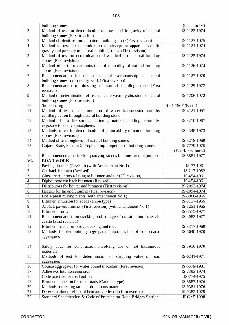
108
CONRACTOR SENIOR MANAGER (CIVIL)
building stones (Part-I to IV)
2. Method of test for determination of true specific gravity of natural
building stones (First revision)
IS-1122-1974
3. Method of identification of natural building stone (First revision) IS-1123-1975
4. Method of test for determination of absorption apparent specific
gravity and porosity of natural building stones (First revision)
IS-1124-1974
5. Method of test for determination of weathering of natural building
stones (First revision)
IS-1125-1974
6. Method of test for determination of durability of natural building
stones (First revision)
IS-1126-1974
7. Recommendation for dimensions and workmanship of natural
building stones for masonry work (First revision)
IS-1127-1970
8. Recommendation of dressing of natural building stone (First
revision)
IS-1129-1972
9. Method of determination of resistance to wear by abrasion of natural
building stones (First revision)
IS-1706-1972
10. Stone facing IS-01-1967 (Part-I)
11. Method of test of determination of water transmission rate by
capillary action through natural building stone
IS-4121-1967
12. Method of test for surface softening natural building stones by
exposure to acidic atmospheres
IS-4210-1967
13. Methods of test for determination of permeability of natural building
stones (First revision)
IS-4348-1973
14. Method of test toughness of natural building stones IS-5218-1969
15. Gujarat State, Section-2, Engineering properties of building stones IS-7779-1975
(Part-I/ Section-2)
16. Recommended practice for quarrying stones for construction purpose IS-8881-1977
VI. ROAD WORK
1. Paving bitumen (Revised) (with Amendment No.1) IS-73-1961
2. Cut back bitumen (Revised) IS-217-1982
3. Glossary of terms relating to bitumen and tar (2nd
revision) IS-454-1961
4. Digboi type cut back bitumen (Revised) IS-454-1961
5. Distributors for hot tar and bitumen (First revision) IS-2093-1974
6. Heaters for tar and bitumen (First revision) IS-2094-1974
7. Hot asphalt mixing plants (with amendment No.1) IS-3066-1965
8. Bitumen emulsion for roads (anion type) IS-3117-1965
9. Asphalt pavers finisher (First revision) (with amendment No.1) IS-3251-1965
10. Bitumen drums IS-3575-1977
11. Recommendations on stacking and storage of construction materials
at site (First revision)
IS-4082-1977
12. Bitumen mastic for bridge decking and roads IS-5317-1969
13. Methods for determining aggregates impact value of soft coarse
aggregates
IS-5640-1970
14. Safety code for construction involving use of hot bituminous
materials
IS-5916-1970
15. Methods of test for determination of stripping value of road
aggregates
IS-6241-1971
16. Course aggregates for water bound macadam (First revision) IS-6579-1981
17. Adhesive, bitumen emulsion IS-7393-1974
18. Code practice for road gullies IS-774-1975
19. Bitumen emulsion for road roads (Cationic type) IS-8887-1976
20. Methods for testing tar and bituminous materials IS-9381-1976
21. Determination of effect of heat and air by thin film over test IS-9382-1979
22. Standard Specification & Code of Practice for Road Bridges Section- IRC : 5-1998

109
CONRACTOR SENIOR MANAGER (CIVIL)
I, General Features of Design (Seventh Revision)
23. Recommended Practice for 2cm thick Bitumen & Tar Carpets
(Second Revision)
IRC : 14-1997
24. Specification for Priming of Base Course with Bituminous Primers
(First Revision)
IRC : 16-1989
25. Tentative Specification for Single Coat Bituminous Surface Dressing IRC : 17-1965
26. Standard Specification & Code of Practice for Water Bound
Macadam (Second Revision)
IRC : 19-1997
27. Recommended Practice for Bituminous Penetration Macadam (Full
Grout)
IRC : 20-1996
28. Tentative Specification for 2 Coats Bituminous Surface Dressing IRC : 23-1996
29. Tentative Specifications for Bituminous Macadam (Base & Binder
Course)
IRC : 27-1967
30. Guidelines for Design of Flexible Pavements (Second Revision) IRC : 37-2001
31. Tentative Specification for Built-up Spray Grout IRC : 47-1972
32. Tentative Specification for Bituminous Surface Dressing using Pre-
coated Aggregates
IRC : 48-1972
33. Recommended Practice for Use & Upkeep of Equipments, Tools &
Appliances for Bituminous Pavement Construction
IRC : 72-1978
34. Code of Practice for Maintenance of Bituminous Surface of
Highways
IRC : 82-1982
35. Guidelines for Section, Operation & Maintenance of Bituminous Hot
Mix Plant
IRC : 90-1985
36. Specifications for Dense Bituminous Macadam IRC : 94-1986
37. Hand Book of Quality Control for Construction of Roads & Runways
(Second Revision)
IRC : SP: 11-1988
38. IRC Highway Research Board, State of Art: Granular & Bound
Bases & Sub-Bases
IRC : HRB : Special
Report 11, 1992
39. Specifications for Road and Bridge Works (Fourth Revision) IRC : 2001
40. Rural Road Manual IRC : SP: 20-2003
In addition to the relevant BIS code, the specifications prescribed and guidelines issued by Central
Water Commission‟s Standard Specifications shall also be followed where BIS specifications are not available.
General Specification:
8.0 The enclosed drawing in the bid document gives broad dimensions and outline of the works to be
executed through this contract. These drawings may however be revised/modified from time to time
and supplementary additional drawing(s) may also be issued as per necessity. During the course of
execution there may be changes in dimensions, specifications and shapes of components. The changes
in the drawings can be done without any way deviating the terms of the contract and the contractor is to
execute the work as per revised drawings and specifications at the same rate as agreed upon for the
work awarded under the original contract. The contractor shall do no work without proper drawings. He
shall check all drawings and specifications carefully and advise the Engineer-in-charge if any error and
omission are discovered where upon the Engineer-in-charge will prepare revised additional drawings
and specifications as may be required to suit the stage of the work.
8.1 Where the drawings are not consistent with the text of the specifications, the text shall govern.
8.2 The Item Rate shall be for finished items of works as per description in schedule of quantities and
according to drawings, specification and conditions of contract. The Item Rate quoted shall be for
execution of finished items of work & the specifications of which confirm to the details furnished in the
Agreement and provisions in Bureau of Indian Standards and shall include all general and incidental
charges which will not be paid separately. Such general and incidental charges are listed in succeeding

110
CONRACTOR SENIOR MANAGER (CIVIL)
Para for the convenience of the tenders but are not exhaustive. Omission of any such items here in but
required for delivering finished items of work, shall not be plea, that such items are not covered by the
Item Rate quoted.
8.2.1 Formation and maintenance of haul roads including river and drainage crossings within the work site is
to be made by the Contractor at his own cost. The existing approaches and haul roads, if any under the
control of the Department may be used but improvement, if required, shall be done by the contractor at
his own cost.
8.2.2 Labour and materials required for construction of reference points, benchmark pillars etc. for setting out
work shall be at contractor‟s cost.
8.2.3 Scaffolding and gang-ways as and when required for the work will be done by the contractors at his
own cost. No additional payment on this score will be entertained.
8.2.4 The rate includes all leads, lifts & de-lifts.
8.2.5 Form work complete includes cost of materials, labour, maintenance, erection and removal.
8.2.6 Construction of coffer dam and dewatering required if any during execution of work is the
responsibility of the contractor.
8.2.7 Protection of components of work during the rainy season shall be the responsibility of the contractor.
The responsibility for the safety of the structure rests, entirely on the contractor and any damages that
may occur has to be made good by the contractor at his own cost.
8.3 The sequence of construction adopted by the Contractor shall have to be approved by the Engineer-in-
Charge.
8.4 The contractor has to make his own design for coffer dam or any type of cross bund required during
course of execution. All materials for the coffer dam or cross bund shall be arranged by the Contractor
at his own cost. The contractor shall maintain the coffer dam till completion of the work.
8.5 QUALITY CONTROL:
8.5.1 Before collecting materials required for execution of the respective items of work as laid down in the
schedule of quantities and in the detailed specifications described hereafter in the subsequent sections,
the contractor shall ensure that samples of materials proposed to be used are first approved by the
Engineer-in-charge. When directed the samples of materials proposed to be used should be furnished to
the Departmental laboratory for testing.
8.5.2 All such testing charges shall be borne by the Contractor. The contractor will provide necessary
assistance for collection of samples.
8.5.3 On the basis of satisfactory test results confirming to technical specification collection of materials shall
be started in the field. The testing of materials shall be checked in the field Laboratory by the
Department as well as staff of Quality Control Organization. If the field test result is found
unsatisfactory, the materials shall be rejected and action taken to remove the same from work site by the
contractor at his own cost. In no case the defective materials shall be used in the work.
8.5.4 On receipt of notice from the Engineer-in-Charge and on observation of Quality Control Division, in
charge of the project, the contractor will rectify the defect in stipulated period at his own cost. If the
defects are not rectified in the stipulated period, the Engineer-in-charge shall assess the cost, get the
defect rectified and recover the cost for the same from the dues of the contractor.

111
CONRACTOR SENIOR MANAGER (CIVIL)
8.6 A quarry chart indicating possible source of materials may be seen in the office of the Executive
Engineer, Kanupur Spillway Division, Basudevpur, Dist- Keonjhar The contractor must however
satisfy himself that the materials as will be made due to non-availability of materials as per required
specification and quality in the quarries shown in the departmental quarry chart. The quarry chart is
only an indication of source of material and the department does not accept the responsibility if the
materials are not available in full quantity and quality.
8.7 No claim for carriage of water whatsoever will be entertained.
8.8 Decision regarding usefulness of excavated materials rests fully on the Engineer-in- charge.
8.9 The item marked “N/A” Not Applicable “do not apply in this contract.
8.10 DISCHARGE RECORDS
RECORDS 8.11 DISCHARGE
The Hydrological data, pertaining to the Dam/ canal and the streams crossing the canal
furnished in the relevant report and drawings, are for information of bidders and contractors. It should
be noted that the data used in preparing these particulars were recorded at locations different from the
work site. The Government (that is Govt. of Odisha) does not guarantee the reliability or accuracy of
any of the data, shall assume no responsibilities for any conclusions or interpretations that may be made
from them. The contractor shall undertake at his expense such studies as are necessary to assess the
reliabilities and accuracy of the information presented in the Data.
SECTION- 8.12 SETTING OUT OF WORK
(A) Temporary bench marks shall be fixed at suitable location connecting G.T.S. bench marks fixed by
Survey of India. Temporary Bench Marks shall be set up by the Department at every 0.5 Km .interval
at convenient locations along the Dam/canal to serve as reference levels. The contractor shall establish
additional reference Bench Marks as may be needed at his own cost for facilitating the setting out and
taking levels for measurement of work, with the approval of the Engineer-in-Charge. The bench mark
shall be marked on a concrete pillar 30 cm. (1) x 30 cm (b) x 75 cm (d) which shall be embedded 55 cm
into firm ground and projecting 20 cm above the ground. The Bench Mark pillar shall be constructed in
plain cement concrete of M-10. The pillar shall be protected from being disturbed. The RL of bench
marks shall be conspicuously carved and painted on the pillar.
(B) Before starting any work and during execution (if required), the contractor shall erect reference Bench
Marks. Reference lines and check profiles at convenient locations as per the direction of the Engineer-
in-Charge. The centerline of the Dam/canal and the reference line for all alignments for demarcation
purpose shall be laid by dug belling on the ground. The reference line shall comprise the base line
properly dug belled on the ground with the numbered concrete/masonry RD pillar suitably spaced.
(C) Centre line of the canal shall be marked by fixing pillar/stone at 30M intervals profiles of the
Dam/canal in filling and in moderate cutting shall be marked at 50 M. intervals in straight reaches and
at 25M intervals in curves. A reference line shall also be marked on ground away from the outer edges
of cutting and filling with pillars at suitable intervals for future reference.
To ensure correctness of execution, the edges of cutting the outer toe lines of Dam/canal in
filling should be marked by fixing pillars or pegs at suitable intervals or by dug belling.
(D) The check profiles shall be located 15 meter apart or longer as directed by the Engineer-in-Charge to
serve as a guide for execution of all slopes and steps to the elevations and profile or profiles indicated in
the approved drawings. All important levels and all reference points with respect to bench marks and
reference shall be fixed and co-related by the contractor as per directions of the Engineer-in-charge.

112
CONRACTOR SENIOR MANAGER (CIVIL)
(E) The zones of full cutting section, full filling section, partial cutting and filling section shall be separated
by conspicuous demarcation in the field.
The curves stipulated in construction drawings shall be carefully laid in the field by adopting
approved method of curve layout. The curves shall be marked on the ground by fixing pegs at very
closer intervals and joining the peg points by dug belling to a suitable depth.
The locations of different structures indicated in construction drawing shall also be clearly
marked on the ground along the alignment of the Dam/ canal. The control structure locations of off
taking canals shall also be clearly demarcated, so that unnecessary excavation or filling at these
locations can be avoided.
The spoils dumping zones shall clearly be demarcated in the field. These zones should be at
least 2m. beyond the location of catch water drains.
(F) To ensure accuracy in execution of cutting, the Dam/canal embankment, spoil banks and the structures,
their layout shall be given in an appropriate manner with pegs and pillars suitably placed in relation to
outer dimensions of these elements.
(G) All materials and labour for setting out works including construction of reference bench marks,
reference lines, check profiles and surveys as may be required at the various states of the construction,
shall be supplied by the contractor at his own cost. The cost of such works shall be deemed to have
included in the cost of items in schedule.
8.13 CLEARING AND GRUBBING:
A. CLEARING AND LEVELING SITE:
The portion of the right of way where required for constructing the work under these specifications
shall be cleared of all trees bushes, rubbish and other objectionable materials. Trees designated by the Engineer-
in-charge shall not be cut and shall be protected from injury. Such cleared materials shall be disposed off as
provided in the sub-paragraph „C‟ below or removed from the site of work before the date of completion of the
contract as approved by the Engineer-in-charge. The clearing operation shall be in accordance with clauses 4.1.,
4.1.1., 4.2 and 4.3 of IS: 4701-1982 Indian code of Practice for earth work in Dam/canals. Surface boulders
either loose or partly embedded in the ground will have to be removed and stacked as directed.
B. GRUBBING:
The area described or shown on the relevant site plan shall be cleared of all obstructions loose stones,
non required materials and rubbish of all kinds. All brushwood shall be cleared and the roots grubbed up. No
trees shall be cut down and removed without the instructions of the Engineer-in-Charge. Those which are cut
down shall be grubbed up. The same remarks apply to jungle clearance. Trees to be preserved will be
designated by the Engineer-in-Charge.
The products of the clearing shall be stacked in such place and manner as may be ordered by the
Engineer-in-Charge and the ground shall be left in a perfectly clean condition all products of the clearing shall
be property of Govt. and shall be disposed off as per the direction of the Engineer-in-Charge.
All holes or hollows, whether originally existing or produced by digging up roots shall be carefully
filled up with earth, well rammed to the design density and leveled off as directed.
PREPARATION OF BED:
Ant hills shall be completely dug out before earth work is started. Loose stones and digging of anthills
involved in the preparation of bed, the contract rate for the earth work shall be deemed to include all the work to
be done in accordance with this clause. In cases where the work of preparation of bed is rather extensive, the
Engineer-in-charge will usually provide a separate schedule item of such preparation, but in the absence of such
schedule provision, the contractor shall understand that his tender rate is inclusive of all such work without
extra charge.
113
CONRACTOR SENIOR MANAGER (CIVIL)
The contractor shall therefore examine the site before tendering and provided for all items to be done
under his earth work tender rate. Old bunds will be benched or sloped as directed by Engineer-in-charge before
addition of earth, the benches being 500 mm x 500 mm unless other sizes are specified. The benches or slope
shall be inspected by the Engineer-in-charge or engineer designated for the purpose and approved before new
earth work is keyed into them.
C. DISPOSAL OF CLEARED AND GRUBBED MATERIAL:
The disposal of cleared and grubbed materials shall be in accordance with clause 4.1.1. of IS 470-1982
code of practice for earth work on canals. All waste materials to be burnt shall be pilled neatly and when in
suitable condition shall be burnt completely to ashes. Pilling of waste material for burning shall be done at such
a location and in such a manner as would not cause any fire risk. Suitable materials and equipments for
prevention and suppression of the fire shall be kept available at all times.
The materials to be disposed off shall be buried.
D. PAYMENT
For the clearance of light jungles, heavy jungle with or without uprooting etc., payment will be made as
provided for in the bill of quantities. No payment towards removal of small stones and boulders of size less than
0.5 cubic meter will be made, and the rate quoted for excavation will be considered to include this item.
However, payment will be made for the removal of surface boulders of sizes greater than 0.5 cubic meter.
Either loose or partly embedded in the ground, at the rate quoted in bill of quantities for the actual quantity so
removed based on stack measurement applicable for the relevant strata classification after deducting 40%
towards voids.
8.14 - USE OF WATER :
8.14.1 WATER FOR DUST ABATEMENT
A. GENERAL
The contractor shall procure and apply water for dust abatement.
Water applied for dust abatement will not be eligible for payment. The cost of procuring and applying
water including all expenses for all means of conveying water to the point of use their collection, usage, and all
other incidental expenses will not be paid separately including creation of source of water and the cost shall be
deemed to have been included in the concerned unit price bid in the bill of quantities of the contract for the
relevant finished item of work for which water for dust abatement is required.
So also the cost of procuring and applying water required for the works hall be included in the price bid
in the bills of quantities for the items of work for which the water is used.
8.14.2 PREWETTING OF DAM/ CANAL PREMISES AND ADJACENT AREAS:
A. GENERAL
The contractor shall furnish all labour, materials and equipment and shall procure and apply water
required for pre-wetting the areas under Dam/canal and embankment.
Water applied for pre-wetting areas as detailed above will not be eligible for payment. The cost of
procuring and applying water including all expenses for all means of conveying the water to the point of use,
their collection, usage and all incidental charges shall be included by the contractor in the concerned unit price
bid in the bill of quantities for that item of work where the water shall be used and no separate payment for the
same will be made.
114
CONRACTOR SENIOR MANAGER (CIVIL)
8.15 - SITE DRAINAGE:
8.15.1 CROSS DRAINAGE:
The contractor shall handle all flows from natural drainage channel intercepted by the work under these
specifications, perform any additional excavation and grading for drainage as directed and provide and maintain
any temporary construction required to bypass or otherwise cause the flows to be harmless to the work and
property. When the temporary construction is no longer needed and prior to acceptance of the work the
contractor shall remove the temporary construction and restore the site to its original condition as approved by
the Engineer-in-charge.
In addition to cross drains, longitudinal drains may the considered necessary for proper drainage. The
drainage system consisting of network of cross and longitudinal drainage system will be led into out fall drains
to prevent stagnation of water at the place of construction. The drains shall be constructed to the section
designed and shall be either open or filled up with material to ensure free flow of water without clogging of the
filled materials.
8.15.2 DRAINS, BERM DRAINS AND DOWEL BANKS:
A. DRAINS:
In connection with excavation and construction for the Dam/ canal and structures, the contractor shall
perform excavation for the construction of drains, beam drains and chutes and any other drains as directed by
the Engineer-in-charge.
The location grades and sections of the drains shall be as shown on the drawings and or as directed.
Payment for excavation for the above drains, channels and embankment will be made at the unit price bid in the
bill of quantities for execution of Dam/canal, which unit price shall include the cost of placing the materials in
embankment or otherwise disposing off the excavated materials and all work necessary to maintain the work in
good order during construction.
B. BERM DRAINAGE AND DOWEL BANKS:
Berm drainage including drainage along the berm and banks of the Dam/canal and longitudinal berm
drains shall be constructed where shown on the drawings as directed. The berm drains shall be constructed to
dimensions and grades shown on the drawings or as directed.
The surface of the berm shall be sloped transversely and dowel banks shall be made along with sides of
the banks and berm where shown on the drawings and elsewhere where directed. The dowel banks may be
made by balding of material in place following completion of a canal reach.
Payment will be made for construing Dowel banks and sloping berm and cost there of shall be included
in the unit price per cubic meter bid in the bill of quantities for construction for Dam/canal embankment
including reconstructing and 114 remodelling.
8.16 MONSOON DAMAGES:
Damages due to rain and natural calamities either in cutting or in banks shall have to be made good by
the Contractor till the work is handed over to the department. The responsibility for de-silting and
making good the damages due to rain/natural calamity rests with the Contractor. No extra cost is
payable for such operations and the contractor shall, therefore, had to take all necessary precautions to
protect the work done during the construction period.
8.17 REMOVAL OF SILT AND WATER:
Payment for removal of silt will be made as provided in bill of quantities. Accumulated silt and water in
the Dam/canal and structures for the works partly done by the contractor in current or previous seasons
should be removed and no extra payment will be made, for such removal of silt and water. This unit
rate of excavation is deemed to include cost of removal of such silt and water.

115
CONRACTOR SENIOR MANAGER (CIVIL)
8.18 PROCEDURE FOR MEASUREMENT:
Before commencement of work, initial levels to indicate existing ground levels shall be taken at 10m
intervals longitudinally along the alignment of the Dam/canal. The level points transversely along the
cross sections shall be maximum at 5 m. Intervals in flat ground and 3 m. In undulating terrain. The
cross sections shall be extended beyond the limit of work to a suitable distance and minimum 5 mtr.
Beyond the toe lines of slopes on both the sides. The interval stipulated shall be made closer depending
on the topography or any stipulation made by the Engineer-in-charge.
All initial levels shall be recorded in ink/ball pen in authenticated level books issued by the
Engineer-in-charge and shall be signed by the Junior Engineer / Assistant Engineer when he records the
levels. The Assistant Engineers and junior engineers shall exercise checks strictly in accordance with
the codal provisions.
Actual construction works shall not be allowed to start unless the above formalities are
fulfilled.
If the work is awarded to any agency the level shall be recorded in the presence of the
contractor or his authorized agent. The contractor or his authorized agent shall sign each page of the
level book/field book in token of acceptance. Without acceptance of the level by both the parties, the
work shall not commence. Dispute if any arises, the decision of the Engineer-in- Charge shall be
conclusive and binding. These cross sections shall form the basis of all future measurements and
payments. Each dimension shall be measured to the nearest 0.01m, areas shall be computed to nearest
0.01sqm. Volume shall be computed to nearest 0.01 cubic metre.

116
CONRACTOR SENIOR MANAGER (CIVIL)
SECTION-9
EARTH WORK
9.1 EARTH WORK - GENERAL
To the extent that they exist, plans and estimates for the Government‟s studies of Earth Work
for construction of the canal will be available for inspection by the Bidders in the office of the
concerned Engineer-in-charge. Such information is made available solely for the convenience of
Bidders. The Government does not guarantee that the information is accurate or complete. Bidders are
cautioned that this information is subject to revision and that the Govt. disclaims responsibility for any
interpretation, deduction or conclusions, which may be made there from. It is not intended that this
information will limit or prescribe the excavation and handling procedures of the contractor, and the
Govt. reserves the right to utilize and distribute earth work materials during the progress of work it
serves the interest of the Govt.
Drawing showing the typical section of the canal annexed to these specifications provides such
details as would enable the contractor to execute the work in general conformity there-with under these
specifications which have been prepared as definitely and in as much detail as possible with regard to
design data presently available. These drawings will be supplemented by such additional, general and
details drawings or directions as may be considered necessary or desirable as the work progresses. For
all changes in approved drawing/design the recommendation of Chief Construction Engineer,
Superintending Engineer and approval of Chief Engineer will be essential. Where details shown on
these drawings differ from the requirements of these specifications. The requirement of specifications
shall govern. The contractor shall do no work without proper drawings. He shall check all drawings and
specifications carefully and advise the Engineer-in-charge if any errors and omissions are discovered
where upon the Engineer-in-charge will prepare and lodge such revised additional drawings and
specifications as may be required to suit the stage of the work. All such additional general and detailed
drawings whether original or revised lodged in the office of the Engineer-in-charge and signed by him
for purpose of identification shall be open for inspection by the contractor under the same terms and
conditions as provided in agreement.
All works of the contract shall be executed as per the specific and relevant clause/clauses of
relevant I.S. code unless otherwise specified. Materials used should, confirm to the desired standards
prescribed in the relevant codes. Wherever a Para of IS Code is cited in specification it goes without
saying that the latest revision of the specification subsequently, shall apply. For purpose of relevancy or
otherwise of any provision of the I.S. Code referred to the decision of the Engineer-in-charge.
9.1.1 SETTING OUT WORKS :
Temporary Benchmark in the vicinity of the dam embankment, set up by the Department at
convenient locations along the dam axis. The contractor shall establish sufficient numbers of references
bench marks for facilitating the setting out and for measurements of works with the approval of the
Engineer-in-charge and taking levels for purpose of measurement at his own cost. The benchmark shall
be 30cm. x 30cm. x 75cm. with concrete pillars which shall be embedded 55 cm. into firm ground and
20 cm. projecting above the ground.
The contractor shall take all such precautions to see that the lines, points and bench marks fixed
by the Department are not disturbed by his work and shall make good of any such damage at his own
cost.
LAYOUT :
Before starting any work and during execution, the contractor shall erect reference bench
marks, reference lines and check profiles at convenient locations as per the direction of the Engineer-in-
charge. The axis of the dam and the reference line shall be laid by properly dug belled on the ground.
The reference line shall comprise with the numbered concrete/ masonry R.D. pillars suitably spaced.
The check profiles shall be located at 30 m. apart or closer as directed by Engineer-in-charge so
as to ensure execution of all slopes, steps and elevations to the profile or profiles indicated in the

117
CONRACTOR SENIOR MANAGER (CIVIL)
approved drawings. All important levels and all control points with reference to bench marks and
reference lines shall be fixed and co-related by the Engineer-in-charge.
To ensure correctness of execution, the edges of cutting the lines of the embankment and those
of spoil bank shall be marked carefully with pegs at close enough intervals so as to obtain layout in plan
free links. The pegs shall then be connected by stretching string from peg to peg and dug belling into
ground along the strings. The line so connected shall be corrected wherever necessary to provide a
stream lined plan of the Dam features. Special care shall be taken at curves to ensure uniform curvature
of the alignment.
All materials and labour for setting out works including construction of reference bench marks,
reference lines, check profiles and surveys, as may be required at the various stage of the construction,
shall be supplied by the Contractor at his own cost. Benchmark should be constructed in P.C.C.M.-10
and the cost of such work shall be deemed to have been included in the costs of the items rate quoted by
the Contractor.
9.1.2 CLEARING AND GRUBBING OPERATIONS :
a) Cleaning and grubbing operations shall be performed in excavation areas including a 20.00 m.
wide strip measured beyond and continuous to the limit line of the areas. These sites should be
cleared of all tree stumps, roots, rubbish bushes and other objectionable materials. All non-
useful materials from cleaning operations shall be burnt/ removed from the work site or
otherwise disposed off as approved. All the materials to be burnt shall be burnt completely.
Piling for burning shall be done in such a manner and in such a location as to cause the least
fire risk. The burning shall be so thorough that all the materials are reduced to ash. Special
precautions shall be taken to prevent fire from spreading to area beyond limits of the areas
specified and suitable equipment and supplying for preventing and suppressing fires shall be
available at all times. The stumps shall be grubbed to its full depth and the roots shall be
entirely removed. The ownership of all the useful materials so removed from clearing sites shall
rest with the department.
b) Cleaning and grubbing shall be performed in advance of earthwork operation and in accordance
with the requirements of the specification.
c) All operation in connection with clearance of jungle such as clearing, cutting and disposal etc.
shall be subject to provision of forest rules.
d) All holes whether originally existing or produced by digging of roots, stumps etc. shall be
carefully filled up with the earth, well rammed and leveled off as may be directed.
9.1.3 RECORDING OF CROSS SECTIONS :
a) Before stripping and prior to the beginning of excavation, initial cross sections of existing
ground shall be taken at every 10 m. interval along axis of dam upto sufficient distance outside
the limits of the work. Levels on these cross sections shall be taken at 10 m. or closer intervals
for dam works. While for structures works, they shall be taken at 3 m. or closer intervals as
directed by Engineer-in-charge and entered in ink in the level book by the Engineer-in-charge
in the presence of the contractor or his authorized agent and shall sign the levels in level books
in token of acceptance. These cross sections shall form the basis of all future measurements
and payments. The original cross sections duly signed by the Contractor and the Engineer-in-
charge shall be preserved. All linear dimensions shall be measured to the nearest 0.01 m.
Areas shall be computed nearest to 0.01 sqm. Volumes shall be computed nearest to 0.01
Cum.
c) No separate payment will be made to the Contractor for the required labour and
materials for taking the cross sectional levels.
d)

118
CONRACTOR SENIOR MANAGER (CIVIL)
9.2 STRIPPING :
a) The entire area of stripping of embankment including toe drain area as shown in the drawing
shall be stripped manually/ mechanically with standard units to a sufficient depth as directed to
remove all unsuitable materials. The unsuitable materials shall include all debris, top soils,
vegetable matter including root grass, bushes, loose rock, organic silt, stump materials and
other perishable or objectionable materials which are unsuitable for use in permanent
construction or that might interfere with the proper bonding of the embankment with the
foundation, or the proper compaction of the materials in the embankment, or that may be
otherwise objectionable. The stripping shall be kept well in advance of other items of works to
ensure that no undesirable materials will get mixed with approved embankment materials and
to enable proper inspection and measurement. Materials out of stripping operation shall be
deposited off at the downstream side within 3 Kms. lead in such a way as not to detract from
the finished appearance of the project or as directed by the Engineer-in-charge.
b) Measurement and Payment : Measurement and payment will be on the basis of volume of work
involved based on levels recorded before and after stripping and cleaning the site. The unit rate
includes cost of all labour, tools and plants and other incidental expenses involved in the work.
9.3 EXCAVATION :
(Cut off trench, Heel trench & Toe drain, etc.)
The cut-off trench, heel trench, toe drain etc. as shown in drawings shall be excavated in the
foundation to the established levels, slopes, lines and grades. The alignments and cross sections shown
in the drawings will be subjected to such changes as may be found necessary as per condition disclosed
after excavation for which the contractor will have no claim. Accurate trimming of the slope of the
excavation will not be required, but excavations shall confirm as closely as practicable to the
established lines and grades.
9.3.1 CLASSIFICATION :
The sub-surface logging has been indicated in the longitudinal section of the dam as carried
during exploration studies. The information is furnished only as an indication of nature of soil met with
during excavation.
Materials once excavated will not be classified for payment. Except or otherwise provided in
these specification, materials excavated will be measured for excavation, to the lines shown on the
drawings or as provided in these specifications and all materials required to be excavated will be paid
for at the applicable rates in the schedule for excavation. No additional allowance above the rates in the
schedule will be made on account of any of the materials being wet and requiring additional time for
drying, stock piling and re-handling. Except for area of rock all areas to be excavated and materials to
be used shall be pre-wetted, so that at the time of excavation, moisture content shall be about optimum.
Bidders and contractors must assume all responsibility for deductions and conclusion as to the nature of
the materials to be excavated and the difficulties of making and maintaining the required excavations.
The classifications of excavation shall be decided by the Engineer-in-charge and will be
binding on the contractor. In case of dispute, the decision of Chief Engineer shall be final. Merely, the
use of explosive in excavation will not be considered in areas on the higher classification unless
blasting is clearly necessary in the option of the Engineer-in-charge.
9.3.2 Excavation of soil and D.I. Rock :
This excavation shall include all over burden dry or wet and shall comprise of all kinds of soil such as
vegetable or organic soil, turf, sand, silt, loam, clay mud, Peat black cotton soil, soft soil, loose or
compact moorum, soft soling/ heavy/ hard shale, stoney earth mixed with gravel and moorum etc. inter
spread with boulders upto 0.5 Cum. size soling of roads, paths, hard core, macadam surface, lean
concrete, stone masonry, brick work, soft conglomerate, stoney earth such as lime stone, sand stone,
laterite, soft conglomerate etc. which does not require blasting and can be quarried by mechanical

119
CONRACTOR SENIOR MANAGER (CIVIL)
means or by pick axes and crowbar etc. However, the contractor resorts to blasting in such D.I. rock for
his convenience, no extra payment will be made.
9.3.3 a) CONVEYANCE AND DISPOSAL OF EXCAVATED MATERIALS :
The materials, when suitable for use with varying lead and lifts in the embankment either
immediately or after stock piling as convenient, the suitable or otherwise of materials and zone
of the embankment in which it is to be placed will be determined by the field Laboratory,
materials excavated from cut-off trench etc. shall not be placed in the embankment till the
foundation for the embankment has been cleared, stripped and prepared as specified and
adequate arrangements made of watering and rolling the layers of earth fill in the embankment.
These materials shall subject to the same degree of embankment control as per the materials
obtained from the borrow areas.
b) Excavated materials which are suitable for or are in excess of other earthwork requirement shall
be wasted as directed by the Engineer-in-charge with all leads and lifts. Waste pipes shall be
located where they shall not interfere harmfully with the natural flow of stream, with the
operation of the reservoir, on with the flow of water to form the spillway of outlet works and
where they will neither detract from the appearance of the completed project, nor interfere with
the accessibility of the structures for operation or cause interference to public and other works.
The waste pipes shall be leveled and trimmed to reasonable regular lines so that it shall not
cause any interference to public and other works.
c) Steps shall be taken to keep the materials clean as subsequent cleaning will be difficult and
imperfect.
d) No extra payment shall be made, in case, the materials excavated from cut off trench, base
stripping etc. is stock piled and then re-handled for use in coffer dam, haul road etc.
9.3.4 DEWATERING :
a) The method of removal of water from foundation shall be efficient and effective, where the
excavation for cut-off trench in the foundation extends below the water table shall be dewatered
in advance of excavation.
b) The dewatering shall be accomplished in a manner that will prevent loss of lines from the
foundations, will maintain stability of the excavated slope and bottom of cut off trench and will
result in all construction operation being performed by dry condition. The use of sufficient
number of properly screened well or other equivalent methods shall be approved for dewatering
sumps by pipe drains leading to sumps from which water shall be of uniform diameter for each
run and shall be provided with ground connections and returns at 15m interval and shall be
embedded in reasonable well graded gravel or like material.
c) During placing and compacting of the impervious materials in the cut off trench, the water level
at every point in the cut off trench shall be maintained below the bottom of the earth fill until
the compacted fill in the cut off trench at that point has reached a depth of 3 m. after which
water level shall be maintained at least 1.5 m., below the top of the compacted fill. When the
fill has been constructed to an elevation which will permit the dewatering systems to maintain
water level or below the designed elevations as determined by the Engineer-in-charge, the pipe
drains including surrounding gravel shall be filled with grout composed of water and cement or
clay.
d) The contractor has to make his own arrangement for dewatering during execution of the work
at his own cost and the unit rates of each item of work, quoted by the contractor shall include
the cost of dewatering.

120
CONRACTOR SENIOR MANAGER (CIVIL)
9.3.5 FINAL EXCAVATION, FOUNDATION PREPARATION &CLEANING :
When the excavation has reached the final level, the surface shall be cleaned off all mud and
rock debris. If foundation surface is satisfactory, further excavation shall be stopped under the
supervision of the Engineer-in-charge. All portions of protruding rock and overhangs shall be removed
and sharp and brittle edges hammer dressed, if any.
9.3.6 PAY LINE :
The excavation shall be made to the lines, dimensions, side slopes and levels shown on the
drawing. Pay line for excavation in all soils and rock including subsequent removal of the extra depth
shall be to the dimensions, slopes, grades and levels as shown on the drawing unless otherwise
specified.
Payment for excavation done shall be strictly as per designed section or for the section as
directed by the Engineer-in-charge. No payment shall be made for excavation done beyond the pay
lines shown on the drawing and defined as above unless otherwise specially indicated.
9.3.7 SLIPS :
Slips shall be avoided, but, if any slip occurs on account of nature of soil or due to failure of
slopes in the opinion of the Engineer-in-charge, the extra excavation involved shall be properly resorted
to restore stability. In such case, payment for necessary excavation and back filling will be made for
this extra work under relevant items.
9.3.8 MONSOON DAMAGES :
Damages due to rain or flood either in cutting or in banks shall have to be made good by the
contractor till the final section is handed over to the department. The responsibility for desilting and
making good the damages due to rain or flood rests with the contractor. No extra cost is payable for
such operation and the contractor shall, therefore, have to take all necessary precautions to protect the
work during construction period.
9.3.9 MEASUREMENT AND PAYMENT :
a) The payment will be made on volumetric basis for the quantities excavated to the required
extent. The cross sections shall be taken initially after stripping and before commencement of
excavation. Lines, levels and grades of excavation shall be marked for excavation. On
completion of excavation, final cross section shall be taken. These sections will be marked on
the initial cross sections taken prior to commencement of work. The quantities between initial
and final cross sections, the pay lines shall be worked out and paid for. It shall be clearly
understood that no excavation beyond pay line will be measured and paid. The rate is inclusive
of dewatering and conveyance and disposal of excavated materials in varying leads maximum
upto 3 Kms.
b) Rate for payment :
The rate for the respective items of excavation provides all costs for labour materials, tools and
plants, machinery, taxes, drilling, blasting, excavation, transportation and all incidental
operation required for carrying out and completing the respective items of work in accordance
with specifications drawing and as directed by the Engineer-in-charge including.
i) Setting out Works
ii) Site clearance
iii) Marking out, providing and forming model sections, lock spitting, straining and stakes as may
be considered necessary by the Engineer-in-charge to guide the contractor in excavating and
depositing.

121
CONRACTOR SENIOR MANAGER (CIVIL)
iv) All cost of drilling on ripping with all cost.
v) All safety measures.
vi) All dewatering of surface and ground water till completion of the work including construction,
maintenance and removal of coffer dam with necessary diversion arrangement for allowing
excess water in coffer dam.
vii) Providing temporary ramps and steps at the sites of deep trenches and subsequent removal.
viii) Transporting the excavated materials mechanically with a variable lead maximum upto 3 Km.
and depositing the same on site or work, spoil bank or stacking in stock piles including re-
handling for use or final disposal.
ix) Construction and maintenance of haul roads.
x) Removal of silt during execution.
xi) Water applied for pre-wetting in excavation areas.
xii) All works necessary to maintain the excavation in good order during excavation.
9.4 BORROW AREA :
9.4.1 GENERAL :
All materials required for the construction of the embankment and back fill for cut off trench
which are not available from cut off trench excavation or other required excavation, shall be obtained
from the designed borrow areas after stripping as shown in drawing or as designated by the Engineer-
in-charge in consultation with the field laboratory subsequently.
The limit of each borrow area to be used in the various zones embankment shall be flagged in
the field and materials from each borrow area shall be placed only in the zones for which it has been
specified.
The depth of cut in all borrow areas will be designed by the Engineer-in-charge and the cuts
shall be made up to such designated depths only. Shallow cuts will be permitted in the borrow area if
un-stratified materials with uniform moisture contents are encountered. Each designated borrow area
shall be fully exploited before switching over to the next designated borrow area. Haphazard
exploration of borrow pits shall not be permitted. The type of equipment used and the operation in the
excavation of materials in borrow areas shall be such as will produce the required uniformity of mixture
of materials for the embankment.
Borrow areas shall not be located within a distance of 10 times the height of the dam from the
upstream heel and 5 times the height from the downstream toe of the dam. Borrow pits shall be
operated so as not to impair the usefulness or mark the appearance of any part of the work or any other
property. The surface of wasted materials shall be left in reasonably smooth and even condition.
No compensation whatsoever for change in limits and location of the borrow areas for getting
suitable earth shall be paid to the contractor.
9.4.2 PREPARATION OF BORROW AREAS :
All areas required for borrowing earth for embankment shall be cleared of all tree stumps,
roots, bushes, rubbish and other objectionable materials. Adequate lighting arrangement should be
provided by the contractor.
Particular care shall be taken to exclude all organic matter from the materials to be placed in the dam,
dyke embankment. All cleared organic materials shall be completely burnt to ashes or disposed of as
directed. The cleared areas shall be maintained free of vegetable growth during the progress of work.

122
CONRACTOR SENIOR MANAGER (CIVIL)
9.4.3 STRIPPING OF BORROW AREAS :
Borrow area shall be stripped of top soil, sods and any other objectionable materials to the
required depth as directed by Engineer-in-charge. The work may be done manually or with suitable
machine. Stripping operation shall be limited only to designated borrow areas. Materials from stripping
shall be deposited off in exhausted borrow or in the approved adjacent areas as directed.
9.4.4 BORROW AREA WATERING/ DEWATERING :
a) Borrow area watering will be done where necessary and in the manner considered necessary by
the Engineer-in-charge of the work.
b) The initial moisture content of materials in the borrow area shall be estimated with the help of
laboratory test. The optimum moisture content for the material in particular, the initial moisture
content and the amount of additional moisture, as decided shall be introduced into the borrow
area by watering well in advance of the excavation to ensure uniformity of moisture content.
c) If, in any location of a borrow area before or during excavation, there is excessive moisture,
steps shall be taken to reduce the moisture to secure the material with moisture content closest
to optimum by excavating drainage ditches, by allowing adequate time for drying or by any
other means. To avoid formation of pools in the borrow areas during excavation operations,
drainage ditches from borrow areas to the outlets shall be excavated wherever necessary. The
borrow pits shall be excavated to such lines and grades that there is no occurrence of earth
slides and shall be so finished as to prevent hazards to persons and livestock‟s and to prevent
conditions favourable for breeding of mosquitoes. No payment shall be made as it is deemed to
have been included in unit bid price of schedule of quantities.
9.4.5 STOCK PILING :
Stock piling shall be done at approved locations only. Before any area is used for stock piling,
it shall be cleared and stripped of all vegetation and top soil as necessary to prepare the stock pile area.
Stock piling of fill materials by end dumping the materials down a sloping face/ chute shall not
be permitted, if, segregation of the materials takes place. No extra payment is admissible for stock
piling the borrow earth.
9.4.6 HAUL ROAD &APPROACH ROAD:
Construction and maintenance of approach roads and haul roads will be the responsibility of the
contractor. The department will have full right of way to those road for inspection purposes. Proper
road signs as directed have to be provided for safety. For haulage of earth, the contractor shall construct
ramps and haul roads of sufficient width along the shortest but most practicable route and shall maintain
and illuminate them in a satisfactory manner. Watering of the road shall be done by the contractor as
often as necessary to prevent raising of dust formation of cuts and consequent deterioration of the
surface. Wherever service roads meant for public thorough fare, traverse through or run close to the
borrow area, the contractor shall direct his excavation and haul operation in such a manner as to ensure
uninterrupted use of the service roads and safety to the public. At the haul road and service road
crossing, the contractor shall install necessary check gates and road signs. No extra payment is
admissible, as this is deemed to have been included in the unit bid price of schedule of quantities being
contingent to the main work.
9.5 BACK FILLING OF CUT OFF TRENCH
a) Cut off trench shall be back filled with selected impervious materials of specification desired
and compacted as in the same manner as per embankment of the dam. The impervious materials
shall be placed in continuous and approximately horizontal layers not more than 15cm. (loose)

123
CONRACTOR SENIOR MANAGER (CIVIL)
and compacted by Vibromax roller or any equivalent machinery under optimum moisture
content to the required degree of compaction.
b) Rolling shall be done along the cutoff trench and the roller shall be taken close to the sides of
the trench.
In case, where the compaction by rollers is not possible, compaction to the required
density shall be achieved such other means as specified by the Engineer-in-Charge.
c) Each layer shall be compacted to achieve the required dry density of not less than 98% of the
maximum dry density (Proctor‟s density) for the type of material at optimum moisture content.
d) During placing and compaction of impervious materials in the cut off trench where dewatering
is involved, the subsoil water level at every point in the cut off trench shall be maintained
below the bottom of the every fill until the compacted fill in the cut off trench at that point has
reached a height of 3m after which water level shall be maintained at least 1.5m below the top
of compacted fill.
e) The quantity for payment shall be the compacted volume of cut off trench measured in cubic
meters. The unit bid price includes cost of all operations as per specification. The payment for
earthwork will be as per dam embankment and payment for compaction will be as per dam
compaction. The arrangement of water will be at contractor‟s cost. (Earthwork payment will be
made on finished level section only)
9.6 DAM EMBANKMENT :
9.6.1 GENERAL :
a) The embankment shall be constructed to the lines and graded shown in the drawing with the
homogeneous earth filling having designated parameters of density, cohesion, permeability etc.
so as to ensure the highest practicable degree of stability and performance of the whole dam
embankment. The quality control organization of the project will carry out requisite tests for the
suitability of construction materials well in advance and the contractor shall ensure that only
approved materials are brought to place to fill and used for construction of embankment. In
case of change of slope and level, also the unit bid price will remain same. Reference pillar
shall be constructed near both sides of embankment while construction.
b) No bushes, roots, sods or other perishable or unsuitable materials shall be placed in the
embankment. The suitability of each part of the foundation for placing embankment materials
thereon and of all materials for the use in embankment construction will be determined by the
field laboratory.
c) The difference in elevations of the dam embankment during construction at any cross section
shall not be exceed 1.0M unless specially authorized by the Engineer-in-Charge. The placing of
layers for the embankment portion programmed for construction in the season shall be
continuous and approximately horizontal. In case the whole of embankment is not constructed
simultaneously, the incomplete embankment shall be at slope not steeper than 1 in 4.
d) For proper in bond of the embankment done in the previous season with the new embankment
the work shall be carried out as detailed below.
124
CONRACTOR SENIOR MANAGER (CIVIL)
i) In case of the old bank to be extended horizontally, it shall be cut to a slope not sleeper than 1
in 4 and the surface so prepared shall be scarified and made loose at least for a depth of 15cm.
Necessary watering shall be done and the earth surface shall be thus prepared to receive the
new embankment. The bank material shall be laid in layers and compacted to the required
degree of compaction to have a proper bond with the old one.
ii) If the old bank is to be raised vertically, vegetation shall be cleared followed by scarifying,
watering and placing of the new earth layers as specified above.
iii) The surface which are damaged due to rain be made good by filling with proper soil duly
compacted by tampers or pneumatic rammers.
e) A cross slope away from the centre of fill of about 1 in 80 shall be maintained to ensure proper
drainage in event of rainfall.
f) No extra or separate payment shall be made for these items of work are these re contingent to
the main work of construction of embankment and consolidation and deemed to have been
included in the item rates.
9.6.2 PREPARATION OF SEAT UNDER EMBANKMENT :
9.6.2.1 No materials shall be placed in any section of the earth fill portion of the dam embankment until the
embankment seat for that section has been dewatered, suitably prepared and has been approved by the
Engineer-in-Charge. All portions of excavation made for test pits or other sub surface investigation, all
holes, hollows and all other existing cavities found with in the area to be covered by earth fill, which
extend below the established lines of excavation for embankment seat, shall be filled with suitable earth
fill for the embankment and suitably compacted. All test pits within the distance of 10 times of the
height of the dam embankment from the upstream toe shall be filled with impervious materials and
properly compacted as directed. Pools of water shall not be permitted in the foundation for embankment
and such water shall be drained and cleared prior to placing the first layer of fill.
Surface of masonry concrete walls, against which the fill is to be placed shall be cleaned and
moistened prior to placing the earth fill. The foundation immediately adjacent to the masonry structures
shall be thoroughly cleared of all loose materials and moistened. On sloping ground benching of size
450mm X 450mm shall be done with slope towards the inside of the benching so as to give good grip to
the embankment soil with the sub-grade.
9.6.2.2 FOUNDATION PREPARATION SHALL BE DONE SUBSEQUENT TO STRIPPING
AND EXCAVATION
a) ROCK FOUNDATION
The treatment of the rock surface under the dam shall be done as to ensure tight bond between
the embankment and foundation. This shall be obtained by the following procedure.
i) Before the grout curtain is installed, the area of the rock surface which is to be in contact with
the earth fill of the dam shall be fully exposed by removing all the loose and D.I. rock leaving
the surface of rock rugged. Hard rock projections and overhangs shall be removed. If blasting is
to be restored to, care shall taken to avoid objectionable shock to foundation rock and

125
CONRACTOR SENIOR MANAGER (CIVIL)
abutments after rough excavation shall be exposed at one time to enable examination of rock
surface characteristics and planning the method of treatment.
ii) Cleaning &Shoveling :
After all the preparation are over, the rock surface shall be thoroughly cleaned. Pockets of silt
and sand and all other soil be removed by hand shoveling and soft erodable seams and localized
cut portion cleaned out as deep as possible. Loose rock shall be removed by wedging hand
picking. Layers of grout filled over from grouting operation shall be chipped and removed to
the maximum possible extent. The hand cleaned surface shall be wet, sand blasted to clean the
rock surface of set grout particles/fines sitting in the seams of rock. In this process, water shall
be used along with sand and air under pressure. Air pressure should be maintained at about
6.33Kg/ Square Centimeter for ensuring effective sand blasting, Percentages of difference sizes
of sand particles shall be approximately in following range.
Size Percentage
8 mesh per inch (25.4 mm) 26
16 mesh per inch (25.4 mm) 30
20 mesh per inch (25.4 mm) 23
50 mesh per inch (25.4 mm) 21
Alternatively, the rock surface shall be cleaned with a high pressure water jet cleaning
machine having the capacity of developing the operating pressure in the range 50–15 bars
(adjustable) with water jet adjustable to deliver 15litrs/min–30litrs/min. It should have a high-pressure
nozzle, 10m high pressure hose and heavy-duty couplings. Such machines are available indigenously
along with a small sand blasting attachment. Development of this high- pressure water jet along with
sand blasting through use of sand (Ordinarily used in cement concrete mix) will ensure excellent
removal of the set laitance.
Lastly, the final clean-up shall be done by an air water jet to be applied through an air water
gun, by delivering compressed air at 1.70cubic meter/min. at 6.33Kg/cm2 water at 270litrs/min.
Contractor shall have adequate number of air water guns.
iii) SEALING CRACKS : Deep pot holes or pockets shall be filled with hand compacted soil of
concrete. If the work surface in the bottom and sides of potholes is cracked, the crack should be
sealed with cement grout. If the rock surface contains so many closely spaced potholes, the
entire rock surface shall be covered with concrete. A cement paste may be used in the smaller
cracks. Any open crack in the surface shall be sealed with cement grout by suitable means.
Fault zones or larger cracks shall be dug out to a depth as determined by the Engineer-in-
Charge and back filled with concrete.
iv) Foundation rock which is fairly impervious but has vary rugged surface shall be treated laying
embankment materials at a moisture content slightly above the optimum in thin layers and
compacted with mechanical equipment and small tampers to ensure that all irregular
depressions in the rock surface have been filled with soil to create an effective and complete
bond. The moisture content and layer thickness shall be specified by the field laboratory.
v) The exposed cleaned surface should be covered with a thin layer of mud leaping just before
placing the first layer of the embankment fill. Care should be taken that the embankment fill
shall be placed before the mud layer is dried up.
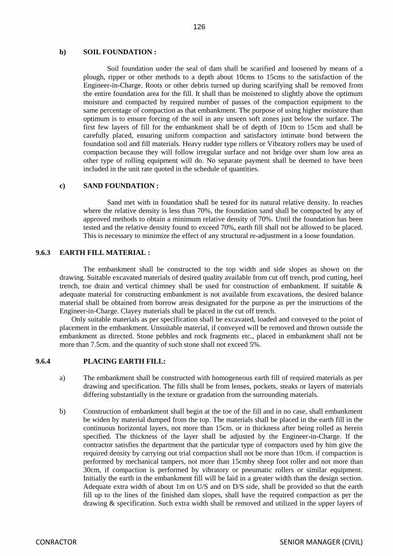
126
CONRACTOR SENIOR MANAGER (CIVIL)
b) SOIL FOUNDATION :
Soil foundation under the seal of dam shall be scarified and loosened by means of a
plough, ripper or other methods to a depth about 10cms to 15cms to the satisfaction of the
Engineer-in-Charge. Roots or other debris turned up during scarifying shall be removed from
the entire foundation area for the fill. It shall than be moistened to slightly above the optimum
moisture and compacted by required number of passes of the compaction equipment to the
same percentage of compaction as that embankment. The purpose of using higher moisture than
optimum is to ensure forcing of the soil in any unseen soft zones just below the surface. The
first few layers of fill for the embankment shall be of depth of 10cm to 15cm and shall be
carefully placed, ensuring uniform compaction and satisfactory intimate bond between the
foundation soil and fill materials. Heavy rudder type rollers or Vibratory rollers may be used of
compaction because they will follow irregular surface and not bridge over sham low area as
other type of rolling equipment will do. No separate payment shall be deemed to have been
included in the unit rate quoted in the schedule of quantities.
c) SAND FOUNDATION :
Sand met with in foundation shall be tested for its natural relative density. In reaches
where the relative density is less than 70%, the foundation sand shall be compacted by any of
approved methods to obtain a minimum relative density of 70%. Until the foundation has been
tested and the relative density found to exceed 70%, earth fill shall not be allowed to be placed.
This is necessary to minimize the effect of any structural re-adjustment in a loose foundation.
9.6.3 EARTH FILL MATERIAL :
The embankment shall be constructed to the top width and side slopes as shown on the
drawing. Suitable excavated materials of desired quality available from cut off trench, prod cutting, heel
trench, toe drain and vertical chimney shall be used for construction of embankment. If suitable &
adequate material for constructing embankment is not available from excavations, the desired balance
material shall be obtained from borrow areas designated for the purpose as per the instructions of the
Engineer-in-Charge. Clayey materials shall be placed in the cut off trench.
Only suitable materials as per specification shall be excavated, loaded and conveyed to the point of
placement in the embankment. Unsuitable material, if conveyed will be removed and thrown outside the
embankment as directed. Stone pebbles and rock fragments etc., placed in embankment shall not be
more than 7.5cm. and the quantity of such stone shall not exceed 5%.
9.6.4 PLACING EARTH FILL:
a) The embankment shall be constructed with homogeneous earth fill of required materials as per
drawing and specification. The fills shall be from lenses, pockets, steaks or layers of materials
differing substantially in the texture or gradation from the surrounding materials.
b) Construction of embankment shall begin at the toe of the fill and in no case, shall embankment
be widen by material dumped from the top. The materials shall be placed in the earth fill in the
continuous horizontal layers, not more than 15cm. or in thickness after being rolled as herein
specified. The thickness of the layer shall be adjusted by the Engineer-in-Charge. If the
contractor satisfies the department that the particular type of compactors used by him give the
required density by carrying out trial compaction shall not be more than 10cm. if compaction is
performed by mechanical tampers, not more than 15cmby sheep foot roller and not more than
30cm, if compaction is performed by vibratory or pneumatic rollers or similar equipment.
Initially the earth in the embankment fill will be laid in a greater width than the design section.
Adequate extra width of about 1m on U/S and on D/S side, shall be provided so that the earth
fill up to the lines of the finished dam slopes, shall have the required compaction as per the
drawing & specification. Such extra width shall be removed and utilized in the upper layers of

127
CONRACTOR SENIOR MANAGER (CIVIL)
embankment along with slope as per drawing for which no additional payment will be made as
it is deemed to have been included in bid price.
c) No fresh layer shall be laid until the properly watered and compacted as per the requirement. If
in the opinion of Engineer-in-Charge the surface of the prepared foundation or the rolled
surface of any layer of earth fill is too dry or smooth to bond properly with layer of materials to
be placed there on, it shall be moistened or worked with harrow, scraper or other suitable
equipment in a approved manner to a sufficient depth to provide a satisfactory bonding surface
before the next succeeding layer of earth fill materials is placed if the rolled surface of any
earth fill is found to be too wet for proper compaction of the layer of earth fill materials to be
placed there on, it shall be raked up and allowed to dry or be worked with harrow, scraper or
any other suitable equipment to reduce the moisture content to the required amount and then, it
shall be compacted before the next succeeding layer of earth fill materials is placed.
d) The materials shall be deposited in row parallel to the dam axis and spread into uniform layers
and breaking clods maximum up to 5cm. to 7cm. Loads shall be dumped and spaced so that the
progress of spreading shall produce adequate blending resulting in uniform layers not
exceeding 45cm. The work of spreading and compaction shall be adjusted as not to interfere
with each other and in such a way that neither of the operations is held up because of non-
completion of rolling & watering. The excavation and placing operations shall be such that the
materials when compacted shall be blended sufficiently to secure the best practicable degree of
compaction, impermeability and stability. If the work is held because of non-completion of
rolling and watering or if the work is held up due to failure of machinery, no claim what so ever
will be entertained even in case the machinery is supplied by department. The surface of
banking shall at all time of construction be maintained true to required cross section.
e) During construction, a small transverse slope from center towards edges should be given to
avoid pools of water forming due to rains.
f) When compacting the soil against the rock abutment or walls or masonry or concrete structures,
the construction surface of the embankment shall be sloped away from the rock or
masonry/concrete structures for a distance of 2.5m. to 3.5m. at an inclination of 6:1 or steeper.
If the foundation surface is too irregular to allow the use of large roller directly against the
structure or rock out crop, the roller shall be used to compact the soil, as close to the directly
against structure or rock out crop, the roller shall be used to compact the soil, as close to the
directly against the rock or the structure shall be compacted with pneumatic hand tampers in
thin layers. The moisture content of the earth fill placed against the rock or the structure shall
be slightly above the optimum to allow it to be compacted into all irregularities of the rock and
this shall be determined by the field laboratory. In placing the earth fill under rock foundation,
the foundation shall first be prepared as detailed earlier.
g) Care shall be taken in placing the first layer to the fill above the filter layer so that no damage is
caused by the hauling machinery which will get concealed by the spread layer of fill. Vibromax
rollers shall not be employed for compaction till the thickness of the layers compacted by other
means is greater by 30cm than the teeth of the roller drum. The soil for the first layer shall be at
moisture content sufficient to enable satisfactory bonding of the fill with the filer surface.
9.6.5 WEATHER CONDITION:
a) Embankment materials shall be placed only when the weather condition are satisfactory to
permit accurate control of the moisture content in the embankment materials. Before closing
work of an embankment in any continuous reach prior to setting of monsoon, the top surface
shall be graded and rolled with a smooth wheeled roller to facilitate run off prior to resuming
work, the top surface shall be scarified and moistened or allowed to dry as necessary and
approved by the Engineer-in-Charge for resumption.

128
CONRACTOR SENIOR MANAGER (CIVIL)
b) The contractor shall provide suitable protection works to protect the slope from erosion due to
rain water. No payment whatsoever shall be made for providing such protection works to
protect the slope from erosion due to rain water or rectifying any monsoon damages.
9.6.6 MOISTURE CONTROL:
The water content of the earth fill material prior to and during compaction shall be distributed
uniformly throughout each layer of materials and it shall be between -2% to +2% of the optimum
moisture content. Moisture determination of soil as well as needle moisture determination of soil shall
be carried out as per designation of USBR/Earth manual (July 74, second reprint 1985 and IS 2720 –
1983).
Laboratory investigation may impose some restriction of the lower limits of the practicable
moisture contents on the basis of studies on consolidation characteristics of soil in embankment. Herein
after, the term range of optimum practicable moisture content shall refer to the value as described
above. As far as practicable, the material shall be brought to the proper moisture content in the borrow
area before excavation. If additional moisture is required, it shall be added by sprinkling water before
rolling of a layer. If the moisture is greater required, the material shall be spread and allowed to dry
before starting rolling moisture control shall be strictly adhered to the moisture content shall be
relatively uniform throughout the layer of material. If necessary, ploughing, disc harrowing or blending
with other materials may have to be resorted to obtain uniform moisture distribution. If the moisture
content is more or less than the range of optimum practicable moisture content or if it is not uniformly
distributed through the layer, rolling and adding of further layer shall be stopped. Further, work shall be
started again only when the above conditions are satisfied.
In order to have proper control of moisture content in the earth fill, no earthwork will be done
during rainy days. No compensation will be made to contractor due to held up of work for rain, fog and
high moisture content in the working process.
9.6.7 COMPACTION :
9.6.7.1 GENERAL :
Having decided on the filling materials to be used standard compaction test shall be made on
the materials proposed for embankment, to indicate broadly which are the most suitable and to give a
rough idea of the best type of equipment to be used and the moisture content at which compaction
should be undertaken and also to determine the effects of soil moisture content, thickness of layer and
number of passes.
Having decided on the thickness of layer and range of moisture contents, tests should be made
with different type of equipments available, and the required number of passes should also be
determined.
In all this work, the state of compaction should be measured in terms of dry density.
Density test shall be made after rolling. Standard proctor density test shall be carried out at
regular intervals to account for variations in the borrow area materials as well as that in-situ excavated
materials. Not less than three tests shall be carried out to indicate variations in the standard proctor
density attained in the laboratory.
Density test shall be conducted from time on site to ascertain whether the compaction is
attained as specified. For every 1500 cum of compacted earth work at least one field density test shall
be taken. Minimum four density tests shall be taken per day irrespective of quantity of earthwork. In
case the tests show that the specified densities are not attained, suitable measures shall be taken by
contractor either by moisture correction or by entire removal and relaying of layer or by additional
rolling as to obtain the specified density which will be checked again by taking fresh tests at the same
locations. Each layer shall be tested after rolling for proper compaction and after that fresh layer over it
will be allowed. Necessary un-skilled labour required for carrying out such density tests shall be
provided by the contractor. However, testing charges shall be borne by the department.
The contractor shall supply all materials, labour, machinery and equipment at his cost as
directed by the Engineer-in-Charge for the work. No extra payment shall be made for these operations

129
CONRACTOR SENIOR MANAGER (CIVIL)
as this shall be deemed to have been included in the price bid in schedule of quantities for the item of
compaction.
9.6.7.2 COMPACTION EQUIPMENT :
Compaction shall be done by mechanical compactors, standard Vibromax roller hauled by
tractor or any standard approved equipment to achieve the require density. While the specification
below provide that equipment of particular type and size is to be furnished and used, it is contended that
the use of improved compaction equipment shall be encouraged as may be most suited to the prevailing
site conditions and programme for construction.
Tampering rollers used for compacting earth fill shall confirm to the following requirements.
i) Roller Drums :- Double drum sheep foot roller shall be used for compaction. Each drum of a roller shall
have an outside diameter not less than 142.25cms (56 inches) and shall not be less than 122cms (48
inches) in length. The space between two adjacent drums when on level surface shall not be less than
30cms (12 inches) and not more than 38cms (15 inches). Each drum shall be free to pivot an axis
parallel to the direction of travel.
ii) Tamping feet :- The total number of feet drum shall be 88cms. At least, one tamping foot shall be
provided for 867cm2 (150 sq inches) of the drum surface area. The length of each tamping foot from the
drum shall be maintained at not less than 18cms. The cross sectional area bearing surface area of each
tamping foot shall not be less than 25.30 Sq. cm not more than 64.5 Sq. cm at place normal to the axis
of shank 15cm from the surface.
iii) Roller Weight:- The weight of the roller when fully loaded shall not less than 20,000Kgs and the
ground pressure when fully loaded shall not be less than 40Kg/cm2. The loading used in the roller drum
shall be required to obtained the desired compaction. Tractor used for pulling rollers shall be 165 HP to
210 HP capacity. It pulls the rollers satisfactorily at a speed of 4Kms/Hr. when the drums are fully
loaded with wet sand blast. During operation of rolling, the space between the tamping foot shall be
kept clear of materials sticking the drum which could hamper the effectiveness of the tamping roller.
Vibromax roller of standard approved specification shall be used for compacting earth fill.
9.6.7.3 ROLLING :
When each layer of materials has been prepared so as to have the proper moisture content
uniform distributed through the materials, it shall be compacted by passing the tamping roller. The
exact number of passes for each layer to obtain specified density shall be designated by the field
laboratory after necessary test. The layer shall be compacted in strips overlapping not less than 0.6m.,
rolling shall commence at edges and progress towards center longitudinally. The rollers of load vehicles
shall travel in a direction parallel to the axis of the dam. Turns shall be made carefully to ensure
uniform compaction.
Rollers shall always be pulled. Density tests shall be made after rolling and dry density attained
which shall satisfy the compaction standards specified in criteria attached. Standard proctor density
tests shall be carried out at regular intervals to account for variation in the borrow area materials as well
as that in site excavated material. The locations where compaction of the earth fill material by means of
the roller in impracticable or undesirable., the earth fill in such locations shall be specially compacted as
specified in para 3.6.7.4.
Earth fill shall be spread in layers not greater than 45cms in thickness when loose, and shall be
moistened to have the required moisture content in accordance with paragraph 3.6.6 when each layer of
materials has been conditioned to have the required moisture content it shall be compacted to specified
density by mechanical compactor like vibromax roller hauled by dozer tractor and such other standard
approved equipment. All equipments and methods used shall be subjected to approval based on
evidence of satisfactory performances and field compaction tests. The moisture control and compaction
shall be equivalent to that obtained in the earth fill actual placed in the dam embankment in accordance
with para 3.6.6 and 3.6.7.

130
CONRACTOR SENIOR MANAGER (CIVIL)
9.6.7. 4 TAMPING:
Rollers will not be permitted to operate within 1.0 metre of concrete and masonry structures. In
the following where compaction of the earth fill materials by means of roller is impracticable or
undesirable, the earth fill shall be specifically compacted as specified below.
i) Portions of the earth fill in dam embankment adjacent to masonry structures and embankment
foundations designated on the drawing as specially compacted earth fill.
ii) Earth fill dam embankment adjacent to steep abutments and
iii) Earth fill at locations specially designated
Earth fill shall be spread in layers of not more than 10 cm. in thickness when loose and shall be
moistened to have conditioned to have the required moisture content, it shall be compacted to the
specified density by special rollers, pneumatic/ hand tempers or by other approved methods. The
moisture control & compaction shall equivalent to that obtained in the earth fill actually placed in the
dam embankment in accordance with the specifications.
9.6.7.5 COMPACTION OF COHESIONLESS MATERIALS:
a) Where compaction of cohesion less free-draining material such as sand and gravel is required, the
materials shall be deposited in horizontal layers and compacted to the relative density specified in
drawings. The excavating and placing operations shall be such that the materials, when compacted,
shall be blended sufficiently to secure the highest practicable unit weight with degree of
compaction and stability. Water shall be added to the materials, as may be required to obtain the
specified density depending on the method of compaction being used.
b) The thickness of the horizontal layers after compaction shall not be more than 10cm. if
compaction is performed by tampers, not more than 15cm by 8 to 10 tonnes rollers and not more
than 30cm if compaction is performed by vibratory or pneumatic roller or similar equipments.
9.6.7.6 DRESSING SLOPE :
The outside slopes of the embankment shall be neatly dressed to lines and grades as shown in
the drawing as the placing of ill progress compaction shall extend over the full width of the
embankment, and materials in slopes shall be compacted as for the rest of the bank. To ensure proper
compaction at the edges, the cross section of the fill during construction shall be kept suitably wider as
directed by Engineer-in-charge and cross section shall be dressed to the designed requirement after
compaction.
All humps and hollows varying more than 300 mm. and 150 mm. respectively from the pay
lines of the embankment as shown on the drawings shall be regarded. Material used to fill depressions
shall be same type as used in the dam and shall be thoroughly compacted and bonded to the original
surface slope shall be maintained until final completion and acceptance. Any material that is lost by
rain, weathering or other causes shall be replaced at the cost of the contractor till completion of the
works and taking over by the department.
9.6.8 SETTLEMENT ALLOWANCE:
In the earth fill embankment, settlement allowance of 2% will be provided. Accordingly extra
height shall be provided but payment for design height will be made. The base width of the dam will
not be increased to maintain the design slopes indicated in the drawing for the additional height as
settlement allowance. But the following procedure will be adopted. Settlement allowance will be
calculated at various levels where the slopes is to be changed and the elevations including settlement
allowance will be derived, keeping the embankment widths at the designed levels unchanged.

131
CONRACTOR SENIOR MANAGER (CIVIL)
The edge of the embankment at the increased elevations (including settlement) when joined
with the point where the slope has changed earlier, below shall give the slope to be adopted for
construction.
If the embankment is raised in more than one season, provision for settlement shall be made in
the last seasons construction as described above.
9.6.9 SPECIAL PRECAUTIONS :
a) During the actual construction of any earth work, maximum use should be made of
construction plant and routing of the plant should be carefully controlled to obtain uniform
compaction over as wide an areas as possible. Care should also be taken during the compaction
operation to shape the surface of the works to facilitate the shedding and to minimize the
absorption of rain water, particular attention being given to the prevention of ponding of water.
The contractor shall do this at the end of each day's work.
b) The earth moving machinery shall not be allowed to pass over a compacted portion of the
embankment beyond certain limits by varying the hauling routes and ramps, thus ensuing that over
compaction does not take place in any particular reach.
c) During the construction, a small transverse slope from centre towards the edges shall be given
and further in the reach when back is being raised , the works shall be tackled in continuous
horizontal layers to avoid pools of water and concentration of allow of water during rains,
which will cause damages, scours and rain gullies.
d) Special precautions shall also be taken while rolling the spread soil near structures, conduit,
sluice barrels, filters, rock toes at the junctions of bank connections with the structures, using
hand or power tampers. It is essential that the compaction of filling should be carried, out in
such a manner as to avoid an unbalanced thrust on walls etc. which might displace or damage
it. The equipment shall be provided with suitably shaped heads to obtain the required density.
9.6.10. MEASUREMENT AND PAYMENT :
9.6.10.1 MEASUREMENT :
a) All work shall be measured by levels.
b) For payments the level books, field books, the cross section sheets and calculation sheets shall
be treated as adjuncts to the measurement books.
c) All linear measurements shall be in metres, correct to 0.01 meter and volume workout in cubic
metres correct to 0.01 cubic metres.
d) The quantities between the level taken after stripping and cross sectional levels taken after
construction of consolidated embankments under OMC conditions with the available useful
excavation soils within the pay lines shall be worked out excluding rip-rip, rock toes,
vertical chimney, filter and filter blankets, it shall be clearly understood that construction
of embankments to extra widths as specified in para 3.6.4(b) and extra height formed for
shrinkage allowance as specified in para 3.6.8will not include for payment.
e) The measurement for construction of consolidated embankments with the materials obtained
from the borrow area shall be the difference between the net quantities of the final compacted

132
CONRACTOR SENIOR MANAGER (CIVIL)
embankment. Section, under OMC and net quantities of compacted embankment constructed
with the suitable materials from all excavations as specified above and in earlier paragraph.
f) Final measurement and level shall be taken at the cross sections specified in para 3.1.3 of the
completed compacted dam design section after the slopes dressed to ensure that the work is
completed as shown as the drawing plus the settlement allowances. The measurements for
computation of quantities shall not include the extra section provides as per sub-para 3.6.4(b)
and 3.6.8. The quantity of the compacted materials utilizing from borrow area shall be worked
out on basis of cross sectional area to the pay lines and the distance between the cross section.
9.6.10.2 RATE FOR PAYMENT :
The rate for dam fill provides all cost of labour, materials, tools and plants, carrying out and
completing the item of work in accordance with the specification, drawing and as directed by Engineer-
in-charge including.
a) Site clearance of borrow areas.
b) Setting out works
c) Cost component of construction and maintenance of coffer dam with diversion arrangements
for allowing to flow the excess water in coffer dam and removal of same after completion of
the work.
d) Cost of stripping of borrow area.
e) Scarifying and benching etc.
f) Marking out, providing and forming model section, lock spitting, string and stacks as may be
considered necessary by the Engineer-in-charge to grace the contractor in embankment
construction.
g) Maintaining borrow area from vegetation growth, arrangement and moisture control including
watering.
h) Loading, conveyance from designated borrow area, unloading and spreading of suitable fill
material including re-handling.
i) Construction and maintenance of approach roads and haul roads.
j) Restricted working near sites of structures.
k) Settlement allowance as per para 3.6.8
l) Spreading in thinner layers at required places.
m) Removal of unsuitable materials like bushes, roots, sods, other perishable materials and pebbles
etc. from the fill materials.
n) Providing labour for testing of samples.
o) The department might review the necessary design on examination at density test results and
the contractor shall have no claim arising out of such a review and consequent change if any, in
the design.
p) All safety measures.

133
CONRACTOR SENIOR MANAGER (CIVIL)
9.6.11 MEASUREMENT FOR PAYMENT (COMPACTION):
9.6.11.1 MEASUREMENT:
The measurement will be on volumetric basis for the earth fill arrived from level sections taken
after stripping and after compaction under OMC within the pay line after deducting the volume of rip-
rap rock toe, filter and filter blankets etc. As specifications and conditions for earth fill will apply for
arriving at the quantity for payment but the volume of compacted earth excavated for vertical chimney
of schedule of quantity shall also be included in the measurement.
9.6.11.2 RATE FOR PAYMENT:
The rate for compaction of embankment provides all costs for labour, materials, tools and plants, taxes
equipment and all incidental necessary to complete the compaction to specification requirements and
drawings and as directed by the Engineer-in-Charge including
(i) All necessary arrangements for conveyance for water, watering including coffer dam and pipe
lines etc.
(ii) Spreading in thin layers at required places
(iii) Compaction with suitable compactors other than Vibromax roller at
required places.
(iv) Restricted working at required site and working narrow width of the embankment.
9.7 TOE DRAIN :
9.7.1 GENERAL:
Pitched toe drains will be provided through out the length at the downstream toe of the earth dam as
indicated in the drawing and as per the detail shown therein. Excavation and paying shall be carried
out to the required size and grade as shown in the drawing therein. The specification of quarried hard
granite stone to be used shall be hard, durable and good of approved quality.
9.8 FILTER,RIP-RAP AND ROCK TOE :
9.8.1 FILTERS :
(a) Horizontal filter shall be laid on the foundation in the downstream portion of the earth dam,
under the rock toe. Horizontal filter blankets in the upstream portions at 4.0m (at
…………………………………….) intervals as shown in the drawing. Number of layer in the
filter blankets, thickness of each layers and specification of individual items shall be as
specified in the drawing. However, the Engineer-in-Charge may change the thickness of layers
of different materials during construction, if required for which no claim what so ever will be
entertained.
(b) Horizontal filter, filter blankets and vertical chimney shall be composed of layers of sand only.
The filter of rock toe, toe drains and upstream rip-rap comprises of sand & crushed aggregates
as shown in the drawing and shall satisfy filter criteria.
The filter materials shall not be placed until sub-grade has been inspected and finally
approved by the Engineer-in-Charge. It shall be ensured that the surface over which the filter is
to be laid has been well consolidated to not less than 96% of standard proctor density. The
graded filter consisting of aggregate and sand layers shall be laid such thickness and line and

134
CONRACTOR SENIOR MANAGER (CIVIL)
grade and specification as shown in the drawing. Sand will be placed & tamped into place in
such a manner that mixing of sand with foundation or back fill material will not occur.
(c) The graded aggregate should be so placed that the smaller sizes of it should be adjacent to the
sand layer to avoid intrusion and so as to provide a suitable transition from sand to rock fill
material. No compensation whatsoever will be due to Contractor for intrusion of aggregate and
sand into coarser layer of materials.
(d) The filter materials shall consist of clean, sound and well graded sand with tentatively specific
gravity 2.6. The finest modulus should be greater than 2.4 % size and bulkage less than 5% and
not over than 20% (IS Code -1498-1970) & clean well graded crushed rock. The materials shall
be free from debris, brush wood, vegetable matter, decomposed rock and other deleterious
matter. The fine materials shall be laid next to the earth work to be followed by progressively
coarser materials so as to form a graded filter.
The materials shall be laid in layers not exceeding 15Cm in thickness. The number of
layer, the thickness of each layer and size of ingredients shall be as per final design based on
laboratory test for which no claim whatsoever from Contractor will be entertained. The
gradation of each filter layer shall need the following requirement to satisfy the filter criteria
with respect to the materials to be protected and also with respect of adjacent.
Filter material sand shall be compacted to an average relative density of 85% with a
minimum relative density of 70%. The filter materials should satisfy the following criteria.
A) Applicable to vertical chimney and horizontal filter.
i) D15 of Filter material . > 4 < 20
D15 of base material
ii) D15 of Filter material < 5
D85 of base material
iii) D50 of Filter material < 25
D50 of base material
iv) Co-efficient of curvature Cc= (D30)2>=1 <=3
D10xD60
v) Co-efficient of uniformity Cu= D60 /D10 >= 6 for SW &>= 4 for GW
SW- Sand well graded
GW- Aggregate well graded
Sand as filter should satisfy either terzaghi‟s filter criteria as mentioned above or criteria
suggested by ISSMFE (International Society of Soil mechanics and Foundation Engineering) as
follows:-
D15(F) D15(F)D60(F) D85(F) D50(F) D35(F)< 5
D85(B) D15(B) D10(B)) D50(B) D35(B) D15(B)
F= Filter material i.e., Sand.
B= Base material i.e., Soil (foundation and embankment)
There should be frequent periodical check up during construction to ascertain the quality of sand
to fulfill the above filter criteria.
The percentage being determined by weight after mechanical analysis.

135
CONRACTOR SENIOR MANAGER (CIVIL)
(e) For filter material under U/S rip-rap
i) D85 of filter material should not less than 1/10 D15 of rip-rap materials.
ii) D15 of filter material should not greater than 5x D85 of embankment materials.
Where D10, D15, D30, D50,D60 &D85 represent the particle sizes at which 10, 15,30,50,60
and 85% of total particles by weight are finer respectively.
f) Chimney filter criteria is same as base filter.
g) The gradation curve of the filter material shall be nearly parallel to the gradation curve of the
Base material.
h) The filter material does not contain more than 5% of the materials finer than 0.075 mm
(Passing through IS sieve No.200).
i) The maximum size of particles in filter material does not exceed 75 mm.
j) If more than one filter layer is required, the same criteria are to be followed.
k) The requirement for the grading of the filter shall be established by the field laboratory on the
basis of mechanical analysis of adjacent materials. Mechanical analysis shall be performed on
samples which have been compacted by methods equivalent to compaction by rollers so that
individual particles of decomposed rock are broken down to their real condition in the
embankment.
l) Following tentative gradation is indicated for the graded gravel/aggregate it shall however,
have to be precisely determined by laboratory tests so as to satisfy the filter criteria.
Sieve Size Percentage Passing
80mm 100
40mm 97 to 56
25mm 84 to 24
10mm 64 to 8
4.75mm 25 to 1
m) The material brought by the contractor to the site shall subject to the aforesaid test in the
laboratory at the project site. The results thereof shall be final and binding. All materials not
confirming to the requirement so determined shall not be permitted for use on the work.
n) Send as filter material shall consist of clean sound well graded sand. It shall be free from
debris. Silt and clay contents shall be less than 5%.(IS. 1948 – 1970)
o) The gradation of filter materials and thickness of layers is tentative as shown in plan and may
require modifications during actual execution. The contractor shall carry out such modifications
without any extra cost.
9.8.1.1 PLACING :
The placement of the graded filter materials shall not be done at any part of the dam until such
surface has been duly approved by the Engineer-in-charge. For the foundation the same shall be
cleared stripped etc. As specified in earlier paragraph. For rip-rap the compacted embankment shall be

136
CONRACTOR SENIOR MANAGER (CIVIL)
trimmed neatly to the slope and graded indicated in the drawings. For chimney the cutting should be
done to the dimensions of the drawings.
The filter shall be laid in horizontal layers not exceeding 15cm thickness saturated with water
and shall be light rolled by light roller or by passes or chain tractors or by approved type of
compactors. The thickness of filter layer could be increased to 30cm if compaction is performed by
treading crawler type tractor surface vibrators or similar approved equipments. The thickness of layer
shall however not be more than the penetrating depth of the vibrators if compaction is performed by
internal vibrator. The work of laying filter shall proceed side by side with the earth work and rock toe
care to be taken to see that filter materials do not mixed up with the soil from adjoining layers and
within the filter layers of different gradation of multi layer filter required to be provided. The placing
of filter is such that segregation is prevented.
In case of inclined filter, the filter shall be raised along the adjoining embankment layers and
shall be properly compacted by suitable means. In order to avoid contamination of filter with
adjoining earth fill material, the top of filter be kept slightly higher than the adjacent embankment
level and any contaminated portion shall be scrapped and removed before adding the new layers.
During or immediately prior to compaction, the material in each layer shall be thoroughly
wetted. The filter materials shall be compacted to an average relative density of 85% with minimum
relative density of 70% as determined by the standard U.S Bureau of Reclamation (Relative density
test for cohesion less free draining soils).
Rd = emax –e x 100
e-max –e-min.
Where „e‟ = void ratio at the state of compaction
E max = void ratio in loosened state
„e‟ min = void ratio in most compacted state and
void ratio = Volume of Voids
Volume of solids
The relative density may also be computed using the maximum and minimum density
as follows.
Rd = Yd max (Yd-Y min) / Yd (Yd max-Yd min)
Where Yd Max = Maximum dry density of soil as obtained by the laboratory procedure
Yd min = Minimum dry density dry density of soil as obtained by the laboratory procedure
Yd = The dry density of the soil in its compacted state.
Extreme care shall be taken in placing materials, in the filter zone so as to obtain free from
lenses, layers on streak of graded materials. After Compaction for the filter blanket, the earth fill
materials shall be placed in 10cm layers and tampered by hand at optimum moisture, and compacted
by sooth rollers or poser compactor as directed to thickness or 60cms over the filter blanket Use of
sheep foot rollers for this work is prohibited. However the compaction for earth fill in the initial
60cms thickness shall be subjected to the same quality control regarding to moisture content and dry
density as for the rest of the embankment.
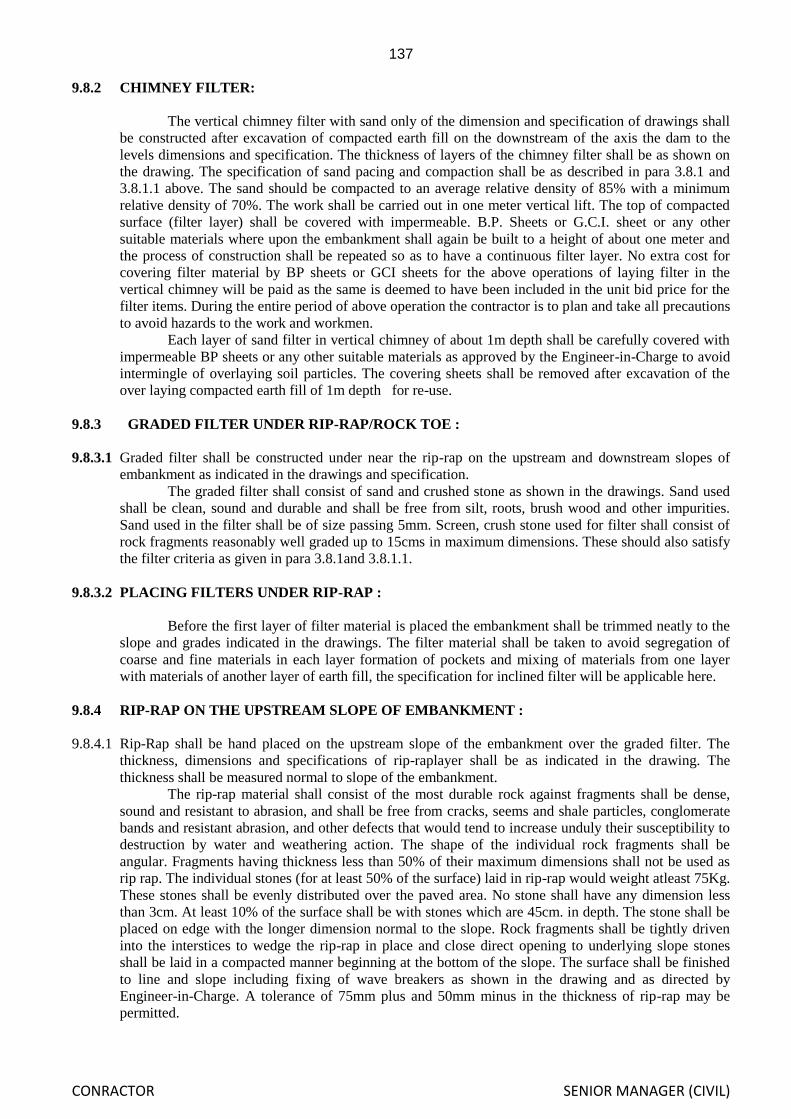
137
CONRACTOR SENIOR MANAGER (CIVIL)
9.8.2 CHIMNEY FILTER:
The vertical chimney filter with sand only of the dimension and specification of drawings shall
be constructed after excavation of compacted earth fill on the downstream of the axis the dam to the
levels dimensions and specification. The thickness of layers of the chimney filter shall be as shown on
the drawing. The specification of sand pacing and compaction shall be as described in para 3.8.1 and
3.8.1.1 above. The sand should be compacted to an average relative density of 85% with a minimum
relative density of 70%. The work shall be carried out in one meter vertical lift. The top of compacted
surface (filter layer) shall be covered with impermeable. B.P. Sheets or G.C.I. sheet or any other
suitable materials where upon the embankment shall again be built to a height of about one meter and
the process of construction shall be repeated so as to have a continuous filter layer. No extra cost for
covering filter material by BP sheets or GCI sheets for the above operations of laying filter in the
vertical chimney will be paid as the same is deemed to have been included in the unit bid price for the
filter items. During the entire period of above operation the contractor is to plan and take all precautions
to avoid hazards to the work and workmen.
Each layer of sand filter in vertical chimney of about 1m depth shall be carefully covered with
impermeable BP sheets or any other suitable materials as approved by the Engineer-in-Charge to avoid
intermingle of overlaying soil particles. The covering sheets shall be removed after excavation of the
over laying compacted earth fill of 1m depth for re-use.
9.8.3 GRADED FILTER UNDER RIP-RAP/ROCK TOE :
9.8.3.1 Graded filter shall be constructed under near the rip-rap on the upstream and downstream slopes of
embankment as indicated in the drawings and specification.
The graded filter shall consist of sand and crushed stone as shown in the drawings. Sand used
shall be clean, sound and durable and shall be free from silt, roots, brush wood and other impurities.
Sand used in the filter shall be of size passing 5mm. Screen, crush stone used for filter shall consist of
rock fragments reasonably well graded up to 15cms in maximum dimensions. These should also satisfy
the filter criteria as given in para 3.8.1and 3.8.1.1.
9.8.3.2 PLACING FILTERS UNDER RIP-RAP :
Before the first layer of filter material is placed the embankment shall be trimmed neatly to the
slope and grades indicated in the drawings. The filter material shall be taken to avoid segregation of
coarse and fine materials in each layer formation of pockets and mixing of materials from one layer
with materials of another layer of earth fill, the specification for inclined filter will be applicable here.
9.8.4 RIP-RAP ON THE UPSTREAM SLOPE OF EMBANKMENT :
9.8.4.1 Rip-Rap shall be hand placed on the upstream slope of the embankment over the graded filter. The
thickness, dimensions and specifications of rip-raplayer shall be as indicated in the drawing. The
thickness shall be measured normal to slope of the embankment.
The rip-rap material shall consist of the most durable rock against fragments shall be dense,
sound and resistant to abrasion, and shall be free from cracks, seems and shale particles, conglomerate
bands and resistant abrasion, and other defects that would tend to increase unduly their susceptibility to
destruction by water and weathering action. The shape of the individual rock fragments shall be
angular. Fragments having thickness less than 50% of their maximum dimensions shall not be used as
rip rap. The individual stones (for at least 50% of the surface) laid in rip-rap would weight atleast 75Kg.
These stones shall be evenly distributed over the paved area. No stone shall have any dimension less
than 3cm. At least 10% of the surface shall be with stones which are 45cm. in depth. The stone shall be
placed on edge with the longer dimension normal to the slope. Rock fragments shall be tightly driven
into the interstices to wedge the rip-rap in place and close direct opening to underlying slope stones
shall be laid in a compacted manner beginning at the bottom of the slope. The surface shall be finished
to line and slope including fixing of wave breakers as shown in the drawing and as directed by
Engineer-in-Charge. A tolerance of 75mm plus and 50mm minus in the thickness of rip-rap may be
permitted.

138
CONRACTOR SENIOR MANAGER (CIVIL)
Rip-rap shall be placed along with the fill so that a minimum of breakdown will occur during
placing & spreading.
9.8.5 ROCK TOE :
a) The rock toe shall be constructed over the base filter to the dimension of the drawing and
specification. The material of rock toe shall consist of the most durable rock fragments of
approved quality selected for the purpose.
b) The quality of rock fragmented shall be dense, sound and resistant to abrasion and shall be free
from cracks, seems shale particle, conglomerate bands and other defects that would tend to
increase unduly their susceptibility to deterioration by water and weathering action. The shape
of individual rock fragment shall be angular. Stones of sizes less than 0.028cum shall not be
used in the rock-toe. The rock toe shall be constructed of rock fragments obtain from the
excavation for permanent construction and from rock surface, if necessary. The rock fill
materials shall consist of rock fragments reasonably well graded and cleaned as determined by
the Engineer-in-Charge up to the maximum size available stones.
c) Successive loads of materials shall be dumped so as to secure the best practicable distribution
of material as determined by the Engineer-in-Charge. To the extent practicable the large
fragmented shall be placed next to the inner portion of the dam embankment. Rock fill shall be
placed in approximately horizontal layer not exceeding 90 cm in thickness. The rock fragment
shall be dumped and roughly leveled and hand packed in manner to have reasonable uniform
surface and to ensure that the completed fill will be stable dense and well graded and there will
be no unfilled spaces within the fill. The voids between the bigger stones after rough leveling
shall be filled with rock fragments of smaller sizes only in quantity enough to fill up the voids.
The material shall be selected and placed in such a way that larger stone shall be placed nearer
the outer slope and the smaller ones to inner slope.
d) The exposed surface of the rock shall be neatly finished confirm the designed lines and grades
as shown in the drawings.
e) Stones of smaller size shall be laid next to filter layer. The filter materials and stones shall be
laid simultaneously I regular layers to the designed slope and width. However, the rock fill
shall be placed and packed to obtain a suitable well-graded and free draining fill.
f) The smaller rock fragments shall be placed adjacent to the filter of embankment and large rock
fragments near the outer edge of the fill.
g) The rock fill shall be placed and roughly leveled in layers not greater than one meter in
thickness. The stones shall be properly hand packed and the inter slices shall be well filed with
spells and chips and tightly welded to ensure firm packing so as to have dense, well graded fill
with no larger voids and cavities.
h) Contamination of rock toe with finer material from any other zones shall be avoided.
i) Suitable out fall for draining out the seepage water collected in rock toe shall be provided
depending upon the site conditions
j) The rock toe zone as shown in the plan is tentative, if required modification may be done
during execution of the work. The contractor shall do the work according to such modifications
as per the instruction of the Engineer-in-Charge without any cost.
The contractor shall collect materials for filters, rip-rap and rock toe from the approved quarry
or from alternative sources which shall meet the requirements of specification as per the
direction of Engineer-in-Charge. The material should be approved prior to being brought to site
of work. The material for filter should be brought by contractor to the aforesaid test in the
laboratory. The results there of shall be final and binding. All materials not confirming to

139
CONRACTOR SENIOR MANAGER (CIVIL)
requirement and specifications so determined shall not be permitted for use in the work and
shall be removed by the contractor at his own cost.
9.8.6 MEASUREMENT AND PAYMENT :
a) Sand: Measurement of quantity of sand, for filters or chimney filter, horizontal filter blanket,
upstream/downstream toe,it has been laid and compacted in proper position to line and grade as
shown in the drawing on approved surface will be volumetric basis based on initial and final
levels before and after laying of materials duly accepted by the contractor on level book and
graph sheet on 15m grid or closed as per site conditions taken concurrent points. The payment
will be restricted to the quantities within the pay lines as shown in the drawings.
b) No compensation for intrusion of sand in to the other filter materials and vice versa will be
paid. These items shall be paid on quantity basis for the cubic contents of finished work at the
rate quoted in schedule of quantities.
c) The net bid price includes the collection, transportation, loading and unloading, spreading,
watering, compaction, tempering, dewatering, all labour, materials, materials, taxes and
royalties, tools, equipment, and all incidentals operations necessary to complete the work as per
specification and direction of Engineer-in-Charge.
d) Stone and aggregates: Measurements and payments for quantity of aggregates will be taken
inthe manner detailed in the para 3.8.6 above. No void will be deducted on the measurement
thus made.
9.9 VERTICAL CHIMNEY EXCAVATION :
Excavation of compacted earth in the vertical chimney shall be as per dimension of the
drawing. Excavation may be done mechanically within the dimensions and no over cut will be due for
payment. The material so excavated in layers of about 1m in height shall be relevant in the construction
of dam embankment as per specification in relevant para. The contractor should make arrangement to
prevent surface water running into vertical chimney excavation.
Payment will be made only for the cutting operation within the pay line as per drawing. No
extra payment for carriage will be made as the same is deemed to have been included in the unit bid
price of earth fill.
9.10 FINE DRESSING AND TURFING ON THE DOWNSTREAM SLOPE :
The downstream slope of the dam as per line grades and dimension of the drawing shall be
protected by turfing the entire slope including the berms. After the slope has been fine dressed to the
line, it shall be roughened or racked evenly without any additional cost. The entire surface shall than be
covered with a layer of dub grass sods consisting of blocks or strips of density living grass growth as
approved.
The sods shall include a mat of root and earth at least 5cm. thick. Sods containing an excess
amount of obnoxious growth shall be excluded. Sods shall be carefully handled in transportation and
transplantation so that minimum amount of earth will be loss from the root mass. The strips of blocks of
sods shall be laid in the slope of close contact and than tamped firmly in place so as to fill and close
joints between the blocks, interval between the collecting and laying shall be kept to a practically
minimum, and sods shall not be permitted to dry out. Immediately after placing the sods, slopes shall be
periodically moisture and if necessary, for a sufficient period to re-establish the plant growth. Slopes
shall be transplanted generally from July to November. Arrangement of suitable sods is the
responsibility of the contractor.
The unit bid price shall be for the finished item including the collection, transportation within
5kms.lead , all lifts and delifts, unloading ,surface preparation, transplanting, tamping, watering till

140
CONRACTOR SENIOR MANAGER (CIVIL)
survival of sods, all labour, material, taxes, equipment and all incidental operations necessary to
complete the work as per specification and direction of Engineer-in-Charge.
9.11 INSPECTION AND TESTS :
9.11.1 GENERAL:
The Engineer in charge shall maintain and exercise a through check on the quality of fill
materials devoured to the dam embankment and will arrange to obtain the data and in-situ properties of
materials after compaction in comparison with design assumptions. To achieve these objectives a
programme of fill testing and inspection shall be planned to effort quality control.
9.11.2 SLOPE OF TESTING INSPECTION REQUIRED:
Field control of fill materials will require visual and laboratory checks. The check on the
effectiveness of placement and compaction procedure shall be made by field density test at prescribed
intervals. The control shall be both of the method type and on end result basis.
Department might review the design if necessary on examination of density test results and the
contractor shall have no claim arising out of such a review and consequent changes if any, in the design
and method type and on end result basis.
9.11.3 EMBANKMENT TEST SECTION:
Placement and compaction methods specified will have to verified by test embankment section
to be built prior to starting to fill operations or at an early stage of construction. Either the initial stage of
dam construction itself would be made to serve the purpose or test embankment section could be
established in borrow areas. The test sections shall be used to establish.
i) Layer thickness of fill materials
ii) Optimum practicable moisture content
iii) No. of passes of sheep foot roller/ vibratory roller for effective compaction
iv) For pneumatic tyred compaction equipment, the test required will be such as to determine the
most suitable loading. Tyre pressure, moisture contents and number of coverage for compaction
of materials.
When an appreciable change in materials occurs, additional test sections should be
made during construction. The procedure for construction of test embankment section is as
follows:
a) Select a location on the embankment where uninterrupted placing operations are being
performed. This area (15m by 30m) should be fully marked and reference so that its limits will
be easily recognized in order to expedite the determination of moisture content to be used more
than one test sections may be established on the embankment at the same time.
b) During construction of test section which will most probably continue for several shifts, a
complete record of the procedure should be kept, this record should include the number of
layers placed, the spread thickness of each layer, the moisture content at which the material are
rolled, the designation (No.1,No.2 etc) of the rollers used, the condition of the roller (clean or
dirty), the section of the material being rolled (such as wavy under the rollers, the amount of
penetration of the rollers‟ teeth after different number of roller trips etc.) and borrow pit
locations from which the materials are brought.
c) Check the rollers to make certain that they meet all the requirements of the specifications.

141
CONRACTOR SENIOR MANAGER (CIVIL)
d) Determine the required spread thickness of layer that will be completed to the specified
thickness after rolling, specified numbers of times and maintain the thickness along as number
of roller passes is kept the same.
e) Using the available data from borrow pit investigation of the materials to be used in the test
section, the optimum moisture content as determined by the laboratory test will be known and
3% less than this moisture content should be used in the first 3 or 4 layers rolled.
f) After 3 or 4 layers have been placed at 3% less than the laboratory optimum moisture content,
field density test should be made throughout the section. These tests should be made for atleast
100 Sqm. of test section area and should be so disturbed over the area that they will depict the
effect of different compaction condition encountered during construction. For example, if the
section is located near an abutment, certain part of the area will receive more compaction from
tract travel than other, hence some test should be made in the portion compacted only by the
rollers and so reported.
g) The next step is to compact another 3 or 4 layers at the moisture content slightly higher (1% or
2%) than the moisture content previously used ,maintaining the same rolled thickness of layers
and number of roller passes as in above Field Density test are again made over the test section.
h) If the resulting field dry density ( of material passing the No. 4 sieve) from (g)-above show an
increase, with increase of moisture, then increase the moisture again by another 1% or 2% and
repeat the test. If an increase in moisture results in decrease in field density, then place, the next
layer slightly dry of the original moisture content used and repeat the test. this procedure is
nothing more than developing on the embankment a moisture density relation or compaction
curve for a certain roller thickness of layer and given number of roller trips if special studies
during investigation have indicated that the material being test should be placed within certain
moisture limits to be used have been specified, the procedure outlined above should include test
at these moisture contents or at moisture contents both greater and smaller than the specified
limits.
i) The roller compaction curve is now compared with the standard laboratory compaction curve, if
the field density of the materials passing the No-4 sieve (from the roller curve)is greater than
the standard compaction density at the specified moisture content, the test section should be
continued decreasing the number of roller trips while maintaining specified desirable moisture
content until the most economical compactive effort is determined. when the roller trips are
decreased, the required spread thickness of the layers that will compacted to the specified
thickness of compacted materials should be reckoned.
9.11.4 BEFORE COMPACTION :
Material delivered to the fill shall be visually examined and their properties estimated by way
of inspection.
These checks shall include
a) Borrow Areas :
i. Excavation of borrow areas shall be limited in extent and depth as indicatedon plans &in
specificatin-3.4.1 and also as per direction of the Engineer-in-charge.
ii. Estimation of moisture content of materials by visual examination and feel.
iii. Samples shall be taken for laboratory analysis in case the soil is of different characteristics.

142
CONRACTOR SENIOR MANAGER (CIVIL)
b) Embankments :
I. Moisture content tests shall be carried out in the field laboratory while placing the fill
materials.
II. Moisture content shall be controlled by adding water or allowing the soil to dry according
to laboratory tests.
III. It shall be ensure that the methods of dumping, spreading and moisture conditions are such
as will result in reducing segregation and/on variation of moisture content to a minimum.
These inspection checks shall be supplemented by sampling the materials at
prescribed minimum intervals and by testing the samples in the laboratory for gradation and
moisture content.
The following tests shall be carried out for determining compaction.
a) Density moisture relation of the soil: In accordance with IS:2720(Part-VII(1980.
b) Density of the soling field: In accordance with IS:2720 (Part.XXVII)1974 or IS:2720 (part-
XIX)1975.
c) Moisture Content: In accordance with IS:2720 (Part-II) 1973. Before compaction: Materials
delivered to the fill shall be visually examined and their properties estimated byway of
inspection.
9.11.5.1 DURING COMPACTION :
It is intended that the checks in operations during compaction shall verify.
i. That the layer thickness of the material is as specified
ii. That the fill is compacted at least to98% of standard proctor's Density (Dry density at OMC) or
70% relative density as the case may be by the specified number of passes of specified
machineries as per Annexure-III.
iii. That no excessive rutting, waving or scaling of the fill occurs during compaction.
9.11.5.2 AFTER COMPACTION :
The condition of the fill after compaction shall be observed and recorded particularly with
respect to rutting or waving. However, the properties of materials after compaction shall be determined
primarily by field density tests. Routine tests on samples taken from constructed embankment shall
include besides density tests, grain size distribution, Attenberg limits, permeability, shear and
consolidation characteristics.
9.11.6 FREQUENCY OF TESTING :
a) It will be necessary to carry out sampling and testing of materials before and after compaction
at sufficient frequencies so that effective checks on the fill operations are maintained. Testing
frequencies proposed should correspond to the frequencies as mentioned in the relevant
paragraphs. However, the actual frequencies should be adjusted to suit the nature and
variability of materials placed and the rate of fill placement.
b) Testing shall be performed at frequent interval than those specified in Annexure during initial
stages of placing in each zone in order to establish control on testing techniques.Also testing

143
CONRACTOR SENIOR MANAGER (CIVIL)
should be conducted at higher rates in case of special problem of control caused by such factors
such as material variation, equipment performance and weather.
c) In addition, these tests shall be made
i) In areas, where the degree of compaction is doubtful.
ii) In areas, where embankment operations are concentrated.
iii) For record tests at the locations of all embedded instruments.
d) Locations of likely insufficient compaction shall cover the following or any other area so
determined by Engineer-in-charge.
i) The junction between areas of mechanical tamping and rolled embankment along abutment or
cutoff walls.
ii) Areas where rollers turn during rolling operations.
iii) Areas where too thick layer is being compacted.
iv) Areas where improper water content exists in material.
v) Areas where less than specified number of roller passes were made.
vi) Areas where dirt clogged rollers were used to compact the materials.
vii) Areas where compacted by rollers that have possibly lost part of their ballast.
viii) Areas where oversized rock is contained in the fillhas been overlooked.
ix) Areas containing materials differing substantially from the average.
9.11.7 RECORDS AND REPORTS:
Record of borrow area material and embankment placing operations shall be maintained in order to have a continuous check on the suitability and availability of full materials and quality of fill. Thus, it shall be possible to have complete description of materials in any portion of the embankments. The record shall be maintained on the form specified in ANNEXURE-II.
9.11.8 FIELD TEST DATA :
Records of field Test Data results should be presented in the form of statistical analysis
sheets and summary sheets in order to provide control required for enforcement of statistical requirements of the specifications. Testing should be as per table Annexure-I.
The test data summary sheets and inspection reports be used to form the basis of construction control report, which should be issued from the site at fortnightly intervals during construction season. The report would contain narrative accounts of the progress and problems of field constructions, statistical analysis of test data and photographs of the fill operations.
9.12 PROTECTION :
The contractor shall take all precautions necessary for the protection of the bank work by
diversion of stream, local surface drainage, rainwater etc., if these are likely to damage the work. Any damage of earth work due to any reason whatsoever shall be made good by the contractor at his own cost till the work is certified as completed and taken over by the department.
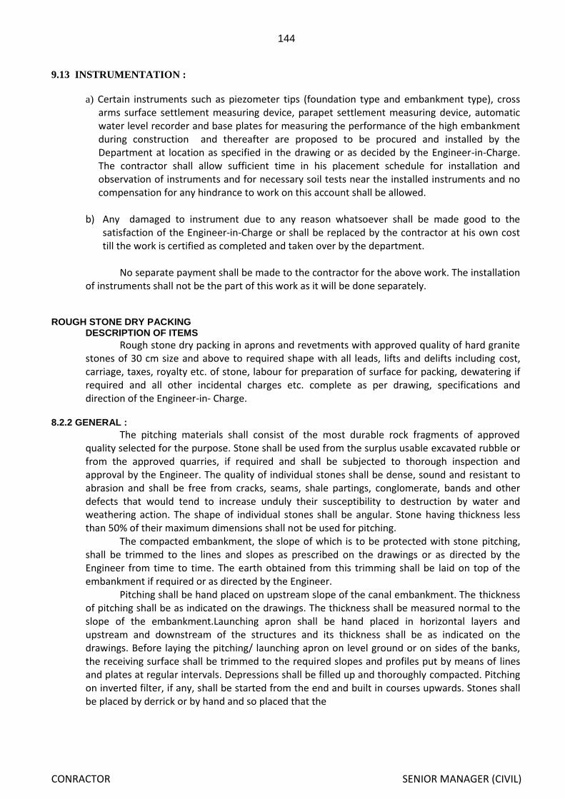
144
CONRACTOR SENIOR MANAGER (CIVIL)
9.13 INSTRUMENTATION :
a) Certain instruments such as piezometer tips (foundation type and embankment type), cross arms surface settlement measuring device, parapet settlement measuring device, automatic water level recorder and base plates for measuring the performance of the high embankment during construction and thereafter are proposed to be procured and installed by the Department at location as specified in the drawing or as decided by the Engineer-in-Charge. The contractor shall allow sufficient time in his placement schedule for installation and observation of instruments and for necessary soil tests near the installed instruments and no compensation for any hindrance to work on this account shall be allowed.
b) Any damaged to instrument due to any reason whatsoever shall be made good to the
satisfaction of the Engineer-in-Charge or shall be replaced by the contractor at his own cost till the work is certified as completed and taken over by the department.
No separate payment shall be made to the contractor for the above work. The installation
of instruments shall not be the part of this work as it will be done separately.
ROUGH STONE DRY PACKING
DESCRIPTION OF ITEMS
Rough stone dry packing in aprons and revetments with approved quality of hard granite stones of 30 cm size and above to required shape with all leads, lifts and delifts including cost, carriage, taxes, royalty etc. of stone, labour for preparation of surface for packing, dewatering if required and all other incidental charges etc. complete as per drawing, specifications and direction of the Engineer-in- Charge.
8.2.2 GENERAL :
The pitching materials shall consist of the most durable rock fragments of approved quality selected for the purpose. Stone shall be used from the surplus usable excavated rubble or from the approved quarries, if required and shall be subjected to thorough inspection and approval by the Engineer. The quality of individual stones shall be dense, sound and resistant to abrasion and shall be free from cracks, seams, shale partings, conglomerate, bands and other defects that would tend to increase unduly their susceptibility to destruction by water and weathering action. The shape of individual stones shall be angular. Stone having thickness less than 50% of their maximum dimensions shall not be used for pitching.
The compacted embankment, the slope of which is to be protected with stone pitching, shall be trimmed to the lines and slopes as prescribed on the drawings or as directed by the Engineer from time to time. The earth obtained from this trimming shall be laid on top of the embankment if required or as directed by the Engineer.
Pitching shall be hand placed on upstream slope of the canal embankment. The thickness of pitching shall be as indicated on the drawings. The thickness shall be measured normal to the slope of the embankment.Launching apron shall be hand placed in horizontal layers and upstream and downstream of the structures and its thickness shall be as indicated on the drawings. Before laying the pitching/ launching apron on level ground or on sides of the banks, the receiving surface shall be trimmed to the required slopes and profiles put by means of lines and plates at regular intervals. Depressions shall be filled up and thoroughly compacted. Pitching on inverted filter, if any, shall be started from the end and built in courses upwards. Stones shall be placed by derrick or by hand and so placed that the

145
CONRACTOR SENIOR MANAGER (CIVIL)
largest dimensions are perpendicular to the face of the slope. The larger stones shall be placed in the bottom course and for use as headers for subsequent courses. All interstices between adjacent stones shall be filled with spalls of proper sizes and wedged in with hammer to ensure tight packing.
8.2.3 MEASUREMENT AND PAYMENT
Measurement for payment will be made on the basis of volumetric measurement of finishedstone packing. The unit rate is inclusive of trimming the earth to required profile, slopes and grade and/ or preparing level at suitable intervals as directed, to have uniform base.
SUPPLYING, LAYING & FIXING OF R.C.C. HUME PIPES 8.1.1 DESCRIPTION OF ITEMS
Supplying, laying and fixing R.C.C. hume pipe in position and collar jointing with necessary twisted and coal tarred hamp yarn including crawling and filling with C.M. (1:1) and finishing the same smooth and curing including cost, conveyance, taxes etc. of R.C.C. hume pipes and all other materials and all other incidental charges etc. complete as per specification and direction of Engineer-in-charge.
8.1.2 GENERAL
R.C.C. hume pipe shall have diameter as specified in the schedule of quantities and shall be of non pressure NP2/NP3 class conforming to IS 458-1971. Length of the pipe shall not be less than 2.00 M or otherwise directed by the Engineer. The contractor shall order the pipes required for the work on the basis of the construction drawings supplied to him by the Engineer. Pipes not conforming to the required specification shall be rejected and the pipes shall be removed away from the work site by the contractor at his own cost. Work shall be done as per IS 783-1956 or its latest edition. Reasonable care shall be exercised in loading, transporting and unloading the concrete pipes. Handling shall be such as to avoid impact. All pipes shall be inspected thoroughly before being laid. Broken or defective pipe shall not be used. Trench shall be of sufficient width side slope to provide for free working space in minimum 30 cm on either side of the pipe. Pipes shall be lowered into the trenches by use of standards appliance. Pipe shall be laid true to line and as specified on the construction drawings. Laying of pipes shall be along proposed grade of the slope. The socket ends of pipe shall face upstream. The connections of the pipes shall be joined together in such a manner that these shall produce perfect even surface along the inside of the pipe. The joining of hume pipes shall be done with necessary twisted and coal tarred hamp yarn including crawling and filling with cement mortar (1:1) and finishing the same smooth and curing for a minimum period of 14 days shall be made. In no case pipes shall be laid directly on rock or other hard materials. Proper care shall be taken to avoid any type of accidents during process of handling of R.C.C. hume pipes.
Trenches shall be kept free from water until the material in the joints has hardened. Walking or working on the completed pipe shall not be permitted until the trench has been back filled to a height of at least 45 cm. Over the pipe except as may necessary for back filling and compaction. Trenches shall be backfilled after pipe has been laid subject to the condition that joining has hardened. Only selected materials shall be used for backfilling. Filling of the trench shall be carried out simultaneously on both sides of pipe in such manner that unequal pressure does not occur.
8.1.3 MEASUREMENT AND PAYMENT
Measurement for payment shall be made on running metre basis of the hume pipe line. The rate shall include cost of hume pipes including cost of loading, conveying, unloading, hauling, handling, storing & laying in position with cost of jointing and curing and all other incidental charges to complete the work as per the specification and direction of Engineer-in-charge.

146
CONRACTOR SENIOR MANAGER (CIVIL)
4.2.23 DETAIL SPECIFICATION OF EXPANSION JOINTS/ CONSTRUCTION JOINTER (EJ/CJ) Description of Items
The joint should be left in concrete in required places as per drawing and design. Embedded parts if any will have to be provided prior to casting of concrete. Old surface of the concrete joints should be made clean free of dirt, grease, protrusions or any objectionable materials as per the direction of the Engineer-in-charge. The face of the joints should be made straight. The surface of joints should be painted with bitumen/ coal tar and fitted with the approved sealing materials like bituminous filler boards, etc. The adjacent concreting masonry then only can be constructed.
In the case of P.V.C. water stop, the pieces should be jointed together at the site by vulcanising thoroughly to make it water tight having sufficient strength to withstand the designed water pressure exerted on it.
In case of copper seal, the thickness of the copper sheet should be of 16 gauge (1.63 mm) and minimum of 0.6m wide with ‘V’, ‘U’ or ‘Z’ groove of size 2.5 cm. at its longitudinal axis. The groove should be perfectly straight and uniform. Adjacent copper sheet should be perfectly braced together on both sides for the whole width by butting the two sheets against each other. If lapping between adjacent sheet are given, the maximum lapping should be 5 cm. and should be held together tight. Brazing should be done on both sides for the whole width. The joints should be braced, watertight and should be capable of withstanding the hydraulic pressure exerted on it. M.S. anchor rods of 6 mm to 8mm dia and 30cm long with hook on outer side and should be braced with the copper sheet @ 50 cm centre to centre approximately on both sides of copper sheet preferably staggered. The minimum length of the rod to be brazed is minimum 5 cm. and brazing should be done on both side of the rod.
The edges of the copper sheet should also be given a link at about 0.5 M. interval to have a better grip with concrete. The brazing should be done as per relevant IS specification. The P.V.C water stop shall be dense, homogeneous and free from holes and other imperfections. The cross section of the water stop shall be uniform along its lengths and thickness shall be symmetrical. Location and embedment of the P.V.C./Copper water stops shall be as shown on the drawings, with approximately one-half of the width. Water stops shall be embedded in the concrete on each side of the joints. In order to eliminate faulty installation that may result leakage, care shall be taken that the water stops shall be installed to form continuous watertight diaphragm in the joints. Unless otherwise shown, adequate provision shall be made to protect the water stops during the progress of the work.
Additional vibrations over and above that used for adjacent concrete placement shall be carried out to assure complete embedment of the water stops in the concrete. Larger pieces of aggregate near the water stops shall be removed by hand during embedment to assure complete contact between the water stop and surrounding concrete.
6 Porous Concrete
(1) Porous concrete shall be placed where free drainage is required and shall be produced by gap
grading or single size aggregate grading.
(2) The strength requirements for porous concrete shall be as for class M10/A40 concrete. The
porosity shall be such that water will pass through a slab 30 mm thick at a minimum rate of 500
l/mi/m2 with a constant depth of water on the slab of 100 mm.
(3) Porous concrete shall not be vibrated but only placed and lightly rammed. Formed surfaces shall
be Class F1 finish. Exposed surfaces of the porous concrete shall be sealed in an approved
manner, such as the use of polyethylene or rendering with sand and cement, before structural
concrete is placed against it.

147
CONRACTOR SENIOR MANAGER (CIVIL)
Section-VI
Drawing

148
CONRACTOR SENIOR MANAGER (CIVIL)

149
CONRACTOR SENIOR MANAGER (CIVIL)

150
CONRACTOR SENIOR MANAGER (CIVIL)

151
CONRACTOR SENIOR MANAGER (CIVIL)

152
CONRACTOR SENIOR MANAGER (CIVIL)

153
CONRACTOR SENIOR MANAGER (CIVIL)