Cougar B Series Electric Vibrators Zero Framecatalog.jamiesonequipment.com/Asset/Martin Cougar B...
27
Cougar ® B Series Electric Vibrators Zero Frame Operator’s Manual M3892
-
Upload
duongthien -
Category
Documents
-
view
238 -
download
1
Transcript of Cougar B Series Electric Vibrators Zero Framecatalog.jamiesonequipment.com/Asset/Martin Cougar B...

Cougar® B Series Electric Vibrators Zero Frame
Operator’s Manual M3892

Table of Contents
Section PageList of Figures . . . . . . . . . . . . . . . . . . . . . . . . . . . . . . . . . . . . . . . . . . . . . . . . . . . . . . . . . . . . . . . . . . . iiList of Tables . . . . . . . . . . . . . . . . . . . . . . . . . . . . . . . . . . . . . . . . . . . . . . . . . . . . . . . . . . . . . . . . . . . . iiIntroduction . . . . . . . . . . . . . . . . . . . . . . . . . . . . . . . . . . . . . . . . . . . . . . . . . . . . . . . . . . . . . . . . . . . . . 1
General . . . . . . . . . . . . . . . . . . . . . . . . . . . . . . . . . . . . . . . . . . . . . . . . . . . . . . . . . . . . . . . . . . . . . . 1
References . . . . . . . . . . . . . . . . . . . . . . . . . . . . . . . . . . . . . . . . . . . . . . . . . . . . . . . . . . . . . . . . . . . 1
Safety . . . . . . . . . . . . . . . . . . . . . . . . . . . . . . . . . . . . . . . . . . . . . . . . . . . . . . . . . . . . . . . . . . . . . . . 1
Materials required . . . . . . . . . . . . . . . . . . . . . . . . . . . . . . . . . . . . . . . . . . . . . . . . . . . . . . . . . . . . . 1
Storage . . . . . . . . . . . . . . . . . . . . . . . . . . . . . . . . . . . . . . . . . . . . . . . . . . . . . . . . . . . . . . . . . . . . . . 1
Before Installing Vibrator . . . . . . . . . . . . . . . . . . . . . . . . . . . . . . . . . . . . . . . . . . . . . . . . . . . . . . . . . . 2Installing Vibrator . . . . . . . . . . . . . . . . . . . . . . . . . . . . . . . . . . . . . . . . . . . . . . . . . . . . . . . . . . . . . . . . 3
Mounting vibrator onto structure . . . . . . . . . . . . . . . . . . . . . . . . . . . . . . . . . . . . . . . . . . . . . . . . . . 3
Connecting power to vibrator. . . . . . . . . . . . . . . . . . . . . . . . . . . . . . . . . . . . . . . . . . . . . . . . . . . . . 7
Installing overload, short-circuit, and ground-fault protection . . . . . . . . . . . . . . . . . . . . . . . . . . . 8
After Installing Vibrator . . . . . . . . . . . . . . . . . . . . . . . . . . . . . . . . . . . . . . . . . . . . . . . . . . . . . . . . . . . 9Checking shaft rotation . . . . . . . . . . . . . . . . . . . . . . . . . . . . . . . . . . . . . . . . . . . . . . . . . . . . . . . . . 9Adjusting eccentric weights . . . . . . . . . . . . . . . . . . . . . . . . . . . . . . . . . . . . . . . . . . . . . . . . . . . . . 9Initial start up/checking line current . . . . . . . . . . . . . . . . . . . . . . . . . . . . . . . . . . . . . . . . . . . . . . . 11Variable frequency inverter . . . . . . . . . . . . . . . . . . . . . . . . . . . . . . . . . . . . . . . . . . . . . . . . . . . . . . 12
Maintenance. . . . . . . . . . . . . . . . . . . . . . . . . . . . . . . . . . . . . . . . . . . . . . . . . . . . . . . . . . . . . . . . . . . . . 13Lubricating vibrator . . . . . . . . . . . . . . . . . . . . . . . . . . . . . . . . . . . . . . . . . . . . . . . . . . . . . . . . . . . 13Repairing motor and replacing bearings . . . . . . . . . . . . . . . . . . . . . . . . . . . . . . . . . . . . . . . . . . . . 13Inspecting vibrator . . . . . . . . . . . . . . . . . . . . . . . . . . . . . . . . . . . . . . . . . . . . . . . . . . . . . . . . . . . . 14
Part Numbers . . . . . . . . . . . . . . . . . . . . . . . . . . . . . . . . . . . . . . . . . . . . . . . . . . . . . . . . . . . . . . . . . . . . 15
Tab
le o
f C
onte
nts

List of Figures
Figure Title Page1 Locating Vibrator on Hoppers. . . . . . . . . . . . . . . . . . . . . . . . . . . . . . . . . . . . . . . . . . . . . . 3
2 Mounting Plate and Channel Assembly . . . . . . . . . . . . . . . . . . . . . . . . . . . . . . . . . . . . . . 43 Mounting Bolt Tightening Sequence . . . . . . . . . . . . . . . . . . . . . . . . . . . . . . . . . . . . . . . . 54 Installing Restraining Cable . . . . . . . . . . . . . . . . . . . . . . . . . . . . . . . . . . . . . . . . . . . . . . . 65 Three Phase Wiring Diagrams. . . . . . . . . . . . . . . . . . . . . . . . . . . . . . . . . . . . . . . . . . . . . . 76 Adjusting Eccentric Weights . . . . . . . . . . . . . . . . . . . . . . . . . . . . . . . . . . . . . . . . . . . . . . . 107 Cougar® Electric Vibrator, Model B1-237-0A-2 . . . . . . . . . . . . . . . . . . . . . . . . . . . . . . . 168 Cougar® Electric Vibrator, Model B1-380-0A-2 . . . . . . . . . . . . . . . . . . . . . . . . . . . . . . . 189 Cougar® Electric Vibrator, Models B3-237-0A-2 & B3-380-0A-2 . . . . . . . . . . . . . . . . . 20
List of Tables
Table Title PageI Mounting Bolts and Torque Requirements . . . . . . . . . . . . . . . . . . . . . . . . . . . . . . . . . . . . 5
II Eccentric Weight Settings . . . . . . . . . . . . . . . . . . . . . . . . . . . . . . . . . . . . . . . . . . . . . . . . . 10III Lubrication Schedule For Each Bearing . . . . . . . . . . . . . . . . . . . . . . . . . . . . . . . . . . . . . . 13IV Cougar® Electric Vibrator Model Numbers and Part Numbers . . . . . . . . . . . . . . . . . . . . 15V Cougar® Electric Vibrator Part Numbers and Quantities . . . . . . . . . . . . . . . . . . . . . . . . . 21
Lis
t of
Fig
ures
/Tab
les

Introduction
General Cougar® Electric Vibrators are designed and manufactured to ensure the best performance and reliability in severe-duty applications. The vibrator motor has a recommended operational ambient temperature and mounting surface temperature range of -22 to 104°F (-30 to 40°C). If operating the motor in environments beyond these temperatures, call Martin Engineering, as the vibrator may require rating reduction, more frequent lubrication, or lubrication substitution.
This manual provides instructions for installation onto steel bins and hoppers only. For installation onto other structures, call Martin Engineering or a representative.
References The following documents are referenced in this manual:
• The National Electrical Code (NEC), National Fire Protection Association,1 Batterymarch Park, P.O. Box 9101, Quincy MA 02269-9101.
• American National Standards Institute (ANSI) z244.1-1982, AmericanNational Standard for Personnel Protection - Lockout/Tagout of EnergySources - Minimum Safety Requirements, American National StandardsInstitute, Inc., 1430 Broadway, New York, NY 10018.
• Code of Federal Regulation (CFR) 29, Part 1910, Control of HazardousEnergy Source (Lockout/Tagout); Final Rule, Department of Labor,Occupational Safety and Health Administration (OSHA), 32nd Floor, Room 3244, 230 South Dearborn Street, Chicago, IL 60604.
• CFR 29, Part 1910.15, Occupational Noise Exposure, Department of Labor,OSHA, 32nd Floor, Room 3244, 230 South Dearborn Street,Chicago, IL 60604.
Safety All safety rules defined in the above documents and all owner/employer safety rules must be strictly followed when working on the vibrator.
Materials required In addition to metric hand tools, the following materials are required to installthis equipment:
• Mounting plate and channel assembly , P/N 32401-B0.
• Martin® Safety Cable Kit, P/N 32271, or equivalent.
Storage Store vibrator in an ambient temperature not less than 41°F (5°C) with a relative humidity not more than 60%. If the vibrator has been stored for 2 or more years, remove bearings, wash them, and repack them with new grease (see “Maintenance”).
Intr
oduc
tion

Before Installing Vibrator
IMPORTANTThe delivery service is responsible for damage occurring in transit. Martin Engineering CANNOT enter claims for damages. Contact your transportation agent for more information.
1. Inspect shipping container/pallet for damage. Report damage to deliveryservice immediately and fill out delivery service’s claim form. Keep anydamaged goods subject to examination.
2. Remove vibrator from shipping container/pallet.
3. If anything is missing contact Martin Engineering or a representative.
WARNING!
Turn off and lock out/tag out all energy sources to conveyor/loading systems to mounting structure.
4. Before installing vibrator, turn off and lock out/tag out all energy sourcesto conveyor/loading systems to mounting structure according to ANSIstandards (see “References”).
WARNING!
If equipment will be installed in an enclosed area, gas level or dust content must be tested before using a cutting torch or welding. Using a cutting torch or welding in an area with gas or dust may cause an explosion.
5. If using a cutting torch or welding, test atmosphere for gas level or dustcontent.
6. Mounting surface must be strong and flat, 0.01 in. (0.25 mm) acrossvibrator feet. (This will minimize internal stress to vibrator casting whentightening mount bolts. Welding in the area of the mounting surface couldaffect its flatness.)
7. Make sure mounting surface is free of paint and debris and foot ofvibrator is clean.
Bef
ore
Inst
alla
tion

Installing Vibrator
IMPORTANTRead entire section before beginning work. This manual provides instructions for installations onto steel bins and hoppers only. For other installations, call Martin Engineering or a representative.
CAUTION!
If installation instructions are not followed, structure and vibrator can be damaged. Abusing or handling vibrator carelessly will accelerate wear and shorten bearing life.
Mounting vibrator onto structure
1. See Figure 1. Locate vibrator in lower 1/4 to 1/3 of structure slope length.If second vibrator is required, mount 180° from first vibrator and halfwayup slope.
Figure 1. Locating Vibrator on Hoppers
CAUTION!
Never weld structure with vibrator mounted and wired. Welding may cause damage to motor windings and bearings.
IMPORTANTThe object of rotary vibration on bins, hoppers, and chutes is to transmit vibration through the wall into the product contained inside. If structure is not made rigid, vibrator may draw high amperage and move material less efficiently.
Make sure structure is free of paint before mounting vibrator.
2. If using customer-supplied mounting plate to mount vibrator ontostructure, do the following:
a. Make sure plate is at least the size of vibrator base.
b. Locate plate so that vibrator can be positioned as shown in Figure 1.
c. Weld mounting plate onto structure.
Inst
alla
tion

3. If using mounting plate and channel assembly to mount vibrator ontostructure (see Figure 2), do the following:
a. Locate channel so that vibrator can be positioned as shown in Figure 1.
b. Extend channel at least 3/4 the length of sloped wall. Cut off end(s) ofchannel if necessary to fit on structure.
c. Skip-weld channel in place: Weld 3 in. (76 mm), then skip 2 in.(51 mm). Repeat for entire perimeter of channel. Do not weld last 1 in.(25 mm) of either end of channel or any corner.
d. Install vibrator onto mounting plate.
Figure 2. Mounting Plate and Channel Assembly
CAUTION!
Never weld structure with vibrator mounted and wired. Welding may cause damage to motor windings and bearings.
Use only new Grade 5 bolts and lock nuts to install vibrator. Old fasteners can break and cause damage to vibrator or structure.
Do not use split lock washers to install vibrator onto mount. Damage to vibrator could result.
Tighten mounting bolts in sequence shown in Figure 3. If not tightened in order, vibrator casting could be damaged.
4. Before installing vibrator onto mount, apply thread sealing compound toall bolts.
5. Install vibrator onto mount with new lock nuts, compression washers, andbolts according to Table I. Tighten bolts in order given in Figure 3 to avoid damaging vibrator casting. (Contact fastener manufacturer for specificinformation regarding bolt torque.)
Mounting Plate andChannel Assembly
Skip Weld
Inst
alla
tion

Figure 3. Mounting Bolt Tightening Sequence
6. After the vibrator has been operated for 10 to 20 minutes, check bolttorque. Tighten if necessary.
Table I. Mounting Bolts and Torque Requirements*
*Torque specifications are for reference only. Contact fastener manufacturer for specific informationregarding bolt torque.
WARNING!
If vibrator is mounted more than 6 in. (152 mm) above ground, install cable securing vibrator to structure. Without cable, vibrator could fall and cause injury.
7. Secure vibrator to structure by installing Martin® Safety Cable Kit,P/N 32271, or equivalent as follows:
1
3 2
4
English Metric
Bolt Size(Gr 5)
Dry Torque(ft-lb)
Bolt SizeDry Torque
(N•m)
5/16 in. -18NC 17 M8 23
Inst
alla
tion
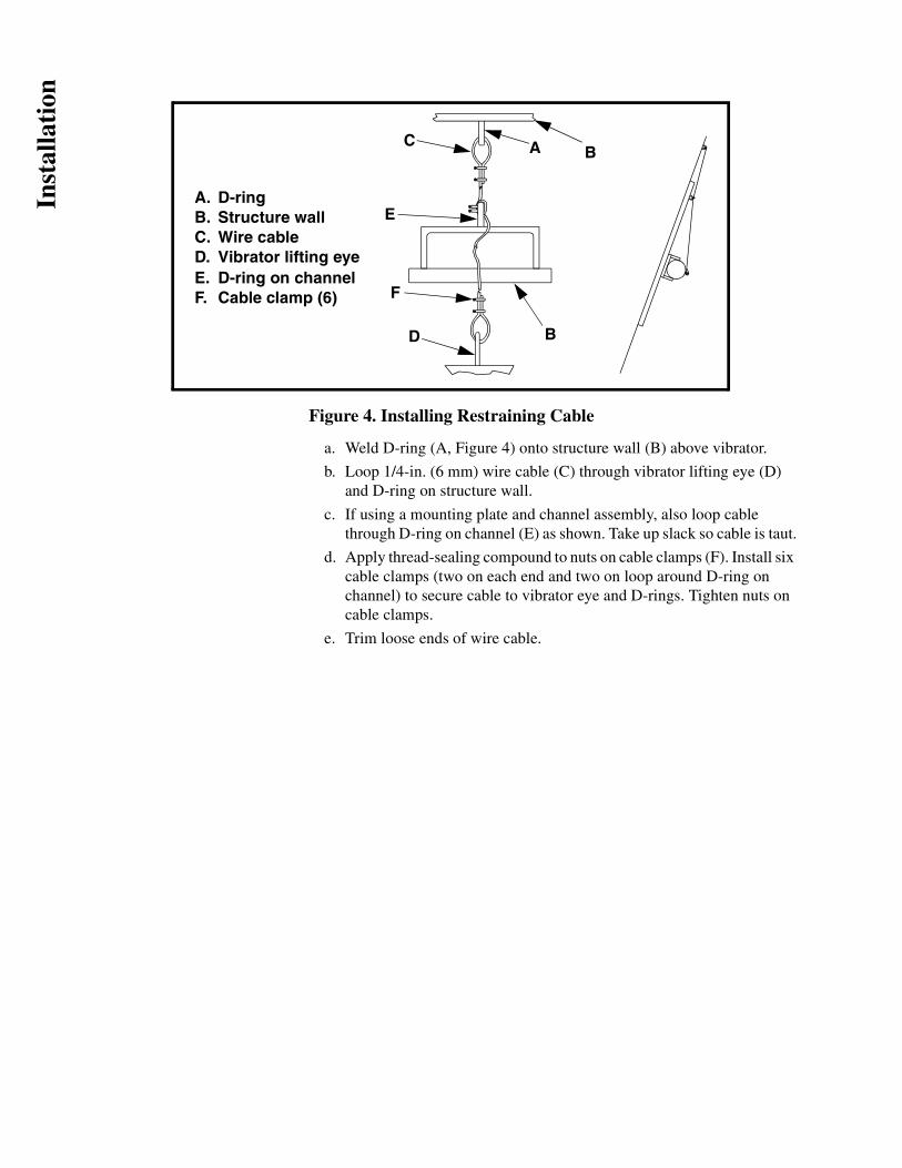
Figure 4. Installing Restraining Cable
a. Weld D-ring (A, Figure 4) onto structure wall (B) above vibrator.
b. Loop 1/4-in. (6 mm) wire cable (C) through vibrator lifting eye (D)and D-ring on structure wall.
c. If using a mounting plate and channel assembly, also loop cablethrough D-ring on channel (E) as shown. Take up slack so cable is taut.
d. Apply thread-sealing compound to nuts on cable clamps (F). Install six cable clamps (two on each end and two on loop around D-ring onchannel) to secure cable to vibrator eye and D-rings. Tighten nuts oncable clamps.
e. Trim loose ends of wire cable.
A
BD
C
E
F
A.B.C.D.E.F.
D-ringStructure wallWire cableVibrator lifting eyeD-ring on channelCable clamp (6)
B
Inst
alla
tion

Connecting power to vibrator
WARNING!
Wire vibrator in accordance with National Electrical Code Article 430. Have wiring installed by a qualified electrician only.
1. Find wiring diagram number for your vibrator on vibrator nameplate orsee Figure 5.
Figure 5. Three Phase Wiring Diagrams
CAUTION!
Before running cord to vibrator, make sure cord voltage rating equals or exceeds the voltage at which you will be operating the vibrator. It must have a minimum temperature rating of 221°F (105°C). If wire is not proper diameter, cord grip will not tighten properly and vibrator could be damaged by moisture or material getting inside wiring compartment. If cord is damaged, it could short power supply or short to ground causing damage to vibrator.
2. The frame size of the electric vibrator will define the size of the cord grip.Each cord grip is designed for a specific cord diameter range.
IMPORTANTThe compression nut must be tightened to a position that will provide proper strain relief for the cord. If the compression nut is not tight enough, the electrical connections may be stressed. If the compression nut is too tight, the cord may be damaged.
IMPORTANTWhen wiring vibrator, leave slack in electrical cable so that cable does not become taut during vibration cycle and cause stress on wire connections. On applications where moisture is present, leave enough slack in power cable to prevent moisture from running down cable into vibrator.
Inst
alla
tion

3. Wire vibrator according to appropriate wiring diagram inside terminalbox.
WARNING!
Vibrator must be grounded using the power supply ground wire (or other if specified in the NEC). Failure to properly ground vibrator can cause severe injury or death.
4. Connect power supply ground wire (or other if specified in the NEC) toground vibrator terminal.
5. Reassemble wiring cover, o-ring, and rubber compression block(s),taking care not to pinch the o-ring. Tighten cord grip around supplyline(s).
Installing overload, short-circuit, and ground-fault protection
CAUTION!
Install overload protection for vibrator. If vibrator is not protected from overload, vibrator can be destroyed and warranty will be void. Determine size of overload protection according to NEC Article 430 and have it installed by a qualified electrician only.
1. Determine overload, short-circuit, and ground-fault protection accordingto NEC Article 430.
NOTEAll single-phase vibrators are supplied with overload protection.
2. Have qualified electrician install overload, short-circuit, and ground-faultprotection.
3. If overload trips during operation, fix problem before resetting.
CAUTION!
For vibratory equipment using two vibrators (such as feeders, screens and bin dischargers), the two motors must be electrically interlocked. If using a single contactor, each motor must be provided with separate overload protection. The motor control circuit must be arranged so that if one motor becomes de-energized, the other motor will automatically and immediately become de-energized. Failure to properly interlock motors could result in severe damage to equipment if one vibrator fails.
4. If using two vibrators, interlock the two vibrator motors and installseparate overload protection for each.
Inst
alla
tion

After Installing Vibrator
Checking shaft rotation
CAUTION!
DO NOT run vibrator with eccentric weights removed. Running vibrator with eccentric weights removed will damage bearings.
WARNING!
When checking shaft rotation with weight cover removed, keep hands away from swinging weights. Weights can crush fingers.
1. Remove cap screws, washers, and vibrator weight covers.
2. Start vibrator for one second, then stop.
3. Observe direction of motor rotation. If motor is not rotating in correctdirection, lock out/tag out energy source and reverse rotation. To reverserotation of three-phase vibrator, reverse any two of the three power supplywires.
4. Replace weight cover, taking care not to pinch o-ring.
Adjusting eccentric weights
NOTEEccentric weights are set at 60% at factory. Table II shows the force output for each weight configuration.
IMPORTANTFor the most efficient operation, vibrator eccentric weights should be adjusted to the lowest force setting required to move the material. This will increase vibrator life and reduce energy costs.
Aft
er I
nsta
llati
on

Figure 6. Adjusting Eccentric Weights
Table II. Eccentric Weight Settings
Models B1-237-0A-2 & B3-237-0A-2 Models B1-380-0A-2 & B3-380-0A-2
Lbs of ForceQty of Weights in
Up PositionQty of Weights in
Down PositionLbs of Force
Qty of Weights in Up Position
Qty of Weights in Down Position
26 4 5 33 5 6
78 3 6 99 4 7
105 2 7 166 3 8
183* 1* 8* 232* 2* 9*
237 0 9 298 1 10
380 0 11
*Factory Setting
A.B.
CoverNutWasherWeight (Up Position)
C.D.
A
CB
DE
E. Weight (Down Position)
AB
CD
E
Aft
er I
nsta
llati
on

WARNING!
Before adjusting weights, turn off and lock out/tag out energy source to vibrator.
1. Turn off and lock out/tag out energy source to vibrator according to ANSIstandards (see “References”).
2. Remove weight cover (A).
3. Remove nut (B) and washer (C).
4. Adjust weights according to Table II.
5. Check o-rings for damage. Replace if damaged.
CAUTION!
Do not operate vibrator with weight covers removed. Dust accumulating around vibrator shaft could cause unit to fail.
6. Replace weight covers.
CAUTION!
Adjust both sets of eccentric weights to same setting (mirror images) or force output will be uneven.
7. Repeat steps 1 through 6 for second set of weights. Set both sets of weightsthe same so they are mirror images.
Initial start up/checking line current
1. Close power supply disconnect switch and allow motor(s) to operate for 10to 20 minutes.
2. If vibrator makes unusual or excessive noise, make sure mounting bolts aretight and mount welds are not damaged.
WARNING!
Vibrator may produce loud noise during operation when mounted on structure. See OSHA 1910.95 for guidelines. If required, wear ear protection to avoid impairment or loss of hearing.
3. Check decibel level of vibrator noise during operation. See OSHA 1910.95 to determine whether noise exceeds safe limits. If required, wear earprotection to avoid impairment or loss of hearing.
CAUTION!
Do not allow motor current to exceed nameplate rating. If vibrator is operated continuously with line current above nameplate rating, vibrator can be damaged.
Aft
er I
nsta
llati
on

4. After a few hours of operation, check each line current. If reading ishigher than nameplate rating, reduce eccentric weight setting, stiffenvibrator mount, or move vibrator to more rigid location. After makingadjustments, check line current again to ensure line current does notexceed nameplate rating.
5. After first 8 hours of use and periodically thereafter, check mounting boltsand tighten if necessary.
Variable frequency inverter
CAUTION!
All motors can be supplied with a variable frequency inverter. NEVER operate the motor at a frequency higher than that specified on the nameplate. Damage to vibrator can result.
Do not operate vibrator motor at frequency higher than specified on nameplate. Throughout frequency range, verify that each line current does not exceed current rating on nameplate. If reading is higher than nameplate, consult inverter manual. If necessary, adjust inverter, reduce eccentric weight setting, stiffen vibrator mount location, or move vibrator to more rigid location. After making adjustment, check line current again to ensure line current does not exceed nameplate rating.
Aft
er I
nsta
llati
on

Maintenance
IMPORTANTRead entire section before beginning work. Allow vibrator to cool to ambient temperature before working on it.
WARNING!
Turn off and lock out/tag out all energy sources to vibrator and conveyor/loading systems before performing maintenance.
Lubricating vibrator
NOTEAll vibrators are lubricated at the factory.
1. See Table III for lubrication schedule and amount of grease required foryour vibrator.
Table III. Lubrication Schedule
Repairing motor and replacing bearings
CAUTION!
Do not attempt to repair vibrator motor or replace bearings yourself. If you attempt to do so during the warranty period, the warranty may be void.
If vibrator motor needs repair or if bearings need to be replaced, call Martin Engineering at 800-544-2947 for instructions.
2-Pole 3450 RPM 60 Hz
ModelGrease Amount
per BearingInterval(hours)
B1-237-0A-2 Lubricated for Life
B1-380-0A-2 Lubricated for Life
B3-237-0A-2 Lubricated for Life
B3-380-0A-2 Lubricated for Life
Mai
nten
ance

Inspecting vibrator
WARNING!
Before inspecting vibrator, turn off and lock out/tag out energy source to vibrator.
1. At least quarterly, inspect vibrator, cable, and connections as follows:
a. Turn off and lock out/tag out energy source to vibrator according toANSI standards (see “References”).
b. Inspect weight covers for cracks and check cap screws for tightness.
c. Inspect cable for damage including cuts and abrasions. Replace ifdamaged.
d. Inspect ground connection. Make sure ground connection to motorenclosure does not exceed 0.1 ohm. Ensure screw on ground terminalis tightened to proper torque.
e. Make sure all wiring connections are tightened properly.
Mai
nten
ance

Part Numbers
This section provides product names and corresponding part numbers for Cougar® Electric Vibrators and related equipment. Please reference part numbers when ordering parts:
Table IV. Cougar® Electric Vibrator Model Numbers and Part Numbers
Model Number Part Number
B1-237-0A-2 206202-02
B1-380-0A-2 206204
B3-237-0A-2 206200
B3-380-0A-2 206203
Par
t N
umbe
rs

Figure 7. Cougar® Electric Vibrator, Model B1-237-0A-2
Par
t N
umbe
rs

NS = Not Shown
Figure 7. Cougar® Electric Vibrator, Model B1-237-0A-2
Item Description Part No. Qty
1 Shaft 150692 1
2 Bearing 100141 2
3 Stator 160292 1
4 Weight 170963 18
5 1/2 Compression Washer 517702 2
6 M13 x 1 Nut 518980 2
7 Endbell 120248 2
8 Endcap 130268 2
9 Housing 110358 1
10 O-ring 603031 2
11 O-ring 603034 2
12 M4 Washer 517451 8
13 M4 x 0.7 x 10 SHCS 501763 8
14 M5 x 0.8 x 10 SHCS 501781 8
15 M5 Washer 517452 12
16 Ground Screw 197060 1
17 Washer 197061 1
18 Terminal Block 195658 1
19 M4 Washer 517406 8
20 M4 x 0.7 Nut 518957 8
21 Jumper 195661 1
22 M4 Washer 532201 4
23 Cover 196518 1
24 Gasket 196665 1
25 Drive Screw 532400 4
26 Nameplate Form 147 1
27 M4 x 0.7 x 16 SHCS 501766 2
28 M5 x 0.8 x 12 SHCS 501783 4
29 (NS) Cord Grip 194995 1
30 Foam 196160 1
31 (NS) Switchbox 194317 1
32 (NS) Caution Electric Form 119 1
33 (NS) Instructional Tag Form 131 1
34 (NS) Operator’s Manual M3892 1
Par
t N
umbe
rs

Figure 8. Cougar® Electric Vibrator, Model B1-380-0A-2
Par
t N
umbe
rs

NS = Not Shown
Figure 8. Cougar® Electric Vibrator, Model B1-380-0A-2
Item Description Part No. Qty
1 Shaft Assembly 150692 1
2 Bearing with Shield CG-100141 2
3 Stator 160292 1
4 1/2 Compression Washer 517702 2
5 M5 Washer 517452 12
6 M4 Washer 517451 8
7 M13 x 1 Nut 518980 2
8 Weight 170964 22
9 Endbell 120248 2
10 Housing 110358 1
11 Endcap 130268 2
12 O-ring 603031 2
13 O-ring 603034 2
14 M4 x 0.7 x 10 SHCS 501763 8
15 M5 x 0.8 x 10 SHCS 501781 8
16 M4 x 0.7 x 16 SHCS 501766 2
17 M5 x 0.8 x 16 SHCS 501783 4
18 Ground Screw 197060 1
19 Cup Washer 197061 1
20 Terminal Block 195658 1
21 Conduit Box Cover 196518 1
22 Gasket 196665 1
23 Drive Pin 532400 4
24 (NS) Cord Grip 194995 1
25 Insulating Block 196160 1
26 (NS) Switchbox 115V 3.15 Amps 194317-3 1
27 (NS) Cougar Vibration Label CG-100328-2 2
28 Nameplate Form 147 1
29 (NS) Caution Electric Form 119 1
30 (NS) Instructional Tag Form 131 1
31 (NS) Operator’s Manual M3892 1
Par
t N
umbe
rs

Figure 9. Cougar® Electric Vibrator, Models B3-237-0A-2 and B3-380-0A-2
Par
t N
umbe
rs

NS = Not Shown
Figure 9. Cougar® Electric Vibrator, Models B3-237-0A-2 and B3-380-0A-2
Table V. Cougar® Electric Vibrator Part Numbers and Quantities
Item Description Part No. Qty
1 Bearing with Shield CG-100141 2
2 Housing 110358 1
3 End Bell 120248 2
4 Endcap 130268 2
5 Rotor Assembly 150691 1
6 Stator 160291 1
7 Weight Table V Table V
8 Cord Grip 194995 1
9 Terminal Block Assembly 195659-02 1
10 Insulating Block 196159 1
11 Ground Screw 197060 1
12 Cup Washer 197061 1
13 Conduit Box Cover 196518 1
14 Gasket 196665 1
15 O-ring 603031 2
16 O-ring 603034 2
17 Washer Compression M5 517452 12
18 Washer Compression M4 517451 8
19 Screw SHC M4 x 16 PF 501766 3
20 Washer Compression 1/2 ZP 517702 2
21 Screw SHC M4 x 10 PF 501763 8
22 Nut Hex 518980 2
23 Screw SHC M5 x 10 PF 501781 8
24 Screw SHC M5 x 12 PF 501783 4
25 Drive Pin 532400 4
26 (NS) Wiring Diagram 996014 1
27 Nameplate Form 147 1
28 (NS) Caution Electric Form 119 1
29 (NS) Cougar Vibration Label CG-100328-2 1
30 (NS) Instructional Tag Form 131 1
31 (NS) Operator’s Manual M3892 1
Model Number Item 7 Part Number Item 7 Qty
B3-237-0A-2 170963 18
B3-380-0A-2 170964 22
Par
t N
umbe
rs


App
endi
x
AppendixCougar® Electric Vibrators
Mount Plate and Channel Fabrication Details

L
90°
STRUCTURAL CHANNEL (SEE
CHART BELOW FOR SIZE & WEIGHT)
DO NOT WELDALONG THESEEDGES
STRUCTURAL CHANNEL (SEE
CHART BELOW FOR SIZE & WEIGHT)
XINTERMITTENT WELDS 1" TO 2"
LONG - WITH 1" SPACESBETWEEN WELDS
INTERMITTENT WELDS 1" TO 2"LONG - WITH 1" SPACES
BETWEEN WELDS
LENGTHMINIMUM
SAME SIZE STRUCTURAL
CHANNEL PIGGYBACK ON
MAIN CHANNEL
USE INTERMITTENT WELDS2" TO 3" LG. WITH
3" SPACES BETWEEN WELDS BOTH SIDES
IMPORTANT! STOP WELDS 1"FROM CHANNEL ENDS
HOPPER WALL
4 BOLT MOUNTING
IMPORTANT!MOUNTING PLATE
MUST BE POSITIONED ON
CHANNEL SO THATVIBRATOR'S SHAFT
IS ALWAYS 90TO LENGTH OF
CHANNEL
NOTE: ALL WELDING SHOULD BE DONE WITH NORMAL MILD STEEL ROD WHEN ATTACHING MOUNTING ASS'Y. TO MILD STEEL STRUCTURES.THESE SAME STRUCTURAL MILD STEEL CHANNELS CAN BE WELDED TO A STAINLESS STEEL HOPPER WALL BY USING A ROD OF THE SAME TYPE OF STAINLESS STEEL AS THE HOPPER IS.
2 BOLT MOUNTING
*IF HOPPER WALL IS TOOTHIN, USE TWO SMALLERVIBRATORS EQUAL IN FORCE TO ONE LARGEVIBRATOR
MAXIMUNCENTRIFUGAL
FORCE OFVIBRATION
MIN.HOPPER
WALL THICKNESSALLOWABLE
*
CHANNELLENGTH
L
MT'G.PLATE
THICKNESSX
CHANNEL SIZE ANDWEIGHT
200 12 GAUGE 18" - 24" 1/4" 4" C @ 5.4#500 1/8" 20" - 26" 3/8" 4" C @ 5.4#700 1/8" 24" - 30" 1/2" 4" C @ 5.4#900 3/16" 36" - 48" 1/2" 4" C @ 5.4#
1300 3/16" 40" - 50" 3/4" 4" C @ 7.25#2500 1/4" 54" - 60" 3/4" 6" C @ 10.5#3500 3/8" 60" - 72" 1" 6" C @ 10.5#5000 1/2" 72" - 84" 1 1/4" 10" C @ 20#
App
endi
x
Jamieson Equipment Company www.jamiesonequipment.com
toll free 800.875.0280