Cougar B Series Electric Vibrators 5 Framecatalog.jamiesonequipment.com/Asset/Martin Cougar B Series...
25
Cougar ® B Series Electric Vibrators 5 Frame Operator’s Manual M3931
Transcript of Cougar B Series Electric Vibrators 5 Framecatalog.jamiesonequipment.com/Asset/Martin Cougar B Series...
Cougar® B SeriesElectric Vibrators 5 Frame
Operator’s Manual M3931

ImportantMARTIN ENGINEERING HEREBY DISCLAIMS ANY LIABILITY FOR: DAMAGE DUE TO CONTAMINATION OF THE MATERIAL; USER’S FAILURE TO INSPECT, MAINTAIN AND TAKE REASONABLE CARE OF THE EQUIPMENT; INJURIES OR DAMAGE RESULTING FROM USE OR APPLICATION OF THIS PRODUCT CONTRARY TO INSTRUCTIONS AND SPECIFICATIONS CONTAINED HEREIN. MARTIN ENGINEERING’S LIABILITY SHALL BE LIMITED TO REPAIR OR REPLACEMENT OF EQUIPMENT SHOWN TO BE DEFECTIVE.Observe all safety rules given herein along with owner and Government standards and regulations. Know and understand lockout/tagout procedures as defined by American National Standards Institute (ANSI) z244.1-1982, American National Standard for Personnel Protection - Lockout/Tagout of Energy Sources - Minimum Safety Requirements and Occupational Safety and Health Administration (OSHA) Federal Register, Part IV, 29 CFR Part 1910, Control of Hazardous Energy Source (Lockout/Tagout); Final Rule.
The following symbols may be used in this manual:
DANGER!
Danger: Immediate hazards that will result in severe personal injury or death.
WARNING!
Warning: Hazards or unsafe practices that could result in personal injury.
CAUTION!
Caution: Hazards or unsafe practices that could result in product or property damages.
IMPORTANTImportant: Instructions that must be followed to ensure proper installation/operation of equipment.
NOTENote: General statements to assist the reader.

Table of Contents
Section PageList of Figures . . . . . . . . . . . . . . . . . . . . . . . . . . . . . . . . . . . . . . . . . . . . . . . . . . . . . . . . . . . . . . . . . . . iiList of Tables . . . . . . . . . . . . . . . . . . . . . . . . . . . . . . . . . . . . . . . . . . . . . . . . . . . . . . . . . . . . . . . . . . . . iiIntroduction . . . . . . . . . . . . . . . . . . . . . . . . . . . . . . . . . . . . . . . . . . . . . . . . . . . . . . . . . . . . . . . . . . . . . 1
General . . . . . . . . . . . . . . . . . . . . . . . . . . . . . . . . . . . . . . . . . . . . . . . . . . . . . . . . . . . . . . . . . . . . . . 1
References . . . . . . . . . . . . . . . . . . . . . . . . . . . . . . . . . . . . . . . . . . . . . . . . . . . . . . . . . . . . . . . . . . . 1
Safety . . . . . . . . . . . . . . . . . . . . . . . . . . . . . . . . . . . . . . . . . . . . . . . . . . . . . . . . . . . . . . . . . . . . . . . 1
Storage . . . . . . . . . . . . . . . . . . . . . . . . . . . . . . . . . . . . . . . . . . . . . . . . . . . . . . . . . . . . . . . . . . . . . . 1
Before Installing Vibrator . . . . . . . . . . . . . . . . . . . . . . . . . . . . . . . . . . . . . . . . . . . . . . . . . . . . . . . . . . 2Installing Vibrator . . . . . . . . . . . . . . . . . . . . . . . . . . . . . . . . . . . . . . . . . . . . . . . . . . . . . . . . . . . . . . . . 3
Mounting vibrator onto structure . . . . . . . . . . . . . . . . . . . . . . . . . . . . . . . . . . . . . . . . . . . . . . . . . . 3
Connecting power to vibrator. . . . . . . . . . . . . . . . . . . . . . . . . . . . . . . . . . . . . . . . . . . . . . . . . . . . . 4
Installing overload, short-circuit, and ground-fault protection . . . . . . . . . . . . . . . . . . . . . . . . . . . 6
After Installing Vibrator . . . . . . . . . . . . . . . . . . . . . . . . . . . . . . . . . . . . . . . . . . . . . . . . . . . . . . . . . . . 7Checking shaft rotation . . . . . . . . . . . . . . . . . . . . . . . . . . . . . . . . . . . . . . . . . . . . . . . . . . . . . . . . . 7Adjusting eccentric weights . . . . . . . . . . . . . . . . . . . . . . . . . . . . . . . . . . . . . . . . . . . . . . . . . . . . . 7Initial start up/checking line current . . . . . . . . . . . . . . . . . . . . . . . . . . . . . . . . . . . . . . . . . . . . . . . 9Variable frequency inverter . . . . . . . . . . . . . . . . . . . . . . . . . . . . . . . . . . . . . . . . . . . . . . . . . . . . . . 10
Maintenance. . . . . . . . . . . . . . . . . . . . . . . . . . . . . . . . . . . . . . . . . . . . . . . . . . . . . . . . . . . . . . . . . . . . . 11Lubricating vibrator . . . . . . . . . . . . . . . . . . . . . . . . . . . . . . . . . . . . . . . . . . . . . . . . . . . . . . . . . . . 11Repairing motor and replacing bearings . . . . . . . . . . . . . . . . . . . . . . . . . . . . . . . . . . . . . . . . . . . . 11Inspecting vibrator . . . . . . . . . . . . . . . . . . . . . . . . . . . . . . . . . . . . . . . . . . . . . . . . . . . . . . . . . . . . 12
Part Numbers . . . . . . . . . . . . . . . . . . . . . . . . . . . . . . . . . . . . . . . . . . . . . . . . . . . . . . . . . . . . . . . . . . . . 13
Tab
le o
f C
onte
nts

List of Figures
Figure Title Page1 Mounting Bolt Tightening Sequence . . . . . . . . . . . . . . . . . . . . . . . . . . . . . . . . . . . . . . . . 32 Installing Restraining Cable . . . . . . . . . . . . . . . . . . . . . . . . . . . . . . . . . . . . . . . . . . . . . . . 43 Three Phase Wiring Diagrams. . . . . . . . . . . . . . . . . . . . . . . . . . . . . . . . . . . . . . . . . . . . . . 54 Adjusting Eccentric Weights . . . . . . . . . . . . . . . . . . . . . . . . . . . . . . . . . . . . . . . . . . . . . . . 85 Setting Sets of Eccentric Weights to Mirror Images . . . . . . . . . . . . . . . . . . . . . . . . . . . . . 96 Cougar® Electric Vibrator, Model B3-16500-5-4 . . . . . . . . . . . . . . . . . . . . . . . . . . . . . . . 147 Cougar® Electric Vibrator, Model B3-10000-5-6 . . . . . . . . . . . . . . . . . . . . . . . . . . . . . . . 15
8 Cougar® Electric Vibrator, Model B3-15000-5-6 . . . . . . . . . . . . . . . . . . . . . . . . . . . . . . . 169 Cougar® Electric Vibrator, Model B3-5280-5-8 . . . . . . . . . . . . . . . . . . . . . . . . . . . . . . . . 17
10 Cougar® Electric Vibrator, Model B3-7900-5-8 . . . . . . . . . . . . . . . . . . . . . . . . . . . . . . . . 1811 Cougar® Electric Vibrator, Model B3-11000-5-2 . . . . . . . . . . . . . . . . . . . . . . . . . . . . . . . 1912 Cougar® Electric Vibrator, Model B3-14660-5-2 . . . . . . . . . . . . . . . . . . . . . . . . . . . . . . . 2013 Cougar® Electric Vibrator, Model B3-10000-5-8 . . . . . . . . . . . . . . . . . . . . . . . . . . . . . . . 21
List of Tables
Table Title PageI Mounting Bolts and Torque Requirements . . . . . . . . . . . . . . . . . . . . . . . . . . . . . . . . . . . . 3
II Lubrication Schedule For Each Bearing . . . . . . . . . . . . . . . . . . . . . . . . . . . . . . . . . . . . . . 11III Cougar® Electric Vibrator Model Numbers and Part Numbers . . . . . . . . . . . . . . . . . . . . 13
Lis
t of
Fig
ures
/Tab
les

Introduction
General Cougar® Electric Vibrators are designed and manufactured to ensure the best performance and reliability in severe-duty applications. The vibrator motor has a recommended operational ambient temperature and mounting surface temperature range of -22 to 104°F (-30 to 40°C). If operating the motor in environments beyond these temperatures, call Martin Engineering, as the vibrator may require rating reduction, more frequent lubrication, or lubrication substitution.
This manual provides instructions for installation onto steel bins and hoppers only. For installation onto other structures, call Martin Engineering or a representative.
References The following documents are referenced in this manual:
• The National Electrical Code (NEC), National Fire Protection Association,1 Batterymarch Park, P.O. Box 9101, Quincy MA 02269-9101.
• American National Standards Institute (ANSI) z244.1-1982, AmericanNational Standard for Personnel Protection - Lockout/Tagout of EnergySources - Minimum Safety Requirements, American National StandardsInstitute, Inc., 1430 Broadway, New York, NY 10018.
• Code of Federal Regulation (CFR) 29, Part 1910, Control of HazardousEnergy Source (Lockout/Tagout); Final Rule, Department of Labor,Occupational Safety and Health Administration (OSHA), 32nd Floor, Room 3244, 230 South Dearborn Street, Chicago, IL 60604.
• CFR 29, Part 1910.15, Occupational Noise Exposure, Department of Labor,OSHA, 32nd Floor, Room 3244, 230 South Dearborn Street,Chicago, IL 60604.
Safety All safety rules defined in the above documents and all owner/employer safety rules must be strictly followed when working on the vibrator.
Storage Store vibrator in an ambient temperature not less than 41°F (5°C) with a relative humidity not more than 60%. If the vibrator has been stored for 2 or more years, remove bearings, wash them, and repack them with new grease (see “Maintenance”).
Intr
oduc
tion

Before Installing Vibrator
IMPORTANTThe delivery service is responsible for damage occurring in transit. Martin Engineering CANNOT enter claims for damages. Contact your transportation agent for more information.
1. Inspect shipping container/pallet for damage. Report damage to deliveryservice immediately and fill out delivery service’s claim form. Keep anydamaged goods subject to examination.
2. Remove vibrator from shipping container/pallet.
3. If anything is missing contact Martin Engineering or a representative.
WARNING!
Turn off and lock out/tag out all energy sources to conveyor/loading systems to mounting structure.
4. Before installing vibrator, turn off and lock out/tag out all energy sourcesto conveyor/loading systems to mounting structure according to ANSIstandards (see “References”).
WARNING!
If equipment will be installed in an enclosed area, gas level or dust content must be tested before using a cutting torch or welding. Using a cutting torch or welding in an area with gas or dust may cause an explosion.
5. If using a cutting torch or welding, test atmosphere for gas level or dustcontent.
6. Mounting surface must be strong and flat, 0.01 in. (0.25 mm) acrossvibrator feet. (This will minimize internal stress to vibrator casting whentightening mount bolts. Welding in the area of the mounting surface couldaffect its flatness.)
7. Make sure mounting surface is free of paint and debris and foot ofvibrator is clean.
Bef
ore
Inst
alla
tion

Installing Vibrator
Mounting vibrator onto structure
CAUTION!
Never weld structure with vibrator mounted and wired. Welding may cause damage to motor windings and bearings.
Use only new Grade 5 bolts and lock nuts to install vibrator. Old fasteners can break and cause damage to vibrator or structure.
Do not use split lock washers to install vibrator onto mount. Damage to vibrator could result.
Tighten mounting bolts in sequence shown in Figure 1. If not tightened in order, vibrator casting could be damaged.
1. Before installing vibrator onto mount, apply thread sealing compound toall bolts.
2. Install vibrator onto mount with new lock nuts, compression washers, and bolts according to Table I. Tighten bolts in order given in Figure 1 to avoid damaging vibrator casting. (Contact fastener manufacturer for specificinformation regarding bolt torque.)
Figure 1. Mounting Bolt Tightening Sequence
3. After the vibrator has been operated for 10 to 20 minutes, check bolttorque. Tighten if necessary.
Table I. Mounting Bolts and Torque Requirements*
*Torque specifications are for reference only. Contact fastener manufacturer for specific informationregarding bolt torque.
1
3 2
4
English Metric
Bolt Size(Gr 5)
Dry Torque(ft-lb)
Bolt SizeDry Torque
(N•m)
3/8 in. -16NC 31 M10 42
1/2 in. -13NC 75 M12 102
5/8 in. -11NC 150 M16 203
3/4 in. -10NC 265 M20 360
1 in. -8NC 640 M24 868
Inst
alla
tion

WARNING!
If vibrator is mounted more than 6 in. (152 mm) above ground, install cable securing vibrator to structure. Without cable, vibrator could fall and cause injury.
4. Secure vibrator to structure by installing Martin® Safety Cable Kit,P/N 32271, or equivalent as follows:
Figure 2. Installing Restraining Cable
a. Weld D-ring (A, Figure 2) onto structure wall (B) above vibrator.
b. Loop 1/4-in. (6 mm) wire cable (C) through vibrator lifting eye (D)and D-ring on structure wall.
c. If using a mounting plate and channel assembly, also loop cablethrough D-ring on channel (E) as shown. Take up slack so cable is taut.
d. Apply thread-sealing compound to nuts on cable clamps (F). Install six cable clamps (two on each end and two on loop around D-ring onchannel) to secure cable to vibrator eye and D-rings. Tighten nuts oncable clamps.
e. Trim loose ends of wire cable.
Connecting power to vibrator
WARNING!
Wire vibrator in accordance with National Electrical Code Article 430. Have wiring installed by a qualified electrician only.
1. Find wiring diagram number for your vibrator on vibrator nameplate orsee Figure 3.
A
BD
C
E
F
A.B.C.D.E.F.
D-ringStructure wallWire cableVibrator lifting eyeD-ring on channelCable clamp (6)
B
Inst
alla
tion

Figure 3. Three Phase Wiring Diagrams
CAUTION!
Before running cord to vibrator, make sure cord voltage rating equals or exceeds the voltage at which you will be operating the vibrator. It must have a minimum temperature rating of 221°F (105°C). If wire is not proper diameter, cord grip will not tighten properly and vibrator could be damaged by moisture or material getting inside wiring compartment. If cord is damaged, it could short power supply or short to ground causing damage to vibrator.
2. The frame size of the electric vibrator will define the size of the cord grip.Each cord grip is designed for a specific cord diameter range.
IMPORTANTThe compression nut must be tightened to a position that will provide proper strain relief for the cord. If the compression nut is not tight enough, the electrical connections may be stressed. If the compression nut is too tight, the cord may be damaged.
IMPORTANTWhen wiring vibrator, leave slack in electrical cable so that cable does not become taut during vibration cycle and cause stress on wire connections. On applications where moisture is present, leave enough slack in power cable to prevent moisture from running down cable into vibrator.
3. Wire vibrator according to appropriate wiring diagram inside terminalbox.
230 V 460 V
Inst
alla
tion

WARNING!
Vibrator must be grounded using the power supply ground wire (or other if specified in the NEC). Failure to properly ground vibrator can cause severe injury or death.
4. Connect power supply ground wire (or other if specified in the NEC) toground vibrator terminal.
5. Reassemble wiring cover, o-ring, and rubber compression block(s),taking care not to pinch the o-ring. Tighten cord grip around supplyline(s).
Installing overload, short-circuit, and ground-fault protection
CAUTION!
Install overload protection for vibrator. If vibrator is not protected from overload, vibrator can be destroyed and warranty will be void. Determine size of overload protection according to NEC Article 430 and have it installed by a qualified electrician only.
1. Determine overload, short-circuit, and ground-fault protection accordingto NEC Article 430.
2. Have qualified electrician install overload, short-circuit, and ground-faultprotection.
3. If overload trips during operation, fix problem before resetting.
CAUTION!
For vibratory equipment using two vibrators (such as feeders, screens and bin dischargers), the two motors must be electrically interlocked. If using a single contactor, each motor must be provided with separate overload protection. The motor control circuit must be arranged so that if one motor becomes de-energized, the other motor will automatically and immediately become de-energized. Failure to properly interlock motors could result in severe damage to equipment if one vibrator fails.
4. If using two vibrators, interlock the two vibrator motors and installseparate overload protection for each.
Inst
alla
tion

After Installing Vibrator
Checking shaft rotation
CAUTION!
DO NOT run vibrator with eccentric weights removed. Running vibrator with eccentric weights removed will damage bearings.
WARNING!
When checking shaft rotation with weight cover removed, keep hands away from swinging weights. Weights can crush fingers.
1. Remove cap screws, washers, and vibrator weight covers.
2. Start vibrator for one second, then stop.
3. Observe direction of motor rotation. If motor is not rotating in correctdirection, lock out/tag out energy source and reverse rotation. To reverserotation of three-phase vibrator, reverse any two of the three power supply wires.
4. Replace weight cover, taking care not to pinch o-ring.
Adjusting eccentric weights
NOTEAll Cougar® Electric Vibrators have one set of eccentric weights on each end of shaft. Eccentric weights are set at 60% at factory.
The percentage increments on the weight or on the weight adjustment disks are percentages of the total force pounds listed on the nameplate. For example, if the nameplate shows 8340 lb, setting the weights to 60% would produce 5004 pounds of force.
IMPORTANTFor the most efficient operation, vibrator eccentric weights should be adjusted to the lowest force setting required to move the material. This will increase vibrator life and reduce energy costs.
WARNING!
Before adjusting eccentric weights, turn off and lock out/tag out energy source to vibrator.
NOTEThe fixed weight is keyed to the shaft. The adjustable weight rotates around the shaft.
Aft
er I
nsta
llati
on

1. Turn off and lock out/tag out energy source to vibrator according to ANSIstandards (see “References”).
2. Remove weight cover.
3. Loosen screw (A, Figure 4) so adjustable weight (B) will rotate aroundshaft (C).
Figure 4. Adjusting Eccentric Weights4. Rotate adjustable eccentric weight to proper setting. To produce more
force, move weight to higher setting (i.e., higher number). When set,tighten screw.
5. Check o-rings for damage. Replace if damaged.
CAUTION!
Do not operate vibrator with weight covers removed. Dust accumulating around vibrator shaft could cause unit to fail.
6. Replace weight covers.
A.B.
ScrewAdjustable weightShaftFixed weight
C.D.
A
C
B
D
Aft
er I
nsta
llati
on

CAUTION!
Adjust both sets of eccentric weights to same setting number (mirror images) or force output will be uneven.
7. Repeat steps 1 through 6 for second set of weights. Set both sets ofweights to same setting number so they are mirror images, as shown inFigure 5.
Figure 5. Setting Sets of Eccentric Weights to Mirror Images
Initial start up/checking line current
1. Close power supply disconnect switch and allow motor(s) to operate for10 to 20 minutes.
2. If vibrator makes unusual or excessive noise, make sure mounting boltsare tight and mount welds are not damaged.
WARNING!
Vibrator may produce loud noise during operation when mounted on structure. See OSHA 1910.95 for guidelines. If required, wear ear protection to avoid impairment or loss of hearing.
3. Check decibel level of vibrator noise during operation. See OSHA1910.95 to determine whether noise exceeds safe limits. If required, wearear protection to avoid impairment or loss of hearing.
CAUTION!
Do not allow motor current to exceed nameplate rating. If vibrator is operated continuously with line current above nameplate rating, vibrator can be damaged.
4. After a few hours of operation, check each line current. If reading ishigher than nameplate rating, reduce eccentric weight setting, stiffenvibrator mount, or move vibrator to more rigid location. After makingadjustments, check line current again to ensure line current does notexceed nameplate rating.
Aft
er I
nsta
llati
on

5. After first 8 hours of use and periodically thereafter, check mounting bolts and tighten if necessary.
Variable frequency inverter
CAUTION!
All motors can be supplied with a variable frequency inverter. NEVER operate the motor at a frequency higher than that specified on the nameplate. Damage to vibrator can result.
Do not operate vibrator motor at frequency higher than specified on nameplate. Throughout frequency range, verify that each line current does not exceed current rating on nameplate. If reading is higher than nameplate, consult inverter manual. If necessary, adjust inverter, reduce eccentric weight setting, stiffen vibrator mount location, or move vibrator to more rigid location. After making adjustment, check line current again to ensure line current does not exceed nameplate rating.
Aft
er I
nsta
llati
on

Maintenance
IMPORTANTRead entire section before beginning work. Allow vibrator to cool to ambient temperature before working on it.
WARNING!
Turn off and lock out/tag out all energy sources to vibrator and conveyor/loading systems before performing maintenance.
CAUTION!
Use only prescribed grease in vibrator. If a different grease is used, vibrator can be damaged and warranty will be void.
Use only prescribed amount of grease to lubricate vibrator. Too much grease will cause bearings to overheat and result in premature bearing failure.
Lubricating vibrator
NOTEAll vibrators are lubricated at the factory.
1. See Table II for lubrication schedule and amount of grease required foryour vibrator.
Table II. Lubrication Schedule
Repairing motor and replacing bearings
CAUTION!
Do not attempt to repair vibrator motor or replace bearings yourself. If you attempt to do so during the warranty period, the warranty may be void.
If vibrator motor needs repair or if bearings need to be replaced, call Martin Engineering at 800-544-2947 for instructions.
ModelGrease Amount
per BearingInterval(hours)
ModelGrease Amount
per BearingInterval(hours)
B3-5280-5-8 Lubricated for Life B3-10000-5-8 15.8 g (.56 oz) 820
B3-7900-5-8 15.8 g (.56 oz) 820 B3-11000-5-2 15.5 g (.55 oz) 180
B3-10000-5-6 15.8 g (.56 oz) 580 B1-16500-5-4 26.4 g (.93 oz) 350
B3-15000-5-6 26.4 g (.93 oz) 490
Mai
nten
ance

Inspecting vibrator
WARNING!
Before inspecting vibrator, turn off and lock out/tag out energy source to vibrator.
1. At least quarterly, inspect vibrator, cable, and connections as follows:
a. Turn off and lock out/tag out energy source to vibrator according toANSI standards (see “References”).
b. Inspect weight covers for cracks and check cap screws for tightness.
c. Inspect cable for damage including cuts and abrasions. Replace ifdamaged.
d. Inspect ground connection. Make sure ground connection to motorenclosure does not exceed 0.1 ohm. Ensure screw on ground terminalis tightened to proper torque.
e. Make sure all wiring connections are tightened properly.
Mai
nten
ance

Part Numbers
This section provides product names and corresponding part numbers for Cougar® Electric Vibrators and related equipment. Please reference part numbers when ordering parts:
Table III. Cougar® Electric Vibrator Model Numbers and Part Numbers
Model Number Part Number
B3-16500-5-4 206101-20
B3-10000-5-6 206102-20
B3-15000-5-6 206103-20
B3-5280-5-8 206104-20
B3-7900-5-8 206105-20
B3-11000-5-2 206100-20
B3-14660-5-2 206108-20
B3-10000-5-8 206106-20
Par
t N
umbe
rs

Figure 6. Cougar® Electric Vibrator, Model B3-16500-5-4
Par
t N
umbe
rs

Figure 7. Cougar® Electric Vibrator, Model B3-10000-5-6
Par
t N
umbe
rs

Figure 8. Cougar® Electric Vibrator, Model B3-15000-5-6
Par
t N
umbe
rs

Figure 9. Cougar® Electric Vibrator, Model B3-5280-5-8
Par
t N
umbe
rs
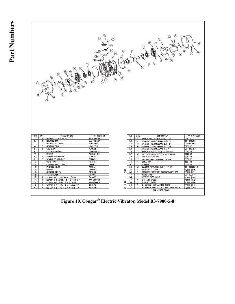
Figure 10. Cougar® Electric Vibrator, Model B3-7900-5-8
Par
t N
umbe
rs

Figure 11. Cougar® Electric Vibrator, Model B3-11000-5-2
Par
t N
umbe
rs

Figure 12. Cougar® Electric Vibrator, Model B3-14660-5-2
Par
t N
umbe
rs

Figure 13. Cougar® Electric Vibrator, Model B3-10000-5-8P
art
Num
bers
Jamieson Equipment Company www.jamiesonequipment.com
toll free 800.875.0280