Corrosion Resitencia Alumina Refractories
24
SUBTASK 6.4 – IMPROVED CORROSION RESISTANCE OF ALUMINA REFRACTORIES Final Topical Report (for the Reporting Period April 15, 1998, through September 30, 2001) Prepared for: AAD Document Control U.S. Department of Energy National Energy Technology Laboratory PO Box 10940 626 Cochrans Mill Road MS 922-273C Pittsburgh, PA 15236-0940 Cooperative Agreement No. DE-FC26-98FT40320; UND Fund 4412 Performance Monitor: Mr. Udaya Rao Prepared by: John P. Hurley Patty L. Kleven Energy & Environmental Research Center University of North Dakota PO Box 9018 Grand Forks, ND 58202-9018 2001-EERC-09-05 September 2001
-
Upload
luciano-renteria -
Category
Documents
-
view
24 -
download
1
description
refractarios
Transcript of Corrosion Resitencia Alumina Refractories

SUBTASK 6.4 – IMPROVED CORROSIONRESISTANCE OF ALUMINA REFRACTORIESFinal Topical Report(for the Reporting Period April 15, 1998, through September 30, 2001)
Prepared for:
AAD Document ControlU.S. Department of EnergyNational Energy Technology LaboratoryPO Box 10940626 Cochrans Mill Road MS 922-273CPittsburgh, PA 15236-0940
Cooperative Agreement No. DE-FC26-98FT40320; UND Fund 4412Performance Monitor: Mr. Udaya Rao
Prepared by:
John P. HurleyPatty L. Kleven
Energy & Environmental Research CenterUniversity of North Dakota
PO Box 9018Grand Forks, ND 58202-9018
2001-EERC-09-05 September 2001

DOE DISCLAIMER
This report was prepared as an account of work sponsored by an agency of the United StatesGovernment. Neither the United States Government, nor any agency thereof, nor any of theiremployees makes any warranty, express or implied, or assumes any legal liability or responsibilityfor the accuracy, completeness, or usefulness of any information, apparatus, product, or processdisclosed or represents that its use would not infringe privately owned rights. Reference herein toany specific commercial product, process, or service by trade name, trademark, manufacturer, orotherwise does not necessarily constitute or imply its endorsement, recommendation, or favoring bythe United States Government or any agency thereof. The views and opinions of authors expressedherein do not necessarily state or reflect those of the United States Government or any agencythereof.
This report is available to the public from the National Technical Information Service, U.S.Department of Commerce, 5285 Port Royal Road, Springfield, VA 22161; phone orders acceptedat (703) 487-4650.
ACKNOWLEDGMENT
This report was prepared with the support of the U.S. Department of Energy (DOE) NationalEnergy Technology Laboratory Cooperative Agreement No. DE-FC26-98FT40320. However, anyopinions, findings, conclusions, or recommendations expressed herein are those of the authors(s) anddo not necessarily reflect the views of DOE.
EERC DISCLAIMER
LEGAL NOTICE This research report was prepared by the Energy & Environmental ResearchCenter (EERC), an agency of the University of North Dakota, as an account of work sponsored byDOE. Because of the research nature of the work performed, neither the EERC nor any of itsemployees makes any warranty, express or implied, or assumes any legal liability or responsibilityfor the accuracy, completeness, or usefulness of any information, apparatus, product, or processdisclosed, or represents that its use would not infringe privately owned rights. Reference herein toany specific commercial product, process, or service by trade name, trademark, manufacturer, orotherwise does not necessarily constitute or imply its endorsement or recommendation by the EERC.

i
TABLE OF CONTENTS
LIST OF FIGURES . . . . . . . . . . . . . . . . . . . . . . . . . . . . . . . . . . . . . . . . . . . . . . . . . . . . . . . . . . . i
EXECUTIVE SUMMARY . . . . . . . . . . . . . . . . . . . . . . . . . . . . . . . . . . . . . . . . . . . . . . . . . . . . . ii
INTRODUCTION . . . . . . . . . . . . . . . . . . . . . . . . . . . . . . . . . . . . . . . . . . . . . . . . . . . . . . . . . . . . 1
OBJECTIVES . . . . . . . . . . . . . . . . . . . . . . . . . . . . . . . . . . . . . . . . . . . . . . . . . . . . . . . . . . . . . . . 1
ACCOMPLISHMENTS . . . . . . . . . . . . . . . . . . . . . . . . . . . . . . . . . . . . . . . . . . . . . . . . . . . . . . . 2Steel Industry Overview . . . . . . . . . . . . . . . . . . . . . . . . . . . . . . . . . . . . . . . . . . . . . . . . . . . 2Integrated Steelmaking Process . . . . . . . . . . . . . . . . . . . . . . . . . . . . . . . . . . . . . . . . . . . . . 3Blast Furnace Process . . . . . . . . . . . . . . . . . . . . . . . . . . . . . . . . . . . . . . . . . . . . . . . . . . . . . 3Basic Oxygen Furnace Process . . . . . . . . . . . . . . . . . . . . . . . . . . . . . . . . . . . . . . . . . . . . . . 3Electric Arc Furnace Steelmaking Process . . . . . . . . . . . . . . . . . . . . . . . . . . . . . . . . . . . . . 5Ladle Refining Process . . . . . . . . . . . . . . . . . . . . . . . . . . . . . . . . . . . . . . . . . . . . . . . . . . . . 5Steel Casting . . . . . . . . . . . . . . . . . . . . . . . . . . . . . . . . . . . . . . . . . . . . . . . . . . . . . . . . . . . . 7Forming and Finishing . . . . . . . . . . . . . . . . . . . . . . . . . . . . . . . . . . . . . . . . . . . . . . . . . . . . 8Glass Industry Overview . . . . . . . . . . . . . . . . . . . . . . . . . . . . . . . . . . . . . . . . . . . . . . . . . . 9Batching . . . . . . . . . . . . . . . . . . . . . . . . . . . . . . . . . . . . . . . . . . . . . . . . . . . . . . . . . . . . . . . 10Melting . . . . . . . . . . . . . . . . . . . . . . . . . . . . . . . . . . . . . . . . . . . . . . . . . . . . . . . . . . . . . . . . 10Refining . . . . . . . . . . . . . . . . . . . . . . . . . . . . . . . . . . . . . . . . . . . . . . . . . . . . . . . . . . . . . . . 11Forming . . . . . . . . . . . . . . . . . . . . . . . . . . . . . . . . . . . . . . . . . . . . . . . . . . . . . . . . . . . . . . . 11Combustion-Heated Furnaces . . . . . . . . . . . . . . . . . . . . . . . . . . . . . . . . . . . . . . . . . . . . . . 13Electrically Heated Furnaces . . . . . . . . . . . . . . . . . . . . . . . . . . . . . . . . . . . . . . . . . . . . . . . 14Refractory Recycling . . . . . . . . . . . . . . . . . . . . . . . . . . . . . . . . . . . . . . . . . . . . . . . . . . . . . 15Controlled Atmosphere Dynamic Corrosion Application Furnace . . . . . . . . . . . . . . . . . . 15
FUTURE WORK . . . . . . . . . . . . . . . . . . . . . . . . . . . . . . . . . . . . . . . . . . . . . . . . . . . . . . . . . . . . . 18
REFERENCES . . . . . . . . . . . . . . . . . . . . . . . . . . . . . . . . . . . . . . . . . . . . . . . . . . . . . . . . . . . . . . 18
LIST OF FIGURES
1 Schematic of the CADCAF . . . . . . . . . . . . . . . . . . . . . . . . . . . . . . . . . . . . . . . . . . . . . . . . 16
2 Schematic showing close-up of interior of the CADCAF . . . . . . . . . . . . . . . . . . . . . . . . . 16

ii
SUBTASK 6.4 – IMPROVED CORROSION RESISTANCE OFALUMINA REFRACTORIES
EXECUTIVE SUMMARY
Appropriate refractory selection is critical in optimizing productivity, energy efficiency,manufacturing, and labor costs in industries employing high process temperatures. Many factors needto be taken into account to select the optimum refractory. Some include material performance withrespect to physical and chemical stability, installation issues, and the potential for contaminating theproduct pool (glass or steel). The greatest challenge is finding refractory that can withstand the harshenvironments and yet be cost-effective since the cost for repairs between relines can be severalmillion dollars. The final consideration for refractory selection is reuse and recycling of the usedmaterials since environmental regulations are becoming more restrictive as to which materials canbe landfilled.
The initial refractory work under the base cooperative agreement focused on the use of rare-earth oxide (REO) additives to castable alumina refractory to determine if the additives couldincrease the resistance of the material to slag corrosion in coal combustion systems. It was found thatthe REOs were not effective because they did not form continuous reaction products at theconcentrations used, nor did they increase the sintered strength of the refractory. Therefore, in thespring of 1999, the focus of the project was changed to understanding refractory corrosion byflowing corrodents in other types of fossil-fueled thermal systems. A literature survey was performedto help define some of the major issues affecting refractories in thermal systems. The surveyindicated that the single largest consumer of refractory materials is the steel industry, which typicallypurchases about 50% by weight of the refractories produced annually, with another 25% by ferrousand nonferrous foundries. Much of the remaining refractory materials are used by the glass industry.In addition, some of the most severe conditions for refractory corrosion in coal-fired power systemsoccur in gasification, not combustion systems. Therefore, it was decided to expand the capability ofthe EERC to perform flowing corrodent corrosion tests under diverse conditions by building a bench-scale furnace system to perform such tests in any atmosphere. This report summarizes the literaturesurvey begun in the spring of 1999, as well as the initial construction of the bench-scale system upto the conclusion of Task 6.4 at the end of May 2001. The work is being continued under Task 6.6,Activity 2.
The initial objective of this project was to do a literature search to define the problems ofrefractory selection in the metals and glass industries. It was used to determine the areas in whichthe EERC can provide the most assistance through bench-scale and laboratory testing. The problemswere found to fall into three categories: Economic – What do the major problems cost the industriesfinancially? Operational – How do the major problems affect production efficiency and impact theenvironment? and Scientific – What are the chemical and physical mechanisms that cause theproblems to occur? This report presents a summary of the results of the survey.
In the steelmaking industry, the operating conditions are particularly difficult: temperaturesgenerally between 1500� and 1700�C; corrosion by molten metal, slag, iron oxide, dust, and gases;
iii
thermal shock; and erosion. Refractory research in the steel industry should focus on applications“downstream” from the furnace. Much improvement has been made in the last decade in refractoriesand methods of repairing them. Therefore, the greatest gains still to be made can be achieved throughresearch directed toward the ladle, tundish, and continuous casting refractories.
The operating conditions of the glass manufacturing industry are equally as difficult as thesteel industry. Typical hot face refractory temperatures range from 1100� and 1700�C. The mainrefractory problems occur above the glass melt where temperatures are the hottest and products ofcombustion reside. The fastest growing technology in the glass industry in the past few years is theconversion from air–fuel combustion to oxy-fuel systems. The benefits include reduced NOx and SOxemissions and particulate carryover, as well as the improvement in glass quality and higherthroughput. But the greatest disadvantage is the increased rate of corrosion to the crown andsuperstructure refractories in oxy-fuel furnaces because of the higher concentrations of water vaporand alkali in the gas caused by the absence of nitrogen which is a nonreactive dilutent. Hot-facecorrosion and ratholing have proven to be very aggressive in oxy-fuel furnaces.
Once the problems were defined, the second goal of this project was begun: to design and builda bench-scale high-temperature controlled atmosphere dynamic corrosion application furnace(CADCAF). The furnace will be used to evaluate the corrosion resistance of refractories in thepresence of flowing corrodents (slag, metal, glass) to temperatures of 1600�C under controlledatmospheres for extended periods of time. The conditions of the test will be chosen to simulateespecially corrosive situations occurring in steel or glass-making operations or in coal gasificationsystems.
The CADCAF is an electrically heated bench-scale box furnace with a removable top, madeof stainless steel. The furnace has a sealed cylindrical inner chamber where the test samples arelocated. It has the capability of testing two refractory test samples simultaneously, up to a maximumof 1600�C. The gas mixture will be introduced through a gas inlet valve located on the side of thecorrodent hopper. It will exit the system through a gas outlet vent located on one side of the catchpot and then exhaust through the fume hood.
As of the end of Task 6.4 at the end of May 2001, the furnace and corrodent feed systems hadbeen purchased, and a stand to hold the furnace and the corrodent catch pot had been built. Inaddition, the inner containment vessel had been cast, but will not be fired until the furnace is fullyoperational. Operational status for the furnace has been delayed because several of the molybdenumdisilicide heating elements were broken during shipping of the furnace system, and we are awaitingtheir replacement.
1
SUBTASK 6.4 – IMPROVED CORROSION RESISTANCE OF ALUMINAREFRACTORIES
INTRODUCTION
Appropriate refractory selection is critical in optimizing productivity, energy efficiency,manufacturing, and labor costs in industries employing high temperatures. Many factors need to betaken into account to select the optimum refractory. Some include material performance with respectto physical and chemical stability, refractory fabrication issues, and the potential for contaminatingthe product pool (glass or steel). The greatest challenge is finding refractory that can withstand theharsh environments and yet be cost-effective since the cost for repairs between relines can be severalmillion dollars. The final consideration for refractory selection is reuse and recycling of the usedmaterials since environmental regulations are becoming more restrictive as to which materials canbe landfilled.
Through the base cooperative agreement and other U.S. Department of Energy programs, theEnergy & Environmental Research Center (EERC) has developed expertise and equipment toaccurately simulate the conditions leading to high-temperature corrosion of refractories in coal-firedcombustion systems. The initial refractory work under the base cooperative agreement focused onthe use of rare-earth oxide (REO) additives to castable alumina refractory to determine if theadditives could increase the resistance of the material to slag corrosion in coal combustion systems.It was found that the REOs were not effective because they did not form continuous reactionproducts at the concentrations used, nor did they increase the sintered strength of the refractory.Therefore, in the spring of 1999, the focus of the project was changed to understanding refractorycorrosion by flowing corrodents in other types of fossil-fueled thermal systems. It was found throughliterature survey that the single largest consumer of refractory materials is the steel industry, whichtypically purchases about 50% by weight of the refractories produced annually, with another 25%by ferrous and nonferrous foundries. Much of the remaining refractory materials are used by the glassindustry. In addition, some of the most severe conditions for refractory corrosion in coal-fired powersystems occur in gasification, not combustion systems. Therefore, it was decided to expand thecapability of the EERC to perform flowing corrodent corrosion tests under diverse conditions bybuilding a bench-scale furnace system to perform such tests in any atmosphere. This reportsummarizes the literature survey begun in the spring of 1999, as well as the initial construction ofthe bench-scale system up to the conclusion of Task 6.4 at the end of May 2001. The work is beingcontinued under Task 6.6, Activity 2.
OBJECTIVES
The initial objective of this project was to do a literature search to define the problems ofrefractory selection in the metals and glass industries. The problems fall into three categories:Economic – What do the major problems cost the industries financially? Operational – How do themajor problems affect production efficiency and impact the environment? and Scientific – What arethe chemical and physical mechanisms that cause the problems to occur? This report presents a

2
summary of these problems. It was used to determine the areas in which the EERC can provide themost assistance through bench-scale and laboratory testing.
The final objective of this project was to design and build a bench-scale high-temperaturecontrolled atmosphere dynamic corrosion application furnace (CADCAF). The furnace will be usedto evaluate refractory test samples in the presence of flowing corrodents for extended periods, totemperatures of 1600�C under controlled atmospheres. Corrodents will include molten slag, steel,and glass. This test should prove useful for the glass and steel industries when faced with thedecision of choosing the best refractory for flowing corrodent conditions.
ACCOMPLISHMENTS
Steel Industry Overview
In the United States, two methods are used to produce steel: the ore-based, or integratedprocess, and the scrap-based, or electric arc furnace (EAF) process. Two different approaches areused to prepare semifinished billet: the integrated process uses a blast furnace, while the scrap-basedprocess is done in a minimill which uses an EAF. Once steel is in the semifinished state, furtherprocessing is required in both the integrated steelmaking process and the minimill.
The integrated process is “old line big steel,” with facilities encompassing several thousandacres. The manufacturing process uses a complex series of capital-intensive units to produce high-quality steel. Annual production of an integrated steel mill is 3 to 5 million metric tons. The minimillis much more compact and can fit within an area as small as a city block. Annual production of aminimill is 0.5 to 2 million metric tons. The minimill initially focused on lowest-quality steelmarkets but has recently taken over the structural steel market and is competing effectively in hot-rolled products.
Refractories and ceramic coatings are currently being used throughout the processes, althoughadvanced ceramics are emerging slowly because of their longer life but higher cost. Steelmakingrefractory development is moving away from the standard “single component” refractory materialsto multicomponent composite materials composed of high-purity oxides, carbon, and graphite.Magnesia–graphite refractories (with and without metallic additions) have been used successfullyin steelmaking vessel barrels and slag lines. Castable refractories, including self-flow types, areincreasingly used to line low-wear areas of steelmaking vessels, while dry vibratable magnesia-basedtundish linings have emerged as an alternative to sprayed magnesia linings.
In the steelmaking industry, the operating conditions are particularly difficult: temperaturesgenerally between 1500� and 1700�C; corrosion by molten metal, slag, and iron oxide; thermalshock; and erosion (1). Refractory research in the steel industry should focus on applications“downstream” from the furnace. Much improvement has been made in the last decade in refractories,and methods of repairing them, used in the steelmaking furnaces. Therefore, the greatest gains stillto be made can be achieved through research directed toward the ladle, tundish, and continuouscasting refractories.

3
Integrated Steelmaking Process
An integrated steel mill starts with iron-bearing materials, principally iron oxides, which arereduced to molten iron in blast furnaces using coke as the reducing agent. Two primary processesare used to prepare the charge for the blast furnace: pelletizing and sintering. In pelletizing, unbakedballs are formed from iron ore combined with a binder. These balls are heat-treated in an oxidizingfurnace at the mine and shipped to the mill where they are fed into the blast furnace along with coke,fluxes, and often sinter. In producing sinter, iron ore fines, coke fines, wastewater sludge, limestone,and air pollution control dust are agglomerated and heated. The heated mass is fused, cooled, andsized before being sent to the blast furnace.
Current applications of advanced ceramics in the integrated steelmaking process include wearsurfaces on grinders, fans and crushers, coke rolls, refractory linings, and pollution control devices.New opportunities include single-piece fans, condensers, recuperators, and hot-gas filtration.
Blast Furnace Process
During the production of iron, ore, coke, limestone, and sinter are fed into the top of a blast furnace while heated air, sometimes augmented with fuel, is fed in through the bottom. As thecharge descends through the furnace, carbon monoxide generated by the burning coke reduces theiron oxide in the ore to iron metal. The acid part of the ore reacts with the limestone to produce slagwhich contains unwanted impurities from the ore. The molten iron collects in the bottom of therefractory-lined furnace at a temperature of 1560�C. The slag is removed from the top of the molteniron and sold as a by-product. The molten iron is tapped from the bottom of the furnace and placedinto refractory-lined cars for transfer to a desulfurization ladle.
Opportunities exist for improved refractories in the lower part of the blast furnace where coalis injected and in the desulfurization ladle. Opportunities also exist for the coal injection tubesthemselves (tuyeres), which are short-lived because of wear. On average, 24 tuyeres are used for coalinjection in a single furnace, each tuyere being 5–25 cm in diameter by 3 meters long.
Basic Oxygen Furnace Process
Basic oxygen furnace (BOF) steelmaking accounts for just under 60% of the liquid steel outputin the United States and Canada (2). BOFs in operation today include conventional top-blownfurnaces, bottom-blown furnaces, combinations of top- and bottom-blown furnaces, and inert gas-bottom stirring configurations. The predominant advantages of the BOF are very high productionrates from few melting units and the tapping of low-residual-element (low-tramp element, low-nitrogen) liquid. The BOF is fed liquid pig iron, usually from blast furnaces, in amounts rangingfrom 65% to 90% of the total metallic charge; the balance is recycled scrap.
The top-blown BOF process generates heat by injecting high-purity oxygen into the molteniron from above. The oxygen reacts with the carbon and silicon to melt the scrap and removeimpurities. No additional heat source is required. Various materials, including fluxing agents toproduce metallurgical slags, are required for the refining process. Alloying materials, in the form of

4
alloyed scrap or ferroalloys, may be added singly or in combination to the molten steel during or afterthe carbon removal to produce steel.
According to Carniglia and Barna (3), the top-blowing process takes approximately15 minutes, during which time the temperature of the charge rises, usually ending somewhat above1700�C. The evolution of CO gas from within the charge churns it violently, intermixing the moltenslag and metal, making voluminous froth and splashing it well up on the sidewalls of the “barrel.”The atmosphere above the charge is principally a CO–CO2 mixture, containing small amounts of SO2and other volatile oxides and much dust. It is exhausted through a movable hood and ducting. Oncompletion of the “blow,” the lance is withdrawn, and the vessel is tilted clockwise about 90�, sothat the hot metal pours out the taphole while the cone restrains the overlying slag. Ordinarily, thevessel is then rocked back and forth to coat the upper walls with slag as much as possible; finally,it is turned all but upside-down to pour out the slag. If no lining repair or maintenance is needed, theBOF is ready for the next heat. The total elapsed time is about 30 minutes. Because of the advancesin refractory materials and the benefits of slag splashing, BOF relines are down to once a year perfurnace or less; lining life is in the 10,000 to 25,000 heat ranges (2).
Opportunities for advanced refractories or ceramics in the BOF process include the taphole gunnozzle, taphole sleeve, sensor shields, refractories in runners used to flow the molten steel from thefurnace to refining ladles, and bottom-stirring elements. There is also a need for either metallizedor refractory coatings for lower hoods to help furnace availability by extending hood life to that ofthe refractory lining (2).
The main differences between the top-blown furnace and the bottom-blown furnace are thatthe gas is injected from the bottom and the steel is removed through a hole drilled (tapped) throughthe refractory liner. A taphole gun is used to plug the hole with a refractory clay mix. The nozzle ofthe taphole gun must have high-thermal-shock resistance, high-temperature capability, and high-impact resistance. Monolithic ceramics of silicon carbide and mullite have been evaluated, butsuccess with these ceramics has been limited because of their unpredictable, brittle behavior.Tapholes also see high-velocity metal and slag; the main concern there is maintenance of a constantdiameter (3).
Shields are sought for sensors that can monitor melt temperature, uniformity of the melt, andoffgas composition. Although lightly loaded, these sensor shields must operate at temperatures inexcess of 1650�C while exposed to highly oxidative and corrosive gases (4). Runners for transferringthe molten steel from the BOF to the refining ladle are often fireclay brick maintained with plasticand ramming mixes. Because of their high maintenance cost, castable refractories high in aluminumoxide and chromium oxide are being used, although operating life is still limited to 1 to 2 weeks.Further environmentally acceptable improvements in the lifetime of the runner refractories aresought. The main type of attack in the runners is from erosion by the molten flowing steel.
Bottom stirring based on gas injection is used in the BOF to reduce slag buildup and improvetemperature and metal uniformity. Bottom-stirring elements include water-cooled metal pipesenclosed in refractory (tuyeres) and porous plugs. Problems with tuyeres include burning back themetal pipe with a loss of flow control, plugging by molten metal flow into the tuyere, cupping of the

5
tuyere end, and loss of furnace energy efficiency when water-cooled. The problem with porous plugsis low gas flow and low abrasion resistance. Improved temperature capability is also sought forporous plug materials.
Electric Arc Furnace Steelmaking Process
The EAF is the second highest producer of steel in the United States (3). The conventional top-charged EAF process now accounts for 40% of the U.S. raw steel production (2). It is versatile asto size and as to feed, receiving scrap and blast furnace hot metal or the output of an oxygen furnace.It may be fed some coke, and either acid or basic slagging may be used. In the United States, thelatter predominates.
Freitag and Richerson (4) describe the EAF process. Unlike the integrated steel process,electric arc steelmaking furnaces use scrap metal as the charge that is melted and refined usingprimarily electricity. Cylindrical, refractory-lined arc furnaces are equipped with carbon electrodesthat are lowered through the furnace roof. During charging, the furnace roof is removed, and scrapmetal is placed into the furnace. Alloying agents and fluxes are added through doors on the side ofthe furnace. The electrodes are lowered to within 1 inch of the metal surface, and current is appliedto generate heat above the metal. Oxygen is injected through a consumable lance to decarburize thesteel and to supplement thermal energy. During melting, oxidation of impurities occurs and formsa slag on the molten metal surface. Similarly, as in the integrated process, unwanted materials areremoved and alloying agents added. The final product is removed from a taphole on the side of thefurnace.
EAFs have the highest refractory wear of steel production furnaces. Refractory consumptionaverages 2 pounds/ton of steel for brick and 9 pounds/ton for gunned repair materials (5). The slagline is a high-wear area because of the turbulence created by the metal–slag mixing. Below the slagline, the refractory is exposed primarily to metal and slag; above it, to splash, CO–CO2, and dust anddirect radiation from the arcs. Hot spots occur in sidewalls where this radiation is most intense.Except for these areas, the sidewalls and bottom see common maximum steelmaking temperaturesof about 1700�C with basic slagging and about 1600�C with acid slagging (3). Opportunities existfor advanced ceramics in EAFs in longer life electrodes, oxygen injection lances, oxy-fuel burnernozzles, recuperators, runners for transferring the hot metal to the refining ladle, and as areplacement for high-maintenance refractories applied to the water-cooled panels of the sidewallsand top of the EAF. Current refractories are repaired on a weekly basis.
Ladle Refining Process
Ladle refining refers to the metallurgical processes done in the ladle (2). According to Freitagand Richerson (4), the cost of refining and casting steel accounts for 95% of the total cost of thefinished product. Thus the use of new materials in these operations could potentially add high valueby significantly lowering overall cost. A number of processes are often used to refine the moltensteel in a ladle after it leaves the BOF or EAF prior to casting. Ladle refining processes include argonoxygen degassing, ladle metallurgy, vacuum arc remelting, and vacuum degassing. Processesselected are based on the desired metallurgy and purity.

6
Refining is performed in separate ladles to prolong the life of the furnaces. Ladle refiningvessels range in sophistication from in-house designs built with plant equipment to engineered,multifunction stations (2). The refractory lining in a ladle arc furnace is exposed to severe serviceconditions (6). These conditions include high temperatures, corrosive slags, long holding times, andviolent bath agitation. The steel ladle refractories must withstand corrosive attack at up to 1700�C.
Freitag and Richerson (4) explain the ladle refining process. It is generally performed byelectric arc reheating. The molten metal bath is stirred throughout the process to provide for thermaland chemical homogenization and to accelerate metallurgical reactions. Stirring is provided by inertgas introduced near the bottom of the ladle using porous plugs, tuyeres, or lances. Gas injected fromabove using water-cooled, refractory-coated metal lances is considered safer than porous plugs ortuyeres, but maintenance is high, and heat efficiency is reduced. Porous plugs, which are the mostcommonly used during refining, last only 30 heats because of erosion by the flowing metal. Becauseof their many disadvantages, replacement of lances is a several million dollar a year business.
Although tap temperatures from the BOF and EAF typically are lower, temperatures at ladleslag lines are higher because of the submerged arc reheating. Slag temperatures have been measuredin excess of 200�C higher than the temperature of the steel bath. The upper slag line (filled level)and lower slag line (discharged level) are foci of corrosive wear. The slag corrosion of refractoriesis directly proportional to slag fluidity and temperature (1). The possibility of “hot spots” in the ladlelining because of arc flare also exists.
Improving slag resistance, especially penetration resistance, of castables for making ladlelinings has become the focus of research and development work in monolithic refractories. Structuralspalling caused by slag intrusion is, in most cases, the main wear mechanism (7). Other requirementsfor the refractory used in ladles is that the refractory must not shrink from the shell over some 10 to100 temperature cycles, nor crack under the thermal shock of being filled, and it must endure muchmechanical abuse (3).
Because of the high temperatures, erosion from the stirred bath, and high corrosiveness of themetallurgical slag, high-alumina and magnesia-based (slag line) castable refractories are preferredfor ladle linings. Still, life remains short (30–50 heats). In some instances, higher-temperature-capable oxide–carbon mixtures are being used to provide a balance of reasonable purity, highthermal shock resistance, and low erosion. Alternative refractories having longer life, lower cost, andsafer disposal are sought.
In addition to use with porous plugs, tuyeres, lances, and refractories, opportunities exist foradvanced ceramics in ladle recuperators and impact pads. Recuperators are exposed to corrosivegases, and impact pads are located at the bottom of the ladle and, ultimately, determine the life ofthe ladle. Materials with higher-strength capability at temperature, improved abrasion resistance, andhigh-thermal shock resistance are desired.

7
Steel Casting
After the steel has been refined, it is ready to be cast into ingots or continuous strips. Ninety-seven percent of all steel produced in 1995 was continuously cast, while the remaining 3% was ingotcast (4). Carniglia and Barna (3) describe continuous casting. In this process, a transfer ladle isplaced at the top. A “ladle shroud” (vertical refractory tube) is affixed under its slide gate valve, bymeans of which molten steel is delivered intermittently to the tundish immediately below. Thisprocedure keeps the tundish, a much smaller surge reservoir, always nearly full. Below the tundishis the “tundish shroud,” another tube whose lower extremity is submerged in the steel, which itdelivers by gravity feed down into a water-cooled copper mold. The casting machine can have eitherone (single strand) or multiple molds (multistrand caster) (4). The steel cools as it passes throughthe mold and forms a solid shell or “skin.” As the steel proceeds onto the runout table with a seriesof hot-handling rollers, the center of the steel solidifies, yielding a semifinished shape at a specifiedwidth and thickness. A cutting torch is used at the end of the roll line to cut the steel to the desiredlength. Because of the harsh operating conditions, the life of many of the components of the casterpouring system is less than one heat.
According to the Steel Industry Technology Roadmap (2), submerged entry nozzles (SENs)are often the limiting material in refractories used for molten steel control. SENs are used insteelmaking to prevent reoxidation of molten steel directly from stream contact with the surroundingenvironment and from air entrapment and splashing when the molten stream strikes the liquidsurface in the mold. Accretion formation and the associated clogging of tundish flow control systemsare major problems that lead to decreased strand speed, premature changing of SENs, or strandtermination and associated reductions in productivity, consistency, and steel quality.
SENs are replaced as often as once every 2 to 4 heats as compared to BOF linings that lastmore than 10,000 heats. Assuming a cost of $500 per SEN, a company would spend in excess of$2 million on SENs between furnace relines. This figure is even greater when other factors areconsidered, such as the cost of physically replacing the SENs and the cost associated with decreasedproductivity as nozzle accretion occurs. Similar cases could be made for ladle slag lines, tundishlinings, and slide gates and shrouds.
Sliding glass plates are used for controlling the steel flow during the casting of steel. A typicalmaterial used for this application is pitch-impregnated corundum–mullite, zirconia, or SiAlON. Theplates are subjected to two main types of attack: corrosion by steel, slag, and iron oxide and erosionby the steel flow. They also have to preserve the steel quality by minimizing inclusions (1).
Bitouzet and others (1) state that one of the most important problems for steelmakers iscorrosion by the low levels of calcium present in steel. In the case of a corundum–mullite slidingplate, the mechanism of corrosion is the formation of CaO by reaction of the calcium with therefractory, followed by the formation of a low melting point liquid phase as the CaO penetrates intothe refractory. The liquid phase is then washed away by the steel. The average service life is less thantwo heats. SiAlON is the preferred material because it is a reduced material, and the porometry isvery fine which allows very little penetration of steel containing CaO. Therefore, the corrosion ismuch slower.

8
Refractory wear and reaction with the highly corrosive slag can generate defect-forminginclusions in the steel. Inclusions are formed from refractories contained in the ladles, tundish, andmolds. Material systems used to contain the steel must be stable and not add to the inclusion count.High alumina refractories are commonly used throughout the process with application of zirconia-based (areas of high wear or thermal shock) and magnesia-based (areas of high slag corrosion)materials as required. Carbon-containing refractories have been considered throughout the pouringsystem, but they react with oxide-based refractories to form carbon monoxide. Aluminum containedin the steel also reacts with the refractory to form alumina. Silica-based refractories are not usedbecause of the potential for steel contamination.
According to Freitag and Richerson (4), clogging of the caster pouring system is the singlelargest operational problem resulting in reduced quality and production delays. One source ofclogging is from the interaction of the molten steel or slag with the refractory. Remedies to clogginginclude alternate refractory materials, application of glazes to the refractory, and reduction of residualporosity in the refractory. Currently available remedies do not completely eliminate clogging;therefore, alternate materials are being sought.
To limit oxygen pickup during pouring from the ladle, a thin-wall ladle shroud is attached tothe bottom of the ladle. The shroud extends into the molten metal contained in the tundish. Commoncauses of ladle shroud failure include plugging, throat cracking, erosion in the throat, bottom slagline erosion, or bottom vertical cracking. A similar shroud is used to protect the molten metal streamas it leaves the tundish when not protected by the nozzle itself. The high-alumina refractoriescommonly used for the shrouds have a life expectancy of 1–10 heats before they need to be replaced.
Forming and Finishing
After casting, the slab, billets, and blooms are further processed to produce strip, sheet, plate,bar, rod, and other structural shapes through various hot-forming operations that can then befollowed by cold-forming operations, depending on application (4). Finishing operations are oftenproduct-specific heat treatments (such as spheroidizing, normalizing, or annealing) or surfacetreatment operations (such as galvanizing, electroplating, carburizing, machining, or surfaceinduction treating) (2).
The most common hot-forming process is hot rolling, which uses a series of water-cooled rollsto reduce the thickness of a heated steel slab. Surface scale is removed from the heated slab by ascale breaker and water sprays prior to entering the roughing stands containing the sets of rolls. Atthe end of the roughing section, the steel enters the finishing stands for final reduction, then it iscooled and coiled.
Cold rolling is used to reduce the steel to final dimensions and surface finish or to form pipesand tubes. Cold rolling is similar to hot rolling except the metal is not heated. During cold rolling,the steel is hardened and must be heated in an annealing furnace (800�–1200�C) before use to makeit more formable. After the steel is softened in the annealing process, it is typically run through atemper mill to produce the desired flatness, metallurgical properties, and surface finish.
9
Finishing processes such as pickling and oiling are used to clean the surface of thesemifinished, hot-rolled steel prior to cold rolling, forming, or coating operations. Mill scale, rust,oxides, oil, grease, and soil are chemically removed by a variety of chemical and physical processes.Acid pickling processes which use hydrochloric, nitric, sulfuric, and other combinations of acids areused to remove oxide scales. After pickling, alkaline cleaners may be used before cold rolling.Corrosion-resistant steels, ceramic-coated steels, graphite, engineered polymers, glass and, in somecases, advanced ceramics (primarily nonoxides) are used throughout these processes. Opportunitiesfor use of advanced ceramics include condensers, exhaust fans, pumps, spray nozzles, and processingtanks.
Glass Industry Overview
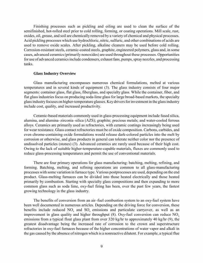
Glass manufacturing encompasses numerous chemical formulations, melted at varioustemperatures and in several kinds of equipment (3). The glass industry consists of four majorsegments: container glass, flat glass, fiberglass, and specialty glass. While the container, fiber, andflat glass industries focus on producing soda-lime glass for large broad-based markets, the specialtyglass industry focuses on higher-temperature glasses. Key drivers for investment in the glass industryinclude cost, quality, and increased productivity.
Ceramic-based materials commonly used in glass-processing equipment include fused silica,alumina, and alumina–zirconia–silica (AZS); graphite; precious metals; and water-cooled ferrousalloys. Ceramics are primarily used as refractories, with ceramic coatings increasingly being usedfor wear resistance. Glass contact refractories must be of oxide composition. Carbons, carbides, andeven chrome-containing oxide formulations would release dark-colored particles into the melt bycorrosion or otherwise, and glass products in general can tolerate neither color nor the presence ofundissolved particles (stones) (3). Advanced ceramics are rarely used because of their high cost.Owing to the lack of suitable higher-temperature-capable materials, fluxes are commonly used toreduce glass-processing temperatures and permit the use of conventional materials.
There are four primary operations for glass manufacturing: batching, melting, refining, andforming. Batching, melting, and refining operations are common to all glass-manufacturingprocesses with some variation in furnace type. Various postprocesses are used, depending on the endproduct. Glass-melting furnaces can be divided into those heated electrically and those heatedprimarily by combustion. Starting with specialty glass compositions and then expanding to morecommon glass such as soda lime, oxy-fuel firing has been, over the past few years, the fastestgrowing technology in the glass industry.
The benefits of conversion from an air–fuel combustion system to an oxy-fuel system havebeen well documented in numerous articles. Depending on the driving force for conversion, thesebenefits include reduced NOx and SOx emissions and particulate carryover, as well as animprovement in glass quality and higher throughput (8). Oxy-fuel conversion can reduce NOxemissions from a typical float glass plant from over 320 kg/hr to approximately 40 kg/hr (9), thegreatest disadvantage being the increased rate of corrosion to the crown and superstructurerefractories in oxy-fuel furnaces because of the higher concentrations of water vapor and alkali inthe gas caused by the absence of nitrogen which is a nonreactive dilutent. For example, a typical flue

10
gas composition for an oxy-fuel soda-lime furnace would be 13% N2, 52%–56% H2O, 2%–4% O2,31% CO2, and 200–220 ppm NaOH. A typical flue gas composition for an air-fueled soda-limefurnace is 68% N2, 18% H2O, 2% O2, 12% CO2, and 60 ppm NaOH (10, 11). Typical hot-facerefractory temperatures in a glass furnace range from 1100� to 1700�C.
Batching
Raw material selection is based on chemistry, purity, uniformity, and particle size. Additionalorganic, metallic, and ceramic contaminants may be introduced throughout the delivery, storage,mixing, and sizing processes, as well as through the use of cullet (recycled glass). Because of theeffects of contamination, the use of cullet varies within the industry according to the desired endproduct. Delivery, mixing, and sizing processes are highly abrasive, and equipment used commonlycontains ceramic-coated wear surfaces or ceramic liners manufactured from alumina, silicon carbide,or tungsten carbide. While generally cost-effective and with adequate performance, lower-costsolutions offering lower risk of contamination are sought.
Melting
The melting tank is a rectangular refractory box about 3–4 ft high (3). The granular feedmaterials are charged and mechanically stirred in at one end, where melting and evolution of CO2are most concentrated. Much of the length of the tank is devoted to achieving uniformity of the glasstemperature and composition. At the opposite end is a constriction or throat, containing a weir underwhich the glass flows to the refiner section. Homogenizing is completed there, plus removal of anyretained CO2 bubbles, by passing gas in much larger bubbles up through the melt: a process called“fining.” The refiner discharges to a forehearth from which the liquid is taken for forming by sheetcasting, molding, blowing, fiberizing, etc.
Glass furnace refractories may be subjected to corrosion by several mechanisms. Winder andothers (12) explain the corrosion mechanisms associated with the glass-melting furnace. Refractoriescontacting liquid silicate in the molten glass bath undergo chemical degradation, with severalphysical mechanisms of material removal being possible. Any glass flow tends to increase contactingrefractory corrosion driven by surface tension, temperature, or density differences. Consideringapplication of the same glass-melting temperature in both oxy-fuel and air-fuel cases, the decreasedviscosity of glass melt in an oxy-fuel furnace may be expected to increase both convective flow andthe diffusion rates of alkali and alkaline-earth species into contacting tank sidewall and bottomrefractories. In addition, increased OH� diffusion into the refractory surface may also cause adegradative effect in the case of refractories containing silicate phases.
According to Winder and others (12), glass tank bottom refractories are generally subjectedto relatively minor convective flow, unless situated close to bubblers, stirrers, etc., because ofbuildup of thick boundary layers. However, tank sidewall refractories are exposed to the three-phaseinterface at the melt line, where a surface tension-driven convection mechanism, otherwise knownas the Marangoni effect, is responsible for relatively rapid material removal. In addition, the three-phase melt line interface usually acts as a heterogeneous nucleation source for exsolution of gaseousphases from the molten glass bath. Surface tension-driven convective forces are associated with the

11
gas bubbles, which consequently grow at this interface, and these forces tend to cause acceleratedrefractory corrosion locally. Undercutting immediately below the melt line has also been a commonexperience, associated with a liquid-corrosion phenomenon called upward drilling (3). By contrast,all refractories above the melt line face a different chemistry, but always coupled with thermalcycling because of the reciprocal operation of the burners and gas flow. If oil is used as fuel, its ashbecomes part of the chemical and erosive environment.
Refining
The glass-conditioning operation (refining) occurs in the forehearth and provides molten glassthat is uniform in temperature. Temperature sensing is critical in the forehearth and shares problemssimilar to those encountered in the melt section. Plungers and nozzles used to distribute the moltenglass are refractory ceramics or molybdenum, but they experience high wear and erosion resultingfrom glass flow and corrosion.
Forming
The forming process varies for the type of glass. Freitag and Richerson (4) review the formingprocess for the different glass industries. Two glass-forming processes are used in the flat glassindustry. One developed by Pilkington Brothers (PB) and one developed by PPG Industries, Inc.Major differences between the two processes involve how the glass is introduced into the furnace.A typical float zone furnace is 49 meters long and 9 meters wide and can hold 909 metric tons ofglass. In the PPG process, the refined glass flows in a continuous, full-width ribbon onto a moltenbath of tin contained in an air-cooled refractory-lined steel shell. In the PB process, the molten glassenters a much narrower region onto a molten bath of tin and takes a very complicated flow pathbefore it reaches its full width. In both processes, glass enters at a temperature of 1040�C and exitsat a temperature of 600�C. The tin bath is maintained at a temperature of 815�C, whereas the steelshell air is cooled to 100�C. An atmosphere of N2 plus 5%–8% H2 is used to prevent oxidation.Alternate materials considered for replacement of the refractory-lined steel/tin bath shell are eithercostly, difficult to fabricate into the desired shape, or lack oxidation resistance.
A fused-silica gate called a tweel regulates the flow of glass into the float zone furnace fromthe refiner. The tweel meters the glass flowing into the float zone furnace and thereby helps controlthe finished product thickness. Because the life of the tweel is only 10 months, alternate materialsare being sought to increase life. In addition to molten glass compatibility, requirements for the tweelinclude high-thermal shock resistance and load-carrying capability at molten glass temperatures.Replacements for water-cooled materials are also sought because of the high level of maintenanceand added cost for corrosion.
In the container glass industry, after conditioning to the desired temperature and uniformity,the molten glass is transferred to the forming operation through the gob feeder. The gob feeder is anintegral part of the forehearth and includes a mixer, plunger, orifice, and shears. The materials ofconstruction for the gob feeder include water-cooled metals (cut-off blades), precious metals (stirrer),and refractories (plunger) to accommodate glass gob temperatures approaching 1100�C.

12
With the exception of coatings, no advanced ceramic materials are used in the forming of glasscontainers. Opportunities for their use exist, however, because of the increasing emphasis onlightweight glass containers, continuous production, and improved energy efficiency as competitionincreases from abroad. Specific opportunities include replacement of graphite in areas of hothandling, with alternate materials providing higher toughness, greater hardness, and improvedoxidative ability. Lower-cost materials are sought to replace precious metals used in the forehearthand gob feeder. Materials with higher thermal diffusivity and hot hardness are sought for the moldsto extend life and reduce cycle time without external cooling. Higher-temperature-capable materialsare desired throughout the mold machine for reduced maintenance and improved quality.
In the fiberglass industry, molten glass leaves the hearth and enters the fiberization processdirectly or after an intermediate marbleizing process. Marbleizing is commonly used for textile fiberproduction when the forming process is not located in close proximity to the melter. Fiberizationoccurs by attenuating a melt stream with air, steam, or combustion gas (for wool) or by drawingmolten glass through precious metal bushings. For the wool processing, a single stream of moltenglass falls into a rapidly rotating cylinder (centrifuge) made of high-temperature base metal alloy.The cylinder contains 10,000 to 30,000 laser-drilled holes having diameters 0.1–0.015 inches.Operating conditions include steady-state temperatures of 1093�C while exposed to air. Typicallifetime is 40–100 heats. Alternate materials are sought with increased creep strength, resistance tocorrosion (sulfidation) and oxidation, and reduced cost. As the molten glass is driven through theperforated cylinder, downwardly directed high-velocity gas jets attenuate the flow and form fibersof varying lengths.
In the continuous textile forming process, glass marbles are fed through orifices in anelectrically heated platinum alloy bushing. Bushing life is about 6 months, at which time the bushingis recycled because of the high cost of raw material. Life is limited by hole wear and sag. Operatingconditions include steady-state temperatures of 1200�C in air. Forced convection-air cooling is usedprior to the sizing application to increase productivity. A winding drum collects the filaments andapplies a traction force to stretch the fibers as they are pulled through a mechanical device thatapplies an organic sizing and twists multiple filaments into a single strand. Materials used to handleand guide hot filaments are carbon-based. Alumina and silicon nitride guides are used for sizingapplication and twisting where high wear can occur. Alternate materials are sought for fiber handlingthat exhibit many of the characteristics of monolithic ceramics but have improved toughness forincreased reliability.
The specialty glass market segment is a catchall for glass products not contained in the flatglass, container glass, and fiberglass market segment. An important difference is that the specialtyglass producers, unlike the other glass producers, work with higher-temperature glasses,aluminosilicates, and borosilicates, as opposed to soda-lime glass. Because of the high temperatures,refractories and thermocouple sheaths are a problem. A range of high-temperature base metal alloysand precious metals are used throughout the melt and forming steps. After the melting process, theglass goes in different directions for forming, depending on the final product. During the formingoperation, molds are generally superalloys. Ceramic molds were considered but shown to increasethe presence of stones in the finished glass. Opportunities common among the different glass market

13
segments also exist, but operating conditions both above and below the melt are much harsher inspecialty glass.
Combustion-Heated Furnaces
There are 600 glass furnaces in North America. The life of a glass-melting furnace betweenrebuilds varies, but 7–8 years is not uncommon. The cost of rebuilding a furnace can easily exceed$1 million and is very time consuming. Glass-melting furnaces can be divided into those heatedelectrically and those heated primarily by combustion.
Freitag and Richerson (4) explain that combustion-heated glass furnaces can be further dividedaccording to the method used to recover exhaust heat and the way the fuel is burned (with air or pureoxygen). Recovery of exhaust waste heat is performed with a regenerator or recuperator. Regeneratorfurnace designs represent one of the oldest and most universal devices for saving energy in the glassindustry.
Refractories commonly used in regenerative glass melt furnaces are AZS, silica, and zirconiasilicate. AZS is the material of choice for the sidewall, with zirconia content ranging from 33% to41%. Various chrome-containing refractories are commonly used in the fiberglass industry becauseof their superior erosion resistance but are gradually being replaced because of environmentalconcerns about chrome. Even though superior in performance, chrome-containing refractories arenot used in the flat, container, and specialty glass industries because chrome impurities result in glassdiscoloration.
At the front of the furnace where the charge is introduced, erosion and thermally induceddamage are the most severe and limit furnace life. Materials that are more corrosion-resistant aresought for the sidewalls. AZS electrodes and burner blocks are located on the sidewall below themelt line. These blocks support the electric boost heat electrodes and burner nozzles, both of whichexperience high local temperatures and thermal stresses that result in reduced life.
The main refractory problems occur above the glass melt where temperatures are the hottestand products of combustion reside. Superstructure refractories can experience temperaturesapproaching 1600�C when air-fuel fired, and much hotter when oxy-fuel fired. Silica is the materialof choice for the crown in soda-lime glass furnaces because of its low cost ($642/m2) and its abilityto dissolve into the melt if dislodged. However, silica does not perform well under the increasinglyharsh environment of oxy-fuel firing. Muysenberg and others (11) describe the corrosion mechanismfor silica refractory exposed to oxy-fuel atmosphere in flint container glass furnace at 1510�C.NaOH from the furnace atmosphere dissolves in FeCaO-silicate grain boundary liquid phase atexposed refractory surfaces. Because of higher flame temperature and lack of diluting nitrogen, theconcentration of NaOH vapor is much higher in an oxy-fuel system than in one heated with an air-fuel flame. The resulting lower viscosity liquid penetrates the open porosity (~24%) by capillaryaction. The refractory structure is unstable in the presence of this liquid, and the crystalline SiO2refractory skeleton is dissolved.

14
Hot face corrosion and ratholing have proven to be very aggressive in oxy-fuel furnaces (13).It is extremely important to seal an area that begins to rathole. The time frame is a matter of hoursand days, not weeks, before a significant amount of refractory material disappears and structural andoperational integrity become a concern (14).The rate of corrosion is more dependent on the positionin the furnace and concentration of alkali than the temperature (13). The corrosion normally does notoccur on the hot face of the refractory, but in a joint or other fissure. The hot flux migrates up intoan opening in the crown or superstructure wall, cools, and condenses. The flux then attacks thesurrounding silica to form a glassy phase that drains out of the fissure. This often forms a void aslarge or larger than a baseball before it is discovered on the cold face of the refractory or fromobservations on the hot face (15).
Mullite has been used for the crown in processing higher-temperature glasses but can createinclusions in the glass (4). Although mullite appears to perform slightly better than silica, it isthermodynamically unstable against NaOH, KOH, etc., in oxy-fuel environments and also does notrepresent the optimum choice for extended refractory service life (8).
Materials such as fused AZS have been considered for the crown, but the cost is much higher($10,764/m2) and the weight is much greater (4, 14). AZS samples exposed to oxy-fuel glass meltingatmospheres exhibit more corrosion than material exposed to air-fuel, but this product isconsiderably less affected than the porous silica and mullite refractories (8). Muysenberg and others(11) explain the corrosion mechanism responsible for the degradation of AZS refractory in oxy-fuelatmosphere of a flint container glass furnace at 1510�C. NaOH from the furnace atmospheredissolves in NaAlO-silicate grain boundary phase at exposed refractory surfaces. The refractories’alumina structure is unstable in the presence of this liquid and is dissolved. This effect causes anexpanding liquid-phase volume on the refractory surface. The aluminosilicate liquid contains bothdissolved and crystalline zirconia so that run-down and drip contaminates the glass bath with apotent source of defects. Defects resulting from corrosion by-products dripping onto the glass surfacecurrently cause a 2% reduction in yield, and total energy loss for the entire U.S. glass industrybecause of defects is approximately 6 × 10¹² Btu/yr (9).
Two fused-cast alumina refractories (α-� alumina, �-alumina) are also considered acceptablein areas where batch carryover and subsequent contamination by silicate is not an issue (8).Experience with these alumina refractories after use has shown the presence of an α-alumina layer.Considerable experience in application of these refractories in glass-melting furnaces suggests thatthis effect passivates over the long term. This layer represents a stable phase in application and assuch is not considered a problem. However, since the �-alumina refractory undergoes lesstransformation, which creates less new porosity, this is considered the optimum choice for above-glass application in most (low alkali) glass-melting environments (8).
Electrically Heated Furnaces
Electrical heating is used exclusively in many smaller specialty and fiberglass melting furnacesbecause of its lower initial cost and low emissions, even though energy costs remain high. Keydisadvantages of all electric furnaces are the high-energy cost and short furnace life. Electric furnacesare rebuilt as often as every 6 months, but because of their small size, down time is limited to only

15
about 2 days. An example of an electric furnace is a bottom entry electrode furnace. The melt exitsthrough a submerged throat into a separate temperature-conditioning chamber. Bubblers and stirrersare frequently used to improve homogeneity of the melt and eliminate bubbles. Materials used in theconstruction of small specialty glass and fiberglass furnaces include precious metals (for bubblers,stirrers, plungers) and molybdenum (for electrodes and flow control hardware). Replacementmaterials are sought that are lower in cost and provide longer life.
Refractory Recycling
When refractory linings are inadequate for continued use, the spent lining is demolished anddiscarded, and a new one is put in place. Depending on the particular application, refractory materialmay last only a few hours or as long as several years. Spent refractory materials are disposed of ina landfill or recycled. Many issues must be considered for the successful recycling and reuse of spentrefractory material. These include the type; users and producers of refractories; local, state, andfederal regulations; health concerns; contamination; value of materials including worth ofcomponents and cost associated with disposal; and economics of separation and beneficiation.
Many factors are driving the interest in recycling and/or reuse of spent refractory materials.Foremost is the need to develop pollution prevention technologies that will improve competitiveness,efficiency, and compliance with environmental regulations. Other incentives include more stringentenvironmental regulations and rising costs of landfill space, landfill bans on hazardous materials,and changing regulations that ban disposal of spent refractories with slag and waste both mineral-andfuel-related natural resources. Refractory recycling is complicated by the presence of varyingamounts and types of impurities within the used refractories, problems sorting and removingunwanted refractories, and problems with foreign objects being transported with the refractories ofinterest.
Controlled Atmosphere Dynamic Corrosion Application Furnace (CADCAF)
The EERC currently has the capability to test the corrosion resistance of refractories or othermaterials by flowing slag in an air environment. However, the literature survey of the needs of thesteel and glass industry and the known needs of coal gasification systems indicate the need for abench-scale flowing corrodent reactor capable of operating in a variety of atmospheres other thanair. Under Task 6.4, the CADCAF was designed and is being built to simulate conditions of dynamiccorrosion on the vertical wall of a refractory-lined glass, steel, or coal gasification system undercontrolled atmospheric conditions. The CADCAF is an electrically heated bench-scale box furnacewith a removable top, made of stainless steel. Approximate external dimensions are 40 by 30 by 40-in. deep, and internal working area, 18- by 16- by 18-in. deep. It is illustrated in Figures 1 and 2. Ithas the capability of testing two refractory test samples simultaneously, up to a maximum of 1600�C.
It uses 12 molybdenum disilicide (MoSi2) heating elements, which are located on all four sidesof the furnace in an 18-in. square. The insulated walls are 7 in. thick with high-temperature grade,vacuum-cast ceramic fiber insulation. The furnace has a sealed cylindrical inner chamber where thetest samples are located. This inner chamber has a 12-in. diameter by 12-in. height, made of

16
Figure 1. Schematic of the CADCAF.
Figure 2. Schematic showing close-up of interior of the CADCAF.

17
vibration-cast alumina refractory. The walls are approximately 7/8 in. thick, including the removabletop and bottom plates.
Two-corrodent injector feed ports and a single view port are located on the removable portionof the top of the furnace. The view port is 99.8% dense recrystallized alumina ceramic tube with aVycorTM window at the cold junction and a sapphire window at the high-temperature junction. Theinjector feed tubes are water-cooled stainless steel tubing inside insulated sleeves which hang 2 in.into the inner sample containment vessel within the furnace. The containment vessel container isbeing constructed from 96% alumina castable refractory in three pieces. The pieces consist of a flatcircular top through which the injector tubes pass, a cylindrical body which will hold the samples,and a flat circular bottom which will be cemented to the bottom of the body with ceramic glue.
An exit port for the spent corrodent material will be glued into and project from the bottomof the inner sample container. It is made of the same material as the view port. The molten spentcorrodent material will drip through the ceramic tube and be collected in a removable refractory-lined catch pot. A stand with rollers was built to hold the catch pot – for easy removal. When thefurnace is in operation, the catch pot will be clamped in place to prevent gas leaks.
The corrodent granules will be introduced into the inner containment vessel by a HethonTM
feeder. The HethonTM feeder is a precise low-rate volumetric feeder with an internal flexible hopperthat allows the use of “massaging paddles” which distort the walls of the hopper to keep the granularcorrodent material flowing smoothly. The HethonTM feeder is operated by means of a tachometricallycontrolled impulse regulator. The transfer of the corrodent granules from the feeder is controlled bya single 4-mm-diameter feedscrew with center shaft. At the end of the transfer tube is a custom-designed feeder splitter to perform a 1-to-2 way split of the corrodent granules into the two feedinjector entry ports, which are connected by high-temperature TygonTR tubing to the water-cooledstainless steel feed injectors. Corrodents used in this system will include molten slag, steel, and glass.
The sample containment system will be gastight from the top of the corrodent hopper to thegas exit from the corrodent catch pot. The preselected gas mixture will be controlled using a gasmanifold and flowmeters. The gas mixture will be introduced through a gas inlet valve located onthe side of the corrodent hopper. The gas will mix with the corrodent material, then enter thecontainment vessel within the furnace through the feed injectors. It will exit the system through agas outlet vent located on one side of the catch pot and then exhaust through the fume hood. Apositive pressure will be maintained in the system by bubbling the gas out of the catch pot throughseveral inches of water head.
The refractory test blocks are 4 by 4 by 9 in. tall with a 30-degree incline on the top surface.On this inclined surface is a well, 1 1/4 by 1/8 in. deep, which is drained by a ½-in.-wide by 1/4-in.-deep open vertical channel. The blocks are cast in rubber molds, cured, then prefired in the furnacebefore corrodent material is introduced.
As of the end of Task 6.4 at the end of May 2001, the furnace and corrodent feed systems hadbeen purchased, and a stand to hold the furnace and the corrodent catch pot had been built. Inaddition, the inner containment vessel had been cast, but will not be fired until the furnace is fully

18
operational. Operational status for the furnace has been delayed because several of the molybdenumdisilicide heating elements were broken during shipping of the furnace system, and we are awaitingtheir replacement.
FUTURE WORK
Over the next year, construction and shakedown of the CADCAF system will be completedunder Activity 2 of the new Subtask 6.6 (base cooperative agreement) entitled High-TemperatureMaterials.
REFERENCES
1. Bitouzet, J.P.; Goulven, F.; Schoennahl, J. SiAlON Bonded Alumina Refractories for Iron andSteel Industry. In Key Engineering Materials Proceedings of the 1997 5th Conference andExhibition of the European Ceramic Society; Versailles, France, Jun 22–26 1997, Trans. Tech.Pub. Clausthal-Zellerfeld, Germany, 1997; Part 3, Vol. 132–136; pp 1794–1797.
2. Steel Industry Technology Roadmap; March 1998, pp 13–50.
3. Carniglia, S.C.; Barna, G.L. Handbook of Industrial Refractories Technology, Principles,Types, Properties, and Applications; Noyes Publications: Park Ridge, NJ, 1982; pp 88–92 to105–120.
4. Freitag, D.W.; Richerson, D.W. Opportunities for Advanced Ceramics to Meet the Needs ofthe Industries of the Future; prepared by U.S. Advanced Ceramics Association and Oak RidgeNational Laboratory for the Office of Industrial Technologies, Dec 1998; Chapters 5 and 6.
5. Bennett, J. Improving Refractory Service Life and Recycling Refractory Materials in EAFSteel Production. Steel Project Fact Sheet, Office of Industrial Technologies, Sept 1999.
6. Engel, R.; Marr, R.; Pretorius, E. Refractory/Slag Systems for Ladles and Secondary RefiningProcesses. In Iron and Steelmaker; Iron & Steel Society of AIME; Warrendale, PA, June 1996;Vol. 23, pp 47–49.
7. Zhou, N.; Rigaud, M. Al2O3-MgO-C Castables for Steelmaking Ladles. In Proceedings of the1999 57th Electric Furnace Conference; Iron and Steel Society; Pittsburgh, PA, Nov 14–16,1999; Vol. 57, pp 131–142.
8. Gupta, A.; Winder, S.M. Ongoing Investigation of Oxy-Fuel Firing Impact on Corrosion ofNonglass Contact Refractories, Part 2. Ceramic Engineering and Science Proceedings of the1995 56th Conference on Glass Problems; Urbana, IL, Oct 24–25, 1995; Sponsored byUniversity of Illinois American Ceramic Society, Westerville, OH, 1996; Vol. 17, No. 2,pp 112–120.

19
9. Johnson, T. Diagnostics and Modeling of High-Temperature Corrosion of SuperstructureRefractories in Oxy-Fuel Glass Furnaces. Glass Project Fact Sheet, Office of IndustrialTechnologies, Feb 1999.
10. Faber, A.J.; Verheijen, O.S. Refractory Corrosion under Oxy-Fuel Firing Conditions. InCeramic Engineering and Science Proceedings of the 1996 57th Conference on GlassProblems; Columbus, OH, Oct 8–9 1996; Sponsored by Ohio State University AmericanCeramic Society, Westerville, OH, 1997; Vol. 18, No. 1, pp 109–119.
11. Muysenberg, E.; Winder, S.M; Gupta, A. Refractory Corrosion Phenomenon. In Proceedings:Oxy-Fuel Issues for Glassmaking in the 90s; Crystal City, VA, Feb 1997; U.S. Department ofEnergy, Office of Industrial Technologies, 1997; pp 229–242 to 253–262.
12. Winder, S.M.; Gupta, A.; Selkregg, K.R. Investigation of Liquid Contact Refractory Corrosionunder Oxy-Fuel Glass Melting Atmospheres. In Ceramic Engineering and ScienceProceedings of the 1997 58th Conference on Glass Problems; Urbana, IL, Oct 14–15 1997;American Ceramic Society, Westerville, OH, 1998; Vol. 19, No. 1, pp 53–73.
13. Kotacska, L.H.; Cooper, T.J. Testing of Superstructure Refractories in Gas-Oxy Atmosphereagainst High-Alkali Glasses. In Ceramic Engineering and Science Proceedings of the 199657th Conference on Glass Problems; Columbus, OH, Oct 8–9 1996; Sponsored by Ohio StateUniversity American Ceramic Society, Westerville, OH, 1997; Vol. 18, No. 1, pp 136–145.
14. Gridley, M. Philosophy, Design, and Performance of Oxy-Fuel Furnaces. In CeramicEngineering and Science Proceedings of the 1996 57th Conference on Glass Problems;Columbus, OH, Oct 8–9 1996; Sponsored by Ohio State University American CeramicSociety, Westerville, OH, 1997; Vol. 18, No. 1, pp 1–13.
15. Shamp, D. In Situ Testing of Superstructure Refractories. In Ceramic Engineering and ScienceProceedings of the 1996 57th Conference on Glass Problems; Columbus, OH, Oct. 8–9 1996;Sponsored by Ohio State University American Ceramic Society, Westerville, OH, 1997;Vol. 18, No. 1, pp 15–29.