CAD Modelling of Lubrication Oil Cooling System
11
Copyright: © the author(s), publisher and licensee Technoscience Academy. This is an open-access article distributed under the terms of the Creative Commons Attribution Non-Commercial License, which permits unrestricted non-commercial use, distribution, and reproduction in any medium, provided the original work is properly cited International Conference on Advances in Materials, Computing and Communication Technologies In Association with International Journal of Scientific Research in Science and Technology Volume 9 | Issue 1 | Print ISSN: 2395-6011 | Online ISSN: 2395-602X (www.ijsrst.com) 834 CAD Modelling of Lubrication Oil Cooling System Gladwin Sam Daniel D¹, Samy K², K.Saravanakarthikeyan³, V. Ramkumar⁴ BE Students¹,² Assistant Professor³, Professor⁴ Department of Mechanical and Automation Engineering, PSN Collage of Engineering and Technology, Tirunelveli, Tamil Nadu, India ABSTRACT I have the developed of the project design on modelized lubrication oil cooling system for automotive engine using CREO Software. This project gives a simulator version of an automotive engine based totally on bodily, semi physical, mathematical and thermodynamic equations, which lets in speedy predictive simulations. The complete automotive engine device is divided into several purposeful blocks: cooling, lubrication, air, injection, combustion and emissions. The sub-fashions and dynamic characteristics of character blocks are hooked up in keeping with automotive engine operating principles equations and experimental facts amassed from a automotive engine. The typical automotive engine system dynamics is expressed as a set of simultaneous algebraic and differential equations the usage of sub-blocks and S-Functions of Matlab/Simulink. The simulation of this version, carried out on Matlab/Simulink has been confirmed and may be used to obtain automotive engine overall performance, pressure, temperature, efficiency, warmth launch, crank perspective, fuel rate, emissions at extraordinary sub-blocks. The simulator could be used, in destiny work, to study the automotive engine performance in defective situations, and may be used to assist automotive engineers in FDI (fault analysis and estimation) in addition to designers to are expecting the behavior of the cooling machine, lubrication machine, injection device, combustion, emissions, so one can optimize the dimensions of different additives. This application is a platform for fault simulator, to analyze the effect on sub-blocks automotive engine’s output of changing values for faults parameters including: defective gas injector, leaky cylinder, worn fuel pump, damaged piston rings, a grimy turbocharger, grimy air clear out, dirty air cooler, air leakage, water leakage, oil leakage and infection, fouling of heat exchanger, pumps. I. INTRODUCTION LUBRICATION SYSTEM An automotive engine is made of many moving parts. Due to continuous movement of two metallic surfaces over each other, there is wearing moving parts, generation of heat and loss of power in the automotive engine lubrication of moving parts is essential to prevent all these harmful effects..
Transcript of CAD Modelling of Lubrication Oil Cooling System
Copyright: © the author(s), publisher and licensee Technoscience Academy. This is an open-access article distributed under the
terms of the Creative Commons Attribution Non-Commercial License, which permits unrestricted non-commercial use,
distribution, and reproduction in any medium, provided the original work is properly cited
International Conference on Advances in Materials, Computing and Communication Technologies
In Association with International Journal of Scientific Research in Science and Technology
Volume 9 | Issue 1 | Print ISSN: 2395-6011 | Online ISSN: 2395-602X (www.ijsrst.com)
834
CAD Modelling of Lubrication Oil Cooling System Gladwin Sam Daniel D¹, Samy K², K.Saravanakarthikeyan³, V. Ramkumar⁴
BE Students¹,² Assistant Professor³, Professor⁴
Department of Mechanical and Automation Engineering, PSN Collage of Engineering and Technology,
Tirunelveli, Tamil Nadu, India
ABSTRACT
I have the developed of the project design on modelized lubrication oil cooling system for automotive engine
using CREO Software. This project gives a simulator version of an automotive engine based totally on bodily,
semi physical, mathematical and thermodynamic equations, which lets in speedy predictive simulations. The
complete automotive engine device is divided into several purposeful blocks: cooling, lubrication, air,
injection, combustion and emissions. The sub-fashions and dynamic characteristics of character blocks are
hooked up in keeping with automotive engine operating principles equations and experimental facts amassed
from a automotive engine. The typical automotive engine system dynamics is expressed as a set of
simultaneous algebraic and differential equations the usage of sub-blocks and S-Functions of
Matlab/Simulink. The simulation of this version, carried out on Matlab/Simulink has been confirmed and
may be used to obtain automotive engine overall performance, pressure, temperature, efficiency, warmth
launch, crank perspective, fuel rate, emissions at extraordinary sub-blocks. The simulator could be used, in
destiny work, to study the automotive engine performance in defective situations, and may be used to assist
automotive engineers in FDI (fault analysis and estimation) in addition to designers to are expecting the
behavior of the cooling machine, lubrication machine, injection device, combustion, emissions, so one can
optimize the dimensions of different additives. This application is a platform for fault simulator, to analyze
the effect on sub-blocks automotive engine’s output of changing values for faults parameters including:
defective gas injector, leaky cylinder, worn fuel pump, damaged piston rings, a grimy turbocharger, grimy air
clear out, dirty air cooler, air leakage, water leakage, oil leakage and infection, fouling of heat exchanger,
pumps.
I. INTRODUCTION
LUBRICATION SYSTEM
An automotive engine is made of many moving parts.
Due to continuous movement of two metallic surfaces
over each other, there is wearing moving parts,
generation of heat and loss of power in the
automotive engine lubrication of moving parts is
essential to prevent all these harmful effects..

International Journal of Scientific Research in Science and Technology (www.ijsrst.com) | Volume 9 | Issue 1
Volume 9 - Issue 1 - Published : April 10, 2021 Page No : 834-844
835
General view of lubrication system
PURPOSE OF LUBRICATION
Lubrication produces the following effects: (a)
Reducing friction effect (b) Cooling effect (c) Sealing
effect and (d) Cleaning effect.
(a) Reducing frictional effect: The primary purpose of
the lubrication is to reduce friction and wear between
two rubbing surfaces. Two rubbing surfaces always
produce friction. The continuous friction produce
heat which causes wearing of parts and loss of power.
In order to avoid friction, the contact of two sliding
surfaces must be reduced as far a possible. This can be
done by proper lubrication only. Lubrication forms an
oil film between two moving surfaces. Lubrication
also reduces noise produced by the movement of two
metal surfaces over each other.
(b) Cooling effect: The heat, generated by piston,
cylinder, and bearings is removed by lubrication to a
great extent. Lubrication creates cooling effect on the
automotive engine parts.
(c) Sealing effect: The lubricant enters into the gap
between the cylinder liner, piston and piston rings.
Thus, it prevents leakage of gases from the automotive
engine cylinder.
(d) Cleaning effect: Lubrication keeps the automotive
engine clean by removing dirt or carbon from inside
of the automotive engine along with the oil.
Lubrication theory: There are two theories in
existence regarding the application of lubricants on a
surface: (i) Fluid film theory and (ii) Boundary layer
theory.
(i) Fluid film theory: According to this theory, the
lubricant is, supposed to act like mass of globules,
rolling in between two surfaces. It produces a rolling
effect, which reduces friction.
(ii) Boundary layer theory: According to this theory,
the lubricant is soaked in rubbing surfaces and forms
oily surface over it. Thus the sliding surfaces are kept
apart from each other, thereby reducing friction.
WHAT IS CREO
Creo, the shorthand name for Creo Parametric,
(formerly known as Pro automotive engineer) is a
powerful and intuitive 3D CAD software optimized to
address the challenges organizations face as they
design, analyze, and share information with
downstream partners. Developed by PTC, the original
pioneers of parametric CAD, Creo is powerful
foundational software supporting an integrated family
of product design tools used by thousands of
manufacturers worldwide.
The Creo family of design applications, modules, and
extension speak a common language, meet the needs
of different stakeholders, and truly combine
parametric and direct modeling techniques. Creo
helps build bridges instead of barriers between you,
your ideas, your teammates, your partners, and your
customers.Creo Parametric 3D CAD software can
easily be customized and extended through the
addition of modules and extensions, but the product
family also contains stand-alone purpose build design
applications such as Creo Simulate, Creo Direct, Creo
Layout & Creo Options Modeler. Each stand-alone
app serves a different purpose in the product
development process. From concept to design to
analysis, to effectively sharing your information with
downstream partners (such as manufacturing and
technical publications), Creo is a rock-solid
foundation for any design group. It supports the needs

International Journal of Scientific Research in Science and Technology (www.ijsrst.com) | Volume 9 | Issue 1
Volume 9 - Issue 1 - Published : April 10, 2021 Page No : 834-844
836
of modern manufacturing and product development
organizations.In short, it is a powerful, integrated
family of product design software. It’s used by
thousands of leading manufacturers across the globe.
It is a PTC product – the originators of parametric
CAD technology.
The way Creo works is that it is made up of individual
apps, including:
• Creo Parametric
• Creo Simulate
• Creo Direct
• Creo Layout
• Creo Options Modeler
Each Creo app serves a different purpose in the
product development process. This means that Creo
takes you through every stage, including concept
design work, design and analysis. Then it also enables
you to communicate effectively with downstream
partners, for instance manufacturing and technical
publications.
SIMULATION
PTC’s simulation software is designed uniquely for
the automotive engineer, complete with the common
Creo user interface, automotive engineering
terminology, and seamless integration between CAD
and CAE data, allowing for a more streamlined
process. Best of all, the results are accurate and
reliable and can be easily calculated with very little
input from non-simulation experts.The simulation
software is a complete structural, thermal and
vibration analysis solution with a comprehensive set
of finite elements analysis (FEA) capabilities that
allow you to analyze and validate the performance of
your 3D virtual prototypes before you make the first
part.
CREO PARAMETRIC
When you work with Creo Simulate, your goal is to
create a simulation model that reflects both the
physical nature and the real world environment of a
part or assembly, analyze the model, and evaluate the
results of the analysis. To help you complete these
tasks efficiently,
Creo Simulate provides a tool—Process Guide—that
leads you through each step in the simulation process.
Process Guide is available for 3D Structure modeling
in both native mode and FEM mode. You can use
Process Guide for both parts and assemblies.
Process Guide also provides the user interface to Creo
Simulate Lite, the free limited functionality version of
Creo Simulate. Process Guide serves several purposes.
In its simplest form, it leads you through the process
and workflow and prompts you to complete the
following steps involved in successfully creating and
analyzing a basic simulation model:
II. METHODOLOGY
The feature-based parametric modelling technique
enables the designer to incorporate the original design
intent into the construction of the model. The word
parametric means the geometric definitions of the
design, such as dimensions, can be varied at any time
in the design process. Parametric modelling is
accomplished by identifying and creating the key
features of the design with the aid of computer
software. The design variables, described in the
sketches and features, can be used to quickly
modify/update the design.
OVER VIEW ON LUBRICATION SYSTEM IN
AUTOMOTIVE ENGINE CONFIGURATION OF
FLYING CAR
Lubrication plays a key function inside the existence
expectancy of an engine. Without oil, an engine
might succumb to overheating and seizing very
quickly. Lubricants assist mitigate this trouble, and if
well monitored and maintained, can amplify the
lifestyles of your motor.

International Journal of Scientific Research in Science and Technology (www.ijsrst.com) | Volume 9 | Issue 1
Volume 9 - Issue 1 - Published : April 10, 2021 Page No : 834-844
837
MAKEUP OF ENGINE OIL
To appreciate the whole impact of the engine
lubrication procedure, you need to apprehend how
oils are formulated. All engine oils have two
components: components and base oil. The total
quantity of additives in motor oil can range from 20
to 30 percentages, relying on emblem, formulation
and alertness. These components can enhance,
suppress or upload homes to the bottom oil.
A traditional additive bundle found in engine oil
would encompass a detergent and a dispersant. These
two components paintings collectively to help rid the
engine system of deposits due to the burning of gas
and contributed to by way of blow-with the aid of
gases. Dispersants and detergents are small debris that
has a polar head and an oleophilic tail. The polar
heads are interested in contaminants in the oil and
surround them, forming a shape referred to as a
micelle.
Engine Oil Systems
This additionally prevents a method called congealing.
During congealing, soot particles begin to stack upon
every different or congeal into a larger particle.
Smaller soot particles that could pass through
additives without interrupting the fluid film can
congeal to make large particles, which may disrupt
the movie and damage surfaces.
Most vehicle engines use a few form of multi-grade
oil. This kind of oil has an additive known as a
viscosity-index (VI) improver. A commonplace
instance would be 10W-30 or 5W-40. These VI
improvers are lengthy-chain organic molecules that
alternate shape because the temperature in their
surroundings modifications.
When in cold environments (engine startup), these
molecules are tightly sure. As the oil heats up, they
begin to stretch out. This permits an oil to flow extra
comfortably at less warm temperatures however
nonetheless maintain an acceptable viscosity and,
extra importantly, a lubricating layer within the
running temperature variety.
Another not unusual additive might be anti-wear
(AW) components. AW additives have debris which
might be fashioned just like detergents and
dispersants; however the polar heads of those
molecules are interested in steel surfaces. Once
attached to a steel surface, AW components shape a
sacrificial layer that protects the surfaces beneath
them from degradation under boundary situations.
Zinc dialkyldithiophosphate (ZDDP) is a
commonplace form of this additive.
OIL BREAKDOWNS
Engine oils are problem to numerous forms of failures.
Contamination poses a huge hassle within engines.
Environmental contaminants can expedite the
procedure of oxidation and cause untimely filter
plugging. Fuel infection can decrease the viscosity of
the oil, leading to boundary situations inside the
engine’s moving elements. Glycol (antifreeze)
contamination does the other, increasing viscosity so
the oil doesn’t drift as nicely into places that require
thinner oil. Overheating and long drain intervals can
also hasten the degradation of the oil and bring about
oxidation and bad lubricate.

International Journal of Scientific Research in Science and Technology (www.ijsrst.com) | Volume 9 | Issue 1
Volume 9 - Issue 1 - Published : April 10, 2021 Page No : 834-844
838
DESIGN OF LUBRICATING OIL COOLING
SYSTEMS
Design Profile of model flying car
This invention relates to turbofan automotive engines
utilizing a mechanical constant speed drive and
particularly to the cooling system for the lubricant
used in the constant speed drive.
As is well known the constant speed drive, which is a
gear and clutch arrangement, serves to generate
electricity for the aircraft. In a turbofan driven
aircraft, the fan air/lubricant cooler is located in the
fan duct (as shown in FIG. 2) and extends into the fan
airstream. Associated with this type of plate/fin heat
exchanger is a pressure loss which is reflected in
terms of aircraft performance penalty. In a given
installation utilizing the JT-9D automotive engine
(manufactured by the P&WA division of UTC, the
assignee) this pressure loss amounted to
approximately a loss of 0.8% of TSFC (thrust specific
fuel consumption).
It has also been well known that a typical constant
speed drive lubricant cooling system would use a
single heat exchanger which is of the plate/fin type in
the fan airstream as described above.
We have found that we can improve TSFC by
reducing the size of the fan air/oil heat exchanger
because fan stream pressure losses have been reduced
by utilizing the automotive engine/oil heat exchanger
that is already in existence. When the JT-9D was
upgraded to increase its thrust, a doubling in size of
the existing fan air/oil cooler would have been
necessary. By virtue of this invention, the size of the
cooler on the upgraded automotive engine was
actually reduced in size by a factor of 6, or
approximately 1/3 of the predecessor automotive
engine cooler. In terms of TSFC, an improvement of 1%
was realized.
Moreover, there are advantages gained from utilizing
the automotive engine fuel/oil cooler that wasn't
available heretofore. Namely, because of fuel pump
inefficiency and automotive engine oil heat transfer, a
large temperature rise of the fuel is occasioned during
aircraft descent. This is primarily due to the pilot
cutting back on the power lever reducing thrust and
automotive engine power, which causes the fuel to
recirculate resulting in a higher fuel temperature.
Connecting the CSD lubricant to the automotive
engine fuel/oil heat exchanger now serves to reduce
the temperature of the fuel prior to it being admitted
to the automotive engine's combustor. This lower fuel
temperature, in effect, reduces the adverse effect of
the higher temperature fuel during descent on the
combustor, resulting in a longer life of the combustor.
By locating the CSD fuel/oil portion of the
automotive engine fuel/oil cooler in a downstream
position, relative to fuel flow, the heat transfer from
the CSD lubricant does not interfere with the
automotive engine lubrication system

International Journal of Scientific Research in Science and Technology (www.ijsrst.com) | Volume 9 | Issue 1
Volume 9 - Issue 1 - Published : April 10, 2021 Page No : 834-844
839
III. ANALYSIS TECHNIQUES FOR LUBRICATION
SYSTEMS
Whilst fluid flows in engines are three dimensional
the lubrication system can be simplified and treated as
a series of one dimensional passages, and the method
of solution adopted can be simplified to steady state
and isothermal with oil viscosity and density
calculated for different thermal conditions of the
engine.
Traditionally engine designers have used oil pressure
in specific parts of the engine to gauge acceptable
lubrication with the majority of the lubrication
system considered during the engine development
phase. However for most critical components
satisfactory performance is governed by the
volumetric oil flow rate and flow balance in the
system. The engine speed can be simulated by
considering the oil pump delivery (taking into
account volumetric efficiency), and, since positive
displacement pumps are most commonly used in
engine applications, oil pump delivery is theoretically
proportional to engine speed . In practice volumetric
efficiency varies slightly with pump speed, oil
pressure and the type of oil pump. Flow
characteristics over the speed range would be given
by results for steady state isothermal solutions at a
number of engine speeds or more accurately for the
equivalent oil pump delivery.
Optimising the lubrication system is a complex task,
having to consider flow balances, optimum flow
requirements and specifications for relief valves
simultaneously leading to an iterative process. This is
further complicated for systems with oil coolers and
thermostatically controlled by-pass valves. Once a
model has been analysed results for interrogation
against acceptable guidelines are:
i. Volumetric flow and velocity of oil through piston
cooling jets per cylinder or average flow rate per
engine cycle for pistons directly fed through the
connecting rod.
ii. Average flow through major bearings per engine
cycle.
iii. Flow through pressure relief valves.
iv. Oil velocity in pick-up pipe.
v. Oil pressure at critical components, hydraulic lash
adjusters for instance.
vi. Hydrodynamic pumping requirement (parasitic
losses due to oil pumping only).
In some cases the lubrication system is
required to provide a pressure (with little or no flow)
for specific functions (e.g. hydraulic lash adjusters).
Here, the system may be designed by using fluid
power techniques and may be analysed separately
with knowledge of the pressure distribution with
engine speed from the flow analysis.
VIEW OF OIL TANK
IV. TESTING AND RESULT
A number of complete vehicle drive cycle replications
were performed in a climatic wind tunnel. Available
are comprehensive measurements of various
temperature, pressure and ows quantities in the
cooling system, aero engine and underhood.
Temperatures and ows on all sides of the heat
exchangers are logged continuously during steady
state and transient driving scenarios. Key
performance parameters such as aero engine torque,
speed and vehicle speed are also logged. Continuous
International Journal of Scientific Research in Science and Technology (www.ijsrst.com) | Volume 9 | Issue 1
Volume 9 - Issue 1 - Published : April 10, 2021 Page No : 834-844
840
runs of driving cycle "Hamburg-Kassel hills" are
reproduced at constant preset ambient temperatures.
In such a test the vehicle's driving wheels are in
contact with a chassis dyno, which can be adjusted to
provide a desired level of resistance regulated by a
control system continuously during the test as
dictated by the pre-defined drive cycle. The vehicle's
accelerator pedal is continuously depressed by a
trained operator in order to satisfy the torque demand.
Meanwhile, the climatic equipment generates ram air
corresponding to the vehicle's driving speed at the
desired temperature level. The test facility allows for
an authentic replication of complete continuous,
unsteady drive cycles, including cold-start tests but
also for steady-state simulations.
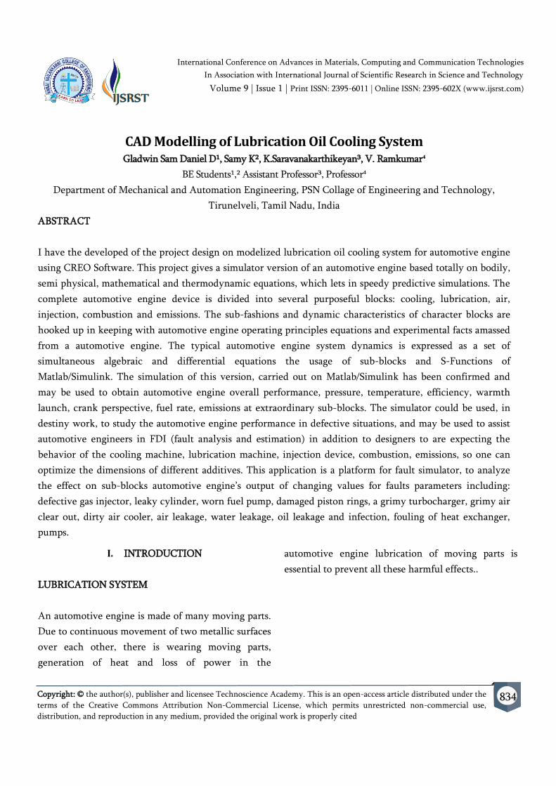
V. SIMULATION RESULTS
1 SIMULATION RESULTS
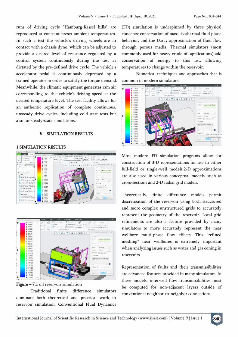
Figure – 7.1 oil reservoir simulation
Traditional finite difference simulators
dominate both theoretical and practical work in
reservoir simulation. Conventional Fluid Dynamics
(FD) simulation is underpinned by three physical
concepts: conservation of mass, isothermal fluid phase
behavior, and the Darcy approximation of fluid flow
through porous media. Thermal simulators (most
commonly used for heavy crude oil applications) add
conservation of energy to this list, allowing
temperatures to change within the reservoir.
Numerical techniques and approaches that is
common in modern simulators:
Most modern FD simulation programs allow for
construction of 3-D representations for use in either
full-field or single-well models.2-D approximations
are also used in various conceptual models, such as
cross-sections and 2-D radial grid models.
Theoretically, finite difference models permit
discretization of the reservoir using both structured
and more complex unstructured grids to accurately
represent the geometry of the reservoir. Local grid
refinements are also a feature provided by many
simulators to more accurately represent the near
wellbore multi-phase flow effects. This “refined
meshing” near wellbores is extremely important
when analyzing issues such as water and gas coning in
reservoirs.
Representation of faults and their transmissibilities
are advanced features provided in many simulators. In
these models, inter-cell flow transmissibilities must
be computed for non-adjacent layers outside of
conventional neighbor-to-neighbor connections.

International Journal of Scientific Research in Science and Technology (www.ijsrst.com) | Volume 9 | Issue 1
Volume 9 - Issue 1 - Published : April 10, 2021 Page No : 834-844
841
Natural fracture simulation (known as dual-porosity
and dual-permeability) is an advanced feature which
model hydrocarbons in tight matrix blocks. Flow
occurs from the tight matrix blocks to the more
permeable fracture networks that surround the
blocks, and to the wells.
A black oil simulator does not consider changes in
composition of the hydrocarbons as the field is
produced. The compositional model, is a more
complex model, where the PVT properties of oil and
gas phases have been fitted to an equation of state
(EOS), as a mixture of components. The simulator
then uses the fitted EOS equation to dynamically
track the movement of both phases and components
in field.
The simulation model computes the saturation change
of three phases (oil, water and gas) and pressure of
each phase in each cell at each time step. As a result
of declining pressure as in a reservoir depletion study,
gas will be liberated from the oil. If pressures increase
as a result of water or gas injection, the gas is re-
dissolved into the oil phase.
Figure – 7.2 oil reservoir Mesh condition
A simulation project of a developed field usually
requires “history matching” where historical field
production and pressures are compared to calculated
values. The model’s parameters are adjusted until a
reasonable match is achieved on a field basis and
usually for all wells. Commonly, producing water cuts
or water-oil ratios and gas-oil ratios are matched.
7.2 CONTINUOUS TRANSIENT DRIVE CYCLE
SIMULATIONS
Presented are predictions for a number of physical
properties of interest to cooling system analysts
including radiator inlet temperature, CAC outlet
temperature, fan speed, coolant mass flow rate, etc.
Figure – 7.3 RPM Flow testing
Figure – 7.4 Coolant flow testing
Figure – 7.5 Temperature testing

International Journal of Scientific Research in Science and Technology (www.ijsrst.com) | Volume 9 | Issue 1
Volume 9 - Issue 1 - Published : April 10, 2021 Page No : 834-844
842
Figure – 7.6 Mass Flow testing
Nineteen steady state simulations were performed to
replicate test measurements from a dynamometer
wind tunnel. Measured values for vehicle speed, fan
speed, radiator inlet temperature and mass flow, CAC
inlet temperature and mass own are imposed as
boundary conditions to the model. The computations
were performed on 200 cores. Most cases converged
within less than 3000 iterations and 3 hours (600 CPU
hours). A representation of the temperature field in a
central section plane, parallel to the longitudinal axis
of the vehicle, is shown on figure. The non-uniform
mass-flow and temperature distribution through the
cooling package are shown on figure.
PROTO TYPE MODELS OVER VIEW – TRUCK
View – 1
View – 2
View – 3
View – 3
View – 1
View – 2
View – 3

International Journal of Scientific Research in Science and Technology (www.ijsrst.com) | Volume 9 | Issue 1
Volume 9 - Issue 1 - Published : April 10, 2021 Page No : 834-844
843
View – 4
VI. CONCLUSION
Presented is a 1D unsteady model varied against
experimental data and supported with parallel 3D
simulations. It contains predictive models of aero
engine, cooling system, oil circuit and utilizes a
temperature dependent model of aero engine friction
losses. The 1D transient model has been validated by
comparison of simulated results with measurements
from a dynamometer test. Satisfactory consistencies
between computed and measured readings for coolant
and oil temperatures were reported.
Results from 3D CFD simulations were used to
calibrate a 1D model of the cooling system with non-
uniform temperature and flow boundary dentition on
the inlet of the cooling package. The implementation
of the non-uniform boundary strategy did not result
in any measurable increase in simulation accuracy,
but the analysis confirmed that validated 3D CFD
methods can be used to calibrate 1D models of the
underhood air path with excellent results in the
absence of data from physical measurements.
Models of the engine, cooling and oil systems were
coupled with a temperature dependent engine friction
model. A series of complete vehicle simulations of a
cold start drive cycle at different initial oil
temperatures were performed in order to evaluate the
influence of reduced warm-up phase on fuel
consumption
VII. REFERENCES
[1]. F. Fortunato et al. Underhood Cooling
Simulation for Development of New Vehicles
(2005). doi: 2005-01-2046.
[2]. GT-SUITE Flow Theory Manual Version 7.3.
Gamma Technologies. 2012.
[3]. J. B. Heywood. Internal Combustion Engine
Fundamentals. McGraw Hill International
Editions, 1988.
[4]. K. Holmberg and P. Andersson. Global energy
consumption due to friction in trucks and busses.
Tribology International 13.78 (2014), 94{114.
[5]. W.-H. Hucho. Aerodynamics of road vehicles.
Society of Automotive Engineers, 1998.
[6]. S. Kaushik. Thermal Management of a Vehicle's
Underhood and Underbody Using Appropriate
Math-Based Analytical Tools and Methodologies
(2007). doi: 2007- 01-1395.
[7]. Schweitzer, G.; Traxler, A.; Bleuler, H.
Magnetlager: Grundlagen, Eigenshaften und
Anwendungen berührungsfreier
elektromagnetischer Lager; Springer:
Berlin/Heidelberg, Germany, 1992; pp. 27–50,
107–142.
[8]. Zhang, C.; Tseng, K.J. Design and control of a
novel flywheel energy storage system assisted by
hybrid mechanical-magnetic bearings.
Mechatronics 2013, 23, 297–309. [CrossRef]
[9]. Brusa, E. Semi-active and active magnetic
stabilization of supercritical rotor dynamics by
contra-rotating damping. Mechatronics 2014, 24,
500–510. [CrossRef]
[10]. B. Minovski, L. L•ofdahl, and P. Gullberg. A 1D
Method for Transient Simulations of Cooling
Systems with Non-Uniform Temperature and
Flow Boundaries extracted from a 3D CFD
solution (2015).
[11]. B. Petroleum. BP Statistical Review of World
Energy June 2014 (2014). url:
http://www.bp.com/statisticalreview.

International Journal of Scientific Research in Science and Technology (www.ijsrst.com) | Volume 9 | Issue 1
Volume 9 - Issue 1 - Published : April 10, 2021 Page No : 834-844
844
[12]. Redrawing the energy-climate map. OECD/IEA
International Energy Agency (2013).
[13]. Kurnyta-Mazurek, P.; Kurnyta, A.; Pre˛gowska,
A.; Kaz´mierczak, K.; Fra˛s´, L. Application
concept of the active magnetic suspension
technology in the aircraft engine. Aviat. Adv.
Maint. 2018, 41, 161–193. [CrossRef]
[14]. Szolc, T.; Falkowski, K. The design of a
combined, self- stabilizing electrodynamic
passive magnetic bearing supporting high-speed
rotors. In Proceedings of the 13th International
Conference, Dynamics of Rotating Machinery
(SIRM 2019), Copenhagen, Denmark, 13–15
Feberary 2019; pp. 272–281.
[15]. Z okowski, M.; Majewski, P.; Spychała, J.
Detection damage in bearing system of jet engine
using vibroacustic method. Acta Mech. Autom.
2017, 11, 237–242.
[16]. Yan, X.; Sun, Z.; Zhao, J.; Shi, Z.; Zhang, C.A.
Fault Diagnosis of Active Magnetic Bearing-
Rotor System via Vibration Images. Sensors 2019,
19, 244. [CrossRef] [PubMed]
[17]. Z˙okowski, M.; Falkowski, K.; Kurnyta-Mazurek,
P.; Henzel, M. Control of bearingless electric
machines dedicated for aviation. Aircr. Eng.
Aerosp. Technol. 2020, 92, 27–36. [CrossRef]