Controlling Movement of Embankments over Peats and Marls
80
SCHOOL OF CIVIL ENGINEERING INDIANA DEPARTMENT OF HIGHWAYS I JOINT HIGHWAY RESEARCH PROJECT IN/JHRP-83/6 CONTROLLING MOVEMENT OF EMBANKMENTS \ OVER PEATS AND MARLS H. Allen Gruen, Jr. C. W. Lovell 3~ UNIVERSITY
Transcript of Controlling Movement of Embankments over Peats and Marls

SCHOOL OFCIVIL ENGINEERING
INDIANA
DEPARTMENT OF HIGHWAYS
I
JOINT HIGHWAY RESEARCH PROJECT
IN/JHRP-83/6
CONTROLLING MOVEMENT OF EMBANKMENTS\
OVER PEATS AND MARLS
H. Allen Gruen, Jr.
C. W. Lovell
3~
UNIVERSITY


JOINT HIGHWAY RESEARCH PROJECT
IN/JHRP-83/6
CONTROLLING MOVEMENT OF EMBANKMENTS
OVER PEATS AND MARLS
H. Allen Gruen, Jr.
C, W. Lovell

Digitized by the Internet Archive
in 2011 with funding from
LYRASIS members and Sloan Foundation; Indiana Department of Transportation
http://www.archive.org/details/controllingmovemOOgrue

FINAL REPORT
TO: H. L. Michael, DirectorJoint Highway Research Project
FROM: C. W. Love 11, Research EngineerJoint Highway Research Project
July 6, 1983
Project: C-36-5P
File: 6-6-16
Attached is a final Report on the JHRP study titled "Controlling
Movements of Embankments Over Peats and Marls." The research and report
were performed by H. Allen Gruen , Jr. and C. W. Lovell of our staff.
The report investigates the properties and behavior of peat and a
calcarious soil termed marl. The influence of calcium carbonate on soil
is determined from tests on laboratory generated and field samples. The
report further proposes classification, sampling, testing and analysis
procedures which will produce reasonable predictions and control of
embankment settlements where peat is the foundation.
The report was preceeded by an interim report entitled "Use of Peats
As Embankment Foundations." Sections of this final report are found in
the interim report where noted.
The report is submitted for review, comment and acceptance as fulfillment
of the referenced JHRP study.
Respectfully submitted,
C. W. LovellResearch Engineer
CWL:bls
cc: A. G. AltschaefflJ. M. BellW. F. ChenW. L. DolchR. L. EskewJ. D. FrickerG. D. Gibson
w. H. Goetz C. F. ScholerG. K. Hallock R. M. Shanteau
J. F. McLaughlin K. C. Sinha
R. D. Miles C. A. VenableP. L. Owens L. E. WoodB. K. Partridge S. R. YoderG. T. Satterly
TECHNICAL REPORT STANDARD TITLE PAGE
1. Report No.
IN/JHRP-83/6
2. Government Acceision No.
4. Title and Subtitle
Controlling Movements of Embankments Over Peats
and Marls
3. Recipient'* Catalog No.
S. Report Date
July 6, 1983
6. Performing Organization Code
7. Authors)
H. Allen Gruen , Jr. and C. W. Lovell8. Performing Orgonizotion Report No.
JHRP-83-6
9. Performing Organization Name and Address
Joint Highway Research Project
Civil Engineering BuildingPurdue UniversityWest Lafayette, Indiana 47907
10. Work Unit No.
1 1 . Contract or Grant No.
12. Sponsoring Agency Name and Addres*
Indiana Department of Highways
State Office Building100 North Senate AvenueIndianapolis, Indiana 46204
13. Type of Report ond Period Covered
Final Report
14. Sponsoring Agency Code
15. Supplementary Notes
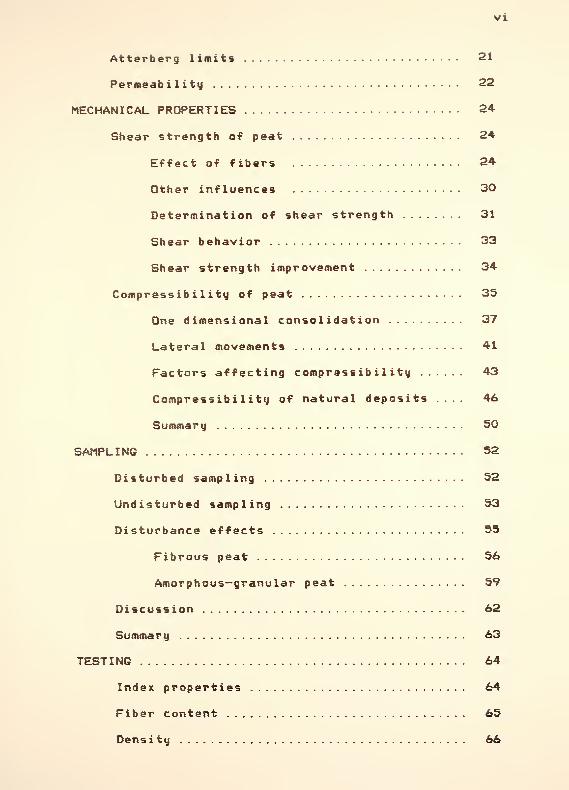
16. Abstract
A deposit which frequently occurs in glaciated areas is peat underlain by a
calcarious soil termed marl. This report investigates the properties and behavior of
peat and marl. The influence of calcium carbonate on soil properties and behavior is
reported
.
This report is presented as an aid to the engineer faced with the problem of
building on peat and/or marl and should shed light on the unique properties and
behavior of these materials. The report proposes a classification system for Indiana
peats, which is in basic conformance with that developed in Committee D18 of the
American Society for Testing and Materials. It further proposes sampling, testing,
and analysis procedures which will produce reasonable predictions and control of
embankment settlements where peat is the foundation.
17. Keywords Marl, peat, embankment,settlement, calssif icat ion , sampling,consolidation, strength
18. Distribution Statement
No restrictions
19. Security Clossif. (ol this report)
Unclassified20. Security Classlf. (of this page)
Unclassified21. No. of Poges
18022. Price
Form DOT F 1700.7 (a-6»)

Final Report
CONTROLLING MOVEMENTS OF EMBANKMENTSOVER PEATS AND MARLS
By
H. Allen Gruen, Jr.
Graduate Instructor In Research
and
C.W. LovellResearch Engineer
Joint Highway Research ProjectProject No. : C-36-5P
File No.: 6-6-16
Prepared for an InvestigationConducted by the
Joint Highway Research ProjectPurdue University
in Cooperation with the
Indiana Department of Highways
The contents of this report reflect the views of the
authors who are responsible for the facts and accuracyof the material presented herein.
Purdue UniversityWest Lafayette, Indiana
July 6, 1983

IV
ACKNOWLEDGEMENTS
The authors would like to thank Mrs. Janet Lovell
for her help and advice during laboratory testing.
Special thanks are extended to Ms. Julie Babler
for reveiw and typing of this report.
The authors would also like to thank the Indiana
Department of Highways for their financial sponsorship
of this study. The research was administered through
the Joint Highway Research Project of Purdue Univer-
sity. Messrs. Bill Sisliano and Bob Rahn of the Indi-
ana Department of Highways. Division of Materials and
Research* were particularly cooperative in supplying
relevant information and in the conduct of the
research. The authors are greatful to them for their
assistance.

TABLE OF CONTENTS
Page
LIST OF TABLES ix
LIST OF FIGURES x
LIST OF ABBREVIATIONS xiii
LIST OF SYMBOLS x iv
HIGHLIGHT SUMMARY xvi i
INTRODUCTION 1
DISTRIBUTION 4
United States 4
Indiana 6
CLASSIFICATION OF PEAT 8
Von Post's humif ication scale 9
Radf orth system 10
Proposed ASTM system 11
PHYSICAL PROPERTIES 17
Fiber content 17
Water content 19
Ash content 19
Organic content 19
Void ratio 20
Density of solids 20
Density 21
Acidity 21
VI
Atterberg limits 21
Permeability 22
MECHANICAL PROPERTIES 24
Shear strength of peat 24
Effect of fibers 24
Other influences 30
Determination of shear strength 31
Shear behavior 33
Shear strength improvement 34
Compressibility of peat 35
One dimensional consolidation 37
Lateral movements 41
Factors affecting compressibility 43
Compressibility of natural deposits .... 46
Summary 50
SAMPLING 52
Disturbed sampling 52
Undisturbed sampling 53
Disturbance effects 55
Fibrous peat 56
Amorphous-granular peat 59
Discussion 62
Summary 63
TESTING 64
Index properties 64
Fiber content 65
Density 66

Vll
Determination of pH 66
Compression test 67
Triaxial testing 72
REVIEW OF CONSOLIDATION THEORIES 74
Terzaghi theory 75
Buisman theory 78
Berry and Poskitt theory 79
Gibson and Lo theory 81
Empirical procedures 84
PREDICTING SETTLEMENTS OF PEAT 87
Terzaghi and Buisman methods 87
Berry and Poskitt theory 88
Compression index method 88
Empirical method 90
Gibson and Lo model 91
Applicability to lab data 91
Applicability to field data 93
Varying the stress change term 97
Case study 101
Limitations 106
Summary 106
ROAD CONSTRUCTION METHODS 108
Relocation HO
Replacement HO
Preconsolidation Ill
Preloading peat Ill

viii
MARL H4
Physical characteristics 115
Marl formation 116
Location of marl deposits 118
Indiana marl deposits 120
Effect of calcium carbonate 122
Test procedures 123
Test results 130
Field samples 132
Recommended design procedure 138
SUMMARY AND RECOMMENDATIONS 142
Peat 142
Need for a uniform classification system. 142
Physical properties 143
Mechanical properties 143
Sampling and testing 145
Embankment design 146
Preloading and control 147
Concluding remarks 148
Recommendations for future research 149
Mar 1 150
Recommendations for future research .... 151
REFERENCES 152
APPENDICES
Appendix A: Computerized Gibson andLo Rheological Model 164
Appendix B: Peat Test Results 168
Appendix C: Compression Test Data 173

IX
LIST OF TABLES
Table Page
1. Classification of peat structure. FromMacFarlane (1969) 12
2. Properties designating nine pure coverageclasses. From MacFarlane (1969) 13
3. Grouping of organic materials. TentativeASTM Standard 16
4. Relative values of various peat properties forpredominate types. From MacFarlane (1969) 18
5. Empirical equations for compressibility of peat.. 85
6. Road construction methods over organic terrain.After MacFarlane (1969) 109
7. Laboratory Test Summary 124
8. Typical ranges of physical properties for peat. . 144

LIST OF FIGURESFigure Page
1. Frequency of occurrence of peat deposits.After Soper and Osbon (1922), and Witczak (1972) 5
2. Effect of compression on peat fabric.From Gruen (1982) 26
3. Shear strength of peat as a function ofeffective normal stress. After Helenelund (1975a)... 28
4. Shear failure modes. From Gruen (1982) 29
5. Phase diagram for a fibrous Indiana peat 36
6. Laboratory strain-time curve for peat.From Dhowian and Edil (1980) 40
7. Consolidation response curve. FromDhowian and Edil (1980) 42
8. Results from settlement observations of atest embankment on peat. From Helenelund (1975a).... 44
9. Compression index versus water content.From MacFarlane (1969) 47
10. Compression index versus void ratio.From MacFarlane (1969) 48
11. Results of unconfined compression tests.From Helenelund (1972a) 58
12. Variation of water content with effectivestress for peat samples. From Helenelund (1975a).... 60
13. Load compression curves from oedometer tests.From Helenelund (1972a) 61
14. Comparison of Taylor's method for determiningthe end of primary consolidation and thatobtained by pore—pressure measurement. Stepload test, 24 hour duration 69
15. Comparison of Taylor's method for determiningthe end of primary consolidation and thatobtained by pore-pressure measurement. Stepload test, loading during primary strain only 70

xi
16. Results of oedometer tests under variousloading sequences 71
17. The Gibson and Lo model 82
18. Predicted and observed compression of peatunder a pressure increment of 200 - 400 kPa.
After Edil and Dhowian (1979) 92
19. Settlement data under preload. AfterEd i 1 ( 1981
)
94
20. Loading sequence for field case 95
21. Applicability of model to field loading case 96
22. Use of model to predict settlement behaviorof 12 kPa load using parameters from test runat 25 kPa 100
23. Use of model to predict settlement behaviorof 12 and 25 kPa load using parameters from testrun at 56. 91 kPa 102
24. Longitudinal subsurface section. From Edil (1981)... 103
25. Theoretical predictions and field settlementdata. From Edil (1981) 105
26. Diagram of part of lake basin showingthe relation of marl and peat depositsin a growing marl bed. From Schwartz( 1959
)
119
27. Calcium carbonate content versus loss onignition. Samples constructed in thelaboratory 125
28. Calcium carbonate content versus watercontent. Samples constructed in thelaboratory 126
29. Calcium carbonate content versus initialvoid ratio. Samples constructed in thelaboratory 127
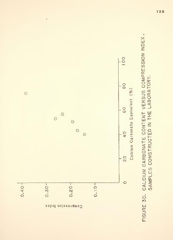
30. Calcium carbonate content versuscompression index. Samples constructedin the laboratory 128

Xll
31. Calcium carbonate content versus princi-pal stress difference determined at 15%axial strain from unconfined compressiontests. Samples constructed in thelaboratory 129
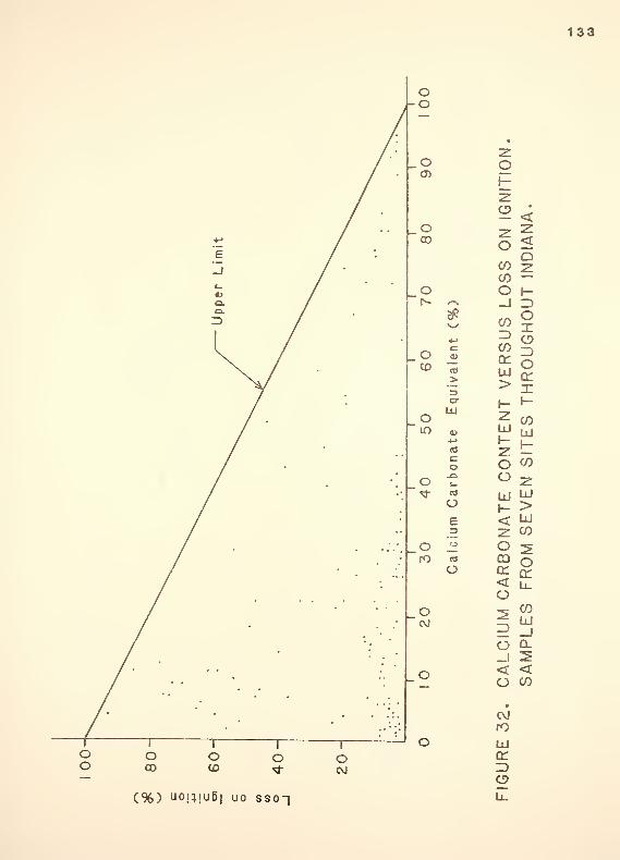
32. Calcium carbonate content versus loss onignition. Samples from seven sitesthroughout Indiana 133
33. Calcium carbonate content versus watercontent. Samples from seven sitesthroughout Indiana 134
34. Loss on ignition (organic content)versus water content. Samples fromseven sites throughout Indiana 135
35. Calcium carbonate content versus initialvoid ratio. Samples from seven sitesthroughout Indiana 136
36. Calcium carbonate content versuscompression index. Samples from sevensites throughout Indiana 137
37. Calcium carbonate content versus densityof solids. Samples from seven sitesthroughout Indiana 139
38. Calcium carbonate content versus plasti-city index. Samples from seven sitesthroughout Indiana 140

XX11
LIST OF ABBREVIATIONS
AASHTO American Association of State Highway andTransportation Officials
ACSSM Association Committee on Soil and SnowMechanics
ASCE American Society of Civil Engineers
ASTM American Society for Testing and Materials
NRC National Research Council
SCPS Swedish Committee on Piston Sampling
SMFE Soil Mechanics and Foundation Engineering
uses Unified Soil Classification System
WHC water holding capacity

XIV
V
LIST OF SYMBOLS
Theological parameter
coefficient of compressibility
A - ash contentc
b - rheological parameter
c
'
- effective stress strength intercept
cc - cubic centimeter
cm - centimeter
C - line intercept
CCE - calcium carbonate equivalent
C - compression index
c - coefficient of consolidationv
D - slope of the line
e - initial void ratioo
ft - feet
g — gram
G - density of solids
h - initial thicknesso
H - layer thickness after primary consolidation
HNO - nitric acid
H - initial thicknesso
i - exponential parameter
in. - inch

XV
k - coefficient of permeability
kg - kilogram
kPa - kilo-Pascal
LIR - load increment ratio
LOI - loss on ignition
m - meter
max - maximum
ml - milliliter
mm - millimeter
MPa - mega-Pascal
N - normality
NaOH - sodium hydroxide
P " - initial effective overburden pressure
r - coefficient of correlation
sec - second
sq - square
S - total settlement
S - primary settlement
S - secondary settlement
t - time
t - time at which secondary strain begins
t. - time at which tertiary strain begins
t - time to complete primary strain
u — excess of equilibrium pore water pressure
vs — versus
W — dry sample weight
w — natural water contentn

Y - strain rate
z - distance from the element to the drainage surface
a - coefficient of primary consolidation
a - coefficient of secondary compression
Ae - change in void ratio
&p - applied stress change
icr
'
- change in effective stress
Ao-_ - stress level at which prediction is to be made
Act.- - stress level for uihich rheological parameters
were calculated
e. - instantaneous strain1
e - primary strain
e_ - secondary strain
e - tertiary strain
e<t> - strain as a function of time
e - vertical strainv
o - density of mater
X - rheological parameter
•*>
'
- effective angle of shear strength
p .- dry density
cr
'
- effective normal stress
cr - major principal stress
o-^ - minor principal stress
t - shear stress
T. — shear strength
> - greater than
< - less than

XVI X
HIGHLIGHT SUMMARY
This report is presented as an aid to the engineer
faced with the problem of dealing with peat and/or marl
for use as an engineering material. Marl overlain by
peat is a common deposit found in glaciated areas.
Peat and marl are discussed separately in this report/
houiever» it should be noted that both peat and marl are
commonly found in the same deposit.
The report reviews the physical and mechanical
properties of peat/ methods of sampling and test pro-
cedures used to determine properties. The unique
characteristics of peat are presented and classifica-
tion systems which distinguish peat from other organic
soils are outlined. A large portion of this report
centers on the stress-deformation behavior of peat and
methods used to estimate field settlements. Methods of
building embankments over peat for use as highway foun-
dations are briefly covered. In many cases preloading

the peat to improve its strength is a desirable wag of
utilizing peat as a foundation material. A rheological
model first presented by Gibson and Lo (1961) is
applied to peat for use as a control over preloading
duration. The applicability of the model is tested on
both laboratory and field data and is found to model
actual peat behavior quite accurately.
Since calcium carbonate distinguishes marl from
other soils/ the effect of calcium carbonate on
engineering behavior of marl was investigated. This
was accomplished by testing samples which were produced
in the laboratory. These tests showed that increasing
the calcium carbonate content caused an increase in
water content- initial void ratio, compressibility* and
strength/ all factors other than calcium carbonate con-
tent remaining constant. This was not the observed
behavior for actual field samples. Calcium carbonate
content had no discernible effect on any of the
observed engineering properties. It was found that the
behavior of marl is similar to other soft, highly
compressible mineral soils, and should be treated as
such for engineering purposes.
INTRODUCTION
Peat underlain by calcarious soils/ termed marl/
is a common depositional feature in glaciated areas.
This combination of weak/ highly compressible materials
causes concern for highway engineers. Embankments are
difficult to construct over peat and marl deposits due
to the unique characteristics of these materials. This
report investigates these characteristics and how they
affect engineering design.
Marl is a soft earthy material/ distinguished from
other soils mainly by its high calcium carbonate con-
tent. Marl can be found underlying peat deposits in a
very loose/ saturated condition. Due to the low over-
burden pressure imposed by the peat/ the marl is nor-
mally consolidated and highly compressible. This
report investigates the effect of calcium carbonate on
marl behavior and how to deal with this behavior in
engineering design. To avoid confusion/ peat will be
dealt with first followed by a discussion of the
behavior of marl.
The highly compressible nature of peat makes it
one of the most undesirable foundation materials for

highway construction. Highway engineers try to avoid
peat deposits whenever possible. Local peat pockets
and shallow deposits are generally excavated and
replaced by a more desirable material when encountered.
However, there are situations when a peat deposit can-
not be avoided. When a highway alignment must pass
over a peat deposit/ the load caused by the pavement
and subgrade will cause some settlement to occur. For
this reason, highway pavements must be elevated above
the peat deposit by means of an embankment. This
embankment causes an additional load on the peat
resulting in more settlement. Predicting and dealing
with these settlements has been a problem for highway
designers and foundation engineers.
Even though peat is an abundant material in many
parts of the world/ most geotechnical engineers are not
sufficiently familiar with the properties and behavior
of peat to deal effectively with it. Peat materials
present many unique problems which are not encountered
with mineral soils. Due to this unusual behavior/ spe-
cialized procedures and methods of analysis must be
used when dealing with peat.
One of the major problems enginers have had with
peat is relating its properties and behavior in a sys-
tematic way. This problem is caused mainly by the lack
of a universal classification system which adequately

groups peat and highly organic soils. The Unified Soil
Classification System (USCS). originally developed by
Casagrande (1948). groups all highly organic soils into
one category called peat, which is identified by
"color, odor/ spongy feel, and frequently by fibrous
texture" (Holtz and Kovacs. 1981). The AASHTO (1970)
classification system treats peat in a similar manner
by placing all peats and highly organic soils into one
group designated A-8. which is given a subgrade rating
of "unsatisfactory. " Trying to deal with peat, its
properties, or behavior in a systematic way requires a
more complete classification system. Considering all
peats and highly organic soils in one group would be
like treating all fine grained soils as one material
with the same properties and behavior. Landva and
LaRochelle (1982) stress that "it is important to dis-
tinguish between the very large variety of materials
within the group of soils currently referred to as
peat. The properties of these materials vary from that
of textile-like fabric to that of a jelly-like sub-
stance. A case record of construction on peat land is
of little value without such distinction and without a
detailed description of the peat involved." Classifi-
cation of peat and highly organic materials along with
the properties and behavior of peat will be dealt with
in later sections.

3a
Note: Pages 4 through 113 are not included in this copyof the report. They are available in substantially the sameform (only slight modifications) in the interim reportIN/JHRP 83/3, entitled "Use of Peats as Embankment FoundationsThey are also available in exact and final form, for the costof duplication from:
Joint Highway Research ProjectCivil Engineering Building
Purdue UniversityWest Lafayette, Indiana 47907
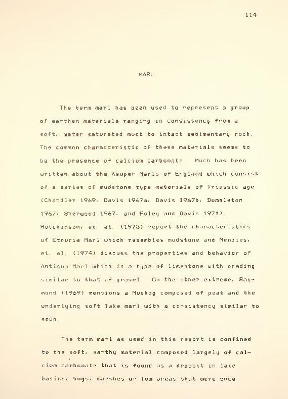
114
MARL
The term marl has been used to represent a group
of earthen materials ranging in consistency from a
soft* water saturated muck to intact sedimentary rock.
The common characteristic of these materials seems to
be the presence of calcium carbonate. Much has been
written about the Keuper Marls of England which consist
of a series of mudstone type materials of Triassic age
(Chandler 1969/ Davis 1967a/ Davis 1967b/ Dumbleton
1967, Sherwood 1967. and Foley and Davis 1971).
Hutchinson/ et. al. (1973) report the characteristics
of Etruria Marl which resembles mudstone and Menzies/
et. al. (1974) discuss the properties and behavior of
Antigua Marl which is a type of limestone with grading
similar to that of gravel. On the other extreme, Ray-
mond (1969) mentions a Muskeg composed of peat and the
underlying soft lake marl with a consistency similar to
soup.
The term marl as used in this report is confined
to the soft/ earthy material composed largely of cal-
cium carbonate that is found as a deposit in lake
basins, bogs, marshes or low areas that were once

115
covered with water. It mag be defined as a mixture of
calcium carbonate/ detrital clay- silt* sand and
organic matter which has been deposited in water.
Physical characteri sties . In hardness and con-
sistency fresh marl resembles softened butter, whereas
in some of the marsh deposits that are partially
drained it is firm enough to be cut in blocks and han-
dled with a shovel. In many locations marl has conso-
lidated to the consistency of a stiff clay.
Its color varies with the amount of impurities it
contains. Marl is usually grayish-white, but darker
colors may be seen where the marl is contaminated with
peaty organic material. Pure marls are more white in
color.
Marl as found in existing lakes may contain as
high as 60% water by volumei while even the dry marl-
beds occurring in swamps or marshes will carry 15 to
25% moisture by volume (Schwartz/ 1957). This mois-
ture* together with the fine granular character of the
marl* gives it a sticky, putty-like character. Because
of its fine texture* marl does not release much of its
water by drainage. Even though marl may be as sticky
as clay* it is markedly lighter in dry weight due to
its large moisture content.

116
The particles or grains composing the marl are
usually very fine and powdery In some marls the
shells of small snails and snail-like molluscs are very
abundant, while in others no traces of shells are
found. The most common form of shell is from the fresh
water univalve Helisoma Trivolvis (Blatchley and Ash-
ley. 1900). Marl usually contains very little sand or
grit, though some of its shells and calcium carbonate
particles may give it a gritty feeling when examined.
Such shells and particles can usually be crushed
between the fingers which will serve to distinguish
them in the field from sand grains.
Mar 1 formation . The source of calcium carbonate
deposited as marl is from rock and soils containing
calcium compounds, such as limestone. In the northern
section of the United States this calcium source is
thought to be glacial drift. Because of its origin.
this glacial debris contains an appreciable amount of
fresh or chemically unaltered rock fragments, contain-
ing calcium compounds. Soil waters percolating through
these limy clays and gravels carr^ with them dissolved
carbon dioxide, and the combined action of the dis-
solved gas and water leaches out the soluble lime com-
pounds from the soils through which it filters. Marl
is formed when these compounds are precipitated and
deposited with the silts and clays which were suspended

117
in the flowing water. Marl is found, therefore, only
in places that were once or are still covered with
water. It is not necessarily confined to the immediate
vicinity of present existing bodies of water, for the
general water level has fallen, and many former shallow
lake basins, covering thousands of acres, are now
drained and dry land.
During the time of active deposition, a marl bed
must have very little covering other than water. As
soon as the upper surface of the deposit approaches the
surface of the water, rushes, sedges and other marsh
vegetation gain a foothold in the newly deposited marl
and use it as a soil. The thickness to which the soil
remains of such vegetation accumulate over the marl is
governed by the relation of the surface of the marl to
the ground water level. When the water level remains
stationary for a great number of years, a thick bed of
peat grows over the marl. If the water level is
lowered while marl deposition is in progress, the marl
dries fast and only a thin bed of peat is formed.
In most deposits there is a sharp contrast between
marl and its underlying foundation. The marl appears
as a distinct stratum and does not merge irregularly
into the surrounding materials. The nature of the
underlying material is determined to some extent by the
character of the surrounding region. Sand or clay

118
usually forms the floor of the basins. Verg rarely is
there any muck or peat underlying the marl. In north-
ern regionsi such relations indicate that calcium car-
bonate deposition began after postglacial drainage
channels mere well established and when clay or sand
deposition at some distances from shore was virtually
at a standstill.
Location of marl deposits . Marl beds owe their
origin to the precipitation of lime carbonate from
solution. It follows that marl is always found in
areas that were originally covered with water. Marl
also underlies partially drained swamps, and in some
places it is found in the banks of streams that have
cut their channels into a bed of marl as the outlet of
a former lake or bog was lowered. Not all lakes of the
glaciated areas contain marl. The reason is that gla-
cial lake basins are formed in a number of different
ways, and some, therefore, are better fitted than oth-
ers as reservoirs for the accumulation of marl.
Marl is most commonly found under the type of peat
which develops around lakes and ponds (see Figure 26).
It is either sedge-grass peat or pond peat composed of
the remains of plants such as reed grass, cattails,
bulrushes, and grasses.
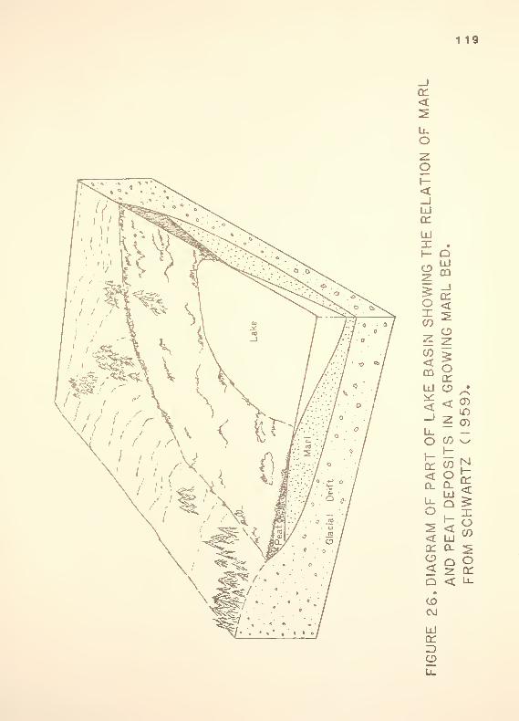
119
£T<SLuO2Oh-<_JLxJ
(T
UJX .
I- QCDU
§ CD
1*2 <^ ZECO-, ^>? z:
CO ^si<TLAKE
IN
AG •
CD
U.o CO v-y
1-1—
-
or co N1-<
< OUJ
£ Q £o X^ < o
CO< UJa: q_ ^2 Q o< z cr
Q < Ll.
CDCVJ
LJcr3CD
u_

120
Marl is commonly found in or around hard water
lakes. It is the presence of calcium bicarbonate that
gives mater the property usually known as temporary
hardness. If the lake water is soft, the calcium con-
tent is so low that no marl deposits are formed.
In the northern United States, more marl is found
in basins of regions where the glacial drift is com-
posed of open-textured gravels and sands than where
impervious clayey tills cover the surface. This is
true even if the lime carbonate content of the clay is
higher than that of sands. This is because the water
which leaches the calcium compounds flows more easily
through the gravels and sands than the clayey tills.
Indiana Marl Deposits. Marl or "merl, " as it is
commonly called, is found in Indiana as a soft, earthy
material, composed principally of an amorphous form of
carbonate of lime. Large deposits of marl are found in
the three northern tiers of Indiana counties. Smaller
deposits are found scattered in other portions of the
glacial drift-covered area of the state, but none has
been reported south of this glacial area (Blatchley and
Ashley, 1900).
Sand or gravel underlies most of the marl deposits
in Indiana, though in a few instances a tough blue clay
may be encountered.

121
In size the marl deposits of Indiana run from a
feu/ hundred square meters to several thousand square
kilometers. Lake Wauiasee/ including the arm known as
Syracuse Lake, in Kosciusko County/ contains about 6900
square kilometers (Blatchley and Ashley* 1900). The
thickness of the marl beds in Indiana varies from to
15+ meters, a deposit of the latter thickness having
been found in Turkey Lake/ Lagrange County. Thickness
may vary drastically over the deposit. Blatchley and
Ashley (1900) report/ "From our own experience it seems
safe to say that a large majority of the deposits have
a maximum depth of over 6 meters, even though the area
of the deposit may be quite limited. "
Blatchley and Ashley (1900) provide an excellent
survey of Indiana's marl resources/ including several
county and lake maps with detailed descriptions and
references provided. Maps are given for the following
counties: Steuben/ Lagrange/ Noble/ Whitley/
Elkhart, Kosciusko, Fulton/ Marshall/ St. Joseph,
Laporte and Lake.
According to Blatchley and Ashley (1900), the
marls found in Indiana were used for the following pur-
poses :
1. As an ingredient in the manufacture of Portlandcement.

122
As a fertilizer of soils.
3. As a means of improving the mechanical conditionof clayey* sandy or peaty soils.
4. As a mineral food for poultry.
5. As a polishing powder.
6. As a material for the manufacture of quicklime.
7. In the place of limestone in the manufacture ofbeet sugar.
A present day usage that Blatchley and Ashley failed to
mention is marls' use as a highway foundation material.
The remainder of this report will discuss the use of
marl as an engineering material.
Effect of calcium carbonate . Since calcium car-
bonate differentiates marl from other soils/ it was
desirable to study its effect in more detail. In order
to determine the effect of calcium carbonate on soil
behavior* samples were constituted in the laboratory.
The mixture initially consisted of 50X clay and 50%
silt. These materials were disaggregated and
thoroughly mixed. Six samples were made by adding
varying amounts of powdered calcium carbonate to the
silt-clay mixture. Water was added until the mixture
had a soup-like consistency. The slurry was placed in
plexiglass molds (12.7 cm d iameter » 15. 2 cm high) and

123
consolidated for 4 weeks under a pressure of 37 kPa.
Several tests were run on the six samples/ with results
given in Table 7. Correlations of test results with
calcium carbonate content are shown in Figures 27/ 28.
29, 30, and 31.
Test procedures. The calcium carbonate content
was determined by the following procedure which is
currently used by the Indiana Department of Highways.
1. Weigh out 1 gram sample which has passed the #60s ieve.
2. Add 50 ml of 0. 5N nitric acid.
3. Heat until effervescence stops.
4. Cool to room temperature.
5. Titrate with 0. 25N sodium hydroxide to phenol-phthalien end point. Note: In this case colorchange was difficult to detect until solid floccu-lated/ which was about 1 ml from the end point.Flocculation varied depending on the amount ofsoil present.
Calculations.
CCE =<ml HN0
3x N> - <ml NaOH x N> x 0.05 x 100
WhereCCE =
<ml HN03
x N> =
<ml NaOH x N> =
0.05
100
W
calcium carbonate equivalent or '/. calciumcarbonate
total milli equ i va 1 ent s HN0_ added
mi 1 1 i equivalents HNO^ left, ormilli equ i va 1 ent s base used
titrimetric factor for CaCO,
dry sample weight

124
CO
o
W Xi/i a>
a. -ui- c
£
CJ
flj
•rt 13 'H+> H +>--( <Q
-PP- Pa; a<
•p +> N"flj (=
2(J
oW -'
W <= -pOO'HX_i e
en
i-4 Q)ID N
€ -P -p
D <TJ C.* p a»
u -p
m t- oo <q oo
N
o co
€
U1
03
uc
0-.
<?
-0 00
^ o* «* «T-l »"» 1-1 (\J
o «-< *<0* N 0-
U
CM 03' 03n n ro
oo
nin
03.0
c-
CJm
ui
COCO
o
rCO
HI
r-
o o re oo

4.0-
C
3.0-
Oo o
125
O
2.0
I.0-
20 40 60 80
Calcium Carbonate Equivalent (%)
FIGURE 27.
CALCIUM CARBONATE CONTENT VERSUS LOSSON IGNITION . SAMPLES CONSTRUCTED IN THELABORATORY.

h-
126
O
Oo
G
OO
oCO
OCO
o<3"
I
OCvJ
(%) 1U3}U00 J8;B/V\
UJH-Zooo
o
S °v^ <
o 4-» co <r00 C 3 o— CO CD
«3
> CC <w _J>
UJ UJ
o 1- X01+->
c H ?oXI Z<3
O QO O uj
O E3 £oO < ^«1 2 K
o < 9<M
GURE
28.
CALCIUM
C
SAMPLES
C

127
O
O
O
§
GO
i
m 10
o00
o
O
oCvJ
#
txl
o£_
oE3
o
°U B d P!°A |Bj;!U|
<en
oo>_j< . •
>-H en
Z o~* HCO <3 cc
CO ocr OQUJ <> _J
i- UJ
2 XUJ h-
H z"Z.
o Qo UJ
Ul
<"Z.
oDOcr<o
I-oZ)eni-co2:oo
^ COUJ3 -J
O D__J S< <o CO
0>CVJ
UJen=>
S2u.
128
XUJo22
o o-o CO
COUJq:
o00 s~\
COM TORY
o C*
+->
c4)
ERSUSABORA
o > > -J
o~ CD 3 l_ LJ
GO
LJ
0)»->
NTEI
IN
T
O c O QO O o
C_
«}
Oe
O
lONATE
C
STRUCTE
OCM
O
CIUM
CARE
PLES
CON:
O _j -5I
oi i
o oro cvj
I
o < <O CO
• • • •
o o o
xapu| ucusssjdwoQ
o 6to
LJa:
O

129
CO
CO
7-
6-
5-
©O
G
4-
co
3-
2-
I
-
FIGURE 3 I.
20 40 60 80Calcium Carbonate Equivalent (%)
CALCIUM CARBONATE CONTENT VERSUS PRINCIPALSTRESS DIFFERENCE DETERMINED AT I 5% AXIALSTRAIN FROM UNCONFINED COMPRESSION TESTSSAMPLES CONSTRUCTED IN THE LABORATORY

130
Water content and loss on ignition were determined in
accordance with ASTM standard D2974 (ASTM 1981). The
initial void ratio and compression index were deter-
mined from standard oedometer tests, load increment
ratio equal to 1. The unconfined compression test was
used to determine the principal stress difference at
15X axial strain.
Test results. As shown in Figure 27, no obvious
correlation exists between loss on ignition (organic
content) and calcium carbonate content. This also
seems to indicate that calcium carbonate and its bypro-
ducts are not burned off at 550 degrees celcius. Thus,
igniting the sample does not directly alter the calcium
compounds present.
Figure 28 shows a near linear correlation between
water content and calcium carbonate content. These
results show that increasing the calcium carbonate con-
tent increases the water content.
Figure 29 also shows a near linear relation
between initial void ratio and calcium carbonate
equivalent. This could be expected after observing
Figure 28. since the samples were completely saturated.
Thus, all other factors remaining constant, increasing
the calcium carbonate content results in a higher water
content and corresponding higher initial void ratio.

131
Figure 30 shows a positive correspondence between
the compression index and calcium carbonate content.
Once again, this is to be expected since higher calcium
carbonate contents resulted in higher water contents
and initial void ratios which are reflected by higher
compressib i 1 ities.
Figure 31 shows an increasing strength (principal
stress difference) with increasing calcium carbonate
content. When the previous test results are con-
sidered, the opposite behavior might be expected;
namely, as the calcium carbonate content increased,
water content increases, the soils becomes looser, and
the strength would be expected to go down. However as
Figure 31 shows, this is not the case. The increasing
strength with calcium carbonate content could be due to
a "cementing" effect similar to that which takes place
when lime is used to stabilize soils. In any case,
calcium carbonate appears to have a positive effect on
strength, as determined from these unconfined compres-
sion tests.
It should be noted that the six samples were the
same except for differences in calcium carbonate con-
tent. This was done to isolate the effect of calcium
carbonate content, eliminating other possible varia-
tions such as organic content, overburden pressure and
clay mineralogy.

132
Field Samples. The effect of calcium carbonate on
natural marl samples taken from the field was also
investigated. Samples used in this testing program
were obtained from seven sites throughout Indiana.
These samples were taken from highway projects located
in Whitley* Kosciusko. Miami/ Noble. Steuben. Hamilton,
and Laporte counties.
Figure 32 shows a large amount of scatter, and no
apparent correlation between organic content and cal-
cium carbonate content. This seems to discount any
relationship between processes which form marl deposits
and organic accumulation.
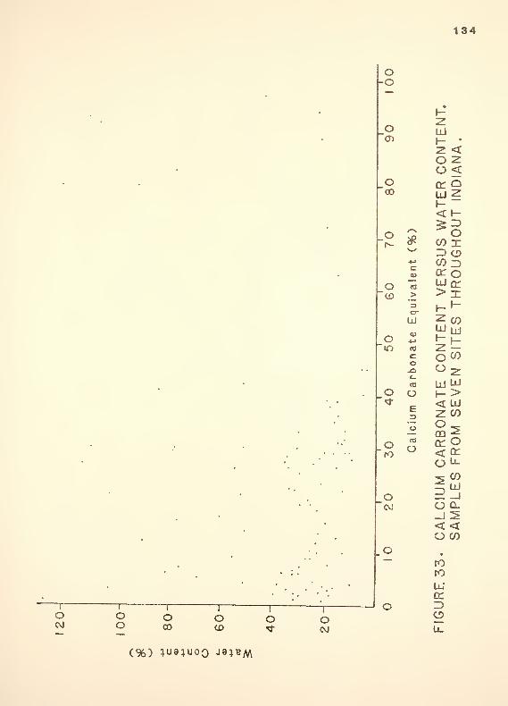
Figure 33 shows no clear correlation between car-
bonate equivalent and water content. The reason for
this scatter is mainly due to variations in organic
content. As shown in Figure 34. there exists a
correspondence between organic content and water con-
tent. A regression analysis was performed to obtain
the best fit line through the data, as shown in Figure
34. These two figures show that the effect of calcium
carbonate on water content is minimal compared to other
factors such as organic content.
Figures 35 and 36 show no correlation between ini-
tial void ratio or compression index and calcium car-
bonate content. This is to be expected when the
133
O
O
COCOo_i
COZ)COccLU>
<<
HOXor>ocrx
i- i-
2 COLUh-
LJ
o f-^
o 2Ld LlI
H- ><£ LJ
£ 5tr q;< Llo-^ CO
I LU5 -J
o Q-
_J 2< <o CO
cOr0
LlI
en
o(%) uo|;iuB| uo sso"i
o-o
134
O UJ~G)
CONT
IANA.
• o en"CO
A/ATE
UT
IN
o *
c9}
OCO X3 OCO 30:0
o <n uJer"CO >
orIxJ ENT
\
ES
TH
o"m CO
co.0c_
cO E
CONT
EN
SIT
o O \->•_ • ~<fr
E3
< LlI
2: CO
. 00 -^
o cd en O;
.
' ' " "• ~K>O < en
u-
.••
O3^
•.
CvJ O Q_
< <
•
•
• •'
•
"•
.
_o
FIGURE
33.
C S
oI
oo
I
oCO
I
oCD
I
OI
oo
(%) 1U91U0Q J8^BM

135
1
o 1
o1
o1
o1
o1
oo o o o o oCD «o <3- ro CVJ —
i±j
oocrUJi- .
< <
COZ>CO<r
>
UJ
Oo
Q-2L
oXoZ>ocrx
CO
<q:o
o
2:CD
CO
UJ>UJCO
COCOo
oenu_
COUJ.Jo_
<-i CO
ro
UJtrID
u_
(M) (%) iua;uoo J9;bm

136
O
O
o CO CD
1~ ~rOJ
°U BU P!°A l^!l!U|
<Od
.
<> 5<
H "~
oCD
157^ CD
Oin
CO 3F.
4->> X
c h- 1-
+-» 2 c/5
o UJ u-tf O fet
<D co
CO O 2o UJ Wro -0 h- >< l±J
O z. CO
o E3
2nr cj
CJ < F(0 Li-
Of^ UJ
.0 2 -1
CALC SAMP
•
10ro
UJ<r
O

137
O
G
O
GG
CO
~rro CVJ
xapu| uoissajdoioQ
XUJQ22o .
CO <to ^UJ <cr o0- z.o ^ -
CD
SCO
HOUT
O 3 oCO 3cr o
c uj cr0> > X
o > i-»-
'<* Z3 z CO
UJUJ ljI- h-
(U z: —cd o <o
orO
co O 2
UJ LlI
(0 h- >O < UJ
g 2 coO"<M
3OOf
OCARBO FROM
_o
ALCIUMAMPLES
o
GURE
36.
C S

138
results of Figures 33 and 34 are considered. Thus*
there are factors other than calcium carbonate content
which dictate initial void ratio and compression
index for these marls.
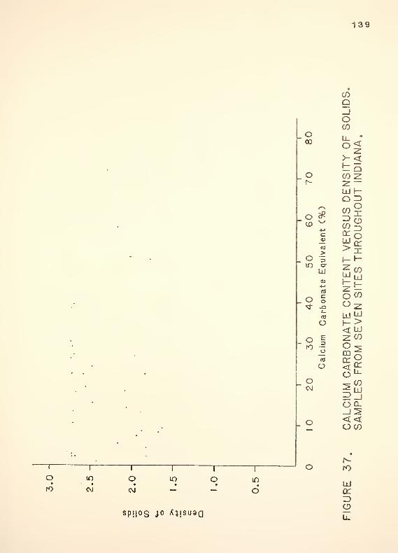
Density of solids versus calcium carbonate content
is shown in Figure 37. Density of solids is defined as
the mass of solids divided by the volume of solids.
These data show no clear relation between these two
proper t ies.
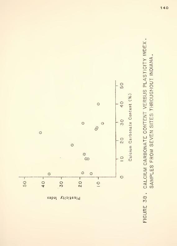
Figure 38 also shows no clear correlation between
plasticity index and calcium carbonate equivalent.
Once again* other factors such as clay mineralogy and
clay content control the plasticity index of these
soils.
Recommended design procedures . Considering the
test results from the field samples* it can be seen
that calcium carbonate content has no clear relation-
ship with the engineering characteristics of marl. The
marl found in Indiana deposits is influenced to a
greater degree by other factors such as organic con-
tent* clay mineralogy* overburden pressure* etc. Since
marl is currently distinguished only by calcium car-
bonate content* it is recommended that soils referred
to as marl* be treated in the same way as other soft
normally or slightly overconsol idated soil deposits.
139
OCO
if)
CO
OOJ
If)
o
CO
9_ioCO
S P!I°S i° ^1!SU8Q
CO
ITY
OF
DIANA.
O co -z.f-~ -z.
—UJ h-Q 3
oCO
#4->
:sus UGHO
c uc O<D ^cr> >x
O ^ y-Y-If)
j
2. CO^ UJ
*-»
(0 z —o c
OjO
o CO
o z£_
LJ LlI
O< UJ
o E z CO
roZ3
o °2o
u_
o ^ COf^bJ=! -JOCLJ2
o <<oco
«
o rO
LJrrZ>oLi_
140
O
O
oGO
©
olO
o oro
oCVJ
xapu| y^ijOj^SBicj
XUJQ2. •
>- <
2 5H Zco—
< Hoin
_J ID0- o
^\ §sj* 2o
ocat
C•^ 1-
o z: wO IxJ L"-1o
ro<L> K t-t-»
c o Mo O 2-O Ld
OATE 3EV
CVJ oE zo o ^o £ °
O «3 or orO
UM
CA
LES
Fl
O
FIGURE
38
.
CALCISAMP

141
Therefore the analysis and design of structures over
marl should be conducted in the same manner as for
other soft, highly compressible mineral soils (Boutrup
and Holtz. 1982; Chirapuntu and Duncan. 1976; Lukan and
Teig. 1976; Tavenas. 1979; and Webster and Alford.
1978)
The engineer should note that in many cases, these
marl deposits are overlain by saturated peat. Due to
the low unit weight of the peat, and the depositional
process, these normally consolidated deposits are typi-
cally very weak and compressible. Excavating the peat
and replacing it with a much heavier fill may cause
failure to occur in the underlying marl.
Preloading the peat and marl may be an effective
method of improving the deposit for foundation use.
Raymond (1969) has observed that the pore water pres-
sure dissipates more quickly in marl than in most
clays; however, not as quickly as in peat.

142
SUMMARY AND RECOMMENDATIONS
Peat . Peat is abundant in many countries around
the world. A geotechnical enginer must be aware of the
unique behavior of peat in order to deal effectively
with this organic material.
Need for a uniform classification system. Peat
and highly organic soils must be separated into
categories which group materials with similar behavior
together. Disagreements as to the behavior of "peati
"
as evident from a review of the literature* generally
can be shown to arise from a lack of proper definition
of the materials concerned. The proposed ASTM classif-
ication of peat and organic soil (Table 3) is recom-
mended for use. The physical description of peat for
geotechnical use should include the following:
1. Fiber content.
2. Ash content.
3. Acidity.
For example, a peat with a fiber content of 50%, ash
content of 10%/ and pH of 5, would be designated a

143
hemic/ medium ash/ moderately acidic peat.
Physical properties. The very loose structure of
peat results in high water content/ high void ratio/
high compressibility and low shear strength. Peat in
its natural state generally has a very high permeabil-
ity; hou/ever/ as the peat is compressed/ the permeabil-
ity is drastically reduced. This behavior accounts in
part for the large deviation between peat and mineral
soils. The effect of the organic fibers also has an
important effect on the behavior and properties of
peat. Typical values of physical properties for peat
are shown in Table 8.
Mechanical properties. The fiber content of peat
has an important effect on shear behavior. The fibers
act as a reinforcement to triaxial shear. As the peat
is compressed/ the shear strength increases rapidly/
being a function of the friction between fibers and
tensile strength of the individual fibers. Peat/ with
its potential for large increases in shear strength
with deformation/ seems to be idealy suited to the
preloading technique.
Peat has a high compressibility which continues
for long periods of time. Settlement of peat is due to
two separate mechanisms/ 1) one dimensional consolida-
tion/ and 2) lateral displacement (shear strain).

144
Table 8. Typical ranges of physical properties for peat.
Fiber content 20% - 80%
Water content 500"/. - 1500"/.
Ash content 2% - 25%
Organic content 75% - 98%
Void ratio 5-20
Density of solids 1.4 - 2.0
Natural density 0. 4 - 1.2 g/cc
Dry density 0.08 - 0.32 g/cc
pH 4-7—3 —5
Natural permeability 1x10 -1x10 cm/sec

145
Sampling and testing. The purpose of the site
investigation should be to delineate the extent and
depth of peat coverage and to obtain samples for clas-
sification and laboratory use. The coverage of the
peat deposit may be obtained by soundings. Disturbed
samples may be obtained from split spoon samples or
continuous flight augers. Reasonably undisturbed sam-
ples may be taken with thin-walled samplers such as a
shelby tube near the surface, or a piston-type sampler
at greater depths. Minimal sampling disturbance will
occur if the sampling tubes are sharpened and lubri-
cated. It is preferable to use a sampling tube which
is the same size as the test specimen to avoid distur-
bance due to trimming.
The testing program should include procedures to
determine the following index properties:
1. Moisture/ ash and organic content (ASTM Standard
D2974).
2. Density of solids (use correlation with ash con-
tent/ Equation 1).
3. Fiber content (use method outlined in Testing sec-
tion).
4. In-situ wet and dry density.

146
5. If metal or concrete is to be placed in contact
with the peati pH should be determined (ASTM Stan-
dard D2976, distilled water method only).
Embankment design. These writers recommend the follow-
ing design approach for embankments over peat:
1. Preliminary surcharge design using settlement andtime estimates from equations (14)* (15) and (16).
Stability analysis should be performed usingstrength from triaxial compression tests.
2. Compare preloading design to other possible solu-tions and choose most desirable alternative.
3. If preloading is chosen/ install settlement platesand monitor settlements.
4. Use Gibson and Lo's model to control duration of
surcharge.
5. After sufficient time* remove the surcharge andcomplete construction.
These writers suggest using single load tests, scaled to
field dimensions using Equations (14)< (15); and (16)
to determine surcharge magnitude and time settlement
behavior. The exponential parameter (i) can be assumed
equal to 1.5 for preliminary design.
These writers recommend using consolidated
undrained triaxial tests to model field behavior. The
samples should be consolidated isotrop ical ly to the
level of vertical effective stress anticipated in the
field. Stability of the embankment need not be con-
sidered unless the height of embankment is lm (3 feet)

147
or more/ in which case the undrained strength parame-
ters should be used in a stability analysis. Stability
analyses involving peat soils are usually made by the
conventional limit design methods of comparing required
stresses with available strength on potential failure
arcs/ or alternatively on the basis of potential slid-
ing blocks. Computerized stability analyses, such as
those presented by Chen (1981) for three dimensional
failures may be used to both refine and facilitate the
computations.
If stability presents problems* loading berms
should be utilized. The positive effects of loading
berms have been analyzed by Hollingshead and Raymond
(1972). Geotextiles also have a beneficial effect on
embankment construction over peat. These fabrics
placed between the embankment and peat deposit prevent
local failures, inhibit pavement rutting, and prevent
spreading of the embankment causing less fill to be
used.
Preloading and control. If peat must be used as a
foundation material, improving the properties of the
deposit by use of preloading may be the most economical
method. The technique presented in this report pro-
vides a tool for the designer to control the duration
of the surcharge period.

148
During construction, settlement plates should be
placed under the embankment. During and after con-
struction of the surcharged embankment; the deformation
behavior should be monitored. After the primary strain
portion of the settlement has occurred (approximately
three months)* Gibson and Lo's model should be applied
as a control over the duration of preload. After suf-
ficient time has passed to accelerate the desired set-
tlements, the surcharge is removed and highway con-
struction is completed.
Concluding remarks. Many highways have been built
over peat deposits using the preload method. This
report improves on previous preloading analyses by
presenting an accurate method of controlling the dura-
tion of the surcharge period. During the preliminary
design, a conservative estimate of the required time
for surcharge is made, based on laboratory compression
tests. The settlement of the field embankment should
be monitored by use of settlement plates. After set-
tlement has progressed into the secondary strain por-
tion, Gibson and Lo's model should be applied and the
required duration of surcharge determined from this
data (the contractor will not object if the surcharge
time can be shortened). The laboratory and field data
should be compared for several embankment sections and
ultimately, correlations may be determined so that the

149
field measurements will not be routinely necessary.
The report also serves to familiarize the reader
with: the relevant properties and behavior of
peat, methods for building highway embankments over
peat, and the latest efforts to classify peat.
Recommendations for future research. There is a
need to correlate the rheological parameters from Gib-
son and Lo's model as determined in the laboratory to
the parameters calculated under field loading situa-
tions. If this relation were determined; field settle-
ments could be predicted from laboratory tests using
this model.
The relationship between the shear strength of
samples consolidated hy drostat ical ly and those consoli-
dated anisotrop ical ly is still not quantitatively
understood. Qualitatively/ the shear strength of peat
is larger when consolidated by a hydrostatic pressure
as compared to anisotropic, where the coefficient of
lateral earth pressure at rest <K > is less than one.o
The magnitude of this difference has not been quanti-
fied. The actual consolidation which occurs in the
field is anisotropic. To model this behavior in triax-
ial tests requires a knowledqe of K , which is diffi-o
cult to determine for peats.

150
Research concerning peat will be made much easier
when a standard classification of peat has been
adopted. At that time, when a case study is presentedi
the researcher will know precisely what material is
being referred to. Presently this condition does not
exist and causes much confusion in the literature.
Marl . Marl, as is used in this report, refers to
a soft, earthy material composed largely of calcium
carbonate that is found as a deposit in areas that were
at one time, or still are covered with water. In
northern Indiana, marl is commonly overlain by peat.
Tests were conducted on specimens consolidated
from a slurry, with varying calcium carbonate contents.
These tests showed, all other factors being equal, that
increasing the calcium carbonate content caused an
increase in water content, initial void ratio, compres-
sibility and strength. It was found, however, that the
effect of calcium carbonate on the engineering propei—
ties of marl in field samples was minimal. Factors
such as organic content had a much larger effect on
marl behavior.
It is therefore recommended that marl be dealt
with in the same manner as any other soft, highly
compressible mineral soil deposit.
151
Recommendations for future research. The behavior
of soft materials underlying peat deposits seem to be
controlled by factors other than calcium carbonate con-
tent. It is likely that organic content is a major
factor in determining the behavior of these soft soils.
It would be desirable to know the effect of high
organic contents (25 to 75 7.) on strength and compres-
sibility parameters of these soft deposits.

REFERENCES

152
REFERENCES
AASHTO (American Association of State Highways andTransportation Officials), (1970)< Standard Specifica-tions for Hiqhmau Mater ia Is and Methods of Samp 1 inq andTesting . Part 1.
ASTM (American Society for Testing and Materials)/(1981), Annual Book of ASTM Standards , Part 19, NaturalBuilding Stones; Soil and Rock, Philadelphia, PA.
Adams, J. I. (1961), "Laboratory Compression Tests onPeat, " Proceed inqs of the Seventh Muskeg ResearchConference , NRC, ACSSM Technical Memorandum pp. 36 -
54.
Adams, J.I. (1963), "The Consolidation of Peat, Fieldand Laboratory Measurements, " Ontar io Hudro ResearchQuarter lg , Fourth Quarter, pp. 1-7.
Adams, J. I. (1965), "The Engineering Behavior of aCanadian Muskeg, " Proceed ings 6th International Confer-ence on SMFE , Volume 1, University of Toronto Press,pp. 3-7.
Amaryan, L. S. (1972), "Methods of Measuring Strengthand Compressibility of Peat," Proceed inqs First Al 1-
Union Conference on Construct ion on Peatu Soi Is , Ka 1 i
-
nin, Russia.- Volume 1, pp. 69 - 89.
Anderson, K. 0. and Hemstock, R. A. (1959), "Relating theEngineering Properties of Muskeg to Some Problems ofFill Construction, " Proceedings 5th Muskeg ResearchConference , NRC of Canada, Technical Memorandum No. 61,pp. 16 - 25.
153
Anderson, K. 0. and Haas, R. C. (1962), "ConstructionOver Muskeg on the Red Deer Bypass, " Proceedings EighthMuskeg Research Conference , NRC, ACSSM TechnicalMemorandum 74, pp. 331 - 41.
Azzouz, AS., Krizek, R.J. and Corotis, R. B , (1976),
"Regression Analysis of Soil Compressibility," Soilsand Foundations , Volume 16, No. 2, pp. 19 - 29.
Barden, L. ,(1965), "Consolidation of Clay with Non-
linear Viscosity," Geotechnigue , Volume 15, No. 4,
pp. 345 - 362.
Begemann, H. K. S. (1966), "The New Apparatus for Takinga Continuous Soil Sample, " LGM - Mededelingen No . 4,
Delft.
Berry, P. L. and Poskitt, T. J. , (1972), "The Consolida-tion of Peat, " Geotechnigue , Volume 22, No. 1, pp. 25 -
52.
Bjerrum, L. and Lo, K. Y. (1963), "Effect of Aging on
the Shear Strength of Normally Consolidated Clay,"Norwegian Geotechnical Institute Pub lication No . 57,
Oslo, Norway, pp. 147 - 157.
Blatchley, W. S. and Ashley, Q.H. (1900), "The Lakes of
Northern Indiana and Their Associated Marl Deposits,"Annual Report of the Indiana Department of Geoloqu andNatural Resources , Indianapolis, pp. 31 - 321.
Boutrup, E. and Holtz, R. D. (1982), "Fabric ReinforcedEmbankments Constructed on Weak Foundations," JointHighway Research Project, Report FHWA / IN /JHRP-82/21
,
Purdue University, West Lafayette, Indiana, 461 pp.
Brawner, CO. (1957), "Classification, Laboratory Test-ing and Highway Construction Procedure for Organic Ter-
rain, " British Columbia Department of Highways, Techni-cal Bulletin No . 2, Victoria, 59 pp.

154
Braumer, CO. (1959), "Preconsol idation in Highway Con-
struction Over Muskeg, " Roads and Engineering Construc-tion , Volume 97, No. 9, pp. 99 - 104.
Buisman, ASK. (1936), "Results of Long Duration Set-tlement Tests, " Proceedings First International Confer-ence on SMFE, Volume 1, pp. 103 - 106, Cambridge, Mass.
Casagrande, A. (1938), "Notes on Soil Mechanics - FirstSemester," Harvard University (unpublished), 129 pp.
Casagrande, A. (1948), "Classification and Identifica-tion of Soils," Transactions , ASCE, Volume 113, pp.901-930.
Casagrande, L. (1966), "Construction of EmbankmentAcross Peaty Soil, " Journal Boston Soc ietu of Civi
1
Enq ineers , Volume 53, Number 3. pp. 272 - 317.
Chandler, R.J. (1969), "The Effect of Weathering on theShear Strength Properties of Keuper Marl," Geotech-nigue , Vol. 19, No. 3, pp. 321 - 334.
Chen, R. H. (1981), "Three-Dimensional Slope StabilityAnalysis, " JHRP Report No . 81 - V7_. Purdue University,West Lafayette, Indiana, 297 pp.
Chirapuntu, S. and Duncan, J. M. (1976), "The Role ofFill Strength in the Stability of Embankments on SoftClay Foundations, " Report No. TE 75-3, to USAF Water-ways Experiment Station by Geotechnical Engineering,University of California, Berkeley, 231 pp.
Cohen, A. D. , (1981), "Standard Classification of Peat,unpublished report to ASTM Subcommittee D18. 18.
Cook, P.M. (1956), "Consolidation Characteristics ofOrganic Soils, " Proceedings 9th Canad ian So i 1 MechanicsConference , NRC, ACSSM Technical Memorandum 41, pp. 82- 87.

155
Davis* AG. (1967a), "The Mineralogy and Phase Equili-brium of Keuper Marl, " Quarter lu Journal of Enq ineer inqQeoloqu , Vol. 1, No. 1, pp. 25-38.
Davis, AG. (1967b), "The Structure of Keuper Marl,"Quarter lu Journal of Engineering Geologg , Vol. 1, No.
3, pp. 145 - 153.
Decker, M. (1982), "Peat as an Energy Source," InternalReport Ground Engineering , No. 104, Purdue University,West Lafayette, Indiana, 18 pp.
Dhowian, A. W. , (1978), Consolidation Effects on Proper-ties of Hiqhlg Compressib le Soi Is - Peat , Ph. D thesis,University of Wisconsin — Madison, 328 pp.
Dhou/ian, A. W. and Edil, T. B. (1980), "ConsolidationBehavior of Peats, " Geotechnical Testing Journal , ASTM,Volume 3, No. 3, pp. 105 - 114.
Digerfeldt, G. (1966), "A New Type of Large - CapacitySampler," Geol . Foren , Forhandl, 87:4, Stockholm, pp.425 - 430.
Doyle, R. G. (1963), The Consol idation Characteristicsof Peat . Unpublished MASC Thesis, Department of CivilEngineering, University of British Columbia, 110 pp.
Dumbleton, M.J. (1967), "The Origin and Mineralogy ofAfrican Red Clays and Keuper Marl, " Quarter lu Journalof Engineering Geologu , Vol. 1, No. 1, pp. 39 - 45.
Edil, T. B. (1981), "Use of Preloading for Constructionon Peat," Unpublished Report, University of Wisconsin •
Mad is on.
Edil, T. B. and Dhowian, AW. (1979), "Analysis of Long- Term Compression of Peats, " Geotechnical Enq ineer ing ,
Southeast Asian Society of Soil Engineering, Volume 10,
No. 2, pp. 159 - 178.

156
Feustel, I.C. and Byers, H. G. (1930). "The Physical andChemical Characteristics of Certain American Peat Pro-files." United States Department Agriculture. Bureau ofChemistry and Soils. Technical Bui letin 214 . Washing-ton. DC.
Foley, G. P. and Davis. AG. (1971), "Piling in KeuperMarl at Leicester." Civi 1 Enq ineer inq . London. Vol. 66.
No. 782, pp 987 - 991.
Garcia-Bengochea. I.. Lovell. C. W. . and Altschaeffl.AG. (1979), "Pore Distribution and Permeability ofSilty Clays," Journal of the Geotechnical Division .
ASCE, Volume 105, No. GT7, pp. 839 - 856.
Gautschi. MA. (1965). "Peat as a Foundation Soil."Research Summaru Report , Norwegian Geotechnical Insti-tute, Oslo.
Gibson, R. E. and Lo. K. Y. , (1961). "A Theory of Conso-lidation of Soil Exhibiting Secondary Compression ."
Nortueg ian Geotechnical Institute . Volume 78. Number 5.
pp. 179 - 215.
Goodman, L.J. and Lee. C.N. (1962), "Laboratory andField Data on Engineering Characteristics of Some PeatSoils, " Proceedings Eighth Muskeg Research Conference ,
NRC, ACSSM Technical Memorandum 74, pp. 107 - 129.
Gruen. H. A. (1982), "The Shear Strength of Feat."Internal Report Ground Engineering . No. 103. PurdueUniversity, West Lafayette. Indiana. 14 pp.
Hanrahan. E. T. (1954). "An Investigation of Some Phy-sical Properties of Peat," Geotechnigue . Volume 4, No.
3, pp. 108 - 123.
Hanrahan, E. T. , Dunne, J. M. and Sodha, V. G. (1967)."Shear Strength of Peat. " Proceed ings GeotechnicalConference . Oslo, Volume 1, pp. 193 - 198.

157
Helenelund/ K. V. (1972), "Influence of Sampling Distur-bance on the Engineering Properties of Peat Samples."Proceedings of the Fourth International Peat Congress .
Otaniemi, Finland, Section II, pp. 229 - 240.
Helenelund, K. V. (1975a), "Compressibility and Settle-ment of Peat Layers, " Proceedings Istanbul Conferenceon SMFE , Volume 2, pp. 1-8.
Helenelund, K. V. (1975b), "Gectechnical Peat Investiga-tions, " Proceedings First Baltic Conference on SMFE ,
Gdansk, Poland, Volume 1, pp. 106 - 123.
Hollingshead, G. W. and Raymond, G. P. (1972a), "FieldLoading Tests on Muskeg," Canadian Qeotechnical Jour-nal, Volume 9 (3), pp. 278 - 289.
Hollingshead, G. W. and Raymond, G. P. (1972b), "LoadSettlement Studies of a Muskeg," Proceedings FourthInternational Peat Congress , Helsinki, Volume II, pp273 - 282.
Holtz, R. D. and Kovacs, W. D. (1981), An Introductionto Geotechnical Enq ineer ing , Prentice-Hall, Inc. , NewJersey, 733 pp.
Holtz, W. G. (1947), "The Use of Maximum PrincipalStress Ratio as the Failure Criterion in EvaluatingTriaxial Shear Tests on Earth Materials," Proceed ingsof the American Soc ietu for Testing Materials , Volume47, pp 1067 - 1076.
Huang, A. B. (1982), "In - Situ Testing of Peat," Inter-nal Report Ground Engineering , No. 105, Purdue Univer-sity, West Lafayette, Indiana, 16 pp.
Hutchinson, J. N. , Somerville, S. H. and Petley, D.J.(1973), "A Landslide in Per ig lac ia 1 ly Disturbed EtruriaMarl at Bury Hill, Staffordshire, " Quarterlu Journal ofEng ineer ing Geologu , Vol. 6, No. 3&4. pp. 377 - 404.

158
Hvorslev, M. J. (1948). Subsurface Exploration and Sam-p 1 inq of Soi Is for Civi 1 Enq ineer inq Purposes . Editedand Printed by Waterways Experiment Station* Vicksburg-Mississippi, 52 1 pp.
Jackson, M. (1958)< Soil Chemical Analusis . Prentice -
Hall, N. J. , 498 pp.
Jarrett, P. (1982), "Use of Geotextiles in OrganicDepositSi " Seminar given at Purdue University, WestLafayette, Indiana.
Jefferies, J. M. (1936), "Building Roads ThroughUnstable Foundations," Civi 1 Enq . , Volume 6, No. 5, pp.
317 - 320.
Kapp, M.S., York, D. L. , Aronowitz, A. and Sitomer, H.
(1966), "Construction on Marshland Deposits: Treatmentand Results," H i q h ma u Research Board , H i q h wa a ResearchRecord No . 133 , Washington, D. C. , pp. 1 - 22.
Karesniomi, K. (1972), "Dependence of HumificationDegree on Certain Properties of Peat, " Proceedings 4thInternational Peat Conqr . , Helsinki, Volume 2» pp. 273
Kogure, and Ohira, (1977), "Statistical Forecasting ofCompressibility of Peaty Ground, " Canad ian GeotechnicalJournal , Volume 14, No. 4, pp 562 - 570.
Lake, J. B. , (1961), "Investigation of the Problem ofConstructing Roads on Peat in Scotland, " Proceedings ofthe Seventh Muskeg Research Conference , NationalResearch Council of Canada, Association Committee onSoil and Snow Mechanics, Technical Memorandum 71, pp.133 - 148.
Landva, A. O. (1964), "Equipment for Cutting and Mount-ing Undisturbed Specimens of Clay in Testing Devices,"Norwegian Geotechnical Institute, Oslo, Publ ication 56,
pp. 1 - 5.

159
Landva, A. O. , (1980a), Geotechnical Behavior and Test-ing of Peat , Ph. D thesis, Laval University, Quebec, 576PP-
Landva, A. O. (1980 b), "Vane Testing in Peat," CanadianGeotechnical Journal , Volume 17, Number 1, pp. 1 - 19.
Landva, A. O. and Pheeney, P. E. (1980), "Peat Fabric andStructure, " Canadian Geotechnical Journal , Volume 17,
Number 3, pp. 416 - 435.
Landva, A. O. and Peck, K. W. (1980), "Behavior of Roadsand Test Fills on Peat, Escuminac, N. B. , " NRC of CanadaTechnical Memorandum No. 127, pp. 52 - 91.
Landva, A. O. and LaRochelle, P. (1982), "Compressibil-ity and Shear Characteristics of Radforth Peats,"Presented at ASTM Symposium on Testing of Peats andOrganic Soils, June 23, Toronto, Canada.
Landva, A. O. , Pheeney, P. E. and Mersereau, D. E. (1982),"Sampling of Peat," Presented at ASTM Symposium onTesting of Peats and Organic Soils, June 23, Toronto,Canada.
Lea, F. M. , (1956), The Chemistry of Cement and Con-crete , Edward Arnold (Publishers) Ltd., London, 637 pp
Lea, N. D. and Brawner, CO. (1963), "Highway Design andConstruction Over Peat Deposits in Lower British Colum-bia, " H i q h wa u Research Board , Research Record No . 7,
Washington, D. C. , pp. 1 - 33.
Lukanen, E. 0. and Teig, C. (1976), "Design and Evalua-tion of Roadway Widening Sections Through Swamps, "
Investigation No . 199 , Initial Report, Research andStandards Section, Minnesota Department of Transporta-tion, St. Paul, 40 pp.

160
Lynn, W. C , McKinzie, WE. and Grossman- R. B. (1974),"Field and Laboratory Tests for Characterization ofHistosols. Histosols: Their Characteristics! Classifi-cation and Use* " Soil Science Society of America, Spe-c ial Pub 1 icat ion Number 6/ Madison, Wisconsin, pp. 11 -
20.
MacFarlane, I.C. (1958), "Guide to a Field Descriptionof Muskeg (Based on the Radforth Classification Sys-tem), " NRC, ACSSM Technical Memorandum 44 , (revisededition) 36 pp.
MacFarlane, I.C, (1965), "The Consolidation of Peat: ALiterature Review, " NRC Technical Paper No . 195 , (NRC8393), 36 pp.
MacFarlane, I.C. (1969), Muskeg Enq ineer inq Handbook ,
Muskeg Subcommittee of the NRC Associate Committee onGeotechnical Research, University of Toronto Press, 297P
MacFarlane, I.C. and Allen, CM. (1964), "An Examina-tion of Some Index Test Procedures for Peat, " Proceed-ings Ninth Muskeg Research Conference , NRC, ACSSMTechnical Memorandum 81, pp. 171 - 183.
Maeguchi, S. , Sakai, K. and Oyamada, H. , (1965), "OnSoil Investigations of the Foundation of Kuehiro PowerStation, " Soi 1 and Foundation , Japanese Society ofSMFE, Volume 13, No. 8, pp. 3-9.
Menzies, B. K. , Looby, G. and Simmons, N. E. (1974), "ACorrelation of Index Tests and Road Performance Experi-ence of an Antigua Marl," Geotechnique , Vol. 24, No. 3,
pp. 433 -438.
Mesri, G. and Godlewski, P.M., (1977), "Time and Stress- Compressibility Interrelationship," Journal of theGeotechnical Engineering Division , ASCE, Volume 103,No. GT5, pp. 417 - 430.
Mickleborough, B. W. (1961), "Embankment ConstructionMuskeg at Prince Albert, " Proceedings 7th MuskegResearch Conference , NRC ACSSM Technical Memorandum71, pp. 164 - 185.

161
Miyakawa, I. (1960), "Some Aspects of Road Constructionin Peaty or Marshy Areas in Hokkaido, With ParticularReference to Filling Methods, " Civil EngineeringResearch Institute, Hokkaido Development Bureau, Sap-poro, 54 pp.
Moore, L. H. (1962), "A Correlation of the EngineeringCharacteristics of Organic Soils in New York State(preliminary)," New York State Department of PublicWorks, Bureau of Soil Mechanics, Technical Report , 13PP
Moran, Proctor, Mueser and Rutledge (1958), "Study ofDeep Soil Stabilization by Vertical Sand Drains,"United States Department Navy, Bureau of Yards andDocks, Report No. u88812 , Washington, D. C. , 429 pp.
Radforth, N. W. , (1952), "Suggested Classification ofMuskeg for the Engineer," Engineering Journal , Volume35, No. 11, pp. 1199 - 1210.
Radforth. N. W. and Brawner, CO. (1977), Muskeg and theNorthern Environment in Canada , University of TorontaPress, Toronto, Canada, 399 pp.
Raymond, G. P. (1969), "Construction Method and Stabil-ity of Embankments on Muskeg, " Canadian GeotechnicalJournal, Vol. 6, No. 1, pp. 81 -96.
Rutledge, P. C. and Johnson, J.J. (1958), "Review ofUses of Vertical Sand Drains, " Hiohwau Research Board ,
Bulletin No. 173, Washington, DC, pp. 67 - 79.
(SCPS) Swedish Committee on Piston Sampling(1961 ), "Standard Piston Sampling," Proceedings SwedishGeotechnical Institute No . 19, Stockholm.
Samson, L. and LaRochelle. P. (1972), "Design Perfor-mance of an Expressway Constructed over Peat byPreloading, " Canadian Geotechnical Journal , Volume 9,No. 4, pp. 447 - 466.
162
Schwartz/ G. M. (1959), Investigation of the CommercialPossibilities of Marl in Minnesota / Published by Officeof the Commissioner of Iron Range Resources and Reha-bilitation/ State of Minnesota/ 190 pp.
Sherwood. P. T. (1967)/ "Classification Tests on AfricanRed Clays and Keuper Marls/ " Quarterlu Journal ofEngineering Geoloqu . Vol. 1» No. 1/ pp. 47 -55.
Silburn/ J. D. (1972)/ "Peat as the Impermeable Membranein an Earth Dam/ •* Sumposium on Peat Moss in Canada /
University of Sherbrooke/ pp. 163 - 196.
Soper, E. K. and Osbon. C. C. (1922)/ "Occurrence andUses of Peat in the United States/ " United States Geo-logical Surveu Bulletin No . 728 / 207 pp.
Tavenasz F. (1979)/ "The Behavior of Embankments onClay Foundations: A State of the Art/ " Presented at the32nd Canadian Geotechnical Conference/ Quebec.
Taylor/ A. E. (1907)/ The Peat Deposits of NorthernIndiana : Indiana Department Geoloqu and NaturalResources / Annual Report 31» pp. 73 - 298.
Taylor/ D. W. (1948)/ Fundamentals o_£ Soil Mechanics /
John Wiley and Sons/ Inc./ New York/ pp. 208 - 249.
Terzaghi. K. . (1925)/ "Erdbaumechanik auf Bodenphysi-kaliseher." Grundlage> Leipzig.
Terzaghi/ K. (1941)/ "Undisturbed Clay Samples andUndisturbed Clays. " Journal of Boston Societu of CivilEngineers / Volume 28/ No. 3/ pp. 211 - 231.
Tessierz G. (1966)/ "Deux Exemples - Types de Construc-tion des Routes sur Muskeg au Quebec/ " ProceedingsEleventh Muskeg Research Conference / NRC/ ACGR Techni-cal Memorandum 87/ pp. 92 -141.

163
Thompson. J. B. and Palmer. L. A. , (1951), "Report ofConsolidation Tests with Peat," Sumposium on Consolida-tion Testing of Soils , ASTM, Special Technical Publica-tion. No. 126. pp. 4-8.
Tveiten, A. A. (1956), "Applicability of Peat as anImpervious Material for Earth Dams." NorwegianGeotechnical Institute. Publication No . 14.
Von Post. L. (1922). "Sveriges Geologiska UndersokningsTorvinventering Och Nagra Av Dess Hittills Vunna Resul-tat. " Sv. Mosskulturfor . Tidskrif t 1. pp. 1 - 27.
Webster. S. L. and Alford. S.J. (1978). "Investigationof Construction Concepts for Pavements Across SoftGround," U.S. Army Engineer Waterways Experiment Sta-tion, Technical Report S-78-6, 23 pp.
Wilson. N. E. (1964). "Consolidation and Flow Charac-teristics of Peat, " Proceedings 9th Muskeg ResearchConference , NRC of Canada, Technical Memorandum 8i, pp.
150 - 160.
Wilson, N. E. , Radforth, N. W. , MacFarlane. I. C. and Lo.
M. B. (1965), "The Rates of Consolidation for Peat."Proceedings 6th International Conference on SMFE , Mont-real. Canada, Volume 1. pp. 407 - 411.
Witczak. M. W. (1972). "Relationships Between Physio-graphic Units and Highway Design Factors," NCHRP Report132 , 161 pp.
Wyld, R. C. (1956), A Further Investigation of theEngineering Properties of Muskeg , Unpublished M. Sc.
Thesis, Faculty of Engineering, Univ. of Alberta, 76PP-

163a
Note: The Appendices/ pages 164 through 180 arenot included in this copy of the report. This sectionis contained in the interim report IN/JHRP-83/3* enti-tled "Use of Peats as Embankment Foundations. " Copiesof this report may be obtained at the cost of duplica-tion from:
Joint Highway Research ProjectCivil Engineering Building
Purdue UniversityWest Lafayette* Indiana 47907