CONTENTS di usione sonora antifurto termoregolazione videocitofonia controllo lan controllo carichi...
63
MY HOME – Automation General features . . . . . . . . . . . . . . . . . . . . . . . 60 Configuration . . . . . . . . . . . . . . . . . . . . . . . . 92 General rules for installation . . . . . . . . . . . . . . 102 Wiring diagrams . . . . . . . . . . . . . . . . . . . . . . 112 CONTENTS MY HOME - AUTOMATION 59
Transcript of CONTENTS di usione sonora antifurto termoregolazione videocitofonia controllo lan controllo carichi...

MY HOME – Automation
General features . . . . . . . . . . . . . . . . . . . . . . . 60
Configuration . . . . . . . . . . . . . . . . . . . . . . . . 92
General rules for installation . . . . . . . . . . . . . . 102
Wiring diagrams . . . . . . . . . . . . . . . . . . . . . . 112
CONTENTS
MY H
OM
E - AU
TOM
ATiON
59

introduction to the Automation system
The MY HOME Automation system
allows you to manage functions in
a simultaneous and integrated way.
To date, these functions have been
performed with special and complex
electrical devices such as:
�� lighting control
�� control for shutters and/or electric
curtains, fans, exhausters, etc.
Compared to the devices
of a conventional electrical
system, Automation devices
have an electronic circuit with
a programmable logic and are
connected in parallel with a
2-conductor BUS cable for sending
information and with low voltage
(27V d.c.) electric power. There are
two types of devices in the system:
�� controls, connected only to the
BUS cable;
�� actuators, connected both to
the BUS cable and to the 230V
a.c. power line for managing the
connected load.
if it is not possible to achieve a BUS
system or if you want to expand a
pre-existing system without any
masonry work, the Automation
system can be expanded with special
wire/radio interfaces, control and
radio devices characterised by high
installation flexibility.
TV/SAT IPTV TV/SAT IPTV
Power supply
230 Vac
LightShutters Shutters
TV/SAT IPTV
TV/SAT IPTV
automazione di�usione sonora antifurto termoregolazione videocitofonia controllo controllo carichilan energia luci tvcc www irrigazione
TV/SAT IPTV
automazione di�usione sonora antifurto termoregolazione videocitofonia controllo controllo carichilan energia luci tvcc www irrigazione
TV/SAT IPTV
automazione di�usione sonora antifurto termoregolazione videocitofonia controllo controllo carichilan energia luci tvcc www irrigazione
The MY HOME Automation system devices are IMQ certifi ed, as they comply with the CEI EN 50428 standard “non-automatic control devices for fi xed electrical home installations and similar uses”. The MY HOME Automation system devices are IMQ certifi ed, as they comply with the installations and similar uses”.
standard “non-automatic control devices for fi xed electrical home
Wire system
Touch control (SOFT TOUCH)
DIN module actuator
DIN module dimmer actuator
Traditional device
Basic contact interface
DIN module actuator
DIN module dimmer actuator Shutter actuator
controlShutter actuator control
General control Local DisplayLocal Display
GENERAL FEATURES
60
auTOmaTiON -
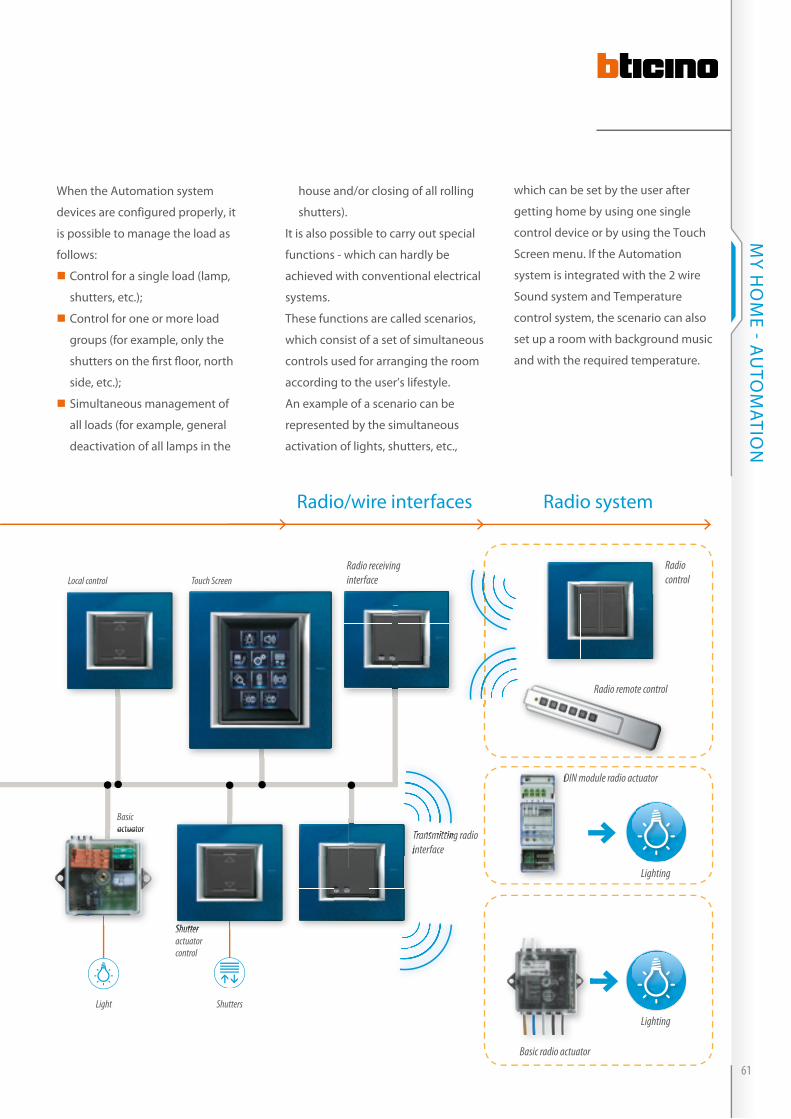
When the Automation system
devices are configured properly, it
is possible to manage the load as
follows:
�� Control for a single load (lamp,
shutters, etc.);
�� Control for one or more load
groups (for example, only the
shutters on the fi rst fl oor, north
side, etc.);
�� Simultaneous management of
all loads (for example, general
deactivation of all lamps in the
house and/or closing of all rolling
shutters).
it is also possible to carry out special
functions - which can hardly be
achieved with conventional electrical
systems.
These functions are called scenarios,
which consist of a set of simultaneous
controls used for arranging the room
according to the user’s lifestyle.
An example of a scenario can be
represented by the simultaneous
activation of lights, shutters, etc.,
which can be set by the user after
getting home by using one single
control device or by using the Touch
Screen menu. if the Automation
system is integrated with the 2 wire
Sound system and Temperature
control system, the scenario can also
set up a room with background music
and with the required temperature.
TV/SAT IPTVTV/SAT IPTV
Light Shutters
TV/SAT IPTV
TV/SAT IPTV
automazione di�usione sonora antifurto termoregolazione videocitofonia controllo controllo carichilan energia luci tvcc www irrigazione
TV/SAT IPTV
automazione di�usione sonora antifurto termoregolazione videocitofonia controllo controllo carichilan energia luci tvcc www irrigazione
Wire system
Radio receiving interface
Radio/wire interfaces Radio system
Local control Touch Screen
Transmitting radio interface
Radio control
Radio remote control
DIN module radio actuatorDIN module radio actuator
Shutter actuator control
Basic actuatoractuator
interface
Shutter
Lighting
Basic radio actuator
TV/SAT IPTV
automazione di�usione sonora antifurto termoregolazione videocitofonia controllo controllo carichilan energia luci tvcc www irrigazione
Lighting
TV/SAT IPTV
automazione di�usione sonora antifurto termoregolazione videocitofonia controllo controllo carichilan energia luci tvcc www irrigazione
Transmitting radio Transmitting radio Transmitting radio Transmitting radio Transmitting radio
61
MY H
OM
E - AU
TOM
ATiON

Control devices
Control devices allow you to control
the state of the actuators, thus
executing different functions: ON,
OFF, timing, etc., which depend
on the functioning mode that has
been assigned to them through an
appropriate configuration.
The electronic part of these devices
Key cover1 function 1 module
Key cover2 functions 1 module
Key cover1 function 2 modules
Control keyControl keyControl key
Key cover2 functions 2 modules
The control with the single key cover can become integrated
with a traditional closing contact (pushbutton or switch).
The double key cover (tilting) can become integrated with a traditional exchanging contact.
NOTE: control keys are supplied with the device as standard.
Upper pushbutton
Lower pushbutton
LED
is separated from the mechanical
operating part so that one can
choose the type, number and size of
the control pushbuttons.
The device can be modular, thus
meeting the different installation
requirements and different functions
required by the user.
Two types of keys and key covers can
be used:
�� 1 function key cover, one or two
modules, to be used with the grey
control key;
�� 2 function key cover, one or two
modules, to be used with the black
control key;
auTOmaTiON - GENERAL FEATURES
62

speciAl control
in addition to the standard functions
it also enables performing all
the Special functions, normally
performed by three different controls:
the Special function control, the
extended control, and the timer
control.
The Special control features 4
pushbuttons and 2 green/red
bicolour LEDs (in the LiViNG and
MÀTiX version) or 4 blue/red bicolour
LEDs (AXOLUTE version).
control stAtus indicAtors
All the controls feature LEDs, which
indicate their status (enabled or
disabled), and make them easier to
find in the dark. The intensity of the
selected load status signalling LED
may be adjusted or turned off using
the pushbutton on the control itself.
lowered controls
These devices are consist of two
lowered flush mounted modules.
This reduces depth, leaving more
room inside the box for the housing
of cables, or for basic modularity
devices.
lowered 2 Module control
The single and double load control
performs the same functions of the
previously released item. The only
differences are:
�� it has been lowered to reduce the
size inside the box;
�� it features two green/red bicolour
LEDS (in the LiViNG and MÀTiX
version), or 4 blue/red bicolour
LEDs (AXOLUTE version).
more space available
Lower pushbutton
LED
Lower pushbutton
Lowered 2 module control
Special control
Upper pushbutton
63
MY H
OM
E - AU
TOM
ATiON

Control devices: controls/key covers - quick matching guide
KeY-CoVeRs WIThoUT sIlK-sCReeN PRINTING
aXolUTe lIVING / lIGhT / lIGhT TeCh MÀTIX
1 ModUle 2 ModUles 1 ModUle 2 ModUles 1 ModUle 2 ModUles
CoNTRols
1 function 2 functions 1 function 2 functions 1 function 2 functions 1 function 2 functions 1 function 2 functions 1 function 2 functions
Spec
ial co
ntro
l
H4651M2L4651M2AM5831M2
HD4915 HC4915 HS4915
HD4911 HC4911 HS4911
HD4915M2 HC4915/2 HS4915/2
HD4911M2 HC4911/2 HS4911/2
L4915 N4915M NT4915M
L4911 N4915M NT4915M
L4915/2 N4915/2M NT4915/2M
L4911/2 N4915/2M NT4915/2M
AM5911 AM5911 AM5911/2 AM5911/2
Cont
rols
for 2
ind
epen
dent
load
s
H4652/2 L4652/2AM5832/2
HD4915 HC4915 HS4915
HD4911 HC4911 HS4911
HD4915M2 HC4915/2 HS4915/2
HD4911M2 HC4911/2 HS4911/2
L4915 N4915M NT4915M
L4911 N4915M NT4915M
L4915/2 N4915/2M NT4915/2M
L4911/2 N4915/2M NT4915/2M
AM5911 AM5911 AM5911/2 AM5911/2
Cont
rols
for 3
ind
epen
dent
load
s
H4652/3L4652/3 AM5832/3
HD4915 HC4915 HS4915
HD4911 HC4911 HS4911
HD4915M2 HC4915/2 HS4915/2
HD4911M2 HC4911/2 HS4911/2
L4915 N4915M NT4915M
L4911 N4915M NT4915M
L4915/2 N4915/2M NT4915/2M
L4911/2 N4915/2M NT4915/2M
AM5911 AM5911 AM5911/2 AM5911/2
HD = WHITE, HC = TECH, HS = ANTHRACITE, L = LIVING, N = LIGHT, NT = LIGHT TECH
KeY-CoVeRs WITh sIlK-sCReeN PRINTING
aXolUTe lIVING / lIGhT / lIGhT TeCh MÀTIX
1 ModUle 2 ModUles 1 ModUle 2 ModUles 1 ModUle 2 ModUles
Controls
1 function 2 functions 1 function 2 functions 1 function 2 functions 1 function 2 functions 1 function 2 functions 1 function 2 functions
Spec
ial co
ntrol
H4651M2 L4651M2 AM5831M2
HD4915... HC4915... HS4915...
HD4911... HC4911... HS4911...
HD4915M2... HC4915/2... HS4915/2...
HD4911M2... HC4911/2... HS4911/2...
L4915... N4915... NT4915...
L4911... N4915... NT4915...
L4915/2... N4915/2... NT4915/2...
L4911/2... N4915/2... NT4915/2...
AM5915... AM5911... AM5915/2... AM5911/2...
Contr
ols fo
r 2
indep
ende
nt loa
ds
H4652/2 L4652/2 AM5832/2
HD4915... HC4915... HS4915...
HD4911... HC4911... HS4911...
HD4915M2... HC4915/2... HS4915/2...
HD4911M2... HC4911/2... HS4911/2...
L4915... N4915... NT4915...
L4911... N4915... NT4915...
L4915/2... N4915/2... NT4915/2...
L4911/2... N4915/2... NT4915/2...
AM5915... AM5911... AM5915/2... AM5911/2...
Contr
ols fo
r 3
indep
ende
nt loa
ds
H4652/3 L4652/3 AM5832/3
HD4915... HC4915... HS4915...
HD4911... HC4911... HS4911...
HD4915M2... HC4915/2... HS4915/2...
HD4911M2... HC4911/2... HS4911/2...
L4915... N4915... NT4915...
L4911... N4915... NT4915...
L4915/2... N4915/2... NT4915/2...
L4911/2... N4915/2... NT4915/2...
AM5915... AM5911... AM5915/2... AM5911/2...
HD = WHITE, HC = TECH, HS = ANTHRACITE, L = LIVING, N = LIGHT, NT = LIGHT TECH * Complete the Key cover code with the letters corresponding to the required screen printing (see table).
auTOmaTiON - GENERAL FEATURES
64
KeY-CoVeRs WIThoUT sIlK-sCReeN PRINTING
aXolUTe lIVING / lIGhT / lIGhT TeCh MÀTIX
1 ModUle 2 ModUles 1 ModUle 2 ModUles 1 ModUle 2 ModUles
CoNTRols
1 function 2 functions 1 function 2 functions 1 function 2 functions 1 function 2 functions 1 function 2 functions 1 function 2 functions
Spec
ial co
ntro
l
H4651M2L4651M2AM5831M2
HD4915 HC4915 HS4915
HD4911 HC4911 HS4911
HD4915M2 HC4915/2 HS4915/2
HD4911M2 HC4911/2 HS4911/2
L4915 N4915M NT4915M
L4911 N4915M NT4915M
L4915/2 N4915/2M NT4915/2M
L4911/2 N4915/2M NT4915/2M
AM5911 AM5911 AM5911/2 AM5911/2
Cont
rols
for 2
ind
epen
dent
load
s
H4652/2 L4652/2AM5832/2
HD4915 HC4915 HS4915
HD4911 HC4911 HS4911
HD4915M2 HC4915/2 HS4915/2
HD4911M2 HC4911/2 HS4911/2
L4915 N4915M NT4915M
L4911 N4915M NT4915M
L4915/2 N4915/2M NT4915/2M
L4911/2 N4915/2M NT4915/2M
AM5911 AM5911 AM5911/2 AM5911/2
Cont
rols
for 3
ind
epen
dent
load
s
H4652/3L4652/3 AM5832/3
HD4915 HC4915 HS4915
HD4911 HC4911 HS4911
HD4915M2 HC4915/2 HS4915/2
HD4911M2 HC4911/2 HS4911/2
L4915 N4915M NT4915M
L4911 N4915M NT4915M
L4915/2 N4915/2M NT4915/2M
L4911/2 N4915/2M NT4915/2M
AM5911 AM5911 AM5911/2 AM5911/2
HD = WHITE, HC = TECH, HS = ANTHRACITE, L = LIVING, N = LIGHT, NT = LIGHT TECH
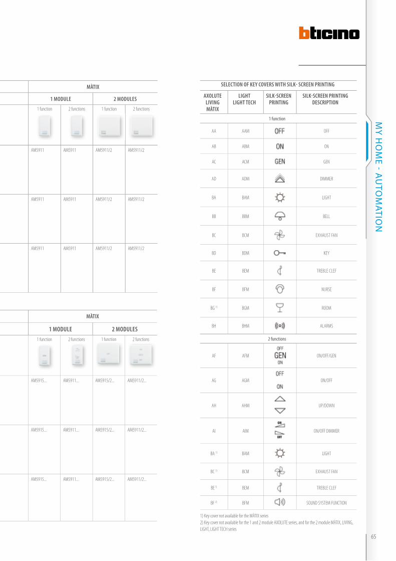
seleCTIoN of KeY CoVeRs WITh sIlK- sCReeN PRINTING
aXolUTelIVINGMÀTIX
lIGhTlIGhT TeCh
sIlK-sCReeN PRINTING
sIlK-sCReeN PRINTING desCRIPTIoN
1 function
AA AAM OFF
AB ABM ON
AC ACM GEN
AD ADM DIMMER
BA BAM LIGHT
BB BBM BELL
BC BCM EXHAUST FAN
BD BDM KEY
BE BEM TREBLE CLEF
BF BFM NURSE
BG 1) BGM ROOM
BH BHM ALARMS
2 functions
AF AFM ON/OFF/GEN
AG AGM ON/OFF
AH AHM UP/DOWN
AI AIM ON/OFF DIMMER
BA 1) BAM LIGHT
BC 1) BCM EXHAUST FAN
BE 1) BEM TREBLE CLEF
BF 2) BFM SOUND SYSTEM FUNCTION
1) Key cover not available for the MÀTIX series2) Key cover not available for the 1 and 2 module AXOLUTE series, and for the 2 module MÀTIX, LIVING, LIGHT, LIGHT TECH series
KeY-CoVeRs WITh sIlK-sCReeN PRINTING
aXolUTe lIVING / lIGhT / lIGhT TeCh MÀTIX
1 ModUle 2 ModUles 1 ModUle 2 ModUles 1 ModUle 2 ModUles
Controls
1 function 2 functions 1 function 2 functions 1 function 2 functions 1 function 2 functions 1 function 2 functions 1 function 2 functions
Spec
ial co
ntrol
H4651M2 L4651M2 AM5831M2
HD4915... HC4915... HS4915...
HD4911... HC4911... HS4911...
HD4915M2... HC4915/2... HS4915/2...
HD4911M2... HC4911/2... HS4911/2...
L4915... N4915... NT4915...
L4911... N4915... NT4915...
L4915/2... N4915/2... NT4915/2...
L4911/2... N4915/2... NT4915/2...
AM5915... AM5911... AM5915/2... AM5911/2...
Contr
ols fo
r 2
indep
ende
nt loa
ds
H4652/2 L4652/2 AM5832/2
HD4915... HC4915... HS4915...
HD4911... HC4911... HS4911...
HD4915M2... HC4915/2... HS4915/2...
HD4911M2... HC4911/2... HS4911/2...
L4915... N4915... NT4915...
L4911... N4915... NT4915...
L4915/2... N4915/2... NT4915/2...
L4911/2... N4915/2... NT4915/2...
AM5915... AM5911... AM5915/2... AM5911/2...
Contr
ols fo
r 3
indep
ende
nt loa
ds
H4652/3 L4652/3 AM5832/3
HD4915... HC4915... HS4915...
HD4911... HC4911... HS4911...
HD4915M2... HC4915/2... HS4915/2...
HD4911M2... HC4911/2... HS4911/2...
L4915... N4915... NT4915...
L4911... N4915... NT4915...
L4915/2... N4915/2... NT4915/2...
L4911/2... N4915/2... NT4915/2...
AM5915... AM5911... AM5915/2... AM5911/2...
HD = WHITE, HC = TECH, HS = ANTHRACITE, L = LIVING, N = LIGHT, NT = LIGHT TECH * Complete the Key cover code with the letters corresponding to the required screen printing (see table).
65
MY H
OM
E - AU
TOM
ATiON
Control devices
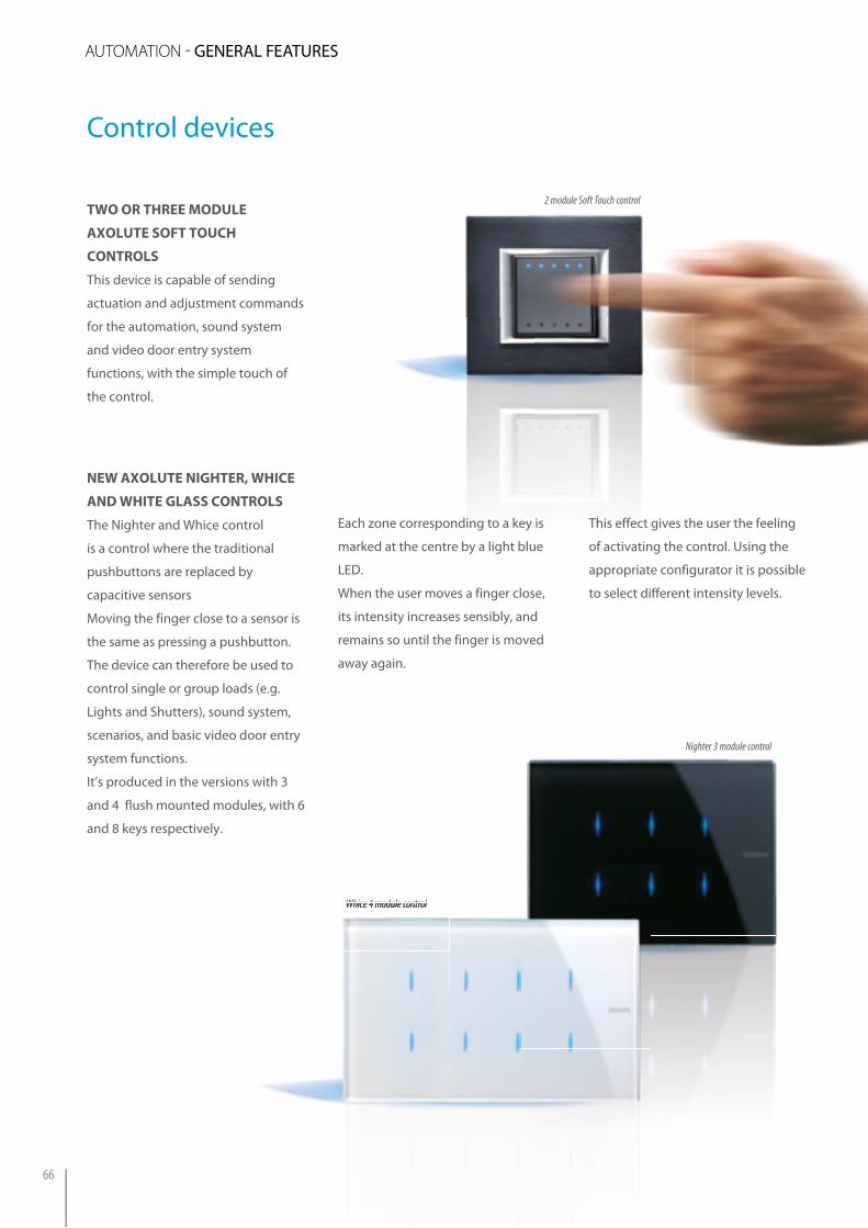
two or three Module
AXolute soft touch
controls
This device is capable of sending
actuation and adjustment commands
for the automation, sound system
and video door entry system
functions, with the simple touch of
the control.
new AXolute nighter, whice
And white glAss controls
The Nighter and Whice control
is a control where the traditional
pushbuttons are replaced by
capacitive sensors
Moving the finger close to a sensor is
the same as pressing a pushbutton.
The device can therefore be used to
control single or group loads (e.g.
Lights and Shutters), sound system,
scenarios, and basic video door entry
system functions.
it’s produced in the versions with 3
and 4 flush mounted modules, with 6
and 8 keys respectively.
Nighter 3 module control
Whice 4 module control
2 module Soft Touch control 2 module Soft Touch control
Each zone corresponding to a key is
marked at the centre by a light blue
LED.
When the user moves a finger close,
its intensity increases sensibly, and
remains so until the finger is moved
away again.
Whice 4 module control
This effect gives the user the feeling
of activating the control. Using the
appropriate configurator it is possible
to select different intensity levels.
auTOmaTiON - GENERAL FEATURES
66
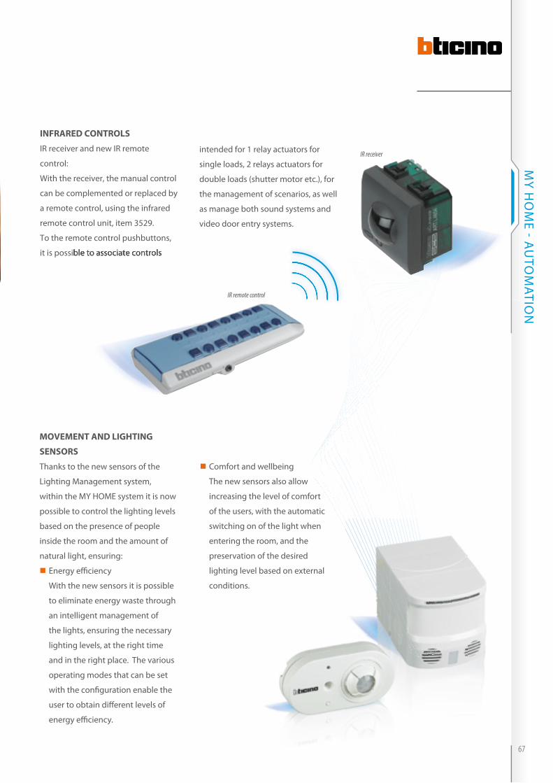
MoveMent And lighting
sensors
Thanks to the new sensors of the
Lighting Management system,
within the MY HOME system it is now
possible to control the lighting levels
based on the presence of people
inside the room and the amount of
natural light, ensuring:
�� Energy effi ciency
With the new sensors it is possible
to eliminate energy waste through
an intelligent management of
the lights, ensuring the necessary
lighting levels, at the right time
and in the right place. The various
operating modes that can be set
with the confi guration enable the
user to obtain diff erent levels of
energy effi ciency.
infrAred controls
iR receiver and new iR remote
control:
With the receiver, the manual control
can be complemented or replaced by
a remote control, using the infrared
remote control unit, item 3529.
To the remote control pushbuttons,
it is possible to associate controls
IR remote control
IR receiver
it is possible to associate controls
�� Comfort and wellbeing
The new sensors also allow
increasing the level of comfort
of the users, with the automatic
switching on of the light when
entering the room, and the
preservation of the desired
lighting level based on external
conditions.
intended for 1 relay actuators for
single loads, 2 relays actuators for
double loads (shutter motor etc.), for
the management of scenarios, as well
as manage both sound systems and
video door entry systems.
67
MY H
OM
E - AU
TOM
ATiON
Control devices
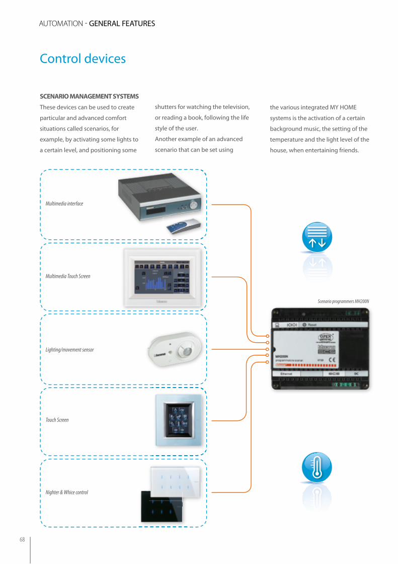
scenArio MAnAgeMent systeMs
These devices can be used to create
particular and advanced comfort
situations called scenarios, for
example, by activating some lights to
a certain level, and positioning some
shutters for watching the television,
or reading a book, following the life
style of the user.
Another example of an advanced
scenario that can be set using
the various integrated MY HOME
systems is the activation of a certain
background music, the setting of the
temperature and the light level of the
house, when entertaining friends.
Scenario programmers MH200N
Multimedia Touch Screen
Multimedia interface
Touch Screen
Lighting/movement sensor
Nighter & Whice control
TV/SAT IPTV
automazione di�usione sonora antifurto termoregolazione videocitofonia controllo controllo carichilan energia luci tvcc www irrigazione
TV/SAT IPTV
automazione di�usione sonora antifurto termoregolazione videocitofonia controllo controllo carichilan energia luci tvcc www irrigazione
auTOmaTiON - GENERAL FEATURES
68

The described scenarios are managed
from particular devices capable of
saving in the memory all the Controls
that define the scenario, and which
the user can recall simultaneously by
pressing one single pushbutton.
The devices capable of saving and
programming these functions are the
following:
�� 2 DiN modules F420 scenario
module for saving 16 scenarios
for automation, sound system,
temperature control, and video
door entry applications.
�� MH200N scenario programmer for
the creation and management of
advanced scenarios, also linked
to time events, system status, and
more.
Video Station (*)
Local display (*)
NOTE (*): at the moment these devices cannot activate scenarios managed by the MH200N scenario programmer.
Scenario module F420
Soft Touch control
Special control
Protected scenario control with transponder (*)
Scenario control
TV/SAT IPTV
automazione di�usione sonora antifurto termoregolazione videocitofonia controllo controllo carichilan energia luci tvcc www irrigazione
TV/SAT IPTV
automazione di�usione sonora antifurto termoregolazione videocitofonia controllo controllo carichilan energia luci tvcc www irrigazione
69
MY H
OM
E - AU
TOM
ATiON
Control devices
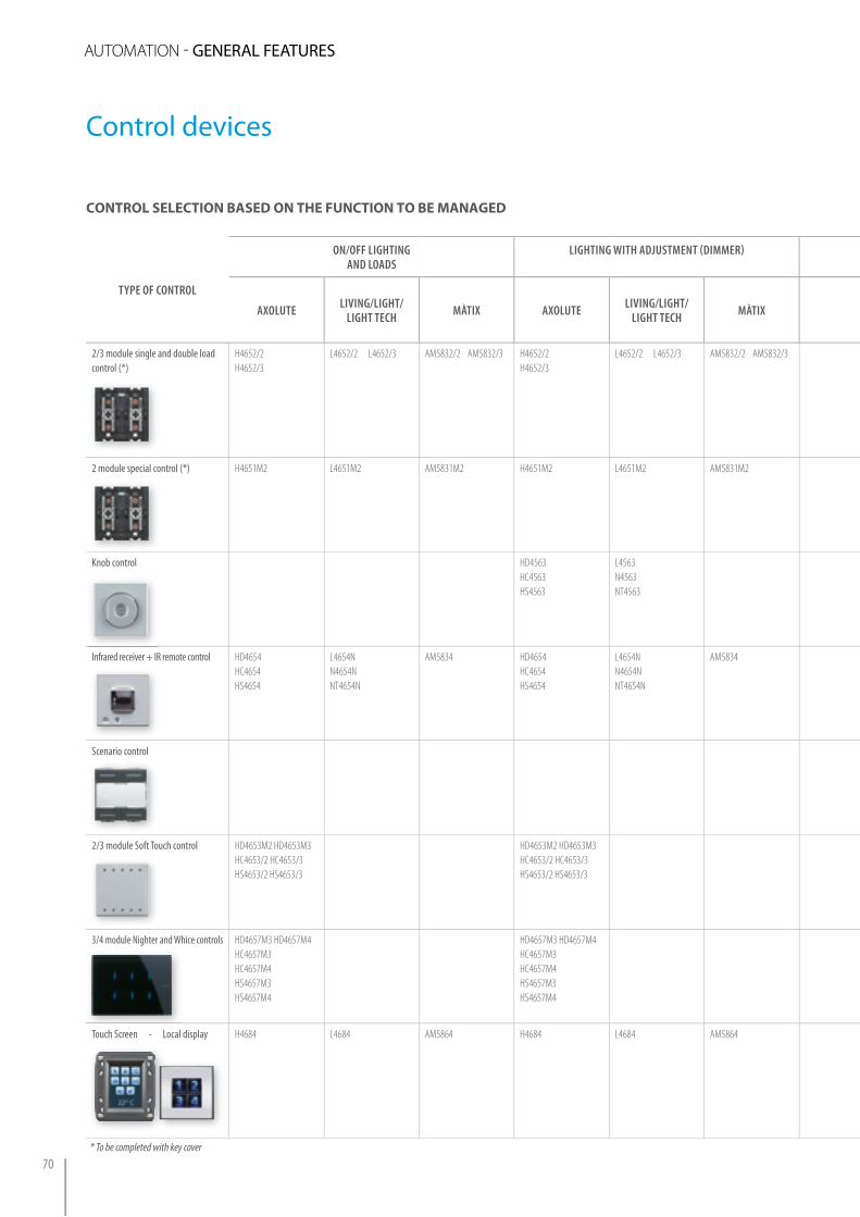
TYPe of CoNTRol
oN/off lIGhTING aNd loads
lIGhTING WITh adJUsTMeNT (dIMMeR) MaNaGeMeNT of aUToMaTIsMs (e.G. CURTaINs aNd shUTTeRs) sCeNaRIo MaNaGeMeNT UsING f420 aNd Mh200N
aXolUTe lIVING/lIGhT/lIGhT TeCh MÀTIX aXolUTe lIVING/lIGhT/
lIGhT TeCh MÀTIX aXolUTelIVING/lIGhT/
lIGhT TeChMÀTIX aXolUTe
lIVING/lIGhT/
lIGhT TeChMÀTIX
2/3 module single and double load control (*)
H4652/2 H4652/3
L4652/2 L4652/3 AM5832/2 AM5832/3 H4652/2 H4652/3
L4652/2 L4652/3 AM5832/2 AM5832/3 H4652/2 H4652/3
L4652/2 L4652/3
AM5832/2 AM5832/3
2 module special control (*) H4651M2 L4651M2 AM5831M2 H4651M2 L4651M2 AM5831M2 H4651M2 L4651M2 AM5831M2 H4651M2 L4651M2 AM5831M2
Knob control HD4563 HC4563HS4563
L4563N4563NT4563
Infrared receiver + IR remote control HD4654HC4654HS4654
L4654NN4654NNT4654N
AM5834 HD4654 HC4654HS4654
L4654NN4654NNT4654N
AM5834 HD4654HC4654HS4654
L4654NN4654NNT4654N
AM5834 HD4654 HC4654HS4654
L4654NN4654NNT4654N
AM5834
Scenario control HD4680 HC4680HS4680
L4680 N4680 NT4680
2/3 module Soft Touch control HD4653M2 HD4653M3 HC4653/2 HC4653/3 HS4653/2 HS4653/3
HD4653M2 HD4653M3 HC4653/2 HC4653/3 HS4653/2 HS4653/3
HD4653M2 HD4653M3HC4653/2 HC4653/3 HS4653/2 HS4653/3
3/4 module Nighter and Whice controls HD4657M3 HD4657M4HC4657M3HC4657M4HS4657M3HS4657M4
HD4657M3 HD4657M4 HC4657M3HC4657M4HS4657M3HS4657M4
HD4657M3 HD4657M4 HC4657M3HC4657M4HS4657M3HS4657M4
HD4657M3 HD4657M4HC4657M3HC4657M4HS4657M3HS4657M4
Touch Screen - Local display
H4684 L4684 AM5864 H4684 L4684 AM5864 H4684 L4684 AM5864 H4684HD4685 HC4685HS4685
L4684L4685N4685NT4685
AM5864
* To be completed with key cover
control selection BAsed on the function to Be MAnAged
auTOmaTiON - GENERAL FEATURES
70
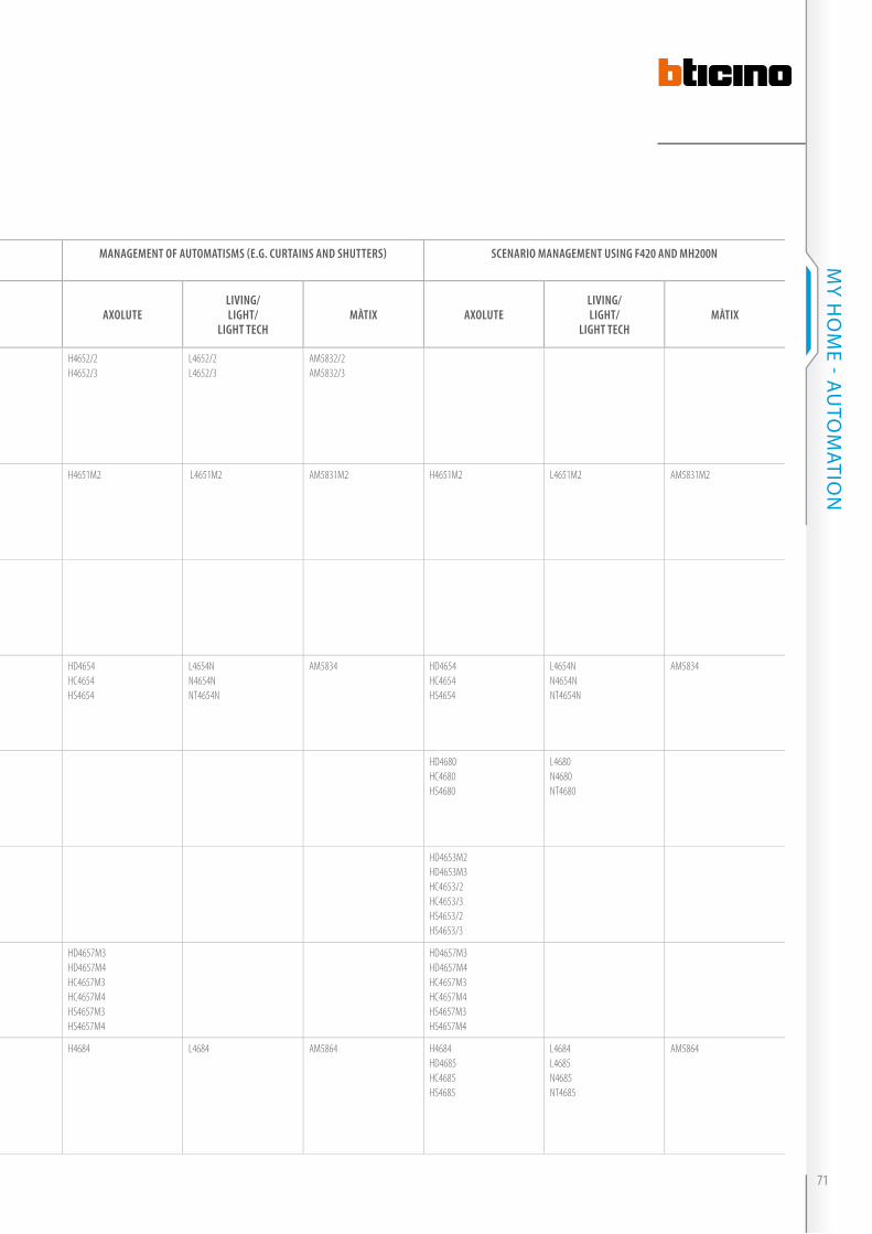
TYPe of CoNTRol
oN/off lIGhTING aNd loads
lIGhTING WITh adJUsTMeNT (dIMMeR) MaNaGeMeNT of aUToMaTIsMs (e.G. CURTaINs aNd shUTTeRs) sCeNaRIo MaNaGeMeNT UsING f420 aNd Mh200N
aXolUTe lIVING/lIGhT/lIGhT TeCh MÀTIX aXolUTe lIVING/lIGhT/
lIGhT TeCh MÀTIX aXolUTelIVING/lIGhT/
lIGhT TeChMÀTIX aXolUTe
lIVING/lIGhT/
lIGhT TeChMÀTIX
2/3 module single and double load control (*)
H4652/2 H4652/3
L4652/2 L4652/3 AM5832/2 AM5832/3 H4652/2 H4652/3
L4652/2 L4652/3 AM5832/2 AM5832/3 H4652/2 H4652/3
L4652/2 L4652/3
AM5832/2 AM5832/3
2 module special control (*) H4651M2 L4651M2 AM5831M2 H4651M2 L4651M2 AM5831M2 H4651M2 L4651M2 AM5831M2 H4651M2 L4651M2 AM5831M2
Knob control HD4563 HC4563HS4563
L4563N4563NT4563
Infrared receiver + IR remote control HD4654HC4654HS4654
L4654NN4654NNT4654N
AM5834 HD4654 HC4654HS4654
L4654NN4654NNT4654N
AM5834 HD4654HC4654HS4654
L4654NN4654NNT4654N
AM5834 HD4654 HC4654HS4654
L4654NN4654NNT4654N
AM5834
Scenario control HD4680 HC4680HS4680
L4680 N4680 NT4680
2/3 module Soft Touch control HD4653M2 HD4653M3 HC4653/2 HC4653/3 HS4653/2 HS4653/3
HD4653M2 HD4653M3 HC4653/2 HC4653/3 HS4653/2 HS4653/3
HD4653M2 HD4653M3HC4653/2 HC4653/3 HS4653/2 HS4653/3
3/4 module Nighter and Whice controls HD4657M3 HD4657M4HC4657M3HC4657M4HS4657M3HS4657M4
HD4657M3 HD4657M4 HC4657M3HC4657M4HS4657M3HS4657M4
HD4657M3 HD4657M4 HC4657M3HC4657M4HS4657M3HS4657M4
HD4657M3 HD4657M4HC4657M3HC4657M4HS4657M3HS4657M4
Touch Screen - Local display
H4684 L4684 AM5864 H4684 L4684 AM5864 H4684 L4684 AM5864 H4684HD4685 HC4685HS4685
L4684L4685N4685NT4685
AM5864
* To be completed with key cover
71
MY H
OM
E - AU
TOM
ATiON

Actuator devices
These devices execute direct controls
and control the connected load in the
same way as an electromechanical
relay.
For this reason, they must be
connected to the BUS cable using the
removable terminals as well as to the
230V a.c. supply line of the load.
There are different types of actuators:
they can differ by shape, size,
installation features and by their
controlled power.
The range includes:
�� Flush mounted two module
actuators;
�� Basic modularity actuators with
reduced profi le;
�� DiN module actuators.
flush-Mounting ActuAtor
with 2 Modules
They are available with 1 and 2
interlocked relays: control for 1 single
load (lamp or motor) or 1 double load
(motor for shutters).
These actuators can be
advantageously used as a control
point, as they are provided with
control pushbuttons at the front side
operated by key covers.
Shutters up-down
TV/SAT IPTV
Example of installation of a flush mounted actuator (with 2 interlocked relays) for the control of the shutters.
TV/SAT IPTV
automazione di�usione sonora antifurto termoregolazione videocitofonia controllo controllo carichilan energia luci tvcc www irrigazione
Key cover1 function 2 modules
Control keyControl key
Key cover2 functions 2 modules
NOTE: the control keys are supplied with the device as standard.
Upper pushbutton
Lower pushbutton
LED
auTOmaTiON - GENERAL FEATURES
72

BAsic Module ActuAtor
Basic actuators are characterized
by extremely compact dimensions:
width = 40.5 mm, height = 40.5 mm,
depth = 18 mm. These dimensions
allow the actuators to be installed
in junction boxes or inside the load
to be controlled (for example in the
bowl of a chandelier, in the structure
of a lampstand, etc.).
it is also possible to place the
control for two light points with
their Basic actuators in a 503E
box; the installation can otherwise
be achieved with a 504E box or
by finding new spaces for the
positioning of the actuators.
Box
SupportControl
Side-by-side Basic items
BUS BUS
Input for traditional devices
Example of installation in flush mounted box
Box
Example of installation in flush mounted box
Control
Basic module actuator
73
MY H
OM
E - AU
TOM
ATiON

Actuator devices:controls/key covers quick matching guide
KeY-CoVeRs WIThoUTsIlK-sCReeN PRINTING
aXolUTe lIVING / lIGhT / lIGhT TeCh MÀTIX
2 ModUles 2 ModUles 2 ModUles
aCTUaToRs
1 function 2 functions 1 function 2 functions 1 function 2 functions
Actu
ator
with
1 re
lay
H4671/1L4671/1AM5851/1
HD4915M2 HC4915/2 HS4915/2
HD4911M2 HC4911/2 HS4911/2
L4915/2 L4915/2MNT4915/2M
L4911/2 N4915/2MNT4915/2M
AM5911/2 AM5911/2
Actu
ator
with
2 int
erloc
ked r
elays
H4671/1L4671/1AM5851/1AM5851/1
HD4911M2 HC4911/2 HS4911/2
L4911/2 N4915/2MNT4915/2M
AM5911/2
Dim
mer
actu
ator
H4678L4678
HD4915M2 HC4915/2 HS4915/2
HD4911M2 HC4911/2 HS4911/2
L4915/2 N4915/2MNT4915/2M
L4911/2 N4915/2MNT4915/2M
HD = WHITE, HC = TECH, HS = ANTHRACITE, L = LIVING, N = LIGHT, NT = LIGHT TECH
KeY-CoVeRs WITh sIlK-sCReeN PRINTING
aXolUTe lIVING / lIGhT / lIGhT TeCh MÀTIX
2 ModUles 2 ModUles 2 ModUles
aCTUaToRs
1 function 2 functions 1 function 2 functions 1 function 2 functions
Actu
ator
with
1 re
lay
H4671/1L4671/1AM5851/1AM5851/1
HD4915M2... HC4915/2... HS4915/2...
HD4911M2... HC4911/2... HS4911/2...
L4915/2... L4915/2...NT4915/2...
L4911/2... N4915/2...NT4915/2...
AM5915/2... AM5911/2...
Actu
ator
with
2int
erloc
ked r
elays
H4671/1L4671/1AM5851/1AM5851/1
HD4911M2... HC4911/2... HS4911/2...
L4911/2... N4915/2...NT4915/2...
AM5911/2...
Dim
mer
actu
ator
H4678L4678L4678
HD4915M2... HC4915/2... HS4915/2...
HD4911M2... HC4911/2... HS4911/2...
L4915/2... N4915/2...NT4915/2...
L4911/2... N4915/2...NT4915/2...
HD = WHITE, HC = TECH, HS = ANTHRACITE, L = LIVING, N = LIGHT, NT = LIGHT TECH * Complete the Key cover code with the letters corresponding to the required screen printing (see table).
auTOmaTiON - GENERAL FEATURES
74

KeY-CoVeRs WIThoUTsIlK-sCReeN PRINTING
aXolUTe lIVING / lIGhT / lIGhT TeCh MÀTIX
2 ModUles 2 ModUles 2 ModUles
aCTUaToRs
1 function 2 functions 1 function 2 functions 1 function 2 functions
Actu
ator
with
1 re
lay
H4671/1L4671/1AM5851/1
HD4915M2 HC4915/2 HS4915/2
HD4911M2 HC4911/2 HS4911/2
L4915/2 L4915/2MNT4915/2M
L4911/2 N4915/2MNT4915/2M
AM5911/2 AM5911/2
Actu
ator
with
2 int
erloc
ked r
elays
H4671/1L4671/1AM5851/1
HD4911M2 HC4911/2 HS4911/2
L4911/2 N4915/2MNT4915/2M
AM5911/2
Dim
mer
actu
ator
H4678L4678
HD4915M2 HC4915/2 HS4915/2
HD4911M2 HC4911/2 HS4911/2
L4915/2 N4915/2MNT4915/2M
L4911/2 N4915/2MNT4915/2M
HD = WHITE, HC = TECH, HS = ANTHRACITE, L = LIVING, N = LIGHT, NT = LIGHT TECH
KeY-CoVeRs WITh sIlK-sCReeN PRINTING
aXolUTe lIVING / lIGhT / lIGhT TeCh MÀTIX
2 ModUles 2 ModUles 2 ModUles
aCTUaToRs
1 function 2 functions 1 function 2 functions 1 function 2 functions
Actu
ator
with
1 re
lay
H4671/1L4671/1AM5851/1
HD4915M2... HC4915/2... HS4915/2...
HD4911M2... HC4911/2... HS4911/2...
L4915/2... L4915/2...NT4915/2...
L4911/2... N4915/2...NT4915/2...
AM5915/2... AM5911/2...
Actu
ator
with
2int
erloc
ked r
elays
H4671/1L4671/1AM5851/1
HD4911M2... HC4911/2... HS4911/2...
L4911/2... N4915/2...NT4915/2...
AM5911/2...
Dim
mer
actu
ator
H4678L4678
HD4915M2... HC4915/2... HS4915/2...
HD4911M2... HC4911/2... HS4911/2...
L4915/2... N4915/2...NT4915/2...
L4911/2... N4915/2...NT4915/2...
HD = WHITE, HC = TECH, HS = ANTHRACITE, L = LIVING, N = LIGHT, NT = LIGHT TECH * Complete the Key cover code with the letters corresponding to the required screen printing (see table).
seleCTIoN of KeY CoVeRs WITh sIlK-sCReeN PRINTING
aXolUTelIVINGMÀTIX
lIGhTlIGhT TeCh
sIlK-sCReeN PRINTING
sIlK-sCReeN PRINTING desCRIPTIoN
1 function
AA AAM OFF
AB ABM ON
AC ACM GEN
AD ADM DIMMER
BA BAM LIGHT
BB BBM BELL
BC BCM EXHAUST FAN
BD BDM KEY
BE BEM TREBLE CLEF
BF BFM NURSE
BG 1) BGM ROOM
BH BHM ALARMS
2 functions
AF AFM ON/OFF/GEN
AG AGM ON/OFF
AH AHM UP – DOWN
AI AIM ON/OFF DIMMER
BA 1) BAM LIGHT
BC 1) BCM EXHAUST FAN
BE 1) BEM TREBLE CLEF
BF 2) BFM SOUND SYSTEM FUNCTION
1) Key cover not available for the MÀTIX series2) Key cover not available for the 1 and 2 module AXOLUTE series, and for the 2 module MÀTIX, LIVING, LIGHT, LIGHT TECH series
75
MY H
OM
E - AU
TOM
ATiON

Actuator devices
din Moduel ActuAtors
These devices are suitable for
centralised installations in boards
and switchboards (2 DiN modules).
Available in versions with 1, 2 and 4
relays for controlling single loads or
double loads (motor for shutters);
these devices are also provided with
load control keys for carrying out an
operational test.
These actuators are characterised by
having the advantage of removing
the rear DiN adapter and the front
Load connection
terminals
Load control pushbutton
Configurator housing
cover so as to reduce the overall
dimensions, thus allowing them to
be installed in raceways, junction
boxes, false ceilings, boxes for rolling
shutters, etc.
With centralised installations, for
example, DiN switchboards E215/...,
MULTiBOX or with the innovative
installation solution MY HOME
FLATWALL*, the DiN adapter and the
front cover enable you to align the
profile of the adapter to that of the
other DiN modular devices.
Removable front cover
Removable adapter for installation on DIN rail in switchboards
DIN actuator for installation in switchboards
Example of installation inside a junction boxExample of installation inside a junction box
Switchboard installation example
auTOmaTiON - GENERAL FEATURES
76
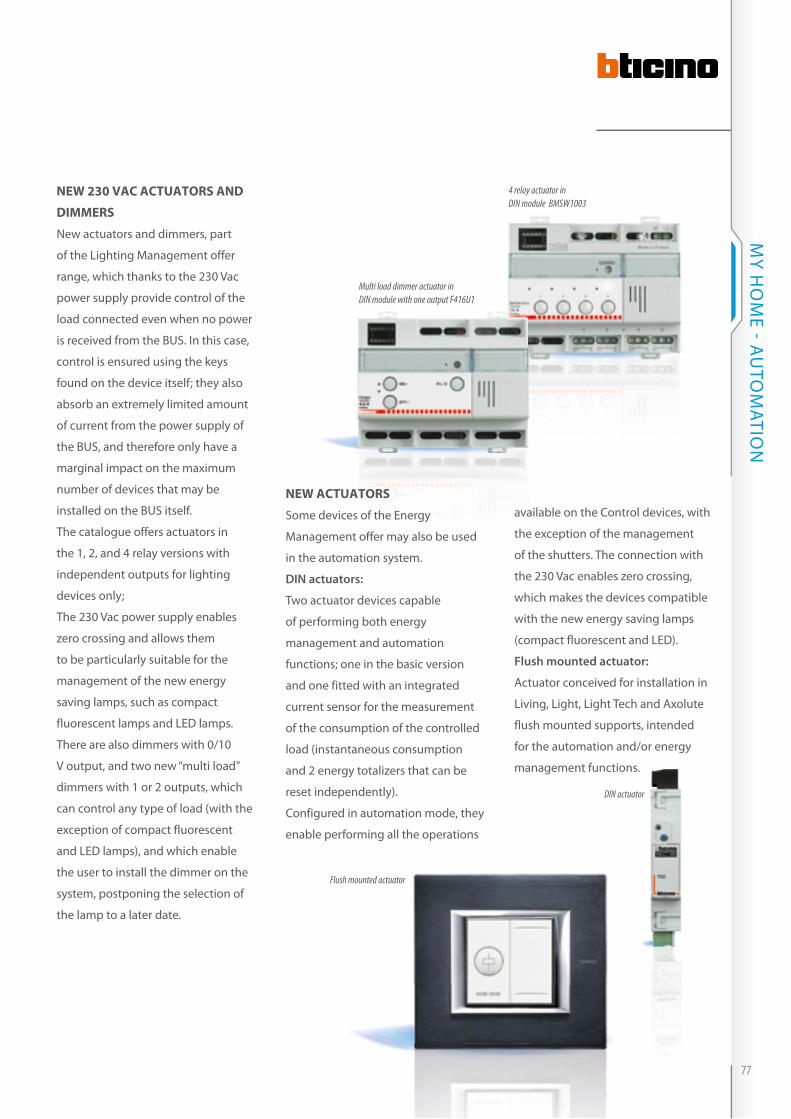
new 230 vAc ActuAtors And
diMMers
New actuators and dimmers, part
of the Lighting Management offer
range, which thanks to the 230 Vac
power supply provide control of the
load connected even when no power
is received from the BUS. in this case,
control is ensured using the keys
found on the device itself; they also
absorb an extremely limited amount
of current from the power supply of
the BUS, and therefore only have a
marginal impact on the maximum
number of devices that may be
installed on the BUS itself.
The catalogue offers actuators in
the 1, 2, and 4 relay versions with
independent outputs for lighting
devices only;
The 230 Vac power supply enables
zero crossing and allows them
to be particularly suitable for the
management of the new energy
saving lamps, such as compact
fluorescent lamps and LED lamps.
There are also dimmers with 0/10
V output, and two new “multi load”
dimmers with 1 or 2 outputs, which
can control any type of load (with the
exception of compact fluorescent
and LED lamps), and which enable
the user to install the dimmer on the
system, postponing the selection of
the lamp to a later date.
new ActuAtors
Some devices of the Energy
Management offer may also be used
in the automation system.
DIN actuators:
Two actuator devices capable
of performing both energy
management and automation
functions; one in the basic version
and one fitted with an integrated
current sensor for the measurement
of the consumption of the controlled
load (instantaneous consumption
and 2 energy totalizers that can be
reset independently).
Configured in automation mode, they
enable performing all the operations
available on the Control devices, with
the exception of the management
of the shutters. The connection with
the 230 Vac enables zero crossing,
which makes the devices compatible
with the new energy saving lamps
(compact fluorescent and LED).
Flush mounted actuator:
Actuator conceived for installation in
Living, Light, Light Tech and Axolute
flush mounted supports, intended
for the automation and/or energy
management functions.
4 relay actuator in DIN module BMSW1003
Multi load dimmer actuator in DIN module with one output F416U1
DIN actuator
Flush mounted actuator
77
MY H
OM
E - AU
TOM
ATiON
Actuator devices
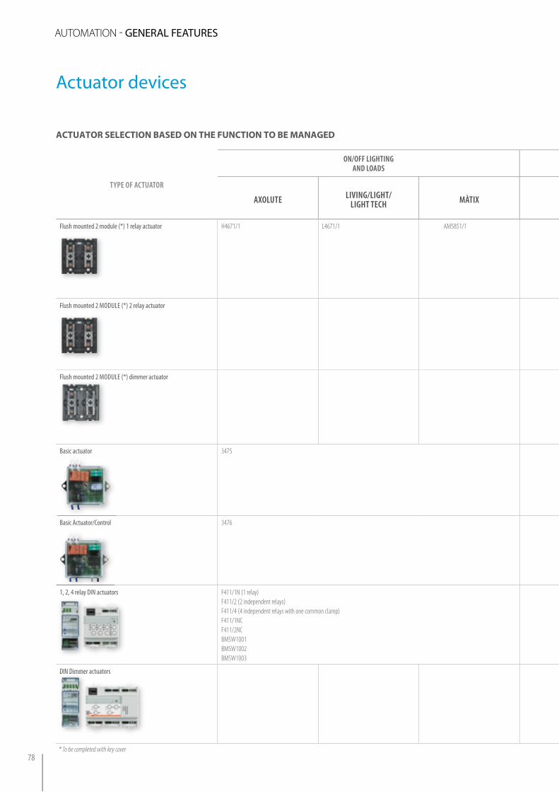
TYPe of aCTUaToR
oN/off lIGhTING aNd loads
lIGhTING WITh adJUsTMeNT (dIMMeR) MaNaGeMeNT of aUToMaTIsMs (e.G. CURTaINs aNd shUTTeRs)
aXolUTe lIVING/lIGhT/lIGhT TeCh MÀTIX aXolUTe lIVING/lIGhT/
lIGhT TeCh MÀTIX aXolUTelIVING/lIGhT/
lIGhT TeChMÀTIX
Flush mounted 2 module (*) 1 relay actuator H4671/1 L4671/1 AM5851/1
Flush mounted 2 MODULE (*) 2 relay actuator H4671/2 L4671/2 AM5851/2
Flush mounted 2 MODULE (*) dimmer actuator H4678 L4678
Basic actuator 3475
Basic Actuator/Control 3476
1, 2, 4 relay DIN actuators F411/1N (1 relay)F411/2 (2 independent relays)F411/4 (4 independent relays with one common clamp)F411/1NCF411/2NCBMSW1001BMSW1002BMSW1003
F411/1N (1 relay - e.g.to control a solenoid valve) -)F411/2 (2 relays - ex. for 230 Vac motors -)F411/4 (4 independent relays with one common clamp)
DIN Dimmer actuatorsDIN Dimmer actuators F413N (for electronic ballasts and LED lamps)F414 (for 60 - 1000 VA resistive loads and ferromagnetic transformers)F415 (for 60 - 400 VA Electronic transformers)F416U1F417U2BMDI1001
* To be completed with key cover
ActuAtor selection BAsed on the function to Be MAnAged
auTOmaTiON - GENERAL FEATURES
78
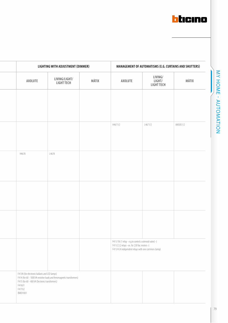
TYPe of aCTUaToR
oN/off lIGhTING aNd loads
lIGhTING WITh adJUsTMeNT (dIMMeR) MaNaGeMeNT of aUToMaTIsMs (e.G. CURTaINs aNd shUTTeRs)
aXolUTe lIVING/lIGhT/lIGhT TeCh MÀTIX aXolUTe lIVING/lIGhT/
lIGhT TeCh MÀTIX aXolUTelIVING/lIGhT/
lIGhT TeChMÀTIX
Flush mounted 2 module (*) 1 relay actuator H4671/1 L4671/1 AM5851/1
Flush mounted 2 MODULE (*) 2 relay actuator H4671/2 L4671/2 AM5851/2
Flush mounted 2 MODULE (*) dimmer actuator H4678 L4678
Basic actuator 3475
Basic Actuator/Control 3476
1, 2, 4 relay DIN actuators F411/1N (1 relay)F411/2 (2 independent relays)F411/4 (4 independent relays with one common clamp)F411/1NCF411/2NCBMSW1001BMSW1002BMSW1003
F411/1N (1 relay - e.g.to control a solenoid valve) -)F411/2 (2 relays - ex. for 230 Vac motors -)F411/4 (4 independent relays with one common clamp)
DIN Dimmer actuators F413N (for electronic ballasts and LED lamps)F414 (for 60 - 1000 VA resistive loads and ferromagnetic transformers)F415 (for 60 - 400 VA Electronic transformers)F416U1F417U2BMDI1001
* To be completed with key cover79
MY H
OM
E - AU
TOM
ATiON

Table of The loads
ActuatorsPower supply/
frequencyControllable loads
Energy saving incandescent and halogen lamps
Resistive loads Linear fluorescent lamps 1)
Compact fluorescent lamps
Electronic transformers
Ferromagnetic transformers 2)
Reducer motor for shutters 3)
34753476
P L
L
L1
PLA
G1M
G2
27 Vdc @ 50/60 Hz 2 A 500 W
2 A 500 W
--
40 W1 lamp maximum
--
2 A cosφ0.5500 VA
--
F411/1N
2
3127 Vdc @ 50/60 Hz 10 A
2300 W16 A3500 W
4 A1000 W
500 W10 lamps maximum
4 A1000 W
4 A cosφ0.51000 VA
F411/242
31
27 Vdc @ 50/60 Hz 6 A1400 W
10 A2300 W
1 A250 W
250 W4 lamps maximum
1 A250 W
2 A cosφ0.5500 VA
2 A500 W
F411/4
5432
1 27 Vdc @ 50/60 Hz 2 A500 W
6 A1400 W
0.3 A70 W
70 W2 lamps maximum
0.3 A70 W
2 A cosφ0.5500 VA
2 A500 W
F413N 27 Vdc @ 50/60 Hz --
--
2.5 A550 W 4)
MAX. 10 ballast type T5, T8, compact or driver for LED
--
--
--
--
F414 27 Vdc @ 50/60 Hz 0.25 - 4 A60 - 1000 W
0.25 - 4 A60 - 1000 W
--
--
--
0.25 - 4 A60 - 1000 VA
--
F415 27 Vdc @ 50/60 Hz --
--
--
--
0.25 - 1.7A60 - 400 VA
--
--
H/L4671/1AM5851/1
P L
L
L1
PLA
G1M
G2
27 Vdc @ 50/60 Hz 6 A1400 W
6 A1400 W
0.65 A150 W
150 W3 lamps maximum
0.65 A150 W
2 A cosφ0.5500 VA
--
H/L4671/2AM5851/2
NOC
NOPLA
GM
NO
C
NO
27 Vdc @ 50/60 Hz --
--
--
--
--
--
2 A 500 W
Actuator devices:selection of the actuators depending on the type of load
The table allows identification of the actuator device depending on what it is to be used for, the electrical features of the load
to be controlled and the installation features.
auTOmaTiON - GENERAL FEATURES
80
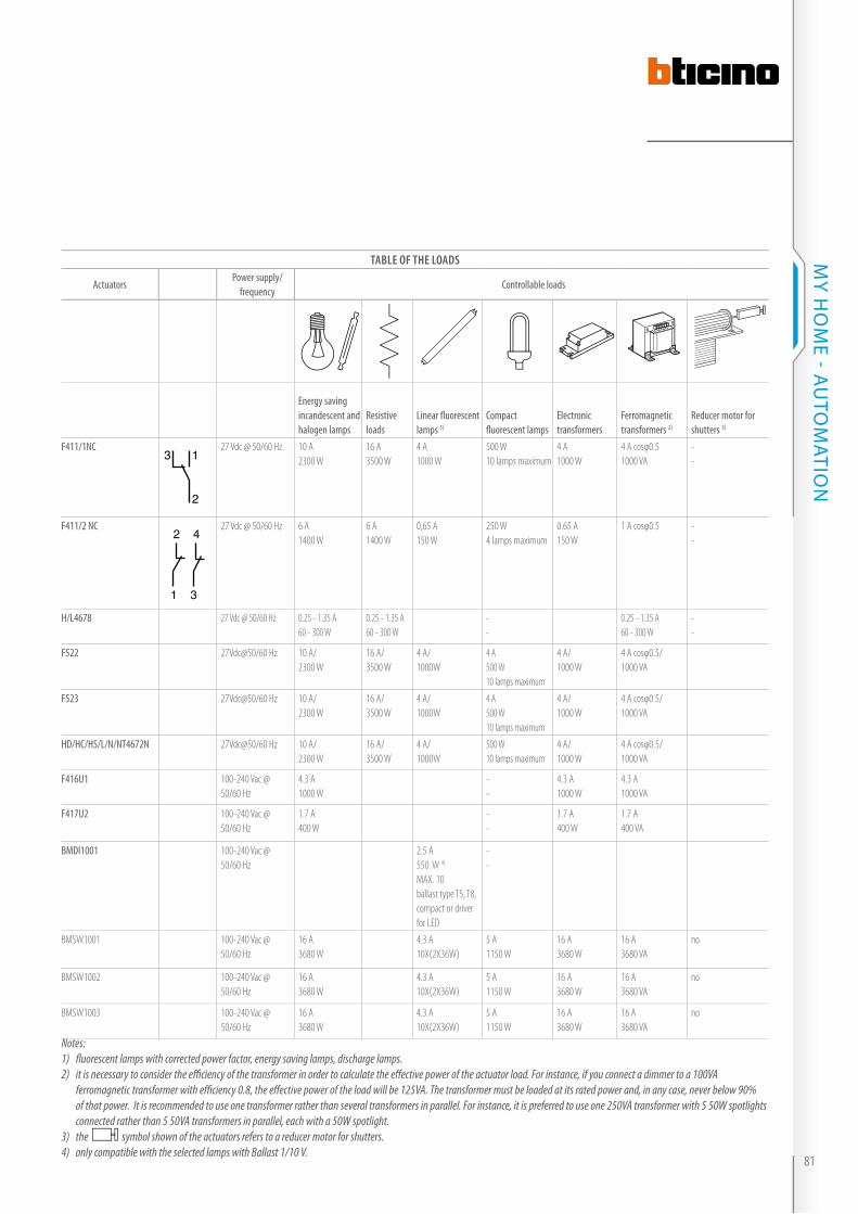
Notes:1) fl uorescent lamps with corrected power factor, energy saving lamps, discharge lamps. 2) it is necessary to consider the effi ciency of the transformer in order to calculate the eff ective power of the actuator load. For instance, if you connect a dimmer to a 100VA ferromagnetic transformer with effi ciency 0.8, the eff ective power of the load will be 125VA. The transformer must be loaded at its rated power and, in any case, never below 90% of that power. It is recommended to use one transformer rather than several transformers in parallel. For instance, it is preferred to use one 250VA transformer with 5 50W spotlights connected rather than 5 50VA transformers in parallel, each with a 50W spotlight.3) the symbol shown of the actuators refers to a reducer motor for shutters.4) only compatible with the selected lamps with Ballast 1/10 V.
Table of The loads
ActuatorsPower supply/
frequencyControllable loads
Energy saving incandescent and halogen lamps
Resistive loads
Linear fl uorescent lamps 1)
Compact fl uorescent lamps
Electronic transformers
Ferromagnetic transformers 2)
Reducer motor for shutters 3)
F411/1NC
2
1327 Vdc @ 50/60 Hz 10 A
2300 W16 A3500 W
4 A1000 W
500 W10 lamps maximum
4 A1000 W
4 A cosφ0.51000 VA
--
F411/2 NC42
31
27 Vdc @ 50/60 Hz 6 A1400 W
6 A 1400 W
0,65 A150 W
250 W4 lamps maximum
0.65 A150 W
1 A cosφ0.5 --
H/L4678 27 Vdc @ 50/60 Hz 0.25 - 1.35 A60 - 300 W
0.25 - 1.35 A60 - 300 W
--
0.25 - 1.35 A60 - 300 W
--
F522 27Vdc@50/60 Hz 10 A/2300 W
16 A/3500 W
4 A/1000W
4 A500 W 10 lamps maximum
4 A/1000 W
4 A cosφ0.5/1000 VA
F523 27Vdc@50/60 Hz 10 A/2300 W
16 A/3500 W
4 A/1000W
4 A500 W 10 lamps maximum
4 A/1000 W
4 A cosφ0.5/1000 VA
HD/HC/HS/L/N/NT4672N 27Vdc@50/60 Hz 10 A/2300 W
16 A/3500 W
4 A/1000W
500 W10 lamps maximum
4 A/1000 W
4 A cosφ0.5/1000 VA
F416U1 100-240 Vac @ 50/60 Hz
4.3 A1000 W
--
4.3 A1000 W
4.3 A1000 VA
F417U2 100-240 Vac @ 50/60 Hz
1.7 A400 W
--
1.7 A400 W
1.7 A400 VA
BMDI1001 100-240 Vac @ 50/60 Hz
2.5 A550 W 4)
MAX. 10 ballast type T5, T8, compact or driver for LED
--
BMSW1001 100-240 Vac @ 50/60 Hz
16 A3680 W
4.3 A10X(2X36W)
5 A1150 W
16 A3680 W
16 A3680 VA
no
BMSW1002 100-240 Vac @ 50/60 Hz
16 A3680 W
4.3 A10X(2X36W)
5 A1150 W
16 A3680 W
16 A3680 VA
no
BMSW1003 100-240 Vac @ 50/60 Hz
16 A3680 W
4.3 A10X(2X36W)
5 A1150 W
16 A3680 W
16 A3680 VA
no
81
MY H
OM
E - AU
TOM
ATiON

CONTACT INTERFACE IN DIN
MODULE
With this device it is possible to
connect traditional devices to the BUS,
such as switches and pushbuttons,
thus extending the use of the BUS to
traditional pre-existing systems.
It is also possible to interface
thermostats, control devices, humidity
detectors, wind detectors etc.
CONTACT INTERFACE IN BASIC
MODULE
The essential feature of this
device, due to the reduced overall
dimensions, is the rear-device
installation mode. As a result, it is
possible to install the interface in a
503E box right behind the traditional
devices (e.g. switch, pushbutton) or
behind electronic shallow devices
(e.g. controls, detectors).
It is also possible to interface
thermostats, humidity detectors,
wind detectors etc. This installation
solution simplifies the conversion of
traditional electric systems into home
automation systems, as it makes it
possible to keep the existing flush
mounted boxes, without the need for
masonry work.
Interfaces
External devices Prestige switch (reuse of historical devices)
DIN module contact interface
Basic module contact interface
AUTOMATION - GENERAL FEATURES
82

The wired automation system
described in the previous pages
can be expanded at any time by
extending the wiring or adding new
devices.
However, this is not always easy
to do; in some buildings, either
historic and/or valuable buildings,
the extension of the system entails
unavoidable and costly interventions
on the building work. To avoid the
above inconveniences, particular
radio devices may be used (controls
and actuators), which give the
possibility of adding new command
and control points for the users, in
positions that cannot be reached by
the BUS wiring. The logic connection
among these devices and those
in the BUS wiring is performed
“wirelessly” from two special
interfaces connected to the BUS:
�� a receiving interface, for the
control of any actuator of the wired
system using a radio control;
�� a transmitting interface for the
control of any radio actuators
using a wired system control.
The integration between the two
technologies, radio and wired,
enables therefore the installer to
select each time the best solution
that meets the requirements of
the customer, both in terms of
functionality, and in relation to the
homes.
This solution can also be extended,
with some advantages, to new
buildings; for example in offices
with moving walls it may be useful
to include in the system the wired
actuators in the false ceiling, and
use the radio controls to easily move
the walls to change the layout of
buildings and furniture.
Power cable and Automation BUS
Power cable
Wire Automation extension with radio devices
Practical example of a wire system with the addition of a radio control
Radio receiving interface
Radio control
Radio actuatorRadio actuator
83
MY H
OM
E - AU
TOM
ATiON

Wire Automation extension with radio devices
wire/rAdio eXtension Mode
1. Addition of one or more radio
control points
This is done by installing a receiving
interface in the BUS wire system by
means of which one or more wire
devices (actuators, module scenarios
etc.) can be managed with radio
controls.
This mode is useful whenever one
wants to add not originally planned
control points to the existing system
or to manage a new system from
positions which the BUS cannot
reach.
Radio receiving interface
Existing rolling shutter control
Light control
TV/SAT IPTV
TV/SAT IPTVLight actuator
Shutter actuator
Radio receiving interface
Light actuator
Shutter actuator
Power supply
Radio remote control
Extra radio control for rolling shutterrolling shutterrolling shutter
11 Extension of wire system with bus to control the rolling shutter with radio control and with a convenient remote control.
230 Vac
Light Shutters
TV/SAT IPTV
automazione di�usione sonora antifurto termoregolazione videocitofonia controllo controllo carichilan energia luci tvcc www irrigazione
TV/SAT IPTV
automazione di�usione sonora antifurto termoregolazione videocitofonia controllo controllo carichilan energia luci tvcc www irrigazione
auTOmaTiON - GENERAL FEATURES
84
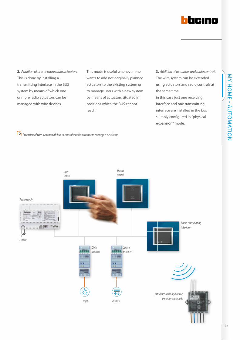
2. Addition of one or more radio actuators
This is done by installing a
transmitting interface in the BUS
system by means of which one
or more radio actuators can be
managed with wire devices.
Shutter control
Light control
TV/SAT IPTV
TV/SAT IPTVLight actuator
Shutter actuator
Light actuator
Shutter actuator
3. Addition of actuators and radio controls
The wire system can be extended
using actuators and radio controls at
the same time.
in this case just one receiving
interface and one transmitting
interface are installed in the bus
suitably configured in “physical
expansion” mode.
This mode is useful whenever one
wants to add not originally planned
actuators to the existing system or
to manage users with a new system
by means of actuators situated in
positions which the BUS cannot
reach.
Power supply
Radio transmitting interface
Attuatore radio aggiuntivo per nuova lampada
22 Extension of wire system with bus to control a radio actuator to manage a new lamp
230 Vac
Light Shutters
TV/SAT IPTV
automazione di�usione sonora antifurto termoregolazione videocitofonia controllo controllo carichilan energia luci tvcc www irrigazione
TV/SAT IPTV
automazione di�usione sonora antifurto termoregolazione videocitofonia controllo controllo carichilan energia luci tvcc www irrigazione
85
MY H
OM
E - AU
TOM
ATiON
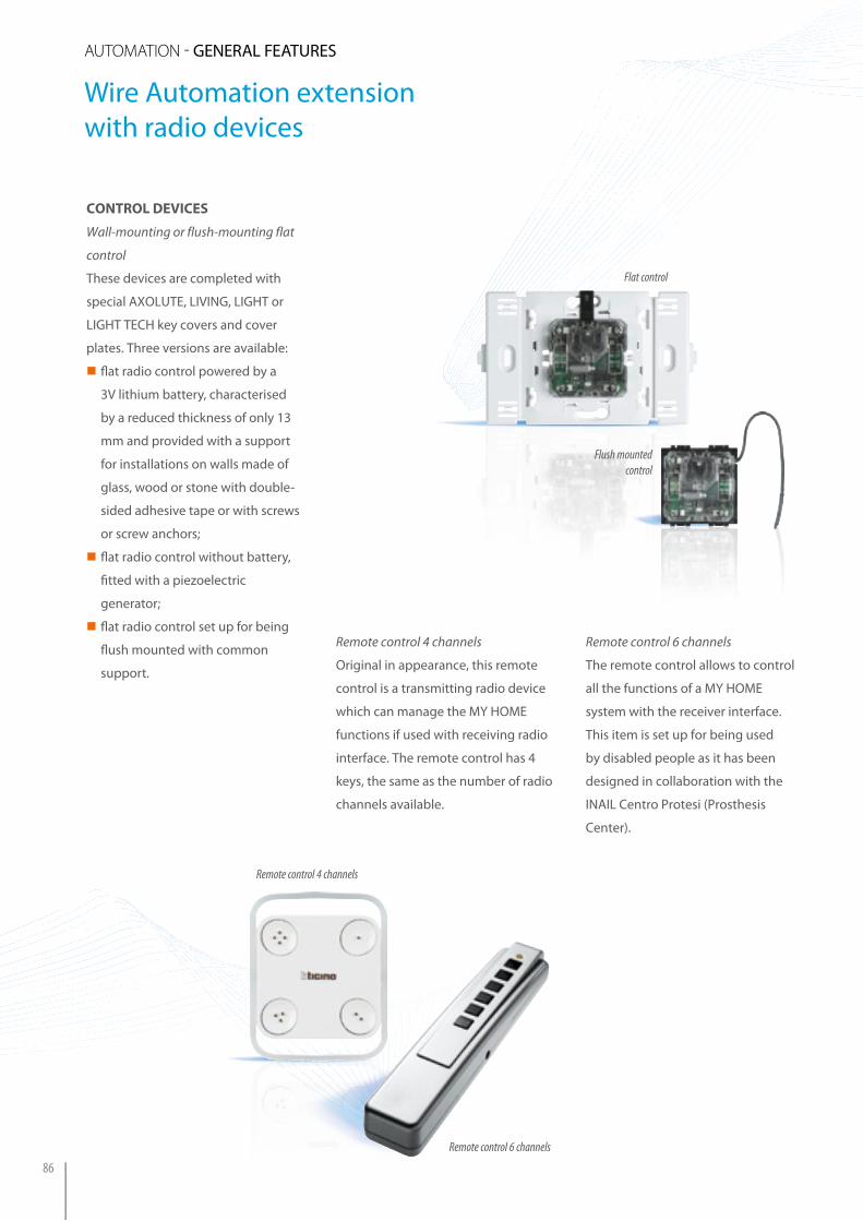
control devices
Wall-mounting or flush-mounting flat
control
These devices are completed with
special AXOLUTE, LiViNG, LiGHT or
LiGHT TECH key covers and cover
plates. Three versions are available:
�� fl at radio control powered by a
3V lithium battery, characterised
by a reduced thickness of only 13
mm and provided with a support
for installations on walls made of
glass, wood or stone with double-
sided adhesive tape or with screws
or screw anchors;
�� fl at radio control without battery,
fi tted with a piezoelectric
generator;
�� fl at radio control set up for being
fl ush mounted with common
support.
Remote control 6 channels
The remote control allows to control
all the functions of a MY HOME
system with the receiver interface.
This item is set up for being used
by disabled people as it has been
designed in collaboration with the
iNAiL Centro Protesi (Prosthesis
Center).
Remote control 4 channels
Original in appearance, this remote
control is a transmitting radio device
which can manage the MY HOME
functions if used with receiving radio
interface. The remote control has 4
keys, the same as the number of radio
channels available.
Remote control 4 channels
Flat control
Flush mounted control
Remote control 6 channels
Wire Automation extension with radio devices
auTOmaTiON - GENERAL FEATURES
86

MaIN fUNCTIoNs
Radio remote control
ON/OFF lights with dimmer
UP/DOWN shutters
Video door entry system (4)
Sound system management
Call (R) Scenario or Programming (P)
CEN control (5)
Auxiliary channels
Radio interface
Interface functioning mode
Interface mode confi guration
3528R
HC/HS4575L/N/NT4575N
Self-learning (2) M=0
PRemote scenarios M=6–8 (1)
Scenario programmer
M=CEN
3527R
Self-learning (2) M=0
P
Remote scenarios M=6–8 (1)
Scenario programmer
M=CEN
H/L4572PIHA/HB/L4572
R
Physical expansion (3)
M=1
HA/HB/L4572SBR
HC/HS-4575SBL/N/NT4575SB
Self-learning (2) SPE=0
Automation SPE=1
PRemote scenarios SPE=6
Sound system SPE=8
Video door entry system
SPE=9
Notes:(1) Correspondence between the radio control pushbuttons and the scenarios saved (item F420). See “Confi guration” section for details(2) Mode which associates a function performed by the control or system actuator to each pushbutton(3) Extension of the wire system with radio controls (4) Electric door lock, staircase lights, call to the fl oor, self-switching ON and cycle camera control. The last 2 functions are only available with video modulator item F442.(5) Control to manage the scenario programmer item MH200.
rAdio controls - functions perforMed And Mode of interfAcing with the wire AutoMAtion systeM
87
MY H
OM
E - AU
TOM
ATiON
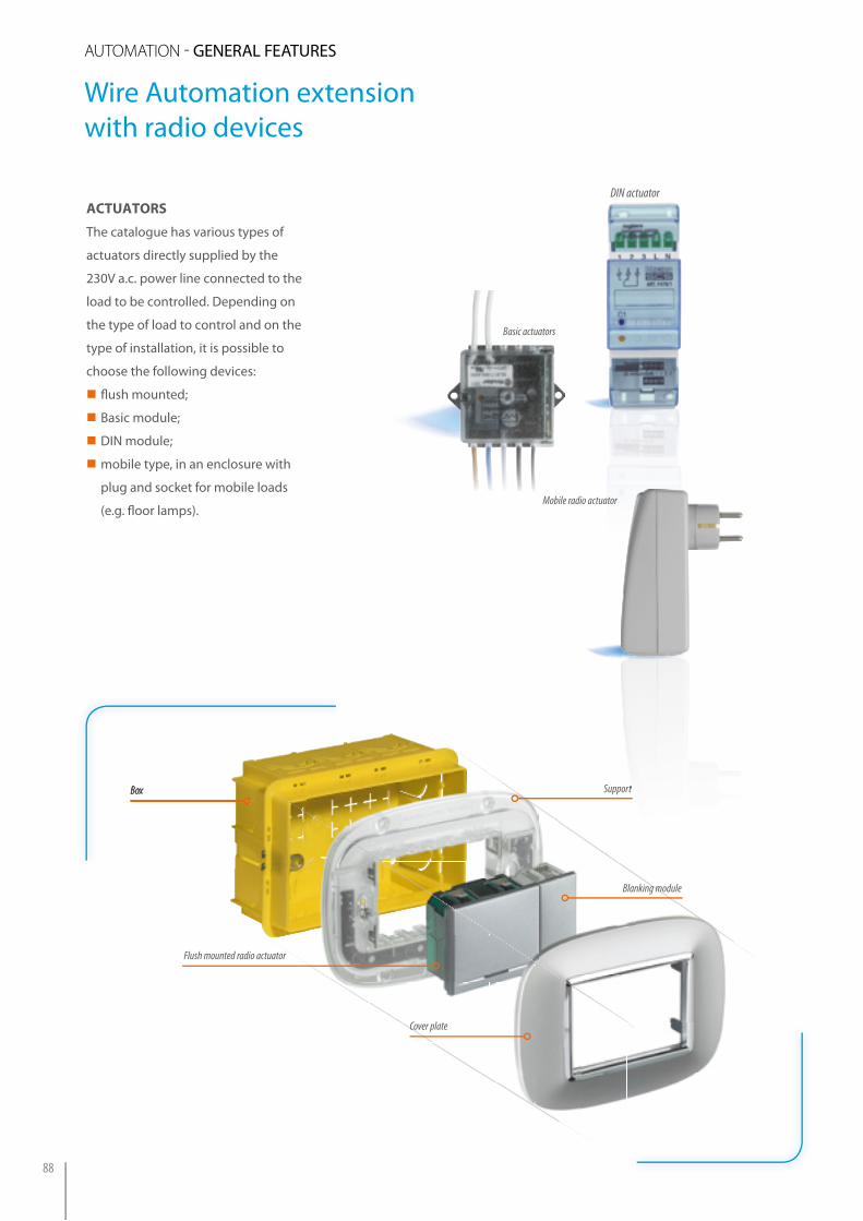
ActuAtors
The catalogue has various types of
actuators directly supplied by the
230V a.c. power line connected to the
load to be controlled. Depending on
the type of load to control and on the
type of installation, it is possible to
choose the following devices:
�� fl ush mounted;
�� Basic module;
�� DiN module;
�� mobile type, in an enclosure with
plug and socket for mobile loads
(e.g. fl oor lamps).
Basic actuators
Mobile radio actuator
Box Support
Blanking module
Box
DIN actuator
Support
Flush mounted radio actuator
Cover plate
Wire Automation extension with radio devices
auTOmaTiON - GENERAL FEATURES
88

INsTallaTIoN Mode
oN/off lIGhTING aNd loads
CURTaIN aNd shUTTeR MaNaGeMeNT
AXOLUTELIVING/LIGHT/
LIGHT TECHAXOLUTE
LIVING/LIGHT/
LIGHT TECH
Radio
actu
ator
wi
th 2
relay
s
Flush mounted.To be completed with key cover.
H4573/2 L4573/2 H4573/2 L4573/2
Radio
actu
ator
wi
th 1
relay
Flush mounted. To be completed with key cover.
H4574 L4574
Basic
radio
ac
tuat
or
Flush mounted 3470
Mob
ile ra
dio
actu
ator
In an electric system socket, mobile 35263526/103526/16
Radio
ac
tuat
or
In DIN switchboard F470/1F470/2
F470/2
overview of the ActuAtors
This table lists the radio actuators divided by type of use.
89
MY H
OM
E - AU
TOM
ATiON
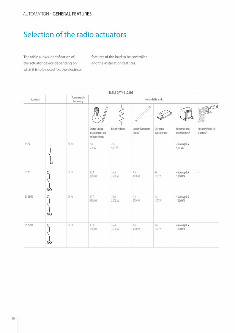
Selection of the radio actuators
The table allows identification of
the actuator device depending on
what it is to be used for, the electrical
Table of The loads
ActuatorsPower supply
frequencyControllable loads
Energy saving incandescent and halogen lamps
Resistive loads Linear fluorescent lamps 1)
Electronic transformers
Ferromagnetic transformers 2)
Reducer motor for shutters 3)
3470
P L
L
L1
PLA
G1M
G2
50 Hz 2 A500 W
2 A500 W
- - 2 A cosφ0.5500 VA
-
3526 C
NO
50 Hz 10 A2300 W
16 A3500 W
4 A1000 W
4 A1000 W
4 A cosφ0.51000 VA
-
3526/10 C
NO
50 Hz 10 A2300 W
10 A2300 W
4 A1000 W
4 A1000 W
4 A cosφ0.51000 VA
-
3526/16 C
NO
50 Hz 10 A2300 W
16 A3500 W
4 A1000 W
4 A1000 W
4 A cosφ0.51000 VA
-
features of the load to be controlled
and the installation features.
auTOmaTiON - GENERAL FEATURES
90

Notes:1) fl uorescent lamps with corrected power factor, energy saving lamps, discharge lamps. 2) it is necessary to consider the effi ciency of the transformer in order to calculate the eff ective power of the actuator load. For instance, if you connect a dimmer to a 100 Va ferromagnetic transformer with effi ciency 0.8, the eff ective power of the load will be 125 Va. The transformer must be loaded at its rated power and, in any case, never below 90% of that power. It is recommended to use one transformer rather than several transformers in parallel. For instance, it is preferred to use one 250 Va transformer with 5 50 W spotlights connected rather than 5 50 Va transformers in parallel, each with a 50 W spotlight.3) the symbol shown on the actuators refers to a reducer motor for shutters.
Table of The loads
ActuatorsPower supply
frequencyControllable loads
Energy saving incandescent and halogen lamps
Resistive loads Linear fl uorescent lamps 1)
Electronic transformers
Ferromagnetic transformers 2)
Reducer motor for shutters 3)
F470/1
3
12 50 Hz 6 A1400 W
10 A2300 W
1 A230 W
1 A230 W
2 A cosφ0.5500 VA
-
F470/2
2 1
350 Hz 2 A
500 W6 A1400 W
0.3 A70 W
0.3 A70 W
2 A cosφ0.5500 VA
2 A500 W
H/L4573/2
C2C1
L 50 Hz 2 A500 W
2 A500 W
- - 2 A cosφ0.5500 VA
2 A500 W
H/L4574
C1
L
C2
50 Hz 0.2 – 2 A50 – 500 W
0.2 – 2 A50 – 500W
0.05 –0.3A12 – 70W
0.05 – 0.3 A12 – 70 W
0.2 –2 A cosφ0.550 – 500 VA
-
91
MY H
OM
E - AU
TOM
ATiON
General concepts
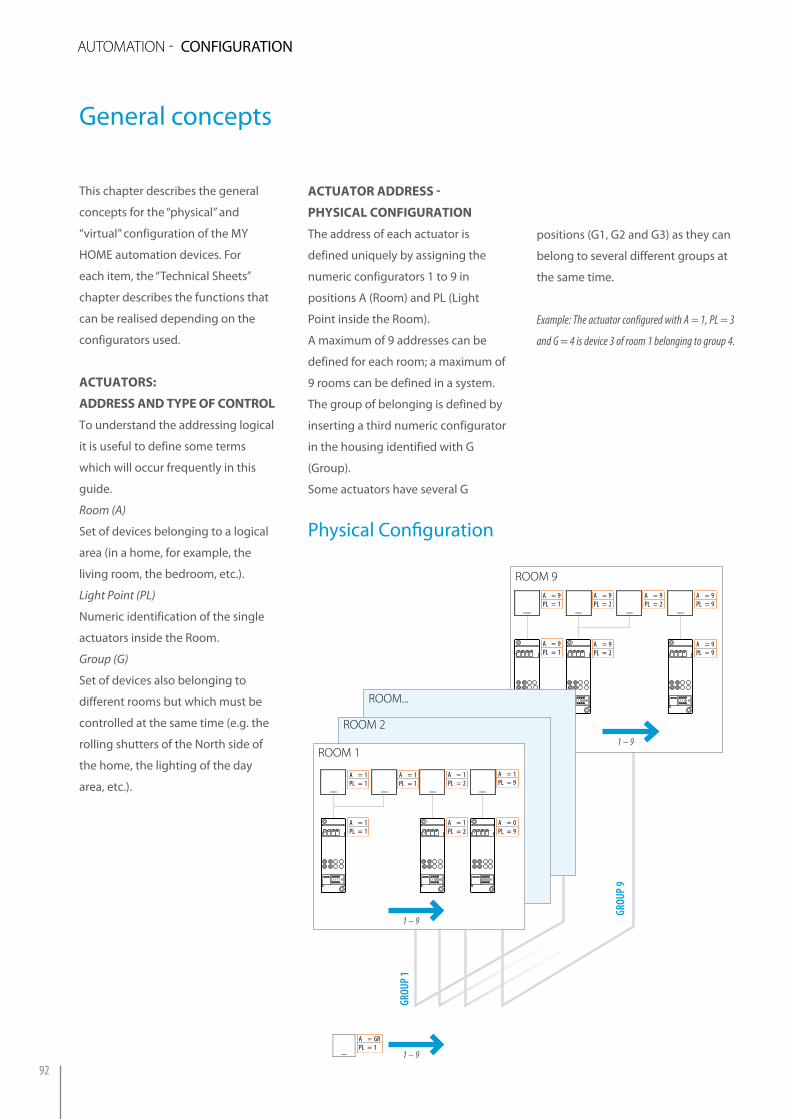
This chapter describes the general
concepts for the “physical” and
“virtual” configuration of the MY
HOME automation devices. For
each item, the “Technical Sheets”
chapter describes the functions that
can be realised depending on the
configurators used.
ActuAtors:
Address And type of control
To understand the addressing logical
it is useful to define some terms
which will occur frequently in this
guide.
Room (A)
Set of devices belonging to a logical
area (in a home, for example, the
living room, the bedroom, etc.).
Light Point (PL)
Numeric identification of the single
actuators inside the Room.
Group (G)
Set of devices also belonging to
different rooms but which must be
controlled at the same time (e.g. the
rolling shutters of the North side of
the home, the lighting of the day
area, etc.).
ActuAtor Address -
physicAl configurAtion
The address of each actuator is
defined uniquely by assigning the
numeric configurators 1 to 9 in
positions A (Room) and PL (Light
Point inside the Room).
A maximum of 9 addresses can be
defined for each room; a maximum of
9 rooms can be defined in a system.
The group of belonging is defined by
inserting a third numeric configurator
in the housing identified with G
(Group).
Some actuators have several G
ROOM 9
ROOM...
ROOM 2
ROOM 1
A = 1PL = 1
A = 1PL = 1
A = 1PL = 1
A = 1PL = 2
A = 1PL = 2
A = 1PL = 9
A = 0PL = 9
1 – 9
1 – 9
GRoU
P 1
GRoU
P 9
A = 9PL = 2
A = 9PL = 1
A = 9PL = 1
A = 9PL = 2
A = 9PL = 2
A = 9PL = 9
A = 9PL = 9
1 – 9
A = GRPL = 1
positions (G1, G2 and G3) as they can
belong to several different groups at
the same time.
Example: The actuator configured with A = 1, PL = 3
and G = 4 is device 3 of room 1 belonging to group 4.
Physical Configuration
92
auTOmaTiON - CONFiGURATiON
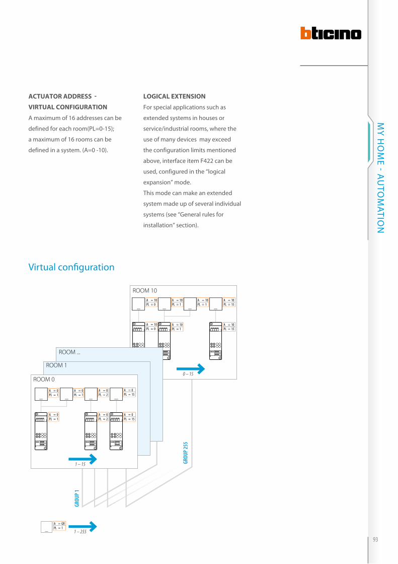
logicAl eXtension
For special applications such as
extended systems in houses or
service/industrial rooms, where the
use of many devices may exceed
the configuration limits mentioned
above, interface item F422 can be
used, configured in the “logical
expansion” mode.
This mode can make an extended
system made up of several individual
systems (see “General rules for
installation” section).
ActuAtor Address -
virtuAl configurAtion
A maximum of 16 addresses can be
defined for each room(PL=0-15);
a maximum of 16 rooms can be
defined in a system. (A=0 -10).
ROOM 10
ROOM ...
ROOM 1
ROOM 0
A = 0PL = 1
A = 0PL = 1
A = 0PL = 1
A = 0PL = 2
A = 0PL = 2
A = 0PL = 15
A = 0PL = 15
1 – 15
1 – 255
GRoU
P 1
GRoU
P 255
A = 10PL = 1
A = 10PL = 0
A = 10PL = 0
A = 10PL = 1
A = 10PL = 1
A = 10PL = 15
A = 10PL = 15
0 – 15
A = GRPL = 1
Virtual confi guration
93
MY H
OM
E - AU
TOM
ATiON

controls: Address And type
of control
The control devices also have
positions A and PL to define the
addresses of the devices which
receive the control (actuators).
For these positions there are numeric
TYPe of CoNTRol CoNTRol deVICe
confi gurator socket value of the confi gurator
Point-pointAPL
1-91-9
RoomAPL
AMB1-9
GroupAPL
GR1-9
GeneralAPL
GEN-
TYPe of CoNTRol CoNTRol deVICe
Confi gurable address Confi guration
Point-pointAPL
0-100-15
RoomAPL
AMB0-10
GroupAPL
GR1-255
GeneralAPL
GEN-
configurators with graphics which
enable the device to send the control
with the various ways listed in the
table below.
Mode for addressing the devices using the Physical Configuration Mode for addressing the devices using the Virtual Configuration
TYPe of CoNTRol CoNTRol deVICe
confi gurator socket
Point-pointAPL
RoomAPL
A
Mode for addressing the devices using the Physical Configuration
GR1-255
GEN-
General features
auTOmaTiON - CONFiGURATiON
94
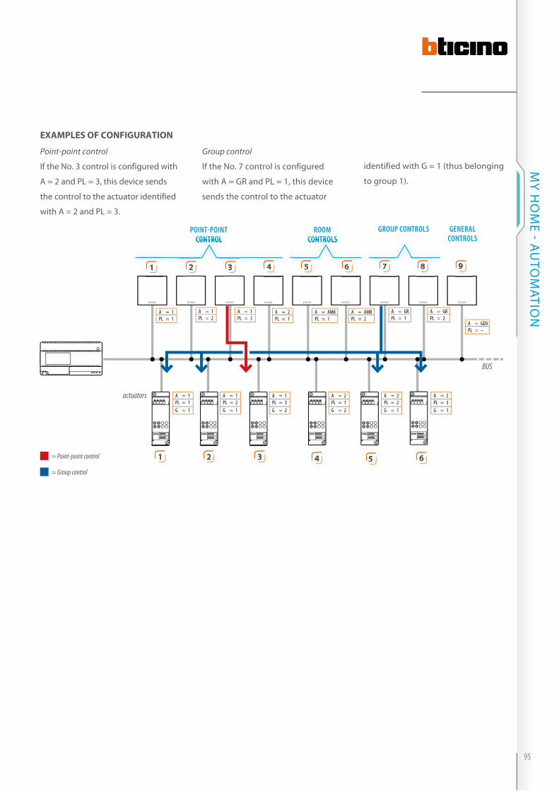
Group control
if the No. 7 control is configured
with A = GR and PL = 1, this device
sends the control to the actuator
Point-point control
if the No. 3 control is configured with
A = 2 and PL = 3, this device sends
the control to the actuator identified
with A = 2 and PL = 3.
eXAMples of configurAtion
PoINT-PoINTCoNTRol
RooM CoNTRols
GRoUP CoNTRols GeNeRal CoNTRols
actuators
BUS
= Point-point control
= Group control
A = 1PL = 3
A = 1PL = 2
A = 1PL = 1
A = 2PL = 1
A = AMBPL = 1
A = AMBPL = 2
A = GRPL = 1
A = GRPL = 2
A = GENPL = –
A = 1PL = 1G = 1
A = 1PL = 2G = 1
A = 1PL = 3G = 2
A = 2PL = 1G = 2
A = 2PL = 2G = 1
A = 2PL = 3G = 1
identified with G = 1 (thus belonging
to group 1).
CoNTRol CoNTRols
11
11
22
222
33
333
44
444
55
555
66
666 777 888 99
95
MY H
OM
E - AU
TOM
ATiON

For a better understanding of the
concepts described in the previous
page, the four addressing modes are
described below.
The control devices (senders) can
activate the actuators (receivers) with
the following modes.
point-point control
Direct control to one actuator
identified by a “room number” and a
“light point number”.
rooM control
Direct control to all the actuators
identified by the same room number.
Control device: A = n* PL = n*
Actuator: A = n* PL = n*
Control device: A = AMB PL = n*
Actuator: A = n* PL = n*
Example: control for a single load (lamp, fan, rolling shutter, etc.)
n* = any numeric confi gurator from 1 to 9
Addressing levels
Example: control for all the lamps of a room
TV/SAT IPTV
A = 1PL = 1
A = 1PL = 2
A = 1PL = 3
TV/SAT IPTVTV/SAT IPTV
A = 2PL = 1
A = 2PL = 2
A = 2PL = 3
TV/SAT IPTVTV/SAT IPTV
RooM 1RooM 1 RooM 2RooM 2
A = 1PL = 1
A = 1PL = 2
A = 1PL = 3
A = 2PL = 1
A = 2PL = 2
A = 2PL = 3
A = 1PL = 1
A = 1PL = 2
A = 1PL = 3
A = 2PL = 1
A = 2PL = 2
A = 2PL = 3
RooM 1RooM 1 RooM 2RooM 2
A = 1PL = 1
A = 1PL = 2
A = 1PL = 3
A = 2PL = 1
A = 2PL = 2
A = 2PL = 3
A = AMBPL = 1
A = AMBPL = 2
auTOmaTiON - CONFiGURATiON
96

group control
Direct control to all the actuators
which perform particular functions
even if they belong to different
rooms and are identified by the same
“group number”.
Example: control of all the lamps of a fl oor, on the North side of the building
Control device: A = GR PL = n*
Actuator: A = n* PL = n* G = n*
A = 1PL = 1
A = 1PL = 2
A = 1PL = 3
A = 2PL = 1
A = 2PL = 2
A = 2PL = 3
RooM 1RooM 1 RooM 2RooM 2
A = AMBPL = 1
A = AMBPL = 2
A = GRPL = 1
A = GRPL = 2
A = 1PL = 2G = 1
A = 1PL = 3G = 2
A = 1PL = 1G = 1
A = 2PL = 2G = 1
A = 2PL = 3G = 1
A = 2PL = 1G = 2
97
MY H
OM
E - AU
TOM
ATiON
A = AMBPL = 1
A = AMBPL = 2
A = 1PL = 1
A = 1PL = 2
A = 1PL = 3
A = 2PL = 1
A = 2PL = 2
A = 2PL = 3
RooM 1RooM 1 RooM 2RooM 2
A = GRPL = 1
A = GRPL = 2
A = 1PL = 2G = 1
A = 1PL = 3G = 2
A = 1PL = 1G = 1
A = 2PL = 2G = 1
A = 2PL = 3G = 1
A = 2PL = 1G = 2
A = GENPL = -
Addressing levels
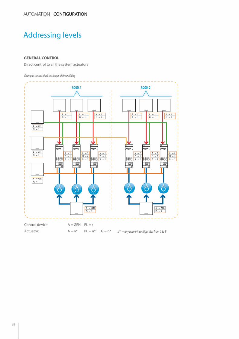
generAl control
Direct control to all the system actuators
n* = any numeric configurator from 1 to 9
Example: control of all the lamps of the building
Control device: A = GEN PL = /
Actuator: A = n* PL = n* G = n*
auTOmaTiON - CONFiGURATiON
98

The devices in the automation system
can perform different functions, such
as setting the brightness, switching
lamps on/off or opening/closing
rolling shutters.
The function performed, i.e. what the
device must do, is defined by putting
configurators into the housings
marked with M of the control devices
and completing the devices with
keys and key covers (if the devices
CONTROL TABLEKey covers Con� gurator value (M) Function performed
1 function
M
M ON
M OFF
M O / I
M
M
M
M
M SLA
M
SPE 1√8
1√8
PUL
1√8M 1√4
M
no con� gurator
Cyclical ON-OFF control Repeatedly pressing the relay actuators device key cover, ON and OFF controls will be sent in a cyclical way. With dimmer actuators, keep the pushbutton pressed to adjust the load power.
M
M ON
M OFF
M O / I
M
M
M
M
M SLA
M
SPE 1√8
1√8
PUL
1√8M 1√4
M
con� gurator ON
ON controlWhen pressing the corresponding key cover, the device sends the ON control.
M
M ON
M OFF
M O / I
M
M
M
M
M SLA
M
SPE 1√8
1√8
PUL
1√8M 1√4
M
con� gurator OFF
OFF controlWhen pressing the corresponding key cover, the device sends the OFF control.
M
M ON
M OFF
M O / I
M
M
M
M
M SLA
M
SPE 1√8
1√8
PUL
1√8M 1√4
M
con� gurator PUL
Monostable ON-OFF control (pushbutton) This mode can perform an ON/OFF control similar to the control of a traditional point-point pushbutton, thus intended just for one address.
2 FUNCTION
M
M ON
M OFF
M O / I
M
M
M
M
M SLA
M
SPE 1√8
1√8
PUL
1√8M 1√4
M
con� gurator
Bistable control with hold (UP-DOWN for rolling shutters)Pressing the key cover (lower or upper) sends the UP-DOWN control to the rolling shutter motor. After the con-trol has been sent, press the lower or upper key cover again, to stop the rolling shutter in the required position.
M
M ON
M OFF
M O / I
M
M
M
M
M SLA
M
SPE 1√8
1√8
PUL
1√8M 1√4
M
con� gurator M
Monostable control (UP-DOWN for rolling shutters)The device sends an UP-DOWN control for a rolling shutter motor as long as the lower or upper key cover is pressed. When the key cover is released, the motor STOPS.
M
M ON
M OFF
M O / I
M
M
M
M
M SLA
M
SPE 1√8
1√8
PUL
1√8M 1√4
M
con� gurator O/I
ON/OFF control Used with relay actuators, when the upper key cover is pressed the device sends an ON control; when the lower key cover is pressed the device sends an OFF control.With dimmer actuators, pressing the upper and lower key cover adjusts the load power.
are flush mounted). The table below
lists the various operating modes as a
function of the configurator and type
of key cover used in the device.
Main operating modes
99
MY H
OM
E - AU
TOM
ATION

Type of control Configuration Identification of scenario activation keysSpecial controlH/L4651M2 and AM5831M2
A=0–9; PL=0–9; M=CEN; LIV1/AUX=0; LIV2=0; SPE=0; I=0 T1
Basic control for 2 independent loadsH/L4652/2 and AM5832/2
A1=0–9; PL1=0–9; M1=CEN; A2=0; PL2=0; M2=0 T2T1
A1=0–9; PL1=0–9; M1=CEN; A2=0; PL2=0; M2=CEN T2T1 T2
Basic control for 3 independent loadsH/L4652/3 and AM5832/3
A1=0–9; PL1=0–9; A2=0; PL2=0; A3=0; PL3=0; M=CEN T3 T4T1 T2
T4 T5
T3
T6
ACTUATOR TABLEConfigurator value (M) Function performed
M
M ON
M OFF
M O / I
M
M
M
M
M SLA
M
SPE 1√8
1√8
PUL
1√8M 1√4
M
configurator 1÷4
Special functionsThis mode can perform special functions (OFF delayed, STOP timed) on the basis of the type of actuator used (single or double) and the numeric configurator inserted.
M
M ON
M OFF
M O / I
M
M
M
M
M SLA
M
SPE 1√8
1√8
PUL
1√8M 1√4
M
configurator SLA
SlaveThis mode can perform a control with two or more actuators. In practice the actuators with the SLA (Slave) configurator repeat the function performed by another actuator which acts as Master.The actuators must have the same addresses and must be of the same type (either all light actuators or all rolling shutter actuators).
M
M ON
M OFF
M O / I
M
M
M
M
M SLA
M
SPE 1√8
1√8
PUL
1√8M 1√4
M
configurator PUL
PULThe device does not operate with the Room and General controls.
Main actuator operating Modes
The actuators can be configured for the following operating modes:
cen operating Mode
This particular mode is used to
manage scenario programmer
devices item MH200N.
As described in the pages of this
guide, the device can manage
even complex scenarios activated
automatically after events in the
system or manually by pressing a
key of a control device configured
with the CEN configurator in the M
position. The key (upper or lower) of
the control device and the scenario
to be activated are linked through
the TiMH200 program written to
create the scenarios and then saving
them in the MH200N device.
For example, two independent
scenarios can be activated using
the special control H/L4651M2,
AM5831M2, by pressing the T1
(upper) and T2 (lower) pushbuttons.
For the correspondence between
the control keys and the scenarios to
activate see the table:
Main operating modes
automation - CoNFigurATioN
100

Examples of confi guration
The drawing shows a system for
the management of three lamps
and three shutters. Each actuator is
identified by three numbers: Room
number (A), device progressive
number (PL for light actuators and
PL1 and PL2 for shutter actuators)
and Group (G) of belonging.
defining the Addresses
Point-point control
Control 1 (A = 1, PL = 1) controls
actuators 1 (A = 1, PL = 1 and G = 1).
in the same way control 2 (A = 1,
PL = 2) controls actuator 2 (A = 1,
PL = 2 and G = 1) etc..
Room control
Room control 8 (A=AMB, PL=2)
controls actuators 4 and 5 marked
with A=2
Group control
Group control 7 marked with A=GR
and PL=1, controls actuators 1 and 2
marked with G=1
General control
The devices identified A=GEN and
PL= - (no configurator) send a general
control to all the actuators, for the
lights and for the shutters, in the
system.
NOTE: The actuators which manage the shutters,
unlike those for the lights, are configured in the same
way in the two positions PL1 and PL2.
The control devices are instead
distinguished from the configurators
in positions A and PL which specify
the addresses of the actuators
receiving the control (one only, a
BUS
A = 1PL = 1M = O/I
A = 1PL = 1G = 1
A = 1PL = 2G = 1
A = 1PL = 3G = 2
A = 2PL = 1G = 1
A = 2PL = 2G = 2
A = 3PL = 1G = 1
A = 1PL = 2M = O/I
A = 1PL = 3M = O/I
A = 2PL = 1M = M
A = 2PL = 2M = M
A = 3PL = 1M = M
A = GRPL = 1M = O/I
A = GENPL = –M = O/I
A = AMBPL = 2M = M
A = GENPL = –M = M
PoINT-PoINTCoNTRol
RooM CoNTRols
GRoUP CoNTRols
GeNeRal CoNTRolsCoNTRol CoNTRols CoNTRols
11
1A = 1
1
22
2A = 1
2
33
3A = 1
3
44
4A = 2
4
55
5A = 2
5
66
6A = 3
6
77 88 99 1010
actuators
group or several room actuators) and
from the configurators in position
M to define the function (ON/OFF or
ON/DOWN).
control operAting Mode
The configurator inserted in position
M of each control device identifies
the operating mode.
The O/i configurator specifies a lamp
switching on control which is given
by pressing the upper key cover (ON)
and the lower key cover (OFF).
The configurators and M in
position M instead specify a control
to manage the rolling shutters
intended for actuators 4, 5 and 6.
101
MY H
OM
E - AU
TOM
ATiON

Maximum distances and absorptions
This chapter outlines the details for
ensuring a correct realisation of a MY
HOME automation system:
�� Selv classifi cation
�� Maximum distances and
absorptions
�� Maximum number of devices
which can be confi gured
selv clAssificAtion
The automation system is SELV
(Safety Extra Low Voltage) classified
due to the fact that it is powered
using double safety insulation
independent devices, not connected
to the earth, and with maximum
operating voltage of 27 Vdc, non-
undulated, in accordance with CEi EN
600065. it is therefore comparable
to a SELV source as described in
point 411.125 of CEi 64-8-4. The
conformity to SELV classification
is only guaranteed subject to full
compliance with current installation
regulations, and with the general
rules for installation for each single
device and cable making up the
system recommended by BTicino.
MAXiMuM distAnces of the
Bus cABle And ABsorptions
The maximum number of devices
that can be connected to the BUS
depends on their total absorption
and on the distance between the
connection point and the power
supply. The power supply unit can
deliver up to 1200 mA or 600 mA;
ihence, the maximum number of
devices will be determined by the
sum of the absorptions of the single
devices you need to install.
22 The total length of the connections must not be more than 500 metres (extended cable).
Device Junction boxPower supply
Device Junction boxPower supply
11 The connection between the power supply and the furthest away device must not be longer than 250m.
For the purpose of the above
calculations, refer to the TECHNiCAL
DATA shown in the Technical Sheets
chapter.
When calculating the absorptions,
it is also necessary to consider the
availability of current according to
the length of the cable.
When setting up, please observe the
following rules:
auTOmaTiON -
102
GENERAL RULES FOR iNSTALLATiON
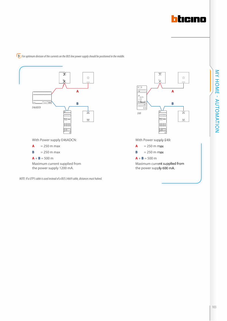
33 For optimum division of the currents on the BUS line power supply should be positioned in the middle.
NOTE: If a UTP5 cable is used instead of a BUS L4669 cable, distances must halved.
4321
C1 C2
1
C3 C4
55432
ON
OFF
E46ADCN
PRI
E49PRI: 220 – 240 V~ 185 – 175 mA 50/60 Hz
SCS: 27 Vdc 600 mA
SCS
4321
C1 C2
1
C3 C4
55432
ON
OFF
E49
With Power supply E46ADCN:
A = 250 m max
B = 250 m max
A + B = 500 mMaximum current supplied from the power supply 1200 mA.
With Power supply E49:
A = 250 m max
B = 250 m max
A + B = 500 mMaximum current supplied from the power supply 600 mA.
AA
BB
ON
OFF
With Power supply E49:
= 250 m max
= 250 m max
Maximum current supplied from the power supply 600 mA.
103
MY H
OM
E - AU
TOM
ATiON

Maximum distances and absorptions
MAXiMuM distAnces for the
connection of ActuAtors
depending on the loAd
in order to manage some types of
loads correctly, it is necessary to
observe the installation specifications
for all actuators used.
�� Fluorescent lamps: the length of
the connecting cable between the
actuator and the load must not
be less than 3m. Do not connect
more than 15 actuators controlling
this type of lamp on the same line.
�� Metallic iodide and sodium-
vapor lamps: in addition to
the indications given for the
fl uorescent lamps, please pay
attention to the operating
instructions of these lamps (for
example, avoid switching on when
hot), do not connect dimmers to
the same line of these lamps, keep
the bus line and the power line of
these lamps separated from each
other (at least 1 metre)
�� Three-phase networks: when using
three-phase networks, check the
balance of the phases as well as
the quality of the network.
Non-compliance of the above
regulations may affect proper
operation of the devices.
MAXiMuM distAnce for
connecting the contAct
interfAce
The connection between the
interface (basic or DiN module) and
the traditional type device must not
exceed 50 metres in length. Several
pushbuttons may be connected to
the interface inputs.
PL1 CPL2
SPEMPL2
APL1
BUS
Prestige switch (reuse of historical devices)
50 m
(reuse of historical devices)
PL1
SPEMPL2
APL1
C1
1 2 3
F411/1N 1 2 L N
N
L
MIN 3 m
3
Example of connection with itemF411/1N
Maximum distances for connecting the contact interface
N
Example of connection with itemF411/1N
Warning: Refer to the technical data shown on the technical sheets for each actuator
auTOmaTiON - GENERAL RULES FOR iNSTALLATiON
104
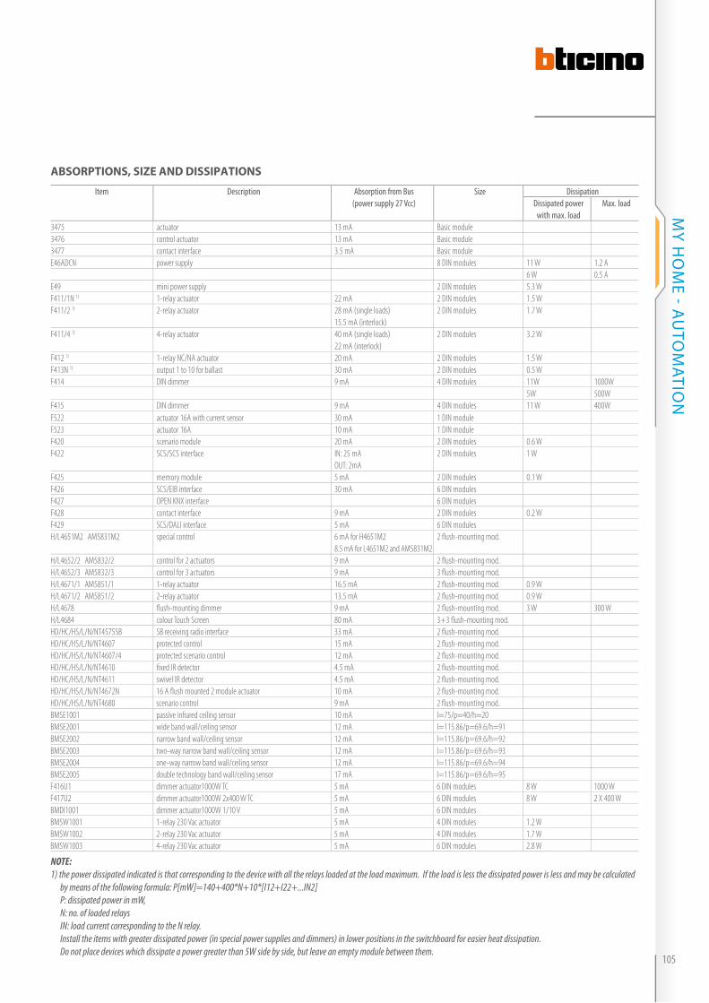
Item Description Absorption from Bus (power supply 27 Vcc)
Size DissipationDissipated power
with max. loadMax. load
3475 actuator 13 mA Basic module3476 control actuator 13 mA Basic module3477 contact interface 3.5 mA Basic moduleE46ADCN power supply 8 DIN modules 11 W 1.2 A
6 W 0.5 AE49 mini power supply 2 DIN modules 5.3 WF411/1N 1) 1-relay actuator 22 mA 2 DIN modules 1.5 WF411/2 1) 2-relay actuator 28 mA (single loads)
15.5 mA (interlock)2 DIN modules 1.7 W
F411/4 1) 4-relay actuator 40 mA (single loads)22 mA (interlock)
2 DIN modules 3.2 W
F412 1) 1-relay NC/NA actuator 20 mA 2 DIN modules 1.5 WF413N 1) output 1 to 10 for ballast 30 mA 2 DIN modules 0.5 WF414 DIN dimmer 9 mA 4 DIN modules 11W 1000W
5W 500WF415 DIN dimmer 9 mA 4 DIN modules 11 W 400WF522 actuator 16A with current sensor 30 mA 1 DIN moduleF523 actuator 16A 10 mA 1 DIN moduleF420 scenario module 20 mA 2 DIN modules 0.6 WF422 SCS/SCS interface IN: 25 mA
OUT: 2mA2 DIN modules 1 W
F425 memory module 5 mA 2 DIN modules 0.1 WF426 SCS/EIB interface 30 mA 6 DIN modules F427 OPEN KNX interface 6 DIN modules F428 contact interface 9 mA 2 DIN modules 0.2 WF429 SCS/DALI interface 5 mA 6 DIN modules H/L4651M2 AM5831M2 special control 6 mA for H4651M2
8.5 mA for L4651M2 and AM5831M22 fl ush-mounting mod.
H/L4652/2 AM5832/2 control for 2 actuators 9 mA 2 fl ush-mounting mod.H/L4652/3 AM5832/3 control for 3 actuators 9 mA 3 fl ush-mounting mod.H/L4671/1 AM5851/1 1-relay actuator 16.5 mA 2 fl ush-mounting mod. 0.9 WH/L4671/2 AM5851/2 2-relay actuator 13.5 mA 2 fl ush-mounting mod. 0.9 WH/L4678 fl ush-mounting dimmer 9 mA 2 fl ush-mounting mod. 3 W 300 WH/L4684 colour Touch Screen 80 mA 3+3 fl ush-mounting mod.HD/HC/HS/L/N/NT4575SB SB receiving radio interface 33 mA 2 fl ush-mounting mod.HD/HC/HS/L/N/NT4607 protected control 15 mA 2 fl ush-mounting mod.HD/HC/HS/L/N/NT4607/4 protected scenario control 12 mA 2 fl ush-mounting mod.HD/HC/HS/L/N/NT4610 fi xed IR detector 4.5 mA 2 fl ush-mounting mod.HD/HC/HS/L/N/NT4611 swivel IR detector 4.5 mA 2 fl ush-mounting mod.HD/HC/HS/L/N/NT4672N 16 A fl ush mounted 2 module actuator 10 mA 2 fl ush-mounting mod.HD/HC/HS/L/N/NT4680 scenario control 9 mA 2 fl ush-mounting mod.BMSE1001 passive infrared ceiling sensor 10 mA l=75/p=40/h=20BMSE2001 wide band wall/ceiling sensor 12 mA l=115.86/p=69.6/h=91BMSE2002 narrow band wall/ceiling sensor 12 mA l=115.86/p=69.6/h=92BMSE2003 two-way narrow band wall/ceiling sensor 12 mA l=115.86/p=69.6/h=93BMSE2004 one-way narrow band wall/ceiling sensor 12 mA l=115.86/p=69.6/h=94BMSE2005 double technology band wall/ceiling sensor 17 mA l=115.86/p=69.6/h=95F416U1 dimmer actuator1000W TC 5 mA 6 DIN modules 8 W 1000 WF417U2 dimmer actuator1000W 2x400 W TC 5 mA 6 DIN modules 8 W 2 X 400 WBMDI1001 dimmer actuator1000W 1/10 V 5 mA 6 DIN modulesBMSW1001 1-relay 230 Vac actuator 5 mA 4 DIN modules 1.2 WBMSW1002 2-relay 230 Vac actuator 5 mA 4 DIN modules 1.7 WBMSW1003 4-relay 230 Vac actuator 5 mA 6 DIN modules 2.8 W
NOTE: 1) the power dissipated indicated is that corresponding to the device with all the relays loaded at the load maximum. If the load is less the dissipated power is less and may be calculated by means of the following formula: P[mW]=140+400*N+10*[I12+I22+...IN2] P: dissipated power in mW, N: no. of loaded relays IN: load current corresponding to the N relay. Install the items with greater dissipated power (in special power supplies and dimmers) in lower positions in the switchboard for easier heat dissipation. Do not place devices which dissipate a power greater than 5W side by side, but leave an empty module between them.
ABsorptions, siZe And dissipAtions
105
MY H
OM
E - AU
TOM
ATiON
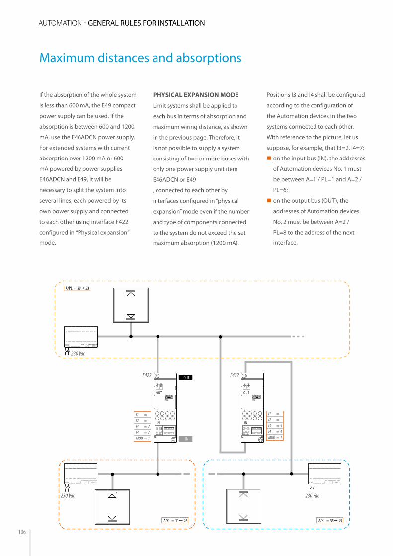
Maximum distances and absorptions
if the absorption of the whole system
is less than 600 mA, the E49 compact
power supply can be used. if the
absorption is between 600 and 1200
mA, use the E46ADCN power supply.
For extended systems with current
absorption over 1200 mA or 600
mA powered by power supplies
E46ADCN and E49, it will be
necessary to split the system into
several lines, each powered by its
own power supply and connected
to each other using interface F422
configured in “Physical expansion”
mode.
physicAl eXpAnsion Mode
Limit systems shall be applied to
each bus in terms of absorption and
maximum wiring distance, as shown
in the previous page. Therefore, it
is not possible to supply a system
consisting of two or more buses with
only one power supply unit item
E46ADCN or E49
, connected to each other by
interfaces configured in “physical
expansion” mode even if the number
and type of components connected
to the system do not exceed the set
maximum absorption (1200 mA).
I1 = –I2 = –I3 = 2I4 = 7MOD = 1
OUT
IN
C
F422
OUT
IN
C
F422
I1 = –I2 = –I3 = 5I4 = 4MOD = 1
OUT
IN
A/PL = 28 53
A/PL = 11 26 A/PL = 55 99
F422 F422
230 Vac
230 Vac 230 Vac
Positions i3 and i4 shall be configured
according to the configuration of
the Automation devices in the two
systems connected to each other.
With reference to the picture, let us
suppose, for example, that i3=2, i4=7:
�� on the input bus (iN), the addresses
of Automation devices No. 1 must
be between A=1 / PL=1 and A=2 /
PL=6;
�� on the output bus (OUT), the
addresses of Automation devices
No. 2 must be between A=2 /
PL=8 to the address of the next
interface.
auTOmaTiON - GENERAL RULES FOR iNSTALLATiON
106
instAllAtion rules
When setting up the system, consider
the following recommendations:
�� The buses, connected to the
interface input and output, must
be supplied with their own power
supply unit; additionally, the
system limits apply for each of
them, in terms of absorption and
maximum distance.
�� Therefore, it is not possible to
supply a system consisting of
two or more buses with only one
power supply unit (E46ADCN or
E49) connected to each other
by various interfaces confi gured
in physical expansion mode
even if the number and type of
components connected to the
system do not exceed the set
maximum absorption (1200 mA).
�� it is not possible to connect two
interfaces in parallel to the same
BUS
�� it is possible to use up to 4
interfaces in series, which divide
the system into 5 separate
sections.
�� The F420 scenario module, the
F425 memory module, and the
devices that can be confi gured
using the self-learning mode must
be installed on the bus section
corresponding to their own
local address. For example if the
scenario module is confi gured
as A=0 (no confi gurator), PL=1, it
will have to be placed on section
1 of the system. The energy
management system central unit,
item F421, and the control panel,
item N4682, must be installed on
the BUS with the highest addresses
(system no. 3 in the example).
107
MY H
OM
E - AU
TOM
ATiON
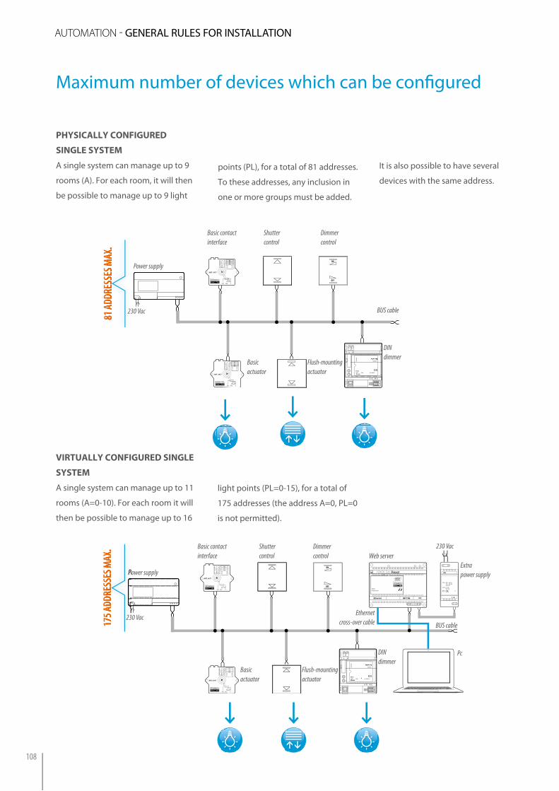
Maximum number of devices which can be confi gured
physicAlly configured
single systeM
A single system can manage up to 9
rooms (A). For each room, it will then
be possible to manage up to 9 light
virtuAlly configured single
systeM
A single system can manage up to 11
rooms (A=0-10). For each room it will
then be possible to manage up to 16
Basic contact interface
Shutter control
Dimmer control
3
A
M
PL1PL2
SPE
PL1 PL2 C
31
ART. 3477
3
A
M
PL1PL2
SPE
PL1 PL2 C
31
ART. 3477
L
A PL M G
F414
T5H
250V
230V~
0245 06
50Hz 60 1000V A¤
ON
OFF
Flush-mounting actuator
Basic actuator
DINdimmer
Power supply
BUS cable
81 ad
dRes
ses M
aX.
81 ad
dRes
ses M
aX.
points (PL), for a total of 81 addresses.
To these addresses, any inclusion in
one or more groups must be added.
light points (PL=0-15), for a total of
175 addresses (the address A=0, PL=0
is not permitted).
it is also possible to have several
devices with the same address.
Basic contact interface
Shutter control
Dimmer control
3
A
M
PL1PL2
SPE
PL1 PL2 C
31
ART. 3477
3
A
M
PL1PL2
SPE
PL1 PL2 C
31
ART. 3477
L
A PL M G
F414
T5H
250V
230V~
0245 06
50Hz 60 1000V A¤
ON
OFF
PRI: 220 – 240 V~ 175 – 165 mA 47/63 Hz
SCS: 27 Vdc 600 mA1 2 1
F453
Flush-mounting actuator
Basic actuator
DINdimmer
Power supply
BUS cable175 a
ddRe
sses
MaX
.
Power supply
175 a
ddRe
sses
MaX
.
Web serverExtrapower supply
Ethernet cross-over cable
230 Vac
230 Vac
230 Vac
Pc
auTOmaTiON - GENERAL RULES FOR iNSTALLATiON
108
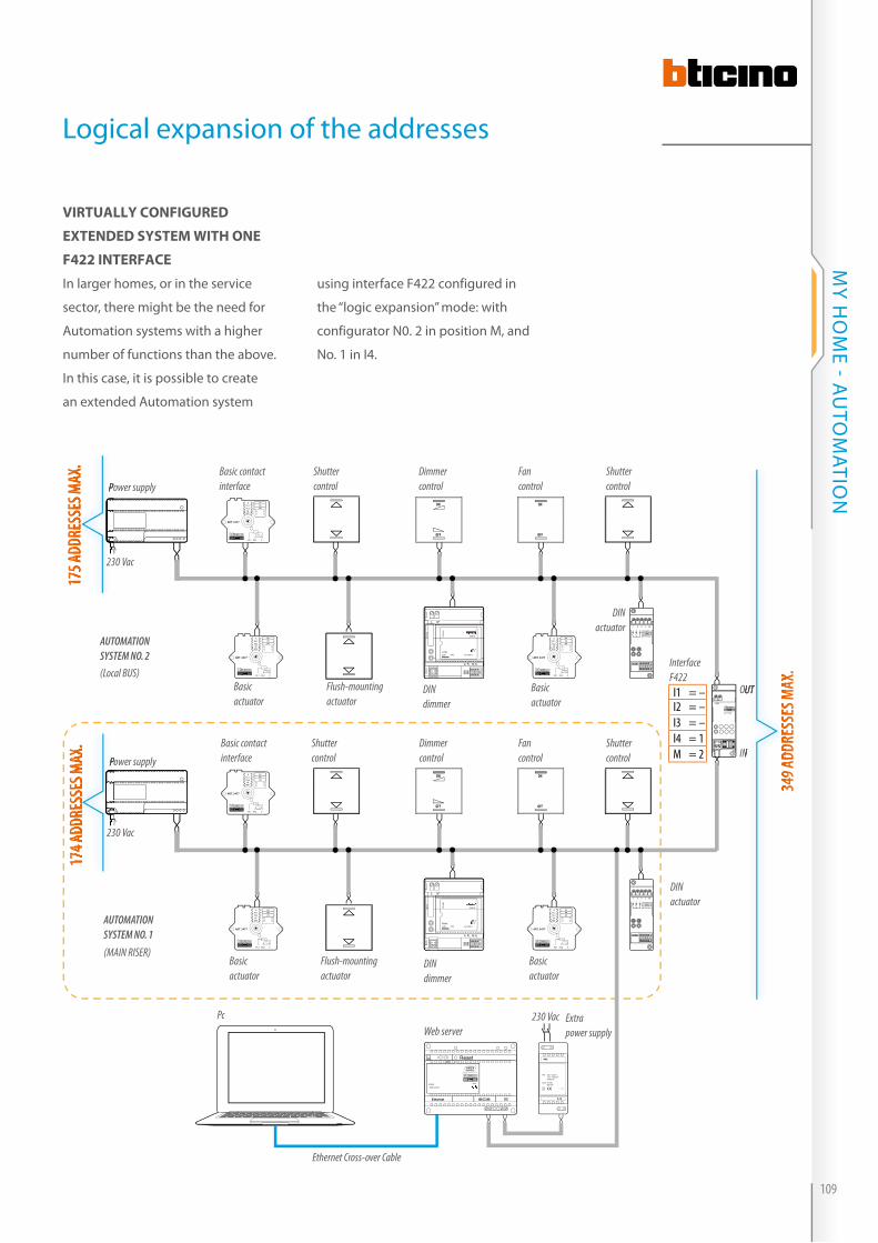
3
A
M
PL1PL2
SPE
PL1 PL2 C
31
ART. 3477
3
A
M
PL1PL2
SPE
PL1 PL2 C
31
ART. 3477
3
A
M
PL1PL2
SPE
PL1 PL2 C
31
ART. 3477
L
A PL M G
F414
T5H
250V
230V~
0245 06
50Hz 60 1000V A¤
ON
OFF
ON
OFF
1 2 3 L N
AR T.F470/2
1 2 3
3
A
M
PL1PL2
SPE
PL1 PL2 C
31
ART. 3477
3
A
M
PL1PL2
SPE
PL1 PL2 C
31
ART. 3477
3
A
M
PL1PL2
SPE
PL1 PL2 C
31
ART. 3477
L
A PL M G
F414
T5H
250V
230V~
0245 06
50Hz 60 1000V A¤
ON
OFF
ON
OFF
1 2 3 L N
AR T.F470/2
1 2 3
AR T.F422
OUT
PRI: 220 – 240 V~ 175 – 165 mA 47/63 Hz
SCS: 27 Vdc 600 mA1 2 1
F453
virtuAlly configured
eXtended systeM with one
f422 interfAce
in larger homes, or in the service
sector, there might be the need for
Automation systems with a higher
number of functions than the above.
in this case, it is possible to create
an extended Automation system
using interface F422 configured in
the “logic expansion” mode: with
configurator N0. 2 in position M, and
No. 1 in i4.
Power supply
Power supply
OUT
IN
Interface F422(Local BUS)
AUTOMATION SYSTEM NO. 2
Basic contact interface
Shutter control
Dimmer control
Flush-mounting actuator
Basic actuator
PcWeb server
Extrapower supply
DINdimmer
Fancontrol
Shutter control
Basic actuator
DIN actuator
Basic contact interface
Shutter control
Dimmer control
Flush-mounting actuator
Basic actuator
DINdimmer
Fancontrol
Shutter control
Basic actuator
DIN actuator
AUTOMATION SYSTEM NO. 1
(MAIN RISER)
I1 = –I2 = –I3 = –I4 = 1M = 2
175 a
ddRe
sses
MaX
.
Power supply
175 a
ddRe
sses
MaX
.17
4 add
Ress
es M
aX.
Power supply
174 a
ddRe
sses
MaX
.
349 a
ddRe
sses
MaX
.
OUT
IN
349 a
ddRe
sses
MaX
.
Ethernet Cross-over Cable
230 Vac
230 Vac
230 Vac
Logical expansion of the addresses
109
MY H
OM
E - AU
TOM
ATiON
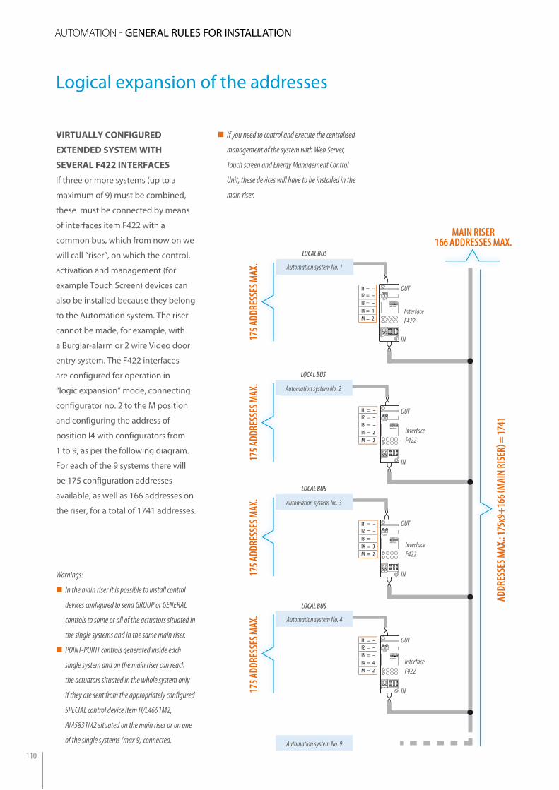
virtuAlly configured
eXtended systeM with
severAl f422 interfAces
if three or more systems (up to a
maximum of 9) must be combined,
these must be connected by means
of interfaces item F422 with a
common bus, which from now on we
will call “riser”, on which the control,
activation and management (for
example Touch Screen) devices can
also be installed because they belong
to the Automation system. The riser
cannot be made, for example, with
a Burglar-alarm or 2 wire Video door
entry system. The F422 interfaces
are configured for operation in
“logic expansion” mode, connecting
configurator no. 2 to the M position
and configuring the address of
position i4 with configurators from
1 to 9, as per the following diagram.
For each of the 9 systems there will
be 175 configuration addresses
available, as well as 166 addresses on
the riser, for a total of 1741 addresses.
Warnings:
�� In the main riser it is possible to install control
devices confi gured to send GROUP or GENERAL
controls to some or all of the actuators situated in
the single systems and in the same main riser.
�� POINT-POINT controls generated inside each
single system and on the main riser can reach
the actuators situated in the whole system only
if they are sent from the appropriately confi gured
SPECIAL control device item H/L4651M2,
AM5831M2 situated on the main riser or on one
of the single systems (max 9) connected.
I1 = –I2 = –I3 = –I4 = 3M = 2
I1 = –I2 = –I3 = –I4 = 4M = 2
OUT
IN
Interface F422
Automation system No. 1
LOCAL BUS
OUT
IN
Interface F422
Automation system No. 2
OUT
IN
Interface F422
Automation system No. 3
LOCAL BUS
OUT
IN
Interface F422
Automation system No. 4
LOCAL BUS
ART.F422
OUT
ART.F422
OUT
ART.F422
OUT
ART.F422
OUT
Automation system No. 9
LOCAL BUS
175 a
ddRe
sses
MaX
.17
5 add
Ress
es M
aX.
175 a
ddRe
sses
MaX
.17
5 add
Ress
es M
aX.
addR
esse
s MaX
.: 175
x9+1
66 (M
aIN
RIse
R) =
1741
MaIN RIseR166 addResses MaX.
I1 = –I2 = –I3 = –I4 = 1M = 2
I1 = –I2 = –I3 = –I4 = 2M = 2
�� If you need to control and execute the centralised
management of the system with Web Server,
Touch screen and Energy Management Control
Unit, these devices will have to be installed in the
main riser.
Logical expansion of the addresses
auTOmaTiON - GENERAL RULES FOR iNSTALLATiON
110
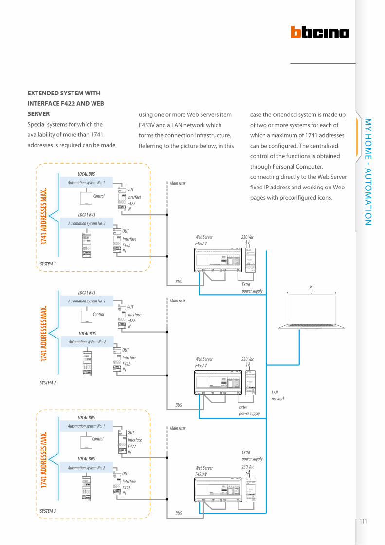
C1 C2
ART. F411/2
1 2 43
eXtended systeM with
interfAce f422 And weB
server
Special systems for which the
availability of more than 1741
addresses is required can be made
using one or more Web Servers item
F453V and a LAN network which
forms the connection infrastructure.
Referring to the picture below, in this
BUS
Control
Control
LOCAL BUS
Control
BUS
BUS
LAN network
F453AV 0319 06
USB USB
ETH DCSCSAV IN
SCSAV
SCSAV OUT
SCSAI
Speed Full Link Aux System
Web ServerF453AV
ART.F422
OUT
OUT
IN
Interface F422
Main riser
ART.F422
OUT
OUT
IN
Interface F422
ART.F422
OUT
OUT
IN
Interface F422
ART.F422
OUT
OUT
IN
Interface F422
ART.F422
OUT
OUT
IN
Interface F422
ART.F422
OUT
OUT
IN
Interface F422
C1 C2
ART. F411/2
1 2 43
C1 C2
ART. F411/2
1 2 43
Web ServerF453AV
Web ServerF453AV
Main riser
Main riser
case the extended system is made up
of two or more systems for each of
which a maximum of 1741 addresses
can be configured. The centralised
control of the functions is obtained
through Personal Computer,
connecting directly to the Web Server
fixed iP address and working on Web
pages with preconfigured icons.
1741
addR
esse
s MaX
.17
41 ad
dRes
ses M
aX.
1741
addR
esse
s MaX
.17
41 ad
dRes
ses M
aX.
1741
addR
esse
s MaX
.17
41 ad
dRes
ses M
aX.
SYSTEM 2
SYSTEM 1
SYSTEM 3
LOCAL BUS
Automation system No. 1
Automation system No. 2
LOCAL BUS
Automation system No. 1
LOCAL BUS
Automation system No. 1
LOCAL BUS
Automation system No. 2
LOCAL BUS
Automation system No. 2
F453AV 0319 06
USB USB
ETH DCSCSAV IN
SCSAV
SCSAV OUT
SCSAI
Speed Full Link Aux System
F453AV 0319 06
USB USB
ETH DCSCSAV IN
SCSAV
SCSAV OUT
SCSAI
Speed Full Link Aux System
PRI: 220 – 240 V~ 175 – 165 mA 47/63 Hz
SCS: 27 Vdc 600 mA
Extrapower supply
230 Vac
Extrapower supply
PRI: 220 – 240 V~ 175 – 165 mA 47/63 Hz
SCS: 27 Vdc 600 mA
230 Vac
Extrapower supply
PRI: 220 – 240 V~ 175 – 165 mA 47/63 Hz
SCS: 27 Vdc 600 mA
230 Vac
PC
111
MY H
OM
E - AU
TOM
ATiON

Lighting management
The device controls the load with the address indicated in A and PL. When a movement is detected, if the lighting level is lower than the set level, the device switches the assigned load on, and keeps it on until the time set with the configurator connected to T expires. The PIR movement sensor sensitivity is set with the configurator connected to S. For correct operation the sensor Lighting set point must be defined (see procedure). If the user switches the light off manually with a control device, the movement sensor is disabled until a presence is detected, for a time set in T.
diAgrAM 2 AutoMAtic switching on of the light with pAssive infrAred ceiling sensor
N
L
ON
OFF
ON
OFF
ON
OFF
ON
OFF
ON
GEN
OFF
L4671/1 L4671/1
BUSBUS
L4652/2L4652/2
E46ADCN
230 Vac
230 Vac
L1 L2
To other devices
A = 1PL = 1M = O/IG1 = –G2 = –
A = 1PL = 2M = O/IG1 = –G2 = –
A = GENPL1 = –M = O/I
A = 1PL1 = 1M1 = O/IA2 = 1PL2 = 2M = O/I
N
L
ON
OFF
11
ART. 3475
230V ˜
2A cosϕ = 0,6
2A
L L1
E46ADCN3475
To other devicesBUS230 Vac
BMSE1001
230 Vac
L4652/2
A = 1PL = 1M = –G = –
A = 1PL = 1M = –S = 1T = 6
A1 = 1PL1 = 1M1 = O/I
diAgrAM 1 switching on/off of 2 lAMps froM 4 light points with generAl on/off control
auTOmaTiON -
112
WiRiNG DiAGRAMS
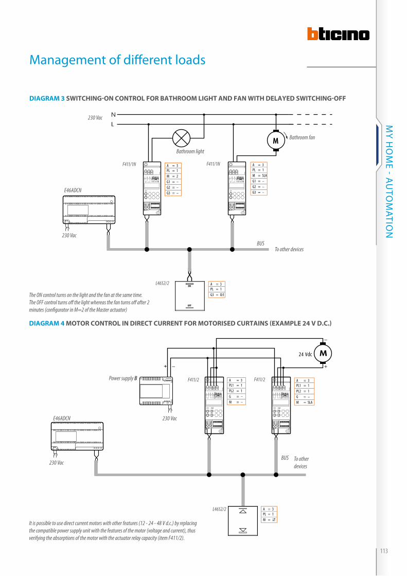
Management of diff erent loads
It is possible to use direct current motors with other features (12 - 24 - 48 V d.c.) by replacing the compatible power supply unit with the features of the motor (voltage and current), thus verifying the absorptions of the motor with the actuator relay capacity (item F411/2).
diAgrAM 3 switching-on control for BAthrooM light And fAn with delAyed switching-off
diAgrAM 4 Motor control in direct current for Motorised curtAins (eXAMple 24 v d.c.)
The ON control turns on the light and the fan at the same time.The OFF control turns off the light whereas the fan turns off after 2 minutes (confi gurator in M=2 of the Master actuator)
N
L
M
ON
OFF
C1
1 2 3
F411/1N
C1
1 2 3
F411/1N
E46ADCN
F411/1N
To other devices
F411/1N
230 Vac
Bathroom light
Bathroom fan
230 Vac
BUS
L4652/2
A = 3PL = 1M = 2G1 = –G2 = –G3 = –
A = 3PL = 1M = SLAG1 = –G2 = –G3 = –
A = 3PL = 1G3 = O/I
C1 C2
ART. F411/2
1 2 43
C1 C2
ART. F411/2
1 2 43
24 Vdc M
++
Power supply B
E46ADCN
F411/2
L4652/2
F411/2
230 Vac
230 Vac
To other devices
BUS
A = 3PL1 = 1PL2 = 1G = –M = –
A = 3PL = 1M =
A = 3PL1 = 1PL2 = 1G = –M = SLA
113
MY H
OM
E - AU
TOM
ATiON
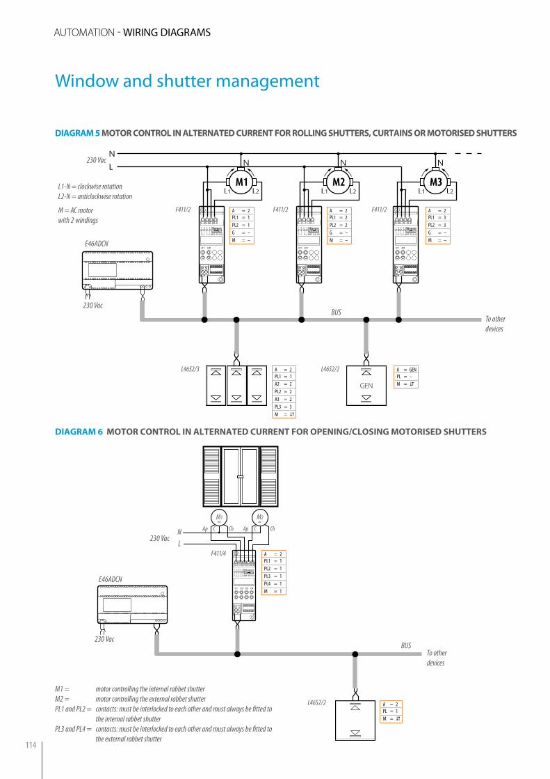
diAgrAM 5 Motor control in AlternAted current for rolling shutters, curtAins or Motorised shutters
C1 C2
ART. F411/2
1 2 43
N
L
M1
N
L1 L2
C1 C2
ART. F411/2
1 2 43
M2
N
L1 L2
C1 C2
ART. F411/2
1 2 43
M3
N
L1 L2
GEN
E46ADCN
230 Vac
F411/2
L4652/2
To other devices
BUS
L1-N = clockwise rotationL2-N = anticlockwise rotation
M = AC motorwith 2 windings
230 Vac
A = GENPL = –M =
A = 2PL1 = 1PL2 = 1G = –M = –
C1 C2 C3 C4
ART. F411/4
1 2 4 53
E46ADCN
230 Vac
L4652/2
M2
˜Ap C ChNL
Ap C Ch
230 Vac
F411/4
To other devices
BUS
M1
˜
A = 2PL = 1M =
A = 2PL1 = 1PL2 = 1PL3 = 1PL4 = 1M = 1
diAgrAM 6 Motor control in AlternAted current for opening/closing Motorised shutters
A = 2PL1 = 1A2 = 2PL2 = 2A3 = 2PL3 = 3M =
L4652/3
F411/2 A = 2PL1 = 2PL2 = 2G = –M = –
F411/2 A = 2PL1 = 3PL2 = 3G = –M = –
Window and shutter management
M1 = motor controlling the internal rabbet shutterM2 = motor controlling the external rabbet shutterPL1 and PL2 = contacts: must be interlocked to each other and must always be fitted to
the internal rabbet shutterPL3 and PL4 = contacts: must be interlocked to each other and must always be fitted to
the external rabbet shutter
auTOmaTiON - WiRiNG DiAGRAMS
114

diAgrAM 7 switching on And off And Brightness AdJustMent of fluorescent lAMps
By MeAns of the “BAllAst”
diAgrAM 8 switching on And off And Brightness AdJustMent of incAndescence lAMps, hAlogen
And ferroMAgnetic trAnsforMers
C1
ART. F413N
2+-
0-10V
1 NC 43
L
+
N L - +
ON
OFF
To other devices
BUS
L4652/2
F413
E46ADCN
230 Vac
230 VacN
LN
Ballast
A1 = 2PL1 = 1M1 = O/I
A = 2PL1 = 1M = –G = –
L
A PL M G
F414
T5H
250V
230V~
0245 06
50Hz 60 1000VA¤
N
L
ON
OFF
To other devices
BUS
L4652/2
DIN dimmer actuator
E46ADCN
Incandescence lamps,halogen and ferromagnetic transformer
230 Vac
230 Vac
A1 = 1PL1 = 2M1 = O/I
A = 1PL = 2M = –G = –
Management of dimmer lamps
115
MY H
OM
E - AU
TOM
ATiON
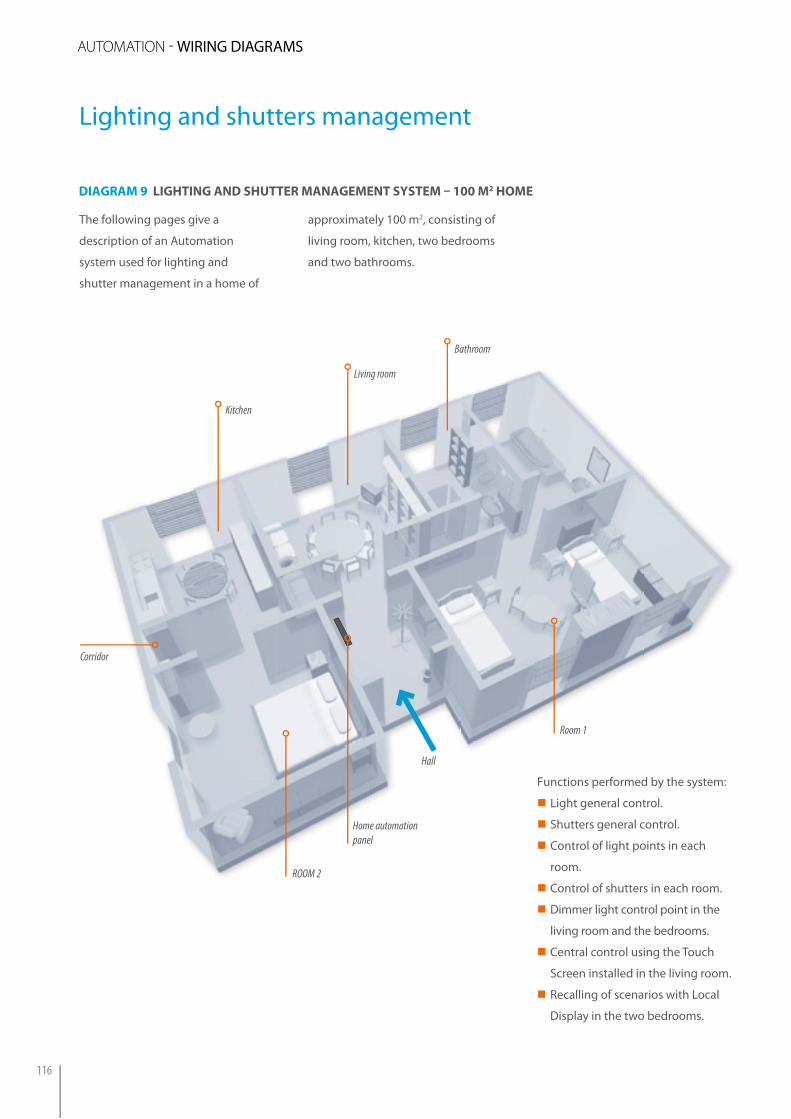
The following pages give a
description of an Automation
system used for lighting and
shutter management in a home of
Functions performed by the system:
�� Light general control.
�� Shutters general control.
�� Control of light points in each
room.
�� Control of shutters in each room.
�� Dimmer light control point in the
living room and the bedrooms.
�� Central control using the Touch
Screen installed in the living room.
�� Recalling of scenarios with Local
Display in the two bedrooms.
Living room
Bathroom
Room 1
ROOM 2
Hall
Corridor
Home automation panel
Kitchen
diAgrAM 9 lighting And shutter MAnAgeMent systeM – 100 M2 hoMe
approximately 100 m2, consisting of
living room, kitchen, two bedrooms
and two bathrooms.
Lighting and shutters management
auTOmaTiON - WiRiNG DiAGRAMS
116

DISTRIBUTION COMPONENTS IN THE SINGLE ROOMS ITEM
HALL
1 lighting general control (1)1 shutter general control (2)1 ceiling light point controlled by ush mounted actuator (3)1 control (4) for the corridor light point
H4652/2H4652/2H4671/1H4652/2
CORRIDOR 2 ceiling light points controlled by ush mounted actuator and 8 other points (4 - 6 - 7 - 9 - 13 - 22 - 28) H4671/1
KITCHEN
1 ceiling light point controlled from one point (7) and by a 1 relay actuator in the DIN module (*)1 motorised shutter controlled from 1 point (8) and bya 2 relay actuator in the DIN module (*)
H4652/2F411/1NH4652/2F411/2
LIVING ROOM
1 wall light point controlled from 1 point (11) with light intensity adjustment and by 1 dimmer actuator in DIN module (*)1 ceiling light point controlled from two points (9 - 11) and bya 1 relay actuator in the DIN module (*)1 motorised shutter controlled from 1 point (10) and bya 2 relay actuator in the DIN module (*)1 Touch Screen (12)
H4652/2F415H4652/2F411/1NH4652/2F411/2H4684
BATHROOM 1
1 ceiling light point controlled from one point (13) and bya 1 relay actuator in the DIN module (*)1 motorised shutter controlled from 1 point (14) and bya 2 relay actuator in the DIN module (*)
H4652/2F411/1NH4652/2F411/2
ROOM 1
1 ceiling light point controlled from 3 points (16 - 17 - 18) with light intensity adjustment and by 1 dimmer actuator in DIN module (*)1 motorised shutter controlled from 1 point (15) and bya 2 relay actuator in the DIN module (*)1 wall light point controlled from 1 point (17)1 wall light point controlled from 1 point (18) and bya 2 relay actuator in the DIN module (*)1 control (20) for the Corridor Light Point1 Local Display (19)
H4652/2F415H4652/2F411/2H4652/2H4652/2F411/2H4652/2HC4685
ROOM 2
1 ceiling light point controlled from 3 points (22 - 23 - 24) with light intensity adjustment and by 1 dimmer actuator in DIN module (*)1 motorised shutter controlled from 1 point (21) and bya 2 relay actuator in the DIN module (*)1 wall light point controlled from 1 point (23)1 wall light point controlled from 1 point (24) and bya 2 relay actuator in the DIN module (*)1 control (26) for the Corridor Light Point1 Local Display (25)
H4652/2F415H4652/2F411/2H4652/2H4652/2F411/2H4652/2HC4685
NOTE: All the controls must be completed with support, cover plate and key covers for the desired civil series. These can be found in the BTicino General Installation catalogue. For this specific example products of the AXOLUTE civil series have been used.NOTE (*): All the actuators in DIN module are installed on the 54 module home automation panel in the hall.
HOME AUTOMATION PANEL DIN MODULES
1 SCS power supply8
12 DIN actuators 24
3 DIN dimmer12
1 scenario module2
Total 46
117
MY H
OM
E - AU
TOM
ATION
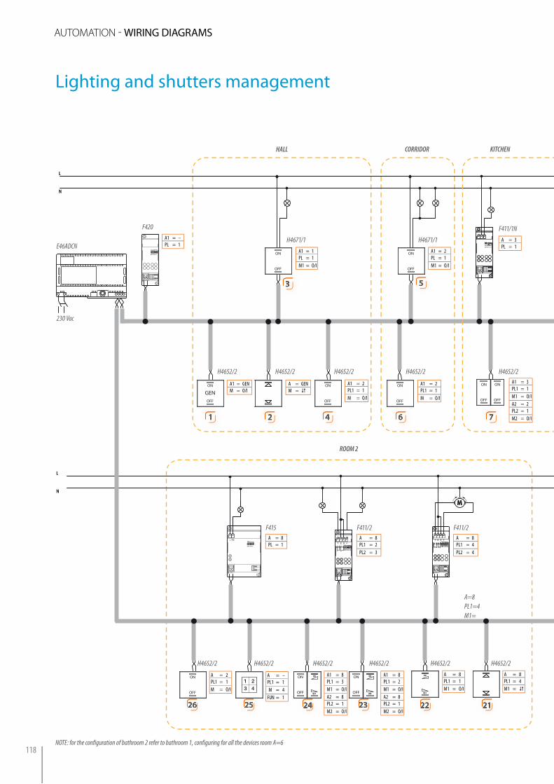
HALL CORRIDOR KITCHEN
ROOM 2
230 Vac
E46ADCN
F420
H4671/1 H4671/1
F411/1N
H4652/2 H4652/2 H4652/2 H4652/2H4652/2
F415 F411/2 F411/2
H4652/2 H4652/2 H4652/2 H4652/2 H4652/2
A=8PL1=4M1=
H4652/2
NOTE: for the configuration of bathroom 2 refer to bathroom 1, configuring for all the devices room A=6
A1 = –PL = 1
A1 = 1PL = 1M1 = O/I
A1 = GENM = O/I
A = GENM =
A1 = 2PL1 = 1M = O/I
A1 = 2PL1 = 1M = O/I
A1 = 3PL1 = 1M1 = O/IA2 = 2PL2 = 1M2 = O/I
A1 = 2PL = 1M1 = O/I
A = 3PL = 1
A = 8PL = 1
A = 8PL1 = 2PL2 = 3
A = 8PL1 = 4PL2 = 4
A = 2PL1 = 1M = O/I
A = –PL1 = 1M = 4
FUN = 1
A1 = 8PL1 = 3M1 = O/IA2 = 8PL2 = 1M2 = O/I
A1 = 8PL1 = 2M1 = O/IA2 = 8PL2 = 1M2 = O/I
A = 8PL1 = 1M1 = O/I
A = 8PL1 = 4M1 =
33
11 22 44 66 77
55
212122222323242425252626
ART.F411/2
1 2 31 2 3 4
ART.F411/2
1 2 3 41 2 3 4
L
N
L
N
ART.F415
L
ART.F420
ON
GENOFF
ON
OFF
ON
OFF
ART.F411/2
1 2 31 2 3 4
ART.F411/2
1 2 3 41 2 3 4
ON
OFF
ON
OFF
L
N
L
N
ART.F411/1 ART.F411/1 ART.F411/1
ON
OFF
ON
OFF
MM
ART.F411/2
1 2 31 2 3 4
ART.F411/2
1 2 3 41 2 3 4
ON
OFF
ON
OFF
ON
OFF
ON
OFF
ON
OFF
ON
OFF
ON
OFF
ON
OFF
ON
OFF
ON
OFF
ON
OFF
ON
OFF
ART.F415
L
ART.F411/2
1 2 31 2 3 4
ART.F411/2
1 2 3 41 2 3 4
ON
OFF
ON
OFF
ON
OFF
ON
OFF
ON
OFF
ON
OFF
ART.F415
L
MM
ART.F411/2
1 2 31 2 3 4
ART.F411/2
1 2 3 41 2 3 4
MM
ART.F411/2
1 2 31 2 3 4
ART.F411/2
1 2 3 41 2 3 4
MM
ART.F411/2
1 2 31 2 3 4
ART.F411/2
1 2 3 41 2 3 4
MM
Lighting and shutters management
auTOmaTiON - WiRiNG DiAGRAMS
118

ART.F411/2
1 2 31 2 3 4
ART.F411/2
1 2 3 41 2 3 4
L
N
L
N
ART.F415
L
ART.F420
ON
GENOFF
ON
OFF
ON
OFF
ART.F411/2
1 2 31 2 3 4
ART.F411/2
1 2 3 41 2 3 4
ON
OFF
ON
OFF
L
N
L
N
ART.F411/1 ART.F411/1 ART.F411/1
ON
OFF
ON
OFF
MM
ART.F411/2
1 2 31 2 3 4
ART.F411/2
1 2 3 41 2 3 4
ON
OFF
ON
OFF
ON
OFF
ON
OFF
ON
OFF
ON
OFF
ON
OFF
ON
OFF
ON
OFF
ON
OFF
ON
OFF
ON
OFF
ART.F415
L
ART.F411/2
1 2 31 2 3 4
ART.F411/2
1 2 3 41 2 3 4
ON
OFF
ON
OFF
ON
OFF
ON
OFF
ON
OFF
ON
OFF
ART.F415
L
MM
ART.F411/2
1 2 31 2 3 4
ART.F411/2
1 2 3 41 2 3 4
MM
ART.F411/2
1 2 31 2 3 4
ART.F411/2
1 2 3 41 2 3 4
MM
ART.F411/2
1 2 31 2 3 4
ART.F411/2
1 2 3 41 2 3 4
MM
KITCHEN LIVING ROOM BATHROOM
ROOM 1
F411/2 F411/1N F415 F411/2 F411/1N F411/2
H4652/2 H4652/2 H4652/2 H4652/2H4684 H4652/2
H4652/2
F415 F411/2 F411/2
H4652/2 H4652/2 H4652/2 H4652/2 H4652/2 H4652/2
A1 = 4PL1 = 1M1 = O/IA2 = 2PL2 = 1M2 = O/I
A1 = 4PL1 = 2M1 = O/IA2 = 4PL2 = 1M2 = O/I
A1 = 3PL1 = 2M =
A = 3PL1 = 2PL2 = 2
A = 4PL = 1
A = 4PL = 2
A = 4PL1 = 3PL2 = 3
A = 5PL1 = 2PL2 = 2
A = 5PL = 1
A1 = 4PL1 = 3M =
A1 = 5PL1 = 2M =
A1 = 5PL1 = 1M1 = O/IA2 = 2PL2 = 1M2 = O/I
A = 7PL = 1 A = 7
PL1 = 2PL2 = 3
A = 7PL1 = 4PL2 = 4
A1 = 2PL1 = 1M = O/I
A = –PL1 = 1M = 4
FUN = 1
A1 = 7PL1 = 3M1 = O/IA2 = 7PL2 = 1M2 = O/I
A1 = 7PL1 = 2M1 = O/IA2 = 7PL2 = 1M2 = O/I
A = 7PL1 = 1M1 = O/I
A = 7PL1 = 4M1 =
88 99 1010 11111212
1313 1414
1515
OFF
1616
OFFOFF
1717
OFFOFF
18181919
OFF
2020
119
MY H
OM
E - AU
TOM
ATiON
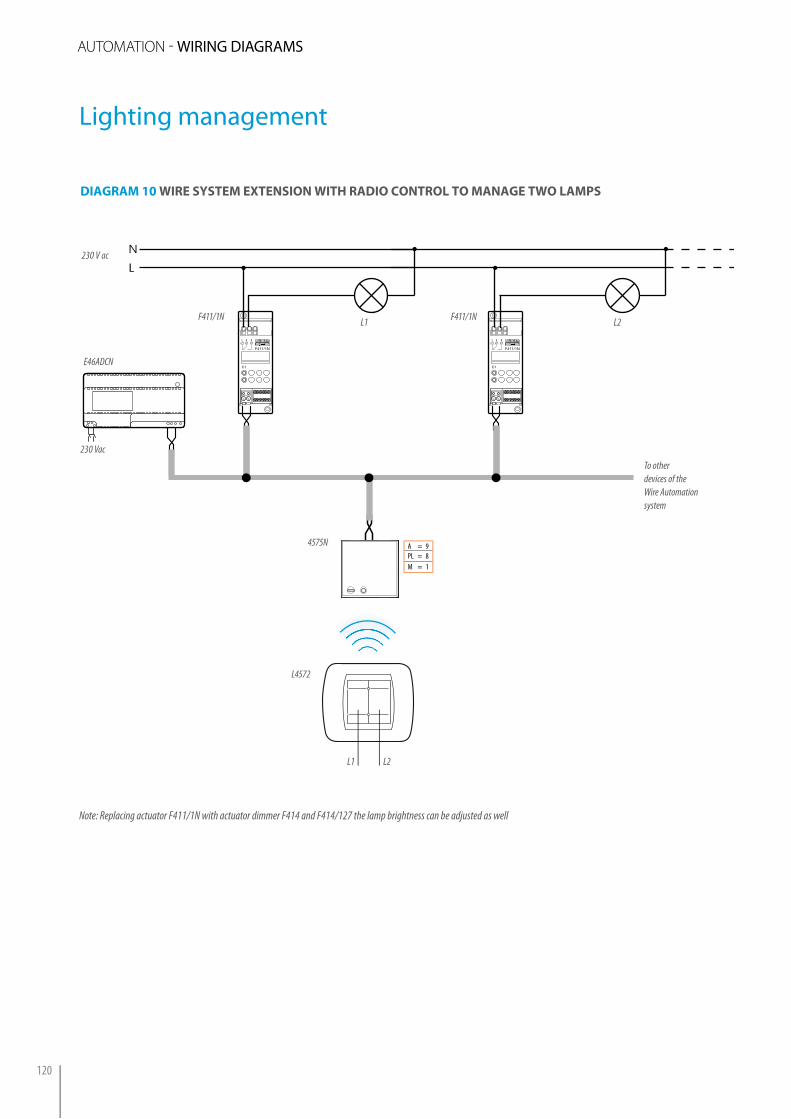
Note: Replacing actuator F411/1N with actuator dimmer F414 and F414/127 the lamp brightness can be adjusted as well
diAgrAM 10 wire systeM eXtension with rAdio control to MAnAge two lAMps
C1
1 2 3
F411/1N
C1
1 2 3
F411/1N
N
L
F411/1N
4575N
To otherdevices of the Wire Automation system
L4572
230 Vac
F411/1N
230 V ac
L1 L2
L1 L2
A = 9PL = 8M = 1
E46ADCN
Lighting management
auTOmaTiON - WiRiNG DiAGRAMS
120

diAgrAM 11 wire systeM eXtension with rAdio ActuAtor to MAnAge A rolling shutter And A lAMp
M
N
L1 L2
N
L
µ
1 2 3 L N
ART.F470/2
1 2 3
4576N
HC4652/2 HC4652/2
L1-N = clockwise rotationL2-N = anticlockwise rotation
M = rotor in AC with 2 windings
F470/2
L1T1
230 Vac
L1 T1
BUS
3470
E46ADCN
A = 2PL = 1M = –G = –
A = 2PL = 9M = 1
A = 2PL1 = 2PL2 = 2M = –G = –
A1 = 2PL1 = 1M1 = –
A1 = 2PL1 = 2
M1 =
Lighting and shutters management
121
MY H
OM
E - AU
TOM
ATiON