Construction Inspection Manual - Lexington, Kentucky...CONSTRUCTION INSPECTION MANUAL...
246
Construction Inspection Manual Lexington-Fayette Urban County Government Lexington, Kentucky January 1, 2005
Transcript of Construction Inspection Manual - Lexington, Kentucky...CONSTRUCTION INSPECTION MANUAL...

Construction Inspection Manual
Lexington-Fayette Urban County Government
Lexington, Kentucky
January 1, 2005

CONSTRUCTION INSPECTION MANUAL LEXINGTON-FAYETTE CO., KY 1-i January 1, 2005
TABLE OF CONTENTS
1.1 Introduction............................................................................................................... 1
1.1.1 General.............................................................................................................. 1 1.2 Purpose of Inspection................................................................................................ 2 1.3 Qualifications of Inspector........................................................................................ 3 1.4 Inspector Authority ................................................................................................... 4 1.5 References................................................................................................................. 5
1.5.1 Publications....................................................................................................... 5

CONSTRUCTION INSPECTION MANUAL LEXINGTON-FAYETTE CO., KY 2-i January 1, 2005
TABLE OF CONTENTS
2.1 Introduction................................................................................................................ 1 2.1.1 General ............................................................................................................... 1 2.1.2 Definitions.......................................................................................................... 1
2.2 Pre-Construction Responsibilities.............................................................................. 2 2.2.1 Review of Contract Documents ......................................................................... 2 2.2.2 Review of Geotechnical Report ......................................................................... 2 2.2.3 Site Visit............................................................................................................. 2 2.2.4 Pre-Construction Conference............................................................................. 3
2.3 Post-Construction Responsibilities ............................................................................ 4 2.3.1 Preparation of Punch List................................................................................... 4 2.3.2 Review of Record Drawings .............................................................................. 4
2.4 References .................................................................................................................. 5 2.5 Pre-Construction and Post-Construction Inspection Checklist.................................. 6
2.5.1 Pre-Construction Tasks ...................................................................................... 6 2.5.2 Post-Construction Tasks .................................................................................... 7

CONSTRUCTION INSPECTION MANUAL LEXINGTON-FAYETTE CO., KY 3-i January 1, 2005
TABLE OF CONTENTS
3.1 Introduction................................................................................................................ 1 3.1.1 General ............................................................................................................... 1 3.1.2 Definitions.......................................................................................................... 1
3.2 Inspection Reports and Forms.................................................................................... 3 3.2.1 Daily Field Report.............................................................................................. 3 3.2.2 Field Density Report .......................................................................................... 5 3.2.3 Low-Pressure Air Test Report ........................................................................... 7 3.2.4 Sewer Infiltration / Exfiltration Report.............................................................. 7 3.2.5 Manhole Vacuum Test Report ......................................................................... 10 3.2.6 Pump Station Wet Well Vacuum Test Report ................................................. 10 3.2.7 Pump Station Equipment Check List ............................................................... 13 3.2.8 Pump Station Start-Up Report ......................................................................... 13 3.2.9 Force Main Hydrostatic Test Report................................................................ 13 3.2.10 Pavement Subgrade Inspection Report ............................................................ 19 3.2.11 Pre-Concreting Inspection Report.................................................................... 19 3.2.12 Report of Test on Concrete Cylinders.............................................................. 19 3.2.13 Contractor Submittal Log................................................................................. 24 3.2.14 Erosion and Sediment Control Inspection and Maintenance Report ............... 24
3.3 Construction Photographs ........................................................................................ 27 3.4 Record Drawings...................................................................................................... 28 3.5 References ................................................................................................................ 29
3.5.1 Publications...................................................................................................... 29 3.5.2 Test Methods and Specifications ..................................................................... 29

CONSTRUCTION INSPECTION MANUAL LEXINGTON-FAYETTE CO., KY 4-i January 1, 2005
TABLE OF CONTENTS
4.1 Introduction................................................................................................................ 1 4.2 Contractor's Role........................................................................................................ 2 4.3 Inspector's Role .......................................................................................................... 3 4.4 Traffic Control ........................................................................................................... 4 4.5 References .................................................................................................................. 5

CONSTRUCTION INSPECTION MANUAL LEXINGTON-FAYETTE CO., KY 5-i January 1, 2005
TABLE OF CONTENTS
5.1 Introduction................................................................................................................ 1 5.1.1 General ............................................................................................................... 1 5.1.2 Definitions.......................................................................................................... 1
5.2 Site Preparation .......................................................................................................... 3 5.2.1 Clearing and Grubbing....................................................................................... 3 5.2.2 Utility Relocation and Structure Removal ......................................................... 3 5.2.3 Stripping............................................................................................................. 3
5.3 Control of Surface Runoff.......................................................................................... 5 5.4 Excavation.................................................................................................................. 6
5.4.1 General ............................................................................................................... 6 5.4.2 Blasting .............................................................................................................. 6
5.5 Embankment Construction......................................................................................... 8 5.5.1 General ............................................................................................................... 8 5.5.2 Borrow Materials ............................................................................................... 8 5.5.3 Foundation Preparation ...................................................................................... 9 5.5.4 Soil Placement.................................................................................................. 10 5.5.5 Soil Compaction............................................................................................... 10 5.5.6 Rock Fill........................................................................................................... 12 5.5.7 Random Earth and Rock Fill............................................................................ 12 5.5.8 Non-Durable Rock Fill..................................................................................... 13 5.5.9 Finishing........................................................................................................... 13 5.5.10 Dust Control ..................................................................................................... 13
5.6 References ................................................................................................................ 14 5.6.1 Publications...................................................................................................... 14 5.6.2 Test Methods and Specifications ..................................................................... 14
5.7 Earthwork Inspection Checklist ............................................................................... 16 5.7.1 Site Preparation ................................................................................................ 16 5.7.2 Excavation........................................................................................................ 17 5.7.3 Embankment .................................................................................................... 18

CONSTRUCTION INSPECTION MANUAL LEXINGTON-FAYETTE CO., KY 6-i January 1, 2005
TABLE OF CONTENTS
6.1 Introduction................................................................................................................ 1 6.1.1 General ............................................................................................................... 1 6.1.2 Definitions.......................................................................................................... 1
6.2 Site Preparation .......................................................................................................... 4 6.3 Excavation.................................................................................................................. 6
6.3.1 Minimum Trench Width for PVC Sewers ......................................................... 6 6.3.2 Maximum Trench Width for RCP Sewers ......................................................... 6 6.3.3 Excavation Considerations................................................................................. 6 6.3.4 Sheeting and Bracing ......................................................................................... 7 6.3.5 Foundation Preparation ...................................................................................... 8
6.4 Pipe Installation........................................................................................................ 10 6.4.1 Pipe Materials and Inspection .......................................................................... 10 6.4.2 Cradle and Encasement .................................................................................... 10 6.4.3 Pipe Laying and Jointing.................................................................................. 11
6.5 Backfill..................................................................................................................... 13 6.5.1 Materials........................................................................................................... 13
6.6 Acceptance Testing .................................................................................................. 14 6.6.1 Low-Pressure Air Test ..................................................................................... 14 6.6.2 Deflection Test ................................................................................................. 15 6.6.3 Infiltration/Exfiltration Test ............................................................................. 15 6.6.4 Sanitary Sewer TV Surveys ............................................................................. 15
6.7 References ................................................................................................................ 16 6.7.1 Publications ...................................................................................................... 16 6.7.2 Test Methods and Specifications ..................................................................... 16
6.8 Open-Trench Inspection Checklist........................................................................... 17 6.8.1 Site Preparation ................................................................................................ 17 6.8.2 Excavation........................................................................................................ 17 6.8.3 Pipe Installation................................................................................................ 18 6.8.4 Backfill............................................................................................................. 19 6.8.5 Acceptance Testing .......................................................................................... 19

CONSTRUCTION INSPECTION MANUAL LEXINGTON-FAYETTE CO., KY 7-i January 1, 2005
TABLE OF CONTENTS
7.1 Introduction................................................................................................................ 1 7.1.1 General ............................................................................................................... 1 7.1.2 Definitions.......................................................................................................... 1
7.2 Types of Appurtenances............................................................................................. 4 7.2.1 Branches and Fittings......................................................................................... 4 7.2.2 Stubs................................................................................................................... 4 7.2.3 Property Service Laterals and Risers ................................................................. 4 7.2.4 Manholes ............................................................................................................ 4 7.2.5 Drop Manholes................................................................................................... 5 7.2.6 Non-Circular Manholes...................................................................................... 5 7.2.7 Surface Inlets and Curb Inlets ............................................................................ 7 7.2.8 Headwalls........................................................................................................... 7
7.3 Inspection of Appurtenances...................................................................................... 8 7.3.1 General ............................................................................................................... 8 7.3.2 Branches and Fittings......................................................................................... 9 7.3.3 Stubs................................................................................................................. 10 7.3.4 Property Service Laterals and Risers ............................................................... 10 7.3.5 Manholes .......................................................................................................... 10 7.3.6 Drop Manholes................................................................................................. 12 7.3.7 Non-Circular Manholes.................................................................................... 12 7.3.8 Storm Sewer Inlets ........................................................................................... 12 7.3.9 Headwalls......................................................................................................... 12
7.4 References ................................................................................................................ 13 7.4.1 Publications ...................................................................................................... 13 7.4.2 Test Methods and Specifications ..................................................................... 13
7.5 Appurtenances Inspection Checklist ........................................................................ 14 7.5.1 General ............................................................................................................. 14 7.5.2 Branches and Fittings....................................................................................... 14 7.5.3 Stubs................................................................................................................. 15 7.5.4 Property Service Laterals and Risers ............................................................... 15 7.5.5 Manholes .......................................................................................................... 16 7.5.6 Drop Manholes................................................................................................. 16 7.5.7 Non-Circular Manholes and Junction Chambers ............................................. 17 7.5.8 Storm Sewer Inlets ........................................................................................... 17 7.5.9 Headwalls......................................................................................................... 18

CONSTRUCTION INSPECTION MANUAL LEXINGTON-FAYETTE CO., KY 8-i January 1, 2005
TABLE OF CONTENTS
8.1 Introduction..................................................................................................................... 1 8.1.1 General.................................................................................................................... 1 8.1.2 Definitions............................................................................................................... 1
8.2 General Operation of Pump Stations .............................................................................. 5 8.3 Wet Well Pump Station .................................................................................................. 6
8.3.1 Wet Well ................................................................................................................. 6 8.3.2 Submersible Pumps................................................................................................. 6 8.3.3 Discharge Piping and Valve Vault.......................................................................... 7 8.3.4 Control Panel and Switches .................................................................................... 7 8.3.5 Electric Service and Components ........................................................................... 8 8.3.6 Telemetry System ................................................................................................... 8 8.3.7 Backup Power Generator ........................................................................................ 8
8.4 Force Mains and Components ........................................................................................ 9 8.4.1 Force Main Piping................................................................................................... 9 8.4.2 Horizontal Anchors................................................................................................. 9 8.4.3 Air Release Valves.................................................................................................. 9 8.4.4 Cleanouts................................................................................................................. 9 8.4.5 Markers ................................................................................................................... 9
8.5 Pump Station Inspection ............................................................................................... 11 8.5.1 General.................................................................................................................. 11 8.5.2 Review of Submittals............................................................................................ 11 8.5.3 Wet Well Construction ......................................................................................... 11 8.5.4 Wet Well Vacuum Testing.................................................................................... 12 8.5.5 Pumps, Installation System, and Drainage Piping ................................................ 13 8.5.6 Valve Vault ........................................................................................................... 14 8.5.7 Control Panel and Electrical Components ............................................................ 14 8.5.8 Telemetry System ................................................................................................. 15 8.5.9 Operating Demonstration...................................................................................... 15
8.6 Force Main Inspection .................................................................................................. 17 8.6.1 General.................................................................................................................. 17 8.6.2 Cleanouts and Valves............................................................................................ 17 8.6.3 Thrust Blocks ........................................................................................................ 17 8.6.4 Force Main Hydrostatic Testing ........................................................................... 17
8.7 References..................................................................................................................... 19 8.7.1 Publications........................................................................................................... 19 8.7.2 Test Methods and Specifications .......................................................................... 19
8.8 Pump Station and Force Main Inspection Checklist..................................................... 20 8.8.1 Review of Submittals............................................................................................ 20 8.8.2 Wet Well and Valve Vault.................................................................................... 20 8.8.3 Pumps, Installation Systems, and Discharge Piping............................................. 22 8.8.4 Control Panel, Electrical Switches........................................................................ 23 8.8.5 Force Mains .......................................................................................................... 23

CONSTRUCTION INSPECTION MANUAL LEXINGTON-FAYETTE CO., KY 9-i January 1, 2005
TABLE OF CONTENTS
9.1 Introduction..................................................................................................................... 1 9.1.1 General.................................................................................................................... 1 9.1.2 Definitions............................................................................................................... 1
9.2 Pipe Tunneling ................................................................................................................ 2 9.3 Pipe Tunneling Inspection .............................................................................................. 3
9.3.1 Pre-Construction Inspection.................................................................................... 3 9.3.2 Operation Inspection............................................................................................... 3 9.3.3 Casing ..................................................................................................................... 3 9.3.4 Carrier Pipe ............................................................................................................. 4 9.3.5 Grouting .................................................................................................................. 4
9.4 References....................................................................................................................... 5 9.4.1 Publications............................................................................................................. 5 9.4.2 Test Methods and Specifications ............................................................................ 5
9.5 Pipe Tunneling Inspection Checklist .............................................................................. 6

CONSTRUCTION INSPECTION MANUAL LEXINGTON-FAYETTE CO., KY 10-i January 1, 2005
TABLE OF CONTENTS 10.1 Introduction......................................................................................................................... 1
10.1.1 General........................................................................................................................ 1 10.1.2 Definitions................................................................................................................... 2
10.2 New Pavements................................................................................................................... 4 10.2.1 Subgrade ..................................................................................................................... 6 10.2.2 Subbase ....................................................................................................................... 7 10.2.3 Granular Base Course ................................................................................................. 8 10.2.4 Asphalt Base and Surface Courses ............................................................................. 8 10.2.5 Tack Coat .................................................................................................................... 9
10.3 Existing Pavements........................................................................................................... 11 10.3.1 Preparation of Paving Areas ..................................................................................... 11 10.3.2 Surface Course .......................................................................................................... 11
10.4 Inspection of Asphalt Mixes ............................................................................................. 14 10.5 References......................................................................................................................... 16
10.5.1 Publications............................................................................................................... 16 10.5.2 Test Methods and Specifications .............................................................................. 16
10.6 Bituminous Pavement Construction Inspection Checklist................................................ 17 10.6.1 New Pavement .......................................................................................................... 17 10.6.2 Existing Pavement .................................................................................................... 18

CONSTRUCTION INSPECTION MANUAL LEXINGTON-FAYETTE CO., KY 11-i January 1, 2005
TABLE OF CONTENTS 11.1 Introduction......................................................................................................................... 1
11.1.1 General........................................................................................................................ 1 11.1.2 Definitions................................................................................................................... 1
11.2 Fundamentals of Concrete .................................................................................................. 3 11.2.1 Cement ........................................................................................................................ 3 11.2.2 Aggregates .................................................................................................................. 3 11.2.3 Admixtures.................................................................................................................. 4
11.3 LFUCG Concrete Requirements......................................................................................... 5 11.4 Methods of Manufacturing Concrete .................................................................................. 6 11.5 Pre-Concreting Inspection .................................................................................................. 7
11.5.1 General........................................................................................................................ 7 11.5.2 Excavation................................................................................................................... 7 11.5.3 Formwork.................................................................................................................... 7 11.5.4 Steel Reinforcement.................................................................................................... 8 11.5.5 Embedded Items........................................................................................................ 12 11.5.6 Construction Joints.................................................................................................... 12
11.6 Concrete Sampling and Testing ........................................................................................ 13 11.6.1 General...................................................................................................................... 13 11.6.2 Slump Testing ........................................................................................................... 14 11.6.3 Air Content Testing................................................................................................... 14 11.6.4 Test Cylinders ........................................................................................................... 14
11.7 Concrete Placement .......................................................................................................... 16 11.7.1 General...................................................................................................................... 16 11.7.2 Hot Weather Concreting ........................................................................................... 17 11.7.3 Cold Weather Concreting ......................................................................................... 18
11.8 Concrete Finishing............................................................................................................ 20 11.8.1 Form Removal .......................................................................................................... 20 11.8.2 Surface Repairs ......................................................................................................... 20 11.8.3 Curing ....................................................................................................................... 20
11.9 References......................................................................................................................... 22 11.9.1 Publications............................................................................................................... 22 11.9.2 Test Methods and Specifications .............................................................................. 22
11.10 Concrete Construction Inspection Checklist..................................................................... 23 11.10.1 Pre-Concrete Inspection............................................................................................ 23 11.10.2 Concrete Placement Inspection................................................................................. 24 11.10.3 Post-Concrete Inspection .......................................................................................... 24

CONSTRUCTION INSPECTION MANUAL LEXINGTON-FAYETTE CO., KY 12-i January 1, 2005
TABLE OF CONTENTS 12.1 Introduction......................................................................................................................... 1
12.1.1 General........................................................................................................................ 1 12.1.2 Definitions................................................................................................................... 1
12.2 Geosynthetic Materials ....................................................................................................... 3 12.2.1 General........................................................................................................................ 3 12.2.2 Geotextiles .................................................................................................................. 3 12.2.3 Geogrids...................................................................................................................... 3 12.2.4 Geonets ....................................................................................................................... 4 12.2.5 Geocomposites............................................................................................................ 4
12.3 Geosynthetic Quality Control ............................................................................................. 5 12.3.1 General........................................................................................................................ 5 12.3.2 Manufacturer Quality Control (MQC)........................................................................ 5 12.3.3 Conformance Testing.................................................................................................. 5
12.4 Geosynthetic Construction Monitoring............................................................................... 7 12.4.1 General........................................................................................................................ 7 12.4.2 Delivery....................................................................................................................... 7 12.4.3 Storage ........................................................................................................................ 7 12.4.4 Subgrade Considerations ............................................................................................ 8 12.4.5 Deployment................................................................................................................. 8 12.4.6 Seaming....................................................................................................................... 8 12.4.7 Cover Materials........................................................................................................... 9
12.5 References......................................................................................................................... 10 12.5.1 Publications............................................................................................................... 10 12.5.2 Test Methods and Specifications .............................................................................. 10
12.6 Geosynthetic Inspection Check List ................................................................................. 11

CONSTRUCTION INSPECTION MANUAL LEXINGTON-FAYETTE CO., KY 13-i January 1, 2005
TABLE OF CONTENTS 13.1 Introduction......................................................................................................................... 1
13.1.1 General........................................................................................................................ 1 13.1.2 Definitions................................................................................................................... 1
13.2 Erosion and Sediment Control Facilities ............................................................................ 2 13.3 Inspection of Erosion and Sediment Control Facilities ...................................................... 3 13.4 References........................................................................................................................... 5
13.4.1 Publications................................................................................................................. 5 13.5 Erosion and Sediment Control Facilities Inspection Check List ........................................ 6

CONSTRUCTION INSPECTION MANUAL LEXINGTON-FAYETTE CO., KY 14-i January 1, 2005
TABLE OF CONTENTS 14.1 Introduction......................................................................................................................... 1
14.1.1 General........................................................................................................................ 1 14.2 Cleanup ............................................................................................................................... 2 14.3 Landscaping ........................................................................................................................ 3 14.4 References........................................................................................................................... 4
14.4.1 Publications................................................................................................................. 4 14.5 Cleanup and Landscaping Inspection Checklist ................................................................. 5
14.5.1 Cleanup ....................................................................................................................... 5 14.5.2 Landscaping ................................................................................................................ 5

CHAPTER 1 GENERAL INFORMATION

CONSTRUCTION INSPECTION MANUAL LEXINGTON-FAYETTE CO., KY 1-1 January 1, 2005
1.1 Introduction 1.1.1 General The Inspector is also known as the Engineer’s Resident Project Representative. The Inspector's job is vital to achieving high quality construction on every infrastructure project. It is one of verifying that construction operations produce the results called for by the Plans and Specifications. This role is one of the toughest jobs in the construction industry and demands knowledge, awareness, keen observational skills, and diplomacy. The Inspector has the responsibility to identify deviations from project Plans and Specifications and to bring them to the attention of the Contractor and the Engineer. This manual provides the Inspector with the knowledge of practice and policy required during the construction of infrastructure in Fayette County.

CONSTRUCTION INSPECTION MANUAL LEXINGTON-FAYETTE CO., KY 1-2 January 1, 2005
1.2 Purpose of Inspection The purpose of inspection on construction projects is to ensure the quality of the work, and to verify that the finished construction meets project requirements. To accomplish this, the Inspector must be familiar with the Plans and Specifications. Together the Plans and Specifications explain requirements that the Contractor must observe to build a satisfactory project and receive payment in full for his work. Plans are the Contract Documents that show the location, physical aspects, and dimensions of the work. The Plans include layouts, profiles, cross-sections, and other details. The Specifications are the written technical directions and requirements for the work. In addition, the Specifications complement the Plans by providing instructions that are not specifically indicated on the drawings. Specifications are the means of communication among the Engineer, the Contractor, and the Inspector, and are particularly important to the Inspector's job. The Plans and Specifications are dynamic documents, subject to revisions as unknown conditions and requested design changes are encountered on the project. Therefore, it is imperative that the Inspector maintain a current awareness of these documents.

CONSTRUCTION INSPECTION MANUAL LEXINGTON-FAYETTE CO., KY 1-3 January 1, 2005
1.3 Qualifications of Inspector The personal attributes of the Inspector extend beyond those expected by an ordinary workman or technician. The Inspector must be:
• honest and able to conduct himself/herself in a fair, straight-forward manner; • able to maintain his/her composure and make good decisions; and • a skilled diplomat, able to handle tough situations without causing hostility.
In addition to these positive personal attributes, the Inspector must have the organizational and technical ability to perform his/her job. The Inspector shall have a high school diploma and a technical background, preferably with additional technical study or previous construction experience. The Inspector must:
• know how to read and interpret Plans, Specifications, and other documents to
understand the requirements of the work; • be able to observe ongoing construction progress, and identify existing or potential
construction operations that are not according to the Plans and Specifications; • have the verbal communication skills to notify the Contractor in a courteous manner
that unsatisfactory conditions exist, or that the Specifications are not being met; • have the writing skills to properly document and record the daily work progression
and any factors affecting the progress or quality of the work; • be able to perform accurate mathematical calculations; • be knowledgeable of the physical characteristics of the materials involved in
construction projects; and • understand the principles of materials testing, including the interpretation of test
results.

CONSTRUCTION INSPECTION MANUAL LEXINGTON-FAYETTE CO., KY 1-4 January 1, 2005
1.4 Inspector Authority The Inspector is responsible for determining that the work being done and the materials being used meet the requirements of the Plans and Specifications. The Inspector has the authority to reject defective material or work that is being done improperly. The Inspector also has the authority and obligation to notify the Contractor when unusual conditions have been created or encountered during construction. The Inspector should realize that implementation of this authority should be regularly supplemented with advice and assistance from the Engineer. The Inspector should realize that he/she is not authorized to revoke, alter, or relax any requirements of the Contract; or to issue a Stop Work Order to the Contractor. These actions are among the responsibilities of the LFUCG.

CONSTRUCTION INSPECTION MANUAL LEXINGTON-FAYETTE CO., KY 1-5 January 1, 2005
1.5 References 1.5.1 Publications
(1) “Construction Inspection Guidance Manual,” Louisville and Jefferson County Metropolitan Sewer District (MSD), Revised Edition, May 1993.

CHAPTER 2 PRE-CONSTRUCTION AND POST-CONSTRUCTION
RESPONSIBILITIES

CONSTRUCTION INSPECTION MANUAL LEXINGTON-FAYETTE CO., KY 2-1 January 1, 2005
2.1 Introduction 2.1.1 General During the pre-construction phase, the Inspector shall review all required aspects of the project, and shall try to resolve any errors or conflicts that he/she observes. In general, the Inspector shall obtain and review all Contract Documents, review pertinent engineering reports, visit the job site prior to construction, and attend the pre-construction conference. During the post-construction period, the Inspector shall review and verify that all aspects of the job have been completed, and shall review project record documentation for accuracy and completeness. 2.1.2 Definitions Benchmark - Point of known or assumed elevation used as a reference in determining and recording other elevations. Geotechnical Report - Engineering report of observed subsurface soil and rock conditions, laboratory tests, engineering analyses, and engineering recommendations determined from a subsurface sampling and testing program (geotechnical exploration). Recommendations by a geotechnical engineer usually include allowable bearing capacities for foundations on insitu soil or bedrock or structural fill, compaction requirements for borrow materials, and utilization of other on site materials. Punch List - A summary of additional or corrective work required for completion of a project usually prepared after a site walk-over. Record Drawings - Engineering plans that have been revised to reflect all changes to the plans that occurred during construction. Subgrade - Soil exposed in a trench bottom or a roadbed and upon which the pipe bedding material or pavement base material will be placed.

CONSTRUCTION INSPECTION MANUAL LEXINGTON-FAYETTE CO., KY 2-2 January 1, 2005
2.2 Pre-Construction Responsibilities 2.2.1 Review of Contract Documents The Inspector is responsible for having a thorough understanding of the project Plans and Specifications and other appropriate parts of the Contract Documents. A complete and knowledgeable understanding by the Inspector of these documents is essential in performing proper inspections during construction. The Specifications represent detailed descriptions of the materials, workmanship, and testing methods required on the project. The Plans present layouts, profiles, dimensions, cross-sections, and details necessary to construct the project. Together, these documents define the scope and nature of the work to be performed. During this review, the Inspector shall make note of any items in the Contract Documents that are unclear and discuss these with the Engineer. In addition, any detected errors, omissions, discrepancies, or deficiencies shall be reported to the Engineer. At this time, any questions by the Inspector regarding the contents of the Contract Documents or scope of project shall be resolved. 2.2.2 Review of Geotechnical Report The Contract Documents should include the report of the geotechnical exploration that was performed for the project. This exploration is typically performed prior to design to provide subsurface information for the design and construction of the proposed facility. The geotechnical report should present a summary of the on-site soil and rock conditions that were determined through a sampling and testing program. The Inspector shall review this report to become familiar with the identities and locations of materials that are suitable for fill, pipe backfill, road subgrades, etc. The report should also identify materials that are unsuitable for the proposed construction and identify subsurface conditions that require special construction considerations. An Inspector's knowledge of this information is critical to ensuring that appropriate materials and adequate foundation conditions are present in the constructed product. 2.2.3 Site Visit The Inspector shall visit the site prior to construction, and shall walk the site with the Plans in hand. At this time, the Inspector shall become familiar with the proposed area of construction and the proposed locations of all structures and earthwork indicated on the Plans. The Inspector shall look for any obvious errors in the Plans, as well as any areas that may require special attention during construction. All items for concern, errors, or discrepancies noted by the Inspector shall be discussed with the Engineer or during the pre-construction meeting, as appropriate. During the site visit, the Inspector shall look for the following items:
(1) job site alterations which may have occurred since preparation of site plans contained within the Contract documents;

CONSTRUCTION INSPECTION MANUAL LEXINGTON-FAYETTE CO., KY 2-3 January 1, 2005
(2) the obvious presence of any utilities which are not marked on the Plans but which
may present problems during construction;
(3) the location of any trees or plants that are marked "Do Not Disturb" on the Plans. These trees/plants shall be marked by the Contractor with flagging to avoid any possible confusion later;
(4) the location of any bench marks (BMs) or temporary bench marks (TBMs) shown on the Plans. The Inspector shall confirm the bench mark locations are as shown on the Plans. If the bench marks have been obviously disturbed, they shall be replaced prior to construction.
In addition, during the site visit, the Inspector shall take a series of pre-construction photographs. These photographs shall be logged and indexed to allow future reference, if necessary. 2.2.4 Pre-Construction Conference On most infrastructure projects, a pre-construction conference is held among the LFUCG Representative, Engineer, Contractor, Inspector and, when appropriate, utility company representatives. During the conference, matters such as the coordinating work, construction schedule, traffic controls, utility conflicts, and special construction considerations are addressed. The Inspector shall attend this conference and obtain a copy of the meeting agenda and minutes. During this meeting, the Inspector shall discuss those items of concern that he/she may have discovered during prior reviews and site visits that have not already been resolved. Also, the Inspector shall obtain the names of the Engineer, the Contractor's Supervisor, and LFUCG's Representative. The Inspector shall make it a point to introduce himself/herself to each contact, and begin building professional relationships to ensure open communications throughout the project.

CONSTRUCTION INSPECTION MANUAL LEXINGTON-FAYETTE CO., KY 2-4 January 1, 2005
2.3 Post-Construction Responsibilities 2.3.1 Preparation of Punch List When the Contractor considers the project complete, the Inspector shall assist the Engineer and Contractor with preparing a punch list that itemizes all of the work tasks still necessary for completion of the project. When preparing the punch list, the Inspector, Engineer, and Contractor shall walk the project site and note any areas that require additional or corrective work. This field review shall be very thorough because successful completion of these tasks will indicate that the project is complete. During this walkover, the project status can be reviewed and discussed in detail to avoid any misunderstanding of the work required for final acceptance. As the Contractor completes items on the punch list, the Inspector shall inspect each item. Items on the punch list shall be checked off only when the Inspector has reviewed the work and decided that it is acceptable. The project is considered completed after all items on the list have been checked off. 2.3.2 Review of Record Drawings The project Record Drawings are a set of drawings that illustrate the as-constructed details and layout of the project. The Engineer shall be responsible for maintaining and updating the Record Drawings as construction progresses to reflect:
• minor design changes,
• deviations from the original Plans,
• unknown field conditions, and
• unknown utility locations. These drawings are important because they represent the final record of the constructed facility. These drawings are often relied upon for reference during future maintenance and expansion of the infrastructure system. The Inspector, as a result of his intimate knowledge of day-to-day construction activities, shall regularly review the Record Drawings during construction to confirm that the drawings are accurately maintained. At the completion of the project, the Inspector shall review the Record Drawings. The Inspector shall note any errors or omissions observed on the drawings and report these immediately to the Engineer.
CONSTRUCTION INSPECTION MANUAL LEXINGTON-FAYETTE CO., KY 2-5 January 1, 2005
2.4 References Construction Inspection Guidance Manual, Louisville and Jefferson County Metropolitan Sewer District (MSD), Revised Edition, May 1993.

CONSTRUCTION INSPECTION MANUAL LEXINGTON-FAYETTE CO., KY 2-6 January 1, 2005
2.5 Pre-Construction and Post-Construction Inspection Checklist 2.5.1 Pre-Construction Tasks
Yes No N/A (1) Have the project Plans and Specifications and all other
applicable Contract Documents been obtained from the Engineer?
(2) Have the documents been thoroughly reviewed, noting any
errors, omissions, discrepancies, or deficiencies? (3) Has the project site been visited prior to construction? (4) Has the site been examined, paying particular attention to
existing utilities, trees to remain, and location and condition of existing bench marks?
(5) Have pre-construction photographs been taken? (6) Has the geotechnical exploration report been reviewed? (7) Is the Inspector familiar with the identity and location of
suitable fill materials? (8) Have any special subsurface conditions been reported? (9) Has the pre-construction meeting been attended? (10) Did the Inspector obtain a copy of the meeting minutes? (11) Have the names of the Contractor's Supervisor, Engineer, and
LFUCG’s Representative been obtained? (12) Has the Inspector made contact with these individuals?

CONSTRUCTION INSPECTION MANUAL LEXINGTON-FAYETTE CO., KY 2-7 January 1, 2005
2.5.2 Post-Construction Tasks
Yes No N/A (1) After the Contractor considers the job complete, has a punch
list been prepared, noting all work that still needs to be completed?
(2) Was the punch list prepared in cooperation with the Engineer
and the Contractor? (3) Have details of the remaining work been discussed among the
Engineer, Contractor, and Inspector so that misunderstandings may be avoided?
(4) As the Contractor has completed the items on the punch list,
has the Inspector reviewed the work and verified that it is acceptable?
(5) Has the Inspector performed a thorough review of the Record
Drawings? (6) Have all noted errors or omissions been described to the
Engineer?

CHAPTER 3 RECORDS AND REPORTS

CONSTRUCTION INSPECTION MANUAL LEXINGTON-FAYETTE CO., KY 3-1 January 1, 2005
3.1 Introduction 3.1.1 General Construction records and reports provide documentation of data, activities, transactions, and verbal communications relating to the project. The importance of good construction records and reports cannot be overemphasized. During execution of the project, records and reports enable other personnel who are not directly involved with its construction to monitor and assess the work as it progresses. Following completion of construction, the records and reports provide permanent documentation of the work as performed. This information may be used for payment purposes, resolution of disputes, and re-creation of the job history. Reporting of the work should be secondary to the actual observation of the construction process. While it is essential that the Inspector not allow report writing to interfere with the prime objective of his job, records and reports must be considered as an integral part of the inspection process. Records and reports must be accurate and shall be written promptly while job occurrences are still easily recalled by the Inspector. All records and reports must be completed in a neat and organized manner. The Inspector should remember that his/her reports and records will be viewed by others, and that they may even be presented in a court of law as evidence relative to the project. As a result, erasures of recorded data shall not be permitted in any reports that document job progress. Any errors or mistakes shall be crossed out with single lines so that the original words or numbers are still legible. The use of slang terms should be avoided when writing reports. 3.1.2 Definitions Admixtures - Materials other than water, aggregate, or cement added to the batch before or during mixing to modify the properties of the concrete mix. Examples include air-entraining admixtures, water reducers, and superplasticizers. Aggregates - A hard granular material of mineral composition such as sand, gravel, slag, or crushed stone, used for mixing in graduated sizes of fragments. Air Content - Percent of air by volume in fresh concrete determined by ASTM C 231, ASTM C 173, or ASTM C 138. ASTM - An abbreviation for American Society for Testing and Materials. Concrete Cylinders - Concrete samples formed in the field according to ASTM C 31 for laboratory compressive strength testing. Curing - The maintenance of a satisfactory moisture content and temperature in concrete during a specified period immediately following placement and finishing so that the desired properties may develop.

CONSTRUCTION INSPECTION MANUAL LEXINGTON-FAYETTE CO., KY 3-2 January 1, 2005
Exfiltration - The exit of sewage through faulty joints or cracks in pipes or manholes. Force Main - A pipe under internal pressure created by being on the discharge side of a pumping station. Infiltration - The entrance of groundwater into a sewer system through faulty joints or cracks in the pipes or manholes. Maximum Dry Density - The maximum density obtained in a Proctor moisture-density test using a specific compactive effort and method of compaction specified by ASTM D 698 or ASTM D 1557. Optimum Moisture Content - The moisture content corresponding to the maximum dry density in a Proctor moisture-density test. Percent Compaction - The ratio, expressed as a percentage, of: 1) dry unit weight of a soil as established in a job site embankment or backfill; to 2) maximum unit weight obtained in a laboratory compaction test. Proctor Test - A laboratory compacting procedure whereby a soil at a known water content is placed in a specified manner into a mold of given dimensions, subjected to a compactive effort of controlled magnitude, and the resulting unit weight determined. The procedure is repeated for various water contents sufficient to establish a relation between water content and unit weight. Record Drawings - Engineering plans that have been revised to reflect all changes to the plans that occurred during construction. Slope - The gradient in feet per feet or expressed as percent. Station - A distance of 100 feet, measured along a centerline or baseline and designated by a stake bearing its number. Structural Fill - Selected fill material placed, compacted and inspected according to specific density and moisture requirements. Surge - The pressure increase observed in a closed conduit system (pipe) during the sudden deceleration of flow due to rapid valve closure or pump shutdown. Trench - Usually a long, narrow, nearly vertical-sided cut in rock or soil such as is made for utility lines. Wet Well - Usually an underground circular concrete storage tank for the temporary storage of sewer influent and containment of submersible pumps, piping, and float bulb switches.

CONSTRUCTION INSPECTION MANUAL LEXINGTON-FAYETTE CO., KY 3-3 January 1, 2005
3.2 Inspection Reports and Forms 3.2.1 Daily Field Report The Daily Field Report is used as a permanent record of the job history, and to provide a means for re-creating job progress on a day-to-day basis. Any job-related items that the Inspector feels is relatively important shall be included in the Daily Field Report. An example of a completed Daily Field Report is shown in Figure 3.1. All Daily Field Reports must be completed daily, preferably as soon as possible after specific events occur. They must not be written in "bunches" every two or three days, or at the end of the week. The Inspector must submit all Daily Field Reports to the Engineer at the end of each day. Daily Field Reports shall have, as a minimum, the following information:
(1) Site Specific Information - The project name, job number, date, Inspector's time of arrival and departure, Contractor's representatives, equipment on site, and visitors on site.
(2) Weather - The daily temperature, sky conditions, presence of rain, snow, or wind.
(3) Daily Work Completed - Summarize the construction activities of the day. List
specific details such as how many cubic yards of concrete were placed, the number of embankment lifts that were compacted, or how many linear feet of pipe were installed. When summarizing activities, describe the construction methodologies used to perform the work. Examples include trench backfilling procedures or procedures used to consolidate concrete. Comment on any testing performed during the day and the results of the tests.

CONSTRUCTION INSPECTION MANUAL
CONSTRUCTION INSPECTION MANUAL LEXINGTON-FAYETTE CO., KY 3-4 January 1, 2005
FIGURE 3.1 Daily Field Report

CONSTRUCTION INSPECTION MANUAL LEXINGTON-FAYETTE CO., KY 3-5 January 1, 2005
(4) Unusual Occurrences - List any adverse conditions encountered such as soft soil conditions, unexpected bedrock, presence of ground water, utility conflicts, equipment breakdowns, and unsafe conditions. Report any delays, and identify causes for the delays. Discuss any controversial matters, noting any deficiencies or violations by the Contractor with respect to the Contract Documents. Also, describe any corrective measures undertaken by the Contractor.
(5) Instructions Issued and Received - Any instructions pertaining to the project that are
issued or received by the Inspector shall be recorded. The recipient or source of the instructions must be identified.
3.2.2 Field Density Report Field Density Reports are used to summarize the test results from daily in-place moisture and density determinations of engineered structural fill. Nuclear test methods (ASTM D 2922 and ASTM D 3017) are typically used to perform rapid, nondestructive in-place density and moisture determinations. Another method, though not as common, is the sand cone (ASTM D 1556). Field Density Reports are used as a permanent record of the construction of earth embankments and structural fill. An example of a completed Field Density Report is presented as Figure 3.2. Data on the Field Density Reports shall be recorded as the tests are performed. The Inspector shall submit the Field Density Reports to the Engineer as an attachment to the Daily Field Report. As a minimum, the following information shall be included on all Field Density Reports:
(1) The project name, project number, date, the Inspector's name, and the Contractor.
(2) A location description for each density test. This description shall reference the layer/lift of fill (i.e., second lift, etc.), project stationing, offset, elevation, etc.
(3) Density tests shall be chronologically numbered for the duration of the project.
(4) The measured values of in-place dry density and moisture content.
(5) The maximum dry density and optimum moisture content as determined by the
standard Proctor (ASTM D 698) or the modified Proctor (ASTM D 1557) compaction tests.


CONSTRUCTION INSPECTION MANUAL LEXINGTON-FAYETTE CO., KY 3-7 January 1, 2005
(6) The relative compaction of the measured in-place density reported as a percentage of
the Proctor density.
(7) The required relative compaction expressed in terms of percent of Proctor density (i.e., 95 percent of Proctor).
(8) A pass or fail determination based on the allowable moisture content deviations from
optimum, and the required relative compaction value specified in the Contract Documents.
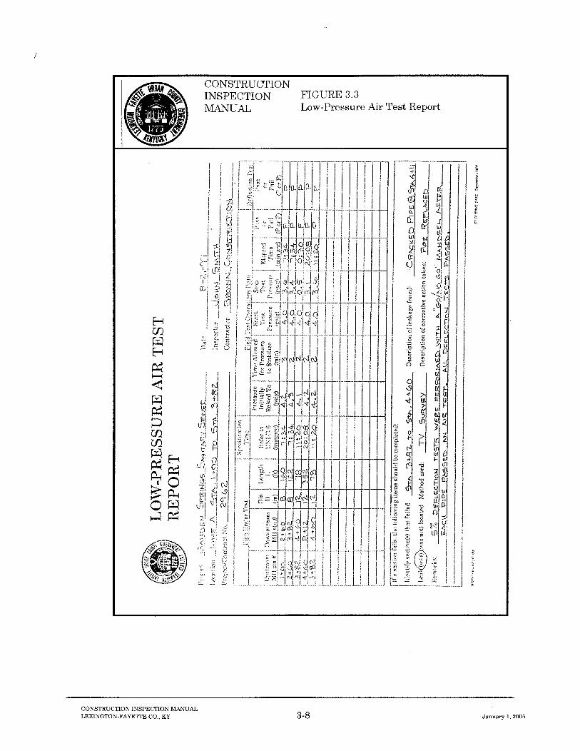
All passing and failing field density tests shall be reported. Fill represented by failing tests shall be reworked, recompacted, or replaced until the requirements of the Contract Documents are achieved. Finally, field density tests of reworked fill shall be noted as retests of previously tested areas. 3.2.3 Low-Pressure Air Test Report Low-pressure air tests shall be performed on flexible and rigid-pipe gravity sanitary sewers in accordance with UNI-B-6-90 and ASTM F1417 for plastic and ductile iron pipe, respectively, and ASTM C924 for concrete pipe. An example of a completed Low-Pressure Air Test Report is shown in Figure 3.3. In the report, the type, size, and location of the pipe tested are identified. The time required for completion of the air test varies with pipe size in accordance with the applicable specification. In addition, the Low-Pressure Air Test Report is used to record the results of deflection tests. Following the completion of either test, the results of the test are noted by writing either "passed" or "failed" on the appropriate line. Since low-pressure air tests and deflection tests of a sewer line are often conducted on separate days, the date of a particular test shall be properly noted. If an air or deflection test should fail, then a passing retest of that pipe section must be performed and documented. The Low-Pressure Air Test Report shall be submitted to the Engineer as an attachment to the Daily Field Report. 3.2.4 Sewer Infiltration / Exfiltration Report Infiltration and exfiltration tests are used to assess the leakage potential of installed sanitary sewers. These tests shall be conducted in accordance with ASTM C 969. An example of a completed Infiltration/Exfiltration Test Report is shown in Figure 3.4. In the report, the type of test performed shall be identified by circling either "Exfiltration" or "Infiltration" at the top of the report. Similar to the Hydrostatic Test Report, all information relative to the sewer pipe being tested shall be entered on the lines provided, and the allowable leakage of the sewer during the test shall be determined by filling in the appropriate data and performing the necessary calculations as outlined in the report.


CONSTRUCTION INSPECTION MANUAL LEXINGTON-FAYETTE CO., KY 3-10 January 1, 2005
When computing the allowable leakage, the pipe diameter must be expressed in inches and the pipe length must be expressed in feet. The results of the test are determined by measuring the total leakage that occurs during the test. During infiltration testing, the flow may be measured by utilizing a flow measuring device such as a flow meter or a V-notch weir, or by directing the inflow into a container of known volume. During exfiltration testing, the total leakage that occurs during the test is generally determined by measuring the decrease in the height of the water in the upstream manhole. If this method is utilized, the total leakage of the test (TLT) may be determined by using the formula included on the report. When using this formula, the decrease in the water level in the manhole and the radius of the manhole must be expressed in feet. It should be noted that this method of measuring the total leakage will not be valid if the level of water in the manhole drops below the crown of the sewer pipe. If this occurs, the total leakage for the test should be determined by measuring the quantity of water required to raise the water level in the manhole to its original position. 3.2.5 Manhole Vacuum Test Report Vacuum tests shall be performed on all sanitary manholes according to ASTM C1244. An example of a completed Manhole Vacuum Test Report is shown in Figure 3.5. In the report, the depth, diameter, location, and required test time for the manhole are noted. The minimum test time required for the completion of the vacuum test varies with manhole depth and diameter. Minimum test times are tabulated in ASTM C 1244 and on the report form. Following the completion of a test, the results are noted by writing either "passed" or "failed" on the appropriate line. If a vacuum test should fail, then a passing retest of the manhole must be performed and documented. The Manhole Vacuum Test Report shall be submitted to the Engineer as an attachment to the Daily Field Report. 3.2.6 Pump Station Wet Well Vacuum Test Report Vacuum tests shall be performed on all pump station wet wells according to the LFUCG test procedures given in Section 8.0. An example of a completed Pump Station Wet Well Vacuum Test Report is shown in Figure 3.6. In the report, the depth, diameter, location, and required test time for the wet well are noted. The minimum test time required for the completion of the vacuum test varies with wet well depth and diameter. Minimum test times required by the LFUCG are tabulated in Section 8.0 and on the report form. Following the completion of a test, the results are noted by writing either "passed" or "failed" on the appropriate line. If a vacuum test should fail, then a passing retest of the wet well must be performed and documented. The Pump Station Wet Well Vacuum Test Report shall be submitted to the Engineer as an attachment to the Daily Field Report.


CONSTRUCTION INSPECTION MANUAL LEXINGTON-FAYETTE CO., KY 3-13 January 1, 2005
3.2.7 Pump Station Equipment Check List The Pump Station Equipment Check List shall be completed after the pump station is constructed and prior to the initial start-up of the station. An example of a completed Pump Station Equipment Check List is shown in Figure 3.7. The Inspector shall carefully check the pump station to verify that pertinent items included on the form have been installed and are working. Any deviation from the Contract Documents shall be listed under remarks. Following completion of the check list, the form shall be submitted to the Engineer as an attachment to the Daily Field Report. 3.2.8 Pump Station Start-Up Report Prior to final acceptance of a pump station by LFUCG, a Pump Station Start-Up Report must be completed. The purpose of the Pump Station Start-Up Report is to verify that all components of the pump station are working properly. An example of a Pump Station Start-Up Report is shown in Figure 3.8. All information on the report must be completed by the Inspector, and the form shall be forwarded to the Engineer. Any components that are found to not function properly shall be repaired or replaced as soon as possible, and a new Pump Station Start-Up Report shall be submitted. 3.2.9 Force Main Hydrostatic Test Report Hydrostatic testing is required on all force mains. An example of a completed Force Main Hydrostatic Test Report is shown in Figure 3.9. In the report, all pertinent information relative to the force main shall be entered on the lines provided. The allowable leakage of the force main may be easily determined by filling in the appropriate data and performing the necessary calculations as outlined in the report. When computing the allowable leakage, the pipe diameter must be expressed in inches and the pipe length must be expressed in feet. In addition, the testing pressure and the testing period are to be recorded. The force mains should be filled with water and subjected to an internal pressure of 100 psi or twice the surge plus operating pressure, whichever is greater, but not to exceed 125 percent of the maximum pressure rating for the pipe, measured at the downstream end. The testing pressure should be held for a period of 2 hours. Evaluation of the final results is to be noted by writing "passed" or "failed" on the appropriate line. The Force Main Hydrostatic Test Report shall be submitted to the Engineer as an attachment to the Daily Field Report.


CONSTRUCTION INSPECTION MANUAL LEXINGTON-FAYETTE CO., KY 3-19 January 1, 2005
3.2.10 Pavement Subgrade Inspection Report Prior to placement of granular base, the subgrade shall be inspected to ensure that it meets the requirements of the Contract Documents and to verify that site conditions are consistent with the Plans. The Pavement Subgrade Inspection Report form is to be used by the Inspector to record his/her field observations. An example of a completed form is shown in Figure 3.10. The Inspector shall submit the Pavement Subgrade Inspection Report Form to the Engineer as an attachment to the Daily Field Report. 3.2.11 Pre-Concreting Inspection Report Pre-concreting Inspection Reports are used to record observations made during the inspection of the steel reinforcement installation, form work, and excavations for concrete structures prior to concrete placement. An example of a completed Pre-concreting Inspection Report is shown in Figure 3.11. The report serves as a basic checklist of items to which the Inspector should be alerted and shall be completed as the elements are being inspected. The Inspector shall submit the Pre-concreting Inspection Report to the Engineer as an attachment to the Daily Field Report. 3.2.12 Report of Test on Concrete Cylinders Acceptance testing of fresh concrete generally involves the molding (ASTM C 31) and testing (ASTM C 39) of concrete cylinders. The Report of Tests on Concrete Cylinders is used to record field observations and test results. Report originals shall accompany the cylinders to the laboratory for the recording of compression test results. Field copies shall be submitted to the Engineer as attachments to the Daily Field Report. An example of a completed Report of Tests on Concrete Cylinders is shown in Figure 3.12. Concrete inspection includes measuring and recording the slump (ASTM C 143), air content (ASTM C 173 or ASTM C 231), and temperature of fresh concrete. All concrete testing shall be performed after the addition of any water or admixtures. If water or admixtures are added after the initial concrete tests, a second set of tests shall be performed after a minimum of 30 additional mixing revolutions. The procedures for field sampling and testing of fresh concrete are included in Section 11.0. When inspecting fresh concrete, the Inspector shall receive a batch delivery ticket immediately when the delivery arrives. The ticket shall be inspected to determine when the mix was batched, the volume delivered, the concrete type, and the design strength. This information, along with any additions to the mix after delivery, such as water or admixtures, shall be noted in the report form. The Inspector shall also record the elapsed time and number of drum revolutions between the introduction of water to the cement and aggregate at the plant and the discharge of the fresh concrete at the site.


CONSTRUCTION INSPECTION MANUAL LEXINGTON-FAYETTE CO., KY 3-24 January 1, 2005
After molding, all concrete cylinders shall be capped to prevent the loss of moisture and allowed to cure for 24 hours before moving. Appropriate methods shall be taken to protect the cylinders from motion, evaporation, or freezing according to ASTM C 192. After 24 hours, the cylinders shall be carefully transported to a laboratory for final curing and future testing. 3.2.13 Contractor Submittal Log The Contractor Submittal Log shown in Figure 3.13 is used to provide a permanent record of all submittals by the Contractor. These submittals typically include shop drawings, material samples, and other required or requested data received during construction. The log shall list a description of each submittal received, along with the date, the specification reference, the number of copies received, any necessary actions, and the date returned. Maintenance and coordination of this document are typically the responsibility of the Engineer. However, it is the Inspector's responsibility to ensure that he/she possesses the current edition of the log throughout construction. The submittal log will enable the Inspector to track submittals and verify that the appropriate reviews of materials and plans have been made before incorporation into the work. 3.2.14 Erosion and Sediment Control Inspection and Maintenance Report The Erosion and Sediment Control Inspection and Maintenance Report form shown in Figure 3.14 is a permanent record of the inspection and maintenance of erosion and sediment control facilities. The facilities shall be inspected weekly and after every significant rainfall. The report shall list a description of each area inspected, the type of erosion control facility inspected, the required maintenance, and the date of repairs.


CONSTRUCTION INSPECTION MANUAL LEXINGTON-FAYETTE CO., KY 3-27 January 1, 2005
3.3 Construction Photographs The importance of routinely taking and logging construction photographs cannot be over emphasized. These photographs are important for documenting construction activities, site conditions, and weather conditions. The Inspector shall make a habit of photographing all aspects of construction and not just those activities that may present potential conflict. The Inspector shall prepare a description log of each photograph when the photograph is taken. The Inspector shall not wait until the film is developed or the end of the job to prepare logs, as memories can fade. The log shall specifically identify the subject of the photograph and its location, (i.e., station, offset, and elevation). Photographs and logs shall be submitted to the Engineer as soon as practicable after each roll is developed. Finally, construction photographs shall be taken with a camera having an automatic date-recording function.

CONSTRUCTION INSPECTION MANUAL LEXINGTON-FAYETTE CO., KY 3-28 January 1, 2005
3.4 Record Drawings The Record Drawings represent the final record of the as-constructed alignment, layout, and details of the facility. These drawings will be relied upon by LFUCG for future expansion and maintenance planning. The Record Drawings are a dynamic set of plans that are continually updated by the Engineer during construction to reflect minor design changes, deviations from the original plans, and the locations of previously unknown utilities and site conditions. Considering the Inspector's knowledge of the site and construction activities, it is imperative that he/she routinely review the Record Drawings during construction and at the completion of the project. The Inspector's independent review will reduce errors and omissions present in the final documents.

CONSTRUCTION INSPECTION MANUAL LEXINGTON-FAYETTE CO., KY 3-29 January 1, 2005
3.5 References 3.5.1 Publications ACI Manual of Concrete Inspection, American Concrete Institute, Publication SP-2(92). Construction Inspection Guidance Manual, Louisville and Jefferson County Metropolitan Sewer District (MSD), Revised Edition, May 1993. Guide to Earthwork Construction, Transportation Research Board, National Research Council, State of the Art Report 8, 1990. Lexington/Fayette Urban County Government Sanitary Sewer Pumping Stations General Requirements for Administration, Design, and Construction, July 1992. National Engineering Handbook Section 19, Construction Inspection, United States Department of Agriculture, Soil Conservation Service, 1985. 3.5.2 Test Methods and Specifications ASTM C 31, Standard Practice for Making and Curing Concrete Test Specimens in the Field ASTM C 39, Standard Test Method for Compressive Strength of Cylindrical Concrete Specimens ASTM C 94, Standard Specification for Ready-Mixed Concrete ASTM C 143, Standard Test Method for Slump of Hydraulic Cement Concrete ASTM C 172, Standard Practice for Sampling Freshly Mixed Concrete ASTM C 173, Standard Test Method for Air Content of Freshly Mixed Concrete by the Volumetric Method ASTM C 231, Standard Test Method for Air Content of Freshly Mixed Concrete by the Pressure Method ASTM C 924, Standard Practice for Testing Concrete Pipe Sewer Lines by Low-Pressure Air Test Method ASTM C 969, Practice for Infiltration and Exfiltration Acceptance Testing of Installed Precast Concrete Pipe Sewer Lines ASTM C 1244, Test Method for Concrete Sewer Manholes by the Negative Air Pressure (Vacuum) Test.

CONSTRUCTION INSPECTION MANUAL LEXINGTON-FAYETTE CO., KY 3-30 January 1, 2005
ASTM D 698, Test Method for Laboratory Compaction Characteristics of Soil Using Standard Method (12,400 ft-lbf/ft3 (600 kN-m/m3)) ASTM D 1556, Test Method for Density and Unit Weight of Soil in Place by the Sand-Cone Method ASTM D 1557, “Test Method for Laboratory Compaction Characteristics of Soil Using Modified Effort (56,000 ft-lbf/ft3 (2,700 kN-m/m3)) ASTM D 2922, Standard Test Methods for Density of Soil and Soil Aggregate in Place by Nuclear Methods (Shallow Depth) ASTM D 3017, Standard Test Method for Water Content of Soil and Rock in Place by Nuclear Methods (Shallow Depth) UNI-B-90 Recommended Practice for Low-Pressure Air Testing of Installed Sewer Pipe, Uni-Bell PVC Pipe Association ASTM F1417, Standard Test Method for Installation Acceptance of Plastic Gravity Sewer Lines using Low-Pressure Air

CHAPTER 4 SAFETY RESPONSIBILITIES
TABLE OF CONTENTS

CONSTRUCTION INSPECTION MANUAL LEXINGTON-FAYETTE CO., KY 4-1 January 1, 2005
4.1 Introduction Annually, millions of man-hours are lost in the United States as a result of construction-related injuries. The injuries and subsequent lost man-hours result in a disruption of the working environment, job delays, increased construction and insurance cost, and in some cases, litigation fees. When considering the emotional and physical trauma due to loss of life or permanent disabilities, the actual cost can be overwhelming. Therefore, it can be easily understood that construction safety and traffic control are an important aspect of the construction project. Because of the potential emotional trauma and monetary liability associated with construction-related accidents, each party's responsibility for jobsite safety shall be clearly defined in the Contract Documents. To understand his/her responsibility, the Inspector shall review the sections of the Contract Documents relating to job site safety and traffic control. The Inspector shall discuss his/her role on the project with his/her immediate supervisor to address issues which may be unclear. The Inspector must understand clearly how his/her actions impact jobsite safety responsibility and the personal or corporate liability of each party. Discussion of the Contractor's and Inspector's roles is presented to illustrate typical jobsite safety and traffic control responsibilities.

CONSTRUCTION INSPECTION MANUAL LEXINGTON-FAYETTE CO., KY 4-2 January 1, 2005
4.2 Contractor's Role The Contractor controls the construction site; is in charge of the construction process; and is to supervise construction. Since supervision and direction of the work is the Contractor's direct responsibility, he shall assume complete responsibility for the means, methods, sequences, and procedures of construction safety precautions and programs at the site. The Contractor is solely responsible for providing a safe working environment and for assuring that the public is protected at all times, not just during working hours. Therefore, the Contractor shall take all necessary precautions for the safety of employees on the work site, and shall comply with all applicable provisions of Federal, State, and Municipal safety laws and building codes to prevent accidents or injury to persons on or adjacent to the premises where the work is being performed. How the Contractor achieves that result is his/her concern.

CONSTRUCTION INSPECTION MANUAL LEXINGTON-FAYETTE CO., KY 4-3 January 1, 2005
4.3 Inspector's Role The Inspector is on site to perform quality assurance monitoring, sampling, and testing of the constructed product. The control of the construction process or the safety programs and necessary precautions are not the responsibility of the Inspector. In addition, it is not the Inspector's responsibility to review the Contractor's safety program or procedures to ensure compliance with any regulatory or on-site requirements. The Inspector should, however, be alert for unusual or unsafe conditions which are created by the Contractor, especially during higher risk operations such as open-trench or tunnel construction and blasting. If unusual or unsafe conditions are observed, the Inspector shall first verbally inform the Contractor of the condition, and he/she shall document the conversation in the Daily Field Report. If the Contractor does not immediately move to correct the situation, and if the Inspector feels that it represents an imminent hazard to workers or the public, the Inspector shall notify the Engineer immediately. Photographs shall also be taken to document any unusual or unsafe conditions.

CONSTRUCTION INSPECTION MANUAL LEXINGTON-FAYETTE CO., KY 4-4 January 1, 2005
4.4 Traffic Control The Contractor is required to provide all necessary signs, barricades, lights, flaggers, etc. in accordance with the US Department of Transportation's "Manual on Uniform Traffic Control Devices." In addition, the Contract Documents may contain items specific to the project for maintaining proper traffic control. The Contractor shall also obtain all local, state or federal permits necessary for any required lane closures. Immediately prior to beginning construction in an area where traffic control is necessary, the Contractor shall erect the necessary signs and other traffic control devices to warn motorists of any disruption in the normal traffic flow. Signs that are erected, but do not apply to existing traffic conditions, must be covered until applicable. During construction, the Contractor must keep his signs and other traffic control devices current with the existing traffic conditions, clean, and in a good state of repair.

CONSTRUCTION INSPECTION MANUAL LEXINGTON-FAYETTE CO., KY 4-5 January 1, 2005
4.5 References Construction Inspection Guidance Manual, Louisville and Jefferson County Metropolitan Sewer District (MSD), Revised Edition, May 1993. Manual on Uniform Traffic Control Devices, US Department of Transportation, Federal Highway Administration, 1988 Edition. Standards and Guides for Traffic Controls for Street and Highway Construction, Maintenance, Utility, and Incident Management Operations, Part VI, Manual on Uniform Traffic Control Devices, US Department of Transportation, Federal Highway Administration, Revision 3, September 1993.

CHAPTER 5 EARTHWORK CONSTRUCTION

CONSTRUCTION INSPECTION MANUAL LEXINGTON-FAYETTE CO., KY 5-1 January 1, 2005
5.1 Introduction 5.1.1 General Earthwork construction on LFUCG infrastructure projects is generally associated with street and roadway construction. To properly perform his/her duties, the Inspector must be familiar with the lines, grades, and cross-sections shown on the Plans and must be familiar with the Specifications controlling the work. The Inspector shall review geotechnical reports relative to the project to become familiar with materials to be encountered. The Inspector must know the extent of the proposed earthwork and the intended use of the excavated materials. The Inspector must also understand that conditions may vary from those shown on the Plans. These conditions may change gradually and the Inspector must be able and alert to identify these changes. The Inspector must know when a change in conditions may affect the facility to the degree that the design is no longer adequate. By reporting these changes to the Engineer immediately, the affect can be reviewed and proper action taken. The Inspector must be familiar with the capabilities and limitations of the Contractor's equipment. He/She must also know the Contractor's operation plan and proposed methods of performing unique items of work, such as drilling, blasting, and dewatering. Finally, the Inspector must understand potential impacts that construction operations may have on future activities, the constructed facilities, and structures adjacent to or outside the work area. 5.1.2 Definitions AASHTO - An abbreviation for American Association of State Highway Transportation Officials. ASTM - An abbreviation for American Society for Testing and Materials. Clearing - The cutting and removal of all trees, logs, and brush above to about 1 foot above the ground surface. Compaction - The act of compressing a given volume of material into a smaller volume by rolling, tamping, or wetting. In earthwork construction, subgrade preparation, and in paving, compaction is needed to increase the density, strength, and stability of the soil or bituminous concrete and decrease its permeability. Grubbing - The removal of all stumps and roots after the clearing operation. Maximum Dry Density - The maximum density obtained in a Proctor moisture-density test using a specific compactive effort and method of compaction specified by ASTM D 698 or ASTM D 1557. Optimum Moisture Content - The moisture content corresponding to the maximum dry density in a Proctor moisture-density test.

CONSTRUCTION INSPECTION MANUAL LEXINGTON-FAYETTE CO., KY 5-2 January 1, 2005
Percent Compaction - The ratio, expressed as a percentage of: 1) dry unit weight of a soil as established in a job site embankment or backfill; to 2) maximum unit weight obtained in a laboratory compaction test. Proctor Test - A laboratory compacting procedure whereby a soil at a known water content is placed in a specified manner into a mold of given dimensions, subjected to a compactive effort of controlled magnitude, and the resulting unit weight determined. The procedure is repeated for various water contents sufficient to establish a relation between water content and unit weight. SDI - An abbreviation for Slate Durability Index. Stripping - The removal of topsoil or other material unsuitable for use in compacted earth fill, beneath foundations, or pavements. Structural Fill - Selected fill material placed, compacted, and inspected according to specific density and moisture requirements. Topsoil - Soil at or below the ground surface, usually high in organic content and unsuitable for structural fill applications. Trench - Usually a long, narrow, near vertical-sided cut in rock or soil such as is made for utility lines.

CONSTRUCTION INSPECTION MANUAL LEXINGTON-FAYETTE CO., KY 5-3 January 1, 2005
5.2 Site Preparation 5.2.1 Clearing and Grubbing Construction areas to be filled or excavated will require clearing and grubbing. Clearing is normally defined as the cutting and removal of all trees, logs, and brush to approximately 1 foot above the ground surface, while grubbing is defined as the removal of all stumps and roots. If carefully done and properly sequenced, soil erosion and impacts to slope stability can be minimal. If carelessly done, it can add to the cost of operating and maintaining the project. Before clearing and grubbing operations begin, the Inspector shall review the limits with the Contractor. During the field review, utilities that could cause concern shall be identified and marked. In addition, trees, fences, structures, bench marks, reference stakes, etc., which are to remain in place shall be identified and marked. The Inspector shall observe that debris is disposed in accordance with the Contract Documents. The Inspector shall be aware that if burning is allowed, there may be local or state ordinances that govern the methods, time, and fire protection facilities on site. Unless specifically allowed by the Contract Documents, debris or unburned ash or residue shall not be buried on site. These materials shall be removed from the site and disposed of properly by the Contractor. 5.2.2 Utility Relocation and Structure Removal Site preparation may include the removal or relocation of existing public utilities such as telephone, electric, gas, and water. The relocation of these facilities is usually performed by the utility companies that own them. Typically, the Contractor is required by the Contract Documents to take appropriate measures to protect these facilities during construction operations. The Inspector must be aware of utility locations and potential impacts from the work, and shall check that safeguards are in place. Existing structures may require removal if they interfere with construction or impair the usefulness of the facility. These structures may include foundations, walls, culverts, pipes, buildings, or other manmade features. The Contract Documents normally do not specify details for demolition or disposal, but will identify requirements for salvaged items. Therefore, during structure removal the Inspector should generally be concerned only with the adequate removal of structures, salvage operations, and the protection of other elements of the work and surrounding features. The Inspector shall observe and record that salvaged materials have been properly inventoried, delivered, and stored as required by the Contract Documents. 5.2.3 Stripping Topsoil is typically considered unsuitable for use in compacted earth fill, beneath structure foundations, or below pavement subgrades. As a result, it is normally stripped from the work
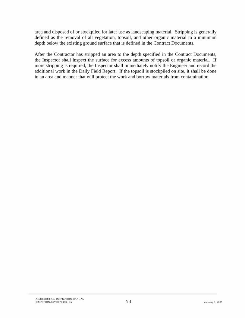
CONSTRUCTION INSPECTION MANUAL LEXINGTON-FAYETTE CO., KY 5-4 January 1, 2005
area and disposed of or stockpiled for later use as landscaping material. Stripping is generally defined as the removal of all vegetation, topsoil, and other organic material to a minimum depth below the existing ground surface that is defined in the Contract Documents. After the Contractor has stripped an area to the depth specified in the Contract Documents, the Inspector shall inspect the surface for excess amounts of topsoil or organic material. If more stripping is required, the Inspector shall immediately notify the Engineer and record the additional work in the Daily Field Report. If the topsoil is stockpiled on site, it shall be done in an area and manner that will protect the work and borrow materials from contamination.

CONSTRUCTION INSPECTION MANUAL LEXINGTON-FAYETTE CO., KY 5-5 January 1, 2005
5.3 Control of Surface Runoff Control of surface runoff is vital to the protection of the subgrade, foundation, and compacted earth fill. The Contractor is responsible, unless otherwise specified in the Contract Documents, for designing and constructing the necessary diversion works. Delayed ditch work or improperly designed and constructed surface water control facilities can result in serious erosion, unstable cut slopes, and saturated soils within excavations, on embankments, or in borrow areas. In addition to construction of diversion works, the Contractor shall maintain positive grades to prevent the ponding of water within the limits of earthwork, where possible. The Inspector shall check diversion and dewatering facilities and operations to be sure the site is protected adequately. Areas of deficiency or requiring maintenance shall be noted and brought to the attention of the Contractor.

CONSTRUCTION INSPECTION MANUAL LEXINGTON-FAYETTE CO., KY 5-6 January 1, 2005
5.4 Excavation 5.4.1 General Excavation is the removal of earth, rock, or other materials to the lines and grades specified in the Contract Documents. Excavation also typically includes the removal of unsuitable material from embankment foundations, structure foundations, and pavement subgrades. The Inspector must know the requirements of these excavations and be able to recognize conditions that may require a change in extent or location. To the extent possible, material from on-site excavations are used in the construction of the required earth and rock fills. The Inspector must understand the proposed uses of these materials and verify that the materials are used appropriately. At times, the rate of excavation may outpace embankment construction. During these periods, the excavated materials shall be segregated and stockpiled based on material types and intended uses. Unsuitable or surplus excavated materials must be disposed of in accordance with the Contract Documents. Wet materials, which are otherwise suitable, may be stockpiled for use after drying. The Inspector must be able to identify the presence of unsuitable materials. If encountered and not anticipated in the Contract Documents, the Inspector shall determine the extent by surface measurements and test pit excavations. The Inspector shall then consult with the Engineer to evaluate the conditions and determine appropriate actions. 5.4.2 Blasting If the material or rock to be excavated is too dense or cemented to be removed by mechanical means, blasting may be required. If the Contractor intends to blast materials and blasting was not anticipated in the Contract Documents, the Inspector shall immediately notify the Engineer. Before drilling and blasting operations begin, the Contractor, Engineer, and Inspector shall hold an on-site meeting to discuss the blasting plan and procedures. If required by the Contract Documents, a pre-blast survey of all nearby residences shall be performed and stored on file prior to blasting. The Contractor has sole responsibility for storing, transporting, and handling blasting materials in accordance with safety regulations and local governing codes, in addition to meeting excavation requirements. The Contractor shall ensure that blasting operations are supervised by a licensed blaster. The Contractor shall observe the following proper blasting procedures:
(1) Blasting operations are in accordance with the Commonwealth of Kentucky Department of Mines and Minerals, Laws and Regulations Governing Explosives and Blasting and other current local, state, and federal laws and regulations governing explosives and blasting.
(2) Blasting operations are stopped during the approach of a thunderstorm and while it is
in progress.

CONSTRUCTION INSPECTION MANUAL LEXINGTON-FAYETTE CO., KY 5-7 January 1, 2005
(3) Appropriate precautions are taken to eliminate local radio and microwave
transmissions around blasting sites. The precautions shall conform with "Safety Guide for the Prevention of Radio Frequency Radiation Hazards in the Use of Commercial Electric Detonators" (Institute of Makers of Explosives Safety Library Publication No. 20).
(4) All blasting holes loaded in a work shift or day are detonated on the same shift or day.
Blasting that loosens rock outside the planned subgrade or slope lines is generally objectionable. It is, however, common for hole depths to extend a short distance below subgrade or slope to eliminate the need for secondary blasting. The Inspector shall periodically check the Contractor's operation by plotting the depth, direction, and spacing of the holes on cross-sections. Occurrences of serious over-drilling shall be brought to the attention of the Contractor and Engineer, immediately.

CONSTRUCTION INSPECTION MANUAL LEXINGTON-FAYETTE CO., KY 5-8 January 1, 2005
5.5 Embankment Construction 5.5.1 General The inherent variability of earth and rock materials requires a greater tolerance in design and construction than for most other construction materials. Materials available on construction sites may range from cohesive fine-grained soils to durable rock, and as a result may have greatly differing properties. Therefore, the kinds of materials available and their engineering properties will directly influence the designs of the facility. The proper use of earth and rock as construction materials requires special attention. The Inspector must be sure that the materials placed in the embankments meet the requirements of the Contract Documents. Inspection of embankment construction requires knowledge, experience, and judgment plus the exercise of authority to ensure compliance with the specifications. 5.5.2 Borrow Materials Fills and embankments are constructed from materials from on-site excavations or approved off-site borrow areas. Generally, a geotechnical exploration of the project site is performed prior to design to identify and evaluate material types, their engineering properties, and their suitability for use in the proposed embankments and fills. During this exploration, soils are typically classified using the Unified Soil Classification System (ASTM D 2487) and the American Association of State Highway Transportation Officials (AASHTO) procedures (AASHTO M 145-82). These methods classify soils according to their texture, plasticity, and performance as construction materials. The Inspector must be familiar with the classification system and the procedures outlined in these standards. The Inspector must be familiar with the findings of the geotechnical exploration and be able to identify the material types and their appropriate uses as required by the Contract Documents. In the event embankment construction requires the use of an off-site borrow source, the Inspector must verify that proper laboratory engineering testing has been performed and that the Engineer has determined the materials to be suitable prior to incorporation into the fill. Depending on the application, tests required prior to approval of a borrow source may include engineering classification, Proctor density (ASTM D 698 or ASTM D 1557) and California Bearing Ratio (CBR) (ASTM D 1883) for soils and slake durability index (SDI) (KM-64-513) and jar slake test (KM-64-514) for soils. The Inspector shall assist the Contractor with the obtaining and handling of representative borrow material test samples. In addition, when the Inspector observes a change in the borrow material, he/she must verify that the material has been approved by the Engineer. If not, the Inspector must not allow its placement until the material has been properly tested and approved.

CONSTRUCTION INSPECTION MANUAL LEXINGTON-FAYETTE CO., KY 5-9 January 1, 2005
Prior to soil placement, the Inspector must also confirm that he/she has the appropriate Proctor density test results. These results are needed during field compaction testing for comparison purposes. 5.5.3 Foundation Preparation The embankment foundation must provide a stable base upon which the fill is constructed. Before the Contractor begins placing structural fill material, the embankment foundation must be inspected to ensure that it meets the requirements of the Contract Documents. After clearing, grubbing, and stripping, the embankment foundation shall be inspected for conditions that may inhibit the proper placement and compaction of fill, or may be detrimental to the function of the facility. These conditions may include:
(1) soft or wet soils,
(2) excessive presence of loose rock,
(3) topsoil or other organic material,
(4) large or excessive amounts of roots. Normally it is required that soil foundations be proofrolled prior to fill placement. The Inspector shall observe the proofrolling operation and shall verify that the equipment weight and speed meet the requirements of the Contract Documents. Areas that deflect or pump excessively shall be noted and reported to the Engineer immediately. The Engineer shall evaluate the conditions observed and determine what, if any, stabilization measures are required. Typical methods of foundation stabilization include:
(1) removal of soft or wet materials and replacement with approved fill,
(2) placement of No. 2 crushed stone or shot rock, (with drainage provided where appropriate),
(3) installation of a system of geogrid/geotextile and crushed stone,
(4) chemical modification (lime or cement).
The Inspector shall note the size and location of any area requiring foundation stabilization efforts in his/her Daily Field Report. The Inspector shall confirm that these areas are reflected on the Record Drawings. Detention basin embankment foundations require additional care because of their function and public safety concerns. Depending on the size and hazard classification, the Contract Documents may require that parts of the foundation material be excavated to competent rock to ensure a good bond and seal through the foundation. The construction of facilities having

CONSTRUCTION INSPECTION MANUAL LEXINGTON-FAYETTE CO., KY 5-10 January 1, 2005
specialized features such as zoned embankments and cutoff trenches are beyond the scope of this manual. Even with small detention basins, a good bond between the foundation and embankment soils is necessary to minimize leakage and maintenance costs. Typically, the Contract Documents will require the foundation soil beneath a detention basin fill be moist and scarified prior to fill placement. If the foundation soils become dry and cracked, the Inspector must observe that the material is reworked and moistened until the requirements of the Contract Documents are achieved. 5.5.4 Soil Placement No material shall be placed until the foundation has been inspected and approved. The foundation shall remain free of water and unacceptable materials until fill placement. The fill materials shall be placed in essentially horizontal loose lifts and shall not be dumped into final place but shall be spread or bladed. The Inspector shall observe that lift thicknesses do not exceed the limits specified in the Contract Documents. Maximum allowed lift thicknesses typically range from 8 to 12 inches, depending on the material placed and the facility application. All roots, vegetation, oversized rock, and other debris that have been brought to the fill must be removed. The Inspector must observe that no fill is placed on a frozen surface and that snow, ice, or frozen materials are not mixed with the fill. The Inspector must also confirm that the moisture content of soil fill is within the specified range at the time of compaction. Typically, this range is based on the optimum moisture content obtained from the Proctor density test. For road embankments, the normal range of moisture required is 2 percent above optimum to 4 percent below. The moisture content of fill is measured during the performance of the field density testing and is given equal weight to density requirements when determining acceptance. Soil fill material that fails to meet the required moisture content range shall be reworked and wetted or dried, accordingly. In addition, if filling operations are abandoned, and the surface material is allowed to dry, the material shall be reworked and moistened until conditions required by the specifications are achieved. 5.5.5 Soil Compaction The Contract Documents shall specify the degree of compaction and the minimum requirements of the type and performance of the compaction equipment. Typically, compaction is performed on earth embankments using a self-propelled or pull-behind tamping foot or sheepsfoot roller. Manually directed tampers or other approved equipment is used to compact parts of the embankment not accessible to heavy rollers. Where this is the case, the lift thickness shall be reduced to no more than 4 inches, loose. The Contract Documents shall also specify the minimum level of compaction required for embankment construction. This minimum compaction requirement is typically expressed as a

CONSTRUCTION INSPECTION MANUAL LEXINGTON-FAYETTE CO., KY 5-11 January 1, 2005
percentage of the maximum dry density obtained from the Proctor density test. Normal specifications for the construction of road embankments require fill to be compacted to at least 95 percent of its maximum dry density determined by the standard Proctor density test (ASTM D 698). To confirm that the operations are resulting in proper moisture control and compaction of earth fills, the Inspector shall observe field moisture-density tests. The most common method of determination is by the use of a nuclear density gauge in accordance with ASTM D 2922. The number of density tests needed varies and is largely a matter of judgment based on the Contractor's operation and performance. More frequent density tests should be taken at the start of the work so that the Inspector can quickly become experienced in judging the behavior of the materials and their reactions to compaction, and in evaluating the consistency and effectiveness of the Contractor's operations. As a minimum, tests shall be performed on each lift placed and one test shall be performed for each 5,000 square feet of the lift's surface area. Accurate locations of each field density test must be recorded. The Inspector shall reference test locations to the project or centerline baseline, if possible. If a test indicates that the fill does not meet specifications, additional tests shall be performed in the vicinity to determine the limits of non-conforming fill. The Contractor shall be immediately notified of all test results. The limits of unsatisfactory fill must be re-worked and re-tested until the requirements of the Contract Documents are achieved. Results of field density tests shall be presented on the forms presented in Section 3.0. The Inspector shall be cautioned not to rely solely on the results of the field density tests. The Inspector shall be knowledgeable and experienced in recognizing proper moisture content and compaction of soil fill materials based on his/her observations of the compaction equipment and soil condition. As an example, the field density test may indicate that density and moisture content meet the specified requirements when compared to the Proctor test results thought to represent the soil being placed. However, the fill is rutting under the weight of field equipment and the compactor is sinking to its barrel. In this example, the soil is obviously too wet and the Inspector must quickly realize the results of the Proctor test do not represent the material. In these situations, the Inspector must notify the Contractor and Engineer immediately. The Contractor must adjust fill operations and use an alternative approved borrow source until a Proctor test is available for this material. The Contractor shall work in another area until the correct Proctor results become available or he/she may remove and replace the material with approved soils. Insufficient compaction can occur for many reasons. Most easily, it can occur at areas where:
(1) too thick a layer is placed,
(2) the moisture content of the soil is not correct,

CONSTRUCTION INSPECTION MANUAL LEXINGTON-FAYETTE CO., KY 5-12 January 1, 2005
(3) insufficient roller passes are made,
(4) inadequate compaction equipment is used,
(5) materials are placed at near-freezing temperatures or contain frost,
(6) materials differ substantially from those originally tested,
(7) dirt-clogged compactors are used. In addition, insufficient compaction can easily occur at junctions between manually compacted and roller compacted zones of the embankments around abutments, pipe conduits, manholes or other restrictive locations. This is normally the result of inadequate overlapping by the roller compactor. 5.5.6 Rock Fill Rock fill consists of rock fragments that are hard, durable, and larger than gravel material. Generally, rock fill contains little or no sand or fine soil materials. The acceptability of rock for use in a rock fill is based on the results of slate durability index (SDI) and the jar slake test. Rock materials having an SDI index greater than or equal to 95 and described as category 6 by the jar slake test are typically considered suitable for rock fills. In constructing rock fill, the rock or shot rock shall not be dumped into final position but shall be distributed by blading or dozing in a manner that will ensure proper placement in the embankment so that voids, pockets, and bridging are held to a minimum. The Contract Document shall specify the maximum allowable lift thickness and rock dimensions. The Kentucky Transportation Cabinet's Standard Specifications for Road and Bridge Construction, allow a maximum lift thickness of 3 feet. In addition, the specification allows rocks in the fill to have maximum dimensions of 3 feet vertically and 4.5 feet horizontal. Further, the specifications restrict the dimensions of rocks within 2 feet of the roadway subgrade to 2 feet in any dimension. Rock fills generally should not be constructed to an elevation higher than 12 inches below subgrade elevation. Generally, compaction of rock fill is not required. 5.5.7 Random Earth and Rock Fill Many times embankments will be constructed of fill consisting of a rock and soil mixture. In these instances, the Contract Documents shall specify the maximum lift thickness and rock dimensions. A maximum lift thickness of 12 inches and a maximum rock size of 12 inches are typical requirements for roadway construction. The mixture shall contain a sufficient fraction of soil to fill the voids between the rocks. In addition, the soil fraction shall be sufficiently moist for proper compaction. A common rule of thumb is that the soil shall feel "plastic.”

CONSTRUCTION INSPECTION MANUAL LEXINGTON-FAYETTE CO., KY 5-13 January 1, 2005
The Contract Documents shall also specify the compaction criteria and compaction equipment requirements. Depending on the ratio of soil to rock, the compaction criteria may range from a specified minimum relative compaction, if the fill is predominately soil, to a specified minimum number of passes with the compaction equipment, if the fill is mostly rock. The latter criterion requires a knowledgeable and experienced Inspector capable of judging the adequacy of compaction based on equipment performance. 5.5.8 Non-Durable Rock Fill Fills containing non-durable, weathered, or friable rock require special attention to assure quality construction. Non-durable rock is generally defined as rock having an SDI less than 95. The Contract Documents shall specify the special requirements needed to place and compact these materials. Generally, non-durable or weathered rock shall be broken down to the degree that further degradation will not be detrimental to the facility. The degree to which the material is broken down is very site specific and dependent on the material used and the embankment requirements. It may be necessary to break down very soft shales to a soil like material, while non-durable limestones may be broken down to cobble or gravel size materials. Non-durable rock materials are typically broken down by mechanical means. The material is distributed in specified lift thickness, usually 12 inches. Water is sometimes added to the material as it is placed to expedite slaking and degradation. The lift is then compacted with a specified number of passes from a static and/or vibratory tamping foot roller. If necessary, the lift may be disked to uniformly incorporate moisture prior to compaction. As with soil and rock mixtures, inspection of non-durable rock fill construction requires a knowledgeable Inspector to judge the adequacy of the placement or compaction operations. The Inspector must work closely with the Engineer during initial placement and compaction operations to assess proper moisture and compaction criteria and determine testing requirements, if needed. 5.5.9 Finishing Embankment and cut slopes must be dressed to the lines and grades that are specified. All cut-and-fill surfaces shall be uniform and pleasing in appearance. All stones, roots, and other debris must be removed from the site, or disposed of as required. If specified, topsoil is spread as a top dressing on the embankment, cut slopes, and other disturbed areas. 5.5.10 Dust Control The Inspector shall be aware of the Contractor's responsibility to provide dust control. The Contractor shall use water to control dust during the construction operations during dry weather periods. Dust can promote on-site health and safety hazards and shall not be overlooked. For additional information, refer to Section 13.0 of this manual.

CONSTRUCTION INSPECTION MANUAL LEXINGTON-FAYETTE CO., KY 5-14 January 1, 2005
5.6 References 5.6.1 Publications Construction Inspection Guidance Manual, Louisville and Jefferson County Metropolitan Sewer District (MSD), Revised Edition, May 1993. Laws and Regulations Governing Explosives and Blasting, Commonwealth of Kentucky Department of Mines and Minerals, November 1996. Guide to Earthwork Construction, Transportation Research Board, National Research Council, State of the Art Report 8, 1990. National Engineering Handbook Section 19, Construction Inspection, United States Department of Agriculture, Soil Conservation Service 1985. Safety Guide for the Prevention of Radio Frequency Radiation Hazards in the Use of Commercial Electric Detonators, Institute of the Makers of Explosives Safety Library Publication No. 20. 5.6.2 Test Methods and Specifications AASHTO M 145-82, The Classification of Soils and Soil-Aggregate Mixtures for Highway Construction Purposes. ASTM D 698, Test Method for Laboratory Compaction Characteristics of Soil Using Standard Method (12,400 ft-lbf/ft3 (600kN-m/m3). ASTM D 1556, Test Method for Density and Unit Weight of Soil in Place by the Sand-Cone Method. ASTM D 1557, Test Method for Laboratory Compaction Characteristics of Soil Using Modified Effort (56,000 ft-lbf/ft3 (2,700 kN-m/m3). ASTM D 1883, Test Method of CBR (California Bearing Ratio) of Laboratory-Compacted Soils. ASTM D 2487, Classification of Soils for Engineering Purposes (Unified Soil Classification System). ASTM D 2922, Standard Test Methods for Density of Soil and Soil-Aggregate in Place by Nuclear Methods (Shallow Depth). ASTM D 3017, Standard Test Method for Water Content of Soil and Rock in Place by Nuclear Methods (Shallow Depth).

CONSTRUCTION INSPECTION MANUAL LEXINGTON-FAYETTE CO., KY 5-15 January 1, 2005
KM-64-607, Specific Gravity and Absorption of Coarse Aggregates, Kentucky Transportation Cabinet (KYTC), Kentucky Test Methods Manual. KM-64-620, Wet Sieve Analysis of Fine and Coarse Aggregates, Kentucky Transportation Cabinet (KYTC), Kentucky Test Methods Manual.

CONSTRUCTION INSPECTION MANUAL LEXINGTON-FAYETTE CO., KY 5-16 January 1, 2005
5.7 Earthwork Inspection Checklist 5.7.1 Site Preparation
Yes No N/A (1) Have the clearing and grubbing operations been performed on
the correct limits? (2) If allowed, is burning in accordance with local ordinances? (3) Have debris and ash been disposed of properly? (4) Have ditches been installed to direct runoff away from the
work area before the earthwork is started? (5) Has the stripping operation removed all of the topsoil and
organic material? (6) Have utilities been located? (7) Having existing structures been removed? (8) Has debris been properly disposed? (9) If required, have items been properly salvaged and stored?

CONSTRUCTION INSPECTION MANUAL LEXINGTON-FAYETTE CO., KY 5-17 January 1, 2005
5.7.2 Excavation
Yes No N/A (1) Is excavation occurring in areas as directed by the Contract
Documents? (2) Are the excavation grades and slopes uniform and do they meet
the requirements of the Contract Documents? (3) Are excavated materials being properly segregated and
stockpiled? (4) Is blasting expected for the project and if unexpected, has the
Engineer been notified? (5) Have pre-blast surveys been performed?

CONSTRUCTION INSPECTION MANUAL LEXINGTON-FAYETTE CO., KY 5-18 January 1, 2005
5.7.3 Embankment Yes No N/A (1) Do the on-site borrow materials match the descriptions given in
the geotechnical report? (2) Is the borrow material being obtained from off site? (3) Has proper testing of the borrow material been performed, and
has the material been approved by the Engineer? (4) If soft soils were found during proofrolling, has the Engineer
been notified? (5) Where required, have soil stabilization/modification procedures
been performed? (6) Is the foundation free of water? (7) Are loose lift thicknesses as specified and are they
approximately horizontal? (8) Is embankment material properly bladed in place? (9) Is the embankment surface approximately horizontal but sloped
for drainage? (10) Is the moisture-density of the compacted fill as specified? (11) Are field density tests accurately referenced to project baseline
or centerline? (12) Are moisture-density relationships (Proctor curves) appropriate
for materials? (13) Are lift thickness and particle dimensions as specified? (14) Do fills consisting of soil and rock mixtures contain sufficient
amounts of soil to fill voices and is compaction adequate? (15) Are non-durable rocks broken down as specified and is
compaction adequate?

CONSTRUCTION INSPECTION MANUAL LEXINGTON-FAYETTE CO., KY 5-19 January 1, 2005
Yes No N/A (16) Are fill slopes uniform and do they meet the requirements of
the Contract Documents? (17) Is the Contractor providing adequate dust control?

CHAPTER 6 OPEN-TRENCH CONSTRUCTION

CONSTRUCTION INSPECTION MANUAL LEXINGTON-FAYETTE CO., KY 6-1 January 1, 2005
6.1 Introduction 6.1.1 General Most sanitary and storm sewers are installed in open trenches. As a result, the Inspector must be knowledgeable of the proper installation, inspection, and construction testing methods for sewers installed in open trenches. The Inspector shall also be aware of the structural load conditions on the pipe that are created by open-trench construction. This section addresses these topics that relate to open-trench construction on public infrastructure projects. 6.1.2 Definitions ASTM - An abbreviation for American Society for Testing and Materials. Backfill - The refilling of an excavation after a structure has been placed therein or the material placed in an excavation in the process of backfilling. In sewer construction, backfill refers to the material placed in the trench from the top of the pipe encasement or cap up to the ground or subgrade level. Bracing - Refers to any one of the methods commonly used to hold back the walls of an excavation by the use of timber or steel members. Cap - Type of encasement, consisting of Class B concrete, which is required when there is: 1) less than 2 feet of vertical clearance between the proposed sewer and an existing or proposed storm drain, utility conduit, or ditch; 2) less than 4 feet of cover between the proposed sewer and a pavement surface; and 3) less than 30 inches of cover between the proposed sewer and a grassed surface. Compaction - The act of compressing a given volume of material into a smaller volume by rolling, tamping, or wetting. In earthwork construction, subgrade preparation, and in paving, compaction is needed to increase the density, strength, and stability of the soil or bituminous concrete and decrease its permeability. Cradle - Refers to bedding and haunching materials (No. 57 crushed stone or Class B concrete) being laid upward from the trench bottom to the springline of the pipe. Culvert - Pipe that drains open channels, swales, or ditches under a roadway or embankment. DND - Abbreviation for Do-Not-Disturb, normally attached to trees to prevent damage or removal during construction. Encasement - Class B concrete or No. 57 crushed stone used to enclose a sewer in a trench. Encasement shall extend at least 6 inches all the way around the outside of the exterior wall of the pipe being encased. Exfiltration - The exit of sewage through faulty joints or cracks in pipes or manholes.

CONSTRUCTION INSPECTION MANUAL LEXINGTON-FAYETTE CO., KY 6-2 January 1, 2005
Haunches - Pipe exterior below the springline to the outside bottom where crushed stone shall be hand placed and consolidated to provide uniform side and bottom support. Home - Refers to condition that occurs when spigot or tongue end of pipe has been properly inserted into the bell or groove end. On PVC pipes, a reference mark is provided on the spigot end to indicate when the section of pipe has been pushed "home.” Infiltration - The entrance of groundwater into a sewer system through faulty joints or cracks in the pipes or manholes. Mandrel - A device used to check installed flexible pipe for excessive deflection (greater than 5%). A mandrel is specifically sized for the diameter of pipe to be tested. As the mandrel is pulled through the pipe, excessive deflection in the pipe will prevent its passage. Manhole - A sewer appurtenance installed to provide: 1) access to sewers for inspection and maintenance; and 2) for changes in sewer direction, elevation, and grade. Percent Compaction - The ratio, expressed as a percentage, of the field dry unit weight of a soil to the maximum unit weight obtained in a laboratory compaction test. Precast - That which is formed in a mold or formed and distributed by the manufacturer as a complete unit. Sanitary Sewer - A sewer that carries liquid and waterborne wastes from residences, commercial buildings, industrial plants, and institutions, together with minor quantities of ground, storm, and surface waters that are not admitted intentionally. SDR - Abbreviation for the Standard Dimension Ratio expressed as the outside diameter of the pipe divided by the pipe wall thickness. Sewage - Largely, the water supply of the common community after it has been fouled by various uses. Sewer - A pipe or enclosed channel that carries wastewater or drainage water. Sheeting - Wood or metal members placed against the trench wall and braced across the trench that are used to prevent cave-ins of trench walls or subsidence of areas adjacent to the trench. Soap - Term commonly used for lubricating the spigot end of the pipe section prior to insertion into the bell end. Springline - The line on the outermost points on the side of a sewer. On a circular sewer, it would be the line on the points at half the diameter above the invert.

CONSTRUCTION INSPECTION MANUAL LEXINGTON-FAYETTE CO., KY 6-3 January 1, 2005
Storm Sewer - A sewer that carries Stormwater and surface water, street wash, and other wash waters, or drainage, but excludes domestic wastewater and industrial wastes. Also called storm drain. Stormwater - Runoff from a storm event. Trench - Usually a long, narrow, near vertical sided cut in rock or soil such as is made for utility lines. Trench Shield - A rigid, prefabricated, steel unit used to protect workers inside the shield from earthen cave-ins during pipe installation. Trench Width - A specified minimum or maximum horizontal trench dimension that shall be maintained from below the pipe to at least one-foot above the top of pipe. TV Survey - Inspection method for PVC sanitary sewers where a video camera and skid assembly is pulled through a pipe section.

CONSTRUCTION INSPECTION MANUAL LEXINGTON-FAYETTE CO., KY 6-4 January 1, 2005
6.2 Site Preparation Site preparation can significantly influence progress of the project. The amount and type of work vary with the location of the project, surrounding topography, and existing utilities. In developed areas, this phase of the project is generally more complicated than in undeveloped areas. Commonly included during site preparation are the following items of work:
1. Marking existing underground utilities.
2. Protecting or pruning back existing trees and complete removal of trees, shrubs, and bushes located on line.
3. Constructing access roads and detours.
4. Erecting traffic control signage and public safety barriers.
5. Installing provisions to handle surface drainage.
6. Sawing through pavements and sidewalks.
It is generally the Contractor's responsibility to contact all applicable utility agencies and request the marking of underground utilities at least 48 hours in advance of excavating a trench. The party responsible for contacting utility agencies should be identified in the Contract Documents. The Inspector shall make it a practice to look for stakes, flags, or paint markings that denote the positions of underground utilities. If they are not present in an area where the Contractor is beginning to excavate, particularly if utility lines are shown on the Plans, or physical evidence of potential underground utility conflicts are observed, the Inspector shall ask the Contractor whether all utility companies have been notified of his operations. Table 6.1 provides a partial list of telephone numbers and associated organizations that should be contacted, as applicable, to help locate existing utilities prior to trench excavation.
TABLE 6.1 UTILITY CONTACTS
Contact Utility Organization Telephone Numbers
Kentucky Underground Protection, Inc.
1-800-752-6007
LFUCG Sanitary Sewers (606) 258-3461 Kentucky Utilities Company (606) 278-9355
(Construction Switchboard) Kentucky-American Water Company (606) 268-6363 or
(606) 268-6354 TCI of Lexington (Telecable - direct)
(606) 268-1123, extension 263
University of Kentucky (606) 257-4786

CONSTRUCTION INSPECTION MANUAL LEXINGTON-FAYETTE CO., KY 6-5 January 1, 2005
Please note that Kentucky Underground Protection, Inc. (KUPI) will schedule utility locates with AT&T, Ashland Oil, Columbia Gas, Columbia Gas Transmissions, GTE, Sprint and TCI. They will typically ask for a specific site location, and accept a request from the caller for a date and time to meet representatives on site. KUPI will provide the caller with a locate request confirmation number such as 923430435, for reference. Most of the organizations listed require two working days (48 hours) notice to schedule a utility locate. Additional utilities to those noted, and privately owned utilities, may also be present at a given site. The possible presence of these types of utilities must also be considered prior to performing any excavation. Damage to existing trees shall be avoided whenever possible, and particularly when a tree is marked on the Plans "Do Not Disturb (DND).” The Inspector shall monitor the Contractor's treatment of trees which are damaged or which must be trimmed to permit access of his equipment. When open-trench excavation occurs in pavements, sidewalks, and areas of pedestrian traffic, the control of traffic and the protection of the general public must be considered. Prior to excavation, the Inspector shall inquire of the Contractor whether all necessary signs and traffic control devices have been erected to warn motorists of disruptions and detours. The Inspector shall also ask the Contractor whether the materials to construct/erect barricades necessary to protect the public during the operations are on site. Surface water shall be diverted away from open trenches for several reasons. Water can destabilize a trench wall and cause cave-ins by adding additional loads to the trench wall and reducing the soil strength. It can soften the trench bottom and contribute to excessive settlement of the installed sewer. It creates a muddy environment for workers, and water accumulation in the trench can cause a sewer that is laid, but not yet covered, to float. When sewers are to be installed beneath pavements or sidewalks, the surfaces must be cut with a pavement saw before being removed. All saw cuts shall be straight and shall completely penetrate the pavement or sidewalk. The Inspector shall check the width between the saw cuts. This distance shall be as shown in the LFUCG Standard Drawings.

CONSTRUCTION INSPECTION MANUAL LEXINGTON-FAYETTE CO., KY 6-6 January 1, 2005
6.3 Excavation 6.3.1 Minimum Trench Width for PVC Sewers The minimum trench width for Polyvinyl Chloride (PVC) pipe installations is determined by the size of the pipe and the ability to get compaction equipment between the pipe and the trench walls. The minimum trench width shall be provided, as shown in the LFUCG Standard Drawings. If poor soil conditions are encountered, such as soft clay, that cannot provide adequate lateral support, the Engineer shall be notified immediately. 6.3.2 Maximum Trench Width for RCP Sewers The trench earth load on rigid pipe is directly related to the trench width; therefore, trench excavations for reinforced concrete pipe (RCP) installations shall not be over-excavated. Trench widths shall be provided as shown in the LFUCG Standard Drawings. In the event the Contractor has over-excavated the trench, the Engineer shall be consulted. Depending on the depth and amount of excessive width, it may be necessary to increase the class of pipe or provide a concrete cradle for additional pipe support. 6.3.3 Excavation Considerations Excavation, pipe installation, and backfill operations shall follow in sequence as closely as possible. Avoiding long stretches of open trench will:
• Assist in promoting good public relations,
• Reduce the potential for trench flooding and displacement of pipe already placed and bedded,
• Reduce the need to control ground water and surface runoff over long intervals of
length at any one time, and
• Reduce traffic control needs and public safety issues. The method and equipment used for excavating the trench will depend on the type of material being excavated, the depth of the trench, and the amount of space available for the Contractor's operation. The choices of method and equipment rests with the Contractor. Various types of equipment have limitations, however, in minimum trench widths and maximum depths, and in casting capabilities. Furthermore, the equipment utilized by the Contractor shall be in relatively good repair. Leaking hydraulic fluid, diesel oil, and gasoline can damage pavements, driveways, and grass.

CONSTRUCTION INSPECTION MANUAL LEXINGTON-FAYETTE CO., KY 6-7 January 1, 2005
Likewise, local residents shall not be subjected to excessively loud engine noises caused by a faulty muffler. As a safety consideration, all equipment shall have back-up alarms. When blasting is required for excavation purposes, lead wires for electric blasting caps shall be cut off flush with the ground surface after a blast is fired or before leaving the prospective site at the end of the work period. In addition, all trash wire shall be picked up and removed on a daily basis. The Inspector shall pay attention to the placement of materials removed from the trench. Surplus excavated material shall be removed from the site as soon as it is excavated in order to prevent excessive erosion and siltation problems. Soil or rock which is to be utilized for backfill shall be placed at a sufficient distance back from the edge of the trench to prevent caving of the trench wall and to permit safe access along the trench according to applicable federal Occupational Safety and Health Administration (OSHA) regulations. In addition, sheeting and bracing must be designed for any additional surcharge loading created by stockpiling. The Inspector shall observe that excavated materials are placed in such a manner as not to block sidewalks or streets. The specified pipe strength is based on the allowable trench width and the depth of the installation. If the actual trench width exceeds the allowable width, the load on the pipe will be greater than that which had been estimated, and structural distress or excessive deflection of the pipe may result. Therefore, trench widths shall be checked by the Inspector to be sure they are in accordance with the designer's assumed trench dimensions. If the trench depth or width exceeds the specified dimensions, the Engineer shall be consulted. When the excavated material is to be used for backfill, the Inspector shall visually examine the material for the presence of rocks, frozen lumps, highly organic soil and materials, muck or other objectionable materials that are unsuitable. The main considerations for judging backfill are its suitability for proper compaction and the presence of rocks or boulders that could cause concentrated loads on the pipe. Extremely wet and soft clay, highly plastic clay, and material containing a significant amount of organic debris will not compact well. Boulders larger than one cubic foot in volume may cause excessive stresses on the pipe. If the Inspector is doubtful about a material's suitability for trench backfill, he/she shall consult with the Engineer. 6.3.4 Sheeting and Bracing Sheeting and bracing must be adequate to prevent cave-in of the trench walls or subsidence of areas adjacent to the trench. The Contractor is responsible for the structural adequacy of any required sheeting and bracing system. Normally, the sheeting and bracing plan is prepared by the Contractor and reviewed and approved by the Engineer. The approved sheeting and bracing plan shall be reviewed by the Inspector prior to trench excavation. Since sheeting and bracing is a costly method of ensuring stable trench walls, many Contractors will opt for additional excavation of the trench (i.e., layback of slope). The

CONSTRUCTION INSPECTION MANUAL LEXINGTON-FAYETTE CO., KY 6-8 January 1, 2005
maximum trench width shall be maintained to approximately 1 foot above the planned elevation of the top of the pipe. Refer to Section 6.3.1 for discussion of "trench width" as it applies to design loading for the pipe. Regardless of the method used to stabilize trench walls, the Contractor shall inspect trench walls after every rainstorm to determine if maintenance of the stabilization system is required or if additional protection against slides and cave-ins are necessary. Excavation support systems that are commonly used are as follows:
(1) Trench Shield (Trench Box). A rigid prefabricated steel unit used in lieu of shoring, which extends from the bottom of the excavation to within a few feet of the top of the cut. Pipes are laid within the shield, which is pulled ahead as trenching proceeds. Typically, this system is useful in loose granular or soft cohesive soils where the excavation depth does not exceed 12 feet. Special shields have been used successfully to depths of 30 feet. The use of trench shields shall follow OSHA regulations.
(2) Sheeting and Bracing. Steel sheeting or timber shoring and bracing may be used
according to OSHA regulations. Structural members shall safely withstand water and lateral earth pressures. Steel sheeting with timber or steel wales and struts have also been utilized. In relatively narrow trenches, trench jacks are often used to hold the sheeting in place.
Sheeting may be installed either by driving it with hammers or by pushing it into place in trenches with light equipment. A hand maul or a light air hammer is generally sufficient for pushing sheeting in a trench where the bottom can be excavated ahead of driving, and earth loads on the sheeting are light. When the sheeting is to be driven in advance of excavation, or when the earth loads on the sheeting are heavy, equipment such as a drop hammer, vibratory hammer, or a pile driver shall be used. The driving equipment must be capable of supplying ample energy to move the sheeting easily. A driver that strikes a heavy blow at low velocity at impact will do the most work with the least damage to the sheeting. 6.3.5 Foundation Preparation Correct preparation of the trench bottom is essential for a satisfactory sewer pipe installation. Unless instructed otherwise, all sewer trenches excavated for LFUCG public infrastructure are excavated to at least 6 inches beneath the pipe. The Inspector shall make a concerted effort to check the subgrades of all sewer trenches for suitable conditions before a crushed stone or concrete cradle is placed. The trench bottom shall be smooth and free of large stones, clods of earth, or any frozen materials. When the trench bottom is in earth, the Inspector shall also examine the bottom for deep grooves left by the excavator cutting teeth. If such grooves are observed, the Contractor shall be instructed to smooth the trench bottom. If the trench is in rock, the Inspector shall check that all loose rock has been removed, and that no ledges or pinnacles of rock extend into the zone reserved for the crushed stone cradle or encasement.

CONSTRUCTION INSPECTION MANUAL LEXINGTON-FAYETTE CO., KY 6-9 January 1, 2005
Soft, yielding soils are considered to be unsuitable for proper support of a buried sewer. If the subgrade soil cannot support workers in the trench without sinking, it is too soft to serve as a subgrade for a normal sewer installation. Typically, most soft trench subgrades can be adequately stabilized by undercutting the trench bottom an additional 1 to 2 feet. This undercut zone shall be backfilled with crushed stone. For sewers that cross ditches or streams, concrete shall be placed to backfill the undercut zone. In most instances, this procedure will provide a suitably stabilized subgrade upon which normal pipe laying operations can be conducted. The Inspector shall consult with the Engineer prior to the performance of any stabilization measures not shown on the Plans. In extremely soft soil conditions, it may be necessary to resort to special treatments to provide a stable bed for the pipe. In addition, caverns or sinkholes are sometimes encountered during trench excavation. These too require special attention and treatment during construction. In any situation where special treatment is indicated as being necessary, the Inspector shall consult with the Engineer.

CONSTRUCTION INSPECTION MANUAL LEXINGTON-FAYETTE CO., KY 6-10 January 1, 2005
6.4 Pipe Installation 6.4.1 Pipe Materials and Inspection Polyvinyl chloride pipe is typically used for gravity sanitary sewers, and RCP is used for both sanitary and storm sewers. The Inspector shall examine all pipe when it is delivered to the site. PVC piping for gravity sanitary sewers shall be inspected to confirm that the ASTM specification number and Standard Dimension Ratio (SDR) correspond with the requirements in the Contract Documents. Smooth wall PVC pipe shall conform with ASTM D 3034. The Inspector shall refer to the LFUCG Standard Drawings for the maximum fill height above the given SDR rating and verify that is consistent with field conditions. Reinforced concrete pipe shall be examined for good workmanship. If applicable, the stenciled marking shall be examined, noting the manufacture date and class of pipe. If technical data is not stenciled on RCP sections, the Contractor shall be asked to supply a certificate of compliance for all pipe delivered to the site. The pipe shall be free from cracks and surface defects. Round or O-ring rubber gaskets are to be used for all sanitary sewer installations and there shall be a recessed groove on the pipe tongue or spigot in which the O-ring gasket is placed. Unless indicated otherwise in the Contract Documents, all RCP shall be minimum Class III pipe as specified in ASTM C 76. 6.4.2 Cradle and Encasement Reinforced concrete pipe is normally placed on a crushed stone cradle, and PVC pipe is encased in crushed stone. A cradle refers to select material placed from a specified minimum depth below the pipe up to the springline. A cap refers to select material above the springline to a specified level above the pipe. Encasement includes both a cradle and a cap of select material. In all cases, the select material is placed across the entire width of the trench. Details of crushed stone cradle and encasement requirements are shown in the LFUCG Standard Drawings. Placement of the crushed stone cradle or bedding shall proceed as follows. The crushed stone is placed in the trench and shoveled by hand until a relatively uniform stone surface is achieved on a straight grade paralleling that required for the sewer. The pipe section is then placed in the trench, jointed, and the final grade position of the bell or groove end is checked with a laser beam or by measuring down from the stringline. Crushed stone is added or removed from beneath the pipe to provide uniform support at final grade without any bends or bowing in the pipe. The Inspector shall make sure that the Contractor excavates beneath the bell end so that the pipe is uniformly supported throughout its entire length. After the pipe has been laid and properly bedded, additional crushed stone is shoveled and worked in by hand under the pipe haunches to the springline of the pipe. It is not acceptable to simply dump crushed stone from the top of the trench into its final position.

CONSTRUCTION INSPECTION MANUAL LEXINGTON-FAYETTE CO., KY 6-11 January 1, 2005
If crushed stone encasement is required, stone is added above the pipe and shoveled until it is at a uniform thickness above the pipe as shown in the LFUCG Standard Drawings. The Inspector shall periodically verify that the Contractor is providing sufficient stone cover above the pipe. There are instances where concrete is placed as the select material instead of crushed stone. If additional pipe protection is required (stream crossings, ditch crossings or poor soil conditions), or if the sewer will have less than 2 feet of vertical clearance between it and an underlying storm drain or utility conduit, the cradle or encasement may consist of concrete instead of stone. The Inspector shall check the installation prior to concrete placement to ensure that the Contractor has temporarily supported the pipe on grade by means of concrete blocks or saddles and has provided bracing against the top of the pipe to prevent it from floating off grade as the concrete is placed. Concrete cradle and encasement details are shown in the LFUCG Standard Drawings. When sewers are encased in concrete, care shall be taken to encase only the sections that specifically require concrete encasement. Excessive concrete encasement causes needless work for maintenance and construction crews. Generally, a concrete cap shall be installed over the pipe when a utility conduit or storm drain will cross over the sewer with less than 2 feet of clearance. It shall also be placed when less than 2 feet of cover will be provided within a street right-of-way. Details of the concrete cap are shown in the LFUCG Standard Drawings. 6.4.3 Pipe Laying and Jointing Unless otherwise specified, all pipe laying shall proceed in the upstream direction. The bell or groove ends of the pipe shall point upstream. Extreme care shall be taken in assembling and jointing the pipe to ensure tight, leak-proof fits. Polyvinyl chloride pipe sewers are sealed using elastometric gaskets. These gaskets may be supplied separately in cartons, or they may be installed into the pipe bell at the plant. If supplied separately, the gaskets must be seated as recommended by the manufacturer. In all cases, the Contractor shall clean the gasket, bell, or coupling interior, and the spigot area using a dry cloth, brush, or paper towel to remove any dirt or foreign material. Lubricant shall be applied to the spigot end of the pipe and the gasket as recommended by the pipe manufacturer. This is commonly termed "soaping the pipe.” Reportedly, some lubricants may cause bacterial growth and damage to the gaskets or the pipe. Therefore, the Contractor shall use a lubricant recommended by the pipe manufacturer. The lubricant container shall be kept covered while in the trench to prevent contamination of the lubricant by soil or foreign materials. The spigot end of the pipe shall be inserted into the bell and pushed into the "home" position; that is when the reference mark on the spigot end is flush with the end of the bell. The pipe shall not be pushed into the bell past the reference mark since this may produce a leaking joint or create a reduced diameter of the joint. If the pipe cannot be jointed using manual labor, it

CONSTRUCTION INSPECTION MANUAL LEXINGTON-FAYETTE CO., KY 6-12 January 1, 2005
is probable that a stone or some other object has become lodged in the bell. In this case, the joint shall be disassembled, cleaned, and rejointed. Sealants for RCP are typically of two different types. Sanitary sewers require the use of round, O-ring, or rubber gaskets. Storm sewers may utilize a butyl resin or mastic sealant that is supplied in suitable form and size to fill the joint space as the pipes are joined. O-ring gaskets shall be fitted into the recess groove on the tongue or spigot end of the pipe. A screwdriver shall be inserted under the gasket and run around the pipe circumference several times to equalize the stretch in the gasket. The gasket shall be well-lubricated with a lubricant and installed as recommended by the manufacturer. When connecting to an active sewer, the Contractor shall install a mechanical plug in the new sewer pipe to prevent flow into or out of the existing sewer.

CONSTRUCTION INSPECTION MANUAL LEXINGTON-FAYETTE CO., KY 6-13 January 1, 2005
6.5 Backfill This operation refers to filling the open trench above the crushed stone cradle or encasement to the pavement subgrade level (in rights-of-way or other paved areas) or to the final ground level (in easements). The Inspector shall see that backfilling commences as soon as possible following installation of the sewer, and it conforms to the requirements of the Contract Documents or LFUCG Standard Drawings, as applicable. 6.5.1 Materials Open trenches are normally backfilled with crushed stone or with selected excavated materials which have been removed during trench excavation. Crushed stone shall be used as backfill in paved areas, street right-of-ways, or areas that may be paved following construction. Where the pipes are installed beneath existing pavement, the trench shall be capped with concrete as shown in the LFUCG Standard Drawings. Selected excavated materials or crushed stone may be used in areas outside paved areas or street rights-of-way. Where selected excavated materials are used, these materials shall be as described in Section 6.3.3. In addition, the Inspector must observe that materials placed into the trench contain no rock within the 1-foot interval above the top of pipe or encasement, or within the 1-foot interval below the ground surface. Typically, the remainder of the trench may include rock fragments provided no individual fragments exceed 6 inches in any dimension. The Inspector shall verify the fragments are mixed with earth before being placed in a trench.

CONSTRUCTION INSPECTION MANUAL LEXINGTON-FAYETTE CO., KY 6-14 January 1, 2005
6.6 Acceptance Testing 6.6.1 Low-Pressure Air Test After the sanitary sewer pipe has been backfilled, each section of the sewer between manholes must be tested by performing a low-pressure air test. This test is intended to indicate the presence of pipe damage and whether or not the joints have been properly sealed. This discussion assumes that the test is performed by the Contractor and that testing is observed, and the results recorded, by the Inspector. Low-pressure air tests performed on RCP shall be performed according to ASTM C 924. Likewise, low-pressure air tests on PVC and other "flexible" pipes shall be performed according to the Uni-Bell specification UNI-B-6-90. Prior to the tests being run, the Contractor shall examine each section of pipe and observe that it is free from any blockage or debris. A mirror, to direct sunlight through the pipe, or a flashlight is useful for this purpose. The Inspector shall also observe the bench and channel of each manhole for construction debris that may have been deposited in the manhole. The section of pipe to be tested is plugged at each end by means of inflatable stoppers. Through an inlet port in one of the stoppers, pressurized air is introduced into the sewer until the required stabilized pressure registers on the pressure gage. The Inspector shall instruct the Contractor to disconnect the air supply hose rather than closing the air supply valve because a leaking valve may result in an invalid test. When the air line is disconnected, the Inspector shall begin timing the test with a stopwatch. The minimum required time for an allowable pressure drop is dependent on the type of pipe, RCP or flexible, and the pipe length and diameter. The Inspector shall refer to the appropriate specification to determine the required test time. If the sewer holds the pressure for the required time (within an allowable pressure drop), it has passed the test. Otherwise, the Contractor must isolate the section where the leak occurs, excavate that section, and repair the leak. The results of the tests shall be documented in the Low Pressure Air Test Report presented in Section 3.2.3. In most cases, a cracked pipe or a leaking joint will prevent the required build up of pressure. If a leak is detected, the stoppers shall be checked first, to ensure that air is not escaping around a poorly sealed plug. Since stoppers occasionally blow out from the pipes they are sealing, persons shall not enter either manhole when the sewer is pressurized. Remember, 3.5 psi exerts a force of approximately 175 pounds on an 8-inch diameter plug. If other underground utilities are installed on the project following performance of the air test, a second low pressure air test must be performed. This test is necessary to detect leaks caused by the other construction.

CONSTRUCTION INSPECTION MANUAL LEXINGTON-FAYETTE CO., KY 6-15 January 1, 2005
6.6.2 Deflection Test PVC and other "flexible" pipes must be checked for a maximum 5 percent deflection (reduction of inside diameter) after the trench has been backfilled. The majority of Contractors use go/no-go mandrels that have been calibrated for each pipe size. The mandrels are of open design so that they can be pulled through minor obstructions, such as gravel. During the test, the mandrel is pulled through the pipe in a smooth motion. If it becomes jammed because of excessive pipe deflection, the mandrel is removed and the Contractor must repair the deflected portion of the pipe. Deflection and low pressure air tests are typically performed at the same time. Therefore, results of the deflection test shall be documented on the Low Pressure Air Test Report presented in Section 3.2.3. 6.6.3 Infiltration/Exfiltration Test Infiltration and exfiltration tests are used to determine the amount of leakage into and out of concrete sewers. Generally, exfiltration tests are performed when the ground water level is less than 1 foot above the top of the installed sewer pipe. Infiltration tests, on the other hand, are performed on sewers in which the ground water level is higher than 1 foot above the top of the installed sewer pipe, and preferably when the ground water level is at a maximum. Infiltration and exfiltration tests shall be conducted in accordance with ASTM C 969. This specification sets the allowable leakage rate to be 200 gallons per 24 hours per inch of diameter per mile of sewer. Results of the infiltration/exfiltration test shall be reported on the forms presented in Section 3.2.4. 6.6.4 Sanitary Sewer TV Surveys Typically, the PVC sewer section is acceptable if the TV survey does not show obvious construction flaws, and if the camera and attached skid successfully pass through the pipe without getting stuck. However, a deflection test is still required.

CONSTRUCTION INSPECTION MANUAL LEXINGTON-FAYETTE CO., KY 6-16 January 1, 2005
6.7 References 6.7.1 Publications Construction Inspection Manual, Louisville and Jefferson County Metropolitan Sewer District (MSD), Revised Edition, May 1993. Lexington/Fayette Urban County Government Standard Drawings, Review Submittal, June 1997. 6.7.2 Test Methods and Specifications ASTM C 76, Specification for Reinforced Concrete Culvert, Storm Drain, and Sewer Pipe. ASTM D 3034, Specifications for Type PSM PolyVinyl Chloride (PVC) Sewer Pipe and Fittings. UNI-B-90, Recommended Practice for Low-Pressure Air Testing of Installed Sewer Pipe, Uni-Bell PVC Pipe Association.

CONSTRUCTION INSPECTION MANUAL LEXINGTON-FAYETTE CO., KY 6-17 January 1, 2005
6.8 Open-Trench Inspection Checklist 6.8.1 Site Preparation Yes No N/A (1) Do the markings for existing utilities indicate possible conflicts
with the sewer as designed? (2) Has the Contractor completed tree pruning and trimming in
accordance with required methods? (3) Are operations being conducted so as to damage the fewest
possible trees? (4) Are the necessary access roads, detours, signage, and barricades
in place? (5) Have provisions to prevent surface drainage from entering the
trench been established? (6) Have pavement cuts been made? (7) Are saw cuts straight and do they extend downwardly to the road
base? 6.8.2 Excavation Yes No N/A (1) Is the Contractor excavating the trench within the allowable
trench limits? (2) Are excavated materials that will not be used for trench backfill
being removed from the site promptly to prevent erosion and siltation?
(3) Are excavated materials that will be used for backfill stockpiled
properly away from the trench wall? (4) Is the Contractor maintaining traffic control and providing proper
access to residents? (5) Does sheeting and bracing appear to conform to the approved
Plans?

CONSTRUCTION INSPECTION MANUAL LEXINGTON-FAYETTE CO., KY 6-18 January 1, 2005
Yes No N/A (6) Are trench walls inspected by the Contractor after every rain to
determine if additional protection against slides and cave-ins is necessary?
(7) Is the trench bottom smooth, firm, and free of clods of earth,
stones, and frozen materials? (8) Is the trench free from loose rock and pinnacles or ledges that
extend into the trench? (9) Have soft or yielding foundation conditions been corrected by
crushed stone stabilization? 6.8.3 Pipe Installation Yes No N/A (1) Have correct type and class of pipe been supplied for the
project? (2) Does the pipe appear free from cracks and defects? (3) Does stone proposed for use as cradle or encasement appear to
be of the correct gradation and is it relatively free from sharp, sliver-shaped pieces?
(4) Is the Contractor obtaining the proper thickness of crushed stone
beneath the pipe? (5) Is the Contractor excavating beneath the bells so that the pipe
will be uniformly supported throughout its entire length? (6) Is grade being checked for every section of pipe being laid? (7) Are concrete cradles, caps, or encasements installed at the
locations shown on the Plans? (8) Is crushed stone encasement being placed to provide the correct
cover thickness over the pipe? (9) Is the pipe being laid in the upstream direction and is it being
laid with the bell or groove end pointing upstream?

CONSTRUCTION INSPECTION MANUAL LEXINGTON-FAYETTE CO., KY 6-19 January 1, 2005
Yes No N/A (10) Is the pipe properly braced against floating prior to placement of
concrete in cradles and encasements? (11) Are pipe joints being properly lubricated and have gaskets been
installed properly? (12) Are joints being pushed "home" for the correct distance? (13) Is a mechanical plug installed in the new sewer pipe when tying
into an existing sewer? 6.8.4 Backfill Yes No N/A (1) Is the backfill consistent with that shown in the Contract
Documents? (2) Is the backfill being compacted in proper layer thicknesses? (3) Is compaction being achieved in accordance with the Contract
Documents?
6.8.5 Acceptance Testing Yes No N/A (1) Have all sewer pipes been visually examined to ensure the
absence of debris or blockages, prior to running low pressure air tests?
(2) Have low pressure air tests been performed as required? (3) Did the pipe hold the pressure satisfactorily? (4) If pipe did not hold pressure, did the Contractor determine where
the leak occurred and did he make the necessary repairs? (5) On projects where underground utilities were installed after the
first air test, were second low pressure air tests performed? (6) Have deflection tests been performed as required?

CONSTRUCTION INSPECTION MANUAL LEXINGTON-FAYETTE CO., KY 6-20 January 1, 2005
Yes No N/A (7) During the deflection test, did the mandrel pass through the
pipe? (8) Are infiltration or exfiltration tests of the sewers required? (9) If required, have infiltration or exfiltration tests been performed? (10) Are TV surveys of the sanitary sewers required? (11) If required, have TV surveys been performed?

CHAPTER 7 APPURTENANCES

CONSTRUCTION INSPECTION MANUAL LEXINGTON-FAYETTE CO., KY 7-1 January 1, 2005
7.1 Introduction 7.1.1 General Appurtenances are auxiliary structures or devices that are added to sewers to enhance their operation and to facilitate inspection and maintenance. Appurtenances are integral parts of the sewer system, and must be constructed properly for the sewer system to function as it is designed. Most appurtenances for public infrastructure are constructed in accordance with the LFUCG Standard Drawings. Accordingly, the construction of many types of appurtenances is very similar from one project to another. Some projects, however, may require special designs or construction techniques for appurtenances to function properly in association with the sewer system. In this section, common types of appurtenances installed for infrastructure will be identified and their related construction procedures will be discussed. 7.1.2 Definitions Appurtenances - Auxiliary structures such as manholes, catch basins, and service connections attached to the main sewer structure, but not considered as integral parts thereof, for the purpose of enabling the sewer system to function. ASTM - An abbreviation for American Society for Testing and Materials. Backfill - The refilling of an excavation after a structure has been placed therein or the material placed in an excavation in the process of backfilling. In sewer construction, backfill refers to the material placed in the trench from the top of the pipe encasement or cap up to the ground or subgrade level. Branch Sewer - A sewer that receives sewage from collector sewers and discharges into a trunk sewer. Castings - Metallic objects (normally cast iron) formed of molten metal in a mold. Examples are: manhole lids, manhole rims, catch basin grates, and frames, etc. Cleanout - An upturned sewer pipe, generally placed at the end of the sewer, for providing means for inserting cleaning tools, for flushing, or for inserting an inspection light into the sewer. Collector Sewer - A sewer located below a street, alley, or easement that receives flows directly from property service connections, sometimes referred to as the street sewer or sewer main.

CONSTRUCTION INSPECTION MANUAL LEXINGTON-FAYETTE CO., KY 7-2 January 1, 2005
Cradle - Refers to bedding and haunching materials (crushed stone or concrete) being laid upward from the trench bottom to the springline of the pipe. Culvert - Pipe that drains open channels, swales, or ditches under a roadway or embankment. Donut - A precast concrete ring placed at the top of a manhole to permit minor adjustments in elevation of the manhole frame and cover. Drop Inlet - An assembly of pipe fittings at a manhole that is utilized when the incoming sewer is considerably higher in elevation than the ongoing sewer. Encasement - Concrete or crushed stone used to enclose a sewer in a trench. Encasement shall extend all the way around the outside of the exterior wall of the pipe being encased as shown in the LFUCG Standard Drawings. Grout - A fluid mixture of cement, sand, and water that can be poured or pumped easily. Headwall - A wall at the end of a culvert or drain to protect the fill from scour or undermining, increase hydraulic efficiency, divert direction of flow, and serve as a retaining wall. Inlet - A form of connection between surface of the ground and a drain or sewer for the admission of surface or stormwater into the sewer system. Invert - The lower portion of a sewer or structure; the portion that is below the springline and is concave upward. Also, the lowest point on the inside surface of a sewer is referred to as the invert, particularly in reference to the elevation or slope of the sewer. Junction Chamber - A monolithic concrete structure used to direct the flow from one or more branch sewers into the main sewer. Lateral Risers - Vertical section of a property service connection specified when the depth of the sewer is excessive. Risers are encased in Class B concrete. Main Sewer - The principal sewer to which branch sewers are tributary, also called a trunk sewer. Manhole - A sewer appurtenance installed to provide: 1) access to sewers for inspection and maintenance, and 2) changes in sewer direction, elevation, and grade. Precast - That which is formed in a mold or formed and distributed by the manufacturer as a complete unit. Sanitary Sewer - A sewer that carries liquid and waterborne wastes from residences, commercial buildings, industrial plants, and institutions, together with minor quantities of ground, storm, and surface waters that are not admitted intentionally.

CONSTRUCTION INSPECTION MANUAL LEXINGTON-FAYETTE CO., KY 7-3 January 1, 2005
Service Laterals - A sanitary sewer line connection from the collection sewer to each adjacent property. Sewage - Largely, the water supply of the common community after it has been fouled by various uses. Sewer - A pipe or enclosed channel that carries wastewater or drainage water. Storm Sewer - A sewer that carries stormwater and surface water, street wash, and other wash waters, or drainage, but excludes domestic wastewater and industrial wastes. Also called a storm drain. Stormwater - Runoff from a storm event. Stub - A short section of sewer installed into a manhole and plugged, to provide a future point of entry into the sewer system. Subgrade - Soil exposed in a trench bottom or a road bed and upon which the pipe bedding material or pavement base material will be placed. T (TEE) Branch - A pipe joined at a 90 degree angle with another pipe, molded together and manufactured as a whole unit. Trench - Usually, a long, narrow, near vertical sided cut in rock or soil such as is made for utility lines. Water Table - A surface of groundwater where the water pressure is equal to the atmospheric pressure. The static water level in a well defines the depth to the water table at that location.

CONSTRUCTION INSPECTION MANUAL LEXINGTON-FAYETTE CO., KY 7-4 January 1, 2005
7.2 Types of Appurtenances Appurtenances that are commonly installed include branches and fittings, stubs, property service laterals, manholes, drop manholes, non-circular manholes, storm sewer inlets, and headwalls. In addition, other structures or devices of special design may be classified as appurtenances. The following paragraphs present brief descriptions of the types of appurtenances commonly utilized. 7.2.1 Branches and Fittings Branches and fittings typically serve to connect property service laterals to collector sewers and to provide accesses for cleaning and inspection. The most common types of branches are tee and wye branches. Fittings commonly used include bends, spacers, reducers, and caps. Wyes or tees are used to construct sanitary sewer lateral cleanouts along property service laterals. A cleanout is a vertical pipe with a capped end at the ground surface that provides an entrance for inserting cleaning tools or flushing the sewer lateral. 7.2.2 Stubs A stub is a short section of sewer pipe installed into a manhole and directed toward an area for which LFUCG anticipates providing future service. The stub shall be a minimum of 12 inches in length and no longer than 6 feet. Following its construction, the upstream end of the stub is sealed with a watertight stopper or bulkhead. 7.2.3 Property Service Laterals and Risers Lateral connections are often equipped with fittings and steep pipe sections or risers to aid in connecting property service laterals to the main sewer line when the main sewer is excessively deep or below the top of rock elevation. Riser sections provide steep grades within the right-of-way to prevent excessive excavation on private property. Lateral connections and allowable riser slopes are shown in the LFUCG Standard Drawings. 7.2.4 Manholes The manhole is an appurtenance that permits the entry of personnel and equipment for inspection and maintenance of the sewer line. Generally, manholes are placed at all changes in vertical grade or horizontal alignment of the sewer. Sanitary and storm manhole details are illustrated in the LFUCG Standard Drawings. Most manholes utilize precast concrete sections conforming to ASTM C 478. These precast sections typically include base sections, vertical risers, eccentric cones, concentric cones, bottom and top slabs, and grade rings. Figure 7.1 illustrates typical precast concrete manhole assemblies used for sewer construction.

CONSTRUCTION INSPECTION MANUAL LEXINGTON-FAYETTE CO., KY 7-5 January 1, 2005
The invert of the manhole is constructed with a channel of equal flow capacity to that of the incoming sewer, and with a bench, referred to as the wash section, which provides a work surface for maintenance. Manholes are restricted to a minimum inside diameter of 4 feet. The top slab of the manhole is usually constructed of precast concrete eight inches thick, and provided with precast concrete grade rings (donuts) which permit close adjustments of the top elevation. In some manholes, eccentric or concentric cones are used above the top riser section in order to reduce the inside diameter of the manhole. The top is also equipped with a cast iron manhole frame and cover. In high water areas, the castings must be watertight. Manhole steps are made of cast iron or steel with a plastic coating and are embedded in the riser wall during the manufacturer's precasting process. Pipe openings 8 inches and smaller in diameter are generally fitted with watertight sewer pipe connections (elastomeric gaskets or couplings) which provide flexible joint connections between the pipes and the manhole. 7.2.5 Drop Manholes If a sanitary sewer enters a manhole at an elevation 2 feet or higher than the outgoing pipe, it is not satisfactory to permit the sewage stream to pour freely into the manhole because the structure would not provide an acceptable working space. Drop manholes are usually provided in these cases. Drop manholes are equipped with an exterior drop inlet encased in concrete that connects the higher invert to the manhole bottom. A typical drop manhole is shown in the LFUCG Standard Drawings. 7.2.6 Non-Circular Manholes Non-Circular Manholes are square or rectangular junction structures installed at the intersections of two or more large sewers. Generally, junction chambers are constructed of precast or cast-in-place concrete, and precast manhole barrels are provided above the structure for inspection and maintenance access as shown in the LFUCG Standard Drawings.


CONSTRUCTION INSPECTION MANUAL LEXINGTON-FAYETTE CO., KY 7-7 January 1, 2005
7.2.7 Surface Inlets and Curb Inlets Storm sewer inlets are generally located at street intersections or at intermediate points along curbs for the purpose of intercepting gutter flows and conveying them into the storm sewer system. Storm sewer inlets are generally constructed of precast or cast-in-place concrete. Inlet castings include frames, grates, and curb irons. Typical surface and curb storm inlets are illustrated in the LFUCG Standard Drawings. 7.2.8 Headwalls Headwalls are reinforced concrete structures normally constructed at both ends of a culvert. These structures provide stability for the pipe, prevent erosion around the ends of the pipe, and promote hydraulic efficiency of the pipe. Depending on the skews, locations and facility types, these structures are designed to accommodate single and multiple lines of circular and non-circular pipes. Typical headwalls are illustrated in the LFUCG Standard Drawings.

CONSTRUCTION INSPECTION MANUAL LEXINGTON-FAYETTE CO., KY 7-8 January 1, 2005
7.3 Inspection of Appurtenances 7.3.1 General Careful inspection of the construction of appurtenances is necessary to ensure that the sewer facility functions properly. Like all structures, appurtenances must be accurately located according to Plans and must be constructed properly with respect to required sizes and dimensions. The foundations for all appurtenances that require concrete construction, such as lateral risers, manholes, drop manholes, storm sewer inlets, non-circular junction structures and headwalls, must be prepared properly. If the appurtenance is to be constructed upon soil, the concrete may be placed, provided that the soil subgrade is judged to be adequate for support of the structure. The excavation shall be kept free of water during construction. Any soil beneath the appurtenance that does not appear to be adequate for support of the structure shall be stabilized as directed by the Engineer. If the appurtenance is to be constructed on or below the bedrock surface, additional rock must be removed and backfilled with crushed stone in accordance with the LFUCG Standard Drawings. The crushed stone is provided between the concrete and bedrock to prevent concentrated stresses caused by irregular rock surfaces. Under no circumstances shall the concrete be placed directly against bedrock. Any branches, fittings, stubs, or sewer pipes that are to remain unconnected following the completion of the project shall be properly sealed. When the open ends of the pipes or fittings are smaller than 18 inches in diameter, the opening shall be sealed with stoppers cemented into place using a rubber gasket between the stopper and bell or socket. Openings 18 inches in diameter or larger shall be sealed with brick masonry or concrete bulkheads at least 4 inches thick. For precast structures, the following criteria must be met:
1. Any use of precast structures must be so noted in the Contract Documents.
2. Structures that require specially designed footings shall not be precast.
3. Openings in precast structures for pipes shall be the outside diameter of the pipe plus a maximum of 6 inches. In order to use non-shrink grout, the opening shall be the outside diameter of pipe plus 3 inches. (Outside diameter of pipe plus 4½ inches is permissible when tapered hole forms are utilized.)
4. For precast structures (other than those with knockout panels) the opening around the
pipe shall either be filled with non-shrink grout for the wall thickness of the structure or the pipe shall be encased with a minimum 6-inch collar of concrete from the inside face of the wall to 1 foot outside the outer face of the wall. The pipe shall be adequately supported to prevent settling while the grout or the concrete encasement is setting up. The inside face of the structure walls shall be finished with a trowel and wet brush finish.

CONSTRUCTION INSPECTION MANUAL LEXINGTON-FAYETTE CO., KY 7-9 January 1, 2005
5. For circular structures, the maximum inside diameter (or horizontal dimension) of pipe
to be used with a given size of manhole shall meet the requirements shown in the LFUCG Standard Drawings.
6. For circular structures, the minimum distance allowed between precast holes for the
pipes shall be 12 inches.
7. For circular structures and rectangular structures (other than those with knockout panels), the minimum vertical distance from the holes for the pipes to the top of the structure wall shall be 4 inches. If this vertical distance is less than 12 inches, then additional reinforcing steel shall be furnished for this section. The top slab must be designated for HS-20 loading.
8. For precast structures with knockout panels, holes for the pipes shall not be cut into
the structural members, (i.e., top beams and corner columns) and non-shrink grout shall not be allowed to be placed around the pipes. The pipes shall be encased with concrete a minimum of 6 inches around the outside of pipe or a minimum of 3 inches beyond the hole knocked in the wall, whichever is greater. In addition, the concrete encasement shall extend from the inside face of the wall to 1 foot outside the outer face of the wall.
9. Precast structures with knockout panels shall not be used with more than 2 feet of
earth cover unless load calculations are supplied.
10. For rectangular structures where pipe will be installed in adjacent walls (other than those with knockout panels), at least 6 inches of wall (measured from the interior corner) is required on each side of the pipe beyond the precast opening for the pipe. This rule is not applicable for structures that have pipe installed in opposite walls or where one outlet pipe is utilized.
7.3.2 Branches and Fittings All branches and fittings must be inspected to confirm that they are of the proper types and sizes according to Plans. It is extremely important that all branches and fittings are connected properly. Leakages at branches and fittings may be avoided by ensuring that the bell and rubber gaskets are clean. If gaskets must be placed on the pipe in the field, the direction of the bevel shall be checked. Bells and gaskets shall be lubricated and connections shall be completed, taking care not to push the pipe too far past the home mark. Excessive insertion of the pipe past the mark may contribute to clogging or cause erroneous deflection readings.

CONSTRUCTION INSPECTION MANUAL LEXINGTON-FAYETTE CO., KY 7-10 January 1, 2005
Any branch or fitting which is to remain unconnected for a long period of time during construction shall be temporarily sealed with a cap, plug, or stopper. Backfill shall not be placed over a branch or fitting with an unsealed open end. If the crushed stone encasements are not properly placed, stresses may develop at branches and fittings and cause cracking. The crushed stone must be placed uniformly around and beneath the branches or fittings to provide adequate support. Workers shall be advised not to stand on a branch or fitting if the stone encasement has not been placed to its final thickness above the pipe. 7.3.3 Stubs Stubs must be installed as indicated on project Plans. The methods discussed in Section 7.3.2 shall be observed in inspecting the installation of stubs. All stubs must have a minimum length of 1 foot. 7.3.4 Property Service Laterals and Risers Property service laterals shall be provided to each property adjacent to the collection sewer. Service laterals shall be extended 1 foot outside the easement or 1 foot inside the property line, whichever is greater. The laterals shall have a minimum slope of 1/8-inch per foot length, and a tee section shall be used to connect the lateral service line to the collection line. In general, lateral lines are installed to within 6 feet of final grades. If the collection sewer is deeper than 6 feet, a steeper lateral line is required within the right-of-way or easement so that property connection is less than 6 feet deep outside the easement. If the collection sewer is excessively deep or within a rock excavation, a vertical riser may be required from the sewer connection. A concrete cradle is required to support the vertical riser connection to the sewer collection pipe as shown in the LFUCG Standard Drawings. When inspecting the construction of a riser, the Inspector shall pay particular attention to the dimensions of the riser, the concrete cradle, and the condition of the foundation material supporting the riser. In deep trench cuts on large sewers, it may be necessary to strengthen the riser by using steel reinforcing bars. When such reinforcing is shown on the Plans, the Inspector shall confirm that the proper sizes and grades of steel are used, and that the reinforcing steel is firmly positioned while concrete is placed. 7.3.5 Manholes As noted earlier, manholes are constructed using precast and/or cast-in-place concrete. All precast units installed in manhole construction shall be inspected to ensure that they are of the types and dimensions as indicated on project Plans. All cast-in-place concrete shall be inspected observing the techniques discussed in Section 11.0. The installation location and bottom elevation of the manhole are important. The bottom of the manhole excavation shall be checked to confirm that the excavation has been extended to the proper depth, allowing for the thickness of the manhole bottom and the crushed stone bed.

CONSTRUCTION INSPECTION MANUAL LEXINGTON-FAYETTE CO., KY 7-11 January 1, 2005
The foundation material shall be checked to confirm that the manhole will bear upon firm soil or rock. If ground or surface water inflow is a problem, the Contractor shall be required to pump the excavation and perform all concrete work in the dry. If high ground water is present, the potential for the manhole to be displaced upwardly because of buoyant forces may exist. This shall be brought to the attention of the Engineer. An invert channel exhibiting good hydraulic properties is an important objective of manhole construction that frequently is not achieved. The channel shall be, as far as is possible, a smooth continuation of the pipe. According to design procedures, the sewer grades are calculated to the centers of the manholes, and these centers represent points where changes in slope shall occur. In addition, the bench adjacent to the channel shall be sloped downwardly toward the channel. The concrete surfaces within the riser sections shall be free of voids or honeycombs. The corrosive atmosphere within the manhole makes it very important to determine that sufficient concrete cover is provided over the reinforcing steel. Before each section is placed, the Inspector shall make sure that flexible joint sealant has been placed properly in the groove end of the riser section, or, that a rubber O-ring gasket has been inserted into the recessed slot on the tongue end of the section. The Inspector shall also verify the alignments and elevations of the openings for the influent and discharge pipes. All pipe openings 15 inches or smaller in diameter shall be provided with positive seal elastomeric gaskets. When inspecting the riser sections, the manhole steps shall be checked to make sure that they are securely embedded in the wall. The Inspector shall verify that the manhole castings are as specified in the Plans or as shown in the LFUCG Standard Drawings. The manhole cover and frame shall have machined seating edges, and the cover shall set neatly in the frame with the top of the cover flush with the top of the frame ring. The covers shall have sufficient corrugations for tire traction and be marked in large letters, "SANITARY" or "STORM SEWER, LEXINGTON, KENTUCKY.” The covers shall have two pick holes about 1-1/2 inches wide and 1/2 inch deep with 3/8 inch undercut all around. All manholes 4 feet or greater in depth shall be equipped with manhole steps spaced as shown in the LFUCG Standard Drawings to form a continuous ladder. Manhole steps shall be aligned with the straight side of eccentric cone sections. All sanitary sewer manholes must pass the application of a vacuum test according to ASTM C 1244. During the test, all pipes and lift holes are plugged and a vacuum of 10 inches of mercury shall be drawn on the manhole. The time is recorded for the vacuum to drop to 9 inches of mercury. Minimum allowable test times vary according to manhole depths and diameter and are tabulated in ASTM C 1244. If a manhole fails the initial test, necessary repairs shall be made and the manhole retested until a passing test is obtained. The manhole vacuum test is typically performed by LFUCG. Results of the test shall be documented in the Manhole Vacuum Test Report presented in Section 3.0.

CONSTRUCTION INSPECTION MANUAL LEXINGTON-FAYETTE CO., KY 7-12 January 1, 2005
7.3.6 Drop Manholes Drop manholes are constructed as circular manholes with additional branches and fittings to direct flow from higher invert elevations to the base of the manhole. Accordingly, the inspection techniques discussed in Section 7.3.5 must be followed. During construction of drop manholes, particular attention shall be given to the dimensions of the vertical drop that occurs between the connecting sewer lines. The drop riser, tee, and stub must be encased in concrete as shown in the LFUCG Standard Drawings. 7.3.7 Non-Circular Manholes Non-circular manholes or junction chambers are constructed of precast or cast-in-place concrete. When inspecting the concrete construction of junction chambers, the techniques described in Section 11.0 must be followed. The Inspector shall refer to the Contract Documents for the concrete type specified. Items of particular concern when constructing junction chambers are the smoothness of the channels contained within the structure, the slope of the chamber floor, and the invert elevations of the adjoining pipes. Turbulence can be a problem in junction chambers, thus the channels constructed in the floor must be as smooth as possible and free of obstructions. The floor of the chamber must be sloped downwardly toward the channels to prevent the accumulation of sewage or sediment in the structure. The invert elevations of the adjoining sewer pipes must conform to those shown on the Plans. Generally, the inverts of branch lines are higher than the invert of the main sewer line to promote smooth flows. To provide access to the junction chamber, an opening is provided in the top of the structure. Generally, the opening is constructed with standard precast manhole sections and the same manhole castings described in Section 7.3.5 are used and securely fastened. If required, vacuum testing shall be performed as described in Section 7.3.5. 7.3.8 Storm Sewer Inlets The majority of storm sewer inlets are constructed using precast concrete. Similar to other appurtenances, storm sewer inlets must be constructed to the required sizes and dimensions as indicated on project Plans. An area of particular concern when constructing a storm sewer inlet is the location and diameter of the opening for the outgoing sewer pipe. All pipe connections shall be grouted and watertight. In addition, all castings used in association with the storm sewer inlet must be securely fastened. Only approved castings are permitted. 7.3.9 Headwalls Headwalls may be of precast or cast-in-place construction. The techniques discussed in Section 11.0 shall be undertaken when inspecting cast-in-place headwalls. Following construction of the headwall, backfill must be carefully placed around the sewer pipe and the headwall to avoid cracking of the concrete.

CONSTRUCTION INSPECTION MANUAL LEXINGTON-FAYETTE CO., KY 7-13 January 1, 2005
7.4 References 7.4.1 Publications Construction Inspection Guidance Manual, Louisville and Jefferson County Metropolitan Sewer District (MSD), Revised Edition, May 1993. Lexington Fayette Urban County Government Standard Drawings, June 1997, Review Submittal. 7.4.2 Test Methods and Specifications ASTM C 478, Specification for Precast Reinforced Concrete Manhole Sections. ASTM C 1244, Test Method for Concrete Sewer Manholes by the Negative Air Pressure (Vacuum) Test.

CONSTRUCTION INSPECTION MANUAL LEXINGTON-FAYETTE CO., KY 7-14 January 1, 2005
7.5 Appurtenances Inspection Checklist 7.5.1 General Yes No N/A (1) Are all appurtenance structures constructed to the proper
dimensions and locations in accordance with the Plans? (2) Are the foundations for all appurtenances properly prepared? (3) If an appurtenance structure is to be constructed upon soil, is the
soil subgrade adequate to support the structure? (4) If the appurtenance is to be constructed on rock, is a cushion of
crushed stone provided between concrete faces and the rock? (5) Are any branches, fittings, stubs, or sewer pipes that are to
remain unconnected following completion of the project properly sealed?
(6) Do precast structures meet the appropriate criteria? (7) Have the precast structures been approved for use by the
LFUCG Division of Engineering? (8) Are pipe openings of proper size and location? (9) Have shop drawings been submitted and approved?
7.5.2 Branches and Fittings Yes No N/A (1) Are all branches and fittings properly connected? (2) Are spigot ends and gaskets being lubricated? (3) Are connections being made so that no twisting or folding of the
rubber gasket used to seal the connection occurs? (4) Is proper care being exercised by the Contractor to ensure that
the property service connection sewer is not pushed too far into the branch?

CONSTRUCTION INSPECTION MANUAL LEXINGTON-FAYETTE CO., KY 7-15 January 1, 2005
Yes No N/A (5) Prior to being covered with crushed stone, are branches or
fittings that have been installed in the collector sewer, but which have not yet been connected to a property service connection, been temporarily sealed with a stopper?
(6) Is crushed stone properly placed around and beneath all branches
and fittings to prevent cracking at the fitting? (7) Are caps or plugs being placed at the upstream end of property
service connections? 7.5.3 Stubs Yes No N/A (1) Are stubs installed according to Plans? (2) Are the stubs properly sealed? (3) Are stubs a minimum of 1 foot in length?
7.5.4 Property Service Laterals and Risers Yes No N/A (1) Has a service lateral been installed to each property? (2) All risers provided where needed? (3) When installed, are risers constructed to the proper elevations
above the collector sewer? (4) Are the risers cradled in concrete in accordance with the LFUCG
Standard Drawings or Contract Documents, as appropriate? (5) Are the riser slopes in accordance with the LFUCG Standard
Drawings or Contract Documents, as appropriate?

CONSTRUCTION INSPECTION MANUAL LEXINGTON-FAYETTE CO., KY 7-16 January 1, 2005
7.5.5 Manholes Yes No N/A (1) Are the openings constructed in the base section of the sewer
pipes of the appropriate sizes and at the proper elevations? (2) If required by the Contract Documents, are the openings fitted
with positive seal elastometric gaskets? (3) Are manholes constructed so that they are watertight and are the
proper seals or O-ring gaskets used in all joints? (4) Is the channel in the base section constructed using the correct
grades, diameters, and invert elevations? (5) Is the bench sloped downwardly toward the channel? (6) Do all castings conform to the LFUCG Standard Drawings or
Contract Drawings, as appropriate? (7) Are the casings properly placed and securely fastened? (8) Have all sanitary sewer manholes passed a vacuum test? (9) Have the test results been documented in the Manhole Vacuum
Test Report? 7.5.6 Drop Manholes Yes No N/A (1) Does the extend of the vertical drop provided correspond to the
Plans? (2) Is the drop inlet properly constructed with tightly sealed fittings
that are firmly connected to the manhole before the concrete encasement is placed?
(3) Is the drop inlet properly encased in concrete as shown in the
LFUCG Standard Drawings or Contract Drawings, as appropriate?

CONSTRUCTION INSPECTION MANUAL LEXINGTON-FAYETTE CO., KY 7-17 January 1, 2005
7.5.7 Non-Circular Manholes and Junction Chambers Yes No N/A (1) Are the cast-in-place concrete junction chambers constructed
according to the techniques discussed in Section 11.0? (2) Are the channels in the junction chamber smooth and
constructed on a uniform grade(s) through the chamber? (3) Is the bench sloped downwardly toward the channels? (4) Do the invert elevations of adjoining sewer pipes conform to the
Plans? (5) Is the access opening of the junction chamber properly
constructed? (6) Are all castings installed for the opening securely fastened? (7) Do the castings conform to the LFUCG Standard Drawings?
7.5.8 Storm Sewer Inlets Yes No N/A (1) Are all connections between the inlet box and storm sewers
grouted and watertight? (2) Are all castings used in association with the storm sewer inlet
securely fastened? (3) Do the castings conform to the LFUCG Standard Drawings,
where appropriate? (4) Were the proper types of grates and curb boxes provided? (5) Is the outlet pipe placed at the proper elevation and is it of the
proper diameter?

CONSTRUCTION INSPECTION MANUAL LEXINGTON-FAYETTE CO., KY 7-18 January 1, 2005
7.5.9 Headwalls Yes No N/A (1) Are cast-in-place concrete headwalls constructed using the
techniques discussed in Section 11.0? (2) Is backfill carefully placed around the sewer pipe and headwalls
in such a manner that no cracking of the concrete occurs?

CHAPTER 8 PUMP STATION AND FORCE MAIN CONSTRUCTION

CONSTRUCTION INSPECTION MANUAL LEXINGTON-FAYETTE CO., KY 8-1 January 1, 2005
8.1 Introduction 8.1.1 General Pump stations and force mains move sewage from low-lying areas or from areas where the ground topography otherwise precludes the use of gravity-flow sewers. They are also used to move sewage over an extended distance, as from an isolated area requiring service to an existing sewer system. 8.1.2 Definitions Air Release Valve - Valve installed within the valve vault or dry pit to allow gases to escape before entering the force main. Alarm Light - A light that is used to attract attention when a problem occurs in a pump station. ASTM - An abbreviation for American Society for Testing and Materials. AWWA - An abbreviation for American Water Works Association. Backfill - The refilling of an excavation after a structure has been placed therein or the material placed in an excavation in the process of backfilling. In sewer construction, backfill refers to the material placed in the trench from the top of the pipe encasement or cap up to the ground or subgrade level. Check Valve - Spring load valve installed within the valve vault or dry pit to prevent sewage back-flow through the pumps. Cleanout - An upturned sewer pipe, generally placed along force mains or at the end of the sewer, for providing means for inserting cleaning tools, for flushing, or for inserting an inspection light. Compaction - The act of compressing a given volume of material into a smaller volume by rolling, tamping, or wetting. In earthwork construction, subgrade preparation, and in paving, compaction is needed to increase the density, strength, and stability of the soil or bituminous concrete and decrease its permeability. Control Panel - Electrical display of pump operations enclosed within a cabinet. Dewatering - The removal of groundwater from excavations to allow dry construction operations. DI - An abbreviation for Ductile Iron (piping). Duplex - A pumping station containing two pumps.

CONSTRUCTION INSPECTION MANUAL LEXINGTON-FAYETTE CO., KY 8-2 January 1, 2005
Enclosure - The cabinet or specially designed box in which electrical controls and apparatus are housed. It is required to protect persons from live electrical parts and limit access to authorized personnel. It also provides mechanical and environmental protection. Force Main - A pipe under internal pressure created by being on the discharge side of a pumping station. Gate Valve - Manual, screw-type, pipe valves within the discharge piping that isolate one or both of the discharge pipes from the force main during maintenance. GPM - An abbreviation for Gallons per Minute. Grout - A fluid mixture of cement, sand, and water that can be poured or pumped easily. Guide Rail System - A device that allows the pump-motor unit to be installed in or removed from the wet well, without disconnecting any piping and without anyone having to enter the wet well. HDPE - An abbreviation for High Density Polyethylene (piping). Horizontal Anchor - Cast-in-place concrete placed at bends of a force main to transfer the pressure forces exerted on the pipe to the surrounding soil. Invert - The lower portion of a sewer or structure; the portion that is below the springline and is concave upward. Also, the lowest point on the inside surface of a sewer is referred to as the invert, particularly in reference to the elevation or slope of the sewer. Lag Pump - A succeeding or backup pump in a pump system. Control systems usually alternate pump operations. Lead Pump - The first pump to start in a pump cycle. Markers - Concrete or steel posts that identify force main alignments. Mercury Float Switches - Electrical mercury switches mounted in watertight, polyurethane coated, steel shell, tilt bulbs suspended from the top slab of the wet well/pit that start/stop the pumps. Usually four switches control the pump operations. Non-Submersible Pumps - Wastewater pumps used in dry pump chambers designed to operate in open air. Permit - An authorization, license, or equivalent control document issued by a governing agency to implement the requirements of a regulation. Precast - That which is formed in a mold or formed and distributed by the manufacturer as a complete unit.

CONSTRUCTION INSPECTION MANUAL LEXINGTON-FAYETTE CO., KY 8-3 January 1, 2005
Pump Chamber - Dry pit of prefabricated pump station housing non-submersible pumps, valves, and control panels. PVC - An abbreviation for Polyvinyl Chloride (piping). RCP - An abbreviation for Reinforced Concrete Pipe. RPM - An abbreviation for Revolutions per Minute. Sanitary Sewer - A sewer that carries liquid and waterborne wastes from residences, commercial buildings, industrial plants, and institutions, together with minor quantities of ground, storm, and surface waters that are not admitted intentionally. SDR - An abbreviation for the Standard Dimension Ratio expressed as the outside diameter of the pipe divided by the pipe wall thickness. Sealing Flange - The connection between the pump discharge and force main when used with guide rail systems. Service Pole - Utility pole providing electrical service, usually equipped with electric meter and telemetry enclosure. Sewage - Largely, the water supply of the common community after it has been fouled by various uses. Slope - The gradient in feet per feet or expressed as percent. Station - A distance of 100 feet, measured along a centerline or baseline and designated by a stake bearing its number. Storm Sewer - A sewer that carries Stormwater and surface water, street wash, and other wash waters, or drainage, but excludes domestic wastewater and industrial wastes. Also called storm drain. Submersible Pumps - Submersible wastewater pumps are vertical, close-coupled, extra-heavy-duty pump motor units that are designed to operate under the liquid they are pumping. They are non-clogging, usually having a 3-inch or larger discharge, and are also called submersible sewage pumps. Support Bracket - Metal mounts that secure the discharge pipe(s) to the internal wall of the wet well. TDH - An abbreviation for Total Dynamic Head.

CONSTRUCTION INSPECTION MANUAL LEXINGTON-FAYETTE CO., KY 8-4 January 1, 2005
Telemetering - The transmitting of alarm and control signals from remote pump station controls to a central monitoring location. Trench - Usually a long, narrow, near vertical sided cut in rock or soil such as is made for utility lines. Valve Vault - Precast or cast-in-place concrete structure housing gate valves, check valves, and air release valves. Volute - The casing of a centrifugal pump made in the form of a spiral or volute as an aid to the partial conversion of the velocity energy into pressure head as the water leaves the impeller. Wet Well - Usually an underground circular concrete storage tank for the temporary storage of sewer influent and containment of submersible pumps, piping, and float bulb switches.

CONSTRUCTION INSPECTION MANUAL LEXINGTON-FAYETTE CO., KY 8-5 January 1, 2005
8.2 General Operation of Pump Stations Pump stations serve to pump sewage collected from a gravity sewer to a treatment plant, to another gravity sewer, or to still another pump station. The sewage collected in the gravity sewer system flows to the pump station where it is collected in a wet well. After a sufficient volume has been collected, the pumps are activated and the sewage is pumped under pressure through the force main. The size and capacity of the pumps are dependent upon the volume of sewage that the pump station must handle, and upon the pressure head against which the sewage must be pumped. The length of time that sewage is retained in a wet well prior to being pumped is of particular concern. As the retention period is increased, the generation of objectionable odors, toxic gases, and the accumulation of sludge in the wet well become significant factors. Accordingly, the ideal situation is one in which the sewage would be pumped continuously. This would not be practical, however, because of the highly variable inflow rates during different periods of the day. To provide a practical means for operating small duplex pump stations, the pumps are designed to run intermittently, utilizing a lead-lag system of operation. The lead pump is activated first by an automatic system when the liquid surface of the sewage collected in the wet well reaches a pre-determined level. This pump continues to operate until a sufficient volume of sewage has been pumped from the wet well, at which point the pump is switched off automatically. During periods of high inflow, when the capacity of the lead pump is exceeded and the liquid surface of the sewage reaches a second predetermined level, the lag pump is activated and both pumps continue to operate until sufficient sewage has been removed. If the pumping capacity of both pumps working together is exceeded by the inflow, and the liquid surface of the sewage in the wet well rises to a third level, an alarm is activated. In order for the pumps to wear evenly, the role of the lead pump is switched from one pump to the other after each pumping cycle. The frequency and duration vary according to the rate of inflow into the pump station. The wet well and pump system are normally sized such that the pumps will not start more than once every ten (10) minutes. Details of pump station design criteria are provided in the LFUCG Sanitary Sewer and Pumping Station Manual.

CONSTRUCTION INSPECTION MANUAL LEXINGTON-FAYETTE CO., KY 8-6 January 1, 2005
8.3 Wet Well Pump Station Wet well, duplex pump stations usually consist of a circular wet well with two submersible pumps and an external valve vault containing check valves, gate valves, and associated gauges. Wet well pump stations may have one or two wet wells depending upon the required flow capacity. Usually single wet well systems are used for pump capacities less than 75 gallons per minute (gpm) and double wet well systems for larger capacities. The double wet well is usually preferred because the double well configuration allows pump maintenance within one well while the other remains in operation. Drawings showing the details of wet well pump stations are provided in the LFUCG Sanitary Sewer and Pumping Station Manual. Although the basic design of a duplex pump station is not extremely complicated, a large number of components are necessary for operation of the facility. The separate elements in a duplex pump station typically include: (1) wet wells or wet pits; (2) submersible pumps, (3) discharge piping and valve vault or dry pit; (4) control panel and switches, (5) electric service; (6) telemetry system, and (7) backup power generators when specified. 8.3.1 Wet Well In single and dual wet well stations, the wet well serves as both the holding tank for the collection of the sewage and as the sump from which the sewage is pumped. Wet wells are generally circular in plan and may extend 20 to 30 feet in depth below the ground surface. The minimum required diameters for wet wells systems are presented in the LFUCG Sanitary Sewer and Pumping Station Manual. They are usually constructed by first pouring a reinforced concrete base slab. Class III, wall "B" precast manhole sections (ASTM C76) are then placed as vertical riser units, to construct the wet well up to the ground surface. Concrete is used to construct the invert with sloping walls so that sludge and solids will be diverted toward the pump intakes in the center of the well. At the ground surface, a precast or cast-in-place slab is placed to seal the top of the wet well. 8.3.2 Submersible Pumps Pumps installed in small duplex stations are submersible centrifugal pumps, designed to pump raw, unscreened sewage with a minimum amount of clogging. Generally, constant speed pumps are used instead of variable speed pumps in LFUCG duplex pump stations. Pumps and motors are designed so that they may be lifted out and replaced, without having to drain the wet well, or requiring personnel to enter the wet well. Duplex stations utilize a stainless lifting cable, two stainless steel guide rails, and a bracket attached to each pump for this purpose. These components permit the pump to be raised from the well, or lowered to its resting position where the discharge port seals tightly against the discharge elbow.

CONSTRUCTION INSPECTION MANUAL LEXINGTON-FAYETTE CO., KY 8-7 January 1, 2005
8.3.3 Discharge Piping and Valve Vault
In duplex pump stations, all discharge piping, including the elbows, vertical risers, and horizontal piping through the valve vault, is constructed using either ductile iron pipe or stainless steel pipe, as shown on the Plans. Pipe support brackets for the vertical riser pipes are required as shown on the pump station drawings presented in the LFUCG Sanitary Sewer and Pumping Station Manual. The valve vault is constructed using either precast or cast-in-place concrete. If precast concrete is used, it shall conform to ASTM C 913, and all pipe connections shall have elastomeric gaskets. If cast-in-place concrete is used, it shall be of the type specified in the Contract Documents. The valve vault tops shall be provided with an aluminum access hatch and a vent pipe. A drain pipe shall also be provided to maintain the valve vault free of condensation and any leakage from the fittings. Two check valves, two gate valves, a pressure gage, and an air release valve are normally contained within the valve vault. The check valves are installed to prevent sewage back-flow through the pumps. They are generally spring-loaded valves fitted with an outside lever for manual operation. The gate valves isolate one or both of the discharge pipes from the force main during maintenance. The air release valve is installed in the header pipe that is common to both pump discharge pipes. Its purpose is to allow removal of accumulated gases from the sewage, before it reaches the force main. All connections between these valves are bolted flange connections. 8.3.4 Control Panel and Switches The control panel for wet well pump stations is housed in a weather-tight stainless steel enclosure that is mounted on a stainless steel pedestal. The control components contained within the control panel enclosure include a phase monitor, two main circuit breakers, motor starters, selector switches, elapsed time meters, an alternator, and a control transformer. All duplex pump stations are designed for automatic and manual controls. The automatic pumping mode is activated through the use of mercury float switches positioned in the wet well or pit. The mercury float switches are mounted in unbreakable steel shells that in turn are encased in solid polyurethane. The switches are suspended from a stainless steel hanger mounted below the top slab by means of cables that are coated with a material resistant to the corrosive atmosphere of sewage. In a duplex pump station, four mercury float switches are necessary. The lowest switch is positioned at the pump turn-off elevation, which corresponds to the top of the pump discharge (volute). Proper determination of this position is important to ensure that the pump is turned off before the surface of the liquid drops below the level at which air is sucked into the force main, or the pump loses its prime. The second and third switches are suspended at the predetermined elevations where the lead and lag pumps are to be activated. The fourth switch is set at the elevation corresponding to the level of sewage at which the alarm system is to be activated.

CONSTRUCTION INSPECTION MANUAL LEXINGTON-FAYETTE CO., KY 8-8 January 1, 2005
8.3.5 Electric Service and Components The components necessary to provide power to the pump station include the service pole, surge protectors, conduits, electric meter, disconnect switches, and switch enclosure. 8.3.6 Telemetry System All pump stations shall be provided with telemetry equipment and sensors compatible with LFUCG's existing telemetry system. Requirements for the telemetry system are presented in the LFUCG Sanitary Sewer and Pump Station Manual. 8.3.7 Backup Power Generator Backup power generators shall be provided as required by the LFUCG Sanitary Sewer and Pump Station Manual.

CONSTRUCTION INSPECTION MANUAL LEXINGTON-FAYETTE CO., KY 8-9 January 1, 2005
8.4 Force Mains and Components The design of a force main is based on the velocity of flow in the main. Engineers ensure that a minimum velocity of 2.0 feet per second (fps) is achieved during pump operation, so that solids will be picked up and moved by the flow. Velocities above 5.0 fps are avoided because high energy losses occur at increased flow rates and higher velocities require larger motors. Force main diameters are selected accordingly. Generally, a 4-inch diameter pipe is the minimum size used. The primary elements in force main construction are: (1) piping; (2) horizontal anchors; (3) air release valves; (4) cleanouts, and (5) surface markers. 8.4.1 Force Main Piping Force mains are usually constructed of polyvinyl chloride (PVC) pressure pipe, or ductile iron (DI) pipe. PVC force main pipes shall exhibit a minimum wall thickness of SDR 21, and a pressure rating of 150 psi, respectively, and shall be completely encased in crushed stone, unless shown otherwise on the Plans. Ductile iron pipe shall be cement-lined, Class 50 (minimum) pipe, and shall be cradled in crushed stone, unless shown otherwise on the Plans. 8.4.2 Horizontal Anchors Horizontal anchor blocks, also known as thrust blocks or "kickers,” shall be placed at bends in the force main. These anchors transfer the pressure forces exerted upon the pipe bends to the trench walls, and thereby prevent separation of pipe joints near bends. Horizontal anchors are typically constructed with non-reinforced concrete. 8.4.3 Air Release Valves Air release valves allow for the removal of air pockets that would otherwise collect in the force main and cause partial blockages and inefficient pumping within the system. Automatic air releases are generally installed on all major high points along the route of the force main and manual air releases are typically placed on minor high points. The Inspector shall check and verify that the air release field locations match those shown on the Plans. 8.4.4 Cleanouts Cleanouts usually consist of wye branch fittings installed in the force main. These fittings permit the insertion of cleaning tools and are typically installed in the same underground vault housing the air release valves. 8.4.5 Markers Force mains installed in fields or other undeveloped areas shall be sufficiently marked by concrete and/or steel markers to adequately locate the main for future reference. Markers shall

CONSTRUCTION INSPECTION MANUAL LEXINGTON-FAYETTE CO., KY 8-10 January 1, 2005
be installed as shown on the Plans. Magnetic tape shall also be placed along the top of non-metal force mains for location purposes.

CONSTRUCTION INSPECTION MANUAL LEXINGTON-FAYETTE CO., KY 8-11 January 1, 2005
8.5 Pump Station Inspection 8.5.1 General Poor quality construction may cause inefficient operation; resulting in shorter pump life, higher power usage, and increased maintenance. Pumps and force mains must be properly installed to ensure that these pressure systems operate as they are designed. The Inspector shall closely monitor all phases of pump station and force main construction, and check that the materials conform to the Contract Documents. This section is intended to summarize the main items that an Inspector shall attend when inspecting the construction of a pump station/force main system. Since the electrical and mechanical components complicate the inspection, the Inspector shall not hesitate to request assistance when he/she feels that it is necessary. The Inspector shall complete a Pump Station Equipment Check List, as shown in Section 3.0, during pump station construction. 8.5.2 Review of Submittals After being assigned to a project that includes construction of a pump station, the Inspector shall obtain all plans, shop drawings, and submittals relative to the pump station. This information includes the pump station drawings, the manufacturer's submittals on various components, and the installation, operating, and maintenance instructions for the pump. The Inspector shall verify that all submittals have been reviewed and approved by LFUCG and the Kentucky Division of Water (DOW). Under no circumstances shall the construction of the wet well begin prior to the approval of all pump submittals. The Inspector shall review the Contract Documents and make note of any items that may be missing, such as the designated location of the service pole, or a critical elevation value. Discrepancies or omissions shall be directed to the attention of the Engineer. 8.5.3 Wet Well Construction As noted earlier, the wet well is constructed using precast and/or cast-in-place concrete. All precast units used in construction of the wet well shall be reviewed to confirm that they are of the types and dimensions as indicated on the Plans and in the Contract Documents. All cast-in-place concrete shall be inspected observing the techniques discussed in Section 11.0. As in the construction of manholes, the location and bottom elevation of the wet well are important. The bottom of the excavation shall be checked to confirm that the excavation has been extended to the proper depth, allowing for the thickness of the bottom slab and the crushed stone bed. The foundation material shall be checked to confirm that the station will bear upon firm soil or rock. If ground or surface water inflow is a problem, the Contractor shall pump the excavation and perform all concrete work in the dry. If high ground water is present, the potential for the wet well to be displaced upwardly because of buoyant forces may exist. This condition shall be brought to the attention of the Engineer.

CONSTRUCTION INSPECTION MANUAL LEXINGTON-FAYETTE CO., KY 8-12 January 1, 2005
Inspection of the bottom slab shall be in accordance with the procedures outlined for cast-in-place concrete in Section 11.0. It is extremely important that placement of the concrete will result in a water-tight seal being achieved at the junction between the base slab and the lowest riser section. The invert of the wet well shall be checked to confirm that the discharge elbow/base plate assembly can be bolted against a level surface. The walls around the invert shall be checked to be sure that they slope properly toward the center of the well. The concrete surfaces within the vertical riser sections shall be free of voids or honeycombs. The corrosive atmosphere within the wet well makes it very important to determine that sufficient concrete cover is provided over the reinforcing steel. Before each section is placed, the Inspector shall verify that flexible joint sealant has been placed properly in the groove end of the riser section, or that a rubber O-ring gasket has been inserted into the recessed slot on the tongue end of the section. The Inspector shall also verify the alignments and elevations of the openings for the influent and discharge pipes. All influent pipe openings shall be provided with watertight elastomeric gaskets. The top slab shall be checked against the Plans for correct type and location of the access hatch. The access hatch shall be of the type and size as shown in the pump station submittals. The Inspector shall verify that the access hatch opening is large enough and positioned so that the pumps, if necessary, can be removed for maintenance. The hatch shall have a raised diamond-pattern aluminum plate, a torsion spring to aid in opening, an automatic hold-open arm and stainless steel hardware. The hinged side of the hatch shall be away from the guide rails. The Inspector must be aware that different pump manufacturers position the guide rails differently, and that the actual locations of the rails may therefore vary from the sectional view of the wet well as shown on the Plans. The top slab shall also be checked for proper thickness and the presence of a galvanized steel or PVC vent pipe fitted with a 180° close bend and stainless steel bird screen. During backfilling around the wet well, the Inspector shall observe that the backfill material is brought up evenly and properly compacted on all sides to eliminate unequal loading which could cause opening of joints between the riser sections. 8.5.4 Wet Well Vacuum Testing All wet wells must pass the application of a vacuum test. The vacuum test shall be performed by the Engineer using the following procedures:
(1) Temporarily plug all pipes entering the wet well at least 8 inches into the pipe(s). The plugs must be braced to prevent the plugs or pipes from being drawn into the wet well. The plug must be inflated at a location past the wet well/pipe gasket.
(2) The test head is placed inside the access at the top of the wet well and inflated, in
accordance with the manufacturer's recommendations.
(3) A vacuum of 10 inches of mercury is then drawn on the wet well. Shut the valve on the vacuum line to the wet well and disconnect the vacuum line.

CONSTRUCTION INSPECTION MANUAL LEXINGTON-FAYETTE CO., KY 8-13 January 1, 2005
(4) The wet well is considered to pass the vacuum test if it holds at least 9 inches of mercury
for the time durations listed in Table 8.1.
TABLE 8.1 REQUIRED TIME DURATIONS FOR WET WELL VACUUM TESTS
(Minutes)
Wet Well 4' 5' 6' 8' Depth Diameter Diameter Diameter Diameter
20 feet or less 1 2 3 4 20.1 to 30 feet 2 3 4 5
(5) If a wet well fails the vacuum test, the wet well shall be repaired with a non-shrinkable
grout or other suitable material based on the material of which the wet well is constructed. The repaired wet well shall be retested, as described above.
The Inspector shall complete a Manhole/Wet Well Vacuum Test Report as presented in Section 3.0. for each wet well tested 8.5.5 Pumps, Installation System, and Drainage Piping Upon delivery, the Inspector shall check the pumps and motors for identifications of correct manufacturer, model number, horsepower, motor revolutions per minute (RPM), voltage, phase and cycle, gallons per minute (GPM) and total dynamic head (TDH). This information shall be supplied on nameplates delivered with the pumps and motors. One nameplate shall be permanently affixed to each piece of equipment, and an identical plate shall be obtained from the Contractor. The pumps and motors shall be checked closely by the Inspector. The cast iron motor and pump casing shall be checked for cracks. The power cable shall be checked for proper length, damage to sheathing, and the absence of splices. The mating surface between the pump volute and the discharge elbow shall be machined smooth. O-rings shall be supplied as required. In submersible pump installations, the base plate, discharge elbow, and guide rail sleeves are normally provided as a factory-assembled unit and generally do not require close inspection. Proper positioning of these items in the wet well, however, is important. The base plates must be positioned in such a manner that the guide rails will be exactly plumb when they are fastened to the access hatch frame above. In addition, the base plates must be at the correct distance from each other, so that the pumps will be properly separated. Guide rails shall be checked for proper support. The pump manufacturer will specify the proper locations of support brackets. If the rails do not seem to be well supported after installation of the brackets, the Engineer shall be notified and the issue shall be discussed. Support brackets shall also be installed on the discharge pipes. The brackets shall be set at vertical intervals not to exceed a 10-foot spacing unless otherwise shown in the Contract Documents.

CONSTRUCTION INSPECTION MANUAL LEXINGTON-FAYETTE CO., KY 8-14 January 1, 2005
Following installation of the guide rails and the discharge piping, flange bolts and fasteners shall be checked by the Inspector with an adjustable wrench to verify tightening by the Contractor. The Contractor shall raise and lower each pump several times to demonstrate that the pumps slide freely on the rails and will properly connect to the discharge piping. This process shall be conducted using the stainless steel lifting cable only. Under no circumstances shall the power cable be used to support, lower, or lift the pump. 8.5.6 Valve Vault The valve vault itself shall be measured to confirm correct overall dimensions, wall and slab thicknesses, and positions of steel reinforcement. The Inspector shall also verify that the aluminum access hatch is as shown on the Plans, and that the vent pipe has been installed. The Inspector shall next check the interior components for correct types and positions. The gate valves shall be positioned downstream from the check valves. The air release valve shall be of the proper type. Paper or rubber gaskets shall be in place between the flanges for each fitting and all bolts shall be tightened. Finally, the Inspector shall have both the gate and check valves exercised through several open and close cycles to verify smooth operations. 8.5.7 Control Panel and Electrical Components The majority of the inspections of these items will involve the Inspector checking to verify that the Contractor has provided and installed the number and types of electrical components as approved in the Plans and Shop Drawings. The Inspector shall observe the enclosures and pedestals provided and check that the manufacturer's names and catalog numbers match those shown in the pump station submittals. The Inspector shall do the same with the circuit breakers, motor starters, voltage monitor, transformer, alternator, control relays, time delay relays, elapsed time meters, alarm and silence relays, rechargeable batteries, and charger with all other electrical devices. The Inspector shall observe the control panel. One red "motor running" indicator light and one amber "overheated" indicator light shall be provided for each pump. Two selector switches (one for each pump) shall also be installed on the panel to allow the pumps to be operated in either the automatic or the manual mode. Each pump shall have a motor elapsed time meter installed on the control panel. The meters shall be capable of registering elapsed time to 99,999.9 hours. The Inspector shall also verify that the mercury float bulbs have been suspended at the proper elevations in the wet well, and that no splices have been used on the float bulb cables. The alarm system shall be activated using the upper float switch and the Inspector shall

CONSTRUCTION INSPECTION MANUAL LEXINGTON-FAYETTE CO., KY 8-15 January 1, 2005
check the horn silence switch for its proper operation. The warning light shall be checked to confirm its continued flashing until the alarm system is deactivated. The service pole shall be checked for the presence of all features that are shown on the Plans. These include the lightning arrestor, electric meter, disconnect switch, and enclosure. The disconnect switch box shall be opened and the fuses checked for their correct ampere ratings and numbers of poles as shown in the submittals. Service cables into the weather head shall have drip loops. All wiring shall be enclosed within heavy-duty galvanized steel conduit and weather-tight fittings. No wiring shall be smaller than No. 12 AWG wire, and all wiring shall be identified with labels affixed to the terminal ends. 8.5.8 Telemetry System All sewage pump stations shall be provided with telemetry equipment and sensors in accordance with the LFUCG Sanitary Sewer and Pumping Station Manual. The Inspector shall review the telemetry equipment and enclosures provided and check that the manufacturer's names and catalog numbers match those shown in the pump station submittals. 8.5.9 Operating Demonstration When the work has been completed and all systems have been tested and are operating in accordance with the Contract Documents, an operating demonstration will be held for the LFUCG by the Engineer. The following LFUCG officials shall be notified in writing by the Engineer at least 72 hours in advance of the operating demonstration:
(1) Division of Engineering;
(2) Division of Sanitary Sewers. The following persons shall be present for the operating demonstration unless previous arrangements have been made with LFUCG:
(1) Engineer;
(2) Inspector;
(3) Contractor;
(4) Equipment supplier representative;
(5) Representatives of the Division of Engineering;
(6) Representative of the Division of Sanitary Sewers. The operating demonstration shall consist of the following (at a minimum):

CONSTRUCTION INSPECTION MANUAL LEXINGTON-FAYETTE CO., KY 8-16 January 1, 2005
(1) Operating demonstration of all equipment;
(2) Discussion of operation and maintenance procedures, with emphasis on unusual equipment;
(3) Delivering of two (2) additional copies of instruction books and operation and
maintenance manuals to the Division of Sanitary Sewer's Representative.
(4) Inventory and receipt for all spare parts furnished with the station;
(5) Correction of all deficiencies noted during the operating demonstration;
(6) Copies of drawdown and pump tests;
(7) Certification of force main pressure test by a professional engineer; During the Operation Demonstration, the Inspector shall complete a Pump Station Start-Up Report as presented in Section 3.0.

CONSTRUCTION INSPECTION MANUAL LEXINGTON-FAYETTE CO., KY 8-17 January 1, 2005
8.6 Force Main Inspection 8.6.1 General Force mains are installed in trenches using the same techniques that are followed for the installation of gravity flow sewers; therefore, much of the content of Section 6.0 will apply. This includes checking the pipe, excavation, encasement or cradle, and backfill. The main difference between the installations of these two types of sewers is that force main construction does not require the close grade control needed for gravity sewers. Typically, force main grades are set to follow the topography along the force main alignment, and the final depth to the top of the main is controlled by the minimum depth specified in the Contract Documents. During backfilling, the Contractor is required to place detectable marking tape approximately 12 inches below the finished grade. In pavement areas, the detectable marking tape shall be placed 12 inches into the subgrade. 8.6.2 Cleanouts and Valves The Inspector shall check to confirm that cleanouts and air release valves are installed at the locations as shown on the Plans. When installing alone, cleanouts are typically backfilled along with the force main. Air release valves are installed in precast or cast-in-place valve vaults with a manhole casting at the top for access. The Inspector shall check the vault for its proper size and shall verify that a crushed stone drain has been provided in the floor. The force main shall be supported at the height above the floor as shown on the Plans. If PVC pipe is used as force main pipe, a leak-proof mechanically tapped saddle fitting shall be installed on the pipe, and the air release valve shall be connected into this fitting. The use of PVC stubs for air release valve installations is normally not permitted. 8.6.3 Thrust Blocks At all force main bends, the Contractor shall construct horizontal anchors or thrust blocks. Anchor bolt or flange bolt threads shall be wrapped with tape or otherwise protected so that concrete will not be poured directly on the threads. The sizes of the anchors shall be as shown on the Plans and the bearing sides of all anchors shall be in firm contact with the trench walls. Any loose materials on the trench walls shall be removed prior to placing the concrete. The sizes of all thrust blocks shall be as shown on the Plans. 8.6.4 Force Main Hydrostatic Testing Hydrostatic testing is required for all force mains. The hydrostatic pressure used in the test shall be equal to 100 psi or twice the surge plus operating pressure, whichever is greater, but not to exceed 125 percent of the maximum pressure rating for the pipe measured at the downstream end. Pressure testing shall be performed with water for a duration of 2 hours. The Inspector shall calculate the allowable leakage of the force main by performing a simple calculation as outlined in the sample Hydrostatic Test Report presented in Section 3.0. A water meter shall be used to measure the total leakage that occurs during the test. If the allowable leakage amount is

CONSTRUCTION INSPECTION MANUAL LEXINGTON-FAYETTE CO., KY 8-18 January 1, 2005
exceeded within 2 hours, the force main shall be repaired and retested until a passing test is achieved. Results of the hydrostatic test shall be reported on the Force Main Hydrostatic Test Report form presented in Section 3.0.

CONSTRUCTION INSPECTION MANUAL LEXINGTON-FAYETTE CO., KY 8-19 January 1, 2005
8.7 References 8.7.1 Publications Lexington/Fayette Urban County Government Sanitary Sewer and Pumping Station Manual, September 1998 (Draft). Construction Inspection Guidance Manual, Louisville and Jefferson County Metropolitan Sewer District (MSD), Revised Edition, May 1993. 8.7.2 Test Methods and Specifications ASTM C 913, Specification for Precast Concrete Water and Wastewater Structures. ASTM C 76, Specification for Reinforced Concrete Culvert, Storm Drain, and Sewer Pipe.

CONSTRUCTION INSPECTION MANUAL LEXINGTON-FAYETTE CO., KY 8-20 January 1, 2005
8.8 Pump Station and Force Main Inspection Checklist 8.8.1 Review of Submittals
Yes No N/A (1) Having approved prints of all Plans for the construction of the
pump station and force main been obtained? (2) Do the Plans appear to be complete? (3) Are the designated locations of all features such as the service
pole, guy wires, fences, valve vaults, wet well, and entrance road clearly shown on the Plans?
(4) Are all critical elevations shown on the sectional view? (5) Has an approved copy of the operations and maintenance manual
for the pumps, motors, and all equipment been obtained? (6) Does the manual appear to be complete? (7) Does the manual provide manufacturers’ names and model or
catalog numbers for all mechanical and electrical components? (8) Have all pump submittals been approved prior to construction of
the wet well? 8.8.2 Wet Well and Valve Vault
Yes No N/A (1) Has excavation for the wet well been extended to the proper depth? (2) Are foundation conditions adequate for proper support of the pump
station? (3) Does the excavation require dewatering? (4) Does the presence of loose soil and high ground water suggest that
flotation could be a problem? (5) Has the correct thickness of crushed stone been placed below the
base slab?

CONSTRUCTION INSPECTION MANUAL LEXINGTON-FAYETTE CO., KY 8-21 January 1, 2005
Yes No N/A (6) Is the base slab constructed to Plan dimensions? (7) Is reinforcing steel in the base slab of the size and spaced as shown
on the Plans? (8) Is the lowest riser section properly spaced and blocked prior to
concrete placement for the base slab? (9) Has the correct class of concrete been delivered for placement in
the base slab? (10) Has the invert been checked for sloping walls as shown on the
Plans? (11) Have the riser sections been checked upon delivery for proper
dimensions, defects, locations and elevations of openings for pipes and conduits, and the presence of watertight elastometric connections at the openings for pipes?
(12) Are gaskets being placed at each joint between the riser sections? (13) Does the wet well top slab exhibit the correct dimensions? (14) Have the access hatch and frame been positioned properly in the
wet well top slab? (15) Is the access hatch opening large enough and positioned so that the
pumps can be removed for maintenance through the hatch opening?
(16) Has a vent pipe opening been provided in the wet well top slab? (17) Is backfill being brought up evenly around the wet well to avoid
unequal loading upon the well? (18) Does the valve vault exhibit the correct dimensions? (19) Has the valve vault top slab been provided with an access hatch
and vent pipe? (20) Has the drain pipe been installed in the valve vault? (21) Are hatches and frames on the valve vault and the wet well
constructed of aluminum with stainless steel hardware?

CONSTRUCTION INSPECTION MANUAL LEXINGTON-FAYETTE CO., KY 8-22 January 1, 2005
Yes No N/A (22) Are hatches equipped with torsion springs, provisions for locking,
and an automatic hold-open arm? (23) Have all wet wells passed a vacuum test? (24) Have the tests been documented in the Pump Station Wet Well
Vacuum Test Report? 8.8.3 Pumps, Installation Systems, and Discharge Piping
Yes No N/A (1) Upon delivery, check the pumps, motors, and power cables for
damage. (2) Has the correct equipment been delivered? (3) Are cables of sufficient lengths and have O-rings been supplied at
pump discharge? (4) Obtain one nameplate for each pump and motor and verify that
identical plates are attached to the equipment. (5) Have base plates for discharge elbows and guide rail sleeves been
securely bolted to the wet well invert at proper locations? (6) Are the guide rails plumb? (7) Have guide rails been secured to the wet well with support
brackets? (8) Do the pumps move freely on the rails and do they properly
connect to the discharge elbows when lowered to the bottom of the well?
(9) Have discharge pipes been installed properly using ductile iron
pipe and are flange bolts tight? (10) Have pipe support brackets been installed? (11) Have the gate and check valve been installed in the proper
sequence? (12) Do the gate and check valves work smoothly?

CONSTRUCTION INSPECTION MANUAL LEXINGTON-FAYETTE CO., KY 8-23 January 1, 2005
Yes No N/A (13) Has the proper type of air release valve been installed? (14) Have gaskets been provided between all flanges?
8.8.4 Control Panel, Electrical Switches
Yes No N/A (1) Check the control panel enclosures and electrical components for
manufacturer’s name and model of catalog numbers. Compare this information with the operation and maintenance manual.
(2) Are all hardware stainless steel and have the enclosures been
provided with hasps for padlocks? (3) Check the control panel for the proper selector switches, indicator
lights, and elapsed time meters. (4) Are the float bulb switches suspended and have the adjustable
weights been set at the correct elevations? (5) Does the alarm system operate correctly when the high water
switch is turned on? (6) Check the service pole. Have the lightning arrestor, electric meter,
disconnect switch, and enclosure been mounted? (7) Make note of the electric meter number.
8.8.5 Force Mains
Yes No N/A (1) Has the correct type of pipe been supplied for the project? (2) Does the pipe being used exhibit the proper pressure rating? (3) Is the force main being laid with the minimum depth of cover? (4) Has the Contractor properly placed detectable marking tape below
the finished grade?

CONSTRUCTION INSPECTION MANUAL LEXINGTON-FAYETTE CO., KY 8-24 January 1, 2005
Yes No N/A (5) In pavement areas, is the detectable marking tape 12 inches into
subgrade over all force mains? (6) All cleanouts and air release valves installed at the proper location? (7) Are thrust blocks of the correct sizes and has one been placed at
each bend? (8) Has the force main passed a hydrostatic pressure test? (9) Have the test results been documented in the Force Main
Hydrostatic Test Report presented in Section 3.0?

CHAPTER 9 PIPE TUNNELING

CONSTRUCTION INSPECTION MANUAL LEXINGTON-FAYETTE CO., KY 9-1 January 1, 2005
9.1 Introduction 9.1.1 General The open-trench method of installing underground conduits is the most commonly used construction process on infrastructure sewer projects. Interference with traffic, however, and the resulting inconvenience to, and disruption, of business and industry, are undesirable and costly consequences of the open-trench method. In these cases, tunneling is a safe and practical alternative. Tunneling is considered to be any construction method that permits the placement or construction of an underground conduit without requiring continuous disturbance of the ground surface. The use of tunneling for the construction of sewers is widely accepted, and many contractors specialize solely in this area. The consequences of improper or unsafe tunnel construction can be costly and dangerous; therefore, this process requires very careful inspection. 9.1.2 Definitions Boring and Jacking - Pipe tunneling method using a mechanical boring machine that rotates an auger through the casing pipe as the casing and auger advance together. Butt Weld - Pipes welded together end to end with a circumferential weld. Carrier Pipe - Sanitary or storm sewer piping slipped inside the installed casing pipe. Casing Pipe - Steel pipe with continuous circumferential butt-welded joints, jacked into position during the boring operation. Guide Rails - Steel tracks that align the boring equipment to the correct pipe direction and grade within the boring pit. Tunneling - Any construction method that permits the placement of underground conduit without continuous disturbance of the ground surface.

CONSTRUCTION INSPECTION MANUAL LEXINGTON-FAYETTE CO., KY 9-2 January 1, 2005
9.2 Pipe Tunneling On infrastructure projects, most pipe tunneling is performed by the boring and jacking method. This method involves a procedure in which a steel casing pipe is installed underground from one excavation (the access or boring pit) to another (the receiving pit). The casing pipe is advanced along its intended alignment using a boring machine that rotates an auger through the casing. The rotating auger cuts into the earth at the boring face, and conveys the cuttings back to the access pit where they are removed. The boring machine is pushed forward by hydraulic jacks, and this in turn pushes the casing pipe into the boring. After a section of casing is installed (casing is typically supplied in 20-foot lengths), the boring machine is retracted and additional auger and casing sections are set in place on the machine. The new casing is welded to the previously installed section with a continuous circumferential weld, and the process of boring and jacking is repeated. In all boring and jacking operations, it is important that the direction and orientation of the boring machine be established carefully prior to the start of work. Guide rails must be installed in the bottom of the access pit, and crushed stone shall be placed to maintain a stable base for the guide rails. In the case of a large pipe, guide rails shall be carefully set in a concrete slab. The number and capacity of the jacks to be used depends primarily on the size and length of the pipe to be placed and in the type of soil encountered. Backstops must be strong enough and large enough to distribute the maximum capacity of the jacks against the soil behind them. The boring pit is generally established on the downstream end unless the Contractor has received special permission to do otherwise. This maintains drainage away from the boring face. In addition, it is easier to correct the grade when the boring is on a positive (uphill) slope. The carrier pipe is inserted after the casing has been installed. Wood blocks secured to the carrier pipe using stainless steel bands are typically used to maintain the proper clearance. When pushing the pipe into position, care must be exercised to keep pipe sections from becoming unjointed. After the carrier pipe is in final position, blocked properly and checked, the remaining space inside the casing pipe is completely filled with grout. When using the boring and jacking technique, the presence of boulders and/or high bedrock is a serious deterrent. If such obstructions are encountered it is generally necessary to resort to a mining method. Discussion of mining methods is beyond the scope of this manual.

CONSTRUCTION INSPECTION MANUAL LEXINGTON-FAYETTE CO., KY 9-3 January 1, 2005
9.3 Pipe Tunneling Inspection 9.3.1 Pre-Construction Inspection The Inspector shall closely review the tunneling information prior to construction, and shall confirm that the Contractor observes techniques as outlined in the Contract Documents to complete the project. Prior to construction, the Inspector shall verify that all surveying necessary for the project is complete and accurate. Offset stakes shall be set at pit locations so that the ends of the tunnel can be correctly located. A benchmark shall also be set near the pit to provide vertical control. 9.3.2 Operation Inspection The Inspector shall document tunnel advancement and related construction activities in the Daily Field Report. The access pit shall be of sufficient size to provide ample working space for the boring and jacking equipment, guide rails, reaction blocks, bracing, spoil removal, and sections of pipe as required. Provisions shall be made for the erection of guide rails in the bottom of the pit by providing a crushed stone base or concrete slab where applicable. The Contractor is responsible for providing stable foundation and wall supports during boring operations. The boring and jacking machine to be used shall be in good mechanical condition and capable of advancing the bore hole within the required limits of accuracy. The Contractor must push the casing pipe as the bore progresses. All cutting heads shall be removable without retracting the casing pipe. Backstops and guide rails shall be of sufficient strength and rigidity to support the thrust of the boring and jacking machine without displacement. Guide rails shall be accurately laid to line and grade and maintained in this position until completion of the boring and jacking operation. A smooth casing pipe of sufficient strength and diameter shall be forced into the bored hole to provide a tight fit against the earth sides of the bore hole. When unforeseen obstructions or conditions require abandonment of a partially completed bore hole, the Contractor shall plug the end of pipe by filling with grout. Then the Contractor shall backfill the abandoned bore hole and start a new hole. 9.3.3 Casing Normally, steel casing pipe used for boring and jacking should conform to ASTM A 139. The casing pipe material shall be specified in the Contract Documents. The required casing diameter is dependent on the size and type of pipe application as listed in Table 9.1.
TABLE 9.1 REQUIRED CASING DIAMETER
Carrier Pipe Minimum Casing Diameter 6-Inch or Smaller Gravity Sanitary Sewers 12 Inches 8-Inch or Smaller Force Mains 12 Inches 8-Inch or Larger Gravity Sanitary Sewers 30 Inches 10-Inch or Larger Force Mains 30 Inches All Storm Drains 30 Inches

CONSTRUCTION INSPECTION MANUAL LEXINGTON-FAYETTE CO., KY 9-4 January 1, 2005
In general, a 12-inch clearance shall be provided between the carrier pipe bell and the inside of the casing. Force main clearance tolerances may be less because the grade has less effect on the end use. The casing pipe shall be smooth and of sufficient strength and diameter to provide a tight fit against the earth sides of the bore hole. The minimum wall thickness and grade of casing pipe shall be as shown on the Plans. Casing pipe joints shall be welded with a continuous circumference weld. Following installation, the casing pipe shall be carefully inspected to ensure the carrier pipe can be properly placed. 9.3.4 Carrier Pipe During placement of the carrier pipe in the casing, the carrier pipe shall be blocked or otherwise supported to secure the proper flow line elevations throughout its full length. The carrier pipe shall be placed in the casing pipe only by such method as will keep the pipe joints in compression. 9.3.5 Grouting The Inspector shall check that grouting is performed as outlined in the Contract Documents. Typically, the space between the casing and carrier pipe shall be grouted at the upstream end only; therefore, allowing any water infiltration within the casing to exit at the downstream end. The mix requirements for the cement grout shall be specified in the Contract Documents. Typically, it is a mixture of Type I cement and mortar sand. The water shall be adjusted to produce a mixture of consistency suitable for pumping. Generally, a slump of 5 to 9 inches is appropriate.

CONSTRUCTION INSPECTION MANUAL LEXINGTON-FAYETTE CO., KY 9-5 January 1, 2005
9.4 References 9.4.1 Publications 1. Construction Inspection Guidance Manual, Louisville and Jefferson County Metropolitan
Sewer District (MSD), Revised Edition, May 1993. 9.4.2 Test Methods and Specifications 1. ASTM A 139, Standard Specification for Electric-Fusion (ARC) Welded Steel Pipe.
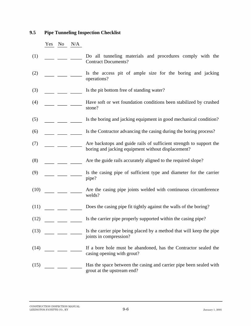
CONSTRUCTION INSPECTION MANUAL LEXINGTON-FAYETTE CO., KY 9-6 January 1, 2005
9.5 Pipe Tunneling Inspection Checklist
Yes No N/A (1) Do all tunneling materials and procedures comply with the
Contract Documents? (2) Is the access pit of ample size for the boring and jacking
operations? (3) Is the pit bottom free of standing water? (4) Have soft or wet foundation conditions been stabilized by crushed
stone? (5) Is the boring and jacking equipment in good mechanical condition? (6) Is the Contractor advancing the casing during the boring process? (7) Are backstops and guide rails of sufficient strength to support the
boring and jacking equipment without displacement? (8) Are the guide rails accurately aligned to the required slope? (9) Is the casing pipe of sufficient type and diameter for the carrier
pipe? (10) Are the casing pipe joints welded with continuous circumference
welds? (11) Does the casing pipe fit tightly against the walls of the boring? (12) Is the carrier pipe properly supported within the casing pipe? (13) Is the carrier pipe being placed by a method that will keep the pipe
joints in compression? (14) If a bore hole must be abandoned, has the Contractor sealed the
casing opening with grout? (15) Has the space between the casing and carrier pipe been sealed with
grout at the upstream end?

CHAPTER 10 BITUMINOUS PAVEMENT CONSTRUCTION

CONSTRUCTION INSPECTION MANUAL LEXINGTON-FAYETTE CO., KY 10-1 January 1, 2005
10.1 Introduction 10.1.1 General The quality of bituminous pavement construction is an important phase of construction that reflects directly on LFUCG's public image. Many other infrastructure construction components, such as sewer lines or pump stations, are soon forgotten by the public once they have been placed beneath the ground and covered. Problems that arise because of poor quality bituminous pavement construction, however, remain visible and may serve as a constant source of complaints long after a project is finished. On infrastructure construction projects, the Inspector may be asked to monitor the construction of new pavements, the repair/resurfacing of existing pavements, asphalt mixes, and/or asphalt compaction. When completing these tasks, the Inspector shall remember the following basic objectives in bituminous pavement construction: 1. Support traffic loads; 2. Protect subgrade, subbase, and/or base from surface water; 3. Minimize loss of surface material; 4. Provide a reasonable surface texture; 5. Provide flexibility for subbase deflections; and 6. Provide resistance to weathering. These basic objectives shall have been incorporated into the design of the pavement sections or repair efforts. One of the Inspector's primary tasks is to understand how field observations of actual construction conditions may affect these basic objectives of road construction and to relay any concerns to the Engineer. Prior to construction of new pavements or the repair/resurfacing of existing pavements, the Inspector shall have a thorough understanding of Contract Documents, the geotechnical report, LFUCG Roadway Manual, relevant LFUCG Standard Drawings, and the individual components of the pavement section. In some instances, the project specifications may dictate the use of lime stabilization or cement modification (or other means) to stabilize bearing materials. In these instances, the Inspector shall obtain the appropriate construction specifications, product data, or reference materials and become familiar with the particular job requirements. At other times, the Contract Documents may place logistics constraints on the Contractor (i.e. the Contractor may be required to pave certain areas before others, etc.). The Inspector shall observe the Contractor operations and notify the Engineer when these constraints are not being met. The Contract Documents may require the Contractor to submit material certifications, aggregate sieve analyses, and bituminous pavement mix formulas. Prior to construction, the Inspector shall verify that the appropriate submittals have been made and approvals received. The status of

CONSTRUCTION INSPECTION MANUAL LEXINGTON-FAYETTE CO., KY 10-2 January 1, 2005
contractor submittals shall be tracked on the form presented in Section 3.0. All Inspector observations and field test results shall be documented using the Daily Field Report form shown in Section 3.0. 10.1.2 Definitions Aggregate - A hard granular material of mineral composition such as sand, gravel, or crushed stone. Asphalt - A dark brown to black cementitious material in which the predominating constituents are bitumens that occur in nature or are obtained in petroleum processing. Asphalt is a constituent in varying proportions of most crude petroleums. Asphalt Base Course - A foundation course or pavement layer consisting of well-graded mineral aggregate mix bound together with asphalt material on which successive course(s) are placed. Asphalt Surface Course - The top course of an asphalt pavement, sometimes called asphalt wearing course. Cement Modification - The modification of a soil mass through the addition of measured amounts of Portland cement and water that is thoroughly mixed and compacted. Cutback Asphalt - Asphalt cement that has been liquefied by blending with petroleum solvents. Upon exposure to the atmosphere, the solvents evaporate leaving the asphalt cement to perform its function. Dense Graded Aggregate - An aggregate that has a particular size distribution such that when it is compacted, the resulting voids between the aggregate particles, expressed as a percentage of the total space occupied by the material, are relatively small. Emulsified Asphalt - Asphalt cement that has been liquefied by blending with water and an emulsifying agent. Upon exposure to the atmosphere, the water evaporates, and the asphalt cement is left behind to perform it function. Granular Base Course - A layer of dense graded aggregate placed and compacted on the subgrade to serve as a stable foundation upon which asphalt pavement is placed. Lime Stabilization - The addition of lime to increase or maintain the stability of a soil mass or to otherwise improve engineering properties. Pugmill - Type of mixer used to combine dense graded aggregate base material with the amount of water necessary to achieve proper compaction in the field. Resurfacing - A supplemental surface or replacement placed on an existing pavement to restore its riding qualities or increase its strength.

CONSTRUCTION INSPECTION MANUAL LEXINGTON-FAYETTE CO., KY 10-3 January 1, 2005
Subbase - A layer of aggregate or soil of planned thickness and quality placed on the subgrade soil as a foundation for the granular base course. The upper portions of the subgrade may also be improved with cement modification, lime stabilization, or geotextile aggregate combinations, and this improved layer can be termed the subbase. Subgrade - The portion of a roadbed surface, which has been prepared as specified, upon which a subbase, base, base course, or pavement is to be placed. Swale - An elongated depression in the land surface that is normally without flowing water. Tack Coat - A sprayed application of an emulsified asphalt to an existing pavement, prior to placing the surface course. The purpose of the tack coat is to promote a bond between the existing pavement and the course that is to be placed over it. Wedge - To apply one or more asphalt courses of variable thickness to eliminate irregularities on an existing pavement surface prior to resurfacing.

CONSTRUCTION INSPECTION MANUAL LEXINGTON-FAYETTE CO., KY 10-4 January 1, 2005
10.2 New Pavements New pavements are typically comprised of four components. The prepared roadway bed is typically called the subgrade. The subgrade may consist of natural soils or an approved soil fill. In some instances, the uppermost surface (6-18 inches) of the subgrade is modified to improve bearing characteristics and increase stability. This modified or improved zone of the subgrade is sometimes called the subbase. The subbase may also consist of select materials, such as natural gravels or merely select borrow material. The granular base course typically overlies the subgrade (and subbase) and generally consists of dense-graded aggregate (DGA). The granular base is followed by a mixture of asphalt and coarse-grained aggregate called the asphalt base course. The final (top) component of the bituminous pavement section is the asphalt surface course, which is generally thinner than the underlying base course, contains smaller aggregates, and more bitumen. Figure 10.1 illustrates the typical components of a pavement section. The thickness and composition of the pavement section is typically based on an engineering design utilizing the site-specific soils. Soil samples are normally collected during the geotechnical exploration of the site and are subjected to tests that indicate their acceptability for bearing materials. A typical test to indicate acceptability of bearing medium is the California Bearing Ratio (CBR) (ASTM D 1883) test. Unfortunately, in Fayette County, many of the residual soils have high clay contents and are poor bearing media, (i.e., low CBR). High clay contents typically mean poor drainage characteristics and low long-term strengths. Consequently, many pavement designs in the Fayette County area incorporate the use of subgrade modifications such as additions of cement or lime, biaxial geogrids, filter fabric or aggregate subbases. Pavement sections may also incorporate means to improve natural drainage characteristics such as piping networks or the addition of open-graded subbases. The Inspector shall be familiar with the descriptions of soils utilized in the pavement design, and have a basic understanding of the drainage requirements so that he/she is able to identify changed subgrade and drainage conditions and bring them to the attention of the Engineer. In addition, the Inspector shall verify that "No Parking" signs have been erected 24-hours prior to commencement of paving.


CONSTRUCTION INSPECTION MANUAL LEXINGTON-FAYETTE CO., KY 10-6 January 1, 2005
10.2.1 Subgrade Section 5.0 of this manual presents the Inspector guidelines for earthwork as it relates to clearing and grubbing, placement of fills, compaction, undercutting, excavations, etc. All of the earthwork components discussed therein are necessary so that a stable pavement subgrade can be achieved. Unless otherwise provided for in the Contract Documents, several items shall be verified by the Inspector prior to establishing subgrade competency. These items include: 1. Verify that any bedrock identified at the subgrade level has been undercut to the depth
specified in the Contract Documents. 2. Verify that utilities which traverse the roadway alignment have been installed, 3. Verify that the subgrade is free from ruts, large stones, and excessive dust, 4. Verify that the subgrade elevation is correct according to the cross-sections and alignment,
and 5. Request a subgrade proof-roll test. Regarding items 1 through 4, any noteworthy observations shall be brought to the attention of the Engineer. These verifications will help reduce the amount of interruptions in the paving operations and future discontinuities in the pavement surface. Regarding item 5, the Inspector shall request that the roadway subgrade be subjected to a subgrade proof-roll test so that soft, wet, or pumping areas may be identified. The minimum total weight of the loaded dump truck shall be 37 tons. The truck shall be operated at walking speed over the entire subgrade. Any excessive deflections such as rutting or pumping may require stabilization measures and shall be brought to the attention of the Engineer. The Inspector shall observe the operations to verify correct speed and ensure all areas of the subgrade are covered. Typical treatments of soft or wet areas of the pavement subgrade include removal and replacement (undercutting), “working-in” No. 2 stone, or installation of a geogrid/geotextile system and crushed stone. The extents and performance requirements of such improvements shall be set forth in the Contract Documents or as directed by the Engineer. Other means to stabilize the subgrade are available. Lime stabilization or cement modification (KTC Section 304) may be required and the Inspector shall become familiar with the requirements in the Contract Documents for each. On projects that require these special treatments, the Inspector shall consult with the Engineer to obtain a revised Proctor curve(s), compaction requirements, and construction operations to be utilized. The Inspector shall be aware that changes in soil subgrade conditions (material types, moisture conditions, etc.) may have a direct influence on the type and extent of stabilization/modification being utilized and he/she shall stay in close contact with the Engineer. Any deviations from the Inspector's understanding of the required soil conditions, compaction requirements, application rates or construction operations and procedures shall immediately be reported to the Engineer.

CONSTRUCTION INSPECTION MANUAL LEXINGTON-FAYETTE CO., KY 10-7 January 1, 2005
The pavement subgrade shall be compacted to a uniform density throughout according to the requirements of the Contract Documents. If the density of the subgrade has been diminished by exposure to weather, after having been previously compacted, it shall be recompacted to the required density and moisture content. Observations made shall be reported on the Pavement Subgrade Inspection Form presented - Section 3.0. At the completion of subgrade verification and preparation operations, the Contract Documents may require the installation of subgrade drainage systems or perforated pipe underdrains. LFUCG Standard Drawings shall be utilized where appropriate. 10.2.2 Subbase Subbases, if required by the Contract Documents, may consist of select materials, such as natural gravels, that are stable but that have characteristics that make them not completely suitable as granular base courses. Subbases may also be of stabilized soil or merely select borrow. The purpose of a subbase is to permit the building of relatively thick pavements at low costs. Thus, the quality of subbases can vary within wide limits, as long as the thickness and material requirements set forth in the Contract Documents are fulfilled. Because subbases may consist of a variety of material types and consistencies, they can be grouped according to the nature of quality control procedures that shall be implemented during placement. Typical groupings utilized in the Contract Documents are "Soils" and "Aggregates.” Select borrow soils are typically placed in an engineered fashion as described in Section 5.0 to a specified density and within a certain percentage of optimum moisture content. The Inspector shall verify that the necessary soil samples have been obtained and that the proper tests have been performed. The Inspector shall assist the Contractor with obtaining representative samples from the proposed borrow area(s). Further, the Inspector shall review the results of the testing to ensure that the soils fulfill the requirements of the Contract Documents. Such information may include a complete soil classification (ASTM D 2487), CBR, and Proctor moisture-density relationship (ASTM D 698 or ASTM D 1557). The soils shall be placed in accordance with the Contract Documents that usually include a maximum loose lift thickness of 8 inches and a compacted density of 95 percent of the standard Proctor maximum dry density. Aggregate materials utilized as subbase shall be placed in accordance with the Contract Documents. Aggregates with a small percentage of fines are typically bladed in place and tamped to minimize voids and bridging. Aggregates with a greater percentage of fines, such as dense-graded aggregate (DGA), are typically compacted to a certain percentage (usually 84 percent) of the solid volume density determined from the oven-dry bulk-specific gravity (KM 64-607). If the top surface of the subgrade has been modified with the application of cement or stabilized with lime, the Engineer or Contract Documents may treat this zone as a subbase. In any case, the precautions and items to observe for such improvements are noted in Section 10.2.1. The Inspector shall also be aware that the pavement section may also include aggregate-geogrid or aggregate-geotextile layers. The Inspector shall become familiar with the construction techniques discussed in the Contract Documents as well as their testing requirements. Under all circumstances, the Inspector shall verify that construction materials, specified depths or

CONSTRUCTION INSPECTION MANUAL LEXINGTON-FAYETTE CO., KY 10-8 January 1, 2005
thicknesses and construction practices are implemented in the field as specified in the Contract Documents. Any deviations shall be brought to the attention of the Engineer. 10.2.3 Granular Base Course The granular base course, unless stated otherwise in the Contract Documents, shall consist of compacted dense-graded aggregate (DGA) meeting the requirements set forth in Section 805 of the Kentucky Transportation Cabinet's (KTC) Standard Specifications for Bridge and Road Construction. The Contract Documents may require that the DGA be obtained from a previously approved source. If the DGA source has not previously been approved, the Contractor may be required to submit results of physical tests performed on the material to verify that it meets the requirements referenced above. The Inspector shall assist the Contractor in obtaining a representative sample and in its care and handling. The DGA shall be applied in thicknesses specified in the Contract Documents. Typically, these lifts are no less than 3 inches and no more than 6 inches in thickness. Each lift of DGA shall be compacted to a density specified in the Contract Documents that is generally no less than 84 percent of the solid volume density based on the oven-dry bulk specific gravity as determined by KM 64-607. A typical minimum frequency for field density testing of DGA placement is one test per 2,000 square feet with a minimum of one test per shift during which DGA is placed. The DGA shall be compacted using a vibratory roller or vibratory plate. In addition to the previously stated guidelines for compaction equipment and lift thickness, the Inspector shall pay close attention to the moisture content of the DGA base during placement and compaction. Before arriving at the site, the DGA shall be adequately mixed with water in a pugmill. During transportation and storage on site, the DGA shall be covered to prevent loss of moisture. DGA shall not be stored or stockpiled at the site unless otherwise provided for in the Contract Documents. If drying of the DGA occurs, the Contractor shall add water to the DGA and shall thoroughly mix the material prior to its placement. A moisture content value between five and seven percent at the time of compaction is typically adequate for the placement of limestone DGA. 10.2.4 Asphalt Base and Surface Courses An asphalt base course is an intermediate asphalt course placed between a granular base course and an asphalt surface course. The surface course represents the top portion of the asphalt pavement. These asphalt mixes consist of well-graded aggregate and asphalt cement. The aggregate gradation of the base is typically coarser than that of the surface mix. In addition, in a typical mix, the asphalt content will range from 4 to 8 percent, by weight. The aggregate gradation and asphalt content requirements shall be specified in the Contract Documents. The Inspector shall compare test results and certifications submitted by the Contractor with the requirements to ensure compliance. The requirements of the equipment used to spread and compact bituminous pavement shall meet the requirements of the Contract Documents. The paver must spread the mixture without tearing the surface and must strike a finish that is true to the required cross section, uniform in density and texture, and free of irregularities. The speed of the paver shall be adjusted as necessary to

CONSTRUCTION INSPECTION MANUAL LEXINGTON-FAYETTE CO., KY 10-9 January 1, 2005
that speed which provides the best result for the type of mixture being placed. The Inspector shall observe each course immediately after striking off and before rolling for irregularities that require correction. Fat sandy droppings shall be removed and fat areas shall be removed and replaced with satisfactory material. Any portion of the pavement course that is defective or that shows excessive segregation shall be removed and replaced with suitable material. Well proportioned asphalt mixes compact readily if spread and rolled at proper temperatures. Compaction requirements vary widely from project to project and consequently, the Contract Documents shall be referenced in this regard. Rolling shall start immediately after the material has been spread by the paver, provided undue lateral movement does not take place under the roller. If rolling causes displacement of the material, the affected areas shall be loosened at once with an asphalt rake and restored to the original grade with loose material before re-rolling. Rolling shall be done with care to prevent undue roughening of the pavement surface. Rolling of a longitudinal joint shall be done immediately behind the paving operation. The initial, or breakdown, pass with the roller shall be made as soon as it is possible to roll the mixture without cracking the mat or having the mix picked up on the roller wheels. The second, or intermediate, rolling shall follow the breakdown rolling as closely as possible and shall be done while the paving mix is still at a temperature that will result in maximum density. The finish rolling shall be done while the material is still workable enough for removal of roller marks. Roller wheels shall be kept moist during compaction, with only enough water to prevent the wheels from picking up the asphalt mixture. Rollers shall move at a slow but uniform speed generally with the drive roller or wheels nearest the paver. The line of rolling shall not be suddenly changed or the direction of the roller suddenly reversed. The pavement course thicknesses and construction tolerances shall be specified in the Contract Documents. The surface of each course shall be checked with templates, straightedges, and/or stringlines for uniformity. These checks can be made by the Contractor in the presence of the Inspector. All irregularities exceeding the allowable tolerances must be repaired as required by the Contract Documents or as directed by the Engineer. The Inspector must note all checks and measurements made of pavement surface uniformity in the Daily Field Report and report any repairs made. 10.2.5 Tack Coat The purpose of the tack coat is to increase the bond between old and new surfaces. It may be required on new pavements between the binder and surface courses or on repair of existing pavements. If the tack coat is too heavy, the tack coat may act as a lubricant between the two surfaces, causing the mat to slip when rolled. If the tack coat is not adequate, the mat will not bond to the underlying course properly and may slip under the roller, causing waving or cracking of the mat being placed. In either case, subsequent raveling will occur and eventually a deterioration of the surface will develop. Unless otherwise stated in the Contract Documents, the tack coat shall be type SS-1h. Prior to applying the tack coat, the area to receive pavement shall be cleaned. The tack coat shall be

CONSTRUCTION INSPECTION MANUAL LEXINGTON-FAYETTE CO., KY 10-10 January 1, 2005
applied well in advance of the paving operation to allow all water to evaporate before the surface course is placed. This chemical process is termed "breaking" or "setting.” One way to determine when the material has set is that its color will change to dark brown within a short time after application, with the exact length of time depending on the ambient and pavement temperatures. Work shall be planned so that no more tack coat than is necessary for the day's operation is placed on the surface. Existing traffic and weather conditions may curtail the distance tack can be placed ahead of the paving operation.

CONSTRUCTION INSPECTION MANUAL LEXINGTON-FAYETTE CO., KY 10-11 January 1, 2005
10.3 Existing Pavements Many LFUCG projects require construction in pavement areas. Following construction, disturbed areas must be repaired and repaved appropriately. The Contract Documents may also require resurfacing of existing pavements. Criteria governing the restoration of damaged pavement areas shall be included in the Contract Documents. All cutting back and restoration of existing pavement damaged due to trenched utility construction shall conform with the LFUCG Standard Drawings unless otherwise required by the Plans and Specifications. 10.3.1 Preparation of Paving Areas Prior to placing surface course materials, all areas to receive pavement must be properly prepared. Cut-backs must be constructed on each side of utility trenches in accordance with the Contract Documents or LFUCG Standard Drawings, as applicable. The Inspector shall observe that sections of pavements to be removed are cut in straight lines in such a manner that all joints between existing and new pavement will be smooth and continuous. If additional pavement must be removed, other than the pavement that was removed during initial trench construction, it shall be cut using a pavement saw in such a manner that a straight transition zone is provided for pavement restoration. All cutting of the pavement shall extend to the subgrade and the affected area shall be completely excavated. Within the limits of the cut-backs the base, and subgrade immediately below the surface course shall be replaced with concrete, as shown in the LFUCG Standard Drawings. In some instances, the Contract Documents may require the placement of an asphalt base course prior to resurfacing. In these instances, the areas to receive an asphalt base course shall be cleaned. The remaining discussions in Section 10.2 regarding asphalt base courses apply. During blasting operations, some pavement areas may heave or otherwise be damaged. All areas damaged because of blasting must be cut and excavated to the top of the subgrade. As in trench excavation, the cutting must be performed so that continuous straight lines are formed between the existing and new pavements. On projects in which the road affected by the trench is to be resurfaced entirely, edge keys must be provided at locations where the old and new asphalts meet. Edge keys are necessary to provide a smooth transition between the new and existing surface courses and to prevent spalling of the new asphalt. Edge key details are shown in the LFUCG Standard Drawings. Prior to any resurfacing, all manholes, storm sewer inlets, and catch basins must be adjusted to the proper elevations. On drainage projects, the depth of all swales located within driveways or entrances shall be checked prior to paving to verify that safe traffic crossing can be made. 10.3.2 Surface Course The placement of the surface course is slightly different for patching and resurfacing pavement operations. For jobs in which the pavement is to be patched, the surface course shall be placed

CONSTRUCTION INSPECTION MANUAL LEXINGTON-FAYETTE CO., KY 10-12 January 1, 2005
and compacted to the required thickness, in such manner that the top of the surface course is level with the existing pavement. Care shall be exercised to ensure that a smooth transition occurs between the existing pavement and the pavement patch. Following placement of the surface course, the perimeter of the patched area shall be sealed with an approved sealer compound. For jobs in which the entire pavement is to be resurfaced, special precautions shall be taken prior to placing the surface course. The existing pavement shall be checked for any weak or cracked areas, and the necessary repairs shall be made in advance of the placement of the surface course. In areas where the existing asphalt is distorted, the construction of leveling courses or wedges may be necessary to obtain a smooth asphalt surface. A leveling course is an asphalt mat of varying thickness used to eliminate irregularities in the contour of the existing surface, prior to placing the surface course. Wedges, on the other hand, are a series of patches of asphalt plant mix used to level sags and depressions prior to placement of the surface course. If distortion of the existing asphalt is not severe, a leveling course applied with a paver should be sufficient for removing irregularities. If the distortion of the existing asphalt is severe, then wedges must be used to restore the pavement surface. Leveling wedges should be placed in two layers if they are from 3 to 6 inches in thickness. Wedges thicker than 6 inches should be placed in individually compacted layers not exceeding 3 inches in thickness. In placing multiple layers, the layer of shortest plan dimension shall be placed first with the successive longer layer or layers extending over or covering the shorter ones. If incorrect methods are used, there is a tendency of a series of steps to develop at each joint because of the difficulty of feathering out asphalt mixes at the beginning and end of a layer. Bumps are very likely to form at these improper joints after the placement of the surface course. Correct and incorrect procedures for placing leveling wedges are illustrated in Figure 10.2. After all necessary surface repairs have been made to the existing asphalt, including manhole adjustments, the entire area to receive pavement shall be cleaned. The existing pavement shall be hosed down and swept accordingly. A tack coat shall be applied to the area sufficiently ahead of the paving operation to allow breaking of the tack coat (see Section 10.2.5). After all preparations have been completed, the surface course shall be placed and compacted to the required thickness. When the placement of pavement results in an abrupt vertical transition adjacent to the shoulders, the contractor shall place additional pavement so as to provide a smooth transition from the pavement surface to the original shoulder. The bituminous surface course shall be tapered at driveways and entrances to a feather-edge at the edge of the pavement. Edge keys are not necessary at driveways and entrances.


CONSTRUCTION INSPECTION MANUAL LEXINGTON-FAYETTE CO., KY 10-14 January 1, 2005
10.4 Inspection of Asphalt Mixes All asphalt mixes used for infrastructure construction projects shall be inspected prior to placement. Some projects require only limited use of asphalt mixes. The inspection on these projects shall consist of observing the asphalt mix prior to placement and noting any inconsistencies. Guidance on the level of inspection and conformance testing shall be sought from the Contract Documents and the Engineer. Any asphalt mix delivered to the project site that is deemed to be inadequate by the Inspector shall be brought to the Contractor's attention immediately. Rejection of the asphalt mix shall be exercised as a last alternative, if corrective measures are not taken. Typically, asphalt mixes used on projects should be composed of a well-graded aggregate mixture containing no particles larger than 3/8-inch, with an asphalt content of 4 to 8 percent. The temperature of the asphalt mix during placement shall range between 225°F to 325°F. During asphalt inspection, the following criteria shall be used for judging the quality of the asphalt mix: 1. Blue Smoke. Blue smoke rising from the mix in the truck or in the spreading device may
indicate an overheated batch. The temperature of the mix shall be checked immediately with an asphalt thermometer to ensure that the temperature does not exceed 325°F.
2. Stiff Appearance. A stiff appearance, or improper coating of the larger aggregate particles
may indicate a cold mixture. The temperature of the mix shall be checked, and if it is below the optimum placing temperature, but within the specified range for placement of 225°F to 325°F, immediate steps shall be taken to notify the asphalt plant to correct the condition. If the temperature is below the specified range, the asphalt mix shall be rejected.
3. Mix Slumped in Truck. When loads have been arriving at the spreader with the material
peaked, or domed up, and a load suddenly appears in which the material lies flat, or nearly flat, it may contain too much asphalt.
4. Lean, Dull Appearance. A mix that contains too little asphalt generally can be detected
immediately in the truck or in the spreader by its lean, granular appearance, improper coating of the aggregates, and lack of the typical shiny black luster. Lack of sufficient asphalt in the mix can be detected on the road by a lean, brown, dull appearance on the surface and by unsatisfactory compaction under the roller.
5. Rising Steam. Excess moisture may be detected by steam rising from the mix when it is
dumped into the hopper or the paver. The hot mix may be bubbling and popping as if it were boiling. The mix may also appear to contain too much asphalt.
6. Segregation. Segregation of the aggregates may occur because of improper handling of the
mix. To avoid segregation, the asphalt mix shall be spread uniformly with a paver. If hand spreading is required, the asphalt mix shall be shoveled with care so that the material is not dispersed by "throwing" the asphalt mix into place.

CONSTRUCTION INSPECTION MANUAL LEXINGTON-FAYETTE CO., KY 10-15 January 1, 2005
7. Contamination. Mixes can become contaminated in a number of ways: by spilled gasoline, kerosene, or oil, or by rags, paper, or trash and dirt in or on the mixture. The contamination can be removed if it is not too extensive.
No paving shall be conducted between November 15 and April 1 without written permission from the Engineer. In addition, paving shall not be placed on any wet surface or when the ambient air temperature is less than the recommended minimum temperature presented below unless otherwise allowed by the Contract Documents or Engineer.
TABLE 10.1 TEMPERATURE LIMITATIONS
Minimum Ambient
Bituminous Mixtures
Air Temperature for Placing
(Degrees Fahrenheit) Bituminous Concrete Surface, 1" thick or less 45 Bituminous Concrete Surface, thicker than 1" 40 Bituminous Concrete Base 35 Leveling and Wedging 45
During paving operations, the thickness and longitudinal dimensions of the asphalt shall be checked for conformance with the Contract Documents. Longitudinally, the finished surface of the binder course typically shall not deviate by more than 1/4-inch over a 10-foot length. The finished surface of the surface course typically shall not deviate by more than 1/8-inch over a 10-foot length. The cross slope of all courses shall not deviate from the specified cross-section by more than 1/4-inch in 5 feet.

CONSTRUCTION INSPECTION MANUAL LEXINGTON-FAYETTE CO., KY 10-16 January 1, 2005
10.5 References 10.5.1 Publications Construction Inspection Guidance Manual, Louisville and Jefferson County Metropolitan Sewer District (MSD), Revised Edition, May 1993. Lexington Fayette Urban County Government Standard Drawings, June 1997, Review Submittal. Lime Roadbed Stabilization, Kentucky Transportation Cabinet, Special Provision No. 84, B(91). National Engineering Handbook Section 19, Construction Inspection, United States Department of Agriculture, Soil Conservation Service, 1985. Principles of Construction of Hot-Mix Asphalt Pavements, Asphalt Institute, Manual Series No. 22, 1983. Soil Stabilization in Pavement Structures, United States Department of Transportation, Federal Highway Administration, 1979. Standard Specifications for Road and Bridge Construction, Kentucky Transportation Cabinet Department of Highways, 1984. The Asphalt Handbook, Asphalt Institute, Manual Series No. 4, 1989. 10.5.2 Test Methods and Specifications ASTM D 698, Test Method for Laboratory Compaction Characteristics of Soil using Standard Effort. ASTM D 1557, Test Method for Laboratory Compaction Characteristics of Soil Using Modified Effort. ASTM D 1883, Test Method for CBR (California Bearing Ratio) of Laboratory Compacted Soils. ASTM D 2487, Test Method for Classification of Soils for Engineering Purposes. KM-64-607, Specific Gravity and Absorption of Coarse Aggregates, Kentucky Transportation Cabinet (KTC), Kentucky Test Methods Manual. KM-64-620, Wet Sieve Analysis of Fine and Coarse Aggregates, Kentucky Transportation Cabinet (KTC), Kentucky Test Methods Manual.

CONSTRUCTION INSPECTION MANUAL LEXINGTON-FAYETTE CO., KY 10-17 January 1, 2005
10.6 Bituminous Pavement Construction Inspection Checklist 10.6.1 New Pavement
Yes No N/A (1) Has the subgrade been constructed to the proper lines and grades? (2) Has the subgrade been proof-rolled? (3) Did the dump truck used to proof-roll the subgrade weigh at least
37 tons? (4) Was excessive rutting or deflection observed during the proof-roll? (5) Have soft or wet areas in the subgrade been observed? (6) Have soft areas and areas that rutted during proof-rolling been
stabilized? (7) Do the Contract Documents specify construction of subbase? (8) Is cement modification or lime stabilization of the subgrade
required? (9) If cement modification or lime stabilization of the subgrade is
required, have the revised Proctor curves and lime/cement application rates been submitted?
(10) Has the Contractor submitted the required material certifications,
aggregate sieve analysis, and asphalt mix formulas? (11) Have the appropriate approvals been received for the above
submittals? (12) Is the granular base course being properly placed and compacted? (13) Is the DGA at the proper moisture content during placement and
compaction? (14) Have “No Parking” signs been erected at least 24 hours prior to
paving? (15) Prior to placing the surface course, is the asphalt base course being
cleaned and treated with tack coat?

CONSTRUCTION INSPECTION MANUAL LEXINGTON-FAYETTE CO., KY 10-18 January 1, 2005
Yes No N/A (16) Is the tack coat allowed to “break” prior to placing the surface
course? (17) Are the asphalt base and surface courses being placed with
equipment and machinery meeting the requirements of the Contract Documents?
(18) Is the asphalt mix being properly rolled so that it is compacted to
the required thickness? (19) Does all asphalt mix delivered to the site appear to be acceptable
with respect to color, texture, asphalt content, and temperature? 10.6.2 Existing Pavement
Yes No N/A (1) Are all areas of pavement repair being cut back properly in straight
lines so that joints between existing and new pavements will be smooth and continuous?
(2) Do the pavement cut-backs conform to the Contract Documents
and the LFUCG Standard Drawings? (3) Is the pavement being cut with a pavement saw? (4) Within the area of the cut-back, has the pavement been replaced in
accordance with the Contract Documents and the LFUCG Standard Drawings?
(5) In areas to be completely resurfaced, are edge keys properly
constructed where old and new pavements are joined? (6) If required, have all manholes, storm sewer inlets, and catch basins
been adjusted to the proper elevation? (7) If necessary, have wedges or leveling courses been placed
properly? (8) Have all requirements of the Contract Documents been met
regarding the placement of the driveway wedges and adjustment to pavement shoulders?

CHAPTER 11 CONCRETE CONSTRUCTION

CONSTRUCTION INSPECTION MANUAL LEXINGTON-FAYETTE CO., KY 11-1 January 1, 2005
11.1 Introduction 11.1.1 General Concrete is commonly used as a construction material on public infrastructure projects because it provides high compressive strength, water tightness, and durability and abrasion resistance. In addition, concrete can be readily formed in a just poured state to fit construction needs and requirements. The quality of finished concrete is largely dependent on the proper control of the initial ingredients of the concrete mix and of the concrete placement and finishing. Therefore, careful monitoring of concrete operations is essential for proper construction. Generally, infrastructure projects features requiring concrete construction include pipe encasements, paved ditches, drop inlets, headwalls, catch basins, box culverts, large junction structures, and pump stations. 11.1.2 Definitions Admixtures - Materials other than water, aggregate, or cement added to the batch before or during mixing to modify the properties of the concrete mix. Examples include air-entraining admixtures, water reducers, and superplasticizers. Aggregates - Hard granular materials of mineral composition, such as sand, gravel, slag, or crushed stone, used for mixing in graduated sizes of fragments. Air Content - Percent of air by volume in fresh concrete determined by ASTM C231, ASTM C 173, or ASTM C 138. ASTM - An abbreviation for American Society for Testing and Materials. Bleeding - The migration of water to the top surface of freshly placed concrete caused by the settlement of the solid materials within the mass. CRSI - An abbreviation for Concrete Reinforcing Steel Institute. Concrete Cylinders -Concrete samples formed in the field according to ASTM C 31 for laboratory compressive strength testing. Curing - The maintenance of satisfactory moisture content and temperature in concrete during some definite time period immediately following placing and finishing so that the desired properties may develop. Hooks - Steel reinforcement usually used at structural end sections where space limitations prohibit the specified embedment length. Minimum bend diameters are specified by CRSI.

CONSTRUCTION INSPECTION MANUAL LEXINGTON-FAYETTE CO., KY 11-2 January 1, 2005
Rebar - Reinforcing steel used in concrete structures to resist tensile stresses resulting from induced loads. Slump - A measurement of the consistency of fresh concrete as specified in ASTM C 143. Splices - Steel reinforcement that is overlapped or welded together when specified. Steel Grade - A number such as 60, corresponding to the yield strength of the steel reinforcement, i.e., 60,000 psi.

CONSTRUCTION INSPECTION MANUAL LEXINGTON-FAYETTE CO., KY 11-3 January 1, 2005
11.2 Fundamentals of Concrete Concrete is produced by mixing a paste consisting of cement and water with aggregate materials. The most commonly used aggregate materials are sand and gravel or crushed stone. As soon as the cement and water are combined, a chemical process initiates, and in a few hours the mixture begins to harden with the paste functioning to bind the aggregates into a solid mass. Under normal conditions, the hardening process will continue until the concrete assumes a very hard, rock-like character. The properties of the finished concrete, including its strength, weight, color, and porosity, are subject to considerable variation. Variables include the type of cement; the ratio of water to cement; air content; the type, size, and proportional amounts of the aggregates; the various actions performed while mixing and depositing the wet mix; and the weather conditions that occur while the concrete is hardening (called the curing period). Well made concrete has significant resistance to compressive stress, but is relatively weak in resisting tension. In some applications, concrete may be required to resist primarily compressive stresses and thus requires no assistance. For most applications, however, some assistance must be provided to develop tension resistance. The most common assistance is provided in the form of steel reinforcing bars. In addition, a minimum amount of reinforcing steel is normally used to prevent excessive widening of cracks caused by shrinkage and temperature changes. 11.2.1 Cement The cement used most often in concrete construction is Portland cement. Portland cement is a finely powdered, grayish material that consists chiefly of calcium and aluminum silicates. The common materials from which it is made are limestones, clays, and shales. Normally, Type I Portland cement is used for concrete construction on infrastructure projects. When the cement is mixed with water to form the cement paste, it gradually stiffens until it becomes a solid. The cementing properties of the paste are due to a chemical reaction, known as hydration, which occurs between cement and water. This reaction results in recrystallization of the cement. Generally, an amount of water equal to about 25 percent of the cement, by weight, is needed chemically to provide complete hydration. Additional water, however, is required to provide the necessary workability of the concrete mix. This additional water produces pores in the cement paste that decrease its strength. Therefore, the strength of the cement paste, and correspondingly, of the finished concrete, depends largely on the water-cement ratio. The amount of water that may be added to concrete is limited by the design water-cement ratio. If the design water-cement ratio is exceeded during the batching or subsequent placement of the concrete mixture, the resulting concrete will have a reduced strength and will be subject to cracking. 11.2.2 Aggregates The materials held together by the paste formed by cement and water are the aggregates. In ordinary structural concrete, the aggregates occupy about 60 to 80 percent of the volume of the

CONSTRUCTION INSPECTION MANUAL LEXINGTON-FAYETTE CO., KY 11-4 January 1, 2005
hardened mass. In general, the more densely the aggregates can be packed, the better are the strength, weather resistance, and economy of the concrete. For this reason, the gradations of the particle sizes in the aggregates are of considerable importance. It is also important that the aggregates have good strength, durability, and weather resistance; that aggregate surfaces be free from impurities such as loam, silt, and organic matter which may weaken the bond with the cement paste; and that no unfavorable chemical reactions take place between the aggregates and the cement. Natural aggregates are generally classified as fine and coarse. Fine aggregate or sand is any material that will be retained on a No. 200 sieve, but will pass a No. 4 sieve, i.e., consists of particles ranging in size from approximately 0.005 to 0.25 inches. Coarse aggregate is any material that will be retained on a No. 4 sieve, i.e., consists of materials greater than 0.25 inches. 11.2.3 Admixtures Substances added to concrete to improve its workability, accelerate its set, harden its surface, and increase its waterproofing qualities are known as admixtures. These substances include all materials other than cement, water, and aggregates that are added just before or during mixing. The major types are accelerating, air-entraining, water-reducing and set-controlling admixtures, finely divided mineral admixtures, and superplasticizers. Accelerating admixtures are added to the concrete mix to reduce the time of setting and accelerate early strength development. Air-entraining admixtures form small bubbles in the concrete mix that increase the workability and the freeze-thaw resistance of the concrete. Water-reducing admixtures are for the purpose of reducing the quantity of mixing water required to produce concrete of a given consistency. Finely divided mineral admixtures are used to correct deficiencies in the concrete mix by providing missing fines to the fine aggregate. In addition, they reduce the permeability of the concrete. Superplasticizers are added to increase the workability of concrete temporarily, without adding additional water.

CONSTRUCTION INSPECTION MANUAL LEXINGTON-FAYETTE CO., KY 11-5 January 1, 2005
11.3 LFUCG Concrete Requirements Unless stated otherwise, concrete used on infrastructure projects shall be Class A or Class B. Class A concrete is used in structural concrete, headwalls, small retaining walls, culverts, sidewalks, curbs, driveways, pavements, paved ditches, and paved channel linings. Class B concrete is used for concrete encasements, caps, cradles, lateral risers, gravity retaining walls and for all non-reinforced concrete deposited as fill for cavities or voids, and mass footings. The minimum compressive strength at 28 days (f 'c) for Class A and Class B concrete is 3,500 and 2,500 psi, respectively.

CONSTRUCTION INSPECTION MANUAL LEXINGTON-FAYETTE CO., KY 11-6 January 1, 2005
11.4 Methods of Manufacturing Concrete Concrete may be mixed at the project site, or be delivered to the project site in a mixed form. In almost all cases, the concrete used on infrastructure projects is "Ready-Mixed" concrete. Ready-mixed concrete is manufactured by three methods of mixing: 1. Central-mixed concrete is mixed completely in a stationary mixer and is delivered either in a
truck agitator, a truck mixer operating at agitating speed, or a special nonagitating truck. 2. Shrink-mixed concrete is mixed partially in a stationary mixer and the mixing is completed in
a truck mixer. 3. Truck-mixed concrete is mixed completely in a truck mixer.

CONSTRUCTION INSPECTION MANUAL LEXINGTON-FAYETTE CO., KY 11-7 January 1, 2005
11.5 Pre-Concreting Inspection 11.5.1 General Before concrete is placed at the project site, the specification requirements regarding excavation, formwork, steel reinforcement, and construction joints must be fulfilled and the work inspected. In order to accomplish this, the Inspector must familiarize himself with the Contract Documents, shop drawings, and any revisions pertaining to the project. In addition, all concrete and concreting materials used at the site must conform to the Contract Documents. The Inspector shall document all pre-concreting activities in the Daily Field Report, and record observations made during the inspection of the installation of the steel reinforcement, form work, and excavations in the Preconcreting Inspecting Report presented in Section 3.0. 11.5.2 Excavation Prior to placing concrete, the excavated area shall be inspected for any pockets of soft material that might affect construction support. Any soft zones shall be undercut and backfilled as directed by the Engineer. In excavations to rock, the surface of the rock shall be sound and level. Excavated surfaces against which concrete is to be placed shall be clean and moist, but not so wet that the surfaces become soft. The surfaces shall be free of frost, ice, or mud prior to the placement of concrete. Concrete shall not be placed under water unless permitted in the Contract Documents or approved by the Engineer. Removal of water from excavated areas may require special drainage provisions or pumping. Under no circumstances shall water be allowed to be impounded against concrete prior to its initial set. 11.5.3 Formwork Before concreting is permitted, forms shall be inspected to assure that they are in the correct locations and that they will result in concrete of the required dimensions. All forms shall be mortar-tight and sufficiently strong and rigid to maintain their positions and shapes under loads and operations incidental to the placement and curing of the concrete. During the placing of concrete, the forms shall be watched for evidences of movement and shall be made secure where necessary. The material used for formwork normally consists of wood. Metal and other materials may be used as forms, provided that they provide rigid support. Forms used for permanently exposed concrete surfaces shall be inspected to assure that they are smooth and free from irregularities, dents, sags, or holes. Prior to being re-used, forms shall be cleaned by wire brushing and, if necessary, be reconditioned. Metal forms shall not be sandblasted or abraded to a bright surface. Prior to placing concrete or reinforcing steel, the inside faces of the forms shall be coated with a light non-staining form of oil or lacquer. Coatings shall not be so thick as to stain or soften the concrete surface. Any excess oil or lacquer shall be wiped off. Oil shall not be placed on construction joint surfaces or steel reinforcement.

CONSTRUCTION INSPECTION MANUAL LEXINGTON-FAYETTE CO., KY 11-8 January 1, 2005
All foreign material such as sawdust, chips, blocks, dried mortar, ice and water shall be removed from the formwork prior to concrete. Foreign material is likely to accumulate in corners and places which are difficult to access. In deep narrow forms or other forms that cannot be readily inspected, access openings with sealing doors shall be provided to facilitate the cleaning and inspection of the formwork. All access openings must be sealed prior to placing concrete. 11.5.4 Steel Reinforcement The sizes of steel reinforcing bars are designated by numbers ranging from 2 through 18. For bars 2 through 9, the numbers designate the diameters of the bars in 1/8-inch multiples. For instance, a No. 3 bar has a 3/8-inch nominal diameter. For bar sizes larger than No. 9, the multiple is slightly higher. Under present standards, No. 2 is a smooth round bar and Nos. 3 through 18 are deformed round bars. Weights and nominal dimensions for deformed round bar sizes are shown in Table 11.1.
TABLE 11.1 ASTM STANDARD REINFORCING BARS
Nominal Dimensions - Round
Sections
Bar Size Weight Diameter Cross-Sectional Perimeter Designation (Lbs./Ft.) (Inches) Area (Sq. In.) (Inches)
#3 0.376 .0375 0.11 1.178 #4 0.668 0.500 0.20 1.571 #5 1.043 0.625 0.31 1.963 #6 1.502 0.750 0.44 2.356 #7 2.044 0.875 0.60 2.749 #8 2.670 1.000 0.79 3.142 #9 3.400 1.128 1.00 3.544 #10 4.303 1.270 1.27 3.990 #11 5.313 1.410 1.56 4.430 #14 7.650 1.693 2.25 5.320 #18 13.600 2.257 4.00 7.090
Various grades of steel, which vary in yield strength, ultimate tensile strength, percentage of elongation, bend test requirements and chemical composition, are available for use in concrete structures. The Inspector shall verify that bars having the proper grade are being used. In addition to steel bars, welded wire fabric and polypropylene fibers are often used for concrete reinforcement. Steel reinforcement manufacturers are required to roll onto each bar a symbol identifying the manufacturer's mill, a number corresponding to the size of the bar, a symbol to indicate the type of steel and markings to designate bar grade. Figure 11.1 illustrates standard identification marks for steel reinforcement as specified in the Concrete Reinforcing Steel Institute's (CRSI), Manual of Standard Practice.


CONSTRUCTION INSPECTION MANUAL LEXINGTON-FAYETTE CO., KY 11-10 January 1, 2005
Prior to concreting, steel reinforcement shall be checked for proper grade, size, bending, spacing, location, firmness of installation and surface condition. Figure 11.2 depicts typical bar dimensions for 90° and 180° hooks recommended by CRSI. Unless closer limits are stated in the Contact Documents, reinforcing bars shall be spaced to within a tolerance of plus or minus 1/2-inch and placed to within a tolerance of plus or minus 1/4-inch of the specified clearance from the face of the concrete. Lengths, depths, and radii as shown on the bending details shall be correctly reproduced. Steel shall not be bent or straightened in a manner that would damage the material. Heating of reinforcement for bending shall be resorted to only when the entire operation is approved by the Engineer, as heating may change the characteristics of the steel. If heated, the metal shall not be allowed to exceed a dull red glow. Storage conditions that might cause excessive rusting of the steel shall be avoided. Before reinforcement is placed, the surfaces shall be free from objectionable coatings, particularly heavy corrosion caused by outdoor storage. A thin adherent film of rust or mill scale is not considered to be seriously objectionable, but loose rust or scale that can be removed by rubbing with burlap or by other effective means should be removed. Other objectionable coatings likely to be found on parts of the reinforcement are paint, oil, grease, dried mud, and weak dried mortar that has been splashed on the bars ahead of concrete being placed. If such dried mortar has little or no strength, it shall be brushed from the bars and removed from the forms; if it is difficult to remove, it is probably harmless where it is. Reinforcement shall be properly spaced, spliced, and anchored; embedded a specified minimum distance from the surface; and accurately located and firmly held. The Inspector shall not wait until reinforcement has been wired substantially in place before checking the correctness of its position, but rather to avoid costly mistakes, he/she shall inspect it as early as possible during its placement. To allow adequate time for inspection, the Inspector shall ask the Contractor to keep him/her informed of schedules to place reinforcement. All steel reinforcement shall be positioned accurately in the forms and held firmly in place before and during the casting of concrete, by means of built-in concrete blocks, metallic supports, spacer bars, wires, or other devices adequate to ensure against displacement during construction and to keep the steel at the proper distances from the forms. Bar supports and spacers shall be sufficient in number and strength to properly support the steel, even when it is subjected to construction loads. The use of rocks, wood blocks, or other unapproved objects to support the steel shall not be permitted. The Plans or Contract Documents shall clearly show or describe all reinforcement splice locations, types permitted or required, and for lap splices, length of lap required. Splices shall be made only where required or permitted on the Plans, in the Contract Documents, or as authorized by the Engineer.


CONSTRUCTION INSPECTION MANUAL LEXINGTON-FAYETTE CO., KY 11-12 January 1, 2005
11.5.5 Embedded Items Items to be embedded in cast-in-place concrete such as ties, anchor bolts, inserts, brick, flashing, pipe sleeves, conduits and conduit fittings, manhole steps and other items shall be fixed in position before concrete is placed and held in position until the concrete operations are completed. Built-in fixtures shall not be permitted to affect the positions of steel reinforcement except as shown on the Plans. Correct locations of the embedded items must be verified from the Plans. Where wooden spreaders, keys, joint fillers and similar items are used, they must be constructed in such a manner that the concrete will not be damaged during their removal. Form ties and spreaders shall be removed to a minimum depth of 1 inch from the face of the finished concrete. After all form ties and spreaders are removed, the corresponding holes left in the concrete shall be cleaned and filled with mortar consisting of one part cement and two parts sand. 11.5.6 Construction Joints Joints are installed in concrete structures to control the locations of cracking (control joints), to permit movements between sections of the structure (expansion joints), and to aid in the building of forms and the placing of concrete and reinforcing steel. In addition, joints are used to provide breaks in concrete placement operations. Since joints represent weakened areas of the concrete section, their locations are important. The Inspector shall check the location and type of each joint to confirm that they conform to the Plans. No joints shall be added to a structure without the approval of the Engineer. All joints shall be horizontal or vertical, unless otherwise shown on Plans or approved by the Engineer. Construction joints require special care to develop a good bond between the new and the existing concrete. Wet concrete mixtures must be avoided near a joint since wet mixes tend to segregate and bleed badly, resulting in weak concrete at the surface. Coarse aggregates must be well consolidated near joints, and the surface of the concrete must be relatively smooth. Prior to placing concrete, all key formwork shall be inspected to ensure that the keys will be constructed to the specified dimensions. Prior to placing new concrete, construction joints shall be inspected for proper cleaning. All loose surface materials, foreign materials, and coatings on existing concrete shall be removed, using a stiff wire brush. The joint surface shall be washed with water and kept in a saturated state until the new concrete is placed. It shall be noted that excessive abrasion can damage the concrete surface by removing fine aggregates around and under edges of the coarse aggregates.

CONSTRUCTION INSPECTION MANUAL LEXINGTON-FAYETTE CO., KY 11-13 January 1, 2005
11.6 Concrete Sampling and Testing 11.6.1 General Generally, the decision to require sampling and testing of concrete for a specific project is the responsibility of the Engineer. The types and frequencies of the tests to be performed shall be included in the Contract Documents. If not, the Engineer shall be consulted to establish the type and frequency of concrete tests. Regardless of whether a concrete sampling and testing program is or is not required for a project, the Inspector shall pay particular attention to the consistency of the concrete and give an indication of the amount of water used in the concrete mix. For jobs in which concrete sampling and testing are not required, the Inspector shall have at his disposal a slump cone used for slump testing, so that any questionable concrete mix can be checked and a decision can be made regarding its use in the project. In addition to checking the slump, the Inspector shall pay close attention to the temperature of the concrete and the time elapsed between batching and the subsequent placement. The temperature of concrete at time of placement shall range between 50°F and 90°F, and may be easily determined by use of a concrete thermometer. Concrete with temperatures outside of this range shall not be placed unless otherwise specified in the Contract Documents or approved by the Engineer. For concrete delivered to the site, the elapsed time between batching and placement of concrete shall be noted by examining the batch ticket, which the driver of the ready-mix truck can provide. According to ASTM C 94, no more than 90 minutes or 300 drum revolutions shall elapse between the initial batching at the plant and placement of concrete at the site unless otherwise specified in the Contract Documents or approved by the Engineer. The best way to maintain close control of the quality of concrete used for a large project, while not slowing down the concrete placement operation, is to carefully inspect the initial concrete delivered to the site. If this concrete meets requirements, then subsequent testing shall be limited according to the Contract Documents, or if additional concrete delivered to the site is believed to be inadequate. If the initial concrete fails to meet the requirements, its use shall be rejected and each subsequent delivery of concrete shall be checked until a satisfactory concrete mix is delivered to the site. On concrete pours involving structural concrete or otherwise requiring close quality control, a copy of the batch ticket shall be obtained from the truck driver when each ready-mix truck arrives on site. On the ticket, the time of concrete batching shall already be noted and if the concrete cannot be placed within the specified time limitations, the load of concrete shall be rejected unless otherwise directed by the Engineer. The Inspector shall record on the ticket the following information: 1. time of arrival on site, 2. time of placement, 3. location of the pour,

CONSTRUCTION INSPECTION MANUAL LEXINGTON-FAYETTE CO., KY 11-14 January 1, 2005
4. project/contract number, The copies of these tickets shall be submitted as an attachment to the Daily Field Report to the Engineer. In addition, results of concrete sampling and testing shall be noted on the Report of Test on Concrete Cylinders form presented in Section 3.0. 11.6.2 Slump Testing As previously discussed, the slump test is used to determine the consistency of concrete and to give an indication of the amount of water used in the concrete mix. Generally, slump tests shall be performed at intervals as specified by the Contract Documents or as directed by the Engineer, to verify that concrete delivered to the site is within specified limits. Any concrete that the Inspector feels may have a slump outside of project requirements shall be tested. On projects in which concrete sampling and testing are not specifically required by the Contract Documents, the Inspector shall take it upon himself/herself to perform slump tests. Prior to performing a slump test or any other concrete test, the concrete shall be sampled according to ASTM C 172. Slump testing shall be performed in accordance with ASTM C 143. The minimum and maximum slump requirements for concrete shall be specified in the Contract Documents. If the slump measured at the site is below the minimum requirement, water may be added to the truck according to the Contract Documents to increase the slump to within required limits. The amount of water to be added shall be determined by the concrete supplier. It is very important that the amount of water added does not cause the slump to exceed the maximum requirement. Under no circumstances shall concrete be placed if it exhibits a slump higher than the maximum requirement. All concrete tests shall be performed on the concrete subsequent to the addition of water. 11.6.3 Air Content Testing The air content test is used to determine the amount of entrained air in a concrete mix. Air content tests shall be performed in accordance with ASTM C 173, or ASTM C 231. The number and frequency of air content tests required for a particular project shall be included in the Contract Documents. If that information is absent, the Engineer shall be consulted to determine the need for air content testing. Concrete with air entrainment outside of project requirements as stated in the Contract Documents shall be rejected. If too much entrained air is added to concrete, the strength of the concrete will be reduced. Likewise, if the amount of entrained air is below project requirements, the resulting concrete will be more subject to cracking caused by freezing and thawing. 11.6.4 Test Cylinders Concrete test cylinders shall be made and tested according to ASTM C 31 and ASTM C 39, respectively. The number of test cylinders, the frequency at which test cylinders are to be made, and the age at which test cylinders are to be tested, shall be specified in the Contract Documents.

CONSTRUCTION INSPECTION MANUAL LEXINGTON-FAYETTE CO., KY 11-15 January 1, 2005
Unless stated otherwise, concrete test cylinders shall be made in approved molds 6 inches in diameter and 12 inches in height. Concrete test specimens must be protected from jarring and vibration during the first 24 hours after molding and shall be protected from freezing and hot temperatures. They must be stored upright on a hard, clean, level surface until they have hardened. Careless treatment of specimens can destroy the validity of compressive strength test results. Test specimens can be moved to the appropriate testing agency any time after the first 24 hours. During shipment, the specimens must be handled with care and shall be protected from jarring, vibration, and freezing. Each shipment must have complete identification and sampling data including the date, location of sampling in the structure, slump, air content, concrete and air temperature, and the age at which tests on concrete are to be made. Concrete test specimens shall be shipped to the testing agency as soon as possible so that curing procedures may be implemented. Test specimens that remain on site for long periods of time shall be cured at the site according to ASTM C 31.

CONSTRUCTION INSPECTION MANUAL LEXINGTON-FAYETTE CO., KY 11-16 January 1, 2005
11.7 Concrete Placement 11.7.1 General The quality of finished concrete greatly depends on the handling of the concrete mix during placement. The entire concrete placement operation shall be carefully inspected, and any concrete sampling or testing shall not interfere with the inspection process. The Contractor may select methods and facilities to be used during concrete placement as long as they are capable of producing the desired finished product. The Inspector shall be responsible for observing that all methods and facilities used will produce acceptable results. Any equipment or procedures incapable of producing acceptable results must be modified promptly or replaced. During concrete placement, segregation of the coarse aggregate from the mortar, or loss of free water (bleeding) from the concrete mixture must be avoided. If the concrete is discharged at an angle from the mixer or conveyor, the largest aggregate is thrown to the far side of the container or form while the mortar is thrown to the near side. For this reason, all hoppers, chutes, buckets and other concrete conveyors must be provided with vertical drops at their points of discharge. In placing concrete, the first batch must be placed at the far end of the form. Then each new batch is dumped against, not away from, previously placed concrete. The concrete shall not be dumped in separate piles, then leveled and integrated. On all jobs, it is necessary to prevent water from collecting at the ends and corners and along the form faces. A summary of the procedures that shall be following during concrete placement, unless specific exemptions are authorized, is presented below: 1. The concrete must be conveyed from the mixer or transit mixer to the forms or subgrades as
rapidly as is practicable by methods that prevent segregation or loss of the ingredients. When chutes are used, slopes of the chutes must be no steeper than 1 horizontal to 2 vertical unless baffles are provided. Vertical drops must be no greater than 5 feet unless a tremie or similar device is used to prevent segregation.
2. Concrete placement shall be restricted to that amount which can be satisfactorily
consolidated and properly finished at one time. 3. The concrete shall be deposited as closely as possible to its final position. Rehandling shall
be held to a minimum, and the concrete shall not be moved laterally by vibrators. 4. Vibrators shall be operated so as not to distort forms. Forms shall be checked continually
during concrete placement to be sure that they have not moved and that wedges, ties, and bracings have not loosened or failed.
5. Concrete shall be placed in uniform, continuous layers no more than 20 inches deep until the
monolith is completed. If placing is interrupted long enough for initial hardening to take place, a construction joint must be formed.

CONSTRUCTION INSPECTION MANUAL LEXINGTON-FAYETTE CO., KY 11-17 January 1, 2005
6. The total time between batching and final placement shall not exceed 90 minutes, provided that mixing is continuous in the truck agitator. On large continuous concrete pours, the elapsed time between the placement of subsequent batches of concrete shall not exceed 20 minutes, unless otherwise approved.
7. Construction joints shall be allowed to cure for at least 12 hours or as otherwise specified by
the Contract Documents before additional rebars and forms are installed or before new concrete is placed. The construction joints must be prepared as stated in the Contract Documents.
8. If a mechanical vibrator is used to consolidate concrete, vibration shall not be applied
through the forms or used to move the concrete laterally. Vibration shall be supplemented by hand spading on the exposed faces along the forms. Too much vibration causes segregation, sand streaking, excessive laitance, and bleeding. Too little vibration results in poor consolidation and honeycombing.
9. All concrete shall be placed in such a manner that the top surface is level with respect to the
forms. Finishing shall be performed after the concrete has hardened enough to prevent an excess of fine material and water from working to the surface. Finishing at too early a stage can result in fine surface cracks and reduced surface durability. Delaying finishing too long results in a surface too hard to finish properly. Overworking the concrete at any stage prior to the initial set tends to concentrate water and fines at the surface and cause fine hairline cracking (crazing), dusting, and poor surface durability. Cracking also can result from rapid drying or cooling of the concrete surface. To prevent surface cracking when the temperature is high and the humidity is low, it may be necessary to apply a fine spray (fog) of water to the surface until the curing process can be initiated. 11.7.2 Hot Weather Concreting When the weather is hot and the temperature of the concrete mixture approaches 90°F, special measures are necessary to obtain concrete of good quality. Wind and low humidity increase the problem. High temperatures cause rapid evaporation of the mixing water, resulting in erratic air content, reduction in slump, plastic shrinkage cracks (crazing), excessive volume change, rapid hydration, and early setting; all of which reduce the ultimate strength of the concrete. Finishing the surfaces also becomes more difficult because of the erratic, initial set. During concrete placement in hot weather, the forms, reinforcing steel, and other surfaces that will come in contact with the concrete shall be cooled to below 90°F by spraying with water or by other approved methods. The subgrade and forms shall be kept moist up to the time of placement to eliminate the withdrawal of moisture from the concrete mixture. However, there must be no free water on the subgrade or form surfaces when the concrete is placed. The delivery schedule of the concrete and the adequacy of labor to place and finish the concrete as rapidly as possible are particularly important. If necessary, the layer thickness and the area of

CONSTRUCTION INSPECTION MANUAL LEXINGTON-FAYETTE CO., KY 11-18 January 1, 2005
deposit must be reduced so that the concrete stays plastic and cold joints do not form. The concrete can also be placed in the early morning or late afternoon when temperatures are lower. Finishing concrete on hot, dry, windy days can be especially difficult since the rapid drying of the surface causes erratic and early setting, produces shrinkage cracks, and reduces surface quality. Windbreaks, shade, and the application of water through fog nozzles or blankets will help protect the concrete surface and make a proper finishing operation easier. Any concrete mix arriving on site with a temperature over 90°F shall be rejected. 11.7.3 Cold Weather Concreting Concrete may be placed in cold weather; however, the concrete shall be placed and maintained at a minimum temperature, for three calendar days after placement, as specified by the American Concrete Institute (ACI) Manual of Concrete Practice, ACI 3062R-88, unless otherwise specified in the Contract Documents. In general, concrete gains strength very slowly when temperatures fall below 40°F, and it must be protected from freezing until the saturation of the concrete has been reduced by the process of hydration. Serious damage can result when concrete freezes and thaws at an early age. Concrete of good quality can be placed throughout the winter if protection is provided when temperatures of 40°F of lower occur during the placing or curing periods. Materials for closures, insulation, heating equipment, fuels, and other incidentals shall be available at the site before the work starts. Concrete must not be placed on a frozen subgrade because uneven settling will occur when the ground thaws. All snow and ice must be completely removed from forms, the subgrade, reinforcing steel and other materials. Any of these items with which concrete may come in contact must be above 40°F. When concrete is placed, it is important that its temperature be above 50°F so that initial hydration can take place normally. Heating the mixing water or aggregate at the ready mix plant is the simplest way to raise the temperature; often this is all that is required. Concrete producers routinely supply heated concrete having a 55°F to 60°F minimum temperature. Overheating the water or the aggregate must be avoided to prevent flash setting of the cement. ASTM C 94 specifies that at no time shall the concrete mix be heated above 90°F during its production or transportation. After the concrete is placed and finished, it shall be covered and/or heated. In cold weather, it is better to use covering than spray or curing compounds. Insulation, such as a thick blanket of straw, or even better, insulated curing blanket without artificial heat is often sufficient protection for slabs on ground. The concrete hydration process produces heat, and by containing this heat with insulation, concrete is protected for several days. After three days, concrete heat of hydration is lost and all coverings should be removed and concrete allowed to air dry. It is a frequent mistake to keep concrete covered for more than 3 days, since concrete in a saturated condition can be damaged by freezing temperatures. If the new concrete is enclosed and heated, the Contractor shall use vented heaters. Use of unvented heaters on fresh concrete can allow carbon dioxide to settle on fresh concrete surface. This will cause dusting or carbonization of the surface. If heating equipment is used, the

CONSTRUCTION INSPECTION MANUAL LEXINGTON-FAYETTE CO., KY 11-19 January 1, 2005
equipment must be tended so that there is no chance for a malfunction to go uncorrected or for the concrete to freeze. If for any reason the concrete does freeze, the Engineer shall be consulted for direction.

CONSTRUCTION INSPECTION MANUAL LEXINGTON-FAYETTE CO., KY 11-20 January 1, 2005
11.8 Concrete Finishing Finishing includes both the treatment of exposed non-formed surfaces after the concrete is placed and the treatment of formed elements after the forms have been removed. Since the concrete finishing operation directly affects the quality of the finished product, careful inspection is required. 11.8.1 Form Removal Forms shall not be removed until the concrete has gained sufficient strength to carry the dead load and construction loads satisfactorily. Any restrictions governing the removal of forms shall be specified in the Contract Documents. In determination of the time for removal of forms, consideration shall be given to the location and character of the structure, weather, and other conditions influencing the hardening of the concrete. Unless otherwise specified in the Contract Documents, removal of the form shall be in accordance with ACI 347R-88. 11.8.2 Surface Repairs Defects, such as small rock or air pockets, tie holes, ridges, and bulges shall be treated as specified in the Contract Documents. All surface treatment must be done using mortar before applying a curing compound. When repairing defects or applying special finishes, concrete surfaces must be clean and thoroughly wetted. A burlap sack works well for spreading the patching mortar and filling small voids. After the voids are filled, any excess mortar on the concrete must be removed (for example by rubbing with dry burlap). Removal of the excess mortar is important because any thin coatings that are allowed to remain will crack and spall in a few years. The repaired areas shall be kept moist for a few hours to allow the mortar to set before applying a curing compound. 11.8.3 Curing The object of curing is to prevent the loss of moisture from the concrete mixture during the "rapid" stage of hydration. The water content of fresh concrete is more than adequate for hydration of the cement, but evaporation and sometimes bleeding or absorption by dry forms or the foundation allow enough mixing water to be lost to delay or prevent complete hydration. It is very important to follow curing procedures specified in the Contract Documents so that the concrete can reach its full strength. Methods in general use for curing concrete are: • applying curing compounds, • keeping the surface continually moist by spraying or ponding, and • covering the surface with wet blankets for the specified time.

CONSTRUCTION INSPECTION MANUAL LEXINGTON-FAYETTE CO., KY 11-21 January 1, 2005
Under most conditions, a curing compound will seal the surface and allow the concrete to retain enough moisture for hydration. A white-pigmented compound is very good because it reflects sunlight and is more easily checked for uniform coverage. The compound shall be applied to exposed, unformed surfaces as soon as the finish is completed and the surface water has disappeared. It must not be applied if the concrete surface is shiny or has free water. Curing compound shall not be used if the finish is to be "rubbed" afterwards, or if painting or other adhesion is required later. Formed surfaces must be coated immediately after the forms are removed and surface repairs are completed. Areas to be repaired must be kept continuously moist until the repair is completed and extended curing is applied.

CONSTRUCTION INSPECTION MANUAL LEXINGTON-FAYETTE CO., KY 11-22 January 1, 2005
11.9 References 11.9.1 Publications ACI Manual of Concrete Inspection, American Concrete Institute, Publication SP-2(92). ACI 306R-88, Cold Weather Concreting, ACI Manual of Concrete Practice 1993 Part 2, American Concrete Institute, Construction Practices, and Inspection-Pavements 1993. ACI 347R-88, Guide to Formwork for Concrete, ACI Manual of Concrete Practice 1993 Part 2, American Concrete Institute, Construction Practices and Inspection-Pavements 1993. Construction Inspection Guidance Manual, Louisville and Jefferson County Metropolitan Sewer District (MSD), Revised Edition, May 1993. Manual of Standard Practice, Concrete Reinforcing Steel Institute, 26th Edition, January 1997. 11.9.2 Test Methods and Specifications ASTM C 31, Standard Practice for Making and Curing Concrete Test Specimens in the Field ASTM C 39, Standard Test Method for Compressive Strength of Cylindrical Concrete Specimens ASTM C 94, Standard Specification for Ready-Mixed Concrete ASTM C 143, Standard Test Method for Slump of Hydraulic Cement Concrete ASTM C 172, Standard Practice for Sampling Freshly Mixed Concrete ASTM C 173, Standard Test Method for Air Content of Freshly-Mixed Concrete by the Volumetric Method ASTM C 231, Standard Test Method for Air Content of Freshly-Mixed Concrete by the Pressure Method

CONSTRUCTION INSPECTION MANUAL LEXINGTON-FAYETTE CO., KY 11-23 January 1, 2005
11.10 Concrete Construction Inspection Checklist 11.10.1 Pre-Concrete Inspection
Yes No N/A (1) Is the concrete subgrade free from frost, ice, mud, water, or loose
material? (2) Is the concrete subgrade firm? (3) Have any soft areas encountered in the subgrade been removed and
backfilled as directed by the Engineer? (4) Are form locations, alignments, and dimensions correct? (5) Are forms mortar-tight and strong enough to withstand concrete
placement? (6) Are form surfaces clean, smooth, oiled, and free from holes and
blemishes? (7) Are all unapproved objects removed from the forms prior to
placing concrete? (8) Is steel reinforcement free from objectionable coatings such as
rust, paint, oil, grease, mud, and dried mortar? (9) Are splices properly constructed as specified on the Plans or
approved by the Engineer? (10) Are splices properly constructed as specified on the Plans or
approved by the Engineer? (11) Are embedded items properly placed? (12) Do the locations and types of joints conform to Plans? (13) Are keys formed in all joints? (14) Are concrete joint surfaces properly cleaned prior to placing new
concrete?

CONSTRUCTION INSPECTION MANUAL LEXINGTON-FAYETTE CO., KY 11-24 January 1, 2005
11.10.2 Concrete Placement Inspection
Yes No N/A (1) Is the appropriate type of Concrete (Class A or B) being used for
the project? (2) If required, has the concrete been sampled and tested? (3) Has a copy of the concrete delivery ticket been obtained when the
ready mix truck arrived at the job? The following items shall be noted on the ticket:
• time batched (shall already be on ticket) • time of arrival on site • time of placement • location of pour • project number (4) Is the concrete placed within 90 minutes of batching? (5) For continuous pours, is the elapsed time between the placement of
subsequent batches of concrete less than 20 minutes? (6) Is the temperature of the concrete within the appropriate range? (7) Is the concrete being placed and vibrated properly? (8) If the concrete is to be placed in hot or cold weather, have special
protections been provided? 11.10.3 Post-Concrete Inspection Yes No N/A (1) Having the forms been in place for the time period specified in the
Contract Documents? (2) Are defects such as small rock or air pockets, tie holes, ridges, and
bulges being treated properly? (3) Is any excess mortar being removed from the concrete after the
repair of defects? (4) Is an appropriate curing method being used?

CONSTRUCTION INSPECTION MANUAL LEXINGTON-FAYETTE CO., KY 11-25 January 1, 2005
Yes No N/A (5) Is the curing method applied as soon as possible, after the finishing
is complete and all surface water on the face of the concrete has disappeared?
(6) Are formed surfaces being cured after removal of the forms? (7) Have all concrete test cylinders set a minimum of 24 hours prior to
being delivered to the testing laboratory?

CHAPTER 12 GEOSYNTHETIC CONSTRUCTION

CONSTRUCTION INSPECTION MANUAL LEXINGTON-FAYETTE CO., KY 12-1 January 1, 2005
12.1 Introduction 12.1.1 General Successful geosynthetic material applications depend, to a large degree, on a properly engineered design along with proper construction methodology. As in most construction projects, without adequate construction monitoring and related documentation, the quality of geosynthetic installations is often compromised. Unlike construction projects using conventional materials, what may appear in the field to be a minor variance from the project specifications can result in failure of geosynthetic systems to perform as designed. This section of the LFUCG Construction Inspection Manual has been developed to provide inspectors with valuable insight regarding the basic principles of geosynthetic construction applications. The primary function of geosynthetics can be generally classified into the following five areas: (1) Soil reinforcement; (2) Separation of materials; (3) Water drainage; (4) Soil particle filtration and (5) Barriers to movement of liquids from one point to another, commonly referred to as "liners.” The use of geosynthetic liners is not anticipated in infrastructure projects and therefore, further discussion of this application is not included within the scope of this manual. The term geosynthetics has been adapted by the engineering and construction industries to describe basically all synthetic materials developed for use to enhance or replace earth materials. As the use of geosynthetics for soil reinforcement and other applications was refined over the years, early use of short lived cotton fabric and other synthetics has evolved into today's thriving geosynthetic industry. Currently, the use of specialized polymer (plastic) materials dominates the industry. Geosynthetics are now used routinely on construction projects throughout the world. Today's assortment of available materials can provide cost effective alternatives for a variety of applications. 12.1.2 Definitions Direction, cross-machine - The direction perpendicular to the long, machine, or manufactured direction of geosynthetics. Direction, machine - Typically, the direction parallel to the long dimension and the direction of movement of geosynthetics during the manufacturing process. Fabric - A term used interchangeably with the term geotextile in the context of geotechnics. Geocomposite - Material manufacturer using a combination of geotextiles, geonets, geogrids, or other geosynthetic materials. Geogrid - A polymeric material with a relatively open grid-like structure used primarily for reinforcement of geotechnical materials.

CONSTRUCTION INSPECTION MANUAL LEXINGTON-FAYETTE CO., KY 12-2 January 1, 2005
Geonet - A polymeric material with net-like structure formed by a series of intersecting ribs joined at junctions and used primarily as a drainage media in geotechnical applications. Geosynthetics - Generic term for synthetic (man-made) materials used in geotechnical applications. Geotextile - A permeable fabric used in geotechnical applications.

CONSTRUCTION INSPECTION MANUAL LEXINGTON-FAYETTE CO., KY 12-3 January 1, 2005
12.2 Geosynthetic Materials 12.2.1 General The geosynthetics industry is growing rapidly with new products and applications evolving at a staggering rate. Geotechnical design engineers must continually review industry and engineering publications in order to stay in tune with new products and research efforts. Currently, geosynthetics with potential applications in infrastructure projects can be generally grouped into one of the following product lines: • Geotextiles • Geogrids • Geonets • Geocomposites Brief descriptions of these materials, along with general discussion of their respective applications, are provided in the following sections. 12.2.2 Geotextiles The majority of today's geotextile fabrics are made from polypropylene, polyethylene, or polyester polymer fibers or yarns. The predominantly used fibers or yarns consist of monofilaments and multifilaments. The fabrics formed from these fibers are generally either woven or nonwoven materials. Geotextiles are typically used to provide separation between materials located above and below the fabric, soil reinforcement, filtration of soil particles, and/or a combination of these functions. The ability of geotextiles to provide drainage is generally limited and is dependent on the type of materials used, along with site-specific conditions. 12.2.3 Geogrids Geogrids are reinforcement geosynthetics formed by intersecting and joining sets of longitudinal and transverse ribs with resulting open spaces called "apertures.” These products are available for soil reinforcement in one direction (uniaxial), and also in two directions (biaxial). Currently, two classes of geogrids are available. The two classes consist of: (1) Stiff unitized, geogrids made from polyethylene or polypropylene materials which are cold worked into a post-yield state; and (2) Flexible, textile-like geogrids made from high strength polyester fibers, joined at grid intersections and coated with a polymer or bitumen for protection of the fibers. Geogrids in soil reinforcement applications improve the effective bearing capacity of soil by distributing loads over a wider area, similar to the way a snowshoe distributes a man's weight over soft snow. Through the use of geogrids, embankments have been constructed over materials too soft to support a man's weight.

CONSTRUCTION INSPECTION MANUAL LEXINGTON-FAYETTE CO., KY 12-4 January 1, 2005
12.2.4 Geonets Geonets are primarily plastic material with continuous ribs oriented in a grid pattern with openings typically smaller than that of geogrids. The smaller openings result in a net-like appearance. The sole function of geonets is transmission of water or gas. The individual ribs that form the net are relatively tall to provide the required flow paths. 12.2.5 Geocomposites A geocomposite is formed from a combination of materials. Typically, geocomposites are formed from a combination of geosynthetic materials such as geotextiles bonded to geonets. Geocomposites also include synthetics that are used in combination with earth materials. The evolution of these materials was driven by the realization that enhanced performance could be attained by combining the attributes of multiple materials. Each component of these "hybrid" materials has a specific function. In the combination referenced above, the geotextile provides filtration and separation while the geonet provides drainage. Geocomposite materials are available for a wide range of applications including separation, reinforcement, filtration, drainage, and erosion control.

CONSTRUCTION INSPECTION MANUAL LEXINGTON-FAYETTE CO., KY 12-5 January 1, 2005
12.3 Geosynthetic Quality Control 12.3.1 General Geosynthetic quality control, as presented in this manual, includes manufacturer quality control and conformance testing performed to establish if materials meet specified minimum physical properties as well as engineering properties. Physical properties are properties that generally describe the material in terms of quality and consistency. Engineering properties are properties that are generally used in the design of these materials and in the design of engineered projects that use geosynthetic materials. Geosynthetics are typically produced in rectangular shaped panels with a relatively narrow width when compared to the length of the panel. The term "machine direction" is commonly used in specifications to indicate the long panel dimension or the direction parallel to the direction of movement during the manufacturing process. The short dimension is typically referred to as the cross-machine direction, or simply cross direction. All required geosynthetic quality control documentation, as outlined in Contract Documents, shall be complete and included as part of the project records. 12.3.2 Manufacturer Quality Control (MQC) Typically, a competent laboratory is maintained by the producer of geosynthetics to ensure quality control in accordance with industry standards. The manufacturer shall provide documentation of the MQC operations for specific materials prior to shipment. The required documentation shall be defined in the Contract Documents. This documentation typically includes a manufacturer's certification, signed by an authorized representative, that the material(s) meets specified "minimum average roll value" properties. In addition, the MQC documentation shall include: • Name of manufacturer; • chemical composition; • product identification and description; and • statement of manufacturer's legally authorized official attesting to the information required. 12.3.3 Conformance Testing Conformance testing consists of independent verification, through laboratory testing, that samples of delivered material meet specified minimum material properties. Typically, upon delivery of geosynthetics to the project site, the Inspector (or independent laboratory operating under his/her direction), obtains samples for laboratory conformance testing. The minimum testing frequencies shall be established in Contract Documents and are typically specified on a square footage basis.

CONSTRUCTION INSPECTION MANUAL LEXINGTON-FAYETTE CO., KY 12-6 January 1, 2005
It should be noted that conformance testing may not be a requirement on specific projects. If conformance testing is not required by the Contract Documents, the Inspector shall observe the geosynthetic materials as they are deployed, noting any suspect variations in the materials and reporting these observations to the Engineer. All conformance testing shall be performed in accordance with specific standard test methods as required by the Contract Documents. Should any of the required tests fail to meet the minimum specified criteria, all material represented by the testing may be considered unacceptable for the project and rejected at the discretion of the Engineer. However, the responsible party may choose to test individual rolls of a shipment in an attempt to isolate the rejected material. The responsibilities of the Inspector generally include verification that all required conformance testing has been performed and that the materials are approved prior to deployment.

CONSTRUCTION INSPECTION MANUAL LEXINGTON-FAYETTE CO., KY 12-7 January 1, 2005
12.4 Geosynthetic Construction Monitoring 12.4.1 General Geosynthetic construction monitoring includes field observations, field testing (if required), along with appropriate documentation of all geosynthetic construction operations. Typically, the Inspector shall consult with the Engineer prior to and during geosynthetic construction operations in order to provide continuity between the design and construction phases of the project. 12.4.2 Delivery Geosynthetics are typically delivered to the project site in large rolls. The Inspector shall first verify that materials do not appear to have been damaged during shipment and that the materials are unloaded in accordance with manufacturer's recommendations. The Inspector shall inventory each shipment, check that each roll is properly labeled with appropriate manufacturer identification, and verify that the materials delivered represent those addressed by the manufacturer's certification documentation. Any material that does not contain appropriate manufacturer identification shall be rejected and not unloaded at the job site, if possible. The Inspector's inventory documentation shall include date of delivery and comments relative to any observed material shipment damage. The Inspector shall also observe and document any required conformance sampling operations. 12.4.3 Storage Geosynthetics can be significantly damaged from improper storage. Materials shall be stored on site in accordance with manufacturer's recommendations and project specifications. The designated storage area shall be away from high traffic areas but sufficiently close to the active work area to minimize required handling. The storage area shall be flat, dry, and stable. Stacked rolls present a potential site hazard if not adequately "chocked" into position. Materials are typically stacked with the bottom rolls lying on a protective surface, and the stacks are then covered with a tarpaulin or ultraviolet protective plastic sheeting. Potential damaging elements associated with on site storage include: • Excessive moisture, • storage loads (height of roll stacks), • infiltration of soil into bottom rolls, • excessive temperatures, and • exposure to sunlight (ultraviolet degradation of polymers).

CONSTRUCTION INSPECTION MANUAL LEXINGTON-FAYETTE CO., KY 12-8 January 1, 2005
The Inspector shall confirm and document that materials are properly protected from all damaging elements during storage as required by the Contract Documents and/or available manufacturer's recommendations. 12.4.4 Subgrade Considerations Constructed or prepared subgrades for geosynthetic materials shall be relatively smooth and free of sharp or angular rocks or other materials that could damage the material. Project specific subgrade requirements shall be provided in the Contract Documents. 12.4.5 Deployment Geosynthetics are typically deployed from rolls to form rectangular panels on the ground. Geosynthetic materials shall be deployed in accordance with the Contract Documents and manufacturer's recommendations. A signed subgrade acceptance form may be required prior to geosynthetic deployment. The subgrade acceptance form typically states that the subgrade has been prepared in accordance with the project specifications and has been accepted for geosynthetic deployment. The form is typically signed by the Contractor and the Inspector. Typically, rolls of material are moved from the on site storage area and staged near the deployment area immediately prior to deployment. Rolls are transported on site through the use of heavy equipment. Wheeled loaders are often used for on site transport of geosynthetic materials. The transporting equipment may be fitted with a steel "stinger" bar that is inserted into the roll core or with a spreader bar/stinger combination. When using a stinger bar, the material is typically pulled into position from the elevated roll. When using a spreader bar/stinger combination, the material is typically anchored temporarily or held by laborers at the starting point while the transporter backs away from this position to deploy the material. Geosynthetic panels shall be deployed at grades and panel orientations specified within the Contract Documents. Panels located within relatively steep areas are typically oriented perpendicular to the principal slope direction. 12.4.6 Seaming Seaming requirements at the junction between individual geosynthetic panels are dependent on site-specific conditions, the geosynthetic materials specified, and the design intent of the geosynthetic materials. All sewn seams shall be performed with appropriate polymeric thread. The required thread size is dependent on required seam strength. All thread shall have chemical and weathering resistance equal to, or exceeding that of the seamed material. Specific seaming and/or anchorage requirements shall be provided within the Contract Documents. Typical seaming methodology for respective geosynthetic materials is outlined below. Geotextile seams can be formed by overlap, heat bonding, or continuous sewing depending primarily on the intended function of the material being seamed.

CONSTRUCTION INSPECTION MANUAL LEXINGTON-FAYETTE CO., KY 12-9 January 1, 2005
Geonet seams are formed by overlapping the net and securing with plastic ties placed through the openings in the material. The plastic ties shall be white, yellow, or other colors that contrast to the geonet to allow easy inspection of the work. Geogrids are often simply overlapped to form seams. Other seaming and/or anchorage methods include steel pins, staples (hog rings), and sandbags. Geocomposite seams often include a combination of seams for the respective materials used to form the composite. 12.4.7 Cover Materials Cover materials include specified soil or aggregates placed over geosynthetics. The cover materials shall not be placed until geosynthetics within the subject area have been inspected and approved. The project work plan shall take into account the site geometry, seaming conditions, and sequence of cover material placement. Cover materials are typically placed over geosynthetics with tracked "dozer" equipment that transfers relatively low ground pressure. A minimum cover material thickness is typically maintained under the equipment. This process can be performed by first establishing the specified minimum cover soil lift thickness at a starting point, located immediately outside the limits of the geosynthetics. Cover material is then bladed out over the geosynthetics gradually raising the blade as the cover soil "pad" progresses forward across the area. This method of cover placement will allow the equipment to stay on top of the constructed pad at all times. If geosynthetic seams consist of overlapped panels, the cover soil pad shall progress in the direction of the shingled seam pattern. This precaution reduces the potential for soils to move under the overlapped areas and generally maintains the required overlap should the geosynthetics be displaced slightly during the operation. Cover soils shall be pushed in an upward direction on areas with significant slopes. Minimum cover soil depths for various equipment shall be provided in the Contract Documents. Once pad construction has been initiated, project specifications may allow truck back-dumping of materials on the pad. Care shall be exercised when operating any equipment over covered geosynthetics. All sudden stops, starts, and tight turns shall be minimized to prevent damage to the underlying materials. Some specifications may allow small ATVs to travel directly on geosynthetics; however, under no condition shall tracked vehicles be allowed to travel directly over these materials. Compaction of each cover soil lift shall be performed in accordance with Contract Documents.

CONSTRUCTION INSPECTION MANUAL LEXINGTON-FAYETTE CO., KY 12-10 January 1, 2005
12.5 References 12.5.1 Publications Designing with Geosynthetics, 3rd Edition, Robert M. Koerner, Prentice-Hall Inc., 1994 Quality Assurance and Quality Control for Waste Containment Facilities, United States Environmental Protection Agency, EPA/600/R-93/182. Geotechnical Fabrics Report - 1997 Specifier’s Guide, December 1996, Volume 14, No. 9 12.5.2 Test Methods and Specifications ASTM Standards and Other Specifications and Test Methods on the Quality Assurance of Landfill Liner Systems, ASTM Publication Code Number: 03-435193-38 Geotextile Testing and the Design Engineer: A Symposium Sponsored by ASTM Committee D-35 on Geotextiles, Geomembranes, and Related Products; Los Angeles CA, June 26, 1985; Joseph E. Fluet, Jr. Editor; ASTM Publication Code Number 04-952000-38. Standard Specifications for Road and Bridge Construction, 1994, Kentucky Transportation Cabinet.

CONSTRUCTION INSPECTION MANUAL LEXINGTON-FAYETTE CO., KY 12-11 January 1, 2005
12.6 Geosynthetic Inspection Check List
Yes No N/A (1) Has manufacturer quality control documentation been received? (2) Do materials have the appropriate manufacturer identification? (3) Have conformance tests been performed? (4) Have the geosynthetic materials to be deployed been approved? (5) Are geosynthetic materials being unloaded and stored in
accordance with manufacturer recommendations and the Contract Documents?
(6) Is the subgrade relatively smooth and is it free of sharp or angular
rocks? (7) Has the subgrade been approved for deployment by the Inspector? (8) On steep slopes, are geosynthetic panels oriented parallel to the
principal slope direction? (9) Are seaming procedures in accordance with the Contract
Documents? (10) Are the seaming procedures appropriate for the materials
deployed? (11) Are cover materials properly placed over the geosynthetics? (12) Is care being exercised to maintain proper lift thickness to protect
geosynthetic materials? (13) Are sudden stops, starts, or tight turns being avoided by equipment
placing cover materials? (14) Are steps taken to make sure equipment does not operate directly
on the geosynthetic materials?
CHAPTER 13 EROSION AND SEDIMENT CONTROL

CONSTRUCTION INSPECTION MANUAL LEXINGTON-FAYETTE CO., KY 13-1 January 1, 2005
13.1 Introduction 13.1.1 General Erosion is the process by which the land surface is worn away by the action of water, ice, and wind. While all lands erode, not all land can be considered a source of sediment pollution. There has always been a certain amount of erosion that occurs naturally. However, erosion that occurs as a result of man's disturbances generally occurs at a much quicker rate. When left uncontrolled, erosion results in muddy roads, clogged storm sewers and ditches, and sediment filled lakes and streams. It is not possible to conduct construction without exposing soils to erosive forces. However, it is possible to plan construction and implement control devices that will greatly reduce sediment production and off-site deposition. This deposition of eroded soil particles is called sedimentation. 13.1.2 Definitions Best Management Practices (BMPs) - Schedules of activities, prohibitions of practices, maintenance procedures, and other management practices to prevent or reduce the pollution of waters of the United States. BMPs also include treatment requirements, operating procedures, and practices to control site runoff, spillage or leaks, sludge or waste disposal, or drainage from material storage; with regards to construction, these may include structural devices or nonstructural practices that are designed to prevent pollutants from entering water or to direct the flow of water. Erosion - The process by which the ground surface is worn away or detached by the action of wind, water, ice, or other geological agent, including such processes as gravitational creep. Scour - To abrade and wear away; used to describe the wearing away of terraces, diversion channels, or streambeds. Sediment - Any solid material, both mineral and organic that is in suspension, is being transported, or has been moved from its site or origin by air, water, or gravity as a product of erosion. Sedimentation - The process by which eroded particles are transported to a lake, stream or river where the particles then fall out of suspension or are deposited. Stripping - Any activity that removes or significantly disturbs the vegetation surface cover including clearing and grubbing operations. Stormwater - Runoff from a storm event, snow melt runoff, and surface runoff and drainage. Swale - An elongated depression in the land surface that is at least seasonally wet, is usually heavily vegetated, and is normally without flowing water.

CONSTRUCTION INSPECTION MANUAL LEXINGTON-FAYETTE CO., KY 13-2 January 1, 2005
13.2 Erosion and Sediment Control Facilities There are a number of erosion and sediment control facilities available to reduce the amount of erosion from a construction site. In order for the facilities to function properly, the correct type of control must be selected for the given situation, and the controls must be installed and maintained properly. Erosion and sediment control practices that may be implemented on infrastructure projects are described in the LFUCG Stormwater Manual. The Inspector shall review this manual and develop a thorough understanding of the appropriate application and implementation of these practices. Site design must also include preparation of an Erosion and Sediment Control Plan (ESCP) that is to be followed during construction to reduce soil loss and properly manage storm water. The ESCP must be prepared and accepted by LFUCG prior to construction. The requirements of an ESCP are detailed in the LFUCG Stormwater Manual.

CONSTRUCTION INSPECTION MANUAL LEXINGTON-FAYETTE CO., KY 13-3 January 1, 2005
13.3 Inspection of Erosion and Sediment Control Facilities Erosion and sediment control are important aspects of construction that are often overlooked. The adverse impact that erosion and sedimentation from construction sites has on the environment is well documented. For this reason alone, erosion and sediment control should be considered a high priority on every infrastructure project. Therefore, the Inspector shall inspect all disturbed areas of the project site, and the areas where materials are stored to ensure compliance with the ESCP. All erosion and sediment controls that are identified in the ESCP shall be inspected and maintained. The Inspector shall obtain a copy of the site specific ESCP and become familiar with the practices to be utilized. The Inspector shall review these documents and become familiar with the installation and maintenance procedures. The Inspector shall confirm that sediment control facilities have been properly installed in accordance with the ESCP. Any deficiencies with respect to location or proper installation shall immediately be brought to the Contractor's attention. If the Contractor does not correct the deficiency, the Inspector shall notify the Engineer. Maintenance of erosion and sediment control facilities is also very important for the facilities to function as designed. The ESCP should discuss maintenance procedures to be utilized by the Contractor. The Inspector shall verify that the Contractor is utilizing these procedures to maintain the facilities. Generally, this will involve checking the facilities periodically and after heavy rainfalls to verify that the facilities are working properly and are not damaged. Any erosion and sediment control devices that are damaged shall be repaired or replaced immediately. In addition, the Contractor will need to periodically remove sediment from the facilities. In addition, the Inspector shall verify that the sequencing of the construction as outlined in the ESCP is being followed. The best practice is to limit the amount of time that the soil surface is exposed to erosion. The Contractor should not strip areas of vegetative cover long before the area is to be worked in. In addition, the Contractor shall establish vegetation in an area as soon as practical after construction in the area is complete. The Contractor must provide stabilization measures in all areas where construction activities have temporarily or permanently ceased. The Inspector shall verify that the erosion and sediment control facilities used on the project are effectively minimizing erosion and sedimentation from the site. To do this, the Inspector shall check areas downhill or downstream from the control devices for evidences of siltation. This includes checking ditches, swales, or streams for muddy water that is obviously caused by the construction site. If the facilities are not properly preventing erosion or sedimentation, the devices should first be checked to verify that they were installed and maintained properly. If all devices are installed and maintained per the ESCP, the Contractor shall be advised and new approaches to minimize erosion and sedimentation shall be explored. This shall also be brought to the attention of the Engineer. Lastly, to aid in the inspection and maintenance of erosion and sediment control facilities, the Inspector shall maintain an Erosion and Sediment Control Inspection and Maintenance Report Form as presented in Section 3.0. This form shall be used to record erosion and sediment control

CONSTRUCTION INSPECTION MANUAL LEXINGTON-FAYETTE CO., KY 13-4 January 1, 2005
inspections throughout the project duration. An inspection shall be performed weekly and after rainfall events.
CONSTRUCTION INSPECTION MANUAL LEXINGTON-FAYETTE CO., KY 13-5 January 1, 2005
13.4 References 13.4.1 Publications Stormwater Manual, Lexington-Fayette Urban County Government, Draft, 1998. Storm Water Management for Construction Activities, Developing Pollution Prevention Plans and Best Management Practices, United States Environmental Protection Agency, September 1992. Kentucky Best Management Practices for Construction Activity, Division of Conservation and Division of Water, Natural Resources and Environmental Protection Cabinet, August 1994. Zoning Ordinance, Lexington-Fayette Urban County Government, Current Edition. Land Subdivision Regulations, Lexington-Fayette Urban County Government, Current Edition. Construction Inspection Guidance Manual, Louisville and Jefferson County Metropolitan Sewer District (MSD), Revised Edition, May 1993.

CONSTRUCTION INSPECTION MANUAL LEXINGTON-FAYETTE CO., KY 13-6 January 1, 2005
13.5 Erosion and Sediment Control Facilities Inspection Check List
Yes No N/A (1) Has a copy of the Erosion and Sediment Control Plan (ESCP) been
obtained and has it been reviewed? (2) Does the ESCP appear to match site conditions? (3) Is the Contractor implementing control practices in accordance
with the ESCP? (4) Is the Contractor following the construction sequence outlined in
the ESCP? (5) Are proper maintenance practices being followed? (6) Do the control practices appear effective? (7) Is siltation of the receiving waters occurring?

CHAPTER 14 CLEANUP AND LANDSCAPING

CONSTRUCTION INSPECTION MANUAL LEXINGTON-FAYETTE CO., KY 14-1 January 1, 2005
14.1 Introduction 14.1.1 General All ground surfaces on public rights-of-way, easements, and private properties that are disturbed during construction must be restored to conditions as good or better than those that existed prior to construction. The importance of this phase of construction cannot be overemphasized. Problems that develop because of poor quality ground restoration may serve as a constant source of complaints long after the project is finished.
CONSTRUCTION INSPECTION MANUAL LEXINGTON-FAYETTE CO., KY 14-2 January 1, 2005
14.2 Cleanup Cleanup of the project site should be provided on a daily basis, with all construction debris, garbage, mud, dirt, etc. properly transported and disposed of at an approved off-site location. The site should be restored to original or proposed conditions in accordance with the Contract Documents. Sediments that have been tracked by vehicles or have been transported by wind or stormwater about the project site or onto nearby roadways should also be removed.

CONSTRUCTION INSPECTION MANUAL LEXINGTON-FAYETTE CO., KY 14-3 January 1, 2005
14.3 Landscaping Trees shall be planted along all new collector and local streets according to an approved landscape plan or the Contract Documents. The Inspector shall verify the following landscape criteria before planting begins:
• Types of trees specified
• Number of trees required per foot of street frontage
• Specified planting locations or easements
• Recommended planting season. Typically, deciduous type trees with root growth patterns that minimize potential damage to pavements, sidewalks, and underground utilities are planted adjacent to pavements or within utility easements. Tree species should be consistent within a development, and at least one alternative species of the same genus should be specified.

CONSTRUCTION INSPECTION MANUAL LEXINGTON-FAYETTE CO., KY 14-4 January 1, 2005
14.4 References 14.4.1 Publications Construction Inspection Guidance Manual, Louisville and Jefferson County Metropolitan Sewer District (MSD), Revised Edition, May 1993. Land Subdivision Regulations for Lexington-Fayette County, Kentucky, June 5, 1995. Roadway Manual, Lexington-Fayette Urban County Government, June, 1998 (Draft).

CONSTRUCTION INSPECTION MANUAL LEXINGTON-FAYETTE CO., KY 14-5 January 1, 2005
14.5 Cleanup and Landscaping Inspection Checklist 14.5.1 Cleanup
Yes No N/A (1) Is the Contractor removing all waste materials, rubbish, and other
debris from the job site to an approved disposal site on a daily basis?
(2) Are all easements, access roads, and streams being cleaned of all
debris and sediment? 14.5.2 Landscaping
Yes No N/A (1) Is the landscaping being performed according to an approved
landscape plan or the Contract Documents? (2) Are the correct types and numbers of trees being planted? (3) Are the trees being planted within the approved planting locations
or easements? (4) Are the trees being planted during the planting season
recommended in the Contract Documents?

Appendix
Blank Construction Reporting Forms

Copies To: Signed: Attachments: CONSTRUCTION INSPECTION MANUAL LEXINGTON-FAYETTE CO., KY EFFECTIVE DATE: January 1, 2005
DAILY FIELD REPORT
Page __ of __ Project Date Location Inspector Project/Contract No. Contractor Weather Temperature Present at Site THE FOLLOWING WAS NOTED TODAY:

Remarks:
CONSTRUCTION INSPECTION MANUAL LEXINGTON-FAYETTE CO., KY EFFECTIVE DATE: January 1, 2005
FIELD DENSITY REPORT
Project Contractor Project/Contact No. Date Inspector
Dry Proctor Optimum Required Pass Test Density Moisture Density Moisture Compaction Compaction or No. Test Location (pcf) (%) (pcf) (%) (%) (%) Fail

CONSTRUCTION INSPECTION MANUAL LEXINGTON-FAYETTE CO., KY EFFECTIVE DATE: January 1, 2005
LOW-PRESSURE AIR TEST REPORT
Project Date Location Inspector Project/Contract No. Contractor
Pipe Under Test
Specification Time
Field Test Operations Data
Deflection Test
Pressure Time Allowed Start Stop Pass Pass Dia Length Refer to Initially for Pressure Test Test Elapsed or or
Upstream Downstream D L UNI-B-6, ASTM F1417
Raised To to Stabilize Pressure Pressure Time Fail Fail
MH sta # MH sta # (in) (ft) (min:sec) (psig) (min) (psig) (psig) (min:sec) (P or F) (P or F)
If a section fails, the following items should be completed: Identify section(s) that failed Description of leakage found: Leak (was) (was not) located. Method used: Description of corrective action taken: Remarks:

CONSTRUCTION INSPECTION MANUAL LEXINGTON-FAYETTE CO., KY EFFECTIVE DATE: January 1, 2005
INFILTRATION/EXFILTRATION TEST REPORT
Project Date Location Inspector Project/Contract No. Contractor Infiltration Test Exfiltration Test (1) TEST INFORMATION: Pipe Description Pipe Diameter (A) (inches) Pipe Length (B) (feet) Length of Test (C) (hours) (2) ALLOWABLE LEAKAGE:
Total Allowable Leakage (TAL) = 200 gallons per inch diameter, per mile of pipe, per 24 hours. TAL = 200 x A x (B ÷ 5,280) x (C ÷ 24) = 200 x _________ x ( ________ ÷ 5,280) x ( _________ ÷ 24) = _________ gallons (3) TEST RESULTS:
The Total Leakage for Test (TLT) for the exfiltration test may be determined by measuring the decrease in the height of the water in the manhole. If this method is utilized, the following formula may be used to calculate the TLT in terms of gallons:
Diameter of Manhole (D) (feet) Decrease in Manhole Water Level (E) (feet) TLT = E x 3.14 x (D ÷ 2)2 x 7.48 = ________ x 3.14 x (________ ÷ 2)2 x 7.48 = ________(gallons) Final Result ___________________________

CONSTRUCTION INSPECTION MANUAL LEXINGTON-FAYETTE CO., KY EFFECTIVE DATE: January 1, 2005
MANHOLE VACUUM TEST REPORT
Project Date Location Inspector Project/Contract No. Contractor (1) MANHOLE INFORMATION: Manhole Station Manhole Diameter (feet) Manhole Depth (feet) Minimum Test Time (sec) (See Table) (2) TEST RESULTS: Test Starting Time Gauge Reading (in. Hg) Test Ending Time Gauge Reading (in. Hg) Final Result
Minimum Test Times for Various Manhole Diameters (seconds) (from ASTM C 1244)
Manhole Depth Manhole Diameter (ft)
(ft) 4.0 4.5 5.0 5.5 6.0 Time (seconds)
8 20 23 26 29 33 10 25 29 33 36 41 12 30 35 39 43 49 14 35 41 46 51 57 16 40 46 52 58 67 18 45 52 59 65 73 20 50 53 65 72 81 22 55 64 72 79 89 24 59 64 78 87 97 26 64 75 85 94 105 28 69 81 91 101 113 30 74 87 98 108 121

CONSTRUCTION INSPECTION MANUAL LEXINGTON-FAYETTE CO., KY EFFECTIVE DATE: January 1, 2005
PUMP STATION WET WELL VACUUM TEST REPORT
Project Date Location Inspector Project/Contract No. Contractor (1) WET WELL INFORMATION: Wet Well Diameter (feet) Wet Well Depth (feet) Minimum Test Time (minutes) (2) TEST RESULTS: Test Starting Time Gauge Reading (in. Hg) Test Ending Time Gauge Reading (in. Hg) Final Result
Minimum Test Times for Various Wet Well Diameters (minutes)
Wet Well Depth Wet Well Diameter (feet)
(ft) 4.0 5.0 6.0 8.0 Time (minutes)
<20 1 2 3 4 >20 2 3 4 5

CONSTRUCTION INSPECTION MANUAL LEXINGTON-FAYETTE CO., KY EFFECTIVE DATE: January 1, 2005
PUMP STATION EQUIPMENT CHECK LIST Page 1 of 2
Project Date Location Inspector Project/Contract No. Contractor
Review Specifications Copies of O & M Manual
Access Road: Paved Stone
Landscape: Stone Sod Seed
Valve Pit
Vent: Paint Hatch Hole Open Arm & Spring Clean Drain Check Value Air Relief Valve 3 Gauge Taps
Gauge: Ft. of H2O (head) Pressure Check Value (spring) Gate Valve Rising Stem (handwheel)
Pump Station
Vent: Paint Hatch Hole Open Arm & Spring Leafs Pump Cable Holder S.S. Tilt Bulb Holder S.S. Pump Lifting Cable S.S. Pump Rails S.S. Pipe Bolts S.S. Rail Supports S.S. Anchor Bolts S.S.
Electric
Service Pole: Main Disconnect Single Phase Three Phase Light Telemetry Panel Rigid Conduit
Control Cabinet
Stand S.S. Cabinet S.S. Vault Door Closure Handle Telemetering S.S. Transformer Outdoor Use

CONSTRUCTION INSPECTION MANUAL LEXINGTON-FAYETTE CO., KY EFFECTIVE DATE: January 1, 2005
PUMP STATION EQUIPMENT CHECK LIST (continued) Page 2 of 2
Check
Plumb Alignment of Guide Rails Easy Pump Removal Through Access Hatch
Tilt Bulb Elevations: Pump Off No. 1 Pump On No. 2 Pump On High Wet Well Level
Tilt Bulb Cable Holder Location for Operational Clearance
Power Cable Loop Length (2 ft min) Rigid Conduit Seal Cable into Cabinet Review Plan and Control Cabinet Instruments for Compliance
Remarks
_
____________

CONSTRUCTION INSPECTION MANUAL LEXINGTON-FAYETTE CO., KY EFFECTIVE DATE: January 1, 2005
PUMP STATION START-UP REPORT
Page 1 of 2 Project Date Location Inspector Project/Contract No. Contractor Pump Specifications: Manufacturer Model No. H.P. Phase Cycle Volts Amps GPM
Number 1 Pump Serial Number Design Total Head Operating Head
Number 2 Pump Serial Number Design Total Head Operating Head
Design Total Head Both Pumps Operating Head
Telephone Service Number Electric Meter Number Incoming Voltage P-1 P-2 P-3
Manual Operating Pump Number 1: Running Light On Amps: P-1 P-2 P-3 Volts: P-1 P-2 P-3 Gauge Reading PSI x 2.304 = Ft. of H2O Head Piping Leaks Check Valve Operation
Manual Operating Pump Number 2: Running Light On Amps: P-1 P-2 P-3 Volts: P-1 P-2 P-3 Gauge Reading PSI x 2.304 = Ft. of H2O Head Piping Leaks Check Valve Operation Manual Operation Both Pumps: Pump Number 1 Amps: P-1 P-2 P-3 Volts: P-1 P-2 P-3 Pump Number 2 Amps: P-1 P-2 P-3 Volts: P-1 P-2 P-3 Discharge Gauge Reading: PSI _________ x 2,304 = _________ Ft. of H2O Head

CONSTRUCTION INSPECTION MANUAL LEXINGTON-FAYETTE CO., KY EFFECTIVE DATE: January 1, 2005
PUMP STATION START-UP REPORT (continued) Page 2 of 2
Automatic Operation: Lead Selector Pump No. 1 Pump On Pump Off Lead Selector Pump No. 2 Pump On Pump Off Remarks:
Inspector Contractor
Factory Service Representative

CONSTRUCTION INSPECTION MANUAL LEXINGTON-FAYETTE CO., KY EFFECTIVE DATE: January 1, 2005
FORCE MAIN HYDROSTATIC TEST REPORT
Project Date Location Inspector Project/Contract No. Contractor (1) TEST INFORMATION: Pipe Description/Location Pipe Diameter (A) (inches) Pipe Length (B) (feet) Length of Test (C) (hours) Testing Pressure (psi) Note: Testing pressure equals 100 psi or twice the surge plus operation pressure,
whichever is greater, but not to exceed 125 percent of the maximum pressure rating for the pipe, measured at the downstream end.
(2) ALLOWABLE LEAKAGE:
Total Allowable Leakage (TAL) = 0.5 gallons per inch diameter, per 1,000 feet, per hour.
TAL = 0.5 x A x (B ÷ 1,000) x C = 0.5 x ________ x ________ ÷ 1,000 x _________ = ________ gallons (3) TEST RESULTS: Test Starting Time Meter Reading (D) _________ (gallons) Test Ending Time Meter Reading (E) _________ (gallons) Total Leakage for Test (TLT) = E - D = _________ - _________ = _________ gallons Final Result

CONSTRUCTION INSPECTION MANUAL LEXINGTON-FAYETTE CO., KY EFFECTIVE DATE: January 1, 2005
PAVEMENT SUBGRADE INSPECTION REPORT FORM
Page 1 of 2 Project Date Street Name Inspector Station to Contractor Project/Contract No. Weather Temperature General: YES NO N/A Remarks Bedrock Undercut Performed Utilities Installed Ruts Alignment/Grade Correct Large Stones Excessive Dust Wet Field Density Tests Subgrade Stabilization: Stabilization Method: Not Required Material Removal and Replacement Crushed Stone Geosynthetics Chemical (Lime or Cement)
Remarks

CONSTRUCTION INSPECTION MANUAL LEXINGTON-FAYETTE CO., KY EFFECTIVE DATE: January 1, 2005
PAVEMENT SUBGRADE INSPECTION REPORT FORM (continued) Page 2 of 2
Proof Roll:
Truck Model Gross Weight
Pass Fail
Remarks

CONSTRUCTION INSPECTION MANUAL LEXINGTON-FAYETTE CO., KY EFFECTIVE DATE: January 1, 2005
PRE-CONCRETING INSPECTION REPORT
Project Date Location Inspector Project/Contract No. Contractor Structure/Element Plans Used
Contract Drawings Shop Drawings Drawing No.(s) Do the following items comply with Plans and Contract Documents?
REINFORCING STEEL FORMS YES NO YES NO Rebar Size Size/Alignment Spacing Clean Supports Wet or Oiled Straight Tightness Clean Tied EXCAVATION Clearances Level Dowels Loose Soil
Remove
Damaged Epoxy Repaired
Free of Water
REMARKS

CONSTRUCTION INSPECTION MANUAL LEXINGTON-FAYETTE CO., KY EFFECTIVE DATE: January 1, 2005
REPORT OF TEST ON CONCRETE CYLINDERS
Project Date Location Inspector Project/Contract No. Contractor (1) FIELD DATA: Location of Concrete Cylinder/Set No. Slump (inches) Air Content (%) Concrete Temperature (°F) Ambient Temperature (°F) Specified Date Strength & Type Sampled (2) LABORATORY RESULTS:
Cylinder Number
Date Received
Date Tested
Age When Tested (days)
Maximum Load (pounds)
Compressive Strength (psi)
(3) REMARKS:

CONSTRUCTION INSPECTION MANUAL LEXINGTON-FAYETTE CO., KY EFFECTIVE DATE: January 1, 2005
CONTRACTOR SUBMITTAL LOG
Project Submittal Log Issue Date Project/Contract No. Contractor
Con Action Copies
Date Rec'd
Trans. mittal
No.
Description
Ref. Spec. Section
tractor Trans.
No.
No. Copies Rec'd N
o E
xcep
tions
Ta
ken
Mad
e N
oted
C
orre
ctio
ns
Rev
ise
&
Res
ubm
it
Rej
ecte
d
Date
Returned
No Copies Ret'd
Remarks

CONSTRUCTION INSPECTION MANUAL LEXINGTON-FAYETTE CO., KY EFFECTIVE DATE: January 1, 2001
EROSION AND SEDIMENT CONTROL INSPECTION AND MAINTENANCE REPORT FORM (to be completed every 7 days and within 24 hours of a rainfall event of 0.5 inches or more)
Project Date Project/Contract No. Contractor Location Inspector Days since last rainfall Amount of last rainfall inches
STABILIZATION MEASURE SUMMARY
Area Stabilization
Type Stabilization
Installed Correctly?
Date of Stabilization
Condition of Stabilization
Maintenance Needed?
Date of Repairs
Date of Final
Stabilization
Remarks