Connection and installation components … and installation components COMBIFLEX Features − Easy,...
30
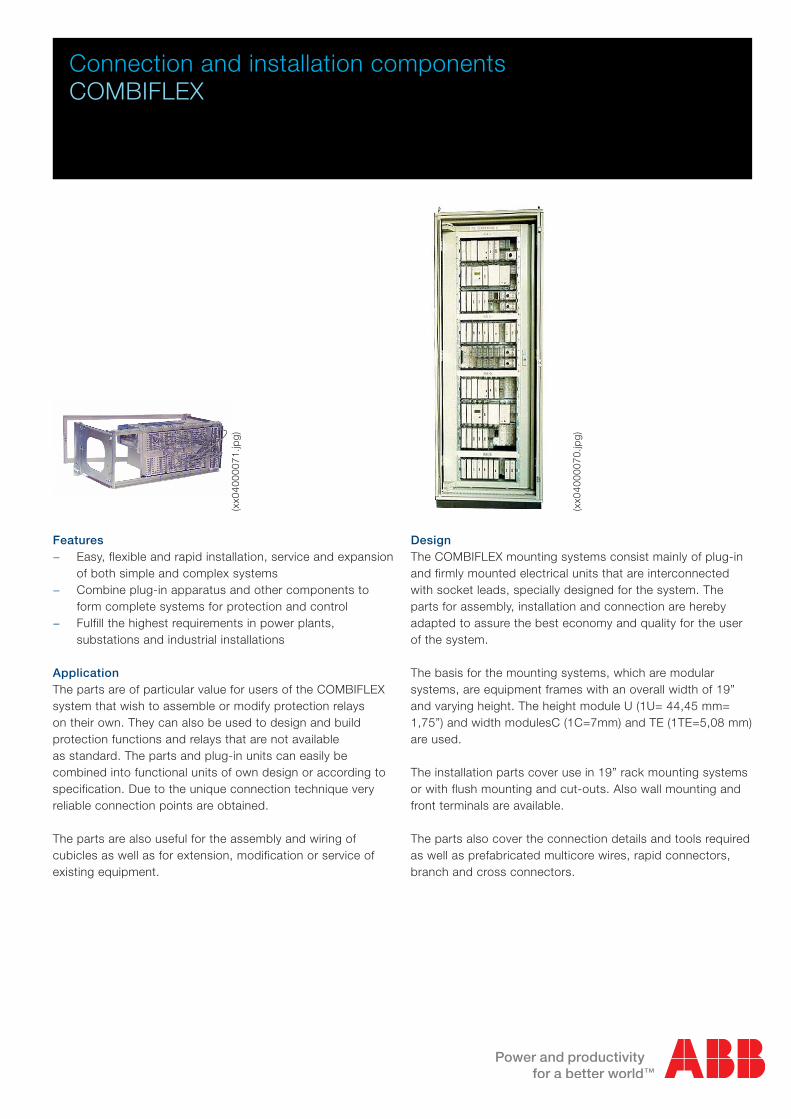
Connection and installation components COMBIFLEX Features − Easy, flexible and rapid installation, service and expansion of both simple and complex systems − Combine plug-in apparatus and other components to form complete systems for protection and control − Fulfill the highest requirements in power plants, substations and industrial installations Application The parts are of particular value for users of the COMBIFLEX system that wish to assemble or modify protection relays on their own. They can also be used to design and build protection functions and relays that are not available as standard. The parts and plug-in units can easily be combined into functional units of own design or according to specification. Due to the unique connection technique very reliable connection points are obtained. The parts are also useful for the assembly and wiring of cubicles as well as for extension, modification or service of existing equipment. Design The COMBIFLEX mounting systems consist mainly of plug-in and firmly mounted electrical units that are interconnected with socket leads, specially designed for the system. The parts for assembly, installation and connection are hereby adapted to assure the best economy and quality for the user of the system. The basis for the mounting systems, which are modular systems, are equipment frames with an overall width of 19” and varying height. The height module U (1U= 44,45 mm= 1,75”) and width modulesC (1C=7mm) and TE (1TE=5,08 mm) are used. The installation parts cover use in 19” rack mounting systems or with flush mounting and cut-outs. Also wall mounting and front terminals are available. The parts also cover the connection details and tools required as well as prefabricated multicore wires, rapid connectors, branch and cross connectors. (xx04000071.jpg) (xx04000070.jpg)
Transcript of Connection and installation components … and installation components COMBIFLEX Features − Easy,...
Connection and installation componentsCOMBIFLEX
Features − Easy, flexible and rapid installation, service and expansion
of both simple and complex systems − Combine plug-in apparatus and other components to
form complete systems for protection and control − Fulfill the highest requirements in power plants,
substations and industrial installations
ApplicationThe parts are of particular value for users of the COMBIFLEX system that wish to assemble or modify protection relays on their own. They can also be used to design and build protection functions and relays that are not available as standard. The parts and plug-in units can easily be combined into functional units of own design or according to specification. Due to the unique connection technique very reliable connection points are obtained.
The parts are also useful for the assembly and wiring of cubicles as well as for extension, modification or service of existing equipment.
DesignThe COMBIFLEX mounting systems consist mainly of plug-in and firmly mounted electrical units that are interconnected with socket leads, specially designed for the system. The parts for assembly, installation and connection are hereby adapted to assure the best economy and quality for the user of the system.
The basis for the mounting systems, which are modular systems, are equipment frames with an overall width of 19” and varying height. The height module U (1U= 44,45 mm= 1,75”) and width modulesC (1C=7mm) and TE (1TE=5,08 mm) are used.
The installation parts cover use in 19” rack mounting systems or with flush mounting and cut-outs. Also wall mounting and front terminals are available.
The parts also cover the connection details and tools required as well as prefabricated multicore wires, rapid connectors, branch and cross connectors.
(xx0
4000
071.
jpg)
(xx0
4000
070.
jpg)

2 | Connection and installation components - 1MRK513003-BEN Revision: E
Product overview
(se9
1799
.ep
s)
RX Terminal bases, sockets and leads. For more information see page 5.
Tools for connection and installation. For more information see page 7.
RTXI and RTXK current connectors. For more information see page 9.
RTXG, RTXC, RTXCB Connectors. For more information see page 10 and page 12.
DIN-rail adapter. For more information see page 14.
(se9
8008
5.ep
s)
(se9
7090
0.ep
s)
(se7
3954
.ep
s)
(se9
1864
.ep
s)(s
e939
94.e
ps)
(se940734.eps)
(se9
5024
3.ep
s)

Connection and installation components - 1MRK513003-BEN Revision: E | 3
RXZ Panel bases for surface mounting.
− For 2 or 4 seat COMBIFLEX relaysFor more information see page 15.
RHGT is a 19” rack system for mounting in cubicles.
− With or without doorFor more information see page 16.
RHGS is a 19” case system for cubicle or surface mounting.
− Case size 1/4, 1/2 and 1/1 (full) 19” rack − 6U high − self standing and accessory to 500-, 650- or 670-series
protection and control terminals.For more information see page 21.
RHGP is a case system for panel (flush) mounting.
− Variants for 1, 2, 2H, 4 and 8 COMBIFLEX relay seats − Variant covering cut-outs according to ABB’s earlier
900-series − With or without front cover
For more information see page 25.
RHGX is a case system for panel (flush) mounting.
− Case size 12C, 24C, 36C and 60C with 4U height − Case size 60C and 8U height − Flush and semiflush mounting − Front door
For more information see page 28.
(se9
5925
.ep
s)
(xx0
4000
072.
jpg)
(se9
7010
3.ep
s)
((xx0
0000
630.
tif)
(se8
1702
.ep
s)

4 | Connection and installation components - 1MRK513003-BEN Revision: E
Technical data
* Valid for RTXP and RTXK
Data pertaining to connection details
Clearance and creepage distances, live part to live part = 4 mm
Clearance and creepage distances, live part to exposed conductive part = 6 mm
Current carrying capacity continuous for 10 A pin/socket = 10 A at max. +70°C
Current carrying capacity continuous for 20 A pin/socket = 20 A at max. +70°C
Current carrying capacity during 1 s for 10 A pin/socket = 150 A at max. +70°C
Current carrying capacity during 1 s for 20 A pin/socket = 500 A at max. +70°C*
Contact resistance pin to socket = < 5 mΩ
Data pertaining to socket leads
Conductor area mm2 1,0-1,5 2,5
Rated voltage, V 750 750
Test voltage at 50 Hz for 15 min, V 2500 2500
Rated current, A 10 20
Max continuous operating temp., °C 70 70
Tensile strength socket-lead, N/mm2 ≥ 150 ≥ 150

Connection and installation components - 1MRK513003-BEN Revision: E | 5
The terminal bases provide the mechanical mounting for modules and connectors. They have rows of dual terminal holes with built-in locking clips which permit the connection and retention of one or two external wiring socket leads to the same electrical connection point. When a module is plugged into the terminal base, the pins enter the sockets secured in the terminal base. An RTXD extractor tool is used to remove socket leads from the terminal base. Terminal bases also have component pockets for the inserting of RTXE component blocks or RTXK and RTXI 20A current connectors.
(SE
9400
4.ep
s)
OrderingTerminal bases, sockets and leads
(se9
1799
.ep
s)
(se9
8008
5.ep
s)
(SE
9400
5.ep
s)
Tapping screws, type ST3.5 for mounting the terminal bases are included.
For each module seat 16 double 10 A terminals are provided.
Terminal bases can be mounted directly on panels for surface mounting with rear connection of up to 4 module mounting seats. For surface mounting with front connection, see panel bases RXZ 21 and RXZ 41.
For relay assemblies or other apparatus groups, terminal bases are mounted side by side on apparatus bars.
Type No. of component pockets Modular dimensions No. of seats Ordering No. Weight, g
RX 1 1 2U 6C 1 5619 622-A 70
RX 2H 2 4U 6C 2 5619 625-A 125
RX 2 2 2U 12C 2 5619 483-A 125
RX 4 4 4U 12C 4 5619 499-A 260
Rated current, A Suitable for conductor
area, mm2
Max. outer diameter of the
insulation of lead, mm
Package pcs Ordering No. Weight, g/package
10 0,25-1,5 3,7 100 1MRK 002 136-A 50
10 0,25-1,5 3,7 1000 1MRK 002 136-B 500
10 0,25-1,5 3,7 5000 1MRK 002 136-C 2500
20 1,5-2,5 4,2 100 1MRK 002 136-D 90
20 1,5-2,5 4,2 1000 1MRK 002 136-E 900
20 1,5-2,5 4,2 5000 1MRK 002 136-F 4500
Contact socketsContact sockets plug into terminals with locking clips; for example, terminal bases, branch connector and test switches.
They mate with the associated contact pins of a relay module, connector, test switch, etc. Contact sockets crimp to multistranded leads with the insulation stripped to length of 10,5 ± 0,5 mm. They are as standard silver plated and gold on request. They are delivered in plastic bags with fixed quantities acc. to table below.
(SE95037a.eps)
(SE95037b.eps)

6 | Connection and installation components - 1MRK513003-BEN Revision: E
Ordering
Area, mm2 Roll length, m Ordering No.
1,0 100 9ADA102-7
1,5 100 9ADA102-10
2,5 100 9ADA102-13
Leads on rollsLeads having a tinned multistranded copper conductor with gray insulation (specify no of metres, but multiples of rolls lengths).
Socket leadsThe socket leads have a multistranded copper conductor with gray insulation. The length of the stripped end (leads with socket on one end) is 10,5 mm and is intended for connection to a terminal block or cable lug. Terminal sockets are silver plated.
Leads with a terminal socket on each end
Terminal socket combination: Terminal socket combination:
10 A-10 A 10 A-20 A 20 A-20 A
Length of insulated part Conductor area, mm2
1,0 1,5 1,5 2,5
mm Ordering No.
100 SK 791 019-B SK 791 007-B SK 791 013-B SK 791 015-B
180 SK 791 019-D SK 791 007-D SK 791 013-D SK 791 015-D
280 SK 791 019-F SK 791 007-F SK 791 013-F SK 791 015-F
380 SK 791 019-H SK 791 007-H SK 791 013-H SK 791 015-H
580 SK 791 019-N SK 791 007-N SK 791 013-N SK 791 015-N
(SE93328a.jpg)
Leads with a terminal socket on one end and insulation stripped on the other
Terminal socket size 10 A Terminal socket size 20 A
Length of insulated part Conductor area, mm2
1,5 2,5
680 SK 791 009-R SK 791 017-R
1780 SK 791 009-Z SK 791 017-Z
2980 SK 791 009-AD SK 791 017-AD
(SE93328b.jpg)

Connection and installation components - 1MRK513003-BEN Revision: E | 7
COMBIFLEX tools
Tool set No. incl.
in the tool
set
Ordering No. Weight/
item
Set of tools consisting of the number of tools, test
items and spare parts mentioned below.
Supplied in a tool box (size 47x24x20 cm)See below RK 924 020-AA 6,3 kg
Extractor RTXD (set of 10 pcs) for withdrawing 10 A and
20 A socket leads1 1MRK 002 138-A 3 g
Phillips type screwdriver
For screws No. 1
For screws No. 2
Screw driver torx T10
Screw driver torx T15
Screw driver torx T20
Screw driver torx T25
Screw driver torx T30
1
1
1
1
1
1
1
6883 1111-137
6883 1111-138
1MRK 000 436-3
1MRK 000 436-7
1MRK 000 436-4
1MRK 000 436-5
1MRK 000 436-6
60 g
110 g
50 g
50 g
70 g
70 g
110 gStripping tool
For stripping and cutting of leads with conductor area of
0,25-2,5 mm2.
The length of the stripped part will be 10,5 ± 0,5 mm
1 RK 924 034-AA 260 g
Crimping tool for 10 and 20 A contact terminal sockets and
pins onto leads.
10 A, conductor area, 0,5-1,5 mm2 (0,25 mm2 through field
adjustment)
20 A, conductor area, 1,5-2,5 mm2
1 1MRK 001 593-1 680 g
Test-plug handle RTXH 18
Test-plug handle RTXH 24
Trip-block plug RTXB
Ammeter test plug RTXM
1
1
5
1
RK 926 011-BC
RK 926 016-AA
RK 926 005-AC
RK 926 006-AB
500 g
950 g
10 g
300 g20 A test leads
Length 2,5 m with 4 mm banana type pins at each end and
a conductor area of 2,5 mm2
black
red
5
5
2639 0605-1
2639 0605-2
110 g
110 g10 A test leads
Length 2,5 m with a 4 mm banana pin on the end and a 10
A terminal pin on the other. Conductor area 1,0 mm2.
black
red
2
2
2639 0180-B
2639 0181-B
110 g
110 g
(xx0
4000
080.
jpg)
(SE73954.eps)
(SE91814.eps)
(SE76821.eps)
(SE970900.eps)
(SE820289.eps)

8 | Connection and installation components - 1MRK513003-BEN Revision: E
COMBIFLEX tools
Tool set No. incl.
in the tool
set
Ordering No. Weight/
item
Contact sockets, silver plated (set of 100 pcs)
10 A, conductor area 0,25-1,5 mm2
20 A, conductor area 1,5-2,5 mm2
1
1
1MRK 002 136-A
1MRK 002 136-D
50 g
90 gContact pins, silver plated (set of 100 pcs)
10 A, conductor area 0,25-1,5 mm2
20 A, conductor area 1,5-2,5 mm2
1
1
1MRK 002 136-G
1MRK 002 136-H
60 g
120 gPlastic plugs for blanking off the holes in the front of plastic
covers of plug-in apparatus.
Hole in diameter 6,1 mm
100 2188 152-1
(SE95037a.jpg)
(SE95037b.jpg)
(SE95037c.jpg)
(SE95037d.jpg)
Other useful tools Ordering No.
Electric press for crimping contact sockets and pins onto leads for 10 A
and 20 A.
1MRK 002 011-A
(xx04000088.jpg)

Connection and installation components - 1MRK513003-BEN Revision: E | 9
RTXI, RTXK current connectors
(SE
9453
6.ep
s)
As the relay is withdrawn from the terminal base, the current circuit is short-circuited before the relay is disconnected (see Fig. 1). It is mainly used in ac circuits for short-circuiting a CT secondary circuit when the relay is removed from the terminal base.
The RTXI beige plastic shunt connector which has two 20 A terminals provides for the connection of 20 A socket leads to the base-mounted dc current modules. When the module is with-drawn from the terminal base, the current circuit is opened. It is mainly used in dc shunt circuits.
These 20 A current connectors fit into the terminal base component pocket and adapt the terminal base for current connections.
The RTXK transparent plastic short-circuiting connector contains two fixed contacts with 20 A terminals and one movable springloaded contact. When the current relay module is plugged into the terminal base, the module terminal pins connect the relay into the circuit before a guide pin on the module depresses the spring-loaded contact so that the current circuit is opened.
(960
0029
8.tif
)
Type Ordering No. Weight, g
RTXK 5371 050-A 12
Terminal markings, wiring side
RTXI 5371 050-B 4,5
Terminal markings, wiring side
Figure 1: Connection when mounting the shortcircuiting connector RTXK
(SE
9186
4.ep
s)
(960
0029
9.tif
)
(SE
9186
2.ep
s)
(960
0030
0.tif
)
10 | Connection and installation components - 1MRK513003-BEN Revision: E
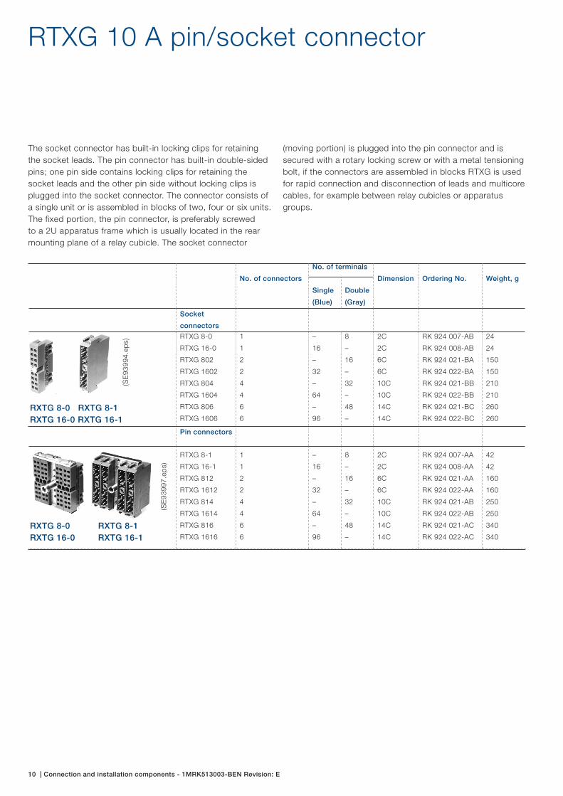
RTXG 10 A pin/socket connector
The socket connector has built-in locking clips for retaining the socket leads. The pin connector has built-in double-sided pins; one pin side contains locking clips for retaining the socket leads and the other pin side without locking clips is plugged into the socket connector. The connector consists of a single unit or is assembled in blocks of two, four or six units. The fixed portion, the pin connector, is preferably screwed to a 2U apparatus frame which is usually located in the rear mounting plane of a relay cubicle. The socket connector
(moving portion) is plugged into the pin connector and is secured with a rotary locking screw or with a metal tensioning bolt, if the connectors are assembled in blocks RTXG is used for rapid connection and disconnection of leads and multicore cables, for example between relay cubicles or apparatus groups.
No. of connectors
No. of terminals
Dimension Ordering No. Weight, g
Single
(Blue)
Double
(Gray)
Socket
connectors
RTXG 8-0
RTXG 16-0
RTXG 802
RTXG 1602
RTXG 804
RTXG 1604
RTXG 806
RTXG 1606
1
1
2
2
4
4
6
6
–
16
–
32
–
64
–
96
8
–
16
–
32
–
48
–
2C
2C
6C
6C
10C
10C
14C
14C
RK 924 007-AB
RK 924 008-AB
RK 924 021-BA
RK 924 022-BA
RK 924 021-BB
RK 924 022-BB
RK 924 021-BC
RK 924 022-BC
24
24
150
150
210
210
260
260
Pin connectors
RTXG 8-1
RTXG 16-1
RTXG 812
RTXG 1612
RTXG 814
RTXG 1614
RTXG 816
RTXG 1616
1
1
2
2
4
4
6
6
–
16
–
32
–
64
–
96
8
–
16
–
32
–
48
–
2C
2C
6C
6C
10C
10C
14C
14C
RK 924 007-AA
RK 924 008-AA
RK 924 021-AA
RK 924 022-AA
RK 924 021-AB
RK 924 022-AB
RK 924 021-AC
RK 924 022-AC
42
42
160
160
250
250
340
340
(SE
9399
4.ep
s)
(SE
9399
7.ep
s)
RXTG 8-0 RXTG 8-1RXTG 16-0 RXTG 16-1
RXTG 8-0 RXTG 8-1RXTG 16-0 RXTG 16-1

Connection and installation components - 1MRK513003-BEN Revision: E | 11
Accessories to RTXG
Fixing screws are included Suitable for RTXG Ordering No. Weight, g
1. Cable holder for socket connector.
With two straight and one curved clamp. The
holder is to be fixed both at the top and the
bottom of the socket connector. Using the
straight clamp, wire bundles having a X-section of
23 x 1 to 23 x 7 mm can be attached. Using the
curved clamp wire diameters between 5-10 mm
can be attached.
8-0, 16-0 RK 924 025-AA 32
2. Cable holder without clamp
The holder is to be fixed at the bottom of
the socket connector. A bundle of wires with
diameter 3-12 mm can be fixed with cable strap
2166 2055-3.
8-0, 16-0 RK 924 025-AC 25
3. Cable holder for socket connector
With clamp for cable diameter 10-20 mm
Without clamp (Clamp listed below)
802, 1602
804, 1604
806, 1606
RK 924 025-BA
RK 924 025-CA
43
37
4. Clamp for cable holder RK 924 025-CA
For cable diameter 10-20 mm
For cable diameter 20-32 mm
RK 924 025-EA
RK 924 025-DA
6
15
5. Keying pins for pin connector
Prevents the socket connector from being
inserted in the incorrect pin connector. Set of ten
rings each with four key pins and instruction for
six reliable key combinations.
8-1, 16-1 RK 924 028-AA 25
6. Mounting bars for socket connectors.
For assembly of three socket connectors. When
two connectors are assembled, the surplus part
is removed. Set of two bars.
8-0, 16-0 RK 924 026-AA 7
7. Attachment bars for pin connectors.
For attachment of five pin connectors in 2U
apparatus frame. Set of two bars.
8-1, 16-1 RK 924 030-AA 14
8. Attachment for pin connectors.
For assembly of two pin connectors one above
the other in a 4U apparatus frame.
8-1, 16-1 RK 924 029-AA 5
9. 2U apparatus frame with space for 1 to 30
RTXG connectors. The frame is supplied with a
marking bar and can be pivoted, giving access
to the pin connector wiring side. Screws are
included. Height requirements 3U.
5284 1350-D 1000
(SE
7827
20.e
ps)
(S
E78
2723
.ep
s)
(SE
9400
1.ep
s)
(960
0030
1.tif
) (S
E93
998.
eps)
(SE93999.eps)
(SE95043.eps)
(SE82533.eps)
12 | Connection and installation components - 1MRK513003-BEN Revision: E
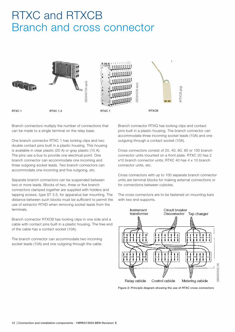
RTXC and RTXCBBranch and cross connector
Branch connectors multiply the number of connections that can be made to a single terminal on the relay base.
One branch connector RTXC 1 has locking clips and two double contact pins built in a plastic housing. This housing is available in clear plastic (20 A) or gray plastic (10 A). The pins use a bus to provide one electrical point. One branch connector can accommodate one incoming and three outgoing socket leads. Two branch connectors can accommodate one incoming and five outgoing, etc.
Separate branch connectors can be suspended between two or more leads. Blocks of two, three or five branch connectors clamped together are supplied with holders and tapping screws, type ST 3.5, for apparatus bar mounting. The distance between such blocks must be sufficient to permit the use of extractor RTXD when removing socket leads from the terminals.
Branch connector RTXCB has locking clips in one side and a cable with contact pins built in a plastic housing. The free end of the cable has a contact socket (10A).
The branch connector can accommodate two incoming socket leads (10A) and one outgoing through the cable.
(SE
9407
34.e
ps)
RTXC 1 RTXC 1.3 RTXC 1
(SE
9452
8.ep
s)
(RTX
CB
.jpg)
RTXCB
Branch connector RTXQ has locking clips and contact pins built in a plastic housing. The branch connector can accommodate three incoming socket leads (10A) and one outgoing through a contact socket (10A).
Cross connectors consist of 20, 40, 60, 80 or 100 branch connector units mounted on a front plate. RTXC 20 has 2 x10 branch connector units; RTXC 40 has 4 x 10 branch connector units, etc.
Cross connectors with up to 100 separate branch connector units are terminal blocks for making external connections or for connections between cubicles.
The cross connectors are to be fastened on mounting bars with two end supports.
(960
0030
2.tif
)
Figure 2: Principle diagram showing the use of RTXC cross connectors
Connection and installation components - 1MRK513003-BEN Revision: E | 13
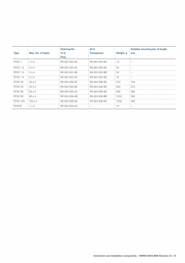
Type Max. No. of leads
Ordering No.
10 A
Gray
20 A
Transparent Weight, g
Suitable mounting bar of length
mm
RTXC 1 1 x 4 RK 924 004-AA RK 924 004-BA 10 –
RTXC 1.2 2 x 4 RK 924 002-AA RK 924 002-BA 40 –
RTXC 1.3 3 x 4 RK 924 002-AB RK 924 002-BB 50 –
RTXC 1.5 5 x 4 RK 924 002-AC RK 924 002-BC 75 –
RTXC 20 20 x 4 RK 924 006-AE RK 924 006-BE 310 150
RTXC 40 40 x 4 RK 924 006-AD RK 924 006-BD 625 210
RTXC 60 60 x 4 RK 924 006-AC RK 924 006-BC 935 265
RTXC 80 80 x 4 RK 924 006-AB RK 924 006-BB 1225 295
RTXC 100 100 x 4 RK 924 006-AA RK 924 006-BA 1530 350
RTXCB 1 x 2 RK 924 050-AA – 10 –

14 | Connection and installation components - 1MRK513003-BEN Revision: E
Adapter for DIN-rail screw terminal bars or for direct surface mounting
(xx0
4000
077.
jpg)
(x
x040
0007
8.jp
g)
An adapter for DIN-rail screw terminal bars is needed to mount COMBIFLEX-relays inside the relay cubicle directly onto the screw terminal bars.
The bases for terminal bars comprise of one RX terminal base, available in four sizes, plus a mounting arrangement consisting of one steel adapter mounting bracket, two, three or four plastic clamp-fit holders and screws. Connections are normally made directly to the terminal bases via COMBIFLEX-connections.
The adapters can be mounted onto vertical or horizontal DIN-rails by rotating the clamp-fit holders 90°.
Terminal bases 2U and 4U mounted on bars.
(SE950244.eps)
Relays size 2U mounted on bases for terminal bars.
(se9
5024
2.ep
s)
Relays with size 4U mounted on bases for terminal bars.(9
7000
041.
tif)
Type Size No. of seats Ordering No.
RXZ 1 2U6C 1 1MRK 000 893-A
RXZ 2H 4U6C 2 1MRK 000 893-B
RXZ 2 2U12C 2 1MRK 000 893-C
RXZ 4 4U12C 4 1MRK 000 893-D
The clamp-fit holders are attached to the steel adapter for the terminal base according to the mounting instruction over-leaf. It is important to provide the necessary wiring of the terminal base prior to assembly.
Surface Mounting alternativeThe steel adapters may be used without the plastic clamp-fit holders for direct mounting onto a steel or e.g. concrete wall surface.

Connection and installation components - 1MRK513003-BEN Revision: E | 15
Panel base Ordering No. Weight, kg
RXZ 21 Support case RK 928 008-AA 0,4
RXZ 21 with terminal base without
terminal blockRK 928 008-AB 0,5
RXZ 21 with terminal base and
terminal blockRK 928 008-AC 0,7
RXZ 41 Support case RK 928 009-AA 0,7
RXZ 41 with terminal base without
terminal blockRK 928 009-AB 0,9
RXZ 41 with terminal base and
terminal blockRK 928 009-AC 1,3
RXZ 21/41Panel bases for surface mounting
The front-connected panel base, RXZ 21/41, provided with two or four modular mounting seats, is used in applications where surface mounting is preferred. It consists of a terminal base, a terminal block (optional) and a metal support case.
The RXZ 21 has one place for a RX 2 terminal base and the RXZ 41 has one place for a RX 4 terminal base. The complete panel base RXZ 21 also includes one terminal block with 16 terminals, wired according to buyer’s specification.
The complete RXZ 41 has two terminal blocks each with 16 terminals also wired according to specification. When
multistranded leads are used connection can be made directly to the terminal base; thus variants without terminal blocks are chosen.
Panel frames for surface mountingThe panel frame provides front connection and surface mounting for protection relay assemblies, else intended for rack or case mounting.
The panel frame is made of two end panels joined together with intermediate profiles on which the protection relay is fitted. Terminal blocks are delivered separately without wiring.
(SE
9592
5.ep
s)
(SE
9917
6.ep
s)
(SE
9592
2.ep
s)
(SE
9592
1.ep
s)
(SE
9592
6.ep
s)
Panel base RXZ 21
Support case
Panel base RXZ 41Support case
Panel base RXZ 41, equipped
Optional items for RXZ Bases Maximum quantity
Article no. Description RK928008-AC RK928009-AC
5371 050-A RTXK 2 4
5371 050-B RTXI 2 4
2663 045-1 Terminal block - 2
2639 530-AM Lead, 10 A, L=110 16 32 1)
SK791 017-B Lead, 20 A, L=100 4 8 1)
SK791 019-B Lead, 10 A, L=100 4 8 3)
2639 530-AN Lead, 10 A, L=190 - 16 2)
SK791 017-D Lead, 20 A, L=180 - 4 2)
SK791 019-D Lead, 10 A, L=180 - 16 3)
1) For connecting RX4 Base to Terminal Block2) If 1 PC of Terminal Block has been ordered, these leads should be used to connect
relay place 1 and 2 to the lower terminal block or relay place 3 and 4 to the upper
terminal block3) For internal connection between the relay places

16 | Connection and installation components - 1MRK513003-BEN Revision: E
RHGT 19” equipment frame
These types of equipment frame is used for cubicle mounting or panel mounting of plugin units in the COMBIFLEX range.
The window is of flame-retarding carbonate plastic. At the top of the apparatus frame or support frame there is a marking strip on which the C-modules are numbered from 01 to 60.
The overall width of the equipment frame is equivalent to 19” and the inside space for apparatus is 60C = 420 mm. The height is given in U units equal to 44.45 mm/1.75 inches, therefore 4U = 7 inches.
Frames, end panels and brackets are zinc plated, doors are powder coated light beige or gray.
A strengthening plate is available for equiment frames which may be subject to severe vibrations. When mounting such equipment frames in a cubicle there must be at least 1U distance between the frames.
(xx04000073.jpg)
(xx04000082.jpg)
The frame is available in size: 4U (7”x19”) for mounting 20 module seats.
The equipment frame has a mounting bar (combined apparatus and support bar) for mounting of assemblies and terminal bases side-by-side if a 10 mm (apparatus bar thickness) difference of front level is acceptable.
Equipment frames with end panels are used for flush-mounting or in cubicles with a hinged frame. Equipment frames with mounting brackets are intended to be mounted in the rear of cubicles.
Equipment frames with end panels have an optional front door, with a transparent window. The door, hinged on the left, is 4U high.
(96000281.tif)
Figure 3: Mounting without apparatus bars
(96000282.tif)
Figure 4: Mounting with apparatus bars

Connection and installation components - 1MRK513003-BEN Revision: E | 17
Set of equipment frame details Size Ordering No. Weight, kg
Without door 4U 19” 1MRK 000 137-PA 2,0
With door, beige 4U 19” 1MRK 000 137-RA 2,6
Figure 5: Dimensions
(96000283.tif)
(xx04000083.jpg) (xx04000084.jpg)
Delivered as a set of necessary material, unassembled.
1. End panel2. Terminal base RX 43. Terminal base RX 2H4. 4U x 4C apparatus plate5. 4U x 18C apparatus plate6. 4U x 60C mounting bar

18 | Connection and installation components - 1MRK513003-BEN Revision: E
For all RHGT equipment frames Size Ordering No. Weight, Kg
Strengthening plate
To be fitted to top and bottom of equipment frame. Two
required per frame. Extra space 1U between racks is a
necessity.
60 C 1MRK 000 588-2 0,6
End panels
To be fitted to apparatus frame to make up an
equipment frame for flush-mounting. Two required per
equipment frame.
4U 2176 138-6 0,2
Mounting brackets
To be fitted to apparatus frame or support frame to make
up an equipment frame for flush-mounting. Two required
per equipment frame.
To get a folding support frame, one 2174 195-1 and one
2174195-10 is provided.
4U
8U
2174 195-1
2174 195-10
0,2
0,2
Door with transparent window, beige.
To be mounted on left end panel of equipment frame.
Door with transparent window, gray
To be mounted on left end panel of equipment frame.
Hinge (two are needed for each door)
Lock
4U 60C
4U 60C
5284 1342-Y
1TSA340015R0025
2184 0512-1
2167 247-3
0,6
Marking bar (marking 01-60)
To be fixed on top of upper bar of apparatus frame or
support frame. Incl. two fixing plugs.60C 5284 1509-A 0,1
Lead holder
To enable lead bundles to be tied at the rear of the
equipment frame. For vertical mounting on rear edge of
end panel.
2166 352-3 0,1
Set of screws
Set containing all screws needed to mount any of the
4U equipment frames. A 8U frame needs two sets and a
12U frame needs three sets.
5284 1935-N 0,1
Accessories and individual parts for equipment frames
(SE96405.eps)
(SE96413.eps)
(SE96414a.eps) (SE96414b.eps)
(SE96415.eps)
(SE75433.eps)
(96000284.tif)

Connection and installation components - 1MRK513003-BEN Revision: E | 19
Apparatus bars, plates and frames
Modular width Ordering No. Weight, Kg
Apparatus bars
Used for assembling of apparatus groups: e.g.
protective relays. The terminal bases of the
plug-in apparatus included in the group are
mounted adjacent to each other on two bars.
These U-shaped bars are available in various
lengths and have 3,2 mm diameter holes at a
distance equivalent to one C module (7 mm)
suitable for ST 3,5 tapping screw to a support
frame (within case or 19” equipment frame
etc.).
60C
48C
42C
36C
30C
24C
18C
12C
6C
2175 323-5
2175 323-10
2175 323-9
2175 323-3
2175 323-6
2175 323-2
2175 323-8
2175 323-1
2175 323-7
0,27
0,24
0,21
0,16
0,15
0,10
0,09
0,05
0,03
4U apparatus plates, zinc plated
Used to support apparatus which cannot be
inserted in terminal bases. Transformers and
resistors, for example, can be mounted on the
plate which in turn is screwed to a supporting
frame or apparatus bars/apparatus frame. The
plate is also used to cover vacant space in the
equipment frame.
To be mounted on apparatus bars/apparatus frame:
60C
48C
42C
36C
30C
24C
18C
12C
6C
2172 467-15
2172 467-12
2172 467-19
2172 467-9
2172 467-18
2172 467-6
2172 467-17
2172 467-3
2172 467-16
1,14
0,90
0,80
0,68
0,60
0,45
0,36
0,2
0,12
(SE82532.eps)
(SE82536.eps)
To be affixed to Description Marking No. of identical
markings
Ordering No.
Apparatus bar
C-module divisions,
white with black text
01-18
19-36
37-60
100
100
50
-
-
-Set of markings as per
above 1MRK 002 137-A
Marking bar in
equipment frame
or case
C-module divisions,
white with black text
02-24, 24-02
25-48, 48-25
49-60, 60-49
100
100
10
-
-
-Connectors and
other separately
mounted devices
Labels 12 x 6 mm,
yellow with black text X1 45 -
Set of markings as per
above 1MRK 002 137-B
Markings
(96000303.tif)
(96000304.tif)

20 | Connection and installation components - 1MRK513003-BEN Revision: E
Size Ordering No. Weight, Kg
For building RHGT equipment frames with combined
apparatus and support bar (variant A)Mounting bar (2 required)
To mount terminal bases and apparatus plates on, as
well as assemblies or apparatus bars.
1MRK 000 316-23 0,3
General accessories
Mounting Kit
For the mounting of RTXP 24 in 4U cases 1MRK 000 020-BT 0,1
Mounting Bracket
For the mounting of RTXP 8 in 4U cases 1MRK 000 316-19 0,1
(xx04000076.jpg)
Accessories and individual parts for equipment frames
(xx04000075.jpg)
(xx04000074.jpg)
Connection and installation components - 1MRK513003-BEN Revision: E | 21
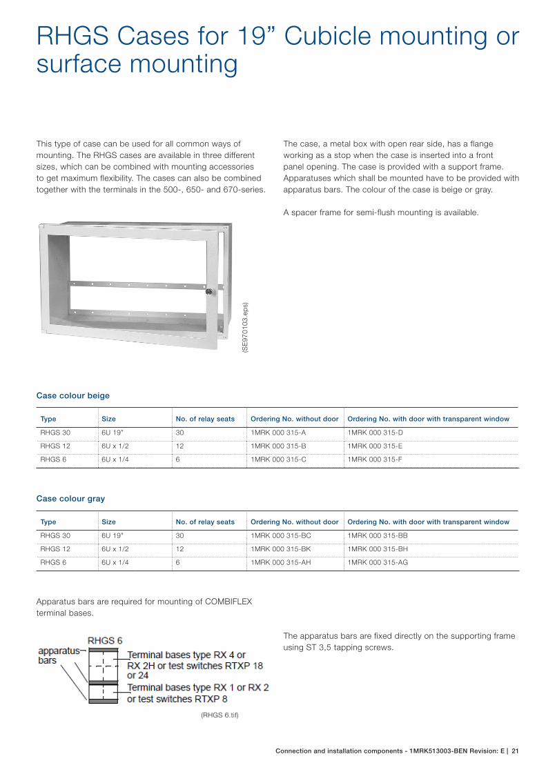
RHGS Cases for 19” Cubicle mounting or surface mounting
Type Size No. of relay seats Ordering No. without door Ordering No. with door with transparent window
RHGS 30 6U 19” 30 1MRK 000 315-A 1MRK 000 315-D
RHGS 12 6U x 1/2 12 1MRK 000 315-B 1MRK 000 315-E
RHGS 6 6U x 1/4 6 1MRK 000 315-C 1MRK 000 315-F
This type of case can be used for all common ways of mounting. The RHGS cases are available in three different sizes, which can be combined with mounting accessories to get maximum flexibility. The cases can also be combined together with the terminals in the 500-, 650- and 670-series.
The case, a metal box with open rear side, has a flange working as a stop when the case is inserted into a front panel opening. The case is provided with a support frame. Apparatuses which shall be mounted have to be provided with apparatus bars. The colour of the case is beige or gray.
A spacer frame for semi-flush mounting is available.
(SE
9701
03.e
ps)
Apparatus bars are required for mounting of COMBIFLEX terminal bases.
The apparatus bars are fixed directly on the supporting frame using ST 3,5 tapping screws.
(RHGS 6.tif)
Case colour beige
Type Size No. of relay seats Ordering No. without door Ordering No. with door with transparent window
RHGS 30 6U 19” 30 1MRK 000 315-BC 1MRK 000 315-BB
RHGS 12 6U x 1/2 12 1MRK 000 315-BK 1MRK 000 315-BH
RHGS 6 6U x 1/4 6 1MRK 000 315-AH 1MRK 000 315-AG
Case colour gray
22 | Connection and installation components - 1MRK513003-BEN Revision: E
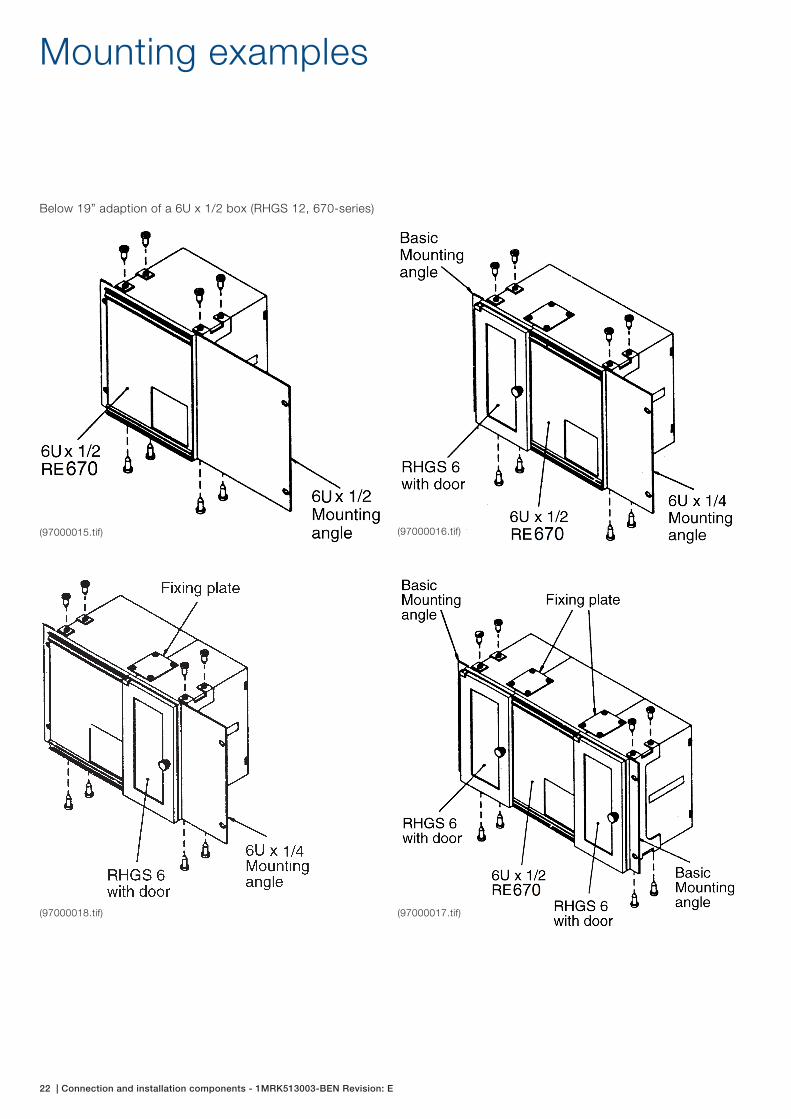
Mounting examples
Below 19” adaption of a 6U x 1/2 box (RHGS 12, 670-series)
(97000015.tif) (97000016.tif)
(97000018.tif) (97000017.tif)
Connection and installation components - 1MRK513003-BEN Revision: E | 23
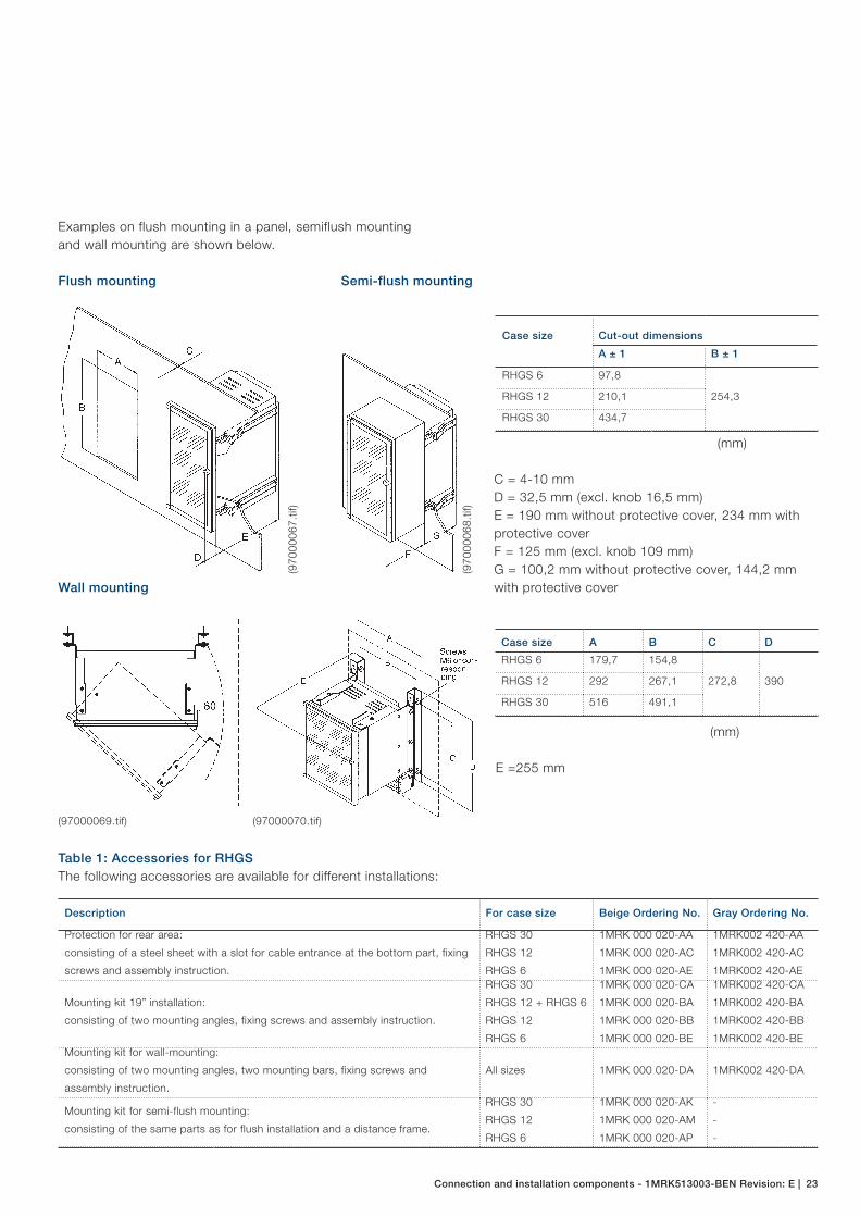
Examples on flush mounting in a panel, semiflush mounting and wall mounting are shown below.
(970
0006
7.tif
)
(970
0006
8.tif
)
Flush mounting Semi-flush mounting
Case size Cut-out dimensions
A ± 1 B ± 1
RHGS 6 97,8
254,3RHGS 12 210,1
RHGS 30 434,7
C = 4-10 mmD = 32,5 mm (excl. knob 16,5 mm)E = 190 mm without protective cover, 234 mm with protective coverF = 125 mm (excl. knob 109 mm)G = 100,2 mm without protective cover, 144,2 mm with protective cover
(97000069.tif)
Wall mounting
(97000070.tif)
E =255 mm
(mm)
Case size A B C D
RHGS 6 179,7 154,8
272,8 390RHGS 12 292 267,1
RHGS 30 516 491,1
(mm)
Description For case size Beige Ordering No. Gray Ordering No.
Protection for rear area:
consisting of a steel sheet with a slot for cable entrance at the bottom part, fixing
screws and assembly instruction.
RHGS 30
RHGS 12
RHGS 6
1MRK 000 020-AA
1MRK 000 020-AC
1MRK 000 020-AE
1MRK002 420-AA
1MRK002 420-AC
1MRK002 420-AE
Mounting kit 19” installation:
consisting of two mounting angles, fixing screws and assembly instruction.
RHGS 30
RHGS 12 + RHGS 6
RHGS 12
RHGS 6
1MRK 000 020-CA
1MRK 000 020-BA
1MRK 000 020-BB
1MRK 000 020-BE
1MRK002 420-CA
1MRK002 420-BA
1MRK002 420-BB
1MRK002 420-BEMounting kit for wall-mounting:
consisting of two mounting angles, two mounting bars, fixing screws and
assembly instruction.
All sizes 1MRK 000 020-DA 1MRK002 420-DA
Mounting kit for semi-flush mounting:
consisting of the same parts as for flush installation and a distance frame.
RHGS 30
RHGS 12
RHGS 6
1MRK 000 020-AK
1MRK 000 020-AM
1MRK 000 020-AP
-
-
-
Table 1: Accessories for RHGSThe following accessories are available for different installations:
24 | Connection and installation components - 1MRK513003-BEN Revision: E
Mounting examples
Description For case size Beige Ordering No. Gray Ordering No.
Mounting kit for flush installation:
consisting of four fastener, sealing strip, fixing screws and assembly instruction.All sizes 1MRK 000 020-Y 1MRK 000 020-Y
Mounting kit for side-by-side installation:
consisting of two fixing plates, fixing screws and assembly drawing.All sizes 1MRK 000 020-Z 1MRK 002 420-Z
Table 1: Accessories for RHGSThe following accessories are available for different installations:
Note: All kits are complete including screws.
Ordering example:Example:
− Mounting kit for 19” installation of RHGS 30 = 1MRK 000 020-CA
− Mounting kit for 19” installation of RHGS 12 = 1MRK 000 020-BB
− For side-by-side installation of two cases, two mounting kits must be ordered
Example:
− Mounting kit for 19” installation, cases RHGS 12 + RHGS 6 = 1MRK 000 020-BA + 1MRK 000 020-Z
− Mounting kits for 19” installation, cases RHGS 12 + RHGS 12 = 1MRK 000 020-BB + 1MRK 000 020-Z
Connection and installation components - 1MRK513003-BEN Revision: E | 25
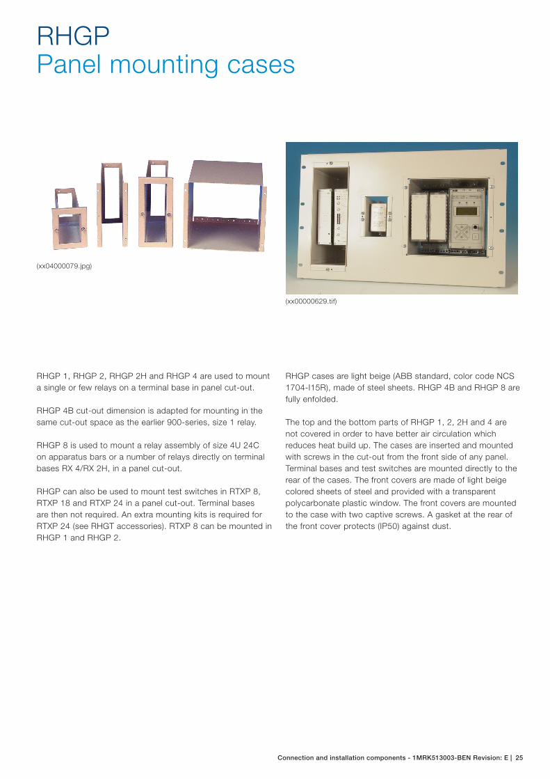
RHGPPanel mounting cases
(xx04000079.jpg)
(xx00000629.tif)
RHGP 1, RHGP 2, RHGP 2H and RHGP 4 are used to mount a single or few relays on a terminal base in panel cut-out.
RHGP 4B cut-out dimension is adapted for mounting in the same cut-out space as the earlier 900-series, size 1 relay.
RHGP 8 is used to mount a relay assembly of size 4U 24C on apparatus bars or a number of relays directly on terminal bases RX 4/RX 2H, in a panel cut-out.
RHGP can also be used to mount test switches in RTXP 8, RTXP 18 and RTXP 24 in a panel cut-out. Terminal bases are then not required. An extra mounting kits is required for RTXP 24 (see RHGT accessories). RTXP 8 can be mounted in RHGP 1 and RHGP 2.
RHGP cases are light beige (ABB standard, color code NCS 1704-I15R), made of steel sheets. RHGP 4B and RHGP 8 are fully enfolded.
The top and the bottom parts of RHGP 1, 2, 2H and 4 are not covered in order to have better air circulation which reduces heat build up. The cases are inserted and mounted with screws in the cut-out from the front side of any panel. Terminal bases and test switches are mounted directly to the rear of the cases. The front covers are made of light beige colored sheets of steel and provided with a transparent polycarbonate plastic window. The front covers are mounted to the case with two captive screws. A gasket at the rear of the front cover protects (IP50) against dust.

26 | Connection and installation components - 1MRK513003-BEN Revision: E
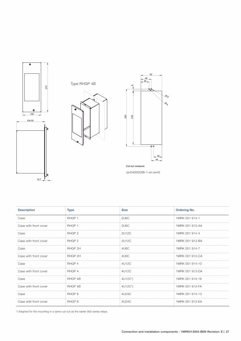
Type A B C D E F G
RHGP 1
RHGP 2
RHGP 2H
RHGP 4
RHGP 8
Measure
5684 105 93 46.5 15
98126 105 93 46.5 15
5684 182 170 85 21.5 4
103131 182 170 85 21.5
182210 187 175 87.5 21.5
H
154.5
154.5
154.5
154.5
175
16.7
K
A
B
C
K
DH H
E
FG
G
For M4 or similar
Cut-out measure
(en04000094-1-en.wmf)
Connection and installation components
Connection and installation components - 1MRK513003-BEN Revision: E | 27
92
4636
8
250
234
36
46
O 4
O 6
100
270
154.50
16.7
Cut-out measure
*) Adapted for the mounting in a same cut-out as the earlier 900-series relays.
Type RHGP 4B
Description Type Size Ordering No.
Case RHGP 1 2U6C 1MRK 001 914-1
Case with front cover RHGP 1 2U6C 1MRK 001 913-AA
Case RHGP 2 2U12C 1MRK 001 914-4
Case with front cover RHGP 2 2U12C 1MRK 001 913-BA
Case RHGP 2H 4U6C 1MRK 001 914-7
Case with front cover RHGP 2H 4U6C 1MRK 001 913-CA
Case RHGP 4 4U12C 1MRK 001 914-10
Case with front cover RHGP 4 4U12C 1MRK 001 913-DA
Case RHGP 4B 4U12C*) 1MRK 001 914-16
Case with front cover RHGP 4B 4U12C*) 1MRK 001 913-FA
Case RHGP 8 4U24C 1MRK 001 914-13
Case with front cover RHGP 8 4U24C 1MRK 001 913-EA
(en04000096-1-en.wmf)
28 | Connection and installation components - 1MRK513003-BEN Revision: E
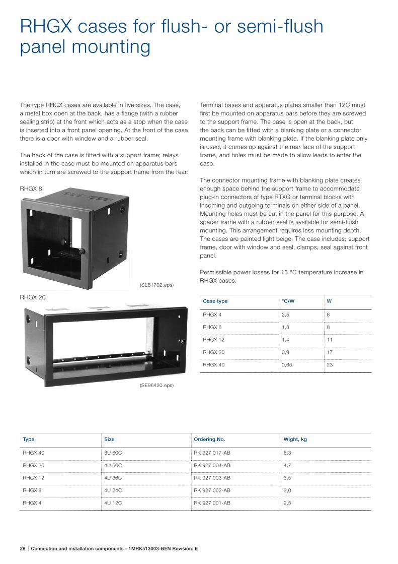
RHGX cases for flush- or semi-flush panel mounting
Case type °C/W W
RHGX 4 2,5 6
RHGX 8 1,8 8
RHGX 12 1,4 11
RHGX 20 0,9 17
RHGX 40 0,65 23
The type RHGX cases are available in five sizes. The case, a metal box open at the back, has a flange (with a rubber sealing strip) at the front which acts as a stop when the case is inserted into a front panel opening. At the front of the case there is a door with window and a rubber seal.
The back of the case is fitted with a support frame; relays installed in the case must be mounted on apparatus bars which in turn are screwed to the support frame from the rear.
Terminal bases and apparatus plates smaller than 12C must first be mounted on apparatus bars before they are screwed to the support frame. The case is open at the back, but the back can be fitted with a blanking plate or a connector mounting frame with blanking plate. If the blanking plate only is used, it comes up against the rear face of the support frame, and holes must be made to allow leads to enter the case.
The connector mounting frame with blanking plate creates enough space behind the support frame to accommodate plug-in connectors of type RTXG or terminal blocks with incoming and outgoing terminals on either side of a panel. Mounting holes must be cut in the panel for this purpose. A spacer frame with a rubber seal is available for semi-flush mounting. This arrangement requires less mounting depth. The cases are painted light beige. The case includes; support frame, door with window and seal, clamps, seal against front panel.
Permissible power losses for 15 °C temperature increase in RHGX cases.
Type Size Ordering No. Wight, kg
RHGX 40 8U 60C RK 927 017-AB 6,3
RHGX 20 4U 60C RK 927 004-AB 4,7
RHGX 12 4U 36C RK 927 003-AB 3,5
RHGX 8 4U 24C RK 927 002-AB 3,0
RHGX 4 4U 12C RK 927 001-AB 2,5
(SE81702.eps)
(SE96420.eps)
RHGX 8
RHGX 20
Connection and installation components - 1MRK513003-BEN Revision: E | 29
Accessories for RHGX
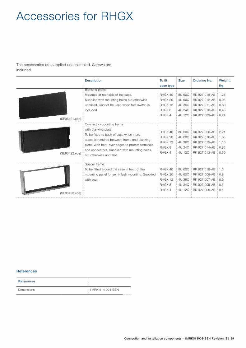
The accessories are supplied unassembled. Screws are included.
Description To fit
case type
Size Ordering No. Weight,
KgBlanking plate:
Mounted at rear side of the case.
Supplied with mounting holes but otherwise
undrilled. Cannot be used when test switch is
included.
RHGX 40
RHGX 20
RHGX 12
RHGX 8
RHGX 4
8U 60C
4U 60C
4U 36C
4U 24C
4U 12C
RK 927 019-AB
RK 927 012-AB
RK 927 011-AB
RK 927 010-AB
RK 927 009-AB
1,26
0,96
0,60
0,43
0,24
Connector-mounting frame
with blanking plate:
To be fixed to back of case when more
space is required between frame and blanking
plate. With bent-over edges to protect terminals
and connectors. Supplied with mounting holes,
but otherwise undrilled.
RHGX 40
RHGX 20
RHGX 12
RHGX 8
RHGX 4
8U 60C
4U 60C
4U 36C
4U 24C
4U 12C
RK 927 020-AB
RK 927 016-AB
RK 927 015-AB
RK 927 014-AB
RK 927 013-AB
2,21
1,65
1,10
0,85
0,60
Spacer frame:
To be fitted around the case in front of the
mounting panel for semi-flush mounting. Supplied
with seal.
RHGX 40
RHGX 20
RHGX 12
RHGX 8
RHGX 4
8U 60C
4U 60C
4U 36C
4U 24C
4U 12C
RK 927 018-AB
RK 927 008-AB
RK 927 007-AB
RK 927 006-AB
RK 927 005-AB
1,3
0,8
0,6
0,5
0,4
(SE96421.eps)
(SE96422.eps)
(SE96423.eps)
References
References
Dimensions 1MRK 514 004-BEN
1MR
K51
3003
-BE
N R
evis
ion:
E
Contact us
ABB AB Substation Automation Products721 59 Västerås, Sweden Phone: +46 (0) 21 32 50 00
www.abb.com/protection-control
ABB India Limited Plot no. 4A, 5 & 6, II PhasePeenya Industrial AreaBangalore - 560 058. India Phone: +91 80 2294 9632Facsimile: + 91 80 2294 9188
Note:We reserve the right to make technical changes or modify the contents of this document without prior notice. ABB AB does not accept any responsibility whatsoever for potential errors or possible lack of information in this document.We reserve all rights in this document and in the subject matter and illustrations contained herein. Any reproduction, disclosure to third parties or utilization of its contents – in whole or in part – is forbidden without prior written consent of ABB AB.
© Copyright 2014 ABB.
All rights reserved.