Configuring PPP for Wide-Area Networking
30
Configuring PPP for Wide-Area Networking IV-235 FINAL DRAFT CISCO CONFIDENTIAL Configuring PPP for Wide-Area Networking The Point-to-Point Protocol (PPP), described in RFCs 1661 and 1332, encapsulates network layer protocol information over point-to-point links. You can configure PPP on the following types of physical interfaces: • Asynchronous serial • HSSI • ISDN • Synchronous serial By enabling PPP encapsulation on physical interfaces, PPP can also be in effect on calls placed by the dialer interfaces that use the physical interfaces. The current implementation of PPP supports option 3, authentication using CHAP or PAP, option 4, Link Quality Monitoring, and option 5, Magic Number configuration options. The software always sends option 5 and negotiates for options 3 and 4 if so configured. All other options are rejected. Cisco supports the following upper-layer protocols: AppleTalk, Bridging, CLNS, DECnet, IP, IPX, VINES, and XNS. The software provides PPP as an encapsulation method. It also provides the Challenge Handshake Authentication Protocol (CHAP) and Password Authentication Protocol (PAP) on serial interfaces running PPP encapsulation. The following sections describe the tasks to configure PPP routing features. Magic Number support is available on all serial interfaces. PPP always attempts to negotiate for Magic Numbers, which are used to detect looped-back lines. Depending on how the down-when-looped command is configured, the router might shut down a link if it detects a loop. PPP Configuration Task List To configure PPP on a serial interface, perform the following task in interface configuration mode: • Enable PPP Encapsulation You can also complete the tasks in the following sections; these tasks are optional but offer a variety of uses and enhancements for PPP on your systems and networks: • Enable CHAP or PAP Authentication • Enable Link Quality Monitoring (LQM) • Configure Automatic Detection of Encapsulation Type • Configure Compression of PPP Data
-
Upload
networksguy -
Category
Documents
-
view
524 -
download
2
Transcript of Configuring PPP for Wide-Area Networking

Configuring PPP for Wide-Area Networking IV-235
FINAL DRAFT CISCO CONFIDENTIAL
Configuring PPP for Wide-AreaNetworking
The Point-to-Point Protocol (PPP), described in RFCs 1661 and 1332, encapsulates network layerprotocol information over point-to-point links. You can configure PPP on the following types ofphysical interfaces:
• Asynchronous serial
• HSSI
• ISDN
• Synchronous serial
By enabling PPP encapsulation on physical interfaces, PPP can also be in effect on calls placed bythe dialer interfaces that use the physical interfaces.
The current implementation of PPP supports option 3, authentication using CHAP or PAP, option 4,Link Quality Monitoring, and option 5, Magic Number configuration options. The software alwayssends option 5 and negotiates for options 3 and 4 if so configured. All other options are rejected.
Cisco supports the following upper-layer protocols: AppleTalk, Bridging, CLNS, DECnet, IP, IPX,VINES, and XNS.
The software provides PPP as an encapsulation method. It also provides the Challenge HandshakeAuthentication Protocol (CHAP) and Password Authentication Protocol (PAP) on serial interfacesrunning PPP encapsulation. The following sections describe the tasks to configure PPP routingfeatures.
Magic Number support is available on all serial interfaces. PPP always attempts to negotiate forMagic Numbers, which are used to detect looped-back lines. Depending on how thedown-when-loopedcommand is configured, the router might shut down a link if it detects a loop.
PPP Configuration Task ListTo configure PPP on a serial interface, perform the following task in interface configuration mode:
• Enable PPP Encapsulation
You can also complete the tasks in the following sections; these tasks are optional but offer a varietyof uses and enhancements for PPP on your systems and networks:
• Enable CHAP or PAP Authentication
• Enable Link Quality Monitoring (LQM)
• Configure Automatic Detection of Encapsulation Type
• Configure Compression of PPP Data
IV-236 Wide-Area Networking Configuration Guide
Enable PPP Encapsulation
FINAL DRAFT CISCO CONFIDENTIAL
• Configure IP Address Pooling
• Configure PPP Callback
• Disable or Reenable Peer Neighbor Routes
• Configure PPP Half-Bridging
• Configure Multilink PPP
• Configure Multichassis Multilink PPP
• Configure Virtual Private Dial-up Networks
• Enable PPP on VTY Lines for Asynchronous Access over ISDN
See the “PPP Examples” section at the end of this chapter.
Enable PPP EncapsulationYou can enable PPP on serial lines to encapsulate IP and other network protocol datagrams. To doso, perform the following task in interface configuration mode:
PPP echo requests are used as keepalives to minimize disruptions to the end users of your network.Theno keepalive command can be used to disable echo requests.
Enable CHAP or PAP AuthenticationThe Point-to-Point Protocol (PPP) with Challenge Handshake Authentication Protocol (CHAP)authentication or Password Authentication Protocol (PAP) is often used to inform the central siteabout which remote routers are connected to it.
With this authentication information, if the router or access server receives another packet for adestination to which it is already connected, it does not place an additional call. However, if therouter or access server is using rotaries, it sends the packet out the correct port.
CHAP and PAP are specified in RFC 1334. These protocols are supported on synchronous andasynchronous serial interfaces. When using CHAP or PAP authentication, each router or accessserver identifies itself by aname. This identification process prevents a router from placing anothercall to a router to which it is already connected, and also prevents unauthorized access. See the“Configuring Interfaces” chapter in theConfiguration Fundamentals Configuration Guidefor moreinformation about CHAP and PAP.
Access control using Challenge Handshake Authentication Protocol (CHAP) or PasswordAuthentication Protocol (PAP) is available on all serial interfaces that use PPP encapsulation. Theauthentication feature reduces the risk of security violations on your router or access server. You canconfigure either CHAP or PAP for the interface.
Note To use CHAP or PAP, you must be running PPP encapsulation.
Task Command
Enable PPP encapsulation. encapsulation ppp

Enable CHAP or PAP Authentication
Configuring PPP for Wide-Area Networking IV-237
FINAL DRAFT CISCO CONFIDENTIAL
When CHAP is enabled on an interface and a remote device attempts to connect to it, the local routeror access server sends a CHAP packet to the remote device. The CHAP packet requests or“challenges” the remote device to respond. The challenge packet consists of an ID, a randomnumber, and the host name of the local router.
The required response consists of two parts:
• An encrypted version of the ID, a secret password (orsecret), and the random number
• Either the host name of the remote device or the name of the user on the remote device
When the local router or access server receives the response, it verifies the secret by performing thesame encryption operation as indicated in the response and looking up the required host name orusername. The secret passwords must be identical on the remote device and the local router.
By transmitting this response, the secret is never transmitted in clear text, preventing other devicesfrom stealing it and gaining illegal access to the system. Without the proper response, the remotedevice cannot connect to the local router.
CHAP transactions occur only at the time a link is established. The local router or access server doesnot request a password during the rest of the call. (The local device can, however, respond to suchrequests from other devices during a call.)
When PAP is enabled, the remote router attempting to connect to the local router or access server isrequired to send an authentication request. If the username and password specified in theauthentication request are accepted, the Cisco IOS software sends an authenticationacknowledgment.
After you have enabled CHAP or PAP, the local router or access server requires authentication fromremote devices. If the remote device does not support the enabled protocol, no traffic will be passedto that device.
To use CHAP or PAP, you must perform the following tasks:
Step 1 Enable PPP encapsulation.
Step 2 Enable CHAP or PAP on the interface.
Step 3 For CHAP, configure host name authentication and the secret or password for each remotesystem with which authentication is required.
To enable PPP encapsulation, perform the following task in interface configuration mode:
To enable CHAP or PAP authentication on an interface configured for PPP encapsulation, performthe following task in interface configuration mode:
Theppp authentication chap optional keywordif-needed can be used only with TACACS orextended TACACS. The optional keywordlist-name can only be used with AAA/TACACS+.
Task Command
Enable PPP on an interface. encapsulation ppp
Task Command
Define the authentication methods supported and theorder in which they are used.
ppp authentication { chap | chap pap | papchap | pap} [if-needed] [ list-name | default][callin]
IV-238 Wide-Area Networking Configuration Guide
Enable Link Quality Monitoring (LQM)
FINAL DRAFT CISCO CONFIDENTIAL
Caution If you use alist-name that has not been configured with theaaa authentication pppcommand, you disable PPP on the line.
Add ausername entry for each remote system from which the local router or access server requiresauthentication.
To specify the password to be used in CHAP or PAP caller identification, perform the following taskin global configuration mode:
To configure Terminal Access Controller Access Control System (TACACS) on a specific interfaceas an alternative to global host authentication, perform the following task in interface configurationmode:
Use theppp use-tacacs command with TACACS and Extended TACACS. Use theaaaauthentication ppp command with Authentication, Authorization, and Accounting(AAA)/TACACS+.
For an example of CHAP, see the section “CHAP with an Encrypted Password Examples” at the endof this chapter. CHAP and PAP are specified in RFC 1334, “The PPP Authentication Protocols,” byBrian Lloyd of Lloyd and Associates and William A. Simpson of Computer Systems ConsultingServices.
Enable Link Quality Monitoring (LQM)Link Quality Monitoring (LQM) is available on all serial interfaces running PPP. LQM will monitorthe link quality, and if the quality drops below a configured percentage, the router shuts down thelink. The percentages are calculated for both the incoming and outgoing directions. The outgoingquality is calculated by comparing the total number of packets and bytes sent with the total numberof packets and bytes received by the destination node. The incoming quality is calculated bycomparing the total number of packets and bytes received with the total number of packets and bytessent by the destination peer.
When LQM is enabled, Link Quality Reports (LQRs) are sent every keepalive period. LQRs are sentin place of keepalives. All incoming keepalives are responded to properly. If LQM is not configured,keepalives are sent every keepalive period and all incoming LQRs are responded to with an LQR.
LQR is specified in RFC 1333, “PPP Link Quality Monitoring,” by William A. Simpson ofComputer Systems Consulting Services.
1. This command is documented in the “System Management Commands” chapter in theConfiguration FundamentalsCommand Reference.
2. This command is documented in the “Network Access Security Commands” chapter in theSecurity Command Reference.
Task Command
Configure identification. usernamenamepasswordsecret
Task Command
Configure TACACS. ppp use-tacacs[single-line]1
oraaa authentication ppp2
Configure Automatic Detection of Encapsulation Type
Configuring PPP for Wide-Area Networking IV-239
FINAL DRAFT CISCO CONFIDENTIAL
To enable LQM on the interface, perform the following task in interface configuration mode:
Thepercentage argument specifies the link quality threshold. That percentage must be maintained,or the link is deemed to be of poor quality and taken down.
Configure Automatic Detection of Encapsulation TypeYou can enable a serial or ISDN interface to accept calls and dynamically change the encapsulationin effect on the interface when the remote device does not signal the call type. For example, if anISDN call does not identify the call type in the Lower Layer Compatibility fields and is using anencapsulation that is different from the one configured on the interface, the interface can change itsencapsulation type on the fly.
This feature enables interoperation with ISDN terminal adapters that use V.120 encapsulation but donot signal V.120 in the call setup message. An ISDN interface that by default answers a call assynchronous serial with PPP encapsulation can change its encapsulation and answer such calls.
Automatic detection is attempted for the first 10 seconds after the link is established or the first fivepackets exchanged over the link, whichever is first.
To enable automatic detection of encapsulation type, perform the following task in interfaceconfiguration mode:
You can specify one or more encapsulations to detect. Cisco IOS software currently supportsautomatic detection of PPP and V.120 encapsulations.
Configure Compression of PPP DataYou can configure point-to-point software compression on serial interfaces that use PPPencapsulation. Compression reduces the size of a PPP frame via lossless data compression. Thecompression algorithm used is a predictor algorithm (the RAND algorithm), which uses acompression dictionary to predict the next character in the frame.
PPP encapsulations support both predictor and Stacker compression algorithms.
Compression is performed in software and might significantly affect system performance. Ciscorecommends that you disable compression if the router CPU load exceeds 65 percent. To display theCPU load, use theshow process cpu EXEC command.
If the majority of your traffic is already compressed files, do not use compression.
To configure compression over PPP, perform the following tasks in interface configuration mode:
Task Command
Enable LQM on the interface. ppp quality percentage
Task Command
Enable automatic detection of encapsulation typeon the specified interface.
autodetect encapsulation encapsulation-type
Task Command
Step 1 Enable encapsulation of a singleprotocol on the serial line.
encapsulation ppp
Step 2 Enable compression. ppp compress[predictor | stac]

IV-240 Wide-Area Networking Configuration Guide
Configure IP Address Pooling
FINAL DRAFT CISCO CONFIDENTIAL
Configure IP Address PoolingPoint-to-point interfaces must be able to provide a remote node with its IP address through the IPControl Protocol (IPCP) address negotiation process. The IP address can be obtained from a varietyof sources. The address can be configured through the command line, entered with an EXEC-levelcommand or provided by TACACS+, DHCP, or from a locally administered pool.
IP address pooling consists of a pool of IP addresses from which an incoming interface can providean IP address to a remote node through the IP Control Protocol (IPCP) address negotiation process.It also enhances the flexibility of configuration by allowing multiple types of pooling to be activesimultaneously.
The IP address pooling feature now allows the configuration of a global default address poolingmechanism, per-interface configuration of the mechanism, and per-interface configuration of aspecific address or pool name.
Peer Address AllocationA peer IP address can be allocated to an interface through several methods:
• Dialer map lookup—This method is used only if the peer requests an IP address, no other peerIP address has been assigned, and the interface is a member of a dialer group.
• PPP or SLIP EXEC command—An asynchronous dial-up user can enter a peer IP address or hostname when PPP or SLIP is invoked from the command line. The address is used for the currentsession and then discarded.
• IPCP negotiation—If the peer presents a peer IP address during IPCP address negotiation and noother peer address is assigned, the presented address is acknowledged and used in the currentsession.
• Chat script—The IP address in the dialer map command entry that started the script is assignedto the interface and overrides any previously assigned peer IP address.
• VTY/Protocol translation—The translate command can define the peer IP address for a VTY(pseudo async interface).
• Default IP address—Thepeer default ip address command and themember peer default ipaddress command can be used to define default peer IP addresses.
• TACACS+ assigned IP address—During the authorization phase of IPCP address negotiation,TACACS+ can return an IP address that the user being authenticated on a dial-up interface canuse. This address overrides any default IP address and prevents pooling from taking place.
• DHCP retrieved IP address—If configured, the routers acts as a proxy client for the dial-up userand retrieves an IP address from a DHCP server. That address is returned to the DHCP serverwhen the timer expires or when the interface goes down.
• Local address pool—The local address pool contains a set of contiguous IP addresses (amaximum of 256 addresses) stored in two queues. Thefree queue contains addresses available tobe assigned and theused queue contains addresses that are in use. Addresses are stored to the freequeue in first-in first-out (FIFO) order to minimize the chance the address will be reused and toallow a peer to reconnect using the same address that it used in the last connection. If the addressis available, it is assigned; if not, another address from the free queue is assigned.
The pool configured for the interface is used, unless TACACS+ returns a pool name as part ofauthentication, authorization, and accounting (AAA). If no pool is associated with a giveninterface, the global pool nameddefault is used.

Configure IP Address Pooling
Configuring PPP for Wide-Area Networking IV-241
FINAL DRAFT CISCO CONFIDENTIAL
Precedence RulesThe following precedence rules of peer IP address support determine which address is used.Precedence is listed from most likely to least likely:
1 AAA/TACACS+ provided address or addresses from the pool named by AAA/TACACS+
2 An address from a local IP address pool or DHCP (typically not allocated unless no other addressexists)
3 Dialer map lookup address (not done unless no other address exists)
4 Address from an EXEC-level PPP or SLIP command or from a chat script
5 Configured address from thepeer default ip address command or address from the protocoltranslate command
6 Peer provided address from IPCP negotiation (not accepted unless no other address exists)
Interfaces AffectedThis feature is available on all asynchronous serial, synchronous serial, ISDN BRI, and ISDN PRIinterfaces running the Point-to-Point Protocol (PPP) or Serial Line Internet Protocol (SLIP).
Choose the IP Address Assignment MethodThe IP address pooling feature now allows configuration of a global default address poolingmechanism, per-interface configuration of the mechanism, and per-interface configuration of aspecific address or pool name.
You can define the type of IP address pooling mechanism used on router interfaces in the followingways:
• Define the Global Default Mechanism
• Configure Per-Interface IP Address Assignment
Define the Global Default MechanismThe global default mechanism applies to all point-to-point interfaces (asynchronous, synchronous,ISDN BRI, ISDN PRI, and dialer interfaces) that support PPP encapsulation and that have nototherwise been configured for IP address pooling. You can define the global default mechanism tobe either DHCP or local address pooling.
To configure the global default mechanism for IP address pooling, perform the tasks in one offollowing sections:
• Define DHCP as the Global Default Mechanism
• Define Local Address Pooling as the Global Default Mechanism
After you have defined a global default mechanism, you can disable it on a specific interface byconfiguring the interface for some other pooling mechanism. You can define a local pool other thanthe default pool for the interface or you can configure the interface with a specific IP address to beused for dial-in peers.
IV-242 Wide-Area Networking Configuration Guide
Configure IP Address Pooling
FINAL DRAFT CISCO CONFIDENTIAL
Define DHCP as the Global Default MechanismThe Dynamic Host Configuration Protocol (DHCP) specifies the following components:
• A DHCP server—A host-based DHCP server configured to accept and process requests fortemporary IP addresses.
• A DHCP proxy-client—A Cisco access server configured to arbitrate DHCP calls between theDHCP server and the DHCP client. The DHCP client-proxy feature manages a pool of IPaddresses available to dial-in clients without a known IP address.
To enable DHCP as the global default mechanism, complete the following tasks in globalconfiguration mode:
In Step 2, you can provide as few as one or as many as ten DHCP servers for the proxy-client (theCisco router or access server) to use. DHCP servers provide temporary IP addresses.
Define Local Address Pooling as the Global Default MechanismTo specify that the global default mechanism to use is local pooling, complete the following tasks inglobal configuration mode:
If no other pool is defined, the local pool calleddefault is used.
Configure Per-Interface IP Address AssignmentWhen you have defined a global default mechanism for assigning IP addresses to dial-in peers, youcan then configure the few interfaces for which it is important to have a nondefault configuration.You can do any of the following;
• Define a nondefault address pool for use by a specific interface.
• Define DHCP on an interface even if you have defined local pooling as the global defaultmechanism.
• Specify one IP address to be assigned to all dial-in peers on an interface.
• Make temporary IP addresses available on a per-interface basis to asynchronous clients usingSerial Line Internet Protocol (SLIP) or Point-to-Point Protocol (PPP).
Task Command
Step 1 Specify DHCP client-proxy as theglobal default mechanism.
ip address-pool dhcp-proxy-client
Step 2 (Optional) Specify the IP address of aDHCP server for the proxy client touse.
ip dhcp-server [ip-address | name]
Task Command
Step 1 Specify local pooling as the global defaultmechanism.
ip address-pool local
Step 2 Create one or more local IP address pools.ip local pool {default | poolname} low-ip-address[high-ip-address]

Configure PPP Callback
Configuring PPP for Wide-Area Networking IV-243
FINAL DRAFT CISCO CONFIDENTIAL
To define a nondefault address pool for use on an interface, perform the following tasks beginningin global configuration mode:
To define DHCP as the IP address mechanism for an interface, complete the following tasksbeginning in global configuration mode:
To define a specific IP address to be assigned to all dial-in peers on an interface, complete thefollowing tasks beginning in global configuration mode:
To make temporary IP addresses available on a per-interface basis for dial-in asynchronous clientsusing Serial Line Internet Protocol (SLIP) or Point-to-Point Protocol (PPP), perform the followingtasks, beginning in global configuration mode:
Configure PPP CallbackPPP callback provides a client-server relationship between the end points of a point-to-pointconnection. PPP callback allows a router to request that a dial-up peer router call back. The callbackfeature can be used to control access and toll costs between the routers.
Task Command
Create one or more local IP address pools. ip local poolpoolname { low-ip-address[high-ip-address]}
Specify the interface and enter interfaceconfiguration mode.
interface type number
Specify the pool for the interface to use. peer default ip address poolpoolname
Task Command
Specify the interface and enter interfaceconfiguration mode.
interface type number
Specify DHCP as the IP address mechanism on thisinterface.
peer default ip address pool dhcp
Task Command
Specify the interface and enter interfaceconfiguration mode.
interface type number
Specify the IP address to assign. peer default ip addressip-address
Task Command
Step 1 Specify that the access server use alocal IP address pool on allasynchronous interfaces.
ip address-pool local
Step 2 Create one or more local IP addresspools.
ip local pool {default | poolname {begin-ip-address-range[end-ip-address-range]}}
Step 3 (Optional) Enter interfaceconfiguration mode.
interface asyncnumber
Step 4 (Optional) If you want an interface touse an address pool other than default,specify which pool each interfaceuses.
peer default ip address poolpoolname

IV-244 Wide-Area Networking Configuration Guide
Configure PPP Callback
FINAL DRAFT CISCO CONFIDENTIAL
When PPP callback is configured on the participating routers, the calling router (the callback client)passes authentication information to the remote router (the callback server), which uses the hostname and dial string authentication information to determine whether to place a return call. If theauthentication is successful, the callback server disconnects and then places a return call. The remoteusername of the return call is used to associate it with the initial call so that packets can betransmitted.
Both routers on a point-to-point link must be configured for PPP callback; one must function as acallback client and one must be configured as a callback server.. The callback client must beconfigured to initiate PPP callback, and the callback server must be configured to accept PPPcallback.
This feature implements the following callback specifications of RFC 1570:
• For the client—Option 0, location is determined by user authentication
• For the server—Option 0, location is determined by user authentication; Option 1, dialing string;and Option 3, E.164 number.
Return calls are made through the same dialer rotary group but not necessarily the same line as theinitial call.
Note If the return call fails (because the line is not answered or the line is busy), no retry occurs. Ifthe callback server has no interface available when attempting the return call, it does not retry.
For an example of configuring PPP callback, see the “PPP Callback Example” section later in thischapter.
Configure a Router as a Callback ClientTo configure a router interface as a callback client, complete the following tasks beginning in globalconfiguration mode:
1. This command is documented in the “Interface Commands” chapter in theConfiguration Fundamentals CommandReference.
2. This command is documented in the “DDR Commands” chapter of this manual.
Task Command
Step 1 Specify the interface. interface serial number1
Step 2 Enable DDR. Set parity on synchronousserial interfaces and asynchronousinterfaces.
dialer in-band [no-parity | odd-parity ] 2
Step 3 Enable PPP encapsulation. encapsulation ppp
Step 4 Enable CHAP or Password AuthenticationProtocol (PAP) authentication.
ppp authentication chaporppp authentication pap
Step 5 Map the next hop address to the host nameand phone number.
dialer map protocol next-hop-addressnamehostname dial-string2
Step 6 Enable the interface to request PPPcallback for this callback map class.
ppp callback request
Step 7 Configure a dialer hold queue to storepackets for this callback map class.(Optional)
dialer hold-queuepacketstimeout seconds2

Disable or Reenable Peer Neighbor Routes
Configuring PPP for Wide-Area Networking IV-245
FINAL DRAFT CISCO CONFIDENTIAL
Configure a Router as a Callback ServerTo configure a router as a callback server, complete the following tasks beginning in globalconfiguration mode:
Note On the PPP callback server, thedialer enable-timeout functions as the timer for returningcalls to the callback client.
Disable or Reenable Peer Neighbor RoutesThe Cisco IOS software automatically creates neighbor routes by default; that is, it automaticallysets up a route to the peer address on a point-to-point interface when the PPP IPCP negotiation iscompleted.
1. This command is documented in the “Interface Commands” chapter in theConfiguration Fundamentals CommandReference.
2. This command is documented in the “DDR Commands” chapter of this manual.3. Default is 15 seconds for enable timer. Time between the initial call and the return call can be improved by reducing this
number, but care should be taken to ensure that the initial call is completely disconnected before the timer expires.4. This command is documented in the “Image and Configuration File Load Commands” chapter of theConfiguration
Fundamentals Command Reference.
Task Command
Step 1 Specify the interface and enter interfaceconfiguration mode.
interface serial number1
Step 2 Enable DDR. Set parity on synchronousserial interfaces and asynchronousinterfaces.
dialer in-band [no-parity | odd-parity ] 2
Step 3 Enable PPP encapsulation. encapsulation ppp
Step 4 Enable CHAP or PAP authentication. ppp authentication { chap | pap}
Step 5 Map the next hop address to the host nameand phone number, using the name of themap-class established for PPP callback onthis interface.
dialer map protocol addressnamehostnameclassclassname dial-string2
Step 6 Configure a dialer hold queue to storepackets to be transferred when thecallback connection is established.(Optional)
dialer hold-queuenumbertimeout seconds2
Step 7 Configure a timeout period between calls(Optional).
dialer enable-timeoutseconds2, 3
Step 8 Configure the interface to accept PPPcallback.
ppp callback accept
Step 9 Enable callback security, if desired.(Optional)
dialer callback-secure
Step 10 Return to global configuration mode. exit4
Step 11 Configure a dialer map class for PPPcallback.
map-class dialerclassname
Step 12 Configure a dialer map class as a callbackserver.
dialer callback-server [username]

IV-246 Wide-Area Networking Configuration Guide
Configure PPP Half-Bridging
FINAL DRAFT CISCO CONFIDENTIAL
To disable this default behavior or to reenable it once it has been disabled, complete the followingtasks in interface configuration mode:
Note If entered on a dialer or async-group interface, this command affects all member interfaces.
Configure PPP Half-BridgingFor situations in which a routed network needs connectivity to a remote bridged Ethernet network,a serialor ISDN interface can be configured to function as a PPP half-bridge. The line to the remotebridge functions as a virtual Ethernet interface, and the router’s serial or ISDN interface functions asa node on the same Ethernet subnetwork as the remote network.
The bridge sends bridge packets to the PPP half-bridge, which converts them to routed packets andforwards them to other router processes. Likewise, the PPP half-bridge converts routed packets toEthernet bridge packets and sends them to the bridge on the same Ethernet subnetwork.
Note An interface cannot function as both a half-bridge and a bridge.
Figure 37 shows a router with a serial interface configured as a PPP half-bridge. The interfacefunctions as a node on the Ethernet subnetwork with the bridge. Note that the serial interface has anIP address on the same Ethernet subnetwork as the bridge.
Figure 37 Router Serial Interface Configured as a Half-Bridge
Note The Cisco IOS software supports no more than one PPP half-bridge per Ethernet subnetwork.
Task Command
Disable creation of neighbor routes. no peer neighbor-route
Reenable creation of neighbor routes. peer neighbor-route
S47
63
SOEO
172.69.5.9
Ethernet subnet 172.69.5.0
Configure Multilink PPP
Configuring PPP for Wide-Area Networking IV-247
FINAL DRAFT CISCO CONFIDENTIAL
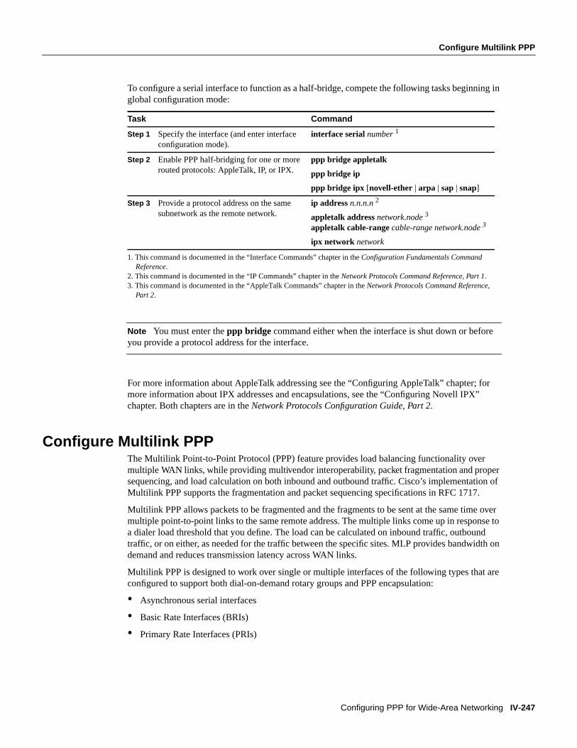
To configure a serial interface to function as a half-bridge, compete the following tasks beginning inglobal configuration mode:
Note You must enter theppp bridge command either when the interface is shut down or beforeyou provide a protocol address for the interface.
For more information about AppleTalk addressing see the “Configuring AppleTalk” chapter; formore information about IPX addresses and encapsulations, see the “Configuring Novell IPX”chapter. Both chapters are in theNetwork Protocols Configuration Guide, Part 2.
Configure Multilink PPPThe Multilink Point-to-Point Protocol (PPP) feature provides load balancing functionality overmultiple WAN links, while providing multivendor interoperability, packet fragmentation and propersequencing, and load calculation on both inbound and outbound traffic. Cisco’s implementation ofMultilink PPP supports the fragmentation and packet sequencing specifications in RFC 1717.
Multilink PPP allows packets to be fragmented and the fragments to be sent at the same time overmultiple point-to-point links to the same remote address. The multiple links come up in response toa dialer load threshold that you define. The load can be calculated on inbound traffic, outboundtraffic, or on either, as needed for the traffic between the specific sites. MLP provides bandwidth ondemand and reduces transmission latency across WAN links.
Multilink PPP is designed to work over single or multiple interfaces of the following types that areconfigured to support both dial-on-demand rotary groups and PPP encapsulation:
• Asynchronous serial interfaces
• Basic Rate Interfaces (BRIs)
• Primary Rate Interfaces (PRIs)
1. This command is documented in the “Interface Commands” chapter in theConfiguration Fundamentals CommandReference.
2. This command is documented in the “IP Commands” chapter in theNetwork Protocols Command Reference, Part 1.3. This command is documented in the “AppleTalk Commands” chapter in theNetwork Protocols Command Reference,
Part 2.
Task Command
Step 1 Specify the interface (and enter interfaceconfiguration mode).
interface serialnumber1
Step 2 Enable PPP half-bridging for one or morerouted protocols: AppleTalk, IP, or IPX.
ppp bridge appletalk
ppp bridge ip
ppp bridge ipx [novell-ether | arpa | sap | snap]
Step 3 Provide a protocol address on the samesubnetwork as the remote network.
ip addressn.n.n.n2
appletalk addressnetwork.node3
appletalk cable-rangecable-range network.node3
ipx network network

IV-248 Wide-Area Networking Configuration Guide
Configure Multilink PPP
FINAL DRAFT CISCO CONFIDENTIAL
Configure Multilink PPP on Asynchronous InterfacesTo configure Multilink PPP on asynchronous interfaces, you configure the asynchronous interfacesto support DDR and PPP encapuslation, then you configure a dialer interface to support PPPencapsulation, bandwidth on demand, and Multilink PPP.
To configure an asynchronous interface to support DDR and PPP encapsulation, complete thefollowing tasks beginning in global configuration mode:
Repeat this step for additional asynchronous interfaces, as needed.
At some point, adding more asynchronous interfaces does not improve performance, With thedefault MTU size, Multilink PPP should support three asynchronous interfaces using V.34 modems.However, packets might be dropped occasionally if the MTU is small or large bursts of short framesoccur.
To configre a dialer interface to support PPP encapsulation and Multilink PPP, complete thefollowing tasks beginning in global configuration mode:
Configure Multilink PPP on a Single ISDN BRI InterfaceTo enable Multilink PPP on a single Integrated Services Digital Network (ISDN) BRI interface, youare not required to define a dialer rotary group separately because ISDN interfaces are dialer rotarygroups by default.
1. This command is documented in the “Interface Commands” chapter in theConfiguration Fundamentals CommandReference.
2. This command is documented in the “DDR Commands” chapter of this manual.
1. This command is documented in the “DDR Commands” chapter of this manual.
Task Command
Step 1 Specify an asynchronous interface. interface asyncnumber1
Step 2 Specify no IP address for the interface. no ip address
Step 3 Enable PPP encapsulation. encapsulation ppp
Step 4 Enable DDR on the interface. dialer in-band 2
Step 5 Include the interface in a specific dialerrotary group.
dialer rotary-group number2
Task Command
Step 1 Define a dialer rotary group. interface dialer number1
Step 2 Specify no IP address for the interface. no ip address
Step 3 Enable PPP encapsulation. encapsulation ppp
Step 4 Enable DDR on the interface. dialer in-band 1
Step 5 Configure bandwidth on demand byspecifying the maximum load before thedialer places another call to a destination.
dialer load-threshold load [inbound | outbound |either] 1
Step 6 Enable Multilink PPP. ppp multilink
Configure Multilink PPP
Configuring PPP for Wide-Area Networking IV-249
FINAL DRAFT CISCO CONFIDENTIAL
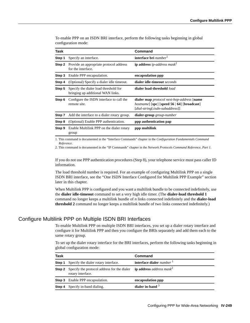
To enable PPP on an ISDN BRI interface, perform the following tasks beginning in globalconfiguration mode:
If you do not use PPP authentication procedures (Step 8), your telephone service must pass caller IDinformation.
The load threshold number is required. For an example of configuring Multilink PPP on a singleISDN BRI interface, see the “One ISDN Interface Configured for Multilink PPP Example” sectionlater in this chapter.
When Multilink PPP is configured and you want a multilink bundle to be connected indefinitely, usethe dialer idle-timeout command to set a very high idle timer. (Thedialer-load threshold 1command no longer keeps a multilink bundle ofn links connected indefinitely and thedialer-loadthreshold 2 command no longer keeps a multilink bundle of two links connected indefinitely.)
Configure Multilink PPP on Multiple ISDN BRI InterfacesTo enable Multilink PPP on multiple ISDN BRI interfaces, you set up a dialer rotary interface andconfigure it for Multilink PPP and then you configure the BRIs separately and add them each to thesame rotary group.
To set up the dialer rotary interface for the BRI interfaces, perform the following tasks beginning inglobal configuration mode:
1. This command is documented in the “Interface Commands” chapter in theConfiguration Fundamentals CommandReference.
2. This command is documented in the “IP Commands” chapter in theNetwork Protocols Command Reference, Part 1.
Task Command
Step 1 Specify an interface. interface bri number1
Step 2 Provide an appropriate protocol addressfor the interface.
ip address ip-address mask2
Step 3 Enable PPP encapsulation. encapsulation ppp
Step 4 (Optional) Specify a dialer idle timeout. dialer idle-timeout seconds
Step 5 Specify the dialer load threshold forbringing up additional WAN links.
dialer load-threshold load
Step 6 Configure the ISDN interface to call theremote site.
dialer map protocol next-hop-address[namehostname] [spc] [speed 56| 64] [broadcast][dial-string[:isdn-subaddress]]
Step 7 Add the interface to a dialer rotary group.dialer-group group-number
Step 8 (Optional) Enable PPP authentication. ppp authentication pap
Step 9 Enable Multilink PPP on the dialer rotarygroup
ppp multilink
Task Command
Step 1 Specify the dialer rotary interface. interface dialer number1
Step 2 Specify the protocol address for the dialerrotary interface.
ip addressaddress mask2
Step 3 Enable PPP encapsulation. encapsulation ppp
Step 4 Specify in-band dialing. dialer in-band 3

IV-250 Wide-Area Networking Configuration Guide
Configure Multilink PPP
FINAL DRAFT CISCO CONFIDENTIAL
If you do not use PPP authentication procedures (Step 10), your telephone service must pass callerID information.
To configure each of the BRIs to belong to the same rotary group, perform the following tasksbeginning in global configuration mode:
Repeat Steps 1 through 6 for each BRI you want to belong to the same dialer rotary group.
For an example of configuring Multilink PPP on multiple ISDN BRI interfaces, see the “MultipleISDN Interfaces Configured for Multilink PPP Example” section later in this chapter.
1. This command is documented in the “Interface Commands” chapter in theConfiguration Fundamentals CommandReference.
2. This command is documented in the “IP Commands” chapter in theNetwork Protocols Command Reference, Part 1.3. This command is documented in the “DDR Commands” chapter in theWide-Area Networking Command Reference
1. This command is documented in the “Interface Commands” chapter in theConfiguration Fundamentals CommandReference.
2. This command is documented in the “IP Commands” chapter in theNetwork Protocols Command Reference, Part 1.3. This command is documented in the “DDR Commands” chapter in theWide-Area Networking Command Reference.
Step 5 (Optional) Specify the dialer idle timeoutperiod, using the same timeout period asthe individual BRI interfaces.
dialer idle-timeout seconds3
Step 6 Map the next-hop protocol address andname to the dial string needed to reach it.
dialer map protocol next-hop-address[namehostname] [spc] [speed 56| 64] [broadcast][dial-string[:isdn-subaddress]] 3
Step 7 Specify the dialer load threshold, using thesame threshold as the individual BRIinterfaces.
dialer load-threshold load 3
Step 8 Control access to this interface by addingit to a dialer access group.
dialer-group group-number3
Step 9 (Optional) Enable PPP ChallengeHandshake Authentication Protocol(CHAP) authentication.
ppp authentication chap
Step 10 Enable Multilink PPP. ppp multilink
Task Command
Step 1 Specify one of the BRI interfaces. interface bri number1
Step 2 Specify that it does not have an individualprotocol address.
no ip address2
Step 3 Enable PPP encapsulation. encapsulation ppp
Step 4 Set the dialer idle timeout period, usingthe same timeout for each of the BRIinterfaces you configure.
dialer idle-timeout seconds3
Step 5 Add the interface to the rotary group. dialer rotary-group group-number3
Step 6 Specify the dialer load threshold forbringing up additional WAN links.
dialer load-threshold load 3
Task Command

Configure Multichassis Multilink PPP
Configuring PPP for Wide-Area Networking IV-251
FINAL DRAFT CISCO CONFIDENTIAL
When Multilink PPP is configured and you want a multilink bundle to be connected indefinitely, usethe dialer idle-timeout command to set a very high idle timer. (Thedialer load-threshold 1command no longer keeps a multilink bundle ofn links connected indefinitely and thedialerload-threshold 2 command no longer keeps a multilink bundle of two links connected indefinitely.)
Configure Multichassis Multilink PPPPrior to Release 11.2, Cisco IOS supported Multilink PPP. Beginning with Release 11.2, Cisco IOSsoftware also supports MMP (MMP).
Multilink PPP provides the capability of splitting and recombining packets to a single end-systemacross a logical pipe (also called abundle) formed by multiple links. Multilink PPP providesbandwidth on demand and reduces transmission latency across WAN links.
MMP, on the other hand, provides the additional capability for links to terminate at multiple routerswith different remote addresses. MMP can also handle both analog and digital traffic.
The MMP feature is intended for situations with large pools of dialup users, for which the numberof ports on a chassis cannot be allowed to be a limit. This feature allows companies to provide asingle dialup number to its users and to apply the same solution to analog and digital calls. Thisfeature allows internet service providers, for example, to allocate a single ISDN rotary number toseveral PRIs across several routers.
Multichassis Multilink PPP (MMP) does not require reconfiguration of telephone companyswitches.
Multichassis Multilink PPP is supported on the Cisco 7500, 4500, and 2500 series platforms and onsynchronous serial, asynchronous serial, ISDN BRI, ISDN PRI, and dialer interfaces.
Understand Multichassis Multilink PPPRouters or access servers are configured to belong to groups of peer routers, calledstack groups. Allmembers of the stack group are peers. Any stack group member can answer calls coming from asingle access number, which is usually an ISDN PRI hunt group. Calls can come in from remote userdevices, which can be routers, modems, ISDN terminal adapters, or PC cards.
Once a connection is established with one of the member of a stack group, that member owns thecall. If a second call comes in from the same client and a different router answers the call, the routerestablishes a tunnel and forwards all packets belonging to the call to the router that owns the call.
With the availability of a more powerful router, it can be configured as a member of the stack groupand the other stack group members can all establish tunnels and forward calls to it. In such a case,the other stack group members are just answering calls and forwarding traffic.
Note High-latency WAN lines between stack group members can make stack group operationinefficient.

IV-252 Wide-Area Networking Configuration Guide
Configure Multichassis Multilink PPP
FINAL DRAFT CISCO CONFIDENTIAL
Figure 38 Typical Multichassis Multilink PPP Scenario
MMP call handling, bidding, and level-2 forwarding operation in the stack group proceeds asfollows, as shown in Figure 38:
• When the first call coming in to the stack group, Router A answers.
• In the bidding, Router A wins because it already has the call. Router A becomes thecall-masterfor that session with the remote device. (Router A might also be called thehost to the masterbundle interface.)
• When the remote device that initiated the call needs more bandwidth, it makes a second MultilinkPPP call to the group.
• When the second call comes in Router D answers it and informs the stack group. Router A winsthe bidding because it already is handling the session with that remote device.
• Router D establishes a tunnel to Router A, and forwards the raw PPP data to Router A.
• Router A reassembles and resequences the packets.
• If more calls come in to Router D and they too belong to Router A, the tunnel between A and Denlarges to handle the added traffic. Router D does not establish an additional tunnel to A.
• If more calls come in and are answered by any other router, that router also establishes a tunnelto A and forwards the raw PPP data.
The reassembled data is passed on the corporate network as if it had all come through one physicallink.
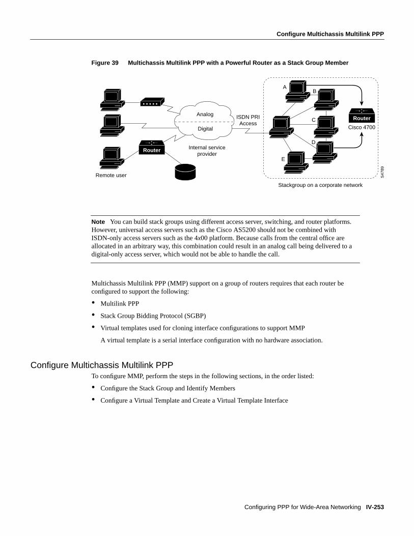
In Figure39, access servers that belong to a stack group answer calls, establish tunnels, and forwardcalls to a Cisco 4700 router that wins the bidding and is the call-master for all the calls. TheCisco 4700 reassembles and resequences all the packets coming in through the stack group.
S47
88
Router
ISDN PRI Access
Digital
Stackgroup on a corporate network
Remote user
Internal service provider
AB
C
D
E
Analog
Configure Multichassis Multilink PPP
Configuring PPP for Wide-Area Networking IV-253
FINAL DRAFT CISCO CONFIDENTIAL
Figure 39 Multichassis Multilink PPP with a Powerful Router as a Stack Group Member
Note You can build stack groups using different access server, switching, and router platforms.However, universal access servers such as the Cisco AS5200 should not be combined withISDN-only access servers such as the 4x00 platform. Because calls from the central office areallocated in an arbitrary way, this combination could result in an analog call being delivered to adigital-only access server, which would not be able to handle the call.
Multichassis Multilink PPP (MMP) support on a group of routers requires that each router beconfigured to support the following:
• Multilink PPP
• Stack Group Bidding Protocol (SGBP)
• Virtual templates used for cloning interface configurations to support MMP
A virtual template is a serial interface configuration with no hardware association.
Configure Multichassis Multilink PPPTo configure MMP, perform the steps in the following sections, in the order listed:
• Configure the Stack Group and Identify Members
• Configure a Virtual Template and Create a Virtual Template Interface
S47
89
Router
RouterISDN PRI Access
Digital
Stackgroup on a corporate network
Remote user
Internal service provider
AB
Cisco 4700C
D
E
Analog
IV-254 Wide-Area Networking Configuration Guide
Configure Virtual Private Dial-up Networks
FINAL DRAFT CISCO CONFIDENTIAL
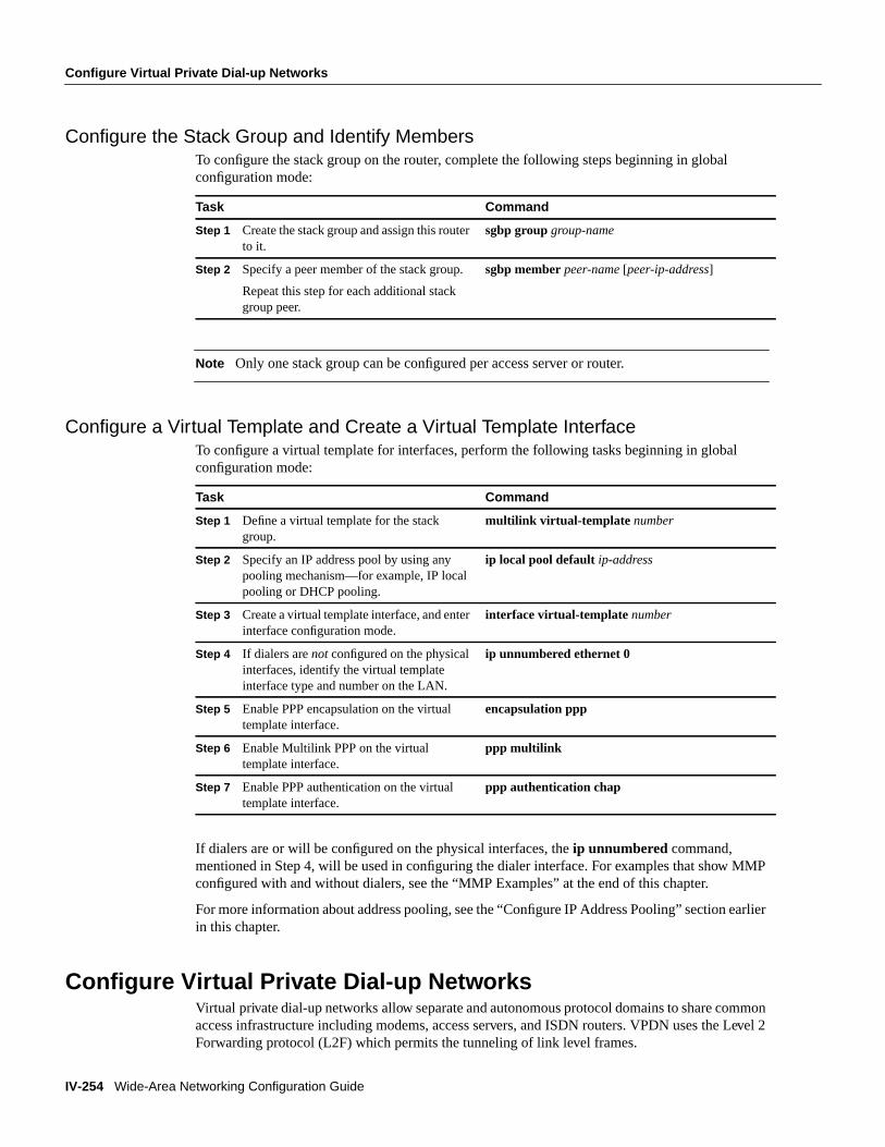
Configure the Stack Group and Identify MembersTo configure the stack group on the router, complete the following steps beginning in globalconfiguration mode:
Note Only one stack group can be configured per access server or router.
Configure a Virtual Template and Create a Virtual Template InterfaceTo configure a virtual template for interfaces, perform the following tasks beginning in globalconfiguration mode:
If dialers are or will be configured on the physical interfaces, theip unnumbered command,mentioned in Step 4, will be used in configuring the dialer interface. For examples that show MMPconfigured with and without dialers, see the “MMP Examples” at the end of this chapter.
For more information about address pooling, see the “Configure IP Address Pooling” section earlierin this chapter.
Configure Virtual Private Dial-up NetworksVirtual private dial-up networks allow separate and autonomous protocol domains to share commonaccess infrastructure including modems, access servers, and ISDN routers. VPDN uses the Level 2Forwarding protocol (L2F) which permits the tunneling of link level frames.
Task Command
Step 1 Create the stack group and assign this routerto it.
sgbp groupgroup-name
Step 2 Specify a peer member of the stack group.
Repeat this step for each additional stackgroup peer.
sgbp memberpeer-name [peer-ip-address]
Task Command
Step 1 Define a virtual template for the stackgroup.
multilink virtual-template number
Step 2 Specify an IP address pool by using anypooling mechanism—for example, IP localpooling or DHCP pooling.
ip local pool default ip-address
Step 3 Create a virtual template interface, and enterinterface configuration mode.
interface virtual-template number
Step 4 If dialers arenot configured on the physicalinterfaces, identify the virtual templateinterface type and number on the LAN.
ip unnumbered ethernet 0
Step 5 Enable PPP encapsulation on the virtualtemplate interface.
encapsulation ppp
Step 6 Enable Multilink PPP on the virtualtemplate interface.
ppp multilink
Step 7 Enable PPP authentication on the virtualtemplate interface.
ppp authentication chap

Configure Virtual Private Dial-up Networks
Configuring PPP for Wide-Area Networking IV-255
FINAL DRAFT CISCO CONFIDENTIAL
Using L2F tunneling, an Internet Service Provider (ISP) or other access service can create a virtualtunnel to link a customer’s remote sites or remote users with corporate home networks. In particular,a network access server at the ISP’s point of presence (POP) exchanges PPP messages with theremote users, and communicates by L2F requests and responses with the customer’s home gatewayto set up tunnels.
L2F passes protocol-level packets through the virtual tunnel between endpoints of a point-to-pointconnection.
Frames from the remote users are accepted by the ISP’s POP, stripped of any linked framing ortransparency bytes, encapsulated in L2F, and forwarded over the appropriate tunnel. The customer’shome gateway accepts these L2F frames, strips the L2F encapsulation, and process the incomingframes for the appropriate interface.
Note This implementation of VPDN supports PPP dial-up only.
To configure virtual private dial-up networks, complete the tasks in the following sections:
• Understand Virtual Private Dial-up Networks
• Configure a Virtual Template and Create a Virtual Template Interface on the Home Gateway
• Configure Incoming VPDN Connections on the Home Gateway
• Configure Outgoing VPDN Connections on the Network Access Server
For more information, see the draft RFCLevel Two Forwarding (Protocol) “L2F”, which describesthe proposed implementation of L2F.
Understand Virtual Private Dial-up NetworksVirtual private dial-up networking enables users to configure secure networks that take advantage ofInternet Service Providers that tunnel the company’s remote access traffic through the ISP cloud.
Remote offices or mobile users can connect to their home network using local dial-up services ofthird parties. The dial-up service provider agrees to forward the company’s traffic from the ISP POPto a company-run home gateway. Network configuration and security remains in the control of theclient. The dial-up service provider provides a virtual pipe between the company’s sites.
Note The MMP feature uses VPDN to connect multiple PPP sessions for which individual dial-incalls have arrived on different stack group members. VPDN provides speed and reliability for thesetup and shutdown of Multilink PPP.
A VPDN connection between a remote user and the home LAN is done in the following steps:
1 The remote user initiates a PPP connection to the ISP using the analog telephone system or ISDN.
2 The ISP network access server accepts the connection.
3 The ISP network access server authenticates the end user with CHAP or PAP. The username isused to determine whether the user is an VPDN client. If the user is not a VPDN client, the clientaccesses the Internet or other contacted service.

IV-256 Wide-Area Networking Configuration Guide
Configure Virtual Private Dial-up Networks
FINAL DRAFT CISCO CONFIDENTIAL
4 The tunnel endpoints—the network access server and the home gateway—authenticateeachother before any sessions are attempted within a tunnel.
5 If no L2F tunnel exists between the network access server and the remote users’ home gateway,a tunnel is created. Once the tunnel exists, an unused slot within the tunnel is allocated.
6 The home gateway accepts or rejects the connection. Initial setup can include authenticationinformation required to allow the home gateway to authenticate the user.
7 The home gateway sets up a virtual interface. Link-level frames can now pass through this virtualinterface through the L2F tunnel.
Figure40 illustrates a VPDN connection from a remote user, who makes a local call, to the corporatenetwork, through an end-to-end L2F tunnel (shown by the dotted line).
Figure 40 Virtual Private Dialup Network
Configure a Virtual Template and Create a Virtual Template Interface on the Home GatewayTo configure a virtual template for interfaces on a home gateway access server, perform thefollowing tasks beginning in global configuration mode:
Configure Incoming VPDN Connections on the Home GatewayTo configure virtual private dialup networking on a home gateway router or access server, completethe following tasks in global configuration mode:
Task Command
Step 1 Specify a default local IP address pool. ip local pool default ip-address
Step 2 Create a virtual template interface, and enterinterface configuration mode.
interface virtual-template number
Step 3 Identify the virtual template interface typeand number on the LAN.
ip unnumbered ethernet 0
Step 4 Enable PPP encapsulation on the virtualtemplate interface.
encapsulation ppp
Step 5 Enable PPP authentication on the virtualtemplate interface.
ppp authentication chap
Task Command
Enable virtual private networking. vpdn enable
Specify the remote host, the local name to use forauthenticating, and the virtual template to use.
vpdn incoming remote-name local-namevirtual-template number
S47
87
Corporate Network
Access across corporate network to specific LAN
server or application
Router
RouterTunnelRemote user makes a
local call to service provider
Home gateway
ISP or Public Data Network
Network Access server
Enable PPP on VTY Lines for Asynchronous Access over ISDN
Configuring PPP for Wide-Area Networking IV-257
FINAL DRAFT CISCO CONFIDENTIAL
Configure Outgoing VPDN Connections on the Network Access ServerTo configure a network access server to make outgoing L2F connections to a home gateway forvirtual private dialup networking, complete the following tasks in global configuration mode:
Enable PPP on VTY Lines for Asynchronous Access over ISDNYou can configure a router to support asynchronous access over ISDN by globally enabling PPP onVTY lines. PPP is typically enabled on synchronous or asynchronous serial interfaces; however, theCisco IOS software permits you to configure PPP on virtual terminal (VTY) lines. This configuresthe VTY line to support asynchronous access over ISDN from an ISDN terminal to a VTY sessionon the router.
To enable asynchronous protocol features on all the router’s VTY lines, perform the following taskin global configuration mode:
This task enables PPP on VTY lines on a global basis on the router. To configure PPP on a per-VTYbasis, use thetranslate command, which is documented in the “Protocol Translation ConfigurationCommands” chapter in theAccess Services Command Reference.
Monitor and Maintain MLP, MMP, and VPDN Virtual InterfacesTo monitor and maintain virtual interfaces, you can perform any of the following tasks:
PPP ExamplesThe examples provided in this section show various PPP configurations as follows:
• CHAP with an Encrypted Password Examples
• Multilink PPP Examples
• MMP Examples
1. This command is documented in the “Terminal Lines and Modem Support” chapter in theAccess Services CommandReference.
Task Command
Enable virtual private networking. vpdn enable
Specify the remote host that is to accept L2Fconnections.
vpdn outgoingdomain-name local-nameipip-address
Task Command
Configure all VTY lines to support asynchronousprotocol features
vty-async1
Task Command
Display MLP and MMP bundle information. show ppp multilink
Display information about the active L2F tunnels andthe L2F message identifiers.
show vpdn
Display the status of the stack group members. show sgbp
Display the current seed bid value. show sgbp queries

IV-258 Wide-Area Networking Configuration Guide
PPP Examples
FINAL DRAFT CISCO CONFIDENTIAL
• PPP Callback Example
• VPDN Examples
CHAP with an Encrypted Password ExamplesThe following configuration examples enable CHAP on interface serial 0 of three devices.
Configuration of Router yyyhostname yyyinterface serial 0encapsulation pppppp authentication chapusername xxx password secretxyusername zzz password secretzy
Configuration of Router xxxhostname xxxinterface serial 0encapsulation pppppp authentication chapusername yyy password secretxyusername zzz password secretxz
Configuration of Router zzzhostname zzzinterface serial 0encapsulation pppppp authentication chapusername xxx password secretxzusername yyy password secretzy
When you look at the configuration file, the passwords will be encrypted and the display will looksimilar to the following:
hostname xxxinterface serial 0encapsulation pppppp authentication chapusername yyy password 7 121F0A18username zzz password 7 1329A055
Multilink PPP ExamplesThe following examples configure Multilink PPP. The first example configures it on one BRIinterface, and the second configures multiple BRIs to belong to the same dialer rotary group, whichis then configured for Multilink PPP.
Multilink PPP on One ISDN Interface ExampleThe following example enables Multilink PPP on the BRI 0 interface. Because an ISDN interface isa rotary group by default, when one BRI is configured, no dialer rotary group configuration isrequired.

PPP Examples
Configuring PPP for Wide-Area Networking IV-259
FINAL DRAFT CISCO CONFIDENTIAL
interface bri 0description connected to ntt 81012345678902ip address 7.1.1.7 255.255.255.0encapsulation pppdialer idle-timeout 30dialer load-threshold 40 eitherdialer map ip 7.1.1.8 name atlanta 81012345678901dialer-group 1ppp authentication papppp multilink
Multilink PPP on Multiple ISDN Interfaces ExampleThe following example configures multiple ISDN BRIs to belong to the same dialer rotary group forMultilink PPP. Thedialer rotary-group command is used to assign each of the ISDN BRIs to thatdialer rotary group.
interface BRI0no ip addressencapsulation pppdialer idle-timeout 500dialer rotary-group 0dialer load-threshold 255 balanced!interface BRI1no ip addressencapsulation pppdialer idle-timeout 500dialer rotary-group 0dialer load-threshold 255 balanced!interface BRI2no ip addressencapsulation pppdialer idle-timeout 500dialer rotary-group 0dialer load-threshold 255 balanced!interface Dialer0ip address 99.0.0.2 255.0.0.0encapsulation pppdialer in-banddialer idle-timeout 500dialer map ip 99.0.0.1 name atlanta broadcast 81012345678901dialer load-threshold 255 balanceddialer-group 1ppp authentication chapppp multilink
MMP ExamplesThe examples in this section show MMP configuration without and with dialers.
Multichassis Multilink PPP without DialersThe following example shows the configuration of MMP when no dialers are involved. Commentsin the configuration discuss the commands. Variations are shown for a Cisco AS5200 access serveror Cisco 4000 series router, and for an E1 controller.

IV-260 Wide-Area Networking Configuration Guide
PPP Examples
FINAL DRAFT CISCO CONFIDENTIAL
! First make sure the multilink global virtual template number is defined on each¡ stack group member.multilink virtual-template 1
! If you have not configured any dialer interfaces for the physical interfaces in! question (PRI, BRI, async, sync serial etc), you can define a virtual template.
interface virtual-template 1ip unnumbered e0ppp authentication chapppp multilink
! Never define a specific IP address on the virtual template because projected Virtual! Access Interfaces are always cloned from the Virtual template interface. If a! subsequent PPP link also gets projected to a stack member with a Virtual Access! interface already cloned and active, we will have identical IP addresses on the two! Virtual Interfaces. IP will erroneously route between them.
! On a AS5200 or 4X platform:
! On a TI controller!controller T1 0framing esflinecode b8zspri-group timeslots 1-24!interface Serial 0:23no ip addressencapsulation pppno ip route-cacheppp authentication chapppp multilink!! Or on an E1 Controller!controller E1 0framing crc4linecode hdb3pri-group timeslots 1-31
interface Serial 0:15no ip addressencapsulation pppno ip route-cacheppp authentication chapppp multilink
Multichassis Multilink PPP with DialersWhen dialers are configured on the physical interfaces, do not specify the ip unnumbered e0on thevirtual template interface. In this case, the virtual access interface acts as a passive interface,buttressed between the dialer interface and the physical interfaces associated with the dialerinterface.
multilink virtual-template 1
interface virtual-template 1ppp authentication chapppp multilink

PPP Examples
Configuring PPP for Wide-Area Networking IV-261
FINAL DRAFT CISCO CONFIDENTIAL
! On a AS5200 or 4X platform:!interface dialer 1ip unnum e0dialer map .....encap pppppp authentication chapdialer-group 1dialer rotary 1
! On a T1 controller
controller T1 0framing esflinecode b8zspri-group timeslots 1-24interface Serial0:23no ip addressencapsulation pppdialer in-banddialer rotary group 1dialer-group 1no ip route-cacheppp authentication chapppp multilink
PPP Callback ExampleThe following example configures a PPP callback server and client to call each other.
The PPP callback server is configured on an ISDN BRI interface in a router in Atlanta. The callbackserver requires an enable timeout and a map class to be defined.
The PPP callback client is configured on an ISDN BRI interface in a router in Dallas. The callbackclient does not require an enable timeout and a map class to be defined.
PPP Callback Serverinterface BRI0 ip address 7.1.1.7 255.255.255.0 encapsulation ppp dialer callback-secure dialer enable-timeout 2 dialer map ip 7.1.1.8 name atlanta class dial1 81012345678901 dialer-group 1 ppp callback accept ppp authentication chap!map-class dialer dial1 dialer callback-server username
PPP Callback Clientinterface BRI0 ip address 7.1.1.8 255.255.255.0 encapsulation ppp dialer map ip 7.1.1.7 name dallas 81012345678902 dialer-group 1 ppp callback request ppp authentication chap
IV-262 Wide-Area Networking Configuration Guide
PPP Examples
FINAL DRAFT CISCO CONFIDENTIAL
VPDN ExamplesThis section provides three examples that illustrate the following:
• One network access server (NAS) servicing multiple domains on multiple home gateways
• One NAS servicing multiple domains on one home gateway
• One NAS Using TACACS+ for Forwarding
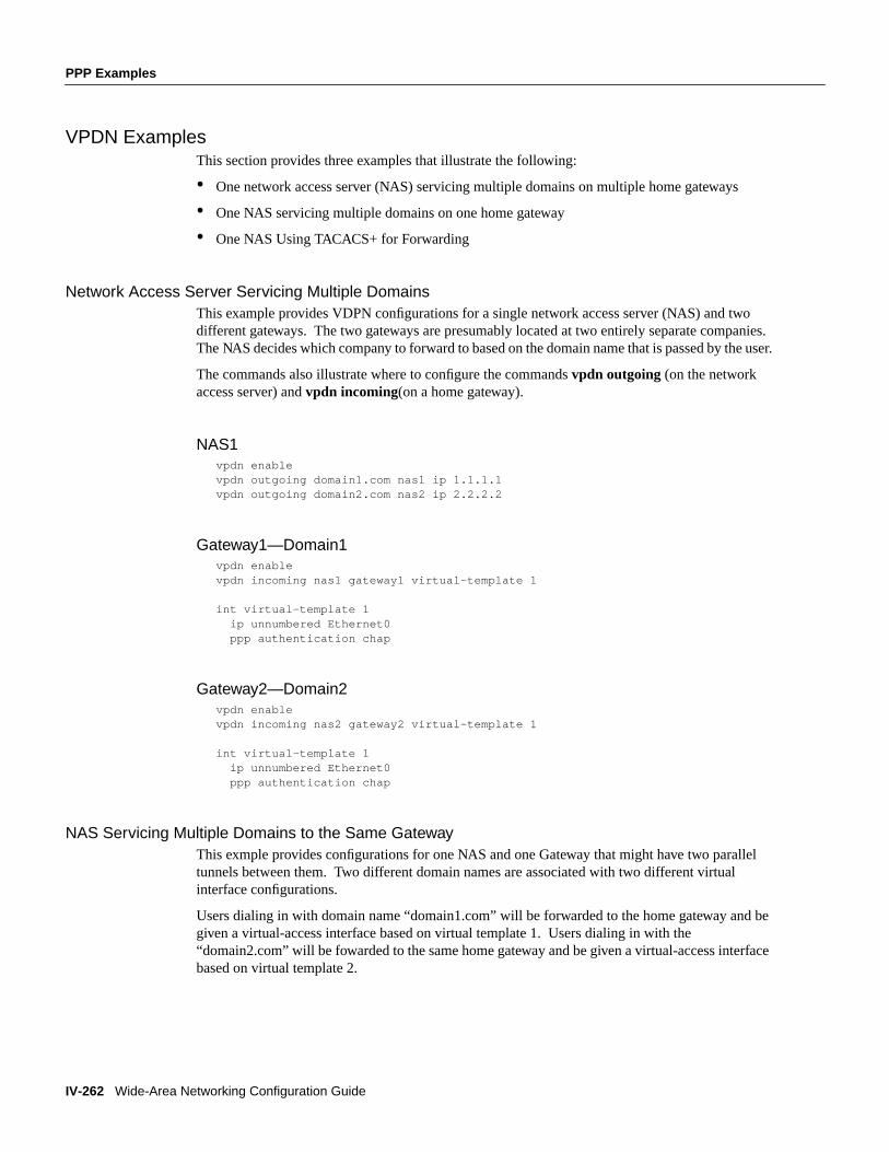
Network Access Server Servicing Multiple DomainsThis example provides VDPN configurations for a single network access server (NAS) and twodifferent gateways. The two gateways are presumably located at two entirely separate companies.The NAS decides which company to forward to based on the domain name that is passed by the user.
The commands also illustrate where to configure the commandsvpdn outgoing (on the networkaccess server) andvpdn incoming(on a home gateway).
NAS1vpdn enablevpdn outgoing domain1.com nas1 ip 1.1.1.1vpdn outgoing domain2.com nas2 ip 2.2.2.2
Gateway1—Domain1vpdn enablevpdn incoming nas1 gateway1 virtual-template 1
int virtual-template 1 ip unnumbered Ethernet0 ppp authentication chap
Gateway2—Domain2vpdn enablevpdn incoming nas2 gateway2 virtual-template 1
int virtual-template 1 ip unnumbered Ethernet0 ppp authentication chap
NAS Servicing Multiple Domains to the Same GatewayThis exmple provides configurations for one NAS and one Gateway that might have two paralleltunnels between them. Two different domain names are associated with two different virtualinterface configurations.
Users dialing in with domain name “domain1.com” will be forwarded to the home gateway and begiven a virtual-access interface based on virtual template 1. Users dialing in with the“domain2.com” will be fowarded to the same home gateway and be given a virtual-access interfacebased on virtual template 2.
PPP Examples
Configuring PPP for Wide-Area Networking IV-263
FINAL DRAFT CISCO CONFIDENTIAL
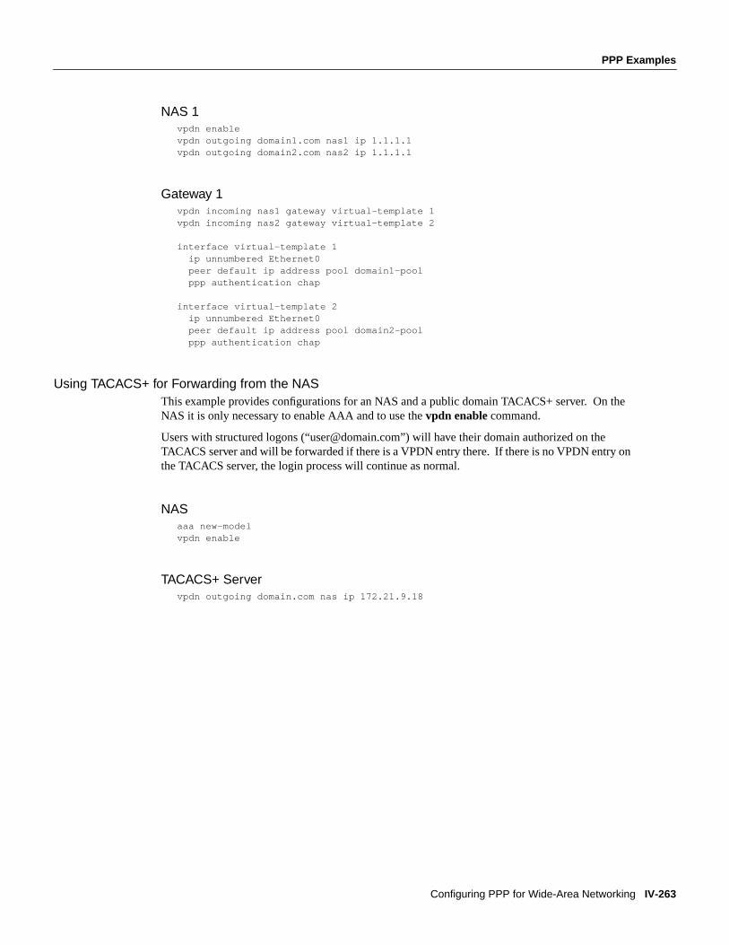
NAS 1vpdn enablevpdn outgoing domain1.com nas1 ip 1.1.1.1vpdn outgoing domain2.com nas2 ip 1.1.1.1
Gateway 1vpdn incoming nas1 gateway virtual-template 1vpdn incoming nas2 gateway virtual-template 2
interface virtual-template 1 ip unnumbered Ethernet0 peer default ip address pool domain1-pool ppp authentication chap
interface virtual-template 2 ip unnumbered Ethernet0 peer default ip address pool domain2-pool ppp authentication chap
Using TACACS+ for Forwarding from the NASThis example provides configurations for an NAS and a public domain TACACS+ server. On theNAS it is only necessary to enable AAA and to use thevpdn enable command.
Users with structured logons (“[email protected]”) will have their domain authorized on theTACACS server and will be forwarded if there is a VPDN entry there. If there is no VPDN entry onthe TACACS server, the login process will continue as normal.
NASaaa new-modelvpdn enable
TACACS+ Servervpdn outgoing domain.com nas ip 172.21.9.18

IV-264 Wide-Area Networking Configuration Guide
PPP Examples
FINAL DRAFT CISCO CONFIDENTIAL