Introduction to Policy-Based Routing Configuring...
14
This appendix discusses policy-based routing. It covers the following topics: ■ Introduction to Policy-Based Routing ■ Configuring Policy-Based Routing ■ Verifying Policy-Based Routing ■ Policy-Based Routing Examples
Transcript of Introduction to Policy-Based Routing Configuring...
This appendix discusses policy-based routing. It covers the following topics:
■
Introduction to Policy-Based Routing
■
Configuring Policy-Based Routing
■
Verifying Policy-Based Routing
■
Policy-Based Routing Examples
2237xxd.fm Page 2 Friday, December 1, 2006 3:41 PM
A P P E N D I X
D
Manipulating Routing Updates Supplement
Chapter 7, “Manipulating Routing Updates,” describes route maps and how you can use them for route filtering. This appendix describes another use for route maps, called policy-based routing (PBR). PBR enables the administrator to define a routing policy other than basic destination-based routing using the routing table. With PBR, route maps can be used to match source and destination addresses, protocol types, and end-user applications. When a match occurs, a
set
command can be used to define items, such as the interface or next-hop address to which the packet should be sent.
Introduction to Policy-Based Routing
In modern high-performance internetworks, organizations need the freedom to implement packet forwarding and routing according to their own defined policies in a way that goes beyond traditional routing protocol concerns.
Routers normally forward packets to destination addresses based on information in their routing tables. By using PBR, introduced in Cisco IOS Release 11.0, you can implement policies that selectively cause packets to take different paths based on source address, protocol types, or application types. Therefore, PBR overrides the router’s normal routing procedures.
PBR also provides a mechanism to mark packets with different types of service (ToS). This feature can be used in conjunction with Cisco IOS queuing techniques so that certain kinds of traffic can receive preferential service.
PBR provides an extremely powerful, simple, and flexible tool to implement solutions in cases where legal, contractual, or political constraints dictate that traffic be routed through specific paths. Here are some of the benefits you can achieve by implementing PBR:
■
Source-based transit provider selection
—Internet service providers (ISPs) and other organizations can use PBR to route traffic originating from different sets of users through different Internet connections across policy routers.
2237xxd.fm Page 3 Friday, December 1, 2006 3:41 PM
4
Appendix D: Manipulating Routing Updates Supplement
■
Quality of service (QoS)
—Organizations can provide QoS to differentiated traffic by setting the ToS values in the IP packet headers in routers at the periphery of the network and then leveraging queuing mechanisms to prioritize traffic in the network’s core or backbone. This setup improves network performance by eliminating the need to classify the traffic explicitly at each WAN interface in the network’s core or backbone.
■
Cost savings
—An organization can direct the bulk traffic associated with a specific activity to use a higher-bandwidth, high-cost link for a short time and to continue basic connectivity over a lower-bandwidth, low-cost link for interactive traffic. For example, a dial-on-demand Integrated Services Digital Network (ISDN) line could be brought up in response to traffic destined for a finance server; PBR would select this link.
■
Load sharing
—In addition to the dynamic load-sharing capabilities offered by destination-based routing that the Cisco IOS Software has always supported, network managers can implement policies to distribute traffic among multiple paths based on the traffic characteristics.
Configuring Policy-Based Routing
Configuring PBR involves configuring a route map with
match
and
set
commands and then applying the route map to the interface.
KEY
POINT
PBR Is Applied to Incoming Packets
PBR is applied to
incoming
packets. Enabling PBR causes the router to evaluate all packets incoming on the interface using a route map configured for that purpose.
KEY
POINT
PBR permit and deny Statements
You can configure the route map statements used for PBR as
permit
or
deny
.
If the statement is marked as
deny
, a packet meeting the match criteria is sent through the normal forwarding channels (in other words, destination-based routing is performed).
Only if the statement is marked as
permit
and the packet meets all the match criteria are the
set
commands applied.
If no match is found in the route map, the packet is
not
dropped; it is forwarded through the normal routing channel, which means that destination-based routing is performed.
If you do not want to revert to normal forwarding but instead want to drop a packet that does not match the specified criteria, configure a
set
statement to route the packets to interface null 0 as the last entry in the route map.
2237xxd.fm Page 4 Friday, December 1, 2006 3:41 PM
Configuring Policy-Based Routing
5
Policy-Based Routing match Commands
IP standard or extended access lists can be used to establish PBR match criteria using the
match ip address
{
access-list-number
|
name
} [...
access-list-number
|
name
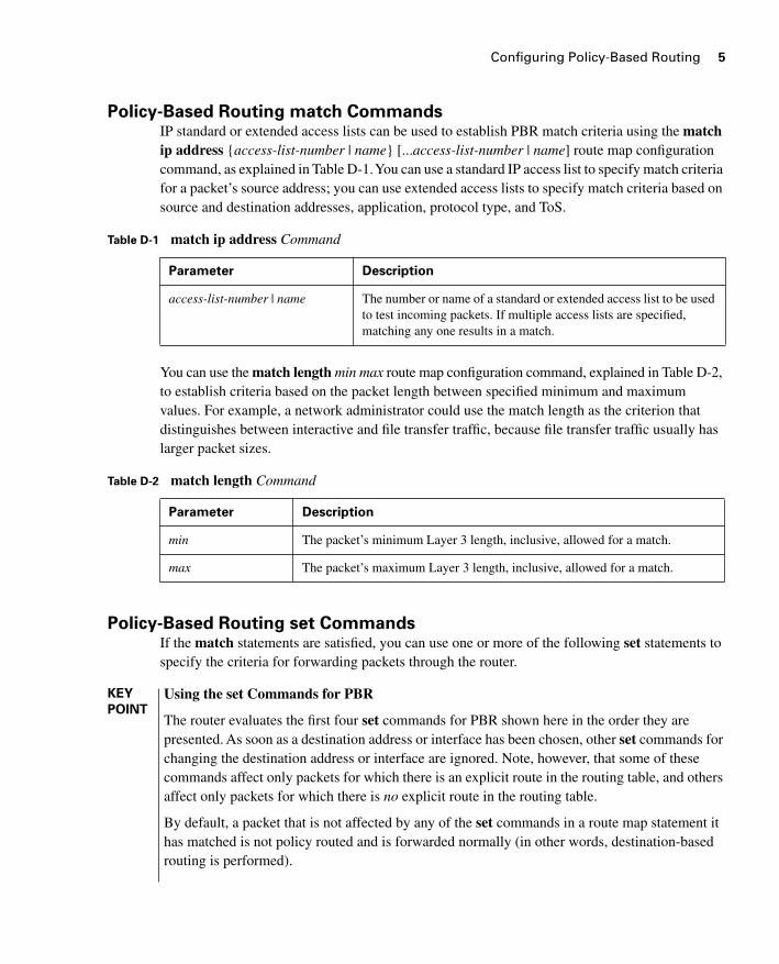
] route map configuration command, as explained in Table D-1. You can use a standard IP access list to specify match criteria for a packet’s source address; you can use extended access lists to specify match criteria based on source and destination addresses, application, protocol type, and ToS.
You can use the
match length
min max
route map configuration command, explained in Table D-2, to establish criteria based on the packet length between specified minimum and maximum values. For example, a network administrator could use the match length as the criterion that distinguishes between interactive and file transfer traffic, because file transfer traffic usually has larger packet sizes.
Policy-Based Routing set Commands
If the
match
statements are satisfied, you can use one or more of the following
set
statements to specify the criteria for forwarding packets through the router.
Table D-1
match ip address
Command
Parameter Description
access-list-number
|
name
The number or name of a standard or extended access list to be used to test incoming packets. If multiple access lists are specified, matching any one results in a match.
Table D-2
match length
Command
Parameter Description
min
The packet’s minimum Layer 3 length, inclusive, allowed for a match.
max
The packet’s maximum Layer 3 length, inclusive, allowed for a match.
KEY
POINT
Using the set Commands for PBR
The router evaluates the first four
set
commands for PBR shown here in the order they are presented. As soon as a destination address or interface has been chosen, other
set
commands for changing the destination address or interface are ignored. Note, however, that some of these commands affect only packets for which there is an explicit route in the routing table, and others affect only packets for which there is
no
explicit route in the routing table.
By default, a packet that is not affected by any of the
set
commands in a route map statement it has matched is not policy routed and is forwarded normally (in other words, destination-based routing is performed).
2237xxd.fm Page 5 Friday, December 1, 2006 3:41 PM
6
Appendix D: Manipulating Routing Updates Supplement
The
set ip next-hop
ip-address
[...
ip-address
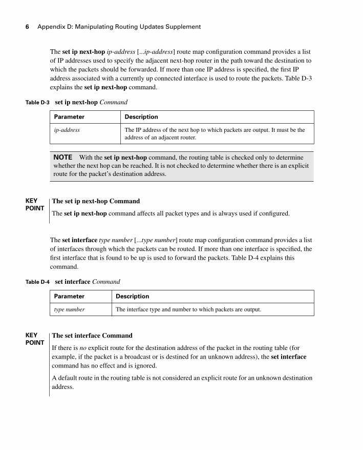
] route map configuration command provides a list of IP addresses used to specify the adjacent next-hop router in the path toward the destination to which the packets should be forwarded. If more than one IP address is specified, the first IP address associated with a currently up connected interface is used to route the packets. Table D-3 explains the
set ip next-hop
command.
The
set interface
type number
[...
type number
] route map configuration command provides a list of interfaces through which the packets can be routed. If more than one interface is specified, the first interface that is found to be up is used to forward the packets. Table D-4 explains this command.
Table D-3
set ip next-hop
Command
Parameter Description
ip-address
The IP address of the next hop to which packets are output. It must be the address of an adjacent router.
NOTE
With the
set ip next-hop
command, the routing table is checked only to determine whether the next hop can be reached. It is not checked to determine whether there is an explicit route for the packet’s destination address.
KEY
POINT
The set ip next-hop Command
The
set ip next-hop
command affects all packet types and is always used if configured.
Table D-4
set interface
Command
Parameter Description
type number
The interface type and number to which packets are output.
KEY
POINT
The set interface Command
If there is
no
explicit route for the destination address of the packet in the routing table (for example, if the packet is a broadcast or is destined for an unknown address), the
set interface
command has no effect and is ignored.
A default route in the routing table is not considered an explicit route for an unknown destination address.
2237xxd.fm Page 6 Friday, December 1, 2006 3:41 PM
Configuring Policy-Based Routing
7
The
set ip default next-hop
ip-address
[...
ip-address
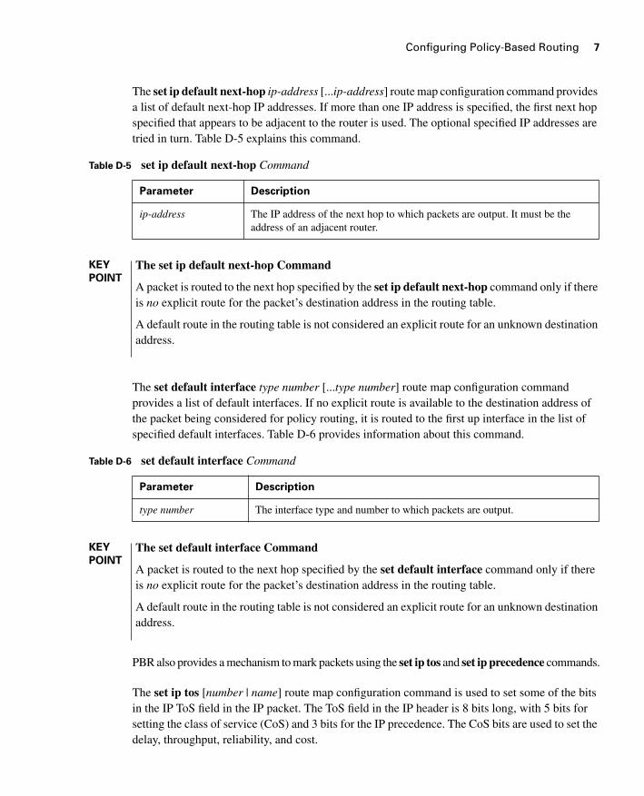
] route map configuration command provides a list of default next-hop IP addresses. If more than one IP address is specified, the first next hop specified that appears to be adjacent to the router is used. The optional specified IP addresses are tried in turn. Table D-5 explains this command.
The
set default interface
type number
[...
type number
] route map configuration command provides a list of default interfaces. If no explicit route is available to the destination address of the packet being considered for policy routing, it is routed to the first up interface in the list of specified default interfaces. Table D-6 provides information about this command.
PBR also provides a mechanism to mark packets using the
set ip tos
and
set ip precedence
commands.
The
set ip tos
[
number
|
name
] route map configuration command is used to set some of the bits in the IP ToS field in the IP packet. The ToS field in the IP header is 8 bits long, with 5 bits for setting the class of service (CoS) and 3 bits for the IP precedence. The CoS bits are used to set the delay, throughput, reliability, and cost.
Table D-5
set ip default next-hop
Command
Parameter Description
ip-address
The IP address of the next hop to which packets are output. It must be the address of an adjacent router.
KEY
POINT
The set ip default next-hop Command
A packet is routed to the next hop specified by the
set ip default next-hop
command only if there is
no
explicit route for the packet’s destination address in the routing table.
A default route in the routing table is not considered an explicit route for an unknown destination address.
Table D-6
set default interface
Command
Parameter Description
type number
The interface type and number to which packets are output.
KEY
POINT
The set default interface Command
A packet is routed to the next hop specified by the
set default interface
command only if there is
no
explicit route for the packet’s destination address in the routing table.
A default route in the routing table is not considered an explicit route for an unknown destination address.
2237xxd.fm Page 7 Friday, December 1, 2006 3:41 PM
8
Appendix D: Manipulating Routing Updates Supplement
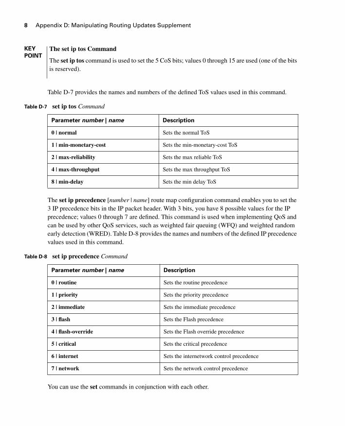
Table D-7 provides the names and numbers of the defined ToS values used in this command.
The
set ip precedence
[
number
|
name
]
route map configuration command enables you to set the 3 IP precedence bits in the IP packet header. With 3 bits, you have 8 possible values for the IP precedence; values 0 through 7 are defined. This command is used when implementing QoS and can be used by other QoS services, such as weighted fair queuing (WFQ) and weighted random early detection (WRED). Table D-8 provides the names and numbers of the defined IP precedence values used in this command.
You can use the
set
commands in conjunction with each other.
KEY
POINT
The set ip tos Command
The
set ip tos
command is used to set the 5 CoS bits; values 0 through 15 are used (one of the bits is reserved).
Table D-7 set ip tos Command
Parameter number | name Description
0 | normal Sets the normal ToS
1 | min-monetary-cost Sets the min-monetary-cost ToS
2 | max-reliability Sets the max reliable ToS
4 | max-throughput Sets the max throughput ToS
8 | min-delay Sets the min delay ToS
Table D-8 set ip precedence Command
Parameter number | name Description
0 | routine Sets the routine precedence
1 | priority Sets the priority precedence
2 | immediate Sets the immediate precedence
3 | flash Sets the Flash precedence
4 | flash-override Sets the Flash override precedence
5 | critical Sets the critical precedence
6 | internet Sets the internetwork control precedence
7 | network Sets the network control precedence
2237xxd.fm Page 8 Friday, December 1, 2006 3:41 PM
Verifying Policy-Based Routing 9
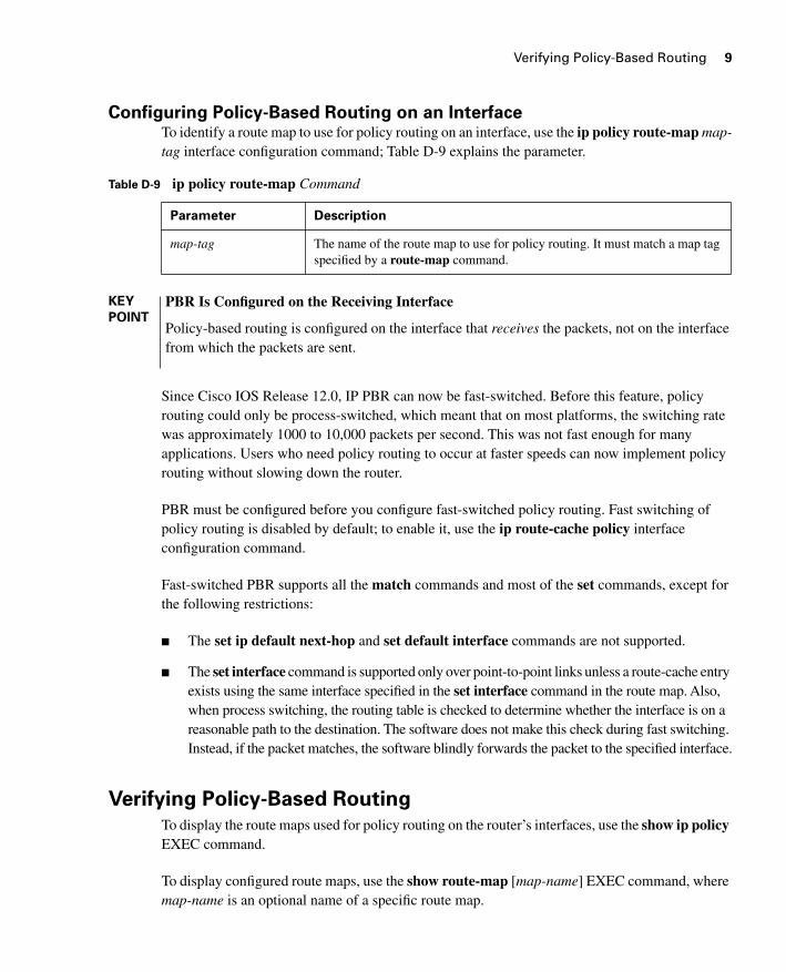
Configuring Policy-Based Routing on an InterfaceTo identify a route map to use for policy routing on an interface, use the ip policy route-map map-tag interface configuration command; Table D-9 explains the parameter.
Since Cisco IOS Release 12.0, IP PBR can now be fast-switched. Before this feature, policy routing could only be process-switched, which meant that on most platforms, the switching rate was approximately 1000 to 10,000 packets per second. This was not fast enough for many applications. Users who need policy routing to occur at faster speeds can now implement policy routing without slowing down the router.
PBR must be configured before you configure fast-switched policy routing. Fast switching of policy routing is disabled by default; to enable it, use the ip route-cache policy interface configuration command.
Fast-switched PBR supports all the match commands and most of the set commands, except for the following restrictions:
■ The set ip default next-hop and set default interface commands are not supported.
■ The set interface command is supported only over point-to-point links unless a route-cache entry exists using the same interface specified in the set interface command in the route map. Also, when process switching, the routing table is checked to determine whether the interface is on a reasonable path to the destination. The software does not make this check during fast switching. Instead, if the packet matches, the software blindly forwards the packet to the specified interface.
Verifying Policy-Based Routing
To display the route maps used for policy routing on the router’s interfaces, use the show ip policy EXEC command.
To display configured route maps, use the show route-map [map-name] EXEC command, where map-name is an optional name of a specific route map.
Table D-9 ip policy route-map Command
Parameter Description
map-tag The name of the route map to use for policy routing. It must match a map tag specified by a route-map command.
KEY
POINT
PBR Is Configured on the Receiving Interface
Policy-based routing is configured on the interface that receives the packets, not on the interface from which the packets are sent.
2237xxd.fm Page 9 Friday, December 1, 2006 3:41 PM
10 Appendix D: Manipulating Routing Updates Supplement
Use the debug ip policy EXEC command to display IP policy routing packet activity. This command shows in detail what policy routing is doing. It displays information about whether a packet matches the criteria and, if so, the resulting routing information for the packet.
To discover the routes that the packets follow when traveling to their destination from the router, use the traceroute privileged EXEC command. To change the default parameters and invoke an extended traceroute, enter the command without a destination argument. You are then stepped through a dialog to select the desired parameters.
To check host reachability and network connectivity, use the ping privileged EXEC command. You can use the ping command’s extended command mode to specify the supported header options by entering the command without any arguments.
Policy-Based Routing Examples
This section provides two examples of PBR.
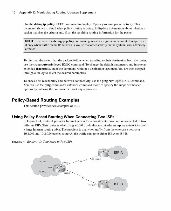
Using Policy-Based Routing When Connecting Two ISPsIn Figure D-1, router A provides Internet access for a private enterprise and is connected to two different ISPs. This router is advertising a 0.0.0.0 default route into the enterprise network to avoid a large Internet routing table. The problem is that when traffic from the enterprise networks 10.1.0.0 and 10.2.0.0 reaches router A, the traffic can go to either ISP A or ISP B.
Figure D-1 Router A Is Connected to Two ISPs
NOTE Because the debug ip policy command generates a significant amount of output, use it only when traffic on the IP network is low, so that other activity on the system is not adversely affected.
Fa0/0
10.2.0.0
10.1.0.0S/0/0/0
S0/0/1
192.168.6.6
172.16.7.7
A
ISP A
ISP B
2237xxd.fm Page 10 Friday, December 1, 2006 3:41 PM
Policy-Based Routing Examples 11
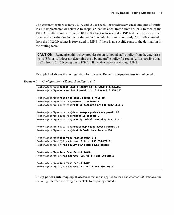
The company prefers to have ISP A and ISP B receive approximately equal amounts of traffic. PBR is implemented on router A to shape, or load balance, traffic from router A to each of the ISPs. All traffic sourced from the 10.1.0.0 subnet is forwarded to ISP A if there is no specific route to the destination in the routing table (the default route is not used). All traffic sourced from the 10.2.0.0 subnet is forwarded to ISP B if there is no specific route to the destination in the routing table.
Example D-1 shows the configuration for router A. Route map equal-access is configured.
The ip policy route-map equal-access command is applied to the FastEthernet 0/0 interface, the incoming interface receiving the packets to be policy-routed.
CAUTION Remember, this policy provides for an outbound traffic policy from the enterprise to its ISPs only. It does not determine the inbound traffic policy for router A. It is possible that traffic from 10.1.0.0 going out to ISP A will receive responses through ISP B.
Example D-1 Configuration of Router A in Figure D-1
RouterA(config)#aaaacccccccceeeessssssss----lllliiiisssstttt 1111 ppppeeeerrrrmmmmiiiitttt iiiipppp 11110000....1111....0000....0000 0000....0000....222255555555....222255555555
RouterA(config)#aaaacccccccceeeessssssss----lllliiiisssstttt 2222 ppppeeeerrrrmmmmiiiitttt iiiipppp 11110000....2222....0000....0000 0000....0000....222255555555....222255555555
RouterA(config)#rrrroooouuuutttteeee----mmmmaaaapppp eeeeqqqquuuuaaaallll----aaaacccccccceeeessssssss ppppeeeerrrrmmmmiiiitttt 11110000
RouterA(config-route-map)#mmmmaaaattttcccchhhh iiiipppp aaaaddddddddrrrreeeessssssss 1111
RouterA(config-route-map)#sssseeeetttt iiiipppp ddddeeeeffffaaaauuuulllltttt nnnneeeexxxxtttt----hhhhoooopppp 111199992222....111166668888....6666....6666
RouterA(config-route-map)#rrrroooouuuutttteeee----mmmmaaaapppp eeeeqqqquuuuaaaallll----aaaacccccccceeeessssssss ppppeeeerrrrmmmmiiiitttt 22220000
RouterA(config-route-map)#mmmmaaaattttcccchhhh iiiipppp aaaaddddddddrrrreeeessssssss 2222
RouterA(config-route-map)#sssseeeetttt iiiipppp ddddeeeeffffaaaauuuulllltttt nnnneeeexxxxtttt----hhhhoooopppp 111177772222....11116666....7777....7777
RouterA(config-route-map)#rrrroooouuuutttteeee----mmmmaaaapppp eeeeqqqquuuuaaaallll----aaaacccccccceeeessssssss ppppeeeerrrrmmmmiiiitttt 33330000
RouterA(config-route-map)#sssseeeetttt ddddeeeeffffaaaauuuulllltttt iiiinnnntttteeeerrrrffffaaaacccceeee nnnnuuuullllllll0000
RouterA(config)#iiiinnnntttteeeerrrrffffaaaacccceeee FFFFaaaassssttttEEEEtttthhhheeeerrrrnnnneeeetttt 0000////0000
RouterA(config-if)#iiiipppp aaaaddddddddrrrreeeessssssss 11110000....1111....1111....1111 222255555555....222255555555....222255555555....0000
RouterA(config-if)#iiiipppp ppppoooolllliiiiccccyyyy rrrroooouuuutttteeee----mmmmaaaapppp eeeeqqqquuuuaaaallll----aaaacccccccceeeessssssss
RouterA(config)#iiiinnnntttteeeerrrrffffaaaacccceeee SSSSeeeerrrriiiiaaaallll 0000////0000////0000
RouterA(config-if)#iiiipppp aaaaddddddddrrrreeeessssssss 111199992222....111166668888....6666....5555 222255555555....222255555555....222255555555....0000
RouterA(config)#iiiinnnntttteeeerrrrffffaaaacccceeee SSSSeeeerrrriiiiaaaallll 0000////0000////1111
RouterA(config-if)#iiiipppp aaaaddddddddrrrreeeessssssss 111177772222....11116666....7777....6666 222255555555....222255555555....222255555555....0000
2237xxd.fm Page 11 Friday, December 1, 2006 3:41 PM
12 Appendix D: Manipulating Routing Updates Supplement
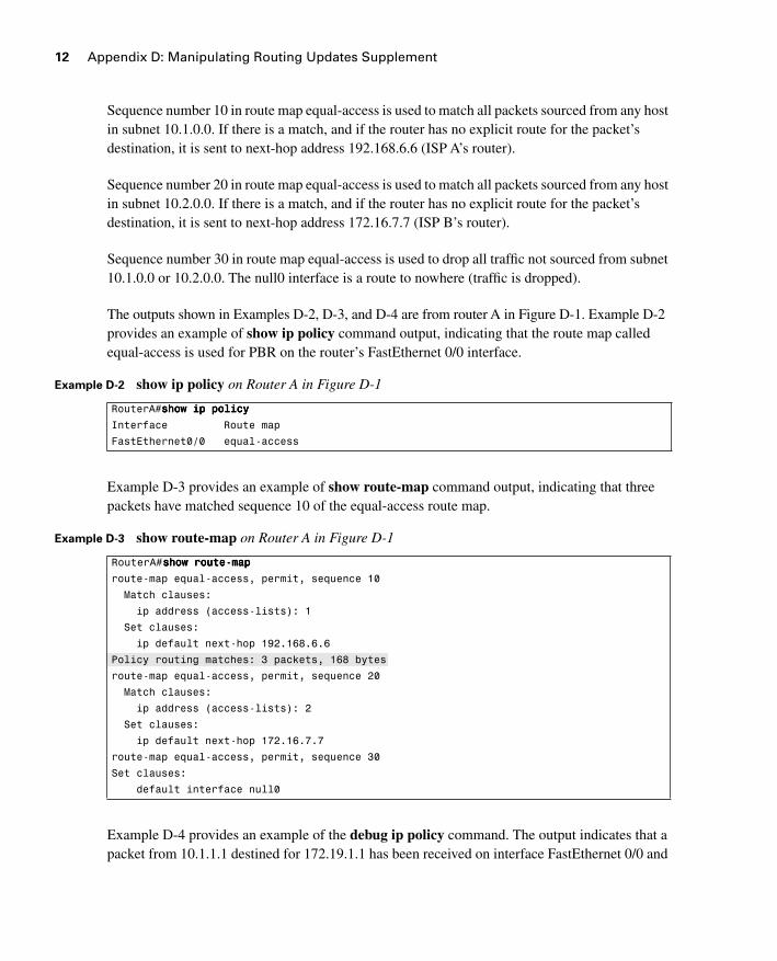
Sequence number 10 in route map equal-access is used to match all packets sourced from any host in subnet 10.1.0.0. If there is a match, and if the router has no explicit route for the packet’s destination, it is sent to next-hop address 192.168.6.6 (ISP A’s router).
Sequence number 20 in route map equal-access is used to match all packets sourced from any host in subnet 10.2.0.0. If there is a match, and if the router has no explicit route for the packet’s destination, it is sent to next-hop address 172.16.7.7 (ISP B’s router).
Sequence number 30 in route map equal-access is used to drop all traffic not sourced from subnet 10.1.0.0 or 10.2.0.0. The null0 interface is a route to nowhere (traffic is dropped).
The outputs shown in Examples D-2, D-3, and D-4 are from router A in Figure D-1. Example D-2 provides an example of show ip policy command output, indicating that the route map called equal-access is used for PBR on the router’s FastEthernet 0/0 interface.
Example D-3 provides an example of show route-map command output, indicating that three packets have matched sequence 10 of the equal-access route map.
Example D-4 provides an example of the debug ip policy command. The output indicates that a packet from 10.1.1.1 destined for 172.19.1.1 has been received on interface FastEthernet 0/0 and
Example D-2 show ip policy on Router A in Figure D-1
RouterA#sssshhhhoooowwww iiiipppp ppppoooolllliiiiccccyyyy
Interface Route map
FastEthernet0/0 equal-access
Example D-3 show route-map on Router A in Figure D-1
RouterA#sssshhhhoooowwww rrrroooouuuutttteeee----mmmmaaaapppp
route-map equal-access, permit, sequence 10
Match clauses:
ip address (access-lists): 1
Set clauses:
ip default next-hop 192.168.6.6
Policy routing matches: 3 packets, 168 bytes
route-map equal-access, permit, sequence 20
Match clauses:
ip address (access-lists): 2
Set clauses:
ip default next-hop 172.16.7.7
route-map equal-access, permit, sequence 30
Set clauses:
default interface null0
2237xxd.fm Page 12 Friday, December 1, 2006 3:41 PM
Policy-Based Routing Examples 13
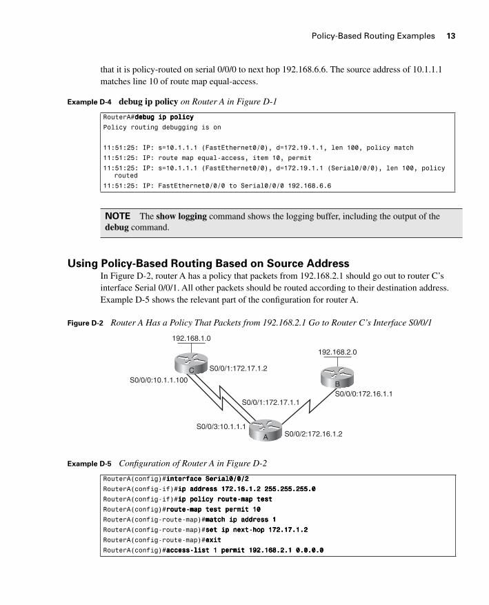
that it is policy-routed on serial 0/0/0 to next hop 192.168.6.6. The source address of 10.1.1.1 matches line 10 of route map equal-access.
Using Policy-Based Routing Based on Source AddressIn Figure D-2, router A has a policy that packets from 192.168.2.1 should go out to router C’s interface Serial 0/0/1. All other packets should be routed according to their destination address. Example D-5 shows the relevant part of the configuration for router A.
Figure D-2 Router A Has a Policy That Packets from 192.168.2.1 Go to Router C’s Interface S0/0/1
Example D-4 debug ip policy on Router A in Figure D-1
RouterA#ddddeeeebbbbuuuugggg iiiipppp ppppoooolllliiiiccccyyyy
Policy routing debugging is on
11:51:25: IP: s=10.1.1.1 (FastEthernet0/0), d=172.19.1.1, len 100, policy match
11:51:25: IP: route map equal-access, item 10, permit
11:51:25: IP: s=10.1.1.1 (FastEthernet0/0), d=172.19.1.1 (Serial0/0/0), len 100, policy routed
11:51:25: IP: FastEthernet0/0/0 to Serial0/0/0 192.168.6.6
NOTE The show logging command shows the logging buffer, including the output of the debug command.
Example D-5 Configuration of Router A in Figure D-2
RouterA(config)#iiiinnnntttteeeerrrrffffaaaacccceeee SSSSeeeerrrriiiiaaaallll0000////0000////2222
RouterA(config-if)#iiiipppp aaaaddddddddrrrreeeessssssss 111177772222....11116666....1111....2222 222255555555....222255555555....222255555555....0000
RouterA(config-if)#iiiipppp ppppoooolllliiiiccccyyyy rrrroooouuuutttteeee----mmmmaaaapppp tttteeeesssstttt
RouterA(config)#rrrroooouuuutttteeee----mmmmaaaapppp tttteeeesssstttt ppppeeeerrrrmmmmiiiitttt 11110000
RouterA(config-route-map)#mmmmaaaattttcccchhhh iiiipppp aaaaddddddddrrrreeeessssssss 1111
RouterA(config-route-map)#sssseeeetttt iiiipppp nnnneeeexxxxtttt----hhhhoooopppp 111177772222....11117777....1111....2222
RouterA(config-route-map)#eeeexxxxiiiitttt
RouterA(config)#aaaacccccccceeeessssssss----lllliiiisssstttt 1111 ppppeeeerrrrmmmmiiiitttt 111199992222....111166668888....2222....1111 0000....0000....0000....0000
S0/0/0:10.1.1.100
S0/0/3:10.1.1.1S0/0/2:172.16.1.2
S0/0/1:172.17.1.2
S0/0/1:172.17.1.1S0/0/0:172.16.1.1
C
A
192.168.1.0
B
192.168.2.0
2237xxd.fm Page 13 Friday, December 1, 2006 3:41 PM
14 Appendix D: Manipulating Routing Updates Supplement
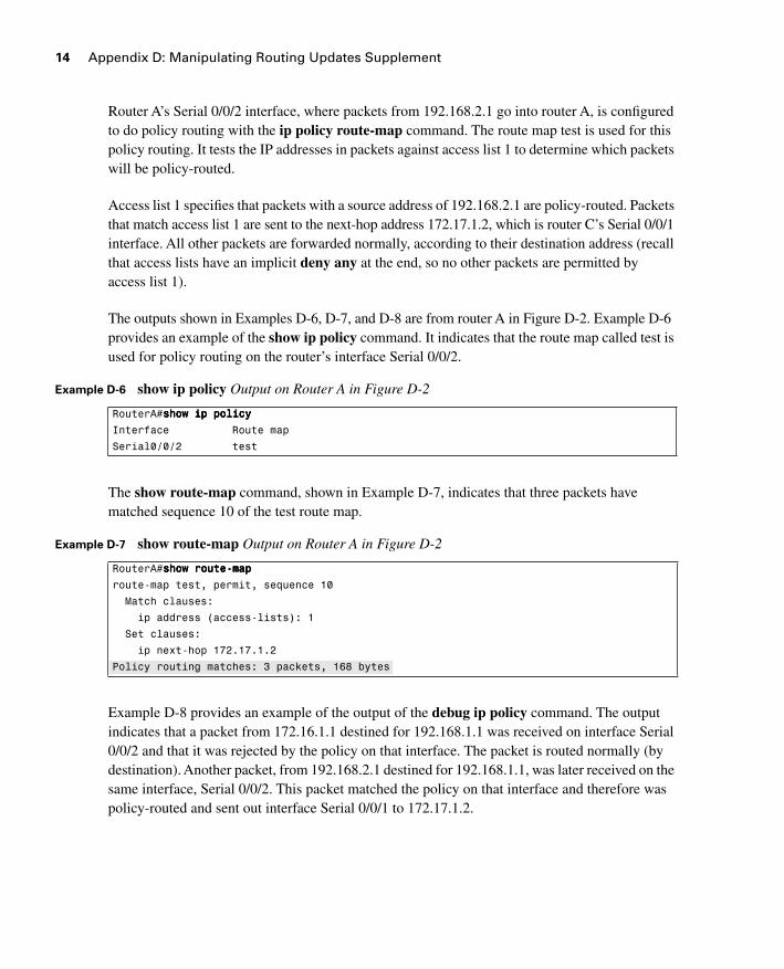
Router A’s Serial 0/0/2 interface, where packets from 192.168.2.1 go into router A, is configured to do policy routing with the ip policy route-map command. The route map test is used for this policy routing. It tests the IP addresses in packets against access list 1 to determine which packets will be policy-routed.
Access list 1 specifies that packets with a source address of 192.168.2.1 are policy-routed. Packets that match access list 1 are sent to the next-hop address 172.17.1.2, which is router C’s Serial 0/0/1 interface. All other packets are forwarded normally, according to their destination address (recall that access lists have an implicit deny any at the end, so no other packets are permitted by access list 1).
The outputs shown in Examples D-6, D-7, and D-8 are from router A in Figure D-2. Example D-6 provides an example of the show ip policy command. It indicates that the route map called test is used for policy routing on the router’s interface Serial 0/0/2.
The show route-map command, shown in Example D-7, indicates that three packets have matched sequence 10 of the test route map.
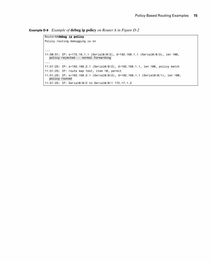
Example D-8 provides an example of the output of the debug ip policy command. The output indicates that a packet from 172.16.1.1 destined for 192.168.1.1 was received on interface Serial 0/0/2 and that it was rejected by the policy on that interface. The packet is routed normally (by destination). Another packet, from 192.168.2.1 destined for 192.168.1.1, was later received on the same interface, Serial 0/0/2. This packet matched the policy on that interface and therefore was policy-routed and sent out interface Serial 0/0/1 to 172.17.1.2.
Example D-6 show ip policy Output on Router A in Figure D-2
RouterA#sssshhhhoooowwww iiiipppp ppppoooolllliiiiccccyyyy
Interface Route map
Serial0/0/2 test
Example D-7 show route-map Output on Router A in Figure D-2
RouterA#sssshhhhoooowwww rrrroooouuuutttteeee----mmmmaaaapppp
route-map test, permit, sequence 10
Match clauses:
ip address (access-lists): 1
Set clauses:
ip next-hop 172.17.1.2
Policy routing matches: 3 packets, 168 bytes
2237xxd.fm Page 14 Friday, December 1, 2006 3:41 PM
Policy-Based Routing Examples 15
Example D-8 Example of debug ip policy on Router A in Figure D-2
RouterA#ddddeeeebbbbuuuugggg iiiipppp ppppoooolllliiiiccccyyyy
Policy routing debugging is on
...
11:50:51: IP: s=172.16.1.1 (Serial0/0/2), d=192.168.1.1 (Serial0/0/3), len 100, policy rejected -- normal forwarding
...
11:51:25: IP: s=192.168.2.1 (Serial0/0/2), d=192.168.1.1, len 100, policy match
11:51:25: IP: route map test, item 10, permit
11:51:25: IP: s=192.168.2.1 (Serial0/0/2), d=192.168.1.1 (Serial0/0/1), len 100, policy routed
11:51:25: IP: Serial0/0/2 to Serial0/0/1 172.17.1.2
2237xxd.fm Page 15 Friday, December 1, 2006 3:41 PM