
Configuration and Options Guide - Kev009.comps-2.kev009.com/pccbbs/pc_servers_pdf/oct02cog.pdf ·...
277
Configuration and Options Guide Systems and Options External Expansion Rack Cabinets & Options Fibre Channel Solutions Internal/External Cabling System Management H/W October 15, 2002 IBM IntelliStation xSeries
Transcript of Configuration and Options Guide - Kev009.comps-2.kev009.com/pccbbs/pc_servers_pdf/oct02cog.pdf ·...
Configuration and Options Guide
Systems and Options
External Expansion
Rack Cabinets & Options
Fibre Channel Solutions
Internal/External Cabling
System Management H/W
October 15, 2002
IBMIntelliStation xSeries

Introducing in this issue ...
4560 Automation Tape Enclosure LibraryNetXtreme 1000 T Ethernet Adapter (copper)Thirty-inch Single-drop Internal LVD Ultra160 SCSI Cable (for internal RAID support in xSeries 235 and 345)xSeries 305 models with 2.67GHz Pentium 4 processor and 533MHz FSB

Table of Contents
Information Sources ..........................2 IBM RXE-100 Expansion ......................150
Server Positioning ..........................4 IBM BladeCenter ......................156
xSeries Selection Guide ..........................6 IBM External Storage ......................166
Fibre Channel Solutions ......................170
IntelliStation Video Guide ..........................10
IntelliStation E Pro 6216 ..........................12 Rack Cabinets and Options ......................195
IntelliStation E Pro 6226 ..........................16 Rack Console Options ......................201
IntelliStation M Pro 6229 ..........................20 Rack Power Configurator ......................207
IntelliStation M Pro 6850 ..........................26 Appendix A: Tape Drives ......................211
IBM xSeries 200 ..........................32 Appendix B: Tape Libraries ......................213
IBM xSeries 205 ..........................40 Appendix C: UPS ......................215
IBM xSeries 220 ..........................48 Appendix D: External Cables ......................217
IBM xSeries 235 ..........................56 Appendix E: Serial I/O ......................219
IBM xSeries 250 ..........................66 Appendix F: Internal Cabling ......................220
IBM xSeries 255 ..........................76 Appendix G: System Management ......................224
IBM xSeries 300 DC ..........................86 Appendix H: I/O Options ......................234
IBM xSeries 305 ..........................92 Important Notes ......................236
IBM xSeries 330 ........................100
IBM xSeries 335 ........................110
IBM xSeries 343 (NEBS) ........................118
IBM xSeries 345 ........................122
IBM xSeries 360 ........................130
IBM xSeries 440 ........................138
Updated 10/15/02 1

Information Sources
Europe, Middle East and Africa (EMEA)AUDIENCE WHERE TO GO HOW TO GET
IBM xSeries Configuration and Options Guide
Business Partners www.ibm.com/pc/europe/configurators - or -e-mail distribution
download - or -e-mail to:- psg_configure@uk.
ibm.com
IBM Employees www.ibm.com/pc/europe/configurators - or -e-mail distribution
download - or -e-mail to:- psg_configure@uk.
ibm.comFeedback e-mail to:- [email protected] e-mail to:- [email protected]
2 Updated 10/15/02

3For the latest product & technical information, refer to the Information Sources on pages 2 and 3.Updated 10/15/02
Info
rma
tio
n S
ou
rce
s
The information contained in this document has not been submitted to any formal IBM test. The following paragraph does not apply to the United Kingdom or any country where any such provisions are inconsistent with local law:
The use of this information or the implementation of any of these techniques is a customer responsibility and depends on the customer’s ability to evaluate and integrate them into the customer’s operational environment. While each item may have been reviewed by IBM for accuracy in a specific situation, there is no guarantee that the same or similar results will be obtained elsewhere. Customers attempting to adapt these techniques to their own environments do so at their own risk.
The following sample configurations are for illustration only and may not be suitable for any specific customer installation. Contact your IBM Business Partner or IBM Marketing Representative for assistance with your specific configuration requirements.
United States
Audience Where to go How to get
IBM xSeries Configuration and Options Guide
Customers
www.pc.ibm.com/us/eserver/xseries/library/configtools.html
Select Configuration and Options Guide.
www.pc.ibm.com/us/compat Select Configuration and Options Guide.
Business Partners www.pc.ibm.com/partner/us/Select Marketing Information --> Marketing Essentials --> Configuration and Options Guide (user ID and password required).
IBM EmployeesPC Marketing Essentials (US) on Lotus Notes database D04DB014\p_dir\pcpartnr\marketng\me4fe-us.nsf
Main menu --> Configuration and Options Guide
Feedback [email protected] E-mail
IBM xSeries and Netfinity Rack Configurator
Customers www.pc.ibm.com/us/eserver/xseries/library Select Configuration Tools.
Business Partners www.pc.ibm.com/partner/us/ Select Sales Tools, then Marketing Essentials, then IBM PC Server--> Rack Configurator. User ID and password required.
IBM EmployeesPC Marketing Essentials (US) on Lotus Notes database D04DB014\p_dir\pcpartnr\marketng\me4fe-us.nsf Main menu --> Configurators
Feedback [email protected] E-mail
PC Sales Guide/Configurator and WorkPad Pricer (updated twice per week)
Customers www.can.ibm.com/config Download PSC-US1 and PSC-US2.
Business Partners www.can.ibm.com/config Download PSC-US1 and PSC-US2.
IBM Employees www.can.ibm.com/config Download PSC-US1 and PSC-US2.
Feedback [email protected] E-mail
Latest Product & Technical Information
Customerswww.pc.ibm.com/us/eserver/xseriesor call 1-800-772-2227
Business Partners www.pc.ibm.com/partner/us/ or call 1-800-426-7763 Select Products & Services (user ID and password required).
IBM EmployeesPC Marketing Essentials (US) on Lotus Notes database D04DB014\p_dir\pcpartnr\marketng\me4fe-us.nsf
From main menu or by brand category.
Additional URLs
Audience Where to go How to get
Technical spec sheets (PSREF) www.pc.ibm.com/us/eserver/xseries/library.html Select Technical spec sheets (PSREF).
IBM Datacenter Solutionswww.pc.ibm.com/ww/eserver/xseries/windows/datacenter.html
Clustering (US, LA, CAN) www.pc.ibm.com/ww/eserver/xseries/clustering/index.html
Select appropriate category or server.
Benchmark Results www.pc.ibm.com/ww/eserver/xseries/benchmarks/ Select appropriate category or server.
Options/NOS/Server Compatibility www.pc.ibm.com/us/compat Select appropriate Product Type.
NOS - Hot-Plug/Failover Support www.pc.ibm.com/us/compat Select Active PCI Info.
IBM Storage Products www.storage.ibm.com Select appropriate category .
Adobe® Acrobat® Reader v5.0 www.adobe.com/products/acrobat/readstep.html Follow instructions.
Adv Sys Mgmt Adapter Firmware www.pc.ibm.com/ww/eserver/xseriesSelect Servers, select Intel-based Servers, select Fixes, select Get Fixes, select appropriate category.
Flash BIOS Updates www.pc.ibm.com/ww/eserver/xseries Select Servers, select Intel-based Servers, select Fixes, select Get Fixes, select device drivers by server, select appropriate category.
ServeRAID™ Updates www.pc.ibm.com/ww/eserver/xseriesSelect Servers, select Intel-based Servers, select Fixes, select Get Fixes, select appropriate category.

4
Server Product Positioning
Infrastructure Application
Work
load
Increased Capacity:SMP
StorageI/O
Availability Features
Number of Clients
x235
x205
x335
x220
x360
x305
x440
x255x345
x380
BladeCenter HS20

5For the latest product & technical information, refer to the Information Sources on pages 2 and 3.Updated 10/15/02
Pro
du
ct
Po
siti
on
ing
When in a competitive situation, this table suggests the appropriate IBM xSeries server to bid against other vendors’ equipment. However, as an IBM business partner, you may determine that customer-specific requirements may make an alternative IBM solution a better choice.
ValueUniversal/Tower
Departmental/MissionCritical
Universal/Tower
ModularRack-optimized
Modular EnterpriseScalable Nodes
IA-64IBM: xSeries 380Dell: PowerEdge 7150HP: ProLiant rx5670
IA-32>4-way IBM: xSeries 440 (Xeon MP)
4-way IBM: xSeries 255Dell: PowerEdge 6600HP:ProLiant ML570
IBM: xSeries 360Dell: PowerEdge 6650 HP: ProLiant DL580G2
IBM: xSeries 440 (Xeon)Dell: PowerEdge 6650HP: ProLiant DL580G2
2-wayIBM: xSeries 220 Dell: PowerEdge 1500SCHP: NetServer E60
IBM: xSeries 235Dell: PowerEdge 2500HP:ProLiant ML370
IBM: xSeries 335, xSeries 345Dell: PowerEdge 1650, 2650 HP: ProLiant DL360G2, DL380
IBM: BladeCenter HS20
UniIBM: xSeries 205 Dell: PowerEdge 500SCHP: ProLiant tc2100
IBM: xSeries 305Dell: PowerEdge 350 HP: ProLiant DL320

6
IBM xSeries™ Selection Guide This graph represents general guidelines for selecting the appropriate server based on the number of users that can be supported in a particular application environment. This chart is for general guidance since each customer environment is unique and is unlikely to be precisely represented by any of the specific applications in the chart, but by using the chart, a reasonable approximation can be derived. External Storage Units are utilized when internal capacities are exceeded. Utilize the chart by following the steps outlined at the end of this section. These are not published benchmark results. Access www.pc.ibm.com/ww/eserver/xseries/benchmarks/index.html to obtain the benchmark data.
Application/Expectation of
Maximum # of Users
xSeries 200 Uni-
Pentium® III 1.26GHz/
512KB
xSeries 205 2.26Ghx/
512KB Pentium 4
xSeries 220 Dual
Pentium III 1.4GHz/512KB
xSeries 300 Uni-
Pentium III 1GHz/256KB
xSeries 305 2.26GHz/
512KB Pentium 4
xSeries 330 Dual
Pentium III 1.4GHz/512KB
xSeries 335 Dual
2.4GHz/512KB
Xeon DP
DB Transaction ProcessingSelect, Update and Delete; Does not include image or
Decision Support
# Users 1500 1800 2030 1500 2750 2175 4400# Processors 1 1 2 1 1 2 2Memory 1.5GB 2GB 2GB 1.5GB 2 - 4GB 2GB 4GB# Hard Disk Drives 12 to 18 20 to 30 40 to 50 12 to 20 40 to 50 36 to 48 60 to 80# RAID Adapters >1 >2 or Fibre >2 1 Fibre >2 Fibre# Network Connections 1 1 1 1 1 to 2 1 1 to 2
File and PrintApplication is stored locally.
(For server stored applications - cut number of users in half).
# Users 800 1400 1000 800 1800 2100 2700# Processors 1 1 2 1 1 2 2Memory 1. 5GB 2GB 2GB 1.5GB 2 - 3GB 2GB 2 - 3# Hard Disk Drives 5 to 10 10 to 20 4 to 8 5 to 10 14 to 25 20 to 30 20 to 30# RAID Adapters >1 1 or Fibre 1 1 1 or Fibre 1 to 2 1 to 2# 100Mbps EthernetConnections
>2 1Gb 2 2 1Gb 4 1Gb
Lotus® Notes®10% Power Users 40% Mail
50% Mail & DB
# Users 900 1600 1215 900 2500 2010 3800# Processors 1 2 1 1 2 2 2Memory 1.5GB 2GB 2GB 1.5GB 3GB 2GB 3GB# Hard Disk Drives 5 to 10 14 to 25 10 to15 5 to 10 20 to 30 20 to 30 20 to 30# RAID Adapters >1 1 to 2 1 1 1 to 2 1 to 2 2 to 3# Network Connections >1 >2 >2 >2 >3 >2 >3
Microsoft® ExchangeServer 2000
100% Med Users30MB Mailbox
# Users 1400 1750 2500 900 1750 2500 3250# Processors 1 1 2 1 1 2 2Memory 768MBB 1GB 1.5GB 512MB 1GB 1.5GB 2GB
# Hard Disk Drives 10 12 17 6 12 17 22# RAID Adapters 1 4Lx 1 4Mx 1 4Mx 1 4Lx 1 4Mx 1 4Mx 1 4H# Network Connections 1 1 1 1 1 1-2 1-2
SAP 3-Tier DistributedVersion 4.0bProcessing
Sales and Distribution Application (Minimum of 16-20
Servers)
# Users - - - - - -# Processors - - - - - -Memory - - - - - -# Hard Disk Drives - - - - - -# RAID Adapters - - - - - -# Network Connections - - - - - -
SAP Central Version 4.0bProcessing
Sales and Distribution Application
(One Server)
# Users 75 170 80 75 170 130 180# Processors 1 2 1 1 2 2 2Memory 1GB 2GB 1GB 1GB 2GB 1GB 2GB# Hard Disk Drives 12 12 to 24 12 12 12 to 24 12 to 24 12 to 24# RAID Adapters >1 >1 >1 >1 >1 >1 >1# Network Connections 1 1 1 1 1 1 1
High Availability Features
Hot-Swap HDD Bays - X X - - X XHot-Plug PCI Slots - - - - - - -Hot-Swap Power - - - - - - -Hot-Swap Fans - - - - - - -RAID Opt Opt Opt Opt Opt Opt OptClustering Support - - - - - - -Sys Mgt Processor - Opt Opt - Opt X X
Other DistinguishingFeatures
Max # Processors 1 1 2 1 1 2 2Max Memory 1.5GB 2GB 4GB 1.5GB 4GB 4GB 4GBMax Int Storage 293.6GB2 293.6GB 293.6GB 146.8GB 146.8GB 146.8GB 146.8GBMax Int Storagewith Int Tape Drive
293.6GB 293.6GB 293.6GB - - - -
Available PCI Slots 5 5 5 1 1 2 219in Rack Models - - - X X X X

7For the latest product & technical information, refer to the Information Sources on pages 2 and 3.Updated 10/15/02
Se
rve
r S
ele
cti
on
Gu
ide
IBM xSeries Selection Guide Application/
Expectation of Maximum # of
Users
xSeries 345 Dual Xeon DP 2.4GHz/ 512KB
xSeries 235 Dual Xeon DP 2.4GHz/512KB
xSeries 250 Quad
Pentium III Xeon
900MHz1/2MB
xSeries 255 Quad Xeon MP 1.6GHz/
1MB
xSeries 360 Quad
Pentium III Xeon 1.6GHz/
1MB
xSeries 440 Eight-way Xeon MP 1.6GHz/
1MB
DB Transaction Processing
Select, Update and Delete; Does not include image or Decision Support
# Users 4400 7150 7030 11000 9225 16740# Processors 2 2 4 4 4 8Memory 4GB 8GB 4GB 8GB 8GB 16GB# Hard Disk Drives 60 to 80 50 to 70 80 to 140 125 to 200 100 to 175 150 to 200# RAID Adapters Fibre >2 >4 >4 or Fibre >4 >5 or Fibre# Network Connections 1 to 2 1 to 2 2 to 3 2 to 3 2 to 3 2 to 3
File and PrintApplication is stored locally. (For server
stored applications cut number of users in
half).
# Users 2700 5500 5000 6500 6500 7150# Processors 2 2 2 3-4 3 -4 3-4Memory 2 - 3GB 2 to 4GB 2 to 4GB 4GB 3 to 4GB 4GB# Hard Disk Drives 20 to 30 50 to 90 50 to 90 75 to 150 60 to 100 75 to 150# RAID Adapters 1 to 2 >4 >4 >4 or Fibre >3 >4 or Fibre# 100Mbps EthernetConnections 1Gb 4 or 1Gb 4 or 1Gb 4 or 1Gb 4 or 1Gb 4 or 1Gb
Lotus Notes10% Power Users 40%
Mail50% Mail & DB
# Users 3800 4500 4615 5580 5075 8800# Processors 2 2 4 4 4 4Memory 3GB 3GB 3GB 3GB 3GB 4GB# Hard Disk Drives 20 to 30 20 to 30 20 to 30 25 to 30 25 to 30 30 to 40# RAID Adapters 2 to 3 2 to 3 2 to 3 2 to 3 2 to 3 >3# Network Connections >3 >3 >3 >3 or 1Gb >3 or 1Gb 4 or 1Gb
Microsoft ExchangeServer2000
100% Med Users30MB Mailbox
# Users 3250 3250 3500 4500 4000 4500# Processors 2 2 4 4 4 4Memory 2GB 2GB 3GB 4GB 3GB 4GB# Hard Disk Drives 22 22 24 30 27 30# RAID Adapters 1 4H 1 4H 1 4H 1 4H 1 4H 1 4H# Network Connections 1-2 1-2 2 2 2 2
SAP 3-TierDistributed Version
4.0bProcessing
Sales and Distribution Application (Minimum
of 16-20 Servers)
# Users - - 4000 4800 4600 6400# Processors - - 4 4 4 8Memory - - >4GB >4GB 8GB >4GB# Hard Disk Drives - - 48 to 60 48 to 60 48 to 60 48 to 60# RAID Adapters - - >3 >3 >3 >3# Network Connections - - 1 1 1 1
SAP Central Version4.0b
ProcessingSales and Distribution
Application(One Server)
# Users 180 180 300 375 345 480# Processors 2 2 4 4 4 8Memory 2GB 2GB >2GB >2GB 8GB >4GB# Hard Disk Drives 12 to 24 12 to 24 24 to 36 24 to 36 24 to 36 24 to 36# RAID Adapters >1 >1 >2 >2 >2 >2# Network Connections 1 1 1 1 1 1
High AvailabilityFeatures
Hot-Swap HDD Bays X X X X X XHot-Plug PCI Slots - X X X X XHot-Swap Power X X X X X XHot-Swap Fans X X X X X XRAID Opt Opt Opt Opt Opt OptClustering Support X X X X X XSys Mgt Processor X X X X X X
Other DistinguishingFeatures
Max # Processors 2 2 4 4 4 8Max Memory 4GB 6GB 16GB 12GB 8GB 32GBMax Int Storage 440.4GB 660.6GB 734GB 880.8GB 220.2GB 146.8GBMax Int Storage with IntTape Drive
- 440.4GB 734GB 880.8GB - -
Available PCI Slots 5 6 6 7 6 619in Rack Models X - X X X X
8
1. MHz/GHz only measure microprocessor internal clock speed, not application performance. Many factors affect application performance.2. When referring to hard disk drive capacity, GB equals one billion bytes. Total user accessible capacity may vary depending on operating environments.
Procedure for Server Selection Guidance ChartFile and Print numbers are Novell Netware-based with all others based on Microsoft Windows NT®. Other Network Operating System (NOS) results could vary.Extensive SAP sizings are available from IBM/SAP Competency Centers. Contact your IBM Marketing Representative for additional information.Step 1: Determine which application (row) most closely represents the customer’s environment.Step 2: Move from left to right along the row (chosen in Step 1) noting which columns contain numbers that are equal to or greater than the maximum customer’s planned number of users.Step 3: Move up the columns (chosen in Step 2) to the top row to determine which IBM xSeries or Netfinity servers should be considered as possible solutions.Step 4: Evaluate other features such as storage, memory capacity, high availability components, number of available expansion slots, etc., which are unique to each server, in order to determine which is the most appropriate to recommend.For your reference, configuration information corresponding to the number of users is also provided.

Updated 10/15/02 9
10
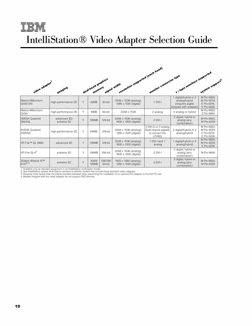
IntelliStation® Video Adapter Selection Guide
Matrox Millennium G450 DVI high-performance 2D Y 32MB 64-bit 2048 x 1536 (analog),
1280 x 1024 (digital) 1 DVI-I
1 digital/hybrid or 2 analog/hybrid
(requires pigtail shipped with adapter)
M Pro 6850,M Pro 6229,E Pro 6216,E Pro 6226
Matrox Millennium G450 high-performance 2D Y 16MB 64-bit 2048 x 1536 2 analog 2 analog or hybrid M Pro 6850,
Z Pro 6894
NVIDIA Quadro4 900XGL
advanced 3D/extreme 3D Y 128MB 128-bit 2048 x 1536 (analog),
1600 x 1200 (digital) 2 DVI-I2 digital, hybrid or
analog (any combination)
M Pro 6850,M Pro 6229
NVIDIA Quadro4 200NVS high-performance 2D Y 64MB 128-bit 2048 x 1536 (analog),
1280 x 1024 (digital)
2 DVI-D or 2 analog (both require pigtails
to convert the LFH60)
2 digital/hybrid or 2 analog/hybrid
M Pro 6850,M Pro 6229,E Pro 6216, E Pro 6226
ATI Fire™ GL 8800 advanced 3D Y 128MB 128-bit 2048 x 1536 (analog), 1600 x 1200 (digital)
1 DVI-I and 1 analog
1 digital/hybrid or 2 analog/hybrid
M Pro 6850,M Pro 6229,E Pro 6226
ATI Fire GL43 extreme 3D Y 128MB 256-bit 2048 x 1536 (analog), 1600 x 1200 (digital) 2 DVI-I
2 digital, hybrid or analog (any combination)
M Pro 6850
3Dlabs Wildcat III™ 61103, 4 extreme 3D Y 16/64/
128MB128/128/
64-bit1920 x 1080 (analog), 1280 x 1024 (digital) 2 DVI-I
2 digital, hybrid or analog (any combination)
M Pro 6850,M Pro 6229
1. Available only as standard equipment in an IntelliStation workstation model.2. See IntelliStation system At-A-Glance sections to identify models that include these standard video adapters.3. Requires more space than the planar provides between slots, preventing the installation of an optional PCI adapter in the first PCI slot.4. Models shipped with this video adapter do not support DVD devices.
video adapter1
imaging
dual-head graphics
memory
signal width
resolution supporte
d (each head)
monitor c
onnector type
# / type m
onitors supporte
d
system support2
11For the latest product & technical information, refer to the Information Sources on pages 2 and 3.Updated 10/15/02
Inte
lliS
tati
on
Vid
eo
Ad
ap
ter
Se
lec
tio
n G
uid
e

IntelliStation E Pro 6216
EMEA Part Number Cross ReferenceIntelliStation E Pro 6216 System Unit Part Numbers
EMEA AMERICAS M/C TYPE DESCRIPTION EMEAP/N P/N MODEL WDFM DATE
KAU20xx 621620U 6216-20G P4 2.0GHz/400MHz, 512KB, 256MB, 40GB EIDE,Matrox Millenium G450 DVI, Windows XP, Desktop ---
KAUB0xx N/A 6216-B0G P4 2.0GHz/400MHz, 512KB, 256MB, 40GB EIDE,Matrox Millenium G450 DVI, DOS 2000 Lic., Desktop ---
KAU22xx 621622U 6216-22G P4 2.0GHz/400MHz, 512KB, 256MB, 40GB EIDE,NVIDIA Quadro4 200NVS, Windows XP, Desktop ---
KAUB2xx N/A 6216-B2G P4 2.0GHz/400MHz, 512KB, 256MB, 40GB EIDE,NVIDIA Quadro4 200NVS, DOS 2000 Lic., Desktop ---
KAU23xx 621623U 6216-23G P4 2.0GHz/400MHz, 512KB, 256MB, 18.2GB SCSI,NVIDIA Quadro4 200NVS, Windows XP, Desktop ---
KAUB3xx N/A 6216-B3G P4 2.0GHz/400MHz, 512KB, 256MB, 18.2GB SCSI,NVIDIA Quadro4 200NVS, DOS 2000 Lic., Desktop ---
KAU30xx N/A 6216-30G P4 2.26GHz/533MHz, 512KB, 256MB, 40GB EIDE,Matrox Millenium G450 DVI, Windows XP, Desktop ---
KAUC0xx N/A 6216-C0G P4 2.26GHz/533MHz, 512KB, 256MB, 40GB EIDE,Matrox Millenium G450 DVI, DOS 2000 Lic., Desktop ---
KAU32xx N/A 6216-32G P4 2.26GHz/533MHz, 512KB, 256MB, 40GB EIDE,NVIDIA Quadro4 200NVS, Windows XP, Desktop ---
KAUC2xx N/A 6216-C2G P4 2.26GHz/533MHz, 512KB, 256MB, 40GB EIDE,NVIDIA Quadro4 200NVS, DOS 2000 Lic., Desktop ---
KAU40xx 621640U 6216-40G P4 2.4GHz/533MHz, 512KB, 256MB, 40GB EIDE,Matrox Millenium G450 DVI, Windows XP, Desktop ---
KAUD0xx N/A 6216-D0G P4 2.4GHz/533MHz, 512KB, 256MB, 40GB EIDE,Matrox Millenium G450 DVI, DOS 2000 Lic., Desktop ---
KAU42xx 621642U 6216-42G P4 2.4GHz/533MHz, 512KB, 256MB, 40GB EIDE,NVIDIA Quadro4 200NVS, Windows XP, Desktop ---
KAUD2xx N/A 6216-D2G P4 2.4GHz/533MHz, 512KB, 256MB, 40GB EIDE,NVIDIA Quadro4 200NVS, DOS 2000 Lic., Desktop ---
IntelliStation E Pro 6216 I/O Option Part NumbersEMEA AMERICAS M/C TYPE DESCRIPTION EMEA
P/N P/N MODEL WDFM DATEN/A 19K4162 --- V90 PCI Data/Fax WinModem (Low Profile Enabled) N/A
IntelliStation E Pro 6216 Power, Monitors & AccessoriesEMEA AMERICAS M/C TYPE DESCRIPTION EMEA
P/N P/N MODEL MONITORS WDFM DATENote 1 T274Axx 66274AN 6627-4AN G78 17" (16" viewable image) Colour Monitor (S/Black ---Note 1 T57HGxx 6657HG2 6657-HG2 T750 17" Hybrid Flat Panel Colour Monitor (S/Black) ---Note 1 T52U3xx 6652U3N 6652-U3N P275 21" (19.8" viewable image) Colour Monitor (S/Bla ---Note 1 T39U3xx 6639U3N 6639-U3N P77 17" (16" viewable image) Colour Monitor (S/Black) ---Note 1 T1U3Nxx 6651U3N 6651-U3N P97 19" (18" viewable image) Colour Monitor (S/Black) ---Note 1 T51U3xx 655163N 6551-63N P96 19" (17.9" viewable image) Colour Monitor (S/Blac 30/07/02Note 1 T56HGxx 6656HG2 6656-HG2 T560 15" Flat Panel Colour Monitor (S/Black) ---Note 1 T4HB0xx 9494HB0 9494-HB0 T860 18.1" Hybrid Flat Panel Color Monitor (S/Black) ---Note 1 T59HGxx 6659HG2 6659-HG2 T210 20.8" Flat Panel Colour Monitor (S/Black) ---Note 1 T53HGxx 6653HG2 6653-HG2 T545 15" Flat Panel Colour Monitor (S/Black) 10/09/02Note 1 T12ABxx 9512AB1 9512-AB1 T541 15" Flat Panel Colour Monitor (S/Black) ---
1. Where ‘xx’ represents a specific country code as follows: DK=Denmark, IS=Israel, IT=Italy, SD=SaudiArabia, SA=South Africa/Pakistan, CH=Switzerland, UK=UK, EU=Europe.
11A Updated 10/15/02
IntelliStation E Pro 6216
EMEA Part Number Cross ReferenceIntelliStation E Pro 6216 Power, Monitors & Accessories
EMEA AMERICAS M/C TYPE DESCRIPTION EMEA
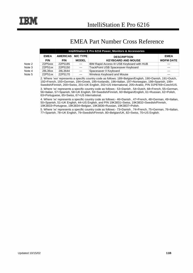
P/N P/N MODEL KEYBOARD AND MOUSE WDFM DATENote 2 22P5xxx 22P5185 --- IBM Rapid Access III USB Keyboard with HUB ---Note 3 22P51xx 22P5150 --- TrackPoint USB Spacesaver Keyboard ---Note 4 28L36xx 28L3644 --- Spacesaver II Keyboard ---Note 5 22P51xx 22P5170 --- Wireless Keyboard and Mouse ---
2. Where ‘xxx’ represents a specific country code as follows: 189=Belgian/English, 190=Danish, 191=Dutch,192=French, 193=German, 194=Greek, 195=Icelandic, 196=Italian, 197=Norwegian, 198=Spanish, 199=Swedish/Finnish, 200=Swiss, 201=UK English, 202=US International, 205=Arabic, P/N 31P8769=Czech/US.3. Where ‘xx’ represents a specific country code as follows:- 53=Danish , 54=Dutch, 68=French, 55=German,56=Italian, 57=Spanish, 58=UK English, 59=Swedish/Finnish, 60=Belgian/English, 61=Russian, 62=Polish,63=Portuguese, 65=Swiss, 67=US International.4. Where ‘xx’ represents a specific country code as follows:- 46=Danish , 47=French, 48=German, 49=Italian,50=Spanish, 51=UK English, 44=US English, and P/N 19K3831=Swiss, 19K3832=Swedish/Finnish,19K3833=Portugese, 19K3834=Belgian, 19K3836=Russian, 19K3837=Polish.5. Where ‘xx’ represents a specific country code as follows:- 73=Danish , 74=French, 75=German, 76=Italian,77=Spanish, 78=UK English, 79=Swedish/Finnish, 80=Belgian/UK, 82=Swiss, 70=US English.
Updated 10/15/02 11B

12
IntelliStation E Pro 6216
IntelliStation E Pro 6216 At-A-Glance
6216-20U1 22 1/1 512KB 256MB/2GBMatrox
Millennium G450 DVI
Low-profile Desktop
10/100/1000 IDE4 2/0 40GB/
80GB5 48X-20X 3/0 3/3
6216-22U1 22 1/1 512KB25Updated
10/15/026MB/2GB
NVIDIA Quadro4 200NVS
Low-profile Desktop
10/100/1000 IDE4 2/0 40GB/
80GB5 48X-20X 3/0 3/3
6216-23U1 22 1/1 512KB 256MB/2GB NVIDIA Quadro4 200NVS
Low-profile Desktop
10/100/1000 U1604 2/0 18.2GB/
73.4GB5 48X-20X 3/0 3/2
6216-40U1 2.43 1/1 512KB 256MB/2GBMatrox
Millennium G450 DVI
Low-profile Desktop
10/100/1000 IDE4 2/0 40GB/
80GB5 48X-20X 3/0 3/3
6216-42U1 2.43 1/1 512KB 256MB/2GB NVIDIA Quadro4 200NVS
Low-profile Desktop
10/100/1000 IDE4 2/0 40GB/
80GB5 48X-20X 3/0 3/3
1. IntelliStation E Pro ships with a keyboard and mouse. See "Power, Monitors and Accessories" for a list of compatible monitors.2. Intel Pentium 4 processor with advanced transfer ECC L2 cache, 400MHz (quad-pumped) Front-side Bus (FSB) and MMX technology.3. Intel Pentium 4 processor with advanced transfer ECC L2 cache, 533MHz (quad-pumped)FSB and MMX technology.4. All models include an integrated ATA-100 IDE controller that supports both the IDE CD-ROM and the IDE HDD for IDE models. SCSI models include a single-channel Ultra160 SCSI PCI controller with one internal and one external port (each with high-density 68-pin connectors) installed in slot three. A one-drop, terminated 16-bit LVD internal SCSI cable is included with SCSI models, which supports the single SCSI HDD. IDE models include two one-drop ATA-100 IDE cables.5. Maximum internal storage capacity requires replacement of the standard 18.2GB 10,000rpm nonhot-swap HDD with a 73.4GB nonhot-swap HDD in SCSI models and replacement of the standard 40GB IDE HDD with an 80GB IDE HDD in IDE models.6. Variable read rate. Actual playback speed will vary and is often less than the maximum possible.
IntelliStation E Pro 6216 Memory
Total Memory1
Quantity of UDIMMs Added2
256MBstd
256MB (10K0067)
512MB (10K0069)
1GB (10K0071
512MB 1 - -
768MB - 1 -
Part Number
Memory Description11024MB3 - 2 -
10K0067 256MB PC2100 CL2.5 ECC DDR SDRAM UDIMM 1280MB - - 1
10K0069 512MB PC2100 CL2.5 ECC DDR SDRAM UDIMM 1536MB3 - 1 1
10K0071 1GB PC2100 CL2.5 ECC DDR SDRAM UDIMM 2GB3 - - 2
1. Memory UDIMMs of different densities can be mixed in the two memory sockets. This table does not represent all possible memory configurations. Memory modules may vary in price per MB. Selection of smaller UDIMMs may provide a more cost-effective alternative to using larger UDIMMs.
1. Network operating systems may limit the maximum amount of addressable memory. See operating system specifications for further information.2. Select the total memory in the Total Memory column, then install the DIMMs in that row.3. Requires replacing the standard UDIMM.
Part Number
Processor Speed (G
Hz)
Number of P
rocessors (Std/M
ax)
L2 ECC Cache
Memory (Std/M
ax)
Video Adapter
Form Factor
Onboard Ethernet (Mbps)
SCSI Contro
ller (D
ual, Ultr
a, RAID)
Removable Media Bays (T
otal/Avail)
Internal Hard Disk Driv
e (Std/M
ax)
CD-ROM (ID
E)6
Bays (Total/A
vail)
Slots (Total/A
vail)

13For the latest product & technical information, refer to the Information Sources on pages 2 and 3.Updated 10/15/02
Inte
lliS
tati
on
E P
ro 6
21
6
IntelliStation E Pro 6216 Hard Disk Drive (HDD) Storage
SCSI ModelsTotal Int Storage1
10,000rpm HDDs18.2GB
(06P5750)36.4GB
(06P5751)73.4GB
(06P5752)
18.2GB (Standard on SCSI models)
36.4GB2 - 1 -
73.4GB2 - - 1
1. Select a total storage row then replace the standard HDD with the HDD from the appropriate column.2. Requires replacement of the standard HDD.
EIDE ModelsTotal Internal
Storage17200rpm EIDE HDDs2
40GB (P/N 22P7157)
60GB(P/N 09N4207)
80GB(P/N 09N4226)
40GB Standard on EIDE models
60GB2 - 1 -
80GB2 - - 1
1. Select a total storage row then replace the standard HDD with the HDD from the appropriate column.2. Requires replacing the standard HDD.
Bay Form Factor
Height Front Access
Usage Part Number
Description RPM Height Bays Supported
Max Qty
1 89mm (3.5in) SL yes FDD IDE HDD1
2 133mm (5.25in) HH yes optical 22P7157 40GB 7200rpm ATA-100 (EIDE) HDD 7200 SL 3 1
3 89mm (3.5in) SL no HDD 09N4207 60GB 7200rpm ATA-100 (EIDE) HDD 7200 SL 3 1
09N4226 80GB 7200rpm ATA-100 (EIDE) HDD 7200 SL 3 1
Ultra160 HDDs2
06P5750 18.2GB 10Krpm Ultra160 SCSI SL HDD 10000 SL 3 1
06P5751 36.4GB 10Krpm Ultra160 SCSI SL HDD 10000 SL 3 1
06P5752 73.4GB 10Krpm Ultra160 SCSI SL HDD 10000 SL 3 1
Removable Media DevicesBays
Supported10K3782 48x-20x IDE CD-ROM3 2
22P6976 40x-12x-40x Max Black CD-RW Drive4 2
22P6950 16x Max RAM-Read DVD-ROM Drive4 2
1. IDE models support a maximum of three IDE devices including two IDE optical drives and an IDE hard disk drive.2. SCSI models support one SCSI HDD and one IDE optical drives.3. Standard CD-ROM.4. Requires removing the standard CD-ROM and installing in bay two.
Bay 2: CD-ROM
Bay 3: HDD
Bay 1: FDD
E Pro 6216 front view
14
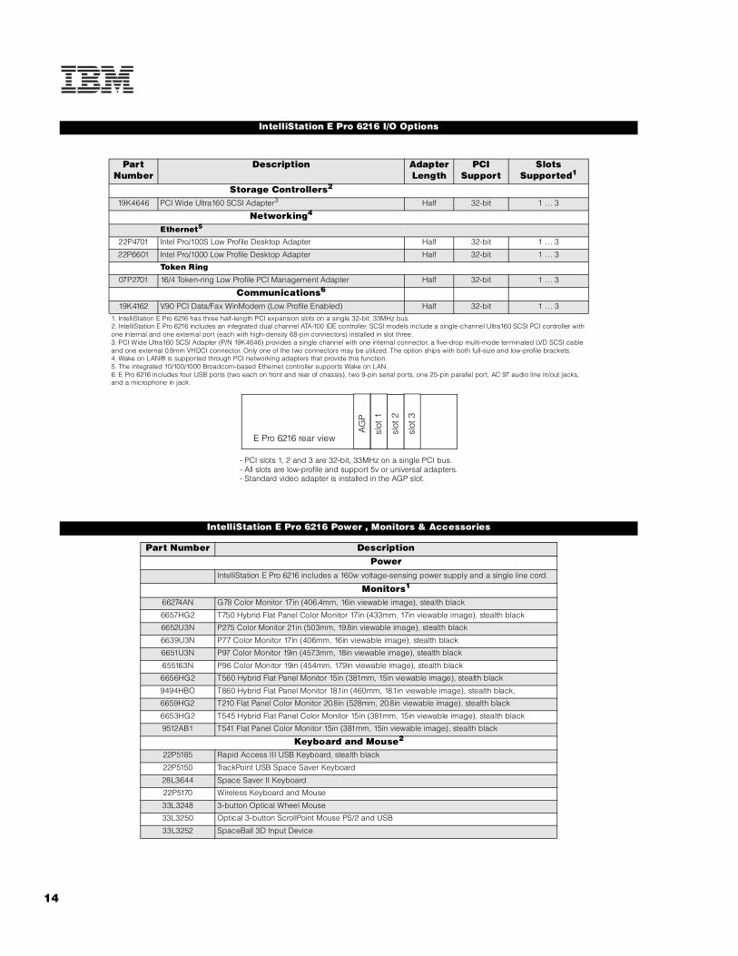
IntelliStation E Pro 6216 I/O Options
Part Number
Description Adapter Length
PCI Support
Slots Supported1
Storage Controllers2
19K4646 PCI Wide Ultra160 SCSI Adapter3 Half 32-bit 1 . .. 3
Networking4
Ethernet5
22P4701 Intel Pro/100S Low Profile Desktop Adapter Half 32-bit 1 . .. 3
22P6601 Intel Pro/1000 Low Profile Desktop Adapter Half 32-bit 1 . .. 3
Token Ring
07P2701 16/4 Token-ring Low Profile PCI Management Adapter Half 32-bit 1 . .. 3
Communications6
19K4162 V.90 PCI Data/Fax WinModem (Low Profile Enabled) Half 32-bit 1 . .. 3
1. IntelliStation E Pro 6216 has three half-length PCI expansion slots on a single 32-bit, 33MHz bus.2. IntelliStation E Pro 6216 includes an integrated dual channel ATA-100 IDE controller. SCSI models include a single-channel Ultra160 SCSI PCI controller with one internal and one external port (each with high-density 68-pin connectors) installed in slot three.3. PCI Wide Ultra160 SCSI Adapter (P/N 19K4646) provides a single channel with one internal connector, a five-drop multi-mode terminated LVD SCSI cable and one external 0.8mm VHDCI connector. Only one of the two connectors may be utilized. The option ships with both full-size and low-profile brackets.4. Wake on LAN® is supported through PCI networking adapters that provide this function.5. The integrated 10/100/1000 Broadcom-based Ethernet controller supports Wake on LAN.6. E Pro 6216 includes four USB ports (two each on front and rear of chassis), two 9-pin serial ports, one 25-pin parallel port, AC 97 audio line in/out jacks, and a microphone in jack.
IntelliStation E Pro 6216 Power , Monitors & Accessories
Part Number DescriptionPower
IntelliStation E Pro 6216 includes a 160w voltage-sensing power supply and a single line cord.
Monitors1
66274AN G78 Color Monitor 17in (406.4mm, 16in viewable image), stealth black
6657HG2 T750 Hybrid Flat Panel Color Monitor 17in (433mm, 17in viewable image), stealth black
6652U3N P275 Color Monitor 21in (503mm, 19.8in viewable image), stealth black
6639U3N P77 Color Monitor 17in (406mm, 16in viewable image), stealth black
6651U3N P97 Color Monitor 19in (457.3mm, 18in viewable image), stealth black
655163N P96 Color Monitor 19in (454mm, 17.9in viewable image), stealth black
6656HG2 T560 Hybrid Flat Panel Monitor 15in (381mm, 15in viewable image), stealth black
9494HBO T860 Hybrid Flat Panel Monitor 18.1in (460mm, 18.1in viewable image), stealth black,
6659HG2 T210 Flat Panel Color Monitor 20.8in (528mm, 20.8in viewable image), stealth black
6653HG2 T545 Hybrid Flat Panel Color Monitor 15in (381mm, 15in viewable image), stealth black
9512AB1 T541 Flat Panel Color Monitor 15in (381mm, 15in viewable image), stealth black
Keyboard and Mouse2
22P5185 Rapid Access III USB Keyboard, stealth black
22P5150 TrackPoint USB Space Saver Keyboard
28L3644 Space Saver II Keyboard
22P5170 Wireless Keyboard and Mouse
33L3248 3-button Optical Wheel Mouse
33L3250 Optical 3-button ScrollPoint Mouse PS/2 and USB
33L3252 SpaceBall 3D Input Device
E Pro 6216 rear view
AG
P
slot
3
slot
2
slot
1
- PCI slots 1, 2 and 3 are 32-bit, 33MHz on a single PCI bus.- All slots are low-profile and support 5v or universal adapters.- Standard video adapter is installed in the AGP slot.

15For the latest product & technical information, refer to the Information Sources on pages 2 and 3.Updated 10/15/02
Inte
lliS
tati
on
E P
ro 6
21
6
1. One digital monitor is supported by systems with Matrox Millennium G450 DVI video adapters. Two digital monitors are supported by systems with NVIDIA Quadro4 200NVS video adapters. Digital-to-analog adapters to support analog monitors through digital video adapter connectors are shipped with the system.2. IntelliStation E Pro 6216 ships standard with a keyboard and mouse.

IntelliStation E Pro 6226
EMEA Part Number Cross ReferenceIntelliStation E Pro 6226 System Unit Part Numbers
EMEA AMERICAS M/C TYPE DESCRIPTION EMEAP/N P/N MODEL WDFM DATE
KBU20xx 622620U 6226-20G P4 2.0GHz/400MHz, 512KB, 256MB, 40GB EIDE,Matrox Millenium G450 DVI, Windows XP, Desktop ---
KBUB0xx N/A 6226-B0G P4 2.0GHz/400MHz, 512KB, 256MB, 40GB EIDE,Matrox Millenium G450 DVI, DOS 2000 Lic., Desktop ---
KBU22xx 622622U 6226-22G P4 2.0GHz/400MHz, 512KB, 256MB, 40GB EIDE,NVIDIA Quadro4 200NVS, Windows XP, Desktop ---
KBUB2xx N/A 6226-B2G P4 2.0GHz/400MHz, 512KB, 256MB, 40GB EIDE,NVIDIA Quadro4 200NVS, DOS 2000 Lic., Desktop ---
KBU30xx N/A 6226-30G P4 2.26GHz/533MHz, 512KB, 256MB, 40GB EIDE,Matrox Millenium G450 DVI, Windows XP, Desktop ---
KBUC0xx N/A 6226-C0G P4 2.26GHz/533MHz, 512KB, 256MB, 40GB EIDE,Matrox Millenium G450 DVI, DOS 2000 Lic., Desktop ---
KBU32xx N/A 6226-32G P4 2.26GHz/533MHz, 512KB, 256MB, 40GB EIDE,NVIDIA Quadro4 200NVS, Windows XP, Desktop ---
KBUC2xx N/A 6226-C2G P4 2.26GHz/533MHz, 512KB, 256MB, 40GB EIDE,NVIDIA Quadro4 200NVS, DOS 2000 Lic., Desktop ---
KBU35xx N/A 6226-35G P4 2.26GHz/533MHz, 512KB, 256MB, 18.2GB U160,ATI Fire GL8800, Windows XP, Desktop ---
KBUC5xx N/A 6226-C5G P4 2.26GHz/533MHz, 512KB, 256MB, 18.2GB U160,ATI Fire GL8800, DOS 2000 Lic., Desktop ---
KBU40xx 622640U 6226-40G P4 2.4GHz/533MHz, 512KB, 256MB, 40GB EIDE,Matrox Millenium G450 DVI, Windows XP, Desktop ---
KBUD0xx N/A 6226-D0G P4 2.4GHz/533MHz, 512KB, 256MB, 40GB EIDE,Matrox Millenium G450 DVI, DOS 2000 Lic., Desktop ---
KBU42xx 622642U 6226-42G P4 2.4GHz/533MHz, 512KB, 256MB, 40GB EIDE,NVIDIA Quadro4 200NVS, Windows XP, Desktop ---
KBUD2xx N/A 6226-D2G P4 2.4GHz/533MHz, 512KB, 256MB, 40GB EIDE,NVIDIA Quadro4 200NVS, DOS 2000 Lic., Desktop ---
KBU45xx 622645U 6226-45G P4 2.4GHz/533MHz, 512KB, 256MB, 18.2GB U160,ATI Fire GL8800, Windows XP, Desktop ---
KBUD5xx N/A 6226-D5G P4 2.4GHz/533MHz, 512KB, 256MB, 18.2GB U160,ATI Fire GL8800, DOS 2000 Lic., Desktop ---
IntelliStation E Pro 6226 I/O Option Part NumbersEMEA AMERICAS M/C TYPE DESCRIPTION EMEA
P/N P/N MODEL WDFM DATEN/A 19K4162 --- V90 PCI Data/Fax WinModem (Low Profile Enabled) N/A
IntelliStation E Pro 6226 Power, Monitors & AccessoriesEMEA AMERICAS M/C TYPE DESCRIPTION EMEA
P/N P/N MODEL MONITORS WDFM DATENote 1 T274Axx 66274AN 6627-4AN G78 17" (16" viewable image) Colour Monitor (S/Black ---Note 1 T57HGxx 6657HG2 6657-HG2 T750 17" Hybrid Flat Panel Colour Monitor (S/Black) ---Note 1 T52U3xx 6652U3N 6652-U3N P275 21" (19.8" viewable image) Colour Monitor (S/Bla ---Note 1 T39U3xx 6639U3N 6639-U3N P77 17" (16" viewable image) Colour Monitor (S/Black) ---Note 1 T1U3Nxx 6651U3N 6651-U3N P97 19" (18" viewable image) Colour Monitor (S/Black) ---Note 1 T51U3xx 655163N 6551-63N P96 19" (17.9" viewable image) Colour Monitor (S/Blac 30/07/02Note 1 T56HGxx 6656HG2 6656-HG2 T560 15" Flat Panel Colour Monitor (S/Black) ---Note 1 T4HB0xx 9494HB0 9494-HB0 T860 18.1" Hybrid Flat Panel Color Monitor (S/Black) ---Note 1 T59HGxx 6659HG2 6659-HG2 T210 20.8" Flat Panel Colour Monitor (S/Black) ---Note 1 T53HGxx 6653HG2 6653-HG2 T545 15" Flat Panel Colour Monitor (S/Black) 10/09/02Note 1 T12ABxx 9512AB1 9512-AB1 T541 15" Flat Panel Colour Monitor (S/Black) ---
1. Where ‘xx’ represents a specific country code as follows: DK=Denmark, IS=Israel, IT=Italy, SD=SaudiArabia, SA=South Africa/Pakistan, CH=Switzerland, UK=UK, EU=Europe.
15A Updated 10/15/02

IntelliStation E Pro 6226
EMEA Part Number Cross ReferenceIntelliStation E Pro 6226 Power, Monitors & Accessories
EMEA AMERICAS M/C TYPE DESCRIPTION EMEAP/N P/N MODEL KEYBOARD AND MOUSE WDFM DATE
Note 2 22P5xxx 22P5185 --- IBM Rapid Access III USB Keyboard with HUB ---Note 3 22P51xx 22P5150 --- TrackPoint USB Spacesaver Keyboard ---Note 4 28L36xx 28L3644 --- Spacesaver II Keyboard ---Note 5 22P51xx 22P5170 --- Wireless Keyboard and Mouse ---
2. Where ‘xxx’ represents a specific country code as follows: 189=Belgian/English, 190=Danish, 191=Dutch,192=French, 193=German, 194=Greek, 195=Icelandic, 196=Italian, 197=Norwegian, 198=Spanish, 199=Swedish/Finnish, 200=Swiss, 201=UK English, 202=US International, 205=Arabic, P/N 31P8769=Czech/US.3. Where ‘xx’ represents a specific country code as follows:- 53=Danish , 54=Dutch, 68=French, 55=German, 56=Italian, 57=Spanish, 58=UK English, 59=Swedish/Finnish, 60=Belgian/English, 61=Russian, 62=Polish, 63=Portuguese, 65=Swiss, 67=US International.4. Where ‘xx’ represents a specific country code as follows:- 46=Danish , 47=French, 48=German, 49=Italian, 50=Spanish, 51=UK English, 44=US English, and P/N 19K3831=Swiss, 19K3832=Swedish/Finnish,19K3833=Portugese, 19K3834=Belgian, 19K3836=Russian, 19K3837=Polish.5. Where ‘xx’ represents a specific country code as follows:- 73=Danish , 74=French, 75=German, 76=Italian, 77=Spanish, 78=UK English, 79=Swedish/Finnish, 80=Belgian/UK, 82=Swiss, 70=US English.
Updated 10/15/02 15B

16
IntelliStation E Pro 6226
IntelliStation E Pro 6226 At-A-Glance
6226-20U1 22 1/1 512KB 256MB/2GB Matrox Millennium G450 DVI Desktop 10/100/
1000 IDE4 3/1 40GB/80GB5 48X-20X 4/1 3/3
6226-22U1 22 1/1 512KB 256MB/2GB NVIDIA Quadro4 200NVS Desktop 10/100/
1000 IDE4 3/1 40GB/80GB5 48X-20X 4/1 3/3
6226-40U1 2.43 1/1 512KB 256MB/2GB Matrox Millennium G450 DVI Desktop 10/100/
1000 IDE4 3/1 40GB/80GB5 48X-20X 4/1 3/3
6226-42U1 2.43 1/1 512KB 256MB/2GB NVIDIA Quadro4 200NVS Desktop 10/100/
1000 IDE4 3/1 40GB/80GB5 48X-20X 4/1 3/3
6226-45U1 2.42 1/1 512KB 256MB/2GB ATI Fire GL8800 Desktop 10/100/1000 U1604 3/1 18.2GB/
73.4GB5 48X-20X 4/1 3/2
1. IntelliStation E Pro ships with a keyboard and mouse. See "Power, Monitors and Accessories" for a list of compatible monitors.2. Intel Pentium 4 processor with advanced transfer ECC L2 cache, 400MHz (quad-pumped) Front Side Bus (FSB) and MMX technology.3. Intel Pentium 4 processor with advanced transfer ECC L2 cache, 533MHz (quad-pumped) FSB and MMX technology.4. All models include an integrated ATA-100 IDE controller that supports both the IDE CD-ROM and the IDE HDD for IDE models. SCSI models include a single-channel Ultra160 SCSI PCI controller with one internal and one external port (each with high-density 68-pin connectors) installed in slot three. A three-drop, terminated 16-bit LVD internal SCSI cable is included with SCSI models, which supports up to two SCSI HDDs. IDE models include two two-drop ATA-100 IDE cables.5. Maximum internal storage capacity in SCSI models requires removing the standard 18.2GB 10,000rpm nonhot-swap HDD and installing one 73.4GB nonhot-swap HDD. In IDE models, maximum capacity is achieved by removing the standard 40GB IDE HDD and installing one 80GB IDE HDD.6. Variable read rate. Actual playback speed will vary and is often less than the maximum possible.
IntelliStation E Pro 6226 Memory
Total Memory1
Quantity of UDIMMs Added
256MBstd
256MB (10K0067)
512MB (10K0069)
1GB (10K0071)
512MB 1 - -
768MB - 1 -
Part Number
Memory Description11GB3 - 2 -
10K0067 256MB PC2100 CL2.5 ECC DDR SDRAM UDIMM 1.25GB - - 1
10K0069 512MB PC2100 CL2.5 ECC DDR SDRAM UDIMM 1.5GB3 - 1 1
10K0071 1GB PC2100 CL2.5 ECC DDR SDRAM UDIMM 2GB3 - - 2
1. Memory UDIMMs of different densities can be mixed in the two memory sockets. This table does not represent all possible memory configurations. Memory modules may vary in price per MB. Selection of smaller UDIMMs may provide a more cost-effective alternative to using larger UDIMMs.
1. Network operating systems may limit the maximum amount of addressable memory. See operating system specifications for further information.2. Select the total memory in the Total Memory column, then install the UDIMMs in that row.3. Requires replacing the standard UDIMM.
Part Number
Processor Speed (G
Hz)
Number of P
rocessors (Std/M
ax)
L2 ECC Cache
Memory (Std/M
ax)
Video Adapter
Form Factor
Onboard Ethernet (Mbps)
SCSI Contro
ller (D
ual, Ultr
a, RAID)
Removable Media Bays (T
otal/Avail)
Internal Hard Disk Driv
e (Std/M
ax)
CD-ROM (ID
E)6
Bays (Total/A
vail)
Slots (Total/A
vail)

17For the latest product & technical information, refer to the Information Sources on pages 2 and 3.Updated 10/15/02
Inte
lliS
tati
on
E P
ro 6
22
6
IntelliStation E Pro 6226 Hard Disk Drive (HDD) Storage
SCSI ModelsTotal Int Storage1
10,000rpm HDDs 15,000rpm HDDs18.2GB
(06P5750)36.4GB
(06P5751)73.4GB
(06P5752)18.2GB
(06P5765)36.4GB
(06P5766)
18.2GB (Standard on SCSI models)
36.4GB2 - 1 - - 1
73.4GB2 - - 1 - -
1. Select a total storage row then replace the standard HDD with the HDD from the appropriate column.2. Requires replacement of the standard HDD.
EIDE ModelsTotal Internal
Storage17200rpm EIDE HDDs2
40GB (P/N 22P7157)
60GB(P/N 09N4207)
80GB(P/N 09N4226)
40GB Standard on EIDE models
60GB2 - 1 -
80GB2 - - 1
1. Select a total storage row then replace the standard HDD with the HDD from the appropriate column.2. Requires replacing the standard HDD.
Bay Form Factor
Height Front Access
Usage Part Number
Description RPM Height Bays Supported
Max Qty
1 89mm (3.5in) SL yes FDD IDE HDD1
2 89mm (3.5in) SL no HDD 22P7157 40GB 7200rpm ATA-100 (EIDE) HDD 7200 SL 2 1
3 133mm (5.25in) HH yes optical 09N4207 60GB 7200rpm ATA-100 (EIDE) HDD 7200 SL 2 1
4 133mm (5.25in) HH yes open1 09N4226 80GB 7200rpm ATA-100 (EIDE) HDD 7200 SL 2 1
1. An optional optical drive or IDE tape drive can be installed in bay four.
Ultra160 HDDs2
06P5750 18.2GB 10Krpm Ultra160 SCSI SL HDD 10000 SL 2 1
06P5751 36.4GB 10Krpm Ultra160 SCSI SL HDD 10000 SL 2 1
06P5752 73.4GB 10Krpm Ultra160 SCSI SL HDD 10000 SL 2 1
06P5765 18.2GB 15Krpm Ultra160 SCSI SL HDD 15000 SL 2 1
06P5766 36.4GB 15Krpm Ultra160 SCSI SL HDD 15000 SL 2 1
Removable Media Devices Bays Supported
10K3782 48x-20x IDE CD-ROM3 3, 4
22P6976 40x-12x-40x Max Black CD-RW Drive4 3, 4
22P6950 16x Max RAM-Read DVD-ROMrive4 3, 41. IDE models support a maximum of three IDE devices including two IDE optical drives and an IDE hard disk drive.2. SCSI models support one SCSI HDD and two IDE optical drives (or one IDE optical drive and an IDE tape drive).3. Standard CD-ROM.4. Requires either removing the standard CD-ROM and installing in bay three or installing in bay four.
Bay 3: CD-ROM
Bay 4: openBay 2: HDD
Bay 1: FDD
E Pro 6226 front view

18
IntelliStation E Pro 6226 I/O Options
Part Number
Description Adapter Length
PCI Support
Slots Supported1
Storage Controllers2
19K4646 PCI Wide Ultra160 SCSI Adapter3 Half 32-bit 1 . .. 3
Networking4
Ethernet5
22P4501 Intel Pro/100S Desktop Adapter Half 32-bit 1 . .. 5
22P6501 Pro/1000 T Desktop Adapter by Intel Half 32-bit 1 . .. 3
09N3601 10/100 EtherLink PCI Management Adapter by 3Com Half 32-bit 1 . .. 3
22P6901 Wireless LAN Adapter Half 128-bit 1 . .. 3
Token Ring
34L5001 16/4 Token-ring PCI Management Adapter Half 32-bit 1 . .. 3
34L5201 High-speed 100/16/4 Token-ring PCI Management Adapter Half 32-bit 1 . .. 3
Communications6
19K4162 V.90 PCI Data/Fax WinModem (Low Profile Enabled) Half 32-bit 1 . .. 3
1. IntelliStation E Pro 6226 has three half-length PCI expansion slots on a single 32-bit, 33MHz bus.2. IntelliStation E Pro 6226 includes an integrated dual channel ATA-100 IDE controller. SCSI models include a single-channel Ultra160 SCSI PCI controller with one internal and one external port (each with high-density 68-pin connectors) installed in slot three.3. PCI Wide Ultra160 SCSI Adapter (P/N 19K4646) provides a single channel with one internal connector, a five-drop multi-mode terminated LVD SCSI cable and one external 0.8mm VHDCI connector. Only one of the two connectors may be utilized. The option ships with both full-size and low-profile brackets.4. Wake on LAN is supported through PCI networking adapters that provide this function.5. The integrated 10/100/1000 Broadcom-based Ethernet controller supports Wake on LAN.6. E Pro 6226 includes four USB ports (two each on front and rear of chassis), two 9-pin serial ports, one 25-pin parallel port, AC 97 audio line in/out jacks, and a microphone in jack.
IntelliStation E Pro 6226 Power , Monitors & Accessories
Part Number DescriptionPower
IntelliStation E Pro 6226 includes a 200w voltage-sensing power supply and a single line cord.
Monitors1
66274AN G78 Color Monitor 17in (406.4mm, 16in viewable image), stealth black
6657HG2 T750 Hybrid Flat Panel Color Monitor 17in (433mm, 17in viewable image), stealth black
6652U3N P275 Color Monitor 21in (503mm, 19.8in viewable image), stealth black
6639U3N P77 Color Monitor 17in (406mm, 16in viewable image), stealth black
6651U3N P97 Color Monitor 19in (457.3mm, 18in viewable image), stealth black
655163N P96 Color Monitor 19in (454mm, 17.9in viewable image), stealth black
6656HG2 T560 Hybrid Flat Panel Monitor 15in (381mm, 15in viewable image), stealth black
9494HBO T860 Hybrid Flat Panel Monitor 18.1in (460mm, 18.1in viewable image), stealth black,
6659HG2 T210 Flat Panel Color Monitor 20.8in (528mm, 20.8in viewable image), stealth black
6653HG2 T545 Hybrid Flat Panel Color Monitor 15in (381mm, 15in viewable image), stealth black
9512AB1 T541 Flat Panel Color Monitor 15in (381mm, 15in viewable image), stealth black
E Pro 6226 rear view
AG
P
slot
1
slot
2
slot
3
- PCI slots 1, 2 and 3 are 32-bit, 33MHz on a single PCI bus.- All slots support 5v or universal adapters.- Standard video adapter is installed in the AGP slot.
19For the latest product & technical information, refer to the Information Sources on pages 2 and 3.Updated 10/15/02
Inte
lliS
tati
on
E P
ro 6
22
6
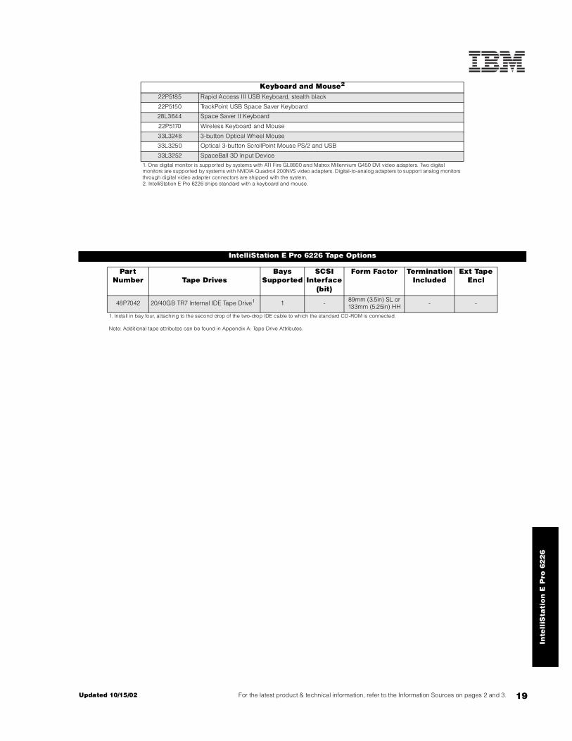
Keyboard and Mouse2
22P5185 Rapid Access III USB Keyboard, stealth black
22P5150 TrackPoint USB Space Saver Keyboard
28L3644 Space Saver II Keyboard
22P5170 Wireless Keyboard and Mouse
33L3248 3-button Optical Wheel Mouse
33L3250 Optical 3-button ScrollPoint Mouse PS/2 and USB
33L3252 SpaceBall 3D Input Device
1. One digital monitor is supported by systems with ATI Fire GL8800 and Matrox Millennium G450 DVI video adapters. Two digital monitors are supported by systems with NVIDIA Quadro4 200NVS video adapters. Digital-to-analog adapters to support analog monitors through digital video adapter connectors are shipped with the system.2. IntelliStation E Pro 6226 ships standard with a keyboard and mouse.
IntelliStation E Pro 6226 Tape Options
Part Number Tape Drives
Bays Supported
SCSI Interface
(bit)
Form Factor Termination Included
Ext Tape Encl
48P7042 20/40GB TR7 Internal IDE Tape Drive1 1 - 89mm (3.5in) SL or 133mm (5.25in) HH - -
1. Install in bay four, attaching to the second drop of the two-drop IDE cable to which the standard CD-ROM is connected.
Note: Additional tape attributes can be found in Appendix A: Tape Drive Attributes.
IntelliStation M Pro 6229
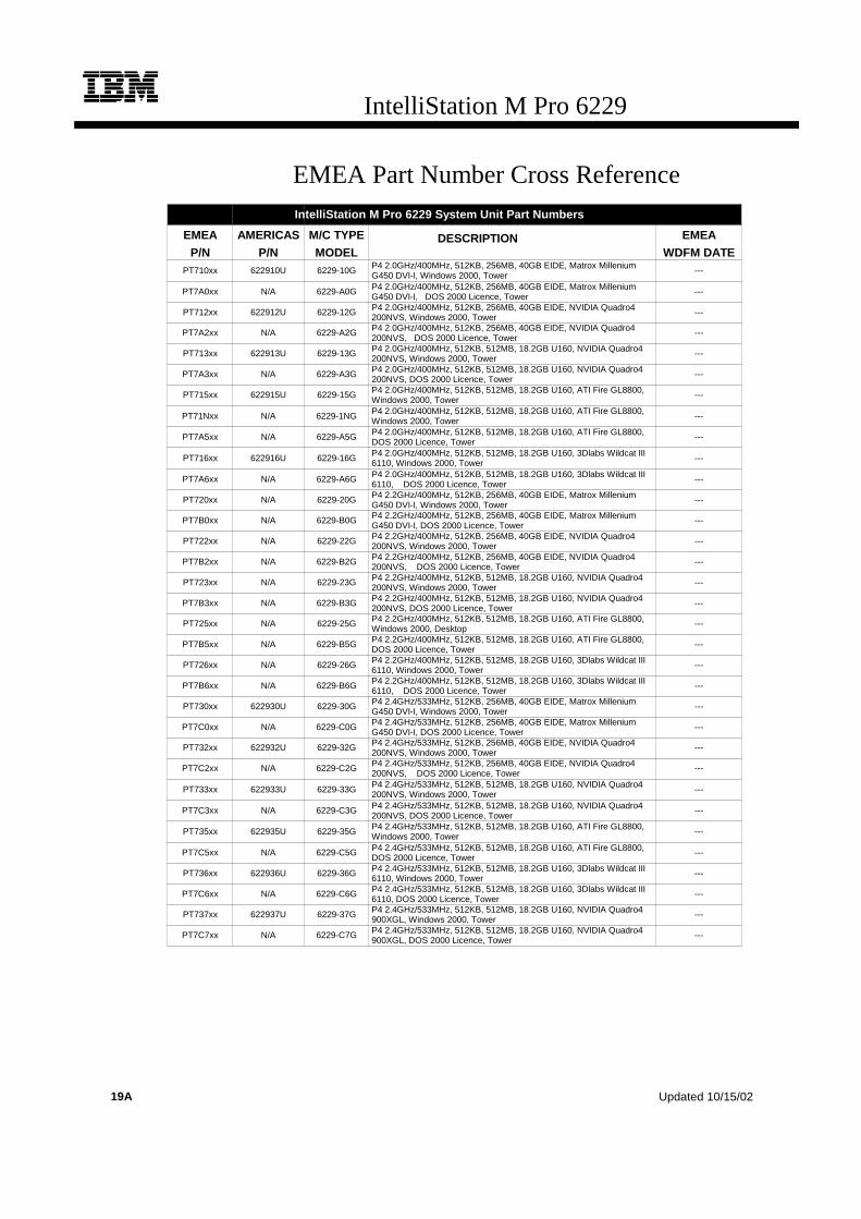
EMEA Part Number Cross ReferenceIntelliStation M Pro 6229 System Unit Part Numbers
EMEA AMERICAS M/C TYPE DESCRIPTION EMEAP/N P/N MODEL WDFM DATE
PT710xx 622910U 6229-10G P4 2.0GHz/400MHz, 512KB, 256MB, 40GB EIDE, Matrox MilleniumG450 DVI-I, Windows 2000, Tower ---
PT7A0xx N/A 6229-A0G P4 2.0GHz/400MHz, 512KB, 256MB, 40GB EIDE, Matrox MilleniumG450 DVI-I, DOS 2000 Licence, Tower
---
PT712xx 622912U 6229-12G P4 2.0GHz/400MHz, 512KB, 256MB, 40GB EIDE, NVIDIA Quadro4200NVS, Windows 2000, Tower
---
PT7A2xx N/A 6229-A2G P4 2.0GHz/400MHz, 512KB, 256MB, 40GB EIDE, NVIDIA Quadro4200NVS, DOS 2000 Licence, Tower
---
PT713xx 622913U 6229-13G P4 2.0GHz/400MHz, 512KB, 512MB, 18.2GB U160, NVIDIA Quadro4200NVS, Windows 2000, Tower
---
PT7A3xx N/A 6229-A3G P4 2.0GHz/400MHz, 512KB, 512MB, 18.2GB U160, NVIDIA Quadro4200NVS, DOS 2000 Licence, Tower
---
PT715xx 622915U 6229-15G P4 2.0GHz/400MHz, 512KB, 512MB, 18.2GB U160, ATI Fire GL8800,Windows 2000, Tower
---
PT71Nxx N/A 6229-1NG P4 2.0GHz/400MHz, 512KB, 512MB, 18.2GB U160, ATI Fire GL8800,Windows 2000, Tower ---
PT7A5xx N/A 6229-A5G P4 2.0GHz/400MHz, 512KB, 512MB, 18.2GB U160, ATI Fire GL8800,DOS 2000 Licence, Tower
---
PT716xx 622916U 6229-16G P4 2.0GHz/400MHz, 512KB, 512MB, 18.2GB U160, 3Dlabs Wildcat III6110, Windows 2000, Tower ---
PT7A6xx N/A 6229-A6G P4 2.0GHz/400MHz, 512KB, 512MB, 18.2GB U160, 3Dlabs Wildcat III6110, DOS 2000 Licence, Tower
---
PT720xx N/A 6229-20G P4 2.2GHz/400MHz, 512KB, 256MB, 40GB EIDE, Matrox MilleniumG450 DVI-I, Windows 2000, Tower
---
PT7B0xx N/A 6229-B0G P4 2.2GHz/400MHz, 512KB, 256MB, 40GB EIDE, Matrox MilleniumG450 DVI-I, DOS 2000 Licence, Tower
---
PT722xx N/A 6229-22G P4 2.2GHz/400MHz, 512KB, 256MB, 40GB EIDE, NVIDIA Quadro4200NVS, Windows 2000, Tower
---
PT7B2xx N/A 6229-B2G P4 2.2GHz/400MHz, 512KB, 256MB, 40GB EIDE, NVIDIA Quadro4200NVS, DOS 2000 Licence, Tower
---
PT723xx N/A 6229-23G P4 2.2GHz/400MHz, 512KB, 512MB, 18.2GB U160, NVIDIA Quadro4200NVS, Windows 2000, Tower
---
PT7B3xx N/A 6229-B3G P4 2.2GHz/400MHz, 512KB, 512MB, 18.2GB U160, NVIDIA Quadro4200NVS, DOS 2000 Licence, Tower
---
PT725xx N/A 6229-25G P4 2.2GHz/400MHz, 512KB, 512MB, 18.2GB U160, ATI Fire GL8800,Windows 2000, Desktop
---
PT7B5xx N/A 6229-B5G P4 2.2GHz/400MHz, 512KB, 512MB, 18.2GB U160, ATI Fire GL8800,DOS 2000 Licence, Tower
---
PT726xx N/A 6229-26G P4 2.2GHz/400MHz, 512KB, 512MB, 18.2GB U160, 3Dlabs Wildcat III6110, Windows 2000, Tower
---
PT7B6xx N/A 6229-B6G P4 2.2GHz/400MHz, 512KB, 512MB, 18.2GB U160, 3Dlabs Wildcat III6110, DOS 2000 Licence, Tower
---
PT730xx 622930U 6229-30G P4 2.4GHz/533MHz, 512KB, 256MB, 40GB EIDE, Matrox MilleniumG450 DVI-I, Windows 2000, Tower
---
PT7C0xx N/A 6229-C0G P4 2.4GHz/533MHz, 512KB, 256MB, 40GB EIDE, Matrox MilleniumG450 DVI-I, DOS 2000 Licence, Tower
---
PT732xx 622932U 6229-32G P4 2.4GHz/533MHz, 512KB, 256MB, 40GB EIDE, NVIDIA Quadro4200NVS, Windows 2000, Tower
---
PT7C2xx N/A 6229-C2G P4 2.4GHz/533MHz, 512KB, 256MB, 40GB EIDE, NVIDIA Quadro4200NVS, DOS 2000 Licence, Tower
---
PT733xx 622933U 6229-33G P4 2.4GHz/533MHz, 512KB, 512MB, 18.2GB U160, NVIDIA Quadro4200NVS, Windows 2000, Tower ---
PT7C3xx N/A 6229-C3G P4 2.4GHz/533MHz, 512KB, 512MB, 18.2GB U160, NVIDIA Quadro4200NVS, DOS 2000 Licence, Tower
---
PT735xx 622935U 6229-35G P4 2.4GHz/533MHz, 512KB, 512MB, 18.2GB U160, ATI Fire GL8800,Windows 2000, Tower ---
PT7C5xx N/A 6229-C5G P4 2.4GHz/533MHz, 512KB, 512MB, 18.2GB U160, ATI Fire GL8800,DOS 2000 Licence, Tower
---
PT736xx 622936U 6229-36G P4 2.4GHz/533MHz, 512KB, 512MB, 18.2GB U160, 3Dlabs Wildcat III6110, Windows 2000, Tower
---
PT7C6xx N/A 6229-C6G P4 2.4GHz/533MHz, 512KB, 512MB, 18.2GB U160, 3Dlabs Wildcat III6110, DOS 2000 Licence, Tower
---
PT737xx 622937U 6229-37G P4 2.4GHz/533MHz, 512KB, 512MB, 18.2GB U160, NVIDIA Quadro4900XGL, Windows 2000, Tower
---
PT7C7xx N/A 6229-C7G P4 2.4GHz/533MHz, 512KB, 512MB, 18.2GB U160, NVIDIA Quadro4900XGL, DOS 2000 Licence, Tower
---
19A Updated 10/15/02

IntelliStation M Pro 6229
EMEA Part Number Cross ReferenceIntelliStation M Pro 6229 System Unit Part Numbers (Cont.)
EMEA AMERICAS M/C TYPE DESCRIPTION EMEAP/N P/N MODEL WDFM DATE
PT740xx 622940U 6229-40G P4 2.67GHz/533MHz, 512KB, 512MB, 40GB EIDE, MatroxMillenium G450 DVI-I, Windows XP, Tower
---
PT7D0xx N/A 6229-D0G P4 2.67GHz/533MHz, 512KB, 512MB, 40GB EIDE, MatroxMillenium G450 DVI-I, DOS 2000 Licence, Tower
---
PT742xx 622942U 6229-42G P4 2.67GHz/533MHz, 512KB, 512MB, 40GB EIDE, NVIDIAQuadro4 200NVS, Windows XP, Tower
---
PT7D2xx N/A 6229-D2G P4 2.67GHz/533MHz, 512KB, 512MB, 40GB EIDE, NVIDIAQuadro4 200NVS, DOS 2000 Licence, Tower
---
PT745xx 622945U 6229-45G P4 2.67GHz/533MHz, 512KB, 512MB, 18.2GB U160, ATI FireGL8800, Windows XP, Tower
---
PT7D5xx N/A 6229-D5G P4 2.67GHz/533MHz, 512KB, 512MB, 18.2GB U160, ATI FireGL8800, DOS 2000 Licence, Tower
---
PT747xx 622947U 6229-47G P4 2.67GHz/533MHz, 512KB, 512MB, 18.2GB U160, NVIDIAQuadro4 900XGL, Windows XP, Tower
---
PT7D7xx N/A 6229-D7G P4 2.67GHz/533MHz, 512KB, 512MB, 18.2GB U160, NVIDIAQuadro4 900XGL, DOS 2000 Licence, Tower
---
PT753xx 622953U 6229-53G P4 2.8GHz/533MHz, 512KB, 512MB, 18.2GB U160, NVIDIAQuadro4 200NVS, Windows XP, Tower
---
PT7E3xx N/A 6229-E3G P4 2.8GHz/533MHz, 512KB, 512MB, 18.2GB U160, NVIDIAQuadro4 200NVS, DOS 2000 Licence, Tower
---
PT756xx 622956U 6229-56G P4 2.8GHz/533MHz, 512KB, 512MB, 18.2GB U160, 3DlabsWildcat III 6110, Windows XP, Tower
---
PT7E6xx N/A 6229-E6G P4 2.8GHz/533MHz, 512KB, 512MB, 18.2GB U160, 3DlabsWildcat III 6110, DOS 2000 Licence, Tower
---
PT757xx 622957U 6229-57G P4 2.8GHz/533MHz, 512KB, 512MB, 18.2GB U160, NVIDIAQuadro4 900XGL, Windows XP, Tower
---
PT7E7xx N/A 6229-E7G P4 2.8GHz/533MHz, 512KB, 512MB, 18.2GB U160, NVIDIAQuadro4 900XGL, DOS 2000 Licence, Tower
---
IntelliStation M Pro 6229 I/O Option Part NumbersEMEA AMERICAS M/C TYPE DESCRIPTION EMEA
P/N P/N MODEL WDFM DATEN/A 19K4162 --- V90 PCI Data/Fax WinModem (Low Profile Enabled) N/A
IntelliStation M Pro 6229 Power, Monitors & AccessoriesEMEA AMERICAS M/C TYPE DESCRIPTION EMEA
P/N P/N MODEL MONITORS WDFM DATENote 1 T274Axx 66274AN 6627-4AN G78 17" (16" viewable image) Colour Monitor (S/Black) ---
Note 1 T57HGxx 6657HG2 6657-HG2 T750 17" Hybrid Flat Panel Colour Monitor (S/Black) ---
Note 1 T52U3xx 6652U3N 6652-U3N P275 21" (19.8" viewable image) Colour Monitor (S/Black) ---
Note 1 T39U3xx 6639U3N 6639-U3N P77 17" (16" viewable image) Colour Monitor (S/Black) ---
Note 1 T1U3Nxx 6651U3N 6651-U3N P97 19" (18" viewable image) Colour Monitor (S/Black) ---
Note 1 T56HGxx 6656HG2 6656-HG2 T560 15" Flat Panel Colour Monitor (S/Black) ---
Note 1 T4HB0xx 9494HB0 9494-HB0 T860 18.1" Hybrid Flat Panel Color Monitor (S/Black) ---
Note 1 T4HBNxx 9494HBN 9494-HBN T860 18.1" Hybrid F/Panel Color Monitor w/o stand (S/B) ---
Note 1 T59HGxx 6659HG2 6659-HG2 T210 20.8" Flat Panel Colour Monitor (S/Black) ---
1. Where ‘xx’ represents a specific country code as follows: DK=Denmark, IS=Israel, IT=Italy, SD=Saudi Arabia, SA=South Africa/Pakistan, CH=Switzerland, UK=UK, EU=Europe.
IntelliStation M Pro 6229 Power, Monitors & Accessories
EMEA AMERICAS M/C TYPE DESCRIPTION EMEAP/N P/N MODEL KEYBOARD AND MOUSE WDFM DATE
Note 2 22P5xxx 22P5185 --- IBM Rapid Access III USB Keyboard with HUB ---
2. Where ‘xxx’ represents a specific country code as follows: 189=Belgian/English, 190=Danish, 191=Dutch, 192=French, 193=German, 194=Greek, 195=Icelandic, 196=Italian, 197=Norwegian, 198=Spanish, 199=Swedish/Finnish, 200=Swiss, 201=UKEnglish, 202=US International, 205=Arabic, P/N 31P8769=Czech/US.
Updated 10/15/02 19B

20
IntelliStation M Pro 6229
IntelliStation M Pro 6229 At-A-Glance
6229-10U1 22 1/1 512KB 256MB/2GB Matrox Millennium G450 DVI Tower 10/100 IDE4 3/1 40GB/
360GB5 48X-20X 7/4 5/5
6229-12U1 22 1/1 512KB 256MB/2GB NVIDIA Quadro4 200NVS Tower 10/100 IDE4 3/1 40GB/
360GB5 48X-20X 7/4 5/5
6229-13U1 22 1/1 512KB 512MB/2GB NVIDIA Quadro4 200NVS Tower 10/100 U1604 3/1 18.2GB/
293.6GB6 48X-20X 7/4 5/4
6229-15U1 22 1/1 512KB 512MB/2GB ATI Fire GL8800™ Tower 10/100 U1604 3/1 18.2GB/
293.6GB6 48X-20X 7/4 5/4
6229-16U1 22 1/1 512KB 512MB/2GB 3Dlabs Wildcat III 6110 Tower 10/100 U1604 3/1 18.2GB/
293.6GB6 48X-20X 7/4 5/3
6229-30U1 2.43 1/1 512KB 256MB/2GB Matrox Millennium G450 DVI Tower 10/100 IDE4 3/1 40GB/
360GB5 48X-20X 7/4 5/5
6229-32U1 2.43 1/1 512KB 256MB/2GB NVIDIA Quadro4 200NVS Tower 10/100 IDE4 3/1 40GB/
360GB5 48X-20X 7/4 5/5
6229-33U1 2.43 1/1 512KB 512MB/2GB NVIDIA Quadro4 200NVS Tower 10/100 U1604 3/1 18.2GB/
293.6GB6 48X-20X 7/4 5/4
6229-35U1 2.43 1/1 512KB 512MB/2GB ATI Fire GL8800 Tower 10/100 U1604 3/1 18.2GB/293.6GB6 48X-20X 7/4 5/4
6229-36U1 2.43 1/1 512KB 512MB/2GB 3Dlabs Wildcat III 6110 Tower 10/100 U1604 3/1 18.2GB/
293.6GB6 48X-20X 7/4 5/3
6229-37U1 2.43 1/1 512KB 512MB/2GB NVIDIA Quadro4 900XGL Tower 10/100 U1604 3/1 18.2GB/
293.6GB6 48X-20X 7/4 5/4
6229-40U1 2.673 1/1 512KB 512MB/2GB Matrox Millennium G450 DVI Tower 10/100 IDE4 3/1 40GB/
360GB5 48X-20X 7/4 5/5
6229-42U1 2.673 1/1 512KB 512MB/2GB NVIDIA Quadro4 200NVS Tower 10/100 IDE4 3/1 40GB/
360GB5 48X-20X 7/4 5/5
6229-45U1 2.673 1/1 512KB 512MB/2GB ATI Fire GL8800 Tower 10/100 U1604 3/1 18.2GB/293.6GB6 48X-20X 7/4 5/4
6229-47U1 2.673 1/1 512KB 512MB/2GB NVIDIA Quadro4 900XGL Tower 10/100 U1604 3/1 18.2GB/
293.6GB6 48X-20X 7/4 5/4
6229-53U1 2.83 1/1 512KB 512MB/2GB NVIDIA Quadro4 200NVS Tower 10/100 U1604 3/1 18.2GB/
293.6GB6 48X-20X 7/4 5/4
6229-56U1 2.83 1/1 512KB 512MB/2GB 3Dlabs Wildcat III 6110 Tower 10/100 U1604 3/1 18.2GB/
293.6GB6 48X-20X 7/4 5/3
6229-57U1 2.83 1/1 512KB 512MB/2GB NVIDIA Quadro4 900XGL Tower 10/100 U1604 3/1 18.2GB/
293.6GB6 48X-20X 7/4 5/4
Part Number
Processor Speed (G
Hz)
Number of P
rocessors (Std/M
ax)
L2 ECC Cache
Memory (Std/M
ax)
Video Adapter
Form Factor
Onboard Ethernet (Mbps)
SCSI Contro
ller (
Dual, Ultra
, RAID)
Removable Media Bays (T
otal/Avail)
Internal Hard Disk Driv
e (Std/M
ax)
CD-ROM (ID
E)7
Bays (Total/A
vail)
Slots (Total/A
vail)8

Inte
lliS
tati
on
M P
ro 6
22
9
21For the latest product & technical information, refer to the Information Sources on pages 2 and 3.Updated 10/15/02
1. IntelliStation M Pro 6229 ships with a keyboard and mouse. See “Power, Monitors and Accessories” for a list of compatible monitors. Tower models are rack-mountable using an optional tower-to-rack conversion kit, or they can be turned on the side and installed as desktop units capable of supporting the weight of a monitor.2. Intel Pentium 4 processor with advanced transfer ECC L2 cache,400MHz (quad-pumped) Front Side Bus (FSB) and MMX technology.3. Intel Pentium 4 processor with advanced transfer ECC L2 cache, 533MHz (quad-pumped) FSB and MMX technology. Models shipped with this processor require 288Mb memory options that support 533MHz FSB operation (P/N 31P8431, 3, 5). 4. All models include an integrated ATA-100 IDE controller that supports up to four IDE devices (three IDE HDDs and one optical drive) in IDE models. SCSI models include a single-channel Ultra160 SCSI PCI controller with one internal and one external port (each with high-density 68-pin connectors) installed in slot five. A five-drop, terminated 16-bit LVD internal SCSI cable is included with SCSI models, which support up to five SCSI HDDs.5. IDE models include two two-drop ATA-100 IDE cables. Maximum storage is based on three120GB IDE HDDs, which requires replacing the standard 40GB HDD.6. Requires replacement of the standard 18.2GB 10,000rpm HDD with a 73.4GB HDD and installing three additional nonhot-swap 73.4GB HDDs.7. Variable read rate. Actual playback speed will vary and is often less than the maximum possible.8. Certain video adapters require additional space, preventing slot one from being used to install an optional PCI adapter. This applies to models with the3Dlabs Wildcat III 6110 adapter.
IntelliStation M Pro 6229 Memory
Total System Memory1
Quantity of RIMMs Added
256MB (2 x 128) Models
512MB(2 x 256) Models
128MB ( 31P8431)
256MB ( 31P8433)
512MB (31P8435)3
512MB 768MB 2 - -
768MB 1024MB - 2 -
Part Number
Memory Description11280MB 1536MB - - 2
31P8431 128MB PC800 4D ECC RDRAM RIMM (288Mb) 2GB2 2GB2 - - 4
31P8433 256MB PC800 8D ECC RDRAM RIMM (288Mb)
This table does not represent all possible memory configurations. Memory modules may vary in price per MB. Selection of smaller RIMMs may provide a more cost-effective alternative to using larger RIMMs.1. Network operating systems may limit the maximum amount of addressable memory. See operating system specifications for further information.2. Requires replacing the standard RIMM.
31P8435 512MB PC800 16D ECC RDRAM RIMM (288Mb)
1. Memory RIMMs must be installed in pairs using the same option part number according to the following order: RIMM connectors one and two (set one), then connectors three and four (set two).
IntelliStation M Pro 6229 Hard Disk Drive (HDD) Storage
SCSI ModelsTotal Int Storage1
10,000RPM HDDs 15,000RPM HDDs18.2GB
(06P5750)36.4GB
(06P5751)73.4GB
(06P5752)18.2GB
(06P5765)36.4GB
(06P5766)
18.2GB (Standard on SCSI models)
36.4GB 1 - - 1 -
54.6GB 2 - - 2 -
72.8GB 3 - - 3 -
91GB 2 1 - 2 1
109.2GB 1 2 - 1 2
127.4GB - 3 - - 3
145.6GB2 - 4 - - 4
182.6GB2 - 3 1 - -
219.6GB2 - 2 2 - -
256.6GB2 - 1 3 - -
293.6GB2 - - 4 - -
This table does not represent all possible HDD configurations.
1. Select a total storage row then add the quantity of HDDs from all columns in an RPM range to the standard HDD.2. Requires replacement of the standard HDD.
RIMM 3
RIMM 4
RIMM 2
RIMM 1

22
EIDE ModelsTotal Internal
Storage17200RPM EIDE HDDs2
40GB (P/N 22P7157)
60GB(P/N 09N4207)
80GB(P/N 09N4226)
120GB(P/N 09N4231)
40GB Standard on EIDE models
80GB 1 - - -
100GB - 1 - -
120GB 2 - - -
140GB 1 1 - -
160GB - 2 - -
180GB3 - 3 - -
200GB - - 2 -
240GB3 - - 3 -
280GB3 - - 2 1
320GB3 - - 1 2
360GB3 - - - 3
This table does not represent all possible HDD configurations.Total Internal Storage listed is within +/-0.2GB unless otherwise noted.
1. Select a total storage row then add the quantity of HDDs from all columns to the standard HDD.2. Supports a maximum of four IDE devices including CD-ROM drives, HDDs and IDE tape drives.3. Requires replacing the standard HDD.
Bay Form Factor
Height Front Access
Usage Part Number
Description RPM Height Bays Supported3
Max Qty
1 133mm (5.25in) HH yes CD-ROM1 IDE HDD1, 2
2 133mm (5.25in) HH yes open1 22P7157 40GB 7200rpm ATA-100 (EIDE) HDD 7200 SL 3 .. . 7 33
3 89mm (3.5in) SL yes FDD 09N4207 60GB 7200rpm ATA-100 (EIDE) HDD 7200 SL 3 .. . 7 33
4 89mm (3.5in) SL yes open2 09N4226 80GB 7200rpm ATA-100 (EIDE) HDD 7200 SL 3 .. . 7 33
5, 6 89mm (3.5in) SL no open3 09N4231 120GB 7200rpm ATA-100 (EIDE) HDD 7200 SL 3 .. . 7 33
7 89mm (3.5in) SL no Std HDD Ultra160 HDDs2, 4
1. Supports removable media devices only. Hard disk drives are not supported.2. Supports a third IDE HDD in IDE models or a fourth SCSI HDD in SCSI models.3. Bay six supports a third SCSI HDD in SCSI models, but the third IDE HDD IDE models should be installed in bay four
06P5750 18.2GB 10Krpm Ultra160 SCSI SL HDD 10000 SL 3 .. . 7 44
. 06P5751 36.4GB 10Krpm Ultra160 SCSI SL HDD 10000 SL 3 .. . 7 44
06P5752 73.4GB 10Krpm Ultra160 SCSI SL HDD 10000 SL 3 .. . 7 44
06P5765 18.2GB 15Krpm Ultra160 SCSI SL HDD 15000 SL 3 .. . 7 44
06P5766 36.4GB 15Krpm Ultra160 SCSI SL HDD 15000 SL 3 .. . 7 44
Removable Media Devices5 Bays Supported
10K3782 48X-20X IDE CD-ROM5 1, 2
10K3790 8X-4X-32X-8X Max CD-RW/DVD-ROM Combination Drive5, 6 1, 2
22P6950 16X Max RAM-Read DVD-ROM Drive5, 6 1, 2
22P6959 DVD-RAM/DVD-R Drive5, 6 1, 2
22P6965 24X/10X/40X Max Black CD-RWDrive5 1, 2
00N8078 250MB IDE Internal Zip Drive 4
1. IDE models support a maximum of four IDE devices including CD-ROM drives, IDE hard disk drives and IDE tape drives.2. Standard HDD installed in bay seven for both SCSI and IDE models.3. Maximum quantity of IDE HDDs requires installing the third IDE HDD in bay four on the same bus as the optical drive in bay one.4. SCSI models support a maximum of four SCSI HDDs installed in the following order: bay seven, six, five, four.5. Either replace the standard CD-ROM or install in the available media bay. An IDE cable with three connectors is included with the optional optical drive. The included audio cable must be connected in order to support audio for music CDs but not for DVD-ROM.6. DVD video playback is not supported for models that include a 3Dlabs Wildcat III 6110 video adapter.
Inte
lliS
tati
on
M P
ro 6
22
9
23For the latest product & technical information, refer to the Information Sources on pages 2 and 3.Updated 10/15/02
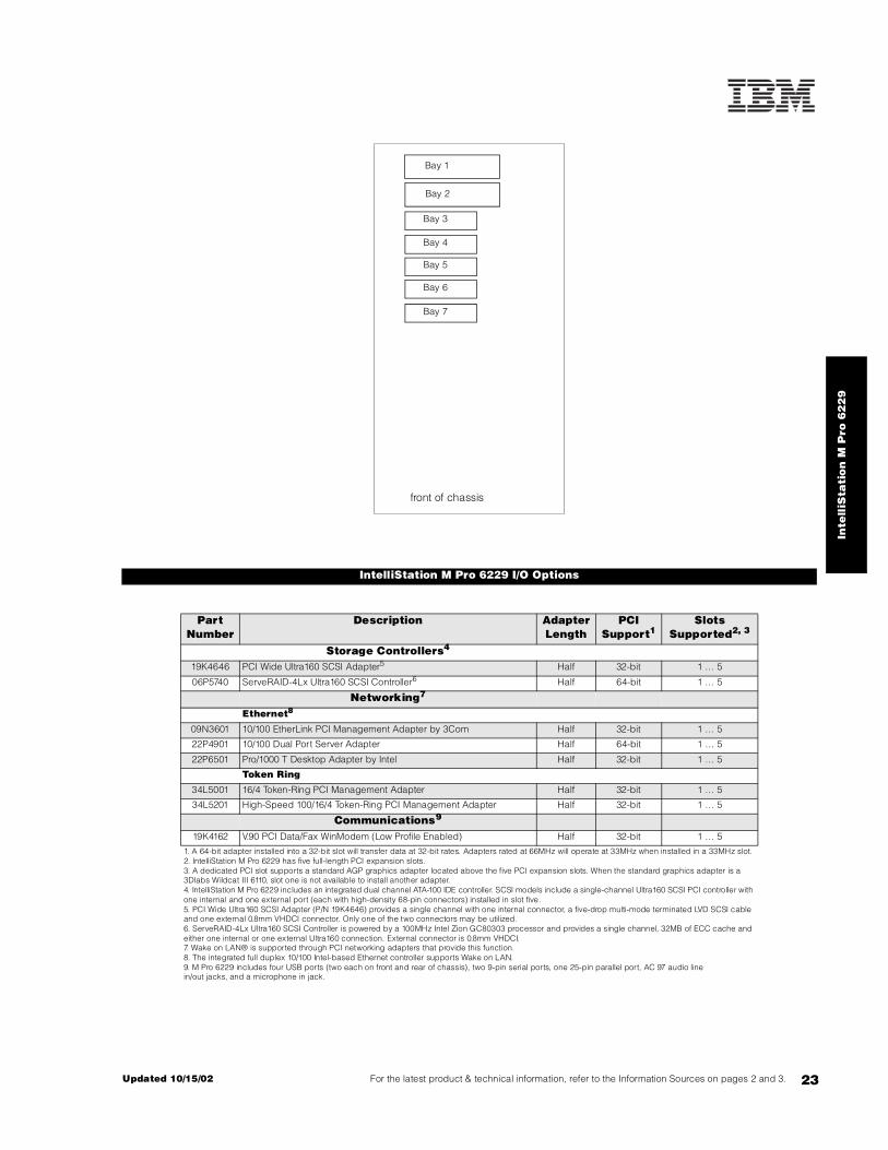
IntelliStation M Pro 6229 I/O Options
Part Number
Description Adapter Length
PCI Support1
Slots Supported2, 3
Storage Controllers4
19K4646 PCI Wide Ultra160 SCSI Adapter5 Half 32-bit 1 ... 5
06P5740 ServeRAID-4Lx Ultra160 SCSI Controller6 Half 64-bit 1 ... 5
Networking7
Ethernet8
09N3601 10/100 EtherLink PCI Management Adapter by 3Com Half 32-bit 1 ... 5
22P4901 10/100 Dual Port Server Adapter Half 64-bit 1 ... 5
22P6501 Pro/1000 T Desktop Adapter by Intel Half 32-bit 1 ... 5
Token Ring
34L5001 16/4 Token-Ring PCI Management Adapter Half 32-bit 1 ... 5
34L5201 High-Speed 100/16/4 Token-Ring PCI Management Adapter Half 32-bit 1 ... 5
Communications9
19K4162 V.90 PCI Data/Fax WinModem (Low Profile Enabled) Half 32-bit 1 ... 5
1. A 64-bit adapter installed into a 32-bit slot will transfer data at 32-bit rates. Adapters rated at 66MHz will operate at 33MHz when installed in a 33MHz slot. 2. IntelliStation M Pro 6229 has five full-length PCI expansion slots.3. A dedicated PCI slot supports a standard AGP graphics adapter located above the five PCI expansion slots. When the standard graphics adapter is a 3Dlabs Wildcat III 6110, slot one is not available to install another adapter.4. IntelliStation M Pro 6229 includes an integrated dual channel ATA-100 IDE controller. SCSI models include a single-channel Ultra160 SCSI PCI controller with one internal and one external port (each with high-density 68-pin connectors) installed in slot five.5. PCI Wide Ultra160 SCSI Adapter (P/N 19K4646) provides a single channel with one internal connector, a five-drop multi-mode terminated LVD SCSI cable and one external 0.8mm VHDCI connector. Only one of the two connectors may be utilized.6. ServeRAID-4Lx Ultra160 SCSI Controller is powered by a 100MHz Intel Zion GC80303 processor and provides a single channel, 32MB of ECC cache and either one internal or one external Ultra160 connection. External connector is 0.8mm VHDCI.7. Wake on LAN® is supported through PCI networking adapters that provide this function.8. The integrated full duplex 10/100 Intel-based Ethernet controller supports Wake on LAN.9. M Pro 6229 includes four USB ports (two each on front and rear of chassis), two 9-pin serial ports, one 25-pin parallel port, AC 97 audio linein/out jacks, and a microphone in jack.
Bay 2
Bay 4
front of chassis
Bay 5
Bay 6
Bay 7
Bay 3
Bay 1

24
IntelliStation M Pro 6229 Power, Monitors & Accessories
Part Number DescriptionPower
IntelliStation M Pro 6229 includes a 340w voltage-sensing power supply and a single line cord.
Monitors1
66274AN G78 Color Monitor 17in (406.4mm, 16in viewable image), stealth black
6657HG2 T750 Hybrid Flat Panel Color Monitor 17in (433mm, 17in viewable image), stealth black
6652U3N P275 Color Monitor 21in (503mm, 19.8in viewable image), stealth black
6639U3N P77 Color Monitor 17in (406mm, 16in viewable image), stealth black
6651U3N P97 Color Monitor 19in (457.3mm, 18in viewable image), stealth black
6656HG2 T560 Hybrid Flat Panel Monitor 15in (381mm, 15in viewable image), stealth black
9494HBO T860 Hybrid Flat Panel Monitor 18.1in (460mm, 18.1in viewable image), stealth black
9494HBN T860 Hybrid Flat Panel Monitor 18.1in (460mm, 18.1in viewable image), stealth black, w/o stand
6659HG2 T210 Flat Panel Color Monitor 20.8in (528mm, 20.8in viewable image), stealth black
Conversion Kit09N4300 4Ux20D Tower-to-Rack Kit
Keyboard and Mouse2
22P5185 Rapid Access III USB Keyboard, stealth black
33L3252 SpaceBall 3D Input Device
1. One digital monitor is supported by systems with NVIDIA Quadro2 Pro, ATI Fire GL8800 and Matrox Millennium G450 DVI video adapters. Two digital monitors are supported by systems with NVIDIA Quadro4 200NVS, ATI Fire GL4 and 3Dlabs Wildcat III 6110 video adapters. The previous generation of Matrox Millennium G450 does not support digital monitors. Digital-to-analog adapters to support analog monitors through digital video adapter connectors are shipped with the system.2. IntelliStation M Pro 6229 ships standard with an IBM 104-key keyboard and three-button mouse.
All PCI expansion slots are full-length, 32-bit, 33MHz, 5V or universal on a single PCI bus.
Slot 2
rear of chassis
Slot 3
Slot 4
Slot 5
Slot 1
AGP slot
Inte
lliS
tati
on
M P
ro 6
22
9
25For the latest product & technical information, refer to the Information Sources on pages 2 and 3.Updated 10/15/02
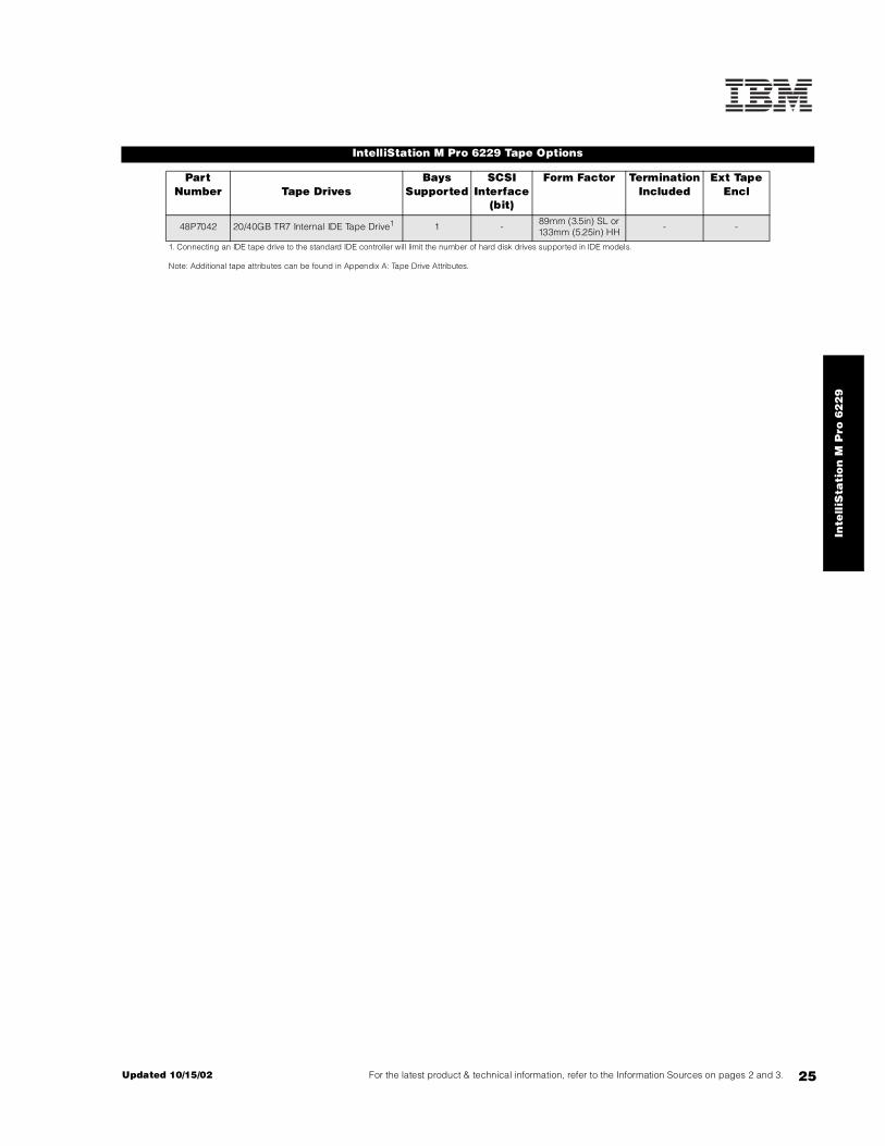
IntelliStation M Pro 6229 Tape Options
Part Number Tape Drives
Bays Supported
SCSI Interface
(bit)
Form Factor Termination Included
Ext Tape Encl
48P7042 20/40GB TR7 Internal IDE Tape Drive1 1 - 89mm (3.5in) SL or 133mm (5.25in) HH - -
1. Connecting an IDE tape drive to the standard IDE controller will limit the number of hard disk drives supported in IDE models.
Note: Additional tape attributes can be found in Appendix A: Tape Drive Attributes.

IntelliStation M Pro 6850
EMEA Part Number Cross ReferenceIntelliStation M Pro 6850 System Unit Part Numbers
EMEA AMERICAS M/C TYPE DESCRIPTION EMEAP/N P/N MODEL WDFM DATE
KDT40xx 685040U 6850-40G Xeon 2.0GHz/400MHz, 512KB, 512MB, 40GB EIDE, Matrox MilleniumG450 DVI-I, Windows 2000, Tower ---
KDTD0xx N/A 6850-D0G Xeon 2.0GHz/400MHz, 512KB, 512MB, 40GB EIDE, Matrox MilleniumG450 DVI-I, DOS 2000 Licence, Tower
---
KDT42xx 685042U 6850-42G Xeon 2.0GHz/400MHz, 512KB, 512MB, 40GB EIDE, NVIDIA Quadro4200NVS, Windows 2000, Tower
---
KDTD2xx N/A 6850-D2G Xeon 2.0GHz/400MHz, 512KB, 512MB, 40GB EIDE, NVIDIA Quadro4200NVS, DOS 2000 Licence, Tower
---
KDT43xx 685043U 6850-43G Xeon 2.0GHz/400MHz, 512KB, 512MB, 18.2GB U160, NVIDIA Quadro4200NVS, Windows 2000, Tower
---
KDTD3xx N/A 6850-D3G Xeon 2.0GHz/400MHz, 512KB, 512MB, 18.2GB U160, NVIDIA Quadro4200NVS, DOS 2000 Licence, Tower
---
KDT45xx 685045U 6850-45G Xeon 2.0GHz/400MHz, 512KB, 512MB, 18.2GB U160, ATI Fire GL8800, Windows 2000, Tower
---
KDTD5xx N/A 6850-D5G Xeon 2.0GHz/400MHz, 512KB, 512MB, 18.2GB U160, ATI Fire GL8800, DOS 2000 Licence, Tower
---
KDT46xx 685046U 6850-46G Xeon 2.0GHz/400MHz, 512KB, 512MB, 18.2GB U160, 3Dlabs WildcatIII 6110, Windows 2000, Tower ---
KDTD6xx N/A 6850-D6G Xeon 2.0GHz/400MHz, 512KB, 512MB, 18.2GB U160, 3Dlabs WildcatIII 6110, DOS 2000 Licence, Tower
---
KDT50xx N/A 6850-50G Xeon 2.2GHz/400MHz, 512KB, 512MB, 40GB EIDE, Matrox MilleniumG450 DVI-I, Windows 2000, Tower
---
KDTE0xx N/A 6850-E0G Xeon 2.2GHz/400MHz, 512KB, 512MB, 40GB EIDE, Matrox MilleniumG450 DVI-I, DOS 2000 Licence, Tower
---
KDT52xx N/A 6850-52G Xeon 2.2GHz/400MHz, 512KB, 512MB, 40GB EIDE, NVIDIA Quadro4200NVS, Windows 2000, Tower
---
KDTE2xx N/A 6850-E2G Xeon 2.2GHz/400MHz, 512KB, 512MB, 40GB EIDE, NVIDIA Quadro4200NVS, DOS 2000 Licence, Tower
---
KDT53xx N/A 6850-53G Xeon 2.2GHz/400MHz, 512KB, 512MB, 18.2GB U160, NVIDIA Quadro4200NVS, Windows 2000, Tower
---
KDTE3xx N/A 6850-E3G Xeon 2.2GHz/400MHz, 512KB, 512MB, 18.2GB U160, NVIDIA Quadro4200NVS, DOS 2000 Licence, Tower
---
KDT55xx N/A 6850-55G Xeon 2.2GHz/400MHz, 512KB, 512MB, 18.2GB U160, ATI Fire GL8800, Windows 2000, Desktop
---
KDTE5xx N/A 6850-E5G Xeon 2.2GHz/400MHz, 512KB, 512MB, 18.2GB U160, ATI Fire GL8800, DOS 2000 Licence, Tower
---
KDT56xx N/A 6850-56G Xeon 2.2GHz/400MHz, 512KB, 512MB, 18.2GB U160, 3Dlabs WildcatIII 6110, Windows 2000, Tower
---
KDTE6xx N/A 6850-E6G Xeon 2.2GHz/400MHz, 512KB, 512MB, 18.2GB U160, 3Dlabs WildcatIII 6110, DOS 2000 Licence, Tower
---
KDT60xx 685060U 6850-60G Xeon 2.4GHz/400MHz, 512KB, 512MB, 40GB EIDE, Matrox MilleniumG450 DVI-I, Windows 2000, Tower
---
KDTG0xx N/A 6850-G0G Xeon 2.4GHz/400MHz, 512KB, 512MB, 40GB EIDE, Matrox MilleniumG450 DVI-I, DOS 2000 Licence, Tower
---
KDT62xx 685062U 6850-62G Xeon 2.4GHz/400MHz, 512KB, 512MB, 40GB EIDE, NVIDIA Quadro4200NVS, Windows 2000, Tower
---
KDTG2xx N/A 6850-G2G Xeon 2.4GHz/400MHz, 512KB, 512MB, 40GB EIDE, NVIDIA Quadro4200NVS, DOS 2000 Licence, Tower
---
KDT63xx 685063U 6850-63G Xeon 2.4GHz/400MHz, 512KB, 512MB, 18.2GB U160, NVIDIA Quadro4200NVS, Windows 2000, Tower ---
KDTG3xx N/A 6850-G3G Xeon 2.4GHz/400MHz, 512KB, 512MB, 18.2GB U160, NVIDIA Quadro4200NVS, DOS 2000 Licence, Tower
---
KDT65xx 685065U 6850-65G Xeon 2.4GHz/400MHz, 512KB, 512MB, 18.2GB U160, ATI Fire GL8800, Windows 2000, Tower ---
KDTG5xx N/A 6850-G5G Xeon 2.4GHz/400MHz, 512KB, 512MB, 18.2GB U160, ATI Fire GL8800, DOS 2000 Licence, Tower
---
KDT66xx 685066U 6850-66G Xeon 2.4GHz/400MHz, 512KB, 512MB, 18.2GB U160, 3Dlabs WildcatIII 6110, Windows 2000, Tower
---
KDTG6xx N/A 6850-G6G Xeon 2.4GHz/400MHz, 512KB, 512MB, 18.2GB U160, 3Dlabs WildcatIII 6110, DOS 2000 Licence, Tower
---
KDT67xx 685067U 6850-67G Xeon 2.4GHz/400MHz, 512KB, 512MB, 18.2GB U160, NVIDIA Quadro4900XGL, Windows 2000, Tower
---
KDTG7xx N/A 6850-G7G Xeon 2.4GHz/400MHz, 512KB, 512MB, 18.2GB U160, NVIDIA Quadro4900XGL, DOS 2000 Licence, Tower
---
25A Updated 10/15/02

IntelliStation M Pro 6850
EMEA Part Number Cross ReferenceIntelliStation M Pro 6850 System Unit Part Numbers (Cont.)
EMEA AMERICAS M/C TYPE DESCRIPTION EMEAP/N P/N MODEL WDFM DATE
KDT70xx 685070U 6850-70G Xeon 2.8GHz/400MHz, 512KB, 512MB, 40GB EIDE, MatroxMillenium G450 DVI-I, Windows XP, Tower
---
KDTH0xx N/A 6850-H0G Xeon 2.8GHz/400MHz, 512KB, 512MB, 40GB EIDE, MatroxMillenium G450 DVI-I, DOS 2000 Licence, Tower
---
KDT72xx 685072U 6850-72G Xeon 2.8GHz/400MHz, 512KB, 512MB, 40GB EIDE, NVIDIAQuadro4 200NVS, Windows XP, Tower
---
KDTH2xx N/A 6850-H2G Xeon 2.8GHz/400MHz, 512KB, 512MB, 40GB EIDE, NVIDIAQuadro4 200NVS, DOS 2000 Licence, Tower
---
KDT73xx 685073U 6850-73G Xeon 2.8GHz/400MHz, 512KB, 512MB, 18.2GB U160, NVIDIAQuadro4 200NVS, Windows XP, Tower
---
KDTH3xx N/A 6850-H3G Xeon 2.8GHz/400MHz, 512KB, 512MB, 18.2GB U160, NVIDIAQuadro4 200NVS, DOS 2000 Licence, Tower
---
KDT75xx 685075U 6850-750G Xeon 2.8GHz/400MHz, 512KB, 512MB, 18.2GB U160, ATIFire GL8800, Windows XP, Tower
---
KDTH5xx N/A 6850-H5G Xeon 2.8GHz/400MHz, 512KB, 512MB, 18.2GB U160, ATIFire GL8800, DOS 2000 Licence, Tower
---
KDT76xx 685076U 6850-76G Xeon 2.8GHz/400MHz, 512KB, 512MB, 18.2GB U160, 3DlabsWildcat III 6110, Windows XP, Tower
---
KDTH6xx N/A 6850-H6G Xeon 2.8GHz/400MHz, 512KB, 512MB, 18.2GB U160, 3DlabsWildcat III 6110, DOS 2000 Licence, Tower
---
KDT77xx 685077U 6850-77G Xeon 2.8GHz/400MHz, 512KB, 512MB, 18.2GB U160, NVIDIAQuadro4 900XGL, Windows XP, Tower
---
KDTH7xx N/A 6850-H7G Xeon 2.8GHz/400MHz, 512KB, 512MB, 18.2GB U160, NVIDIAQuadro4 900XGL, DOS 2000 Licence, Tower
---
IntelliStation M Pro 6850 I/O Option Part NumbersEMEA AMERICAS M/C TYPE DESCRIPTION EMEA
P/N P/N MODEL WDFM DATEN/A 19K4162 --- V90 PCI Data/Fax WinModem (Low Profile Enabled) N/A
IntelliStation M Pro 6850 Power, Monitors & AccessoriesEMEA AMERICAS M/C TYPE DESCRIPTION EMEA
P/N P/N MODEL MONITORS WDFM DATENote 1 T274Axx 66274AN 6627-4AN G78 17" (16" viewable image) Colour Monitor (S/Black) ---
Note 1 T57HGxx 6657HG2 6657-HG2 T750 17" Hybrid Flat Panel Colour Monitor (S/Black) ---
Note 1 T52U3xx 6652U3N 6652-U3N P275 21" (19.8" viewable image) Colour Monitor (S/Black) ---
Note 1 T39U3xx 6639U3N 6639-U3N P77 17" (16" viewable image) Colour Monitor (S/Black) ---
Note 1 T1U3Nxx 6651U3N 6651-U3N P97 19" (18" viewable image) Colour Monitor (S/Black) ---
Note 1 T51U3xx 655163N 6551-63N P96 19" (17.9" viewable image) Colour Monitor (S/Black) 30/07/02
Note 1 T56HGxx 6656HG2 6656-HG2 T560 15" Flat Panel Colour Monitor (S/Black) ---
Note 1 T4HB0xx 9494HB0 9494-HB0 T860 18.1" Hybrid Flat Panel Color Monitor (S/Black) ---
Note 1 T4HBNxx 9494HBN 9494-HBN T860 18.1" Hybrid F/Panel Color Monitor w/o stand (S/B) ---
Note 1 T59HGxx 6659HG2 6659-HG2 T210 20.8" Flat Panel Colour Monitor (S/Black) ---
1. Where ‘xx’ represents a specific country code as follows: DK=Denmark, IS=Israel, IT=Italy, SD=Saudi Arabia, SA=South Africa/Pakistan, CH=Switzerland, UK=UK, EU=Europe.
IntelliStation M Pro 6850 Power, Monitors & Accessories
EMEA AMERICAS M/C TYPE DESCRIPTION EMEAP/N P/N MODEL KEYBOARD AND MOUSE WDFM DATE
Note 2 22P5xxx 22P5185 --- IBM Rapid Access III USB Keyboard with HUB ---
Note 3 22P51xx 22P5170 --- Wireless Keyboard and Mouse ---
2. Where ‘xxx’ represents a specific country code as follows: 189=Belgian/English, 190=Danish, 191=Dutch, 192=French, 193=German, 194=Greek, 195=Icelandic, 196=Italian, 197=Norwegian, 198=Spanish, 199=Swedish/Finnish, 200=Swiss, 201=UKEnglish, 202=US International, 205=Arabic, P/N 31P8769=Czech/US.
3. Where ‘xx’ represents a specific country code as follows:- 73=Danish , 74=French, 75=German, 76=Italian, 77=Spanish, 78=UK English, 79=Swedish/Finnish, 80=Belgian/UK, 82=Swiss, 70=US English
Updated 10/15/02 25B

26
IntelliStation M Pro 6850
IntelliStation M Pro 6850 At-A-Glance
6850-40U1 - 2 1/2 512 512MB/4GB Matrox Millennium G450 DVI Tower 10/100 U1603 3/1 40GB/
360GB4 48X-20X 9/6 5/5
6850-42U1 - 2 1/2 512 512MB/4GB NVIDIA Quadro4 200NVS Tower 10/100 U1603 3/1 40GB/
360GB4 48X-20X 9/6 5/5
685043U1 - 2 1/2 512 512MB/4GB NVIDIA Quadro4 200NVS Tower 10/100 U1603 3/1 18.2GB/
440.4GB5 48X-20X 9/6 5/5
6850-45U1 - 2 1/2 512 512MB/4GB ATI Fire GL8800 Tower 10/100 U1603 3/1 18.2GB/440.4GB5 48X-20X 9/6 5/5
6850-46U1 - 2 1/2 512 512MB/4GB 3Dlabs Wildcat III 6110 Tower 10/100 U1603 3/1 18.2GB/
440.4GB5 48X-20X 9/6 5/4
6850-60U1 - 2.4 1/2 512 512MB/4GB Matrox Millennium G450 DVI Tower 10/100 U1603 3/1 40GB/
360GB4 48X-20X 9/6 5/5
6850-62U1 - 2.4 1/2 512 512MB/4GB NVIDIA Quadro4 200NVS Tower 10/100 U1603 3/1 40GB/
360GB4 48X-20X 9/6 5/5
6850-63U1 - 2.4 1/2 512 512MB/4GB NVIDIA Quadro4 200NVS Tower 10/100 U1603 3/1 18.2GB/
440.4GB5 48X-20X 9/6 5/5
6850-65U1 - 2.4 1/2 512 512MB/4GB ATI Fire GL8800 Tower 10/100 U1603 3/1 18.2GB/440.4GB5 48X-20X 9/6 5/5
6850-66U1 - 2.4 1/2 512 512MB/4GB 3Dlabs Wildcat III 6110 Tower 10/100 U1603 3/1 18.2GB/
440.4GB5 48X-20X 9/6 5/4
6850-67U1 - 2.4 1/2 512 512MB/4GB NVIDIA Quadro4 900XGL Tower 10/100 U1603 3/1 18.2GB/
440.4GB5 48X-20X 9/6 5/5
6850-70U1 - 2.8 1/2 512 512MB/4GB Matrox Millennium G450 DVI Tower 10/100 U1603 3/1 40GB/
360GB4 48X-20X 9/6 5/5
6850-72U1 - 2.8 1/2 512 512MB/4GB NVIDIA Quadro4 200NVS Tower 10/100 U1603 3/1 40GB/
360GB4 48X-20X 9/6 5/5
6850-73U1 - 2.8 1/2 512 512MB/4GB NVIDIA Quadro4 200NVS Tower 10/100 U1603 3/1 18.2GB/
440.4GB5 48X-20X 9/6 5/5
6850-75U1 - 2.8 1/2 512 512MB/4GB ATI Fire GL8800 Tower 10/100 U1603 3/1 18.2GB/440.4GB5 48X-20X 9/6 5/5
6850-76U1 - 2.8 1/2 512 512MB/4GB 3Dlabs Wildcat III 6110 Tower 10/100 U1603 3/1 18.2GB/
440.4GB 48X-20X 9/6 5/4
6850-77U1 - 2.8 1/2 512 512MB/4GB NVIDIA Quadro4 900XGL Tower 10/100 U1603 3/1 18.2GB/
440.4GB5 48X-20X 9/6 5/5
1. IntelliStation M Pro 6850 ships with a keyboard and mouse. See “Power, Monitors and Accessories” for a list of compatible monitors. Tower models are rack-mountable using an optional tower-to-rack conversion kit, or they can be turned on the side and installed as desktop units capable of supporting the weight of a monitor.2. Intel Xeon™ processor with advanced transfer ECC L2 cache and 4 X 100MHz (quad-pumped) Front Side Bus (FSB).3. All models include both an integrated ATA-100 IDE controller and an integrated Ultra160 SCSI controller. The IDE controller supports up to four IDE devices (four HDDs or three IDE HDDs and one CD-ROM or IDE tape drive) in IDE models, which ship with two two-drop IDE cables. The integrated Ultra160 SCSI controller has one internal and one external port. Both ports are 68-pin, 16-bit Ultra 160 (LVD) connectors. The external port supports external Ultra160 SCSI storage devices. SCSI models include asix-drop LVD SCSI cable that supports up to six internal SCSI HDDs.4. IDE models include a two-drop ATA-100 IDE cable and a two-drop ATA-33 IDE cable. One connector of the ATA-33 cable is attached to the standard CD-ROM and the other connector can be used for an IDE HDD. Maximum storage is based on three 120GB IDE HDDs, which requires replacing the standard 40GB HDD.5. Maximum amount requires replacement of the standard 18.2GB 10,000rpm HDD with a 73.4GB HDD and installing five additional 73.4GB HDDs.6. Variable read rate. Actual playback speed will vary and is often less than the maximum possible.
Part Number
Withdrawal D
ate7
Processor Speed (G
Hz)2
Number of P
rocessors (Std/M
ax)
L2 ECC Cache (KB)
Memory (Std/M
ax)
Video Adapter
Form Factor
Onboard Ethernet (Mbps)
SCSI Contro
ller (D
ual, Ultr
a, RAID)
Removable Media Bays (T
otal/Avail)
Internal Hard Disk Driv
e (Std/M
ax)
CD-ROM (ID
E)6
Bays (Total/A
vail)
Slots (Total/A
vail)

27For the latest product & technical information, refer to the Information Sources on pages 2 and 3.Updated 10/15/02
Inte
lliS
tati
on
M P
ro 6
85
0
IntelliStation M Pro 6850 Processors
Part Number
Processor Upgrades SMP Support1
25P2653 2GHz 512KB Cache Xeon Second Processor for 6850 4xU
32P8586 2.2GHz 512KB Cache Xeon Second Processor for 6850 5xU
24P7456 2.4GHz 512KB Cache Xeon Second Processor for 6850 6xU
24P7470 2.8GHz 400MHz FSB 512KB Cache Xeon Second Processor for 6850 7xU
1. One additional processor may be installed, providing a maximum of two. All processors must be identical in type, speed, and cache size.
IntelliStation M Pro 6850 Memory
Total System Memory1
Quantity of RIMMs Added
256MB (2 x 128) Models
512MB(2 x 256) Models
128MB (31P8431)
256MB (31P8433)
512MB (31P8435)
512MB 768MB 2 - -
768MB 1024MB 4 - -
1024MB 1280MB 6 - -
Part Number
Memory Description11280MB 1536MB 4 2 -
31P8431 128MB PC800 4D ECC RDRAM RIMM (288Mb) 1792MB 2048MB 4 - 2
31P8433 256MB PC800 8D ECC RDRAM RIMM (288Mb) 2304MB 2560MB - 4 2
31P8435 512MB PC800 16D ECC RDRAM RIMM (288Mb) 2560MB 2816MB 2 - 4
1. Memory RIMMs must be installed in pairs using the same option part number according to the following order: RIMM connectors one and two, three and four, five and six, and seven and eight
2816MB 3072MB - 2 4
3328MB 3584MB - - 6
. 4GB (max)2 4GB (max)2 - - 8
This table does not represent all possible memory configurations. Memory modules may vary in price per MB. Selection of smaller RIMMs may provide a more cost-effective alternative to using larger RIMMs.1. Network operating systems may limit the maximum amount of addressable memory. See operating system specifications for further information.2. Requires replacing the standard RIMM.
RIMM 5
RIMM 7
RIMM 3
RIMM 1
RIMM 2
RIMM 4
RIMM 8
RIMM 6

28
IntelliStation M Pro 6850 Hard Disk Drive (HDD) Storage
SCSI ModelsTotal Int Storage1
10,000RPM HDDs 15,000RPM HDDs18.2GB
(06P5750)36.4GB
(06P5751)73.4GB
(06P5752)18.2GB
(06P5765)36.4GB
(06P5766)
18.2GB (Standard on SCSI models)
36.4GB 1 - - 1 -
54.6GB 2 - - 2 -
72.8GB 3 - - 3 -
91GB 4 - - 4 -
109.2GB 5 - - 5 -
127.4GB 4 1 - 4 1
145.6GB 3 2 - 3 2
163.8GB 2 3 - 2 3
182GB 1 4 - 1 4
200.2GB - 5 - - 5
237.2GB - 4 1 - -
274.2GB - 3 2 - -
311.2GB - 2 3 - -
348.2GB - 1 4 - -
385.2GB - - 5 - -
440.4GB2 - - 6 - -
This table does not represent all possible HDD configurations.
1. Select a total storage row then add the quantity of HDDs from all columns within an RPM range to the standard HDD.2. Requires replacement of the standard HDD.
EIDE ModelsTotal Internal
Storage17200RPM EIDE HDDs2
20.4GB(P/N 19K4461)
40GB (P/N 22P7157)
60GB(P/N 09N4207)
80GB(P/N 09N4226)
120GB(09N4231)
40GB Standard on EIDE models
60.4GB 1 - - - -
80GB - 1 - - -
100GB - - 1 - -
120GB - 2 - - -
140GB - 1 1 - -
160GB - - 2 - -
180GB3 - - 3 - -
240GB4 - - 4 -
280GB3 - - - 3
320GB4 - - - 4
360GB4 - - - 3 1
400GB4 - - - 2 2
440GB4 - - - 1 3
480GB4 - - - - 4
This table does not represent all possible HDD configurations.Total Internal Storage listed is within +/-0.2GB unless otherwise noted.
1. Select a total storage row then add the quantity of HDDs to the standard HDD.2. Supports a maximum of four IDE devices including CD-ROM drives, HDDs and IDE tape drives.3. Requires replacing the standard HDD.4. Requires replacing the standard HDD and disconnecting the CD-ROM.

29For the latest product & technical information, refer to the Information Sources on pages 2 and 3.Updated 10/15/02
Inte
lliS
tati
on
M P
ro 6
85
0
Bay Form Factor
Height Front Access
Usage Part Number
Description RPM Height Bays Supported3
Max Qty
1 133mm (5.25in) HH yes open1 IDE HDD1, 2
2 133mm (5.25in) HH yes CD-ROM 19K4461 20.4GB 7200rpm ATA-100 (EIDE) HDD 7200 SL 4 ... 9 4
3 89mm (3.5in) SL yes Diskette 22P7157 40GB 7200rpm ATA-100 (EIDE) HDD 7200 SL 4 ... 9 4
4 ... 8 89mm (3.5in) SL no open2 09N4207 60GB 7200rpm ATA-100 (EIDE) HDD 7200 SL 4 ... 9 4
9 89mm (3.5in) SL no Std HDD3 09N4226 80GB 7200rpm ATA-100 (EIDE) HDD 7200 SL 4 ... 9 4
1. Supports removable media devices only. Hard disk drives are not supported.2. Maximum of six SCSI HDDs supported in SCSI models and a maximum of three IDE HDDs supported without disconnecting the CD-ROM drive in IDE models.3. The standard IDE HDD is installed in bay five in IDE models.
09N4231 120GB 7200rpm ATA-100 (EIDE) HDD 7200 SL 4 ... 9 4
Ultra160 HDDs2, 4
06P5750 18.2GB 10Krpm Ultra160 SCSI SL HDD 10000 SL 4 ... 9 6
06P5751 36.4GB 10Krpm Ultra160 SCSI SL HDD 10000 SL 4 ... 9 6
06P5752 73.4GB 10Krpm Ultra160 SCSI SL HDD 10000 SL 4 ... 9 6
06P5765 18.2GB 15Krpm Ultra160 SCSI SL HDD 15000 SL 4 ... 9 6
06P5766 36.4GB 15Krpm Ultra160 SCSI SL HDD 15000 SL 4 ... 9 6
Removable Media DevicesBays
Supported10K3782 48X-20X IDE CD-ROM5 1, 2
10K3790 8X-4X-32X-8X Max CD-RW/DVD-ROM Combination Drive5, 6 1, 2
22P6950 16X Max RAM-Read DVD-ROM Drive5, 6 1, 2
00N8078 250MB IDE Internal Zip Drive7 1, 2
1. IDE models support a maximum of four IDE devices including CD-ROM drives, IDE hard disk drives and IDE tape drives.2. Mixing of IDE and SCSI hard disk drives is not supported. 3. Standard HDD installed in bay nine for SCSI models and bay five for IDE models.4. SCSI models support a maximum of six SCSI HDDs.5. Either replace the standard CD-ROM or install in the available media bay. An IDE cable with three connectors is included with the optional optical drive. The included audio cable must be connected in order to support audio for music CDs but not for DVD-ROM.6. DVD video playback is not supported for models that include a 3Dlabs Wildcat III 6110 video adapter.7. Hardware for converting a 5.25in bay to 3.5in is included with the option.
IntelliStation M Pro 6850 I/O Options
Dis
kette
Bay 1
CD-ROM
Bay 9
Bay 7
Bay 6
Bay 5
Bay 4
Bay 8
AGP Pro adapter
Slot 4: 66MHz, 64-bit, 3.3v or universal
Slot 5: 66MHz, 64-bit, 3.3v or universal
Slot 3: 33MHz, 32-bit, 5v or universal
Slot 2: 33MHz, 32-bit, 5v or universal
Slot 1: 33MHz, 32-bit, 5v or universal
All slots are full-length.
rear of chassis
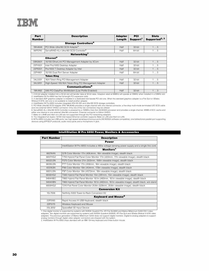
30
Part Number
Description Adapter Length
PCI Support1
Slots Supported2, 3
Storage Controllers4
19K4646 PCI Wide Ultra160 SCSI Adapter5 Half 32-bit 1 . .. 5
06P5740 ServeRAID-4Lx Ultra160 SCSI Controller6 Half 64-bit 1 . .. 5
Networking7
Ethernet8
09N3601 10/100 EtherLink PCI Management Adapter by 3Com Half 32-bit 1 . .. 5
22P4501 Intel Pro/100S Desktop Adapter Half 32-bit 1 . .. 5
22P6501 Pro/1000 T Desktop Adapter by Intel Half 32-bit 1 . .. 5
22P4901 10/100 Dual Port Server Adapter Half 64-bit 1 . .. 5
Token Ring
34L5001 16/4 Token-Ring PCI Management Adapter Half 32-bit 1 . .. 5
34L5201 High-Speed 100/16/4 Token-Ring PCI Management Adapter Half 32-bit 1 . .. 5
Communications9
19K4162 V.90 PCI Data/Fax WinModem (Low Profile Enabled) Half 32-bit 1 . .. 3
1. A 64-bit adapter installed into a 32-bit slot will transfer data at 32-bit rates. Adapters rated at 66MHz will operate at 33MHz when installed in a 33MHz slot. 2. IntelliStation M Pro 6850 has five full-length PCI expansion slots.3. A standard AGP graphics adapter is installed in a dedicated slot beside PCI slot one. When the standard graphics adapter is a Fire GL4 or 3Dlabs Wildcat III 6110, slot one is not available to install another adapter.4. IntelliStation M Pro 6850 includes integrated ATA-100 IDE and Ultra160 SCSI storage controllers.5. PCI Wide Ultra160 SCSI Adapter (P/N 19K4646) provides a single channel with one internal connector, a five-drop multi-mode terminated LVD SCSI cable and one external 0.8mm VHDCI connector. Only one of the two connectors may be utilized.6. ServeRAID-4Lx Ultra160 SCSI Controller is powered by a 100MHz Intel Zion GC80303 processor and provides a single channel, 32MB of ECC cache and either one internal or one external Ultra160 connection. External connector is 0.8mm VHDCI.7. Wake on LAN® and Alert-on-LAN are not supported through the PCI networking adapters.8. The integrated full duplex 10/100 Intel-based Ethernet controller supports Wake on LAN and Alert-on-LAN.9. M Pro 6850 includes two USB ports, two high-speed serial/asynchronous ports (NS16550A software compatible), one bidirectional parallel port supporting devices using EPP/ECP protocols, audio in/out jacks and a microphone in jack.
IntelliStation M Pro 6850 Power, Monitors & Accessories
Part Number DescriptionPower
IntelliStation M Pro 6850 includes a 480w voltage-sensing power supply and a single line cord.
Monitors1
66274AN G78 Color Monitor 17in (406.4mm, 16in viewable image), stealth black
6657HG2 T750 Hybrid Flat Panel Color Monitor 17in (433mm, 17in viewable image), stealth black
6652U3N P275 Color Monitor 21in (503mm, 19.8in viewable image), stealth black
6639U3N P77 Color Monitor 17in (406mm, 16in viewable image), stealth black
655163N P96 Color Monitor 19in (454mm, 17.9in viewable image), stealth black
6651U3N P97 Color Monitor 19in (457.3mm, 18in viewable image), stealth black
6656HG2 T560 Hybrid Flat Panel Monitor 15in (381mm, 15in viewable image), stealth black
9494HBO T860 Hybrid Flat Panel Monitor 18.1in (460mm, 18.1in viewable image), stealth black
9494HBN T860 Hybrid Flat Panel Monitor 18.1in (460mm, 18.1in viewable image), stealth black, w/o stand
6659HG2 T210 Flat Panel Color Monitor 20.8in (528mm, 20.8in viewable image), stealth black
Conversion Kit10L7006 Netfinity 5000 Tower-to-Rack Conversion Kit
Keyboard and Mouse2
22P5185 Rapid Access III USB Keyboard, stealth black
22P5170 Wireless Keyboard and Mouse
33L3252 SpaceBall 3D Input Device
1. One digital monitor is supported by systems with NVIDIA Quadro2 Pro, ATI Fire GL8800 and Matrox Millennium G450 DVI-I video adapters. Two digital monitors are supported by systems with NVIDIA Quadro4 200NVS, ATI Fire GL4 and 3Dlabs Wildcat III 6110 video adapters. The previous generation of Matrox Millennium G450 does not support digital monitors. Digital-to-analog adapters to support analog monitors through digital video adapter connectors are shipped with the system.2. IntelliStation M Pro 6850 ships standard with an IBM 104-key keyboard and three-button mouse.

31For the latest product & technical information, refer to the Information Sources on pages 2 and 3.Updated 10/15/02
Inte
lliS
tati
on
M P
ro 6
85
0
IntelliStation M Pro 6850 Tape Options
Part Number Tape Drives
Bays Supported
SCSI Interface
(bit)
Form Factor Termination Included
Ext Tape Encl
48P7042 20/40GB TR7 Internal IDE Tape Drive 1 - 89mm (3.5in) SL or 133mm (5.25in) HH - -
Note: Additional tape attributes can be found in Appendix A: Tape Drive Attributes.
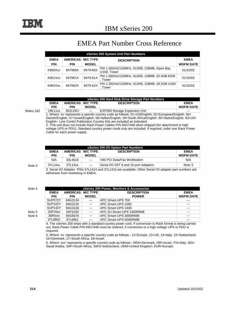
IBM xSeries 200
EMEA Part Number Cross ReferencexSeries 200 System Unit Part Numbers
EMEA AMERICAS M/C TYPE DESCRIPTION EMEAP/N P/N MODEL WDFM DATE
K960Xxx 847960X 8479-60X PIII 1.26GHz/133MHz, 512KB, 128MB, Open BayU160, Tower 01/10/02
K961Xxx 847961X 8479-61X PIII 1.26GHz/133MHz, 512KB, 128MB, 20.4GB EIDE, Tower 01/10/02
K962Xxx 847962X 8479-62X PIII 1.26GHz/133MHz, 512KB, 128MB, 18.2GB U160, Tower 01/10/02
xSeries 200 Hard Disk Drive Storage Part NumbersEMEA AMERICAS M/C TYPE DESCRIPTION EMEA
P/N P/N MODEL WDFM DATENotes 1&2 19K11xx 35311RU --- EXP300 Storage Expansion Unit ---
1. Where ‘xx’ represents a specific country code as follows: 51=US/English, 52=European/English, 56=Danish/English, 57=Israel/English, 58=Italian/English, 59=South Africa/English, 60=Swiss/English, 63=UK/English:- Line Cords/ Publication Country Kits are included as indicated.2. This unit does not include Rack Power Cables P/N 94G7448 when shipped (for attachment to highvoltage UPS or PDU). Standard country power cords only are included. If required, order one Rack PowerCable for each power supply.
xSeries 200 I/O Option Part NumbersEMEA AMERICAS M/C TYPE DESCRIPTION EMEA
P/N P/N MODEL WDFM DATEN/A 33L4618 --- V90 PCI Data/Fax WinModem N/A
Note 3 37L14xx 37L14xx --- Serial I/O SST 8 and 16 port Adapters Note 33. Serial I/O Adapter P/Ns 37L1414 and 37L1415 are available. Other Serial I/O adapter part numbers arewithdrawn from marketing in EMEA.
Note 4 xSeries 200 Power, Monitors & AccessoriesEMEA AMERICAS M/C TYPE DESCRIPTION EMEA
P/N P/N MODEL POWER WDFM DATESUP072Y 94G3134 --- APC Smart-UPS 700 ---SUP102Y 94G3135 --- APC Smart-UPS 1000 ---SUP142Y 94G3136 --- APC Smart-UPS 1400 ---
Note 5 32P16xx 32P1020 --- APC 2U Smart-UPS 1400RMiB ---Note 6 30RIxxx 94G6676 --- APC Smart-UPS 3000RMiB ---
37L6862 37L6861 --- APC Smart-UPS 5000RMiB ---4. The xSeries 200 ships with a standard country power cord. If conversion to Rack format is being carriedout, Rack Power Cable P/N 94G7448 must be ordered, if connection to a high voltage UPS or PDU isrequired.5. Where ‘xx’ represents a specific country code as follows:- 12=Europe, 13=UK, 14=Italy, 15=Switzerland,16=Denmark, 17=South Africa, 18=Israel.6. Where ‘xxx’ represents a specific country code as follows:- DEN=Denmark, ISR=Israel, ITA=Italy, SDI=Saudi Arabia, SAF=South Africa, SWS=Switzerland, UKM=United Kingdom, EUR=Europe.
31A Updated 10/15/02

IBM xSeries 200
EMEA Part Number Cross ReferencexSeries 200 Power, Monitors & Accessories
EMEA AMERICAS M/C TYPE DESCRIPTION EMEAP/N P/N MODEL MONITORS WDFM DATE
Note 7 T3147xx 633147N 6331-47N E54 15" (13.8" viewable image) Colour Monitor (S/Blac ---Note 7 T3247xx 63324HN 6332-4HN E74 17" (16" viewable image) Colour Monitor (S/Black) ---Note 7 T274Axx 66274AN 6627-4AN G78 17" (16" viewable image) Colour Monitor (S/Black ---Note 7 T12ABxx 9512AB1 9512-AB1 T541 15" Flat Panel Colour Monitor (S/Black) ---
N/A 32P1031 --- NetBAY 1U Flat Panel Monitor Console Kit (with US ke N/AN/A 32P1702 --- NetBAY 2U Flat Panel Monitor Console Kit (with US ke N/A
7. Where ‘xx’ represents a specific country code as follows: DK=Denmark, IS=Israel, IT=Italy, SD=SaudiArabia, SA=South Africa/Pakistan, CH=Switzerland, UK=UK, EU=Europe.
xSeries 200 Power, Monitors & Accessories
EMEA AMERICAS M/C TYPE DESCRIPTION EMEAP/N P/N MODEL KEYBOARD AND MOUSE WDFM DATE
Note 8 28L36xx 28L3644 --- Spacesaver II Keyboard ---Note 9 10K38xx 10K3849 --- 106-key Preferred USB Keyb. with 2-port USB Hub (S/ ---
28L3675 28L3673 --- Sleek 2-button Mouse (S/Black) ---8. Where ‘xx’ represents a specific country code as follows:- 46=Danish , 47=French, 48=German, 49=Italian, 50=Spanish, 51=UK English, 44=US English, and P/N 19K3831=Swiss, 19K3832=Swedish/Finnish,19K3833=Portugese, 19K3834=Belgian, 19K3836=Russian, 19K3837=Polish.9. Where ‘xx’ represents a specific country code as follows:- 53=Danish , 54=Dutch, 55=France, 56=Germany, 57=Italian, 58=Norwegian, 59=Swedish/Finnish, 10K2343=Swiss, 10K2344=UK English, 10K2345=US ISO.
xSeries 200 Tape OptionsEMEA AMERICAS M/C TYPE DESCRIPTION EMEA
P/N P/N MODEL WDFM DATE10L7440 3510020 --- External Half High SCSI Storage Enclosure ---03K8756 3551001 --- NetMEDIA Storage Expansion Unit EL ---
Updated 10/15/02 31B

32
IBM xSeries 200
xSeries 200 At-A-Glance
8479-60X1 1.26GHz 1/1 512 128MB/1.5GB Tower 1/1 - - - 10/100 U1602 4/2 0/293.6GB 48X-20X 7/5 5/4
8479-61X1 1.26GHz 1/1 512 128MB/1.5GB Tower 1/1 - - - 10/100 IDE 4/2 20.4GB/360GB3 48X-20X 7/4 5/5
8479-62X1, 4 1.26GHz 1/1 512 128MB/1.5GB Tower 1/1 - - - 10/100 U1602 4/2 18.2GB/293.6GB3 48X-20X 7/4 5/4
1. Includes Intel Pentium III processor with advanced transfer L2 cache and 133MHz FSB.2. Includes a single-channel, 32-bit Ultra160 SCSI PCI storage adapter installed in slot three.3. Maximum capacity assumes replacement of standard hard disk drives with the largest supported IBM hard disk drive.4. Not available in the United States.
xSeries 200 Memory
Total System Memory
(Standard Models)1
DIMMs
128MB(1 x 128)
128MB(33L3081)
256MB(33L3083)
512MB(33L3085)
192MB - - -
256MB 1 - -
384MB 2 or 1 -
Part Number
Memory Description640MB - 2 or 1
33L3081 128MB 133MHz ECC SDRAM Unbuffered DIMM Memory 768MB2 - 3 -
33L3083 256MB 133MHz ECC SDRAM Unbuffered DIMM Memory 1152MB - - 2
33L3085 512MB 133MHz ECC SDRAM Unbuffered DIMM Memory 1536MB2 - - 3
This table does not represent all possible memory configurations. Memory modules may vary in price per MB. Selection of smaller DIMMs may provide a more cost-effective alternative to using larger DIMMs. Select the desired total memory, then select a quantity in that row from one of the DIMM columns.
1. Network operating systems may limit the maximum amount of addressable memory. See operating system specifications for further information.2. Requires removal of standard DIMMs.
Part Number
Processor Speed
Number of P
rocessors (Std/M
ax)
L2 ECC Cache (KB)
Memory (Std/M
ax)
Form Factor
Power Supply Quantity
(Std/M
ax)
Hot-Swap (P
ower, Slots, H
DD, Fans)
Redundancy (Optio
nal, Standard)
Adv System Management P
rocessor
Onboard Ethernet (Mbps)
SCSI Contro
ller (D
ual, Ultr
a, RAID)
Removable Media Bays (T
otal/Avail)
Internal Hard Disk Driv
e (Std/M
ax)
CD-ROM (IDE)
Bays (Total/A
vail)
Slots (Total/A
vail)
DIMM Socket
DIMM Socket
DIMM Socket

33For the latest product & technical information, refer to the Information Sources on pages 2 and 3.Updated 10/15/02
IBM
xS
eri
es 2
00
EIDE ModelsIn xSeries 200 models using the EIDE interface for storage device attachment, a two-drop cable is used to attach the standard EIDE HDD to one of the EIDE connectors. A second EIDE controller provides the interface for the IDE CD-ROM drive. A two-drop cable connects the IDE controller to the IDE CD-ROM. Up to two additional IDE devices can be installed (one off of each controller).
SCSI ModelsxSeries 200 models with a SCSI adapter are cabled internally with a five-drop, 16-bit wide LVD SCSI cable with a built-in multi-mode active terminator at one end of the cable. The other end of the cable is attached to the internal 68-pin connector of the standard Ultra160 SCSI adapter. SCSI devices can be connected to any of the five cable connectors. If 8-bit (narrow) devices are to be installed, a 68- to 50-pin converter (32G3925) is required for each narrow device.
Other Configuration AlternativesIn the case where a RAID controller is used to support internal drives in an xSeries 200, the standard cable is moved from the standard PCI storage controller to the RAID adapter. To connect a tape drive to the standard SCSI controller, use the 16-bit multi-mode terminated, two-drop SCSI cable included with optional Media Bay Tray and LVD Cable Kit (P/N 10K2340) unless the tape option includes a terminated SCSI cable.
External SCSI support can be obtained by installing an optional SCSI adapter or RAID controller and using appropriate external SCSI cabling.
For additional information regarding internal cabling, refer to Appendix F: Internal Cabling Overview.
xSeries 200 Internal SCSI Cabling
xSeries 200 Hard Disk Drive (HDD)
Total Internal Storage1
10,000rpm SCSI HDDs 15,000rpm SCSI HDDs18.2GB
(06P5750)36.4GB
(06P5751)73.4GB
(06P5752)18.2GB
(06P5765)36.4GB
(06P5766)0GB Standard on some base models
18.2GB 1 - - 1
36.4GB 2 1 - 2 1
54.6GB 3 - - 3 -
72.8GB 4 2 - 4 2
109.2GB - 3 - - 3
145.6GB - 4 - - 4
146.8GB - - 2 - -
220.2GB - - 3 - -
293.6GB (Max) - - 4 - -This table does not represent all possible HDD configurations.Total Internal Storage listed is within +/-0.2GB unless otherwise noted.1. Select a total storage row then select the quantity of HDDs from a column corresponding to the HDD of choice.
Total Internal Storage1
7200rpm IDE HDDs2
20.4GB(19K4461)
30GB (00N8203)
40GB (22P7157)
60GB(09N4207)
80GB(09N4226)
120GB(09N4231)
20.4GB Std on IDE models
40.8GB 1 - - - - -
50.4GB - 1 - - - -
60.4GB - - 1 - - -
61.2GB 2 - - - - -
80.4GB - 2 - - - -
100.4GB - - 2 - - -
120GB3 - - 3 - - -
140.4GB - - - 2 - -
180GB3 - - - 3 - -
180.4GB - - - - 2 -
240GB3 - - - - 3 -
280GB3 - - - - 2 1
320GB3 - - - - 1 2
360GB3 - - - - - 3
This table does not represent all possible HDD configurations.Total Internal Storage listed is within +/-0.2GB unless otherwise noted.
1. Select a total storage row then add the quantity of HDDs from all columns to the standard HDD. 2. The two EIDE controllers support a maximum of four IDE devices per machine including CD-ROM drives, HDDs and IDE tape drives.3. Requires removal of the standard HDD.
Bay 4
CD-ROM
Bay 2
Diskette
Bay 5
Bay 6
Bay 7

34
Bay Form Factor
Height Front Access
Usage Part Number
Description RPM Height Bays Supported
Max Qty
1 133mm (5.25in) HH yes IDE CD-
ROMIDE HDDs1, 2
2 133mm (5.25in) HH yes open1 19K4461 20.4GB 7200rpm ATA-100 (EIDE) HDD 7200 SL 4 ... 7 3
3 89mm (3.5in) SL yes Diskette 00N8203 30GB 7200rpm ATA-100 (EIDE) HDD 7200 SL 4 ... 7 3
4 89mm(3.5in) SL yes open 22P7157 40GB 7200rpm ATA-100 (EIDE) HDD 7200 SL 4 ... 7 3
5 ... 7 89mm(3.5in) SL no open 09N4207 60GB 7200rpm ATA-100 (EIDE) HDD 7200 SL 4 ... 7 3
1. Supports removable media devices only. Hard disk drives are not supported. 09N4226 80GB 7200rpm ATA-100 (EIDE) HDD 7200 SL 4 ... 7 3
09N4231 120GB 7200rpm ATA-100 (EIDE) HDD 7200 SL 4 ... 7 3
Ultra160 HDDs2
06P5750 18.2GB 10Krpm Ultra160 SCSI SL HDD 10000 SL 4 ... 7 4
06P5751 36.4GB 10Krpm Ultra160 SCSI SL HDD 10000 SL 4 ... 7 4
06P5752 73.4GB 10Krpm Ultra160 SCSI SL HDD 10000 SL 4 ... 7 4
06P5765 18.2GB 15Krpm Ultra160 SCSI SL HDD 15000 SL 4 ... 7 4
06P5766 36.4GB 15Krpm Ultra160 SCSI SL HDD 15000 SL 4 ... 7 4
Optical Devices Bays Supported22P6950 16X Max RAM-Read DVD-ROM Drive3, 4 1, 2
22P6976 40x-12x-40x Max Black CD-RW Drive3 1, 2
External Storage Expansion Units5 Form Factor
35311RU EXP300 Storage Expansion Unit6 Rack (3U)
09N7296 EXP300 Rack-to-Tower Conversion Kit -1.The xSeries 200 EIDE controllers support a maximum of four IDE devices per machine including CD-ROM drives, HDDs and IDE tape drives.2. Mixing of internal IDE and SCSI HDDs is not supported.3. Either replace the standard CD-ROM or install in the available media bay. An IDE cable with three connectors is included with the optional optical drive (same cable is provided standard in the system). If installing as an additional device, connect the cable to each optical device and the IDE connector on the system board. Configure the optional device as a master using the preset configuration if replacing the standard device or as a slave if installed as a redundant device.4. Audio not supported for DVD-ROM drives. The drive provides data input/output only.5. Not supported by the external SCSI port included in SCSI models. Select an optional SCSI controller then refer to Appendix D: Cables - Storage Unit - Controllers to confirm the controller supports the desired External Storage Expansion Unit and to select a supported cable. For HDD or other expansion unit options, see the specific expansion unit section.6. EXP300 includes a single 2M Ultra2 SCSI cable and dual hot-swap 500W redundant power supplies, each with its own power cord. To convert an EXP300 to a tower form factor, EXP300 Rack-to-Tower Conversion Kit (P/N 09N7296) is required.

35For the latest product & technical information, refer to the Information Sources on pages 2 and 3.Updated 10/15/02
IBM
xS
eri
es 2
00
xSeries 200 I/O Options
Part Number
Description Adapter Length
PCI Support1
Slots Supported2, 3
-
Storage Controllers4, 5
06P5736 ServeRAID-4Mx Ultra160 SCSI Controller6 Full 64-bit 2 ... 5
06P5740 ServeRAID-4Lx Ultra160 SCSI Controller7 Half 64-bit 2 ... 5
19K4646 PCI Wide Ultra160 SCSI Adapter8 Half 32-bit 2 ... 5
02K3454 PCI Fast/Wide Ultra SCSI Adapter9 Half 32-bit 2 ... 5
Networking10
Ethernet11
09N9901 10/100 EtherLink Server Adapter by 3Com12 Half 32-bit 1 ... 5
06P3601 10/100 Ethernet Server Adapter12 Half 32-bit 1 ... 5
22P4901 10/100 Dual Port Server Adapter12 Half 64-bit 1 ... 5
22P6801 PRO/1000XT Server Adapter by Intel (copper) w/CD, manuals12 Half 64-bit 1 ... 5
22P7801 NetXtreme 1000 SX Fiber Ethernet Adapter Half 64-bit 1 ... 5
Token Ring
34L5001 16/4 Token-Ring PCI Management Adapter12 Half 32-bit 1 ... 5
34L5201 High-Speed 100/16/4 Token-Ring PCI Management Adapter12 Half 32-bit 1 ... 5
Communications13
33L4618 V.90 PCI Data/Fax Modem Half 32-bit 2 ... 5
37L14xx Serial I/O SST 8- and 16-port adapters14 Half 32-bit 2 ... 5
1. A 64-bit adapter installed into a 32-bit slot will transfer data at 32-bit rates. Adapters rated at 66MHz will operate at 33MHz when installed in a 33MHz slot. 2. The xSeries 200 has five full-length, 33MHz PCI expansion slots. The number of available slots is model specific.3. The Ultra160 SCSI controller shipped standard in SCSI models is installed in slot two.4. xSeries 200 SCSI models include a standard single-channel Ultra160 SCSI adapter with a five-drop, multimode terminated LVD SCSI Cable. All models include dual IDE connectors. IDE models require an optional SCSI PCI adapter for SCSI functionality. See At-A-Glance for model attributes5. Storage controllers are supported in slots two through five only. When a bootable SCSI device (a SCSI storage controller attached to the boot HDD) such as the standard SCSI PCI controller in SCSI models or an optional RAID controller are installed with a second storage controller, they should be installed in slots two and four or slots three and five (standard SCSI adapter is installed in slot two). Networking adapters would then be installed in slots one, three or five. Networking and internal storage adapters cannot share slots two and four (paired) or three and five (paired). If a bootable SCSI device is not installed in any PCI slot, then pairing restrictions do not apply. 6. ServeRAID-4Mx Ultra160 SCSI Controller is powered by a 100MHz Intel Zion GC80303 processor that provides 64MB of battery-backed ECC cache and two internal and two external Ultra160 connections (only two connectors may be used). External connections are 0.8mm VHDCI.7. ServeRAID-4Lx Ultra160 SCSI Controller is powered by a 100MHz Intel Zion GC80303 processor and provides a single channel, 32MB of ECC cache and either one internal or one external Ultra160 connection. External connectior is 0.8mm VHDCI.8. PCI Wide Ultra160 SCSI Adapter (P/N 19K4646) provides a single channel with one internal connector, a five-drop multi-mode terminated LVD SCSI cable and one external 0.8mm VHDCI connector. Only one of the two connectors may be utilized.9. PCI Fast/Wide Ultra SCSI Adapter (P/N 02K3454) provides one external 68-pin high density connector that supports external SCSI devices such as tape enclosures. The adapter includes 8- and 16-bit internal SCSI connectors. Only one connector can be used at a time. A 16-bit terminated UltraSCSI internal cable is included.10. xSeries 200 includes an integrated full-duplex, 10/100Mbps copper-based Intel Ethernet controller. Networking adapters are supported in slots one through five. Slots two and four or slots three and five cannot share a networking adapter with a bootable SCSI controller.11. In a fault-tolerant networking environment, using the fault-tolerant software delivered with the Ethernet adapters of a single manufacturer is recommended. Installing fault-tolerant solutions provided by multiple manufacturers may cause failures if the intermediate drivers provided with the adapters are not compatible. Three optional Ethernet adapters are copper and Intel-based (P/N 06P3601, 22P4901, 22P6801). One is Broadcom-based (P/N 22P7801).12. Wake on LAN is supported for this option when installed in slots one through five. Networking adapters cannot share slots two and four (paired) or three and five (paired) with a SCSI controller attached to a boot HDD.13. xSeries 200 includes two USB ports, two high-speed serial/asynchronous ports (NS16550A software compatible) and one high-speed parallel port supporting devices usingSSP/EPP/ECP protocols adhering to the IEEE 1284 Standard.7. 14. See Appendix E for details on Serial I/O options and configuration limitations.
Slo
t 4-
33 M
Hz,
32-
bit,
5 V
or
Uni
vers
al
Slo
t 5-
33 M
Hz,
32-
bit,
5 V
or
Uni
vers
al
All
Slo
ts-F
ull L
eng
th
Slo
t 1-
33 M
Hz,
32-
bit,
5 V
or
Uni
vers
al
Slo
t 3-
33 M
Hz,
32-
bit,
5 V
or
Uni
vers
al
External Connector Access
S3
AG
P v
ideo
ad
apte
r1
1. xSeries 200 ships standard with an AGP video adapter. Alternate video adapters are not supported.
Slo
t 2-
33 M
Hz,
32-
bit,
5 V
or
Uni
vers
al
36
xSeries 200 Power, Monitors & Accessories
Part Number DescriptionPower1
Tower Uninterruptible Power Supply (UPS)2
94G3134 APC Smart-UPS 7003
94G3135 APC Smart-UPS 10003
94G3136 APC Smart-UPS 14003
Rack Mount Uninterruptible Power Supply (UPS)2
32P1020 APC 2U Smart-UPS 1400RMB
94G6676 APC Smart-UPS 3000RMB4
37L6861 APC Smart-UPS 5000RMB5
Monitors6
633147N E54 Color Monitor 15in (350mm, 13.8in viewable image), stealth black7
63324HN E74 Color Monitor 17in (406mm, 16in viewable image), stealth black7
66274AN G78 Color Monitor 17in (406.4mm, 16in viewable image), stealth black7
9512AB1 T541 Flat Panel Color Monitor (381mm, 15in viewable image), stealth black3
32P1031 NetBAY 1U Flat Panel Monitor Console Kit (with US Space Saver keyboard)8
32P1032 NetBAY 1U Flat Panel Monitor Console Kit (without keyboard)8
32P1702 NetBAY 2U Flat Panel Monitor Console Kit (with US Space Saver keyboard)8
32P1703 NetBAY 2U Flat Panel Monitor Console Kit (without keyboard)8
1. The xSeries 200 includes a 330W voltage sensing power supply and a single line cord.2. For runtimes and UPS attributes see Appendix C: UPS Runtime Estimate.3. Not supported for rack mounting.4. Height is 3U. See Rack Cabinets and Options section for supported IBM racks.5. Height is 5U. See Rack Cabinets and Options section for supported IBM racks.6. The xSeries 200 contains an ATI Savage-4 LT video adapter with 8MB of video memory that is plugged into the standard AGP slot.. 7. Installation within a rack requires optional Monitor Compartment (P/N 94G7444).8. Includes a 15in Flat Panel Monitor.
Part Number DescriptionConversion Kits
09N4300 4Ux20D Tower-to-Rack Kit
Rack and NetBAY1
Refer to the Rack Cabinets and Options section for information concerning IBM racks and rack-supported devices.
Keyboard and Mouse2
28L3644 Space Saver II Keyboard3, 4
10K3849 106-key Preferred USB Keyboard with 2-port USB Hub (stealth black)5, 6
28L3673 Sleek 2-button Stealth Black Mouse
33L3244 Sleek USB Mouse (stealth black)6
1 Rack installation of an xSeries 200 requires 4Ux20D Tower-to-Rack Kit (P/N 09N4300) and one of the racks listed in the Rack Cabinets and Options section.2. The xSeries 200 includes both a mouse and nonspace saver keyboard.3. Installation within a rack requires optional keyboard tray (P/N 28L4707) which stows in ready-to-use position, or NetBAY 1U or 2U Flat Panel Monitor Console Kit (P/N 32P1032, 32P1702). Standard with 1U and 2U NetBAY console kits (P/N 32P1031, 32P1702).4. Advanced TrackPoint IV features are not available on IBM xSeries systems.5. Installation within a rack requires optional keyboard tray (P/N 28L4707). This keyboard cannot share a keyboard tray with a flat panel display.6. USB accessories attach to a single USB-capable server. They are not compatible with the NetBAY console switches.

37For the latest product & technical information, refer to the Information Sources on pages 2 and 3.Updated 10/15/02
IBM
xS
eri
es 2
00
xSeries 200 Tape Options
Part Number Tape Drives
Bays Supported
SCSI Interface
(bit)
Form Factor
Termination Included
68/50-pin Converter
Incl
Ext Tape Enclosures1
48P7042 20/40GB TR7 Internal IDE Tape Drive2 1 -
89mm (3.5in) SL or
133mm (5.25in) HH
- - -
09N4041 12/24GB DDS/3 4mm Internal SCSI Tape Drive3, 4 2 8
89mm (3.5in) HH or 133mm (5.25in) HH
Y Y 3510020, 3551001
00N7991 20/40 GB DDS/4 4mm Internal TapeDrive5 2 16 Ultra2 LVD
89mm (3.5in) HH or 133mm (5.25in) HH
Y6 - 35100207, 35510018
00N8015 110/220GB Super DLT Internal SCSI Tape Drive - 16 Ultra2 LVD 133mm
(5.25in) FH Y6 - 35510018
00N8016 100/200GB LTO Tape Drive - 16 Ultra2 LVD 133mm (5.25in) FH Y6 - 35510018
24P2396 100/200GB LTO Half-High Tape Drive - 16 Ultra2 LVD 133mm (5.25in) HH Y6 - 35510018
35100207
24P2398 40/80GB Half-High DLTVS Internal SCSI Tape Drive5 2 16 Ultra2 LVD 133mm
(5.25in) HH Y6 - 35510018
35100207
External Tape Enclosures3510020 External Half High SCSI Storage Enclosure9 - 8, 16 Desktop N - -
3551001 NetMEDIA Storage Expansion Unit EL10 - 16 Rack Y - -
10L7113 NetMEDIA Systems Management Adapter11 - 16 LVD - Y - 3551001
Associated Options
00N7956 68-pin External Multimode LVD/SE SCSI Terminator - 16 LVD/SE External Y - 3510020
10K2340 Media Bay Tray and LVD Cable Kit4 - 16 LVD Internal Y - 3551001Note: SCSI models include an Ultra160 SCSI controller with a five-drop multi-mode terminated LVD SCSI cable. Single-ended devices attached to this cable will limit the entire SCSI bus to single-ended performance. SCSI tape drives and external tape enclosures are supported by PCI Wide Ultra160 SCSI Adapter (P/N 19K4646) which includes a five-drop multi-mode LVD SCSI cable and an external 0.8-mm VHDCI connector.
1. To determine cable requirements, note the tape drive’s SCSI interface, the appropriate SCSI controller from the system configurator section and the desired enclosure, then refer to Appendix D: Cables - Storage Units - Controllers.2. SCSI models include a two-drop IDE cable for attachment to the CD-ROM and an IDE tape drive. IDE models include two two-drop IDE cables.3. This single-ended device will limit the SCSI bus to which it is attached to Ultra SCSI speeds. To provide a dedicated tape SCSI bus, install PCI Wide Ultra160 SCSI Adapter (P/N 19K4646) which includes a five-drop multi-mode LVD SCSI cable.4. Internal RAID configurations (SCSI models only) where the standard internal SCSI cable is attached to a RAID adapter require the two-drop multi-mode terminated LVD SCSI cable included with Media Bay Tray and LVD Cable Kit (P/N 10K2340) in order to connect tape drives to the standard PCI storage controller.5. EIDE models require optional PCI Wide Ultra160 SCSI Adapter (P/N 19K4646), which includes a five-drop multi-mode LVD SCSI cable.6. Termination requires installing the 34in single-drop, terminated LVD SCSI cable provided with the option. When installed in a NetMEDIA Storage Expansion Unit, termination is also provided by the standard cables shipped with the enclosure. 7. Requires 68-pin External Multimode LVD/SE SCSI Terminator (P/N 00N7956).8. LVD support for LVD tape drives installed in a NetMEDIA Storage Expansion Unit EL (P/N 3551001) is provided by two four-drop internal LVD cables.9. Black desktop tape enclosure that supports a single133mm (5.25in) half-high (HH) tape drive. Internal connector is configurable as 50-pin Centronix or 68-pin high density. Requires either tape drive self termination or 68-pin External Multimode LVD/SE SCSI Terminator (P/N 00N7956). The option includes face plates for either a 68-pin HD or 0.8mm VHDCI external connection. External cables are not included.10. NetMEDIA Storage Expansion Unit EL (P/N 3551001) is a black 3U, rack-mountable tape enclosure which includes two full-high (FH) or four half-high (HH) extended length 133mm (5.25in) bays, two external 0.8mm VHDCI connectors and two internal four-drop LVD terminated 16-bit SCSI cables for device attachment. Two power supplies and two power cords are also included. External storage cables are not included.11. NetMEDIA Systems Management Adapter (P/N 10L7113) may be installed in a 3551001 to provide repeater function, aggregate cable lengths up to 12m when attached to an LVD SCSI controller, and auto-termination when the 3551001 is powered off. External connector is 0.8mm VHDCI.
Note: Additional tape attributes can be found in Appendix A: Tape Drive Attributes.

38
Note: The following sample configurations are for illustration only and may not be suitable for any specific customer installation. Contact your IBM Business Partner or IBM Marketing Representative for assistance with your specific configuration requirements.
Internet Server
An Internet server handles all requests from the Internet (Intranet or Extranet). Usually, this type of server has the same characteristics as a normal file server. The main difference is that an Internet server talks a different language (TCP/IP vs NETBEUI or IPX/SPX) and often needs to do an extra security check (firewall). In the case of an Internet server, the server itself talks mostly to one client, the Internet Service Provider (ISP), instead of many clients as a file server does.
With this is mind, the xSeries 200 was selected to provide an affordable price point for the growing Internet server market with an Intel Pentium III processor, 256MB of system memory (expandable to 1.5GB), and power protection with an APC Smart-UPS.
The network configuration depends on the method that will be used to connect the server to the Internet. Usually fast Ethernet routers are used, but if other methods are used you can add the appropriate adapter. The configuration includes a tape backup unit for secure backup of critical data in the event of a system or storage failure.
File and Print Server
A small business or departmental server is usually required to perform all typical server functions while servicing up to 100 users in a normal workgroup computing environment, but doesn’t require the high-end performance and fault-tolerance properties of larger servers.
The sample configuration above consists of an xSeries 200 with 256MB of memory and 54.6GB of hard disk drive space. It has enough processor power and memory to run most current network operating systems comfortably and enough hard disk drive space to store a significant amount of data with additional external storage expansion still available. Demanding network traffic is effectively handled by the standard 100Mbps Ethernet connection.
This configuration also includes a tape backup unit, monitor, and a UPS to keep the system protected during power surges and outages.
Application Server
An application server differs from a file and print server in that it has a higher workload in providing application serving requirements for users. With this in mind, the xSeries 200 was selected to provide an affordable price point for an application server with Pentium III processing, 384MB of system memory (expandable to 1.5GB), and availability features such as RAID-protected internal storage and power protection with an APC Smart-UPS.
xSeries 200 Sample Configurations
Part Number Description Quantity8479-61X xSeries 200 1.26GHz/512KB Pentium III, 128MB ECC, 20.4GB EIDE, 48x 133L3081 128MB 133Mhz ECC SDRAM DIMM Memory 11
19K4461 20.4GB 7200rpm ATA/100 (EIDE) HDD 12
48P7042 20/40GB TR7 Internal IDE Tape Drive 1633147N E54 Color Monitor 15in (350mm, 13.8in viewable image), stealth black 194G3134 APC Smart-UPS 700 1
1. For a total of 256MB of system memory.2. For a total of 40.8GB of internal storage.
Part Number Description Quantity8479-60X xSeries 200 1.26GHz/512KB Pentium III, 128MB ECC, open, 48X 133L3081 128MB 133MHz ECC SDRAM DIMM Memory 11
06P5750 18.2GB 10Krpm Ultra160 SCSI SL HDD 32
00N7991 20/40GB DDS/4 4mm Internal Tape Drive 1633147N E54 Color Monitor 15in (350mm, 13.8in viewable image), stealth black 194G3134 APC Smart-UPS 700 1
1. For a total of 256MB of system memory.2. For a total of 54.6GB of internal storage.
Part Number Description Quantity8479-60X xSeries 200 1.26GHz/512KB Pentium III, 128MB ECC, open, 48X 133L3083 256MB 133MHz ECC SDRAM DIMM Memory 11
06P5740 ServeRAID-4Lx Ultra160 SCSI Controller 106P5750 18.2GB 10Krpm Ultra160 SCSI SL HDD 32
00N7991 20/40GB DDS/4 4mm Internal Tape Drive 1633147N E54 Color Monitor 15in (350mm, 13.8in viewable image), stealth black 194G3134 APC Smart-UPS 700 1
1. For a total of 384MB of system memory.2. Three HDDs are used for RAID 5 protection. Effective capacity is two HDDs or 36.4GB.

39For the latest product & technical information, refer to the Information Sources on pages 2 and 3.Updated 10/15/02
IBM
xS
eri
es 2
00

IBM xSeries 205
EMEA Part Number Cross ReferencexSeries 205 System Unit Part Numbers
EMEA AMERICAS M/C TYPE DESCRIPTION EMEAP/N P/N MODEL WDFM DATE
P013Xxx 848013X 8480-13X P4 1.8GHz/400MHz, 512KB, 256MB, 40GB EIDE,Tower ---
P022Xxx 848022X 8480-22X P4 2.0GHz/400MHz, 512KB, 256MB, 18.2GB U160,Tower ---
P023Xxx 848023X 8480-23X P4 2.0GHz/400MHz, 512KB, 256MB, 40GB EIDE,Tower ---
P02AXxx 84802AX 8480-2AX P4 2.0GHz/400MHz, 512KB, 256MB, Open BayU160, Tower ---
P032Xxx 848032X 8480-32X P4 2.4GHz/533MHz, 512KB, 256MB, 36.4GB U160,Tower ---
P033Xxx 848033X 8480-33X P4 2.4GHz/533MHz, 512KB, 256MB, 40GB EIDE,Tower ---
P03AXxx 84803AX 8480-3AX P4 2.4GHz/533MHz, 512KB, 256MB, Open BayU160,, Tower ---
xSeries 205 Hard Disk Drive Storage Part NumbersEMEA AMERICAS M/C TYPE DESCRIPTION EMEA
P/N P/N MODEL WDFM DATENotes 1&2 19K11xx 35311RU --- EXP300 Storage Expansion Unit ---
1. Where ‘xx’ represents a specific country code as follows: 51=US/English, 52=European/English, 56=Danish/English, 57=Israel/English, 58=Italian/English, 59=South Africa/English, 60=Swiss/English, 63=UK/English:- Line Cords/ Publication Country Kits are included as indicated.2. This unit does not include Rack Power Cables P/N 94G7448 when shipped (for attachment to highvoltage UPS or PDU). Standard country power cords only are included. If required, order one Rack PowerCable for each power supply.
xSeries 205 I/O Option Part NumbersEMEA AMERICAS M/C TYPE DESCRIPTION EMEA
P/N P/N MODEL WDFM DATE
Note 3 09N75xx 09N7585 --- Remote Supervisor Adapter ---3. Where ‘xx’ represents a specific country code as follows:- 86=Europe, 87=Denmark, 88=South Africa, 89=UK, 90=Switzerland, 91=Italy, 92=Israel, 85=USA..
Note 4 xSeries 205 Power, Monitors & AccessoriesEMEA AMERICAS M/C TYPE DESCRIPTION EMEA
P/N P/N MODEL POWER WDFM DATESUP072Y 94G3134 --- APC Smart-UPS 700 ---SUP102Y 94G3135 --- APC Smart-UPS 1000 ---SUP142Y 94G3136 --- APC Smart-UPS 1400 ---
Note 5 32P16xx 32P1020 --- APC 2U Smart-UPS 1400RMiB ---Note 6 30RIxxx 94G6676 --- APC Smart-UPS 3000RMiB ---
37L6862 37L6861 --- APC Smart-UPS 5000RMiB ---4. The xSeries 205 ships with a standard country power cord. If conversion to Rack format is being carriedout, Rack Power Cable P/N 94G7448 must be ordered, if connection to a high voltage UPS or PDU isrequired..5. Where ‘xx’ represents a specific country code as follows:- 12=Europe, 13=UK, 14=Italy, 15=Switzerland,16=Denmark, 17=South Africa, 18=Israel.6. Where ‘xxx’ represents a specific country code as follows:- DEN=Denmark, ISR=Israel, ITA=Italy, SDI=Saudi Arabia, SAF=South Africa, SWS=Switzerland, UKM=United Kingdom, EUR=Europe.
39A Updated 10/15/02

IBM xSeries 205
EMEA Part Number Cross ReferencexSeries 205 Power, Monitors & Accessories
EMEA AMERICAS M/C TYPE DESCRIPTION EMEAP/N P/N MODEL MONITORS WDFM DATE
Note 7 T3147xx 633147N 6331-47N E54 15" (13.8" viewable image) Colour Monitor (S/Blac ---Note 7 T3247xx 63324HN 6332-4HN E74 17" (16" viewable image) Colour Monitor (S/Black) ---Note 7 T274Axx 66274AN 6627-4AN G78 17" (16" viewable image) Colour Monitor (S/Black ---Note 7 T12ABxx 9512AB1 9512-AB1 T541 15" Flat Panel Colour Monitor (S/Black) ---Note 7 T4HB0xx 9494HB0 9494-HB0 T860 18.1" Hybrid Flat Panel Color Monitor (S/Black) ---
N/A 32P1031 --- NetBAY 1U Flat Panel Monitor Console Kit (with US ke N/AN/A 32P1702 --- NetBAY 2U Flat Panel Monitor Console Kit (with US ke N/A
7. Where ‘xx’ represents a specific country code as follows: DK=Denmark, IS=Israel, IT=Italy, SD=SaudiArabia, SA=South Africa/Pakistan, CH=Switzerland, UK=UK, EU=Europe.
xSeries 205 Power, Monitors & AccessoriesEMEA AMERICAS M/C TYPE DESCRIPTION EMEA
P/N P/N MODEL KEYBOARD AND MOUSE WDFM DATENote 8 28L36xx 28L3644 --- Spacesaver II Keyboard ---Note 9 10K38xx 10K3849 --- 106-key Preferred USB Keyb. with 2-port USB Hub (S/ ---
Note 10 22P51xx 22P5150 --- TrackPoint USB Spacesaver Keyboard ---Note 11 22P51xx 22P5170 --- Wireless Keyboard and Mouse ---
28L3675 28L3673 --- Sleek 2-button Mouse (S/Black) ---8. Where ‘xx’ represents a specific country code as follows:- 46=Danish , 47=French, 48=German, 49=Italian, 50=Spanish, 51=UK English, 44=US English, and P/N 19K3831=Swiss, 19K3832=Swedish/Finnish,19K3833=Portugese, 19K3834=Belgian, 19K3836=Russian, 19K3837=Polish.9. Where ‘xx’ represents a specific country code as follows:- 53=Danish , 54=Dutch, 55=France, 56=Germany, 57=Italian, 58=Norwegian, 59=Swedish/Finnish, 10K2343=Swiss, 10K2344=UK English, 10K2345=US ISO.10. Where ‘xx’ represents a specific country code as follows:- 53=Danish , 54=Dutch, 68=French, 55=German, 56=Italian, 57=Spanish, 58=UK English, 59=Swedish/Finnish, 60=Belgian/English, 61=Russian, 62=Polish, 63=Portuguese, 65=Swiss, 67=US International.11. Where ‘xx’ represents a specific country code as follows:- 73=Danish , 74=French, 75=German, 76=Italian, 77=Spanish, 78=UK English, 79=Swedish/Finnish, 80=Belgian/UK, 82=Swiss, 70=US English.
xSeries 205 Tape OptionsEMEA AMERICAS M/C TYPE DESCRIPTION EMEA
P/N P/N MODEL WDFM DATE10L7440 3510020 --- External Half High SCSI Storage Enclosure ---
Note 12 24P24xx 3503B1X --- Full-High SCSI Tape Enclosure ---12. Where ‘xx’ represents a country specific code: 35=UK, 39=Swiss, 40=Italy, 41=Israel, 36=EU, 37=Denmark, 38=South Africa..
Updated 10/15/02 39B
40
IBM xSeries 205
xSeries 205 At-A-Glance
8480-13X 1.81 1/1 512 256MB/2GB Tower 1/1 - - - 10/100/1000 IDE 3/1 40GB/240GB6 48X-20X 7/4 5/5
8480-22X 21 1/1 512 256MB/2GB Tower 1/1 - - - 10/100/1000 U1604 3/1 18.2GB/
293.6GB5 48X-20X 7/4 5/5
8480-23X 21 1/1 512 256MB/2GB Tower 1/1 - - - 10/100/1000 IDE 3/1 40GB/240GB6 48X-20X 7/4 5/5
8480-2AX 21 1/1 512 256MB/2GB Tower 1/1 H - - 10/100/1000 U1604 3/1 0/293.6GB5 48X-20X 7/5 5/5
8480-32X 2.42 1/1 512 256MB/2GB Tower 1/1 - - - 10/100/1000 U1604 3/1 36.4GB/
293.6GB5 48X-20X 7/4 5/5
8480-33X 2.42 1/1 512 256MB/2GB Tower 1/1 - - - 10/100/1000 IDE 3/1 40GB/240GB6 48X-20X 7/4 5/5
8480-3AX 2.42 1/1 512 256MB/2GB Tower 1/1 H - - 10/100/1000 U1604 3/1 0/293.6GB5 48X-20X 7/5 5/5
1. Intel Pentium 4 processor with advanced transfer L2 cache and 400MHz (quad-pumped) Front-side Bus (FSB).2. Intel Pentium 4 processor with advanced transfer L2 cache and 533MHz (quad-pumped) FSB.3. Broadcom 5702 integrated gigabit Ethernet controller.4. Integrated single channel Ultra160 SCSI storage controller.5. Maximum capacity is based on four 73.4GB SCSI HDDs.6. Maximum capacity is based on three 80GB IDE HDDs.7. Variable read rate. Actual playback speed will vary and is often less than the maximum possible.
xSeries 205 Memory
Total System Memory1
Quantity of UDIMMs Added1 X 256MB standard
256MB(10K0067)
512MB(10K0069)
1GB(10K0071)
512MB 1 - -
768MB - 1 -
1024MB2 - 2 -
1280MB - - 1
Part Number Memory Description 1536MB2 - 1 1
10K0067 256MB PC2100 CL2.5 ECC DDR SDRAM UDIMM 2048MB2 - - 2
10K0069 512MB PC2100 CL2.5 ECC DDR SDRAM UDIMM
This table does not represent all possible memory configurations. Memory modules may vary in price per MB. Selection of smaller UDIMMs may provide a more cost-effective alternative to using larger UDIMMs.
10K0071 1GB PC2100 CL2.5 ECC DDR SDRAM UDIMM
1. Select the desired total memory, then add the selection in that row to the standard memory.2. Requires removal of standard UDIMM.
Part Number
Processor Speed (G
Hz)
Number of P
rocessors (Std/M
ax)
L2 ECC Cache (KB)
Memory (Std/M
ax)
Form Factor
Power Supply Quantity
(Std/M
ax)
Hot-Swap (P
ower, Slots, H
DD, Fans)
Redundancy (Optio
nal, Standard)
Adv System Management P
rocessor
Onboard Ethernet (Mbps)3
Storage Controlle
r (Dual, U
ltra, R
AID)
Removable Media Bays (T
otal/Avail)
Internal Hard Disk Driv
e (Std/M
ax)
CD-ROM (IDE)7
Bays (Total/A
vail)
Slots (Total/A
vail)
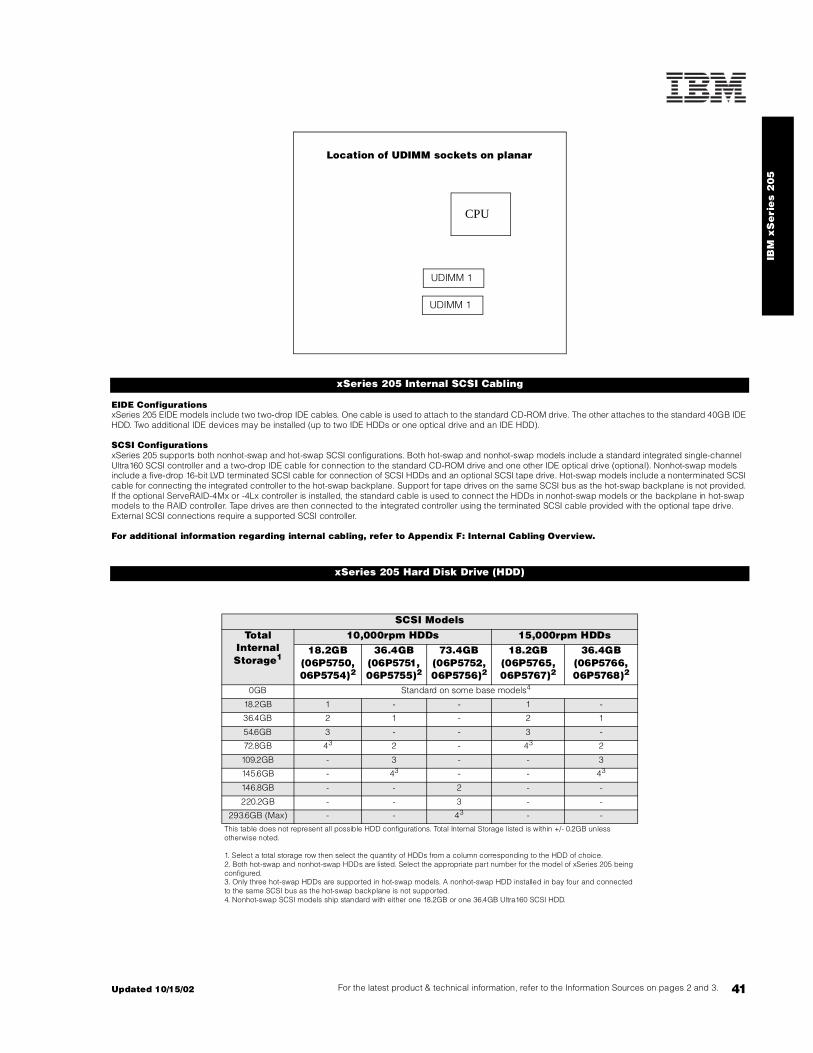
IBM
xS
eri
es 2
05
41For the latest product & technical information, refer to the Information Sources on pages 2 and 3.Updated 10/15/02
EIDE ConfigurationsxSeries 205 EIDE models include two two-drop IDE cables. One cable is used to attach to the standard CD-ROM drive. The other attaches to the standard 40GB IDE HDD. Two additional IDE devices may be installed (up to two IDE HDDs or one optical drive and an IDE HDD).
SCSI ConfigurationsxSeries 205 supports both nonhot-swap and hot-swap SCSI configurations. Both hot-swap and nonhot-swap models include a standard integrated single-channel Ultra160 SCSI controller and a two-drop IDE cable for connection to the standard CD-ROM drive and one other IDE optical drive (optional). Nonhot-swap models include a five-drop 16-bit LVD terminated SCSI cable for connection of SCSI HDDs and an optional SCSI tape drive. Hot-swap models include a nonterminated SCSI cable for connecting the integrated controller to the hot-swap backplane. Support for tape drives on the same SCSI bus as the hot-swap backplane is not provided. If the optional ServeRAID-4Mx or -4Lx controller is installed, the standard cable is used to connect the HDDs in nonhot-swap models or the backplane in hot-swap models to the RAID controller. Tape drives are then connected to the integrated controller using the terminated SCSI cable provided with the optional tape drive. External SCSI connections require a supported SCSI controller.
For additional information regarding internal cabling, refer to Appendix F: Internal Cabling Overview.
xSeries 205 Internal SCSI Cabling
xSeries 205 Hard Disk Drive (HDD)
SCSI ModelsTotal
Internal Storage1
10,000rpm HDDs 15,000rpm HDDs18.2GB
(06P5750, 06P5754)2
36.4GB(06P5751, 06P5755)2
73.4GB(06P5752, 06P5756)2
18.2GB(06P5765, 06P5767)2
36.4GB(06P5766, 06P5768)2
0GB Standard on some base models4
18.2GB 1 - - 1 -
36.4GB 2 1 - 2 1
54.6GB 3 - - 3 -
72.8GB 43 2 - 43 2
109.2GB - 3 - - 3
145.6GB - 43 - - 43
146.8GB - - 2 - -
220.2GB - - 3 - -
293.6GB (Max) - - 43 - -
This table does not represent all possible HDD configurations. Total Internal Storage listed is within +/- 0.2GB unless otherwise noted.
1. Select a total storage row then select the quantity of HDDs from a column corresponding to the HDD of choice.2. Both hot-swap and nonhot-swap HDDs are listed. Select the appropriate part number for the model of xSeries 205 being configured.3. Only three hot-swap HDDs are supported in hot-swap models. A nonhot-swap HDD installed in bay four and connected to the same SCSI bus as the hot-swap backplane is not supported.4. Nonhot-swap SCSI models ship standard with either one 18.2GB or one 36.4GB Ultra160 SCSI HDD.
Location of UDIMM sockets on planar
CPU
UDIMM 1
UDIMM 1

42
EIDE ModelsTotal
Internal Storage1
7200rpm HDDs2
20.4GB (P/N 19K4461)
40GB (P/N 22P7157)
60GB (P/N 09N4207)
80GB(P/N 09N4226)
40GB Std on IDE models-
60.4GB 1 - - -
80GB - 1 - -
100GB - - 1 -
120GB - - - 1
140GB - 1 1 -
160GB - 1 - 1
180GB - - 1 1
200GB - - - 2
240GB3 - - - 3
This table does not represent all possible HDD configurations. Total Internal Storage listed is within +/- 0.2GB unless otherwise noted.
1. Select a total storage row then add the quantity of HDDs from all columns to the standard HDD.2. The two EIDE controllers support a maximum of four IDE devices per machine including CD-ROM drives, HDDs and IDE tape drives.3. Requires removal of the standard HDD.
Hot-swap Models Nonhot-swap ModelsPart
NumberDescription RPM Height Bays
Supported3Maximum Quantity
Bays Supported
Maximum Quantity
IDE HDD1
19K4461 20.4GB 7200rpm ATA-100 (EIDE) HDD 7200 SL - - 4 . .. 7 3
22P7157 40GB 7200rpm ATA-100 (EIDE) HDD 7200 SL - - 4 . .. 7 3
09N4207 60GB 7200rpm ATA-100 (EIDE) HDD 7200 SL - - 4 . .. 7 3
09N4226 80GB 7200rpm ATA-100 (EIDE) HDD 7200 SL - - 4 . .. 7 3
Nonhot-swap Ultra160 HDDs2
06P5750 18.2GB 10Krpm Ultra160 SCSI SL HDD 10000 SL 4 1 4 ... 7 4
06P5751 36.4GB 10Krpm Ultra160 SCSI SL HDD 10000 SL 4 1 4 ... 7 4
06P5752 73.4GB 10Krpm Ultra160 SCSI SL HDD 10000 SL 4 1 4 ... 7 4
06P5765 18.2GB 15Krpm Ultra160 SCSI SL HDD 15000 SL 4 1 4 ... 7 4
06P5766 36.4GB 15Krpm Ultra160 SCSI SL HDD 15000 SL 4 1 4 ... 7 4
Hot-swap Ultra160 HDDs3
06P5754 18.2GB 10Krpm Ultra160 SCSI Hot-Swap SL HDD 10000 SL 5 .. . 7 3 - -
06P5755 36.4GB 10Krpm Ultra160 SCSI Hot-Swap SL HDD 10000 SL 5 .. . 7 3 - -
06P5756 73.4GB 10Krpm Ultra160 SCSI Hot-Swap SL HDD 10000 SL 5 .. . 7 3 - -
06P5767 18.2GB 15Krpm Ultra160 SCSI Hot-Swap SL HDD 15000 SL 5 .. . 7 3 - -
06P5768 36.4GB 15Krpm Ultra160 SCSI Hot-Swap SL HDD 15000 SL 5 .. . 7 3 - -
Optical Devices Bays Supported22P6950 16X Max RAM-Read DVD-ROM Drive4, 5 1, 2
22P6959 Combination DVD-RAM/R Drive3, 4 1, 2
22P6976 40x-12x-40x Max Black CD-RW Drive4 1, 2
10K3782 48x-20x CD-ROM Black Internal IDE Drive4 1, 2
22P6973 32x-10x-40x-16x Max CD-RW/DVD-ROM Combination Drive3, 4 1, 2
External Storage Expansion Units6 Form Factor
35311RU EXP300 Storage Expansion Unit7 Rack (3U)
09N7296 EXP300 Rack-to-Tower Conversion Kit -

IBM
xS
eri
es 2
05
43For the latest product & technical information, refer to the Information Sources on pages 2 and 3.Updated 10/15/02
1. The xSeries 205 EIDE controllers support a maximum of four IDE devices per machine including CD-ROM drives, hard disk drives and IDE tape drives.2. Nonhot-swap HDDs are supported in bays 4 ... 7 of nonhot-swap models and in bay four of hot-swap models. Nonhot-swap HDDs are not supported on the same SCSI bus as the hot-swap backplane in hot-swap models.3. Hot-swap HDDs are supported in bays 5 ... 7 of hot-swap models. Bay four supports nonhot-swap HDDs only. Nonhot-swap HDDs are not supported on the same SCSI bus as the hot-swap backplane in hot-swap models.4. Either replace the standard CD-ROM or install in the available media bay. An IDE cable with three connectors is included with the optional optical drive (same cable is standard in the system). If installing as an additional device, connect the cable to each optical device and the IDE connector on the system board. Configure the optional device as a master using the preset configuration if replacing the standard device or as a slave if installed as a redundant device. 5. Audio not supported for DVD-ROM drives. The drive provides data input/output only.6. Not supported by the onboard SCSI controller. Select an optional SCSI controller then refer to Appendix D: Cables - Storage Units - Controllers to confirm the controller supports the desired External Storage Expansion Unit and to select a supported cable. For HDD or other expansion unit options, see the specific expansion unit section.7. EXP300 includes a single 2m Ultra2 SCSI cable and dual hot-swap 500w redundant power supplies, each with its own power cord. To convert an EXP300 to a tower form factor, EXP300 Rack-to-Tower Conversion Kit (P/N 09N7296) is required.
Bay Form Factor
Height Front Access
Usage
1 133mm (5.25in) HH yes CD-ROM
2 133mm (5.25in) HH yes open1
3 89mm (3.5in) SL yes FDD
4 89mm(3.5in) SL yes open
5 .. . 72 89mm(3.5in) SL yes open
Note: HDDs are installed in the order of bays seven through four, i.e., 7, 6, 5, 4.
1. Supports removable media devices only. Hard disk drives are not supported.2. Bays five, six and seven are configured as hot-swap bays on xAX models. These bays are not front-accessible in nonhot-swap models.
xSeries 205 I/O Options
Part Number
Description Adapter Length
PCI Support1
Slots Supported2
Storage Controllers3
06P5736 ServeRAID-4Mx Ultra160 SCSI Controller4 Full 64-bit 1 ... 5
06P5740 ServeRAID-4Lx Ultra160 SCSI Controller5 Half 64-bit 1 ... 5
19K4646 PCI Wide Ultra160 SCSI Adapter6 Half 32-bit 1 ... 5
Networking7
Ethernet8
09N9901 10/100 EtherLink Server Adapter by 3Com9 Half 32-bit 1 ... 5
06P3601 10/100 Ethernet Server Adapter9 Half 32-bit 1 ... 5
22P4901 10/100 Dual Port Server Adapter9 Half 64-bit 1 ... 5
22P6801 PRO/1000XT Server Adapter by Intel (copper) w/CD, manuals9 Half 64-bit 1 ... 5
Token Ring
34L5001 16/4 Token-ring PCI Management Adapter9 Half 32-bit 1 ... 5
Bay 1: CD-ROM
Front of chassis
Bay 2
Bay 4
Bay 6
Bay 7
Bay 5
Bay 3: FDD

44
34L5201 High-Speed 100/16/4 Token-Ring PCI Management Adapter9 Half 32-bit 1 .. . 5
System Management09N7585 Remote Supervisor Adapter10 Half 32-bit 1
Communications11
1. A 64-bit adapter installed into a 32-bit slot will transfer data at 32-bit rates. Adapters rated at 66MHz will operate at 33MHz when installed in a 33MHz slot. 2. The xSeries 205 has five full-length PCI expansion slots on a single 32-bit, 33MHz bus.3. xSeries 205 has an integrated Ultra160 SCSI Controller with a single internal channel. Nonhot-swap models ship with a five-drop, multimode terminated LVD SCSI cable. Hot-swap models ship with a nonterminated LVD SCSI cable.4. ServeRAID-4Mx Ultra160 SCSI Controller is powered by a 100MHz Intel Zion GC80303 processor that provides 64MB of battery-backed ECC cache and two internal and two external Ultra160 connections (only two connectors my be used). External connections are 0.8mm VHDCI.5. ServeRAID-4Lx Ultra160 SCSI Controller is powered by a 100MHz Intel Zion GC80303 processor and provides a single channel, 32MB of ECC cache and either one internal or one external Ultra160 connection. External connector is 0.8mm VHDCI.6. PCI Wide Ultra160 SCSI Adapter (P/N 19K4646) provides a single channel with one internal connector, a five-drop multi-mode terminated LVD SCSI cable and one external 0.8mm VHDCI connector. Only one of the two connectors may be utilized.7. xSeries 205 includes an integrated copper-based Broadcom 5702 full-duplex, 10/100/1000Mbps Ethernet controller.8. In a fault-tolerant networking environment, using the fault-tolerant software delivered with the Ethernet adapters of a single manufacturer is recommended. Installing fault-tolerant solutions provided by multiple manufacturers may cause failures if the intermediate drivers provided with the adapters are not compatible. Three optional Ethernet adapters are copper and Intel-based (P/N 06P3601, 22P4901, 22P6801).9. Wake on LAN is supported for this option when installed in slots one through five.10. When installing this option in xSeries 205, the external power supply provided with the option is not required. All power is supplied through the internal 20-pin ribbon cable.11. xSeries 205 includes two USB ports (on rear of chassis), two 9-pin serial ports, one 25-pin parallel port, AC 97 audio line in/out jacks, and a microphone in jack.
xSeries 205 Power, Monitors & Accessories
Part Number DescriptionPower1
Tower Uninterruptible Power Supply (UPS)2
94G3134 APC Smart-UPS 7003
94G3135 APC Smart-UPS 10003
94G3136 APC Smart-UPS 14003
Rack Mount Uninterruptible Power Supply (UPS)2
32P1020 APC 2U Smart-UPS 1400RMB
94G6676 APC Smart-UPS 3000RMB4
37L6861 APC Smart-UPS 5000RMB5
Monitors6
633147N E54 Color Monitor 15in (350mm, 13.8in viewable image), stealth black7
63324HN E74 Color Monitor 17in (406mm, 16in viewable image), stealth black7
66274AN G78 Color Monitor 17in (406.4mm, 16in viewable image), stealth black7
9512AB1 T541 Flat Panel Color Monitor (381mm, 15in viewable image), stealth black3
32P1031 NetBAY 1U Flat Panel Monitor Console Kit (with US Space Saver keyboard)8
32P1032 NetBAY 1U Flat Panel Monitor Console Kit (without keyboard)8
32P1702 NetBAY 2U Flat Panel Monitor Console Kit (with US Space Saver keyboard)8
32P1703 NetBAY 2U Flat Panel Monitor Console Kit (without keyboard)8
9494HBO T860 Hybrid Flat Panel Monitor 18.1in (460mm, 18.1in viewable image), stealth black3
1. The xSeries 205 includes a 340w voltage sensing power supply with a single line cord.2. For runtimes and UPS attributes see Appendix C: UPS Runtime Estimate.3. Not supported for rack mounting.4. Height is 3U. See Rack Cabinets and Options section for supported IBM racks.5. Height is 5U. See Rack Cabinets and Options section for supported IBM racks.6. The xSeries 205 contains an ATI Rage XL video controller with 8MB of video memory.7. Installation within a rack requires optional Monitor Compartment (P/N 94G7444).8. Includes a 15in Flat Panel Monitor.
Part Number DescriptionConversion Kits
09N4300 4Ux20D Tower-to-Rack Kit
Rack and NetBAY1
Refer to the Rack Cabinets and Options section for information concerning IBM racks and rack-supported devices.
Keyboard and Mouse2
28L3644 Space Saver II Keyboard3, 4
IBM
xS
eri
es 2
05
45For the latest product & technical information, refer to the Information Sources on pages 2 and 3.Updated 10/15/02
10K3849 106-key Preferred USB Keyboard with 2-port USB Hub (stealth black)5, 6
22P5150 TrackPoint USB Space Saver Keyboard5, 6
22P5170 Wireless Keyboard and Mouse
28L3673 Sleek 2-button Stealth Black Mouse
33L3244 Sleek USB Mouse (stealth black)6
33L3248 3-button Optical Wheel Mouse1. Rack installation of an xSeries 205 requires 4Ux20D Tower-to-Rack Kit (P/N 09N4300) and one of the racks listed in the Rack Cabinets and Options section.2. xSeries 205 models ship standard with both a mouse and nonspace saver keyboard.3. Installation within a rack requires optional keyboard tray (P/N 28L4707) which stows in ready-to-use position, or NetBAY 1U or 2U Flat Panel Monitor Console Kit (P/N 32P1032, 32P1702). Standard with 1U and 2U NetBAY console kits (P/N 32P1031, 32P1702).4. Advanced TrackPoint IV features are not available on IBM xSeries systems.5. Installation within a rack requires optional keyboard tray P/N 28L4707. This keyboard cannot share a keyboard tray with a flat panel display.6. USB accessories attach to a single USB-capable server. They are not compatible with the NetBAY console switches.
xSeries 205 Tape Options
Part Number Tape Drives
Bays Supported
SCSI Interface
(bit)
Form Factor
Termination Included
Ext Tape Enclosures1
48P7042 20/40GB TR7 Internal IDE Tape Drive2 1 -89mm (3.5in) SL or 133mm (5.25in) HH
- -
00N7991 20/40 GB DDS/4 4mm Internal TapeDrive3 2 16 Ultra2 LVD
89mm (3.5in) HH or 133mm
(5.25in) HHY4 35100205
24P2396 100/200GB LTO Half-High Tape Drive3 2 16 Ultra2 LVD 133mm (5.25in) HH Y4 35100205
24P2398 40/80GB Half-High DLTVS Internal SCSI Tape Drive3 2 16 Ultra2 LVD 133mm
(5.25in) HH Y4 35100205
External Tape Enclosures3510020 External Half High SCSI Storage Enclosure6 - 8, 16 Desktop N -
3503B1X Full-High SCSI Tape Enclosure7 - 16 Ultra2 LVD Desktop or 3U Rack Y -
Associated Options
00N7956 68-pin External Multimode LVD/SE SCSI Terminator - 16 LVD/SE External Y 3510020
1. To determine external cable requirements, note the tape drive's SCSI interface, the appropriate SCSI controller from the systemconfigurator section and the desired enclosure, then refer to Appendix D: Cables - Storage Units - Controllers.2. SCSI models include a two-drop EIDE cable for attachment to the CD-ROM and an IDE tape drive.3. EIDE models require optional PCI Wide Ultra160 SCSI Adapter (P/N 19K4646), which includes a five-drop multimode LVD SCSI cable.4. When installed internally, termination requires installing the 34in single-drop, terminated LVD SCSI cable provided with the option.5. Requires 68-pin External Multimode LVD/SE SCSI Terminator (P/N 00N7956).6. Black desktop tape enclosure that supports a single 133mm (5.25in) half-high (HH) tape drive. Internal connector is configurable as 50-pin Centronix or 68-pin high density. Requires either tape drive self-termination or 68-pin External Multimode LVD/SE SCSI Terminator (P/N 00N7956). The option includes face plates for either a 68-pin HD or 0.8mm VHDCI external connection. External cables are not included.7. Black desktop or 3U rack tape enclosure supports a single 133mm (5.25in) full-high LVD tape device including DLT tape drives. Requires a fixed shelf if installed in a rack (allow additional 1U for fixed shelf). Includes a 90w power supply, cooling fan, external terminator, power cord (country-specific), and 2m 68-pin to 0.8mm external cable. Supports the following full-high tape options: 00N8015, 00N8016, 00N7992, 00N7990.
Note: Additional tape attributes can be found in Appendix A: Tape Drive Attributes
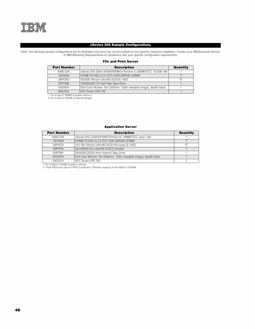
46
Note: The following sample configurations are for illustration only and may not be suitable for any specific customer installation. Contact your IBM Business Partner or IBM Marketing Representative for assistance with your specific configuration requirements.
File and Print Server
Application Server
xSeries 205 Sample Configurations
Part Number Description Quantity8480-22X xSeries 205 2GHz-512KB/400MHz Pentium 4, 256MB ECC, 18.2GB, 48x 110K0069 512MB PC2100 CL2.5 ECC DDR SDRAM UDIMM 11
06P5750 18.2GB 10Krpm Ultra160 SCSI SL HDD 32
24P2396 100/200GB LTO Half-High Tape Drive 1633147N E54 Color Monitor 15in (350mm, 13.8in viewable image), stealth black 194G3134 APC Smart-UPS 700 1
1. For a total of 768MB of system memory.2. For a total of 72.8GB of internal storage.
Part Number Description Quantity8480-3AX xSeries 205 2.4GHz/512KB Pentium III, 128MB ECC, open, 48x 110K0069 512MB PC2100 CL2.5 ECC DDR SDRAM UDIMM 11
06P5754 18.2 GB 10Krpm Ultra160 SCSI Hot-swap SL HDD 32
06P5740 ServeRAID-4Lx Ultra160 SCSI Controller 100N7991 20/40GB DDS/4 4mm Internal Tape Drive 1633147N E54 Color Monitor 15in (350mm, 13.8in viewable image), stealth black 194G3134 APC Smart-UPS 700 1
1. For a total of 1.25GB of system memory.2. Three HDDs are used for RAID 5 protection. Effective capacity is two HDDs or 36.4GB.

IBM
xS
eri
es 2
05
47For the latest product & technical information, refer to the Information Sources on pages 2 and 3.Updated 10/15/02

IBM xSeries 220
EMEA Part Number Cross ReferencexSeries 220 System Unit Part Numbers
EMEA AMERICAS M/C TYPE DESCRIPTION EMEAP/N P/N MODEL WDFM DATE
K641Xxx 864641X 8646-41X PIII 1.26GHz/133MHz, 512KB, 128MB, Open BayU160, Tower ---
K642Xxx 864642X 8646-42X PIII 1.26GHz/133MHz, 512KB, 128MB, 18.2GB U160, Tower ---
K64AXxx 86464AX 8646-4AX PIII 1.26GHz/133MHz, 512KB, 256MB, Open Bay HSU160, Tower ---
K651Xxx 864651X 8646-51X PIII 1.4GHz/133MHz, 512KB, 128MB, Open BayU160, Tower ---
K652Xxx 864652X 8646-52X PIII 1.4GHz/133MHz, 512KB, 128MB, 18.2GB U160,Tower ---
K65AXxx 86465AX 8646-5AX PIII 1.4GHz/133MHz, 512KB, 256MB, Open Bay HSU160, Tower ---
xSeries 220 Hard Disk Drive Storage Part NumbersEMEA AMERICAS M/C TYPE DESCRIPTION EMEA
P/N P/N MODEL WDFM DATENotes 1&2 19K11xx 35311RU --- EXP300 Storage Expansion Unit ---
1. Where ‘xx’ represents a specific country code as follows: 51=US/English, 52=European/English, 56=Danish/English, 57=Israel/English, 58=Italian/English, 59=South Africa/English, 60=Swiss/English, 63=UK/English:- Line Cords/ Publication Country Kits are included as indicated.2. This unit does not include Rack Power Cables P/N 94G7448 when shipped (for attachment to highvoltage UPS or PDU). Standard country power cords only are included. If required, order one Rack PowerCable for each power supply.
xSeries 220 I/O Option Part NumbersEMEA AMERICAS M/C TYPE DESCRIPTION EMEA
P/N P/N MODEL WDFM DATEN/A 33L4618 --- V90 PCI Data/Fax WinModem N/A
Note 3 37L14xx 37L14xx --- Serial I/O SST 8 and 16 port Adapters Note 3
Note 4 09N75xx 09N7585 --- Remote Supervisor Adapter ---3. Serial I/O Adapter P/Ns 37L1414 and 37L1415 are available. Other Serial I/O adapter part numbers arewithdrawn from marketing in EMEA.4. Where ‘xx’ represents a specific country code as follows:- 86=Europe, 87=Denmark, 88=South Africa, 89=UK, 90=Switzerland, 91=Italy, 92=Israel, 85=USA..
Note 5 xSeries 220 Power, Monitors & AccessoriesEMEA AMERICAS M/C TYPE DESCRIPTION EMEA
P/N P/N MODEL POWER WDFM DATESUP072Y 94G3134 --- APC Smart-UPS 700 ---SUP102Y 94G3135 --- APC Smart-UPS 1000 ---SUP142Y 94G3136 --- APC Smart-UPS 1400 ---
Note 6 32P16xx 32P1020 --- APC 2U Smart-UPS 1400RMiB ---Note 7 30RIxxx 94G6676 --- APC Smart-UPS 3000RMiB ---
37L6862 37L6861 --- APC Smart-UPS 5000RMiB ---5. The xSeries 205 ships with a standard country power cord. If conversion to Rack format is being carriedout, Rack Power Cable P/N 94G7448 must be ordered, if connection to a high voltage UPS or PDU isrequired.6. Where ‘xx’ represents a specific country code as follows:- 12=Europe, 13=UK, 14=Italy, 15=Switzerland,16=Denmark, 17=South Africa, 18=Israel.7. Where ‘xxx’ represents a specific country code as follows:- DEN=Denmark, ISR=Israel, ITA=Italy, SDI=Saudi Arabia, SAF=South Africa, SWS=Switzerland, UKM=United Kingdom, EUR=Europe.
47A Updated 10/15/02

IBM xSeries 220
EMEA Part Number Cross ReferencexSeries 220 Power, Monitors & Accessories
EMEA AMERICAS M/C TYPE DESCRIPTION EMEAP/N P/N MODEL MONITORS WDFM DATE
Note 8 T3147xx 633147N 6331-47N E54 15" (13.8" viewable image) Colour Monitor (S/Blac ---Note 8 T3247xx 63324HN 6332-4HN E74 17" (16" viewable image) Colour Monitor (S/Black) ---Note 8 T274Axx 66274AN 6627-4AN G78 17" (16" viewable image) Colour Monitor (S/Black ---Note 8 T12ABxx 9512AB1 9512-AB1 T541 15" Flat Panel Colour Monitor (S/Black) ---
N/A 32P1031 --- NetBAY 1U Flat Panel Monitor Console Kit (with US ke N/AN/A 32P1702 --- NetBAY 2U Flat Panel Monitor Console Kit (with US ke N/A
8. Where ‘xx’ represents a specific country code as follows: DK=Denmark, IS=Israel, IT=Italy, SD=SaudiArabia, SA=South Africa/Pakistan, CH=Switzerland, UK=UK, EU=Europe.
xSeries 220 Power, Monitors & AccessoriesEMEA AMERICAS M/C TYPE DESCRIPTION EMEA
P/N P/N MODEL KEYBOARD AND MOUSE WDFM DATENote 9 28L36xx 28L3644 --- Spacesaver II Keyboard ---
Note 10 10K38xx 10K3849 --- 106-key Preferred USB Keyb. with 2-port USB Hub (S/ ---28L3675 28L3673 --- Sleek 2-button Mouse (S/Black) ---
9. Where ‘xx’ represents a specific country code as follows:- 46=Danish , 47=French, 48=German, 49=Italian, 50=Spanish, 51=UK English, 44=US English, and P/N 19K3831=Swiss, 19K3832=Swedish/Finnish,19K3833=Portugese, 19K3834=Belgian, 19K3836=Russian, 19K3837=Polish.10. Where ‘xx’ represents a specific country code as follows:- 53=Danish , 54=Dutch, 55=France, 56=Germany, 57=Italian, 58=Norwegian, 59=Swedish/Finnish, 10K2343=Swiss, 10K2344=UK English, 10K2345=US ISO.
xSeries 220 Tape OptionsEMEA AMERICAS M/C TYPE DESCRIPTION EMEA
P/N P/N MODEL WDFM DATEN/A 3570C2x --- Magstar MP 3570 Tape Subsystem N/A
10L7440 3510020 --- External Half High SCSI Storage Enclosure ---03K8756 3551001 --- NetMEDIA Storage Expansion Unit EL ---
Updated 10/15/02 47B

48
IBM xSeries 220
xSeries 220 At-A-Glance
8646-41X 1.26 1/2 512 128MB(R)/4GB Tower 1/1 - - - 10/100 U160 4/2 0/293.6GB 48X-20X 7/5 5/5
8646-42X1 1.26 1/2 512 128MB(R)/4GB Tower 1/1 - - - 10/100 U160 4/2 18.2GB/293.6GB 48X-20X 7/4 5/5
8646-4AX 1.26 1/2 512 256MB(R)/4GB Tower 1/1 H - - 10/100 U160 4/2 0/220.2GB 48X-20X 7/5 5/5
8646-51X 1.4 1/2 512 128MB(R)/4GB Tower 1/1 - - - 10/100 U160 4/2 0/293.6GB 48X-20X 7/5 5/5
8646-52X1 1.4 1/2 512 128MB(R)/4GB Tower 1/1 - - - 10/100 U160 4/2 18.2GB/293.6GB 48X-20X 7/4 5/5
8646-5AX 1.4 1/2 512 256MB(R)/4GB Tower 1/1 H - - 10/100 U160 4/2 0/220.2GB 48X-20X 7/5 5/5
1. Not available in the United States.2. Intel Pentium III processor with advanced transfer L2 cache and 133MHz FSB.3. Variable read rate. Actual playback speed will vary and is often less than the maximum possible..
xSeries 220 Processor Upgrades
Part Number
Processor Upgrades SMP Support1 Processor Speed Upgrade2
32P0652 xSeries 1.26GHz/133MHz 512KB Cache Upgrade with Pentium III Processor SVR 4xX -
25P2090 xSeries 1.4GHz/133MHz-512KB Cache Upgrade with Pentium III Processor 5xX 4xX
1. One additional processor may be installed, providing a maximum of two. All processors must be identical in type, speed, and cache size.2. Requires removal of the standard processor. A maximum of two processors may be installed. Upgrades may require a BIOS update. To obtain the latest Flash BIOS, access www.pc.ibm.com/support and enter machine “Type-Model” in Quick Path. Select “Downloadable files” and then “BIOS”.
xSeries 220 Memory
Total System Memory1
Quantity of RDIMMs Added
128MB(1 x 128) Models
256MB (1 x 256) Models
128MB(10K0018)
256MB(10K0020)
512MB(10K0022)
1GB(33L3326)
256MB 384MB 1 - - -
384MB 512MB 2 or 1 - -
512MB 640MB 3 - - -
Part Number
Memory Description1640MB 768MB - 2 or 1 -
10K0018 128MB PC133 ECC SDRAM RDIMM 896MB 1024MB - 3 - -
10K0020 256MB PC133 ECC SDRAM RDIMM 1024MB2 - - 4 - -
10K0022 512MB PC133 ECC SDRAM RDIMM 1152MB 1280MB - - 2 or 1
33L3326 1GB PC133 ECC SDRAM RDIMM 1664MB 1792MB - - 3 -
1. Install additional RDIMMs in sequence of socket two through four. 2048MB2 2048MB2 - - 4 -
2176MB 2304MB - - - 2
3200MB 3328MB - - - 3
4096MB2 (max)
4096MB2 (max) - - - 4
Part Number
Processor Speed
2 (GHz)
Number of P
rocessors (Std/M
ax)
L2 ECC Cache (KB)
Memory (Std/M
ax) (R=RDIM
M)
Form Factor
Power Supply Quantity
(Std/M
ax)
Hot-Swap (P
ower, Slots, H
DD, Fans)
Redundancy (Optio
nal, Standard)
Adv System Management P
rocessor
Onboard Ethernet (Mbps)
SCSI Contro
ller (D
ual, Ultr
a, RAID)
Removable Media Bays (T
otal/Avail)
Internal Hard Disk Driv
e (Std/M
ax)
CD-ROM (IDE)3
Bays (Total/A
vail)
Slots (Total/A
vail)
RDIMM Socket
RDIMM Socket
RDIMM Socket
RDIMM Socket

49For the latest product & technical information, refer to the Information Sources on pages 2 and 3.Updated 10/15/02
IBM
xS
eri
es
22
0
Nonhot-swap ModelsxSeries 220 nonhot-swap models are cabled internally with a five-drop, 16-bit wide LVD SCSI cable with a built-in multi-mode active terminator on one end of the cable. The other end of the cable is attached to the internal 68-pin connector of the integrated Ultra160 SCSI controller. SCSI devices can be connected to any of the five cable connectors. If 8-bit (narrow) devices are to be installed, a 68- to 50-pin converter (32G3925) is required for each narrow device.
Hot-swap ModelsxSeries 220 hot-swap models are cabled internally with a two-drop, 16-bit wide LVD SCSI cable. One end is connected to the internal 68-pin connector of the integrated Ultra160 SCSI controller. The second drop is connected to the hot-swap SCSI backplane.The SCSI backplane provides termination for the SCSI bus. Tape options installed in the removable media bay are not supported on the same SCSI bus as the hot-swap backplane.
Other Configuration AlternativesIn the case where a RAID controller is used to support internal drives in an xSeries 220, the standard cable is moved from the onboard controller to the RAID adapter. To connect a tape drive to the onboard SCSI controller, the two-drop cable from Media Bay Tray and LVD Cable Kit (P/N 10K2340) must be used unless the tape option includes a terminated SCSI cable.
External SCSI support can be obtained by installing an optional SCSI adapter or RAID controller and using appropriate external SCSI cabling.
For additional information regarding internal cabling, refer to Appendix F: Internal Cabling Overview.
This table does not represent all possible memory configurations. Memory modules may vary in price per MB. Selection of smaller RDIMMs may provide a more cost-effective alternative to using larger RDIMMs. Select the desired total memory from the appropriate column (Standard Model128MB), then select a quantity in that row from one of the RDIMM columns.
1. Network operating systems may limit the maximum amount of addressable memory. See operating system specifications for further information.2. Requires removal of standard memory.
xSeries 220 Internal SCSI Cabling
xSeries 220 Hard Disk Drive (HDD) and External Storage
Total Internal Storage1
10,000rpm HDDs 15,000rpm HDDs
18.2GB(06P5750, 06P5754)2
36.4GB(06P5751,06P5755)2
73.4GB(06P5752, 06P5756)2
18.2GB(06P5765, 06P5767)2
36.4GB(06P5766, 06P5768)2
0GB Standard on some base models4
18.2GB 1 - - 1 -
36.4GB 2 1 - 2 1
54.6GB 3 - - 3 -
72.8GB 43 2 - 43 2
109.2GB - 3 - - 3
145.6GB - 43 - - 43
146.8GB - - 2 - -
220.2GB - - 3 - -
293.6GB (max) - - 43 - -
This table does not represent all possible HDD configurations. Total Internal Storage listed is within +/-0.2GB unless otherwise noted.
1. Select a total storage row then select the quantity of HDDs from a column corresponding to the HDD of choice.2. Both hot-swap and nonhot-swap HDDs are listed. Select the appropriate part number for the model of xSeries 220 being configured.3. Only three hot-swap HDDs are supported on hot-swap models. A nonhot-swap HDD installed in bay four and connected to the same SCSI bus as the hot-swap backplane is not supported.4. Nonhot-swap SCSI models ship standard with one 18.2GB Ultra160 SCSI HDD.

50
Hot-swap Models Nonhot-swap ModelsPart
NumberDescription RPM Height Bays
Supported2Maximum Quantity
Bays Supported
Maximum Quantity
Nonhot-swap Ultra160 HDDs1
06P5750 18.2GB 10Krpm Ultra160 SCSI SL HDD 10000 SL 4 1 4 ... 7 4
06P5751 36.4GB 10Krpm Ultra160 SCSI SL HDD 10000 SL 4 1 4 ... 7 4
06P5752 73.4GB 10Krpm Ultra160 SCSI SL HDD 10000 SL 4 1 4 ... 7 4
06P5765 18.2GB 15Krpm Ultra160 SCSI SL HDD 15000 SL 4 1 4 ... 7 4
06P5766 36.4GB 15Krpm Ultra160 SCSI SL HDD 15000 SL 4 1 4 ... 7 4
Hot-swap Ultra160 HDDs2
06P5754 18.2GB 10Krpm Ultra160 SCSI Hot-Swap SL HDD 10000 SL 5 .. . 7 3 - -
06P5755 36.4GB 10Krpm Ultra160 SCSI Hot-Swap SL HDD 10000 SL 5 .. . 7 3 - -
06P5756 73.4GB 10Krpm Ultra160 SCSI Hot-Swap SL HDD 10000 SL 5 .. . 7 3 - -
06P5767 18.2GB 15Krpm Ultra160 SCSI Hot-Swap SL HDD 15000 SL 5 .. . 7 3 - -
06P5768 36.4GB 15Krpm Ultra160 SCSI Hot-Swap SL HDD 15000 SL 5 .. . 7 3 - -
Optical Devices Bays Supported22P6950 16X Max RAM-Read DVD-ROM Drive3, 4 1, 2
22P6976 40x-12x-40x Max Black CD-RW Drive3 1, 2
External Storage Expansion Units5 Form Factor
35311RU EXP300 Storage Expansion Unit6 Rack (3U)
09N7296 EXP300 Rack-to-Tower Conversion Kit -
1. Nonhot-swap HDDs are supported in bays 4 ... 7 of nonhot-swap models and in bay four of hot-swap models. Nonhot-swap HDDs are not supported on the same SCSI bus as the hot-swap backplane in hot-swap models.2. Hot-swap HDDs are supported in bays 5 ... 7 of hot-swap models. Bay four supports nonhot-swap HDDs only. Nonhot-swap HDDs are not supported on the same SCSI bus as the hot-swap backplane in hot-swap models.3. Either replace the standard CD-ROM or install in the available media bay. An IDE cable with three connectors is included with the optional optical drive (same cable is standard in the system). If installing as an additional device, connect the cable to each optical device and the IDE connector on the system board. Configure the optional device as a master using the preset configuration if replacing the standard device or as a slave if installed as a redundant device. 4. Audio not supported for DVD-ROM drives. The drive provides data input/output only.5. Not supported by the onboard SCSI controller. Select an optional SCSI controller then refer to Appendix D: Cables - Storage Units - Controllers to confirm the controller supports the desired External Storage Expansion Unit and to select a supported cable. For HDD or other expansion unit options, see the specific expansion unit section.6. EXP300 includes a single 2M Ultra2 SCSI cable and dual hot-swap 500W redundant power supplies, each with its own power cord. To convert an EXP300 to a tower form factor, EXP300 Rack-to-Tower Conversion Kit (P/N 09N7296) is required.
Bay Form Factor
Height Front Access
Usage
1 133mm (5.25in) HH yes IDE CD-
ROM
2 133mm (5.25in) HH yes open1
3 89mm (3.5in) SL yes Floppy
4 89mm(3.5in) SL yes open
5 ... 7 89mm(3.5in) SL2 yes open
Note: HDDs are installed in the order of bays seven through four, i.e., 7, 6, 5, 4. The boot disk must be installed in bay seven (SCSI ID 0).
1. Supports removable media devices only. Hard disk drives are not supported.2. Bays five, six and seven are configured as hot-swap bays on xAX models. These bays are not front-accessible in nonhot-swap models.
Bay 4
CD-ROM
Bay 2
Diskette
Bay 5
Bay 6
Bay 7
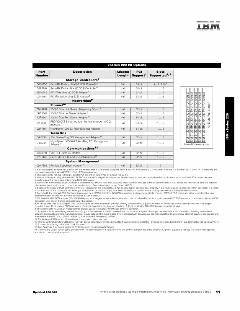
51For the latest product & technical information, refer to the Information Sources on pages 2 and 3.Updated 10/15/02
IBM
xS
eri
es
22
0
xSeries 220 I/O Options
Part Number
Description Adapter Length
PCI Support1
Slots Supported1, 2
Storage Controllers3
06P5736 ServeRAID-4Mx Ultra160 SCSI Controller4 Full 64-bit (1, 2, 3, 5)5
06P5740 ServeRAID-4Lx Ultra160 SCSI Controller6 Half 64-bit 1 . .. 5
19K4646 PCI Wide Ultra160 SCSI Adapter7 Half 32-bit 1 . .. 5
02K3454 PCI Fast/Wide Ultra SCSI Adapter8 Half 32-bit 1 . .. 5
Networking9
Ethernet10
09N9901 10/100 EtherLink Server Adapter by 3Com11 Half 32-bit 1 . .. 5
06P3601 10/100 Ethernet Server Adapter11 Half 32-bit 1 . .. 5
22P4901 10/100 Dual Port Server Adapter11 Half 64-bit 1 . .. 5
22P6801 PRO/1000XT Server Adapter by Intel (copper) w/CD, manuals11 Half 64-bit 1 . .. 5
22P7801 NetXtreme 1000 SX Fiber Ethernet Adapter Half 64-bit 1 . .. 5
Token Ring
34L5001 16/4 Token-Ring PCI Management Adapter11 Half 32-bit 1 . .. 5
34L5201 High-Speed 100/16/4 Token-Ring PCI Management Adapter11 Half 32-bit 1 . .. 5
Communications12
33L4618 V.90 PCI Data/Fax Modem Half 32-bit 1 . .. 5
37L14xx Serial I/O SST 8- and 16-port adapters13 Half 32-bit 1 . .. 5
System Management09N7585 Remote Supervisor Adapter14 Half 32-bit 2
1. A 64-bit adapter installed into a 32-bit slot will transfer data at 32-bit rates. Adapters rated at 66MHz will operate at 33MHz when installed in a 33MHz slot. 133MHz PCI-X adapters are backward compatible with 33/66MHz, 64-bit PCI-based servers.2. The xSeries 220 has five full-length, 33MHz PCI expansion slots, three 64-bit and two 32-bit.3. xSeries 220 has an integrated Ultra160 SCSI Controller with a single internal channel. Nonhot-swap models ship with a five-drop, multi-mode terminated LVD SCSI cable. Hot-swap models ship with a two-drop nonterminated LVD SCSI cable.4. ServeRAID-4Mx Ultra160 SCSI Controller is powered by a 100MHz Intel Zion GC80303 processor that provides 64MB of battery-backed ECC cache and two internal and two external Ultra160 connections (only two connectors may be used). External connections are 0.8mm VHDCI.5. Because the onboard SCSI controller connector is located in-line with slot four, a full-length adapter does not seat properly in slot four if a cable is attached to that connector. If a cable is not attached to that connector, the full-length adapter can be installed in slot four. The interference is created by the battery pack on the ServeRAID-4Mx controller.6. ServeRAID-4Lx Ultra160 SCSI Controller is powered by a 100MHz Intel Zion GC80303 processor and provides a single channel, 32MB of ECC cache and either one internal or one external Ultra160 connection. External connector is 0.8mm VHDCI.7. PCI Wide Ultra160 SCSI Adapter (P/N 19K4646) provides a single channel with one internal connector, a five-drop multi-mode terminated LVD SCSI cable and one external 0.8mm VHDCI connector. Only one of the two connectors may be utilized.8. PCI Fast/Wide Ultra SCSI Adapter (P/N 02K3454) provides one external 68-pin high density connector that supports external SCSI devices such as tape enclosures. The adapter includes 8- and 16-bit internal SCSI connectors. Only one connector can be used at a time. A 16-bit terminated UltraSCSI internal cable is included.9. The xSeries 220 includes an integrated Intel copper-based full-duplex, 10/100Mbps Ethernet controller. 10. In a fault-tolerant networking environment, using the fault-tolerant software delivered with the Ethernet adapters of a single manufacturer is recommended. Installing fault-tolerant solutions provided by multiple manufacturers may cause failures if the intermediate drivers provided with the adapters are not compatible.Three optional Ethernet adapters are copper and Intel-based (P/N 06P3601, 22P4901, 22P6801). One is Broadcom-based (22P7801).11. The Wake on LAN feature of this adapter is supported only in slot one.12. xSeries 220 includes two USB ports, two high-speed serial/asynchronous ports, (NS16550A software compatible) and one high-speed parallel port supporting devices using SSP/EPP/ECP protocols adhering to the IEEE 1284 Standard.13. See Appendix E for details on Serial I/O Options and configuration limitations.14. Connect the 20-pin ribbon cable provided with the option between the planar connector and the adapter. Install the external AC power supply. Do not use the system management adapter to power down the system.
Slo
t 4-
33M
Hz,
64-
bit,
5V
or
Uni
vers
alS
lot 5
- 33
MH
z, 6
4-b
it, 5
V o
r U
nive
rsal
All
Slo
ts-F
ull L
eng
th
Slo
t 1-
33M
Hz,
32-
bit,
5V
or
Uni
vers
alS
lot 2
- 33
MH
z, 3
2-b
it, 5
V o
r U
nive
rsal
Slo
t 3-
33M
Hz,
64-
bit,
5V
or
Uni
vers
al
External Connector Access

52
xSeries 220 Power, Monitors & Accessories
Part Number DescriptionPower1
Tower Uninterruptible Power Supply (UPS)2
94G3134 APC Smart-UPS 7003
94G3135 APC Smart-UPS 10003
94G3136 APC Smart-UPS 14003
Rack Mount Uninterruptible Power Supply (UPS)2
32P1020 APC 2U Smart-UPS 1400RMB
94G6676 APC Smart-UPS 3000RMB4
37L6861 APC Smart-UPS 5000RMB5
Monitors6
633147N E54 Color Monitor 15in (350mm, 13.8in viewable image), stealth black7
63324HN E74 Color Monitor 17in (406mm, 16in viewable image), stealth black7
66274AN G78 Color Monitor 17in (406.4mm, 16in viewable image), stealth black7
9512AB1 T541 Flat Panel Color Monitor (381mm, 15in viewable image), stealth black3
32P1031 NetBAY 1U Flat Panel Monitor Console Kit (with US Space Saver keyboard)8
32P1032 NetBAY 1U Flat Panel Monitor Console Kit (without keyboard)8
32P1702 NetBAY 2U Flat Panel Monitor Console Kit (with US Space Saver keyboard)8
32P1703 NetBAY 2U Flat Panel Monitor Console Kit (without keyboard)8
1. The xSeries 220 includes a 330W voltage sensing power supply and a single line cord.2. For runtimes and UPS attributes see Appendix C: UPS Runtime Estimate.3. Not supported for rack mounting.4. Height is 3U. See Rack Cabinets and Options section for supported IBM racks.5. Height is 5U. See Rack Cabinets and Options section for supported IBM racks.6. The xSeries 220 includes an integrated SVGA controller (S3 Savage4 Chipset) with 8MB of video memory.7. Installation within a rack requires optional Monitor Compartment (P/N 94G7444).8. Includes a 15in Flat Panel Monitor.
Part Number DescriptionConversion Kits
09N4300 4Ux20D Tower-to-Rack Kit
Rack and NetBAY1
Refer to the Rack Cabinets and Options section for information concerning IBM racks and rack-supported devices.
Keyboard and Mouse2
28L3644 Space Saver II Keyboard3, 4
10K3849 106-key Preferred USB Keyboard with 2-port USB Hub (stealth black)5, 6
28L3673 Sleek 2-button Stealth Black Mouse
33L3244 Sleek USB Mouse (stealth black)6
1 Rack installation of an xSeries 220 requires 4Ux20D Tower-to-Rack Kit (P/N 09N4300) and one of the racks listed in the Rack Cabinets and Options section.2. The xSeries 220 includes both a mouse and nonspace saver keyboard.3. Installation within a rack requires optional keyboard tray (P/N 28L4707) which stows in ready-to-use position, or NetBAY 1U or 2U Flat Panel Monitor Console Kit (P/N 32P1032, 32P1702). Standard with 1U and 2U NetBAY console kits (P/N 32P1031, 32P1702).4. Advanced TrackPoint IV features are not available on IBM xSeries systems.5. Installation within a rack requires optional keyboard tray (P/N 28L4707). This keyboard cannot share a keyboard tray with a flat panel display.6. USB accessories attach to a single USB-capable server. They are not compatible with the NetBAY console switches.
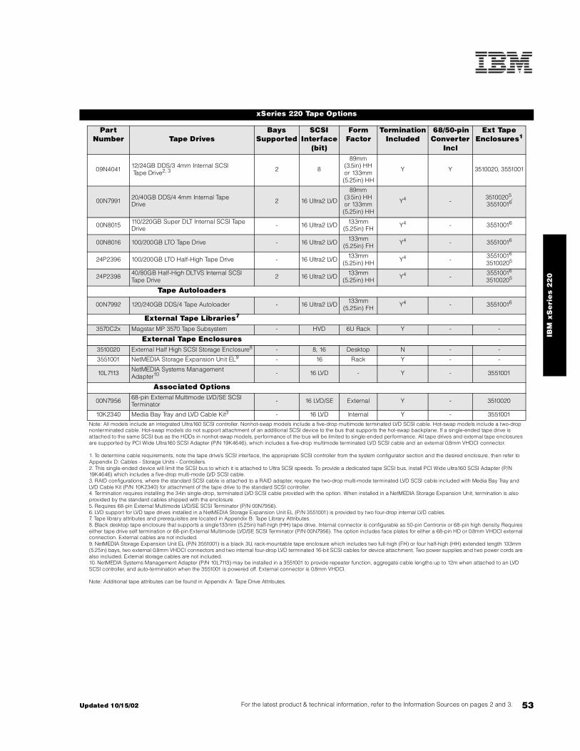
53For the latest product & technical information, refer to the Information Sources on pages 2 and 3.Updated 10/15/02
IBM
xS
eri
es
22
0
xSeries 220 Tape Options
Part Number Tape Drives
Bays Supported
SCSI Interface
(bit)
Form Factor
Termination Included
68/50-pin Converter
Incl
Ext Tape Enclosures1
09N4041 12/24GB DDS/3 4mm Internal SCSI Tape Drive2, 3 2 8
89mm (3.5in) HH or 133mm (5.25in) HH
Y Y 3510020, 3551001
00N7991 20/40GB DDS/4 4mm Internal TapeDrive 2 16 Ultra2 LVD
89mm (3.5in) HH or 133mm (5.25in) HH
Y4 - 35100205, 35510016
00N8015 110/220GB Super DLT Internal SCSI Tape Drive - 16 Ultra2 LVD 133mm
(5.25in) FH Y4 - 35510016
00N8016 100/200GB LTO Tape Drive - 16 Ultra2 LVD 133mm (5.25in) FH Y4 - 35510016
24P2396 100/200GB LTO Half-High Tape Drive - 16 Ultra2 LVD 133mm (5.25in) HH Y4 - 35510016
35100205
24P2398 40/80GB Half-High DLTVS Internal SCSI Tape Drive 2 16 Ultra2 LVD 133mm
(5.25in) HH Y4 - 35510016
35100205
Tape Autoloaders
00N7992 120/240GB DDS/4 Tape Autoloader - 16 Ultra2 LVD 133mm (5.25in) FH Y4 - 35510016
External Tape Libraries7
3570C2x Magstar MP 3570 Tape Subsystem - HVD 6U Rack Y - -
External Tape Enclosures3510020 External Half High SCSI Storage Enclosure8 - 8, 16 Desktop N - -
3551001 NetMEDIA Storage Expansion Unit EL9 - 16 Rack Y - -
10L7113 NetMEDIA Systems Management Adapter10 - 16 LVD - Y - 3551001
Associated Options
00N7956 68-pin External Multimode LVD/SE SCSI Terminator - 16 LVD/SE External Y - 3510020
10K2340 Media Bay Tray and LVD Cable Kit3 - 16 LVD Internal Y - 3551001
Note: All models include an integrated Ultra160 SCSI controller. Nonhot-swap models include a five-drop multimode terminated LVD SCSI cable. Hot-swap models include a two-drop nonterminated cable. Hot-swap models do not support attachment of an additional SCSI device to the bus that supports the hot-swap backplane. If a single-ended tape drive is attached to the same SCSI bus as the HDDs in nonhot-swap models, performance of the bus will be limited to single-ended performance. All tape drives and external tape enclosures are supported by PCI Wide Ultra160 SCSI Adapter (P/N 19K4646), which includes a five-drop multimode terminated LVD SCSI cable and an external 0.8mm VHDCI connector.
1. To determine cable requirements, note the tape drive’s SCSI interface, the appropriate SCSI controller from the system configurator section and the desired enclosure, then refer to Appendix D: Cables - Storage Units - Controllers.2. This single-ended device will limit the SCSI bus to which it is attached to Ultra SCSI speeds. To provide a dedicated tape SCSI bus, install PCI Wide ultra160 SCSI Adapter (P/N 19K4646) which includes a five-drop multi-mode LVD SCSI cable.3. RAID configurations, where the standard SCSI cable is attached to a RAID adapter, require the two-drop multi-mode terminated LVD SCSI cable included with Media Bay Tray and LVD Cable Kit (P/N 10K2340) for attachment of the tape drive to the standard SCSI controller. 4. Termination requires installing the 34in single-drop, terminated LVD SCSI cable provided with the option. When installed in a NetMEDIA Storage Expansion Unit, termination is also provided by the standard cables shipped with the enclosure.5. Requires 68-pin External Multimode LVD/SE SCSI Terminator (P/N 00N7956).6. LVD support for LVD tape drives installed in a NetMEDIA Storage Expansion Unit EL (P/N 3551001) is provided by two four-drop internal LVD cables.7. Tape library attributes and prerequisites are located in Appendix B: Tape Library Attributes.8. Black desktop tape enclosure that supports a single133mm (5.25in) half-high (HH) tape drive. Internal connector is configurable as 50-pin Centronix or 68-pin high density. Requires either tape drive self termination or 68-pin External Multimode LVD/SE SCSI Terminator (P/N 00N7956). The option includes face plates for either a 68-pin HD or 0.8mm VHDCI external connection. External cables are not included.9. NetMEDIA Storage Expansion Unit EL (P/N 3551001) is a black 3U, rack-mountable tape enclosure which includes two full-high (FH) or four half-high (HH) extended length 133mm (5.25in) bays, two external 0.8mm VHDCI connectors and two internal four-drop LVD terminated 16-bit SCSI cables for device attachment. Two power supplies and two power cords are also included. External storage cables are not included.10. NetMEDIA Systems Management Adapter (P/N 10L7113) may be installed in a 3551001 to provide repeater function, aggregate cable lengths up to 12m when attached to an LVD SCSI controller, and auto-termination when the 3551001 is powered off. External connector is 0.8mm VHDCI.
Note: Additional tape attributes can be found in Appendix A: Tape Drive Attributes.

54
Note: The following sample configurations are for illustration only and may not be suitable for any specific customer installation. Contact your IBM Business Partner or IBM Marketing Representative for assistance with your specific configuration requirements.
Internet Server
An Internet server handles all requests from the Internet (Intranet or Extranet). Usually, this type of server has the same characteristics as a normal file server. The main difference is that an Internet server talks a different language (TCP/IP vs NETBEUI or IPX/SPX) and often needs to do an extra security check (firewall). In the case of an Internet server, the server itself talks mostly to just one client, the Internet Service Provider (ISP), instead of many clients as a file server does.
With this is mind, the xSeries 220 was selected to provide an affordable price point for the growing Internet server market with two-way Pentium III processing,384MB of system memory (expandable to 4GB), and power protection with an APC Smart-UPS.
The network configuration depends on the method that will be used to connect the server to the Internet. Usually fast Ethernet routers are used, but if other methods are used you can add the appropriate adapter. The configuration includes a tape backup unit for secure backup of critical data in the event of a system or storage failure.
File and Print Server
A small business or departmental server is usually required to perform all typical server functions while servicing up to 100 users in a normal workgroup computing environment, but doesn’t require the high-end performance and fault-tolerance properties of larger servers.
The sample configuration above consists of an xSeries 220 with 256MB of memory and 54.6GB of HDD space. It has enough processor power and memory to run most current network operating systems comfortably and enough hard disk drive space to store a significant amount of data with additional external storage expansion still available. Demanding network traffic is effectively handled by the standard 100Mbps Ethernet connection.
This configuration also includes a tape backup unit, monitor, and a UPS to keep the system protected during power surges and outages.
Application Server
An application server differs from a file and print server in that it has a higher workload in providing application serving requirements for users. With this in mind, the xSeries 220 was selected to provide an affordable price point for an application server with two-way Pentium III processing, 512MB of system memory (expandable to 4GB), and availability features such as RAID-protected internal storage and power protection with an APC Smart-UPS.
xSeries 220 Sample Configurations
Part Number Description Quantity8646-5AX xSeries 220 1.4GHz/512KB Pentium III, 256MB ECC, open hot-swap, 48X 110K0018 128MB PC133 ECC SDRAM RDIMM 11
06P5754 18.2GB 10Krpm Ultra160 SCSI Hot-Swap SL HDD 22
00N7991 20/40GB DDS/4 4mm Internal Tape Drive 119K4646 PCI Wide Ultra160 SCSI Adapter 1633147N E54 Color Monitor 15in (350mm, 13.8in viewable image), stealth black 194G3134 APC Smart-UPS 700 1
1. For a total of 384MB of system memory.2. For a total of 36.4GB of internal storage.
Part Number Description Quantity8646-51X xSeries 220 1.4GHz/512KB Pentium III, 128MB ECC, open, 48X 110K0018 128MB PC133 ECC SDRAM RDIMM 11
06P5750 18.2GB 10Krpm Ultra160 SCSI SL HDD 32
00N7991 20/40GB DDS/4 4mm Internal Tape Drive 1633147N E54 Color Monitor 15in (350mm, 13.8in viewable image), stealth black 194G3134 APC Smart-UPS 700 1
1. For a total of 256MB of system memory.2. For a total of 54.6GB of internal storage.
Part Number Description Quantity8646-4AX xSeries 220 1.26GHz/512KB, 256MB ECC, open hot-swap, 48X 132P0652 xSeries 220 1.26GHz /133MHz 512KB Cache Upgrade with Pentium III Processor SVR 110K0020 256MB PC133 ECC SDRAM RDIMM 11
06P5740 ServeRAID-4Lx Ultra160 SCSI Controller 106P5754 18.2GB 10Krpm Ultra160 SCSI Hot-Swap SL HDD 32
10K2340 Media Bay Tray and LVD Cable Kit3 100N7991 20/40GB DDS/4 4mm Internal Tape Drive NS Internal SCSI Tape Drive 1633147N E54 Color Monitor 15in (350mm, 13.8in viewable image), stealth black 194G3134 APC Smart-UPS 700 1
1. For a total of 512MB of system memory.2. Three HDDs are used for RAID 5 protection. Effective capacity is two HDDs or 36.4GB3. Cable for dedicated attachment of tape to standard controller.

55For the latest product & technical information, refer to the Information Sources on pages 2 and 3.Updated 10/15/02
IBM
xS
eri
es
22
0

IBM xSeries 235
EMEA Part Number Cross ReferencexSeries 235 S ystem Unit Part Numbers
EMEA AMERICAS M/C TYPE DESCRIPTION EMEAP/N P/N MODEL WDFM DATE
K111Xxx 867111X 8671-11X Xeon 1.8GHz/400MHz, 512KB, 256MB, Open BayU320, Tower ---
K11AXxx 86711AX 8671-1AX Xeon 1.8GHz/400MHz, 512KB, 512MB, Open BayU320, Redundant Power, Tower ---
K121Xxx 867121X 8671-21X Xeon 2.0GHz/400MHz, 512KB, 256MB, Open BayU320, Tower ---
P12AXxx 86712AX 8671-2AX Xeon 2.0GHz/400MHz, 512KB, 512MB, Open BayU320, Redundant Power, Tower ---
K131Xxx 867131X 8671-31X Xeon 2.2GHz/400MHz, 512KB, 256MB, Open BayU320, Tower 01/10/02
P13AXxx 86713AX 8671-3AX Xeon 2.2GHz/400MHz, 512KB, 512MB, Open BayU320, Redundant Power, Tower 01/10/02
K141Xxx 867141X 8671-41X Xeon 2.4GHz/400MHz, 512KB, 256MB, Open BayU320, Tower ---
K14AXxx 86714AX 8671-4AX Xeon 2.4GHz/400MHz, 512KB, 512MB, Open BayU320, Redundant Power, Tower ---
xSeries 235 Hard Disk Drive Storage Part NumbersEMEA AMERICAS M/C TYPE DESCRIPTION EMEA
P/N P/N MODEL WDFM DATENotes 1&2 19K11xx 35311RU --- EXP300 Storage Expansion Unit ---Notes 3&2 00N71xx 35601RU --- FAStT EXP500 Storage Expansion Unit ---Notes 4&2 24P09xx 17401RU --- FAStT EXP700 Storage Expansion Unit ---Notes 5&2 19K11xx 35421RU --- FAStT 200 Storage Server ---Notes 6&2 19K11xx 35422RU --- FAStT 200 HA Storage Server ---
1. Where ‘xx’ represents a specific country code as follows: 51=US/English, 52=European/English, 56=Danish/English, 57=Israel/English, 58=Italian/English, 59=South Africa/English, 60=Swiss/English, 63=UK/English.2. This unit does not include Rack Power Cables P/N 94G7448 when shipped (for attachment to highvoltage UPS or PDU). Standard country power cords only are included. If required, order one Rack PowerCable for each power supply.3. Where ‘xx’ represents a specific country code as follows:- 36=US/English, 37=Euro/English, 41=Denmark/English, 42=Israel/English, 43=Italy/English, 44=South Africa/English, 45=Switzerland/English, 49=UK/English.4. Where ‘xx’ represents a specific country code as follows:- 01=Eur/English, 02=Eur/Spanish, 05=Denmark/English, 06=Israel/English, 07=Italy/English, 08=South Africa/English, 09=Switzerland/English, 12=UK/English.5. Where ‘xx’ represents a specific country code as follows:- 23=US/English, 24=Euro/English, 25=Euro/Spanish, 27=Euro/German, 28=Denmark/English, 29=Israel/English, 30=Italy/English, 31=South Africa/English, 32=Switzerland/English, 34=Switzerland/German, 36=UK/English..6. Where ‘xx’ represents a specific country code as follows:- 37=US/English, 38=Euro/English, 39=Euro/Spanish, 41=Euro/German, 42=Denmark/English, 43=Israel/English, 44=Italy/English, 45=South Africa/English, 46=Switzerland/English, 48=Switzerland/German, 50=UK/English.
xSeries 235 I/O Option Part NumbersEMEA AMERICAS M/C TYPE DESCRIPTION EMEA
P/N P/N MODEL WDFM DATEN/A 19K4162 --- V90 PCI Data/Fax WinModem N/A
N/A 33L4618 --- V90 PCI Data/Fax WinModem N/A
Note 7 37L14xx 37L14xx --- Serial I/O SST 8 and 16 port Adapters Note 7
Note 8 09N75xx 09N7585 --- Remote Supervisor Adapter ---7. Serial I/O Adapter P/Ns 37L1414 and 37L1415 are available. Other Serial I/O adapter part numbers arewithdrawn from marketing in EMEA.8. Where ‘xx’ represents a specific country code as follows:- 86=Europe, 87=Denmark, 88=South Africa, 89=UK, 90=Switzerland, 91=Italy, 92=Israel, 85=USA..
55A Updated 10/15/02
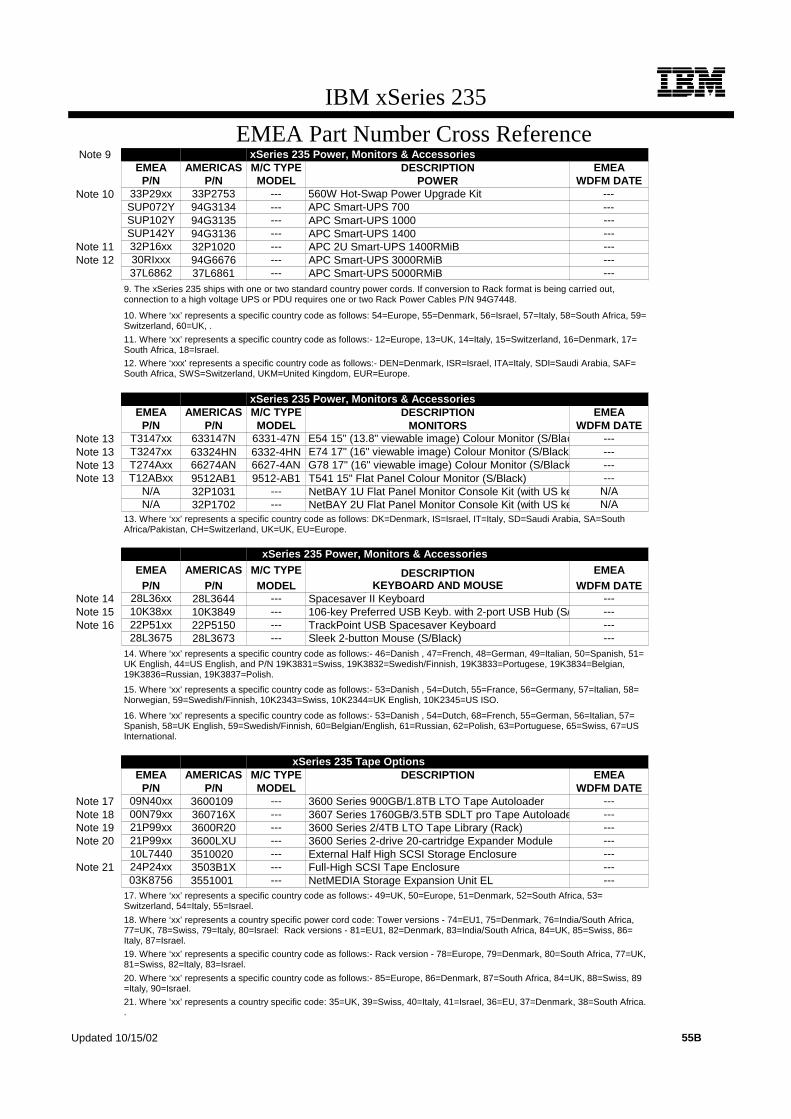
IBM xSeries 235
EMEA Part Number Cross ReferenceNote 9 xSeries 235 Power, Monitors & Accessories
EMEA AMERICAS M/C TYPE DESCRIPTION EMEAP/N P/N MODEL POWER WDFM DATE
Note 10 33P29xx 33P2753 --- 560W Hot-Swap Power Upgrade Kit ---SUP072Y 94G3134 --- APC Smart-UPS 700 ---SUP102Y 94G3135 --- APC Smart-UPS 1000 ---SUP142Y 94G3136 --- APC Smart-UPS 1400 ---
Note 11 32P16xx 32P1020 --- APC 2U Smart-UPS 1400RMiB ---Note 12 30RIxxx 94G6676 --- APC Smart-UPS 3000RMiB ---
37L6862 37L6861 --- APC Smart-UPS 5000RMiB ---9. The xSeries 235 ships with one or two standard country power cords. If conversion to Rack format is being carried out,connection to a high voltage UPS or PDU requires one or two Rack Power Cables P/N 94G7448.
10. Where ‘xx’ represents a specific country code as follows: 54=Europe, 55=Denmark, 56=Israel, 57=Italy, 58=South Africa, 59=Switzerland, 60=UK, .
11. Where ‘xx’ represents a specific country code as follows:- 12=Europe, 13=UK, 14=Italy, 15=Switzerland, 16=Denmark, 17=South Africa, 18=Israel.
12. Where ‘xxx’ represents a specific country code as follows:- DEN=Denmark, ISR=Israel, ITA=Italy, SDI=Saudi Arabia, SAF=South Africa, SWS=Switzerland, UKM=United Kingdom, EUR=Europe.
xSeries 235 Power, Monitors & AccessoriesEMEA AMERICAS M/C TYPE DESCRIPTION EMEA
P/N P/N MODEL MONITORS WDFM DATENote 13 T3147xx 633147N 6331-47N E54 15" (13.8" viewable image) Colour Monitor (S/Blac ---Note 13 T3247xx 63324HN 6332-4HN E74 17" (16" viewable image) Colour Monitor (S/Black) ---Note 13 T274Axx 66274AN 6627-4AN G78 17" (16" viewable image) Colour Monitor (S/Black ---Note 13 T12ABxx 9512AB1 9512-AB1 T541 15" Flat Panel Colour Monitor (S/Black) ---
N/A 32P1031 --- NetBAY 1U Flat Panel Monitor Console Kit (with US ke N/AN/A 32P1702 --- NetBAY 2U Flat Panel Monitor Console Kit (with US ke N/A
13. Where ‘xx’ represents a specific country code as follows: DK=Denmark, IS=Israel, IT=Italy, SD=Saudi Arabia, SA=SouthAfrica/Pakistan, CH=Switzerland, UK=UK, EU=Europe.
xSeries 235 Power, Monitors & AccessoriesEMEA AMERICAS M/C TYPE DESCRIPTION EMEA
P/N P/N MODEL KEYBOARD AND MOUSE WDFM DATENote 14 28L36xx 28L3644 --- Spacesaver II Keyboard ---Note 15 10K38xx 10K3849 --- 106-key Preferred USB Keyb. with 2-port USB Hub (S/ ---Note 16 22P51xx 22P5150 --- TrackPoint USB Spacesaver Keyboard ---
28L3675 28L3673 --- Sleek 2-button Mouse (S/Black) ---14. Where ‘xx’ represents a specific country code as follows:- 46=Danish , 47=French, 48=German, 49=Italian, 50=Spanish, 51=UK English, 44=US English, and P/N 19K3831=Swiss, 19K3832=Swedish/Finnish, 19K3833=Portugese, 19K3834=Belgian,19K3836=Russian, 19K3837=Polish.
15. Where ‘xx’ represents a specific country code as follows:- 53=Danish , 54=Dutch, 55=France, 56=Germany, 57=Italian, 58=Norwegian, 59=Swedish/Finnish, 10K2343=Swiss, 10K2344=UK English, 10K2345=US ISO.
16. Where ‘xx’ represents a specific country code as follows:- 53=Danish , 54=Dutch, 68=French, 55=German, 56=Italian, 57=Spanish, 58=UK English, 59=Swedish/Finnish, 60=Belgian/English, 61=Russian, 62=Polish, 63=Portuguese, 65=Swiss, 67=USInternational.
xSeries 235 Tape OptionsEMEA AMERICAS M/C TYPE DESCRIPTION EMEA
P/N P/N MODEL WDFM DATENote 17 09N40xx 3600109 --- 3600 Series 900GB/1.8TB LTO Tape Autoloader ---Note 18 00N79xx 360716X --- 3607 Series 1760GB/3.5TB SDLT pro Tape Autoloade ---Note 19 21P99xx 3600R20 --- 3600 Series 2/4TB LTO Tape Library (Rack) ---Note 20 21P99xx 3600LXU --- 3600 Series 2-drive 20-cartridge Expander Module ---
10L7440 3510020 --- External Half High SCSI Storage Enclosure ---Note 21 24P24xx 3503B1X --- Full-High SCSI Tape Enclosure ---
03K8756 3551001 --- NetMEDIA Storage Expansion Unit EL ---17. Where ‘xx’ represents a specific country code as follows:- 49=UK, 50=Europe, 51=Denmark, 52=South Africa, 53=Switzerland, 54=Italy, 55=Israel.
18. Where ‘xx’ represents a country specific power cord code: Tower versions - 74=EU1, 75=Denmark, 76=India/South Africa,77=UK, 78=Swiss, 79=Italy, 80=Israel: Rack versions - 81=EU1, 82=Denmark, 83=India/South Africa, 84=UK, 85=Swiss, 86=Italy, 87=Israel.
19. Where ‘xx’ represents a specific country code as follows:- Rack version - 78=Europe, 79=Denmark, 80=South Africa, 77=UK,81=Swiss, 82=Italy, 83=Israel.
20. Where ‘xx’ represents a specific country code as follows:- 85=Europe, 86=Denmark, 87=South Africa, 84=UK, 88=Swiss, 89=Italy, 90=Israel.
21. Where ‘xx’ represents a country specific code: 35=UK, 39=Swiss, 40=Italy, 41=Israel, 36=EU, 37=Denmark, 38=South Africa..
Updated 10/15/02 55B
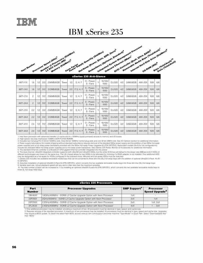
56
IBM xSeries 235
xSeries 235 At-A-Glance
8671-11X 1.8 1/2 512 256MB/6GB Tower 1/2 S, H, F O - Power,
S - Fans Y 10/100/1000 D,U320 4/2 0/660.6GB 48X-20X 10/8 6/6
8671-1AX 1.8 1/2 512 512MB/6GB Tower 2/2 P, S, H, F S - Power, S - Fans Y 10/100/
1000 D,U320 4/2 0/660.6GB 48X-20X 10/8 6/6
8671-21X 2 1/2 512 256MB/6GB Tower 1/2 S, H, F O - Power,
S - Fans Y 10/100/1000 D,U320 4/2 0/660.6GB 48X-20X 10/8 6/6
8671-2AX 2 1/2 512 512MB/6GB Tower 2/2 P, S, H, F S - Power, S - Fans Y 10/100/
1000 D,U320 4/2 0/660.6GB 48X-20X 10/8 6/6
8671-31X 2.2 1/2 512 256MB/6GB Tower 1/2 S, H, F O - Power,
S - Fans Y 10/100/1000 D,U320 4/2 0/660.6GB 48X-20X 10/8 6/6
8671-3AX 2.2 1/2 512 512MB/6GB Tower 2/2 P, S, H, F S - Power, S - Fans Y 10/100/
1000 D,U320 4/2 0/660.6GB 48X-20X 10/8 6/6
8671-41X 2.4 1/2 512 256MB/6GB Tower 1/2 S, H, F O - Power,
S - Fans Y 10/100/1000 D,U320 4/2 0/660.6GB 48X-20X 10/8 6/6
8671-4AX 2.4 1/2 512 512MB/6GB Tower 2/2 P, S, H, F S - Power,
S - Fans Y 10/100/1000 D,U320 4/2 0/660.6GB 48X-20X 10/8 6/6
1. Intel Xeon processor with advanced transfer L2 cache and 4 x 100MHz (quad-pumped) access to memory and I/O buses.2. High-speed, two-way interleaved 133MHz DDR PC2100 RDIMM.3. Includes two hot-plug PCI-X 64-bit 133MHz slots, three 64-bit 100MHz nonhot-plug slots and one 32-bit 33MHz slot. See I/O Options section for additional information.4. Power supply redundancy for models shipping without standard redundancy requires removal of the standard 560w power supply and the addition of two 560w hot-swap power supplies and a hot-swap power backplane provided with the 560w Hot-swap Power Upgrade Kit (P/N 33P2753). Redundant models (N+N for full configurations) include two standard 560w hot-swap power supplies and a hot-swap power backplane. See xSeries 235 Power, Monitor & Accessories for additional information.5. The standard Ethernet controller is a Broadcom 5703 gigabit Ethernet controller integrated into the planar.6. The dual-channel, Ultra320 integrated controller supports both Ultra160 and Ultra320 HDDs, but the entire SCSI bus will default to the slower rate (MB/second) if HDDs of different technologies are mixed on the same bus. The LSI chipset allows for two HDDs to be allocated for mirroring if a RAID adapter is not installed. One additional HDD may be designated as a hot-spare for HDDs configured in the onboard mirror. Mirrored and hot-spare HDDs must be matched.7. xSeries 235 includes two available removable media bays that can be converted to three slim-line (SL) hot-swap bays with the addition of optional Ultra320 3-Pack Kit (P/N 33P2751).8. Assumes installation of optional Ultra320 3-Pack Kit (P/N 33P2751), which converts the two available removable media bays into three slim-line (SL) hot-swap bays.9. Variable read rate. Actual playback speed will vary and is often less than the maximum possible.10. The total number of bays can be increased to 11 by installing an optional Ultra320 3-pack Kit (P/N 33P2751), which converts the two available removable media bays to three SL hot-swap HDD bays.
xSeries 235 Processors
Part Number
Processor Upgrades SMP Support1 Processor Speed Upgrade2
19K4642 1.8GHz/400MHz - 512KB L2 Cache Upgrade Option with Xeon Processor 1xX -
33P2931 2GHz/400MHz - 512KB L2 Cache Upgrade Option with Xeon Processor 2xX 1xX
33P2932 2.2GHz/400MHz - 512KB L2 Cache Upgrade Option with Xeon Processor 3xX 1xX, 2xX
37L3533 2.4GHz/400MHz - 512KB L2 Cache Upgrade Option with Xeon Processor 4xX 1 .. . 3xX1. One additional processor may be installed, providing a maximum of two. All processors must be identical in type, speed, and cache size.2. Requires removal of the standard processor. A maximum of two processors may be installed. All processors must be identical in type, speed and cache size. Upgrades may require a BIOS update. To obtain the latest Flash BIOS, access www.pc.ibm.com/support and enter machine “Type-Model” in Quick Path. Select “Downloadable files” then “BIOS.”
Part Number
Processor Speed (G
Hz)1
Number of P
rocessors (Std/M
ax)
L2 ECC Cache (KB)
Memory (Std/M
ax)2
Form Factor
Power Supply Quantity
(Std/M
ax)
Hot-Swap (P
ower, Slots, H
DD, Fans)3
Redundancy (Optio
nal, Standard)4
Integrated System Management P
rocessor
Onboard Ethernet (Mbps)5
SCSI Contro
ller (D
ual, Ultr
a, RAID)6
Removable Media Bays (T
otal/Avail)
7
Internal Hard Disk Driv
e (Std/M
ax)8
CD-ROM (ID
E)9
Bays (Total/A
vail)10
Slots (Total/A
vail)

57For the latest product & technical information, refer to the Information Sources on pages 2 and 3.Updated 10/15/02
IBM
xS
eri
es
23
5
The xSeries 235 contains 10 drive bays in the standard base configuration. The six 3.5in hot-swap bays on the lower half of the chassis front support Ultra320 or Ultra160 hot-swap HDDs. The four media bays above the HDD bays include a 3.5in bay for the standard floppy disk drive (FDD) and a 5.25in bay containing the standard CD-ROM. The two open 5.25in media bays are available for removable media devices such as tape drives, or an Ultra320 3-bay kit can be installed in two available media bays to provide a hot-swap backplane that supports three slim-line hot-swap HDDs.
The standard six-bay hot-swap backplane connects to one channel of the dual-channel integrated Ultra320 storage controller through a single-drop 16-bit LVD SCSI cable. If internal RAID is required, this cable cannot be used to connect optional ServeRAID-4H, -4Mx or -4Lx controllers to the hot-swap backplane. Instead, optional Single-drop Internal LVD Ultra160 SCSI Cable (P/N 71P8995) must be purchased. If the RAID controller is ServeRAID-5i, a cable is not required and both channels of the integrated controller are managed by ServeRAID-5i. The standard SCSI cable cannot be used to connect to an optional SCSI media device because it is not terminated.
One full-high or half-high tape drive can be installed in the available media bays. The terminated LVD SCSI cable provided with the tape drive can be used to connect the tape drive to the integrated controller if ServeRAID-4H, -4Mx or -4Lx are installed (or if no RAID controller is installed). If ServeRAID-5i is installed, only supported tape drives can be connected to the RAID bus (see Tape Options section). If the tape drive is not supported for RAID attachment or the configuration does not require the tape drive to be installed on the RAID bus, PCI Wide Ultra160 SCSI Adapter (P/N 19K4646) is required.
External tape drive support requires installation of External SCSI Interface Kit (P/N 32P8164) to connect the external port to the second channel of the integrated controller. The external port cannot be enabled if both channels of the integrated controller are connected internally. If ServeRAID-5i is installed, only RAID-supported tape drives can be installed in the tape enclosure. An external tape enclosure is also supported by installing PCI Wide Ultra160 SCSI Adapter (P/N 19K4646), in which case the External SCSI Interface Kit is no longer required.
For additional information regarding internal cabling, refer to Appendix F: Internal Cabling Overview.
xSeries 235 Memory
Total System Memory1
Quantity of RDIMMs Added
256MB (2 x 128) Models
512MB (2 x 256) Models
128MB (33L5036)
256MB (33L5037)
512MB (33L5038)
1GB (33L5039)
512MB 768MB 2 - - -
768MB 1024MB 4 - - -
1024MB 1280MB 2 2 - -
1280MB 1536MB - 4 - -
1792MB 2048MB - 2 2 -
2304MB 2560MB - - 4 -
2560MB 2816MB 2 - - 2
2816MB 3072MB - 2 - 2
3328MB 3584MB - - 2 2
4352MB 4608MB - - - 4
Part Number
Memory Description16GB (max)2 6GB (max)2 - - - 6
33L5036 128MB DDR PC2100 ECC RDIMM This table does not represent all possible memory configurations. Memory modules may vary in price per MB. Selection of smaller RDIMMs may provide a more cost-effective alternative to using larger RDIMMs.
1. Network operating systems may limit the maximum amount of addressable memory. See operating system specifications for further information.2. Requires replacing the standard RDIMM.
33L5037 256MB DDR PC2100 ECC RDIMM
33L5038 512MB DDR PC2100 ECC RDIMM
33L5039 1GB DDR PC2100 ECC RDIMM
1. Due to two-way interleaving, installation of memory options in matched pairs beginning with set 1 is required.
xSeries 235 Internal SCSI Cabling
RDIMM 1
Set 1: RDIMMs 5, 6Set 2: RDIMMs 3, 4Set 3: RDIMMs 1, 2
RDIMM 2
RDIMM 4
RDIMM 5
RDIMM 6
RDIMM 3

58
xSeries 235 Hard Disk Drive (HDD) Storage
Total Internal Storage1
10,000rpm HDDs 15,000rpm HDDs18.2GB
(06P5754) 36.4GB
(06P5755)73.4GB
(06P5756)18.2GB
(06P5767)36.4GB
(06P5768, 06P5776)4
0GB Standard on base models
18.2GB 1 - - 1 -
36.4GB 2 1 - 2 1
54.6GB 3 - - 3 -
72.8GB 4 2 - 4 2
91GB 5 - - 5 -
109.2GB 6 3 - 6 3
145.6GB - 4 - - 4
182GB - 5 - - 5
218.4GB - 6 - - 6
327.6GB2 - 9 - - 9
440.4GB - - 6 - -
660.6GB3 - - 9 - -
This table does not represent all possible HDD configurations. Total Internal Storage listed is within +/-0.2GB unless otherwise noted.
1. Select a total storage row then select the quantity of HDDs from a column corresponding to the HDD of choice.2. Internal storage using 36.4GB HDD can be increased to 327.6GB by converting the two available removable bays to three hot-swap HDD bays using an optional Ultra320 3-Pack Kit (P/N 33P2751).3. Maximum internal storage using 73.4GB HDD can be increased to 660.6GB by converting the two available removable media bays to three hot-swap HDD bays using an optional Ultra320 3-Pack Kit (P/N 33P2751).4. When an Ultra320 HDD is installed in the same SCSI bus as an Ultra160 HDD, performance of the entire bus is reduced to Ultra160 speeds.
Bay Form Factor
Height Front Access
Usage Part Number
Description RPM Height Bays Supported1
Max Qty2
A1 133mm (5.25in) HH2 Yes Open Hot-Swap Ultra160 HDDs
B1 133mm (5.25in) HH2 Yes Open 06P5754 18.2GB 10Krpm Ultra160 SCSI Hot-
swap SL HDD 10000 SL 1 ... 6 6
C3 133mm (5.25in) HH Yes IDE CD-
ROM 06P5755 36.4GB 10Krpm Ultra160 SCSI Hot-swap SL HDD 10000 SL 1 ... 6 6
D4 89mm(3.5in) SL Yes Diskette 06P5756 73.4GB 10Krpm Ultra160 SCSI Hot-
swap SL HDD 10000 SL 1 ... 6 6
1 ... 6 HS SL Yes Open 06P5767 18.2GB 15Krpm Ultra160 SCSI Hot-swap SL HDD 15000 SL 1 ... 6 6
1. Removable media bays A and B can be converted to three hot-swap HDD bays using the optional Ultra320 3-Pack Kit (P/N 33P2751).2. Two half-high (HH) bays can be combined to support a singlefull-high (FH) device. 3. This bay supports optical drives only.4. This bay supports a floppy disk drive only.
06P5768 36.4GB 15Krpm Ultra160 SCSI Hot-swap SL HDD 15000 SL 1 ... 6 6
Hot-Swap Ultra320 HDDs
06P5776 36.4GB 15Krpm Ultra320 SCSI Hot-swap SL HDD 15000 SL 1 ... 6 6
Associated Options33P2751 Ultra320 3-Pack Kit3 - - A+B 1
32P8164 External SCSI Interface Kit4 - - - 1
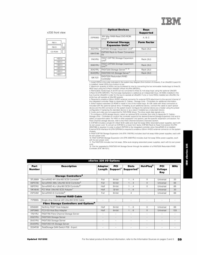
59For the latest product & technical information, refer to the Information Sources on pages 2 and 3.Updated 10/15/02
IBM
xS
eri
es
23
5
Optical Devices Bays Supported
22P6950 16X Max RAM-Read DVD-ROM Drive5, 6 A, B, C
External Storage Expansion Units7
Form Factor
35311RU EXP300 Storage Expansion Unit8 Rack (3U)
09N7296 EXP300 Rack-to-Tower Conversion Kit -
17401RU FAStT EXP700 Storage Expansion Unit9 Rack (3U)
35601RU FAStT EXP500 Storage Expansion Unit10 Rack (3U)
35421RU FAStT200 Storage Server11, 12 Rack (3U)
35422RU FAStT200 HA Storage Server11 Rack (3U)
19K1121 FAStT200 Redundant RAID Controller -
1. Install HDDs in the order indicated in the system bay diagram (from bottom of chassis). If an Ultra320 3-pack Kit is installed, install HDDs from bottom to top.2. Maximum quantity of HDDs can be increased to nine by converting the two removable media bays to three SL HDD bays using the 3-Pack Ultra320 3-Pack Kit (P/N 33P2751).3. Removable media bays A and B can be converted to three SL hot-swap bays using the optional Ultra320 3-Pack Kit (P/N 33P2751). The hot-swap backplane is cabled as an independent bus. All HDDs installed in the bus must be Ultra320 in order for the bus to operate at Ultra320. If one or more HDDs installed are Ultra160, the entire bus will operate at Ultra160 speeds.4. Required to enable a 0.8mm VHDCI external connector for external SCSI attachment to the second channel of the integrated controller. Refer to Appendix D: Cables - Storage Units - Controllers for additional information.5. Either replace standard CD-ROM or install in one of the media bays. An IDE cable with three connectors is included with the optional optical drive. If installing as an additional device, connect the cable to each optical device and the IDE connector on the system board. Configure the optional device as a master using the preset configuration if replacing the standard device or as a slave if installed as a redundant device.6. Audio and video are not supported for DVD-ROM drives. The drive reads data signals only.7. To configure a SCSI storage device, select an optional SCSI controller then refer to Appendix D: Cables - Storage Units - Controllers to confirm the controller supports the desired External Storage Expansion Unit and to select a supported cable. For HDD or other expansion unit options, see the specific expansion unit section. For Fibre Channel storage devices, refer to the Fibre Channel Solutions Overview section.8. EXP300 includes a single 2m Ultra2 SCSI cable and dual hot-swap 500w redundant power supplies, each with its own power cord. To convert an EXP300 to a tower form factor, EXP300 Rack-to-Tower Conversion Kit (P/N 09N7296) is required. In order to attach EXP300 to the integrated controller when ServeRAID-5i is installed, External SCSI Interface Kit (P/N 32P8164) is required to enable a 0.8mm VHDCI external connector on the system chassis.9. FAStT EXP700 Storage Expansion Unit (P/N 17401RU) includes dual hot-swap 400w power supplies, each with its own power cord.10. FAStT EXP500 Storage Expansion Unit (P/N 35601RU) includes dual hot-swap 350w power supplies, each with its own power cord.11. The FAStT200 includes two hot-swap, 350w auto-ranging redundant power supplies, each with its own power cord.12. Can be upgraded to FAStT200 HA Storage Server through the addition of a FAStT200 Redundant RAID Controller (P/N 19K1121).
xSeries 235 I/O Options
Part Number
Description Adapter Length
PCI Support1
Slots Supported1
Hot-Plug2 PCI Voltage
Key
MHz
Storage Controllers3
37L6889 ServeRAID-4H Ultra160 SCSI Controller4 Full 64-bit 1 . .. 4 X Universal 33
06P5736 ServeRAID-4Mx Ultra160 SCSI Controller5 Full 64-bit 1 . .. 4 X Universal 66
06P5740 ServeRAID-4Lx Ultra160 SCSI Controller6 Half 64-bit 1 . .. 4 X Universal 66
19K4646 PCI Wide Ultra160 SCSI Adapter7 Half 32-bit 1 . .. 6 - Universal 33
25P3492 ServeRAID-5i Controller8 Full 64-bit 4 - Universal 66
Internal RAID Cable71P8995 Single-drop Internal LVD Ultra160 SCSI Cable - - - - - -
Fibre Storage Controllers and Options9
00N6881 Netfinity FAStT Host Adapter Half 64-bit 1 . .. 6 X Universal 66
24P0960 FC2-133 Host Bus Adapter Half 64-bit 1 . .. 6 X Universal 133
17421RU FAStT700 Fibre Channel Storage Server - - - - - -
35521RU FAStT500 Storage Server - - - - - -
35421RU FAStT200 Storage Server - - - - - -
35422RU FAStT200 HA Storage Server - - - - - -
3534F08 TotalStorage SAN Switch F08 - 8-port - - - - - -
x235 front view
RM A
RM B
CD-ROM
FDD
HDD 5
HDD 4
HDD 6
HDD 2
HDD 3
HDD 1

60
2109F16 SAN Fibre Channel Switch, 16-Port - - - - - -
2108R3L SAN Data Gateway Router Ultra SCSI LVD Port10 - - - - - -
Networking11
Ethernet12
06P3601 10/100 Ethernet Server Adapter13 Half 32-bit 1 .. . 6 X Universal 33
09N9901 10/100 EtherLink Server Adapter by 3Com14 Half 32-bit 1 .. . 6 X Universal 33
22P4901 10/100 Dual Port Server Adapter13 Half 64-bit 1 .. . 6 X Universal 66
22P6801 PRO/1000XT Server Adapter by Intel (copper) w/CD, manuals13 Half 64-bit 1 .. . 6 X Universal 133
22P7801 NetXtreme 1000 SX Fiber Ethernet Adapter Half 64-bit 1 .. . 6 X Universal 133
Token Ring
34L5201 High-Speed 100/16/4 Token-Ring PCI Management Adapter Half 32-bit 1 .. . 6 X Universal 33
34L5001 16/4 Token-Ring PCI Management Adapter13 Half 32-bit 1 .. . 6 X Universal 33
Communications15
19K4162 V.90 PCI Data/Fax WinModem (Low Profile Enabled)16 Half 32-bit 1 - 5 33
33L4618 V.90 PCI Data/Fax Modem16 Half 32-bit 1 - 5 33
37L14xx Serial I/O SST 8- and 16-port adapters17 Half 32-bit 1 - 5 33
System Management09N7585 Remote Supervisor Adapter18 Half 32-bit 1 - Universal 33
Note: xSeries 235 supports the IXA Adapter (P/N 1519100) for connection to iSeries models for Windows 2000 Server and Advanced Server. Installation is restricted to slot four and Remote Supervisor Adapter (P/N 09N7585) must be installed.
1. A 64-bit adapter installed into a 32-bit slot will transfer data at 32-bit rates. Adapters rated at 66MHz will operate at 33MHz when installed in a 33MHz slot. 33MHz adapters will reduce 66MHz buses to 33MHz. 133MHz PCI-X adapters are backward compatible with 33/66MHz, 64-bit PCI-based servers.2. Slots five and six (bus 2) are hot-plug capable. For Network Operating System support, access www.pc.ibm.com/us/compat.3. xSeries 235 includes a dual-channel Ultra320 SCSI controller with two internal connectors. An external 0.8mm VHDCI connector can be enabled using optional External SCSI Interface Kit (P/N 32P8164) to connect channel A to the external connector. External connection using this option and the external knockout is not supported if both channels of the integrated controller are connected internally, in which case a supported PCI SCSI controller is required to support an external SCSI device. See “Internal SCSI Cabling” for cabling alternatives.4. ServeRAID-4H Ultra160 SCSI Controller is powered by a 266MHz PowerPC 750 processor and provides 128MB of battery-backed ECC cache with two internal and four external Ultra160 connectors (a combination of four connectors may be utilized). External connectors are 0.8mm VHDCI. Connection of this adapter to the HDD backplane requires optional Single-drop Internal LVD Ultra160 SCSI Cable (P/N 71P8995), which is a 30in single-drop nonterminated LVD SCSI cable.5. ServeRAID-4Mx Ultra160 SCSI Controller is powered by a 100MHz Intel Zion GC80303 processor that provides 64MB of battery-backed ECC cache and two internal and two external Ultra160 connections (only two connectors may be used). External connections are 0.8mm VHDCI. Connection of this adapter to the HDD backplane requires optional Single-drop Internal LVD Ultra160 SCSI Cable (P/N 71P8995), which is a 30in single-drop nonterminated LVD SCSI cable.6. ServeRAID-4Lx Ultra160 SCSI Controller is powered by a 100MHz Intel Zion GC80303 processor and provides a single channel, 32MB of ECC cache and either one internal or one external Ultra160 connection. External connector is 0.8mm VHDCI. Connection of this adapter to the HDD backplane requires optional Single-drop Internal LVD Ultra160 SCSI Cable(P/N 71P8995), which is a 30in single-drop nonterminated LVD SCSI cable.7. PCI Wide Ultra160 SCSI Adapter (P/N 19K4646) provides a single channel with one internal connector, a five-drop multi-mode terminated LVD SCSI cable and one external 0.8mm VHDCI connector. Only one of the two connectors may be utilized.8. ServeRAID-5i (P/N 25P3492) supports both Ultra320 and Ultra160 HDDs in a dedicated or mixed environment. The adapter installs into PCI slot four and converts both channels of the onboard SCSI controller to RAID in conjunction with the LSI 1020/30 chipset. Both the standard and the optional SCSI HDD backplanes cable directly to the onboard controller connectors. Half-high tape drives can be supported either internally or externally on the second channel of an integrated controller managed by ServeRAID-5i if the bus is designated as SCSI during RAID setup. Supports up to 528MB/s data transfers across the PCI bus with 128MB ECC SDRAM write-back cache with battery backup. Supports RAID levels 0, 1, 10, 5, 50 and 1E. The option includes brackets for installation in both low-profile and standard PCI slots.9. See Fibre Channel Solutions Overview section for additional configuration information.10.The 2108R3L SAN Data Gateway Router Ultra SCSI LVD Port provides one integrated short-wave optical port and two SCSI ports for tape storage connections (LVD, HVD and single-ended).11. xSeries 235 includes a copper integrated 10/100/1000Mbps Broadcom (BCM5703) single-port Ethernet controller.12. In a fault-tolerant networking environment, using the fault-tolerant software delivered with the Ethernet adapters of a single manufacturer is recommended. Installing fault-tolerant solutions provided by multiple manufacturers may cause failures if the intermediate drivers provided with the adapters are not compatible.Three optional Ethernet adapters are copper and Intel-based (P/N 06P3601, 22P4901, 22P6801). One is Broadcom-based (22P7801).13. The Wake on LAN (WoL) function provided by this Ethernet PCI adapter is supported in this system.14. Not supported when greater than 4GB of random access memory (RAM) is installed.15. xSeries 235 provided three USB ports (two on the rear of the chassis and one on the front), one serial port, two RS-485 ports for system management and one parallel port.16. Due to homologation variances, modem availability may differ by country.17. See Appendix E for details on Serial I/O options and configuration limitations.18. When installed in xSeries 235, Remote Supervisor Adapter (RSA) shares functionality with the integrated service processor and serves as interface for both. RSA provides full system management functionality through a customer-supplied Ethernet cable or modem connection or as part of an interconnected system management bus (option includes all interconnect hardware). An external Cat5 connection between RSA and the integrated service processor using the pigtail cable and short Cat5 cable supplied with RSA is not required. The 20-pin ribbon cable connecting RSA to the planar meets all powering and signaling requirements. Connection of the external AC power supply provided with RSA is not required.
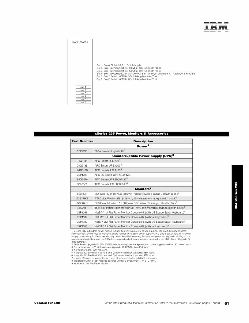
61For the latest product & technical information, refer to the Information Sources on pages 2 and 3.Updated 10/15/02
IBM
xS
eri
es
23
5
xSeries 235 Power, Monitors & Accessories
Part Number Description
Power1
33P2753 560w Power Upgrade Kit2
Uninterruptible Power Supply (UPS)3
94G3134 APC Smart-UPS 7004
94G3135 APC Smart-UPS 10004
94G3136 APC Smart-UPS 14004
32P1020 APC 2U Smart-UPS 1400RMB
94G6676 APC Smart-UPS 3000RMB5
37L6861 APC Smart-UPS 5000RMB6
Monitors7
633147N E54 Color Monitor 15in (350mm, 13.8in viewable image), stealth black8
63324HN E74 Color Monitor 17in (406mm, 16in viewable image), stealth black8
66274AN G78 Color Monitor 17in (406mm, 16in viewable image), stealth black8
9512AB1 T541 Flat Panel Color Monitor (381mm, 15in viewable image), stealth black4
32P1031 NetBAY 1U Flat Panel Monitor Console Kit (with US Space Saver keyboard)9
32P1032 NetBAY 1U Flat Panel Monitor Console Kit (without keyboard)9
32P1702 NetBAY 2U Flat Panel Monitor Console Kit (with US Space Saver keyboard)9
32P1703 NetBAY 2U Flat Panel Monitor Console Kit (without keyboard)9
1. xSeries 235 redundant power models include two hot-swap 560w power supplies, each with two power cords. Nonredundant power models include a single nonhot-swap 560w power supply with a single power cord. N+N power supply redundancy for these models may be achieved by removing the standard power supply and installing a hot-swap power backplane and two 560w hot-swap redundant power supplies provided in the 560w Power Upgrade Kit (P/N 33P2753).2. 560w Power Upgrade Kit (P/N 33P2753) includes a power backplane, two power supplies and two 9ft power cords. 3. For runtimes and UPS attributes see Appendix C: UPS Runtime Estimate.4. Not supported for rack mounting.5. Height is 3U. See Rack Cabinets and Options section for supported IBM racks.6. Height is 5U. See Rack Cabinets and Options section for supported IBM racks.7. xSeries 235 uses an integrated ATI Rage XL video controller with 8MB of memory.8. Installation within a rack requires optional Monitor Compartment (P/N 94G7444).9. Includes a 15in Flat Panel Monitor.
slot 1
slot 4
slot 6
slot 2slot 3
slot 5
Slot 1: Bus 0, 32-bit, 33MHz, 5v, full-lengthSlot 2: Bus 1 (primary), 64-bit, 100MHz, 3.3v, full-length PCI-XSlot 3: Bus 1 (primary), 64-bit, 100MHz, 3.3v, full-length PCI-X
Slot 5: Bus 2, 64-bit, 100MHz, 3.3v, full-length Active PCI-XSlot 4: Bus 1 (secondary), 64-bit, 100MHz, 3.3v, full-length extended PCI-X (supports RAID 5i)
Slot 6: Bus 2, 64-bit, 100MHz, 3.3v, full-length Active PCI-X
rear of chassis
slot 6slot 5

62
Part Number Description
Conversion Kits
59P4211 5Ux24D Tower-to-Rack Kit III
Rack and NetBAY1
Refer to the Rack Cabinets and Options section for information concerning IBM racks and rack-supported devices.
Keyboard and Mouse2
28L3644 Space Saver II Keyboard3, 5
10K3849 106-key Preferred USB Keyboard with 2-port USB Hub (stealth black)4, 6
22P5150 TrackPoint USB Space Saver Keyboard3, 5, 6
28L3673 Sleek 2-Button Stealth Black Mouse
33L3244 Sleek USB Mouse (stealth black)6
1. Rack installations require a supported IBM rack and a tower-to-rack conversion kit.2. xSeries 235 includes tower models only and ships with a keyboard and mouse.3. Installation within a rack requires optional keyboard tray (P/N 28L4707) which stows in ready-to-use position, or NetBAY 1U or 2U Flat Panel Monitor Console Kit (P/N 32P1032, 32P1702). Standard with 1U and 2U NetBAY console kits (P/N 32P1031, 32P1702).4. Installation within a rack requires optional keyboard tray (P/N 28L4707). This keyboard cannot share a keyboard tray with a flat panel display.5. Advanced TrackPoint IV features are not available on IBM xSeries systems.6. USB accessories attach to a single USB-capable server. They are not compatible with the NetBAY console switches.
xSeries 235 Tape Options
Part Number
Tape Drives
Bays Supported
SCSI Interface
(bit)
Form Factor Termination Included
Ext Tape Enclosures
00N7991 20/40GB DDS/4 4mm Internal Tape Drive1 A, B 16 Ultra2 LVD89mm (3.5in) HH or 133mm (5.25in)
HHY2 35100204,
35510013
00N8015 110/220GB Super DLT Internal SCSI Tape Drive A+B 16 Ultra2 LVD 133mm (5.25in) FH Y2 35510013
3503B1X
00N8016 100/200GB LTO Tape Drive A+B 16 Ultra2 LVD 133mm (5.25in) FH Y2 35510013
3503B1X
24P2396 100/200GB LTO Half-High Tape Drive1 A, B 16 Ultra2 LVD 133mm (5.25in) HH Y2 35510013
35100204
24P2398 40/80GB Half-High DLTVS Internal SCSI Tape Drive1 A, B 16 Ultra2 LVD 133mm (5.25in)
HH Y2 35510013
35100204
Tape Autoloaders
00N7992 120/240GB DDS/4 Tape Autoloader A+B 16 Ultra2 LVD 133mm (5.25in) FH Y2 35510013
3503B1X
3600109 3600 Series 900GB/1.8TB LTO Tape Autoloader5 - 16 Ultra2 LVD Tower or 6U Rack Y -
360716X 3607 Series 1760GB/3.5TB SDLTpro Tape Autoloader - 16 Ultra2 LVD 2U Rack Y -
External Tape Libraries6
3600R20 3600 Series 2/4TB LTO Tape Library (Rack) - 16 Ultra2 LVD 5U Rack Y -
3600LXU 3600 Series 2-Drive, 20-Cartridge Expander Module7 - 16 Ultra2 LVD 5U Rack Y -
09N4048 3600 Series LTO Drive Upgrade Option8 - 16 Ultra2 LVD - N -
External Tape Enclosures3510020 External Half-High SCSI Storage Enclosure9 - 8, 16 Desktop N -
3503B1X Full-High SCSI Tape Enclosure10 - 16 Ultra2 LVD Desktop or 3U Rack Y -
3551001 NetMEDIA Storage Expansion Unit EL11 - 16 Rack Y -10L7113 NetMEDIA Systems Management Adapter12 - 16 LVD - Y 3551001
Associated Options10K2340 Media BayTray and LVD Cable Kit - 16 LVD Int Y 3551001
00N7956 68-pin External Multimode LVD/SE SCSI Terminator - 16 LVD/SE Ext Y 3510020
32P8164 External SCSI Interface Kit13 - 16 LVD Int Y -

63For the latest product & technical information, refer to the Information Sources on pages 2 and 3.Updated 10/15/02
IBM
xS
eri
es
23
5
Note: The following sample configurations are for illustration only and may not be suitable for any specific customer installation. Contact your IBM Business Partner or IBM Marketing Representative for assistance with your specific configuration requirements.
File and Print Server (large user base)
Note: Optional External SCSI Interface Kit (P/N 32P8164) is required to enable the external 0.8mm VHDCI connector on the rear of the chassis to support external tape enclosures. Attachment of internal media bay devices to one connector of the Ultra320 controller requires a supported terminated SCSI cable that is provided with optional tape drives. If the hot-swap HDD backplane is connected to ServeRAID-4H, 4Mx or 4Lx, an internal tape drive can be connected to the integrated controller. If ServeRAID-5i supports the internal HDD backplanes, some tape drives can be supported on channel B of the integrated controller (which is managed by the ServeRAID-5i adapter) if the bus is designated as conventional SCSI during set-up and Microsoft Windows 2000 is installed. ServeRAID-5i supports the same tape drives in an external tape enclosure on the second channel if the external SCSI port is enabled (the external port cannot be enabled if both channels of the integrated controller are connected internally). Optional PCI Wide Ultra160 SCSI Adapter (P/N 19K4646) also supports external tape enclosures and internal tape drives.
1. Supported by ServeRAID-5i when installed on an internal bus connected to an integrated controller connector or in an external tape enclosure when connected to the second channel of the integrated controller through the enabled external SCSI port.2. Termination requires installing the 34in single-drop, terminated LVD SCSI cable provided with the option. When installed in a NetMEDIA Storage Expansion Unit, termination is also provided by the standard cables shipped with the enclosure.3. LVD support for LVD tape drives installed in a NetMEDIA Storage Expansion Unit EL (P/N 3551001) is provided by two four-drop internal LVD cables.4. Requires 68-pin External Multimode LVD/SE SCSI terminator (P/N 00N7956).5. If installed in a rack, a fixed shelf is required. Allow an additional 1U for the fixed shelf. One unit only per shelf is supported.6. Tape library attributes and prerequisites are located in Appendix B: Tape Library Attributes.7. Supported only with the 3600 Series LTO Tape Library (rack) (P/N 3600R20). Allow one additional EIA space when installing either one or two (maximum) units to accommodate a filler plate for cable routing. Up to two 3600 Series LTO Drive Upgrade Options can be installed in each module or the module can operate off the LTO drives installed in the LTO tape library.8. Install in second drive bay of 3600 Series LTO Tape Libraries or in either of the two bays of 3600 Series 2-drive 20-Cartridge Expander Module to increase performance. Includes an LTO (Ultrium) drive and a one-meter external LVD SCSI cable.9. Black desktop tape enclosure that supports a single133mm (5.25in) half-high (HH) tape drive. Internal connector is configurable as 50-pin Centronix or 68-pin high density. Requires either tape drive self termination or 68-pin External Multimode LVD/SE SCSI Terminator (P/N 00N7956). The option includes face plates for either a 68-pin HD or 0.8mm VHDCI external connection. External cables are not included.10. Black desktop or 3U rack tape enclosure supports a single 133mm (5.25in) full-high LVD tape device including DLT tape drives. Requires a fixed shelf if installed in a rack (allow additional 1U for fixed shelf). Includes a 90w power supply, cooling fan, external terminator, power cord (country-specific), and 2m 68-pin to 0.8mm external cable. Supports the following full-high tape options: 00N8015, 00N8016, 00N7992.11. NetMEDIA Storage Expansion Unit EL (P/N 3551001) is a black 3U, rack-mountable tape enclosure which includes two full-high (FH) or four half-high (HH) extended length 133mm (5.25in) bays, two external 0.8mm VHDCI connectors and two internal four-drop LVD terminated 16-bit SCSI cables for device attachment. Two power supplies and two power cords are also included. External storage cables are not included.12. NetMEDIA Systems Management Adapter (P/N 10L7113) may be installed in a 3551001 to provide repeater function, aggregate cable lengths up to 12m when attached to an LVD SCSI controller, and auto-termination when the 3551001 is powered off. External connector is 0.8mm VHDCI.13. Required to connect one channel of the integrated Ultra320 storage controller to the 0.8mm VHDCI external port, which cannot be enabled if both channels of the integrated controller are connected internally.
Note: Additional tape attributes can be found in Appendix A: Tape Drive Attributes.
xSeries 235 Sample Configurations
Part Number Description Quantity8671-21X xSeries 235 2GHz/512KB Xeon, 256MB ECC, open, 48X 133L5036 128MB DDR PC2100 ECC DIMM 21
06P5754 18.2GB 10Krpm Ultra160 SCSI Hot-swap SL HDD 22
06P5755 36.4GB 10Krpm Ultra160 SCSI Hot-swap SL HDD 43
25P3492 ServeRAID-5i Controller 100N7991 20/40GB DDS/4 4mm Internal Tape Drive 163324HN E74 Color Monitor 17in (406mm, 16in viewable image), stealth black 194G3136 APC Smart-UPS 1400 1
1. For a total of 512MB of system memory.2. Two HDDs are used to provide NOS mirroring.3. Three HDDs are used for RAID 5 protection. One HDD is identified as a hot-spare. Effective capacity is two HDDs or 72.8GB.

64
High-availability Microsoft Exchange Server Solution
Part Number Description Quantity8671-2AX xSeries 235 2GHz/512KB Xeon, 512MB ECC, open, 48X 133P2931 2GHz/400MHz - 512KB L2 Cache Upgrade Option with Xeon Processor 11
33L5037 256MB DDR PC2100 ECC DIMM 225P3492 ServeRAID-5i Controller 109N7585 Remote Supervisor Adapter 106P5754 18.2GB 10Krpm Ultra160 SCSI Hot-swap SL HDD 22
06P5755 36.4GB 10Krpm Ultra160 SCSI Hot-swap SL HDD 43
32P8164 External SCSI Interface Kit 133P2753 560w Power Upgrade Kit III 159P4211 5Ux24DTower-to-Rack Kit 19306250 NetBAY25 Standard Rack Cabinet 13551001 NetMEDIA Storage Expansion Unit EL 124P2398 40/80GB Half-High DLTVS Internal SCSI Tape Drive 163324HN E74 Color Monitor 17in (406mm, 16in viewable image), stealth black 132P1020 APC 2U Smart-UPS 1400RMB 194G6670 Blank Filler Panel Kit 1
1. For a total of 1GB of system memory.2. Two HDDs are used to provide NOS mirroring.3. Three HDDs are used for RAID 5 protection. One HDD is identified as a hot-spare. Effective capacity is two HDDs or 72.8GB.

65For the latest product & technical information, refer to the Information Sources on pages 2 and 3.Updated 10/15/02
IBM
xS
eri
es
23
5

IBM xSeries 250
EMEA Part Number Cross ReferencexSeries 250 S ystem Unit Part Numbers
EMEA AMERICAS M/C TYPE DESCRIPTION EMEAP/N P/N MODEL WDFM DATE
K561Yxx 866561Y 8665-61Y PIII Xeon 700MHz/100MHz, 1MB, 512MB, Open BayUltra2, Tower 31/05/02
K56RYxx 86656RY 8665-6RY PIII Xeon 700MHz/100MHz, 1MB, 512MB, Open BayUltra2, Rack 31/05/02
K571Yxx 866571Y 8665-71Y PIII Xeon 700MHz/100MHz, 2MB, 512MB, Open BayUltra2, Tower 31/05/02
K57RYxx 86657RY 8665-7RY PIII Xeon 700MHz/100MHz, 2MB, 512MB, Open BayUltra2, Rack 31/05/02
K581Yxx 866581Y 8665-81Y PIII Xeon 900MHz/100MHz, 2MB, 512MB, Open BayUltra2, Tower 31/05/02
K58RYxx 86658RY 8665-8RY PIII Xeon 900MHz/100MHz, 2MB, 512MB, Open BayUltra2, Rack 31/05/02
xSeries 250 Hard Disk Drive Storage Part NumbersEMEA AMERICAS M/C TYPE DESCRIPTION EMEA
P/N P/N MODEL WDFM DATENotes 1&2 19K11xx 35311RU --- EXP300 Storage Expansion Unit ---Notes 3&2 00N71xx 35601RU --- FAStT EXP500 Storage Expansion Unit ---Notes 4&2 24P09xx 17401RU --- FAStT EXP700 Storage Expansion Unit ---Notes 5&2 19K11xx 35421RU --- FAStT 200 Storage Server ---Notes 6&2 19K11xx 35422RU --- FAStT 200 HA Storage Server ---
1. Where ‘xx’ represents a specific country code as follows: 51=US/English, 52=European/English, 56=Danish/English, 57=Israel/English, 58=Italian/English, 59=South Africa/English, 60=Swiss/English, 63=UK/English.2. This unit does not include Rack Power Cables P/N 94G7448 when shipped (for attachment to highvoltage UPS or PDU). Standard country power cords only are included. If required, order one Rack PowerCable for each power supply.3. Where ‘xx’ represents a specific country code as follows:- 36=US/English, 37=Euro/English, 41=Denmark/English, 42=Israel/English, 43=Italy/English, 44=South Africa/English, 45=Switzerland/English, 49=UK/English.4. Where ‘xx’ represents a specific country code as follows:- 01=Eur/English, 02=Eur/Spanish, 05=Denmark/English, 06=Israel/English, 07=Italy/English, 08=South Africa/English, 09=Switzerland/English, 12=UK/English.5. Where ‘xx’ represents a specific country code as follows:- 23=US/English, 24=Euro/English, 25=Euro/Spanish, 27=Euro/German, 28=Denmark/English, 29=Israel/English, 30=Italy/English, 31=South Africa/English, 32=Switzerland/English, 34=Switzerland/German, 36=UK/English..6. Where ‘xx’ represents a specific country code as follows:- 37=US/English, 38=Euro/English, 39=Euro/Spanish, 41=Euro/German, 42=Denmark/English, 43=Israel/English, 44=Italy/English, 45=South Africa/English, 46=Switzerland/English, 48=Switzerland/German, 50=UK/English.
xSeries 250 I/O Option Part NumbersEMEA AMERICAS M/C TYPE DESCRIPTION EMEA
P/N P/N MODEL WDFM DATEN/A 33L4618 --- V90 PCI Data/Fax WinModem N/A
Note 7 37L14xx 37L14xx --- Serial I/O SST 8 and 16 port Adapters Note 7
Note 8 36L96xx 01K7209 --- Advanced System Management PCI Adapter ---7. Serial I/O Adapter P/Ns 37L1414 and 37L1415 are available. Other Serial I/O adapter part numbers arewithdrawn from marketing in EMEA.8. Where ‘xx’ represents a specific country code as follows:- 57=Denmark, 58=South Africa, 59=UK, 60=Switzerland, 61=Italy, 62=Israel, 01K7310=Europe.
65A Updated 10/15/02
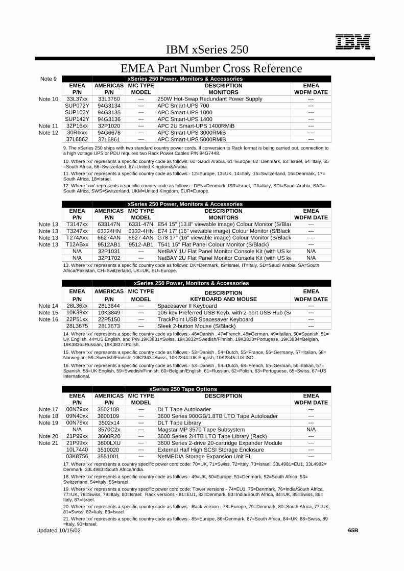
IBM xSeries 250
EMEA Part Number Cross ReferenceNote 9 xSeries 250 Power, Monitors & Accessories
EMEA AMERICAS M/C TYPE DESCRIPTION EMEAP/N P/N MODEL MONITORS WDFM DATE
Note 10 33L37xx 33L3760 --- 250W Hot-Swap Redundant Power Supply ---SUP072Y 94G3134 --- APC Smart-UPS 700 ---SUP102Y 94G3135 --- APC Smart-UPS 1000 ---SUP142Y 94G3136 --- APC Smart-UPS 1400 ---
Note 11 32P16xx 32P1020 --- APC 2U Smart-UPS 1400RMiB ---Note 12 30RIxxx 94G6676 --- APC Smart-UPS 3000RMiB ---
37L6862 37L6861 --- APC Smart-UPS 5000RMiB ---
9. The xSeries 250 ships with two standard country power cords. If conversion to Rack format is being carried out, connection toa high voltage UPS or PDU requires two Rack Power Cables P/N 94G7448.
10. Where ‘xx’ represents a specific country code as follows: 60=Saudi Arabia, 61=Europe, 62=Denmark, 63=Israel, 64=Italy, 65=South Africa, 66=Switzerland, 67=United Kingdom&Arabia.
11. Where ‘xx’ represents a specific country code as follows:- 12=Europe, 13=UK, 14=Italy, 15=Switzerland, 16=Denmark, 17=South Africa, 18=Israel.
12. Where ‘xxx’ represents a specific country code as follows:- DEN=Denmark, ISR=Israel, ITA=Italy, SDI=Saudi Arabia, SAF=South Africa, SWS=Switzerland, UKM=United Kingdom, EUR=Europe.
xSeries 250 Power, Monitors & AccessoriesEMEA AMERICAS M/C TYPE DESCRIPTION EMEA
P/N P/N MODEL MONITORS WDFM DATENote 13 T3147xx 633147N 6331-47N E54 15" (13.8" viewable image) Colour Monitor (S/Blac ---Note 13 T3247xx 63324HN 6332-4HN E74 17" (16" viewable image) Colour Monitor (S/Black) ---Note 13 T274Axx 66274AN 6627-4AN G78 17" (16" viewable image) Colour Monitor (S/Black ---Note 13 T12ABxx 9512AB1 9512-AB1 T541 15" Flat Panel Colour Monitor (S/Black) ---
N/A 32P1031 --- NetBAY 1U Flat Panel Monitor Console Kit (with US ke N/AN/A 32P1702 --- NetBAY 2U Flat Panel Monitor Console Kit (with US ke N/A
13. Where ‘xx’ represents a specific country code as follows: DK=Denmark, IS=Israel, IT=Italy, SD=Saudi Arabia, SA=SouthAfrica/Pakistan, CH=Switzerland, UK=UK, EU=Europe.
xSeries 250 Power, Monitors & AccessoriesEMEA AMERICAS M/C TYPE DESCRIPTION EMEA
P/N P/N MODEL KEYBOARD AND MOUSE WDFM DATENote 14 28L36xx 28L3644 --- Spacesaver II Keyboard ---Note 15 10K38xx 10K3849 --- 106-key Preferred USB Keyb. with 2-port USB Hub (S/ ---Note 16 22P51xx 22P5150 --- TrackPoint USB Spacesaver Keyboard ---
28L3675 28L3673 --- Sleek 2-button Mouse (S/Black) ---14. Where ‘xx’ represents a specific country code as follows:- 46=Danish , 47=French, 48=German, 49=Italian, 50=Spanish, 51=UK English, 44=US English, and P/N 19K3831=Swiss, 19K3832=Swedish/Finnish, 19K3833=Portugese, 19K3834=Belgian,19K3836=Russian, 19K3837=Polish.
15. Where ‘xx’ represents a specific country code as follows:- 53=Danish , 54=Dutch, 55=France, 56=Germany, 57=Italian, 58=Norwegian, 59=Swedish/Finnish, 10K2343=Swiss, 10K2344=UK English, 10K2345=US ISO.
16. Where ‘xx’ represents a specific country code as follows:- 53=Danish , 54=Dutch, 68=French, 55=German, 56=Italian, 57=Spanish, 58=UK English, 59=Swedish/Finnish, 60=Belgian/English, 61=Russian, 62=Polish, 63=Portuguese, 65=Swiss, 67=USInternational.
xSeries 250 Tape OptionsEMEA AMERICAS M/C TYPE DESCRIPTION EMEA
P/N P/N MODEL WDFM DATENote 17 00N79xx 3502108 --- DLT Tape Autoloader ---Note 18 09N40xx 3600109 --- 3600 Series 900GB/1.8TB LTO Tape Autoloader ---Note 19 00N79xx 3502x14 --- DLT Tape Library ---
N/A 3570C2x --- Magstar MP 3570 Tape Subsystem N/ANote 20 21P99xx 3600R20 --- 3600 Series 2/4TB LTO Tape Library (Rack) ---Note 21 21P99xx 3600LXU --- 3600 Series 2-drive 20-cartridge Expander Module ---
10L7440 3510020 --- External Half High SCSI Storage Enclosure ---03K8756 3551001 --- NetMEDIA Storage Expansion Unit EL ---
17. Where ‘xx’ represents a country specific power cord code: 70=UK, 71=Swiss, 72=Italy, 73=Israel, 33L4981=EU1, 33L4982=Denmark, 33L4983=South Africa/India.
18. Where ‘xx’ represents a specific country code as follows:- 49=UK, 50=Europe, 51=Denmark, 52=South Africa, 53=Switzerland, 54=Italy, 55=Israel.
19. Where ‘xx’ represents a country specific power cord code: Tower versions - 74=EU1, 75=Denmark, 76=India/South Africa,77=UK, 78=Swiss, 79=Italy, 80=Israel: Rack versions - 81=EU1, 82=Denmark, 83=India/South Africa, 84=UK, 85=Swiss, 86=Italy, 87=Israel.
20. Where ‘xx’ represents a specific country code as follows:- Rack version - 78=Europe, 79=Denmark, 80=South Africa, 77=UK,81=Swiss, 82=Italy, 83=Israel.
21. Where ‘xx’ represents a specific country code as follows:- 85=Europe, 86=Denmark, 87=South Africa, 84=UK, 88=Swiss, 89=Italy, 90=Israel.
Updated 10/15/02 65B
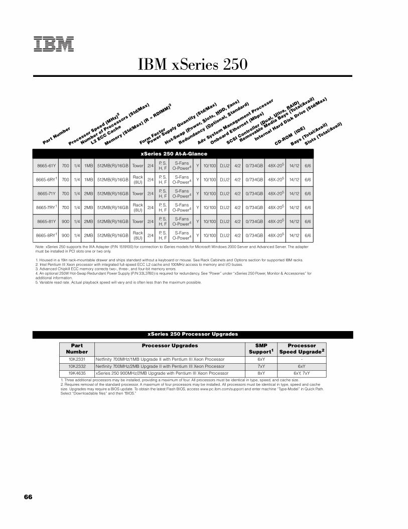
66
IBM xSeries 250
xSeries 250 At-A-Glance
8665-61Y 700 1/4 1MB 512MB(R)/16GB Tower 2/4 P, S, H, F
S-FansO-Power4 Y 10/100 D,U2 4/2 0/734GB 48X-205 14/12 6/6
8665-6RY1 700 1/4 1MB 512MB(R)/16GB Rack (8U) 2/4 P, S,
H, FS-Fans
O-Power4 Y 10/100 D,U2 4/2 0/734GB 48X-205 14/12 6/6
8665-71Y 700 1/4 2MB 512MB(R)/16GB Tower 2/4 P, S, H, F
S-FansO-Power4 Y 10/100 D,U2 4/2 0/734GB 48X-205 14/12 6/6
8665-7RY1 700 1/4 2MB 512MB(R)/16GB Rack (8U) 2/4 P, S,
H, FS-Fans
O-Power4 Y 10/100 D,U2 4/2 0/734GB 48X-205 14/12 6/6
8665-81Y 900 1/4 2MB 512MB(R)/16GB Tower 2/4 P, S, H, F
S-FansO-Power4 Y 10/100 D,U2 4/2 0/734GB 48X-205 14/12 6/6
8665-8RY1 900 1/4 2MB 512MB(R)/16GB Rack (8U) 2/4 P, S,
H, FS-Fans
O-Power4 Y 10/100 D,U2 4/2 0/734GB 48X-205 14/12 6/6
Note: xSeries 250 supports the IXA Adapter (P/N 1519100) for connection to iSeries models for Microsoft Windows 2000 Server and Advanced Server. The adapter must be installed in PCI slots one or two only.
1. Housed in a 19in rack-mountable drawer and ships standard without a keyboard or mouse. See Rack Cabinets and Options section for supported IBM racks.2. Intel Pentium III Xeon processor with integrated full-speed ECC L2 cache and 100MHz access to memory and I/O buses.3. Advanced Chipkill ECC memory corrects two-, three-, and four-bit memory errors. 4. An optional 250W Hot-Swap Redundant Power Supply (P/N 33L3760) is required for redundancy. See “Power” under “xSeries 250 Power, Monitor & Accessories” for additional information.5. Variable read rate. Actual playback speed will vary and is often less than the maximum possible.
xSeries 250 Processor Upgrades
Part Number
Processor Upgrades SMP Support1
Processor Speed Upgrade2
10K2331 Netfinity 700MHz/1MB Upgrade II with Pentium III Xeon Processor 6xY -
10K2332 Netfinity 700MHz/2MB Upgrade II with Pentium III Xeon Processor 7xY 6xY
19K4635 xSeries 250 900MHz/2MB Upgrade with Pentium III Xeon Processor 8xY 6xY, 7xY
1. Three additional processors may be installed, providing a maximum of four. All processors must be identical in type, speed, and cache size.2. Requires removal of the standard processor. A maximum of four processors may be installed. All processors must be identical in type, speed and cache size. Upgrades may require a BIOS update. To obtain the latest Flash BIOS, access www.pc.ibm.com/support and enter machine “Type-Model” in Quick Path. Select “Downloadable files” and then “BIOS.”
Part Number
Processor Speed (M
Hz)2
Number of P
rocessors (Std/M
ax)
L2 ECC Cache
Memory (Std/M
ax) (R = RDIM
M)3
Form Factor
Power Supply Quantity
(Std/M
ax)
Hot-Swap (P
ower, Slots, H
DD, Fans)
Redundancy (Optio
nal, Standard)
Adv System Management P
rocessor
Onboard Ethernet (Mbps)
SCSI Contro
ller (D
ual, Ultr
a, RAID)
Removable Media Bays (T
otal/Avail)
Internal Hard Disk Driv
e (Std/M
ax)
CD-ROM (ID
E)
Bays (Total/A
vail)
Slots (Total/A
vail)

67For the latest product & technical information, refer to the Information Sources on pages 2 and 3.Updated 10/15/02
IBM
xS
eri
es 2
50
The xSeries 250 contains a hot-swap backplane architected into two backplanes, each containing five drives. This split backplane supports a total of 10 hot-swap SCA-2 compliant drives. One of the backplanes is connected to one of the internal connectors of the standard Ultra2 SCSI controller through a 16-bit LVDS cable. Another 16-bit LVDS cable is connected to the other backplane connector; however, this cable is left disconnected at the other end. The standard configuration allows support of five drives from the standard SCSI controller. If additional drive bays are needed, an optional xSeries Ultra160 SCSI Repeater Card(P/N 37L7086) must be installed to connect both backplanes into a single channel, 10-bay configuration. The repeater card is shipped with a jumper cable and installation hardware. Channel A of the dual-channel, Wide Ultra2 SCSI controller only supports external SCSI attachment and is connected directly to an external 0.8mm VHDCI SCSI connector. To support SCSI devices in the internal 5.25in half-high bays, a two-drop terminated, 16-bit LVD SCSI cable shipped with the system can be used to connect channel B of the integrated Wide Ultra2 SCSI controller to SCSI devices in one or both of the removable media bays when an optional RAID controller is used to support the internal hot-swap drive bays. If the standard SCSI controller is used to support the hot-swap drive bays, then an optional SCSI adapter is required to support installation of devices in these 5.25/3.5in half-high bays. Most configurations for this class of server will generally incorporate an optional ServeRAID-4 Ultra160 SCSI controller to support internal RAID protection. The split backplane of the xSeries 250 is optimized to support a two-channel ServeRAID controller to enhance performance. Each backplane can be cabled to an internal connector of the RAID controller by removing the standard 16-bit LVDS cable from the Ultra2 SCSI controller and attaching it to one of the RAID controller connections. The other standard 16-bit LVDS cable is attached to the remaining internal connector of the RAID controller. In configurations where a single channel RAID array is required, an xSeries Ultra160 SCSI Repeater Card must be installed.
For additional information regarding internal cabling, refer to Appendix F: Internal Cabling Overview.
xSeries 250 Memory
Total Memory1
Quantity of RDIMMs Added2
4 x 128 RDIMMs standard
128MB (33L3113)
256MB (33L3115)
512MB (33L3147)
1GB (33L3119)
512MB - - - -
1GB 4 - - -
1.5GB - 4 - -
2GB 4 4 - -
2.5GB - 8 - -
3GB 4 - 4 -
4GB 4 4 4 -
5GB 4 - 8 -
6GB3 - 8 8 -
7GB3 - 4 12 -
8GB3 - - 16 -
9GB 4 - - 8
10GB3 - - 12 4
12GB3 - - 8 8
14GB3 - - 4 12
16GB3 (max) - - - 16
This table does not represent all possible memory configurations. Memory modules may vary in price per MB. Selection of smaller RDIMMs may provide a more cost-effective alternative to using larger RDIMMs.1. Network operating systems may limit the maximum amount of addressable memory. See operating system specifications for further information.2. To obtain the Quantity of memory identified in the “Total Memory” column, select the appropriate row and order the quantity of RDIMMs identified in all columns for that row. Example: For 2GB, order 4 x 33L3113 plus 4 x 33l3115. 3. Requires removal of standard RDIMMs.
Part Number
Memory Description1
33L3113 Netfinity 128MB, 100MHz ECC SDRAM RDIMM
33L3115 Netfinity 256MB, 100MHz ECC SDRAM RDIMM
33L3119 Netfinity 1GB 100MHz ECC SDRAM RDIMM
33L3147 2GB 100MHz ECC SDRAM RDIMM Kit (4 x 512MB)
1. Due to four-way interleaving all RDIMMs installed in each set must be the same size, but all the sets do not have to contain RDIMMs of the same size. Memory must be installed in sets of four identical RDIMMs (example: quantity four of 33L3113). Install RDIMM sets in numerical sequence from Set 1 to Set 4. Chipkill support is provided on the memory card.
xSeries 250 Internal SCSI Cabling
Set 1-J1Set 2-J2Set 3-J3
Set 4-J4
Set 1-J5Set 2-J6Set 3-J7Set 4-J8
Std RDIMM
All RDIMMs installed in each set must be the same
size, but all the sets do not have to contain RDIMMs
of the same size. Install RDIMM sets in numerical
sequence from one to four.
Std RDIMM
Std RDIMM
Std RDIMM
Set 1-J9
Set 1-J13Set 2-J14Set 3-J15Set 4-J16
Set 4-J12Set 3-J11Set 2-J10

68
xSeries 250 Hard Disk Drive (HDD) Storage
Total Int Storage1
10,000rpm HDDs 15,000rpm HDDs18.2GB
(06P5754)236.4GB
(06P5755)273.4GB
(06P5756)218.2GB
(06P5767)236.4GB
(06P5768)2
0GB Standard on base models
18.2GB 1 - - 1 -
36.4GB 2 1 - 2 1
54.6GB 3 - - 3 -
72.8GB 4 2 - 4 2
91GB 5 - - 5 -
109.2GB 6 3 - 6 3
127.4GB 7 - - 7 -
145.6GB 8 4 - 8 4
163.8GB 9 - - 9 -
182GB 10 5 - 10 5
218.4GB - 6 - - 6
254.8GB - 7 - - 7
291.2GB - 8 - - 8
327.6GB - 9 - - 9
364GB - 10 - - 10
367GB - - 5 - -
440.4GB - - 6 - -
513.8GB - - 7 - -
587.2GB - - 8 - -
660.6GB - - 9 - -
734GB (max) - - 10 - -
This table does not represent all possible HDD configurations. Total Internal Storage listed is within +/-0.2GB unless otherwise noted.1. Select a total storage row then select the quantity of HDDs from a column corresponding to the HDD of choice. 2. xSeries 250 ships standard with an Ultra2 SCSI storage controller. The standard backplane supports Ultra160 HDDs at Ultra2 speeds (80MBps) when connected to the standard integrated storage controller or at Ultra160 speeds (160MBps) with the addition of an optional Ultra160 storage controller.

69For the latest product & technical information, refer to the Information Sources on pages 2 and 3.Updated 10/15/02
IBM
xS
eri
es 2
50
Bay Form Factor
Height Front Access
Usage Part Number
Description RPM Height Bays Supported
Max Qty
- 89mm (3.5in) SL Yes Diskette Ultra160 HDDs1
- 133mm (5.25in) HH Yes IDE CD-
ROM 06P5754 18.2GB 10Krpm Ultra160 SCSI Hot-Swap SL HDD 10000 SL See diagram 10
RM 1 133mm (5.25in) HH1 Yes Open 06P5755 36.4GB 10Krpm Ultra160 SCSI
Hot-Swap SL HDD 10000 SL See diagram 10
RM 2 133mm (5.25in) HH1 Yes Open 06P5756 73.4GB 10Krpm Ultra160 SCSI
Hot-Swap SL HDD 10000 SL See diagram 10
1 ... 10 HS SL Yes Open 06P5767 18.2GB 15Krpm Ultra160 SCSI Hot-Swap SL HDD 15000 SL See diagram 10
NB32 19in Rack 3U Yes Open 06P5768 36.4GB 15Krpm Ultra160 SCSI Hot-Swap SL HDD 15000 SL See diagram 10
1. Two half-high (HH) bays can be combined to support a single full-high (FH) device2. Tower models support installation of up to three NetBAY3s. See IBM Netfinity NetBAY3 Stackable Enclosure section for supported devices
Associated Options
37L7086 xSeries Ultra160 SCSI Repeater Card2 - - - 1
External Storage Expansion Units3
Form Factor
35311RU EXP300 Storage Expansion Unit4 Rack (3U)
. 09N7296 EXP300 Rack-to-Tower Conversion Kit -
17401RU FAStT EXP700 Storage Expansion Unit5 Rack (3U)
35601RU FAStT EXP500 Storage Expansion Unit6 Rack (3U)
35421RU FAStT200 Storage Server7, 8 Rack (3U)
35422RU FAStT200 HA Storage Server7 Rack (3U)
19K1121 FAStT200 Redundant RAID Controller -
1. xSeries 250 contains an Ultra2 hot-swap, split backplane which supports Ultra160 HDDs at Ultra2 bus speeds when connected to the standard integrated storage controller. Ultra160 bus speeds are supported with the addition of an optional Ultra160 storage controller.2. xSeries Ultra160 SCSI Repeater Card kit includes a jumper cable and installation hardware. This option is used to convert the standard split backplane into a single SCSI channel supporting up to 10 HDDs.3. Not supported by the onboard external SCSI port. To configure one of the SCSI storage devices listed here, select an optional SCSI controller then refer to Appendix D: Cables - Storage Units - Controllers to confirm that the controller supports the desired External Storage Expansion Unit and to select a supported cable. For HDD or other expansion unit options, see the specific expansion unit section. For Fibre Channel storage devices, refer to the Fibre Channel Solutions Overview section.4. EXP300 includes a single 2M Ultra2 SCSI cable and dual hot-swap 500W power supplies, each with its own power cord. To convert an EXP300 to a tower form factor, Netfinity EXP300 Rack-to-Tower Conversion Kit (P/N 09N7296) is required.5. FAStT EXP700 Storage Expansion Unit (P/N 17401RU) includes dual hot-swap 400w power supplies, each with its own power cord.6. FAStT EXP500 Storage Expansion Unit (P/N 35601RU) includes dual hot-swap 350W power supplies, each with its own power cord.7.The FAStT200 includes two hot-swap, 350W auto-ranging redundant power supplies, each with its own power cord.8. Can be upgraded to FAStT200 HA Storage Server through the addition of a FAStT200 Redundant RAID Controller (P/N 19K1121).
Diskette
Bay 1
CD-ROM
Bay 2
SL
1
4
3
0
15
12
11
5
14
13
Removable Media (RM) Bays Hot-Swap (HS)
Bays 10 x SL
(SCSI IDs shown)
Netfinity NetBAY3 (NB3)(Optional on Tower Configurations)
Bus A includes the top five bays supported by the standard integrated Ultra2 SCSI controller connected by a standard 16-bit LVDS cable. Bus B includes the lower five bays. For clarity, the SCSI IDs are identified.
Diskette
CD-ROM

70
xSeries 250 I/O Options
Part Number
Description Adapter Length
PCI Support1
Slots Supported1
Hot-Plug2
PCI Voltage
Key
MHz
Storage Controllers3
37L6889 ServeRAID-4H Ultra160 SCSI Controller4 Full 64-bit 1 .. . 6 X Universal 33
06P5736 ServeRAID-4Mx Ultra160 SCSI Controller5 Full 64-bit 1 .. . 6 X Universal 66
06P5740 ServeRAID-4Lx Ultra160 SCSI Controller6 Half 64-bit 1 .. . 6 X Universal 66
19K4646 PCI Wide Ultra160 SCSI Adapter7 Half 32-bit 1 .. . 6 - Universal 66
02K3454 PCI Fast/Wide Ultra SCSI Adapter8 Half 32-bit 3 .. . 6 - 5 33
Fiber Storage Controllers and Options9
00N6881 Netfinity FAStT Host Adapter Half 64-bit 1 .. . 6 X Universal 66
24P0960 FC2-133 Host Bus Adapter Half 64-bit 1 .. . 6 X Universal 133
17421RU FAStT700 Fibre Channel Storage Server - - - - - -
35521RU FAStT500 Storage Server - - - - - -
35421RU FAStT200 Storage Server - - - - - -
35422RU FAStT200 HA Storage Server - - - - - -
3534F08 TotalStorage SAN Switch F08 - 8-port - - - - - -
2109F16 SAN Fibre Channel Switch, 16-Port - - - - - -
2108R3L SAN Data Gateway Router Ultra SCSI LVD Port10 - - - - - -
Networking11
Ethernet12
09N9901 10/100 EtherLink Server Adapter by 3Com13, 20 Half 32-bit 1 .. . 6 X Universal 33
06P3601 10/100 Ethernet Server Adapter13 Half 32-bit 1 .. . 6 X Universal 33
22P4901 10/100 Dual Port Server Adapter13 Half 64-bit 1 .. . 6 X Universal 66
22P6801 PRO/1000XT Server Adapter by Intel (copper) w/cd, manuals13 Half 64-bit 1 .. . 6 X Universal 133
Token Ring
34L0701 Token-Ring 16/4 PCI Adapter 2 with Wake on LAN13 Half 64-bit 1 .. . 6 X Universal 33
34L5001 16/4 Token-Ring PCI Management Adapter13 Half 32-bit 1 .. . 6 X Universal 33
34L5201 High-Speed 100/16/4 Token-Ring PCI Management Adapter13 Half 32-bit 1 .. . 6 X Universal 33
Communications14
33L4618 V.90 PCI Data/Fax Modem15 Half 32-bit 3 .. . 6 - 5 33
37L14xx Serial I/O SST 8- and 16-port adapters16 Half 32-bit 3 .. . 6 - 5 33
System Management17
01K7209 Advanced System Management PCI Adapter18 Full 32-bit 3 . .. 619 - 5 33
Note: xSeries 250 supports the IXA Adapter (P/N 1519100) for connection to iSeries models for Microsoft Windows 2000 Server and Advanced Server. The adapter must be installed in PCI slots one or two only.
1. The 5V slots support Universal or 5V adapters. The 3.3V slots support Universal or 3.3V adapters. A 66MHz adapter plugged into a 33MHz slot will operate at 33MHz. A 33MHz adapter plugged into a 66MHz slot limits other adapters installed on the same bus to 33MHz. A 64-bit adapter installed into a 32-bit slot will transfer data at 32-bit rates. 133MHz PCI-X adapters are backward compatible with 33/66MHz, 64-bit PCI-based servers.2. Slots three through six include hot-plug capability using IBM’s Active PCI technology. For Network Operating System support access www.pc.ibm.com/us/compat.3. All models include a dual-port, dual-channel, 64-bit Wide Ultra2 SCSI controller with one internal connector (connected to Channel A of the hot-swap split backplane) and one external port with a 0.8mm Very High Density Connection Interface (VHDCI).4. ServeRAID-4H Ultra160 SCSI Controller is powered by a 266MHz PowerPC 750 processor and provides 128MB of battery-backed ECC cache with two internal and four external Ultra160 connectors (a combination of four connectors may be utilized). External connectors are 0.8mm VHDCI.5. ServeRAID-4Mx Ultra160 SCSI Controller is powered by a 100MHz Intel Zion GC80303 processor that provides 64MB of battery-backed ECC cache and two internal and two external Ultra160 connections (only two connectors may be used). External connections are 0.8mm VHDCI.6. ServeRAID-4Lx Ultra160 SCSI Controller is powered by a 100MHz Intel Zion GC80303 processor and provides a single channel, 32MB of ECC cache and either one internal or one external Ultra160 connection. External connectior is 0.8mm VHDCI.7. PCI Wide Ultra160 SCSI Adapter (P/N 19K4646) provides a single channel with one internal connector, a five-drop multi-mode terminated LVD SCSI cable and one external 0.8mm VHDCI connector. Only one of the two connectors may be utilized.8. PCI Fast/Wide Ultra SCSI Adapter (P/N 02K3454) provides one external 68-pin high density connector that supports external SCSI devices such as tape enclosures. The adapter includes 8- and 16-bit internal SCSI connectors. Only one connector can be used at a time. A 16-bit terminated UltraSCSI internal cable is included.9. See Fibre Channel Solutions Overview section for additional configuration information.

71For the latest product & technical information, refer to the Information Sources on pages 2 and 3.Updated 10/15/02
IBM
xS
eri
es 2
50
10. The 2108R3L SAN Data Gateway Router Ultra SCSI LVD port provides one integrated short-wave optical port and two SCSI ports for tape storage connections (LVD, HVD and single-ended).11. xSeries 250 includes a copper AMD-based full-duplex, 10/100Mbps Ethernet PCI Controller.12. In a fault-tolerant networking environment, using the fault-tolerant software delivered with the Ethernet adapters of a single manufacturer is recommended. Installing fault-tolerant solutions provided by multiple manufacturers may cause failures if the intermediate drivers provided with the adapters are not compatible. Three of the optional PCI Ethernet adapters listed are copper and Intel-based (P/N 06P3601, 22P4901, 22P6801). 13. The Wake-on LAN function of this option is not supported by this server.14. xSeries 250 includes two USB ports, two high-speed serial/asynchronous ports (NS16550A compatible), and one high-speed (up to 2MB/sec data transfer speed) bidirectional parallel port supporting devices using ECP/EPP/SSP protocols adhering to the IEEE 1284 standard.15. Due to homologation variances, modem availability may differ by country.16. See Appendix E for details on Serial I/O Options and configuration limitations. 17. The Advanced System Management Processor and interconnect bus integrated into xSeries 250 work with IBM Director to provide significant system management functionality when used with optional Advanced System Management PCI Adapter (P/N 01K7209) or connected directly into an interconnect network using the integrated RS-485 ports located on the rear of the system chassis. Additional management and control of up to 12 Advanced System Management Processors or optional Advanced System Management PCI Adapters may be interconnected with an aggregate connection length of no more than 91.4m (300ft). A customer-supplied Cat5 cable is required for each interconnection. An additional 12 Integrated System Management Processors or Remote Supervisor Adapters may be connected to the network for a total of 24 devices. 18. Includes PCI adapter, Advanced System Management Interconnect Cable Kit components and 56W AC adapter, which requires a separate power source. Provides an integrated 10/100 Ethernet port. 19. A maximum quantity of one is supported.20. Not supported when greater than 4GB of random access memory (RAM) is installed.
xSeries 250 Power, Monitors & Accessories
Part Number Description
Power1
33L3760 250W Hot-Swap Redundant Power Supply
Uninterruptible Power Supply (UPS)2
94G3134 APC Smart-UPS 7003
94G3135 APC Smart-UPS 10003
94G3136 APC Smart-UPS 14003
32P1020 APC 2U Smart-UPS 1400RMB
94G6676 APC Smart-UPS 3000RMB4
37L6861 APC Smart-UPS 5000RMB5
Monitors6
633147N E54 Color Monitor 15in (350mm, 13.8in viewable image), stealth black6
63324HN E74 Color Monitor 17in (406mm, 16in viewable image ), stealth black7
66274AN G78 Color Monitor 17in (406.4mm, 16in viewable image ), stealth black7
9519AG1 T85A Flat Panel Color Monitor (459mm, 18.1in viewable image), stealth black3
9512AB1 T541 Flat Panel Color Monitor (381mm, 15in viewable image), stealth black3
32P1031 NetBAY 1U Flat Panel Monitor Console Kit (with US Space Saver keyboard)9
32P1032 NetBAY 1U Flat Panel Monitor Console Kit (without keyboard)9
32P1702 NetBAY 2U Flat Panel Monitor Console Kit (with US Space Saver keyboard)9
32P1703 NetBAY 2U Flat Panel Monitor Console Kit (without keyboard)9
1. xSeries 250 includes two 250W hot-swap power supplies, with the ability to accept two additional 250W Hot-Swap Redundant Power Supplies (P/N 33L3760). Each power supply includes its own 9ft power cord for attachment to a low voltage UPS, low voltage PDU or wall outlet. To assist in determining when an additional power supply is required to preserve redundancy, a “Non-Redundant LED” is a standard feature of the xSeries 250. Predicting whether a particular configuration will require an additional power supply for redundancy is very complex. However, once the system is installed, the “Non-Redundant LED” will indicate when an additional power supply is required. The following sample configuration is provided as a reference.
Slot 1- Bus A- 66MHz- 3.3v or Universal
Slot 6- Bus B- 33MHz- 5v or Universal, Active PCI
Slot 2- Bus A- 66MHz- 3.3v or Universal
Slot 5- Bus B- 33MHz- 5v or Universal, Active PCI
Slot 4- Bus B- 33MHz- 5v or Universal, Active PCI
Slot 3- Bus B- 33MHz- 5v or Universal, Active PCI
All Slots- Full Length, 64-bit

72
.
2. For runtimes and UPS attributes see Appendix C: UPS Runtime Estimate.3. Not supported for rack mounting.4. Height is 3U. See Rack Cabinets and Options section for supported IBM racks.5. Height is 5U. See Rack Cabinets and Options section for supported IBM racks.6. xSeries 250 uses an SVGA controller (S3 Trio 3D chipset) with 4MB of video memory.7. Installation within a rack requires optional Monitor Compartment (P/N 94G7444).8. The addition of a DLT tape drive may require a fourth power supply to preserve redundancy.9. Includes a 15in Flat Pabel Monitor.
Part Number Description
Conversion Kits
37L6859 8Ux24D Tower-to-Rack Kit
Rack and NetBAY1
Refer to the Rack Cabinets and Options section for information concerning IBM racks and rack-supported devices.
Keyboard and Mouse2
28L3644 Space Saver II Keyboard3, 5
10K3849 106-key Preferred USB Keyboard with 2-port USB Hub (stealth black)4, 6
22P5150 TrackPoint USB Space Saver Keyboard3, 5, 6
33L3244 Sleek USB Mouse (stealth black)6
28L3673 Sleek 2-Button Stealth Black Mouse
1. xSeries 250 rack models are housed in a 19in rack-mountable drawer and require one of the racks listed in the Rack Cabinets and Options section. 2. xSeries 250 rack models ship without a keyboard or mouse.3. Installation within a rack requires optional keyboard tray (P/N 28L4707) which stows in ready-to-use position, or NetBAY 1U or 2U Flat Panel Monitor Console Kit (P/N 32P1032, 32P1702). Standard with 1U and 2U NetBAY console kits (P/N 32P1031, 32P1702).4. Installation within a rack requires optional keyboard tray (P/N 28L4707). This keyboard cannot share a keyboard tray with a flat panel display.5. Advanced TrackPoint IV features are not available on IBM xSeries systems.6. USB accessories attach to a single USB-capable server. They are not compatible with the NetBAY console switches.
Number of Power Supplies
System Configuration Supported
Typical Nonredundant Configuration
2 x Processors
2 3 x PCI Adapters
5 x Slim-Line HDDs
8 x 512MB RDIMMs
Typical Redundant Configuration
4 x Processors
37 6 x PCI Adapters
10 x Slim-Line HDDs
16 x 512MB RDIMMs
4 Full Configuration with Redundancy

73For the latest product & technical information, refer to the Information Sources on pages 2 and 3.Updated 10/15/02
IBM
xS
eri
es 2
50
xSeries 250 Tape Options
Part Number
Tape Drives
Bays Supported
SCSI Interface
(bit)
Form Factor
Termination Included
68/50-pin Converter
Incl
Ext Tape Enclosures
00N7991 20/40GB DDS/4 4mm Internal Tape Drive 1, 2 16 Ultra2 LVD
89mm (3.5in) HH or 133mm
(5.25in) HH
Y1 - 35100203, 35510012
00N7990 40/80GB DLT Internal SCSI Tape Drive 1+2 16 Ultra2 LVD 133mm (5.25in) FH Y1 - 35510012
00N8015 110/220GB Super DLT Internal SCSI Tape Drive 1+2 16 Ultra2 LVD 133mm
(5.25in) FH Y1 - 35510012
00N8016 100/200GB LTO Tape Drive 1+2 16 Ultra2 LVD 133mm (5.25in) FH Y1 - 35510012
24P2396 100/200GB LTO Half-High Tape Drive 1, 2 16 Ultra2 LVD 133mm (5.25in) HH Y1 - 35510012
35100203
24P2398 40/80GB Half-High DLTVS Internal SCSI Tape Drive 1, 2 16 Ultra2 LVD 133mm
(5.25in) HH Y1 - 35510012
35100203
Tape Autoloaders3502108 DLT Tape Autoloader - 16 Desktop Y - -
00N7992 120/240GB DDS/4 Tape Autoloader 1+2 16 Ultra2 LVD 133mm (5.25in) FH Y1 - 35510012
3600109 3600 Series 900GB/1.8TB LTO Tape Autoloader4 - 16 Ultra2 LVD Tower or 6U
Rack Y - -
External Tape Libraries5
3502x14 DLT Tape Library - 16 Desktop or Rack Y - -
3570C2X Magstar MP 3570 Tape Subsystem - HVD 6U Rack Y - -3600R20 3600 Series 2/4TB LTO Tape Library (Rack) - 16 Ultra2 LVD 5U Rack Y - -
3600LXU 3600 Series 2-Drive, 20-Cartridge Expander Module6 - 16 Ultra2 LVD 5U Rack Y - -
09N4048 3600 Series LTO Drive Upgrade Option7 - 16 Ultra2 LVD - N - -
External Tape Enclosures3510020 External Half High SCSI Storage Enclosure8 - 8, 16 Desktop N - -3551001 NetMEDIA Storage Expansion Unit EL9 - 16 Rack Y - -10L7113 NetMEDIA Systems Management Adapter10 - 16 LVD - Y - 3551001
Associated Options
00N7956 68-pin External Multimode LVD/SE SCSI Terminator - 16 LVD/SE Ext Y - 3510020
10K2340 Media BayTray and LVD Cable Kit - 16 LVD Int Y - 3551001 Note: xSeries 250 includes a two-drop, multimode terminated LVD SCSI cable, an available internal Ultra2 SCSI port and an external Ultra2 0.8mm VHDCI connector.
1. Termination requires installing the 34in single-drop, terminated LVD SCSI cable provided with the option. When installed in a NetMEDIA Storage Expansion Unit, termination is also provided by the standard cables shipped with the enclosure.2. LVD support for LVD tape drives installed in a NetMEDIA Storage Expansion Unit EL (P/N 3551001) is provided by two four-drop internal LVD cables.3. Requires 68-pin External Multimode LVD/SE SCSI terminator (P/N 00N7956).4. If installed in a rack, a fixed shelf is required. Allow an additional 1U for the fixed shelf. One unit only per shelf is supported.5. Tape library attributes and prerequisites are located in Appendix B: Tape Library Attributes.6. Supported only with the 3600 Series LTO Tape Library (rack) (P/N 3600R20). Allow one additional EIA space when installing either one or two (maximum) units to accommodate a filler plate for cable routing. Up to two 3600 Series LTO Drive Upgrade Options can be installed in each module or the module can operate off the LTO drives installed in the LTO tape library.7. Install in second drive bay of 3600 Series LTO Tape Libraries or in either of the two bays of 3600 Series 2-Drive 20-Cartridge Expander Module to increase performance. Includes an LTO (Ultrium) drive and a one-meter external LVD SCSI cable.8. Black desktop tape enclosure that supports a single133mm (5.25in) half-high (HH) tape drive. Internal connector is configurable as 50-pin Centronix or 68-pin high density. Requires either tape drive self termination or 68-pin External Multimode LVD/SE SCSI Terminator (P/N 00N7956). The option includes face plates for either a 68-pin HD or 0.8mm VHDCI external connection. External cables are not included.9. NetMEDIA Storage Expansion Unit EL (P/N 3551001) is a black 3U, rack-mountable tape enclosure which includes two full-high (FH) or four half-high (HH) extended length 133mm (5.25in) bays, two external 0.8mm VHDCI connectors and two internal four-drop LVD terminated 16-bit SCSI cables for device attachment. Two power supplies and two power cords are also included. External storage cables are not included.10. NetMEDIA Systems Management Adapter (P/N 10L7113) may be installed in a 3551001 to provide repeater function, aggregate cable lengths up to 12m when attached to an LVD SCSI controller, and auto-termination when the 3551001 is powered off. External connector is 0.8mm VHDCI.
Note: Additional tape attributes can be found in Appendix A: Tape Drive Attributes.

74
Note: The following sample configurations are for illustration only and may not be suitable for any specific customer installation. Contact your IBM Business Partner or IBM Marketing Representative for assistance with your specific configuration requirements.
High-Availability Application Server
1. Six HDDs are used for RAID 5 protection. One HDD is identified as a hot-spare. Effective capacity is four HDDs or 72.8GB.
This rack server is configured to act as the foundation for business critical applications, applications your business cannot afford to be without. Configured with enough HDDs to mirror the operating system and provide a standard RAID 5 environment for data, optional hot-swap redundant power and UPS for power even during a blackout, this server represents the leading edge in high availability for Intel-architecture servers. An internal tape drive is included to back up that all important asset--data. A modem could be included to allow out-of-band (non-LAN) system management utilizing the integrated Netfinity Advanced System Management Processor.
Server Consolidation
1. Eight HDDs are used for RAID 5 protection. One HDD is identified as a hot-spare. Effective capacity is six HDDs or 218.4GB.
This rack server is configured to meet the need of server consolidation. Many businesses are trying to achieve better control of the dispersed departmental servers that have grown up around the enterprise. By moving multiple servers on to one platform, there is only one system to manage both hardware and software. There is potentially less expense for service, software licenses, etc., and there is less concern about single points of failure because the xSeries 250 is designed for high availability. This configuration includes 109GB of internal HDD storage, features three power supplies which provide fully redundant power, a UPS to help protect the system against a momentary electricity loss, and an internal tape drive that backs up as much as 80GB per tape--in addition to all the standard features of the xSeries 250.
xSeries 250 Sample Configurations
Part Number Description Quantity Usage8665-7RY xSeries 250 Pentium III Xeon 700/2MB, 512MB(R) ECC, OPEN, 40X (Rack 8U) 1 -33L3113 Netfinity 128MB, 100MHz ECC SDRAM RDIMM 4 -33L3115 Netfinity 256MB, 100MHz ECC SDRAM RDIMM 4 -33L3119 Netfinity 1GB, 100MHz ECC SDRAM RDIMM 4 6GB total system memory10K2332 Netfinity 700MHz/2MB Upgrade II with Pentium III Xeon Processor 3 Total of 4 SMP processors06P5736 ServeRAID-4Mx Ultra160 SCSI Controller 1 Optional RAID adapter06P5754 18.2GB 10Krpm Ultra160 SCSI Hot-Swap SL HDD 2 18.2GB HDDs mirrored for NOS06P5754 18.2GB 10Krpm Ultra160 SCSI Hot-Swap SL HDD 61 72.8GB RAID 5 with hot-spare00N7990 40/80GB DLT Internal SCSI Tape Drive 1 -33L3760 250W Hot-Swap Redundant Power Supply 2 Full power redundancy66274AN G78 Color Monitor 17in (406.4mm, 16in Viewable Image Size), stealth black 128L3644 Space Saver II Keyboard 1 -32P1020 APC 2U Smart-UPS 1400RMB 1 -
External Storage35311RU EXP300 Storage Expansion Unit 1 Includes 2M Ultra2 cable
06P5755 36.4GB 10Krpm Ultra160 SCSI Hot-Swap SL HDD 14 RAID 5 data storage with hot-spare
Rack9306250 NetBAY25 Standard Rack Cabinet 109N4290 NetBAY 1x4 Console Switch 194G6667 Power Cable - Type A14 194G7447 NetBAY Console Cable Set-12ft 194G6670 Blank Filler Panel Kit 1
Part Number Description Quantity Usage8665-6RY xSeries 250 Pentium III Xeon 700/1MB, 512MB(R) ECC, OPEN, 40X (Rack 8U) 1 -33L3113 Netfinity 128MB, 100MHz ECC SDRAM RDIMM 4 1GB total system memory10K2331 Netfinity 700MHz/1MB Upgrade II with Pentium III Xeon Processor 1 Total of 2 SMP processors06P5736 ServeRAID-4Mx Ultra160 SCSI Controller 1 Optional RAID adapter06P5754 18.2GB 10Krpm Ultra160 SCSI Hot-Swap SL HDD 2 18.2GB HDDs mirrored for NOS06P5755 36.4GB 10Krpm Ultra160 SCSI Hot-Swap SL HDD 81 218.4GB RAID 5 with hot-spare06P3601 10/100 Ethernet Server Adapter 3 Total of 4 Ethernet connections00N7990 40/80GB DLT Internal SCSI Tape Drive 1 -66274AN G78 Color Monitor 17in (406.4mm, 16in Viewable Image Size), stealth black 128L3644 Space Saver II Keyboard 1 -32P1020 APC 2U Smart-UPS 1400RMB 1 -
Rack9306250 NetBAY25 Standard Rack Cabinet 1 -09N4290 NetBAY 1x4 Console Switch 1 -94G6667 Power Cable - Type A14 1 Attaches to monitor94G7447 NetBAYConsole Cable Set 12ft 1 -94G6670 Blank Filler Panel Kit 2 -

75For the latest product & technical information, refer to the Information Sources on pages 2 and 3.Updated 10/15/02
IBM
xS
eri
es 2
50
High-Availability File and Print Server
1. Eight HDDs are used for RAID 5 protection. One HDD is identified as a hot-spare. Effective capacity is six HDDs or 218.4GB
This file and print server is designed to handle a high workload with significant storage and availability requirements. With this in mind, the IBM xSeries 250 was selected to provide an affordable price point for a high end file and print server with optional four-way Pentium III Xeon processing, 1GB of system memory (expandable to 16GB), and availability such as battery-backed cache RAID-protected internal hot-swap storage and power protection with an APC Smart-UPS.
Part Number Description Quantity Usage8665-61Y xSeries 250 Pentium III Xeon 700/1MB, 512MB(R) ECC, OPEN, 40X (Tower) 1 -33L3113 Netfinity 128MB, 100MHz ECC SDRAM RDIMM 4 1GB total system memory10K2331 Netfinity 700MHz/1MB Upgrade II with Pentium III Xeon Processor 1 Total of 2 SMP processors06P5736 ServeRAID-4Mx Ultra160 SCSI Controller 1 Optional RAID adapter
37L7086 xSeries Ultra160 SCSI Repeater Card 1 Create single SCSI bus from split backplane
06P5754 18.2GB 10Krpm Ultra160 SCSI Hot-Swap SL HDD 2 18.2GB HDDs mirrored for NOS06P5755 36.4GB 10Krpm Ultra160 SCSI Hot-Swap SL HDD 81 218.4GB RAID 5 with hot-spare06P3601 10/100 Ethernet Server Adapter 3 Total of 4 Ethernet connections00N7990 40/80GB DLT Internal SCSI Tape Drive 1 -66274AN G78 Color Monitor 17in (406.4mm, 16in Viewable Image Size), stealth black 1 -94G3136 APC Smart-UPS 1400 1 -

IBM xSeries 255
EMEA Part Number Cross ReferencexSeries 255 S ystem Unit Part Numbers
EMEA AMERICAS M/C TYPE DESCRIPTION EMEAP/N P/N MODEL WDFM DATE
K511Xxx 868511X 8685-11X Xeon MP 1.4GHz/400MHz, 512KB, 512MB, OpenBay U160, Tower ---
K51RXxx 86851RX 8685-1RX Xeon MP 1.4GHz/400MHz, 512KB, 512MB, OpenBay U160, Rack ---
P521Xxx 868521X 8685-21X Xeon MP 1.5GHz/400MHz, 512KB, 1GB, Open BayU160, Tower ---
K52RXxx 86852RX 8685-2RX Xeon MP 1.5GHz/400MHz, 512KB, 1GB, Open BayU160, Rack ---
P531Xxx 868531X 8685-31X Xeon MP 1.6GHz/400MHz, 1MB, 1GB, Open BayU160, Tower ---
K53RXxx 86853RX 8685-3RX Xeon MP 1.6GHz/400MHz, 1MB, 1GB, Open BayU160, Rack ---
xSeries 255 Hard Disk Drive Storage Part NumbersEMEA AMERICAS M/C TYPE DESCRIPTION EMEA
P/N P/N MODEL WDFM DATENotes 1&2 19K11xx 35311RU --- EXP300 Storage Expansion Unit ---Notes 3&2 00N71xx 35601RU --- FAStT EXP500 Storage Expansion Unit ---Notes 4&2 19K11xx 35421RU --- FAStT 200 Storage Server ---Notes 5&2 19K11xx 35422RU --- FAStT 200 HA Storage Server ---
1. Where ‘xx’ represents a specific country code as follows: 51=US/English, 52=European/English, 56=Danish/English, 57=Israel/English, 58=Italian/English, 59=South Africa/English, 60=Swiss/English, 63=UK/English.2. This unit does not include Rack Power Cables P/N 94G7448 when shipped (for attachment to highvoltage UPS or PDU). Standard country power cords only are included. If required, order one Rack PowerCable for each power supply.3. Where ‘xx’ represents a specific country code as follows:- 36=US/English, 37=Euro/English, 41=Denmark/English, 42=Israel/English, 43=Italy/English, 44=South Africa/English, 45=Switzerland/English, 49=UK/English.4. Where ‘xx’ represents a specific country code as follows:- 23=US/English, 24=Euro/English, 25=Euro/Spanish, 27=Euro/German, 28=Denmark/English, 29=Israel/English, 30=Italy/English, 31=South Africa/English, 32=Switzerland/English, 34=Switzerland/German, 36=UK/English..5. Where ‘xx’ represents a specific country code as follows:- 37=US/English, 38=Euro/English, 39=Euro/Spanish, 41=Euro/German, 42=Denmark/English, 43=Israel/English, 44=Italy/English, 45=South Africa/English, 46=Switzerland/English, 48=Switzerland/German, 50=UK/English.
xSeries 255 I/O Option Part NumbersEMEA AMERICAS M/C TYPE DESCRIPTION EMEA
P/N P/N MODEL WDFM DATEN/A 33L4618 --- V90 PCI Data/Fax WinModem N/A
Note 6 09N75xx 09N7585 --- Remote Supervisor Adapter ---6. Where ‘xx’ represents a specific country code as follows:- 86=Europe, 87=Denmark, 88=South Africa, 89=UK, 90=Switzerland, 91=Italy, 92=Israel, 85=USA..
75A Updated 10/15/02

IBM xSeries 255
EMEA Part Number Cross ReferenceNote 7 xSeries 255 Power, Monitors & Accessories
EMEA AMERICAS M/C TYPE DESCRIPTION EMEAP/N P/N MODEL POWER WDFM DATE
SUP142Y 94G3136 --- APC Smart-UPS 1400 ---Note 8 32P16xx 32P1020 --- APC 2U Smart-UPS 1400RMiB ---Note 9 30RIxxx 94G6676 --- APC Smart-UPS 3000RMiB ---
37L6862 37L6861 --- APC Smart-UPS 5000RMiB ---
7. The xSeries 255 ships with two standard country power cords. If conversion to Rack format is being carried out, connection toa high voltage UPS or PDU requires two Rack Power Cables P/N 94G7448.
8. Where ‘xx’ represents a specific country code as follows:- 12=Europe, 13=UK, 14=Italy, 15=Switzerland, 16=Denmark, 17=South Africa, 18=Israel.
9. Where ‘xxx’ represents a specific country code as follows:- DEN=Denmark, ISR=Israel, ITA=Italy, SDI=Saudi Arabia, SAF=South Africa, SWS=Switzerland, UKM=United Kingdom, EUR=Europe.
xSeries 255 Power, Monitors & AccessoriesEMEA AMERICAS M/C TYPE DESCRIPTION EMEA
P/N P/N MODEL MONITORS WDFM DATENote 10 T3147xx 633147N 6331-47N E54 15" (13.8" viewable image) Colour Monitor (S/Blac ---Note 10 T3247xx 63324HN 6332-4HN E74 17" (16" viewable image) Colour Monitor (S/Black) ---Note 10 T274Axx 66274AN 6627-4AN G78 17" (16" viewable image) Colour Monitor (S/Black ---Note 10 T12ABxx 9512AB1 9512-AB1 T541 15" Flat Panel Colour Monitor (S/Black) ---
N/A 32P1031 --- NetBAY 1U Flat Panel Monitor Console Kit (with US ke N/AN/A 32P1702 --- NetBAY 2U Flat Panel Monitor Console Kit (with US ke N/A
10. Where ‘xx’ represents a specific country code as follows: DK=Denmark, IS=Israel, IT=Italy, SD=Saudi Arabia, SA=SouthAfrica/Pakistan, CH=Switzerland, UK=UK, EU=Europe.
xSeries 255 Power, Monitors & AccessoriesEMEA AMERICAS M/C TYPE DESCRIPTION EMEA
P/N P/N MODEL KEYBOARD AND MOUSE WDFM DATENote 11 28L36xx 28L3644 --- Spacesaver II Keyboard ---Note 12 10K38xx 10K3849 --- 106-key Preferred USB Keyb. with 2-port USB Hub (S/ ---Note 13 22P51xx 22P5150 --- TrackPoint USB Spacesaver Keyboard ---
28L3675 28L3673 --- Sleek 2-button Mouse (S/Black) ---11. Where ‘xx’ represents a specific country code as follows:- 46=Danish , 47=French, 48=German, 49=Italian, 50=Spanish, 51=UK English, 44=US English, and P/N 19K3831=Swiss, 19K3832=Swedish/Finnish, 19K3833=Portugese, 19K3834=Belgian,19K3836=Russian, 19K3837=Polish.
12. Where ‘xx’ represents a specific country code as follows:- 53=Danish , 54=Dutch, 55=France, 56=Germany, 57=Italian, 58=Norwegian, 59=Swedish/Finnish, 10K2343=Swiss, 10K2344=UK English, 10K2345=US ISO.
13. Where ‘xx’ represents a specific country code as follows:- 53=Danish , 54=Dutch, 68=French, 55=German, 56=Italian, 57=Spanish, 58=UK English, 59=Swedish/Finnish, 60=Belgian/English, 61=Russian, 62=Polish, 63=Portuguese, 65=Swiss, 67=USInternational.
xSeries 255 Tape OptionsEMEA AMERICAS M/C TYPE DESCRIPTION EMEA
P/N P/N MODEL WDFM DATENote 14 09N40xx 3600109 --- 3600 Series 900GB/1.8TB LTO Tape Autoloader ---Note 15 00N79xx 360716X --- 3607 Series 1760GB/3.5TB SDLT pro Tape Autoloade ---Note 16 21P99xx 3600R20 --- 3600 Series 2/4TB LTO Tape Library (Rack) ---Note 17 21P99xx 3600LXU --- 3600 Series 2-drive 20-cartridge Expander Module ---Note 18 24P24xx 3503B1X --- Full-High SCSI Tape Enclosure ---
03K8756 3551001 --- NetMEDIA Storage Expansion Unit EL ---14. Where ‘xx’ represents a specific country code as follows:- 49=UK, 50=Europe, 51=Denmark, 52=South Africa, 53=Switzerland, 54=Italy, 55=Israel.
15. Where ‘xx’ represents a country specific power cord code: Tower versions - 74=EU1, 75=Denmark, 76=India/South Africa,77=UK, 78=Swiss, 79=Italy, 80=Israel: Rack versions - 81=EU1, 82=Denmark, 83=India/South Africa, 84=UK, 85=Swiss, 86=Italy, 87=Israel.
16. Where ‘xx’ represents a specific country code as follows:- Rack version - 78=Europe, 79=Denmark, 80=South Africa, 77=UK,81=Swiss, 82=Italy, 83=Israel.
17. Where ‘xx’ represents a specific country code as follows:- 85=Europe, 86=Denmark, 87=South Africa, 84=UK, 88=Swiss, 89=Italy, 90=Israel.
18. Where ‘xx’ represents a country specific code: 35=UK, 39=Swiss, 40=Italy, 41=Israel, 36=EU, 37=Denmark, 38=South Africa..
Updated 10/15/02 75B

76
IBM xSeries 255
xSeries 255 At-A-Glance
8685-11X1 1.4 1/4 512KB 512MB/12GB Tower 2/4 P, S, H, F
S-FansO-Power5 Y
10/100/1000
D,U160 4/2 0/880.8GB6 48X-20X 16/14 7/7
8685-1RX2 1.4 1/4 512KB 512MB/12GB Rack (7U) 2/4 P, S,
H, FS-Fans
O-Power5 Y10/
100/1000
D,U160 4/2 0/880.8GB6 48X-20X 16/14 7/7
8685-21X1 1.5 1/4 512KB 1GB/12GB Tower 2/4 P, S, H, F
S-FansO-Power5 Y
10/100/1000
D,U160 4/2 0/880.8GB6 48X-20X 16/14 7/7
8685-2RX2 1.5 1/4 512KB 1GB/12GB Rack (7U) 2/4 P, S,
H, FS-Fans
O-Power5 Y10/
100/1000
D,U160 4/2 0/880.8GB6 48X-20X 16/14 7/7
8685-31X1 1.6 1/4 1MB 1GB/12GB Tower 2/4 P, S, H, F
S-FansO-Power5 Y
10/100/1000
D,U160 4/2 0/880.8GB6 48X-20X 16/14 7/7
8685-3RX2 1.6 1/4 1MB 1GB/12GB Rack (7U) 2/4 P, S,
H, FS-Fans
O-Power5 Y10/
100/1000
D,U160 4/2 0/880.8GB6 48X-20X 16/14 7/7
Note: xSeries 255 supports the IXA Adapter (P/N 1519100) for connection to iSeries models for Windows 2000 Server and Advanced Server. Installation is restricted to slot two and Remote Supervisor (P/N 09N7585) must be installed.
1. Ships standard with keyboard and mouse.2. Housed in a 19in rack-mountable drawer and ships standard without a keyboard or mouse. See Rack Cabinets and Options section for supported IBM racks.3. Intel Xeon MP processor with integrated full-speed ECC L3 cache and 400MHz (quad-pumped) access to memory and I/O buses.4. Advanced Chipkill ECC memory corrects two-, three-, and four-bit memory errors. Standard memory supports two-way interleaving. Two or four optional RDIMMs are installed in pairs to support two-way interleaving (up to a total of six RDIMMs). Four-way interleaving is supported with the selection of two optional RDIMMs and selection of an additional four or eight RDIMMs in groups of four. Hot-spare memory is supported for both two-way interleaving (up to six RDIMMs) and four-way interleaving (see Memory section). Four-way interleaving outperforms two-way interleaving. Memory options must match in density and technology in order to support interleaving and hot-spare memory.5. Two optional 370w Reversed Fan Hot-swap Redundant Power Supplies (P/N 31P6133) are required to support N+N redundancy. Refer to the Power section in xSeries 255 Power, Monitor & Accessories for additional information.6. Maximum internal HDD storage capacity is based on 12 hot-swap 73.4GB HDDs, which requires optional 6-pack Ultra320 Hot-swap Expansion Kit (P/N 32P8163). Both the standard and optional hot-swap HDD backplanes are Ultra320 and are capable of supporting both Ultra320 and Ultra160 HDDs. The entire bus is limited to the speed of the slowest HDD.7. Variable read rate. Actual playback speed will vary and is often less than the maximum possible.8. Total number of bays includes the standard bays plus six additional bays provided by installation of optional 6-pack Ultra320 Hot-swap Expansion Kit (P/N 32P8163).
xSeries 255 Processor Upgrades
Part Number
Processor Upgrades SMP Support1
Processor Speed
Upgrade2
59P5111 xSeries 1.4GHz/400MHz-512KB Xeon MP Processor Option 1xX -
59P5106 xSeries 1.5GHz/400MHz-512KB Xeon MP Processor Option 2xX 1xX
59P5107 xSeries 1.6GHz/400MHz-1MB Xeon MP Processor Option 3xX 1xX, 2xX
1. Three additional processors may be installed, providing a maximum of four. All processors must be identical in type, speed, and cache size. See diagram for order of installation.2. Requires removal of the standard processor. A maximum of four processors may be installed (see xSeries 255 planar diagram for order of installation). All processors must be identical in type, speed and cache size. Upgrades may require a BIOS update. To obtain the latest Flash BIOS, access www.pc.ibm.com/support and enter machine “Type-Model” in Quick Path. Select “Downloadable files” and then “BIOS.”
Part Number
Processor Speed (G
Hz)3
Number of P
rocessors (Std/M
ax)
L3 ECC Cache
Memory (Std/M
ax)4
Form Factor
Power Supply Quantity
(Std/M
ax)
Hot-Swap (P
ower, Slots, H
DD, Fans)
Redundancy (Optio
nal, Standard)
System Management P
rocessor
Onboard Ethernet (Mbps)
SCSI Contro
ller (D
ual, Ultr
a, RAID)
Removable Media Bays (T
otal/Avail)
Internal Hard Disk Driv
e (Std/M
ax)
CD-ROM (ID
E)7
Bays (Total/A
vail)8
Slots (Total/A
vail)
rear
top view of x255 planarfront
CP
U1
CP
U2
CP
U4
CP
U3
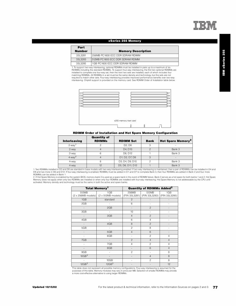
IBM
xS
eri
es
25
5
77For the latest product & technical information, refer to the Information Sources on pages 2 and 3.Updated 10/15/02
xSeries 255 Memory
Part Number Memory Description 33L3281 256MB PC1600 ECC DDR SDRAM RDIMM
33L3283 512MB PC1600 ECC DDR SDRAM RDIMM
33L3285 1GB PC1600 ECC DDR SDRAM RDIMM
1. To support two-way interleaving, optional RDIMMs must be installed in pairs up to a maximum of six RDIMMs including the standard RDIMMs. To support four-way interleaving, the first two optional RDIMMs are installed to complete one four-way set, then the next two sets are installed, each of which includes four matching RDIMMs. All RDIMMs in a set must be the same density and technology, but the sets are not required to match other sets. Four-way interleaving provides improved performance benefits over two-way interleaving. Chipkill support is provided on the memory card. See RDIMM Order of Installation table below.
RDIMM Order of Installation and Hot Spare Memory Configuration
InterleavingQuantity of RDIMMs RDIMM Set Bank Hot Spare Memory2
2-way1 2 D2, D8 3 -
2-way 4 D4, D10 2 Bank 3
2-way 6 D6, D12 1 Bank 3
4-way2 4 D1, D2, D7, D8 3 -
4-way 8 D3, D4, D9, D10 2 Bank 3
4-way 12 D5, D6, D11, D12 1 Bank 3
1. Two RDIMMs installed in D2 and D8 are standard in base models with two-way interleaving enabled. If two-way interleaving is maintained, then a pair of RDIMMs can be installed in D4 and D8 and two more in D6 and D12. If four-way interleaving is enabled, RDIMMs must be added in D1 and D7 to complete Bank 3, then four RDIMMs are added in Bank 2 and four more RDIMMs can be added in Bank 12. If Hot Spare Memory is enabled by the system BIOS, memory bank 3 is used as a spare bank in the event of RDIMM failure. Bank 3 serves as a hot spare for both banks 1 and 2. Hot Spare Memory does not apply when only two RDIMMs are installed or when only four RDIMMs are installed with four-way interleaving. Hot Spare Memory is not addressable by the CPU until activated. Memory density and technology must be the same in both the active and spare banks.
Total Memory1 Quantity of RDIMMs Added2
512MB (2 x 256MB models)
1GB(2 x 512MB models)
256MB(P/N 33L3281)
512MB(P/N 33L3283)
1GB(P/N 33L3285)
1GB standard 2 - -
2GB - 6 - -
- 2GB - 2 -
3GB - 10 - -
- 3GB 4 2 -
4GB - 6 4 -
- 4GB 8 2 -
5GB - 2 8 -
- 5GB 4 6 -
- 6GB - 2 4
7GB - 2 4 4
- 7GB 4 2 4
- 8GB - 6 4
9GB - 2 - 8
10GB3 - - 4 8
- 10GB - 2 8
12GB3 12GB3 - - 12
This table does not represent all possible memory configurations. Four-way interleaving is assumed for the purposes of this table. Memory modules may vary in price per MB. Selection of smaller RDIMMs may provide a more cost-effective alternative to using larger RDIMMs.
D1D2D3D4
D6D5
D7D8D9D10
D12D11
x255 memory riser card

78
The xSeries 255 contains 10 standard bays with the option of adding an additional six HDD bays. The six standard slim-line hot-swap HDD bays are located on the upper left half of the front of both tower and rack models. Four removable media bays are located on the right-side front of the chassis. The top bay contains the standard floppy disk drive and the second bay from the top contains the standard CD-ROM drive. The remaining two removable media bays support tape or optical drive options.
The standard Ultra320 hot-swap backplane supports six hot-swap HDD bays. The backplane is connected to the integrated dual-channel, Ultra160 SCSI controller through a standard 16-bit LVD SCSI cable. If internal RAID support is required, this cable can be used to connect the backplane to a supported RAID controller. A second optional hot-swap backplane with six hot-swap HDD bays is supported for installation directly below the standard backplane. The optional backplane can be configured as an independent SCSI bus with the addition of an optional SCSI storage controller or it can be configured with the six standard hot-swap HDD bays by connecting each of the hot-swap backplanes to separate connectors of a two- or four-channel RAID controller. The optional backplane cannot be connected to the integrated SCSI controller if the standard backplane remains connected, and there is no accommodation for connecting the two backplanes directly.
Supported internal tape drives include a 34-inch terminated SCSI cable for connecting optional tape drives to either a supported SCSI controller or to channel A of the integrated SCSi controller if the hot-swap backplane is connected to an optional controller. The standard CD-ROM is cabled to the IDE port on the planar through a two-drop IDE cable.
External attachment of supported SCSI devices requires installation of the optional External SCSI Interface Kit (P/N 32P8164), which provides a SCSI cable with an external 0.8mm VHDCI connector that attaches to the rear of the chassis and connects at the other end to the 68-pin connector of channel B on the planar.
For additional information regarding internal cabling, refer to Appendix F: Internal Cabling Overview.
1. Network operating systems may limit the maximum amount of addressable memory. See operating system specifications for further information.2. To obtain the Quantity of memory identified in the “Total Memory” column, select the appropriate row and order the quantity of RDIMMs identified in all columns for that row. 3. Requires removal of standard RDIMMs.
xSeries 255 Internal SCSI Cabling
xSeries 255 Hard Disk Drive (HDD) Storage
Total Int Storage1
10,000rpm HDDs 15,000rpm HDDs18.2GB
(06P5754)236.4GB
(06P5755)273.4GB
(06P5756)218.2GB
(06P5767)236.4GB
(06P5768)2
0GB Standard on base models
18.2GB 1 - - 1 -
36.4GB 2 1 - 2 1
54.6GB 3 - - 3 -
72.8GB 4 2 - 4 2
91GB 5 - - 5 -
109.2GB 6 3 - 6 3
127.4GB 7 - - 7 -
145.6GB 8 4 - 8 4
163.8GB 9 - - 9 -
182GB 10 5 - 10 5
200.2GB 11 - 11 -
218.4GB 12 6 - 12 6
254.8GB - 7 - - 7
291.2GB - 8 - - 8
327.6GB - 9 - - 9
364GB - 10 - - 10
367GB - - 5 - -
400.4GB - 11 - - 11
436.8GB - 12 - - 12
440.4GB - - 6 - -
513.8GB - - 7 - -
587.2GB - - 8 - -
660.6GB - - 9 - -
734GB - - 10 - -
807.4GB - - 11 - -
880.8GB - - 12 - -
This table does not represent all possible HDD configurations.Total Internal Storage listed is within +/-0.2GB unless otherwise noted.
1. Select a total storage row then select the quantity of HDDs from a column corresponding to the HDD of choice. 2. xSeries 255 ships standard with a dual-channel, Ultra160 SCSI storage controller. The standard backplane supports Ultra160 HDDs at Ultra160 speeds when connected to the standard integrated storage controller or at Ultra320 speeds (320MBps) with the addition of an optional Ultra320 storage controller (future). If Ultra160 and Ultra320 HDDs are mixed on the same bus, the entire bus is limited to Ultra160 speeds.
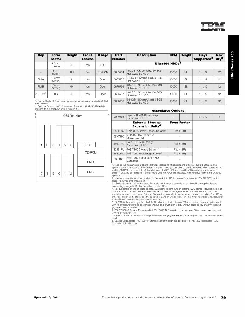
IBM
xS
eri
es
25
5
79For the latest product & technical information, refer to the Information Sources on pages 2 and 3.Updated 10/15/02
Bay Form Factor
Height Front Access
Usage Part Number
Description RPM Height Bays Supported2
Max Qty2
- 89mm (3.5in) SL Yes FDD Ultra160 HDDs1
- 133mm (5.25in) HH Yes CD-ROM 06P5754 18.2GB 10Krpm Ultra160 SCSI
Hot-swap SL HDD 10000 SL 1 ... 12 12
RM A 133mm (5.25in) HH1 Yes Open 06P5755 36.4GB 10Krpm Ultra160 SCSI
Hot-swap SL HDD 10000 SL 1 ... 12 12
RM B 133mm (5.25in) HH1 Yes Open 06P5756 73.4GB 10Krpm Ultra160 SCSI
Hot-swap SL HDD 10000 SL 1 ... 12 12
(1 . .. 12)2 HS SL Yes Open 06P5767 18.2GB 15Krpm Ultra160 SCSI Hot-swap SL HDD 15000 SL 1 ... 12 12
1. Two half-high (HH) bays can be combined to support a single full-high (FH) device2. Optional 6-pack Ultra320 Hot-swap Expansion Kit (P/N 32P8163) is required to support bays seven through 12.
Note: Install HDDs in the same order as bays are numbered, i.e., bays one to 12.
06P5768 36.4GB 15Krpm Ultra160 SCSI Hot-swap SL HDD 15000 SL 1 ... 12 12
Associated Options
32P8163 6-pack Ultra320 Hot-swap Expansion Kit3 - - 6 . .. 12 1
External Storage Expansion Units4
Form Factor
35311RU EXP300 Storage Expansion Unit5 Rack (3U)
09N7296 EXP300 Rack-to-Tower Conversion Kit -
35601RU FAStT EXP500 Storage Expansion Unit6 Rack (3U)
35421RU FAStT200 Storage Server7, 8 Rack (3U)
35422RU FAStT200 HA Storage Server7 Rack (3U)
19K1121 FAStT200 Redundant RAID Controller -
1. xSeries 255 contains an Ultra320 hot-swap backplane which supports Ultra160 HDDs at Ultra160 bus speeds when connected to the standard integrated storage controller or Ultra320 speeds when connected to an Ultra320 PCI controller (future). Installation of Ultra320 HDDs and an Ultra320 controller are required to support Ultra320 bus speeds. If one or more Ultra160 HDDs are installed, the entire bus is limited to Ultra160 speeds.2. Maximum quantity requires installation of 6-pack Ultra320 Hot-swap Expansion Kit (P/N 32P8163), which supports bays seven through 12.3. xSeries 6-pack Ultra320 Hot-swap Expansion Kit is used to provide an additional hot-swap backplane supporting a single SCSI channel with up to six HDDs.4. Not supported by the onboard external SCSI port. To configure an external SCSI storage devices, select an optional SCSI controller then refer to Appendix D: Cables - Storage Units - Controllers to confirm that the controller supports the desired External Storage Expansion Unit and to select a supported cable. For HDD or other expansion unit options, see the specific expansion unit section. For Fibre Channel storage devices, refer to the Fibre Channel Solutions Overview section.5. EXP300 includes a single 2m Ultra2 SCSI cable and dual hot-swap 500w redundant power supplies, each with its own power cord. To convert an EXP300 to a tower form factor, EXP300 Rack-to-Tower Conversion Kit(P/N 09N7296) is required.6. FAStT EXP500 Storage Expansion Unit (P/N 35601RU) includes dual hot-swap 350w power supplies, each with its own power cord.7.The FAStT200 includes two hot-swap, 350w auto-ranging redundant power supplies, each with its own power cord.8. Can be upgraded to FAStT200 HA Storage Server through the addition of a FAStT200 Redundant RAID Controller (P/N 19K1121).
FDD
CD-ROM
RM A
RM B
1 2 3 4 5 6
7 8 9 10 11 12
x255 front view
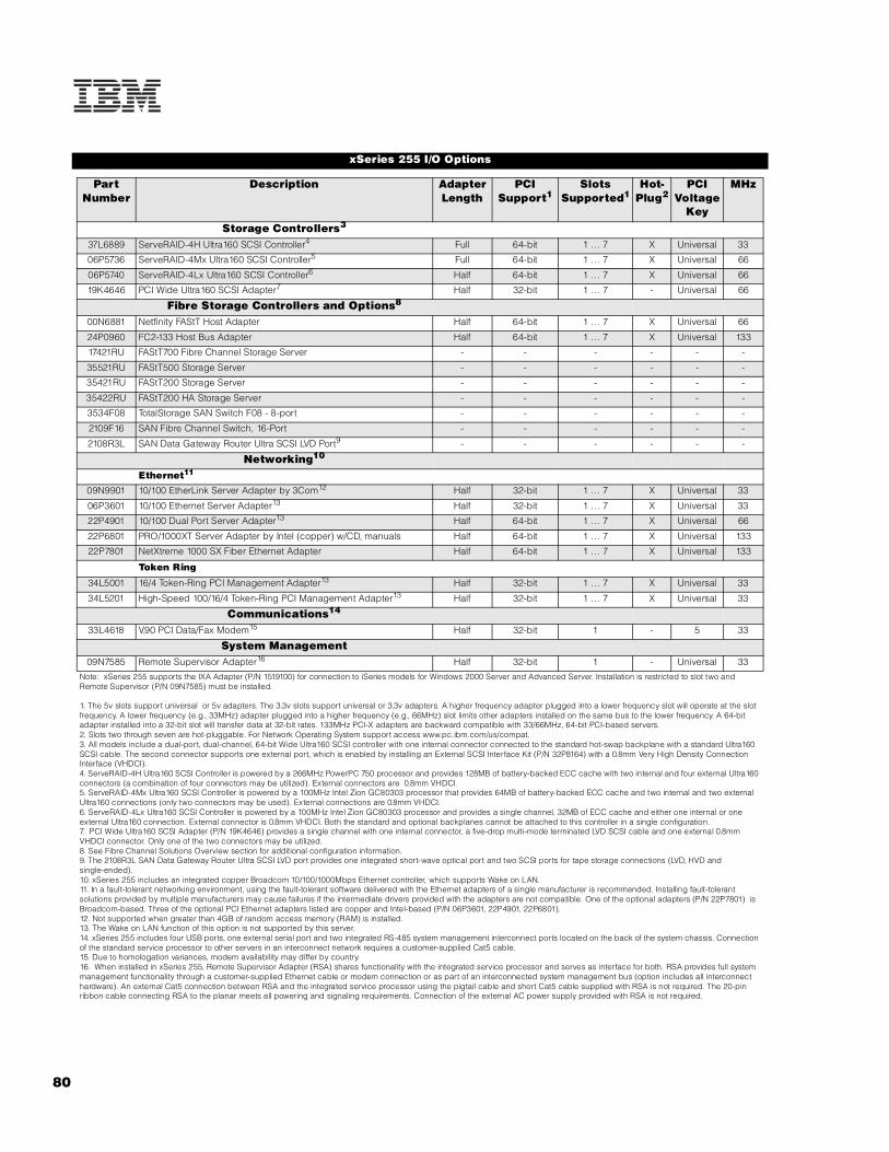
80
xSeries 255 I/O Options
Part Number
Description Adapter Length
PCI Support1
Slots Supported1
Hot-Plug2
PCI Voltage
Key
MHz
Storage Controllers3
37L6889 ServeRAID-4H Ultra160 SCSI Controller4 Full 64-bit 1 .. . 7 X Universal 33
06P5736 ServeRAID-4Mx Ultra160 SCSI Controller5 Full 64-bit 1 .. . 7 X Universal 66
06P5740 ServeRAID-4Lx Ultra160 SCSI Controller6 Half 64-bit 1 .. . 7 X Universal 66
19K4646 PCI Wide Ultra160 SCSI Adapter7 Half 32-bit 1 .. . 7 - Universal 66
Fibre Storage Controllers and Options8
00N6881 Netfinity FAStT Host Adapter Half 64-bit 1 .. . 7 X Universal 66
24P0960 FC2-133 Host Bus Adapter Half 64-bit 1 .. . 7 X Universal 133
17421RU FAStT700 Fibre Channel Storage Server - - - - - -
35521RU FAStT500 Storage Server - - - - - -
35421RU FAStT200 Storage Server - - - - - -
35422RU FAStT200 HA Storage Server - - - - - -
3534F08 TotalStorage SAN Switch F08 - 8-port - - - - - -
2109F16 SAN Fibre Channel Switch, 16-Port - - - - - -
2108R3L SAN Data Gateway Router Ultra SCSI LVD Port9 - - - - - -
Networking10
Ethernet11
09N9901 10/100 EtherLink Server Adapter by 3Com12 Half 32-bit 1 .. . 7 X Universal 33
06P3601 10/100 Ethernet Server Adapter13 Half 32-bit 1 .. . 7 X Universal 33
22P4901 10/100 Dual Port Server Adapter13 Half 64-bit 1 .. . 7 X Universal 66
22P6801 PRO/1000XT Server Adapter by Intel (copper) w/CD, manuals Half 64-bit 1 .. . 7 X Universal 133
22P7801 NetXtreme 1000 SX Fiber Ethernet Adapter Half 64-bit 1 .. . 7 X Universal 133
Token Ring
34L5001 16/4 Token-Ring PCI Management Adapter13 Half 32-bit 1 .. . 7 X Universal 33
34L5201 High-Speed 100/16/4 Token-Ring PCI Management Adapter13 Half 32-bit 1 .. . 7 X Universal 33
Communications14
33L4618 V.90 PCI Data/Fax Modem15 Half 32-bit 1 - 5 33
System Management09N7585 Remote Supervisor Adapter16 Half 32-bit 1 - Universal 33
Note: xSeries 255 supports the IXA Adapter (P/N 1519100) for connection to iSeries models for Windows 2000 Server and Advanced Server. Installation is restricted to slot two and Remote Supervisor (P/N 09N7585) must be installed.
1. The 5v slots support universal or 5v adapters. The 3.3v slots support universal or 3.3v adapters. A higher frequency adapter plugged into a lower frequency slot will operate at the slot frequency. A lower frequency (e.g., 33MHz) adapter plugged into a higher frequency (e.g., 66MHz) slot limits other adapters installed on the same bus to the lower frequency. A 64-bit adapter installed into a 32-bit slot will transfer data at 32-bit rates. 133MHz PCI-X adapters are backward compatible with 33/66MHz, 64-bit PCI-based servers.2. Slots two through seven are hot-pluggable. For Network Operating System support access www.pc.ibm.com/us/compat.3. All models include a dual-port, dual-channel, 64-bit Wide Ultra160 SCSI controller with one internal connector connected to the standard hot-swap backplane with a standard Ultra160 SCSI cable. The second connector supports one external port, which is enabled by installing an External SCSI Interface Kit (P/N 32P8164) with a 0.8mm Very High Density Connection Interface (VHDCI).4. ServeRAID-4H Ultra160 SCSI Controller is powered by a 266MHz PowerPC 750 processor and provides 128MB of battery-backed ECC cache with two internal and four external Ultra160 connectors (a combination of four connectors may be utilized). External connectors are 0.8mm VHDCI.5. ServeRAID-4Mx Ultra160 SCSI Controller is powered by a 100MHz Intel Zion GC80303 processor that provides 64MB of battery-backed ECC cache and two internal and two external Ultra160 connections (only two connectors may be used). External connections are 0.8mm VHDCI.6. ServeRAID-4Lx Ultra160 SCSI Controller is powered by a 100MHz Intel Zion GC80303 processor and provides a single channel, 32MB of ECC cache and either one internal or one external Ultra160 connection. External connector is 0.8mm VHDCI. Both the standard and optional backplanes cannot be attached to this controller in a single configuration.7. PCI Wide Ultra160 SCSI Adapter (P/N 19K4646) provides a single channel with one internal connector, a five-drop multi-mode terminated LVD SCSI cable and one external 0.8mm VHDCI connector. Only one of the two connectors may be utilized.8. See Fibre Channel Solutions Overview section for additional configuration information.9. The 2108R3L SAN Data Gateway Router Ultra SCSI LVD port provides one integrated short-wave optical port and two SCSI ports for tape storage connections (LVD, HVD and single-ended).10. xSeries 255 includes an integrated copper Broadcom 10/100/1000Mbps Ethernet controller, which supports Wake on LAN.11. In a fault-tolerant networking environment, using the fault-tolerant software delivered with the Ethernet adapters of a single manufacturer is recommended. Installing fault-tolerant solutions provided by multiple manufacturers may cause failures if the intermediate drivers provided with the adapters are not compatible. One of the optional adapters (P/N 22P7801) is Broadcom-based. Three of the optional PCI Ethernet adapters listed are copper and Intel-based (P/N 06P3601, 22P4901, 22P6801).12. Not supported when greater than 4GB of random access memory (RAM) is installed.13. The Wake on LAN function of this option is not supported by this server.14. xSeries 255 includes four USB ports, one external serial port and two integrated RS-485 system management interconnect ports located on the back of the system chassis. Connection of the standard service processor to other servers in an interconnect network requires a customer-supplied Cat5 cable.15. Due to homologation variances, modem availability may differ by country.16. When installed in xSeries 255, Remote Supervisor Adapter (RSA) shares functionality with the integrated service processor and serves as interface for both. RSA provides full system management functionality through a customer-supplied Ethernet cable or modem connection or as part of an interconnected system management bus (option includes all interconnect hardware). An external Cat5 connection between RSA and the integrated service processor using the pigtail cable and short Cat5 cable supplied with RSA is not required. The 20-pin ribbon cable connecting RSA to the planar meets all powering and signaling requirements. Connection of the external AC power supply provided with RSA is not required.

IBM
xS
eri
es
25
5
81For the latest product & technical information, refer to the Information Sources on pages 2 and 3.Updated 10/15/02
xSeries 255 Power, Monitors & Accessories
Part Number Description
Power1
31P6133 370w Reversed Fan Hot-swap Redundant Power Supply
Uninterruptible Power Supply (UPS)2
94G3136 APC Smart-UPS 14003
32P1020 APC 2U Smart-UPS 1400RMB
94G6676 APC Smart-UPS 3000RMB4
37L6861 APC Smart-UPS 5000RMB5
Monitors6
633147N E54 Color Monitor 15in (350mm, 13.8in viewable image), stealth black7
63324HN E74 Color Monitor 17in (406mm, 16in viewable image), stealth black8
66274AN G78 Color Monitor 17in (406mm, 16in viewable image), stealth black8
9512AB1 T541 Flat Panel Color Monitor (381mm, 15in viewable image), stealth black3
32P1031 NetBAY 1U Flat Panel Monitor Console Kit (with US Space Saver keyboard)9
32P1032 NetBAY 1U Flat Panel Monitor Console Kit (without keyboard)9
32P1702 NetBAY 2U Flat Panel Monitor Console Kit (with US Space Saver keyboard)9
32P1703 NetBAY 2U Flat Panel Monitor Console Kit (without keyboard)9
1. xSeries 255 includes two 370w hot-swap power supplies with the ability to accept two additional 370w Reversed Fan Hot-swap Redundant Power Supplies (P/N 31P6133). Each power supply bus in rack models includes an IEC 9ft rack power cable (P/N 36L8886) for attachment to NetBAY Rack PDUs and high voltage UPS units. The US country kit for rack models includes two NEMA 5-15P cords (P/N 6952300) for connection to a low voltage UPS, low voltage PDU or wall outlet. Tower models ship with two 1.8m NEMA 5-15P cords (P/N 6952301). Each of the two standard power supplies is installed on a separate bus. Installation of one optional power supply on each bus is required to achieve full power redundancy. Additional power cords are not used.2. For runtimes and UPS attributes see Appendix C: UPS Runtime Estimate.3. Not supported for rack mounting.4. Height is 3U. See Rack Cabinets and Options section for supported IBM racks.5. Height is 5U. See Rack Cabinets and Options section for supported IBM racks.6. xSeries 255 uses an SVGA controller (S3 Trio 3D chipset) with 4MB of video memory.7. Installation within a rack requires optional Monitor Compartment (P/N 94G7444).8. Installation within a rack requires optional Netfinity Flat Panel Monitor Rack Mount Kit II (P/N 37L6888) and Netfinity Rack Keyboard Tray (P/N 28L4707). A space saver keyboard may coexist within the same 28L4707 keyboard tray.9. Includes a 15in Flat Panel Monitor.
x255 rear viewsl
ot 1
slot
2
slot
3
slot
4
slot
5
slot
6
slot
7
External VHDCISCSI port
Slot 4: Bus C, 100MHz, 64-bit, 3.3v, full-length, Active PCI-X Slot 5: Bus C, 100MHz, 64-bit, 3.3v, full-length, Active PCI-X Slot 6: Bus D, 100MHz, 64-bit, 3.3v, full-length, Active PCI-X Slot 7: Bus D, 100MHz, 64-bit, 3.3v, full-length, Active PCI-X
Slot 1: Bus A, 33MHz, 32-bit, 5v, full-length Slot 2: Bus B, 100MHz, 64-bit, 3.3v, full-length, Active PCI-X Slot 3: Bus B, 100MHz, 64-bit, 3.3v, full-length, Active PCI-X

82
Part Number Description
Conversion Kits
32P1474 7Ux26D Tower-to-Rack Kit
Rack and NetBAY1
Refer to the Rack Cabinets and Options section for information concerning IBM racks and rack-supported devices.
Keyboard and Mouse2
28L3644 Space Saver II Keyboard3, 5
10K3849 106-key Preferred USB Keyboard with 2-port USB Hub (stealth black)4, 6
22P5150 TrackPoint USB Space Saver Keyboard3, 5, 6
33L3244 Sleek USB Mouse (stealth black)6
28L3673 Sleek 2-Button Stealth Black Mouse
1. xSeries 255 rack models are housed in a 19in rack-mountable drawer and require one of the racks listed in the Rack Cabinets and Options section. 2. xSeries 255 rack models ship without a keyboard or mouse.3. Installation within a rack requires optional keyboard tray (P/N 28L4707) which stows in ready-to-use position, or NetBAY 1U or 2U Flat Panel Monitor Console Kit (P/N 32P1032, 32P1702). Standard with 1U and 2U NetBAY console kits (P/N 32P1031, 32P1702).4. Installation within a rack requires optional keyboard tray (P/N 28L4707). This keyboard cannot share a keyboard tray with a flat panel display.5. Advanced TrackPoint IV features are not available on IBM xSeries systems.6. USB accessories attach to a single USB-capable server. They are not compatible with the NetBAY console switches.
xSeries 255 Tape Options
Part Number
Tape Drives
Bays Supported
SCSI Interface
(bit)
Form Factor
Termination Included
Ext Tape Enclosures
00N7991 20/40GB DDS/4 4mm Internal Tape Drive A, B 16 Ultra2 LVD
89mm (3.5in) HH or 133mm
(5.25in) HH
Y1 35510012
00N7990 40/80GB DLT Internal SCSI Tape Drive A+B 16 Ultra2 LVD 133mm (5.25in) FH Y1 35510012
3503B1X
00N8015 110/220GB Super DLT Internal SCSI Tape Drive A+B 16 Ultra2 LVD 133mm
(5.25in) FH Y1 35510012
3503B1X
00N8016 100/200GB LTO Tape Drive A+B 16 Ultra2 LVD 133mm (5.25in) FH Y1 35510012
3503B1X
24P2396 100/200GB LTO Half-High Tape Drive A, B 16 Ultra2 LVD 133mm (5.25in) HH Y1 35510012
24P2398 40/80GB Half-High DLTVS Internal SCSI Tape Drive A, B 16 Ultra2 LVD 133mm
(5.25in) HH Y1 35510012
Tape Autoloaders
360716X 3607 Series 1760GB/3.5TB SDLTpro Tape Autoloader - 16 Ultra2 LVD 2U Rack Y -
00N7992 120/240GB DDS/4 Tape Autoloader A+B 16 Ultra2 LVD 133mm (5.25in) FH Y1 35510012
3503B1X
3600109 3600 Series 900GB/1.8TB LTO Tape Autoloader3 - 16 Ultra2 LVD Tower or 6U
Rack Y -
External Tape Libraries4
3600R20 3600 Series 2/4TB LTO Tape Library (Rack) - 16 Ultra2 LVD 5U Rack Y -
3600LXU 3600 Series 2-Drive, 20-Cartridge Expander Module5 - 16 Ultra2 LVD 5U Rack Y -
09N4048 3600 Series LTO Drive Upgrade Option6 - 16 Ultra2 LVD - N -
External Tape Enclosures
3503B1X Full-High SCSI Tape Enclosure7 - 16 Ultra2 LVD Desktop or 3U Rack Y -
3551001 NetMEDIA Storage Expansion Unit EL8 - 16 Rack Y -10L7113 NetMEDIA Systems Management Adapter9 - 16 LVD - Y 3551001
Associated Options32P8164 External SCSI Interface Kit10 - 16 Ultra2 LVD - Y -

IBM
xS
eri
es
25
5
83For the latest product & technical information, refer to the Information Sources on pages 2 and 3.Updated 10/15/02
Note: The following sample configurations are for illustration only and may not be suitable for any specific customer installation. Contact your IBM Business Partner or IBM Marketing Representative for assistance with your specific configuration requirements.
High-availability, High-performance Seibel Application Server Solution
1. Eight HDDs are used for RAID 5 protection. One HDD is identified as a hot-spare. Effective capacity is six HDDs or 218.4GB.
Note: xSeries 255 includes an external 0.8mm VHDCI connector for support of external SCSI devices. External SCSI Interface Kit (P/N 32P8164) is required to enable the external port.
1.Termination requires installing the 34in single-drop, terminated LVD SCSI cable provided with the option. When installed in a NetMEDIA Storage Expansion Unit, termination is also provided by the standard cables shipped with the enclosure.2. LVD support for LVD tape drives installed in a NetMEDIA Storage Expansion Unit EL (P/N 3551001) is provided by two four-drop internal LVD cables.3. If installed in a rack, a fixed shelf is required. Allow an additional 1U for the fixed shelf. One unit only per shelf is supported.4. Tape library attributes and prerequisites are located in Appendix B: Tape Library Attributes.5. Supported only with the 3600 Series LTO Tape Library (rack) (P/N 3600R20). Allow one additional EIA space when installing either one or two (maximum) units to accommodate a filler plate for cable routing. Up to two 3600 Series LTO Drive Upgrade Options can be installed in each module or the module can operate off the LTO drives installed in the LTO tape library.6. Install in second drive bay of 3600 Series LTO Tape Libraries or in either of the two bays of 3600 Series 2-Drive 20-Cartridge Expander Module to increase performance. Includes an LTO (Ultrium) drive and a one-meter external LVD SCSI cable.7. Black desktop or 3U rack tape enclosure supports a single 133mm (5.25in) full-high LVD tape device including DLT tape drives. Requires a fixed shelf if installed in a rack (allow additional 1U for fixed shelf). Includes a 90w power supply, cooling fan, external terminator, power cord (country-specific), and 2m 68-pin to 0.8mm external cable. Supports the following full-high tape options: 00N8015, 00N8016, 00N7992, 00N7990.8. NetMEDIA Storage Expansion Unit EL (P/N 3551001) is a black 3U, rack-mountable tape enclosure which includes two full-high (FH) or four half-high (HH) extended length 133mm (5.25in) bays, two external 0.8mm VHDCI connectors and two internal four-drop LVD terminated 16-bit SCSI cables for device attachment. Two power supplies and two power cords are also included. External storage cables are not included.9. NetMEDIA Systems Management Adapter (P/N 10L7113) may be installed in a 3551001 to provide repeater function, aggregate cable lengths up to 12m when attached to an LVD SCSI controller, and auto-termination when the 3551001 is powered off. External connector is 0.8mm VHDCI.10. External SCSI Interface Kit (P/N 32P8164) is an internal terminated LVD SCSI cable with two screws for fastening to the rear of the chassis providing an external 0.8mm VHDCI connector, connecting to the 68-pin channel A connector located on the planar near PCI slot six.
Note: Additional tape attributes can be found in Appendix A: Tape Drive Attributes.
xSeries 255 Sample Configurations
Part Number Description Quantity Usage8685-3RX xSeries 255 1.6GHz/1MB Xeon MP, 2x512MB ECC, open, 48x (7U rack) 1 -59P5107 xSeries 1.6GHz/400MHz - 1MB L3 Cache Xeon MP Processor Option 3 Total of 4 SMP processors
33L3283 512MB PC1600 ECC DDR SDRAM RDIMM 6 4GB total memory (4-way interleaved)
06P5736 ServeRAID-4Mx Ultra160 SCSI Controller 1 RAID adapter06P5754 18.2GB 10Krpm Ultra160 SCSI Hot-swap SL HDD 2 18.2GB HDDs mirrored for NOS06P5755 36.4GB 10Krpm Ultra160 SCSI Hot-swap SL HDD 81 218.4GB RAID 5 with hot-spare22P6801 PRO/1000XT Server Adapter by Intel (copper) w/CD, manuals 1 2 Ethernet ports total09N7585 Remote Supervisor Adapter 1 system management adapter32P8163 6-pack Ultra320 Hot-swap Expansion Kit 1 -
32P8164 External SCSI Interface Kit 1 enables external 0.8mm VHDCI connector
00N8015 110/220GB Super DLT Internal SCSI Tape Drive 1 -32P1031 NetBAY 1U Flat Panel Monitor Console Kit (with US Space Saver keyboard) 1 -31P6133 370w Reversed Fan Hot-swap Redundant Power Supply 2 Full power redundancy32P1020 APC 2U Smart-UPS 1400RMB 1 -
External Storage35311RU EXP300 Storage Expansion Unit 1 Includes 2m Ultra2 cable
06P5755 36.4GB 10Krpm Ultra160 SCSI Hot-Swap SL HDD 14 RAID 5 data storage with hot-spare
Rack9306250 NetBAY25 Standard Rack Cabinet 1 -94G6670 Blank Filler Panel Kit 1
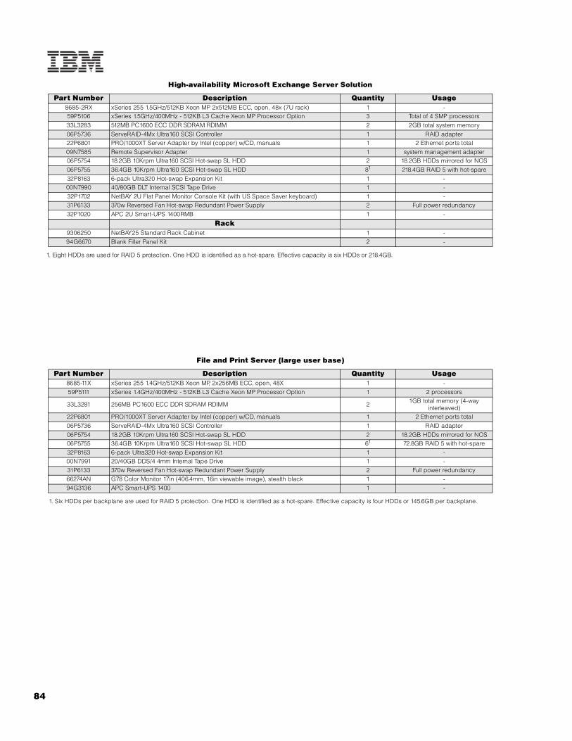
84
High-availability Microsoft Exchange Server Solution
1. Eight HDDs are used for RAID 5 protection. One HDD is identified as a hot-spare. Effective capacity is six HDDs or 218.4GB.
File and Print Server (large user base)
1. Six HDDs per backplane are used for RAID 5 protection. One HDD is identified as a hot-spare. Effective capacity is four HDDs or 145.6GB per backplane.
Part Number Description Quantity Usage8685-2RX xSeries 255 1.5GHz/512KB Xeon MP 2x512MB ECC, open, 48x (7U rack) 1 -59P5106 xSeries 1.5GHz/400MHz - 512KB L3 Cache Xeon MP Processor Option 3 Total of 4 SMP processors33L3283 512MB PC1600 ECC DDR SDRAM RDIMM 2 2GB total system memory06P5736 ServeRAID-4Mx Ultra160 SCSI Controller 1 RAID adapter22P6801 PRO/1000XT Server Adapter by Intel (copper) w/CD, manuals 1 2 Ethernet ports total09N7585 Remote Supervisor Adapter 1 system management adapter06P5754 18.2GB 10Krpm Ultra160 SCSI Hot-swap SL HDD 2 18.2GB HDDs mirrored for NOS06P5755 36.4GB 10Krpm Ultra160 SCSI Hot-swap SL HDD 81 218.4GB RAID 5 with hot-spare32P8163 6-pack Ultra320 Hot-swap Expansion Kit 1 -00N7990 40/80GB DLT Internal SCSI Tape Drive 1 -32P1702 NetBAY 2U Flat Panel Monitor Console Kit (with US Space Saver keyboard) 1 -31P6133 370w Reversed Fan Hot-swap Redundant Power Supply 2 Full power redundancy32P1020 APC 2U Smart-UPS 1400RMB 1 -
Rack9306250 NetBAY25 Standard Rack Cabinet 1 -94G6670 Blank Filler Panel Kit 2 -
Part Number Description Quantity Usage8685-11X xSeries 255 1.4GHz/512KB Xeon MP, 2x256MB ECC, open, 48X 1 -59P5111 xSeries 1.4GHz/400MHz - 512KB L3 Cache Xeon MP Processor Option 1 2 processors
33L3281 256MB PC1600 ECC DDR SDRAM RDIMM 2 1GB total memory (4-way interleaved)
22P6801 PRO/1000XT Server Adapter by Intel (copper) w/CD, manuals 1 2 Ethernet ports total06P5736 ServeRAID-4Mx Ultra160 SCSI Controller 1 RAID adapter06P5754 18.2GB 10Krpm Ultra160 SCSI Hot-swap SL HDD 2 18.2GB HDDs mirrored for NOS06P5755 36.4GB 10Krpm Ultra160 SCSI Hot-swap SL HDD 61 72.8GB RAID 5 with hot-spare32P8163 6-pack Ultra320 Hot-swap Expansion Kit 1 -00N7991 20/40GB DDS/4 4mm Internal Tape Drive 1 -31P6133 370w Reversed Fan Hot-swap Redundant Power Supply 2 Full power redundancy66274AN G78 Color Monitor 17in (406.4mm, 16in viewable image), stealth black 1 -94G3136 APC Smart-UPS 1400 1 -

IBM
xS
eri
es
25
5
85For the latest product & technical information, refer to the Information Sources on pages 2 and 3.Updated 10/15/02

IBM xSeries 300
EMEA Part Number Cross ReferencexSeries 300 S ystem Unit Part Numbers
EMEA AMERICAS M/C TYPE DESCRIPTION EMEAP/N P/N MODEL WDFM DATE
K22AXxx 86722AX 8672-2AX Celeron 800MHz/100MHz, 128KB, 128MB, 20.4GBEIDE, Rack 01/05/02
xSeries 300 Hard Disk Drive Storage Part NumbersEMEA AMERICAS M/C TYPE DESCRIPTION EMEA
P/N P/N MODEL WDFM DATENotes 1&2 19K11xx 35311RU --- EXP300 Storage Expansion Unit ---Notes 3&2 00N71xx 35601RU --- FAStT EXP500 Storage Expansion Unit ---Notes 4&2 24P09xx 17401RU --- FAStT EXP700 Storage Expansion Unit ---Notes 5&2 19K11xx 35421RU --- FAStT 200 Storage Server ---Notes 6&2 19K11xx 35422RU --- FAStT 200 HA Storage Server ---
1. Where ‘xx’ represents a specific country code as follows: 51=US/English, 52=European/English, 56=Danish/English, 57=Israel/English, 58=Italian/English, 59=South Africa/English, 60=Swiss/English, 63=UK/English.2. This unit does not include Rack Power Cables P/N 94G7448 when shipped (for attachment to highvoltage UPS or PDU). Standard country power cords only are included. If required, order one Rack PowerCable for each power supply.3. Where ‘xx’ represents a specific country code as follows:- 36=US/English, 37=Euro/English, 41=Denmark/English, 42=Israel/English, 43=Italy/English, 44=South Africa/English, 45=Switzerland/English, 49=UK/English.4. Where ‘xx’ represents a specific country code as follows:- 01=Eur/English, 02=Eur/Spanish, 05=Denmark/English, 06=Israel/English, 07=Italy/English, 08=South Africa/English, 09=Switzerland/English, 12=UK/English.5. Where ‘xx’ represents a specific country code as follows:- 23=US/English, 24=Euro/English, 25=Euro/Spanish, 27=Euro/German, 28=Denmark/English, 29=Israel/English, 30=Italy/English, 31=South Africa/English, 32=Switzerland/English, 34=Switzerland/German, 36=UK/English..6. Where ‘xx’ represents a specific country code as follows:- 37=US/English, 38=Euro/English, 39=Euro/Spanish, 41=Euro/German, 42=Denmark/English, 43=Israel/English, 44=Italy/English, 45=South Africa/English, 46=Switzerland/English, 48=Switzerland/German, 50=UK/English.
xSeries 300 I/O Option Part NumbersEMEA AMERICAS M/C TYPE DESCRIPTION EMEA
P/N P/N MODEL WDFM DATEN/A 33L4618 --- V90 PCI Data/Fax WinModem N/A
85A Updated 10/15/02

IBM xSeries 300
EMEA Part Number Cross ReferenceNote 7 xSeries 300 Power, Monitors & Accessories
EMEA AMERICAS M/C TYPE DESCRIPTION EMEAP/N P/N MODEL POWER WDFM DATE
Note 8 32P16xx 32P1020 --- APC 2U Smart-UPS 1400RMiB ---Note 9 30RIxxx 94G6676 --- APC Smart-UPS 3000RMiB ---
37L6862 37L6861 --- APC Smart-UPS 5000RMiB ---
7. The xSeries 300 ships with a standard country power cord. For connection to a high voltage UPS or PDU, order Rack PowerCable P/N 94G7448.
8. Where ‘xx’ represents a specific country code as follows:- 12=Europe, 13=UK, 14=Italy, 15=Switzerland, 16=Denmark, 17=South Africa, 18=Israel.
9. Where ‘xxx’ represents a specific country code as follows:- DEN=Denmark, ISR=Israel, ITA=Italy, SDI=Saudi Arabia, SAF=South Africa, SWS=Switzerland, UKM=United Kingdom, EUR=Europe.
xSeries 300 Power, Monitors & AccessoriesEMEA AMERICAS M/C TYPE DESCRIPTION EMEA
P/N P/N MODEL MONITORS WDFM DATENote 10 T3147xx 633147N 6331-47N E54 15" (13.8" viewable image) Colour Monitor (S/Blac ---Note 10 T3247xx 63324HN 6332-4HN E74 17" (16" viewable image) Colour Monitor (S/Black) ---Note 10 T274Axx 66274AN 6627-4AN G78 17" (16" viewable image) Colour Monitor (S/Black ---
N/A 32P1031 --- NetBAY 1U Flat Panel Monitor Console Kit (with US ke N/AN/A 32P1702 --- NetBAY 2U Flat Panel Monitor Console Kit (with US ke N/A
10. Where ‘xx’ represents a specific country code as follows: DK=Denmark, IS=Israel, IT=Italy, SD=Saudi Arabia, SA=SouthAfrica/Pakistan, CH=Switzerland, UK=UK, EU=Europe.
xSeries 300 Power, Monitors & AccessoriesEMEA AMERICAS M/C TYPE DESCRIPTION EMEA
P/N P/N MODEL KEYBOARD AND MOUSE WDFM DATENote 11 28L36xx 28L3644 --- Spacesaver II Keyboard ---Note 12 10K38xx 10K3849 --- 106-key Preferred USB Keyb. with 2-port USB Hub (S/ ---
28L3675 28L3673 --- Sleek 2-button Mouse (S/Black) ---11. Where ‘xx’ represents a specific country code as follows:- 46=Danish , 47=French, 48=German, 49=Italian, 50=Spanish, 51=UK English, 44=US English, and P/N 19K3831=Swiss, 19K3832=Swedish/Finnish, 19K3833=Portugese, 19K3834=Belgian,19K3836=Russian, 19K3837=Polish.
12. Where ‘xx’ represents a specific country code as follows:- 53=Danish , 54=Dutch, 55=France, 56=Germany, 57=Italian, 58=Norwegian, 59=Swedish/Finnish, 10K2343=Swiss, 10K2344=UK English, 10K2345=US ISO.
xSeries 300 Tape OptionsEMEA AMERICAS M/C TYPE DESCRIPTION EMEA
P/N P/N MODEL WDFM DATEN/A 3570C2x --- Magstar MP 3570 Tape Subsystem N/A
10L7440 3510020 --- External Half High SCSI Storage Enclosure ---03K8756 3551001 --- NetMEDIA Storage Expansion Unit EL ---
Updated 10/15/02 85B

86
IBM xSeries 300 DC
EIDE Configuration Cabling
The xSeries 300DC contains two integrated ATA-100 EIDE controllers. One controller is cabled directly to the 24x-10x IDE CD-ROM. xSeries 300 models that ship with a standard EIDE HDD use the second EIDE controller to attach the standard HDD. This controller supports up to two EIDE HDDs through the use of a two-drop cable.
For additional information regarding internal cabling, refer to Appendix F: Internal Cabling Overview.
xSeries 300 DC At-A-Glance
8672-2AX1, 4 - 8002 1/1 128 128MB/1.5GB Rack (1U) 1/14 - - N 2 x 10/100 IDE 2/0 20.4GB/
240GB 24X-10X 4/1 2/2
1. Housed in a 19in rack-mountable drawer and ships standard without a keyboard or mouse. See Rack Cabinets and Options section for supported IBM racks.2. Intel Celeron processor with 100MHz FSB. xSeries 300 does not support processor upgrades.3. Variable read rate. Actual playback speed will vary and is often less than the maximum possible.4. This direct current (DC) power model includes a 200W, -48v direct current power supply requiring a direct current power source for utilization in a telecommunications network infrastructure.
xSeries 300 DC Memory
Total System Memory (Standard
Models)1
DIMMs
128MB (1 x 128)
128MB(33L3081)
256MB(33L3083)
512MB(33L3085)
256MB 1 - -
384MB 2 - -
512MB 1 1 -
Part Number
Memory Description640MB - 2 -
33L3081 128MB 133MHz ECC SDRAM Unbuffered DIMM Memory 896MB - 1 1
33L3083 256MB 133MHz ECC SDRAM Unbuffered DIMM Memory 1152MB - - 2
33L3085 512MB 133MHz ECC SDRAM Unbuffered DIMM Memory 1536MB (max)2 - - 3
This table does not represent all possible memory configurations. Memory modules may vary in price per MB. Selection of smaller DIMMs may provide a more cost-effective alternative to using larger DIMMs. Select the desired total memory from the appropriate column (Standard 128MB or 256MB models), then add the quantities in that row from the DIMM columns.
1. Network operating systems may limit the maximum amount of addressable memory. See operating system specifications for further information.2. Requires removal of standard DIMMs.
xSeries 300 DC Internal Cabling
Part Number
Withdrawal D
ate8
Processor Speed (M
Hz)
Number of P
rocessors (Std/M
ax)
L2 ECC Cache (KB)
Memory (Std/M
ax) (R = RDIM
M)
Form Factor
Power Supply Quantit
y (Std/M
ax)
Hot-Swap (P
ower, Slots, H
DD, Fans)
Redundancy (Optio
nal, Standard)
Adv System Management P
rocessor
Onboard Ethernet (Mbps)
SCSI Contro
ller (D
ual, Ultr
a, RAID)
Removable Media Bays (T
otal/Avail)
Internal Hard Disk Driv
e (Std/M
ax)
CD-ROM (ID
E)3
Bays (Total/A
vail)
Slots (Total/A
vail)
DIMM Socket
DIMM Socket
DIMM Socket

IBM
xS
eri
es
30
0D
C
87For the latest product & technical information, refer to the Information Sources on pages 2 and 3.Updated 10/15/02
xSeries 300 DC Hard Disk Drive (HDD) Storage
EIDE ModelsTotal
Internal Storage1
7200rpm EIDE HDDs2
20.4GB (P/N 19K4461)
40GB (P/N 22P7157)
60GB(P/N 09N4207)
80GB(P/N 09N4226)
120GB(P/N 09N4231)
20.4GB (Std on EIDE models)
40.8GB 1 - - -
60.4GB - 1 - -
80GB3 - 2 - -
80.4GB - - 1 -
120GB3 - - 2 -
140GB3 - - 1 1
160GB3 - - - 2 -
200GB3 - - - 1 1
240GB3 - - - - 2
This table does not represent all possible HDD configurations. Total Internal Storage listed is within +/-0.2GB unless otherwise noted.
1. Select a total storage row then add the quantity of HDDs from all columns to the standard HDD.2. The xSeries 300 dual integrated EIDE controllers support a maximum of three IDE devices per machine including one CD-ROM and two IDE HDDs.3. Requires removal of the standard HDD.
Part Number Description RPM Height
Bays Supported
Max Qty
Bay Form Factor
Height Front Access
UsageIDE HDDs1, 2
11 89mm (3.5in) SL no HDD 19K4461 20.4GB 7200rpm ATA-100 (EIDE) HDD 7200 SL 1, 2 2
2 89mm (3.5in) SL no Open 22P7157 40GB 7200rpm ATA-100 (EIDE) HDD 7200 SL 1, 2 2
1. Boot drive should be located in bay 1. 09N4207 60GB 7200rpm ATA-100 (EIDE) HDD 7200 SL 1, 2 2
09N4226 80GB 7200rpm ATA-100 (EIDE) HDD 7200 SL 1, 2 2
09N4231 120GB 7200rpm ATA-100 (EIDE) HDD 7200 SL 1, 2 2
External Storage Expansion Units2 Form Factor
35311RU Netfinity EXP300 Storage Expansion Unit3 Rack (3U)
17401RU FAStT EXP700 Storage Expansion Unit4 Rack (3U)
35601RU Netfinity FAStT EXP500 Storage Expansion Unit5 Rack (3U)
35421RU FAStT200 Storage Server6, 7 Rack (3U)
35422RU FAStT200 HA Storage Server6 Rack (3U)
19K1121 FAStT200 Redundant RAID Controller -
Floppy / CD-ROM Bay 1 Bay 2

88
1. The xSeries 300 dual integrated EIDE controllers support a maximum of three IDE devices per machine including one CD-ROM, and two IDE hard disk drives.2. xSeries 300 does not include an external SCSI connector. To configure a SCSI storage device, select an optional SCSI controller then refer to Appendix D: Cables - Storage Units - Controllers to confirm the controller supports the desired External Storage Expansion Unit and to select a supported cable. For HDD or other expansion unit options, see the specific expansion unit section. For Fibre Channel storage devices, refer to the Fibre Channel Solutions Overview section.3. EXP300 includes a single 2M Ultra2 SCSI cable and dual hot-swap 500W redundant power supplies, each with its own power cord. 4. FAStT EXP700 Storage Expansion Unit (P/N 17401RU) includes dual hot-swap 400w power supplies, each with its own power cord.5. FAStT EXP500 Storage Expansion Unit (P/N 35601RU) includes dual hot-swap 350W power supplies, each with its own power cord.6. The FAStT200 includes two hot-swap, 350W auto-ranging redundant power supplies, each with its own power cord.7. Can be upgraded to FAStT200 HA Storage Server through the addition of a FAStT200 Redundant RAID Controller (P/N 19K1121).
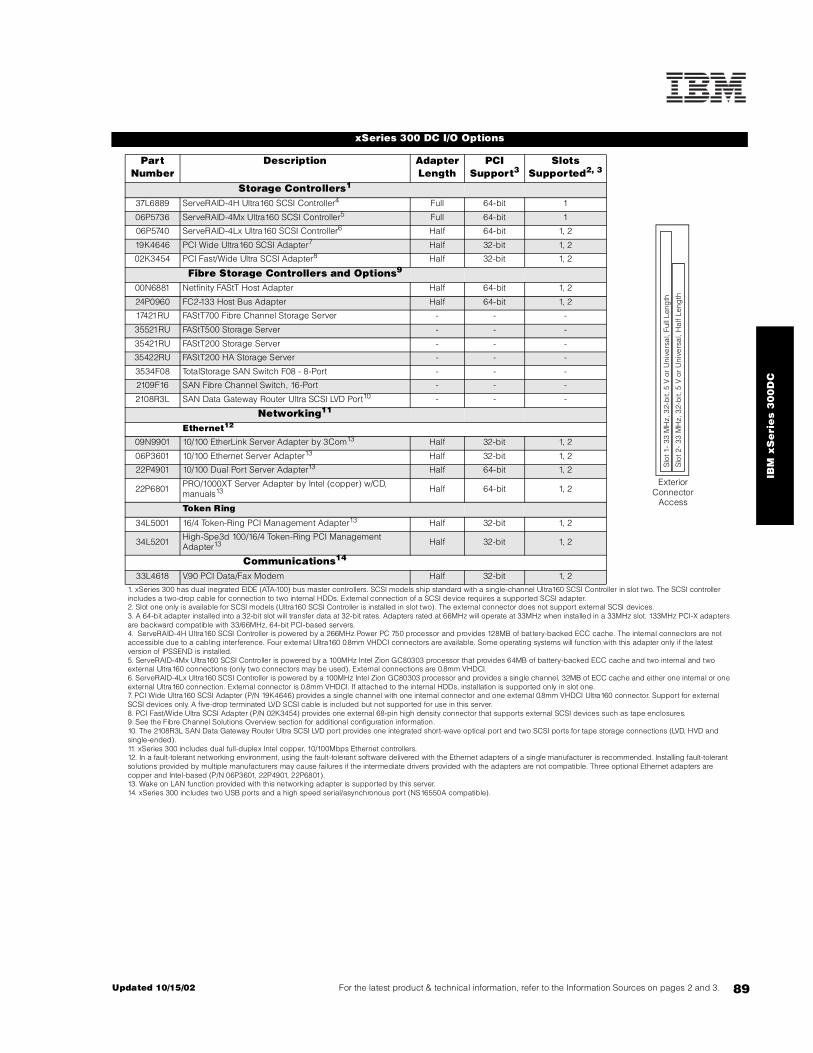
IBM
xS
eri
es
30
0D
C
89For the latest product & technical information, refer to the Information Sources on pages 2 and 3.Updated 10/15/02
xSeries 300 DC I/O Options
Part Number
Description Adapter Length
PCI Support3
Slots Supported2, 3
Storage Controllers1
37L6889 ServeRAID-4H Ultra160 SCSI Controller4 Full 64-bit 1
06P5736 ServeRAID-4Mx Ultra160 SCSI Controller5 Full 64-bit 1
06P5740 ServeRAID-4Lx Ultra160 SCSI Controller6 Half 64-bit 1, 2
19K4646 PCI Wide Ultra160 SCSI Adapter7 Half 32-bit 1, 2
02K3454 PCI Fast/Wide Ultra SCSI Adapter8 Half 32-bit 1, 2
Fibre Storage Controllers and Options9
00N6881 Netfinity FAStT Host Adapter Half 64-bit 1, 2
24P0960 FC2-133 Host Bus Adapter Half 64-bit 1, 2
17421RU FAStT700 Fibre Channel Storage Server - - -
35521RU FAStT500 Storage Server - - -
35421RU FAStT200 Storage Server - - -
35422RU FAStT200 HA Storage Server - - -
3534F08 TotalStorage SAN Switch F08 - 8-Port - - -
2109F16 SAN Fibre Channel Switch, 16-Port - - -
2108R3L SAN Data Gateway Router Ultra SCSI LVD Port10 - - -
Networking11
Ethernet12
09N9901 10/100 EtherLink Server Adapter by 3Com13 Half 32-bit 1, 2
06P3601 10/100 Ethernet Server Adapter13 Half 32-bit 1, 2
22P4901 10/100 Dual Port Server Adapter13 Half 64-bit 1, 2
22P6801 PRO/1000XT Server Adapter by Intel (copper) w/CD, manuals13 Half 64-bit 1, 2
Token Ring
34L5001 16/4 Token-Ring PCI Management Adapter13 Half 32-bit 1, 2
34L5201 High-Spe3d 100/16/4 Token-Ring PCI Management Adapter13 Half 32-bit 1, 2
Communications14
33L4618 V.90 PCI Data/Fax Modem Half 32-bit 1, 2
1. xSeries 300 has dual inegrated EIDE (ATA-100) bus master controllers. SCSI models ship standard with a single-channel Ultra160 SCSI Controller in slot two. The SCSI controller includes a two-drop cable for connection to two internal HDDs. External connection of a SCSI device requires a supported SCSI adapter.2. Slot one only is available for SCSI models (Ultra160 SCSI Controller is installed in slot two). The external connector does not support external SCSI devices.3. A 64-bit adapter installed into a 32-bit slot will transfer data at 32-bit rates. Adapters rated at 66MHz will operate at 33MHz when installed in a 33MHz slot. 133MHz PCI-X adapters are backward compatible with 33/66MHz, 64-bit PCI-based servers.4. ServeRAID-4H Ultra160 SCSI Controller is powered by a 266MHz Power PC 750 processor and provides 128MB of battery-backed ECC cache. The internal connectors are not accessible due to a cabling interference. Four external Ultra160 0.8mm VHDCI connectors are available. Some operating systems will function with this adapter only if the latest version of IPSSEND is installed.5. ServeRAID-4Mx Ultra160 SCSI Controller is powered by a 100MHz Intel Zion GC80303 processor that provides 64MB of battery-backed ECC cache and two internal and two external Ultra160 connections (only two connectors may be used). External connections are 0.8mm VHDCI.6. ServeRAID-4Lx Ultra160 SCSI Controller is powered by a 100MHz Intel Zion GC80303 processor and provides a single channel, 32MB of ECC cache and either one internal or one external Ultra160 connection. External connector is 0.8mm VHDCI. If attached to the internal HDDs, installation is supported only in slot one.7. PCI Wide Ultra160 SCSI Adapter (P/N 19K4646) provides a single channel with one internal connector and one external 0.8mm VHDCI Ultra160 connector. Support for external SCSI devices only. A five-drop terminated LVD SCSI cable is included but not supported for use in this server.8. PCI Fast/Wide Ultra SCSI Adapter (P/N 02K3454) provides one external 68-pin high density connector that supports external SCSI devices such as tape enclosures.9. See the Fibre Channel Solutions Overview section for additional configuration information.10. The 2108R3L SAN Data Gateway Router Ultra SCSI LVD port provides one integrated short-wave optical port and two SCSI ports for tape storage connections (LVD, HVD and single-ended).11. xSeries 300 includes dual full-duplex Intel copper, 10/100Mbps Ethernet controllers.12. In a fault-tolerant networking environment, using the fault-tolerant software delivered with the Ethernet adapters of a single manufacturer is recommended. Installing fault-tolerant solutions provided by multiple manufacturers may cause failures if the intermediate drivers provided with the adapters are not compatible. Three optional Ethernet adapters are copper and Intel-based (P/N 06P3601, 22P4901, 22P6801).13. Wake on LAN function provided with this networking adapter is supported by this server.14. xSeries 300 includes two USB ports and a high speed serial/asynchronous port (NS16550A compatible).
Slo
t 1-
33 M
Hz,
32-
bit,
5 V
or
Uni
vers
al,
Full
Leng
th
Slo
t 2-
33 M
Hz,
32-
bit,
5 V
or
Uni
vers
al,
Hal
f Len
gth
Exterior Connector
Access

90
xSeries 300 DC Power, Monitors & Accessories
Part Number DescriptionPower1, 2
Uninterruptible Power Supply (UPS)3
32P1020 APC 2U Smart-UPS 1400RMB
94G6676 APC Smart-UPS 3000RMB4
37L6861 APC Smart-UPS 5000RMB5
Monitors6
633147N E54 Color Monitor 15in (350mm, 13.8in viewable image), stealth black7
63324HN E74 Color Monitor 17in (406mm, 16in viewable image), stealth black7
66274AN G78 Color Monitor 17in (406.4mm, 16in viewable image), stealth black7
32P1031 NetBAY 1U Flat Panel Monitor Console Kit (with US Space Saver keyboard)8
32P1032 NetBAY 1U Flat Panel Monitor Console Kit (without keyboard)8
32P1702 NetBAY 2U Flat Panel Monitor Console Kit (with US Space Saver keyboard)8
32P1703 NetBAY 2U Flat Panel Monitor Console Kit (without keyboard)8
1. Most xSeries 300 models include a worldwide, voltage-sensing 200W power supply with auto restart and two 9ft line cords. One line cord contains a 110V NEMA 5-15P connector while the other contains an IEC 320 C14 for attachment to a high voltage PDU or UPS.2. A direct current model (2AX) includes a 200W, -48v direct current power supply. The line cord is customer-supplied. This model is designed for specific application in a telecommunications infrastructure.3. For runtimes and UPS attributes see Appendix C: UPS Runtime Estimate.4. Height is 3U. See Rack Cabinets and Options section for supported IBM racks.5. Height is 5U. See Rack Cabinets and Options section for supported IBM racks.6. xSeries 300 uses an SVGA controller (S-3 Savage4 chipset) with 8MB of video memory. 7. Installation within a rack requires optional Monitor Compartment (P/N94G7444).8. Includes a 15in Flat Panel Monitor.
Part Number DescriptionRack and NetBAY1, 2
Refer to the Rack Cabinets and Options section for information concerning IBM racks and rack-supported devices.
Keyboard and Mouse3
28L3644 Space Saver II Keyboard4, 5
10K3849 106-key Preferred USB Keyboard with 2-port USB Hub (stealth black)6, 7
28L3673 Sleek 2-button Stealth Black Mouse
33L3244 Sleek USB Mouse (stealth black)7
1. xSeries 300 is housed in a 19in rack-mountable drawer and requires one of the racks listed in the Rack Cabinets and Options section.2. Note limitations and restrictions for adequate cooling in the Rack Cabinets and Options section. If non-IBM racks are to be used, assure that both the front and rear doors offer a minimum of 48% open area uniformly distributed and in line with installed servers. A clearance of 51 to 64mm (2 to 2.5in) must be maintained between the front door and the system unit’s front bezel. The rear door must maintain the same or greater clearance. 3. xSeries 300 supports rack configurations only and ships without a keyboard or mouse.4. Installation within a rack requires optional keyboard tray (P/N 28L4707) which stows in ready-to-use position, or NetBAY 1U or 2U Flat Panel Monitor Console Kit (P/N 32P1032, 32P1702). Standard with 1U and 2U NetBAY console kits (P/N 32P1031, 32P1702).5. Advanced TrackPoint IV features are not available on IBM xSeries systems.6. Installation within a rack requires optional keyboard tray (P/N 28L4707). This keyboard cannot share a keyboard tray with a flat panel display.7. USB accessories attach to a single USB-capable server. They are not compatible with the NetBAY console switches.
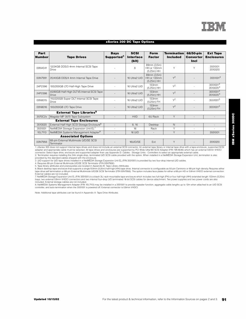
IBM
xS
eri
es
30
0D
C
91For the latest product & technical information, refer to the Information Sources on pages 2 and 3.Updated 10/15/02
xSeries 300 DC Tape Options
Part Number Tape Drives
Bays Supported1
SCSI Interface
(bit)
Form Factor
Termination Included
68/50-pin Converter
Incl
Ext Tape Enclosures
09N4041 12/24GB DDS/3 4mm Internal SCSI Tape Drive - 8
89mm (3.5in) HH or 133mm
(5.25in) HHY Y 3551001
3510020
00N7991 20/40GB DDS/4 4mm Internal Tape Drive - 16 Ultra2 LVD89mm (3.5in) HH or 133mm
(5.25in) HHY2 - 35510013
24P2396 100/200GB LTO Half-High Tape Drive - 16 Ultra2 LVD 133mm (5.25in) HH Y2 - 35510013
35100204
24P2398 40/80GB Half-High DLTVS Internal SCSI Tape Drive - 16 Ultra2 LVD 133mm
(5.25in) HH Y2 - 35510013
35100204
00N8015 110/220GB Super DLT Internal SCSI Tape Drive - 16 Ultra2 LVD 133mm
(5.25in) FH Y2 - 35510013
00N8016 100/200GB LTO Tape Drive - 16 Ultra2 LVD 133mm (5.25in) FH Y2 - 35510013
External Tape Libraries5
3570C2x Magstar MP 3570 Tape Subsystem - HVD 6U Rack Y - -
External Tape Enclosures3510020 External Half High SCSI Storage Enclosure6 - 8, 16 Desktop N - -3551001 NetMEDIA Storage Expansion Unit EL7 - 16 Rack Y - -10L7113 NetMEDIA Systems Management Adapter8 - 16 LVD - Y - 3551001
Associated Options
00N7956 68-pin External Multimode LVD/SE SCSI Terminator - 16LVD/SE Ext Y - 3510020
1. xSeries 300 does not support internal tape drives and does not include an external SCSI connector. An external tape library or internal tape drive with a tape enclosure, supported SCSI adapter and appropriate cable must be selected. All tape drives and enclosures are supported by PCI Wide Ultra160 SCSI Adapter (P/N 19K4646) which has an external 0.8mm VHDCI connector. Select tape drive, enclosure and supported adapter then use Appendix D: Cables - Storage Units - Controllers to select an appropriate external cable. 2. Termination requires installing the 34in single-drop, terminated LVD SCSI cable provided with the option. When installed in a NetMEDIA Storage Expansion Unit, termination is also provided by the standard cables shipped with the enclosure.3 .LVD support for LVD tape drives installed in a NetMEDIA Storage Expansion Unit EL (P/N 3551001) is provided by two four-drop internal LVD cables.4. Requires 68-pin External Multimode LVD/SE SCSI Terminator (P/N 00N7956).5. Tape library attributes and prerequisites are located in Appendix B: Tape Library Attributes.6. Black desktop tape enclosure that supports a single133mm (5.25in) half-high (HH) tape drive. Internal connector is configurable as 50-pin Centronix or 68-pin high density. Requires either tape drive self termination or 68-pin External Multimode LVD/SE SCSI Terminator (P/N 00N7956). The option includes face plates for either a 68-pin HD or 0.8mm VHDCI external connection. External cables are not included.7. NetMEDIA Storage Expansion Unit EL (P/N 3551001) is a black 3U, rack-mountable tape enclosure which includes two full-high (FH) or four half-high (HH) extended length 133mm (5.25in) bays, two external 0.8mm VHDCI connectors and two internal four-drop LVD terminated 16-bit SCSI cables for device attachment. Two power supplies and two power cords are also included. External storage cables are not included.8. NetMEDIA Systems Management Adapter (P/N 10L7113) may be installed in a 3551001 to provide repeater function, aggregate cable lengths up to 12m when attached to an LVD SCSI controller, and auto-termination when the 3551001 is powered off. External connector is 0.8mm VHDCI.
Note: Additional tape attributes can be found in Appendix A: Tape Drive Attributes.

IBM xSeries 305
EMEA Part Number Cross ReferencexSeries 305 S ystem Unit Part Numbers
EMEA AMERICAS M/C TYPE DESCRIPTION EMEAP/N P/N MODEL WDFM DATE
K392Xxx 867392X 8673-92X P4 1.8GHz/400MHz, 512KB, 256MB, 40GB EIDE,Rack ---
K312Xxx 867312X 8673-12X P4 2.0GHz/400MHz, 512KB, 256MB, 40GB EIDE,Rack ---
K313Xxx 867313X 8673-13X P4 2.0GHz/400MHz, 512KB, 256MB, 18.2GB U160,Rack ---
K342Xxx 867342X 8673-42X P4 2.4GHz/533MHz, 512KB, 256MB, 40GB EIDE,Rack ---
K343Xxx 867343X 8673-43X P4 2.4GHz/533MHz, 512KB, 256MB, 18.2GB U160,Rack ---
K362Xxx 867362X 8673-62X P4 2.67GHz/533MHz, 512KB, 256MB, 40GB EIDE,Rack ---
K363Xxx 867363X 8673-63X P4 2.67GHz/533MHz, 512KB, 256MB, 18.2GB U160,Rack ---
xSeries 305 Hard Disk Drive Storage Part NumbersEMEA AMERICAS M/C TYPE DESCRIPTION EMEA
P/N P/N MODEL WDFM DATENotes 1&2 19K11xx 35311RU --- EXP300 Storage Expansion Unit ---
1. Where ‘xx’ represents a specific country code as follows: 51=US/English, 52=European/English, 56=Danish/English, 57=Israel/English, 58=Italian/English, 59=South Africa/English, 60=Swiss/English, 63=UK/English.2. This unit does not include Rack Power Cables P/N 94G7448 when shipped (for attachment to highvoltage UPS or PDU). Standard country power cords only are included. If required, order one Rack PowerCable for each power supply.
xSeries 305 I/O Option Part NumbersEMEA AMERICAS M/C TYPE DESCRIPTION EMEA
P/N P/N MODEL WDFM DATE
Note 3 37L14xx 37L14xx --- Serial I/O SST 8 and 16 port Adapters Note 3Note 4 09N75xx 09N7585 --- Remote Supervisor Adapter ---
3. Serial I/O Adapter P/Ns 37L1414 and 37L1415 are available. Other Serial I/O adapter part numbers arewithdrawn from marketing in EMEA.4. Where ‘xx’ represents a specific country code as follows:- 86=Europe, 87=Denmark, 88=South Africa, 89=UK, 90=Switzerland, 91=Italy, 92=Israel, 85=USA.
Note 5 xSeries 305 Power, Monitors & AccessoriesEMEA AMERICAS M/C TYPE DESCRIPTION EMEA
P/N P/N MODEL POWER WDFM DATENote 6 32P16xx 32P1020 --- APC 2U Smart-UPS 1400RMiB ---Note 7 30RIxxx 94G6676 --- APC Smart-UPS 3000RMiB ---
37L6862 37L6861 --- APC Smart-UPS 5000RMiB ---5. The xSeries 305 ships with one standard country power cord and one Rack Power cord for connection either to a wall socketor a high voltage UPS or PDU.
6. Where ‘xx’ represents a specific country code as follows:- 12=Europe, 13=UK, 14=Italy, 15=Switzerland, 16=Denmark, 17=South Africa, 18=Israel.
7. Where ‘xxx’ represents a specific country code as follows:- DEN=Denmark, ISR=Israel, ITA=Italy, SDI=Saudi Arabia, SAF=South Africa, SWS=Switzerland, UKM=United Kingdom, EUR=Europe.
91A Updated 10/15/02
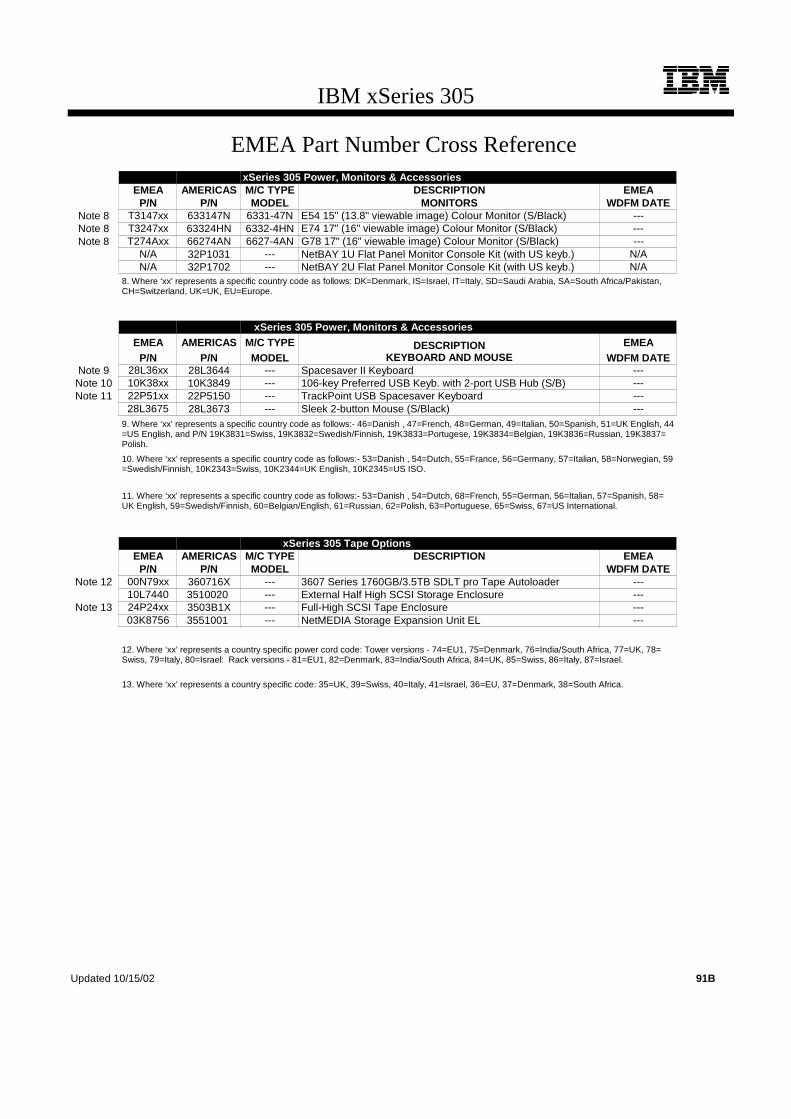
IBM xSeries 305
EMEA Part Number Cross ReferencexSeries 305 Power, Monitors & Accessories
EMEA AMERICAS M/C TYPE DESCRIPTION EMEAP/N P/N MODEL MONITORS WDFM DATE
Note 8 T3147xx 633147N 6331-47N E54 15" (13.8" viewable image) Colour Monitor (S/Black) ---Note 8 T3247xx 63324HN 6332-4HN E74 17" (16" viewable image) Colour Monitor (S/Black) ---Note 8 T274Axx 66274AN 6627-4AN G78 17" (16" viewable image) Colour Monitor (S/Black) ---
N/A 32P1031 --- NetBAY 1U Flat Panel Monitor Console Kit (with US keyb.) N/AN/A 32P1702 --- NetBAY 2U Flat Panel Monitor Console Kit (with US keyb.) N/A
8. Where ‘xx’ represents a specific country code as follows: DK=Denmark, IS=Israel, IT=Italy, SD=Saudi Arabia, SA=South Africa/Pakistan,CH=Switzerland, UK=UK, EU=Europe.
xSeries 305 Power, Monitors & AccessoriesEMEA AMERICAS M/C TYPE DESCRIPTION EMEA
P/N P/N MODEL KEYBOARD AND MOUSE WDFM DATENote 9 28L36xx 28L3644 --- Spacesaver II Keyboard ---
Note 10 10K38xx 10K3849 --- 106-key Preferred USB Keyb. with 2-port USB Hub (S/B) ---Note 11 22P51xx 22P5150 --- TrackPoint USB Spacesaver Keyboard ---
28L3675 28L3673 --- Sleek 2-button Mouse (S/Black) ---9. Where ‘xx’ represents a specific country code as follows:- 46=Danish , 47=French, 48=German, 49=Italian, 50=Spanish, 51=UK English, 44=US English, and P/N 19K3831=Swiss, 19K3832=Swedish/Finnish, 19K3833=Portugese, 19K3834=Belgian, 19K3836=Russian, 19K3837=Polish.
10. Where ‘xx’ represents a specific country code as follows:- 53=Danish , 54=Dutch, 55=France, 56=Germany, 57=Italian, 58=Norwegian, 59=Swedish/Finnish, 10K2343=Swiss, 10K2344=UK English, 10K2345=US ISO.
11. Where ‘xx’ represents a specific country code as follows:- 53=Danish , 54=Dutch, 68=French, 55=German, 56=Italian, 57=Spanish, 58=UK English, 59=Swedish/Finnish, 60=Belgian/English, 61=Russian, 62=Polish, 63=Portuguese, 65=Swiss, 67=US International.
xSeries 305 Tape OptionsEMEA AMERICAS M/C TYPE DESCRIPTION EMEA
P/N P/N MODEL WDFM DATENote 12 00N79xx 360716X --- 3607 Series 1760GB/3.5TB SDLT pro Tape Autoloader ---
10L7440 3510020 --- External Half High SCSI Storage Enclosure ---Note 13 24P24xx 3503B1X --- Full-High SCSI Tape Enclosure ---
03K8756 3551001 --- NetMEDIA Storage Expansion Unit EL ---
12. Where ‘xx’ represents a country specific power cord code: Tower versions - 74=EU1, 75=Denmark, 76=India/South Africa, 77=UK, 78=Swiss, 79=Italy, 80=Israel: Rack versions - 81=EU1, 82=Denmark, 83=India/South Africa, 84=UK, 85=Swiss, 86=Italy, 87=Israel.
13. Where ‘xx’ represents a country specific code: 35=UK, 39=Swiss, 40=Italy, 41=Israel, 36=EU, 37=Denmark, 38=South Africa.
Updated 10/15/02 91B
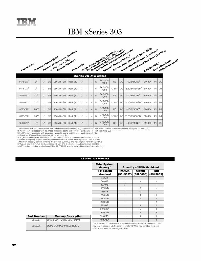
92
IBM xSeries 305
xSeries 305 At-A-Glance
8673-12X1 22 1/1 512 256MB/4GB Rack (1U) 1/1 - - N 2x10/100/1000 IDE 2/0 40GB/240GB6 24X-10X 4/1 2/2
8673-13X1 22 1/1 512 256MB/4GB Rack (1U) 1/1 - - N 2x10/100/1000 U1605 2/0 18.2GB/146.8GB7 24X-10X 4/1 2/1
8673-42X 2.43 1/1 512 256MB/4GB Rack (1U) 1/1 - - N 2x10/100/1000 IDE 2/0 40GB/240GB6 24X-10X 4/1 2/2
8673-43X 2.43 1/1 512 256MB/4GB Rack (1U) 1/1 - - N 2x10/100/1000 U1605 2/0 18.2GB/146.8GB7 24X-10X 4/1 2/1
8673-62X 2.673 1/1 512 256MB/4GB Rack (1U) 1/1 - - N 2x10/100/1000 IDE 2/0 40GB/240GB6 24X-10X 4/1 2/2
8673-63X 2.673 1/1 512 256MB/4GB Rack (1U) 1/1 - - N 2x10/100/1000 U1605 2/0 18.2GB/146.8GB7 24X-10X 4/1 2/1
8673-92X1 1.82 1/1 512 256MB/4GB Rack (1U) 1/1 - - N 2x10/100/1000 IDE 2/0 40GB/240GB5 24X-10X 4/1 2/2
1. Housed in a 19in rack-mountable drawer and ships standard without a keyboard or mouse. See Rack Cabinets and Options section for supported IBM racks.2. Intel Pentium 4 processor with advanced transfer L2 cache and 400MHz (quad-pumped) Front-side Bus (FSB).3. Intel Pentium 4 processor with advanced transfer L2 cache and 533MHz (quad-pumped) FSB.4 .Broadcom 5703 dual integrated gigabit Ethernet controllers. 5. Single channel Adaptec 29160 Ultra160 low-profile PCI SCSI storage controller installed in slot two.6. Maximum capacity requires removing the standard IDE HDD and installing two 120GB IDE HDDs.7. Maximum capacity requires removing the standard SCSI HDD and installing two 73.4GB SCSI HDDs.8. Variable read rate. Actual playback speed will vary and is often less than the maximum possible.9. SCSI models include a single-channel Ultra160 PCI SCSI adapter installed in slot two (low-profile slot).
xSeries 305 Memory
Total System Memory1 Quantity of RDIMMs Added
1 X 256MB standard
256MB(33L5037)
512MB(33L5038)
1GB(33L5039)
512MB 1 - -
768MB 2 - -
1024MB 3 - -
1280MB - 2 -
1536MB 1 2 -
2048MB 1 1 1
2304MB - 2 1
2560MB 1 - 2
2816MB - 1 2
3072MB2 - 2 2
3328MB - - 3
Part Number Memory Description 3584MB2 - 1 3
33L5037 256MB DDR PC2100 ECC RDIMM 4096MB2 - - 4
33L5038 512MB DDR PC2100 ECC RDIMM This table does not represent all possible memory configurations. Memory modules may vary in price per MB. Selection of smaller RDIMMs may provide a more cost-effective alternative to using larger RDIMMs.
Part Number
Processor Speed (G
Hz)
Number of P
rocessors (Std/M
ax)
L2 ECC Cache (KB)
Memory (Std/M
ax)
Form Factor
Power Supply Quantity
(Std/M
ax)
Hot-Swap (P
ower, Slots, H
DD, Fans)
Redundancy (Optio
nal, Standard)
Adv System Management P
rocessor
Onboard Ethernet (Mbps)4
Storage Controlle
r (Dual, U
ltra, R
AID)
Removable Media Bays (T
otal/Avail)
Internal Hard Disk Driv
e (Std/M
ax)
CD-ROM (IDE)8
Bays (Total/A
vail)
Slots (Total/A
vail)9

93For the latest product & technical information, refer to the Information Sources on pages 2 and 3.Updated 10/15/02
IBM
xS
eri
es 3
05
EIDE ConfigurationsEIDE models include a standard CD-ROM drive attached to one connector of the IDE controller using a single-drop IDE cable and the standard IDE HDD is attached to the other IDE connector using a standard two-drop IDE cable. One additional IDE HDD may be installed in the one available HDD bay, attaching to the second drop of the standard two-drop IDE cable.
SCSI ConfigurationsSCSI models include a standard single-channel PCI SCSI storage controller with one internal connector installed in slot two that attaches to a standard nonhot-swap SCSI HDD using the standard 16-bit LVD terminated two-drop SCSI cable. External SCSI devices require a supported SCSI controller. The standard CD-ROM attaches to the IDE connector using a single-drop IDE cable. In RAID configurations using a ServeRAID-4Lx controller, the HDDs are attached to the RAID controller using the standard cable.
For additional information regarding internal cabling, refer to Appendix F: Internal Cabling Overview.
33L5039 1GB DDR PC2100 ECC RDIMM 1. Select the desired total memory, then add the selection in that row to the standard memory.2. Requires removal of standard RDIMM.
Note: xSeries 305 does not support memory interleaving. Compatible memory options of different densities may be installed. The order of installation id RDIMM 4, 3, 2, 1 as indicated in the planar diagram.
xSeries 305 Internal SCSI Cabling
xSeries 305 Hard Disk Drive (HDD)
SCSI ModelsTotal
Internal Storage1
10,000rpm SCSI HDDs 15,000rpm SCSI HDDs18.2GB
(06P5750)36.4GB
(06P5751)73.4GB
(06P5752)18.2GB
(06P5765)36.4GB
(06P5766)18.2GB Standard in SCSI models - - - -
36.4GB 1 - - 1 -
72.8GB2 - 2 - - 2
73.4GB2 - - 1 - -
146.8GB2 - - 2 - -
This table does not represent all possible HDD configurations. Total Internal Storage listed is within +/- 0.2GB unless otherwise noted.
1. Select a total storage row then select the quantity of HDDs from a column corresponding to the HDD of choice.2. Requires removing the standard HDD.
Location of RDIMM sockets on planar
CPU
RDIMM 1
RDIMM 2
RDIMM 3
RDIMM 4
front
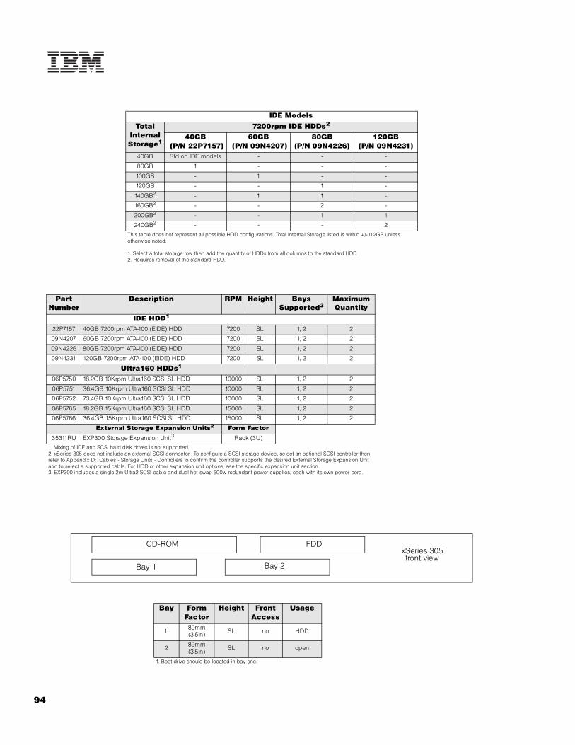
94
IDE ModelsTotal
Internal Storage1
7200rpm IDE HDDs2
40GB (P/N 22P7157)
60GB (P/N 09N4207)
80GB(P/N 09N4226)
120GB(P/N 09N4231)
40GB Std on IDE models - - -
80GB 1 - - -
100GB - 1 - -
120GB - - 1 -
140GB2 - 1 1 -
160GB2 - - 2 -
200GB2 - - 1 1
240GB2 - - - 2
This table does not represent all possible HDD configurations. Total Internal Storage listed is within +/- 0.2GB unless otherwise noted.
1. Select a total storage row then add the quantity of HDDs from all columns to the standard HDD.2. Requires removal of the standard HDD.
Part Number
Description RPM Height Bays Supported3
Maximum Quantity
IDE HDD1
22P7157 40GB 7200rpm ATA-100 (EIDE) HDD 7200 SL 1, 2 2
09N4207 60GB 7200rpm ATA-100 (EIDE) HDD 7200 SL 1, 2 2
09N4226 80GB 7200rpm ATA-100 (EIDE) HDD 7200 SL 1, 2 2
09N4231 120GB 7200rpm ATA-100 (EIDE) HDD 7200 SL 1, 2 2
Ultra160 HDDs1
06P5750 18.2GB 10Krpm Ultra160 SCSI SL HDD 10000 SL 1, 2 2
06P5751 36.4GB 10Krpm Ultra160 SCSI SL HDD 10000 SL 1, 2 2
06P5752 73.4GB 10Krpm Ultra160 SCSI SL HDD 10000 SL 1, 2 2
06P5765 18.2GB 15Krpm Ultra160 SCSI SL HDD 15000 SL 1, 2 2
06P5766 36.4GB 15Krpm Ultra160 SCSI SL HDD 15000 SL 1, 2 2
External Storage Expansion Units2 Form Factor
35311RU EXP300 Storage Expansion Unit3 Rack (3U)1. Mixing of IDE and SCSI hard disk drives is not supported.2. xSeries 305 does not include an external SCSI connector. To configure a SCSI storage device, select an optional SCSI controller then refer to Appendix D: Cables - Storage Units - Controllers to confirm the controller supports the desired External Storage Expansion Unit and to select a supported cable. For HDD or other expansion unit options, see the specific expansion unit section. 3. EXP300 includes a single 2m Ultra2 SCSI cable and dual hot-swap 500w redundant power supplies, each with its own power cord.
Bay Form Factor
Height Front Access
Usage
11 89mm (3.5in) SL no HDD
2 89mm(3.5in) SL no open
1. Boot drive should be located in bay one.
CD-ROM
Bay 1
FDD
Bay 2
xSeries 305 front view

95For the latest product & technical information, refer to the Information Sources on pages 2 and 3.Updated 10/15/02
IBM
xS
eri
es 3
05
Slot 1: Bus 1, 64-bit, 66/100/133MHz PCI-X, full-size, half-length, 3.3v Slot 2: Bus 2, 64-bit, 66/100/133MHz PCI-X, low-profile, half-length, 3.3v
Note: When two 133MHz adapters are installed, the bus will operate at a maximum frequency of 100MHz. If only one 133MHz adapter is installed, the bus will support the rated frequency of the adapter. If a lower frequency adapter is installed, the bus will be limited to the rated frequency of that adapter.
xSeries 305 I/O Options
Part Number
Description Adapter Length
PCI Support2
Slots Supported
Storage Controllers1
06P5740 ServeRAID-4Lx Ultra160 SCSI Controller3 Half 64-bit 1
19K4646 PCI Wide Ultra160 SCSI Adapter4 Half 32-bit 1, 2
Networking5
Ethernet6
09N9901 10/100 EtherLink Server Adapter by 3Com7 Half 32-bit 1
06P3601 10/100 Ethernet Server Adapter7 Half 32-bit 1
22P4901 10/100 Dual Port Server Adapter7 Half 64-bit 1
22P6801 PRO/1000XT Server Adapter by Intel (copper) w/CD, manuals7 Half 64-bit 1
22P7801 NetXtreme 1000 SX Fiber Ethernet Adapter Half 64-bit 1, 2
Token Ring
34L5001 16/4 Token-ring PCI Management Adapter7 Half 32-bit 1
07P2701 16/4 Token-ring Low Profile PCI Management Adapter7 Half 32-bit 2
Communications8
37L14xx Serial I/O SST 8- and 16-port adapters9 Half 32-bit 1
System Management09N7585 Remote Supervisor Adapter10 Half 32-bit 1
1. xSeries 305 has dual integrated EIDE (ATA-100) bus master controllers. SCSI models ship standard with a single-channel Ultra160 SCSI controller installed in slot two. The SCSI controller includes a two-drop cable for connection to two internal HDDs. External connection of a SCSI device requires a supported SCSI adapter.2. A 64-bit adapter installed into a 32-bit slot will transfer data at 32-bit rates. Adapters rated at 66MHz will operate at 33MHz when installed in a 33MHz slot. 133MHz PCI-X adapters are backward compatible with 33/66MHz, 64-bit PCI-based servers.3. ServeRAID-4Lx Ultra160 SCSI Controller is powered by a 100MHz Intel Zion GC80303 processor and provides a single channel, 32MB of ECC cache and either one internal or one external Ultra160 connection. External connector is 0.8mm VHDCI. Internal RAID support for HDDs requires removal of the standard SCSI PCI controller in SCSI models.4. PCI Wide Ultra160 SCSI Adapter (P/N 19K4646) provides a single channel with one internal connector and one external 0.8mm VHDCI connector. Support for external SCSI devices only. A five-drop terminated LVD SCSI cable is included but not supported for use in this server. This option includes brackets for both low-profile and full-size slots.5. xSeries 305 includes dual full-duplex copper 10/100/1000Mbps Broadcom Ethernet controllers.6. In a fault-tolerant networking environment, using the fault-tolerant software delivered with the Ethernet adapters of a single manufacturer is recommended. Installing fault-tolerant solutions provided by multiple manufacturers may cause failures if the intermediate drivers provided with the adapters are not compatible. Three optional Ethernet adapters are copper and Intel-based (P/N 06P3601, 22P4901, 22P6801). One adapter is Broadcom-based (P/N 22P7801)7. Wake on LAN function provided with this networking adapter is supported by this server.8. xSeries 305 includes two USB ports (front of chassis), a serial port, and video, keyboard and mouse ports.9. See Appendix E for details on Serial I/O options and configuration limitations.10. The Remote Supervisor Adapter requires installation of the AC power adapter included with the option in order to operate in standby mode.
PCI slot 2
PCI slot 1xSeries 305
rear view
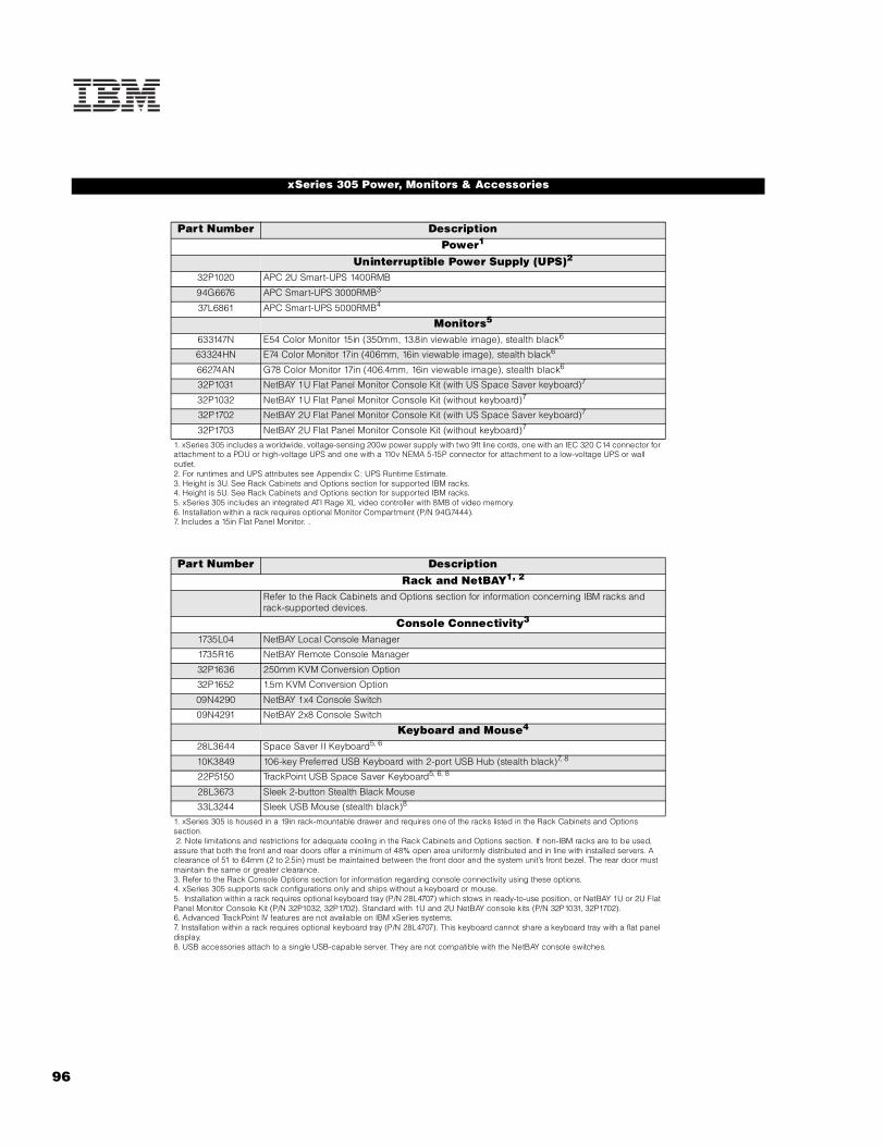
96
xSeries 305 Power, Monitors & Accessories
Part Number DescriptionPower1
Uninterruptible Power Supply (UPS)2
32P1020 APC 2U Smart-UPS 1400RMB
94G6676 APC Smart-UPS 3000RMB3
37L6861 APC Smart-UPS 5000RMB4
Monitors5
633147N E54 Color Monitor 15in (350mm, 13.8in viewable image), stealth black6
63324HN E74 Color Monitor 17in (406mm, 16in viewable image), stealth black6
66274AN G78 Color Monitor 17in (406.4mm, 16in viewable image), stealth black6
32P1031 NetBAY 1U Flat Panel Monitor Console Kit (with US Space Saver keyboard)7
32P1032 NetBAY 1U Flat Panel Monitor Console Kit (without keyboard)7
32P1702 NetBAY 2U Flat Panel Monitor Console Kit (with US Space Saver keyboard)7
32P1703 NetBAY 2U Flat Panel Monitor Console Kit (without keyboard)7
1. xSeries 305 includes a worldwide, voltage-sensing 200w power supply with two 9ft line cords, one with an IEC 320 C14 connector for attachment to a PDU or high-voltage UPS and one with a 110v NEMA 5-15P connector for attachment to a low-voltage UPS or wall outlet.2. For runtimes and UPS attributes see Appendix C: UPS Runtime Estimate.3. Height is 3U. See Rack Cabinets and Options section for supported IBM racks.4. Height is 5U. See Rack Cabinets and Options section for supported IBM racks.5. xSeries 305 includes an integrated ATI Rage XL video controller with 8MB of video memory.6. Installation within a rack requires optional Monitor Compartment (P/N 94G7444).7. Includes a 15in Flat Panel Monitor. .
Part Number DescriptionRack and NetBAY1, 2
Refer to the Rack Cabinets and Options section for information concerning IBM racks and rack-supported devices.
Console Connectivity3
1735L04 NetBAY Local Console Manager
1735R16 NetBAY Remote Console Manager
32P1636 250mm KVM Conversion Option
32P1652 1.5m KVM Conversion Option
09N4290 NetBAY 1x4 Console Switch
09N4291 NetBAY 2x8 Console Switch
Keyboard and Mouse4
28L3644 Space Saver II Keyboard5, 6
10K3849 106-key Preferred USB Keyboard with 2-port USB Hub (stealth black)7, 8
22P5150 TrackPoint USB Space Saver Keyboard5, 6, 8
28L3673 Sleek 2-button Stealth Black Mouse
33L3244 Sleek USB Mouse (stealth black)8
1. xSeries 305 is housed in a 19in rack-mountable drawer and requires one of the racks listed in the Rack Cabinets and Options section. 2. Note limitations and restrictions for adequate cooling in the Rack Cabinets and Options section. If non-IBM racks are to be used, assure that both the front and rear doors offer a minimum of 48% open area uniformly distributed and in line with installed servers. A clearance of 51 to 64mm (2 to 2.5in) must be maintained between the front door and the system unit’s front bezel. The rear door must maintain the same or greater clearance.3. Refer to the Rack Console Options section for information regarding console connectivity using these options.4. xSeries 305 supports rack configurations only and ships without a keyboard or mouse.5. Installation within a rack requires optional keyboard tray (P/N 28L4707) which stows in ready-to-use position, or NetBAY 1U or 2U Flat Panel Monitor Console Kit (P/N 32P1032, 32P1702). Standard with 1U and 2U NetBAY console kits (P/N 32P1031, 32P1702).6. Advanced TrackPoint IV features are not available on IBM xSeries systems.7. Installation within a rack requires optional keyboard tray (P/N 28L4707). This keyboard cannot share a keyboard tray with a flat panel display.8. USB accessories attach to a single USB-capable server. They are not compatible with the NetBAY console switches.

97For the latest product & technical information, refer to the Information Sources on pages 2 and 3.Updated 10/15/02
IBM
xS
eri
es 3
05
xSeries 305 Tape Options
Part Number Tape Drives
Bays Supported
SCSI Interface
(bit)
Form Factor
Termination Included
Ext Tape Enclosures1
00N7991 20/40 GB DDS/4 4mm Internal TapeDrive - 16 Ultra2 LVD
89mm (3.5in) HH or 133mm
(5.25in) HH
Y2 35510013 35100204
00N8016 100/200GB LTO Tape Drive - 16 Ultra2 LVD 133mm (5.25in) FH Y2 35510013
3503B1X
Tape Autoloaders
00N7992 120/240GB DDS/4 Tape Autoloader - 16 Ultra2 LVD 133mm (5.25in) FH Y2 35510013
3503B1X
360716X 3607 Series 1760GB/3.5TB SDLTpro Tape Autoloader 16 Ultra2 LVD 2U Rack Y -
External Tape Enclosures3510020 External Half High SCSI Storage Enclosure5 - 8, 16 Desktop N -
3503B1X Full-High SCSI Tape Enclosure6 - 16 Ultra2 LVD Desktop or 3U Rack Y -
3551001 NetMEDIA Storage Expansion Unit EL7 - 16 Rack Y -
10L7113 NetMEDIA Systems Management Adapter8 - 16 LVD - Y 3551001
Associated Options
00N7956 68-pin External Multimode LVD/SE SCSI Terminator - 16 LVD/SE Ext Y 3510020
10K2340 Media Bay Tray and LVD Cable Kit - 16LVD Int Y 3551001
1. xSeries 305 does not support internal tape drives and does not include an external SCSI connector. An external tape library or internal tape drive with a tape enclosure, supported SCSI adapter and appropriate cable must be selected. All tape drives and enclosures are supported by PCI Wide Ultra160 SCSI Adapter (P/N 19K4646), which has an external 0.8mm VHDCI connector. Select tape drive, enclosure and supported adapter then use Appendix D: Cables - Storage Units - Controllers to select an appropriate external cable.2. Termination requires installing the 34in single-drop, terminated LVD SCSI cable provided with the option. When installed in a NetMEDIA Storage Expansion Unit, termination is also provided by the standard cables shipped with the enclosure.3. LVD support for LVD tape drives installed in a NetMEDIA Storage Expansion Unit EL (P/N 3551001) is provided by two four-drop internal LVD cables.4. Requires 68-pin External Multimode LVD/SE SCSI Terminator (P/N 00N7956).5. Black desktop tape enclosure that supports a single 133mm (5.25in) half-high (HH) tape drive. Internal connector is configurable as 50-pin Centronix or 68-pin high density. Requires either tape drive self-termination or 68-pin External Multimode LVD/SE SCSI Terminator (P/N 00N7956). The option includes face plates for either a 68-pin HD or 0.8mm VHDCI external connection. External cables are not included.6. Black desktop or 3U rack tape enclosure supports a single 133mm (5.25in) full-high LVD tape device including DLT tape drives. Requires a fixed shelf if installed in a rack (allow additional 1U for fixed shelf). Includes a 90w power supply, cooling fan, external terminator, power cord (country-specific), and 2m 68-pin to 0.8mm external cable. 'Supports the following full-high tape options: 00N8015, 00N8016, 00N7992.7. NetMEDIA Storage Expansion Unit EL (P/N 3551001) is a black 3U, rack-mountable tape enclosure which includes two full-high (FH) or four half-high (HH) extended length 133mm (5.25in) bays, two external 0.8mm VHDCI connectors and two internal four-drop LVD terminated 16-bit SCSI cables for device attachment. Two power supplies and two power cords are also included. External storage cables are not included.8. NetMEDIA Systems Management Adapter (P/N 10L7113) may be installed in a 3551001 to provide repeater function, aggregate cable lengths up to 12m when attached to an LVD SCSI controller, and auto-termination when the 3551001 is powered off. External connector is 0.8mm VHDCI.
Note: Additional tape attributes can be found in Appendix A: Tape Drive Attributes

98
Note: The following sample configurations are for illustration only and may not be suitable for any specific customer installation. Contact your IBM Business Partner or IBM Marketing Representative for assistance with your specific configuration requirements.
Caching Server1
Static Web Content Server1
xSeries 305 Sample Configurations
Part Number Description Quantity8673-13X xSeries 305 2GHz-512KB/400MHz Pentium 4, 256MB ECC, 18.2GB, 24x (1U rack) 133L5039 1GB DDR PC2100 ECC RDIMM 22
06P5751 36.4GB 10Krpm Ultra160 SCSI SL HDD 13
32P1702 NetBAY 2U Flat Panel Monitor Console Kit (with US Space Saver keyboard) 132P1020 APC 2U Smart-UPS 1400 RMB 1
1. Rack components are not included.2.Total memory is 4GB. Removal of the standard 256MB RDIMM is required.3. For a total of 54.6GB of internal storage.
Part Number Description Quantity8673-12X xSeries 305 2GHz-512KB/400MHz Pentium 4, 256MB ECC, 40GB EIDE, 24x (1U rack) 133L5037 256MB DDR PC2100 ECC RDIMM 32
09N4226 80GB 7200rpm ATA-100 (EIDE) HDD 23
32P1702 NetBAY 2U Flat Panel Monitor Console Kit (with US Space Saver keyboard) 132P1020 APC 2U Smart-UPS 1400 RMB 1
1. Rack components are not included.2. For a total of 1GB of system memory.3. For a total of 160GB of internal storage. Removal of the standard IDE HDD is required.

99For the latest product & technical information, refer to the Information Sources on pages 2 and 3.Updated 10/15/02
IBM
xS
eri
es 3
05

IBM xSeries 330
EMEA Part Number Cross ReferencexSeries 330 S ystem Unit Part Numbers
EMEA AMERICAS M/C TYPE DESCRIPTION EMEAP/N P/N MODEL WDFM DATE
K411Xxx 867411X 8674-11X PIII 1.13GHz/133MHz, 512KB, 256MB, Open BayU160 HS, Rack 30/08/02
K412Xxx 867412X 8674-12X PIII 1.13GHz/133MHz, 512KB, 256MB, 20.4GB EIDE, Rack 30/07/02
K413Xxx 867413X 8674-13X PIII 1.13GHz/133MHz, 512KB, 256MB, 18.2GB U160, Rack 30/07/02
K431Xxx 867431X 8674-31X PIII 1.26GHz/133MHz, 512KB, 256MB, Open BayU160 HS, Rack ---
K432Xxx 867432X 8674-32X PIII 1.26GHz/133MHz, 512KB, 256MB, 20.4GB EIDE, Rack ---
K433Xxx 867433X 8674-33X PIII 1.26GHz/133MHz, 512KB, 256MB, 18.2GB U160, Rack ---
K43AXxx 86743AX 8674-3AX PIII 1.26GHz/133MHz, 512KB, 256MB, Open BayU160 HS, Rack ---
K4N1Xxx 8674N1X 8674-N1X PIII 1.26GHz/133MHz, 512KB, 1GB, 36.4GB U160HS, Rack ---
K441Xxx 867441X 8674-41X PIII 1.4GHz/133MHz, 512KB, 256MB, Open BayU160 HS, Rack ---
K442Xxx 867442X 8674-42X PIII 1.4GHz/133MHz, 512KB, 256MB, 40GB EIDE,Rack ---
K443Xxx 867443X 8674-43X PIII 1.4GHz/133MHz, 512KB, 256MB, 18.2GB U160,Rack ---
K54MXxx 86744MX 8674-4MX PIII 1.4GHz/133MHz, 512KB, 512MB, Open BayU160 HS, Rack ---
xSeries 330 Hard Disk Drive Storage Part NumbersEMEA AMERICAS M/C TYPE DESCRIPTION EMEA
P/N P/N MODEL WDFM DATENotes 1&2 19K11xx 35311RU --- EXP300 Storage Expansion Unit ---Notes 3&2 00N71xx 35601RU --- FAStT EXP500 Storage Expansion Unit ---Notes 4&2 24P09xx 17401RU --- FAStT EXP700 Storage Expansion Unit ---Notes 5&2 19K11xx 35421RU --- FAStT 200 Storage Server ---Notes 6&2 19K11xx 35422RU --- FAStT 200 HA Storage Server ---
1. Where ‘xx’ represents a specific country code as follows: 51=US/English, 52=European/English, 56=Danish/English, 57=Israel/English, 58=Italian/English, 59=South Africa/English, 60=Swiss/English, 63=UK/English.2. This unit does not include Rack Power Cables P/N 94G7448 when shipped (for attachment to highvoltage UPS or PDU). Standard country power cords only are included. If required, order one Rack PowerCable for each power supply.3. Where ‘xx’ represents a specific country code as follows:- 36=US/English, 37=Euro/English, 41=Denmark/English, 42=Israel/English, 43=Italy/English, 44=South Africa/English, 45=Switzerland/English, 49=UK/English.4. Where ‘xx’ represents a specific country code as follows:- 01=Eur/English, 02=Eur/Spanish, 05=Denmark/English, 06=Israel/English, 07=Italy/English, 08=South Africa/English, 09=Switzerland/English, 12=UK/English.5. Where ‘xx’ represents a specific country code as follows:- 23=US/English, 24=Euro/English, 25=Euro/Spanish, 27=Euro/German, 28=Denmark/English, 29=Israel/English, 30=Italy/English, 31=South Africa/English, 32=Switzerland/English, 34=Switzerland/German, 36=UK/English..6. Where ‘xx’ represents a specific country code as follows:- 37=US/English, 38=Euro/English, 39=Euro/Spanish, 41=Euro/German, 42=Denmark/English, 43=Israel/English, 44=Italy/English, 45=South Africa/English, 46=Switzerland/English, 48=Switzerland/German, 50=UK/English.
xSeries 330 I/O Option Part NumbersEMEA AMERICAS M/C TYPE DESCRIPTION EMEA
P/N P/N MODEL WDFM DATEN/A 33L4618 --- V90 PCI Data/Fax WinModem N/A
Note 7 37L14xx 37L14xx --- Serial I/O SST 8 and 16 port Adapters Note 7Note 8 09N75xx 09N7585 --- Remote Supervisor Adapter ---
7. Serial I/O Adapter P/Ns 37L1414 and 37L1415 are available. Other Serial I/O adapter part numbers arewithdrawn from marketing in EMEA.8. Where ‘xx’ represents a specific country code as follows:- 86=Europe, 87=Denmark, 88=South Africa, 89=UK, 90=Switzerland, 91=Italy, 92=Israel, 85=USA..
99A Updated 10/15/02

IBM xSeries 330
EMEA Part Number Cross ReferenceNote 9 xSeries 330 Power, Monitors & Accessories
EMEA AMERICAS M/C TYPE DESCRIPTION EMEAP/N P/N MODEL POWER WDFM DATE
Note 10 32P16xx 32P1020 --- APC 2U Smart-UPS 1400RMiB ---Note 11 30RIxxx 94G6676 --- APC Smart-UPS 3000RMiB ---
37L6862 37L6861 --- APC Smart-UPS 5000RMiB ---
9. The xSeries 330 ships with a standard country power cord. For connection to a high voltage UPS or PDU, order Rack PowerCable P/N 94G7448.
10. Where ‘xx’ represents a specific country code as follows:- 12=Europe, 13=UK, 14=Italy, 15=Switzerland, 16=Denmark, 17=South Africa, 18=Israel.
11. Where ‘xxx’ represents a specific country code as follows:- DEN=Denmark, ISR=Israel, ITA=Italy, SDI=Saudi Arabia, SAF=South Africa, SWS=Switzerland, UKM=United Kingdom, EUR=Europe.
xSeries 330 Power, Monitors & AccessoriesEMEA AMERICAS M/C TYPE DESCRIPTION EMEA
P/N P/N MODEL MONITORS WDFM DATENote 12 T3147xx 633147N 6331-47N E54 15" (13.8" viewable image) Colour Monitor (S/Blac ---Note 12 T3247xx 63324HN 6332-4HN E74 17" (16" viewable image) Colour Monitor (S/Black) ---Note 12 T274Axx 66274AN 6627-4AN G78 17" (16" viewable image) Colour Monitor (S/Black ---
N/A 32P1031 --- NetBAY 1U Flat Panel Monitor Console Kit (with US ke N/AN/A 32P1702 --- NetBAY 2U Flat Panel Monitor Console Kit (with US ke N/A
12. Where ‘xx’ represents a specific country code as follows: DK=Denmark, IS=Israel, IT=Italy, SD=Saudi Arabia, SA=SouthAfrica/Pakistan, CH=Switzerland, UK=UK, EU=Europe.
xSeries 330 Power, Monitors & AccessoriesEMEA AMERICAS M/C TYPE DESCRIPTION EMEA
P/N P/N MODEL KEYBOARD AND MOUSE WDFM DATENote 13 28L36xx 28L3644 --- Spacesaver II Keyboard ---Note 14 10K38xx 10K3849 --- 106-key Preferred USB Keyb. with 2-port USB Hub (S/ ---
28L3675 28L3673 --- Sleek 2-button Mouse (S/Black) ---13. Where ‘xx’ represents a specific country code as follows:- 46=Danish , 47=French, 48=German, 49=Italian, 50=Spanish, 51=UK English, 44=US English, and P/N 19K3831=Swiss, 19K3832=Swedish/Finnish, 19K3833=Portugese, 19K3834=Belgian,19K3836=Russian, 19K3837=Polish.
14. Where ‘xx’ represents a specific country code as follows:- 53=Danish , 54=Dutch, 55=France, 56=Germany, 57=Italian, 58=Norwegian, 59=Swedish/Finnish, 10K2343=Swiss, 10K2344=UK English, 10K2345=US ISO.
xSeries 330 Tape OptionsEMEA AMERICAS M/C TYPE DESCRIPTION EMEA
P/N P/N MODEL WDFM DATENote 15 00N79xx 3502108 --- DLT Tape Autoloader ---Note 16 09N40xx 3600109 --- 3600 Series 900GB/1.8TB LTO Tape Autoloader ---Note 17 00N79xx 3502x14 --- DLT Tape Library ---
N/A 3570C2x --- Magstar MP 3570 Tape Subsystem N/ANote 18 21P99xx 3600R20 --- 3600 Series 2/4TB LTO Tape Library (Rack) ---Note 19 21P99xx 3600LXU --- 3600 Series 2-drive 20-cartridge Expander Module ---Note 20 24P24xx 3503B1X --- Full-High SCSI Tape Enclosure ---
03K8756 3551001 --- NetMEDIA Storage Expansion Unit EL ---
15. Where ‘xx’ represents a country specific power cord code: 70=UK, 71=Swiss, 72=Italy, 73=Israel, 33L4981=EU1, 33L4982=Denmark, 33L4983=South Africa/India.16. Where ‘xx’ represents a specific country code as follows:- 49=UK, 50=Europe, 51=Denmark, 52=South Africa, 53=Switzerland, 54=Italy, 55=Israel.
17. Where ‘xx’ represents a country specific power cord code: Tower versions - 74=EU1, 75=Denmark, 76=India/South Africa,77=UK, 78=Swiss, 79=Italy, 80=Israel: Rack versions - 81=EU1, 82=Denmark, 83=India/South Africa, 84=UK, 85=Swiss, 86=Italy, 87=Israel.
18. Where ‘xx’ represents a specific country code as follows:- Rack version - 78=Europe, 79=Denmark, 80=South Africa, 77=UK,81=Swiss, 82=Italy, 83=Israel.
19. Where ‘xx’ represents a specific country code as follows:- 85=Europe, 86=Denmark, 87=South Africa, 84=UK, 88=Swiss, 89=Italy, 90=Israel.
20. Where ‘xx’ represents a country specific code: 35=UK, 39=Swiss, 40=Italy, 41=Israel, 36=EU, 37=Denmark, 38=South Africa..
Updated 10/15/02 99B

100
IBM xSeries 330
xSeries 330 At-A-Glance
8674-11X1 1.132 1/2 512 256MB(R)/4GB Rack (1U) 1/1 H - Y 2 x 10/
100 U160 2/0 0/146.8GB 24X-10X 4/2 2/2
8674-12X1 1.132 1/2 512 256MB(R)/4GB Rack (1U) 1/1 - - Y 2 x 10/
100 IDE 2/0 20.4GB/240GB 24X-10X 4/1 2/2
8674-13X1 1.132 1/2 512 256MB(R)/4GB Rack (1U) 1/1 - - Y 2 x 10/
100 U160 2/0 18.2GB/146.8GB3 24X-10X 4/1 2/2
8674-31X1 1.262 1/2 512 256MB(R)/4GB Rack (1U) 1/1 H - Y 2 x 10/
100 U160 2/0 0/146.8GB 24X-10X 4/2 2/2
8674-32X1 1.262 1/2 512 256MB(R)/4GB Rack (1U) 1/1 - - Y 2 x 10/
100 IDE 2/0 20.4GB/240GB 24X-10X 4/1 2/2
8674-33X1 1.262 1/2 512 256MB(R)/4GB Rack (1U) 1/1 - - Y 2 x 10/
100 U160 2/0 18.2GB/146.8GB3 24X-10X 4/1 2/2
8674-3AX1, 5 1.262 1/2 512 256MB(R)/4GB Rack (1U) 1/15 H - Y 2 x 10/
100 U160 2/0 0/146.8GB 24X-10X 4/2 2/2
8674-N1X1, 5 1.262 2/2 512 1GB(R)/1GB7 Rack (1U) 1/15 H - Y 2 x 10/
100 U160 2/0 36.4GB/36.4GB7 24X-10X 4/0 2/0
8674-41X1 1.42 1/2 512 256MB(R)/4GB Rack (1U) 1/1 H - Y 2 x 10/
100 U160 2/0 0/146.8GB 24X-10X 4/2 2/2
8674-42X1 1.42 1/2 512 256MB(R)/4GB Rack (1U) 1/1 - - Y 2 x 10/
100 IDE 2/0 40GB/240GB 24X-10X 4/1 2/2
8674-43X1 1.42 1/2 512 256MB(R)/4GB Rack (1U) 1/1 - - Y 2 x 10/
100 U160 2/0 18.2GB/146.8GB 24X-10X 4/1 2/2
8675-4MX1, 6 1.42 1/2 512 512MB(R)/4GB Rack (1U) 1/1 H - Y 2 x 10/
100 U160 2/0 0/146.8GB 24X-10X 4/2 2/2
1. Housed in a 19in rack-mountable drawer and ships standard without a keyboard or mouse. See Rack Cabinets and Options section for supported IBM racks.2. Intel Pentium III processor with 133MHz FSB and 512KB advanced transfer cache.3. This model does not support hot-swap HDDs.4. Variable read rate. Actual playback speed will vary and is often less than the maximum possible.5. This direct current (DC) power model includes a 200w, -48v direct current power supply requiring a direct current power source for utilization in a telecommunications network infrastructure. Model N1X is Network Equipment Building System (NEBS) Level 3 compliant. Only the standard shipped configuration is supported for model N1X.6. This MXT (Memory Xpansion Technology) system uses an advanced memory controller and caching process for increased performance. Advanced Chipkill ECC corrects two-, three-, and four-bit memory errors.7. Two 10,000rpm 18.2GB Ultra160 hot-swap HDDs and four 256MB RDIMMs ship standard with this specific NEBS configuration. Please contact your IBM representative, Business Partner or the IBM Help Center with questions regarding different NEBS configurations.
xSeries 330 Processors
Part Number
Processor Upgrades SMP Support1
Processor Speed Upgrade2
25P2835 xSeries 1.13GHz Upgrade with 133MHz FSB and 512KB Advanced Transfer Cache Pentium III Processor 1xX -
25P2836 xSeries 1.26GHz/133MHz, 512KB Cache Upgrade with Pentium III Processor 3xX 1xX
48P7466 xSeries 1.4GHz/133MHz, 512KB Cache Upgrade with Pentium III Processor 4xX 1 ... 3xX1. One additional processor may be installed, providing a maximum of two. All processors must be identical in type, speed, and cache size.2. Requires removal of the standard processor. A maximum of two processors may be installed. All processors must be identical in type, speed and cache size. Upgrades may require a BIOS update. To obtain the latest Flash BIOS, access www.pc.ibm.com/support and enter machine “Type-Model” in Quick Path. Select “Downloadable files” then “BIOS.”
Part Number
Processor Speed (G
Hz)
Number of P
rocessors (Std/M
ax)
L2 ECC Cache (KB)
Memory (Std/M
ax) (R = RDIM
M)
Form Factor
Power Supply Quantit
y (Std/M
ax)
Hot-Swap (P
ower, Slots, H
DD, Fans)
Redundancy (Optio
nal, Standard)
Adv System Management P
rocessor
Onboard Ethernet (Mbps)
SCSI Contro
ller (D
ual, Ultr
a, RAID)
Removable Media Bays (T
otal/Avail)
Internal Hard Disk Driv
e (Std/M
ax)
CD-ROM (ID
E)4
Bays (Total/A
vail)
Slots (Total/A
vail)

101For the latest product & technical information, refer to the Information Sources on pages 2 and 3.Updated 10/15/02
IBM
xS
eri
es
33
0
xSeries 330 Memory
Machine type 8674 modelsTotal
Memory1Quantity of RDIMMs Added
256MB (1 x 256) Models
128MB (10K0018)
256MB (10K0020)
512MB (10K0022)
1GB (33L3326)
384MB 1 - - -
512MB 2 or 1 - -
640MB 3 - - -
Part Number
Memory Description1768MB - 2 or 1 -
10K0018 128MB PC133 ECC SDRAM RDIMM 1024MB - 3 - -
10K0020 256MB PC133 ECC SDRAM RDIMM 1280MB - - 2 or 1
10K0022 512MB PC133 ECC SDRAM RDIMM 1792MB - - 3 -
33L3326 1GB PC133 ECC SDRAM RDIMM 2048MB - - 42 -
1. Memory RDIMMs must be installed in sequence from RDIMM connector 1 through connector 4. RDIMM size is not relevant.
2304MB - - - 2
3328MB - - - 3
4096MB (max) - - - 42
This table does not represent all possible memory configurations. Memory modules may vary in price per MB. Selection of smaller RDIMMs may provide a more cost-effective alternative to using larger RDIMMs.1. Network operating systems may limit the maximum amount of addressable memory. See operating system specifications for further information.2. Requires removal of standard memory.
Machine type 8675 modelsTotal
Memory1Quantity of RDIMMs Added
512MB (2 x 256) Models
256MB (33L3322)
512MB (33L3324)
1GB (33L3326)
1024MB 2 - -
1536MB - 2 -
2560MB - - 2
3072MB2 - 2 2
4GB2, 3 - - 4
This table does not represent all possible memory configurations. Memory modules may vary in price per MB. Selection of smaller RDIMMs may provide a more cost-effective alternative to using larger RDIMMs. RDIMMs must be added in pairs to support interleaving technology.
1. Network operating systems may limit the maximum amount of addressable memory. See operating system specifications for further information.2. Requires removal of standard memory.3. When memory options total 4GB, slot two does not support dual address cycle (DAC) PCI options (RAID controllers, gigabit Ethernet adapters, Fibre Channel host adapters) in 8675 models.
Part Number
Memory Description1
33L3322 256MB PC133 ECC SDRAM RDIMM
33L3324 512MB PC133 ECC SDRAM RDIMM
33L3326 1GB PC133 ECC SDRAM RDIMM2
1. Due to two-way interleaving, installation of memory options in pairs beginning with set 1 is required. Chipkill support is provided on the memory card.2. When four 1GB RDIMMs are installed in 8675 models, slot two does not support dual address cycle (DAC) PCI options (RAID controllers, gigabit Ethernet adapters, Fibre Channel host adapters).
RD
IMM
4
RD
IMM
3
RD
IMM
2
RD
IMM
1
RDIMM Set 1
RDIMM Set 2
RDIMM Set 2
RDIMM Set 1Std RDIMM
Recommended order of installation: Set 1-2.
Std RDIMM

102
xSeries 330 hot-swap models contain a DASD backplane supporting two hot-swap, SCA-2 compliant drive bays. The backplane is connected to the internal connector of the integrated Ultra160 SCSI controller through a 16-bit LVD SCSI cable. If internal RAID is required, the cable can be attached to the internal connector of the optional RAID adapter. The cable is of sufficient length to attach to adapters in slot one but not slot two.
xSeries 330 nonhot-swap models contain either of the following:• 20.4GB or 40GB EIDE HDDs cabled directly to an integrated EIDE controller through a two-drop cable that can support up to two EIDE HDDs• 18.2GB 10,000RPM Ultra160 SCSI HDD cabled directly to the Ultra160 SCSI controller through a terminated two-drop LVDS SCSI cable that can support up to two HDDs.
In configurations where external SCSI device attachment is required, a supported SCSI adapter or ServeRAID controller must be installed.
For additional information regarding internal cabling, refer to Appendix F: Internal Cabling Overview.
xSeries 330 Internal SCSI Cabling
xSeries 330 Hard Disk Drive (HDD) Storage
SCSI ModelsTotal Int Storage1
10,000rpm HDDs 15,000rpm HDDs18.2GB
(06P5750, 06P5754)
36.4GB(06P5751, 06P5755)
73.4GB(06P5752,06P5756)
18.2GB(06P5765, 06P5767)
36.4GB(06P5766, 06P5768)
0GB Standard on some base models
18.2GB2 12 - - 1 -
36.4GB - 1 - - 1
72.8GB - 2 - - 2
73.4GB - - 1 - -
146.8GB (max)3 - - 2 - -
This table does not represent all possible HDD configurations. Total Internal Storage listed is within +/-0.2GB unless otherwise noted.
1. Select a total storage row then select the quantity of HDDs from a column corresponding to the HDD of choice.2. Some SCSI models support only nonhot-swap HDDs and ship standard with one 18.2GB nonhot-swap HDD.3. Requires replacing standard HDD in nonhot-swap SCSI models.
EIDE ModelsTotal Internal Storage1 7200rpm HDDs2
20.4GB models 40GB models20.4GB
(P/N 19K4461)40GB
(P/N 22P7157)60GB
(P/N 09N4207)80GB
(P/N 09N4226)120GB
(P/N 09N4231)40.8GB 60.4GB 1 - - - -
60.4GB 80GB - 1 - - -
80.4GB 100GB - - 1 - -
120GB3 120GB3 - - 2 - -
140GB3 140GB3 - - 1 1 -
160GB3 160GB3 - - - 2 -
200GB3 160GB3 - - - 1 1
240GB3 160GB3 - - - - 2
This table does not represent all possible HDD configurations. Total Internal Storage listed is within +/-0.2GB unless otherwise noted.
1. Select a total storage row then add the quantity of HDDs from all columns to the standard HDD.2. The xSeries 330 dual integrated EIDE controllers support a maximum of three IDE devices per machine including one CD-ROM and two IDE HDDs.3. Requires replacing the standard HDD.
Floppy / CD-ROM Bay 1 Bay 2

103For the latest product & technical information, refer to the Information Sources on pages 2 and 3.Updated 10/15/02
IBM
xS
eri
es
33
0
Bay Form Factor
Height Front Access
Usage Part Number
Description RPM Height Bays Supported
Max Qty
11 HS or89mm (3.5in)2 SL yes Open3 IDE HDDs1, 2
2 HS or89mm (3.5in)2 SL yes Open3 19K4461 20.4GB 7200rpm ATA-100 (EIDE)
HDD 7200 SL 1, 2 2
1. Boot drive should be located in bay 1.2. x330 includes IDE, nonhot-swap and hot-swap models.3. Nonhot-swap SCSI and IDE models ship with one standard HDD. Bays one and two in these models are not front-accessible.
22P7157 40GB 7200rpm ATA-100 (EIDE) HDD 7200 SL 1, 2 2
09N4207 60GB 7200rpm ATA-100 (EIDE) HDD 7200 SL 1, 2 2
09N4226 80GB 7200rpm ATA-100 (EIDE) HDD 7200 SL 1, 2 2
09N4231 120GB 7200rpm ATA-100 (EIDE) HDD 7200 SL 1, 2 2
Nonhot-swap Ultra160 HDDs2, 3
06P5750 18.2GB 10Krpm Ultra160 SCSI SL HDD 10000 SL 1, 2 2
06P5751 36.4GB 10Krpm Ultra160 SCSI SL HDD 10000 SL 1, 2 2
06P5752 73.4GB 10Krpm Ultra160 SCSISL HDD 10000 SL 1, 2 2
06P5765 18.2GB 15Krpm Ultra160 SCSISL HDD 15000 SL 1, 2 2
06P5766 36.4GB 15Krpm Ultra160 SCSISL HDD 15000 SL 1, 2 2
Hot-swap Ultra160 HDDs4
06P5754 18.2GB 10Krpm Ultra160 SCSI Hot-Swap SL HDD 10000 SL 1, 2 2
06P5755 36.4GB 10Krpm Ultra160 SCSI Hot-Swap SL HDD 10000 SL 1, 2 2
06P5756 73.4GB 10Krpm Ultra160 SCSI Hot-Swap SL HDD 10000 SL 1, 2 2
06P5767 18.2GB 15Krpm Ultra160 SCSI Hot-Swap SL HDD 15000 SL 1, 2 2
06P5768 36.4GB 15Krpm Ultra160 SCSI Hot-Swap SL HDD 15000 SL 1, 2 2
External Storage Expansion Units5
Form Factor
35311RU Netfinity EXP300 Storage Expansion Unit6 Rack (3U)
17401RU FAStT EXP700 Storage Expansion Unit7 Rack (3U)
35601RU Netfinity FAStT EXP500 Storage Expansion Unit8 Rack (3U)
35421RU FAStT200 Storage Server9, 10 Rack (3U)
35422RU FAStT200 HA Storage Server9 Rack (3U)
19K1121 FAStT200 Redundant RAID Controller -
1. The xSeries 330 dual integrated EIDE controllers support a maximum of three IDE devices per machine including one CD-ROM and two IDE hard disk drives. IDE HDDs are supported only on IDE models.2. Mixing of IDE and SCSI hard disk drives is not supported.3. Nonhot-swap HDDs are supported only in fixed disk models.4. Hot-swap HDDs are supported only in hot-swap models.5. xSeries 330 does not include an external SCSI connector. To configure a SCSI storage device, select an optional SCSI controller then refer to Appendix D: Cables - Storage Units - Controllers to confirm the controller supports the desired External Storage Expansion Unit and to select a supported cable. For HDD or other expansion unit options, see the specific expansion unit section. For Fibre Channel storage devices, refer to the Fibre Channel Solutions Overview section.6. EXP300 includes a single 2M Ultra2 SCSI cable and dual hot-swap 500W redundant power supplies, each with its own power cord. 7. FAStT EXP700 Storage Expansion Unit (P/N 17401RU) includes dual hot-swap 400w power supplies, each with its own power cord.8. FAStT EXP500 Storage Expansion Unit (P/N 35601RU) includes dual hot-swap 350W power supplies, each with its own power cord.9. The FAStT200 includes two hot-swap, 350W auto-ranging redundant power supplies, each with its own power cord.10. Can be upgraded to FAStT200 HA Storage Server through the addition of a FAStT200 Redundant RAID Controller (P/N 19K1121).

104
xSeries 330 I/O Options
Part Number
Description Adapter Length
PCI Support3
Slots Supported3
Storage Controllers1, 2
37L6889 ServeRAID-4H Ultra160 SCSI Controller4 Full 64-bit 1
06P5736 ServeRAID-4Mx Ultra160 SCSI Controller5 Full 64-bit 1
06P5740 ServeRAID-4Lx Ultra160 SCSI Controller6 Half 64-bit 1, 2
19K4646 PCI Wide Ultra160 SCSI Adapter7 Half 32-bit 1, 2
02K3454 PCI Fast/Wide Ultra SCSI Adapter8 Half 32-bit 1, 219
Fibre Storage Controllers and Options9
00N6881 Netfinity FAStT Host Adapter Half 64-bit 1, 2
24P0960 FC2 - 133 Host Bus Adapter Half 64-bit 1, 23
17421RU FAStT700 Fibre Channel Storage Server - - -
35521RU FAStT500 Storage Server - - -
35421RU FAStT200 Storage Server - - -
35422RU FAStT200 HA Storage Server - - -
3534F08 TotalStorage SAN Switch F08 - 8-port - - -
2109F16 SAN Fibre Channel Switch, 16-Port - - -
2108R3L SAN Data Gateway Router Ultra SCSI LVD Port10 - - -
Networking11
Ethernet12
09N9901 10/100 EtherLink Server Adapter by 3Com13 Half 32-bit 1, 2
06P3601 10/100 Ethernet Server Adapter13 Half 32-bit 1, 2
22P4901 10/100 Dual Port Server Adapter13 Half 64-bit 1, 2
22P6801 PRO/1000XT Server Adapter by Intel (copper) w/CD, manuals13, 14 Half 64-bit 1, 23
22P7801 NetXtreme 1000 SX Fiber Ethernet Adapter Half 64-bit 1, 2
Token Ring
34L0701 Token-Ring 16/4 PCI Adapter2 with Wake on LAN13 Half 64-bit 1, 2
34L5001 16/4 Token-Ring PCI Management Adapter13 Half 32-bit 1, 2
34L5201 High-Speed 100/16/4 Token-Ring PCI Management Adapter13 Half 32-bit 1, 2
Communications15
33L4618 V.90 PCI Data/Fax Modem Half 32-bit 1, 219
37L14xx Serial I/O SST 8- and 16-port adapters16 Half 32-bit 1, 219
System Management17
09N7585 Remote Supervisor Adapter18 Half 32-bit see note: 20
1. xSeries 330 has an integrated single channel Ultra160 SCSI Controller.2. When storage controllers are installed in both PCI slots, the BIOS for the integrated storage controller must be disabled, i.e., it cannot support either external or internal storage media. If the two storage controllers in slots one and two are both RAID adapters, the boot media must be attached to the RAID adapter in slot one.3. A 64-bit adapter installed into a 32-bit slot will transfer data at 32-bit rates. Adapters rated at 66MHz will operate at 33MHz when installed in a 33MHz slot. 33MHz adapters will reduce 66MHz buses to 33MHz. 133MHz PCI-X adapters are backward compatible with33/66MHz, 64-bit PCI-based servers.4. ServeRAID-4H Ultra160 SCSI Controller is powered by a 266MHz Power PC 750 processor and provides 128MB of battery-backed ECC cache. The internal connectors are not accessible due to a cabling interference. Four external Ultra160 0.8mm VHDCI connectors are available. Not compatible with machine type 8675 models.5. ServeRAID-4Mx Ultra160 SCSI Controller is powered by a 100MHz Intel Zion GC80303 processor that provides 64MB of battery-backed ECC cache and two internal and two external Ultra160 connections (only two connectors may be used). External connections are 0.8mm VHDCI.6. ServeRAID-4Lx Ultra160 SCSI Controller is powered by a 100MHz Intel Zion GC80303 processor and provides a single channel, 32MB of ECC cache and either one internal or one external Ultra160 connection. External connector is 0.8mm VHDCI. If attached to the internal HDDs, installation is supported only in slot one.7. PCI Wide Ultra160 SCSI Adapter (P/N 19K4646) provides a single channel with one internal connector and one external 0.8mm VHDCI Ultra160 connector. Support for external SCSI devices only. A five-drop terminated LVD SCSI cable is included but not supported for use in this server.8. PCI Fast/Wide Ultra SCSI Adapter (P/N 02K3454) provides one external 68-pin high density connector that supports external SCSI devices such as tape enclosures.9. See the Fibre Channel Solutions Overview section for additional configuration information.10. The 2108R3L SAN Data Gateway Router Ultra SCSI LVD port provides one integrated short-wave optical port and two SCSI ports for tape storage connections (LVD, HVD and single-ended).11. xSeries 330 includes dual full-duplex copper 10/100Mbps Intel Ethernet controllers.

105For the latest product & technical information, refer to the Information Sources on pages 2 and 3.Updated 10/15/02
IBM
xS
eri
es
33
0
12. In a fault-tolerant networking environment, using the fault-tolerant software delivered with the Ethernet adapters of a single manufacturer is recommended. Installing fault-tolerant solutions provided by multiple manufacturers may cause failures if the intermediate drivers provided with the adapters are not compatible. Three optional Ethernet adapters are copper and Intel-based (P/N 06P3601, 22P4901, 22P6801). One adapter is Broadcom-based (22P7801).13. The Wake on LAN function of this option is supported by machine type 8674 models. 14. The Wake on LAN function of this option is not supported by machine type 8675 models. Installation in slot two is supported only if total memory is 2GB or less. Installation in slot one is supported with up to 4GB of memory installed.15. xSeries 330 includes two USB ports and a high speed serial/asynchronous port (NS16550A compatible).16. See Appendix E for details on Serial I/O Options and configuration limitations.17. xSeries 330 has two integrated RS-485 system management interconnect ports located on the back of the system chassis. Connection of the standard service processor to other servers in an interconnect network requires only a customer-supplied Cat5 cable.18. When installed in an xSeries 330, Remote Supervisor Adapter (RSA) is connected externally to the integrated service processor using one of the integrated RS-485 ports. The optional adapter serves only as an Ethernet and interconnect gateway. The integrated ASM processor will provide all service processor data. The external AC power supply provided with RSA is not required.19. Supported in slot two only for machine type 8675 models.20. Supported in slot two for machine type 8674 models and slot one for machine type 8675 models.
xSeries 330 Power, Monitors & Accessories
Part Number DescriptionPower1, 2
Uninterruptible Power Supply (UPS)3
32P1020 APC 2U Smart-UPS 1400RMB
94G6676 APC Smart-UPS 3000RMB4
37L6861 APC Smart-UPS 5000RMB5
Monitors6
06P4792 Cable Chain Technology Cable Kit7
633147N E54 Color Monitor 15in (350mm, 13.8in viewable image), stealth black8
63324HN E74 Color Monitor 17in (406mm, 16in Viewable Image), stealth black8
66274AN G78 Color Monitor 17in (406.4mm, 16in Viewable Image), stealth black8
32P1031 NetBAY 1U Flat Panel Monitor Console Kit (with US Space Saver keyboard)9
32P1032 NetBAY 2U Flat Panel Monitor Console Kit (without keyboard)9
32P1702 NetBAY 2U Flat Panel Monitor Console Kit (with US Space Saver keyboard)9
32P1703 NetBAY 2U Flat Panel Monitor Console Kit (without keyboard)9
PCI slot 1 PCI slot 2
Slot 1: 33MHz, 64-bit, 5v or universal, full-lengthSlot 2: 33MHz, 64-bit, 5v or universal, half-length
Machine type 8674 (rear view)
PCI slot 1 PCI slot 2
Slot 1: 66MHz, 64-bit, 3.3v, full-lengthSlot 2: 33MHz, 64-bit, 5v, half-length
Machine type 8675 (rear view)

106
1. Most xSeries 330 models include a worldwide, voltage-sensing 200W power supply with auto restart and two 9ft line cords. One line cord contains a 110V NEMA 5-15P connector while the other contains an IEC 320 C14 for attachment to a high voltage PDU or UPS.2. Direct current models (8674-3AX, N1X) include a 200w, -48v direct current power supply. The line cord is customer-supplied. This model is designed for specific application in a telecommunications infrastructure.3. For runtimes and UPS attributes see Appendix C: UPS Runtime Estimate.4. Height is 3U. See Rack Cabinets and Options section for supported IBM racks.5. Height is 5U. See Rack Cabinets and Options section for supported IBM racks.6. xSeries 330 uses an SVGA controller (S-3 Savage4 chipset) with 8MB of video memory. 7. A C2T Interconnect™ Cable Chaining Technology Cable Kit (P/N 06P4792) is required for the attachment of console devices to one or multiple chained xSeries 330s. The kit contains a 2M (6.5ft) breakout cable for attachment to a keyboard. mouse and monitor as well as a 2M (6.5ft) chaining cable for connecting two xSeries 330s together when the standard 260mm (10in) chaining cable is not long enough. A maximum of 42 xSeries 330s are supported in a single chain. No more than one Cable Chain Technology Cable Kit may be used. If the last server in the chain is connected to a console switch rather than directly to a monitor, a console cable(P/N 09N4293 or 94G7447) is required in addition to the cable kit.8. Installation within a rack requires optional Monitor Compartment (P/N94G7444).9. Includes a 15in Flat Panel Monitor.
Part Number DescriptionRack and NetBAY1, 2
Refer to the Rack Cabinets and Options section for information concerning IBM racks and rack-supported devices.
Keyboard and Mouse3
06P4792 Cable Chain Technology Cable Kit4
28L3644 Space Saver II Keyboard5, 6
10K3849 106-key Preferred USB Keyboard with 2-port USB Hub (stealth black)7, 8
28L3673 Sleek 2-button Stealth Black Mouse
33L3244 Sleek USB Mouse (stealth black)8
1. xSeries 330 is housed in a 19in rack-mountable drawer and requires one of the racks listed in the Rack Cabinets and Options section.2. Note limitations and restrictions for adequate cooling in the Rack Cabinets and Options section. If non-IBM racks are to be used, assure that both the front and rear doors offer a minimum of 48% open area uniformly distributed and in line with installed servers. A clearance of 51 to 64mm (2 to 2.5in) must be maintained between the front door and the system unit’s front bezel. The rear door must maintain the same or greater clearance. 3. xSeries 330 supports rack configurations only and ships without a keyboard or mouse.4. A C2T Interconnect™ Cable Chaining Technology Cable Kit (P/N 06P4792) is required for the attachment of console devices to one or multiple chained xSeries 330s. The kit contains a 2M (6.5ft) breakout cable for attachment to a keyboard. mouse and monitor as well as a 2M (6.5ft) chaining cable for connecting two xSeries 330s together when the standard 260mm (10in) chaining cable is not long enough. A maximum of 42 xSeries 330s are supported in a single chain. No more than one Cable Chain Technology Cable Kit may be used. If the last server in the chain is connected to a console switch rather than directly to a monitor, a console cable(P/N 09N4293 or 94G7447) is required in addition to the cable kit.5. Installation within a rack requires optional keyboard tray (P/N 28L4707) which stows in ready-to-use position, or NetBAY 1U or 2U Flat Panel Monitor Console Kit (P/N 32P1032, 32P1702). Standard with 1U and 2U NetBAY console kits (P/N 32P1031, 32P1702).6. Advanced TrackPoint IV features are not available on IBM xSeries systems.7. Installation within a rack requires optional keyboard tray (P/N 28L4707). This keyboard cannot share a keyboard tray with a flat panel display. 8. USB accessories attach to a single USB-capable server. They are not compatible with the NetBAY console switches.

107For the latest product & technical information, refer to the Information Sources on pages 2 and 3.Updated 10/15/02
IBM
xS
eri
es
33
0
xSeries 330 Tape Options
Part Number Tape Drives
Bays Supported1
SCSI Interface
(bit)
Form Factor
Termination Included
68/50-pin Converter
Incl
Ext Tape Enclosures
09N4041 12/24GB DDS/3 4mm Internal SCSI Tape Drive - 8
89mm (3.5in) HH or
133mm (5.25in) HH
Y Y 3551001
00N7991 20/40GB DDS/4 4mm Internal Tape Drive - 16 Ultra2 LVD
89mm (3.5in) HH or
133mm (5.25in) HH
Y2 - 35510013
00N7990 40/80GB DLT Internal SCSI Tape Drive - 16 Ultra2 LVD 133mm (5.25in) FH Y2 - 35510013
3503B1X
00N8015 110/220GB Super DLT Internal SCSI Tape Drive12 - 16 Ultra2 LVD 133mm
(5.25in) FH Y2 - 35510013
3503B1X
00N8016 100/200GB LTO Tape Drive - 16 Ultra2 LVD 133mm (5.25in) FH Y2 - 35510013
3503B1X
24P2396 100/200GB LTO Half-High Tape Drive - 16 Ultra2 LVD 133mm (5.25in) HH Y2 - 35510013
24P2398 40/80GB Half-High DLTVS Internal SCSI Tape Drive - 16 Ultra2 LVD 133mm
(5.25in) HH Y2 - 35510013
Tape Autoloaders3502108 DLT Tape Autoloader - 16 Desktop Y - -
00N7992 120/240GB DDS/4 Tape Autoloader - 16 Ultra2 LVD 133mm (5.25in) FH Y2 - 35510013
3503B1X
3600109 3600 Series 900GB/1.8TB LTO Tape Autoloader4 - 16 Ultra2 LVD Tower or 6U
Rack Y - -
External Tape Libraries5
3502R14 DLT Tape Library - 16 Rack Y - -3570C2X Magstar MP 3570 Tape Subsystem - HVD 6U Rack Y - -3600R20 3600 Series 2/4TB LTO Tape Library (Rack) - 16 Ultra2 LVD 5U Rack Y - -
3600LXU 3600 Series 2-Drive, 20-Cartridge Expander Module6 - 16 Ultra2 LVD 5U Rack Y - -
09N4048 3600 Series LTO Drive Upgrade Option7 - 16 Ultra2 LVD - N - -
External Tape Enclosures3551001 NetMEDIA Storage Expansion Unit EL8 - 16 Rack Y - -10L7113 NetMEDIA Systems Management Adapter9 - 16 LVD - Y - 3551001
3503B1X Full-High SCSI Tape Enclosure10, 11 16 Ultra2 LVD Desktop or 3U Rack Y - -
Associated Options10K2340 Media Bay Tray and LVD Cable Kit - 16 LVD Int Y - 3551001
1. xSeries 330 does not support internal tape drives and does not include an external SCSI connector. An external tape library or internal tape drive with a tape enclosure, supported SCSI adapter and appropriate cable must be selected. All tape drives and enclosures are supported by PCI Wide Ultra160 SCSI Adapter (P/N 19K4646) which has an external 0.8mm VHDCI connector. Select tape drive, enclosure and supported adapter then use Appendix D: Cables - Storage Units - Controllers to select an appropriate external cable. 2. Termination requires installing the 34in single-drop, terminated LVD SCSI cable provided with the option. When installed in a NetMEDIA Storage Expansion Unit, termination is also provided by the standard cables shipped with the enclosure.3. LVD support for LVD tape drives installed in a NetMEDIA Storage Expansion Unit EL (P/N 3551001) is provided by two four-drop internal LVD cables.4. If installed in a rack, a fixed shelf is required. Allow an additional 1U for the fixed shelf. One unit only per shelf is supported.5. Tape library attributes and prerequisites are located in Appendix B: Tape Library Attributes.6. Supported only with the 3600 Series LTO Tape Library (rack) (P/N 3600R20). Allow one additional EIA space when installing either one or two (maximum) units to accommodate a filler plate for cable routing. Up to two 3600 Series LTO Drive Upgrade Options can be installed in each module or the module can operate off the LTO drives installed in the LTO tape library.7. Install in second drive bay of 3600 Series LTO Tape Libraries or in either of the two bays of 3600 Series 2-Drive 20-Cartridge Expander Module to increase performance. Includes an LTO (Ultrium) drive and a one-meter external LVD SCSI cable.8. NetMEDIA Storage Expansion Unit EL (P/N 3551001) is a black 3U, rack-mountable tape enclosure which includes two full-high (FH) or four half-high (HH) extended length 133mm (5.25in) bays, two external 0.8mm VHDCI connectors and two internal four-drop LVD terminated 16-bit SCSI cables for device attachment. Two power supplies and two power cords are also included. External storage cables are not included.9. NetMEDIA Systems Management Adapter (P/N 10L7113) may be installed in a 3551001 to provide repeater function, aggregate cable lengths up to 12m when attached to an LVD SCSI controller, and auto-termination when the 3551001 is powered off. External connector is 0.8mm VHDCI.10.Black desktop or 3U rack tape enclosure supports a single 133mm (5.25in) full-high LVD tape device including DLT tape drives. Requires a fixed shelf if installed in a rack (allow additional 1U for fixed shelf). Includes a 90w power supply, cooling fan, external terminator, power cord (country-specific), and 2m 68-pin to 0.8mm external cable. Supports the following full-high tape options: 00N8015, 00N8016, 00N7992, 00N7990.11. Supported only with machine tyoe 8675 models.12. Not compatible with machine type 8675 models.
Note: Additional tape attributes can be found in Appendix A: Tape Drive Attributes.

108
Note: The following sample configurations are for illustration only and may not be suitable for any specific customer installation. Contact your IBM Business Partner or IBM Marketing Representative for assistance with your specific configuration requirements.
Internet Server1
An Internet server handles all requests from the Internet (Intranet or Extranet). Usually, this type of server has the same characteristics as a normal file server. The main difference is that an Internet server talks a different language (TCP/IP vs. NETBEUI or IPX/SPX) and often needs to do an extra security check (firewall). In the case of an Internet server, the server itself talks mostly to one client, the Internet Service Provider (ISP), instead of many clients as a file server does.
With this is mind, the xSeries 330 was selected to provide an affordable price point for the growing Internet server market with two-way Pentium III processing, 256MB of system memory (expandable to 4GB), and power protection with an APC Smart-UPS.
The network configuration depends on the method that will be used to connect the server to the Internet. Usually fast Ethernet routers are used, but if other methods are used you can add the appropriate adapter.
File and Print Server1
A small business or departmental server is usually required to perform all typical server functions while servicing up to 100 users in a normal workgroup computing environment, but doesn’t require the high-end performance and fault-tolerance properties of larger servers.
The sample configuration above consists of an xSeries 330 with 384MB of memory and 72.8GB of HDD space. It has enough processor power and memory to run most current network operating systems comfortably and enough HDD space to store a significant amount of data with additional external storage expansion still available. Demanding network traffic is effectively handled by the standard 100Mbps Ethernet connection.
This configuration also includes a UPS to keep the system protected during power surges and outages.
Application Server1
An application server differs from a file and print server in that it has a higher workload in providing application serving requirements for users. With this in mind, the xSeries 330 was selected to provide an affordable price point for an application server with two-way Pentium III processing, 512MB of system memory (expandable to 4GB), power protection with an APC Smart-UPS, and optional availability features such as RAID-protected internal storage.
xSeries 330 Sample Configurations
Part Number Description Quantity8674-41X xSeries 330 1.4GHz/512KB Pentium III, 256MB ECC, open hot-swap, 24X (1U rack) 106P5754 18.2GB 10Krpm Ultra160 SCSI Hot-Swap SL HDD 22
06P4792 Cable Chain Technology Cable Kit 13
633147N E54 Color Monitor 15in (350mm, 13.8in viewable image), stealth black 128L3644 Space Saver II Keyboard 132P1020 APC 2U Smart-UPS 1400RMB 1
1. This example shows a 19in rackable configuration. The rack components are not included.2. For a total of 36.4GB of internal storage.3. A single Cable Chain Technology Cable Kit (P/N 06P4792) is required for attachment of one or multiple (up to 42) chained xSeries 330s to a single monitor, mouse and keyboard.
Part Number Description Quantity8674-41X xSeries 330 1.4GHz/512KB Pentium III, 256MB ECC, open hot-swap, 24X (1U rack) 110K0018 128MB PC133 ECC SDRAM RDIMM 12
06P5755 36.4GB 10Krpm Ultra160 SCSI Hot-Swap SL HDD 23
06P4792 Cable Chain Technology Cable Kit 14
633147N E54 Color Monitor 15in (350mm, 13.8in viewable image), stealth black 128L3644 Space Saver II Keyboard 132P1020 APC 2U Smart-UPS 1400RMB 1
1. This example shows a 19in rackable configuration. The rack components are not included.2. For a total of 384MB of system memory.3. For a total of 72.8GB of internal storage.4. A single Cable Chain Technology Cable Kit (P/N 06P4792) is required for attachment of one or multiple (up to 42) chained xSeries 330s to a single monitor, mouse and keyboard.
Part Number Description Quantity8674-31X xSeries 330 1.26GHz/512KB Pentium III, 256MB ECC, Open Hot-Swap, 24X 125P2836 xSeries 1.26GHz/133MHz, 512KB Cache Upgrade with Pentium III Processor 110K0020 256MB PC133 ECC SDRAM RDIMM 12
06P5754 18.2GB 10Krpm Ultra160 SCSI Hot-Swap SL HDD 23
06P4792 Cable Chain Technology Cable Kit 14
633147N E54 Color Monitor 15in (350mm, 13.8in viewable image), stealth black 128L3644 Space Saver II Keyboard 132P1020 APC 2U Smart-UPS 1400RMB 1
1. This example shows a 19in rackable configuration. The rack components are not included.2. For a total of 512MB of system memory.3. For a total of 36.4GB of internal storage.4. A single Cable Chain Technology Cable Kit (P/N 06P4792) is required for attachment of one or multiple (up to 42) chained xSeries 330s to a single monitor, mouse and keyboard.

109For the latest product & technical information, refer to the Information Sources on pages 2 and 3.Updated 10/15/02
IBM
xS
eri
es
33
0

IBM xSeries 335
EMEA Part Number Cross ReferencexSeries 335 S ystem Unit Part Numbers
EMEA AMERICAS M/C TYPE DESCRIPTION EMEAP/N P/N MODEL WDFM DATE
P641Xxx 867641X 8676-41X Xeon 2.0MHz/400GHz, 512KB, 512MB, Open BayU320, Rack ---
P642Xxx 867642X 8676-42X Xeon 2.0GHz/400MHz, 512KB, 512MB, 40GB EIDE,Rack ---
P661Xxx 867661X 8676-61X Xeon 2.4GHz/400MHz, 512KB, 512MB, Open BayU320, Rack ---
P662Xxx 867662X 8676-62X Xeon 2.4GHz/400MHz, 512KB, 512MB, 40GB EIDE,Rack ---
xSeries 335 Hard Disk Drive Storage Part NumbersEMEA AMERICAS M/C TYPE DESCRIPTION EMEA
P/N P/N MODEL WDFM DATENotes 1&2 19K11xx 35311RU --- EXP300 Storage Expansion Unit ---Notes 3&2 00N71xx 35601RU --- FAStT EXP500 Storage Expansion Unit ---Notes 4&2 24P09xx 17401RU --- FAStT EXP700 Storage Expansion Unit ---Notes 5&2 19K11xx 35421RU --- FAStT 200 Storage Server ---Notes 6&2 19K11xx 35422RU --- FAStT 200 HA Storage Server ---
1. Where ‘xx’ represents a specific country code as follows: 51=US/English, 52=European/English, 56=Danish/English, 57=Israel/English, 58=Italian/English, 59=South Africa/English, 60=Swiss/English, 63=UK/English.2. This unit does not include Rack Power Cables P/N 94G7448 when shipped (for attachment to highvoltage UPS or PDU). Standard country power cords only are included. If required, order one Rack PowerCable for each power supply.3. Where ‘xx’ represents a specific country code as follows:- 36=US/English, 37=Euro/English, 41=Denmark/English, 42=Israel/English, 43=Italy/English, 44=South Africa/English, 45=Switzerland/English, 49=UK/English.4. Where ‘xx’ represents a specific country code as follows:- 01=Eur/English, 02=Eur/Spanish, 05=Denmark/English, 06=Israel/English, 07=Italy/English, 08=South Africa/English, 09=Switzerland/English, 12=UK/English.5. Where ‘xx’ represents a specific country code as follows:- 23=US/English, 24=Euro/English, 25=Euro/Spanish, 27=Euro/German, 28=Denmark/English, 29=Israel/English, 30=Italy/English, 31=South Africa/English, 32=Switzerland/English, 34=Switzerland/German, 36=UK/English..6. Where ‘xx’ represents a specific country code as follows:- 37=US/English, 38=Euro/English, 39=Euro/Spanish, 41=Euro/German, 42=Denmark/English, 43=Israel/English, 44=Italy/English, 45=South Africa/English, 46=Switzerland/English, 48=Switzerland/German, 50=UK/English.
xSeries 335 I/O Option Part NumbersEMEA AMERICAS M/C TYPE DESCRIPTION EMEA
P/N P/N MODEL WDFM DATE
Note 7 09N75xx 09N7585 --- Remote Supervisor Adapter ---7. Where ‘xx’ represents a specific country code as follows:- 86=Europe, 87=Denmark, 88=South Africa, 89=UK, 90=Switzerland, 91=Italy, 92=Israel, 85=USA..
109A Updated 10/15/02

IBM xSeries 335
EMEA Part Number Cross ReferenceNote 8 xSeries 335 Power, Monitors & Accessories
EMEA AMERICAS M/C TYPE DESCRIPTION EMEAP/N P/N MODEL POWER WDFM DATE
Note 9 32P16xx 32P1020 --- APC 2U Smart-UPS 1400RMiB ---Note 10 30RIxxx 94G6676 --- APC Smart-UPS 3000RMiB ---
37L6862 37L6861 --- APC Smart-UPS 5000RMiB ---
8. The xSeries 335 ships with one standard country power cord and one Rack Power cord for connection either to a wall socketor a high voltage UPS or PDU.
9. Where ‘xx’ represents a specific country code as follows:- 12=Europe, 13=UK, 14=Italy, 15=Switzerland, 16=Denmark, 17=South Africa, 18=Israel.
10. Where ‘xxx’ represents a specific country code as follows:- DEN=Denmark, ISR=Israel, ITA=Italy, SDI=Saudi Arabia, SAF=South Africa, SWS=Switzerland, UKM=United Kingdom, EUR=Europe.
xSeries 335 Power, Monitors & AccessoriesEMEA AMERICAS M/C TYPE DESCRIPTION EMEA
P/N P/N MODEL MONITORS WDFM DATENote 11 T3147xx 633147N 6331-47N E54 15" (13.8" viewable image) Colour Monitor (S/Blac ---Note 11 T3247xx 63324HN 6332-4HN E74 17" (16" viewable image) Colour Monitor (S/Black) ---Note 11 T274Axx 66274AN 6627-4AN G78 17" (16" viewable image) Colour Monitor (S/Black ---
N/A 32P1031 --- NetBAY 1U Flat Panel Monitor Console Kit (with US ke N/AN/A 32P1702 --- NetBAY 2U Flat Panel Monitor Console Kit (with US ke N/A
11. Where ‘xx’ represents a specific country code as follows: DK=Denmark, IS=Israel, IT=Italy, SD=Saudi Arabia, SA=SouthAfrica/Pakistan, CH=Switzerland, UK=UK, EU=Europe.
xSeries 335 Power, Monitors & AccessoriesEMEA AMERICAS M/C TYPE DESCRIPTION EMEA
P/N P/N MODEL KEYBOARD AND MOUSE WDFM DATENote 12 28L36xx 28L3644 --- Spacesaver II Keyboard ---Note 13 10K38xx 10K3849 --- 106-key Preferred USB Keyb. with 2-port USB Hub (S/ ---Note 14 22P51xx 22P5150 --- TrackPoint USB Spacesaver Keyboard ---
28L3675 28L3673 --- Sleek 2-button Mouse (S/Black) ---12. Where ‘xx’ represents a specific country code as follows:- 46=Danish , 47=French, 48=German, 49=Italian, 50=Spanish, 51=UK English, 44=US English, and P/N 19K3831=Swiss, 19K3832=Swedish/Finnish, 19K3833=Portugese, 19K3834=Belgian,19K3836=Russian, 19K3837=Polish.
13. Where ‘xx’ represents a specific country code as follows:- 53=Danish , 54=Dutch, 55=France, 56=Germany, 57=Italian, 58=Norwegian, 59=Swedish/Finnish, 10K2343=Swiss, 10K2344=UK English, 10K2345=US ISO.
14. Where ‘xx’ represents a specific country code as follows:- 53=Danish , 54=Dutch, 68=French, 55=German, 56=Italian, 57=Spanish, 58=UK English, 59=Swedish/Finnish, 60=Belgian/English, 61=Russian, 62=Polish, 63=Portuguese, 65=Swiss, 67=USInternational.
xSeries 335 Tape OptionsEMEA AMERICAS M/C TYPE DESCRIPTION EMEA
P/N P/N MODEL WDFM DATENote 15 24P24xx 3503B1X --- Full-High SCSI Tape Enclosure ---
03K8756 3551001 --- NetMEDIA Storage Expansion Unit EL ---
15. Where ‘xx’ represents a country specific code: 35=UK, 39=Swiss, 40=Italy, 41=Israel, 36=EU, 37=Denmark, 38=South Africa.
Updated 10/15/02 109B

110
IBM xSeries 335
xSeries 335 At-A-Glance
8676-41X1 2 1/2 512 512MB/4GB Rack (1U) 1/1 H - Y 2x10/100/1000 U3206 2/0 0/146.8GB7 24X-10X 4/2 2/2
8676-42X1 2 1/2 512 512MB/4GB Rack (1U) 1/1 - - Y 2x10/100/1000 IDE 2/0 40GB/240GB8 24X-10X 4/1 2/2
8676-61X1 2.4 1/2 512 512MB/4GB Rack (1U) 1/1 H - Y 2x10/100/1000 U3206 2/0 0/146.8GB7 24X-10X 4/2 2/2
8676-62X1 2.4 1/2 512 512MB/4GB Rack (1U) 1/1 - - Y 2x10/100/1000 IDE 2/0 40GB/240GB8 24X-10X 4/1 2/2
8830-61X1, 10 2.4 1/2 512 512MB/4GB Rack (1U) 1/1 H - Y 2x10/100/1000 U3206 0/146.8GB7 24X-10X 4/2 2/2
8830-62X1, 10 2.4 1/2 512 512MB/4GB Rack (1U) 1/1 - - Y 2x10/100/1000 IDE 40GB/240GB8 24X-10X 4/1 2/2
1. Housed in a 19in rack-mountable drawer and ships standard without a keyboard or mouse. See Rack Cabinets and Options section for supported IBM racks.2. Intel Xeon processor with advanced transfer L2 cache and 400MHz (quad-pumped) Front-side Bus (FSB).3. Two 256MB RDIMMs are standard, supporting two-way interleaving and Chipkill technology. Maximum memory will increase to 8GB when 2GB memory options become available.4. A single 331w power supply is standard. Redundancy and hot-swap are not supported.5. Broadcom 5703 integrated dual gigabit Ethernet controllers.6. The single-channel, Ultra320 integrated controller supports both Ultra160 and Ultra320 HDDs, but the entire SCSI bus will default to the slower rate (MB/second) if HDDs of different technologies are mixed on the same bus. The LSI chipset allows for two HDDs to be allocated for mirroring if a RAID adapter is not used to support the internal HDDs. Mirrored HDDs must match.7. Maximum capacity requires installing two 73.4GB SCSI HDDs. Mixing of Ultra320 and Ultra160 HDDs is supported, but the bus will operate at the speed of the lowest rated HDD.8. Maximum capacity requires removing the standard IDE HDD and installing two 120GB IDE HDDs.9. Variable read rate. Actual playback speed will vary and is often less than the maximum possible.10. This model includes a one-year parts and labor warranty rather than the standard three-year warranty.
xSeries 335 Processors
Part Number
Processor Upgrades SMP Support1
Processor Speed
Upgrade2
59P5100 xSeries 2GHz 400MHz 512KB L2 Cache Xeon Processor 4xX -
59P5102 xSeries 2.4GHz 400MHz 512KB L2 Cache Xeon Processor 6xX 4xX
1. One additional processor may be installed, providing a maximum of two. All processors must be identical in type, speed and cache size.2. Requires removal of the standard processor. A maximum of two processors may be installed. All processors must be identical in type, speed and cache size. Upgrades may require a BIOS update. To obtain the latest Flash BIOS, access www.pc.ibm.com/support and enter machine "Type-Model" in Quick Path. Select "Downloadable files" then "BIOS."
Part Number
Processor Speed (G
Hz)2
Number of P
rocessors (Std/M
ax)
L2 ECC Cache (KB)
Memory (Std/M
ax)3
Form Factor
Power Supply Quantity
(Std/M
ax)4
Hot-Swap (P
ower, Slots, H
DD, Fans)
Redundancy (Optio
nal, Standard)
Integrated System Management P
rocessor
Onboard Ethernet (Mbps)5
Storage Controlle
r (Dual, U
ltra, R
AID)
Removable Media Bays (T
otal/Avail)
Internal Hard Disk Driv
e (Std/M
ax)
CD-ROM (IDE)9
Bays (Total/A
vail)
Slots (Total/A
vail)
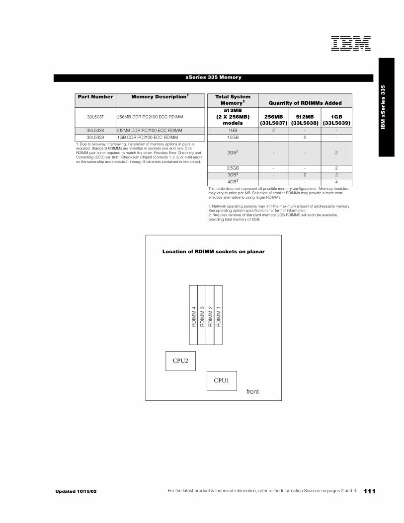
IBM
xS
eri
es 3
35
111For the latest product & technical information, refer to the Information Sources on pages 2 and 3.Updated 10/15/02
xSeries 335 Memory
Part Number Memory Description1 Total System Memory1 Quantity of RDIMMs Added
33L5037 256MB DDR PC2100 ECC RDIMM 512MB
(2 X 256MB) models
256MB(33L5037)
512MB(33L5038)
1GB(33L5039)
33L5038 512MB DDR PC2100 ECC RDIMM 1GB 2 - -
33L5039 1GB DDR PC2100 ECC RDIMM 1.5GB - 2 -
1. Due to two-way interleaving, installation of memory options in pairs is required. Standard RDIMMs are installed in sockets one and two. One RDIMM pair is not required to match the other. Provides Error Checking and Correcting (ECC) via 16-bit Checksum Chipkill (corrects 1, 2, 3, or 4-bit errors on the same chip and detects 2- through 8-bit errors contained in two chips).
2GB2 - - 2
2.5GB - - 2
3GB2 - 2 2
4GB2 - - 4
This table does not represent all possible memory configurations. Memory modules may vary in price per MB. Selection of smaller RDIMMs may provide a more cost-effective alternative to using larger RDIMMs.
1. Network operating systems may limit the maximum amount of addressable memory. See operating system specifications for further information2. Requires removal of standard memory. 2GB RDIMMS will soon be available, providing total memory of 8GB.
Location of RDIMM sockets on planar
CPU2
RD
IMM
3
RD
IMM
2
RD
IMM
1
RD
IMM
4
CPU1
front

112
EIDE ConfigurationsEIDE models include a standard CD-ROM drive attached to one connector of the IDE controller using a single-drop IDE cable and the standard IDE HDD is attached to the other IDE connector using a standard two-drop IDE cable. One additional IDE HDD may be installed in the one available HDD bay, attaching to the second drop of the standard two-drop IDE cable.
SCSI ConfigurationsxSeries 335 hot-swap SCSI models support two hot-swap SCSI HDDs on a DASD backplane. The backplane is connected to the integrated Ultra320 single-channel controller through a 16-bit nonterminated SCSI cable. Attachment of external SCSI devices require a supported optional SCSI PCI controller. The standard CD-ROM is attached to the IDE connector using a single-drop IDE cable.
RAID configurations are supported by the integrated LSI chipset, which provides onboard mirroring. Optional ServeRAID-4Lx or -4Mx controllers can be installed to support the internal HDDs, in which case the standard cable would be used to attach the backplane to the RAID controller.
For additional information regarding internal cabling, refer to Appendix F: Internal Cabling Overview.
xSeries 335 Internal SCSI Cabling
xSeries 335 Hard Disk Drive (HDD)
SCSI ModelsTotal
Internal Storage1
10,000rpm SCSI HDDs 15,000rpm SCSI HDDs18.2GB
(06P5754)36.4GB
(06P5755)73.4GB
(06P5756)18.2GB
(06P5767)36.4GB
(06P5768, 06P5776)
0GB Standard in base models
18.2GB 1 - - 1 -
36.4GB 2 1 - 2 1
72.8GB - 2 - - 2
73.4GB - - 1 - -
146.8GB max - - 2 - -
This table does not represent all possible HDD configurations. Total Internal Storage listed is within +/- 0.2GB unless otherwise noted.
1. Select a total storage row then select the quantity of HDDs from a column corresponding to the HDD of choice.
EIDE ModelsTotal
Internal Storage1
7200rpm EIDE HDDs40GB
(P/N 22P7157)60GB
(P/N 09N4207)80GB
(P/N 09N4226)120GB
(P/N 09N4231)40GB Std in IDE models - - -
80GB 1 - - -
100GB - 1 - -
120GB - - 1 -
140GB2 - 1 1 -
160GB - - - 1
180GB2 - 1 - 1
200GB2 - - 1 1
240GB2 - - - 2
1. Select a total storage row then add the HDDs from all columns to the standard HDD.2. Requires replacing the standard HDD.

IBM
xS
eri
es 3
35
113For the latest product & technical information, refer to the Information Sources on pages 2 and 3.Updated 10/15/02
Part Number
Description RPM Height Bays Supported
Maximum Quantity
IDE HDD1, 2
19K4461 20.4GB 7200rpm ATA-100 (EIDE) HDD 7200 SL 1, 2 2
22P7157 40GB 7200rpm ATA-100 (EIDE) HDD 7200 SL 1, 2 2
09N4207 60GB 7200rpm ATA-100 (EIDE) HDD 7200 SL 1, 2 2
09N4226 80GB 7200rpm ATA-100 (EIDE) HDD 7200 SL 1, 2 2
09N4231 120GB 7200rpm ATA-100 (EIDE) HDD 7200 SL 1, 2 2
Hot-swap Ultra160 HDDs1, 3
06P5754 18.2GB 10Krpm Ultra160 SCSI Hot-Swap SL HDD 10000 SL 1, 2 2
06P5755 36.4GB 10Krpm Ultra160 SCSI Hot-Swap SL HDD 10000 SL 1, 2 2
06P5756 73.4GB 10Krpm Ultra160 SCSI Hot-Swap SL HDD 10000 SL 1, 2 2
06P5767 18.2GB 15Krpm Ultra160 SCSI Hot-Swap SL HDD 15000 SL 1, 2 2
06P5768 36.4GB 15Krpm Ultra160 SCSI Hot-Swap SL HDD 15000 SL 1, 2 2
Hot-swap Ultra320 HDDs1, 3
06P5776 36.4GB 15Krpm Ultra320 SCSI Hot-Swap SL HDD 15000 SL 1, 2 2
External USB Drives05K9276 USB Portable Diskette Drive -
33L5151 USB Portable CD-ROM Drive -
External Storage Expansion Units4 Form Factor35311RU EXP300 Storage Expansion Unit5 Rack (3U)
17401RU FAStT EXP700 Storage Expansion Unit6 Rack (3U)
35601RU FAStT EXP500 Storage Expansion Unit7 Rack (3U)
35421RU FAStT200 Storage Server8, 9 Rack (3U)
35422RU FAStT200 HA Storage Server8 Rack (3U)
19K1121 FAStT200 Redundant RAID Controller -
1. Mixing of IDE and SCSI hard disk drives is not supported.2. Nonhot-swap HDDs are supported only in IDE models.3. Hot-swap HDDs are supported only in hot-swap models.4. xSeries 335 does not include an external SCSI connector. To configure a SCSI storage device, select an optional SCSI controller then refer to Appendix D: Cables - Storage Units - Controllers to confirm the controller supports the desired External Storage Expansion Unit and to select a supported cable. For HDD or other expansion unit options, see the specific expansion unit section. For Fibre Channel storage devices, refer to the Fibre Channel Solutions Overview section.5. EXP300 includes a single 2m Ultra2 SCSI cable and dual hot-swap 500w redundant power supplies, each with its own power cord. 6. FAStT EXP700 Storage Expansion Unit (P/N 17401RU) includes dual hot-swap 400w power supplies, each with its own power cord.7. FAStT EXP500 Storage Expansion Unit (P/N 35601RU) includes dual hot-swap 350w power supplies, each with its own power cord.8. The FAStT200 includes two hot-swap, 350w auto-ranging redundant power supplies, each with its own power cord.9. Can be upgraded to FAStT200 HA Storage Server through the addition of a FAStT200 Redundant RAID Controller (P/N 19K1121).
xSeries 335 Hard Disk Drive (HDD)
Bay Form Factor
Height Front Access
Usage
11HS or 89mm (3.5in)2
SL yes3 open
2HS or 89mm(3.5in)2
SL yes3 open
1. Boot drive should be located in bay one.2. x335 supports IDE and hot-swap models.3. Bays one and two are not front-accessible in IDE models, which include one IDE HDD in bay one.
xSeries 335 front viewFDD
CD-ROM HDD bay 1 HDD bay 2

114
xSeries 335 I/O Options
Part Number
Description Adapter Length
PCI Support3
Slots Supported3
Hot-Plug PCI Voltage
Key
MHz
Storage Controllers1, 2 -
37L6889 ServeRAID-4H Ultra160 SCSI Controller4 Full 64-bit 2 - Universal 33
06P5736 ServeRAID-4Mx Ultra160 SCSI Controller5 Full 64-bit 2 - Universal 66
06P5740 ServeRAID-4Lx Ultra160 SCSI Controller6 Half 64-bit 1, 2 - Universal 66
19K4646 PCI Wide Ultra160 SCSI Adapter7 Half 32-bit 1, 2 - Universal 33
Fibre Storage Controllers and Options8
00N6881 Netfinity FAStT Host Adapter Half 64-bit 1, 2 - Universal 66
24P0960 FC2-133 Host Bus Adapter Half 64-bit 1, 2 - Universal 133
17421RU FAStT700 Fibre Channel Storage Server - - - - - -
35521RU FAStT500 Storage Server - - - - - -
35421RU FAStT200 Storage Server - - - - - -
35422RU FAStT200 HA Storage Server - - - - - -
3534F08 TotalStorage SAN Switch F08 - 8-port - - - - - -
2109F16 SAN Fibre Channel Switch, 16-Port - - - - - -
2108R3L SAN Data Gateway Router Ultra SCSI LVD Port9 - - - - - -
Networking10
Ethernet11
09N9901 10/100 EtherLink Server Adapter by 3Com12 Half 32-bit 1, 2 - Universal 33
06P3601 10/100 Ethernet Server Adapter12 Half 32-bit 1, 2 - Universal 33
22P4901 10/100 Dual Port Server Adapter12 Half 64-bit 1, 2 - Universal 66
22P6801 PRO/1000XT Server Adapter by Intel (copper) w/CD, manuals12 Half 64-bit 1, 2 - Universal 133
22P7801 NetXtreme 1000 SX Fiber Ethernet Adapter Half 64-bit 1, 2 - Universal 133
Token Ring
34L5001 16/4 Token-Ring PCI Management Adapter12 Half 32-bit 1, 2 - Universal 33
34L5201 High-speed 100/16/4 Token-Ring PCI Management Adapter12 Half 32-bit 1, 2 - Universal 33
Communications13
System Management14
09N7585 Remote Supervisor Adapter15 Half 32-bit 1 - Universal 33
1. xSeries 335 has a single-channel, Ultra320 integrated controller that supports both Ultra160 and Ultra320 HDDs. The entire SCSI bus will default to the slower rate (MB/second) if HDDs of different technologies are mixed on the same bus. The LSI chipset allows for two HDDs to be allocated for mirroring if a RAID adapter is not installed.2. When storage controllers are installed in both PCI slots, the BIOS for the integrated storage controller must be disabled, i.e., it cannot support either external or internal storage media. If the two storage controllers in slots one and two are both RAID adapters, the boot media must be attached to the RAID adapter in slot one.3. A 64-bit adapter installed into a 32-bit slot will transfer data at 32-bit rates. Adapters rated at 66MHz will operate at 33MHz when installed in a 33MHz slot. 33MHz adapters will reduce 66MHz buses to 33MHz. 133MHz PCI-X adapters are backward compatible with 33/66MHz, 64-bit PCI-based servers.4. ServeRAID-4H Ultra160 SCSI Controller is powered by a 266MHz PowerPC 750 processor and provides 128MB of battery-backed ECC cache The internal connectors are not accessible due to a cabling interference. Four external Ultra160 0.8mm VHDCI connectors are available.5. ServeRAID-4Mx Ultra160 SCSI Controller is powered by a 100MHz Intel Zion GC80303 processor that provides 64MB of battery-backed ECC cache and two internal and two external Ultra160 connections (only two connectors my be used). External connections are 0.8mm VHDCI.6. ServeRAID-4Lx Ultra160 SCSI Controller is powered by a 100MHz Intel Zion GC80303 processor and provides a single channel, 32MB of ECC cache and either one internal or one external Ultra160 connection. External connector is 0.8mm VHDCI.7. PCI Wide Ultra160 SCSI Adapter (P/N 19K4646) provides a single channel with one internal connector and one external 0.8mm VHDCI connector. Support for external SCSI devices only. A five-drop terminated LVD SCSI cable is included but not supported for use in this server.8. See the Fibre Channel Solutions Overview section for additional configuration information.9. The 2108R3L SAN Data Gateway Router UltraSCSI LVD Port provides one integrated short-wave optical port and two SCSI ports for tape storage connections (LVD, HVD and single-ended).10. xSeries 335 includes dual full-duplex copper 10/100/1000Mbps Broadcom 5703 Ethernet controllers.11. In a fault-tolerant networking environment, using the fault-tolerant software delivered with the Ethernet adapters of a single manufacturer is recommended. Installing fault-tolerant solutions provided by multiple manufacturers may cause failures if the intermediate drivers provided with the adapters are not compatible. Three optional Ethernet adapters are copper and Intel-based (P/N 06P3601, 22P4901, 22P6801). One adapter is Broadcom-based (22P7801).12. The Wake on LAN function of this option is supported.13. xSeries 335 includes four USB ports (two each on both front and rear), a high-speed serial/asynchronous port (NS16550A compatible), one RS-485 port, and in/out C2T Interconnect connectors.14. xSeries 335 has one integrated RS-485 system management interconnect port located on the back of the system chassis. Connection of the standard service processor to servers other than xSeries 335 in an interconnect network requires a customer-supplied Cat5 Ethernet cable. Connection to other xSeries 335 servers can also be achieved through the C2T Interconnect chaining cables, which transmits both console connectivity and system management functionality.15. When installed in an xSeries 335, Remote Supervisor Adapter (RSA) shares functionality with the integrated service processor and serves as interface for both. An external Cat5 connection between RSA and the integrated service processor using the dongle (pigtail cable) and short Cat5 cable supplied with RSA is required in addition to connection of the 20-pin ribbon cable to the planar if the server is acting as focal point in a system management interconnect network, which indicates it is the first server in a chain of x335 systems. Connection of the external AC power supply provided with RSA is not required.

IBM
xS
eri
es 3
35
115For the latest product & technical information, refer to the Information Sources on pages 2 and 3.Updated 10/15/02
xSeries 335 Power, Monitors & Accessories
Part Number DescriptionPower1
Uninterruptible Power Supply (UPS)2
32P1020 APC 2U Smart-UPS 1400RMB
94G6676 APC Smart-UPS 3000RMB3
37L6861 APC Smart-UPS 5000RMB4
Monitors5
633147N E54 Color Monitor 15in (350mm, 13.8in viewable image), stealth black6
63324HN E74 Color Monitor 17in (406mm, 16in viewable image), stealth black6
66274AN G78 Color Monitor 17in (406mm, 16in viewable image), stealth black6
32P1031 NetBAY 1U Flat Panel Monitor Console Kit (with US Space Saver keyboard)7
32P1032 NetBAY 1U Flat Panel Monitor Console Kit (without keyboard)7
32P1702 NetBAY 2U Flat Panel Monitor Console Kit (with US Space Saver keyboard)7
32P1703 NetBAY 2U Flat Panel Monitor Console Kit (without keyboard)7
1. xSeries 335 models include a worldwide, voltage-sensing 331w power supply with auto-restart and two 9ft line cords, one with an IEC 320 C14 connector for attachment to a PDU or high-voltage UPS and one with a 110v NEMA 5-15P connector for attachment to a low-voltage UPS or wall outlet.2. For runtimes and UPS attributes see Appendix C: UPS Runtime Estimate.3. Height is 3U. See Rack Cabinets and Options section for supported IBM racks.4. Height is 5U. See Rack Cabinets and Options section for supported IBM racks.5. xSeries 335 includes an integrated ATI Rage XL SVGA controller with 8MB of video memory.6. Installation within a rack requires optional Monitor Compartment (P/N 94G7444).7. Includes a 15in Flat Panel Monitor.
Part Number DescriptionRack and NetBAY1, 2
Refer to the Rack Cabinets and Options section for information concerning IBM racks and rack-supported devices.
Console Connectivity3
06P4792 Cable Chain Technology Cable Kit4
1735L04 NetBAY Local Console Manager
1735R16 NetBAY Remote Console Manager
32P1637 C2T Conversion Option
09N4290 NetBAY 1x4 Console Switch
09N4291 NetBAY 2x8 Console Switch
Keyboard and Mouse5
28L3644 Space Saver II Keyboard6, 7
10K3849 106-key Preferred USB Keyboard with 2-port USB Hub (stealth black)8, 9
22P5150 TrackPoint USB Space Saver Keyboard6, 7, 9
28L3673 Sleek 2-button Stealth Black Mouse
33L3244 Sleek USB Mouse (stealth black)9
33L3250 Optical 3-button ScrollPoint Mouse PS/2 and USB
Slot 1: Bus 2, 100MHz, 64-bit, 3.3v, half-length, PCI-XSlot 2: Bus 1, 100MHz, 64-bit, 3.3v, full-length, PCI-X
xSeries 335 rear view
PCI slot 2
PCI slot 1
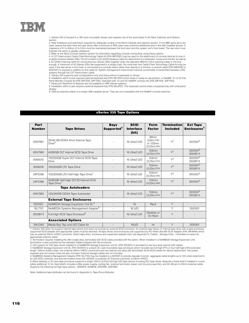
116
1. xSeries 335 is housed in a 19in rack-mountable drawer and requires one of the racks listed in the Rack Cabinets and Options section.2. Note limitations and restrictions required for adequate cooling in the Rack Cabinets and Options section. If non-IBM racks are to be used, assure that both front and rear doors offer a minimum of 48% open area uniformly distributed and in line with installed servers. A clearance of 51 to 64mm (2 to 2.5in) must be maintained between the front door and the system unit's front bezel. The rear door must maintain the same or greater clearance.3. Refer to the Rack Console Options section for information regarding console connectivity using these options.4. A C2T Interconnect Cable ChainTechnology Cable Kit (P/N 06P4792) may be used for the attachment of console devices to one or multiple chained xSeries 335s. The kit contains a 2m (6.5ft) breakout cable for attachment to a keyboard, mouse and monitor as well as a 2m (6.5ft) chaining cable for connecting two xSeries 335s together when the standard 260mm (10in) chaining cable is not long enough. A maximum of 42 xSeries 335s are supported in a single chain. No more than one Cable Chain Technology Cable Kit may be used. If the last server in the chain is connected to a console switch rather than directly to a monitor, a console cable (P/N 09N4293 or 94G7447) is required in addition to the cable kit. System management interconnect network functionality is transmitted between x335 systems through the C2T Interconnect cable.5. xSeries 335 supports rack configurations only and ships without a keyboard or mouse.6. Installation within a rack requires optional keyboard tray (P/N 28L4707) which stows in ready-to-use position, or NetBAY 1U or 2U Flat Panel Monitor Console Kit (P/N 32P1032, 32P1702). Standard with 1U and 2U NetBAY console kits (P/N 32P1031, 32P1702).7. Advanced TrackPoint IV features are not available on IBM xSeries systems.8. Installation within a rack requires optional keyboard tray (P/N 28L4707). This keyboard cannot share a keyboard tray with a flat panel display.9. USB accessories attach to a single USB-capable server. They are not compatible with the NetBAY console switches.
xSeries 335 Tape Options
Part Number Tape Drives
Bays Supported1
SCSI Interface
(bit)
Form Factor
Termination Included
Ext Tape Enclosures1
00N7991 20/40 GB DDS/4 4mm Internal TapeDrive5 - 16 Ultra2 LVD
89mm (3.5in) HH or 133mm
(5.25in) HH
Y2 35510013
00N7990 40/80GB DLT Internal SCSI Tape Drive - 16 Ultra2 LVD 133mm (5.25in) FH Y2 35510013
3503B1X
00N8015 110/220GB Super DLT Internal SCSI Tape Drive - 16 Ultra2 LVD 133mm
(5.25in) FH Y2 35510013 3503B1X
00N8016 100/200GB LTO Tape Drive - 16 Ultra2 LVD 133mm (5.25in) FH Y2 35510013
3503B1X
24P2396 100/200GB LTO Half-High Tape Drive1 - 16 Ultra2 LVD 133mm (5.25in) HH Y2 35510013
24P2398 40/80GB Half-High DLTVS Internal SCSI Tape Drive1 - 16 Ultra2 LVD 133mm
(5.25in) HH Y2 35510013
Tape Autoloaders
00N7992 120/240GB DDS/4 Tape Autoloader - 16 Ultra2 LVD 133mm (5.25in) FH Y2 35510013
3503B1X
External Tape Enclosures3551001 NetMEDIA Storage Expansion Unit EL4 - 16 Rack Y -
10L7113 NetMEDIA Systems Management Adapter5 - 16 LVD - Y 3551001
3503B1X Full-High SCSI Tape Enclosure6 - 16 Ultra2 LVD Desktop or 3U Rack Y -
Associated Options10K2340 Media Bay Tray and LVD Cable Kit - 16LVD Int Y 3551001
1. xSeries 335 does not support internal tape drives and does not include an external SCSI connector. An external tape library or internal tape drive with a tape enclosure, supported SCSI adapter and appropriate cable must be selected. All tape drives and enclosures are supported by PCI Wide Ultra160 SCSI Adapter (P/N 19K4646) which has an external 0.8mm VHDCI connector. Select tape drive, enclosure and supported adapter then use Appendix D: Cables - Storage Units - Controllers to select an appropriate external cable.2. Termination requires installing the 34in single-drop, terminated LVD SCSI cable provided with the option. When installed in a NetMEDIA Storage Expansion Unit, termination is also provided by the standard cables shipped with the enclosure.3. LVD support for LVD tape drives installed in a NetMEDIA Storage Expansion Unit EL (P/N 3551001) is provided by two four-drop internal LVD cables.4. NetMEDIA Storage Expansion Unit EL (P/N 3551001) is a black 3U, rack-mountable tape enclosure which includes two full-high (FH) or four half-high (HH) extended length 133mm (5.25in) bays, two external 0.8mm VHDCI connectors and two internal four-drop LVD terminated 16-bit SCSI cables for device attachment. Two power supplies and two power cords are also included. External storage cables are not included.5. NetMEDIA Systems Management Adapter (P/N 10L7113) may be installed in a 3551001 to provide repeater function, aggregate cable lengths up to 12m when attached to an LVD SCSI controller, and auto-termination when the 3551001 is powered off. External connector is 0.8mm VHDCI.6. Black desktop or 3U rack tape enclosure supports a single 133mm (5.25in) full-high LVD tape device including DLT tape drives. Requires a fixed shelf if installed in a rack (allow additional 1U for fixed shelf). Includes a 90w power supply, cooling fan, external terminator, power cord (country-specific), and 2m 68-pin to 0.8mm external cable. Supports the following full-high tape options: 00N8015, 00N8016, 00N7992, 00N7990.
Note: Additional tape attributes can be found in Appendix A: Tape Drive Attributes

IBM
xS
eri
es 3
35
117For the latest product & technical information, refer to the Information Sources on pages 2 and 3.Updated 10/15/02
Note: The following sample configurations are for illustration only and may not be suitable for any specific customer installation. Contact your IBM Business Partner or IBM Marketing Representative for assistance with your specific configuration requirements.
Web Content Server1
Linux Cluster Node1
xSeries 335 Sample Configurations
Part Number Description Quantity8676-41X xSeries 335 2GHz/512KB Xeon, 512MB ECC, open, 24x (1U rack) 159P5100 xSeries 2GHz 400MHz 512KB L2 Cache Xeon Processor 133L5037 256MB DDR PC2100 ECC RDIMM 22
06P5776 36.4GB 15Krpm Ultra320 SCSI Hot-swap SL HDD 23
09N7585 Remote Supervisor Adapter 1633147N E54 Color Monitor 15in (350mm, 13.8in viewable image), stealth black 128L3644 Space Saver II Keyboard 132P1020 APC 2U Smart-UPS 1400RMB 1
1. Rack components are not included.2. Total memory is 1GB.3. Total Internal storage is 72.8GB.
Part Number Description Quantity8676-61X xSeries 335 2.4GHz/512KB Xeon, 512MB ECC, open, 24x (1U rack) 159P5102 xSeries 2.4GHz 400MHz 512KB L2 Cache Xeon Processor 133L5039 1GB DDR PC2100 ECC RDIMM 42
06P5756 73.4GB 10Krpm Ultra160 SCSI Hot-swap SL HDD 109N7585 Remote Supervisor Adapter 1633147N E54 Color Monitor 15in (350mm, 13.8in viewable image), stealth black 128L3644 Space Saver II Keyboard 132P1020 APC 2U Smart-UPS 1400RMB 1
1. Rack components are not included.2. For a total of 1GB of system memory. Requires removal of the standard pair of RDIMMs.

IBM xSeries 343
EMEA Part Number Cross ReferencexSeries 343S ystem Unit Part Numbers
EMEA AMERICAS M/C TYPE DESCRIPTION EMEAP/N P/N MODEL WDFM DATE
882714X 882714X 8827-14X P4 1.8GHz/400MHz, 512KB, 256MB, 40GB EIDE,Rack ---
Note 1 xSeries 305 Power, Monitors & AccessoriesEMEA AMERICAS M/C TYPE DESCRIPTION EMEA
P/N P/N MODEL MONITORS WDFM DATENote 2 T3147xx 633147N 6331-47N E54 15" (13.8" viewable image) Colour Monitor (S/Black ---
1. The power cord for the xSeries 343 is customer-supplied.
2. Where ‘xx’ represents a specific country code as follows: DK=Denmark, IS=Israel, IT=Italy, SD=Saudi Arabia, SA=South Africa/Pakistan, CH=Switzerland, UK=UK, EU=Europe.
xSeries 305 Power, Monitors & AccessoriesEMEA AMERICAS M/C TYPE DESCRIPTION EMEA
P/N P/N MODEL KEYBOARD AND MOUSE WDFM DATENote 3 28L36xx 28L3644 --- Spacesaver II Keyboard ---
28L3675 28L3673 --- Sleek 2-button Mouse (S/Black) ---
3. Where ‘xx’ represents a specific country code as follows:- 46=Danish , 47=French, 48=German, 49=Italian, 50=Spanish, 51=UK English, 44=US English, and P/N 19K3831=Swiss, 19K3832=Swedish/Finnish, 19K3833=Portugese, 19K3834=Belgian,19K3836=Russian, 19K3837=Polish.
117A Updated 10/15/02

Updated 10/15/02 117B

118
IBM xSeries 343 (NEBS-compliant)
xSeries 343 At-A-Glance
8827-14X1, 2 1.263 2/2 512 2GB/6GB Rack (2U) 2/24 P S-Power Y 2 x 10/
100D,
U1605 - 36.4GB/72.8GB6 24X-10X 4/1 6/6
1. This system is Network Equipment Building System (NEBS) Level 3 compliant and includes two 350w, -48v direct current (DC) power supplies requiring a direct current power source (-48v to -60v) for utilization in a telecommunications network infrastructure.2. Housed in a 19in rack-mountable drawer and ships standard without a keyboard or mouse. Requires two-post rack; not supported for installation in standard IBM racks.3. Intel Pentium III processor with 133MHz FSB and 512KB advanced transfer cache.4. Includes two standard 350w, -48v direct current (DC) hot-swap, redundant power supplies. 5. Includes an integrated dual-channel Ultra160 SCSI controller supporting both internal and external SCSI attachment.6. One 10,000rpm 36.4GB Ultra160 HDD ships standard with this specific NEBS configuration. Please contact your IBM representative, Business Partner or the IBM Help Center with questions regarding different NEBS configurations. This system does not support hot-swap HDDs.7. Variable read rate. Actual playback speed will vary and is often less than the maximum possible.8. Optional third-party PCI networking adapters are supported on this system. Refer to ServerProven test results for supported third-party options at www.pc.ibm.com/us/compat. Select x343 from the Fast Access pulldown menu, click Go, then select the appropriate categories on the following screen. IBM makes no representations or warranties with respect to non-IBM products. These products are offered and warranted by third parties, not IBM.
xSeries 343 Memory
Total System
Memory1
Quantity of RDIMMs Added2
2GB (2 x 1GB) Standard
512MB (33L3324)
1GB (33L3326)
3GB 2 -
4GB 4 -
5GB 2 2
6GB - 4
This table does not represent all possible memory configurations. Memory modules may vary in price per MB. Selection of smaller RDIMMs may provide a more cost-effective alternative to using larger RDIMMs. RDIMMs must be added in pairs to support interleaving technology.
1. Network operating systems may limit the maximum amount of addressable memory. See operating system specifications for further information.2. Add options from both columns in each row to the standard memory.
Part Number
Memory Description1
33L3324 512MB PC133 ECC SDRAM RDIMM
33L3326 1GB PC133 ECC SDRAM RDIMM
1. Due to two-way interleaving, installation of memory options in pairs beginning with sockets one and four is required. Add memory options in sockets two and five, then three and six.
Part Number
Processor Speed (G
Hz)
Number of P
rocessors (Std/M
ax)
L2 ECC Cache (KB)
Memory (Std/M
ax)
Form Factor
Power Supply Quantit
y (Std/M
ax)
Hot-Swap (P
ower, Slots, H
DD, Fans)
Redundancy (Optio
nal, Standard)
Adv System Management P
rocessor
Onboard Ethernet (Mbps)
SCSI Contro
ller (D
ual, Ultr
a, RAID)
Removable Media Bays (T
otal/Avail)
Internal Hard Disk Driv
e (Std/M
ax)
CD-ROM (ID
E)7
Bays (Total/A
vail)
Slots (Total/A
vail)8
5 4 3 2 1 6
back

IBM
xS
eri
es
34
3(N
EB
S-c
om
pli
an
t)
119For the latest product & technical information, refer to the Information Sources on pages 2 and 3.Updated 10/15/02
The xSeries 343 contains four drive bays. The top bay on the left contains the standard CD-ROM drive and the bay beneath contains the standard 1.44MB, 3.5in slim-line diskette drive. Two 3.5in slim-line bays are located side-by-side, one beneath the CD-ROM and FDD at the bottom of the chassis and the other directly beside it on the right side of the server.
One bay contains the standard 10,000rpm, Ultra160 SCSI nonhot-swap HDD and the other is unpopulated. The 24x-10x IDE CD-ROM is connected to the IDE port. HDDs installed in the drive bays are connected to the internal connector of the integrated Ultra160 SCSI controller through a two-drop, 16-bit LVD SCSI cable. The xSeries 343 contains an external 0.8mm VHDCI connector to attach supported external SCSI devices to the second channel of the integrated SCSI controller.
For additional information regarding internal cabling, refer to Appendix F: Internal Cabling Overview.
xSeries 343 Internal SCSI Cabling
xSeries 343 Hard Disk Drive (HDD) Storage
Bay Form Factor
Height Front Access
Usage Part Number
Description RPM Height Bays Supported
Max Qty
- 133mm (5.25in) - yes IDE CD-ROM
Ultra160 Hard Disk Drives (HDD)
- 89mm (3.5in) - yes Diskette 06P5751 36.4GB 10Krpm Ultra160 SCSI SL HDD 10000 SL 1, 21 2
1 89mm (3.5in) SL No std HDD 1. xSeries 343 ships with a 36.4GB 10,000rpm nonhot-swap HDD installed in bay one.
2 89mm (3.5in) SL No open
xSeries 343 I/O Options
CD-ROM
FDD
bay 2 bay 1
front of chassis
slot 3
rear of chassis
slot 6
slot 5
slot 4
slot 2
slot 1
slot 1: bus 1, low profile, 64-bit, 66MHz, 3.3v, half-lengthslot 2: bus 1, low profile, 64-bit, 66MHz, 3.3v, half-lengthslot 3: bus 1, low profile, 64-bit, 66MHz, 3.3v, half-lengthslot 4: bus 2, full-size, 64-bit, 33MHz, 5v, full-lengthslot 5: bus 2, full-size, 64-bit, 33MHz, 5v, full-lengthslot 6: bus 2, full-size, 64-bit, 33MHz, 5v, full-length
Note: Optional third-party PCI networking adapters are supported on this system. Refer to ServerProven test results for supported third-party options at www.pc.ibm.com/us/compat. Select x343 from the Fast Access pulldown menu, click Go, then select the appropriate categories on the following screen. IBM makes no representations or warranties with respect to non-IBM products. These products are offered and warranted by third parties, not IBM.

120
xSeries 343 Power, Monitors & Accessories
Part Number DescriptionPower1
Monitors2
633147N E54 Color Monitor 15in (350mm, 13.8in viewable image), stealth black3
1. xSeries 343 systems include two 350w, -48v direct current (DC) power supplies requiring a direct current power source(-48v to -60v). Power cord is customer-supplied.2. xSeries 343 uses an ATA Rage XL SVGA controller with 8MB of video memory.3. Installation within a rack requires optional Monitor Compartment (P/N 94G7444).
Part Number DescriptionRack and NetBAY1
Keyboard and Mouse2
28L3644 Space Saver II Keyboard3
28L3673 Sleek 2-button Stealth Black Mouse
1. xSeries 343 is housed in a 19in rack-mountable drawer and requires a two-post rack. Not supported for installation in standard IBM racks.2. xSeries 343 supports rack configurations only and ships without a mouse or keyboard.3. Installation within a rack requires optional keyboard tray (P/N 28L4707), which stows in ready-to-use position.

IBM
xS
eri
es
34
3(N
EB
S-c
om
pli
an
t)
121For the latest product & technical information, refer to the Information Sources on pages 2 and 3.Updated 10/15/02

IBM xSeries 345
EMEA Part Number Cross ReferencexSeries 345 S ystem Unit Part Numbers
EMEA AMERICAS M/C TYPE DESCRIPTION EMEAP/N P/N MODEL WDFM DATE
K011Xxx 867011X 8670-11X Xeon 2.0GHz/400MHz, 512KB, 512MB, Open BayU320 HS, Rack ---
K021Xxx 867021X 8670-21X Xeon 2.2GHz/400MHz, 512KB, 512MB, Open BayU320 HS, Rack 01/10/02
K031Xxx 867031X 8670-31X Xeon 2.4GHz/400MHz, 512KB, 512MB, Open BayU320 HS, Rack ---
xSeries 345 Hard Disk Drive Storage Part NumbersEMEA AMERICAS M/C TYPE DESCRIPTION EMEA
P/N P/N MODEL WDFM DATENotes 1&2 19K11xx 35311RU --- EXP300 Storage Expansion Unit ---Notes 3&2 00N71xx 35601RU --- FAStT EXP500 Storage Expansion Unit ---Notes 4&2 24P09xx 17401RU --- FAStT EXP700 Storage Expansion Unit ---Notes 5&2 19K11xx 35421RU --- FAStT 200 Storage Server ---Notes 6&2 19K11xx 35422RU --- FAStT 200 HA Storage Server ---
1. Where ‘xx’ represents a specific country code as follows: 51=US/English, 52=European/English, 56=Danish/English, 57=Israel/English, 58=Italian/English, 59=South Africa/English, 60=Swiss/English, 63=UK/English.2. This unit does not include Rack Power Cables P/N 94G7448 when shipped (for attachment to highvoltage UPS or PDU). Standard country power cords only are included. If required, order one Rack PowerCable for each power supply.3. Where ‘xx’ represents a specific country code as follows:- 36=US/English, 37=Euro/English, 41=Denmark/English, 42=Israel/English, 43=Italy/English, 44=South Africa/English, 45=Switzerland/English, 49=UK/English.4. Where ‘xx’ represents a specific country code as follows:- 01=Eur/English, 02=Eur/Spanish, 05=Denmark/English, 06=Israel/English, 07=Italy/English, 08=South Africa/English, 09=Switzerland/English, 12=UK/English.5. Where ‘xx’ represents a specific country code as follows:- 23=US/English, 24=Euro/English, 25=Euro/Spanish, 27=Euro/German, 28=Denmark/English, 29=Israel/English, 30=Italy/English, 31=South Africa/English, 32=Switzerland/English, 34=Switzerland/German, 36=UK/English..6. Where ‘xx’ represents a specific country code as follows:- 37=US/English, 38=Euro/English, 39=Euro/Spanish, 41=Euro/German, 42=Denmark/English, 43=Israel/English, 44=Italy/English, 45=South Africa/English, 46=Switzerland/English, 48=Switzerland/German, 50=UK/English.
xSeries 345 I/O Option Part NumbersEMEA AMERICAS M/C TYPE DESCRIPTION EMEA
P/N P/N MODEL WDFM DATEN/A 19K4162 --- V90 PCI Data/Fax WinModem N/A
Note 7 09N75xx 09N7585 --- Remote Supervisor Adapter ---7. Where ‘xx’ represents a specific country code as follows:- 86=Europe, 87=Denmark, 88=South Africa, 89=UK, 90=Switzerland, 91=Italy, 92=Israel, 85=USA..
Note 8 xSeries 345 Power, Monitors & AccessoriesEMEA AMERICAS M/C TYPE DESCRIPTION EMEA
P/N P/N MODEL POWER WDFM DATENote 9 32P16xx 32P1020 --- APC 2U Smart-UPS 1400RMiB ---
Note 10 30RIxxx 94G6676 --- APC Smart-UPS 3000RMiB ---37L6862 37L6861 --- APC Smart-UPS 5000RMiB ---
8. The xSeries 345 ships with a standard country power cord. For connection to a high voltage UPS or PDU, order Rack PowerCable P/N 94G7448.
9. Where ‘xx’ represents a specific country code as follows:- 12=Europe, 13=UK, 14=Italy, 15=Switzerland, 16=Denmark, 17=South Africa, 18=Israel.
10. Where ‘xxx’ represents a specific country code as follows:- DEN=Denmark, ISR=Israel, ITA=Italy, SDI=Saudi Arabia, SAF=South Africa, SWS=Switzerland, UKM=United Kingdom, EUR=Europe.
121A Updated 10/15/02
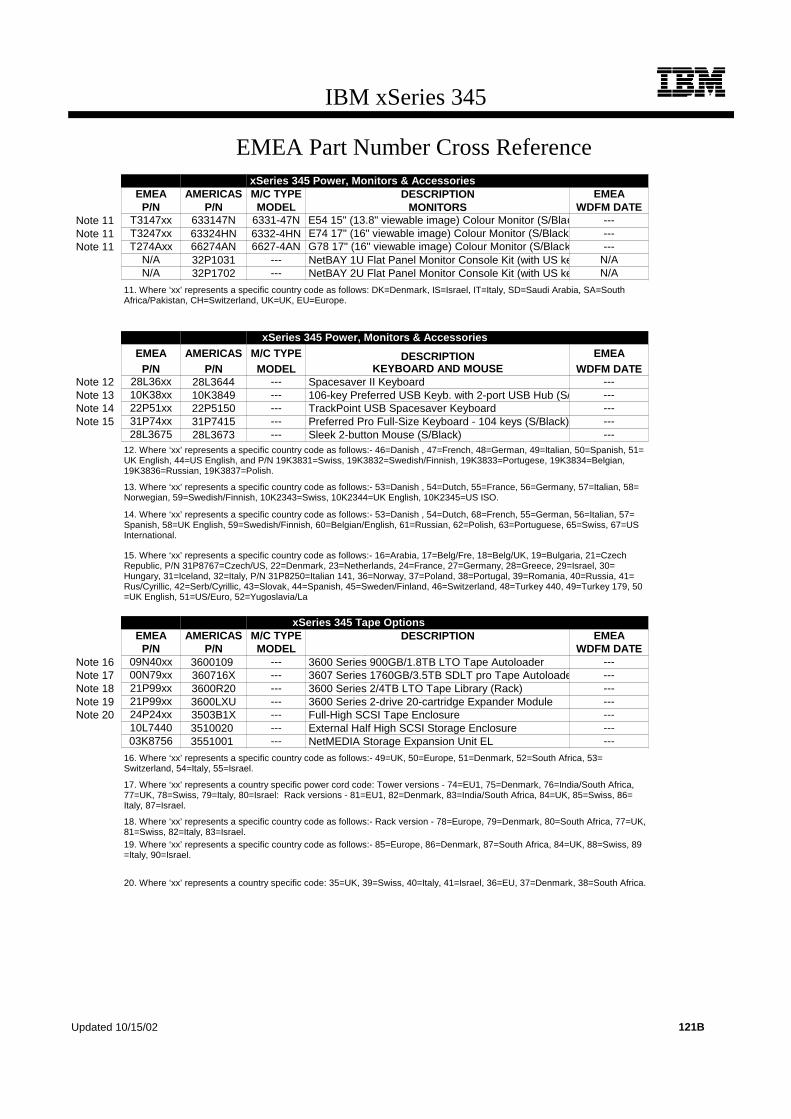
IBM xSeries 345
EMEA Part Number Cross ReferencexSeries 345 Power, Monitors & Accessories
EMEA AMERICAS M/C TYPE DESCRIPTION EMEAP/N P/N MODEL MONITORS WDFM DATE
Note 11 T3147xx 633147N 6331-47N E54 15" (13.8" viewable image) Colour Monitor (S/Blac ---Note 11 T3247xx 63324HN 6332-4HN E74 17" (16" viewable image) Colour Monitor (S/Black) ---Note 11 T274Axx 66274AN 6627-4AN G78 17" (16" viewable image) Colour Monitor (S/Black ---
N/A 32P1031 --- NetBAY 1U Flat Panel Monitor Console Kit (with US ke N/AN/A 32P1702 --- NetBAY 2U Flat Panel Monitor Console Kit (with US ke N/A
11. Where ‘xx’ represents a specific country code as follows: DK=Denmark, IS=Israel, IT=Italy, SD=Saudi Arabia, SA=SouthAfrica/Pakistan, CH=Switzerland, UK=UK, EU=Europe.
xSeries 345 Power, Monitors & AccessoriesEMEA AMERICAS M/C TYPE DESCRIPTION EMEA
P/N P/N MODEL KEYBOARD AND MOUSE WDFM DATENote 12 28L36xx 28L3644 --- Spacesaver II Keyboard ---Note 13 10K38xx 10K3849 --- 106-key Preferred USB Keyb. with 2-port USB Hub (S/ ---Note 14 22P51xx 22P5150 --- TrackPoint USB Spacesaver Keyboard ---Note 15 31P74xx 31P7415 --- Preferred Pro Full-Size Keyboard - 104 keys (S/Black) ---
28L3675 28L3673 --- Sleek 2-button Mouse (S/Black) ---12. Where ‘xx’ represents a specific country code as follows:- 46=Danish , 47=French, 48=German, 49=Italian, 50=Spanish, 51=UK English, 44=US English, and P/N 19K3831=Swiss, 19K3832=Swedish/Finnish, 19K3833=Portugese, 19K3834=Belgian,19K3836=Russian, 19K3837=Polish.
13. Where ‘xx’ represents a specific country code as follows:- 53=Danish , 54=Dutch, 55=France, 56=Germany, 57=Italian, 58=Norwegian, 59=Swedish/Finnish, 10K2343=Swiss, 10K2344=UK English, 10K2345=US ISO.
14. Where ‘xx’ represents a specific country code as follows:- 53=Danish , 54=Dutch, 68=French, 55=German, 56=Italian, 57=Spanish, 58=UK English, 59=Swedish/Finnish, 60=Belgian/English, 61=Russian, 62=Polish, 63=Portuguese, 65=Swiss, 67=USInternational.
15. Where ‘xx’ represents a specific country code as follows:- 16=Arabia, 17=Belg/Fre, 18=Belg/UK, 19=Bulgaria, 21=CzechRepublic, P/N 31P8767=Czech/US, 22=Denmark, 23=Netherlands, 24=France, 27=Germany, 28=Greece, 29=Israel, 30=Hungary, 31=Iceland, 32=Italy, P/N 31P8250=Italian 141, 36=Norway, 37=Poland, 38=Portugal, 39=Romania, 40=Russia, 41=Rus/Cyrillic, 42=Serb/Cyrillic, 43=Slovak, 44=Spanish, 45=Sweden/Finland, 46=Switzerland, 48=Turkey 440, 49=Turkey 179, 50=UK English, 51=US/Euro, 52=Yugoslavia/La
xSeries 345 Tape OptionsEMEA AMERICAS M/C TYPE DESCRIPTION EMEA
P/N P/N MODEL WDFM DATENote 16 09N40xx 3600109 --- 3600 Series 900GB/1.8TB LTO Tape Autoloader ---Note 17 00N79xx 360716X --- 3607 Series 1760GB/3.5TB SDLT pro Tape Autoloade ---Note 18 21P99xx 3600R20 --- 3600 Series 2/4TB LTO Tape Library (Rack) ---Note 19 21P99xx 3600LXU --- 3600 Series 2-drive 20-cartridge Expander Module ---Note 20 24P24xx 3503B1X --- Full-High SCSI Tape Enclosure ---
10L7440 3510020 --- External Half High SCSI Storage Enclosure ---03K8756 3551001 --- NetMEDIA Storage Expansion Unit EL ---
16. Where ‘xx’ represents a specific country code as follows:- 49=UK, 50=Europe, 51=Denmark, 52=South Africa, 53=Switzerland, 54=Italy, 55=Israel.
17. Where ‘xx’ represents a country specific power cord code: Tower versions - 74=EU1, 75=Denmark, 76=India/South Africa,77=UK, 78=Swiss, 79=Italy, 80=Israel: Rack versions - 81=EU1, 82=Denmark, 83=India/South Africa, 84=UK, 85=Swiss, 86=Italy, 87=Israel.
18. Where ‘xx’ represents a specific country code as follows:- Rack version - 78=Europe, 79=Denmark, 80=South Africa, 77=UK,81=Swiss, 82=Italy, 83=Israel.19. Where ‘xx’ represents a specific country code as follows:- 85=Europe, 86=Denmark, 87=South Africa, 84=UK, 88=Swiss, 89=Italy, 90=Israel.
20. Where ‘xx’ represents a country specific code: 35=UK, 39=Swiss, 40=Italy, 41=Israel, 36=EU, 37=Denmark, 38=South Africa.
Updated 10/15/02 121B

122
IBM xSeries 345
xSeries 345 At-A-Glance
8670-11X1 2 1/2 512 512MB/4GB Rack(2U) 1/2 P, H, F O - Power,
O - Fans4 Y2 x
10/100/1000
D,U320 2/06 0/440.4GB7 24X-10X 8/6 5/5
8670-21X1 2.2 1/2 512 512MB/4GB Rack(2U) 1/2 P, H, F O - Power,
O - Fans4 Y2 x
10/100/1000
D,U320 2/06 0/440.4GB7 24X-10X 8/6 5/5
8670-31X1 2.4 1/2 512 512MB/4GB Rack(2U) 1/2 P, H, F O - Power,
O - Fans4 Y2 x
10/100/1000
D,U320 2/06 0/440.4GB7 24X-10X 8/6 5/5
1. Housed in a 19in rack-mountable drawer and ships standard without a keyboard or mouse. See Rack Cabinets and Options section for supported IBM racks.2. Intel Xeon processor with advanced transfer L2 cache and 4 x 100MHz (quad-pumped) access to memory and I/O buses. 3. High-speed, two-way interleaved 133MHz DDR PC2100 RDIMM. 4 .Power supply redundancy requires installation of optional 350w Hot-swap Redundant Power Supply (P/N 59P4057), which includes a power supply, line cord and three hot-swap fans that provide redundant cooling.5. The dual-channel, Ultra320 integrated controller supports both Ultra160 and Ultra320 HDDs, but the entire SCSI bus will default to the slower rate (MB/second) if HDDs of different technologies are mixed on the same bus. The LSI chipset allows for two HDDs to be allocated for mirroring if a RAID adapter is not installed. One additional HDD may be designated as a hot-spare for HDDs configured in the onboard mirror. Mirrored and hot-spare HDDs must be matched.6. xSeries 345 includes two slim-line media bays populated by a standard slim-line CD-ROM and a floppy disk drive.7. Total capacity includes installation of six 73.4GB slim-line (SL) hot-swap HDDs.8. Variable read rate. Actual playback speed will vary and is often less than the maximum possible.9. Three slots are horizontal full-size slots (two full-length and one half-length) and two are vertical low-profile slots that are both full-length (see I/O Options section).
xSeries 345 Processors
Part Number
Processor Upgrades SMP Support1 Processor Speed Upgrade2
33P2931 2GHz/400MHz - 512KB L2 Cache Upgrade Option with Xeon Processor 11X -
33P2932 2.2GHz/400MHz - 512KB L2 Cache Upgrade Option with Xeon Processor 21X 11X
37L3533 2.4GHz/400MHz - 512KB L2 Cache Upgrade Option with Xeon Processor 31X 11X, 21X
1. One additional processor may be installed, providing a maximum of two. All processors must be identical in type, speed, and cache size.2. Requires removal of the standard processor. A maximum of two processors may be installed. All processors must be identical in type, speed and cache size. Upgrades may require a BIOS update. To obtain the latest Flash BIOS, access www.pc.ibm.com/support and enter machine “Type-Model” in Quick Path. Select “Downloadable files” then “BIOS.”
xSeries 345 Memory
Part Number
Memory Description1
33L5037 256MB DDR PC2100 ECC RDIMM
33L5038 512MB DDR PC2100 ECC RDIMM
33L5039 1GB DDR PC2100 ECC RDIMM
1. Due to two-way interleaving, installation of memory options in matched pairs is required. Install first two RDIMMs in sockets one and two and the second set in sockets three and four (refer to planar diagram).
Part Number
Processor Speed (G
Hz)2
Number of P
rocessors (Std/M
ax)
L2 ECC Cache (KB)
Memory (Std/M
ax)3
Form Factor
Power Supply Quantity
(Std/M
ax)
Hot-Swap (P
ower, Slots, H
DD, Fans)
Redundancy (Optio
nal, Standard)
Integrated System Management P
rocessor
Onboard Ethernet (Mbps)
SCSI Contro
ller (D
ual, Ultr
a, RAID)5
Removable Media Bays (T
otal/Avail)
Internal Hard Disk Driv
e (Std/M
ax)
CD-ROM (ID
E)8
Bays (Total/A
vail)
Slots (Total/A
vail)9

123For the latest product & technical information, refer to the Information Sources on pages 2 and 3.Updated 10/15/02
IBM
xS
eri
es
34
5
The xSeries 345 includes eight front-accessible bays. The top right slim-line bay contains a slim-line 3.5in diskette drive and the top left slim-line bay contains a slim-line CD-ROM. Six slim-line, hot-swap HDD bays are located in the center of the front of the chassis
The system contains a DASD backplane supporting six hot-swap, SCA-2-compliant HDD bays. The backplane is connected to one of the connectors of the integrated Ultra320 SCSI controller through a 16-bit (nonterminated) LVD SCSI cable. In RAID configurations using ServeRAID-5i, no cable is required and both channels of the integrated controller are managed by ServeRAID-5i. Internal RAID configurations using ServeRAID-4Mx or -4Lx require optional 30in nonterminated Single-drop Internal LVD Ultra160 SCSI Cable (P/N 71P8995).
External SCSI device attachment is facilitated by a dedicated 0.8mm VHDCI port on the rear of the system chassis, which is connected to the second channel of the integrated controller. If ServeRAID-5i is installed, supported tape drives that can be installed in an external tape enclosure are limited (see Tape Options section). External tape enclosures are also supported by installing PCI Wide Ultra160 SCSI Adapter (P/N 19K4646).
The 24x-10x CD-ROM is connected to the IDE port through an interposer card.
For additional information regarding internal cabling, refer to Appendix F: Internal Cabling Overview.
Total System Memory1
Quantity of RDIMMs Added
512MB (2 x 256MB)
256MB (33L5037)
512MB (33L5038)
1GB (33L5039)
1GB 2 - -
1.5GB - 2 -
2.5GB - - 2
3GB2 - 2 2
4GB2 - - 4
This table does not represent all possible memory configurations. Memory modules may vary in price per MB. Selection of smaller RDIMMs may provide a more cost-effective alternative to using larger RDIMMs.
1. Network operating systems may limit the maximum amount of addressable memory. See operating system specifications for further information.2. Requires replacing the standard RDIMM.
xSeries 345 Internal SCSI Cabling
RD
IMM
4
fan 4fan 3fan 1 fan 2
fan 8fan 7fan 6fan 5
Top view of planar
(rear)
RD
IMM
3
RD
IMM
2
RD
IMM
1
CPU 1 CPU 2
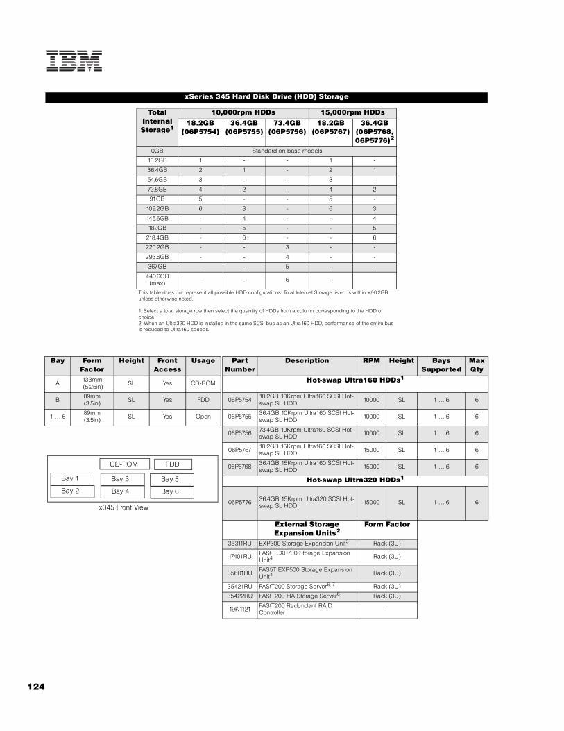
124
xSeries 345 Hard Disk Drive (HDD) Storage
Total Internal Storage1
10,000rpm HDDs 15,000rpm HDDs18.2GB
(06P5754) 36.4GB
(06P5755)73.4GB
(06P5756)18.2GB
(06P5767)36.4GB
(06P5768, 06P5776)2
0GB Standard on base models
18.2GB 1 - - 1 -
36.4GB 2 1 - 2 1
54.6GB 3 - - 3 -
72.8GB 4 2 - 4 2
91GB 5 - - 5 -
109.2GB 6 3 - 6 3
145.6GB - 4 - - 4
182GB - 5 - - 5
218.4GB - 6 - - 6
220.2GB - - 3 - -
293.6GB - - 4 - -
367GB - - 5 - -
440.6GB (max) - - 6 -
This table does not represent all possible HDD configurations. Total Internal Storage listed is within +/-0.2GB unless otherwise noted.
1. Select a total storage row then select the quantity of HDDs from a column corresponding to the HDD of choice.2. When an Ultra320 HDD is installed in the same SCSI bus as an Ultra160 HDD, performance of the entire bus is reduced to Ultra160 speeds.
Bay Form Factor
Height Front Access
Usage Part Number
Description RPM Height Bays Supported
Max Qty
A 133mm (5.25in) SL Yes CD-ROM Hot-swap Ultra160 HDDs1
B 89mm(3.5in) SL Yes FDD 06P5754 18.2GB 10Krpm Ultra160 SCSI Hot-
swap SL HDD 10000 SL 1 ... 6 6
1 ... 6 89mm(3.5in) SL Yes Open 06P5755 36.4GB 10Krpm Ultra160 SCSI Hot-
swap SL HDD 10000 SL 1 ... 6 6
06P5756 73.4GB 10Krpm Ultra160 SCSI Hot-swap SL HDD 10000 SL 1 ... 6 6
06P5767 18.2GB 15Krpm Ultra160 SCSI Hot-swap SL HDD 15000 SL 1 ... 6 6
06P5768 36.4GB 15Krpm Ultra160 SCSI Hot-swap SL HDD 15000 SL 1 ... 6 6
Hot-swap Ultra320 HDDs1
06P5776 36.4GB 15Krpm Ultra320 SCSI Hot-swap SL HDD 15000 SL 1 ... 6 6
External Storage Expansion Units2
Form Factor
35311RU EXP300 Storage Expansion Unit3 Rack (3U)
17401RU FAStT EXP700 Storage Expansion Unit4 Rack (3U)
35601RU FAS5T EXP500 Storage Expansion Unit4 Rack (3U)
35421RU FAStT200 Storage Server6, 7 Rack (3U)
35422RU FAStT200 HA Storage Server6 Rack (3U)
19K1121 FAStT200 Redundant RAID Controller -
Bay 5
Bay 6
Bay 1
Bay 2
Bay 3
Bay 4
CD-ROM FDD
x345 Front View

125For the latest product & technical information, refer to the Information Sources on pages 2 and 3.Updated 10/15/02
IBM
xS
eri
es
34
5
1. Mixing of Ultra160 and Ultra320 HDDs is supported, but the entire bus will operate at the speed of the slowest HDD.2. To configure a SCSI storage device, select an optional SCSI controller then refer to Appendix D: Cables - Storage Units - Controllers to confirm the controller supports the desired External Storage Expansion Unit and to select a supported cable. For HDD or other expansion unit options, see the specific expansion unit section. For Fibre Channel storage devices, refer to the Fibre Channel Solutions Overview section.3. EXP300 includes a single 2m Ultra2 SCSI cable and dual hot-swap 500w redundant power supplies, each with its own power cord.4. FAStT EXP700 Storage Expansion Unit (P/N 17401RU) includes dual hot-swap 400w power supplies, each with its own power cord.5. FAStT EXP500 Storage Expansion Unit (P/N 35601RU) includes dual hot-swap 350w power supplies, each with its own power cord.6. The FAStT200 includes two hot-swap, 350w auto-ranging redundant power supplies, each with its own power cord.7. Can be upgraded to FAStT200 HA Storage Server through the addition of a FAStT200 Redundant RAID Controller (P/N 19K1121).
xSeries 345 I/O Options
Part Number
Description Adapter Length
PCI Support1
Slots Supported1
Hot-Plug2 PCI Voltage
Key
MHz
Storage Controllers3
06P5736 ServeRAID-4Mx Ultra160 SCSI Controller4 Full 64-bit 3 . .. 4 - Universal 66
06P5740 ServeRAID-4Lx Ultra160 SCSI Controller5 Half 64-bit 3 . .. 5 - Universal 66
19K4646 PCI Wide Ultra160 SCSI Adapter6 Half 32-bit 1 . .. 5 - Universal 33
25P3492 ServeRAID-5i Controller7 Full 64-bit 2 - Universal 66
Internal RAID Cable71P8995 Single-drop Internal LVD Ultra160 SCSI Cable - - - - - -
Fibre Storage Controllers and Options8
00N6881 Netfinity FAStT Host Adapter Half 64-bit 3 . .. 5 - Universal 66
24P0960 FC2-133 Host Bus Adapter Half 64-bit 1 . .. 5 - Universal 133
17421RU FAStT700 Fibre Channel Storage Server - - - - - -
35521RU FAStT500 Storage Server - - - - - -
35421RU FAStT200 Storage Server - - - - - -
35422RU FAStT200 HA Storage Server - - - - - -
3534F08 TotalStorage SAN Switch F08 - 8-port - - - - - -
2109F16 SAN Fibre Channel Switch, 16-Port - - - - - -
2108R3L SAN Data Gateway Router Ultra SCSI LVD Port9 - - - - - -
Networking10
Ethernet11
06P3601 10/100 Ethernet Server Adapter12 Half 32-bit 3 . .. 5 - Universal 33
09N9901 10/100 EtherLink Server Adapter by 3Com13 Half 32-bit 3 . .. 5 - Universal 33
22P4901 10/100 Dual Port Server Adapter12 Half 64-bit 3 . .. 5 - Universal 66
22P6801 PRO/1000XT Server Adapter by Intel (copper) w/CD, manuals12 Half 64-bit 3 . .. 5 - Universal 133
22P7801 NetXtreme 1000 SX Fiber Ethernet Adapter Half 64-bit 3 . .. 5 - Universal 133
Token Ring
34L5201 High-speed 100/16/4 Token-ring PCI Management Adapter Half 32-bit 3 . .. 5 - Universal 33
34L5001 16/4 Token-ring PCI Management Adapter12 Half 32-bit 3 . .. 5 - Universal 33
07P2701 16/4 Token-ring Low Profile PCI Management Adapter12 Half 32-bit 1, 2 - Universal 33
Communications14
19K4162 V.90 PCI Data/Fax WinModem (Low Profile Enabled)15 Half 32-bit 5 - 5 33
System Management09N7585 Remote Supervisor Adapter16 Half 32-bit 5 - Universal 33
1. A 64-bit adapter installed into a 32-bit slot will transfer data at 32-bit rates. Adapters rated at 66MHz will operate at 33MHz when installed in a 33MHz slot. 33MHz adapters will reduce 66MHz buses to 33MHz. 133MHz PCI-X adapters are backward compatible with 33/66MHz, 64-bit PCI-based servers.2. This system does not support hot-plug PCI.3. xSeries 345 includes a dual-channel Ultra320 SCSI controller. Channel A is connected to the hot-swap backplane and channel B to an external 0.8mm VHDCI connector. If ServeRAID-5i is installed in slot two, both channels of the integrated controller are managed by the RAID controller and support of external SCSI devices using the 0.8mm VHDCI external connector are subject to RAID rules.4. ServeRAID-4Mx Ultra160 SCSI Controller is powered by a 100MHz Intel Zion GC80303 processor that provides 64MB of battery-backed ECC cache and two internal and two external Ultra160 connectors. External connectors are 0.8mm VHDCI. Internal connection to the HDD backplane requires optional Single-drop Internal LVD Ultra160 SCSI Cable (P/N 71P8995).5. ServeRAID-4Lx Ultra160 SCSI Controller is powered by a 100MHz Intel Zion GC80303 processor and provides a single channel, 32MB of ECC cache and either one internal or one external Ultra160 connection. External connector is 0.8mm VHDCI. Internal connection to the HDD backplane requires optional Single-drop Internal LVD SCSI Cable (P/N 71P8995).

126
6. PCI Wide Ultra160 SCSI Adapter (P/N 19K4646) provides a single channel with one internal connector, a five-drop multi-mode terminated LVD SCSI cable and one external 0.8mm VHDCI connector. Only one of the two connectors may be utilized. Hardware is included in the option to support either low-profile or full-size installations.7. ServeRAID-5i (P/N 25P3492) supports both Ultra320 and Ultra160 HDDs in a dedicated or mixed environment. The adapter installs into PCI slot two and converts both channels of the onboard SCSI controller to RAID in conjunction with the LSI 1020/30 chipset. Both the standard and the optional SCSI HDD backplanes cable directly to the onboard controller connectors. Half-high tape drives can be supported either internally or externally on the second channel of an integrated controller managed by ServeRAID-5i if the bus is designated as SCSI during RAID setup. Supports up to 528MB/s data transfers across the PCI bus with 128MB ECC SDRAM write-back cache with battery backup. Supports RAID levels 0, 1, 10, 5, 50 and 1E. 8. See Fibre Channel Solutions Overview section for additional configuration information.9. The 2108R3L SAN Data Gateway Router UltraSCSI LVD Port provides one integrated short-wave optical port and two SCSI ports for tape storage connections (LVD, HVD and single-ended).10. xSeries 345 includes dual integrated copper Intel 10/100/1000Mbps Ethernet controllers, which support Wake on LAN.11. In a fault-tolerant networking environment, using the fault-tolerant software delivered with the Ethernet adapters of a single manufacturer is recommended. Installing fault-tolerant solutions provided by multiple manufacturers may cause failures if the intermediate drivers provided with the adapters are not compatible. Three optional adapters are copper and Intel-based (P/N 06P3601, 22P4901, 22P6801). One adapter is Broadcom-based (22P7801).12. The Wake on LAN (WoL) function provided by this Ethernet PCI adapter is supported in this system.13. Not supported when greater than 4GB of random access memory (RAM) is installed.14. xSeries 345 provides three USB ports (two on the rear of the chassis and one on the front), one serial port and two RS-485 ports for system management.15. Due to homologation variances, modem availability may differ by country. 16. When installed in xSeries345, Remote Supervisor Adapter (RSA) shares functionality with the integrated service processor and serves as interface for both. RSA provides full system management functionality through a customer-supplied Ethernet cable or modem connection or as part of an interconnected system management bus (option includes all interconnect hardware). An external Cat5 connection between RSA and the integrated service processor using the pigtail cable and short Cat5 cable supplied with RSA is not required. The 20-pin ribbon cable connecting RSA to the planar meets all powering and signaling requirements. Connection of the external AC power supply provided with RSA is not required.
xSeries 345 Power, Monitors & Accessories
Part Number Description
Power1
59P4057 350w Hot-swap Power Supply Upgrade2
Uninterruptible Power Supply (UPS)3
32P1020 APC 2U Smart-UPS 1400RMB
94G6676 APC Smart-UPS 3000RMB4
37L6861 APC Smart-UPS 5000RMB5
Monitors6
633147N E54 Color Monitor 15in (350mm, 13.8in viewable image), stealth black7
63324HN E74 Color Monitor 17in (406mm, 16in viewable image), stealth black7
66274AN G78 Color Monitor 17in (406mm, 16in viewable image), stealth black7
32P1031 NetBAY 1U Flat Panel Monitor Console Kit (with US Space Saver keyboard)8
32P1032 NetBAY 1U Flat Panel Monitor Console Kit (without keyboard)8
32P1702 NetBAY 2U Flat Panel Monitor Console Kit (with US Space Saver keyboard)8
32P1703 NetBAY 2U Flat Panel Monitor Console Kit (without keyboard)8
1. xSeries 345 ships with a single worldwide, voltage-sensing 350w hot-swap power supply and two 9ft power cords, one auto-sensing cable with IEC 320-C13 to IEC 320-C14 connectors for attachment to a rack PDU or high-voltage UPS and the other a low voltage cord with IEC 320-C13 to NEMA 5-15P connectors for direct attachment to the local power source depending on country requirements. N+N power supply redundancy requires installation of optional 350w Hot-swap Redundant Power Supply (P/N 59P4057).2. 350w Hot-swap Power Supply Upgrade includes a power supply, three hot-swap fans that provide redundant cooling and one 9ft power cord for connection to a rack PDU. If a low voltage connection is required, use optional low-voltage 14ft NEMA 5-15P power cord (P/N 94G6667).3. For runtimes and UPS attributes see Appendix C: UPS Runtime Estimate.4. Height is 3U. See Rack Cabinets and Options section for supported IBM racks.5. Height is 5U. See Rack Cabinets and Options section for supported IBM racks.6. xSeries 345 uses an integrated ATI Rage XL video controller with 8MB of memory.7. Installation within a rack requires optional Monitor Compartment (P/N 94G7444).8. Includes a 15in Flat Panel Monitor.
slot
1
slot
2
rear view of
slot 5
slot 4
slot 3
Slot 1; bus 1, 64-bit, 100MHz, 3.3v, PCI-X, low-profile, full lengthSlot 2: bus 2, 64-bit, 100MHz, 3.3v, PCI-X, low-profile, full-length extended (supports ServeRAID-5i)Slot 3: bus 3, 64-bit, 133MHz, 3.3v, PCI-X, full-length, installs horizontally on riser cardSlot 4: bus 4, 64-bit, 133MHz, 3.3v, PCI-X, full-length, installs horizontally on riser cardSlot 5: bus 5, 32-bit, 33MHz, 5v, half-length, installs horizontally on riser card

127For the latest product & technical information, refer to the Information Sources on pages 2 and 3.Updated 10/15/02
IBM
xS
eri
es
34
5
Part Number Description
Rack and NetBAY1
Refer to the Rack Cabinets and Options section for information concerning IBM racks and rack-supported devices.
Keyboard and Mouse2
28L3644 Space Saver II Keyboard3, 5
10K3849 106-key Preferred USB Keyboard with 2-port USB Hub (stealth black)4, 6
22P5150 TrackPoint USB Space Saver Keyboard3, 5, 6
31P7415 Preferred Pro Full-size Keyboard - 104 Keys (stealth black)4, 6
28L3673 Sleek 2-Button Stealth Black Mouse
33L3244 Sleek USB Mouse (stealth black)6
1. xSeries 345 is housed in a 19in rack-mountable drawer and requires one of the racks listed in the Rack Cabinets and Options section.2. xSeries 345 supports rack configurations only and ships without a mouse or keyboard.3. Installation within a rack requires optional keyboard tray (P/N 28L4707) which stows in ready-to-use position, or NetBAY 1U or 2U Flat Panel Monitor Console Kit (P/N 32P1032, 32P1702). Standard with 1U and 2U NetBAY console kits (P/N 32P1031, 32P1702).4. Installation within a rack requires optional keyboard tray (P/N 28L4707). This keyboard cannot share a keyboard tray with a flat panel display.5. Advanced TrackPoint IV features are not available on IBM xSeries systems.6. USB accessories attach to a single USB-capable server. They are not compatible with the NetBAY console switches.
xSeries 345 Tape Options
Part Number
Tape Drives
Bays Supported
SCSI Interface
(bit)
Form Factor Termination Included
Ext Tape Enclosures
00N8015 110/220GB Super DLT Internal SCSI Tape Drive - 16 Ultra2 LVD 133mm (5.25in) FH Y2 35510013
3503B1X
00N8016 100/200GB LTO Tape Drive - 16 Ultra2 LVD 133mm (5.25in) FH Y2 35510013
3503B1X
24P2396 100/200GB LTO Half-High Tape Drive1 - 16 Ultra2 LVD 133mm (5.25in) HH Y2 35510013
35100204
24P2398 40/80GB Half-High DLTVS Internal SCSI Tape Drive1 - 16 Ultra2 LVD 133mm (5.25in)
HH Y2 35510013
35100204
Tape Autoloaders
00N7992 120/240GB DDS/4 Tape Autoloader 16 Ultra2 LVD 133mm (5.25in) FH Y2 35510013
3503B1X
3600109 3600 Series 900GB/1.8TB LTO Tape Autoloader5 - 16 Ultra2 LVD Tower or 6U Rack Y -
360716X 3607 Series 1760GB/3.5TB SDLTpro Tape Autoloader - 16 Ultra2 LVD 2U Rack Y -
External Tape Libraries6
3600R20 3600 Series 2/4TB LTO Tape Library (Rack) - 16 Ultra2 LVD 5U Rack Y -
3600LXU 3600 Series 2-Drive, 20-Cartridge Expander Module7 - 16 Ultra2 LVD 5U Rack Y -
09N4048 3600 Series LTO Drive Upgrade Option8 - 16 Ultra2 LVD - N -
External Tape Enclosures3510020 External Half-High SCSI Storage Enclosure9 - 8, 16 Desktop N -
3503B1X Full-High SCSI Tape Enclosure10 - 16 Ultra2 LVD Desktop or 3U Rack Y -
3551001 NetMEDIA Storage Expansion Unit EL11 - 16 Rack Y -10L7113 NetMEDIA Systems Management Adapter12 - 16 LVD - Y 3551001
Associated Options10K2340 Media BayTray and LVD Cable Kit - 16 LVD Int Y 3551001
00N7956 68-pin External Multimode LVD/SE SCSI Terminator - 16 LVD/SE Ext Y 3510020
Note: ServeRAID-5i supports the HH tape drives in an external tape enclosure connected to the second channel of the integrated controller through the external 0.8mm VHDCI SCSI connector if the bus is designated to operate as SCSI during RAID set-up and Windows 2000 is installed. Optional PCI Wide Ultra160 SCSI Adapter(P/N 19K4646) also supports external tape enclosures.

128
Note: The following sample configurations are for illustration only and may not be suitable for any specific customer installation. Contact your IBM Business Partner
or IBM Marketing Representative for assistance with your specific configuration requirements.
eCommerce Server
Collaboration/Messaging Server
1. Supported by ServeRAID-5i when installed in an external tape enclosure when connected to the second channel of the integrated controller through the external 0.8mm VHDCI SCSI port. The bus must be designated as SCSI during set-up and Microsoft Windows 2000 must be installed.2. Termination requires installing the 34in single-drop, terminated LVD SCSI cable provided with the option. When installed in a NetMEDIA Storage Expansion Unit, termination is also provided by the standard cables shipped with the enclosure.3. LVD support for LVD tape drives installed in a NetMEDIA Storage Expansion Unit EL (P/N 3551001) is provided by two four-drop internal LVD cables.4. Requires 68-pin External Multimode LVD/SE SCSI terminator (P/N 00N7956).5. If installed in a rack, a fixed shelf is required. Allow an additional 1U for the fixed shelf. One unit only per shelf is supported.6. Tape library attributes and prerequisites are located in Appendix B: Tape Library Attributes.7. Supported only with the 3600 Series LTO Tape Library (rack) (P/N 3600R20). Allow one additional EIA space when installing either one or two (maximum) units to accommodate a filler plate for cable routing. Up to two 3600 Series LTO Drive Upgrade Options can be installed in each module or the module can operate off the LTO drives installed in the LTO tape library.8. Install in second drive bay of 3600 Series LTO Tape Libraries or in either of the two bays of 3600 Series 2-drive 20-Cartridge Expander Module to increase performance. Includes an LTO (Ultrium) drive and a one-meter external LVD SCSI cable.9. Black desktop tape enclosure that supports a single 133mm (5.25in) half-high (HH) tape drive. Internal connector is configurable as 50-pin Centronix or 68-pin high density. Requires either tape drive self-termination or 68-pin External Multimode LVD/SE SCSI Terminator (P/N 00N7956). The option includes face plates for either a 68-pin HD or 0.8mm VHDCI external connection. External cables are not included.10. Black desktop or 3U rack tape enclosure supports a single 133mm (5.25in) full-high LVD tape device including DLT tape drives. Requires a fixed shelf if installed in a rack (allow additional 1U for fixed shelf). Includes a 90w power supply, cooling fan, external terminator, power cord (country-specific), and 2m 68-pin to 0.8mm external cable. Supports the following full-high tape options: 00N8015, 00N8016, 00N7992.11. NetMEDIA Storage Expansion Unit EL (P/N 3551001) is a black 3U, rack-mountable tape enclosure which includes two full-high (FH) or four half-high (HH) extended length 133mm (5.25in) bays, two external 0.8mm VHDCI connectors and two internal four-drop LVD terminated 16-bit SCSI cables for device attachment. Two power supplies and two power cords are also included. External storage cables are not included.12. NetMEDIA Systems Management Adapter (P/N 10L7113) may be installed in a 3551001 to provide repeater function, aggregate cable lengths up to 12m when attached to an LVD SCSI controller, and auto-termination when the 3551001 is powered off. External connector is 0.8mm VHDCI.
Note: Additional tape attributes can be found in Appendix A: Tape Drive Attributes.
xSeries 345 Sample Configurations
Part Number Description Quantity8670-21X xSeries 345 2.2GHz/512KB Xeon, 512MB DDR ECC, Ultra320, open, 24X (2U rack) 133P2932 2.2GHz/400MHz - 512KB L2 Cache Upgrade Option with Xeon Processor 133L5039 1GB DDR PC2100 ECC RDIMM 21
25P3492 ServeRAID-5i Controller 106P5776 36.4GB 15Krpm Ultra320 SCSI Hot-swap SL HDD 62
59P4057 350w Hot-swap Power Supply Upgrade 132P1031 NetBAY 1U Flat Panel Monitor Console Kit (with US Space Saver keyboard) 19306250 NetBAY25 Standard Rack Cabinet 194G6670 Blank Filler Panel Kit 232P1020 APC 2U Smart-UPS 1400RMB 1
1. For a total of 2.5GB of system memory.2. Six HDDs are used for RAID 5 protection. Effective capacity is five HDDs or 182GB.
Part Number Description Quantity8670-31X xSeries 345 2.4GHz/512KB Xeon, 512MB DDR ECC, Ultra320, open, 24X (2U rack) 137L3533 2.4GHz/400MHz - 512KB L2 Cache Upgrade Option with Xeon Processor 133L5037 256MB DDR PC2100 ECC RDIMM 21
25P3492 ServeRAID-5i Controller 106P5776 36.4GB 15Krpm Ultra320 SCSI Hot-swap SL HDD 42
59P4057 350w Hot-swap Power Supply Upgrade 132P1031 NetBAY 1U Flat Panel Monitor Console Kit (with US Space Saver keyboard) 19306250 NetBAY25 Standard Rack Cabinet 194G6670 Blank Filler Panel Kit 232P1020 APC 2U Smart-UPS 1400RMB 1
1. For a total of 1GB of system memory.2. Four HDDs are used for RAID 5 protection. Effective capacity is three HDDs or 109.2GB.

129For the latest product & technical information, refer to the Information Sources on pages 2 and 3.Updated 10/15/02
IBM
xS
eri
es
34
5

IBM xSeries 360
EMEA Part Number Cross ReferencexSeries 360 S ystem Unit Part Numbers
EMEA AMERICAS M/C TYPE DESCRIPTION EMEAP/N P/N MODEL WDFM DATE
K64RXxx 86864RX 8686-4RX Xeon MP 1.4GHz/400MHz, 512KB, 1GB XA32, OpenBay U160 HS, Rack ---
K65RXxx 86865RX 8686-5RX Xeon MP 1.5GHz/400MHz, 512KB, 1GB XA32, OpenBay U160 HS, Rack ---
K66RXxx 86866RX 8686-6RX Xeon MP 1.6GHz/400MHz, 512KB, 1GB XA32, OpenBay U160 HS, Rack ---
xSeries 360 Hard Disk Drive Storage Part NumbersEMEA AMERICAS M/C TYPE DESCRIPTION EMEA
P/N P/N MODEL WDFM DATENotes 1&2 19K11xx 35311RU --- EXP300 Storage Expansion Unit ---Notes 3&2 00N71xx 35601RU --- FAStT EXP500 Storage Expansion Unit ---Notes 4&2 24P09xx 17401RU --- FAStT EXP700 Storage Expansion Unit ---Notes 5&2 19K11xx 35421RU --- FAStT 200 Storage Server ---Notes 6&2 19K11xx 35422RU --- FAStT 200 HA Storage Server ---
1. Where ‘xx’ represents a specific country code as follows: 51=US/English, 52=European/English, 56=Danish/English, 57=Israel/English, 58=Italian/English, 59=South Africa/English, 60=Swiss/English, 63=UK/English.2. This unit does not include Rack Power Cables P/N 94G7448 when shipped (for attachment to highvoltage UPS or PDU). Standard country power cords only are included. If required, order one Rack PowerCable for each power supply.3. Where ‘xx’ represents a specific country code as follows:- 36=US/English, 37=Euro/English, 41=Denmark/English, 42=Israel/English, 43=Italy/English, 44=South Africa/English, 45=Switzerland/English, 49=UK/English.4. Where ‘xx’ represents a specific country code as follows:- 01=Eur/English, 02=Eur/Spanish, 05=Denmark/English, 06=Israel/English, 07=Italy/English, 08=South Africa/English, 09=Switzerland/English, 12=UK/English.5. Where ‘xx’ represents a specific country code as follows:- 23=US/English, 24=Euro/English, 25=Euro/Spanish, 27=Euro/German, 28=Denmark/English, 29=Israel/English, 30=Italy/English, 31=South Africa/English, 32=Switzerland/English, 34=Switzerland/German, 36=UK/English..6. Where ‘xx’ represents a specific country code as follows:- 37=US/English, 38=Euro/English, 39=Euro/Spanish, 41=Euro/German, 42=Denmark/English, 43=Israel/English, 44=Italy/English, 45=South Africa/English, 46=Switzerland/English, 48=Switzerland/German, 50=UK/English.
xSeries 360 I/O Option Part NumbersEMEA AMERICAS M/C TYPE DESCRIPTION EMEA
P/N P/N MODEL WDFM DATE86841RX 86841RX --- RXE-100 Remote Expansion Enclosure ---
Note 7 xSeries 360 Power, Monitors & AccessoriesEMEA AMERICAS M/C TYPE DESCRIPTION EMEA
P/N P/N MODEL POWER WDFM DATENote 8 32P15xx 31P6108 --- 370W Hot-Swap Redundant Power Supply ---Note 9 32P16xx 32P1020 --- APC 2U Smart-UPS 1400RMiB ---
Note 10 30RIxxx 94G6676 --- APC Smart-UPS 3000RMiB ---37L6862 37L6861 --- APC Smart-UPS 5000RMiB ---
7. The xSeries 360 ships with one or two standard country power cords. For connection to a high voltage UPS or PDU, RackPower Cable P/N 94G7448 needs to be ordered according to requirements.
8. Where ‘xx’ represents a specific country code as follows:- 74=Europe, 75=Denmark, 76=Israel, 77=Italy, 78=South Africa, 79=Switzerland, 80=UK.
9. Where ‘xx’ represents a specific country code as follows:- 12=Europe, 13=UK, 14=Italy, 15=Switzerland, 16=Denmark, 17=South Africa, 18=Israel.
10. Where ‘xxx’ represents a specific country code as follows:- DEN=Denmark, ISR=Israel, ITA=Italy, SDI=Saudi Arabia, SAF=South Africa, SWS=Switzerland, UKM=United Kingdom, EUR=Europe.
129A Updated 10/15/02

IBM xSeries 360
EMEA Part Number Cross ReferencexSeries 360 Power, Monitors & Accessories
EMEA AMERICAS M/C TYPE DESCRIPTION EMEAP/N P/N MODEL MONITORS WDFM DATE
Note 11 T3147xx 633147N 6331-47N E54 15" (13.8" viewable image) Colour Monitor (S/Blac ---Note 11 T3247xx 63324HN 6332-4HN E74 17" (16" viewable image) Colour Monitor (S/Black) ---Note 11 T274Axx 66274AN 6627-4AN G78 17" (16" viewable image) Colour Monitor (S/Black ---
N/A 32P1031 --- NetBAY 1U Flat Panel Monitor Console Kit (with US ke N/AN/A 32P1702 --- NetBAY 2U Flat Panel Monitor Console Kit (with US ke N/A
11. Where ‘xx’ represents a specific country code as follows: DK=Denmark, IS=Israel, IT=Italy, SD=Saudi Arabia, SA=SouthAfrica/Pakistan, CH=Switzerland, UK=UK, EU=Europe.
xSeries 360 Power, Monitors & AccessoriesEMEA AMERICAS M/C TYPE DESCRIPTION EMEA
P/N P/N MODEL KEYBOARD AND MOUSE WDFM DATENote 12 28L36xx 28L3644 --- Spacesaver II Keyboard ---Note 13 10K38xx 10K3849 --- 106-key Preferred USB Keyb. with 2-port USB Hub (S/ ---Note 14 22P51xx 22P5150 --- TrackPoint USB Spacesaver Keyboard ---
28L3675 28L3673 --- Sleek 2-button Mouse (S/Black) ---12. Where ‘xx’ represents a specific country code as follows:- 46=Danish , 47=French, 48=German, 49=Italian, 50=Spanish, 51=UK English, 44=US English, and P/N 19K3831=Swiss, 19K3832=Swedish/Finnish, 19K3833=Portugese, 19K3834=Belgian,19K3836=Russian, 19K3837=Polish.
13. Where ‘xx’ represents a specific country code as follows:- 53=Danish , 54=Dutch, 55=France, 56=Germany, 57=Italian, 58=Norwegian, 59=Swedish/Finnish, 10K2343=Swiss, 10K2344=UK English, 10K2345=US ISO.
14. Where ‘xx’ represents a specific country code as follows:- 53=Danish , 54=Dutch, 68=French, 55=German, 56=Italian, 57=Spanish, 58=UK English, 59=Swedish/Finnish, 60=Belgian/English, 61=Russian, 62=Polish, 63=Portuguese, 65=Swiss, 67=USInternational.
xSeries 360 Tape OptionsEMEA AMERICAS M/C TYPE DESCRIPTION EMEA
P/N P/N MODEL WDFM DATENote 15 09N40xx 3600109 --- 3600 Series 900GB/1.8TB LTO Tape Autoloader ---Note 16 21P99xx 3600R20 --- 3600 Series 2/4TB LTO Tape Library (Rack) ---Note 17 21P99xx 3600LXU --- 3600 Series 2-drive 20-cartridge Expander Module ---Note 18 24P24xx 3503B1X --- Full-High SCSI Tape Enclosure ---
03K8756 3551001 --- NetMEDIA Storage Expansion Unit EL ---
15. Where ‘xx’ represents a specific country code as follows:- 49=UK, 50=Europe, 51=Denmark, 52=South Africa, 53=Switzerland, 54=Italy, 55=Israel.
16. Where ‘xx’ represents a specific country code as follows:- Rack version - 78=Europe, 79=Denmark, 80=South Africa, 77=UK,81=Swiss, 82=Italy, 83=Israel.17. Where ‘xx’ represents a specific country code as follows:- 85=Europe, 86=Denmark, 87=South Africa, 84=UK, 88=Swiss, 89=Italy, 90=Israel.
18. Where ‘xx’ represents a country specific code: 35=UK, 39=Swiss, 40=Italy, 41=Israel, 36=EU, 37=Denmark, 38=South Africa.
Updated 10/15/02 129B
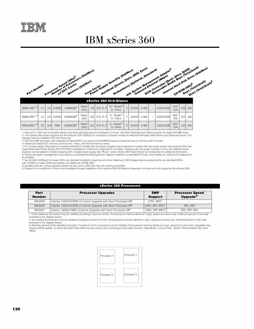
130
IBM xSeries 360
xSeries 360 At-A-Glance
8686-4RX1, 2 1.4 1/4 512KB 1GB/8GB4 Rack (3U) 1/3 P, S, H, F O - Power5
S - Fans Y 10/100 U160 - 0/220.2GB 24X-10X 5/3 6/6
8686-5RX1, 2 1.5 2/4 512KB 2GB/8GB4 Rack (3U) 2/3 P, S, H, F S - Power5
S - Fans Y 10/100 U160 - 0/220.2GB 24X-10X 5/3 6/6
8686-6RX1, 2 1.6 2/4 1MB 2GB/8GB4 Rack (3U) 2/3 P, S, H, F S - Power5
S - Fans Y 10/100 U160 - 0/220.2GB 24X-10X 5/3 6/6
1. Housed in a 19in rack-mountable drawer and ships standard without a keyboard or mouse. See Rack Cabinets and Options section for supported IBM racks.2. This xSeries 360 model supports the IXA Adapter (P/N 1519100) for connection to iSeries models for Microsoft Windows 2000 Server and Advanced Server. The adapter must be installed in PCI slot three only. 3. Intel Xeon MP processor with integrated full-speed ECC L3 cache and 4x100MHz (quad-pumped) access to memory and I/O buses.4. Advanced Chipkill ECC memory corrects two-, three-, and four-bit memory errors.5. N+1 power supply redundancy is provided standard in models with two power supplies and is optional in models with one power supply. One optional 370w Hot-swap Redundant Power Supply (P/N 31P6108) is available for maximum configurations in models shipping with two power supplies or up to two optional power supplies can be added to models shipping with a single power supply. See “Power” under xSeries 360 Power Monitor & Accessories for additional information.6. Advanced system management is provided by a standard Remote Supervisor Adapter installed in a dedicated PCI slot, which allows six optional PCI adapters to be installed.7. Two 36.4GB 10,000rpm hot-swap HDDs are standard (installed in bays four and five). Maximum HDD storage requires replacing the two standard HDDswith 73.4GB hot-swap HDDs and adding one additional 73.4GB HDD.8. Variable read rate. Actual playback speed will vary and is often less than the maximum possible.9. Support for an additional 12 64-bit slots available through installation of the optional RXE-100 Remote Expansion Unit (one unit only supported by xSeries 360).
xSeries 360 Processors
Part Number
Processor Upgrades SMP Support
Processor Speed Upgrade3
19K4638 xSeries 1.4GHz/512KB L3 Cache Upgrade with Xeon Processor MP (1RX, 4RX)1 -
19K4639 xSeries 1.5GHz/512KB L3 Cache Upgrade with Xeon Processor MP (2RX, 2RY, 5RX)2 1RX, 4RX
19K4647 xSeries 1.6GHz/1MB L3 Cache Upgrade with Xeon Processor MP (3RX, 3RY, 6RX)2 2RX, 2RY, 5RX1. Three additional processors may be installed, providing a maximum of four. All processors must be identical in type, speed and cache size. Install processors in the order indicated in the diagram below.2. Two additional processors may be installed, providing a maximum of four. All processors must be identical in type, speed and cache size. Install processors in the order indicated in the diagram below.3. Requires removal of the standard processor. A maximum of four processors can be installed. All processors must be identical in type, speed and cache size. Upgrades may require a BIOS update. To obtain the latest Flash BIOS, access www.pc.ibm.com/support and enter machine “Type-Model” in Quick Path. Select “Downloadable files” then “BIOS.”
Part Number
Processor Speed (G
Hz)3
Number of P
rocessors (Std/M
ax)
L3 ECC Cache
Memory (Std/M
ax)
Form Factor
Power Supply Quantit
y (Std/M
ax)
Hot-Swap (P
ower, Slots, H
DD, Fans)
Redundancy (Optio
nal, Standard)
Adv System Management A
dapter6
Onboard Ethernet (Mbps)
SCSI Contro
ller (D
ual, Ultr
a, RAID)
Removable Media Bays (T
otal/Avail)
Internal Hard Disk Driv
e (Std/M
ax)
CD-ROM (ID
E)8
Bays (Total/A
vail)
Slots (Total/A
vail)9
Processor 4
Processor 2 Processor 3
Processor 1

131For the latest product & technical information, refer to the Information Sources on pages 2 and 3.Updated 10/15/02
IBM
xS
eri
es
36
0
xSeries 360 contains five front-accessible drive bays located on the right side of the server. The top two bays contain the standard slim-line CD-ROM and 1.44MB slim-line diskette drive. Three 3.5in slim-line, hot-swap drive bays are located beneath them. The IDE CD-ROM is docked to a media interposer card that is cabled to the lightpath card before terminating at the system planar. The three SCA2-compliant hot-swap bays attach to a hot-swap backplane that connects to the integrated single-channel Ultra160 controller through an integrated bus. For RAID configurations, a cable provided with the system is connected to one of the internal connectors of the RAID controller and the other end of the cable is attached to a connector that supports the hot-swap HDD backplane, located on the planar between slot one and the memory card, beneath the memory options.
For additional information regarding internal cabling, refer to Appendix F: Internal Cabling Overview.
xSeries 360 Memory
Total Memory1 Quantity of RDIMMs Added2
1GB (2x512MB
model)
2GB (4x512MB models)
256MB (33L3281)
512MB (33L3283)
1GB (33L3285)
2GB 3GB 4 - -
2.5GB 3.5GB 2 2 -
3GB 4GB - 4 -
3.5GB 4.5GB 2 - 2
4GB 5GB - 2 2
5GB 6GB - - 4
6GB - - 2 4
7GB - - - 6
8GB (max)3 8GB3 - - 8
This table does not represent all possible memory configurations. 1. Network operating systems may limit the maximum amount of addressable memory. See operating system specifications for further information.2. To obtain the quantity of memory identified in the “Total Memory” column, select the appropriate row and order the quantity of RDIMMs identified in all columns for that row.3. Requires removal of standard RDIMMs.
Part Number
Memory Description1
33L3281 256MB PC 1600 ECC DDR SDRAM RDIMM
33L3283 512MB PC1600 ECC DDR SDRAM RDIMM
33L3285 1GB PC1600 ECC DDR SDRAM RDIMM
1. Due to two-way interleaving, all RDIMMs must be installed in pairs in the order indicated by the diagram. Chipkill support is provided on the memory card. Only installation in pairs is supported. The order of installation in pairs is sockets one and two, three and four, five and six, and seven and eight.
xSeries 360 Internal SCSI Cabling
xSeries 360 Hard Disk Drive (HDD) Storage
Total Int Storage1
10,000rpm HDDs 15,000rpm HDDs18.2GB
(06P5754)36.4GB
(06P575573.4GB06P5756
18.2GB (06P5767)
36.4GB(06P5768)
0GB Standard in base models (except 2RX and 3RX)
18.2GB 1 - - 1 -
36.4GB 2 1 - 2 1
54.6GB 3 - - 3 -
72.8GB2 - 22 - - 2
109.2GB - 3 - - 3
146.8GB - - 23 - -
220.2GB - - 33 - -This table does not represent all possible HDD configurations.1. Select a total storage row then select the quantity of HDDs from a column corresponding to the HDD of choice.2. Models 2RX and 3RX include two standard 36.4GB 10,000rpm HDDs installed in bays four and five.3. Requires replacing the standard HDDs in models 2RX and 3RX.
DIMM socket 5
DIMM socket 7
DIMM socket 3
DIMM socket 1
DIMM socket 6
DIMM socket 8
DIMM socket 4
DIMM socket 2Memory Card Assembly
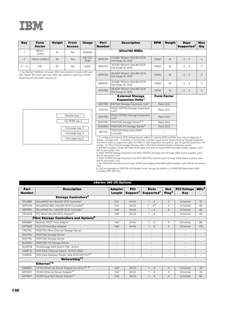
132
Bay Form Factor
Height Front Access
Usage Part Number
Description RPM Height Bays Supported1
Max Qty
1 89mm (3.5in) SL Yes Diskette Ultra160 HDDs
2 133mm (5.25in) SL Yes IDE CD-ROM 06P5756 73.4GB 10Krpm Ultra160 SCSI
Hot-Swap SL HDD 10000 SL 3 ... 5 3
3 ... 5 HS SL Yes Open1 06P5754 18.2GB 10Krpm Ultra160 SCSI Hot-Swap SL HDD 10000 SL 3 ... 5 3
1. Two 36.4GB 10,000rpm hot-swap HDDs are standard in models 2RX and 3RX. Model 1RX ships open bay. HDDs are installed in open bay models beginning with the bottom bay (5-4-3).
06P5755 36.4GB 10Krpm Ultra160 SCSI Hot-Swap SL HDD 10000 SL 3 ... 5 3
06P5767 18.2GB 15Krpm Ultra160 SCSI Hot-Swap SL HDD 15000 SL 3 ... 5 3
06P5768 36.4GB 15Krpm Ultra160 SCSI Hot-Swap SL HDD 15000 SL 3 ... 5 3
External Storage Expansion Units1
Form Factor
35311RU EXP300 Storage Expansion Unit2 Rack (3U)
17401RU FAStT EXP700 Storage Expansion Unit3 Rack (3U)
35601RU FAStT EXP500 Storage Expansion Unit4 Rack (3U)
35421RU FAStT200 Storage Server5, 6 Rack (3U)
35422RU FAStT200 HA Storage Server5 Rack (3U)
19K1121 FAStT200 Redundant RAID Controller -
1. To configure an external SCSI storage device, select an optional SCSI controller then refer to Appendix D: Cables - Storage Units - Controllers to confirm the controller supports the desired External Storage Expansion Unit and to select a supported cable. For HDD or other expansion unit options, see the specific expansion unit section. For Fibre Channel storage devices, refer to the Fibre Channel Solutions Overview section.2. EXP300 includes a single 2M Ultra2 SCSI cable and dual hot-swap 500W redundant power supplies, each with its own power cord.3. FAStT EXP700 Storage Expansion Unit (P/N 17401RU) includes dual hot-swap 400w power supplies, each with its own power cord.4. FAStT EXP500 Storage Expansion Unit (P/N 35601RU) includes dual hot-swap 350W power supplies, each with its own power cord.5. The FAStT200 includes two hot-swap, 350W auto-ranging redundant power supplies, each with its own power cord.6. Can be upgraded to FAStT200 HA Storage Server through the addition of a FAStT200 Redundant RAID Controller (P/N 19K1121).
xSeries 360 I/O Options
Part Number
Description Adapter Length
PCI Support1
Slots Supported1
Hot-Plug2
PCI Voltage Key
MHz3
Storage Controllers4
37L6889 ServeRAID-4H Ultra160 SCSI Controller5 Full 64-bit 1 .. . 6 X Universal 33
06P5736 ServeRAID-4Mx Ultra160 SCSI Controller6 Full 64-bit 1 . .. 617 X Universal 66
06P5740 ServeRAID-4Lx Ultra160 SCSI Controller7 Half 64-bit 1 .. . 6 X Universal 66
19K4646 PCI Wide Ultra160 SCSI Adapter8 Half 32-bit 1 .. . 6 - Universal 66
Fibre Storage Controllers and Options9
00N6881 Netfinity FAStT Host Adapter Half 64-bit 1 .. . 6 X Universal 66
24P0960 FC2-133 Host Bus Adapter Half 64-bit 1 .. . 6 X Universal 133
17421RU FAStT700 Fibre Channel Storage Server - - - - - -
35521RU FAStT500 Storage Server - - - - - -
35421RU FAStT200 Storage Server - - - - - -
35422RU FAStT200 HA Storage Server - - - - - -
3534F08 TotalStorage SAN Switch F08 - 8-port - - - - - -
2109F16 SAN Fibre Channel Switch, 16-Port (2Gb) - - - - - -
2108R3L SAN Data Gateway Router Ultra SCSI LVD Port10 - - - - - -
Networking11
Ethernet12
09N9901 10/100 EtherLink Server Adapter by 3Com13, 18 Half 32-bit 1 .. . 6 X Universal 33
06P3601 10/100 Ethernet Server Adapter13 Half 32-bit 1 .. . 6 X Universal 33
22P4901 10/100 Dual Port Server Adapter13 Half 64-bit 1 .. . 6 X Universal 66
Hot-swap bay 5
Hot-swap bay 4
Hot-swap bay 3
Diskette bay 1
CD-ROM bay 2

133For the latest product & technical information, refer to the Information Sources on pages 2 and 3.Updated 10/15/02
IBM
xS
eri
es
36
0
22P6801 PRO/1000XT Server Adapter by Intel (copper) w/CD, manuals13 Half 64-bit 3 . .. 6 X Universal 133
22P7801 NetXtreme 1000 SX Fiber Ethernet Adapter19 Half 64-bit 1 . .. 6 - Universal 133
Token Ring34L5001 16/4 Token-Ring PCI Management Adapter13 Half 32-bit 1 . .. 6 X Universal 33
34L5201 High-Speed 100/16/4 Token-Ring PCI Management Adapter13 Half 32-bit 1 . .. 6 X Universal 33
System Management14
03K9309 Advanced System Management Interconnect Cable Kit15 - - - - - -
Remote I/O Expansion8684-1RX RXE-100 Remote Expansion Enclosure16 - - - - - -
Note: xSeries 360 supports the IXA Adapter (P/N 1519100) for connection to iSeries models. This adapter is supported in slot three only.
1. Adapters rated at a lower frequency than the slots in which they are installed will reduce the bus to the frequency of the slowest adapter. 133MHz PCI-X adapters are backward compatible with 33/66MHz, 64-bit PCI-based servers.2. All six slots are full-length hot-plug capable. For Network Operating System support, access www.pc.ibm.com/us/compat.3. Bus two (slots one and two) supports 133MHz operation of a single 133MHz adapter installed in slot one with slot two remaining empty. If 133MHz adapters are installed in both slots one and two, the bus speed for both slots becomes 100MHz.4. xSeries 360 includes an integrated single-channel Ultra160 SCSI controller. See “Internal SCSI Cabling” for cabling alternatives. When a RAID controller is installed as a boot disk, it must be installed in a slot that is scanned before other RAID controllers in a configuration. Refer to the scan sequence provided in this section.5. ServeRAID-4H Ultra160 SCSI Controller is powered by a 266MHz PowerPC 750 processor and provides 128MB of battery-backed ECC cache. The two internal connectors are not accessible due to a cabling interference. Four external Ultra160 0.8mm VHDCI connectors are available.6. ServeRAID-4Mx Ultra160 SCSI Controller is powered by a 100MHz Intel Zion GC80303 processor that provides 64MB of battery-backed ECC cache and two internal and two external Ultra160 connections (only two connectors may be used). External connectors are 0.8mm VHDCI.7. ServeRAID-4Lx Ultra160 SCSI Controller is powered by a 100MHz Intel Zion GC80303 processor and provides a single channel, 32MB of ECC cache and either one internal or one external Ultra160 connection. External connector is 0.8mm VHDCI.8. PCI Wide Ultra160 SCSI Adapter (P/N 19K4646) provides a single channel with one internal connector, a five-drop multi-mode terminated LVD SCSI cable and one external 0.8mm VHDCI connector. This system supports external connection only.9. See Fibre Channel Solutions Overview section for additional configuration information.10. The 2108R3L SAN Data Gateway Router Ultra SCSI LVD port provides one integrated short-wave optical port and two SCSI ports for tape storage connections (LVD, HVD and single-ended).11. xSeries 360 has an integrated copper Intel-based 10/100 PCI Ethernet controller. Wake on LAN is supported only for the integrated controller.12. In a fault-tolerant networking environment, using the fault-tolerant software delivered with the Ethernet adapters of a single manufacturer is recommended. Installing fault-tolerant solutions provided by multiple manufacturers may cause failures if the intermediate drivers provided with the adapters are not compatible. Three of the optional PCI Ethernet adapters listed are copper and Intel-based (P/N 06P3601, 22P4901, 22P6801). One adapter is Broadcom-based (22P7801).13. The Wake on LAN function of this option is not supported by this server.14. xSeries 360 includes a Remote Supervisor Adapter installed in a dedicated PCI slot with an external connector, leaving six PCI slots available for optional adapters. Support for connection to other servers requires an optional Advanced System Management Interconnect Cable Kit (P/N 03K9309). Direct connection to the RXE drawer management controller in an RXE-100 Remote Expansion Enclosure is supported through a standard Interconnect Management Cable Kit with 3.5m cable connecting to an integrated RS-485 port on the rear of the system chassis. An 8m optional cable is available.15. Required to connect the standard Remote Supervisor Adapter to an interconnect network with other servers for system management support through a single LAN or modem connection. Up to 24 Integrated System Management Processors or Remote Supervisor Adapters may be interconnected with an aggregate connection length of no more than 91.4m (300ft). This interconnect network of 24 devices may include a maximum of 12 Advanced System Management Processors or Advanced System Management PCI Adapters. A customer-supplied Cat5 cable is required for each interconnection.16. RXE-100 Remote Expansion Enclosure supports up to 12 additional PCI-X slots. Cable required for connection included with expansion unit, which attaches to a standard external connector located on the back of the x360 chassis. An optional longer cable is available. See section on RXE-100.17. Not supported in slot one if the RAID adapter is attached to the connector on the planar that controls the hot-swap backplane as a result of a cabling interference with the standard RAID cable, which must be routed under the adapter. External RAID attachment only is supported for full-length RAID adapters installed in slot one.18. Not supported when greater than 4GB of random access memory (RAM) is installed.19. The hot-plug feature of this adapter is not supported on this system.
RS
A
slo
t 1
slo
t 2
slo
t 3
slo
t 4
slo
t 5
slo
t 6
rear view of chassis
RSA: standard Remote Supervisor AdapterSlot 1: Bus 2, 100MHz, 64-bit, full-length, Active PCI-X, 3.3v (Bus 2 also supports one 133MHz adapter installed in slot 1.)Slot 2: Bus 2, 100MHz, 64-bit, full-length, Active PCI-X, 3.3v (Slot 2 must be empty if a 133MHz adapter installed in slot 1.)Slot 3: Bus 1, 66MHz, 64-bit, full-length, Active PCI-X, 3.3v Slot 4: Bus 1, 66MHz, 64-bit, full-length, Active PCI-X, 3.3v Slot 5: Bus 1, 66MHz, 64-bit, full-length, Active PCI-X, 3.3vSlot 6: Bus 1, 66MHz, 64-bit, full-length, Active PCI-X, 3.3v
Scan sequence:Inside the server: slots 3, 4, 5, 6, 1, 2Continuing in an RXE-100: slots 11, 12, 9, 10, 7, 8, 17, 18, 15, 16, 13, 14.

134
xSeries 360 Power, Monitors & Accessories
Part Number Description
Power1
31P6108 370W Hot-Swap Redundant Power Supply2
Uninterruptible Power Supply (UPS)3, 4
32P1020 APC 2U Smart-UPS 1400RMB
94G6676 APC Smart-UPS 3000RMB5
37L6861 APC Smart-UPS 5000RMB6
Monitors7
633147N E54 Color Monitor 15in (350mm, 13.8in viewable image), stealth black8
63324HN E74 Color Monitor 17in (406mm, 16in viewable image), stealth black8
66274AN G78 Color Monitor 17in (406.4mm, 16in viewable image), stealth black8
32P1031 NetBAY 1U Flat Panel Monitor Console Kit (with US Space Saver Keyboard)9
32P1032 NetBAY 1U Flat Panel Monitor Console Kit (without keyboard)9
32P1702 NetBAY 2U Flat Panel Monitor Console Kit (with US Space Saver keyboard)9
32P1703 NetBAY 2U Flat Panel Monitor Console Kit (without keyboard)9
1. xSeries 360 models 2RX and 3RX include two 370W, hot-swap power supplies, each with two 9ft power cords--one high voltage IEC 320-C13 to IEC 320-C14 and one low voltage IEC 320-C13 to NEMA 5-15P. N+1 power supply redundancy is standard for these models. The addition of an optional 370W Hot-Swap Redundant Power Supply (P/N 31P6108) is supported for configurations of greater than 370W with power redundancy, i.e., a total of three 370W power supplies. Model 1RX includes one standard power supply and may be upgraded to two or three power supplies according to the same rules for redundancy as models 2RX and 3RX. The following table is provided as a reference. The table shows an example of a maximum configuration that can be supported by two 370W power supplies with power redundancy.
2. 370W Hot-Swap Redundant Power Supply (P/N 31P6108) includes two 9ft power cords, one high voltage IEC 320-C13 to IEC 320 -C14 and one low voltage IEC 320-C13 to NEMA 5-15P.3. For runtimes and UPS attributes see Appendix C: UPS Runtime Estimate.4. Because the x360 is not equipped with a serial port, UPS remote management requires a USB to serial adapter such as the Belkin USB to Serial Adapter (P/N 10K3661), which is available at www.pc.ibm.com/ww/eserver/xseries. Select Accessories, Upgrades & Monitors and the country, then click Go. Scroll to the bottom of the page, select Cables and Adapters, then open the Adapters pulldown menu.5. Height is 3U. See Rack Cabinets and Options section for supported IBM racks.6. Height is 5U. See Rack Cabinets and Options section for supported IBM racks.7. xSeries 360 uses an SVGA controller (S3 Savage4 LT chipset) with 8MB of video memory. Optional video adapters are not supported.8. Installation within a rack requires optional Monitor Compartment (P/N 94G7444).9. Includes a 15in Flat Panel Monitor.
Part Number Description
Rack and NetBAY1
Refer to the Rack Cabinets and Options section for information concerning IBM racks and rack-supported devices.
Keyboard and Mouse2
28L3644 Space Saver II Keyboard3, 4
22P5150 TrackPoint USB Space Saver Keyboard3, 4, 6
10K3849 106-key Preferred USB Keyboard with 2-port USB Hub (stealth black)5, 6
28L3673 Sleek 2-Button Stealth Black Mouse
33L3244 Sleek USB Mouse (stealth black)6
Number of power supplies
System configuration supported
Redundant
Up to three processors
2 Up to four PCI adapters
Up to two HDDs
Up to six memory RDIMMs

135For the latest product & technical information, refer to the Information Sources on pages 2 and 3.Updated 10/15/02
IBM
xS
eri
es
36
0
1. xSeries 360 is housed in a 19in rack-mountable drawer and requires one of the racks listed in the Rack Cabinets and Options section.2. xSeries 360 supports rack configurations only and ships without a keyboard or mouse. The system includes three USB ports, SVGA video port, mouse port and keyboard port. 3. Installation within a rack requires optional keyboard tray (P/N 28L4707) which stows in ready-to-use position, or NetBAY 1U or 2U Flat Panel Monitor Console Kit (P/N 32P1032, 32P1702). Standard with 1U and 2U NetBAY console kits (P/N 32P1031, 32P1702).4. Advanced TrackPoint IV features are not available on IBM xSeries systems.5. Installation within a rack requires optional keyboard tray (P/N 28L4707). This keyboard cannot share a keyboard tray with a flat panel display.6. USB accessories attach to a single USB-capable server. They are not compatible with the NetBAY console switches.
xSeries 360 Tape Options
Part Number Tape Drives
Bays Supported1
SCSI Interface
(bit)
Form Factor
Termination Included
Ext Tape Enclosures
00N8016 100/200GB LTO Tape Drive - 16 Ultra2 LVD 133mm (5.25in) FH Y2 35510013
3503B1X
00N8015 110/220GB Super DLT Internal SCSI Tape Drive - 16 Ultra2 LVD 133mm
(5.25in) FH Y2 35510013
3503B1X
24P2396 100/200GB LTO Half-High Tape Drive - 16 Ultra2 LVD 133mm (5.25in) HH Y2 35510013
Tape Autoloaders
3600109 3600 Series 900GB/1.8TB LTO Tape Autoloader4 - 16 Ultra2 LVD Tower or 6U
Rack Y -
External Tape Libraries5
3600R20 3600 Series 2/4TB LTO Tape Library (Rack) - 16 Ultra2 LVD 5U Rack Y -
3600LXU 3600 Series 2-Drive, 20-Cartridge Expander Module6 - 16 Ultra2 LVD 5U Rack Y -
09N4048 3600 Series LTO Drive Upgrade Option7 - 16 Ultra2 LVD - N -
External Tape Enclosures3551001 NetMEDIA Storage Expansion Unit EL8 - 16 Rack Y -10L7113 NetMEDIA Systems Management Adapter9 - 16 LVD - Y 3551001
3503B1X Full-High SCSI Tape Enclosure10 - 16 Ultra2 LVD Desktop or 3U Rack Y -
1. IBM xSeries 360 does not support internal tape drives. An external tape library or tape enclosure must be used. All tape drives and enclosures are supported by PCI Wide Ultra160 SCSI Adapter (P/N 19K4646) which has an external 0.8mm VHDCI connector. Select tape drive, enclosure and controller then use Appendix D: Cables - Storage Units - Controllers to select an appropriate external cable.2. Termination requires installing the 34in single-drop, terminated LVD SCSI cable provided with the option. When installed in a NetMEDIA Storage Expansion Unit, termination is also provided by the standard cables shipped with the enclosure.3. LVD support for LVD tape drives installed in a NetMEDIA Storage Expansion Unit EL (P/N 3551001) is provided by two four-drop internal LVD cables.4. If installed in a rack, a fixed shelf is required. Allow an additional 1U for the fixed shelf. One unit only per shelf is supported.5. Tape library attributes and prerequisites are located in Appendix B: Tape Library Attributes.6. Supported only with the 3600 Series LTO Tape Library (rack) (P/N 3600R20). Allow one additional EIA space when installing either one or two (maximum) units to accommodate a filler plate for cable routing. Up to two 3600 Series LTO Drive Upgrade Options can be installed in each module or the module can operate off the LTO drives installed in the LTO tape library.7. Install in second drive bay of 3600 LTO Tape Libraries or in either of the two bays of 3600 Series 2-Drive 20-Cartridge Expander Module to increase performance. Includes an LTO (Ultrium) drive and a one-meter external LVD SCSI cable.8. NetMEDIA Storage Expansion Unit EL (P/N 3551001) is a black 3U, rack-mountable tape enclosure which includes two full-high (FH) or four half-high (HH) extended length 133mm (5.25in) bays, two external 0.8mm VHDCI connectors and two internal four-drop LVD terminated 16-bit SCSI cables for device attachment. Two power supplies and two power cords are also included. External storage cables are not included.9. NetMEDIA Systems Management Adapter (P/N 10L7113) may be installed in a 3551001 to provide repeater function, aggregate cable lengths up to 12m when attached to an LVD SCSI controller, and auto-termination when the 3551001 is powered off. External connector is 0.8mm VHDCI.10. Black desktop or 3U rack tape enclosure supports a single 133mm (5.25in) full-high LVD tape device including DLT tape drives. Requires a fixed shelf if installed in a rack (allow additional 1U for fixed shelf). Includes a 90w power supply, cooling fan, external terminator, power cord (country-specific), and 2m 68-pin to 0.8mm external cable. Supports the following full-high tape options: 00N8015, 00N8016.
Note: Additional tape attributes can be found in Appendix A: Tape Drive Attributes.

136
Note: The following sample configurations are for illustration only and may not be suitable for any specific customer installation. Contact your IBM Business Partner or IBM Marketing Representative for assistance with your specific configuration requirements.
Microsoft Exchange SCSI Solution1
Microsoft Exchange High-Availability Fibre Channel Solution1
xSeries 360 Sample Configurations
Part Number Description Quantity8686-6RX xSeries 360 2x1.6GHz/4x100MHz, 1MB L3 Cache Xeon MP, 2GB ECC, open, 24x 119K4647 xSeries 1.6GHz/1MB L3 Cache Upgrade with Xeon Processor MP 22
31P6108 xSeries 370W Hot-swap Redundant Power Supply 13
33L3283 512MB PC 1600 ECC DDR SDRAM RDIMM 24
37L6889 ServeRAID-4H Ultra160 SCSI Controller 15
06P5755 36.4GB 10Krpm Ultra160 SCSI Hot-Swap SL HDD 36
06P3601 10/100 Ethernet Server Adapter 1633147N E54 Color Monitor 15in (350mm, 13.8in viewable image), stealth black 137L6861 APC Smart-UPS 5000RMB 1
External Storage35311RU EXP300 Storage Expansion Unit 206P5755 36.4GB 10Krpm Ultra160 SCSI Hot-Swap SL HDD 147
3600109 3600 Series 900GB/1.8TB LTO Tape Autoloader 1
Rack Options9306250 NetBAY25 Standard Rack Cabinet 128L3644 Space Saver II Keyboard 194G6670 Blank Filler Panel Kit 1
1. This configuration supports 8,000 users.2. Total of four processors.3. Required to maintain N+1 power redundancy in this configuration--total of three 370W power supplies.4. Total memory of 3GB.5. External connectors only can be used due ti internal cabling restriction.6. Total internal storage of 109.2GB.7. Six HDDs are used for RAID-5E protection in each EXP300. One HDD is identified as a hot-spare. Effective capacity is five HDDs in each storage enclosure (total of 182GB).
Part Number Description Quantity8686-6RX xSeries 360 2x1.6GHz/4x100MHz, 1MB L3 Cache Xeon MP, 2GB ECC, open, 24x 119K4647 xSeries 1.6GHz/1MB L3 Cache Upgrade with Xeon Processor MP 22
31P6108 xSeries 370W Hot-swap Redundant Power Supply 13
33L3283 512MB PC 1600 ECC DDR SDRAM RDIMM 24
06P5736 ServeRAID-4MX Ultra160 SCSI Controller 106P5755 36.4GB 10Krpm Ultra160 SCSI Hot-Swap SL HDD 35
06P3601 10/100 Ethernet Server Adapter 124P0960 FC2-133 Host Bus Adapter 28684-1RX RXE-100 Remote Expansion Enclosure 137L6861 APC Smart-UPS 5000RMB 194G6676 APC Smart-UPS 3000RMB 1
External Storage17421RU FAStT700 Storage Server 16
35601RU FAStT EXP500 Storage Expansion Unit 319K0653 Netfinity 36.4GB 10K-4 FC Hot-Swap HDD 187
3600109 3600 Series 900GB/1.8TB LTO Tape Autoloader 1
Rack Options9306420 NetBAY42 Standard Rack Cabinet 132P1031 NetBAY 1U Flat Panel Monitor Console Kit (w/ US Space Saver Keyboard) 194G6670 Blank Filler Panel Kit 1
1. This configuration supports 8,000 users.2. Total of four processors.3. Required to maintain N+1 power redundancy in this configuration--total of three 370W power supplies.4. Total memory of 3GB.5. Total internal storage of 109.2GB.6. Fibre Channel cable, SFP Modules and FAStT700 Mini Hubs not included.7. Six HDDs are used for RAID-5E protection in each FAStT EXP500. One HDD is identified as a hot-spare. Effective capacity is five HDDs in each storage enclosure (total of 182GB).
137For the latest product & technical information, refer to the Information Sources on pages 2 and 3.Updated 10/15/02
IBM
xS
eri
es
36
0

IBM xSeries 440
EMEA Part Number Cross ReferencexSeries 440 S ystem Unit Part Numbers
EMEA AMERICAS M/C TYPE DESCRIPTION EMEAP/N P/N MODEL WDFM DATE
K71RXxx 86871RX 8687-1RX Xeon MP 1.4GHz/400MHz, 512KB, 2GB, Open BayU160 HS, Rack ---
K72RXxx 86872RX 8687-2RX Xeon MP 1.5GHz/400MHz, 512KB, 2GB, Open BayU160 HS, Rack ---
K73RXxx 86873RX 8687-3RX Xeon MP 1.6GHz/400MHz, 1MB, 2GB, Open BayU160 HS, Rack ---
K73RYxx 86873RY 8687-3RY Xeon DP 2.4GHz/400MHz, 512KB, 2GB, Open BayU160 HS, Rack ---
K74RYxx 86874RY 8687-4RY Xeon DP 2.4GHz/400MHz, 512KB, 4GB, Open BayU160 HS, Rack ---
xSeries 440 Hard Disk Drive Storage Part NumbersEMEA AMERICAS M/C TYPE DESCRIPTION EMEA
P/N P/N MODEL WDFM DATENotes 1&2 19K11xx 35311RU --- EXP300 Storage Expansion Unit ---Notes 3&2 00N71xx 35601RU --- FAStT EXP500 Storage Expansion Unit ---Notes 4&2 24P09xx 17401RU --- FAStT EXP700 Storage Expansion Unit ---Notes 5&2 19K11xx 35421RU --- FAStT 200 Storage Server ---Notes 6&2 19K11xx 35422RU --- FAStT 200 HA Storage Server ---
1. Where ‘xx’ represents a specific country code as follows: 51=US/English, 52=European/English, 56=Danish/English, 57=Israel/English, 58=Italian/English, 59=South Africa/English, 60=Swiss/English, 63=UK/English.2. This unit does not include Rack Power Cables P/N 94G7448 when shipped (for attachment to highvoltage UPS or PDU). Standard country power cords only are included. If required, order one Rack PowerCable for each power supply.3. Where ‘xx’ represents a specific country code as follows:- 36=US/English, 37=Euro/English, 41=Denmark/English, 42=Israel/English, 43=Italy/English, 44=South Africa/English, 45=Switzerland/English, 49=UK/English.4. Where ‘xx’ represents a specific country code as follows:- 01=Eur/English, 02=Eur/Spanish, 05=Denmark/English, 06=Israel/English, 07=Italy/English, 08=South Africa/English, 09=Switzerland/English, 12=UK/English.5. Where ‘xx’ represents a specific country code as follows:- 23=US/English, 24=Euro/English, 25=Euro/Spanish, 27=Euro/German, 28=Denmark/English, 29=Israel/English, 30=Italy/English, 31=South Africa/English, 32=Switzerland/English, 34=Switzerland/German, 36=UK/English..6. Where ‘xx’ represents a specific country code as follows:- 37=US/English, 38=Euro/English, 39=Euro/Spanish, 41=Euro/German, 42=Denmark/English, 43=Israel/English, 44=Italy/English, 45=South Africa/English, 46=Switzerland/English, 48=Switzerland/German, 50=UK/English.
xSeries 440 I/O Option Part NumbersEMEA AMERICAS M/C TYPE DESCRIPTION EMEA
P/N P/N MODEL WDFM DATE86841RX 86841RX --- RXE-100 Remote Expansion Enclosure ---
Note 7 xSeries 440 Power, Monitors & AccessoriesEMEA AMERICAS M/C TYPE DESCRIPTION EMEA
P/N P/N MODEL POWER WDFM DATENote 8 32P16xx 32P1020 --- APC 2U Smart-UPS 1400RMiB ---Note 9 30RIxxx 94G6676 --- APC Smart-UPS 3000RMiB ---
37L6862 37L6861 --- APC Smart-UPS 5000RMiB ---7. The xSeries 440 ships with two standard country power cords and two Rack Power cords for connection either to wall socketsor a high voltage UPS or PDU.
8. Where ‘xx’ represents a specific country code as follows:- 12=Europe, 13=UK, 14=Italy, 15=Switzerland, 16=Denmark, 17=South Africa, 18=Israel.
9. Where ‘xxx’ represents a specific country code as follows:- DEN=Denmark, ISR=Israel, ITA=Italy, SDI=Saudi Arabia, SAF=South Africa, SWS=Switzerland, UKM=United Kingdom, EUR=Europe.
137A Updated 10/15/02

IBM xSeries 440
EMEA Part Number Cross ReferencexSeries 440 Power, Monitors & Accessories
EMEA AMERICAS M/C TYPE DESCRIPTION EMEAP/N P/N MODEL MONITORS WDFM DATE
Note 10 T3147xx 633147N 6331-47N E54 15" (13.8" viewable image) Colour Monitor (S/Blac ---Note 10 T3247xx 63324HN 6332-4HN E74 17" (16" viewable image) Colour Monitor (S/Black) ---Note 10 T274Axx 66274AN 6627-4AN G78 17" (16" viewable image) Colour Monitor (S/Black ---
N/A 32P1031 --- NetBAY 1U Flat Panel Monitor Console Kit (with US ke N/AN/A 32P1702 --- NetBAY 2U Flat Panel Monitor Console Kit (with US ke N/A
10. Where ‘xx’ represents a specific country code as follows: DK=Denmark, IS=Israel, IT=Italy, SD=Saudi Arabia, SA=SouthAfrica/Pakistan, CH=Switzerland, UK=UK, EU=Europe.
xSeries 440 Power, Monitors & AccessoriesEMEA AMERICAS M/C TYPE DESCRIPTION EMEA
P/N P/N MODEL KEYBOARD AND MOUSE WDFM DATENote 11 28L36xx 28L3644 --- Spacesaver II Keyboard ---Note 12 10K38xx 10K3849 --- 106-key Preferred USB Keyb. with 2-port USB Hub (S/ ---Note 13 22P51xx 22P5150 --- TrackPoint USB Spacesaver Keyboard ---
28L3675 28L3673 --- Sleek 2-button Mouse (S/Black) ---11. Where ‘xx’ represents a specific country code as follows:- 46=Danish , 47=French, 48=German, 49=Italian, 50=Spanish, 51=UK English, 44=US English, and P/N 19K3831=Swiss, 19K3832=Swedish/Finnish, 19K3833=Portugese, 19K3834=Belgian,19K3836=Russian, 19K3837=Polish.
12. Where ‘xx’ represents a specific country code as follows:- 53=Danish , 54=Dutch, 55=France, 56=Germany, 57=Italian, 58=Norwegian, 59=Swedish/Finnish, 10K2343=Swiss, 10K2344=UK English, 10K2345=US ISO.
13. Where ‘xx’ represents a specific country code as follows:- 53=Danish , 54=Dutch, 68=French, 55=German, 56=Italian, 57=Spanish, 58=UK English, 59=Swedish/Finnish, 60=Belgian/English, 61=Russian, 62=Polish, 63=Portuguese, 65=Swiss, 67=USInternational.
xSeries 440 Tape OptionsEMEA AMERICAS M/C TYPE DESCRIPTION EMEA
P/N P/N MODEL WDFM DATENote 14 09N40xx 3600109 --- 3600 Series 900GB/1.8TB LTO Tape Autoloader ---Note 15 21P99xx 3600R20 --- 3600 Series 2/4TB LTO Tape Library (Rack) ---Note 16 21P99xx 3600LXU --- 3600 Series 2-drive 20-cartridge Expander Module ---Note 17 24P24xx 3503B1X --- Full-High SCSI Tape Enclosure ---
03K8756 3551001 --- NetMEDIA Storage Expansion Unit EL ---
14. Where ‘xx’ represents a specific country code as follows:- 49=UK, 50=Europe, 51=Denmark, 52=South Africa, 53=Switzerland, 54=Italy, 55=Israel.
15. Where ‘xx’ represents a specific country code as follows:- Rack version - 78=Europe, 79=Denmark, 80=South Africa, 77=UK,81=Swiss, 82=Italy, 83=Israel.16. Where ‘xx’ represents a specific country code as follows:- 85=Europe, 86=Denmark, 87=South Africa, 84=UK, 88=Swiss, 89=Italy, 90=Israel.
17. Where ‘xx’ represents a country specific code: 35=UK, 39=Swiss, 40=Italy, 41=Israel, 36=EU, 37=Denmark, 38=South Africa.
Updated 10/15/02 137B

138
IBM xSeries 440
xSeries 440 At-A-Glance
8687-1RX1, 11 1.42 2/8 512KB 2GB/32GB5 Rack (4U) 2/2 P, S, H, F S-Fans,
S-Power Y 10/100/1000 D, U160 2/0 0/146.8GB 24X-
10X 4/2 6/6
8687-2RX1,11 1.52 2/8 512KB 2GB/32GB5 Rack (4U) 2/2 P, S, H, F S-Fans,
S-Power Y 10/100/1000 D, U160 2/0 0/146.8GB 24X-
10X 4/2 6/6
8687-3RX1, 11 1.62 2/8 1MB 2GB/32GB5 Rack (4U) 2/2 P, S, H, F S-Fans,
S-Power Y 10/100/1000 D, U160 2/0 0/146.8GB 24X-
10X 4/2 6/6
8687-3RY1, 11 2.43 2/4 512KB 2GB/32GB5 Rack (4U) 2/2 P, S, H, F S-Fans,
S-Power Y 10/100/1000 D, U160 2/0 0/146.8GB 24X-
10X 4/2 6/6
8687-4RY1, 11 2.43 4/4 512KB 4GB/32GB6 Rack (4U) 2/2 P, S, H, F S-Fans,
S-Power Y 10/100/1000 D, U160 2/0 0/146.8GB 24X-
10X 4/2 6/6
Note: xSeries 440 supports the IXA Adapter (P/N 1519100) for connection to iSeries models for Microsoft Windows 2000 Server and Advanced Server. The adapter must be installed in PCI slot two only.
1. Housed in a 19in rack-mountable drawer and ships standard without a keyboard or mouse. See Rack Cabinets and Options section for supported IBM racks.2. Intel Xeon MP processor with integrated full-speed ECC L3 cache and 4x100MHz (quad-pumped) access to memory and I/O buses.3. Intel Xeon DP processor with integrated full-speed ECC L2 cache and 4x100MHz (quad-pumped) access to memory and I/O buses. A maximum of two processors can be installed in each SMP Expansion Module (four total per system).4. Either two or six additional optional processors are supported in models 1 ... 3RX. In these models, xSeries SMP Expansion Module (P/N 32P8340) is required to increase maximum support of processors from four to eight and memory options from 16 to 32. The optional SMP Expansion Module requires four processors prepopulated and a minimum of four RDIMMs (eight if memory mirroring is enabled). In models 3RY and 4RY, a maximum of two processors can be installed in each SMP Expansion Module (memory options can be added as with models 1 ... 3RX). Models 3RY and 4RY can be upgraded by replacing the standard Xeon DP processors with Xeon MP processors, which then allows all functionality and compatibility of models 1 ... 3RX.5. Advanced Chipkill ECC memory controller corrects single, two-, three-, and four-bit memory errors. Memory options are four-way interleaved. Sixteen sockets are provided in standard models, four of which are populated with 512MB RDIMMs. An additional 16 sockets are supported with the installation of xSeries SMP Expansion Module (P/N 32P8340).6. Advanced Chipkill ECC memory controller corrects single, two-, three-, and four-bit memory errors. Memory options are four-way interleaved. Thirty-two sockets are provided in standard models,eight of which are populated with 512MB RDIMMs (four in each SMP Expansion Module). 7. Two 1050w, voltage-sensing, hot-swap power supplies that support N+1 redundancy on full configurations are standard.8. Advanced system management is provided by a standard Remote Supervisor Adapter installed in a dedicated PCI slot, which allows six optional PCI adapters to be installed.9. Variable read rate. Actual playback speed will vary and is often less than the maximum possible.10. Support for an additional 12 64-bit slots available through installation of the optional RXE-100 Remote Expansion Unit. Refer to x440 I/O Options or the RXE-100 section for more information.11. Availability in the U.S. is limited to the Large Enterprise Direct (LED) program or through EXAct Business Partner program members.
Part Number
Processor Speed (G
Hz)
Number of P
rocessors (Std/M
ax)4
L3 ECC Cache
Memory (Std/M
ax)
Form Factor
Power Supply Quantity
(Std/M
ax)7
Hot-Swap (P
ower, Slots, H
DD, Fans)
Redundancy (Optio
nal, Standard)
Adv System Management A
dapter8
Onboard Ethernet (Mbps)
SCSI Contro
ller (D
ual, Ultr
a, RAID)
Removable Media Bays (T
otal/Avail)
Internal Hard Disk Driv
e (Std/M
ax)
CD-ROM (ID
E)9
Bays (Total/A
vail)
Slots (Total/A
vail)10
IBM
xS
eri
es 4
40
139For the latest product & technical information, refer to the Information Sources on pages 2 and 3.Updated 10/15/02
xSeries 440 Processors
Part Number
Processor Upgrades1 SMP Support
Processor Speed/Cache Upgrade3
71P7919 xSeries SMP Expansion Module with Dual Xeon Processors 2.4GHz/512KB4 3RY -
32P8705 xSeries 1.4GHz/512KB L3 Cache Upgrade with Xeon Processor MP 1RX2 -
32P8706 xSeries 1.5GHz/512KB L3 Cache Upgrade with Xeon Processor MP 2RX2 1RX
32P8707 xSeries 1.6GHz/1MB L3 Cache Upgrade with Xeon Processor MP 3RX2 1RX, 2RX
32P8340 xSeries SMP Expansion Module5 1 .. . 3RX -
1. IBM xSeries 440 architecture optimizes memory and bus performance using an XA-32 core chipset with up to two CPU/memory cards and two PCI-X host-bridge controllers. Up to eight Pentium Xeon MP processors are supported. The recommended order of processor installation is shown in the accompanying diagrams. In models 1 ... 3RX, two processors are standard with additional support for either two optional processors (total of four) or six optional processors (total of eight). Eight processors require an xSeries SMP Expansion Module. Models 2RY and 3RY are limited to two Xeon DP processors in each SMP Expansion Module, but can be upgraded by replacing the standard processors with Xeon MP processors.2. Up to six additional processors may be installed, providing a maximum of eight. All processors must be identical in type, speed and cache size. The fifth through eighth processors require an xSeries SMP Expansion Module, prepopulated with four processors, which is supported only when fully populated.3. Requires removal of standard processors. A maximum of eight processors may be installed. Installation of greater than four processors requires the addition of an xSeries SMP Expansion Module. All processors must be identical in type, speed and cache size. Upgrades may require a BIOS update. To obtain the latest Flash BIOS, access www.pc.ibm.com/support and enter machine "Type-Model" in Quick Path. Select "Downloadable files" then "BIOS."4. Required to upgrade 3RY from two to the maximum of four Xeon DP processors. Memory options are not included. Both models 3RY and 4RY can be upgraded by replacing the standard processors with Xeon MP processors. The same SMP Expansion Module is used, which supports up to four Xeon MP processors.5. The fifth through eighth processors for models 1 ... 3RX require this option, which installs directly above the standard CPU/memory board. Two 10in scalability cables (P/N 32P8336) are included with the option. See SMP Expansion Module cabling diagrams below for scalability cabling configuration. Four CPUs are required with each optional SMP Expansion Module for models 1 ... 3RX. A minimum of four RDIMMs installed in each SMP Expansion Module are required (not included). Memory mirroring requires aminimum of eight RDIMMs in each SMP Expansion Module. This option is not compatible with models 3RY and 4RY.

140
standard CPU/memory module
CPU 2
CPU 1
CPU 3
CPU 4
Memory board 1Memory board 2
RDIMMs 9-16 RDIMMs 1-8
fan
fan
fan
fan
powersupplies
front
CPU 6
CPU 5
CPU 7
CPU 8
Memory board 1Memory board 2
RDIMMs 9-16 RDIMMs 1-8
Optional SMP Expansion Module (P/N 32P8340)installs directly above standard CPU/memory board, requiring installation of four processors and a minimum of four RDIMMs.
Forwarding ScalabilityPort
Scalability Cable
Non-forwardingScalability Port
Ope
ratin
gS
yste
mIn
stan
ce
Sys ManProc
PCI-X
RemoteI/O
I/OBridge
CPU CPU
CPUCPU
CEC #11
2
3
I/OBridge
Ope
ratin
gS
yste
mIn
stan
ce
PCI-X
RemoteI/O
I/O Bridge
Sys MgtProc
CPU CPU
CPUCPU
CEC #1
CPU CPU
CPUCPU
CEC #2
1
2
3
1
2
3
I/O Bridge
Key:
Logical diagram of SMP Expansion Module cabling for single node, four-way x440 running one operating system
Logical diagram of SMP Expansion Module cabling (including scalability cables) for single node, eight-way x440 running one operating system
bottom SMP Expansion Module
top SMP Expansion Module
IBM
xS
eri
es 4
40
141For the latest product & technical information, refer to the Information Sources on pages 2 and 3.Updated 10/15/02
xSeries 440 provides four drive bays on the lower front panel of the system chassis. At the bottom, two adjacent slim-line bays contain the standard CD-ROM and a 1.44MB diskette drive. Two 3.5in, SCA-2-compliant slim-line hot-swap hard disk drive bays are located directly above. The IDE CD-ROM is cabled directly to the IDE port on the planar, and the hot-swap backplane that supports two hot-swap bays is connected to one channel of the dual channel integrated SCSI controller through a 16-bit LVDS cable.
An optional ServeRAID controller is supported for internal and external RAID applications. An additional, longer 16-bit LVDS SCSI cable is provided standard with the system to connect the hot-swap backplane to the ServeRAID controller for internal RAID configurations. The integrated controller includes a second channel that supports external tape enclosures. A 16-bit LVDS cable connects this channel to an industry-standard, 0.8mm VHDCI connector.
For additional information regarding internal cabling, refer to Appendix F: Internal Cabling Overview.
xSeries 440 Memory
Part Number
Memory Description1Total
Memory1Quantity of RDIMMs
Added2, 4
33L3324 512MB PC133 ECC SDRAM RDIMM2GB
(4 x 512MB)3512MB
(33L3324)1GB
(31P8300)31P8300 1GB PC133 ECC SDRAM RDIMM 4GB3 4 -
1. Due to four-way interleaving, installation of memory options in banks of four is required. Banks may be populated in any order. A minimum of four RDIMMs are required for each SMP Expansion Module (minimum of eight required to enable memory mirroring).
6GB 8 -
Notes: 8GB 12 -
1. See numbering of RDIMM sockets on memory card for bank configuration.2. Performance is optimized by balancing the amount of memory between ports (and between SMP Expansion Modules).3. In order to enable memory mirroring during BIOS set-up, the same memory configuration must be installed in each port (memory mirroring reduces the amount of memory available to the operating system by half).4. Memory mirroring is specific to each SMP Expansion Module, i.e., it is not required in both the standard and optional CPU/memory boards.
10GB 8 4
12GB 4 8
14GB - 12
16GB4 28 -
18GB4 24 4
20GB4 20 8
22GB4 16 12
24GB4 12 16
26GB4 8 20
28GB4 4 24
30GB4 - 28
32GB5 - 32
This table does not represent all possible memory configurations. RDIMMs must be added in sets of four to support interleaving technology.
1. Network operating systems may limit the maximum amount of addressable memory. See operating system specifications for further information.2. To obtain the quantity of memory identified in the “Total Memory” column, select the appropriate row and order the quantity of RDIMMs identified in all columns for that row, which will be added to the standard memory noted at the top of the left column.3. Model 4RY ships with 4GB of memory standard (4 x 512MB RDIMMs installed in each SMP Expansion Module).4. Optional xSeries SMP Expansion Module (P/N 01R1338) is required if total RDIMMs exceed 16.5. Requires removal of standard memory. Installation of greater than 16 RDIMMs requires optional xSeries SMP Expansion Module (P/N 01R1338).
xSeries 440 Internal SCSI Cabling
1 2 93 4 5 6 7 8 10 11 12 13 14 15 16port 1: RDIMM 1-8 port 2: RDIMM 9-16
front of planar
back of planar
Numbering of RDIMM sockets on memory card
Bank 1: sockets 1, 3, 5, 7Bank 2: sockets 9, 11, 13, 15Bank 3: sockets 2, 4, 6, 8Bank 4: sockets 10, 12, 14, 16
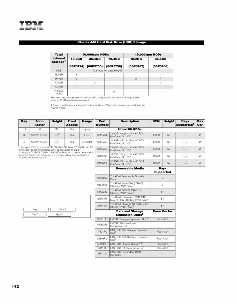
142
xSeries 440 Hard Disk Drive (HDD) Storage
Total Internal Storage1
10,000rpm HDDs 15,000rpm HDDs18.2GB
(06P5754)
36.4GB
(06P5755)
73.4GB
(06P5756)
18.2GB
(06P5767)
36.4GB
(06P5768)0GB Standard on base models
18.2GB 1 - - 1 -
36.4GB 2 1 - 2 1
72.8GB - 2 - - 2
73.4GB - - 1 - -
146.8GB (max) - - 2 - -
This table does not represent all possible HDD configurations. Total Internal Storage listed iswithin +/-0.2GB unless otherwise noted.
1. Select a total storage row then select the quantity of HDDs froma column corresponding to the HDD of choice.
Bay Form Factor
Height Front Access
Usage Part Number
Description RPM Height Bays Supported1
Max Qty
1, 2 HS SL Yes open Ultra160 HDDs
3 133mm (5.25in) SL1 Yes FDD 06P5754 18.2GB 10Krpm Ultra160 SCSI Hot-Swap SL HDD 10000 SL 1, 2 2
4 133mm (5.25in) SL2 Yes CD-ROM 06P5755 36.4GB 10Krpm Ultra160 SCSI Hot-Swap SL HDD 10000 SL 1, 2 2
1. Supports FDD, high-density FDD, CD-ROM, CD-RW or DVD-ROM. If an IDE device (optical drive) is installed, must be configured as slave.2. Supports CD-ROM, CD-RW or DVD-ROM. Must be configured as master if bay three contains an optical drive. If only one optical drive is installed, it must be installed in bay four.
06P5756 73.4GB 10Krpm Ultra160 SCSI Hot-Swap SL HDD 10000 SL 1, 2 2
06P5767 18.2GB 15Krpm Ultra160 SCSI Hot-Swap SL HDD 15000 SL 1, 2 2
06P5768 36.4GB 15Krpm Ultra160 SCSI Hot-Swap SL HDD 15000 SL 1, 2 2
Removable Media Bays Supported
08K9603 ThinkPad Removable Diskette Drive1 3
08K9616 ThinkPad SuperDisk (LS240) Ultrabay 2000 Drive2 3
05K9233 ThinkPad 24X-10X CD-ROM Ultrabay 2000 Drive3 3, 4
22P9101 ThinkPad Enhanced 8X/4X/24X Max CD-RW Ultrabay 2000 Drive4 3, 4
22P9102 ThinkPad Ultralight 8X DVD-ROM Ultrabay 2000 Drive4 3, 4
External Storage Expansion Units5
Form Factor
35311RU EXP300 Storage Expansion Unit6 Rack (3U)
09N7296 EXP300 Rack-to-Tower Conversion Kit -
17401RU FAStT EXP700 Storage Expansion Unit7 Rack (3U)
35601RU FAStT EXP500 Storage Expansion Unit8 Rack (3U)
35421RU FAStT200 Storage Server9, 10 Rack (3U)
35422RU FAStT200 HA Storage Server9 Rack (3U)
19K1121 FAStT200 Redundant RAID Controller -
Bay 3
Bay 1
Bay 4
Bay 2

IBM
xS
eri
es 4
40
143For the latest product & technical information, refer to the Information Sources on pages 2 and 3.Updated 10/15/02
1. Installed standard in bay 3. Not compatible with bay four.2. Install only as an option in bay three, requiring removal of standard FDD.3. Installed standard in bay four.4. Install in either bay three or four, requring removal of standard devices. If only one optical drive is installed, it must be installed in bay four. If a second optical drive is installed, use bay three configured as slave.5. Not supported by the onboard external SCSI port, which supports external tape enclosures only. External SCSI HDD storage requires a RAID controller. Fibre Channel HDD storage requires a Fibre Channel controller. For HDD expansion unit options, see the specific expansion unit section. For Fibre Channel storage devices, refer to the Fibre Channel Solutions Overview section.6. EXP300 includes a single 2M Ultra2 SCSI cable and dual hot-swap 500W redundant power supplies, each with its own power cord. 7. FAStT EXP700 Storage Expansion Unit (P/N 17401RU) includes dual hot-swap 400w power supplies, each with its own power cord.8. FAStT EXP500 Storage Expansion Unit (P/N 35601RU) includes dual hot-swap 350W power supplies, each with its own power cord.9. The FAStT200 includes two hot-swap, 350W auto-ranging redundant power supplies, each with its own power cord.10. Can be upgraded to FAStT200 HA Storage Server through the addition of a FAStT200 Redundant RAID Controller (P/N 19K1121).
xSeries 440 I/O Options
Part Number
Description Adapter Length
PCI Support1
Slots Supported1
Hot-Plug2
PCI Voltage Key
MHz
Storage Controllers3
37L6889 ServeRAID-4H Ultra160 SCSI Controller4 Full 64-bit 1 .. . 6 X Universal 33
06P5736 ServeRAID-4Mx Ultra160 SCSI Controller5 Full 64-bit 1 .. . 6 X Universal 66
06P5740 ServeRAID-4Lx Ultra160 SCSI Controller6 Half 64-bit 1 .. . 6 X Universal 66
19K4646 PCI Wide Ultra160 SCSI Adapter7 Half 32-bit 1 .. . 6 - Universal 66
Fibre Storage Controllers and Options8
00N6881 Netfinity FAStT Host Adapter Half 64-bit 1 .. . 6 X Universal 66
24P0960 FC2-133 Host Bus Adapter Half 64-bit 1 .. . 6 X Universal 133
17421RU FAStT700 Fibre Channel Storage Server - - - - - -
35521RU FAStT500 Storage Server - - - - - -
35421RU FAStT200 Storage Server - - - - - -
35422RU FAStT200 HA Storage Server - - - - - -
3534F08 TotalStorage SAN Switch F08 - 8-port - - - - - -
2109F16 SAN Fibre Channel Switch, 16-Port (2Gb) - - - - - -
2108R3L SAN Data Gateway Router Ultra SCSI LVD Port9 - - - - - -
Networking10
Ethernet11
09N9901 10/100 EtherLink Server Adapter by 3Com12, 18 Half 32-bit 1 .. . 6 X Universal 33
06P3601 10/100 Ethernet Server Adapter12 Half 32-bit 1 .. . 6 X Universal 33
22P4901 10/100 Dual Port Server Adapter12 Half 64-bit 1 .. . 6 X Universal 66
22P6801 PRO/1000XT Server Adapter by Intel (copper) w/CD, manuals13 Half 64-bit 1, 2, (3, 4)13 X Universal 133
22P7801 NetXtreme 1000 SX Fiber Ethernet Adapter Half 64-bit 1 .. . 6 X Universal 133
Token Ring34L5001 16/4 Token-Ring PCI Management Adapter12 Half 32-bit 1 .. . 6 X Universal 33
34L5201 High-Speed 100/16/4 Token-Ring PCI Management Adapter12 Half 32-bit 1 .. . 6 X Universal 33
System Management14
03K9309 Advanced System Management Interconnect Cable Kit15 - - - - - -
Remote I/O Expansion8684-1RX RXE-100 Remote Expansion Enclosure16, 17 - - - - - -
Note: xSeries 440 supports the IXA Adapter (P/N 1519100) for connection to iSeries models. The adapter must be installed in PCI slot two only.
1. Adapters rated at a lower frequency than the slots in which they are installed will reduce the bus to the frequency of the slowest adapter. 133MHz PCI-X adapters are backward compatible with 33/66MHz, 64-bit PCI-based servers.2. All six slots are full-length hot-plug capable. For network operating system support, access www.pc.ibm.com/us/compat.3. xSeries 440 includes an integrated dual channel Ultra160 SCSI controller with one external and one internal connector. See Internal SCSI Cabling or Internal Cabling Overview for cabling alternatives. When a RAID controller is installed as a boot disk, it must be installed in a slot that is scanned before other RAID controllers in the configuration. Refer to the scan sequence provided in this section.4. ServeRAID-4H Ultra160 SCSI Controller is powered by a 266MHz PowerPC 750 processor and provides 128MB of battery-backed ECC cache. The two internal connectors are not accessible due to a cabling interference. Four external Ultra160 0.8mm VHDCI connectors are available..
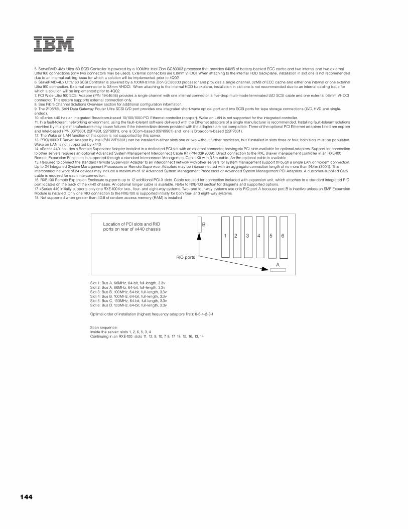
144
5. ServeRAID-4Mx Ultra160 SCSI Controller is powered by a 100MHz Intel Zion GC80303 processor that provides 64MB of battery-backed ECC cache and two internal and two external Ultra160 connections (only two connectors may be used). External connectors are 0.8mm VHDCI. When attaching to the internal HDD backplane, installation in slot one is not recommended due to an internal cabling issue for which a solution will be implemented prior to 4Q02.6. ServeRAID-4Lx Ultra160 SCSI Controller is powered by a 100MHz Intel Zion GC80303 processor and provides a single channel, 32MB of ECC cache and either one internal or one external Ultra160 connection. External connector is 0.8mm VHDCI. When attaching to the internal HDD backplane, installation in slot one is not recommended due to an internal cabling issue for which a solution will be implemented prior to 4Q02.7. PCI Wide Ultra160 SCSI Adapter (P/N 19K4646) provides a single channel with one internal connector, a five-drop multi-mode terminated LVD SCSI cable and one external 0.8mm VHDCI connector. This system supports external connection only.8. See Fibre Channel Solutions Overview section for additional configuration information.9. The 2108R3L SAN Data Gateway Router Ultra SCSI LVD port provides one integrated short-wave optical port and two SCSI ports for tape storage connections (LVD, HVD and single-ended).10. xSeries 440 has an integrated Broadcom-based 10/100/1000 PCI Ethernet controller (copper). Wake on LAN is not supported for the integrated controller.11. In a fault-tolerant networking environment, using the fault-tolerant software delivered with the Ethernet adapters of a single manufacturer is recommended. Installing fault-tolerant solutions provided by multiple manufacturers may cause failures if the intermediate drivers provided with the adapters are not compatible. Three of the optional PCI Ethernet adapters listed are copper and Intel-based (P/N 06P3601, 22P4901, 22P6801), one is 3Com-based (09N9901) and one is Broadcom-based (22P7801).12. The Wake on LAN function of this option is not supported by this server.13. PRO/1000XT Server Adapter by Intel (P/N 22P6801) can be installed in either slots one or two without further restriction, but if installed in slots three or four, both slots must be populated. Wake on LAN is not supported by x440.14. xSeries 440 includes a Remote Supervisor Adapter installed in a dedicated PCI slot with an external connector, leaving six PCI slots available for optional adapters. Support for connection to other servers requires an optional Advanced System Management Interconnect Cable Kit (P/N 03K9309). Direct connection to the RXE drawer management controller in an RXE-100 Remote Expansion Enclosure is supported through a standard Interconnect Management Cable Kit with 3.5m cable. An 8m optional cable is available. 15. Required to connect the standard Remote Supervisor Adapter to an interconnect network with other servers for system management support through a single LAN or modem connection. Up to 24 Integrated System Management Processors or Remote Supervisor Adapters may be interconnected with an aggregate connection length of no more than 91.4m (300ft). This interconnect network of 24 devices may include a maximum of 12 Advanced System Management Processors or Advanced System Management PCI Adapters. A customer-supplied Cat5 cable is required for each interconnection.16. RXE-100 Remote Expansion Enclosure supports up to 12 additional PCI-X slots. Cable required for connection included with expansion unit, which attaches to a standard integrated RIO port located on the back of the x440 chassis. An optional longer cable is available. Refer to RXE-100 section for diagrams and supported options.17. xSeries 440 initially supports only one RXE-100 for two-, four- and eight-way systems. Two- and four-way systems use only RIO port A because port B is inactive unless an SMP Expansion Module is installed. Only one RIO connection to the RXE-100 is supported initially for both four- and eight-way systems.18. Not supported when greater than 4GB of random access memory (RAM) is installed
Location of PCI slots and RIO ports on rear of x440 chassis
Slot 1: Bus A, 66MHz, 64-bit, full-length, 3.3vSlot 2: Bus A, 66MHz, 64-bit, full-length, 3.3v Slot 3: Bus B, 100MHz, 64-bit, full-length, 3.3v Slot 4: Bus B, 100MHz, 64-bit, full-length, 3.3v Slot 5: Bus C, 133MHz, 64-bit, full-length, 3.3vSlot 6: Bus D, 133MHz, 64-bit, full-length, 3.3v
Optimal order of installation (highest frequency adapters first): 6-5-4-2-3-1
Scan sequence:Inside the server: slots 1, 2, 6, 5, 3, 4Continuing in an RXE-100: slots 11, 12, 9, 10, 7, 8, 17, 18, 15, 16, 13, 14.
1 2 3 4 5 6
B
A
RIO ports

IBM
xS
eri
es 4
40
145For the latest product & technical information, refer to the Information Sources on pages 2 and 3.Updated 10/15/02
xSeries 440 Power, Monitors & Accessories
Part Number Description
Power1
Uninterruptible Power Supply (UPS)2, 3
32P1020 APC 2U Smart-UPS 1400RMB
94G6676 APC Smart-UPS 3000RMB4
37L6861 APC Smart-UPS 5000RMB5
Monitors6
633147N E54 Color Monitor 15in (350mm, 13.8in viewable image), stealth black7
63324HN E74 Color Monitor 17in (406mm, 16in viewable image), stealth black7
66274AN G78 Color Monitor 17in (406.4mm, 16in viewable image), stealth black7
32P1031 NetBAY 1U Flat Panel Monitor Console Kit (with US Space Saver Keyboard)8
32P1032 NetBAY 1U Flat Panel Monitor Console Kit (without keyboard)8
32P1702 NetBAY 2U Flat Panel Monitor Console Kit (with US Space Saver keyboard)8
32P1703 NetBAY 2U Flat Panel Monitor Console Kit (without keyboard)8
1. xSeries 440 systems include two 1050W, hot-swap power supplies with two 2.8m/9ft IEC 320-C13 toIEC 320-C14 power cables for intrarack power distribution. Models shipped in the US also include two 2.8m/9ft IEC 320-C13 to NEMA 6-15P power cords for attachment to high voltage power sources. Power supply redundancy is standard for all configurations with a high voltage power source. If a low voltage source is used, power supplies operate at 550w and redundancy is supported only for configurations with two processors. 2. For runtimes and UPS attributes see Appendix C: UPS Runtime Estimate.3. Because the x440 is not equipped with an external serial port, UPS remote management requires a USB to serial adapter such as the Belkin USB to Serial Adapter (P/N 10K3661), which is available at www.pc.ibm.com/ww/eserver/xseries. Select Accessories, Upgrades & Monitors and the country, then click Go. Scroll to the bottom of the page, select Cables and Adapters, then open the Adapters pulldown menu.4. Height is 3U. See Rack Cabinets and Options section for supported IBM racks.5. Height is 5U. See Rack Cabinets and Options section for supported IBM racks.6. xSeries 440 uses an SVGA controller (S3 Savage4 LT chipset) with 8MB of video memory Optional video adapters are not supported.7. Installation within a rack requires optional Monitor Compartment (P/N 94G7444).8. Includes a 15in Flat Panel Monitor.
Part Number Description
Stack Option
9306110 NetBAY11 Standard Rack Cabinet
Rack and NetBAY1
Refer to the Rack Cabinets and Options section for information concerning IBM racks and rack-supported devices.
Keyboard and Mouse2
28L3644 Space Saver II Keyboard3, 4
22P5150 TrackPoint USB Space Saver Keyboard3, 4, 6
10K3849 106-key Preferred USB Keyboard with 2-port USB Hub (stealth black)5, 6
28L3673 Sleek 2-Button Stealth Black Mouse
33L3244 Sleek USB Mouse (stealth black)6
1. xSeries 440 is housed in a 19in rack-mountable drawer and requires one of the racks listed in the Rack Cabinets and Options section.2. xSeries 440 supports rack configurations only and ships without a keyboard or mouse. The system includes three USB ports (one on front of chassis), SVGA video port, mouse port and keyboard port. 3. Installation within a rack requires optional keyboard tray (P/N 28L4707) which stows in ready-to-use position, or NetBAY 1U or 2U Flat Panel Monitor Console Kit (P/N 32P1032, 32P1702). Standard with 1U and 2U NetBAY console kits (P/N 32P1031, 32P1702).4. Advanced TrackPoint IV features are not available on IBM xSeries systems.5. Installation within a rack requires optional keyboard tray (P/N 28L4707). This keyboard cannot share a keyboard tray with a flat panel display.6. USB accessories attach to a single USB-capable server. They are not compatible with the NetBAY console switches.
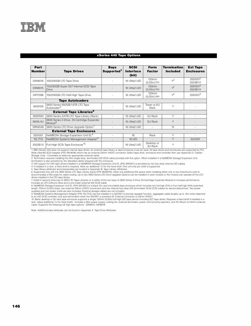
146
xSeries 440 Tape Options
Part Number Tape Drives
Bays Supported1
SCSI Interface
(bit)
Form Factor
Termination Included
Ext Tape Enclosures
00N8016 100/200GB LTO Tape Drive - 16 Ultra2 LVD 133mm (5.25in) FH Y2 35510013
3503B1X
00N8015 110/220GB Super DLT Internal SCSI Tape Drive - 16 Ultra2 LVD 133mm
(5.25in) FH Y2 35510013
3503B1X
24P2396 100/200GB LTO Half-High Tape Drive - 16 Ultra2 LVD 133mm (5.25in) HH Y2 35510013
Tape Autoloaders
3600109 3600 Series 900GB/1.8TB LTO Tape Autoloader4 - 16 Ultra2 LVD Tower or 6U
Rack Y -
External Tape Libraries5
3600R20 3600 Series 2/4TB LTO Tape Library (Rack) - 16 Ultra2 LVD 5U Rack Y -
3600LXU 3600 Series 2-Drive, 20-Cartridge Expander Module6 - 16 Ultra2 LVD 5U Rack Y -
09N4048 3600 Series LTO Drive Upgrade Option7 - 16 Ultra2 LVD - N -
External Tape Enclosures3551001 NetMEDIA Storage Expansion Unit EL8 - 16 Rack Y -10L7113 NetMEDIA Systems Management Adapter9 - 16 LVD - Y 3551001
3503B1X Full-High SCSI Tape Enclosure10 - 16 Ultra2 LVD Desktop or 3U Rack Y -
1. IBM xSeries 440 does not support internal tape drives. An external tape library or tape enclosure must be used. All tape drives and enclosures are supported by PCI Wide Ultra160 SCSI Adapter (P/N 19K4646) which has an external 0.8mm VHDCI connector. Select tape drive, enclosure and controller then use Appendix D: Cables - Storage Units - Controllers to select an appropriate external cable.2. Termination requires installing the 34in single-drop, terminated LVD SCSI cable provided with the option. When installed in a NetMEDIA Storage Expansion Unit, termination is also provided by the standard cables shipped with the enclosure.3. LVD support for LVD tape drives installed in a NetMEDIA Storage Expansion Unit EL (P/N 3551001) is provided by two four-drop internal LVD cables.4. If installed in a rack, a fixed shelf is required. Allow an additional 1U for the fixed shelf. One unit only per shelf is supported.5. Tape library attributes and prerequisites are located in Appendix B: Tape Library Attributes.6. Supported only with the 3600 Series LTO Tape Library (rack) (P/N 3600R20). Allow one additional EIA space when installing either one or two (maximum) units to accommodate a filler plate for cable routing. Up to two 3600 Series LTO Drive Upgrade Options can be installed in each module or the module can operate off the LTO drives installed in the LTO tape library.7. Install in second drive bay of 3600 LTO Tape Libraries or in either of the two bays of 3600 Series 2-Drive 20-Cartridge Expander Module to increase performance. Includes an LTO (Ultrium) drive and a one-meter external LVD SCSI cable.8. NetMEDIA Storage Expansion Unit EL (P/N 3551001) is a black 3U, rack-mountable tape enclosure which includes two full-high (FH) or four half-high (HH) extended length 133mm (5.25in) bays, two external 0.8mm VHDCI connectors and two internal four-drop LVD terminated 16-bit SCSI cables for device attachment. Two power supplies and two power cords are also included. External storage cables are not included.9. NetMEDIA Systems Management Adapter (P/N 10L7113) may be installed in a 3551001 to provide repeater function, aggregate cable lengths up to 12m when attached to an LVD SCSI controller, and auto-termination when the 3551001 is powered off. External connector is 0.8mm VHDCI.10. Black desktop or 3U rack tape enclosure supports a single 133mm (5.25in) full-high LVD tape device including DLT tape drives. Requires a fixed shelf if installed in a rack (allow additional 1U for fixed shelf). Includes a 90w power supply, cooling fan, external terminator, power cord (country-specific), and 2m 68-pin to 0.8mm external cable. Supports the following full-high tape options: 00N8015, 00N8016
Note: Additional tape attributes can be found in Appendix A: Tape Drive Attributes.

IBM
xS
eri
es 4
40
147For the latest product & technical information, refer to the Information Sources on pages 2 and 3.Updated 10/15/02
Note: The following sample configurations are for illustration only and may not be suitable for any specific customer installation. Contact your IBM Business Partner or IBM Marketing Representative for assistance with your specific configuration requirements.
Basic SCSI Configuration
High-availability SCSI Storage Solution1
xSeries 440 Sample Configurations
Part Number Description Quantity8687-1RX xSeries 440 2x1.4GHz/512KB xeon, 2GB ECC, open, 24X (4U rack) 106P5754 18.2GB 10Krpm Ultra160 SCSI Hot-swap SL HDD 206P5736 ServeRAID-4Mx Ultra160 SCSI Controller 11
633147N E54 Color Monitor 15in (350mm, 13.8in viewable image), stealth black 137L6861 APC Smart-UPS 5000RMB 1
External Storage35311RU EXP300 Storage Expansion Unit 206P5754 18.2GB 10Krpm Ultra160 SCSI Hot-swap SL HDD 62
Rack Options9306110 NetBAY11 Standard Rack Cabinet 128L3644 Space Saver II Keyboard 1
1. External connectors only can be used due to internal cabling restriction.2. Six HDDs are used for RAID-5E protection in each EXP300. One HDD is identified as a hot-spare. Effective capacity is five HDDs in the storage enclosure(total of 91GB).
Part Number Description Quantity8687-2RX xSeries 440 2x1.5GHz/512KB Xeon, 2GB ECC, open, 24X (4U rack) 132P8706 xSeries 1.5GHz/512KB L3 Cache with Xeon Processor MP 21
33L3324 512MB PC133 ECC SDRAM RDIMM 122
06P5767 18.2GB 15Krpm Ultra160 SCSI Hot-swap SL HDD 206P5736 ServeRAID-4Mx Ultra160 SCSI Controller 222P6801 PRO/1000XT Server Adapter by Intel (copper) w/CD, manuals 237L6861 APC Smart-UPS 5000RMB 1
External Storage35311RU EXP300 Storage Expansion Unit3 406P5767 18.2GB 15Krpm Ultra160 SCSI Hot-swap SL HDD 524
3551001 NetMEDIA Storage Expansion Unit EL 110L7113 NetMEDIA Systems Management Adapter 100N8016 100/200GB LTO Tape Drive 2
Rack Options9306420 NetBAY42 Standard Rack Cabinet 132P1031 NetBAY 1U Flat Panel Monitor Console Kit (w/ US Space Saver Keyboard) 194G6670 Blank Filler Panel Kit 1
1. Total of four processors.2. Total memory of 8GB.3. Cables for daisy-chaining EXP300s not included in this table.4. Thirteen HDDs are used for RAID-5E protection in each EXP300 (bay six remains empty in twintail high-availability EXP300 configurations). One HDD is identified as a hot-spare. Effective capacity is 12 HDDs in each storage enclosure (total of 946.4GB).

148
Microsoft Exchange High-availability Fibre Channel Solution
Refer to the IBM Datacenter Solutions section for xSeries 440 cluster solutions configured with Fibre Channel storage components and connections. Datacenter cluster solutions are also certified for Windows 2000 and NT 4.0 operating systems.
Part Number Description Quantity8687-3RX xSeries 440 2x1.6GHz/1MB Xeon, 2GB ECC, open, 24X (4U rack) 119K4647 xSeries 1.6GHz/1MB L3 Cache Upgrade with Xeon Processor MP 61
32P8340 xSeries SMP Expansion Module 133L3324 512MB PC133 ECC SDRAM RDIMM 282
06P5736 ServeRAID-4Mx Ultra160 SCSI Controller 106P5767 18.2GB 15Krpm Ultra160 SCSI Hot-swap SL HDD 23
22P6801 PRO/1000XT Server Adapter by Intel (copper) w/CD, manuals 124P0960 FC2-133 Host Bus Adapter 237L6861 APC Smart-UPS 5000RMB 194G6676 APC Smart-UPS 3000RMB 1
External Storage17421RU FAStT700 Storage Server 14
35601RU FAStT EXP500 Storage Expansion Unit 406P5707 Netfinity 18.2GB 15Krpm FC Hot-Swap HDD 403600109 3600 Series 900GB/1.8TB LTO Tape Autoloader 1
Rack Options9306420 NetBAY42 Standard Rack Cabinet 132P1031 NetBAY 1U Flat Panel Monitor Console Kit (w/ US Space Saver Keyboard) 194G6670 Blank Filler Panel Kit 1
1. Total of eight processors (four per SMP Expansion Module).2. Total memory of 16GB.3. Total of two 18.2GB internal HDDs for NOS mirroring attached to a ServeRAID adapter.4. Fibre Channel cable, SFP Modules and FAStT700 Mini Hubs not included.

IBM
xS
eri
es 4
40
149For the latest product & technical information, refer to the Information Sources on pages 2 and 3.Updated 10/15/02

IBM RXE-100
EMEA Part Number Cross ReferenceRXE-100 System Unit Part Numbers
EMEA AMERICAS M/C TYPE DESCRIPTION EMEAP/N P/N MODEL WDFM DATE
86841RX 86841RX 8684-1RX RXE-100 Remote Expansion Enclosure ---
RXE-100 Hard Disk Drive Storage Part NumbersEMEA AMERICAS M/C TYPE DESCRIPTION EMEA
P/N P/N MODEL WDFM DATENotes 1&2 19K11xx 35311RU --- EXP300 Storage Expansion Unit ---Notes 3&2 00N71xx 35601RU --- FAStT EXP500 Storage Expansion Unit ---Notes 4&2 19K11xx 35421RU --- FAStT 200 Storage Server ---Notes 5&2 19K11xx 35422RU --- FAStT 200 HA Storage Server ---
1. Where ‘xx’ represents a specific country code as follows: 51=US/English, 52=European/English, 56=Danish/English, 57=Israel/English, 58=Italian/English, 59=South Africa/English, 60=Swiss/English, 63=UK/English.2. This unit does not include Rack Power Cables P/N 94G7448 when shipped (for attachment to highvoltage UPS or PDU). Standard country power cords only are included. If required, order one Rack PowerCable for each power supply.3. Where ‘xx’ represents a specific country code as follows:- 36=US/English, 37=Euro/English, 41=Denmark/English, 42=Israel/English, 43=Italy/English, 44=South Africa/English, 45=Switzerland/English, 49=UK/English.4. Where ‘xx’ represents a specific country code as follows:- 23=US/English, 24=Euro/English, 25=Euro/Spanish, 27=Euro/German, 28=Denmark/English, 29=Israel/English, 30=Italy/English, 31=South Africa/English, 32=Switzerland/English, 34=Switzerland/German, 36=UK/English..5. Where ‘xx’ represents a specific country code as follows:- 37=US/English, 38=Euro/English, 39=Euro/Spanish, 41=Euro/German, 42=Denmark/English, 43=Israel/English, 44=Italy/English, 45=South Africa/English, 46=Switzerland/English, 48=Switzerland/German, 50=UK/English.
Note 6 RXE-100 Power, Monitors & AccessoriesEMEA AMERICAS M/C TYPE DESCRIPTION EMEA
P/N P/N MODEL POWER WDFM DATEN/A 31P6108 --- 370W Hot-Swap Redundant Power Supply N/A
Note 7 32P16xx 32P1020 --- APC 2U Smart-UPS 1400RMiB ---Note 8 30RIxxx 94G6676 --- APC Smart-UPS 3000RMiB ---
37L6862 37L6861 --- APC Smart-UPS 5000RMiB ---
6. The RXE-100 Remote Expansion Enclosure ships with two Rack Power cords for connection to a high voltage UPS or PDU.
7. Where ‘xx’ represents a specific country code as follows:- 12=Europe, 13=UK, 14=Italy, 15=Switzerland, 16=Denmark, 17=South Africa, 18=Israel.
8. Where ‘xxx’ represents a specific country code as follows:- DEN=Denmark, ISR=Israel, ITA=Italy, SDI=Saudi Arabia, SAF=South Africa, SWS=Switzerland, UKM=United Kingdom, EUR=Europe.
149A Updated 10/15/02

IBM RXE-100
EMEA Part Number Cross Reference
RXE-100 Tape OptionsEMEA AMERICAS M/C TYPE DESCRIPTION EMEA
P/N P/N MODEL WDFM DATENote 9 09N40xx 3600109 --- 3600 Series 900GB/1.8TB LTO Tape Autoloader ---
N/A 3570C2x --- Magstar MP 3570 Tape Subsystem N/ANote 10 21P99xx 3600R20 --- 3600 Series 2/4TB LTO Tape Library (Rack) ---Note 11 21P99xx 3600LXU --- 3600 Series 2-drive 20-cartridge Expander Module ---Note 12 24P24xx 3503B1X --- Full-High SCSI Tape Enclosure ---
03K8756 3551001 --- NetMEDIA Storage Expansion Unit EL ---
9. Where ‘xx’ represents a specific country code as follows:- 49=UK, 50=Europe, 51=Denmark, 52=South Africa, 53=Switzerland, 54=Italy, 55=Israel.
10. Where ‘xx’ represents a specific country code as follows:- Rack version - 78=Europe, 79=Denmark, 80=South Africa, 77=UK,81=Swiss, 82=Italy, 83=Israel.11. Where ‘xx’ represents a specific country code as follows:- 85=Europe, 86=Denmark, 87=South Africa, 84=UK, 88=Swiss, 89=Italy, 90=Israel.
12. Where ‘xx’ represents a country specific code: 35=UK, 39=Swiss, 40=Italy, 41=Israel, 36=EU, 37=Denmark, 38=South Africa.
Updated 10/15/02 149B

150
IBM RXE-100 Remote Expansion Enclosure
RXE-100 Remote Expansion Enclosure At-A-Clance
8684-1RX1 Rack (3U) 2/2 P, S, F S - FansS - Power2 Y3 6/64 6/65
1. Housed in a 19in rack-mountable drawer. See Rack Cabinets and Options section for supported IBM racks. Ships with one 3.5m Remote I/O Cable Kit (P/N 31P6102) and one 3.5m Interconnect Management Cable Kit (P/N 31P6087). Eight-meter cables are available as options (P/N 31P6103, 31P6088).2. N+1 power supply redundancy is provided standard.Two 370W Hot-Swap Redundant Power Supplies (P/N 31P6108) ship installed in the RXE-100.3. RXE-100 management controller interfaces with Remote Supervisor Adapter standard in xSeries 360 using the standard 3.5m Interconnect Management Cable Kit (P/N 31P6087) or the 8m option (P/N 31P6088).4. RXE-100 ships with six full-length, 64-bit PCI-X slots supporting three 133MHz adapters or six 100MHz adapters. Adapters rated at 33 or 66MHz restrict PCI buses in which they are installed to the frequency of the slowest adapter. 5. Support for additional six 64-bit slots available through installation of the optional Remote I/O PCI-X 6-slot Expansion Kit (P/N 31P5998). Remote I/O connection is cabled internally within the RXE-100 enclosure using the secondary connector on each PCI-X 6-slot Expansion Kit, i.e., only one connection between the server and RXE-100 is required. Although the six slots arehot-swap, the expansion kit itself is not hot-swap.
Part Number
Form Factor
Power Supply Quantit
y (Std/M
ax)
Hot-Swap (P
ower, Slots, H
DD, Fans)
Redundancy (Optio
nal, Standard)
System Management C
ontrolle
r
Standard Slots (Total/A
vail)
Optional S
lots (Total/A
vail)

IBM
RX
E-1
00
151For the latest product & technical information, refer to the Information Sources on pages 2 and 3.Updated 10/15/02
RXE-100 Remote Expansion Enclosure External HDD Storage
Part Number
External Storage Expansion Units1
Form Factor
35311RU EXP300 Storage Expansion Unit2 Rack (3U)
35601RU FAStT EXP500 Storage Expansion Unit3 Rack (3U)
35421RU FAStT200 Storage Server4, 5 Rack (3U)
35422RU FAStT200 HA Storage Server4 Rack (3U)
19K1121 FAStT200 Redundant RAID Controller -
Remote I/O PCI-X 6-slot Expansion Kit
Six-pack B
Remote I/O PCI-X 6-slot Expansion Kit
Six-pack A(standard)
Fans
Fans
power supply
power supply
(rear)
(front)
primary RIO connections (external) and DMC ports(RS-485 bus)
secondary RIO connections
RXE-100 Remote Expansion Enclosure
P/N 8684-1RXtop view
• Rack-mounted 3U enclosure that fits standard IBM racks.• Contains six active PCI-X adapter slots with support for six optional slots (6-slot expansion kits are not hot-swap).• Supports three 133MHz or six 100MHz adapters (backward compatible to 33 or 66MHz adapters).• Interfaces directly to the host server memory controller.• Interfaces with Remote Supervisor Adapter in the host server (jumper cable provided with Remote I/O PCI-X 6-slot Expansion Kit to connect second six-pack to the system management bus).• Hot-swap redundancy for fans and power supplies (two 370W power supplies and four cooling fans).
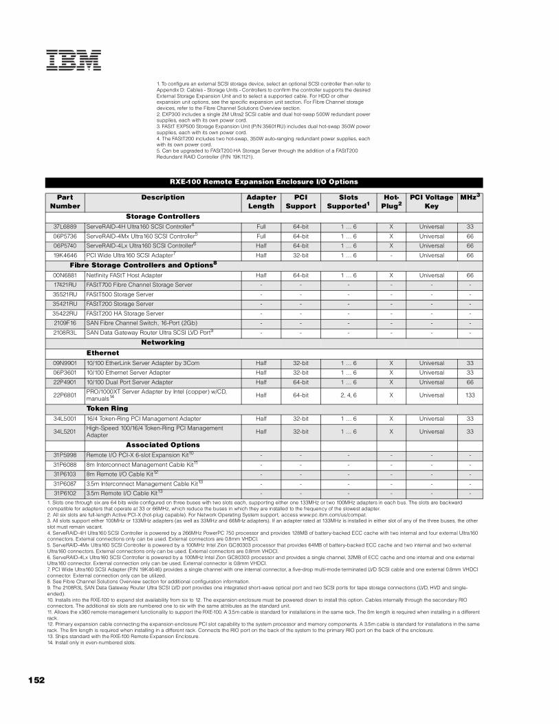
152
1. To configure an external SCSI storage device, select an optional SCSI controller then refer to Appendix D: Cables - Storage Units - Controllers to confirm the controller supports the desired External Storage Expansion Unit and to select a supported cable. For HDD or other expansion unit options, see the specific expansion unit section. For Fibre Channel storage devices, refer to the Fibre Channel Solutions Overview section.2. EXP300 includes a single 2M Ultra2 SCSI cable and dual hot-swap 500W redundant power supplies, each with its own power cord.3. FAStT EXP500 Storage Expansion Unit (P/N 35601RU) includes dual hot-swap 350W power supplies, each with its own power cord.4. The FAStT200 includes two hot-swap, 350W auto-ranging redundant power supplies, each with its own power cord.5. Can be upgraded to FAStT200 HA Storage Server through the addition of a FAStT200 Redundant RAID Controller (P/N 19K1121).
RXE-100 Remote Expansion Enclosure I/O Options
Part Number
Description Adapter Length
PCI Support
Slots Supported1
Hot-Plug2
PCI Voltage Key
MHz3
Storage Controllers37L6889 ServeRAID-4H Ultra160 SCSI Controller4 Full 64-bit 1 ... 6 X Universal 33
06P5736 ServeRAID-4Mx Ultra160 SCSI Controller5 Full 64-bit 1 ... 6 X Universal 66
06P5740 ServeRAID-4Lx Ultra160 SCSI Controller6 Half 64-bit 1 ... 6 X Universal 66
19K4646 PCI Wide Ultra160 SCSI Adapter7 Half 32-bit 1 ... 6 - Universal 66
Fibre Storage Controllers and Options8
00N6881 Netfinity FAStT Host Adapter Half 64-bit 1 ... 6 X Universal 66
17421RU FAStT700 Fibre Channel Storage Server - - - - - -
35521RU FAStT500 Storage Server - - - - - -
35421RU FAStT200 Storage Server - - - - - -
35422RU FAStT200 HA Storage Server - - - - - -
2109F16 SAN Fibre Channel Switch, 16-Port (2Gb) - - - - - -
2108R3L SAN Data Gateway Router Ultra SCSI LVD Port9 - - - - - -
NetworkingEthernet
09N9901 10/100 EtherLink Server Adapter by 3Com Half 32-bit 1 ... 6 X Universal 33
06P3601 10/100 Ethernet Server Adapter Half 32-bit 1 ... 6 X Universal 33
22P4901 10/100 Dual Port Server Adapter Half 64-bit 1 ... 6 X Universal 66
22P6801 PRO/1000XT Server Adapter by Intel (copper) w/CD, manuals14 Half 64-bit 2, 4, 6 X Universal 133
Token Ring34L5001 16/4 Token-Ring PCI Management Adapter Half 32-bit 1 ... 6 X Universal 33
34L5201 High-Speed 100/16/4 Token-Ring PCI Management Adapter Half 32-bit 1 ... 6 X Universal 33
Associated Options31P5998 Remote I/O PCI-X 6-slot Expansion Kit10 - - - - - -
31P6088 8m Interconnect Management Cable Kit11 - - - - - -
31P6103 8m Remote I/O Cable Kit12 - - - - - -
31P6087 3.5m Interconnect Management Cable Kit13 - - - - - -
31P6102 3.5m Remote I/O Cable Kit13 - - - - - -
1. Slots one through six are 64 bits wide configured on three buses with two slots each, supporting either one 133MHz or two 100MHz adapters in each bus. The slots are backward compatible for adapters that operate at 33 or 66MHz, which reduce the buses in which they are installed to the frequency of the slowest adapter.2. All six slots are full-length Active PCI-X (hot-plug capable). For Network Operating System support, access www.pc.ibm.com/us/compat.3. All slots support either 100MHz or 133MHz adapters (as well as 33MHz and 66MHz adapters). If an adapter rated at 133MHz is installed in either slot of any of the three buses, the other slot must remain vacant.4. ServeRAID-4H Ultra160 SCSI Controller is powered by a 266MHz PowerPC 750 processor and provides 128MB of battery-backed ECC cache with two internal and four external Ultra160 connectors. External connections only can be used. External connectors are 0.8mm VHDCI.5. ServeRAID-4Mx Ultra160 SCSI Controller is powered by a 100MHz Intel Zion GC80303 processor that provides 64MB of battery-backed ECC cache and two internal and two external Ultra160 connectors. External connections only can be used. External connectors are 0.8mm VHDCI.6. ServeRAID-4Lx Ultra160 SCSI Controller is powered by a 100MHz Intel Zion GC80303 processor and provides a single channel, 32MB of ECC cache and one internal and one external Ultra160 connector. External connection only can be used. External connector is 0.8mm VHDCI.7. PCI Wide Ultra160 SCSI Adapter (P/N 19K4646) provides a single channel with one internal connector, a five-drop multi-mode terminated LVD SCSI cable and one external 0.8mm VHDCI connector. External connection only can be utilized.8. See Fibre Channel Solutions Overview section for additional configuration information.9. The 2108R3L SAN Data Gateway Router Ultra SCSI LVD port provides one integrated short-wave optical port and two SCSI ports for tape storage connections (LVD, HVD and single-ended).10. Installs into the RXE-100 to expand slot availability from six to 12. The expansion enclosure must be powered down to install this option. Cables internally through the secondary RIO connectors. The additional six slots are numbered one to six with the same attributes as the standard unit.11. Allows the x360 remote management functionality to support the RXE-100. A 3.5m cable is standard for installations in the same rack. The 8m length is required when installing in a different rack.12. Primary expansion cable connecting the expansion enclosure PCI slot capability to the system processor and memory components. A 3.5m cable is standard for installations in the same rack. The 8m length is required when installing in a different rack. Connects the RIO port on the back of the system to the primary RIO port on the back of the enclosure.13. Ships standard with the RXE-100 Remote Expansion Enclosure.14. Install only in even-numbered slots.

IBM
RX
E-1
00
153For the latest product & technical information, refer to the Information Sources on pages 2 and 3.Updated 10/15/02
RXE-100 Remote Expansion Enclosure Power
Part Number Description
Power1
31P6108 370W Hot-Swap Redundant Power Supply
Uninterruptible Power Supply (UPS)2
32P1020 APC 2U Smart-UPS 1400RMB
94G6676 APC Smart-UPS 3000RMB3
37L6861 APC Smart-UPS 5000RMB4
1. RXE-100 includes two 370W hot-swap power supplies, each with two 9ft power cords--one high voltage IEC 320-C13 to IEC 320-C14 and one low voltage IEC 320-C13 to NEMA 5-15P. N+1 power supply redundancy is standard for full configurations. A third power supply is not supported.2. For runtimes and UPS attributes see Appendix C: UPS Runtime Estimate.3. Height is 3U. See Rack Cabinets and Options section for supported IBM racks.4. Height is 5U. See Rack Cabinets and Options section for supported IBM racks.
RXE-100 Remote Expansion Enclosure Tape Options
Part Number Tape Drives
Bays Supported1
SCSI Interface
(bit)
Form Factor
Termination Included
Ext Tape Enclosures
00N8016 100/200GB LTO Tape Drive - 16 Ultra2 LVD 133mm (5.25in) FH Y2 35510013
3503B1X
00N8015 110/220GB Super DLT Internal SCSI Tape Drive - 16 Ultra2 LVD 133mm
(5.25in) FH Y2 35510013
3503B1X
24P2396 100/200GB LTO Half-High Tape Drive - 16 Ultra2 LVD 133mm (5.25in) HH Y2 35510013
Tape Autoloaders
3600109 3600 Series 900GB/1.8TB LTO Tape Autoloader4 - 16 Ultra2 LVD Tower or 6U
Rack Y -
External Tape Libraries5
3570C2x Magstar MP 3570 Tape Subsystem - HVD 6U Rack Y -3600R20 3600 Series 2/4TB LTO Tape Library (Rack) - 16 Ultra2 LVD 5U Rack Y -
3600LXU 3600 Series 2-Drive, 20-Cartridge Expander Module6 - 16 Ultra2 LVD 5U Rack Y -
09N4048 3600 Series LTO Drive Upgrade Option7 - 16 Ultra2 LVD - N -
External Tape Enclosures3551001 NetMEDIA Storage Expansion Unit EL8 - 16 Rack Y -10L7113 NetMEDIA Systems Management Adapter9 - 16 LVD - Y 3551001
3503B1X Full-High SCSI Tape Enclosure10 - 16 Ultra2 LVD Desktop or 3U Rack Y -
Bus 3: PCIX Slot 1, 3.3V
Bus 1: PCIX Slot 6, 3.3V
Bus 3: PCIX Slot 2, 3.3V
Bus 1: PCIX Slot 5, 3.3V
Bus 2: PCIX Slot 4, 3.3V
Bus 2: PCIX Slot 3, 3.3V
All slots are 64-bit, full-length, 133MHz Active PCI-X. Each bus supports only one 133MHz adapter. If two 133MHz adapters are installed, both will operate at 100MHz. If a lower frequency adapter is installed, the bus will operate at that frequency.
Scan sequence: slots 11, 12, 9, 10, 7, 8, 17, 18, 15, 16, 13, 14.

154
1. RXE-100 does not support internal tape drives. An external tape library or tape enclosure must be used. All tape drives and enclosures are supported by PCI Wide Ultra160 SCSI Adapter (P/N 19K4646) which has an external 0.8mm VHDCI connector. Select tape drive, enclosure and controller then use Appendix D: Cables - Storage Units - Controllers to select an appropriate external cable.2. Termination requires installing the 34in single-drop, terminated LVD SCSI cable provided with the option. When installed in a NetMEDIA Storage Expansion Unit, termination is also provided by the standard cables shipped with the enclosure.3. LVD support for LVD tape drives installed in a NetMEDIA Storage Expansion Unit EL (P/N 3551001) is provided by two four-drop internal LVD cables.4. If installed in a rack, a fixed shelf is required. Allow an additional 1U for the fixed shelf. One unit only per shelf is supported.5. Tape library attributes and prerequisites are located in Appendix B: Tape Library Attributes.6. Supported only with the 3600 Series LTO Tape Library (rack) (P/N 3600R20). Allow one additional EIA space when installing either one or two (maximum) units to accommodate a filler plate for cable routing. Up to two 3600 Series LTO Drive Upgrade Options can be installed in each module or the module can operate off the LTO drives installed in the LTO tape library.7. Install in second drive bay of 3600 LTO Tape Libraries or in either of the two bays of 3600 Series 2-Drive 20-Cartridge Expander Module to increase performance. Includes an LTO (Ultrium) drive and a one-meter external LVD SCSI cable.8. NetMEDIA Storage Expansion Unit EL (P/N 3551001) is a black 3U, rack-mountable tape enclosure which includes two full-high (FH) or four half-high (HH) extended length 133mm (5.25in) bays, two external 0.8mm VHDCI connectors and two internal four-drop LVD terminated 16-bit SCSI cables for device attachment. Two power supplies and two power cords are also included. External storage cables are not included.9. NetMEDIA Systems Management Adapter (P/N 10L7113) may be installed in a 3551001 to provide repeater function, aggregate cable lengths up to 12m when attached to an LVD SCSI controller, and auto-termination when the 3551001 is powered off. External connector is 0.8mm VHDCI.10. Black desktop or 3U rack tape enclosure supports a single 133mm (5.25in) full-high LVD tape device including DLT tape drives. Requires a fixed shelf if installed in a rack (allow additional 1U for fixed shelf). Includes a 90w power supply, cooling fan, external terminator, power cord (country-specific), and 2m 68-pin to 0.8mm external cable. Supports the following full-high tape options: 00N8015, 00N8016

IBM
RX
E-1
00
155For the latest product & technical information, refer to the Information Sources on pages 2 and 3.Updated 10/15/02

BladeCenter
EMEA Part Number Cross ReferenceNote: This section contains all the valid part numbers for EMEA - for standard (non-CTO) ordering.
BladeCenter Part NumbersEMEA AMERICAS M/C TYPE DESCRIPTION EMEA
P/N P/N MODEL WDFM DATET71XXxx 86771XX 8677-1XX BladeCenter ---
T821Xxx 867821X 8678-21X BladeCenter HS20 ---T841Xxx 867841X 8678-41X BladeCenter HS20 ---
BladeCenter Option Part NumbersEMEA AMERICAS M/C TYPE DESCRIPTION EMEA
P/N P/N MODEL WDFM DATE48P7054 48P7054 --- BladeCenter 4-port GB Ethernet switch module ---48P7062 48P7062 --- BladeCenter 2-port Fibre Channel switch module ---48P7052 48P7052 --- BladeCenter 1200W power supply module ---
48P7060 48P7060 --- 2.0GHz/400MHz Xeon DP Processor ---48P7096 48P7096 --- 2.4GHz/400MHz Xeon DP Processor ---33L5037 33L5037 --- 256MB PC2100 ECC DDR SDRAM RDIMM ---33L5038 33L5038 --- 512MB PC2100 ECC DDR SDRAM RDIMM ---33L5039 33L5039 --- 1GB PC2100 ECC DDR SDRAM RDIMM ---48P7063 48P7063 --- HS20 40GB EIDE Hard Disk Drive ---48P7058 48P7058 --- HS20 SCSI Storage Expansion Unit ---06P5754 06P5754 --- 18.2GB 10Krpm SCSI U160 HDD ---06P5755 06P5755 --- 36.4GB 10Krpm SCSI U160 HDD ---06P5756 06P5756 --- 73.4GB 10Krpm SCSI U160 HDD ---06P5767 06P5767 --- 18.2GB 15Krpm SCSI U160 HDD ---06P5768 06P5768 --- 36.4GB 15Krpm SCSI U160 HDD ---06P5776 06P5776 --- 36.4GB 15Krpm SCSI U320 HDD ---48P7061 48P7061 --- HS20 Fibre Channel Expansion Card ---
BladeCenter Storage and Communication ExpansionEMEA AMERICAS M/C TYPE DESCRIPTION EMEA
P/N P/N MODEL WDFM DATENote 1 19K11xx 35421RU --- FAStT 200 Storage Server ---Note 2 19K11xx 35422RU --- FAStT 200 HA Storage Server ---Note 3 00N69xx 35521RU --- FAStT500 Storage Server ---Note 4 24P09xx 17421RU --- FAStT700 Storage Server ---
35L1647 35341RU --- SAN Fibre Channel Managed Hub ---2108R3L 2108R3L --- SAN Data Gateway Router UltraSCSI LVD port ---
Note 5 00N71xx 35601RU --- FAStT EXP500 Storage Expansion Unit ---Note 6 24P09xx 17401RU --- FAStT EXP700 Storage Expansion Unit ---Note 7 00N79xx 360716X --- 3607 Series 1760GB/3.5TB SDLT pro Tape Autoloade ---
1. Where ‘xx’ represents a specific country code as follows:- 23=US/English, 24=Euro/English, 25=Euro/Spanish, 27=Euro/German, 28=Denmark/English, 29=Israel/English, 30=Italy/English, 31=South Africa/English, 32=Switzerland/English, 34=Switzerland/German, 36=UK/English..2. Where ‘xx’ represents a specific country code as follows:- 37=US/English, 38=Euro/English, 39=Euro/Spanish, 41=Euro/German, 42=Denmark/English, 43=Israel/English, 44=Italy/English, 45=South Africa/English, 46=Switzerland/English, 48=Switzerland/German, 50=UK/English.
3. Where ‘xx’ represents a specific country code as follows:- 13=US/English, 14=Euro/English, 18=Denmark/English, 19=Israel/English, 20=Italy/English, 21=South Africa/English, 22=Switzerland/English, 26=UK/English.4. Where ‘xx’ represents a specific country code as follows:- 14=Euro/English, 18=Denmark/English, 19=Israel/English, 20=Italy/English, 21=South Africa/English, 22=Switzerland/English, 25=UK/English.
5. Where ‘xx’ represents a specific country code as follows:- 36=US/English, 37=Euro/English, 41=Denmark/English, 42=Israel/English, 43=Italy/English, 44=South Africa/English, 45=Switzerland/English, 49=UK/English.
6. Where ‘xx’ represents a specific country code as follows:- 01=Eur/English, 02=Eur/Spanish, 05=Denmark/English, 06=Israel/English, 07=Italy/English, 08=South Africa/English, 09=Switzerland/English, 12=UK/English.
7. Where ‘xx’ represents a country specific power cord code: Tower versions - 74=EU1, 75=Denmark, 76=India/South Africa, 77=UK, 78=Swiss, 79=Italy, 80=Israel: Rack versions - 81=EU1, 82=Denmark, 83=India/South Africa, 84=UK, 85=Swiss, 86=Italy,87=Israel.
155A Updated 10/15/02

BladeCenter
EMEA Part Number Cross Reference
BladeCenter Power, Monitors, AccessoriesEMEA AMERICAS M/C TYPE DESCRIPTION EMEA
P/N P/N MODEL WDFM DATE48P7052 48P7052 --- BladeCenter 1200W power supply module ---37L6862 37L6861 --- APC Smart-UPS 5000RMiB ---
Note 8 T3147xx 633147N 6331-47N E54 15" (13.8" viewable image) Colour Monitor (S/Blac ---Note 8 T3247xx 63324HN 6332-4HN E74 17" (16" viewable image) Colour Monitor (S/Black) ---Note 8 T274Axx 66274AN 6627-4AN G78 17" (16" viewable image) Colour Monitor (S/Black ---
N/A 32P1031 --- NetBAY 1U Flat Panel Monitor Console Kit (with US ke N/A32P1032 32P1032 --- NetBAY 1U Flat Panel Monitor Console Kit (w/o keybo ---
N/A 32P1702 --- NetBAY 2U Flat Panel Monitor Console Kit (with US ke N/A32P1703 32P1703 --- NetBAY 2U Flat Panel Monitor Console Kit (w/o keybo ---1735L04 1735L04 --- NetBAY Local Console Manager ---1735R16 1735R16 --- NetBAY Remote Console Manager ---32P1636 32P1636 --- 250mm KVM Conversion Option ---32P1652 32P1652 --- 1.5M KVM Conversion Option ---49P2694 49P2694 --- BladeCenter acoustic attenuation module ---
Note 9 28L36xx 28L3644 --- Spacesaver II Keyboard ---Note 10 31P74xx 31P7415 --- Preferred Pro Full-Size Keyboard - 104 keys (S/Black) ---
28L3675 28L3673 --- Sleek 2-button Mouse (S/Black) ---8. Where ‘xx’ represents a specific country code as follows: DK=Denmark, IS=Israel, IT=Italy, SD=Saudi Arabia, SA=South Africa/Pakistan, CH=Switzerland, UK=UK, EU=Europe.
9. Where ‘xx’ represents a specific country code as follows:- 46=Danish , 47=French, 48=German, 49=Italian, 50=Spanish, 51=UK English, 44=US English, and P/N 19K3831=Swiss, 19K3832=Swedish/Finnish, 19K3833=Portugese, 19K3834=Belgian,19K3836=Russian, 19K3837=Polish.
10. Where ‘xx’ represents a specific country code as follows:- 16=Arabia, 17=Belg/Fre, 18=Belg/UK, 19=Bulgaria, 21=CzechRepublic, P/N 31P8767=Czech/US, 22=Denmark, 23=Netherlands, 24=France, 27=Germany, 28=Greece, 29=Israel, 30=Hungary, 31=Iceland, 32=Italy, P/N 31P8250=Italian 141, 36=Norway, 37=Poland, 38=Portugal, 39=Romania, 40=Russia, 41=Rus/Cyrillic, 42=Serb/Cyrillic, 43=Slovak, 44=Spanish, 45=Sweden/Finland, 46=Switzerland, 48=Turkey 440, 49=Turkey 179, 50=UK English, 51=US/Euro, 52=Yugoslavia/La
Updated 10/15/02 155B

156
BladeCenter™
BladeCenter™ At-A-Glance
8677-1XX Rack (7U)1 2/42 P, B3, B S-Blowers
S-Power 1/14 10/100/10005 4/4 24x-10x
USB1.44MB
USB 14/14 0/06 49P2654
Notes:A fully configured eServer BladeCenter™ chassis doubles the density of 14 equally configured 1U xSeries 335 servers by accommodating up to 14 BladeCenter HS20 units installed in a 7U rack space.
BladeCenter™ increases usability and reduces complexity because it provides common sourcing for up to 14 BladeCenter HS20 units for cabling and cabling connections, I/O options, power modules, system management requirements (optional adapters and external cabling), external Fibre Channel storage switching and connectivity, and network management and expansion.
1. Housed in a 7U, 19in rack-mountable chassis (28in deep). See Rack Cabinets and Options section for supported IBM racks.2. N+N power supply redundancy is provided standard for HS20 bays one through six and all module bays. Two 220v BladeCenter 1200w Power Modules ship installed in BladeCenter power module bays one and two. Redundant power for bays seven through 14 requires two additional power modules installed in power module bays three and four, which are both provided in optional BladeCenter 1200w Power Supply Modules (P/N 48P7052). Nonredundant power can be supplied to all 14 bays by moving power module two from the second bay to the third, which is not recommended.3. The blade bays in the front of the chassis support hot-swapping of blade servers. A spring-action cover closes the bay opening when the blade server is removed, allowing the blade to be removed for up to two hours before thermal restrictions require replacement..4. Comprehensive system management functionality is provided through the standard management module installed in management module bay one, which communicates with the integrated service processor on each HS20 planar. The management module also acts as a multiplexor for installed HS20 units for console connectivity (keyboard, video and mouse).5. One of the dual integrated gigabit Ethernet controllers on each HS20 planar connects to an optional BladeCenter 4-port Gigabit Ethernet Switch Module (P/N 48P7054) installed in switch module bay one. An additional Ethernet switch module may be installed in switch module bay two, to which the second Ethernet controller integrated into each HS20 planar is connected. Ethernet capability is not provided standard in BladeCenter.6. BladeCenter contains no PCI expansion slots or HDD bays. Internal HDD expansion is provided in the individual HS20 units. Standard I/O support includes system management, KVM (console) and Ethernet connectivity. Expanded I/O functionality is provided through optional Fibre Channel switch modules that install into the BladeCenter chassis. System management functionality is controlled by a system management module, which also installs into the rear system chassis. Expansion switch modules may not be mixed in a BladeCenter configuration because all HS20 units installed in a single BladeCenter must contain either the same kind of expansion card or no expansion card. (If an expansion card is installed, only one IDE HDD is allowed.)7. IBM offers configure-to-order (CTO) capability for selected products through Easy Access. Although similar to machine type models (MTM), CTO systems utilize different part numbers called Sales Building Blocks (SBB). The contents of an option may not entirely correspond to an SBB because only a certain component within an option package may be required to configure a specific system. Additional or different configuration rules or limitations may apply to the SBB. When a difference occurs, the rules will be documented in the tables, diagrams or footnotes.
Option Part
Number
Form Factor
Power Module Quantity
(Std/M
ax)
Hot-swap (P
ower, Bays, B
lowers)
Redundancy (Optio
nal, Standard)
System Management M
odule (Std/M
ax)
Integrated Ethernet
Switch M
odule Bays (Total/A
vail)
CD-ROM
Floppy Disk Drive
Blade Bays (Total/A
vail)
PCI Slots / H
DD Bays (Total/A
vail)
SBB Number (Easy Access only)7
Acoustic Attenuation Module
REAR VIEW
Blades (HS20)
Filler blades
FRONT VIEW
SCSI Storage Expansion Unit(attached to blade in bay 5)
Blade controlpanel
Media tray(removable)
CD-ROMFDD

157For the latest product & technical information, refer to the Information Sources on pages 2 and 3.Updated 10/15/02
Bla
de
Ce
nte
r
BladeCenter™ Sales Building Blocks
SBB Number
Option Part Number SBB Description Rules
Selectable HardwareSelect one power cord. An identical power cord will be derived in Easy Access for each power supply installed (total quantities of
two or four).
24P2605 - Rack Power Cable - 2.8m, 100-240v, C13 to IEC 320-C14 (WW) Two cables ship with MTM. Two additional are provided with the MTM power supply option, which includes two power supplies.
32P9071 - Rack Power Cable - 4.3m, 100-240v, C13 to IEC 320-C14 (WW) Optional for CTO. Power cords for all power supplies must match.
32P9072 - Line cord - 2.8m, 200-240v, C13 to NEMA 6-15P (US) Optional for CTO. Power cords for all power supplies must match.
32P9073 - Line cord - 1.8m, 200-240v, C13 to NEMA 6-15P (US) Optional for CTO. Power cords for all power supplies must match.
21P9459 - Line cord - 2.8m, 200-240v, C13 to GB 2099.1 (China) Optional for CTO. Power cords for all power supplies must match.
21P9452 - Line cord - 2.8m, 200-240v, C13 to AS/NZ 3112 (Australia/NZ) Optional for CTO. Power cords for all power supplies must match.
21P9454 - Line cord - 2.8m, 200-240v, C13 to CEE7-VII (European) Optional for CTO. Power cords for all power supplies must match.
21P9456 - Line cord - 2.8m, 200-240v, C13 to DK2-5a (Denmark) Optional for CTO. Power cords for all power supplies must match.
21P9461 - Line cord - 2.8m, 200-240v, C13 to SABS 164 (S Africa/India) Optional for CTO. Power cords for all power supplies must match.
21P9455 - Line cord - 2.8m, 200-240v, C13 to BS 1363/A (UK) Optional for CTO. Power cords for all power supplies must match.
21P9462 - Line cord - 2.8m, 200-240v, C13 to SEV 1011-S24507 (Swiss) Optional for CTO. Power cords for all power supplies must match.
21P9457 - Line cord - 2.8m, 200-240v, C13 to CEI 23-16 (Italy) Optional for CTO. Power cords for all power supplies must match.
21P9460 - Line cord - 2.8m, 200-240v, C13 to SI 32 (Israel) Optional for CTO. Power cords for all power supplies must match.
21P9458 - Line cord - 2.8m, 200-240v, C13 to IRAM 2073 (Argentina) Optional for CTO. Power cords for all power supplies must match.
Switch and Power Modules
48P7080 - BladeCenter 1200w Power Supplies one and two Standard with MTM, required for CTO. Provides redundant power to blade bays 1-6 and all media bays.
48P7082 48P7054 BladeCenter 4-port GB Ethernet Switch Module
Required to enable one of two integrated Ethernet controllers on the HS20 planar, installed in module bay 1. Select a second to enable the second integrated Ethernet controller, installed in module bay 2.
59P6627 48P7062 BladeCenter 2-port Fibre Channel Switch ModuleSelect up to two. First one installs in module bay 3, the second in module bay 4 supporting two FC controller ports on expansion card.
59P6648 48P7052 BladeCenter 1200w Power Supplies three and fourRequired to provide redundant power to blade bays 7-14. Installs in bays 3 and 4. (The MTM option also includes both power supplies.)
Derived Hardware49P2654 - Base System BladeCenter chassis with empty blade and module bays.
48P7077 - Blade Filler Panel Required for each open blade bay
48P7081 48P7055 BladeCenter Redundant KVM/Management Module
Standard with MTM. Derived for CTO from base system. Provides system management connectivity for HS20s and console connectivity for keyboard, video and mouse. Includes PS/2 keyboard, PS/2 mouse and video connectors.
32P0902 - 24x Slim CD-ROM Internal IDE Drive Standard with MTM and CTO.
48P7078 - Switch/Management Module Filler Required for each open module bay.
48P7079 - Power Module Filler Required for each open power supply bay.
Publications01R1100 - Pubs and Software - U.S. English Standard with MTM. Selectable for CTO.

158
BladeCenter™ Storage and Communications Expansion
Option Part Number Description Form Factor
SBB Number1
Fibre Channel Storage Controllers17421RU FAStT700 Fibre Channel Storage Server Rack (4U) -
35521RU FAStT500 Storage Server Rack (4U) -
35421RU FAStT200 Storage Server Rack (3U) -
35422RU FAStT200 HA Storage Server Rack (3U) -
Fibre Channel Switches, Hubs and Routers35341RU SAN Fibre Channel Managed Hub Rack (1U) -
2108R3L SAN Data Gateway Router UltraSCSI LVD Port2 Rack (2U) -
Fibre Channel External Storage Enclosures17401RU FAStT EXP700 Storage Expansion Unit Rack (3U) -
35601RU FAStT EXP500 Storage Expansion Unit Rack (3U) -
35421RU FAStT200 Storage Server Rack (3U) -
35422RU FAStT200 HA Storage Server Rack (3U) -
External Tape Storage360716X 3607 Series 1760GB/3.5TB SDLTpro Tape Autoloader3 Rack (2U)
BladeCenter Switch Modules48P7062 BladeCenter 2-port Fibre Channel Switch Module - 59P6627
48P7054 BladeCenter 4-port Gigabit Ethernet Switch Module - 48P7082
Blade Server Expansion Card4
48P7061 HS20 Fibre Channel Expansion Card - 59P6613
1. IBM offers configure-to-order (CTO) capability for selected products through Easy Access. Although similar to machine type models (MTM), CTO systems utilize different part numbers called Sales Building Blocks (SBB). The contents of an option may not entirely correspond to an SBB because only a certain component within an option package may be required to configure a specific system. Additional or different configuration rules or limitations may apply to the SBB. When a difference occurs, the rules will be documented in the tables, diagrams or footnotes.2. The 2108R3L SAN Data Gateway Router UltraSCSI LVD Port provides one integrated short-wave optical port (1Gb) and two SCSI ports for tape storage connections (LVD, HVD). Required for attachment of external tape storage options to the BladeCenter Fibre Channel switch module directly, through a supported switch or hub, or through a storage server.3. Requires a SAN Data Gateway Router to attach to the external BladeCenter Fibre Channel storage configuration. Refer to Appendix A: Tape Drive Attributes or Appendix D: Cables - Storage Units - Controllers for additional information.4. Install in HS20 over IDE HDD bay two (allowing only one IDE HDD). Includes two Fibre Channel channels with two ports. One channel connects to an optional BladeCenter 2-port Fibre Channel Switch Module (48P7062) installed in switch module bay three and the second channel connects to a second optional switch module installed in switch module bay four, which provides redundancy. Compatibility with the switch module selected for installation in BladeCenter switch modules three and four is required. Expansion cards cannot be mixed within a BladeCenter chassis.
AC
AC
DC
DC
Switch modulebay 3
Switch module 1
Switch module bay 4
Switch module 2
Power modulebay 3
Power module 1
Power module bay 4
Power module 2
Managementmodule
Reserved
Blower module 1
Blower module 2
Rear system LED panel
Ethernet portsKeyboardVideoMouse
Rear of BladeCenter Chassis
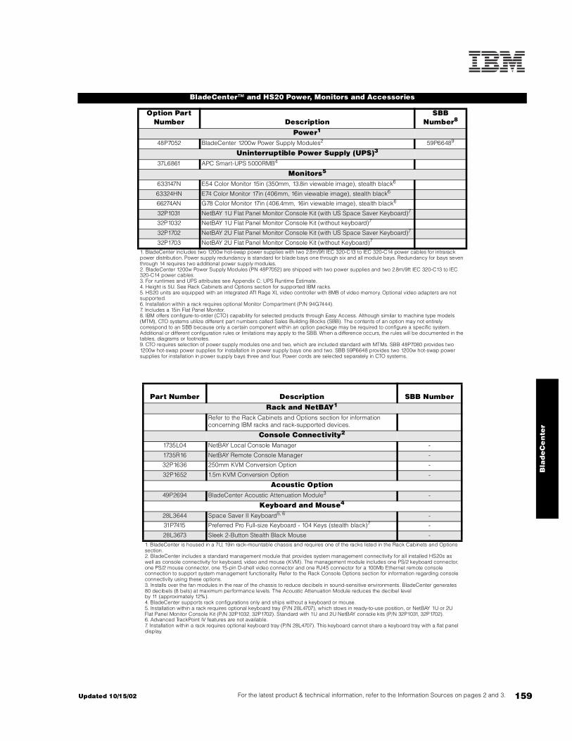
159For the latest product & technical information, refer to the Information Sources on pages 2 and 3.Updated 10/15/02
Bla
de
Ce
nte
r
BladeCenter™ and HS20 Power, Monitors and Accessories
Option Part Number Description
SBB Number8
Power1
48P7052 BladeCenter 1200w Power Supply Modules2 59P66489
Uninterruptible Power Supply (UPS)3
37L6861 APC Smart-UPS 5000RMB4
Monitors5
633147N E54 Color Monitor 15in (350mm, 13.8in viewable image), stealth black6
63324HN E74 Color Monitor 17in (406mm, 16in viewable image), stealth black6
66274AN G78 Color Monitor 17in (406.4mm, 16in viewable image), stealth black6
32P1031 NetBAY 1U Flat Panel Monitor Console Kit (with US Space Saver Keyboard)7
32P1032 NetBAY 1U Flat Panel Monitor Console Kit (without keyboard)7
32P1702 NetBAY 2U Flat Panel Monitor Console Kit (with US Space Saver Keyboard)7
32P1703 NetBAY 2U Flat Panel Monitor Console Kit (without Keyboard)7
1. BladeCenter includes two 1200w hot-swap power supplies with two 2.8m/9ft IEC 320-C13 to IEC 320-C14 power cables for intrarack power distribution. Power supply redundancy is standard for blade bays one through six and all module bays. Redundancy for bays seven through 14 requires two additional power supply modules.2. BladeCenter 1200w Power Supply Modules (PN 48P7052) are shipped with two power supplies and two 2.8m/9ft IEC 320-C13 to IEC 320-C14 power cables.3. For runtimes and UPS attributes see Appendix C: UPS Runtime Estimate. 4. Height is 5U. See Rack Cabinets and Options section for supported IBM racks.5. HS20 units are equipped with an integrated ATI Rage XL video controller with 8MB of video memory. Optional video adapters are not supported.6. Installation within a rack requires optional Monitor Compartment (P/N 94G7444).7. Includes a 15in Flat Panel Monitor.8. IBM offers configure-to-order (CTO) capability for selected products through Easy Access. Although similar to machine type models (MTM), CTO systems utilize different part numbers called Sales Building Blocks (SBB). The contents of an option may not entirely correspond to an SBB because only a certain component within an option package may be required to configure a specific system. Additional or different configuration rules or limitations may apply to the SBB. When a difference occurs, the rules will be documented in the tables, diagrams or footnotes.9. CTO requires selection of power supply modules one and two, which are included standard with MTMs. SBB 48P7080 provides two 1200w hot-swap power supplies for installation in power supply bays one and two. SBB 59P6648 provides two 1200w hot-swap power supplies for installation in power supply bays three and four. Power cords are selected separately in CTO systems.
Part Number Description SBB NumberRack and NetBAY1
Refer to the Rack Cabinets and Options section for information concerning IBM racks and rack-supported devices.
Console Connectivity2
1735L04 NetBAY Local Console Manager -
1735R16 NetBAY Remote Console Manager -
32P1636 250mm KVM Conversion Option -
32P1652 1.5m KVM Conversion Option -
Acoustic Option49P2694 BladeCenter Acoustic Attenuation Module3 -
Keyboard and Mouse4
28L3644 Space Saver II Keyboard5, 6 -
31P7415 Preferred Pro Full-size Keyboard - 104 Keys (stealth black)7 -
28L3673 Sleek 2-Button Stealth Black Mouse -
1. BladeCenter is housed in a 7U, 19in rack-mountable chassis and requires one of the racks listed in the Rack Cabinets and Options section.2. BladeCenter includes a standard management module that provides system management connectivity for all installed HS20s as well as console connectivity for keyboard, video and mouse (KVM). The management module includes one PS/2 keyboard connector, one PS/2 mouse connector, one 15-pin D-shell video connector and one RJ45 connector for a 100Mb Ethernet remote console connection to support system management functionality. Refer to the Rack Console Options section for information regarding console connectivity using these options.3. Installs over the fan modules in the rear of the chassis to reduce decibels in sound-sensitive environments. BladeCenter generates 80 decibels (8 bels) at maximum performance levels. The Acoustic Attenuation Module reduces the decibel levelby 11 (approximately 12%).4. BladeCenter supports rack configurations only and ships without a keyboard or mouse.5. Installation within a rack requires optional keyboard tray (P/N 28L4707), which stows in ready-to-use position, or NetBAY 1U or 2U Flat Panel Monitor Console Kit (P/N 32P1032, 32P1702). Standard with 1U and 2U NetBAY console kits (P/N 32P1031, 32P1702).6. Advanced TrackPoint IV features are not available. 7. Installation within a rack requires optional keyboard tray (P/N 28L4707). This keyboard cannot share a keyboard tray with a flat panel display.

16
0
BladeCenter™ HS20
BladeCenter™ HS20 At-A-Glance
8678-21X 21 1/2 512 512MB / 4GB2
Dual ATA-100 2/2 0/
80GB2x 10/100/
1000 Y ATI Rage XL/ 8MB 0/1 U320 2/2 0/146.8GB 0/1 48P7066
8678-41X 2.41 1/2 512 512MB / 4GB2
Dual ATA-100 2/2 0/
80GB2x 10/100/
1000 Y ATI Rage XL/ 8MB 0/1 U320 2/2 0/146.8GB 0/1 48P7066
1. Intel Xeon processor with advanced transfer L2 cache and 400MHz (quad-pumped) Front-side Bus (FSB). Heat sinks provide liquid sodium cooling.2. Two 256MB RDIMMs are standard, supporting two-way interleaving and Chipkill technology. The system architecture supports up to 8GB total memory using 2GB RDIMMS when available.3. Maximum IDE HDD storage capacity based on two 40GB 5400rpm IDE HDDs. Space for only one IDE HDD is available if an expansion card is installed.4. Broadcom 5703 dual integrated copper gigabit Ethernet controller.5. System management functionality, interconnect network connectivity and console connectivity are managed through the standard management module. The standard integrated service processor monitors HS20 system management activity, communicating with the management module in the BladeCenter.6. Optional HS20 SCSI Storage Expansion Unit (P/N 48P7058) provides an integrated single-channel Ultra320 storage controller and two hot-swap SCSI HDD bays. The expansion unit installs onto the HS20 by connecting the SCSI connector, then installing both units together into the BladeCenter. The storage expansion module is the same size as the HS20. The integrated controller supports both Ultra160 and Ultra320 HDDs, but the entire SCSI bus will default to the slower rate (MB/second) if HDDs of different technologies are mixed on the same bus. The LSI chipset allows for two HDDs to be allocated for mirroring.7. Two hot-swap SCSI HDD bays and an integrated Ultra320 single-channel storage controller are provided in the HS20 SCSI Storage Expansion Unit.8. Maximum capacity requires installing two 73.4GB SCSI HDDs. Mixing of Ultra320 and Ultra160 HDDs is supported, but the bus will operate at the speed of the lowest rated HDD.9. HS20 Fibre Channel Expansion Card (P/N 48P7061) installs over IDE connector two attaching into the expansion card connector, preventing installation of a second IDE HDD. The expansion card includes two Fibre Channel channels and two ports. One channel connects the HS20 to one optional BladeCenter 2-port Fibre Channel Switch Module (P/N 48P7062) installed in switch module bay three. The second channel connects to a second optional Fibre Channel switch module in bay four, which provides a redundant environment. Ethernet and serial I/O expansion cards are planned for future release. Expansion card selections cannot be mixed within a single BladeCenter chassis because they must connect to switch modules installed in switch module bays three and four.10. IBM offers configure-to-order (CTO) capability for selected products through Easy Access. Although similar to machine type models (MTM), CTO systems utilize different part numbers called Sales Building Blocks (SBB). The contents of an option may not entirely correspond to an SBB because only a certain component within an option package may be required to configure a specific system. Additional or different configuration rules or limitations may apply to the SBB. When a difference occurs, the rules will be documented in the tables, diagrams or footnotes.
Option Part
Number
Processor Speed (G
Hz)
Number of P
rocessors (Std/M
ax)
L2 ECC Cache (KB)
Memory (Std/M
ax)
IDE Storage Controlle
r
IDE HDD Bays (Total/A
vail)
Internal IDE HDD Capacity
(Std/M
ax)3
Onboard Ethernet (Mbps)4
Integrated System Management P
rocessor5
Video Controlle
r / Memory
SCSI Storage Expansion Unit (
Std/Max)6
SCSI Interfa
ce
SCSI HDD Bays (T
otal/Avail)
7
SCSI HDD Capacity
(Std/M
ax)8
Expansion Cards (Std/M
ax)9
SBB Number (Easy Access only)1
0
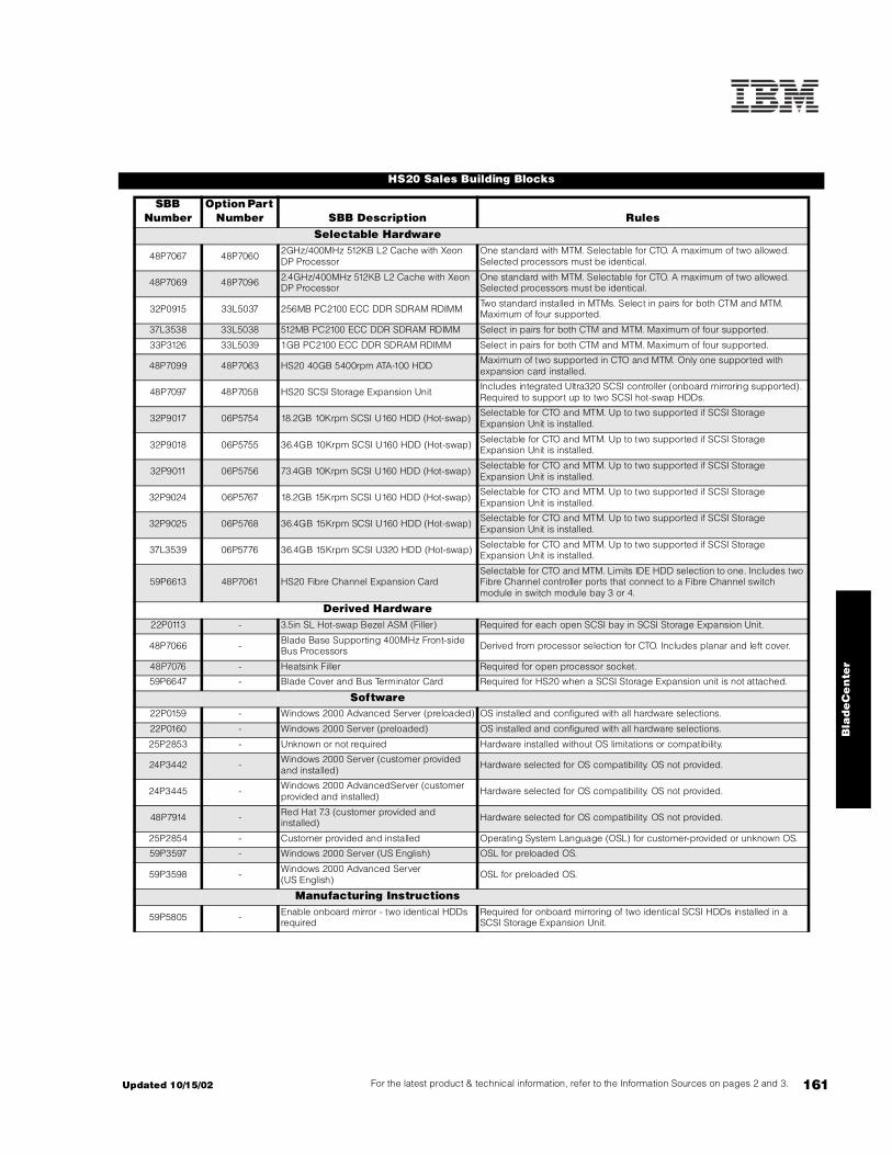
161For the latest product & technical information, refer to the Information Sources on pages 2 and 3.Updated 10/15/02
Bla
de
Ce
nte
r
HS20 Sales Building Blocks
SBB Number
Option Part Number SBB Description Rules
Selectable Hardware
48P7067 48P7060 2GHz/400MHz 512KB L2 Cache with Xeon DP Processor
One standard with MTM. Selectable for CTO. A maximum of two allowed. Selected processors must be identical.
48P7069 48P7096 2.4GHz/400MHz 512KB L2 Cache with Xeon DP Processor
One standard with MTM. Selectable for CTO. A maximum of two allowed. Selected processors must be identical.
32P0915 33L5037 256MB PC2100 ECC DDR SDRAM RDIMM Two standard installed in MTMs. Select in pairs for both CTM and MTM. Maximum of four supported.
37L3538 33L5038 512MB PC2100 ECC DDR SDRAM RDIMM Select in pairs for both CTM and MTM. Maximum of four supported.
33P3126 33L5039 1GB PC2100 ECC DDR SDRAM RDIMM Select in pairs for both CTM and MTM. Maximum of four supported.
48P7099 48P7063 HS20 40GB 5400rpm ATA-100 HDD Maximum of two supported in CTO and MTM. Only one supported with expansion card installed.
48P7097 48P7058 HS20 SCSI Storage Expansion Unit Includes integrated Ultra320 SCSI controller (onboard mirroring supported). Required to support up to two SCSI hot-swap HDDs.
32P9017 06P5754 18.2GB 10Krpm SCSI U160 HDD (Hot-swap) Selectable for CTO and MTM. Up to two supported if SCSI Storage Expansion Unit is installed.
32P9018 06P5755 36.4GB 10Krpm SCSI U160 HDD (Hot-swap) Selectable for CTO and MTM. Up to two supported if SCSI Storage Expansion Unit is installed.
32P9011 06P5756 73.4GB 10Krpm SCSI U160 HDD (Hot-swap) Selectable for CTO and MTM. Up to two supported if SCSI Storage Expansion Unit is installed.
32P9024 06P5767 18.2GB 15Krpm SCSI U160 HDD (Hot-swap) Selectable for CTO and MTM. Up to two supported if SCSI Storage Expansion Unit is installed.
32P9025 06P5768 36.4GB 15Krpm SCSI U160 HDD (Hot-swap) Selectable for CTO and MTM. Up to two supported if SCSI Storage Expansion Unit is installed.
37L3539 06P5776 36.4GB 15Krpm SCSI U320 HDD (Hot-swap) Selectable for CTO and MTM. Up to two supported if SCSI Storage Expansion Unit is installed.
59P6613 48P7061 HS20 Fibre Channel Expansion CardSelectable for CTO and MTM. Limits IDE HDD selection to one. Includes two Fibre Channel controller ports that connect to a Fibre Channel switch module in switch module bay 3 or 4.
Derived Hardware22P0113 - 3.5in SL Hot-swap Bezel ASM (Filler) Required for each open SCSI bay in SCSI Storage Expansion Unit.
48P7066 - Blade Base Supporting 400MHz Front-side Bus Processors Derived from processor selection for CTO. Includes planar and left cover.
48P7076 - Heatsink Filler Required for open processor socket.
59P6647 - Blade Cover and Bus Terminator Card Required for HS20 when a SCSI Storage Expansion unit is not attached.
Software22P0159 - Windows 2000 Advanced Server (preloaded) OS installed and configured with all hardware selections.
22P0160 - Windows 2000 Server (preloaded) OS installed and configured with all hardware selections.
25P2853 - Unknown or not required Hardware installed without OS limitations or compatibility.
24P3442 - Windows 2000 Server (customer provided and installed) Hardware selected for OS compatibility. OS not provided.
24P3445 - Windows 2000 AdvancedServer (customer provided and installed) Hardware selected for OS compatibility. OS not provided.
48P7914 - Red Hat 7.3 (customer provided and installed) Hardware selected for OS compatibility. OS not provided.
25P2854 - Customer provided and installed Operating System Language (OSL) for customer-provided or unknown OS.
59P3597 - Windows 2000 Server (US English) OSL for preloaded OS.
59P3598 - Windows 2000 Advanced Server (US English) OSL for preloaded OS.
Manufacturing Instructions
59P5805 - Enable onboard mirror - two identical HDDs required
Required for onboard mirroring of two identical SCSI HDDs installed in a SCSI Storage Expansion Unit.

162
HS20 Processors
Option Part Number
Processor Upgrades SMP Support1 Processor Speed Upgrade2
SBBNumber3
48P7060 2GHz 400MHz 512KB L2 Cache Xeon Processor 21X - 48P7067
48P7096 2.4GHz 400MHz 512KB L2 Cache Xeon Processor 41X 21X 48P7069
1. One additional processor may be installed, providing a maximum of two. All processors must be identical in type, speed and cache size.2. Requires removal of the standard processor. A maximum of two processors may be installed. All processors must be identical in type, speed and cache size. Upgrades may require a BIOS update. To obtain the latest Flash BIOS, access www.pc.ibm.com/support and enter machine "Type-Model" in Quick Path. Select "Downloadable files" then "BIOS."3. IBM offers configure-to-order (CTO) capability for selected products through Easy Access. Although similar to machine type models (MTM), CTO systems utilize different part numbers called Sales Building Blocks (SBB). The contents of an option may not entirely correspond to an SBB because only a certain component within an option package may be required to configure a specific system. Additional or different configuration rules or limitations may apply to the SBB. When a difference occurs, the rules will be documented in the tables, diagrams or footnotes.
Battery
SCSI expansionconnector (J8)
IDE connector 1(J13)
IDE connector 2(J62)
Network-interfaceoption connector (J34)
Network-interfaceoption connector (J9)
Control panelconnector (J64)
Microprocessorsocket 2and heat sink filler(U70)
Microprocessor 1and heat sink (U66)
DIMM socket 1 (J1)DIMM socket 2 (J5)
DIMM socket 3 (J2)DIMM socket 4 (J6)
HS20 Planar
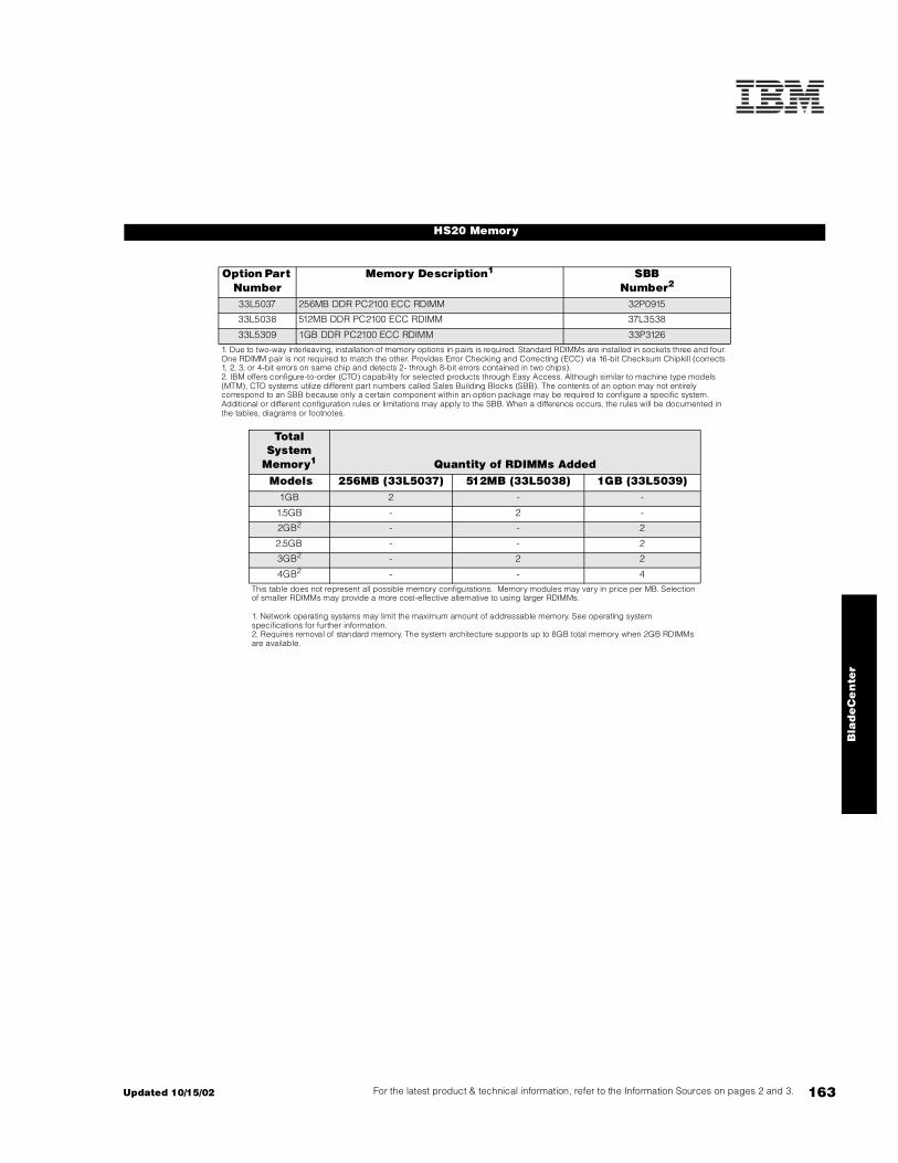
163For the latest product & technical information, refer to the Information Sources on pages 2 and 3.Updated 10/15/02
Bla
de
Ce
nte
r
HS20 Memory
Option Part Number
Memory Description1 SBBNumber2
33L5037 256MB DDR PC2100 ECC RDIMM 32P0915
33L5038 512MB DDR PC2100 ECC RDIMM 37L3538
33L5309 1GB DDR PC2100 ECC RDIMM 33P3126
1. Due to two-way interleaving, installation of memory options in pairs is required. Standard RDIMMs are installed in sockets three and four. One RDIMM pair is not required to match the other. Provides Error Checking and Correcting (ECC) via 16-bit Checksum Chipkill (corrects 1, 2, 3, or 4-bit errors on same chip and detects 2- through 8-bit errors contained in two chips).2. IBM offers configure-to-order (CTO) capability for selected products through Easy Access. Although similar to machine type models (MTM), CTO systems utilize different part numbers called Sales Building Blocks (SBB). The contents of an option may not entirely correspond to an SBB because only a certain component within an option package may be required to configure a specific system. Additional or different configuration rules or limitations may apply to the SBB. When a difference occurs, the rules will be documented in the tables, diagrams or footnotes.
Total System
Memory1 Quantity of RDIMMs Added Models 256MB (33L5037) 512MB (33L5038) 1GB (33L5039)
1GB 2 - -
1.5GB - 2 -
2GB2 - - 2
2.5GB - - 2
3GB2 - 2 2
4GB2 - - 4
This table does not represent all possible memory configurations. Memory modules may vary in price per MB. Selection of smaller RDIMMs may provide a more cost-effective alternative to using larger RDIMMs.
1. Network operating systems may limit the maximum amount of addressable memory. See operating system specifications for further information.2. Requires removal of standard memory. The system architecture supports up to 8GB total memory when 2GB RDIMMs are available.

164
HS20 Hard Disk Drive (HDD) Storage
SCSI HDD Configuration with Storage Expansion Unit InstalledTotal Int Storage1
10,000rpm HDDs 15,000rpm HDDs
18.2GB(06P5754)
36.4GB(06P5755)
73.4GB(06P5756)
18.2GB(06P5767)
36.4GB(06P5768, 06P5776)
0GB Standard on base models
18.2GB 1 - - 1 -
36.4GB 2 1 - 2 1
72.8GB - 2 - - 2
73.4GB - - 1 - -
146.8GB - - 2 - -
This table does not represent all possible HDD configurations. Total Internal Storage listed is within +/-0.2GB unless otherwise noted.1. Select a total storage row then select the quantity of HDDs from a column corresponding to the HDD of choice.
HDD OptionsOption
Part Number
Description RPM HeightBays
SupportedMax Qty1
SBB Number4
IDE HDD1
48P7063 HS20 40GB 5400rpm ATA-100 HDD 5400 SL 1, 2 2 48P7099
Hot-swap Ultra160 HDDs2
06P5754 18.2GB 10Krpm Ultra160 SCSI Hot-swap SL HDD 10000 SL 1, 2 2 32P9017
06P5755 36.4GB 10Krpm Ultra160 SCSI Hot-swap SL HDD 10000 SL 1, 2 2 32P9108
06P5756 73.4GB 10Krpm Ultra160 SCSI Hot-swap SL HDD 10000 SL 1, 2 2 32P9011
06P5767 18.2GB 15Krpm Ultra160 SCSI Hot-swap SL HDD 15000 SL 1, 2 2 32P9024
06P5768 36.4GB 15Krpm Ultra160 SCSI Hot-swap SL HDD 15000 SL 1, 2 2 32P9025
Hot-swap Ultra320 HDDs2
06P5776 36.4GB 15Krpm Ultra320 SCSI Hot-swap SL HDD 15000 SL 1, 2 2 37L3539
Internal Storage Expansion48P7058 SCSI Storage Expansion Unit3 - - - - 48P7097
1. Up to two IDE HDDs may be installed in each HS20. The second IDE HDD cannot be added if a Fibre Channel expansion card is installed. IDE HDDs may remain installed when a SCSI Storage Expansion Unit and up to two SCSI HDDs are added to the configuration. Either the IDE or SCSI bus can support the boot disk. Onboard mirroring is not supported on the IDE bus.2. Two SCSI HDDs may be installed in a SCSI Storage Expansion Unit. The integrated Ultra320 SCSI controller supports both Ultra320 and Ultra160 HDDs, though bus speed is reduced to the rated performance of the slowest HDD. The LSI chipset supports onboard HDD mirroring when two identical SCSI HDDs are installed.3. Optional HS20 SCSI Storage Expansion Unit (P/N 48P7058) provides an integrated single-channel Ultra320 storage controller and two hot-swap SCSI HDD bays. The expansion unit installs onto the HS20 by connecting the SCSI connector, then installing both units together into the BladeCenter. The storage expansion unit mechanical is the same size as the HS20. The integrated controller supports both Ultra160 and Ultra320 HDDs, but the entire SCSI bus will default to the slower rate (MB/second) if HDDs of different technologies are mixed on the same bus. The LSI chipset allows for two matched SCSI HDDs to be allocated for mirroring.4. IBM offers configure-to-order (CTO) capability for selected products through Easy Access. Although similar to machine type models (MTM), CTO systems utilize different part numbers called Sales Building Blocks (SBB). The contents of an option may not entirely correspond to an SBB because only a certain component within an option package may be required to configure a specific system. Additional or different configuration rules or limitations may apply to the SBB. When a difference occurs, the rules will be documented in the tables, diagrams or footnotes.

165For the latest product & technical information, refer to the Information Sources on pages 2 and 3.Updated 10/15/02
Bla
de
Ce
nte
r
Note: The following sample configurations are for illustration only and may not be suitable for any specific customer installation. Contact your IBM Business Partner or IBM Marketing Representative for assistance with your specific configuration requirements.
Microsoft Exchange Cluster Solution1
Citrix Solution1
BladeCenter Sample Configurations
Part Number Description Quantity8677-1XX eServer BladeCenter 148P7052 BladeCenter 1200w Power Supply Modules 12
48P7054 BladeCenter 4-port Gigabit Ethernet Switch Module 248P7062 BladeCenter 2-port Fibre Channel Switch Module 28678-41X BladeCenter HS20 2.4Ghz/512KB Xeon, 512MB ECC, open 1433L5037 256MB DDR PC2100 ECC RDIMM 283
48P7061 HS20 Fibre Channel Expansion Card 14
External Storage4
17421RU FAStT700 Storage Server 117401RU FAStT EXP700 Storage Expansion Unit 1606P5771 2Gbps FC 18.2GB/15K Drive 2245
Note: This configuration supports 15,000 users.
1. Rack, console and power options not included.2. Total of four power modules, which provides full redundancy. Two power modules are standard in BladeCenter.3. Total memory of 1GB per HS20.4. Fibre Channel cable, SFP Modules and FAStT700 Mini Hubs not included.5. Fourteen Fibre Channel HDDs per FAStT EXP700.
Part Number Description Quantity8677-1XX eServer BladeCenter 148P7052 BladeCenter 1200w Power Supply Modules 12
48P7054 BladeCenter 4-port Gigabit Ethernet Switch Module 28678-41X BladeCenter HS20 2.4Ghz/512KB Xeon, 512MB ECC, open 1448P7063 BladeCenter 40GB 5400rpm ATA-100 HDD 2833L5039 1GB DDR PC2100 ECC RDIMM 563
1. Rack, console and power options not included.2. Total of four power modules, which provides full redundancy. Two power modules are standard in BladeCenter.3. Total memory of 4GB per HS20. Requires replacing the standard RDIMMs.
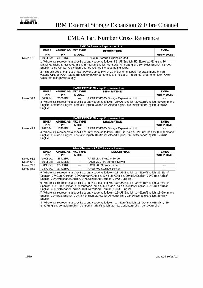
IBM External Storage Expansion & Fibre Channel
EMEA Part Number Cross ReferenceEXP300 Stora ge Expansion Unit
EMEA AMERICAS M/C TYPE DESCRIPTION EMEAP/N P/N MODEL WDFM DATE
Notes 1&2 19K11xx 35311RU --- EXP300 Storage Expansion Unit ---1. Where ‘xx’ represents a specific country code as follows: 51=US/English, 52=European/English, 56=Danish/English, 57=Israel/English, 58=Italian/English, 59=South Africa/English, 60=Swiss/English, 63=UK/English:- Line Cords/ Publication Country Kits are included as indicated.2. This unit does not include Rack Power Cables P/N 94G7448 when shipped (for attachment to highvoltage UPS or PDU). Standard country power cords only are included. If required, order one Rack PowerCable for each power supply.
FAStT EXP500 Storage Expansion UnitEMEA AMERICAS M/C TYPE DESCRIPTION EMEA
P/N P/N MODEL WDFM DATENotes 3&2 00N71xx 35601RU --- FAStT EXP500 Storage Expansion Unit ---
3. Where ‘xx’ represents a specific country code as follows:- 36=US/English, 37=Euro/English, 41=Denmark/English, 42=Israel/English, 43=Italy/English, 44=South Africa/English, 45=Switzerland/English, 49=UK/English.
FAStT EXP700 Storage Expansion UnitEMEA AMERICAS M/C TYPE DESCRIPTION EMEA
P/N P/N MODEL WDFM DATENotes 4&2 24P09xx 17401RU --- FAStT EXP700 Storage Expansion Unit ---
4. Where ‘xx’ represents a specific country code as follows:- 01=Eur/English, 02=Eur/Spanish, 05=Denmark/English, 06=Israel/English, 07=Italy/English, 08=South Africa/English, 09=Switzerland/English, 12=UK/English.
Fibre Channel - FAStT Storage ServersEMEA AMERICAS M/C TYPE DESCRIPTION EMEA
P/N P/N MODEL WDFM DATENotes 5&2 19K11xx 35421RU --- FAStT 200 Storage Server ---Notes 6&2 19K11xx 35422RU --- FAStT 200 HA Storage Server ---Notes 7&2 00N69xx 35521RU --- FAStT500 Storage Server ---Notes 8&2 24P09xx 17421RU --- FAStT700 Storage Server ---
5. Where ‘xx’ represents a specific country code as follows:- 23=US/English, 24=Euro/English, 25=Euro/Spanish, 27=Euro/German, 28=Denmark/English, 29=Israel/English, 30=Italy/English, 31=South Africa/English, 32=Switzerland/English, 34=Switzerland/German, 36=UK/English..6. Where ‘xx’ represents a specific country code as follows:- 37=US/English, 38=Euro/English, 39=Euro/Spanish, 41=Euro/German, 42=Denmark/English, 43=Israel/English, 44=Italy/English, 45=South Africa/English, 46=Switzerland/English, 48=Switzerland/German, 50=UK/English.7. Where ‘xx’ represents a specific country code as follows:- 13=US/English, 14=Euro/English, 18=Denmark/English, 19=Israel/English, 20=Italy/English, 21=South Africa/English, 22=Switzerland/English, 26=UK/English.8. Where ‘xx’ represents a specific country code as follows:- 14=Euro/English, 18=Denmark/English, 19=Israel/English, 20=Italy/English, 21=South Africa/English, 22=Switzerland/English, 25=UK/English.
165A Updated 10/15/02

IBM External Storage Expansion & Fibre Channel
EMEA Part Number Cross Reference1Gb Fibre Channel Fabric Components
EMEA AMERICAS M/C TYPE DESCRIPTION EMEAP/N P/N MODEL KEYBOARD AND MOUSE WDFM DATE
35L1647 35341RU --- SAN Fibre Channel Managed Hub ---
Updated 10/15/02 165B

166
IBM External Storage Expansion Unit Overview
Ultra SCSI External Expansion At-A-Glance
35311RUEXP3001 Ultra160 LVDS 14 14/142 1027.6 444mm x 519mm x 127.5mm
(17.5in x 20.4in x 5in)Rack Drawer
(3U)334.5kg
(76.1lbs)Redundant
500w
Fibre Channel External Expansion At-A-Glance
35421RUFAStT200 Fibre Channel 10 10/10 734 480mm x 575mm x 131.8mm
(18.9in x 22.63in x 5.2in) Rack Drawer (3U) 42.3kg (94lbs)
Redundant350w
35422RU4
FAStT200 HA Fibre Channel 10 10/10 734 480mm x 575mm x 131.8mm (18.9in x 22.63in x 5.2in) Rack Drawer (3U) 42.3kg
(94lbs)Redundant
350w
35601RU5 FAStTEXP500 Fibre Channel 10 10/10 734 447mm x 56mm x 128mm
(17.6in x 22.2in x 5in) Rack Drawer (3U) 36.1kg(79.6lbs)
Redundant350w
17401RU6 FAStT EXP700 Fibre Channel 14 14/142 1027.6 482mm x 597mm x 132mm
(18.97in x 23.52in x 5.21in) Rack Drawer (3U) 41.47kg (91.42lbs)
Redundant400w
1. To attach a SCSI storage enclosure to an xSeries server, an appropriate RAID controller and external cable is required.See Appendix D: Cables - Storage Units - Controllers.2. Supports slim-line drives only (FAStT EXP500 supports either half-high or slim-line HDDs).3. A rack-to-tower conversion kit option (P/N 09N7296) is available.4. Identical to FAStT200 (P/N 35421RU) with the addition of a FAStT200 Redundant RAID Controller (P/N 19K1121).5.Attachment to a FAStT500 Storage Server (P/N 35521RU) or FAStT700 Storage Server (P/N 17421RU) is required. This expansion unit does not attach directly to an xSeries server. See FAStT EXP500 section for more information.6. Attachment to a FAStT700 Storage Server (P/N 17401RU) is required. This expansion unit does not attach directly to an xSeries server. See FAStT EXP700 section for more information.
Part Number
Subsystem Type
Total Bays
Hot-Swap Bays (to
tal/avail)
Maximum Storage Capacity
(GB)
Dimensions (W
x D x H)
Form Factor
Max Cfg Wt
Power Supply
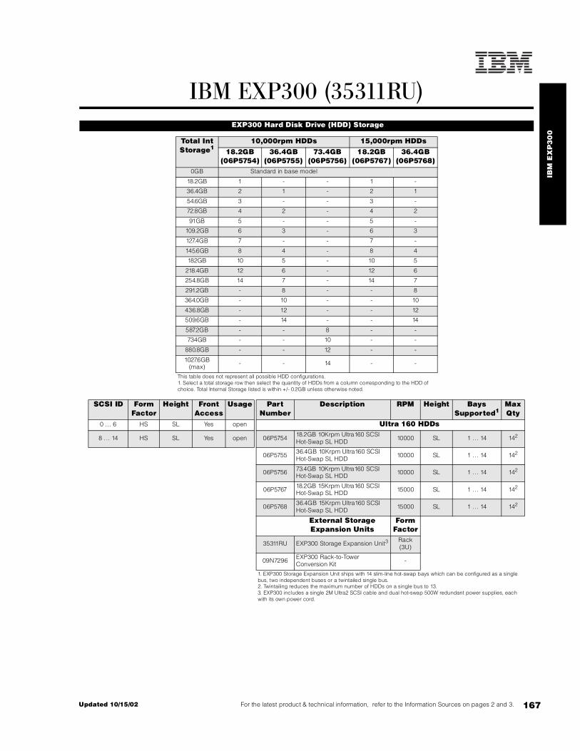
IBM
EX
P3
00
167For the latest product & technical information, refer to the Information Sources on pages 2 and 3.Updated 10/15/02
IBM EXP300 (35311RU) EXP300 Hard Disk Drive (HDD) Storage
Total Int Storage1
10,000rpm HDDs 15,000rpm HDDs18.2GB
(06P5754)36.4GB
(06P5755)73.4GB
(06P5756)18.2GB
(06P5767)36.4GB
(06P5768)0GB Standard in base model
18.2GB 1 - - 1 -
36.4GB 2 1 - 2 1
54.6GB 3 - - 3 -
72.8GB 4 2 - 4 2
91GB 5 - - 5 -
109.2GB 6 3 - 6 3
127.4GB 7 - - 7 -
145.6GB 8 4 - 8 4
182GB 10 5 - 10 5
218.4GB 12 6 - 12 6
254.8GB 14 7 - 14 7
291.2GB - 8 - - 8
364.0GB - 10 - - 10
436.8GB - 12 - - 12
509.6GB - 14 - - 14
587.2GB - - 8 - -
734GB - - 10 - -
880.8GB - - 12 - -
1027.6GB (max) - - 14 - -
This table does not represent all possible HDD configurations.1. Select a total storage row then select the quantity of HDDs from a column corresponding to the HDD of choice. Total Internal Storage listed is within +/- 0.2GB unless otherwise noted.
SCSI ID Form Factor
Height Front Access
Usage Part Number
Description RPM Height Bays Supported1
Max Qty
0 ... 6 HS SL Yes open Ultra 160 HDDs
8 ... 14 HS SL Yes open 06P5754 18.2GB 10Krpm Ultra160 SCSI Hot-Swap SL HDD 10000 SL 1 .. . 14 142
06P5755 36.4GB 10Krpm Ultra160 SCSI Hot-Swap SL HDD 10000 SL 1 .. . 14 142
06P5756 73.4GB 10Krpm Ultra160 SCSI Hot-Swap SL HDD 10000 SL 1 .. . 14 142
06P5767 18.2GB 15Krpm Ultra160 SCSI Hot-Swap SL HDD 15000 SL 1 .. . 14 142
06P5768 36.4GB 15Krpm Ultra160 SCSI Hot-Swap SL HDD 15000 SL 1 .. . 14 142
External Storage Expansion Units
Form Factor
35311RU EXP300 Storage Expansion Unit3 Rack (3U)
09N7296 EXP300 Rack-to-Tower Conversion Kit -
1. EXP300 Storage Expansion Unit ships with 14 slim-line hot-swap bays which can be configured as a single bus, two independent buses or a twintailed single bus.2. Twintailing reduces the maximum number of HDDs on a single bus to 13.3. EXP300 includes a single 2M Ultra2 SCSI cable and dual hot-swap 500W redundant power supplies, each with its own power cord.

168
Cables and Controllers:See Appendix D: Cables - Storage Units - Controllers
SCSI Connectors
Hot-swap Power Supplies with Integrated Fan
EXP300 Storage Expansion Unit 35311RU
• Fourteen slim-high drive bays.• Supports Ultra160 SCSI data transfer speeds - up to 160MB/s. • Single or dual SCSI bus configurations.• Dual hot-swap 500W redundant power supplies with integrated fan assemblies.• Height is 3U (1U=1.75in or 44.45mm).• Tower capability through optional Rack-to-Tower Conversion Kit.• Requires Netfinity Enterprise Rack or Expansion Cabinet, IBM NetBAY Enterprise Rack or Expansion Cabinet, Netfinity Rack, Netfinity NetBAY22 or 19in EIA-D Industry-Standard Rack. Mounting rails are included with the unit.
35311RU EXP3001 2 x 0.8mm VHDCI
Selectable Bus Configuration 2 x 7 bays 1 x 142 baysUltra2 and/or Ultra160 HDDs3
SCSI IDs 0 .. . 6SCSI IDs 8 . .. 14
1. Housed in a 19in rack mountable drawer and ships standard with redundant 500W hot-swap power supplies, two power cords and a single 2M Ultra2 SCSI cable capable of supporting Ultra160 speeds.2. Twintailing reduces the maximum number of HDDs on a single bus to 13.3. When combined with a ServeRAID-4x controller, Ultra2 and Ultra160 HDDs may be mixed on the same bus and operate at up to their maximum respective speeds.
Requires IBM NetBAY 42 Enterprise Rack or Expansion Cabinet (930842S, E), NetBAY 42 Standard Rack Cabinet or Expansion Cabinet (9306420, 1), NetBAY 25 (9306250), NetBAY 22 (9306200), NetBAY 3 (10L6912), NetBAY 3E (36L9701) or Rack-to-Tower Conversion Kit (09N7296). External Storage Expansion Units require storage controllers and external cables. Select a supported RAID controller from the system configurator and cables from Appendix D: Cables - Storage Units - Controllers.
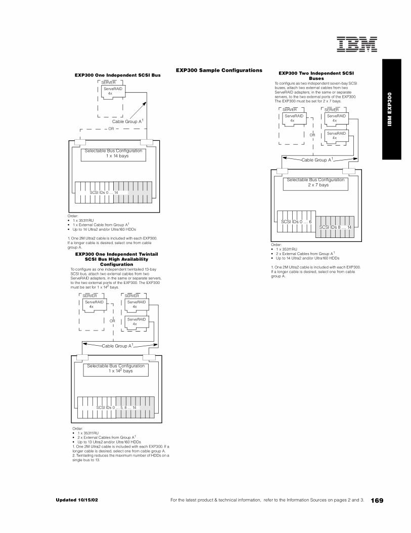
IBM
EX
P3
00
169For the latest product & technical information, refer to the Information Sources on pages 2 and 3.Updated 10/15/02
EXP300 One Independent SCSI Bus
Selectable Bus Configuration 2 x 7 bays
SCSI IDs 0 ... 6SCSI IDs 8 . .. 14
ServeRAID 4x
ServeRAID 4x
ServeRAID 4x
SERVER SERVER
Cable Group A1
OR
Order:• 1 x 35311RU• 2 x External Cables from Group A1
• Up to 14 Ultra2 and/or Ultra160 HDDs
1. One 2M Ultra2 cable is included with each EXP300. If a longer cable is desired, select one from cable group A.
EXP300 Two Independent SCSI Buses
To configure as two independent seven-bay SCSI buses, attach two external cables from two ServeRAID adapters, in the same or separate servers, to the two external ports of the EXP300. The EXP300 must be set for 2 x 7 bays.
Order:• 1 x 35311RU• 2 x External Cables from Group A1
• Up to 13 Ultra2 and/or Ultra160 HDDs1. One 2M Ultra2 cable is included with each EXP300. If a longer cable is desired, select one from cable group A.2. Twintailing reduces the maximum number of HDDs on a single bus to 13.
Selectable Bus Configuration 1 x 14 bays
ServeRAID 4x
SERVER
Cable Group A1
OR
SCSI IDs 0 . .. 14
Order:• 1 x 35311RU• 1 x External Cable from Group A1
• Up to 14 Ultra2 and/or Ultra160 HDDs
1. One 2M Ultra2 cable is included with each EXP300. If a longer cable is desired, select one from cable group A.
Selectable Bus Configuration 1 x 142 bays
ServeRAID 4x
ServeRAID 4x
ServeRAID 4x
SERVER SERVER
Cable Group A1
OR
SCSI IDs 0 ... 5, 8 ... 14
EXP300 One Independent Twintail SCSI Bus High Availability
ConfigurationTo configure as one independent twintailed 13-bay SCSI bus, attach two external cables from two ServeRAID adapters, in the same or separate servers, to the two external ports of the EXP300. The EXP300 must be set for 1 x 142 bays.
EXP300 Sample Configurations

170
Fibre Channel Solutions Overview
Fibre Channel Solutions Overview At-A-Glance
FAStT Storage Servers35421RU FAStT200 Storage Server 734GB1 16 1/1 - - - 3U35422RU FAStT200 HA Storage Server 4.4TB2 16 2/2 1 - 1/1 3U35521RU FAStT500 Storage Server 16.15TB3 16 4/8 4 2/4 1/2 4U17421RU FAStT700 Fibre Channel Storage Server 16.44TB4 64 4/8 4 2/4 1/2 4U
Fibre Channel HDD Expansion Units35601RU FAStT EXP500 Storage Expansion Unit 734GB - - - - - 3U17401RU FAStT EXP700 Storage Expansion Unit 1027.6GB - - - - - 3U
1Gb Fibre Channel Fabric Components00N6881 FAStT Host Adapter - - - - - - -00N6882 FAStT500 Mini Hub - - - - - - -00N6883 FAStT500 256MB Cache - - - - - - -19K1121 FAStT200 Redundant RAID Controller - - - - - -2108R3L SAN Data Gateway Router UltraSCSI LVD Port - - - - - - -03K9307 FC Long-wave GBIC - - - - - - -03K9308 FC Short-wave GBIC - - - - - - -03K9305 Netfinity Fibre Channel 25M Cable - - - - - - -03K9306 Netfinity Fibre Channel 5M Cable - - - - - - -36L9973 Netfinity Fibre Channel 1M Cable - - - - - - -
2Gb Fibre Channel Fabric Components24P0960 FC2-133 Host Bus Adapter - - - - - - -19K1269 FAStT700 Mini Hub - - - - - - -3534F08 TotalStorage SAN Switch F08, 8-port5 - - - - - - -2109F16 SAN FC Switch, 16-Port6 - - - - - - -19K1271 Short-wave SFP Module - - - - - - -19K1272 Long-wave SFP Module - - - - - - -19K1247 1M LC-LC Fibre Channel Cable - - - - - - -19K1248 5M LC-LC Fibre Channel Cable - - - - - - -19K1249 25M LC-LC Fibre Channel Cable - - - - - - -19K1250 LC-SC Fibre Channel Adapter Cable7 - - - - - - -
Fibre Channel HDDs19K0653 Netfinity 36.4GB 10K-4 FC Hot-swap HDD - - - - - - -19K0654 Netfinity 73.4GB 10K-4 FC Hot-swap HDD - - - - - - -06P5707 Netfinity 18.2GB 15Krpm FC Hot-swap HDD - - - - - - -06P5761 2Gbps FC 36.4GB/10K Drive - - - - - - -06P5762 2Gbps FC 73.4GB/10K Drive - - - - - - -06P5771 2Gbps FC 18.2GB/15K Drive - - - - - - -06P5772 2Gbps FC 36.4GB/15K Drive - - - - - - -
1. Attaching expansion units to a FAStT200 Storage Server is not recommended because a single point-of-failure occurs when external storage is connected through only one RAID controller. The maximum storage value is based on 10 internal 73.4GB internal FC HDDs.2. Based on a maximum of 60 73.4GB FC HDDs installed in the redundant storage loop that includes the FAStT200 internal HDD bays and five FAStT EXP500 expansion units.3. Based on a maximum of 220 73.4GB FC HDDs installed in a maximum of 22 FAStT EXP500 expansion units. A maximum of 11 expansion units are supported in a redundant drive loop (cable pair). Four drive-side mini hubs are required to support two loops running in redundant mode.4. Based on a maximum of 224 73.4GB Fibre Channel HDDs installed in a maximum of 16 FAStT EXP700 expansion units. A maximum of eight expansion units are supported in a redundant drive loop (cable pair). Four drive-side mini hubs are required to support two loops running in redundant mode.5. Additional related options include F08 Full Fabric Activation (P/N 18P5060) and Performance Bundle Activation (P/N 18P4405).6. Additional related options include Remote Switch Activation (P/N 18P3536), Extended Fabric Activation (P/N 18P3580) and F16 Performance Bundle Activation (P/N 18P3590). Power cords for nonrack installation are available by country.7. The LC-SC Fibre Channel Adapter Cable (P/N 19K1250) is designed to connect any 1Gb device or cable to any 2Gb device or cable. When 2Gb and 1Gb technology are combined in a configuration, the signal transfer automatically converts to the slower speed.
Part
Num
ber
Des
crip
tion
Max
Sup
port
ed
Sto
rage
Hos
t Pa
rtit
ions
Hos
t Fa
bric
Por
ts
(std
/max
)
Max
Red
unda
nt H
ost
Con
nect
ions
Dri
ve S
ide
Min
i Hub
s
(st
d/m
ax)
Red
unda
nt D
rive
Loop
s (s
td/m
ax)
Form
Fac
tor

171For the latest product & technical information, refer to the Information Sources on pages 2 and 3.Updated 10/15/02
FAS
tT2
00
Sto
rag
e S
erv
er
IBM FAStT200 Storage Server (3542xRU) FAStT200 (HA) Storage Expansion Unit
Total Internal Storage1
10,000RPM HDDs 15,000RPM HDDs
36.4GB(P/N 19K0653,
06P5761)
73.4GB(P/N 19K0654,
06P5762)
18.2GB(P/N 06P5707,
06P5771)
36.4GB(P/N 06P5772)
0GB Standard in base model
18.2GB - - 1 -
36.4GB 1 - 2 1
54.6GB - - 3 -
72.8GB 2 - 4 2
73.4GB - 1 - -
91GB - - 5 -
109.2GB 3 - 6 3
145.6GB 4 - 8 4
146.8GB - 2 - -
182GB 5 - 10 5
218.4GB 6 - - 6
220.2GB - 3 - -
254.8GB 7 - - 7
291.2GB 8 - - 8
293.6GB - 4 - -
327.6GB 9 - - 9
364GB 10 - - 10
367GB - 5 - -
440.4GB - 6 - -
513.8GB - 7 - -
587.2GB - 8 - -
660.6GB - 9 - -
734GB (max) - 10 - -
This table does not represent all valid HDD configurations.1. Select a total storage row and then select the quantity of HDDs from a column corresponding to the HDD of choice. Total Internal Storage listed is within +/- 0.2GB unless otherwise noted.
Part Number
Description RPM Height Bays Supported
Max Qty Supported
19K0653 Netfinity 36.4GB 10K-4 FC Hot-Swap HDD 10,000 SL 1 .. . 10 10
19K0654 Netfinity 73.4GB 10K-4 FC Hot-Swap HDD 10,000 HH 1 .. . 10 10
06P5707 Netfinity 18.2GB 15Krpm FC Hot-Swap HDD 15,000 SL 1 .. . 10 10
06P5761 2Gbps FC 36.4GB/10K Drive 10,000 SL 1 .. . 10 10
06P5762 2Gbps FC 73.4GB/10K Drive 10,000 SL 1 .. . 10 10
06P5771 2Gbps FC 18.2GB/15K Drive 15,000 SL 1 .. . 10 10
06P5772 2Gbps FC 36.4GB/15K Drive 15,000 SL 1 .. . 10 10
External Storage Expansion Units Form Factor35421RU FAStT200 Storage Server1, 2 Rack (3U)
35422RU FAStT200 HA Storage Server1 Rack (3U)
19K1121 FAStT200 Redundant RAID Controller -
1. The FAStT200 includes two hot-swap, 350W auto-ranging redundant power supplies, each with its own power cord. 2. Can be upgraded to FAStT200 HA Storage Server through the addition of a FAStT200 Redundant RAID Controller (P/N 19K1121).

172
External: Fibre ChannelInternal: Fibre ChannelAuto Termination
Fibre Channel Connectors3
FAStT200 Storage Server1
35421RU2 / 35422RU
IN = connection to hostOUT = connection to expansion units
1. Housed in a 19in rack-mountable drawer and ships standard with redundant power supplies and two power cables requiring separate power sources. Requires an IBM industry standard 19in rack, EIA-310D with a minimum depth of 24in (711.2mm ) or NetBAY3/3E. Select optional storage controllers and external cables, which are not included with the FAStT storage server or external enclosure, using the Fibre Channel Device Ports Reference.2. 35421RU includes a single loop only. The second loop is created with the addition of FAStT200 Redundant RAID Controller (P/N 19K1121).3. GBICs are not included. Either Fibre Channel long-wave GBICs (P/N 03K9307)or short-wave (P/N 03K9308) GBICs may be used.
OUT
Bay
1Ba
y 2
Bay
4
Bay
6Ba
y 7
Bay
8Ba
y 9
Bay
10
Bay
5
Bay
3
IN OUT IN
Loop B
Loop A
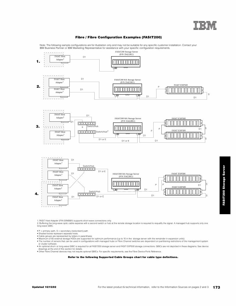
173For the latest product & technical information, refer to the Information Sources on pages 2 and 3.Updated 10/15/02
FAS
tT2
00
Sto
rag
e S
erv
er
Fibre / Fibre Configuration Examples (FAStT200)
Note: The following sample configurations are for illustration only and may not be suitable for any specific customer installation. Contact your IBM Business Partner or IBM Marketing Representative for assistance with your specific configuration requirements.
1. FAStT Host Adapter (P/N 00N6881) supports short-wave connections only.2. Buffering the long-wave optic cable expanse with a second switch or hub at the remote storage location is required to requalify the signal. A managed hub supports only one long-wave GBIC.
• P = primary path, S = secondary (redundant) path• Shaded boxes represent separate hosts.• Cable groups are represented by letters in parenthesis.• Maximum of 60 external storage HDDs are supported for optimum performance (up to 10 in the storage server with the remainder in expansion units).• The number of servers that can be used in configurations with managed hubs or Fibre Channel switches are dependent on partitioning restrictions of the management system
or cluster software.• An optional short- or long-wave GBIC is required for all FAStT200 storage server and FAStT EXP500 storage connections. GBICs are not depicted in these diagrams. See device
drawings at the end of this section for details.• Other Fibre Channel devices may not require optional GBICs. For specific requirements, see the Fibre Device Ports Reference.
Refer to the following Supported Cable Groups chart for cable type definitions.
FAStT Host
Adapter1
FAStT Host
Adapter1
FAStT Host
Adapter1
FAStT Host
Adapter1
FAStT Host
Adapter1
FAStT Host
Adapter1 FAStT200 HA Storage Server(P/N 35422RU)
FAStT EXP500FAStT Host
Adapter1
FAStT Host
Adapter1
Switch/Hub
Switch/Hub2
Switch/Hub
P
P
S
S
P
S
S
S
D1
D1
D1
D1
D1
D1
D1 or E
D1 or E
D1
E
D1
D1
D1
D1
FAStT EXP500
FAStT200 Storage Server(P/N 35421RU)
P
D1 or E
D1
FAStT Host
Adapter1 FAStT200 HA Storage Server(P/N 35422RU)
FAStT EXP500
FAStT EXP500D1
FAStT200 HA Storage Server(P/N 35422RU)
FAStT EXP500
D1
D1 or E
Switch/Hub
P
D1
4.
2.
3.
1.
D1

174
Supported Cable Groups
Cable Group A (0.8mm to 0.8mm)03K9310 Netfinity 2m Ultra2 SCSI Cable03K9311 Netfinity 4.2m Ultra2 SCSI Cable37L7101 Netfinity 20m Ultra2 SCSI Cable
Cable Group D (short-wave Fibre Channel)Group D1 - 1Gb (SC-SC) short-wave Fibre Channel cables
36L9973 Netfinity Fibre Channel 1m Cable 03K9306 Netfinity Fibre Channel 5m Cable03K9305 Netfinity Fibre Channel 25m Cable
Group D2 - 2Gb (LC-LC) short-wave Fibre Channel cables19K1247 1m LC-LC Fibre Channel Cable19K1248 5m LC-LC Fibre Channel Cable19K1249 25m LC-LC Fibre Channel Cable
Customer-supplied short-wave cable of up to 500m (0.31 miles)
Cable Group E (long-wave Fibre Channel)Customer-supplied long-wave cable of up to 10km (6.2 miles)
Fibre Channel Connectors1Gb (SC-SC) GBICs
03K9308 Netfinity Fibre Channel Short-wave GBIC03K9307 Netfinity Fibre Channel Long-wave GBIC
2Gb (LC-LC) SFP Modules19K1271 Short-wave SFP Module19K1272 Long-wave SFP Module
2Gb to 1Gb (LC-SC) adapter19K1250 LC-SC Fibre Channel Adapter Cable
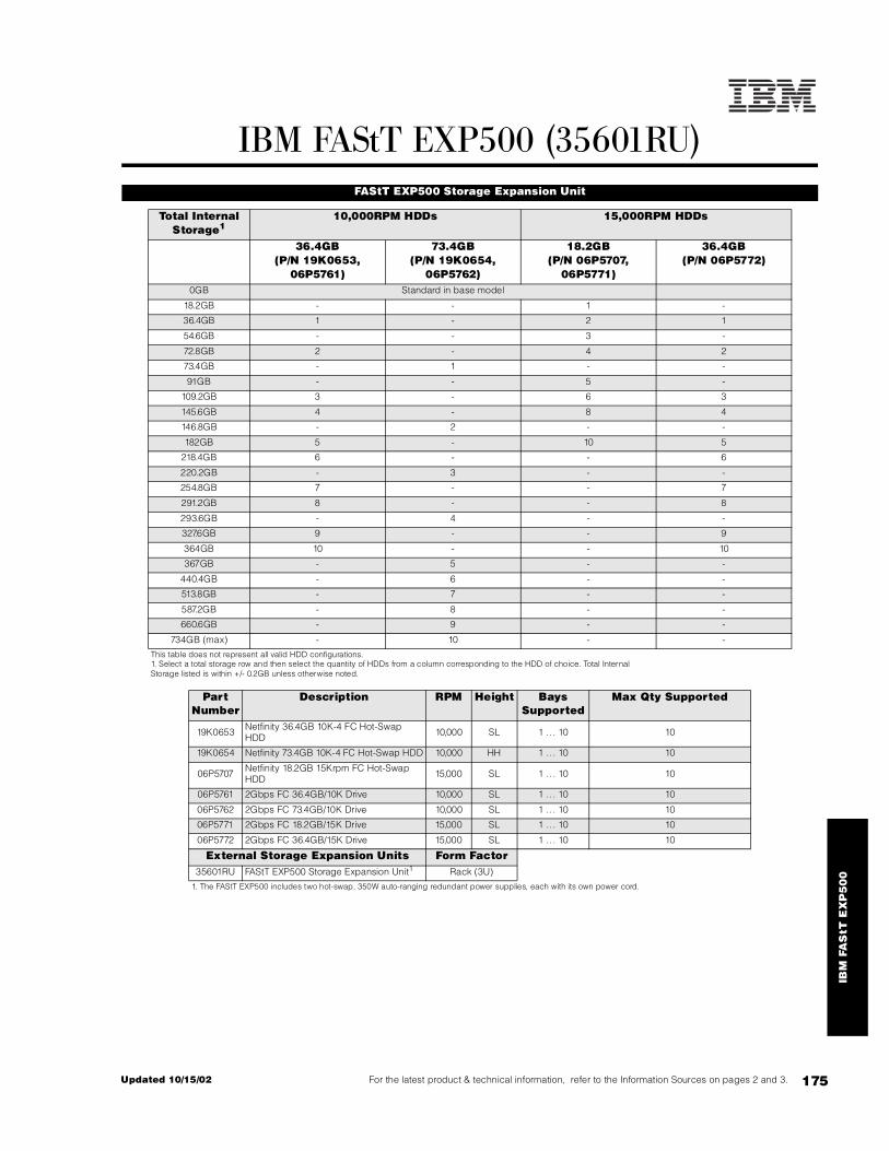
175For the latest product & technical information, refer to the Information Sources on pages 2 and 3.Updated 10/15/02
IBM
FA
StT
EX
P5
00
IBM FAStT EXP500 (35601RU) FAStT EXP500 Storage Expansion Unit
Total Internal Storage1
10,000RPM HDDs 15,000RPM HDDs
36.4GB(P/N 19K0653,
06P5761)
73.4GB(P/N 19K0654,
06P5762)
18.2GB(P/N 06P5707,
06P5771)
36.4GB(P/N 06P5772)
0GB Standard in base model
18.2GB - - 1 -
36.4GB 1 - 2 1
54.6GB - - 3 -
72.8GB 2 - 4 2
73.4GB - 1 - -
91GB - - 5 -
109.2GB 3 - 6 3
145.6GB 4 - 8 4
146.8GB - 2 - -
182GB 5 - 10 5
218.4GB 6 - - 6
220.2GB - 3 - -
254.8GB 7 - - 7
291.2GB 8 - - 8
293.6GB - 4 - -
327.6GB 9 - - 9
364GB 10 - - 10
367GB - 5 - -
440.4GB - 6 - -
513.8GB - 7 - -
587.2GB - 8 - -
660.6GB - 9 - -
734GB (max) - 10 - -
This table does not represent all valid HDD configurations.1. Select a total storage row and then select the quantity of HDDs from a column corresponding to the HDD of choice. Total Internal Storage listed is within +/- 0.2GB unless otherwise noted.
Part Number
Description RPM Height Bays Supported
Max Qty Supported
19K0653 Netfinity 36.4GB 10K-4 FC Hot-Swap HDD 10,000 SL 1 .. . 10 10
19K0654 Netfinity 73.4GB 10K-4 FC Hot-Swap HDD 10,000 HH 1 .. . 10 10
06P5707 Netfinity 18.2GB 15Krpm FC Hot-Swap HDD 15,000 SL 1 .. . 10 10
06P5761 2Gbps FC 36.4GB/10K Drive 10,000 SL 1 .. . 10 10
06P5762 2Gbps FC 73.4GB/10K Drive 10,000 SL 1 .. . 10 10
06P5771 2Gbps FC 18.2GB/15K Drive 15,000 SL 1 .. . 10 10
06P5772 2Gbps FC 36.4GB/15K Drive 15,000 SL 1 .. . 10 10
External Storage Expansion Units Form Factor35601RU FAStT EXP500 Storage Expansion Unit1 Rack (3U)
1. The FAStT EXP500 includes two hot-swap, 350W auto-ranging redundant power supplies, each with its own power cord.

176
External: Fibre ChannelInternal: Fibre ChannelAuto Termination
Fibre Channel Connectors2
FAStT EXP5001
35601RU
IN = primary or secondary (redundant) connection from FAStT500 Storage Server or previous FAStT EXP500 expansion unit daisy-chained from the storage serverOUT = primary or secondary (redundant) connection to additional FAStT EXP500 expansion units
1. Housed in a 19in rack mountable drawer and ships standard with redundant power supplies and two power cables requiring separate power sources. Requires an IBM industry standard 19in rack, EIA-310D with a minimum depth of 24in (711.2mm ) or NetBAY3/3E. Select optional storage controllers and external cables, which are not included with the FAStT storage server or external enclosure, using the Fibre Channel Device Ports Reference.2. GBICs are not included. Either Fibre Channel long or short-wave GBICs (P/N 03K9307 or 03K9308 respectively) may be used.
OUT
Bay
1B
ay 2
Bay
4
Bay
6B
ay 7
Bay
8B
ay 9
Bay
10
Bay
5
Bay
3
IN OUT IN
Loop B
Loop A

177For the latest product & technical information, refer to the Information Sources on pages 2 and 3.Updated 10/15/02
IBM
FA
StT
EX
P5
00
Fibre / Fibre Configuration ExamplesFAStT EXP500 with FAStT500 Storage Server
Note: The following sample configurations are for illustration only and may not be suitable for any specific customer installation. Contact your IBM Business Partner or IBM Marketing Representative for assistance with your specific configuration requirements.
1. FAStT Host Adapter (P/N 00N6881) supports shortwave connections only.2. Buffering the long-wave optic cable expanse with a second switch or hub at the remote storage location is required to requalify the signal.
• P = primary path, S = secondary (redundant) path• Shaded boxes represent separate hosts.• Cable groups are represented by letters in parenthesis.• Maximum of 220 external storage HDDs are supported through 11 enclosures in each cable pair.• The number of servers that can be used in configurations with managed hubs or Fibre Channel switches are dependent on partitioning restrictions of the management system or cluster software.• An optional short- or long-wave GBIC is required for all FAStT500 storage server and FAStT EXP500 storage connections. GBICs are not depicted in these diagrams. See device drawings at the end of this section for details. Other Fibre Channel devices may not require optional GBICs. For specific requirements, see the Fibre Device Ports Reference.
Refer to the Supported Cable Groups chart following the FAStT 200 configuration examples for cable type definitions.
FAStT500 Storage Server(P/N 35521RU)
FAStT Host
Adapter1
FAStT Host
Adapter1
FAStT Host
Adapter1FAStT500 Storage Server
(P/N 35521RU)
FAStT Host
Adapter1
FAStT500 Storage Server(P/N 35521RU)
FAStT Host
Adapter1
FAStT Host
Adapter1 FAStT500 Storage Server(P/N 35521RU)
FAStT Host
Adapter1
FAStT Host
Adapter1
Switch/Hub
Switch/Hub
Switch/Hub2
Switch/Hub
Switch/Hub
P
P
P
S
S
S
S
S
S
S
D1
D1
D1
D1
D1
D1
D1
D1 or E
D1 or E
D1 or E
D1 or E
D1
D1
D1
D1
E
D1
D1
D1
D1
FAStT EXP500
FAStT EXP500
FAStT EXP500
FAStT EXP500
FAStT EXP500
FAStT EXP500
FAStT EXP500
P
P
P
P
D1
D1
D1
4.
2.
3.
1.

178
Fibre / Fibre Configuration ExamplesFAStT EXP500 with FAStT700 Fibre Channel Storage Server
Note: The following sample configurations are for illustration only and may not be suitable for any specific customer installation. Contact your IBM Business Partner or IBM Marketing Representative for assistance with your specific configuration requirements.
1. FAStT FC-2 Host Bus Adapter (P/N 19K1246) includes an integrated short-wave SFF Module, supporting short-wave connections only.2. Fibre Channel connections to the FAStT EXP500 require GBICs. LC-LC Fibre Channel cable does not connect directly into a GBIC. LC-SC Fibre Channel Adapter Cable (P/N 19K1250) is required. Use SC Fibre Channel cable for daisy-chaining FAStT EXP500 units (see the Supported Cable Groups chart for a list of SC cables).3. Buffering the long-wave optic cable expanse with a second switch or hub at the remote storage location is required to requalify the signal.
• P = primary path, S = secondary (redundant) path• Shaded boxes represent separate hosts.• Cable groups are represented by letters in parenthesis.• Maximum of 220 external storage HDDs are supported through a maximum of 11 enclosures in each channel pair (22 enclosures total).• The number of servers that can be used in configurations with managed hubs or Fibre Channel switches are dependent on partitioning restrictions of the management system or cluster software.• An optional short- or long-wave GBIC is required for all FAStT500 EXP500 storage connections. FAStT700 and 2Gb FC switch connections require SFP Modules. LC-SC FC Adapter Cables are required to connect LC-LC FC cables to GBICs in FAStT EXP500 connections. GBICs, SFP Modules and adapter cables are not depicted in these diagrams. See device drawings at the end of this section for details.• For specific requirements concerning connections, refer to the Fibre Device Ports Reference or Fibre Interconnection Guidelines.
Refer to the Supported Cable Groups chart following the FAStT 200 configuration examples for cable type definitions.
FAStT700 Storage Server(P/N 17421RU)
FAStT FC-2 Host
Bus Adapter1
FAStT FC-2 Host
Bus Adapter1
FAStT FC-2 Host
Bus Adapter1FAStT700 Storage Server
(P/N 17421RU)
FAStT FC-2 Host
Bus Adapter1
FAStT700 Storage Server(P/N 17421RU)
FAStT FC-2 Host
Bus Adapter1
FAStT FC-2 Host
Bus Adapter1 FAStT700 Storage Server(P/N 17421RU)
FAStT FC-2 Host
Bus Adapter1
FAStT FC-2 Host
Bus Adapter1
P
P
P
S
S
S
S
S
S
S
D2
D2
D2
D2
D2
D2
D2
D2 or E
D2 or E
D2 or E
D1 or D22
D1 or D22
D1 or D22
D1 or D22
E
D1 or D22
D1 or D22
D1 or D22
D1 or D22
FAStT EXP500
FAStT EXP500
FAStT EXP500
FAStT EXP500
FAStT EXP500
FAStT EXP500
FAStT EXP500
P
P
P
P
D1
D1
D1
D2
SAN FC Switch (2109F16)
SAN FC Switch
(2109F16)3
SAN FC Switch 16-port
(2109F16)
4.
3.
2.
1.
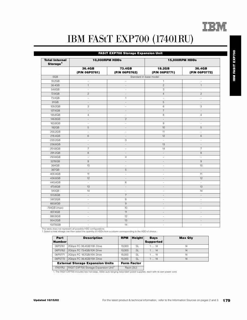
IBM
FA
StT
EX
P70
0
179For the latest product & technical information, refer to the Information Sources on pages 2 and 3.Updated 10/15/02
IBM FAStT EXP700 (17401RU) FAStT EXP700 Storage Expansion Unit
Total Internal Storage1
10,000RPM HDDs 15,000RPM HDDs
36.4GB(P/N 06P5761)
73.4GB(P/N 06P5762)
18.2GB(P/N 06P5771)
36.4GB(P/N 06P5772)
0GB Standard in base model
18.2GB - - 1 -
36.4GB 1 - 2 1
54.6GB - - 3 -
72.8GB 2 - 4 2
73.4GB - 1 - -
91GB - - 5 -
109.2GB 3 - 6 3
127.4GB - - 7 -
145.6GB 4 - 8 4
146.8GB - 2 - -
163.8GB - - 9 -
182GB 5 - 10 5
200.2GB - - 11 -
218.4GB 6 - 12 6
220.2GB - 3 - -
236.6GB - - 13 -
254.8GB 7 - 14 7
291.2GB 8 - - 8
293.6GB - 4 - -
327.6GB 9 - - 9
364GB 10 - - 10
367GB - 5 - -
400.4GB 11 - - 11
436.8GB 12 - - 12
440.4GB - 6 - -
473.6GB 13 - - 13
510GB 14 - - 14
513.8GB - 7 - -
587.2GB - 8 - -
660.6GB - 9 - -
734GB (max) - 10 - -
807.4GB - 11 - -
880.8GB - 12 - -
954.2GB - 13 - -
1027.6GB - 14 - -
This table does not represent all possible HDD configurations.1. Select a total storage row then select the quantity of HDDs from a column corresponding to the HDD of choice.
Part Number
Description RPM Height Bays Supported
Max Qty
06P5761 2Gbps FC 36.4GB/10K Drive 10,000 SL 1 ... 14 14
06P5762 2Gbps FC 73.4GB/10K Drive 10,000 SL 1 ... 14 14
06P5771 2Gbps FC 18.2GB/15K Drive 15,000 SL 1 ... 14 14
06P5772 2Gbps FC 36.4GB/15K Drive 15,000 SL 1 ... 14 14
External Storage Expansion Units Form Factor17401RU FAStT EXP700 Storage Expansion Unit1 Rack (3U)
1. The FAStT EXP700 includes two hot-swap, 400w auto-ranging redundant power supplies, each with its own power cord.

180
Bay
1
Bay
2
Bay
3
Bay
4
Bay
5
Bay
6
Bay
7
Bay
8
Bay
9
Bay
10
Bay
11
Bay
12
Bay
13
Bay
14
Loop A
InOutInOut
Loop B
Fibre Channel Connectors2
FAStT EXP7001
17401RU
IN = primary or secondary (redundant) connection from FAStT700 Storage Server or previous FAStT EXP700 expansion unit daisy-chained from the storage serverOUT = primary or secondary (redundant) connection to additional FAStT EXP700 expansion units
1. Housed in a 19in rack-mountable drawer and ships standard with redundant power supplies and two power cables requiring separate power sources. Requires an IBM industry standard 19in rack, EIA-310D with a minimum depth of 24in (711.2mm). Select optional storage controllers and external cables, which are not included with the FAStT storage server or external enclosure, using the Fibre Device Ports Reference.2. SFP Modules are not included. Either Fibre Channel long or short-wave SFP Modules (P/N 19K1272 or 19K1271 respectively) may be used.
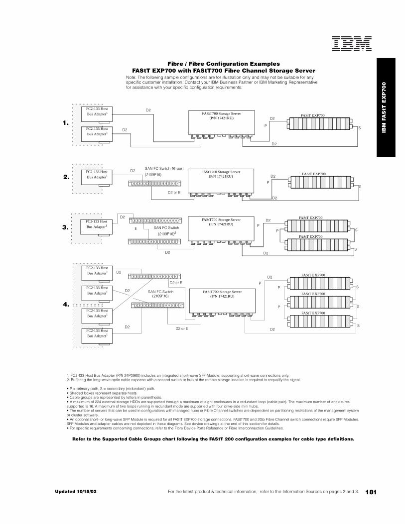
IBM
FA
StT
EX
P70
0
181For the latest product & technical information, refer to the Information Sources on pages 2 and 3.Updated 10/15/02
Fibre / Fibre Configuration ExamplesFAStT EXP700 with FAStT700 Fibre Channel Storage Server
Note: The following sample configurations are for illustration only and may not be suitable for any specific customer installation. Contact your IBM Business Partner or IBM Marketing Representative for assistance with your specific configuration requirements.
1. FC2-133 Host Bus Adapter (P/N 24P0960) includes an integrated short-wave SFF Module, supporting short-wave connections only.2. Buffering the long-wave optic cable expanse with a second switch or hub at the remote storage location is required to requalify the signal.
• P = primary path, S = secondary (redundant) path.• Shaded boxes represent separate hosts.• Cable groups are represented by letters in parenthesis.• A maximum of 224 external storage HDDs are supported through a maximum of eight enclosures in a redundant loop (cable pair). The maximum number of enclosures supported is 16. A maximum of two loops running in redundant mode are supported with four drive-side mini hubs.• The number of servers that can be used in configurations with managed hubs or Fibre Channel switches are dependent on partitioning restrictions of the management system or cluster software.• An optional short- or long-wave SFP Module is required for all FAStT EXP700 storage connections. FAStT700 and 2Gb Fibre Channel switch connections require SFP Modules. SFP Modules and adapter cables are not depicted in these diagrams. See device drawings at the end of this section for details.• For specific requirements concerning connections, refer to the Fibre Device Ports Reference or Fibre Interconnection Guidelines.
Refer to the Supported Cable Groups chart following the FAStT 200 configuration examples for cable type definitions.
FAStT700 Storage Server(P/N 17421RU)
FC2-133 Host
Bus Adapter1
FC2-133 Host
Bus Adapter1
FC2-133 Host
Bus Adapter1FAStT700 Storage Server
(P/N 17421RU)
FC2-133 Host
Bus Adapter1
FAStT700 Storage Server(P/N 17421RU)
FC2-133 Host
Bus Adapter1
FC2-133 Host
Bus Adapter1 FAStT700 Storage Server(P/N 17421RU)
FC2-133 Host
Bus Adapter1
FC2-133 Host
Bus Adapter1
P
P
P
S
S
S
S
S
S
S
D2
D2
D2
D2
D2
D2
D2
D2 or E
D2 or E
D2 or E
D2
D2
D2
D2
E
D2
D2
D2
D2
P
P
P
P
D2
SAN FC Switch (2109F16)
SAN FC Switch
(2109F16)2
SAN FC Switch 16-port
(2109F16)
4.
3.
2.
1.FAStT EXP700
FAStT EXP700
FAStT EXP700
FAStT EXP700
FAStT EXP700
FAStT EXP700
FAStT EXP700

182
Fibre Interconnection Guidelines
00N6881 FAStT Host Adapter - S - S - S S S - S6 S6 S6 S6 - H24P0960 FC2-133 Host Bus Adapter - S7 - S7 - S7 S7 S7 - S S S S - H
2108R3L SAN Data Gateway Router UltraSCSI LVD Port - - - - - - - - - S6 S6 - - - H
3534F08 SAN Fibre Channel Switch, 8-port2, 3 S E7 S E7 S7 E7 E7 E7 - E E E E - H
2109F16 SAN Fibre Channel Switch, 16-Port2, 4 S E7 S E7 S7 E7 E7 E7 - E E E E - H
35421RU FAStT200 Storage Server1 S - S7 H - - - - E E E - - E H35422RU FAStT200 HA Storage Server1 S - S7 - - - - - E E E - - E H
19K1121 FAStT200 Redundant RAID Controller1 S - S7 - - H - - E - - - - - H
35521RU FAStT500 Storage Server1 - H S7 - - - - - E - - - - - H00N6882 FAStT500 Mini Hub1 - E S7 E - - - H E - - - - - H
35601RU FAStT EXP500 Storage Expansion Unit1 - E - E - E E E - - - E6 E6 - H
17421RU FAStT700 Fibre Channel Storage Server2 S7 - S - - - - - E7 E E - H E H
19K1269 FAStT700 Mini Hub2 S7 - S - - - - - E7 E E H - E H
17401RU FAStT EXP700 Storage Expansion Unit2 - - S - - - - - - - - E E - -
03K9307 FC Long-wave GBIC - H - H - H H H H - - - - - H03K9308 FC Short-wave GBIC - H - H - H H H H - - - - - H
19K1250 LC-SC Fibre Channel Adapter Cable5 H H H H H H H H H H H H H H -
19K1271 Short-wave SFP Module - - - - - - - - - H H H H H H19K1272 Long-wave SFP Module - - - - - - - - - H H H H H H
48P7062 BladeCenter 2-port Fibre Channel Switch Module8 - E - E - E E E - - - E E - H
Par
t N
umbe
r
Des
crip
tion
00N
6881
FAStT
Hos
t A
dapt
er00
N68
82 F
AStT
Min
i Hub
124P
0960
FC
2-13
3
Hos
t B
us A
dapt
er
19K
1121
Fas
tT20
0
Red
un R
aid
Con
trol
ler1
2108
R3L
SA
N D
ata
Gat
eway
Rou
ter
3542
1RU
FA
StT
200
Sto
rage
Ser
ver1
3542
2RU
FA
StT
200
HA
Sto
rage
Ser
ver1
3552
1RU
FAStT
500
Sto
rage
Ser
ver1
3560
1RU
FAS
tT
EX
P50
01
3534
F08
Tota
lSto
rage
SAN
Sw
itch
F08
- 8-
Port
221
09F1
6 SA
N F
ibre
Cha
nnel
Sw
itch
,
16- p
ort2
1742
1RU
FA
StT
700
FC S
tora
ge S
erve
r2
19K
1269
FA
StT
Min
i
Hub
2
1740
1RU
FAStT
EX
P70
02
19K
1250
LC
-SC
Fib
re
Cha
nnel
Ada
pter
Cab
le5

183For the latest product & technical information, refer to the Information Sources on pages 2 and 3.Updated 10/15/02
Fib
re C
ha
nn
el
Ove
rvie
w
S Short-wave connection only. See Fibre Device Ports Reference section for GBIC, SFP module or integrated optical port information.E Either short-wave or long-wave connections allowed via the appropriate GBIC or SFP module. See Fibre Device Ports Reference section for GBIC, SFP module or integrated optical port information.H Hardware connection: One of these devices installs directly into the other, e.g., the FAStT500 Mini Hub (P/N 00N6882) installs directly into the FAStT500 Storage Server (P/N 35521RU) to provide GBIC availability.
1. This device requires the use of GBICs. Purchase of GBICs may be needed in order to make connections to this device. See the Fibre Device Ports Reference section for GBIC or integrated optical port information.2. This device requires a long- or short-wave SFP module. See Fibre Device Ports Reference for additional information.3. Additional related options include F08 Full Fabric Activation (P/N 18P5060) and Performance Bundle Activation (P/N 18P4405).4. Additional related options include Remote Switch Activation (P/N 18P3536), Extended Fabric Activation (P/N 18P3580) and F16 Performance Bundle Activation (P/N 18P3590). Power cords for nonrack installation are available by country.5. The LC-SC Fibre Channel Adapter Cable (P/N 19K1250) is designed to connect any 1Gb device or cable to any 2Gb device or cable. When 2Gb and 1Gb technology are combined in a configuration, the signal transfer automatically converts to the slower speed.6. When connected to 2Gb devices or cable, LC-SC Fibre Channel Adapter Cable (P/N 19K1250) is required.7. When connected to 1Gb devices or cable, LC-SC Fibre Channel Adapter Cable (P/N 19K1250) is required.8. Compatible only with BladeCenter. Supports two SFP modules (either short- or long-wave).
Fibre Device Ports Reference
Part Number
Description Total Connections
Possible
Integrated Ports5
Mini Hubs
Possible
Mini Hubs
Installed
GBIC or SFP ModulePorts
GBICs or SFP Modules
Included5
00N6881 FAStT Host Adapter 1 1 - - - -00N6882 FAStT500 Mini Hub1 2 - - - 2 -03K9307 FC Long-wave GBIC 1 - - - - -03K9308 FC Short-wave GBIC 1 - - - - -19K1121 FAStT200 Redundant RAID Controller 2 - - - 2 -
2108R3L San DataGateway Router UltraSCSI LVD Port2 1 1 - - - -
3534F08 TotalStorage SAN Switch F08 - 8-port3 8 - - - 8 410
2109F16 SAN FC Switch, 16-Port4 16 - - - 16 811
35421RU FAStT200 Storage Server 2 - - - 2 -35422RU FAStT200 HA Storage Server 4 - - - 4 -35521RU FAStT500 Storage Server6 12 - 8 4 121 -35601RU FAStT EXP500 Storage Expansion Unit 4 - - - 4 -24P0960 FC2-133 Host Bus Adapter 1 1 - - - -17421RU FAStT700 FC Storage Server7 12 - 8 4 12 -19K1269 FAStT700 Mini Hub8 2 - - - 2 -17401RU FAStT EXP700 Storage Expansion Unit 4 - - - 4 -19K1250 LC-SC FC Adapter Cable9 1 1 - - - -19K1271 Short-wave SFP Module 1 - - - - -19K1272 Long-wave SFP Module 1 - - - - -
48P7062 BladeCenter 2-port Fibre Channel Switch Module12 2 - - - 2 -
1. Each FAStT500 Mini Hub provides two GBIC ports. The host-side mini hubs connect to one of two Fibre Channel controllers in the FAStT500 Storage Server. The drive-side mini hubs each connect to both Fibre Channel controllers. Full redundancy requires connection to two drive-side and two host-side mini hubs. Drive-side mini hubs support connection to one port only.2. Provides one integrated short-wave optical port and two SCSI ports for tape storage connections (one LVD or HVD and one single-ended).3. Additional related options include F08 Full Fabric Activation (P/N 18P5060) and Performance Bundle Activation (P/N 18P4405).4. Additional related options include Remote Switch Activation (P/N 18P3536), Extended Fabric Activation (P/N 18P3580) and F16 Performance Bundle Activation (P/N 18P3590). Power cords for nonrack installation are available by country.5. Standard GBICs, SFP Modules and integrated optical ports are short-wave.6. FAStT500 Storage Server supports up to eight nonredundant or four redundant host connections and two redundant storage drive loops.7. FAStT700 Storage Server supports up to eight nonredundant or four redundant host connections and two redundant storage drive loops.8. Each FAStT700 Mini Hub provides two SFP Module ports. The host-side mini hubs connect to one of two Fibre Channel controllers in the FAStT700 Storage Server. The drive side mini hubs each connect to both Fibre Channel controllers. Full redundancy requires connection to two drive-side and two host-side mini hubs. Drive-side mini hubs support connection to one port only.9. The LC-SC Fibre Channel Adapter Cable (P/N 19K1250) is designed to connect any 1Gb device or cable to any 2Gb device or cable. When 2Gb and 1Gb technology are combined in a configuration, the signal transfer automatically converts to the slower speed.10. Four short-wave SFP modules are standard. Either short-wave or long-wave modules can populate the other four ports.11. Eight short-wave SFP modules are standard. Either short-wave or long-wave modules can populate the other eight ports.12. Compatible only with BladeCenter. Supports two SFP modules (either short- or long-wave).
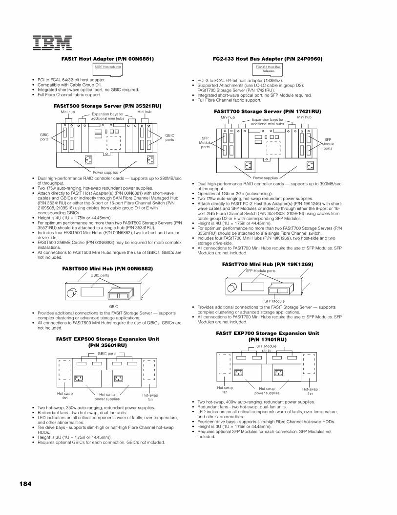
184
FAStT Host Adapter (P/N 00N6881)
• PCI to FCAL 64/32-bit host adapter.• Compatible with Cable Group D1.• Integrated short-wave optical port, no GBIC required.• Full Fibre Channel fabric support.
FAStT500 Storage Server (P/N 35521RU)
• Dual high-performance RAID controller cards — supports up to 380MB/sec of throughput.
• Two 175w auto-ranging, hot-swap redundant power supplies.• Attach directly to FAStT Host Adapter(s) (P/N 00N6881) with short-wave
cables and GBICs or indirectly through SAN Fibre Channel Managed Hub (P/N 35341RU) or either the 8-port or 16-port Fibre Channel Switch (P/N 2109S08, 2109S16) using cables from cable group D1 or E with corresponding GBICs.
• Height is 4U (1U = 1.75in or 44.45mm).• For optimum performance no more than two FAStT500 Storage Servers (P/N
35521RU) should be attached to a single hub (P/N 35341RU).• Includes four FAStT500 Mini Hubs (P/N 00N6882), two for host and two for
drive-side.• FAStT500 256MB Cache (P/N 00N6883) may be required for more complex
installations.• All connections to FAStT500 Mini Hubs require the use of GBICs. GBICs are
not included.
FAStT500 Mini Hub (P/N 00N6882)
• Provides additional connections to the FAStT Storage Server — supports complex clustering or advanced storage applications.
• All connections to FAStT500 Mini Hubs require the use of GBICs. GBICs are not included.
FAStT EXP500 Storage Expansion Unit (P/N 35601RU)
• Two hot-swap, 350w auto-ranging, redundant power supplies.• Redundant fans - two hot-swap, dual-fan units.• LED indicators on all critical components warn of faults, over-temperature,
and other abnormalities.• Ten drive bays - supports slim-high or half-high Fibre Channel hot-swap
HDDs.• Height is 3U (1U = 1.75in or 44.45mm).• Requires optional GBICs for each connection. GBICs not included.
FC2-133 Host Bus Adapter (P/N 24P0960)
• PCI-X to FCAL 64-bit host adapter (133Mhz).• Supported Attachments (use LC-LC cable in group D2):
FAStT700 Storage Server (P/N 17421RU).• Integrated short-wave optical port, no SFP Module required.• Full Fibre Channel fabric support.
FAStT700 Storage Server (P/N 17421RU)
• Dual high-performance RAID controller cards — supports up to 390MB/sec of throughput.
• Operates at 1Gb or 2Gb (autosensing).• Two 175w auto-ranging, hot-swap redundant power supplies.• Attach directly to FAStT FC-2 Host Bus Adapter(s) (P/N 19K1246) with short-
wave cables and SFP Modules or indirectly through either the 8-port or 16-port 2Gb Fibre Channel Switch (P/N 3534S08, 2109F16) using cables from cable group D2 or E with corresponding SFP Modules.
• Height is 4U (1U = 1.75in or 44.45mm).• For optimum performance no more than two FAStT700 Storage Servers (P/N
35521RU) should be attached to a a single Fibre Channel switch.• Includes four FAStT700 Mini Hubs (P/N 19K1269), two host-side and two
storage drive-side.• All connections to FAStT700 Mini Hubs require the use of SFP Modules. SFP
Modules are not included.
FAStT700 MIni Hub (P/N 19K1269)
• Provides additional connections to the FAStT Storage Server — supports complex clustering or advanced storage applications.
• All connections to FAStT700 Mini Hubs require the use of SFP Modules. SFP Modules are not included.
FAStT EXP700 Storage Expansion Unit (P/N 17401RU)
• Two hot-swap, 400w auto-ranging, redundant power supplies.• Redundant fans - two hot-swap, dual-fan units.• LED indicators on all critical components warn of faults, over-temperature,
and other abnormalities.• Fourteen drive bays - supports slim-high Fibre Channel hot-swap HDDs.• Height is 3U (1U = 1.75in or 44.45mm).• Requires optional SFP Modules for each connection. SFP Modules not
included.
FAStT Host Adapter
Mini hub Mini hubExpansion bays for additional mini hubs
Power supplies
GBIC ports
GBICports
GBIC
GBIC ports
GBIC ports
Hot-swapfan
Hot-swapfan
Hot-swappower supplies
FC2-133 Host Bus Adapter
Mini hub Mini hubExpansion bays for additional mini hubs
Power supplies
SFPModuleports
SFPModuleports
SFP Module
SFP Module ports
SFP Module ports
Hot-swapfan
Hot-swapfan
Hot-swappower supplies
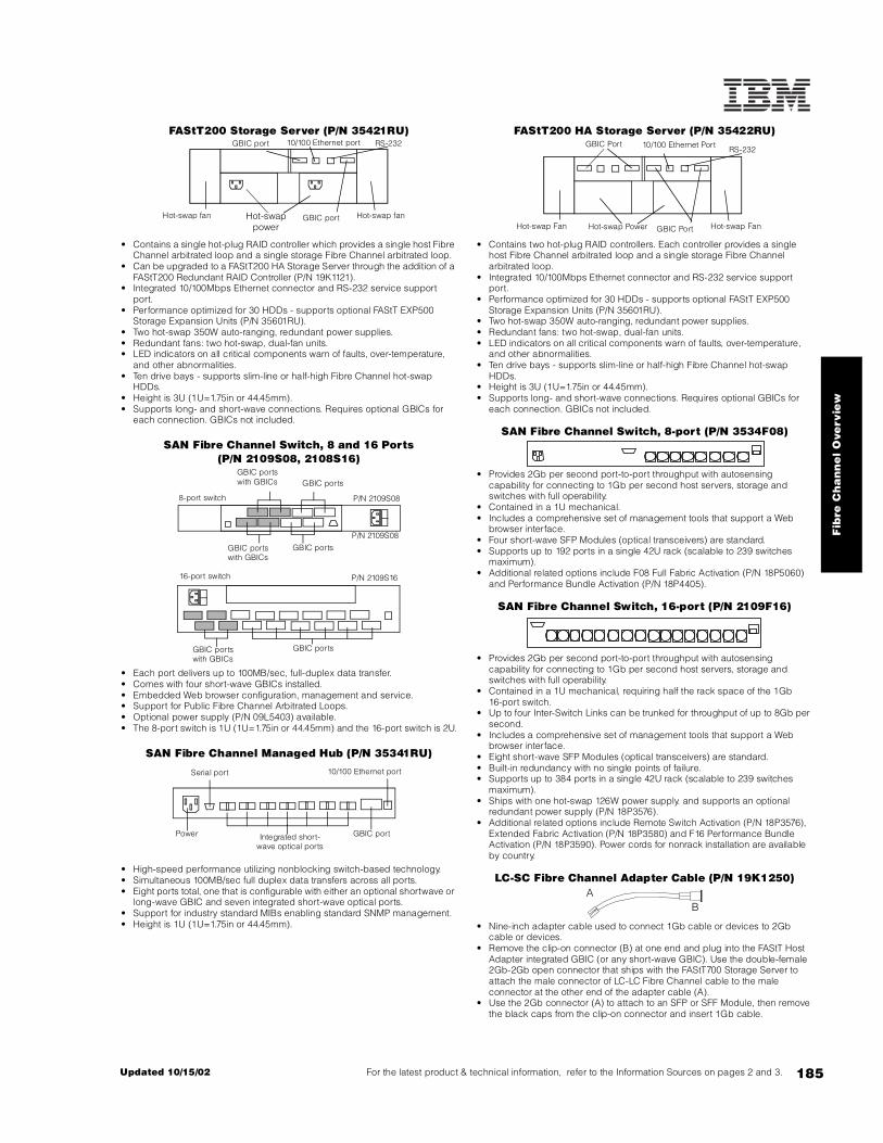
185For the latest product & technical information, refer to the Information Sources on pages 2 and 3.Updated 10/15/02
Fib
re C
ha
nn
el
Ove
rvie
w
FAStT200 Storage Server (P/N 35421RU)
• Contains a single hot-plug RAID controller which provides a single host Fibre Channel arbitrated loop and a single storage Fibre Channel arbitrated loop.
• Can be upgraded to a FAStT200 HA Storage Server through the addition of a FAStT200 Redundant RAID Controller (P/N 19K1121).
• Integrated 10/100Mbps Ethernet connector and RS-232 service support port.
• Performance optimized for 30 HDDs - supports optional FAStT EXP500 Storage Expansion Units (P/N 35601RU).
• Two hot-swap 350W auto-ranging, redundant power supplies.• Redundant fans: two hot-swap, dual-fan units.• LED indicators on all critical components warn of faults, over-temperature,
and other abnormalities.• Ten drive bays - supports slim-line or half-high Fibre Channel hot-swap
HDDs.• Height is 3U (1U=1.75in or 44.45mm).• Supports long- and short-wave connections. Requires optional GBICs for
each connection. GBICs not included.
SAN Fibre Channel Switch, 8 and 16 Ports(P/N 2109S08, 2108S16)
• Each port delivers up to 100MB/sec, full-duplex data transfer.• Comes with four short-wave GBICs installed.• Embedded Web browser configuration, management and service.• Support for Public Fibre Channel Arbitrated Loops.• Optional power supply (P/N 09L5403) available.• The 8-port switch is 1U (1U=1.75in or 44.45mm) and the 16-port switch is 2U.
SAN Fibre Channel Managed Hub (P/N 35341RU)
• High-speed performance utilizing nonblocking switch-based technology.• Simultaneous 100MB/sec full duplex data transfers across all ports.• Eight ports total, one that is configurable with either an optional shortwave or
long-wave GBIC and seven integrated short-wave optical ports.• Support for industry standard MIBs enabling standard SNMP management.• Height is 1U (1U=1.75in or 44.45mm).
FAStT200 HA Storage Server (P/N 35422RU)
• Contains two hot-plug RAID controllers. Each controller provides a single host Fibre Channel arbitrated loop and a single storage Fibre Channel arbitrated loop.
• Integrated 10/100Mbps Ethernet connector and RS-232 service support port.
• Performance optimized for 30 HDDs - supports optional FAStT EXP500 Storage Expansion Units (P/N 35601RU).
• Two hot-swap 350W auto-ranging, redundant power supplies.• Redundant fans: two hot-swap, dual-fan units.• LED indicators on all critical components warn of faults, over-temperature,
and other abnormalities.• Ten drive bays - supports slim-line or half-high Fibre Channel hot-swap
HDDs.• Height is 3U (1U=1.75in or 44.45mm).• Supports long- and short-wave connections. Requires optional GBICs for
each connection. GBICs not included.
SAN Fibre Channel Switch, 8-port (P/N 3534F08)
• Provides 2Gb per second port-to-port throughput with autosensing capability for connecting to 1Gb per second host servers, storage and switches with full operability.
• Contained in a 1U mechanical.• Includes a comprehensive set of management tools that support a Web
browser interface.• Four short-wave SFP Modules (optical transceivers) are standard.• Supports up to 192 ports in a single 42U rack (scalable to 239 switches
maximum).• Additional related options include F08 Full Fabric Activation (P/N 18P5060)
and Performance Bundle Activation (P/N 18P4405).
SAN Fibre Channel Switch, 16-port (P/N 2109F16)
• Provides 2Gb per second port-to-port throughput with autosensing capability for connecting to 1Gb per second host servers, storage and switches with full operability.
• Contained in a 1U mechanical, requiring half the rack space of the 1Gb16-port switch.
• Up to four Inter-Switch Links can be trunked for throughput of up to 8Gb per second.
• Includes a comprehensive set of management tools that support a Web browser interface.
• Eight short-wave SFP Modules (optical transceivers) are standard.• Built-in redundancy with no single points of failure.• Supports up to 384 ports in a single 42U rack (scalable to 239 switches
maximum).• Ships with one hot-swap 126W power supply. and supports an optional
redundant power supply (P/N 18P3576).• Additional related options include Remote Switch Activation (P/N 18P3576),
Extended Fabric Activation (P/N 18P3580) and F16 Performance Bundle Activation (P/N 18P3590). Power cords for nonrack installation are available by country.
LC-SC Fibre Channel Adapter Cable (P/N 19K1250)
• Nine-inch adapter cable used to connect 1Gb cable or devices to 2Gb cable or devices.
• Remove the clip-on connector (B) at one end and plug into the FAStT Host Adapter integrated GBIC (or any short-wave GBIC). Use the double-female 2Gb-2Gb open connector that ships with the FAStT700 Storage Server to attach the male connector of LC-LC Fibre Channel cable to the male connector at the other end of the adapter cable (A).
• Use the 2Gb connector (A) to attach to an SFP or SFF Module, then remove the black caps from the clip-on connector and insert 1Gb cable.
Hot-swap fan Hot-swap power
Hot-swap fanGBIC port
GBIC port 10/100 Ethernet port RS-232
GBIC portswith GBICs GBIC ports
GBIC portsGBIC portswith GBICs
GBIC ports
8-port switch
16-port switch
GBIC portswith GBICs
P/N 2109S08
P/N 2109S16
P/N 2109S08
Power Integrated short-wave optical ports
GBIC port
Serial port 10/100 Ethernet port
Hot-swap Fan Hot-swap Power Hot-swap FanGBIC Port
GBIC Port 10/100 Ethernet PortRS-232
AB
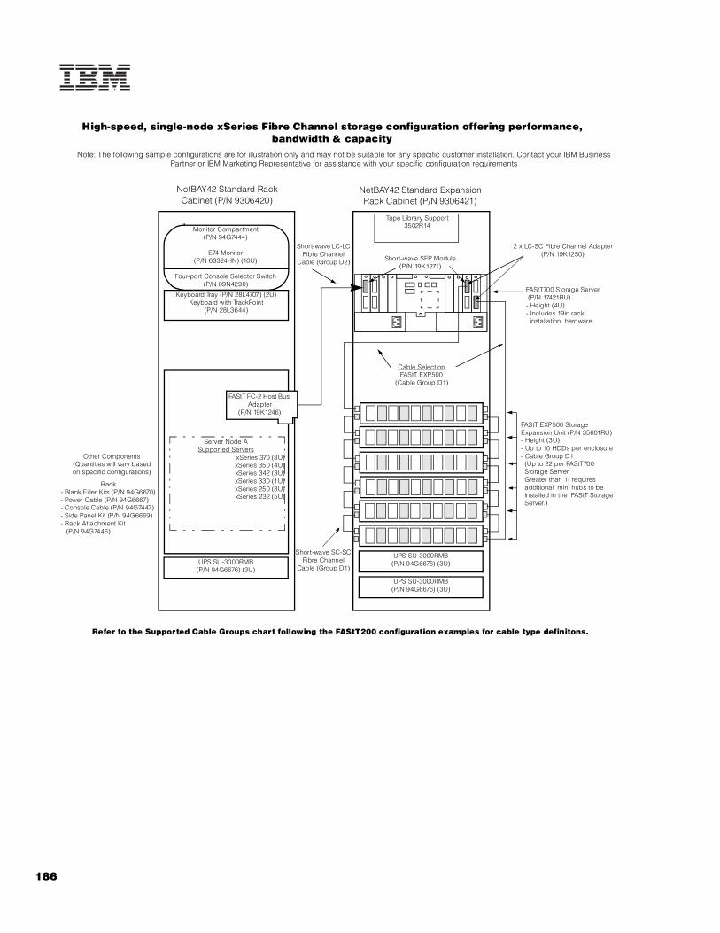
186
Refer to the Supported Cable Groups chart following the FAStT200 configuration examples for cable type definitons.
Keyboard Tray (P/N 28L4707) (2U)Keyboard with TrackPoint
(P/N 28L3644)
Monitor Compartment(P/N 94G7444)
E74 Monitor(P/N 63324HN) (10U)
Four-port Console Selector Switch(P/N 09N4290)
Server Node ASupported Servers
xSeries 370 (8U)xSeries 350 (4U)xSeries 342 (3U)xSeries 330 (1U)xSeries 250 (8U)xSeries 232 (5U)
NetBAY42 Standard Rack Cabinet (P/N 9306420)
UPS SU-3000RMB(P/N 94G6676) (3U)
UPS SU-3000RMB(P/N 94G6676) (3U)
UPS SU-3000RMB(P/N 94G6676) (3U)
Short-wave LC-LC Fibre Channel
Cable (Group D2)
NetBAY42 Standard Expansion Rack Cabinet (P/N 9306421)
Other Components(Quantities will vary basedon specific configurations)
Note: The following sample configurations are for illustration only and may not be suitable for any specific customer installation. Contact your IBM Business Partner or IBM Marketing Representative for assistance with your specific configuration requirements
FAStT FC-2 Host Bus Adapter
(P/N 19K1246)
Tape Library Support3502R14
FAStT EXP500 Storage Expansion Unit (P/N 35601RU)- Height (3U)- Up to 10 HDDs per enclosure- Cable Group D1 (Up to 22 per FAStT700 Storage Server. Greater than 11 requires additional mini hubs to be installed in the FAStT Storage Server.)
FAStT700 Storage Server (P/N 17421RU)- Height (4U)- Includes 19in rack installation hardware
Cable SelectionFAStT EXP500
(Cable Group D1)
Short-wave SC-SCFibre Channel
Cable (Group D1)
Short-wave SFP Module(P/N 19K1271)
High-speed, single-node xSeries Fibre Channel storage configuration offering performance, bandwidth & capacity
2 x LC-SC Fibre Channel Adapter (P/N 19K1250)
Rack- Blank Filler Kits (P/N 94G6670)- Power Cable (P/N 94G6667)- Console Cable (P/N 94G7447)- Side Panel Kit (P/N 94G6669)- Rack Attachment Kit (P/N 94G7446)

187For the latest product & technical information, refer to the Information Sources on pages 2 and 3.Updated 10/15/02
Fib
re C
ha
nn
el
Ove
rvie
w
Refer to the Supported Cable Groups chart following the FAStT200 configuration examples for cable type definitions.
NetBAY42 Standard Rack Cabinet (P/N 9306420)
UPS SU-3000RMB(P/N 94G6676) (3U)
FAStT FC-2 Host Bus Adapter
(P/N 19K1246)
Other Components(Quantities will vary basedon specific configurations)
Rack- Blank Filler Kits (P/N 94G6670)- Power Cable (P/N 94G6667)- Console Cable (P/N 94G7447)- Side Panel Kit (P/N 94G6669)- Rack Attachment Kit (P/N 94G7446)
High-speed, single-node xSeries Fibre Channel storage configuration with Microsoft NT failover support and RAID redundancy for availability, performance and capacity
Note: The following sample configurations are for illustration only and may not be suitable for any specific customer installation. Contact your IBM Business Partner or IBM Marketing Representative for assistance with your specific configuration requirements
FAStT FC-2 Host Bus Adapter
(P/N 19K1256)
UPS SU-3000RMB(P/N 94G6676) (3U)
UPS SU-3000RMB(P/N 94G6676) (3U)
NetBAY42 Standard Expansion Rack Cabinet (P/N 9306421)
Tape Library Support3502R14
Cable SelectionFAStT EXP500
(Cable Group D1)
Short Wave GBIC(P/N 03K9308)
Server Node ASupported Servers
xSeries 370 (8U)xSeries 350 (4U)xSeries 342 (3U)xSeries 330 (1U)xSeries 250 (8U)xSeries 232 (5U)
2 x LC-SC Fibre Channel Adapter (P/N 19K1250)
FAStT EXP500 Storage Expansion Unit (P/N 35601RU)- Height (3U)- Up to 10 HDDs per enclosure- Cable Group D1 (Up to 22 per FAStT700 Storage Server. Greater than 11 requires additional mini hubs to be installed in the FAStT Storage Server.)
FAStT700 Storage Server (P/N 17421RU)- Height (4U)- Includes 19in rack installation hardware
Keyboard Tray (P/N 28L4707) (2U)Keyboard with TrackPoint
(P/N 28L3644)
Monitor Compartment(P/N 94G7444)
E74 Monitor(P/N 63324HN) (10U)
Four-port Console Selector Switch(P/N 09N4290)
Short-wave LC-LC Fibre Channel
Cable (Group D2)
Short-wave SC-SC Fibre Channel
Cable (Group D1)

Pages intentionally blank
Pages intentionally blank
188-194 Updated 10/15/02

Pages intentionally blank
Pages intentionally blank
188-194 Updated 10/15/02

IBM Rack Cabinets and Options
EMEA Part Number Cross ReferenceNetBAY Rack Cabinets
EMEA AMERICAS M/C TYPE DESCRIPTION EMEAP/N P/N MODEL WDFM DATE
9306110 9306110 --- NetBAY 11 ---9306250 9306250 --- NetBAY 25 Standard Rack ---9306420 9306420 --- NetBAY 42 Standard Rack ---9306421 9306421 --- NetBAY 42 Expansion ---930842S 930842S --- NetBAY 42 Enterprise Standard Rack ---930842E 930842E --- NetBAY 42 Enterprise Expansion ---
Rack OptionsEMEA AMERICAS M/C TYPE DESCRIPTION EMEA
P/N P/N MODEL WDFM DATENote 1 28L36xx 28L3644 --- Spacesaver II Keyboard ---Note 2 T3147xx 633147N 6331-47N E54 15" (13.8" viewable image) Colour Monitor (S/Blac ---Note 2 T3247xx 63324HN 6332-4HN E74 17" (16" viewable image) Colour Monitor (S/Black) ---Note 2 T274Axx 66274AN 6627-4AN G78 17" (16" viewable image) Colour Monitor (S/Black ---
N/A 32P1031 --- NetBAY 1U Flat Panel Monitor Console Kit (with US ke ---N/A 32P1702 --- NetBAY 2U Flat Panel Monitor Console Kit (with US ke ---
Note 3 37L68xx 37L6866 --- NetBAY Rack PDU ---Note 4 37L68xx 37L6865 --- NetBAY Server Dual-Cord PDU ---
37L6885 37L6884 --- NetBAY 200-240V Single-Phase Front-End PDU ---37L6887 37L6886 --- NetBAY Three-Phase Front-End PDU ---
Note 5 32P16xx 32P1020 --- APC 2U Smart-UPS 1400RMiB ---Note 6 30RIxxx 94G6676 --- APC Smart-UPS 3000RMiB ---
37L6862 37L6861 --- APC Smart-UPS 5000RMiB ---94G7448 94G6667 --- Rack Power Cord ---
1. Where ‘xx’ represents a specific country code as follows:- 46=Danish , 47=French, 48=German, 49=Italian, 50=Spanish, 51=UK English, 44=US English, and P/N 19K3831=Swiss, 19K3832=Swedish/Finnish, 19K3833=Portugese, 19K3834=Belgian,19K3836=Russian, 19K3837=Polish.
2. Where ‘xx’ represents a specific country code as follows: DK=Denmark, IS=Israel, IT=Italy, SD=Saudi Arabia, SA=South Africa/Pakistan, CH=Switzerland, UK=UK, EU=Europe.
3. Where ‘xx’ represents a specific country code as follows: 66=US/Saudi Arabia, 68=EU, 70=Denmark/Switzerland, 72=Israel, 74=Italy, 76=South Africa, P/N 06P6028=UK.
4. Where ‘xx’ represents a specific country code as follows: 65=US/Saudi Arabia, 67=EU, 69=Denmark/Switzerland, 71=Israel, 73=Italy, 75=South Africa, P/N 06P6027=UK.
5. Where ‘xx’ represents a specific country code as follows:- 12=Europe, 13=UK, 14=Italy, 15=Switzerland, 16=Denmark, 17=South Africa, 18=Israel.
6. Where ‘xxx’ represents a specific country code as follows:- DEN=Denmark, ISR=Israel, ITA=Italy, SDI=Saudi Arabia, SAF=South Africa, SWS=Switzerland, UKM=United Kingdom, EUR=Europe.
194A Updated 10/15/02

195For the latest product & technical information, refer to the Information Sources on pages 2 and 3.Updated 10/15/02
IBM
Ra
ck
Ca
bin
et
Rack Cabinets and Options
IBM NetBAY11 Standard Rack
IBM NetBAY25 Standard Rack3
IBM NetBAY42 Standard Rack
IBM NetBAY42 Enterprise Rack
Machine Type / Model 9306110 9306250 9306420 9306421 930842S 930842E
EIA Capacity1 11U 25U 42U 42U 42U 42U
Sidewall Compartments 0 2 6 6 4 4
Front Stabilizers Std Std Std Std Std Std
Side Stabilizers NR NR Std Std NR NR
Casters Std Std Std Std Std Std
Leveling Feet NA Std Std Std Std Std
Side Covers Std Std Std NR Std NR
Rack Attachment Kit2 NA NA NR Std NR Std
Glass Front Door NA NA NA NA NA NA
Perforated Front Door Std Std Std Std Std Std
Perforated Rear Door NA Std Std Std Std Std
Height (mm/in)4 611 / 24.1 1360 / 53.5 2076 / 81.7 2076 / 81.7 2020 / 79.5 2020 / 79.5
Width (mm/in) 518 / 20.4 600 / 23.6 600 / 23.6 600 / 23.6 648 / 25.5 648 / 25.5
Depth (mm/in) 873 / 34.4 1000 / 39.4 1000 / 39.4 1000 / 39.4 1105 / 43.5 1105 / 43.5
Empty Weight (kg/lb) 34 / 75 80 / 177 117 / 258 92 / 202 261 / 575 234 / 516
Max Load (kg/lb) 182 / 401 385 / 849 646 / 1424 646 / 1424 667 / 1470 667 / 1470
Total Weight (kg/lb) 216 / 476 465 / 1026 763 / 1682 738 / 1626 928 / 2045 901 / 1986
Shippable Loaded5 Yes Yes No No Yes Yes
NR - Not Required NA - Not Available 1U=1.75in (44.5mm)
1. Conforms to EIA 310 - D Standard 19in rack specification for a Type A cabinet with universal hole spacing.2. Required to attach racks together to make a suite.3. Display and keyboard may be placed on top of the NetBAY25.4. Minimum clearance to the ceiling is 305mm / 12in.5. ‘Shippable loaded’ means the cabinet is capable of being transported with equipment installed. Required packaging is provided. The integrator/assembler is responsible for assuring the stability of the shipped configuration. Rack Integration Services are available from IBM.
U
U
U
U
1010 10
10
20 2020
3030
40
A B
C DF
A B
C D
E
A B
IBM NetBAY11Standard Rack
9306-110
IBM NetBAY25Standard Rack
9306-250
IBM NetBAY42Standard Rack9306-420, 421
IBM NetBAY42Enterprise Rack9308-42S, 42E
40

196
Server System Rack AlternativesConversion Kits Standard Racks1 Enterprise
Racks1
09
N4
30
04
Ux
20
D T
ow
er-
to-R
ac
k K
it21
P9
59
35
Ux
24
D T
ow
er-
to-R
ack
Kit
II
59
P42
11
5U
x2
4D
To
we
r-to
-Ra
ck
Kit
iII
32
P1
474
7U
x2
6D
Tow
er-
to-R
ac
k K
it37
L6
859
8U
x2
4D
Tow
er-
to-R
ac
k K
it
37
L6
86
08
Ux
24
D R
ack
-to
-Tow
er
Kit
93
06
-11
0N
etB
AY
11
93
06
-25
0N
etB
AY
25
SR
93
06
-42
0N
etB
AY
42
SR
93
06
-421
Ne
tBAY
42
SX
93
08
-42
SN
etB
AY
42
ER
93
08
-42
EN
etB
AY
42
EX
ServersxSeries 2002 X X X X X X X
xSeries 2052 X X X X X X X
xSeries 2202 X X X X X X X
xSeries 235 X X X X X X X
xSeries 250 X X X X X X X X
xSeries 255 X X X X X X X
xSeries 3003 X X X X X X
xSeries 3053 X X X X X X
xSeries 3303 X X X X X X
xseries 335 X X X X X X
xSeries 345 X X X X X X
xSeries 360 X X X X X X
xSeries 440 X X X X X X
BladeCenter X X X X X X
1. See the first page of Rack Cabinets and Options section for additional information concerning IBM rack-supported devices.2. Rack installation requires appropriate conversion kit.3. Blank filler panels (P/N 94G6670) should be placed on the front of any unused rack space to aid proper airflow through the system units. If non-IBM racks are used, assure that both the front and rear doors offer a minimum of 45% open area uniformly distributed and in line with the installed servers. A clearance of at least 51mm (2in) must be maintained between the front door and the system unit’s front bezel. The rear door must maintain the same or greater clearance. Nonrack installations are not supported.
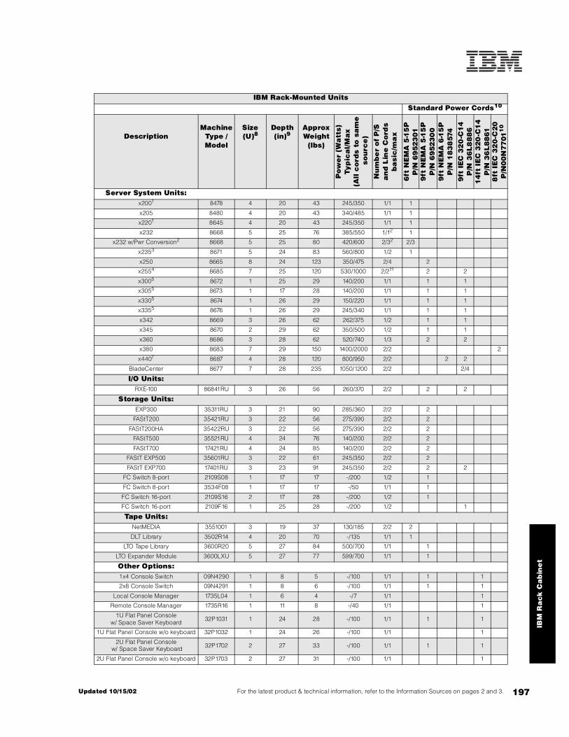
197For the latest product & technical information, refer to the Information Sources on pages 2 and 3.Updated 10/15/02
IBM
Ra
ck
Ca
bin
et
IBM Rack-Mounted UnitsStandard Power Cords10
DescriptionMachine
Type / Model
Size (U)8
Depth (in)9
Approx Weight
(lbs)
Pow
er
(Wa
tts)
Typ
ica
l/M
ax
(A
ll c
ord
s to
sa
me
so
urc
e)
Nu
mb
er
of
P/S
a
nd
Lin
e C
ord
sb
asi
c/m
ax
6ft
NE
MA
5-1
5P
P
/N 6
952
301
9ft
NE
MA
5-1
5P
P
/N 6
952
30
09
ft N
EM
A 6
-15
P
P/N
18
38
574
9ft
IE
C 3
20
-C1
4
P/N
36
L8
88
61
4ft
IE
C 3
20
-C1
4
P/N
36
L8
861
8ft
IE
C 3
20
-C2
0
P/N
00
N77
011
0
Server System Units:x2001 8478 4 20 43 245/350 1/1 1
x205 8480 4 20 43 340/485 1/1 1
x2201 8645 4 20 43 245/350 1/1 1
x232 8668 5 25 76 385/550 1/12 1
x232 w/Pwr Conversion2 8668 5 25 80 420/600 2/32 2/3
x2353 8671 5 24 83 560/800 1/2 1
x250 8665 8 24 123 350/475 2/4 2
x2554 8685 7 25 120 530/1000 2/211 2 2
x3005 8672 1 25 29 140/200 1/1 1 1
x3055 8673 1 17 28 140/200 1/1 1 1
x3305 8674 1 26 29 150/220 1/1 1 1
x3355 8676 1 26 29 245/340 1/1 1 1
x342 8669 3 26 62 262/375 1/2 1 1
x345 8670 2 29 62 350/500 1/2 1 1
x360 8686 3 28 62 520/740 1/3 2 2
x380 8683 7 29 150 1400/2000 2/2 2
x4407 8687 4 28 120 800/950 2/2 2 2
BladeCenter 8677 7 28 235 1050/1200 2/2 2/4
I/O Units:RXE-100 86841RU 3 26 56 260/370 2/2 2 2
Storage Units:EXP300 35311RU 3 21 90 285/360 2/2 2
FAStT200 35421RU 3 22 56 275/390 2/2 2
FAStT200HA 35422RU 3 22 56 275/390 2/2 2
FAStT500 35521RU 4 24 76 140/200 2/2 2
FAStT700 17421RU 4 24 85 140/200 2/2 2
FAStT EXP500 35601RU 3 22 61 245/350 2/2 2
FAStT EXP700 17401RU 3 23 91 245/350 2/2 2 2
FC Switch 8-port 2109S08 1 17 17 -/200 1/2 1
FC Switch 8-port 3534F08 1 17 17 -/50 1/1 1
FC Switch 16-port 2109S16 2 17 28 -/200 1/2 1
FC Switch 16-port 2109F16 1 25 28 -/200 1/2 1
Tape Units:NetMEDIA 3551001 3 19 37 130/185 2/2 2
DLT Library 3502R14 4 20 70 -/135 1/1 1
LTO Tape Library 3600R20 5 27 84 500/700 1/1 1
LTO Expander Module 3600LXU 5 27 77 599/700 1/1 1
Other Options:1x4 Console Switch 09N4290 1 8 5 -/100 1/1 1 1
2x8 Console Switch 09N4291 1 8 6 -/100 1/1 1 1
Local Console Manager 1735L04 1 6 4 -/7 1/1 1
Remote Console Manager 1735R16 1 11 8 -/40 1/1 1
1U Flat Panel Console w/ Space Saver Keyboard 32P1031 1 24 28 -/100 1/1 1 1
1U Flat Panel Console w/o keyboard 32P1032 1 24 26 -/100 1/1 1
2U Flat Panel Console w/ Space Saver Keyboard 32P1702 2 27 33 -/100 1/1 1 1
2U Flat Panel Console w/o keyboard 32P1703 2 27 31 -/100 1/1 1
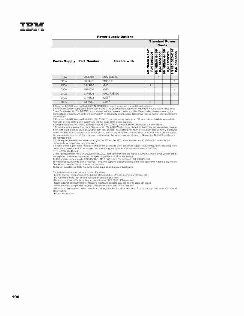
198
Power Supply OptionsStandard Power
Cords
Power Supply Part Number Usable with
6ft
NE
MA
5-1
5P
P/N
69
523
01
9ft
NE
MA
5-1
5P
P/N
69
523
00
6ft
NE
MA
6-1
5P
P/N
18
38
576
9ft
IE
C 3
20
-C1
4P
/N 3
6L
88
86
110w 09L5403 2109-S08, 16 1
126w 18P3576 2109-F16 1
250w 33L3760 x250 1
350w 59P4057 x345 1
370w 31P6108 x360, RXE-100 1 1
370w 31P6133 x25511
560w 33P2753 x23512 2
1. Requires 4Ux20D Tower-to-Rack Kit (P/N 09N4300) to mount server unit into an EIA rack cabinet.2. One 385W power supply standard on base models, two 250W power supplies on redundant models. xSeries Hot-Swap Power Conversion Kit (P/N 24P3513) supports one to three hot-swap power supplies. Base models require removing the standard power supply and adding the conversion kit with 250W power supply. Redundant models do not require adding the conversion kit.3. Requires 5Ux24D Tower-to-Rack Kit III (P/N 59P4211) to mount server unit into an EIA rack cabinet. Models are available with both a single 560w power supply and two hot-swap 560w power supplies.4. Tower models require 7Ux26D Tower-to-Rack Kit (P/N 32P1474) to mount server unit into an EIA rack cabinet.5. To provide adequate cooling, blank filler panel kit (P/N 94G6670) should be placed on the front of any unused rack space. If non-IBM racks are to be used, assure that both front and rear doors offer a minimum of 48% open area uniformly distributed and in line with installed servers. A clearance of 51 to 64mm (2 to 2.5in) must be maintained between the front of the door and the system unit’s front bezel. The rear door must maintain the same or greater clearance. Nonrack or NetBAY3 installations are not supported.6. x370 requires installation of extension kit (P/N 36L9703 or 36L9702) when installed in a 9306-900, 910 or 9306-200, respectively, for proper rear door clearance. 7. Internal power supply logic limits low voltage (100-127VAC) to 550w per power supply. Thus, configurations requiring more power are not redundant for low voltage installations, e.g., configurations with more than two processors. 8. 1U = 1.75in (44.45mm).9. The Rack Extension Kits (P/N 36L9703 or 36L9702) add eight inches to the rear of a 9306-900, 910 or 9306-200 for cable management and are recommended for systems greater than 24 inches in depth.10. Optional rack power cords: P/N 94G6667 - 14ft NEMA 5-15P; P/N 94G7448 - 14ft IEC 320-C14.11. Additional power cords are not required. This power supply option shares use of line cords provided with the base system. Should be ordered in pairs to maintain redundancy.12. Option includes two 560w hot-swap power supplies and a power backplane.
General rack placement rules and other information:- Locate heaviest components at the bottom of the rack (i.e., UPS, then servers or storage, etc.).- Do not extend more than one component on side rails at a time.- Maximum of three UPSs (including no more than two APC 5000 UPSs) per rack.- Utilize sidewall compartments for mounting PDUs and console switches prior to using EIA space.- When mounting components in a rack, consider user and service requirements.- When selecting length of power, console and storage cables, consider extension of cable management arms and overall cable routing.- BTUs = Watts x 3.41.

199For the latest product & technical information, refer to the Information Sources on pages 2 and 3.Updated 10/15/02
IBM
Ra
ck
Ca
bin
et
Rack OptionsPart Number Description Information
28L4707 Netfinity Rack Keyboard Tray Supports keyboards in racks, also used with Flat Panel Monitor Rack Mount Kit II
28L3644 Space Saver II Keyboard 1U, includes TrackPoint IV, requires Rack Keyboard Tray (P/N 28L4707)
94G7444 Monitor Compartment
633147N E54 Color Monitor 9U, requires Monitor Compartment (P/N 94G7444)
63324HN E74 Color Monitor 10U, requires Monitor Compartment (P/N 94G7444)
32P1702 NetBAY 2U Flat Panel Monitor Console Kit with Space Saver Keyboard (US)
2U, built-in 15in Flat Panel Monitor (15in viewable image), includes SpaceSaver Keyboard-US English (P/N 28L3644)
32P1703 NetBAY 2U Flat Panel Monitor Console Kit without keyboard
2U, built-in 15in Flat Panel Monitor (15in viewable image), space for SpaceSaver Keyboard
32P1031 NetBAY1U Flat Panel Monitor Console Kit with Space Saver Keyboard (US)
1U, built-in 15in Flat Panel Monitor (15in viewable image), includes SpaceSaver Keyboard - US English (P/N 28L3644)
32P1032 NetBAY 1U Flat Panel Monitor Console Kit without keyboard
1U, built-in 15in Flat Panel Monitor (15in viewable image), space for SpaceSaver Keyboard
09N4290 NetBAY 1 x 4 Console Switch 1U, mounts in sidewall compartments, EIA space or Monitor Compartment; supports one to four servers, one console
09N4291 NetBAY 2 x 8 Console Switch1U, mounts in sidewall compartments, EIA space or Monitor Compartment; supports one to eight servers, two consoles (only one console when installed in the Monitor Compartment)
09N4293 Console Cable Set - 7ft Connects servers to console switch
94G7447 Console Cable Set - 12ft Connects servers to console switch
1735L04 Local Console Manager 1U, mounts in sidewall compartments, EIA space or behind 1U Console Kit; supports one to 64 servers, one local console
1735R16 Remote Console Manager 1U, mounts in sidewall compartments or EIA space; supports one to 256 servers, one local console and two remote consoles
32P1636 Short KVM Conversion OptionConverts the console signals of servers without cable management arms (not on slides) so they can be chained to connect to a Local or Remote Console Manager using Cat5 cable
32P1652 Long KVM Conversion OptionConverts the console signals of servers with cable management arms (on slides) so they can be chained to connect to a Local or Remote Console Manager using Cat5 cable
32P1637 C2T Conversion Option Converts the console signals of a chain of C2T-capable servers so they can be connected to a Local or Remote Console Manager using Cat5 cable
94G6666 100-120V Power Distribution Unit 1U, 100-120V, 12A, mounts in sidewall compartment or EIA space, eight NEMA 5-15R outlets, requires one L5-15R wall receptacle
37L6866 NetBAY Rack PDU (US) 1U, 100-240V, 15A, mounts in sidewall compartment or EIA space, seven IEC 320-C13 outlets, requires one NEMA L5-20R or L6-20R wall receptacle
37L6865 NetBAY Server Dual-cord PDU (US) 1U, 100-240V, 15/10A, mounts in sidewall compartment or EIA space, four IEC 320-C13 outlets, requires two NEMA L5-20R or L6-20R wall receptacles
37L6883 NetBAY 100-127V Single-phase Front-end PDU (US) 1U, 100-127V, 24A, mounts in sidewall compartment, three IEC 320-C19 outlets, requires one NEMA L5-30R wall receptacle
37L6884 NetBAY 200-240V Single-phase Front-end PDU(US) 1U, 200-240V, 24A, mounts in sidewall compartment, three IEC 320-C19 outlets, requires one NEMA L6-30R wall receptacle
37L6886 NetBAY 3-phase Front-end PDU (US)1U ,input: 200-250V, 30A, three-phase service, mounts in sidewall compartment, output: three single-phase 115-145V, shared 41A, IEC 320-C19 outlets, requires one NEMA L21-30R wall receptacle
32P1020 APC 2U Smart-UPS 1400RMB 2U, 120V, 9.5A, six NEMA 5-15R outlets, requires one NEMA L5-15R wall receptacle
94G6676 APC Smart-UPS 3000RMB 3U, 120V, 22.5A, eight NEMA 5-15R outlets, requires one NEMA L5-30R wall receptacle
37L6861 APC Smart-UPS 5000RMB5U, 208V, 18.75A, eight IEC 320-C13 outlets, two IEC 320-C19 outlets, requires one NEMA L6-30R wall receptacle; ships standard with two IEC 320-C19 to C20 cables to support PDUs
94G6670 Blank Filler Panel Kit Consists of one 5U, one 3U, and two 1U blank filler panels
94G7442 Fixed Shelf Supports up to 100lbs
94G6667 Rack Power Cord -Type A14 IEC 320-C13 to NEMA 5-15P (14ft)
94G7448 Rack Power Cord -Type C12 IEC 320-C13 to IEC 320-C14 (14ft)
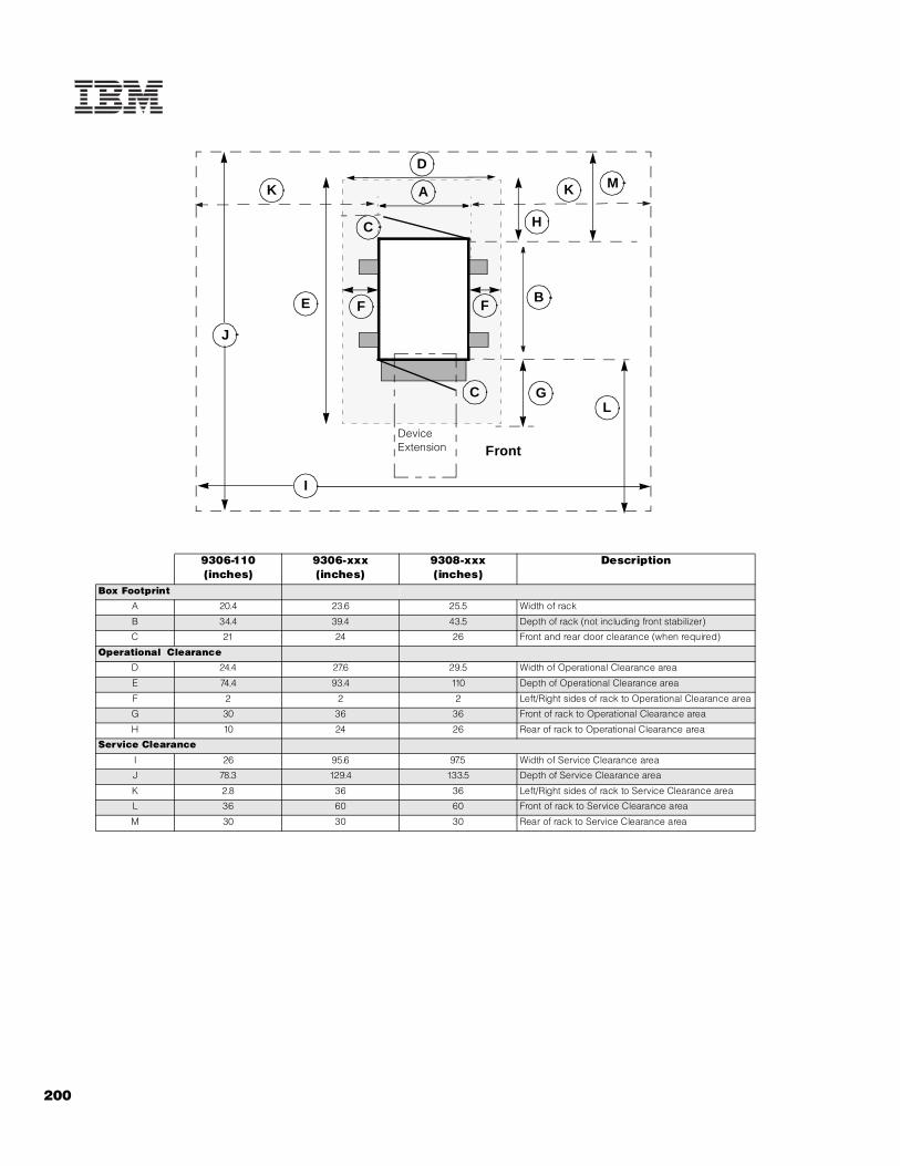
200
9306-110 (inches)
9306-xxx(inches)
9308-xxx(inches)
Description
Box Footprint
A 20.4 23.6 25.5 Width of rack
B 34.4 39.4 43.5 Depth of rack (not including front stabilizer)
C 21 24 26 Front and rear door clearance (when required)
Operational Clearance
D 24.4 27.6 29.5 Width of Operational Clearance area
E 74.4 93.4 110 Depth of Operational Clearance area
F 2 2 2 Left/Right sides of rack to Operational Clearance area
G 30 36 36 Front of rack to Operational Clearance area
H 10 24 26 Rear of rack to Operational Clearance area
Service Clearance
I 26 95.6 97.5 Width of Service Clearance area
J 78.3 129.4 133.5 Depth of Service Clearance area
K 2.8 36 36 Left/Right sides of rack to Service Clearance area
L 36 60 60 Front of rack to Service Clearance area
M 30 30 30 Rear of rack to Service Clearance area
K MK
D
LG
B
H
E
Front
C
C
A
FF
J
I
Device Extension

Ra
ck
Co
nso
le O
pti
on
s
201For the latest product & technical information, refer to the Information Sources on pages 2 and 3.Updated 10/15/02
Rack Console Options A console consisting of a keyboard, monitor and pointing device is required by each server for system maintenance and
support. The console may be local or remote and may be dedicated to a single server or shared across a large array of servers, which requires the use of one or more console switching devices.
Flat Panel Monitor Console Kits

202
Multi-server Console Switching
Refer to the table labeling key in the Cable Options table appearing later in this section.
1. Standard PS/2 Keyboard - Video - Mouse (KVM)2. IBM C2T Interconnect Cable Chaining Technology3. IBM Advanced Connectivity Technology (ACT)

Ra
ck
Co
nso
le O
pti
on
s
203For the latest product & technical information, refer to the Information Sources on pages 2 and 3.Updated 10/15/02
Refer to the table labeling key in the Cable Options table appearing later in this section.

Rack Console Options
20
4For the latest p
roduct &
technical information, refer to the Inform
ation Sources on pag
es 2 and 3.U
pd
ate
d 1
0/1
5/0
2

20
5
Switch OptionsPorts Capacity Standard Parts
IN OUT Two-level Tiering
Part Number Description
Type of switch Type Qty Type Qty m
ax
KV
M s
erv
ers
C2
T c
ha
ins
AC
T c
ha
ins
KV
M s
wit
ch
es
ma
x K
VM
se
rve
rs
loc
al
co
nso
les
rem
ote
co
nso
les
1U
bla
nk
fil
ler
pa
ne
l
1.8
m C
AT
5 c
ab
le
Ca
t5 t
erm
ina
tor
EIA
mo
un
tin
g b
rac
ke
ts
sid
e-w
all
mo
un
tin
g b
rac
ke
ts
09N4290 1x4 Console Switch KVM PS2 4 PS2 1 4 4 0 4 16 1 0 - - - - 1
09N4291 2x8 Console Switch KVM PS2 8 PS2 2 8 8 0 8 64 2 0 1 - - 1 1
1735L04 Local Console Manager ACT CAT5 4 PS2 1 64 64 4 4 32 1 0 1 1 4 1 1
1735R16 Remote Console Manager ACT CAT5 16 PS2 1 256 256 16 16 128 1 2 1 1 16 1 1
LAN 1
Switch Placement RulesMounting Locations 1x4 2x8 LCM RCM
monitor shelf \ switch bay yes yes no no3U Console \ switch bay yes yes yes yes1U Console \ switch bay yes yes yes nowith (above) 2U console yes yes yes yesside-wall compartment yes yes yes yesU compartment (EIA space) no yes yes yes
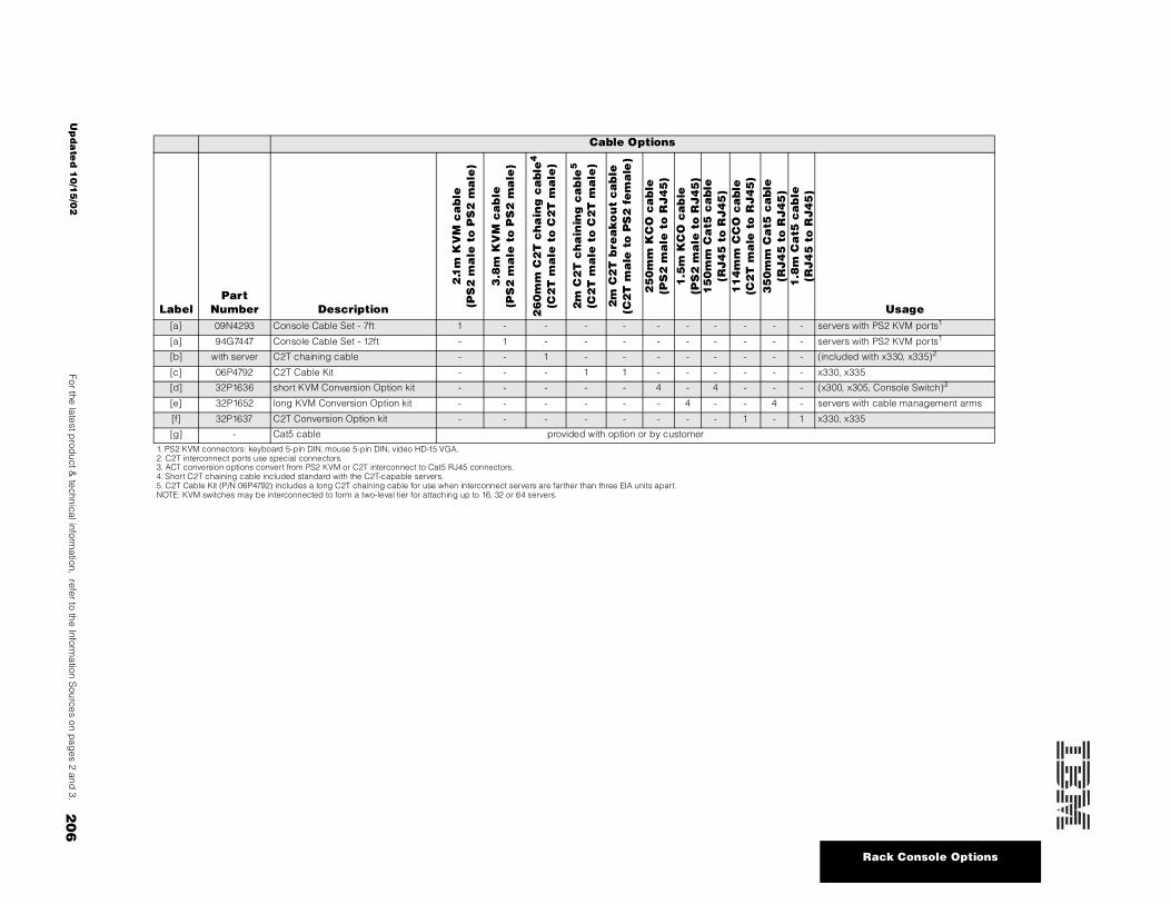
Rack Console Options
20
6For the latest p
roduct &
technical information, refer to the Inform
ation Sources on pag
es 2 and 3.U
pd
ate
d 1
0/1
5/0
2
Cable Options
LabelPart
Number Description
2.1
m K
VM
ca
ble
(PS
2 m
ale
to
PS
2 m
ale
)
3.8
m K
VM
ca
ble
(PS
2 m
ale
to
PS
2 m
ale
)
26
0m
m C
2T
ch
ain
g c
able
4
(C2
T m
ale
to
C2
T m
ale
)
2m
C2
T c
ha
inin
g c
ab
le5
(C2
T m
ale
to
C2
T m
ale
)
2m
C2
T b
rea
ko
ut
ca
ble
(C2
T m
ale
to
PS
2 f
em
ale
)
25
0m
m K
CO
ca
ble
(PS
2 m
ale
to
RJ
45
)
1.5
m K
CO
ca
ble
(PS
2 m
ale
to
RJ
45
)1
50
mm
Ca
t5 c
able
(RJ
45
to
RJ
45
)1
14
mm
CC
O c
able
(C2
T m
ale
to
RJ
45
)3
50
mm
Ca
t5 c
able
(RJ
45
to
RJ
45
)1
.8m
Ca
t5 c
ab
le(R
J4
5 t
o R
J4
5)
Usage[a] 09N4293 Console Cable Set - 7ft 1 - - - - - - - - - - servers with PS2 KVM ports1
[a] 94G7447 Console Cable Set - 12ft - 1 - - - - - - - - - servers with PS2 KVM ports1
[b] with server C2T chaining cable - - 1 - - - - - - - - (included with x330, x335)2
[c] 06P4792 C2T Cable Kit - - - 1 1 - - - - - - x330, x335
[d] 32P1636 short KVM Conversion Option kit - - - - - 4 - 4 - - - (x300, x305, Console Switch)3
[e] 32P1652 long KVM Conversion Option kit - - - - - - 4 - - 4 - servers with cable management arms
[f] 32P1637 C2T Conversion Option kit - - - - - - - - 1 - 1 x330, x335
[g] - Cat5 cable provided with option or by customer
1. PS2 KVM connectors: keyboard 5-pin DIN, mouse 5-pin DIN, video HD-15 VGA.2. C2T interconnect ports use special connectors.3. ACT conversion options convert from PS2 KVM or C2T interconnect to Cat5 RJ45 connectors.4. Short C2T chaining cable included standard with the C2T-capable servers.5. C2T Cable Kit (P/N 06P4792) includes a long C2T chaining cable for use when interconnect servers are farther than three EIA units apart.NOTE: KVM switches may be interconnected to form a two-leval tier for attaching up to 16, 32 or 64 servers.

207For the latest product & technical information, refer to the Information Sources on pages 2 and 3.Updated 10/15/02
Ne
tBAY
Ra
ck
Pow
er
Co
nfi
gu
rato
r
NetBAY Rack Power Configurator
US models EMEA models
Outlets C19 C13 NEMA C19 C13
APC 1400RMB 0 0 6 0 4
APC 3000RMB 0 0 8 1 8
APC 5000RMB 2 8 0 2 8
Outlets C19 C13
Rack PDU 0 7
Server PDU 0 4
Front-end PDU 3 0
Outlets:
Possible Power Configurations:
PDU
PDU
RackCabinet
P/S
PDU
up to 7
C13
Device/UnitSingle Rack PDU
PDU used as UPS back-end
(2)
(1)
Rack PDU 7 outlets-C13100-240Vac 15a
UPS
PDU
(5)
P/SP/S
Units with redundant p/s
PDU
(2)
(1)
Redundant Power Distribution
Device/Unit
C13
C13C19
(6)
(3)
(1)
PDU
UPS (3)
(6)
(2)
Redundant Power Distribution with PDU and UPS
Units with redundant p/s
(1)
PDU
UPS (3)
(6)
(2)
Redundant Power Distribution with PDU and UPS with PDU
Units with redundant p/s
(1)
PDU
FE
PDU
PDU
RackCabinet
PDU
FE
PDU
PDU
Typical Rack Power Configurations:Simple -- three Rack PDUs and one Front-end PDU (single circuit, 21 outlets)
Redundant -- six Rack PDUs and two Front-end PDUs (dual circuit, 42 outlets)
PDU
FE
PDU
PDU
(5)
(4)
(4)
Front-end PDU3 outlets - C191 inlet - hardwired
Rack Rules:Total PDUs (LV PDUs, HV PDUs, Rack PDUs, Server PDUs, FE PDUs) = 8Total Server PDUs = 3Total Front-end PDUs = 2
NOTES:1. Each device/unit usually comes with a power cord. The PDU requires the power cord to have an IEC 320-C14 plug. Order P/N 94G7448 (14ft) if appropriate cord is not provided by the device/unit.2. Each PDU and UPS comes with a country-specific power cord.3. Internal rack power cable provided with APC SmartUPS 5000 UPS.4. Internal rack power cable provided with Front-end PDU.5. Line cord provided with Front-end PDU.6. UPS comes with a country-specific power cord or a terminal block.7. Customer responsible to provide a dedicated circuit for each line cord protected with an appropriate circuit breaker.8. P/S = Power Supply.

208
Country-Specific Considerations: USA, Canada, parts of Latin America, Taiwan
C
C
C
C 3100W
1600W
Typical Office
115Vac
wall outletNEMA 5-15R
5-15P
15a
dedicated circuit = 1600Wtypical shared circuit = 300W eachmax leakage current = 3.5ma
load
1. Device to Rack PDU power cable IEC C13 to C14, 10/15a cable typical: P/N 36L8886 (2.8m) requirement: C14 plug, long enough to reach available option: 94G7448 (14ft)2. Rack PDU to wall line cord IEC C19 to country-specific connector, 16/20a, 14ft (4.3m)3. Rack PDU to UPS power cable IEC C19 to C20, 16/20a P/N 00N7700 (2m) provided with P/N 37L6861 (APC SU-5000RMB)4. Rack PDU to Front-end PDU power cable IEC C19 to C20, 16/20a P/N 00N7698 (1m) provided with the Front-end PDUs5. FE PDU to wall line cord special to country-specific connector, 30a, 8.2ft (2.5m)
Power Cables:
(2) Line Cords: Rack PDU
Part Number Plug Type
Source Circuit (single phase 50/
60Hz)
PDU Output(single phase 50/60Hz)
37L6866NEMA L5-20P 100-127Vac, 20a seven 100-127Vac, shared 15a
NEMA L6-20P 200-240Vac, 20a seven 200-240Vac, shared 15a
(2) Line Cords: Type W PDU
Part Number Plug Type Source Circuit (50/
60Hz)PDU Output
(single phase 50/60Hz)
37L6883 NEMA L5-30P 100-127Vac, 30a, single-phasethree 100-127Vac, 20a each, shared 24a
37L6884 NEMA L6-30P200-240Vac, 30a, single phase line-to-line with ground three 200-240Vac, shared 24a
37L6886 NEMA L21-30P200-250Vac, 30a, three-phase Y-connection with neutral
three 100-127Vac (115-145), 20a each, shared 41a
Power Load Capacity -- xSeries / Netfinity Rack Systems
C 1700W
NOTE:
C: = Rack PDU with a 15a circuit breakerW = FE PDU with a 20a fuse per outletdedicated circuitleakage current > 3.5ma
920W
920W
920W2760W
W
shared 24aL5-30P
Low Voltage
L5-20P115-127V1 phase20aNEMA L5-20R
115-127V1 phase30aNEMA L5-30R
C 1660W
C 1660W
C 1660W
C 1640W
C 1640W
C 1640W
W
W
208V1 phasew/neutral
20a
208V 3 phase w/neutral
30a per pole
208V line-to-line w/ground
30a
L6-30P
L6-20P
L21-30P
3100W max208V
shared 24a
4990W
4920W
5-wire
3-wire
120V
High Voltage
1 ph
1 ph
3 ph
1 ph
NOTE: Actual power values (watts) may vary based on actual source voltage.
115V

209For the latest product & technical information, refer to the Information Sources on pages 2 and 3.Updated 10/15/02
Ne
tBAY
Ra
ck
Pow
er
Co
nfi
gu
rato
r
Country-Specific Considerations: Europe, Mid-East, Africa, Asia Pacific, parts of Latin America
1. Device to Rack PDU power cable IEC C13 to C14, 10/15a cable typical: P/N 36L8886 (2.8m) requirement: C14 plug, long enough to reach available option: 94G7448 (14ft)2. Rack PDU to wall line cord IEC C19 to country-specific connector, 16/20a, 14ft (4.3m)3. Rack PDU to UPS power cable IEC C19 to C20, 16/20a P/N 00N7700 (2m) provided with P/N 37L6861 (APC SU-5000RMB)4. Rack PDU to Front-end PDU power cable IEC C19 to C20, 16/20a P/N 00N7698 (1m) provided with the Front-end PDUs5. Front-end PDU to wall line cord special to country-specific connector, 30/32a, 8.2ft (2.5m)
Power Cables: (2) Line Cords: Rack PDUs
(5) Line Cords: Front-end PDUs
Part Number Plug Type Source Circuit (single
phase 50/60Hz)PDU Output
(single phase 50/60Hz)
37L6866NEMA L5-20P 100-127Vac, 20a seven 100-127Vac, shared 15a
NEMA L6-20P 200-240Vac, 20a
seven 220-240Vac, shared 15a
37L6868 CEE7-VII 220-240Vac, 16a
37L6870 IEC 309-2P+Gnd 220-240Vac, 16a
37L6872 SII 32 220-240Vac, 16a
37L6874 CEI 23-16 220-240Vac, 16a
37L6876 SABS 164 220-240Vac, 16a
06P6028 BS 1363/A 220-240Vac, 13a
37L6864 country-specific line cord provided by IBM
country specific seven 220-240Vac, shared 13a
Part Number Plug Type Source Circuit (50/
60Hz)PDU Output
(single phase 50/60Hz)
37L6883 NEMA L5-30P 100-127Vac, 30a, single-phasethree 100-127Vac, 20a each, shared 30a
37L6884 NEMA L6-30P 200-240Vac, 30a, single phase line-to-line with ground
three 200-240Vac, shared 24a
37L6886 NEMA L21-30P200-250Vac, 30a, three-phase Y-connection with neutral
three 100-127Vac (115-145), 20a each, shared 41a
37L6885 IEC 309-2P+Gnd 220-240Vac, 32a, single-phasethree 220-240Vac, 16a each, shared 32a
37L6887 IEC 309-3P+N+Gnd380-415Vac, 32a, three-phase Y-connection with neutral
three 220-240Vac, 16a each
Power Load Capacity -- xSeries / Netfinity Rack Systems
220V 230V 235V 240V
3525W3450W3300W 3600W
220V 230V 235V 240V
3525W3450W3300W 3600W
220V 230V 235V 240V
3525W3450W3300W 3600W
220V 230V 235V 240V
2506W2453W2346W 2560W
C
C
C
C
220V 230V 235V 240V
2506W2453W2346W 2560W
220V 230V 235V 240V
2506W2453W2346W 2560W
C
C
220V 230V 235V 240V
3525W3450W 3300W 3600W
7040W 7360W 7620W 7680W
220V 240V235V230V
9900W 10350W 10575W 10800W
220V 240V235V230V
C
@ country specific: IEC 309-2P+G CEE7-VII SII 32 SABS 164 BS 1363 w/fuse CEI 23-16 etc.
W
W
220-240Vac
1 phase
16a
220-240Vac
1 phase
32a
380-415Vac
3 phase
32a
w/neutral
various @
309-2P+G
309-3P+N+G
shared 32a
NOTE:C = Rack PDU with a 15a circuit breakerW = FE PDU with a 20a fuse per outlet
1 ph
3 ph
NOTE: Actual power values (watts) may vary based on actual source voltage.
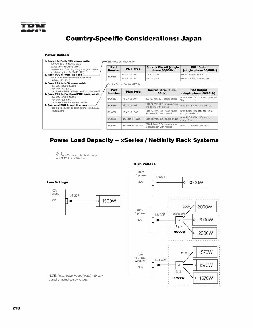
210
Country-Specific Considerations: Japan
1. Device to Rack PDU power cable IEC C13 to C14, 10/15a cable typical: P/N 36L8886 (2.8m) requirement: C14 plug, long enough to reach available option: 94G7448 (14ft)2. Rack PDU to wall line cord IEC C19 to country-specific connector, 16/20a, 14ft (4.3m)3. Rack PDU to UPS power cable IEC C19 to C20, 16/20a P/N 00N7700 (2m) provided with P/N 37L6861 (APC SU-5000RMB)4. Rack PDU to Front-end PDU power cable IEC C19 to C20, 16/20a P/N 00N7698 (1m) provided with the Front-end PDUs5. Front-end PDU to wall line cord special to country-specific connector, 30/32a, 8.2ft (2.5m)
Power Cables:
(2) Line Cords: Rack PDUs
(5) Line Cords: Front-end PDUs
Part Number Plug Type Source Circuit (single
phase 50/60Hz)PDU Output
(single phase 50/60Hz)
37L6866NEMA L5-20P 100Vac, 20a seven 100Vac, shared 15a
NEMA L6-20P 200Vac, 20a seven 200Vac, shared 15a
Part Number Plug Type Source Circuit (50/
60Hz)PDU Output
(single phase 50/60Hz)
37L6883 NEMA L5-30P 100-127Vac, 30a, single-phasethree 100-127Vac, 20a each, shared 30a
37L6884 NEMA L6-30P200-240Vac, 30a, single phase line-to-line with ground
three 200-240Vac, shared 30a
37L6886 NEMA L21-30P 200-250Vac, 30a, three-phase Y-connection with neutral
three 100-127Vac (115-145), 20a each, shared 41a
37L6885 IEC 309-2P+Gnd 220-240Vac, 32a, single-phasethree 220-240Vac, 16a each, shared 32a
37L6887 IEC 309-3P+N+Gnd380-415Vac, 32a, three-phase Y-connection with neutral
three 220-240Vac, 16a each
C 3000W
C 2000W
C 2000W
C 2000W
C 1570W
C 1570W
C 1570W
W
W
200V1 phase
20a
200V 3 phase w/neutral
30a
200V1 phase
30a
L6-30P
L6-20P
L21-30P
200V
shared 30a
6000W
4700W
115V
High Voltage
NOTE:C = Rack PDU has a 15a circuit breakerW = FE PDU has a 20a fuse
Power Load Capacity -- xSeries / Netfinity Rack Systems
C 1500W
100V1 phase
20a
L5-20P
Low Voltage
NOTE: Actual power values (watts) may vary based on actual source voltage.
1 ph
3 ph

211For the latest product & technical information, refer to the Information Sources on pages 2 and 3.Updated 10/15/02
Tap
e A
ttri
bu
tes
Appendix A: Tape Drive Attributes
Tape Drives
20L0549 10/20GB TR5 Internal IDE Tape Drive - 89mm (3.5in) SL or 133mm (5.25in) HH 10/20 1/2 - - - 1/0 -
48P7042 20/40GB TR7 Internal IDE Tape Drive - 89mm (3.5in) SL or 133mm (5.25in) HH 20/40 2/4 - - - 1/1 -
09N4041 12/24GB DDS/3 4mm Internal SCSI Tape Drive 889mm (3.5in) HH or 133mm (5.25in)
HH12/24 1.1/2.2 Y Y - 1/1 3510020,
3551001
00N7991 20/40GB DDS/4 4mm Internal Tape Drive 16 Ultra2 LVD89mm (3.5in) HH or 133mm (5.25in)
HH20/40 2.75/5.5 Y13 - - 1/1 35100204,
35510013
00N7990 40/80GB DLT Internal SCSI Tape Drive 16 Ultra2 LVD 133mm (5.25in) FH 40/80 6/10 Y13 - - 1/1 3503B1X, 35510013
00N8016 100/200GB LTO Tape Drive 16 Ultra2 LVD 133mm (5.25in) FH 100/200 15/30 Y13 - - 1/1 35510013, 3503B1X
24P2396 100/200GB LTO Half-High Tape Drive 16 Ultra2 LVD 133mm (5.25in) HH 100/200 8/16 Y13 - - 1/1 35510013
35100204
00N8015 110/220GB Super DLT Internal SCSI Tape Drive 16 Ultra2 LVD 133mm (5.25in) FH 110/220 11/22 Y13 - - 1/1 35510013,3503BIX
24P2398 40/80GB Half-High DLTVS Internal SCSI Tape Drive 16 Ultra2 LVD 133mm (5.25in) HH 40/80 3/6 Y13 - - 1/1 35510013 35100204
Associated Options00N7956 68-pin External Multimode LVD/SE SCSI Terminator 16 LVD/SE Ext - - Y - - - 3510020
36L9636 Netfinity Two-Drop Internal SCSI Cable5 16 Int - - Y - 16-bit, 2-drop - -
10K2340 Media Bay Tray and LVD Cable Kit6 16 LVD Int - - Y - 16-bit 2-drop - 3551001
Tape Autoloaders3502108 DLT Tape Autoloader 16 Desktop 280/560 5/10 Y - - 1/1 -
00N7992 120/240GB DDS/4 Tape Autoloader 16 Ultra2 LVD 133mm (5.25in) FH 120/240 3/6 Y13 - - 5/1 3551001, 3503B1X
3600109 3600 Series 900GB/1.8TB LTO Tape Autoloader7 16 Ultra2 LVD Tower or 6U Rack 900/1.8TB 15/30 Y - - 1/1 -360716X 3607 Series 1760GB/1.8TB SDLTpro Tape Autoloader 16 Ultra2 LVD 2U Rack 1760/3.53TB 11/22 Y - - 1/1 -
External Tape Enclosures
3510020 External Half High SCSI Storage Enclosure8 8, 16 Desktop - - N - 8-bit or 16-bit - -
3551001 NetMEDIA Storage Expansion Unit EL9 16 Rack - - Y -2 x 16-bit, 4- drop
- -
10L7113 NetMEDIA Systems Management Adapter10 16 - - - Y - - - 3551001
3503B1X Full-High SCSI Tape Enclosure11 16 Ultra2 LVD Desktop or 3U Rack - - Y - 16-bit - -
External Tape Libraries12
3502x14 DLT Tape Library 16 Desktop or Rack 490/980 5/10 Y - - 1/1 -
3570C2x Magstar MP 3570 Tape Subsystem HVD 6U Rack 100/300 2.2/6or 7/15 Y - - 1/1 -
3600xxx 3600 Series LTO Tape Library and Expander Module 16 Ultra2 LVD Tower or Rack 2TB/4TB 15/30 Y - - 1/1 -
4560SLX 4560 Automation Tape Enclosure Library 16 Ultra2 LVD 5U Rack
4.16TB/8.32TB (all SDLT);
3TB/6TB (all LTO)14
16/32 (all SDLT); 15/
30 (all LTO)15
Y - - 0/016 -
Par
t N
umbe
r
LEGEND:
HH: Half-High - approx height of 1.6inSL: Slim-Line - approx height of 1inFH: Full-High
Description SC
SI In
terf
ace
(bit
)
Form
Fac
tor
Max
sto
rage
(G
B)-N
ativ
e/
Com
pr2
MB
/sec
- Nat
ive/
com
pr2
Term
inat
ion
Incl
68/5
0-pi
n C
onve
rter
Inc
l
Inte
rnal
Cab
les
Dat
a/C
lean
ing
Car
trid
ges
Incl
uded
Ext
Tape
Enc
losu
res
1

212
1. To determine cable requirements, note the tape drive’s SCSI interface, the appropriate SCSI controller from the system configurator section and the desired enclosure then refer to Appendix D: Cables - Storage Units - Controllers. For installation of an internal tape drive into a server, see the appropriate system section.2. Data compression typically provides a 2X improvement in capacity and transfer rate, but since data compression is affected by many factors, actual improvements may be more or less than 2X.3. LVD support for LVD tape drives installed in a NetMEDIA Storage Expansion Unit EL (P/N 3551001) is provided by two four-drop internal LVD cables.4. Requires 68-pin External Multimode LVD/SE SCSI Terminator (P/N 00N7956). 5. Netfinity Two-Drop Internal SCSI Cable (P/N 36L9636) is a single-ended wide two-drop terminated cable.6. Media Bay Tray and LVD Cable Kit (P/N 10K2340) includes an internal two-drop multi-mode terminated LVD SCSI cable.7. If installed in a rack, a fixed shelf is required. Allow an additional 1U for the fixed shelf. One unit only per shelf is supported.8. Black desktop tape enclosure that supports a single133mm (5.25in) half-high (HH) tape drive. Internal connector is configurable as 50-pin Centronix or 68-pin high density. Requires either tape drive self termination or 68-pin External Multimode LVD/SE SCSI Terminator (P/N 00N7956). The option includes face plates for either a 68-pin HD or 0.8mm VHDCI external connection. External cables are not included.9. NetMEDIA Storage Expansion Unit EL (P/N 3551001) is a black 3U, rack-mountable tape enclosure which includes two full-high (FH) or four half-high (HH) extended length 133mm (5.25in) bays, two external 0.8mm VHDCI connectors and two internal four-drop LVD terminated 16-bit SCSI cables for device attachment. Two power supplies and two power cords are also included. External storage cables are not included.10. NetMEDIA Systems Management Adapter (P/N 10L7113) may be installed in a 3551001 to provide repeater function, aggregate cable lengths up to 12m when attached to an LVD SCSI controller, and auto-termination when the 3551001 is powered off. External connector is 0.8mm VHDCI.11. Black desktop or 3U rack tape enclosure supports a single 133mm (5.25in) full-high LVD tape device including DLT tape drives. Requires a fixed shelf if installed in a rack (allow additional 1U for fixed shelf). Includes a 90w power supply, cooling fan, external terminator, power cord (country-specific), and 2m 68-pin to 0.8mm external cable. Supports the following full-high tape options: 00N8015, 00N8016, 00N7992, 00N7990.12. Tape library attributes and prerequisites are located in Appendix B: Tape Library Attributes.13. Termination requires installing the 34in single-drop, terminated LVD SCSI cable provided with the option. When installed in a NetMEDIA Storage Expansion Unit, termination is also provided by the standard cables shipped with the enclosure or by installation of NetMEDIA Systems Management Adapter (P/N 10L7113).14. 4560 Automation Tape Enclosure Library supports either LTO or SDLT (or both if the application software supports mixed media and the drives and magazines are matched). Up to eight units can be stacked. Two magazines and two drive sleds can be installed in each unit. An external LVD SCSI cable with 0.8mm VHDCI connectors at each end ships standard with the library unit. A single 300w power supply with an IEC 320-C13 to NEMA 5-15P low voltage power cord is standard.15. Data transfer speed is rated separately for LTO and SDLT media. Compressed speed may be less than the maximum rate provided.16. LTO and SDLT data cartridges are not provided standard. Cleaning cartridges are shipped standard with LTO and SDLT drive sleds.
Note: Tape support varies by system depending on internal bay availability, SCSI cabling type, number of cable drops, existence of a RAID controller and availability of a suitable external enclosure. The following general rules should be followed.a) Tapes are not supported for attachment to RAID controllers.b) Single-ended (non-LVD) devices may be attached to internal multi-mode terminated cables. The entire SCSI bus will be limited to single-ended operation with a maximum bus speed of Ultra-SCSI.c) LVD devices attached to single-ended terminated cables will operate in single-ended mode with a maximum bus speed of Ultra-SCSI.
Internal SCSI Cables and Optional SCSI AdaptersMost systems support the following SCSI adapters for use with tape. Consult the I/O Options table in the system sections for specific system support. Where tapes are supported internal to the system, the cables which ship with the adapters are supported for tape attachment. Some restrictions may apply based on cable and tape type which are explained in the note above.
Part Number
Description Cable Description External Connector
02K3454 PCI Fast/Wide Ultra SCSI Adapter Four-drop, single-ended terminated, 16-bit 68-pin high density
19K4646 PCI Wide Ultra160 SCSI Adapter Five-drop, multi-mode terminated 0.8mm VHDCI
36L9636 Netfinity Two-Drop Internal SCSI Cable Two-drop, single-ended terminated, 16-bit -
10K2340 Media Bay Tray and LVD Cable Kit Two-drop, multi-mode terminated -

213For the latest product & technical information, refer to the Information Sources on pages 2 and 3.Updated 10/15/02
Tap
e A
ttri
bu
tes
Appendix B: Tape Library Attributes
DLT Tape Libraries
3502314 DLT Tape Library - Tower SE Desktop Y M68-M68 (3M) Y 1/14 1 2/2 1/3 490GB/980GB 5/10
3502R14 DLT Tape Library - Rack2 SE 4U Rack Y M68-M68 (3M) Y 1/14 1 2/2 1/3 490GB/980GB 5/10
33L4979 DLT Library Drive Upgrade3 SE - N Jumper N - - - - - 5/10
3600 Series Tape Libraries3600R20 3600 Series 2/4TB LTO Tape Library (Rack) LVD 5U Rack Y M68-M0.8 (2M) N 1/20 1 4/4 1/2 2TB/4TB8 15/303600LXU 3600 Series 2-Drive, 20-Cartridge Expander Module4 LVD 5U Rack Y M68-M0.8 (2M) N 0/20 1 4/4 0/2 2TB/4TB 15/30
3600109 3600 Series 900GB/1.8TB LTO Tape Autoloader5 LVD Tower or 6U Rack Y M68-M0.8 (2M) N 1/9 1 1/1 1/1 900GB/1.8TB 15/30
09N4048 3600 Series LTO Drive Upgrade Option6 LVD - N Jumper (1m) N - - - - - 15/30
09N4047 Fibre Tape Automation Adapter7 LVD - - M68-M0.8 (2 x 18in) - - - - - - -
4560 Automation Tape Enclosure Library
4560SLX 4560 Automation Tape Enclosure Library (5U rack)9 LVD 5U Rack Y M0.8-M0.8 (4m) N0/30 (LTO only); 0/26 (SDLT only)
- 0/2 0/2
4.16TB/8.32TB (all SDLT);
3TB/6TB (all LTO)16
16/32 (all SDLT); 15/30
(all LTO)16
59P6657 Fibre Channel Card Option10 LVD - - M0.8-M0.8 (0.5m) - - - - - - -59P6658 4560 LTO Drive Sled Option11 LVD - - Jumper (0.5m) N - 1 - - - 15/3016
59P6659 4560 LTO Magazine Option12 LVD - - - - 0/15 - - - 3TB/6TB16 -59P6660 4560 SDLT Drive Sled Option11 LVD - - Jumper (0.5m) N - 1 - - - 16/3216
59P6661 4560 SDLT Magazine Option13 LVD - - - - 0/13 - - - 4.16TB/8.32TB16 -
59P6662 EZConnect Elevator Option14 LVD - - - - - - - - - -59P6663 EZConnect Elevator Extension15 LVD - - - - - - - - - -
08L9120 LTO Data Cartridge LVD - - - - - - - - 100GB/200GB -
35L1119 SDLT Data Cartridge LVD - - - - - - - - 160GB/320GB -
Magstar Tape Systems
3570C21 Magstar MP 3570 Tape Subsystem17 HVD 6U Rack Y (4.5M) Y 1/20 1 2/2 1/2 100GB/300GB 7/15
3570C22 Magstar MP 3570 Tape Subsystem17 HVD 6U Rack Y (4.5M) Y 1/20 1 2/2 2/222 100GB/300GB 7/15
08L6517 3570 Adapter Card Kit18 HVD - Y (4.5M) Y - - - - - -08L6480 Second “C” Drive for C2119 HVD - - - N - - - - - 7/15
Magstar MP Media20
05H2462 Magstar MP Fast Access Linear Tape Cartridge,B-format21 - - - - - - - - - - -
05H2463 Magstar MP Cleaning Cartridge - - - - - - - - - - -
08L6187 Magstar MP Fast Access Linear Tape Cartridge,C-format
- - - - - - - - - - -
1. Transfer rates are for single SCSI channel configurations. Tape libraries utilizing split library or dual host configurations may obtain higher rates. Data compression typically provides a 2X improvement in capacity and transfer rate, but since data compression is affected by many factors, actual improvements may be more or less than 2X.2. Includes Fixed Shelf (P/N 94G7442) for installation in an IBM rack or NetBAY22.3. Upgrade 33L4979 is an additional drive for 3502x14 DLT Tape Libraries. Up to two drive upgrades may be installed for a maximum of three drives per 3502x14.4. Supported only with the 3600 Series LTO Tape Library (rack) (P/N3600R20). Allow one additional EIA space when installing either one or two (maximum) units to accommodate a filler plate for cable routing. Up to two 3600 Series LTO Drive Upgrade Options can be installed in each module or the module can operate off the LTO drives installed in the LTO tape library.5. If installed in a rack, a fixed shelf is required. Allow an additional 1U for the fixed shelf. Only one unit is supported per shelf.6. Install in second drive bay of 3600 Series LTO Tape Libraries or in either of the two bays of 3600 Series 2-drive, 20-cartridge Expander Module to increase performance. Includes an LTO (Ultrium) drive and a one-meter external LVD SCSI cable. 7. This adapter installs in a 3600 Series Tape Library or Expander Module. It includes a Fibre Channel-to-SCSI bridge that serves as a router to provide direct attachment to a Fibre Channel host adapter or GBIC installed in a Fibre Channel Switch (P/N 2109S08, 16) or Managed Hub (P/N 35341RU) via a short-wave Fibre Channel cable (P/N 36L9973, 03K9306, 03K9305). Two 18in LVD cables with a 68-pin male connector on one end and a male 0.8mm VHDCI connector on the other are included with the option. The 68-pin connector attaches to either the standard or optional LTO tape drive in the Tape Library or Expander Module and the 0.8mm VHDCI connector attaches to one of two connectors on the adapter. Each adapter supports up to two LTO drives in a single 3600 layer (3600R20 or 3600LXU) using one SCSI connector and cable for each drive.8. Maximum configuration includes two 3600 Series 2-Drive, 20-Cartridge Expander Modules (P/N 3600LXU), which combine with a 3600 Series Tape Library to provide a total of 6TB of native storage capacity and 12TB compressed.
Par
t N
umbe
r
SCSI Interface and Cable Legend M: Male - External68: 16-bit, 68-pin High Density connector0.8: 16-bit, 68-pin Very High Density Connection Interface (VHDCI) 0.8mm connectorSE: Single-ended SCSIHVD: High Voltage Differential SCSILVD: Low Voltage Differential SCSI
Description SC
SI In
terf
ace
Form
Fac
tor
Term
inat
or Inc
lude
dExt
Cab
les
Incl
(len
gth)
SC
SI C
ontr
olle
rs Inc
l
Dat
a C
artr
idge
s st
d/m
axC
lean
ing
Car
trid
ges
std
Car
trid
ge M
ags
std/
max
Qty
of dr
ives
- st
d/m
ax
Max
sto
rage
-Nat
ive/
Com
pres
sed
MB
/sec
- Nat
ive/
com
pr1

214
9. 4560 Automation Tape Enclosure Library supports either LTO or SDLT (or both if the application software supports mixed media and the drives and magazines are matched). Up to eight units can be stacked. Two magazines and two drive sleds can be installed in each unit. An external LVD SCSI cable with 0.8mm VHDCI connectors at each end ships standard with the library unit. A single 300w power supply with an IEC 320-C13 to NEMA 5-15P low voltage power cord is standard.10. Ships with external LVD SCSI cable with 0.8mm VHDCI connector for connection to the tape drive. Requires a short- or long-wave SFP Module (P/N 19K1271, 2) for connection to Fibre Channel cable.11. Ships with external LVD SCSI cable. Supported configurations are none, one or two drives. When a drive sled is not installed, the library unit must be cabled to another unit that contains at least one drive sled. The LTO Drive Sled Option includes one LTO Cleaning Cartridge (P/N 08L9124) and the SDLT Drive Sled Option includes one SDLT Cleaning Cartridge (P/N 19P4357).12. One or two magazines are supported. Up to 15 tape data cartridges (P/N 08L9120) are supported in each magazine. 13. One or two magazines are supported. Up to 13 tape data cartridges (P/N 35L1119) are supported in each magazine.14. Required to connect two library units.15. Required to connect each additional library unit (from three through eight).16. Data transfer speed and capacity are rated separately for LTO and SDLT media. Compressed speed and data capacity may be less than the maximum indicated.17. Includes rack mounting hardware and two power cords (120V and 250V). Models B22 and C22 include an additional two power cords.18. Required for Dual Host or Split Library configurations with 3570B2x or 3570C2x containing two drives.19. Required for either dual host or split library operation. Should be installed by qualified service personnel.20. Magstar MP Media can be ordered by calling 888-IBM-MEDIA or 888-426-6334 in the US, Canada, or Puerto Rico.21. B-format tape cartridges can be used in either Magstar MP 3570 Model B or C tape drives.22. The two tape drives are daisy-chained on the same SCSI bus with an included 0.5m SCSI cable. Dual Host and Split Library configurations require 3570 Adapter Card Kit(P/N 08L6517).

215For the latest product & technical information, refer to the Information Sources on pages 2 and 3.Updated 10/15/02
UP
S R
un
tim
e
Appendix C: UPS Runtime Estimate (minutes)Servers # Pwr Cords Std/Max Watts Load Max/Typ1
xSeries 2002 1/1 350/245xSeries 2052 1/1 485/340xSeries 2202 1/1 350/245xSeries 2352 1/2 800/560xSeries 2502 2/4 475/350xSeries 2552 2/4 1000/530xSeries 3002 1/1 200/140xseries 3052 1/1 200/140xSeries 3302 1/1 220/150xSeries 3352 1/1 340/245xSeries 3452 1/2 500/350xSeries 3602 2/3 740/520xSeries 4402 2/2 950/800
Other DevicesRXE-100 (8684-1RX)2 2/2 370/260EXP300 Storage Expansion Unit (35311RU)2 2/2 360/285FAStT200 Storage Server (35421RU)2 2/2 390/275FAStT200 HA Storage Server (35422RU)2 2/2 390/275FAStT500 Storage Server (35521RU)2 2/2 200/140FAStT700 Storage Server (17421RU)2 2/2 390/275FAStT EXP500 Storage Expansion Unit (35601RU)2 2/2 350/245FAStT EXP700 Storage Expansion Unit (17401RU)2 2/2 350/245SAN Fibre Channel Switch, 8-port (2109S08) 1/2 200/n/aSAN Fibre Channel Switch, 16-port (2109S16) 1/2 200/n/aTotalStorage SAN Switch F08, 8-port (3534F08) 1/1 50/n/aSAN Fibre Channel Switch, 16-port (2109F16) 1/2 200/n/aSAN Data Gateway Router UltraScsi LVD Port (2108R3L) 1/1 90/n/aDLT Tape Autoloader and Library (3502) 1/1 135/n/aMagstar MP 3570 Tape Subsystem (C2x) 1/1 200/140NetMEDIA Storage Expansion Unit EL (3551) 2/2 185/1303600 Series Tape Autoloader and Library (3600xxx) 1/1 700/5001. This table represents general guidelines for selecting the appropriate UPS based on minimum and typical runtime estimates. A ‘maximum configuration’ load will result in ‘minimum’ UPS runtime. ‘Typical’ loads are based on a production system running at approximately 70% of maximum capacity. The ‘typical’ loads represent a more likely configuration and is a more likely estimate of runtime. Customer environments are unique and are unlikely to be precisely represented by any of the specific entries in the table.2. Power-Factor Corrected (PFC) power supply.
Tower Rack MountedINT’L P/N
SU-700iNET94G4073
SU-1000iNET94G4074
SU-1400iNET94G4075
SU-2200iNET94G4076
2U SU-1400RMiB32P10226
SU-3000RMiB94G6677
SU-5000RMiB37L6862
US P/N
SU-700NET94G3134
SU-1000NET94G3135
SU-1400NET94G3136
Not Available
2U SU-1400RMB32P1020
SU-3000RMB94G6676
SU-5000RMB37L6861
UPS AttributesCommunications Links
to Servers 1 1 1 1 1 3 3
Color black black black white black black black
EIA Height - - - - 2U 3U 5U
Int’l Models50 or 60Hz, single
phase, VAC:2, 3 220-240(xxx) 220-240(xxx) 220-240(xxx) 220-240(xxx) 220-240(xxx) 220-240(xxx) 220-240(xxx)
10-Amp, IEC 320-C13 (Device) receptacles 4 4 4 8 4 8 8
16-Amp, IEC 320-C19(PDU) receptacles - - - 1 - 1 2
Line Cord Receptacle(IEC 320-) C14 C14 C20 C20 C14 C20 TB5
US Models50 or 60Hz, single
phase, VAC:2 120 (120) 120 (120) 120 (120) - 120 (120) 120 (120) 200-220 (208)
Receptacles (NEMA 5-15R) 4 6 6 - 6 8 -
10-Amp, IEC 320-C13 (Device) receptacles - - - - - - 8
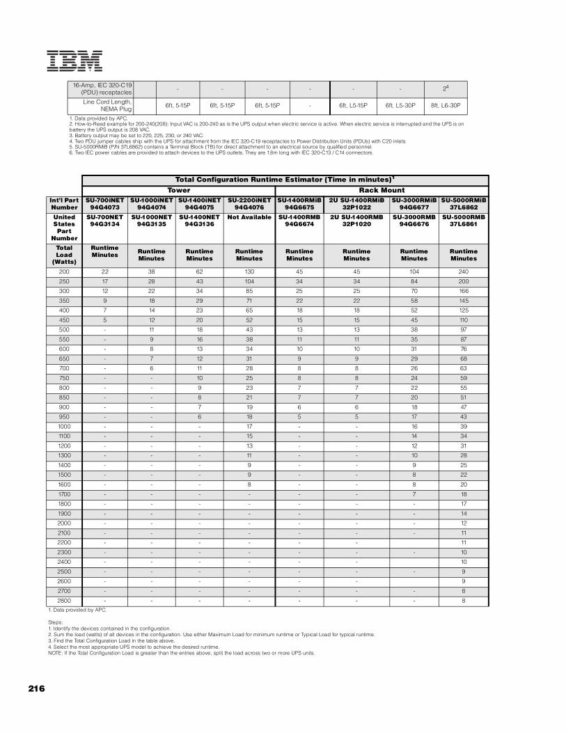
216
16-Amp, IEC 320-C19(PDU) receptacles - - - - - - 24
Line Cord Length,NEMA Plug 6ft, 5-15P 6ft, 5-15P 6ft, 5-15P - 6ft, L5-15P 6ft, L5-30P 8ft, L6-30P
1. Data provided by APC.2. How-to-Read example for 200-240(208): Input VAC is 200-240 as is the UPS output when electric service is active. When electric service is interrupted and the UPS is on battery the UPS output is 208 VAC.3. Battery output may be set to 220, 225, 230, or 240 VAC.4. Two PDU jumper cables ship with the UPS for attachment from the IEC 320-C19 receptacles to Power Distribution Units (PDUs) with C20 inlets.5. SU-5000RMiB (P/N 37L6862) contains a Terminal Block (TB) for direct attachment to an electrical source by qualified personnel.6. Two IEC power cables are provided to attach devices to the UPS outlets. They are 1.8m long with IEC 320-C13 / C14 connectors.
Total Configuration Runtime Estimator (Time in minutes)1
Tower Rack MountInt’l Part Number
SU-700iNET94G4073
SU-1000iNET94G4074
SU-1400iNET94G4075
SU-2200iNET94G4076
SU-1400RMiB94G6675
2U SU-1400RMiB32P1022
SU-3000RMiB94G6677
SU-5000RMiB37L6862
United States Part
Number
SU-700NET94G3134
SU-1000NET94G3135
SU-1400NET94G3136
Not Available SU-1400RMB94G6674
2U SU-1400RMB32P1020
SU-3000RMB94G6676
SU-5000RMB37L6861
Total Load
(Watts)
Runtime Minutes Runtime
MinutesRuntime Minutes
Runtime Minutes
Runtime Minutes
RuntimeMinutes
Runtime Minutes
Runtime Minutes
200 22 38 62 130 45 45 104 240
250 17 28 43 104 34 34 84 200
300 12 22 34 85 25 25 70 166
350 9 18 29 71 22 22 58 145
400 7 14 23 65 18 18 52 125
450 5 12 20 52 15 15 45 110
500 - 11 18 43 13 13 38 97
550 - 9 16 38 11 11 35 87
600 - 8 13 34 10 10 31 76
650 - 7 12 31 9 9 29 68
700 - 6 11 28 8 8 26 63
750 - - 10 25 8 8 24 59
800 - - 9 23 7 7 22 55
850 - - 8 21 7 7 20 51
900 - - 7 19 6 6 18 47
950 - - 6 18 5 5 17 43
1000 - - - 17 - - 16 39
1100 - - - 15 - - 14 34
1200 - - - 13 - - 12 31
1300 - - - 11 - - 10 28
1400 - - - 9 - - 9 25
1500 - - - 9 - - 8 22
1600 - - - 8 - - 8 20
1700 - - - - - - 7 18
1800 - - - - - - - 17
1900 - - - - - - - 14
2000 - - - - - - - 12
2100 - - - - - - - 11
2200 - - - - - - 11
2300 - - - - - - - 10
2400 - - - - - - 10
2500 - - - - - - - 9
2600 - - - - - - 9
2700 - - - - - - - 8
2800 - - - - - - - 81. Data provided by APC.
Steps:1. Identify the devices contained in the configuration.2. Sum the load (watts) of all devices in the configuration. Use either Maximum Load for minimum runtime or Typical Load for typical runtime.3. Find the Total Configuration Load in the table above.4. Select the most appropriate UPS model to achieve the desired runtime.NOTE: If the Total Configuration Load is greater than the entries above, split the load across two or more UPS units.
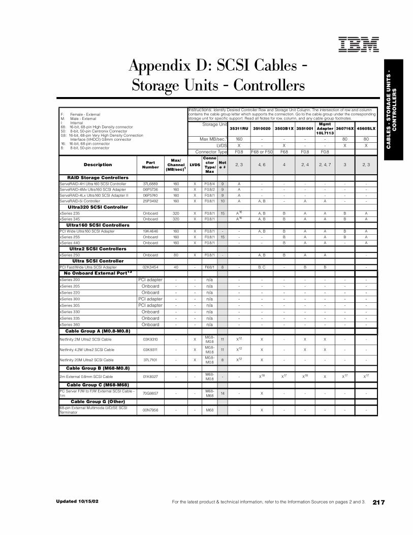
CA
BL
ES
- S
TO
RA
GE
UN
ITS
-
CO
NT
RO
LL
ER
S
217For the latest product & technical information, refer to the Information Sources on pages 2 and 3.Updated 10/15/02
Appendix D: SCSI Cables -Storage Units - Controllers
F: Female - External M: Male - External I: Internal 68: 16-bit, 68-pin High Density connector 50: 8-bit, 50-pin Centronix Connector 0.8: 16-bit, 68-pin Very High Density Connection Interface (VHDCI) 0.8mm connector 16: 16-bit, 68-pin connector 8: 8-bit, 50-pin connector
Instructions: Identify Desired Controller Row and Storage Unit Column. The intersection of row and column contains the cable group letter which supports the connection. Go to the cable group under the corresponding storage unit for specific support. Read all Notes for row, column, and any cable group footnotes.
Storage Unit35311RU 3510020 3503B1X 3551001
MgmtAdapter10L7113
360716X 4560SLX
Max MB/sec.1 160 - - - - 80 80LVDS X - X - - X X
Connector Type F0.8 F68 or F50 F68 F0.8 F0.8
Description Part Number
Max/Channel
(MB/sec)1LVDS
Connector
Type/ Max
Note # 2, 3 4, 6 4 2, 4 2, 4, 7 3 2, 3
RAID Storage ControllersServeRAID-4H Ultra160 SCSI Controller 37L6889 160 X F0.8/4 9 A - - - - - -
ServeRAID-4Mx Ultra160 SCSI Adapter 06P5736 160 X F0.8/2 9 A - - - - - -
ServeRAID-4Lx Ultra160 SCSI Adapter II 06P5740 160 X F0.8/1 9 A - - - - - -
ServeRAID-5i Controller 25P3492 160 X F0.8/1 10 A A, B - A A - -
Ultra320 SCSI ControllerxSeries 235 Onboard 320 X F0.8/1 15 A16 A, B B A A B A
xSeries 345 Onboard 320 X F0.8/1 A16 A, B B A A B A
Ultra160 SCSI ControllersPCI Wide Ultra160 SCSI Adapter 19K4646 160 X F0.8/1 - - A, B B A A B A
xSeries 255 Onboard 160 X F0.8/1 15 - - B A A B A
xSeries 440 Onboard 160 X F0.8/1 - - B A A - A
Ultra2 SCSI ControllersxSeries 250 Onboard 80 X F0.8/1 - - A, B B A A -
Ultra SCSI ControllerPCI Fast/Wide Ultra SCSI Adapter 02K3454 40 - F68/1 8 - B, C - B B -
No Onboard External Port13
xSeries 200 PCI adapter - - n/a - - - - - - -xSeries 205 Onboard - - n/a - - - - - - -xSeries 220 Onboard - - n/a - - - - - - -xSeries 300 PCI adapter - - n/a - - - - - - -xSeries 305 PCI adapter - - n/a - - - - - - -xSeries 330 Onboard - - n/a - - - - - - -xSeries 335 Onboard - - n/a - - - - - - -xSeries 360 Onboard - - n/a - - - - - - -
Cable Group A (M0.8-M0.8)
Netfinity 2M Ultra2 SCSI Cable 03K9310 - X M0.8-M0.8
11 X12 X - X X - -
Netfinity 4.2M Ultra2 SCSI Cable 03K9311 - XM0.8-M0.8
11 X12 X - X X - -
Netfinity 20M Ultra2 SCSI Cable 37L7101 - XM0.8-M0.8
8 X12 X - - - - -
Cable Group B (M68-M0.8)
2m External 0.8mm SCSI Cable 01K8027 - -M68-M0.8
- - X18 X17 X18 X X17 X17
Cable Group C (M68-M68)PC Server F/W to F/W External SCSI Cable - 1m
70G9857 - -M68-M68
14 - X - - - - -
Cable Group G (Other)68-pin External Multimode LVD/SE SCSI Terminator
00N7956 - - M68 - X - - - - -
--

218
1. Maximum supported speeds may be limited by installation of lower speed devices, controllers or cable lengths greater than two meters.2. Rack installation cable management requires devices to have a minimum cable length of two meters. Cable length requirements will vary based on placement within a single or multiple rack suite.3. Maximum speeds may be limited by the installed devices or SCSI controller.4. Daisy chaining tape enclosures is not supported at this time.5. The 3600 Series (rack) Tape Library supports up to two Expander Modules (P/N 3600LXU). 3600 Series Tape Library and Expander Modules are shipped with a 2m M68-M0.8 external SCSI cable (P/N 01K8027).6. Requires 68-pin External Multimode LVD/SE SCSI Terminator (P/N 00N7956).7. NetMEDIA Systems Management Adapter (P/N 10L7113) may be installed in a 3551001 to provide repeater function, LVDS interface, aggregate cable lengths up to 12 meters when attached to an LVD SCSI controller, and auto-termination when the 3551001 is powered off. External connector is 0.8mm VHDCI.8. Cable lengths exceeding 4.3 meters are NOT supported for attachment to non-LVD controllers.9. Maximum speeds may be limited by the enclosure or its installed devices.10. ServeRAID-5i neither cables internally nor has its own external connector. In systems with an external SCSI connector cabled to channel B of the integrated storage controller, ServeRAID-5i can attach through the integrated controller to external SCSI HDDs (EXP300). ServeRAID-5i supports the following half-high tape drives when installed in an available internal media bay connected to channel B of a dual-channel integrated controller or installed in a supported external tape enclosure: 00N7991, 24P2396, 24P2398. When the RAID controller is configured, channel B is designated as a standard SCSI channel in order to support the tape drives.11. Supports attachment to Ultra2 or single-ended SCSI controllers with operational speeds of up to Ultra2. Controller, storage unit, cable length or storage device limitations may apply (see Max MB/sec row and column above).12. EXP300 (P/N 35311RU) includes a single 2M Ultra2 SCSI cable similar to Netfinity 2M Ultra2 SCSI Cable (P/N 03K9310).13. No external SCSI port is available on these systems. A supported optional controller must be installed. See the systems section to determine which controllers and external storage units are supported then refer back to this table for cable requirements using the controller row. 14. Not supported for use in a rack. Rack installations require a minimum cable length of two meters.15. Requires External SCSI Interface Kit (P/N 32P8164) to enable the external 0.8mm VHDCI port.16. Support for EXP300 connected to the external SCSI port requires installation of ServeRAID-5i (P/N 25P3492) and availability of one channel of the integrated Ultra320 controller.17. External storage cable is included standard with the enclosure.18. External storage cable is not included standard with the enclosure. xx Instructions: Identify Desired Controller Row and Storage Unit Column. The intersection of row and column contains the cable group letter which supports the connection. Go to the cable group under the corresponding storage unit for specific support. Read all Notes for row, column, and any cable group footnotes.

219For the latest product & technical information, refer to the Information Sources on pages 2 and 3.Updated 10/15/02
IBM
Se
ria
l I/
O
Appendix E: IBM Serial I/O
37L1414 Serial I/O SST8P DB Adapter1, 5
37L1415 Serial I/O SST16P RJ Adapter2, 5
37L1423 Serial I/O SST16P DB Adapter3, 5
37L1417 Serial I/O PM16RJ Port Module4
37L1418 Serial I/O PM16DB Port Module4
1. Intelligent serial I/O interface card providing eight DB-25 RS232 serial connections using an octopus cable. Support for all ports at 921.6Kbps simultaneously.2. Intelligent serial I/O interface card providing sixteen RJ-45 RS232 serial connections in a breakout box. Support for all ports at 115.2Kbps simultaneously.3. Intelligent serial I/O interface card providing sixteen DB-25 RS232 serial connections in a breakout box. Support for all ports at 115.2Kbps simultaneously.4. Port Modules and Multiplexer Sets attach to one or more Port Modules or Multiplexer Sets already attached to one of the cables. A maximum of four Port Modules or Multiplexer Sets may be attached to a single cable. 5. Serial I/O Adapters are 32-bit PCI half length cards. A maximum of four Serial I/O adapters (in any combination) may be installed in a single host system.
IBM Serial I/O SST16PRJ Adapter
(P/N 37L1415)
IBM Serial I/O SST16PDB Adapter
(P/N 37L1423)
IBM Serial I/O SST8PDB Adapter
(P/N 37L1414)
IBM Serial I/O Adapters
IBM Serial I/O Port Module
Serial I/OPM16DB Port
Module(P/N 37L1418)
Serial I/OPM16RJ Port
Module(P/N 37L1417)
IBM Serial I/O SST16PDB Adapter
(P/N 37L1423)

22
0
Appendix F: Internal Cabling Overview
System IDE Connections SCSI Connections Media Int RAIDx
Se
rie
s se
rve
r
IDE
co
nn
ec
tor
#1
co
nn
ec
ts t
o (
as
ship
pe
d)
std
ca
ble
(ID
E)
ad
dit
ion
al
co
nn
ec
tivi
ty (
IDE
)
# s
tan
da
rd S
CS
I c
on
tro
lle
rs
sta
nd
ard
SC
SI
co
ntr
oll
er
typ
e
on
bo
ard
# c
ha
nn
els
ch
an
ne
l n
am
e (
lett
er)
inte
rna
l (I
) o
r ex
tern
al
(E)
co
nn
ec
tors
typ
e o
f c
on
ne
cto
r
inte
nde
d o
r st
an
da
rd c
on
ne
cti
on
int
SC
SI
ca
ble
(1
6-b
it L
VD
)
term
ina
ted
op
tio
na
l c
on
ne
cti
vity
(S
CS
I)2
0
me
dia
ba
y c
able
so
urc
e1
1
Use
std
SC
SI
ca
ble
to
co
nn
ec
t R
AID
?
x200 IDE 1 CD-ROM 2-drop21 optical,
IDE tape or IDE HDD
- - - - - - - - - - - 19K464612 N/A
2 IDE HDD 2-drop 1 HDD - - - - - - - - - - - - -
x200 SCSI 1 CD-ROM 2-drop 1 optical or IDE tape 1 U160 N 1 A I 68-pin 1 NH/S SCSI HDD
or open bay5 5-drop Y 3 NH/S HDDs, 1 HH tape9 std13 Y16
x205 IDE 1 CD-ROM 2-drop1 optical,
IDE tape or IDE HDD
- - - - - - - - - - - 19K464612 N/A
2 IDE HDD 2-drop 1 HDD - - - - - - - - - - - - -
x205 NH/S SCSI 1 CD-ROM 2-drop 1 optical 1 U160 Y 1 A I 68-pin 1 NH/S SCSI HDD or open bay 5-drop Y 3 NH/S HDDs, 1
HH tape10 std13 Y16
x205 H/S SCSI 1 CD-ROM 2-drop 1 optical 1 U160 Y 1 A I 68-pin H/S backplane 2-drop N8 - 19K464614 Y17
x220 NH/S SCSI 1 CD-ROM 2-drop 1 optical 1 U160 Y 1 A I 68-pin 1 NH/S SCSI HDD or open bay5 5-drop Y 3 NH/S HDDs, 1
HH tape10 std13 Y16
x220 H/S SCSI 1 CD-ROM 2-drop 1 optical 1 U160 Y 1 A I 68-pin H/S backplane 2-drop N8 - 19K464614 Y17
x232 1 CD-ROM 2-drop 1 optical 1 U160 Y 2 A I 68-pin H/S backplane 1 drop N8 - - Y17
- - - - - - - - B I 68-pin media bays7 2 drop Y 2 HH or 1 FH tape 10K234015 -
x235 1 CD-ROM 2-drop 1 optical 1 U320 Y 2 A I 68-pin H/S backplane 1 drop N8 - - N28
--

221
For the latest product &
technical information, refer to the Inform
ation Sources on pag
es 2 and 3.U
pd
ate
d 1
0/1
5/0
2
Internal Cabling Overview
- - - - - - - - B I 68-pin media bays26 1 drop Y27 HH or FH tape or U320 3-pack Kit
std w/ option Y29
- - - - - - - - B E 0.8mm VHDCI ext SCSI device26 - - - - -
x250 1 CD-ROM 2-drop - 1 U2 Y 2 B I 68-pin H/S backplane6 1-drop N8 - std18 Y17
- - - - - - - - A E 0.8mm VHDCI ext SCSI device - - - - -
x255 1 CD-ROM 2-drop 1 optical 1 U160 Y 2 A I 68-pin H/S backplane 1-drop N8 HH or FH tape, 6-pack kit30
std w/option Y31
- - - - - - - - B E 0.8mm VHDCI ext SCSI device - - - - -
x300 IDE 1 CD-ROM 1-drop3 - - - - - - - - - - - - - N/A
2 IDE HDD 2-drop 1 IDE HDD - - - - - - - - - - - - -
x300 SCSI 1 CD-ROM 1-drop3 - 1 U160 N 1 A I 68-pin 1 NH/S SCSI HDD or open bay5 2-drop Y 1 NH/S HDD - Y
x305 IDE 1 CD-ROM 1-drop - - - - - - - - - - - - - N/A
2 IDE-HDD 2-drop 1 IDE HDD - - - - - - - - - - - - -
x305 SCSI 1 CD-ROM 1-drop - 1 U160 N 1 A I 68-pin 1 NH/S SCSI HDD or open bay5 2-drop Y 1 NH/S HDD - Y
x330 IDE 1 CD-ROM 1-drop3 - - - - - - - - - - - - - N/A
2 IDE HDD 2-drop 1 IDE HDD - - - - - - - - - - - - -
x330 NH/S SCSI 1 CD-ROM 1-drop3 - 1 U160 Y 1 A I 68-pin 1 NH/S SCSI HDD 2-drop Y 1 NH/S HDD - Y
x330 H/S SCSI 1 CD-ROM 1-drop3 - 1 U160 Y 1 A I 68-pin H/S backplane 1-drop N8 - - Y
x335 IDE 1 CD-ROM 1-drop - - - - - - - - - - - - - N/A
2 IDE HDD 2-drop 1 IDE HDD - - - - - - - - - - - - -
x335 H/S SCSI 1 CD-ROM 1-drop - 1 U320 Y 1 A I 68-pin H/S backplane 1-drop N8 - - Y
x342 1 CD-ROM 1-drop4 - 1 U160 Y 2 A I 68-pin H/S backplane 1-drop N8 - - Y17
- - - - - - - - B I 68-pin media bays7 2-drop Y 2 HH or 1 FH tape 10K234015 -
x343 (NEBS) 1 CD-ROM 1-drop - 1 U160 Y 2 A I 68-pin 1 NH/S SCSI HDD 2-drop Y - - -
- - - - - - - - B E 0.8mm VHDCI ext SCSI device - - - - -
x345 1 CD-ROM 1-drop - 1 U320 Y 2 A I 68-pin H/S backplane 1-drop N8 - - Y32
- - - - B E 0.8mm VHDCI ext SCSI device - - - - -
x360 1 CD-ROM 1-drop21 - 1 U160 Y 1 A I Integrated H/S backplane22 - - - - Y23
System IDE Connections SCSI Connections Media Int RAID

22
2
x380 1 CD-ROM 1-drop - 1 U160 Y 2 A I 68-pin H/S backplane 1-drop N8 - - Y
2 LS-120 1-drop - - - - - B E 0.8mm VHDCI ext SCSI device - - - - -
x440 1 CD-ROM n/a24 - 1 U160 Y 2 A I 68-pin H/S backplane 1-drop N8 - - Y25
2 FDD n/a24 - - - - - B E 0.8mm VHDCI ext SCSI device - - - - -
1. IDE controllers have two channels, generally with one connector per channel. Standard IDE cables include two drops. Some IDE devices, e.g., a slim-line CD-ROM, use a single-drop ribbon cable, which is soldered to a backplane instead of using a connector at the device end of the cable.2.The term drop refers to a device connector on a cable. The connector that attaches to the controller is not counted as a drop.3.The cable is connected at one end to one of the channels (connectors) of the IDE controller, and at the other end it is soldered to a dedicated backplane.4.The single-device cable is soldered to the CD-ROM backplane. In order to install one or two optional optical devices in vacant media bays, the two-drop cable included with the optional devices is connected to one connector of the IDE controller and one of the two drops connects to an optional device. The standard CD-ROM cannot be used when an optional device is installed in one or both media bays. A single optional device is configured as primary, and when two optional devices are installed, one must be configured as primary and the other as secondary (master and slave).5. US models ship open bay. NH/S indicates nonhot-swap.6. xSeries 250 includes a split backplane with five HDD bays each. Read the SCSI Cabling section in the x250 section for additional information.7. Supports 3-Pack Ultra160 Hot-swap Expansion Kit (P/N 33L5050) that allows converting the two media bays to three hot-swap bays. Through the use of a repeater card provided with the option, the expansion backplane can be cabled as an extension of the standard backplane, or the expansion backplane can be cabled as an independent bus attached to either a separate channel of the storage controller to which the standard backplane is attached or to a different controller. If tape drives are installed in one or both media bays, an additional supported terminated SCSI cable is required.8. Termination is provided by the hot-swap backplane.9. An IDE tape drive uses an IDE cable attached to an IDE connector. Attaching a SCSI tape drive to the same SCSI bus as the HDDs may reduce performance. If the SCSI tape drive is an 8-bit device, the entire SCSI bus is limited to the speed of the tape drive. Slim-line tape drives may be supported in bay four.10. Attaching a SCSI tape drive to the same SCSI bus as the HDDs may reduce performance. If the SCSI tape drive is an 8-bit device, the entire SCSI bus is limited to the speed of the tape drive. Slim-line tape drives may be supported in bay four. (see the system Tape Options section). 11. An additional cable to connect SCSI devices installable in internal removable media bays to the standard SCSI storage controller may be required when the standard SCSI cable is used to connect an optional RAID adapter. The necessary cable is provided in the option specified in this column, or if one of the following tape drives is the media device being connected, a 34in terminated SCSI cable is now provided with the tape option: 00N7990, 00N7991, 00N7992, 00N8015, 00N8016, 24P2396, 24P2398.12. If installing an IDE tape drive, the standard IDE cable is used (maximum number of IDE optical drives or HDDs is reduced by one because only two IDE connectors are provided on each of the two IDE cables). If installing an internal SCSI device, a supported SCSI storage controller is required. The single-channel Ultra160 SCSI adapter (P/N 19K4646) includes a 16-bit five-drop terminated multimode SCSI cable and a 0.8mm VHDCI external connector. The PCI Fast/Wde Ultra SCSI Adapter (P/N 02K3454) is also single-channel and includes a 16-bit four-drop terminated single-ended SCSI cable and a 68-pin external connector.13. If installing an IDE tape drive, the second connector of the standard IDE cable can be used. If installing a SCSI device, one connector of the five-drop SCSI cable can be used, which may adversely affect performance for the entire SCSI bus. Installing the tape drive on an independent bus requires an optional controller (P/N 19K4646) unless the HDDs are attached to a RAID controller.14. Half-high SCSI devices installed in the media bay (bay two) require an additional storage controller. A five-drop terminated multimode cable is provided with the single-channel Ultra160 SCSI adapter(P/N 19K4646).15. Media bay attachment requires a supported cable such as the two-drop terminated LVD cable provided in the Media Bay Tray and LVD Cable Kit (P/N 10K2340). If one of the following tape drives is the media device being connected, a 34in terminated SCSI cable is now provided with the tape option: 00N7990, 00N7991, 00N7992, 00N8015, 00N8016, 24P2396, 24P2398.16. In nonhot-swap models, SCSI RAID adapters are connected to one end of the standard SCSI cable (usually either a two-drop, e.g., x300, or five-drop, e.g., x220 nonhot-swap). When the standard cable is used to attach to the RAID adapter, media bay attachment to the standard SCSI controller for SCSI devices in the x200 and nonhot-swap models of the x205 and x220 require the two-drop terminated LVD cable provided in the Media Bay Tray and LVD Cable Kit (P/N 10K2340) unless one of the following tape drives is the media device being connected, which now include a 34in terminated SCSI cable: 00N7990, 00N7991, 00N7992, 00N8015, 00N8016, 24P2396, 24P2398.17. SCSI RAID adapters are generally connected to the hot-swap backplane using the standard cable that connects the integrated storage controller. When the standard cable is used for RAID attachment, media bay attachment requires another supported cable, e.g., the two-drop terminated LVD cable provided in the Media Bay Tray and LVD Cable Kit (P/N 10K2340). unless one of the following tape drives is the media device being connected, which now include a 34in terminated SCSI cable: 00N7990, 00N7991, 00N7992, 00N8015, 00N8016, 24P2396, 24P2398.18. Attachment of SCSI devices in either (or both) of the two available media bays requires a supported optional SCSI storage controller (P/N 19K4646) in non-RAID configurations. Two half-high or one full-high device may be installed. A two-drop SCSI cable is included with the server, which can be used to attach one or two internal tape options to the integrated controller when a ServeRAID adapter is used to support the hot-swap backplane.19. The external connector is enabled by using the included cable to connect to channel B of the integrated controller. This channel can alternatively be used to connect to the optional hot-swap backplane included with the 3-Pack Ultra160 Hot-swap Expansion Kit (P/N 33L5050), which creates an independant bus for the additional three HDDs. Through the use of a repeater card provided with the option, the expansion backplane can be cabled as an extension of the standard backplane.20. Attachment of tape or optical drives to RAID adapters is not supported.21. The standard slim-line CD-ROM docks directly into a media interposer card that is routed through the lightpath card before terminating at the planar.22. The hot-swap backplane is connected to the integrated controller through a SCSI bus integrated into the system planar.23. Internal RAID configurations are supported by connecting an internal connector on the RAID controller to a connector on the planar located between slot one and the memory card using a dedicated RAID cable provided with the system. (Route cable underneath PCI adapters.) Note: If the hot-swap backplane is attached to a RAID adapter, a full-length adapter cannot be installed in slot one.24. xSeries 440 ships with a slim-line UltraBay 2000 CD-ROM installed in bay 4 (lower right of four bays) and an UltraBay 2000 floppy disk drive (FDD) installed in bay three. An optional UltraBay 2000 CD-RW and high-density FDD are available. FDDs can be installed in bay three only, but optical devices can be installed in either bay. If only one optical device is installed, it must be located in bay four. If two are installed, the standard FDD is removed and the second device is installed in bay three configured as slave.25. If a RAID adapter is attached to the hot-swap backplane, the standard SCSI cable is removed and a longer cable shipped with the system is connected to one of the internal connectors of the RAID adapter and to the hot-swap backplane connector.26. This channel may be connected to either a supported tape drive or the Ultra320 3-pack Kit (P/N 33P2751) installed in the media bays. If no internal connection is established, the 0.8mm VHDCI external SCSI port can be enabled by installing External SCSI Interface Kit (P/N 32P8164).27. Termination is provided by the one-drop cable included with the tape option or by the optional hot-swap backplane when the Ultra320 3-pack Kit is installed, which includes a nonterminated cable.28. Optional 30in nonterminated Single-drop Internal LVD Ultra160 SCSI Cable (P/N 71P8995) is required to connect the hot-swap backplane to ServeRAID-4H, -4Mx or -4Lx. ServeRAID-5i does not require a cable.29. If the optional Ultra320 3-pack Kit (P/N 33P2751) is installed in the media bays, the cable that ships with the option is used to connect to ServeRAID-4H, -4Mx or -4Lx or to the integrated controller if ServeRAID 5i is installed.30. An optional 6-pack Ultra320 Hot-swap Expansion Kit (P/N 32P8163) can be installed above the standard six hot-swap HDD bays and a full-high or half-high tape drive can be installed in the available media bays.
System IDE Connections SCSI Connections Media Int RAID
223For the latest product & technical information, refer to the Information Sources on pages 2 and 3.Updated 10/15/02
Inte
rna
l C
ab
lin
g O
verv
iew
31. SCSI RAID adapters are generally connected to the hot-swap backplane using the standard cable that connects the integrated storage controller. When the standard cable is used for RAID attachment, media bay attachment requires another supported cable, e.g., the two-drop terminated LVD cable provided in the Media Bay Tray and LVD Cable Kit (P/N 10K2340) unless one of the following tape drives is the media device being connected, which now include a 34in terminated SCSI cable: 00N7990, 00N7991, 00N7992, 00N8015, 00N8016, 24P2396, 24P2398. Attachment of optional 6-pack Ultra320 Hot-swap Expansion Kit (P/N 32P8163) connects to a RAID adapter using the cable that ships with the option.32. If ServeRAID-5i is installed, the standard cable that connects the backplane to the integrated controller remains connected. If ServeRAID-4Mx or -4Lx support the internal HDD backplane, then optional 30in nonterminated Single-drop Internal LVD Ultra160 SCSI Cable (P/N 71P8995) is required.
For additional information, refer to the Internal SCSI Cabling and Tape Options sections for each system or to Appendix D: SCSI Cables - Storage Units - Controllers.

224
Appendix G: System Management Overview
IBM system management solutions allow you to run your business-critical applications using innovative hardware technology that prevents most outages and recovers rapidly from the few that do occur. This technology makes xSeries simpler to service and easier to manage.
This section shows the available range of standard and optional system management processors and describes the features and configuration process for each. This section further demonstrates how these service processors can be interconnected to form a communication network for alerting and monitoring a wide range of system functions and hardware conditions.
Key to abbreviationsASMP Advanced System Management Processor ISMP Integrated System Management Processor
ASMAAdvanced System Management PCI Adapter (P/N 01K7209)
RSA Remote Supervisor Adapter (P/N 09N7585)
ASMIC Advanced System Management Interconnect Cable Kit (P/N 03K9309)
General Notes:
All descriptions of features and compatibility of ISMP described here require the use of firmware version 1.02 or newer. As of January 1, 2002, all ISMPs ship standard with firmware version 1.02. Firmware updates may be found on the IBM Web site at the URL www.pc.ibm.com/qtechinfo/MIGR-4WEP53.html.
An advanced system management interconnect network is configured with at least one focal point (generally an ASMA or RSA in a server) that provides Ethernet LAN and serial connections for management and alerting, which are shared between all the members of an interconnect network.
Up to 24 ISMPs and/or RSAs may be interconnected in a single ASM interconnect network (including standard and optional processors).
Up to 12 ASMPs and/or ASMAs may be interconnected in a single ASM interconnect network (including standard and optional processors). Up to 12 additional ISMPs and/or RSAs may be added to an ASM interconnect network containing 12 or less ASMPs and/or ASMAs.
An ASM interconnect network may contain an aggregate connection length of no more than 91.4m (300ft).
A customer-supplied Cat5 Ethernet cable is required for each interconnection.
Connecting servers that do not have two external RS-485 ports as an ASM interconnect network requires Advanced System Management Interconnect Cable Kit (P/N 03K9309). RSA and ASMA do not include this option when shipped standard with a system.
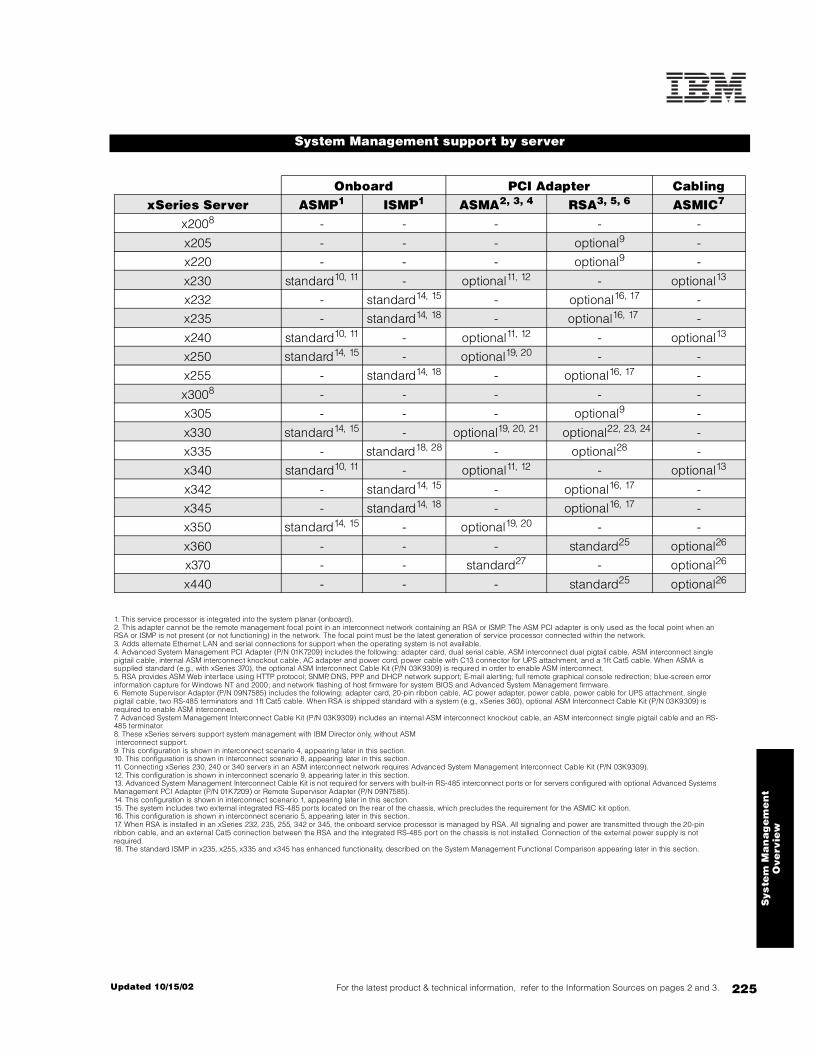
225For the latest product & technical information, refer to the Information Sources on pages 2 and 3.Updated 10/15/02
Sys
tem
Ma
nag
em
en
tO
verv
iew
System Management support by server
Onboard PCI Adapter CablingxSeries Server ASMP1 ISMP1 ASMA2, 3, 4 RSA3, 5, 6 ASMIC7
x2008 - - - - -
x205 - - - optional9 -
x220 - - - optional9 -
x230 standard10, 11 - optional11, 12 - optional13
x232 - standard14, 15 - optional16, 17 -
x235 - standard14, 18 - optional16, 17 -
x240 standard10, 11 - optional11, 12 - optional13
x250 standard14, 15 - optional19, 20 - -
x255 - standard14, 18 - optional16, 17 -
x3008 - - - - -
x305 - - - optional9 -
x330 standard14, 15 - optional19, 20, 21 optional22, 23, 24 -
x335 - standard18, 28 - optional28 -
x340 standard10, 11 - optional11, 12 - optional13
x342 - standard14, 15 - optional16, 17 -
x345 - standard14, 18 - optional16, 17 -
x350 standard14, 15 - optional19, 20 - -
x360 - - - standard25 optional26
x370 - - standard27 - optional26
x440 - - - standard25 optional26
1. This service processor is integrated into the system planar (onboard).2. This adapter cannot be the remote management focal point in an interconnect network containing an RSA or ISMP. The ASM PCI adapter is only used as the focal point when an RSA or ISMP is not present (or not functioning) in the network. The focal point must be the latest generation of service processor connected within the network.3. Adds alternate Ethernet LAN and serial connections for support when the operating system is not available.4. Advanced System Management PCI Adapter (P/N 01K7209) includes the following: adapter card, dual serial cable, ASM interconnect dual pigtail cable, ASM interconnect single pigtail cable, internal ASM interconnect knockout cable, AC adapter and power cord, power cable with C13 connector for UPS attachment, and a 1ft Cat5 cable. When ASMA is supplied standard (e.g., with xSeries 370), the optional ASM Interconnect Cable Kit (P/N 03K9309) is required in order to enable ASM interconnect.5. RSA provides ASM Web interface using HTTP protocol; SNMP, DNS, PPP and DHCP network support; E-mail alerting; full remote graphical console redirection; blue-screen error information capture for Windows NT and 2000; and network flashing of host firmware for system BIOS and Advanced System Management firmware.6. Remote Supervisor Adapter (P/N 09N7585) includes the following: adapter card, 20-pin ribbon cable, AC power adapter, power cable, power cable for UPS attachment, single pigtail cable, two RS-485 terminators and 1ft Cat5 cable. When RSA is shipped standard with a system (e.g., xSeries 360), optional ASM Interconnect Cable Kit (P/N 03K9309) is required to enable ASM interconnect.7. Advanced System Management Interconnect Cable Kit (P/N 03K9309) includes an internal ASM interconnect knockout cable, an ASM interconnect single pigtail cable and an RS-485 terminator.8. These xSeries servers support system management with IBM Director only, without ASM interconnect support.9. This configuration is shown in interconnect scenario 4, appearing later in this section.10. This configuration is shown in interconnect scenario 8, appearing later in this section.11. Connecting xSeries 230, 240 or 340 servers in an ASM interconnect network requires Advanced System Management Interconnect Cable Kit (P/N 03K9309).12. This configuration is shown in interconnect scenario 9, appearing later in this section.13. Advanced System Management Interconnect Cable Kit is not required for servers with built-in RS-485 interconnect ports or for servers configured with optional Advanced Systems Management PCI Adapter (P/N 01K7209) or Remote Supervisor Adapter (P/N 09N7585).14. This configuration is shown in interconnect scenario 1, appearing later in this section.15. The system includes two external integrated RS-485 ports located on the rear of the chassis, which precludes the requirement for the ASMIC kit option.16. This configuration is shown in interconnect scenario 5, appearing later in this section.17. When RSA is installed in an xSeries 232, 235, 255, 342 or 345, the onboard service processor is managed by RSA. All signaling and power are transmitted through the 20-pin ribbon cable, and an external Cat5 connection between the RSA and the integrated RS-485 port on the chassis is not installed. Connection of the external power supply is not required.18. The standard ISMP in x235, x255, x335 and x345 has enhanced functionality, described on the System Management Functional Comparison appearing later in this section.
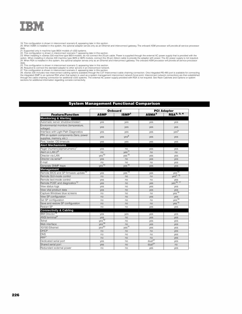
226
19. This configuration is shown in interconnect scenario 6, appearing later in this section.20. When ASMA is installed in this system, the optional adapter serves only as an Ethernet and interconnect gateway. The onboard ASM processor will provide all service processor data.21. Supported only in machine type 8654 models of x330 systems.22. This configuration is shown in interconnect scenario 7, appearing later in this section.23. When installing in xSeries 330 machine type 8654 models, do not connect the 20-pin cable. Power is supplied through the external AC power supply that is provided with the option. When installing in xSeries 330 machine type 8674 or 8675 models, connect the 20-pin ribbon cable to provide the adapter with power. The AC power supply is not required. 24. When RSA is installed in this system, the optional adapter serves only as an Ethernet and interconnect gateway. The onboard ASM processor will provide all service processor data.25. This configuration is shown in interconnect scenario 3, appearing later in this section.26. Required to connect the standard adapter to other servers in an interconnect network.27. This configuration is shown in interconnect scenario 2, appearing later in this section.28. xSeries 335 includes new interconnect cabling options available through the C2T Interconnect cable chaining connection. One integrated RS-485 port is available for connecting the integrated ISMP to an optional RSA when that system is used as a system management interconnect network focal point. Interconnect network connections are then established through the cable chaining connection for additional x335 systems. The external AC power supply provided with RSA is not required. See Rack Cabinets and Options or system sections for additional information regarding console connectivity.
System Management Functional Comparison
Onboard PCI AdapterFeature/Function ASMP ISMP1 ASMA2 RSA2, 3, 4
Monitoring & AlertingAutomatic server shutdown/restart yes yes yes yesEnvironmental monitors (temperature, voltage) yes yes yes yes
Interface with Light Path Diagnostics yes yes yes yes5
PFA on system components (fans, power supplies, memory, etc.) yes yes6 yes yes
Post, loader, OS timeouts yes yes yes yesAlert MechanismsPager (numeric/alphanumeric)7 yes no yes yesAlert on LAN 28 no yes11 no noDirector via LAN yes10 yes10 yes yesDirector via serial9 yes no yes yesE-mail no no no yesGenerate SNMP traps yes10 yes10 yes yesManagementRemote BIOS and SP firmware update12 yes yes13 yes yes14
Remote GUI-mode control no no no yes5, 15
Remote text-mode control yes no no yesRemote POST and diagnostics12 yes no yes yes16, 17
View status logs yes no yes yesView vital product data yes no yes yesCapture Windows blue screens no no no yes15
View SP configuration no no yes yesSet SP configuration no no no yes14
Save and restore SP configuration no no no yes15
Restart SP no no yes yesConnectivity & CablingIBM Director18 yes yes yes yesANSI terminal9 yes no yes yesTelnet yes19 no yes yesWeb interface yes19 no yes yes10/100 Ethernet yes20 yes11 yes yesDHCP no no no yesDNS no no no yesPPP7 no no no yesDedicated serial port yes no dual21 yesShared serial port yes no dual21 noRedundant external power no no yes yes

227For the latest product & technical information, refer to the Information Sources on pages 2 and 3.Updated 10/15/02
Sys
tem
Ma
nag
em
en
tO
verv
iew
1. This table is correct only for ISMP firmware v1.02 or newer. Systems shipped after January 1, 2002 include v1.02 firmware. Firmware updates are available on the Web at the URL www.pc.ibm.com/qtechinfo/MIGR-4WEP53.html.2. When either RSA or ASMA are integrated as a standard adapter in an xSeries server (e.g., x360 or x440), the two interconnect cables, external power supply and power cords provided with the optional packages are not included.3. When an optional RSA (P/N 09N7585) is installed in a system with standard ISMP, the optional adapter manages the onboard service processor and assumes all communications functionality.4. When an optional RSA (P/N 09N7585) is installed in a system with standard ASMP, the optional adapter serves only as an Ethernet and interconnect gateway. The onboard ASMP provides all service processor data. An external Cat5 connection is required.5. Not available when RSA is added as an option to systems with standard ASMP (e.g., x330).6. Performs monitoring capability only. Automated alerting available through IBM Director only.7. Requires customer-supplied external modem.8. Only available with IBM Director version 3.1 or newer.9. Requires customer-supplied external modem or null-modem cable.10. The specified alerting mechanisms may be configured, but sending such alerts to their destination requires connection through an RSA or ASMA either within the local machine or via the interconnect network.11. This functionality is only available on xSeries 235 and 255 servers, which include ISMP upgraded with a dedicated gigabit Ethernet processor. 12. Requires an out-of-band connection such as a serial, Ethernet or ASM interconnect network (out-of-band connections bypass the NOS and are established even when the NOS is not functioning).13. Only updates to the the service processor firmwware are possible. BIOS firmware updates are not available when using ISMP.14. Only available through the Web interface, connected via Ethernet or PPP.15. Only available through the Web or Telnet interface, via an Ethernet connection.16. Not available via interconnect network.17. Not available on systems without standard system management to which an optional RSA has been added (e.g., x220).18. Connection to IBM Director allows use of all management and alerting functionality (except save and restore configuration file) via an active in-band, out-of-band or interconnect network connection.19. Connection using Telnet, Web interface or Ethernet is available via an RSA or ASMA through the interconnect network.20. Requires interconnection of integrated service processor to optional ASMA or RSA using an Interconnect Cable Kit (P/N 03K9309).21. Requires the use of the included serial port splitter cable.
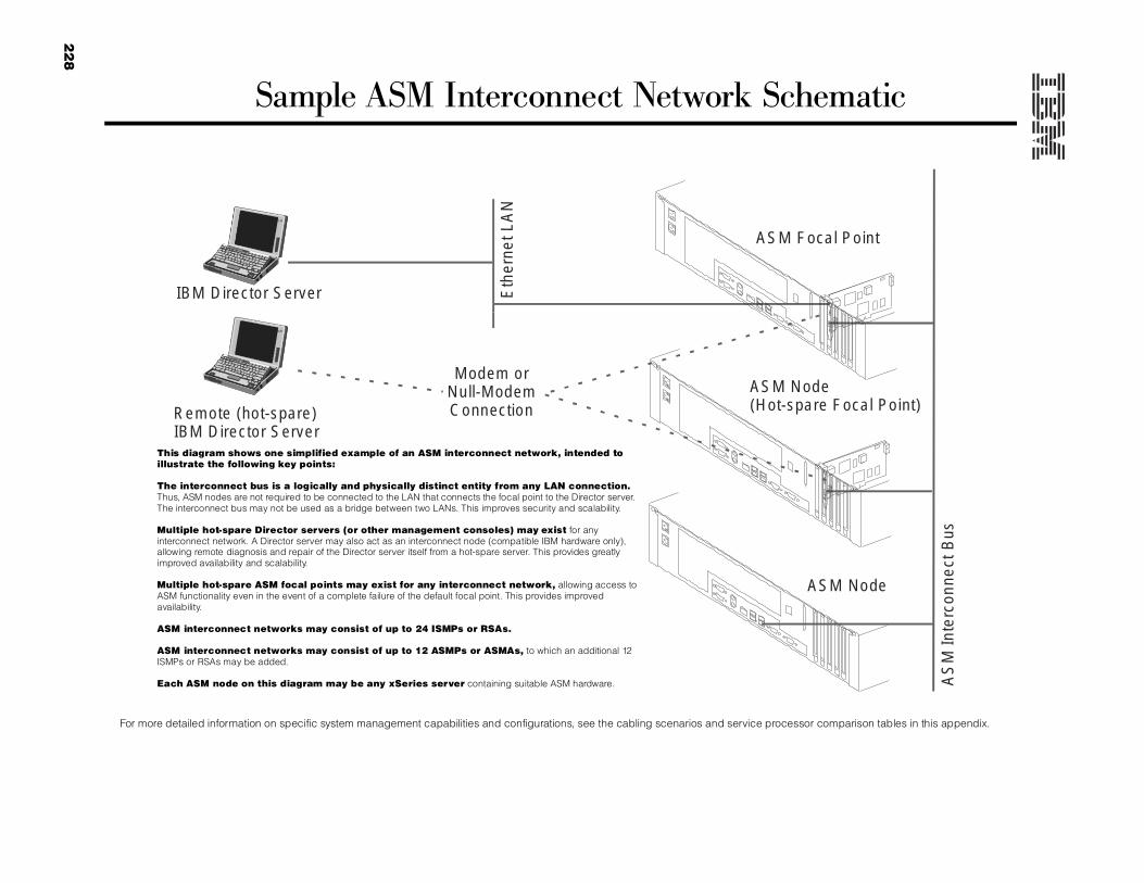
22
8
Sample ASM Interconnect Network Schematic
Eth
erne
tLA
N
Modem orNull-ModemConnection
AS
MIn
terc
onne
ctB
us
IBM Director Server
Remote (hot-spare)IBM Director Server
ASM Focal Point
ASM Node(Hot-spare Focal Point)
ASM Node
This diagram shows one simplified example of an ASM interconnect network, intended to illustrate the following key points:
The interconnect bus is a logically and physically distinct entity from any LAN connection. Thus, ASM nodes are not required to be connected to the LAN that connects the focal point to the Director server. The interconnect bus may not be used as a bridge between two LANs. This improves security and scalability.
Multiple hot-spare Director servers (or other management consoles) may exist for any interconnect network. A Director server may also act as an interconnect node (compatible IBM hardware only), allowing remote diagnosis and repair of the Director server itself from a hot-spare server. This provides greatly improved availability and scalability.
Multiple hot-spare ASM focal points may exist for any interconnect network, allowing access to ASM functionality even in the event of a complete failure of the default focal point. This provides improved availability.
ASM interconnect networks may consist of up to 24 ISMPs or RSAs.
ASM interconnect networks may consist of up to 12 ASMPs or ASMAs, to which an additional 12 ISMPs or RSAs may be added.
Each ASM node on this diagram may be any xSeries server containing suitable ASM hardware.
For more detailed information on specific system management capabilities and configurations, see the cabling scenarios and service processor comparison tables in this appendix.

22
9For the latest p
roduct &
technical information, refer to the Inform
ation Sources on pag
es 2 and 3.U
pd
ate
d 1
0/1
5/0
2
System ManagementOverview
xSeries Advanced System Management Interconnect Network Scenarios
Configuration Interconnect hardware connections
ASM interconnect ports
1
2
1. Server with ASMP or ISMP and two integrated RS-485 ASM interconnect ports on the rear of the chassis
Key Features:
• Allows standard system management functionality, including remote flash update of BIOS and adapter microcode, remote hardware diagnostics, and monitoring and alerting of critical voltage and temperature thresholds.• Remote BIOS update only available on ASMP.• Only includes ISMP with firmware v1.02 or later.
Servers:xSeries 232, 235, 250, 255, 330, 342, 345, 350
Instructions:
1. Attach customer-supplied Cat5 cables (for connection to one or two other ASM interconnect nodes) to the integrated RS-485 ports at the rear of the server. Unused RS-485 ports must be terminated with the supplied RS-485 terminator.
2. Server with standard ASMA
Key Features:
xSeries 370 ships standard with ASMA, which provides all basic system management functionality including remote management via Telnet or a Web interface.
Requires purchase of ASM Interconnect Cable Kit (P/N 03K9309).
Servers:xSeries 370
Instructions:
1. Insert pigtail cable into RS-485 interconnect port on adapter panel.2. Attach customer-supplied Cat5 cables (for connection to one or two other ASM interconnect nodes) to the integrated RS-485 ports of the pigtail adapter. Unused RS-485 ports must be terminated with the supplied RS-485 terminator.

23
0
1
2
To system planar1
2
3
4
3. Server with standard RSA
Key Features:
xSeries 360 and 440 ship standard with RSA, which provides the latest generation of system management functionality. In addition to standard system management capabilities, RSA adds advanced features such as full remote operation of server NOS, advanced Ethernet features and system management access even in the event of a complete server NOS failure.
Requires purchase of ASM Interconnect Cable Kit (P/N 03K9309).
ServersxSeries 360, 440
Instructions:
1. Insert pigtail cable into RS-485 ASM interconnect port on rear of adapter.2. Attach customer-supplied Cat5 cables (for connection to one or two other ASM interconnect nodes) to the RS-485 ports of the pigtail adapter. UnusedRS-485 ports must be terminated with the supplied RS-485 terminator.
4. Server with no standard service processor and optional RSA
Key Features:
xSeries 220 ships standard without system management capability. To enable system management, an optional Remote Supervisor Adapter (P/N 09N7585) is required.
Servers:xSeries 205, 220
Instructions:
1. Insert RSA into PCI slot on system planar (see system I/O section for slot restrictions).2. Connect 20-pin ribbon cable between system planar and RSA. xSeries 220 requires the external AC power supply.3. Insert pigtail cable into RS-485 interconnect port on adapter panel.4. Attach customer-supplied Cat5 cables (for connection to one or two other ASM interconnect nodes) to the RS-485 ports of the pigtail adapter. UnusedRS-485 ports must be terminated with the supplied RS-485 terminator.

231
For the latest prod
uct & technical inform
ation, refer to the Information S
ources on pages 2 and 3.
Up
da
ted
10
/15
/02
System ManagementOverview
To system planar1
2
3
4
1
23
4
6
5
5. Server with ISMP plus optional RSA
Key Features:Adding an RSA to a server containing an ISMP merges their functionality. The RSA manages the ISMP and handles communications.
Only applicable to ISMP with firmware v1.02 or later
ServersxSeries 232, 235, 255, 335 (see note below),342, 345
Instructions:
1. Insert RSA into PCI connector on System Planar (see system I/O section for slot restrictions).2. Connect 20-pin ribbon cable between system planar and RSA.3. Insert pigtail cable into RS-485 port on adapter panel.4. Attach customer-supplied Cat5 cables (for connection to one or two other ASM interconnect nodes) to the RS-485 ports of the pigtail adapter. UnusedRS-485 ports must be terminated with the supplied RS-485 terminator.
Note: Refer to x335 I/O Options for more information on C2T Interconnect cable chaining technology connections supporting system management.
6. Server with standard ASMP and two integrated RS-485 ASM interconnect ports on the rear of the server chassis, into which
an ASMA is installed
Key Features:
Adding an ASMA to a server containing an ASMP enables the ASMP to access the additional communication methods available on ASMA hardware. The ASMP retains full control of the system management role, with the ASMA acting as a gateway between system management and Ethernet. Requires purchase of optional ASM PCI Adapter (P/N 01K7209).
Servers:xSeries 230, 330 (8654 models), 350
Instructions:
1. Install ASMA into PCI slot on system planar (see system I/O section for slot restrictions).2. Plug the pigtail adapter into the RS-485 interconnect port of the ASMA.3. Attach one end of the 1ft Cat5 cable (included with the ASMA option) to one of the RS-485 ports of the pigtail cable.4. Attach the other end of the included 1ft Cat5 cable to one of the RS-485 ports built into the chassis.5. Attach the customer-supplied Cat5 cable into the other RS-485 port of the pigtail cable.6. If interconnection to a second ASM interconnect node is required, plug a second interconnect cable into the available integrated RS-485 port at the rear of the chassis. Otherwise, the second RS-485 port should be terminated using the suppliedRS-485 terminator.7. Connect the external AC power supply provided with the option.
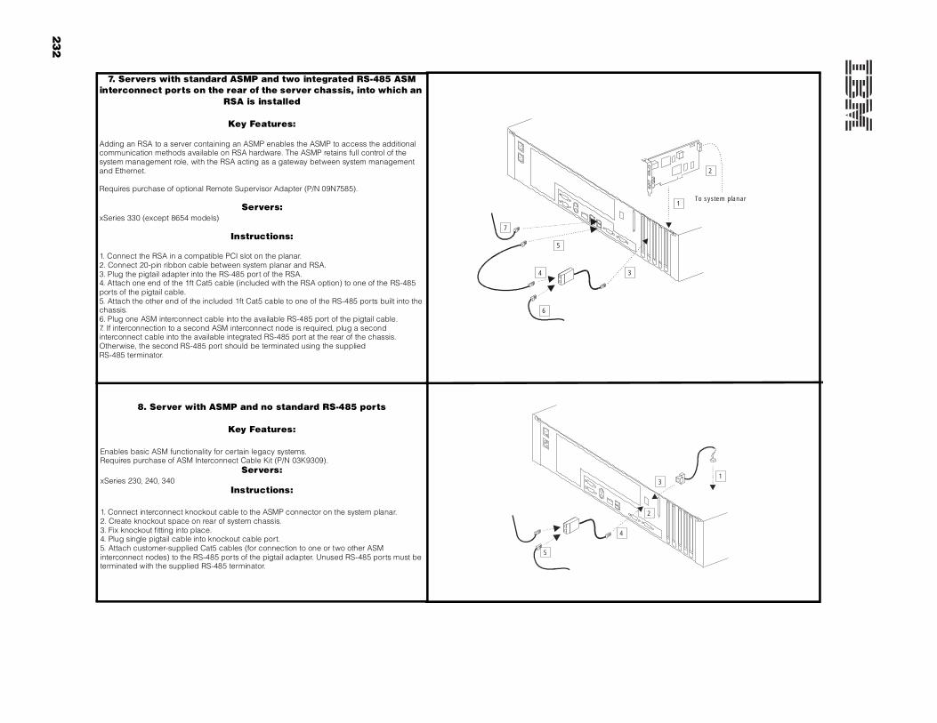
232
To system planar1
2
34
7
6
5
1
2
3
4
5
7. Servers with standard ASMP and two integrated RS-485 ASM interconnect ports on the rear of the server chassis, into which an
RSA is installed
Key Features:
Adding an RSA to a server containing an ASMP enables the ASMP to access the additional communication methods available on RSA hardware. The ASMP retains full control of the system management role, with the RSA acting as a gateway between system management and Ethernet.
Requires purchase of optional Remote Supervisor Adapter (P/N 09N7585).
Servers:xSeries 330 (except 8654 models)
Instructions:
1. Connect the RSA in a compatible PCI slot on the planar.2. Connect 20-pin ribbon cable between system planar and RSA.3. Plug the pigtail adapter into the RS-485 port of the RSA.4. Attach one end of the 1ft Cat5 cable (included with the RSA option) to one of the RS-485 ports of the pigtail cable.5. Attach the other end of the included 1ft Cat5 cable to one of the RS-485 ports built into the chassis.6. Plug one ASM interconnect cable into the available RS-485 port of the pigtail cable.7. If interconnection to a second ASM interconnect node is required, plug a second interconnect cable into the available integrated RS-485 port at the rear of the chassis. Otherwise, the second RS-485 port should be terminated using the suppliedRS-485 terminator.
8. Server with ASMP and no standard RS-485 ports
Key Features:
Enables basic ASM functionality for certain legacy systems.Requires purchase of ASM Interconnect Cable Kit (P/N 03K9309).
Servers:xSeries 230, 240, 340
Instructions:
1. Connect interconnect knockout cable to the ASMP connector on the system planar.2. Create knockout space on rear of system chassis.3. Fix knockout fitting into place.4. Plug single pigtail cable into knockout cable port.5. Attach customer-supplied Cat5 cables (for connection to one or two other ASM interconnect nodes) to the RS-485 ports of the pigtail adapter. Unused RS-485 ports must be terminated with the supplied RS-485 terminator.

23
3For the latest p
roduct &
technical information, refer to the Inform
ation Sources on pag
es 2 and 3.U
pd
ate
d 1
0/1
5/0
2
System ManagementOverview
1
2
3
4
7
6
5
9. Server with ASMP and no standard RS-485 ports, into which an optional ASMA is installed
Key Features:
Enables basic ASM functionality for certain legacy systems.
Servers:xSeries 230, 240, 340
Instructions:
1. Connect interconnect knockout cable to the ASMP connector on the system planar.2. Create knockout space on rear of system chassis.3. Fix knockout fitting into place.4. Connect the ASMA to a compatible PCI slot on the planar.5. Plug one pigtail cable into knockout cable port.6. Plug other pigtail cable into the RS-485 port of ASMA.7. Attach customer-supplied Cat5 cables (for connection to one or two other ASM interconnect nodes) to the RS-485 ports of the pigtail adapter. UnusedRS-485 ports must be terminated with the supplied RS-485 terminator.8. Connect the external AC power supply provided with the option.

234
Appendix H: xSeries I/O Option Attributes
I/O Option Attributes
Part Number
Description Adapter Length
PCI Support1
Low-profile
Enabled
Hot-Plug2 PCI Voltage
Key
MHz1
Storage Controllers37L6889 ServeRAID-4H Ultra160 SCSI Controller3 Full 64-bit - X Universal 33
06P5736 ServeRAID-4Mx Ultra160 SCSI Controller4 Full 64-bit - X Universal 66
06P5740 ServeRAID-4Lx Ultra160 SCSI Controller5 Half 64-bit - X Universal 66
25P3492 ServeRAID-5i Controller6 Full 64-bit X - Universal 66
19K4646 PCI Wide Ultra160 SCSI Adapter7 Half 32-bit X - Universal 66
02K3454 PCI Fast/Wide Ultra SCSI Adapter8 Half 32-bit - - 5 33
Fibre Storage Controllers and Options9
00N6881 Netfinity FAStT Host Adapter Half 64-bit - X Universal 66
24P0960 FC2-133 Host Bus Adapter27 Half 64-bit X X Universal 13328
17421RU FAStT700 Fibre Channel Storage Server - - - - - -
35521RU FAStT500 Storage Server - - - - - -
35421RU FAStT200 Storage Server - - - - - -
35422RU FAStT200 HA Storage Server - - - - - -
3534F08 TotalStorage SAN Switch F08 - 8-port (2Gb) - - - - - -
2109F16 SAN Fibre Channel Switch, 16-Port (2Gb) - - - - - -
2108R3L SAN Data Gateway Router Ultra SCSI LVD Port10 - - - - - -
NetworkingEthernet11
09N3601 10/100 EtherLink PCI Management Adapter by 3Com12 Half 32-bit - - Universal 33
22P4501 Intel Pro/100S Desktop Adapter13 Half 32-bit - - Universal 33
22P4701 Intel Pro/100S Low Profile Desktop Adapter13 Half 32-bit X - Universal 33
22P6501 Pro/1000 T Desktop Adapter by Intel14 Half 32-bit - - Universal 33
22P6601 Intel Pro/1000 Low Profile Desktop Adapter14 Half 32-bit X - Universal 33
22P6901 Wireless LAN Adapter Half 128-bit X - Universal 33
09N9901 10/100 EtherLink Server Adapter by 3Com14, 15 Half 32-bit - X Universal 33
06P3601 10/100 Ethernet Server Adapter14 Half 32-bit - X Universal 33
22P4901 10/100 Dual Port Server Adapter14 Half 64-bit - X Universal 66
22P6801 PRO/1000XT Server Adapter by Intel (copper) w/CD, manuals14 Half 64-bit - X Universal 13328
22P7801 NetXtreme 1000 SX Fiber Ethernet Adapter27 Half 64-bit X X Universal 13328
31P6301 NetXtreme 1000 T Ethernet Adapter (copper)14, 27 Half 64-bit X X Universal 13328
Token Ring
34L5001 16/4 Token-ring PCI Management Adapter14 Half 32-bit - X Universal 33
34L5201 High-Speed 100/16/4 Token-ring PCI Management Adapter16 Half 32-bit - X Universal 33
34L0701 Token-ring 16/4 PCI Adapter 2 with Wake on LAN16 Half 64-bit - X Universal 33
07P2701 16/4 Token-ring Low Profile PCI Management Adapter14 Half 32-bit X X Universal 33
Systems Management17
03K9309 Advanced System Management Interconnect Cable Kit18 - - - - - -
09N7585 Remote Supervisor Adapter Half 32-bit - - Universal29 33
01K7209 Advanced System Management PCI Adapter Full 32-bit - - 5 33
Communications33L4618 V.90 PCI Data/Fax Modem19 Half 32-bit - - 5 33
19K4162 V.90 PCI Data/Fax WinModem (Low Profile Enabled)19 Half 32-bit - - 5 33
37L14xx Serial I/O SST 8- and 16-port adapters20 Half 32-bit - - 5 33
1519100 IXA Adapter21 Half 32-bit - - Universal -
22P5888 PCI Parallel Port Adapter (low profile) Half 32-bit - - 5 33
Remote I/O Expansion8684-1RX RXE-100 Remote Expansion Enclosure22 - - - - - -

xS
eri
es I
/O O
pti
on
Att
ribu
tes
235For the latest product & technical information, refer to the Information Sources on pages 2 and 3.Updated 10/15/02
Related I/O Cables - - - -
33P3168 Internal SCSI Interface Kit23 - - - - - -
32P8164 External SCSI Interface Kit24 - - - - - -
10K3661 USB to Serial Adapter25, 26 - - - - - -
19K4164 NetVista USB - Parallel Printer Adapter25 - - - - - -
1. Adapters rated at a lower frequency than the slots in which they are installed will reduce the bus to the frequency of the slowest adapter. 133MHz PCI-X adapters are backward compatible with 33/66MHz, 64-bit PCI-based servers.2. Hot-plug feature only supported in systems with Active PCI slots. For network operating system support, point your browser to www.pc.ibm.com/us/compat.3. ServeRAID-4H Ultra160 SCSI Controller is powered by a 266MHz PowerPC 750 processor and provides 128MB of battery-backed ECC cache with two internal and four external Ultra160 connectors (a combination of four connectors may be utilized). External connectors are 0.8mm VHDCI.4. ServeRAID-4Mx Ultra160 SCSI Controller is powered by a 100MHz Intel Zion GC80303 processor that provides 64MB of battery-backed ECC cache and two internal and two external Ultra160 connections (only two connectors may be used simultaneously). External connectors are 0.8mm VHDCI.5. ServeRAID-4Lx Ultra160 SCSI Controller is powered by a 100MHz Intel Zion GC80303 processor and provides a single channel, 32MB of ECC cache and either one internal or one external Ultra160 connection. External connector is 0.8mm VHDCI.6. ServeRAID-5i (P/N 25P3492) supports both Ultra320 and Ultra160 HDDs in a dedicated or mixed environment, allowing each HDD to perform at rated capacity. The adapter installs into limited PCI slots and converts both channels of the onboard SCSI controller to RAID in conjunction with the LSI 1020/30 chipset. Both standard and the optional SCSI HDD backplanes as well as internal tape drives and external SCSI devices cable directly to the onboard controller connectors. Supports up to 528MB/s data transfers across the PCI bus with 128MB ECC SDRAM write-back cache with battery backup. Supports RAID levels 0, 1, 10, 5, 50 and 1E. The option includes brackets for installation in both low-profile and standard PCI slots. Internal and external tape drives are supported by ServeRAID-5i only when a second channel on the integrated controller is available and the RAID configuration designates the second channel as a conventional SCSI bus. See system sections for supported tape drives.7. PCI Wide Ultra160 SCSI Adapter (P/N 19K4646) provides a single channel with one internal connector, a five-drop multi-mode terminated LVD SCSI cable and one external 0.8mm VHDCI connector. Only one of the two connectors may be utilized. Hardware is included in the option to support either low-profile or full-size installations.8. PCI Fast/Wide Ultra SCSI Adapter (P/N 02K3454) provides one external 68-pin high density connector that supports external SCSI devices such as tape enclosures.9. See Fibre Channel Solutions Overview section for additional configuration information.10.The 2108R3L SAN Data Gateway Router UltraSCSI LVD Port provides one integrated short-wave optical port and two SCSI ports for tape storage connections (LVD, HVD and single-ended).11. In a fault-tolerant networking environment, using the fault-tolerant software delivered with the Ethernet adapters of a single manufacturer is recommended. Installing fault-tolerant solutions provided by multiple manufacturers may cause failures if the intermediate drivers provided with the adapters are not compatible. See individual system I/O Options sections for additional information on adapter driver compatibility.12. The remote wake-up feature (Wake on LAN) can be used only in a system that has been designed to support this capability. Systems that are compliant with PCI 2.2 enable this capability through the PCI bus. Systems that are not PCI 2.2-compliant must support the 3-pin header cable and provide auxiliary power for +5v +/-5% at 375mA. Wake on LAN cable is provided.13. For use of the Alert on LAN 2 features in the Desktop adapter, the system must be enabled with IBM-compatible Alert on LAN 2 hardware and software components. Use of the Wake on LAN function requires a PCI 2.2 compatible system that supports Wake on LAN and provides auxiliary 3.3v power through the PCI bus.14. Use of the Wake on LAN function requires a PCI 2.2 compatible system that supports Wake on LAN and provides auxiliary power through the PCI bus.15. Not supported when greater than 4GB of random access memory (RAM) is installed.16. Use of the Wake on LAN function requires a PCI 2.1 or 2.2-compatible system that supports Wake on LAN and provides auxiliary power through the 5v Wake on LAN cable provided with the adapter via a 3-pin header in the system planar.17. Up to 24 Integrated System Management Processors or Remote Supervisors Adapters may be interconnected with an aggregate connection length of no more than 91.4m (300ft). This interconnect network of 24 devices may also include a maximum of 12 Advanced System Management Processors or advanced System Management PCI Adapters. A customer-supplied Cat5 cable is required for each interconnection.18. When a standard Remote Supervisor Adapter or ASM PCI Adapter is installed in a dedicated PCI slot with an external connector, support for connection to other servers in an ASM interconnect network requires an optional Advanced System Management Interconnect Cable Kit(P/N 03K9309). Where applicable, direct connection to the RXE drawer management controller in an RXE-100 Remote Expansion Enclosure is supported through a standard Interconnect Management Cable Kit with 3.5m cable (8m optional cable is available). Support is provided through a single LAN or modem connection. 19. Due to homologation variances, modem availability may differ by country.20. See Appendix E for details on Serial I/O options and configuration limitations. A maximum of four Serial I/O adapters (any combination of P/N 37L1414, 37L1415, 37L1423) may be installed.21. Some xSeries servers support the IXA Adapter (P/N 1519100) for connection to iSeries models. Refer to system sections for PCI slot restrictions.22. RXE-100 Remote Expansion Enclosure supports up to 12 additional PCI-X slots. Cable required for connection included with expansion unit, which attaches to a standard integrated RIO port located on the back of the system chassis. An optional longer cable is available. Refer to RXE-100 section for diagrams and supported options.23. Required to connect ServeRAID-4H, -4Mx or -4Lx to the hot-swap backplane in xSeries 235systems.24. Required to enable external 0.8mm VHDCI connectors on some systems (x235, x255).25. When supported, this option can be used for certain external device connections when only USB ports rather than serial or parallel ports are present on a system chassis.26. Available only in the US.27. The option includes brackets for installation in both low-profile and standard PCI slots.28. This adapter is designed using PCI-X technology.29. Although the voltage key of this adapter is universal (compatible with 3.3 or 5v slots), the BIOS of each system limits installation to a specific PCI slot.
236
Important NotesIBM reserves the right to change product specifications and to discontinue marketing products without notice.MHz and GHz only measure microprocessor internal clock speed, not application performance. Many factors affect application performance.When referring to storage capacity, GB stands for 1,000,000,000 bytes. Total user-accessible capacity may be less.Tape Drives which utilize data compression technology have storage capacity that will vary depending upon whether the drive is operating in native mode (without compression) or compressed mode. Actual storage capacity will vary based upon many factors and may be less than the maximum possible.Maximum internal hard disk drive capacities assume the replacement of any hard disk drives and the population of all hard disk drive bays with the largest currently supported drives available from IBM.The information contained in this document has not been submitted to any formal IBM test and is distributed AS IS. The use of this information or the implementation of any of these techniques is a customer responsibility and depends on the customer’s ability to evaluate and integrate them into the customer’s operational environment. While each item may have been reviewed by IBM for accuracy in a specific situation, there is no guarantee that the same or similar results will be obtained elsewhere. Customers attempting to adapt these techniques to their own environments do so at their own risk.For more information on IBM’s statement of Limited Warranty, please call 1-800-772-2227 in the United States, 1-800-426-2255 in Canada, or contact your IBM representative or reseller. Copies are available upon request. For warranties including onsite service, a technician is sent after IBM attempts to resolve the problem remotely.Energy Star compliance: The EPA, as a matter of policy, does not endorse any particular company or its products.IBM makes no representations or warranties with respect to non-IBM products. Support (if any) for the non-IBM products is provided by the third party, not IBM. IBM makes no warranties, express or implied, regarding non-IBM products and services that are ServerProven, including but not limited to the implied warranties of merchantability and fitness for particular purpose. These products are offered and warranted solely by third parties.Unless otherwise noted, phone numbers and fax numbers are valid only in the United States. Outside the United States, please call your local IBM representative for assistance. Applications included in IBM products may vary from retail versions and may not include all documentation or functions. Not all products are sold separately. Third-party software licenses may apply.This publication was produced in the United States. IBM may not offer the products, services or features discussed in this document in other countries, and the information is subject to change without notice. Consult your local IBM representative for more information on the products, services and features available in your area.
©IBM Server Group3039 Cornwallis Rd.Research Triangle Park, NC 27709
All the part numbers referenced in this publication are product part numbers and not service part numbers.This publication could contain technical inaccuracies or typographical errors. Changes are periodically made to the information herein; these changes will be incorporated in new editions of this publication. IBM may make improvements and/or changes in the product(s) and/or program(s) described in this publication at any time. IBM reserves the right to alter specifications and other product information without notice. It is your responsibility to obtain the latest information.Other part numbers in addition to those listed in this document may be required to support a specific device or function.Data on competitive products is obtained from publicly obtained information and is subject to change without notice. Please contact the manufacturer for the most recent information.This IBM equipment is subject to applicable rules and regulations of the United States Federal Communication Commission (FCC).The following items are trademarks or registered trademarks of IBM Corporation in the United States or other countries or both: IBM, the IBM logo, Active PCI, Alert on LAN, Chipkill memory, the e-business logo, ESCON, IntelliStation, LANStreamer, Light Path Diagnostics, NetBAY3, NetBAY3E, NetBAY22, Netfinity, OS/2, Predictive Failure Analysis, ServeRAID, ServerGuide, ServerProven, SurePath, TechConnect, TME 10 Netfinity, Wake on LAN, xSeries, X-Architecture, 800-CALL-IBM.Lotus, Lotus Notes and Lotus SmartSuite are trademarks of Lotus Development Corporation, and/or IBM Corporation. Intel, Pentium, Celeron, Itanium, MMX, and Pentium III Xeon are trademarks or registered trademarks of Intel Corporation. Microsoft, Windows and Windows NT are trademarks or registered trademarks of the Microsoft Corporation. UNIX is a registered trademark in the United States and other countries or registered trademarks licensed exclusively through X/Open Company Limited. Trinitron is a trademark of the Sony Corporation. Java and all Java-based trademarks and logos are trademarks or registered trademarks of Sun Microsystems, Inc. in the U.S. and/or other countries. All other registered trademarks and trademarks are properties of their respective owners.

© C o p y r i g h t I B M C o r p o r a t i o n 2 0 01
IBM Server Group3039 Cornwallis RoadResearch Triangle Park, NC 27709