Hardware Maintenance Manual - Kev009.comps-2.kev009.com/DS4xxx/Docs/gc26770201.pdf · Installation...
162
IBM TotalStorage DS4000 Hardware Maintenance Manual GC26-7702-01
Transcript of Hardware Maintenance Manual - Kev009.comps-2.kev009.com/DS4xxx/Docs/gc26770201.pdf · Installation...
IBM TotalStorage DS4000
Hardware Maintenance Manual
GC26-7702-01
���


IBM TotalStorage DS4000
Hardware Maintenance Manual
GC26-7702-01
���

Note
Before using this information and the product it supports, be sure to read the general information in “Notices” on page 119.
Second Edition (October 2006)
© Copyright International Business Machines Corporation 2004, 2006. All rights reserved.
US Government Users Restricted Rights – Use, duplication or disclosure restricted by GSA ADP Schedule Contract
with IBM Corp.
Contents
Figures . . . . . . . . . . . . . . . . . . . . . . . . . . . vii
Tables . . . . . . . . . . . . . . . . . . . . . . . . . . . . ix
Safety . . . . . . . . . . . . . . . . . . . . . . . . . . . . xi
Caution notice . . . . . . . . . . . . . . . . . . . . . . . . . xii
Safety information . . . . . . . . . . . . . . . . . . . . . . . . xii
General safety . . . . . . . . . . . . . . . . . . . . . . . . xii
Grounding requirements . . . . . . . . . . . . . . . . . . . . xiii
Electrical safety . . . . . . . . . . . . . . . . . . . . . . . xiii
Handling ESD-sensitive devices . . . . . . . . . . . . . . . . . xiv
Safety inspection procedure . . . . . . . . . . . . . . . . . . . xv
About this document . . . . . . . . . . . . . . . . . . . . . xvii
FAStT product renaming . . . . . . . . . . . . . . . . . . . . . xvii
Who should read this document . . . . . . . . . . . . . . . . . . xviii
How this document is organized . . . . . . . . . . . . . . . . . . xviii
Notices used in this document . . . . . . . . . . . . . . . . . . . xix
Getting information, help, and service . . . . . . . . . . . . . . . . xix
Before you call . . . . . . . . . . . . . . . . . . . . . . . . xix
Using the documentation . . . . . . . . . . . . . . . . . . . . xx
Web sites . . . . . . . . . . . . . . . . . . . . . . . . . . xx
Software service and support . . . . . . . . . . . . . . . . . . . xx
Hardware service and support . . . . . . . . . . . . . . . . . . xxi
Fire suppression systems . . . . . . . . . . . . . . . . . . . xxi
How to send your comments . . . . . . . . . . . . . . . . . . . . xxi
Chapter 1. About hardware maintenance . . . . . . . . . . . . . . . 1
Finding maintenance information about other DS4000 models . . . . . . . . 1
Where to start . . . . . . . . . . . . . . . . . . . . . . . . . . 2
Related documents . . . . . . . . . . . . . . . . . . . . . . . . 2
Chapter 2. Type 3523 Fibre Channel Hub and GBIC . . . . . . . . . . . 3
General checkout . . . . . . . . . . . . . . . . . . . . . . . . 4
Port Status LEDs . . . . . . . . . . . . . . . . . . . . . . . 4
Verifying GBIC and cable signal presence . . . . . . . . . . . . . . 4
Additional service information . . . . . . . . . . . . . . . . . . . . 5
Applications and configurations . . . . . . . . . . . . . . . . . . 5
Power on systems check for the fibre channel hub . . . . . . . . . . . 6
Symptom-to-FRU index . . . . . . . . . . . . . . . . . . . . . . 8
Parts listing (Type 3523 fibre channel hub and GBIC) . . . . . . . . . . . 9
Chapter 3. Fibre Channel PCI Adapter . . . . . . . . . . . . . . . 11
General checkout . . . . . . . . . . . . . . . . . . . . . . . . 11
Hardware problems . . . . . . . . . . . . . . . . . . . . . . 11
System configuration problems . . . . . . . . . . . . . . . . . . 11
Fibre channel problems . . . . . . . . . . . . . . . . . . . . . 11
Additional service information . . . . . . . . . . . . . . . . . . . 11
Chapter 4. DS4000 Host Adapter . . . . . . . . . . . . . . . . . 13
General checkout . . . . . . . . . . . . . . . . . . . . . . . . 13
Hardware problems . . . . . . . . . . . . . . . . . . . . . . 13
System configuration problems . . . . . . . . . . . . . . . . . . 13
© Copyright IBM Corp. 2004, 2006 iii
||
Fibre channel problems . . . . . . . . . . . . . . . . . . . . . 14
Additional service information . . . . . . . . . . . . . . . . . . . 14
Chapter 5. DS4000 FC2-133 Host Bus Adapter . . . . . . . . . . . . 17
General checkout . . . . . . . . . . . . . . . . . . . . . . . . 17
Hardware problems . . . . . . . . . . . . . . . . . . . . . . 17
System configuration problems . . . . . . . . . . . . . . . . . . 18
Fibre channel problems . . . . . . . . . . . . . . . . . . . . . 18
Additional service information . . . . . . . . . . . . . . . . . . . 18
Chapter 6. Type 3526 Fibre Channel RAID Controller . . . . . . . . . . 21
General checkout . . . . . . . . . . . . . . . . . . . . . . . . 21
Additional service information . . . . . . . . . . . . . . . . . . . 22
Powering on the controller . . . . . . . . . . . . . . . . . . . . 22
Recovering from a power supply shutdown . . . . . . . . . . . . . 22
Connectors and host IDs . . . . . . . . . . . . . . . . . . . . 22
Host and drive ID numbers . . . . . . . . . . . . . . . . . . . 22
Fibre channel host cable requirements . . . . . . . . . . . . . . . 23
LVD-SCSI drive cable requirements . . . . . . . . . . . . . . . . 23
Specifications . . . . . . . . . . . . . . . . . . . . . . . . 24
Tested configurations . . . . . . . . . . . . . . . . . . . . . 24
Symptom-to-FRU index . . . . . . . . . . . . . . . . . . . . . . 32
Parts listing . . . . . . . . . . . . . . . . . . . . . . . . . . 33
Chapter 7. FAStT200 Type 3542 and FAStT200 HA Type 3542 . . . . . . 35
General checkout . . . . . . . . . . . . . . . . . . . . . . . . 35
General information . . . . . . . . . . . . . . . . . . . . . . . 35
Additional service information . . . . . . . . . . . . . . . . . . . 36
Operating specifications . . . . . . . . . . . . . . . . . . . . 36
Storage server components . . . . . . . . . . . . . . . . . . . 36
Interface ports and switches . . . . . . . . . . . . . . . . . . . 38
Diagnostics . . . . . . . . . . . . . . . . . . . . . . . . . . 39
Monitoring status through software . . . . . . . . . . . . . . . . 40
Checking the LEDs . . . . . . . . . . . . . . . . . . . . . . 40
Symptom-to-FRU index . . . . . . . . . . . . . . . . . . . . . . 44
Parts listing . . . . . . . . . . . . . . . . . . . . . . . . . . 45
Chapter 8. Type 3552 FAStT500 RAID Controller . . . . . . . . . . . 47
General checkout . . . . . . . . . . . . . . . . . . . . . . . . 47
Checking the indicator lights . . . . . . . . . . . . . . . . . . . 47
Tested configurations . . . . . . . . . . . . . . . . . . . . . . 52
Symptom-to-FRU index . . . . . . . . . . . . . . . . . . . . . . 57
Parts listing . . . . . . . . . . . . . . . . . . . . . . . . . . 58
Chapter 9. Type 1742 DS4400 Storage Server . . . . . . . . . . . . 61
General checkout . . . . . . . . . . . . . . . . . . . . . . . . 61
Checking the indicator lights . . . . . . . . . . . . . . . . . . . 61
Using the diagnostic hardware . . . . . . . . . . . . . . . . . . 69
Symptom-to-FRU index . . . . . . . . . . . . . . . . . . . . . . 69
Parts listing . . . . . . . . . . . . . . . . . . . . . . . . . . 70
Chapter 10. IBM TotalStorage FAStT EXP15 and EXP200 Storage
Expansion Units . . . . . . . . . . . . . . . . . . . . . . . 73
Diagnostics and test information . . . . . . . . . . . . . . . . . . 73
Additional service information . . . . . . . . . . . . . . . . . . . 73
Performing a shutdown . . . . . . . . . . . . . . . . . . . . . 74
iv IBM TotalStorage DS4000: Hardware Maintenance Manual
Turning the power on . . . . . . . . . . . . . . . . . . . . . 74
Specifications . . . . . . . . . . . . . . . . . . . . . . . . 74
Symptom-to-FRU index . . . . . . . . . . . . . . . . . . . . . . 76
Chapter 11. IBM TotalStorage FAStT EXP500 Storage Expansion Unit . . . 79
Diagnostics and test information . . . . . . . . . . . . . . . . . . 79
Additional service information . . . . . . . . . . . . . . . . . . . 79
Turning the expansion unit on and off . . . . . . . . . . . . . . . 79
Performing an emergency shutdown . . . . . . . . . . . . . . . . 81
Restoring power after an emergency . . . . . . . . . . . . . . . . 81
Specifications . . . . . . . . . . . . . . . . . . . . . . . . 81
Symptom-to-FRU index . . . . . . . . . . . . . . . . . . . . . . 83
Parts listing . . . . . . . . . . . . . . . . . . . . . . . . . . 84
Chapter 12. IBM Storage Area Network Data Gateway Router (2108-R03) 87
Service Aids . . . . . . . . . . . . . . . . . . . . . . . . . . 87
LED indicators . . . . . . . . . . . . . . . . . . . . . . . . 87
POST . . . . . . . . . . . . . . . . . . . . . . . . . . . 88
Health Check . . . . . . . . . . . . . . . . . . . . . . . . 88
Event Log . . . . . . . . . . . . . . . . . . . . . . . . . . 88
Service Port Commands . . . . . . . . . . . . . . . . . . . . 88
Diagnostics . . . . . . . . . . . . . . . . . . . . . . . . . 101
Appendix A. Power cords . . . . . . . . . . . . . . . . . . . . 103
Appendix B. Additional DS4000 documentation . . . . . . . . . . . 105
DS4000 Storage Manager Version 9 library . . . . . . . . . . . . . . 105
DS4800 Storage Subsystem library . . . . . . . . . . . . . . . . . 106
DS4700 Storage Subsystem library . . . . . . . . . . . . . . . . . 107
DS4500 Fibre Channel Storage Server library . . . . . . . . . . . . . 108
DS4400 Fibre Channel Storage Server library . . . . . . . . . . . . . 109
DS4300 Fibre Channel Storage Server library . . . . . . . . . . . . . 110
DS4200 Express Storage Subsystem library . . . . . . . . . . . . . . 111
DS4100 SATA Storage Server library . . . . . . . . . . . . . . . . 112
DS4000 Storage Expansion Enclosure documents . . . . . . . . . . . 113
Other DS4000 and DS4000-related documents . . . . . . . . . . . . 114
Appendix C. Product Recycling and Disposal . . . . . . . . . . . . 115
Appendix D. Battery Return Program . . . . . . . . . . . . . . . 117
Notices . . . . . . . . . . . . . . . . . . . . . . . . . . . 119
Trademarks . . . . . . . . . . . . . . . . . . . . . . . . . . 119
Important notes . . . . . . . . . . . . . . . . . . . . . . . . 120
Electronic emission notices . . . . . . . . . . . . . . . . . . . . 120
Federal Communications Commission (FCC) statement . . . . . . . . 120
Chinese class A compliance statement . . . . . . . . . . . . . . . 121
Industry Canada Class A emission compliance statement . . . . . . . . 121
Australia and New Zealand Class A statement . . . . . . . . . . . . 121
United Kingdom telecommunications safety requirement . . . . . . . . 121
European Union EMC Directive conformance statement . . . . . . . . 121
Taiwan electrical emission statement . . . . . . . . . . . . . . . 122
Japanese Voluntary Control Council for Interference (VCCI) statement 122
Glossary . . . . . . . . . . . . . . . . . . . . . . . . . . 123
Contents v

Index . . . . . . . . . . . . . . . . . . . . . . . . . . . . 133
vi IBM TotalStorage DS4000: Hardware Maintenance Manual
Figures
1. Verifying signal presence . . . . . . . . . . . . . . . . . . . . . . . . . . . . 5
2. Verifying node end . . . . . . . . . . . . . . . . . . . . . . . . . . . . . . . 5
3. Type 3523 fibre channel hub . . . . . . . . . . . . . . . . . . . . . . . . . . . 6
4. Type 3523 fibre channel hub power connector . . . . . . . . . . . . . . . . . . . . 6
5. Type 3523 fibre channel hub active LEDs . . . . . . . . . . . . . . . . . . . . . . 7
6. Type 3523 fibre channel hub port bypass LEDs . . . . . . . . . . . . . . . . . . . . 7
7. Type 3523 fibre channel hub parts listing . . . . . . . . . . . . . . . . . . . . . . 9
8. Fibre Host ID . . . . . . . . . . . . . . . . . . . . . . . . . . . . . . . . 23
9. Media Interface Adapter . . . . . . . . . . . . . . . . . . . . . . . . . . . . 23
10. Type 3526 fibre channel RAID controller basic configuration . . . . . . . . . . . . . . . 25
11. Type 3526 fibre channel RAID controller basic dual controller configuration . . . . . . . . . 25
12. Type 3526 fibre channel RAID controller orthogonal data striping . . . . . . . . . . . . . 26
13. Type 3526 fibre channel RAID controller simple fully redundant . . . . . . . . . . . . . . 27
14. Type 3526 fibre channel RAID controller cluster/non-cluster share . . . . . . . . . . . . . 27
15. Type 3526 fibre channel RAID controller multi-MSCS no external hubs . . . . . . . . . . . 28
16. Type 3526 fibre channel RAID controller multi-MSCS extended . . . . . . . . . . . . . . 28
17. Type 3526 fibre channel RAID controller cornhusker configuration . . . . . . . . . . . . . 29
18. Type 3526 fibre channel RAID controller basic storage partitions . . . . . . . . . . . . . 29
19. Type 3526 fibre channel RAID controller capacity configuration . . . . . . . . . . . . . . 30
20. Type 3526 fibre channel RAID controller SAN - Using partitions of clusters . . . . . . . . . 30
21. Type 3526 fibre channel RAID controller Legato HA/replication for MSCS . . . . . . . . . . 31
22. Type 3526 fibre channel RAID controller parts list . . . . . . . . . . . . . . . . . . . 33
23. FAStT200 and FAStT200 HA storage server front view . . . . . . . . . . . . . . . . . 37
24. FAStT200 and FAStT200 HA storage server bays (back view) . . . . . . . . . . . . . . 38
25. FAStT200 and FAStT200 HA storage server interface ports and switches . . . . . . . . . . 39
26. FAStT200 and FAStT200 HA storage server LEDs (front) . . . . . . . . . . . . . . . . 41
27. FAStT200 and FAStT200 HA storage server LEDs (rear) . . . . . . . . . . . . . . . . 42
28. FAStT200 and FAStT200 HA fan and power supply LEDs . . . . . . . . . . . . . . . . 43
29. FAStT200 and FAStT200 HA controller parts list . . . . . . . . . . . . . . . . . . . 46
30. FAStT500 RAID controller indicator lights (front panel) . . . . . . . . . . . . . . . . . 48
31. FAStT500 RAID controller indicator lights (back panel) . . . . . . . . . . . . . . . . . 49
32. FAStT500 RAID controller mini hub indicator lights . . . . . . . . . . . . . . . . . . 50
33. FAStT500 RAID controller basic configuration . . . . . . . . . . . . . . . . . . . . 52
34. FAStT500 RAID controller simple fully redundant . . . . . . . . . . . . . . . . . . . 52
35. FAStT500 RAID controller cluster/non-cluster share . . . . . . . . . . . . . . . . . . 53
36. FAStT500 RAID controller multi-MSCS no external hubs . . . . . . . . . . . . . . . . 53
37. FAStT500 RAID controller multi-MSCS extended . . . . . . . . . . . . . . . . . . . 54
38. FAStT500 RAID controller cornhusker configuration . . . . . . . . . . . . . . . . . . 54
39. FAStT500 RAID controller basic storage partitions . . . . . . . . . . . . . . . . . . 55
40. FAStT500 RAID controller capacity configuration . . . . . . . . . . . . . . . . . . . 55
41. FAStT500 RAID controller capacity configuration host detail . . . . . . . . . . . . . . . 56
42. FAStT500 RAID controller SAN - Using partitions of clusters . . . . . . . . . . . . . . . 56
43. FAStT500 RAID controller Legato HA/replication for MS . . . . . . . . . . . . . . . . 57
44. FAStT500 RAID controller parts listing . . . . . . . . . . . . . . . . . . . . . . . 59
45. DS4400 storage server indicator lights . . . . . . . . . . . . . . . . . . . . . . . 62
46. DS4400 storage server RAID controller indicator lights . . . . . . . . . . . . . . . . . 63
47. DS4400 storage server battery indicator lights . . . . . . . . . . . . . . . . . . . . 64
48. DS4400 storage server fan and communications module indicator light . . . . . . . . . . . 65
49. DS4400 storage server power supply indicator light . . . . . . . . . . . . . . . . . . 66
50. DS4400 storage server mini hub indicator lights . . . . . . . . . . . . . . . . . . . 66
51. DS4400 storage server parts listing . . . . . . . . . . . . . . . . . . . . . . . . 70
52. FAStT EXP500 storage expansion unit parts list . . . . . . . . . . . . . . . . . . . 84
53. SDG Router front panel LEDs . . . . . . . . . . . . . . . . . . . . . . . . . . 87
© Copyright IBM Corp. 2004, 2006 vii

54. SDG Router showBox command output . . . . . . . . . . . . . . . . . . . . . . 98
viii IBM TotalStorage DS4000: Hardware Maintenance Manual

Tables
1. Mapping of FAStT names to DS4000 Series names . . . . . . . . . . . . . . . . . . xvii
2. Type 3523 fibre channel hub port status LEDs . . . . . . . . . . . . . . . . . . . . 4
3. Symptom-to-FRU index for Type 3523 fibre channel hub and GBIC . . . . . . . . . . . . . 8
4. Fibre channel PCI adapter operating environment . . . . . . . . . . . . . . . . . . . 12
5. Fibre channel PCI adapter specifications . . . . . . . . . . . . . . . . . . . . . . 12
6. DS4000 host adapter operating environment . . . . . . . . . . . . . . . . . . . . 14
7. DS4000 host adapter specifications . . . . . . . . . . . . . . . . . . . . . . . . 14
8. DS4000 FC2-133 host bus adapter operating environment . . . . . . . . . . . . . . . 18
9. DS4000 FC2-133 host bus adapter specifications . . . . . . . . . . . . . . . . . . . 18
10. Type 3526 fibre channel RAID controller MIA specifications . . . . . . . . . . . . . . . 23
11. Symptom-to-FRU index for Type 3526 fibre channel RAID controller . . . . . . . . . . . . 32
12. Model 3542-2RU storage server operating specifications . . . . . . . . . . . . . . . . 36
13. FAStT200 and FAStT200 HA storage server LEDs (front) . . . . . . . . . . . . . . . . 41
14. FAStT200 and FAStT200 HA storage server RAID controller LEDs . . . . . . . . . . . . 42
15. FAStT200 and FAStT200 HA fan LEDs . . . . . . . . . . . . . . . . . . . . . . . 43
16. FAStT200 and FAStT200 HA power supply LEDs . . . . . . . . . . . . . . . . . . . 43
17. Symptom-to-FRU index for FAStT200 and FAStT200 HA Type 3542 controller . . . . . . . . 44
18. FAStT500 RAID controller indicator lights (front panel) . . . . . . . . . . . . . . . . . 48
19. FAStT500 RAID controller indicator lights (back panel) . . . . . . . . . . . . . . . . . 50
20. FAStT500 RAID controller mini hub indicator lights . . . . . . . . . . . . . . . . . . 51
21. Symptom-to-FRU index for FAStT500 RAID controller . . . . . . . . . . . . . . . . . 57
22. DS4400 storage server indicator lights . . . . . . . . . . . . . . . . . . . . . . . 62
23. DS4400 storage server RAID controller indicator lights . . . . . . . . . . . . . . . . . 64
24. DS4400 storage server battery indicator lights . . . . . . . . . . . . . . . . . . . . 65
25. DS4400 storage server fan and communications module indicator light . . . . . . . . . . . 65
26. DS4400 storage server power supply indicator light . . . . . . . . . . . . . . . . . . 66
27. DS4400 storage server host-side and drive-side mini hub indicator lights . . . . . . . . . . 67
28. Symptom-to-FRU index for DS4400 storage server . . . . . . . . . . . . . . . . . . 69
29. Specifications for FAStT EXP15 and FAStT EXP200 . . . . . . . . . . . . . . . . . . 74
30. Symptom-to-FRU index for FAStT EXP15 and FAStT EXP200 storage expansion units . . . . . 76
31. Symptom-to-FRU index for FAStT EXP500 storage expansion unit . . . . . . . . . . . . 83
32. SDG Router LED indicators . . . . . . . . . . . . . . . . . . . . . . . . . . . 87
33. SDG Router service port commands . . . . . . . . . . . . . . . . . . . . . . . 88
34. SDG Router event log levels . . . . . . . . . . . . . . . . . . . . . . . . . . 94
35. DS4000 Storage Manager Version 9.1 titles by user tasks . . . . . . . . . . . . . . . 105
36. DS4800 Storage Subsystem document titles by user tasks . . . . . . . . . . . . . . . 106
37. DS4700 Storage Subsystem document titles by user tasks . . . . . . . . . . . . . . . 107
38. DS4500 Fibre Channel Storage Server document titles by user tasks . . . . . . . . . . . 108
39. DS4400 Fibre Channel Storage Server document titles by user tasks . . . . . . . . . . . 109
40. DS4300 Fibre Channel Storage Server document titles by user tasks . . . . . . . . . . . 110
41. DS4200 Express Storage Subsystem document titles by user tasks . . . . . . . . . . . . 111
42. DS4100 SATA Storage Server document titles by user tasks . . . . . . . . . . . . . . 112
43. DS4000 Storage Expansion Enclosure document titles by user tasks . . . . . . . . . . . 113
44. DS4000 and DS4000–related document titles by user tasks . . . . . . . . . . . . . . 114
© Copyright IBM Corp. 2004, 2006 ix

x IBM TotalStorage DS4000: Hardware Maintenance Manual

Safety
Before installing this product, read the Safety information.
Antes de instalar este produto, leia as Informações de Segurança.
Pred instalací tohoto produktu si prectete prírucku bezpecnostních instrukcí.
Læs sikkerhedsforskrifterne, før du installerer dette produkt.
Lees voordat u dit product installeert eerst de veiligheidsvoorschriften.
Ennen kuin asennat tämän tuotteen, lue turvaohjeet kohdasta Safety Information.
Avant d’installer ce produit, lisez les consignes de sécurité.
Vor der Installation dieses Produkts die Sicherheitshinweise lesen.
Prima di installare questo prodotto, leggere le Informazioni sulla Sicurezza.
Les sikkerhetsinformasjonen (Safety Information) før du installerer dette produktet.
Antes de instalar este produto, leia as Informações sobre Segurança.
Antes de instalar este producto, lea la información de seguridad.
Läs säkerhetsinformationen innan du installerar den här produkten.
© Copyright IBM Corp. 2004, 2006 xi
Caution notice
The following Caution notice is printed in English throughout this document. For a
translation of this notice, see IBM® Safety Information.
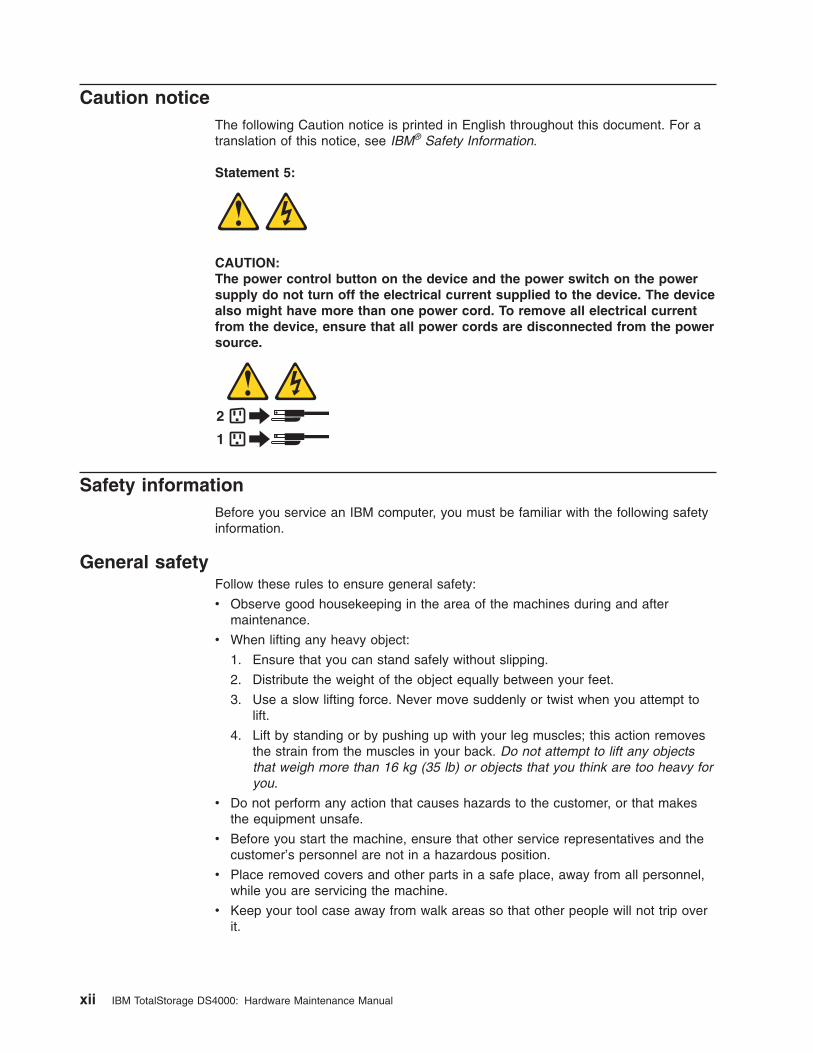
Statement 5:
CAUTION:
The power control button on the device and the power switch on the power
supply do not turn off the electrical current supplied to the device. The device
also might have more than one power cord. To remove all electrical current
from the device, ensure that all power cords are disconnected from the power
source.
1
2
Safety information
Before you service an IBM computer, you must be familiar with the following safety
information.
General safety
Follow these rules to ensure general safety:
v Observe good housekeeping in the area of the machines during and after
maintenance.
v When lifting any heavy object:
1. Ensure that you can stand safely without slipping.
2. Distribute the weight of the object equally between your feet.
3. Use a slow lifting force. Never move suddenly or twist when you attempt to
lift.
4. Lift by standing or by pushing up with your leg muscles; this action removes
the strain from the muscles in your back. Do not attempt to lift any objects
that weigh more than 16 kg (35 lb) or objects that you think are too heavy for
you.
v Do not perform any action that causes hazards to the customer, or that makes
the equipment unsafe.
v Before you start the machine, ensure that other service representatives and the
customer’s personnel are not in a hazardous position.
v Place removed covers and other parts in a safe place, away from all personnel,
while you are servicing the machine.
v Keep your tool case away from walk areas so that other people will not trip over
it.
xii IBM TotalStorage DS4000: Hardware Maintenance Manual
v Do not wear loose clothing that can be trapped in the moving parts of a machine.
Ensure that your sleeves are fastened or rolled up above your elbows. If your
hair is long, fasten it.
v Insert the ends of your necktie or scarf inside clothing or fasten it with a
nonconductive clip, approximately 8 centimeters (3 in.) from the end.
v Do not wear jewelry, chains, metal-frame eyeglasses, or metal fasteners for your
clothing. Remember: Metal objects are good electrical conductors.
v Wear safety glasses when you are doing any of the following: hammering, drilling
soldering, cutting wire, attaching springs, using solvents, or working in any other
conditions that might be hazardous to your eyes.
v After service, reinstall all safety shields, guards, labels, and ground wires.
Replace any safety device that is worn or defective.
v Reinstall all covers correctly before returning the machine to the customer.
Grounding requirements
Electrical grounding of the computer is required for operator safety and correct
system function. Proper grounding of the electrical outlet can be verified by a
certified electrician.
Electrical safety
Important
Use only approved tools and test equipment. Some hand tools have handles that are covered with a soft material
that does not insulate you when working with live electrical currents.
Many customers have, near their equipment, rubber floor mats that contain small conductive fibers to decrease
electrostatic discharges. Do not use this type of mat to protect yourself from electrical shock.
Observe the following rules when working on electrical equipment.
v Find the room emergency power-off (EPO) switch, disconnecting switch, or
electrical outlet. If an electrical accident occurs, you can then operate the switch
or unplug the power cord quickly.
v Do not work alone under hazardous conditions or near equipment that has
hazardous voltages.
v Disconnect all power before doing any of the following tasks:
– Performing a mechanical inspection
– Working near power supplies
– Removing or installing main units
v Before you start to work on the machine, unplug the power cord. If you cannot
unplug it, ask the customer to power-off the wall box that supplies power to the
machine and to lock the wall box in the off position.
v If you need to work on a machine that has exposed electrical circuits, observe
the following precautions:
– Ensure that another person, familiar with the power-off controls, is near you.
Remember: Another person must be there to switch off the power, if
necessary.
– Use only one hand when working with powered-on electrical equipment; keep
the other hand in your pocket or behind your back.
Safety xiii
Remember: There must be a complete circuit to cause electrical shock. By
observing the previous rule, you might prevent a current from passing through
your body.
– When using testers, set the controls correctly and use the approved probe
leads and accessories for that tester.
– Stand on suitable rubber mats (obtained locally, if necessary) to insulate you
from grounds such as metal floor strips and machine frames.
Observe the special safety precautions when you work with very high voltages;
these instructions are in the safety sections of maintenance information. Use
extreme care when measuring high voltages.
v Regularly inspect and maintain your electrical hand tools for safe operational
condition.
v Do not use worn or broken tools and testers.
v Never assume that power has been disconnected from a circuit. First, check that
it has been powered-off.
v Always look carefully for possible hazards in your work area. Examples of these
hazards are moist floors, nongrounded power extension cables, power surges,
and missing safety grounds.
v Do not touch live electrical circuits with the reflective surface of a plastic dental
mirror. The surface is conductive and can cause personal injury and machine
damage.
v Do not service the following parts (or similar units) with the power on when they
are removed from their normal operating places in a machine. This practice
ensures correct grounding of the units.
– Power supply units
– Pumps
– Blowers and fans
– Motor generators
v If an electrical accident occurs:
– Use caution; do not become a victim yourself.
– Switch off power.
– Send another person to get medical aid.
Handling ESD-sensitive devices
Any computer part that contains transistors or integrated circuits (ICs) should be
considered sensitive to electrostatic discharge (ESD). ESD damage can occur when
there is a difference in charge between objects. Protect against ESD damage by
equalizing the charge so that the machine, the part, the work mat, and the person
that is handling the part are all at the same charge.
Notes:
1. Use product-specific ESD procedures when they exceed the requirements noted
here.
2. Make sure that the ESD protective devices that you use have been certified
(ISO 9000) as fully effective.
Use the following precautions when handling ESD-sensitive parts:
v Keep the parts in protective packages until they are inserted into the product.
v Avoid contact with other people.
v Wear a grounded wrist strap against your skin to eliminate static on your body.
xiv IBM TotalStorage DS4000: Hardware Maintenance Manual
v Prevent the part from touching your clothing. Most clothing is insulative and
retains a charge even when you are wearing a wrist strap.
v Select a grounding system, such as those listed below, to provide protection that
meets the specific service requirement.
Note: The use of a grounding system is desirable but not required to protect
against ESD damage.
– Attach the ESD ground clip to any frame ground, ground braid, or green-wire
ground.
– Use an ESD common ground or reference point when working on a
double-insulated or battery-operated system. You can use coax or
connector-outside shells on these systems.
– Use the round ground-prong of the ac plug on ac-operated computers.
v Use the black side of a grounded work mat to provide a static-free work surface.
The mat is especially useful when handling ESD-sensitive devices.
Safety inspection procedure
Use this safety inspection procedure to identify potentially unsafe conditions on a
product. Each machine, as it was designed and built, had required safety items
installed to protect users and service personnel from injury. This procedure
addresses only those items. However, good judgment should be used to identify
any potential safety hazards due to attachment of non-IBM features or options not
covered by this inspection procedure.
If any unsafe conditions are present, you must determine how serious the apparent
hazard could be and whether you can continue without first correcting the problem.
Consider these conditions and the safety hazards they present:
v Electrical hazards, especially primary power (primary voltage on the frame can
cause serious or fatal electrical shock).
v Explosive hazards, such as a damaged cathode ray tube (CRT) face or bulging
capacitor
v Mechanical hazards, such as loose or missing hardware
Complete the following checks with the power off, and with the power cord
disconnected.
1. Check the exterior covers for damage (loose, broken, or sharp edges).
2. Check the power cord for the following conditions:
a. A third-wire ground connector in good condition. Use a meter to measure
third-wire ground continuity for 0.1 ohm or less between the external ground
pin and frame ground.
b. The power cord should be the appropriate type as specified in the parts
listings.
c. Insulation must not be frayed or worn.
3. Remove the cover.
4. Check for any obvious non-IBM alterations. Use good judgment as to the safety
of any non-IBM alterations.
5. Check the inside the unit for any obvious unsafe conditions, such as metal
filings, contamination, water or other liquids, or signs of fire or smoke damage.
6. Check for worn, frayed, or pinched cables.
Safety xv

7. Check that the power supply cover fasteners (screws or rivets) have not been
removed or tampered with.
xvi IBM TotalStorage DS4000: Hardware Maintenance Manual
About this document
This document provides information about hardware maintenance for some IBM
TotalStorage® FAStT and DS4000 products
Note: Maintenance information about DS4300 and DS4500 storage subsystems is
no longer included in this document. You can now find the information in the
following publications:
v IBM System Storage DS4300 Storage Subsystem Installation, User's, and
Maintenance Guide
v IBM System Storage DS4500 Storage Subsystem Installation, User's, and
Maintenance Guide
In addition, you can find maintenance information about other DS4000
storage subsystems and expansion enclosures in the Installation, User's, and
Maintenance Guide that is included with the product documentation at the
time of purchase. These publications are also available at the following Web
site:
www-1.ibm.com/servers/storage/support/disk/
FAStT product renaming
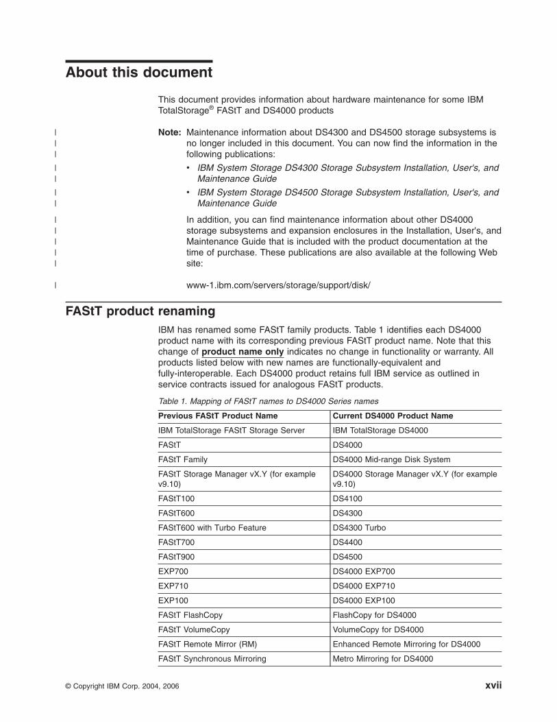
IBM has renamed some FAStT family products. Table 1 identifies each DS4000
product name with its corresponding previous FAStT product name. Note that this
change of product name only indicates no change in functionality or warranty. All
products listed below with new names are functionally-equivalent and
fully-interoperable. Each DS4000 product retains full IBM service as outlined in
service contracts issued for analogous FAStT products.
Table 1. Mapping of FAStT names to DS4000 Series names
Previous FAStT Product Name Current DS4000 Product Name
IBM TotalStorage FAStT Storage Server IBM TotalStorage DS4000
FAStT DS4000
FAStT Family DS4000 Mid-range Disk System
FAStT Storage Manager vX.Y (for example
v9.10)
DS4000 Storage Manager vX.Y (for example
v9.10)
FAStT100 DS4100
FAStT600 DS4300
FAStT600 with Turbo Feature DS4300 Turbo
FAStT700 DS4400
FAStT900 DS4500
EXP700 DS4000 EXP700
EXP710 DS4000 EXP710
EXP100 DS4000 EXP100
FAStT FlashCopy FlashCopy for DS4000
FAStT VolumeCopy VolumeCopy for DS4000
FAStT Remote Mirror (RM) Enhanced Remote Mirroring for DS4000
FAStT Synchronous Mirroring Metro Mirroring for DS4000
© Copyright IBM Corp. 2004, 2006 xvii
|||
||
||
|||||
|
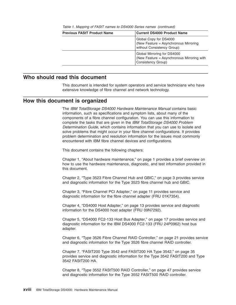
Table 1. Mapping of FAStT names to DS4000 Series names (continued)
Previous FAStT Product Name Current DS4000 Product Name
Global Copy for DS4000(New Feature = Asynchronous Mirroring
without Consistency Group)
Global Mirroring for DS4000(New Feature = Asynchronous Mirroring with
Consistency Group)
Who should read this document
This document is intended for system operators and service technicians who have
extensive knowledge of fibre channel and network technology.
How this document is organized
The IBM TotalStorage DS4000 Hardware Maintenance Manual contains basic
information, such as specifications and symptom lists, about many of the
components of a fibre channel configuration. You can use this information to
complete the tasks that are given in the IBM TotalStorage DS4000 Problem
Determination Guide, which contains information that you can use to isolate and
solve problems that might occur in your fibre channel configurations. It provides
problem determination and resolution information for the issues most commonly
encountered with IBM fibre channel devices and configurations.
This document contains the following chapters:
Chapter 1, “About hardware maintenance,” on page 1 provides a brief overview on
how to use the hardware maintenance, diagnostic, and test information provided in
this document.
Chapter 2, “Type 3523 Fibre Channel Hub and GBIC,” on page 3 provides service
and diagnostic information for the Type 3523 fibre channel hub and GBIC.
Chapter 3, “Fibre Channel PCI Adapter,” on page 11 provides service and
diagnostic information for the fibre channel adapter (FRU 01K7354).
Chapter 4, “DS4000 Host Adapter,” on page 13 provides service and diagnostic
information for the DS4000 host adapter (FRU 09N7292).
Chapter 5, “DS4000 FC2-133 Host Bus Adapter,” on page 17 provides service and
diagnostic information for the IBM DS4000 FC2-133 (FRU 24P0962) host bus
adapter.
Chapter 6, “Type 3526 Fibre Channel RAID Controller,” on page 21 provides service
and diagnostic information for the Type 3526 fibre channel RAID controller.
Chapter 7, “FAStT200 Type 3542 and FAStT200 HA Type 3542,” on page 35
provides service and diagnostic information for the Type 3542 FAStT200 and Type
3542 FAStT200 HA.
Chapter 8, “Type 3552 FAStT500 RAID Controller,” on page 47 provides service
and diagnostic information for the Type 3552 FAStT500 RAID controller.
xviii IBM TotalStorage DS4000: Hardware Maintenance Manual
Chapter 9, “Type 1742 DS4400 Storage Server,” on page 61 provides service and
diagnostic information for the Type 1742 DS4400 storage server.
Chapter 10, “IBM TotalStorage FAStT EXP15 and EXP200 Storage Expansion
Units,” on page 73 provides service and diagnostic information for both the EXP15
and EXP200 storage expansion units.
Chapter 11, “IBM TotalStorage FAStT EXP500 Storage Expansion Unit,” on page 79
provides service and diagnostic information for the EXP500 storage expansion unit.
Chapter 12, “IBM Storage Area Network Data Gateway Router (2108-R03),” on
page 87 provides service and diagnostic information for the Storage Area Network
Data Gateway Router.
Appendix A, “Power cords,” on page 103 lists required power cords for the DS4000
storage components discussed in this document by country and region.
Notices used in this document
This document can contain the following notices that are designed to highlight key
information:
v Note: These notices provide important tips, guidance, or advice.
v Important: These notices provide information that might help you avoid
inconvenient or problem situations.
v Attention: These notices indicate possible damage to programs, devices, or
data. An attention notice is placed just before the instruction or situation in which
damage could occur.
v Caution: These statements indicate situations that can be potentially hazardous
to you. A caution statement is placed just before the description of a potentially
hazardous procedure step or situation.
v Danger: These statements indicate situations that can be potentially lethal or
extremely hazardous to you. A danger statement is placed just before the
description of a potentially lethal or extremely hazardous procedure step or
situation.
Getting information, help, and service
If you need help, service, or technical assistance or just want more information
about IBM products, you will find a wide variety of sources available from IBM to
assist you. This section contains information about where to go for additional
information about IBM and IBM products, what to do if you experience a problem
with your IBM Eserver xSeries™ or IntelliStation® system, and whom to call for
service, if it is necessary.
Before you call
Before you call, make sure that you have taken these steps to try to solve the
problem yourself:
v Check all cables to make sure that they are connected.
v Check the power switches to make sure that the system is turned on.
v Use the troubleshooting information in your system documentation, and use the
diagnostic tools that come with your system.
v Check for technical information, hints, tips, and new device drivers at the IBM
Support Web site:
About this document xix
www-1.ibm.com/servers/storage/support/disk/
v Use an IBM discussion forum on the IBM Web site to ask questions.
You can solve many problems without outside assistance by following the
troubleshooting procedures that IBM provides in the online help or in the documents
that are provided with your system and software. The information that comes with
your system also describes the diagnostic tests that you can perform. Most xSeries
and IntelliStation systems, operating systems, and programs come with information
that contains troubleshooting procedures and explanations of error messages and
error codes. If you suspect a software problem, see the information for the
operating system or program.
Using the documentation
Information about your xSeries or IntelliStation system and preinstalled software, if
any, is available in the documents that come with your system. This includes printed
documents, online documents, readme files, and help files. See the troubleshooting
information in your system documentation for instructions for using the diagnostic
programs. The troubleshooting information or the diagnostic programs might tell you
that you need additional or updated device drivers or other software.
Web sites
IBM maintains pages on the World Wide Web where you can get the latest
technical information and download device drivers and updates.
v For DS4000 information, go to the following Web site:
www-1.ibm.com/servers/storage/support/disk/
The support page has many sources of information and ways for you to solve
problems, including:
– Diagnosing problems, using the IBM Online Assistant
– Downloading the latest device drivers and updates for your products
– Viewing frequently asked questions (FAQ)
– Viewing hints and tips to help you solve problems
– Participating in IBM discussion forums
– Setting up e-mail notification of technical updates about your products
v You can order publications through the IBM Publications Ordering System at the
following Web site:
www.elink.ibmlink.ibm.com/public/applications/publications/cgibin/pbi.cgi/
v For the latest information about IBM xSeries products, services, and support, go
to the following Web site:
www.ibm.com/eserver/xseries/
v For the latest information about the IBM IntelliStation information, go to the
following Web site:
www.ibm.com/pc/intellistation/
v For the latest information about operating system and HBA support, clustering
support, SAN fabric support, and Storage Manager feature support, see the
TotalStorage DS4000 Interoperability Matrix at the following Web site:
www.storage.ibm.com/disk/fastt/supserver.htm
Software service and support
Through IBM Support Line, for a fee you can get telephone assistance with usage,
configuration, and software problems with xSeries servers, IntelliStation
xx IBM TotalStorage DS4000: Hardware Maintenance Manual
workstations, and appliances. For information about which products are supported
by Support Line in your country or region, go to the following Web site:
www.ibm.com/services/sl/products/
For more information about the IBM Support Line and other IBM services, go to the
following Web sites:
v www.ibm.com/services/
v www.ibm.com/planetwide/
Hardware service and support
You can receive hardware service through IBM Integrated Technology Services or
through your IBM reseller, if your reseller is authorized by IBM to provide warranty
service. Go to the following Web site for support telephone numbers:
www.ibm.com/planetwide
In the U.S. and Canada, hardware service and support is available 24 hours a day,
7 days a week. In the U.K., these services are available Monday through Friday,
from 9 a.m. to 6 p.m.
Fire suppression systems
A fire suppression system is the responsibility of the customer. The customer’s own
insurance underwriter, local fire marshal, or a local building inspector, or both,
should be consulted in selecting a fire suppression system that provides the correct
level of coverage and protection. IBM designs and manufactures equipment to
internal and external standards that require certain environments for reliable
operation. Because IBM does not test any equipment for compatibility with fire
suppression systems, IBM does not make compatibility claims of any kind nor does
IBM provide recommendations on fire suppression systems.
How to send your comments
Your feedback is important to help us provide the highest quality information. If you
have any comments about this document, you can submit them in one of the
following ways:
v E-mail
Submit your comments electronically to:
Be sure to include the name and order number of the document and, if
applicable, the specific location of the text you are commenting on, such as a
page number or table number.
v Mail
Fill out the Readers’ Comments form (RCF) at the back of this document and
return it by mail or give it to an IBM representative. If the RCF has been
removed, you can address your comments to:
International Business Machines Corporation
Information Development
Department GZW
9000 South Rita Road
Tucson, Arizona 85744–0001
U.S.A.
About this document xxi

When you send information to IBM, you grant IBM a nonexclusive right to use or
distribute the information in any way it believes appropriate without incurring any
obligation to you.
xxii IBM TotalStorage DS4000: Hardware Maintenance Manual
Chapter 1. About hardware maintenance
This hardware maintenance manual contains basic information, such as
specifications and symptom lists, about many of the components of some FAStT
and DS4000 fibre-channel configurations. You can use this information to complete
the tasks given in the problem determination procedures provided in the IBM
TotalStorage DS4000 Problem Determination Guide.
Note: Graphics used in this document are for illustrative purposes only. The
appearance of actual device may differ from the graphic.
The component information that is provided in this document has been extracted
from the individual Hardware Maintenance Manuals or Installation and User’s
Guides for each component. Therefore, you might find it helpful to see the individual
documents for specific components.
Note: For information about how to use and troubleshoot problems with the FC
6228 2 gigabit fibre channel adapter in IBM Eserver pSeries® AIX hosts,
see Fibre Channel Planning and Integration: User’s Guide and Service
Information, SC23-4329.
Finding maintenance information about other DS4000 models
This publication contains information about older models of FAStT and DS4000
storage subsystems and storage expansion enclosures.
Information about the following DS4000 storage subsystems and expansion
enclosures is not included in this publication:
DS4000 Storage Subsystems
v DS4100 Storage Subsystem
v DS4300 Storage Subsystem
v DS4500 Storage Subsystem
v DS4200 Express Storage Subsystem
v DS4700 Storage Subsystem
v DS4800 Storage Subsystem
DS4000 EXP Storage Expansion Enclosures
v EXP100 Storage Expansion Enclosure
v EXP420 Storage Expansion Enclosure
v EXP700/710 Storage Expansion Enclosure
v EXP810 Storage Expansion Enclosure
See the appropriate IBM DS4000 Storage Subsystem Installation, User's, and
Maintenance Guide or IBM DS4000 EXP Storage Expansion Enclosure Installation,
User's, and Maintenance Guide for maintenance information about these DS4000
products. You can find these publications at the IBM Disk Support Web site:
www-1.ibm.com/servers/storage/support/disk/
© Copyright IBM Corp. 2004, 2006 1
|
||
||
|
|
|
|
|
|
|
|
|
|
|
|
||||
|
Where to start
Start with the General Checkout sections in each chapter to help you to diagnose
problems with the IBM fibre channel products that this document describes.
For error codes and error messages, see the Symptom-to-FRU Index for the server
that the fibre channel hub, adapter, or RAID controller is connected to.
Related documents
For information about managed hubs and switches that can be in your installation,
see the following publications:
v IBM 3534 SAN Fibre Channel Managed Hub Installation and Service Guide,
SY27-7616
v IBM SAN Fibre Channel Switch 2109 Model S08 Installation and Service Guide,
SC26-7350
v IBM SAN Fibre Channel Switch 2109 Model S16 Installation and Service Guide,
SC26-7352
This installation and service information can be found at the following Web site:
www-1.ibm.com/servers/storage/san/index.html
2 IBM TotalStorage DS4000: Hardware Maintenance Manual
Chapter 2. Type 3523 Fibre Channel Hub and GBIC
Note: The problem determination (PD) maps found in the IBM TotalStorage
DS4000 Problem Determination Guide provide you with additional diagnostic
aids.
The type 3523 fibre channel hub and Gigabit Interface Converter (GBIC) are
compatible with the following IBM products:
v Fibre channel PCI adapter (FRU 01K7354) (see Chapter 3 on page 11)
v IBM DS4000 host adapter (FRU 09N7292) (see Chapter 4 on page 13)
v Type 3526 fibre channel RAID controller (see Chapter 6 on page 21)
The IBM fibre channel hub is a 7-port central interconnection for Fibre Channel
Arbitrated Loops (FC-AL) that follow the ANSI FC-AL standard. Each fibre channel
hub port receives serial data from an attached node and retransmits the data out of
the next hub port to the next node attached in the loop. Each reception includes
data regeneration (both signal timing and amplitude) that supports full-distance
optical links.
The fibre channel hub detects any loop node that is missing or is inoperative and
automatically routes the data to the next operational port and attached node in the
loop. LED indicators provide status information to indicate whether the port is active
or bypassed.
Each port requires a GBIC to connect it to each attached node. The fibre channel
hub supports any combination of short-wave or long-wave optical GBICs. The
GBICs are hot-pluggable into the fibre channel hub, which means you can add host
computers, servers, and storage modules to the arbitrated loop dynamically without
powering off the fibre channel hub or any connected devices. If you remove a GBIC
from a fibre channel hub port, that port is automatically bypassed. The remaining
hub ports continue to operate normally with no degradation of system performance.
Conversely, if you plug a GBIC into the fibre channel hub, it is automatically
inserted and becomes a node on the loop if valid fibre channel data is received
from the device.
Data transfer within the fibre channel hub is implemented in serial differential
Positive Emitter Coupled Logic (PECL) AC coupled logic. Each fibre channel hub
port monitors the serial data input stream as well as the GBIC connected to it.
The following conditions cause the fibre channel hub to bypass a port:
v TX_FAULT: Detects a GBIC transmitter fault
v RX_LOS: Detects a loss of received signal amplitude from the device
v MOD_DEF: Detects the absence of a GBIC
The fibre channel hub circuitry detects off-frequency data, excessive jitter, or
inadequate edge transition density on a per-port basis. The fibre channel hub uses
the standardized AMP SCA2 20-pin connector to implement hot plugging. Surge
currents, caused by hot plugging, are minimized by slow-start circuitry and a
pin-sequencing procedure on the GBIC. Electrostatic discharge (ESD) transients are
minimized by means of sequenced connector contacts.
The fibre channel hub includes a universal power supply that can operate from 95
to 250 V ac and from 50 to 60 Hz.
© Copyright IBM Corp. 2004, 2006 3
General checkout
Installation and operational problems in an arbitrated loop environment are typically
caused by one of the following situations:
v Faulty cabling or cable connector
v Incorrect cable plugging
v Faulty GBIC
v Faulty hubs
v Invalid fibre channel signaling from the host bus adapter (HBA) or disk array
v Device driver or microcode conflicts between the HBAs and other devices
The following information will help you to isolate and correct the physical layer
problems. For protocol-related problems, such as inoperability between devices, see
the documentation that came with the individual devices.
Port Status LEDs
The hub provides two status LEDs for each port (see Table 2). Use these LEDs to
help you quickly diagnose and recover from problems.
The upper, green LED is lit when an operational GBIC is installed. The lower,
amber LED is lit when the port is in the bypass mode. In the bypass mode, a port is
disabled, which prevents erratic signals or data from disrupting loop activity. The
bypass mode could be triggered by the loss of a valid signal or by a GBIC fault.
The combination of green and amber LEDs indicates one of the four following
states.
Table 2. Type 3523 fibre channel hub port status LEDs
Green LED Amber LED Port State
Off Off No GBIC Installed
On Off Operational GBIC; Valid Signal
Off On Faulty GBIC; Port Bypassed
On On Operational GBIC; No Valid Signal; Port Bypassed
Verifying GBIC and cable signal presence
Note: Do not look directly into any fiber cable or GBIC optical output. To view an
optical signal, use a mirror to view the reflected light.
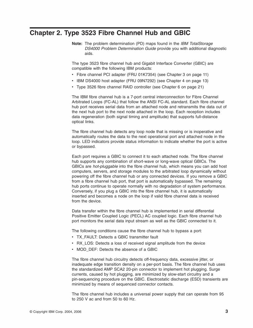
Verifying signal presence
In addition to verifying port LED status, you can verify signal presence by using a
mirror to look for a reflected light at the fiber-optic cable ends and the GBIC
transmitter. To verify signal presence at the hub end of a link, insert a GBIC into the
hub and place a mirror at the bottom of the SC connector. If a signal is present, you
will see a low intensity red light in the mirror reflecting from the GBIC transmitter.
See Figure 1 on page 5.
4 IBM TotalStorage DS4000: Hardware Maintenance Manual
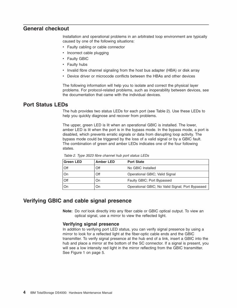
Verifying node end
To verify the integrity of the fiber-optic cable at the node end of a link, make sure
the cable is attached to the GBIC at the hub and the hub is turned on. Dual SC
fiber-optic cable connectors are keyed and will insert into a GBIC in one direction
only. Place a mirror at the node end of the link. A low intensity red light is visible in
the mirror reflection of one of the SC leads, as shown in Figure 2.
If a fiber-optic cable has good transmitter output but a broken or degraded receiver
lead, the end node might sense a loop down state. Because the transmitter is good,
the hub responds to the end node valid fibre channel signal and adds the device to
the loop. But, because the end node is not receiving fibre channel signals, it will
stream loop-down sequences onto the loop. This prevents all data communications
among the devices on the loop and will continue to do so until the condition is
corrected.
Verifying hub end
To verify the integrity of the fiber-optic cable at the hub end, make sure the
fiber-optic cable is plugged into the host bus adapter at the host or into a disk-array
controller and that the device is enabled on the loop. Using a mirror, examine the
cable SC leads to verify that a low-intensity red light is visible on the receiver lead.
Note: Some fiber-optic cables are marked with an A on the receiver lead and a B
on the transmitter lead and are keyed. Some multimode cables plugged into
a GBIC, HBA, or disk array controller are key-oriented with the B lead
inserted into the device transmitter. Place a mirror on the opposite end of the
cable to see the low-intensity red light on the A receiver lead.
Additional service information
This section contains additional service information for the fibre channel hub.
Applications and configurations
The fibre channel hub modular interface provides flexibility and is upgradable to
available short-wave and long-wave optical fibre channel product port interfaces.
Fibre channel products that are commonly interconnected to the fibre channel hub
Figure 1. Verifying signal presence
ConnectorKeys
Figure 2. Verifying node end
Chapter 2. Type 3523 Fibre Channel Hub and GBIC 5
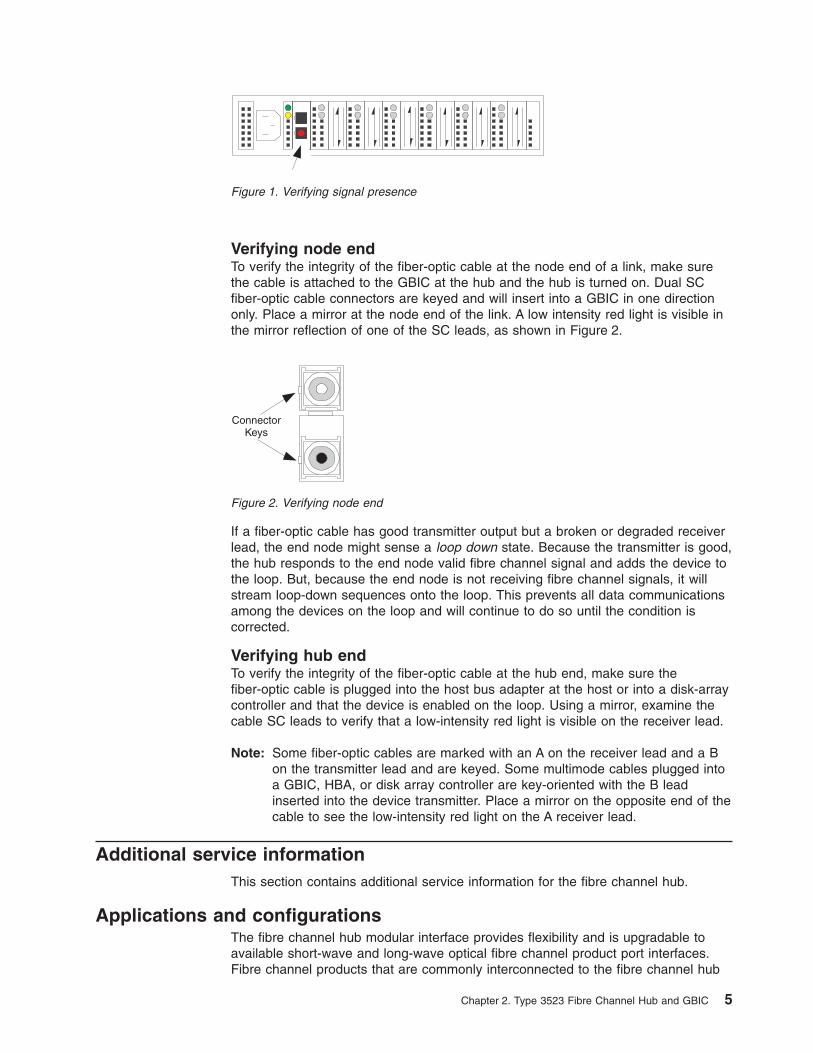
are fibre channel host bus adapters, FC-AL storage devices, and FC-AL storage
arrays. SCSI initiators (workstations and servers) set up and initiate the transfer of
data to or from the storage devices. The storage devices that receive the requests
made by the SCSI initiators are the SCSI targets. Initiators and targets represent
individual nodes that are linked by the shared FC-AL. See Figure 3.
Power on systems check for the fibre channel hub
Power on the storage modules first, then the controller and the fibre channel hub,
then everything else.
Note: Make sure the fibre channel hub is powered on before the host adapter to
insure proper loop initialization.
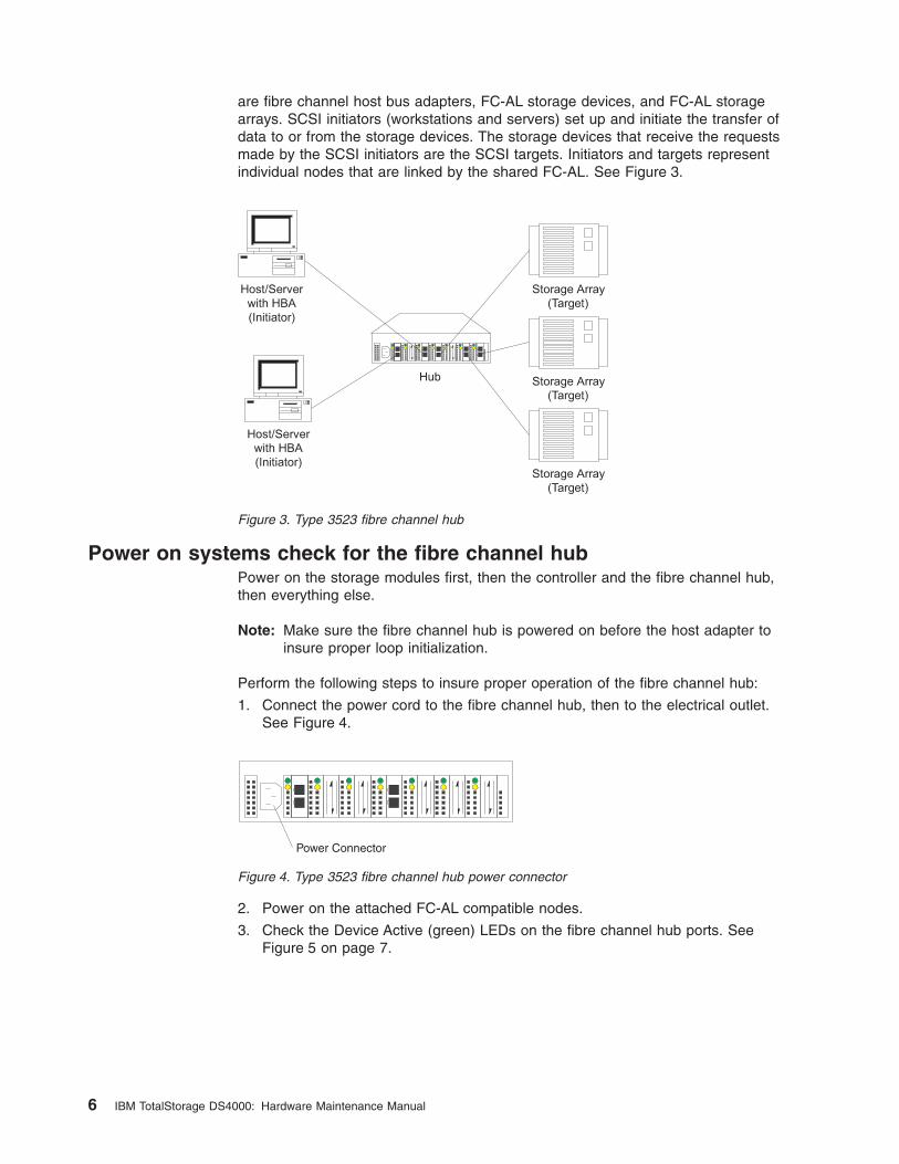
Perform the following steps to insure proper operation of the fibre channel hub:
1. Connect the power cord to the fibre channel hub, then to the electrical outlet.
See Figure 4.
2. Power on the attached FC-AL compatible nodes.
3. Check the Device Active (green) LEDs on the fibre channel hub ports. See
Figure 5 on page 7.
Figure 3. Type 3523 fibre channel hub
Power Connector
Figure 4. Type 3523 fibre channel hub power connector
6 IBM TotalStorage DS4000: Hardware Maintenance Manual
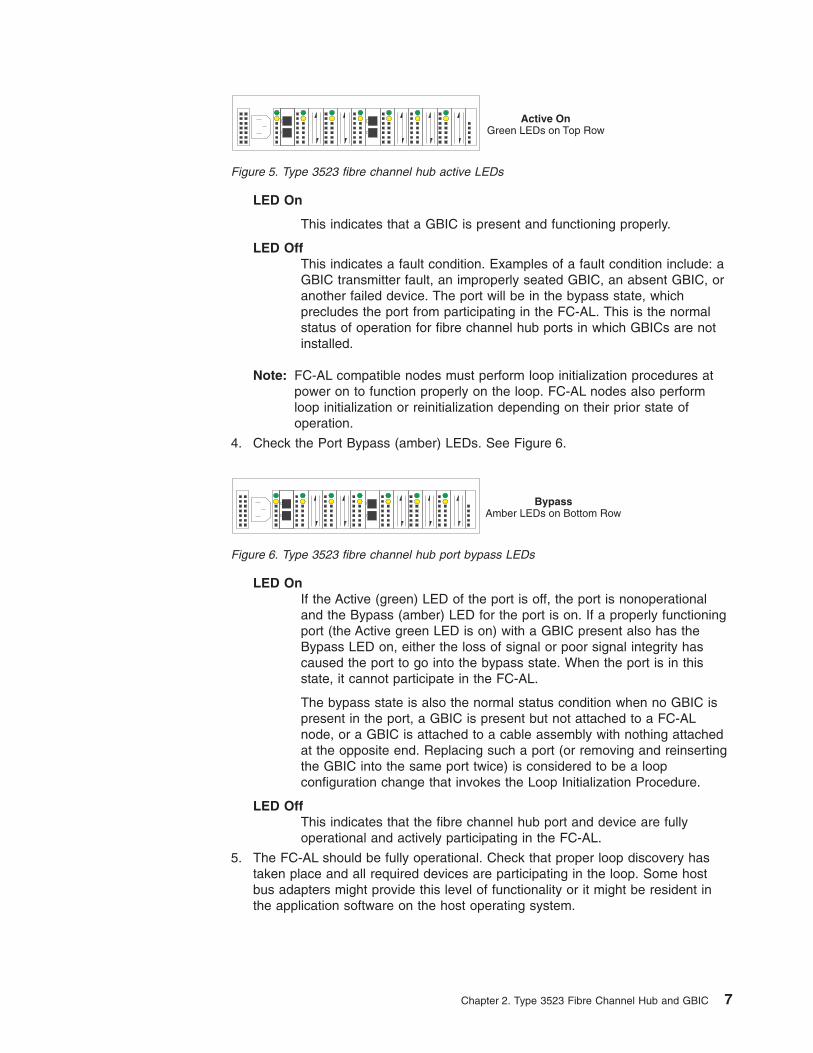
LED On
This indicates that a GBIC is present and functioning properly.
LED Off
This indicates a fault condition. Examples of a fault condition include: a
GBIC transmitter fault, an improperly seated GBIC, an absent GBIC, or
another failed device. The port will be in the bypass state, which
precludes the port from participating in the FC-AL. This is the normal
status of operation for fibre channel hub ports in which GBICs are not
installed.
Note: FC-AL compatible nodes must perform loop initialization procedures at
power on to function properly on the loop. FC-AL nodes also perform
loop initialization or reinitialization depending on their prior state of
operation.
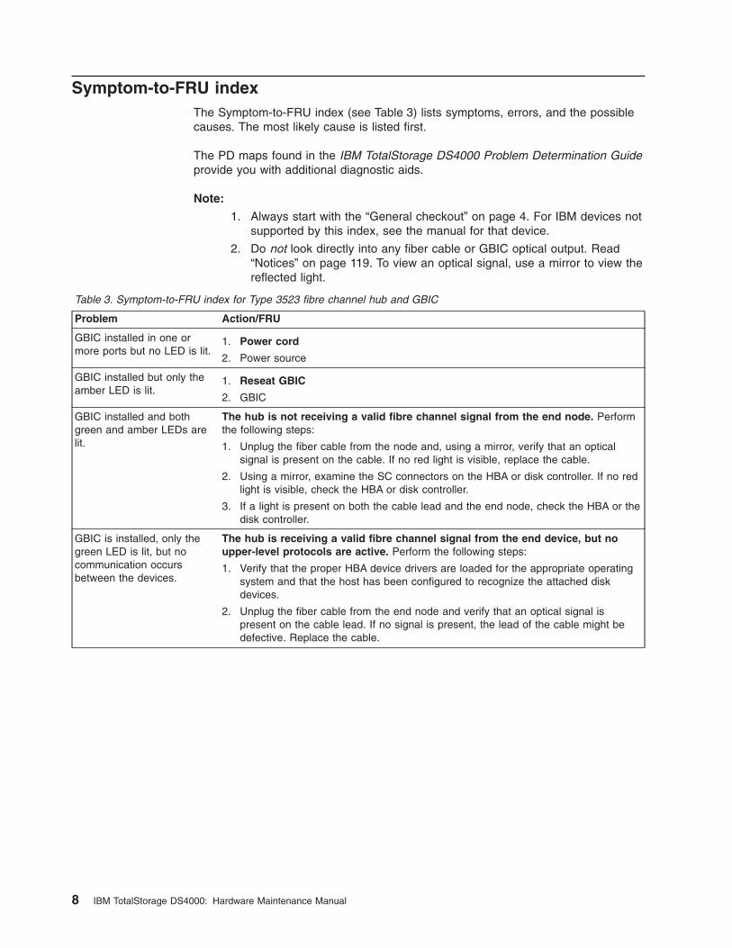
4. Check the Port Bypass (amber) LEDs. See Figure 6.
LED On
If the Active (green) LED of the port is off, the port is nonoperational
and the Bypass (amber) LED for the port is on. If a properly functioning
port (the Active green LED is on) with a GBIC present also has the
Bypass LED on, either the loss of signal or poor signal integrity has
caused the port to go into the bypass state. When the port is in this
state, it cannot participate in the FC-AL.
The bypass state is also the normal status condition when no GBIC is
present in the port, a GBIC is present but not attached to a FC-AL
node, or a GBIC is attached to a cable assembly with nothing attached
at the opposite end. Replacing such a port (or removing and reinserting
the GBIC into the same port twice) is considered to be a loop
configuration change that invokes the Loop Initialization Procedure.
LED Off
This indicates that the fibre channel hub port and device are fully
operational and actively participating in the FC-AL.
5. The FC-AL should be fully operational. Check that proper loop discovery has
taken place and all required devices are participating in the loop. Some host
bus adapters might provide this level of functionality or it might be resident in
the application software on the host operating system.
Active OnGreen LEDs on Top Row
Figure 5. Type 3523 fibre channel hub active LEDs
BypassAmber LEDs on Bottom Row
Figure 6. Type 3523 fibre channel hub port bypass LEDs
Chapter 2. Type 3523 Fibre Channel Hub and GBIC 7
Symptom-to-FRU index
The Symptom-to-FRU index (see Table 3) lists symptoms, errors, and the possible
causes. The most likely cause is listed first.
The PD maps found in the IBM TotalStorage DS4000 Problem Determination Guide
provide you with additional diagnostic aids.
Note:
1. Always start with the “General checkout” on page 4. For IBM devices not
supported by this index, see the manual for that device.
2. Do not look directly into any fiber cable or GBIC optical output. Read
“Notices” on page 119. To view an optical signal, use a mirror to view the
reflected light.
Table 3. Symptom-to-FRU index for Type 3523 fibre channel hub and GBIC
Problem Action/FRU
GBIC installed in one or
more ports but no LED is lit.
1. Power cord
2. Power source
GBIC installed but only the
amber LED is lit.
1. Reseat GBIC
2. GBIC
GBIC installed and both
green and amber LEDs are
lit.
The hub is not receiving a valid fibre channel signal from the end node. Perform
the following steps:
1. Unplug the fiber cable from the node and, using a mirror, verify that an optical
signal is present on the cable. If no red light is visible, replace the cable.
2. Using a mirror, examine the SC connectors on the HBA or disk controller. If no red
light is visible, check the HBA or disk controller.
3. If a light is present on both the cable lead and the end node, check the HBA or the
disk controller.
GBIC is installed, only the
green LED is lit, but no
communication occurs
between the devices.
The hub is receiving a valid fibre channel signal from the end device, but no
upper-level protocols are active. Perform the following steps:
1. Verify that the proper HBA device drivers are loaded for the appropriate operating
system and that the host has been configured to recognize the attached disk
devices.
2. Unplug the fiber cable from the end node and verify that an optical signal is
present on the cable lead. If no signal is present, the lead of the cable might be
defective. Replace the cable.
8 IBM TotalStorage DS4000: Hardware Maintenance Manual
Parts listing (Type 3523 fibre channel hub and GBIC)
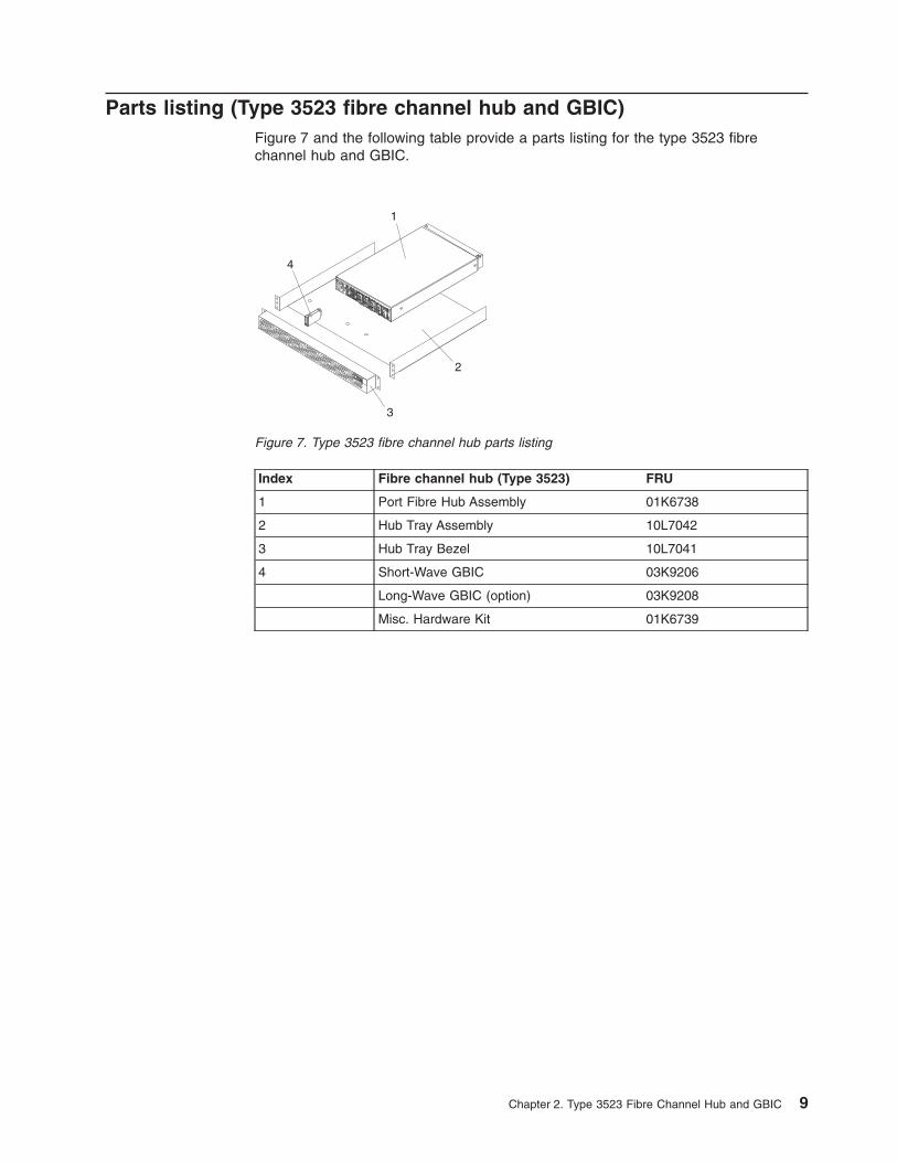
Figure 7 and the following table provide a parts listing for the type 3523 fibre
channel hub and GBIC.
Index Fibre channel hub (Type 3523) FRU
1 Port Fibre Hub Assembly 01K6738
2 Hub Tray Assembly 10L7042
3 Hub Tray Bezel 10L7041
4 Short-Wave GBIC 03K9206
Long-Wave GBIC (option) 03K9208
Misc. Hardware Kit 01K6739
1
2
3
4
Figure 7. Type 3523 fibre channel hub parts listing
Chapter 2. Type 3523 Fibre Channel Hub and GBIC 9

10 IBM TotalStorage DS4000: Hardware Maintenance Manual
Chapter 3. Fibre Channel PCI Adapter
Note: The PD maps found in the IBM TotalStorage DS4000 Problem Determination
Guide provide you with additional diagnostic aids.
The fibre channel PCI adapter (FRU 01K7354) is compatible with the following IBM
products:
v Type 3523 fibre channel hub and GBIC (see Chapter 2 on page 3)
v Type 3526 fibre channel RAID controller (see Chapter 6 on page 21)
v Type 2109 fibre channel switch
v Type 3534 managed hub
The IBM TotalStorage DS4000 Problem Determination Guide provides detailed
configuration information for advanced users who want to use IBM Fast!UTIL to
customize the configuration of the fibre channel PCI adapter (FRU 01K7354).
General checkout
The following three basic types of problems can cause the fibre channel PCI
adapter to function incorrectly:
v Hardware problems
v System configuration problems
v Fibre channel problems
Hardware problems
The following list will help you determine whether a problem was caused by the
hardware:
v Verify that all of the adapters are installed securely.
v Verify that all of the cables are connected securely to the correct connectors. Be
sure that the SC connectors that attach from the J1 connector on the fibre
channel PCI adapter to the device are connected correctly.
v Verify that the fibre channel PCI adapter is installed correctly and seated firmly in
the expansion slot.
v Verify that all peripheral devices are properly powered on. See the IBM
TotalStorage DS4000 Problem Determination Guide for information about how to
use IBM Fast!UTIL to display attached devices.
System configuration problems
To determine whether a problem was caused by the system configuration, check
the system board to make sure it is configured properly (see the appropriate IBM
TotalStorage DS4000 Product Installation Guide).
Fibre channel problems
To determine whether a problem was caused by the fibre channel, verify that all of
the FC devices were powered on before you powered on the server.
Additional service information
The following information supports the fibre channel PCI adapter.
© Copyright IBM Corp. 2004, 2006 11
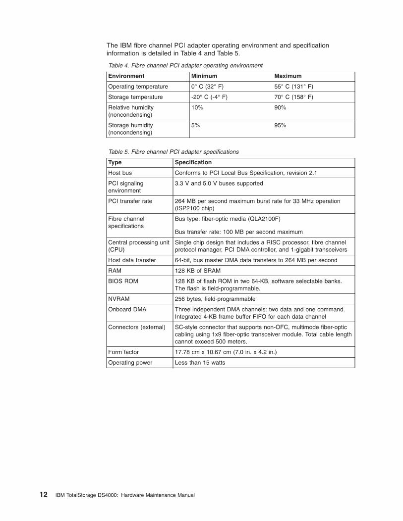
The IBM fibre channel PCI adapter operating environment and specification
information is detailed in Table 4 and Table 5.
Table 4. Fibre channel PCI adapter operating environment
Environment Minimum Maximum
Operating temperature 0° C (32° F) 55° C (131° F)
Storage temperature -20° C (-4° F) 70° C (158° F)
Relative humidity
(noncondensing)
10% 90%
Storage humidity
(noncondensing)
5% 95%
Table 5. Fibre channel PCI adapter specifications
Type Specification
Host bus Conforms to PCI Local Bus Specification, revision 2.1
PCI signaling
environment
3.3 V and 5.0 V buses supported
PCI transfer rate 264 MB per second maximum burst rate for 33 MHz operation
(ISP2100 chip)
Fibre channel
specifications
Bus type: fiber-optic media (QLA2100F)
Bus transfer rate: 100 MB per second maximum
Central processing unit
(CPU)
Single chip design that includes a RISC processor, fibre channel
protocol manager, PCI DMA controller, and 1-gigabit transceivers
Host data transfer 64-bit, bus master DMA data transfers to 264 MB per second
RAM 128 KB of SRAM
BIOS ROM 128 KB of flash ROM in two 64-KB, software selectable banks.
The flash is field-programmable.
NVRAM 256 bytes, field-programmable
Onboard DMA Three independent DMA channels: two data and one command.
Integrated 4-KB frame buffer FIFO for each data channel
Connectors (external) SC-style connector that supports non-OFC, multimode fiber-optic
cabling using 1x9 fiber-optic transceiver module. Total cable length
cannot exceed 500 meters.
Form factor 17.78 cm x 10.67 cm (7.0 in. x 4.2 in.)
Operating power Less than 15 watts
12 IBM TotalStorage DS4000: Hardware Maintenance Manual
Chapter 4. DS4000 Host Adapter
Note: The PD maps found in the IBM TotalStorage DS4000 Problem Determination
Guide provide you with additional diagnostic aids.
The IBM DS4000 host adapter (FRU 09N7292) is a high-performance, direct
memory access (DMA), bus-master host adapter designed for high-end systems.
The function and performance are derived from the ISP2200A chip, making the
DS4000 host adapter a leading-edge host adapter.
The ISP2200A chip combines a powerful RISC processor, a fibre protocol module
(FPM) with gigabit transceivers, and a 64-bit peripheral component interconnect
(PCI) local bus interface in a single-chip solution. The DS4000 host adapter
supports all fibre channel peripheral devices that support private-loop direct attach
(PLDA) and fabric-loop attach (FLA).
The IBM DS4000 host adapter is compatible with the following IBM products:
v Type 3526 fibre channel RAID controller (see Chapter 6 on page 21)
v Type 3552 FAStT500 RAID controller (see Chapter 8 on page 47)
v FAStT200 Type 3542 and FAStT200 HA Type 3542 (see Chapter 7 on page 35)
v Type 2109 fibre channel switch
v Type 3534 managed hub
The IBM TotalStorage DS4000 Problem Determination Guide provides detailed
configuration information for advanced users who want to use IBM Fast!UTIL to
customize the configuration of the fibre channel adapter (FRU 09N7292).
General checkout
The following types of problems can cause the adapter to malfunction:
v Hardware problems
v System configuration problems
v Fibre channel problems
Hardware problems
The following list will help you determine whether your installation problem is
caused by the hardware:
v Verify that all adapters are installed securely.
v Verify that all cables are attached securely to the correct connectors. Be sure
that the FC connectors that attach from the J1 connector on the adapter to the
device are connected securely.
v Verify that the adapter is installed correctly and fully seated in the expansion slot.
Check for interference due to nonstandard PCI connectors.
v Verify that all peripheral devices are turned on. See the IBM TotalStorage
DS4000 Problem Determination Guide for information about how to use IBM
Fast!UTIL to display attached devices.
System configuration problems
To determine whether a problem was caused by the system configuration, check
the system board to make sure that it was configured properly (see the appropriate
IBM TotalStorage DS4000 Product Installation Guide).
© Copyright IBM Corp. 2004, 2006 13
Fibre channel problems
To determine whether your installation problem is caused by the fibre channel,
verify that all of the fibre channel devices were turned on before you turned on the
server. Also, ensure that all cables are connected properly.
The PD maps found in the IBM TotalStorage DS4000 Problem Determination Guide
provide you with additional diagnostic aids.
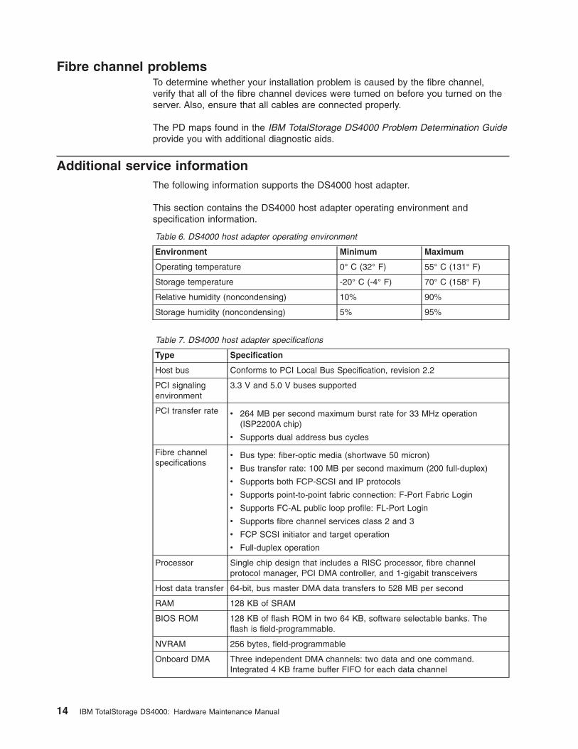
Additional service information
The following information supports the DS4000 host adapter.
This section contains the DS4000 host adapter operating environment and
specification information.
Table 6. DS4000 host adapter operating environment
Environment Minimum Maximum
Operating temperature 0° C (32° F) 55° C (131° F)
Storage temperature -20° C (-4° F) 70° C (158° F)
Relative humidity (noncondensing) 10% 90%
Storage humidity (noncondensing) 5% 95%
Table 7. DS4000 host adapter specifications
Type Specification
Host bus Conforms to PCI Local Bus Specification, revision 2.2
PCI signaling
environment
3.3 V and 5.0 V buses supported
PCI transfer rate v 264 MB per second maximum burst rate for 33 MHz operation
(ISP2200A chip)
v Supports dual address bus cycles
Fibre channel
specifications
v Bus type: fiber-optic media (shortwave 50 micron)
v Bus transfer rate: 100 MB per second maximum (200 full-duplex)
v Supports both FCP-SCSI and IP protocols
v Supports point-to-point fabric connection: F-Port Fabric Login
v Supports FC-AL public loop profile: FL-Port Login
v Supports fibre channel services class 2 and 3
v FCP SCSI initiator and target operation
v Full-duplex operation
Processor Single chip design that includes a RISC processor, fibre channel
protocol manager, PCI DMA controller, and 1-gigabit transceivers
Host data transfer 64-bit, bus master DMA data transfers to 528 MB per second
RAM 128 KB of SRAM
BIOS ROM 128 KB of flash ROM in two 64 KB, software selectable banks. The
flash is field-programmable.
NVRAM 256 bytes, field-programmable
Onboard DMA Three independent DMA channels: two data and one command.
Integrated 4 KB frame buffer FIFO for each data channel
14 IBM TotalStorage DS4000: Hardware Maintenance Manual
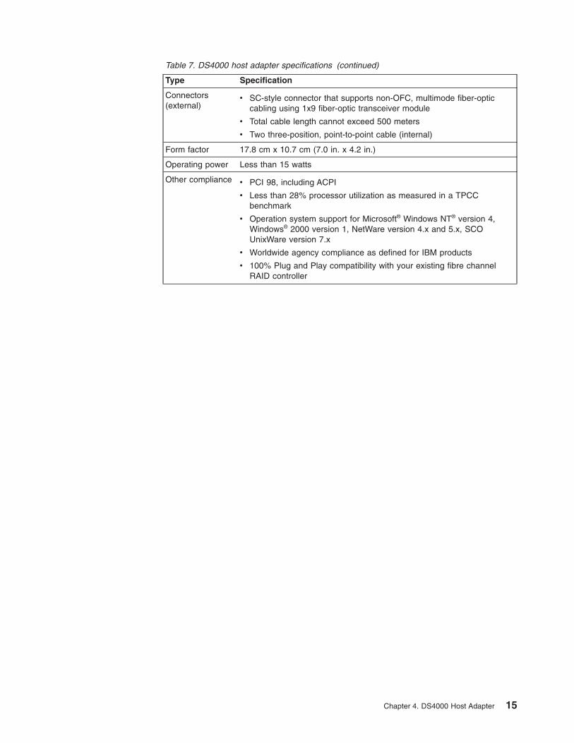
Table 7. DS4000 host adapter specifications (continued)
Type Specification
Connectors
(external)
v SC-style connector that supports non-OFC, multimode fiber-optic
cabling using 1x9 fiber-optic transceiver module
v Total cable length cannot exceed 500 meters
v Two three-position, point-to-point cable (internal)
Form factor 17.8 cm x 10.7 cm (7.0 in. x 4.2 in.)
Operating power Less than 15 watts
Other compliance v PCI 98, including ACPI
v Less than 28% processor utilization as measured in a TPCC
benchmark
v Operation system support for Microsoft® Windows NT® version 4,
Windows® 2000 version 1, NetWare version 4.x and 5.x, SCO
UnixWare version 7.x
v Worldwide agency compliance as defined for IBM products
v 100% Plug and Play compatibility with your existing fibre channel
RAID controller
Chapter 4. DS4000 Host Adapter 15

16 IBM TotalStorage DS4000: Hardware Maintenance Manual
Chapter 5. DS4000 FC2-133 Host Bus Adapter
Note: The PD maps found in the IBM TotalStorage DS4000 Problem Determination
Guide provide you with additional diagnostic aids.
The IBM DS4000 FC2-133 host bus adapter (single port model, FRU 24P0962) is a
2 Gbps high-performance, direct memory access (DMA), bus master, fibre channel
host adapter designed for high-end systems. The function and performance are
derived from the ISP2312/ISP2340 chips, making the IBM DS4000 FC2-133 host
bus adapter a leading-edge host adapter.
The ISP2312/ISP2340 chips combine a powerful, reduced instruction set computer
(RISC) processor, a fibre channel protocol manager (FPM) with one 2 Gbps fibre
channel transceiver, and a peripheral component interconnect (PCI) or peripheral
component interconnect-extended (PCI-X) local bus interface in a single-chip
solution. The IBM DS4000 FC2-133 host bus adapter supports all fibre channel
(FC) peripheral devices that support private-loop direct attach (PLDA) and
fabric-loop attach (FLA).
The IBM TotalStorage DS4000 Problem Determination Guide provides detailed
configuration information for advanced users who want to use IBM Fast!UTIL to
customize the configuration of the DS4000 FC2-133 host bus adapter.
Note: For information about how to use and troubleshoot problems with the FC
6228 2 Gigabit fibre channel adapter in pSeries AIX® hosts, see Fibre
Channel Planning and Integration: User’s Guide and Service Information,
SC23-4329-03.
General checkout
The following types of installation problems might cause your DS4000 FC2-133 host
bus adapter to function incorrectly:
v Hardware problems
v System configuration problems
v Fibre channel problems
If you are having problems, use the following information to help you determine the
cause of the problem and the action to take.
Hardware problems
Take the following actions to determine if your installation problem is caused by the
hardware:
v Verify that all adapters are installed securely.
v Verify that all cables are attached securely to the correct connectors. Be sure
that one end of the LC-LC fibre channel cable is attached to the optical interface
connector (located at J1 on the adapter) and that the other end is connected to
the fibre channel device.
v Verify that the DS4000 FC2-133 host bus adapter is installed correctly and is fully
seated in the expansion slot. Check for interference due to nonstandard PCI
connectors.
v Verify that the Fast!UTIL data-rate setting is correct. The Fast!UTIL data-rate
setting must match the speed of the device to which you are connected.
© Copyright IBM Corp. 2004, 2006 17
v Verify that all peripheral devices are turned on. See the IBM TotalStorage
DS4000 Problem Determination Guide for information about how to use
Fast!UTIL to display attached fibre channel devices.
System configuration problems
To verify that your installation problem is caused by the system configuration, check
your server to ensure that it is configured properly (see the appropriate IBM
TotalStorage DS4000 Product Installation Guide).
Note: All PCI-compliant and PCI-X-compliant systems automatically detect 32-bit or
64-bit adapters and set the appropriate bus speed (for example, 66 MHz or
133 MHz).
Fibre channel problems
To determine if your installation problem is caused by an attached fibre channel
device, perform the following actions:
v Verify that all of the fibre channel devices were turned on before you turned on
the server.
v Ensure that all cables are connected properly.
v Verify that you configured your RAID storage subsystems using the utilities that
the manufacturer provided.
v If your fibre channel switch supports zoning, make sure that your peripheral
device is configured to the same switch zone as the DS4000 FC2-133 host bus
adapter. For more information, see your fibre channel switch documentation.
Additional service information
Table 8 and Table 9 contain the DS4000 FC2-133 host bus adapter operating
environment and specification information.
Table 8. DS4000 FC2-133 host bus adapter operating environment
Environment Minimum Maximum
Operating temperature 0° C (32° F) 55° C (131° F)
Storage temperature -20° C (-4° F) 70° C (158° F)
Relative humidity (noncondensing) 10% 90%
Storage humidity (noncondensing) 5% 95%
Table 9. DS4000 FC2-133 host bus adapter specifications
Type Specification
Host bus Conforms to Intel™ PCI Local Bus Specification, revision 2.2
and the PCI-X Addendum, revision 1.0.
PCI/PCI-X signaling
environment
3.3 V and 5.0 V buses supported
PCI/PCI-X transfer rate v Support for 32 bit and 64 bit PCI bus at 33 MHz and 64
MHz
v Support for 64 bit PCI-X bus at 50 MHz, 100 MHz, and
133 MHz
v PCI transfer rate 264 MB per second maximum burst rate
for 33 MHz operation (ISP2312/ISP2340 chips)
v Support for dual address bus cycles
18 IBM TotalStorage DS4000: Hardware Maintenance Manual

Table 9. DS4000 FC2-133 host bus adapter specifications (continued)
Type Specification
Fibre channel specifications v Fiber-optic media (shortwave multimode 50 micron cable)
v Bus transfer rate: 200 MBps maximum at half-duplex and
at 400 MBps maximum full-duplex
v Interface chip: ISP2312/ISP2340 (PCI-X QLA23xx boards)
v Support for both FCP-SCSI and IP protocols
v Support for point-to-point fabric connection: F-port Fabric
Login
v Support for FC-AL public loop profile: FL-port Login
v Support for fibre channel services class 2 and 3
v Support for FCP SCSI initiator and target operation
v Support for full-duplex operation
Processor Single-chip design that includes a RISC processor, fibre
channel protocol manager, PCI/PCI-X DMA controller, and
integrated serializer/deserializer (SERDES) and electrical
transceivers that can auto-negotiate a data rate of 2 Gbps
Host data transfer 64-bit, bus-master DMA data transfers to 528 MBps
RAM 256 KB of SRAM supporting parity protection
BIOS ROM 128 KB of flash ROM in two 64 KB, software selectable
banks. The flash is field programmable.
NVRAM 256 bytes, field-programmable
Onboard DMA Five-channel DMA controller: two data, one command, one
auto-DMA request, and one auto-DMA response
Frame buffer FIFO Integrated 4 KB transmit and 6 KB receive frame buffer
first-in first-out (FIFO) for each data channel
Connectors (external) v LC-style connector that supports non-OFC, multimode
fiber-optic cabling using a small form factor (SFF)
fiber-optic transceiver module.
v Total cable length cannot exceed 500 m
Form factor 5.15 cm x 16.75 cm (2.5 in. x 6.7 in.)
Operating power Less than 15 watts
Chapter 5. DS4000 FC2-133 Host Bus Adapter 19

20 IBM TotalStorage DS4000: Hardware Maintenance Manual
Chapter 6. Type 3526 Fibre Channel RAID Controller
The Type 3526 fibre channel RAID controller is compatible with the following IBM
products:
v Type 3523 fibre channel hub and GBIC (see Chapter 2 on page 3)
v Fibre channel PCI adapter (FRU 01K7354) (see Chapter 3 on page 11)
v IBM DS4000 host adapter (FRU 09N7292) (see Chapter 4 on page 13)
v Type 2109 fibre channel switch
v Type 3534 managed hub
General checkout
Use the status LEDs and the “Symptom-to-FRU index” on page 32 to diagnose
problems.
Note: The PD maps found in the IBM TotalStorage DS4000 Problem Determination
Guide provide you with additional diagnostic aids.
The LEDs of the control unit indicate the hardware status:
v Green LED indicates normal operation
v Amber LED indicates a hardware problem
The LEDs on the controller unit indicate the status of the controller unit and its
individual components. The green LEDs indicate a normal operating status; amber
LEDs indicate a hardware fault. Check all of the LEDs on the front and back of the
controller unit when it is powered on.
Notes:
1. If power was just applied to the controller unit, the green and amber LEDs might
turn on and off intermittently. Wait until the controller unit finishes powering up
before you begin checking for faults.
2. To view the controller Customer Replaceable Unit (CRU) LEDs, the front cover
must be removed from the controller unit.
Also use LEDs on the front cover, controller CRUs, and drive units (if applicable) to
determine whether the controllers and drives are responding to I/O transmissions
from the host.
The following list describes LED activities:
v If a Fast Write Cache operation to the controller unit (or attached drive units), or
if other I/O activity is in progress, then you might see several green LEDs
blinking, including: the Fast Write Cache LED (on the front cover), controller CRU
status LEDs, or applicable drive activity LEDs.
v The green Heartbeat LEDs on the controller CRUs blink continuously. The
number and pattern of green status LEDs lit on the controllers depend on how
the system is configured. An active controller will not have the same status LEDs
lit as a passive controller. See the appropriate IBM TotalStorage DS4000 Product
Installation Guide.
© Copyright IBM Corp. 2004, 2006 21

Additional service information
This section provides additional service information about the Type 3526 fibre
channel RAID controller.
Powering on the controller
Note: All drive modules must be powered on before you power on the controller.
The controller might take from three to 10 seconds to power on. During this time,
the amber and green LEDs on the controller unit flash.
After power on, check all fault LEDs to make sure they are off. If a fault LED is on,
see the “Symptom-to-FRU index” on page 32.
Recovering from a power supply shutdown
Both power supplies have a built-in temperature sensor designed to prevent the
power supplies from overheating. If a temperature sensor detects an
over-temperature condition (ambient air temperature of 70° C (158° F) or above),
the overheated power supply automatically shuts down. The other power supply
remains on as long as its temperature remains below 70° C (158° F). If not, the
second power supply shuts down, which turns off all power to the controller unit.
After the air temperature cools to below 70° C (158° F), the power supplies
automatically restart. An automatic restart resets the controllers, attempts to spin up
the drives (which has no effect on the drives if they are already running), and
returns the controller unit to a normal operating state. Typically, you will not need to
perform recovery procedures after an automatic power supply shutdown and restart.
After a power supply shutdown, check all controller LEDs.
If the power supply power LED is off, or the amber power supply LED on the front
cover is on, go to the “Symptom-to-FRU index” on page 32.
Connectors and host IDs
The host ID switches and connectors for interface cables are on the connector plate
located on the back of the controller unit.
Host and drive ID numbers
Each controller must have a unique Fibre Host ID number (see Figure 8 on page
23). The Host ID numbers assigned to each controller are based on two elements:
v Host ID numbers set through hardware switches on the controller unit. Five Host
ID switches allow you to set ID numbers 0 through 127 for each controller. The
factory default settings are ID #5 for Controller A and ID #4 for controller B.
v Software algorithms that calculate the actual fibre channel address, based on the
controller unit’s hardware settings and position on the loop or hub
Note: The preferred ID is assigned on the fibre channel loop unless it is already
being used. If the ID is already in use, a soft ID is assigned.
22 IBM TotalStorage DS4000: Hardware Maintenance Manual
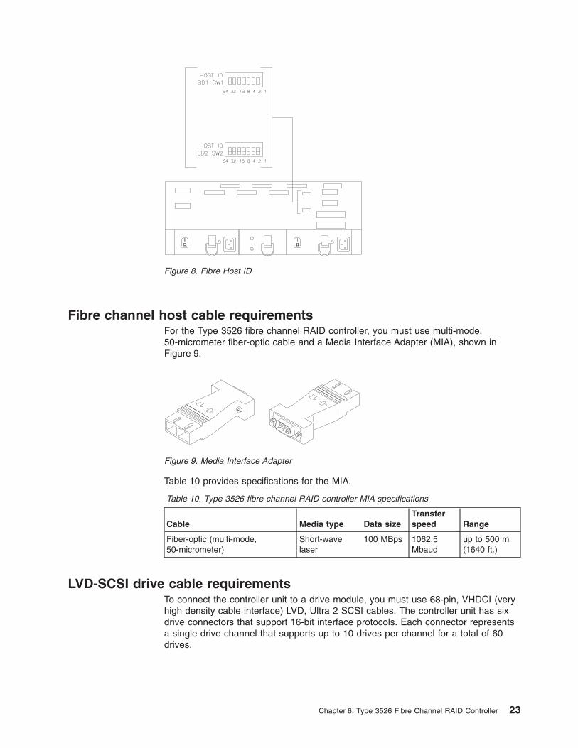
Fibre channel host cable requirements
For the Type 3526 fibre channel RAID controller, you must use multi-mode,
50-micrometer fiber-optic cable and a Media Interface Adapter (MIA), shown in
Figure 9.
Table 10 provides specifications for the MIA.
Table 10. Type 3526 fibre channel RAID controller MIA specifications
Cable Media type Data size
Transfer
speed Range
Fiber-optic (multi-mode,
50-micrometer)
Short-wave
laser
100 MBps 1062.5
Mbaud
up to 500 m
(1640 ft.)
LVD-SCSI drive cable requirements
To connect the controller unit to a drive module, you must use 68-pin, VHDCI (very
high density cable interface) LVD, Ultra 2 SCSI cables. The controller unit has six
drive connectors that support 16-bit interface protocols. Each connector represents
a single drive channel that supports up to 10 drives per channel for a total of 60
drives.
Figure 8. Fibre Host ID
Figure 9. Media Interface Adapter
Chapter 6. Type 3526 Fibre Channel RAID Controller 23
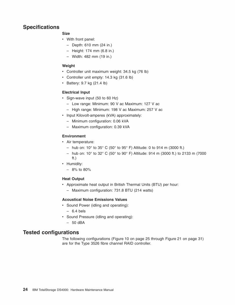
Specifications
Size
v With front panel:
– Depth: 610 mm (24 in.)
– Height: 174 mm (6.8 in.)
– Width: 482 mm (19 in.)
Weight
v Controller unit maximum weight: 34.5 kg (76 lb)
v Controller unit empty: 14.3 kg (31.6 lb)
v Battery: 9.7 kg (21.4 lb)
Electrical Input
v Sign-wave input (50 to 60 Hz)
– Low range: Minimum: 90 V ac Maximum: 127 V ac
– High range: Minimum: 198 V ac Maximum: 257 V ac
v Input Kilovolt-amperes (kVA) approximately:
– Minimum configuration: 0.06 kVA
– Maximum configuration: 0.39 kVA
Environment
v Air temperature:
– hub on: 10° to 35° C (50° to 95° F) Altitude: 0 to 914 m (3000 ft.)
– hub on: 10° to 32° C (50° to 90° F) Altitude: 914 m (3000 ft.) to 2133 m (7000
ft.)
v Humidity:
– 8% to 80%
Heat Output
v Approximate heat output in British Thermal Units (BTU) per hour:
– Maximum configuration: 731.8 BTU (214 watts)
Acoustical Noise Emissions Values
v Sound Power (idling and operating):
– 6.4 bels
v Sound Pressure (idling and operating):
– 50 dBA
Tested configurations
The following configurations (Figure 10 on page 25 through Figure 21 on page 31)
are for the Type 3526 fibre channel RAID controller.
24 IBM TotalStorage DS4000: Hardware Maintenance Manual
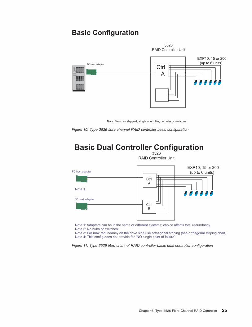
Basic Configuration
3526
RAID Controller Unit
Ctrl
A
EXP10, 15 or 200
(up to 6 units)FC Host adapter
Note: Basic as shipped, single controller, no hubs or switches
Figure 10. Type 3526 fibre channel RAID controller basic configuration
FC host adapter
FC host adapter
Note 1
Note 1: Adapters can be in the same or different systems; choice affects total redundancyNote 2: No hubs or switches
Basic Dual Controller Configuration3526
RAID Controller Unit
EXP10, 15 or 200
(up to 6 units)
Note 3: For max redundancy on the drive side use orthagonal striping (see chart)Note 4: This config does not provide for “NO single point of failure”
orthagonal striping
CtrlB
CtrlA
Figure 11. Type 3526 fibre channel RAID controller basic dual controller configuration
Chapter 6. Type 3526 Fibre Channel RAID Controller 25

...
...
...
...
...
...
SCSI Channel 1
SCSI Channel 2
SCSI Channel 3
SCSI Channel 4
SCSI Channel 5
SCSI Channel 6
Data striped across channels
EXP10, 15 or 200
Orthogonal Data Striping
Figure 12. Type 3526 fibre channel RAID controller orthogonal data striping
26 IBM TotalStorage DS4000: Hardware Maintenance Manual
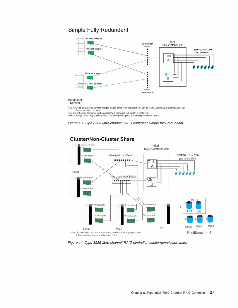
Simple Fully Redundant
RedundantServers
,
FC host adapter
FC host adapter
FC host adapter
FC host adapter
3526RAID Controller Unit
EXP10, 15 or 200(up to 6 units)
Hub/switch
CtrlB
CtrlA
Hub/switch
Note 1: Since disks are seen from multiple places some form of protection such as MSCS, storage partitioning, Sanergy,Oracle etc must be used.
Note 2: For best performance and managibility, a managed hub switch is preferred.Note 3: Always try to keep connections to hub on adjacent ports and unplug all unused GBICs
Figure 13. Type 3526 fibre channel RAID controller simple fully redundant
Cluster/Non-Cluster Share
Managed Hub/Switch
Managed Hub/Switch
Clus1
Notes 1 File 1 DB 1
Clus1
LD1
Notes 1 File 1 DB 1
Partitions 1 - 4
FC host adapter
FC host adapter
FC host adapter
FC host adapter
FC host adapter
FC host adapter
FC host adapter
FC host adapter
FC host adapter
FC host adapter
1
2 3 4
Note : Factors such as performance and number of storage partitions
influence the number and type of nodes.
LD2
3526
RAID Controller Unit
Ctrl
A
EXP10, 15 or 200
(up to 6 units)
Ctrl
B
Figure 14. Type 3526 fibre channel RAID controller cluster/non-cluster share
Chapter 6. Type 3526 Fibre Channel RAID Controller 27
Multi-MSCS No External HubsFC host adapter
FC host adapter
FC host adapter
FC host adapter
FC host adapter
FC host adapter
FC host adapter
FC host adapter
Clus1
Clus2
LD1 LD2
1
2
LD3 LD4
Clus1
Clus2
Notes : 2 partitions shown; Clus1 partition separate from Clus2 partition.
LD is a logical drive
3526
RAID Controller Unit
Ctrl
A
EXP10, 15 or 200
(up to 6 units)
Ctrl
B
Managed Hub/Switch
Managed Hub/Switch
Figure 15. Type 3526 fibre channel RAID controller multi-MSCS no external hubs
FCSwitches
Multi-MSCS extended
FC host adapter
FC host adapter
FC host adapter
FC host adapter
Notes :- Each group of 4 ports on the switches ( ) can support one cluster element ( )red dash box black dash box
- Storage partitioning is used to separate clusters
- Match performance needs of servers to max I/o available from 60 drives
- You may use some the switch ports to add 3526 units rather than hosts. Extending this to 16 port switches allows more of both
3526
RAID Controller Unit
Ctrl
A
EXP10, 15 or 200
(up to 6 units)
Ctrl
B
Figure 16. Type 3526 fibre channel RAID controller multi-MSCS extended
28 IBM TotalStorage DS4000: Hardware Maintenance Manual
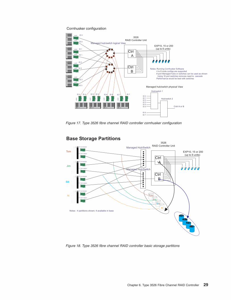
Notes: Running Cornhusker Software
4 to 8 node configs are supported
8 port Managed hubs or switches can be used as shown
Using 16 port switches removes need to cascade
Performance would be best with switches
HARP
HARP
HARP
HARP
HARP
HARP
HARP
HARP
HA
RP
HA
RP
HA
RP
HA
RP
HA
RP
HA
RP
HA
RP
HA
RP
ID 0
ID 0
ID 1
ID 1
ID 2
ID 3
ID 4 ID 5 ID 6 ID 7
ID 2
ID 3
ID 4 ID 5 ID 6 ID 7ID 0
ID 7
Hub/switch 1
Hub/switch 2ID 1ID 2
ID 3
ID 4
ID 5
ID 6
Cntrl A or B
Managed hub/switch physical View
Managed hub/switch logical View
3526
RAID Controller Unit
Ctrl
A
EXP10, 15 or 200
(up to 6 units)
Ctrl
B
Cornhusker configuration
Figure 17. Type 3526 fibre channel RAID controller cornhusker configuration
Tom
Jim
Bill
Al
Al
Jim
Bill
Tom
FC host adapter
FC host adapter
FC host adapter
FC host adapter
FC host adapter
FC host adapter
FC host adapter
FC host adapter
Notes : 4 partitions shown; 4 available in base
3526
RAID Controller Unit
Ctrl
A
EXP10, 15 or 200
(up to 6 units)
Ctrl
B
Managed Hub/Switch
Managed Hub/Switch
Base Storage Partitions
Figure 18. Type 3526 fibre channel RAID controller basic storage partitions
Chapter 6. Type 3526 Fibre Channel RAID Controller 29
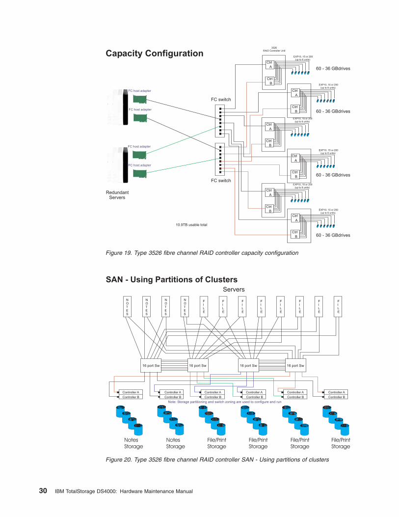
Capacity Configuration
RedundantServers
FC host adapter
FC host adapter
FC host adapter
FC host adapter
EXP10, 15 or 200
(up to 6 units)
3526
RAID Controller Unit
EXP10, 15 or 200
(up to 6 units)
EXP10, 15 or 200
(up to 6 units)
EXP10, 15 or 200
(up to 6 units)
EXP10, 15 or 200
(up to 6 units)
EXP10, 15 or 200
(up to 6 units)
60 - 36 GBdrives
60 - 36 GBdrives
60 - 36 GBdrives
60 - 36 GBdrives
Ctrl
A
Ctrl
A
Ctrl
A
Ctrl
A
Ctrl
A
Ctrl
A
Ctrl
B
Ctrl
B
Ctrl
B
Ctrl
B
Ctrl
B
Ctrl
B
10.9TB usable total
FC switch
FC switch
Figure 19. Type 3526 fibre channel RAID controller capacity configuration
SAN - Using Partitions of Clusters
Note: Storage partitioning and switch zoning are used to configure and run
Servers
NOTES
NOTES
NOTES
NOTES
FILE
FILE
FILE
FILE
FILE
FILE
FILE
FILE
16 port Sw 16 port Sw 16 port Sw 16 port Sw
Controller A Controller A Controller A Controller A Controller A Controller A
Controller BController BController BController BController BController B
File/Print
Storage
File/Print
Storage
File/Print
Storage
File/Print
Storage
Notes
Storage
Notes
Storage
Figure 20. Type 3526 fibre channel RAID controller SAN - Using partitions of clusters
30 IBM TotalStorage DS4000: Hardware Maintenance Manual
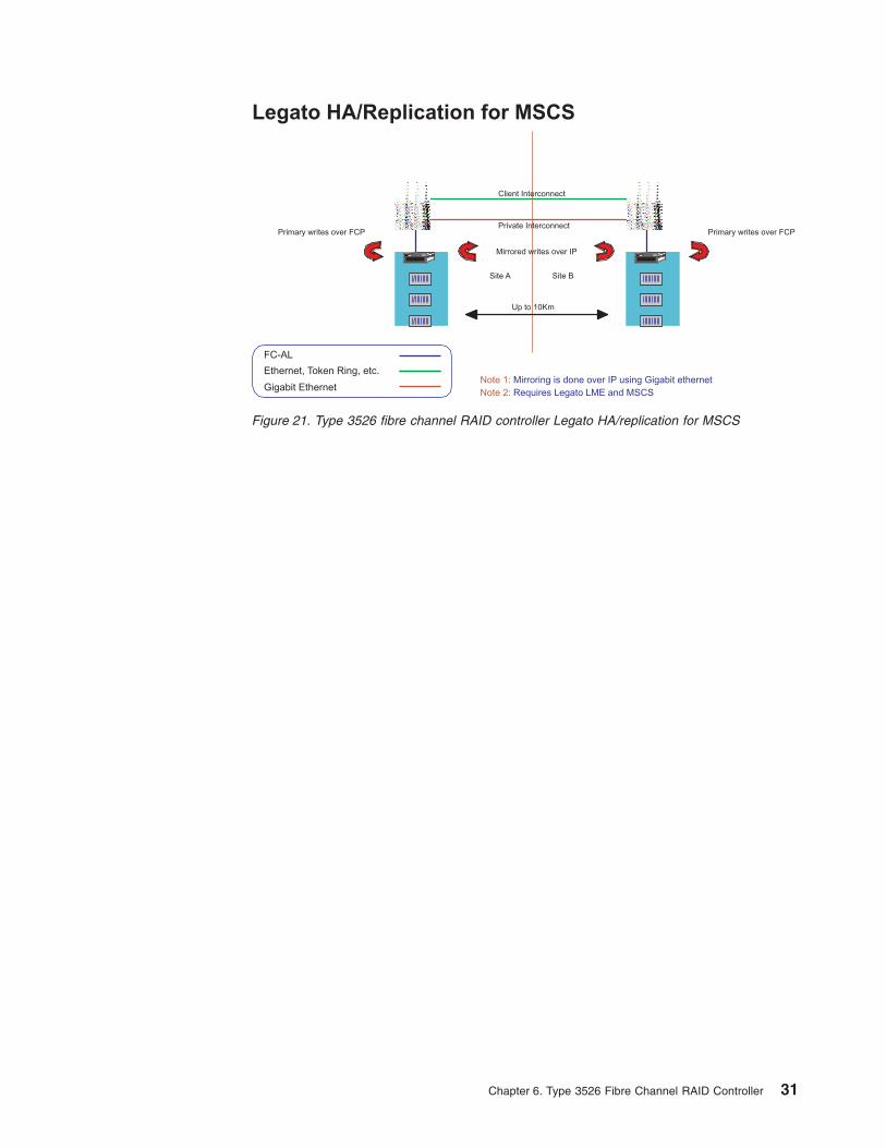
Note 1: Mirroring is done over IP using Gigabit ethernet
Note 2: Requires Legato LME and MSCS
Legato HA/Replication for MSCS
Primary writes over FCP
Client Interconnect
Private InterconnectPrimary writes over FCP
Mirrored writes over IP
Site A Site B
Up to 10Km
FC-AL
Ethernet, Token Ring, etc.
Gigabit Ethernet
Figure 21. Type 3526 fibre channel RAID controller Legato HA/replication for MSCS
Chapter 6. Type 3526 Fibre Channel RAID Controller 31
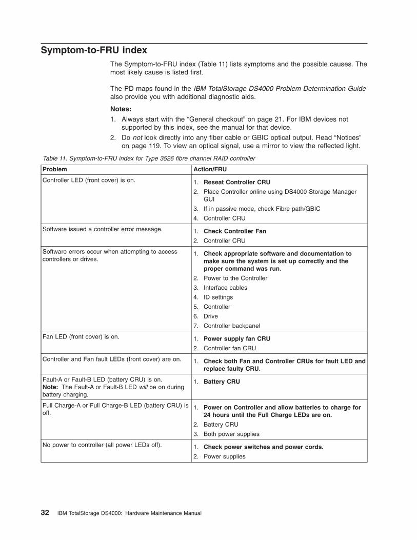
Symptom-to-FRU index
The Symptom-to-FRU index (Table 11) lists symptoms and the possible causes. The
most likely cause is listed first.
The PD maps found in the IBM TotalStorage DS4000 Problem Determination Guide
also provide you with additional diagnostic aids.
Notes:
1. Always start with the “General checkout” on page 21. For IBM devices not
supported by this index, see the manual for that device.
2. Do not look directly into any fiber cable or GBIC optical output. Read “Notices”
on page 119. To view an optical signal, use a mirror to view the reflected light.
Table 11. Symptom-to-FRU index for Type 3526 fibre channel RAID controller
Problem Action/FRU
Controller LED (front cover) is on. 1. Reseat Controller CRU
2. Place Controller online using DS4000 Storage Manager
GUI
3. If in passive mode, check Fibre path/GBIC
4. Controller CRU
Software issued a controller error message. 1. Check Controller Fan
2. Controller CRU
Software errors occur when attempting to access
controllers or drives.
1. Check appropriate software and documentation to
make sure the system is set up correctly and the
proper command was run.
2. Power to the Controller
3. Interface cables
4. ID settings
5. Controller
6. Drive
7. Controller backpanel
Fan LED (front cover) is on. 1. Power supply fan CRU
2. Controller fan CRU
Controller and Fan fault LEDs (front cover) are on. 1. Check both Fan and Controller CRUs for fault LED and
replace faulty CRU.
Fault-A or Fault-B LED (battery CRU) is on.
Note: The Fault-A or Fault-B LED will be on during
battery charging.
1. Battery CRU
Full Charge-A or Full Charge-B LED (battery CRU) is
off.
1. Power on Controller and allow batteries to charge for
24 hours until the Full Charge LEDs are on.
2. Battery CRU
3. Both power supplies
No power to controller (all power LEDs off). 1. Check power switches and power cords.
2. Power supplies
32 IBM TotalStorage DS4000: Hardware Maintenance Manual
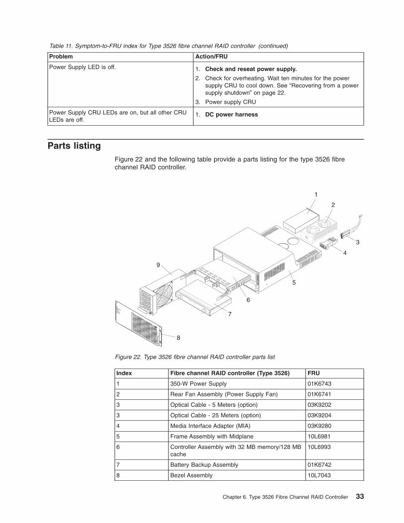
Table 11. Symptom-to-FRU index for Type 3526 fibre channel RAID controller (continued)
Problem Action/FRU
Power Supply LED is off. 1. Check and reseat power supply.
2. Check for overheating. Wait ten minutes for the power
supply CRU to cool down. See “Recovering from a power
supply shutdown” on page 22.
3. Power supply CRU
Power Supply CRU LEDs are on, but all other CRU
LEDs are off.
1. DC power harness
Parts listing
Figure 22 and the following table provide a parts listing for the type 3526 fibre
channel RAID controller.
Index Fibre channel RAID controller (Type 3526) FRU
1 350-W Power Supply 01K6743
2 Rear Fan Assembly (Power Supply Fan) 01K6741
3 Optical Cable - 5 Meters (option) 03K9202
3 Optical Cable - 25 Meters (option) 03K9204
4 Media Interface Adapter (MIA) 03K9280
5 Frame Assembly with Midplane 10L6981
6 Controller Assembly with 32 MB memory/128 MB
cache
10L6993
7 Battery Backup Assembly 01K6742
8 Bezel Assembly 10L7043
2
3
4
5
6
7
8
9
1
Figure 22. Type 3526 fibre channel RAID controller parts list
Chapter 6. Type 3526 Fibre Channel RAID Controller 33
Index Fibre channel RAID controller (Type 3526) FRU
9 Front Fan Assembly (Controller CRU Fan) 01K6740
128 MB cache module 10L5862
Battery Cable 03K9285
Fan Cable 03K9281
Power Cable 03K9284
Miscellaneous Hardware Kit 01K6739
Rail Kit 10L6982
Appendix A, “Power cords,” on page 103 lists required power cords for the DS4000
storage components discussed in this document by country and region.
34 IBM TotalStorage DS4000: Hardware Maintenance Manual
Chapter 7. FAStT200 Type 3542 and FAStT200 HA Type 3542
The FAStT200 Type 3542 and FAStT200 HA Type 3542 are compatible with the
following IBM products:
v IBM DS4000 host adapter (FRU 09N7292) (see Chapter 4 on page 13)
v IBM FAStT EXP500 storage expansion unit (see Chapter 11 on page 79)
v Type 3534-F08 fibre channel switch
v Type 2109 Series fibre channel switches
v Type 2005 Series fibre channel switches
v DS4000 FC2-66 host bus adapter (FRU 19K1247)
v DS4000 FC2-133 host bus adapter (FRU 24P0962) (see Chapter 5 on page 17)
General checkout
Use the status LEDs, symptom-to-FRU list, and the storage management software
to diagnose problems. See “Monitoring status through software” on page 40 and
“Checking the LEDs” on page 40.
To diagnose a cluster system, use the cluster problem determination procedure in
the IBM TotalStorage DS4000 Problem Determination Guide. The PD maps found in
the IBM TotalStorage DS4000 Problem Determination Guide also provide you with
additional diagnostic aids.
Note: If power was just applied to the controller unit, the green and amber LEDs
might turn on and off intermittently. Wait until the controller unit finishes
powering up before you begin to check for faults.
General information
The IBM FAStT200 storage server is available in two models.
The IBM FAStT200 HA storage server (Model 3542-2RU) comes with two RAID
controllers, two power supplies, and two cooling units and provides dual, redundant
controllers, redundant cooling, redundant power, and battery backup of the RAID
controller cache.
The IBM FAStT200 storage server (Model 3542-1RU) comes with one RAID
controller, two power supplies, and two cooling units and provides battery backup of
the RAID controller cache. A FAStT200 Redundant RAID controller option is
available for purchase. Contact your IBM reseller or IBM marketing representative.
The IBM FAStT200 HA storage server is designed to provide maximum host- and
drive-side redundancy. Each RAID controller supports direct attachment of one host
that contains one or two host adapters. By using external managed hubs and
switches in conjunction with the storage server, you can build even larger
configurations. (Throughout this chapter, the use of hub or external hub refers to a
managed hub.)
Note: Throughout this chapter, the term storage server refers to both the IBM
FAStT200 storage server (Model 3542-1RU) and the IBM FAStT200 HA
storage server (Model 3542-2RU). Model-specific information is noted where
applicable.
© Copyright IBM Corp. 2004, 2006 35

Additional service information
This section provides additional service information about the IBM FAStT200
storage server.
Operating specifications
Table 12 summarizes the operating specifications of the controller unit.
Table 12. Model 3542-2RU storage server operating specifications
Size (with front panel and without mounting
rails)
v Depth: 57.5 cm (22.6 in)
v Height: 13.2 cm (5.2 in)
v Width: 48 cm (18.9 in)
Weight
v Standard storage server as shipped: 25.74 kg
(56.7 lb)
v Typical storage server fully configured: 37.65 kg
(83 lb)
Electrical input
v Sine-wave input (50 to 60 Hz) is required
v Input voltage:
– Low range:
- Minimum: 90 V ac
- Maximum: 136 V ac
– High range:
- Minimum: 198 V ac
- Maximum: 264 V ac
– Input kilovolt-amperes (kVA) approximately:
- Minimum configuration: 0.06 kVA
- Maximum configuration: 0.37 kVA
Environment
v Air temperature:
– Storage server on:10° to 35° C(50° to 95° F)Altitude: 0 to 914 m
(3000 ft.)
– Storage server on:10° to 32° C(50° to 90° F)Altitude: 914 m (3000 ft.)
to 2133 m (7000 ft.)
v Humidity:
– 8% to 80%
Acoustical noise emissions values
For open bay (0 drives installed) and typical
system configurations (8 hard disk drives
installed):
v Sound power (idling):
– 6.3 bels (open bay)
– 6.5 bels (typical)
v Sound power (operating):
– 6.3 bels (open bay)
– 6.8 bels (typical)
v Sound pressure (idling):
– 47 dBA (open bay)
– 65 dBA (typical)
v Sound pressure (operating):
– 47 dBA (open bay)
– 68 dBA (typical)
These levels are measured in controlled
acoustical environments according to ISO
7779 and are reported in accordance with ISO
9296. The declared sound power levels
indicate an upper limit, below which a large
portion of machines operate. Sound pressure
levels in your location might exceed the
average 1-meter values stated because of
room reflections and other nearby noise.
Storage server components
The following sections show the components of the storage server.
The hot-swap features of the storage server enable you to remove and replace hard
disk drives, power supplies, RAID controllers, and fans without turning off the
storage server. Therefore, you can maintain the availability of your system while a
hot-swap device is removed, installed, or replaced.
Front view
Figure 23 on page 37 shows the components and controls on the front of the
server.
36 IBM TotalStorage DS4000: Hardware Maintenance Manual
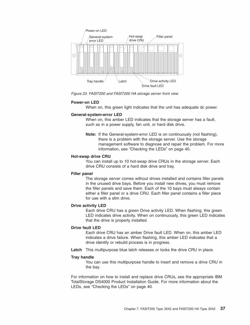
Power-on LED
When on, this green light indicates that the unit has adequate dc power.
General-system-error LED
When on, this amber LED indicates that the storage server has a fault,
such as in a power supply, fan unit, or hard disk drive.
Note: If the General-system-error LED is on continuously (not flashing),
there is a problem with the storage server. Use the storage
management software to diagnose and repair the problem. For more
information, see “Checking the LEDs” on page 40.
Hot-swap drive CRU
You can install up to 10 hot-swap drive CRUs in the storage server. Each
drive CRU consists of a hard disk drive and tray.
Filler panel
The storage server comes without drives installed and contains filler panels
in the unused drive bays. Before you install new drives, you must remove
the filler panels and save them. Each of the 10 bays must always contain
either a filler panel or a drive CRU. Each filler panel contains a filler piece
for use with a slim drive.
Drive activity LED
Each drive CRU has a green Drive activity LED. When flashing, this green
LED indicates drive activity. When on continuously, this green LED indicates
that the drive is properly installed.
Drive fault LED
Each drive CRU has an amber Drive fault LED. When on, this amber LED
indicates a drive failure. When flashing, this amber LED indicates that a
drive identify or rebuild process is in progress.
Latch This multipurpose blue latch releases or locks the drive CRU in place.
Tray handle
You can use this multipurpose handle to insert and remove a drive CRU in
the bay.
For information on how to install and replace drive CRUs, see the appropriate IBM
TotalStorage DS4000 Product Installation Guide. For more information about the
LEDs, see “Checking the LEDs” on page 40.
Drive activity LED
Hot-swapdrive CRU
Tray handle LatchDrive fault LED
Power-on LED
General-system-error LED
Filler panel
Figure 23. FAStT200 and FAStT200 HA storage server front view
Chapter 7. FAStT200 Type 3542 and FAStT200 HA Type 3542 37
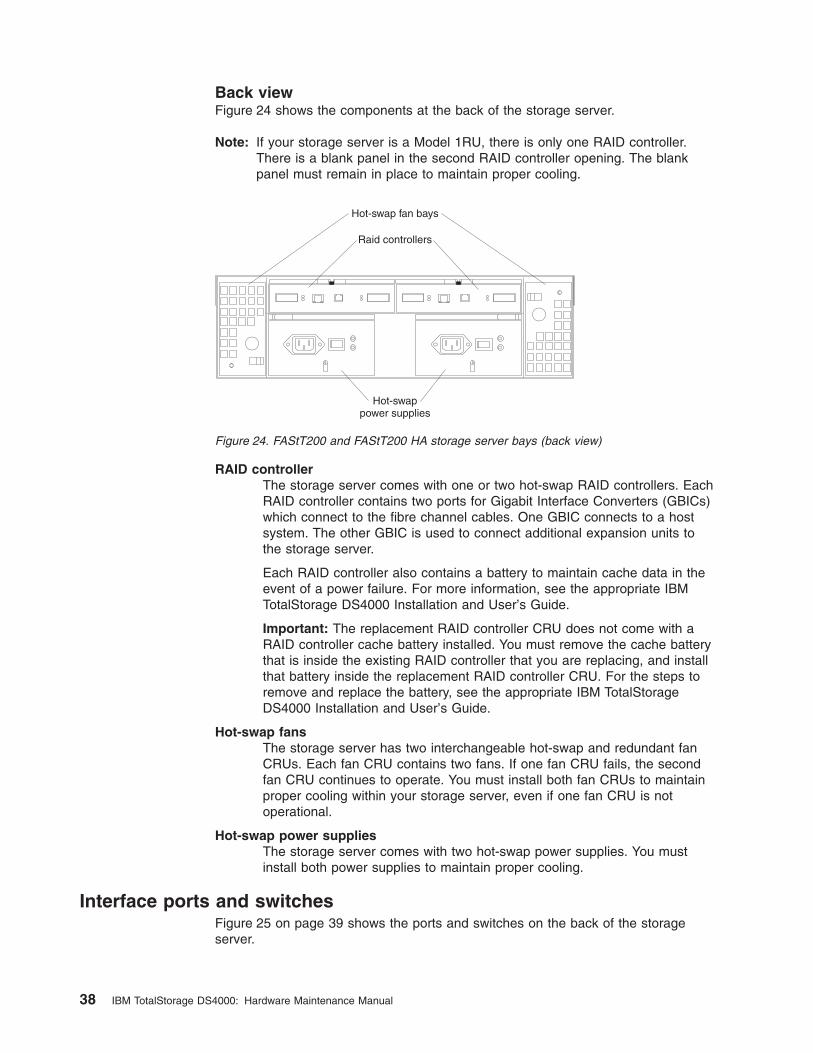
Back view
Figure 24 shows the components at the back of the storage server.
Note: If your storage server is a Model 1RU, there is only one RAID controller.
There is a blank panel in the second RAID controller opening. The blank
panel must remain in place to maintain proper cooling.
RAID controller
The storage server comes with one or two hot-swap RAID controllers. Each
RAID controller contains two ports for Gigabit Interface Converters (GBICs)
which connect to the fibre channel cables. One GBIC connects to a host
system. The other GBIC is used to connect additional expansion units to
the storage server.
Each RAID controller also contains a battery to maintain cache data in the
event of a power failure. For more information, see the appropriate IBM
TotalStorage DS4000 Installation and User’s Guide.
Important: The replacement RAID controller CRU does not come with a
RAID controller cache battery installed. You must remove the cache battery
that is inside the existing RAID controller that you are replacing, and install
that battery inside the replacement RAID controller CRU. For the steps to
remove and replace the battery, see the appropriate IBM TotalStorage
DS4000 Installation and User’s Guide.
Hot-swap fans
The storage server has two interchangeable hot-swap and redundant fan
CRUs. Each fan CRU contains two fans. If one fan CRU fails, the second
fan CRU continues to operate. You must install both fan CRUs to maintain
proper cooling within your storage server, even if one fan CRU is not
operational.
Hot-swap power supplies
The storage server comes with two hot-swap power supplies. You must
install both power supplies to maintain proper cooling.
Interface ports and switches
Figure 25 on page 39 shows the ports and switches on the back of the storage
server.
Hot-swap fan bays
Hot-swappower supplies
Raid controllers
Figure 24. FAStT200 and FAStT200 HA storage server bays (back view)
38 IBM TotalStorage DS4000: Hardware Maintenance Manual
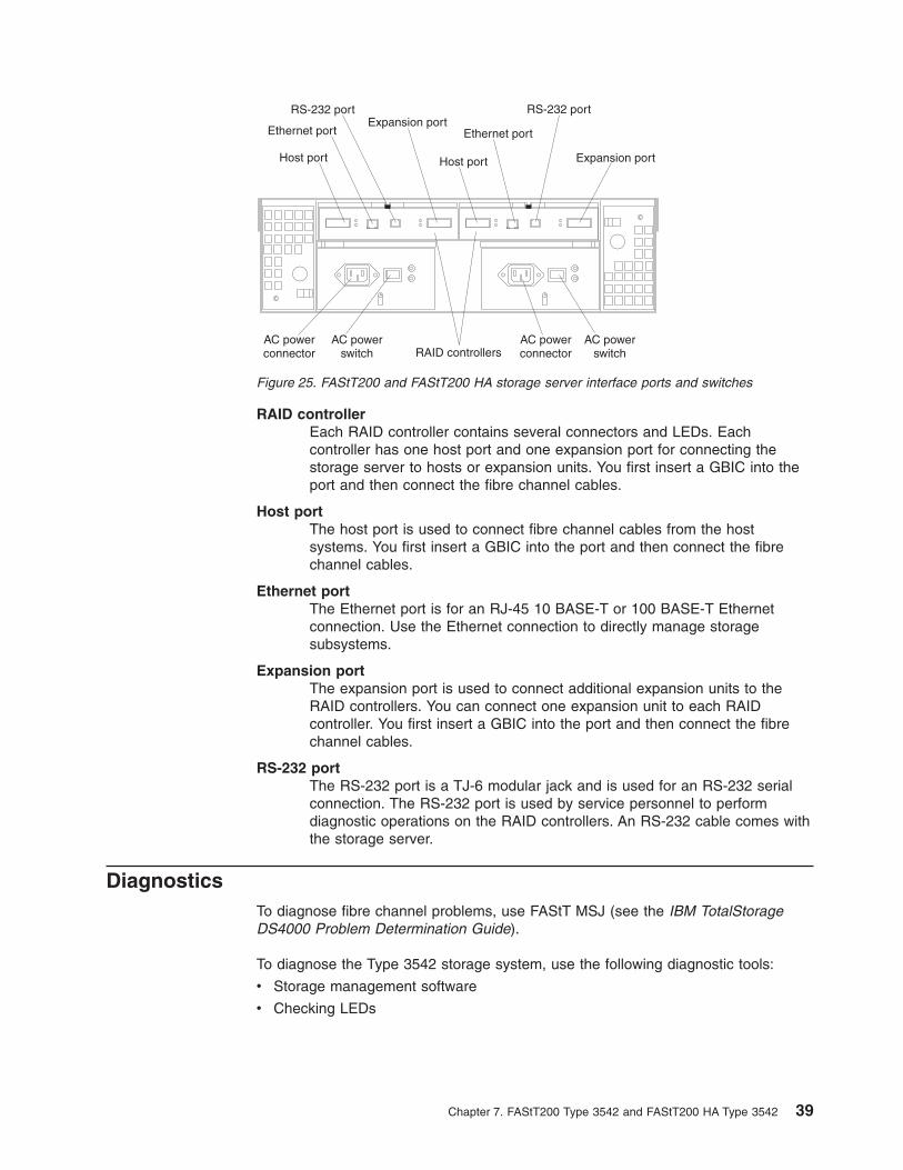
RAID controller
Each RAID controller contains several connectors and LEDs. Each
controller has one host port and one expansion port for connecting the
storage server to hosts or expansion units. You first insert a GBIC into the
port and then connect the fibre channel cables.
Host port
The host port is used to connect fibre channel cables from the host
systems. You first insert a GBIC into the port and then connect the fibre
channel cables.
Ethernet port
The Ethernet port is for an RJ-45 10 BASE-T or 100 BASE-T Ethernet
connection. Use the Ethernet connection to directly manage storage
subsystems.
Expansion port
The expansion port is used to connect additional expansion units to the
RAID controllers. You can connect one expansion unit to each RAID
controller. You first insert a GBIC into the port and then connect the fibre
channel cables.
RS-232 port
The RS-232 port is a TJ-6 modular jack and is used for an RS-232 serial
connection. The RS-232 port is used by service personnel to perform
diagnostic operations on the RAID controllers. An RS-232 cable comes with
the storage server.
Diagnostics
To diagnose fibre channel problems, use FAStT MSJ (see the IBM TotalStorage
DS4000 Problem Determination Guide).
To diagnose the Type 3542 storage system, use the following diagnostic tools:
v Storage management software
v Checking LEDs
RAID controllers
Host port Host port
Ethernet port Ethernet port
RS-232 port RS-232 portExpansion port
Expansion port
AC powerconnector
AC powerswitch
AC powerswitch
AC powerconnector
Figure 25. FAStT200 and FAStT200 HA storage server interface ports and switches
Chapter 7. FAStT200 Type 3542 and FAStT200 HA Type 3542 39
Monitoring status through software
Use the storage management software to monitor the status of the storage server.
Run the software constantly, and check it frequently.
The storage management software provides the best way to diagnose and repair
storage server failures. The software can help you:
v Determine the nature of the failure
v Locate the failed component
v Determine the recovery procedures to repair the failure
Although the storage server has fault LEDs, these lights do not necessarily indicate
which component failed or needs to be replaced, or which type of recovery
procedure that you must perform. In some cases (such as loss of redundancy in
various components), the fault LED does not turn on. Only the storage management
software can detect the failure.
For example, the recovery procedure for a Predictive Failure Analysis®
(PFA) flag
(impending drive failure) on a drive varies depending on the drive status (hot spare,
unassigned, RAID level, current logical drive status, and so on). Depending on the
circumstances, a PFA flag on a drive can indicate a high risk of data loss (if the
drive is in a RAID 0 volume) or a minimal risk (if the drive is unassigned). Only the
storage management software can identify the risk level and provide the necessary
recovery procedures.
Note: For PFA flags, the General-system-error LED and Drive fault LEDs do not
turn on, so checking the LEDs will not notify you of the failure, even if the
risk of data loss is high.
Recovering from a storage server failure might require you to perform procedures
other than replacing the component (such as backing up the logical drive or failing a
drive before removing it). The storage management software gives these
procedures.
Attention: Not following the software-recovery procedures can result in data loss.
Checking the LEDs
The LEDs display the status of the storage server and components. Green LEDs
indicate a normal operating status; amber LEDs indicate a possible failure.
It is important to check all the LEDs on the front and back of the storage server
when you turn on the power. In addition to checking for faults, you can use the
LEDs on the front of the storage server to determine whether the drives are
responding to I/O transmissions from the host.
40 IBM TotalStorage DS4000: Hardware Maintenance Manual
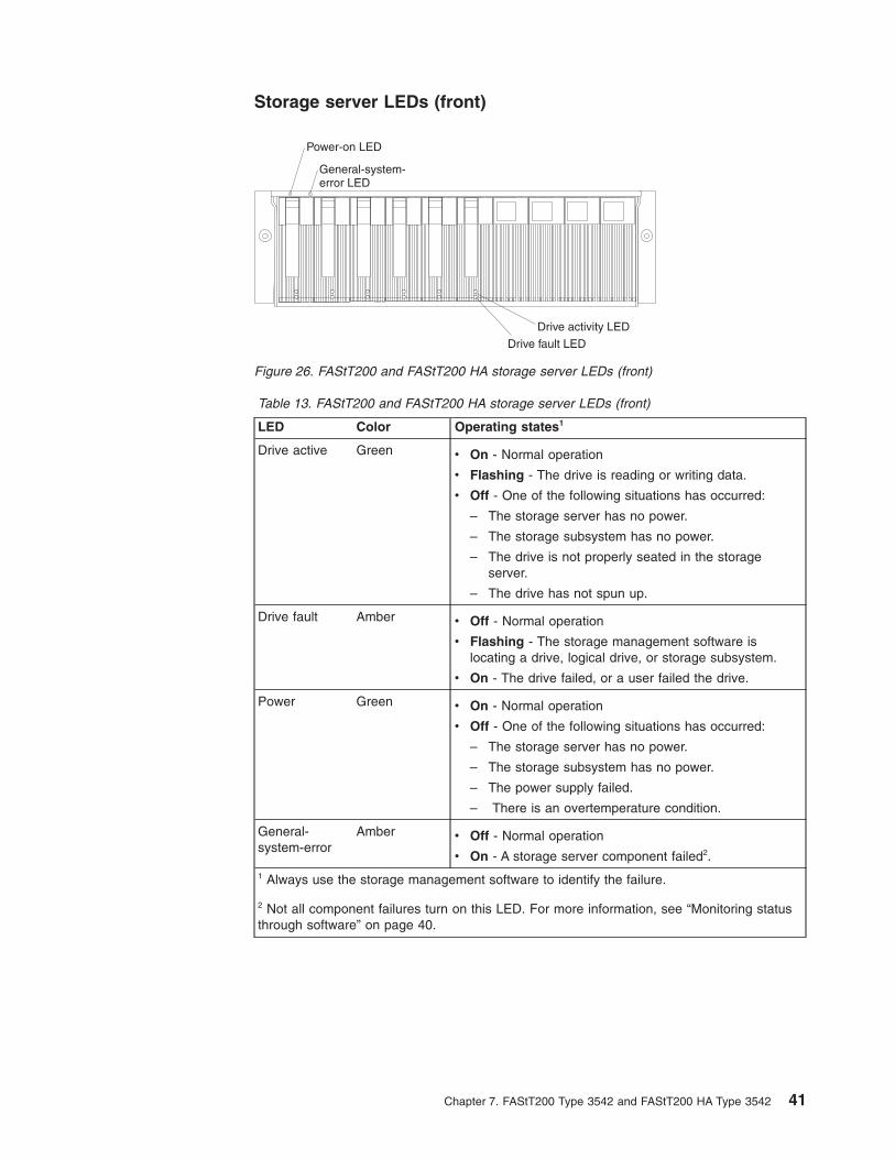
Storage server LEDs (front)
Table 13. FAStT200 and FAStT200 HA storage server LEDs (front)
LED Color Operating states1
Drive active Green v On - Normal operation
v Flashing - The drive is reading or writing data.
v Off - One of the following situations has occurred:
– The storage server has no power.
– The storage subsystem has no power.
– The drive is not properly seated in the storage
server.
– The drive has not spun up.
Drive fault Amber v Off - Normal operation
v Flashing - The storage management software is
locating a drive, logical drive, or storage subsystem.
v On - The drive failed, or a user failed the drive.
Power Green v On - Normal operation
v Off - One of the following situations has occurred:
– The storage server has no power.
– The storage subsystem has no power.
– The power supply failed.
– There is an overtemperature condition.
General-system-error
Amber v Off - Normal operation
v On - A storage server component failed2.
1 Always use the storage management software to identify the failure.
2 Not all component failures turn on this LED. For more information, see “Monitoring status
through software” on page 40.
Drive activity LED
Drive fault LED
Power-on LED
General-system-error LED
Figure 26. FAStT200 and FAStT200 HA storage server LEDs (front)
Chapter 7. FAStT200 Type 3542 and FAStT200 HA Type 3542 41

Storage server LEDs (rear)
Table 14. FAStT200 and FAStT200 HA storage server RAID controller LEDs
Icon LED Color Operating states1
Fault Amber v Off - Normal operation
v On - The RAID controller failed.
Host loop Green v On - Normal operation
v Off - One of the following situations has occurred:
– The host loop is down, not turned on, or not connected.
– A GBIC failed, or the host port is not occupied.
– The RAID controller circuitry failed, or the RAID controller
has no power.
Cache active Green v On - There is data in the RAID controller cache.
v Off - One of the following situations has occurred:
– There is no data in cache.
– There are no cache options selected for this array.
– The cache memory failed, or the battery failed.
+
Battery Green v On - Normal operation
v Flashing - The battery is recharging or performing a self-test.
v Off - The battery or battery charger failed.
Expansion port
bypass
Amber v Off - Normal operation
v On - One of the following situations has occurred:
– The expansion port is not occupied.
– The fibre channel cable is not attached to an expansion
unit.
– The attached expansion unit is not turned on.
– A GBIC failed, a fibre channel cable failed, or a GBIC failed
on the attached expansion unit.
Expansion loop Green v On - Normal operation
v Off - The RAID controller circuitry failed, or the RAID controller
has no power.
Fault
Host loop 10BT 100BT Battery Expansion loop
Expansion port bypassCache active
ControllerFault
10BT 100BTFC-Host
FC-Expansion
Figure 27. FAStT200 and FAStT200 HA storage server LEDs (rear)
42 IBM TotalStorage DS4000: Hardware Maintenance Manual
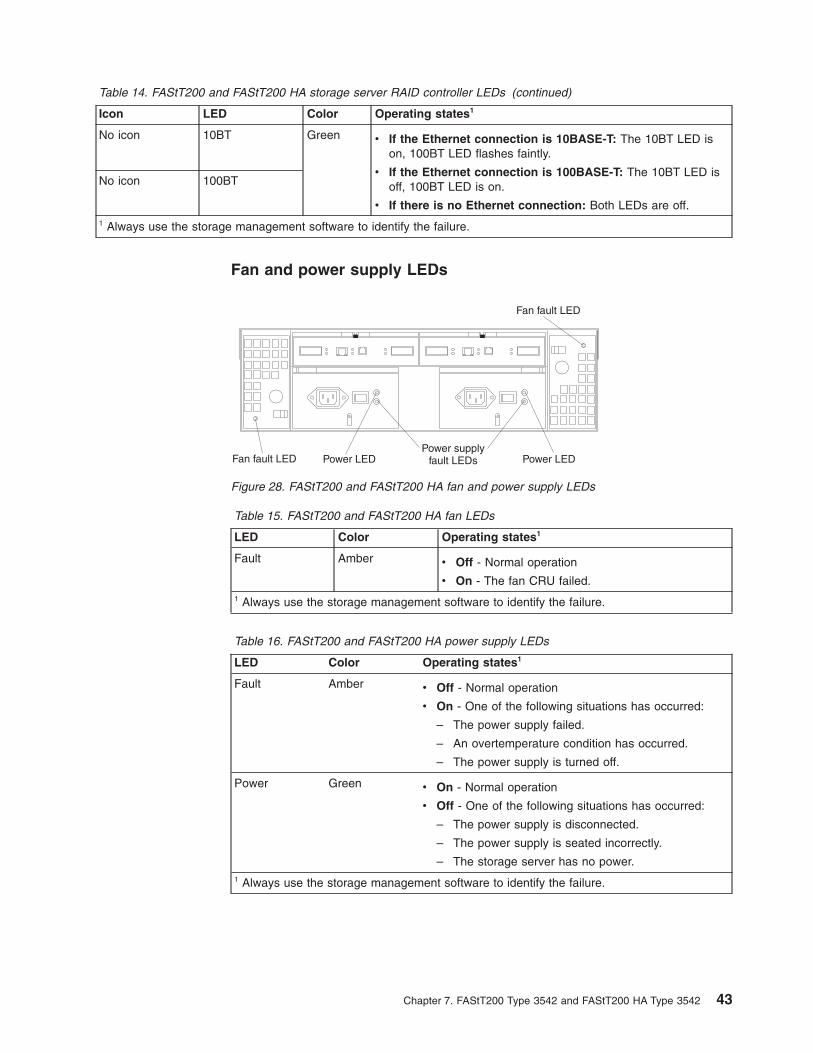
Table 14. FAStT200 and FAStT200 HA storage server RAID controller LEDs (continued)
Icon LED Color Operating states1
No icon 10BT Green v If the Ethernet connection is 10BASE-T: The 10BT LED is
on, 100BT LED flashes faintly.
v If the Ethernet connection is 100BASE-T: The 10BT LED is
off, 100BT LED is on.
v If there is no Ethernet connection: Both LEDs are off.
No icon 100BT
1 Always use the storage management software to identify the failure.
Fan and power supply LEDs
Table 15. FAStT200 and FAStT200 HA fan LEDs
LED Color Operating states1
Fault Amber v Off - Normal operation
v On - The fan CRU failed.
1 Always use the storage management software to identify the failure.
Table 16. FAStT200 and FAStT200 HA power supply LEDs
LED Color Operating states1
Fault Amber v Off - Normal operation
v On - One of the following situations has occurred:
– The power supply failed.
– An overtemperature condition has occurred.
– The power supply is turned off.
Power Green v On - Normal operation
v Off - One of the following situations has occurred:
– The power supply is disconnected.
– The power supply is seated incorrectly.
– The storage server has no power.
1 Always use the storage management software to identify the failure.
Power supplyfault LEDsPower LED
Fan fault LED
Fan fault LED Power LED
Figure 28. FAStT200 and FAStT200 HA fan and power supply LEDs
Chapter 7. FAStT200 Type 3542 and FAStT200 HA Type 3542 43
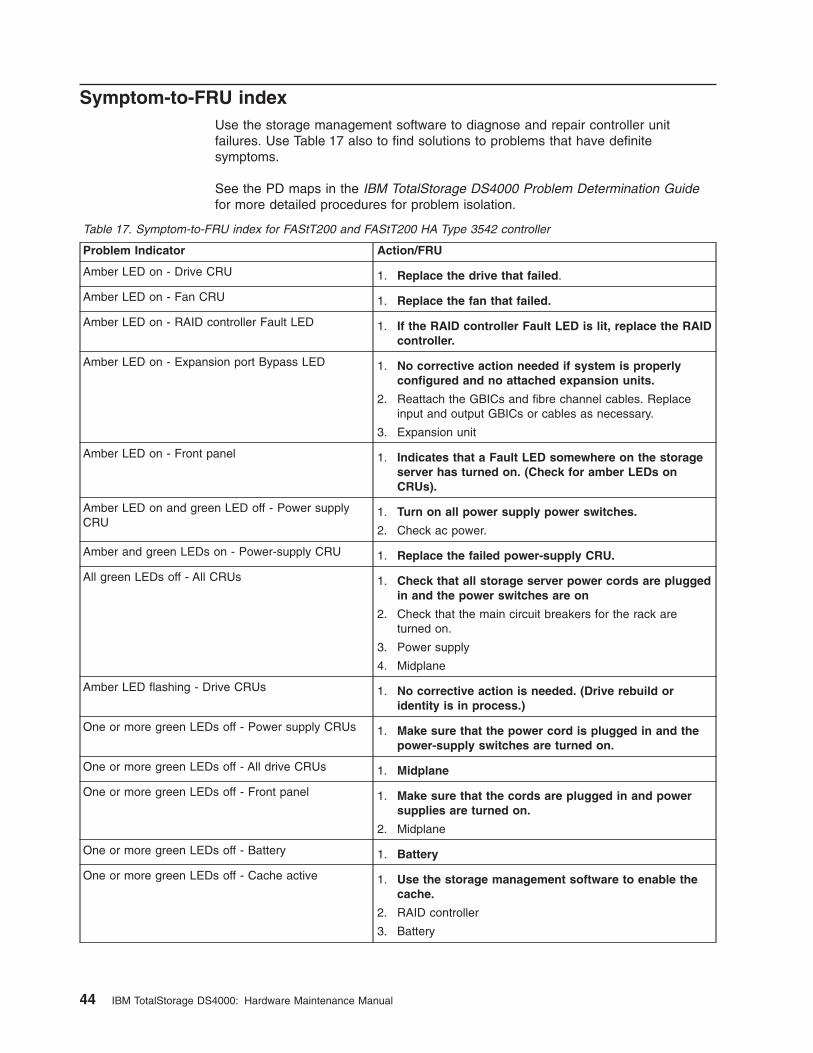
Symptom-to-FRU index
Use the storage management software to diagnose and repair controller unit
failures. Use Table 17 also to find solutions to problems that have definite
symptoms.
See the PD maps in the IBM TotalStorage DS4000 Problem Determination Guide
for more detailed procedures for problem isolation.
Table 17. Symptom-to-FRU index for FAStT200 and FAStT200 HA Type 3542 controller
Problem Indicator Action/FRU
Amber LED on - Drive CRU 1. Replace the drive that failed.
Amber LED on - Fan CRU 1. Replace the fan that failed.
Amber LED on - RAID controller Fault LED 1. If the RAID controller Fault LED is lit, replace the RAID
controller.
Amber LED on - Expansion port Bypass LED 1. No corrective action needed if system is properly
configured and no attached expansion units.
2. Reattach the GBICs and fibre channel cables. Replace
input and output GBICs or cables as necessary.
3. Expansion unit
Amber LED on - Front panel 1. Indicates that a Fault LED somewhere on the storage
server has turned on. (Check for amber LEDs on
CRUs).
Amber LED on and green LED off - Power supply
CRU
1. Turn on all power supply power switches.
2. Check ac power.
Amber and green LEDs on - Power-supply CRU 1. Replace the failed power-supply CRU.
All green LEDs off - All CRUs 1. Check that all storage server power cords are plugged
in and the power switches are on
2. Check that the main circuit breakers for the rack are
turned on.
3. Power supply
4. Midplane
Amber LED flashing - Drive CRUs 1. No corrective action is needed. (Drive rebuild or
identity is in process.)
One or more green LEDs off - Power supply CRUs 1. Make sure that the power cord is plugged in and the
power-supply switches are turned on.
One or more green LEDs off - All drive CRUs 1. Midplane
One or more green LEDs off - Front panel 1. Make sure that the cords are plugged in and power
supplies are turned on.
2. Midplane
One or more green LEDs off - Battery 1. Battery
One or more green LEDs off - Cache active 1. Use the storage management software to enable the
cache.
2. RAID controller
3. Battery
44 IBM TotalStorage DS4000: Hardware Maintenance Manual
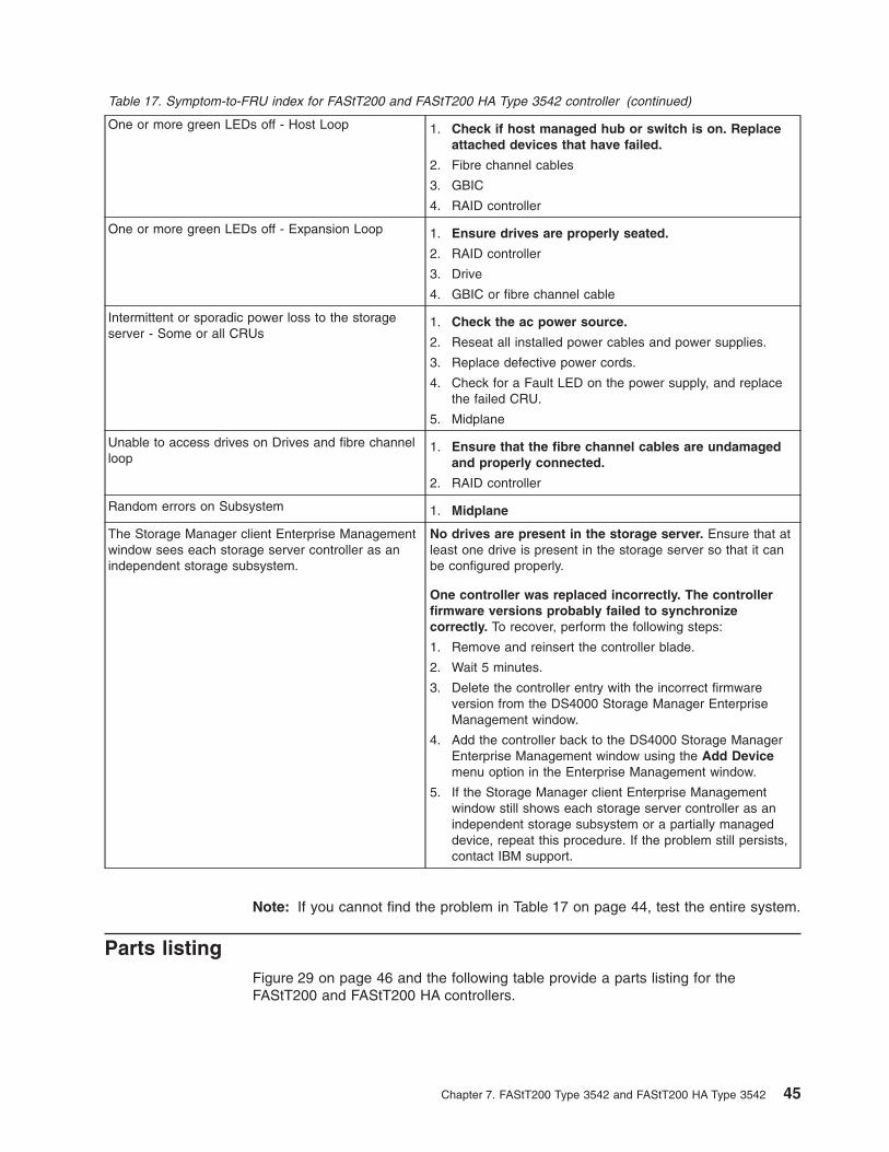
Table 17. Symptom-to-FRU index for FAStT200 and FAStT200 HA Type 3542 controller (continued)
One or more green LEDs off - Host Loop 1. Check if host managed hub or switch is on. Replace
attached devices that have failed.
2. Fibre channel cables
3. GBIC
4. RAID controller
One or more green LEDs off - Expansion Loop 1. Ensure drives are properly seated.
2. RAID controller
3. Drive
4. GBIC or fibre channel cable
Intermittent or sporadic power loss to the storage
server - Some or all CRUs
1. Check the ac power source.
2. Reseat all installed power cables and power supplies.
3. Replace defective power cords.
4. Check for a Fault LED on the power supply, and replace
the failed CRU.
5. Midplane
Unable to access drives on Drives and fibre channel
loop
1. Ensure that the fibre channel cables are undamaged
and properly connected.
2. RAID controller
Random errors on Subsystem 1. Midplane
The Storage Manager client Enterprise Management
window sees each storage server controller as an
independent storage subsystem.
No drives are present in the storage server. Ensure that at
least one drive is present in the storage server so that it can
be configured properly.
One controller was replaced incorrectly. The controller
firmware versions probably failed to synchronize
correctly. To recover, perform the following steps:
1. Remove and reinsert the controller blade.
2. Wait 5 minutes.
3. Delete the controller entry with the incorrect firmware
version from the DS4000 Storage Manager Enterprise
Management window.
4. Add the controller back to the DS4000 Storage Manager
Enterprise Management window using the Add Device
menu option in the Enterprise Management window.
5. If the Storage Manager client Enterprise Management
window still shows each storage server controller as an
independent storage subsystem or a partially managed
device, repeat this procedure. If the problem still persists,
contact IBM support.
Note: If you cannot find the problem in Table 17 on page 44, test the entire system.
Parts listing
Figure 29 on page 46 and the following table provide a parts listing for the
FAStT200 and FAStT200 HA controllers.
Chapter 7. FAStT200 Type 3542 and FAStT200 HA Type 3542 45
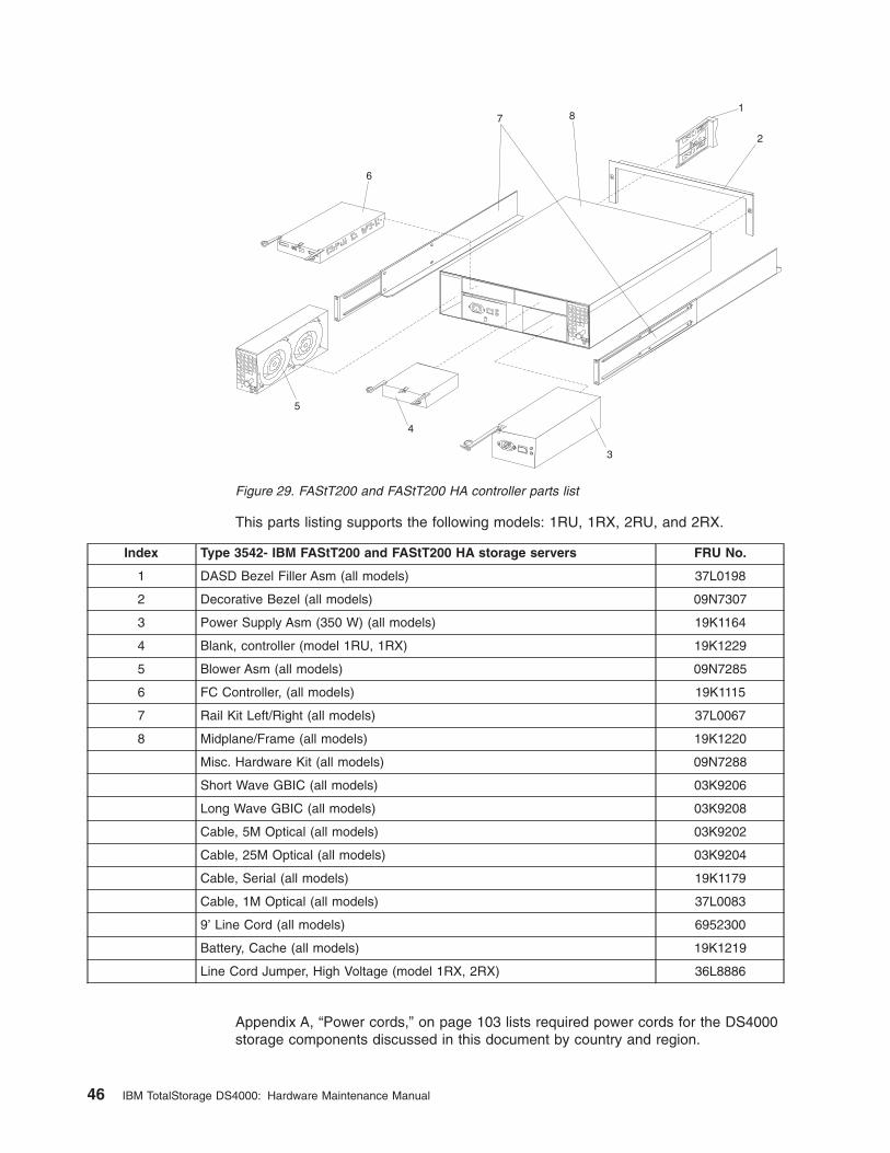
This parts listing supports the following models: 1RU, 1RX, 2RU, and 2RX.
Index Type 3542- IBM FAStT200 and FAStT200 HA storage servers FRU No.
1 DASD Bezel Filler Asm (all models) 37L0198
2 Decorative Bezel (all models) 09N7307
3 Power Supply Asm (350 W) (all models) 19K1164
4 Blank, controller (model 1RU, 1RX) 19K1229
5 Blower Asm (all models) 09N7285
6 FC Controller, (all models) 19K1115
7 Rail Kit Left/Right (all models) 37L0067
8 Midplane/Frame (all models) 19K1220
Misc. Hardware Kit (all models) 09N7288
Short Wave GBIC (all models) 03K9206
Long Wave GBIC (all models) 03K9208
Cable, 5M Optical (all models) 03K9202
Cable, 25M Optical (all models) 03K9204
Cable, Serial (all models) 19K1179
Cable, 1M Optical (all models) 37L0083
9’ Line Cord (all models) 6952300
Battery, Cache (all models) 19K1219
Line Cord Jumper, High Voltage (model 1RX, 2RX) 36L8886
Appendix A, “Power cords,” on page 103 lists required power cords for the DS4000
storage components discussed in this document by country and region.
1
2
3
4
5
6
7 8
Figure 29. FAStT200 and FAStT200 HA controller parts list
46 IBM TotalStorage DS4000: Hardware Maintenance Manual
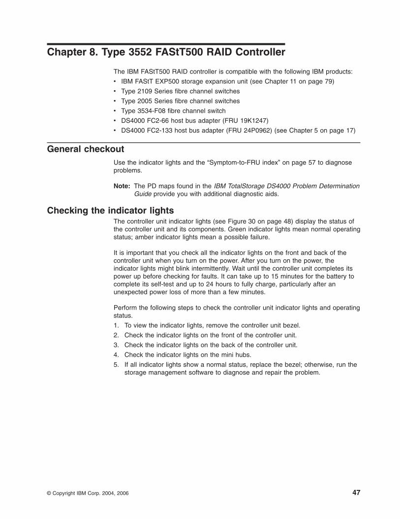
Chapter 8. Type 3552 FAStT500 RAID Controller
The IBM FAStT500 RAID controller is compatible with the following IBM products:
v IBM FAStT EXP500 storage expansion unit (see Chapter 11 on page 79)
v Type 2109 Series fibre channel switches
v Type 2005 Series fibre channel switches
v Type 3534-F08 fibre channel switch
v DS4000 FC2-66 host bus adapter (FRU 19K1247)
v DS4000 FC2-133 host bus adapter (FRU 24P0962) (see Chapter 5 on page 17)
General checkout
Use the indicator lights and the “Symptom-to-FRU index” on page 57 to diagnose
problems.
Note: The PD maps found in the IBM TotalStorage DS4000 Problem Determination
Guide provide you with additional diagnostic aids.
Checking the indicator lights
The controller unit indicator lights (see Figure 30 on page 48) display the status of
the controller unit and its components. Green indicator lights mean normal operating
status; amber indicator lights mean a possible failure.
It is important that you check all the indicator lights on the front and back of the
controller unit when you turn on the power. After you turn on the power, the
indicator lights might blink intermittently. Wait until the controller unit completes its
power up before checking for faults. It can take up to 15 minutes for the battery to
complete its self-test and up to 24 hours to fully charge, particularly after an
unexpected power loss of more than a few minutes.
Perform the following steps to check the controller unit indicator lights and operating
status.
1. To view the indicator lights, remove the controller unit bezel.
2. Check the indicator lights on the front of the controller unit.
3. Check the indicator lights on the back of the controller unit.
4. Check the indicator lights on the mini hubs.
5. If all indicator lights show a normal status, replace the bezel; otherwise, run the
storage management software to diagnose and repair the problem.
© Copyright IBM Corp. 2004, 2006 47
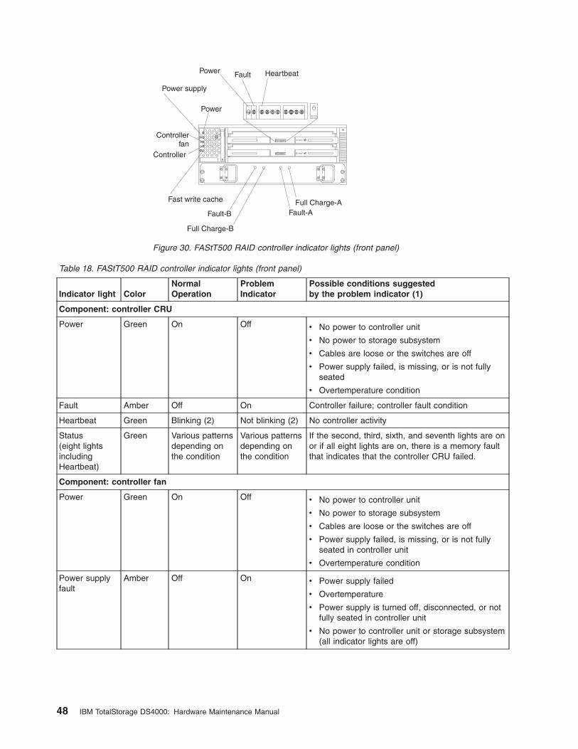
Table 18. FAStT500 RAID controller indicator lights (front panel)
Indicator light Color
Normal
Operation
Problem
Indicator
Possible conditions suggested
by the problem indicator (1)
Component: controller CRU
Power Green On Off v No power to controller unit
v No power to storage subsystem
v Cables are loose or the switches are off
v Power supply failed, is missing, or is not fully
seated
v Overtemperature condition
Fault Amber Off On Controller failure; controller fault condition
Heartbeat Green Blinking (2) Not blinking (2) No controller activity
Status
(eight lights
including
Heartbeat)
Green Various patterns
depending on
the condition
Various patterns
depending on
the condition
If the second, third, sixth, and seventh lights are on
or if all eight lights are on, there is a memory fault
that indicates that the controller CRU failed.
Component: controller fan
Power Green On Off v No power to controller unit
v No power to storage subsystem
v Cables are loose or the switches are off
v Power supply failed, is missing, or is not fully
seated in controller unit
v Overtemperature condition
Power supply
fault
Amber Off On v Power supply failed
v Overtemperature
v Power supply is turned off, disconnected, or not
fully seated in controller unit
v No power to controller unit or storage subsystem
(all indicator lights are off)
Power
Power
Power supply
Fault Heartbeat
Fast write cache
Controller
Controllerfan
Full Charge-B
Full Charge-A
Fault-B Fault-A
Figure 30. FAStT500 RAID controller indicator lights (front panel)
48 IBM TotalStorage DS4000: Hardware Maintenance Manual
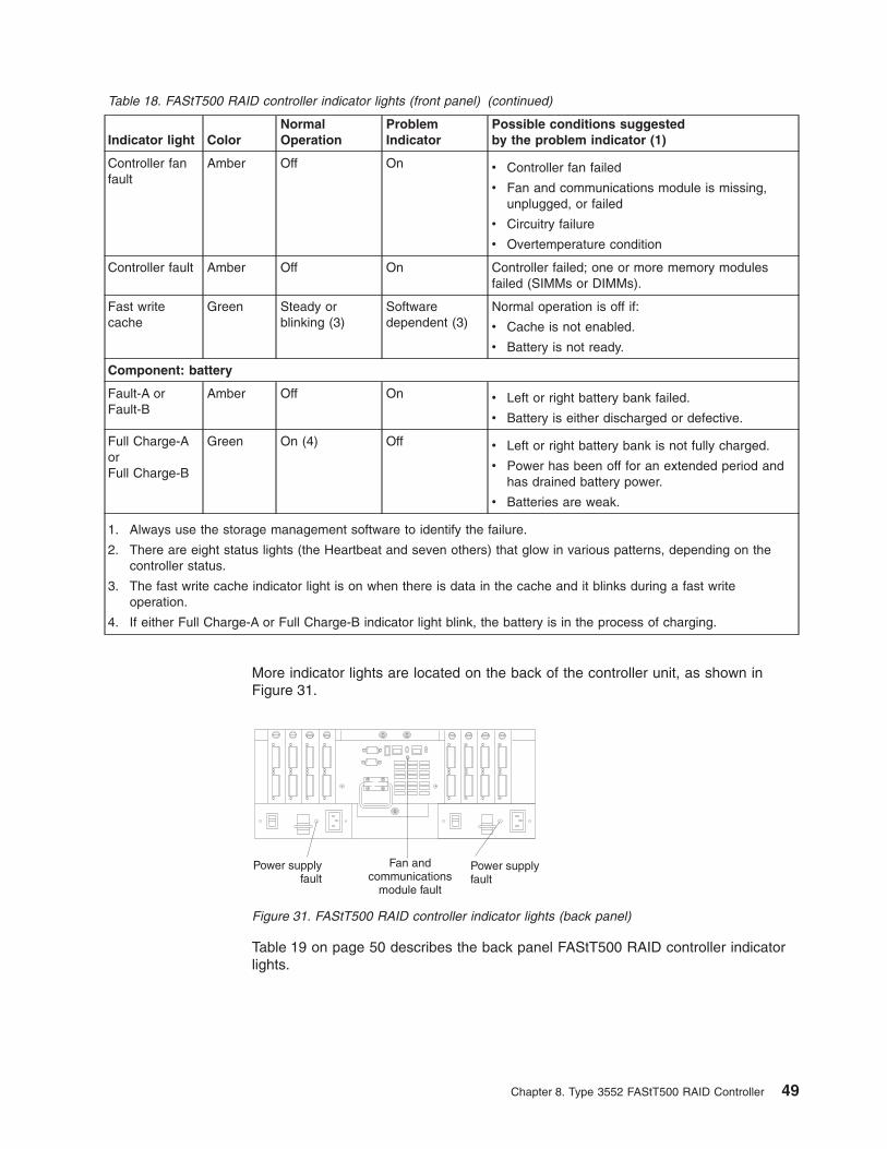
Table 18. FAStT500 RAID controller indicator lights (front panel) (continued)
Indicator light Color
Normal
Operation
Problem
Indicator
Possible conditions suggested
by the problem indicator (1)
Controller fan
fault
Amber Off On v Controller fan failed
v Fan and communications module is missing,
unplugged, or failed
v Circuitry failure
v Overtemperature condition
Controller fault Amber Off On Controller failed; one or more memory modules
failed (SIMMs or DIMMs).
Fast write
cache
Green Steady or
blinking (3)
Software
dependent (3)
Normal operation is off if:
v Cache is not enabled.
v Battery is not ready.
Component: battery
Fault-A or
Fault-B
Amber Off On v Left or right battery bank failed.
v Battery is either discharged or defective.
Full Charge-A
or
Full Charge-B
Green On (4) Off v Left or right battery bank is not fully charged.
v Power has been off for an extended period and
has drained battery power.
v Batteries are weak.
1. Always use the storage management software to identify the failure.
2. There are eight status lights (the Heartbeat and seven others) that glow in various patterns, depending on the
controller status.
3. The fast write cache indicator light is on when there is data in the cache and it blinks during a fast write
operation.
4. If either Full Charge-A or Full Charge-B indicator light blink, the battery is in the process of charging.
More indicator lights are located on the back of the controller unit, as shown in
Figure 31.
Table 19 on page 50 describes the back panel FAStT500 RAID controller indicator
lights.
Power supplyfault
Power supplyfault
Fan andcommunications
module fault
Figure 31. FAStT500 RAID controller indicator lights (back panel)
Chapter 8. Type 3552 FAStT500 RAID Controller 49
Table 19. FAStT500 RAID controller indicator lights (back panel)
Indicator light Color
Normal
Operation
Problem
Indicator
Possible conditions suggested by the problem
indicator (1)
Fan and communications module
Fan and
communication
fault
Amber Off On v Fan and communications module failed or is
installed incorrectly
v Overtemperature condition
Power supply
Power supply Green On Off v No power to controller unit
v No power to storage subsystem
v Power supply failed
v Overtemperature condition
1. Always use the storage management software to identify the failure.
The mini hub indicator lights on the back of the controller unit are shown in
Figure 32.
Table 20 on page 51 describes the mini hub indicator lights.
OU
TIN
Fault
Bypass(upper port)
Bypass(lower port)
Loopgood
Mini-hub indicator lights
Figure 32. FAStT500 RAID controller mini hub indicator lights
50 IBM TotalStorage DS4000: Hardware Maintenance Manual

Table 20. FAStT500 RAID controller mini hub indicator lights
Icon Indicator light Color
Normal
Operation
Problem
Indicator
Possible conditions suggested by the
problem indicator
Component: mini hub (host-side)
Fault Amber Off On Mini hub or GBIC failed.
Note: If a host-side mini hub is not
connected to a controller, this fault light is
always on.
Bypass (upper
port)
Amber Off On v Upper mini hub port is bypassed.
v Mini hub or GBIC failed, is loose, or is
missing.
v Fiber-optic cables are damaged.
Note: If the port is unoccupied, the light is
on.
Loop good Green On Off v The loop is not operational.
v Mini hub failed or a faulty device might be
connected to the mini hub.
v Controller failed.
Note: If a host-side mini hub is not
connected to a controller, the green light is
always off and the fault light is always on.
Bypass (lower port) Amber Off On v Lower mini hub port is bypassed.
v Mini hub or GBIC failed, is loose, or is
missing.
v Fiber-optic cables are damaged.
Note: If the port is unoccupied, the light is
on.
Component: Mini hub (drive-side)
Fault Amber Off On Mini hub or GBIC failed.
Note: If a drive-side mini hub is not
connected to a controller, this fault light is
always on.
Bypass (upper
port)
Amber Off On v Upper mini hub port is bypassed.
v Mini hub or GBIC failed, is loose, or is
missing.
v Fiber-optic cables are damaged.
Note: If the port is unoccupied, the light is
on.
Loop good Green On Off v The loop is not operational.
v Mini hub failed or a faulty device might be
connected to the mini hub.
v Drive failed.
Note: If a drive-side mini hub is not
connected to a controller, the green light is
always off and the fault light is always on.
Bypass (lower port) Amber Off On v Lower mini hub port is bypassed.
v Mini hub or GBIC failed, is loose, or is
missing.
v Fiber-optic cables are damaged.
Note: If the port is unoccupied, the light is
on.
Chapter 8. Type 3552 FAStT500 RAID Controller 51
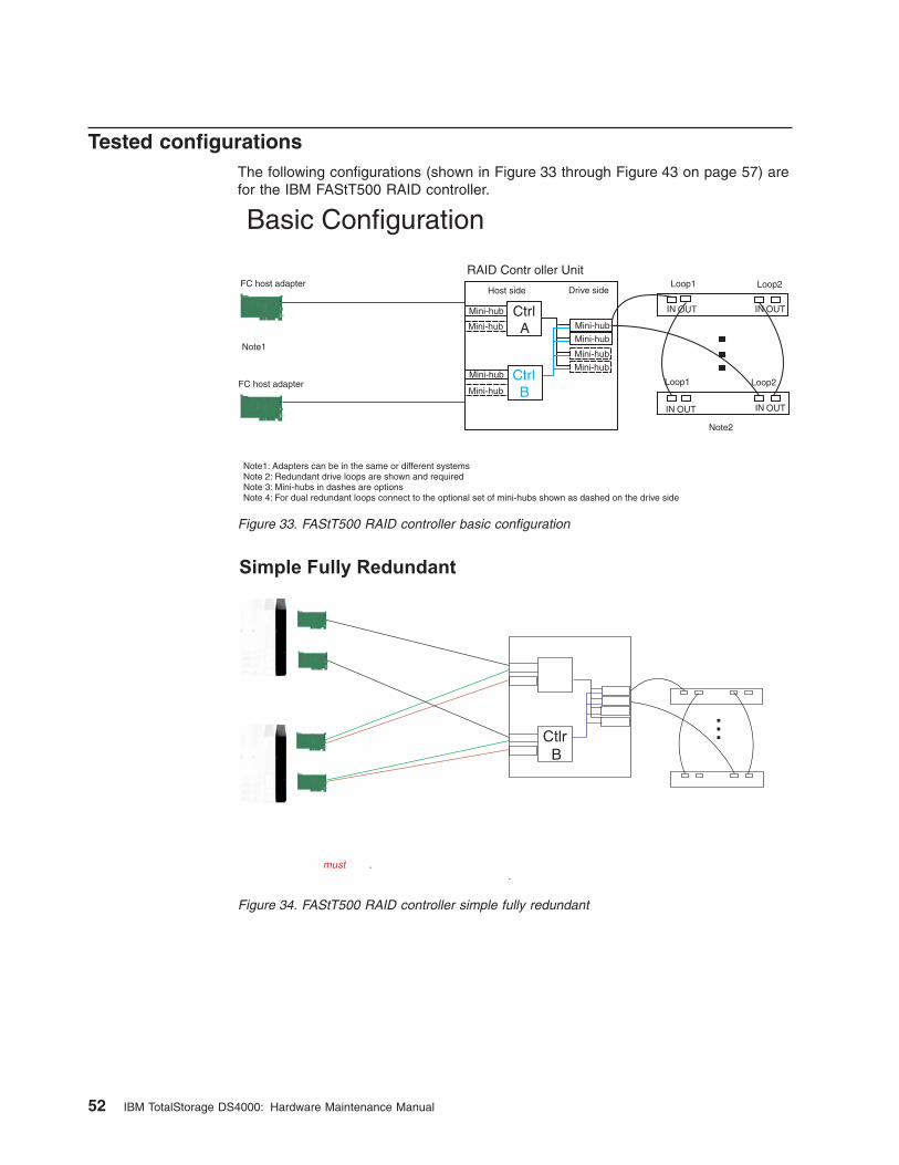
Tested configurations
The following configurations (shown in Figure 33 through Figure 43 on page 57) are
for the IBM FAStT500 RAID controller.
Basic Configuration
Mini-hub
Host side
Mini-hub
Mini-hub
Mini-hub
RAID Contr oller Unit
CtrlB
CtrlA
Mini-hub
Mini-hub
Mini-hub
Mini-hub
Drive sideLoop1
Loop1
OUT OUT
OUTOUT
IN IN
ININ
Loop2
Loop2
Note2
Note1
Note1: Adapters can be in the same or different systemsNote 2: Redundant drive loops are shown and requiredNote 3: Mini-hubs in dashes are optionsNote 4: For dual redundant loops connect to the optional set of mini-hubs shown as dashed on the drive side
FC host adapter
FC host adapter
Figure 33. FAStT500 RAID controller basic configuration
Simple Fully Redundant
...
..
must
Ctlr
B
Figure 34. FAStT500 RAID controller simple fully redundant
52 IBM TotalStorage DS4000: Hardware Maintenance Manual
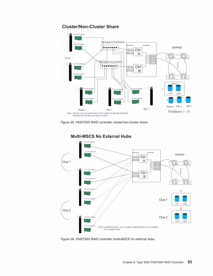
Cluster/Non-Cluster Share
Managed Hub/Switch
Managed Hub/Switch
Clus1
DB 1
FC host adapter
FC host adapter
FC host adapter
FC host adapter
Notes 1 File 1
Note : Factors such as performance and number of storage partitions
influence the number and type of nodes.
Clus1
LD1
Notes 1 File 1 DB 1
Partitions 1 - 4
1
2 3 4
LD2
...
Host side Drive side
Mini-hub
Mini-hub
Mini-hub
Mini-hub
Mini-hub
Mini-hub
Mini-hub
Mini-hub
EXP500
Loop 1
Loop 1
Loop 2
Loop 2
IN IN
IN OUT IN
OUT OUT
OUT
FC host adapter
FC host adapter FC host adapter
FC host adapter FC host adapter
FC host adapter
CtrlB
CtrlA
Figure 35. FAStT500 RAID controller cluster/non-cluster share
Multi-MSCS No External Hubs
LD1 LD2
...
Host side Drive side
Mini-hub
Mini-hub
Mini-hub
Mini-hub
Mini-hub
Mini-hub
Mini-hub
Mini-hub
EXP500
Loop 1
Loop 1
Loop 2
Loop 2
IN IN
IN OUT IN
OUT OUT
OUT
Clus 1
LD3 LD4
Clus 2
1
2
CtrlB
CtrlA
FC host adapter
FC host adapter
FC host adapter
FC host adapter
FC host adapter
FC host adapter
FC host adapter
FC host adapter
Clus 1
Note: 2 partitions shown; Clus 1 partition separate from Clus 2 partition
LD is a logical drive
Clus 2
Figure 36. FAStT500 RAID controller multi-MSCS no external hubs
Chapter 8. Type 3552 FAStT500 RAID Controller 53
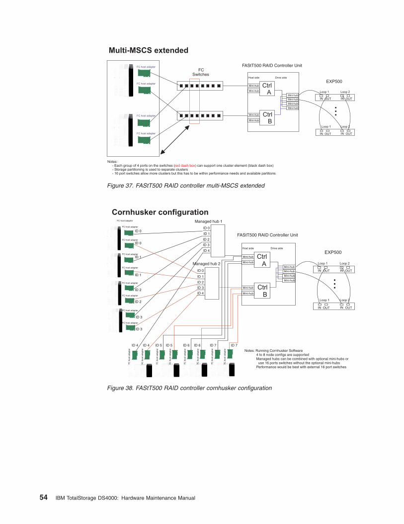
FCSwitches
Multi-MSCS extended
Notes:- Each group of 4 ports on the switches ( ) can support one cluster element (black dash box)- Storage partitioning is used to separate clusters- 16 port switches allow more clusters but this has to be within performance needs and available partitions
red dash box
FC host adapter
FC host adapter
FC host adapter
FC host adapter
...Host side Drive side
Mini-hub
Mini-hub
Mini-hub
Mini-hub
Mini-hub
Mini-hub
Mini-hub
Mini-hub
EXP500
Loop 1
Loop 1
Loop 2
Loop 2
IN IN
IN OUT IN
OUT OUT
OUT
CtrlB
CtrlA
FAStT500 RAID Controller Unit
Figure 37. FAStT500 RAID controller multi-MSCS extended
Cornhusker configuration
...
Host side Drive side
Mini-hub
Mini-hub
Mini-hub
Mini-hub
Mini-hub
Mini-hub
Mini-hub
Mini-hub
EXP500
Loop 1
Loop 1
Loop 2
Loop 2
IN IN
IN OUT IN
OUT OUT
OUT
CtrlB
CtrlA
FAStT500 RAID Controller Unit
Managed hub 1
Managed hub 2
ID 0
ID 0
ID 1
ID 2
ID 3
ID 4
ID 4
ID 3
ID 2
ID 1
Notes: Running Cornhusker Software4 to 8 node configs are supportedManaged hubs can be combined with optional mini-hubs oruse 16 ports switches without the optional mini-hubs
Performance would be best with external 16 port switches
FC host adapter
FC host adapter
FC host adapter
FC host adapter
FC host adapter
FC host adapter
FC host adapter
FC host adapter
FC host adapter
ID 0
ID 0
ID 1
ID 1
ID 2
ID 2
ID 3
ID 3
ID 4 ID 4 ID 5 ID 5 ID 6 ID 6 ID 7 ID 7
FC
hos
t ada
pter
FC
hos
t ada
pter
FC
hos
t ada
pter
FC
hos
t ada
pter
FC
hos
t ada
pter
FC
hos
t ada
pter
FC
hos
t ada
pter
FC
hos
t ada
pter
Figure 38. FAStT500 RAID controller cornhusker configuration
54 IBM TotalStorage DS4000: Hardware Maintenance Manual
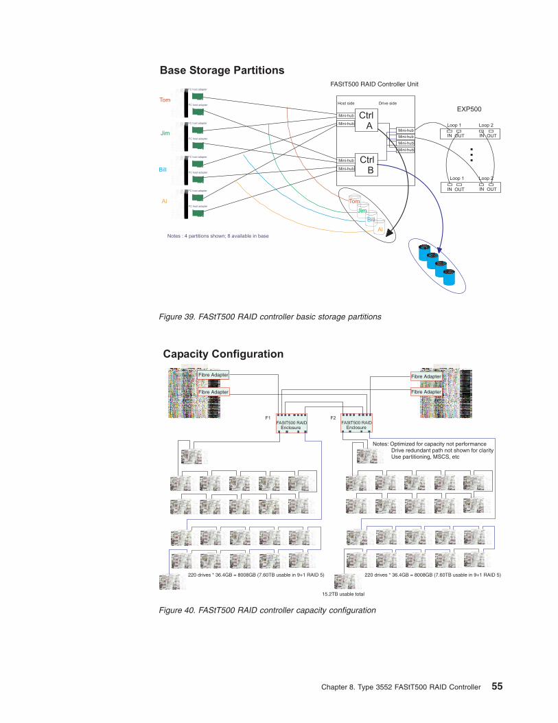
Tom
Jim
Bill
Al
Al
Jim
Bill
Tom
FC host adapter
FC host adapter
FC host adapter
FC host adapter
FC host adapter
FC host adapter
FC host adapter
FC host adapter
Notes : 4 partitions shown; 8 available in base
Base Storage Partitions
...Host side Drive side
Mini-hub
Mini-hub
Mini-hub
Mini-hub
Mini-hub
Mini-hub
Mini-hub
Mini-hub
EXP500
Loop 1
Loop 1
Loop 2
Loop 2
IN IN
IN OUT IN
OUT OUT
OUT
CtrlB
CtrlA
FAStT500 RAID Controller Unit
Figure 39. FAStT500 RAID controller basic storage partitions
FAStT500 RAIDEnclosure
Fibre Adapter
FAStT500 RAIDEnclosure
Capacity Configuration
Fibre Adapter
Fibre Adapter Fibre Adapter
Fibre Adapter
F1 F2
Notes: Optimized for capacity not performanceDrive redundant path not shown for clarityUse partitioning, MSCS, etc
220 drives * 36.4GB = 8008GB (7.60TB usable in 9+1 RAID 5)
15.2TB usable total
220 drives * 36.4GB = 8008GB (7.60TB usable in 9+1 RAID 5)
Figure 40. FAStT500 RAID controller capacity configuration
Chapter 8. Type 3552 FAStT500 RAID Controller 55
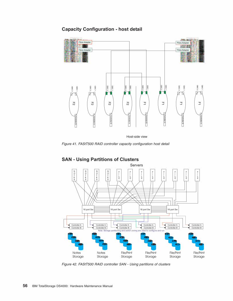
Fibre Adapter
Capacity Configuration - host detail
Fibre Adapter
Fibre Adapter
Fibre Adapter
Fibre Adapter
GB
IC 2
GB
IC 2
GB
IC 2
GB
IC 2
GB
IC 2
GB
IC 2
GB
IC 2
GB
IC 2
GB
IC 1
GB
IC 1
GB
IC 1
GB
IC 1
GB
IC 1
GB
IC 1
GB
IC 1
GB
IC 1
F2
F2
F2
F2
F1
F1
F1
F1
Host-side view
Controller B
Controller B
Controller B
Controller B
Controller A
Controller A
Controller A
Controller A
Figure 41. FAStT500 RAID controller capacity configuration host detail
SAN - Using Partitions of Clusters
Note: Storage partitioning and switch zoning are used to configure and run
Servers
NOTES
NOTES
NOTES
NOTES
FILE
FILE
FILE
FILE
FILE
FILE
FILE
FILE
16 port Sw 16 port Sw 16 port Sw 16 port Sw
Controller A Controller A Controller A Controller A Controller A Controller A
Controller BController BController BController BController BController B
File/Print
Storage
File/Print
Storage
File/Print
Storage
File/Print
Storage
Notes
Storage
Notes
Storage
Figure 42. FAStT500 RAID controller SAN - Using partitions of clusters
56 IBM TotalStorage DS4000: Hardware Maintenance Manual
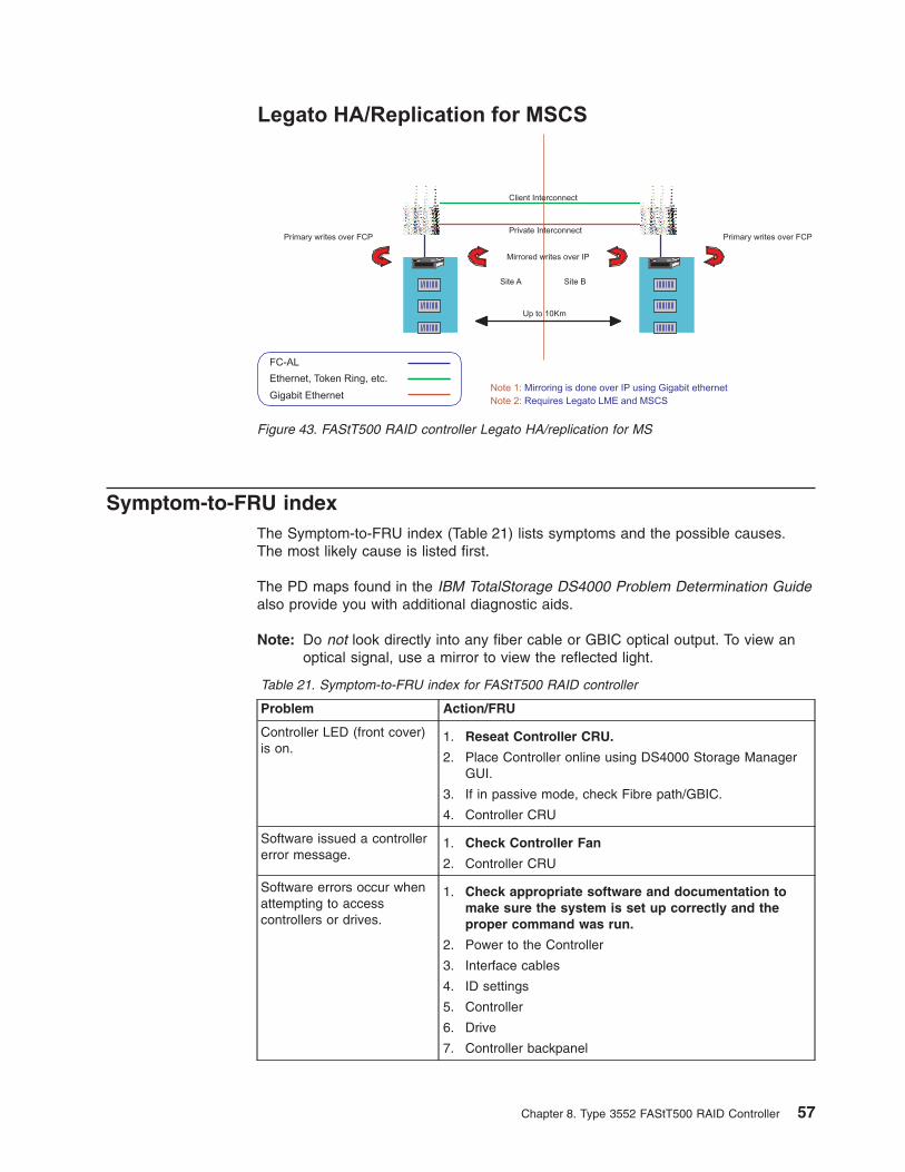
Symptom-to-FRU index
The Symptom-to-FRU index (Table 21) lists symptoms and the possible causes.
The most likely cause is listed first.
The PD maps found in the IBM TotalStorage DS4000 Problem Determination Guide
also provide you with additional diagnostic aids.
Note: Do not look directly into any fiber cable or GBIC optical output. To view an
optical signal, use a mirror to view the reflected light.
Table 21. Symptom-to-FRU index for FAStT500 RAID controller
Problem Action/FRU
Controller LED (front cover)
is on.
1. Reseat Controller CRU.
2. Place Controller online using DS4000 Storage Manager
GUI.
3. If in passive mode, check Fibre path/GBIC.
4. Controller CRU
Software issued a controller
error message.
1. Check Controller Fan
2. Controller CRU
Software errors occur when
attempting to access
controllers or drives.
1. Check appropriate software and documentation to
make sure the system is set up correctly and the
proper command was run.
2. Power to the Controller
3. Interface cables
4. ID settings
5. Controller
6. Drive
7. Controller backpanel
Note 1: Mirroring is done over IP using Gigabit ethernet
Note 2: Requires Legato LME and MSCS
Legato HA/Replication for MSCS
Primary writes over FCP
Client Interconnect
Private InterconnectPrimary writes over FCP
Mirrored writes over IP
Site A Site B
Up to 10Km
FC-AL
Ethernet, Token Ring, etc.
Gigabit Ethernet
Figure 43. FAStT500 RAID controller Legato HA/replication for MS
Chapter 8. Type 3552 FAStT500 RAID Controller 57
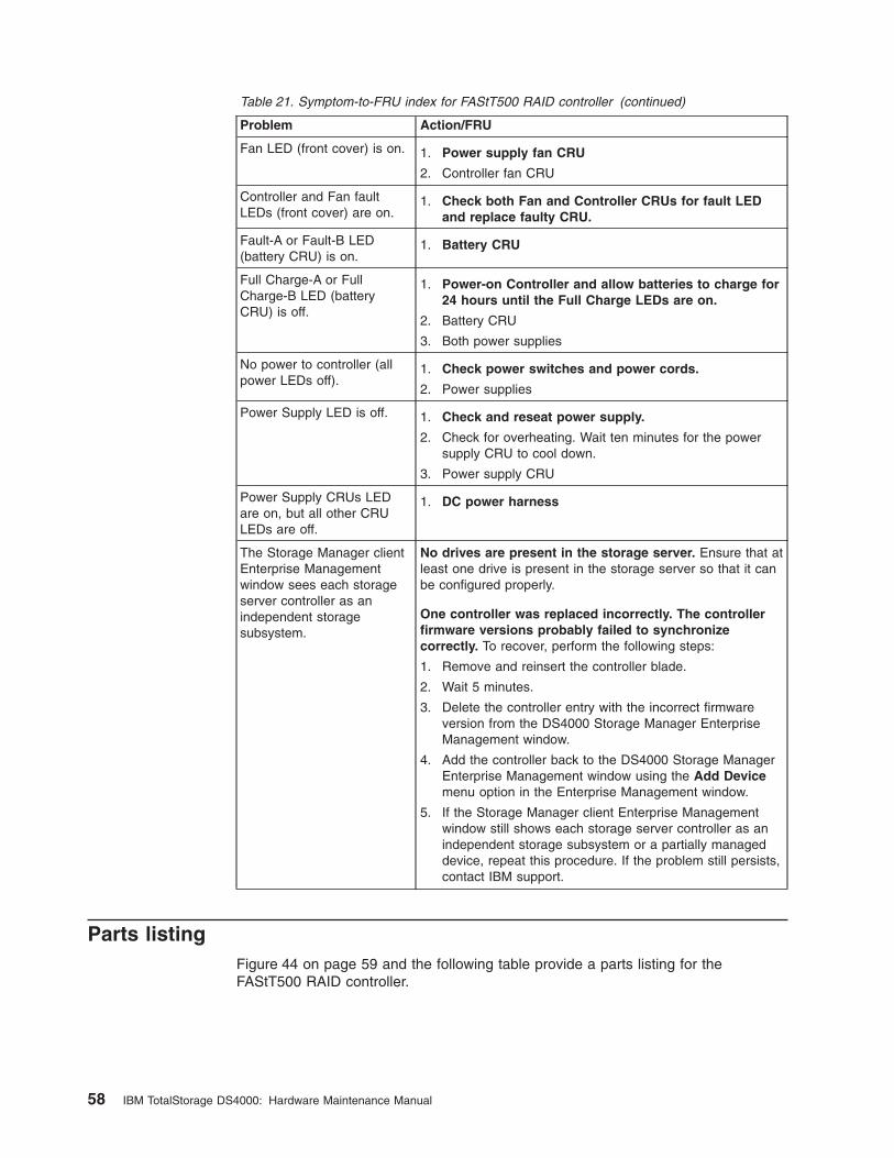
Table 21. Symptom-to-FRU index for FAStT500 RAID controller (continued)
Problem Action/FRU
Fan LED (front cover) is on. 1. Power supply fan CRU
2. Controller fan CRU
Controller and Fan fault
LEDs (front cover) are on.
1. Check both Fan and Controller CRUs for fault LED
and replace faulty CRU.
Fault-A or Fault-B LED
(battery CRU) is on.
1. Battery CRU
Full Charge-A or Full
Charge-B LED (battery
CRU) is off.
1. Power-on Controller and allow batteries to charge for
24 hours until the Full Charge LEDs are on.
2. Battery CRU
3. Both power supplies
No power to controller (all
power LEDs off).
1. Check power switches and power cords.
2. Power supplies
Power Supply LED is off. 1. Check and reseat power supply.
2. Check for overheating. Wait ten minutes for the power
supply CRU to cool down.
3. Power supply CRU
Power Supply CRUs LED
are on, but all other CRU
LEDs are off.
1. DC power harness
The Storage Manager client
Enterprise Management
window sees each storage
server controller as an
independent storage
subsystem.
No drives are present in the storage server. Ensure that at
least one drive is present in the storage server so that it can
be configured properly.
One controller was replaced incorrectly. The controller
firmware versions probably failed to synchronize
correctly. To recover, perform the following steps:
1. Remove and reinsert the controller blade.
2. Wait 5 minutes.
3. Delete the controller entry with the incorrect firmware
version from the DS4000 Storage Manager Enterprise
Management window.
4. Add the controller back to the DS4000 Storage Manager
Enterprise Management window using the Add Device
menu option in the Enterprise Management window.
5. If the Storage Manager client Enterprise Management
window still shows each storage server controller as an
independent storage subsystem or a partially managed
device, repeat this procedure. If the problem still persists,
contact IBM support.
Parts listing
Figure 44 on page 59 and the following table provide a parts listing for the
FAStT500 RAID controller.
58 IBM TotalStorage DS4000: Hardware Maintenance Manual
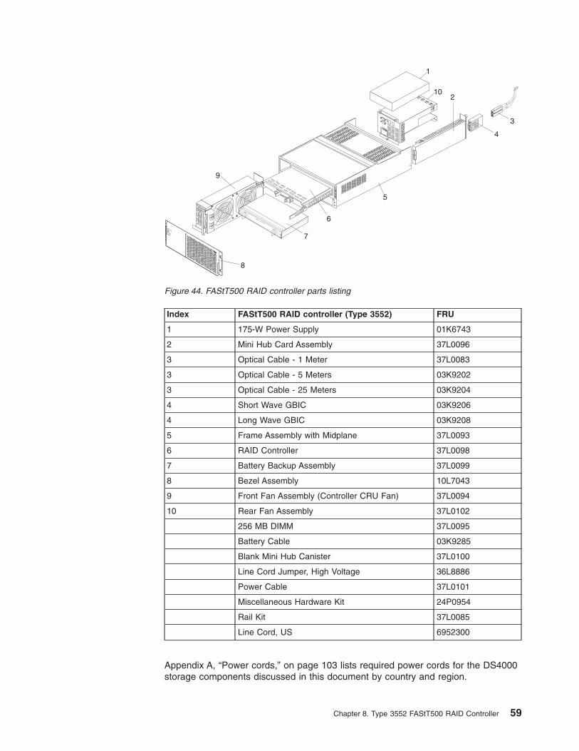
Index FAStT500 RAID controller (Type 3552) FRU
1 175-W Power Supply 01K6743
2 Mini Hub Card Assembly 37L0096
3 Optical Cable - 1 Meter 37L0083
3 Optical Cable - 5 Meters 03K9202
3 Optical Cable - 25 Meters 03K9204
4 Short Wave GBIC 03K9206
4 Long Wave GBIC 03K9208
5 Frame Assembly with Midplane 37L0093
6 RAID Controller 37L0098
7 Battery Backup Assembly 37L0099
8 Bezel Assembly 10L7043
9 Front Fan Assembly (Controller CRU Fan) 37L0094
10 Rear Fan Assembly 37L0102
256 MB DIMM 37L0095
Battery Cable 03K9285
Blank Mini Hub Canister 37L0100
Line Cord Jumper, High Voltage 36L8886
Power Cable 37L0101
Miscellaneous Hardware Kit 24P0954
Rail Kit 37L0085
Line Cord, US 6952300
Appendix A, “Power cords,” on page 103 lists required power cords for the DS4000
storage components discussed in this document by country and region.
102
5
6
7
8
9
3
4
.
..
.
.
..
.
.
..
.
.
..
.
1
Figure 44. FAStT500 RAID controller parts listing
Chapter 8. Type 3552 FAStT500 RAID Controller 59

60 IBM TotalStorage DS4000: Hardware Maintenance Manual
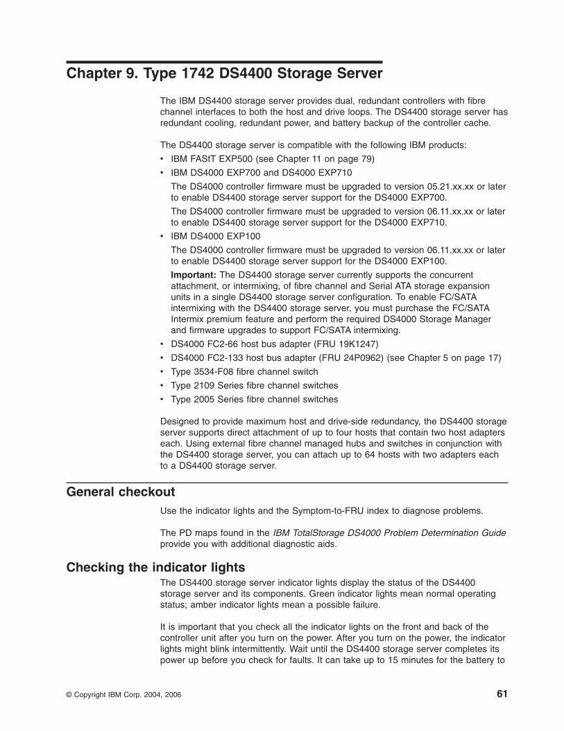
Chapter 9. Type 1742 DS4400 Storage Server
The IBM DS4400 storage server provides dual, redundant controllers with fibre
channel interfaces to both the host and drive loops. The DS4400 storage server has
redundant cooling, redundant power, and battery backup of the controller cache.
The DS4400 storage server is compatible with the following IBM products:
v IBM FAStT EXP500 (see Chapter 11 on page 79)
v IBM DS4000 EXP700 and DS4000 EXP710
The DS4000 controller firmware must be upgraded to version 05.21.xx.xx or later
to enable DS4400 storage server support for the DS4000 EXP700.
The DS4000 controller firmware must be upgraded to version 06.11.xx.xx or later
to enable DS4400 storage server support for the DS4000 EXP710.
v IBM DS4000 EXP100
The DS4000 controller firmware must be upgraded to version 06.11.xx.xx or later
to enable DS4400 storage server support for the DS4000 EXP100.
Important: The DS4400 storage server currently supports the concurrent
attachment, or intermixing, of fibre channel and Serial ATA storage expansion
units in a single DS4400 storage server configuration. To enable FC/SATA
intermixing with the DS4400 storage server, you must purchase the FC/SATA
Intermix premium feature and perform the required DS4000 Storage Manager
and firmware upgrades to support FC/SATA intermixing.
v DS4000 FC2-66 host bus adapter (FRU 19K1247)
v DS4000 FC2-133 host bus adapter (FRU 24P0962) (see Chapter 5 on page 17)
v Type 3534-F08 fibre channel switch
v Type 2109 Series fibre channel switches
v Type 2005 Series fibre channel switches
Designed to provide maximum host and drive-side redundancy, the DS4400 storage
server supports direct attachment of up to four hosts that contain two host adapters
each. Using external fibre channel managed hubs and switches in conjunction with
the DS4400 storage server, you can attach up to 64 hosts with two adapters each
to a DS4400 storage server.
General checkout
Use the indicator lights and the Symptom-to-FRU index to diagnose problems.
The PD maps found in the IBM TotalStorage DS4000 Problem Determination Guide
provide you with additional diagnostic aids.
Checking the indicator lights
The DS4400 storage server indicator lights display the status of the DS4400
storage server and its components. Green indicator lights mean normal operating
status; amber indicator lights mean a possible failure.
It is important that you check all the indicator lights on the front and back of the
controller unit after you turn on the power. After you turn on the power, the indicator
lights might blink intermittently. Wait until the DS4400 storage server completes its
power up before you check for faults. It can take up to 15 minutes for the battery to
© Copyright IBM Corp. 2004, 2006 61
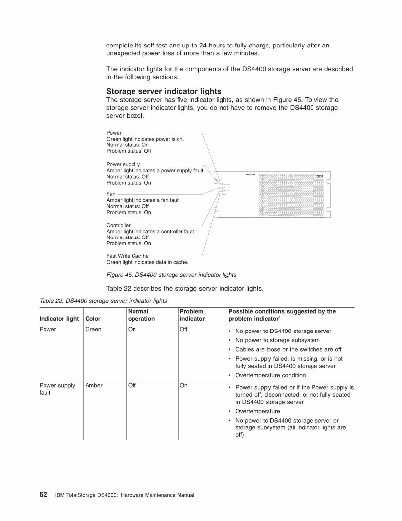
complete its self-test and up to 24 hours to fully charge, particularly after an
unexpected power loss of more than a few minutes.
The indicator lights for the components of the DS4400 storage server are described
in the following sections.
Storage server indicator lights
The storage server has five indicator lights, as shown in Figure 45. To view the
storage server indicator lights, you do not have to remove the DS4400 storage
server bezel.
Table 22 describes the storage server indicator lights.
Table 22. DS4400 storage server indicator lights
Indicator light Color
Normal
operation
Problem
indicator
Possible conditions suggested by the
problem indicator1
Power Green On Off v No power to DS4400 storage server
v No power to storage subsystem
v Cables are loose or the switches are off
v Power supply failed, is missing, or is not
fully seated in DS4400 storage server
v Overtemperature condition
Power supply
fault
Amber Off On v Power supply failed or if the Power supply is
turned off, disconnected, or not fully seated
in DS4400 storage server
v Overtemperature
v No power to DS4400 storage server or
storage subsystem (all indicator lights are
off)
FAStT700
PowerGreen light indicates power is on.Normal status: OnProblem status: Off
Power suppl yAmber light indicates a power supply fault.Normal status: OffProblem status: On
FanAmber light indicates a fan fault.Normal status: OffProblem status: On
Contr ollerAmber light indicates a controller fault.Normal status: OffProblem status: On
Fast Write Cac heGreen light indicates data in cache.
Figure 45. DS4400 storage server indicator lights
62 IBM TotalStorage DS4000: Hardware Maintenance Manual
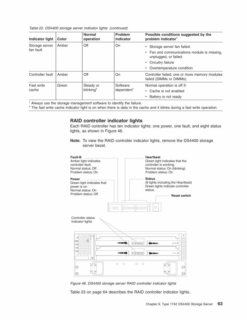
Table 22. DS4400 storage server indicator lights (continued)
Indicator light Color
Normal
operation
Problem
indicator
Possible conditions suggested by the
problem indicator1
Storage server
fan fault
Amber Off On v Storage server fan failed.
v Fan and communications module is missing,
unplugged, or failed.
v Circuitry failure
v Overtemperature condition
Controller fault Amber Off On Controller failed; one or more memory modules
failed (SIMMs or DIMMs).
Fast write
cache
Green Steady or
blinking2
Software
dependent1
Normal operation is off if:
v Cache is not enabled
v Battery is not ready
1 Always use the storage management software to identify the failure.
2 The fast write cache indicator light is on when there is data in the cache and it blinks during a fast write operation.
RAID controller indicator lights
Each RAID controller has ten indicator lights: one power, one fault, and eight status
lights, as shown in Figure 46.
Note: To view the RAID controller indicator lights, remove the DS4400 storage
server bezel.
Table 23 on page 64 describes the RAID controller indicator lights.
Fault-BAmber light indicatescontroller fault.Normal status: OffProblem status: On
PowerGreen light indicates thatpower is on.Normal status: OnProblem status: Off
HeartbeatGreen light indicates that thecontroller is working.Normal status: On (blinking)Problem status: On
Status(8 lights including the Heartbeat)Green lights indicate controllerstatus.
Controller statusindicator lights
Reset switch
Figure 46. DS4400 storage server RAID controller indicator lights
Chapter 9. Type 1742 DS4400 Storage Server 63
Table 23. DS4400 storage server RAID controller indicator lights
Indicator light Color
Normal
operation
Problem
indicator
Possible conditions suggested by the
problem indicator1
Power Green On Off v No power to storage subsystem
v Cables are loose or the switches are off
v Power supply failed, is missing, or is not
fully seated
v Overtemperature condition
Fault3 Amber Off On Controller failure; controller fault condition
Heartbeat Green Blinking Not blinking No controller activity
Status3 (seven
lights, not
including
Heartbeat)
Green Various patterns
depending on the
condition2
Various patterns
depending on
the condition2
If any status indicator lights are lit and the
controller is not offline, there is a memory fault
that indicates that the controller CRU failed.
1 Always use the storage management software to identify the failure.
2 There are eight status lights (the Heartbeat and seven others) that glow in various patterns, depending on the
controller status.
3 If the controller is offline, all of the indicator lights will be lit. This does not indicate failure.
Battery indicator lights
The battery has four indicator lights as shown in Figure 47.
Note: To view the battery indicator lights, remove the DS4400 storage server bezel.
Table 24 on page 65 describes the battery indicator lights.
Fault-BAmber light indicates a fault inthe left battery bank.Normal status: OffProblem status: On
Fault-AAmber light indicates a fault inthe left battery bank.Normal status: OffProblem status: On
Full Charge-BGreen light indicates the leftbattery bank is fully charged.Normal status: OnProblem status: OffChanging status: Blinking
Full Charge-AGreen light indicates the rightbattery bank is fully charged.Normal status: OnProblem status: OffChanging status: Blinking
Figure 47. DS4400 storage server battery indicator lights
64 IBM TotalStorage DS4000: Hardware Maintenance Manual

Table 24. DS4400 storage server battery indicator lights
Indicator light Color
Normal
operation
Problem
indicator
Possible conditions suggested by the
problem indicator1
Fault-A or
Fault-B
Amber Off On v Left or right battery bank failed
v Battery is either discharged or defective
Full Charge-A
or Full
Charge-B
Green On2 Off v Left or right battery bank is not fully charged
v Power has been off for an extended period
and has drained battery power
v Batteries are weak
1 Always use the storage management software to identify the failure.
2 If either Full Charge-A or Full Charge-B indicator light is blinking, the battery is in the process of charging.
Fan and communications module indicator light
The fan and communications module has one indicator light as shown in Figure 48.
Table 25 describes the fan and communications module indicator light.
Table 25. DS4400 storage server fan and communications module indicator light
Indicator light Color
Normal
operation
Problem
indicator
Possible conditions suggested by the
problem indicator1
Fan and
communication fault
Amber Off On v Fan and communications module failed
or is installed incorrectly
v Overtemperature condition
1 Always use the storage management software to identify the failure.
Power supply indicator light
The power supply has one indicator light, as shown in Figure 49 on page 66.
OUT
IN
!2 Gb/s1 Gb/s
OUT
IN
!2 Gb/s1 Gb/s
OUT
IN
!2 Gb/s1 Gb/s
OUT
IN
!2 Gb/s1 Gb/s
OUT
IN
!2 Gb/s1 Gb/s
OUT
IN
!2 Gb/s1 Gb/s
OUT
IN
!2 Gb/s1 Gb/s
OUT
IN
!2 Gb/s1 Gb/s
FaultAmber light indicates a fault in the fan andcommunications module.Normal status: OffProblem status: On
Figure 48. DS4400 storage server fan and communications module indicator light
Chapter 9. Type 1742 DS4400 Storage Server 65
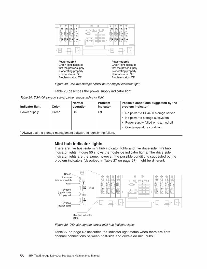
Table 26 describes the power supply indicator light.
Table 26. DS4400 storage server power supply indicator light
Indicator light Color
Normal
operation
Problem
indicator
Possible conditions suggested by the
problem indicator1
Power supply Green On Off v No power to DS4400 storage server
v No power to storage subsystem
v Power supply failed or is turned off
v Overtemperature condition
1 Always use the storage management software to identify the failure.
Mini hub indicator lights
There are five host-side mini hub indicator lights and five drive-side mini hub
indicator lights. Figure 50 shows the host-side indicator lights. The drive side
indicator lights are the same; however, the possible conditions suggested by the
problem indicators (described in Table 27 on page 67) might be different.
Table 27 on page 67 describes the indicator light status when there are fibre
channel connections between host-side and drive-side mini hubs.
OUT
IN
!2 Gb/s1 Gb/s
OUT
IN
!2 Gb/s1 Gb/s
OUT
IN
!2 Gb/s1 Gb/s
OUT
IN
!2 Gb/s1 Gb/s
OUT
IN
!2 Gb/s1 Gb/s
OUT
IN
!2 Gb/s1 Gb/s
OUT
IN
!2 Gb/s1 Gb/s
OUT
IN
!2 Gb/s1 Gb/s
Power supplyGreen light indicatesthat the power supplyis operating properly.Normal status: OnProblem status: Off
Power supplyGreen light indicatesthat the power supplyis operating properly.Normal status: OnProblem status: Off
Figure 49. DS4400 storage server power supply indicator light
OUT
IN
!2 Gb/s1 Gb/s
OUT
IN
!2 Gb/s1 Gb/s
OUT
IN
!2 Gb/s1 Gb/s
OUT
IN
!2 Gb/s1 Gb/s
OUT
IN
!2 Gb/s1 Gb/s
OUT
IN
!2 Gb/s1 Gb/s
OUT
IN
!2 Gb/s1 Gb/s
OUT
IN
!2 Gb/s1 Gb/s
OUT
IN
!2 Gb/s1 Gb/s
OUT
Speed
Bypass(upper port)
Bypass(lower port)
Loop good
Fault
Mini-hub indicatorlights
Link rateinterface switch
Figure 50. DS4400 storage server mini hub indicator lights
66 IBM TotalStorage DS4000: Hardware Maintenance Manual
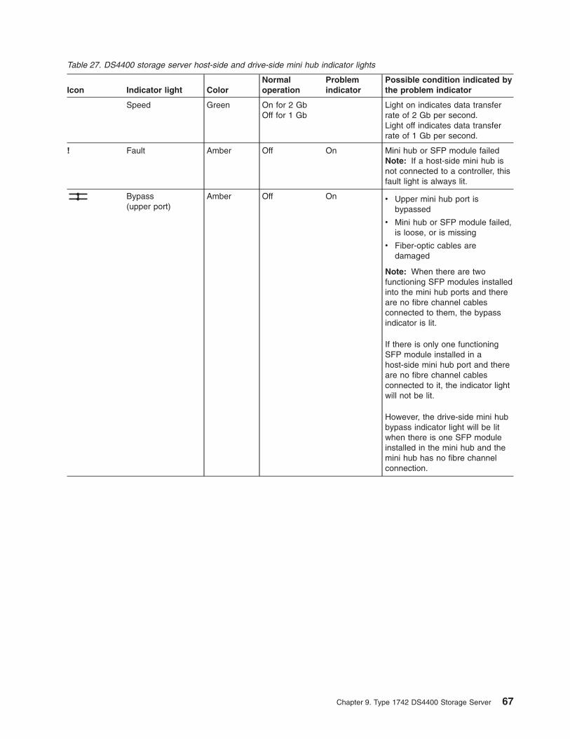
Table 27. DS4400 storage server host-side and drive-side mini hub indicator lights
Icon Indicator light Color
Normal
operation
Problem
indicator
Possible condition indicated by
the problem indicator
Speed Green On for 2 Gb
Off for 1 Gb
Light on indicates data transfer
rate of 2 Gb per second.
Light off indicates data transfer
rate of 1 Gb per second.
! Fault Amber Off On Mini hub or SFP module failed
Note: If a host-side mini hub is
not connected to a controller, this
fault light is always lit.
Bypass
(upper port)
Amber Off On v Upper mini hub port is
bypassed
v Mini hub or SFP module failed,
is loose, or is missing
v Fiber-optic cables are
damaged
Note: When there are two
functioning SFP modules installed
into the mini hub ports and there
are no fibre channel cables
connected to them, the bypass
indicator is lit.
If there is only one functioning
SFP module installed in a
host-side mini hub port and there
are no fibre channel cables
connected to it, the indicator light
will not be lit.
However, the drive-side mini hub
bypass indicator light will be lit
when there is one SFP module
installed in the mini hub and the
mini hub has no fibre channel
connection.
Chapter 9. Type 1742 DS4400 Storage Server 67
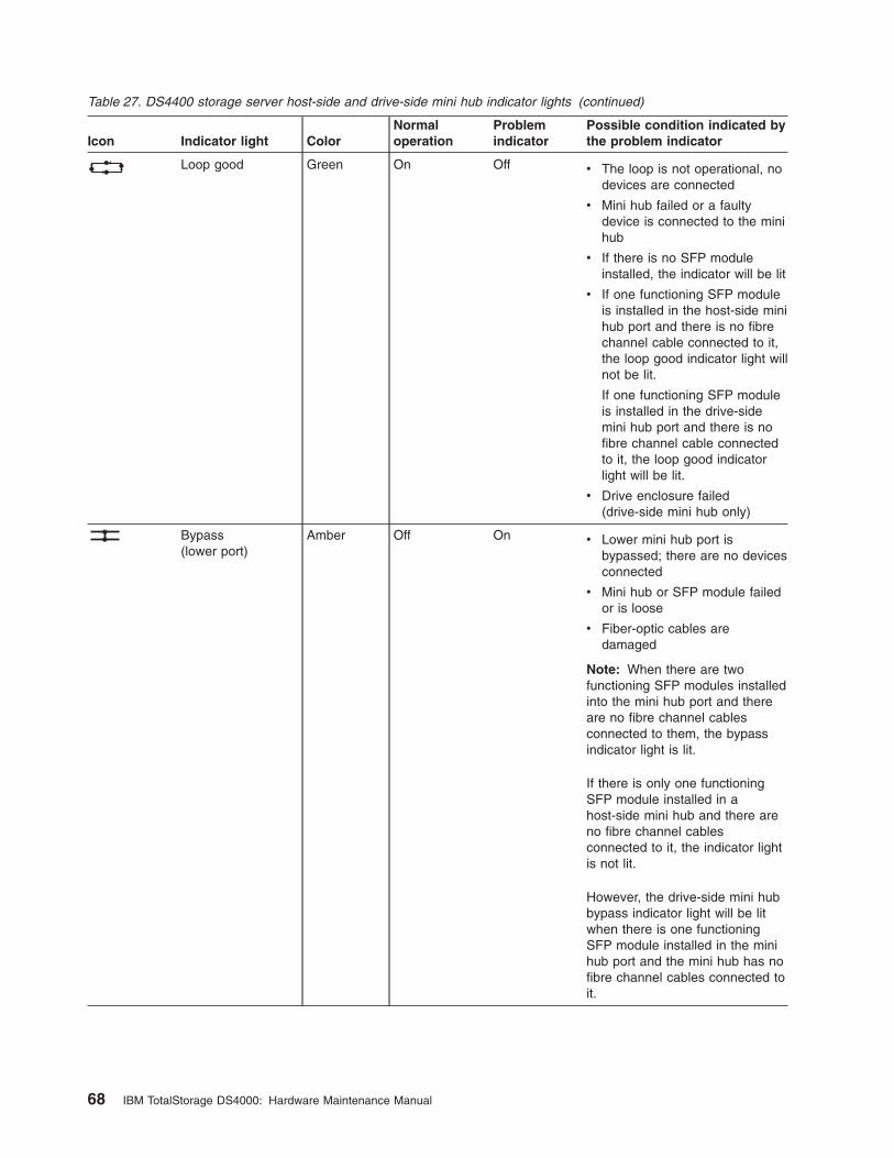
Table 27. DS4400 storage server host-side and drive-side mini hub indicator lights (continued)
Icon Indicator light Color
Normal
operation
Problem
indicator
Possible condition indicated by
the problem indicator
Loop good Green On Off v The loop is not operational, no
devices are connected
v Mini hub failed or a faulty
device is connected to the mini
hub
v If there is no SFP module
installed, the indicator will be lit
v If one functioning SFP module
is installed in the host-side mini
hub port and there is no fibre
channel cable connected to it,
the loop good indicator light will
not be lit.
If one functioning SFP module
is installed in the drive-side
mini hub port and there is no
fibre channel cable connected
to it, the loop good indicator
light will be lit.
v Drive enclosure failed
(drive-side mini hub only)
Bypass
(lower port)
Amber Off On v Lower mini hub port is
bypassed; there are no devices
connected
v Mini hub or SFP module failed
or is loose
v Fiber-optic cables are
damaged
Note: When there are two
functioning SFP modules installed
into the mini hub port and there
are no fibre channel cables
connected to them, the bypass
indicator light is lit.
If there is only one functioning
SFP module installed in a
host-side mini hub and there are
no fibre channel cables
connected to it, the indicator light
is not lit.
However, the drive-side mini hub
bypass indicator light will be lit
when there is one functioning
SFP module installed in the mini
hub port and the mini hub has no
fibre channel cables connected to
it.
68 IBM TotalStorage DS4000: Hardware Maintenance Manual

Using the diagnostic hardware
The DS4400 storage server comes with a wrap-plug adapter and LC coupler. The
wrap-plug adapter and LC coupler are used to identify Fibre channel path problems.
The loopback and sendEcho tests are described in the IBM TotalStorage DS4000
Problem Determination Guide.
Symptom-to-FRU index
The Symptom-to-FRU index (Table 28) lists symptoms and the possible causes.
The most likely cause is listed first.
The problem determination (PD) maps found in the IBM TotalStorage DS4000
Problem Determination Guide provide you with additional diagnostic aids.
Table 28. Symptom-to-FRU index for DS4400 storage server
Problem Action/FRU
Controller LED (front cover)
is on.
1. Reseat Controller CRU.
2. Place Controller online using DS4000 Storage Manager
GUI.
3. If in passive mode, check Fibre path/GBIC.
4. Controller CRU
Software issued a controller
error message.
1. Check Controller Fan
2. Controller CRU
Software errors occur when
attempting to access
controllers or drives.
1. Check appropriate software and documentation to
make sure the system is set up correctly and the
proper command was run.
2. Power to the Controller
3. Interface cables
4. ID settings
5. Controller
6. Drive
7. Controller backpanel
Fan LED (front cover) is on. 1. Power supply fan CRU
2. Controller fan CRU
Controller and Fan fault
LEDs (front cover) are on.
1. Check both Fan and Controller CRUs for fault LED
and replace faulty CRU.
Fault-A or Fault-B LED
(battery CRU) is on.
1. Battery CRU
Full Charge-A or Full
Charge-B LED (battery
CRU) is off.
1. Power-on Controller and allow batteries to charge for
24 hours until the Full Charge LEDs are on.
2. Battery CRU
3. Both power supplies
No power to controller (all
power LEDs off).
1. Check power switches and power cords.
2. Power supplies
Power Supply LED is off. 1. Check and reseat power supply.
2. Check for overheating. Wait ten minutes for the power
supply CRU to cool down.
3. Power supply CRU
Chapter 9. Type 1742 DS4400 Storage Server 69
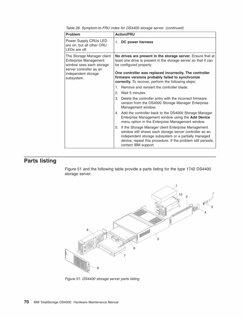
Table 28. Symptom-to-FRU index for DS4400 storage server (continued)
Problem Action/FRU
Power Supply CRUs LED
are on, but all other CRU
LEDs are off.
1. DC power harness
The Storage Manager client
Enterprise Management
window sees each storage
server controller as an
independent storage
subsystem.
No drives are present in the storage server. Ensure that at
least one drive is present in the storage server so that it can
be configured properly.
One controller was replaced incorrectly. The controller
firmware versions probably failed to synchronize
correctly. To recover, perform the following steps:
1. Remove and reinsert the controller blade.
2. Wait 5 minutes.
3. Delete the controller entry with the incorrect firmware
version from the DS4000 Storage Manager Enterprise
Management window.
4. Add the controller back to the DS4000 Storage Manager
Enterprise Management window using the Add Device
menu option in the Enterprise Management window.
5. If the Storage Manager client Enterprise Management
window still shows each storage server controller as an
independent storage subsystem or a partially managed
device, repeat this procedure. If the problem still persists,
contact IBM support.
Parts listing
Figure 51 and the following table provide a parts listing for the type 1742 DS4400
storage server.
102
5
6
7
8
9
3
4
.
..
.
.
..
.
.
..
.
.
..
.
1
Figure 51. DS4400 storage server parts listing
70 IBM TotalStorage DS4000: Hardware Maintenance Manual
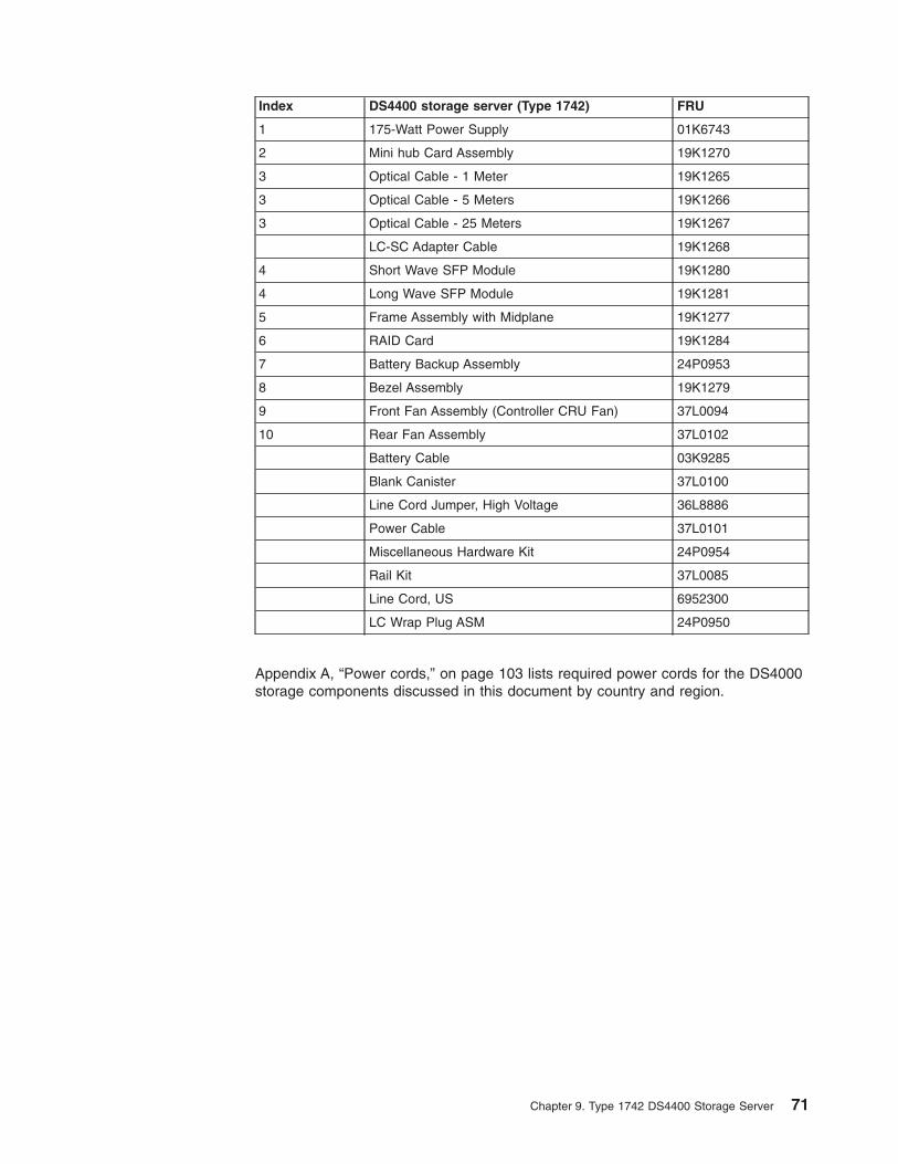
Index DS4400 storage server (Type 1742) FRU
1 175-Watt Power Supply 01K6743
2 Mini hub Card Assembly 19K1270
3 Optical Cable - 1 Meter 19K1265
3 Optical Cable - 5 Meters 19K1266
3 Optical Cable - 25 Meters 19K1267
LC-SC Adapter Cable 19K1268
4 Short Wave SFP Module 19K1280
4 Long Wave SFP Module 19K1281
5 Frame Assembly with Midplane 19K1277
6 RAID Card 19K1284
7 Battery Backup Assembly 24P0953
8 Bezel Assembly 19K1279
9 Front Fan Assembly (Controller CRU Fan) 37L0094
10 Rear Fan Assembly 37L0102
Battery Cable 03K9285
Blank Canister 37L0100
Line Cord Jumper, High Voltage 36L8886
Power Cable 37L0101
Miscellaneous Hardware Kit 24P0954
Rail Kit 37L0085
Line Cord, US 6952300
LC Wrap Plug ASM 24P0950
Appendix A, “Power cords,” on page 103 lists required power cords for the DS4000
storage components discussed in this document by country and region.
Chapter 9. Type 1742 DS4400 Storage Server 71

72 IBM TotalStorage DS4000: Hardware Maintenance Manual
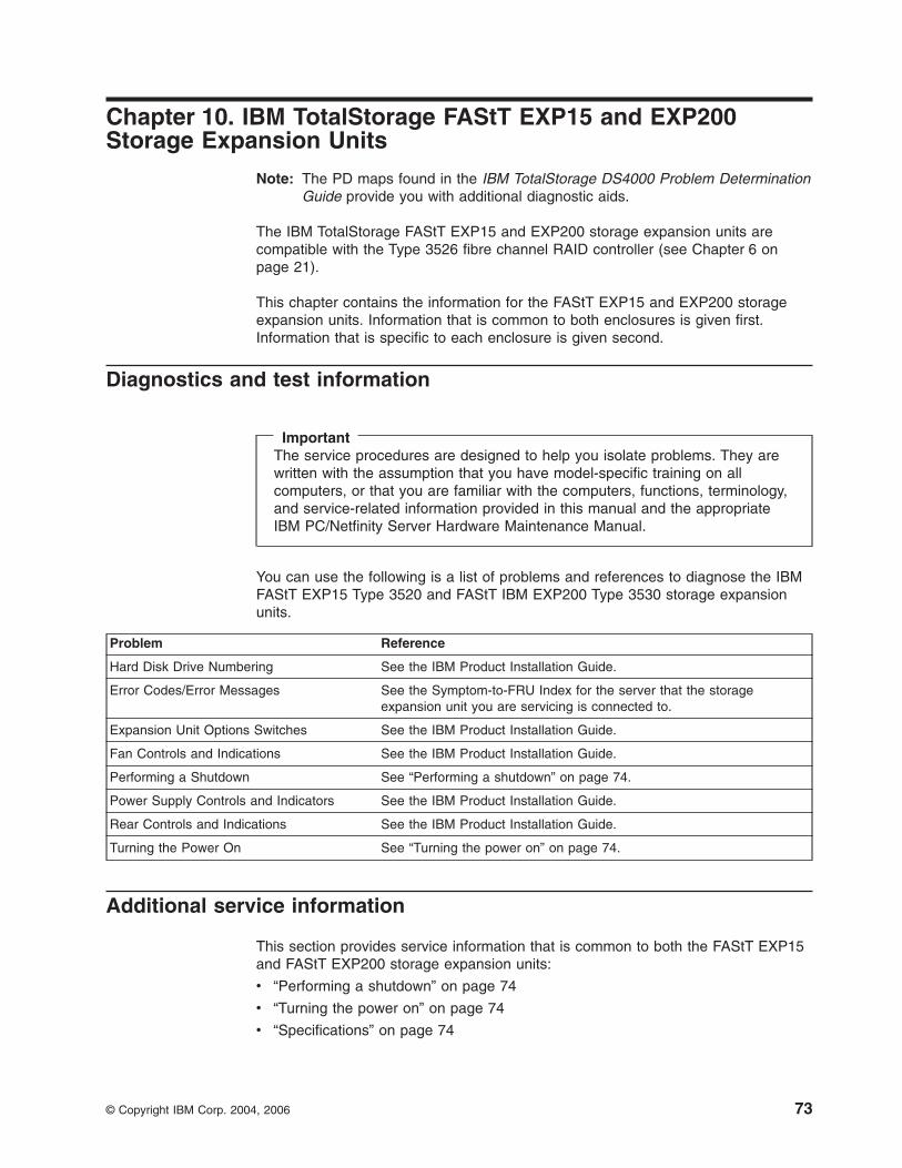
Chapter 10. IBM TotalStorage FAStT EXP15 and EXP200
Storage Expansion Units
Note: The PD maps found in the IBM TotalStorage DS4000 Problem Determination
Guide provide you with additional diagnostic aids.
The IBM TotalStorage FAStT EXP15 and EXP200 storage expansion units are
compatible with the Type 3526 fibre channel RAID controller (see Chapter 6 on
page 21).
This chapter contains the information for the FAStT EXP15 and EXP200 storage
expansion units. Information that is common to both enclosures is given first.
Information that is specific to each enclosure is given second.
Diagnostics and test information
Important
The service procedures are designed to help you isolate problems. They are
written with the assumption that you have model-specific training on all
computers, or that you are familiar with the computers, functions, terminology,
and service-related information provided in this manual and the appropriate
IBM PC/Netfinity Server Hardware Maintenance Manual.
You can use the following is a list of problems and references to diagnose the IBM
FAStT EXP15 Type 3520 and FAStT IBM EXP200 Type 3530 storage expansion
units.
Problem Reference
Hard Disk Drive Numbering See the IBM Product Installation Guide.
Error Codes/Error Messages See the Symptom-to-FRU Index for the server that the storage
expansion unit you are servicing is connected to.
Expansion Unit Options Switches See the IBM Product Installation Guide.
Fan Controls and Indications See the IBM Product Installation Guide.
Performing a Shutdown See “Performing a shutdown” on page 74.
Power Supply Controls and Indicators See the IBM Product Installation Guide.
Rear Controls and Indications See the IBM Product Installation Guide.
Turning the Power On See “Turning the power on” on page 74.
Additional service information
This section provides service information that is common to both the FAStT EXP15
and FAStT EXP200 storage expansion units:
v “Performing a shutdown” on page 74
v “Turning the power on” on page 74
v “Specifications” on page 74
© Copyright IBM Corp. 2004, 2006 73
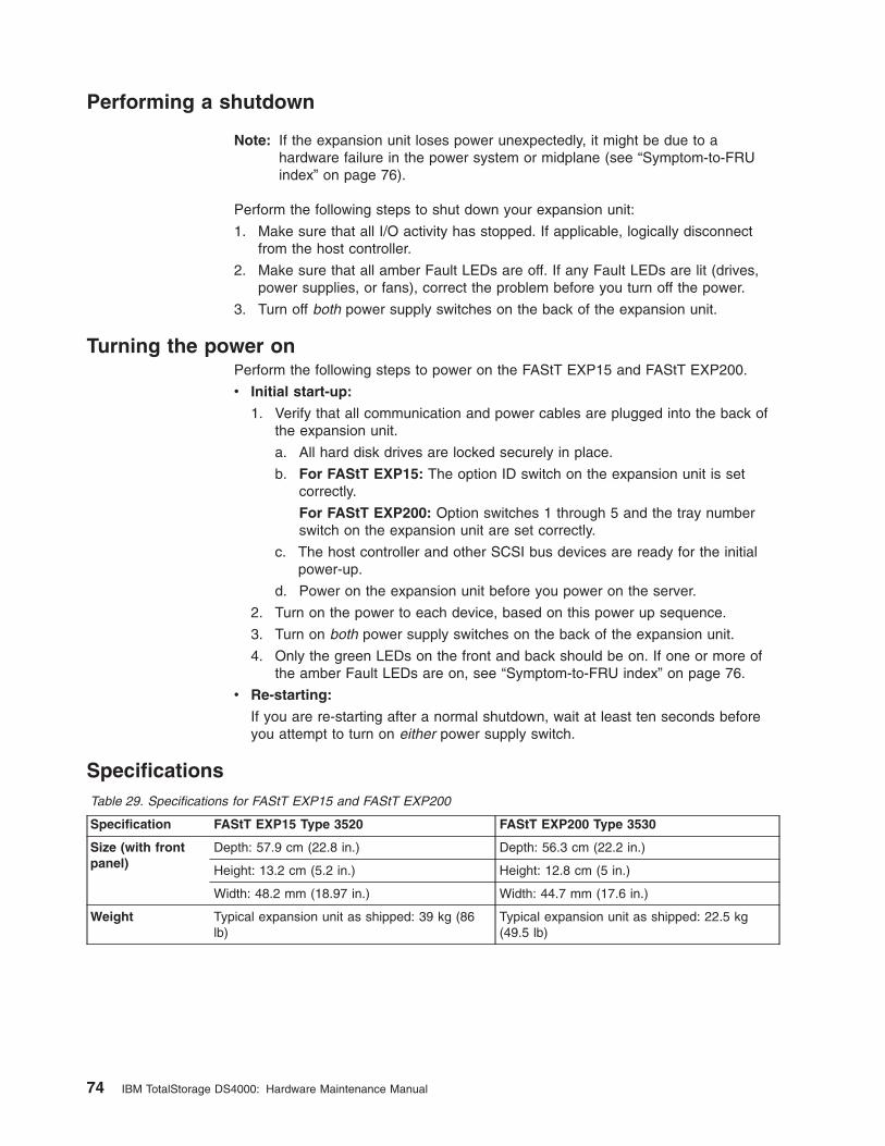
Performing a shutdown
Note: If the expansion unit loses power unexpectedly, it might be due to a
hardware failure in the power system or midplane (see “Symptom-to-FRU
index” on page 76).
Perform the following steps to shut down your expansion unit:
1. Make sure that all I/O activity has stopped. If applicable, logically disconnect
from the host controller.
2. Make sure that all amber Fault LEDs are off. If any Fault LEDs are lit (drives,
power supplies, or fans), correct the problem before you turn off the power.
3. Turn off both power supply switches on the back of the expansion unit.
Turning the power on
Perform the following steps to power on the FAStT EXP15 and FAStT EXP200.
v Initial start-up:
1. Verify that all communication and power cables are plugged into the back of
the expansion unit.
a. All hard disk drives are locked securely in place.
b. For FAStT EXP15: The option ID switch on the expansion unit is set
correctly.
For FAStT EXP200: Option switches 1 through 5 and the tray number
switch on the expansion unit are set correctly.
c. The host controller and other SCSI bus devices are ready for the initial
power-up.
d. Power on the expansion unit before you power on the server.
2. Turn on the power to each device, based on this power up sequence.
3. Turn on both power supply switches on the back of the expansion unit.
4. Only the green LEDs on the front and back should be on. If one or more of
the amber Fault LEDs are on, see “Symptom-to-FRU index” on page 76.
v Re-starting:
If you are re-starting after a normal shutdown, wait at least ten seconds before
you attempt to turn on either power supply switch.
Specifications
Table 29. Specifications for FAStT EXP15 and FAStT EXP200
Specification FAStT EXP15 Type 3520 FAStT EXP200 Type 3530
Size (with front
panel)
Depth: 57.9 cm (22.8 in.) Depth: 56.3 cm (22.2 in.)
Height: 13.2 cm (5.2 in.) Height: 12.8 cm (5 in.)
Width: 48.2 mm (18.97 in.) Width: 44.7 mm (17.6 in.)
Weight Typical expansion unit as shipped: 39 kg (86
lb)
Typical expansion unit as shipped: 22.5 kg
(49.5 lb)
74 IBM TotalStorage DS4000: Hardware Maintenance Manual

Table 29. Specifications for FAStT EXP15 and FAStT EXP200 (continued)
Specification FAStT EXP15 Type 3520 FAStT EXP200 Type 3530
Electrical Input: Sign-wave input (50 to 60 Hz)
v Low range: Minimum: 90 V ac / Maximum: 127 V ac
v High range: Minimum: 198 V ac / Maximum: 257 V ac
Input Kilovolt-amperes (kVA) approximately
v Minimum configuration: 0.06 kVA
v Maximum configuration: 0.39 kVA
Environment Air Flow: Air flow is from front to back
Air temperature:
v Expansion unit on:
10° to 35° C (50° to 95° F)
Altitude: 0 to 914 m (3000 ft.)
v Expansion unit on:
10° to 32 °C (50° to 90° F)
Altitude: 914 m (3000 ft.) to 2133 m (7000 ft.)
Humidity: 10% to 80%
Heat Output Approximate heat output in British Thermal Units (BTU) per hour:
v Minimum configuration: 205.2 BTU (60 watts)
v Maximum configuration: 1333.8 BTU (390 watts)
Acoustical Noise
Emissions Values
For open bay (0 hard disk drives installed) and typical system configurations (8 hard disk drives
installed).
v Sound Power (idling):
– 6.2 bels (open bay)
– 6.4 bels (typical)
v Sound Power (operating):
– 6.2 bels (open bay)
– 6.5 bels (typical)
v Sound Pressure (idling):
– 47 dBA (open bay)
– 49 dBA (typical)
v Sound Pressure (operating):
– 47 dBA (open bay)
– 50 dBA (typical)
v Sound Power (idling):
– 6.3 bels (open bay)
– 6.5 bels (typical)
v Sound Power (operating):
– 6.3 bels (open bay)
– 6.6 bels (typical)
v Sound Pressure (idling):
– 47 dBA (open bay)
– 49 dBA (typical)
v Sound Pressure (operating):
– 47 dBA (open bay)
– 50 dBA (typical)
These levels are measured in controlled acoustical environments according to ISO 7779 and
are reported in accordance with ISO 9296. The declared sound power levels indicate an upper
limit, below which a large portion of machines operate. Sound pressure levels in your location
might exceed the average 1-meter values stated because of room reflections and other nearby
noise.
Chapter 10. IBM TotalStorage FAStT EXP15 and EXP200 Storage Expansion Units 75
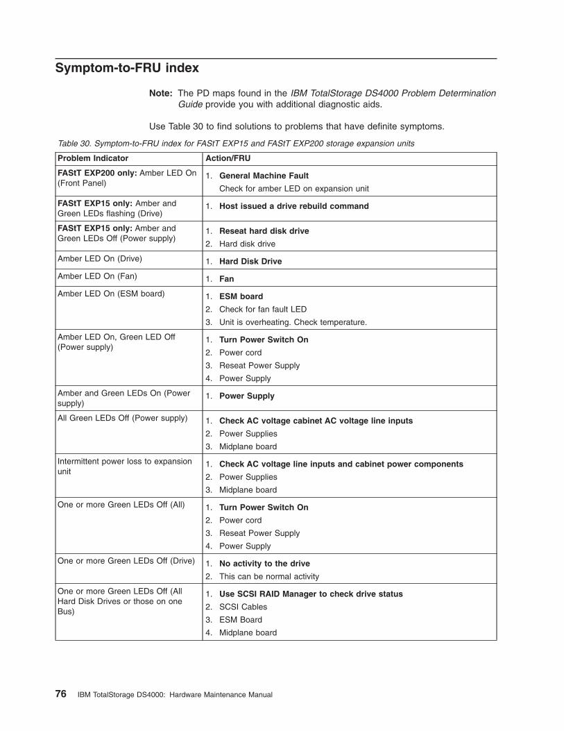
Symptom-to-FRU index
Note: The PD maps found in the IBM TotalStorage DS4000 Problem Determination
Guide provide you with additional diagnostic aids.
Use Table 30 to find solutions to problems that have definite symptoms.
Table 30. Symptom-to-FRU index for FAStT EXP15 and FAStT EXP200 storage expansion units
Problem Indicator Action/FRU
FAStT EXP200 only: Amber LED On
(Front Panel)
1. General Machine Fault
Check for amber LED on expansion unit
FAStT EXP15 only: Amber and
Green LEDs flashing (Drive)
1. Host issued a drive rebuild command
FAStT EXP15 only: Amber and
Green LEDs Off (Power supply)
1. Reseat hard disk drive
2. Hard disk drive
Amber LED On (Drive) 1. Hard Disk Drive
Amber LED On (Fan) 1. Fan
Amber LED On (ESM board) 1. ESM board
2. Check for fan fault LED
3. Unit is overheating. Check temperature.
Amber LED On, Green LED Off
(Power supply)
1. Turn Power Switch On
2. Power cord
3. Reseat Power Supply
4. Power Supply
Amber and Green LEDs On (Power
supply)
1. Power Supply
All Green LEDs Off (Power supply) 1. Check AC voltage cabinet AC voltage line inputs
2. Power Supplies
3. Midplane board
Intermittent power loss to expansion
unit
1. Check AC voltage line inputs and cabinet power components
2. Power Supplies
3. Midplane board
One or more Green LEDs Off (All) 1. Turn Power Switch On
2. Power cord
3. Reseat Power Supply
4. Power Supply
One or more Green LEDs Off (Drive) 1. No activity to the drive
2. This can be normal activity
One or more Green LEDs Off (All
Hard Disk Drives or those on one
Bus)
1. Use SCSI RAID Manager to check drive status
2. SCSI Cables
3. ESM Board
4. Midplane board
76 IBM TotalStorage DS4000: Hardware Maintenance Manual
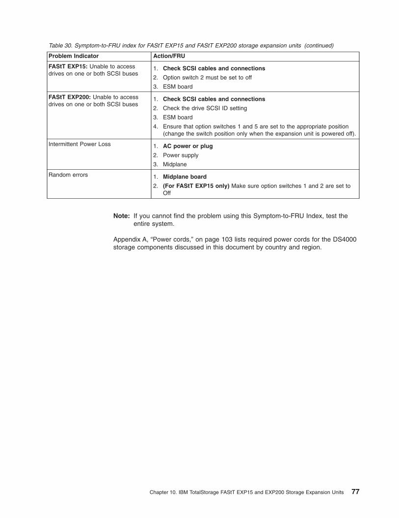
Table 30. Symptom-to-FRU index for FAStT EXP15 and FAStT EXP200 storage expansion units (continued)
Problem Indicator Action/FRU
FAStT EXP15: Unable to access
drives on one or both SCSI buses
1. Check SCSI cables and connections
2. Option switch 2 must be set to off
3. ESM board
FAStT EXP200: Unable to access
drives on one or both SCSI buses
1. Check SCSI cables and connections
2. Check the drive SCSI ID setting
3. ESM board
4. Ensure that option switches 1 and 5 are set to the appropriate position
(change the switch position only when the expansion unit is powered off).
Intermittent Power Loss 1. AC power or plug
2. Power supply
3. Midplane
Random errors 1. Midplane board
2. (For FAStT EXP15 only) Make sure option switches 1 and 2 are set to
Off
Note: If you cannot find the problem using this Symptom-to-FRU Index, test the
entire system.
Appendix A, “Power cords,” on page 103 lists required power cords for the DS4000
storage components discussed in this document by country and region.
Chapter 10. IBM TotalStorage FAStT EXP15 and EXP200 Storage Expansion Units 77

78 IBM TotalStorage DS4000: Hardware Maintenance Manual

Chapter 11. IBM TotalStorage FAStT EXP500 Storage
Expansion Unit
Note: The PD maps found in the IBM TotalStorage DS4000 Problem Determination
Guide provide you with additional diagnostic aids.
The IBM TotalStorage FAStT EXP500 storage expansion unit is compatible with the
following IBM products:
v Type 3552 FAStT500 RAID controller (see Chapter 8 on page 47)
v Type 1742 DS4400 storage server (see Chapter 9 on page 61)
v FAStT200 type 3542 and FAStT200 HA type 3542 (see Chapter 7 on page 35)
Diagnostics and test information
The following list of problems and references is for diagnosing the IBM FAStT
EXP500 Type 3530 storage expansion unit.
Problem Reference
Hard Disk Drive Numbering IBM Product Installation Guide
Error Codes/Error Messages Symptom-to-FRU Index for the server that the storage expansion unit you
are servicing is connected to
Expansion Unit Options Switches IBM Product Installation Guide
Front Controls and Indications IBM Product Installation Guide
Rear Controls and Indications IBM Product Installation Guide
Additional service information
This section provides information on the following topics:
v “Turning the expansion unit on and off”
v “Performing an emergency shutdown” on page 81
v “Restoring power after an emergency” on page 81
v “Specifications” on page 81
Turning the expansion unit on and off
This section contains instructions for turning the expansion unit on and off under
normal and emergency circumstances.
If you are turning on the expansion unit after an emergency shutdown or power
outage, see “Restoring power after an emergency” on page 81.
Turning on the expansion unit
Perform the following steps to turn on the power for the initial startup of the
expansion unit:
1. Verify that:
a. All communication and power cables are plugged into the back of the
expansion unit and an ac power outlet.
b. All hard disk drives are locked securely in place.
c. The tray number switches on the expansion unit are set correctly. (See the
IBM Product Installation Guide for more information.)
© Copyright IBM Corp. 2004, 2006 79
2. Check the system documentation for all the hardware devices you intend to turn
on and determine the proper startup sequence.
Note: Be sure to turn on the IBM FAStT EXP500 before you turn on the server.
3. Turn on the power to each device, based on the startup sequence.
Attention: If you are restarting the system after a normal shutdown, wait at
least 10 seconds before you turn on the power supply switches.
4. Turn on both power supply switches on the back of the unit.
The expansion unit might take a few seconds to power up. During this time, you
might see the amber and green LEDs on the expansion unit turn on and off
intermittently. When the startup sequence is complete, only the green LEDs on
the front and back and the amber Bypass LEDs for unconnected GBIC ports
should remain on. If other amber LEDs remain lit, see “Symptom-to-FRU index”
on page 83.
Turning off the expansion unit
Attention: Except in an emergency, never turn off the power if any Fault LEDs
are lit on the expansion unit. Correct the fault before you turn off the power, using
the proper troubleshooting or servicing procedure. This action ensures that the
expansion unit will power up correctly later. For guidance, see “Symptom-to-FRU
index” on page 83.
The expansion unit is designed to run continuously, 24 hours a day. After you turn
on the expansion unit, do not turn it off. Turn off the power only when:
v Instructions in a hardware or software procedure require you to turn off the
power.
v A service technician tells you to turn off the power.
v A power outage or emergency situation occurs (see “Performing an emergency
shutdown” on page 81).
CAUTION:
The power control button on the device and the power switch on the power
supply do not turn off the electrical current supplied to the device. The device
also might have more than one power cord. To remove all electrical current
from the device, ensure that all power cords are disconnected from the power
source.
Perform the following steps to turn off the power:
1. Check the system documentation for all hardware devices you intend to turn off
and determine the proper power-down sequence.
2. Make sure that all I/O activity has stopped.
3. Make sure that all amber Fault LEDs are off. If any Fault LEDs are lit (drives,
power supplies, or fans), correct the problem before you turn off the power. For
guidance, see “Symptom-to-FRU index” on page 83.
4. Turn off both power supply switches on the back on the expansion unit.
80 IBM TotalStorage DS4000: Hardware Maintenance Manual
Performing an emergency shutdown
Attention: Emergency situations might include fire, flood, extreme weather
conditions, or other hazardous circumstances. If a power outage or emergency
situation occurs, always turn off all power switches on all computing equipment.
This action helps safeguard your equipment from potential damage due to electrical
surges when power is restored. If the expansion unit loses power unexpectedly, it
might be due to a hardware failure in the power system or midplane (see
“Symptom-to-FRU index” on page 83).
Perform the following steps to shut down during an emergency:
1. If you have time, stop all activity and check the LEDs (front and back). Make
note of any Fault LEDs that are lit so that you can correct the problem when
you turn on the power again.
2. Turn off all power supply switches; then, unplug the power cords from the
expansion unit.
Restoring power after an emergency
Perform the following steps to restart the expansion unit if you turned off the power
supply switches during an emergency shut down, or if a power failure or a power
outage occurred:
1. After the emergency situation is over or power is restored, check the expansion
unit for damage. If there is no visible damage, continue with step 2; otherwise,
have your system serviced.
2. After you have checked for damage, ensure that the power switches are in the
off position; then, plug in the expansion unit power cords.
3. Check the system documentation for the hardware devices you intend to power
up and determine the proper startup sequence.
Note: Be sure to turn on the FAStT EXP500 before you turn on the server.
4. Turn on the power to each device, based on the startup sequence.
5. Turn on both power supply switches on the back of the FAStT EXP500.
6. Only the green LEDs on the front and back and the amber Bypass LEDs for
unconnected GBIC ports should remain on. If other amber Fault LEDs are on,
see “Symptom-to-FRU index” on page 83 for instructions.
7. Use your installed software application as appropriate to check the status of the
expansion unit.
Specifications
The following gives the operating specifications of the FAStT EXP500.
Size (with front panel and without mounting rails)
v Depth: 56.3 cm (22.2 in)
v Height: 12.8 cm (5 in)
v Width: 44.7 cm (17.6 in)
Weight
v Standard expansion unit as shipped: 25 kg (54.5 lbs)
v Typical expansion unit fully loaded: 35.5 kg (78 lbs)
Electrical input
v Sine-wave input (50 to 60 Hz) is required
Chapter 11. IBM TotalStorage FAStT EXP500 Storage Expansion Unit 81
v Input Voltage:
– Low range:
- Minimum: 90 V ac
- Maximum: 127 V ac
– High range:
- Minimum: 198 V ac
- Maximum: 257 V ac
– Input kilovolt-amperes (kVA) approximately:
- Minimum configuration: 0.06 kVA
- Maximum configuration: 0.36 kVA
Environment
v Air temperature:
– Expansion unit on:
10° to 35° C
(50° to 95° F)
Altitude: 0 to 914 m (3000 ft.)
– Expansion unit on:
10° to 32° C
(50° to 90° F)
Altitude: 914 m (3000 ft.) to 2133 m (7000 ft.)
v Humidity:
– 8% to 80%
Acoustical noise emissions values
For open bay (0 drives installed) and typical system configurations (8
hard drives installed).
– Sound Power (idling):
- 6.3 bels (open bay)
- 6.5 bels (typical)
– Sound Power (operating):
- 6.3 bels (open bay)
- 6.6 bels (typical)
– Sound Pressure (idling):
- 47 dBA (open bay)
- 49 dBA (typical)
– Sound Pressure (operating):
- 47 dBA (open bay)
- 50 dBA (typical)
These levels are measured in controlled acoustical environments according to
ISO 7779 and are reported in accordance with ISO 9296. The declared sound
power levels indicate an upper limit, below which a large portion of machines
operate. Sound pressure levels in your location might exceed the average
1-meter values stated because of room reflections and other nearby noise.
82 IBM TotalStorage DS4000: Hardware Maintenance Manual
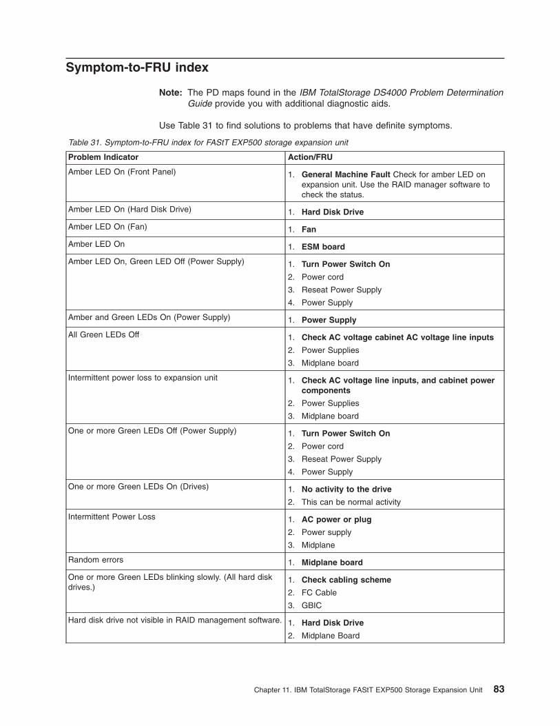
Symptom-to-FRU index
Note: The PD maps found in the IBM TotalStorage DS4000 Problem Determination
Guide provide you with additional diagnostic aids.
Use Table 31 to find solutions to problems that have definite symptoms.
Table 31. Symptom-to-FRU index for FAStT EXP500 storage expansion unit
Problem Indicator Action/FRU
Amber LED On (Front Panel) 1. General Machine Fault Check for amber LED on
expansion unit. Use the RAID manager software to
check the status.
Amber LED On (Hard Disk Drive) 1. Hard Disk Drive
Amber LED On (Fan) 1. Fan
Amber LED On 1. ESM board
Amber LED On, Green LED Off (Power Supply) 1. Turn Power Switch On
2. Power cord
3. Reseat Power Supply
4. Power Supply
Amber and Green LEDs On (Power Supply) 1. Power Supply
All Green LEDs Off 1. Check AC voltage cabinet AC voltage line inputs
2. Power Supplies
3. Midplane board
Intermittent power loss to expansion unit 1. Check AC voltage line inputs, and cabinet power
components
2. Power Supplies
3. Midplane board
One or more Green LEDs Off (Power Supply) 1. Turn Power Switch On
2. Power cord
3. Reseat Power Supply
4. Power Supply
One or more Green LEDs On (Drives) 1. No activity to the drive
2. This can be normal activity
Intermittent Power Loss 1. AC power or plug
2. Power supply
3. Midplane
Random errors 1. Midplane board
One or more Green LEDs blinking slowly. (All hard disk
drives.)
1. Check cabling scheme
2. FC Cable
3. GBIC
Hard disk drive not visible in RAID management software. 1. Hard Disk Drive
2. Midplane Board
Chapter 11. IBM TotalStorage FAStT EXP500 Storage Expansion Unit 83
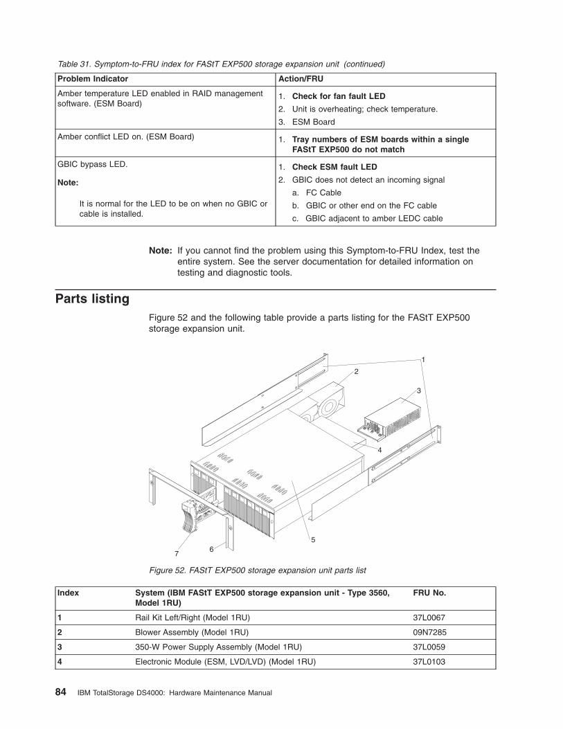
Table 31. Symptom-to-FRU index for FAStT EXP500 storage expansion unit (continued)
Problem Indicator Action/FRU
Amber temperature LED enabled in RAID management
software. (ESM Board)
1. Check for fan fault LED
2. Unit is overheating; check temperature.
3. ESM Board
Amber conflict LED on. (ESM Board) 1. Tray numbers of ESM boards within a single
FAStT EXP500 do not match
GBIC bypass LED.
Note:
It is normal for the LED to be on when no GBIC or
cable is installed.
1. Check ESM fault LED
2. GBIC does not detect an incoming signal
a. FC Cable
b. GBIC or other end on the FC cable
c. GBIC adjacent to amber LEDC cable
Note: If you cannot find the problem using this Symptom-to-FRU Index, test the
entire system. See the server documentation for detailed information on
testing and diagnostic tools.
Parts listing
Figure 52 and the following table provide a parts listing for the FAStT EXP500
storage expansion unit.
Index System (IBM FAStT EXP500 storage expansion unit - Type 3560,
Model 1RU)
FRU No.
1 Rail Kit Left/Right (Model 1RU) 37L0067
2 Blower Assembly (Model 1RU) 09N7285
3 350-W Power Supply Assembly (Model 1RU) 37L0059
4 Electronic Module (ESM, LVD/LVD) (Model 1RU) 37L0103
1
2
3
4
56
7
Figure 52. FAStT EXP500 storage expansion unit parts list
84 IBM TotalStorage DS4000: Hardware Maintenance Manual
Index System (IBM FAStT EXP500 storage expansion unit - Type 3560,
Model 1RU)
FRU No.
5 Midplane/Frame (Model 1RU)
Note: The midplane board and frame are replaced as a unit. If either
part is needed, order the above FRU.
37L0104
6 Decorative Bezel (Model 1RU) 37L0074
7 Blank Tray Assembly (Model 1RU) 37L6708
Miscellaneous Hardware Kit (Model 1RU) 09N7288
Line Cord, 9 Foot (Model 1RU) 6952300
Line Cord Jumper, High Voltage (Model 1RU) 36L8886
Appendix A, “Power cords,” on page 103 lists required power cords for the DS4000
storage components discussed in this document by country and region.
Chapter 11. IBM TotalStorage FAStT EXP500 Storage Expansion Unit 85

86 IBM TotalStorage DS4000: Hardware Maintenance Manual

Chapter 12. IBM Storage Area Network Data Gateway Router
(2108-R03)
Note: The PD maps found in the IBM System DS4000 Problem Determination
Guide provide you with additional diagnostic aids.
Service Aids
The SAN Data Gateway (SDG) Router service capabilities include the following:
v LED indicators
v Power-on–self-test (POST)
v Health Check
v Event Log
v Service Port commands
v Diagnostics
LED indicators
Shown in Figure 53, the LEDs on the front panel provide a visual indication of the
status and activity of the SDG and its interfaces. The LEDs are refreshed
automatically about 5 times per second.
Table 32 describes the SDG Router LED indicators.
Table 32. SDG Router LED indicators
LEDs (G=Green)
(A=Amber) Function On Off Flash
SAN
Connection
Activity (G) Link traffic SAN interface
activity
Status (G) Link status Link Active No transmission
(Link down)
SCSI (G)
Activity (1 and 2) SCSI Activity SCSI traffic No SCSI traffic SCSI Interface
activity
ETHERNET
Link (G) Status Link active Link down
Transmit (G) Status Transmission in
progress
SAN Connection
Status
Activity
1 2
SCSI Channels Ethernet
Links Transmit Collision
Ready
Power
Warning Alarm
Temperature
2108-R03 Storage Area Network Data Gateway Router
Activity
Status
Figure 53. SDG Router front panel LEDs
© Copyright IBM Corp. 2004, 2006 87
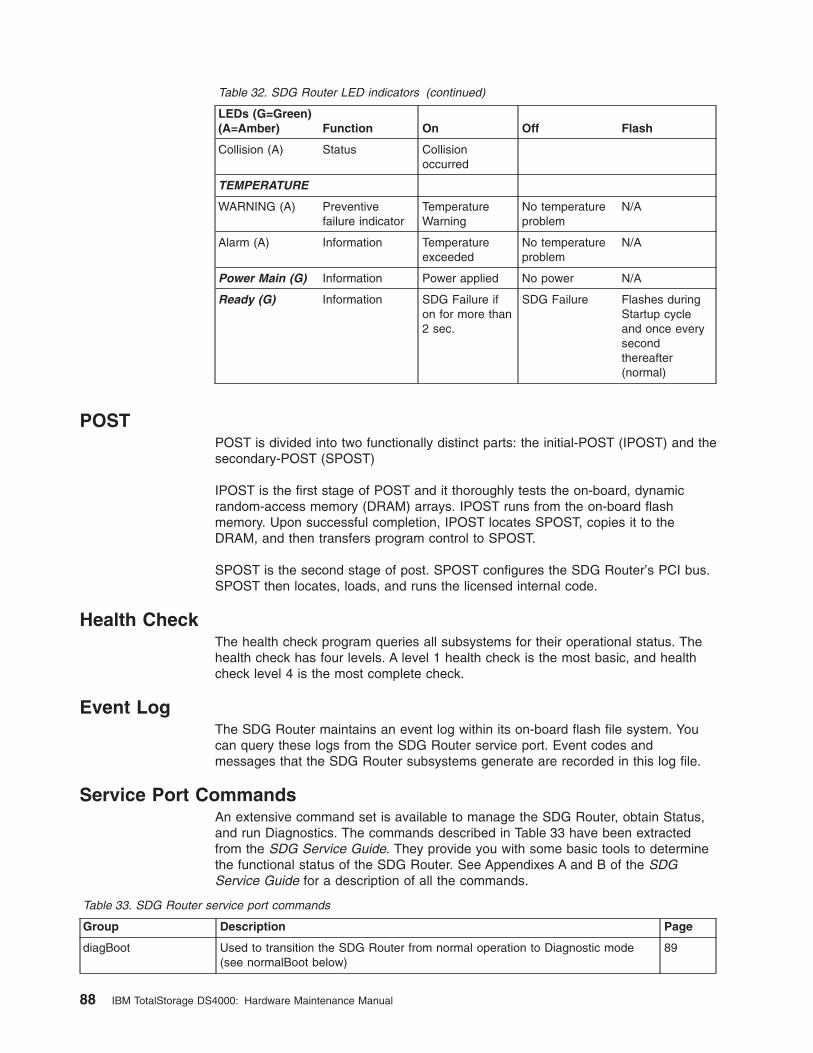
Table 32. SDG Router LED indicators (continued)
LEDs (G=Green)
(A=Amber) Function On Off Flash
Collision (A) Status Collision
occurred
TEMPERATURE
WARNING (A) Preventive
failure indicator
Temperature
Warning
No temperature
problem
N/A
Alarm (A) Information Temperature
exceeded
No temperature
problem
N/A
Power Main (G) Information Power applied No power N/A
Ready (G) Information SDG Failure if
on for more than
2 sec.
SDG Failure Flashes during
Startup cycle
and once every
second
thereafter
(normal)
POST
POST is divided into two functionally distinct parts: the initial-POST (IPOST) and the
secondary-POST (SPOST)
IPOST is the first stage of POST and it thoroughly tests the on-board, dynamic
random-access memory (DRAM) arrays. IPOST runs from the on-board flash
memory. Upon successful completion, IPOST locates SPOST, copies it to the
DRAM, and then transfers program control to SPOST.
SPOST is the second stage of post. SPOST configures the SDG Router’s PCI bus.
SPOST then locates, loads, and runs the licensed internal code.
Health Check
The health check program queries all subsystems for their operational status. The
health check has four levels. A level 1 health check is the most basic, and health
check level 4 is the most complete check.
Event Log
The SDG Router maintains an event log within its on-board flash file system. You
can query these logs from the SDG Router service port. Event codes and
messages that the SDG Router subsystems generate are recorded in this log file.
Service Port Commands
An extensive command set is available to manage the SDG Router, obtain Status,
and run Diagnostics. The commands described in Table 33 have been extracted
from the SDG Service Guide. They provide you with some basic tools to determine
the functional status of the SDG Router. See Appendixes A and B of the SDG
Service Guide for a description of all the commands.
Table 33. SDG Router service port commands
Group Description Page
diagBoot Used to transition the SDG Router from normal operation to Diagnostic mode
(see normalBoot below)
89
88 IBM TotalStorage DS4000: Hardware Maintenance Manual
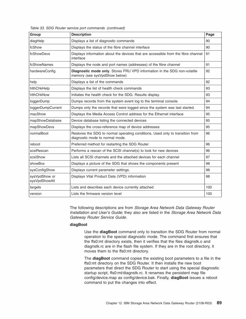
Table 33. SDG Router service port commands (continued)
Group Description Page
diagHelp Displays a list of diagnostic commands 90
fcShow Displays the status of the fibre channel interface 90
fcShowDevs Displays information about the devices that are accessible from the fibre channel
interface
91
fcShowNames Displays the node and port names (addresses) of the fibre channel 91
hardwareConfig Diagnostic mode only. Stores FRU VPD information in the SDG non-volatile
memory (see sysVpdShow below)
92
help Displays a list of the commands 92
hlthChkHelp Displays the list of health check commands 93
hlthChkNow Initiates the health check for the SDG. Results display. 93
loggerDump Dumps records from the system event log to the terminal console 94
loggerDumpCurrent Dumps only the records that were logged since the system was last started. 94
macShow Displays the Media Access Control address for the Ethernet interface 95
mapShowDatabase Device database listing the connected devices 95
mapShowDevs Displays the cross-reference map of device addresses 95
normalBoot Restores the SDG to normal operating conditions. Used only to transition from
diagnostic mode to normal mode.
96
reboot Preferred method for restarting the SDG Router 96
scsiRescan Performs a rescan of the SCSI channel(s) to look for new devices 96
scsiShow Lists all SCSI channels and the attached devices for each channel 97
showBox Displays a picture of the SDG that shows the components present 98
sysConfigShow Displays current parameter settings. 98
sysVpdShow or
sysVpdShowAll
Displays Vital Product Data (VPD) information 98
targets Lists and describes each device currently attached 100
version Lists the firmware version level 100
The following descriptions are from Storage Area Network Data Gateway Router
Installation and User’s Guide; they also are listed in the Storage Area Network Data
Gateway Router Service Guide.
diagBoot
Use the diagBoot command only to transition the SDG Router from normal
operation to the special diagnostic mode. The command first ensures that
the ffs0:mt directory exists, then it verifies that the files diagnstk.o and
diagnstk.rc are in the flash file system. If they are in the root directory, it
moves them to the ffs0:mt directory.
The diagBoot command copies the existing boot parameters to a file in the
ffs0:mt directory on the SDG Router. It then installs the new boot
parameters that direct the SDG Router to start using the special diagnostic
startup script, ffs0:mt/diagnstk.rc. It renames the persistent map file
config/device.map as config/device.bak. Finally, diagBoot issues a reboot
command to put the changes into effect.
Chapter 12. IBM Storage Area Network Data Gateway Router (2108-R03) 89
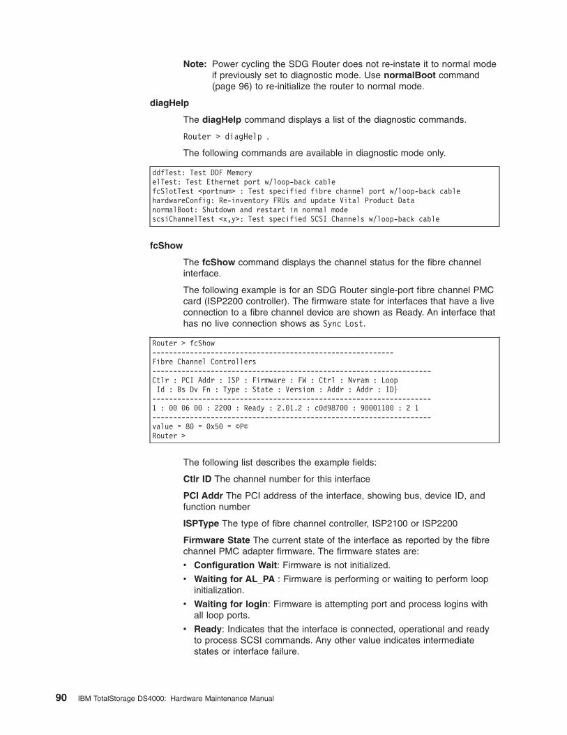
Note: Power cycling the SDG Router does not re-instate it to normal mode
if previously set to diagnostic mode. Use normalBoot command
(page 96) to re-initialize the router to normal mode.
diagHelp
The diagHelp command displays a list of the diagnostic commands.
Router > diagHelp .
The following commands are available in diagnostic mode only.
ddfTest: Test DDF Memory
elTest: Test Ethernet port w/loop-back cable
fcSlotTest <portnum> : Test specified fibre channel port w/loop-back cable
hardwareConfig: Re-inventory FRUs and update Vital Product Data
normalBoot: Shutdown and restart in normal mode
scsiChannelTest <x,y>: Test specified SCSI Channels w/loop-back cable
fcShow
The fcShow command displays the channel status for the fibre channel
interface.
The following example is for an SDG Router single-port fibre channel PMC
card (ISP2200 controller). The firmware state for interfaces that have a live
connection to a fibre channel device are shown as Ready. An interface that
has no live connection shows as Sync Lost.
Router > fcShow
----------------------------------------------------------
Fibre Channel Controllers
-------------------------------------------------------------------
Ctlr : PCI Addr : ISP : Firmware : FW : Ctrl : Nvram : Loop
Id : Bs Dv Fn : Type : State : Version : Addr : Addr : ID}
-------------------------------------------------------------------
1 : 00 06 00 : 2200 : Ready : 2.01.2 : c0d98700 : 90001100 : 2 1
-------------------------------------------------------------------
value = 80 = 0x50 = ©P©
Router >
The following list describes the example fields:
Ctlr ID The channel number for this interface
PCI Addr The PCI address of the interface, showing bus, device ID, and
function number
ISPType The type of fibre channel controller, ISP2100 or ISP2200
Firmware State The current state of the interface as reported by the fibre
channel PMC adapter firmware. The firmware states are:
v Configuration Wait: Firmware is not initialized.
v Waiting for AL_PA : Firmware is performing or waiting to perform loop
initialization.
v Waiting for login: Firmware is attempting port and process logins with
all loop ports.
v Ready: Indicates that the interface is connected, operational and ready
to process SCSI commands. Any other value indicates intermediate
states or interface failure.
90 IBM TotalStorage DS4000: Hardware Maintenance Manual
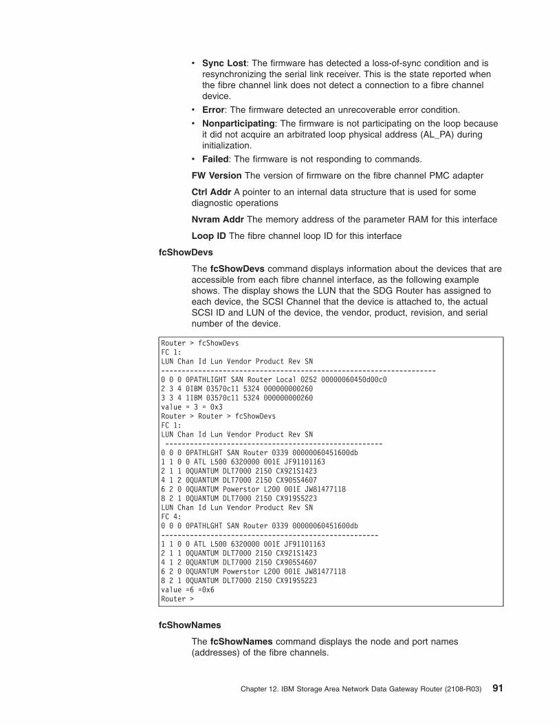
v Sync Lost: The firmware has detected a loss-of-sync condition and is
resynchronizing the serial link receiver. This is the state reported when
the fibre channel link does not detect a connection to a fibre channel
device.
v Error: The firmware detected an unrecoverable error condition.
v Nonparticipating: The firmware is not participating on the loop because
it did not acquire an arbitrated loop physical address (AL_PA) during
initialization.
v Failed: The firmware is not responding to commands.
FW Version The version of firmware on the fibre channel PMC adapter
Ctrl Addr A pointer to an internal data structure that is used for some
diagnostic operations
Nvram Addr The memory address of the parameter RAM for this interface
Loop ID The fibre channel loop ID for this interface
fcShowDevs
The fcShowDevs command displays information about the devices that are
accessible from each fibre channel interface, as the following example
shows. The display shows the LUN that the SDG Router has assigned to
each device, the SCSI Channel that the device is attached to, the actual
SCSI ID and LUN of the device, the vendor, product, revision, and serial
number of the device.
Router > fcShowDevs
FC 1:
LUN Chan Id Lun Vendor Product Rev SN
-------------------------------------------------------------------
0 0 0 0PATHLIGHT SAN Router Local 0252 00000060450d00c0
2 3 4 0IBM 03570c11 5324 000000000260
3 3 4 1IBM 03570c11 5324 000000000260
value = 3 = 0x3
Router > Router > fcShowDevs
FC 1:
LUN Chan Id Lun Vendor Product Rev SN
-----------------------------------------------------
0 0 0 0PATHLGHT SAN Router 0339 00000060451600db
1 1 0 0 ATL L500 6320000 001E JF91101163
2 1 1 0QUANTUM DLT7000 2150 CX921S1423
4 1 2 0QUANTUM DLT7000 2150 CX905S4607
6 2 0 0QUANTUM Powerstor L200 001E JW81477118
8 2 1 0QUANTUM DLT7000 2150 CX919S5223
LUN Chan Id Lun Vendor Product Rev SN
FC 4:
0 0 0 0PATHLGHT SAN Router 0339 00000060451600db
-----------------------------------------------------
1 1 0 0 ATL L500 6320000 001E JF91101163
2 1 1 0QUANTUM DLT7000 2150 CX921S1423
4 1 2 0QUANTUM DLT7000 2150 CX905S4607
6 2 0 0QUANTUM Powerstor L200 001E JW81477118
8 2 1 0QUANTUM DLT7000 2150 CX919S5223
value =6 =0x6
Router >
fcShowNames
The fcShowNames command displays the node and port names
(addresses) of the fibre channels.
Chapter 12. IBM Storage Area Network Data Gateway Router (2108-R03) 91
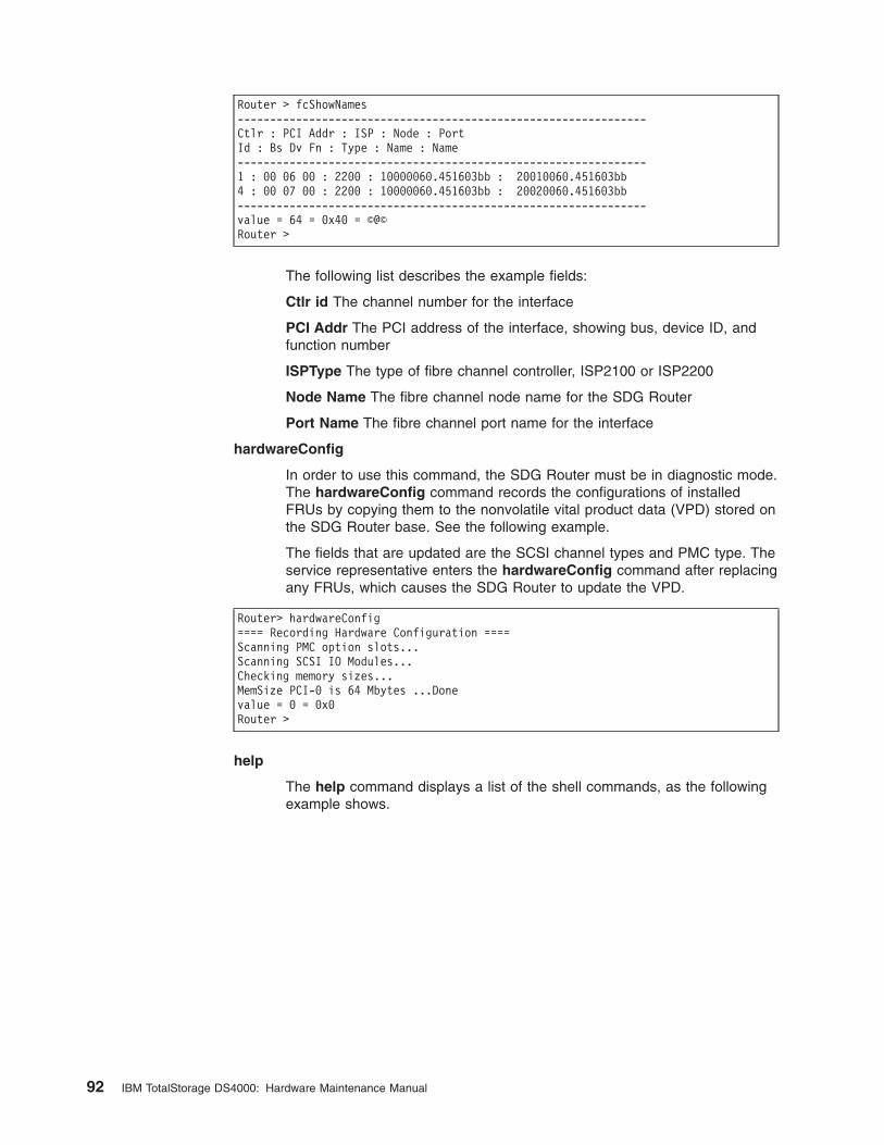
Router > fcShowNames
---------------------------------------------------------------
Ctlr : PCI Addr : ISP : Node : Port
Id : Bs Dv Fn : Type : Name : Name
---------------------------------------------------------------
1 : 00 06 00 : 2200 : 10000060.451603bb : 20010060.451603bb
4 : 00 07 00 : 2200 : 10000060.451603bb : 20020060.451603bb
---------------------------------------------------------------
value = 64 = 0x40 = ©@©
Router >
The following list describes the example fields:
Ctlr id The channel number for the interface
PCI Addr The PCI address of the interface, showing bus, device ID, and
function number
ISPType The type of fibre channel controller, ISP2100 or ISP2200
Node Name The fibre channel node name for the SDG Router
Port Name The fibre channel port name for the interface
hardwareConfig
In order to use this command, the SDG Router must be in diagnostic mode.
The hardwareConfig command records the configurations of installed
FRUs by copying them to the nonvolatile vital product data (VPD) stored on
the SDG Router base. See the following example.
The fields that are updated are the SCSI channel types and PMC type. The
service representative enters the hardwareConfig command after replacing
any FRUs, which causes the SDG Router to update the VPD.
Router> hardwareConfig
==== Recording Hardware Configuration ====
Scanning PMC option slots...
Scanning SCSI IO Modules...
Checking memory sizes...
MemSize PCI-0 is 64 Mbytes ...Done
value = 0 = 0x0
Router >
help
The help command displays a list of the shell commands, as the following
example shows.
92 IBM TotalStorage DS4000: Hardware Maintenance Manual
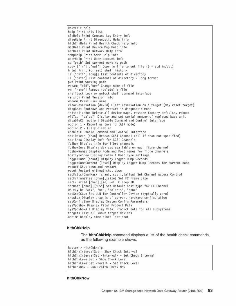
Router > help
help Print this list
cleHelp Print Command Log Entry info
diagHelp Print Diagnostic Help info
hlthChkHelp Print Health Check Help info
mapHelp Print Device Map Help info
netHelp Print Network Help info
snmpHelp Print SNMP Help info
userHelp Print User account info
cd "path" Set current working path
copy ["in"][,"out"] Copy in file to out file (0 = std in/out)
h [n] Print (or set) shell history
ls ["path"[,long]] List contents of directory
ll ["path"] List contents of directory - long format
pwd Print working path
rename "old","new" Change name of file
rm ["name"] Remove (delete) a file
shellLock Lock or unlock shell command interface
version Print Version info
whoami Print user name
clearReservation [devId] Clear reservation on a target (may reset target)
diagBoot Shutdown and restart in diagnostic mode
initializeBox Delete all device maps, restore factory defaults, reboot
ridTag ["value"] Display and set serial number of replaced base unit
disableCC [option] Disable Command and Control Interface
option 1 - Report as Invalid (AIX mode)
option 2 - Fully disabled
enableCC Enable Command and Control Interface
scsiRescan [chan] Rescan SCSI Channel (all if chan not specified)
scsiShow Display info for SCSI Channels
fcShow Display info for fibre channels
fcShowDevs Display devices available on each fibre channel
fcShowNames Display Node and Port names for fibre channels
hostTypeShow Display Default Host Type settings
loggerDump [count] Display Logger Dump Records
loggerDumpCurrent [level] Display Logger Dump Records for current boot
reboot Shut down and restart
reset Restart without shut down
setFcScsiChanMask [chan],[scsi],[allow] Set Channel Access Control
setFcFrameSize [chan],[size] Set FC Frame Size
setFcHardId [chan],[id] Set FC Loop ID
setHost [chan],["OS"] Set default host type for FC Channel
OS may be "aix", "nt", "solaris", "hpux"
setSnaCCLun Set LUN for Controller Device (typically zero)
showBox Display graphic of current hardware configuration
sysConfigShow Display System Config Parameters
sysVpdShow Display Vital Product Data
sysVpdShowAll Display Vital Product Data for all subsystems
targets List all known target devices
uptime Display time since last boot
hlthChkHelp
The hlthChkHelp command displays a list of the health check commands,
as the following example shows.
Router > hlthChkHelp
hlthChkIntervalGet - Show Check Interval
hlthChkIntervalSet <interval> - Set Check Interval
hlthChkLevelGet - Show Check Level
hlthChkLevelSet <level> - Set Check Level
hlthChkNow - Run Health Check Now
hlthChkNow
Chapter 12. IBM Storage Area Network Data Gateway Router (2108-R03) 93
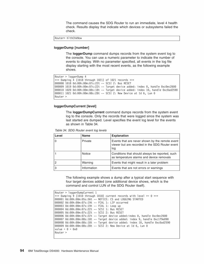
The command causes the SDG Router to run an immediate, level 4 health
check. Results display that indicate which devices or subsystems failed the
check.
Router> hlthChkNow
loggerDump [number]
The loggerDump command dumps records from the system event log to
the console. You can use a numeric parameter to indicate the number of
events to display. With no parameter specified, all events in the log file
display starting with the most recent events, as the following example
shows.
Router > loggerDump 4
*** Dumping 4 (1018 through 1021) of 1021 records ***
000008 1018 0d:00h:00m:07s:22t -- SCSI 2: Bus RESET
000009 1019 0d:00h:00m:07s:22t -- Target device added: index 0, handle 0xc0ec2600
000010 1020 0d:00h:00m:08s:18t -- Target device added: index 10, handle 0xc0ad2590
000011 1021 0d:00h:00m:08s:28t -- SCSI 2: New Device at Id 6, Lun 0
Router >
loggerDumpCurrent [level]
The loggerDumpCurrent command dumps records from the system event
log to the console. Only the records that were logged since the system was
last started are dumped. Level specifies the event log level for the events
as shown in Table 34.
Table 34. SDG Router event log levels
Level Name Explanation
0 Private Events that are never shown by the remote event
viewer but are recorded in the SDG Router event
log
1 Notice Conditions that should always be reported, such
as temperature alarms and device removals
2 Warning Events that might result in a later problem
3 Information Events that are not errors or warnings
The following example shows a dump after a typical start sequence with
four target devices added (one additional device shows, which is the
command and control LUN of the SDG Router itself).
Router > loggerDumpCurrent 1
*** Dumping 9 (1010 through 1018) current records with level >= 0 ***
000001 0d:00h:00m:05s:56t -- NOTICE: CS and LOGGING STARTED
000002 0d:00h:00m:07s:19t -- FCAL 1: LIP occurred
000003 0d:00h:00m:07s:19t -- FCAL 1: Loop up
000004 0d:00h:00m:07s:22t -- SCSI 1: Bus RESET
000005 0d:00h:00m:07s:22t -- SCSI 2: Bus RESET
000006 0d:00h:00m:07s:22t -- Target device added:index 0, handle 0xc0ec2600
000007 0d:00h:00m:08s:18t -- Target device added: index 9, handle 0xc1f9e090
000008 0d:00h:00m:08s:18t -- Target device added: index 10, handle 0xc0ad2590
000009 0d:00h:00m:08s:28t -- SCSI 2: New Device at Id 6, Lun 0
value = 0 = 0x0
Router >
94 IBM TotalStorage DS4000: Hardware Maintenance Manual

macShow
The macShow command displays the media access control (MAC) address
for the Ethernet interface, as the following example shows.
Router > macShow
Enet MAC Address: 0.60.45.d.0.80
value = 33 = 0x21 = ©!©
Router >
mapShowDatabase
The SDG Router maintains a database of attached devices to ensure that
each time a host attaches to the SDG Router, the target devices are seen
at a consistent address. The database lists not only the devices presently
connected, but also devices that were previously connected. If a previously
attached device is later reattached, it is assigned its previous address. Use
the mapShowDatabase command to display the persistent device map
table.
Router > mapShowDatabase
devId Type Chan tId tLun UID
-----------------------------------------------
000 SNA 127 127 127 00000060:450d00c0
001 SCSI 001 003 000 00000060:450d00c0
002 SCSI 001 002 000 00000060:450d00c0
003 SCSI 001 001 000 00000060:450d00c0
004 SCSI 002 002 000 00000060:450d00c0
005 SCSI 002 000 000 00000060:450d00c0
006 SCSI 002 006 000 00000060:450d00c0
007 SCSI 002 009 000 00000060:450d00c0
008 SCSI 002 002 001 00000060:450d00c0
009 SCSI 002 005 000 00000060:450d00c0
010 SCSI 002 005 001 00000060:450d00c0
011 SCSI 001 000 000 00000060:450d00c0
012 SCSI 001 006 000 00000060:450d00c0
value = 0 = 0x0
Router >
The following list describes the example fields:
devId The index of the device in the database
Type The type of interface where the device is connected. SNA indicates
an internal device. SCSI or fibre channel indicate I/O interfaces.
Chan The channel number of the interface where the device is attached
tId Target ID mapping for SCSI initiators
tLun Target LUN mapping for SCSI initiators
UID For a fibre channel interface, the unique ID of the device. For SCSI
interface, the unique ID of the SDG Router.
mapShowDevs
The SDG Router maintains a cross-reference map of device addresses.
You can display Information about the presently attached and available
devices in the map by using the mapShowDevs command.
Chapter 12. IBM Storage Area Network Data Gateway Router (2108-R03) 95
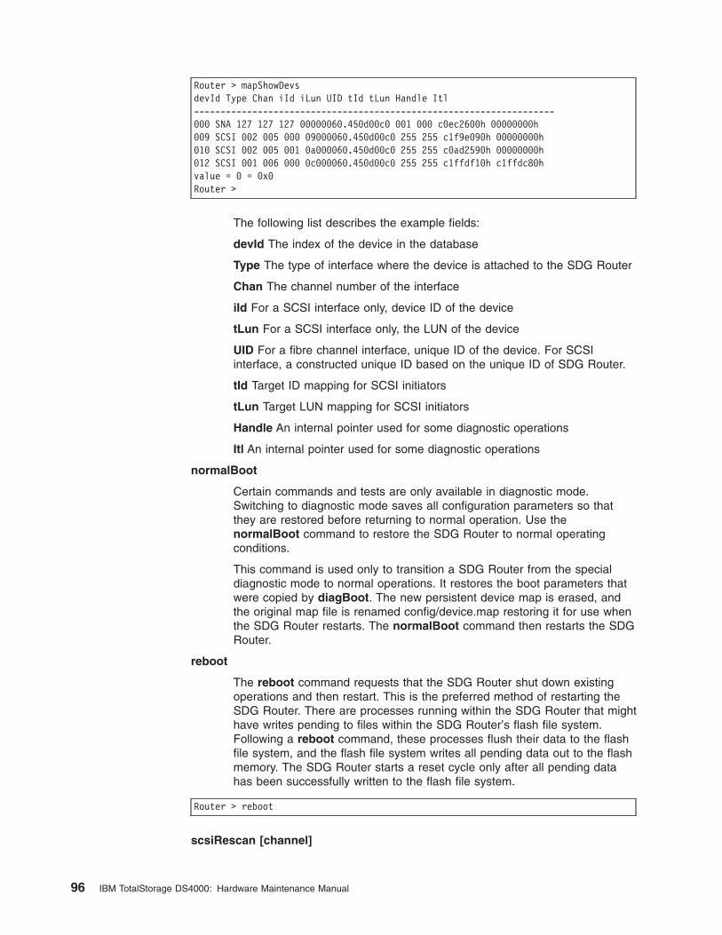
Router > mapShowDevs
devId Type Chan iId iLun UID tId tLun Handle Itl
--------------------------------------------------------------------
000 SNA 127 127 127 00000060.450d00c0 001 000 c0ec2600h 00000000h
009 SCSI 002 005 000 09000060.450d00c0 255 255 c1f9e090h 00000000h
010 SCSI 002 005 001 0a000060.450d00c0 255 255 c0ad2590h 00000000h
012 SCSI 001 006 000 0c000060.450d00c0 255 255 c1ffdf10h c1ffdc80h
value = 0 = 0x0
Router >
The following list describes the example fields:
devId The index of the device in the database
Type The type of interface where the device is attached to the SDG Router
Chan The channel number of the interface
iId For a SCSI interface only, device ID of the device
tLun For a SCSI interface only, the LUN of the device
UID For a fibre channel interface, unique ID of the device. For SCSI
interface, a constructed unique ID based on the unique ID of SDG Router.
tId Target ID mapping for SCSI initiators
tLun Target LUN mapping for SCSI initiators
Handle An internal pointer used for some diagnostic operations
Itl An internal pointer used for some diagnostic operations
normalBoot
Certain commands and tests are only available in diagnostic mode.
Switching to diagnostic mode saves all configuration parameters so that
they are restored before returning to normal operation. Use the
normalBoot command to restore the SDG Router to normal operating
conditions.
This command is used only to transition a SDG Router from the special
diagnostic mode to normal operations. It restores the boot parameters that
were copied by diagBoot. The new persistent device map is erased, and
the original map file is renamed config/device.map restoring it for use when
the SDG Router restarts. The normalBoot command then restarts the SDG
Router.
reboot
The reboot command requests that the SDG Router shut down existing
operations and then restart. This is the preferred method of restarting the
SDG Router. There are processes running within the SDG Router that might
have writes pending to files within the SDG Router’s flash file system.
Following a reboot command, these processes flush their data to the flash
file system, and the flash file system writes all pending data out to the flash
memory. The SDG Router starts a reset cycle only after all pending data
has been successfully written to the flash file system.
Router > reboot
scsiRescan [channel]
96 IBM TotalStorage DS4000: Hardware Maintenance Manual
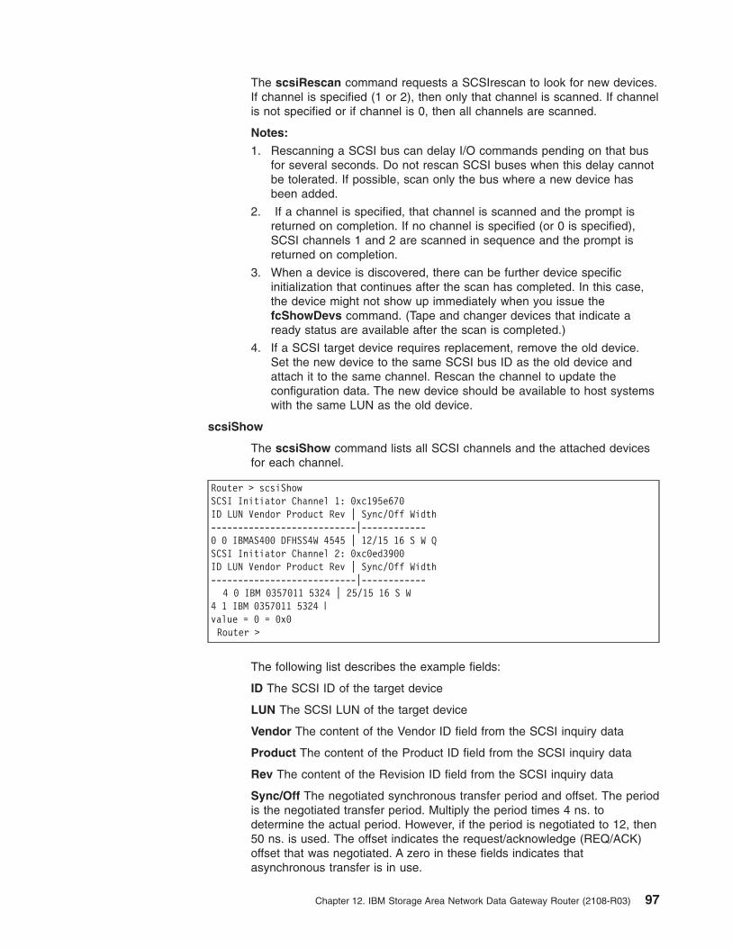
The scsiRescan command requests a SCSIrescan to look for new devices.
If channel is specified (1 or 2), then only that channel is scanned. If channel
is not specified or if channel is 0, then all channels are scanned.
Notes:
1. Rescanning a SCSI bus can delay I/O commands pending on that bus
for several seconds. Do not rescan SCSI buses when this delay cannot
be tolerated. If possible, scan only the bus where a new device has
been added.
2. If a channel is specified, that channel is scanned and the prompt is
returned on completion. If no channel is specified (or 0 is specified),
SCSI channels 1 and 2 are scanned in sequence and the prompt is
returned on completion.
3. When a device is discovered, there can be further device specific
initialization that continues after the scan has completed. In this case,
the device might not show up immediately when you issue the
fcShowDevs command. (Tape and changer devices that indicate a
ready status are available after the scan is completed.)
4. If a SCSI target device requires replacement, remove the old device.
Set the new device to the same SCSI bus ID as the old device and
attach it to the same channel. Rescan the channel to update the
configuration data. The new device should be available to host systems
with the same LUN as the old device.
scsiShow
The scsiShow command lists all SCSI channels and the attached devices
for each channel.
Router > scsiShow
SCSI Initiator Channel 1: 0xc195e670
ID LUN Vendor Product Rev | Sync/Off Width
---------------------------|------------
0 0 IBMAS400 DFHSS4W 4545 | 12/15 16 S W Q
SCSI Initiator Channel 2: 0xc0ed3900
ID LUN Vendor Product Rev | Sync/Off Width
---------------------------|------------
4 0 IBM 0357011 5324 | 25/15 16 S W
4 1 IBM 0357011 5324 |
value = 0 = 0x0
Router >
The following list describes the example fields:
ID The SCSI ID of the target device
LUN The SCSI LUN of the target device
Vendor The content of the Vendor ID field from the SCSI inquiry data
Product The content of the Product ID field from the SCSI inquiry data
Rev The content of the Revision ID field from the SCSI inquiry data
Sync/Off The negotiated synchronous transfer period and offset. The period
is the negotiated transfer period. Multiply the period times 4 ns. to
determine the actual period. However, if the period is negotiated to 12, then
50 ns. is used. The offset indicates the request/acknowledge (REQ/ACK)
offset that was negotiated. A zero in these fields indicates that
asynchronous transfer is in use.
Chapter 12. IBM Storage Area Network Data Gateway Router (2108-R03) 97
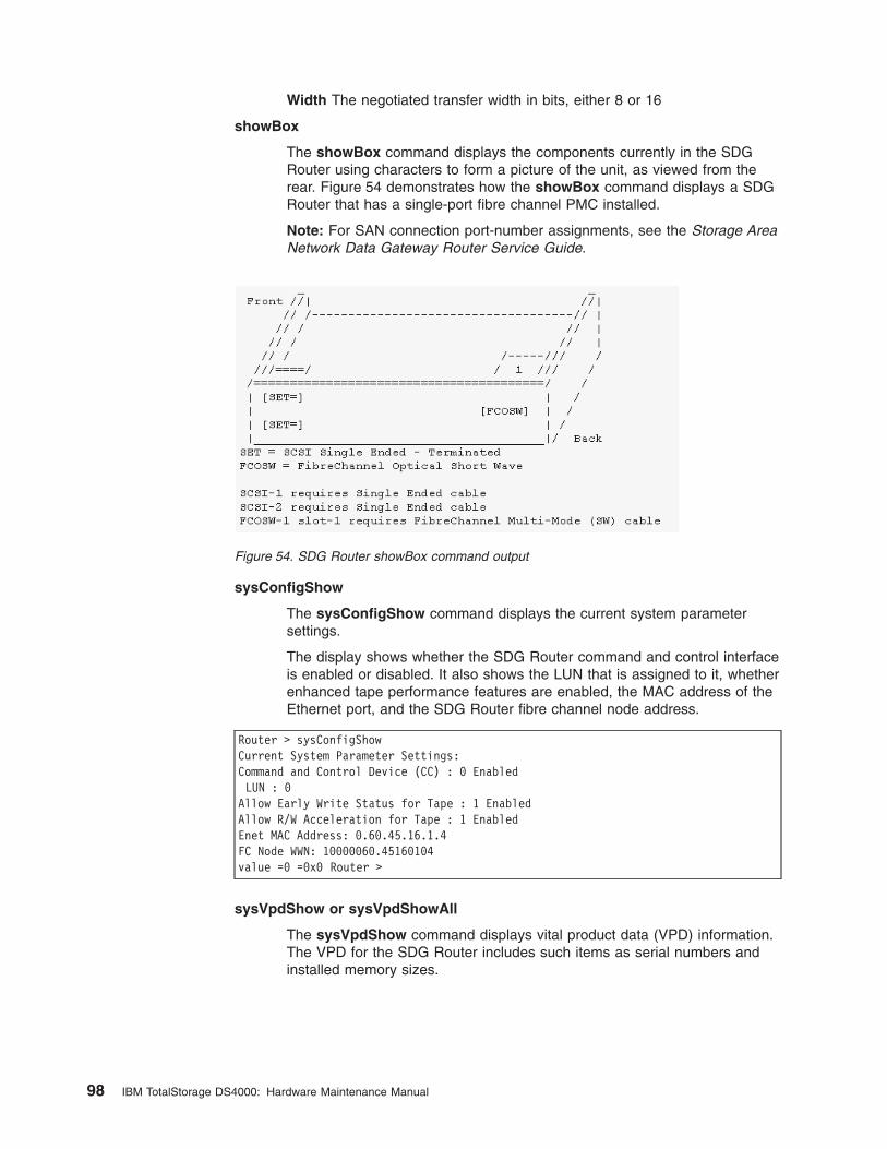
Width The negotiated transfer width in bits, either 8 or 16
showBox
The showBox command displays the components currently in the SDG
Router using characters to form a picture of the unit, as viewed from the
rear. Figure 54 demonstrates how the showBox command displays a SDG
Router that has a single-port fibre channel PMC installed.
Note: For SAN connection port-number assignments, see the Storage Area
Network Data Gateway Router Service Guide.
sysConfigShow
The sysConfigShow command displays the current system parameter
settings.
The display shows whether the SDG Router command and control interface
is enabled or disabled. It also shows the LUN that is assigned to it, whether
enhanced tape performance features are enabled, the MAC address of the
Ethernet port, and the SDG Router fibre channel node address.
Router > sysConfigShow
Current System Parameter Settings:
Command and Control Device (CC) : 0 Enabled
LUN : 0
Allow Early Write Status for Tape : 1 Enabled
Allow R/W Acceleration for Tape : 1 Enabled
Enet MAC Address: 0.60.45.16.1.4
FC Node WWN: 10000060.45160104
value =0 =0x0 Router >
sysVpdShow or sysVpdShowAll
The sysVpdShow command displays vital product data (VPD) information.
The VPD for the SDG Router includes such items as serial numbers and
installed memory sizes.
Figure 54. SDG Router showBox command output
98 IBM TotalStorage DS4000: Hardware Maintenance Manual
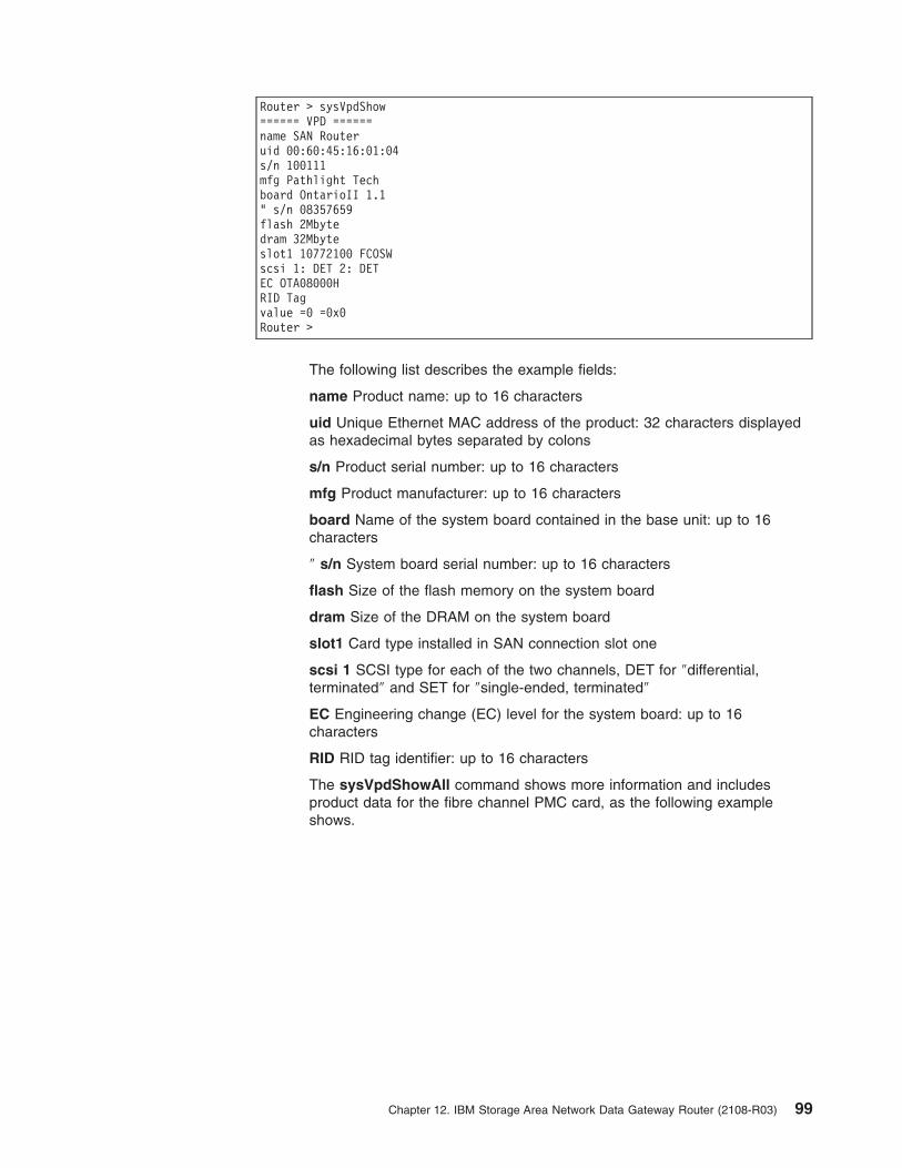
Router > sysVpdShow
====== VPD ======
name SAN Router
uid 00:60:45:16:01:04
s/n 100111
mfg Pathlight Tech
board OntarioII 1.1
" s/n 08357659
flash 2Mbyte
dram 32Mbyte
slot1 10772100 FCOSW
scsi 1: DET 2: DET
EC OTA08000H
RID Tag
value =0 =0x0
Router >
The following list describes the example fields:
name Product name: up to 16 characters
uid Unique Ethernet MAC address of the product: 32 characters displayed
as hexadecimal bytes separated by colons
s/n Product serial number: up to 16 characters
mfg Product manufacturer: up to 16 characters
board Name of the system board contained in the base unit: up to 16
characters
″ s/n System board serial number: up to 16 characters
flash Size of the flash memory on the system board
dram Size of the DRAM on the system board
slot1 Card type installed in SAN connection slot one
scsi 1 SCSI type for each of the two channels, DET for ″differential,
terminated″ and SET for ″single-ended, terminated″
EC Engineering change (EC) level for the system board: up to 16
characters
RID RID tag identifier: up to 16 characters
The sysVpdShowAll command shows more information and includes
product data for the fibre channel PMC card, as the following example
shows.
Chapter 12. IBM Storage Area Network Data Gateway Router (2108-R03) 99
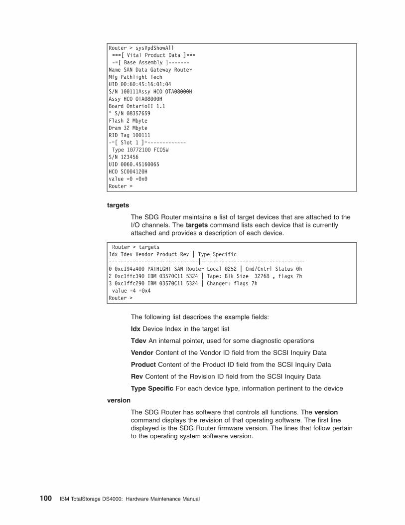
Router > sysVpdShowAll
===[ Vital Product Data ]===
-=[ Base Assembly ]-------
Name SAN Data Gateway Router
Mfg Pathlight Tech
UID 00:60:45:16:01:04
S/N 100111Assy HCO OTA08000H
Assy HCO OTA08000H
Board OntarioII 1.1
" S/N 08357659
Flash 2 Mbyte
Dram 32 Mbyte
RID Tag 100111
-=[ Slot 1 ]=-------------
Type 10772100 FCOSW
S/N 123456
UID 0060.45160065
HCO SC004120H
value =0 =0x0
Router >
targets
The SDG Router maintains a list of target devices that are attached to the
I/O channels. The targets command lists each device that is currently
attached and provides a description of each device.
Router > targets
Idx Tdev Vendor Product Rev | Type Specific
------------------------------|-----------------------------------
0 0xc194a400 PATHLGHT SAN Router Local 0252 | Cmd/Cntrl Status 0h
2 0xc1ffc390 IBM 03570C11 5324 | Tape: Blk Size 32768 , flags 7h
3 0xc1ffc290 IBM 03570C11 5324 | Changer: flags 7h
value =4 =0x4
Router >
The following list describes the example fields:
Idx Device Index in the target list
Tdev An internal pointer, used for some diagnostic operations
Vendor Content of the Vendor ID field from the SCSI Inquiry Data
Product Content of the Product ID field from the SCSI Inquiry Data
Rev Content of the Revision ID field from the SCSI Inquiry Data
Type Specific For each device type, information pertinent to the device
version
The SDG Router has software that controls all functions. The version
command displays the revision of that operating software. The first line
displayed is the SDG Router firmware version. The lines that follow pertain
to the operating system software version.
100 IBM TotalStorage DS4000: Hardware Maintenance Manual
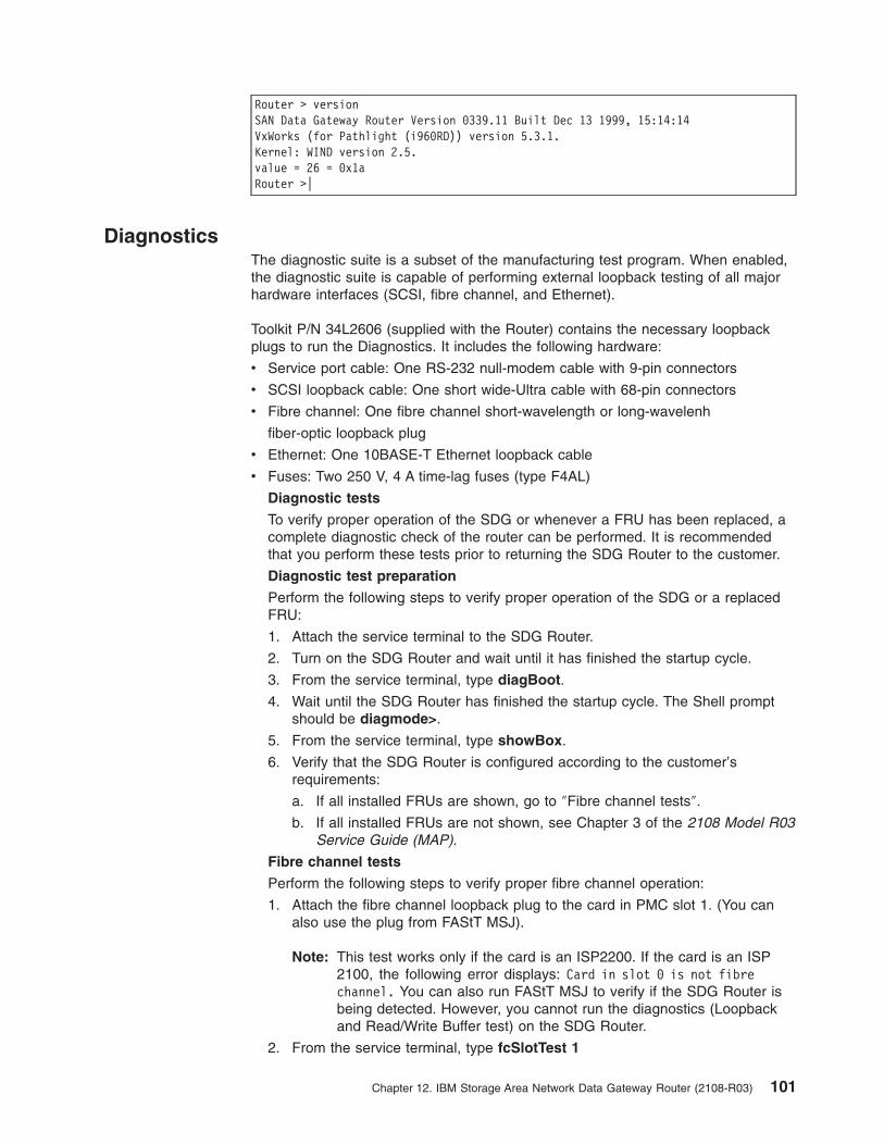
Router > version
SAN Data Gateway Router Version 0339.11 Built Dec 13 1999, 15:14:14
VxWorks (for Pathlight (i960RD)) version 5.3.1.
Kernel: WIND version 2.5.
value = 26 = 0x1a
Router >|
Diagnostics
The diagnostic suite is a subset of the manufacturing test program. When enabled,
the diagnostic suite is capable of performing external loopback testing of all major
hardware interfaces (SCSI, fibre channel, and Ethernet).
Toolkit P/N 34L2606 (supplied with the Router) contains the necessary loopback
plugs to run the Diagnostics. It includes the following hardware:
v Service port cable: One RS-232 null-modem cable with 9-pin connectors
v SCSI loopback cable: One short wide-Ultra cable with 68-pin connectors
v Fibre channel: One fibre channel short-wavelength or long-wavelenh
fiber-optic loopback plug
v Ethernet: One 10BASE-T Ethernet loopback cable
v Fuses: Two 250 V, 4 A time-lag fuses (type F4AL)
Diagnostic tests
To verify proper operation of the SDG or whenever a FRU has been replaced, a
complete diagnostic check of the router can be performed. It is recommended
that you perform these tests prior to returning the SDG Router to the customer.
Diagnostic test preparation
Perform the following steps to verify proper operation of the SDG or a replaced
FRU:
1. Attach the service terminal to the SDG Router.
2. Turn on the SDG Router and wait until it has finished the startup cycle.
3. From the service terminal, type diagBoot.
4. Wait until the SDG Router has finished the startup cycle. The Shell prompt
should be diagmode>.
5. From the service terminal, type showBox.
6. Verify that the SDG Router is configured according to the customer’s
requirements:
a. If all installed FRUs are shown, go to ″Fibre channel tests″.
b. If all installed FRUs are not shown, see Chapter 3 of the 2108 Model R03
Service Guide (MAP).
Fibre channel tests
Perform the following steps to verify proper fibre channel operation:
1. Attach the fibre channel loopback plug to the card in PMC slot 1. (You can
also use the plug from FAStT MSJ).
Note: This test works only if the card is an ISP2200. If the card is an ISP
2100, the following error displays: Card in slot 0 is not fibre
channel. You can also run FAStT MSJ to verify if the SDG Router is
being detected. However, you cannot run the diagnostics (Loopback
and Read/Write Buffer test) on the SDG Router.
2. From the service terminal, type fcSlotTest 1
Chapter 12. IBM Storage Area Network Data Gateway Router (2108-R03) 101
a. If the fcSlotTest test completes successfully, remove the loopback plug
and go to ″SCSI test″.
b. If not, see Chapter 3 of the 2108 Model R03 Service Guide (MAP).
SCSI test
Perform the following steps to verify proper SCSI operation:
1. If there is only one SCSI interface installed, proceed to ″Ethernet Test″.
2. Attach the SCSI loopback cable to SCSI channels 1 and 2.
3. From the service terminal, type scsiChannelTest 1, 2.
a. If the test completes successfully, go to step 4.
b. If not, see Chapter 3 of the 2108 Model R03 Service Guide (MAP).
4. Remove the SCSI loopback cable.
5. Proceed to ″Ethernet Test″.
Ethernet test
Perform the following steps to verify proper Ethernet operation:
1. Obtain the SDG Router Ethernet network parameters from the customer.
Configure the Ethernet port host name, address, routes, and enable the
Ethernet. See the IBM DS4000 product installation uide.
2. Attach the Ethernet loopback plug to the Ethernet port.
3. From the service terminal, type elTest.
4. If the test completes successfully, go to step 5. If not, see Chapter 3 of the
2108 Model R03 Service Guide (MAP).
5. Remove the Ethernet loopback plug.
Verifying SDG Router operation
Perform the following steps to verify proper SDG operation:
1. From the service terminal, type normalBoot.
2. Wait until the SDG Router has finished the startup cycle. The Ready light
should be blinking once every second, indicating the SDG Router POST was
successful. If the light remains on or is off, see Chapter 3 of the 2108 Model
R03 Service Guide (MAP).
102 IBM TotalStorage DS4000: Hardware Maintenance Manual
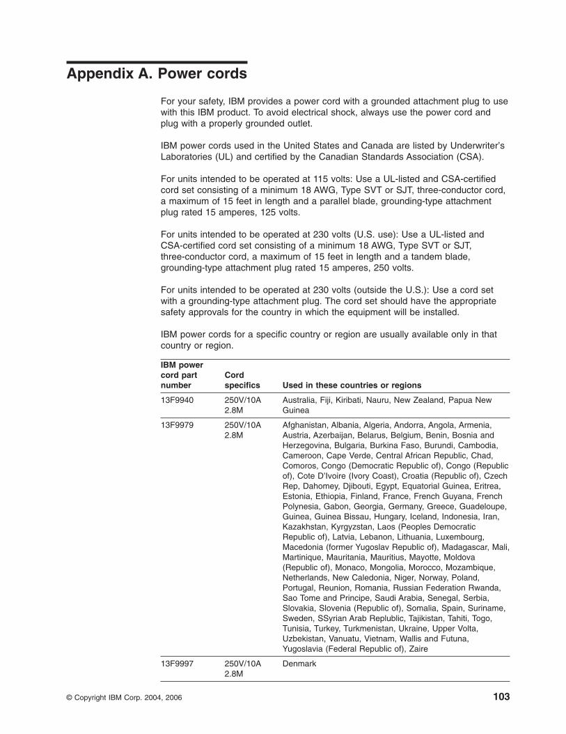
Appendix A. Power cords
For your safety, IBM provides a power cord with a grounded attachment plug to use
with this IBM product. To avoid electrical shock, always use the power cord and
plug with a properly grounded outlet.
IBM power cords used in the United States and Canada are listed by Underwriter’s
Laboratories (UL) and certified by the Canadian Standards Association (CSA).
For units intended to be operated at 115 volts: Use a UL-listed and CSA-certified
cord set consisting of a minimum 18 AWG, Type SVT or SJT, three-conductor cord,
a maximum of 15 feet in length and a parallel blade, grounding-type attachment
plug rated 15 amperes, 125 volts.
For units intended to be operated at 230 volts (U.S. use): Use a UL-listed and
CSA-certified cord set consisting of a minimum 18 AWG, Type SVT or SJT,
three-conductor cord, a maximum of 15 feet in length and a tandem blade,
grounding-type attachment plug rated 15 amperes, 250 volts.
For units intended to be operated at 230 volts (outside the U.S.): Use a cord set
with a grounding-type attachment plug. The cord set should have the appropriate
safety approvals for the country in which the equipment will be installed.
IBM power cords for a specific country or region are usually available only in that
country or region.
IBM power
cord part
number
Cord
specifics Used in these countries or regions
13F9940 250V/10A
2.8M
Australia, Fiji, Kiribati, Nauru, New Zealand, Papua New
Guinea
13F9979 250V/10A
2.8M
Afghanistan, Albania, Algeria, Andorra, Angola, Armenia,
Austria, Azerbaijan, Belarus, Belgium, Benin, Bosnia and
Herzegovina, Bulgaria, Burkina Faso, Burundi, Cambodia,
Cameroon, Cape Verde, Central African Republic, Chad,
Comoros, Congo (Democratic Republic of), Congo (Republic
of), Cote D’Ivoire (Ivory Coast), Croatia (Republic of), Czech
Rep, Dahomey, Djibouti, Egypt, Equatorial Guinea, Eritrea,
Estonia, Ethiopia, Finland, France, French Guyana, French
Polynesia, Gabon, Georgia, Germany, Greece, Guadeloupe,
Guinea, Guinea Bissau, Hungary, Iceland, Indonesia, Iran,
Kazakhstan, Kyrgyzstan, Laos (Peoples Democratic
Republic of), Latvia, Lebanon, Lithuania, Luxembourg,
Macedonia (former Yugoslav Republic of), Madagascar, Mali,
Martinique, Mauritania, Mauritius, Mayotte, Moldova
(Republic of), Monaco, Mongolia, Morocco, Mozambique,
Netherlands, New Caledonia, Niger, Norway, Poland,
Portugal, Reunion, Romania, Russian Federation Rwanda,
Sao Tome and Principe, Saudi Arabia, Senegal, Serbia,
Slovakia, Slovenia (Republic of), Somalia, Spain, Suriname,
Sweden, SSyrian Arab Replublic, Tajikistan, Tahiti, Togo,
Tunisia, Turkey, Turkmenistan, Ukraine, Upper Volta,
Uzbekistan, Vanuatu, Vietnam, Wallis and Futuna,
Yugoslavia (Federal Republic of), Zaire
13F9997 250V/10A
2.8M
Denmark
© Copyright IBM Corp. 2004, 2006 103

IBM power
cord part
number
Cord
specifics Used in these countries or regions
14F0015 250V/10A
2.8M
Bangladesh, Lesotho, Maceo, Maldives, Namibia, Nepal,
Pakistan, Samoa, South Africa, Sri Lanka, Swaziland,
Uganda
14F0033 250V/10A
2.8M
Abu Dhabi, Bahrain, Botswana, Brunei Darussalam, Channel
Islands, Cyprus, Dominica, Gambia, Ghana, Grenada,
Guyana, Hong Kong S.A.R. of China, Iraq, Ireland, Jordan,
Kenya, Kuwait, Liberia, Malawi, Malaysia, Malta, Myanmar
(Burma), Nigeria, Oman, Qatar, Saint Kitts & Nevis, Saint
Lucia, Saint Vincent and the Grenadines, Seychelles, Sierra
Leone, Singapore, Sudan, Tanzania (United Republic of),
Trinidad & Tobago, United Arab Emirates (Dubai), United
Kingdom, Yemen, Zambia, Zimbabwe
14F0051 250V/10A
2.8M
Liechtenstein, Switzerland
14F0069 250V/10A
2.8M
Chile, Italy, Libyan Arab Jamahiriya
14F0087 250V/10A
2.8M
Israel
1838574 250V/10A
2.8M
Antigua and Barbuda, Aruba, Bahamas, Barbados, Belize,
Bermuda, Bolivia, Brazil, Caicos Islands, Canada, Cayman
Islands, Costa Rica, Columbia, Cuba, Dominican Republic,
Ecuador, El Salvador, Guam, Guatemala, Haiti, Honduras,
Jamaica, Japan, Mexico, Micronesia (Federal States of),
Netherlands Antilles, Nicaragua, Panama, Peru, Philippines,
Taiwan, United States, Venezuela
36L8880 250V/10A
2.8M
Argentina, Paraguay, Uruguay
02K0546 250V/6A
2.8M
PRC (China)
6952300 125V/10A
2.8M
Antigua and Barbuda, Aruba, Bahamas, Barbados, Belize,
Bermuda, Bolivia, Cayman Islands, Costa Rica, Columbia,
Cuba, Dominican Republic, Ecuador, El Salvador, Guam,
Guatemala, Haiti, Honduras, Jamaica, Mexico, Micronesia
(Federal States of), Netherlands Antilles, Nicaragua,
Panama, Peru, Philippines, Saudi Arabia, Taiwan, Thailand,
Turks and Caicos Islands, United States, Venezuela
6952301 125V/10A
1.8M
104 IBM TotalStorage DS4000: Hardware Maintenance Manual
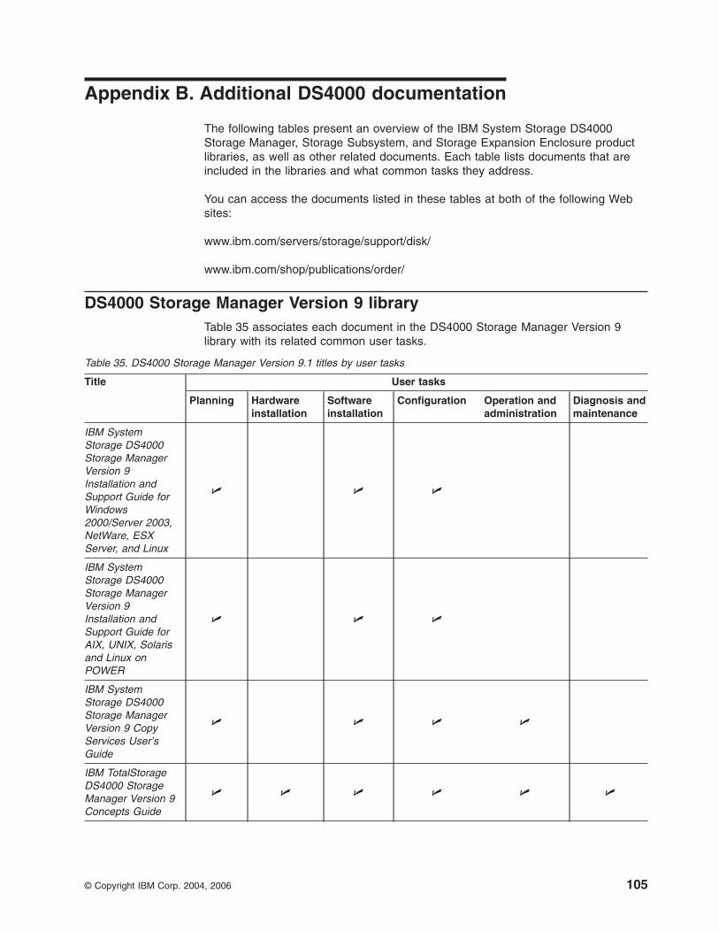
Appendix B. Additional DS4000 documentation
The following tables present an overview of the IBM System Storage DS4000
Storage Manager, Storage Subsystem, and Storage Expansion Enclosure product
libraries, as well as other related documents. Each table lists documents that are
included in the libraries and what common tasks they address.
You can access the documents listed in these tables at both of the following Web
sites:
www.ibm.com/servers/storage/support/disk/
www.ibm.com/shop/publications/order/
DS4000 Storage Manager Version 9 library
Table 35 associates each document in the DS4000 Storage Manager Version 9
library with its related common user tasks.
Table 35. DS4000 Storage Manager Version 9.1 titles by user tasks
Title User tasks
Planning Hardware
installation
Software
installation
Configuration Operation and
administration
Diagnosis and
maintenance
IBM System
Storage DS4000
Storage Manager
Version 9
Installation and
Support Guide for
Windows
2000/Server 2003,
NetWare, ESX
Server, and Linux
U U U
IBM System
Storage DS4000
Storage Manager
Version 9
Installation and
Support Guide for
AIX, UNIX, Solaris
and Linux on
POWER
U U U
IBM System
Storage DS4000
Storage Manager
Version 9 Copy
Services User’s
Guide
U U U U
IBM TotalStorage
DS4000 Storage
Manager Version 9
Concepts Guide
U U U U U U
© Copyright IBM Corp. 2004, 2006 105

DS4800 Storage Subsystem library
Table 36 associates each document in the DS4800 Storage Subsystem library with
its related common user tasks.
Table 36. DS4800 Storage Subsystem document titles by user tasks
Title User Tasks
Planning Hardware
Installation
Software
Installation
Configuration Operation and
Administration
Diagnosis and
Maintenance
IBM System Storage
DS4800 Installation,
User’s and
Maintenance Guide
U U U U U
IBM System Storage
DS4800 Installation
and Cabling
Overview
U
IBM TotalStorage
DS4800 Controller
Cache Upgrade Kit
Instructions
U U U
106 IBM TotalStorage DS4000: Hardware Maintenance Manual
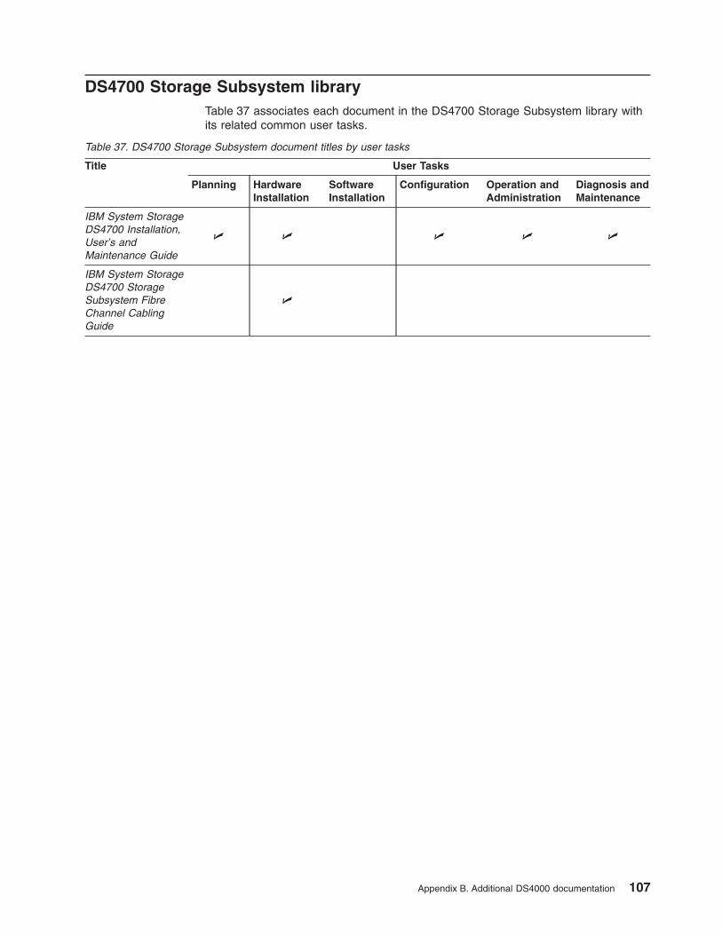
DS4700 Storage Subsystem library
Table 37 associates each document in the DS4700 Storage Subsystem library with
its related common user tasks.
Table 37. DS4700 Storage Subsystem document titles by user tasks
Title User Tasks
Planning Hardware
Installation
Software
Installation
Configuration Operation and
Administration
Diagnosis and
Maintenance
IBM System Storage
DS4700 Installation,
User’s and
Maintenance Guide
U U U U U
IBM System Storage
DS4700 Storage
Subsystem Fibre
Channel Cabling
Guide
U
Appendix B. Additional DS4000 documentation 107
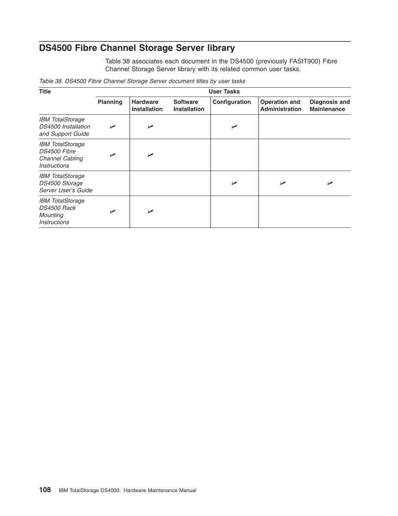
DS4500 Fibre Channel Storage Server library
Table 38 associates each document in the DS4500 (previously FAStT900) Fibre
Channel Storage Server library with its related common user tasks.
Table 38. DS4500 Fibre Channel Storage Server document titles by user tasks
Title User Tasks
Planning Hardware
Installation
Software
Installation
Configuration Operation and
Administration
Diagnosis and
Maintenance
IBM TotalStorage
DS4500 Installation
and Support Guide
U U U
IBM TotalStorage
DS4500 Fibre
Channel Cabling
Instructions
U U
IBM TotalStorage
DS4500 Storage
Server User’s Guide
U U U
IBM TotalStorage
DS4500 Rack
Mounting
Instructions
U U
108 IBM TotalStorage DS4000: Hardware Maintenance Manual
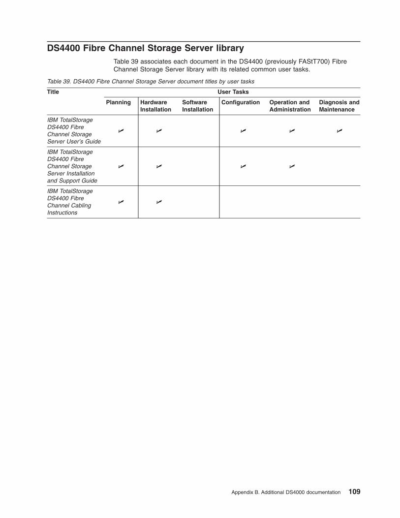
DS4400 Fibre Channel Storage Server library
Table 39 associates each document in the DS4400 (previously FAStT700) Fibre
Channel Storage Server library with its related common user tasks.
Table 39. DS4400 Fibre Channel Storage Server document titles by user tasks
Title User Tasks
Planning Hardware
Installation
Software
Installation
Configuration Operation and
Administration
Diagnosis and
Maintenance
IBM TotalStorage
DS4400 Fibre
Channel Storage
Server User’s Guide
U U U U U
IBM TotalStorage
DS4400 Fibre
Channel Storage
Server Installation
and Support Guide
U U U U
IBM TotalStorage
DS4400 Fibre
Channel Cabling
Instructions
U U
Appendix B. Additional DS4000 documentation 109
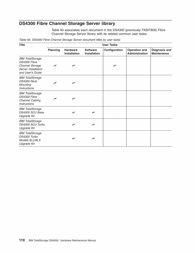
DS4300 Fibre Channel Storage Server library
Table 40 associates each document in the DS4300 (previously FAStT600) Fibre
Channel Storage Server library with its related common user tasks.
Table 40. DS4300 Fibre Channel Storage Server document titles by user tasks
Title User Tasks
Planning Hardware
Installation
Software
Installation
Configuration Operation and
Administration
Diagnosis and
Maintenance
IBM TotalStorage
DS4300 Fibre
Channel Storage
Server Installation
and User’s Guide
U U U
IBM TotalStorage
DS4300 Rack
Mounting
Instructions
U U
IBM TotalStorage
DS4300 Fibre
Channel Cabling
Instructions
U U
IBM TotalStorage
DS4300 SCU Base
Upgrade Kit
U U
IBM TotalStorage
DS4300 SCU Turbo
Upgrade Kit
U U
IBM TotalStorage
DS4300 Turbo
Models 6LU/6LX
Upgrade Kit
U U
110 IBM TotalStorage DS4000: Hardware Maintenance Manual
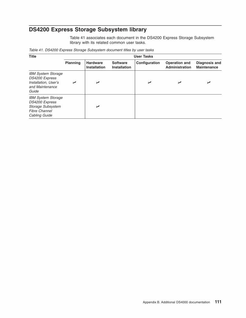
DS4200 Express Storage Subsystem library
Table 41 associates each document in the DS4200 Express Storage Subsystem
library with its related common user tasks.
Table 41. DS4200 Express Storage Subsystem document titles by user tasks
Title User Tasks
Planning Hardware
Installation
Software
Installation
Configuration Operation and
Administration
Diagnosis and
Maintenance
IBM System Storage
DS4200 Express
Installation, User’s
and Maintenance
Guide
U U U U U
IBM System Storage
DS4200 Express
Storage Subsystem
Fibre Channel
Cabling Guide
U
Appendix B. Additional DS4000 documentation 111
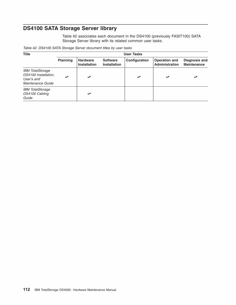
DS4100 SATA Storage Server library
Table 42 associates each document in the DS4100 (previously FAStT100) SATA
Storage Server library with its related common user tasks.
Table 42. DS4100 SATA Storage Server document titles by user tasks
Title User Tasks
Planning Hardware
Installation
Software
Installation
Configuration Operation and
Administration
Diagnosis and
Maintenance
IBM TotalStorage
DS4100 Installation,
User’s and
Maintenance Guide
U U U U U
IBM TotalStorage
DS4100 Cabling
Guide
U
112 IBM TotalStorage DS4000: Hardware Maintenance Manual
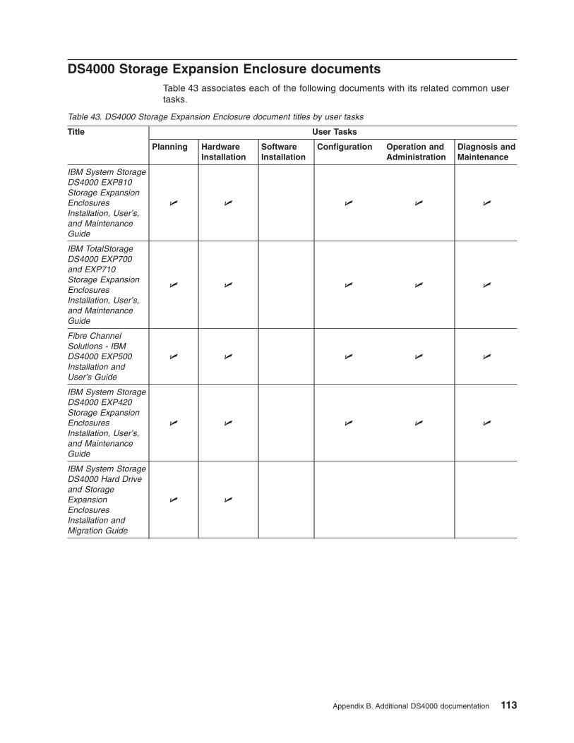
DS4000 Storage Expansion Enclosure documents
Table 43 associates each of the following documents with its related common user
tasks.
Table 43. DS4000 Storage Expansion Enclosure document titles by user tasks
Title User Tasks
Planning Hardware
Installation
Software
Installation
Configuration Operation and
Administration
Diagnosis and
Maintenance
IBM System Storage
DS4000 EXP810
Storage Expansion
Enclosures
Installation, User’s,
and Maintenance
Guide
U U U U U
IBM TotalStorage
DS4000 EXP700
and EXP710
Storage Expansion
Enclosures
Installation, User’s,
and Maintenance
Guide
U U U U U
Fibre Channel
Solutions - IBM
DS4000 EXP500
Installation and
User’s Guide
U U U U U
IBM System Storage
DS4000 EXP420
Storage Expansion
Enclosures
Installation, User’s,
and Maintenance
Guide
U U U U U
IBM System Storage
DS4000 Hard Drive
and Storage
Expansion
Enclosures
Installation and
Migration Guide
U U
Appendix B. Additional DS4000 documentation 113
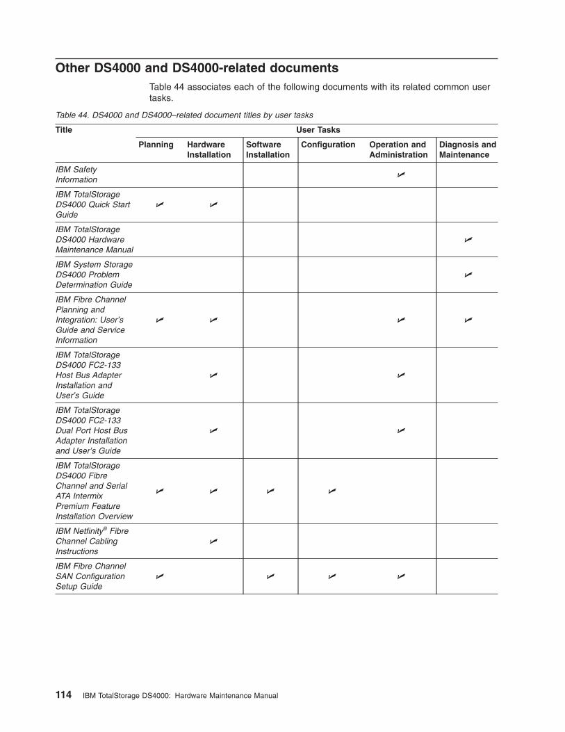
Other DS4000 and DS4000-related documents
Table 44 associates each of the following documents with its related common user
tasks.
Table 44. DS4000 and DS4000–related document titles by user tasks
Title User Tasks
Planning Hardware
Installation
Software
Installation
Configuration Operation and
Administration
Diagnosis and
Maintenance
IBM Safety
Information
U
IBM TotalStorage
DS4000 Quick Start
Guide
U U
IBM TotalStorage
DS4000 Hardware
Maintenance Manual
U
IBM System Storage
DS4000 Problem
Determination Guide
U
IBM Fibre Channel
Planning and
Integration: User’s
Guide and Service
Information
U U U U
IBM TotalStorage
DS4000 FC2-133
Host Bus Adapter
Installation and
User’s Guide
U U
IBM TotalStorage
DS4000 FC2-133
Dual Port Host Bus
Adapter Installation
and User’s Guide
U U
IBM TotalStorage
DS4000 Fibre
Channel and Serial
ATA Intermix
Premium Feature
Installation Overview
U U U U
IBM Netfinity® Fibre
Channel Cabling
Instructions
U
IBM Fibre Channel
SAN Configuration
Setup Guide
U U U U
114 IBM TotalStorage DS4000: Hardware Maintenance Manual
Appendix C. Product Recycling and Disposal
This unit must be recycled or discarded according to applicable local and national
regulations. IBM encourages owners of information technology (IT) equipment to
responsibly recycle their equipment when it is no longer needed. IBM offers a
variety of product return programs and services in several countries to assist
equipment owners in recycling their IT products. Information on IBM product
recycling offerings can be found on IBM’s Internet site at www.ibm.com/ibm/environment/products/prp.shtml.
Esta unidad debe reciclarse o desecharse de acuerdo con lo establecido en la
normativa nacional o local aplicable. IBM recomienda a los propietarios de equipos
de tecnología de la información (TI) que reciclen responsablemente sus equipos
cuando éstos ya no les sean útiles. IBM dispone de una serie de programas y
servicios de devolución de productos en varios países, a fin de ayudar a los
propietarios de equipos a reciclar sus productos de TI. Se puede encontrar
información sobre las ofertas de reciclado de productos de IBM en el sitio web de
IBM www.ibm.com/ibm/environment/products/prp.shtml.
Notice: This mark applies only to countries within the European Union (EU) and
Norway.
Appliances are labeled in accordance with European Directive 2002/96/EC
concerning waste electrical and electronic equipment (WEEE). The Directive
determines the framework for the return and recycling of used appliances as
applicable throughout the European Union. This label is applied to various products
to indicate that the product is not to be thrown away, but rather reclaimed upon end
of life per this Directive.
In accordance with the European WEEE Directive, electrical and electronic
equipment (EEE) is to be collected separately and to be reused, recycled, or
recovered at end of life. Users of EEE with the WEEE marking per Annex IV of the
WEEE Directive, as shown above, must not dispose of end of life EEE as unsorted
municipal waste, but use the collection framework available to customers for the
return, recycling and recovery of WEEE. Customer participation is important to
minimize any potential effects of EEE on the environment and human health due to
the potential presence of hazardous substances in EEE. For proper collection and
treatment, contact your local IBM representative.
© Copyright IBM Corp. 2004, 2006 115

116 IBM TotalStorage DS4000: Hardware Maintenance Manual

Appendix D. Battery Return Program
This product may contain sealed lead acid, nickel cadmium, nickel metal hydride,
lithium, or a lithium ion battery. Consult your user manual or service manual for
specific battery information. The battery must be recycled or disposed of properly.
Recycling facilities may not be available in your area. For information on disposal of
batteries outside the United States, go to www.ibm.com/ibm/environment/products/batteryrecycle.shtml or contact your local waste disposal facility.
In the United States, IBM has established a return process for reuse, recycling, or
proper disposal of used IBM sealed lead acid, nickel cadmium, nickel metal hydride,
and other battery packs from IBM Equipment. For information on proper disposal of
these batteries, contact IBM at 1-800-426-4333. Please have the IBM part number
listed on the battery available prior to your call.
For Taiwan:
Please recycle batteries
For the European Union:
For California:
Perchlorate Material - special handling may apply. See www.dtsc.ca.gov/hazardouswaste/perchlorate.
The foregoing notice is provided in accordance with California Code of Regulations
Title 22, Division 4.5 Chapter 33. Best Management Practices for Perchlorate
Materials. This product/part may include a lithium manganese dioxide battery which
contains a perchlorate substance.
© Copyright IBM Corp. 2004, 2006 117

118 IBM TotalStorage DS4000: Hardware Maintenance Manual

Notices
This publication was developed for products and services offered in the U.S.A.
IBM may not offer the products, services, or features discussed in this document in
other countries. Consult your local IBM representative for information on the
products and services currently available in your area. Any reference to an IBM
product, program, or service is not intended to state or imply that only that IBM
product, program, or service may be used. Any functionally equivalent product,
program, or service that does not infringe any IBM intellectual property right may be
used instead. However, it is the user’s responsibility to evaluate and verify the
operation of any non-IBM product, program, or service.
IBM may have patents or pending patent applications covering subject matter
described in this document. The furnishing of this document does not give you any
license to these patents. You can send license inquiries, in writing, to:
IBM Director of Licensing
IBM Corporation
North Castle Drive
Armonk, NY 10504-1785
U.S.A.
INTERNATIONAL BUSINESS MACHINES CORPORATION PROVIDES THIS
PUBLICATION “AS IS” WITHOUT WARRANTY OF ANY KIND, EITHER EXPRESS
OR IMPLIED, INCLUDING, BUT NOT LIMITED TO, THE IMPLIED WARRANTIES
OF NON-INFRINGEMENT, MERCHANTABILITY OR FITNESS FOR A
PARTICULAR PURPOSE. Some states do not allow disclaimer of express or
implied warranties in certain transactions, therefore, this statement may not apply to
you.
This information could include technical inaccuracies or typographical errors.
Changes are periodically made to the information herein; these changes will be
incorporated in new editions of the publication. IBM may make improvements and/or
changes in the product(s) and/or the program(s) described in this publication at any
time without notice.
Any references in this publication to non-IBM Web sites are provided for
convenience only and do not in any manner serve as an endorsement of those
Web sites. The materials at those Web sites are not part of the materials for this
IBM product, and use of those Web sites is at your own risk.
IBM may use or distribute any of the information you supply in any way it believes
appropriate without incurring any obligation to you.
Trademarks
The following terms are trademarks of International Business Machines Corporation
in the United States, other countries, or both:
IBM
Eserver
AIX
AT®
FlashCopy®
PC/XT™
PS/2®
© Copyright IBM Corp. 2004, 2006 119
ServerProven
TotalStorage
XT™
Intel and Pentium® III are trademarks of Intel Corporation in the United States, other
countries, or both.
Microsoft, Windows, and Windows NT are trademarks of Microsoft Corporation in
the United States, other countries, or both.
Other company, product, or service names may be the trademarks or service marks
of others.
Important notes
Processor speeds indicate the internal clock speed of the microprocessor; other
factors also affect application performance.
CD-ROM drive speeds list the variable read rate. Actual speeds vary and are often
less than the maximum possible.
When referring to processor storage, real and virtual storage, or channel volume,
KB stands for approximately 1000 bytes, MB stands for approximately 1000000
bytes, and GB stands for approximately 1000000000 bytes.
When referring to hard disk drive capacity or communications volume, MB stands
for 1 000 000 bytes, and GB stands for 1 000 000 000 bytes. Total user-accessible
capacity may vary depending on operating environments.
Maximum internal hard disk drive capacities assume the replacement of any
standard hard disk drives and population of all hard disk drive bays with the largest
currently supported drives available from IBM.
Maximum memory may require replacement of the standard memory with an
optional memory module.
IBM makes no representation or warranties regarding non-IBM products and
services that are ServerProven®
, including but not limited to the implied warranties
of merchantability and fitness for a particular purpose. These products are offered
and warranted solely by third parties.
Unless otherwise stated, IBM makes no representations or warranties with respect
to non-IBM products. Support (if any) for the non-IBM products is provided by the
third party, not IBM.
Some software may differ from its retail version (if available), and may not include
user manuals or all program functionality.
Electronic emission notices
Federal Communications Commission (FCC) statement
Note: This equipment has been tested and found to comply with the limits for a
Class A digital device, pursuant to Part 15 of the FCC Rules. These limits are
designed to provide reasonable protection against harmful interference when the
equipment is operated in a commercial environment. This equipment generates,
120 IBM TotalStorage DS4000: Hardware Maintenance Manual

uses, and can radiate radio frequency energy and, if not installed and used in
accordance with the instruction manual, may cause harmful interference to radio
communications. Operation of this equipment in a residential area is likely to cause
harmful interference, in which case the user will be required to correct the
interference at his own expense.
Properly shielded and grounded cables and connectors must be used in order to
meet FCC emission limits. IBM is not responsible for any radio or television
interference caused by using other than recommended cables and connectors or by
unauthorized changes or modifications to this equipment. Unauthorized changes or
modifications could void the user’s authority to operate the equipment.
This device complies with Part 15 of the FCC Rules. Operation is subject to the
following two conditions: (1) this device may not cause harmful interference, and (2)
this device must accept any interference received, including interference that may
cause undesired operation.
Chinese class A compliance statement
Attention: This is a class A statement. In a domestic environment, this product
might cause radio interference in which case the user might be required to take
adequate measures.
Industry Canada Class A emission compliance statement
This Class A digital apparatus complies with Canadian ICES-003.
Avis de conformité à la réglementation d’Industrie Canada
Cet appareil numérique de la classe A est conforme à la norme NMB-003 du
Canada.
Australia and New Zealand Class A statement
Attention: This is a Class A product. In a domestic environment this product may
cause radio interference in which case the user may be required to take adequate
measures.
United Kingdom telecommunications safety requirement
Notice to Customers
This apparatus is approved under approval number NS/G/1234/J/100003 for indirect
connection to public telecommunication systems in the United Kingdom.
European Union EMC Directive conformance statement
This product is in conformity with the protection requirements of EU Council
Directive 89/336/EEC on the approximation of the laws of the Member States
relating to electromagnetic compatibility. IBM cannot accept responsibility for any
Notices 121
failure to satisfy the protection requirements resulting from a nonrecommended
modification of the product, including the fitting of non-IBM option cards.
This product has been tested and found to comply with the limits for Class A
Information Technology Equipment according to CISPR 22/European Standard EN
55022. The Limits for Class A equipment were derived for commercial and industrial
environments to provide reasonable protection against interference with licensed
communication equipment.
Attention: This is a Class A product. In a domestic environment this product may
cause radio interference in which case the user may be required to take adequate
measures.
Taiwan electrical emission statement
Japanese Voluntary Control Council for Interference (VCCI) statement
122 IBM TotalStorage DS4000: Hardware Maintenance Manual
Glossary
This glossary provides definitions for the
terminology and abbreviations used in IBM
TotalStorage DS4000 publications.
If you do not find the term you are looking for, see
the IBM Glossary of Computing Terms located at
the following Web site:
www.ibm.com/ibm/terminology
This glossary also includes terms and definitions
from:
v Information Technology Vocabulary by
Subcommittee 1, Joint Technical Committee 1,
of the International Organization for
Standardization and the International
Electrotechnical Commission (ISO/IEC
JTC1/SC1). Definitions are identified by the
symbol (I) after the definition; definitions taken
from draft international standards, committee
drafts, and working papers by ISO/IEC
JTC1/SC1 are identified by the symbol (T) after
the definition, indicating that final agreement
has not yet been reached among the
participating National Bodies of SC1.
v IBM Glossary of Computing Terms. New York:
McGraw-Hill, 1994.
The following cross-reference conventions are
used in this glossary:
See Refers you to (a) a term that is the
expanded form of an abbreviation or
acronym, or (b) a synonym or more
preferred term.
See also
Refers you to a related term.
Abstract Windowing Toolkit (AWT). A Java graphical
user interface (GUI).
accelerated graphics port (AGP). A bus specification
that gives low-cost 3D graphics cards faster access to
main memory on personal computers than the usual
peripheral component interconnect (PCI) bus. AGP
reduces the overall cost of creating high-end graphics
subsystems by using existing system memory.
access volume. A special logical drive that allows the
host-agent to communicate with the controllers in the
storage subsystem.
adapter. A printed circuit assembly that transmits user
data input/output (I/O) between the internal bus of the
host system and the external fibre-channel (FC) link and
vice versa. Also called an I/O adapter, host adapter, or
FC adapter.
advanced technology (AT) bus architecture. A bus
standard for IBM compatibles. It extends the XT bus
architecture to 16 bits and also allows for bus
mastering, although only the first 16 MB of main
memory are available for direct access.
agent. A server program that receives virtual
connections from the network manager (the client
program) in a Simple Network Management
Protocol-Transmission Control Protocol/Internet Protocol
(SNMP-TCP/IP) network-managing environment.
AGP. See accelerated graphics port.
AL_PA. See arbitrated loop physical address.
arbitrated loop. One of three existing fibre-channel
topologies, in which 2 - 126 ports are interconnected
serially in a single loop circuit. Access to the Fibre
Channel-Arbitrated Loop (FC-AL) is controlled by an
arbitration scheme. The FC-AL topology supports all
classes of service and guarantees in-order delivery of
FC frames when the originator and responder are on
the same FC-AL. The default topology for the disk array
is arbitrated loop. An arbitrated loop is sometimes
referred to as a Stealth Mode.
arbitrated loop physical address (AL_PA). An 8-bit
value that is used to uniquely identify an individual port
within a loop. A loop can have one or more AL_PAs.
array. A collection of fibre-channel or SATA hard drives
that are logically grouped together. All the drives in the
array are assigned the same RAID level. An array is
sometimes referred to as a ″RAID set.″ See also
redundant array of independent disks (RAID), RAID
level.
asynchronous write mode. In remote mirroring, an
option that allows the primary controller to return a write
I/O request completion to the host server before data
has been successfully written by the secondary
controller. See also synchronous write mode, remote
mirroring, Global Copy,Global Mirroring.
AT. See advanced technology (AT) bus architecture.
ATA. See AT-attached.
AT-attached. Peripheral devices that are compatible
with the original IBM AT computer standard in which
signals on a 40-pin AT-attached (ATA) ribbon cable
followed the timings and constraints of the Industry
Standard Architecture (ISA) system bus on the IBM PC
AT computer. Equivalent to integrated drive electronics
(IDE).
© Copyright IBM Corp. 2004, 2006 123
auto-volume transfer/auto-disk transfer (AVT/ADT).
A function that provides automatic failover in case of
controller failure on a storage subsystem.
AVT/ADT. See auto-volume transfer/auto-disk transfer.
AWT. See Abstract Windowing Toolkit.
basic input/output system (BIOS). The personal
computer code that controls basic hardware operations,
such as interactions with diskette drives, hard disk
drives, and the keyboard.
BIOS. See basic input/output system.
BOOTP. See bootstrap protocol.
bootstrap protocol (BOOTP). In Transmission Control
Protocol/Internet Protocol (TCP/IP) networking, an
alternative protocol by which a diskless machine can
obtain its Internet Protocol (IP) address and such
configuration information as IP addresses of various
servers from a BOOTP server.
bridge. A storage area network (SAN) device that
provides physical and transport conversion, such as
Fibre Channel to small computer system interface
(SCSI) bridge.
bridge group. A bridge and the collection of devices
connected to it.
broadcast. The simultaneous transmission of data to
more than one destination.
cathode ray tube (CRT). A display device in which
controlled electron beams are used to display
alphanumeric or graphical data on an
electroluminescent screen.
client. A computer system or process that requests a
service of another computer system or process that is
typically referred to as a server. Multiple clients can
share access to a common server.
command. A statement used to initiate an action or
start a service. A command consists of the command
name abbreviation, and its parameters and flags if
applicable. A command can be issued by typing it on a
command line or selecting it from a menu.
community string. The name of a community
contained in each Simple Network Management
Protocol (SNMP) message.
concurrent download. A method of downloading and
installing firmware that does not require the user to stop
I/O to the controllers during the process.
CRC. See cyclic redundancy check.
CRT. See cathode ray tube.
CRU. See customer replaceable unit.
customer replaceable unit (CRU). An assembly or
part that a customer can replace in its entirety when any
of its components fail. Contrast with field replaceable
unit (FRU).
cyclic redundancy check (CRC). (1) A redundancy
check in which the check key is generated by a cyclic
algorithm. (2) An error detection technique performed at
both the sending and receiving stations.
dac. See disk array controller.
dar. See disk array router.
DASD. See direct access storage device.
data striping. See striping.
default host group. A logical collection of discovered
host ports, defined host computers, and defined host
groups in the storage-partition topology that fulfill the
following requirements:
v Are not involved in specific logical drive-to-LUN
mappings
v Share access to logical drives with default logical
drive-to-LUN mappings
device type. Identifier used to place devices in the
physical map, such as the switch, hub, or storage.
DHCP. See Dynamic Host Configuration Protocol.
direct access storage device (DASD). A device in
which access time is effectively independent of the
location of the data. Information is entered and retrieved
without reference to previously accessed data. (For
example, a disk drive is a DASD, in contrast with a tape
drive, which stores data as a linear sequence.) DASDs
include both fixed and removable storage devices.
direct memory access (DMA). The transfer of data
between memory and an input/output (I/O) device
without processor intervention.
disk array controller (dac). A disk array controller
device that represents the two controllers of an array.
See also disk array router.
disk array router (dar). A disk array router that
represents an entire array, including current and
deferred paths to all logical unit numbers (LUNs) (hdisks
on AIX). See also disk array controller.
DMA. See direct memory access.
domain. The most significant byte in the node port
(N_port) identifier for the fibre-channel (FC) device. It is
not used in the Fibre Channel-small computer system
interface (FC-SCSI) hardware path ID. It is required to
be the same for all SCSI targets logically connected to
an FC adapter.
124 IBM TotalStorage DS4000: Hardware Maintenance Manual
drive channels. The DS4200, DS4700, and DS4800
subsystems use dual-port drive channels that, from the
physical point of view, are connected in the same way
as two drive loops. However, from the point of view of
the number of drives and enclosures, they are treated
as a single drive loop instead of two different drive
loops. A group of storage expansion enclosures are
connected to the DS4000 storage subsystems using a
drive channel from each controller. This pair of drive
channels is referred to as a redundant drive channel
pair.
drive loops. A drive loop consists of one channel from
each controller combined to form one pair of redundant
drive channels or a redundant drive loop. Each drive
loop is associated with two ports. (There are two drive
channels and four associated ports per controller.) For
the DS4800, drive loops are more commonly referred to
as drive channels. See drive channels.
DRAM. See dynamic random access memory.
Dynamic Host Configuration Protocol (DHCP). A
protocol defined by the Internet Engineering Task Force
that is used for dynamically assigning Internet Protocol
(IP) addresses to computers in a network.
dynamic random access memory (DRAM). A
storage in which the cells require repetitive application
of control signals to retain stored data.
ECC. See error correction coding.
EEPROM. See electrically erasable programmable
read-only memory.
EISA. See Extended Industry Standard Architecture.
electrically erasable programmable read-only
memory (EEPROM). A type of memory chip which can
retain its contents without consistent electrical power.
Unlike the PROM which can be programmed only once,
the EEPROM can be erased electrically. Because it can
only be reprogrammed a limited number of times before
it wears out, it is appropriate for storing small amounts
of data that are changed infrequently.
electrostatic discharge (ESD). The flow of current
that results when objects that have a static charge
come into close enough proximity to discharge.
environmental service module (ESM) canister. A
component in a storage expansion enclosure that
monitors the environmental condition of the components
in that enclosure. Not all storage subsystems have ESM
canisters.
E_port. See expansion port.
error correction coding (ECC). A method for
encoding data so that transmission errors can be
detected and corrected by examining the data on the
receiving end. Most ECCs are characterized by the
maximum number of errors they can detect and correct.
ESD. See electrostatic discharge.
ESM canister. See environmental service module
canister.
automatic ESM firmware synchronization. When
you install a new ESM into an existing storage
expansion enclosure in a DS4000 storage subsystem
that supports automatic ESM firmware synchronization,
the firmware in the new ESM is automatically
synchronized with the firmware in the existing ESM.
EXP. See storage expansion enclosure.
expansion port (E_port). A port that connects the
switches for two fabrics.
Extended Industry Standard Architecture (EISA). A
bus standard for IBM compatibles that extends the
Industry Standard Architecture (ISA) bus architecture to
32 bits and allows more than one central processing
unit (CPU) to share the bus. See also Industry Standard
Architecture.
fabric. A Fibre Channel entity which interconnects and
facilitates logins of N_ports attached to it. The fabric is
responsible for routing frames between source and
destination N_ports using address information in the
frame header. A fabric can be as simple as a
point-to-point channel between two N-ports, or as
complex as a frame-routing switch that provides multiple
and redundant internal pathways within the fabric
between F_ports.
fabric port (F_port). In a fabric, an access point for
connecting a user’s N_port. An F_port facilitates N_port
logins to the fabric from nodes connected to the fabric.
An F_port is addressable by the N_port connected to it.
See also fabric.
FC. See Fibre Channel.
FC-AL. See arbitrated loop.
feature enable identifier. A unique identifier for the
storage subsystem, which is used in the process of
generating a premium feature key. See also premium
feature key.
Fibre Channel (FC). A set of standards for a serial
input/output (I/O) bus capable of transferring data
between two ports at up to 100 Mbps, with standards
proposals to go to higher speeds. FC supports
point-to-point, arbitrated loop, and switched topologies.
Fibre Channel-Arbitrated Loop (FC-AL). See
arbitrated loop.
Fibre Channel Protocol (FCP) for small computer
system interface (SCSI). A high-level fibre-channel
mapping layer (FC-4) that uses lower-level fibre-channel
Glossary 125
(FC-PH) services to transmit SCSI commands, data,
and status information between a SCSI initiator and a
SCSI target across the FC link by using FC frame and
sequence formats.
field replaceable unit (FRU). An assembly that is
replaced in its entirety when any one of its components
fails. In some cases, a field replaceable unit might
contain other field replaceable units. Contrast with
customer replaceable unit (CRU).
FlashCopy. A premium feature for DS4000 that can
make an instantaneous copy of the data in a volume.
F_port. See fabric port.
FRU. See field replaceable unit.
GBIC. See gigabit interface converter
gigabit interface converter (GBIC). A transceiver that
performs serial, optical-to-electrical, and
electrical-to-optical signal conversions for high-speed
networking. A GBIC can be hot swapped. See also
small form-factor pluggable.
Global Copy. Refers to a remote logical drive mirror
pair that is set up using asynchronous write mode
without the write consistency group option. This is also
referred to as ″Asynchronous Mirroring without
Consistency Group.″ Global Copy does not ensure that
write requests to multiple primary logical drives are
carried out in the same order on the secondary logical
drives as they are on the primary logical drives. If it is
critical that writes to the primary logical drives are
carried out in the same order in the appropriate
secondary logical drives, Global Mirroring should be
used instead of Global Copy. See also asynchronous
write mode, Global Mirroring, remote mirroring, Metro
Mirroring.
Global Mirroring. Refers to a remote logical drive
mirror pair that is set up using asynchronous write mode
with the write consistency group option. This is also
referred to as ″Asynchronous Mirroring with Consistency
Group.″ Global Mirroring ensures that write requests to
multiple primary logical drives are carried out in the
same order on the secondary logical drives as they are
on the primary logical drives, preventing data on the
secondary logical drives from becoming inconsistent
with the data on the primary logical drives. See also
asynchronous write mode, Global Copy, remote
mirroring, Metro Mirroring.
graphical user interface (GUI). A type of computer
interface that presents a visual metaphor of a real-world
scene, often of a desktop, by combining high-resolution
graphics, pointing devices, menu bars and other menus,
overlapping windows, icons, and the object-action
relationship.
GUI. See graphical user interface.
HBA. See host bus adapter.
hdisk. An AIX term representing a logical unit number
(LUN) on an array.
heterogeneous host environment. A host system in
which multiple host servers, which use different
operating systems with their own unique disk storage
subsystem settings, connect to the same DS4000
storage subsystem at the same time. See also host.
host. A system that is directly attached to the storage
subsystem through a fibre-channel input/output (I/O)
path. This system is used to serve data (typically in the
form of files) from the storage subsystem. A system can
be both a storage management station and a host
simultaneously.
host bus adapter (HBA). An interface between the
fibre-channel network and a workstation or server.
host computer. See host.
host group. An entity in the storage partition topology
that defines a logical collection of host computers that
require shared access to one or more logical drives.
host port. Ports that physically reside on the host
adapters and are automatically discovered by the
DS4000 Storage Manager software. To give a host
computer access to a partition, its associated host ports
must be defined.
hot swap. To replace a hardware component without
turning off the system.
hub. In a network, a point at which circuits are either
connected or switched. For example, in a star network,
the hub is the central node; in a star/ring network, it is
the location of wiring concentrators.
IBMSAN driver. The device driver that is used in a
Novell NetWare environment to provide multipath
input/output (I/O) support to the storage controller.
IC. See integrated circuit.
IDE. See integrated drive electronics.
in-band. Transmission of management protocol over
the fibre-channel transport.
Industry Standard Architecture (ISA). Unofficial
name for the bus architecture of the IBM PC/XT
personal computer. This bus design included expansion
slots for plugging in various adapter boards. Early
versions had an 8-bit data path, later expanded to 16
bits. The ″Extended Industry Standard Architecture″
(EISA) further expanded the data path to 32 bits. See
also Extended Industry Standard Architecture.
126 IBM TotalStorage DS4000: Hardware Maintenance Manual
initial program load (IPL). The initialization procedure
that causes an operating system to commence
operation. Also referred to as a system restart, system
startup, and boot.
integrated circuit (IC). A microelectronic
semiconductor device that consists of many
interconnected transistors and other components. ICs
are constructed on a small rectangle cut from a silicon
crystal or other semiconductor material. The small size
of these circuits allows high speed, low power
dissipation, and reduced manufacturing cost compared
with board-level integration. Also known as a chip.
integrated drive electronics (IDE). A disk drive
interface based on the 16-bit IBM personal computer
Industry Standard Architecture (ISA) in which the
controller electronics reside on the drive itself,
eliminating the need for a separate adapter card. Also
known as an Advanced Technology Attachment
Interface (ATA).
Internet Protocol (IP). A protocol that routes data
through a network or interconnected networks. IP acts
as an intermediary between the higher protocol layers
and the physical network.
Internet Protocol (IP) address. The unique 32-bit
address that specifies the location of each device or
workstation on the Internet. For example, 9.67.97.103 is
an IP address.
interrupt request (IRQ). A type of input found on
many processors that causes the processor to suspend
normal processing temporarily and start running an
interrupt handler routine. Some processors have several
interrupt request inputs that allow different priority
interrupts.
IP. See Internet Protocol.
IPL. See initial program load.
IRQ. See interrupt request.
ISA. See Industry Standard Architecture.
Java Runtime Environment (JRE). A subset of the
Java Development Kit (JDK) for end users and
developers who want to redistribute the Java Runtime
Environment (JRE). The JRE consists of the Java virtual
machine, the Java Core Classes, and supporting files.
JRE. See Java Runtime Environment.
label. A discovered or user entered property value that
is displayed underneath each device in the Physical and
Data Path maps.
LAN. See local area network.
LBA. See logical block address.
local area network (LAN). A computer network
located on a user’s premises within a limited geographic
area.
logical block address (LBA). The address of a logical
block. Logical block addresses are typically used in
hosts’ I/O commands. The SCSI disk command
protocol, for example, uses logical block addresses.
logical partition (LPAR). (1) A subset of a single
system that contains resources (processors, memory,
and input/output devices). A logical partition operates as
an independent system. If hardware requirements are
met, multiple logical partitions can exist within a system.
(2) A fixed-size portion of a logical volume. A logical
partition is the same size as the physical partitions in its
volume group. Unless the logical volume of which it is a
part is mirrored, each logical partition corresponds to,
and its contents are stored on, a single physical
partition. (3) One to three physical partitions (copies).
The number of logical partitions within a logical volume
is variable.
logical unit number (LUN). An identifier used on a
small computer system interface (SCSI) bus to
distinguish among up to eight devices (logical units) with
the same SCSI ID.
loop address. The unique ID of a node in
fibre-channel loop topology sometimes referred to as a
loop ID.
loop group. A collection of storage area network
(SAN) devices that are interconnected serially in a
single loop circuit.
loop port. A node port (N_port) or fabric port (F_port)
that supports arbitrated loop functions associated with
an arbitrated loop topology.
LPAR. See logical partition.
LUN. See logical unit number.
MAC. See medium access control.
management information base (MIB). The
information that is on an agent. It is an abstraction of
configuration and status information.
man pages. In UNIX-based operating systems, online
documentation for operating system commands,
subroutines, system calls, file formats, special files,
stand-alone utilities, and miscellaneous facilities.
Invoked by the man command.
MCA. See micro channel architecture.
media scan. A media scan is a background process
that runs on all logical drives in the storage subsystem
for which it has been enabled, providing error detection
on the drive media. The media scan process scans all
Glossary 127
logical drive data to verify that it can be accessed, and
optionally scans the logical drive redundancy
information.
medium access control (MAC). In local area
networks (LANs), the sublayer of the data link control
layer that supports medium-dependent functions and
uses the services of the physical layer to provide
services to the logical link control sublayer. The MAC
sublayer includes the method of determining when a
device has access to the transmission medium.
Metro Mirroring. This term is used to refer to a
remote logical drive mirror pair which is set up with
synchronous write mode. See also remote mirroring,
Global Mirroring.
MIB. See management information base.
micro channel architecture (MCA). Hardware that is
used for PS/2 Model 50 computers and above to
provide better growth potential and performance
characteristics when compared with the original
personal computer design.
Microsoft Cluster Server (MSCS). MSCS, a feature
of Windows NT Server (Enterprise Edition), supports the
connection of two servers into a cluster for higher
availability and easier manageability. MSCS can
automatically detect and recover from server or
application failures. It can also be used to balance
server workload and provide for planned maintenance.
mini hub. An interface card or port device that
receives short-wave fiber channel GBICs or SFPs.
These devices enable redundant Fibre Channel
connections from the host computers, either directly or
through a Fibre Channel switch or managed hub, over
optical fiber cables to the DS4000 Storage Server
controllers. Each DS4000 controller is responsible for
two mini hubs. Each mini hub has two ports. Four host
ports (two on each controller) provide a cluster solution
without use of a switch. Two host-side mini hubs are
shipped as standard. See also host port, gigabit
interface converter (GBIC), small form-factor pluggable
(SFP).
mirroring. A fault-tolerance technique in which
information on a hard disk is duplicated on additional
hard disks. See also remote mirroring.
model. The model identification that is assigned to a
device by its manufacturer.
MSCS. See Microsoft Cluster Server.
network management station (NMS). In the Simple
Network Management Protocol (SNMP), a station that
runs management application programs that monitor
and control network elements.
NMI. See non-maskable interrupt.
NMS. See network management station.
non-maskable interrupt (NMI). A hardware interrupt
that another service request cannot overrule (mask). An
NMI bypasses and takes priority over interrupt requests
generated by software, the keyboard, and other such
devices and is issued to the microprocessor only in
disastrous circumstances, such as severe memory
errors or impending power failures.
node. A physical device that allows for the
transmission of data within a network.
node port (N_port). A fibre-channel defined hardware
entity that performs data communications over the
fibre-channel link. It is identifiable by a unique worldwide
name. It can act as an originator or a responder.
nonvolatile storage (NVS). A storage device whose
contents are not lost when power is cut off.
N_port. See node port.
NVS. See nonvolatile storage.
NVSRAM. Nonvolatile storage random access
memory. See nonvolatile storage.
Object Data Manager (ODM). An AIX proprietary
storage mechanism for ASCII stanza files that are
edited as part of configuring a drive into the kernel.
ODM. See Object Data Manager.
out-of-band. Transmission of management protocols
outside of the fibre-channel network, typically over
Ethernet.
partitioning. See storage partition.
parity check. (1) A test to determine whether the
number of ones (or zeros) in an array of binary digits is
odd or even. (2) A mathematical operation on the
numerical representation of the information
communicated between two pieces. For example, if
parity is odd, any character represented by an even
number has a bit added to it, making it odd, and an
information receiver checks that each unit of information
has an odd value.
PCI local bus. See peripheral component interconnect
local bus.
PDF. See portable document format.
performance events. Events related to thresholds set
on storage area network (SAN) performance.
peripheral component interconnect local bus (PCI
local bus). A local bus for PCs, from Intel, that
provides a high-speed data path between the CPU and
up to 10 peripherals (video, disk, network, and so on).
The PCI bus coexists in the PC with the Industry
Standard Architecture (ISA) or Extended Industry
128 IBM TotalStorage DS4000: Hardware Maintenance Manual

Standard Architecture (EISA) bus. ISA and EISA boards
plug into an IA or EISA slot, while high-speed PCI
controllers plug into a PCI slot. See also Industry
Standard Architecture, Extended Industry Standard
Architecture.
polling delay. The time in seconds between
successive discovery processes during which discovery
is inactive.
port. A part of the system unit or remote controller to
which cables for external devices (such as display
stations, terminals, printers, switches, or external
storage units) are attached. The port is an access point
for data entry or exit. A device can contain one or more
ports.
portable document format (PDF). A standard
specified by Adobe Systems, Incorporated, for the
electronic distribution of documents. PDF files are
compact; can be distributed globally by e-mail, the Web,
intranets, or CD-ROM; and can be viewed with the
Acrobat Reader, which is software from Adobe Systems
that can be downloaded at no cost from the Adobe
Systems home page.
premium feature key. A file that the storage
subsystem controller uses to enable an authorized
premium feature. The file contains the feature enable
identifier of the storage subsystem for which the
premium feature is authorized, and data about the
premium feature. See also feature enable identifier.
private loop. A freestanding arbitrated loop with no
fabric attachment. See also arbitrated loop.
program temporary fix (PTF). A temporary solution or
bypass of a problem diagnosed by IBM in a current
unaltered release of the program.
PTF. See program temporary fix.
RAID. See redundant array of independent disks
(RAID).
RAID level. An array’s RAID level is a number that
refers to the method used to achieve redundancy and
fault tolerance in the array. See also array, redundant
array of independent disks (RAID).
RAID set. See array.
RAM. See random-access memory.
random-access memory (RAM). A temporary storage
location in which the central processing unit (CPU)
stores and executes its processes. Contrast with DASD.
RDAC. See redundant disk array controller.
read-only memory (ROM). Memory in which stored
data cannot be changed by the user except under
special conditions.
recoverable virtual shared disk (RVSD). A virtual
shared disk on a server node configured to provide
continuous access to data and file systems in a cluster.
redundant array of independent disks (RAID). A
collection of disk drives (array) that appears as a single
volume to the server, which is fault tolerant through an
assigned method of data striping, mirroring, or parity
checking. Each array is assigned a RAID level, which is
a specific number that refers to the method used to
achieve redundancy and fault tolerance. See also array,
parity check, mirroring, RAID level, striping.
redundant disk array controller (RDAC). (1) In
hardware, a redundant set of controllers (either
active/passive or active/active). (2) In software, a layer
that manages the input/output (I/O) through the active
controller during normal operation and transparently
reroutes I/Os to the other controller in the redundant set
if a controller or I/O path fails.
remote mirroring. Online, real-time replication of data
between storage subsystems that are maintained on
separate media. The Enhanced Remote Mirror Option is
a DS4000 premium feature that provides support for
remote mirroring. See also Global Mirroring, Metro
Mirroring.
ROM. See read-only memory.
router. A computer that determines the path of
network traffic flow. The path selection is made from
several paths based on information obtained from
specific protocols, algorithms that attempt to identify the
shortest or best path, and other criteria such as metrics
or protocol-specific destination addresses.
RVSD. See recoverable virtual shared disk.
SAI. See Storage Array Identifier.
SA Identifier. See Storage Array Identifier.
SAN. See storage area network.
SATA. See serial ATA.
scope. Defines a group of controllers by their Internet
Protocol (IP) addresses. A scope must be created and
defined so that dynamic IP addresses can be assigned
to controllers on the network.
SCSI. See small computer system interface.
segmented loop port (SL_port). A port that allows
division of a fibre-channel private loop into multiple
segments. Each segment can pass frames around as
an independent loop and can connect through the fabric
to other segments of the same loop.
sense data. (1) Data sent with a negative response,
indicating the reason for the response. (2) Data
describing an I/O error. Sense data is presented to a
host system in response to a sense request command.
Glossary 129

serial ATA. The standard for a high-speed alternative
to small computer system interface (SCSI) hard drives.
The SATA-1 standard is equivalent in performance to a
10 000 RPM SCSI drive.
serial storage architecture (SSA). An interface
specification from IBM in which devices are arranged in
a ring topology. SSA, which is compatible with small
computer system interface (SCSI) devices, allows
full-duplex packet multiplexed serial data transfers at
rates of 20 Mbps in each direction.
server. A functional hardware and software unit that
delivers shared resources to workstation client units on
a computer network.
server/device events. Events that occur on the server
or a designated device that meet criteria that the user
sets.
SFP. See small form-factor pluggable.
Simple Network Management Protocol (SNMP). In
the Internet suite of protocols, a network management
protocol that is used to monitor routers and attached
networks. SNMP is an application layer protocol.
Information on devices managed is defined and stored
in the application’s Management Information Base
(MIB).
SL_port. See segmented loop port.
SMagent. The DS4000 Storage Manager optional
Java-based host-agent software, which can be used on
Microsoft Windows, Novell NetWare, HP-UX, and
Solaris host systems to manage storage subsystems
through the host fibre-channel connection.
SMclient. The DS4000 Storage Manager client
software, which is a Java-based graphical user interface
(GUI) that is used to configure, manage, and
troubleshoot storage servers and storage expansion
enclosures in a DS4000 storage subsystem. SMclient
can be used on a host system or on a storage
management station.
SMruntime. A Java compiler for the SMclient.
SMutil. The DS4000 Storage Manager utility software
that is used on Microsoft Windows, HP-UX, and Solaris
host systems to register and map new logical drives to
the operating system. In Microsoft Windows, it also
contains a utility to flush the cached data of the
operating system for a particular drive before creating a
FlashCopy.
small computer system interface (SCSI). A standard
hardware interface that enables a variety of peripheral
devices to communicate with one another.
small form-factor pluggable (SFP). An optical
transceiver that is used to convert signals between
optical fiber cables and switches. An SFP is smaller
than a gigabit interface converter (GBIC). See also
gigabit interface converter.
SNMP. See Simple Network Management Protocol and
SNMPv1.
SNMP trap event. (1) (2) An event notification sent by
the SNMP agent that identifies conditions, such as
thresholds, that exceed a predetermined value. See
also Simple Network Management Protocol.
SNMPv1. The original standard for SNMP is now
referred to as SNMPv1, as opposed to SNMPv2, a
revision of SNMP. See also Simple Network
Management Protocol.
SRAM. See static random access memory.
SSA. See serial storage architecture.
static random access memory (SRAM). Random
access memory based on the logic circuit know as
flip-flop. It is called static because it retains a value as
long as power is supplied, unlike dynamic random
access memory (DRAM), which must be regularly
refreshed. It is however, still volatile, meaning that it can
lose its contents when the power is turned off.
storage area network (SAN). A dedicated storage
network tailored to a specific environment, combining
servers, storage products, networking products,
software, and services. See also fabric.
Storage Array Identifier (SAI or SA Identifier). The
Storage Array Identifier is the identification value used
by the DS4000 Storage Manager host software
(SMClient) to uniquely identify each managed storage
server. The DS4000 Storage Manager SMClient
program maintains Storage Array Identifier records of
previously-discovered storage servers in the host
resident file, which allows it to retain discovery
information in a persistent fashion.
storage expansion enclosure (EXP). A feature that
can be connected to a system unit to provide additional
storage and processing capacity.
storage management station. A system that is used
to manage the storage subsystem. A storage
management station does not need to be attached to
the storage subsystem through the fibre-channel
input/output (I/O) path.
storage partition. Storage subsystem logical drives
that are visible to a host computer or are shared among
host computers that are part of a host group.
storage partition topology. In the DS4000 Storage
Manager client, the Topology view of the Mappings
window displays the default host group, the defined host
group, the host computer, and host-port nodes. The
host port, host computer, and host group topological
130 IBM TotalStorage DS4000: Hardware Maintenance Manual
elements must be defined to grant access to host
computers and host groups using logical drive-to-LUN
mappings.
striping. Splitting data to be written into equal blocks
and writing blocks simultaneously to separate disk
drives. Striping maximizes performance to the disks.
Reading the data back is also scheduled in parallel, with
a block being read concurrently from each disk then
reassembled at the host.
subnet. An interconnected but independent segment
of a network that is identified by its Internet Protocol (IP)
address.
sweep method. A method of sending Simple Network
Management Protocol (SNMP) requests for information
to all the devices on a subnet by sending the request to
every device in the network.
switch. A fibre-channel device that provides full
bandwidth per port and high-speed routing of data by
using link-level addressing.
switch group. A switch and the collection of devices
connected to it that are not in other groups.
switch zoning. See zoning.
synchronous write mode. In remote mirroring, an
option that requires the primary controller to wait for the
acknowledgment of a write operation from the
secondary controller before returning a write I/O request
completion to the host. See also asynchronous write
mode, remote mirroring, Metro Mirroring.
system name. Device name assigned by the vendor’s
third-party software.
TCP. See Transmission Control Protocol.
TCP/IP. See Transmission Control Protocol/Internet
Protocol.
terminate and stay resident program (TSR
program). A program that installs part of itself as an
extension of DOS when it is executed.
topology. The physical or logical arrangement of
devices on a network. The three fibre-channel
topologies are fabric, arbitrated loop, and point-to-point.
The default topology for the disk array is arbitrated loop.
TL_port. See translated loop port.
transceiver. A device that is used to transmit and
receive data. Transceiver is an abbreviation of
transmitter-receiver.
translated loop port (TL_port). A port that connects
to a private loop and allows connectivity between the
private loop devices and off loop devices (devices not
connected to that particular TL_port).
Transmission Control Protocol (TCP). A
communication protocol used in the Internet and in any
network that follows the Internet Engineering Task Force
(IETF) standards for internetwork protocol. TCP
provides a reliable host-to-host protocol between hosts
in packed-switched communication networks and in
interconnected systems of such networks. It uses the
Internet Protocol (IP) as the underlying protocol.
Transmission Control Protocol/Internet Protocol
(TCP/IP). A set of communication protocols that
provide peer-to-peer connectivity functions for both local
and wide-area networks.
trap. In the Simple Network Management Protocol
(SNMP), a message sent by a managed node (agent
function) to a management station to report an
exception condition.
trap recipient. Receiver of a forwarded Simple
Network Management Protocol (SNMP) trap.
Specifically, a trap receiver is defined by an Internet
Protocol (IP) address and port to which traps are sent.
Presumably, the actual recipient is a software
application running at the IP address and listening to
the port.
TSR program. See terminate and stay resident
program.
uninterruptible power supply. A source of power
from a battery that is installed between a computer
system and its power source. The uninterruptible power
supply keeps the system running if a commercial power
failure occurs, until an orderly shutdown of the system
can be performed.
user action events. Actions that the user takes, such
as changes in the storage area network (SAN), changed
settings, and so on.
worldwide port name (WWPN). A unique identifier for
a switch on local and global networks.
worldwide name (WWN). A globally unique 64-bit
identifier assigned to each Fibre Channel port.
WORM. See write-once read-many.
write-once read many (WORM). Any type of storage
medium to which data can be written only a single time,
but can be read from any number of times. After the
data is recorded, it cannot be altered.
WWN. See worldwide name.
zoning. (1) In Fibre Channel environments, the
grouping of multiple ports to form a virtual, private,
storage network. Ports that are members of a zone can
communicate with each other, but are isolated from
ports in other zones. (2) A function that allows
segmentation of nodes by address, name, or physical
port and is provided by fabric switches or hubs.
Glossary 131

132 IBM TotalStorage DS4000: Hardware Maintenance Manual
Index
Aadapters, 2-Gb 1
AIX 1
CClass A electronic emission notice 120
comments, how to send xxi
Concepts Guide 105
Copy Services Guide 105
Ddocumentation
DS4000 105
DS4000 Problem Determination Guide xviii
DS4000 Storage Manager 105
DS4000-related documents 113, 114
DS4100 SATA Storage Server 112
DS4200 Express Storage Subsystem 111
DS4300 Fibre Channel Storage Server 110
DS4400 Fibre Channel Storage Server 109
DS4500 Fibre Channel Storage Server 108
DS4700 Storage Subsystem 107
DS4800 Storage Subsystem 106
managed hubs and switches 2
DS4000 documentation 105
DS4000 FC2-133 host bus adapteradditional service information 18
general checkout 17
installation problems 17
operating environment 18
overview 17
specifications 18
DS4000 Hardware Maintenance Manual 113, 114
DS4000 host adapteradditional service information 14
general checkout 13
operating environment 14
specifications 14
DS4000 Problem Determination Guide 113, 114
DS4000 Quick Start Guide 113, 114
DS4000 Storage Managerdocumentation 105
related documents 113, 114
DS4000/FAStT product renaming xvii
DS4100 information 1
DS4100 SATA Storage Server library 112
DS4200 Exoress Storage Subsystem library 111
DS4200 information 1
DS4300 Fibre Channel Storage Server library 110
DS4300 information 1
DS4400 storage servergeneral checkout 61
parts listing 70
symptom-to-FRU index 69
DS4400 Storage Server library 109
DS4500 Fibre Channel Storage Server library 108
DS4500 information 1
DS4700 information 1
DS4700 Storage Subsystem library 107
DS4800 information 1
DS4800 Storage Subsystem library 106
Eelectronic emission Class A notice 120
FFAStT EXP15
additional service information 73
diagnostics and test information 73
symptom-to-FRU index 76
FAStT EXP200additional service information 73
diagnostics and test information 73
symptom-to-FRU index 76
FAStT EXP500additional service information 79
parts listing 84
symptom-to-FRU index 83
FAStT/DS4000 product renaming xvii
FAStT200 and FAStT200 HA, Type 3542additional service information 36
diagnostics 39
general checkout 35
parts listing 45
symptom-to-FRU index 44
FAStT500 RAID controllergeneral checkout 47
parts listing 58
symptom-to-FRU index 57
tested configurations 52
FCC Class A notice 120
fibre channel PCI adapteradditional service information 11
general checkout 11
operating environment 12
specifications 12
fire suppression xxi
Gglossary 123
Hhardware maintenance, overview 1
hardware service and support xxi
IIBM Safety Information 113, 114
© Copyright IBM Corp. 2004, 2006 133

MMigration Guide 105
Nnotes, important 120
noticeselectronic emission 120
FCC, Class A 120
used in this document xix
PpSeries 1
Rrenaming xvii
SSAN Data Gateway Router
diagnostics 101
LED indicators 87
service aids 87
software service and support xx
Ttasks by document title 105
tasks by documentation title 105
trademarks 119
Type 3523 fibre channel hub and GBICadditional service information 5
general checkout 4
parts listing 9
port status LEDs 4
symptom-to-FRU index 8
verifying GBIC and cable signal presence 4
Type 3526 fibre channel RAID controlleradditional service information 22
general checkout 21
parts listing 33
symptom-to-FRU index 32
UUnited States electronic emission Class A notice 120
United States FCC Class A notice 120
Wweb sites, related xx
134 IBM TotalStorage DS4000: Hardware Maintenance Manual
Readers’ Comments — We’d Like to Hear from You
IBM TotalStorage DS4000
Hardware Maintenance Manual
Publication No. GC26-7702-01
We appreciate your comments about this publication. Please comment on specific errors or omissions, accuracy,
organization, subject matter, or completeness of this book. The comments you send should pertain to only the
information in this manual or product and the way in which the information is presented.
For technical questions and information about products and prices, please contact your IBM branch office, your IBM
business partner, or your authorized remarketer.
When you send comments to IBM, you grant IBM a nonexclusive right to use or distribute your comments in any
way it believes appropriate without incurring any obligation to you. IBM or any other organizations will only use the
personal information that you supply to contact you about the issues that you state on this form.
Comments:
Thank you for your support.
Submit your comments using one of these channels:
v Send your comments to the address on the reverse side of this form.
If you would like a response from IBM, please fill in the following information:
Name
Address
Company or Organization
Phone No. E-mail address
Readers’ Comments — We’d Like to Hear from You GC26-7702-01
GC26-7702-01
����
Cut or FoldAlong Line
Cut or FoldAlong Line
Fold and Tape Please do not staple Fold and Tape
Fold and Tape Please do not staple Fold and Tape
NO POSTAGENECESSARYIF MAILED IN THEUNITED STATES
BUSINESS REPLY MAIL FIRST-CLASS MAIL PERMIT NO. 40 ARMONK, NEW YORK
POSTAGE WILL BE PAID BY ADDRESSEE
International Business Machines Corporation
Information Development
Department GZW
9000 South Rita Road
Tucson, Arizona
U.S.A. 85744-0001
_ _ _ _ _ _ _ _ _ _ _ _ _ _ _ _ _ _ _ _ _ _ _ _ _ _ _ _ _ _ _ _ _ _ _ _ _ _ _ _ _ _ _ _ _ _ _ _ _ _ _ _ _ _ _ _ _ _ _ _ _ _ _ _ _ _ _ _ _ _ _ _ _ _ _ _ _ _ _ _ _ _ _ _ _ _ _ _ _
_ _ _ _ _ _ _ _ _ _ _ _ _ _ _ _ _ _ _ _ _ _ _ _ _ _ _ _ _ _ _ _ _ _ _ _ _ _ _ _ _ _ _ _ _ _ _ _ _ _ _ _ _ _ _ _ _ _ _ _ _ _ _ _ _ _ _ _ _ _ _ _ _ _ _ _ _ _ _ _ _ _ _ _ _ _ _ _ _
__
__
__
__
__
__
__
__
__
__
__
__
__
__
__
__
__
__
__
__
__
__
__
__
__
__
__
__
__
__
__
__
__
__
__
__
__
__
__
__
__
__
__
__
__
__
__
__
__
_


����
Printed in USA
GC26-7702-01