IntelliStation POWER 9112 Model 265...
365
IntelliStation POWER 9112 Model 265 Service Guide SA38-0609-00 IBM
Transcript of IntelliStation POWER 9112 Model 265...

IntelliStation POWER 9112 Model 265
Service Guide
SA38-0609-00
IBM


IntelliStation POWER 9112 Model 265
Service Guide
SA38-0609-00
IBM

First Edition (February 2002)
Before using this information and the product it supports, read the information in “Safety Notices” on page ix,Appendix A, “Environmental Notices” on page 305, and Appendix B, “Notices” on page 307.
A reader’s comment form is provided at the back of this publication. If the form has been removed, address commentsto Information Development, Department H6DS-905-6C006, 11400 Burnet Road, Austin, Texas 78758-3493. To sendcomments electronically, use this commercial internet address: [email protected]. Any information that yousupply may be used without incurring any obligation to you.
© International Business Machines Corporation, 2002. All rights reserved. Note to U.S. Government Users --Documentation related to restricted rights -- Use, duplication or disclosure is subject to restrictions set forth is GSAADP Schedule Contract with IBM Corp.

Contents
Safety Notices . . . . . . . . . . . . . . . . . . . . . . . . ixElectrical Safety . . . . . . . . . . . . . . . . . . . . . . . . ixLaser Safety Information . . . . . . . . . . . . . . . . . . . . . x
Laser Compliance . . . . . . . . . . . . . . . . . . . . . . x
Data Integrity and Verification . . . . . . . . . . . . . . . . . . xi
About This Book . . . . . . . . . . . . . . . . . . . . . . xiiiISO 9000 . . . . . . . . . . . . . . . . . . . . . . . . . xiiiRelated Publications . . . . . . . . . . . . . . . . . . . . . . xiiiTrademarks . . . . . . . . . . . . . . . . . . . . . . . . . xiv
Chapter 1. Reference Information . . . . . . . . . . . . . . . . . 1System Unit Locations. . . . . . . . . . . . . . . . . . . . . . 1
Front View. . . . . . . . . . . . . . . . . . . . . . . . . 1Rear View . . . . . . . . . . . . . . . . . . . . . . . . . 2Power Supply Locations . . . . . . . . . . . . . . . . . . . . 3Fan Locations . . . . . . . . . . . . . . . . . . . . . . . 4System Board Locations . . . . . . . . . . . . . . . . . . . . 5Memory DIMMs Location . . . . . . . . . . . . . . . . . . . . 6Power Backplane . . . . . . . . . . . . . . . . . . . . . . 7Operator Panel . . . . . . . . . . . . . . . . . . . . . . . 8SCSI IDs and Bay Locations . . . . . . . . . . . . . . . . . . 9
System Logic Flow Diagram . . . . . . . . . . . . . . . . . . . 10Location Codes. . . . . . . . . . . . . . . . . . . . . . . . 11
Physical Location Codes . . . . . . . . . . . . . . . . . . . 11Location Code Format . . . . . . . . . . . . . . . . . . . . 11AIX Location Codes . . . . . . . . . . . . . . . . . . . . . 12
AIX and Physical Location Code Table . . . . . . . . . . . . . . . . 15System Cables . . . . . . . . . . . . . . . . . . . . . . . . 19Specifications . . . . . . . . . . . . . . . . . . . . . . . . 20Power Cables . . . . . . . . . . . . . . . . . . . . . . . . 21Service Inspection Guide . . . . . . . . . . . . . . . . . . . . 22
Chapter 2. Diagnostic Overview . . . . . . . . . . . . . . . . . 23Maintenance Analysis Procedures (MAPs). . . . . . . . . . . . . . . 23Attention LED and Lightpath LEDs . . . . . . . . . . . . . . . . . 24
Indicator Panel . . . . . . . . . . . . . . . . . . . . . . . 24Component LEDs . . . . . . . . . . . . . . . . . . . . . . 25Resetting the LEDs . . . . . . . . . . . . . . . . . . . . . 25
Checkpoints . . . . . . . . . . . . . . . . . . . . . . . . . 26FRU Isolation . . . . . . . . . . . . . . . . . . . . . . . . 27Electronic Service Agent for the RS/6000 . . . . . . . . . . . . . . . 27Using the Service Processor and Electronic Service Agent Features . . . . . . 27
Service Processor . . . . . . . . . . . . . . . . . . . . . . 27Electronic Service Agent . . . . . . . . . . . . . . . . . . . 28
iii

Chapter 3. Maintenance Analysis Procedures (MAPs) . . . . . . . . . . 31Quick Entry MAP . . . . . . . . . . . . . . . . . . . . . . . 32
Quick Entry MAP Table of Contents . . . . . . . . . . . . . . . . 32MAP 1020: Problem Determination . . . . . . . . . . . . . . . . . 40MAP 1240: Memory Problem Resolution . . . . . . . . . . . . . . . 45
General Memory Information . . . . . . . . . . . . . . . . . . 46MAP 1520: Power . . . . . . . . . . . . . . . . . . . . . . . 49MAP 1540: Minimum Configuration . . . . . . . . . . . . . . . . . 59
Chapter 4. Checkpoints . . . . . . . . . . . . . . . . . . . . 81Unresolved Checkpoint Problems . . . . . . . . . . . . . . . . . 81Service Processor Checkpoints . . . . . . . . . . . . . . . . . . 82Firmware Checkpoints . . . . . . . . . . . . . . . . . . . . . 88Boot Problems/Concerns . . . . . . . . . . . . . . . . . . . . 106
Chapter 5. Error Code to FRU Index . . . . . . . . . . . . . . . 109Performing Slow Boot . . . . . . . . . . . . . . . . . . . . . 109Considerations for Using the Error Code to FRU Index . . . . . . . . . . 109Firmware/POST Error Codes . . . . . . . . . . . . . . . . . . . 110Memory DIMM Present Detect Bits (PD-Bits) . . . . . . . . . . . . . 169Error Codes E0A0, E0B0, E0C0, E0E0, E0E1 and 40A00000 Recovery Procedure 170Bus SRN to FRU Reference Table . . . . . . . . . . . . . . . . . 171Typical Boot Sequence for 9112 Model 265 . . . . . . . . . . . . . . 172
Chapter 6. Loading the System Diagnostics . . . . . . . . . . . . . 175Performing Slow Boot . . . . . . . . . . . . . . . . . . . . . 175Loading Standalone Diagnostics . . . . . . . . . . . . . . . . . 175Loading Online Diagnostics . . . . . . . . . . . . . . . . . . . 175Default Boot List and Service Mode Boot List . . . . . . . . . . . . . 176
Chapter 7. Using the Service Processor . . . . . . . . . . . . . . 177Service Processor Menus . . . . . . . . . . . . . . . . . . . . 179
Service Processor Menu Inactivity . . . . . . . . . . . . . . . . 179Accessing Service Processor Menus Locally . . . . . . . . . . . . 179Accessing Service Processor Menus Remotely. . . . . . . . . . . . 179Saving and Restoring Service Processor Settings . . . . . . . . . . . 179
General User Menu . . . . . . . . . . . . . . . . . . . . . . 180Privileged User Menus . . . . . . . . . . . . . . . . . . . . . 182
Main Menu. . . . . . . . . . . . . . . . . . . . . . . . 182Service Processor Setup Menu . . . . . . . . . . . . . . . . . 183Passwords . . . . . . . . . . . . . . . . . . . . . . . . 183Serial Port Snoop Setup Menu . . . . . . . . . . . . . . . . . 186System Power Control Menu . . . . . . . . . . . . . . . . . . 187System Information Menu . . . . . . . . . . . . . . . . . . . 191Language Selection Menu . . . . . . . . . . . . . . . . . . 194Call-In/Call-Out Setup Menu . . . . . . . . . . . . . . . . . . 195Modem Configuration Menu . . . . . . . . . . . . . . . . . . 196Serial Port Selection Menu . . . . . . . . . . . . . . . . . . 196Serial Port Speed Setup Menu . . . . . . . . . . . . . . . . . 197Telephone Number Setup Menu. . . . . . . . . . . . . . . . . 197
iv Service Guide

Call-Out Policy Setup Menu . . . . . . . . . . . . . . . . . . 199Customer Account Setup Menu . . . . . . . . . . . . . . . . . 200Call-Out Test . . . . . . . . . . . . . . . . . . . . . . . 200
System Power-On Methods . . . . . . . . . . . . . . . . . . . 200Service Processor Call-In Security . . . . . . . . . . . . . . . . . 201Service Processor Reboot/Restart Recovery . . . . . . . . . . . . . 202
Boot (IPL) Speed . . . . . . . . . . . . . . . . . . . . . 202Failure During Boot Process . . . . . . . . . . . . . . . . . . 202Failure During Normal System Operation. . . . . . . . . . . . . . 202Service Processor Reboot/Restart Policy Controls . . . . . . . . . . . 202Processor Boot-Time Deconfiguration (CPU Repeat Gard) . . . . . . . . 202Memory Boot-Time Deconfiguration (Memory Repeat Gard) . . . . . . . 203
Service Processor System Monitoring - Surveillance . . . . . . . . . . . 204System Firmware Surveillance . . . . . . . . . . . . . . . . . 204Operating System Surveillance . . . . . . . . . . . . . . . . . 204Call Out. . . . . . . . . . . . . . . . . . . . . . . . . 205
Console Mirroring . . . . . . . . . . . . . . . . . . . . . . 206System Configuration for Console Mirroring . . . . . . . . . . . . . 206
Service Processor Firmware Updates . . . . . . . . . . . . . . . . 207Service Processor Error Log . . . . . . . . . . . . . . . . . . . 207Service Processor Operational Phases . . . . . . . . . . . . . . . 208
Pre-Standby Phase . . . . . . . . . . . . . . . . . . . . . 208Standby Phase . . . . . . . . . . . . . . . . . . . . . . 208Bring-Up Phase . . . . . . . . . . . . . . . . . . . . . . 209Run-time Phase . . . . . . . . . . . . . . . . . . . . . . 209
Service Processor Procedures in Service Mode . . . . . . . . . . . . 210
Chapter 8. Using System Management Services . . . . . . . . . . . 211Graphical System Management Services . . . . . . . . . . . . . . . 211Config . . . . . . . . . . . . . . . . . . . . . . . . . . 214Multiboot . . . . . . . . . . . . . . . . . . . . . . . . . 215Utilities . . . . . . . . . . . . . . . . . . . . . . . . . . 218
Password . . . . . . . . . . . . . . . . . . . . . . . . 220Spin Delay . . . . . . . . . . . . . . . . . . . . . . . . 224Error Log . . . . . . . . . . . . . . . . . . . . . . . . 225RIPL . . . . . . . . . . . . . . . . . . . . . . . . . . 226SCSI ID. . . . . . . . . . . . . . . . . . . . . . . . . 231
Firmware Update. . . . . . . . . . . . . . . . . . . . . . . 232Firmware Recovery . . . . . . . . . . . . . . . . . . . . . 232
Text-Based System Management Services . . . . . . . . . . . . . . 233Select Language . . . . . . . . . . . . . . . . . . . . . . . 234Change Password Options . . . . . . . . . . . . . . . . . . . 235
Set Privileged-Access Password . . . . . . . . . . . . . . . . 235Unattended Start Mode . . . . . . . . . . . . . . . . . . . 235
View Error Log . . . . . . . . . . . . . . . . . . . . . . . 236Setup Remote IPL (Initial Program Load). . . . . . . . . . . . . . . 237Change SCSI Settings . . . . . . . . . . . . . . . . . . . . . 240Select Console . . . . . . . . . . . . . . . . . . . . . . . 240Select Boot Options. . . . . . . . . . . . . . . . . . . . . . 241
Select Boot Device . . . . . . . . . . . . . . . . . . . . . 242
Contents v
Configure Nth Boot Device . . . . . . . . . . . . . . . . . . 243View System Configuration Components . . . . . . . . . . . . . . . 245System/Service Processor Firmware Update . . . . . . . . . . . . . 246Firmware Recovery . . . . . . . . . . . . . . . . . . . . . . 246
Chapter 9. Removal and Replacement Procedures . . . . . . . . . . 247Handling Static-Sensitive Devices . . . . . . . . . . . . . . . . . 248Stopping the System . . . . . . . . . . . . . . . . . . . . . 248Front Door . . . . . . . . . . . . . . . . . . . . . . . . . 249
Removal . . . . . . . . . . . . . . . . . . . . . . . . 249Replacement . . . . . . . . . . . . . . . . . . . . . . . 250
Service Access Cover . . . . . . . . . . . . . . . . . . . . . 251Removal . . . . . . . . . . . . . . . . . . . . . . . . 251Replacement . . . . . . . . . . . . . . . . . . . . . . . 252
Bezels . . . . . . . . . . . . . . . . . . . . . . . . . . 253Removal . . . . . . . . . . . . . . . . . . . . . . . . 253Replacement . . . . . . . . . . . . . . . . . . . . . . . 253
Processor and Memory Card Cover . . . . . . . . . . . . . . . . 254Removal . . . . . . . . . . . . . . . . . . . . . . . . 254Replacement . . . . . . . . . . . . . . . . . . . . . . . 254
CEC Cage . . . . . . . . . . . . . . . . . . . . . . . . . 255Removal . . . . . . . . . . . . . . . . . . . . . . . . 255Replacement . . . . . . . . . . . . . . . . . . . . . . . 255
Memory Card and Memory DIMMs . . . . . . . . . . . . . . . . . 256Memory Card Removal. . . . . . . . . . . . . . . . . . . . 256Memory Card Replacement . . . . . . . . . . . . . . . . . . 261
Processor Card . . . . . . . . . . . . . . . . . . . . . . . 263Removal . . . . . . . . . . . . . . . . . . . . . . . . 263Replacement . . . . . . . . . . . . . . . . . . . . . . . 264
Adapters . . . . . . . . . . . . . . . . . . . . . . . . . 266Removal . . . . . . . . . . . . . . . . . . . . . . . . 266Replacement . . . . . . . . . . . . . . . . . . . . . . . 267
System Board. . . . . . . . . . . . . . . . . . . . . . . . 270Removal . . . . . . . . . . . . . . . . . . . . . . . . 270Replacement . . . . . . . . . . . . . . . . . . . . . . . 271
Power Supply . . . . . . . . . . . . . . . . . . . . . . . . 272Removal . . . . . . . . . . . . . . . . . . . . . . . . 272Replacement . . . . . . . . . . . . . . . . . . . . . . . 274
Operator Panel . . . . . . . . . . . . . . . . . . . . . . . 277Removal . . . . . . . . . . . . . . . . . . . . . . . . 277Replacement . . . . . . . . . . . . . . . . . . . . . . . 277System Vital Product Data (VPD) Update Procedure . . . . . . . . . . 278
Power Backplane . . . . . . . . . . . . . . . . . . . . . . 280Removal . . . . . . . . . . . . . . . . . . . . . . . . 280Replacement . . . . . . . . . . . . . . . . . . . . . . . 280
SCSI Backplane . . . . . . . . . . . . . . . . . . . . . . . 281Removal . . . . . . . . . . . . . . . . . . . . . . . . 281Replacement . . . . . . . . . . . . . . . . . . . . . . . 281
Media Devices (CD-ROM, Tape, or Disk Drive) . . . . . . . . . . . . . 282Removal . . . . . . . . . . . . . . . . . . . . . . . . 282
vi Service Guide
Replacement . . . . . . . . . . . . . . . . . . . . . . . 283Battery . . . . . . . . . . . . . . . . . . . . . . . . . . 284
Removal . . . . . . . . . . . . . . . . . . . . . . . . 284Replacement . . . . . . . . . . . . . . . . . . . . . . . 285
Hot-Swap Disk Drives . . . . . . . . . . . . . . . . . . . . . 286Deconfiguring (Removing) or Configuring a Disk Drive . . . . . . . . . 286Deconfiguring (Removing). . . . . . . . . . . . . . . . . . . 286Configuring (Replacing) . . . . . . . . . . . . . . . . . . . 287Removal . . . . . . . . . . . . . . . . . . . . . . . . 288Replacement . . . . . . . . . . . . . . . . . . . . . . . 289
Hot-Swap Fan Assembly . . . . . . . . . . . . . . . . . . . . 290Removal . . . . . . . . . . . . . . . . . . . . . . . . 290Replacement . . . . . . . . . . . . . . . . . . . . . . . 291
Chapter 10. Parts Information . . . . . . . . . . . . . . . . . . 293System Parts . . . . . . . . . . . . . . . . . . . . . . . . 294System Internal Cables . . . . . . . . . . . . . . . . . . . . 296SCSI Cables . . . . . . . . . . . . . . . . . . . . . . . . 298Keyboards and Mouse (White) . . . . . . . . . . . . . . . . . . 302Keyboards and Mouse (Black) . . . . . . . . . . . . . . . . . . 303
Appendix A. Environmental Notices . . . . . . . . . . . . . . . . 305Product Recycling and Disposal . . . . . . . . . . . . . . . . . . 305Environmental Design . . . . . . . . . . . . . . . . . . . . . 305Acoustical Noise Emissions . . . . . . . . . . . . . . . . . . . 305
Declared Acoustical Noise Emissions . . . . . . . . . . . . . . . 305
Appendix B. Notices . . . . . . . . . . . . . . . . . . . . . 307
Appendix C. Service Processor Setup and Test . . . . . . . . . . . 309Service Processor Setup Checklist . . . . . . . . . . . . . . . . . 309Testing the Setup . . . . . . . . . . . . . . . . . . . . . . 310
Testing Call-In . . . . . . . . . . . . . . . . . . . . . . 310Testing Call-Out . . . . . . . . . . . . . . . . . . . . . . 310Serial Port Configuration . . . . . . . . . . . . . . . . . . . 311
Appendix D. Modem Configurations . . . . . . . . . . . . . . . 313Sample Modem Configuration Files . . . . . . . . . . . . . . . . 313
Generic Modem Configuration Files . . . . . . . . . . . . . . . 313Specific Modem Configuration Files . . . . . . . . . . . . . . . 313
Configuration File Selection . . . . . . . . . . . . . . . . . . . 314Examples for Using the Generic Sample Modem Configuration Files . . . . 316Customizing the Modem Configuration Files. . . . . . . . . . . . . 316IBM 7852-400 DIP Switch Settings . . . . . . . . . . . . . . . . 317Xon/Xoff Modems . . . . . . . . . . . . . . . . . . . . . 317Ring Detection . . . . . . . . . . . . . . . . . . . . . . 317Terminal Emulators . . . . . . . . . . . . . . . . . . . . . 318Recovery Procedures . . . . . . . . . . . . . . . . . . . . 318
Transfer of a Modem Session . . . . . . . . . . . . . . . . . . 318Recovery Strategy . . . . . . . . . . . . . . . . . . . . . 319
Contents vii

Prevention Strategy . . . . . . . . . . . . . . . . . . . . . 320Modem Configuration Sample Files . . . . . . . . . . . . . . . . 321
Sample File modem_m0.cfg . . . . . . . . . . . . . . . . . . 321Sample File modem_m1.cfg . . . . . . . . . . . . . . . . . . 323Sample File modem_z.cfg. . . . . . . . . . . . . . . . . . . 325Sample File modem_z0.cfg . . . . . . . . . . . . . . . . . . 327Sample File modem_f.cfg . . . . . . . . . . . . . . . . . . . 329Sample File modem_f0.cfg . . . . . . . . . . . . . . . . . . 332Sample File modem_f1.cfg . . . . . . . . . . . . . . . . . . 335
Appendix E. Firmware Updates . . . . . . . . . . . . . . . . . 339Checking the Current Firmware Levels . . . . . . . . . . . . . . . 339Updating System Firmware . . . . . . . . . . . . . . . . . . . 339
Index . . . . . . . . . . . . . . . . . . . . . . . . . . 341
viii Service Guide
Safety Notices
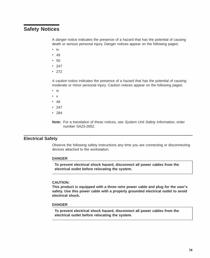
A danger notice indicates the presence of a hazard that has the potential of causingdeath or serious personal injury. Danger notices appear on the following pages:
v ix
v 49
v 50
v 247
v 272
A caution notice indicates the presence of a hazard that has the potential of causingmoderate or minor personal injury. Caution notices appear on the following pages:
v ix
v x
v 49
v 247
v 284
Note: For a translation of these notices, see System Unit Safety Information, ordernumber SA23-2652.
Electrical SafetyObserve the following safety instructions any time you are connecting or disconnectingdevices attached to the workstation.
DANGER
To prevent electrical shock hazard, disconnect all power cables from theelectrical outlet before relocating the system.
CAUTION:This product is equipped with a three–wire power cable and plug for the user’ssafety. Use this power cable with a properly grounded electrical outlet to avoidelectrical shock.
DANGER
To prevent electrical shock hazard, disconnect all power cables from theelectrical outlet before relocating the system.
ix

Laser Safety Information
CAUTION:This product may contain a CD-ROM which is a class 1 laser product.
Laser ComplianceAll lasers are certified in the U.S. to conform to the requirements of DHHS 21 CFRSubchapter J for class 1 laser products. Outside the U.S., they are certified to be incompliance with the IEC 825 (first edition 1984) as a class 1 laser product. Consult thelabel on each part for laser certification numbers and approval information.
CAUTION:All IBM laser modules are designed so that there is never any human access tolaser radiation above a class 1 level during normal operation, user maintenance,or prescribed service conditions. Data processing environments can containequipment transmitting on system links with laser modules that operate atgreater than class 1 power levels. For this reason, never look into the end of anoptical fiber cable or open receptacle. Only trained service personnel shouldperform the inspection or repair of optical fiber cable assemblies and receptacles.
x Service Guide

Data Integrity and VerificationIBM computer systems contain mechanisms designed to reduce the possibility ofundetected data corruption or loss. This risk, however, cannot be eliminated. Users whoexperience unplanned outages, system failures, power fluctuations or outages, orcomponent failures must verify the accuracy of operations performed and data saved ortransmitted by the system at or near the time of the outage or failure. In addition, usersmust establish procedures to ensure that there is independent data verification beforerelying on such data in sensitive or critical operations. Users should periodically checkthe IBM support websites for updated information and fixes applicable to the system andrelated software.
xi

xii Service Guide
About This Book
This book provides maintenance information that is specific to the 9112 Model 265 aswell as adapters and attached devices that do not have their own service information. Italso contains Maintenance Analysis Procedures (MAPs) that are not common to othersystems. In this book, the 9112 Model 265 are hereafter referred to as the ″system.″
MAPs that are common to all systems are contained in the RS/6000 Eserver pSeriesDiagnostic Information for Multiple Bus Systems.
This book is used by the service technician to repair system failures. This bookassumes that the service technician has had training on the system unit.
ISO 9000ISO 9000 registered quality systems were used in the development and manufacturingof this product.
Related PublicationsThe following publications provide additional information about your system unit:
v The IntelliStation POWER 9112 Model 265 Installation Guide, order numberSA38-0607, contains information on how to set up and cable the system, install andremove options, and verify system operation.
v The IntelliStation POWER 9112 Model 265 User’s Guide, order number SA38-0608,contains information to help users use the system, use the service aids, and solveminor problems.
v The RS/6000 Eserver pSeries Diagnostic Information for Multiple Bus Systems,order number SA38-0509, contains diagnostic information, service request numbers(SRNs), and failing function codes (FFCs).
v The RS/6000 Eserver pSeries Adapters, Devices, and Cable Information forMultiple Bus Systems, order number SA38-0516, contains information aboutadapters, devices, and cables for your system. This manual is intended tosupplement the service information found in the RS/6000 Eserver pSeriesDiagnostic Information for Multiple Bus Systems.
v The Site and Hardware Planning Guide, order number SA38-0508, containsinformation to help you plan your installation.
v The System Unit Safety Information, order number SA23-2652, contains translationsof safety information used throughout this book.
v The PCI Adapter Placement Reference, order number SA38-0538, containsinformation regarding slot restrictions for adapters that can be used in this system.
xiii
TrademarksThe following terms are trademarks of International Business Machines Corporation inthe United States, other countries, or both:
v AIX
v IBM
v PowerPC
v pSeries
v e (logo)
v IntelliStation
Other company, product, and service names may be trademarks or service marks ofothers.
xiv Service Guide
Chapter 1. Reference Information
System Unit Locations
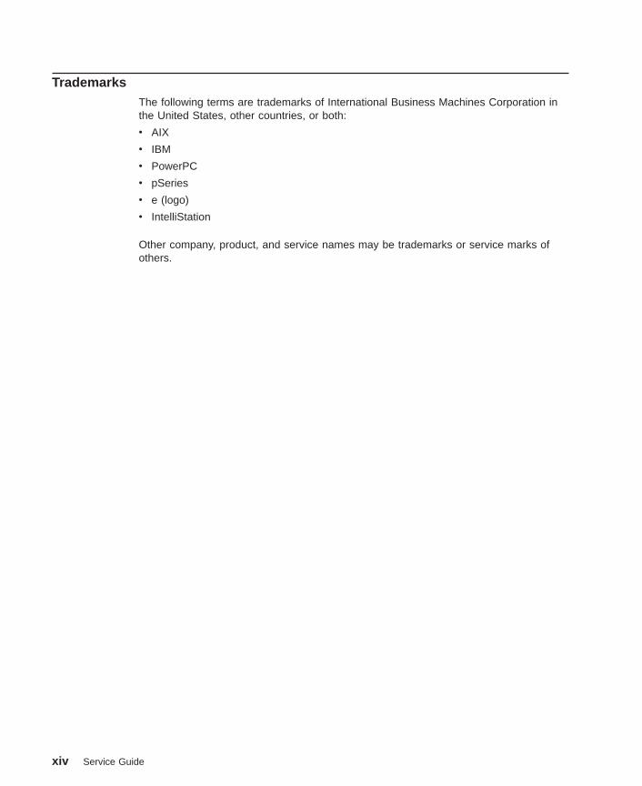
Front View
1
2
3
4
5
6
1 Diskette drive2 Hot-swap disk drives (optional on some systems)3 Cover release lever4 CD-ROM drive5 Media bay6 Operator panel
1

Rear View
1
4
2
3
5
6
7
89
101112131415
16
1 PCI slots2 PCI slots 1-2 (64-Bit/3.3V)3 PCI slot 3 (64-Bit/5V)4 PCI slots 4-5 (32-Bit/5V)5 Parallel connector6 SCSI connector7 Attention LED8 Rack indicator connector9 Power LED10 Ethernet connector 211 Serial connector 112 Ethernet connector 113 Serial connector 314 Serial connector 215 Mouse connector16 Keyboard connector
2 Service Guide
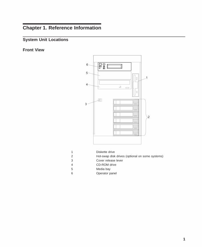
Power Supply Locations
1 2 3
4
56
7
1 Power supply 1
2 Power supply 2
3 Filler panel or power supply 3
4 Power supply 2 power connector
5 Power supply 1 power connector
6 DC power light
7 AC power light
Chapter 1. Reference Information 3
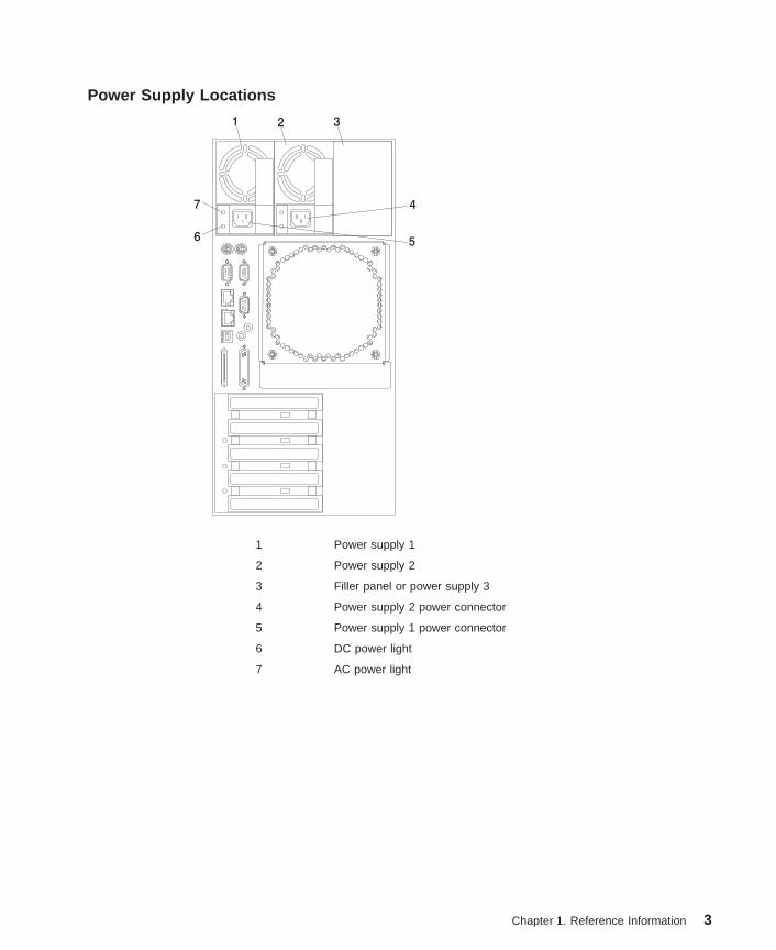
Fan Locations
1
2
3
4
1 Fan #1
2 Fan #2
3 Fan #3
4 Fan #4
4 Service Guide

System Board Locations
23 6
4
5
8
9
10
11
12
1314
17 1518 16
19
20
21
22
23
24
7
1
1 Rear serial port (#1) connector 2 Rear power and attention LED connector
3 Processor power connector 4 Processor #2 card connector
5 Processor #1 card connector 6 Power connector
7 Power connector 8 Power connector
9 Power connector 10 Light path card connector
11 Processor fans 12 Blowers
13 Diskette connector 14 Memory card connector
15 Front serial port connector 16 Operator panel connector
17 CD-ROM IDE connector 18 Internal SCSI connector
19 - 20 32-bit PCI connectors(33MHz, 5V)
21 64-bit PCI connector(33MHz, 5V)
22 - 23 64-bit PCI connector(50MHz, 3.3V)
24 Battery connector
Chapter 1. Reference Information 5
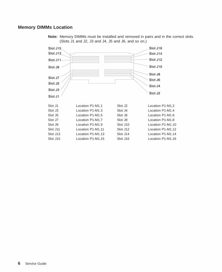
Memory DIMMs Location
Note: Memory DIMMs must be installed and removed in pairs and in the correct slots.(Slots J1 and J2, J3 and J4, J5 and J6, and so on.)
Slot J1
Slot J3Slot J4
Slot J2
Slot J5Slot J6
Slot J9 Slot J10
Slot J11 Slot J12
Slot J13 Slot J14
Slot J15 Slot J16
Slot J7Slot J8
Slot J1 Location P1-M1.1 Slot J2 Location P1-M1.2Slot J3 Location P1-M1.3 Slot J4 Location P1-M1.4Slot J5 Location P1-M1.5 Slot J6 Location P1-M1.6Slot J7 Location P1-M1.7 Slot J8 Location P1-M1.8Slot J9 Location P1-M1.9 Slot J10 Location P1-M1.10Slot J11 Location P1-M1.11 Slot J12 Location P1-M1.12Slot J13 Location P1-M1.13 Slot J14 Location P1-M1.14Slot J15 Location P1-M1.15 Slot J16 Location P1-M1.16
6 Service Guide
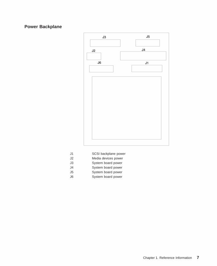
Power Backplane
J3
J2 J4
J1J6
J5
J1 SCSI backplane powerJ2 Media devices powerJ3 System board powerJ4 System board powerJ5 System board powerJ6 System board power
Chapter 1. Reference Information 7

Operator Panel
4
5
1 2 3
1 Power-On Switch2 Reset Switch3 Display4 Attention LED5 Power-On LED
8 Service Guide
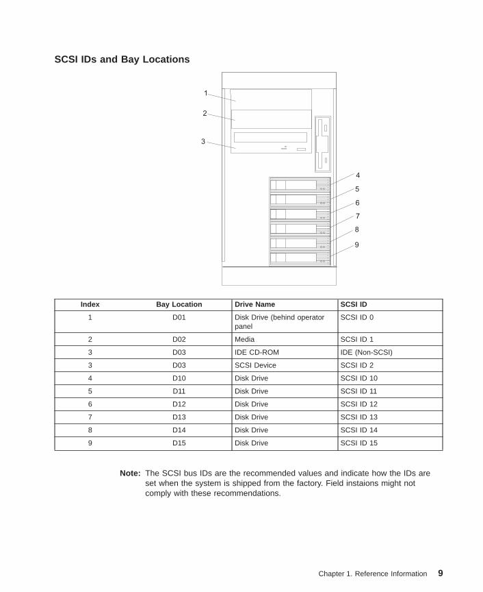
SCSI IDs and Bay Locations
1
2
3
4
5
6
7
8
9
Index Bay Location Drive Name SCSI ID
1 D01 Disk Drive (behind operatorpanel
SCSI ID 0
2 D02 Media SCSI ID 1
3 D03 IDE CD-ROM IDE (Non-SCSI)
3 D03 SCSI Device SCSI ID 2
4 D10 Disk Drive SCSI ID 10
5 D11 Disk Drive SCSI ID 11
6 D12 Disk Drive SCSI ID 12
7 D13 Disk Drive SCSI ID 13
8 D14 Disk Drive SCSI ID 14
9 D15 Disk Drive SCSI ID 15
Note: The SCSI bus IDs are the recommended values and indicate how the IDs areset when the system is shipped from the factory. Field instaions might notcomply with these recommendations.
Chapter 1. Reference Information 9
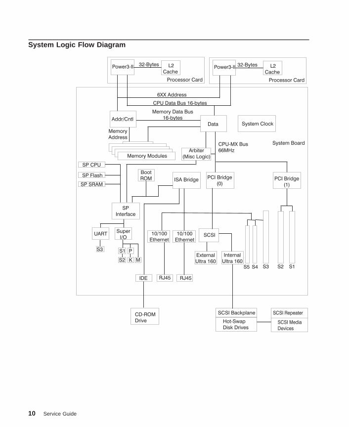
System Logic Flow Diagram
Power3-II Power3-II
Processor Card Processor Card
System Board
Addr/Cntl
Memory
Address
Memory Data Bus
16-bytes
6XX Address
CPU Data Bus 16-bytes
CPU-MX Bus
66MHzMemory Modules
Data System Clock
Arbiter
(Misc Logic)
S4 S3 S2 S1S5
PCI Bridge
(0)ISA Bridge
SCSI
CD-ROM
Drive
SCSI Backplane SCSI Repeater
Hot-Swap
Disk DrivesSCSI Media
Devices
Internal
Ultra 160External
Ultra 160
RJ45 RJ45IDE
10/100
Ethernet10/100
Ethernet
Boot
ROM
SP CPU
SP Flash
SP SRAM
SP
Interface
Super
I/OUART
S3 P
K
S1
S2 M
PCI Bridge
(1)
L2
CacheL2
Cache
32-Bytes 32-Bytes
10 Service Guide

Location CodesThis system unit uses physical location codes in conjunction with AIX location codes toprovide mapping of the failing field replaceable units. The location codes are producedby the system unit’s firmware and AIX.
Physical Location CodesPhysical location codes provide a mapping of logical functions in a platform (orexpansion sites for logical functions, such as connectors or ports) to their specificlocations within the physical structure of the platform.
Location Code FormatThe location code is an alphanumeric string of variable length, consisting of a series oflocation identifiers, separated by a dash (-), or slash (/), or a pound sign (#) character.The series is hierarchical; that is, each location identifier in the string is a physical orlogical child of the one preceding it.
v The - (dash) separator character represents a normal structural relationship wherethe child is a separate physical package and it plugs into (or is connected to) theparent. For example, P1-C1 is a processor card (C1) plugged into a planar (P1), orP1-M1 is a memory card (M1) plugged into a planar (P1).
v The / (slash) separator character separates the base location code of a function fromany extended location information. A group of logical devices can have the samebase location code because they are all on the same physical package, but mayrequire extended location information to describe the connectors they support. Forexample, P2/S1 describes the location of the serial port 1 controller and its connector(S1), which is located on planar P2 (its base location code), but the / indicates thatfurther devices can be connected to it at the external S1 serial connector. Thekeyboard controller and its connector likewise have location code P2/K1, whichmeans they have the same base location code (P2) as serial port 1, but a differentexternal connector. In contrast, the location code P2-K1 actually points to the deviceconnected to connector K1; that is, the keyboard. The location code P2/Z1 indicatesan integrated SCSI controller which drives connector Z1, while location codes ofP2-Z1-... point to the actual SCSI bus and devices.
v The # (pound sign) separator character indicates a cable connection between aconnector and parent.
The following are examples:
v P1-C1 identifies processor card C1 plugged into planar P1.
v P1-M1 identifies memory card M1 plugged into planar P1.
v P2/S1 identifies serial port 1 controller on I/O board P2 or the connector for serialport 1.
v P1-K1 identifies a keyboard attached to connector K1 on planar P1.
v P2/Z1 identifies an integrated SCSI port controller on planar P2 which drivesconnector Z1.
v P2-Z1-... points to the actual SCSI bus and devices attached to Z1.
Chapter 1. Reference Information 11
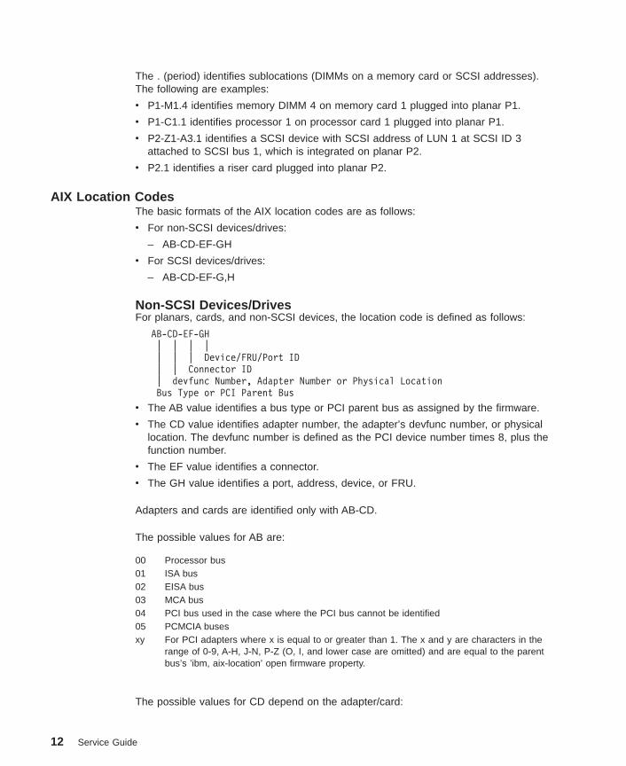
The . (period) identifies sublocations (DIMMs on a memory card or SCSI addresses).The following are examples:
v P1-M1.4 identifies memory DIMM 4 on memory card 1 plugged into planar P1.
v P1-C1.1 identifies processor 1 on processor card 1 plugged into planar P1.
v P2-Z1-A3.1 identifies a SCSI device with SCSI address of LUN 1 at SCSI ID 3attached to SCSI bus 1, which is integrated on planar P2.
v P2.1 identifies a riser card plugged into planar P2.
AIX Location CodesThe basic formats of the AIX location codes are as follows:
v For non-SCSI devices/drives:
– AB-CD-EF-GH
v For SCSI devices/drives:
– AB-CD-EF-G,H
Non-SCSI Devices/DrivesFor planars, cards, and non-SCSI devices, the location code is defined as follows:
AB-CD-EF-GH| | | || | | Device/FRU/Port ID| | Connector ID| devfunc Number, Adapter Number or Physical LocationBus Type or PCI Parent Bus
v The AB value identifies a bus type or PCI parent bus as assigned by the firmware.
v The CD value identifies adapter number, the adapter’s devfunc number, or physicallocation. The devfunc number is defined as the PCI device number times 8, plus thefunction number.
v The EF value identifies a connector.
v The GH value identifies a port, address, device, or FRU.
Adapters and cards are identified only with AB-CD.
The possible values for AB are:
00 Processor bus01 ISA bus02 EISA bus03 MCA bus04 PCI bus used in the case where the PCI bus cannot be identified05 PCMCIA busesxy For PCI adapters where x is equal to or greater than 1. The x and y are characters in the
range of 0-9, A-H, J-N, P-Z (O, I, and lower case are omitted) and are equal to the parentbus’s ’ibm, aix-location’ open firmware property.
The possible values for CD depend on the adapter/card:
12 Service Guide
v For pluggable PCI adapters/cards, CD is the device’s devfunc number (PCI devicenumber times 8, plus the function number). The C and D are characters in the rangeof 0-9, and A-F (hex numbers). Location codes therefore uniquely identify multipleadapters on individual PCI cards.
v For pluggable ISA adapters, CD is equal to the order of the ISA cardsdefined/configured either by SMIT or the ISA Adapter Configuration Service Aid.
v For an integrated ISA adapters, CD is equal to a unique code identifying the ISAadapter. In most cases, this code is equal to the adapter’s physical location code. Incases where a physical location code is not available, CD will be FF.
EF is the connector ID. It is used to identify the adapter’s connector to which a resourceis attached.
GH is used to identify a port, device, or FRU. For example:
v For async, devices GH defines the port on the fanout box. The values re 00 a to 15.
v For a diskette drive, H identifies either diskette drive 1 or 2. G is always 0.
v For all other devices, GH is equal to 00.
For an integrated adapter, EF-GH is the same as the definition for a pluggable adapter.For example, the location code for a diskette drive is 01-D1-00-00. A second diskettedrive is 01-D1-00-01.
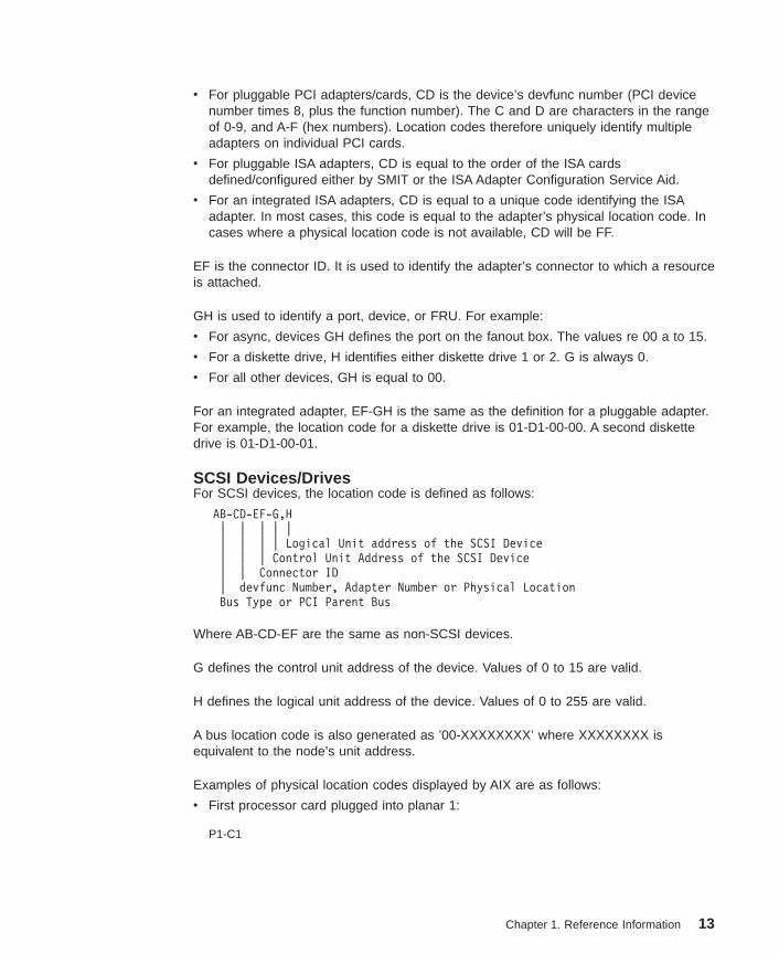
SCSI Devices/DrivesFor SCSI devices, the location code is defined as follows:
AB-CD-EF-G,H| | | | || | | | Logical Unit address of the SCSI Device| | | Control Unit Address of the SCSI Device| | Connector ID| devfunc Number, Adapter Number or Physical LocationBus Type or PCI Parent Bus
Where AB-CD-EF are the same as non-SCSI devices.
G defines the control unit address of the device. Values of 0 to 15 are valid.
H defines the logical unit address of the device. Values of 0 to 255 are valid.
A bus location code is also generated as ’00-XXXXXXXX’ where XXXXXXXX isequivalent to the node’s unit address.
Examples of physical location codes displayed by AIX are as follows:
v First processor card plugged into planar 1:
P1-C1
Chapter 1. Reference Information 13

v Second memory card in planar P1:
P1-M2
v Memory DIMM 12 on second memory card plugged into planar P1:
P1-M2.12
Examples of AIX location codes displayed are as follows:
v Integrated PCI adapter:
10-80 Ethernet10-60 Integrated SCSI Port 1 (internal)10-88 Integrated SCSI Port 2 (external)
v Pluggable PCI adapters:
20-58 to 20-5F Any PCI card in slot 120-60 to 20-67 Any PCI card in slot 210-68 to 10-6F Any PCI card in slot 310-70 to 10-77 Any PCI card in slot 410-78 to 10-7F Any PCI card in slot 5
v Integrated ISA adapters:
01-D1 Diskette adapter01-R1 Parallel port adapter01-S1 Serial port 1 adapter01-S2 Serial port 2 adapter01-S3 Serial port 3 adapter01-K1 Keyboard adapter
v Device attached to SCSI controller:
10-60-00-4,0 Device attached to integrated SCSI Port 1
14 Service Guide
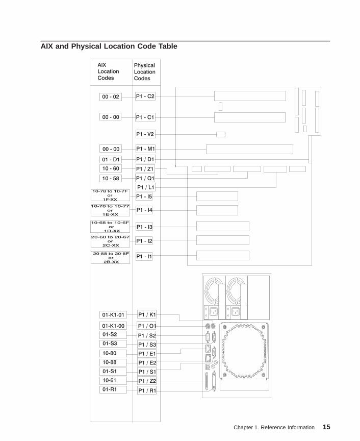
AIX and Physical Location Code Table
AIX
Location
Codes
Physical
Location
Codes
10-78 to 10-7F
or
1F-XX
10-70 to 10-77
or
1E-XX
10-68 to 10-6F
or
1D-XX
20-60 to 20-67
or
2C-XX
20-58 to 20-5F
or
2B-XX
P1 - I1
P1 - I2
P1 - I3
P1 - I4
P1 - I5
P1 - C200 - 02
00 - 00
00 - 00
01 - D1
10 - 60
10 - 58
01-K1-00
01-S2
01-S3
10-80
10-88
01-S1
10-61
01-R1
01-K1-01
P1 - C1
P1 - V2
P1 - M1
P1 / D1
P1 / Z1
P1 / Q1
P1 / L1
P1 / O1
P1 / S2
P1 / S3
P1 / E1
P1 / E2
P1 / S1
P1 / Z2
P1 / R1
P1 / K1
Chapter 1. Reference Information 15

Component Name AIX Location Code Physical LocationCode
Logical Identification
Central Electronics Complex (CEC)
System Board 00-00 P1
Processor Card 1 00-00 P1-C1 Processor 0
Processor Card 2 00-02 P1-C2 Processor 2
Memory Card 00-00 P1-M1
Memory DIMMs onMemory Card
00-00 P1-M1.1 thruP1-M1.16
Extents:0H, 0L, 2H, 2L, 4H,4L, 6H, 6L, 1H, 1L,3H, 3L, 5H, 5L, 7H, 7L
Integrated Devices
Diskette Drive 01-D1-00-00 P1-D1
Keyboard 01-K1-00-00 P1/K1-K1
Mouse 01-K1-01-00 P1/O1-O1
Diskette Port 01-D1 P1/D1
Keyboard Port 01-K1-00 P1/K1
Mouse Port 01-K1-01 P1/O1
Serial Port 1 01-S1 P1/S1
Serial Port 2 01-S2 P1/S2
Serial Port 3 01-S3 P1/S3
Parallel Port 01-R1 P1/R1
Ethernet Port 1 10-80 P1/E1
Ethernet Port 2 10-88 P1/E2
Internal SCSI Port 10-60 P1/Z1
External SCSI Port 10-61 P1/Z2
IDE Port 10-58 P1/Q1
Base CD-ROM (IDE)in bay D03
10-59 P1/Q1–A2
Pluggable Adapters
PCI Host Bridge 1 00-FEE00000 P1
Card in PCI Slot 1 20-58 to 20-5F or2B-xx
P1-I1
Card in PCI Slot 2 20-60 to 20-67 or2C-xx
P1-I2
PCI Host Bridge 0 00-FEF00000 P1
Card in PCI Slot 3 10-68 to 10-6F or1D-xx
P1-I3
Card in PCI Slot 4 10-70 to 10-77 or1E-xx
P1-I4
16 Service Guide

Component Name AIX Location Code Physical LocationCode
Logical Identification
Card in PCI Slot 5 10-78 to 10-7F or1F-xx
P1-I5
SCSI Devices
SCSI Backplane N/A P2
SCSI RepeaterBackplane
N/A N/A
SCSI Device in bayD01
10-60-00-0,0 P1/Z1–A0 Internal SCSI Bus ID 0
SCSI Device in bayD02
10-60-00-1,0 P1/Z1-A1 Internal SCSI Bus ID 1
SCSI Device in bayD03
10-60-00-2,0 P1/Z1-A2 Internal SCSI Bus ID 2
SAF-TE Controller 10-60-00-9-0 P1/Z1–A9 SCSI EnclosureServices Controller
Hot-swap DASD bay 1 10-60-00-10,0 P1/Z1-Aa Primary SCSI Bus ID10
Hot-swap DASD bay 2 10-60-00-11,0 P1/Z1-Ab Primary SCSI Bus ID11
Hot-swap DASD bay 3 10-60-00-12,0 P1/Z1-Ac Primary SCSI Bus ID12
Hot-swap DASD bay 4 10-60-00-13,0 P1/Z1-Ad Primary SCSI Bus ID13
Hot-swap DASD bay 5 10-60-00-14,0 P1/Z1-Ae Primary SCSI Bus ID14
Hot-swap DASD bay 6 10-60-00-15,0 P1/Z1-Af Primary SCSI Bus ID15
Fans
Fan 1 F1 Fan
Fan 2 F2 Fan
Fan 3 F3 Fan
Fan 4 F4 Fan
Operator Panel
Operator panel L1
LightpathLED panel
L2
Power Supply
Power backplane P3
Power supply 1 P3-V1
Power supply 2 P3-V2
Power supply 3 P3-V3
Chapter 1. Reference Information 17

Component Name AIX Location Code Physical LocationCode
Logical Identification
Battery
Battery P1-V2
System VPD module
System VPD module L1-N1
Notes:
1. The physical location code for the PCI slots, when empty, uses the P1/Ix notation, where the’/’ identifies an integrated device (in this case the empty slot). A PCI device plugged into theslot uses the P1-Ix notation, where the ’-’ identifies a plugged device.
2. The SCSI bus IDs are the recommended values. The SCSI IDs shown for media devicesindicate how the devices are set when they are shipped from the factory. Field installationsmay not comply with these recommendations.
18 Service Guide

System Cables
J6
J5
J3
J4
J1
J2
T
Fan
Fan
Power
Backplane
System Board
Processor Slot
Processor Slot
Diskette
DASD
Operator
Panel
CD-ROM
Tape
Power
Power
SCSI
SCSI
Power
IDE
Power
Signal
Power
SCSI
SCSI
Backplane
Blower
Light
Path
LEDs
RJ45
Serial
Rear
Serial
Port #1
Rear
LEDs
Blower
Chapter 1. Reference Information 19

Specifications
Dimensions
Height 426 mm (16.8 in.)
Width 215 mm (8.5 in..Depth 617 mm (24 in.).WeightMinimum configuration 35.5 kg 78 lbs.Maximum configuration 43.1 kg 94.8 lbs.
ElectricalPower source loading(maximum in kVA)
0.46
Power source loading (typical inkVA)
0.31
Voltage range (V ac) 100 to 127 or 200 to 240 (autoranging)Frequency (hertz) 50 / 60Voltage range (V dc) Not supportedThermal output (maximum) 1536 Btu/hrThermal output (typical) 1024 Btu/hrPower requirements (maximum) 450 wattsPower requirements (typical) 300 wattsPower factor - US, World Trade,Japan
0.98
Inrush current² 70 ampsMaximum altitude³,⁴ 2135 m (7000 ft.)
Temperature Requirements ³ Operating10 to 40°C
(50 to 104°F)
Non-Operating10 to 52°C
(50 to 126°F)
Humidity Requirements ⁴ Operating Non-Operating(Noncondensing) 8 to 80% 8 to 80%Wet Bulb 27°C (80°F) 27°C (80°F)
Noise Emissions ¹,⁵ Operating IdleLWAd 6.1 bels 6.1 bels<LpA>m 42 dBA 41 dBA
Install/Air Flow Maintenance of proper service clearance should allow properair flow.
1. Inrush currents occur only at initial application of power, no inrush occurs during normalpower off-on cycle.
2. The upper limit of the dry bulb temperature must be derated 1 degree C per 137 m (450 ft.)above 915 m (3000 ft.).
3. The upper limit of the wet bulb temperature must be derated 1 degree C per 274 m (900 ft. )above 305 m (1000 ft.).
4. Levels are for a single system installed in a T00 32 EIA rack with the center of the unitapproximately 1500 mm (59 in.) off the floor.
20 Service Guide

Power CablesTo avoid electrical shock, a power cable with a grounded attachment plug is provided.Use only properly grounded outlets.
Power cables used in the United States and Canada are listed by Underwriter’sLaboratories (UL) and certified by the Canadian Standards Association (CSA). Thesepower cords consist of the following:
v Electrical cables, Type SVT or SJT.
v Attachment plugs complying with National Electrical Manufacturers Association(NEMA) 5-15P, that is:
″For 115 V operation, use a UL listed cable set consisting of a minimum 18 AWG, TypeSVT or SJT three-conductor cord a maximum of 15 feet in length and a parallel blade,grounding type attachment plug rated at 15 A, 125 V.″
″For 230 V operation in the United States use a UL listed cable set consisting of aminimum 18 AWG, Type SVT or SJT three-conductor cable a maximum of 15 feet inlength, and a tandem blade, grounding type attachment plug rated at 15 A, 250 V.″
v Appliance couplers complying with International Electrotechnical Commission (IEC)Standard 320, Sheet C13.
Power cables used in other countries consist of the following:
v Electrical cables, Type HD21.
v Attachment plugs approved by the appropriate testing organization for the specificcountries where they are used.
″For units set at 230 V (outside of U.S.): use a cable set consisting of a minimum 18AWG cable and grounding type attachment plug rated 15 A, 250 V. The cable setshould have the appropriate safety approvals for the country in which the equipment willbe installed and should be marked `HAR’.″
Refer to Chapter 10, “Parts Information” on page 293 to find the power cables that areavailable.
Chapter 1. Reference Information 21

Service Inspection GuidePerform a service inspection on the system when:
v The system is inspected for a maintenance agreement.
v Service is requested and service has not recently been performed.
v An alterations and attachments review is performed.
v Changes have been made to the equipment that may affect the safe operation of theequipment.
v External devices with their own power cables have those cables attached.
If the inspection indicates an unacceptable safety condition, the condition must becorrected before anyone can service the machine.
Note: The owner of the system is responsible to correct any unsafe conditions.
Perform the following checks:
1. Check the covers for sharp edges and for damage or alterations that expose theinternal parts of the system.
2. Check the covers for proper fit to the system. They should be in place and secure.
3. Gently rock the system from side to side to determine if it is steady.
4. Set the power switch of the system to Off.
5. Remove the covers.
6. Check for alterations or attachments. If there are any, check for obvious safetyhazards, such as broken wires, sharp edges, or broken insulation.
7. Check the internal cables for damage.
8. Check for dirt, water, and any other contamination within the system.
9. Check the voltage label on the back of the system to ensure that it matches thevoltage at the outlet.
10. Check the external power cable for damage.
11. With the external power cable connected to the system, check for 0.1 ohm or lessresistance between the ground lug on the external power cable plug and the metalframe.
12. Perform the following checks on each device that has its own power cables:
a. Check for damage to the power cord.
b. Check for the correctly grounded power cable.
c. With the external power cable connected to the device, check for 0.1 ohm orless resistance between the ground lug on the external power cable plug andthe metal frame of the device.
13. Install the covers.
22 Service Guide

Chapter 2. Diagnostic Overview
The system uses an integrated set of software diagnostic procedures to facilitateisolation of failing components and system maintenance. This book, along with theRS/6000 Eserver pSeries Diagnostic Information for Multiple Bus Systems, is thebasis of the diagnostic procedures for the system. In particular, Chapter 4,“Checkpoints” on page 81, Chapter 5, “Error Code to FRU Index” on page 109,Chapter 6, “Loading the System Diagnostics” on page 175, and Chapter 10, “PartsInformation” on page 293, in this book are important for the trained servicerepresentative to understand and use when isolating a failure on the system.
The manufacturer recommends that systems configured with 4 GB of memory orgreater have access to a 4-mm or 8-mm tape drive for submission of system dumpinformation if required. This function can be accomplished through locally attached ornetwork-attached devices, as appropriate.
Maintenance Analysis Procedures (MAPs)Maintenance Analysis Procedures (MAPs) guide the trained service person through thesystem. These MAPs are the entry point for all isolation and error recovery procedures.The MAPs are consistent with existing procedures and methods. The system uses a setof integrated procedures, mentioned earlier, to which the MAPs are the primary entrypoint.
The MAPS are as follows:
v Entry MAP
v Quick Entry MAP
v Problem Determination MAP
v Power MAP
v Minimum Configuration MAP
The Entry Map is the starting point for problem determination. The purpose of this MAPis to quickly point to the appropriate MAP or service reference information either in thisbook, or in the common book set, which includes the RS/6000 Eserver pSeriesDiagnostic Information for Multiple Bus Systems and PCI Adapter PlacementReference.
The Quick Entry MAP is a subset of the Entry MAP and helps to save time for sometypes of problems.
The Problem Determination MAP provides a structured analysis method to get an errorcode if one is not provided by the customer, or if diagnostics cannot be loaded.
The Power MAP deals with isolation of components to diagnose a power problem.Power problems can be related to powering on and powering off the system, or powerfailures that occur after power is turned on.
23
The Minimum Configuration MAP is used to locate defective components not found bynormal diagnostics or error-isolation methods. This MAP provides a systematic methodof isolation to the failing item or items.
Attention LED and Lightpath LEDsThe Attention and Lightpath LEDs provide a means to identify failing components inyour server. When a failing component is detected in your server, the Attention LED isturned on. To further help you identify the failing component, go to the indicator panel(see “Indicator Panel”) inside the server and check which LEDs are on.
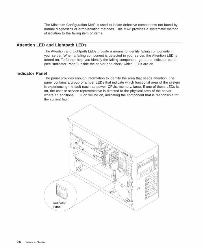
Indicator PanelThe panel provides enough information to identify the area that needs attention. Thepanel contains a group of amber LEDs that indicate which functional area of the systemis experiencing the fault (such as power, CPUs, memory, fans). If one of these LEDs ison, the user or service representative is directed to the physical area of the serverwhere an additional LED on will be on, indicating the component that is responsible forthe current fault.
Indicator
Panel
24 Service Guide

The following illustration shows the LEDs on the indicator panel, located inside theserver.
Memory
CPU
PCI
Fan
Fan
System Board
Power Board
1
2
3
4 3
2
1
Component LEDsIn addition to the indicator panel or display, individual LEDs are located on or near thefailing components. The LEDs are either on the component itself or on the carrier of thecomponent (memory card, fan, memory module, CPU).
The LEDs are amber, except for the power supplies. For the power supplies, two greenLEDs (ac power good and dc power good) indicate the fault condition for the powersupply.
Resetting the LEDsTo reset the LEDs:
1. Replace the failing component with the new component.
2. Log in as root user.
3. At the command line, type diag.
4. Select Task Selection .
5. Select Log Repair Action .
6. Select the device that was repaired. (If the device is not listed, select sysplanar0.)
Chapter 2. Diagnostic Overview 25

CheckpointsThe system uses various types of checkpoints, error codes, and SRNs, which arereferred to throughout this book (primarily in Chapter 4, “Checkpoints” on page 81,Chapter 5, “Error Code to FRU Index” on page 109, Chapter 6, “Loading the SystemDiagnostics” on page 175, and Chapter 10, “Parts Information” on page 293). Thesecodes may appear in the service processor boot progress log, the AIX error log, and theoperator panel display. Understanding the definition and relationships of these codes isimportant to the service personnel who are installing or maintaining the system.
Codes that can appear on the operator panel or in error logs are as follows:
CheckpointsCheckpoints display in the operator panel from the time ac power is connectedto the system until the AIX login prompt is displayed after a successfuloperating system boot. These checkpoints have the following forms:
E000 - E075These checkpoints display from the time ac power is connected to thesystem until the OK prompt displays on the operator panel display.During this time, the service processor performs self-test and NVRAMinitialization.
E0A0 - E0E1When power on is initiated, the service processor starts built-inself-test (BIST) on the central electronics complex (CEC). VPD data isread.
E0E2 - E2xxThis range indicates that the system processor is in control and isinitializing system resources.
E3xx These codes indicate that the system processor is running memorytests.
E1xx The system firmware attempts to boot from devices in the boot list.Control is passed to AIX when E105 (normal mode boot) or E15B(service mode boot) displays on the operator panel display.
0xxx and 2xxx0xxx codes are AIX checkpoints and configuration codes. Locationcodes may also be shown on the operator panel display during thistime.
Error CodesIf a fault is detected, an 8-digit error code is displayed in the operator paneldisplay. A location code may be displayed at the same time on the second lineof the display.
Checkpoints can become error codes if the system fails to advance past thepoint at which the code was presented.
For a list of checkpoints, see Chapter 4, “Checkpoints” on page 81. Each entryprovides a description of the event and the recommended action if the systemfails to advance.
26 Service Guide

SRNs Service request numbers, in the form xxx-xxx, may also be displayed on theoperator panel display and be noted in the AIX error log.
SRNs are listed in the Diagnostic Information for Multiple Bus Systems.
FRU IsolationFor a list of error codes and recommended actions for each code, see Chapter 5, “ErrorCode to FRU Index” on page 109. These actions can refer to Chapter 10, “PartsInformation” on page 293, Chapter 3, “Maintenance Analysis Procedures (MAPs)” onpage 31, or provide informational message and directions. If a replacement part isindicated, direct reference is made to the part name. The respective AIX and physicallocation codes are listed for each occurrence as required. For a list of locations codes,see “Location Codes” on page 11.
To look up part numbers and view component diagrams, see Chapter 10, “PartsInformation” on page 293. The beginning of that chapter provides a parts index with thepredominant field replaceable units (FRUs) listed by name. The remainder of thechapter provides illustrations of the various assemblies and components that make upthe system.
Electronic Service Agent for the RS/6000Service support for the system can be enhanced through the use of the applicationprogram, Electronic Service Agent for the RS/6000. This application provides a numberof advantages for the customer, including automatic error reporting and analysis withoutcustomer intervention. The Electronic Service Agent kit ships with the system andincludes the following:
v Electronic Service Agent for the RS/6000 program on CD-ROM
v The manual Electronic Service Agent for the RS/6000 User’s Guide.
If the manual is not included, it can be downloaded from the following Web site:ftp://ftp.software.ibm.com/aix/.
Using the Service Processor and Electronic Service Agent FeaturesThe service processor and Electronic Service Agent features protect users againstunnecessary system downtime by advising support personnel (both internal andexternal) of any unexpected changes in the system environment. In combination, thetwo features provide a flexible solution to automated system maintenance.
Service ProcessorThe service processor runs on its own power boundary and continually monitorshardware attributes, the AIX operating system, and the environmental conditions withinthe system. Any system failure which prevents the system from coming back to anoperational state (a fully functional AIX operating system) is reported by the serviceprocessor. The service processor is controlled by firmware and does not require the AIX
Chapter 2. Diagnostic Overview 27
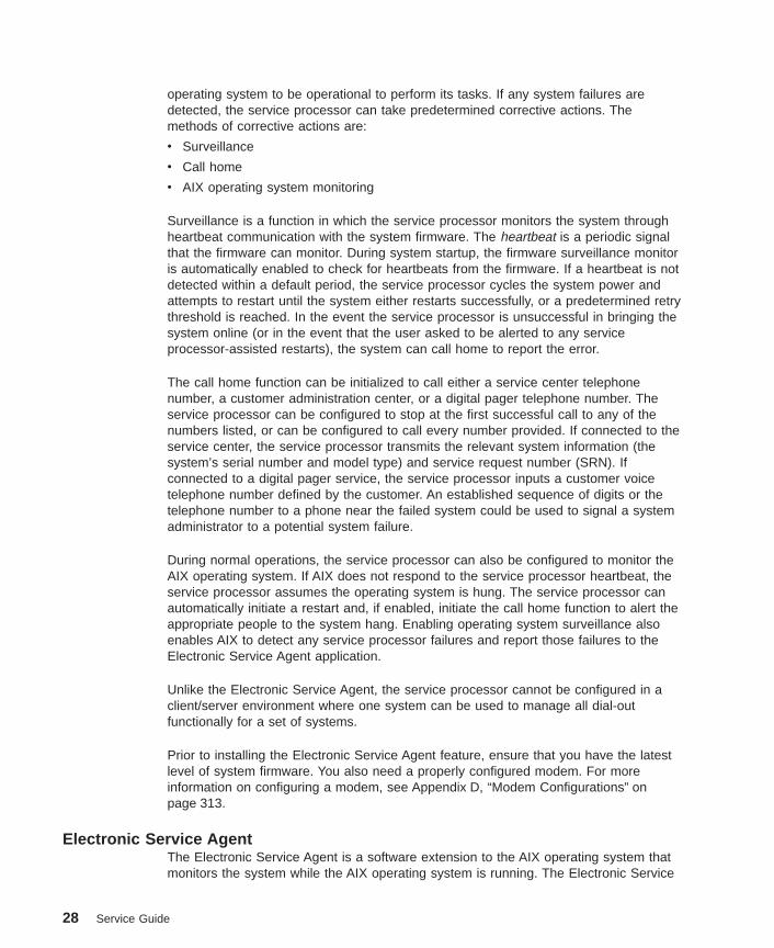
operating system to be operational to perform its tasks. If any system failures aredetected, the service processor can take predetermined corrective actions. Themethods of corrective actions are:
v Surveillance
v Call home
v AIX operating system monitoring
Surveillance is a function in which the service processor monitors the system throughheartbeat communication with the system firmware. The heartbeat is a periodic signalthat the firmware can monitor. During system startup, the firmware surveillance monitoris automatically enabled to check for heartbeats from the firmware. If a heartbeat is notdetected within a default period, the service processor cycles the system power andattempts to restart until the system either restarts successfully, or a predetermined retrythreshold is reached. In the event the service processor is unsuccessful in bringing thesystem online (or in the event that the user asked to be alerted to any serviceprocessor-assisted restarts), the system can call home to report the error.
The call home function can be initialized to call either a service center telephonenumber, a customer administration center, or a digital pager telephone number. Theservice processor can be configured to stop at the first successful call to any of thenumbers listed, or can be configured to call every number provided. If connected to theservice center, the service processor transmits the relevant system information (thesystem’s serial number and model type) and service request number (SRN). Ifconnected to a digital pager service, the service processor inputs a customer voicetelephone number defined by the customer. An established sequence of digits or thetelephone number to a phone near the failed system could be used to signal a systemadministrator to a potential system failure.
During normal operations, the service processor can also be configured to monitor theAIX operating system. If AIX does not respond to the service processor heartbeat, theservice processor assumes the operating system is hung. The service processor canautomatically initiate a restart and, if enabled, initiate the call home function to alert theappropriate people to the system hang. Enabling operating system surveillance alsoenables AIX to detect any service processor failures and report those failures to theElectronic Service Agent application.
Unlike the Electronic Service Agent, the service processor cannot be configured in aclient/server environment where one system can be used to manage all dial-outfunctionally for a set of systems.
Prior to installing the Electronic Service Agent feature, ensure that you have the latestlevel of system firmware. You also need a properly configured modem. For moreinformation on configuring a modem, see Appendix D, “Modem Configurations” onpage 313.
Electronic Service AgentThe Electronic Service Agent is a software extension to the AIX operating system thatmonitors the system while the AIX operating system is running. The Electronic Service
28 Service Guide

Agent monitors and analyzes all recoverable system failures, and, if needed, canautomatically place a service call to a service center (without user intervention).
The service center receives the machine type/serial number, host name, SRN, and aproblem description. The service center analyzes the problem report and, if warranted,dispatches a service person to the customer site. The service center also determines ifany hardware components need to be ordered prior to the service person’s arrival.
The Electronic Service Agent code also gives the user the option to establish a singlesystem as the problem reporting server. A single system, accessible over the usernetwork, can be used as the central server for all the other systems on the local areanetwork (LAN) that are running the Electronic Service Agent application. If theElectronic Service Agent application on a remote client decides a service request needsto be placed, the client forwards the information to the Electronic Service Agent server,which dials the service center telephone number from its locally attached modem. Inthis scenario, the user only needs to maintain a single analog line for providing call-outcapabilities for a large set of servers.
When used in a Scalable Parallel (SP) environment, a client/server type implementationis configured. The Electronic Service Agent client code runs on each of the SP nodes.The server component runs on the control workstation. In the event of any systemfailures, the relevant information is transmitted to the control workstation through theintegrated Ethernet. Once alerted to the system failure, the control workstation initiatesactions to prepare and send the service request.
A modem is required for enabling automated problem reporting to the IBM servicecenter. Configuration files for several types of modems are included as part of theElectronic Service Agent package. Refer to Appendix D, “Modem Configurations” onpage 313 for more information on configuring your modem.
Chapter 2. Diagnostic Overview 29

30 Service Guide

Chapter 3. Maintenance Analysis Procedures (MAPs)
This chapter contains Maintenance Analysis Procedures (MAPs) for the system.
Notes:
1. If you replace a FRU, go to ″MAP 0410: Repair Checkout″ in the RS/6000 Eserver
pSeries Diagnostic Information for Multiple Bus Systems to verify correct systemoperation.
2. When possible, run online diagnostics in service mode. Online diagnostics performadditional functions compared to standalone diagnostics. This ensures that the errorstate of the system that has been captured in nonvolatile random access memory(NVRAM) is available for your use in fixing the problem. The AIX error log and SMITare only available when diagnostics are run from the hard drive.
3. If more than eight digits are displayed in the operator panel, use only the first eightdigits to find the error in the tables. The digits that display beyond the first eightdigits are location codes that can assist you in diagnosing the problem. See“Location Codes” on page 11.
4. Licensed programs frequently rely on system information stored on the vital productdata (VPD) on the operator panel control assembly. If the MAPs indicate that theoperator panel should be replaced, update the VPD as described in “System VitalProduct Data (VPD) Update Procedure” on page 278.
5. If a network adapter or the system board is replaced, the network administratormust be notified so that the client IP addresses used by the server can be changed.In addition, the operating system configuration of the network controller might needto be changed in order to enable system startup. Also check to ensure that anyclient or server that addresses this system is updated.
6. If you are not able to isolate the problem, try loading standalone diagnostics fromthe CD-ROM or NIM.
31

Quick Entry MAPUse the following table to determine your starting point.
Quick Entry MAP Table of Contents
Problem Description Page No.
Service Actions 33
System Stops With an 8-Digit Number Displayed 33
System Stops With a 4-Digit Number Displayed 33
OK Does Not Appear in the Operator Panel Display Before Pressing thePower On Button
33
System Stops or Hangs With Alternating Numbers Displayed in the OperatorDisplay Panel.
34
There Appears to be a Display Problem (Distortion, Blurring,Etc.) 34
Power and Cooling Problems 34
Flashing 888 in Operator Panel Display 36
Other Symptoms or Problems 36
You Cannot Find the Symptom in this Table 39
32 Service Guide

Symptom Action
Service Actions
You have parts to exchange or acorrective action to perform.
1. Go to Chapter 9, “Removal and Replacement Procedures”on page 247.
2. Go to ″MAP 0410: Repair Checkout″ in the RS/6000Eserver pSeries Diagnostic Information for Multiple BusSystems.
You need to verify that a partexchange or corrective actioncorrected the problem.
Go to ″MAP 0410: Repair Checkout″ in the RS/6000 Eserver
pSeries Diagnostic Information for Multiple Bus Systems.
You need to verify correct systemoperation.
Go to ″MAP 0410: Repair Checkout″ in the RS/6000 Eserver
pSeries Diagnostic Information for Multiple Bus Systems.
System Stops With An 8-Digit Number Displayed
The system stops with an 8-digiterror code displayed in theoperator panel display or on theconsole.
Record the error code. Go to Chapter 5, “Error Code to FRUIndex” on page 109.
System Stops With A 4-Digit Number Displayed
The system stops and a 4-digitnumber is displayed in theoperator panel display or on theconsole.
If the number displayed has the format ″E0xx″ then go to“Service Processor Checkpoints” on page 82.
If the number displayed is in the range ″E1xx-EFFF″, makenote of any location code that is displayed on the second lineof the operator panel. If the location code indicates a card slot(for example, P2-I3), replace the card in the indicated slot. Ifthis does not correct the problem, then go to “FirmwareCheckpoints” on page 88.
For all other numbers, record SRN 101-xxx, where xxx is thelast three digits of the four-digit number displayed in theoperator panel, then go to the ″Fast Path MAP″ in theRS/6000 Eserver pSeries Diagnostic Information for MultipleBus Systems.Note: If the operator panel displays 2 sets of numbers, usethe bottom set of numbers as the error code.
OK does not appear in the operator panel display before pressing the power on button
Chapter 3. Maintenance Analysis Procedures (MAPs) 33
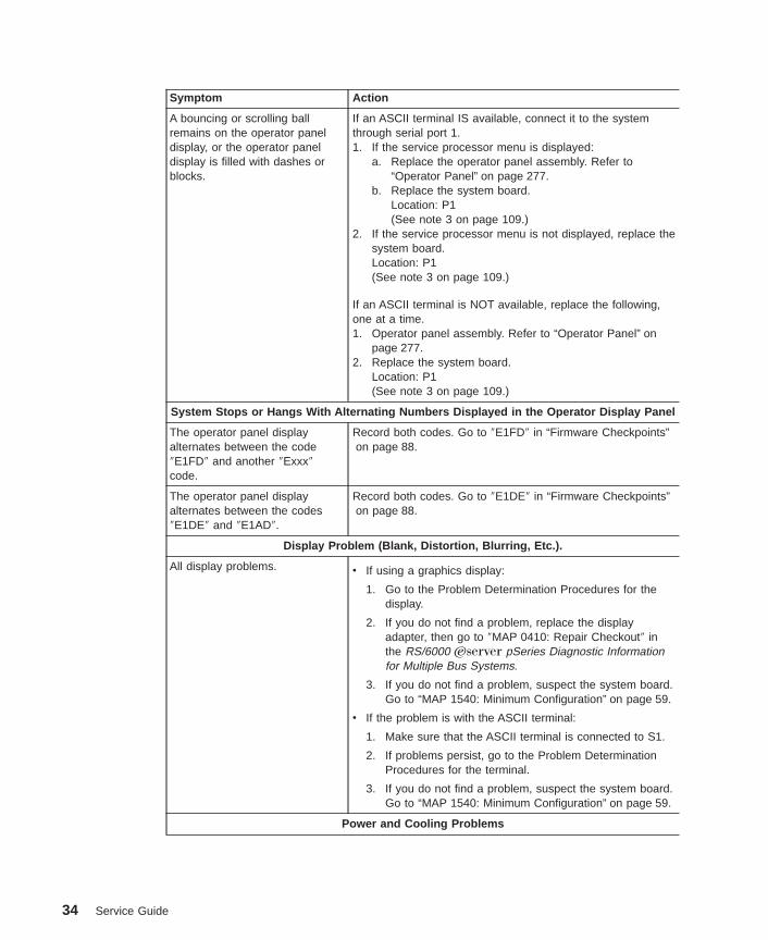
Symptom Action
A bouncing or scrolling ballremains on the operator paneldisplay, or the operator paneldisplay is filled with dashes orblocks.
If an ASCII terminal IS available, connect it to the systemthrough serial port 1.1. If the service processor menu is displayed:
a. Replace the operator panel assembly. Refer to“Operator Panel” on page 277.
b. Replace the system board.Location: P1(See note 3 on page 109.)
2. If the service processor menu is not displayed, replace thesystem board.Location: P1(See note 3 on page 109.)
If an ASCII terminal is NOT available, replace the following,one at a time.1. Operator panel assembly. Refer to “Operator Panel” on
page 277.2. Replace the system board.
Location: P1(See note 3 on page 109.)
System Stops or Hangs With Alternating Numbers Displayed in the Operator Display Panel
The operator panel displayalternates between the code″E1FD″ and another ″Exxx″code.
Record both codes. Go to ″E1FD″ in “Firmware Checkpoints”on page 88.
The operator panel displayalternates between the codes″E1DE″ and ″E1AD″.
Record both codes. Go to ″E1DE″ in “Firmware Checkpoints”on page 88.
Display Problem (Blank, Distortion, Blurring, Etc.).
All display problems. v If using a graphics display:
1. Go to the Problem Determination Procedures for thedisplay.
2. If you do not find a problem, replace the displayadapter, then go to ″MAP 0410: Repair Checkout″ inthe RS/6000 Eserver pSeries Diagnostic Informationfor Multiple Bus Systems.
3. If you do not find a problem, suspect the system board.Go to “MAP 1540: Minimum Configuration” on page 59.
v If the problem is with the ASCII terminal:
1. Make sure that the ASCII terminal is connected to S1.
2. If problems persist, go to the Problem DeterminationProcedures for the terminal.
3. If you do not find a problem, suspect the system board.Go to “MAP 1540: Minimum Configuration” on page 59.
Power and Cooling Problems
34 Service Guide

Symptom Action
The power LEDs on the operatorpanel and power supplies do notstart blinking within 30 secondsof ac power application and theoperator panel display is blank.
Go to ″MAP 1520: Power″, “Step 1520-2” on page 51.
The power LEDs on the operatorpanel and power supplies areblinking and the operator paneldisplay is blank.
Go to ″MAP 1520: Power″, “Step 1520-3” on page 51
The power LED on the operatorpanel is on solid, the powerLEDs on the power supplies areblinking and the operator paneldisplay is blank.
When the power on switch onthe operator panel is pressed,there is no indication of activity.The power LED on the powersupply does not change fromblinking to solid and none of thefans, including the fan in thepower supplies, start to turn.
Go to ″MAP 1520: Power″, “Step 1520-3” on page 51
The power LEDs on the operatorpanel and power supplies areblinking and OK, STBY or DIAGSTBY is displayed on theoperator panel display.
When the power on switch onthe operator panel is pressed,there is no indication of activity.None of the power LEDs changefrom blinking to solid and none ofthe fans, including the fan in thepower supplies, start to turn.
Go to ″MAP 1520: Power″, “Step 1520-3” on page 51
The power LEDs on the operatorpanel and power supplies areblinking and OK, STBY or DIAGSTBY is displayed on theoperator panel display.
When the power on switch onthe operator panel is pressed,the power LEDs change fromblinking to solid and the systembegins to power on, but thepower LEDs on the operatorpanel and power supplies do notstay on and the system powersoff.
Go to ″MAP 1520: Power″, “Step 1520-3” on page 51
Chapter 3. Maintenance Analysis Procedures (MAPs) 35

Symptom Action
The power LED on the operatorpanel is on solid, the power LEDon the power supply is blinkingand OK, STBY or DIAG STBY isdisplayed on the operator paneldisplay.
When the power on switch onthe operator panel is pressed,there is no indication of activity.The power LED on the powersupply does not change fromblinking to solid and none of thefans, including the fans in thepower supplies, start to turn.
Go to ″MAP 1520: Power″, “Step 1520-3” on page 51
The power LEDs on the operatorpanel and power supplies areblinking and OK, STBY or DIAGSTBY is displayed on theoperator panel display.
When the power on switch onthe operator panel is pressed,the power LEDs change fromblinking to solid, the fans comeon and stay on, but the systemdoes not power on.
Go to ″MAP 1520: Power″, “Step 1520-3” on page 51
The power LED on the operatorpanel is on solid, the power LEDon the power supplies areblinking and OK, STBY or DIAGSTBY is displayed on theoperator panel display.
When the power on switch onthe operator panel is pressed,the power LED on the operatorpanel changes from blinking tosolid, the fans come on and stayon, but the system does notpower on.
Go to ″MAP 1520: Power″, “Step 1520-3” on page 51
Flashing 888 in Operator Panel Display
888 is displayed in the operatorpanel.
Go to the ″Fast Path MAP″ in the RS/6000 Eserver pSeriesDiagnostic Information for Multiple Bus Systems.
Other Symptoms or Problems
You have OK displayed. Fansand blowers are off.
The service processor is ready. The system is waiting forpower-on.
36 Service Guide
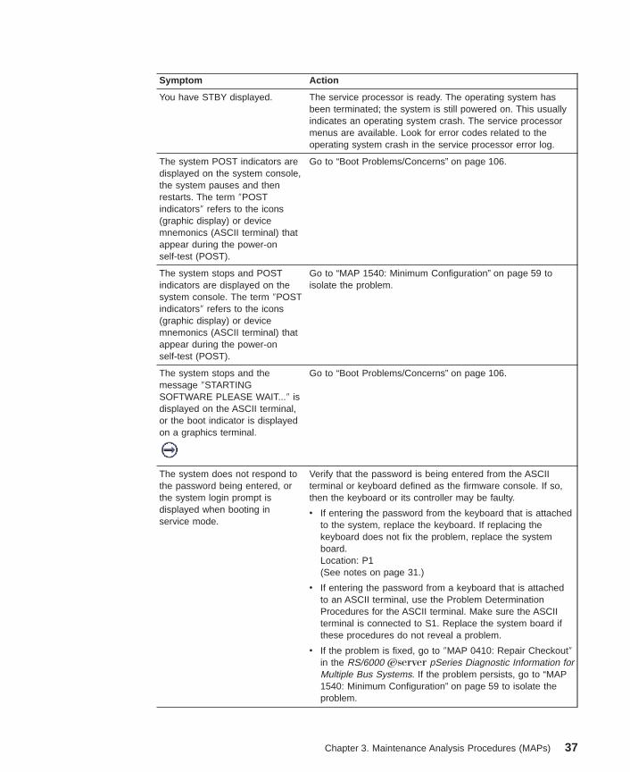
Symptom Action
You have STBY displayed. The service processor is ready. The operating system hasbeen terminated; the system is still powered on. This usuallyindicates an operating system crash. The service processormenus are available. Look for error codes related to theoperating system crash in the service processor error log.
The system POST indicators aredisplayed on the system console,the system pauses and thenrestarts. The term ″POSTindicators″ refers to the icons(graphic display) or devicemnemonics (ASCII terminal) thatappear during the power-onself-test (POST).
Go to “Boot Problems/Concerns” on page 106.
The system stops and POSTindicators are displayed on thesystem console. The term ″POSTindicators″ refers to the icons(graphic display) or devicemnemonics (ASCII terminal) thatappear during the power-onself-test (POST).
Go to “MAP 1540: Minimum Configuration” on page 59 toisolate the problem.
The system stops and themessage ″STARTINGSOFTWARE PLEASE WAIT...″ isdisplayed on the ASCII terminal,or the boot indicator is displayedon a graphics terminal.
Go to “Boot Problems/Concerns” on page 106.
The system does not respond tothe password being entered, orthe system login prompt isdisplayed when booting inservice mode.
Verify that the password is being entered from the ASCIIterminal or keyboard defined as the firmware console. If so,then the keyboard or its controller may be faulty.
v If entering the password from the keyboard that is attachedto the system, replace the keyboard. If replacing thekeyboard does not fix the problem, replace the systemboard.Location: P1(See notes on page 31.)
v If entering the password from a keyboard that is attachedto an ASCII terminal, use the Problem DeterminationProcedures for the ASCII terminal. Make sure the ASCIIterminal is connected to S1. Replace the system board ifthese procedures do not reveal a problem.
v If the problem is fixed, go to ″MAP 0410: Repair Checkout″in the RS/6000 Eserver pSeries Diagnostic Information forMultiple Bus Systems. If the problem persists, go to “MAP1540: Minimum Configuration” on page 59 to isolate theproblem.
Chapter 3. Maintenance Analysis Procedures (MAPs) 37

Symptom Action
No codes are displayed on theoperator panel within a fewseconds of turning on thesystem. The operator panel isblank before the system ispowered on.
Reseat the operator panel cable. If the problem is notresolved, replace these parts in the following order:
1. Operator panel assembly.Location: L1See 4 on page 31.
2. System board (See notes on page 31.)
If the problem is fixed, go to ″MAP 0410: RepairCheckout″ in the RS/6000 Eserver pSeries DiagnosticInformation for Multiple Bus Systems. If the problempersists, go to “MAP 1540: Minimum Configuration” onpage 59 to isolate the problem.
The SMS configuration list orboot sequence selection menushows more SCSI devicesattached to a controller/adapterthan are actually attached.
A device may be set to use the same SCSI bus ID as thecontrol adapter. Note the ID being used by thecontroller/adapter (this can be checked and/or changed via anSMS utility), and verify that no device attached to thecontroller is set to use that ID.
If settings do not appear to be in conflict:
1. Replace the SCSI cable.
2. Replace the device.
3. Replace the SCSI adapter (or system board if connectedto one of the two integrated SCSI controllers on thesystem board). (See notes on page31 if the system boardis replaced.)
Note: In a ″twin-tailed″ configuration where there is morethan one initiator device (normally another system) attachedto the SCSI bus, it may be necessary to change the ID of theSCSI controller or adapter with the System ManagementServices.
The System ManagementServices menu is displayed.
The device or media you are attempting to boot from may befaulty.
1. Check the SMS error log for any errors. To check the errorlog:
a. Choose error log from the utilities menu.
b. If an error is logged, check the time stamp.
c. If the error was logged during the current boot attempt,record it.
d. Look up the error in Chapter 5, “Error Code to FRUIndex” on page 109 and perform the listed action.
e. If no recent error is logged in the error log, continue tothe next step below.
2. Go to “Boot Problems/Concerns” on page 106.
3. Go to “MAP 1540: Minimum Configuration” on page 59.
You have a problem that doesnot prevent the system frombooting.
Go to the ″Fast Path MAP″ in the RS/6000 Eserver pSeriesDiagnostic Information for Multiple Bus Systems.
38 Service Guide

Symptom Action
You have an SRN. Go to the ″Fast Path MAP″ in the RS/6000 Eserver pSeriesDiagnostic Information for Multiple Bus Systems.
You suspect a cable problem. See the RS/6000 Eserver pSeries Adapters, Devices, andCable Information for Multiple Bus Systems.
You do not have a symptom. Go to ″MAP 0020: Problem Determination Procedure″ in theRS/6000 Eserver pSeries Diagnostic Information for MultipleBus Systems.
You have not determined asymptom.
Go to “MAP 1020: Problem Determination” on page 40.
You Cannot Find the Symptom in this Table
All other problems. Go to “MAP 1020: Problem Determination” on page 40.
Chapter 3. Maintenance Analysis Procedures (MAPs) 39
MAP 1020: Problem Determination
Purpose of This MAPUse this MAP to get an error code if you were not provided one by the customer or youare unable to load diagnostics. If you are able to load the diagnostics, go to MAP 0020in the RS/6000 Eserver pSeries Diagnostic Information for Multiple Bus Systems.
The service processor may have recorded one or more symptoms in its error log. It is agood idea to examine that error log before proceeding (see “System Information Menu”on page 191).
Be prepared to record code numbers and use those numbers in the course of analyzinga problem.
The service processor may have been set by the user to monitor server operations andto attempt recoveries. You may wish to disable these actions while you diagnose andservice the system. If the system was set up according to the recommendations of theUser’s Guide, all the settings of the service processor (except language) were saved byusing the SAVE/RESTORE HARDWARE MAINTENANCE POLICIES service aid. Youcan use that same service aid to restore the settings at the end of your service action.
In case the service processor settings were not saved by the user, if you disable them,make notes of their current settings so that you can restore them before you leave.
In addition to the parameters in the table below, you might want to disconnect themodem to prevent incoming signals that could cause the system to power on.
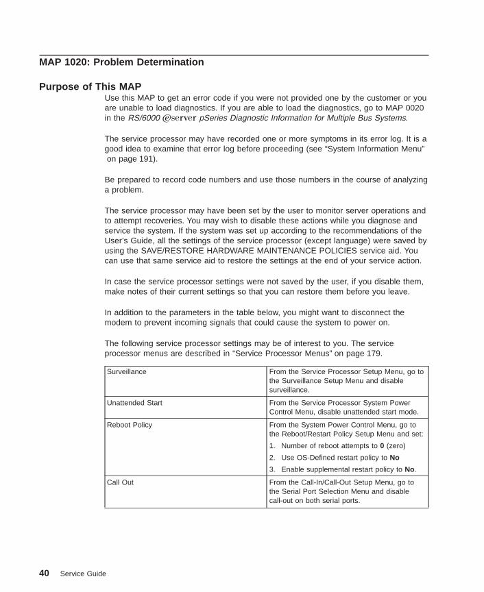
The following service processor settings may be of interest to you. The serviceprocessor menus are described in “Service Processor Menus” on page 179.
Surveillance From the Service Processor Setup Menu, go tothe Surveillance Setup Menu and disablesurveillance.
Unattended Start From the Service Processor System PowerControl Menu, disable unattended start mode.
Reboot Policy From the System Power Control Menu, go tothe Reboot/Restart Policy Setup Menu and set:
1. Number of reboot attempts to 0 (zero)
2. Use OS-Defined restart policy to No
3. Enable supplemental restart policy to No.
Call Out From the Call-In/Call-Out Setup Menu, go tothe Serial Port Selection Menu and disablecall-out on both serial ports.
40 Service Guide
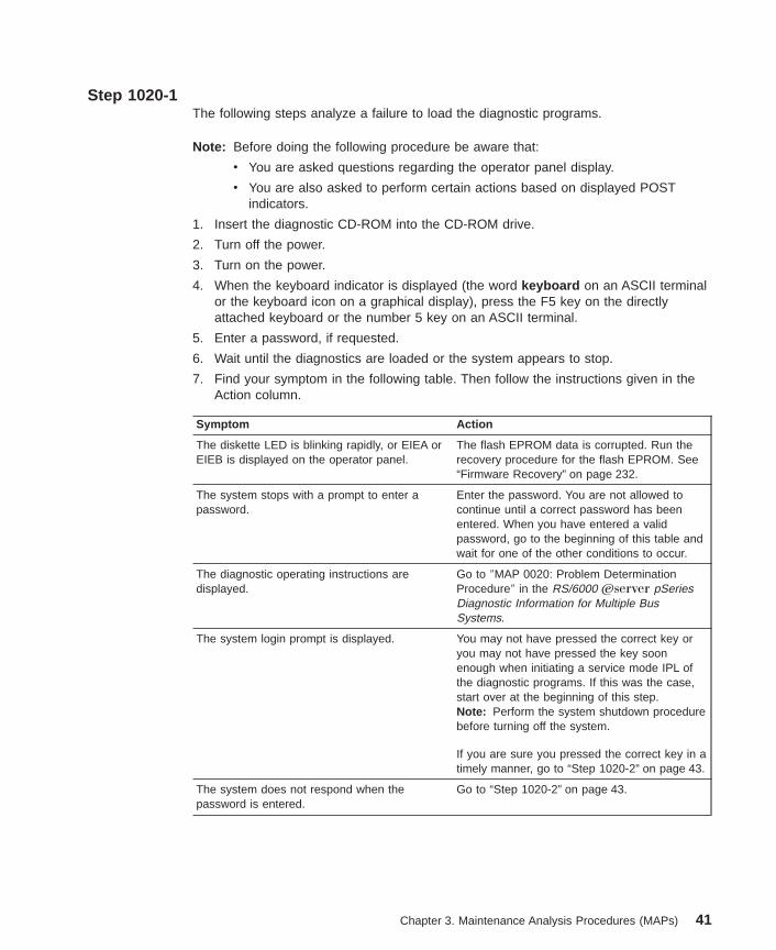
Step 1020-1The following steps analyze a failure to load the diagnostic programs.
Note: Before doing the following procedure be aware that:
v You are asked questions regarding the operator panel display.
v You are also asked to perform certain actions based on displayed POSTindicators.
1. Insert the diagnostic CD-ROM into the CD-ROM drive.
2. Turn off the power.
3. Turn on the power.
4. When the keyboard indicator is displayed (the word keyboard on an ASCII terminalor the keyboard icon on a graphical display), press the F5 key on the directlyattached keyboard or the number 5 key on an ASCII terminal.
5. Enter a password, if requested.
6. Wait until the diagnostics are loaded or the system appears to stop.
7. Find your symptom in the following table. Then follow the instructions given in theAction column.
Symptom Action
The diskette LED is blinking rapidly, or EIEA orEIEB is displayed on the operator panel.
The flash EPROM data is corrupted. Run therecovery procedure for the flash EPROM. See“Firmware Recovery” on page 232.
The system stops with a prompt to enter apassword.
Enter the password. You are not allowed tocontinue until a correct password has beenentered. When you have entered a validpassword, go to the beginning of this table andwait for one of the other conditions to occur.
The diagnostic operating instructions aredisplayed.
Go to ″MAP 0020: Problem DeterminationProcedure″ in the RS/6000 Eserver pSeriesDiagnostic Information for Multiple BusSystems.
The system login prompt is displayed. You may not have pressed the correct key oryou may not have pressed the key soonenough when initiating a service mode IPL ofthe diagnostic programs. If this was the case,start over at the beginning of this step.Note: Perform the system shutdown procedurebefore turning off the system.
If you are sure you pressed the correct key in atimely manner, go to “Step 1020-2” on page 43.
The system does not respond when thepassword is entered.
Go to “Step 1020-2” on page 43.
Chapter 3. Maintenance Analysis Procedures (MAPs) 41
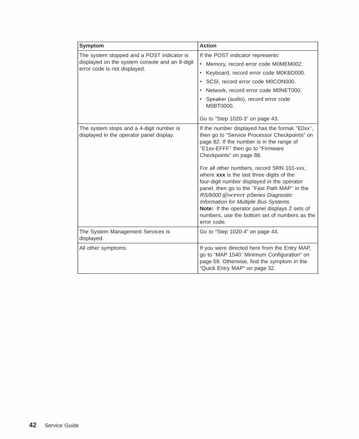
Symptom Action
The system stopped and a POST indicator isdisplayed on the system console and an 8-digiterror code is not displayed.
If the POST indicator represents:
v Memory, record error code M0MEM002.
v Keyboard, record error code M0KBD000.
v SCSI, record error code M0CON000.
v Network, record error code M0NET000.
v Speaker (audio), record error codeM0BT0000.
Go to “Step 1020-3” on page 43.
The system stops and a 4-digit number isdisplayed in the operator panel display.
If the number displayed has the format ″E0xx″,then go to “Service Processor Checkpoints” onpage 82. If the number is in the range of″E1xx-EFFF″ then go to “FirmwareCheckpoints” on page 88.
For all other numbers, record SRN 101-xxx,where xxx is the last three digits of thefour-digit number displayed in the operatorpanel, then go to the ″Fast Path MAP″ in theRS/6000 Eserver pSeries DiagnosticInformation for Multiple Bus Systems.Note: If the operator panel displays 2 sets ofnumbers, use the bottom set of numbers as theerror code.
The System Management Services isdisplayed.
Go to “Step 1020-4” on page 44.
All other symptoms. If you were directed here from the Entry MAP,go to “MAP 1540: Minimum Configuration” onpage 59. Otherwise, find the symptom in the“Quick Entry MAP” on page 32.
42 Service Guide
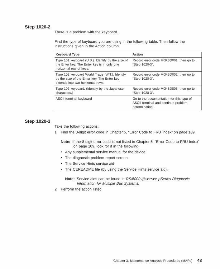
Step 1020-2There is a problem with the keyboard.
Find the type of keyboard you are using in the following table. Then follow theinstructions given in the Action column.
Keyboard Type Action
Type 101 keyboard (U.S.). Identify by the size ofthe Enter key. The Enter key is in only onehorizontal row of keys.
Record error code M0KBD001; then go to“Step 1020-3”.
Type 102 keyboard World Trade (W.T.). Identifyby the size of the Enter key. The Enter keyextends into two horizontal rows.
Record error code M0KBD002; then go to“Step 1020-3”.
Type 106 keyboard. (Identify by the Japanesecharacters.)
Record error code M0KBD003; then go to“Step 1020-3”.
ASCII terminal keyboard Go to the documentation for this type ofASCII terminal and continue problemdetermination.
Step 1020-3Take the following actions:
1. Find the 8-digit error code in Chapter 5, “Error Code to FRU Index” on page 109.
Note: If the 8-digit error code is not listed in Chapter 5, “Error Code to FRU Index”on page 109, look for it in the following:
v Any supplemental service manual for the device
v The diagnostic problem report screen
v The Service Hints service aid
v The CEREADME file (by using the Service Hints service aid).
Note: Service aids can be found in RS/6000 Eserver pSeries DiagnosticInformation for Multiple Bus Systems.
2. Perform the action listed.
Chapter 3. Maintenance Analysis Procedures (MAPs) 43
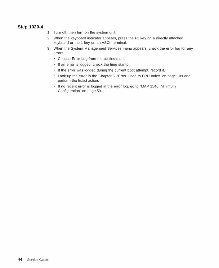
Step 1020-41. Turn off, then turn on the system unit.
2. When the keyboard indicator appears, press the F1 key on a directly attachedkeyboard or the 1 key on an ASCII terminal.
3. When the System Management Services menu appears, check the error log for anyerrors.
v Choose Error Log from the utilities menu
v If an error is logged, check the time stamp.
v If the error was logged during the current boot attempt, record it.
v Look up the error in the Chapter 5, “Error Code to FRU Index” on page 109 andperform the listed action.
v If no recent error is logged in the error log, go to “MAP 1540: MinimumConfiguration” on page 59.
44 Service Guide

MAP 1240: Memory Problem Resolution
Note: The firmware checkpoint that sent you here could be one of the following: E122,E213, E214, E218, E220 or E3xx. You may also have been sent here by an8-digit error code.
Purpose of This MAPThis MAP is used to troubleshoot a problem during the memory test when the systemstops at a memory checkpoint and/or a error code is displayed on the operator panel.
Notes:
1. If the symptom changes while you are using this MAP, check for loose cards,cables, and obvious problems. If you do not find a problem, go to “MAP 1540:Minimum Configuration” on page 59.
2. The service processor may have recorded one or more symptoms in its error log. Itis a good idea to examine that error log before proceeding (see Service ProcessorSystem Information Menu). If you find an obvious problem, fix the problem; then goto ″MAP 0410: Repair Checkout″ in the RS/6000 Eserver pSeries DiagnosticInformation for Multiple Bus Systems.
3. The service processor may have been set by the user to monitor service operationsand to attempt recoveries. You might want to disable these actions while youdiagnose and service the system. If you disable them, make notes of their currentsettings so that you can restore them before you leave. The following settings maybe of interest to you.
Surveillance From the Service Processor Setup Menu, go tothe Surveillance Setup Menu and disablesurveillance.
Unattended Start From the Service Processor System PowerControl Menu, disable unattended start mode.
Reboot Policy From the System Power Control Menu, go tothe Reboot/Restart Policy Setup Menu and set:
1. Number of reboot attempts to 0 (zero)
2. Use OS-Defined restart policy to No
3. Enable supplemental restart policy to No.
Call Out From the Call-In/Call-Out Setup Menu, go tothe Serial Port Selection Menu and disablecall-out on both serial ports.
Chapter 3. Maintenance Analysis Procedures (MAPs) 45

General Memory InformationBe sure to unplug the power cables before removing or installing the memory DIMMs toavoid damage to them.
Memory DIMMs must be installed in matched (size and speed) pairs. Refer to “MemoryCard and Memory DIMMs” on page 256 for labeling of the memory card andinstructions on DIMM removal and installation. (Do not, however, replace the covers asdirected while troubleshooting this problem.) A single memory DIMM pair may beinstalled in module slots J1 and J2 (not slots J1 and J3). A second memory DIMM paircould be installed in module slots J5 and J6 (slots J3 and J4 do not have to bepopulated first). Along these same lines, there is no requirement that memory DIMMslots J1 and J2 be populated before another slot pair.
Step 1240-11. Turn off the power.
2. Remove all installed memory DIMMs from the memory card. Record the positions ofthe memory DIMMs so that when instructed to reinstall them they can be installed intheir original positions.
3. Install one pair of memory DIMMs.
4. Turn on the power.
Does the system stop with a memory checkpoint or memory error code displayedon the operator panel?
NO If there are no more memory DIMMs to be installed, reseating the DIMMs onthe memory card has corrected the problem.
If there was more than one pair of memory DIMMs on the memory card, go to“Step 1240-2” on page 47.
YES Go to “Step 1240-3” on page 47.
46 Service Guide

Step 1240-21. Turn off the power.
2. Install a pair of memory DIMMs.
3. Turn on the power.
Does the system stop with a memory checkpoint or error code displayed on theoperator panel?
NO Repeat this step until all the memory DIMMs are installed and tested.
If all the memory DIMMs have been installed, reseating the memory DIMMs onthe memory card has corrected the problem.
Go to ″Map 0410: Repair Checkout″ in the RS/6000 Eserver pSeriesDiagnostic Information for Multiple Bus Systems.
YES Go to “Step 1240-3”.
Step 1240-3The failure may be caused by the last pair of memory DIMMs installed or the memorycard. To isolate the failing FRU, do the following:
1. Turn off the power.
2. Exchange the last memory DIMM pair installed with another pair removed in “Step1240-2” (or any other available pair).
3. Turn on the power.
Does the system stop with a memory checkpoint or error code displayed on theoperator panel?
NO Go to “Step 1240-5” on page 48.
YES Go to “Step 1240-4” on page 48.
Chapter 3. Maintenance Analysis Procedures (MAPs) 47

Step 1240-4One of the FRUs remaining in the system unit is defective.
1. Turn off the power.
2. Replace the following FRUs (one at a time) in the order listed.
v Memory card
v System board
v Processor card, processor #1, then processor #2
3. Turn on the power.
Note: Replacing any of the above listed FRUs may result in missing and newresources.
Does the system stop with a memory checkpoint or error code displayed on theoperator panel?
NO Go to ″MAP 0410: Repair Checkout″ in the RS/6000 Eserver pSeriesDiagnostic Information for Multiple Bus Systems.
YES Reinstall the original FRU.
Repeat this step until the defective FRU is identified or all the FRUs have beenexchanged.
If the symptom did not change and all FRUs have been exchanged, go to“MAP 1540: Minimum Configuration” on page 59.
Step 1240-5The memory DIMM(s) (may be both) you exchanged in the previous step may bedefective. To isolate the failing memory module, do the following:
1. Turn off the power.
2. Reinstall one of the memory DIMMs you exchanged in the previous step.
3. Turn on the power.
Does the system stop with a memory checkpoint or error code displayed on theoperator panel?
NO Repeat this step with the second memory DIMM you exchanged in theprevious step.
Go to ″MAP 0410: Repair Checkout″ in the RS/6000 Eserver pSeriesDiagnostic Information for Multiple Bus Systems.
YES Replace the memory DIMM.
If you have not tested both memory DIMMs, repeat this step with the secondmemory module you exchanged in the previous step.
If the symptom did not change and both memory DIMMs have beenexchanged, go to “Step 1240-4”.
48 Service Guide
MAP 1520: Power
Notes:
1. This is not a start-of-call MAP. Use this Power MAP only if you have been directedhere from another MAP, an SRN in the RS/6000 Eserver pSeries DiagnosticInformation for Multiple Bus Systems, or an error code.
2. The 9112 Model 265 can accommodate three power supplies installed with separatepower receptacles on the rear of the system.
This procedure is used to locate power problems in system units. If a problem isdetected, this procedure helps you isolate the problem to a failing unit.
Observe the following safety notice during service procedures.
DANGER
An electrical outlet that is not correctly wired could place hazardous voltageon metal parts of the system or the devices that attach to the system. It is theresponsibility of the customer to ensure that the outlet is correctly wired andgrounded to prevent an electrical shock.
Before installing or removing signal cables, ensure that the power cables forthe system unit and all attached devices are unplugged.
When adding or removing any additional devices to or from the system,ensure that the power cables for those devices are unplugged before thesignal cables are connected. If possible, disconnect all power cables from theexisting system before you add a device.
Use one hand, when possible, to connect or disconnect signal cables toprevent a possible shock from touching two surfaces with different electricalpotentials.
During an electrical storm, do not connect cables for display stations, printers,telephones, or station protectors for communications lines.
CAUTION:This product is equipped with a three–wire power cable and plug for the user’ssafety. Use this power cable with a properly grounded electrical outlet to avoidelectrical shock.
Chapter 3. Maintenance Analysis Procedures (MAPs) 49
DANGER
To prevent electrical shock hazard, disconnect all power cables from theelectrical outlet before relocating the system.
Step 1520-1Check the power supply ac LEDs, the green LED on the rear of the system unit and thepower LED on the operator panel.
Note: If the condition exists that three power supplies are present, but only two areworking, you can verify this situation through the service processor and awarning-level EPOW.
You might have been directed to this MAP for several reasons:
v The ac LEDs on the power supplies are not on, the green LED on the rear of thesystem unit is not flashing and the operator panel is blank.
Go to “Step 1520-2” on page 51.
v The ac LEDs on the power supplies are on, the green LED on the rear of the systemunit is not flashing and the operator panel is blank.
Go to “Step 1520-7” on page 53.
v The ac LEDs on the power supplies are on, the green LED on the rear of the systemunit is flashing and OK, STBY or DIAG STBY is displayed on the operator panel.When the power button on the operator panel is pressed:
– There is no indication of activity
– The power LED on the operator panel does not come on
– The green LED on the rear of the system unit does not come on
– The dc LEDs on the power supplies are not on
– None of the fans start to turn.
Go to “Step 1520-7” on page 53.
v The ac LEDs on the power supplies are on, the green LED on the rear of the systemunit is flashing and OK, STBY or DIAG STBY is displayed on the operator panel.When the power button on the operator panel is pressed:
– The power LED on the operator panel comes on
– The green LED on the rear of the system unit comes on
– The dc LEDs on the power supplies are on
– All of the fans start to turn but the power LED on the operator panel, the greenLED on the rear of the system unit, the dc LEDs on the power supplies and thefans do not stay on.
Go to “Step 1520-7” on page 53.
v An SRN in RS/6000 Eserver pSeries Diagnostic Information for Multiple BusSystems listed “MAP 1520: Power” on page 49 in the ″Action/Description″ column fora voltage sensor out of range.
50 Service Guide

Step 1520-21. Turn off the power.
2. Unplug the power cables from the power outlet.
3. Unplug the power cables from the system.
4. Check that the power cables have continuity.
5. Check that the power outlet has been wired correctly with the correct voltage.
Did you find a problem?
NO Go to “Step 1520-3”.
YES Correct the problem. Go to ″MAP 0410: Repair Checkout″ in the RS/6000Eserver pSeries Diagnostic Information for Multiple Bus Systems.
Step 1520-31. Find all the cables connecting the power backplane to the system. Unplug these
cables from the system, but leave them attached to the power backplane.
2. Connect the power cables from the system unit to the power outlets.
Do the ac LEDs on the power supplies come on within 30 seconds after applyingac power?
NO Go to “Step 1520-4”.
YES Go to “Step 1520-7” on page 53.
Step 1520-41. Unplug the power cord from the system unit.
2. Unplug all the cables from the power backplane.
3. Connect the power cables to the system unit.
Do the ac LEDs on the power supplies come on within 30 seconds after applyingac power?
NO Go to “Step 1520-6” on page 52.
YES Go to “Step 1520-5” on page 52.
Chapter 3. Maintenance Analysis Procedures (MAPs) 51

Step 1520-5One of the cables you unplugged from the power backplane may be defective.
1. Unplug the power cables from the system.
2. Reconnect one of the cables to the power backplane.
3. Connect the power cables to the system.
Do the ac LEDs on the power supplies come on within 30 seconds after applyingac power?
NO Replace the last cable that you connected to the power backplane.
Repeat this step until all the cables have been reconnected.
Replace the faulty cooling fan. Go to ″MAP 0410: Repair Checkout″ in theRS/6000 Eserver pSeries Diagnostic Information for Multiple Bus Systems.
YES Repeat this step until the defective cable is identified or all the cables havebeen reconnected.
Step 1520-6Either the power supplies or the power backplane may be defective.
To test each FRU, exchange the FRUs that have not already been exchanged in thefollowing order.
v Power supply 1.
v Power supply 2.
v Power supply 3 (if installed).
v Power backplane.
1. Turn off the power.
2. Unplug the power cables from the system.
3. Exchange one of the FRUs in the list.
4. Connect the power cables to the system.
Do the ac LEDs on the power supplies come on within 30 seconds after applyingac power?
NO Reinstall the original FRU.
Repeat this step until the defective FRU is identified or all the FRUs have beenexchanged.
If the symptom did not change and all the FRUs have been exchanged, callyour service support person for assistance.
YES Go to ″MAP 0410: Repair Checkout″ in the RS/6000 Eserver pSeriesDiagnostic Information for Multiple Bus Systems.
52 Service Guide

Step 1520-71. Unplug the power cables from the system.
2. Exchange the operator panel electronics assembly.
3. Plug the power cables into the system and wait for OK, STBY or DIAG STBY on theoperator panel display.
4. Turn on the power.
Does the power LED on the operator panel come on and stay on?
NO Reinstall the original operator panel electronics assembly.
Go to “Step 1520-8”.
YES Go to ″MAP 0410: Repair Checkout″ in the RS/6000 Eserver pSeriesDiagnostic Information for Multiple Bus Systems.
Step 1520-81. Turn off the power.
2. Unplug the power cables from the system.
3. Record the slot numbers of all the adapters. Label and record the location of anycables attached to the adapters. Disconnect any cables attached to the adaptersand remove all the adapters.
4. Remove the memory card.
5. Remove the second processor card (if installed).
6. Unplug the power cable from the 6-pack backplane.
7. Unplug the disk drives from the 6-pack backplane.
8. Unplug the power cables from all devices in the media bay.
9. Remove or unplug all the fans.
10. Plug the power cables into the system.
11. Turn on the power.
Does the power LED on the operator panel come on and stay on?
NO Go to “Step 1520-9” on page 54.
YES Go to “Step 1520-10” on page 55.
Chapter 3. Maintenance Analysis Procedures (MAPs) 53
Step 1520-9
Note: Either the processor card, system board, or the power supplies may bedefective.
To test each FRU, exchange the FRUs that have not already been exchanged in thefollowing order:
v Power supply 1.
v Power supply 2.
v Power supply 3 (if installed).
v Power backplane.
v Processor board
1. Turn off the power.
2. Unplug the power cables from the system.
3. Exchange one of the FRUs in the list.
4. Connect the power cables to the system.
5. Turn on the power.
Does the power LED on the operator panel come on and stay on?
NO Repeat these steps until all the parts have been installed or connected.
If the symptom did not change and all the parts have been installed orconnected, call service support for assistance.
If the symptom has changed, check for loose cards, cables, and obviousproblems. If you do not find a problem, return to “Step 1520-1” on page 50 inthis MAP and follow the instructions for the new symptom.
YES Repeat these steps until all the parts have been installed or connected.
Go to ″MAP 0410: Repair Checkout″ in the RS/6000 Eserver pSeriesDiagnostic Information for Multiple Bus Systems.
54 Service Guide

Step 1520-10One of the parts that was removed or unplugged is causing the problem. Install orconnect the parts in the following order:
1. Second processor card (if removed).
2. Memory card.
3. PCI adapters, lowest slot to highest slot.
4. Fans.
Turn the power on after each part is installed or connected. If the system does notpower on or the power LED on the operator panel does not stay on, the most recentlyinstalled or connected part is causing the failure.
1. Turn off the power.
2. Unplug the power cable from the system.
3. Install or connect one of the parts in the list.
4. Plug the power cable into the system.
5. Turn on the power.
Does the power LED on the operator panel come on and stay on?
NO Replace the last part installed.
If the memory card was just installed, remove all of the memory DIMMs. If thesystem does not come up, replace the memory card.
Reinstall the memory DIMMs, one pair at a time, until the problem recurs.Replace the memory DIMM pair that was just installed.
Note: The memory DIMM pair must be installed in slots that are next to eachother. Refer to “Memory Card and Memory DIMMs” on page 256.
Repeat these steps until all the parts have been installed.
Go to “Step 1520-11”.
YES Go to ″MAP 0410: Repair Checkout″ in the RS/6000 Eserver pSeriesDiagnostic Information for Multiple Bus Systems.
Step 1520-11Does the system contain three power supplies?
NO Go to “Step 1520-12” on page 56.
YES Go to “Step 1520-14” on page 57.
Chapter 3. Maintenance Analysis Procedures (MAPs) 55
Step 1520-12Shut down the system and remove all power cables from the rear of the system.
Exchange the following FRUs in the order listed:
1. Power supply.
2. Power cables to system board.
3. System board.
4. Power backplane.
Restart the system and perform error log analysis.
Do you get an SRN indicating a voltage sensor is out of range?
NO The last FRU exchanged is defective. Go to ″MAP 0410: Repair Checkout″ inthe RS/6000 Eserver pSeries Diagnostic Information for Multiple BusSystems.
YES Reinstall the original FRU.
Repeat the FRU replacement steps until a defective FRU is identified or all theFRUs have been exchanged.
If the symptom did not change and all FRUs have been exchanged, go to“Step 1520-13”.
If the symptom has changed, check for loose cards, cables, and obviousproblems. If you do not find a problem, return to “Step 1520-1” on page 50 inthis MAP, and follow the instructions for the new symptom.
Step 1520-13Check that the power outlet is properly wired and is providing the correct voltage.
Did you find a problem?
NO Go to “Step 1540-1” on page 60.
YES Correct the problem. Go to ″MAP 0410: Repair Checkout″ in the RS/6000Eserver pSeries Diagnostic Information for Multiple Bus Systems.
56 Service Guide

Step 1520-14Because the 9112 Model 265 accommodate redundant power supplies, it is notnecessary to power off the system when replacing a power supply.
The power supplies are symmetrical, so replacement starts with power supply 1 (theunit closest to the bottom in a Model 6C1 or to the top left in a Model 6E1). Refer to“Power Supply” on page 272 for instructions on replacing a power supply.
Notes:
1. Always service first the power supply whose green LED, located on top of thepower supplies, is either blinking or out.
2. Before removing a power supply, be sure the redundant power supply is operationalby observing the green LED. The green LED must be steady and not blinking orout.
Replace the following FRUs in order:
1. Power supply 1
2. Power supply 2
Perform error log analysis.
Do you receive an SRN indicating a voltage sensor out of range?
NO The last FRU exchanged is defective. Go to ″MAP 0410: Repair Checkout″ inthe RS/6000 Eserver pSeries Diagnostic Information for Multiple BusSystems.
YES Reinstall the original FRU.
Repeat the FRU replacement steps until a defective FRU is identified or all theFRUs have been exchanged.
If the symptom did not change and all FRUs have been exchanged, go to“Step 1520-13” on page 56.
If the symptom has changed, check for loose cards, cables, and obviousproblems. If you do not find a problem, return to “Step 1520-1” on page 50 inthis MAP and follow the instructions for the new symptom.
Chapter 3. Maintenance Analysis Procedures (MAPs) 57

Step 1520-15The problem lies within the system hardware or with the line voltage/wiring.
Shut down the system and remove the power cable from the system.
Exchange the following FRUs in order:
1. Power cables to system board.
2. System board.
3. Power backplane.
Restart the system and perform error log analysis.
Do you receive an SRN indicating a voltage sensor out of range?
NO The last FRU exchanged is defective. Go to ″MAP 0410: Repair Checkout″ inthe RS/6000 Eserver pSeries Diagnostic Information for Multiple BusSystems.
YES Reinstall the original FRU.
Repeat the FRU replacement steps until a defective FRU is identified or all theFRUs have been exchanged.
If the symptom did not change and all FRUs have been exchanged, go to“Step 1520-13” on page 56.
If the symptom has changed, check for loose cards, cables, and obviousproblems. If you do not find a problem, return to “Step 1520-1” on page 50 inthis MAP and follow the instructions for the new symptom.
58 Service Guide
MAP 1540: Minimum Configuration
Notes:
1. Be sure to unplug the power cords before removing or installing processor card(s),the memory card, or the system board to avoid damage to it.
2. This MAP assumes that a CD-ROM drive is installed and connected to theintegrated SCSI or IDE adapter, and a diagnostic CD-ROM is available.
3. If a power-on password or privileged-access password is installed, you areprompted to enter the password before the diagnostic CD-ROM can load.
4. The term ″POST indicators″ refers to the icons (graphic display) or devicemnemonics (ASCII terminal) that appear during the power-on self-test (POST).
5. The service processor might have recorded one or more symptoms in its error log.It is a good idea to examine that error log before proceeding (see “SystemInformation Menu” on page 191).
6. The service processor might have been set by the user to monitor server operationsand to attempt recoveries. You might want to disable these actions while youdiagnose and service the system. If you disable them, make notes of their currentsettings so that you can restore them before you leave. The following settings maybe of interest to you.
Surveillance From the Service Processor Setup Menu, go tothe OS Surveillance Setup Menu and disablesurveillance.
Unattended Start Mode From the System Power Control Menu, disableunattended start mode.
Reboot Policy From the System Power Control Menu, go tothe Reboot/Restart Policy Setup Menu and set:a. Number of reboot attempts to 0 (zero)b. Use OS-Defined restart policy to Noc. Enable supplemental restart policy to No.
Call Out From the Call-In/Call-Out Setup Menu, go tothe Serial Port Selection Menu and disablecall-out on both serial ports.
Chapter 3. Maintenance Analysis Procedures (MAPs) 59
Purpose of this MAPThis MAP is used to locate defective FRUs not found by normal diagnostics. For thisprocedure, diagnostics are run on a minimally configured system. If a failure is detectedon the minimally configured system, the remaining FRUs are exchanged one at a timeuntil the failing FRU is identified. If a failure is not detected, FRUs are added back untilthe failure occurs. The failure is then isolated to the failing FRU.
When directed to exchange a FRU that is common to a FRU removed to create aminimum configuration system, use one of the removed FRUs instead of a new FRU.For example, if the system contains 16 memory modules and you are directed toremove 14 of them to create a minimun configuration system, then use one of theremoved memory modules when exchanging the FRU. Once the failing FRU is isolated,replace it with a new one.
Step 1540-11. Insert the diagnostic CD-ROM into the CD-ROM drive.
Note: If you cannot insert the diagnostic CD-ROM, go to “Step 1540-2” on page 61.
2. Ensure that the diagnostics and the operating system are shut down.
3. Turn off the power.
4. Turn on the power.
5. When the keyboard indicator is displayed (the word keyboard on an ASCII terminalor the keyboard icon on a graphical display), press the F5 key on the directlyattached keyboard or the number 5 key on an ASCII terminal.
6. Enter the appropriate password if you are prompted to do so.
Is the ″Please define the System Console ″ screen displayed?
NO Go to “Step 1540-2” on page 61.
YES Go to “Step 1540-18” on page 75.
60 Service Guide
Step 1540-21. Turn off the power.
2. If you have not already done so, configure the service processor with theinstructions in note 6 on page 59. Then return here and continue.
3. Exit the service processor menus and remove the power cords.
4. Disconnect all external cables (parallel, serial port 1, serial port 2, serial port 3,keyboard, mouse, Ethernet, SCSI, and so on).
5. Remove the service access cover (Model 6E1) or place the drawer (Model 6C1)into the service position and remove the service access cover.
6. Record the slot numbers of the PCI adapters. Label and record the locations ofany cables attached to the adapters. Disconnect any cables attached to theadapters and remove all the adapters.
7. Remove the second processor (if installed). If the second processor is removed,ensure the first processor is installed.
8. Record the slot numbers of the memory DIMMs. Remove all memory DIMMsexcept for one pair from the memory card.
Notes:
a. Place the memory DIMM locking tabs in the locked (upright) position to preventdamage to the tabs.
b. Memory DIMMs must be installed in pairs and in the correct connectors. Forexample, install the pair in connectors J1 and J2.
9. Disconnect the SCSI cable from the SCSI connector on the system board.
10. Disconnect the IDE cable from the IDE connector on the system board.
11. If installed, disconnect the signal and power connectors from the disk drive cagebackplane.
12. If installed, remove the disk drive(s) from the disk drive cage.
13. Disconnect the signal and power connectors from all the SCSI devices.
14. Disconnect the signal and power connectors from all the IDE devices.
15. Disconnect the diskette drive cable from the diskette drive connector on thesystem board.
16. Plug in the power cords and wait for the OK on the operator panel display.
17. Turn on the power.
Does the system stop with code E1F2, E1F3, STBY or 4BA00830 displayed on theoperator panel?
NO Go to “Step 1540-3” on page 62.
YES If a second processor card was removed, go to “Step 1540-4” on page 63.
If the system has only one processor card, go to “Step 1540-5” on page 63.
Chapter 3. Maintenance Analysis Procedures (MAPs) 61
Step 1540-3One of the FRUs remaining in the system unit is defective.
Note: If a memory module is exchanged, ensure that the new DIMM is the same sizeand speed as the original DIMM.
1. Turn off the power, remove the power cords, and exchange the following FRUs inthe order listed:
a. Processor card
b. Memory DIMM in odd-numbered slot (J1, J3, J5)
c. Memory DIMM in even-numbered slot (J2, J4, J6)
d. Memory card
e. System board (see notes on page 31)
f. Power supplies.
2. Plug in the power cords and wait for the OK on the operator panel display.
3. Turn on the power.
Does the system stop with code E1F2, E1F3, STBY or 4BA00830 displayed on theoperator panel?
NO Reinstall the original FRU.
Repeat the FRU replacement steps until the defective FRU is identified or allthe FRUs have been exchanged.
If the symptom did not change and all the FRUs have been exchanged, callservice support for assistance.
If the symptom has changed, check for loose cards, cables, and obviousproblems. If you do not find a problem, return to “Step 1540-1” on page 60 inthis MAP and follow the instructions for the new symptom.
YES Go to ″MAP 0410: Repair Checkout″ in the RS/6000 Eserver pSeriesDiagnostic Information for Multiple Bus Systems.
62 Service Guide

Step 1540-4No failure was detected with this configuration.
1. Turn off the power and remove the power cords.
2. Reinstall the second processor card.
3. Plug in the power cords and wait for the OK on the operator panel display.
4. Turn on the power.
Does the system stop with code E1F2, E1F3, STBY or 4BA00830 displayed on theoperator panel?
NO One of the FRUs remaining in the system unit is defective.
In the following order, exchange the FRUs that have not been exchanged:
1. Processor card (last one installed)
2. System board (see notes on page 31)
Repeat this step until the FRU is identified or all the FRUs have beenexchanged.
If the symptom did not change and all the FRUs have been exchanged, callyour service support person for assistance.
If the symptom changed, check for loose cards and obvious problems. If youdo not find a problem, return to “Step 1540-1” on page 60 and follow theinstructions for the new symptom.
YES Go to “Step 1540-5”.
Step 1540-5No failure was detected with this configuration.
1. Turn off the power and remove the power cords.
2. Install a pair of memory DIMMs.
Note: Ensure that the new memory DIMMs are the same size and speed as theoriginal memory DIMMs.
3. Plug in the power cords and wait for the OK on the operator panel display.
4. Turn on the power.
Does the system stop with code E1F2, E1F3, STBY or 4BA00830 displayed on theoperator panel?
NO Go to “Step 1540-6” on page 64.
YES Repeat this step until all the memory DIMMs are installed and tested.
Go to “Step 1540-9” on page 66.
Chapter 3. Maintenance Analysis Procedures (MAPs) 63

Step 1540-6The failure may be caused by the last pair of memory DIMMs installed or the memorycard. To isolate the failing FRU, do the following:
1. Turn off the power and remove the power cords.
2. Exchange the last memory DIMM pair installed.
3. Plug in the power cords and wait for the OK on the operator panel display.
4. Turn on the power.
Does the system stop with code E1F2, E1F3, STBY or 4BA00830 displayed on theoperator panel?
NO Go to “Step 1540-8” on page 65.
YES Go to “Step 1540-7”.
Step 1540-7The memory DIMM(s) (may be both) you exchanged in the previous step may bedefective. To isolate the failing DIMM, do the following:
1. Turn off the power and remove the power cords.
2. Reinstall one of the memory DIMMs you exchanged in the previous step.
3. Plug in the power cords and wait for the OK on the operator panel display.
4. Turn on the power.
Does the system stop with code E1F2, E1F3, STBY or 4BA00830 displayed on theoperator panel?
NO Replace the memory DIMM.
If you have not tested both memory DIMMs repeat this step with the secondmemory module you exchanged in the previous step.
If the symptom did not change and both memory DIMMs have beenexchanged, go to “Step 1540-8” on page 65.
YES Repeat this step with the second memory DIMM you exchanged in theprevious step.
If both memory DIMMs have been tested, go to ″MAP 0410: Repair Checkout″in the RS/6000 Eserver pSeries Diagnostic Information for Multiple BusSystems.
64 Service Guide
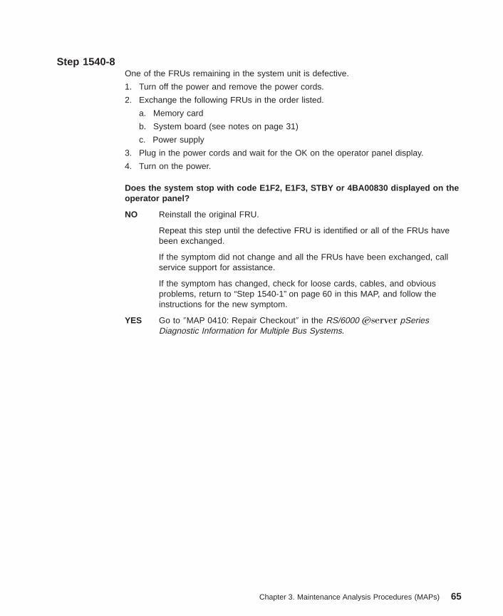
Step 1540-8One of the FRUs remaining in the system unit is defective.
1. Turn off the power and remove the power cords.
2. Exchange the following FRUs in the order listed.
a. Memory card
b. System board (see notes on page 31)
c. Power supply
3. Plug in the power cords and wait for the OK on the operator panel display.
4. Turn on the power.
Does the system stop with code E1F2, E1F3, STBY or 4BA00830 displayed on theoperator panel?
NO Reinstall the original FRU.
Repeat this step until the defective FRU is identified or all of the FRUs havebeen exchanged.
If the symptom did not change and all the FRUs have been exchanged, callservice support for assistance.
If the symptom has changed, check for loose cards, cables, and obviousproblems, return to “Step 1540-1” on page 60 in this MAP, and follow theinstructions for the new symptom.
YES Go to ″MAP 0410: Repair Checkout″ in the RS/6000 Eserver pSeriesDiagnostic Information for Multiple Bus Systems.
Chapter 3. Maintenance Analysis Procedures (MAPs) 65

Step 1540-91. Turn off the power.
2. Reconnect the system console.
Notes:
a. If an ASCII terminal has been defined as the firmware console, attach the ASCIIterminal cable to the S1 connector on the rear of the system unit.
b. If a display attached to a display adapter has been defined as the firmwareconsole, install the display adapter and connect the display to the adapter. Plugthe keyboard into the keyboard connector on the rear of the system unit
3. Turn on the power.
4. If the ASCII terminal or graphics display (including display adapter) is connecteddifferently than it was before, the Console Selection screen appears and requiresthat a new console be selected.
5. When the keyboard indicator is displayed, press the F1 key on the directly attachedkeyboard or the number 1 key on an ASCII terminal.
6. Enter the appropriate password if you are prompted to do so.
Is the SMS screen displayed?
NO One of the FRUs remaining in the system unit is defective.
In the following order, exchange the FRUs that have not been exchanged:
1. Go to the problem determination procedures (test procedures) for thedevice attached to the S1 serial port or the display attached to the graphicsadapter, and test that device. If a problem is found, follow the proceduresto correct the problem on that device.
2. Graphics adapter
3. Cable (async or graphics)
4. System board (see notes on page 31)
Repeat this step until the defective FRU is identified or all the FRUs have beenexchanged.
If the symptom did not change and all the FRUs have been exchanged, callservice support for assistance.
If the symptom changed, check for loose cards, cables, and obvious problems.If you do not find a problem, return to “Step 1540-1” on page 60 and follow theinstructions for the new symptom.
YES Go to “Step 1540-10” on page 67.
66 Service Guide
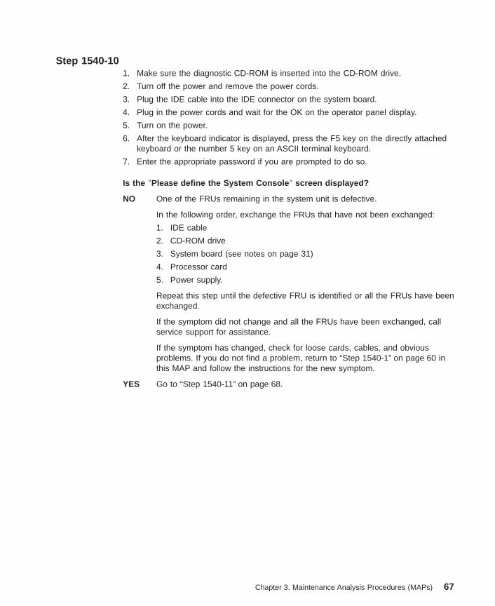
Step 1540-101. Make sure the diagnostic CD-ROM is inserted into the CD-ROM drive.
2. Turn off the power and remove the power cords.
3. Plug the IDE cable into the IDE connector on the system board.
4. Plug in the power cords and wait for the OK on the operator panel display.
5. Turn on the power.
6. After the keyboard indicator is displayed, press the F5 key on the directly attachedkeyboard or the number 5 key on an ASCII terminal keyboard.
7. Enter the appropriate password if you are prompted to do so.
Is the ″Please define the System Console ″ screen displayed?
NO One of the FRUs remaining in the system unit is defective.
In the following order, exchange the FRUs that have not been exchanged:
1. IDE cable
2. CD-ROM drive
3. System board (see notes on page 31)
4. Processor card
5. Power supply.
Repeat this step until the defective FRU is identified or all the FRUs have beenexchanged.
If the symptom did not change and all the FRUs have been exchanged, callservice support for assistance.
If the symptom has changed, check for loose cards, cables, and obviousproblems. If you do not find a problem, return to “Step 1540-1” on page 60 inthis MAP and follow the instructions for the new symptom.
YES Go to “Step 1540-11” on page 68.
Chapter 3. Maintenance Analysis Procedures (MAPs) 67
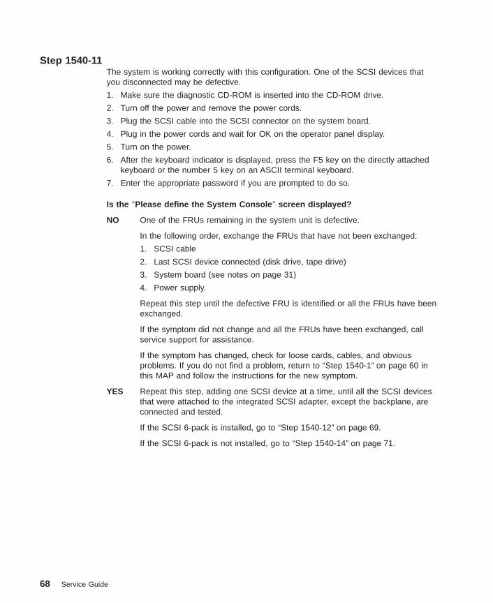
Step 1540-11The system is working correctly with this configuration. One of the SCSI devices thatyou disconnected may be defective.
1. Make sure the diagnostic CD-ROM is inserted into the CD-ROM drive.
2. Turn off the power and remove the power cords.
3. Plug the SCSI cable into the SCSI connector on the system board.
4. Plug in the power cords and wait for OK on the operator panel display.
5. Turn on the power.
6. After the keyboard indicator is displayed, press the F5 key on the directly attachedkeyboard or the number 5 key on an ASCII terminal keyboard.
7. Enter the appropriate password if you are prompted to do so.
Is the ″Please define the System Console ″ screen displayed?
NO One of the FRUs remaining in the system unit is defective.
In the following order, exchange the FRUs that have not been exchanged:
1. SCSI cable
2. Last SCSI device connected (disk drive, tape drive)
3. System board (see notes on page 31)
4. Power supply.
Repeat this step until the defective FRU is identified or all the FRUs have beenexchanged.
If the symptom did not change and all the FRUs have been exchanged, callservice support for assistance.
If the symptom has changed, check for loose cards, cables, and obviousproblems. If you do not find a problem, return to “Step 1540-1” on page 60 inthis MAP and follow the instructions for the new symptom.
YES Repeat this step, adding one SCSI device at a time, until all the SCSI devicesthat were attached to the integrated SCSI adapter, except the backplane, areconnected and tested.
If the SCSI 6-pack is installed, go to “Step 1540-12” on page 69.
If the SCSI 6-pack is not installed, go to “Step 1540-14” on page 71.
68 Service Guide
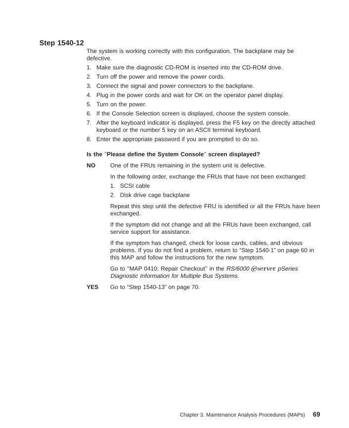
Step 1540-12The system is working correctly with this configuration. The backplane may bedefective.
1. Make sure the diagnostic CD-ROM is inserted into the CD-ROM drive.
2. Turn off the power and remove the power cords.
3. Connect the signal and power connectors to the backplane.
4. Plug in the power cords and wait for OK on the operator panel display.
5. Turn on the power.
6. If the Console Selection screen is displayed, choose the system console.
7. After the keyboard indicator is displayed, press the F5 key on the directly attachedkeyboard or the number 5 key on an ASCII terminal keyboard.
8. Enter the appropriate password if you are prompted to do so.
Is the ″Please define the System Console ″ screen displayed?
NO One of the FRUs remaining in the system unit is defective.
In the following order, exchange the FRUs that have not been exchanged:
1. SCSI cable
2. Disk drive cage backplane
Repeat this step until the defective FRU is identified or all the FRUs have beenexchanged.
If the symptom did not change and all the FRUs have been exchanged, callservice support for assistance.
If the symptom has changed, check for loose cards, cables, and obviousproblems. If you do not find a problem, return to “Step 1540-1” on page 60 inthis MAP and follow the instructions for the new symptom.
Go to ″MAP 0410: Repair Checkout″ in the RS/6000 Eserver pSeriesDiagnostic Information for Multiple Bus Systems.
YES Go to “Step 1540-13” on page 70.
Chapter 3. Maintenance Analysis Procedures (MAPs) 69
Step 1540-13The system is working correctly with this configuration. One of the disk drives that youremoved is removed from the disk drive cage may be defective.
1. Make sure the diagnostic CD-ROM is inserted into the CD-ROM drive.
2. Turn off the power and remove the power cords.
3. Install a disk drive in the disk drive cage.
4. Plug in the power cords and wait for OK on the operator panel display.
5. Turn on the power.
6. After the keyboard indicator is displayed, press the F5 key on the directly attachedkeyboard or the number 5 key on an ASCII terminal keyboard.
7. Enter the appropriate password if you are prompted to do so.
Is the ″Please define the System Console ″ screen displayed?
No In the following order, exchange the FRUs that have not been exchanged:
1. Last disk drive installed
2. Disk drive cage backplane
Repeat this step until the defective FRU is identified or all the FRUs have beenexchanged.
If the symptom did not change and all the FRUs have been exchanged, callservice support for assistance.
If the symptom has changed, check for loose cards, cables, and obviousproblems. If you do not find a problem, return to “Step 1540-1” on page 60 inthis MAP and follow the instructions for the new symptom.
Yes Repeat this step until all drives are installed and tested.
Go to “Step 1540-14” on page 71.
70 Service Guide
Step 1540-14The system is working correctly with this configuration. The diskette drive may bedefective.
1. Make sure the diagnostic CD-ROM is inserted into the CD-ROM drive.
2. Turn off the power and remove the power cords.
3. Plug the diskette drive cable into the diskette drive connector on the system board.
4. Plug in the power cords and wait for OK on the operator panel display.
5. Turn on the power.
6. After the keyboard indicator displays, press the F5 key on the directly attachedkeyboard or the number 5 key on an ASCII terminal keyboard.
7. Enter the appropriate password if you are prompted to do so.
Is the ″Please define the System Console ″ screen displayed?
NO One of the FRUs remaining in the system is defective.
In the following order, exchange the FRUs that have not been exchanged.
1. Diskette drive
2. Diskette drive cable
3. System board (see notes on page 31)
4. Power supply
Repeat this step until the defective FRU is identified or all the FRUs have beenexchanged.
If the symptom did not change and all the FRUs have been exchanged, callservice support for assistance.
If the symptom has changed, check for loose cards, cables, and obviousproblems. If you do not find a problem return, to “Step 1540-1” on page 60 inthis MAP and follow the instructions for the new symptom.
YES Go to “Step 1540-15” on page 72.
Chapter 3. Maintenance Analysis Procedures (MAPs) 71

Step 1540-15The system is working correctly with this configuration. One of the devices that youdisconnected from the system board may be defective.
1. Turn off the power and remove the power cords.
2. Attach a system board device (parallel, serial port 1, serial port 2, serial port 3,keyboard, mouse, Ethernet, SCSI, keyboard or mouse) that had been removed.
3. Plug in the power cords and wait for OK on the operator panel display.
4. Turn on the power.
5. If the Console Selection screen is displayed, choose the system console.
6. After the keyboard indicator displays, press the F5 key on the directly attachedkeyboard or the number 5 key on an ASCII terminal keyboard.
7. Enter the appropriate password if you are prompted to do so.
Is the ″Please define the System Console ″ screen displayed?
NO The last device or cable that you attached is defective.
To test each FRU, exchange the FRUs in the following order:
1. Device and cable (last one attached)
2. System board (see notes on page 31).
If the symptom did not change and all the FRUs have been exchanged, callservice support for assistance.
If the symptom has changed, check for loose cards, cables, and obviousproblems. If you do not find a problem return, to “Step 1540-1” on page 60 inthis MAP and follow the instructions for the new symptom.
Go to ″MAP 0410: Repair Checkout″ in the RS/6000 Eserver pSeriesDiagnostic Information for Multiple Bus Systems.
YES Go to “Step 1540-16” on page 73.
72 Service Guide

Step 1540-16The system is working correctly with this configuration. One of the FRUs (adapters) thatyou removed may be defective.
1. Turn off the power and remove the power cords.
2. Install a FRU (adapter) and connect any cables and devices that were attached tothe FRU.
3. Plug in the power cords and wait for OK on the operator panel display.
4. Turn on the power.
5. If the Console Selection screen is displayed, choose the system console.
6. After the keyboard indicator displays, press the F5 key on the directly attachedkeyboard or the number 5 key on an ASCII terminal keyboard.
7. Enter the appropriate password if you are prompted to do so.
Is the ″Please define the System Console ″ screen displayed?
NO Go to “Step 1540-17” on page 74.
YES Repeat this step until all of the FRUs (adapters) are installed.
Go to ″MAP 0410: Repair Checkout″ in the RS/6000 Eserver pSeriesDiagnostic Information for Multiple Bus Systems.
Chapter 3. Maintenance Analysis Procedures (MAPs) 73

Step 1540-17The last FRU installed or one of its attached devices is probably defective.
1. Make sure the diagnostic CD-ROM is inserted into the CD-ROM drive.
2. Turn off the power and remove the power cords.
3. Starting with the last installed adapter, disconnect one attached device and cable.
4. Plug in the power cords and wait for OK on the operator panel display.
5. Turn on the power.
6. If the Console Selection screen is displayed, choose the system console.
7. After the keyboard indicator displays, press the F5 key on the directly attachedkeyboard or the number 5 key on an ASCII terminal keyboard.
8. Enter the appropriate password if you are prompted to do so.
NO Repeat this step until the defective device or cable is identified or all devicesand cables have been disconnected.
If all the devices and cables have been removed, then one of the FRUsremaining in the system unit is defective.
To test each FRU, exchange the FRUs in the following order:
1. Adapter (last one installed)
2. System board (see notes on page 31)
3. Power supply
If the symptom did not change and all the FRUs have been exchanged, callservice support for assistance.
If the symptom has changed, check for loose cards, cables, and obviousproblems. If you do not find a problem, return to “Step 1540-1” on page 60 inthis MAP and follow the instructions for the new symptom.
YES The last device or cable that you disconnected is defective.
Exchange the defective device or cable.
Go to ″MAP 0410: Repair Checkout″ in the RS/6000 Eserver pSeriesDiagnostic Information for Multiple Bus Systems.
74 Service Guide
Step 1540-181. Follow the instructions on the screen to select the system console.
2. When the DIAGNOSTIC OPERATING INSTRUCTIONS screen is displayed, pressEnter.
3. Select Advanced Diagnostics Routines .
4. If the terminal type has not been defined, you must use the Initialize Terminal optionon the FUNCTION SELECTION menu to initialize the AIX diagnostic environmentbefore you can continue with the diagnostics. This is a separate operation fromselecting the firmware display.
5. If the NEW RESOURCE screen displays, select an option from the bottom of thescreen.
Note: Adapters or devices that require supplemental media are not shown in thenew resource list. If the system has adapters or devices that requiresupplemental media, select option 1.
6. When the DIAGNOSTIC MODE SELECTION screen is displayed, select SystemVerification and press Enter.
7. Select All Resources (if you were sent here from “Step 1540-19” select theadapter/device you loaded from the supplemental media) and commit (F7) to starttest routines. Follow the instructions on the screen to get test results.
Did you get an SRN?
NO Go to “Step 1540-20” on page 76.
YES Go to “Step 1540-19”.
Step 1540-19Look at the FRU part numbers associated with the SRN.
Have you exchanged all the FRUs that correspond to the failing function codes(FFCs)?
NO Exchange the FRU with the highest failure percentage that has not beenchanged.
Repeat this step until all the FRUs associated with the SRN have beenexchanged or diagnostics run with no trouble found. Run diagnostics aftereach FRU is exchanged.
If the system board or a network adapter is removed, see notes on page 31.
Go to ″MAP 0410: Repair Checkout″ in the RS/6000 Eserver pSeriesDiagnostic Information for Multiple Bus Systems.
YES If the symptom did not change and all the FRUs have been exchanged, callservice support for assistance.
Chapter 3. Maintenance Analysis Procedures (MAPs) 75
Step 1540-20Does the system have adapters or devices that require supplemental media?
NO Go to “Step 1540-21”.
YES Go to “Step 1540-22”.
Step 1540-21Consult the PCI adapter configuration documentation for your operating system to verifythat all installed adapters are configured.
Go to ″MAP 0410: Repair Checkout″ in the RS/6000 Eserver pSeries DiagnosticInformation for Multiple Bus Systems.
If the symptom did not change and all the FRUs have been exchanged, call servicesupport for assistance.
Step 1540-22Select Task Selection .
Select Process Supplemental Media and follow the onscreen instructions to processthe media.
Supplemental media must be loaded and processed one at a time.
Did the system return to the TASKS SELECTION SCREEN after the supplementalmedia was processed?
NO Go to “Step 1540-23” on page 77.
YES Press F3 to return to the FUNCTION SELECTION screen.
Go to “Step 1540-18” on page 75, substep 4.
76 Service Guide
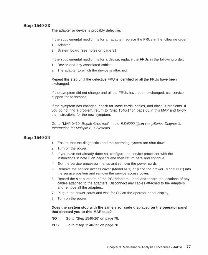
Step 1540-23The adapter or device is probably defective.
If the supplemental medium is for an adapter, replace the FRUs in the following order:
1. Adapter
2. System board (see notes on page 31)
If the supplemental medium is for a device, replace the FRUs in the following order:
1. Device and any associated cables
2. The adapter to which the device is attached.
Repeat this step until the defective FRU is identified or all the FRUs have beenexchanged.
If the symptom did not change and all the FRUs have been exchanged, call servicesupport for assistance.
If the symptom has changed, check for loose cards, cables, and obvious problems. Ifyou do not find a problem, return to “Step 1540-1” on page 60 in this MAP and followthe instructions for the new symptom.
Go to ″MAP 0410: Repair Checkout″ in the RS/6000 Eserver pSeries DiagnosticInformation for Multiple Bus Systems.
Step 1540-241. Ensure that the diagnostics and the operating system are shut down.
2. Turn off the power.
3. If you have not already done so, configure the service processor with theinstructions in note 6 on page 59 and then return here and continue.
4. Exit the service processor menus and remove the power cords.
5. Remove the service access cover (Model 6E1) or place the drawer (Model 6C1) intothe service position and remove the service access cover.
6. Record the slot numbers of the PCI adapters. Label and record the locations of anycables attached to the adapters. Disconnect any cables attached to the adaptersand remove all the adapters.
7. Plug in the power cords and wait for OK on the operator panel display.
8. Turn on the power.
Does the system stop with the same error code displayed on the operator panelthat directed you to this MAP step?
NO Go to “Step 1540-26” on page 78.
YES Go to “Step 1540-25” on page 78.
Chapter 3. Maintenance Analysis Procedures (MAPs) 77

Step 1540-25One of the FRUs remaining in the system unit is defective. Do the following:
1. Turn off the power.
2. Remove the power cords.
3. Replace the system board (see notes on page 31).
4. Plug in the power cable and wait for OK on the operator panel display.
5. Turn on the power.
Does the system stop with the same error code displayed on the operator panelthat directed you to this MAP step?
NO Go to ″MAP 0410: Repair Checkout″ in the RS/6000 Eserver pSeriesDiagnostic Information for Multiple Bus Systems.
YES Reinstall the original FRU.
If the symptom did not change and all the FRUs have been exchanged, returnto “Step 1540-2” on page 61 in this MAP.
Step 1540-26The system is working correctly with this configuration. One of the FRUs (adapters) thatyou removed is probably defective.
1. Turn off the power.
2. Remove the power cable.
3. Install a FRU (adapter) and connect any cables and devices that were attached toit.
4. Plug in the power cable and wait for OK on the operator panel display.
5. Turn on the power.
6. If the Console Selection screen is displayed, choose the firmware console.
7. Enter the appropriate password if you are prompted to do so.
Does the system stop with the same error code displayed on the operator panelthat directed you to this MAP step?
NO Repeat this step until all of the FRUs (adapters) are installed, then go to ″MAP0410: Repair Checkout″ in the RS/6000 Eserver pSeries DiagnosticInformation for Multiple Bus Systems.
YES Go to “Step 1540-27” on page 79.
78 Service Guide
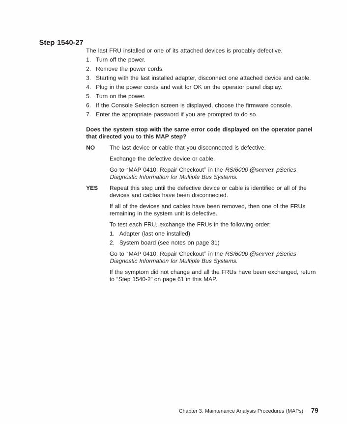
Step 1540-27The last FRU installed or one of its attached devices is probably defective.
1. Turn off the power.
2. Remove the power cords.
3. Starting with the last installed adapter, disconnect one attached device and cable.
4. Plug in the power cords and wait for OK on the operator panel display.
5. Turn on the power.
6. If the Console Selection screen is displayed, choose the firmware console.
7. Enter the appropriate password if you are prompted to do so.
Does the system stop with the same error code displayed on the operator panelthat directed you to this MAP step?
NO The last device or cable that you disconnected is defective.
Exchange the defective device or cable.
Go to ″MAP 0410: Repair Checkout″ in the RS/6000 Eserver pSeriesDiagnostic Information for Multiple Bus Systems.
YES Repeat this step until the defective device or cable is identified or all of thedevices and cables have been disconnected.
If all of the devices and cables have been removed, then one of the FRUsremaining in the system unit is defective.
To test each FRU, exchange the FRUs in the following order:
1. Adapter (last one installed)
2. System board (see notes on page 31)
Go to ″MAP 0410: Repair Checkout″ in the RS/6000 Eserver pSeriesDiagnostic Information for Multiple Bus Systems.
If the symptom did not change and all the FRUs have been exchanged, returnto “Step 1540-2” on page 61 in this MAP.
Chapter 3. Maintenance Analysis Procedures (MAPs) 79

80 Service Guide
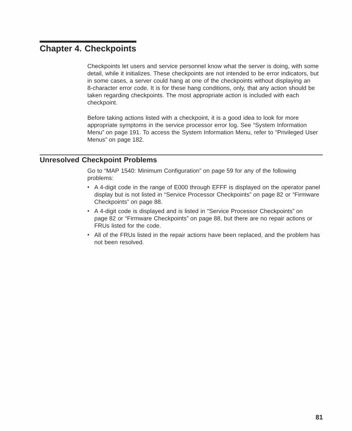
Chapter 4. Checkpoints
Checkpoints let users and service personnel know what the server is doing, with somedetail, while it initializes. These checkpoints are not intended to be error indicators, butin some cases, a server could hang at one of the checkpoints without displaying an8-character error code. It is for these hang conditions, only, that any action should betaken regarding checkpoints. The most appropriate action is included with eachcheckpoint.
Before taking actions listed with a checkpoint, it is a good idea to look for moreappropriate symptoms in the service processor error log. See “System InformationMenu” on page 191. To access the System Information Menu, refer to “Privileged UserMenus” on page 182.
Unresolved Checkpoint ProblemsGo to “MAP 1540: Minimum Configuration” on page 59 for any of the followingproblems:
v A 4-digit code in the range of E000 through EFFF is displayed on the operator paneldisplay but is not listed in “Service Processor Checkpoints” on page 82 or “FirmwareCheckpoints” on page 88.
v A 4-digit code is displayed and is listed in “Service Processor Checkpoints” onpage 82 or “Firmware Checkpoints” on page 88, but there are no repair actions orFRUs listed for the code.
v All of the FRUs listed in the repair actions have been replaced, and the problem hasnot been resolved.
81

Service Processor CheckpointsService processor checkpoints are in the range E010 to E0FF. The message OKindicates successful service processor testing and initialization. Firmware checkpointsare listed in “Firmware Checkpoints” on page 88.
If you replace FRUs or perform an action, and the problem is still unresolved, go to“MAP 1540: Minimum Configuration” on page 59 unless otherwise indicated in thetables.
If you replace FRUs or perform an action, and the problem is corrected, go to ″MAP0410: Repair Checkout″ in the RS/6000 Eserver pSeries Diagnostic Information forMultiple Bus Systems.
Table 1. Service Processor Checkpoints.
Checkpoint Description Action/ Possible Failing FRU
DIAG STBY Service processor is ready. The systemunit was shut down in service mode bythe operating system; however, thesystem unit is still powered on.
The service processor is ready. Theoperating system has been terminated;the system is still powered on. Thisusually indicates an operating systemcrash. The service processor menus areavailable. Look for error codes relatedto the operating system crash in theservice processor error log.
E000 System support controller beginsoperation. This is an informationalcheckpoint.
Call support.
E010 Starting service processor self-tests Replace the system board.Location: P1(See note 3 on page 109.)
E011 Service processor self-tests completedsuccessfully
Call support.
E012 Begin to set up service processor helps Replace the system board.Location: P1(See note 3 on page 109.)
E020 Configuring CMOS Replace the system board.Location: P1(See note 3 on page 109.)
E021 Configuring NVRAM 1. Manually drain the NVRAM byremoving the battery. Short circuitthe battery leads for at least 30seconds. Use a conductive objectsuch as a coin or a screwdriver forthis purpose.
2. Replace the system board.Location: P1(See note 3 on page 109.)
E022 Accessing system board VPD Replace the system board.Location: P1(See note 3 on page 109.)
82 Service Guide
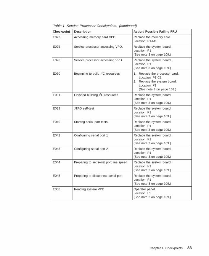
Table 1. Service Processor Checkpoints. (continued)
Checkpoint Description Action/ Possible Failing FRU
E023 Accessing memory card VPD Replace the memory cardLocation: P1-M1
E025 Service processor accessing VPD. Replace the system board.Location: P1(See note 3 on page 109.)
E026 Service processor accessing VPD. Replace the system board.Location: P1(See note 3 on page 109.)
E030 Beginning to build I2C resources 1. Replace the processor card.Location: P1-C1
2. Replace the system board.Location: P1(See note 3 on page 109.)
E031 Finished building I2C resources Replace the system board.Location: P1(See note 3 on page 109.)
E032 JTAG self-test Replace the system board.Location: P1(See note 3 on page 109.)
E040 Starting serial port tests Replace the system board.Location: P1(See note 3 on page 109.)
E042 Configuring serial port 1 Replace the system board.Location: P1(See note 3 on page 109.)
E043 Configuring serial port 2 Replace the system board.Location: P1(See note 3 on page 109.)
E044 Preparing to set serial port line speed Replace the system board.Location: P1(See note 3 on page 109.)
E045 Preparing to disconnect serial port Replace the system board.Location: P1(See note 3 on page 109.)
E050 Reading system VPD Operator panel.Location: L1(See note 2 on page 109.)
Chapter 4. Checkpoints 83

Table 1. Service Processor Checkpoints. (continued)
Checkpoint Description Action/ Possible Failing FRU
E051 Reading processor card VPD If one processor is installed:
v Replace processor card 1Location P1-C1
v Replace the system board.Location: P1(See note 3 on page 109.)
If two processor cards are installed:
1. Remove processor card 2 (P1-C2)and turn on the power. If the systemdoes not hang on E051, replaceprocessor card 2. If removingprocessor card 2 does not fix thesystem, continue to the next step.
2. Remove processor card 1 (P1-C1)and install processor card 2 in slot 1(P1-C1) and turn on the power. Ifthe system does not hang on E051,replace processor card 1. If thisswap does not fix the system,continue to the next step.
3. Replace the system board.Location: P1(See note 3 on page 109.)
E053 Reading system board VPD Replace the system board.Location: P1(See note 3 on page 109.)
E054 Reading system board VPD Replace the system board.Location: P1(See note 3 on page 109.)
E055 Reading power supply VPD Power supplyLocation: P3-V1Location: P3-V2Location: P3-V3
E060 Preparing to auto power-on (ACrestored)
1. Replace the system board.Location: P1(See note 3 on page 109.)
2. Replace processor card 1Location P1-C1
3. Replace processor card 2Location P1-C2
E061 Preparing to auto power-on (Timer) 1. Replace the system board.Location: P1(See note 3 on page 109.)
2. Replace processor card 1Location P1-C1
3. Replace processor card 2Location P1-C2
84 Service Guide

Table 1. Service Processor Checkpoints. (continued)
Checkpoint Description Action/ Possible Failing FRU
E070 Configuring modem 1. Try another modem configurationfrom the service processor menus.
2. Check the cabling between themodem and the system unit.
3. Replace the modem.4. Replace the system board.
Location: P1(See note 3 on page 109.)
E072 Preparing to call home 1. Try another modem configurationfrom the service processor menus.
2. Check the cabling between themodem and the system unit.
3. Replace the modem.4. Replace the system board.
Location: P1(See note 3 on page 109.)
E075 Service processor menus are available This code is posted on the operatorpanel when the service processormenus are available; the system is instand-by waiting for user input.
If the service processor menus are notdisplayed on the ASCII terminal:1. Verify that the ASCII terminal is
functional. Check the cable betweenthe ASCII terminal and the serialport on the system.
2. Remove, then reapply AC power.The service processor settings(modem speeds and call-outnumbers, for example) may have tobe reentered.
3. Replace the system board.Location: P1(See note 3 on page 109.)
E076 Leaving service processor menus;attempting to disconnect modems
1. Try another modem configurationfrom the service processor menus.
2. Check the cabling between themodem and the system unit.
3. Replace the modem.4. Replace the system board.
Location: P1(See note 3 on page 109.)
Chapter 4. Checkpoints 85
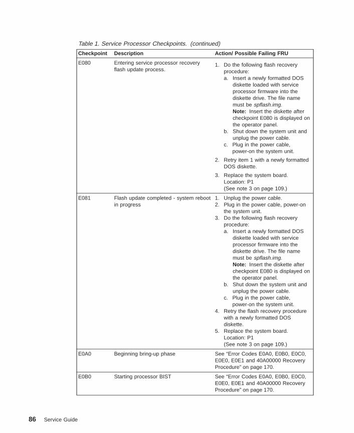
Table 1. Service Processor Checkpoints. (continued)
Checkpoint Description Action/ Possible Failing FRU
E080 Entering service processor recoveryflash update process.
1. Do the following flash recoveryprocedure:a. Insert a newly formatted DOS
diskette loaded with serviceprocessor firmware into thediskette drive. The file namemust be spflash.img.Note: Insert the diskette aftercheckpoint E080 is displayed onthe operator panel.
b. Shut down the system unit andunplug the power cable.
c. Plug in the power cable,power-on the system unit.
2. Retry item 1 with a newly formattedDOS diskette.
3. Replace the system board.Location: P1(See note 3 on page 109.)
E081 Flash update completed - system rebootin progress
1. Unplug the power cable.2. Plug in the power cable, power-on
the system unit.3. Do the following flash recovery
procedure:a. Insert a newly formatted DOS
diskette loaded with serviceprocessor firmware into thediskette drive. The file namemust be spflash.img.Note: Insert the diskette aftercheckpoint E080 is displayed onthe operator panel.
b. Shut down the system unit andunplug the power cable.
c. Plug in the power cable,power-on the system unit.
4. Retry the flash recovery procedurewith a newly formatted DOSdiskette.
5. Replace the system board.Location: P1(See note 3 on page 109.)
E0A0 Beginning bring-up phase See “Error Codes E0A0, E0B0, E0C0,E0E0, E0E1 and 40A00000 RecoveryProcedure” on page 170.
E0B0 Starting processor BIST See “Error Codes E0A0, E0B0, E0C0,E0E0, E0E1 and 40A00000 RecoveryProcedure” on page 170.
86 Service Guide

Table 1. Service Processor Checkpoints. (continued)
Checkpoint Description Action/ Possible Failing FRU
E0C0 Starting X5 BIST See “Error Codes E0A0, E0B0, E0C0,E0E0, E0E1 and 40A00000 RecoveryProcedure” on page 170.
E0D0 Creating JTAG scanlog (This procedurecould take several minutes.)
Call support
E0E0 Pulling processor card out of the resetstate.
See “Error Codes E0A0, E0B0, E0C0,E0E0, E0E1 and 40A00000 RecoveryProcedure” on page 170.
E0E1 Pull processor card out of reset: okay See “Error Codes E0A0, E0B0, E0C0,E0E0, E0E1 and 40A00000 RecoveryProcedure” on page 170.
OK Service Processor Ready. Waiting forpower-on normal operation
Press the system unit’s power button topower-on the system unit.
STBY Service processor is ready. Theoperating system has been terminated;the system is still powered on.
This usually indicates an operatingsystem crash. The service processormenus are available. Look for errorcodes related to the operating systemcrash in the service processor error log.
Chapter 4. Checkpoints 87

Firmware CheckpointsFirmware uses progress codes (checkpoints) in the range of E1xx to EFFF. Thesecheckpoints occur during system startup and can be useful in diagnosing certainproblems. Service processor checkpoints are listed in “Service Processor Checkpoints”on page 82.
If you replace FRUs or perform an action, and the problem is still unresolved, go to“MAP 1540: Minimum Configuration” on page 59 unless otherwise indicated in thetables.
If you replace FRUs or perform an action, and the problem is corrected, go to ″MAP0410: Repair Checkout″ in the RS/6000 Eserver pSeries Diagnostic Information forMultiple Bus Systems.
Table 2. Firmware Checkpoints.
Checkpoint Description Action/ Possible Failing FRU
E100 Reserved/Unused See “Unresolved Checkpoint Problems”on page 81.
E101 Video enabled, extended memory test See “Unresolved Checkpoint Problems”on page 81.
E102 Firmware restart See “Unresolved Checkpoint Problems”on page 81.
E103 Set memory refresh (composite image) See “Unresolved Checkpoint Problems”on page 81.
E104 Set memory refresh (recovery block) See “Unresolved Checkpoint Problems”on page 81.
E105 Transfer control to operating system(normal boot).
See “Boot Problems/Concerns” onpage 106.
E108 Run recovery block base memory (test2K), set stack
See “Unresolved Checkpoint Problems”on page 81.
E109 Copy CRC verification code to RAM See “Unresolved Checkpoint Problems”on page 81.
E10A Turn on cache See “Unresolved Checkpoint Problems”on page 81.
E10B Flush cache See “Unresolved Checkpoint Problems”on page 81.
E10C Jump to CRC verification code in RAM See “Unresolved Checkpoint Problems”on page 81.
E10D Compute composite image CRC See “Unresolved Checkpoint Problems”on page 81.
E10E Jump back to ROM See “Unresolved Checkpoint Problems”on page 81.
E10F Transfer control to open firmware See “Unresolved Checkpoint Problems”on page 81.
E110 Turn off cache, check if compositeimage CRC is valid
See “Unresolved Checkpoint Problems”on page 81.
88 Service Guide
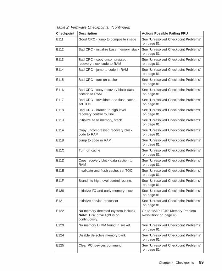
Table 2. Firmware Checkpoints. (continued)
Checkpoint Description Action/ Possible Failing FRU
E111 Good CRC - jump to composite image See “Unresolved Checkpoint Problems”on page 81.
E112 Bad CRC - initialize base memory, stack See “Unresolved Checkpoint Problems”on page 81.
E113 Bad CRC - copy uncompressedrecovery block code to RAM
See “Unresolved Checkpoint Problems”on page 81.
E114 Bad CRC - jump to code in RAM See “Unresolved Checkpoint Problems”on page 81.
E115 Bad CRC - turn on cache See “Unresolved Checkpoint Problems”on page 81.
E116 Bad CRC - copy recovery block datasection to RAM
See “Unresolved Checkpoint Problems”on page 81.
E117 Bad CRC - Invalidate and flush cache,set TOC
See “Unresolved Checkpoint Problems”on page 81.
E118 Bad CRC - branch to high levelrecovery control routine.
See “Unresolved Checkpoint Problems”on page 81.
E119 Initialize base memory, stack See “Unresolved Checkpoint Problems”on page 81.
E11A Copy uncompressed recovery blockcode to RAM
See “Unresolved Checkpoint Problems”on page 81.
E11B Jump to code in RAM See “Unresolved Checkpoint Problems”on page 81.
E11C Turn on cache See “Unresolved Checkpoint Problems”on page 81.
E11D Copy recovery block data section toRAM
See “Unresolved Checkpoint Problems”on page 81.
E11E Invalidate and flush cache, set TOC See “Unresolved Checkpoint Problems”on page 81.
E11F Branch to high level control routine. See “Unresolved Checkpoint Problems”on page 81.
E120 Initialize I/O and early memory block See “Unresolved Checkpoint Problems”on page 81.
E121 Initialize service processor See “Unresolved Checkpoint Problems”on page 81.
E122 No memory detected (system lockup)Note: Disk drive light is oncontinuously.
Go to “MAP 1240: Memory ProblemResolution” on page 45.
E123 No memory DIMM found in socket. See “Unresolved Checkpoint Problems”on page 81.
E124 Disable defective memory bank See “Unresolved Checkpoint Problems”on page 81.
E125 Clear PCI devices command See “Unresolved Checkpoint Problems”on page 81.
Chapter 4. Checkpoints 89
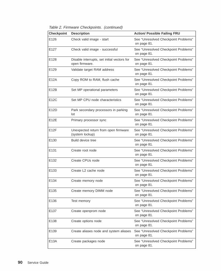
Table 2. Firmware Checkpoints. (continued)
Checkpoint Description Action/ Possible Failing FRU
E126 Check valid image - start See “Unresolved Checkpoint Problems”on page 81.
E127 Check valid image - successful See “Unresolved Checkpoint Problems”on page 81.
E128 Disable interrupts, set initial vectors foropen firmware.
See “Unresolved Checkpoint Problems”on page 81.
E129 Validate target RAM address See “Unresolved Checkpoint Problems”on page 81.
E12A Copy ROM to RAM, flush cache See “Unresolved Checkpoint Problems”on page 81.
E12B Set MP operational parameters See “Unresolved Checkpoint Problems”on page 81.
E12C Set MP CPU node characteristics See “Unresolved Checkpoint Problems”on page 81.
E12D Park secondary processors in parkinglot
See “Unresolved Checkpoint Problems”on page 81.
E12E Primary processor sync See “Unresolved Checkpoint Problems”on page 81.
E12F Unexpected return from open firmware(system lockup)
See “Unresolved Checkpoint Problems”on page 81.
E130 Build device tree See “Unresolved Checkpoint Problems”on page 81.
E131 Create root node See “Unresolved Checkpoint Problems”on page 81.
E132 Create CPUs node See “Unresolved Checkpoint Problems”on page 81.
E133 Create L2 cache node See “Unresolved Checkpoint Problems”on page 81.
E134 Create memory node See “Unresolved Checkpoint Problems”on page 81.
E135 Create memory DIMM node See “Unresolved Checkpoint Problems”on page 81.
E136 Test memory See “Unresolved Checkpoint Problems”on page 81.
E137 Create openprom node See “Unresolved Checkpoint Problems”on page 81.
E138 Create options node See “Unresolved Checkpoint Problems”on page 81.
E139 Create aliases node and system aliases See “Unresolved Checkpoint Problems”on page 81.
E13A Create packages node See “Unresolved Checkpoint Problems”on page 81.
90 Service Guide
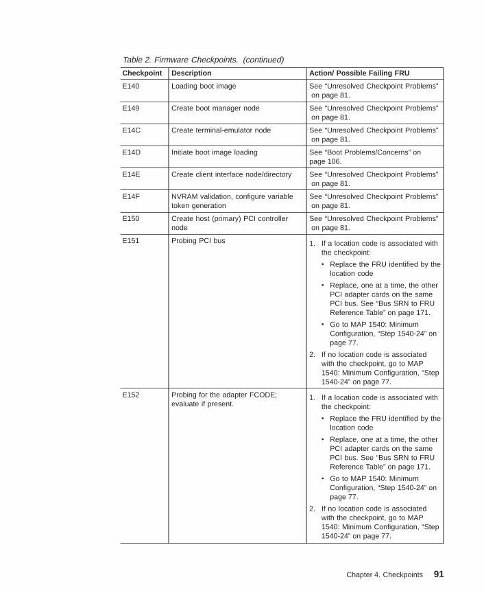
Table 2. Firmware Checkpoints. (continued)
Checkpoint Description Action/ Possible Failing FRU
E140 Loading boot image See “Unresolved Checkpoint Problems”on page 81.
E149 Create boot manager node See “Unresolved Checkpoint Problems”on page 81.
E14C Create terminal-emulator node See “Unresolved Checkpoint Problems”on page 81.
E14D Initiate boot image loading See “Boot Problems/Concerns” onpage 106.
E14E Create client interface node/directory See “Unresolved Checkpoint Problems”on page 81.
E14F NVRAM validation, configure variabletoken generation
See “Unresolved Checkpoint Problems”on page 81.
E150 Create host (primary) PCI controllernode
See “Unresolved Checkpoint Problems”on page 81.
E151 Probing PCI bus 1. If a location code is associated withthe checkpoint:
v Replace the FRU identified by thelocation code
v Replace, one at a time, the otherPCI adapter cards on the samePCI bus. See “Bus SRN to FRUReference Table” on page 171.
v Go to MAP 1540: MinimumConfiguration, “Step 1540-24” onpage 77.
2. If no location code is associatedwith the checkpoint, go to MAP1540: Minimum Configuration, “Step1540-24” on page 77.
E152 Probing for the adapter FCODE;evaluate if present.
1. If a location code is associated withthe checkpoint:
v Replace the FRU identified by thelocation code
v Replace, one at a time, the otherPCI adapter cards on the samePCI bus. See “Bus SRN to FRUReference Table” on page 171.
v Go to MAP 1540: MinimumConfiguration, “Step 1540-24” onpage 77.
2. If no location code is associatedwith the checkpoint, go to MAP1540: Minimum Configuration, “Step1540-24” on page 77.
Chapter 4. Checkpoints 91

Table 2. Firmware Checkpoints. (continued)
Checkpoint Description Action/ Possible Failing FRU
E153 End adapter FCODE probe/evaluation 1. If a location code is associated withthe checkpoint:
v Replace the FRU identified by thelocation code
v Replace, one at a time, the otherPCI adapter cards on the samePCI bus. See “Bus SRN to FRUReference Table” on page 171.
v Go to MAP 1540: MinimumConfiguration, “Step 1540-24” onpage 77.
2. If no location code is associatedwith the checkpoint, go to MAP1540: Minimum Configuration, “Step1540-24” on page 77.
E154 Create PCI bridge node 1. If a location code is associated withthe checkpoint:
v Replace the FRU identified by thelocation code
v Replace, one at a time, the otherPCI adapter cards on the samePCI bus. See “Bus SRN to FRUReference Table” on page 171.
v Go to MAP 1540: MinimumConfiguration, “Step 1540-24” onpage 77.
2. If no location code is associatedwith the checkpoint, go to MAP1540: Minimum Configuration, “Step1540-24” on page 77.
E155 Probing PCI bridge secondary bus 1. If a location code is associated withthe checkpoint:
v Replace the FRU identified by thelocation code
v Replace, one at a time, the otherPCI adapter cards on the samePCI bus. See “Bus SRN to FRUReference Table” on page 171.
v Go to MAP 1540: MinimumConfiguration, “Step 1540-24” onpage 77.
2. If no location code is associatedwith the checkpoint, go to MAP1540: Minimum Configuration, “Step1540-24” on page 77.
92 Service Guide
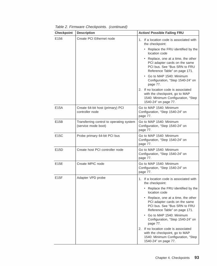
Table 2. Firmware Checkpoints. (continued)
Checkpoint Description Action/ Possible Failing FRU
E156 Create PCI Ethernet node 1. If a location code is associated withthe checkpoint:
v Replace the FRU identified by thelocation code
v Replace, one at a time, the otherPCI adapter cards on the samePCI bus. See “Bus SRN to FRUReference Table” on page 171.
v Go to MAP 1540: MinimumConfiguration, “Step 1540-24” onpage 77.
2. If no location code is associatedwith the checkpoint, go to MAP1540: Minimum Configuration, “Step1540-24” on page 77.
E15A Create 64-bit host (primary) PCIcontroller node
Go to MAP 1540: MinimumConfiguration, “Step 1540-24” onpage 77.
E15B Transferring control to operating system(service mode boot)
Go to MAP 1540: MinimumConfiguration, “Step 1540-24” onpage 77.
E15C Probe primary 64-bit PCI bus Go to MAP 1540: MinimumConfiguration, “Step 1540-24” onpage 77.
E15D Create host PCI controller node Go to MAP 1540: MinimumConfiguration, “Step 1540-24” onpage 77.
E15E Create MPIC node Go to MAP 1540: MinimumConfiguration, “Step 1540-24” onpage 77.
E15F Adapter VPD probe 1. If a location code is associated withthe checkpoint:
v Replace the FRU identified by thelocation code
v Replace, one at a time, the otherPCI adapter cards on the samePCI bus. See “Bus SRN to FRUReference Table” on page 171.
v Go to MAP 1540: MinimumConfiguration, “Step 1540-24” onpage 77.
2. If no location code is associatedwith the checkpoint, go to MAP1540: Minimum Configuration, “Step1540-24” on page 77.
Chapter 4. Checkpoints 93

Table 2. Firmware Checkpoints. (continued)
Checkpoint Description Action/ Possible Failing FRU
E160 CPU node VPD creation Go to MAP 1540: MinimumConfiguration, “Step 1540-24” onpage 77.
E161 Root node VPD creation Go to MAP 1540: MinimumConfiguration, “Step 1540-24” onpage 77.
E162 Service processor node VPD creation Go to MAP 1540: MinimumConfiguration, “Step 1540-24” onpage 77.
E164 Create PCI graphics node (P9) Go to MAP 1540: MinimumConfiguration, “Step 1540-24” onpage 77.
E168 Create PCI graphics node (S3) Go to MAP 1540: MinimumConfiguration, “Step 1540-24” onpage 77.
E170 Start of PCI bus probe 1. If a location code is associated withthe checkpoint:
v Replace the FRU identified by thelocation code
v Replace, one at a time, the otherPCI adapter cards on the samePCI bus. See “Bus SRN to FRUReference Table” on page 171.
v Go to MAP 1540: MinimumConfiguration, “Step 1540-24” onpage 77.
2. If no location code is associatedwith the checkpoint, go to MAP1540: Minimum Configuration, “Step1540-24” on page 77.
E171 Executing PCI-Delay function 1. If a location code is associated withthe checkpoint:
v Replace the FRU identified by thelocation code
v Replace, one at a time, the otherPCI adapter cards on the samePCI bus. See “Bus SRN to FRUReference Table” on page 171.
v Go to MAP 1540: MinimumConfiguration, “Step 1540-24” onpage 77.
2. If no location code is associatedwith the checkpoint, go to MAP1540: Minimum Configuration, “Step1540-24” on page 77.
94 Service Guide

Table 2. Firmware Checkpoints. (continued)
Checkpoint Description Action/ Possible Failing FRU
E172 First pass PCI device probe 1. If a location code is associated withthe checkpoint:
v Replace the FRU identified by thelocation code
v Replace, one at a time, the otherPCI adapter cards on the samePCI bus. See “Bus SRN to FRUReference Table” on page 171.
v Go to MAP 1540: MinimumConfiguration, “Step 1540-24” onpage 77.
2. If no location code is associatedwith the checkpoint, go to MAP1540: Minimum Configuration, “Step1540-24” on page 77.
E174 Establish host connection Refer to “Boot Problems/Concerns” onpage 106 for general considerations.
E175 BootP request Refer to “Boot Problems/Concerns” onpage 106 for general considerations.1. Turn off, then on, and retry the boot
operation.2. Verify boot list by using the firmware
SMS Multiboot menus.3. Verify the network connection
(network could be down).4. Have network administrator verify
the server configuration for thisclient.
E176 TFTP file transfer Refer to “Boot Problems/Concerns” onpage 106 for general considerations.1. Turn off, then on, and retry the boot
operation.2. Verify boot list by using the firmware
SMS Multiboot menus.3. Verify the network connection
(network could be down).4. Have network administrator verify
the server configuration for thisclient.
Chapter 4. Checkpoints 95
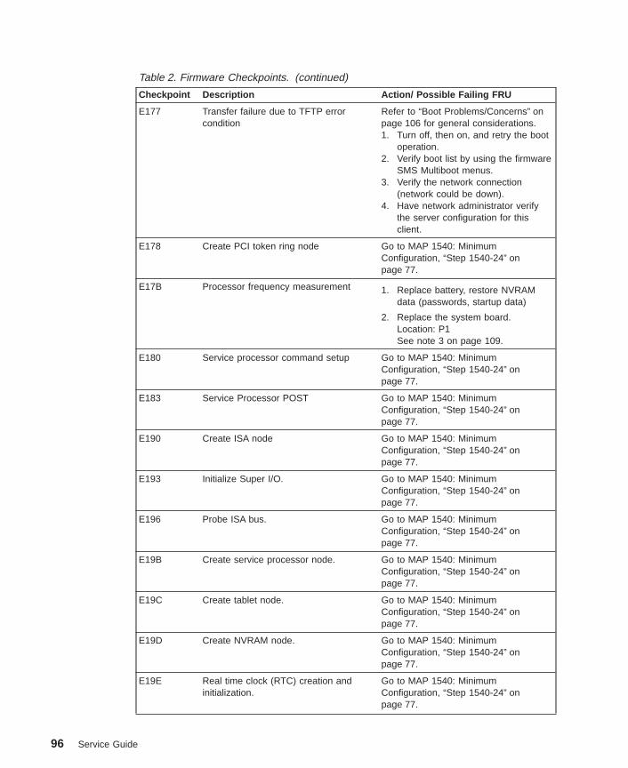
Table 2. Firmware Checkpoints. (continued)
Checkpoint Description Action/ Possible Failing FRU
E177 Transfer failure due to TFTP errorcondition
Refer to “Boot Problems/Concerns” onpage 106 for general considerations.1. Turn off, then on, and retry the boot
operation.2. Verify boot list by using the firmware
SMS Multiboot menus.3. Verify the network connection
(network could be down).4. Have network administrator verify
the server configuration for thisclient.
E178 Create PCI token ring node Go to MAP 1540: MinimumConfiguration, “Step 1540-24” onpage 77.
E17B Processor frequency measurement 1. Replace battery, restore NVRAMdata (passwords, startup data)
2. Replace the system board.Location: P1See note 3 on page 109.
E180 Service processor command setup Go to MAP 1540: MinimumConfiguration, “Step 1540-24” onpage 77.
E183 Service Processor POST Go to MAP 1540: MinimumConfiguration, “Step 1540-24” onpage 77.
E190 Create ISA node Go to MAP 1540: MinimumConfiguration, “Step 1540-24” onpage 77.
E193 Initialize Super I/O. Go to MAP 1540: MinimumConfiguration, “Step 1540-24” onpage 77.
E196 Probe ISA bus. Go to MAP 1540: MinimumConfiguration, “Step 1540-24” onpage 77.
E19B Create service processor node. Go to MAP 1540: MinimumConfiguration, “Step 1540-24” onpage 77.
E19C Create tablet node. Go to MAP 1540: MinimumConfiguration, “Step 1540-24” onpage 77.
E19D Create NVRAM node. Go to MAP 1540: MinimumConfiguration, “Step 1540-24” onpage 77.
E19E Real time clock (RTC) creation andinitialization.
Go to MAP 1540: MinimumConfiguration, “Step 1540-24” onpage 77.
96 Service Guide

Table 2. Firmware Checkpoints. (continued)
Checkpoint Description Action/ Possible Failing FRU
E19F Create EEPROM node. Go to MAP 1540: MinimumConfiguration, “Step 1540-24” onpage 77.
E1AD Alternating pattern of E1AD and E1DEis used to indicate a default catchcondition before the firmware″checkpoint″ word is available
Go to MAP 1540: MinimumConfiguration, “Step 1540-24” onpage 77.
E1B0 Create LPT node. Go to MAP 1540: MinimumConfiguration, “Step 1540-24” onpage 77.
E1B1 Create serial node. Go to MAP 1540: MinimumConfiguration, “Step 1540-24” onpage 77.
E1B2 Create audio node. Go to MAP 1540: MinimumConfiguration, “Step 1540-24” onpage 77.
E1B3 Create 8042 node. Go to MAP 1540: MinimumConfiguration, “Step 1540-24” onpage 77.
E1B6 Probe for (ISA) keyboard. Go to MAP 1540: MinimumConfiguration, “Step 1540-24” onpage 77.
E1BA Enable L2 cache. See “Unresolved Checkpoint Problems”on page 81.
E1BB Set cache parameters for burst. See “Unresolved Checkpoint Problems”on page 81.
E1BC Set cache parameters for 512KB. See “Unresolved Checkpoint Problems”on page 81.
E1BD Probe for (ISA) mouse. Go to MAP 1540: MinimumConfiguration, “Step 1540-24” onpage 77.
E1BE Create operator panel node. Go to MAP 1540: MinimumConfiguration, “Step 1540-24” onpage 77.
E1BF Create power management node. Go to MAP 1540: MinimumConfiguration, “Step 1540-24” onpage 77.
E1C5 Create ISA interrupt controller (PIC)node.
Go to MAP 1540: MinimumConfiguration, “Step 1540-24” onpage 77.
E1C6 Create DMA node. Go to MAP 1540: MinimumConfiguration, “Step 1540-24” onpage 77.
Chapter 4. Checkpoints 97

Table 2. Firmware Checkpoints. (continued)
Checkpoint Description Action/ Possible Failing FRU
E1D0 Create PCI SCSI node. 1. If a location code is associated withthe checkpoint:
v Replace the FRU identified by thelocation code
v Replace, one at a time, the otherPCI adapter cards on the samePCI bus. See “Bus SRN to FRUReference Table” on page 171.
v Go to MAP 1540: MinimumConfiguration, “Step 1540-24” onpage 77.
2. If no location code is associatedwith the checkpoint, go to MAP1540: Minimum Configuration, “Step1540-24” on page 77.
E1D3 Create SCSI block device node. 1. If a location code is associated withthe checkpoint:
v Replace the FRU identified by thelocation code
v Replace, one at a time, the otherPCI adapter cards on the samePCI bus. See “Bus SRN to FRUReference Table” on page 171.
v Go to MAP 1540: MinimumConfiguration, “Step 1540-24” onpage 77.
2. If no location code is associatedwith the checkpoint, go to MAP1540: Minimum Configuration, “Step1540-24” on page 77.
E1D4 Create SCSI byte device node (ST). 1. If a location code is associated withthe checkpoint:
v Replace the FRU identified by thelocation code
v Replace, one at a time, the otherPCI adapter cards on the samePCI bus. See “Bus SRN to FRUReference Table” on page 171.
v Go to MAP 1540: MinimumConfiguration, “Step 1540-24” onpage 77.
2. If no location code is associatedwith the checkpoint, go to MAP1540: Minimum Configuration, “Step1540-24” on page 77.
98 Service Guide
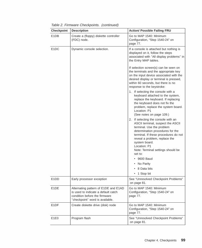
Table 2. Firmware Checkpoints. (continued)
Checkpoint Description Action/ Possible Failing FRU
E1DB Create a (floppy) diskette controller(FDC) node.
Go to MAP 1540: MinimumConfiguration, “Step 1540-24” onpage 77.
E1DC Dynamic console selection. If a console is attached but nothing isdisplayed on it, follow the stepsassociated with ″All display problems″ inthe Entry MAP tables.
If selection screen(s) can be seen onthe terminals and the appropriate keyon the input device associated with thedesired display or terminal is pressed,within 60 seconds, but there is noresponse to the keystroke:
1. If selecting the console with akeyboard attached to the system,replace the keyboard. If replacingthe keyboard does not fix theproblem, replace the system board.Location: P1(See notes on page 109.)
2. If selecting the console with anASCII terminal, suspect the ASCIIterminal. Use the problemdetermination procedures for theterminal. If these procedures do notreveal a problem, replace thesystem board.Location: P1Note: Terminal settings should beset to:
v 9600 Baud
v No Parity
v 8 Data bits
v 1 Stop bit
E1DD Early processor exception See “Unresolved Checkpoint Problems”on page 81.
E1DE Alternating pattern of E1DE and E1ADis used to indicate a default catchcondition before the firmware″checkpoint″ word is available.
Go to MAP 1540: MinimumConfiguration, “Step 1540-24” onpage 77.
E1DF Create diskette drive (disk) node Go to MAP 1540: MinimumConfiguration, “Step 1540-24” onpage 77.
E1E0 Program flash See “Unresolved Checkpoint Problems”on page 81.
Chapter 4. Checkpoints 99
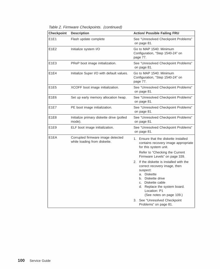
Table 2. Firmware Checkpoints. (continued)
Checkpoint Description Action/ Possible Failing FRU
E1E1 Flash update complete See “Unresolved Checkpoint Problems”on page 81.
E1E2 Initialize system I/O Go to MAP 1540: MinimumConfiguration, “Step 1540-24” onpage 77.
E1E3 PReP boot image initialization. See “Unresolved Checkpoint Problems”on page 81.
E1E4 Initialize Super I/O with default values. Go to MAP 1540: MinimumConfiguration, “Step 1540-24” onpage 77.
E1E5 XCOFF boot image initialization. See “Unresolved Checkpoint Problems”on page 81.
E1E6 Set up early memory allocation heap. See “Unresolved Checkpoint Problems”on page 81.
E1E7 PE boot image initialization. See “Unresolved Checkpoint Problems”on page 81.
E1E8 Initialize primary diskette drive (polledmode).
See “Unresolved Checkpoint Problems”on page 81.
E1E9 ELF boot image initialization. See “Unresolved Checkpoint Problems”on page 81.
E1EA Corrupted firmware image detectedwhile loading from diskette.
1. Ensure that the diskette installedcontains recovery image appropriatefor this system unit.
Refer to “Checking the CurrentFirmware Levels” on page 339.
2. If the diskette is installed with thecorrect recovery image, thensuspect:a. Disketteb. Diskette drivec. Diskette cabled. Replace the system board.
Location: P1(See notes on page 109.)
3. See “Unresolved CheckpointProblems” on page 81.
100 Service Guide
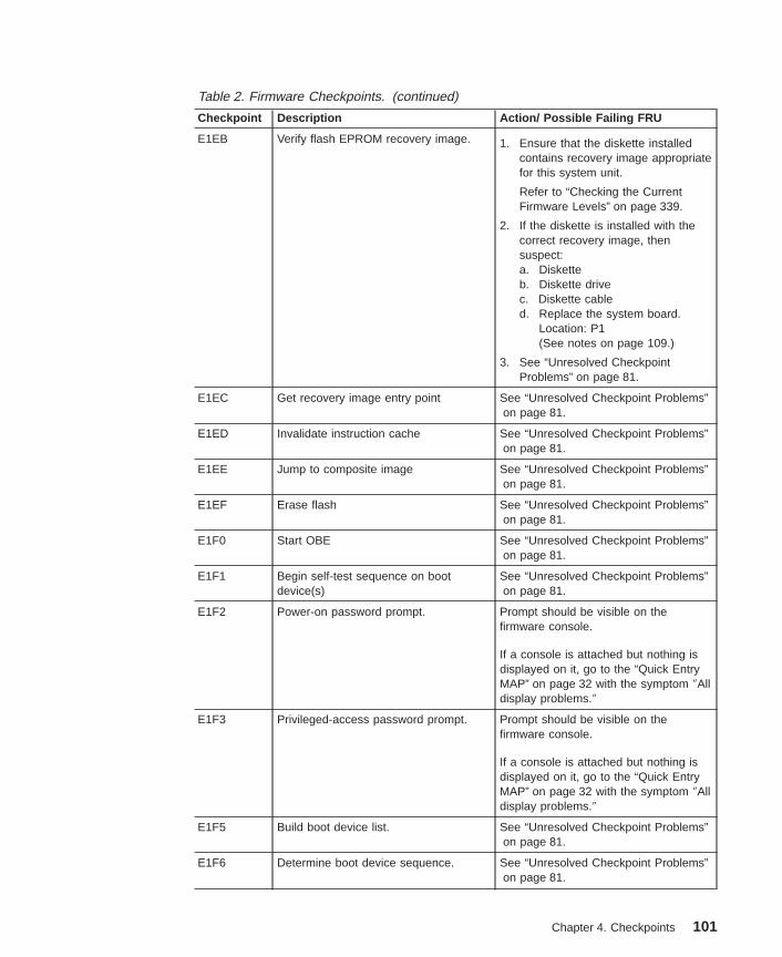
Table 2. Firmware Checkpoints. (continued)
Checkpoint Description Action/ Possible Failing FRU
E1EB Verify flash EPROM recovery image. 1. Ensure that the diskette installedcontains recovery image appropriatefor this system unit.
Refer to “Checking the CurrentFirmware Levels” on page 339.
2. If the diskette is installed with thecorrect recovery image, thensuspect:a. Disketteb. Diskette drivec. Diskette cabled. Replace the system board.
Location: P1(See notes on page 109.)
3. See “Unresolved CheckpointProblems” on page 81.
E1EC Get recovery image entry point See “Unresolved Checkpoint Problems”on page 81.
E1ED Invalidate instruction cache See “Unresolved Checkpoint Problems”on page 81.
E1EE Jump to composite image See “Unresolved Checkpoint Problems”on page 81.
E1EF Erase flash See “Unresolved Checkpoint Problems”on page 81.
E1F0 Start OBE See “Unresolved Checkpoint Problems”on page 81.
E1F1 Begin self-test sequence on bootdevice(s)
See “Unresolved Checkpoint Problems”on page 81.
E1F2 Power-on password prompt. Prompt should be visible on thefirmware console.
If a console is attached but nothing isdisplayed on it, go to the “Quick EntryMAP” on page 32 with the symptom ″Alldisplay problems.″
E1F3 Privileged-access password prompt. Prompt should be visible on thefirmware console.
If a console is attached but nothing isdisplayed on it, go to the “Quick EntryMAP” on page 32 with the symptom ″Alldisplay problems.″
E1F5 Build boot device list. See “Unresolved Checkpoint Problems”on page 81.
E1F6 Determine boot device sequence. See “Unresolved Checkpoint Problems”on page 81.
Chapter 4. Checkpoints 101
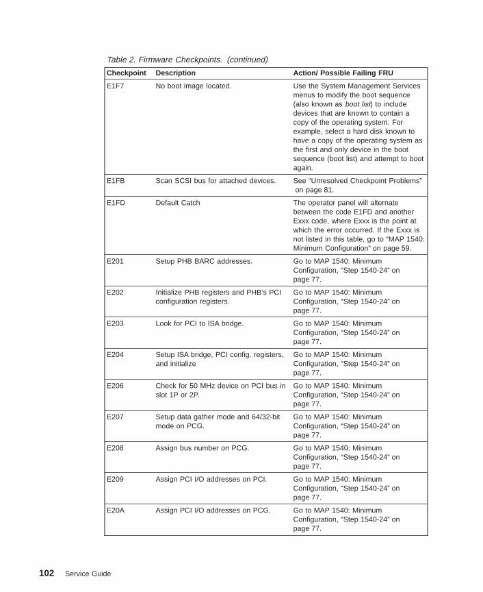
Table 2. Firmware Checkpoints. (continued)
Checkpoint Description Action/ Possible Failing FRU
E1F7 No boot image located. Use the System Management Servicesmenus to modify the boot sequence(also known as boot list) to includedevices that are known to contain acopy of the operating system. Forexample, select a hard disk known tohave a copy of the operating system asthe first and only device in the bootsequence (boot list) and attempt to bootagain.
E1FB Scan SCSI bus for attached devices. See “Unresolved Checkpoint Problems”on page 81.
E1FD Default Catch The operator panel will alternatebetween the code E1FD and anotherExxx code, where Exxx is the point atwhich the error occurred. If the Exxx isnot listed in this table, go to “MAP 1540:Minimum Configuration” on page 59.
E201 Setup PHB BARC addresses. Go to MAP 1540: MinimumConfiguration, “Step 1540-24” onpage 77.
E202 Initialize PHB registers and PHB’s PCIconfiguration registers.
Go to MAP 1540: MinimumConfiguration, “Step 1540-24” onpage 77.
E203 Look for PCI to ISA bridge. Go to MAP 1540: MinimumConfiguration, “Step 1540-24” onpage 77.
E204 Setup ISA bridge, PCI config. registers,and initialize
Go to MAP 1540: MinimumConfiguration, “Step 1540-24” onpage 77.
E206 Check for 50 MHz device on PCI bus inslot 1P or 2P.
Go to MAP 1540: MinimumConfiguration, “Step 1540-24” onpage 77.
E207 Setup data gather mode and 64/32-bitmode on PCG.
Go to MAP 1540: MinimumConfiguration, “Step 1540-24” onpage 77.
E208 Assign bus number on PCG. Go to MAP 1540: MinimumConfiguration, “Step 1540-24” onpage 77.
E209 Assign PCI I/O addresses on PCI. Go to MAP 1540: MinimumConfiguration, “Step 1540-24” onpage 77.
E20A Assign PCI I/O addresses on PCG. Go to MAP 1540: MinimumConfiguration, “Step 1540-24” onpage 77.
102 Service Guide

Table 2. Firmware Checkpoints. (continued)
Checkpoint Description Action/ Possible Failing FRU
E20B Check MCERs stuck at fault. Go to MAP 1540: MinimumConfiguration, “Step 1540-24” onpage 77.
E20C Testing L2 cache. 1. Replace the processor card.Location: P1-C1Location: P1-C2(See notes on page 109.)
2. See “Unresolved CheckpointProblems” on page 81.
E210 Processors L1 data cache array testfails. System hangs.
See “Unresolved Checkpoint Problems”on page 81.
E211 IPL ROS CRC checking. Go to MAP 1540: MinimumConfiguration, “Step 1540-24” onpage 77.
E212 Processor POST. 1. Replace the processor card.Location: P1-C1Location: P1-C2(See notes on page 109.)
2. See “Unresolved CheckpointProblems” on page 81.
E213 Initial memory configuration. Go to “MAP 1240: Memory ProblemResolution” on page 45.
E214 Memory test. Go to “MAP 1240: Memory ProblemResolution” on page 45.
E216 Copy ROS into RAM. Setup translationand C environment.
1. Go to “MAP 1240: Memory ProblemResolution” on page 45.
2. See “Unresolved CheckpointProblems” on page 81.
E218 Memory test. Go to “MAP 1240: Memory ProblemResolution” on page 45.
E21A System has good memory See “Unresolved Checkpoint Problems”on page 81.
E220 Final memory configuration. Go to “MAP 1240: Memory ProblemResolution” on page 45.
E240 Setup Winbond ISA bridge. Go to MAP 1540: MinimumConfiguration, “Step 1540-24” onpage 77.
E241 Reset PCI Bus. Go to MAP 1540: MinimumConfiguration, “Step 1540-24” onpage 77.
E242 Initialize ISA DMA channel. Go to MAP 1540: MinimumConfiguration, “Step 1540-24” onpage 77.
Chapter 4. Checkpoints 103

Table 2. Firmware Checkpoints. (continued)
Checkpoint Description Action/ Possible Failing FRU
E243 Setup configuration registers. Go to MAP 1540: MinimumConfiguration, “Step 1540-24” onpage 77.
E244 Enable system speaker and send abeep.
Go to MAP 1540: MinimumConfiguration, “Step 1540-24” onpage 77.
E246 System firmware corrupted, takerecovery path.
Go to MAP 1540: MinimumConfiguration, “Step 1540-24” onpage 77.
E247 Capture memory module SPDs intoNVRAM.
Go to MAP 1540: MinimumConfiguration, “Step 1540-24” onpage 77.
E249 Enter recover path’s main code. Go to MAP 1540: MinimumConfiguration, “Step 1540-24” onpage 77.
E297 Start firmware softload path execution. See “Unresolved Checkpoint Problems”on page 81.
E298 Start firmware recovery path execution. See “Unresolved Checkpoint Problems”on page 81.
E299 Start C code execution. See “Unresolved Checkpoint Problems”on page 81.
E3xx Memory test See “MAP 1240: Memory ProblemResolution” on page 45.
E440 Validate NVRAM, initialize partitions asneeded.
1. Verify that the system and serviceprocessor firmware levels are at thecurrent release levels; update asnecessary.
2. Go to MAP 1540: MinimumConfiguration, “Step 1540-24” onpage 77.
E441 Generate /options node NVRAMconfiguration variable properties.
1. Verify that the system and serviceprocessor firmware levels are at thecurrent release levels; update asnecessary.
2. Go to MAP 1540: MinimumConfiguration, “Step 1540-24” onpage 77.
E442 Validate NVRAM partitions. 1. Verify that the system and serviceprocessor firmware levels are at thecurrent release levels; update asnecessary.
2. Go to MAP 1540: MinimumConfiguration, “Step 1540-24” onpage 77.
104 Service Guide

Table 2. Firmware Checkpoints. (continued)
Checkpoint Description Action/ Possible Failing FRU
E443 Generate NVRAM configuration variabledictionary words.
Suspect a system firmware problem ifthis problem persists. Verify that thesystem firmware is at the currentrelease level, update as necessary. See“Unresolved Checkpoint Problems” onpage 81.
E600 SSA PCI adapter open firmware has runsuccessfully.
1. Replace the SSA adapter.2. See “Unresolved Checkpoint
Problems” on page 81.
E601 SSA PCI adapter BIST has been startedbut failed to complete after 4 seconds.
1. Replace the SSA adapter.2. See “Unresolved Checkpoint
Problems” on page 81.
E602 SSA PCI adapter open firmware hasstarted.
1. Replace the SSA adapter.2. See “Unresolved Checkpoint
Problems” on page 81.
E603 SSA PCI adapter BIST has completedwith an error.
1. Replace the SSA adapter.2. See “Unresolved Checkpoint
Problems” on page 81.
E604 SSA PCI adapter BIST and subsequentPOSTs have completed successfully
1. Replace the SSA adapter.2. See “Unresolved Checkpoint
Problems” on page 81.
E605 SSA PCI adapter BIST has completedsuccessfully, but the subsequent POSTshave failed.
1. Replace the SSA adapter.2. See “Unresolved Checkpoint
Problems” on page 81.
E60E SSA PCI adapter open firmware aboutto exit (no stack corruption).
1. Replace the SSA adapter.2. See “Unresolved Checkpoint
Problems” on page 81.
E60F SSA PCI adapter open firmware has rununsuccessfully.
1. Replace the SSA adapter.2. See “Unresolved Checkpoint
Problems” on page 81.
E6FF SSA PCI adapter open firmware aboutto exit (with stack corruption)
1. Replace the SSA adapter.2. See “Unresolved Checkpoint
Problems” on page 81.
Chapter 4. Checkpoints 105

Boot Problems/ConcernsDepending on the boot device, a checkpoint may be displayed on the operator panel foran extended period of time while the boot image is retrieved from the device. This isparticularly true for tape and network boot attempts. If booting from CD-ROM or tape,watch for activity on the drive’s LED indicator. A blinking LED indicates that the loadingof either the boot image or additional information required by the operating systembeing booted is still in progress. If the checkpoint is displayed for an extended period oftime and the drive LED is not indicating any activity, there might be a problem loadingthe boot image from the device.
Note: For network boot attempts, if the system is not connected to an active network orif the target server is inaccessible (this can also result from incorrect IPparameters being supplied), the system will still attempt to boot. Becausetime-out durations are necessarily long to accommodate retries, the system mayappear to be hung.
This procedure assumes that a CD-ROM drive is connected to the internal IDEconnector and a diagnostic CD-ROM is available. Booting from CD-ROM or NIM on thediagnostics image is referred to as Standalone Diagnostics.
Step 1Restart the system and access the firmware SMS Main Menu. Select Multiboot .
1. Check to see if the intended boot device is correctly specified in the boot list. If it isin the boot list:
a. Remove all removable media from devices in the boot list from which you do notwant to boot.
b. If attempting to boot from the network, go to “Step 2”.
c. If attempting to boot from a disk drive or CD-ROM, go to “Step 3” on page 107.
2. If the intended boot device is not correctly identified in the boot sequence, add it tothe boot sequence using the SMS menus. If the device can be added to the bootsequence, reboot the system. If the intended boot device cannot be added to theboot list, go to “Step 3” on page 107.
Step 2If attempting to boot from the network:
1. Verify that IP parameters are correct.
2. Attempt to ″ping″ the target server using the SMS Ping utility. If the ping is notsuccessful, have the network administrator verify the server configuration for thisclient.
3. Check with the network administrator to ensure that the network is up.
4. Check the network cabling to the adapter.
5. Turn the power off, then on and retry the boot operation.
106 Service Guide

Step 3Try to boot and run standalone diagnostics against the system, particularly against theintended boot device. If an SRN is generated, go to the RS/6000 Eserver pSeriesDiagnostic Information for Multiple Bus Systems manual.
If diagnostics boot successfully and ″No Trouble Found″ was the result whendiagnostics were run against the intended boot device, go to substep 4. If thediagnostics boot successfully, but the intended boot device was not present in theresource list:
1. If you booted from IDE CD-ROM Standalone Diagnostics, follow these steps:
a. Check the SCSI cables
b. Remove all hot-swap disk drives except the intended boot device if it’s ahot-swap drive.
c. Disconnect all other internal SCSI devices.
d. Replace the SCSI cables
e. Replace the repeater card
f. Replace the SCSI backplane
g. Replace the intended boot device.
h. Replace the system board.
2. Go to the Task Selection Menu and select Task, Display Configuration andResource List . If the intended boot device is not listed, go to ″MAP 0290: MissingResource Problem Resolution″ in the RS/6000 Eserver pSeries DiagnosticInformation for Multiple Bus Systems manual.
3. If an SRN, not an 8-digit error code, is reported, go to the RS/6000 Eserver
pSeries Diagnostic Information for Multiple Bus Systems manual.
4. If the diagnostics are successful, and no other devices have been disconnected, itmay be necessary to perform an operating system-specific recovery process, orreinstall the operating system.
5. If you replaced the indicated FRUs and the problem is not corrected, or the abovedescriptions did not address your particular situation, go to “MAP 1540: MinimumConfiguration” on page 59.
If the problem has been corrected, go to ″MAP 0410: Repair Checkout″ in RS/6000Eserver pSeries Diagnostic Information for Multiple Bus Systems.
If diagnostics do not boot successfully, and a SCSI boot failure is also occurring, go to“MAP 1540: Minimum Configuration” on page 59.
If diagnostics do not boot successfully, and a SCSI boot failure is not occurring:
1. Check IDE cabling to boot device.
2. Check device configuration jumpers.
If no problem is found with the cabling or the jumpers, continue to “Step 4” onpage 108.
Chapter 4. Checkpoints 107

Step 4It is possible that another installed adapter is causing the problem. Do the following:
1. Remove all installed adapters except the one the CD-ROM drive is attached to andthe one used for the console.
2. Try to boot the standalone diagnostics again.
3. If unable to load standalone diagnostics, go to “Step 5”.
4. If standalone diagnostics load, reinstall adapters (and attached devices asapplicable) one at a time and retry the boot operation until the problem recurs. Thenreplace the adapter or device that caused the problem. (The primary I/O drawerbackplane can also cause the device or adapter to fail.) Go to ″MAP 0410: RepairCheckout″ in the RS/6000 Eserver pSeries Diagnostic Information for Multiple BusSystems.
Step 5The CD-ROM drive, IDE cable, graphics adapter (if installed), or the system board ismost likely defective. A TTY terminal attached to the serial port also can be used todetermine if the graphics adapter is causing the problem. This is done by removing thegraphics adapter, attaching a TTY to the serial port, and retrying standalonediagnostics. If the standalone diagnostics load, replace the graphics adapter.
1. Replace the CD-ROM drive.
2. Replace the IDE cable.
3. Replace the system board.
4. If you replaced the indicated FRUs and the problem is still not corrected, or theabove descriptions did not address your particular situation, go to “MAP 1540:Minimum Configuration” on page 59.
5. Go to ″MAP 0410: Repair Checkout″ in RS/6000 Eserver pSeries DiagnosticInformation for Multiple Bus Systems
108 Service Guide
Chapter 5. Error Code to FRU Index
The Error Code to FRU Index lists error symptoms and possible causes. The mostlikely cause is listed first. Use this index to help you decide which FRUs to replacewhen you are servicing the system.
Performing Slow BootTo fully analyze all of the available information, perform the following steps beforecontinuing or doing a hardware repair or replacement, especially if the error is related tothe CPU or memory:
1. Record the 8-character error code (and location code if present) displayed in theoperator panel or that was reported by the customer.
2. Do a slow-mode boot in service mode. This can be specified using the SystemPower Control Menu on the service processor main menu. (A fast-mode boot skipsmuch of the built-in diagnostic testing.) A slow-mode boot may yield a new8-character error code on the operator panel and new errors in the serviceprocessor error log. If a new error code is reported, use it in subsequent steps tocontinue problem analysis. If a new error code is not reported, continue with the olderror code.
Considerations for Using the Error Code to FRU IndexIf you replace FRUs or perform an action and the problem is still not corrected, go to“MAP 1540: Minimum Configuration” on page 59, unless otherwise indicated in thetables.
If you replace FRUs or perform an action and the problem is corrected, go to ″MAP0410: Repair Checkout″ in the RS/6000 Eserver pSeries Diagnostic Information forMultiple Bus Systems.
If the codes in the following tables indicate a device that is present more than once inthe system unit, a location code is needed to specify which device generated the error.Go to “Step 1020-4” on page 44 to display the System Management Services error logand obtain a location code. Location code descriptions can be found under “LocationCodes” on page 11.
After you have obtained the location code, see Chapter 10, “Parts Information” onpage 293 for the part number.
Notes:
1. If more than eight digits are displayed in the operator panel, use only the first eightdigits to find the error in the tables. The digits that display beyond the first eightdigits are location codes that can assist you in diagnosing the problem. See“Location Codes” on page 11.
2. Licensed programs frequently rely on system information stored on the VPD on theoperator panel control assembly. If the MAPs indicate that the operator panel control
109
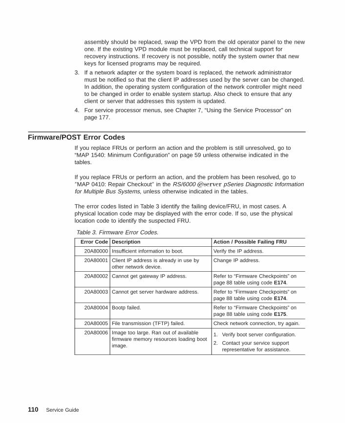
assembly should be replaced, swap the VPD from the old operator panel to the newone. If the existing VPD module must be replaced, call technical support forrecovery instructions. If recovery is not possible, notify the system owner that newkeys for licensed programs may be required.
3. If a network adapter or the system board is replaced, the network administratormust be notified so that the client IP addresses used by the server can be changed.In addition, the operating system configuration of the network controller might needto be changed in order to enable system startup. Also check to ensure that anyclient or server that addresses this system is updated.
4. For service processor menus, see Chapter 7, “Using the Service Processor” onpage 177.
Firmware/POST Error CodesIf you replace FRUs or perform an action and the problem is still unresolved, go to“MAP 1540: Minimum Configuration” on page 59 unless otherwise indicated in thetables.
If you replace FRUs or perform an action, and the problem has been resolved, go to″MAP 0410: Repair Checkout″ in the RS/6000 Eserver pSeries Diagnostic Informationfor Multiple Bus Systems, unless otherwise indicated in the tables.
The error codes listed in Table 3 identify the failing device/FRU, in most cases. Aphysical location code may be displayed with the error code. If so, use the physicallocation code to identify the suspected FRU.
Table 3. Firmware Error Codes.
Error Code Description Action / Possible Failing FRU
20A80000 Insufficient information to boot. Verify the IP address.
20A80001 Client IP address is already in use byother network device.
Change IP address.
20A80002 Cannot get gateway IP address. Refer to “Firmware Checkpoints” onpage 88 table using code E174.
20A80003 Cannot get server hardware address. Refer to “Firmware Checkpoints” onpage 88 table using code E174.
20A80004 Bootp failed. Refer to “Firmware Checkpoints” onpage 88 table using code E175.
20A80005 File transmission (TFTP) failed. Check network connection, try again.
20A80006 Image too large. Ran out of availablefirmware memory resources loading bootimage.
1. Verify boot server configuration.
2. Contact your service supportrepresentative for assistance.
110 Service Guide

Table 3. Firmware Error Codes. (continued)
Error Code Description Action / Possible Failing FRU
20D0000F Self-test failed on device, noerror/location code information available.
Check the System ManagementServices error log entry (described in“Step 1020-4” on page 44) for thiserror code. The location code (ifpresent) in the error log entry shouldidentify the location of the failingdevice.
20D00010 Self-test failed on device, cannot locatepackage.
Contact your service supportrepresentative for assistance.
20D00011 Instantiate RTAS failed. Contact your service support personfor assistance.
20E00000 Power-on password entry error. The password has been enteredincorrectly.
Re-enter the password.
20E00001 Privileged-access password entry error. The password has been enteredincorrectly.
Re-enter the password.
20E00002 Privileged-access password jumper notenabled.
The privileged-access passwordjumper is not in the correct position forpassword initial entry.
Consult the system’s User’s Guide forjumper location and position.
20E00003 Power-on password must be set forunattended mode.
Unattended mode requires the settingof the power-on password before it isenabled.
20E00004 Battery drained or needs replacement. 1. Replace battery.Location: P1-V2
2. Replace the system board.Location: P1(See notes on page 109.)
20E00008 CMOS corrupted or tampering evident,CMOS initialized.
1. Replace battery, restore NVRAMdata (passwords, startup data).Location: P1-V2
2. Replace the system board.Location: P1(See notes on page 109.)
20E00009 Invalid password entered - systemlocked.
The password has been enteredincorrectly 3 times.
Turn off, then turn on the system unit,then enter the password correctly.
20E0000C Failed to open RTC device tree node. 1. Turn off, turn on system unit.2. Replace the system board.
Location: P1(See notes on page 109.)
Chapter 5. Error Code to FRU Index 111

Table 3. Firmware Error Codes. (continued)
Error Code Description Action / Possible Failing FRU
20E00017 Cold boot needed for password entry. Turn off, turn on system unit.
20EE0003 IP parameter requires 3 dots ″.″ Enter valid IP parameter.
Example: 000.000.000.000
20EE0004 Invalid IP parameter. Enter valid (numeric) IP parameter.
Example: 000.000.000.000
20EE0005 Invalid IP parameter (>255) Enter valid (numeric) IP parameter inthe range of 0 to 255.
Example: 255.192.002.000
20EE0006 No SCSI controllers present The system board should always haveat least 2 integrated PCI SCSIcontrollers; one internal and oneexternal. Replace the system board.Location: P1(See notes on page 109.)
20EE0007 Keyboard not found 1. Plug in keyboard.2. Replace the system board.
Location: P1(See notes on page 109.)
20EE0008 No configurable adapters found in thesystem by the remote IPL menu in theSMS utilities.
This warning occurs when the remoteIPL menu in the SMS utilities cannotlocate any LAN adapters that aresupported by the remote IPL function.If a supported device is installed:
1. Replace the adapter.
2. Replace the system board.Location: P1(See notes on page 109.)
20EE0009 Unable to communicate with serviceprocessor
Replace the system board.Location: P1(See notes on page 109.)
112 Service Guide

Table 3. Firmware Error Codes. (continued)
Error Code Description Action / Possible Failing FRU
20EE000A Pointer to the operating system found innonvolatile storage.
Values normally found in nonvolatilestorage that point to the location of anoperating system were not found. Thiscan happen for either of two reasons:
v Your installed operating systemdoes not support storing the values.
v Some event occurred that causedthe system to lose nonvolatilestorage information (drainage orreplacement of the battery).
If you are running AIX, this informationcan be reconstructed by running thebootlist command specifying thedevice that the operating system isinstalled on. Refer to your AIXdocumentation for the exact syntaxand usage of the bootlist command.
To boot the operating system so thatthe above-mentioned values can bereconstructed, power off the systemand power it back on again. Thisshould cause the system to look forthe operating system in the devicescontained in the custom boot list or inthe default boot list, depending on thecondition of the system. If this is notsuccessful, use the SystemManagement Services menus tomodify the boot sequence (also knownas boot list) to include devices that areknown to contain a copy of theoperating system. For example, selecta hard disk known to have a copy ofthe operating system as the first andonly device in the boot sequence(boot list) and attempt to boot again.
20EE000B The system was unable to find anoperating system on the device list thatwas attempted.
Go to “Boot Problems/Concerns” onpage 106.
Chapter 5. Error Code to FRU Index 113
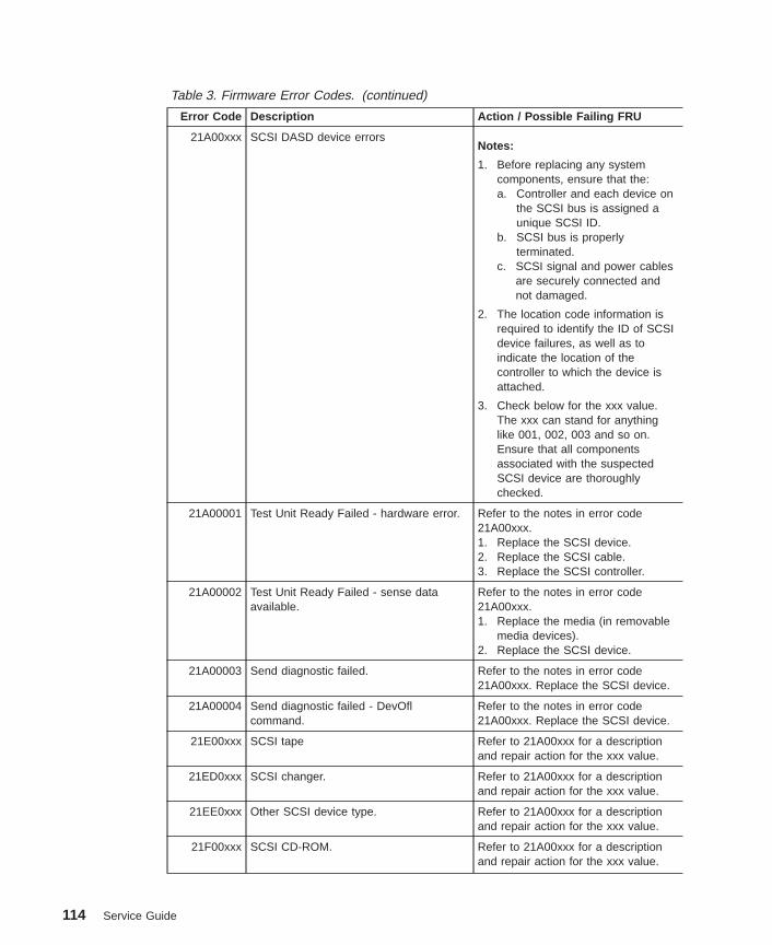
Table 3. Firmware Error Codes. (continued)
Error Code Description Action / Possible Failing FRU
21A00xxx SCSI DASD device errorsNotes:
1. Before replacing any systemcomponents, ensure that the:a. Controller and each device on
the SCSI bus is assigned aunique SCSI ID.
b. SCSI bus is properlyterminated.
c. SCSI signal and power cablesare securely connected andnot damaged.
2. The location code information isrequired to identify the ID of SCSIdevice failures, as well as toindicate the location of thecontroller to which the device isattached.
3. Check below for the xxx value.The xxx can stand for anythinglike 001, 002, 003 and so on.Ensure that all componentsassociated with the suspectedSCSI device are thoroughlychecked.
21A00001 Test Unit Ready Failed - hardware error. Refer to the notes in error code21A00xxx.1. Replace the SCSI device.2. Replace the SCSI cable.3. Replace the SCSI controller.
21A00002 Test Unit Ready Failed - sense dataavailable.
Refer to the notes in error code21A00xxx.1. Replace the media (in removable
media devices).2. Replace the SCSI device.
21A00003 Send diagnostic failed. Refer to the notes in error code21A00xxx. Replace the SCSI device.
21A00004 Send diagnostic failed - DevOflcommand.
Refer to the notes in error code21A00xxx. Replace the SCSI device.
21E00xxx SCSI tape Refer to 21A00xxx for a descriptionand repair action for the xxx value.
21ED0xxx SCSI changer. Refer to 21A00xxx for a descriptionand repair action for the xxx value.
21EE0xxx Other SCSI device type. Refer to 21A00xxx for a descriptionand repair action for the xxx value.
21F00xxx SCSI CD-ROM. Refer to 21A00xxx for a descriptionand repair action for the xxx value.
114 Service Guide

Table 3. Firmware Error Codes. (continued)
Error Code Description Action / Possible Failing FRU
21F20xxx SCSI read/write optical. Refer to 21A00xxx for a descriptionand repair action for the xxx value.
22000001 Internal wrap test failed. Replace adapter.
22001001 Internal wrap test failed. Replace adapter.
22002001 Adapter failed to complete hardwareinitialization.
Replace adapter.
22010001 Adapter failed to complete hardwareinitialization.
Replace adapter.
22011001 Adapter failed to complete hardwareinitialization.
Replace adapter.
25000000 Memory controller failed. Replace the system board.
25010xxx Flash Update Problem
25010000 No diskette in drive. Insert diskette containing firmwareimage.
25010001 Diskette seek error. 1. Retry function.2. Replace diskette drive.3. Replace diskette cable.4. Replace the system board.
Location: P1(See notes on page 109.)
25010002 Diskette in drive does not contain an*.IMG file.
Insert diskette with firmware updatefile.
25010003 Cannot open OPENPROM package. Replace the system board.Location: P1(See notes on page 109.)
25010004 Cannot find OPENPROM node. Replace the system board.Location: P1(See notes on page 109.)
25010006 System ID does not match image systemID.
Make sure correct firmware updatediskette is being used with thissystem.
Chapter 5. Error Code to FRU Index 115

Table 3. Firmware Error Codes. (continued)
Error Code Description Action / Possible Failing FRU
25010007 Image has bad CRC. 1. Power-on the system unit.2. Do the following flash recovery
procedure:a. Insert a newly formatted DOS
diskette loaded with serviceprocessor firmware into thediskette drive. The file namemust be spflash.img.
b. Shut down the system unit andunplug the power cable.
c. Plug in the power cable,power-on the system unit.
3. Retry item 2 with a newlyformatted DOS diskette.
4. Go to “MAP 1540: MinimumConfiguration” on page 59.
25010008 Flash is write-protected, updatecancelled.
1. Turn off, turn on system unit andretry.
2. Replace the system board.Location: P1(See notes on page 109.)
25010009 Flash module is unsupported or notrecognized.
Make sure correct firmware updatediskette is being used with thissystem.
2501000A Flash write-protected. 1. Turn off, turn on system unit, retry.2. Replace the system board.
Location: P1(See notes on page 109.)
2501000C Failed write to flash memory 1. Turn off, turn on system unit, retry.2. Replace the system board.
Location: P1(See notes on page 109.)
25A0xxx0 L2 cache controller problem. 1. Replace the processor card.Location: P1-C1Location: P1-C2Replace the system board.Location: P1(See notes on page 109.)
See error code 2B2xxx22 for xxxdefinitions.
116 Service Guide
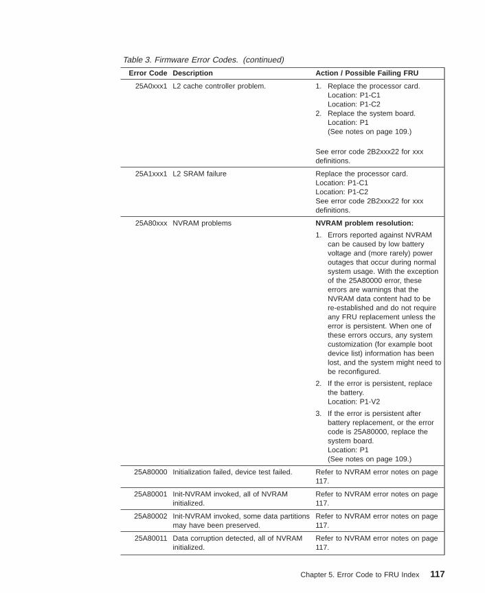
Table 3. Firmware Error Codes. (continued)
Error Code Description Action / Possible Failing FRU
25A0xxx1 L2 cache controller problem. 1. Replace the processor card.Location: P1-C1Location: P1-C2
2. Replace the system board.Location: P1(See notes on page 109.)
See error code 2B2xxx22 for xxxdefinitions.
25A1xxx1 L2 SRAM failure Replace the processor card.Location: P1-C1Location: P1-C2See error code 2B2xxx22 for xxxdefinitions.
25A80xxx NVRAM problems NVRAM problem resolution:
1. Errors reported against NVRAMcan be caused by low batteryvoltage and (more rarely) poweroutages that occur during normalsystem usage. With the exceptionof the 25A80000 error, theseerrors are warnings that theNVRAM data content had to bere-established and do not requireany FRU replacement unless theerror is persistent. When one ofthese errors occurs, any systemcustomization (for example bootdevice list) information has beenlost, and the system might need tobe reconfigured.
2. If the error is persistent, replacethe battery.Location: P1-V2
3. If the error is persistent afterbattery replacement, or the errorcode is 25A80000, replace thesystem board.Location: P1(See notes on page 109.)
25A80000 Initialization failed, device test failed. Refer to NVRAM error notes on page117.
25A80001 Init-NVRAM invoked, all of NVRAMinitialized.
Refer to NVRAM error notes on page117.
25A80002 Init-NVRAM invoked, some data partitionsmay have been preserved.
Refer to NVRAM error notes on page117.
25A80011 Data corruption detected, all of NVRAMinitialized.
Refer to NVRAM error notes on page117.
Chapter 5. Error Code to FRU Index 117
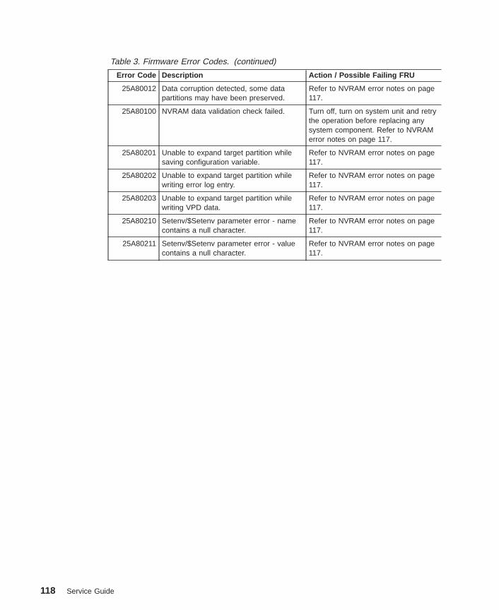
Table 3. Firmware Error Codes. (continued)
Error Code Description Action / Possible Failing FRU
25A80012 Data corruption detected, some datapartitions may have been preserved.
Refer to NVRAM error notes on page117.
25A80100 NVRAM data validation check failed. Turn off, turn on system unit and retrythe operation before replacing anysystem component. Refer to NVRAMerror notes on page 117.
25A80201 Unable to expand target partition whilesaving configuration variable.
Refer to NVRAM error notes on page117.
25A80202 Unable to expand target partition whilewriting error log entry.
Refer to NVRAM error notes on page117.
25A80203 Unable to expand target partition whilewriting VPD data.
Refer to NVRAM error notes on page117.
25A80210 Setenv/$Setenv parameter error - namecontains a null character.
Refer to NVRAM error notes on page117.
25A80211 Setenv/$Setenv parameter error - valuecontains a null character.
Refer to NVRAM error notes on page117.
118 Service Guide
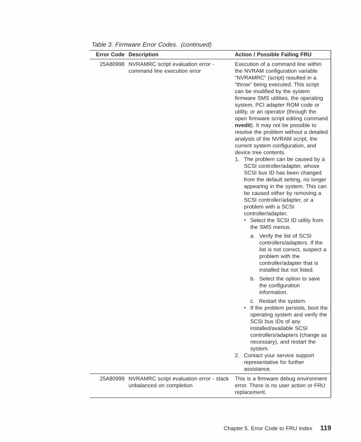
Table 3. Firmware Error Codes. (continued)
Error Code Description Action / Possible Failing FRU
25A80998 NVRAMRC script evaluation error -command line execution error
Execution of a command line withinthe NVRAM configuration variable“NVRAMRC” (script) resulted in a“throw” being executed. This scriptcan be modified by the systemfirmware SMS utilities, the operatingsystem, PCI adapter ROM code orutility, or an operator (through theopen firmware script editing commandnvedit ). It may not be possible toresolve the problem without a detailedanalysis of the NVRAM script, thecurrent system configuration, anddevice tree contents.1. The problem can be caused by a
SCSI controller/adapter, whoseSCSI bus ID has been changedfrom the default setting, no longerappearing in the system. This canbe caused either by removing aSCSI controller/adapter, or aproblem with a SCSIcontroller/adapter.v Select the SCSI ID utility from
the SMS menus.
a. Verify the list of SCSIcontrollers/adapters. If thelist is not correct, suspect aproblem with thecontroller/adapter that isinstalled but not listed.
b. Select the option to savethe configurationinformation.
c. Restart the system.v If the problem persists, boot the
operating system and verify theSCSI bus IDs of anyinstalled/available SCSIcontrollers/adapters (change asnecessary), and restart thesystem.
2. Contact your service supportrepresentative for furtherassistance.
25A80999 NVRAMRC script evaluation error - stackunbalanced on completion
This is a firmware debug environmenterror. There is no user action or FRUreplacement.
Chapter 5. Error Code to FRU Index 119
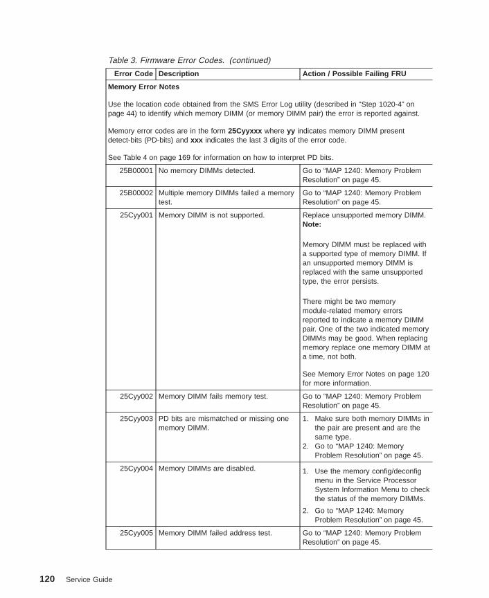
Table 3. Firmware Error Codes. (continued)
Error Code Description Action / Possible Failing FRU
Memory Error Notes
Use the location code obtained from the SMS Error Log utility (described in “Step 1020-4” onpage 44) to identify which memory DIMM (or memory DIMM pair) the error is reported against.
Memory error codes are in the form 25Cyyxxx where yy indicates memory DIMM presentdetect-bits (PD-bits) and xxx indicates the last 3 digits of the error code.
See Table 4 on page 169 for information on how to interpret PD bits.
25B00001 No memory DIMMs detected. Go to “MAP 1240: Memory ProblemResolution” on page 45.
25B00002 Multiple memory DIMMs failed a memorytest.
Go to “MAP 1240: Memory ProblemResolution” on page 45.
25Cyy001 Memory DIMM is not supported. Replace unsupported memory DIMM.Note:
Memory DIMM must be replaced witha supported type of memory DIMM. Ifan unsupported memory DIMM isreplaced with the same unsupportedtype, the error persists.
There might be two memorymodule-related memory errorsreported to indicate a memory DIMMpair. One of the two indicated memoryDIMMs may be good. When replacingmemory replace one memory DIMM ata time, not both.
See Memory Error Notes on page 120for more information.
25Cyy002 Memory DIMM fails memory test. Go to “MAP 1240: Memory ProblemResolution” on page 45.
25Cyy003 PD bits are mismatched or missing onememory DIMM.
1. Make sure both memory DIMMs inthe pair are present and are thesame type.
2. Go to “MAP 1240: MemoryProblem Resolution” on page 45.
25Cyy004 Memory DIMMs are disabled. 1. Use the memory config/deconfigmenu in the Service ProcessorSystem Information Menu to checkthe status of the memory DIMMs.
2. Go to “MAP 1240: MemoryProblem Resolution” on page 45.
25Cyy005 Memory DIMM failed address test. Go to “MAP 1240: Memory ProblemResolution” on page 45.
120 Service Guide
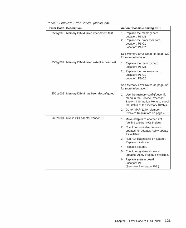
Table 3. Firmware Error Codes. (continued)
Error Code Description Action / Possible Failing FRU
25Cyy006 Memory DIMM failed inter-extent test. 1. Replace the memory card.Location: P1-M1
2. Replace the processor card.Location: P1-C1Location: P1-C2
See Memory Error Notes on page 120for more information.
25Cyy007 Memory DIMM failed extent access test. 1. Replace the memory card.Location: P1-M1
2. Replace the processor card.Location: P1-C1Location: P1-C2
See Memory Error Notes on page 120for more information.
25Cyy008 Memory DIMM has been deconfigured. 1. Use the memory config/deconfigmenu in the Service ProcessorSystem Information Menu to checkthe status of the memory DIMMs.
2. Go to “MAP 1240: MemoryProblem Resolution” on page 45.
26020001 Invalid PCI adapter vendor ID. 1. Move adapter to another slot(behind another PCI bridge).
2. Check for available firmwareupdates for adapter. Apply updateif available.
3. Run AIX diagnostics on adapter.Replace if indicated.
4. Replace adapter.
5. Check for system firmwareupdates. Apply if update available.
6. Replace system board.Location: P1(See note 3 on page 109.)
Chapter 5. Error Code to FRU Index 121

Table 3. Firmware Error Codes. (continued)
Error Code Description Action / Possible Failing FRU
26020002 Invalid PCI adapter device ID. 1. Move adapter to another slot(behind a different PCI bridge).
2. Check for available firmwareupdates for adapter. Apply updateif available.
3. Run AIX diagnostics on adapter.Replace if indicated.
4. Replace adapter.
5. Check for system firmwareupdates. Apply if update available.
6. Replace system board.Location: P1(See note 3 on page 109.)
26020003 Invalid or unrecognized PCI adapter classcode.
1. Move adapter to another slot(behind a different PCI bridge).
2. Check for available firmwareupdates for adapter. Apply updateif available.
3. Run AIX diagnostics on adapter.Replace if indicated.
4. Replace adapter.
5. Check for system firmwareupdates. Apply if update available.
6. Replace system board.Location: P1(See note 3 on page 109.)
26020007 Unable to allocate bus resources to PCIadapter. (Partial allocation may havesucceeded)
1. Move adapter to another slot(behind a different PCI bridge).
2. Check for available firmwareupdates for adapter. Apply updateif available.
3. Run AIX diagnostics on adapter.Replace if indicated.
4. Replace adapter.
5. Check for system firmwareupdates. Apply if update available.
6. Replace system board.Location: P1(See note 3 on page 109.)
122 Service Guide
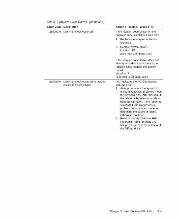
Table 3. Firmware Error Codes. (continued)
Error Code Description Action / Possible Failing FRU
26800Cxx Machine check occurred. If the location code shown on theoperator panel identifies a card slot:
1. Replace the adapter in the slotidentified.
2. Replace system board.Location: P1(See note 3 on page 109.)
If the location code shown does notidentify a card slot, or if there is nolocation code, replace the systemboard.Location: P1(See note 3 on page 109.)
26800Dxx Machine check occurred, unable toisolate to single device
″xx″ indicates the PCI bus numberwith the error.1. Attempt to reboot the system to
online diagnostics in service mode;this preserves the AIX error log. Ifthe reboot fails, attempt to rebootfrom the CD-ROM. If the reboot issuccessful, run diagnostics inproblem determination mode todetermine the cause of failure.Otherwise, continue.
2. Refer to the “Bus SRN to FRUReference Table” on page 171using PCI bus ″xx″ for isolation ofthe failing device.
Chapter 5. Error Code to FRU Index 123
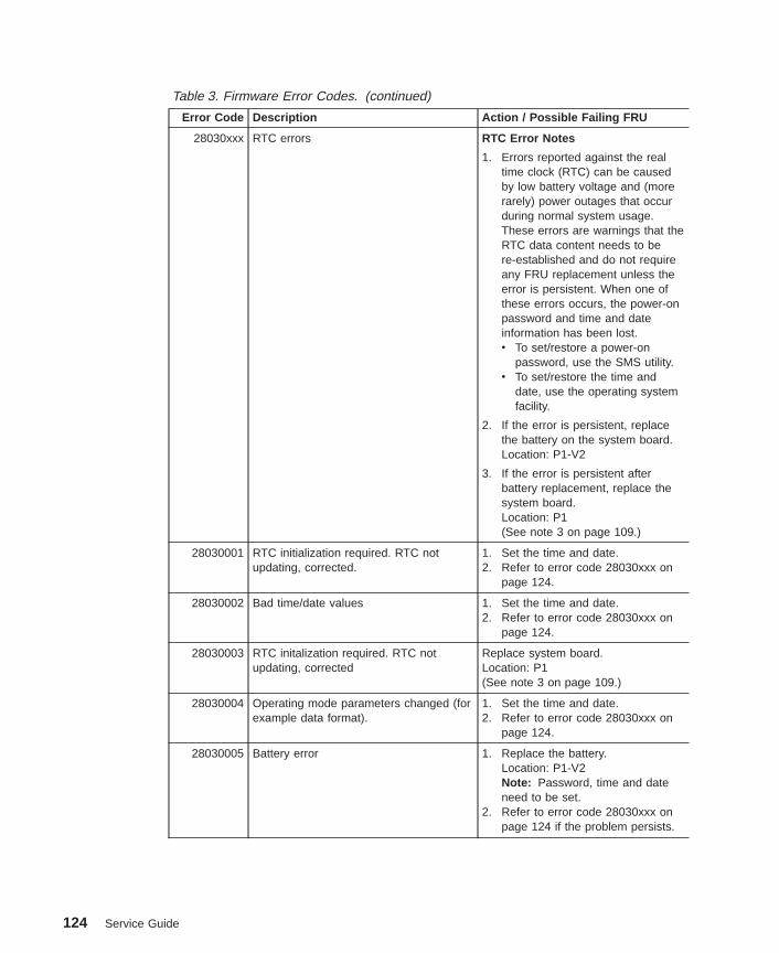
Table 3. Firmware Error Codes. (continued)
Error Code Description Action / Possible Failing FRU
28030xxx RTC errors RTC Error Notes
1. Errors reported against the realtime clock (RTC) can be causedby low battery voltage and (morerarely) power outages that occurduring normal system usage.These errors are warnings that theRTC data content needs to bere-established and do not requireany FRU replacement unless theerror is persistent. When one ofthese errors occurs, the power-onpassword and time and dateinformation has been lost.v To set/restore a power-on
password, use the SMS utility.v To set/restore the time and
date, use the operating systemfacility.
2. If the error is persistent, replacethe battery on the system board.Location: P1-V2
3. If the error is persistent afterbattery replacement, replace thesystem board.Location: P1(See note 3 on page 109.)
28030001 RTC initialization required. RTC notupdating, corrected.
1. Set the time and date.2. Refer to error code 28030xxx on
page 124.
28030002 Bad time/date values 1. Set the time and date.2. Refer to error code 28030xxx on
page 124.
28030003 RTC initalization required. RTC notupdating, corrected
Replace system board.Location: P1(See note 3 on page 109.)
28030004 Operating mode parameters changed (forexample data format).
1. Set the time and date.2. Refer to error code 28030xxx on
page 124.
28030005 Battery error 1. Replace the battery.Location: P1-V2Note: Password, time and dateneed to be set.
2. Refer to error code 28030xxx onpage 124 if the problem persists.
124 Service Guide
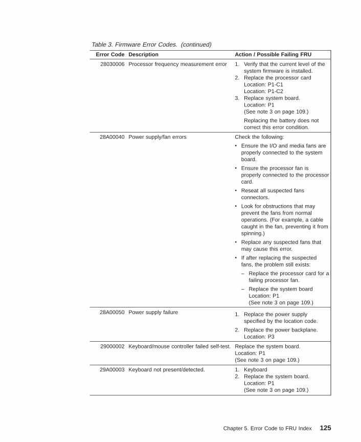
Table 3. Firmware Error Codes. (continued)
Error Code Description Action / Possible Failing FRU
28030006 Processor frequency measurement error 1. Verify that the current level of thesystem firmware is installed.
2. Replace the processor cardLocation: P1-C1Location: P1-C2
3. Replace system board.Location: P1(See note 3 on page 109.)
Replacing the battery does notcorrect this error condition.
28A00040 Power supply/fan errors Check the following:
v Ensure the I/O and media fans areproperly connected to the systemboard.
v Ensure the processor fan isproperly connected to the processorcard.
v Reseat all suspected fansconnectors.
v Look for obstructions that mayprevent the fans from normaloperations. (For example, a cablecaught in the fan, preventing it fromspinning.)
v Replace any suspected fans thatmay cause this error.
v If after replacing the suspectedfans, the problem still exists:
– Replace the processor card for afailing processor fan.
– Replace the system boardLocation: P1(See note 3 on page 109.)
28A00050 Power supply failure 1. Replace the power supplyspecified by the location code.
2. Replace the power backplane.Location: P3
29000002 Keyboard/mouse controller failed self-test. Replace the system board.Location: P1(See note 3 on page 109.)
29A00003 Keyboard not present/detected. 1. Keyboard2. Replace the system board.
Location: P1(See note 3 on page 109.)
Chapter 5. Error Code to FRU Index 125

Table 3. Firmware Error Codes. (continued)
Error Code Description Action / Possible Failing FRU
29A00004 Keyboard stuck key test failed. 1. Keyboard2. Replace the system board.
Location: P1(See note 3 on page 109.)
29B00004 Mouse not present/detected. 1. Mouse2. Replace the system board.
Location: P1(See note 3 on page 109.)
2B2xxx11 Processor is manually disabled Use service processor menus tore-enable the processor, then rebootthe system. (See error code 2B2xxx22on page 126 for xxx definition.)
2B2xxx22 Processor disabled. Replace processor card.Location: P1-C1Location: P1-C2Note: Where xxx indicates theprocessor type as follows:711 333Mhz processor with 1
MB of L2 cache.7D4 400Mhz processor with 4
MB of L2 cache.758 450 MHz processor with 8
MB of L2 cache
2B2xxx31 Processor failed. Replace processor card.Location: P1-C1Location: P1-C2See error code 2B2xxx22 on page126 for xxx definition.
2B2xxx42 Unsupported processor type. Replace processor card.Location: P1-C1Location: P1-C2See error code 2B2xxx22 on page126 for xxx definition.
2BA00000 Service processor POST failure. 1. Unplug the system power cableand wait until the system powerindicator remains off and theoperator panel is blank.
2. Plug in the system power cableand retry the operation.
3. Replace the system board.Location: P1(See note 3 on page 109.)
126 Service Guide

Table 3. Firmware Error Codes. (continued)
Error Code Description Action / Possible Failing FRU
2BA00012 Service processor reports self-test failure. 1. Unplug the system power cableand wait until the system powerindicator remains off and theoperator panel is blank.
2. Plug the system power cable backin and retry the operation.
3. Replace the system board.Location: P1(See note 3 on page 109.)
2BA00013 Service processor reports bad NVRAMCRC.
1. If problem persists, replacebattery.Location: P1-V2
2. Replace the system board.Location: P1(See note 3 on page 109.)
2BA00014 Service processor reports bad serviceprocessor firmware.
Use service processor firmwarediskette to reprogram firmware.
2BA00017 Service processor reports bad or lowbattery.
1. Replace the battery.Location: P1-V2
2. Replace the system board.Location: P1(See note 3 on page 109.)
2BA00018 EPOW test failure. Replace the system board.Location: P1(See note 3 on page 109.)
2BA00019 IRQ13 test failure. Replace the system board.Location: P1(See note 3 on page 109.)
2BA00024 Service processor reports bad powercontroller firmware.
Use the system firmware diskette toreprogram the system firmware.
2BA00040 Service processor reports serviceprocessor VPD module not present.
1. Use the service processorfirmware diskette to reprogram theservice processor firmware.
2. Replace the system board.Location: P1(See note 3 on page 109.)
2BA00041 Service processor VPD is corrupted. 1. Use the service processorfirmware diskette to reprogram theservice processor firmware.
2. Replace the system board.Location: P1(See note 3 on page 109.)
Chapter 5. Error Code to FRU Index 127
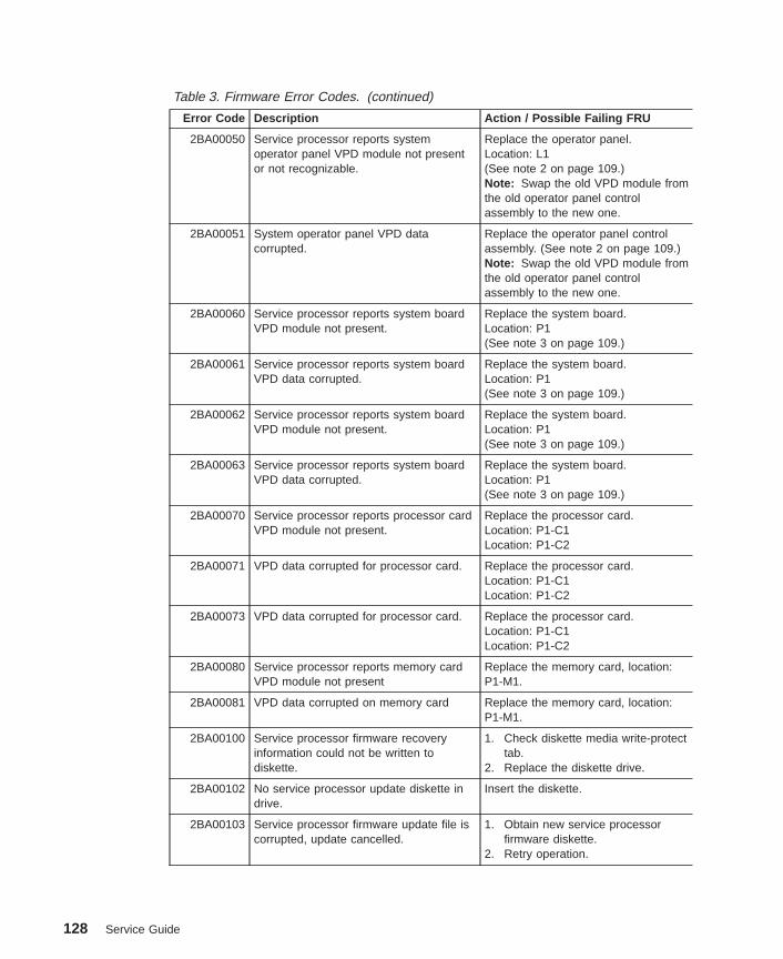
Table 3. Firmware Error Codes. (continued)
Error Code Description Action / Possible Failing FRU
2BA00050 Service processor reports systemoperator panel VPD module not presentor not recognizable.
Replace the operator panel.Location: L1(See note 2 on page 109.)Note: Swap the old VPD module fromthe old operator panel controlassembly to the new one.
2BA00051 System operator panel VPD datacorrupted.
Replace the operator panel controlassembly. (See note 2 on page 109.)Note: Swap the old VPD module fromthe old operator panel controlassembly to the new one.
2BA00060 Service processor reports system boardVPD module not present.
Replace the system board.Location: P1(See note 3 on page 109.)
2BA00061 Service processor reports system boardVPD data corrupted.
Replace the system board.Location: P1(See note 3 on page 109.)
2BA00062 Service processor reports system boardVPD module not present.
Replace the system board.Location: P1(See note 3 on page 109.)
2BA00063 Service processor reports system boardVPD data corrupted.
Replace the system board.Location: P1(See note 3 on page 109.)
2BA00070 Service processor reports processor cardVPD module not present.
Replace the processor card.Location: P1-C1Location: P1-C2
2BA00071 VPD data corrupted for processor card. Replace the processor card.Location: P1-C1Location: P1-C2
2BA00073 VPD data corrupted for processor card. Replace the processor card.Location: P1-C1Location: P1-C2
2BA00080 Service processor reports memory cardVPD module not present
Replace the memory card, location:P1-M1.
2BA00081 VPD data corrupted on memory card Replace the memory card, location:P1-M1.
2BA00100 Service processor firmware recoveryinformation could not be written todiskette.
1. Check diskette media write-protecttab.
2. Replace the diskette drive.
2BA00102 No service processor update diskette indrive.
Insert the diskette.
2BA00103 Service processor firmware update file iscorrupted, update cancelled.
1. Obtain new service processorfirmware diskette.
2. Retry operation.
128 Service Guide

Table 3. Firmware Error Codes. (continued)
Error Code Description Action / Possible Failing FRU
2BA00104 Service processor firmware update file isthe same level as the service processorfirmware, update cancelled.
1. Obtain new level of serviceprocessor firmware.
2. Retry operation.
2BA00200 Service processor firmware update erroroccurred, update not completed.
Error occurred during service processorflash write operation.
Service processor firmware updateerror recovery procedure:1. Turn off the system.2. Unplug power cable and then plug
power cable back in.3. Turn on the system.4. Replace the system board.
Location: P1(See note 3 on page 109.)
2BA00201 Service processor firmware update erroroccurred, update not completed.
Error occurred while reading serviceprocessor CRC.
See error code 2BA00200 forrecovery procedure.
2BA00202 Service processor firmware update erroroccurred, update not completed.
Error occurred while verifying serviceprocessor firmware CRC.
See error code 2BA00200 forrecovery procedure.
2BA00203 Service processor firmware update erroroccurred, update not completed.
Error occurred while reading new serviceprocessor firmware CRC after updatingservice processor firmware.
See error code 2BA00200 forrecovery procedure.
2BA00204 Service processor firmware update erroroccurred, update not completed.
Error occurred while calculating firmwareCRC.
See error code 2BA00200 forrecovery procedure.
2BA00300 Service processor reports slow fannumber 1.
1. Replace fan 1.Location: F1
2. Replace the system board.Location: P1(See note 3 on page 109.)
2BA00301 Service processor reports slow fannumber 2.
1. Replace fan 2.Location: F2
2. Replace the system board.Location: P1(See note 3 on page 109.)
2BA00302 Service processor reports slow fannumber 3.
1. Replace fan 3.Location: F3
2. Replace the system board.Location: P1(See note 3 on page 109.)
Chapter 5. Error Code to FRU Index 129
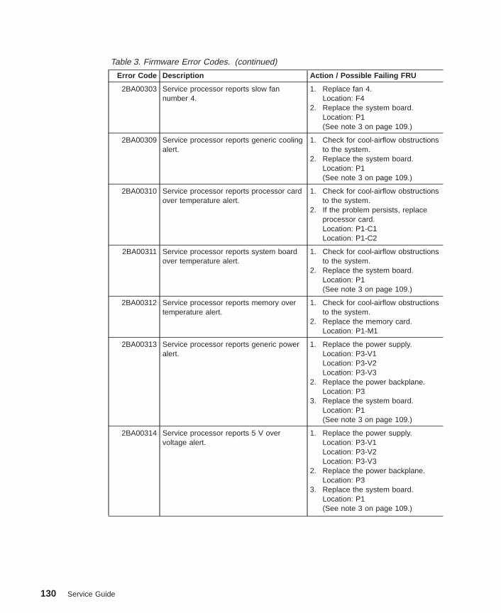
Table 3. Firmware Error Codes. (continued)
Error Code Description Action / Possible Failing FRU
2BA00303 Service processor reports slow fannumber 4.
1. Replace fan 4.Location: F4
2. Replace the system board.Location: P1(See note 3 on page 109.)
2BA00309 Service processor reports generic coolingalert.
1. Check for cool-airflow obstructionsto the system.
2. Replace the system board.Location: P1(See note 3 on page 109.)
2BA00310 Service processor reports processor cardover temperature alert.
1. Check for cool-airflow obstructionsto the system.
2. If the problem persists, replaceprocessor card.Location: P1-C1Location: P1-C2
2BA00311 Service processor reports system boardover temperature alert.
1. Check for cool-airflow obstructionsto the system.
2. Replace the system board.Location: P1(See note 3 on page 109.)
2BA00312 Service processor reports memory overtemperature alert.
1. Check for cool-airflow obstructionsto the system.
2. Replace the memory card.Location: P1-M1
2BA00313 Service processor reports generic poweralert.
1. Replace the power supply.Location: P3-V1Location: P3-V2Location: P3-V3
2. Replace the power backplane.Location: P3
3. Replace the system board.Location: P1(See note 3 on page 109.)
2BA00314 Service processor reports 5 V overvoltage alert.
1. Replace the power supply.Location: P3-V1Location: P3-V2Location: P3-V3
2. Replace the power backplane.Location: P3
3. Replace the system board.Location: P1(See note 3 on page 109.)
130 Service Guide

Table 3. Firmware Error Codes. (continued)
Error Code Description Action / Possible Failing FRU
2BA00315 Service processor reports 5 V undervoltage alert.
1. Replace the power supply.Location: P3-V1Location: P3-V2Location: P3-V3
2. Replace the power backplane.Location: P3
3. Replace the system board.Location: P1(See note 3 on page 109.)
2BA00316 Service processor reports 3.3V overvoltage alert.
1. Check, and reseat if necessary,power connectors P1 and P2.
2. Replace the power supply.Location: P3-V1Location: P3-V2Location: P3-V3
3. Replace the system board.Location: P1(See note 3 on page 109.)
2BA00317 Service processor reports 3.3V undervoltage alert.
1. Replace the power supply.Location: P3-V1Location: P3-V2Location: P3-V3
2. Replace the power backplane.Location: P3
3. Replace the system board.Location: P1(See note 3 on page 109.)
2BA00318 Service processor reports 2.5 V overvoltage alert.
1. Replace the power supply.Location: P3-V1Location: P3-V2Location: P3-V3
2. Replace the power backplane.Location: P3
3. Replace the system board.Location: P1(See note 3 on page 109.)
2BA00319 Service processor reports 2.5 V undervoltage alert.
1. Replace the power supply.Location: P3-V1Location: P3-V2Location: P3-V3
2. Replace the power backplane.Location: P3
3. Replace the system board.Location: P1(See note 3 on page 109.)
Chapter 5. Error Code to FRU Index 131
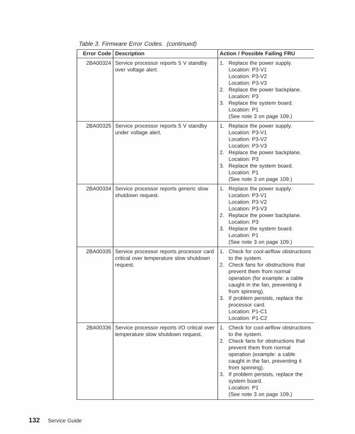
Table 3. Firmware Error Codes. (continued)
Error Code Description Action / Possible Failing FRU
2BA00324 Service processor reports 5 V standbyover voltage alert.
1. Replace the power supply.Location: P3-V1Location: P3-V2Location: P3-V3
2. Replace the power backplane.Location: P3
3. Replace the system board.Location: P1(See note 3 on page 109.)
2BA00325 Service processor reports 5 V standbyunder voltage alert.
1. Replace the power supply.Location: P3-V1Location: P3-V2Location: P3-V3
2. Replace the power backplane.Location: P3
3. Replace the system board.Location: P1(See note 3 on page 109.)
2BA00334 Service processor reports generic slowshutdown request.
1. Replace the power supply.Location: P3-V1Location: P3-V2Location: P3-V3
2. Replace the power backplane.Location: P3
3. Replace the system board.Location: P1(See note 3 on page 109.)
2BA00335 Service processor reports processor cardcritical over temperature slow shutdownrequest.
1. Check for cool-airflow obstructionsto the system.
2. Check fans for obstructions thatprevent them from normaloperation (for example: a cablecaught in the fan, preventing itfrom spinning).
3. If problem persists, replace theprocessor card.Location: P1-C1Location: P1-C2
2BA00336 Service processor reports I/O critical overtemperature slow shutdown request.
1. Check for cool-airflow obstructionsto the system.
2. Check fans for obstructions thatprevent them from normaloperation (example: a cablecaught in the fan, preventing itfrom spinning).
3. If problem persists, replace thesystem board.Location: P1(See note 3 on page 109.)
132 Service Guide

Table 3. Firmware Error Codes. (continued)
Error Code Description Action / Possible Failing FRU
2BA00337 Service processor reports memory criticalover temperature slow shutdown request.
1. Check for cool-airflow obstructionsto the system.
2. Check fans for obstructions thatprevent them from normaloperation (example: a cablecaught in the fan, preventing itfrom spinning)
3. If problem persists, replace thememory card.Location: P1-M1
2BA00338 Service processor reports generic fastshutdown request.
1. Replace the power supply.Location: P3-V1Location: P3-V2Location: P3-V3
2. Replace the system board.Location: P1(See note 3 on page 109.)
2BA00340 Service processor reports locked fan -fast shutdown request fan number 1.
1. Replace fan 1.Location: F1
2. Replace the system board.Location: P1(See note 3 on page 109.)
2BA00341 Service processor reports locked fan -fast shutdown request fan number 2.
1. Replace fan 2.Location: F2
2. Replace the system board.Location: P1(See note 3 on page 109.)
2BA00342 Service processor reports locked fan -fast shutdown request fan number 3.
1. Replace fan 3.Location: F3
2. Replace the system board.Location: P1(See note 3 on page 109.)
2BA00343 Service processor reports locked fan -fast shutdown request fan number 4.
1. Replace fan 4.Location: F4
2. Replace the system board.Location: P1(See note 3 on page 109.)
2BA00350 Service processor reports genericimmediate shutdown request.
1. Replace the power supply.Location: P3-V1Location: P3-V2Location: P3-V3
2. Replace the system board.Location: P1(See note 3 on page 109.)
Chapter 5. Error Code to FRU Index 133

Table 3. Firmware Error Codes. (continued)
Error Code Description Action / Possible Failing FRU
2BA00351 Service processor reports generic ACpower loss EPOW.
1. Replace the power supply.Location: P3-V1Location: P3-V2Location: P3-V3
2. Replace the system board.Location: P1(See note 3 on page 109.)
2BA00352 Service processor reports loss of ACpower (outlet).
1. Replace the power supply.Location: P3-V1Location: P3-V2Location: P3-V3
2. Replace the system board.Location: P1(See note 3 on page 109.)
2BA00353 Service processor reports loss of ACpower (power button).
1. Replace the power supply.Location: P3-V1Location: P3-V2Location: P3-V3
2. Replace the system board.Location: P1(See note 3 on page 109.)
2BA00356 Service processor reports fan failure in apower supply
1. Replace the power supplyspecified by the location code.
2. Replace the power backplane.Location: P3.
2BA00357 Service processor reportsover-temperature condition in a powersupply
1. Replace the power supplyspecified by the location code.
2. Replace the power backplane.Location: P3.
2BA00358 Service processor reports redundantpower supply failure
1. Replace the power supplyspecified by the location code.
2. Replace the power backplane.Location: P3.
2BA00399 Service processor reports unsupportedvalue in EPOW.
1. Check EPOW cabling on SCSI orSSA backplanes.
2. Replace the system board.Location: P1(See note 3 on page 109.)
134 Service Guide

Table 3. Firmware Error Codes. (continued)
Error Code Description Action / Possible Failing FRU
40100005 Loss of system power detected. 1. Possible temporary AC power loss.Turn on the power. If the systemboots, use the AIX Service Aids toreset the System Attentionindicator and the Lightpathindicators. On your next shutdownand prior to reboot, use theservice processor menus to resetthe error log.
2. If AC power is available to system,replace the power suppliesone-at-a-time.Location: P3-V1Location: P3-V2Location: P3-V3
40100006 Loss of ac power to system detected. 1. Possible temporary AC power loss.Turn on the power. If the systemboots, use the AIX Service Aids toreset the System Attentionindicator and the Lightpathindicators. On your next shutdownand prior to reboot, use theservice processor menus to resetthe error log.
2. If AC power is available to system,replace the power suppliesone-at-a-time.Location: P3-V1Location: P3-V2Location: P3-V3
40100007 Immediate shutdown due to loss of AC tosystem.
1. Possible temporary AC power loss.Turn on the power. If the systemboots, use the AIX Service Aids toreset the System Attentionindicator and the Lightpathindicators. On your next shutdownand prior to reboot, use theservice processor menus to resetthe error log.
2. If AC power is available to system,replace the power suppliesone-at-a-time.Location: P3-V1Location: P3-V2Location: P3-V3
Chapter 5. Error Code to FRU Index 135

Table 3. Firmware Error Codes. (continued)
Error Code Description Action / Possible Failing FRU
40110000 Loss of a redundant power supply wasdetected
1. If a location code is displayed withthis error code, replace the part atthat location.
2. Look at the service processor errorlog for more error information.
3. Reseat the power supplies4. Replace the power supplies
one-at-a-time.Location: P3-V1Location: P3-V2Location: P3-V3
40110001 Power supply failed 1. If a location code is displayed withthis error code, replace the part atthat location.
2. Look at the service processor errorlog for more error information.
3. Reseat the power supplies4. Replace the power supplies
one-at-a-time.Location: P3-V1Location: P3-V2Location: P3-V3
5. Replace the system boardLocation: P1(See note 3 on page 109.)
40110002 Missing voltage on both processor cards 1. If a location code is displayed withthis error code, replace the part atthat location.
2. Look at the service processor errorlog for more error information.
3. Reseat the power supplies4. Replace the power supplies
one-at-a-time.Location: P3-V1Location: P3-V2Location: P3-V3
40110003 Missing voltage on one processor card If AIX is running, check the AIX errorlog to find out which processor card isfailing. If AIX in not available, checkthe service processor error log.Replace the failing processor.Location: P1-C1 or P1-C2.
136 Service Guide

Table 3. Firmware Error Codes. (continued)
Error Code Description Action / Possible Failing FRU
40110004 Low voltage detected in power supplymain enclosure.
1. If a location code is displayed withthis error code, replace the part atthat location.
2. Look at the service processor errorlog for more error information.
3. Reseat the power supplies4. Replace the power supplies
one-at-a-time.Location: P3-V1Location: P3-V2Location: P3-V3
40110005 Fan warning detected in power supplymain enclosure.
1. If a location code is displayed withthis error code, replace the part atthat location.
2. If a location code is displayed withthis error code, replace the part atthat location.
3. Look at the service processor errorlog for more error information.
4. Reseat the power supplies5. Replace the power supplies
one-at-a-time.Location: P3-V1Location: P3-V2Location: P3-V3
40110006 Fan failure detected in power supply mainenclosure.
1. If a location code is displayed withthis error code, replace the part atthat location.
2. Look at the service processor errorlog for more error information.
3. Reseat the power supplies4. Replace the power supplies
one-at-a-time.Location: P3-V1Location: P3-V2Location: P3-V3
40110007 Thermal warning detected in powersupply main enclosure.
1. If a location code is displayed withthis error code, replace the part atthat location.
2. Look at the service processor errorlog for more error information.
3. Reseat the power supplies4. Replace the power supplies
one-at-a-time.Location: P3-V1Location: P3-V2Location: P3-V3
Chapter 5. Error Code to FRU Index 137
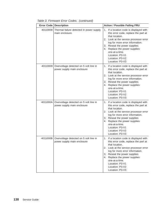
Table 3. Firmware Error Codes. (continued)
Error Code Description Action / Possible Failing FRU
40110008 Thermal failure detected in power supplymain enclosure.
1. If a location code is displayed withthis error code, replace the part atthat location.
2. Look at the service processor errorlog for more error information.
3. Reseat the power supplies4. Replace the power supplies
one-at-a-time.Location: P3-V1Location: P3-V2Location: P3-V3
40110009 Overvoltage detected on 5 volt line inpower supply main enclosure
1. If a location code is displayed withthis error code, replace the part atthat location.
2. Look at the service processor errorlog for more error information.
3. Reseat the power supplies4. Replace the power supplies
one-at-a-time.Location: P3-V1Location: P3-V2Location: P3-V3
4011000A Overvoltage detected on 5 volt line inpower supply main enclosure
1. If a location code is displayed withthis error code, replace the part atthat location.
2. Look at the service processor errorlog for more error information.
3. Reseat the power supplies4. Replace the power supplies
one-at-a-time.Location: P3-V1Location: P3-V2Location: P3-V3
4011000B Overvoltage detected on 5 volt line inpower supply main enclosure
1. If a location code is displayed withthis error code, replace the part atthat location.
2. Look at the service processor errorlog for more error information.
3. Reseat the power supplies4. Replace the power supplies
one-at-a-time.Location: P3-V1Location: P3-V2Location: P3-V3
138 Service Guide
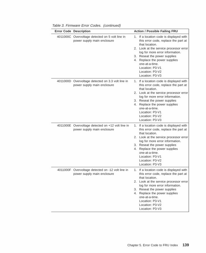
Table 3. Firmware Error Codes. (continued)
Error Code Description Action / Possible Failing FRU
4011000C Overvoltage detected on 5 volt line inpower supply main enclosure
1. If a location code is displayed withthis error code, replace the part atthat location.
2. Look at the service processor errorlog for more error information.
3. Reseat the power supplies4. Replace the power supplies
one-at-a-time.Location: P3-V1Location: P3-V2Location: P3-V3
4011000D Overvoltage detected on 3.3 volt line inpower supply main enclosure
1. If a location code is displayed withthis error code, replace the part atthat location.
2. Look at the service processor errorlog for more error information.
3. Reseat the power supplies4. Replace the power supplies
one-at-a-time.Location: P3-V1Location: P3-V2Location: P3-V3
4011000E Overvoltage detected on +12 volt line inpower supply main enclosure
1. If a location code is displayed withthis error code, replace the part atthat location.
2. Look at the service processor errorlog for more error information.
3. Reseat the power supplies4. Replace the power supplies
one-at-a-time.Location: P3-V1Location: P3-V2Location: P3-V3
4011000F Overvoltage detected on -12 volt line inpower supply main enclosure
1. If a location code is displayed withthis error code, replace the part atthat location.
2. Look at the service processor errorlog for more error information.
3. Reseat the power supplies4. Replace the power supplies
one-at-a-time.Location: P3-V1Location: P3-V2Location: P3-V3
Chapter 5. Error Code to FRU Index 139
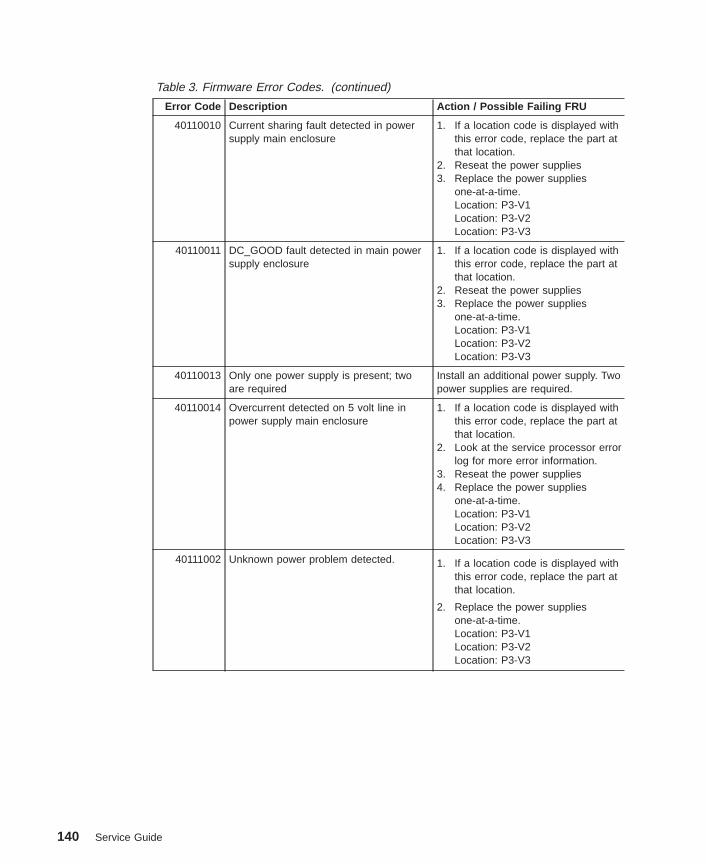
Table 3. Firmware Error Codes. (continued)
Error Code Description Action / Possible Failing FRU
40110010 Current sharing fault detected in powersupply main enclosure
1. If a location code is displayed withthis error code, replace the part atthat location.
2. Reseat the power supplies3. Replace the power supplies
one-at-a-time.Location: P3-V1Location: P3-V2Location: P3-V3
40110011 DC_GOOD fault detected in main powersupply enclosure
1. If a location code is displayed withthis error code, replace the part atthat location.
2. Reseat the power supplies3. Replace the power supplies
one-at-a-time.Location: P3-V1Location: P3-V2Location: P3-V3
40110013 Only one power supply is present; twoare required
Install an additional power supply. Twopower supplies are required.
40110014 Overcurrent detected on 5 volt line inpower supply main enclosure
1. If a location code is displayed withthis error code, replace the part atthat location.
2. Look at the service processor errorlog for more error information.
3. Reseat the power supplies4. Replace the power supplies
one-at-a-time.Location: P3-V1Location: P3-V2Location: P3-V3
40111002 Unknown power problem detected. 1. If a location code is displayed withthis error code, replace the part atthat location.
2. Replace the power suppliesone-at-a-time.Location: P3-V1Location: P3-V2Location: P3-V3
140 Service Guide

Table 3. Firmware Error Codes. (continued)
Error Code Description Action / Possible Failing FRU
40111022 Overvoltage detected on 5.0 volt line 1. If a location code is displayed withthis error code, replace the part atthat location.
2. Replace the power suppliesone-at-a-time.Location: P3-V1Location: P3-V2Location: P3-V3
3. Replace the system board.Location: P1(See note 3 on page 109.)
40111032 Overvoltage detected on the 3.3 volt line. 1. If a location code is displayed withthis error code, replace the part atthat location.
2. Replace the power suppliesone-at-a-time.Location: P3-V1Location: P3-V2Location: P3-V3
3. Replace the system board.Location: P1(See note 3 on page 109.)
40111033 Overvoltage detected on the 2.5 volt line 1. If a location code is displayed withthis error code, replace the part atthat location.
2. Replace the power suppliesone-at-a-time.Location: P3-V1Location: P3-V2Location: P3-V3
3. Replace the system board.Location: P1(See note 3 on page 109.)
40111052 Overvoltage detected on the +12 volt line 1. If a location code is displayed withthis error code, replace the part atthat location.
2. Replace the power suppliesone-at-a-time.Location: P3-V1Location: P3-V2Location: P3-V3
3. Replace the system board.Location: P1(See note 3 on page 109.)
Chapter 5. Error Code to FRU Index 141

Table 3. Firmware Error Codes. (continued)
Error Code Description Action / Possible Failing FRU
40111062 Overvoltage detected on the -12 volt line 1. If a location code is displayed withthis error code, replace the part atthat location.
2. Replace the power suppliesone-at-a-time.Location: P3-V1Location: P3-V2Location: P3-V3
3. Replace the system board.Location: P1(See note 3 on page 109.)
40111072 A high +5 V standby voltage readingdetected.
1. If a location code is displayed withthis error code, replace the part atthat location.
2. Replace the power suppliesone-at-a-time.Location: P3-V1Location: P3-V2Location: P3-V3
3. Replace the system board.Location: P1(See note 3 on page 109.)
40111082 A low 5.0 V reading detected. 1. If a location code is displayed withthis error code, replace the part atthat location.
2. Replace the power suppliesone-at-a-time.Location: P3-V1Location: P3-V2Location: P3-V3
3. Replace the system board.Location: P1(See note 3 on page 109.)
40111092 A low 3.3 V reading detected. 1. If a location code is displayed withthis error code, replace the part atthat location.
2. Replace the power suppliesone-at-a-time.Location: P3-V1Location: P3-V2Location: P3-V3
3. Replace the system board.Location: P1(See note 3 on page 109.)
142 Service Guide

Table 3. Firmware Error Codes. (continued)
Error Code Description Action / Possible Failing FRU
40111093 A low 2.5 V reading detected. 1. If a location code is displayed withthis error code, replace the part atthat location.
2. Replace the power suppliesone-at-a-time.Location: P3-V1Location: P3-V2Location: P3-V3
3. Replace the processor cards.Location: P1-C1Location: P1-C2
401110B2 A low +12 V reading detected. 1. If a location code is displayed withthis error code, replace the part atthat location.
2. Replace the power suppliesone-at-a-time.Location: P3-V1Location: P3-V2Location: P3-V3
3. Replace the system board.Location: P1(See note 3 on page 109.)
401110C2 A low -12 V reading detected. 1. If a location code is displayed withthis error code, replace the part atthat location.
2. Replace the power suppliesone-at-a-time.Location: P3-V1Location: P3-V2Location: P3-V3
3. Replace the system board.Location: P1(See note 3 on page 109.)
401110D2 A low +5 standby V reading detected. 1. If a location code is displayed withthis error code, replace the part atthat location.
2. Replace the power suppliesone-at-a-time.Location: P3-V1Location: P3-V2Location: P3-V3
3. Replace the system board.Location: P1(See note 3 on page 109.)
Chapter 5. Error Code to FRU Index 143

Table 3. Firmware Error Codes. (continued)
Error Code Description Action / Possible Failing FRU
40111101 Power good signal low on eitherprocessor card 1 or processor card 2.
If AIX is running, check the AIX errorlog to find out which processor card isfailing. If AIX in not available, checkthe service processor error log.Replace the failing processor.Location: P1-C1 or P1-C2.
40111102 Wrong processor card plugged into thesystem.
1. Remove processor cards.2. Verify FRU number of new
processor card is correct beforeinstallation.
40111122 High PCI +5.0 voltage reading detected 1. If a location code is displayed withthis error code, replace the part atthat location.
2. Replace the power suppliesone-at-a-time.Location: P3-V1Location: P3-V2Location: P3-V3
3. Replace the system board.Location: P1(See note 3 on page 109.)
40111132 A high PCI 3.3 voltage was detected 1. If a location code is displayed withthis error code, replace the part atthat location.
2. Replace the power suppliesone-at-a-time.Location: P3-V1Location: P3-V2Location: P3-V3
3. Replace the system board.Location: P1(See note 3 on page 109.)
40111152 A high PCI +12 voltage was detected 1. If a location code is displayed withthis error code, replace the part atthat location.
2. Replace the power suppliesone-at-a-time.Location: P3-V1Location: P3-V2Location: P3-V3
3. Replace the system board.Location: P1(See note 3 on page 109.)
144 Service Guide

Table 3. Firmware Error Codes. (continued)
Error Code Description Action / Possible Failing FRU
40111162 A high PCI -12 voltage was detected 1. If a location code is displayed withthis error code, replace the part atthat location.
2. Replace the power suppliesone-at-a-time.Location: P3-V1Location: P3-V2Location: P3-V3
3. Replace the system board.Location: P1(See note 3 on page 109.)
40111182 A low PCI +5 voltage was detected 1. If a location code is displayed withthis error code, replace the part atthat location.
2. Replace the power suppliesone-at-a-time.Location: P3-V1Location: P3-V2Location: P3-V3
3. Replace the system board.Location: P1(See note 3 on page 109.)
40111192 A low PCI +3.3 voltage was detected 1. If a location code is displayed withthis error code, replace the part atthat location.
2. Replace the power suppliesone-at-a-time.Location: P3-V1Location: P3-V2Location: P3-V3
3. Replace the system board.Location: P1(See note 3 on page 109.)
401111B2 A low PCI +12 voltage was detected 1. If a location code is displayed withthis error code, replace the part atthat location.
2. Replace the power suppliesone-at-a-time.Location: P3-V1Location: P3-V2Location: P3-V3
3. Replace the system board.Location: P1(See note 3 on page 109.)
Chapter 5. Error Code to FRU Index 145

Table 3. Firmware Error Codes. (continued)
Error Code Description Action / Possible Failing FRU
401111C2 A low PCI -12 voltage was detected 1. If a location code is displayed withthis error code, replace the part atthat location.
2. Replace the power suppliesone-at-a-time.Location: P3-V1Location: P3-V2Location: P3-V3
3. Replace the system board.Location: P1(See note 3 on page 109.)
40112022 High 5.0 voltage reading detected 1. If a location code is displayed withthis error code, replace the part atthat location.
2. Replace the power suppliesone-at-a-time.Location: P3-V1Location: P3-V2Location: P3-V3
3. Replace the processor cards.Location: P1-C1Location: P1-C2
40112023 High 1.8 V reading detected 1. If a location code is displayed withthis error code, replace the part atthat location.
2. Replace the power suppliesone-at-a-time.Location: P3-V1Location: P3-V2Location: P3-V3
3. Replace the processor cards.Location: P1-C1Location: P1-C2
40112032 High 3.3 V reading detected 1. If a location code is displayed withthis error code, replace the part atthat location.
2. Replace the power suppliesone-at-a-time.Location: P3-V1Location: P3-V2Location: P3-V3
3. Replace the system board.Location: P1(See note 3 on page 109.)
146 Service Guide
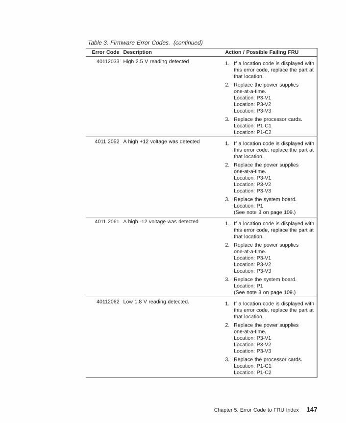
Table 3. Firmware Error Codes. (continued)
Error Code Description Action / Possible Failing FRU
40112033 High 2.5 V reading detected 1. If a location code is displayed withthis error code, replace the part atthat location.
2. Replace the power suppliesone-at-a-time.Location: P3-V1Location: P3-V2Location: P3-V3
3. Replace the processor cards.Location: P1-C1Location: P1-C2
4011 2052 A high +12 voltage was detected 1. If a location code is displayed withthis error code, replace the part atthat location.
2. Replace the power suppliesone-at-a-time.Location: P3-V1Location: P3-V2Location: P3-V3
3. Replace the system board.Location: P1(See note 3 on page 109.)
4011 2061 A high -12 voltage was detected 1. If a location code is displayed withthis error code, replace the part atthat location.
2. Replace the power suppliesone-at-a-time.Location: P3-V1Location: P3-V2Location: P3-V3
3. Replace the system board.Location: P1(See note 3 on page 109.)
40112062 Low 1.8 V reading detected. 1. If a location code is displayed withthis error code, replace the part atthat location.
2. Replace the power suppliesone-at-a-time.Location: P3-V1Location: P3-V2Location: P3-V3
3. Replace the processor cards.Location: P1-C1Location: P1-C2
Chapter 5. Error Code to FRU Index 147
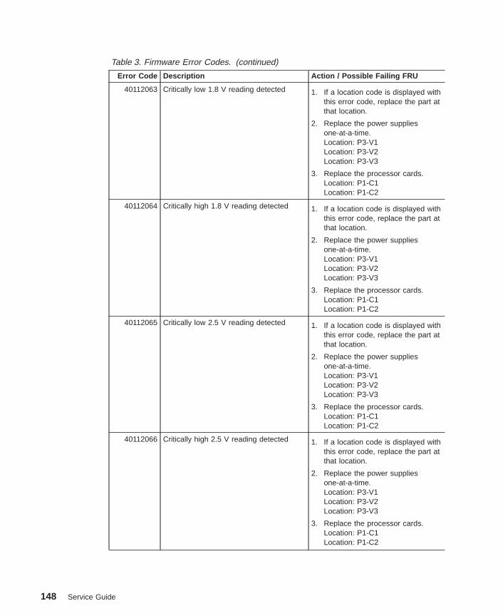
Table 3. Firmware Error Codes. (continued)
Error Code Description Action / Possible Failing FRU
40112063 Critically low 1.8 V reading detected 1. If a location code is displayed withthis error code, replace the part atthat location.
2. Replace the power suppliesone-at-a-time.Location: P3-V1Location: P3-V2Location: P3-V3
3. Replace the processor cards.Location: P1-C1Location: P1-C2
40112064 Critically high 1.8 V reading detected 1. If a location code is displayed withthis error code, replace the part atthat location.
2. Replace the power suppliesone-at-a-time.Location: P3-V1Location: P3-V2Location: P3-V3
3. Replace the processor cards.Location: P1-C1Location: P1-C2
40112065 Critically low 2.5 V reading detected 1. If a location code is displayed withthis error code, replace the part atthat location.
2. Replace the power suppliesone-at-a-time.Location: P3-V1Location: P3-V2Location: P3-V3
3. Replace the processor cards.Location: P1-C1Location: P1-C2
40112066 Critically high 2.5 V reading detected 1. If a location code is displayed withthis error code, replace the part atthat location.
2. Replace the power suppliesone-at-a-time.Location: P3-V1Location: P3-V2Location: P3-V3
3. Replace the processor cards.Location: P1-C1Location: P1-C2
148 Service Guide
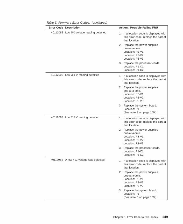
Table 3. Firmware Error Codes. (continued)
Error Code Description Action / Possible Failing FRU
40112082 Low 5.0 voltage reading detected 1. If a location code is displayed withthis error code, replace the part atthat location.
2. Replace the power suppliesone-at-a-time.Location: P3-V1Location: P3-V2Location: P3-V3
3. Replace the processor cards.Location: P1-C1Location: P1-C2
40112092 Low 3.3 V reading detected 1. If a location code is displayed withthis error code, replace the part atthat location.
2. Replace the power suppliesone-at-a-time.Location: P3-V1Location: P3-V2Location: P3-V3
3. Replace the system board.Location: P1(See note 3 on page 109.)
40112093 Low 2.5 V reading detected 1. If a location code is displayed withthis error code, replace the part atthat location.
2. Replace the power suppliesone-at-a-time.Location: P3-V1Location: P3-V2Location: P3-V3
3. Replace the processor cards.Location: P1-C1Location: P1-C2
401120B2 A low +12 voltage was detected 1. If a location code is displayed withthis error code, replace the part atthat location.
2. Replace the power suppliesone-at-a-time.Location: P3-V1Location: P3-V2Location: P3-V3
3. Replace the system board.Location: P1(See note 3 on page 109.)
Chapter 5. Error Code to FRU Index 149

Table 3. Firmware Error Codes. (continued)
Error Code Description Action / Possible Failing FRU
401120C2 A low -12 voltage was detected 1. If a location code is displayed withthis error code, replace the part atthat location.
2. Replace the power suppliesone-at-a-time.Location: P3-V1Location: P3-V2Location: P3-V3
3. Replace the system board.Location: P1(See note 3 on page 109.)
40200001 An unknown cooling problem detected. 1. Check system unit fans.Locations: F1, F2, F3, F4
2. Replace the processor cards.Location: P1-C1Location: P1-C2
40200021 A processor card temperature warningdetected.
1. Check system unit fans.Locations: F1, F2, F3, F4
2. Replace the processor cards.Location: P1-C1Location: P1-C2
40200023 A critical processor card temperaturecondition detected.
1. Check system unit fans.Locations: F1, F2, F3, F4
2. Replace the processor cards.Location: P1-C1Location: P1-C2
40200031 A system board temperature warningdetected.
1. Check system unit fans.Locations: F1, F2, F3, F4
2. Replace the system board.Location: P1(See note 3 on page 109.)
40200033 A critical system board temperaturecondition detected.
1. Check system unit fans.Locations: F1, F2, F3, F4
2. Replace the system board.Location: P1(See note 3 on page 109.)
40200051 An inlet temperature warning detected.(High temperature sensed at the air flowinlet.)
1. Check system unit fans.Locations: F1, F2, F3, F4
2. Replace the system board.Location: P1(See note 3 on page 109.)
150 Service Guide

Table 3. Firmware Error Codes. (continued)
Error Code Description Action / Possible Failing FRU
40200053 An inlet memory temperature conditiondetected. (Critically high temperaturesensed at the air flow inlet.)
1. Check system unit fans.Locations: F1, F2, F3, F4
2. Replace the system board.Location: P1(See note 3 on page 109.)
40210011 A slow fan detected. Check:1. Room operating temperature.2. Check system unit fans.
Locations: F1, F2, F3, F4
40210014 A stopped fan detected. Replace the failing fan.
40A00000 The system firmware surveillance intervalwas exceeded (System firmwaresurveillance time-out).
1. Check for system firmwareupdates
2. Go to the service processor mainmenu and select SystemInformation Menu , then selectRead Progress Indicators fromLast System Boot . Begin yourrepair action with the error code orcheckpoint immediately preceding40A0 0000. If a location codeappears with the error code orcheckpoint, replace the part at thatlocation.
3. If the problem is not resolved, callservice support.
40B00000 The operating system surveillanceinterval exceeded (operating systemsurveillance time-out).
1. This error code indicates that theoperating system terminated early(which usually implies an operatingsystem crash). This error codemay appear in the serviceprocessor error log by itself.However, in the AIX error log,there should be another errorwhich points to the cause of theoperating system crash. Use theother error as the starting point foryour service action.
2. Call service support.
40D00003 An unknown slow shutdown commanded. Insure the ambient temperature is inthe proper range.
40D00004 An unknown fast shutdown occurred. Insure the ambient temperature is inthe proper range.
40D00101 BIST on the system board failed. Replace the system board. (See note3 on page 109.)
40D00102 BIST on the system board failed. Replace system board.Location: P1(See note 3 on page 109.)
Chapter 5. Error Code to FRU Index 151

Table 3. Firmware Error Codes. (continued)
Error Code Description Action / Possible Failing FRU
40D00200 Processor initialization failed. Location code will point to failing FRU.
40D00201 JTAG chip ID miscompare. Replace the failing FRU pointed to bythe location code.
40D00202 Hot-swap SCSI backplane failure Replace the hot-swap backplane.Location: P2
40D00203 SCSI ID conflict on hot-swap disk drives 1. Verify that there are no SCSI IDjumpers on the hot-swap diskdrives. (The SCSI IDs are setautomatically by the hot-swapbackplane.)
2. Isolate the failing hot-swap driveby removing all of the drives, thenreinstalling them one at a timeuntil the error occurs. The last onethat was reinstalled is the failingdrive.
3. Replace the hot-swap backplane.Location: P2
450000C0 Uncorrectable memory error. (checkstop) Go to “MAP 1240: Memory ProblemResolution” on page 45.
450000C1 Memory ECC correctable error(checkstop)
Go to “MAP 1540: MinimumConfiguration” on page 59.
450000C2 Memory ECC correctable error thresholdexceeded (checkstop)
Go to “MAP 1540: MinimumConfiguration” on page 59.
450000C3 Memory controller subsystem internalerror (checkstop)
Go to “MAP 1540: MinimumConfiguration” on page 59.
450000C4 Memory address error (invalid address oraccess attempt) (checkstop)
Go to “MAP 1540: MinimumConfiguration” on page 59.
450000C5 Memory data error (bad data going tomemory) (checkstop)
Go to “MAP 1540: MinimumConfiguration” on page 59.
450000C6 Memory bus/switch internal error(checkstop)
Go to “MAP 1540: MinimumConfiguration” on page 59.
450000C7 Memory time-out error (checkstop) Go to “MAP 1540: MinimumConfiguration” on page 59.
450000D0 System bus time-out error (checkstop) 1. Replace the FRU as indicated bythe physical location codedisplayed on the operator panel.
2. Check the service processor errorlog for additional FRUs.
450000D1 System bus parity error (checkstop) 1. Replace the FRU as indicated bythe physical location codedisplayed on the operator panel.
2. Check the service processor errorlog for additional FRUs.
152 Service Guide
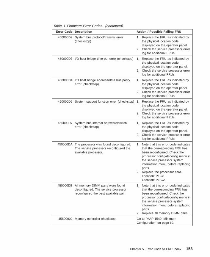
Table 3. Firmware Error Codes. (continued)
Error Code Description Action / Possible Failing FRU
450000D2 System bus protocol/transfer error(checkstop)
1. Replace the FRU as indicated bythe physical location codedisplayed on the operator panel.
2. Check the service processor errorlog for additional FRUs.
450000D3 I/O host bridge time-out error (checkstop) 1. Replace the FRU as indicated bythe physical location codedisplayed on the operator panel.
2. Check the service processor errorlog for additional FRUs.
450000D4 I/O host bridge address/data bus parityerror (checkstop)
1. Replace the FRU as indicated bythe physical location codedisplayed on the operator panel.
2. Check the service processor errorlog for additional FRUs.
450000D6 System support function error (checkstop) 1. Replace the FRU as indicated bythe physical location codedisplayed on the operator panel.
2. Check the service processor errorlog for additional FRUs.
450000D7 System bus internal hardware/switcherror (checkstop)
1. Replace the FRU as indicated bythe physical location codedisplayed on the operator panel.
2. Check the service processor errorlog for additional FRUs.
450000DA The processor was found deconfigured.The service processor reconfigured theavailable processor.
1. Note that this error code indicatesthat the corresponding FRU hasbeen reconfigured. Check theprocessor config/deconfig menu inthe service processor systeminformation menu before replacingparts.
2. Replace the processor card.Location: P1-C1Location: P1-C2
450000DB All memory DIMM pairs were founddeconfigured. The service processorreconfigured the best available pair.
1. Note that this error code indicatesthat the corresponding FRU hasbeen reconfigured. Check theprocessor config/deconfig menu inthe service processor systeminformation menu before replacingparts.
2. Replace all memory DIMM pairs.
45800000 Memory controller checkstop Go to “MAP 1540: MinimumConfiguration” on page 59.
Chapter 5. Error Code to FRU Index 153
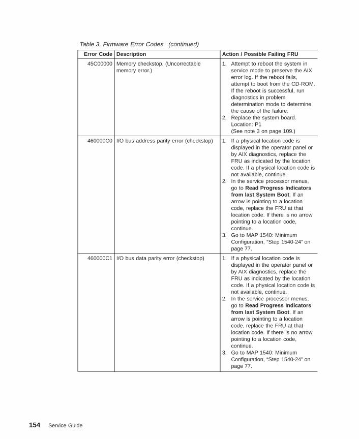
Table 3. Firmware Error Codes. (continued)
Error Code Description Action / Possible Failing FRU
45C00000 Memory checkstop. (Uncorrectablememory error.)
1. Attempt to reboot the system inservice mode to preserve the AIXerror log. If the reboot fails,attempt to boot from the CD-ROM.If the reboot is successful, rundiagnostics in problemdetermination mode to determinethe cause of the failure.
2. Replace the system board.Location: P1(See note 3 on page 109.)
460000C0 I/O bus address parity error (checkstop) 1. If a physical location code isdisplayed in the operator panel orby AIX diagnostics, replace theFRU as indicated by the locationcode. If a physical location code isnot available, continue.
2. In the service processor menus,go to Read Progress Indicatorsfrom last System Boot . If anarrow is pointing to a locationcode, replace the FRU at thatlocation code. If there is no arrowpointing to a location code,continue.
3. Go to MAP 1540: MinimumConfiguration, “Step 1540-24” onpage 77.
460000C1 I/O bus data parity error (checkstop) 1. If a physical location code isdisplayed in the operator panel orby AIX diagnostics, replace theFRU as indicated by the locationcode. If a physical location code isnot available, continue.
2. In the service processor menus,go to Read Progress Indicatorsfrom last System Boot . If anarrow is pointing to a locationcode, replace the FRU at thatlocation code. If there is no arrowpointing to a location code,continue.
3. Go to MAP 1540: MinimumConfiguration, “Step 1540-24” onpage 77.
154 Service Guide

Table 3. Firmware Error Codes. (continued)
Error Code Description Action / Possible Failing FRU
460000C2 I/O bus time-out, access or other error(checkstop)
1. If a physical location code isdisplayed in the operator panel orby AIX diagnostics, replace theFRU as indicated by the locationcode. If a physical location code isnot available, continue.
2. In the service processor menus,go to Read Progress Indicatorsfrom last System Boot . If anarrow is pointing to a locationcode, replace the FRU at thatlocation code. If there is no arrowpointing to a location code,continue.
3. Go to MAP 1540: MinimumConfiguration, “Step 1540-24” onpage 77.
460000C3 I/O bridge/device internal error(checkstop)
1. If a physical location code isdisplayed in the operator panel orby AIX diagnostics, replace theFRU as indicated by the locationcode. If a physical location code isnot available, continue.
2. In the service processor menus,go to Read Progress Indicatorsfrom last System Boot . If anarrow is pointing to a locationcode, replace the FRU at thatlocation code. If there is no arrowpointing to a location code,continue.
3. Go to MAP 1540: MinimumConfiguration, “Step 1540-24” onpage 77.
460000C4 Error from a PCI to non-PCI bridge chip,indicating an error on the secondary bus.(checkstop)
1. If a physical location code isdisplayed in the operator panel orby AIX diagnostics, replace theFRU as indicated by the locationcode. If a physical location code isnot available, continue.
2. In the service processor menus,go to Read Progress Indicatorsfrom last System Boot . If anarrow is pointing to a location codereplace the FRU at that locationcode. If there is no arrow pointingto a location code, continue.
3. Go to MAP 1540: MinimumConfiguration, “Step 1540-24” onpage 77.
Chapter 5. Error Code to FRU Index 155
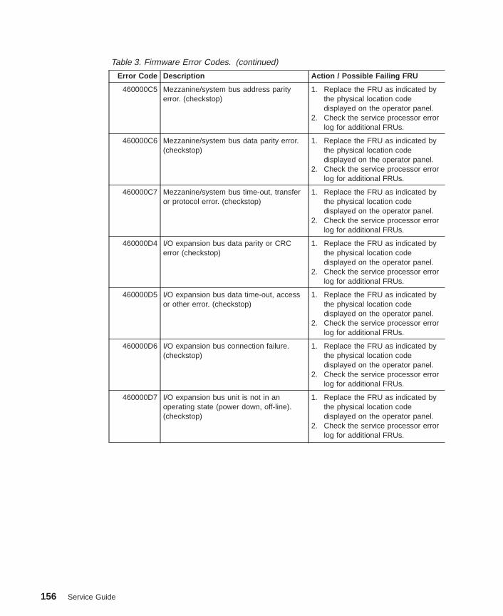
Table 3. Firmware Error Codes. (continued)
Error Code Description Action / Possible Failing FRU
460000C5 Mezzanine/system bus address parityerror. (checkstop)
1. Replace the FRU as indicated bythe physical location codedisplayed on the operator panel.
2. Check the service processor errorlog for additional FRUs.
460000C6 Mezzanine/system bus data parity error.(checkstop)
1. Replace the FRU as indicated bythe physical location codedisplayed on the operator panel.
2. Check the service processor errorlog for additional FRUs.
460000C7 Mezzanine/system bus time-out, transferor protocol error. (checkstop)
1. Replace the FRU as indicated bythe physical location codedisplayed on the operator panel.
2. Check the service processor errorlog for additional FRUs.
460000D4 I/O expansion bus data parity or CRCerror (checkstop)
1. Replace the FRU as indicated bythe physical location codedisplayed on the operator panel.
2. Check the service processor errorlog for additional FRUs.
460000D5 I/O expansion bus data time-out, accessor other error. (checkstop)
1. Replace the FRU as indicated bythe physical location codedisplayed on the operator panel.
2. Check the service processor errorlog for additional FRUs.
460000D6 I/O expansion bus connection failure.(checkstop)
1. Replace the FRU as indicated bythe physical location codedisplayed on the operator panel.
2. Check the service processor errorlog for additional FRUs.
460000D7 I/O expansion bus unit is not in anoperating state (power down, off-line).(checkstop)
1. Replace the FRU as indicated bythe physical location codedisplayed on the operator panel.
2. Check the service processor errorlog for additional FRUs.
156 Service Guide
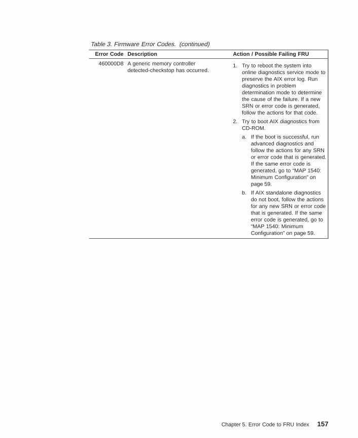
Table 3. Firmware Error Codes. (continued)
Error Code Description Action / Possible Failing FRU
460000D8 A generic memory controllerdetected-checkstop has occurred.
1. Try to reboot the system intoonline diagnostics service mode topreserve the AIX error log. Rundiagnostics in problemdetermination mode to determinethe cause of the failure. If a newSRN or error code is generated,follow the actions for that code.
2. Try to boot AIX diagnostics fromCD-ROM.
a. If the boot is successful, runadvanced diagnostics andfollow the actions for any SRNor error code that is generated.If the same error code isgenerated, go to “MAP 1540:Minimum Configuration” onpage 59.
b. If AIX standalone diagnosticsdo not boot, follow the actionsfor any new SRN or error codethat is generated. If the sameerror code is generated, go to“MAP 1540: MinimumConfiguration” on page 59.
Chapter 5. Error Code to FRU Index 157

Table 3. Firmware Error Codes. (continued)
Error Code Description Action / Possible Failing FRU
460000D9 A generic I/O memory controller-detectedcheckstop has occurred.
1. Try to reboot the system intoonline diagnostics to preserve theAIX error log. Run diagnostics inproblem determination mode todetermine the cause of the failure.If a new SRN or error code isgenerated, follow the actions forthat code.
2. Try to boot AIX diagnostics fromCD-ROM.
a. If the boot is successful, runadvanced diagnostics andfollow the actions for any SRNor error code that is generated.If the same error code isgenerated, go to “MAP 1540:Minimum Configuration” onpage 59.
b. If AIX standalone diagnosticsdo not boot, follow the actionsfor any new SRN or error codethat is generated. If the sameerror code is generated, go to“MAP 1540: MinimumConfiguration” on page 59.
48800909 System VPD error. 1. Check cable to operator panel.
2. Replace the operator panel controlassembly. (See note 2 on page109.)Note: Swap the old VPD modulefrom the old operator panel controlassembly to the new one.
3. Replace the system board.Location: P1(See note 3 on page 109.)
4. Go to “MAP 1540: MinimumConfiguration” on page 59.
4880090A System board VPD read failed. Replace the system board.Location: P1(See note 3 on page 109.)
4880090B Error identifying system type using VPD.
(Possible I2C bus error.)
1. Check the power supply cableconnections
2. Call for support.
4880090C JTAG unable to confirm system typeusing system VPD.
1. Remove cards.2. Verify part numbers.3. Install valid cards.4. Call for support.
158 Service Guide

Table 3. Firmware Error Codes. (continued)
Error Code Description Action / Possible Failing FRU
4B20000A The processor has been deconfigured. 1. Replace the processor card.Location: P1-C1Location: P1-C2
2. Replace the system board.Location: P1(See note 3 on page 109.)
4B200043 Service processor reports JTAG fail 1. Remove the processor card in slot2 (P1-C2), if installed, and see ifthe problem is resolved. Ifresolved, replace the processorcard in P1-C2. If not, proceed tostep 2.
2. Exchange the processor card inslot 1 (P1-C1) with the cardremoved from slot 2 in step 1.(Replace the card in slot 1 with anew FRU if there is only oneprocessor card in the system.)See if the problem is resolved. Ifnot, proceed to step 3.
3. Replace the system board.Location: P1(See note 3 on page 109.)
4. Call service support.
4B200055 No processor found. 1. If only one processor is installed, itmust be in slot 1 (P1-C1).
2. If two processor cards areinstalled, replace the card in slot 1(P1-C1).
4B200056 No processor card. 1. If only one processor is installed, itmust be in slot 1 (P1-C1).
2. If two processor cards areinstalled, replace the card in slot 1(P1-C1).
4B200057 The processor cards are not compatiblewith each other.
Remove the processor cards. Verifythat the FRU numbers are valid.Replace if necessary.
4B200058 Compatibility test on processor card inslot 1 failed.
Remove the processor cards. Verifythat the FRU numbers are valid.Replace if necessary.
4B200059 Compatibility test on processor card inslot 2 failed.
Remove the processor cards. Verifythat the FRU numbers are valid.Replace if necessary.
Chapter 5. Error Code to FRU Index 159
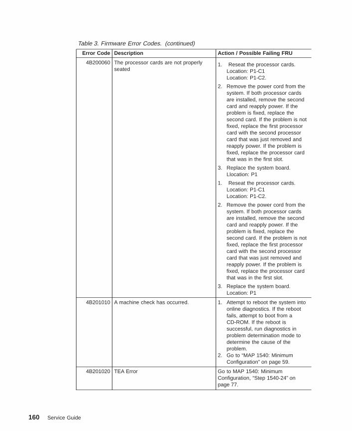
Table 3. Firmware Error Codes. (continued)
Error Code Description Action / Possible Failing FRU
4B200060 The processor cards are not properlyseated
1. Reseat the processor cards.Location: P1-C1Location: P1-C2.
2. Remove the power cord from thesystem. If both processor cardsare installed, remove the secondcard and reapply power. If theproblem is fixed, replace thesecond card. If the problem is notfixed, replace the first processorcard with the second processorcard that was just removed andreapply power. If the problem isfixed, replace the processor cardthat was in the first slot.
3. Replace the system board.Llocation: P1
1. Reseat the processor cards.Location: P1-C1Location: P1-C2.
2. Remove the power cord from thesystem. If both processor cardsare installed, remove the secondcard and reapply power. If theproblem is fixed, replace thesecond card. If the problem is notfixed, replace the first processorcard with the second processorcard that was just removed andreapply power. If the problem isfixed, replace the processor cardthat was in the first slot.
3. Replace the system board.Location: P1
4B201010 A machine check has occurred. 1. Attempt to reboot the system intoonline diagnostics. If the rebootfails, attempt to boot from aCD-ROM. If the reboot issuccessful, run diagnostics inproblem determination mode todetermine the cause of theproblem.
2. Go to “MAP 1540: MinimumConfiguration” on page 59.
4B201020 TEA Error Go to MAP 1540: MinimumConfiguration, “Step 1540-24” onpage 77.
160 Service Guide

Table 3. Firmware Error Codes. (continued)
Error Code Description Action / Possible Failing FRU
4B276851 Processor BIST failed Replace the processor card.Location: P1-C1Location: P1-C2
4B2xxx00 Checkstop 1. Press Enter on an attached ASCIIterminal keyboard to go into theservice processor menus.
2. Select System Information Menu .
3. Select Read Progress Indicatorsfrom Last System Boot and usethe posted code indicated by thearrow. Refer to “Service ProcessorMenus” on page 179 forassistance. If the code is E105,E14D, E15B, E174, E175 or 0xxx,where xxx is any three digits,continue to step 4 instead of thelisted action. Otherwise, find thecode in the “Service ProcessorCheckpoints” on page 82 or“Firmware Checkpoints” onpage 88 and perform the actionindicated.
4. Attempt to reboot the system intoonline diagnostics to preserve theAIX error log. If the reboot fails,attempt to boot from the CD-ROM.If the reboot is successful, rundiagnostics in problemdetermination mode to determinethe cause of the failure.Otherwise, continue.
5. Go to MAP 1540: MinimumConfiguration, “Step 1540-24” onpage 77.
Chapter 5. Error Code to FRU Index 161

Table 3. Firmware Error Codes. (continued)
Error Code Description Action / Possible Failing FRU
4B2xxx01 Checkstop-slot 1 failure 1. Attempt to reboot the system intoonline diagnostics to preserve theAIX error log. If the reboot fails,attempt to boot from the CD-ROM.If the reboot is successful, rundiagnostics in problemdetermination mode to determinethe cause of the failure.Otherwise, continue.
2. Replace the processor card in slot1.Location: P1-C1
3. Replace the system board.Location: P1(See note 3 on page 109.)
4B2xxx02 Checkstop-slot 2 Failure 1. Attempt to reboot the system intoonline diagnostics to preserve theAIX error log. If the reboot fails,attempt to boot from the CD-ROM.If the reboot is successful, rundiagnostics in problemdetermination mode to determinethe cause of the failure.Otherwise, continue.
2. Replace the processor card in slot2.Location: P1-C2
3. Replace the system board.Location: P1(See note 3 on page 109.)
4B2xxx10 Machine check - 0 1. Attempt to reboot the system intoonline diagnostics to preserve theAIX error log. If the reboot fails,attempt to boot from the CD-ROM.If the reboot is successful, rundiagnostics in problemdetermination mode to determinethe cause of the failure.Otherwise, continue.
2. Go to MAP 1540: MinimumConfiguration, “Step 1540-24” onpage 77.
162 Service Guide

Table 3. Firmware Error Codes. (continued)
Error Code Description Action / Possible Failing FRU
4B2xxx11 Machine check - 1 (stuck active) 1. Remove the processor card in slot2 (P1-C2), if installed, and see ifthe problem is resolved. Ifresolved, replace the processorcard in P1-C2. If not, proceed tostep 2.
2. Exchange the processor card inslot 1 (P1-C1) with the cardremoved from slot 2 in step 1.(Replace the card in slot 1 with anew FRU if there is only oneprocessor card in the system.)See if the problem is resolved. Ifnot, proceed to step 3.
3. Replace the system board.Location: P1(See note 3 on page 109.)
4. Call service support.
4B2xxx41 ABIST fail 1. Replace the processor cardindicated by the location code inthe operator panel.
2. Replace the system board.Location: P1(See note 3 on page 109.)
4B2xxx42 ABIST fail 1. Replace the processor cardindicated by the location code inthe operator panel.
2. Replace the system board.Location: P1(See note 3 on page 109.)
4B2xxx51 LBIST fail 1. Replace the processor cardindicated by the location code inthe operator panel.
2. Replace the system board.Location: P1(See note 3 on page 109.)
4B2xxx52 LBIST fail 1. Replace the processor cardindicated by the location code inthe operator panel.
2. Replace the system board.Location: P1(See note 3 on page 109.)
4B2xxxC0 Processor card internal error (checkstop) 1. Replace the FRU as indicated bythe physical location codedisplayed on the operator panel.
2. Check the service processor errorlog for any possible additionalFRUs.
Chapter 5. Error Code to FRU Index 163
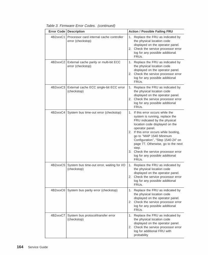
Table 3. Firmware Error Codes. (continued)
Error Code Description Action / Possible Failing FRU
4B2xxxC1 Processor card internal cache controllererror (checkstop)
1. Replace the FRU as indicated bythe physical location codedisplayed on the operator panel.
2. Check the service processor errorlog for any possible additionalFRUs.
4B2xxxC2 External cache parity or multi-bit ECCerror (checkstop)
1. Replace the FRU as indicated bythe physical location codedisplayed on the operator panel.
2. Check the service processor errorlog for any possible additionalFRUs.
4B2xxxC3 External cache ECC single-bit ECC error(checkstop)
1. Replace the FRU as indicated bythe physical location codedisplayed on the operator panel.
2. Check the service processor errorlog for any possible additionalFRUs.
4B2xxxC4 System bus time-out error (checkstop) 1. If this error occurs while thesystem is running, replace theFRU indicated by the physicallocation code displayed on theoperator panel.
2. If this error occurs while booting,go to ″MAP 1540 MinimumConfiguration″, “Step 1540-24” onpage 77. Otherwise, go to the nextstep.
3. Check the service processor errorlog for any possible additionalFRUs.
4B2xxxC5 System bus time-out error, waiting for I/O(checkstop)
1. Replace the FRU as indicated bythe physical location codedisplayed on the operator panel.
2. Check the service processor errorlog for any possible additionalFRUs.
4B2xxxC6 System bus parity error (checkstop) 1. Replace the FRU as indicated bythe physical location codedisplayed on the operator panel.
2. Check the service processor errorlog for any possible additionalFRUs.
4B2xxxC7 System bus protocol/transfer error(checkstop)
1. Replace the FRU as indicated bythe physical location codedisplayed on the operator panel.
2. Check the service processor errorlog for additional FRU withprobability
164 Service Guide

Table 3. Firmware Error Codes. (continued)
Error Code Description Action / Possible Failing FRU
4B2xxxC8 A generic processor-detected checkstophas occurred.
1. Try to reboot the system intoonline diagnostic to preserve theAIX error log. Run diagnostics inproblem determination mode todetermine the cause of the failure.If a new SRN or error code isgenerated, follow the actions forthat code.
2. Try to boot AIX diagnostics fromCD-ROM.
a. If the boot is successful, runadvanced diagnostics andfollow the actions for any SRNor error code that is generated.If the same error code isgenerated, go to “MAP 1540:Minimum Configuration” onpage 59.
b. If AIX standalone diagnosticsdo not boot, follow the actionsfor any new SRN or error codethat is generated. If the sameerror code is generated, go to“MAP 1540: MinimumConfiguration” on page 59.
4BA00000 The system support controller detects theservice processor, but cannot establishcommunication. The system halts.
1. Power off the system unit:
a. Unplug the power cord.
b. Plug in the power cord andpower on the system unit.
2. Replace the system board.Location: P1(See note 3 on page 109.)
4BA00001 The system support controller cannotdetect the service processor.
Replace the system board.Location: P1(See note 3 on page 109.)
4BA0000A Processor card deconfigured 1. Possible BIST failure:
a. Power off the system unit.
b. Unplug the power cord.
c. Plug in the power cord andpower on the system unit.
2. Replace the processor card.Location: P1-C1Location: P1-C2
Chapter 5. Error Code to FRU Index 165

Table 3. Firmware Error Codes. (continued)
Error Code Description Action / Possible Failing FRU
4BA00800 Unknown error. 1. Check level of service processorfirmware. If not the latest, applyupdate.
2. Call service support.
4BA00826 Service processor cannot call home. 1. Check the modem configuration inthe service processor menus.
2. Check the modem physicalconnection to the system unit.
3. Verify (with a conventionaltelephone) that the telephone lineis an active analog line.
4. Replace the modem.5. Replace the system board.
Location: P1(See note 3 on page 109.)
4BA00827 Flash update diskette fail. 1. Copy the flash update image ontoa new, formatted diskette andretry.
2. Verify that the flash update imageis correct for this system unit.
3. Replace the diskette drive.
4BA00828 Flash update (CRC) checksum fail. Copy the flash update image onto anewly formatted diskette and retry.
4BA00829 Bad system firmware. Replace the system board.Location: P1(See note 3 on page 109.)
4BA00830 Boot fail. Go to “Boot Problems/Concerns” onpage 106.
4BA00831 Bad service processor firmware image. 1. Unplug the power cable, wait afew minutes, plug in the powercable and reboot the system unit.Check for progress codes in theoperator panel. If there are anyprogress codes, refer to theirdescription.
2. Replace the system board.Location: P1(See note 3 on page 109.)
4BA00832 Error while doing flash update. 1. Power off the system, then poweron the system; retry the flashprogramming a few times.
2. Replace the system board.Location: P1(See note 3 on page 109.)
4BA10001 SSC SRAM fail Go to “MAP 1540: MinimumConfiguration” on page 59.
166 Service Guide

Table 3. Firmware Error Codes. (continued)
Error Code Description Action / Possible Failing FRU
4BA10002 SSC SRAM fail Go to “MAP 1540: MinimumConfiguration” on page 59.
4BA10003 The service processor hardware self-testfailed.
Replace the system board.Location: P1(See note 3 on page 109.)
4BA10004 The service processor firmware failed. 1. Restore or update the serviceprocessor firmware.
2. Replace the system board.Location: P1(See note 3 on page 109.)
4BA10005 I²C path fail. 1. Replace the system board.Location: P1(See note 3 on page 109.)
2. Replace the processor card.Location: P1-C1.Location: P1-C2
4BA10832 Error while attempting a flash update. 1. Power-off, then power-on thesystem unit.
2. Do the following flash recoveryprocedure:a. Insert a newly formatted DOS
diskette loaded with serviceprocessor firmware into thediskette drive. The file namemust be spflash.img.
b. Shut down the system unit andunplug the power cable.
c. Plug in the power cable,power-on the system unit.
3. Retry item 2 with a newlyformatted DOS diskette.
4. Replace the system board.Location: P1(See note 3 on page 109.)
4BA11111 Problem with system board. Replace the system board.Location: P1(See note 3 on page 109.)
4BA80013 NVRAM access failure. 1. Remove, then reapply AC power.The service processor settings(modem speeds and call-outnumbers, for example) may haveto be reentered
2. Call service support.
Chapter 5. Error Code to FRU Index 167

Table 3. Firmware Error Codes. (continued)
Error Code Description Action / Possible Failing FRU
4BA80014 NVRAM (CRC) checksum fail. This is a recoverable temporarycondition, unless followed by4BA80015. If the system hangs at thiserror code:1. Remove, then reapply AC power.
The service processor settings(modem speeds and call-outnumbers, for example) may haveto be reentered
2. Call service support.
4BA80015 NVRAM reintialization fail. 1. Remove, then reapply AC power.The service processor settings(modem speeds and call-outnumbers, for example) may haveto be reentered
2. Replace the system board.Location: P1(See note 3 on page 109.)The service processor settings(modem speeds and call-outnumbers, for example) will have tobe reentered.
168 Service Guide

Memory DIMM Present Detect Bits (PD-Bits)The following table expands on the Memory Error Notes found on page 120, where yyis the PD value in the table below and xxx are the last three digits of the error code.Use these values to identify the type of memory that generated the error.
If you replace FRUs or perform an action, and the problem is still not corrected, go to“MAP 1540: Minimum Configuration” on page 59 unless otherwise indicated in thetables.
Table 4. Memory DIMM PD bits
PD value Size Clock Cycle (nsecs) Parity/ ECC
28 512 MB 10 ECC
2A 512 MB 8 ECC
38 128 MB 10 ECC
3A 128 MB 8 ECC
48 64 MB 10 ECC
4A 64 MB 8 ECC
58 32 MB 10 ECC
5A 32 MB 8 ECC
68 256 MB 10 ECC
6A 256 MB 8 ECC
Note: Memory DIMMs must be installed in pairs.
Chapter 5. Error Code to FRU Index 169
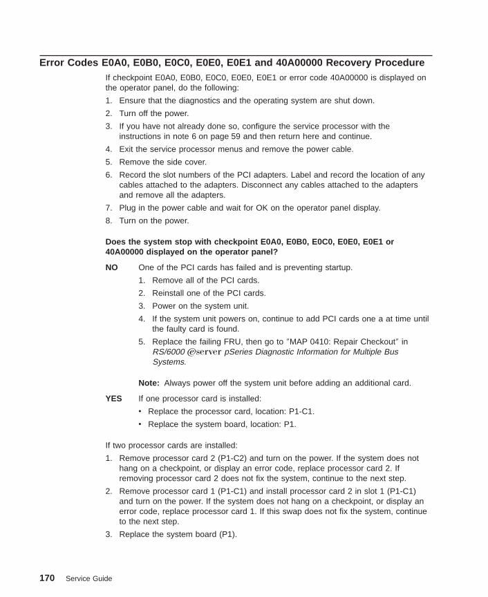
Error Codes E0A0, E0B0, E0C0, E0E0, E0E1 and 40A00000 Recovery ProcedureIf checkpoint E0A0, E0B0, E0C0, E0E0, E0E1 or error code 40A00000 is displayed onthe operator panel, do the following:
1. Ensure that the diagnostics and the operating system are shut down.
2. Turn off the power.
3. If you have not already done so, configure the service processor with theinstructions in note 6 on page 59 and then return here and continue.
4. Exit the service processor menus and remove the power cable.
5. Remove the side cover.
6. Record the slot numbers of the PCI adapters. Label and record the location of anycables attached to the adapters. Disconnect any cables attached to the adaptersand remove all the adapters.
7. Plug in the power cable and wait for OK on the operator panel display.
8. Turn on the power.
Does the system stop with checkpoint E0A0, E0B0, E0C0, E0E0, E0E1 or40A00000 displayed on the operator panel?
NO One of the PCI cards has failed and is preventing startup.
1. Remove all of the PCI cards.
2. Reinstall one of the PCI cards.
3. Power on the system unit.
4. If the system unit powers on, continue to add PCI cards one a at time untilthe faulty card is found.
5. Replace the failing FRU, then go to ″MAP 0410: Repair Checkout″ inRS/6000 Eserver pSeries Diagnostic Information for Multiple BusSystems.
Note: Always power off the system unit before adding an additional card.
YES If one processor card is installed:
v Replace the processor card, location: P1-C1.
v Replace the system board, location: P1.
If two processor cards are installed:
1. Remove processor card 2 (P1-C2) and turn on the power. If the system does nothang on a checkpoint, or display an error code, replace processor card 2. Ifremoving processor card 2 does not fix the system, continue to the next step.
2. Remove processor card 1 (P1-C1) and install processor card 2 in slot 1 (P1-C1)and turn on the power. If the system does not hang on a checkpoint, or display anerror code, replace processor card 1. If this swap does not fix the system, continueto the next step.
3. Replace the system board (P1).
170 Service Guide

Bus SRN to FRU Reference TableThis table is used to locate defective FRUs within the system board PCI and ISA buses.The table indicates which devices should be tested for each SRN. For this procedure, ifpossible, diagnostics are run on the system board bus devices with all adaptersremoved from the failing bus. If a failure is detected on this system with all adaptersremoved from the failing bus, the system board is the isolated FRU. If a failure is notdetected, the adapters are added back one at a time, to their original slot location, andthe configuration is tested until a failure is detected. The failure is then isolated to thefailing FRU.
If a failure has not been detected and all the FRUs have been tested, call technicalservice support for assistance.
Table 5. Bus SRN to FRU Reference Table
SRN BusIdentification
Possible Failing Device and AIXLocation Code
Associated FRU
9CC-100 PCI Bus 00 Internal SCSI port (10-60) System board.(See notes onpage 109.)
Internal/external SCSI port (10-61) System board.(See notes onpage 109.)
Internal Ethernet port (10-80) System board.(See notes onpage 109.)
Device installed in I/O slot 3 (10-68to 10-6F)
Adapter
Device installed in I/O slot 4 (10-70to 10-77)
Adapter
Device installed in I/O slot 5 (10-78to 10-7F)
Adapter
9CC-101 PCI Bus 40 Device installed in I/O slot 1 (20-58to 20-5F)
Adapter
Device installed in I/O slot 2 (20-60to 20-67)
Adapter
651-730 ISA Bus Diskette drive port/device(01-D1-00-00)
System board.(See notes onpage 109.)
Parallel port/device (01-R1) System board.(See notes onpage 109.)
Serial ports (1, 2, 3)/device (01-S1,01-S2, 01-S3)
System board.(See notes onpage 109.)
Mouse port/device (01-K1-01-00) System board.(See notes onpage 109.)
Keyboard port/device (01-K1-00-00) System board.(See notes onpage 109.)
Chapter 5. Error Code to FRU Index 171

Table 5. Bus SRN to FRU Reference Table (continued)
SRN BusIdentification
Possible Failing Device and AIXLocation Code
Associated FRU
Audio port/device (01-Q2) System board.(See notes onpage 109.)
Typical Boot Sequence for 9112 Model 265After the ac power is turned on, the system support controller (SSC) startup begins, andreleases reset to the service processor. If the SSC cannot communicate with theservice processor, the LCD displays 4BA00000. If the service processor is not present,the LCD displays 4BA00001.
A typical boot sequence is as follows:
1. Service processor self-test
v Service processor card performs self-test and NVRAM initialization.
v LCD code range is E000 - E07F.
v LCD code is OK when complete.
2. Service processor in standby mode
v You can enter the service processor menus whenever the LCD code is OK,STBY, or has an eight-digit error code on the LCD display by pressing the Enterkey on an ASCII terminal connected to serial port 1.
3. Built-In Self-Test (BIST)
v The service processor initiates built-in self-test (BIST) on the central electronicscomplex (CEC) when the power button is pressed.
v The VPD data are read and the CRC is checked.
v The processor compatibility test is run.
v LCD code range is E0A0 - E0E1.
4. System Initialization
v System firmware begins to execute and initializes system registers after LCDcode E0E1.
v LCD code range is E1XX - E2XX.
5. Memory Test
v The system firmware tests the system memory and identifies failing memoryDIMM locations.
v LCD code range is E3XX.
6. Device Configuration and Test
v System firmware checks to see which devices are in the system and performs asimple test on them.
172 Service Guide

v The system firmware displays the device name or device icon being tested. Afterthe keyboard name or icon appears, the user can enter the System ManagementServices menu by pressing the 1 key (if ASCII terminal) or the F1 key (if graphicsterminal).
v The user can also enter one of the following:
– 5 or F5 to start the standalone diagnostics (CD).
– 6 or F6 to start the online diagnostics (hard disk).
7. IPL Boot Code
v The system firmware attempts to boot from the devices listed in the boot list.
v LCD code range is E1XX.
8. Boot Image Execution
v After a boot image is located on a device in the boot list, the system firmwarecode passes control to AIX, indicated by either of the following AIX boot codes:
– LCD code E105 for normal boot
– LCD code E15B for service mode boot.
v The AIX boot code displays LCD progress codes in the format 0xxx or 2xxx.
9. AIX Boot Complete
v The AIX login prompt displays on the AIX console.
Chapter 5. Error Code to FRU Index 173

174 Service Guide
Chapter 6. Loading the System Diagnostics
The system diagnostics can be booted using either the default boot list or thecustomized service mode boot list. (The service mode boot list can be modified usingthe system diagnostics ″Display or Change Bootlist″ service aid. The service mode bootlist cannot be modified under the System Management Services.)
Performing Slow BootTo fully analyze all of the available information, perform the following steps before doinga hardware repair or replacement, especially if the error is related to the CPU ormemory:
1. Record the 8-character error code (and location code if present) displayed in theoperator panel, or that was reported by the customer.
2. Do a slow-mode boot in service mode. This can be specified using the SystemPower Control Menu on the service processor main menu. (A fast-mode boot skipsmuch of the built-in diagnostic testing.) A slow-mode boot may yield a new8-character error code on the operator panel and new errors in the serviceprocessor error log. If a new error code is reported, use it in subsequent steps tocontinue problem analysis.
Loading Standalone DiagnosticsTo load Standalone Diagnostics using the default boot list, perform the followingprocedure:
1. Verify with the system administrator and users that all programs may be stopped,then do so.
2. Turn off the system.
3. Wait 30 seconds, and turn on the system.
4. Immediately insert the diagnostic CD-ROM into the CD-ROM drive.
5. After the keyboard indicator appears during startup, and before the tone sounds,press the F5 key on a directly attached keyboard (or the number 5 key on an ASCIIterminal).
6. Enter any requested passwords.
Loading Online DiagnosticsOnline Diagnostics can be loaded by booting using the customized service mode bootlist by pressing the F6 key (on a directly attached keyboard) or the number 6 key on anASCII terminal.
The procedure for booting from the devices listed in the service mode boot list (OnlineDiagnostics ) is the following:
1. Verify with the system administrator and users that all programs may be stopped,then do so.
175
2. Turn off the system.
3. Wait 30 seconds, and turn on the system.
4. After the keyboard indicator appears during startup, and before the tone sounds,press the F6 key on a directly attached keyboard (or the number 6 key on an ASCIIterminal).
5. Enter any requested passwords.
After any requested passwords have been entered, the system attempts to boot fromthe first device of each type found on the list. If no bootable image is found on the firstdevice of each type on the list, the system does not search through the other devices ofthat type for a bootable image; instead, it polls the first device of the next type.
If all types of devices in the boot list have been polled without finding a bootable image,the system restarts, this gives the user the opportunity to start the System ManagementServices (by pressing the F1 key on a directly attached keyboard or the number 1 onan ASCII terminal) before the system attempts to boot again.
Default Boot List and Service Mode Boot ListThe default boot list is:
1. Diskette drive
2. CD-ROM drive
3. Tape drive
4. Disk drive
5. Network adapter
v Token-ring
v Ethernet
Pressing the F5 key on a directly attached keyboard (or the number 5 key on an ASCIIterminal) causes the system to load Standalone Diagnostics provided that adiagnostic CD is present in the CD-ROM drive.
Pressing the F6 key on a directly attached keyboard (or number 6 key on an ASCIIterminal) loads Online Diagnostics using the service mode boot list. No diagnostic CDshould be in the CD-ROM drive because Online Diagnostics are typically run from ahard disk. Like the default boot list, the service mode boot list can contain five entries.The F6 and 6 keys work like the F5 and 5 keys, with the following exceptions:
v The system searches for a boot record according to the service mode boot list.
v If the service mode boot list is discovered by a cyclical redundancy check to becorrupted, the system rebuilds the service mode boot list according to the defaultboot list. (The default boot list contains five entries, and for each matching devicetype found in the system unit, the system makes an entry in the service mode bootlist.)
v If no service mode boot list is present, the system uses the default boot list.
176 Service Guide

Chapter 7. Using the Service Processor
The service processor menus enable you to configure service processor options and toenable and disable functions.
Service processor menus are available using an ASCII terminal when the server isturned off and the service processor is operating with standby power. Service processormenus are also available when server power is on and the service processor hasdetected a server problem (such as surveillance failure).
During the first power-on (that is, the power cord is plugged into the outlet), serviceprocessor menus are not available for 45 seconds while the service processor isrunning self-tests and initializing the server. If the server powers off, service processormenus become available after 15 seconds.
177
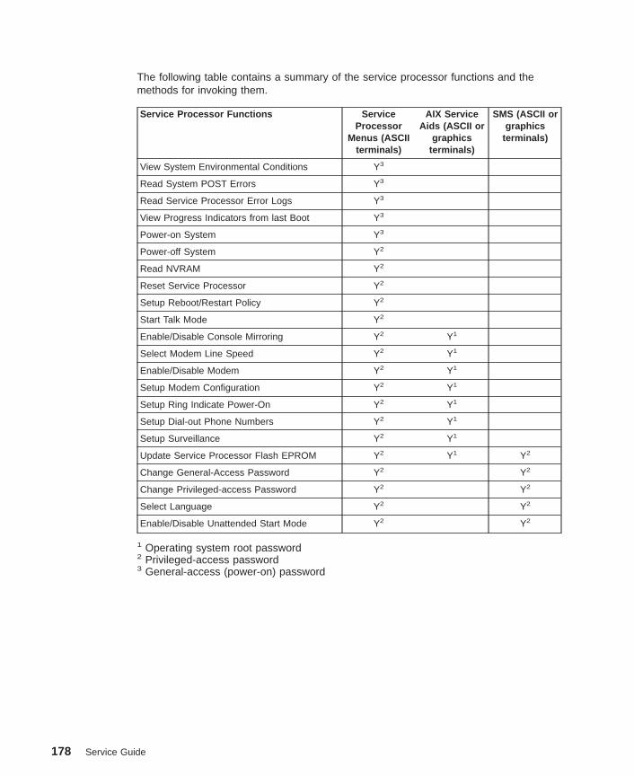
The following table contains a summary of the service processor functions and themethods for invoking them.
Service Processor Functions ServiceProcessor
Menus (ASCIIterminals)
AIX ServiceAids (ASCII or
graphicsterminals)
SMS (ASCII orgraphics
terminals)
View System Environmental Conditions Y3
Read System POST Errors Y3
Read Service Processor Error Logs Y3
View Progress Indicators from last Boot Y3
Power-on System Y3
Power-off System Y2
Read NVRAM Y2
Reset Service Processor Y2
Setup Reboot/Restart Policy Y2
Start Talk Mode Y2
Enable/Disable Console Mirroring Y2 Y1
Select Modem Line Speed Y2 Y1
Enable/Disable Modem Y2 Y1
Setup Modem Configuration Y2 Y1
Setup Ring Indicate Power-On Y2 Y1
Setup Dial-out Phone Numbers Y2 Y1
Setup Surveillance Y2 Y1
Update Service Processor Flash EPROM Y2 Y1 Y2
Change General-Access Password Y2 Y2
Change Privileged-access Password Y2 Y2
Select Language Y2 Y2
Enable/Disable Unattended Start Mode Y2 Y2
1 Operating system root password2 Privileged-access password3 General-access (power-on) password
178 Service Guide
Service Processor MenusThe service processor menus are divided into the following groups:
v General user menus - the user must know the general-access password.
v Privileged user menus - the user must know the privileged-access password.
This section describes these menus, how to access them, and the functions associatedwith each option within the menus.
When the system is powered off, the service processor menus can be accessed locallyor remotely.
Service Processor Menu InactivityTo prevent loss of control in unstable power environments, the service processor leavesthe menu mode after five minutes of inactivity. Return to the menus by pressing any keyon the local or remote terminal.
Accessing Service Processor Menus LocallyService processor menus can be accessed locally by connecting an ASCII terminal toeither serial port 1 (S1) or serial port 2 (S2). The service processor menus cannot beaccessed on serial port 3 (S3). Because the presence of the ASCII terminal cannot beconfirmed by the service processor, you must press a key on the ASCII terminal toconfirm its presence. After OK displays on the operator panel, the service processorprompts you for a password (if set), and when verified, displays the service processormenus.
Accessing Service Processor Menus RemotelyService processor menus can be accessed remotely by connecting a modem to serialport 1 or serial port 2, as follows:
1. Turn off the system, unplug the power cord, and press the Power button to draincapacitance while power is disconnected.
2. Connect the modem to the appropriate serial port and turn on the modem.
3. Plug in the system.
Notes:
1. If your modem has not been configured, go to “Call-In/Call-Out Setup Menu” onpage 195. With a terminal or terminal emulator, call the system’s modem.
2. The service processor prompts you for a password (if set), and when verified,displays the service processor menus.
Saving and Restoring Service Processor SettingsAll the settings you make (except language) from the service processor menus can bebacked up either for recovering from a fault that may corrupt these settings, or forreplicating these settings to other servers that include a service processor.
Chapter 7. Using the Service Processor 179
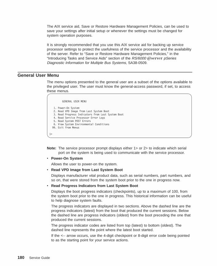
The AIX service aid, Save or Restore Hardware Management Policies, can be used tosave your settings after initial setup or whenever the settings must be changed forsystem operation purposes.
It is strongly recommended that you use this AIX service aid for backing up serviceprocessor settings to protect the usefulness of the service processor and the availabilityof the server. Refer to “Save or Restore Hardware Management Policies,” in the“Introducing Tasks and Service Aids” section of the RS/6000 Eserver pSeriesDiagnostic Information for Multiple Bus Systems, SA38-0509.
General User MenuThe menu options presented to the general user are a subset of the options available tothe privileged user. The user must know the general-access password, if set, to accessthese menus.
GENERAL USER MENU
1. Power-On System2. Read VPD Image from Last System Boot3. Read Progress Indicators from Last System Boot4. Read Service Processor Error Logs5. Read System POST Errors6. View System Environmental Conditions
99. Exit from Menus
1>
Note: The service processor prompt displays either 1> or 2> to indicate which serialport on the system is being used to communicate with the service processor.
v Power-On System
Allows the user to power-on the system.
v Read VPD Image from Last System Boot
Displays manufacturer vital product data, such as serial numbers, part numbers, andso on, that were stored from the system boot prior to the one in progress now.
v Read Progress Indicators from Last System Boot
Displays the boot progress indicators (checkpoints), up to a maximum of 100, fromthe system boot prior to the one in progress. This historical information can be usefulto help diagnose system faults.
The progress indicators are displayed in two sections. Above the dashed line are theprogress indicators (latest) from the boot that produced the current sessions. Belowthe dashed line are progress indicators (oldest) from the boot preceding the one thatproduced the current sessions.
The progress indicator codes are listed from top (latest) to bottom (oldest). Thedashed line represents the point where the latest boot started.
If the <-- arrow occurs, use the 4-digit checkpoint or 8-digit error code being pointedto as the starting point for your service actions.
180 Service Guide

v Read Service Processor Error Logs
Displays the service processor error logs.
The time stamp in this error log is coordinated universal time (UTC), also known asGreenwich mean time (GMT). AIX error logs have additional information availableand are able to time stamp the errors with local time. See “Service Processor ErrorLog” on page 207 for an example of the error log.
v Read System POST Errors
This option should only be used by service personnel to display additional error loginformation.
v View System Environmental Conditions
With this menu option, the service processor reads all environmental sensors andreports the results to the user. This option can be useful when surveillance fails,because it allows the user to determine the environmental conditions that may berelated to the failure.
Chapter 7. Using the Service Processor 181

Privileged User MenusThe following menus are available to privileged users only. The user must know theprivileged-access password, if set, to access these menus.
Main MenuAt the top of the Main Menu is a listing containing:
v Your service processor’s current firmware version
v The firmware copyright notice
v The system name given to your system during setup (optional)
You need the firmware version for reference when you either update or repair thefunctions of your service processor.
System Name, an optional field, is the name that your system reports in problemmessages. This name helps your support team (for example, your system administrator,network administrator, or service representative) to more quickly identify the location,configuration, and history of your system. The system name is set from the Main Menuusing option 6.
Note: The information under the Service Processor Firmware heading in the followingMain Menu illustration is example information only.
Service Processor FirmwareFirmware Level: ct010717
Copyright 2001, IBM CorporationSYSTEM NAME
MAIN MENU
1. Service Processor Setup Menu2. System Power Control Menu3. System Information Menu4. Language Selection Menu5. Call-In/Call-Out Setup Menu6. Set System Name
99. Exit from Menus
1>
182 Service Guide

Service Processor Setup MenuThe Service Processor Setup menu is accessed from the Main Menu:
SERVICE PROCESSOR SETUP MENU
1. Change Privileged-access Password2. Change General-Access Password3. Enable/Disable Console Mirroring:
Currently Disabled
4. Start Talk Mode5. OS Surveillance Setup Menu6. Reset Service Processor7. Reprogram Service Processor Flash EPROM8. Serial Port Snoop Setup Menu98. Return to Previous Menu99. Exit from Menus
1>
Note: Unless otherwise stated in the menu responses, settings become effective whena menu is exited using option 98 or 99.
PasswordsPasswords can be any combination of up to eight alphanumeric characters. You canenter longer passwords, but the entries are truncated to include only the first eightcharacters. Passwords can be set from the Service Processor menu or from the SystemManagement Services menus.
For security purposes, the service processor counts the number of attempts to entercorrect passwords. The results of not recognizing a correct password within this errorthreshold are different, depending on whether the attempts are being made locally (atthe system) or remotely (through a modem). The error threshold is three attempts.
If the error threshold is reached by someone entering passwords at the system, theservice processor exits the menus. This action is taken based on the assumption thatthe system is in an adequately secure location with only authorized users havingaccess. Such users must still successfully enter a login password to access AIX.
If the error threshold is reached by someone entering passwords remotely, the serviceprocessor disconnects the modem to prevent potential security attacks on the server byunauthorized remote users.
Chapter 7. Using the Service Processor 183
The following table illustrates what you can access with the privileged-access passwordand the general-access password.
Privileged-Access Password General-Access Password Resulting Menu
None None MAIN MENU displays
None Set MAIN MENU displays
Set None Users with password see theMAIN MENU.
Set Set Users see menus associatedwith the entered password
v Change Privileged-access Password
Set or change the privileged-access password. It provides the user with the capabilityto access all service processor functions. This password is usually used by thesystem administrator or root user.
v Change General-Access Password
Set or change the general-access password. It provides limited access to serviceprocessor menus and is usually available to all users who are allowed to power onthe system.
v Enable/Disable Console Mirroring
When console mirroring is enabled, the service processor sends information to bothserial ports. This capability, which can be enabled by local or remote users, provideslocal users with the capability to monitor remote sessions. Console mirroring can beenabled for the current session only. For more information, see “Console Mirroring”on page 206.
v Start Talk Mode
In a console-mirroring session, it is useful for those who are monitoring the sessionto be able to communicate with each other. Selecting this menu item activates thekeyboards and displays for such communications while console mirroring isestablished. This is a full duplex link, so message interference is possible. Alternatingmessages between users works best.
184 Service Guide
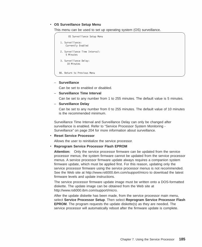
v OS Surveillance Setup Menu
This menu can be used to set up operating system (OS) surveillance.
OS Surveillance Setup Menu
1. Surveillance:Currently Enabled
2. Surveillance Time Interval:5 Minutes
3. Surveillance Delay:10 Minutes
98. Return to Previous Menu
– Surveillance
Can be set to enabled or disabled.
– Surveillance Time Interval
Can be set to any number from 1 to 255 minutes. The default value is 5 minutes.
– Surveillance Delay
Can be set to any number from 0 to 255 minutes. The default value of 10 minutesis the recommended minimum.
Surveillance Time Interval and Surveillance Delay can only be changed aftersurveillance is enabled. Refer to “Service Processor System Monitoring -Surveillance” on page 204 for more information about surveillance.
v Reset Service Processor
Allows the user to reinitialize the service processor.
v Reprogram Service Processor Flash EPROM
Attention: Only the service processor firmware can be updated from the serviceprocessor menus; the system firmware cannot be updated from the service processormenus. A service processor firmware update always requires a companion systemfirmware update, which must be applied first. For this reason, updating only theservice processor firmware using the service processor menus is not recommended.See the Web site at http://www.rs6000.ibm.com/support/micro to download the latestfirmware levels and update instructions.
The service processor firmware update image must be written onto a DOS-formatteddiskette. The update image can be obtained from the Web site athttp://www.rs6000.ibm.com/support/micro.
After the update diskette has been made, from the service processor main menu,select Service Processor Setup . Then select Reprogram Service Processor FlashEPROM. The program requests the update diskette(s) as they are needed. Theservice processor will automatically reboot after the firmware update is complete.
Chapter 7. Using the Service Processor 185
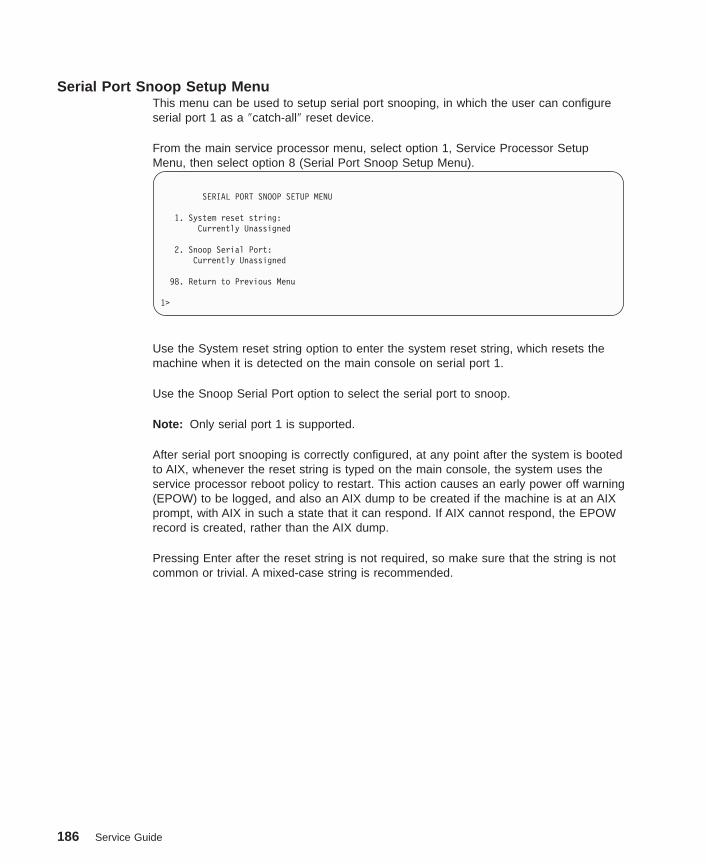
Serial Port Snoop Setup MenuThis menu can be used to setup serial port snooping, in which the user can configureserial port 1 as a ″catch-all″ reset device.
From the main service processor menu, select option 1, Service Processor SetupMenu, then select option 8 (Serial Port Snoop Setup Menu).
SERIAL PORT SNOOP SETUP MENU
1. System reset string:Currently Unassigned
2. Snoop Serial Port:Currently Unassigned
98. Return to Previous Menu
1>
Use the System reset string option to enter the system reset string, which resets themachine when it is detected on the main console on serial port 1.
Use the Snoop Serial Port option to select the serial port to snoop.
Note: Only serial port 1 is supported.
After serial port snooping is correctly configured, at any point after the system is bootedto AIX, whenever the reset string is typed on the main console, the system uses theservice processor reboot policy to restart. This action causes an early power off warning(EPOW) to be logged, and also an AIX dump to be created if the machine is at an AIXprompt, with AIX in such a state that it can respond. If AIX cannot respond, the EPOWrecord is created, rather than the AIX dump.
Pressing Enter after the reset string is not required, so make sure that the string is notcommon or trivial. A mixed-case string is recommended.
186 Service Guide

System Power Control MenuThe menu is used to set power control options.
SYSTEM POWER CONTROL MENU
1. Enable/Disable Unattended Start Mode:Currently Disabled
2. Ring Indicate Power-On Menu3. Reboot/Restart Policy Setup Menu4. Power-On System5. Power-Off System6. Enable/Disable Fast System Boot:
Currently Disabled7. Boot Mode Menu98. Return to Previous Menu99. Exit from Menus
1>
v Enable/Disable Unattended Start Mode
Use this option to instruct the service processor to immediately power-on the serverafter a power failure, bypassing power-on password verification. Unattended startmode can be used on systems that require automatic power-on after a power failure.Unattended start mode can also be set using SMS menus.
v Ring Indicate Power-On Menu
Ring indicate power-on is an alternate method of dialing in without establishing aservice processor session. If the system is powered off and ring indicate power-on isenabled, the system is powered on at the predetermined number of rings. If thesystem is already on, no action is taken. In either case, the telephone call is notanswered. The caller receives no feedback that the system is powered on. The RingIndicate Power-On Menu and defaults are as follows:
Ring Indicate Power-On Menu
1. Ring indicate power-on:Currently Disabled
2. Number of rings:Currently 6
98. Return to Previous Menu
The number of rings can be set to any number greater than zero. The default valueis six rings.
Chapter 7. Using the Service Processor 187

v Reboot/Restart Policy Setup Menu
Reboot describes bringing the system hardware back up from scratch, for example,from a system reset or power-on. The reboot process ends when control passes tothe operating system loading (or initialization) process.
Restart describes activating the operating system after the system hardwarereinitialized. Restart must follow a successful reboot.
Reboot/Restart Policy Setup Menu
1. Number of reboot attempts:Currently 3
2. Use OS-Defined restart policy?Currently Yes
3. Enable supplemental restart policy?Currently No
4. Call-Out before restart:Currently Disabled
98. Return to Previous Menu
1>
– Number of reboot attempts If the system fails to successfully complete the bootprocess, it attempts to reboot the number of times specified. Values equal to orgreater than 0 are valid. Only successive failed reboot attempts count, not rebootsthat occur after a restart attempt. At restart, the counter is set to 0.
– Use OS-Defined restart policy lets the service processor react in the same wayas the operating system to major system faults by reading the setting of theoperating system parameter Automatically Restart/Reboot After a SystemCrash . This parameter may or may not be defined, depending on the operatingsystem or its version and level. If the operating system automatic restart setting isdefined, then it can be set to respond to a major fault by restarting or by notrestarting. See your operating system documentation for details on setting upoperating system automatic restarts. The default value is yes.
– Enable supplemental restart policy - The default setting is no. If set to yes, theservice processor restarts the system when the system loses control as detectedby the service processor surveillance, and either:
- The Use OS-Defined restart policy is set to noOR
- The Use OS-Defined restart policy is set to yes, and the operating systemhas NO automatic restart policy.
Refer to “Service Processor Reboot/Restart Recovery” on page 202.
– Call-out before restart If a restart is necessary due to a system fault, you canenable the service processor to call out and report the event. This option can bevaluable if the number of these events becomes excessive, signalling a biggerproblem.
188 Service Guide
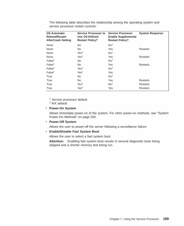
The following table describes the relationship among the operating system andservice processor restart controls:
OS AutomaticReboot/RestartAfterCrash Setting
Service Processor toUse OS-DefinedRestart Policy?
Service ProcessorEnable SupplementalRestart Policy?
System Response
None No No1
None No Yes RestartsNone Yes1 No1
None Yes1 Yes RestartsFalse2 No No1
False2 No Yes RestartsFalse2 Yes1 No1
False2 Yes1 YesTrue No No1
True No Yes RestartsTrue Yes1 No1 RestartsTrue Yes1 Yes Restarts
1 Service processor default2 AIX default
v Power-On System
Allows immediate power-on of the system. For other power-on methods, see “SystemPower-On Methods” on page 200.
v Power-Off System
Allows the user to power-off the server following a surveillance failure.
v Enable/Disable Fast System Boot
Allows the user to select a fast system boot.
Attention: Enabling fast system boot results in several diagnostic tests beingskipped and a shorter memory test being run.
Chapter 7. Using the Service Processor 189

v Boot Mode Menu
Allows users to set the system to automatically start a specific function on the nextsystem start. This setting applies to the next boot only and is reset to the defaultstate of being disabled following a successful boot attempt.
BOOT MODE MENU
1. Boot to SMS Menu:Currently Disabled
2. Service Mode Boot from Saved List:Currently Disabled
3. Service Mode Boot from Default List:Currently Disabled
4. Boot to Open Firmware Prompt:Currently Disabled
98. Return to Previous Menu
1>
– Enabling the Boot to SMS Menu option
Causes the system to automatically stop at the System Management Servicesmenu during the boot process. Enabling this option is equivalent to pressing 1 onthe attached ASCII terminal (or F1 on a graphics terminal) while the systeminitialization indicators display on screen.
– Enabling the Service Mode Boot from Saved list option
This selection causes the system to perform a service mode boot using theservice mode boot list saved in NVRAM. If the system boots AIX from the diskdrive and AIX diagnostics are loaded on the disk drive, AIX boots in service modeto the diagnostics menu.
Using this option to boot the system is the preferred way to run online diagnostics.
– Enabling the Service Mode Boot from Default List option
This selection is similar to “Service Mode Boot from Saved List”, except thesystem boots using the default boot list that is stored in the system firmware. Thisis normally used to try to boot customer diagnostics from the CD-ROM drive.
Using this option to boot the system is the preferred way to run standalonediagnostics.
– Enabling the Boot to Open Firmware Prompt option
Causes the system to automatically enter open firmware prompt (also called theOK prompt). This option should only be used by service personnel to obtainadditional debug information.
190 Service Guide
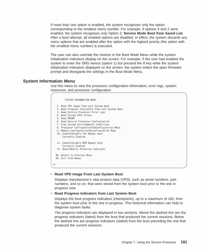
If more than one option is enabled, the system recognizes only the optioncorresponding to the smallest menu number. For example, if options 4 and 2 wereenabled, the system recognizes only Option 2: Service Mode Boot from Saved List .After a boot attempt, all enabled options are disabled. In effect, the system discards anymenu options that are enabled after the option with the highest priority (the option withthe smallest menu number) is executed.
The user can also override the choices in the Boot Mode Menu while the systeminitialization indicators display on the screen. For example, if the user had enabled thesystem to enter the SMS menus (option 1) but pressed the 8 key while the systeminitialization indicators displayed on the screen, the system enters the open firmwareprompt and disregards the settings in the Boot Mode Menu.
System Information MenuUse this menu to view the processor configuration information, error logs, systemresources, and processor configuration.
SYSTEM INFORMATION MENU
1. Read VPD Image From Last System Boot2. Read Progress Indicators From Last System Boot3. Read Service Processor Error Logs4. Read System POST Errors5. Read NVRAM6. Read Service Processor Configuration7. View System Environmental Conditions8. Processor Configuration/Deconfiguration Menu9. Memory Configuration/Deconfiguration Menu10. Enable/Disable CPU Repeat Gard
Currently Enabled
11. Enable/Disable MEM Repeat GardCurrently Enabled
12. Query/Modify Attention Indicator
98. Return to Previous Menu99. Exit from Menus
1>
v Read VPD Image From Last System Boot
Displays manufacturer’s vital product data (VPD), such as serial numbers, partnumbers, and so on, that were stored from the system boot prior to the one inprogress now.
v Read Progress Indicators from Last System Boot
Displays the boot progress indicators (checkpoints), up to a maximum of 100, fromthe system boot prior to the one in progress. This historical information can help todiagnose system faults.
The progress indicators are displayed in two sections. Above the dashed line are theprogress indicators (latest) from the boot that produced the current sessions. Belowthe dashed line are progress indicators (oldest) from the boot preceding the one thatproduced the current sessions.
Chapter 7. Using the Service Processor 191
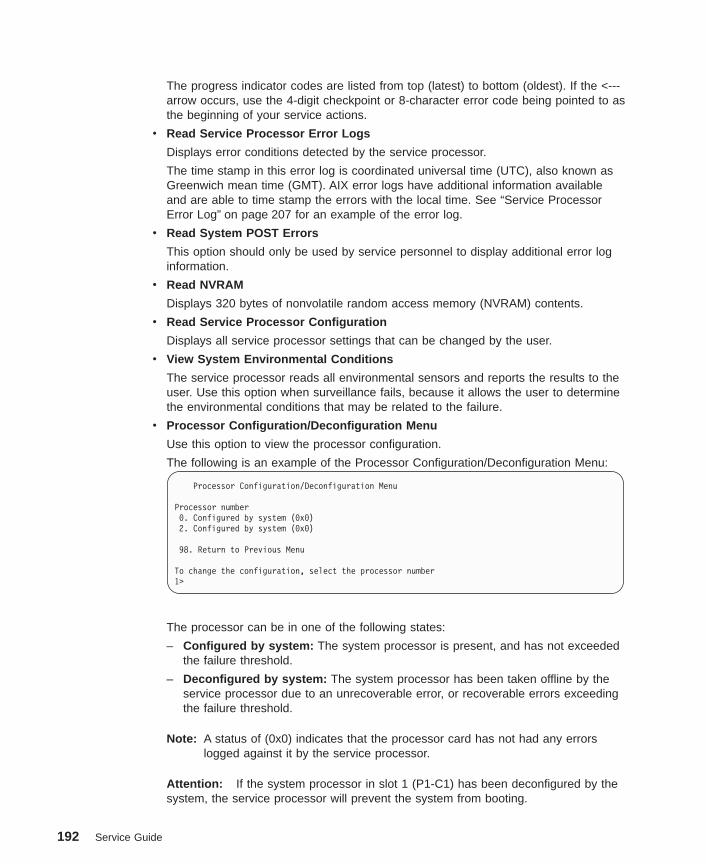
The progress indicator codes are listed from top (latest) to bottom (oldest). If the <---arrow occurs, use the 4-digit checkpoint or 8-character error code being pointed to asthe beginning of your service actions.
v Read Service Processor Error Logs
Displays error conditions detected by the service processor.
The time stamp in this error log is coordinated universal time (UTC), also known asGreenwich mean time (GMT). AIX error logs have additional information availableand are able to time stamp the errors with the local time. See “Service ProcessorError Log” on page 207 for an example of the error log.
v Read System POST Errors
This option should only be used by service personnel to display additional error loginformation.
v Read NVRAM
Displays 320 bytes of nonvolatile random access memory (NVRAM) contents.
v Read Service Processor Configuration
Displays all service processor settings that can be changed by the user.
v View System Environmental Conditions
The service processor reads all environmental sensors and reports the results to theuser. Use this option when surveillance fails, because it allows the user to determinethe environmental conditions that may be related to the failure.
v Processor Configuration/Deconfiguration Menu
Use this option to view the processor configuration.
The following is an example of the Processor Configuration/Deconfiguration Menu:
Processor Configuration/Deconfiguration Menu
Processor number0. Configured by system (0x0)2. Configured by system (0x0)
98. Return to Previous Menu
To change the configuration, select the processor number1>
The processor can be in one of the following states:
– Configured by system: The system processor is present, and has not exceededthe failure threshold.
– Deconfigured by system: The system processor has been taken offline by theservice processor due to an unrecoverable error, or recoverable errors exceedingthe failure threshold.
Note: A status of (0x0) indicates that the processor card has not had any errorslogged against it by the service processor.
Attention: If the system processor in slot 1 (P1-C1) has been deconfigured by thesystem, the service processor will prevent the system from booting.
192 Service Guide

v Memory Configuration/Deconfiguration Menu :
Use this menu to view and modify the dual inline memory module (DIMM)configuration. If it is necessary to take one of the memory DIMMs offline, this menuallows you to deconfigure a DIMM and then reconfigure the DIMM at a later time.
The configuration process takes place during system power-on. Therefore, theconfiguration displayed by this menu in standby mode reflects the configurationduring the last boot.
The following is an example of the Memory Configuration/Deconfiguration Menu.
Memory Configuration/Deconfiguration Menu
DIMMs on memory card number 0:
1. Configured by system (0x0) 2. Configured by system (0x0)3. Configured by system (0x0) 4. Configured by system (0x0)
98. Return to Previous Menu
Enter card number and DIMM number separated by a space1>
In this system, the memory card number is 0 by default.
When the user selects a DIMM, its state toggles between configured anddeconfigured. Memory DIMMs that are not present are not shown.
Each memory DIMM can be in one of following states:
– Configured by system: The memory DIMM is present, and has not exceeded thefailure threshold. It has been configured by the system and is available.
– Deconfigured by system: The memory DIMM is present, but has exceeded thefailure threshold. It has been deconfigured by the system and is currentlyunavailable.
– Manually configured: The memory DIMM is present and available. It has beenconfigured by the user through this menu.
– Manually deconfigured: The memory DIMM is present, but unavailable. It hasbeen deconfigured by the user through this menu.
Note: A status of (0x0) indicates that the memory DIMM has not had any errorslogged against it by the service processor.
v Enable/Disable CPU Repeat Gard Menu
Use this option to enable or disable CPU repeat gard.
v Enable/Disable Memory Repeat Gard Menu
Use this option to enable or disable memory repeat gard.
v Query/Modify Attention Indicator: (amber colored LED located on the operatorpanel)
This option allows the user to query and modify the system fault/system identify LED.This LED displays the state of the attention indicator sensors.
Chapter 7. Using the Service Processor 193
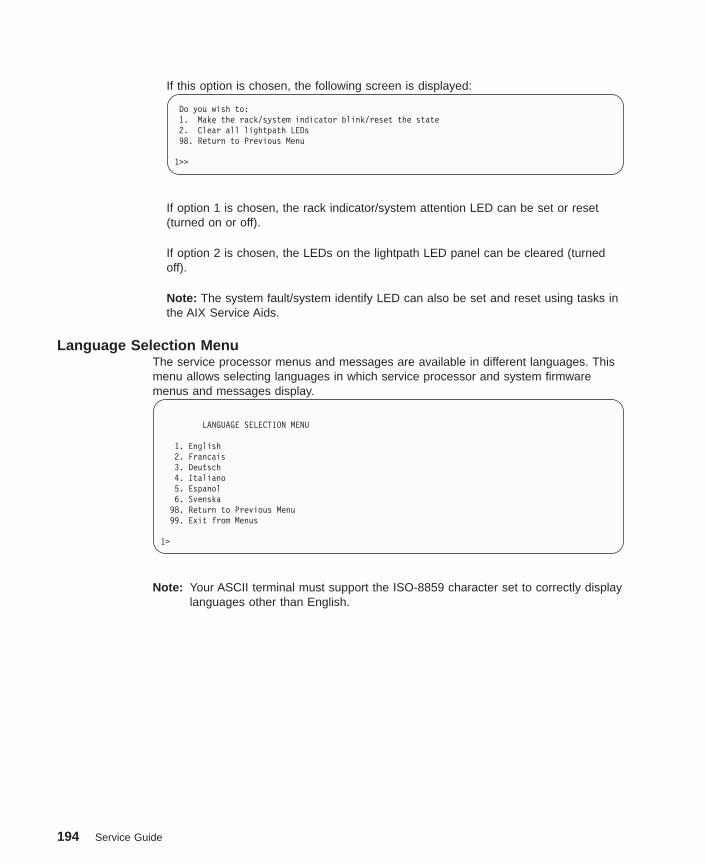
If this option is chosen, the following screen is displayed:
Do you wish to:1. Make the rack/system indicator blink/reset the state2. Clear all lightpath LEDs98. Return to Previous Menu
1>>
If option 1 is chosen, the rack indicator/system attention LED can be set or reset(turned on or off).
If option 2 is chosen, the LEDs on the lightpath LED panel can be cleared (turnedoff).
Note: The system fault/system identify LED can also be set and reset using tasks inthe AIX Service Aids.
Language Selection MenuThe service processor menus and messages are available in different languages. Thismenu allows selecting languages in which service processor and system firmwaremenus and messages display.
LANGUAGE SELECTION MENU
1. English2. Francais3. Deutsch4. Italiano5. Espanol6. Svenska
98. Return to Previous Menu99. Exit from Menus
1>
Note: Your ASCII terminal must support the ISO-8859 character set to correctly displaylanguages other than English.
194 Service Guide

Call-In/Call-Out Setup MenuThis menu is used to configure a modem for the service processor to use to support thesystem.
CALL-IN/CALL-OUT SETUP MENU
1. Modem Configuration Menu2. Serial Port Selection Menu3. Serial Port Speed Setup Menu4. Telephone Number Setup Menu5. Call-Out Policy Setup Menu6. Customer Account Setup Menu7. Call-Out Test8. Ring Indicate Power-On Menu98. Return to Previous Menu99. Exit from Menus
1>
v Modem Configuration Menu , see “Modem Configuration Menu” on page 196.
v Serial Port Selection Menu , see “Serial Port Selection Menu” on page 196.
v Serial Port Speed Setup Menu , see “Serial Port Selection Menu” on page 196.
v Telephone Number Setup Menu , see “Telephone Number Setup Menu” onpage 197.
v Call-Out Policy Setup Menu , see “Call-Out Policy Setup Menu” on page 199.
v Customer Account Setup Menu , see “Customer Account Setup Menu” onpage 200.
v Call-out Test , see “Call-Out Policy Setup Menu” on page 199.
v Ring Indicate Power-On Menu , see page 187.
Chapter 7. Using the Service Processor 195

Modem Configuration MenuEntries at the top of the Modem Configuration Menu display the status of the currentselections. Selections are made in the sections, labeled Modem Ports and ModemConfiguration File Name. Select the serial port that you want to activate and thenselect the modem configuration file for the modem on the port. To set up both serialports with modems, make your selections one port at a time.
For information on choosing a modem configuration file, see “Sample ModemConfiguration Files” on page 313 and “Transfer of a Modem Session” on page 318.
Modem Configuration Menu
Port 1 Modem Configuration File Name:Port 2 Modem Configuration File Name:
To make changes, First select the port and then the configuration filename
Modem Ports:1. Serial port 12. Serial port 2
Modem Configuration File Name:3. none 9. modem_m0_sp4. modem_f_sp 10. modem_m1_sp5. modem_f0_sp6. modem_f1_sp7. modem_z_sp8. modem_z0_sp
30. Save configuration to NVRAM and Configure modem98. Return to Previous Menu
Serial Port Selection MenuThis menu allows you to enable and/or disable the call-in functions of each serial port inany combination.
Serial Port Selection Menu
1. Serial Port 1 Call-Out:Currently Disabled
2. Serial Port 2 Call-Out:Currently Disabled
3. Serial Port 1 Call-In:Currently Disabled
4. Serial Port 2 Call-In:Currently Disabled
98. Return to Previous Menu
196 Service Guide

Serial Port Speed Setup MenuThis menu allows you to set serial port speed to enhance terminal performance or toaccommodate modem capabilities.
Serial Port Speed Setup Menu
1. Serial port 1 speed:Currently 9600
2. Serial port 2 speed:Currently 9600
98. Return to Previous Menu
A speed of 9600 baud or higher is recommended. Valid serial port speeds are asfollows:
50 600 480075 1200 7200110 2000 9600134 2400 19200150 2400 57600300 3600 115200
Telephone Number Setup MenuUse this menu to set or change the telephone numbers for reporting a system failure.
Telephone Number Setup Menu
1. Service Center Telephone Number:Currently Unassigned
2. Customer Administration Center Telephone Number:Currently Unassigned
3. Digital Pager Telephone Number:Currently Unassigned
4. Customer Voice Telephone Number:Currently Unassigned
5. Customer System Telephone Number:Currently Unassigned
98. Return to Previous Menu
1>
v Service Center Telephone Number is the number of the service center computer.The service center usually includes a computer that takes calls from systems withcall-out capability. This computer is referred to as the catcher. The catcher expectsmessages in a specific format to which the service processor conforms. Contact yourservice provider for the correct service center telephone number to enter here. For
Chapter 7. Using the Service Processor 197
more information about the format and catcher computers, refer to the README filein the AIX /usr/samples/syscatch directory.
v Customer Administration Center Telephone Number is the number of the systemadministration center computer (catcher) that receives problem calls from systems.Contact your system administrator for the correct telephone number to enter here.
v Digital Pager Telephone Number is the number for a pager carried by someonewho responds to problem calls from your system. Contact your administration centerrepresentative for the correct telephone number to enter here. For test purposes, usea test number, which you can change later.
Notes:
1. At least one of the preceding three telephone numbers must be assigned in orderfor the call-out test to execute successfully.
2. Some modems, such as IBM 7857-017, are not designed for the paging function.Although they can be used for paging, they return an error message when theydo not get the expected response from another modem. Therefore, even thoughthe paging was successful, the error message causes the service processor toretry, continuing to place pager calls for the number of retries specified in theCall-Out policy Setup Menu. These retries result in redundant pages.
For digital pagers that require a personal identification number (PIN) for access,include the PIN in this field as shown in the following example:
18001234567,,,,87654
The commas create pauses for the voice response system, and the 87654represents the PIN. The length of these pauses is set in modem register S8. Thedefault is usually 1 or 2 seconds each.
v Customer Voice Telephone Number is the telephone number of a phone near theserver or answered by someone responsible for the system. This is the telephonenumber left on the pager for callback. For test purposes, use a test number, whichyou can change later.
v Customer System Telephone Number is the telephone number to which yoursystem’s modem is connected. The service or administration center representativesneed this number to make direct contact with your system for problem investigation.This is also referred to as the call-in phone number.
198 Service Guide
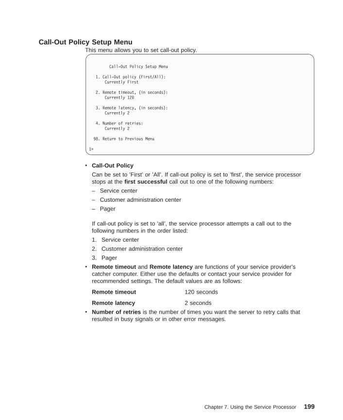
Call-Out Policy Setup MenuThis menu allows you to set call-out policy.
Call-Out Policy Setup Menu
1. Call-Out policy (First/All):Currently First
2. Remote timeout, (in seconds):Currently 120
3. Remote latency, (in seconds):Currently 2
4. Number of retries:Currently 2
98. Return to Previous Menu
1>
v Call-Out Policy
Can be set to ’First’ or ’All’. If call-out policy is set to ’first’, the service processorstops at the first successful call out to one of the following numbers:
– Service center
– Customer administration center
– Pager
If call-out policy is set to ’all’, the service processor attempts a call out to thefollowing numbers in the order listed:
1. Service center
2. Customer administration center
3. Pager
v Remote timeout and Remote latency are functions of your service provider’scatcher computer. Either use the defaults or contact your service provider forrecommended settings. The default values are as follows:
Remote timeout 120 seconds
Remote latency 2 seconds
v Number of retries is the number of times you want the server to retry calls thatresulted in busy signals or in other error messages.
Chapter 7. Using the Service Processor 199

Customer Account Setup MenuThis menu allows users to enter information that is specific to their account.
Customer Account Setup Menu
1. Customer account number:Currently Unassigned
2. Customer RETAIN login userid:Currently Unassigned
3. Customer RETAIN login password:Currently Unassigned
98. Return to Previous Menu
1>
v Customer account number is assigned by your service provider for record-keepingand billing. If you have an account number, enter it. Otherwise, leave this field blank.
v Customer RETAIN login userid and Customer RETAIN login password apply to aservice function to which your service provider may or may not have access. Leavethese fields blank if your service provider does not use RETAIN.
Call-Out TestThe call-out test verifies if the call-out function is working properly. Before the test,call-out must be enabled and the system configured properly for call-out.
During the setup, the user should have entered the phone numbers for the digital pagerand customer voice for test purposes. These numbers are used to determine whethercall-out is working during the call-out test.
The call-out test should cause the user’s phone to ring. If the test is successful, call-outis working properly. The user should now change the test digital pager and customersvoice number to the correct numbers.
System Power-On MethodsThis section discusses the following system power-on methods:
v Power-on switch
v Remote power-on by ring-indicate signal
The server automatically powers on when it detects a ″ring indicate″ signal from amodem attached to one of the integrated serial ports.
A remote user can call the server to activate ring detection by the modem. Listen fora few more rings than the threshold number for starting the system and then hangup. The default threshold is six rings.
Wait 5 minutes for the server to initialize and then call again using an ASCII terminal.The server responds by requesting a password, if set, or presenting the serviceprocessor menus. The remote user now has control of the server.
200 Service Guide

Note: For security, if the system is powered on by the remote power-on by ringindicate signal and the service processor detects a battery failure, the serviceprocessor causes the system to power off. See “Service Processor Call-InSecurity” for more information.
v Unattended start mode - refer to Enable/Disable Unattended Start Mode on page187.
The service processor can be enabled to recover from the loss of ac power (seeEnable/Disable Unattended Power-On Mode in the “System Power Control Menu” onpage 187). When ac power is restored, the system returns to the power state at thetime ac loss occurred. For example, if the system was powered-on when ac lossoccurred, it reboots/restarts when power is restored. If the system was powered-offwhen ac loss occurred, it remains off when power is restored.
v Timed power-on - refer to the shutdown -t command on servers using AIX.
Working in conjunction with AIX, the service processor in your server can operate atimer, much like the wake-up timer on your clock radio. You can set the timer so thatyour server powers on at a certain time after shutting down. The timer is batteryoperated, so power interruptions occurring while the server is off do not affect itsaccuracy. Refer to the AIX shutdown -t command for details on setting the timer.
Note: If an ac power loss is in progress when the timed power-on attempt occurs,the server cannot power on when ac power is restored.
v Follow-up to a failed boot attempt
The service processor initiates a power-on sequence if a failed boot attempt isdetected (due to a hardware or software failure).
v Fast/Slow Boot (IPL) Capabilities
Using the service processor menus, you can select the IPL type, mode, and speed ofyour system. For more information, refer to “System Power Control Menu” onpage 187.
Attention : Selecting fast IPL results in several diagnostic tests being skipped, and ashorter memory test being run.
Service Processor Call-In SecurityIf the service processor detects bad battery-powered storage (indicating that the batteryon the system board has failed or has been removed), it maintains server security bydisabling the call-in capability to both serial ports.
When call-in is disabled, the system can still be powered on by using the ring-indicatorsignal, but the service processor then causes the system to power down, preventingaccess to any system facilities or to AIX.
After battery power is restored, the password(s) must be reset and the call-in function(s)enabled. Both of these operations can be performed from service processor menus.See “Serial Port Selection Menu” on page 196.
Chapter 7. Using the Service Processor 201

Service Processor Reboot/Restart RecoveryReboot describes bringing the system hardware back up; for example, from a systemreset or power-on. The reboot process ends when control passes to the operatingsystem loading (or initialization) process.
Restart describes activating the operating system after the system hardware isreinitialized. Restart must follow a successful reboot.
Boot (IPL) SpeedWhen the server enters reboot recovery, slow IPL is automatically started, which givesthe POST an opportunity to locate and report any problems.
Failure During Boot ProcessDuring the boot process, either initially after system power-on or upon reboot after asystem failure, the service processor monitors the boot progress. If progress stops, theservice processor can reinitiate the boot process (reboot) if enabled to do so. Theservice processor can re-attempt this process according to the number of retriesentered in the Reboot/Restart Policy Setup Menu.
Failure During Normal System OperationWhen the boot process completes and control transfers to the operating system (OS),the service processor can monitor operating system activity (see the Set SurveillanceParameters option in the “Service Processor Setup Menu” on page 183). If OS activitystops due to a hardware- or software-induced failure, the service processor can initiatea reboot/restart process based on the settings in the Service Processor Reboot/RestartPolicy Setup Menu and the OS automatic restart settings (see the operating systemdocumentation).
If you are using the AIX operating system, the menu item under SMIT for setting therestart policy is Automatically Reboot After Crash (True/False). The default is False.When the setting is True, and if the service processor parameter ″Use OS-DefinedRestart Policy″ is Yes (the default), the service processor takes over for AIX toreboot/restart after a hardware or surveillance failure.
Service Processor Reboot/Restart Policy ControlsThe operating system’s automatic restart policy (see operating system documentation)defines the operating system’s response to a system crash. The service processor canbe instructed to refer to that policy by the Use OS-Defined Restart Policy setup menu.
Processor Boot-Time Deconfiguration (CPU Repeat Gard)Processor boot time deconfiguration allows for the removal of processors from thesystem configuration at boot time. The objective is to minimize system failure or dataintegrity exposure due to a faulty processor.
This function uses processor hardware built-in self-test (BIST) and firmware power-onself-test (POST) to discover and isolate processor hardware failures during boot time. Italso uses the hardware error detection logic in the processor to capture run-time
202 Service Guide

recoverable and irrecoverable error indications. The firmware uses the error signaturesin the hardware to analyze and isolate the error to a specific processor.
The processors that are deconfigured remain offline for subsequent reboots until thefaulty processor hardware is replaced.
This function allows users to manually deconfigure or re-enable a previouslydeconfigured processor through the service processor menu. The user can also enableor disable this function through the service processor.
Memory Boot-Time Deconfiguration (Memory Repeat Gard)Memory boot-time deconfiguration allows for the removal of a memory segment orDIMM from the system configuration at boot time. The objective is to minimize systemfailures or data integrity exposure due to faulty memory hardware. The hardwareresource(s) to be removed are the ones that experienced the following failures:
v A boot-time test failure
v Run-time recoverable errors over the error threshold prior to the current boot phase
v Run-time irrecoverable errors prior to the current boot phase
This function uses firmware power-on self-test (POST) to discover and isolate memoryhardware failures during boot time. It also uses the hardware error detection logic in thememory controller to capture run-time recoverable and irrecoverable errors. Thefirmware uses the error signatures in the hardware to analyze and isolate the error tothe specific memory segment or DIMM.
The memory segment or DIMM that is deconfigured remains offline during subsequentreboots until the faulty memory hardware is replaced.
The function allows users to manually deconfigure or re-enable a previouslydeconfigured memory segment/DIMM through the service processor menu. The usercan also enable or disable this function through the service processor menu.
Chapter 7. Using the Service Processor 203
Service Processor System Monitoring - SurveillanceSurveillance is a function in which the service processor monitors the system, and thesystem monitors the service processor. This monitoring is accomplished by periodicsamplings called heartbeats.
Surveillance is available during two phases:
v System firmware startup (automatic)
v Operating system run time (optional)
System Firmware SurveillanceSystem firmware surveillance provides the service processor with a means to detectboot failures while the system firmware is running.
System firmware surveillance is automatically enabled during system power-on. Itcannot be disabled by the user, and the surveillance interval and surveillance delaycannot be changed by the user.
If the service processor detects no heartbeats during system boot (for a set period oftime), it cycles the system power to attempt a reboot. The maximum number of retriesis set from the service processor menus. If the failure condition repeats, the serviceprocessor leaves the machine powered on, logs an error, and displays menus to theuser. If call-out is enabled, the service processor calls to report the failure and displaysthe operating-system surveillance failure code on the operator panel.
Operating System SurveillanceThe operating system surveillance provides the service processor with a means todetect hang conditions, as well as hardware or software failures, while the operatingsystem is running. It also provides the operating system with a means to detect serviceprocessor failure caused by the lack of a return heartbeat.
Operating system surveillance is enabled by default, allowing the user to run operatingsystems that do not support this service processor option.
You can also use service processor menus and AIX service aid to enable or disableoperating system surveillance.
For operating system surveillance to work correctly, you must set the followingparameters:
v Surveillance enable/disable
v Surveillance interval
The maximum time (in minutes) the service processor will wait between heartbeatsfrom the operating system before reporting a surveillance failure.
v Surveillance delay
The maximum time (in minutes) for the service processor will wait for the firstheartbeat from the operating system after the operating system has been started,before reporting a surveillance failure.
204 Service Guide

Surveillance takes effect immediately after the parameters are set from the serviceprocessor menus.
If operating system surveillance is enabled (and system firmware has passed control tothe operating system), and the service processor does not detect any heartbeats fromthe operating system within the surveillance delay period, the service processorassumes the system is hung. The machine is left powered on and the service processorenters standby phase, displaying the operating system surveillance failure code on theoperator panel. If call-out is enabled, the service processor calls to report the failure.
Call OutThe service processor can call out when it detects one of the following conditions:
v System firmware surveillance failure
v Operating system surveillance failure (if supported by the operating system)
v Critical environmental failures
v Restarts
To enable the call-out feature, do the following:
1. Have a modem connected to serial port 1 or 2.
2. Set up the following using the service processor menus or diagnostic service aids:
v Enable call out for the serial port where the modem is connected.
v Set the serial port line speed.
v Enter the modem configuration filename.
v Set up site-specific parameters (such as phone numbers for call-in and call-outpolicy).
v To call out before restart, set Call-Out before restart to Enabled from theReboot/Restart Policy Setup menu.
Note: Some modems, such as IBM 7857-017, are not designed for the paging function.Although they can be used for paging, they return an error message when theydo not get the expected response from another modem. Therefore, even thoughthe paging was successful, the error message causes the service processor toretry, continuing to place pager calls for the number of retries specified in theCall-Out policy Setup Menu. These retries result in redundant pages.
Chapter 7. Using the Service Processor 205

Console MirroringConsole mirroring allows a user on a local ASCII terminal to monitor the serviceprocessor activities of a remote user. Console mirroring ends when the serviceprocessor releases control of the serial ports to the system firmware.
System Configuration for Console MirroringThe following describes the system configuration for console mirroring:
v Modem connected to one serial port and enabled for incoming calls
v Local ASCII terminal connected to the other serial port. This local terminal can beconnected directly to your server or connected through another modem.
Remote console mirroring can be invoked in two ways:
v Remote session first, then local session added:
1. Remote session already in progress.
2. Remote user uses the service processor menus to enable console mirroring,allowing both consoles to be active.
v Local session first, then remote session added:
1. Local session is already in progress.
2. The service processor receives a call from the remote user.
3. The local user selects the option to enable console mirroring. The serviceprocessor immediately begins mirroring service processor menus.
Note: To disconnect quickly, press Ctrl+D on either console, and both sessions will exitthe service processor menus.
206 Service Guide
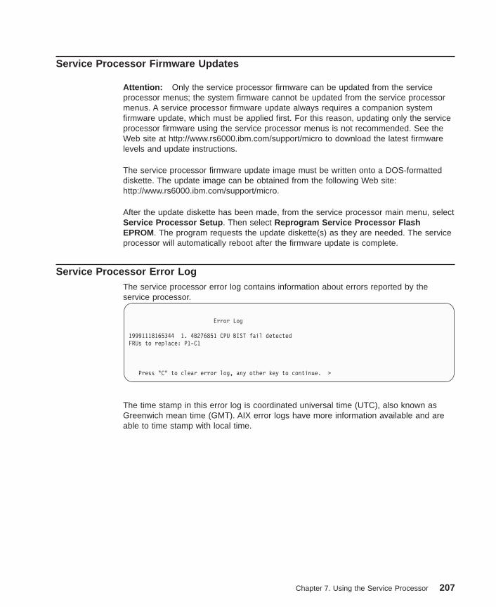
Service Processor Firmware Updates
Attention: Only the service processor firmware can be updated from the serviceprocessor menus; the system firmware cannot be updated from the service processormenus. A service processor firmware update always requires a companion systemfirmware update, which must be applied first. For this reason, updating only the serviceprocessor firmware using the service processor menus is not recommended. See theWeb site at http://www.rs6000.ibm.com/support/micro to download the latest firmwarelevels and update instructions.
The service processor firmware update image must be written onto a DOS-formatteddiskette. The update image can be obtained from the following Web site:http://www.rs6000.ibm.com/support/micro.
After the update diskette has been made, from the service processor main menu, selectService Processor Setup . Then select Reprogram Service Processor FlashEPROM. The program requests the update diskette(s) as they are needed. The serviceprocessor will automatically reboot after the firmware update is complete.
Service Processor Error LogThe service processor error log contains information about errors reported by theservice processor.
Error Log
19991118165344 1. 4B276851 CPU BIST fail detectedFRUs to replace: P1-C1
Press "C" to clear error log, any other key to continue. >
The time stamp in this error log is coordinated universal time (UTC), also known asGreenwich mean time (GMT). AIX error logs have more information available and areable to time stamp with local time.
Chapter 7. Using the Service Processor 207

Service Processor Operational PhasesThis section provides a high-level flow of the phases of the service processor.
Pre-Standby PhaseThis phase is entered when the server is connected to a power source. The server mayor may not be fully powered on. This phase is exited when the power-on self-tests(POST) and configuration tasks are completed.
The pre-standby phase components are:
v Service processor initialization - Performs any necessary hardware and softwareinitializations.
v Service processor POST - Conducts power-on self-tests on its various work andcode areas.
v Service processor unattended start mode checks - To assist fault recovery. Ifunattended start mode is set, the service processor automatically reboots the server.The service processor does not wait for user input or power-on command, but movesthrough the phase and into the bring-up phase. Access SMS menus or serviceprocessor menus to reset the unattended start mode.
Standby PhaseThe standby phase can be reached in either of two ways:
v With the server off and power connected (the normal path), recognized by OK in theLCD display
OR
v With the server on after an operating system fault, recognized by STBY or an 8-digitcode in the LCD display.
In the standby phase, the service processor handles some automatic duties and isavailable for menu operation. The service processor remains in the standby phase untila power-on request is detected.
The standby phase components are as follows:
v Modem configuration
SP Power Applied
Pre-Standby Phase
Standby Phase SP Menus Available
Bring-Up Phase SMS Menus Available
Run-time Phase AIX Login Prompt Available
208 Service Guide
The service processor configures the modem (if installed) so that incoming calls canbe received or outgoing calls can be placed.
v Dial In
Monitor incoming phone line to answer calls, prompt for a password, verify thepassword, and remotely display the standby menu. The remote session can bemirrored on the local ASCII console if the server is so equipped and the user enablesthis function.
v Menus
The service processor menus are password-protected. Before you can access them,you need either the general-access password (GAP) or privileged-access password(PAP).
Bring-Up PhaseThis phase is entered upon power-on, and exited upon loading of the operating system.
The bring-up phase components are:
v Retry Request Check
The service processor checks to see if the previous boot attempt failed. If twoconsecutive failures are detected, the service processor displays an error code andplaces an outgoing call to notify an external party if the user has enabled this option.
v Dial Out
The service processor can dial a preprogrammed telephone number in the event ofan IPL failure. The service processor issues an error report with the last reported IPLstatus indicated and any other available error information.
v Update Operator Panel
The service processor displays operator panel data on the ASCII terminal if aterminal is connected either locally or remotely.
v Environmental Monitoring
The service processor provides expanded error recording and reporting.
v System Firmware Surveillance (Heartbeat Monitoring)
The service processor monitors and times the interval between system firmwareheartbeats.
v Responding to system processor commands
The service processor responds to any command issued by the system processor.
Run-time PhaseThis phase includes the tasks that the service processor performs during steady-stateexecution of the operating system.
v Environmental Monitoring
The service processor monitors voltages, temperatures, and fan speeds (on someservers).
v Responding to System Processor Commands
The service processor responds to any command issued by the system processor.
v Run-Time Surveillance (Heartbeat Monitoring)
Chapter 7. Using the Service Processor 209

If the device driver is installed and surveillance enabled, the service processormonitors the system heartbeat. If the heartbeat times out, the service processorplaces an outgoing call. This is different from the bring-up phase scenario where tworeboot attempts are made before placing an outgoing call.
Service Processor Procedures in Service ModeWhen the system is in service mode, the following service processor parameters aresuspended:
v Unattended start mode
v Reboot/restart policy
v Call-Out
v Surveillance
When service mode is exited, the service processor parameters revert to the customersettings.
210 Service Guide

Chapter 8. Using System Management Services
Use the System Management Services menus to view information about your computerand to perform such tasks as setting passwords and changing device configurations.
If you have chosen a graphical display as your system console, you can use thegraphical System Management Services described below. If you are using an ASCIIdisplay as your system console, see “Text-Based System Management Services” onpage 233.
Graphical System Management ServicesTo start the graphical System Management Services, turn on or restart the computer.
The firmware version installed in your system unit is displayed at the bottom rightcorner of the initial logo screen. Note the version number; processor upgrades mayrequire a specific version of firmware to be installed in your system unit. (UpdateSystem Firmware is an option under the Utilities menu in the System ManagementServices.)
After the logo is displayed, initialization icons display across the bottom of the screen.
To enter the graphical System Management Services, you must press the F1 key afterthe keyboard icon displays during startup and before the tone.
If you have pressed the F1 key, the System Management Services menu displays afterthe initialization and power-on self-test (POST) are complete.
Note: If you have installed a privileged-access password, you are prompted for thispassword before you gain access to the System Management Services menu.
211
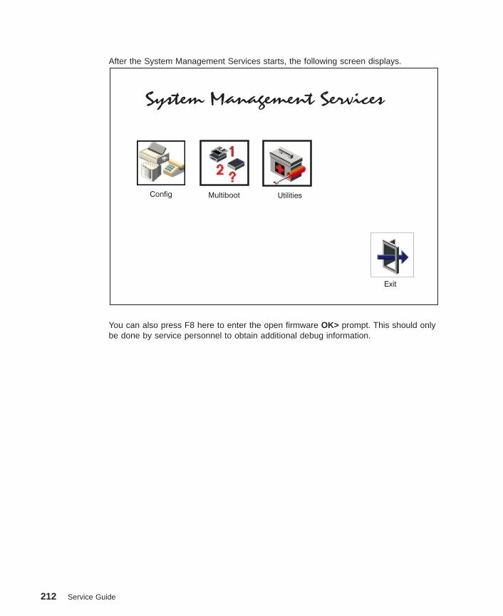
After the System Management Services starts, the following screen displays.
System Management Services
Config Multiboot Utilities
Exit
You can also press F8 here to enter the open firmware OK> prompt. This should onlybe done by service personnel to obtain additional debug information.
212 Service Guide
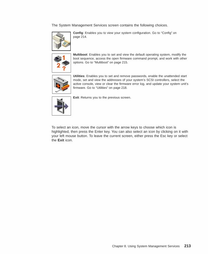
The System Management Services screen contains the following choices.
Config : Enables you to view your system configuration. Go to “Config” onpage 214.
Multiboot : Enables you to set and view the default operating system, modify theboot sequence, access the open firmware command prompt, and work with otheroptions. Go to “Multiboot” on page 215.
Utilities : Enables you to set and remove passwords, enable the unattended startmode, set and view the addresses of your system’s SCSI controllers, select theactive console, view or clear the firmware error log, and update your system unit’sfirmware. Go to “Utilities” on page 218.
Exit : Returns you to the previous screen.
To select an icon, move the cursor with the arrow keys to choose which icon ishighlighted, then press the Enter key. You can also select an icon by clicking on it withyour left mouse button. To leave the current screen, either press the Esc key or selectthe Exit icon.
Chapter 8. Using System Management Services 213

Config
By selecting this icon, you can view information about the setup of your system unit. A list similarto the following appears when you select the Config icon.
Memory Card slot 1, Module Slot =2 size=512MB
Memory Card slot 1, Module Slot =3 size=512MB
Memory Card slot 1, Module Slot =4 size=512MB
Memory Card slot 1, Module Slot =1 size=512MB
Device Name
PowerPC, POWER3 375 MHz
PowerPC, POWER3 375 MHz
L2-Cache, 4096K
L2-Cache, 4096K
Memory
LPT addr=378
addr=3F8
addr=9999FF111R
addr=2F8
Service Processor
Tablet Port
Com
Com
Keyboard
Mouse
Integrated Ethenet
SCSI controller id= 7
Exit
If more than one screen of information is available, a blue arrow displays in the top rightcorner of the screen. Use the page up and page down keys to scroll through the pages.
214 Service Guide

Multiboot
The options available from this screen allow you to view and set various options regarding theoperating system and boot devices.
SoftwareDefault
InstallFrom
SelectSoftware
BootSequence
Multiboot Startup
EXIT
Chapter 8. Using System Management Services 215

The following describes the choices available on this screen.
Select Software : This option is used when more than one operatingsystem is installed on the same disk drive. AIX does not support multipleoperating systems on a single disk drive. Multiple AIX images can beinstalled on separate disk drives; the desired disk drive can be selected forbooting using the Select Boot Device function in System ManagementServices or the AIX diagnostic service aid Display or Change Bootlist .
If Select Software is chosen from this menu, a line similar to the followingis displayed:
–> 1 AIX 5.1.0 <-
This indicates the current version of AIX that is installed on the system. If a1 is entered, the system will boot AIX.
If you receive an informational message saying that no operating system isinstalled, then the system information in nonvolatile storage may have beenlost. This situation can occur if the battery has been removed. To correctthis situation, refer to the boot sequence option on this menu.
Software Default : This option is used when more than one operatingsystem is installed on the same disk drive. AIX does not support multipleoperating systems on a single disk drive. Multiple AIX images can beinstalled on separate disk drives; the desired disk drive can be selected forbooting using the Select Boot Device function in System ManagementServices or the AIX diagnostic service aid Display or Change Bootlist .
If Software Default is chosen from this menu, a line similar to the followingis displayed:
–> 1 AIX 5.1.0 <-
This indicates the current version of AIX that is installed on the system. .Install From: Enables you to select a media drive from which to install anoperating system. Selection of a device is done using the spacebar.
216 Service Guide

Boot Sequence: Enables you to view and change the custom boot list (thesequence in which devices are searched for operating system code). Youmay choose from 1 to 5 devices for the custom boot list.
The default boot sequence is:1. Diskette drive2. CD-ROM drive3. Tape drive4. Hard disk drive5. Network adapter
To change the custom boot list, enter a new order in the New column, thenclick on the Save icon. The list of boot devices is updated to reflect thenew order.
Attention: To change the custom boot list back to the default values, clickon Default . If you change your startup sequence, you must be extremelycareful when performing write operations (for example, copying, saving, orformatting). You can accidentally overwrite data or programs if you selectthe wrong drive.
Multiboot Startup: Clicking on this button toggles whether the Multibootmenu displays automatically at startup.
Chapter 8. Using System Management Services 217
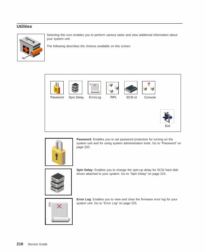
Utilities
Selecting this icon enables you to perform various tasks and view additional information aboutyour system unit.
The following describes the choices available on this screen.
ErrorLog RIPLPassword
Exit
SCSI id ConsoleSpin Delay
Password : Enables you to set password protection for turning on thesystem unit and for using system administration tools. Go to “Password” onpage 220.
Spin Delay : Enables you to change the spin-up delay for SCSI hard diskdrives attached to your system. Go to “Spin Delay” on page 224.
Error Log : Enables you to view and clear the firmware error log for yoursystem unit. Go to “Error Log” on page 225.
218 Service Guide

RIPL (Remote Initial Program Load): Enables you to select a remotesystem from which to load programs through a network adapter when yoursystem unit is first turned on. This option also allows you to configurenetwork adapters, which is required for RIPL. Go to “RIPL” on page 226.
SCSI ID: Allows you to view and change the addresses (IDs) of the SCSIcontrollers attached to your system unit. Go to “SCSI ID” on page 231.
Console : Allows the user to select which console to use to display theSMS menus. This selection is only for the SMS menus. It does not affectthe display used by the AIX operating system.
Follow the instructions that display on the screen. Pressing the number 1key after the keyboard icon appears and before the tone returns you toSMS.
Chapter 8. Using System Management Services 219
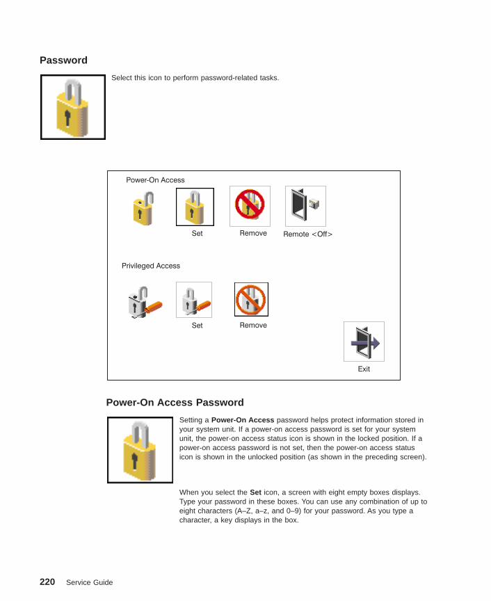
Password
Select this icon to perform password-related tasks.
Set Remove
Remove
Power-On Access
Privileged Access
Exit
Remote <Off>
Set
Power-On Access Password
Setting a Power-On Access password helps protect information stored inyour system unit. If a power-on access password is set for your systemunit, the power-on access status icon is shown in the locked position. If apower-on access password is not set, then the power-on access statusicon is shown in the unlocked position (as shown in the preceding screen).
When you select the Set icon, a screen with eight empty boxes displays.Type your password in these boxes. You can use any combination of up toeight characters (A–Z, a–z, and 0–9) for your password. As you type acharacter, a key displays in the box.
220 Service Guide

Enter Password
Press Enter when you are finished; you must type the password again for verification.
Verify Password
If you type the password incorrectly, press the Esc key and start again.
If the two password entries do not match, an error icon appears with the error code20E00000.
Note: After you have entered and verified the password, the power-on accesspassword icon flashes and changes to the locked position to indicate that yoursystem unit now requires the password you just entered during the power-onprocess.
If you previously had set a power-on-access password and want to remove it, select theRemove icon.
After you have selected the remove icon, the power-on-access status icon flashes andchanges to the unlocked position to indicate that the power-on-access password is notset.
Note: If you forget the power-on access password, you can erase the password byshutting down the system unit and removing the battery for at least 30 seconds.The system unit power cable must be disconnected before removing the battery.
Chapter 8. Using System Management Services 221

A password becomes effective only after the system is turned off and back on again.
Attention: If no user-defined bootlist exists and the power-on-access password hasbeen enabled, you are asked for the power-on-access password at startup every timeyou boot your system.
Remote Mode
Remote Mode : The remote mode, when enabled, allows the system tostart from the defined boot device. This mode is ideal for network serversand other system units that operate unattended. When the remote mode isset, the icon label changes to Remote <On>Note: To use the remote mode feature for booting unattended devices,you must enable the unattended start mode. See the “System PowerControl Menu” on page 187 for instructions on enabling the unattendedstart mode, which allows the system unit to turn on whenever ac power isapplied to the system (instead of having the system unit wait for the powerbutton to be pushed).
Privileged-Access Password
The privileged-access password protects against the unauthorized startingof the system programs. Select the Set icon to set and verify theprivileged-access password.
When you select the Set icon, a screen with eight empty boxes displays.Type your password in these boxes. You can use any combination of up toeight characters (A-Z, a-z, and 0-9) for your password. As you type acharacter, a key displays in the box.
Enter Password
222 Service Guide
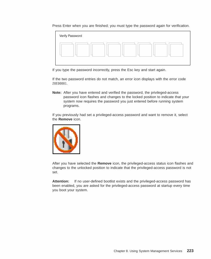
Press Enter when you are finished; you must type the password again for verification.
Verify Password
If you type the password incorrectly, press the Esc key and start again.
If the two password entries do not match, an error icon displays with the error code20E00001.
Note: After you have entered and verified the password, the privileged-accesspassword icon flashes and changes to the locked position to indicate that yoursystem now requires the password you just entered before running systemprograms.
If you previously had set a privileged-access password and want to remove it, selectthe Remove icon.
After you have selected the Remove icon, the privileged-access status icon flashes andchanges to the unlocked position to indicate that the privileged-access password is notset.
Attention: If no user-defined bootlist exists and the privileged-access password hasbeen enabled, you are asked for the privileged-access password at startup every timeyou boot your system.
Chapter 8. Using System Management Services 223

Spin Delay
Select this icon to change the spin-up delay for SCSI hard disk drives attached to your system.Spin-up delay values can be entered manually or you can use a default setting. All values aremeasured in seconds. The default is two seconds. After you have entered the new spin-up delayvalues, use the arrow keys to highlight the Save icon and press Enter.
Save ExitDefault
<Hard Disk Spinup Delay>
Enter New Value (>1)
Current Spin Up Value - 2
(SEC)
224 Service Guide

Error Log
Selecting this icon displays the log of errors that your system has recorded during operations.
Clear
System Error Log
Exit
2. No entry
1. 00/04/13 00:51:32 25C38005 P1-M1.10
Date Time Error Code Location
Selecting the Clear icon erases the entries in this log.
This error log only shows the first and last errors.
Note: The time stamp in this error log is coordinated universal time (UTC), which isalso referred to as Greenwich mean time (GMT). AIX error logs have moreinformation available and can time stamp with your local time.
Chapter 8. Using System Management Services 225

RIPL
Selecting the Remote Initial Program Load (RIPL) icon gives you access to the followingselections.
Set Address
Exit
Ping Config
226 Service Guide

Set Address
The Set Address icon allows you to define addresses from which your systemunit can receive RIPL code.
Client Addr
Remote IPL Setup
Exit
000.000.000.000
000.000.000.000
000.000.000.000Gateway Addr
Server Addr
Subnet Mask
Save
255.255.255.000
If any of the addresses is incomplete or contains a number other than 0 to 255, an errormessage displays when you select the Save icon. To clear this error, correct theaddress and select Save again.
Attention: If the client system and the server are on the same subnet, set thegateway IP address to [0.0.0.0].
To change an address, press the backspace key on the highlighted address until theold address is completely deleted. Then type the new address.
Chapter 8. Using System Management Services 227
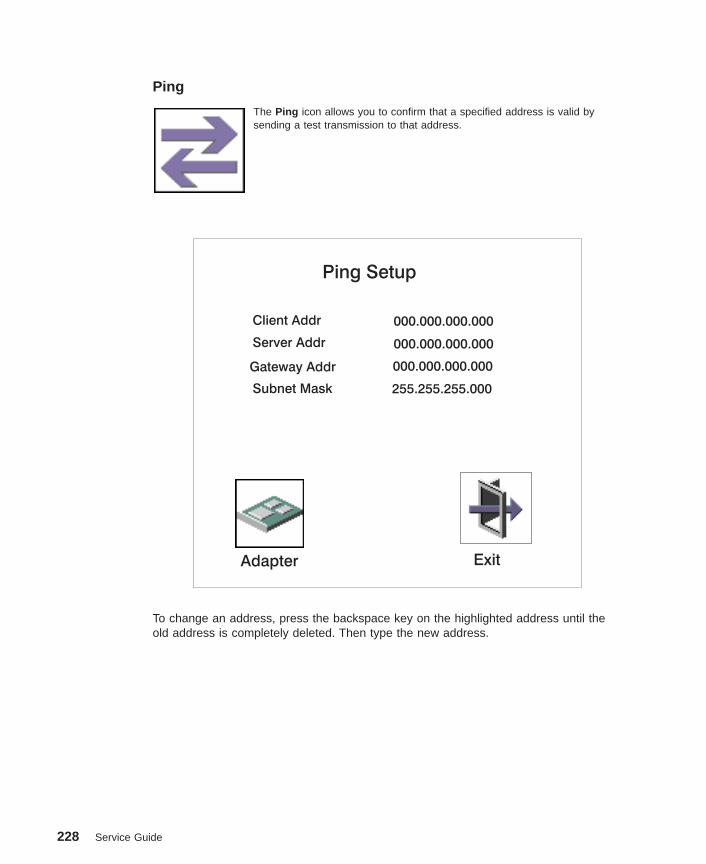
Ping
The Ping icon allows you to confirm that a specified address is valid bysending a test transmission to that address.
Client Addr
Ping Setup
Exit
000.000.000.000
000.000.000.000
000.000.000.000Gateway Addr
Server Addr
Subnet Mask
Adapter
255.255.255.000
To change an address, press the backspace key on the highlighted address until theold address is completely deleted. Then type the new address.
228 Service Guide
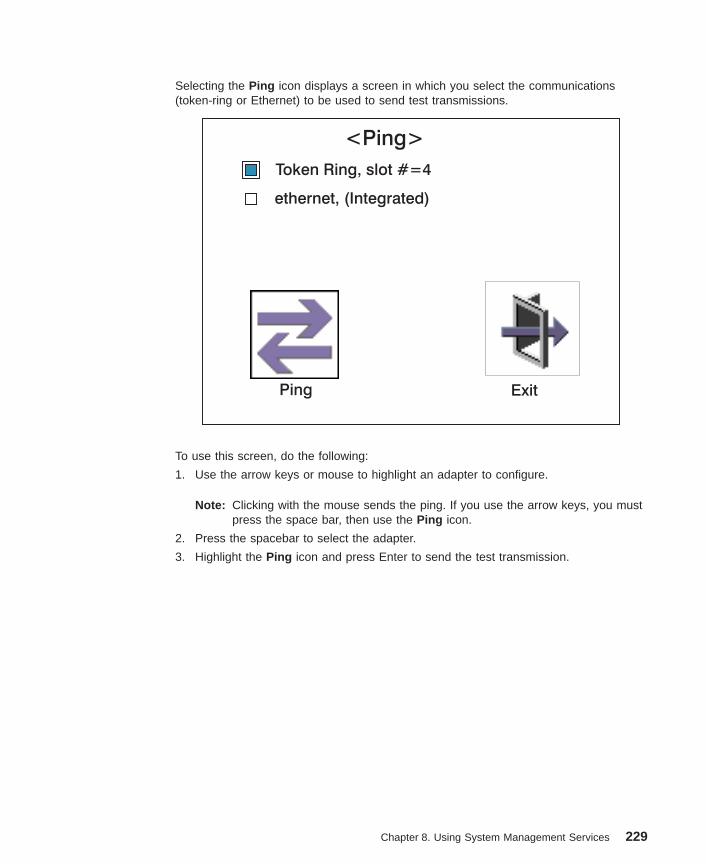
Selecting the Ping icon displays a screen in which you select the communications(token-ring or Ethernet) to be used to send test transmissions.
Exit
<Ping>
Token Ring, slot #=4
ethernet, (Integrated)
Ping
To use this screen, do the following:
1. Use the arrow keys or mouse to highlight an adapter to configure.
Note: Clicking with the mouse sends the ping. If you use the arrow keys, you mustpress the space bar, then use the Ping icon.
2. Press the spacebar to select the adapter.
3. Highlight the Ping icon and press Enter to send the test transmission.
Chapter 8. Using System Management Services 229
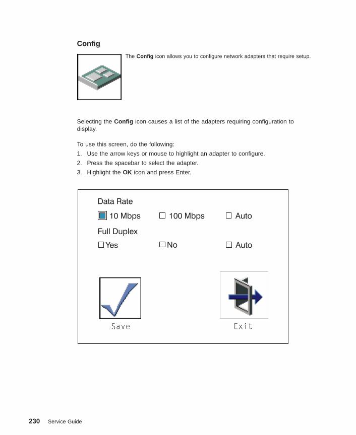
Config
The Config icon allows you to configure network adapters that require setup.
Selecting the Config icon causes a list of the adapters requiring configuration todisplay.
To use this screen, do the following:
1. Use the arrow keys or mouse to highlight an adapter to configure.
2. Press the spacebar to select the adapter.
3. Highlight the OK icon and press Enter.
Save Exit
Data Rate
10 Mbps 100 Mbps
Yes No
Auto
Auto
Full Duplex
230 Service Guide

SCSI ID
Select this icon to view and change the addresses (IDs) of the SCSI controllers attached to yoursystem unit.
To change a SCSI controller ID, highlight the entry by moving the up or down arrowkeys, then use the spacebar to scroll through available IDs. After you have entered thenew address, use the left or right arrow keys or mouse to highlight the Save icon andpress Enter.
At any time in this process, you can select the Default icon to change the SCSI IDs tothe default value of 7.
Type
Change SCSI ID
Fast/Wide 15
15
Max IdSlot
DefaultSave Exit
7
7
Id
Ultra 0
0
Chapter 8. Using System Management Services 231

Firmware Update
Attention: The SMS firmware update utility does not support the combined image updateprocess. It is recommended only for those systems that cannot boot AIX. Detailed instructions onusing the SMS utilities to update system and service processor firmware can be obtained from thefollowing Web site:
http://www.rs6000.ibm.com/support/micro
If you are not able to obtain firmware update images or instructions from this Web site, contactyour service representative.
If the firmware update image is available on your network from another system, see Appendix E,“Firmware Updates” on page 339 for instructions on updating the system and service processorfirmware using a combined image from the AIX command line.
Firmware RecoveryIf a troubleshooting procedure has indicated that the system firmware unit has beendamaged, it may be possible to recover it. For example, if the system hangs duringstartup with E1EA displayed on the operator panel, the system firmware has beendamaged but may be recovered.
To recover damaged system firmware, do the following:
1. Create a firmware recovery diskette. This must be a 3.5″ high-density (1.44 MB)diskette that has been formatted for DOS.
2. Obtain the system firmware update image file from one of the following sources:
a. From the Web address: http://www.rs6000.ibm.com/support/micro
b. From a service representative if you cannot access the Web address.
3. Copy the system firmware update image file to the recovery diskette, naming itPRECOVER.IMG. The file must be written in DOS format.
4. When the system stops booting, for example at E1EA, insert the recovery diskette. Ifthe diskette drive LED does not light up, power the system unit off, then back onagain.
5. If the recovery procedure is successful, the system will continue starting and willdisplay checkpoints of the form E1XX.
6. Enter the System Management Services menu. When the keyboard indicatordisplays, press the 1 key if the system console is an ASCII terminal. If the systemconsole is a graphics display and directly attached keyboard, press the F1 key.
7. When the main menu displays, choose Utilities, then perform an update of thesystem firmware by following the prompts that are displayed.
Attention: A companion service processor firmware update may be required. Seethe Web site at http://www.rs6000.ibm.com/support/micro to get additionalinformation on companion levels and detailed update instructions.
232 Service Guide

Text-Based System Management ServicesThe text-based System Management Services are available if an ASCII terminal isattached to your system. The text-based System Management Services make itpossible for you to view information about your system and to perform such tasks assetting passwords and changing device configurations.
To start the text-based System Management Services, press the number 1 key on theASCII terminal after the word ″keyboard″ appears and before the word ″speaker″appears. After the text-based System Management Services starts, the following screendisplays.
Note: The version of firmware currently installed in your system is displayed at the topof each screen in the text-based System Management Services. Note theversion number. Processor and other device upgrades may require a specificversion of firmware to be installed in your system. Update System Firmware isan option under the Main Menu.
On all menus except the Main Menu, there are several navigator keys:
M Return to the main menu.
ESC Return to the previous menu.
X Exit the System Management Services and start the operating system.
If X is entered, you are asked to confirm your choice to exit the SMS menusand start the operating system.
When there is more than one page of information to display, there are two additionalnavigator keys:
N Display the next page of the list.
P Display the next page of the list.
Note: The lower-case navigator key has the same effect as the upper-case key that isshown on the screen. For example, ″m″ or ″M″ takes you back to the mainmenu.
On each menu screen, you are given the option of choosing a menu item and pressingenter (if applicable), or selecting a navigator key.
Chapter 8. Using System Management Services 233
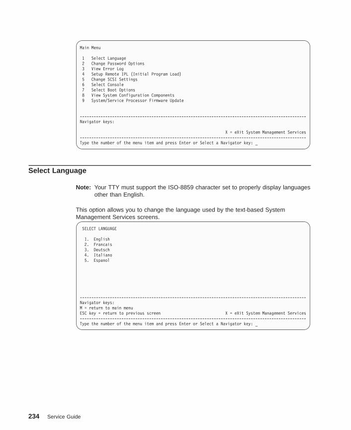
Main Menu
1 Select Language2 Change Password Options3 View Error Log4 Setup Remote IPL (Initial Program Load)5 Change SCSI Settings6 Select Console7 Select Boot Options8 View System Configuration Components9 System/Service Processor Firmware Update
--------------------------------------------------------------------------------------------------Navigator keys:
X = eXit System Management Services--------------------------------------------------------------------------------------------------Type the number of the menu item and press Enter or Select a Navigator key: _
Select Language
Note: Your TTY must support the ISO-8859 character set to properly display languagesother than English.
This option allows you to change the language used by the text-based SystemManagement Services screens.
SELECT LANGUAGE
1. English2. Francais3. Deutsch4. Italiano5. Espanol
--------------------------------------------------------------------------------------------------Navigator keys:M = return to main menuESC key = return to previous screen X = eXit System Management Services--------------------------------------------------------------------------------------------------Type the number of the menu item and press Enter or Select a Navigator key: _
234 Service Guide
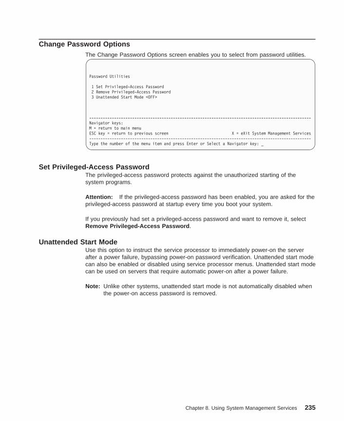
Change Password OptionsThe Change Password Options screen enables you to select from password utilities.
Password Utilities
1 Set Privileged-Access Password2 Remove Privileged-Access Password3 Unattended Start Mode <OFF>
--------------------------------------------------------------------------------------------------Navigator keys:M = return to main menuESC key = return to previous screen X = eXit System Management Services--------------------------------------------------------------------------------------------------Type the number of the menu item and press Enter or Select a Navigator key: _
Set Privileged-Access PasswordThe privileged-access password protects against the unauthorized starting of thesystem programs.
Attention: If the privileged-access password has been enabled, you are asked for theprivileged-access password at startup every time you boot your system.
If you previously had set a privileged-access password and want to remove it, selectRemove Privileged-Access Password .
Unattended Start ModeUse this option to instruct the service processor to immediately power-on the serverafter a power failure, bypassing power-on password verification. Unattended start modecan also be enabled or disabled using service processor menus. Unattended start modecan be used on servers that require automatic power-on after a power failure.
Note: Unlike other systems, unattended start mode is not automatically disabled whenthe power-on access password is removed.
Chapter 8. Using System Management Services 235
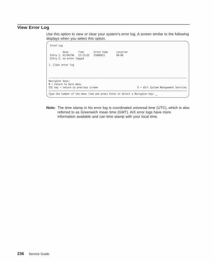
View Error LogUse this option to view or clear your system’s error log. A screen similar to the followingdisplays when you select this option.
Error Log
Date Time Error Code LocationEntry 1. 01/04/96 12:13:22 25A80011 00-00Entry 2. no error logged
1. Clear error log
--------------------------------------------------------------------------------------------------Navigator keys:M = return to main menuESC key = return to previous screen X = eXit System Management Services--------------------------------------------------------------------------------------------------Type the number of the menu item and press Enter or Select a Navigator key: _
Note: The time stamp in his error log is coordinated universal time (UTC), which is alsoreferred to as Greenwich mean time (GMT). AIX error logs have moreinformation available and can time stamp with your local time.
236 Service Guide
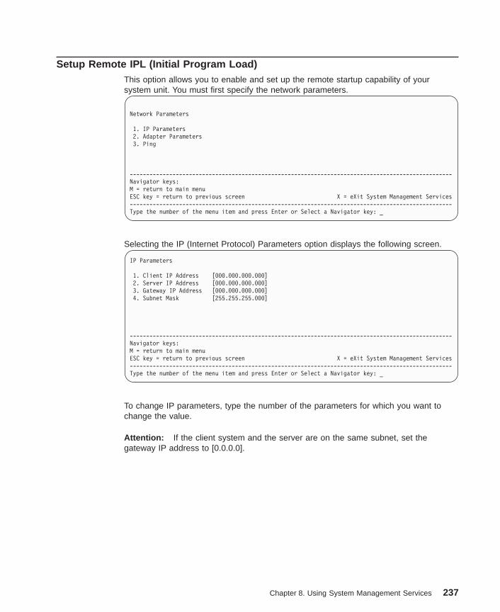
Setup Remote IPL (Initial Program Load)This option allows you to enable and set up the remote startup capability of yoursystem unit. You must first specify the network parameters.
Network Parameters
1. IP Parameters2. Adapter Parameters3. Ping
--------------------------------------------------------------------------------------------------Navigator keys:M = return to main menuESC key = return to previous screen X = eXit System Management Services--------------------------------------------------------------------------------------------------Type the number of the menu item and press Enter or Select a Navigator key: _
Selecting the IP (Internet Protocol) Parameters option displays the following screen.
IP Parameters
1. Client IP Address [000.000.000.000]2. Server IP Address [000.000.000.000]3. Gateway IP Address [000.000.000.000]4. Subnet Mask [255.255.255.000]
--------------------------------------------------------------------------------------------------Navigator keys:M = return to main menuESC key = return to previous screen X = eXit System Management Services--------------------------------------------------------------------------------------------------Type the number of the menu item and press Enter or Select a Navigator key: _
To change IP parameters, type the number of the parameters for which you want tochange the value.
Attention: If the client system and the server are on the same subnet, set thegateway IP address to [0.0.0.0].
Chapter 8. Using System Management Services 237
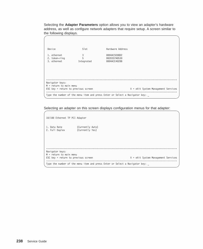
Selecting the Adapter Parameters option allows you to view an adapter’s hardwareaddress, as well as configure network adapters that require setup. A screen similar tothe following displays.
Device Slot Hardware Address
1. ethernet 3 0004AC5E08D22. token-ring 5 0020357A05303. ethernet Integrated 0004ACE4020B
--------------------------------------------------------------------------------------------------Navigator keys:M = return to main menuESC key = return to previous screen X = eXit System Management Services--------------------------------------------------------------------------------------------------Type the number of the menu item and press Enter or Select a Navigator key: _
Selecting an adapter on this screen displays configuration menus for that adapter:
10/100 Ethernet TP PCI Adapter
1. Data Rate (Currently Auto)2. Full Duplex (Currently Yes)
--------------------------------------------------------------------------------------------------Navigator keys:M = return to main menuESC key = return to previous screen X = eXit System Management Services--------------------------------------------------------------------------------------------------Type the number of the menu item and press Enter or Select a Navigator key: _
238 Service Guide
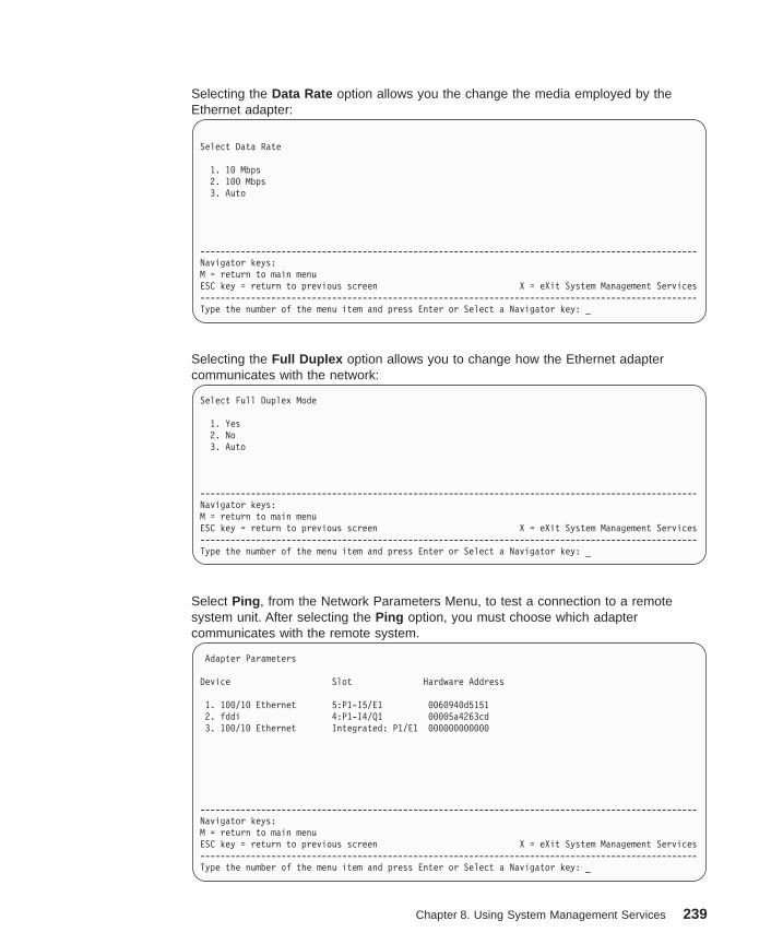
Selecting the Data Rate option allows you the change the media employed by theEthernet adapter:
Select Data Rate
1. 10 Mbps2. 100 Mbps3. Auto
--------------------------------------------------------------------------------------------------Navigator keys:M = return to main menuESC key = return to previous screen X = eXit System Management Services--------------------------------------------------------------------------------------------------Type the number of the menu item and press Enter or Select a Navigator key: _
Selecting the Full Duplex option allows you to change how the Ethernet adaptercommunicates with the network:
Select Full Duplex Mode
1. Yes2. No3. Auto
--------------------------------------------------------------------------------------------------Navigator keys:M = return to main menuESC key = return to previous screen X = eXit System Management Services--------------------------------------------------------------------------------------------------Type the number of the menu item and press Enter or Select a Navigator key: _
Select Ping , from the Network Parameters Menu, to test a connection to a remotesystem unit. After selecting the Ping option, you must choose which adaptercommunicates with the remote system.
Adapter Parameters
Device Slot Hardware Address
1. 100/10 Ethernet 5:P1-I5/E1 0060940d51512. fddi 4:P1-I4/Q1 00005a4263cd3. 100/10 Ethernet Integrated: P1/E1 000000000000
--------------------------------------------------------------------------------------------------Navigator keys:M = return to main menuESC key = return to previous screen X = eXit System Management Services--------------------------------------------------------------------------------------------------Type the number of the menu item and press Enter or Select a Navigator key: _
Chapter 8. Using System Management Services 239
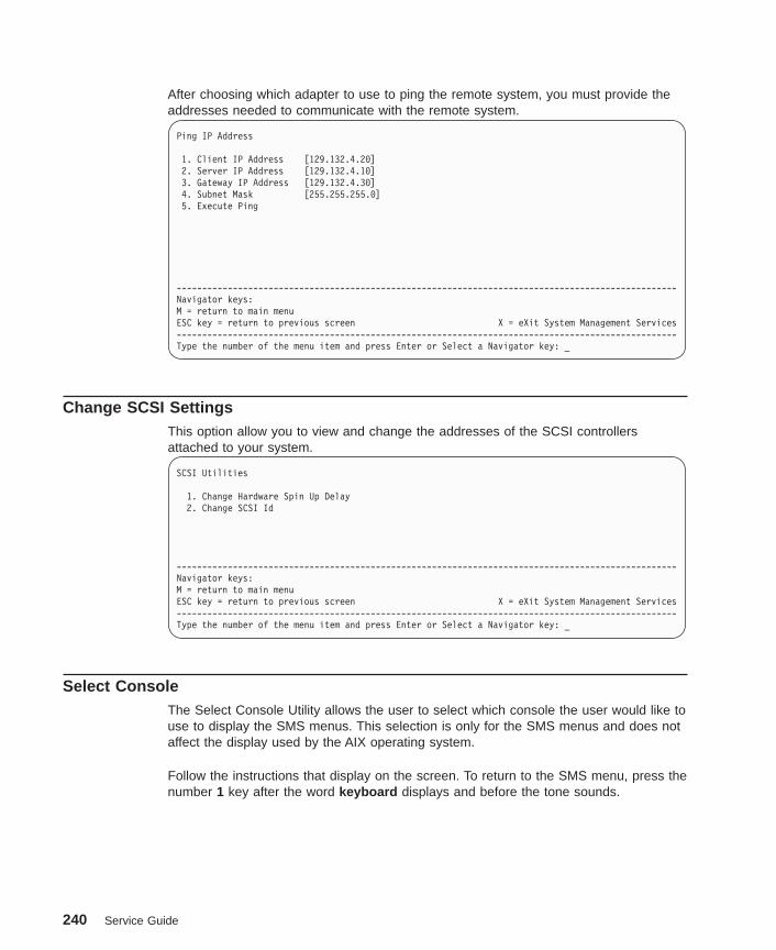
After choosing which adapter to use to ping the remote system, you must provide theaddresses needed to communicate with the remote system.
Ping IP Address
1. Client IP Address [129.132.4.20]2. Server IP Address [129.132.4.10]3. Gateway IP Address [129.132.4.30]4. Subnet Mask [255.255.255.0]5. Execute Ping
--------------------------------------------------------------------------------------------------Navigator keys:M = return to main menuESC key = return to previous screen X = eXit System Management Services--------------------------------------------------------------------------------------------------Type the number of the menu item and press Enter or Select a Navigator key: _
Change SCSI SettingsThis option allow you to view and change the addresses of the SCSI controllersattached to your system.
SCSI Utilities
1. Change Hardware Spin Up Delay2. Change SCSI Id
--------------------------------------------------------------------------------------------------Navigator keys:M = return to main menuESC key = return to previous screen X = eXit System Management Services--------------------------------------------------------------------------------------------------Type the number of the menu item and press Enter or Select a Navigator key: _
Select ConsoleThe Select Console Utility allows the user to select which console the user would like touse to display the SMS menus. This selection is only for the SMS menus and does notaffect the display used by the AIX operating system.
Follow the instructions that display on the screen. To return to the SMS menu, press thenumber 1 key after the word keyboard displays and before the tone sounds.
240 Service Guide

Select Boot OptionsUse this screen to view and set various options regarding the operating system andboot sequence.
Multiboot Menu
1 Select Software2 Software Default3 Select Install Device4 Select Boot Device5 Multiboot Startup <currently OFF>
--------------------------------------------------------------------------------------------------Navigator keys:M = return to main menuESC key = return to previous screen X = eXit System Management Services--------------------------------------------------------------------------------------------------Type the number of the menu item and press Enter or Select a Navigator key: _
Select Software : This option is used when more than one operating system is installedon the same disk drive. AIX does not support multiple operating systems on a singledisk drive. Multiple AIX images can be installed on separate disk drives; the desireddisk drive can be selected for booting using the Select Boot Device function in SystemManagement Services or the AIX diagnostic service aid Display or Change Bootlist .
If Select Software is chosen from this menu, a line similar to the following is displayed:
–> 1 AIX 5.1.0 <-
This indicates the current version of AIX that is installed on the system. If a 1 isentered, the system will boot AIX.
If you are running on AIX and you receive the following message:
No Operating System Installed
this indicates that information in nonvolatile storage could have been lost, as wouldhappen if the battery had been removed. To re-create this value, run the Select BootDevice option on this menu.
The AIX Documentation library is available at the following Web address:http://www.ibm.com/servers/aix/library/techpubs.html. AIX documentation is alsocontained on the AIX Documentation CD. The documentation is made accessible byloading the documentation CD onto the hard disk or by mounting the CD in theCD-ROM drive.
Chapter 8. Using System Management Services 241
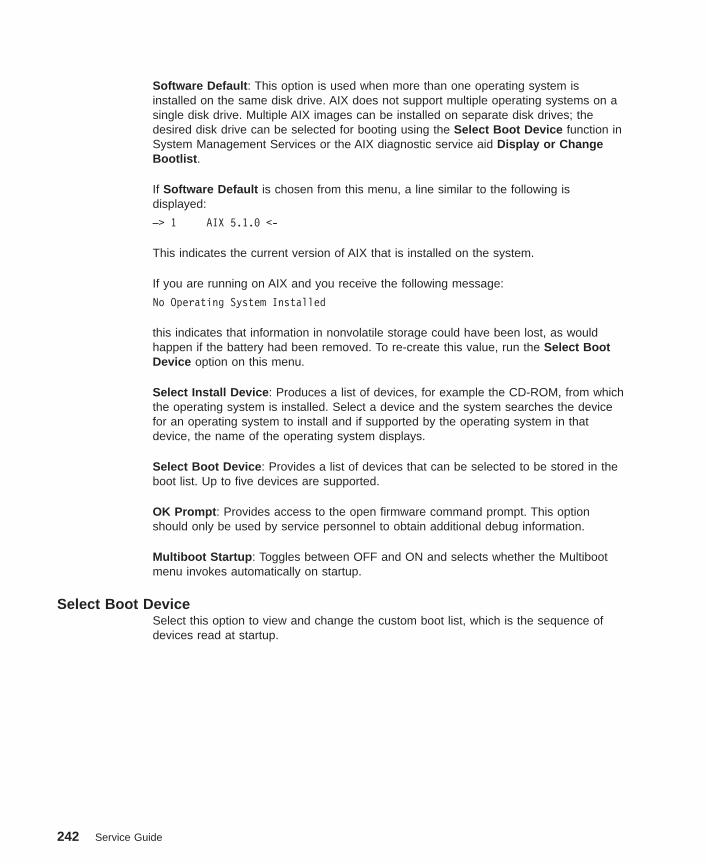
Software Default : This option is used when more than one operating system isinstalled on the same disk drive. AIX does not support multiple operating systems on asingle disk drive. Multiple AIX images can be installed on separate disk drives; thedesired disk drive can be selected for booting using the Select Boot Device function inSystem Management Services or the AIX diagnostic service aid Display or ChangeBootlist .
If Software Default is chosen from this menu, a line similar to the following isdisplayed:
–> 1 AIX 5.1.0 <-
This indicates the current version of AIX that is installed on the system.
If you are running on AIX and you receive the following message:
No Operating System Installed
this indicates that information in nonvolatile storage could have been lost, as wouldhappen if the battery had been removed. To re-create this value, run the Select BootDevice option on this menu.
Select Install Device : Produces a list of devices, for example the CD-ROM, from whichthe operating system is installed. Select a device and the system searches the devicefor an operating system to install and if supported by the operating system in thatdevice, the name of the operating system displays.
Select Boot Device : Provides a list of devices that can be selected to be stored in theboot list. Up to five devices are supported.
OK Prompt : Provides access to the open firmware command prompt. This optionshould only be used by service personnel to obtain additional debug information.
Multiboot Startup : Toggles between OFF and ON and selects whether the Multibootmenu invokes automatically on startup.
Select Boot DeviceSelect this option to view and change the custom boot list, which is the sequence ofdevices read at startup.
242 Service Guide
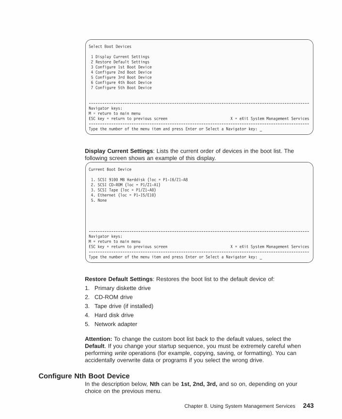
Select Boot Devices
1 Display Current Settings2 Restore Default Settings3 Configure 1st Boot Device4 Configure 2nd Boot Device5 Configure 3rd Boot Device6 Configure 4th Boot Device7 Configure 5th Boot Device
--------------------------------------------------------------------------------------------------Navigator keys:M = return to main menuESC key = return to previous screen X = eXit System Management Services--------------------------------------------------------------------------------------------------Type the number of the menu item and press Enter or Select a Navigator key: _
Display Current Settings : Lists the current order of devices in the boot list. Thefollowing screen shows an example of this display.
Current Boot Device
1. SCSI 9100 MB Harddisk (loc = P1-I6/Z1-A82. SCSI CD-ROM (loc = P1/Z1-A1)3. SCSI Tape (loc = P1/Z1-A0)4. Ethernet (loc = P1-I5/E10)5. None
--------------------------------------------------------------------------------------------------Navigator keys:M = return to main menuESC key = return to previous screen X = eXit System Management Services--------------------------------------------------------------------------------------------------Type the number of the menu item and press Enter or Select a Navigator key: _
Restore Default Settings : Restores the boot list to the default device of:
1. Primary diskette drive
2. CD-ROM drive
3. Tape drive (if installed)
4. Hard disk drive
5. Network adapter
Attention: To change the custom boot list back to the default values, select theDefault . If you change your startup sequence, you must be extremely careful whenperforming write operations (for example, copying, saving, or formatting). You canaccidentally overwrite data or programs if you select the wrong drive.
Configure Nth Boot DeviceIn the description below, Nth can be 1st, 2nd, 3rd, and so on, depending on yourchoice on the previous menu.
Chapter 8. Using System Management Services 243

Options display a screen similar to the following:
Configure Nth Boot Device
Device Current DeviceNumber Position Name
1 1 Diskette2 2 Port E2 - 100/10 Ethernet Adapter (Integrated)3 Port E1 - 100/10 Ethernet Adapter Integrated)4 3 IDE CD-ROM5 4 SCSI 36.4 MB Hard Disk id=@0,0 (Integrated)6 -
--------------------------------------------------------------------------------------------------Navigator keys:M = return to main menuESC key = return to previous screen X = eXit System Management Services--------------------------------------------------------------------------------------------------Type the number of the menu item and press Enter or Select a Navigator key: _
Type the device number of the device name that you want to select as the Nth bootdevice. For example, if you entered this menu by selecting 4 on the previous menu(configure 2nd Boot Device), then enter the number 3 based on the list shown above.You are thus selecting the SCSI CD-ROM device to be the 2nd (Nth) device in the bootsequence.
244 Service Guide
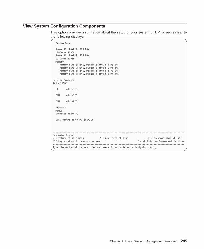
View System Configuration ComponentsThis option provides information about the setup of your system unit. A screen similar tothe following displays.
Device Name
Power PC, POWER3 375 MHzL2-Cache 4096KPower PC, POWER3 375 MHzL2-Cache 4096KMemory
Memory card slot=1, module slot=1 size=512MBMemory card slot=1, module slot=2 size=512MBMemory card slot=1, module slot=3 size=512MBMemory card slot=1, module slot=4 size=512MB
Service ProcessorTablet Port
LPT addr=378
COM addr=3F8
COM addr=2F8
KeyboardMouseDiskette addr=3F0
SCSI controller id=7 (P1/Z1)
--------------------------------------------------------------------------------------------------Navigator keys:M = return to main menu N = next page of list P = previous page of listESC key = return to previous screen X = eXit System Management Services--------------------------------------------------------------------------------------------------Type the number of the menu item and press Enter or Select a Navigator key: _
Chapter 8. Using System Management Services 245
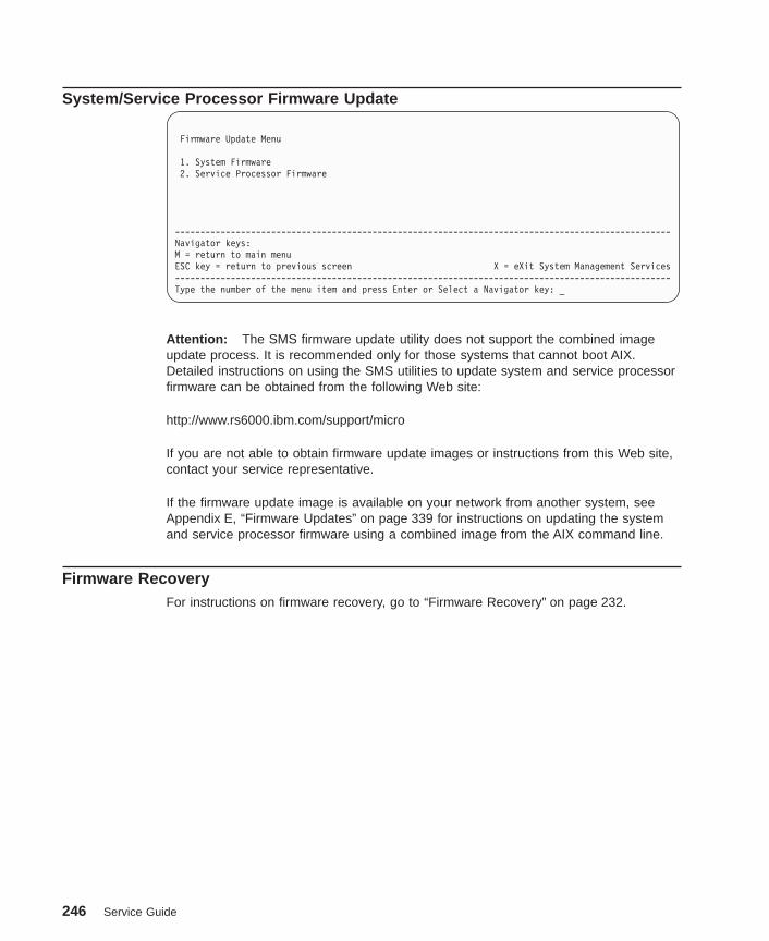
System/Service Processor Firmware Update
Firmware Update Menu
1. System Firmware2. Service Processor Firmware
--------------------------------------------------------------------------------------------------Navigator keys:M = return to main menuESC key = return to previous screen X = eXit System Management Services--------------------------------------------------------------------------------------------------Type the number of the menu item and press Enter or Select a Navigator key: _
Attention: The SMS firmware update utility does not support the combined imageupdate process. It is recommended only for those systems that cannot boot AIX.Detailed instructions on using the SMS utilities to update system and service processorfirmware can be obtained from the following Web site:
http://www.rs6000.ibm.com/support/micro
If you are not able to obtain firmware update images or instructions from this Web site,contact your service representative.
If the firmware update image is available on your network from another system, seeAppendix E, “Firmware Updates” on page 339 for instructions on updating the systemand service processor firmware using a combined image from the AIX command line.
Firmware RecoveryFor instructions on firmware recovery, go to “Firmware Recovery” on page 232.
246 Service Guide
Chapter 9. Removal and Replacement Procedures
Servicing of this system can be performed with the system either in the vertical orhorizontal position.
Before performing any of the removal or replacement procedures in this chapter, readthe following notice.
DANGER
An electrical outlet that is not correctly wired could place hazardous voltageon metal parts of the system or the devices that attach to the system. It is theresponsibility of the customer to ensure that the outlet is correctly wired andgrounded to prevent an electrical shock.
Before installing or removing signal cables, ensure that the power cables forthe system unit and all attached devices are unplugged.
When adding or removing any additional devices to or from the system,ensure that the power cables for those devices are unplugged before thesignal cables are connected. If possible, disconnect all power cables from theexisting system before you add a device.
Use one hand, when possible, to connect or disconnect signal cables toprevent a possible shock from touching two surfaces with different electricalpotentials.
During an electrical storm, do not connect cables for display stations, printers,telephones, or station protectors for communications lines.
CAUTION:This product is equipped with a three–wire power cable and plug for the user’ssafety. Use this power cable with a properly grounded electrical outlet to avoidelectrical shock.
247

Handling Static-Sensitive Devices
Attention: Adapters, planars, diskette drives, and disk drives are sensitive to staticelectricity discharge. These devices are wrapped in antistatic bags to prevent thisdamage.
Take the following precautions:
v If you have an antistatic wrist strap available, use it while handling the device.
v Do not remove the device from the antistatic bag until you are ready to install thedevice in the system.
v With the device still in its antistatic bag, touch it to a metal frame of the system.
v Grasp cards and boards by the edges. Hold drives by the frame. Avoid touching thesolder joints or pins.
v If you need to lay the device down while it is out of the antistatic bag, lay it on theantistatic bag. Before picking it up again, touch the antistatic bag and the metalframe of the system at the same time.
v Handle the devices carefully to prevent permanent damage.
Stopping the SystemAttention: When shutting down your system to install options, shut down allapplications first and then shut down the operating system. The system power turns offand the system goes into standby mode when the operating system is shut down.Before removing power from the system, ensure that the shutdown process is complete.Failure to do so can result in the loss of data. Some option installation procedures donot require the system to be stopped for installation. If necessary, the option installationprocedures in this section will direct you here if stopping the system is required.
1. Log in to the system as root user.
2. Stop any applications that are running on the system.
3. At a command line, type shutdown to stop the operating system.
4. After you shut down the operating system, set the power switches of any attacheddevices to Off.
248 Service Guide
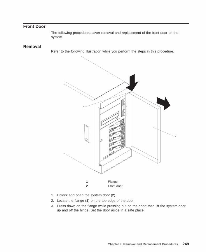
Front DoorThe following procedures cover removal and replacement of the front door on thesystem.
RemovalRefer to the following illustration while you perform the steps in this procedure.
1
2
1 Flange2 Front door
1. Unlock and open the system door (2).
2. Locate the flange (1) on the top edge of the door.
3. Press down on the flange while pressing out on the door; then lift the system doorup and off the hinge. Set the door aside in a safe place.
Chapter 9. Removal and Replacement Procedures 249
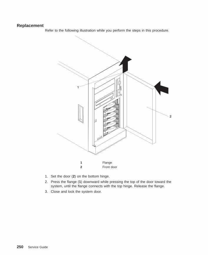
ReplacementRefer to the following illustration while you perform the steps in this procedure.
1
2
1 Flange2 Front door
1. Set the door (2) on the bottom hinge.
2. Press the flange (1) downward while pressing the top of the door toward thesystem, until the flange connects with the top hinge. Release the flange.
3. Close and lock the system door.
250 Service Guide
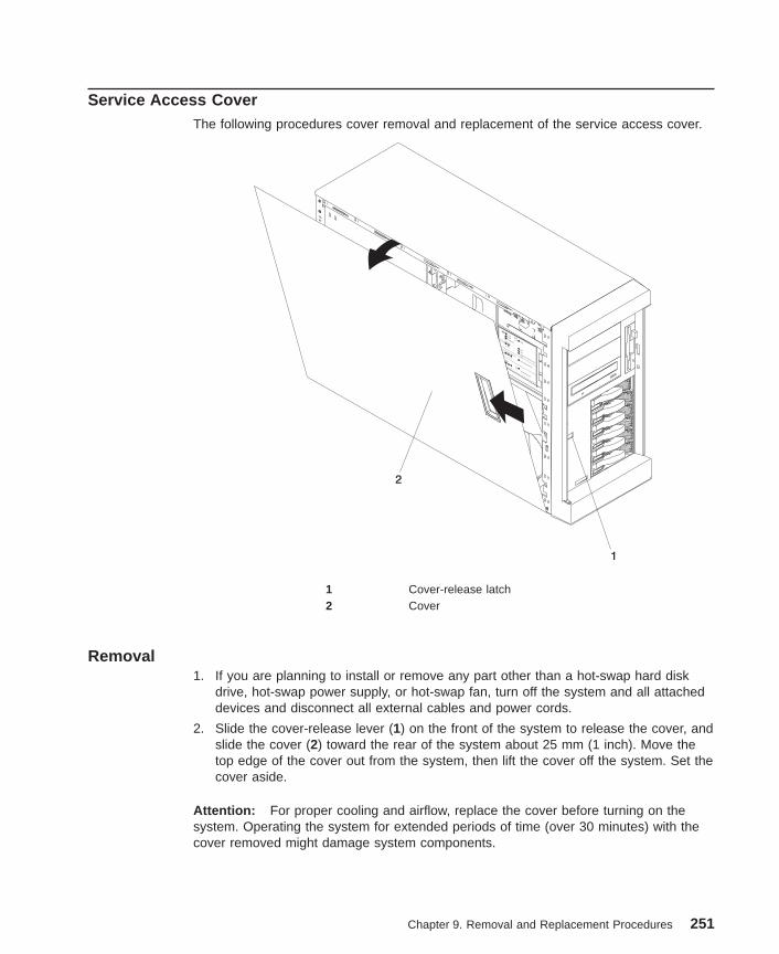
Service Access CoverThe following procedures cover removal and replacement of the service access cover.
1
CPUVRMMEMORY HDD
PCI BUS
NMISMISERVICE PROCESSOR
BUS
NON REDUNDANT
POWER SUPPLY1 2 3
A B
1 2 3
FAN
TEMPERATURE
2
1 Cover-release latch2 Cover
Removal1. If you are planning to install or remove any part other than a hot-swap hard disk
drive, hot-swap power supply, or hot-swap fan, turn off the system and all attacheddevices and disconnect all external cables and power cords.
2. Slide the cover-release lever (1) on the front of the system to release the cover, andslide the cover (2) toward the rear of the system about 25 mm (1 inch). Move thetop edge of the cover out from the system, then lift the cover off the system. Set thecover aside.
Attention: For proper cooling and airflow, replace the cover before turning on thesystem. Operating the system for extended periods of time (over 30 minutes) with thecover removed might damage system components.
Chapter 9. Removal and Replacement Procedures 251

Replacement
CPUVRMMEMORY HDD
PCI BUS
NMISMISERVICE PROCESSOR
BUS
NON REDUNDANT
POWER SUPPLY1 2 3
A B
1 2 3
FAN
TEMPERATURE
1
2
1. Align the service access cover (2) with the left side of the system, about 25 mm (1inch) from the front of the system; place the bottom of the left-side cover on thebottom rail of the left side of the chassis.
2. Insert the tabs at the top of the cover into the slots (1) at the top of the system side.
3. Hold the cover against the system, and slide the cover toward the front of thesystem until the cover clicks into place.
252 Service Guide

BezelsThe following procedures cover removal and replacement of the bezel.
RemovalRefer to the following illustrations while you perform the steps in this procedure.
CPUVRMMEMORY HDD
PCI BUS
NMISMISERVICE PROCESSOR
BUS
NON REDUNDANT
POWER SUPPLY1 2 3
A B
1 2 3
FAN
TEMPERATURE
2
3
1
2
3
1 Bezel-release lever2 Bezel3 Side with bezel tabs and slots
To remove the bezel:
1. Remove the service access cover as described in “Service Access Cover” onpage 251.
2. Move the blue bezel-release lever (1), following the curve of the lever opening.
3. Lift the bezel tabs out of the slots (3), and pull the bezel (2) away from the systemfront. Store the bezel in a safe place.
ReplacementReplace in reverse order.
Chapter 9. Removal and Replacement Procedures 253

Processor and Memory Card CoverThe following procedures cover removal and replacement of the processor and memorycard cover.
Removal1. If you have not already done so, shut down the system as described in “Stopping
the System” on page 248.
2. If you have not already done so, remove the service access cover as described in“Service Access Cover” on page 251.
3. Record any memory card or processor LEDs that are on.
4. Pull out on the snap button, and remove the processor and memory card cover.
Snap
Button
ReplacementReplace in reverse order.
254 Service Guide
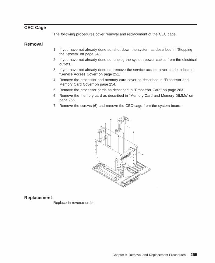
CEC CageThe following procedures cover removal and replacement of the CEC cage.
Removal1. If you have not already done so, shut down the system as described in “Stopping
the System” on page 248.
2. If you have not already done so, unplug the system power cables from the electricaloutlets.
3. If you have not already done so, remove the service access cover as described in“Service Access Cover” on page 251.
4. Remove the processor and memory card cover as described in “Processor andMemory Card Cover” on page 254.
5. Remove the processor cards as described in “Processor Card” on page 263.
6. Remove the memory card as described in “Memory Card and Memory DIMMs” onpage 256.
7. Remove the screws (6) and remove the CEC cage from the system board.
ReplacementReplace in reverse order.
Chapter 9. Removal and Replacement Procedures 255

Memory Card and Memory DIMMsThe following procedures cover removal and replacement of the memory card andmemory DIMMs.
Before performing these procedures, read “Handling Static-Sensitive Devices” onpage 248.
Memory Card Removal1. If you have not already done so, shut down the system as described in “Stopping
the System” on page 248.
2. If you have not already done so, unplug the system power cables from the electricaloutlet.
3. If you have not already done so, remove the service access cover as described in“Service Access Cover” on page 251.
4. Remove the processor and memory card cover as described in “Processor andMemory Card Cover” on page 254.
5. The memory card is secured in place with retention latches, one on each end of thecard. Open the retention latches.
256 Service Guide

Attention: To prevent damage to the card and the card connectors, open or closethe retention latches at the same time.
6. Remove the card from the connector.
Chapter 9. Removal and Replacement Procedures 257
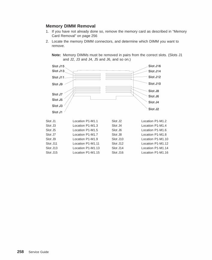
Memory DIMM Removal1. If you have not already done so, remove the memory card as described in “Memory
Card Removal” on page 256
2. Locate the memory DIMM connectors, and determine which DIMM you want toremove.
Note: Memory DIMMs must be removed in pairs from the correct slots. (Slots J1and J2, J3 and J4, J5 and J6, and so on.)
Slot J1
Slot J3Slot J4
Slot J2
Slot J5Slot J6
Slot J9 Slot J10
Slot J11 Slot J12
Slot J13 Slot J14
Slot J15 Slot J16
Slot J7Slot J8
Slot J1 Location P1-M1.1 Slot J2 Location P1-M1.2Slot J3 Location P1-M1.3 Slot J4 Location P1-M1.4Slot J5 Location P1-M1.5 Slot J6 Location P1-M1.6Slot J7 Location P1-M1.7 Slot J8 Location P1-M1.8Slot J9 Location P1-M1.9 Slot J10 Location P1-M1.10Slot J11 Location P1-M1.11 Slot J12 Location P1-M1.12Slot J13 Location P1-M1.13 Slot J14 Location P1-M1.14Slot J15 Location P1-M1.15 Slot J16 Location P1-M1.16
258 Service Guide

3. Remove the memory DIMM by pushing the tabs out on the memory connectors.
Push Locking TabsOut to Release MemoryModule
1
2
1
Chapter 9. Removal and Replacement Procedures 259
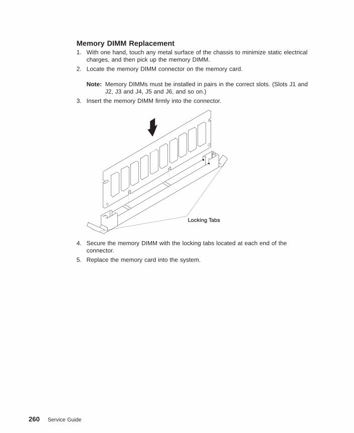
Memory DIMM Replacement1. With one hand, touch any metal surface of the chassis to minimize static electrical
charges, and then pick up the memory DIMM.
2. Locate the memory DIMM connector on the memory card.
Note: Memory DIMMs must be installed in pairs in the correct slots. (Slots J1 andJ2, J3 and J4, J5 and J6, and so on.)
3. Insert the memory DIMM firmly into the connector.
Locking Tabs
4. Secure the memory DIMM with the locking tabs located at each end of theconnector.
5. Replace the memory card into the system.
260 Service Guide

Memory Card Replacement1. Open the retention latches. Both latches should be in an upright position. See the
following illustration.
Attention: To prevent damage to the card and to the card connectors, open orclose both retention latches at the same time.
Chapter 9. Removal and Replacement Procedures 261

2. Align the card with the card guides and card connector.
Processor Card 1
Connector
Memory Card
Connector
Processor Card 2
Connector
3. Close the retention latches, securing the card into the connector.
4. Replace the covers as described in “Service Access Cover” on page 251.
262 Service Guide
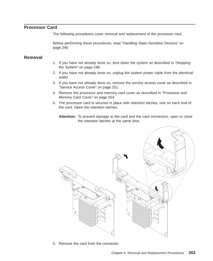
Processor CardThe following procedures cover removal and replacement of the processor card.
Before performing these procedures, read “Handling Static-Sensitive Devices” onpage 248.
Removal1. If you have not already done so, shut down the system as described in “Stopping
the System” on page 248.
2. If you have not already done so, unplug the system power cable from the electricaloutlet.
3. If you have not already done so, remove the service access cover as described in“Service Access Cover” on page 251.
4. Remove the processor and memory card cover as described in “Processor andMemory Card Cover” on page 254.
5. The processor card is secured in place with retention latches, one on each end ofthe card. Open the retention latches.
Attention: To prevent damage to the card and the card connectors, open or closethe retention latches at the same time.
6. Remove the card from the connector.
Chapter 9. Removal and Replacement Procedures 263

Replacement1. Open the retention latches. Both retention latches should be in an upright position.
See the following illustration.
Attention: To prevent damage to the card and to the card connectors, open orclose both retention latches at the same time.
2. Align the card with the card guides and card connector.
Processor Card 1
Connector
Memory Card
Connector
Processor Card 2
Connector
264 Service Guide

3. Close the retention latches, securing the card into the connector.
4. Replace the covers as described in “Service Access Cover” on page 251.
Chapter 9. Removal and Replacement Procedures 265
AdaptersThe following procedures cover removal and replacement of the adapters.
Before performing these procedures, read “Handling Static-Sensitive Devices” onpage 248.
Note: This system does not support hot-plugging of PCI adapters.
Removal1. If you have not already done so, shut down the system as described in “Stopping
the System” on page 248.
2. If you have not already done so, unplug the system power cables from the electricaloutlets.
3. If you have not already done so, remove the service access cover as described in“Service Access Cover” on page 251.
4. Determine which adapter you are removing.
5. Disconnect any cables attached to the adapter.
266 Service Guide
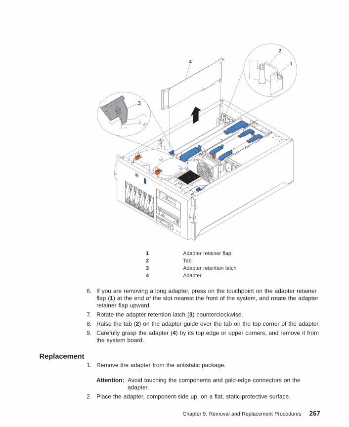
4 1
2
3
1 Adapter retainer flap2 Tab3 Adapter retention latch4 Adapter
6. If you are removing a long adapter, press on the touchpoint on the adapter retainerflap (1) at the end of the slot nearest the front of the system, and rotate the adapterretainer flap upward.
7. Rotate the adapter retention latch (3) counterclockwise.
8. Raise the tab (2) on the adapter guide over the tab on the top corner of the adapter.
9. Carefully grasp the adapter (4) by its top edge or upper corners, and remove it fromthe system board.
Replacement1. Remove the adapter from the antistatic package.
Attention: Avoid touching the components and gold-edge connectors on theadapter.
2. Place the adapter, component-side up, on a flat, static-protective surface.
Chapter 9. Removal and Replacement Procedures 267
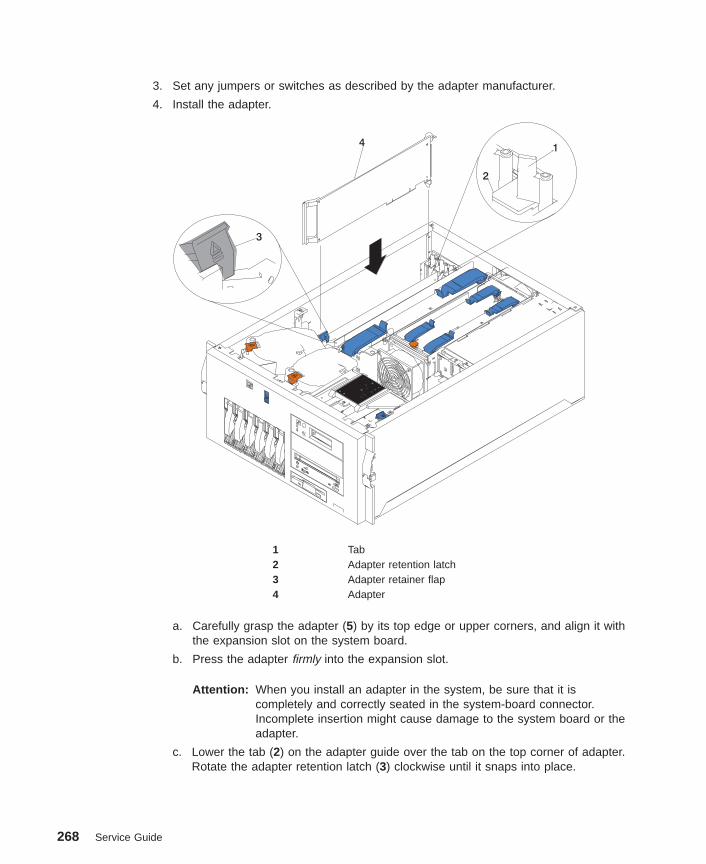
3. Set any jumpers or switches as described by the adapter manufacturer.
4. Install the adapter.
2
41
3
1 Tab2 Adapter retention latch3 Adapter retainer flap4 Adapter
a. Carefully grasp the adapter (5) by its top edge or upper corners, and align it withthe expansion slot on the system board.
b. Press the adapter firmly into the expansion slot.
Attention: When you install an adapter in the system, be sure that it iscompletely and correctly seated in the system-board connector.Incomplete insertion might cause damage to the system board or theadapter.
c. Lower the tab (2) on the adapter guide over the tab on the top corner of adapter.Rotate the adapter retention latch (3) clockwise until it snaps into place.
268 Service Guide

Attention: Power cannot be restored to the adapter slot if the tab is not loweredinto place.
d. If opened previously, close the adapter retainer flap (4).
5. Connect any needed external cables to the adapter and route through the cablemanagement arm.
Attention: Route any internal cables so that the flow of air from the fans is notblocked.
6. Replace the covers as described in “Service Access Cover” on page 251.
Chapter 9. Removal and Replacement Procedures 269

System BoardThe following procedures cover removal and replacement of the system board.
Removal1. If you have not already done so, shut down the system as described in “Stopping
the System” on page 248.
2. If you have not already done so, unplug the system power cable from the electricaloutlet.
3. If you have not already done so, remove the service access cover as described in“Service Access Cover” on page 251.
4. Remove the processor and memory card cover as described in “Processor andMemory Card Cover” on page 254.
5. Remove the adapters as described in “Adapters” on page 266.
6. Remove the adapter retainer flap assembly.
7. Remove the memory card as described in “Memory Card and Memory DIMMs” onpage 256.
8. Remove the processor card(s) as described in “Processor Card” on page 263.
9. Pull the media devices out the front of the system but do not remove completely.
10. Remove fan assembly 2 as described in “Hot-Swap Fan Assembly” on page 290.
11. Remove the CEC cage as described in “CEC Cage” on page 255.
12. Remove all cables from the system board.
13. Remove fan assembly 1 as described in “Hot-Swap Fan Assembly” on page 290.
14. Pull on the release lever to cam the system board out of the system.
270 Service Guide

ReplacementReplace in reverse order.
Chapter 9. Removal and Replacement Procedures 271

Power SupplyThe following procedures cover removal and replacement of the power supplies.
DANGER
Do not attempt to open the covers of the power supply. Power supplies arenot serviceable and are to be replaced as a unit.
RemovalYour system comes with two power supplies. You can add a third power supply toprovide redundant power. After you install a power supply, check the power supplystatus indicators to verify that the power supply is operating properly.
Note: You do not need to turn off the power to the system to install hot-swap powersupplies.
272 Service Guide
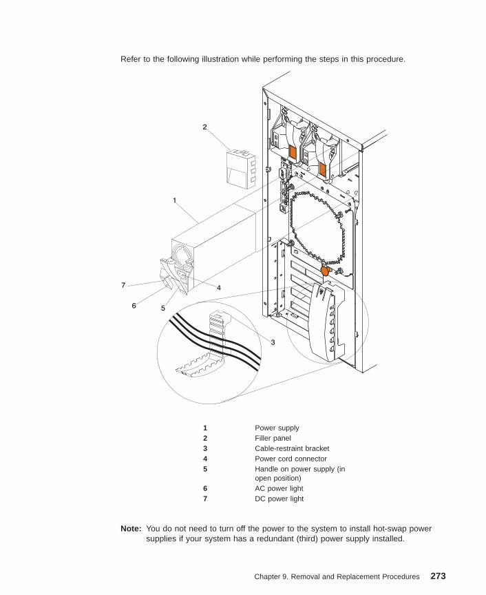
Refer to the following illustration while performing the steps in this procedure.
1
4
56
7
2
3
1 Power supply2 Filler panel3 Cable-restraint bracket4 Power cord connector5 Handle on power supply (in
open position)6 AC power light7 DC power light
Note: You do not need to turn off the power to the system to install hot-swap powersupplies if your system has a redundant (third) power supply installed.
Chapter 9. Removal and Replacement Procedures 273
1. If your system does not have a redundant (third) power supply installed, turn off thepower to the system and peripheral devices. Otherwise, go to the next step.
2. To remove the power supply (1):
a. Unplug the power cord connector from the power supply.
Attention: Be careful when you remove the hot-swap power supply; the powersupply might be too hot to handle comfortably.
b. Remove the defective power supply by placing the handle (5) on the powersupply in the open position (perpendicular to the power supply) and pulling thepower supply from the bay.
3. If you are not replacing the power supply:
a. Install a power-supply filler panel (2).
Note: During normal operation, each power-supply bay must have either apower supply or filler panel installed for proper cooling.
b. Open the cable-restraint bracket (3) and remove the power cord from thecable-restraint bracket. Close the cable-restraint bracket.
c. Unplug the power cord from the electrical outlet.
Replacement
Note: If a power supply is being replaced for a redundant failure, after the servicerepair action is completed, ask the customer to check the crontab file for anypower/cooling warning messages. When a power or cooling error is encountered,AIX adds an entry to the crontab file to ″wall″ a warning message every 12hours, alerting/reminding the customer of the problem. Replacing the faulty partdoes not clear this crontab entry, so unless the crontab file is edited to removethis entry, the customer will continue to be reminded of the failure despite it’shaving been repaired. The AIX command crontab -l reads the crontab file todetermine if an entry exists. The crontab -e command edits the file.
274 Service Guide
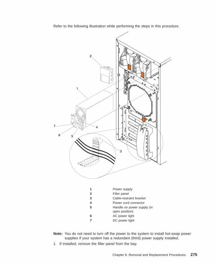
Refer to the following illustration while performing the steps in this procedure.
1
4
56
7
2
3
1 Power supply2 Filler panel3 Cable-restraint bracket4 Power cord connector5 Handle on power supply (in
open position)6 AC power light7 DC power light
Note: You do not need to turn off the power to the system to install hot-swap powersupplies if your system has a redundant (third) power supply installed.
1. If installed, remove the filler panel from the bay.
Chapter 9. Removal and Replacement Procedures 275

2. Install the power supply (1) in the bay:
a. Place the handle (5) on the power supply in the open position (that is,perpendicular to the power supply) and slide the power supply into the chassis.
b. Gently close the handle to seat the power supply in the bay.
3. Plug the power cord for the added power supply into the power cord connector (4).
4. Route the power cord through the cable-restraint bracket (3) and the cablemanagement arm.
5. Plug the power cord into a properly grounded electrical outlet.
6. Verify that the dc power light (7) and ac power light (6) on the power supply are lit,indicating that the power supply is operating correctly.
276 Service Guide

Operator PanelThe following procedures cover removal and replacement of the operator panel.
Removal1. If you have not already done so, shut down the system as described in “Stopping
the System” on page 248.
2. If you have not already done so, unplug the system power cables from the electricaloutlets.
3. Remove the bezel as described in “Bezels” on page 253.
4. Remove the operator panel by grasping the release levers and pulling the operatorpanel tray from the system.
5. If installed, remove the cables from the disk drive.
6. Disconnect the cables from the operator panel and remove the operator panel.
Replacement1. To replace, perform removal steps in reverse order.
2. Complete the VPD update procedure as described in “System Vital Product Data(VPD) Update Procedure” on page 278.
Chapter 9. Removal and Replacement Procedures 277

System Vital Product Data (VPD) Update ProcedureIf you replaced the operator panel with a new FRU, perform the following procedure toensure that the VPD is correct.
1. After you install the new operator panel, wait for the OK message to display in theoperator panel display.
2. Start the Service Processor Firmware menu.
1. Service Processor Setup
2. System Power Control Menu
3. System Information Menu
4. Language Selection
5. Call In/Call Out Setup
6. Set System Name
99. Exit from Menu
Main Menu
Service Processor Firmware
Firmware Level: xxxxxxxx
Copyright 1999, IBM Corporation
1>
Command Prompt
3. At the command prompt, type the code which accesses the hidden menus. Ifnecessary, call your local support center to obtain the code.
This menu is for IBM Authorized use only. If you
have not been authorized to use this menu, please
discontinue use immediately.
Press Return to continue, or X to return to menu 1.
4. Press Return to continue.
VPD Serial Number is not programmed.
Enter the VPD Serial Number (7 ASCII digits): xxxxxxx
5. Type the VPD serial number.
Note: The serial number must be entered correctly. Enter the last seven digits only.Do not include the dash (-) in the serial number as a digit. If the serialnumber is not entered correctly, a new operator panel must be ordered and
278 Service Guide
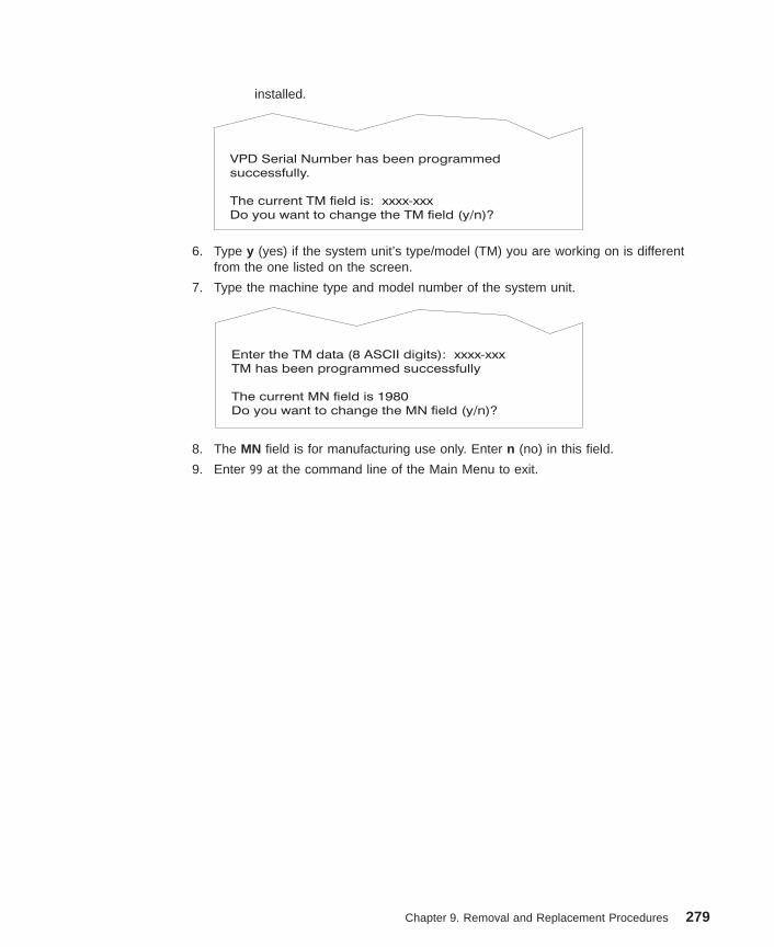
installed.
VPD Serial Number has been programmed
successfully.
The current TM field is: xxxx-xxx
Do you want to change the TM field (y/n)?
6. Type y (yes) if the system unit’s type/model (TM) you are working on is differentfrom the one listed on the screen.
7. Type the machine type and model number of the system unit.
Enter the TM data (8 ASCII digits): xxxx-xxx
TM has been programmed successfully
The current MN field is 1980
Do you want to change the MN field (y/n)?
8. The MN field is for manufacturing use only. Enter n (no) in this field.
9. Enter 99 at the command line of the Main Menu to exit.
Chapter 9. Removal and Replacement Procedures 279

Power BackplaneThe following procedures cover removal and replacement of the power backplane.
Removal1. If you have not already done so, shut down the system as described in “Stopping
the System” on page 248.
2. If you have not already done so, unplug the system power cables from the electricaloutlet.
3. If you have not already done so, remove the service access cover as described in“Service Access Cover” on page 251.
4. Remove the power supplies.
5. Disconnect the cables from the power backplane.
6. Push down on the release lever and remove the power backplane.
1
Replacement1. Replace in reverse order.
280 Service Guide

SCSI BackplaneThe following procedures cover removal and replacement of the SCSI backplane.
Removal1. If you have not already done so, shut down the system as described in “Stopping
the System” on page 248.
2. If you have not already done so, unplug the system power cables from theelectrical outlet.
3. If you have not already done so, remove the service access cover as described in“Service Access Cover” on page 251.
4. Remove the hot-swap drives as described in “Hot-Swap Disk Drives” on page 286.
5. Remove the fan assemblies 3 and 4 as described in “Hot-Swap Fan Assembly” onpage 290.
6. Remove the processor and memory card cover as described in “Processor andMemory Card Cover” on page 254.
7. Remove the CEC cage as described in “CEC Cage” on page 255.
8. Remove all cables from the backplane.
9. Remove the screws and remove the SCSI repeater card (2) from the backplane.
10. Remove the screws from the SCSI backplane.
11. Pull the release lever (1) and remove the backplane.
1
2
Replacement1. Attach the SCSI repeater card removed earlier to the new backplane.
2. Replace in reverse order.
Chapter 9. Removal and Replacement Procedures 281
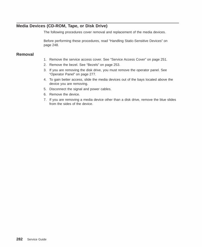
Media Devices (CD-ROM, Tape, or Disk Drive)The following procedures cover removal and replacement of the media devices.
Before performing these procedures, read “Handling Static-Sensitive Devices” onpage 248.
Removal1. Remove the service access cover. See “Service Access Cover” on page 251.
2. Remove the bezel. See “Bezels” on page 253.
3. If you are removing the disk drive, you must remove the operator panel. See“Operator Panel” on page 277.
4. To gain better access, slide the media devices out of the bays located above thedevice you are removing.
5. Disconnect the signal and power cables.
6. Remove the device.
7. If you are removing a media device other than a disk drive, remove the blue slidesfrom the sides of the device.
282 Service Guide

Replacement
1. Touch the static-protective bag containing the drive to any unpainted metal surfaceon the system, then, remove the drive from the bag and place it on astatic-protective surface.
2. Set any jumpers or switches on the device according to the documentation providedwith the drive. Refer to “SCSI IDs and Bay Locations” on page 9 for SCSI idinformation.
3. Install any blue slides removed previously.
4. Place the device so that the slide rails engage in the bay guide rails. Do not pushthe device all the way into the bay.
5. Connect the signal and power cables.
6. Push the device into the bay until it clicks into place.
7. Install any media devices removed earlier.
8. Replace the bezel as described in “Bezels” on page 253.
9. Replace the covers as described in “Service Access Cover” on page 251.
Chapter 9. Removal and Replacement Procedures 283

BatteryThe following procedures cover removal and replacement of the battery.
CAUTION:
A lithium battery can cause fire, explosion, or severe burn. Do not recharge,disassemble, heat above 100°C (212°F), solder directly to the cell, incinerate, orexpose cell contents to water. Keep away from children. Replace only with thepart number specified for your system. Use of another battery may present a riskof fire or explosion.
The battery connector is polarized; do not attempt to reverse polarity.
Dispose of the battery according to local regulations.
Removal1. If you have not already done so, shut down the system as described in “Stopping
the System” on page 248.
2. If you have not already done so, unplug the system power cables from the electricaloutlets.
3. If you have not already done so, remove the service access cover as described in“Service Access Cover” on page 251.
4. If you have not already done so, remove the processor and memory card cover asdescribed in “Processor and Memory Card Cover” on page 254.
5. Remove the processor cards as described in “Processor Card” on page 263.
6. Remove the memory card as described in “Memory Card and Memory DIMMs” onpage 256.
284 Service Guide

7. Locate the battery on the system board.
Rear Battery Clip
Battery P/N
15F8409
Plastic Battery Mount
Battery
Memory Card
Connector
Processor Card
Connectors
8. Pry the battery out of its mount using your fingernail. After the top of the battery hascleared the plastic mount, pull it up and out of the system board.
Replacement1. Ensure that the battery polarity is correct. (Plus (+) side away from plastic battery
mount.)
2. Using your thumb, gently press the battery into the battery mount. Use your indexfinger to support the back of the battery mount during this operation.
3. Replace any removed processors or memory cards.
4. Replace the processor and memory card cover as described in “Processor andMemory Card Cover” on page 254.
5. Replace the covers as described in “Service Access Cover” on page 251.
Chapter 9. Removal and Replacement Procedures 285

Hot-Swap Disk DrivesThe following procedures cover removal and replacement of the hot-swap disk drives.
Note: You do not have to power off the system to remove a hot-swap disk drive fromthe system. Before you perform these procedures, ensure that the customer hastaken appropriate actions to back up the data for the drive you are removing,and that the drive has been removed from the configuration. Physically removinga hot-swap drive from the system before it has been removed from the systemconfiguration can cause unrecoverable data corruption.
Deconfiguring (Removing) or Configuring a Disk DriveUse this procedure if you are removing or installing a drive while the system power isturned on.
Deconfiguring (Removing)1. Back up the information from the disk drive to another drive.
2. Log in as root user.
3. At the command line, type smitty.
4. Select System Storage Management (Physical and Logical Storage) and pressEnter.
5. Select Logical Volume Manager and press Enter.
6. Select Volume Groups and press Enter.
7. Select Set Characteristics of a Volume Group . and press Enter.
8. Select Remove a Physical Volume from a Volume Group .
9. Press F4 to list the available volume groups, then select the volume group nameand press Enter.
10. Press F4 to select a physical volume, and follow the instructions on the screen toselect the physical volume. Then press Enter.
11. Press F3s, Cancel, to go back to the first menu and select System StorageManagement (Physical and Logical Storage) .
12. Select Removable Disk Management .
13. Select Remove a Disk .
14. Select the desired disk from the list on the screen and press Enter.
15. Follow the instructions on the screen to remove the drive.
16. When you are asked ″Are you sure?,″ press Enter. The power LED above thedrive that you selected will remain on.
17. Remove the disk drive by pulling the disk drive lever toward you until it iscompletely open. Then remove the disk drive from the slot. The LED on the top ofthe slot will turn off when the disk drive is removed.
18. Press F10 to exit smitty .
286 Service Guide

Configuring (Replacing)1. Remove the disk drive from its protective packaging, and open the drive latch
handle.
2. Install the disk drive in the drive slot. Align the disk drive with the drive slot rails,and slide the disk drive into the slot until it contacts the backplane at the rear ofthe drive bay. The drive should be in far enough for the latch handle to engage thelatch. Push the disk drive lever up and to the rear to lock the disk drive. The LEDabove the slot will turn on.
3. Log in as root user.
4. At the command line, type smitty.
5. Select Devices .
6. Select Install/Configure Devices Added After IPL and press Enter. Successfulconfiguration is indicated by the OK message displayed next to the Command fieldat the top of the screen
7. Press F3s, Cancel, to go back to the first menu and select System StorageManagement (Physical and Logical Storage) and press Enter.
8. Select Logical Volume Manager and press Enter.
9. Select Volume Groups and press Enter.
10. Select Set Characteristics of a Volume Group and press Enter.
11. Select Add a Physical Volume to a Volume Group .
12. Fill in the fields for the drive you are adding to the system. Press F4 for a list ofselections.
13. See the AIX System Management Guide: Operating System and Devices to finishthe drive configuration. This publication is available at the following Web address:http://www.ibm.com/systems/aix/library/. Select Technical Publications . Thispublication is also contained on the AIX Documentation CD. The documentation ismade accessible by loading the documentation CD files onto the hard disk or bymounting the CD in the CD-ROM drive.
14. Press F10 to exit smitty .
Chapter 9. Removal and Replacement Procedures 287
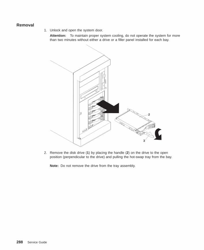
Removal1. Unlock and open the system door.
Attention: To maintain proper system cooling, do not operate the system for morethan two minutes without either a drive or a filler panel installed for each bay.
2
3
2. Remove the disk drive (1) by placing the handle (2) on the drive to the openposition (perpendicular to the drive) and pulling the hot-swap tray from the bay.
Note: Do not remove the drive from the tray assembly.
288 Service Guide

Replacement1. Install the hard disk drive in the hot-swap bay:
a. Ensure the tray handle is open (perpendicular to the drive).
b. Align the drive/tray assembly so that it engages the guide rails in the bay.
c. Push the drive assembly into the bay until the tray handle engages the lockmechanism.
d. Push the tray handle to the right until it locks.
2. Check the disk drive status indicators to verify that the hard disk drive is installedproperly.
3. Close and lock the system door.
Chapter 9. Removal and Replacement Procedures 289

Hot-Swap Fan AssemblyThe following procedures cover removal and replacement of the hot-swap fanassemblies.
Note: You do not need to turn off the power to the system to replace a hot-swap fanassembly.
The following illustration shows the replacement of a hot-swap fan assembly. Refer tothis illustration while performing the steps in this procedure.
1
2
3
4
5
6
7
8
9
101112
1 Hot-swap fan assembly 1 2 Fan assembly 1 LED3 Fan 1 release button 4 Hot-swap fan assembly 25 Fan assembly 2 LED 6 Fan 2 release button7 Fan assembly 3 LED 8 Hot-swap fan assembly 39 Fan 3 release latch 10 Fan assembly 4 LED11 Hot-swap fan assembly 4 12 Fan 4 release latch
Removal1. For fan assemblies 2, 3, and 4, you must remove the service access cover. See
“Service Access Cover” on page 251.
290 Service Guide

Attention: To ensure proper system cooling, do not remove the service accesscover for more than 30 minutes during this procedure.
2. Determine which of the following fan assemblies to replace by checking the fanLEDs on the diagnostic LED panel (see “Attention LED and Lightpath LEDs” onpage 24) and the LEDs located on the fan assemblies.
v Fan assembly 1 (1)
v Fan assembly 2 (4)
v Fan assembly 3 (9)
v Fan assembly 4 (12)
3. If you are removing fan assembly 2, you must remove the processor and memorycard cover. See “Processor and Memory Card Cover” on page 254.
4. If you are removing fan assembly 1 or fan assembly 2, pull out the snap button andremove the fan.
If you are removing fan assembly 3 or fan assembly 4, press the orange releaselatch (9), or (12) for the fan and pull the fan away from the system.
Replacement
Note: If a fan assembly is being replaced for a redundant failure, after the servicerepair action is completed, ask the customer to check the crontab file for anypower/cooling warning messages. When a power or cooling error is encountered,AIX adds an entry to the crontab file to ″wall″ a warning message every 12hours, alerting/reminding the customer of the problem. Replacing the faulty partdoes not clear this crontab entry, so unless the crontab file is edited to removethis entry, the customer will continue to be reminded of the failure despite it’shaving been repaired. The AIX command crontab -l reads the crontab file todetermine if an entry exists. The crontab -e command edits the file.
1. Slide the replacement fan assembly into the system until it clicks into place.
2. Replace the service access cover. See “Service Access Cover” on page 251.
Chapter 9. Removal and Replacement Procedures 291

292 Service Guide

Chapter 10. Parts Information
This chapter contains parts information for the 9112 Model 265.
293

System Parts
1 2 3
4 5
67
8
910
1618
17
191112
131415
20
22
21
23 24
25
26 27 2928
294 Service Guide
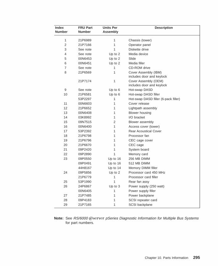
IndexNumber
FRU PartNumber
Units PerAssembly
Description
1 21P6989 1 Chassis (tower)2 21P7166 1 Operator panel3 See note 1 Diskette drive4 See note Up to 2 Media device5 00N6453 Up to 2 Slide6 00N6451 Up to 2 Media filler7 See note 1 CD-ROM drive8 21P6569 1 Cover Assembly (IBM)
includes door and keylock21P7174 1 Cover Assembly (OEM)
includes door and keylock9 See note Up to 6 Hot-swap DASD10 21P6581 Up to 6 Hot-swap DASD filler
53P2297 1 Hot-swap DASD filler (6-pack filler)11 00N6603 1 Cover release12 21P6652 1 Lightpath assembly13 00N6408 1 Blower housing14 03K8992 1 I/O bracket15 09N7515 2 Blower assembly16 00N6400 1 Access cover (tower)17 53P2392 1 Rear Acoustical Cover18 21P6798 1 Processor fan19 21P6796 1 CEC cage cover20 21P6670 1 CEC cage21 09P2420 1 System board22 09P2890 1 Memory card23 09P0550 Up to 16 256 MB DIMM
09P0491 Up to 16 512 MB DIMM44H8167 Up to 14 Memory DIMM filler
24 09P5856 Up to 2 Processor card 450 MHz21P6779 1 Processor card filler
25 53P1990 1 Rear fan assy26 24P6867 Up to 3 Power supply (250 watt)
00N6405 1 Power supply filler27 21P7485 1 Power backplane28 09P4183 1 SCSI repeater card29 21P7165 1 SCSI backplane
Note: See RS/6000 Eserver pSeries Diagnostic Information for Multiple Bus Systemsfor part numbers.
Chapter 10. Parts Information 295

System Internal Cables
T
Fan
Fan
Power
Backplane
System Board
Processor Slot
Processor Slot
Diskette
DASD
Operator
Panel
CD-ROM
Tape
Power
Power
SCSI
SCSI
Power
IDE
Power
Signal
Power
SCSI
SCSI
Backplane
Blower
Light
Path
LEDs
RJ45
Serial
Rear
Serial
Port #1
Rear
LEDs
Blower
1
2
3
4
J1
J2
J6
J5
J3
J4
5
6
7
9
10
11
12
13
14
15
20
16
17
18
19
8
5
1
296 Service Guide

Index Number FRU PartNumber
Units PerAssembly
Description
1 21P6647 1 Fan power cable2 21P6653 1 Rear LED cable3 21P6657 1 Rear serial port #1 cable4 21P6648 1 Processor power cable5 21P6649 Up to 2 Processor power cable6 21P6650 1 Operator panel cable7 21P6655 1 SCSI cable8 53P1466 1 CD-ROM signal cable9 00N6573 1 Media power cable10 00N6549 1 DASD backplane power cable11 21P7399 1 System board power cable12 00N6572 1 System board power cable13 00N6551 1 System board power cable14 00N6550 1 System board power cable15 21P6652 1 Lightpath LED cable16 21P6651 1 Diskette signal cable17 37L6062 1 Blower cable18 21P8070 1 Front RJ45 serial cable19 53P0457 1 Tape signal cable20 21P6923 1 Backplane SCSI cable (not used when
21P6655 is installed)
Chapter 10. Parts Information 297
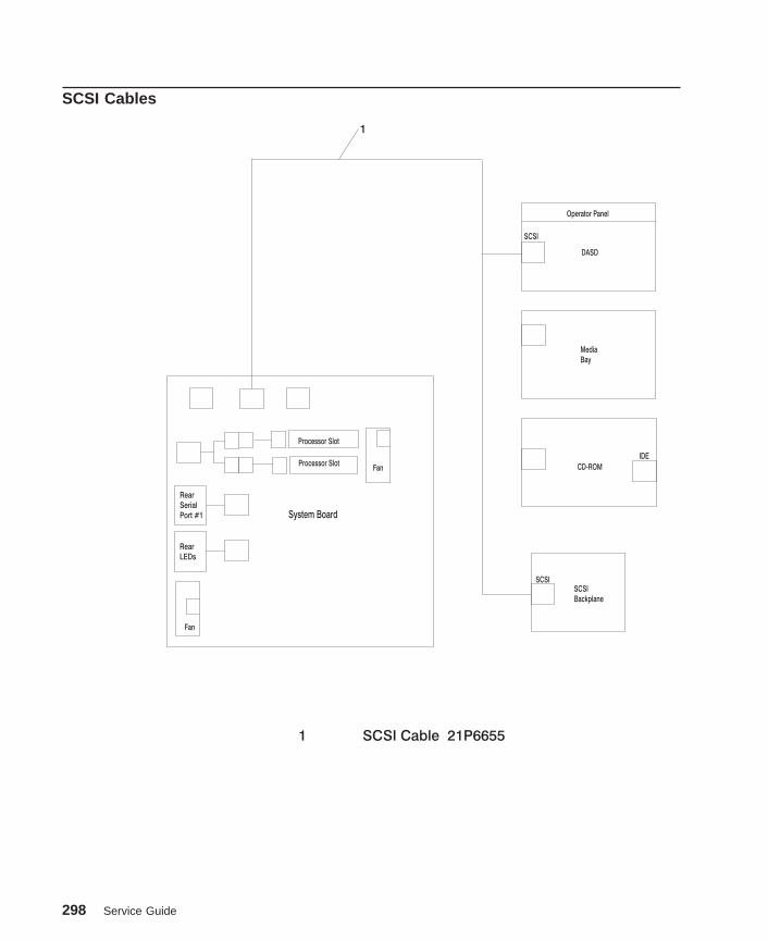
SCSI Cables
Fan
Fan
System Board
Processor Slot
Processor Slot
DASD
Operator Panel
CD-ROM
Media
Bay
SCSI
SCSI
IDE
SCSI
Backplane
Rear
Serial
Port #1
Rear
LEDs
1 SCSI Cable 21P6655
1
298 Service Guide
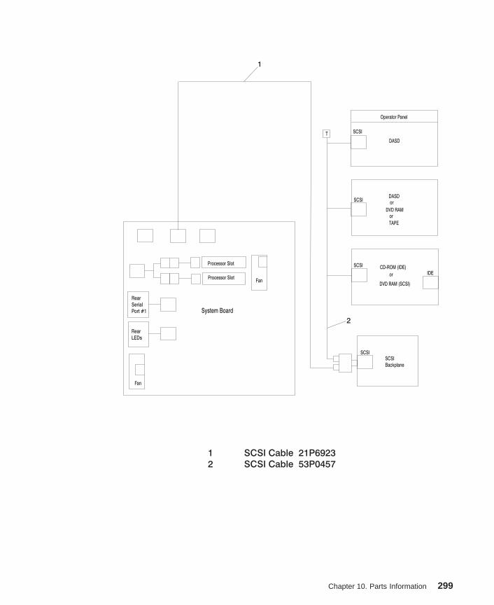
Fan
Fan
System Board
Processor Slot
Processor Slot
DASDor
or
or
DASD
TAPE
DVD RAM
DVD RAM (SCSI)
Operator Panel
CD-ROM (IDE)
SCSI
SCSI
SCSI
SCSI
IDE
T
SCSI
Backplane
Rear
Serial
Port #1
Rear
LEDs
1 SCSI Cable 21P6923
2 SCSI Cable 53P0457
1
2
Chapter 10. Parts Information 299

Fan
Fan
System Board
PCI Adapter
Processor Slot
Processor Slot
DASDor
or
or
DASD
TAPE
DVD RAM
DVD RAM (SCSI)
Operator Panel
CD-ROM (IDE)
SCSI
SCSI
SCSI
SCSI
IDE
T
SCSI
Backplane
Rear
Serial
Port #1
Rear
LEDs
1 SCSI Cable 53P1673
2 SCSI Cable 53P1674
1
2
300 Service Guide
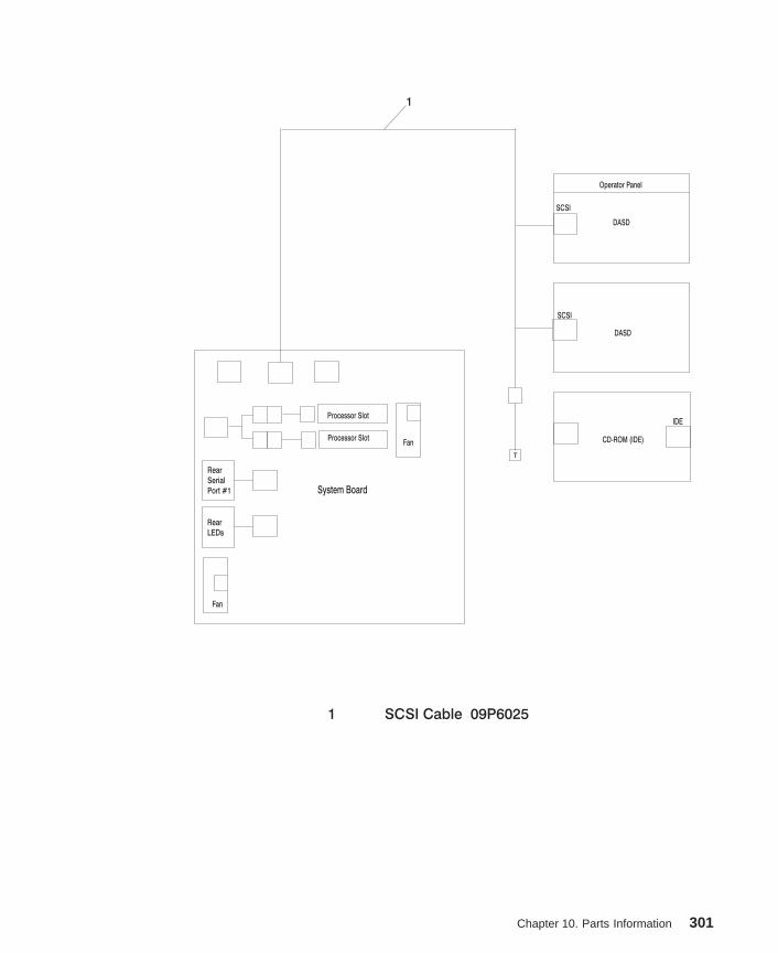
Fan
Fan
System Board
Processor Slot
Processor Slot
DASD
DASD
Operator Panel
CD-ROM (IDE)
SCSI
SCSI
IDE
T
Rear
Serial
Port #1
Rear
LEDs
1 SCSI Cable 09P6025
1
Chapter 10. Parts Information 301
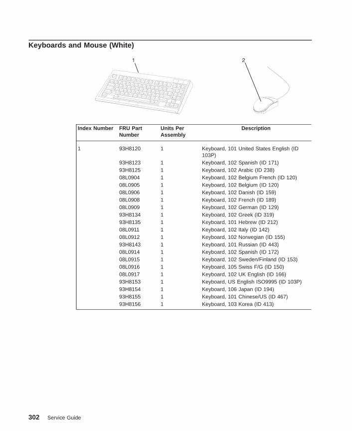
Keyboards and Mouse (White)
Index Number FRU PartNumber
Units PerAssembly
Description
1 93H8120 1 Keyboard, 101 United States English (ID103P)
93H8123 1 Keyboard, 102 Spanish (ID 171)93H8125 1 Keyboard, 102 Arabic (ID 238)08L0904 1 Keyboard, 102 Belgium French (ID 120)08L0905 1 Keyboard, 102 Belgium (ID 120)08L0906 1 Keyboard, 102 Danish (ID 159)08L0908 1 Keyboard, 102 French (ID 189)08L0909 1 Keyboard, 102 German (ID 129)93H8134 1 Keyboard, 102 Greek (ID 319)93H8135 1 Keyboard, 101 Hebrew (ID 212)08L0911 1 Keyboard, 102 Italy (ID 142)08L0912 1 Keyboard, 102 Norwegian (ID 155)93H8143 1 Keyboard, 101 Russian (ID 443)08L0914 1 Keyboard, 102 Spanish (ID 172)08L0915 1 Keyboard, 102 Sweden/Finland (ID 153)08L0916 1 Keyboard, 105 Swiss F/G (ID 150)08L0917 1 Keyboard, 102 UK English (ID 166)93H8153 1 Keyboard, US English ISO9995 (ID 103P)93H8154 1 Keyboard, 106 Japan (ID 194)93H8155 1 Keyboard, 101 Chinese/US (ID 467)93H8156 1 Keyboard, 103 Korea (ID 413)
302 Service Guide

Keyboards and Mouse (Black)
Index Number FRU PartNumber
Units PerAssembly
Description
1 07L9446 1 Keyboard, 101 United States English (ID103P)
07L9447 1 Keyboard, 102 Canada French (ID 058)07L9448 1 Keyboard, 102 Canada French (ID 445)07L9449 1 Keyboard, 102 Spanish (ID 171)07L9450 1 Keyboard, 104 Brazil Portuguese (ID 275)07L9451 1 Keyboard, 102 Arabic (ID 238)07L9452 1 Keyboard, 102 Belgium French (ID 120)07L9453 1 Keyboard, 102 Belgium (ID 120)07L9454 1 Keyboard, 102 Bulgarian (ID 442)07L9455 1 Keyboard, 102 Czech (ID 243)07L9456 1 Keyboard, 102 Danish (ID 159)07L9457 1 Keyboard, 102 Dutch (ID 143)07L9458 1 Keyboard, 102 French (ID 189)07L9459 1 Keyboard, 102 German (ID 129)07L9460 1 Keyboard, 102 Greek (ID 319)07L9461 1 Keyboard, 101 Hebrew (ID 212)07L9462 1 Keyboard, 102 Hungarian (ID 208)07L9463 1 Keyboard, 102 Iceland (ID 197)07L9464 1 Keyboard, 102 Italy (ID 142)07L9465 1 Keyboard, 102 Norwegian (ID 155)07L9466 1 Keyboard, 102 Polish (ID 214)07L9467 1 Keyboard, 102 Portuguese (ID 163)07L9468 1 Keyboard, 102 Romainian (ID 446)07L9469 1 Keyboard, 101 Russian (ID 443)07L9470 1 Keyboard, 102 Serbian (ID 118)07L9471 1 Keyboard, 102 Slovak (ID 245)07L9472 1 Keyboard, 102 Spanish (ID 172)07L9473 1 Keyboard, 102 Sweden/Finland (ID 153)07L9474 1 Keyboard, 105 Swiss F/G (ID 150)07L9475 1 Keyboard, 102 Turkish (ID 179)07L9476 1 Keyboard, 102 Turkish (ID 440)07L9477 1 Keyboard, 102 UK English (ID 166)07L9478 1 Keyboard, 102 Latvia (ID 234)
Chapter 10. Parts Information 303
Index Number FRU PartNumber
Units PerAssembly
Description
07L9479 1 Keyboard, US English ISO9995 (ID 103P)07L9480 1 Keyboard, 106 Japan (ID 194)07L9481 1 Keyboard, 101 Chinese/US (ID 467)07L9482 1 Keyboard, 103 Korea (ID 413)07L9483 1 Keyboard, 101 Thailand (ID 191)
2 08L0362 1 Three Button Mouse (Black)09P4455 1 Three Button Mouse (Black)
304 Service Guide

Appendix A. Environmental Notices
Product Recycling and DisposalThis unit contains materials such as circuit boards, cables, electromagnetic compatibilitygaskets and connectors which may contain lead and copper/beryllium alloys that requirespecial handling and disposal at end of life. Before this unit is disposed of, thesematerials must be removed and recycled or discarded according to applicableregulations. IBM offers product return programs in several countries, for country specificinstructions please refer to the following web site:http://www.ibm.com/ibm/environment/products/prp.phtml
This product may contain a sealed lead acid battery(s) or nickel-cadmium battery(s).The battery(s) must be recycled or disposed of properly. Recycling facilities may not beavailable in your area. In the United States, IBM has established a collection processfor reuse, recycling, or proper disposal of used sealed lead acid, nickel cadmium andnickel metal hydride batteries and battery packs from IBM equipment. For informationon proper disposal of the batteries in this product, please contact IBM at1-800-426-4333. For information on disposal of sealed lead acid or nickel cadmiumbatteries outside the United States, contact your local waste disposal or recyclingfacility.
Environmental DesignThe environmental efforts that have gone into the design of this system signify IBM’scommitment to improve the quality of its products and processes. Some of theseaccomplishments include the elimination of the use of Class 1 ozone-depletingchemicals in the manufacturing process and reductions in manufacturing wastes. Formore information, contact an IBM account representative.
Acoustical Noise EmissionsThe equivalent continuous A-weighted sound pressure level at workstations (emissionsound pressure level at the 1-meter bystander positions) does not exceed 70 dB(A).
Der Geräuschpegel der Einheit ist kleiner oder gleich 70 db(A).
Declared Acoustical Noise Emissions
ProductConfiguration
Declared A-Weighted Sound PowerLevel, LWAd (B)
Declared A-Weighted SoundPressure Level, <LpAm>(dB) at 1
meter Bystander Position
Operating Idling Operating Idling
Model 6E1 6.1 6.1 44 43
Model 6C1 6.2 5.9 46 44
305
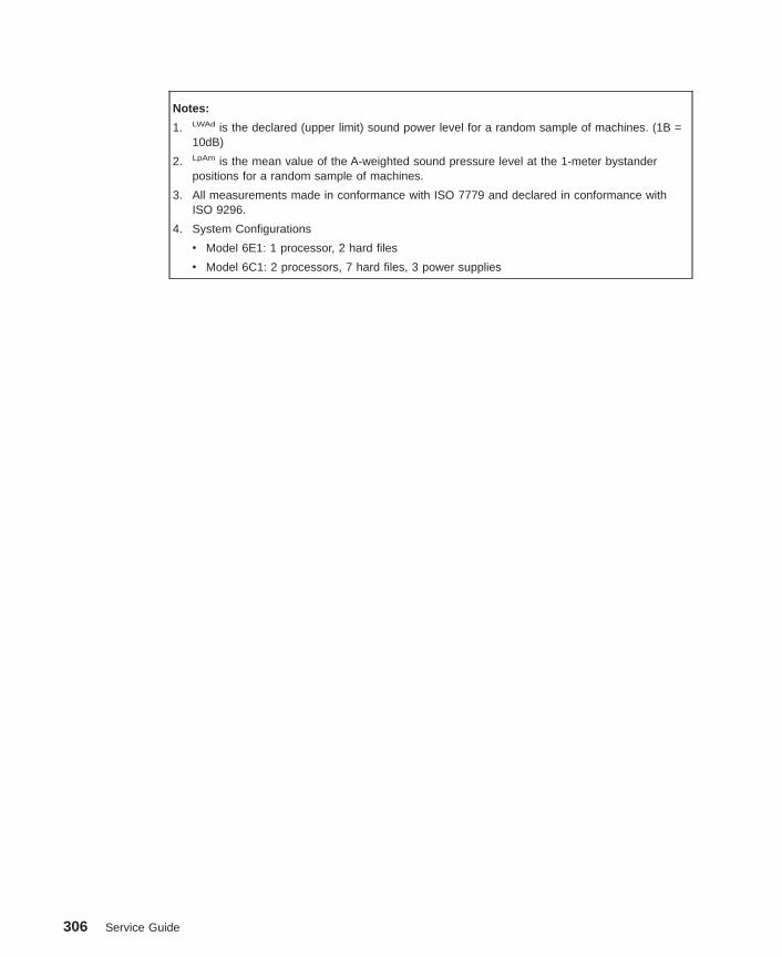
Notes:
1. LWAd is the declared (upper limit) sound power level for a random sample of machines. (1B =10dB)
2. LpAm is the mean value of the A-weighted sound pressure level at the 1-meter bystanderpositions for a random sample of machines.
3. All measurements made in conformance with ISO 7779 and declared in conformance withISO 9296.
4. System Configurations
v Model 6E1: 1 processor, 2 hard files
v Model 6C1: 2 processors, 7 hard files, 3 power supplies
306 Service Guide

Appendix B. Notices
This information was developed for products and services offered in the U.S.A.
The manufacturer may not offer the products, services, or features discussed in thisdocument in other countries. Consult the manufacturer’s representative for informationon the products and services currently available in your area. Any reference to themanufacturer’s product, program, or service is not intended to state or imply that onlythat product, program, or service may be used. Any functionally equivalent product,program, or service that does not infringe any intellectual property right of themanufacturer may be used instead. However, it is the user’s responsibility to evaluateand verify the operation of any product, program, or service.
The manufacturer may have patents or pending patent applications covering subjectmatter described in this document. The furnishing of this document does not give youany license to these patents. You can send license inquiries, in writing, to themanufacturer.
The following paragraph does not apply to the United Kingdom or any countrywhere such provisions are inconsistent with local law: THIS MANUAL ISPROVIDED ″AS IS″ WITHOUT WARRANTY OF ANY KIND, EITHER EXPRESSED ORIMPLIED, INCLUDING, BUT NOT LIMITED TO, THE IMPLIED WARRANTIES OFNON-INFRINGEMENT, MERCHANTABILITY OR FITNESS FOR A PARTICULARPURPOSE. Some states do not allow disclaimer of express or implied warranties incertain transactions; therefore, this statement may not apply to you.
This information could include technical inaccuracies or typographical errors. Changesare periodically made to the information herein; these changes will be incorporated innew editions of the publication. The manufacturer may make improvements and/orchanges in the product(s) and/or the program(s) described in this publication at anytime without notice.
Information concerning products made by other than the manufacturer was obtainedfrom the suppliers of those products, their published announcements, or other publiclyavailable sources. The manufacturer has not tested those products and cannot confirmthe accuracy of performance, compatibility or any other claims related to products madeby other than the manufacturer. Questions on the capabilities of products made by otherthan the manufacturer should be addressed to the suppliers of those products.
307

308 Service Guide

Appendix C. Service Processor Setup and Test
For your convenience, an example of a basic service processor setup checklist isincluded here. Your setup may include more or fewer of the available features, so youcan adjust this checklist for your own application so that it is helpful to you.
Service Processor Setup Checklist1. Unplug the power cord from the server.
2. Attach a local terminal for this setup procedure.
3. Plug in the system and power on the local terminal.
Attention: Make sure that system power remains off.
4. Start the service processor menus. See “Service Processor Menus” on page 179.
5. Set the system name. See “Privileged User Menus” on page 182.
6. Enable surveillance. See OS Surveillance Setup Menu on page 185.
7. Configure Call-In/Call-Out. See “Call-In/Call-Out Setup Menu” on page 195.
8. Exit the service processor menus.
9. Unplug the power cord from the system.
10. Attach modems (if needed). See “Accessing Service Processor Menus Locally” onpage 179.
11. Plug in the system.
Attention: Make sure that the system power remains off.
12. Test both of the following:v Call-In, see “Testing Call-In” on page 310v Call-Out, see “Testing Call-Out” on page 310
13. Use the “Save or Restore Hardware Management Policies,” in the “Introduction toTasks and Service Aids” section of the RS/6000 Eserver pSeries DiagnosticInformation for Multiple Bus Systems to back up the service processor settings.
Note: This step is strongly recommended to protect the usefulness of the serviceprocessor and the availability of the server.
Your service processor is now ready for use.
309
Testing the SetupThis section contains sample testing procedures to help ensure that your setup isworking.
These tests include communicating with the server operating system. Before you start,ensure that the necessary serial port(s) is configured. If you need assistance, refer to“Serial Port Configuration” on page 311.
The server should be powered off as a result of the “Service Processor SetupChecklist” on page 309.
Testing Call-In1. At your remote terminal, call in to your server. Your server answers and offers you
the Service Processor Main Menu after requesting your privileged access password.
2. Select System Power Control .
3. Select Power-On System .
When you are asked if you wish to continue powering on the system, type Y.
4. After the system firmware and operating system have initialized the server, the loginprompt displays at your remote terminal if you set up Seamless Modem Transfer(refer to “Transfer of a Modem Session” on page 318 for more information). Thismay take several minutes. When the login prompt displays, you have successfullycalled the service processor.
5. Type logout to disconnect from the operating system. The message No Carrierdisplays on your remote terminal.
6. Call your server again. The operating system answers and offers you the loginprompt. If these tests are successful, call-in is working.
7. Log in and type shutdown to shut down your server.
8. The message No Carrier displays on your remote terminal.
Testing Call-OutDuring the setup, you entered your phone numbers for the pager (on page 198) andcustomer voice (on page 198). These numbers are used for this test.
1. Your remote terminal is disconnected as a result of the Call-In test.
2. Call your server again.
3. At the service processor main menu, select Call-In/Call-Out Setup menu, thenselect Call-Out test. This action causes a simulated error condition for the purposesof this test.
4. After a few moments, a message displays, regarding an illegal entry. Press Enter toclear the message and return to the main menu.
5. When your telephone rings, answer the call. You should hear the sound of atelephone being dialed. Your computer is trying to page you.
If this test is successful, call-out is working correctly.
310 Service Guide

Return to the “Telephone Number Setup Menu” on page 197 to enter the actualtelephone numbers your server will use for reporting problems.
Serial Port ConfigurationTo configure the serial port on an AIX system, run the following from an AIX console:
1. Log in as root user.
2. To determine if you have any serial ports already configured, type:
lsdev -Cc tty
If no serial ports are configured, none are listed. If you want to configure serialports that are not listed, continue with the remaining steps.
3. Identify the serial port(s) with the modem(s).
4. Type smit tty
5. Select add tty
6. Select RS232
7. Select Baud rate 9600 or higher.
8. Select login enable and set the flow control to RTS.
9. Commit the selections and set up any other needed serial ports.
10. Exit SMIT.
Appendix C. Service Processor Setup and Test 311

312 Service Guide

Appendix D. Modem Configurations
The service processor is designed to place little demand on an attached modem,thereby increasing the setup and connection success rates.
Sample Modem Configuration FilesThis appendix contains information about several sample modem configuration files thateither work directly with your modem or provide a good starting point for a customsetup.
The sample modem configuration files are located in your service processor firmware inthe /usr/share/modems subdirectory (if your server is using AIX) with the followingnames. A listing of each specific file is included in this appendix.
Generic Modem Configuration Files
AIX File Name Service Processor Firmware File Name
modem_z.cfg modem_z_sp
modem_z0.cfg modem_z0_sp
modem_f.cfg modem_f_sp
modem_f0.cfg modem_f0_sp
modem_f1.cfg modem_f1_sp
Specific Modem Configuration Files
AIX File Name Service Processor Firmware File Name
modem_m0.cfg modem_m0_sp
modem_m1.cfg modem_m1_sp
Use the following selection procedures and your modem manual to determine which ofthe configuration files is suitable for your use.
313

Configuration File SelectionUse the following steps to select a configuration file:
1. Is your modem an IBM 7852-400?
If Yes, use modem configuration file modem_m0.cfg and go to step 7 on page 315.
Note: The IBM 7852-400 modem has DIP switches on the right side of the unit.See “IBM 7852-400 DIP Switch Settings” on page 317 for the correct switchsettings.
If No, continue with step 2.
2. Is your modem an IBM 7857-017?
If Yes, use modem configuration file modem_m1.cfg and go to step 7 on page 315.
Note: The IBM 7857-017 modem has two telephone line connections on the backof the unit. One is marked LL (for Leased Line), and the other is markedPTSN (for Public Telephone Switched Network). The service processorexpects to use the modem on the public network, so the telephone lineshould attach to the PTSN connector.
If No, continue with step 3.
3. Does your modem respond to the extended command set (prefixed with &)?
If Yes, go to step 5.If No, continue with step 4.
4. Does your modem respond to:
v ATZ reset command
or
v ATZn reset commands, where n can be 0, 1, and so on?
If ATZ, configuration file modem_z.cfg is recommended.If ATZn, configuration file modem_z0.cfg is recommended.
Go to step 7 on page 315.
5. Does your modem command set include a test for V.42 error correction at theremote modem (often called “Auto-Reliable Mode”)?
If Yes, disable this test. You can use sample configuration files/usr/share/modem_m0.cfg or /usr/share/modem_m1.cfg as models to help youcreate a file for your particular modem. See “Customizing the Modem ConfigurationFiles” on page 316 for more information. Go to step 7 on page 315.
If No, go to step 6.
6. Does your modem respond to:
v AT&F reset command
or
v AT&Fn reset commands, where n can be 0, 1, and so on?
314 Service Guide

If AT&F, configuration file modem_f.cfg is recommended.If AT&Fn, configuration file modem_f0.cfg or modem_f1.cfg is recommended,depending on which provides the hardware flow control profile.
7. You have completed selection of the configuration file.
If your modem configuration selection is not available in the Service ProcessorModem Configuration Menu, you must access it through the Configure RemoteMaintenance Policy Service Aid.
If you find it necessary to adjust any of these configuration files, use the manualprovided with your modem to accomplish that task. It is recommended you selectsettings that enable hardware flow control and respond to DTR.
Note: Some older modems do not respond to the X0 or &R1 commands. Edit outthese commands from the modem configuration file if yours is such amodem. See your modem manual for more information.
Some modems, such as the IBM 7857-017, are not designed for the paging function.Although they can be used for paging, they return an error message when they do notget the expected response from another modem. Therefore, even though the pagingwas successful, the error message causes the service processor to retry, continuing toplace pager calls for the number of retries specified in the Call-Out Policy Setup Menu.These retries result in redundant pages.
Appendix D. Modem Configurations 315

Examples for Using the Generic Sample Modem Configuration FilesThe following table contains information to help you determine which modemconfiguration file to use with various modems.
Modem Setup Z Setup Z0(Rare)
Setup F Setup F0 Setup F1
AT&T DataPort 2001(Ring interrupt only on
first ring)
X
Bocamodem 1440E X
Hayes Smart Modem300
X
IBM 5841 X
IBM 5843 X
IBM 7851 X
IBM 7852-10 X
IBM 7855 X
USRobotics36.6K Sportster
X
Zoom V.32 X
Customizing the Modem Configuration FilesYou can create your own modem configuration files or modify the samples provided.After you customize your modem configuration files, you must access them through theConfigure Remote Maintenance Policy Service Aid rather than from the serviceprocessor menus.
Note: If you have already set up your serial ports, line speeds, authorizations, andtelephone numbers from the service processor menus, use the service aid tospecify your customized modem configuration files.
If you have not already set up your serial ports, line speeds, authorizations, andtelephone numbers from the service processor menus, use the service aids toset them while you specify your customized modem configuration files.
To disable Auto-Reliable Mode testing of the remote modem, use the sample modemconfiguration file /usr/share/modems/modem_f.cfg as a model that you can modify, asfollows:1. Find the necessary command in your modem manual.2. Copy the /usr/share/modems/modem_f.cfg file to a new file with a different name
(for example, modem_fx.cfg ).3. In the new file (modem_fx.cfg ), change the line Send "ATE0T\r" to Send
"ATcccE0T\r" where ccc is the added command as specified in your modemmanual, as follows:
Change the third line of each of the following stanzas:v condout
316 Service Guide

v condinv ripo
4. Save the changes.
IBM 7852-400 DIP Switch SettingsIf you are using a 7852-400 modem to enable service processor communications, forproper operation, the dual inline package (DIP) switches must be set according to thefollowing table:
Switch Position Function
1 Up Force DTR2 Up Flow Control &E43 Down Result Codes Enabled4 Down Modem Emulation Disabled5 Up Auto Answer Enabled6 Up Maximum Throughput Enabled7 Up RTS Normal Functions8 Down Enable Command Mode9 Down Remote Digital Loopback Test Enabled
10 Up Dial-Up Line Enabled11 *Up AT Responses Enabled (Extended Responses Disabled)12 *Down Asynchronous Operation
13 Up 28.8KB Line Speed14 Up
15 Up CD and DSR Normal Functions16 Up 2-Wire Leased Line Enabled* Only switches 11 and 12 are changed from the factory default settings.
Xon/Xoff ModemsSome early modems assume software flow control (Xon/Xoff) between the computerand the modem. Modems with this design send extra characters during and after thetransmitted data. The service processor cannot accept these extra characters. If yourconfiguration includes such a modem, your functional results may be unpredictable.
The sample modem configuration files included in this appendix do not support thesemodems, so custom configuration files are necessary. Anchor Automation 2400E is anexample of such a modem.
If you experience unexplainable performance problems that may be due to Xon/Xoffcharacters, it is recommended that you upgrade your modem.
Ring DetectionMost modems produce an interrupt request each time they detect a ring signal. Somemodems generate an interrupt only on the first ring signal that they receive. AT&TDataPort 2001 is an example of such a modem.
Appendix D. Modem Configurations 317

The service processor uses the ring interrupt request to count the number of rings whenRing Indicate Power-On (RIPO) is enabled. If your modem produces an interrupt ononly the first ring, set Ring Indicate Power-On to start on the first ring. Otherwise, youcan choose to start Ring Indicate Power-On on any ring count.
Terminal EmulatorsThe service processor is compatible with simple ASCII terminals, and thereforecompatible with most emulators. When a remote session is handed off from the serviceprocessor to the operating system, agreement between terminal emulators becomesimportant.
The server’s operating system will have some built-in terminal emulators. You may alsohave a commercially available terminal emulation. It is important that the local and hostcomputers select the same or compatible terminal emulators so that the keyassignments and responses match, ensuring successful communications and control.
For best formatting, choose line wrap in your terminal emulator setup.
Recovery ProceduresSituations such as line noises and power surges can sometimes cause your modem toenter an undefined state. When it is being used for dial-in, dial-out or ring indicatepower-on, your modem is initialized each time one of these actions is expected. If oneof these environmental conditions occur after your modem has been initialized, it mightbe necessary to recover your modem to a known state.
If your modem communicates correctly with remote users, it is probably in control. Itmay be wise to occasionally change some of the functional settings and then changethem back, just for the sense of security that the modem is communicating, and toensure it has been initialized recently.
If your system is particularly difficult to access physically, another strategy is to protect itwith an Uninterruptible Power Source (UPS) and a phone-line surge protector.
In case recovery becomes necessary, shut down your system using establishedprocedures. Disconnect the power cable and press the power button to draincapacitance while power is disconnected. Disconnect and reconnect modem power, andthen reconnect system power to completely reinitialize your system.
Transfer of a Modem SessionBecause many modem command variations exist, the sample modem configuration fileslocated at the end of this appendix have been written to capture the largest number ofworkable modem settings.
The modem command &Dn (where n is a number) generally sets the modem responseto the Data Terminal Ready (DTR) signal from the server’s serial port. The desiredresponse is that the modem will hold a connection while DTR is enabled, and drop theconnection when DTR is released. Using this mechanism, the server hangs up on aconnection under normal conditions.
318 Service Guide

Consult your modem manual for its specific response scheme for the &Dn command.
Two strategies are available for dealing with the modem’s response to DTR:
v Recovery
v Prevention
Before you use one of these strategies, determine if your server’s modem is set upcorrectly to respond to DTR.
With the remote terminal connected to serial port 1 and defined as the Primary ConsoleDevice, there are two tests you can perform:
1. Will the modem drop the connection after the System initialization completemessage displays at the remote terminal?
If Yes, the modem is set up correctly.
If No, try another &Dn setting for your server’s modem. See your modem manualfor this information. The &Dn command appears in three places each in three of thesample modem configuration files, as follows:
2. Will the server’s modem disconnect when the power drops? You can make thisobservation at the remote terminal by commanding your server to shut down andpower off. (Use the AIX command shutdown -F .) Watch for the message NOCARRIER on your remote terminal.
If Yes, this is the correct response. The modem is set up correctly.
If No, try another &Dn setting for your server’s modem. See your model manual forthis information. The &Dn command appears in three places each in three of thesample modem configuration files. Only the following sample modem configurationfiles contain the &Dn command (in three places each):v modem_f.cfgv modem_f0.cfgv modem_f1.cfg
If you are using modem_z.cfg or modem_z0.cfg, you cannot control DTR response.If your remote terminal does not disconnect after logging off, you must commandthe remote terminal emulator to hang up. This then breaks the connection.
Recovery StrategyThe recovery strategy consists of making two calls to establish a remote session. Thissolution is the easiest to implement and allows more freedom for configuring yourserver’s serial ports.
To set up a remote terminal session, dial into the service processor and start thesystem. After the operating system is loaded and initialized, the connection will bedropped. At this point, call the server back and the operating system will answer andoffer you the login prompt.
Appendix D. Modem Configurations 319
Prevention StrategyThe disconnect is caused by the operating system when it initializes the PrimaryConsole. The tests listed in “Transfer of a Modem Session” on page 318 are conductedwith the remote terminal selected as the primary console to manifest the modem’sresponse to DTR transitions.
v If a local ASCII terminal or a graphics console is to be a permanent part of yourserver, then make one of them the primary console. Your remote terminal will nolonger experience the connection loss.
v If a local console is not a permanent part of your server, you can still assign eitherthe unused graphics console or the unused serial port as the primary console. Thisgives you the desired seamless connection at your remote terminal.
v If you choose to use the unused serial port as the primary console, some initializationtraffic will be sent to any serial device attached to that port. As a result, that serialdevice’s connection and function could be affected. These impacts may make thatport unattractive for devices other than a temporary local ASCII terminal.
320 Service Guide
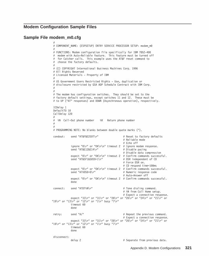
Modem Configuration Sample Files
Sample File modem_m0.cfg## COMPONENT_NAME: (ESPSETUP) ENTRY SERVICE PROCESSOR SETUP: modem_m0## FUNCTIONS: Modem configuration file specifically for IBM 7852-400# modem with Auto-Reliable feature. This feature must be turned off# for Catcher calls. This example uses the AT&F reset command to# choose the factory defaults.## (C) COPYRIGHT International Business Machines Corp. 1996# All Rights Reserved# Licensed Materials - Property of IBM## US Government Users Restricted Rights - Use, duplication or# disclosure restricted by GSA ADP Schedule Contract with IBM Corp.### The modem has configuration switches. They should be set to the# factory default settings, except switches 11 and 12. These must be# to UP ("AT" responses) and DOWN (Asynchronous operation), respectively.
ICDelay 1DefaultTO 10CallDelay 120## %N Call-Out phone number %R Return phone number### PROGRAMMING NOTE: No blanks between double quote marks (").
condout: send "AT&F&E2E0T\r" # Reset to factory defaults# Reliable mode# Echo off
ignore "0\r" or "OK\r\n" timeout 2 # Ignore modem response.send "AT&E12&E14\r" # Disable pacing
# Disable data compressionexpect "0\r" or "OK\r\n" timeout 2 # Confirm commands successful.send "AT&SF1&S0S9=1\r" # DSR independent of CD
# Force DSR on.# CD respond time=100ms
expect "0\r" or "OK\r\n" timeout 2 # Confirm commands successful.send "ATV0S0=0\r" # Numeric response code
# Auto-Answer offexpect "0\r" or "OK\r\n" timeout 2 # Confirm commands successful.done
connect: send "ATDT%N\r" # Tone dialing command.# %N from Call Home setup.# Expect a connection response.
expect "33\r" or "31\r" or "28\r" or "26\r" or "24\r" or "21\r" or"19\r" or "13\r" or "12\r" or "1\r" busy "7\r"
timeout 60done
retry: send "A/" # Repeat the previous command.# Expect a connection response.
expect "33\r" or "31\r" or "28\r" or "26\r" or "24\r" or "21\r" or"19\r" or "13\r" or "12\r" or "1\r" busy "7\r"
timeout 60done
disconnect:delay 2 # Separate from previous data.
Appendix D. Modem Configurations 321

send "+++" # Assure command mode.delay 2 # Allow mode switching delay.send "ATH0T\r" # Set modem switch-hook down
# (i.e., hang up).ignore "0\r" or "OK\r" timeout 2 # Ignore modem response.send "ATE0Q1\r" # Initialize modem: Echo OFF,
# Disable responses.ignore "0\r" timeout 1done
condin: send "AT&F&E2E0T\r" # Reset to factory defaults.# Reliable mode# Echo off
ignore "0\r" or "OK\r\n" timeout 2 # Ignore modem response.send "AT&E12&E14\r" # Disable pacing
# Disable data compressionexpect "0\r" or "OK\r\n" timeout 2 # Confirm commands successfulsend "AT&SF1&S0S9=1\r" # DSR independent of CD.
# Force DSR on.# CD respond time=100ms
expect "0\r" or "OK\r\n" timeout 2 # Confirm commands successful.send "ATV0S0=2\r" # Numberic response code
# Answer on 2nd ringexpect "0\r" timeout 2 # Confirm commands successful.done
waitcall: ignore "2\r" timeout 1 # Ignore first ring.expect "2\r" timeout 10 # Pickup 2nd ring or timeout
# Expect a connection response.expect "33\r" or "31\r" or "28\r" or "26\r" or "24\r" or "21\r" or
"19\r" or "13\r" or "12\r" or "1\r" busy "7\r"timeout 60done
page: send "ATDT%N,,,,%R;\r" # %N = pager call center number# Add enough commas to wait for# time to enter paging number.# %R = paging number
expect "0\r" timeout 60 # Confirm successful command.delay 2 # Wait before hanging up.send "ATH0\r" # Hang up.expect "0\r" timeout 2 # Confirm successful command.done
ripo: send "AT&F&E2E0T\r" # Reset to factory defaults.# Reliable mode# Echo off
ignore "0\r" or "OK\r\n" timeout 2 # Ignore modem response.send "AT&E12&E14\r" # Disable pacing
# Disable data compressionexpect "0\r" or "OK\r\n" timeout 2 # Confirm successful command.send "AT&SF1&S0S9=1\r" # DSR independent of CD.
# Force DSR on.# CD respond time=100ms
expect "0\r" or "OK\r\n" timeout 2 # Confirm commands successful.send "ATV0S0=0\r" # Numeric response code
# Auto Answer OFFexpect "0\r" timeout 2 # Confirm commands successful.done #
error: # Handle unexpected modem# responses.
expect "8\r" or "7\r" or "6\r" or "4\r" or "3\r"delay 2done
322 Service Guide

Sample File modem_m1.cfg## COMPONENT_NAME: (ESPSETUP) ENTRY SERVICE PROCESSOR SETUP modem_m1## FUNCTIONS: Modem configuration file specifically for IBM 7857-017 modem with# Auto-Reliable feature. This feature must be turned off for Catcher calls.# This example uses the AT&F reset command to choose the factory defaults.## To allow dial commands for digital pagers, it is necessary to reduce# the number of characters in the dial command. Each comma (delay) has# been set to 6 seconds (S8=6) for that reason.### (C) COPYRIGHT International Business Machines Corp. 1996# All Rights Reserved# Licensed Materials - Property of IBM## US Government Users Restricted Rights - Use, duplication or# disclosure restricted by GSA ADP Schedule Contract with IBM Corp.#
ICDelay 1DefaultTO 10CallDelay 120## %N Call-Out phone number %R Return phone number### PROGRAMMING NOTE: No blanks between double quote marks (").
condout: send "AT&F*E0E0\r" # Reset to factory defaults.# *E0=data compression disabled# E0=echo disabled
ignore "0\r" or "OK\r\n" timeout 2 # Ignore modem response.send "AT#F0*Q2S8=6\r" # Trellis modulation disabled
# Retrain with adaptive rate# Set ,=6second
expect "0\r" or "OK\r\n" timeout 2 # Confirm commands successfulsend "ATV0X0S0=0\r" # Numeric response code
# AT compatible messages# Auto-Answer disabled
expect "0\r" or "OK\r\n" timeout 2 # Confirm commands successful.done
connect: send "ATDT%N\r" # Tone dialing command.# %N from Call Home setup.
expect "1\r" busy "7\r" timeout 60 # Expect a connection response.done
retry: send "A/" # Repeat the previous command.expect "1\r" busy "7\r" timeout 60 # Expect a connection response.done
disconnect:delay 2 # Separate from previous data.send "+++" # Assure command mode.delay 2 # Allow mode switching delay.send "ATH0\r" # Set modem switch-hook down
# (i.e., hang up).ignore "0\r" or "OK\r" timeout 2 # Ignore modem response.send "ATE0Q1\r" # Initialize modem: Echo OFF,
# Disable responses.ignore "0\r" timeout 1done
condin: send "AT&F*E0E0\r" # Reset to factory defaults.
Appendix D. Modem Configurations 323

# *E0=data compression disabled# E0=echo disabled
ignore "0\r" or "OK\r\n" timeout 2 # Ignore modem response.send "AT#F0*Q2\r" # Trellis modulation disabled
# Retrain with adaptive rateexpect "0\r" or "OK\r\n" timeout 2 # Confirm commands successfulsend "ATV0X0S0=2\r" # Numeric response code
# AT compatible messages# Answer on 2nd ring
expect "0\r" timeout 2 # Confirm commands successful.done
waitcall: ignore "2\r" timeout 1 # Ignore first ring.expect "2\r" timeout 10 # Pick up second ring
# or timeout.# Expect a connection response.
expect "1\r" timeout 60done
page: send "ATD%N,%R\r" # %N = pager call center number# commas=6sec wait time to# enter paging number.# %R = return number
expect "0\r" or "3\r" timeout 30 # Confirm successful command.delay 2 # Wait before hanging up.send "+++" # Assure command mode.delay 2 # Allow mode switching delay.send "ATH0\r" # Hang up.expect "0\r" timeout 2 # Confirm successful command.done
ripo: send "AT&F*E0E0\r" # Reset to factory defaults.# *E0=data compression disabled# E0=echo disabled
ignore "0\r" or "OK\r\n" timeout 2 # Ignore modem response.send "AT#F0*Q2\r" # Trellis modulation disabled
# Retrain with adaptive rateexpect "0\r" or "OK\r\n" timeout 2 # Confirm successful command.send "ATV0X0S0=0\r" # Numeric response code
# AT compatible messages# Auto-Answer disabled
expect "0\r" timeout 2 # Confirm commands successful.done #
error: # Handle unexpected modem# responses.
expect "8\r" or "7\r" or "4\r" or "3\r"delay 2done
324 Service Guide
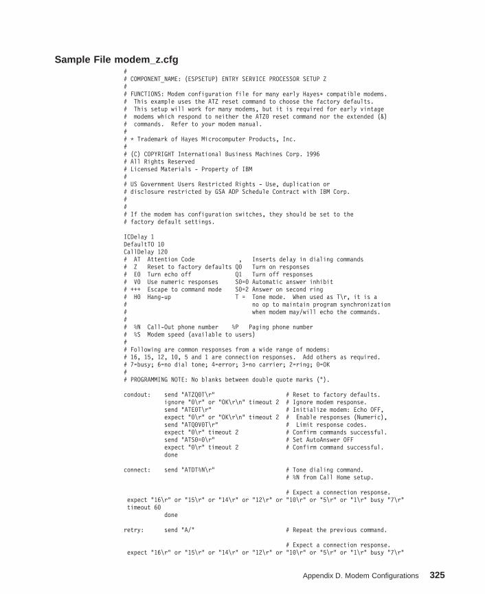
Sample File modem_z.cfg## COMPONENT_NAME: (ESPSETUP) ENTRY SERVICE PROCESSOR SETUP Z## FUNCTIONS: Modem configuration file for many early Hayes* compatible modems.# This example uses the ATZ reset command to choose the factory defaults.# This setup will work for many modems, but it is required for early vintage# modems which respond to neither the ATZ0 reset command nor the extended (&)# commands. Refer to your modem manual.## * Trademark of Hayes Microcomputer Products, Inc.## (C) COPYRIGHT International Business Machines Corp. 1996# All Rights Reserved# Licensed Materials - Property of IBM## US Government Users Restricted Rights - Use, duplication or# disclosure restricted by GSA ADP Schedule Contract with IBM Corp.### If the modem has configuration switches, they should be set to the# factory default settings.
ICDelay 1DefaultTO 10CallDelay 120# AT Attention Code , Inserts delay in dialing commands# Z Reset to factory defaults Q0 Turn on responses# E0 Turn echo off Q1 Turn off responses# V0 Use numeric responses S0=0 Automatic answer inhibit# +++ Escape to command mode S0=2 Answer on second ring# H0 Hang-up T = Tone mode. When used as T\r, it is a# no op to maintain program synchronization# when modem may/will echo the commands.## %N Call-Out phone number %P Paging phone number# %S Modem speed (available to users)## Following are common responses from a wide range of modems:# 16, 15, 12, 10, 5 and 1 are connection responses. Add others as required.# 7=busy; 6=no dial tone; 4=error; 3=no carrier; 2=ring; 0=OK## PROGRAMMING NOTE: No blanks between double quote marks (").
condout: send "ATZQ0T\r" # Reset to factory defaults.ignore "0\r" or "OK\r\n" timeout 2 # Ignore modem response.send "ATE0T\r" # Initialize modem: Echo OFF,expect "0\r" or "OK\r\n" timeout 2 # Enable responses (Numeric),send "ATQ0V0T\r" # Limit response codes.expect "0\r" timeout 2 # Confirm commands successful.send "ATS0=0\r" # Set AutoAnswer OFFexpect "0\r" timeout 2 # Confirm command successful.done
connect: send "ATDT%N\r" # Tone dialing command.# %N from Call Home setup.
# Expect a connection response.expect "16\r" or "15\r" or "14\r" or "12\r" or "10\r" or "5\r" or "1\r" busy "7\r"timeout 60
done
retry: send "A/" # Repeat the previous command.
# Expect a connection response.expect "16\r" or "15\r" or "14\r" or "12\r" or "10\r" or "5\r" or "1\r" busy "7\r"
Appendix D. Modem Configurations 325

timeout 60done
disconnect:delay 2 # Separate from previous data.send "+++" # Assure command mode.delay 2 # Allow mode switching delay.send "ATH0T\r" # Set modem switch-hook down
# (i.e., hang up).ignore "0\r" or "OK\r" timeout 2 # Ignore modem response.send "ATE0Q1\r" # Initialize modem: Echo OFF,
# Disable responses.ignore "0\r" timeout 1done
condin: send "ATZQ0T\r" # Reset to factory defaults.ignore "0\r" or "OK\r\n" timeout 2 # Ignore modem response.send "ATE0T\r" # Initialize modem: Echo OFF,expect "0\r" or "OK\r\n" timeout 2 # Enable responses (Numeric),send "ATQ0V0T\r" # Limit response codes.expect "0\r" timeout 2 # Confirm commands successful.send "ATS0=2\r" # Set AutoAnswer ONexpect "0\r" timeout 2 # Confirm command successful.done
waitcall: ignore "2\r" timeout 1 # Ignore first ring.expect "2\r" timeout 10 # Pick up second ring
# or timeout.# Expect a connection response.
expect "16\r" or "15\r" or "14\r" or "12\r" or "10\r" or "5\r" or "1\r"timeout 60
done
page: send "ATDT%N,,,,%R;\r" # %N = pager call center number# Add enough commas to wait for# time to enter paging number.# %R = paging number
# Confirm successful command.expect "0\r" timeout 60delay 2 # Wait before hanging up.send "ATH0T\r" # Hang up.expect "0\r" timeout 2 # Confirm successful command.done
ripo: send "ATZQ0T\r" # Reset to factory defaults.ignore "0\r" or "OK\r\n" timeout 2 # Ignore modem response.send "ATE0T\r" # Initialize modem: Echo OFF,expect "0\r" or "OK\r\n" timeout 2 # Enable responses (Numeric),send "ATQ0V0T\r" # Limit response codes.expect "0\r" timeout 2 # Confirm commands successful.send "ATS0=0\r" # Set AutoAnswer OFFexpect "0\r" timeout 2 # Confirm command successful.done # RI Power On enabled.
error: # Handle unexpected modem# responses.
expect "8\r" or "7\r" or "6\r" or "4\r" or "3\r"delay 2done
326 Service Guide

Sample File modem_z0.cfg## COMPONENT_NAME: (ESPSETUP) ENTRY SERVICE PROCESSOR SETUP Z0## FUNCTIONS: Modem configuration file for some early Hayes* compatible modems.# This example uses the ATZ0 reset command to choose the factory defaults.# This setup is recommended for modems that will respond to the ATZ0 command# and which do not respond to the extended (&) commands. Refer to your modem# manual.## * Trademark of Hayes Microcomputer Products, Inc.## (C) COPYRIGHT International Business Machines Corp. 1996# All Rights Reserved# Licensed Materials - Property of IBM## US Government Users Restricted Rights - Use, duplication or# disclosure restricted by GSA ADP Schedule Contract with IBM Corp.### If the modem has configuration switches, they should be set to the# factory default settings.
ICDelay 1DefaultTO 10CallDelay 120# AT Attention Code , Inserts delay in dialing commands# Z0 Reset. Restore Profile 0 Q0 Turn on responses# E0 Turn echo off Q1 Turn off responses# V0 Use numeric responses S0=0 Automatic answer inhibit# +++ Escape to command mode S0=2 Answer on second ring# H0 Hang-up X0=0 Limit modem response codes# T = Tone mode. When used as T\r, it is a# no op to maintain program synchronization# when modem may/will echo the commands.## %N Call-Out phone number %P Paging phone number# %S Modem speed (available to users)## Following are common responses from a wide range of modems:# 16, 15, 12, 10, 5 and 1 are connection responses. Add others as required.# 7=busy; 6=no dial tone; 4=error; 3=no carrier; 2=ring; 0=OK## PROGRAMMING NOTE: No blanks between double quote marks (").
condout: send "ATZ0Q0T\r" # Reset modem. Select profile 0ignore "0\r" or "OK\r\n" timeout 2 # Ignore modem response.send "ATE0T\r" # Initialize modem: Echo OFF,expect "0\r" or "OK\r\n" timeout 2 # Enable responses (Numeric),send "ATQ0V0X0T\r" # Limit response codes.expect "0\r" timeout 2 # Confirm commands successful.send "ATS0=0\r" # Set AutoAnswer OFFexpect "0\r" timeout 2 # Confirm command successful.done
connect: send "ATDT%N\r" # Tone dialing command.# %N from Call Home setup.
# Expect a connection response.expect "16\r" or "15\r" or "14\r" or "12\r" or "10\r" or "5\r" or "1\r" busy "7\r"timeout 60
done
retry: send "A/" # Repeat the previous command.
# Expect a connection response.
Appendix D. Modem Configurations 327

expect "16\r" or "15\r" or "14\r" or "12\r" or "10\r" or "5\r" or "1\r" busy "7\r"timeout 60
done
disconnect:delay 2 # Separate from previous data.send "+++" # Assure command mode.delay 2 # Allow mode switching delay.send "ATH0T\r" # Set modem switch-hook down
# (i.e., hang up).ignore "0\r" or "OK\r" timeout 2 # Ignore modem response.send "ATE0Q1\r" # Initialize modem: Echo OFF,
# Disable responses.ignore "0\r" timeout 1done
condin: send "ATZ0Q0T\r" # Reset modem. Select profile 0ignore "0\r" or "OK\r\n" timeout 2 # Ignore modem response.send "ATE0T\r" # Initialize modem: Echo OFF,expect "0\r" or "OK\r\n" timeout 2 # Enable responses (Numeric),send "ATQ0V0X0T\r" # Limit response codes.expect "0\r" timeout 2 # Confirm commands successful.send "ATS0=2\r" # Set AutoAnswer ONexpect "0\r" timeout 2 # Confirm command successful.done
waitcall: ignore "2\r" timeout 1 # Ignore first ring.expect "2\r" timeout 10 # Pick up second ring
# or timeout.# Expect a connection response.
expect "16\r" or "15\r" or "14\r" or "12\r" or "10\r" or "5\r" or "1\r"timeout 60
done
page: send "ATDT%N,,,,%R;\r" # %N = pager call center number# Add enough commas to wait for# time to enter paging number.# %R = paging number
# Confirm successful command.expect "0\r" timeout 60delay 2 # Wait before hanging up.send "ATH0T\r" # Hang up.expect "0\r" timeout 2 # Confirm successful command.done
ripo: send "ATZ0Q0T\r" # Reset modem. Select profile 0ignore "0\r" or "OK\r\n" timeout 2 # Ignore modem response.send "ATE0T\r" # Initialize modem: Echo OFF,expect "0\r" or "OK\r\n" timeout 2 # Enable responses (Numeric),send "ATQ0V0X0T\r" # Limit response codes.expect "0\r" timeout 2 # Confirm commands successful.send "ATS0=0\r" # Set AutoAnswer OFFexpect "0\r" timeout 2 # Confirm command successful.done # RI Power On enabled.
error: # Handle unexpected modem# responses.
expect "8\r" or "7\r" or "6\r" or "4\r" or "3\r"delay 2done
328 Service Guide

Sample File modem_f.cfg## COMPONENT_NAME: (ESPSETUP) ENTRY SERVICE PROCESSOR SETUP F## FUNCTIONS: Modem configuration file for many recent Hayes* compatible modems.# This example uses the AT&F reset command to choose the factory defaults.# This set up is preferred for modems with extended (&) commands. For early# vintage modems, setup Z or Z0 is recommended. If your modem responds to# the extended (&) commands and to factory default choices (&Fn), setup file# F0 or F1 is recommended.## * Trademark of Hayes Microcomputer Products, Inc.## (C) COPYRIGHT International Business Machines Corp. 1996# All Rights Reserved# Licensed Materials - Property of IBM## US Government Users Restricted Rights - Use, duplication or# disclosure restricted by GSA ADP Schedule Contract with IBM Corp.### If the modem has configuration switches, they should be set to the# factory default settings.
ICDelay 1DefaultTO 10CallDelay 120# AT Attention Code , Inserts delay in dialing commands# &F Reset to default profile Q0 Turn on responses# E0 Turn echo off Q1 Turn off responses# V0 Use numeric responses S0=0 Automatic answer inhibit# +++ Escape to command mode S0=2 Answer on second ring# H0 Hang-up X0=0 Limit modem response codes# T = Tone mode. When used as T\r, it is a# no op to maintain program synchronization# when modem may/will echo the commands.## &C1 Detect CD &D2 Respond to DTR (often the default)## %N Call-Out phone number %P Paging phone number# %S Modem speed (available to users)## Following are common responses from a wide range of modems:# 16, 15, 12, 10, 5 and 1 are connection responses. Add others as required.# 7=busy; 6=no dial tone; 4=error; 3=no carrier; 2=ring; 0=OK## PROGRAMMING NOTE: No blanks between double quote marks (").
condout: send "AT&FQ0T\r" # Reset to factory defaults.ignore "0\r" or "OK\r\n" timeout 2 # Ignore modem response.send "ATE0T\r" # Initialize modem: Echo OFF,expect "0\r" or "OK\r\n" timeout 2 # Enable responses (Numeric),send "ATQ0V0X0T\r" # Limit response codes.expect "0\r" timeout 2 # Confirm commands successful.send "ATS0=0\r" # Set AutoAnswer OFFexpect "0\r" timeout 2 # Confirm command successful.send "AT&C1&D2\r" # Detect carrier and DTR.expect "0\r" timeout 2 # Confirm command successful.done
connect: send "ATDT%N\r" # Tone dialing command.# %N from Call Home setup.
# Expect a connection response.expect "16\r" or "15\r" or "14\r" or "12\r" or "10\r" or "5\r" or "1\r" busy "7\r"timeout 60
Appendix D. Modem Configurations 329

done
retry: send "A/" # Repeat the previous command.
# Expect a connection response.expect "16\r" or "15\r" or "14\r" or "12\r" or "10\r" or "5\r" or "1\r" busy "7\r"timeout 60
done
disconnect:delay 2 # Separate from previous data.send "+++" # Assure command mode.delay 2 # Allow mode switching delay.send "ATH0T\r" # Set modem switch-hook down
# (i.e., hang up).ignore "0\r" or "OK\r" timeout 2 # Ignore modem response.send "ATE0Q1\r" # Initialize modem: Echo OFF,
# Disable responses.ignore "0\r" timeout 1done
condin: send "AT&FQ0T\r" # Reset to factory defaults.ignore "0\r" or "OK\r\n" timeout 2 # Ignore modem response.send "ATE0T\r" # Initialize modem: Echo OFF,expect "0\r" or "OK\r\n" timeout 2 # Enable responses (Numeric),send "ATQ0V0X0T\r" # Limit response codes.expect "0\r" timeout 2 # Confirm commands successful.send "ATS0=2\r" # Set AutoAnswer ONexpect "0\r" timeout 2 # Confirm command successful.send "AT&C1&D2\r" # Detect carrier and DTR.expect "0\r" timeout 2 # Confirm command successful.done
waitcall: ignore "2\r" timeout 1 # Ignore first ring.expect "2\r" timeout 10 # Pick up second ring
# or timeout.# Expect a connection response.
expect "16\r" or "15\r" or "14\r" or "12\r" or "10\r" or "5\r" or "1\r"timeout 60
done
page: send "ATDT%N,,,,%R;\r" # %N = pager call center number# Add enough commas to wait for# time to enter paging number.# %R = paging number
# Confirm successful command.expect "0\r" timeout 60delay 2 # Wait before hanging up.send "ATH0T\r" # Hang up.expect "0\r" timeout 2 # Confirm successful command.done
ripo: send "AT&FQ0T\r" # Reset to factory defaults.ignore "0\r" or "OK\r\n" timeout 2 # Ignore modem response.send "ATE0T\r" # Initialize modem: Echo OFF,expect "0\r" or "OK\r\n" timeout 2 # Enable responses (Numeric),send "ATQ0V0X0T\r" # Limit response codes.expect "0\r" timeout 2 # Confirm commands successful.send "ATS0=0\r" # Set AutoAnswer OFFexpect "0\r" timeout 2 # Confirm command successful.send "AT&C1&D2\r" # Detect carrier and DTR.expect "0\r" timeout 2 # Confirm command successful.done # RI Power On enabled.
error: # Handle unexpected modem
330 Service Guide

# responses.expect "8\r" or "7\r" or "6\r" or "4\r" or "3\r"delay 2done
Appendix D. Modem Configurations 331

Sample File modem_f0.cfg## COMPONENT_NAME: (ESPSETUP) ENTRY SERVICE PROCESSOR SETUP F0## FUNCTIONS: Modem configuration file for many recent Hayes* compatible modems.# This example uses the AT&F0 reset command to choose the factory defaults.# This set up is preferred for modems with extended (&) commands. For early# vintage modems, setup Z or Z0 is recommended. If your modem responds to# the extended (&) commands and to factory default choices (&Fn), but doesn’t# work properly with this setup file, setup F1 is recommended.## * Trademark of Hayes Microcomputer Products, Inc.## (C) COPYRIGHT International Business Machines Corp. 1996# All Rights Reserved# Licensed Materials - Property of IBM## US Government Users Restricted Rights - Use, duplication or# disclosure restricted by GSA ADP Schedule Contract with IBM Corp.### If the modem has configuration switches, they should be set to the# factory default settings.
ICDelay 1DefaultTO 10CallDelay 120# AT Attention Code , Inserts delay in dialing commands# &F0 Reset. Restore profile 0 Q0 Turn on responses# E0 Turn echo off Q1 Turn off responses# V0 Use numeric responses S0=0 Automatic answer inhibit# +++ Escape to command mode S0=2 Answer on second ring# H0 Hang-up X0=0 Limit modem response codes# T = Tone mode. When used as T\r, it is a# no op to maintain program synchronization# when modem may/will echo the commands.## &C1 Detect CD &D2 Respond to DTR (often the default)# &R1 Ignore RTS (CTS)## %N Call-Out phone number %P Paging phone number# %S Modem speed (available to users)## Following are common responses from a wide range of modems:# 16, 15, 12, 10, 5 and 1 are connection responses. Add others as required.# 7=busy; 6=no dial tone; 4=error; 3=no carrier; 2=ring; 0=OK## PROGRAMMING NOTE: No blanks between double quote marks (").
condout: send "AT&F0Q0T\r" # Reset modem. Select profile 0ignore "0\r" or "OK\r\n" timeout 2 # Ignore modem response.send "ATE0T\r" # Initialize modem: Echo OFF,expect "0\r" or "OK\r\n" timeout 2 # Enable responses (Numeric),send "ATQ0V0X0T\r" # Limit response codes.expect "0\r" timeout 2 # Confirm commands successful.send "ATS0=0\r" # Set AutoAnswer OFFexpect "0\r" timeout 2 # Confirm command successful.send "AT&C1&D2&R1\r" # Detect carrier and DTR,
# Ignore RTS.expect "0\r" timeout 2 # Confirm command successful.done
connect: send "ATDT%N\r" # Tone dialing command.# %N from Call Home setup.
# Expect a connection response.
332 Service Guide

expect "16\r" or "15\r" or "14\r" or "12\r" or "10\r" or "5\r" or "1\r" busy "7\r"timeout 60
done
retry: send "A/" # Repeat the previous command.
# Expect a connection response.expect "16\r" or "15\r" or "14\r" or "12\r" or "10\r" or "5\r" or "1\r" busy "7\r"timeout 60
done
disconnect:delay 2 # Separate from previous data.send "+++" # Assure command mode.delay 2 # Allow mode switching delay.send "ATH0T\r" # Set modem switch-hook down
# (i.e., hang up).ignore "0\r" or "OK\r" timeout 2 # Ignore modem response.send "ATE0Q1\r" # Initialize modem: Echo OFF,
# Disable responses.ignore "0\r" timeout 1done
condin: send "AT&F0Q0T\r" # Reset modem. Select profile 0ignore "0\r" or "OK\r\n" timeout 2 # Ignore modem response.send "ATE0T\r" # Initialize modem: Echo OFF,expect "0\r" or "OK\r\n" timeout 2 # Enable responses (Numeric),send "ATQ0V0X0T\r" # Limit response codes.expect "0\r" timeout 2 # Confirm commands successful.send "ATS0=2\r" # Set AutoAnswer ONexpect "0\r" timeout 2 # Confirm command successful.send "AT&C1&D2&R1\r" # Detect carrier and DTR,
# Ignore RTS.expect "0\r" timeout 2 # Confirm command successful.done
waitcall: ignore "2\r" timeout 1 # Ignore first ring.expect "2\r" timeout 10 # Pick up second ring
# or timeout.# Expect a connection response.
expect "16\r" or "15\r" or "14\r" or "12\r" or "10\r" or "5\r" or "1\r"timeout 60
done
page: send "ATDT%N,,,,%R;\r" # %N = pager call center number# Add enough commas to wait for# time to enter paging number.# %R = paging number
# Confirm successful command.expect "0\r" timeout 60delay 2 # Wait before hanging up.send "ATH0T\r" # Hang up.expect "0\r" timeout 2 # Confirm successful command.done
ripo: send "AT&F0Q0T\r" # Reset modem. Select profile 0ignore "0\r" or "OK\r\n" timeout 2 # Ignore modem response.send "ATE0T\r" # Initialize modem: Echo OFF,expect "0\r" or "OK\r\n" timeout 2 # Enable responses (Numeric),send "ATQ0V0X0T\r" # Limit response codes.expect "0\r" timeout 2 # Confirm commands successful.send "ATS0=0\r" # Set AutoAnswer OFFexpect "0\r" timeout 2 # Confirm command successful.send "AT&C1&D2&R1\r" # Detect carrier and DTR,
# Ignore RTS.expect "0\r" timeout 2 # Confirm command successful.
Appendix D. Modem Configurations 333

done # RI Power On enabled.
error: # Handle unexpected modem# responses.
expect "8\r" or "7\r" or "6\r" or "4\r" or "3\r"delay 2done
334 Service Guide
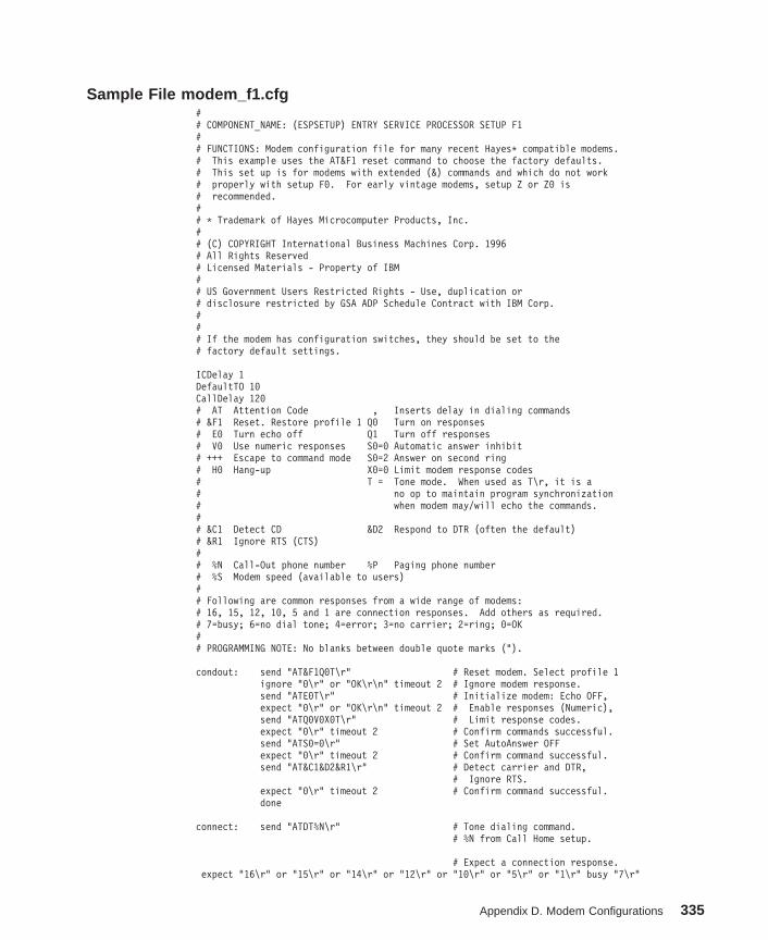
Sample File modem_f1.cfg## COMPONENT_NAME: (ESPSETUP) ENTRY SERVICE PROCESSOR SETUP F1## FUNCTIONS: Modem configuration file for many recent Hayes* compatible modems.# This example uses the AT&F1 reset command to choose the factory defaults.# This set up is for modems with extended (&) commands and which do not work# properly with setup F0. For early vintage modems, setup Z or Z0 is# recommended.## * Trademark of Hayes Microcomputer Products, Inc.## (C) COPYRIGHT International Business Machines Corp. 1996# All Rights Reserved# Licensed Materials - Property of IBM## US Government Users Restricted Rights - Use, duplication or# disclosure restricted by GSA ADP Schedule Contract with IBM Corp.### If the modem has configuration switches, they should be set to the# factory default settings.
ICDelay 1DefaultTO 10CallDelay 120# AT Attention Code , Inserts delay in dialing commands# &F1 Reset. Restore profile 1 Q0 Turn on responses# E0 Turn echo off Q1 Turn off responses# V0 Use numeric responses S0=0 Automatic answer inhibit# +++ Escape to command mode S0=2 Answer on second ring# H0 Hang-up X0=0 Limit modem response codes# T = Tone mode. When used as T\r, it is a# no op to maintain program synchronization# when modem may/will echo the commands.## &C1 Detect CD &D2 Respond to DTR (often the default)# &R1 Ignore RTS (CTS)## %N Call-Out phone number %P Paging phone number# %S Modem speed (available to users)## Following are common responses from a wide range of modems:# 16, 15, 12, 10, 5 and 1 are connection responses. Add others as required.# 7=busy; 6=no dial tone; 4=error; 3=no carrier; 2=ring; 0=OK## PROGRAMMING NOTE: No blanks between double quote marks (").
condout: send "AT&F1Q0T\r" # Reset modem. Select profile 1ignore "0\r" or "OK\r\n" timeout 2 # Ignore modem response.send "ATE0T\r" # Initialize modem: Echo OFF,expect "0\r" or "OK\r\n" timeout 2 # Enable responses (Numeric),send "ATQ0V0X0T\r" # Limit response codes.expect "0\r" timeout 2 # Confirm commands successful.send "ATS0=0\r" # Set AutoAnswer OFFexpect "0\r" timeout 2 # Confirm command successful.send "AT&C1&D2&R1\r" # Detect carrier and DTR,
# Ignore RTS.expect "0\r" timeout 2 # Confirm command successful.done
connect: send "ATDT%N\r" # Tone dialing command.# %N from Call Home setup.
# Expect a connection response.expect "16\r" or "15\r" or "14\r" or "12\r" or "10\r" or "5\r" or "1\r" busy "7\r"
Appendix D. Modem Configurations 335
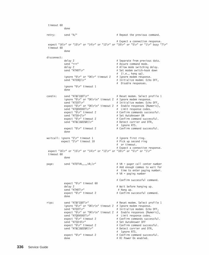
timeout 60done
retry: send "A/" # Repeat the previous command.
# Expect a connection response.expect "16\r" or "15\r" or "14\r" or "12\r" or "10\r" or "5\r" or "1\r" busy "7\r"timeout 60
done
disconnect:delay 2 # Separate from previous data.send "+++" # Assure command mode.delay 2 # Allow mode switching delay.send "ATH0T\r" # Set modem switch-hook down
# (i.e., hang up).ignore "0\r" or "OK\r" timeout 2 # Ignore modem response.send "ATE0Q1\r" # Initialize modem: Echo OFF,
# Disable responses.ignore "0\r" timeout 1done
condin: send "AT&F1Q0T\r" # Reset modem. Select profile 1ignore "0\r" or "OK\r\n" timeout 2 # Ignore modem response.send "ATE0T\r" # Initialize modem: Echo OFF,expect "0\r" or "OK\r\n" timeout 2 # Enable responses (Numeric),send "ATQ0V0X0T\r" # Limit response codes.expect "0\r" timeout 2 # Confirm commands successful.send "ATS0=2\r" # Set AutoAnswer ONexpect "0\r" timeout 2 # Confirm command successful.send "AT&C1&D2&R1\r" # Detect carrier and DTR,
# Ignore RTS.expect "0\r" timeout 2 # Confirm command successful.done
waitcall: ignore "2\r" timeout 1 # Ignore first ring.expect "2\r" timeout 10 # Pick up second ring
# or timeout.# Expect a connection response.
expect "16\r" or "15\r" or "14\r" or "12\r" or "10\r" or "5\r" or "1\r"timeout 60
done
page: send "ATDT%N,,,,%R;\r" # %N = pager call center number# Add enough commas to wait for# time to enter paging number.# %R = paging number
# Confirm successful command.expect "0\r" timeout 60delay 2 # Wait before hanging up.send "ATH0T\r" # Hang up.expect "0\r" timeout 2 # Confirm successful command.done
ripo: send "AT&F1Q0T\r" # Reset modem. Select profile 1ignore "0\r" or "OK\r\n" timeout 2 # Ignore modem response.send "ATE0T\r" # Initialize modem: Echo OFF,expect "0\r" or "OK\r\n" timeout 2 # Enable responses (Numeric),send "ATQ0V0X0T\r" # Limit response codes.expect "0\r" timeout 2 # Confirm commands successful.send "ATS0=0\r" # Set AutoAnswer OFFexpect "0\r" timeout 2 # Confirm command successful.send "AT&C1&D2&R1\r" # Detect carrier and DTR,
# Ignore RTS.expect "0\r" timeout 2 # Confirm command successful.done # RI Power On enabled.
336 Service Guide

error: # Handle unexpected modem# responses.
expect "8\r" or "7\r" or "6\r" or "4\r" or "3\r"delay 2done
Appendix D. Modem Configurations 337

338 Service Guide

Appendix E. Firmware Updates
This section provides information and instruction for updating firmware. You may needto perform these steps if you are installing an option or if your support representativehas instructed you to update your firmware.
Checking the Current Firmware LevelsTo check the current levels that are installed on the system, do the following:
1. Log in as root user.
2. Enter the following command:
lscfg -vp | grep alterable
3. Press enter. A report will be produced similar to the following:
ROM Level.(alterable).......ct010507 <=== service processor F/W level
ROM Level.(alterable).......CLT01198 <=== system F/W level
Notes:
1. In the preceding example, if the current version of service processor firmware isct010507, the last six characters of the ROM level represent a date in a yymmddformat, where yy is the last two digits of the year, mm is the month and dd is the dayof the firmware (Julian date).
2. Also in the preceding example, if the current version of system firmware isCLT01198, the last five characters of the ROM level represent a date in a yydddformat, where yy is the last two digits of the year and ddd is the Gregorian date ofthe firmware.
Check the Web site at http://www.rs6000.ibm.com/support/micro for the latest level ofdownloadable firmware. If the version of system firmware installed on your system isolder than (has an earlier date than) the system firmware shown on the web site, youshould consider downloading and applying the update. If the version of serviceprocessor firmware installed on your system is older than (has an earlier date than) theservice processor firmware shown on the Web site, consider downloading and applyingthe update.
Updating System FirmwareTo update the system firmware, perform the following steps:
1. Log in as root user.
2. If the directory /tmp/fwupdate does not exist, create it by issuing the followingcommand: mkdir /tmp/fwupdate
3. The firmware update file must be written into the /tmp/fwupdate directory on theserver. This can be done by using the ftp command to get the image from an ftpserver, NFS-mounting the directory on the host server, or downloading it from Website at http://www.rs6000.ibm.com/support/micro.
339

After the firmware update file has been written into the /tmp/fwupdate directory,verify its existence by entering the following command:
ls /tmp/fwupdate/cc*.img
The update file name will have the format ccyyddd.img. The cc indicates that this isa combined image for the server, yy is the last two digits of the year, and ddd is theJulian date of the update file.
4. After the update file has been written to the /tmp/fwupdate directory, enter thefollowing commands:
cd /usr/lpp/diagnostics/bin
then
./update_flash -f /tmp/fwupdate/ccyyddd.img
Notes:
a. ccyyddd.img is the file you identified in the previous step.
b. Make sure that you include the periods (.) in the commands shown above.
c. AIX commands are case-sensitive. Type them exactly as shown.
You are asked by the system for confirmation to proceed with the firmware updateand the required reboot. If you confirm, the system applies the new firmware,reboots, and returns to the AIX prompt. This may take up to ten minutes, dependingon the configuration of the system.
Attention: On some systems, the message Wait for rebooting before stoppingmay appear on the system display. Do not turn off the system unit until the systemhas fully rebooted to the AIX login prompt. If a shutdown is necessary at that time,log in as root user and issue the shutdown command. While the update is inprogress, you will see Rebooting... on the display for as long as three minutes.
The firmware update is complete.
340 Service Guide
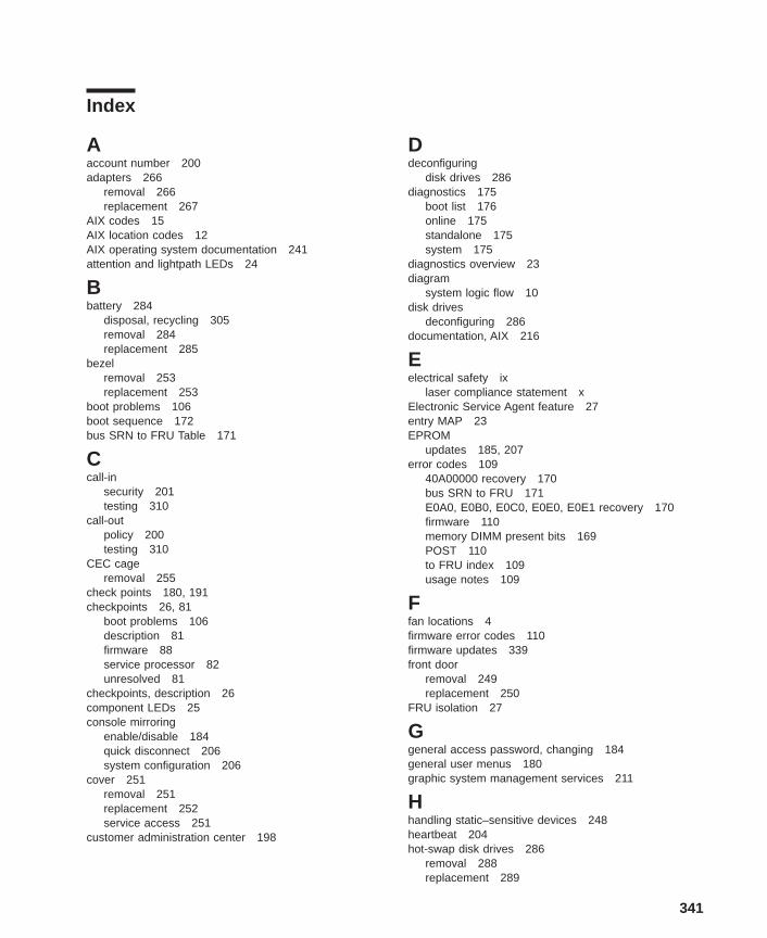
Index
Aaccount number 200adapters 266
removal 266replacement 267
AIX codes 15AIX location codes 12AIX operating system documentation 241attention and lightpath LEDs 24
Bbattery 284
disposal, recycling 305removal 284replacement 285
bezelremoval 253replacement 253
boot problems 106boot sequence 172bus SRN to FRU Table 171
Ccall-in
security 201testing 310
call-outpolicy 200testing 310
CEC cageremoval 255
check points 180, 191checkpoints 26, 81
boot problems 106description 81firmware 88service processor 82unresolved 81
checkpoints, description 26component LEDs 25console mirroring
enable/disable 184quick disconnect 206system configuration 206
cover 251removal 251replacement 252service access 251
customer administration center 198
Ddeconfiguring
disk drives 286diagnostics 175
boot list 176online 175standalone 175system 175
diagnostics overview 23diagram
system logic flow 10disk drives
deconfiguring 286documentation, AIX 216
Eelectrical safety ix
laser compliance statement xElectronic Service Agent feature 27entry MAP 23EPROM
updates 185, 207error codes 109
40A00000 recovery 170bus SRN to FRU 171E0A0, E0B0, E0C0, E0E0, E0E1 recovery 170firmware 110memory DIMM present bits 169POST 110to FRU index 109usage notes 109
Ffan locations 4firmware error codes 110firmware updates 339front door
removal 249replacement 250
FRU isolation 27
Ggeneral access password, changing 184general user menus 180graphic system management services 211
Hhandling static–sensitive devices 248heartbeat 204hot-swap disk drives 286
removal 288replacement 289
341

hot-swap fan assembly 290removal 290replacement 291
Iindicator panel 24isolation, FRU 27
Kkeyboards 302, 303
Llanguage selection 194laser compliance statement xlaser safety information xLEDs
component 25location codes 11
AIX 12format 11physical 11
locationsfans 4memory DIMMs 6power backplane 7power supply 3system board 5system unit 1
Mmaintenance analysis procedures 23MAP 1020, problem determination 40MAP 1240, memory problem resolution 45MAP 1520, power 49MAP 1540, minimum configuration 59MAP rules 31MAP, quick entry 32media devices 282
removal 282replacement 283
memorymodule present bits 169
memory cardremoving 256replacement 261
memory DIMMs 258memory DIMMs location 6menus
general user 180privileged user 182service processor 179service processor call-in/call-out setup 195service processor call-out policy setup 199service processor customer account setup 200service processor language selection 194service processor reboot policy setup 188
menus (continued)service processor serial port selection 196service processor serial port snoop setup 186service processor serial port speed setup 197service processor setup 183service processor system information 191service processor system power control 187service processor telephone setup 197
minimum configuration MAP 23modem
configuration file selection 314configurations 313transfer 318
modem_f.cfg, sample file 329modem_f0.cfg, sample file 332modem_f1.cfg, sample file 335modem_m0.cfg, sample file 321modem_m1.cfg, sample file 323modem_z.cfg, sample file 325modem_z0.cfg, sample file 327
Nnoise emissions 305
Ooperating system documentation, AIX 241operational phases, service processor
standby 208operator panel 8, 277
removal 277replacement 277
overview, diagnostics 23
Ppager 198panel
indicator 24parts
keyboard 302, 303parts information
system internal cables 296passwords
changing General-Access password 184changing privileged-access password 184overview 183
physical location codes 11, 15POST error codes 110POST errors
read 180power backplane 7power cables 21power distribution board 280
removal 280replacement 280
power MAP 23power supply 272
342 Service Guide

power supply (continued)removal 272replacement 274
power supply locations 3power-on methods 200primary console 320privileged user menus 182privileged-access password, changing 184problem determination MAP 23processor and memory card cover
removal 254processor card 263
removal 263replacement 264
product disposal 305progress indicators 180, 191
Qquick entry MAP 23
Rread system, POST errors 180, 192reboot recovery 188, 202recycling 305related publications xiiiremote latency 199remote timeout 199removal 251
adapters 266battery 284bezel 253caution and danger 247CEC cage 255front door 249hot-swap disk drives 288hot-swap fan assembly 290memory card 256operator panel 277power distribution board 280power supply 272processor and memory card cover 254processor card 263SCSI backplane 281service access cover 251static–sensitive devices 248system board 270
replacement 252adapters 267battery 285bezel 253front door 250hot-swap disk drives 289hot-swap fan assembly 291media drives 282, 283operator panel 277
replacement (continued)power distribution board 280power supply 274processor card 264SCSI backplane 281service access cover 252system board 271
replacingmemory card 261
reset service processor 185restart recovery 188, 202RETAIN 200retries 199ring indicator power-on 187
Ssafety notices ixsaving service processor settings 309SCSI backplane 281
removal 281replacement 281
security, call-in 201service center 197service inspection guide 22service mode
service processor procedures 210service processor 179, 208
backup settings 309checklist 309operational phases 208setup 309setup checklist 309test 309
service processor call-in security 201service processor feature 27service processor menu inactivity 179service processor menus
accessing locally 179accessing remotely 179call-in/call-out 195call-out policy 199customer account 200general user 180language selection 194menu inactivity 179privileged user 182reboot policy 188restart policy 188serial port selection 196Serial Port Snoop Setup Menu 186serial port speed setup 197setup menu 183supported menu options 178system information 191system power control 187
Index 343

service processor menus (continued)telephone number 197
service processor procedures in service mode 210service provider 197specifications 20specifications, power cables 21SRN to FRU 171start talk mode 184STBY 208stopping the system 248surveillance
failure 204operating system 204set parameters 185system firmware 204
systemstopping 248
system administrator 198system board 270
removal 270replacement 271
system board locations 5system cables 19system firmware updates 339system information menu 191system logic flow diagram 10system management services 211
graphical system management services 211config 214firmware update 232multiboot 215utilities 218
text-based system management services 233display configuration 245multiboot menu 241select language 234utilities 235
system phone number 198system POST errors
read 180system power-on methods 200system VPD update 278
Ttesting the setup
call-in 310call-out 310
text-based system management services 233trademarks xivtransfer of a modem session 318
Uunattended start mode, enable/disable 187
Vvoice phone number 198VPD update procedure 278
Wweb sites
AIX library 241
344 Service Guide

Readers’ Comments — We’d Like to Hear from You
IntelliStation POWER 9112 Model 265Service Guide
Publication No. SA38-0609-00
Overall, how satisfied are you with the information in this book?
Very Satisfied Satisfied Neutral Dissatisfied Very
Dissatisfied
Overall satisfaction h h h h h
How satisfied are you that the information in this book is:
Very Satisfied Satisfied Neutral Dissatisfied Very
Dissatisfied
Accurate h h h h h
Complete h h h h h
Easy to find h h h h h
Easy to understand h h h h h
Well organized h h h h h
Applicable to your tasks h h h h h
Please tell us how we can improve this book:
Thank you for your responses. May we contact you? h Yes h No
When you send comments to IBM, you grant IBM a nonexclusive right to use or distribute your comments in any
way it believes appropriate without incurring any obligation to you.
Name Address
Company or Organization
Phone No.
Readers’ Comments — We’d Like to Hear from YouSA38-0609-00
SA38-0609-00
IBMCut or FoldAlong Line
Cut or FoldAlong Line
Fold and Tape Please do not staple Fold and Tape
Fold and Tape Please do not staple Fold and Tape
PLACE
POSTAGE
STAMP
HERE
Information DevelopmentDepartment H6DS-905-6C00611400 Burnet RoadAustin, TX 78758-3493
_ _ _ _ _ _ _ _ _ _ _ _ _ _ _ _ _ _ _ _ _ _ _ _ _ _ _ _ _ _ _ _ _ _ _ _ _ _ _ _ _ _ _ _ _ _ _ _ _ _ _ _ _ _ _ _ _ _ _ _ _ _ _ _ _ _ _ _ _ _ _ _ _ _ _ _ _
_ _ _ _ _ _ _ _ _ _ _ _ _ _ _ _ _ _ _ _ _ _ _ _ _ _ _ _ _ _ _ _ _ _ _ _ _ _ _ _ _ _ _ _ _ _ _ _ _ _ _ _ _ _ _ _ _ _ _ _ _ _ _ _ _ _ _ _ _ _ _ _ _ _ _ _ _
__
__
__
__
__
__
__
__
__
__
__
__
__
__
__
__
__
__
__
__
__
__
__
__
__
__
__
__
__
__
__
__
__
__
__
__
__
__
__
__
_


IBM
Printed in U. S. A.
February 2002
SA38-0609-00

Spin
einformat
ion:
IB
MIn
telli
Stat
ion
POW
ER91
12M
odel
265
Serv
ice
Gui
deSA
38-0
609-
00