
CONCEPTUAL PLAN Sun City - environmentclearance.nic.in€¦ · CONCEPTUAL PLAN of ... The design of...
26
CONCEPTUAL PLAN of Sun City Promoted by M/s Sreenidhi Estates India Private Limited No. 19, Nav Khalsa Village, Khajaguda Hyderabad-500 008 Submitted to State Environment Impact Assessment Authority O/o AP Pollution Control Board Sanathnagar, Hyderabad
Transcript of CONCEPTUAL PLAN Sun City - environmentclearance.nic.in€¦ · CONCEPTUAL PLAN of ... The design of...

CONCEPTUAL PLAN
of Sun City
Promoted by
M/s Sreenidhi Estates India Private Limited No. 19, Nav Khalsa Village, Khajaguda
Hyderabad-500 008
Submitted to
State Environment Impact Assessment Authority
O/o AP Pollution Control Board
Sanathnagar, Hyderabad

2
1.0 INTRODUCTION
M/s. Sreenidhi Estates India Pvt. Limited incorporated on 03rd December, 2015. The
registered address is Plot No.19, Nav Khalsa Village, Khajaguda, Hyderabad-500 008,
Telangana and is having five active directors and T. Vasmsidhar is representing the
project.
M/s Sreenidhi Estates India Pvt. Limited proposes to develop a township project at
Sy. No:15/1, 13-1, 13B, 14-1, 13A, 13E, 14-2A, 1-3A, 3H, 21-3, 21-4, 1-3A9, 13-B2, 19-1,
19-2, 19-3, 21-1, 21-2, 13-2, 13-3K, 14-2B, 1-3B-1, 1-3A3G, 1-3A3G, Rajupalem (V),
Venkatreddipalem Grampanchyat, Ojili Mandal ,SPSR Nellore District
The proposed layout is having following features:
Plots for all income groups
Well Gated community
Access roads of 80’, 40’,33’
Separate zone for Educational, Hospital areas
Design approved by DTCP

3
2.0 Project Description :
2.1 Location
The proposed area development project is located at Sy. No: 15/1,13-1,13B,14-
1,13A,13E,14-2A,1-3A,3H,21-3,21-4,1-3A9,13-B2,19-1,19-2,19-3,21-1,21-2,13-2,13-3K,14-
2B,1-3B-1,1-3A3G,1-3A3G, Rajupalem (V), VenkatreddipalemGrampanchyat,
OjiliMandal ,SPSR Nellore District. The site is located 12 km south of Gudur on
Guntur-Chennai highway.
2.2 Project Land Breakup:
The total area of project is 153.40 Acres or 62.07Ha has been granted change of land
use. The design of the layout has been made to cater the needs of all income groups.
Plot Details
S.No. Area of Plot (Sq. Yards)
No. of Plots
1 0-200 882
2 201-300 249
3 301-500 170
4 501-3000 63
5 >3000 11
Total 1375

4
Detailed Area statement
S.No. Site / usage Area (Ac.) Percentage
1 Layouts 82.44 53.71
2 Public Purpose 15.42 10.05
3 Area of the Roads 40.36 26.36
4 Nursery School 1 0.65
5 Primary school 5.42 3.53
6 High School 4 2.60
7 Hospital 2.50 1.63
8 Religious Purpose 2.00 1.3
9 Shops 0.26 0.17
153.4 100
2.3 Roads:
In this prosed to construct 60’ wide roads main access road covering all parts of
the project. It is proposed 33’ roads for residential plots. All the public and amenities
area like hospital and educational areas are access by roads in minimum two sides. All
roads will have pedestrian walkways as per government norms.
2.4 Common Amenities:
It is proposed to utilize 47% of project area for development of roads, parks,
Religious, commercial areas, educational and medical facilities.
2.5 Power Requirement:
It is proposed to develop power lines as per norms of Southern Power
Distribution Company of AP Limited.

5
3.0 Connectivity:
The project site is well connected through National Highway ( Gudur -
Chennai). The nearest railway station is Pedapariya Railway station, about 1.2
Kms from the project site. The nearest airport is Tirupati Airport at 61 Kms
from the project site.
Details about Project Site
Latitude 14°1'48.0"N
Longitude 79°53'22.10"E
Annual rainfall 85 cm
Min and max temp. 200C and 470 C
Avg. relative humidity 78 %
Avg. wind speed 8-10 KMPH
Predominant wind direction Summer Winter
Monsoon
SE N & NE SE & NW
Nearest highway Adjacent to NH 5
Nearest railway station PedapariyaRailway station at1.2 km
Nearest human settlement Vakativari Khandrika Village at 0.1
Km
Nearest town Ojili Mandal Head Quarters -2.9 km
Nearest seaport Krishnapatnam Sea port- 29 KM
Nearest River Swarnamukhi River at 8.2 km

6
Fig: 1 GOOGLE IMAGE

7
Fig: 2 TOPO MAP

8
5.0 Water Requirement and Supply System
The water supply will be provided through bore wells/Panchyat water supply.
The total fresh water requirement is Approximately 2000.0KLD. The daily
water requirement calculation is given below in Table 3:
S.No. Area of Plot (Sq. Yards)
No. of Plots
No. of Occupants
Demand (LCPD)
Total Requirement KLD
1 0-750 1364 6820 920700 920
2 3000 11 50 550
3 Educational Institutions
3 1000 45000 45
4 Hospital 200
1715
Guests @ 5 % 85
Total Demand 1800
Table: 4 Waste Water Calculations
Domestic Water Requirement 1800 KLD
Recycled water for Green Belt (15 Ac.) 150 KLD
Sullage Generated @ 80% of Domestic 1440 KLD
5.1 Waste Water Generation & Treatment:
It is expected that the project will generate total approx. 1440 KLD of waste
water. The waste water will be treated in a STP of 1500 KLD capacity which
will be established in phase wise manner.

9
Fig: 3 Water Balance Diagram
@80%
150 KLD
PROPOSED SEWAGE TREATMENT SYSTEM
Based on the literature available and after study of wastewater characteristics the
following treatment system has been designed for treatment of waste water. The
proposed treatment system consists of three stages:
Stage I: Primary Treatment
It consists of three units Bar screen chamber, Grit Chamber, Neutralization tank
cum Equalization tank.
Stage II : Secondary Treatment
It consists of five units Aeration tank, Secondary clarifier, Clarified Water
storage tank, Sludge holding tank & Filter Press.
Stage III: Tertiary Treatment
In this treatment the treated water will be further treated and polished using
sand filter, Activated carbon filter. After the treatment the water will stored for
gardening and other purposes etc.
FRESH WATER (1800 KLD)
HORTICULTURE (150 KLD)
WASTE WATER GENERATED (1440 KLD) STP Capacity 1500 KLD
10
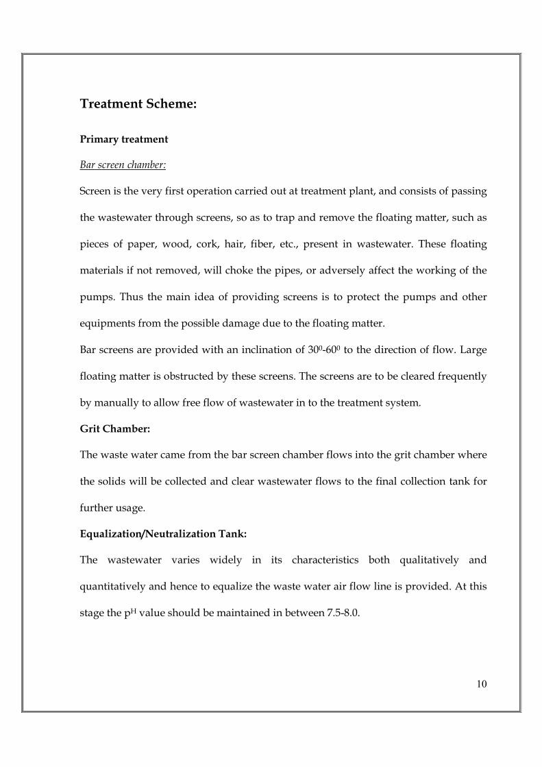
Treatment Scheme:
Primary treatment
Bar screen chamber:
Screen is the very first operation carried out at treatment plant, and consists of passing
the wastewater through screens, so as to trap and remove the floating matter, such as
pieces of paper, wood, cork, hair, fiber, etc., present in wastewater. These floating
materials if not removed, will choke the pipes, or adversely affect the working of the
pumps. Thus the main idea of providing screens is to protect the pumps and other
equipments from the possible damage due to the floating matter.
Bar screens are provided with an inclination of 300-600 to the direction of flow. Large
floating matter is obstructed by these screens. The screens are to be cleared frequently
by manually to allow free flow of wastewater in to the treatment system.
Grit Chamber:
The waste water came from the bar screen chamber flows into the grit chamber where
the solids will be collected and clear wastewater flows to the final collection tank for
further usage.
Equalization/Neutralization Tank:
The wastewater varies widely in its characteristics both qualitatively and
quantitatively and hence to equalize the waste water air flow line is provided. At this
stage the pH value should be maintained in between 7.5-8.0.

11
Secondary Treatment
The coagulation of non – settleable collection solids and the stabilization of organic
matter contributing to BOD are reduced by principally by bacteria. The
microorganisms convert the colloidal and dissolved carbonaceous organic matter into
various gases and into cell tissue. Because cell tissue has a specific gravity slightly
than water the resulting tissue can be remove from the liquid by gravity setting.
The converter of organic matter into gaseous end products and cell tissue can be
accomplished aerobically. An aerobically or facultative suspend growth or attached
growth system. In aerobic conversion apart of the organic matter is converted to end
products and other part to obtain the energy for the synthesis of new cells and hence
the growth.
In most biological treatment systems, these three processes occur simultaneously in
the activated sludge process, the bacteria are the most important microorganisms,
because they are responsible for the decomposition of organic materials in the
influent. In the reactor, or mixed reactor, or mixed liquor tank, a portion of the organic
waste matter is used to obtain energy for the synthesis of the remainder o f he organic
material into new cells.
While bacteria are the microorganisms, that actually degrade the organic waste in the
influent, the metabolic activity of other microorganisms is also important in the
activated sludge system.

12
For example protozoa and rotifers act as wastewater polishers protozoa consume
dispersed matter that have not flocculated and rotifers consume small biological
flocculated particles that have not settled.
Aeration Tank
Supernatant from the Primary clarifier over flows in to the aeration tank where the
organic matter in the wastewater is biologically decomposed under aerobic
conditions. The mixed liquor in the tank is aerated by using 1 no. slow speed diffused
aerator. The MLSS in the aeration tank is maintained around 4000 mg/l by return
sludge, dissolved oxygen of 1 to 3 mg/l has to be maintained. The detention time in
this tank is around 6 hours. The mixed liquor from this tank over flows into the
secondary clarifier.
Secondary Clarifier
The mixed liquor from the aeration tank overflows into the lamella clarifier. Here the
wastewater is kept under comparatively quiescent condition. This allows the solids
from mixed liquor to settle. The mixed liquor enters the drum of the clarifier at the
center and distributes itself equally of all sides. It leaves through the periphery of the
tank. The wastewater moves very slowly facilitating setting of sludge at the bottom as
specific gravity of sludge is higher than that of water. The required amount of sludge
is recycled and the rest is bleed out.

13
Sludge Filter Press
Hydraulically operated filter press will be installed with 12 nos. of plates to dewater
and cake will be used as manure.
Sand Filter and Carbon Filter
The wastewater from secondary clarifier over flow into sand filter where any traces of
organic matter will be removed. Further, the effluent overflow in to activated carbon
filter, there the wastewater will be treated by the principal adsorption and removes
partially total dissolved solids. The clear supernatant will be sent to polishing pond
for recirculation into process or to use for Green belt development.

14
FLOW DIAGRAM FOR SEWAGE TREATMENT PLANT
15
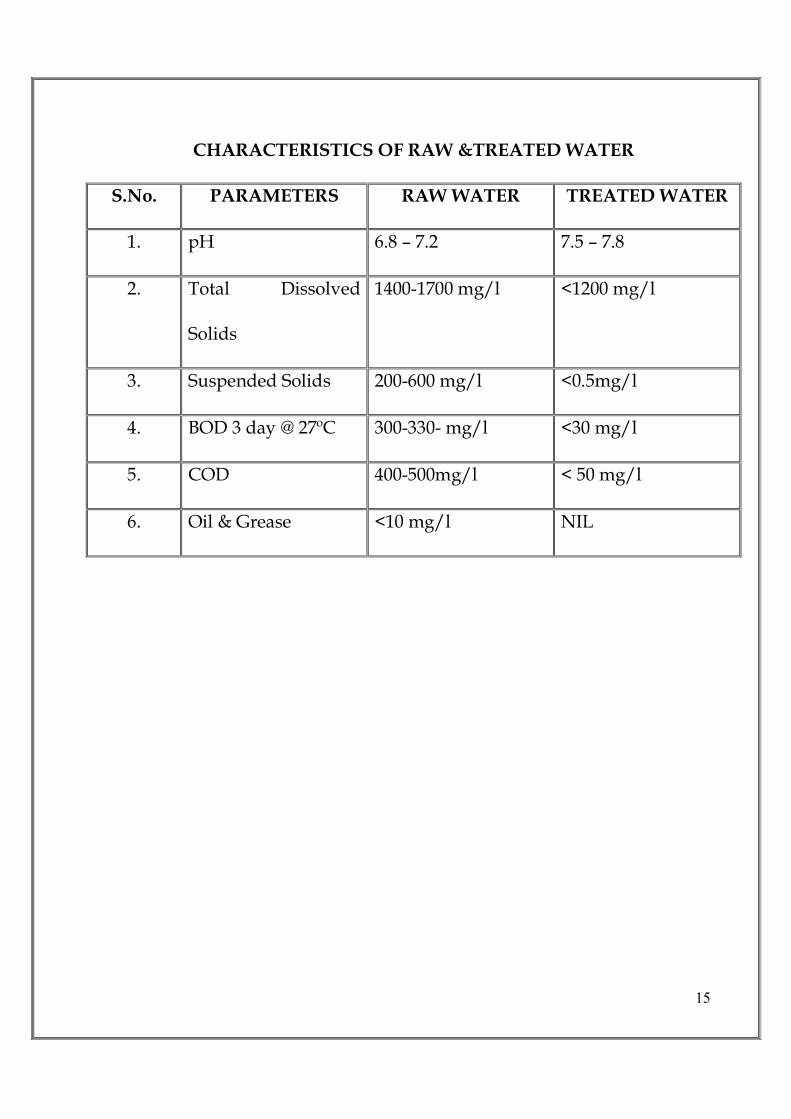
CHARACTERISTICS OF RAW &TREATED WATER
S.No. PARAMETERS RAW WATER TREATED WATER
1. pH 6.8 – 7.2 7.5 – 7.8
2. Total Dissolved
Solids
1400-1700 mg/l <1200 mg/l
3. Suspended Solids 200-600 mg/l <0.5mg/l
4. BOD 3 day @ 27ºC 300-330- mg/l <30 mg/l
5. COD 400-500mg/l < 50 mg/l
6. Oil & Grease <10 mg/l NIL

16
6.0 RAIN WATER HARVESTING
The storm water disposal system for the premises shall be self-sufficient to
avoid any collection/stagnation and flooding of water. The amount of storm water
run-off depends upon many factors such as intensity and duration of precipitation,
characteristics of the tributary area and the time required for such flow to reach the
drains. The drains shall be located near the carriage way along either side of the roads.
Taking the advantage of road chamber, the rainfall run off from roads shall flow
towards the drains. Storm water from various plots/shall be connected to adjacent
drain by a pipe through catch basins. Therefore, it has been calculated to provide 172
rainwater harvesting pits at selected locations, which will catch the maximum run-off
from the area.
1. Since the existing topography is congenial to surface disposal, a network of
storm water pipe drains is planned adjacent to roads. All building roof
water will be brought down through rainwater pipes.
2. Storm water system consists of pipe drain, catch basins and seepage pits at
regular intervals for rainwater harvesting and ground water recharging.
Rain water harvesting has been catered to and designed as per the guideline of
CGWA. Peak hourly rainfall has been considered as 0.03m/hr. The recharge pit of
adequate diameter and depth is constructed for recharging the water. Inside the
recharge pit, a recharge bore is constructed having adequate diameter and depth. The
ground water level in the area is 20-30m bgl. At the bottom of the recharge well, a
filter media is provided to avoid choking of the recharge bore. Design specification of
the rain water harvesting plan are as follows:
Catchments/roofs would be accessible for regular cleaning
The roof will have smooth, hard and dense surface which is less likely to be
damaged allowing release of material into the water. Roof painting has been
avoided since most paints contain toxic substances and may peel off.
All gutter ends will be fitted with a wire mesh screen and a first flush device
would be installed. Most of the debris carried by the water from the rooftop
17
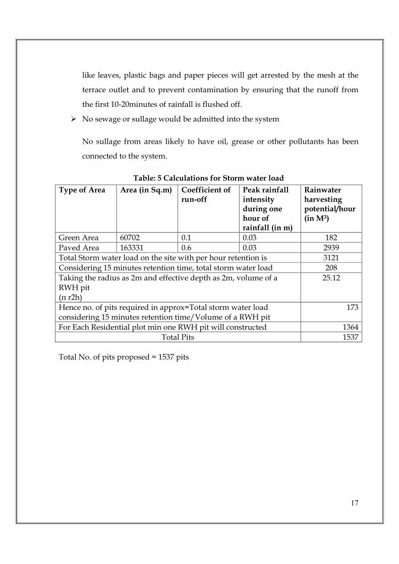
like leaves, plastic bags and paper pieces will get arrested by the mesh at the
terrace outlet and to prevent contamination by ensuring that the runoff from
the first 10-20minutes of rainfall is flushed off.
No sewage or sullage would be admitted into the system
No sullage from areas likely to have oil, grease or other pollutants has been
connected to the system.
Table: 5 Calculations for Storm water load
Type of Area Area (in Sq.m) Coefficient of run-off
Peak rainfall intensity during one hour of rainfall (in m)
Rainwater harvesting potential/hour (in M3)
Green Area 60702 0.1 0.03 182
Paved Area 163331 0.6 0.03 2939
Total Storm water load on the site with per hour retention is 3121
Considering 15 minutes retention time, total storm water load 208
Taking the radius as 2m and effective depth as 2m, volume of a RWH pit (π r2h)
25.12
Hence no. of pits required in approx=Total storm water load considering 15 minutes retention time/Volume of a RWH pit
173
For Each Residential plot min one RWH pit will constructed 1364
Total Pits 1537
Total No. of pits proposed = 1537 pits

18
There will be a provision in allotment letter for saleable area that the individual plot
owner will provide rain water harvesting pit in their plots.
Fig: 4 Typical Diagram for Rain Water Harvesting
19
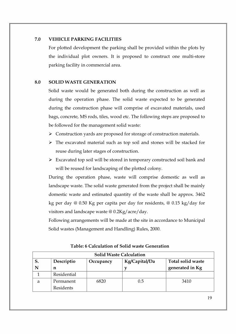
7.0 VEHICLE PARKING FACILITIES
For plotted development the parking shall be provided within the plots by
the individual plot owners. It is proposed to construct one multi-store
parking facility in commercial area.
8.0 SOLID WASTE GENERATION
Solid waste would be generated both during the construction as well as
during the operation phase. The solid waste expected to be generated
during the construction phase will comprise of excavated materials, used
bags, concrete, MS rods, tiles, wood etc. The following steps are proposed to
be followed for the management solid waste:
Construction yards are proposed for storage of construction materials.
The excavated material such as top soil and stones will be stacked for
reuse during later stages of construction.
Excavated top soil will be stored in temporary constructed soil bank and
will be reused for landscaping of the plotted colony.
During the operation phase, waste will comprise domestic as well as
landscape waste. The solid waste generated from the project shall be mainly
domestic waste and estimated quantity of the waste shall be approx. 3462
kg per day @ 0.50 Kg per capita per day for residents, @ 0.15 kg/day for
visitors and landscape waste @ 0.2Kg/acre/day.
Following arrangements will be made at the site in accordance to Municipal
Solid wastes (Management and Handling) Rules, 2000.
Table: 6 Calculation of Solid waste Generation
Solid Waste Calculation
S.
N
Descriptio
n
Occupancy Kg/Capital/Da
y
Total solid waste
generated in Kg
1 Residential
a Permanent
Residents
6820 0.5 3410

20
b Visitors @
5%
341 0.15 52
Total Solid Waste Generated 3462
E-waste will be managed as per E-waste (Management & Handling rules,
2011). It will be handed over to Govt. approved vendors.
8.1 Collection and Segregation of waste:
To encourage source segregation two bin system will be
implemented. Solid waste will be collected in two separate bins as bio
degradable and non bio-degradable. Recyclables will be disposed through
authorized scrap dealers/recyclers and organic waste will disposed
through aerobic compositing or thorough panchyat. Tree/plant trimmings
from land scape will be used in aerobic composting.
8.2 Treatment of waste:
Bio-degradable Wastes
1. Bio-degradable waste will be collected and segregated at site and
subjected to government approved vendors and the compost will be
used as manure.
2. STP sludge is proposed to be used for horticultural purposes as manure
3. Horticultural waste used in aerobic compost.
8.3 Recyclable Wastes:
Recyclable wastes like paper, plastic, metals etc will be sold off to
recyclables
8.4 Disposal:
Only Recyclables wastes will be sold to recyclers and rest non-recyclables
will be sent to Govt. land fill site. Hence, the MSW management approach
will be towards zero landfill.
21
9.0 Green Area:
Total green area measures 15 Ac. Flowering and ornamental plants have
been proposed to be planted inside the premises. Parks will be developed.
10.0 LIST OF MACHINERY USED DURING CONSTRUCTION:
1. Dumper : Shall be used for mud and material
handling
2. Concrete mixer with
hopper : for RCC work
3. Excavator : shall be used for digging and earth
work
4. Road roller : For compacting the earth
5. Bulldozer : For dismantling
22
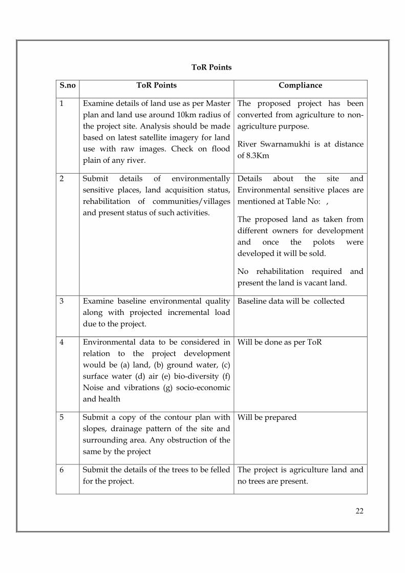
ToR Points
S.no ToR Points Compliance
1 Examine details of land use as per Master
plan and land use around 10km radius of
the project site. Analysis should be made
based on latest satellite imagery for land
use with raw images. Check on flood
plain of any river.
The proposed project has been
converted from agriculture to non-
agriculture purpose.
River Swarnamukhi is at distance
of 8.3Km
2 Submit details of environmentally
sensitive places, land acquisition status,
rehabilitation of communities/villages
and present status of such activities.
Details about the site and
Environmental sensitive places are
mentioned at Table No: ,
The proposed land as taken from
different owners for development
and once the polots were
developed it will be sold.
No rehabilitation required and
present the land is vacant land.
3 Examine baseline environmental quality
along with projected incremental load
due to the project.
Baseline data will be collected
4 Environmental data to be considered in
relation to the project development
would be (a) land, (b) ground water, (c)
surface water (d) air (e) bio-diversity (f)
Noise and vibrations (g) socio-economic
and health
Will be done as per ToR
5 Submit a copy of the contour plan with
slopes, drainage pattern of the site and
surrounding area. Any obstruction of the
same by the project
Will be prepared
6 Submit the details of the trees to be felled
for the project.
The project is agriculture land and
no trees are present.

23
7 Submit the present land use and
permission required for any conversion
such as forest, agriculture etc
The proposed land is agricultural
land and converted into non-
agricultural land.
No forest area involved in this site
8 Submit roles and responsibility of the
developer etc for compliance of
environmental regulations under the
provisions of EP Act.
During construction phase the
developer will take responsibility.
During operation phase it will be
on residents association.
9 Ground water classification as per the
Central Ground water Authority.
As ground water available
abundant and the area is marked as
low usage area by CGWD
10 Examine the details of source of water,
water requirement, use of treated waste
water and prepare a water balance chart.
Source of water will be panchyat
/ground water, 2000 KLD will be
the daily requirement.
11 Rain water harvesting proposals should
be made with due safeguards for ground
water quality. Maximize recycling of
water and utilization of rain water.
Examine details
Rain water Harvesting will be
done in all public places and in
every plot.
12 Examine soil characteristics and depth of
ground water table for rainwater
harvesting
The predominant soil types in the
district are red loamy and sandy.
13 Examine details of solid waste generation
treatment and its disposal
Solid waste generation will be 3
tones per day of which recyclable
will be sent for recycling and bio
degradable will be aerobically
composted.
14 Examine and submit details of use of
solar energy and alternative source of
energy to reduce the fossil energy
consumption. Energy conservation and
energy efficiency.
Solar energy will be used for street
lighting
Use of LEDS for street lighting
24
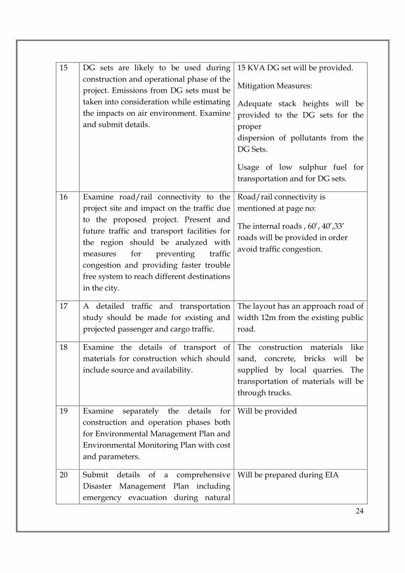
15 DG sets are likely to be used during
construction and operational phase of the
project. Emissions from DG sets must be
taken into consideration while estimating
the impacts on air environment. Examine
and submit details.
15 KVA DG set will be provided.
Mitigation Measures:
Adequate stack heights will be
provided to the DG sets for the
proper
dispersion of pollutants from the
DG Sets.
Usage of low sulphur fuel for
transportation and for DG sets.
16 Examine road/rail connectivity to the
project site and impact on the traffic due
to the proposed project. Present and
future traffic and transport facilities for
the region should be analyzed with
measures for preventing traffic
congestion and providing faster trouble
free system to reach different destinations
in the city.
Road/rail connectivity is
mentioned at page no:
The internal roads , 60’, 40’,33’
roads will be provided in order
avoid traffic congestion.
17 A detailed traffic and transportation
study should be made for existing and
projected passenger and cargo traffic.
The layout has an approach road of
width 12m from the existing public
road.
18 Examine the details of transport of
materials for construction which should
include source and availability.
The construction materials like
sand, concrete, bricks will be
supplied by local quarries. The
transportation of materials will be
through trucks.
19 Examine separately the details for
construction and operation phases both
for Environmental Management Plan and
Environmental Monitoring Plan with cost
and parameters.
Will be provided
20 Submit details of a comprehensive
Disaster Management Plan including
emergency evacuation during natural
Will be prepared during EIA

25
and man-made disaster.
21 Details of litigation pending against the
project, if any, with direction/order
passed by any Court of Law against the
project should be given.
Nil
22 The cost of the project (Capital cost and
recurring cost) as well as cost towards
implementation of EMP should be clearly
spelt out.
The cost of the project is Rs. 87.0
crores and the EMP budget is Rs
8.0 Crores
23 Any further clarification on carrying out
the above studies including anticipated
impacts due to the project and mitigative
measures.
Will be Included in the report