Computer Optimized Design of Electron Guns x-ray devices, for electron beam lithograph and electron...
34
Computer Optimized Design of Electron Guns John David * Lawrence Ives † Hien Tran * Thuc Bui † Michael Read † June 28, 2007 Abstract This paper considers the problem of designing electron guns us- ing computer optimization techniques. Several different design pa- rameters are manipulated while considering multiple design criteria including beam and gun properties. The optimization routines are described. Examples of guns designed using these techniques are pre- sented. Future research is also described. 1 Introduction Electron guns are used in many vacuum electron devices to convert electrical power into an electron beam. Electron beam devices include RF sources for numerous applications such as communications, radar, industrial heating, and high energy accelerators. Electron beams are also used in medical and industrial x-ray devices, for electron beam lithograph and electron beam welding, and in cathode ray guns for televisions and oscilloscopes. Many of these devices are critical for national defense and science and industrial applications. In an RF source, the beam energy is converted to energy in an RF wave. In x-ray sources, welders, or cathode ray devices, precise focusing is required * Department of Mathematics and Center for Research in Scientific Computation, Box 8205,North Carolina State University, Raleigh, North Carolina 27695-8205, ja- [email protected],[email protected] † Calabazas Creek Research, Inc. 690 Port Drive, San Mateo, CA 94404 (650) 312-9575, [email protected], [email protected], [email protected] 1
Transcript of Computer Optimized Design of Electron Guns x-ray devices, for electron beam lithograph and electron...

Computer Optimized Design of Electron Guns
John David ∗ Lawrence Ives † Hien Tran ∗ Thuc Bui †
Michael Read†
June 28, 2007
Abstract
This paper considers the problem of designing electron guns us-ing computer optimization techniques. Several different design pa-rameters are manipulated while considering multiple design criteriaincluding beam and gun properties. The optimization routines aredescribed. Examples of guns designed using these techniques are pre-sented. Future research is also described.
1 Introduction
Electron guns are used in many vacuum electron devices to convert electricalpower into an electron beam. Electron beam devices include RF sources fornumerous applications such as communications, radar, industrial heating,and high energy accelerators. Electron beams are also used in medical andindustrial x-ray devices, for electron beam lithograph and electron beamwelding, and in cathode ray guns for televisions and oscilloscopes. Manyof these devices are critical for national defense and science and industrialapplications.
In an RF source, the beam energy is converted to energy in an RF wave.In x-ray sources, welders, or cathode ray devices, precise focusing is required
∗Department of Mathematics and Center for Research in Scientific Computation,Box 8205,North Carolina State University, Raleigh, North Carolina 27695-8205, [email protected],[email protected]
†Calabazas Creek Research, Inc. 690 Port Drive, San Mateo, CA 94404 (650) 312-9575,[email protected], [email protected], [email protected]
1

to obtain high resolution. The electron gun is a primary component inklystrons, traveling wave tubes (TWTs), gyrotrons, and inductive outputtubes. The configuration of the gun depends on many factors, includingthe operating voltage, current, beam size and shape, magnetic focusing cir-cuit, power supply, and operational environment. Consequently, customizedelectron gun design is required for essentially every new device. Because ofthe large number of variables, this is often a time consuming and expensiveprocess. Typical design time for a new electron gun for an RF source is 30-40 man-hours involving 20-30 design iterations [1]. This is for designs thatcan be modelled in two dimensions. A number of 2D simulation tools areavailable, including EGUNr and TRAKr.
The process becomes more demanding for 3D designs. Recent interestin multiple beam and sheet beam guns is placing severe demands on thecomputational codes as well as the design engineer. 3D analysis is compu-tationally intensive, making iterative design very expensive when performedmanually. As an example, CCR recently designed a sheet beam gun for an X-Band klystron [2]. The development required approximately 2-3 man-monthswith approximately 100 iterations, each involving 8 hours of CPU time. Thegun operated with Brillouin focusing, so the simulations did not include amagnetic field.
CCR completed the design of an X-Band electron gun using a combina-tion of MAFIAr and another 3D simulation code developed in Russia [3].This design was performed several years ago and required approximately oneyear of iterative design. Fortunately, more recent computational tools andexperience are reducing this design time, though a recent design of a multi-ple beam gun for a 200 MHz Multiple Beam Klystron (MBK) still requiredfour months of iterative design [4]. Both these efforts were for singly conver-gent guns. A recent program to design a doubly convergent multiple beamgun was abandoned because the number of variables and the complexity ofthe design could not be overcome. This experience provided much of themotivation for developing computer optimized design.
In a typical design process, the engineer begins with an existing config-uration close to the new requirement or with design equations for the basicconfiguration. The design is simulated and geometrical, electrical, and mag-netic parameters are modified until the required performance is achieved. Ingeneral, the engineer attempts to design an electron gun operating with aspecified combination of voltage and current that produces an electron beamof a specific size with laminar electron trajectories. For confined flow guns
2

where the magnetic field penetrates to the cathode, the engineer must designboth the electrical and magnetic circuits. The requirement is to emit theelectrons at a precise angle to the magnetic field to minimize beam ripple[5]. A typical requirement is that the beam envelope not vary more than 5% through the device.
In previous research, CCR developed a computer optimization processfor Brillouin focused electron guns [6]. This program used EGUNr andMATLABr routines to produce an electron beam of a specific size at aspecified axial location with laminar electron trajectories. This programsuccessfully demonstrated that significant reduction in the design time couldbe achieved with minimal interaction by the design engineer. This translatesinto a reduction in design cost and potentially improved performance.
In the current program, CCR is advancing this capability using the 3Dfinite element, adaptive mesh code Beam Optics Analysis (BOA). Althoughthe initial designs presented here are two dimensional, the simulations arecompletely three dimensional. While this is not necessary for these particu-lar designs, it established the process for direct transition to the 3D designsdescribed later. In this program, a confined flow, Pierce electron gun wasdesigned using computer optimization. There were several goals in the de-velopment. The initial effort involved modification of simple geometrical pa-rameters to achieve the optimum beam quality. These parameters includedthe spacing between the cathode and anode to achieve the desired perveance,the relative position of the magnetic circuit to achieve the desired beam com-pression, and the radius of curvature of the cathode to minimize beam ripple.Figure 1 shows a drawing of the electron gun.
The next task was to demonstrate that nonlinear shaping of electrodesurfaces could improve performance. The program focused on two sub tasks.The first was to demonstrate that the shape of the cathode could be optimizedto reduce beam ripple while still achieving the desired perveance and beamsize. The cathode was defined by a set of points connected with a splinecurve. This curve was rotated about the gun axis to define the cathodesurface. The second task was to define the focus electrode by a similar set ofpoints and a spline curve, then optimize the shape of the curve to minimizethe electric field. Minimization of the electric field will reduce the probabilityof arcing between the gun and the anode. The final step was to combine theseresults to demonstrate a high quality electron beam with minimal potentialfor electrical breakdown. This was followed by application to a sheet beamgun for an X-Band klystron.
3

Figure 1: Pierce electron gun.
The organization of the paper is as follows. The gun geometry wasgenerated in SolidWorksr with BOA used for the computer simulations.These tools are described in Section 2. Section 3 describes the process bywhich MATLABr routines control the optimization process by executingboth SolidWorksr and BOA in batch mode using line commands. Section4 describes the optimization routines. Sections 5, 6 and 7 describe the sim-ulation results. Section 8 gives a description of the research in progress toextend this development to fully 3D devices.
Finally, it should be noted that computer optimization is simply a tool. Itcan not replace the knowledge, experience, and intuition of a trained engineer.Rather it allows the engineer to focus on the physics of the problem whilethe computer performs the routine, iterative task of parameter variation toachieve the defined engineering goals.
4

2 Computer Tools
SolidWorksr and BOA are the principal commercial programs used in thisresearch. SolidWorksr is a 3D, parametric, solid modelling program that cangenerate ACIS-formatted geometry files, a requirement for integration withBOA. Figure 2 shows the Pierce electron gun in SolidWorksr. In this figure,the anode/beam tunnel is semi-transparent.
Figure 2: Pierce electron gun in SolidWorksr. This is the 3D model of thegun shown in Figure 1. The anode is semi-transparent.
An important feature of parametric modelling is the ability to define keydimensions in design tables. One can then update the geometry by changingvalues in these tables. This allows an external program to control parametricchanges to the geometry. Figure 3 shows a sketch of a spherical cathode inSolidWorksr with the associated design table in Excelr. The cathode iscreated by revolving the sketch about the axis.
SolidWorksr allows batch operation, so the MATLABr control programcan modify the design table, execute the CAD program to generate the up-dated model, generate the ACIS file, then terminate the CAD program.
5

Figure 3: Spherical cathode sketch in Solidworksr with associated designtable.
The electron gun simulation is performed using BOA. Like the solid mod-elling program, BOA can be executed by MATLABr. All input for BOA iscontained in an ASCII file that can be modified by the MATLABr controlprogram. The file contains information for solution of the electric fields, in-cluding the voltages assigned to various objects and dielectric constants forceramics. Electron emitters are also defined using information from the CADprogram to identify specific surfaces. The ASCII file provides informationcontrolling the number of trajectories and the temperature and work func-tion for thermionic emitters. All meshing is performed automatically withinBOA. For this research, the magnetic field profile was generated by Maxwell2Dr and used as input to BOA. The axial position of the magnetic cir-cuit relative to the center of the cathode was a variable in the optimizationprocess and controlled the beam compression. Magnetic circuit modellingwill soon be implemented within BOA, so input from external programs willnot be necessary. This will also allow optimization of the magnetic circuitparameters in future research.
BOA is an adaptive mesh, finite element, 3D analysis code for designingelectron beam devices. A principal feature is the adaptive meshing which
6

removes the burden for mesh generation from the user and assigns responsi-bility to the field solver and particle pusher routines. With adaptivity enabledby the user, BOA adapts the mesh density in areas where field gradients arehigh until the specified accuracy is achieved. It can also coarsen mesh inareas where high accuracy is not required to reduce the computational bur-den. The user can also control the mesh density in regions occupied by theelectron beam and in regions near selected surfaces.
3 Design Iteration Procedure
Each iteration of the optimization routine requires several steps. The generalprocess is described in Figure 4, however we will describe each block in moredetail here.
As usual, the iterative methods used in this research require a startingpoint or initial design. For each optimization attempt, the user must specify aset of starting design parameters for the optimization routines. It is generallybeneficial if these design parameters are relatively close to the optimal designparameters, however this may not be necessary. There are routines whichcan consider a general subset of the parameter space and attempt to find aglobal minimum, but these routines generally require an extensive numberof function evaluations, which is not feasible in the case of 3D design.
The first step in a function evaluation is to write the geometry relatedparameters, e.g., cathode radius or spline parameters, focus electrode shapeparameters etc., into Excelr files linked to the SolidWorksr CAD files. Theauthors used a routine written by Brett Shoelson, which was obtained atMATLABr central (http://www.mathworks.com/matlabcentral/), an openexchange for MATLABr users, to write the numerical values from MATLABr
to the Excelr files. SolidWorksr then regenerates the geometry files withthe newly updated parameters from the spreadsheets. This produces a geom-etry file read by BOA, which then executes, producing output files detailingthe trajectories of the particles and fields in the electron gun. MATLABr
routines read these files to determine the beam characteristics and calculatea cost function value that measures how well the current design parametersachieve the design goals. Finally, this optimization routine uses this costfunction value to either compute a new set of trial design parameters or,in the case that the current design parameters are considered optimal, toterminate the routine.
7

Figure 4: Flowchart for local optimization routine.
8

4 Optimization Routines
This section provides an overview of the sampling optimization algorithmsused in the optimal design of the electron guns. Basically, in an optimaldesign problem, one begins by formulating a function that characterizes thedesign goals. The task is then to minimize or maximize this function and thusobtain a design that meets the desired criteria. Mathematically speaking, theproblem is given a function f : RN → R find λ∗ ∈ RN such that f(λ∗) ≤ f(λ)for all λ of interest. If the λ’s of interest are only those near λ∗, then it is alocal optimization problem. On the other hand, if the λ’s of interest belong toa subset Ω ⊂ RN then it is a global optimization problem. The Nelder-Meadand implicit filtering optimization routines used in this research are knownas deterministic sampling methods. Gradient information used by implicitfiltering is only approximate, as it is obtained from sampled points in theparameter space. For a discussion on the advantages and disadvantages ofsampling based methods versus gradient based methods, the interested readeris referred to [7].
4.1 Nelder-Mead Algorithm
The Nelder-Mead algorithm is a deterministic sampling method, i.e., it onlyrequires function values and no gradient information and is thus a simplealgorithm to implement. Given N+1 points in the available parameter range,it sorts the point such that J(λ1) ≤ J(λ2) ≤ · · · ≤ J(λN+1), where J(λi)is the evaluation of the goal function for parameter λi. It then attempts tominimize the function by replacing the point with the highest function valueJ(λN+1), which is the worst point, with a point with a lower function value.It first finds the point centered among the other points, not including theworst points λN+1
λ =1
N
N∑i=1
λi. (1)
It then attempts to replace λN+1 with
λNEW = (1 + β)λ− βλN+1, (2)
where
9

β = βr, βe, βoc, βic (3)
where β represents points obtained by reflection βR, extension βE, outwardcontraction βOC and inward contraction βIC as illustrated in Figure 5 for a2D example. If none of these values are better than the previous worst pointλN+1, the algorithm shrinks the available parameter range toward the bestpoint, i.e., it replaces the point with
λi =λi + λ1
2.
The algorithm then resorts the points and iterates. Our implementation ofthe algorithm used the values
βr, βe, βoc, βic = 1, 2, 1/2,−1/2. (4)
in equation (2).To better illustrate this method, consider the case when N = 2. In
this case the parameters form a triangle in a 2D plane. Figure 5 illustrateswhat Nelder-Mead does in this case. Assume λ3 is the worst parameter, sothe algorithm is attempting to replace this point with either a reflection,r, expansion, e, outward contraction, oc, or inward contraction, ic. Thereare various stopping criteria for this algorithm including iteration number,difference between the function at the best and worst points and the availablerange of parameters. For a more detailed treatment see [7].
4.2 Implicit Filtering
Implicit filtering is a projected quasi-Newton iteration that uses differencegradients, reducing the difference increments as the optimization progresses[8]. The idea is that gradient approximations with a large step size will beinsensitive to high-frequency oscillations, which generally produce a largenumber of local minima, and follow the general landscape of the parameterspace. As the routine approaches the minimum, where the oscillations in theparameter space are less, the step size for the gradient is reduced. Figure6 illustrates a function where implicit filtering may be useful. The specificimplementation used in this work is bound constrained, but, for simplicity,the unconstrained version is described. This algorithm optimizes functionsof the form
10

Figure 5: Nelder-Mead in 2 dimensions.
f = fs + φ (5)
where f is smooth and φ is a low-amplitude perturbation that is smallestnear the minimum.
Given a current λ and step size h, the algorithm proceeds as follows. Firstf is sampled at the 2N points in the range
S(λ, h) = λ± hei, (6)
where ei is the unit vector in the ith coordinate direction. Let
f ∗ = minf(z)|z ∈ S(λ, h). (7)
If f ∗ > f(λ) then this is designated a failure, h is reduced, and the routineiterates. If f ∗ < f(λ) then the routine attempts to update λ with the formula
λNEW = λ− νH−1∇hf(λ) (8)
11

Figure 6: Example of 1D objective function in which implicit filtering wouldbe useful.
where H is the model Hessian obtained from the quasi-Newton update,∇hf(λ) is the approximate gradient obtained from using a centered differenceformula on the available parameter range, and ν is a line search parameterto insure sufficient decrease. This proceeds until h reaches a user specifiedvalue.
5 Results
The electron gun chosen for this research is a Pierce gun that will be usedwith others in a 10 MW, multiple beam klystron at L-Band. The specifi-cations require that the beam voltage be less than 120 kV. Given the totalpower required and the number of guns anticipated, each gun should pro-duce approximately 20 A. Based on a preliminary RF circuit design, a beamfill factor of 66% was chosen as the beam size. Consequently, the goal is todevelop an electron gun operating at 110 kV, producing 20 A with a 66%fill factor in the beam tunnel. An additional requirement is that the beamripple be less than 5%.
12
5.1 Simple Parameters (cathode radius of curvature)
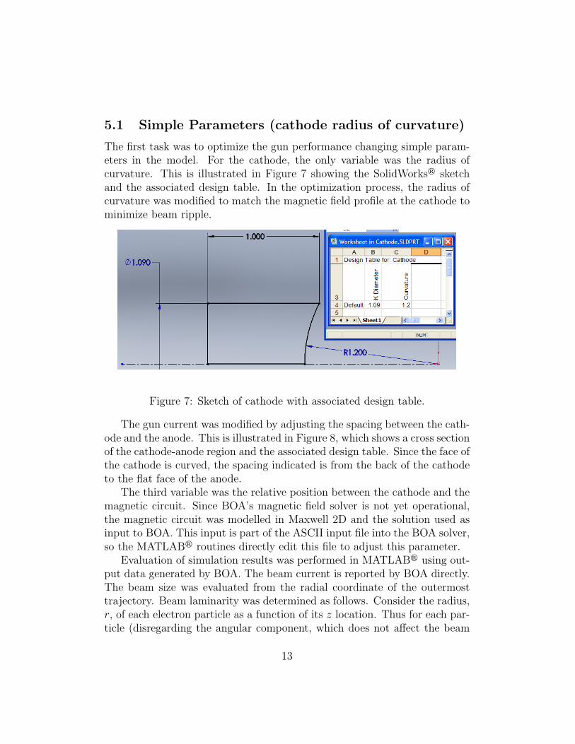
The first task was to optimize the gun performance changing simple param-eters in the model. For the cathode, the only variable was the radius ofcurvature. This is illustrated in Figure 7 showing the SolidWorksr sketchand the associated design table. In the optimization process, the radius ofcurvature was modified to match the magnetic field profile at the cathode tominimize beam ripple.
Figure 7: Sketch of cathode with associated design table.
The gun current was modified by adjusting the spacing between the cath-ode and the anode. This is illustrated in Figure 8, which shows a cross sectionof the cathode-anode region and the associated design table. Since the face ofthe cathode is curved, the spacing indicated is from the back of the cathodeto the flat face of the anode.
The third variable was the relative position between the cathode and themagnetic circuit. Since BOA’s magnetic field solver is not yet operational,the magnetic circuit was modelled in Maxwell 2D and the solution used asinput to BOA. This input is part of the ASCII input file into the BOA solver,so the MATLABr routines directly edit this file to adjust this parameter.
Evaluation of simulation results was performed in MATLABr using out-put data generated by BOA. The beam current is reported by BOA directly.The beam size was evaluated from the radial coordinate of the outermosttrajectory. Beam laminarity was determined as follows. Consider the radius,r, of each electron particle as a function of its z location. Thus for each par-ticle (disregarding the angular component, which does not affect the beam
13

Figure 8: Cross section of the cathode-anode region with associated designtable controlling cathode to anode spacing.
laminarity) one can characterize the ith particle by the function ri(z). Thena measure of the laminarity is the derivatives of this function with respect toz. However it may misrepresent the true beam shape to only look at thesevalues at a single z location, so this information is determined at severallocations along the length of the beam. Since we are looking at trajectoryinformation at specific z values, we have included information about first andsecond derivatives of the trajectories. A zero value of the first derivative isachieved at a peak or trough in the beam shape. However the beam will belaminar at this point if the second derivative is also zero. See Figure 9 forthe potential trajectories that caused us to use first and second derivativeinformation. The goal functions that describes beam laminarity are given by
J1(λ) = α4∑
j=1
N∑i=1
∂ri(zj)
∂z(9)
J2(λ) = β4∑
j=1
N∑i=1
∂2ri(zj)
∂z2, (10)
where α and β are user specified weights, and N is the number of particles
14

used. Note the upper bound of 4 in the sum over the j index is the numberof z-locations at which this information was obtained.
The second goal is to produce a beam with a specific radius. The goalfunction used here is
J3(λ) = γ(b− bd)2, (11)
where b is the beam radius, bd is the desired beam radius, and γ is a userspecified weighting parameter.
Finally the beam should have a specified current. The appropriate goalfunction is
J4(λ) = δ(I − Id)2, (12)
where I is the beam current, Id is the desired beam current, and δ is a userspecified weighting parameter. The total goal function is
J(λ) =4∑
i=1
Ji, (13)
where λ are the parameters which specify gun design.The specific numbers for this optimization are as follows. The weights α,
β, γ, and δ were chosen such that Ji(λ0) = 1 for i = 1, .., 3 and J4(λ0) = 10,where λ0 is the initial value for the design parameters. The initial value forthis problem is λ0 = (50.8mm., 25.4mm., 0mm), where the entries in λ0 arethe spacing between the cathode and the anode, the radius of curvature ofthe cathode and the relative position between the cathode and the magneticcircuit respectively. The desired beam radius is bd =6.2 mm. The desiredcurrent Id =20 A. The optimization process used the Nelder-Mead algorithm.A 2.8 GHz Toshiba laptop running Windows XP executed the optimizationroutines and the CAD and simulation codes. Each iteration in the processrequired approximately eight minutes. Figure 10 shows the value of variousdesign parameters during the process. Figure 11 shows the value of the vari-ous goal functions as the iterations proceed. The results of this optimizationare summarized in Table 1.
As can be seen, the variables appear to reach essentially their final valuesafter approximately 60 iterations. This required approximately eight hours.
The results are summarized in Figure 12 . In addition to the previouslydefined goal functions, the beam ripple or scallop is a value of interest. Thebeam scallop is defined as
15

Figure 9: Examples of potential beam trajectories.
16

Figure 10: Design Parameters as a function of iteration.
Figure 11: Goal functions as a function of iteration
17

λ0 (initial values) λ (optimized parameter)Beam Radius 4.855 mm 6.523 mm
1βJ2 2.068e+022 5.354e+021
1γJ3 4.662 1.311
Current 27.859 A 19.587 A
Table 1: Performance comparison for initial optimization, where the secondcolumn indicates the performance of the gun using the initial design and thethe third column indicates the performance of the gun with the optimizeddesign parameters.
Scall(λ) = 100dmax − dmin
dmax + dmin
, (14)
where dmax and dmin denote the maximum and minimum diameter of thebeam. The current was within 2% of the goal and the beam scallop was wellwithin the goal of 5% or less. The beam size was approximately 7% from thedesired value. Considering that the magnetic profile is not optimized andonly three variables were available for modification, these results were veryencouraging.
18

Figure 12: Optimization Results.
19

6 Spline Cathode
It is anticipated that optimization of 3D structures will require modificationof electrode shapes that can not be achieved with simple dimensional changesof lines, arcs or circles. Previous experience indicates that outstanding resultscan be achieved if one is not restricted to simple changes of lengths and radii[9, 10]. The next task was to demonstrate that shape optimization could beimplemented and achieve further improvements in performance.
A cathode was designed that consisted of points along a radius of thecathode connected by a spline. The full cathode was generated by rotatingthe curve about the cathode axis. Figure 13 shows the initial configuration.The cathode was defined by six points along a constant curvature arc fromthe optimization in the previous section. The optimization routines wereallowed to freely change the axial position of the points, but not the radialposition.
Figure 13: Spline Cathode
20

For this optimization, the beam scallop was again evaluated as given byformula (14).The goal was to minimize the function
J(λ) = J3(λ) + Scall(λ). (15)
The initial decision to vary all points of the spline proved problematic.Changes to points near the axis could not impact the value of the cost func-tion. Thus the process failed to converge and produced unrealistic cathodeshapes. Therefore, it was necessary to limit the number of points that couldbe varied, specifically, those near the outer edge, and constrain the range ofmodifications for each point. Consequently, the design engineer can not betotally eliminated from decisions necessary to achieve a complete design.
Figure 14: Sketch of cathode defined by spline curve.
21

λ0 (initial values) λ (optimized parameter)BeamRadius 4.25mm 6.21 mm
Scall 16 % 4.83 %
Table 2: Performance comparison for initial spline optimization.
Only the outer two points were selected for modification, and, again, onlythe axial coordinate could be changed. As a constraint, the axial distanceof each point from the center of the cathode could not be less than anypoints with a smaller radius. This would result in electrons being emittedwith a positive radial velocity, which was assumed to be at variance with thedesired result. The distance between the cathode and anode was fixed fromthe previous optimization. The relative position between the cathode andthe magnetic circuit was the third parameter in addition to the two outerpoints on the spline cathode.
For this problem Nelder-Mead performed poorly, so the optimization rou-tine used implicit-filtering. The optimization resulted in a beam scallop ofless than 5%, and the beam size was within 2% of the target value. Thefinal cathode shape is shown in Figure 14. Note the subtle deviation from apurely spherical shape near the outer edge. The results are summarized inTable 2 and Figures 15 and 16.
22

Figure 15: Spline optimization: before.
Figure 16: Spline optimization: after.
23

7 Electric Field Optimization: Spline Focus
Electrode
A key failure mechanism in electron guns is arcing between the the focuselectrode and the anode. Consequently, there is a desire to minimize theelectric field so long as the beam performance is not compromised. For thisoptimization, the focus electrode was defined by a series of points connectedwith a spline. As with the cathode, the final electrode was generated byrotating the curve about the axis. Figure 17 shows the starting configurationfor the optimization which consisted of a straight line between the innerradius of the electrode to a constant radius arc tangent to the outer radius.From experience, it is known that high field gradients only occur in the regionof the focus electrode closest to the anode. Consequently, only points in thisregion, specifically, points P4 through P6, were selected for optimization. Theoptimization routines were allowed to change the axial position of the points,but not the radial position. Constraints were added to prevent generation ofunrealistic configurations.
BOA can calculate electric field vectors at discrete points on the surfaces.The electric field vector on the focus electrode was denoted by Ei. The goalfunction for this problem was
J(λ) = max||Ei||. (16)
Note that since the goal function is the maximum value of the electric field onthe focus electrode and we are trying to minimize this goal function, we arethus minimizing the maximum value of the electric field in the device. Usingthe Nelder-Mead algorithm, the magnitude of the vector was reduced for Jby 6.7%. Figure 18 shows the final shape from the optimization process.
Recall that only points P4 through P6 were modified during the optimiza-tion process. The position of P3 was not allowed to change, which explainsthe curvature in the profile at this location. While this shape satisfies com-pletely the optimization goal, it could present unnecessary complications formachining. Using engineering experience and knowing that slight changesin this region would not significantly impact performance, the location ofP3 was manually modified to remove the slight bump in the profile. This isanother indication that engineering experience and knowledge are importantin any computational design effort. The resultant change in the maximumelectric field was less than .008%. This final configuration is shown in Figure
24

Figure 17: Initial focus electrode. Note that the dots along the focus electrodeare the values specified by the user for the shape. The dark line is then thespline created from these points. The dashed lines specify other aspects ofthe CAD drawing.
25

Figure 18: Optimized focus electrode.
26

19. The final task was to ensure that the focus electrode modification wasstill compatible with the desired beam performance. The full beam simula-tion was performed, and the change in beam diameter was negligible, andthe beam scallop changed from 4.8% to 5.1%. As this violated our goal ofunder 5% scallop, we reran an implicit filtering optimization similar to thatdescribed in Section 6 with the focus electrode found in this section. Usingthis routine we were able to reduce the beam scallop to 4.4068%.
27

Figure 19: Final focus electrode.
28

8 Planned 3D Design
The ultimate goal of this research is to develop design tools for complex, 3D,electron beam devices that provide improved capabilities or performance overstandard 2D devices. In the microwave tube industry, significant research isunder way to utilize distributed beam devices, including sheet beam andmultiple beam configurations. Distributed beams allow significant reductionin operating voltage, which translates to dramatically lower cost power sup-plies and improved operating efficiency. It is also anticipated that a newgeneration of electron devices could be developed for new and innovativeapplications.
8.1 Sheet beam gun
Several organizations, including CCR, are developing sheet beam RF sources.These have lower operating voltage, improved efficiency, greater bandwidth,and reduced fabrication cost. They are being developed for the InternationalLinear Collider, which will require several hundred klystrons. Therefore, thepotential impact is quite large.
Sheet beam cathodes typically use a cylindrical emitter to produce therectangular electron beam. The beam is compressed in only one dimension.A major issue is the design of the corners of the electron gun, where electricfields are abruptly changing. Since 3D analysis is required, iterative designis particularly time consuming. Not only does the beam simulation takesignificant time, but manual modification of the 3D geometry itself can alsobe labor intensive.
Modern solid modelling programs can model 3D surfaces defined by pointsin space. These points can be defined by dimensions relative to a commonorigin and, therefore, included in design tables. The initial effort will beto modify the shape of the cathode in the corners and the adjacent focuselectrode. Simple modifications will be performed initially to verify properoperation of the process and better understand the relationship of variousparameters on beam performance. Figure 20 shows one quarter of the sheetbeam cathode with its associated design table. Note that the location of thecorner spline point was moved forward, causing the corner of the cathode tobe pointed more toward the axis of the device.
Similarly, the shape of the adjacent focus electrode can be manipulatedto modify the electric fields accelerating the electrons near the cathode. The
29

Figure 20: Quarter of Sheet Beam Gun with parameter table.
30

initial effort will be to modify the shape of the cathode and focus electrodeto properly focus corner electrons.
A challenge for the sheet beam gun optimization will be defining a goalfunction to evaluate the performance. It will be necessary to identify thecorner trajectories and generate a numerical value for the ’quality’ of theseelectron trajectories. Since the number of trajectories and their specific emis-sion location can vary from geometry to geometry, innovative evaluationtechniques will be required. This will be a key challenge in the upcomingresearch.
8.2 Multiple beam guns (MBGs)
In 2005, the U.S. Department of Enegy awarded CCR a contract to developa doubly convergent MBG for an L-Band klystron. The current generationof multiple beam electron guns use singly convergent beams. This meansthe beams converge about their individual axes, defined by the cathodes,but do not converge toward the axis of the device. Design of MBGs thatconverge about the beams’ local axis and the device axis are referred tohere as doubly convergent MBGs. After several months of development,it became apparent that the number of variables exceeded capabilities tomanually design such a device. Consequently, the effort was abandoned,and CCR initiated the current program to develop computer optimizationtechniques for such 3D devices. As the individual beams converge abouttheir local axis, they begin to rotate about that axis to create the v×B forcenecessary to balance space charge forces within the beam. Nevertheless, thebeams continue to propagate parallel to the device axis in singly convergentguns. For doubly convergent beams, the compression toward the device axiscauses the beams to rotate about the axis of the device, following a spiralpath. This spiraling about the device axis makes design and fabrication ofcomplex circuits impractical, at least using currently available fabricationtechniques.
The rotation of doubly convergent MBG beams about the device axis isnecessary to conserve angular momentum. If the electrons could be emittedfrom the cathodes at an angle to the device axis (and magnetic field), theycould possibly satisfy conservation requirements with the beams propagatingparallel to the device axis when fully compressed. Angular injection at thecathode will require complex, 3D structures to preserve the beam quality.Following completion of the sheet beam gun effort, CCR will use optimization
31

techniques to design these complex structures.Successful development of doubly convergent MBGs would allow design
of high power, multiple beam klystrons using fundamental mode circuits.Existing multiple beam, high power devices must use overmoded circuits toavoid excessive emission current densities at the cathode. Not only does thiscomplicate the design, but increases the radial size and potential for parasiticmode generation. The increased size of the device also increases the size ofthe magnetic circuit and, hence, its power supply requirements.
9 Summary
The 2D research demonstrated that computer optimization could be effec-tively applied to electron gun design. Using the procedures established inthis program, it should be possible for a design engineer to set up an opti-mization process achieving specified electron gun voltage, current, beam size,and beam ripple goals in a few hours . Compared to the 20-30 hours typicallyrequired with current, manual design, this is more than an order of magni-tude reduction in engineering design time. Greater savings are anticipatedwith more complex designs with additional variables, including designs for3D devices.
Additionally, computer optimization can explore significantly larger pa-rameter space than can be practically accomplished manually. Manual tech-niques for simple Pierce guns typically simulate 20-30 variations of the de-sign. The computer optimization processes in this program explored 50-60variations before determining the optimum configuration. As demonstratedin previous optimization efforts [11, 12, 13, 14, 15, 16], computer designstypically exceed the performance achieved with manual design.
If 3D optimization techniques can be successfully developed, it will enablea new generation of devices that can not currently be designed. This willallow new innovative applications for electron beam devices.
10 Acknowledgement
This research was funded by U.S. Department of Energy Small BusinessInnovative Research Grant DE-FG02-06ER86267.
32

References
[1] M. Cattelino, “Communications and power industries,” private commu-nications, December 2006.
[2] M. Read, V. Jabotinski, G. Miram, and L. Ives, “Design of a griddedgun and ppm-focusing structure for a high-power sheet electron beam,”IEEE Transactions on Plasma Science, vol. 33, no. 2, pp. 647–653, April2005.
[3] R. L. Ives, G. Miram, and A. Krasnykh, “Electron gun for multiplebeam klystron using magnetic focusing,” Patent, 2004.
[4] “Development of a 200 MHz multiple beam klystron,” Calabazas CreekResearch, Inc., Tech. Rep. U.S. Department of Energy Grant DE-FG02-04ER83916, 2005.
[5] A. Gilmour, Jr., Principles of Traveling Wave Tubes. Artech House.
[6] B. Lewis, H. Tran, M. Read, and L. Ives, “Design of an electron gunusing computer optimization,” IEEE Transactions on Plasma Science,vol. 32, no. 3, pp. 1242–1250, June 2004.
[7] C. T. Kelley, Iterative Methods for Optimization. SIAM, 1999.
[8] ——, “A brief introduction to implicit filtering,” CRSC, Tech. Rep.CRSC-TR02-28, 2002.
[9] R. Ives, J. Neilson, and W. Vogler, “Cascade - An advanced computa-tional tool for waveguide system and circuit design,” IEEE Intern. Conf.on Plasma Sci., 1998.
[10] J. Neilson, “Optimal synthesis of quasi-optical launchers for high powergyrotrons,” IEEE Transactions on Plasma Science, vol. 34, no. 3, June2006.
[11] D. Abe, T. Antonsen, Jr., D. Whaley, and B. Danly, “Design of a linearC-band helix TWT for digital communications experiments using theCHRISTINE suite of large-signal codes,” IEEE Transaction of PlasmaScience, vol. 30, no. 3, pp. 1053–1062, 2002.
33

[12] D. Whaley, C. Armstrong, B. Gannon, G. Groshart, E. Hurt,J. Hutchins, and M. Roscoe, “Sixty-percent-efficient miniature C-bandvacuum power booster for the microwave power module,” IEEE Trans-action of Plasma Science, vol. 26, no. 3, pp. 912–921, 1998.
[13] J. Neilson and R. Ives, “Computer optimization and statistical toleranc-ing analysis of waveguide windows,” in International Vacuum Electron-ics Conference, Monterey, CA, 2000.
[14] A. Singh, S. Rajapatirana, Y. Men, V. Granatstein, R. Ives, and A. An-tolak, “Design of a multistage depressed collector system for 1-MW CWgyrotrons. I. trajectory control of primary and secondary electrons in atwo-stage depressed collector,” IEEE Transactions on Plasma Science,vol. 27, no. 2, pp. 490–502, 1999.
[15] L. Ives, J. Neilson, and W. Vogler, “Rapid waveguide system and com-ponent design using scattering matrices and computer optimization,”in IEEE International Conference on Plasma Science San Diego, CA,USA, 1997, p. 160.
[16] W. Lawson, M. Arjona, B. Hogan, and R. Ives, “The design ofserpentine-mode converters for high-power microwave applications,”IEEE Transactions on Microwave Theory and Techniques, vol. 48, no. 5,pp. 809–814, 2000.
34