
Computer aided clothing pattern design with 3D editing and pattern ...
14
Computer-Aided Design 44 (2012) 721–734 Contents lists available at SciVerse ScienceDirect Computer-Aided Design journal homepage: www.elsevier.com/locate/cad Computer aided clothing pattern design with 3D editing and pattern alteration Yuwei Meng a,b , P.Y. Mok b,∗ , Xiaogang Jin a a State Key Lab of CAD&CG, Zhejiang University, Hangzhou, China b Institute of Textile & Clothing, The Hong Kong Polytechnic University, Hong Kong article info Article history: Received 25 July 2011 Accepted 15 March 2012 Keywords: Clothing computer aided design Cross parameterization Mesh editing/deformation Pattern alteration abstract The traditional apparel product development process is a typical iterative ‘optimization’ process that involves trial-and-error. In order to confirm the design and achieve a satisfactory fit, a number of repeated cycles of sample preparation, trial fitting and pattern alteration must be conducted. The process itself is time-consuming, costly, and dependent on the designer’s skills and experience. In this paper, a novel computer aided design (CAD) solution for virtual try-on, fitting evaluation and style editing is proposed to speed up the clothing design process. A series of new techniques from cross parameterization, geometrical and physical integrated deformation, to novel editing methods are proposed. First, a cross parameterization technique is employed to map clothing pattern pieces on a model surface. The pattern can be precisely positioned to form the initial shape with low distortion. Next, a new deformation method called hybrid pop-up is proposed to approximate the virtual try-on shape. This method is an integration of geometrical reconstruction and physical based simulation. In addition, user interactive operations are introduced for style editing and pattern alteration in both 2D and 3D manners. The standard rules regulating pattern editing in the fashion industry can be incorporated in the system, so that the resulting clothing patterns are suitable for everyday production. © 2012 Elsevier Ltd. All rights reserved. 1. Introduction The research in clothing computer aided design (CAD) has flourished since the pioneer work of the MIRALab led by Prof. Magnenat-Thalmann in the late 80s. In the past two decades, computer graphics community has made significant contributions to this area, covering all aspects of clothing design, from design au- tomation, interactive editing, virtual try-on, pattern generation to custom-design clothing. 1.1. Related work of clothing CAD The first research problem that needs to be solved for any clothing CAD systems is to accurately display a design. Most researchers follow two main approaches to visualize garment models. One approach represents garments as 2D patterns, which are placed around a human model and then assembled virtually to form 3D garments. This can be named as a 2D-to-3D approach. Fuhrmann [1] used developable surfaces, like cylinders or cones, to position clothing patterns around the virtual human, and then applied the physically based approach for an automated drape simulation. McCartney et al. [2] represented a garment as a collection of panels offset from the body surface, and constructed ∗ Corresponding author. Tel.: +852 27664442; fax: +852 27731432. E-mail address: [email protected] (P.Y. Mok). the garment around a static human model. Volino et al. [3] provided an interactive design environment to edit patterns in 2D and immediately visualized the garment draping results in 3D. Meng et al. [4] used physical-based real-time simulation to visualize design effects by virtually sewing up complex garment patterns on human models. An online made-to-measure system was presented by Cordier et al. [5], allowing shoppers to virtually try on garments on the web. Another approach uses parameterized surfaces and curves to model garments in 3D space directly. Kim et al. [6,7] drew grids on the mannequin and then scanned this information to construct a 3D garment surface. Liu et al. [8] adopted Bezier’s parametric surface to represent a 3D garment surface. Wang et al. [9] proposed a 3D garment design system involving the participation of customers for mass personalization, and they employed style surface and curves to represent garments. Other researchers used approximate surface and offset surface techniques, for example, Turquin et al. [10] and Decaudin et al. [11] sketched garment contours directly onto 3D human models and then generated 3D garments using a predefined distance field around the human model. Wang et al. [12] suggested a system to construct garments around a human model directly in 3D space by stroke input. Luo and Yuen [13] represented patterns as loop of curves, so that the pattern sizes would change in accordance with the size of the human models used. Such a predefined relationship between clothing and body embeds the ‘fit’ in garment modelling. All of 0010-4485/$ – see front matter © 2012 Elsevier Ltd. All rights reserved. doi:10.1016/j.cad.2012.03.006
Transcript of Computer aided clothing pattern design with 3D editing and pattern ...
Computer-Aided Design 44 (2012) 721–734
Contents lists available at SciVerse ScienceDirect
Computer-Aided Design
journal homepage: www.elsevier.com/locate/cad
Computer aided clothing pattern design with 3D editing and pattern alteration
Yuwei Meng a,b, P.Y. Mok b,∗, Xiaogang Jin a
a State Key Lab of CAD&CG, Zhejiang University, Hangzhou, Chinab Institute of Textile & Clothing, The Hong Kong Polytechnic University, Hong Kong
a r t i c l e i n f o
Article history:Received 25 July 2011Accepted 15 March 2012
Keywords:Clothing computer aided designCross parameterizationMesh editing/deformationPattern alteration
a b s t r a c t
The traditional apparel product development process is a typical iterative ‘optimization’ process thatinvolves trial-and-error. In order to confirm the design and achieve a satisfactory fit, a number ofrepeated cycles of sample preparation, trial fitting and pattern alteration must be conducted. The processitself is time-consuming, costly, and dependent on the designer’s skills and experience. In this paper,a novel computer aided design (CAD) solution for virtual try-on, fitting evaluation and style editing isproposed to speed up the clothing design process. A series of new techniques from cross parameterization,geometrical and physical integrated deformation, to novel editing methods are proposed. First, a crossparameterization technique is employed to map clothing pattern pieces on a model surface. The patterncan be precisely positioned to form the initial shapewith low distortion. Next, a new deformationmethodcalled hybrid pop-up is proposed to approximate the virtual try-on shape. This method is an integrationof geometrical reconstruction and physical based simulation. In addition, user interactive operationsare introduced for style editing and pattern alteration in both 2D and 3D manners. The standard rulesregulating pattern editing in the fashion industry can be incorporated in the system, so that the resultingclothing patterns are suitable for everyday production.
© 2012 Elsevier Ltd. All rights reserved.
1. Introduction
The research in clothing computer aided design (CAD) hasflourished since the pioneer work of the MIRALab led byProf. Magnenat-Thalmann in the late 80s. In the past two decades,computer graphics community has made significant contributionsto this area, covering all aspects of clothing design, from design au-tomation, interactive editing, virtual try-on, pattern generation tocustom-design clothing.
1.1. Related work of clothing CAD
The first research problem that needs to be solved for anyclothing CAD systems is to accurately display a design. Mostresearchers follow two main approaches to visualize garmentmodels. One approach represents garments as 2D patterns, whichare placed around a human model and then assembled virtuallyto form 3D garments. This can be named as a 2D-to-3D approach.Fuhrmann [1] used developable surfaces, like cylinders or cones,to position clothing patterns around the virtual human, and thenapplied the physically based approach for an automated drapesimulation. McCartney et al. [2] represented a garment as acollection of panels offset from the body surface, and constructed
∗ Corresponding author. Tel.: +852 27664442; fax: +852 27731432.E-mail address: [email protected] (P.Y. Mok).
0010-4485/$ – see front matter© 2012 Elsevier Ltd. All rights reserved.doi:10.1016/j.cad.2012.03.006
the garment around a static human model. Volino et al. [3]provided an interactive design environment to edit patterns in2D and immediately visualized the garment draping results in3D. Meng et al. [4] used physical-based real-time simulation tovisualize design effects by virtually sewing up complex garmentpatterns on human models. An online made-to-measure systemwas presented by Cordier et al. [5], allowing shoppers to virtuallytry on garments on the web.
Another approach uses parameterized surfaces and curves tomodel garments in 3D space directly. Kim et al. [6,7] drew gridson the mannequin and then scanned this information to constructa 3D garment surface. Liu et al. [8] adopted Bezier’s parametricsurface to represent a 3D garment surface. Wang et al. [9]proposed a 3D garment design system involving the participationof customers for mass personalization, and they employed stylesurface and curves to represent garments. Other researchers usedapproximate surface and offset surface techniques, for example,Turquin et al. [10] and Decaudin et al. [11] sketched garmentcontours directly onto 3D human models and then generated 3Dgarments using a predefined distance field around the humanmodel. Wang et al. [12] suggested a system to construct garmentsaround a human model directly in 3D space by stroke input. Luoand Yuen [13] represented patterns as loop of curves, so thatthe pattern sizes would change in accordance with the size ofthe human models used. Such a predefined relationship betweenclothing and body embeds the ‘fit’ in garment modelling. All of
722 Y. Meng et al. / Computer-Aided Design 44 (2012) 721–734
these are pure geometrical methods. In other words, the designsare freeform designs.
Apart from visualizing a clothing design on the computer, itis also important to allow designers to edit the design and checkthe clothing fit. In 2D-to-3D based clothing CAD applications,design editing and alterations are carried out on 2D patternsand then followed by a drape simulation to examine the results.In applications that follow the second approach of modellinggarments directly in 3D space, the design editing can be done bydeforming the 3D garments. However, a process must be providedto project the 3D design into 2D space, so as to obtain the patternpieces.
The typical approach is by flattening the designed 3D surfacesto 2D planes. Azariadis and Aspragathos [14] proposed twooptimization methods for flattening 3D surfaces: One withouttaking into consideration of the geodesic curvature constraintsof the surface isoparametric curves, and the other method usesthe constraints to control the local accuracy of the derived planarpatterns. Kim and Kang [15] proposed a projection algorithm toflatten surface models by strain minimization and introducingdarts automatically. The pattern flatteningmethods employed playa crucial part in 3D garment design, since they determine thequality of the final manufactured garments. It is important to notethat flattening a freeform design has to involve some kinds ofdeformation. In addition, alterations in design very often start fromediting the human models, because the ‘fit’ – gap between theclothing model and the human model – is predefined in the 3Dgarment modelling. If a design is changed, it needs to do the 3Dgarment modelling anew.
In summary, the 3D-to-2D approach suffers from thedrawbacksof either limited style variation or impractical shape of theflattened patterns for apparel manufacturing applications. In 2D-to-3D approach, physical based systems are often used to simulaterealistic clothing drape and even catwalk animation. However,the computational intensive nature of physical-based simulationforces researchers to trade accuracy for speed by using simplifiedmodels in the simulations. The simulated results may be goodfor virtual characters or film animation, but it cannot reach therequired accuracy in clothing production.
1.2. Traditional fitting process for pattern optimization
The traditional clothing product development is an iterativeeffort for fit and design optimization, involving stages like design,sample preparation, fit evaluation, and pattern alterations. In theindustry, clothing patterns are often constructed in 2D by patternexperts through manipulating a set of basic blocks, or alteringfrom the patterns of similar style. A sample garment is thenprepared and put on a mannequin or a live model to evaluatethe fit achieved. In the fitting process, pattern experts visuallyexamine the sample by looking at where wrinkles are created, soas to estimate the spatial relationship between the sample and thebody, namely the clothing gap. Necessary corrections are markedwith pens and pins on the sample, and the 2D patterns are alteredaccordingly. Another sample garment would then be made. Theprocess is repeated for a number of cycles until a satisfactory fitis achieved (see [16] for detailed guideline on trial fitting process).It is important to note that although the clothing gap is critical forfit evaluation, the traditional sample fitting process is not able tovisualize the gap in any form.
With reference to fit evaluation, both geometrical and physicalbased CAD approaches have limitations. In geometrical based CADsystems, the clothing eases for every design/style are predefined;but this concept is obviously very different from the traditionalpractice of the industry described above, where 2D patterns arealtered to fit the customer’s body shape. The concept of predefined
easemaybepossible only for staple itemswhere style change is notfrequent, like shirts or trousers. However, for fashionable items, thepredefined ease concept is not practical because apparel productshave diverse fit designs and people also have varied preferenceson fit [17]. In physical-based systems, drape simulation could notprovide accurate clothing gap for fit evaluation, but can simulatethe clothing stretch and strain. These simulated stretch and straincould only give designers limited insight on the fit achieved orthe ways for fit improvement. In addition, all clothing design andalterations are done on 2D patterns in physical-based CAD system,thus another simulation must be launched to examine the effectof any alterations made. All in all, true computer-aided ‘design’ isstill absent, because synchronized 2D and 3Ddesign editing are notpossible during the fit evaluation.
In this paper, a method is proposed to establish the spatialrelationship among 2D patterns, 3D garment and the humanmodel. The main advantage of such association is that any patternalterations, either in 2Dor 3D, can be reflected on thehumanmodelfor fit improvement and style editing.
1.3. Research concept and system overview
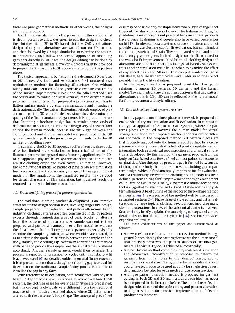
In this paper, a novel three-phase framework is proposed toenable virtual try-on simulation and fit evaluation. In contrast tothe typical approach of 2D-to-3D CAD systems, where 2D pat-terns pieces are pulled towards the human model for virtualsewing simulation, the proposed method adopts a rather differ-ent approach. In the proposed method, 2D pattern pieces arefirst precisely mapped onto the human model surface by a cross-parameterization process. Next, a hybrid position update methodintegrating both geometrical reconstruction and physical simula-tion is developed. By this method, the garment pops up from thebody surface, based on a few defined contact points, to restore itsoriginal size. After the pop-up process, a gap is formed between theclothing and the body that approximates the clothing gap in pat-tern design, which is fundamentally important for fit evaluation.Since a relationship between the clothing and the body has beendefined, pattern editing for fit improvement or design amendmentcould later be facilitated. Finally, a systematic multi-view editingtool is suggested for synchronized 2D and 3D style editing and pat-tern alteration. A brief outline of the proposed three-phasemethodis given in Fig. 1. Each phase of the method will be discussed inseparated Sections 2–4. Phase three of style editing and pattern al-terations is a large topic in clothing development, involving manysteps and operations. In view of the substantial contents involved,Section 4 only briefly explains the underlying concept, and a moredetailed discussion of the topic is given in [18]. Section 5 providesexperimental results.
The main contributions of this paper are summarized asfollows:
• A new mesh-to-mesh cross parameterization method is sug-gested for positioning the pattern pieces onto the humanmodelthat precisely preserves the pattern shapes of the final gar-ments. The virtual try-on is achieved automatically.
• A novel hybrid method combining physical-based simulationand geometrical reconstruction is proposed to deform thegarment from initial form to the ‘desired’ shape, i.e., toresume its original size. The hybrid schema enables the localcoordinate technique to be used not only for single closedmeshdeformation, but also for openmesh surface reconstruction.
• A unique pattern alteration method is proposed for garmentediting in both 2D and 3D manners, and such idea has neverbeen reported in the literature before. The method uses fashiondesign rules to control the style editing and pattern alteration,making it suitable for practical implementation of fashionproduct development.
Y. Meng et al. / Computer-Aided Design 44 (2012) 721–734 723
Fig. 1. System overview.
2. Pattern-to-model cross parameterization
Clothing try-on demands a rigid correspondence between theclothing feature points and the human model feature points. Theproposed computer aided design system starts by first establishinga spatial relationship between the 2D clothing patterns and thehuman model by a surface parameterization process.
Surface parameterization consists of generating a planar pa-rameterization for a 3D mesh surface. Parameterization has var-ious applications in science and engineering, including scattereddata fitting, re-parameterization of spline surfaces, and repairof CAD models. Texture mapping is an important application ofparameterization that commonly used to increase the visualcomplexity of computer generated images while maintaining sim-plicity in the underlying geometric models. Texture mapping algo-rithms provide parameterization by using an embedding functionand barycentric coordinates for each pair ofmesh triangles that de-fine a piecewise-affine mapping. An interactive texture mappingtechnique was first proposed by Maillot et al. [19], who obtainedthe planar development of a 3D surface by solving a global opti-mization problem. Sheffer and Hart [20] described a faster tech-nique to lower the visual distortions. Haker et al. [21] suggested aspherical texture domain for seamless mapping of closed surfaces.Sander et al. [22] and Levy et al. [23] subdivided the surface intomultiple small patches and texturemapped the patches separately.In summary, interactive texture mapping methods strive to mini-mize the distortion in the mapping process according to differentdistortion metrics.
To establish spatial relationship between clothing pattern andhuman model, a new surface parameterization technique is re-quired because clothing patterns of different designs vary largelyin geometrical shapes, for instance, darts and inside darts may beinvolved. In this paper, a duplex mapping scheme is proposed,involving the following three steps: (1) Feature definition: spec-ify the corresponding feature points on both the human meshmodel and the pattern mesh; (2) Mesh segmentation and regionmapping: triangulate 2D patterns based on defined feature pointsto obtain ancillary patterns, and segment the human body meshaccordingly to match with the ancillary patterns; and (3) Cross-parameterization: embed each patch on the body mesh surface tothe corresponding clothing pattern mesh to generate parameteri-zation coordinates.
2.1. Nomenclature and feature definitions
A list of symbols used in cross parameterization process isprovided below:
FH : feature points of the human modelFP : feature points of the clothing patternM: Mesh of 2D patternsM ′: Mesh of ancillary 2D patterns generated based on FPM∗: 3D configuration of the patternM , i.e., the mapping resultPi: patch of the human modelTi: triangle inMT ′
i : triangle in M ′
(pk, pl): vertex in Pi(v′
k, v′
l ): vertex in T ′
i(vk, vl): vertex in Ti
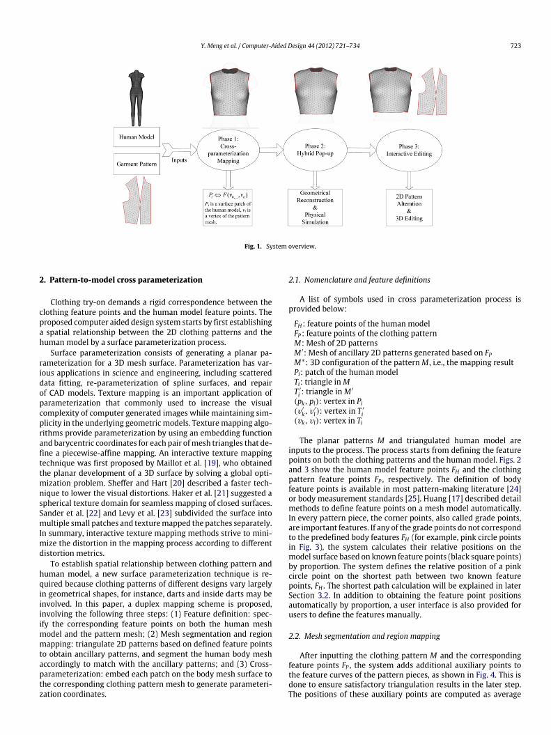
The planar patterns M and triangulated human model areinputs to the process. The process starts from defining the featurepoints on both the clothing patterns and the human model. Figs. 2and 3 show the human model feature points FH and the clothingpattern feature points FP , respectively. The definition of bodyfeature points is available in most pattern-making literature [24]or body measurement standards [25]. Huang [17] described detailmethods to define feature points on a mesh model automatically.In every pattern piece, the corner points, also called grade points,are important features. If any of the grade points do not correspondto the predefined body features FH (for example, pink circle pointsin Fig. 3), the system calculates their relative positions on themodel surface based on known feature points (black square points)by proportion. The system defines the relative position of a pinkcircle point on the shortest path between two known featurepoints, FH . The shortest path calculation will be explained in laterSection 3.2. In addition to obtaining the feature point positionsautomatically by proportion, a user interface is also provided forusers to define the features manually.
2.2. Mesh segmentation and region mapping
After inputting the clothing pattern M and the correspondingfeature points FP , the system adds additional auxiliary points tothe feature curves of the pattern pieces, as shown in Fig. 4. This isdone to ensure satisfactory triangulation results in the later step.The positions of these auxiliary points are computed as average
724 Y. Meng et al. / Computer-Aided Design 44 (2012) 721–734
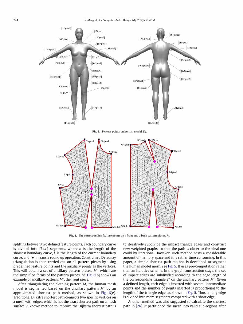
Fig. 2. Feature points on human model, FH .
Fig. 3. The corresponding feature points on a front and a back pattern pieces, FP .
splitting between two defined feature points. Each boundary curveis divided into ⌈li/κ⌉ segments, where κ is the length of theshortest boundary curve, li is the length of the current boundarycurve, and ⌈•⌉ means a round up operation. Constrained Delaunaytriangulation is then carried out on all pattern pieces by usingpredefined feature points and the auxiliary points as the vertices.This will obtain a set of ancillary pattern pieces, M ′, which arethe simplified forms of the pattern pieces, M . Fig. 6(b) shows anexample of ancillary patternsM ′, the front piece.
After triangulating the clothing pattern M , the human meshmodel is segmented based on the ancillary pattern M ′ by anapproximated shortest path method, as shown in Fig. 6(e).Traditional Dijkstra shortest path connects two specific vertices ona mesh with edges, which is not the exact shortest path on a meshsurface. A known method to improve the Dijkstra shortest path is
to iteratively subdivide the impact triangle edges and constructnew weighted graphs, so that the path is closer to the ideal onecould by iterations. However, such method costs a considerableamount of memory space and it is rather time consuming. In thispaper, a simple shortest path method is developed to segmentthe human model mesh, see Fig. 5. It uses pre-computation ratherthan an iterative schema. In the graph construction stage, the setof impact edges are subdivided according to the edge length ofthe corresponding triangle T ′
i on the ancillary pattern M ′. Givena defined length, each edge is inserted with several intermediatepoints and the number of points inserted is proportional to thelength of the triangle edge, as shown in Fig. 5. Thus, a long edgeis divided into more segments compared with a short edge.
Another method was also suggested to calculate the shortestpath in [26]. It partitioned the mesh into valid sub-regions after
Y. Meng et al. / Computer-Aided Design 44 (2012) 721–734 725
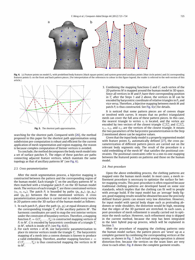
Fig. 4. (a) Feature points on model FH with predefined body features (black square points) and system generated auxiliary points (blue circle points) and (b) correspondingfeatures points FP on the front and back pattern pieces. (For interpretation of the references to colour in this figure legend, the reader is referred to the web version of thisarticle.)
Fig. 5. The shortest path approximation.
searching for the shortest path. Compared with [26], the methodproposed in this paper for the shortest path approximation usingsubdivision pre-computation is robust and efficient for the currentapplication of mesh segmentation and region mapping, the reasonis because complex computation of Steiner vertices is avoided.
To conclude, themethoddecomposes the bodymeshmodel intoa set of surface patches Pi. The edges of these patches are pathsconnecting adjacent feature vertices, which maintain the sametopology as that of ancillary patternsM ′ (see Fig. 6).
2.3. Cross-parameterization
After the mesh segmentation process, a bijective mapping isconstructed between the pattern and the corresponding region ofthe human model. Each triangle T ′
i on the ancillary patterns M ′ isthen matched with a triangular patch Pi on the 3D human modelmesh. The vertices of each triangle T ′
i are three constrained vertices(vk, vl, vm). The patch Pi is bounded by paths (pk, pm), (pl, pm)and (pk, pl) between the three mentioned vertices. A crossparameterization procedure is carried out to embed every vertexin 2D pattern onto the 3D surface of the human model as follows:1. In each patch Pi, place the path (pi, pj) at equal distances along
the corresponding triangle T ′
i of the ancillary pattern M ′. Theharmonic coordinates are used to map the rest interior verticesunder the constraint of boundary vertices. Therefore, amappingfunction Pi = G(T ′
1, . . . , T′
N) is constructed mapping vertices ofPi to M ′. G is encoded by barycentric coordinate of a triangle T ′
iin M ′, which is inside of Pi (see Fig. 6(d)).
2. For each vertex v of M , use barycentric parameterization toplace its interior vertices inside the triangle T ′
i . The barycentricmapping of a mesh into a convex domain is known to producea valid embedding. Therefore, another mapping function v =
G′(T ′
1, . . . , T′
N) is thus constructed mapping the vertices in Mto M ′.
3. Combining the mapping functions G and G′, each vertex of the2D patternsM is mapped around the humanmodel in 3D space.Since all vertices inM and Pi have their corresponding positionin T ′
i after the Steps 1 and 2 above, the vertices in M can beencoded by barycentric coordinate of relative triangles in Pi, andvice versa. Therefore, a bijectivemapping betweenmeshM andpatch Pi is thus constructed. See Fig. 6(e) for details.It is noticed that some pattern pieces are of convex shape
or involved with curves. It means that no perfect triangulatedmesh can cover the full area of these pattern pieces. In this case,the nearest triangle to vertex vi is located, and the vertex areencoded by two vectors of the closest triangle −−−→vc1vc2 and −−−→vc1vc3.vc1, vc2, and vc3 are the vertices of the closest triangle. It meansthe two parameters of the barycentre parameterization in the Step2 mentioned above can be negative values.
Given that the input bodymodel is a properly segmentedmodelwith feature points FH automatically defined [27], the cross pa-rameterization of different pattern pieces are carried out on therelevant body segments only. The result of the procedure is avalid embedding of the mesh M∗ that satisfies the positional con-straints. The positional constraints refer to a one-to-one mappingbetween the featured points on patterns and those on the humanmodel.
2.4. Post-procedure
Upon the above embedding process, the clothing patterns aremapped onto the human mesh model. In most cases, a mesh re-finement procedure is necessary to optimize the surface for bet-ter mapping results. This post-procedure is often required becausetraditional clothing patterns are developed based on some sizestandards, which implies that the clothing can fit well to peoplewith average build. If the input model has an ‘average’ body fig-ure, goodmapping resultswould be obtained because the preciselydefined feature points can ensure very low distortion. However,for input model with special body shape such as protruding ab-domen or wide shoulders, the distortion would be high, meaningthat the edges of the 3D garment are stretched. In such cases, apost-procedure of mesh refinement is usually carried out to opti-mize the mesh surface. However, such refinement step is skippedin the current method, because the step has been integratedin the later hybrid pop-up process, which will be explained inSection 3.
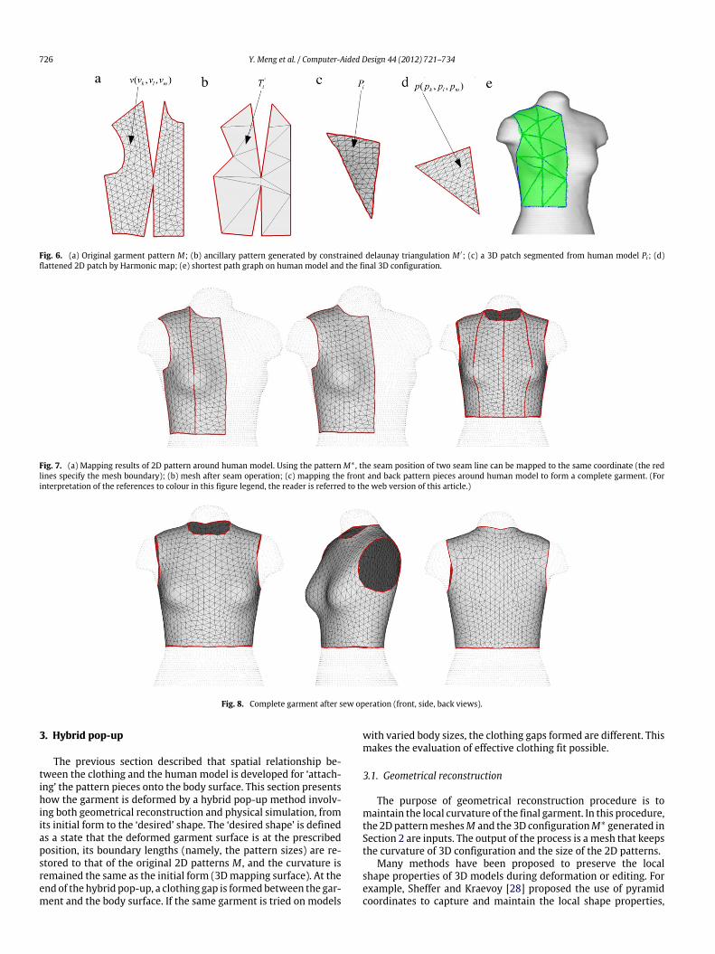
After the procedure of mapping the clothing patterns ontothe human model surface, the pattern pieces are ‘sewn’ up as acomplete garment by combining the corresponding vertices at theseams, as shown in Fig. 7. Such virtual sewing operation is almostdistortion-free, because the vertices on the seam lines are veryclose to each other. Fig. 8 shows the complete garment results.
726 Y. Meng et al. / Computer-Aided Design 44 (2012) 721–734
Fig. 6. (a) Original garment pattern M; (b) ancillary pattern generated by constrained delaunay triangulation M ′; (c) a 3D patch segmented from human model Pi; (d)flattened 2D patch by Harmonic map; (e) shortest path graph on human model and the final 3D configuration.
Fig. 7. (a) Mapping results of 2D pattern around human model. Using the pattern M∗ , the seam position of two seam line can be mapped to the same coordinate (the redlines specify the mesh boundary); (b) mesh after seam operation; (c) mapping the front and back pattern pieces around human model to form a complete garment. (Forinterpretation of the references to colour in this figure legend, the reader is referred to the web version of this article.)
Fig. 8. Complete garment after sew operation (front, side, back views).
3. Hybrid pop-up
The previous section described that spatial relationship be-tween the clothing and the human model is developed for ‘attach-ing’ the pattern pieces onto the body surface. This section presentshow the garment is deformed by a hybrid pop-up method involv-ing both geometrical reconstruction and physical simulation, fromits initial form to the ‘desired’ shape. The ‘desired shape’ is definedas a state that the deformed garment surface is at the prescribedposition, its boundary lengths (namely, the pattern sizes) are re-stored to that of the original 2D patterns M , and the curvature isremained the same as the initial form (3Dmapping surface). At theend of the hybrid pop-up, a clothing gap is formedbetween the gar-ment and the body surface. If the same garment is tried on models
with varied body sizes, the clothing gaps formed are different. Thismakes the evaluation of effective clothing fit possible.
3.1. Geometrical reconstruction
The purpose of geometrical reconstruction procedure is tomaintain the local curvature of the final garment. In this procedure,the 2DpatternmeshesM and the 3D configurationM∗ generated inSection 2 are inputs. The output of the process is a mesh that keepsthe curvature of 3D configuration and the size of the 2D patterns.
Many methods have been proposed to preserve the localshape properties of 3D models during deformation or editing. Forexample, Sheffer and Kraevoy [28] proposed the use of pyramidcoordinates to capture and maintain the local shape properties,
Y. Meng et al. / Computer-Aided Design 44 (2012) 721–734 727
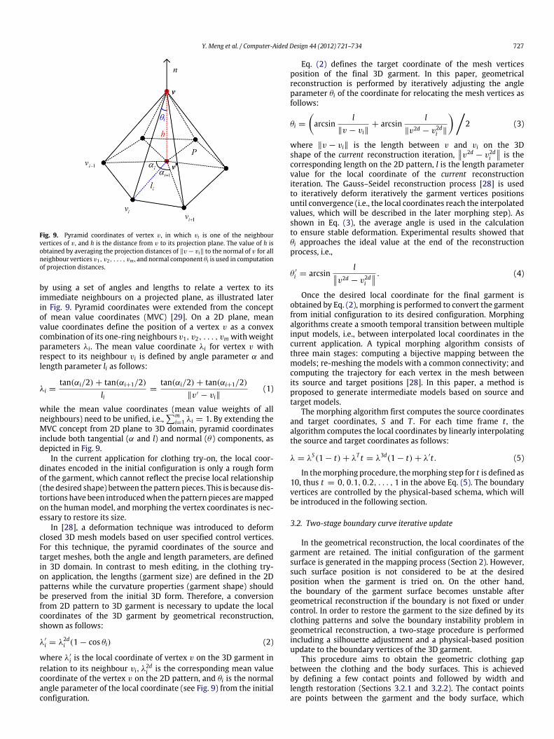
Fig. 9. Pyramid coordinates of vertex v, in which vi is one of the neighbourvertices of v, and h is the distance from v to its projection plane. The value of h isobtained by averaging the projection distances of ∥v − vi∥ to the normal of v for allneighbour vertices v1, v2, . . . , vm , and normal component θi is used in computationof projection distances.
by using a set of angles and lengths to relate a vertex to itsimmediate neighbours on a projected plane, as illustrated laterin Fig. 9. Pyramid coordinates were extended from the conceptof mean value coordinates (MVC) [29]. On a 2D plane, meanvalue coordinates define the position of a vertex v as a convexcombination of its one-ring neighbours v1, v2, . . . , vm withweightparameters λi. The mean value coordinate λi for vertex v withrespect to its neighbour vi is defined by angle parameter α andlength parameter li as follows:
λi =tan(αi/2) + tan(αi+1/2)
li=
tan(αi/2) + tan(αi+1/2)∥v′ − vi∥
(1)
while the mean value coordinates (mean value weights of allneighbours) need to be unified, i.e.,
mi=1 λi = 1. By extending the
MVC concept from 2D plane to 3D domain, pyramid coordinatesinclude both tangential (α and l) and normal (θ ) components, asdepicted in Fig. 9.
In the current application for clothing try-on, the local coor-dinates encoded in the initial configuration is only a rough formof the garment, which cannot reflect the precise local relationship(the desired shape) between the pattern pieces. This is because dis-tortions have been introducedwhen the pattern pieces aremappedon the human model, and morphing the vertex coordinates is nec-essary to restore its size.
In [28], a deformation technique was introduced to deformclosed 3D mesh models based on user specified control vertices.For this technique, the pyramid coordinates of the source andtarget meshes, both the angle and length parameters, are definedin 3D domain. In contrast to mesh editing, in the clothing try-on application, the lengths (garment size) are defined in the 2Dpatterns while the curvature properties (garment shape) shouldbe preserved from the initial 3D form. Therefore, a conversionfrom 2D pattern to 3D garment is necessary to update the localcoordinates of the 3D garment by geometrical reconstruction,shown as follows:
λ′
i = λ2di (1 − cos θi) (2)
where λ′
i is the local coordinate of vertex v on the 3D garment inrelation to its neighbour vi, λ
2di is the corresponding mean value
coordinate of the vertex v on the 2D pattern, and θi is the normalangle parameter of the local coordinate (see Fig. 9) from the initialconfiguration.
Eq. (2) defines the target coordinate of the mesh verticesposition of the final 3D garment. In this paper, geometricalreconstruction is performed by iteratively adjusting the angleparameter θi of the coordinate for relocating the mesh vertices asfollows:
θi =
arcsin
l∥v − vi∥
+ arcsinl
∥v2d − v2di ∥
2 (3)
where ∥v − vi∥ is the length between v and vi on the 3Dshape of the current reconstruction iteration,
v2d− v2d
i
is thecorresponding length on the 2D pattern, l is the length parametervalue for the local coordinate of the current reconstructioniteration. The Gauss–Seidel reconstruction process [28] is usedto iteratively deform iteratively the garment vertices positionsuntil convergence (i.e., the local coordinates reach the interpolatedvalues, which will be described in the later morphing step). Asshown in Eq. (3), the average angle is used in the calculationto ensure stable deformation. Experimental results showed thatθi approaches the ideal value at the end of the reconstructionprocess, i.e.,
θ ′
i = arcsinlv2d − v2d
i
. (4)
Once the desired local coordinate for the final garment isobtained by Eq. (2), morphing is performed to convert the garmentfrom initial configuration to its desired configuration. Morphingalgorithms create a smooth temporal transition between multipleinput models, i.e., between interpolated local coordinates in thecurrent application. A typical morphing algorithm consists ofthree main stages: computing a bijective mapping between themodels; re-meshing the models with a common connectivity; andcomputing the trajectory for each vertex in the mesh betweenits source and target positions [28]. In this paper, a method isproposed to generate intermediate models based on source andtarget models.
The morphing algorithm first computes the source coordinatesand target coordinates, S and T . For each time frame t , thealgorithm computes the local coordinates by linearly interpolatingthe source and target coordinates as follows:
λ = λS(1 − t) + λT t = λ3d(1 − t) + λ′t. (5)
In themorphing procedure, themorphing step for t is defined as10, thus t = 0, 0.1, 0.2, . . . , 1 in the above Eq. (5). The boundaryvertices are controlled by the physical-based schema, which willbe introduced in the following section.
3.2. Two-stage boundary curve iterative update
In the geometrical reconstruction, the local coordinates of thegarment are retained. The initial configuration of the garmentsurface is generated in the mapping process (Section 2). However,such surface position is not considered to be at the desiredposition when the garment is tried on. On the other hand,the boundary of the garment surface becomes unstable aftergeometrical reconstruction if the boundary is not fixed or undercontrol. In order to restore the garment to the size defined by itsclothing patterns and solve the boundary instability problem ingeometrical reconstruction, a two-stage procedure is performedincluding a silhouette adjustment and a physical-based positionupdate to the boundary vertices of the 3D garment.
This procedure aims to obtain the geometric clothing gapbetween the clothing and the body surfaces. This is achievedby defining a few contact points and followed by width andlength restoration (Sections 3.2.1 and 3.2.2). The contact pointsare points between the garment and the body surface, which
728 Y. Meng et al. / Computer-Aided Design 44 (2012) 721–734
the positions would not change in the size restoration process.This is achieved by adding position constraints to these contactpoints in the implementation. These contact points are usuallydefined as the feature points on shoulder line for top garmentslike shirts, and on the waist girth for bottom garments liketrousers. The rationale behind this size restoration procedureis that if the boundary curves of the pattern that define thegarment size can be transformed from its initial state to thedesired lengths by iterative morphing, the interior vertices ofthe garment can be transformed accordingly by the geometricalreconstruction procedure described in Section 3.1. It is later provedby experiments that this approach is valid and effective.
3.2.1. Silhouette adjustmentTo restore the garment to its original size, the adjustment is
done by first extending the garment width in a pre-computationstep, called silhouette adjustment. It is then followed by updatingthe garment vertical lengths using a physical-based method.
For the silhouette adjustment, it is noted that each garment iscomposed of a set of pattern pieces. For example, the front andback panels wrap around the body to form a top garment, such asblouse or t-shirt, orwrap around the legs to forma skirt or trousers.Therefore, the final garment’s girth measurement at the hem levelis known from the pattern pieces, which is the total length of thebottom boundary curves of the front and back pieces.
Assume that the length of the corresponding boundary curveon the initial form, after the cross parameterization, is c , whichis equal to the girth measurement of a feature curve on the bodymodel. If the length of the boundary curve on the final garmentshould be adjusted to c ′(c ′ > c), which is the size of the patternpieces, then the length adjustment for this boundary curve is c ′
−c .It later creates the clothing gap at the hem level. The silhouetteadjustment is done by first computing a geometrical centre ofthe closed boundary curve. To ensure stable transformation, theadjustment of c ′
− c is achieved iteratively by a number of steps.The vertices positions on this closed boundary curve is adjustedusing the geometrical centre of the curve as their average position.For special cases of tight-fit garments, in which the clothing girthis smaller than the circumference of the human body (c ′ > c),the process of size restoration is omitted and this will be discussedfurther later.
3.2.2. Physical-based position updateUpon every step of silhouette adjustment, a physical-based
simulation is performed in the normal direction, so as to updatethe 3D garment length iteratively.Force definition
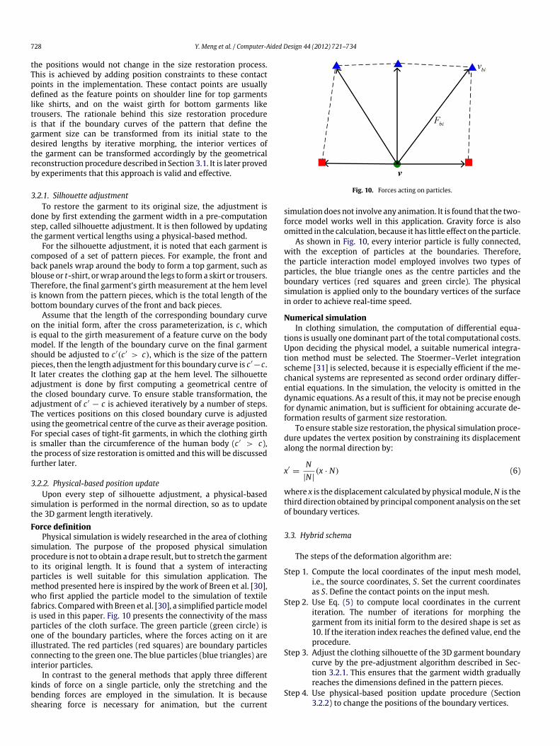
Physical simulation is widely researched in the area of clothingsimulation. The purpose of the proposed physical simulationprocedure is not to obtain a drape result, but to stretch the garmentto its original length. It is found that a system of interactingparticles is well suitable for this simulation application. Themethod presented here is inspired by the work of Breen et al. [30],who first applied the particle model to the simulation of textilefabrics. Comparedwith Breen et al. [30], a simplified particlemodelis used in this paper. Fig. 10 presents the connectivity of the massparticles of the cloth surface. The green particle (green circle) isone of the boundary particles, where the forces acting on it areillustrated. The red particles (red squares) are boundary particlesconnecting to the green one. The blue particles (blue triangles) areinterior particles.
In contrast to the general methods that apply three differentkinds of force on a single particle, only the stretching and thebending forces are employed in the simulation. It is becauseshearing force is necessary for animation, but the current
Fig. 10. Forces acting on particles.
simulation does not involve any animation. It is found that the two-force model works well in this application. Gravity force is alsoomitted in the calculation, because it has little effect on the particle.
As shown in Fig. 10, every interior particle is fully connected,with the exception of particles at the boundaries. Therefore,the particle interaction model employed involves two types ofparticles, the blue triangle ones as the centre particles and theboundary vertices (red squares and green circle). The physicalsimulation is applied only to the boundary vertices of the surfacein order to achieve real-time speed.
Numerical simulationIn clothing simulation, the computation of differential equa-
tions is usually one dominant part of the total computational costs.Upon deciding the physical model, a suitable numerical integra-tion method must be selected. The Stoermer–Verlet integrationscheme [31] is selected, because it is especially efficient if the me-chanical systems are represented as second order ordinary differ-ential equations. In the simulation, the velocity is omitted in thedynamic equations. As a result of this, it may not be precise enoughfor dynamic animation, but is sufficient for obtaining accurate de-formation results of garment size restoration.
To ensure stable size restoration, the physical simulation proce-dure updates the vertex position by constraining its displacementalong the normal direction by:
x′=
N|N|
(x · N) (6)
where x is the displacement calculated by physicalmodule,N is thethird direction obtained by principal component analysis on the setof boundary vertices.
3.3. Hybrid schema
The steps of the deformation algorithm are:
Step 1. Compute the local coordinates of the input mesh model,i.e., the source coordinates, S. Set the current coordinatesas S. Define the contact points on the input mesh.
Step 2. Use Eq. (5) to compute local coordinates in the currentiteration. The number of iterations for morphing thegarment from its initial form to the desired shape is set as10. If the iteration index reaches the defined value, end theprocedure.
Step 3. Adjust the clothing silhouette of the 3D garment boundarycurve by the pre-adjustment algorithm described in Sec-tion 3.2.1. This ensures that the garment width graduallyreaches the dimensions defined in the pattern pieces.
Step 4. Use physical-based position update procedure (Section3.2.2) to change the positions of the boundary vertices.
Y. Meng et al. / Computer-Aided Design 44 (2012) 721–734 729
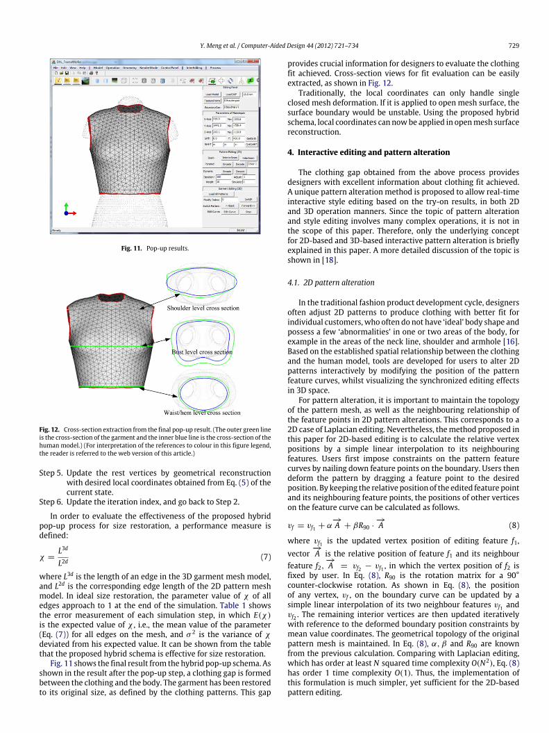
Fig. 11. Pop-up results.
Fig. 12. Cross-section extraction from the final pop-up result. (The outer green lineis the cross-section of the garment and the inner blue line is the cross-section of thehuman model.) (For interpretation of the references to colour in this figure legend,the reader is referred to the web version of this article.)
Step 5. Update the rest vertices by geometrical reconstructionwith desired local coordinates obtained from Eq. (5) of thecurrent state.
Step 6. Update the iteration index, and go back to Step 2.
In order to evaluate the effectiveness of the proposed hybridpop-up process for size restoration, a performance measure isdefined:
χ =L3d
L2d(7)
where L3d is the length of an edge in the 3D garment mesh model,and L2d is the corresponding edge length of the 2D pattern meshmodel. In ideal size restoration, the parameter value of χ of alledges approach to 1 at the end of the simulation. Table 1 showsthe error measurement of each simulation step, in which E(χ)is the expected value of χ , i.e., the mean value of the parameter(Eq. (7)) for all edges on the mesh, and σ 2 is the variance of χdeviated from his expected value. It can be shown from the tablethat the proposed hybrid schema is effective for size restoration.
Fig. 11 shows the final result from the hybrid pop-up schema. Asshown in the result after the pop-up step, a clothing gap is formedbetween the clothing and the body. The garment has been restoredto its original size, as defined by the clothing patterns. This gap
provides crucial information for designers to evaluate the clothingfit achieved. Cross-section views for fit evaluation can be easilyextracted, as shown in Fig. 12.
Traditionally, the local coordinates can only handle singleclosed mesh deformation. If it is applied to open mesh surface, thesurface boundary would be unstable. Using the proposed hybridschema, local coordinates can nowbe applied in openmesh surfacereconstruction.
4. Interactive editing and pattern alteration
The clothing gap obtained from the above process providesdesigners with excellent information about clothing fit achieved.A unique pattern alteration method is proposed to allow real-timeinteractive style editing based on the try-on results, in both 2Dand 3D operation manners. Since the topic of pattern alterationand style editing involves many complex operations, it is not inthe scope of this paper. Therefore, only the underlying conceptfor 2D-based and 3D-based interactive pattern alteration is brieflyexplained in this paper. A more detailed discussion of the topic isshown in [18].
4.1. 2D pattern alteration
In the traditional fashion product development cycle, designersoften adjust 2D patterns to produce clothing with better fit forindividual customers, who often do not have ‘ideal’ body shape andpossess a few ‘abnormalities’ in one or two areas of the body, forexample in the areas of the neck line, shoulder and armhole [16].Based on the established spatial relationship between the clothingand the human model, tools are developed for users to alter 2Dpatterns interactively by modifying the position of the patternfeature curves, whilst visualizing the synchronized editing effectsin 3D space.
For pattern alteration, it is important to maintain the topologyof the pattern mesh, as well as the neighbouring relationship ofthe feature points in 2D pattern alterations. This corresponds to a2D case of Laplacian editing. Nevertheless, themethod proposed inthis paper for 2D-based editing is to calculate the relative vertexpositions by a simple linear interpolation to its neighbouringfeatures. Users first impose constraints on the pattern featurecurves by nailing down feature points on the boundary. Users thendeform the pattern by dragging a feature point to the desiredposition. By keeping the relative position of the edited feature pointand its neighbouring feature points, the positions of other verticeson the feature curve can be calculated as follows.
vf = vf1 + α−→A + βR90 ·
−→A (8)
where vf1 is the updated vertex position of editing feature f1,vector
−→A is the relative position of feature f1 and its neighbour
feature f2,−→A = vf2 − vf1 , in which the vertex position of f2 is
fixed by user. In Eq. (8), R90 is the rotation matrix for a 90°counter-clockwise rotation. As shown in Eq. (8), the positionof any vertex, vf , on the boundary curve can be updated by asimple linear interpolation of its two neighbour features vf1 andvf2 . The remaining interior vertices are then updated iterativelywith reference to the deformed boundary position constraints bymean value coordinates. The geometrical topology of the originalpattern mesh is maintained. In Eq. (8), α, β and R90 are knownfrom the previous calculation. Comparing with Laplacian editing,which has order at least N squared time complexity O(N2), Eq. (8)has order 1 time complexity O(1). Thus, the implementation ofthis formulation is much simpler, yet sufficient for the 2D-basedpattern editing.
730 Y. Meng et al. / Computer-Aided Design 44 (2012) 721–734
Table 1Error measures of each simulation step.
Step 1 2 3 4 5 6 7 8 9 10
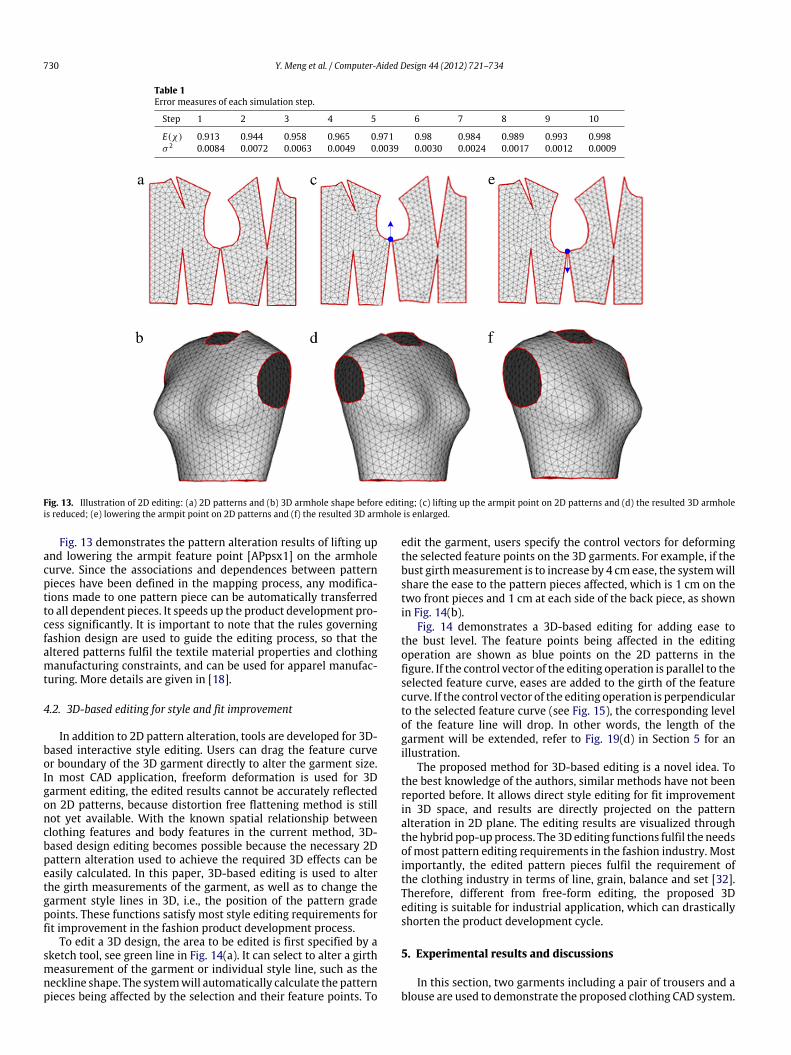
E(χ) 0.913 0.944 0.958 0.965 0.971 0.98 0.984 0.989 0.993 0.998σ 2 0.0084 0.0072 0.0063 0.0049 0.0039 0.0030 0.0024 0.0017 0.0012 0.0009
Fig. 13. Illustration of 2D editing: (a) 2D patterns and (b) 3D armhole shape before editing; (c) lifting up the armpit point on 2D patterns and (d) the resulted 3D armholeis reduced; (e) lowering the armpit point on 2D patterns and (f) the resulted 3D armhole is enlarged.
Fig. 13 demonstrates the pattern alteration results of lifting upand lowering the armpit feature point [APpsx1] on the armholecurve. Since the associations and dependences between patternpieces have been defined in the mapping process, any modifica-tions made to one pattern piece can be automatically transferredto all dependent pieces. It speeds up the product development pro-cess significantly. It is important to note that the rules governingfashion design are used to guide the editing process, so that thealtered patterns fulfil the textile material properties and clothingmanufacturing constraints, and can be used for apparel manufac-turing. More details are given in [18].
4.2. 3D-based editing for style and fit improvement
In addition to 2D pattern alteration, tools are developed for 3D-based interactive style editing. Users can drag the feature curveor boundary of the 3D garment directly to alter the garment size.In most CAD application, freeform deformation is used for 3Dgarment editing, the edited results cannot be accurately reflectedon 2D patterns, because distortion free flattening method is stillnot yet available. With the known spatial relationship betweenclothing features and body features in the current method, 3D-based design editing becomes possible because the necessary 2Dpattern alteration used to achieve the required 3D effects can beeasily calculated. In this paper, 3D-based editing is used to alterthe girth measurements of the garment, as well as to change thegarment style lines in 3D, i.e., the position of the pattern gradepoints. These functions satisfy most style editing requirements forfit improvement in the fashion product development process.
To edit a 3D design, the area to be edited is first specified by asketch tool, see green line in Fig. 14(a). It can select to alter a girthmeasurement of the garment or individual style line, such as theneckline shape. The systemwill automatically calculate the patternpieces being affected by the selection and their feature points. To
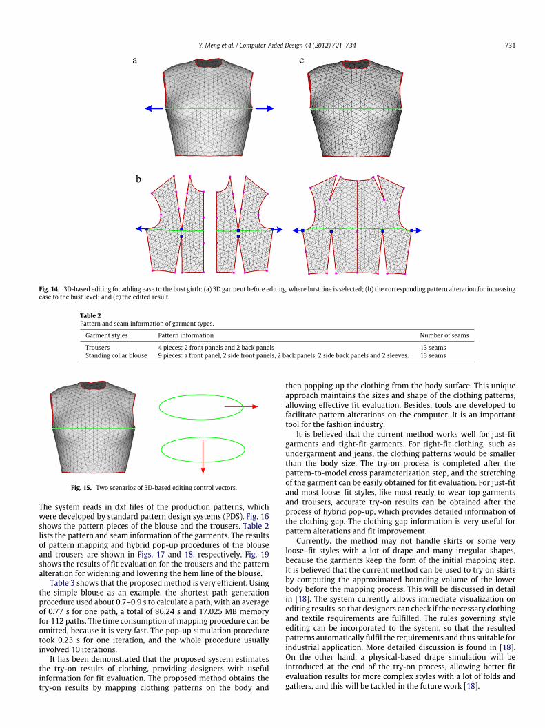
edit the garment, users specify the control vectors for deformingthe selected feature points on the 3D garments. For example, if thebust girthmeasurement is to increase by 4 cm ease, the systemwillshare the ease to the pattern pieces affected, which is 1 cm on thetwo front pieces and 1 cm at each side of the back piece, as shownin Fig. 14(b).
Fig. 14 demonstrates a 3D-based editing for adding ease tothe bust level. The feature points being affected in the editingoperation are shown as blue points on the 2D patterns in thefigure. If the control vector of the editing operation is parallel to theselected feature curve, eases are added to the girth of the featurecurve. If the control vector of the editing operation is perpendicularto the selected feature curve (see Fig. 15), the corresponding levelof the feature line will drop. In other words, the length of thegarment will be extended, refer to Fig. 19(d) in Section 5 for anillustration.
The proposed method for 3D-based editing is a novel idea. Tothe best knowledge of the authors, similar methods have not beenreported before. It allows direct style editing for fit improvementin 3D space, and results are directly projected on the patternalteration in 2D plane. The editing results are visualized throughthe hybrid pop-up process. The 3D editing functions fulfil the needsof most pattern editing requirements in the fashion industry. Mostimportantly, the edited pattern pieces fulfil the requirement ofthe clothing industry in terms of line, grain, balance and set [32].Therefore, different from free-form editing, the proposed 3Dediting is suitable for industrial application, which can drasticallyshorten the product development cycle.
5. Experimental results and discussions
In this section, two garments including a pair of trousers and ablouse are used to demonstrate the proposed clothing CAD system.
Y. Meng et al. / Computer-Aided Design 44 (2012) 721–734 731
Fig. 14. 3D-based editing for adding ease to the bust girth: (a) 3D garment before editing, where bust line is selected; (b) the corresponding pattern alteration for increasingease to the bust level; and (c) the edited result.
Table 2Pattern and seam information of garment types.
Garment styles Pattern information Number of seams
Trousers 4 pieces: 2 front panels and 2 back panels 13 seamsStanding collar blouse 9 pieces: a front panel, 2 side front panels, 2 back panels, 2 side back panels and 2 sleeves. 13 seams
Fig. 15. Two scenarios of 3D-based editing control vectors.
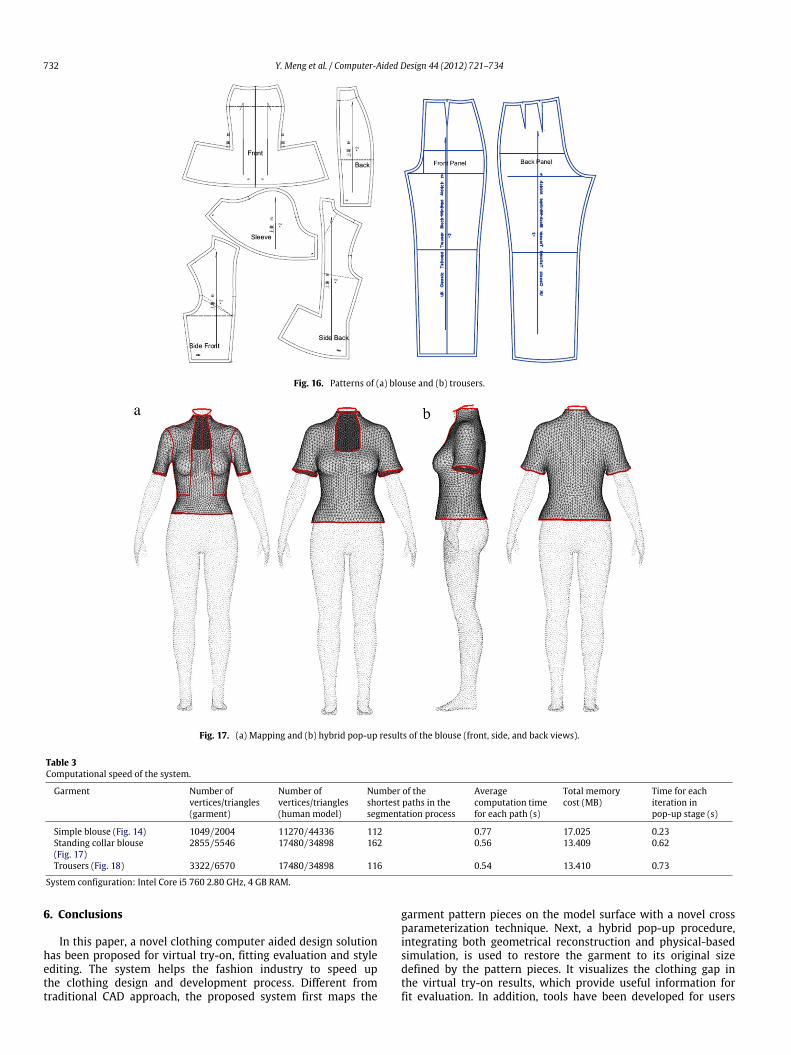
The system reads in dxf files of the production patterns, whichwere developed by standard pattern design systems (PDS). Fig. 16shows the pattern pieces of the blouse and the trousers. Table 2lists the pattern and seam information of the garments. The resultsof pattern mapping and hybrid pop-up procedures of the blouseand trousers are shown in Figs. 17 and 18, respectively. Fig. 19shows the results of fit evaluation for the trousers and the patternalteration for widening and lowering the hem line of the blouse.
Table 3 shows that the proposedmethod is very efficient. Usingthe simple blouse as an example, the shortest path generationprocedure used about 0.7–0.9 s to calculate a path, with an averageof 0.77 s for one path, a total of 86.24 s and 17.025 MB memoryfor 112 paths. The time consumption of mapping procedure can beomitted, because it is very fast. The pop-up simulation proceduretook 0.23 s for one iteration, and the whole procedure usuallyinvolved 10 iterations.
It has been demonstrated that the proposed system estimatesthe try-on results of clothing, providing designers with usefulinformation for fit evaluation. The proposed method obtains thetry-on results by mapping clothing patterns on the body and
then popping up the clothing from the body surface. This uniqueapproach maintains the sizes and shape of the clothing patterns,allowing effective fit evaluation. Besides, tools are developed tofacilitate pattern alterations on the computer. It is an importanttool for the fashion industry.
It is believed that the current method works well for just-fitgarments and tight-fit garments. For tight-fit clothing, such asundergarment and jeans, the clothing patterns would be smallerthan the body size. The try-on process is completed after thepattern-to-model cross parameterization step, and the stretchingof the garment can be easily obtained for fit evaluation. For just-fitand most loose–fit styles, like most ready-to-wear top garmentsand trousers, accurate try-on results can be obtained after theprocess of hybrid pop-up, which provides detailed information ofthe clothing gap. The clothing gap information is very useful forpattern alterations and fit improvement.
Currently, the method may not handle skirts or some veryloose–fit styles with a lot of drape and many irregular shapes,because the garments keep the form of the initial mapping step.It is believed that the current method can be used to try on skirtsby computing the approximated bounding volume of the lowerbody before the mapping process. This will be discussed in detailin [18]. The system currently allows immediate visualization onediting results, so that designers can check if the necessary clothingand textile requirements are fulfilled. The rules governing styleediting can be incorporated to the system, so that the resultedpatterns automatically fulfil the requirements and thus suitable forindustrial application. More detailed discussion is found in [18].On the other hand, a physical-based drape simulation will beintroduced at the end of the try-on process, allowing better fitevaluation results for more complex styles with a lot of folds andgathers, and this will be tackled in the future work [18].
732 Y. Meng et al. / Computer-Aided Design 44 (2012) 721–734
Fig. 16. Patterns of (a) blouse and (b) trousers.
Fig. 17. (a) Mapping and (b) hybrid pop-up results of the blouse (front, side, and back views).
Table 3Computational speed of the system.
Garment Number ofvertices/triangles(garment)
Number ofvertices/triangles(human model)
Number of theshortest paths in thesegmentation process
Averagecomputation timefor each path (s)
Total memorycost (MB)
Time for eachiteration inpop-up stage (s)
Simple blouse (Fig. 14) 1049/2004 11270/44336 112 0.77 17.025 0.23Standing collar blouse(Fig. 17)
2855/5546 17480/34898 162 0.56 13.409 0.62
Trousers (Fig. 18) 3322/6570 17480/34898 116 0.54 13.410 0.73
System configuration: Intel Core i5 760 2.80 GHz, 4 GB RAM.
6. Conclusions
In this paper, a novel clothing computer aided design solutionhas been proposed for virtual try-on, fitting evaluation and styleediting. The system helps the fashion industry to speed upthe clothing design and development process. Different fromtraditional CAD approach, the proposed system first maps the
garment pattern pieces on the model surface with a novel crossparameterization technique. Next, a hybrid pop-up procedure,integrating both geometrical reconstruction and physical-basedsimulation, is used to restore the garment to its original sizedefined by the pattern pieces. It visualizes the clothing gap inthe virtual try-on results, which provide useful information forfit evaluation. In addition, tools have been developed for users
Y. Meng et al. / Computer-Aided Design 44 (2012) 721–734 733
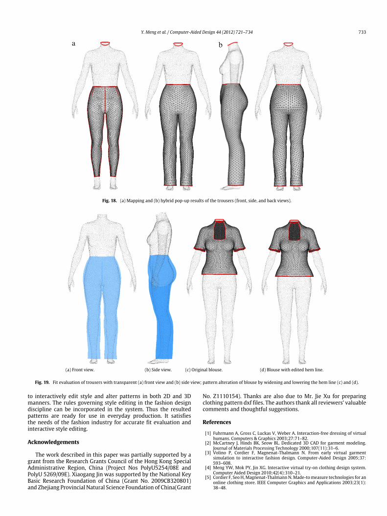
Fig. 18. (a) Mapping and (b) hybrid pop-up results of the trousers (front, side, and back views).
(a) Front view. (b) Side view. (c) Original blouse. (d) Blouse with edited hem line.
Fig. 19. Fit evaluation of trousers with transparent (a) front view and (b) side view; pattern alteration of blouse by widening and lowering the hem line (c) and (d).
to interactively edit style and alter patterns in both 2D and 3Dmanners. The rules governing style editing in the fashion designdiscipline can be incorporated in the system. Thus the resultedpatterns are ready for use in everyday production. It satisfiesthe needs of the fashion industry for accurate fit evaluation andinteractive style editing.
Acknowledgements
The work described in this paper was partially supported by agrant from the Research Grants Council of the Hong Kong SpecialAdministrative Region, China (Project Nos PolyU5254/08E andPolyU 5269/09E). Xiaogang Jin was supported by the National KeyBasic Research Foundation of China (Grant No. 2009CB320801)and Zhejiang Provincial Natural Science Foundation of China(Grant
No. Z1110154). Thanks are also due to Mr. Jie Xu for preparingclothing pattern dxf files. The authors thank all reviewers’ valuablecomments and thoughtful suggestions.
References
[1] Fuhrmann A, Gross C, Luckas V, Weber A. Interaction-free dressing of virtualhumans. Computers & Graphics 2003;27:71–82.
[2] McCartney J, Hinds BK, Seow BL. Dedicated 3D CAD for garment modeling.Journal of Materials Processing Technology 2000;107(11):31–6.
[3] Volino P, Cordier F, Magnenat-Thalmann N. From early virtual garmentsimulation to interactive fashion design. Computer-Aided Design 2005;37:593–608.
[4] Meng YW, Mok PY, Jin XG. Interactive virtual try-on clothing design system.Computer Aided Design 2010;42(4):310–21.
[5] Cordier F, Seo H,Magnenat-ThalmannN.Made-tomeasure technologies for anonline clothing store. IEEE Computer Graphics and Applications 2003;23(1):38–48.
734 Y. Meng et al. / Computer-Aided Design 44 (2012) 721–734
[6] Kim S, Kang T. Garment pattern generation from body scan data. ComputerAided Design 2003;35:611–8.
[7] Kim S, Park CK. Basic garment pattern generation using geometric modelingmethod. International Journal of Clothing Science and Technology 2007;19(1):7–17.
[8] Liu S, Sheng JC, He L, Chen F. Simulation of 3D garment based on six piecesof bezier curved surfaces. Computer Science and Software Engineering (CSSE)2008;1082–5.
[9] Wang J, Lu G, Chen L, Geng Y, Deng W. Customer participating 3Dgarment design formass personalization. Textile Research Journal 2011;81(2):187–204.
[10] Turquin E, Wither J, Boissieux L, Cani MP, Hughes JF. A sketch-based interfacefor clothing virtual characters. IEEEComputerGraphics andApplications 2007;27(1):72–81.
[11] Decaudin P, Julius D, Wither J, et al. Virtual garments: a fully geometricapproach for clothing design. Computer Graphics Forum 2006;25(3):625–34.
[12] Wang CCL, Shana SF, Smith Matthew MF. Surface flattening based on energymodel. Computer-Aided Design 2002;34(11):823–33.
[13] Luo ZG, Yuen MMF. Reactive 2D/3D garment pattern design modification.Computer Aided Design 2005;37(6):623–30.
[14] Azariadis PN, Aspragathos NA. Geodesic curvature preservation in surfaceflattening through constrained global optimization. Computer Aided Design2001;33(8):561–617.
[15] Kim SM, Kang JT. Garment pattern generation from body scan data. Computer-Aided Design 2003;35(7):611–8.
[16] Liechty E, Rasband J, Pottberg-Steineckert D. Fitting & pattern alteration: amulti-method approach to the art of style selection, fitting, and alteration. 2nded. New York: Fairchild Books; 2010.
[17] Huang HQ. Development of 2D block patterns from fit feature-alignedflattenable 3D garments. Ph.D. Thesis. Hong Kong: The Hong Kong PolytechnicUniversity; 2011.
[18] Meng YW, Mok PY, Jin XG, Kwok YL. Interactive computer aided editing ofapparel patterns for style and fit optimisation. Working paper. The Hong KongPolytechnic University. 2011.
[19] Maillot Jerome, Yahia H, Verroust A. Interactive texture mapping. In: Proc.SIGGRAPH 93. 1993. p. 27–34.
[20] Sheffer A, Hart J. Seamster: inconspicuous low-distortion texture seam layout.Proceedings of IEEE Visualization 2002;291–8.
[21] Haker S, Angenent S, Tannenbaum A, Kikinis R, Sapiro G, Halle M.Conformal surface parameterization for texture mapping. IEEE Transactionson Visualization and Computer Graphics 2000;6(2):181–9.
[22] Sander P, Snyder J, Gortler S, Hoppe H. Texture mapping progressive meshes.In: SIGGRAPH. 2001. p. 409–16.
[23] Levy B, Petitjean S, Ray N, Maillot J. Least squares conformal maps forautomatic texture atlas generation. In: SIGGRAPH. 2002. p. 362–71.
[24] Kunick P. Modern sizing and pattern making for women’s and children’sgarments. UK: Philip Kunic Publication; 1984.
[25] ISO 8559, 1989. Garment construction and anthropometric surveys-bodydimensions, 1st ed. ISO.
[26] Kraevoy V, Sheffer A. Cross-parameterization and compatible remeshing of3D models. In: Proceedings of ACM SIGGRAPH 2004, ACM transactions ongraphics. 23. No. 3. 2004. p. 861–9.
[27] Huang HQ, Mok PY, Kwok YL, Au SC. Developing flattenable 3D foundationgarments by developable boundary triangulation with fitting conditionsguaranteed. In: A.D. Sappa (Ed.). Proceedings of the eleventh IASTEDinternational conference on computer graphics and imaging. CGIM2010. 2010.p. 39–45.
[28] Sheffer A, Kraevoy Vladislay. Pyramid coordinates for morphing anddeformation. In: Proceedings of the 2nd international symposium of 3D dataprocessing, visualization, and transmission. 3DPVT’04. 2004. p. 68–75.
[29] Floater MS. Mean value coordinates. Computer Aided Geometric Design 2003;20(1):19–27.
[30] Breen DE, House DH, Getto PH. A physically based particle model of wovencloth. The Visual Computer 1992;8(5–6):264–77.
[31] Ernst H, Christian L, Gerhard W. Geometric numerical integration illustratedby the Störmer-Verlet method. Acta Numerica 2003;390–450.
[32] Erwin MD, Kinchen LA. Clothing for moderns. 5th ed. New York (NY):Macmillan; 1974.