CompSci356: Computer Network Architectures Lecture 8 ...
43
CompSci 356: Computer Network Architectures Lecture 8: Switching technologies Chapter 3.1 Xiaowei Yang [email protected]
Transcript of CompSci356: Computer Network Architectures Lecture 8 ...

CompSci 356: Computer Network Architectures
Lecture 8: Switching technologiesChapter 3.1
Xiaowei [email protected]

Review• Sliding window revisited• End-to-end arguments– Reliable transmission
• Multiple access links– Ethernet: CSMA/CD– Token ring–Wireless• 802.11 (WiFi): RTS/CTS• Bluetooth• Cell phone
– Note: understand the concepts
Wireless links
• Most common– Asymmetric
• Point-to-multipoint

Wireless access control
• Can’t use Ethernet protocol– Hidden terminal• A and C can�t hear each other�s collision at B
– Exposed terminal• B can send to A; C can send to D

802.11 (WiFi) Multiple access with collision avoidance (CSMA/CA)
• Sender and receiver exchange control– Sender à receiver: Request to send (RTS)
• Specifies the length of frame– Receiver à sender: Clear to send (CTS)
• Echoes length of frame– Sender à receiver: frame– Receiver à sender: ack– Other nodes can send after hearing ACK
• Node sees CTS– Too close to receiver, can�t transmit– Addressing hidden terminals
• Node only sees RTS– Okay to transmit– Addressing exposed terminals

How to resolve collision
• Sender cannot do collision detection– Single antenna can�t send and receive at the same
time
• If no CTS, then RTS collide• Exponential backoff to retransmit

Distribution system
• Hosts associate with APs• APs connect via the distribution system – A layer-2 system
• Ethernet, token ring, etc.
– Host IP addresses do not need to change

AP association
• Active scanning– Node: Probe– APs: Probe response– Node selects one of APs, send Association request– AP replies Association Response
• Passive scanning– AP sends Beacon to announce itself– Node sends Association Request
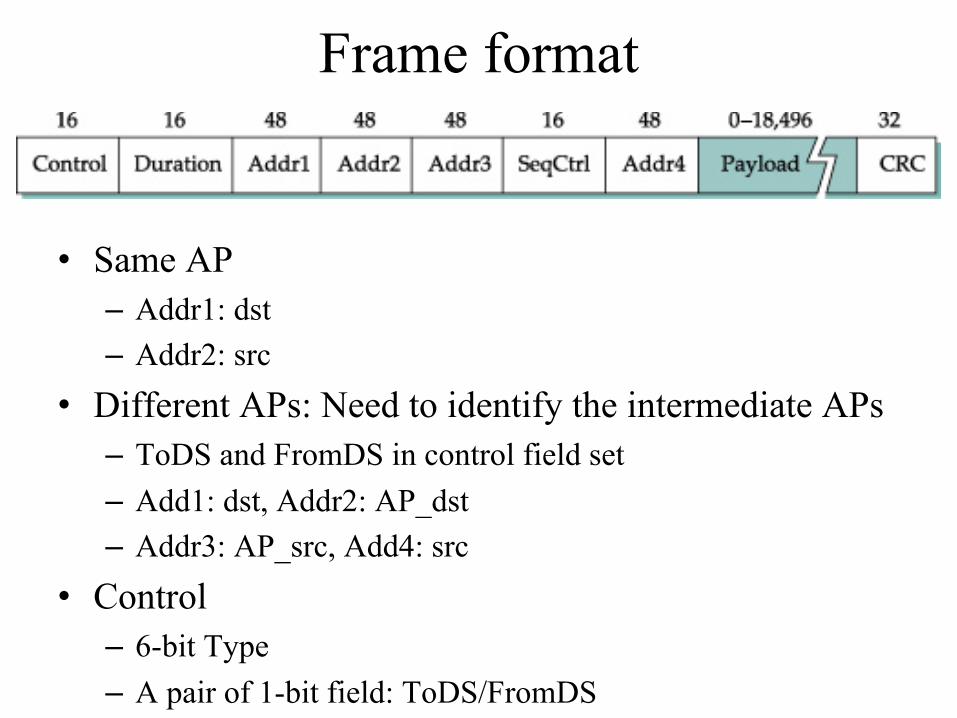
Frame format
• Same AP– Addr1: dst– Addr2: src
• Different APs: Need to identify the intermediate APs– ToDS and FromDS in control field set– Add1: dst, Addr2: AP_dst– Addr3: AP_src, Add4: src
• Control– 6-bit Type– A pair of 1-bit field: ToDS/FromDS
Bluetooth (802.15.1)
• Connecting devices: mobile phones, headsets, keyboards– Very short range communication– Low power
• License exempt band 2.45 Ghz• 1~3Mpbs• Specified by Bluetooth Special Interest Group
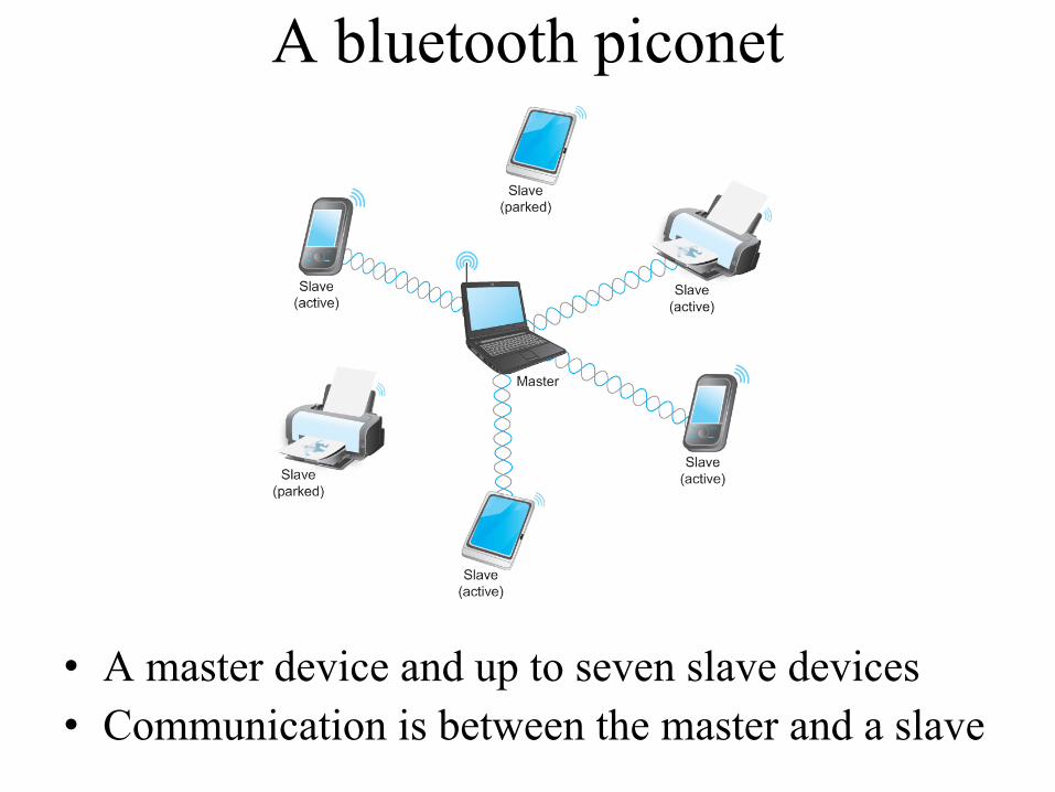
A bluetooth piconet
• A master device and up to seven slave devices• Communication is between the master and a slave

Cell phone technologies
• Using licensed spectrum• Different bands using different frequencies• Base stations form a wired network• Geographic area served by a base station’s
antenna is called a cell– Similar to wifi
• Phone is associated with one base station• Leaving a cell entering a cell causes a handoff

Cellular technologies
• 1G: analog• 2G: digital and data• 3G: higher bandwidth and simultaneous voice
and data• 4G: even higher. Top around 2.6Ghz• 5G: 15Ghz

Today• Types of switching– Datagram– Virtual circuit– Source routing
Packet switching
• Problem: single link networks have limited scale• Ethernet < 1024 hosts, 2500 meters• Wireless limited by radio ranges• Point-to-point links connect only two nodes
• A packet switch is a device with several inputs and outputs leading to and from the nodes that the switch interconnects– Hosts communicate without being directly connected

A star topology• A switch has a limited number
of input and output ports
• Switches can be connected to each other to build larger networks
• Adding a new host may not reduce the performance for other hosts– Not true for shared media
networks– Why?

Switching technologies• Switching / forwarding: to receive incoming packets
on one of its links and to transmit them on some other link.
• Problem: how does a switch decide on which output port to place each packet?
• Solution: looks at the packet header and makes a decision– Connectionless: datagram– Connection oriented: virtual circuit– Source routing

Challenges
• Contention– Input rate exceeds output rate
• Multiple input ports may send to the same output port
– Switches queue packets until contention disappears
• Congestion– When a switch runs out of buffer, it discards packets.– Too frequent packet loss is said to be congested

Datagram
• Every packet contains the destination address– A global unique identifier– Ethernet has 48-bit addresses
• A switch maintains a forwarding table that maps a packet to an output port

Switch 2�s forwarding table
A 3B 0C 3DEFGH
Q: how does a switch compute the table?

Features of datagram switching
• Connectionless
• Unknown network state
• Independent forwarding
• Robust to failures– Switches can re-compute forwarding tables
Virtual circuit switching• Connection oriented– Set up a virtual circuit– Data transfer
• Connection setup phase– Set up connection state– A virtual circuit identifier, an incoming interface,
an outgoing interface, and an outgoing virtual circuit identifier

Virtual circuit table (switch1)
Incominginterface
IncomingVCI
Outgoinginterface
OutgoingVCI
2 5 1 11
5
11

Virtual circuit switching
• Algorithm:– If a packet arrives on the matching incoming port with the
matching incoming VCI, it will be sent to the corresponding outgoing port with the corresponding VCI
• VCIs are link-local

How to setup connection state
• Administrator configured– Permanent virtual circuit (PVC)– Admin manually sets up VC tables– Does not suit large networks
• Signaling– A host sends messages to dynamically setup or tear
down a VC
VC setup protocol• A host A sends a setup message to first hop switch, including
the final destination address– Similar to a datagram packet
• The switch picks an unused VCI to identify the incoming connection, and fills part of the VC table– Why not let the host pick it?
• Every switch repeats the process until the packet reaches the destination B
• The destination B sends an ack to inform its upstream switch the VCI for the connection

Setup B
IF VCI OF VCI2 5 1
Setup B
IF VCI OF VCI3 11 2
Setup B
IF VCI OF VCI0 7 1
Setup B
VCI4

• After setup, A sends to B• A tears down after done
IF VCI OF VCI2 5 1
IF VCI OF VCI3 11 2
IF VCI OF VCI0 7 1
VCI4
ACK, 4
4
ACK,7
7ACK, 11
11ACK, 5
B: VCI 5

Characteristics of VC switching
• - Connection setup wait
• + Data packets contain a small VCI, not the full destination addresses
• - One switch failure tears down the entire connection
• - Connection sets up require routing algorithms– Setup packet is forwarded using a datagram algorithm

VC allows resource reservation
• + Buffers can be allocated during the setup phase to avoid congestion
• An example (X.25)– Buffers allocated during connection setup– Sliding window is run between pairs of nodes
(hop-by-hop flow control)– Circuit is rejected if no more buffer

Quality of service (QoS)
• Connectionless network is difficult to allocate resources– Switches send packets independently– How to associate one packet with other packets?
• Virtual circuit can be used to provide different QoS– Allocate a fraction of link bandwidth to each circuit
Link layer technologies that use VC
• X.25• Frame relay• Asynchronous Transfer Mode (ATM)

Asynchronous Transfer Mode
• ATM Cells: fixed-size packets– 5 bytes header– 48 bytes payload
• If payload smaller than 48B, uses padding• If greater than 48B, breaks it

Why small, fixed-length packets?• Cons: maximum efficiency 48/53=90.6%
• Pros:– Suitable for high-speed hardware implementation–Many switching elements doing the same thing in
parallel– Reducing priority packet latency • Good for QoS
– Reducing transmission latency
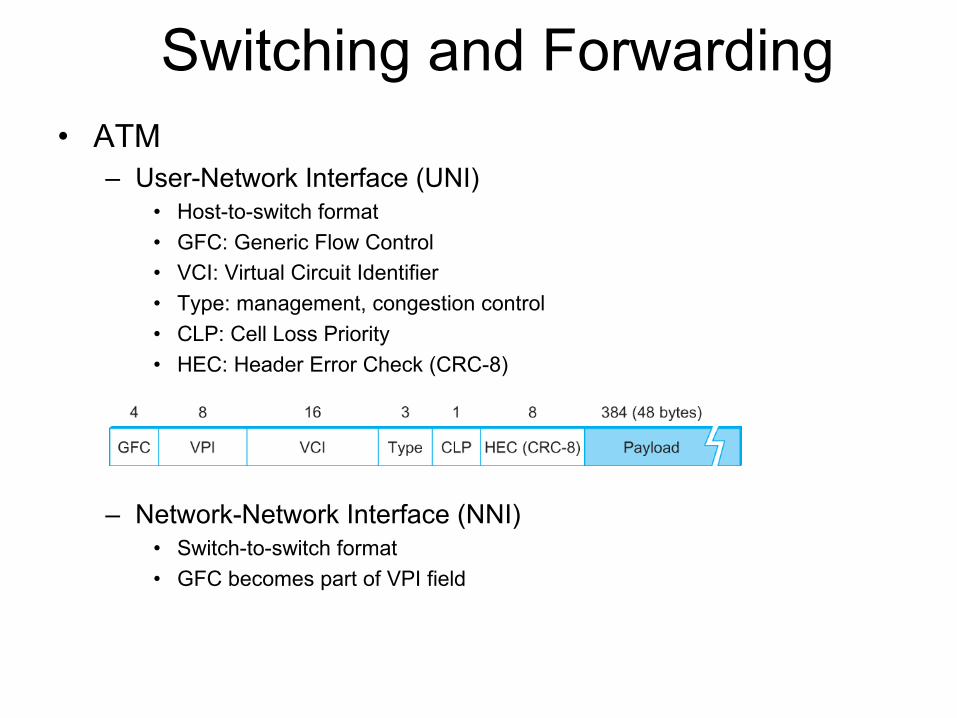
Switching and Forwarding
• ATM
– User-Network Interface (UNI)
• Host-to-switch format
• GFC: Generic Flow Control
• VCI: Virtual Circuit Identifier
• Type: management, congestion control
• CLP: Cell Loss Priority
• HEC: Header Error Check (CRC-8)
– Network-Network Interface (NNI)
• Switch-to-switch format
• GFC becomes part of VPI field

Virtual paths
• 24-bit virtual circuit identifiers (VCIs)• Two-levels of hierarchy– 8-bit virtual path, 16-bit VCI– Virtual paths shared by multiple connections

History of ATM• Why 48 bytes– It�s from the telephone technology– Thought data would be mostly voice– A compromise
• US wanted 64 bytes for efficiency• Europe wanted 32 bytes for simplifying echo cancellation • (64+32) / 2 = 48 bytes
– Popular in the late 80s and early 90s due to its high speed• Major telecoms supported it
– Popularity faded. IP/Ethernet ruled• IP over ATM• DSL over ATM: DSL modem takes Ethernet frames and
chop them into cells

Switching technologies
• Connectionless: datagram
• Connection oriented: virtual circuit– An example of VC switching: ATM
• Source routing

Source routing
• Source host provides all the information for packets to travel across the network– Packets carry output port numbers– Packets carry switch addresses– Variable header length

Handling source routing headers
a. Rotation b. Stripping – No return path!
c. Pointer

Loose or strict source routing
• Strict–Must visit every node on the path
• Loose–Waypoints rather than the complete route

Summary• Wireless links
• Types of switching– Datagram– Virtual circuit– Source routing
• Next: Bridges and LAN switches