Compressors Selection of gas compressors: part...
6
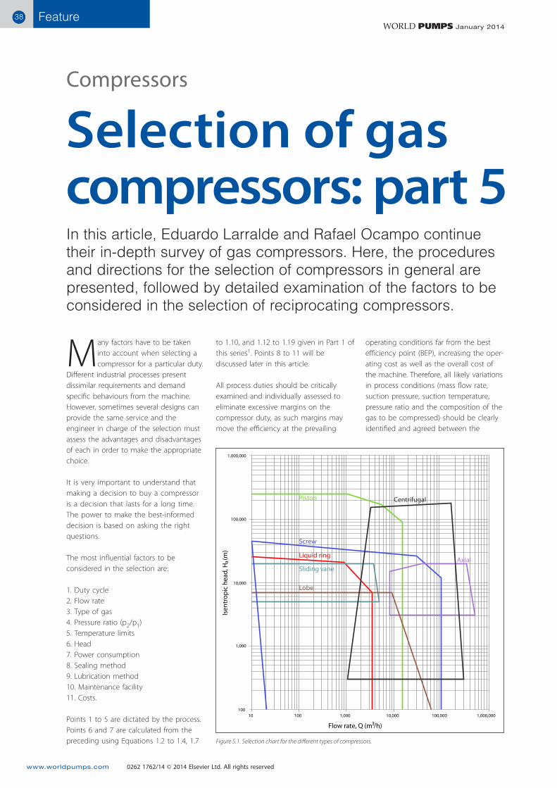
Feature 38 38 www.worldpumps.com WORLD PUMPS January 2014 Piston Centrifugal Axial Sliding vane Liquid ring Screw Lobe 10,000 100,000 1,000,000 1,000 100 10 100 1,000 10,000 100,000 1,000,000 Flow rate, Q (m /h) 3 a Isentropic head, H (m) M any factors have to be taken into account when selecting a compressor for a particular duty. Different industrial processes present dissimilar requirements and demand specific behaviours from the machine. However, sometimes several designs can provide the same service and the engineer in charge of the selection must assess the advantages and disadvantages of each in order to make the appropriate choice. It is very important to understand that making a decision to buy a compressor is a decision that lasts for a long time. The power to make the best-informed decision is based on asking the right questions. The most influential factors to be considered in the selection are: 1. Duty cycle 2. Flow rate 3. Type of gas 4. Pressure ratio (p 2 /p 1 ) 5. Temperature limits 6. Head 7. Power consumption 8. Sealing method 9. Lubrication method 10. Maintenance facility 11. Costs. Points 1 to 5 are dictated by the process. Points 6 and 7 are calculated from the preceding using Equations 1.2 to 1.4, 1.7 operating conditions far from the best efficiency point (BEP), increasing the oper- ating cost as well as the overall cost of the machine. Therefore, all likely variations in process conditions (mass flow rate, suction pressure, suction temperature, pressure ratio and the composition of the gas to be compressed) should be clearly identified and agreed between the to 1.10, and 1.12 to 1.19 given in Part 1 of this series 1 . Points 8 to 11 will be discussed later in this article. All process duties should be critically examined and individually assessed to eliminate excessive margins on the compressor duty, as such margins may move the efficiency at the prevailing In this article, Eduardo Larralde and Rafael Ocampo continue their in-depth survey of gas compressors. Here, the procedures and directions for the selection of compressors in general are presented, followed by detailed examination of the factors to be considered in the selection of reciprocating compressors. Selection of gas compressors: part 5 Compressors 0262 1762/14 © 2014 Elsevier Ltd. All rights reserved Figure 5.1. Selection chart for the different types of compressors.
Transcript of Compressors Selection of gas compressors: part...
Feature3838
www.worldpumps.com
WORLD PUMPS January 2014
Piston Centrifugal
AxialSliding vane
Liquid ring
Screw
Lobe10,000
100,000
1,000,000
1,000
10010 100 1,000 10,000 100,000 1,000,000
Flow rate, Q (m /h)3
aIs
entr
opic
hea
d, H
(m
)
Many factors have to be taken into account when selecting a compressor for a particular duty.
Different industrial processes present dissimilar requirements and demand specific behaviours from the machine. However, sometimes several designs can provide the same service and the engineer in charge of the selection must assess the advantages and disadvantages of each in order to make the appropriate choice.
It is very important to understand that making a decision to buy a compressor is a decision that lasts for a long time. The power to make the best-informed decision is based on asking the right questions.
The most influential factors to be considered in the selection are:
1. Duty cycle2. Flow rate3. Type of gas4. Pressure ratio (p2/p1)5. Temperature limits6. Head7. Power consumption8. Sealing method9. Lubrication method10. Maintenance facility11. Costs.
Points 1 to 5 are dictated by the process. Points 6 and 7 are calculated from the preceding using Equations 1.2 to 1.4, 1.7
operating conditions far from the best efficiency point (BEP), increasing the oper-ating cost as well as the overall cost of the machine. Therefore, all likely variations in process conditions (mass flow rate, suction pressure, suction temperature, pressure ratio and the composition of the gas to be compressed) should be clearly identified and agreed between the
to 1.10, and 1.12 to 1.19 given in Part 1 of this series1. Points 8 to 11 will be discussed later in this article.
All process duties should be critically examined and individually assessed to eliminate excessive margins on the compressor duty, as such margins may move the efficiency at the prevailing
In this article, Eduardo Larralde and Rafael Ocampo continue their in-depth survey of gas compressors. Here, the procedures and directions for the selection of compressors in general are presented, followed by detailed examination of the factors to be considered in the selection of reciprocating compressors.
Selection of gas compressors: part 5
Compressors
0262 1762/14 © 2014 Elsevier Ltd. All rights reserved
Figure 5.1. Selection chart for the different types of compressors.
Feature 39
www.worldpumps.com
WORLD PUMPS January 2014
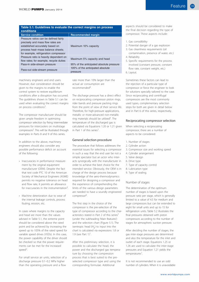
machinery engineers and end users. However, due consideration should be given to the margins to enable the control system to restore equilibrium conditions after a disruption has occurred. The guidelines shown in Table 5.1 can be used when evaluating the correct margins on process conditions2.
The compressor manufacturer should be given ample freedom in optimizing compressor selection by fixing intermediate pressures for intercoolers on multistage compressors2. This will be illustrated through examples in Parts 8 and 9 of this series.
In addition to the above, machinery engineers should also consider any possible performance deficit on account of the following:
Inaccuracies in performance measure-•ment by the original equipment manufacturer (OEM). Despite the fact that test code PTC 10 of the American Society of Mechanical Engineers (ASME) permits no negative tolerance on head and flow rate, it permits an allowance for inaccuracies in the instrumentation3.
Machine deterioration due to wear of •the internal leakage controls, process fouling, erosion, etc.
In cases where margins to the capacity and head are more than the values advised in Table 5.1, the extreme point should be considered above the rated point and be achieved by increasing the speed up to 105% of the rated speed for variable speed drives (VSDs). In this case, the power capability of the driver should be checked so that the power require-ments can be met for the increased speed2.
For small service air units, selection of a discharge pressure 0.1–0.2 MPa higher than the operating pressure and a flow
rate more than 10% larger than the actual air consumption are recommended4.
The discharge pressure has a direct effect on reciprocating compressor piston rings, rider bands and pressure packing rings from the point of view of their service life. Therefore, for high-pressure applications, metallic or more-advanced non-metallic ring materials should be utilized5. The temperature of the discharged gas is calculated via Equations 1.20 or 1.21 given in Part 1 of this series1.
General selection procedure
The procedure that follows addresses the essential issues for selecting a compressor in such a way that the end user be not a simple spectator but an actor who inter-acts synergically with the manufacturer in order to achieve the best choice for the intended service. Obviously, the OEM is in charge of the design process because knowledge of the aero-thermodynamics required for designing a compressor and the experience of comprehending the limits of the various design parameters are needed to have a soundly engineered compressor6.
The first step in the choice of the compressor is the pre-selection of the type of compressor according to the char-acteristics stated in Part 2 of this series7 (under the subheading ‘Main features’) and the selection chart (Figure 5.1). The isentropic head (Ha) to input into the chart is calculated via expressions 1.8 or 1.9 (see Part 1)1.
After this preliminary selection, it is possible to calculate the head, the power and the discharged gas tempera-ture by choosing the compression process that is best suited to the pre-selected compressor type and using the corresponding formulae. Additional
aspects should be considered to make the final decision regarding the type of compressor. These aspects include:
1. Gas corrodibility2. Potential danger of a gas explosion3. Gas cleanliness requirements (oil
contamination, presence of water, etc.)4. Reliability5. Specific requirements for the process
involved (constant pressure, constant flow rate, constant weight, etc.)
6. Layout.
Sometimes these factors can lead to the rejection of a particular type of compressor or force the engineer to look for solutions specially tailored to the case. Since reciprocating and centrifugal compressors are the most commonly used types, complementary selection steps for both are given in detail below and in Part 6 of this series, respectively.
Reciprocating compressor selection
When selecting a reciprocating compressor, there are a number of aspects to be considered:
1. Number of stages2. Cylinder action3. Compressor size and working speed4. Cylinder arrangement5. Valve design6. Drive type7. Type of capacity control8. Lubrication type9. Type of sealing.
Number of stages
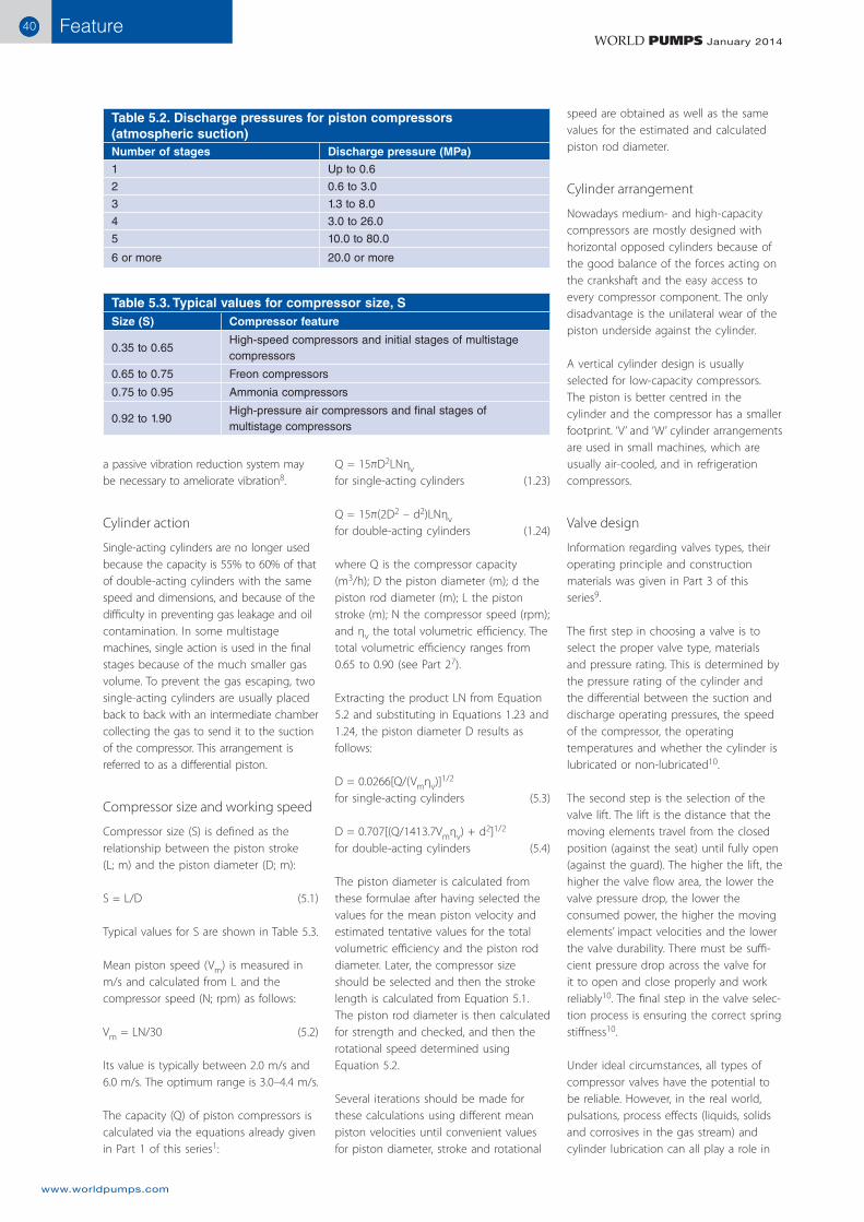
The determination of the optimum number of stages is based upon the pressure ratio per stage, which is generally limited to a value of 4.5 for medium and large compressors but can be extended to eight for small units and up to 15 for refrigeration units. Table 5.2 illustrates the final pressures obtained with piston compressors according to the number of stages for atmospheric suction pressure.
After deciding the number of stages, the gas inter-stage pressures are determined and also the temperature for the inlet and outlet of each stage. Equations 1.25 or 1.26 are used to calculate the inter-stage pressures and Equation 1.21 yields the temperatures1.
It is not recommended to use an odd number of cylinders. When it is unavoidable
Table 5.1. Guidelines to evaluate the correct margins on process conditionsService condition Recommended marginPressure ratios can be defined fairly precisely and mass flow rates are established accurately based on process heat–mass balance sheets; for example, refrigeration compressor
Maximum 10% capacity
Pressure ratio is heavily dependent on flow rates; for example, recycle duties
Maximum 5% capacity and head
Pass-in side-stream pressure 95% of the anticipated absolute pressure
Pass-out side-stream pressure105% of the anticipated absolute pressure
Feature4040
www.worldpumps.com
WORLD PUMPS January 2014
speed are obtained as well as the same values for the estimated and calculated piston rod diameter.
Cylinder arrangement
Nowadays medium- and high-capacity compressors are mostly designed with horizontal opposed cylinders because of the good balance of the forces acting on the crankshaft and the easy access to every compressor component. The only disadvantage is the unilateral wear of the piston underside against the cylinder.
A vertical cylinder design is usually selected for low-capacity compressors. The piston is better centred in the cylinder and the compressor has a smaller footprint. ‘V’ and ‘W’ cylinder arrangements are used in small machines, which are usually air-cooled, and in refrigeration compressors.
Valve design
Information regarding valves types, their operating principle and construction materials was given in Part 3 of this series9.
The first step in choosing a valve is to select the proper valve type, materials and pressure rating. This is determined by the pressure rating of the cylinder and the differential between the suction and discharge operating pressures, the speed of the compressor, the operating temperatures and whether the cylinder is lubricated or non-lubricated10.
The second step is the selection of the valve lift. The lift is the distance that the moving elements travel from the closed position (against the seat) until fully open (against the guard). The higher the lift, the higher the valve flow area, the lower the valve pressure drop, the lower the consumed power, the higher the moving elements’ impact velocities and the lower the valve durability. There must be suffi-cient pressure drop across the valve for it to open and close properly and work reliably10. The final step in the valve selec-tion process is ensuring the correct spring stiffness10.
Under ideal circumstances, all types of compressor valves have the potential to be reliable. However, in the real world, pulsations, process effects (liquids, solids and corrosives in the gas stream) and cylinder lubrication can all play a role in
Q = 15πD2LNηv for single-acting cylinders (1.23)
Q = 15π(2D2 – d2)LNηv for double-acting cylinders (1.24)
where Q is the compressor capacity (m3/h); D the piston diameter (m); d the piston rod diameter (m); L the piston stroke (m); N the compressor speed (rpm); and ηv the total volumetric efficiency. The total volumetric efficiency ranges from 0.65 to 0.90 (see Part 27).
Extracting the product LN from Equation 5.2 and substituting in Equations 1.23 and 1.24, the piston diameter D results as follows:
D = 0.0266[Q/(Vmηv)]1/2 for single-acting cylinders (5.3)
D = 0.707[(Q/1413.7Vmηv) + d2]1/2 for double-acting cylinders (5.4)
The piston diameter is calculated from these formulae after having selected the values for the mean piston velocity and estimated tentative values for the total volumetric efficiency and the piston rod diameter. Later, the compressor size should be selected and then the stroke length is calculated from Equation 5.1. The piston rod diameter is then calculated for strength and checked, and then the rotational speed determined using Equation 5.2.
Several iterations should be made for these calculations using different mean piston velocities until convenient values for piston diameter, stroke and rotational
a passive vibration reduction system may be necessary to ameliorate vibration8.
Cylinder action
Single-acting cylinders are no longer used because the capacity is 55% to 60% of that of double-acting cylinders with the same speed and dimensions, and because of the difficulty in preventing gas leakage and oil contamination. In some multistage machines, single action is used in the final stages because of the much smaller gas volume. To prevent the gas escaping, two single-acting cylinders are usually placed back to back with an intermediate chamber collecting the gas to send it to the suction of the compressor. This arrangement is referred to as a differential piston.
Compressor size and working speed
Compressor size (S) is defined as the relationship between the piston stroke (L; m) and the piston diameter (D; m):
S = L/D (5.1)
Typical values for S are shown in Table 5.3.
Mean piston speed (Vm) is measured in m/s and calculated from L and the compressor speed (N; rpm) as follows:
Vm = LN/30 (5.2)
Its value is typically between 2.0 m/s and 6.0 m/s. The optimum range is 3.0–4.4 m/s.
The capacity (Q) of piston compressors is calculated via the equations already given in Part 1 of this series1:
Table 5.3. Typical values for compressor size, SSize (S) Compressor feature
0.35 to 0.65High-speed compressors and initial stages of multistage compressors
0.65 to 0.75 Freon compressors
0.75 to 0.95 Ammonia compressors
0.92 to 1.90High-pressure air compressors and final stages of multistage compressors
Table 5.2. Discharge pressures for piston compressors (atmospheric suction)Number of stages Discharge pressure (MPa)
1 Up to 0.6
2 0.6 to 3.0
3 1.3 to 8.0
4 3.0 to 26.0
5 10.0 to 80.0
6 or more 20.0 or more
Feature 41
www.worldpumps.com
WORLD PUMPS January 2014
For capacity control when the amount •of gas to be delivered is variable.
There are several types of unloader. An inlet valve unloader (of which there are two styles: finger unloader and port/plug unloader) opens the suction port so that the gas that enters the cylinder on the suction stroke is pushed back into the inlet passage during the return stroke. This means that there will be no compression, and no gas discharged10.
A finger unloader gives a stepless capacity regulation. Although finger-type unloaders have the advantages of being full range, stepless and saving energy, they have the potential for damaging the valve sealing elements and require more care for main-tenance. Valves and unloaders cause around 44% of unscheduled reciprocating compressor shut-downs and this selection has a strong effect on reliability8. Port/plug unloaders use a valve blank (port unloader) or a special partial valve (plug unloader) with a hole in the centre of it. Port/plug unloaders have several advan-tages over the finger type10.
Clearance pocket unloaders are used to open and close a fixed-volume clearance pocket. The clearance pocket adds fixed clearance to the cylinder and enables additional capacity control that cannot be achieved through cylinder end unloading10. The clearance pocket unloader is similar to the port/plug unloader and has the same features10. For large machines, the optimum configura-tion is the selection of part load steps based on a combination of plug/port and clearance pocket unloaders8.
Lubrication type
The running gear is usually lubricated by an oil pump directly coupled to the crankshaft in medium- and small-sized compressors. Oil pumps driven by electric motors are used in large compressors.
reducing the service life and reliability of compressor valves. That is why valve defects are responsible for most of the unscheduled compressor shutdowns (around 36%)5.
Currently there is no such thing as an indestructible compressor valve. However, some designs and types are more tolerant than others of the actual service condi-tions. Based on the results of several studies, valve reliability (based on the type of valve) has been ranked as follows5:
Poppet valves: bestPorted plate valves: goodConcentric ring valves: goodChannel valves: fair to good
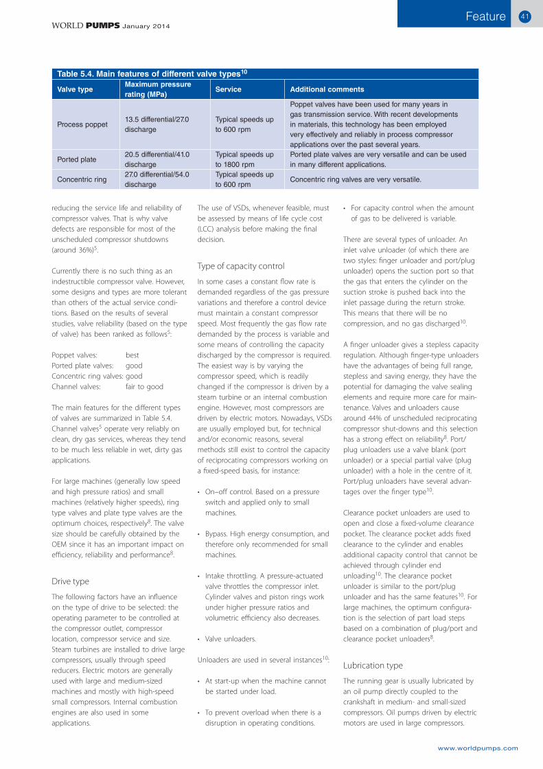
The main features for the different types of valves are summarized in Table 5.4. Channel valves5 operate very reliably on clean, dry gas services, whereas they tend to be much less reliable in wet, dirty gas applications.
For large machines (generally low speed and high pressure ratios) and small machines (relatively higher speeds), ring type valves and plate type valves are the optimum choices, respectively8. The valve size should be carefully obtained by the OEM since it has an important impact on efficiency, reliability and performance8.
Drive type
The following factors have an influence on the type of drive to be selected: the operating parameter to be controlled at the compressor outlet, compressor location, compressor service and size. Steam turbines are installed to drive large compressors, usually through speed reducers. Electric motors are generally used with large and medium-sized machines and mostly with high-speed small compressors. Internal combustion engines are also used in some applications.
The use of VSDs, whenever feasible, must be assessed by means of life cycle cost (LCC) analysis before making the final decision.
Type of capacity control
In some cases a constant flow rate is demanded regardless of the gas pressure variations and therefore a control device must maintain a constant compressor speed. Most frequently the gas flow rate demanded by the process is variable and some means of controlling the capacity discharged by the compressor is required. The easiest way is by varying the compressor speed, which is readily changed if the compressor is driven by a steam turbine or an internal combustion engine. However, most compressors are driven by electric motors. Nowadays, VSDs are usually employed but, for technical and/or economic reasons, several methods still exist to control the capacity of reciprocating compressors working on a fixed-speed basis, for instance:
On–off control. Based on a pressure •switch and applied only to small machines.
Bypass. High energy consumption, and •therefore only recommended for small machines.
Intake throttling. A pressure-actuated •valve throttles the compressor inlet. Cylinder valves and piston rings work under higher pressure ratios and volumetric efficiency also decreases.
Valve unloaders.•
Unloaders are used in several instances10:
At start-up when the machine cannot •be started under load.
To prevent overload when there is a •disruption in operating conditions.
Table 5.4. Main features of different valve types10
Valve typeMaximum pressure rating (MPa)
Service Additional comments
Process poppet 13.5 differential/27.0 discharge
Typical speeds up to 600 rpm
Poppet valves have been used for many years in gas transmission service. With recent developments in materials, this technology has been employed very effectively and reliably in process compressor applications over the past several years.
Ported plate20.5 differential/41.0 discharge
Typical speeds up to 1800 rpm
Ported plate valves are very versatile and can be used in many different applications.
Concentric ring27.0 differential/54.0 discharge
Typical speeds up to 600 rpm
Concentric ring valves are very versatile.
Feature4242
www.worldpumps.com
WORLD PUMPS January 2014
ContactEduardo Larralde
Email: [email protected]
Rafael Ocampo
Email: [email protected]
A separate lubricator coupled to the crankshaft or driven by an electric motor is employed to lubricate the cylinders in the majority of compressors. However, in some processes, contact between the compressed gas and the oil is not allowed and then an oil-free compressor must be selected with piston rings made of suitable material for the service (see Part 3 of this series9).
Cylinder lubrication is truly the ‘lifeblood’ of the wearing components inside the reciprocating compressor cylinder. Here are some tips for improving the overall reliability of reciprocating compressors5:
Use the proper type of lubricant. •Improved cylinder lubricating oils are now available.
Establish the correct lubrication rates to •the cylinder and packing (too much oil can be as harmful as too little).
Try to select a lubricated cylinder •compressor whenever possible from the technical standpoint.
Look at new state-of-the-art lubrication •systems. The trend is to move from the self-priming vacuum-style pump-to-point type system (one pump for each point of lubrication on the compressor) to a divider block system where lubri-cation is properly proportioned and distributed by positive displacement series flow valves.
Add a spare lubrication system (if one •system fails, the other comes on line and the compressor cylinders continue receiving lubrication).
Consider continuous monitoring and •alarm capability for the cylinder and packing lubrication system.
It is important to note that in many cases the lubrication is the problem rather than the wearing characteristic of the ring materials5. Also the life of cylinder valves can be significantly affected by the type and quality of lubrication used8.
API 61411 is typically applied only to reciprocating compressor trains involving a large turbine driver and gear unit. An optimum oil system should include two oil pumps (both over-sized by at least 20%), a dual removable bundle shell and tube oil coolers (TEMA C12) and double oil filters with a removable element and
stainless steel piping8. A mechanical main pump driven by the compressor shaft and an auxiliary electric pump with similar flow are standard. Twin electric-motor-driven pumps are another accepted arrangement whenever it includes a rundown tank and back-up power from an emergency supply system. It is recommended to avoid supplying UPS power for one pump8.
Type of sealing
The type of gas handled and the gas pressure are the factors to be taken into account in deciding what type of sealing to use. As was stated in Part 39, the piston rod seal is the second most important area influencing the reliability of recipro-cating compressors, reaching between 15% and 18% of unscheduled mainte-nance events8. Conventional soft and cheap packings are usually used in low-pressure compressors handling non-aggressive gases. Lubricated bronze, Babbitt-lined packings or special plastic materials are used in medium- and high-pressure compressors. They include segmented rings joined together with spiral circular springs. A seal comprises several rings and each one is located in a seal box. All boxes are bolted together and to the cylinder body. This type of seal is also applied between the piston rod and the crankcase to prevent the escape of oil.
General recommendations
For a reciprocating compressor, the optimum option is a lubricated cylinder with the lowest-available speed machine. Non-lubricated reciprocating compressors should be selected only to suit a specific process demand (oxygen; high-pressure air; downstream facilities sensitive to oil, such as some catalysts, etc.)8.
The optimum configuration is a horizontal cylinder(s) with the discharge nozzle on the underside. For a small compressor it is permissible to use other arrangements8.
Part 6 of this series will present the complementary procedures and direc-tions for the selection of centrifugal compressors.
References
[1] E. Larralde and R. Ocampo, ‘Selection of gas compressors: part 1’, World Pumps, No. 536, pp. 24–28, (2011).
[2] A. Giri, ‘Best Practice Guidelines for Selection and Optimization of Centrif-ugal Compressors’, Hydrocarbon Asia, Vol. 19, No. 3, pp. 54–59, (2009).
[3] American Society of Mechanical Engineers, ‘Performance Test Code on Compressors and Exhausters’, ASME PTC 10, New York, NY, (1997).
[4] Anest Iwata Corp, ‘How to select the desired type of compressor’, http://www.anest-iwata.co.jp/english/prod-ucts/compressor/reference/select.html
[5] S.M. Leonard, ‘Increasing the reliability of reciprocating hydrogen compres-sors’, Hydrocarbon Processing, pp. 67–74, (January 1996).
[6] K.H. Lüdtke, Process Centrifugal Compressors: Basics, Function, Operation, Design, Application, Springer, New York, (2004).
[7] E. Larralde and R. Ocampo, ‘Selection of gas compressors: part 2’, World Pumps, No. 539, pp. 36–43, (2011).
[8] A. Almasi, ‘Reciprocating compressor optimum design and manufacturing with respect to performance, reliability and cost’, World Academy of Science, Engineering and Technology, Vol. 28, pp. 48–53, (2009).
[9] E. Larralde and R. Ocampo, ‘Selection of gas compressors: part 3’, World Pumps, No. 544, pp. 36–41, (2012).
[10] S. Foreman, ‘Compressor Valves and Unloaders for Reciprocating Compressors: An OEM’s Perspective’, www.dresserrand.com/techpapers/tp015.pdf
[11] American Petroleum Institute, Lubrica-tion, Shaft-Sealing and Control-Oil Systems and Auxiliaries for Petroleum, Chemical and Gas Industry Services, API Standard 614, 4th Edn, (April 1999).
[12] TEMA C, Standards of the Tubular Exchanger Manufacturers Association, 9th Edn, (November 2007).

FREE. Go on: Take it…World Pumps keeps you completely up-to-date with the latest business and technology developments in the international pump industry.
Subscribe today atwww.worldpumps.com
FREE.