An Introduction to Basic Mechanical Components...Miscellaneous Mechanical Components...
36
An Introduction to Basic Mechanical Components Course No: M03-043 Credit: 3 PDH Elie Tawil, P.E., LEED AP Continuing Education and Development, Inc. 9 Greyridge Farm Court Stony Point, NY 10980 P: (877) 322-5800 F: (877) 322-4774 [email protected]
Transcript of An Introduction to Basic Mechanical Components...Miscellaneous Mechanical Components...
An Introduction to Basic
Mechanical Components
Course No: M03-043
Credit: 3 PDH
Elie Tawil, P.E., LEED AP
Continuing Education and Development, Inc.
9 Greyridge Farm Court Stony Point, NY 10980
P: (877) 322-5800 F: (877) 322-4774
This course is adapted from the U.S. Department of Energy HDBK-1018/2-93, Volume 2, Module 5
"Miscellaneous Mechanical Components”; which is in the public domain, is authorized for unlimited
distribution and is not copyrighted.
Table of Contents
Air Compressors ....................................................................................... 1
Boilers .......................................................................................................... 10
Cooling Towers .......................................................................................... 14
Steam Traps ................................................................................................ 20
Filters and Strainers .................................................................................. 25
Miscellaneous Mechanical Components DOE-HDBK-1018/2-93 AIR COMPRESSORS
AIR COMPRESSORS
The purpose of an air compressor is to provide a continuous supply of pressurizedair. This chapter will describe the various types of compressors and their basicoperation.
1.1 STATE the three common types of air compressors.
1.2 DESCRIBE the basic operation of the following types of aircompressors:
a. Reciprocatingb. Centrifugalc. Rotary
1.3 STATE the reason for using cooling systems in aircompressors.
1.4 STATE three hazards associated with pressurized air systems.
Introduction
Air compressors of various designs are used widely throughout DOE facilities in numerousapplications. Compressed air has numerous uses throughout a facility including the operation ofequipment and portable tools. Three types of designs include reciprocating, rotary, andcentrifugal air compressors.
Reciprocating Compressors
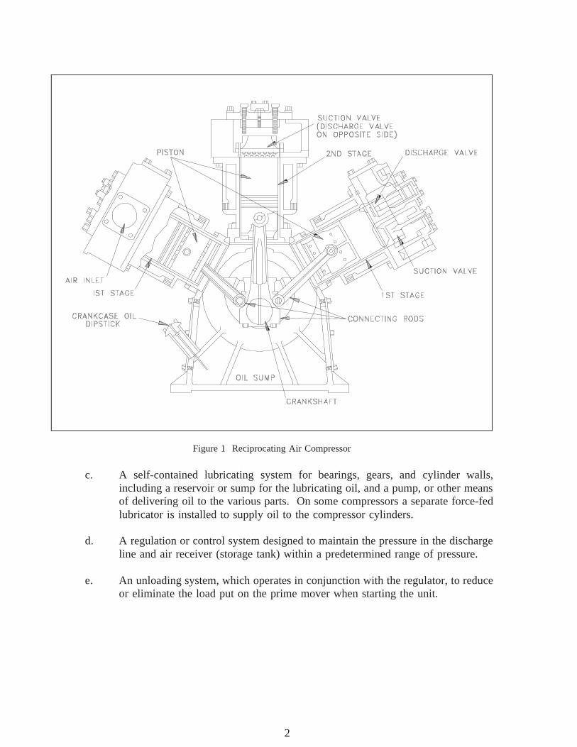
The reciprocating air compressor, illustrated in Figure 1, is the most common design employedtoday.
The reciprocating compressor normally consists of the following elements.
a. The compressing element, consisting of air cylinders, heads and pistons, and airinlet and discharge valves.
b. A system of connecting rods, piston rods, crossheads, and a crankshaft andflywheel for transmitting the power developed by the driving unit to the aircylinder piston.
Rev. 0 ME-05Page 1
1
AIR COMPRESSORS DOE-HDBK-1018/2-93 Miscellaneous Mechanical Components
c. A self-contained lubricating system for bearings, gears, and cylinder walls,
Figure 1 Reciprocating Air Compressor
including a reservoir or sump for the lubricating oil, and a pump, or other meansof delivering oil to the various parts. On some compressors a separate force-fedlubricator is installed to supply oil to the compressor cylinders.
d. A regulation or control system designed to maintain the pressure in the dischargeline and air receiver (storage tank) within a predetermined range of pressure.
e. An unloading system, which operates in conjunction with the regulator, to reduceor eliminate the load put on the prime mover when starting the unit.
ME-05 Rev. 0Page 2
2
Miscellaneous Mechanical Components DOE-HDBK-1018/2-93 AIR COMPRESSORS
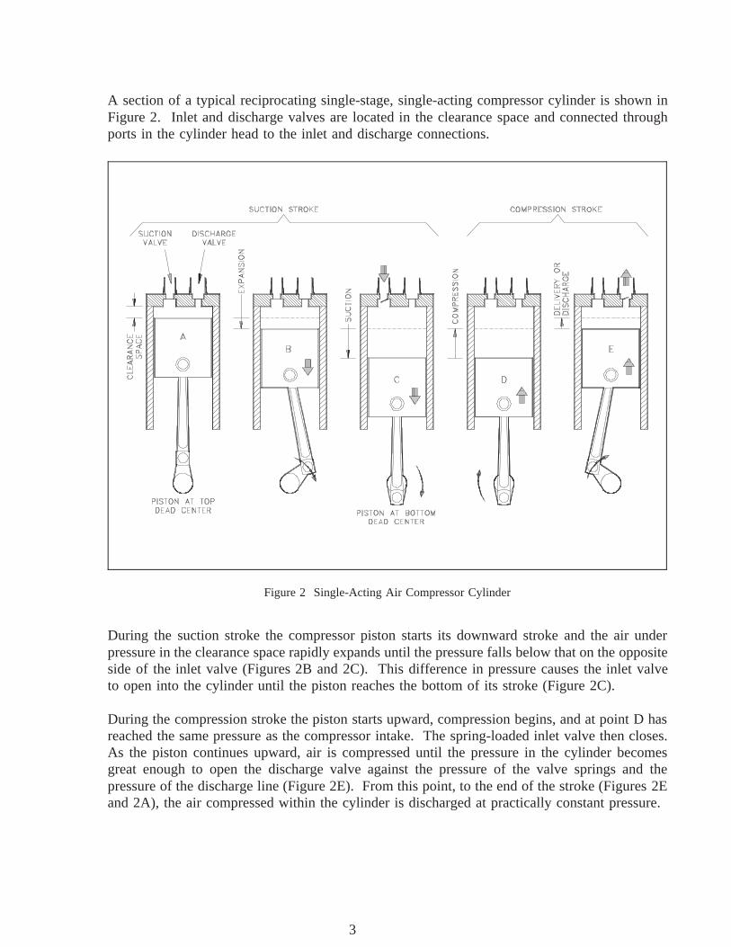
A section of a typical reciprocating single-stage, single-acting compressor cylinder is shown inFigure 2. Inlet and discharge valves are located in the clearance space and connected throughports in the cylinder head to the inlet and discharge connections.
During the suction stroke the compressor piston starts its downward stroke and the air under
Figure 2 Single-Acting Air Compressor Cylinder
pressure in the clearance space rapidly expands until the pressure falls below that on the oppositeside of the inlet valve (Figures 2B and 2C). This difference in pressure causes the inlet valveto open into the cylinder until the piston reaches the bottom of its stroke (Figure 2C).
During the compression stroke the piston starts upward, compression begins, and at point D hasreached the same pressure as the compressor intake. The spring-loaded inlet valve then closes.As the piston continues upward, air is compressed until the pressure in the cylinder becomesgreat enough to open the discharge valve against the pressure of the valve springs and thepressure of the discharge line (Figure 2E). From this point, to the end of the stroke (Figures 2Eand 2A), the air compressed within the cylinder is discharged at practically constant pressure.
Rev. 0 ME-05Page 3
3
AIR COMPRESSORS DOE-HDBK-1018/2-93 Miscellaneous Mechanical Components
Rotary Compressors
The rotary compressor is adaptable to direct drive by induction motors or multicylinder gasolineor diesel engines. The units are compact, relatively inexpensive, and require a minimum ofoperating attention and maintenance. They occupy a fraction of the space and weight of areciprocating machine of equivalent capacity. Rotary compressor units are classified into threegeneral groups, slide vane-type, lobe-type, and liquid seal ring-type.
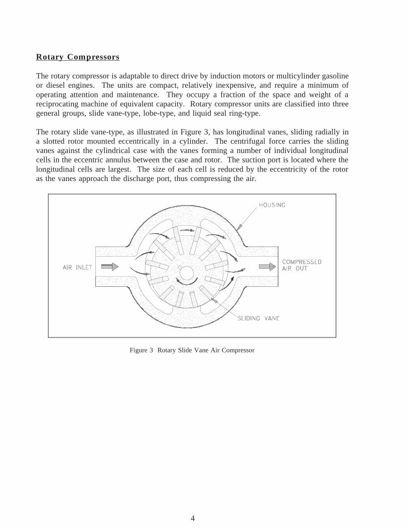
The rotary slide vane-type, as illustrated in Figure 3, has longitudinal vanes, sliding radially ina slotted rotor mounted eccentrically in a cylinder. The centrifugal force carries the slidingvanes against the cylindrical case with the vanes forming a number of individual longitudinalcells in the eccentric annulus between the case and rotor. The suction port is located where thelongitudinal cells are largest. The size of each cell is reduced by the eccentricity of the rotoras the vanes approach the discharge port, thus compressing the air.
Figure 3 Rotary Slide Vane Air Compressor
ME-05 Rev. 0Page 4
4
Miscellaneous Mechanical Components DOE-HDBK-1018/2-93 AIR COMPRESSORS
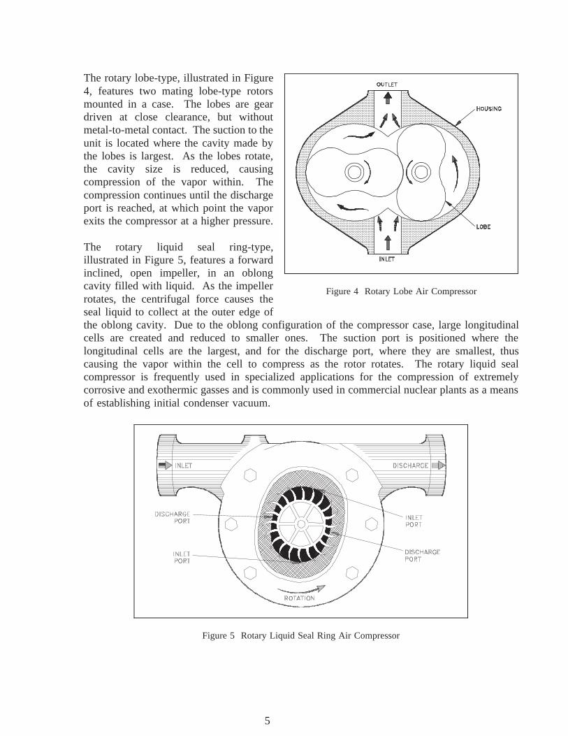
The rotary lobe-type, illustrated in Figure
Figure 4 Rotary Lobe Air Compressor
4, features two mating lobe-type rotorsmounted in a case. The lobes are geardriven at close clearance, but withoutmetal-to-metal contact. The suction to theunit is located where the cavity made bythe lobes is largest. As the lobes rotate,the cavity size is reduced, causingcompression of the vapor within. Thecompression continues until the dischargeport is reached, at which point the vaporexits the compressor at a higher pressure.
The rotary liquid seal ring-type,illustrated in Figure 5, features a forwardinclined, open impeller, in an oblongcavity filled with liquid. As the impellerrotates, the centrifugal force causes theseal liquid to collect at the outer edge ofthe oblong cavity. Due to the oblong configuration of the compressor case, large longitudinalcells are created and reduced to smaller ones. The suction port is positioned where thelongitudinal cells are the largest, and for the discharge port, where they are smallest, thuscausing the vapor within the cell to compress as the rotor rotates. The rotary liquid sealcompressor is frequently used in specialized applications for the compression of extremelycorrosive and exothermic gasses and is commonly used in commercial nuclear plants as a meansof establishing initial condenser vacuum.
Figure 5 Rotary Liquid Seal Ring Air Compressor
Rev. 0 ME-05Page 5
5
AIR COMPRESSORS DOE-HDBK-1018/2-93 Miscellaneous Mechanical Components
Centrifugal Compressors
Figure 6 Simplified Centrifugal Pump
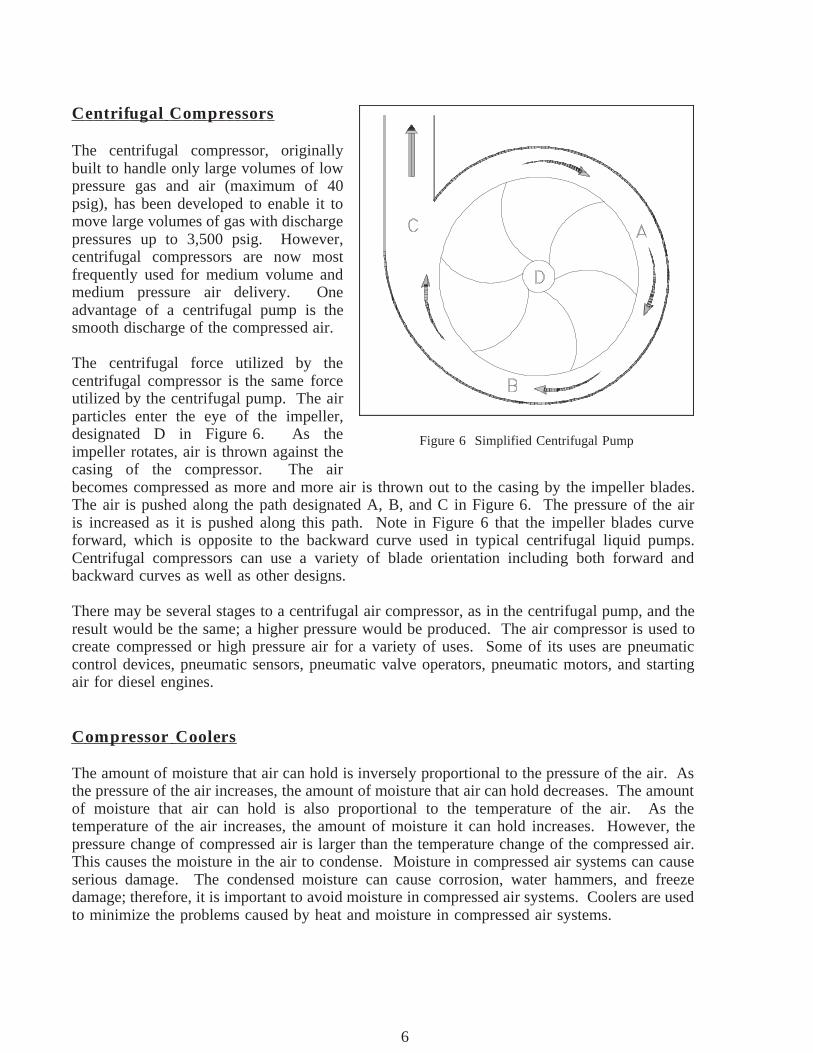
The centrifugal compressor, originallybuilt to handle only large volumes of lowpressure gas and air (maximum of 40psig), has been developed to enable it tomove large volumes of gas with dischargepressures up to 3,500 psig. However,centrifugal compressors are now mostfrequently used for medium volume andmedium pressure air delivery. Oneadvantage of a centrifugal pump is thesmooth discharge of the compressed air.
The centrifugal force utilized by thecentrifugal compressor is the same forceutilized by the centrifugal pump. The airparticles enter the eye of the impeller,designated D in Figure 6. As theimpeller rotates, air is thrown against thecasing of the compressor. The airbecomes compressed as more and more air is thrown out to the casing by the impeller blades.The air is pushed along the path designated A, B, and C in Figure 6. The pressure of the airis increased as it is pushed along this path. Note in Figure 6 that the impeller blades curveforward, which is opposite to the backward curve used in typical centrifugal liquid pumps.Centrifugal compressors can use a variety of blade orientation including both forward andbackward curves as well as other designs.
There may be several stages to a centrifugal air compressor, as in the centrifugal pump, and theresult would be the same; a higher pressure would be produced. The air compressor is used tocreate compressed or high pressure air for a variety of uses. Some of its uses are pneumaticcontrol devices, pneumatic sensors, pneumatic valve operators, pneumatic motors, and startingair for diesel engines.
Compressor Coolers
The amount of moisture that air can hold is inversely proportional to the pressure of the air. Asthe pressure of the air increases, the amount of moisture that air can hold decreases. The amountof moisture that air can hold is also proportional to the temperature of the air. As thetemperature of the air increases, the amount of moisture it can hold increases. However, thepressure change of compressed air is larger than the temperature change of the compressed air.This causes the moisture in the air to condense. Moisture in compressed air systems can causeserious damage. The condensed moisture can cause corrosion, water hammers, and freezedamage; therefore, it is important to avoid moisture in compressed air systems. Coolers are usedto minimize the problems caused by heat and moisture in compressed air systems.
ME-05 Rev. 0Page 6
6
Miscellaneous Mechanical Components DOE-HDBK-1018/2-93 AIR COMPRESSORS
Coolers used on the discharge of a compressor are called aftercoolers. Their purpose is toremove the heat generated during the compression of the air. The decrease in temperaturepromotes the condensing of any moisture present in the compressed air. This moisture iscollected in condensate traps that are either automatically or manually drained.
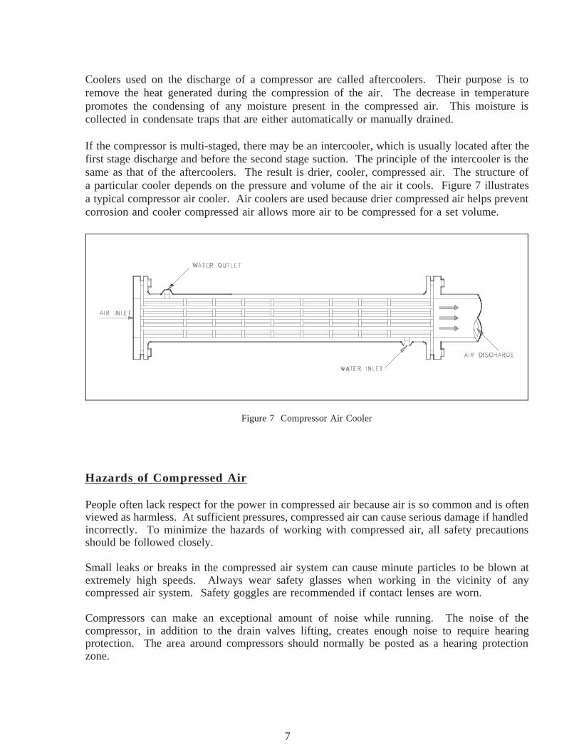
If the compressor is multi-staged, there may be an intercooler, which is usually located after thefirst stage discharge and before the second stage suction. The principle of the intercooler is thesame as that of the aftercoolers. The result is drier, cooler, compressed air. The structure ofa particular cooler depends on the pressure and volume of the air it cools. Figure 7 illustratesa typical compressor air cooler. Air coolers are used because drier compressed air helps preventcorrosion and cooler compressed air allows more air to be compressed for a set volume.
Figure 7 Compressor Air Cooler
Hazards of Compressed Air
People often lack respect for the power in compressed air because air is so common and is oftenviewed as harmless. At sufficient pressures, compressed air can cause serious damage if handledincorrectly. To minimize the hazards of working with compressed air, all safety precautionsshould be followed closely.
Small leaks or breaks in the compressed air system can cause minute particles to be blown atextremely high speeds. Always wear safety glasses when working in the vicinity of anycompressed air system. Safety goggles are recommended if contact lenses are worn.
Compressors can make an exceptional amount of noise while running. The noise of thecompressor, in addition to the drain valves lifting, creates enough noise to require hearingprotection. The area around compressors should normally be posted as a hearing protectionzone.
Rev. 0 ME-05Page 7
7
AIR COMPRESSORS DOE-HDBK-1018/2-93 Miscellaneous Mechanical Components
Pressurized air can do the same type of damage as pressurized water. Treat all operations oncompressed air systems with the same care taken on liquid systems. Closed valves should beslowly cracked open and both sides should be allowed to equalize prior to opening the valvefurther. Systems being opened for maintenance should always be depressurized before workbegins.
Great care should be taken to keep contaminants from entering air systems. This is especiallytrue for oil. Oil introduced in an air compressor can be compressed to the point wheredetonation takes place in a similar manner as that which occurs in a diesel engine. Thisdetonation can cause equipment damage and personnel injury.
Summary
The important information in this chapter is summarized below.
Air Compressors Summary
The three common types of air compressors are reciprocating, rotary, andcentrifugal.
The single-stage reciprocating compressor has a piston that movesdownward during the suction stroke, expanding the air in the cylinder. Theexpanding air causes pressure in the cylinder to drop. When the pressurefalls below the pressure on the other side of the inlet valve, the valveopens and allows air in until the pressure equalizes across the inlet valve.The piston bottoms out and then begins a compression stroke. The upwardmovement of the piston compresses the air in the cylinder, causing thepressure across the inlet valve to equalize and the inlet valve to reseat.The piston continues to compress air during the remainder of the upwardstroke until the cylinder pressure is great enough to open the dischargevalve against the valve spring pressure. Once the discharge valve is open,the air compressed in the cylinder is discharged until the piston completesthe stroke.
ME-05 Rev. 0Page 8
8
Miscellaneous Mechanical Components DOE-HDBK-1018/2-93 AIR COMPRESSORS
Air Compressors Summary (Cont.)
The centrifugal force utilized by the centrifugal compressors is the sameforce utilized by the centrifugal pumps. The air particles enter the eye ofthe impeller. As the impeller rotates, air is thrown against the casing ofthe compressor. The air becomes compressed as more and more air isthrown out to the casing by the impeller blades. The air is pushed alongthe path on the inner wall of the casing. The pressure of the air isincreased as it is pushed along this path. There could be several stages toa centrifugal air compressor just as in the centrifugal pump, resulting inhigher pressure.
Rotary compressors are driven by a direct drive that rotates a mechanism(impellers, vanes, or lobes) that compresses the air being pumped. Theactual compression of the air takes place due either to centrifugal forcesor a diminishing air space as the impellers rotate.
Cooling systems are required in compressed air systems to remove anyheat added by the compression. The advantages to cooling the compressedair are that cool air takes less space and holds less moisture. This reducescorrosion and allows more air to be compressed into a given volume.
Hazards associated with compressed air are similar to hazards of any highpressure system. Three general hazards include the following.
Small leaks or breaks can cause minute particles to be blown at speedshigh enough to cause damage. Goggles or safety glasses should be wornwhen working around compressed gas.
The compressors, especially larger ones, can be quite noisy when running.The cycling of automatic drain valves contributes noise as well. Hearingprotection should be worn around compressors.
Pressure swings may cause system damage. Closed valves in acompressed air system should be slowly cracked open and the pressureshould be allowed to equalize prior to opening the valve further. Systemsshould be depressurized prior to opening for maintenance. Oil should bekept out of air systems to prevent possible explosions.
Rev. 0 ME-05Page 9
9
BOILERS DOE-HDBK-1018/2-93 Miscellaneous Mechanical Components
BOILERS
Boilers are commonly used at large facilities to act as primary or backup steamsources. The source of heat that generates the steam varies, but the basicoperation of the boiler is the same. This chapter will summarize the operationof a boiler.
1. DESCRIBE the basic operation of a boiler.
1. IDENTIFY the following components of a typical boiler:
a. Steam drum d. Downcomerb. Distribution header(s) e. Risersc. Combustion chamber
Introduction
The primary function of a boiler is to produce steam at a given pressure and temperature. Toaccomplish this, the boiler serves as a furnace where air is mixed with fuel in a controlledcombustion process to release large quantities of heat. The pressure-tight construction of aboiler provides a means to absorb the heat from the combustion and transfer this heat to raisewater to a temperature such that the steam produced is of sufficient temperature and quality(moisture content) for steam loads.
Boilers
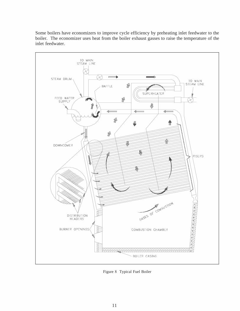
Two distinct heat sources used for boilers are electric probes and burned fuel (oil, coal, etc.)This chapter will use fuel boilers to illustrate the typical design of boilers. Refer to Figure during the following discussion.
The boiler has an enclosed space where the fuel combustion takes place, usually referred to asthe furnace or combustion chamber. Air is supplied to combine with the fuel, resulting incombustion. The heat of combustion is absorbed by the water in the risers or circulating tubes.The density difference between hot and cold water is the driving force to circulate the waterback to the steam drum. Eventually the water will absorb sufficient heat to produce steam.
Steam leaves the steam drum via a baffle, which causes any water droplets being carried by thesteam to drop out and drain back to the steam drum. If superheated steam is required, the steammay then travel through a superheater. The hot combustion gasses from the furnace will heatthe steam through the superheater's thin tube walls. The steam then goes to the steam supplysystem and the various steam loads.
ME-05 Rev. 0Page 14
10
Miscellaneous Mechanical Components DOE-HDBK-1018/2-93 BOILERS
Some boilers have economizers to improve cycle efficiency by preheating inlet feedwater to theboiler. The economizer uses heat from the boiler exhaust gasses to raise the temperature of theinlet feedwater.
Figure Typical Fuel Boiler
Rev. 0 ME-05Page 15
11
BOILERS DOE-HDBK-1018/2-93 Miscellaneous Mechanical Components
Fuel Boiler Components
Figure illustrates a typical fuel boiler. Some of the components are explained below.
Steam drum - The steam drum separates the steam from the heated water. Thewater droplets fall to the bottom of the tank to be cycled again,and the steam leaves the drum and enters the steam system.Feedwater enters at the bottom of the drum to start the heatingcycle.
Downcomers - Downcomers are the pipes in which the water from the steamdrum travels in order to reach the bottom of the boiler where thewater can enter the distribution headers.
Distribution headers - The distribution headers are large pipe headers that carry thewater from the downcomers to the risers.
Risers - The piping or tubes that form the combustion chamber enclosureare called risers. Water and steam run through these to beheated. The term risers refers to the fact that the water flowdirection is from the bottom to the top of the boiler. From therisers, the water and steam enter the steam drum and the cyclestarts again.
Combustion chamber - Located at the bottom of a boiler, the combustion chamber iswhere the air and fuel mix and burn. It is lined with the risers.
ME-05 Rev. 0Page 16
12
Miscellaneous Mechanical Components DOE-HDBK-1018/2-93 BOILERS
Summary
The important information in this chapter is summarized below.
Boilers Summary
Boilers are vessels that allow water in contained piping to be heated to steamby a heat source internal to the vessel. The water is heated to the boilingpoint. The resulting steam separates, and the water is heated again. Someboilers use the heat from combustion off-gasses to further heat the steam(superheat) and/or to preheat the feedwater.
The following components were discussed:
The steam drum is where the steam is separated from the heated water.
Downcomers are the pipes in which the water from the steam drum travels toreach the bottom of the boiler.
Distribution headers are large pipe headers that carry the water from thedowncomers to the risers.
Risers are the piping or tubes that form the combustion chamber enclosure. Water and steam run through the risers to be heated.
The combustion chamber is located at the bottom of the boiler and is wherethe air and fuel mix and burn.
Rev. 0 ME-05Page 17
13
COOLING TOWERS DOE-HDBK-1018/2-93 Miscellaneous Mechanical Components
COOLING TOWERS
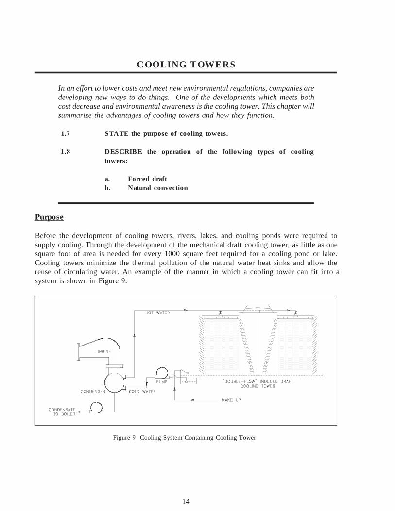
In an effort to lower costs and meet new environmental regulations, companies aredeveloping new ways to do things. One of the developments which meets bothcost decrease and environmental awareness is the cooling tower. This chapter willsummarize the advantages of cooling towers and how they function.
1. STATE the purpose of cooling towers.
1. DESCRIBE the operation of the following types of coolingtowers:
a. Forced draftb. Natural convection
Purpose
Before the development of cooling towers, rivers, lakes, and cooling ponds were required tosupply cooling. Through the development of the mechanical draft cooling tower, as little as onesquare foot of area is needed for every 1000 square feet required for a cooling pond or lake.Cooling towers minimize the thermal pollution of the natural water heat sinks and allow thereuse of circulating water. An example of the manner in which a cooling tower can fit into asystem is shown in Figure .
Figure Cooling System Containing Cooling Tower
ME-05 Rev. 0Page 18
14
Miscellaneous Mechanical Components DOE-HDBK-1018/2-93 COOLING TOWERS
The cooling of the water in a cooling tower is accomplished by the direct contact of water andair. This cooling effect is provided primarily by an exchange of latent heat of vaporizationresulting from evaporation of a small amount of water and by a transfer of sensible heat, whichraises the temperature of the air. The heat transferred from the water to the air is dissipated tothe atmosphere.
Induced Draft Cooling Towers
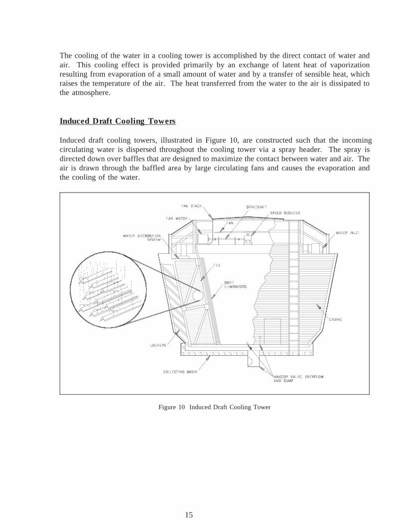
Induced draft cooling towers, illustrated in Figure 1 , are constructed such that the incomingcirculating water is dispersed throughout the cooling tower via a spray header. The spray isdirected down over baffles that are designed to maximize the contact between water and air. Theair is drawn through the baffled area by large circulating fans and causes the evaporation andthe cooling of the water.
Figure 1 Induced Draft Cooling Tower
Rev. 0 ME-05Page 19
15

COOLING TOWERS DOE-HDBK-1018/2-93 Miscellaneous Mechanical Components
The nomenclature for induced draft cooling towers, including some items not illustrated inFigure 1 is summarized below.
Casing - The casing encloses the walls of the cooling tower, exclusive offan deck and louvers.
Collecting basin - The collecting basin is a receptacle beneath the cooling towerfor collecting the water cooled by the cooling tower. It can bemade of concrete, wood, metal, or an alternative material.Certain necessary accessories are required such as sump,strainers, overflow, drain, and a makeup system.
Drift eliminators - The drift eliminators are parallel blades of PVC, wood, metal,or an alternative material arranged on the air discharge side ofthe fill to remove entrained water droplets from the leaving airstream.
Driver - The driver is a device that supplies power to turn the fan. It isusually an electric motor, but turbines and internal combustionengines are occasionally used.
Drive shaft - The drive shaft is a device, including couplings, whichtransmits power from the driver to the speed reducer.
Fan - The fan is a device used to induce air flow through the coolingtower.
Fan deck - The fan deck is a horizontal surface enclosing the top of thecooling tower above the plenum that serves as a workingplatform for inspection and maintenance.
Fan stack - The fan stack is a cylinder enclosing the fan, usually with aneased inlet and an expanding discharge for increased fanefficiency.
Fill - The fill is PVC, wood, metal, or an alternative material thatprovides extended water surface exposure for evaporative heattransfer.
Intake louvers - The intake louvers are an arrangement of horizontal blades atthe air inlets that prevent escape of falling water while allowingthe entry of air.
ME-05 Rev. 0Page 20
16

Miscellaneous Mechanical Components DOE-HDBK-1018/2-93 COOLING TOWERS
Makeup valve - The makeup valve is a valve that introduces fresh water into thecollection basin to maintain the desired collecting basin waterlevel.
Overflow - The overflow is a drain that prevents the collecting basin fromoverflowing.
Partition - The partition is a baffle within a multicell cooling tower that isused to prevent air and/or water flow between adjacent cells.
Plenum - The plenum is the internal cooling tower area between the drifteliminators and the fans.
Speed reducer - The speed reducer is a right-angle gear box that transmitspower to the fan while reducing the driver speed to thatrequired for optimal fan performance.
Sump - The sump is a depressed portion of the collecting basin fromwhich cold water is drawn to be returned to the connectedsystem. The sump usually contains strainer screens, antivortexdevices, and a drain or cleanout connection.
Distribution system - The distribution system is that portion of a cooling tower thatdistributes water over the fill area. It usually consists of one ormore flanged inlets, flow control valves, internal headers,distribution basins, spray branches, metering orifices, and otherrelated components.
Forced Draft Cooling Towers
Forced draft cooling towers are very similar to induced draft cooling towers. The primarydifference is that the air is blown in at the bottom of the tower and exits at the top. Forced draftcooling towers are the forerunner to induced draft cooling towers. Water distribution problemsand recirculation difficulties discourage the use of forced draft cooling towers.
Natural Convection Cooling Towers
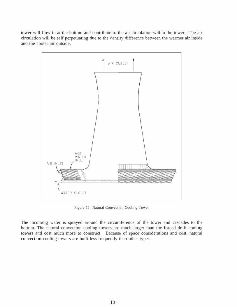
Natural convection cooling towers, illustrated in Figure 1 , use the principle of convective flowto provide air circulation. As the air inside the tower is heated, it rises through the tower. Thisprocess draws more air in, creating a natural air flow to provide cooling of the water. The basinat the bottom of the tower is open to the atmosphere. The cooler, more dense air outside the
Rev. 0 ME-05Page 21
17
COOLING TOWERS DOE-HDBK-1018/2-93 Miscellaneous Mechanical Components
tower will flow in at the bottom and contribute to the air circulation within the tower. The aircirculation will be self perpetuating due to the density difference between the warmer air insideand the cooler air outside.
Figure 1 Natural Convection Cooling Tower
The incoming water is sprayed around the circumference of the tower and cascades to thebottom. The natural convection cooling towers are much larger than the forced draft coolingtowers and cost much more to construct. Because of space considerations and cost, naturalconvection cooling towers are built less frequently than other types.
ME-05 Rev. 0Page 22
18
Miscellaneous Mechanical Components DOE-HDBK-1018/2-93 COOLING TOWERS
Summary
The important information in this chapter is summarized below.
Cooling Towers Summary
The cooling tower removes heat from water used in cooling systems withinthe plant. The heat is released to the air rather than to a lake or stream.This allows facilities to locate in areas with less water available becausethe cooled water can be recycled. It also aids environmental efforts by notcontributing to thermal pollution.
Induced draft cooling towers use fans to create a draft that pulls airthrough the cooling tower fill. Because the water to be cooled isdistributed such that it cascades over the baffles, the air blows through thewater, cooling it.
Forced draft cooling towers blow air in at the bottom of the tower. Theair exits at the top of the tower. Water distribution and recirculationdifficulties limit their use.
Natural convection cooling towers function on the basic principle that hotair rises. As the air inside the tower is heated, it rises through the tower.This process draws more air in, creating a natural air flow to providecooling of the water.
Rev. 0 ME-05Page 23
19
Miscellaneous Mechanical Components DOE-HDBK-1018/2-93 STEAM TRAPS
STEAM TRAPS
Steam traps are installed in steam lines to drain condensate from the lines withoutallowing the escape of steam. There are many designs of steam traps for highand low pressure use.
1. STATE the purpose and general operation of a steam trap.
1.1 IDENTIFY the following types of steam traps:
a. Ball float steam trap c. Bucket steam trapb. Bellow steam trap d. Impulse steam trap
General Operation
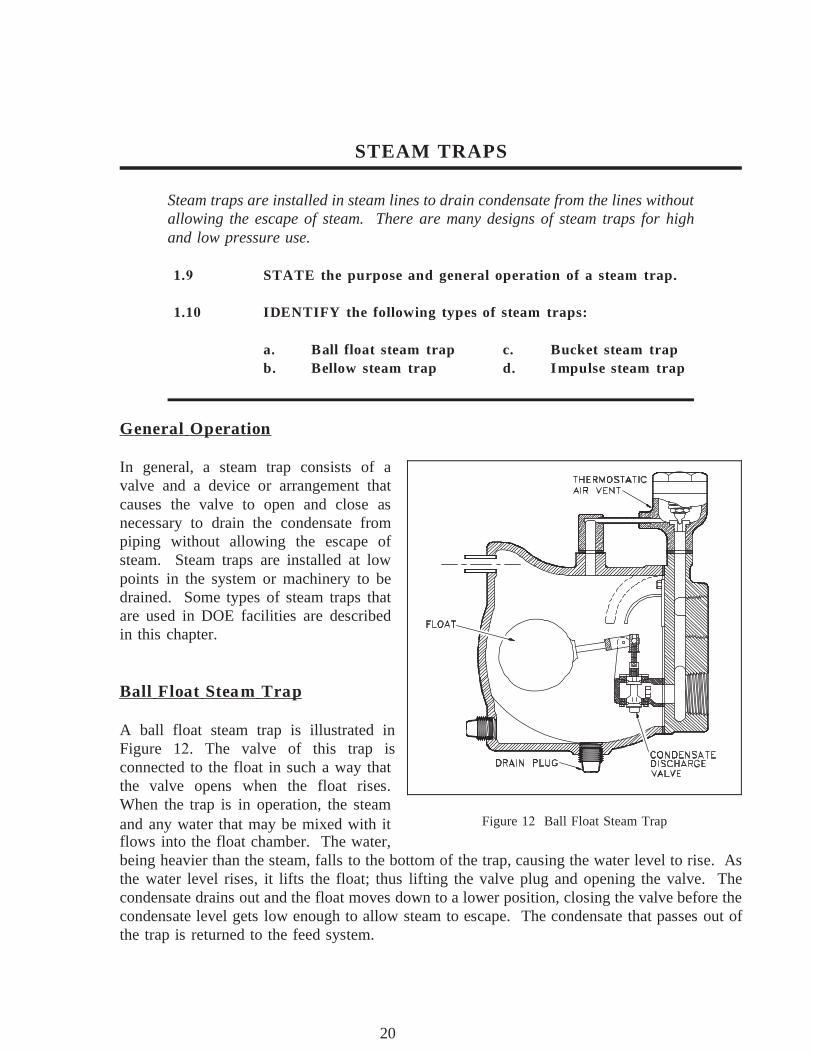
In general, a steam trap consists of avalve and a device or arrangement thatcauses the valve to open and close asnecessary to drain the condensate frompiping without allowing the escape ofsteam. Steam traps are installed at lowpoints in the system or machinery to bedrained. Some types of steam traps thatare used in DOE facilities are describedin this chapter.
Ball Float Steam Trap
A ball float steam trap is illustrated inFigure 1 . The valve of this trap isconnected to the float in such a way thatthe valve opens when the float rises.When the trap is in operation, the steamand any water that may be mixed with it Figure 1 Ball Float Steam Trapflows into the float chamber. The water,being heavier than the steam, falls to the bottom of the trap, causing the water level to rise. Asthe water level rises, it lifts the float; thus lifting the valve plug and opening the valve. Thecondensate drains out and the float moves down to a lower position, closing the valve before thecondensate level gets low enough to allow steam to escape. The condensate that passes out ofthe trap is returned to the feed system.
Rev. 0 ME-05Page 35
20
STEAM TRAPS DOE-HDBK-1018/2-93 Miscellaneous Mechanical Components
Bucket Steam Trap
Figure 1 Bucket Steam Trap
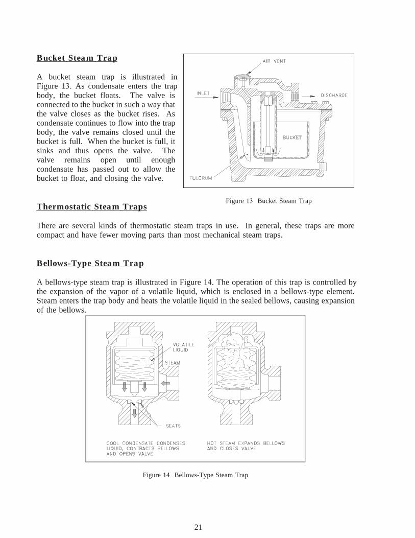
A bucket steam trap is illustrated inFigure 1 . As condensate enters the trapbody, the bucket floats. The valve isconnected to the bucket in such a way thatthe valve closes as the bucket rises. Ascondensate continues to flow into the trapbody, the valve remains closed until thebucket is full. When the bucket is full, itsinks and thus opens the valve. Thevalve remains open until enoughcondensate has passed out to allow thebucket to float, and closing the valve.
Thermostatic Steam Traps
There are several kinds of thermostatic steam traps in use. In general, these traps are morecompact and have fewer moving parts than most mechanical steam traps.
Bellows-Type Steam Trap
A bellows-type steam trap is illustrated in Figure 1 . The operation of this trap is controlled bythe expansion of the vapor of a volatile liquid, which is enclosed in a bellows-type element.Steam enters the trap body and heats the volatile liquid in the sealed bellows, causing expansionof the bellows.
Figure 1 Bellows-Type Steam Trap
ME-05 Rev. 0Page 36
21
Miscellaneous Mechanical Components DOE-HDBK-1018/2-93 STEAM TRAPS
The valve is attached to the bellows in such a way that the valve closes when the bellowsexpands. The valve remains closed, trapping steam in the valve body. As the steam cools andcondenses, the bellows cools and contracts, thereby opening the valve and allowing thecondensate to drain.
Impulse Steam Trap
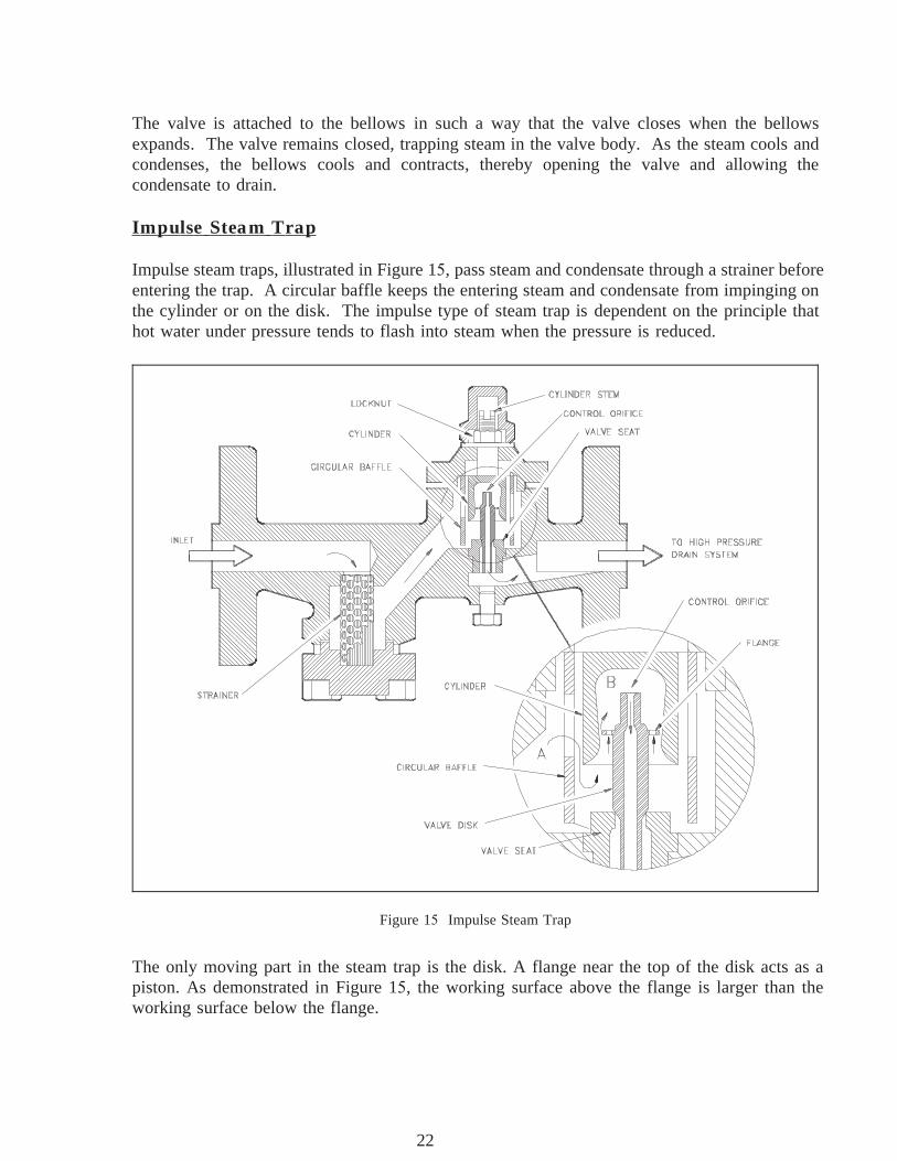
Impulse steam traps, illustrated in Figure 1 , pass steam and condensate through a strainer beforeentering the trap. A circular baffle keeps the entering steam and condensate from impinging onthe cylinder or on the disk. The impulse type of steam trap is dependent on the principle thathot water under pressure tends to flash into steam when the pressure is reduced.
Figure 1 Impulse Steam Trap
The only moving part in the steam trap is the disk. A flange near the top of the disk acts as apiston. As demonstrated in Figure 1 , the working surface above the flange is larger than theworking surface below the flange.
Rev. 0 ME-05Page 37
22
STEAM TRAPS DOE-HDBK-1018/2-93 Miscellaneous Mechanical Components
A control orifice runs through the disk from top to bottom, which is considerably smaller at thetop than at the bottom. The bottom part of the disk extends through and beyond the orifice inthe seat. The upper part of the disk (including the flange) is inside a cylinder. The cylindertapers inward, so the amount of clearance between the flange and the cylinder varies accordingto the position of the valve. When the valve is open, the clearance is greater than when thevalve is closed.
When the trap is first placed in service, pressure from the inlet (chamber A) acts against theunderside of the flange and lifts the disk off the valve seat. Condensate is thus allowed to passout through the orifice in the seat; and, at the same time, a small amount of condensate (calledcontrol flow) flows up past the flange and into chamber B. The control flow discharges throughthe control orifice, into the outlet side of the trap, and the pressure in chamber B remains lowerthan the pressure in chamber A.
As the line warms up, the temperature of the condensate flowing through the trap increases. Thereverse taper of the cylinder varies the amount of flow around the flange until a balancedposition is reached in which the total force exerted above the flange is equal to the total forceexerted below the flange. It is important to note that there is still a pressure difference betweenchamber A and chamber B. The force is equalized because the effective area above the flangeis larger than the effective area below the flange. The difference in working area is such that thevalve maintains at an open, balanced, position when the pressure in chamber B is approximately86% of the pressure in chamber A.
As the temperature of the condensate approaches its boiling point, some of the control flowgoing to chamber B flashes into steam as it enters the low pressure area. Because the steam hasa much greater volume than the water from which it is generated, pressure builds up in the spaceabove the flange (chamber B). When the pressure in this space is 86% of the inlet pressure(chamber A), the force exerted on the top of the flange pushes the entire disk downward andcloses the valve. With the valve closed, the only flow through the trap is past the flange andthrough the control orifice. When the temperature of the condensate entering the trap dropsslightly, condensate enters chamber B without flashing into steam. Pressure in chamber B isthus reduced to the point where the valve opens and allows condensate to flow through theorifice in the valve seat. The cycle is repeated continuously.
With a normal condensate load, the valve opens and closes at frequent intervals, discharging asmall amount of condensate at each opening. With a heavy condensate load, the valve remainsopen and allows a continuous discharge of condensate.
Orifice-Type Steam Trap
DOE facilities may use continuous-flow steam traps of the orifice type in some constant servicesteam systems, oil-heating steam systems, ventilation preheaters, and other systems or servicesin which condensate forms at a fairly constant rate. Orifice-type steam traps are not suitable forservices in which the condensate formation is not continuous.
ME-05 Rev. 0Page 38
23
Miscellaneous Mechanical Components DOE-HDBK-1018/2-93 STEAM TRAPS
Although there are several variations of the orifice-type steam trap, each has one thing incommon; it contains no moving parts. One or more restricted passageways or orifices allowcondensate to trickle through, but do not allow steam to flow through. Some orifice-type steamtraps have baffles in addition to orifices.
Summary
The following important information in this chapter is summarized below.
Steam Traps Summary
A steam trap consists of a valve and a device or arrangement that causes the valveto open and close as necessary to drain the condensate from the lines withoutallowing the escape of steam. Steam traps are installed at low points in the systemor machinery to be drained.
The type of steam trap used depends primarily on its application. Types include ballfloat, bucket traps, thermostatic traps, bellows-type traps, impulse traps, and orifice-type traps.
Impulse steam traps pass steam and condensate through a strainer before entering thetrap. A circular baffle keeps the entering steam and condensate from impinging onthe cylinder or on the disk. The impulse type of steam trap is dependent on the factthat hot water under pressure tends to flash into steam when the pressure is reduced.
Rev. 0 ME-05Page 39
24

FILTERS AND STRAINERS DOE-HDBK-1018/2-93 Miscellaneous Mechanical Components
FILTERS AND STRAINERS
When it is necessary to remove suspended solids from a liquid, the usual methodis to filter or strain the liquid. The two methods differ only in the size of themesh being used. Filtering removes the very small solids, and straining removesthe larger solids. Because filtering and straining are for all practical purposesthe same, this chapter will differentiate the two terms on the basis of applicationof the filter or strainer.
1.1 DESCRIBE each of the following types of strainers and filters,including an example of typical use.
a. Cartridge filters d. Bucket strainerb. Precoated filters e. Duplex strainerc. Deep-bed filters
1.1 EXPLAIN the application and operation of a strainer or filterbackwash.
Introduction
Filtration is a process used to remove suspended solids from a solution. Other processes suchas demineralization remove ions or dissolved ions. Different filters and strainers are used fordifferent applications. In general, the filter passage must be small enough to catch the suspendedsolids but large enough that the system can operate at normal system pressures and flows. Filtersand strainers are used throughout most DOE facilities. They are used in hydraulic systems, oilsystems, cooling systems, liquid waste disposal, water purification, and reactor coolant systems.
Cartridge Filters
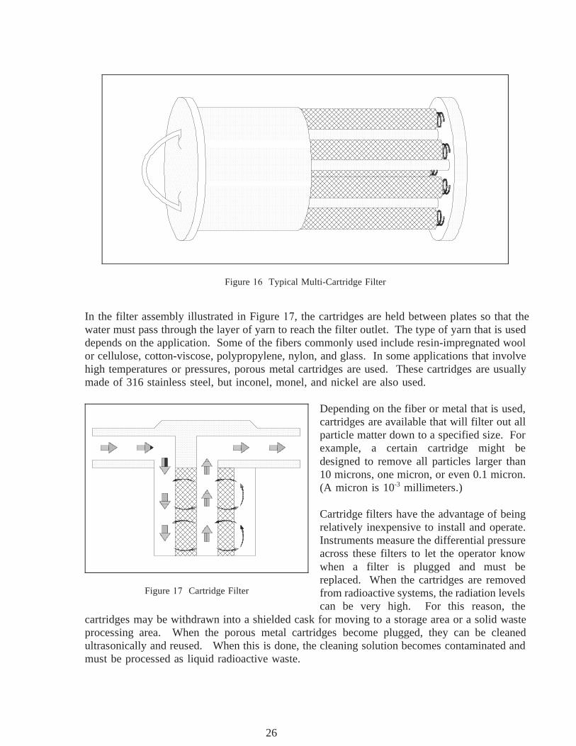
Figure illustrates a typical multi-cartridge filter. The cartridges are cylinders and usuallyconsist of a fiber yarn wound around a perforated metal core. The liquid being filtered is forcedthrough the yarn, which is approximately 1/2 inch thick, and then through the perforations in themetal core to the filter outlet, which can be at either end. A cartridge filter may include severalcartridges, the exact number depending on the liquid flow rate that must be handled.
ME-05 Rev. 0Page 40
25
Miscellaneous Mechanical Components DOE-HDBK-1018/2-93 FILTERS AND STRAINERS
Figure Typical Multi-Cartridge Filter
In the filter assembly illustrated in Figure , the cartridges are held between plates so that thewater must pass through the layer of yarn to reach the filter outlet. The type of yarn that is useddepends on the application. Some of the fibers commonly used include resin-impregnated woolor cellulose, cotton-viscose, polypropylene, nylon, and glass. In some applications that involvehigh temperatures or pressures, porous metal cartridges are used. These cartridges are usuallymade of 316 stainless steel, but inconel, monel, and nickel are also used.
Depending on the fiber or metal that is used,cartridges are available that will filter out allparticle matter down to a specified size. Forexample, a certain cartridge might bedesigned to remove all particles larger than10 microns, one micron, or even 0.1 micron.(A micron is 10-3 millimeters.)
Cartridge filters have the advantage of beingrelatively inexpensive to install and operate.Instruments measure the differential pressureacross these filters to let the operator knowwhen a filter is plugged and must bereplaced. When the cartridges are removed
Figure Cartridge Filter from radioactive systems, the radiation levelscan be very high. For this reason, the
cartridges may be withdrawn into a shielded cask for moving to a storage area or a solid wasteprocessing area. When the porous metal cartridges become plugged, they can be cleanedultrasonically and reused. When this is done, the cleaning solution becomes contaminated andmust be processed as liquid radioactive waste.
Rev. 0 ME-05Page 41
26

FILTERS AND STRAINERS DOE-HDBK-1018/2-93 Miscellaneous Mechanical Components
Another type of cartridge filter is the wafer, or disk filter. In this filter, disks are stacked toform a cartridge and placed down over a central perforated pipe. Each disk is typically 1/8 inchto 1/4 inch thick and made of cellulose or asbestos fibers.
Liquid that enters the disk filter moves up around the outside of the stack of disks, is forcedbetween the disks, travels through the perforations in the central pipe, and then leaves the filter.The filtering action takes place as the liquid is forced between the disks.
As with the smaller cartridges, if a disk filter is used to filter radioactive water, it may be veryradioactive when it is removed, and must be handled very carefully. One way to remove a diskfilter is by means of a crane, which lifts the filter out of its housing and moves it to a shieldedcontainer. The disposal problem is one of the major disadvantages of cartridge and disk-cartridge filters.
Precoat Filters
A precoat filter eliminates the problem of physically handling radioactive materials, because thefilter material (called the medium) can be installed and removed remotely. Inside the filterhousing is a bundle of septums (vertical tubes, on which the filter medium is deposited). Theseptums in some filters are approximately 1 inch in diameter and 3 feet long and are usuallymade of perforated or porous metal (normally stainless steel). There may be several hundredof these septums in a filter. Septums in other filters are approximately 3 inches in diameter and3 feet long and are made of porous stone or porous ceramic material. There are usually lessthan 100 of these larger septums in a filter.
The filtering medium fibers may be finely divided diatomite, perlite, asbestos, or cellulose.Diatomite, the least expensive medium, is used to filter liquid waste that will be discharged fromthe plant. Cellulose is generally used for processing water that will be returned to a reactor,because diatomite can allow silica leaching.
When a precoat filter is in use, water that enters the filter vessel passes through the filtermedium that is deposited on the septums and then leaves through the outlet. Before the filtercan be placed into operation, however, the filter medium must be installed; that is, the filter mustbe precoated.
The first step in precoating the filter is to close the inlet and outlet valves to the filter. The filtermedium used is mixed with demineralized water in an external mixing tank to form a slurry,which is pumped through the filter. Some of the filter medium deposits on the septums and isheld there by the pressure of water on the outside of the septums. At the beginning of theprecoating process, some of the fibers of the filter medium pass through the septums, eitherbecause they are smaller than the openings or because they pass through lengthwise. Thus, thereis still some filter medium in the water as it leaves the filter, so the slurry is recirculated againand again until the water is clear. Clear water indicates that all of the filter medium is depositedon the septums, and the filter is precoated.
ME-05 Rev. 0Page 42
27
Miscellaneous Mechanical Components DOE-HDBK-1018/2-93 FILTERS AND STRAINERS
One characteristic of the precoating process is that a very even layer of filter medium(approximately 1/8 inch thick) is deposited on the septums. This occurs because the circulatingslurry follows the path of least resistance. When the coating at one point reaches a certainthickness, the slurry takes the fibers to another point, and this process continues until precoatingis complete.
Because water pressure holds the filter in place, flow must be maintained through therecirculating loop to keep the medium from falling off. This is called a holding flow. As theinlet and outlet valves are opened for normal usage, called service flow, the holding flow isgradually cut off.
Backwashing Precoat Filters
After a filter has been precoated, it is put into service and kept on line until the pressuredifferential indicates that the filter medium is becoming plugged. When this occurs, the old filtermedium is removed and the filter is precoated again. Filters are usually installed in pairs, so thatone filter can remain in service while the other is undergoing the filter backwashing andprecoating process.
Since water pressure helps to hold the filter medium against the septums, some of the old filtermedium will fall off as soon as this pressure is removed. Backwashing is used to remove thefilter medium that does not fall off. Backwashing is usually done in one of two ways. Withsome filters, demineralized water is pumped backwards through the center of the septums, andthe filter medium coating is knocked off by the water as it comes out through the septums.
Most filters use a multi-step backwashing procedure. First, the inlet valve and the outlet valveare closed, and the drain valve and the top vent are opened to allow the water to drain. Thenthe drain valve and the vent are closed, and the inlet water valve is opened to raise the waterlevel. The filter is equipped with a special high-domed top to trap and compress air. When thewater inlet valve is closed and the drain valve is opened quickly, the compressed air forces waterdown through the center of the septums. This water knocks the filter medium off of theseptums.
With both types of backwashing, the filter medium coating that is removed is sluiced out througha drain line to a filter sludge tank, where it is stored for further processing. The filter is thenprecoated again and put back into service.
With precoat filters, the type and quantity of filter medium is critical. If too little material ortoo coarse a material is used, some of the finely divided crud in the water may get into theopenings of the septums. When the filter is backwashed, this crud is usually not removed. Itcontinues to build up during subsequent use of the filter until the septums become so pluggedthat they have to be replaced.
Rev. 0 ME-05Page 43
28
FILTERS AND STRAINERS DOE-HDBK-1018/2-93 Miscellaneous Mechanical Components
If too much filter medium is used, the layer that builds up on the septums will bridge the areabetween the septums. When the filter is backwashed, these bridges are usually not removed.Therefore the bridging continues, and the filter runs become progressively shorter. Eventually,the filter must be opened and the filter medium must be removed manually.
Precoat filters are much more complicated than cartridge filters, and the equipment required ismuch more expensive to install and maintain. The major advantage of precoat filters is theremote operation, which eliminates the physical handling of highly radioactive filter cartridges.
Deep-Bed Filters
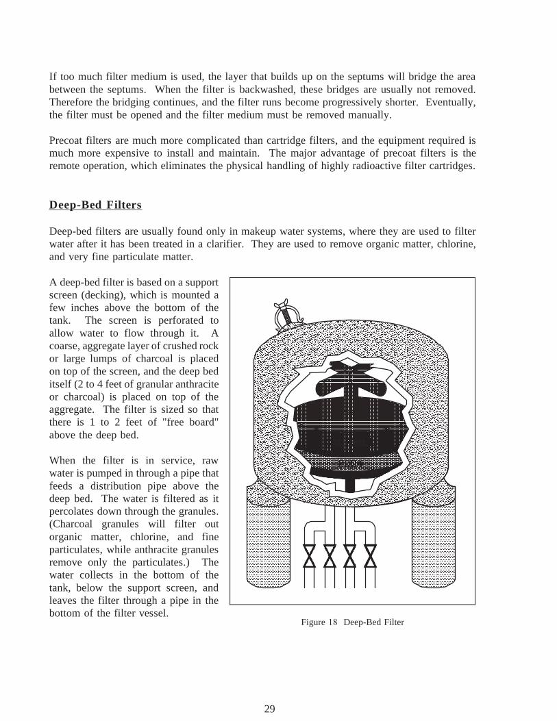
Deep-bed filters are usually found only in makeup water systems, where they are used to filterwater after it has been treated in a clarifier. They are used to remove organic matter, chlorine,and very fine particulate matter.
A deep-bed filter is based on a support
Figure Deep-Bed Filter
screen (decking), which is mounted afew inches above the bottom of thetank. The screen is perforated toallow water to flow through it. Acoarse, aggregate layer of crushed rockor large lumps of charcoal is placedon top of the screen, and the deep beditself (2 to 4 feet of granular anthraciteor charcoal) is placed on top of theaggregate. The filter is sized so thatthere is 1 to 2 feet of "free board"above the deep bed.
When the filter is in service, rawwater is pumped in through a pipe thatfeeds a distribution pipe above thedeep bed. The water is filtered as itpercolates down through the granules.(Charcoal granules will filter outorganic matter, chlorine, and fineparticulates, while anthracite granulesremove only the particulates.) Thewater collects in the bottom of thetank, below the support screen, andleaves the filter through a pipe in thebottom of the filter vessel.
ME-05 Rev. 0Page 44
29

Miscellaneous Mechanical Components DOE-HDBK-1018/2-93 FILTERS AND STRAINERS
Deep-bed filters, like precoat filters, are cleaned by backwashing. Water is pumped through thedistribution piping near the top of the filter. The flow rate of the water is kept high enough tolift the granulated charcoal or anthracite up into the free space. The water washes away thedeposits that have accumulated. When the backwash cycle is completed, the flow is stopped, andthe granules settle back down into the filter bed. The filter can then be put back into service.
Metal-Edged Filters
Metal-edged filters are used in the lubrication (oil) systems of many auxiliary units. A metal-edged filter consists of a series of metal plates or disks. Turning a handle moves the plates ordisks across each other in a manner that removes any particles that have collected on the metalsurfaces. Some metal-edged type filters have magnets to aid in removing fine particles ofmagnetic materials.
Strainers
Strainers are fitted in many piping lines to prevent the passage of grit, scale, dirt, and otherforeign matter, which could obstruct pump suction valves, throttle valves, or other machineryparts. One of the simplest and most common types of strainers found in piping systems is theY-strainer, which is illustrated in Figure .
Figure Y-strainer
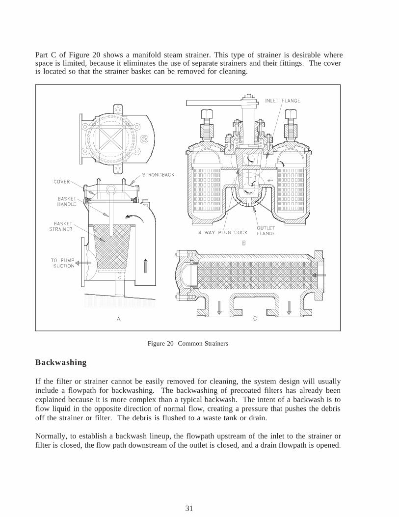
Figure 2 illustrates three additional common types of strainers. Part A shows a typical sumppump suction bucket strainer located in the sump pump suction line between the suction manifoldand the pump. Any debris that enters the piping is collected in the strainer basket. The basketcan be removed for cleaning by loosening the strongback screws, removing the cover, and liftingthe basket out by its handle.
Part B of Figure 2 shows a duplex oil strainer commonly used in fuel oil and lubricating oillines, where it is essential to maintain an uninterrupted flow of oil. The flow may be divertedfrom one basket to the other, while one is being cleaned.
Rev. 0 ME-05Page 45
30
FILTERS AND STRAINERS DOE-HDBK-1018/2-93 Miscellaneous Mechanical Components
Part C of Figure 2 shows a manifold steam strainer. This type of strainer is desirable wherespace is limited, because it eliminates the use of separate strainers and their fittings. The coveris located so that the strainer basket can be removed for cleaning.
Backwashing
Figure 2 Common Strainers
If the filter or strainer cannot be easily removed for cleaning, the system design will usuallyinclude a flowpath for backwashing. The backwashing of precoated filters has already beenexplained because it is more complex than a typical backwash. The intent of a backwash is toflow liquid in the opposite direction of normal flow, creating a pressure that pushes the debrisoff the strainer or filter. The debris is flushed to a waste tank or drain.
Normally, to establish a backwash lineup, the flowpath upstream of the inlet to the strainer orfilter is closed, the flow path downstream of the outlet is closed, and a drain flowpath is opened.
ME-05 Rev. 0Page 46
31
Miscellaneous Mechanical Components DOE-HDBK-1018/2-93 FILTERS AND STRAINERS
The flush source is then opened and the flow goes into the outlet of the strainer or filter, throughthe strainer or filter, and exits the inlet to the backwash drain or waste tank, carrying the debriswith it.
Summary
The important information in this chapter is summarized below.
Filters and Strainers Summary
A cartridge filter may be a single cartridge or multi-cartridge filter. Thecartridges are cylinders that usually consist of a fiber yarn wound around aperforated metal core. The liquid being filtered is forced through the yarn andthen through the perforations in the metal core to the filter outlet, which can beat either end. This type of filter is used to remove fine particles in any flowcondition. Radioactive systems may use these because they are inexpensive andeasy to replace.
Precoat filters consists of a filter housing that contains a bundle of septums,(vertical tubes, on which the filter medium is deposited) usually made ofperforated or porous metal (normally stainless steel), porous stone, or porousceramic material. The filtering medium fibers may be finely divided diatomite,perlite, asbestos, or cellulose. Diatomite, the least expensive medium, is used tofilter liquid waste that will be discharged from the plant. Cellulose is generallyused for processing water that will be returned to the reactor, because diatomitecan allow silica leaching.
A deep-bed filter is based on a support screen (decking), which is mounted a fewinches above the bottom of the tank. The screen is perforated to allow water toflow through it. A coarse, aggregate layer of crushed rock or large lumps ofcharcoal is placed on top of the screen, and the deep bed itself (2 to 4 feet ofgranular anthracite or charcoal) is placed on top of the aggregate. This type offilter is frequently used in raw water treatment.
The bucket strainer is literally a bucket to catch debris. The bucket can beremoved for cleaning by loosening the strongback screws, removing the cover,and lifting the bucket out by its handle. It is usually used in systems expected tohave larger debris.
Rev. 0 ME-05Page 47
32
FILTERS AND STRAINERS DOE-HDBK-1018/2-93 Miscellaneous Mechanical Components
Filters and Strainers Summary (Cont.)
A duplex strainer is a strainer consisting of two sides with a basket in each side.Only one side is placed in service at a time. These are commonly used in fueloil and lubricating oil lines, where it is essential to maintain an uninterrupted flowof oil. The flow may be diverted from one basket to the other, while one is beingcleaned.
If the filter or strainer cannot be easily removed for cleaning, the system designwill usually include a flowpath for backwashing. The intent of a backwash is toflow liquid in the opposite direction of normal flow, creating a pressure thatpushes the debris off the strainer or filter. The debris is flushed to a waste tankor drain.
Normally, to establish a backwash lineup, the flowpath upstream of the inlet tothe strainer or filter is closed, the flow path down stream of the outlet is closed,and a drain flowpath is opened. The flush source is then opened and the flowgoes into the outlet of the strainer or filter, through the strainer or filter, and exitsthe inlet to the backwash drain or waste tank, carrying the debris with it.
end of text.
CONCLUDING MATERIAL
Review activities: Preparing activity:
DOE - ANL-W, BNL, EG&G Idaho, DOE - NE-73EG&G Mound, EG&G Rocky Flats, Project Number 6910-0024LLNL, LANL, MMES, ORAU, REECo,WHC, WINCO, WEMCO, and WSRC.
ME-05 Rev. 0Page 48
33