technology made in Italy · Brick press Briquette machine Pug mill Compactors Compressors...
36
RD technology made in Italy
Transcript of technology made in Italy · Brick press Briquette machine Pug mill Compactors Compressors...

RD
techno logy made in I ta ly

Since 1955 Varvel has been making speed reducers andvariators for light industry applications. Reliable partner inpower transmission equipment offers also customized solutionsalways according to a socially responsible company values.Modularity and flexibility lead Varvel products by a unique kitform, common to all gearbox series. This feature allows distri-butors an easier job to set up required products in few minutes.
Technology Made in Italy
Tecnología Made in ItalyDesde 1955 Varvel proyecta y fabrica reductores y variadoresde velocidad para aplicaciones de pequeña y mediana potencia.Socio fiable para la producción y venta de órganos de transmisióngracias a un elevado nivel de servicio, ofrece también solucionespersonalizadas actuando con el respeto a los valores de laempresa socialmente responsable. Modularidad y flexibilidadguían el diseño de los productos Varvel mediante la realizaciónde kits comunes a toda la familia de reductores, facilitando así lagestión de los distribuidores y revendedores que pueden confi-gurar en pocos minutos el producto solicitado por cada cliente.
Technologie Made in ItalyDepuis 1955 Varvel projette et réalise réducteur et variateurmécaniques dédiés à la petite et moyenne industrie. Partnerfiable dans la production et la vente d’organes de transmissiongrace à un très bon niveau de service, Varvel offre égalementdes solutions personnalisées tout en respectant les valeurs del'entreprise socialement responsable. Modularité et flexibilitéguide la conception des produits Varvel en réalisant des kitscommuns pour toutes les familles de réducteurs, favorisantainsi l’activité des distributeurs et revendeurs qui peuventréaliser en quelques minutes le produit sur demande du client.
*
* V
S m
ade
in C
hina

Helical Gearboxes RD

- 2 -
Helical Gearboxes RD
PRODUCT DESCRIPTION
Multipurpose housing Foot & Foot/Flange Mountings One housing for 2- & 3-stages
Housing & Covers Input Aluminium die cast (5 sizes) NEMA and IEC Cast iron (2 sizes) motor adapters and Universal elastic coupling Gearing Oil seals 20MnCr5 alloy steel Nitrile Butadiene Rubber -NBR Case hardened as standard; Profile ground or shaved Viton and Silicon on request Bearings Output Ball or roller types Solid shafts according to sizes imperial and metric and technical requirements
Lubrication Synthetic long-life oil Grade ISO VG 320
No oil plugs In-house filling
CONTENTS
Product Description .................................................................2-3 Symbols & Formulae...................................................................3 Order Designation ......................................................................4 Mounting Positions .....................................................................5 Service Factors .......................................................................6-8 External Loads ...........................................................................9
Ratings RD 02 - 03 ................................................................................10 RD 12 - 13 ................................................................................11 RD 22 - 23 ................................................................................12 RD 32 - 33 ................................................................................13 RD 42 - 43 ................................................................................14 RD 52 - 53 .................................................................................15 RD 62 - 63 ................................................................................16
Input Arrangements...................................................................17
Dimensions
RD 02 - 03 ........................................................................... 18-19 RD 12 - 13 ........................................................................... 20-21 RD 22 - 23 ........................................................................... 22-23 RD 32 - 33 ........................................................................... 24-25 RD 42 - 43............................................................................ 26-27 RD 52 - 53............................................................................ 28-29 RD 62 - 63............................................................................ 33-31
General Information
Components, 2- and 3-stages ..................................................32 Conversion Factors ...................................................................32

- 3 -
Helical Gearboxes RD
PRODUCT DESCRIPTION
The helical gearboxes Series RD feature a one-piece cast housing complete with inner support to accommodate 2 or 3 gear stages into the same casing. Manufactured to latest ISO engineering design specifications the housing is checked by computer-aided structural analysis for deflection and stress distribution.
Significant strains caused by the effects of torque and external loads do not deflect the monolithic ribwork of the housing, which significantly improves the integrity of the sealed surfaces.
The helical gearboxes Series RD are manufactured in B3 base mounted configuration; they can be easily converted to B5 flange mounting by fitting of the appropriate additional adaptor flange onto the footed body.
Single-setup machining on state-of-the-art CNC production lines, the most recent calculation techniques and process controls give superior operational reliability, maximum output torques, high overhung and thrust load capacity, and long working life-time.
SYMBOLS & FORMULAS
D [in] Transmission element PCD
Fr [lb] Application overhung load (OHL)
Fr1 [lb] Catalogue input overhung load (input OHL)
Fr2 [lb] Catalogue output overhung load (output OHL)
Fr2b(x) [lb] Permissible OHL at position 'X' on output shaft, bearing lifetime condition
Fr2s(x) [lb] Permissible OHL same as Fr2b(x), shaft bending and torsional stress condition
SF Service factor
in Nominal reduction ratio
ir Actual reduction ratio
J1 [ft2-lb] Gearbox moment of inertia at input shaft
J2 [ft2-lb] Application moment of inertia
Jm [ft2-lb] Motor moment of inertia
k(a) Mass acceleration factor
k(t) Transmission element factor
Lub H/V [pt] Lubricant [pt]: H = horizontal mounting / V = vertical mounting
M2 [in-lb] Gearbox maximunm output torque
M(app) [in-lb] Application torque
n1 [RPM] Input speed
n2 [RPM] Output speed
P1 [HP] Input power @ 60Hz
W [lb] Weight: mounting B3-H & average reduction ratio
η Efficiency: 0.96 - 2-stage units 0.94 - 3-stage units
(app)
2
M
M FS =
2
12
n
P 1800 M
η∗∗=
η∗
∗=
1800
n M P
221

- 4 -
Helical Gearboxes RD
ORDER DESIGNATION Example: FRD32/B3-H4 31.5 N56 AU35
F RD 52 B3-H4 31.5 N56 AU DFU
TYPE MOUNTING POSITION OUTPUT
FLANGE mm
RD - Helical gearbox
Page 5
B3 - Foot mounting
B5 - Flange mounting
120 140 160 . . . 300 350
INPUT TYPE SIZE REDUCTION RATIO 1: MOTOR ADAPTER OUTPUT SHAFT DIA.
A) B) A) B) NEMA in
02 03 2.5 40 N42 0.625“
12 13 3.15 50 N48 0.750”
22 23 4.0 63 N56 1.000“
32 33 5.0 80 N140 1.250“
42 43 6.3 100 N180 1.375”
52 53 8.0 125 N200 1.625“
62 63 10.0 160 2.125“
12.5 200
16.0 250
20.0 315
25.0 400
31.5 500
40 630
50
M - Motorized Unit
F - Motor Flange
S - Without Mtr Flange
nil - Solid input
63
A) - 2-stages B) - 3-stages

- 5 -
Helical Gearboxes RD
MOUNTING POSITIONS
B3 Foot mounting
B5 Flange mounting
H2 H1 V6
V5 H4
H3
H2 H1 V6
V5 H4
H3

- 6 -
Helical Gearboxes RD
SERVICE FACTORS SERVICE FACTOR of the gearbox
Service factor SF1.0 is meant as typical of 8 hours/day operation, with uniform load, starts/ stops lower than 60 per hour and ambient temperature between 60 and 95 °F.
The ratio between gearbox maximum output torque M2 of each reduction ratio - listed in gearbox RD ratings, pages 10 to 16 - and application torque M(app) states the service factor to be bigger than the Application factors listed below.
Load duration (hrs/day) Load duration (hrs/day) Application
< 3 3 - 10 > 10 Application
< 3 3 - 10 > 10
Agitators (mixers) Pure liquids
Liquids and solids Liquids - variable density
Blowers Centrifugal Lobe Vane
Brewing and distilling Bottling machinery Brew kettles - continuous duty Cookers - continuous duty Mash tubs - continuous duty Scale hopper - frequent starts
Can filling machine
Car dumpers
Car pullers
Clarifiers
Classifiers
Clay working machinery Brick press Briquette machine Pug mill
Compactors
Compressors Centrifugal Lobe Reciprocating, multi-cylinder Reciprocating, single-cylinder
Conveyors - General purpose Uniformly loaded or fed - Heavy duty Not uniformly fed - Reciprocating or shaker
Crusher Stone or ore
Dredges Cable reels . Conveyors Cutter head drives Pumps Screen drives Stackers Winches
1.00 1.00 1.00
1.00 1.00 1.00
1.00 1.25 1.25 1.25 1.25
1.00
1.50
1.00
1.00
1.00
1.50 1.50 1.00
2.00
1.00 1.00 1.50 1.75
1.00
1.00 1.50
1.75
1.25 1.25 2.00 2.00 1.75 1.25 1.25
1.00 1.00 1.25
1.00 1.25 1.25
1.25 1.25 1.25 1.25 1.25
1.00
1.75
1.25
1.00
1.25
1.75 1.75 1.25
2.00
1.00 1.25 1.50 1.75
1.00
1.25 1.75
1.75
1.25 1.25 2.00 2.00 1.75 1.25 1.25
1.25 1.50 1.50
1.25 1.50 1.50
1.25 1.25 1.25 1.25 1.25
1.25
2.00
1.50
1.25
1.50
2.00 2.00 1.50
2.00
1.25 1.50 1.75 2.00
1.25
1.50 2.00
2.00
1.50 1.50 2.00 2.00 2.00 1.50 1.50
Elevators Bucket Centrifugal discharge Escalators Freight Gravity discharge
Extruders General Plastics Variable speed drive Fixed speed drive Rubber Continuous screw operation Intermittent screw operation Fans Centrifugal Cooling towers Forced draft Induced draft Industrial and mine
Feeders Apron Belt Disc Reciprocating Screw
Food industry Cereal cooker Dough mixer Meat grinders Slicers
Generators and exciters
Hammer mills
Hoists Heavy duty Medium duty Skip hoist
Laundry Tumblers Washers
Lumber industry Barkers Spindle feed Main drive Conveyors Burner Main or heavy duty Main log Re-saw, merry-go-round
1.00 1.00 1.00 1.00 1.00
1.50
1.50 1.75
1.75 1.75
1.00 2.00 1.25 1.50 1.50
1.00 1.00 1.00 1.50 1.00
1.00 1.25 1.25 1.25
1.00
1.75
1.25 1.25 1.25
1.25 1.50
1.25 1.75
1.25 1.50 1.75 1.25
1.25 1.00 1.00 1.25 1.00
1.50
1.50 1.75
1.75 1.75
1.00 2.00 1.25 1.50 1.50
1.25 1.25 1.00 1.75 1.25
1.00 1.25 1.25 1.25
1.00
1.75
1.75 1.25 1.25
1.25 1.50
1.25 1.75
1.25 1.50 1.75 1.25
1.50 1.25 1.25 1.50 1.25
1.50
1.50 1.75
1.75 1.75
1.25 2.00 1.25 1.50 1.50
1.50 1.50 1.25 2.00 1.50
1.25 1.50 1.50 1.50
1.25
2.00
2.00 1.50 1.50
1.50 2.00
1.50 1.75
1.50 1.50 2.00 1.50

- 7 -
Helical Gearboxes RD
SERVICE FACTORS
Load duration (hrs/day) Load duration (hrs/day) Application
< 3 3 - 10 > 10 Application
< 3 3 - 10 > 10
Conveyors Slab Transfer
Chains Floor Green
Cut-off saws Chain Drag
Debarking drums Feeds Edger Gang Trimmer Log deck Log hauls - incline - well type Log turning devices Planer feed Planer tilting hoists Rolls -live-off bearings - roll cases Sorting table Tipple hoist Transfers Chain Crane way Tray drives Veneer lathe drives
Metal mills Draw bench carriage and main drive Runout table Non-reversing Group drives Individual drives Reversing Slab pushers Shears Wire drawing machine Wire winding machine
Metal strip processing machinery Bridles Coilers and uncoilers Edge trimmers Flatteners Loopers (accumulators) Pinch rolls Scrap choppers Shears Slitters
Mills, rotary type Ball and rod Spur ring gear Helical ring gear Direct connected Cement kilns Dryers and coolers
1.75 1.25
1.50 1.50
1.50 1.50
1.75
1.25 1.75 1.25 1.75 1.75 1.75 1.25 1.50 1.75
1.25 1.25
1.50 1.50 1.25 1.25
1.25
1.50 2.00 2.00 1.50 2.00 1.25 1.25
1.25 1.00 1.00 1.25 1.00 1.25 1.25 2.00 1.00
2.00 2.00 1.50 2.00 1.50 1.50
1.75 1.25
1.50 1.50
1.50 1.50
1.75
1.25 1.75 1.25 1.75 1.75 1.75 1.25 1.50 1.75
1.25 1.25
1.50 1.50 1.25 1.25
1.25
1.50 2.00 2.00 1.50 2.00 1.25 1.50
1.25 1.00 1.25 1.25 1.00 1.25 1.25 2.00 1.25
2.00 2.00 1.50 2.00 1.50 1.50
2.00 1.50
1.50 1.75
1.75 1.75
2.00
1.50 1.75 1.50 1.75 1.75 1.75 1.50 1.50 1.75
1.50 1.50
1.75 1.75 1.50 1.50
1.50
1.50 2.00 2.00 1.50 2.00 1.50 1.50
1.50 1.25 1.50 1.50 1.25 1.50 1.50 2.00 1.50
2.00 2.00 1.50 2.00 1.50 1.50
Mixers Concrete
Paper mills
Agitator (mixer) Agitator for pure liquors Barking drums Barkers -mechanical Beater Breaker stack Calendar Chipper Chip feeder Coating rolls Conveyors Chip, bark, chemical Log (including slab) Couch rolls Cutter Cylinder molds Dryers Paper machine Conveyor type Embosser . Extruder Fourdrinier rolls (includes lump breaker, dandy roll, wire turning, and return rolls) Jordan Kiln drive Mt Hope roll Paper rolls Platter Presses - felt and suction Pulper Pumps - vacuum Reel (surface type) Screens Chip Rotary Vibrating Size press Super calendar Thickener (AC motor) (DC motor) Washer (AC motor) (DC motor) Wind and unwind stand Winders (surface type) Yankee dryers
Plastics industry Primary processing Intensive internal mixers Batch mixers Continuous mixers Batch drop mill - two smooth rolls Continuous feed, holding and blend mill Compounding mill Calendars
1.25
1.50 1.25 2.00 2.00 1.50 1.25 1.25 2.00 1.50 1.25
1.25 2.00 1.25 2.00 1.25
1.25 1.25 1.25 1.50
1.25 1.50 1.50 1.25 1.25 1.50 1.25 2.00 1.50 1.25
1.50 1.50 2.00 1.25 1.25 1.50 1.25 1.50 1.25 1.00 1.25 1.25
1.75 1.50 1.25
1.25
1.25 1.50
1.25
1.50 1.25 2.00 2.00 1.50 1.25 1.25 2.00 1.50 1.25
1.25 2.00 1.25 2.00 1.25
1.25 1.25 1.25 1.50
1.25 1.50 1.25 1.50 1.25 1.50 1.25 2.00 1.50 1.25
1.50 1.50 2.00 1.25 1.25 1.50 1.25 1.50 1.25 1.00 1.25 1.25
1.75 1.50 1.25
1.25
1.25 1.50
1.50
1.50 1.25 2.00 2.00 1.50 1.25 1.25 2.00 1.50 1.25
1.25 2.00 1.25 2.00 1.25
1.25 1.25 1.25 1.50
1.25 1.50 1.50 1.25 1.25 1.50 1.25 2.00 1.50 1.25
1.50 1.50 2.00 1.25 1.25 1.50 1.25 1.50 1.25 1.25 1.25 1.25
1.75 1.50 1.25
1.50
1.25 1.25

- 8 -
Helical Gearboxes RD
SERVICE FACTORS
Load duration (hrs/day) Load duration (hrs/day) Application
< 3 3 - 10 > 10 Application
< 3 3 - 10 > 10
Plastics industry Secondary processing Blow molders Coating Film Pipe Pre-plasticizers Rods Sheet Tubing
Pullers -barge haul
Pumps Centrifugal Proportioning Reciprocating Single acting, three or more cylinders Double acting, two or more cylinders Rotary Gear type Lobe Vane
Rubber industry Intensive internal mixers Batch mixers Continuous mixers Mixing mill - two smooth rolls (if
corrugated rolls are used, then use the same selection factors
that are used for a cracker warmer).
Batch drop mill - two smooth rolls Cracker warmer - two rolls; one corrugated roll Cracker - two corrugated rolls. Holding, feed and blend mill - two rolls Refiner - two rolls Calendars
1.50 1.25 1.25 1.25 1.50 1.25 1.25 1.25
1.25
1.00 1.25
1.25
1.25
1.00 1.00 1.00
1.75 1.50 1.50
1.50
1.75
2.00 1.25
1.50 1.50
1.50 1.25 1.25 1.25 1.50 1.25 1.25 1.25
1.25
1.00 1.25
1.25
1.25
1.00 1.00 1.00
1.75 1.50 1.50
1.50
1.75
2.00 1.25
1.50 1.50
1.50 1.25 1.25 1.25 1.50 1.25 1.25 1.50
1.50
1.25 1.00
1.50
1.50
1.25 1.25 1.25
1.75 1.50 1.50
1.50
1.75
2.00 1.25
1.50 1.50
Sand muller
Sewage disposal equipment Bar screens Chemical feeders Dewatering screens Scum breakers Slow or rapid mixers Sludge collectors Thickeners Vacuum filters
Screens Air washing Rotary - stone or gravel Travelling water intake
Sugar industry Beet slicer Cane knives Crushers Mills (low speed end)
Textile industry Batchers Calendars Cards Dry cans Dryers Dyeing machinery Looms Mangles Nappers Pads Slashers Soapers Spinners Tenter frames Washers Winders
1.25
1.25 1.25 1.50 1.50 1.50 1.25 1.50 1.50
1.00 1.25 1.00
2.00 1.50 1.50 1.75
1.25 1.25 1.25 1.25 1.25 1.25 1.25 1.25 1.25 1.25 1.25 1.25 1.25 1.25 1.25 1.25
1.25
1.25 1.25 1.50 1.50 1.50 1.25 1.50 1.50
1.00 1.25 1.00
2.00 1.50 1.50 1.75
1.25 1.25 1.25 1.25 1.25 1.25 1.25 1.25 1.25 1.25 1.25 1.25 1.25 1.25 1.25 1.25
1.50
1.25 1.25 1.50 1.50 1.50 1.25 1.50 1.50
1.25 1.50 1.25
2.00 1.50 1.50 1.75
1.50 1.50 1.50 1.50 1.50 1.50 1.50 1.50 1.50 1.50 1.50 1.50 1.50 1.50 1.50 1.50
This application guide is given by way of an example and therefore, may not include all the possible cases.
Should the application not be referable to any of the listed cases, the table below gives two service factors - one referred to both load type and work duration, and another one to starts and stops number of the duty cycle - of which the product is the gearbox oversizing coefficient in order to have a torque good enough to perform the required work.
Application: Conveyor 1000 in-lb @ 84 RPM - uniform load - 24 hrs/day � F1 =1.4; 60 start/stops per hour � F2 = 1.0; Required torque 1000 x 1.4 x 1.0 = 1400 in-lb Gearbox to select FRD22 1/20 (84 RPM) 1683 in-lb (gearbox service factor SF1.7 = 1683 in-lb : 1000 in-lb)
F1 a b c F2 d
3 - 4 hrs 0.8 1.0 1.5 6 0.8
8 - 10 hrs 1.0 1.2 1.8 60 1.0
SERVICE FACTOR SF = F1 × F2
F1 = Load & time factor a = Uniform load b = Variable load c = Shock load F2 = Running factor d = Start/stops per hour 10 - 24 hrs 1.4 1.6 2.0 120 1.2

- 9 -
Helical Gearboxes RD
EXTERNAL LOADS
OHL - OVERHUNG LOADS - OUTPUT [lb] Overhung (radial) loads have to be checked with the rating factor Fr2 given in the selection tables. Each transmission element fitted on the gearbox output shaft gives its own transmission element factor k(t) according to the following table. - Application OHL k(t) Transmission Element
1.15 Gear - Tooth No. < 17
1.40 Chain sprocket - Tooth No. < 13 1.25 Chain sprocket - Tooth No. < 20 1.00 Chain sprocket - Tooth No. > 20
2.50 V-belt pulley
1.25 Toothed belt pulley
- Catalogue OHL at mid shaft Catalogue value to be greater than application OHL RD 0 1 2 3 4 5 6
a [inch] 0.69 0.79 0.98 1.18 1.38 1.57 1.97
a [mm] 17.5 20 25 30 35 40 50
- OHL offset from gearbox centre * or ** values as appropriate * ** to be greater than application OHL RD 0 1 2 3 4 5 6
a [inch] 0.69 0.79 0.98 1.18 1.38 1.57 1.97
b [inch] 0.61 0.91 0.94 1.06 1.22 1.46 1.54
c [inch] 1.30 1.69 1.93 2.24 2.60 3.03 3.50 AXIAL LOADS - OUTPUT Axial load values are assumed to be 20% of OHL, either on tensile and compressive stress, besides OHL itself.
rr2 F F ≥
D
a
Fr2
x
Fr2
Fr2
Fa2
)t(2
r kDM 2
F ∗∗=
xa
FF
FF
rs(x)r
rs(x)r
∗=
≥
22
2
bxc
FF
FF
r2r2b(x)
rr2b(x)
+∗=
≥
0.2F F r2a2 ∗=

- 10 -
RD02 & RD03 Helical Gearboxes RD
SELECTION 1800 RPM
n2 M2 P1 Fr1 Fr2 J1 × 10-4 NEMA SIZES 440 in-lb
in nominal
ir actual [RPM] [in-lb] [HP] [lb] [lb] [lb x ft2] 42 48 56
2,5 2.568 654 266 3.05 � 97 12.4608 G5 G5
3,15 3.277 512 292 2.63 � 94 10.5434 G5 G5
4,0 4.256 395 319 2.21 � 97 9.2169 G5 G5
5,0 5.276 318 336 1.89 � 117 8.5121 G5 G5
6,3 6.253 281 425 2.04 8 144 10.1946 G5 G5
8,0 7.979 210 434 1.63 25 162 9.1504 G5 G5
10,0 10.362 162 443 1.31 39 184 8.3911 G5 G5
12,5 12.844 131 443 1.04 47 207 7.9758 G5 G5
16,0 16.320 103 451 0.82 55 229 7.6364 G5 G5
20,0 21.533 78 451 0.64 61 263 7.3706 G5 G5
25,0 26.747 62 460 0.52 66 270 7.2259 G5 G5
31,5 30.222 55 460 0.45 67 270 7.1642 G5 G5
35,5 34.675 48 310 0.27 143 321 7.3303 G5 G5
40 43.070 40 310 0.22 145 321 7.1974 G5 G5
RD02 2s
50 48.667 35 310 0.18 146 319 7.1428 G5 G5
40 36.892 44 460 0.37 17 270 7.2734 G3 G3
50 47.074 36 460 0.30 33 270 15.2610 G3 G3
63 61.135 28 460 0.23 47 270 15.0498 G3 G3
80 75.782 22 460 0.18 56 270 14.9478 G3 G3
100 96.288 18 460 0.15 63 270 14.8789 G3 G3
125 127.047 13 460 0.12 70 270 14.8362 G3 G3
160 157.805 11 460 0.08 75 270 14.8172 G3 G3
180 178.311 9.5 460 0.08 77 270 14.8101 G3 G3
200 204.583 8.3 319 0.05 82 319 14.8338 G3 G3
250 254.113 6.6 319 0.03 84 319 14.8172 G3 G3
280 287.133 5.9 319 0.03 85 319 14.8101 G3 G3
RD03 3s
315 324.444 5.2 319 0.03 85 319 15.3346 G3 G3
2s & 3s �
G3, G5
- Number of reduction stages - Recommended input in-line coupling drive - Elastic coupling 'G type' input
Lub. H Lub. V Weight RD
US qt litres US qt litres lb kg
02 0.21 0.20 0.30 0.28 6.7 3.0
03 0.32 0.30 0.40 0.38 7.2 3.2

- 11 -
Helical Gearboxes RD RD12 & RD13
1800 RPM SELECTION
n2 M2 P1 Fr1 Fr2 J1 × 10-4 NEMA SIZES 885 in-lb
in nominal
ir actual [RPM] [in-lb] [HP] [lb] [lb] [lb x ft2] 56 140
2.5 2.534 672 398 4.19 � 292 26.4641 G5 G5
3.15 3.081 534 398 3.70 � 315 22.1452 G5 G5
4 4.011 420 443 3.08 � 337 18.2510 G5 G5
5 5.073 336 487 2.60 � 360 15.9753 G5 G5
6.3 6.686 264 797 3.45 � 382 19.8315 G5 G5
8 8.129 210 797 2.87 � 405 17.6578 G5 G5
10 10.581 168 797 2.23 � 427 15.6027 G5 G5
12.5 13.384 132 797 1.78 � 427 14.3213 G5 G5
16 16.309 108 797 1.48 4 427 13.5500 G5 G5
20 20.391 84 797 1.19 12 427 12.8975 G5 G5
25 26.522 66 841 0.94 17 449 12.3659 G5 G5
31.5 32.653 54 841 0.77 22 449 12.0740 G5 G5
40 39.083 42 620 0.45 133 449 12.3018 G5 G5
50 48.118 36 620 0.37 142 449 12.0313 G5 G5
RD12 2s
63 61.670 26 620 0.28 144 449 11.8059 G5 G5
40 40.103 42 841 0.64 27 337 12.4988 G5
50 52.201 36 841 0.49 47 360 36.8319 G5
63 66.028 26 841 0.39 61 382 36.5305 G5
80 80.432 22 885 0.32 72 405 36.3858 G5
100 100.596 17 885 0.27 79 427 36.2790 G5
125 130.843 13 885 0.20 90 449 36.2125 G5
160 165.075 11 885 0.17 92 449 46.1793 G5
200 206.460 8.4 885 0.13 94 449 46.0915 G5
250 268.538 6.6 885 0.10 97 449 46.0393 G5
315 330.615 5.4 885 0.08 101 449 46.0155 G5
400 395.719 4.2 620 0.05 108 494 46.0393 G5
500 487.197 3.4 620 0.03 110 494 46.0155 G5
RD13 3c
630 624.413 2.6 620 0.03 115 494 46.0013 G5
2s & 3s � G5
- Number of reduction stages - Recommended input in-line coupling drive - Elastic coupling 'G type' input
Lub. H Lub. V Weight RD
US qt litres US qt litres lb kg
12 0.53 0.50 0.74 0.70 10.8 4.8
13 0.53 0.50 0.90 0.85 10.8 4.8

- 12 -
RD22 & RD23 Helical Gearboxes RD
SELECTION 1800 RPM
n2 M2 P1 Fr1 Fr2 J1 × 10-4 NEMA SIZES 1770 in-lb
in nominal
ir actual [RPM] [in-lb] [HP] [lb] [lb] [lb x ft2] 56 140 180
2.5 2.548 672 752 8.36 � 247 82.0335 G6 G6 G6
3.15 3.133 534 797 7.33 � 303 68.8062 G6 G6 G6
4 3.917 420 885 6.29 � 337 58.9889 G6 G6 G6
5 5.013 336 929 5.23 � 382 51.7702 G6 G6 G6
6.3 6.717 264 1549 6.92 � 416 64.6605 G6 G6 G6
8 8.267 210 1593 5.68 � 449 57.3373 G6 G6 G6
10 10.333 168 1593 4.59 � 472 51.6491 G6 G6 G6
12.5 13.227 132 1593 3.64 � 494 47.2899 G6 G6 G6
16 16.29 108 1637 2.98 � 517 44.6748 G6 G6 G6
20 20.667 84 1682 2.38 � 539 42.5343 G6 G6
25 26.729 66 1682 1.86 9 562 40.8969 G6 G6
31.5 31.477 54 1682 1.59 11 584 40.1921 G6 G6
40 39.388 42 1239 0.89 162 652 39.4019 G6
50 50.758 36 1239 0.69 166 685 39.7650 G6
RD22 2s
63 62.127 26 1239 0.57 171 719 39.2429 G6
40 40.759 42 1770 1.26 31 517 41.5305 G5 G5
50 52.172 36 1770 0.99 63 539 61.0084 G5 G5
63 64.256 26 1770 0.80 85 562 60.4887 G5
80 81.519 22 1770 0.65 103 584 60.1256 G5
100 105.431 17 1770 0.50 124 607 59.8717 G5
125 124.159 13 1770 0.42 133 629 59.7886 G5
160 164.938 11 1770 0.32 97 652 73.5617 G5
200 209.25 8.4 1770 0.25 117 674 73.3007 G5
250 270.63 6.6 1770 0.20 130 719 73.1275 G5
315 318.704 5.4 1770 0.17 135 787 73.0800 G5
400 398.802 4.2 1239 0.10 157 787 73.1109 G5
RD23 3s
500 513.92 3.4 1239 0.07 164 787 73.0658 G5
630 629.039 2.6 1239 0.07 171 787 73.0492 G5
2s & 3s �
G5, G6
- Number of reduction stages - Recommended input in-line coupling drive - Elastic coupling 'G type' input
Lub. H Lub. V Weight RD
US qt litres US qt litres lb kg
22 0.85 0.80 1.06 1.0 17.8 7.9
23 0.85 0.80 1.32 1.25 19.1 8.5

- 13 -
Helical Gearboxes RD RD32 & RD33
1800 RPM SELECTION
n2 M2 P1 Fr1 Fr2 J1 × 10-4 NEMA SIZES 3720 in-lb
in nominal
ir actual [RPM] [in-lb] [HP] [lb] [lb] [lb x ft2] 56 140 180
2.5 2.697 672 1682 17.58 187 472 179.416 G6 G6 G6
3.15 3.324 534 1814 15.39 191 494 140.133 G6 G6 G6
4 4.160 420 1947 13.19 198 517 111.032 G6 G6 G6
5 5.331 336 2080 10.98 202 562 89.5560 G6 G6 G6
6.3 6.261 264 3275 15.61 207 607 125.695 G6 G6 G6
8 7.717 210 3275 12.79 220 697 104.767 G6 G6 G6
10 9.658 168 3319 10.34 231 809 88.4525 G6 G6 G6
12.5 12.375 132 3363 8.16 240 854 75.8043 G6 G6 G6
16 16.451 108 3452 6.24 249 899 77.1023 G6 G6 G6
20 19.362 84 3452 5.35 249 944 68.9319 G6 G6 G6
25 25.255 66 3496 4.16 258 1011 56.5898 G6 G6 G6
31.5 33.214 54 3540 2.82 272 1056 53.2699 G6 G6 G6
40 38.571 42 2522 1.84 310 1101 55.8874 G6 G6 G6
50 50.727 36 2522 1.42 312 1124 52.8617 G6 G6
RD32 2s
63 63.333 26 2522 1.16 315 1124 51.1888 G6 G6
40 38.063 42 3717 2.82 22 899 56.5945 G6 G6
50 48.772 36 3717 2.23 79 921 114.444 G6 G6
63 64.836 26 3717 1.69 130 944 123.789 G6 G6
80 76.310 22 3717 1.46 155 989 119.072 G6 G6
100 99.535 17 3762 1.12 187 1011 111.027 G6 G6
125 130.903 13 3762 0.85 196 1034 110.643 G6
160 167.799 11 3762 0.67 191 1056 162.119 G6
200 197.495 8.4 3762 0.57 202 921 157.598 G6
250 257.602 6.6 3806 0.44 209 966 149.530 G6
315 307.214 5.4 3806 0.37 213 1011 149.656 G6
400 393.429 4.2 2567 0.18 258 1124 149.807 G6
500 517.418 3.4 2567 0.15 263 1124 149.591 G6
RD33 3s
630 646.000 2.6 2567 0.12 270 1124 149.499 G6
2s & 3s G6
- Number of reduction stages - Elastic coupling 'G type' input
Lub. H Lub. V Weight RD
US qt litres US qt litres lb kg
32 1.4 1.3 1.9 1.8 30.3 13.5
33 1.7 1.6 2.2 2.1 32.6 14.5

- 14 -
RD42 & RD43 Helical Gearboxes RD
SELECTION 1800 RPM
n2 M2 P1 Fr1 Fr2 J1 × 10-4 NEMA SIZES 6200 in-lb
in nominal
ir actual [RPM] [in-lb] [HP] [lb] [lb] [lb x ft2] 56 140 180
2.5 2.489 672 2655 29.67 110 517 442.880 G6 G6 G6
3.15 3.111 534 2832 25.65 119 562 355.386 G6 G6 G6
4 3.960 420 3363 23.80 126 607 292.287 G6 G6 G6
5 4.830 336 3540 20.62 130 674 256.478 G6 G6 G6
6.3 6.286 264 5487 25.48 225 697 323.587 G6 G6 G6
8 7.857 210 5487 20.62 240 787 279.045 G6 G6 G6
10 10.000 168 5487 16.43 256 831 245.158 G6 G6 G6
12.5 12.199 132 5487 13.41 265 1034 224.819 G6 G6 G6
16 15.223 108 5753 11.06 272 1281 208.049 G6 G6 G6
20 19.643 84 5753 9.55 281 1303 194.297 G6 G6 G6
25 24.478 66 5753 7.04 285 1348 185.728 G6 G6 G6
31.5 29.643 54 5753 5.87 288 1371 180.469 G6 G6 G6
40 41.538 42 3983 2.51 355 1573 184.038 G6 G6
50 50.303 36 3983 2.01 357 1685 179.318 G6 G6
RD42 2s
63 62.963 26 3983 1.84 357 1798 175.272 G6 G6
40 41.875 42 6196 4.19 90 1124 178.414 G6 G6
50 51.084 36 6196 3.52 144 1146 234.833 G6 G6
63 63.747 26 6196 2.51 193 1169 243.924 G6 G6
80 82.254 22 6196 2.85 240 1169 238.775 G6 G6
100 102.502 17 6196 1.84 272 1191 230.578 G6 G6
125 124.129 13 6196 1.51 294 1214 230.118 G6 G6
160 160.689 11 6196 1.17 281 1236 281.371 G6 G6
200 207.341 8.4 6196 1.01 261 1258 276.767 G6 G6
250 258.379 6.6 6196 0.67 290 1303 268.723 G6
315 312.297 5.4 6196 0.59 312 1348 268.770 G6
400 438.462 4.2 4071 0.37 362 1573 268.936 G6
500 530.976 3.4 4071 0.20 371 1685 268.723 G6
RD43 3s
630 664.609 2.6 4071 0.18 375 1798 268.604 G6
2s & 3s G6
- Number of reduction stages - Elastic coupling 'G type' input
Lub. H Lub. V Weight RD
US qt litres US qt litres lb kg
42 2.3 2.2 3.2 3.0 45.0 20.0
43 2.3 2.2 3.6 3.4 48.3 21.5

- 15 -
Helical Gearboxes RD RD52 & RD53
1800 RPM SELECTION
n2 M2 P1 Fr1 Fr2 J1 × 10-4 NEMA SIZES 11,500 in-lb
in nominal
ir actual [RPM] [in-lb] [HP] [lb] [lb] [lb x ft2] 56 140 180 210
2.5 2.557 672 5576 54,75 169 765 620,027 G8 G8 G8 G8
3.15 3.241 534 6107 48,31 178 833 497,531 G8 G8 G8 G8
4 3.926 420 6638 46,70 191 900 409,206 G8 G8 G8 G8
5 4.840 336 7523 43,16 196 1013 359,064 G8 G8 G8 G8
6.3 6.454 264 10267 44,12 338 1035 552,680 G8 G8 G8 G8
8 8.185 210 10356 35,11 360 1170 390,673 G8 G8 G8 G8
10 9.915 168 10444 29,15 383 1238 343,212 G8 G8 G8 G8
12.5 12.222 132 10533 23,83 401 1553 314,759 G8 G8 G8 G8
16 15.452 108 10621 19,00 410 1913 291,266 G8 G8 G8 G8
20 20.298 84 10798 14,65 421 1958 272,021 G8 G8 G8 G8
25 25.989 66 10887 11,59 428 2025 260,156 G8 G8 G8 G8
31.5 31.429 54 10975 9,66 432 2048 252,657 G8 G8 G8 G8
40 40.476 42 7523 5,15 540 2363 257,664 G8 G8 G8
50 53.333 36 7523 3,86 551 2520 251,043 G8 G8
RD52 2s
63 66.667 26 7523 3,06 563 2700 245,372 G8 G8
40 39.333 42 11241 8,05 158 1710 249,786 G8 G8 G8
50 47.984 36 11329 6,60 218 1755 328,760 G8 G8 G8
63 59.878 26 11418 5,48 290 1755 341,504 G8 G8 G8
80 77.262 22 11506 4,19 362 1778 334,290 G8 G8 G8
100 96.280 17 11506 3,38 410 1778 322,804 G8 G8
125 129.800 13 11506 2,58 446 1823 322,163 G8 G8
160 157.143 11 11506 2,09 326 1845 393,924 G8 G8
200 195.824 8.4 11506 1,77 394 1890 387,469 G8 G8
250 264.000 6.6 11506 1,29 434 1958 376,221 G8 G8
315 332.308 5.4 7966 0,72 473 2025 376,292 G8
400 402.424 4.2 7966 0,56 540 2363 376,506 G8
500 503.704 3.4 7966 0,48 563 2520 376,221 G8
RD53 3s
630 629.630 2.6 7966 0,40 574 2700 376,055 G8
2s & 3s G8
- Number of reduction stages - Elastic coupling 'G type' input
Lub. H Lub. V Weight RD
US qt litres US qt litres lb kg
52 4.8 4.5 5.8 5.5 110 49
53 4.8 4.5 6.9 6.5 117 52

- 16 -
RD62 & RD63 Helical Gearboxes RD
SELECTION 1800 RPM
n2 M2 P1 Fr1 Fr2 J1 × 10-4 NEMA SIZES 20,350 in-lb
in nominal
ir actual [RPM] [in-lb] [HP] [lb] [lb] [lb x ft2] 56 140 180 210
2.5 2.616 642 11506 117.34 247 1146 1594.37 G8 G8 G8 G8
3.15 3.318 506 12391 100.57 258 1258 1279.40 G8 G8 G8 G8
4 4.019 418 14161 97.22 274 1348 1052.23 G8 G8 G8 G8
5 4.955 340 15931 92.86 285 1506 923.325 G8 G8 G8 G8
6.3 6.571 256 17702 78.45 490 1551 1421.21 G8 G8 G8 G8
8 8.333 202 17702 61.35 526 1753 1004.55 G8 G8 G8 G8
10 10.095 167 18587 53.14 562 1865 882.580 G8 G8 G8 G8
12.5 12.444 136 18587 43.08 584 2315 809.348 G8 G8 G8 G8
16 15.733 107 18587 34.03 596 2877 748.978 G8 G8 G8 G8
20 20.667 82 18587 25.98 607 2921 699.500 G8 G8 G8 G8
25 24.615 68 18587 21.79 618 3034 668.911 G8 G8 G8 G8
31.5 33.200 50 19649 16.76 640 3079 649.690 G8 G8 G8 G8
40 40.500 42 14161 10.06 764 3528 662.528 G8 G8 G8 G8
50 49.800 34 14161 8.21 775 3775 645.537 G8 G8 G8 G8
RD62 2s
63 56.000 30 14161 7.21 787 4045 630.990 G8 G8 G8 G8
40 39.708 42 19472 14.42 202 2562 642.286 G8 G8 G8 G8
50 48.948 35 19472 11.73 315 2629 845.394 G8 G8 G8 G8
63 61.884 28 19472 9.22 420 2629 878.118 G8 G8 G8 G8
80 81.289 20 20357 7.38 539 2674 859.585 G8 G8 G8 G8
100 104.082 16 20357 6.20 584 2674 830.088 G8 G8 G8
125 125.867 13 20357 5.70 629 2697 828.427 G8 G8 G8
160 157.333 11 20357 4.69 472 2764 1012.93 G8 G8 G8
200 201.571 8.3 20357 3.02 562 2832 996.367 G8 G8 G8
250 265.600 6.4 20357 2.35 629 2921 967.392 G8 G8
315 332.000 5.0 20357 1.84 674 3034 967.582 G8 G8
355 373.333 3.7 20357 2.68 787 3528 968.175 G8 G8
450 448.000 3.7 20357 1.34 809 3775 967.392 G8 G8
RD63 3s
560 560.000 3.0 20357 1.17 831 4045 966.965 G8 G8
2s & 3s G8
- Number of reduction stages - Elastic coupling 'G type' input
Lub. H Lub. V Weight RD
US qt litres US qt litres lb kg
62 7.4 7.0 9.5 9.0 139 62
63 7.4 7.0 11.6 11.0 157 70

- 17 -
Helical Gearboxes RD
INPUT ARRANGEMENT
NEMA INPUT
FRD NEMA 02 03 12 13 22 23 32 33 42 43 52 53 62 63
42 G3
48 G3
56 G5 G5 G5 G6 G5 G6 G6 G6 G6 G8 G8 G8 G8
140 G5 G6 G5 G6 G6 G6 G6 G8 G8 G8 G8
180 G6 G6 G6 G6 G8 G8 G8 G8
210 G8
G3, G5, G6, G8 = Elastic coupling 'G' input
IEC INPUT
FRD IEC 02 03 12 13 22 23 32 33 42 43 52 53 62 63
56 □ ■ □ ■ □ ■ □ ■
63 □ ■ □ ■ □ ■ □ ■
71 □ ■ □ ■ □ ■ □ ■ □ ■ □ ■ □ ■ □ ■
80 □ ■ □ ■ □ ■ □ ■ □ ■ □ ■ □ ■ □ ■ □ ■ □ ■ □ ■ □ ■
90 □ ■ □ ■ □ ■ □ ■ □ ■ □ ■ □ ■ □ ■ □ ■ □ ■ □ ■
100 □ ■ □ ■ □ ■ □ ■ □ ■ □ ■ □ ■ □ ■
112 □ ■ □ ■ □ ■ □ ■ □ ■ □ ■ □ ■
132 □ ■ □ ■ □ ■ □ ■
160 □ ■ □ ■
180 □ ■ □ ■
□ = IEC with G-Coupling (standard) ■ = IEC with quill input (on demand)

- 18 -
RD02 & RD03 Helical Gearboxes RD
DIMENSIONS FOOT MOUNTING
Gear-case flange input A AC B BA BB BC CB D DA DB E EA EB
ø F VB VC
3.94 3.78 4.53 0.81 0.43 0.18 6.10 2.36 4.37 0.26 3.15 0.91 0.35 3.74 0.39 0.35 FRD 02 - 03
100 96 115 20.5 11 4.5 155 60 111 6.5 80 23 9 95 10 9
Note: CB: max. length with the biggest input flange AB, BD, C, P: according to specific motor manufacturer dimensions
Output shaft R U
ø h6 V VA KEY TAP
0.705 0.625 1.38 0.20 3/16 x 3/16 x 1
1/16 1/4 - 20 x 0.63 AU 0.625
imperial - - - - - - - - -
- - -
- - - - - - Standard Imperial
0.75 0.67 1.38 0.20 - - - - - - AU 17 metric 19 17 35 5 5 x 5 x 25 M6 x 16
Standard Metric
0.89 0.79 1.57 0.20 - - - - - - AU 20 metric 22.5 20 40 5 6 x 6 x 30 M6 x16
Optional Metric
Gear-case shaft input
AJ' AK' ø g6
BF RD02
BF RD03
CA RD02
CA RD03 DC R' U'
ø h6 V' VA' VD KEY' TAP'
2.36 2.05 0.98 1.10 5.51 5.63 2.19 0.49 0.43 0.91 0.16 2.36 - - - - - - RD 02 - 03
60 52 25 28 140 143 55.5 12.5 11 23 4 13 4 x 4 x 15 M5 x 12.5
Dimensions are inch / mm
FRD B3
RD B3
Output shaft AU

- 19 -
Helical Gearboxes RD RD02 & RD03
FLANGE MOUNTING DIMENSIONS
Gear-case A AC B BA BB BC CB D DA DB E EA EB ø
F VB VC
3.94 3.78 4.53 1.18 0.43 0.18 6.10 2.36 4.37 0.26 3.15 0.91 0.35 3.74 0.12 0.39 FRD 02 - 03
100 96 115 20.5 11 4.5 155 60 111 6.5 80 23 9 95 3 10
Note: CB: max. length with the biggest input flange AB, BD, C, P: according to specific motor manufacturer dimensions
Output flange
AJ AK AW �
BD H thread / bore
2.95 2.36 3.23 3.39 - - - Built-in flange 75 60g6 82 84 M6 x 14 (7)
3.94 3.15 3.94 4.72 ø 0.28 (4) DFU120
100 80h7 100 120 ø 7 (4)
4.63 3.74 4.53 5.51 ø 0.35 (4) DFU140
115 95h7 115 140 ø 9 (4)
6.12 4.33 6.12 6.30 ø 0.35 (4) DFU160
130 110h7 130 160 ø 9 (4)
Dimensions are inch / mm
FRD B3 / B5
OUTPUT FLANGES
Built -in flange Bolted flange DFU
Output shaft AU see opposite page

- 20 -
RD12 & RD13 Helical Gearboxes RD
DIMENSIONS FOOT MOUNTING
Gear-case flange input
A AC B BA BB BC CB D DA DB E EA EB ø
F VB VC
5.51 5.31 5.20 0.71 0.45 0.20 6.89 2.95 5.17 0.31 4.33 1.50 0.35 4.33 0.39 0.35 FRD12 - 13
140 135 132 18 11.5 5 175 75 131 8 110 38 9 110 10 9
Note: CB: max. length with the biggest input flange AB, BD, C, P: according to specific motor manufacturer dimensions
Output shaft
R U ø h6
V VA KEY TAP
0.83 0.75 1.57 0.25 3/16 x 3/16 x 1
1/16 1/4 - 20 x 0.63 AU 0.75
imperial - - - - - - - - -
- - -
- - - - - - Standard Imperial
0.89 0.79 1.57 0.20 - - - - - - AU 20 metric 22.5 20 40 5 6 x 6 x 30 M6 x 16
Standard Metric
1.10 0.98 1.97 0.20 - - - - - - AU 25 metric 28 25 50 5 8 x 7 x 40 M6 x 16
Optional Metric
Gear-case shaft input
AJ' AK' ø g6
BF RD12
BF RD13
CA RD12
CA RD13
DC R' U' ø h6
V' VA' VD KEY' TAP'
2.76 2.36 0.91 1.30 5.94 6.34 2.76 0.63 0.55 1.18 0.10 0.51 - - - - - - RD12 - 13
70 60 23 33 151 161 70 16 14 30 2.5 13 5 x 5 x 25 M6 x 12
Dimensions are inch / mm
FRD B3
RD B3
Output shaft AU

- 21 -
Helical Gearboxes RD RD12 & RD13
FLANGE MOUNTING DIMENSIONS
Gear-case A AC B BA BB BC CB D DA DB E EA EB ø
F VB VC
5.51 5.31 5.20 0.71 0.45 0.20 6.89 2.95 5.16 0.31 4.33 1.50 0.35 4.33 0.12 0.35 FRD12 - 13
140 135 132 18 11.5 5 175 75 131 8 110 38 9 110 3 9
Note: CB: max. length with the biggest input flange AB, BD, C, P: according to specific motor manufacturer dimensions
Output flange
AJ AK AW �
BD H thread / bore
2.95 2.24 3.23 3.31 - - - Built-in flange 75 60g6 82 84 M6 x 14 (7)
3.94 3.15 3.94 4.72 ø 0.28 (4) DFU120
100 80h7 100 120 ø 7 (4)
4.53 3.74 4.53 5.51 ø 0.35 (4) DFU140
115 95h7 115 140 ø 9 (4)
6.12 4.33 5.12 6.30 ø 0.35 (4) DFU160
130 110h7 130 160 ø 9 (4)
Dimensions are inch / mm
FRD B3 / B5
OUTPUT FLANGES
Built -in flange Bolted flange DFU
Output shaft AU see opposite page

- 22 -
RD22 & RD23 Helical Gearboxes RD
DIMENSIONS FOOT MOUNTING
Gear-case flange input
A AC B BA BB BC CB D DA DB E EA EB ø
F VB VC
6.10 5.51 6.02 0.98 0.51 0.24 8.58 3.54 6.22 0.39 4.33 1.46 0.35 5.12 0.51 0.43 FRD 22 - 23
155 140 153 25 13 6 218 90 158 10 110 37 9 130 13 11
Note: CB: max. length with the biggest input flange AB, BD, C, P: according to specific motor manufacturer dimensions
Output shaft
R U ø h6
V VA KEY TAP
1.11 1.0 1.97 0.26 1/4 x 1/4 x 1
5/16 3/8 - 16 x 0.87 AU 1.0
imperial - - - - - - - - - - - - - - - - - - Standard Imperial
1.10 0.98 1.97 0.30 - - - - - - AU 25 metric 28 25 50 7.5 8 x 7 x 35 M10 x 22
Standard Metric
1.30 1.18 2.36 0.39 - - - - - - AU 30 metric 33 30 60 10 8 x 7 x 40 M10 x 22
Optional Metric
Gear-case shaft input
AJ' AK' ø g6
BF RD22
BF RD23
CA RD22
CA RD23
DC R' U' ø h6
V' VA' VD KEY' TAP'
3.35 2.76 1.38 2.09 7.48 8.19 3.31 0.85 0.75 1.57 0.20 0.61 - - - - - - RD 22 - 23
85 70 35 53 190 208 84 21.5 19 40 5 15.5 5 x 5 x 30 M8 x 10
Dimensions are inch / mm
FRD B3
RD B3
Output shaft AU

- 23 -
Helical Gearboxes RD RD22 & RD23
FLANGE MOUNTING DIMENSIONS
Gear-case A AC B BA BB BC CB D DA DB E EA EB ø
F VB VC
6.10 5.51 6.02 0.98 0.51 0.24 8.58 3.54 6.22 0.39 4.33 1.46 0.35 5.12 0.12 0.47 FRD 22 - 23
155 140 153 25 13 6 218 90 158 10 110 37 9 130 3 12
Note: CB: max. length with the biggest input flange AB, BD, C, P: according to specific motor manufacturer dimensions
Output flange
AJ AK AW �
BD H thread / bore
3.75 2.56 4.02 4.25 - - - Built-in flange 95 65g6 102 108 M6 x 10 (8)
4.53 3.75 4.53 5.51 ø 0.35 (4) DFU140
115 95h7 115 140 ø 9 (4)
5.12 4.33 5.12 6.30 ø 0.35 (4) DFU160
130 110h7 130 160 ø 9 (4)
6.50 5.12 6.50 7.87 ø 0.43 (4) DFU 200
165 130h7 165 200 ø 11 (4)
Dimensions are inch / mm
FRD B3 / B5
OUTPUT FLANGES
Built -in flange Bolted flange DFU
Output shaft AU see opposite page

- 24 -
RD32 & RD33 Helical Gearboxes RD
DIMENSIONS FOOT MOUNTING
Gear-case flange input
A AC B BA BB BC CB D DA DB E EA EB ø
F VB VC
7.48 6.81 7.68 1.18 0.59 0.33 10.31 4.53 7.80 0.55 5.31 1.73 0.45 6.50 0.51 0.43 FRD 32 - 33
190 173 195 30 15 8.5 262 115 198 14 135 44 11.5 165 13 11
Note: CB: max. length with the biggest input flange AB, BD, C, P: according to specific motor manufacturer dimensions
Output shaft
R U ø h6
V VA KEY TAP
1.36 1.25 2.36 0.26 1/4 x 1/4 x 1
1/16 1/2 - 13 x 1.12 AU 1.25
imperial - - - - - - - - -
- - -
- - - - - - Standard Imperial
1.30 1.18 2.36 0.39 - - - - - - AU 30 metric 33 30 60 10 8 x 7 x 40 M10 x 22
Standard Metric
1.50 1.38 2.76 0.39 - - - - - - AU 35 metric 38 35 70 10 10 x 8 x 50 M10 x 22
Optional Metric
Gear-case shaft input
AJ' AK' ø g6
BF RD32
BF RD33
CA RD32
CA RD33
DC R' U' ø h6
V' VA' VD KEY' TAP'
3.35 2.76 0.98 2.28 8.98 9.96 4.19 1.06 0.94 1.97 0.20 0.61 - - - - - - RD 32 - 33
85 70 25 58 228 253 106.5 27 24 50 5 15.5 8 x 7 x 40 M8 x 15
Dimensions are inch / mm
FRD B3
RD B3
Output shaft AU

- 25 -
Helical Gearboxes RD RD32 & RD33
FLANGE MOUNTING DIMENSIONS
Gear-case A AC B BA BB BC CB D DA DB E EA EB ø
F VB VC
7.48 6.81 7.68 1.18 0.59 0.33 10.31 4.53 7.80 0.55 5.31 1.73 0.45 6.50 0.14 0.47 FRD 32 - 33
190 173 195 30 15 8.5 262 115 198 14 135 44 11.5 165 3.5 12
Note: CB: max. length with the biggest input flange AB, BD, C, P: according to specific motor manufacturer dimensions
Output flange
AJ AK AW �
BD H thread / bore
4.53 3.35 4.92 4.72 - - - Built-in flange 115 85g6 125 130 M8 x 18 (8)
5.12 4.33 5.31 6.30 ø 0.35 (4) DFU160
130 110h7 135 160 ø 9 (4)
6.50 5.12 6.50 7.87 ø 0.43 (4) DFU 200
165 130h7 165 200 ø 11 (4)
8.47 7.09 8.47 9.84 ø 0.51 (4) DFU 250
215 180h7 215 250 ø 13 (4)
Dimensions are inch / mm
FRD B3 / B5
OUTPUT FLANGES
Built -in flange Bolted flange DFU
Output shaft AU see opposite page

- 26 -
RD42 & RD43 Helical Gearboxes RD
DIMENSIONS FOOT MOUNTING
Gear-case flange input
A AC B BA BB BC CB D DA DB E EA EB ø
F VB VC
8.46 7.68 8.70 1.18 0.51 0.37 13.03 5.12 8.74 0.59 5.91 1.97 0.53 7.68 0.59 0.51 FRD 42 - 43
215 195 221 30 13 9.5 331 130 222 15 150 50 13.5 195 15 13
Note: CB: max. length with the biggest input flange AB, BD, C, P: according to specific motor manufacturer dimensions
Output shaft
R U ø h6
V VA KEY TAP
1.51 1.375 2.76 0.34 5/16 x 5/16 x 1
13/16 1/2 - 13 x 1.12 AU 1.375
imperial - - - - - - - - -
- - -
- - - - - - Standard Imperial
1.50 1.38 2.76 0.39 - - - - - - AU 35 metric 38 35 70 10 10 x 8 x 50 M12 x 28
Standard Metric
1.69 1.57 3.15 0.39 - - - - - - AU 40 metric 43 40 80 10 12 x 8 x 60 M12 x 28
Optional Metric
Gear-case shaft input
AJ' AK' ø g6
BF RD42
BF RD43
CA RD42
CA RD43
DC R' U' ø h6
V' VA' VD KEY' TAP'
3.94 3.15 1.57 3.15 10.43 12.01 4.74 1.23 1.10 2.36 0.20 0.61 - - - - - - RD 42 - 43
100 80 40 80 265 305 120.5 31 28 60 5 15.5 8 x 7 x 50 M8 x 16
Dimensions are inch / mm
FRD B3
RD B3
Output shaft AU

- 27 -
Helical Gearboxes RD RD42 & RD43
FLANGE MOUNTING DIMENSIONS
Gear-case A AC B BA BB BC CB D DA DB E EA EB ø
F VB VC
8.46 7.68 8.70 1.18 0.51 0.37 13.03 5.12 8.74 0.59 5.91 1.97 0.53 7.68 0.16 0.55 FRD 42 - 43
215 195 221 30 13 9.5 331 130 222 15 150 50 13.5 195 4 14
Note: CB: max. length with the biggest input flange AB, BD, C, P: according to specific motor manufacturer dimensions
Output flange
AJ AK AW �
BD H thread / bore
5.12 3.74 5.60 5.71 - - - Built-in flange 130 95g6 142 145 M8 x 18 (8)
6.50 5.12 6.50 7.87 ø 0.43 (4) DFU200
165 130h7 165 200 ø 11 (4)
8.46 7.09 8.46 9.84 ø 0.53 (4) DFU250
215 180h7 215 250 ø 13.5 (4)
10.43 9.06 10.43 11.81 ø 0.66 (4) DFU 300
265 230h7 265 300 ø 17 (4)
Dimensions are inch / mm
FRD B3 / B5
OUTPUT FLANGES
Built -in flange Bolted flange DFU
Output shaft AU see opposite page

- 28 -
RD 52 & RD53 Helical Gearboxes RD
DIMENSIONS FOOT MOUNTING
Gear-case flange input
A AC B BA BB BC CB D DA DB E EA EB ø
F VB VC
11.18 10.0 10.0 1.38 0.71 0 13.9 5.51 10.04 0.79 6.69 3.03 0.71 8.07 0.71 0.55 FRD 52 - 53
284 254 254 35 18 0 353 140 255 20 170 77 18 205 18 14
Note: CB: max. length with the biggest input flange AB, BD, C, P: according to specific motor manufacturer dimensions
Output shaft
R U ø h6
V VA KEY TAP
1.79 1.625 3.15 0.38 3/8 x 3/8 x 2
1/4 5/8 - 11 x 1.38 AU 1.625
imperial - - - - - - - - - - - - - - - - - - Standard Imperial
1.69 1.57 3.15 0.39 - - - - - - AU 40 metric 43 40 80 10 12 x 8 x 60 M12 x 28
Standard Metric
2.11 1.97 3.94 0.20 - - - - - - AU 50 metric 53.5 50 100 5 14 x 9 x 90 M16 x 36
Optional Metric
Gear-case shaft input
AJ' AK' ø g6
BF - - - CA RD52
CA RD53
DC R' U' ø h6
V' VA' VD KEY' TAP'
5.51 4.72 3.22 - - - 12.68 12.68 5.51 1.61 1.50 3.15 0.39 0.87 - - - - - - RD 52 - 53
140 120 82 - - - 322 322 140 41 38 80 10 22 10 x 8 x 60 M12 x 28
Dimensions are inch / mm
FRD B3
RD B3
Output shaft AU

- 29 -
Helical Gearboxes RD RD 52 - 53
FLANGE MOUNTING DIMENSIONS
Gear-case A AC B BA BB BC CB D DA DB E EA EB ø
F VB VC
11.18 10.0 10.0 1.38 0.71 0 13.9 5.51 10.04 0.79 6.69 3.03 0.71 8.07 0.16 0.67 FRD 52 - 53
284 254 254 35 18 0 353 140 255 20 170 77 18 205 4 17
Note: CB: max. length with the biggest input flange AB, BD, C, P: according to specific motor manufacturer dimensions
Output flange
AJ AK AW �
BD H thread / bore
6.50 5.12 7.09 7.48 - - - Built-in flange 165 130 180 190 M10 x 25 (8)
8.46 7.09 8.46 9.84 ø 0.53 (4) DFU 250
215 180 215 250 ø 13.5 (4)
10.43 9.06 10.43 11.81 ø 0.69 (4) DFU 300
265 230 265 300 ø 17.5 (4)
11.81 9.84 11.81 13.78 ø 0.69 (4) DFU 350
300 250 300 350 ø 17.5 (4)
Dimensions are inch / mm
FRD B3 / B5
OUTPUT FLANGES
Built -in flange Bolted flange DFU
Output shaft AU see opposite page

- 30 -
RD62 & RD63 Helical Gearboxes RD
DIMENSIONS FOOT MOUNTING
Gear-case flange input
A AC B BA BB BC CB D DA DB E EA EB ø
F VB VC
13.39 11.81 12.01 1.57 1.02 0 16.14 7.09 11.89 0.94 8.46 3.23 0.71 10.24 0.71 0.55 FRD 62 - 63
340 300 305 40 26 0 410 180 302 24 215 82 18 260 18 14
Note: CB: max. length with the biggest input flange AB, BD, C, P: according to specific motor manufacturer dimensions
Output shaft
R U ø h6
V VA KEY TAP
2.35 2.125 3.94 0.64 1/2 x 1/2 x 2
5/8 3/4 - 101 x 1.61 AU 2.125
imperial - - - - - - - - - - - - - - - - - - Standard Imperial
2.11 1.97 3.94 0.20 - - - - - - AU 50 metric 53.5 50 100 5 14 x 9 x 90 M16 x 38
Standard Metric
2.52 2.36 4.72 0.20 - - - - - - AU 60 metric 64 60 120 5 18 x 11 x 110 M20 x 42
Optional Metric
Gear-case shaft input
AJ' AK' ø g6
BF - - - CA RD62
CA RD63
DC R' U' ø h6
V' VA' VD KEY' TAP'
5.51 4.72 3.12 - - - 14.92 14.92 7.09 2.03 1.89 3.94 0.39 0.87 - - - - - - RD 62 - 63
140 120 79 - - - 379 379 180 51.5 48 100 10 22 14 x 9 x 80 M16 x 36
Dimensions are inch / mm
FRD B3
RD B3
Output shaft AU

- 31 -
Helical Gearboxes RD RD62 & RD63
FLANGE MOUNTING DIMENSIONS
Gear-case A AC B BA BB BC CB D DA DB E EA EB ø
F VB VC
13.39 11.81 12.01 1.57 1.02 0 16.14 7.09 11.89 0.94 8.46 3.23 0.71 10.24 0.16 0.67 FRD 62 - 63
340 300 305 40 26 0 410 180 302 24 215 82 18 260 4 17
Note: CB: max. length with the biggest input flange AB, BD, C, P: according to specific motor manufacturer dimensions
Output flange
AJ AK AW �
BD H thread / bore
6.50 5.12 7.09 7.48 - - - Built-in flange 165 130 180 190 M10 x 25 (8)
8.46 7.09 8.46 9.84 ø 0.53 (4) DFU 250
215 180 215 250 ø 13.5 (4)
10.43 9.06 10.43 11.81 ø 0.69 (4) DFU 300
265 230 265 300 ø 17.5 (4)
11.81 9.84 11.81 13.78 ø 0.69 (4) DFU 350
300 250 300 350 ø 17.5 (4)
Dimensions are inch / mm
FRD B3 / B5
OUTPUT FLANGES
Built -in flange Bolted flange DFU
Output shaft AU see opposite page

- 32 -
Helical Gearboxes RD
COMPONENTS & CONVERSION FACTORS
Two Stage Gearbox
A - IEC motor flange B - 2 stage input cover & T3 gear C - Housing & T4. T5. T6 gears D - Output flange
Three Stage Gearbox
A - IEC motor flange B - 3 stage input cover & T1. T 2. T3 gears C - Housing & T4. T5. T6 gears D - Output flange
Imperial CONVERSIONS Metric
1 lb = 4.45 N Mass & Force 1 N = 0.225 lb
1 lb = 0.454 kg 1 kg = 2.205 lb
1 oz = 0.028 kg 1 kg = 35.27 oz
HP (60Hz) = kW (50Hz) x 1.341 x 1.2 Power kW (50Hz) = HP (60Hz) x 0.745 x 0.833
HP (50Hz) = kW (50Hz) x 1.341 kW (50Hz) = HP (50Hz) x 0.745
HP = in-lb x RPM : (113,350 x eff. ) kW = Nm x RPM : (9550 x eff.)
1 in-lb = 0.113 Nm Torque 1 Nm = 8.851 in-lb
1 ft-lb = 1.355 Nm 1 Nm = 0.738 ft-lb
ft-lb =108 x k x HP x eff. x ratio Nm = 9550 x kW x eff. : RPM in-lb =9 x k x HP x eff. x ratio
(where k = motor pole #, i.e. 2, 4, 6, 8)
1 pt (US) = 0.47 litre Volume 1 litre = 2.13 pt (US)
C-RD Ed01 2010 rev01 GB-NA 190710.doc
unicef
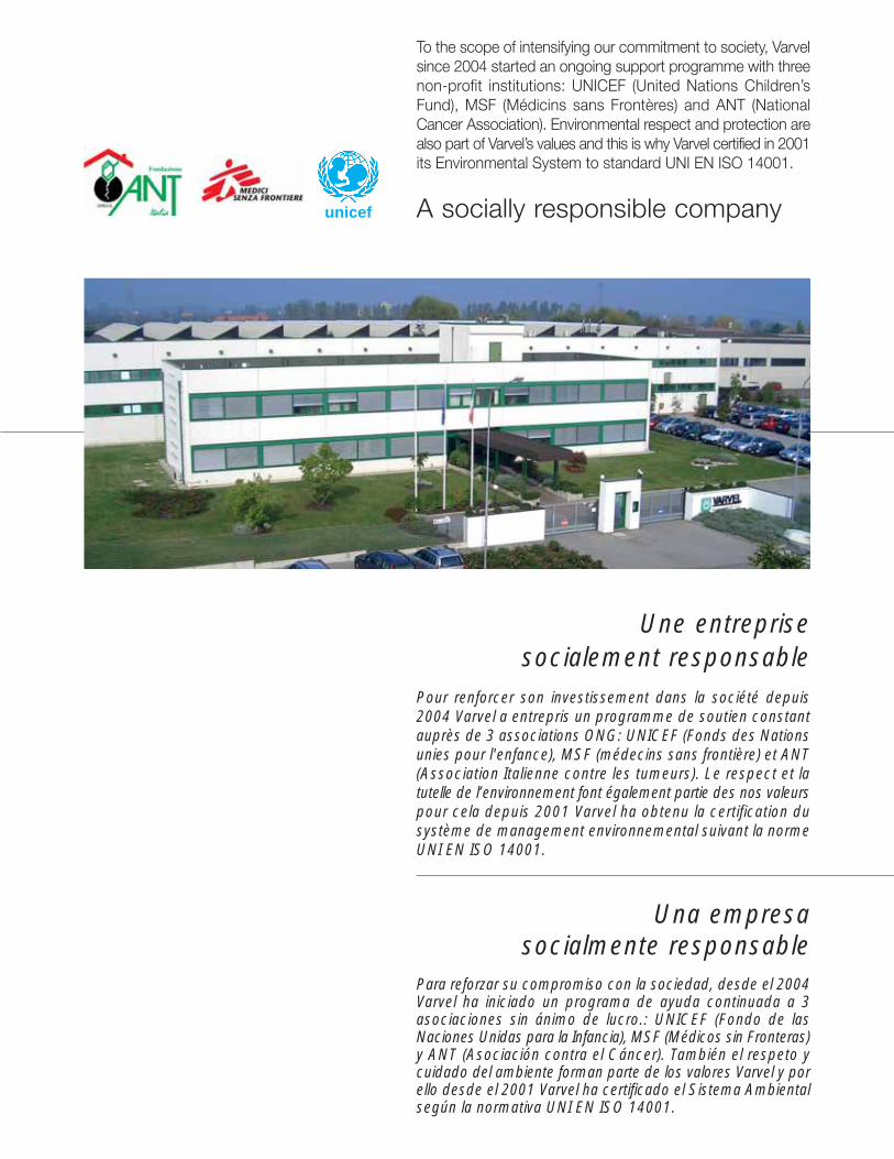
To the scope of intensifying our commitment to society, Varvelsince 2004 started an ongoing support programme with threenon-profit institutions: UNICEF (United Nations Children’sFund), MSF (Médicins sans Frontères) and ANT (NationalCancer Association). Environmental respect and protection arealso part of Varvel’s values and this is why Varvel certified in 2001its Environmental System to standard UNI EN ISO 14001.
A socially responsible company
Una empresasocialmente responsable
Para reforzar su compromiso con la sociedad, desde el 2004Varvel ha iniciado un programa de ayuda continuada a 3asociaciones sin ánimo de lucro.: UNICEF (Fondo de lasNaciones Unidas para la Infancia), MSF (Médicos sin Fronteras)y ANT (Asociación contra el Cáncer). También el respeto ycuidado del ambiente forman parte de los valores Varvel y porello desde el 2001 Varvel ha certificado el Sistema Ambientalsegún la normativa UNI EN ISO 14001.
Une entreprisesocialement responsable
Pour renforcer son investissement dans la société depuis2004 Varvel a entrepris un programme de soutien constantauprès de 3 associations ONG: UNICEF (Fonds des Nationsunies pour l'enfance), MSF (médecins sans frontière) et ANT(Association Italienne contre les tumeurs). Le respect et latutelle de l’environnement font également partie des nos valeurspour cela depuis 2001 Varvel ha obtenu la certification dusystème de management environnemental suivant la normeUNI EN ISO 14001.

Local Distributor Varvel SpA
Via 2 Agosto 1980, 9
40056 Crespellano (BO) Italy
� +39 051 6721811
+39 051 6721825
www.varvel.com
Other catalogues
RN/RO/RV
RS/RT
RG
RP
VR/VS