Compact Controller for Industrial and Marine Applications...
21
ComAp a.s. Kundratka 2359/17, 180 00 Praha 8, Czech Republic Tel: +420 246 012 111, Fax: +420 266 316 647 E-mail: [email protected], www.comap.cz Copyright © 2004-2013 ComAp a.s. Written by Ladislav Kadanik, Vladimir Sebian and Pavel Doubek Prague, Czech Republic Operator guide Compact Controller for Industrial and Marine Applications InteliDrive DCU Expandable engine controller with electronic engines support Industrial Applications: SS and AS Marine Applications: AUX, EME, CMB and PRP January 2013 version r2
Transcript of Compact Controller for Industrial and Marine Applications...

ComAp a.s.Kundratka 2359/17, 180 00 Praha 8, Czech RepublicTel: +420 246 012 111, Fax: +420 266 316 647E-mail: [email protected], www.comap.cz
Copyright © 2004-2013 ComAp a.s.Written by Ladislav Kadanik, Vladimir Sebian and Pavel DoubekPrague, Czech Republic
Operator guide
Compact Controller for Industrial and Marine Applications
InteliDrive DCUExpandable engine controller
with electronic engines support
Industrial Applications: SS and ASMarine Applications: AUX, EME, CMB and PRP
January 2013 version r2

Table of Contents
Table of Contents............................................................................................................................................. 2Abbreviations ................................................................................................................................................... 3Conformity declaration...................................................................................................................................... 5General description........................................................................................................................................... 6Manuals............................................................................................................................................................ 7Operator Interface ............................................................................................................................................ 8
Pushbuttons and LEDs................................................................................................................................. 8How to select engine mode?........................................................................................................................9Display menus.............................................................................................................................................. 9How to view measured data?....................................................................................................................... 9How to view and edit set points?..................................................................................................................9How to view the HISTORY menu?...............................................................................................................9How to change the display contrast?............................................................................................................9How to check the serial number and software revision?.............................................................................10How to change the display backlight intensity?..........................................................................................10How to change controller language?..........................................................................................................10How to find active alarms ?........................................................................................................................ 10Controller screens...................................................................................................................................... 11Functions available from ID-DCU front panel keys.....................................................................................14
Alarm management........................................................................................................................................ 15Warning...................................................................................................................................................... 15Shut down.................................................................................................................................................. 15Cool down.................................................................................................................................................. 15Sensor fail.................................................................................................................................................. 15
Controller monitoring...................................................................................................................................... 17Direct connection to the PC........................................................................................................................ 17DriveMonitor............................................................................................................................................... 17DriveMonitor screen example (ID-DCU-Industrial, SS)...............................................................................19Password protection................................................................................................................................... 20Modbus protocol......................................................................................................................................... 20
Technical data................................................................................................................................................ 21ID-DCU....................................................................................................................................................... 21
InteliDrive-DCU - Operator Guide, ©ComAp – January 2013 - 2 -
ID-Operator_guide_r2.pdf

Abbreviations
aid Archive file extension for InteliDrive controller AIN Controller or extension module Analog inputAlarm General term for any active engine protection Warning, Shutdown, … etc.Alarm list Controller or PC DriveMonitor screen with list of active and unaccepted alarms
detected from ID controller.AS Controller All Speed modeECU Alarm list Controller or PC DriveMonitor screen with list of active and unaccepted alarms
detected from engine ECU.AOUT Controller Analog OUTput or outputs group.Archive Usually aid file that contains all controller data: configuration, setpoints setting and
history records.AUX Controller application (archive, operational mode) for Auxiliary engines.BI Controller binary input.BIN Controller binary inputs group. BO Controller binary output.BOUT Controller binary outputs group. CAN Control Area Network – serial data link.Cd Cool down protection, cooling period is included before engine stops.CMB Controller Combined mode.D+ Controller function for battery charging function check and/or engine running
indication.DC DriveConfig, PC software for InteliDrive configuration.DM DriveMonitor, PC software for InteliDrive monitoring.DriveConfig PC software for InteliDrive configuration.DriveMonitor PC software for InteliDrive monitoring.ECU Engine Electronic (injection) Control Unit.ECU alarm Alarm detected in engine electronic control unit that is received via J1939.EME InteliDrive Emergency operational mode.EMS I. Electronic Management System – version I.EMS II. Electronic Management System – version II.Fls Controller sensor fail alarm.FMI Failure Mode Identifier.GSM modem Modem for Global System of Mobile communicationHistory List of alarms and operational states with Reason, Date and Time and adjustable
values set that is stored in controller, can be listed from the screen or DriveMonitor.HRB Controller Harbor mode.I-CB Inteli - Communication bridge = controller interface for other electronic engines like
MTU, CAT etc.. that are not supported yet.ID InteliDrive controller. ID-COM InteliDrive communication module with interface to J1939, J1587 and to other
controllers.ID-DCU InteliDrive – DieselControlUnit.ID-MCU InteliDrive – Industrial Controller Unit with Volvo Penta front panel modification.ID-RPU InteliDrive – Redundancy Protection Unit = ID backup unit for Over speed and
Emergency stop protection in Marine applications. ID-SCM InteliDrive - Speed Control Module = interface unit for InteliDrive Industrial.IG-IB InteliGen – Internet Bridge = controller interface for internet communication.IGL-RA15 Remote Anunciator = external 15 LED indication panel (three colors, configurable).IG-MU InteliGen – Modem Unit = controller interface for multiple engines application – one
point communication with group or one point modem connection. IGS-PTM Controller extension module with 8 binary inputs and outputs and 4 analog inputs.I-RB Inteli Relay board = interface board with 16 free contact relays.
InteliDrive-DCU - Operator Guide, ©ComAp – January 2013 - 3 -
ID-Operator_guide_r2.pdf

I-RB16 Inteli Relay board = interface board with 16 free contact relays.I-RD Inteli Remote Display (Remote Panel) = the same panel like on controller, all data
received via CAN2 bus.I-RD-CAN Inteli Remote Display (Remote Panel) = the same panel like on controller, all data
received via CAN2 bus.I-RP Inteli Remote Display (Remote Panel) = the same panel like on controller, all data
received via CAN2 bus.IS-AIN8 InteliSys – Analog input module = extension module with 8 analog inputs.IS-BIN16/8 InteliSys – Binary input/output module = extension module with 16 binary inputs and
8 binary outputs.J1587 The J1587 bus is mainly used for redundant signals; system diagnosis and software
download on after market tools.J1587/J1708 See J1587J1939 The J1939 bus in mainly used for engine controls and engine monitoring.KWP2000 Scania Communication protocol.LOC Controller Local modemhx Extension for controller firmware (Motorola HeX file).MID Message Identification Assignments.OFF Controller mode when power supply is switched on, but all binary outputs and start
commands are disabled = engine start is blocked. PID Parameter Identification Assignments.PPID Proprietary Parameter Identification Assignments.PRP Controller application (archive, operational mode) for Propeller engines.RPM Engine Revolution Per Minute – engine speed.PCB Printed Circuit BoardPSID Proprietary Parameter Identification Assignments.RS232 Standard serial data line for PC or Modem connection (controller programming or
monitoring).Sd Shut down protection. SID Subsystem Identification Assignments.SPN Suspect Parameter NumberSS Controller Single Speed modeWrn Warning protection.
InteliDrive-DCU - Operator Guide, ©ComAp – January 2013 - 4 -
ID-Operator_guide_r2.pdf

Conformity declaration
Following described machine complies with the appropriate basic safety and health requirement of the EC Low Voltage Directive No: 73/23 / EEC and EC Electromagnetic Compatibility Directive 89/336 / EEC based on its design and type, as brought into circulation by us.
!!! CAUTION !!!Always properly connect grounding terminals!
Adjust set pointsAll parameters are preadjusted to their typical values. But the set points in the “Basic settings” settings group !!must!! be adjusted before the first startup of the gen-set.
!!! WRONG ADJUSTMENT OF BASIC PARAMETERS CAN DESTROY THE ENGINE !!!
The following instructions are for qualified personnel only.To avoid personal injury do not perform any action not specified in the User guides for ID-
DCU Marine or ID-DCU Industrial !!!
WARNING – VERY IMPORTANT !!!Be aware that the binary outputs can change state during and after software reprogramming. Before the controller is used again ensure that the proper configuration and setpoint settings
are set in the controller.
Disconnect the Binary outputs Starter and Fuel or press EMERGENCY STOP button to avoid unexpected automatic start of genset during any work or maintenance on the engine or switchboard.
Note:ComAp believes that all information provided herein is correct and reliable and reserves the right to update at any time. ComAp does not assume any responsibility for its use unless otherwise expressly undertaken.
InteliDrive-DCU - Operator Guide, ©ComAp – January 2013 - 5 -
ID-Operator_guide_r2.pdf
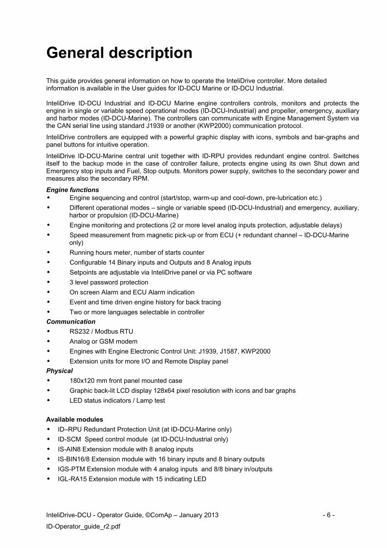
General description
This guide provides general information on how to operate the InteliDrive controller. More detailed information is available in the User guides for ID-DCU Marine or ID-DCU Industrial.
InteliDrive ID-DCU Industrial and ID-DCU Marine engine controllers controls, monitors and protects the engine in single or variable speed operational modes (ID-DCU-Industrial) and propeller, emergency, auxiliary and harbor modes (ID-DCU-Marine). The controllers can communicate with Engine Management System via the CAN serial line using standard J1939 or another (KWP2000) communication protocol.
InteliDrive controllers are equipped with a powerful graphic display with icons, symbols and bar-graphs and panel buttons for intuitive operation.
InteliDrive ID-DCU-Marine central unit together with ID-RPU provides redundant engine control. Switches itself to the backup mode in the case of controller failure, protects engine using its own Shut down and Emergency stop inputs and Fuel, Stop outputs. Monitors power supply, switches to the secondary power and measures also the secondary RPM.
Engine functions Engine sequencing and control (start/stop, warm-up and cool-down, pre-lubrication etc.)
Different operational modes – single or variable speed (ID-DCU-Industrial) and emergency, auxiliary, harbor or propulsion (ID-DCU-Marine)
Engine monitoring and protections (2 or more level analog inputs protection, adjustable delays)
Speed measurement from magnetic pick-up or from ECU (+ redundant channel – ID-DCU-Marine only)
Running hours meter, number of starts counter
Configurable 14 Binary inputs and Outputs and 8 Analog inputs
Setpoints are adjustable via InteliDrive panel or via PC software
3 level password protection
On screen Alarm and ECU Alarm indication
Event and time driven engine history for back tracing
Two or more languages selectable in controller
Communication
RS232 / Modbus RTU
Analog or GSM modem
Engines with Engine Electronic Control Unit: J1939, J1587, KWP2000
Extension units for more I/O and Remote Display panel
Physical
180x120 mm front panel mounted case
Graphic back-lit LCD display 128x64 pixel resolution with icons and bar graphs
LED status indicators / Lamp test
Available modules
ID–RPU Redundant Protection Unit (at ID-DCU-Marine only)
ID-SCM Speed control module (at ID-DCU-Industrial only)
IS-AIN8 Extension module with 8 analog inputs
IS-BIN16/8 Extension module with 16 binary inputs and 8 binary outputs
IGS-PTM Extension module with 4 analog inputs and 8/8 binary in/outputs
IGL-RA15 Extension module with 15 indicating LED
InteliDrive-DCU - Operator Guide, ©ComAp – January 2013 - 6 -
ID-Operator_guide_r2.pdf

Manuals
To download manuals according to the specific controller:1. Open http://www.comap.cz/ in your browser. To access manuals on ComAp website, please, register
in ComAp club2. Where to find documentation on web
Products / Engine controllers / InteliDrive-DCU (Marine) / Downloads / Manuals
Types of Documents on Web pageAll the documents are intended for everybody who is concerned with the installation, operation and maintenance of an engine application.
o Data Sheets describe basic technical specification and purpose of various types of controllers.o Getting Started Guide will help you to answer some basic questions that typically occur during the
first contact with engine controller.o User guide is Installation, Application and Reference guide in one book.o Communication Guides describe communication interface among controller(s) and superior
system. From this manual you can get information on all available types of communication.
o ComAp Electronic Engines Support describes all supported ECU, wiring and functionality.
InteliDrive-DCU - Operator Guide, ©ComAp – January 2013 - 7 -
ID-Operator_guide_r2.pdf

Operator Interface
Pushbuttons and LEDs
Pushbuttons and LED’s:1. MODE ► Cycle forward through engine operation modes OFF -> RUN (AUX, EME, HRB
and PRP in case of Marine version).2. MODE ◄ Cycle backward through engine operation modes OFF <- RUN (AUX, EME,
HRB and PRP in case of Marine version).3. HORN RESET Deactivates the HORN.4. FAULT RESET Acknowledges faults and alarms.5. START Starts the engine in SS or AS mode.6. STOP Stops the engine in SS or AS mode (hold time =1 sec).7. GREEN = Engine running.8. Flashing RED = Not acknowledged (new) alarm present in Alarm List.
Stable RED = Acknowledged alarm present in Alarm List.9. GREEN = On/Off output is active.
10. On/Off Button for Close load or Clutch Binary output control.11. PAGE Cycles through the display screens MEASUREMENT -> ADJUSTEMENT
->HISTORY.12. ▲ Select the set point, select the screen or increase set point value.13. ▼ Select the set point, select the screen or decrease set point value.14. ENTER Confirm set point value.
InteliDrive-DCU - Operator Guide, ©ComAp – January 2013 - 8 -
ID-Operator_guide_r2.pdf
3
11
12
13
14
2 1 45
6
7
8
9
10

How to select engine mode?Use MODE ► or MODE ◄ to select requested engine operation mode.
Hint:Switching to OFF mode is blocked on running engine.
Display menusThere are 4 display menus available: MEASUREMENT, External measurement, ADJUSTMENT and HISTORY.Each menu consists of several screens. Pressing the PAGE button repeatedly will scroll the user through the menu screens.
How to view measured data?Pressing the PAGE button repeatedly will scroll the user through the menu screens. Select the MEASUREMENT screen. Use ▲ or ▼ to select the screen with requested data.
How to view and edit set points?1. Pressing the PAGE button repeatedly will scroll the user through the menu screens. Select the
ADJUSTMENT screen.2. Use ▲ or ▼ to select requested set points group.3. Press ENTER to confirm.4. Use ▲ or ▼ to select requested set point.5. Set points marked “*” are password protected, necessary to input corresponding password first to
enable setpoint edit.6. Press ENTER to edit.7. Use ▲ or ▼ to modify the set point. When ▲ or ▼ is pressed for 2 sec, auto repeat function is
activated.8. Press ENTER to confirm or PAGE to leave without change.
Press PAGE to leave selected set points group.
Hint:Depending on the configuration of ID-DCU controller there can occur some PLC logic modules in configuration. Then the user can adjust them from “PLC” set point group.
How to view the HISTORY menu?1. Pressing the PAGE button repeatedly will scroll the user through the menu screens. Select the
HISTORY screen.2. Use ▲ or ▼ to select a requested record.3. Use ENTER to select requested screen (record items) within displayed records.
How to change the display contrast?Press ENTER and ▲ or ▼ at the same time to adjust the best display contrast.
Hint:Only in MEASUREMENT menu.
InteliDrive-DCU - Operator Guide, ©ComAp – January 2013 - 9 -
ID-Operator_guide_r2.pdf

How to check the serial number and software revision?Hold down the ENTER and the press PAGE. On the display you can see Controller INFO screen for 10 seconds:
Controller name (see Basic setting group)Controller serial number (8 character number)SW version: The firmware version number.Application: IDBranch: InteliDrive
Hint:Only in MEASUREMENT screen.
How to change the display backlight intensity?Press ENTER and ▲ or ▼ at the same time to adjust the best display backlight.
Hint:Only in INFO screen.
How to change controller language?Press PAGE on controller INFO screen to go to Language screen. Select language ▲ or ▼ and press ENTER to confirm selection and exit window.
How to find active alarms ?Active alarm list and J1939 alarm list are the last two screens in the MEASUREMENT menu.Select MEASUREMENT menu. Press ▲ ( ▲ ). You will see the list of all active alarms with the number of alarms at the top-right corner. Inverted alarms are still active. Non-inverted alarms are not active, but not yet confirmed.Press FAULT RESET accepts all alarms in case if Industrial version and accepts just displayed alarms in case of Marine version. Non-active alarms immediately disappear from the list.Active alarm list appears on the screen when a new alarm comes up and Main MEASUREMENT screen is active.
Hint:Alarm list does not activate when you are reviewing the values, parameters or history.
InteliDrive-DCU - Operator Guide, ©ComAp – January 2013 - 10 -
ID-Operator_guide_r2.pdf
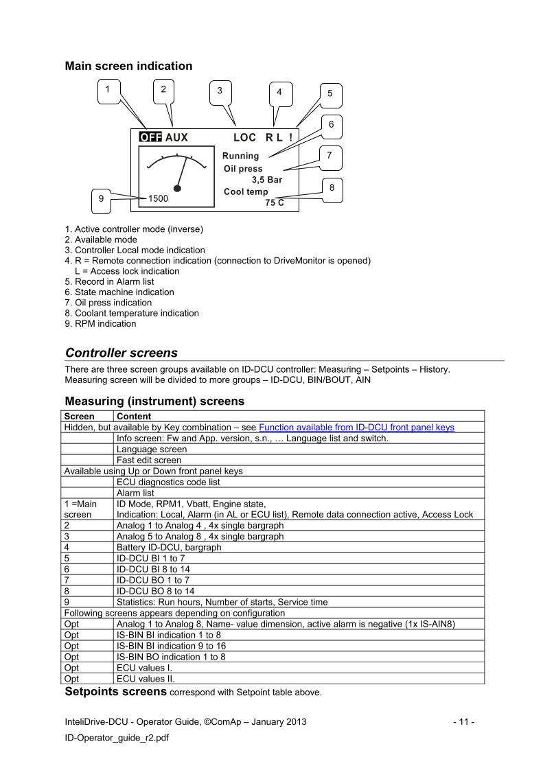
Main screen indication
OFF AUX LOC R L !
Running
Oil press 3,5 BarCool temp
75 C1500
1. Active controller mode (inverse)2. Available mode3. Controller Local mode indication4. R = Remote connection indication (connection to DriveMonitor is opened) L = Access lock indication5. Record in Alarm list6. State machine indication7. Oil press indication8. Coolant temperature indication 9. RPM indication
Controller screensThere are three screen groups available on ID-DCU controller: Measuring – Setpoints – History. Measuring screen will be divided to more groups – ID-DCU, BIN/BOUT, AIN
Measuring (instrument) screensScreen ContentHidden, but available by Key combination – see Function available from ID-DCU front panel keys
Info screen: Fw and App. version, s.n., … Language list and switch.Language screenFast edit screen
Available using Up or Down front panel keysECU diagnostics code listAlarm list
1 =Main screen
ID Mode, RPM1, Vbatt, Engine state, Indication: Local, Alarm (in AL or ECU list), Remote data connection active, Access Lock
2 Analog 1 to Analog 4 , 4x single bargraph3 Analog 5 to Analog 8 , 4x single bargraph4 Battery ID-DCU, bargraph5 ID-DCU BI 1 to 76 ID-DCU BI 8 to 147 ID-DCU BO 1 to 78 ID-DCU BO 8 to 149 Statistics: Run hours, Number of starts, Service timeFollowing screens appears depending on configurationOpt Analog 1 to Analog 8, Name- value dimension, active alarm is negative (1x IS-AIN8)Opt IS-BIN BI indication 1 to 8Opt IS-BIN BI indication 9 to 16Opt IS-BIN BO indication 1 to 8Opt ECU values I.Opt ECU values II.
Setpoints screens correspond with Setpoint table above.
InteliDrive-DCU - Operator Guide, ©ComAp – January 2013 - 11 -
ID-Operator_guide_r2.pdf
321 4 5
7
89
6

Alarm, ECU Alarm list screenSee the Alarm management chapter
Info screenInfo CommentCBH InteliDrive Product type ComAp 2003 – 2013 Company name
ID-DCU-Industrial Controller name
Serial: 0200FFFF Controller serial numberSw ver: 3.0 Software version Appl: SS ApplicationBranch: DCU Industrial Customer branch
Statistic valuesIt is calculated:
1 Number of starts Each successful start (starter is switched off due to RPM> Starting RPM) is calculated. External (manual) engine start
2 Running hours Each finished 60 minutes when engine is running.3 Number of unsuccessful starts Each finished cranking due to MaxCrank time is over
Statistic values can be adjusted from DriveMonitor, password 3 level protected.
History recordsFollowing table does not contain Wrn, Sd and Fls messages from external units.
Events specification Protection type
Information available on binary output
AlarmsWrn Analog input 1 to 8 WRN YESSd Analog input 1 to 8 SD YESID-DCU Binary input 1 to 14 Configurable YES
ID-DCU Battery voltage <, > WRN YES
Battery flat WRNStart fail WRN YESParamFail NONEOverspeed SD YESUnderspeed WRN YESEmergencyStop SDPickup fail WRNStop fail WRN YESWrnServiceTime WRNChrgAlternFail WRN YESFault resetLocal mode ON YESLocal mode OFF Harbour mode ON YESHarbour mode OFFSecBattery YESEmergency stop
InteliDrive-DCU - Operator Guide, ©ComAp – January 2013 - 12 -
ID-Operator_guide_r2.pdf

Engine events NoteStartsButton start Start from ID panelCAN control + Button start Start from ID RDRS232 control + Button start Start from DriveMonitorRemote start Start from BIStopsEngine stop Stop from ID panel or BICAN control + Engine stop Stop from ID RDRS232 control + Engine stop Stop from DriveMonitorRemote start ID-DCU binary inputBlackout start ID-DCU binary input
Button start ID-DCU panel buttonFault reset ID-DCU panel buttonLocal mode ON ID-DCU panel buttonLocal mode OFF ID-DCU panel buttonHRB mode ON ID-DCU panel buttonHRB mode OFF ID-DCU panel button
RS232 control Start, Stop, Fault reset, On/Off button from DriveMonitor or I-RD
Modem control Start, Stop, Fault reset, On/Off from Modem
SMS control Received command from GSM modemCAN control Received command via CAN bus e.g.
from I-RD or IG-MUActCallCH1-OK Successful active call on channel 1ActCallCH2-OK Successful active call on channel 2ActCallCH3-OK Successful active call on channel 3Extern start Manual engine starter handling.Engine stop Engine changed state from Emerg.man ON Emergency manual mode ONEmerg.man OFF Emergency manual mode OFFClutch ON Binary output clutch was closedClutch OFF Binary output clutch was openedStop button ID-DCU panel button
Switched on Controller was switched onCfg loaded Configuration archive was changedFwLoaded Firmware upgradeTime stamp Depends on setpoint setting periodPassword set Any level from any terminalPassword changed Any level from any terminalAccess set Access code was setAccess changed Access code was changedWatchdog Controller internal watchdog protectionParam fail Setpoints checksum failRTC battery RTC battery fail
Hint:Value name can’t exceed 11 characters to be recorded to History file with prefix (Wrn, Fls etc..). Longer names characters are canceled.
InteliDrive-DCU - Operator Guide, ©ComAp – January 2013 - 13 -
ID-Operator_guide_r2.pdf
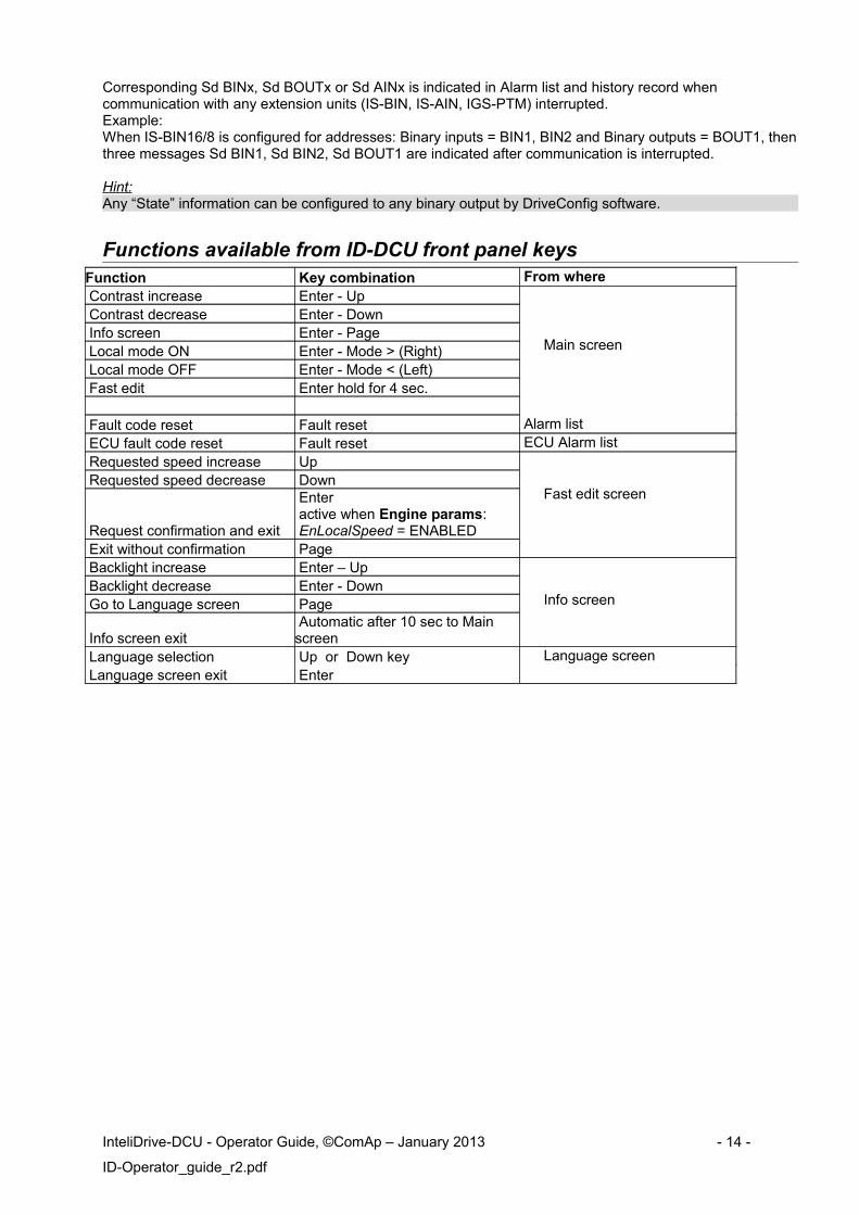
Corresponding Sd BINx, Sd BOUTx or Sd AINx is indicated in Alarm list and history record when communication with any extension units (IS-BIN, IS-AIN, IGS-PTM) interrupted. Example: When IS-BIN16/8 is configured for addresses: Binary inputs = BIN1, BIN2 and Binary outputs = BOUT1, then three messages Sd BIN1, Sd BIN2, Sd BOUT1 are indicated after communication is interrupted.
Hint:Any “State” information can be configured to any binary output by DriveConfig software.
Functions available from ID-DCU front panel keysFunction Key combination From where Contrast increase Enter - Up
Main screen
Contrast decrease Enter - Down Info screen Enter - Page Local mode ON Enter - Mode > (Right) Local mode OFF Enter - Mode < (Left) Fast edit Enter hold for 4 sec.
Fault code reset Fault reset Alarm list ECU fault code reset Fault reset ECU Alarm list Requested speed increase Up
Fast edit screen Requested speed decrease Down
Request confirmation and exit
Enter active when Engine params: EnLocalSpeed = ENABLED
Exit without confirmation Page Backlight increase Enter – Up
Info screen Backlight decrease Enter - Down Go to Language screen Page
Info screen exit Automatic after 10 sec to Main screen
Language selection Up or Down key Language screen Language screen exit Enter
InteliDrive-DCU - Operator Guide, ©ComAp – January 2013 - 14 -
ID-Operator_guide_r2.pdf

Alarm management
Following alarms are available in InteliDrive-DCU:
Binary alarms Analog alarmsNo protection NoneWarning WarningShutdown Sensor failCool down Wrn+shut downSensor fail Wrn+cool downWarning + BW Alarm onlyShutdown + BW HisRecOnlyWarning + Fls
A new record containing selected values is written to the history file in the moment of any alarm comes up.Detection of each binary input alarm is fix 1 sec time delayed.Use DriveConfig to modify binary or analog inputs.
WarningWhen warning comes up, only alarm outputs are closed.Possible warnings:
Binary inputs configured as Warning (alarms are displayed and stored under configured name)Analog inputs configured as Warning (alarms are displayed and stored under configured name)Battery voltage alarm level
Shut downWhen a shutdown occurs, InteliDrive-DCU opens outputs FUEL SOLENOID, STARTER.Possible shut-down alarms:
Over speedUnder speedStart failBinary inputs configured as Shut down (alarms are displayed and stored under configured name)Analog inputs configured as Shut down (alarms are displayed and stored under configured name)
Cool downWhen the cool down alarm comes up InteliDrive unloads engine, waits for Cooling time and opens FUEL SOLENOID output.Binary inputs configured as Cooldown (alarms are displayed and stored under configured name)
Sensor failSensor fail Fls is detected when measured value is 6,2 percent out of range. The controller screen will display #### instead of the measured value.
InteliDrive-DCU - Operator Guide, ©ComAp – January 2013 - 15 -
ID-Operator_guide_r2.pdf

Alarms indication There can be following actions when Alarm is active (depends on Alarm type and configuration): Alarm list record History list record Active call (when is enabled and modem is installed) Controller front panel LED indication Binary output ALARM is closed when Alarm is active or when was deactivated and FAULT RESET
button was not pressed to confirm. Binary output ALARM opens when Alarm was deactivated (no other Alarm is active) and FAULT RESET button was pressed to confirm.
Binary output HORN is closed for adjustable time when any new Alarm occurs. Corresponding value reading (binary input state, analog input value, generator voltage, .. ) is inverse
(e.g. 100 ) on InteliDrive screen when value is out of limits (binary input protection is active).
Broken wireBroken wire (BW) alarm is indicated on ID-RPU module only.
Alarm indicationAlarm list and History record prefixes
Prefix MeaningWrn WarningSd ShutdownCd CooldownBw Broken wireFls Sensor fail
Three state Alarm list indication
* Wrn Water temp Active not accepted alarm Wrn Water temp Active accepted alarm* Wrn Water temp Inactive not accepted alarm
Inactive accepted alarm
ECU Alarm list - SPN/FMI codes screen ECU Alarm list displays alarms from ECU unit of the engine. In the case there is no SPN translation available, the SPN number is displayed only.
E n g O i l P r e s s W R NB o o s t P r e s s F L SE n g O i l T e m p F L S6 2 9 F L S
> C o n t r o l l e r # 1E n g C o o l T e m p W R N
F C : 1 1 0 O C : 7 F M I : 3
InteliDrive-DCU - Operator Guide, ©ComAp – January 2013 - 16 -
ID-Operator_guide_r2.pdf

Controller monitoring
InteliDrive sw pack contains separate PC software tools: DriveConfig (DC) and DriveMonitor (DM). Drive Monitor is meant to be monitoring tool for remote controller connection.DriveMonitor is based on Windows 95/98/NT/ME/2000/XP or higher platform and requires 50 MB of hard disc free space.
Direct connection to the PCInteliDrive can be connected directly with PC via RS232 interface. Use the standard cable RS232 cable to connect PC with InteliDrive controller.Hint:Make sure the grounding system on controller and PC – COM port (negative of the PC DC supply) are identical – before the first direct connection. There must not be any voltage between these two points otherwise the internal PTC protection activates and interrupts RS232 communication. In such case disconnect RS232 line wait a minute for PTC recovery and try again. The simple solution is to assure, that the PC supply 240/20V is ground free (GND terminal is not connected).
5 - GND
2 - RxD3 - TxD
PC
5 - GND
2 - RxD3 - TxD
RS
232
RS
232
230 VAC
0 V
DC
CONTROLLER
+-Battery
Required the samevoltage potentialbetween GND‘s
RS 232
DriveMonitor
Functions On-line direct, Modem or Internet connection to one engine Active Modem or Internet call from engine to PC (activated by selected Alarm) Continuous one engine monitoring in on-line connection On-line or Off-line History record listing Setpoints listing and adjusting (password protected) Statistics value (e.g. Running hours) Set/Reset Password and Access code change
InteliDrive-DCU - Operator Guide, ©ComAp – January 2013 - 17 -
ID-Operator_guide_r2.pdf

Connection type
Direct connection via RS232 (up to 10m). For longer distance use RS232/RS485 converters (e.g. ADVANTECH – ADAM 4520).Modem connection via Analog, ISDN or GSM modem.
Internet via IG-IB (InteliGen internet interface unit). IG-IB Internet - Ethernet or Dial-up connection is available.
Active call (via modem). Controller calls to the preselected telephone number and sends the AID file when active call is activated. To receive AID file the DriveMonitor must be in Active call waiting window. Off line connection enables open and list Application AID file stored in PC.
Hint:More detail regarding different types of connection see in IG-IS Communication guide.
Control window: displays all ID-DCU and I/O states, enables engine control. ID-RPU window … not available in Industrial version
Setpoints: listing and adjusting
Values: reading of all I/O include external modules
History list: complete history list.
InteliDrive-DCU - Operator Guide, ©ComAp – January 2013 - 18 -
ID-Operator_guide_r2.pdf
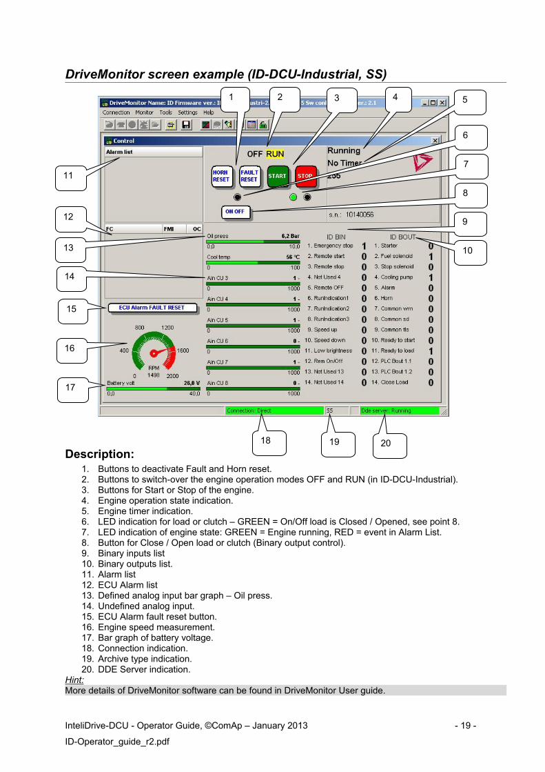
DriveMonitor screen example (ID-DCU-Industrial, SS)
Description:1. Buttons to deactivate Fault and Horn reset.2. Buttons to switch-over the engine operation modes OFF and RUN (in ID-DCU-Industrial).3. Buttons for Start or Stop of the engine.4. Engine operation state indication.5. Engine timer indication.6. LED indication for load or clutch – GREEN = On/Off load is Closed / Opened, see point 8.7. LED indication of engine state: GREEN = Engine running, RED = event in Alarm List.8. Button for Close / Open load or clutch (Binary output control).9. Binary inputs list10. Binary outputs list.11. Alarm list12. ECU Alarm list13. Defined analog input bar graph – Oil press.14. Undefined analog input.15. ECU Alarm fault reset button.16. Engine speed measurement.17. Bar graph of battery voltage.18. Connection indication.19. Archive type indication.20. DDE Server indication.
Hint:More details of DriveMonitor software can be found in DriveMonitor User guide.
InteliDrive-DCU - Operator Guide, ©ComAp – January 2013 - 19 -
ID-Operator_guide_r2.pdf
1
11
12
16
17
2 3 4 5
9
1013
14
15
18 19 20
6
7
8

Password protectionPassword is a four-digit number. Only setpoints associated with the entered password level can be modified.
There are three levels of password protection:0. User level allows change of non-protected setpoints only1. Operator level allows change of setpoints protected by Operator level 1.2. Master level allows change of setpoints protected by Operator 1. and Master level 2.3. Supervisor highest level allows all setpoints or configuration changes, firmware upgrade.
There can be password protected: Setpoints (depends on configuration) Statistics values (Level 3 only) Engine commands (depends on configuration)
Even though one level may have been set from the front panel, the affected setpoints are notaccessible from DriveMonitor (direct or Modem) until this level is set in DriveMonitor (direct or Modem).Setpoints opened from front panel are automatically closed 15 minutes after the last key has beendepressed or when wrong value of password is set.
Password is a four-digit number. Only setpoints associated with the entered password level can bemodified.
Any password can be changed once that level password or higher has been entered.
Modbus protocol Direct connection: RS232, RS422, RS485 Modem connection 9600, 19200 or 38400 bps, 8 data bits, 1 stop bit, no parity Transfer mode RTU Function 3 (Read Multiply Registers) Function 6 (Write Single Register) Function 16 (Write Multiply Registers) The response to an incoming message is sent with minimum 4.096 ms delay after message reception
The complete description of Modbus communication protocol can be found in Modbus Protocol Reference Guide PI-MBUS-300 and Open Modbus Specification Release 1.0. Both documents are available from web site at http://www.modicon.com/openmbus/ .
Modbus Multipack messageIt is special communication object that contains all values that are used for History record (configurable) and can be read by one command.
Hint:Detail Modbus command description see in ComAp Communication guide.
Communication object vs. RegisterAll the data intended for communication has its representation as communication objects in the controller. The communication object is represented by the n-byte array in the controller memory and identified by the unique 16-bit communication object number. The register, according to Modbus communication protocol, represents a two-byte data and in communication functions is referenced by 16-bit register address. Further in the description of communication functions the communication object number will always be used as a register address and length of the communication object will be expressed by number of registers. Just one communication object can be read or written by one communication function.Hint:It is possible to download the Actual InteliDrive controller object description corresponding to actual configuration from on-line controller or from aid archive using DriveConfig software.
InteliDrive-DCU - Operator Guide, ©ComAp – January 2013 - 20 -
ID-Operator_guide_r2.pdf

Technical data
ID-DCU
Power supplyVoltage range 8-36V DCCurrent consumption (depends on supply voltage) 0,34A at 8VDC
0,12A at 24VDC 0,09A at 36VDC
Battery voltage measurement tolerance 2 % at 24VRTC battery life-cycle 10 yearHint:RTC battery flat causes wrong Date&Time information only.
Operating conditionsOperating temperature ID-DCU -20 to +70 °COperating temperature ID-DCU-LT -40 to +70 °CStorage temperature -30 to +80 °CHumidity 95% without condensationFlash memory data retention time 10 yearsProtection front panel IP65Standard conformityLow Voltage Directive EN 61010-1:95 +A1:97Electromagnetic Compatibility EN 61000-6-2, October 2001
EN 61000-6-4, October 2001 IEC 60533, Ed. 2; 1999-11
Vibration 5 - 25 Hz, ±1,6mm25 - 100 Hz, a = 4 g
Shocks a = 200 m/s2
Dimensions and weightDimensions (183x123x47mm)
See chapter terminals and dimensionsWeight 800g
InteliDrive-DCU - Operator Guide, ©ComAp – January 2013 - 21 -
ID-Operator_guide_r2.pdf