Commercial Kitchen Hoods Installation, Operation, … Kitchen Hoods Installation, Operation, ... The...
40
A0011051 August 2014 Rev. 12 Commercial Kitchen Hoods Installation, Operation, and Maintenance Manual Save these instructions. This document is the property of the owner of this equipment and is required for future maintenance. Leave this document with the owner when installation or service is complete. RECEIVING AND INSPECTION Upon receiving unit, check for any interior and exterior damage, and if found, report it immediately to the carrier. Also check that all accessory items are accounted for and are damage free. WARNING!! Installation of this unit should only be performed by a qualified professional who has read and understands these instructions and is familiar with proper safety precautions. Read this manual thoroughly before installing or servicing this equipment.
Transcript of Commercial Kitchen Hoods Installation, Operation, … Kitchen Hoods Installation, Operation, ... The...
A0011051 August 2014 Rev. 12
Commercial Kitchen Hoods
Installation, Operation, and Maintenance Manual
Save these instructions . This document is the property of the owner of this equipment and is required for future maintenance. Leave this document with the owner when installation or service is complete.
RECEIVING AND INSPECTION Upon receiving unit, check for any interior and ext erior damage, and if found, report it immediately to the carrier. Also check that all ac cessory items are accounted for and are damage free.
WARNING!!
Installation of this unit should only be performed by a qualified professional who has read and understands these instructions and is familiar with proper safety precautions. Read this manual thoroughly before installing or servicing this equi pment.


3
TABLE OF CONTENTS
WARRANTY .................................................................................................................................................. 4
LISTINGS ...................................................................................................................................................... 5
INSTALLATION ............................................................................................................................................. 5
Site Preparation ........................................................................................................................................ 5
Clearance Reduction Methods ................................................................................................................. 6
Installation of a Single Hood (Wall or Island) ............................................................................................ 7
Basic Hanging Angle ............................................................................................................................ 9
Full Length Hanging Angle ................................................................................................................... 9
Corner Hanging Angle ........................................................................................................................ 10
PSP Hanging Angle ............................................................................................................................ 10
Side View of Typical Hood ................................................................................................................. 11
End-to-End Hoods .................................................................................................................................. 11
Hanging Detail for Multiple Hood Models Hung End-to-End (Hemmed Ends) .................................. 12
Hanging Detail for Multiple Hood Models Hung End-to-End (Flanged Ends) .................................... 12
Hood Connection Detail for Multiple Hood Models (Hemmed Ends with Trim Strip) ......................... 13
Hood Connection Detail for Multiple Hood Models (Flanged Ends w/out Trim Strip) ........................ 13
Back-to-Back Hoods ............................................................................................................................... 14
Hanging Detail for Hoods Hung Back-to-Back ................................................................................... 14
Guidelines for Ductwork Installation ....................................................................................................... 15
Installation of Hood Accessories............................................................................................................. 16
Back Return Installation ..................................................................................................................... 16
Bolt-Together Standoff Installation ..................................................................................................... 18
Back and Side PSP (Perforated Supply Plenum) Installation ............................................................ 19
AC-PSP Installation ............................................................................................................................ 20
Wrapper (Enclosure Panel) Installation .............................................................................................. 22
End-panel Installation ......................................................................................................................... 26
Quarter End panel Installation ............................................................................................................ 27
Insulated End panel Installation ......................................................................................................... 28
Vertical End panel Installation ............................................................................................................ 29
Backsplash Installation ....................................................................................................................... 30
OPERATION ............................................................................................................................................... 32
Performance Evaluation ......................................................................................................................... 32
Guidelines before Beginning .............................................................................................................. 32
External Factors which may affect Hood Performance ...................................................................... 33
Using a Shortridge Instrument ............................................................................................................ 33
Calculating Make-up Air CFM with a Shortridge Instrument and Spreadsheet ................................. 34
Calculating Make-up Air CFM without a Shortridge Instrument ......................................................... 34
Calculating Exhaust Air CFM with a Shortridge Instrument and Spreadsheet .................................. 34
Calculating Exhaust CFM without a Shortridge Instrument................................................................ 34
Adjustments ........................................................................................................................................ 35
Conclusion .......................................................................................................................................... 35
Complete Equipment List for Performance Evaluations..................................................................... 35
Troubleshooting ...................................................................................................................................... 36
Troubleshooting Chart ........................................................................................................................ 36
MAINTENANCE .......................................................................................................................................... 37
General Maintenance ............................................................................................................................. 37
Daily Maintenance .................................................................................................................................. 37
Quarterly Maintenance ........................................................................................................................... 37
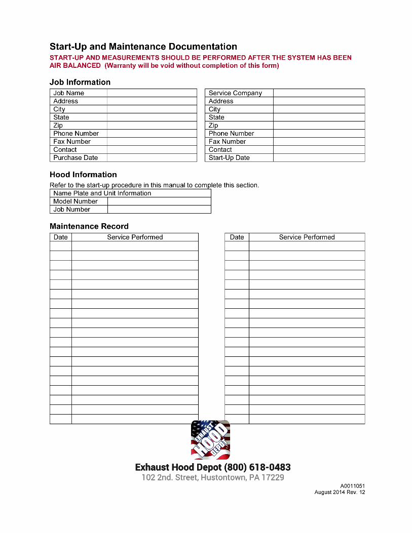
Start-Up and Maintenance Documentation ............................................................................................ 40
Job Information ................................................................................................................................... 40
Hood Information ................................................................................................................................ 40
Maintenance Record .......................................................................................................................... 40
Factory Service Department ............................................................................................................... 40
4
WARRANTY This equipment is warranted to be free from defects in materials and workmanship, under normal use and service, for a period of 12 months from date of shipment. This warranty shall not apply if:
1. The equipment is not installed by a qualified installer per the MANUFACTURER’S installation instructions shipped with the product,
2. The equipment is not installed in accordance with federal, state and local codes and regulations, 3. The equipment is misused or neglected, 4. The equipment is not operated within its published capacity, 5. The invoice is not paid within the terms of the sales agreement.
The MANUFACTURER shall not be liable for incidental and consequential losses and damages potentially attributable to malfunctioning equipment. Should any part of the equipment prove to be defective in material or workmanship within the 12-month warranty period, upon examination by the MANUFACTURER, such part will be repaired or replaced by MANUFACTURER at no charge. The BUYER shall pay all labor costs incurred in connection with such repair or replacement. Equipment shall not be returned without MANUFACTURER’S prior authorization and all returned equipment shall be shipped by the BUYER, freight prepaid to a destination determined by the MANUFACTURER.
5
LISTINGS This hood is ETL-listed to standard UL710 when installed in accordance with these installation instructions and National Fire Protection Association Standard “NFPA 96, Standard for Ventilation Control and Fire Protection of Commercial Cooking Operations.”
INSTALLATION It is imperative that this unit is installed and operated with the designed airflow, filters and construction in accordance with this manual. If there are any questions about any items, please call the service department at 1-866-784-6900 for warranty and technical support issues. WARNING: IMPROPER INSTALLATION, ADJUSTMENT, ALTERAT ION, SERVICE OR MAINTAINANCE CAN CAUSE PROPERTY DAMAGE, INJURY O R DEATH. READ THE INSTALLATION, OPERATION AND MAINTENANCE INSTRUC TIONS THOROUGHLY BEFORE INSTALLING OR SERVICING THIS EQUI PMENT.
Site Preparation
1. Provide clearance around installation site to safely rig and lift equipment into its final position. Consider general service and installation space when locating unit.
2. Locate unit close to the space it will serve to reduce long, twisted duct runs. 3. Thoroughly review the plans and specifications of the project. 4. Determine the exact location in which the cooking hood will be installed and verify that there are
no interferences which will prevent proper installation. 5. Verify that all overhead beams and angles are structurally strong enough to support the weight of
the hood and hanging system. It is often necessary to strengthen existing structural beams, as they are not designed to carry the weight of a stainless steel hood. Refer to the project submittal drawing for hood weight(s). It may also be necessary to create a support structure suspended from the ceiling joists to better align with the desired hood location.
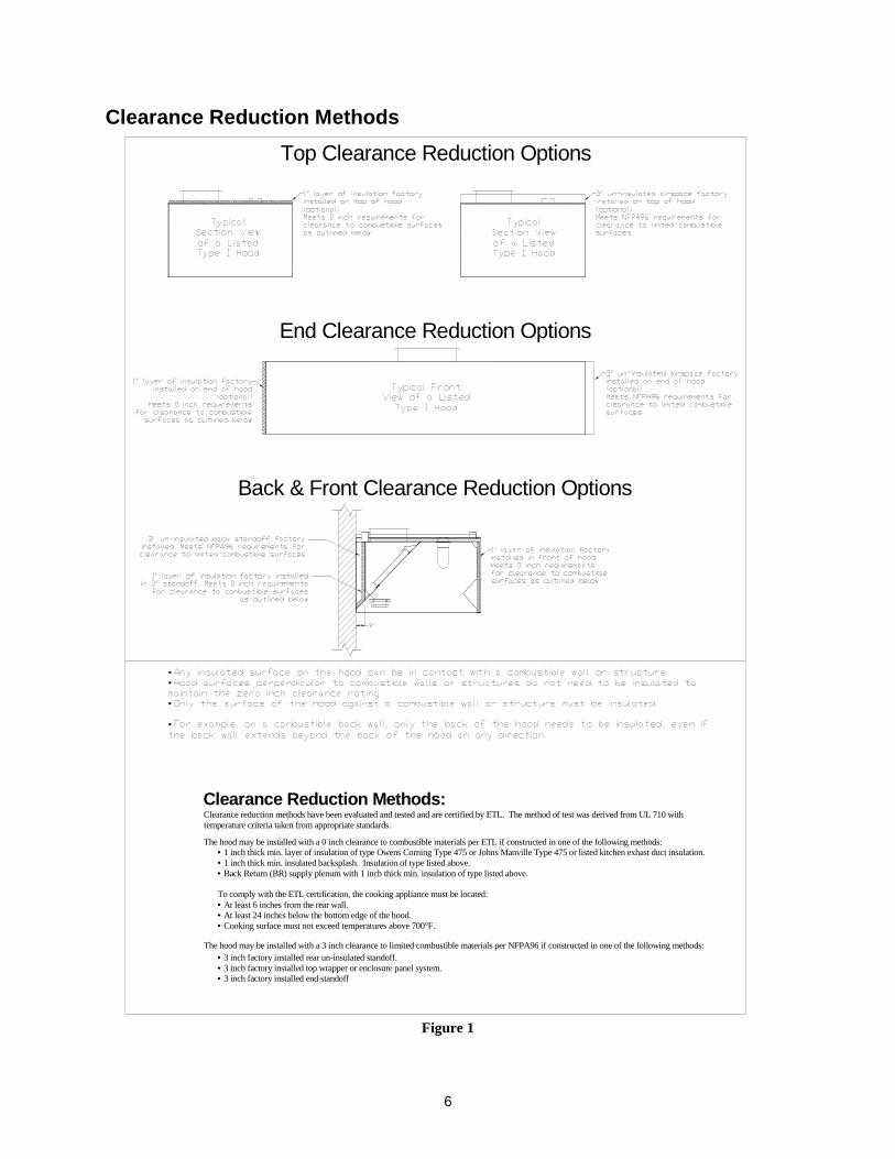
6. Determine if adequate room is available to install the hood and all ductwork with proper clearances from combustible material. IMC, NFPA96 and local authorities having jurisdiction call for a minimum clearance (typically 18 inches for type 1, grease rated hoods) between the cooking hood(s), exhaust ducts, and building materials which are combustible. However, IMC and NFPA96 outline acceptable clearance reduction methods; most authorities accept the clearance reduction methods approved in the manufac turer’s ETL listing for Type 1, grease rated hoods. See Figure 1 . It is important to check with the local authority having jurisdiction to determine that the installation method is satisfactory to meet their requirements prior to installing the equipment.
FOLLOW SMACNA GUIDES AND RE COMMENDATIONS FOR THE HANGING AND INSTALLATION OF HOODS.
6
Clearance Reduction Methods
• •
•
•
The hood may be installed with a 0 inch clearance to combustible materials per ETL if constructed in one of the following methods:
Clearance reduction methods have been evaluated and tested and are certified by ETL. The method of test was derived from UL 710 with temperature criteria taken from appropriate standards.
The hood may be installed with a 3 inch clearance to limited combustible materials per NFPA96 if constructed in one of the following methods:• 3 inch factory installed rear un-insulated standoff.• 3 inch factory installed top wrapper or enclosure panel system.• 3 inch factory installed end standoff
• 1 inch thick min. layer of insulation of type Owens Corning Type 475 or Johns Manville Type 475 or listed kitchen exhast duct insulation.• 1 inch thick min. insulated backsplash. Insulation of type listed above.• Back Return (BR) supply plenum with 1 inch thick min. insulation of type listed above.
To comply with the ETL certification, the cooking appliance must be located:• At least 6 inches from the rear wall.• At least 24 inches below the bottom edge of the hood.• Cooking surface must not exceed temperatures above 700°F.
Clearance Reduction Methods:
Back & Front Clearance Reduction Options
End Clearance Reduction Options
Top Clearance Reduction Options
Figure 1
7
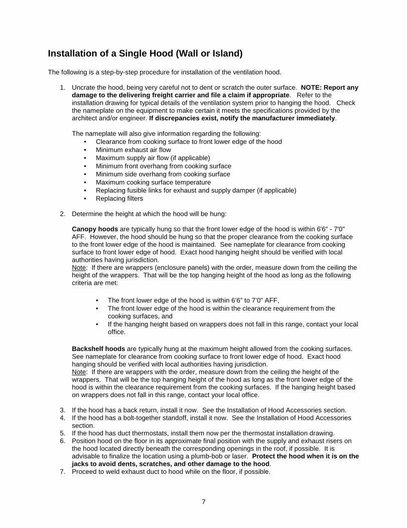
Installation of a Single Hood (Wall or Island) The following is a step-by-step procedure for installation of the ventilation hood.
1. Uncrate the hood, being very careful not to dent or scratch the outer surface. NOTE: Report any damage to the delivering freight carrier and file a claim if appropriate . Refer to the installation drawing for typical details of the ventilation system prior to hanging the hood. Check the nameplate on the equipment to make certain it meets the specifications provided by the architect and/or engineer. If discrepancies exist, notify the manufacturer imm ediately . The nameplate will also give information regarding the following:
• Clearance from cooking surface to front lower edge of the hood • Minimum exhaust air flow • Maximum supply air flow (if applicable) • Minimum front overhang from cooking surface • Minimum side overhang from cooking surface • Maximum cooking surface temperature • Replacing fusible links for exhaust and supply damper (if applicable) • Replacing filters
2. Determine the height at which the hood will be hung: Canopy hoods are typically hung so that the front lower edge of the hood is within 6'6" - 7'0" AFF. However, the hood should be hung so that the proper clearance from the cooking surface to the front lower edge of the hood is maintained. See nameplate for clearance from cooking surface to front lower edge of hood. Exact hood hanging height should be verified with local authorities having jurisdiction. Note: If there are wrappers (enclosure panels) with the order, measure down from the ceiling the height of the wrappers. That will be the top hanging height of the hood as long as the following criteria are met:
• The front lower edge of the hood is within 6’6” to 7’0” AFF, • The front lower edge of the hood is within the clearance requirement from the
cooking surfaces, and • If the hanging height based on wrappers does not fall in this range, contact your local
office.
Backshelf hoods are typically hung at the maximum height allowed from the cooking surfaces. See nameplate for clearance from cooking surface to front lower edge of hood. Exact hood hanging should be verified with local authorities having jurisdiction. Note: If there are wrappers with the order, measure down from the ceiling the height of the wrappers. That will be the top hanging height of the hood as long as the front lower edge of the hood is within the clearance requirement from the cooking surfaces. If the hanging height based on wrappers does not fall in this range, contact your local office.
3. If the hood has a back return, install it now. See the Installation of Hood Accessories section. 4. If the hood has a bolt-together standoff, install it now. See the Installation of Hood Accessories
section. 5. If the hood has duct thermostats, install them now per the thermostat installation drawing. 6. Position hood on the floor in its approximate final position with the supply and exhaust risers on
the hood located directly beneath the corresponding openings in the roof, if possible. It is advisable to finalize the location using a plumb-bob or laser. Protect the hood when it is on the jacks to avoid dents, scratches, and other damage t o the hood .
7. Proceed to weld exhaust duct to hood while on the floor, if possible.
8
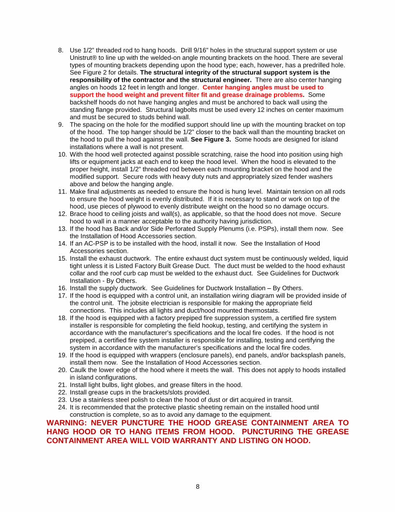
8. Use 1/2” threaded rod to hang hoods. Drill 9/16” holes in the structural support system or use Unistrut® to line up with the welded-on angle mounting brackets on the hood. There are several types of mounting brackets depending upon the hood type; each, however, has a predrilled hole. See Figure 2 for details. The structural integrity of the structural support system is the responsibility of the contractor and the structural engineer. There are also center hanging angles on hoods 12 feet in length and longer. Center hanging angles must be used to support the hood weight and prevent filter fit and grease drainage problems . Some backshelf hoods do not have hanging angles and must be anchored to back wall using the standing flange provided. Structural lagbolts must be used every 12 inches on center maximum and must be secured to studs behind wall.
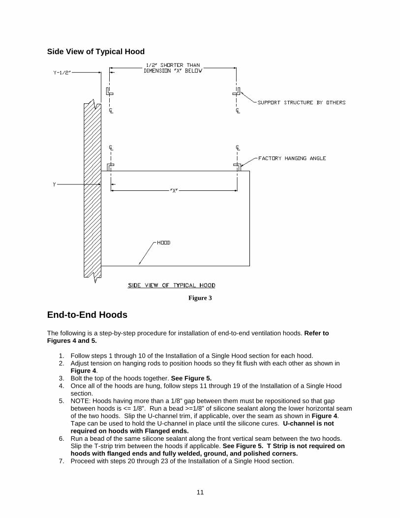
9. The spacing on the hole for the modified support should line up with the mounting bracket on top of the hood. The top hanger should be 1/2” closer to the back wall than the mounting bracket on the hood to pull the hood against the wall. See Figure 3. Some hoods are designed for island installations where a wall is not present.
10. With the hood well protected against possible scratching, raise the hood into position using high lifts or equipment jacks at each end to keep the hood level. When the hood is elevated to the proper height, install 1/2” threaded rod between each mounting bracket on the hood and the modified support. Secure rods with heavy duty nuts and appropriately sized fender washers above and below the hanging angle.
11. Make final adjustments as needed to ensure the hood is hung level. Maintain tension on all rods to ensure the hood weight is evenly distributed. If it is necessary to stand or work on top of the hood, use pieces of plywood to evenly distribute weight on the hood so no damage occurs.
12. Brace hood to ceiling joists and wall(s), as applicable, so that the hood does not move. Secure hood to wall in a manner acceptable to the authority having jurisdiction.
13. If the hood has Back and/or Side Perforated Supply Plenums (i.e. PSPs), install them now. See the Installation of Hood Accessories section.
14. If an AC-PSP is to be installed with the hood, install it now. See the Installation of Hood Accessories section.
15. Install the exhaust ductwork. The entire exhaust duct system must be continuously welded, liquid tight unless it is Listed Factory Built Grease Duct. The duct must be welded to the hood exhaust collar and the roof curb cap must be welded to the exhaust duct. See Guidelines for Ductwork Installation - By Others.
16. Install the supply ductwork. See Guidelines for Ductwork Installation – By Others. 17. If the hood is equipped with a control unit, an installation wiring diagram will be provided inside of
the control unit. The jobsite electrician is responsible for making the appropriate field connections. This includes all lights and duct/hood mounted thermostats.
18. If the hood is equipped with a factory prepiped fire suppression system, a certified fire system installer is responsible for completing the field hookup, testing, and certifying the system in accordance with the manufacturer’s specifications and the local fire codes. If the hood is not prepiped, a certified fire system installer is responsible for installing, testing and certifying the system in accordance with the manufacturer’s specifications and the local fire codes.
19. If the hood is equipped with wrappers (enclosure panels), end panels, and/or backsplash panels, install them now. See the Installation of Hood Accessories section.
20. Caulk the lower edge of the hood where it meets the wall. This does not apply to hoods installed in island configurations.
21. Install light bulbs, light globes, and grease filters in the hood. 22. Install grease cups in the brackets/slots provided. 23. Use a stainless steel polish to clean the hood of dust or dirt acquired in transit. 24. It is recommended that the protective plastic sheeting remain on the installed hood until
construction is complete, so as to avoid any damage to the equipment. WARNING: NEVER PUNCTURE THE HOOD GREASE CONTAINMENT AREA TO HANG HOOD OR TO HANG ITEMS FROM HOOD. PUNCTURING THE GREASE CONTAINMENT AREA WILL VOID WARRANTY AND LISTING ON HOOD.
9
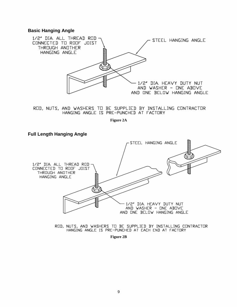
Basic Hanging Angle
Figure 2A
Full Length Hanging Angle
Figure 2B
10
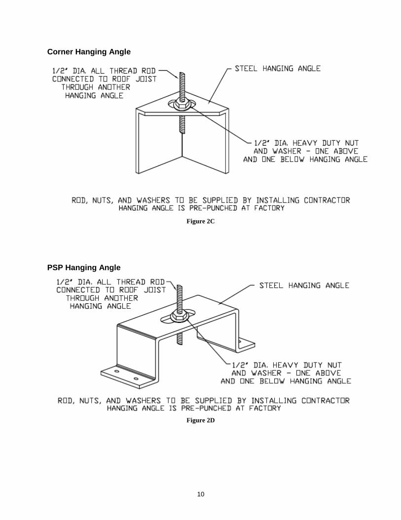
Corner Hanging Angle
Figure 2C
PSP Hanging Angle
Figure 2D
11
Side View of Typical Hood
Figure 3
End-to-End Hoods The following is a step-by-step procedure for installation of end-to-end ventilation hoods. Refer to Figures 4 and 5.
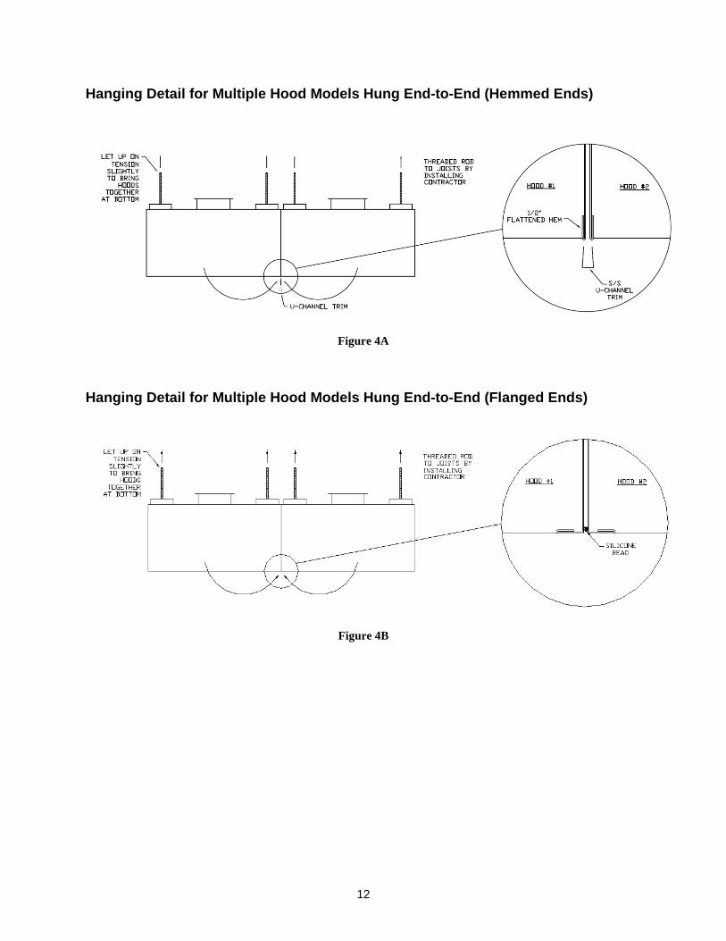
1. Follow steps 1 through 10 of the Installation of a Single Hood section for each hood. 2. Adjust tension on hanging rods to position hoods so they fit flush with each other as shown in
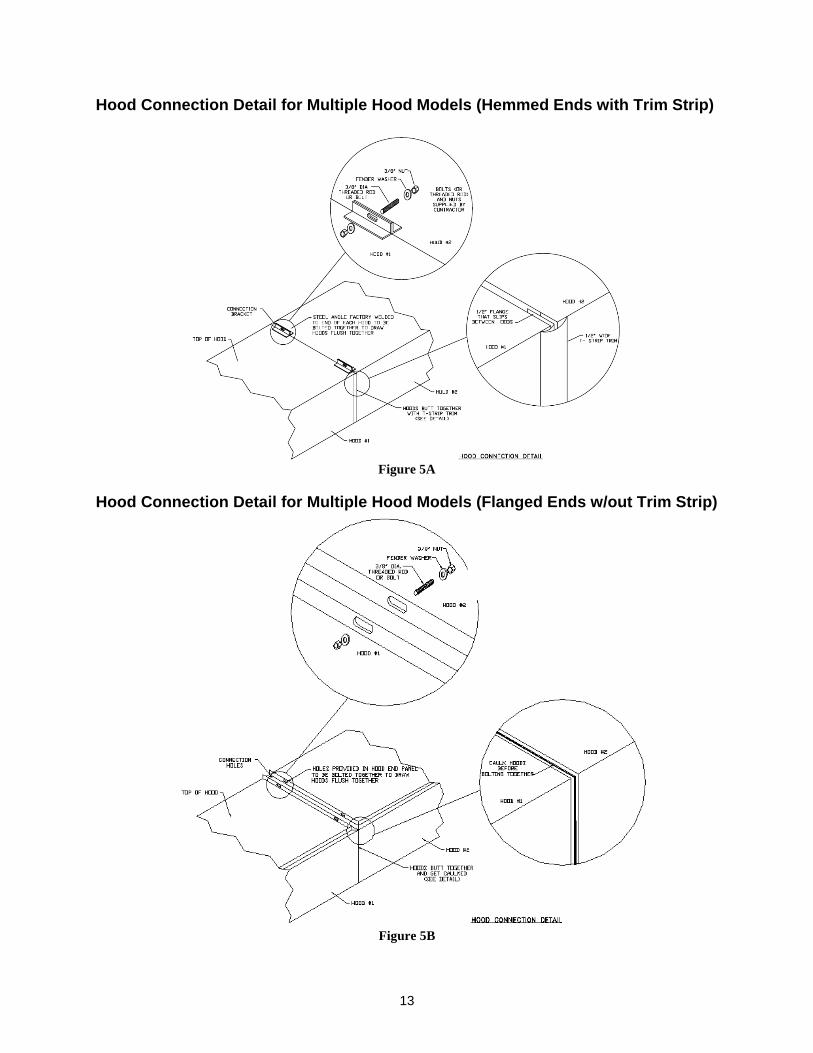
Figure 4 . 3. Bolt the top of the hoods together. See Figure 5. 4. Once all of the hoods are hung, follow steps 11 through 19 of the Installation of a Single Hood
section. 5. NOTE: Hoods having more than a 1/8” gap between them must be repositioned so that gap
between hoods is <= 1/8”. Run a bead >=1/8” of silicone sealant along the lower horizontal seam of the two hoods. Slip the U-channel trim, if applicable, over the seam as shown in Figure 4 . Tape can be used to hold the U-channel in place until the silicone cures. U-channel is not required on hoods with Flanged ends.
6. Run a bead of the same silicone sealant along the front vertical seam between the two hoods. Slip the T-strip trim between the hoods if applicable. See Figure 5. T Strip is not required on hoods with flanged ends and fully welded, ground, a nd polished corners.
7. Proceed with steps 20 through 23 of the Installation of a Single Hood section.
12
Hanging Detail for Multiple Hood Models Hung End-to -End (Hemmed Ends)
Figure 4A
Hanging Detail for Multiple Hood Models Hung End-to -End (Flanged Ends)
Figure 4B
13
Hood Connection Detail for Multiple Hood Models (He mmed Ends with Trim Strip)
Figure 5A
Hood Connection Detail for Multiple Hood Models (Fl anged Ends w/out Trim Strip)
Figure 5B
14
Back-to-Back Hoods
The following is a step-by-step procedure for installation of back-to-back ventilation hoods. Refer to Figures 5 and 6.
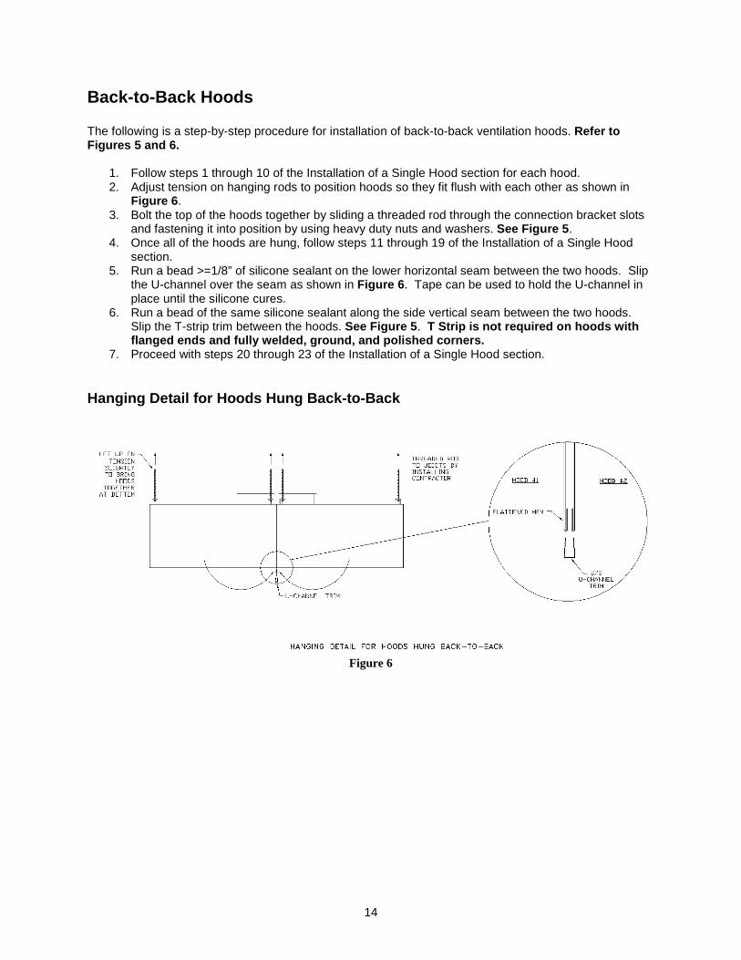
1. Follow steps 1 through 10 of the Installation of a Single Hood section for each hood. 2. Adjust tension on hanging rods to position hoods so they fit flush with each other as shown in
Figure 6 . 3. Bolt the top of the hoods together by sliding a threaded rod through the connection bracket slots
and fastening it into position by using heavy duty nuts and washers. See Figure 5 . 4. Once all of the hoods are hung, follow steps 11 through 19 of the Installation of a Single Hood
section. 5. Run a bead >=1/8” of silicone sealant on the lower horizontal seam between the two hoods. Slip
the U-channel over the seam as shown in Figure 6 . Tape can be used to hold the U-channel in place until the silicone cures.
6. Run a bead of the same silicone sealant along the side vertical seam between the two hoods. Slip the T-strip trim between the hoods. See Figure 5 . T Strip is not required on hoods with flanged ends and fully welded, ground, and polished corners.
7. Proceed with steps 20 through 23 of the Installation of a Single Hood section.
Hanging Detail for Hoods Hung Back-to-Back
Figure 6
15
Guidelines for Ductwork Installation Ductwork is furnished by supplier only if specified by the customer. The following information is provided as a guideline only. Ductwork should be installed in accordance with the local codes and restrictions. It is the responsibility of the installer to check local codes prior to installing the ductwork.
1. All ductwork must be installed in the most direct manner possible. 2. Exhaust duct must be made of 16 gauge carbon steel, 18 gauge stainless steel or must be listed
for use with commercial kitchen hoods and follow the manufacturer’s listing. 3. Per NFPA 96, all exhaust duct seams and joints must have a continuous liquid tight external
weld; exception would be Listed Factory Built Grease Duct. 4. Exhaust risers on the hood have been sized to achieve a velocity of 500-2200 FPM, per NFPA
96, based upon the CFM required for the hood. Maintain the area of each riser when connecting duct offsets or transitions.
5. Branches should enter at gradual expansions and at a preferred angle of 30 degrees or 45 degrees if necessary.
6. When a “pantleg duct” is required to bring two ducts into one exhaust fan, observe the following in order to obtain desired performance:
a. Use ONLY radius back and radius throat elbows. 2 to 2.5 diameter center line radius is recommended.
b. Maintain the distance between the center lines of exhaust ducts at a maximum of 12’ apart.
c. The main duct going to the exhaust fan must be the sum of the area of the separate legs. 7. Supply air risers are sized around a maximum of 600 FPM. Maintain this area when installing
ducts. 8. Do not use “flexible” type duct for supply duct. Only rigid type duct installed in accordance with
SMACNA Low Pressure requirements will be acceptable. 9. Access Doors should be provided at the sides or at the top of the duct, as well as changes of
direction. Please refer to your AHJ if questions on requirements for horizontal and vertical duct run.
10. IMPORTANT: When a fusible link is installed in the make-up air damper at the hood collar, an access door must be cut into the supply duct by the installer.
11. Duct sensor may ship loose on hoods with field cut risers. When double wall duct or ductwork with a diameter smaller than 10” is used, loose duct sensors should be installed in the top of the plenum near the riser in the path of the exhaust airflow.
16
Installation of Hood Accessories
Back Return Installation 1. Locate the assembly and unpack the product from the crate, being very careful not to dent or
scratch the outer surface. NOTE: Report any damage to the delivering freight c arrier and file a claim if appropriate.
2. If the supply risers are to be field cut, cut the risers in as desired. NOTE: For factory cut supply risers, the manufacturer installs a 2” verti cal flange around the opening. This flange is intended to slip inside a supply boot that is provided by the installer.
3. Locate the wall and ceiling joists which will support the assembly. 4. Use 1/2” threaded rod to hang the back return. Install the threaded rod and angle or Unistrut®
that will be used to hang the assembly from the ceiling joists. Drill 9/16” holes as needed in the angle for the threaded rod. Be sure to line up with the welded-on angle mounting brackets on the back return.
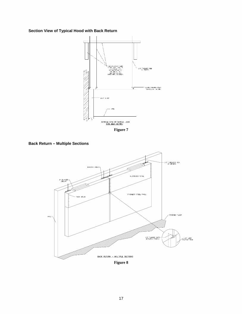
5. The back return is typically hung so its top edge is the same height as the top edge of the hood. See Figure 7 . Refer to Step 2 in the Installation of a Single Hood instructions to determine the hood and back return hanging heights.
6. Slowly raise the back return until hanging rods can be attached to the hanging angles. It is advisable to do this before the back return reaches its final height. NOTE: Please use caution as weight is not proportionally dispersed. Install the threaded rod into the back return hanging angles and use heavy duty nuts to secure the connection.
7. Make sure the back return is level. Secure to wall in a manner acceptable to the AHJ. 8. If there are multiple back return sections, install the remaining sections now. Use caulk and the
T-strip trim between adjacent back return sections. See Figure 8. 9. Peel the protective plastic coating on the back return down below where the bottom edge of the
hood will rest against it, so it does not remain behind the hood. 10. Caulk the seams between the wall and the back return assembly after the hood and all other
accessories have been installed.
17
Section View of Typical Hood with Back Return
Figure 7
Back Return – Multiple Sections
Figure 8
18
Bolt-Together Standoff Installation
1. Unpack the standoff panels from the shipping container, being very careful not to dent or scratch the panels. NOTE: Report any damage to the delivering freight c arrier and file a claim if appropriate.
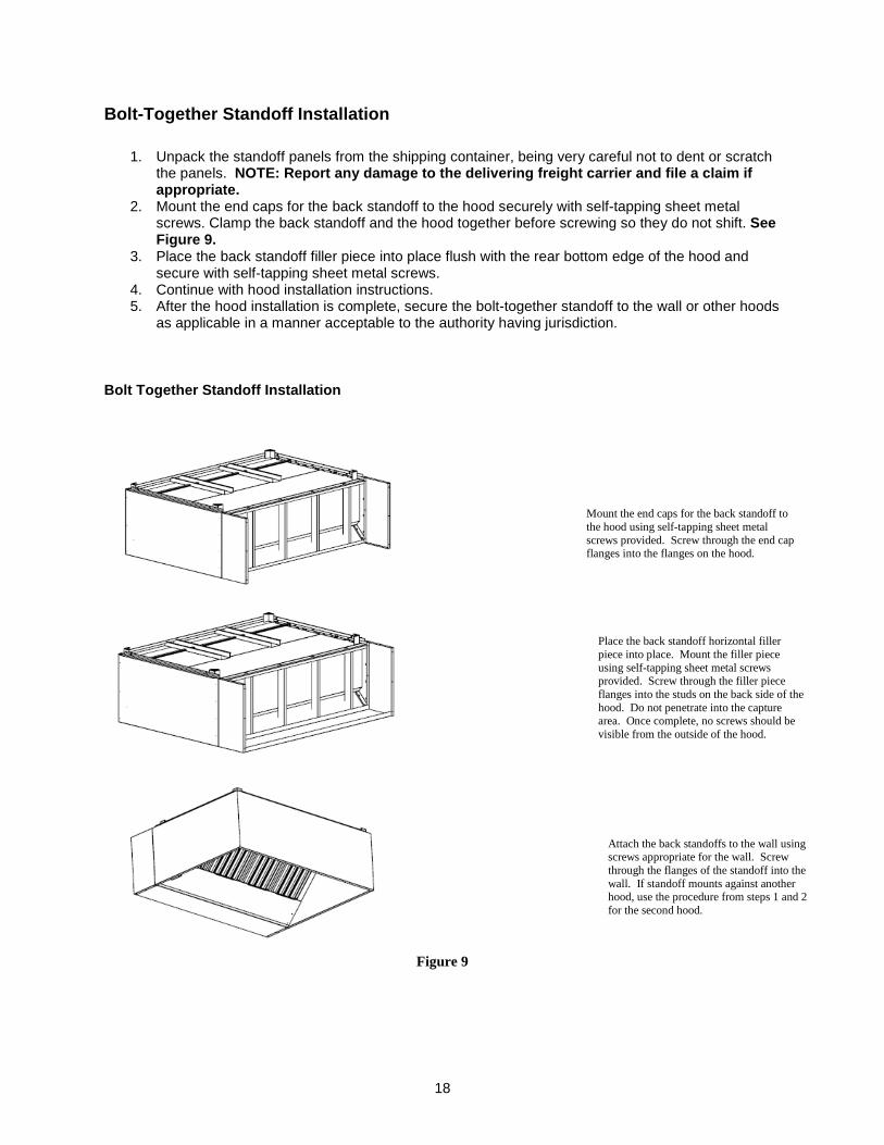
2. Mount the end caps for the back standoff to the hood securely with self-tapping sheet metal screws. Clamp the back standoff and the hood together before screwing so they do not shift. See Figure 9.
3. Place the back standoff filler piece into place flush with the rear bottom edge of the hood and secure with self-tapping sheet metal screws.
4. Continue with hood installation instructions. 5. After the hood installation is complete, secure the bolt-together standoff to the wall or other hoods
as applicable in a manner acceptable to the authority having jurisdiction.
Bolt Together Standoff Installation
Figure 9
Mount the end caps for the back standoff to the hood using self-tapping sheet metal screws provided. Screw through the end cap flanges into the flanges on the hood.
Place the back standoff horizontal filler piece into place. Mount the filler piece using self-tapping sheet metal screws provided. Screw through the filler piece flanges into the studs on the back side of the hood. Do not penetrate into the capture area. Once complete, no screws should be visible from the outside of the hood.
Attach the back standoffs to the wall using screws appropriate for the wall. Screw through the flanges of the standoff into the wall. If standoff mounts against another hood, use the procedure from steps 1 and 2 for the second hood.
19
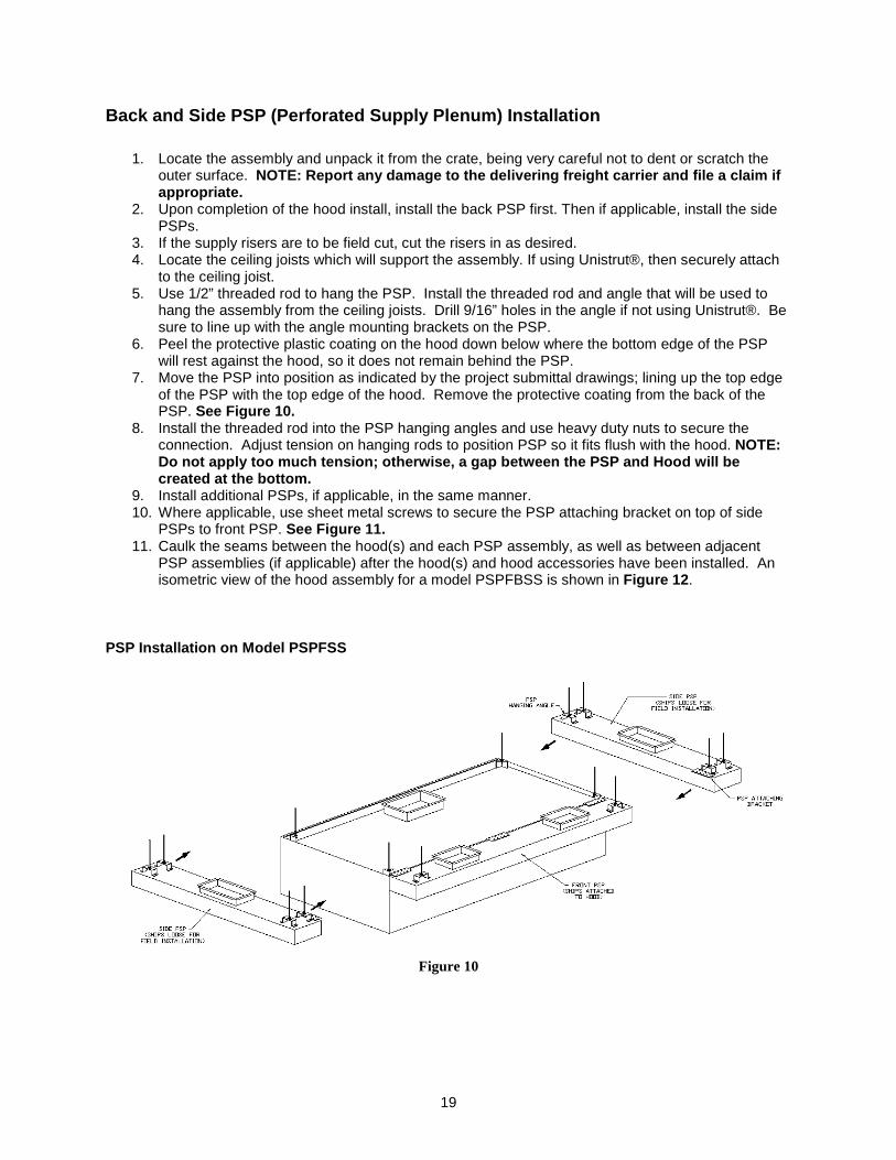
Back and Side PSP (Perforated Supply Plenum) Instal lation
1. Locate the assembly and unpack it from the crate, being very careful not to dent or scratch the outer surface. NOTE: Report any damage to the delivering freight c arrier and file a claim if appropriate.
2. Upon completion of the hood install, install the back PSP first. Then if applicable, install the side PSPs.
3. If the supply risers are to be field cut, cut the risers in as desired. 4. Locate the ceiling joists which will support the assembly. If using Unistrut®, then securely attach
to the ceiling joist. 5. Use 1/2” threaded rod to hang the PSP. Install the threaded rod and angle that will be used to
hang the assembly from the ceiling joists. Drill 9/16” holes in the angle if not using Unistrut®. Be sure to line up with the angle mounting brackets on the PSP.
6. Peel the protective plastic coating on the hood down below where the bottom edge of the PSP will rest against the hood, so it does not remain behind the PSP.
7. Move the PSP into position as indicated by the project submittal drawings; lining up the top edge of the PSP with the top edge of the hood. Remove the protective coating from the back of the PSP. See Figure 10.
8. Install the threaded rod into the PSP hanging angles and use heavy duty nuts to secure the connection. Adjust tension on hanging rods to position PSP so it fits flush with the hood. NOTE: Do not apply too much tension; otherwise, a gap bet ween the PSP and Hood will be created at the bottom.
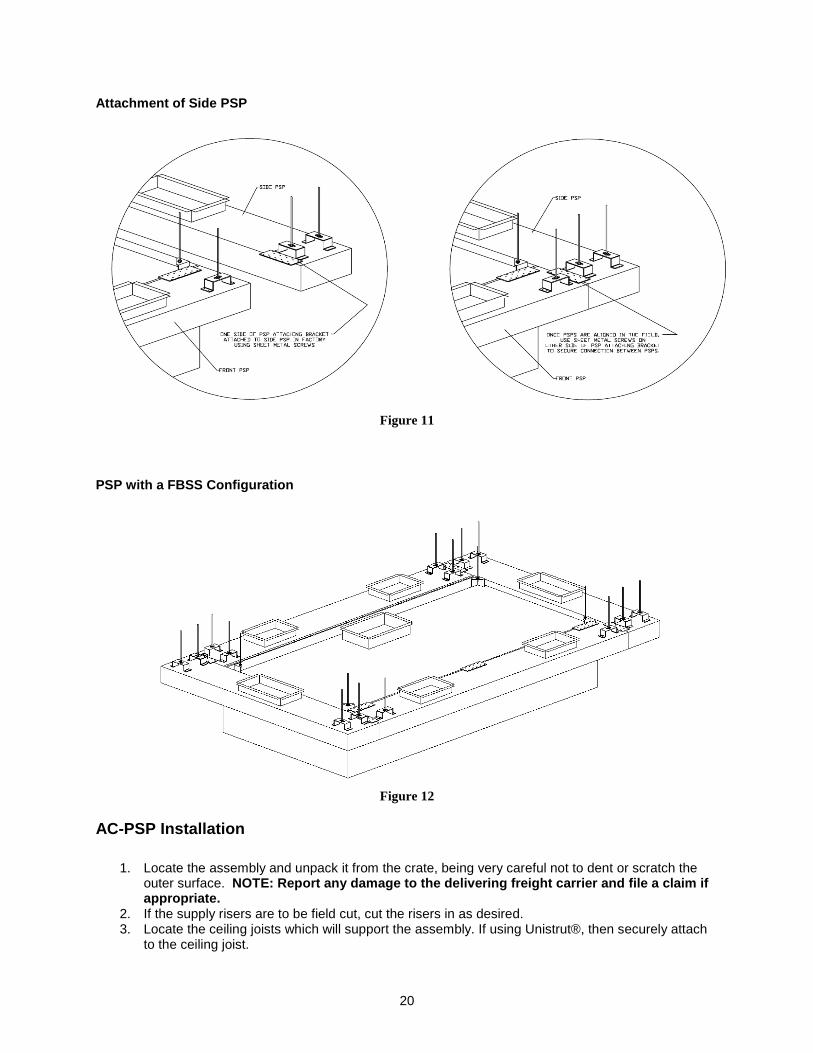
9. Install additional PSPs, if applicable, in the same manner. 10. Where applicable, use sheet metal screws to secure the PSP attaching bracket on top of side
PSPs to front PSP. See Figure 11. 11. Caulk the seams between the hood(s) and each PSP assembly, as well as between adjacent
PSP assemblies (if applicable) after the hood(s) and hood accessories have been installed. An isometric view of the hood assembly for a model PSPFBSS is shown in Figure 12 .
PSP Installation on Model PSPFSS
Figure 10
20
Attachment of Side PSP
Figure 11
PSP with a FBSS Configuration
Figure 12
AC-PSP Installation
1. Locate the assembly and unpack it from the crate, being very careful not to dent or scratch the outer surface. NOTE: Report any damage to the delivering freight c arrier and file a claim if appropriate.
2. If the supply risers are to be field cut, cut the risers in as desired. 3. Locate the ceiling joists which will support the assembly. If using Unistrut®, then securely attach
to the ceiling joist.
21
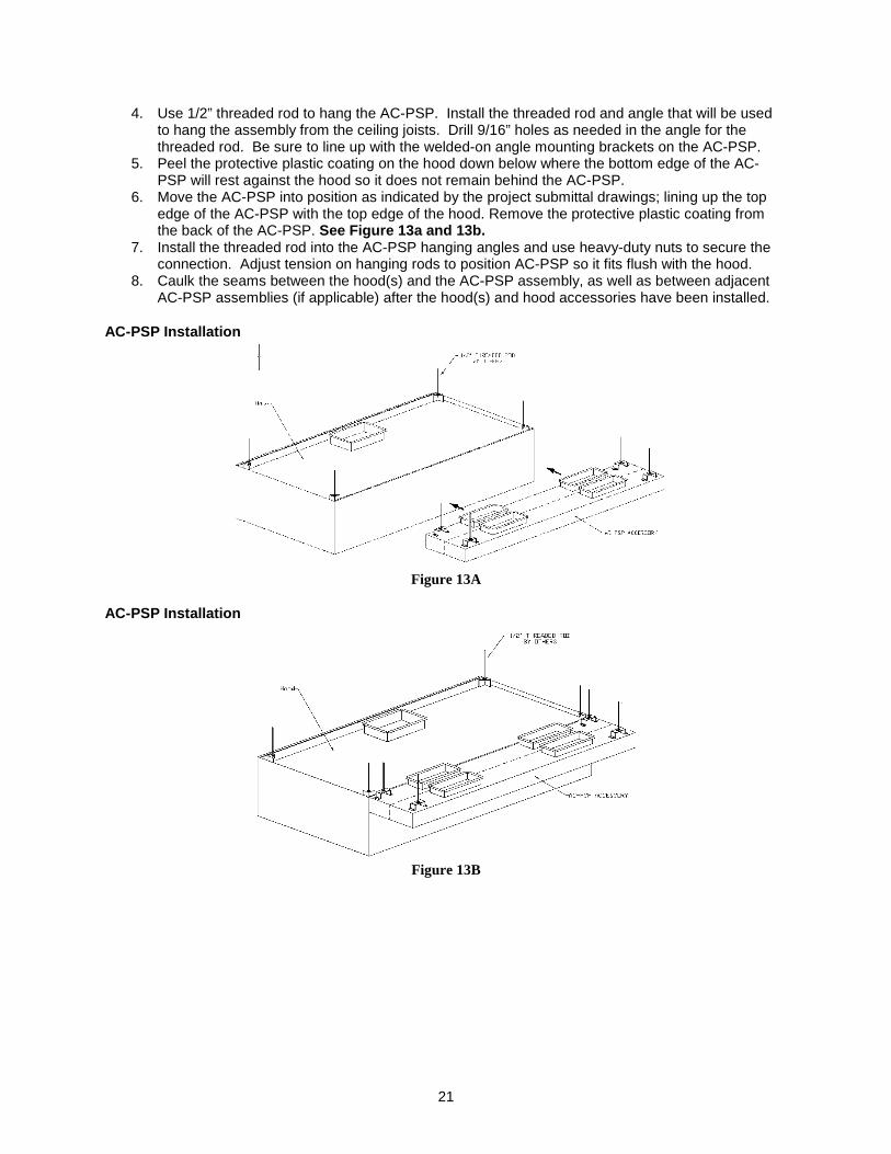
4. Use 1/2” threaded rod to hang the AC-PSP. Install the threaded rod and angle that will be used to hang the assembly from the ceiling joists. Drill 9/16” holes as needed in the angle for the threaded rod. Be sure to line up with the welded-on angle mounting brackets on the AC-PSP.
5. Peel the protective plastic coating on the hood down below where the bottom edge of the AC-PSP will rest against the hood so it does not remain behind the AC-PSP.
6. Move the AC-PSP into position as indicated by the project submittal drawings; lining up the top edge of the AC-PSP with the top edge of the hood. Remove the protective plastic coating from the back of the AC-PSP. See Figure 13a and 13b.
7. Install the threaded rod into the AC-PSP hanging angles and use heavy-duty nuts to secure the connection. Adjust tension on hanging rods to position AC-PSP so it fits flush with the hood.
8. Caulk the seams between the hood(s) and the AC-PSP assembly, as well as between adjacent AC-PSP assemblies (if applicable) after the hood(s) and hood accessories have been installed.
AC-PSP Installation
Figure 13A
AC-PSP Installation
Figure 13B
22
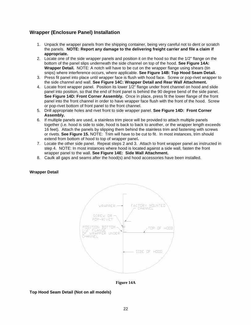
Wrapper (Enclosure Panel) Installation
1. Unpack the wrapper panels from the shipping container, being very careful not to dent or scratch the panels. NOTE: Report any damage to the delivering freight c arrier and file a claim if appropriate.
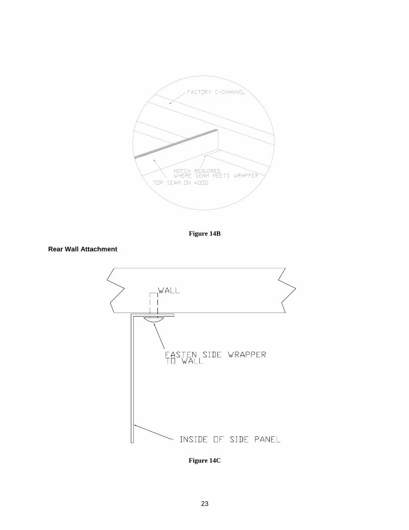
2. Locate one of the side wrapper panels and position it on the hood so that the 1/2” flange on the bottom of the panel slips underneath the side channel on top of the hood. See Figure 14A: Wrapper Detail. NOTE: A notch will have to be cut on the wrapper flange using shears (tin snips) where interference occurs, where applicable. See Figure 14B: Top Hood Seam Detail.
3. Press fit panel into place until wrapper face is flush with hood face. Screw or pop-rivet wrapper to the side channel and wall. See Figure 14C: Wrapper Detail and Rear Wall Attach ment.
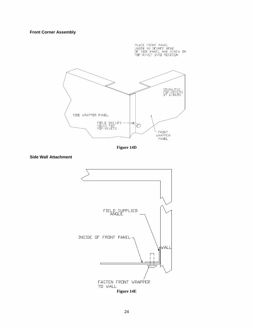
4. Locate front wrapper panel. Position its lower 1/2” flange under front channel on hood and slide panel into position, so that the end of front panel is behind the 90 degree bend of the side panel. See Figure 14D: Front Corner Assembly. Once in place, press fit the lower flange of the front panel into the front channel in order to have wrapper face flush with the front of the hood. Screw or pop-rivet bottom of front panel to the front channel.
5. Drill appropriate holes and rivet front to side wrapper panel. See Figure 14D: Front Corner Assembly.
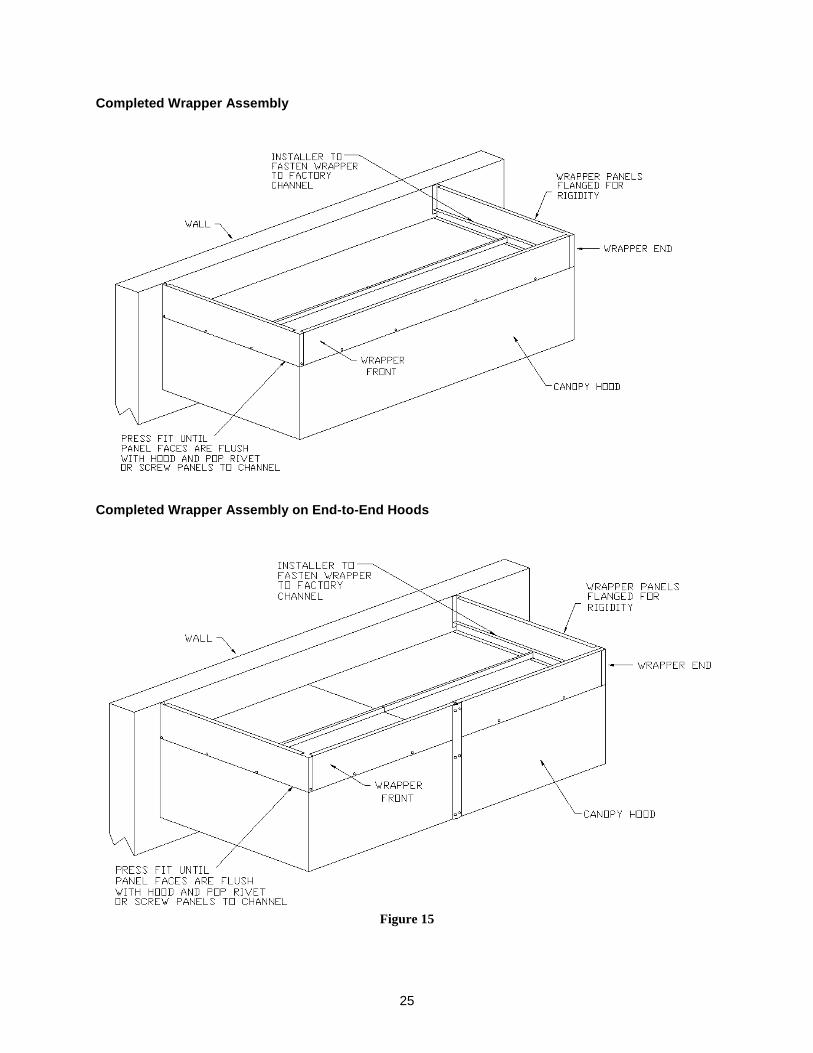
6. If multiple panels are used, a stainless trim piece will be provided to attach multiple panels together (i.e. hood is side to side, hood is back to back to another, or the wrapper length exceeds 16 feet). Attach the panels by slipping them behind the stainless trim and fastening with screws or rivets. See Figure 15. NOTE: Trim will have to be cut to fit. In most instances, trim should extend from bottom of hood to top of wrapper panel.
7. Locate the other side panel. Repeat steps 2 and 3. Attach to front wrapper panel as instructed in step 4. NOTE: In most instances where hood is located against a side wall, fasten the front wrapper panel to the wall. See Figure 14E: Side Wall Attachment.
8. Caulk all gaps and seams after the hood(s) and hood accessories have been installed.
Wrapper Detail
Figure 14A
Top Hood Seam Detail (Not on all models)
23
Figure 14B
Rear Wall Attachment
Figure 14C
24
Front Corner Assembly
Figure 14D
Side Wall Attachment
Figure 14E
25
Completed Wrapper Assembly
Completed Wrapper Assembly on End-to-End Hoods
Figure 15
26
End-panel Installation
1. Unpack the end-panel(s) from the shipping container, being very careful not to dent or scratch the panels. NOTE: Report any damage to the delivering freight c arrier and file a claim if appropriate.
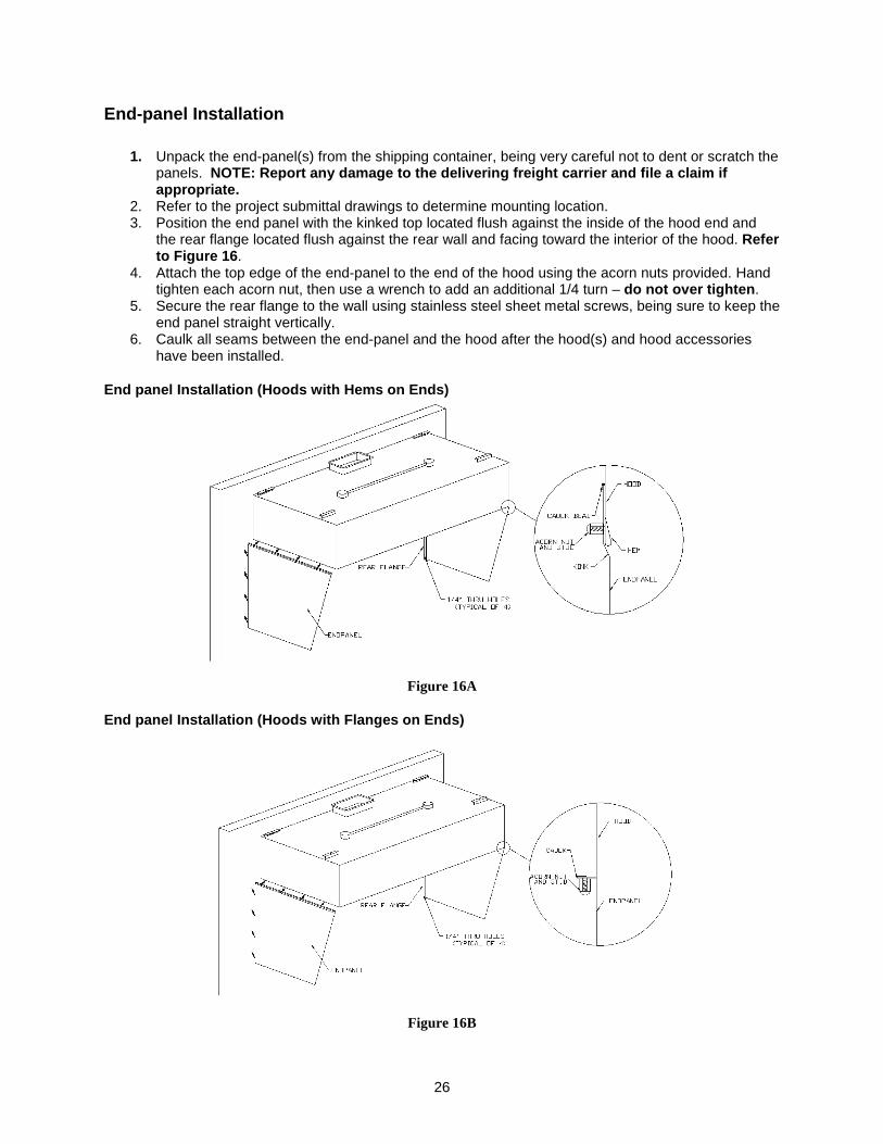
2. Refer to the project submittal drawings to determine mounting location. 3. Position the end panel with the kinked top located flush against the inside of the hood end and
the rear flange located flush against the rear wall and facing toward the interior of the hood. Refer to Figure 16 .
4. Attach the top edge of the end-panel to the end of the hood using the acorn nuts provided. Hand tighten each acorn nut, then use a wrench to add an additional 1/4 turn – do not over tighten .
5. Secure the rear flange to the wall using stainless steel sheet metal screws, being sure to keep the end panel straight vertically.
6. Caulk all seams between the end-panel and the hood after the hood(s) and hood accessories have been installed.
End panel Installation (Hoods with Hems on Ends)
Figure 16A
End panel Installation (Hoods with Flanges on Ends)
Figure 16B
27
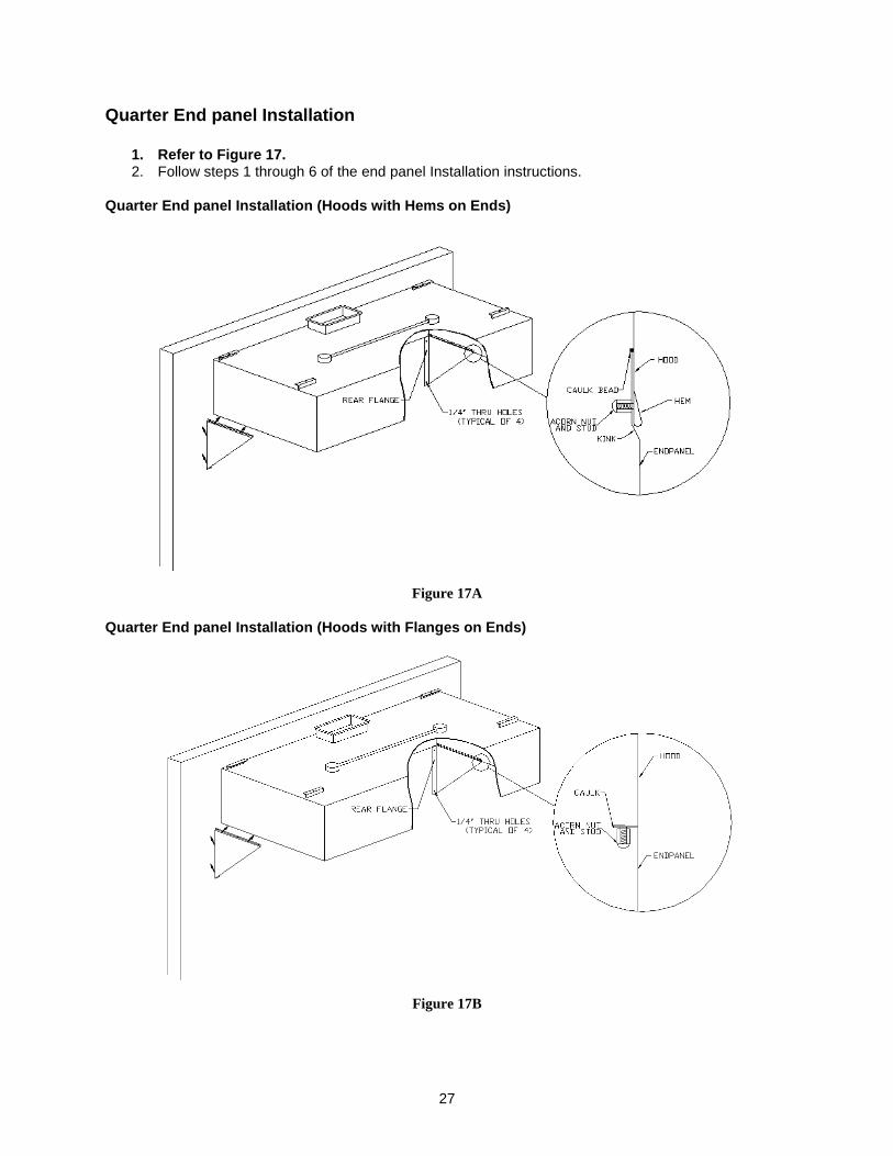
Quarter End panel Installation
1. Refer to Figure 17. 2. Follow steps 1 through 6 of the end panel Installation instructions.
Quarter End panel Installation (Hoods with Hems on Ends)
Figure 17A
Quarter End panel Installation (Hoods with Flanges on Ends)
Figure 17B
28
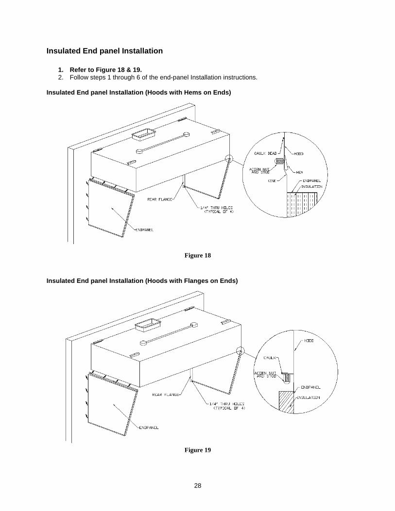
Insulated End panel Installation
1. Refer to Figure 18 & 19. 2. Follow steps 1 through 6 of the end-panel Installation instructions.
Insulated End panel Installation (Hoods with Hems o n Ends)
Figure 18
Insulated End panel Installation (Hoods with Flange s on Ends)
Figure 19
29
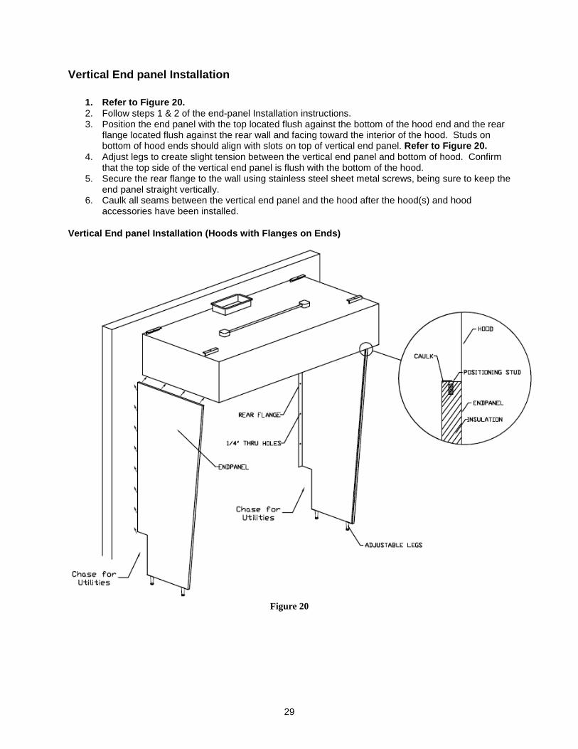
Vertical End panel Installation
1. Refer to Figure 20. 2. Follow steps 1 & 2 of the end-panel Installation instructions. 3. Position the end panel with the top located flush against the bottom of the hood end and the rear
flange located flush against the rear wall and facing toward the interior of the hood. Studs on bottom of hood ends should align with slots on top of vertical end panel. Refer to Figure 20.
4. Adjust legs to create slight tension between the vertical end panel and bottom of hood. Confirm that the top side of the vertical end panel is flush with the bottom of the hood.
5. Secure the rear flange to the wall using stainless steel sheet metal screws, being sure to keep the end panel straight vertically.
6. Caulk all seams between the vertical end panel and the hood after the hood(s) and hood accessories have been installed.
Vertical End panel Installation (Hoods with Flanges on Ends)
Figure 20
30
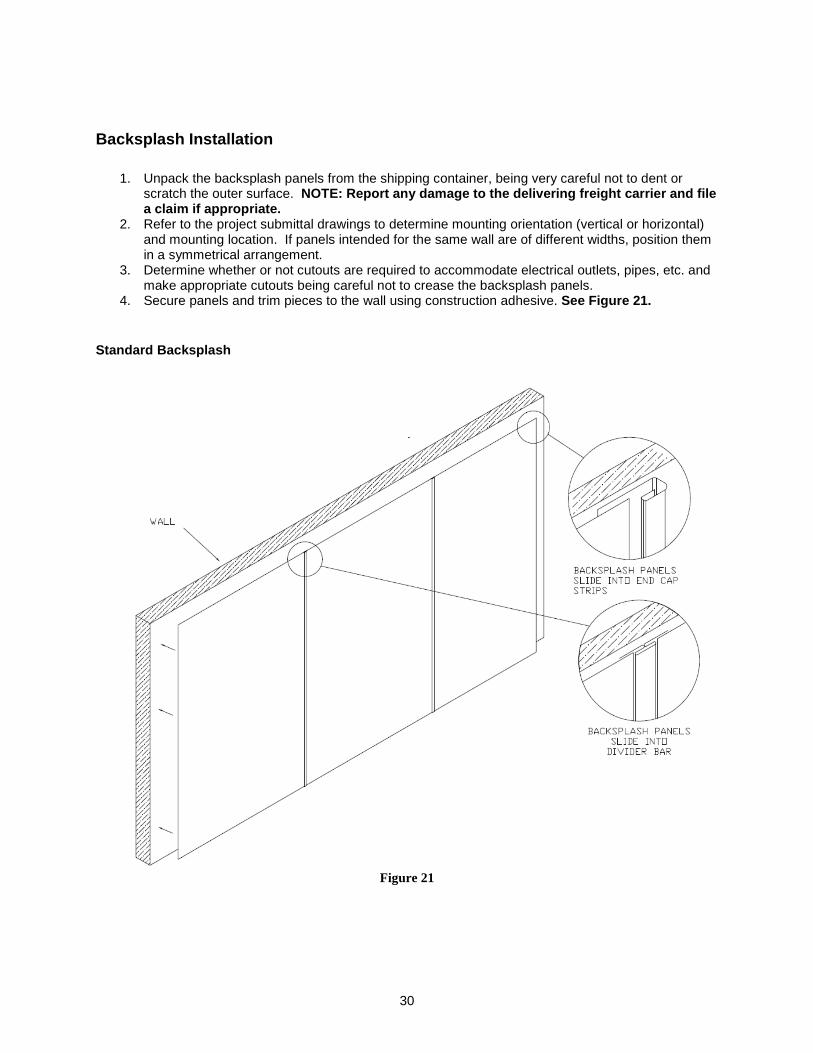
Backsplash Installation
1. Unpack the backsplash panels from the shipping container, being very careful not to dent or scratch the outer surface. NOTE: Report any damage to the delivering freight c arrier and file a claim if appropriate.
2. Refer to the project submittal drawings to determine mounting orientation (vertical or horizontal) and mounting location. If panels intended for the same wall are of different widths, position them in a symmetrical arrangement.
3. Determine whether or not cutouts are required to accommodate electrical outlets, pipes, etc. and make appropriate cutouts being careful not to crease the backsplash panels.
4. Secure panels and trim pieces to the wall using construction adhesive. See Figure 21.
Standard Backsplash
Figure 21
31
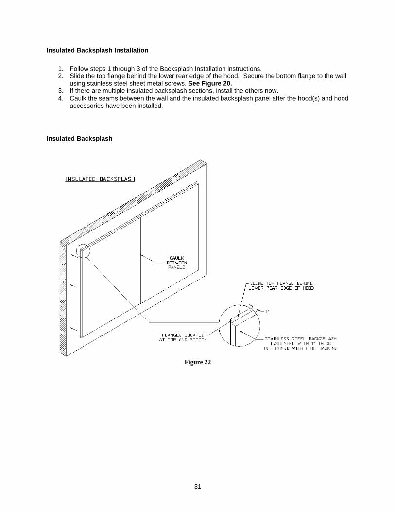
Insulated Backsplash Installation
1. Follow steps 1 through 3 of the Backsplash Installation instructions. 2. Slide the top flange behind the lower rear edge of the hood. Secure the bottom flange to the wall
using stainless steel sheet metal screws. See Figure 20. 3. If there are multiple insulated backsplash sections, install the others now. 4. Caulk the seams between the wall and the insulated backsplash panel after the hood(s) and hood
accessories have been installed. Insulated Backsplash
Figure 22
32
OPERATION Commercial kitchen ventilation hoods are intended to be used in conjunction with ductwork and fans, which have been properly sized and properly installed in accordance with manufacturer’s specifications and local code requirements. Before turning on cooking equipment, make sure that the make-up air and exhaust fans are on. Leave fans on for at least 30 minutes after cooking equipment is shut off. Clean hood as needed to comply with local code requirements and as directed in the Maintenance section of this manual.
Performance Evaluation A performance evaluation of the system can be performed only after all of the following items have been verified:
1. All fans are operational and rotations visually verified by observation of the arrows stamped on them.
2. All filters are in place. 3. Equipment under the hood is in place and operational. 4. HVAC units are in place and operational with blowers operating correctly.
Guidelines before Beginning The testing and balancing of a system is necessary to ensure proper and efficient operation of the system as it was designed. In any building where effluent and hot air is removed, the mass of air must be replaced to maintain a constant pressure in the space. Any change in the pressure differential between inside and outside air will in some way affect the operation of a system; most commonly that affect is a negative one. A test and balance, as well as the simple performance test in International Mechanical Code Section 507.16.1 should be included in all jobs; code inspectors are increasingly enforcing these requirements. Requirements in the 2006 IMC, which is currently effective in most parts of the United States, are as follows:
“507.16 Performance test. A performance test shall be conducted upon completion and before final approval of the installation of a ventilation system serving commercial cooking appliances. The test shall verify the rate of exhaust airflow required by Section 507.13, makeup airflow required by Section 508, and proper operation as specified in this chapter. The permit holder shall furnish the necessary test equipment and devices required to perform the tests. 507.16.1 Capture and containment test. The permit holder shall verify capture and containment performance of the exhaust system. This field test shall be conducted with all appliances under the hood at operating temperatures, with all sources of outdoor air providing makeup air for the hood operating and with all sources of recirculated air providing conditioning for the space in which the hood is operating. Capture and containment shall be verified visually by observing smoke or steam produced by actual or simulated cooking, such as with smoke candles, smoke puffers, etc.”
The simplest means of doing the performance test is using a T-T puffer from www.evhill.com. Activate the puffer and use it to trace effluent around the entire perimeter of the hood, emitting smoke every few inches under the lower edges of the hood.
33
External Factors which may affect Hood Performance 1. HVAC units are generally specified to supply 25% outside air (OA) to the room ventilation. If
RTU’s are not supplying the proper amount of OA to the building, then negative pressure will exist.
2. HVAC return grilles located close to a hood can cause performance problems. The return grille competes with the hood to capture air in the room. For example, a return grille for a 10-ton HVAC unit can draw anywhere from 3000 to 4000 CFM. This is equivalent to the exhaust of a 10’ to 13’ canopy hood. As a result, a return air grille located within six feet (6’) of the hood can have a serious effect on the capture ability of the hood.
3. HVAC diffusers located near a hood can create flows in the room that detract from the capture ability of the hood. If the HVAC diffuser bounces air off the front of the hood or directs air along the hood and past the end, the air flow created can draw smoke and contaminants out of the hood.
Using a Shortridge Instrument The Shortridge is a sophisticated instrument that, with its built-in features, is basically a self contained test and balance kit. It has a “velocity grid” for filter face readings, a “velocity probe” for ductwork readings, a “differential pressure” function to check room pressure and static pressure, as well as a “temperature probe” so it can calculate accurate values based on varying temperature (most equipment assumes standard temperature and pressure), and many other useful features. Hood Information
To calculate the CFM, the following information must first be acquired:
1. Hood size and length 2. Filter size and length 3. PSP width and length
Measuring Hood Static and Room Pressure Static Pressure:
1. Measure hood static pressure at exhaust collar using the Shortridge instrument. Static Pressure = _______________
Room Pressure: For an exhaust hood to work properly, the kitchen should be at a slight negative pressure to the dining area (caused by its air removal) and the building overall slightly positive. The dining room should be a slight positive to the outdoors and the kitchen +0.02” w.c. or about 300 CFM positive. This will keep dust and bugs outside and doors will be easy to open. The kitchen should be a slight negative to the dining room to keep the odors in the kitchen. The kitchen should be balanced to slightly negative, 0” to -0.02” w.c., to the dining room. Generally, if there is not enough negative, or if there is positive pressure there will be smoke roll out from the hood that occurs due to the wind currents from people moving around in the area, while if there is too much negative, there becomes a pressure problem on the building(opening doors, drafts, hot water heaters, etc.)
1. Measure room static pressure using the Shortridge instrument. Adjust the supply fan to set room to 0.02” negative to dining area.
Room Pressure = _______________
34
Calculating Make-up Air CFM with a Shortridge Instr ument and Spreadsheet 1. Use the Velgrid mode of the Shortridge instrument to measure supply air velocity. Make sure to
take measurements every twelve (12) inches along the length of the PSP. 2. Locate the appropriate Excel spreadsheet for the PSP/Supply velocity and record all necessary
data. This spreadsheet will calculate the total supply CFM for the hood. 3. The spreadsheet is located on the manufacturer’s website.
Calculating Make-up Air CFM without a Shortridge In strument 1. Compute the open area of the supply plenum of the hood. This area must be calculated at the
same plane that velocity readings are taken. Area can be calculated using the following formula: Area (ft²) = Length (ft) x Width (ft) If both the length and width are measured in inches, use the following formula: Area (ft²) = Length (in) x Width (in) / 144
2. Record velocity of air through supply openings from left to right on raw data sheet. 3. Compute and record average velocity through supply openings. 4. Compute and record CFM through supply openings.
CFM = Free area x Average Velocity
5. Compute total CFM through all supply openings for each hood.
Calculating Exhaust Air CFM with a Shortridge Instr ument and Spreadsheet 1. Use the Velgrid mode of the Shortridge instrument to measure the velocity at each filter. 2. Locate the appropriate Excel spreadsheet for the exhaust velocity and record all necessary data.
This spreadsheet will calculate the total exhaust CFM for the hood.
Calculating Exhaust CFM without a Shortridge Instru ment 1. Record filter sizes of each hood on raw data sheet. 2. Compute free area of the filters.
Examples: 16”x16” = 14x14 = 1.36 ft² 10”x20” = 8x18 = 1.00 ft² 12”x16” = 10x14 = 0.97 ft²
3. Record velocity of exhaust gases through filters starting top left to right (5 reading/filter). 4. Find average velocity through each filter. 5. Compute CFM through each filter.
CFM = Free area x Average Velocity
6. Total the exhaust CFM for each hood. 7. Multiply total exhaust CFM x 0.78 (this is the K factor necessary when using the EDRA
velometer).
35
Adjustments 1. A hood with multiple risers should be balanced according to the cooking load beneath it. For
example, if a hood with multiple risers has a charbroiler in the center and several ovens on the ends, the risers should be evenly balanced. This will achieve the most efficient contaminant capture.
2. Perforated supply plenums discharging air around the hood should be set to the designed discharge velocity.
3. When fan pulleys are adjusted, belts should then be re-checked for correct tension and an amperage reading should be taken on the motor to make certain it is not overloaded.
4. The prime objective of balancing is to ensure that each hood will capture all the contaminants produced by the equipment it covers without causing undesirable conditions in the kitchen (i.e. excessive negative pressure, excessive quantities of hot or cold air in the kitchen, etc.)
If problems occur, then refer to the Troubleshooting Section of this manual.
Conclusion 1. Compare specified data to the data recorded. Adjust exhaust as necessary using adjustable
pulley on fan. Adjust supply as necessary using dampers on supply risers and adjustable pulley on supply fan.
2. After setting hoods to specified data, the room parameters should be checked. 3. If room parameters are not acceptable yet, the hood can be modified to improve them without
decreasing hood performance. This is an acceptable condition. 4. Use a smoke bomb to verify that the hood captures adequately. This can be your final verification.
Complete Equipment List for Performance Evaluations • Closed End Wrenches (9/16, ½, 7/16, 3/8, 5/16, ¼) • Socket Set & Ratchet (9/16, ½, 7/16, 3/8, 5/16, ¼) • Extension for Ratchet • Cheater Bar • Screwdrivers (Phillips & Standard, Short & Long) • Adjustable Wrenches (Large & Small) • 5/32” 9” Long Allen Wrench • Multi-key Hex Set (Standard Assortment) • Tape Measure, Hammers (Hard & Soft) • 2-Channel Locks • Vise-Grip Pliers (Medium Size) • Shortridge Air Multimeter • Velometer or similar unit, Edra 5LV or Davis LCA6000 recommended • Manometer or similar unit, Dwyer Magnehelic Model #2000-00 recommended • Work Gloves • 6’ Step Ladder • 20’ Extension Ladder • Tachometer (Mechanical) • Amprobe (Volt & Amp Meter)
36
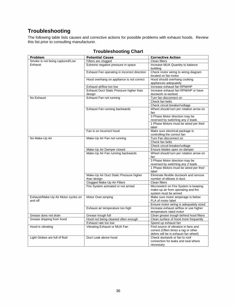
Troubleshooting The following table lists causes and corrective actions for possible problems with exhaust hoods. Review this list prior to consulting manufacturer.
Troubleshooting Chart Problem Potential Cause Corrective Action Smoke is not being captured/Low Exhaust
Filters are clogged Clean filters Extreme negative pressure in space Increase MUA Quantity to balance
building Exhaust Fan operating in incorrect direction Check motor wiring to wiring diagram
located on fan motor Hood overhang on appliance is not correct Hood should overhang cooking
appliances adequately Exhaust airflow too low Increase exhaust fan RPM/HP Exhaust Duct Static Pressure higher than design
Increase exhaust fan RPM/HP or have ductwork re-worked
No Exhaust Exhaust Fan not running Turn fan disconnect on Check fan belts Check circuit breaker/voltage
Exhaust Fan running backwards Wheel should turn per rotation arrow on fan 3 Phase Motor direction may be reversed by switching any 2 leads 1 Phase Motors must be wired per their label
Fan is on incorrect hood Make sure electrical package is controlling the correct fan
No Make-Up Air Make-Up Air Fan not running Turn Fan disconnect on Check fan belts Check circuit breaker/voltage
Make-Up Air Damper closed Ensure blades open on damper Make-Up Air Fan running backwards Wheel should turn per rotation arrow on
fan 3 Phase Motor direction may be reversed by switching any 2 leads 1 Phase Motors must be wired per their label
Make-Up Air Duct Static Pressure higher than design
Eliminate flexible ductwork and remove number of elbows in duct.
Clogged Make-Up Air Filters Clean filters Fire System activated or not armed Microswitch on Fire System is keeping
make-up air from operating and fire system must be armed
Exhaust/Make-Up Air Motor cycles on and off
Motor Over-amping Make sure motor amperage is below FLA of motor label Ensure motor wiring is adequately sized
Exhaust air temperature too high Increase exhaust airflow or use higher temperature rated motor
Grease does not drain Grease trough full Clean grease trough behind hood filters Grease dripping from hood Hood not being cleaned often enough Clean surface of hood more frequently
Exhaust rate too low Speed up exhaust fan Hood is vibrating Vibrating Exhaust or MUA Fan Find source of vibration in fans and
correct (Often times a rag or other debris will be in exhaust fan wheel)
Light Globes are full of fluid Duct Leak above hood Check ductwork or fan to roof connection for leaks and seal where necessary
37
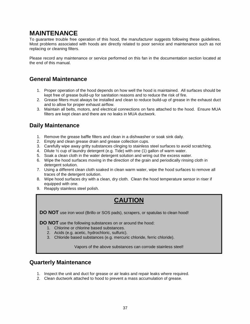
MAINTENANCE To guarantee trouble free operation of this hood, the manufacturer suggests following these guidelines. Most problems associated with hoods are directly related to poor service and maintenance such as not replacing or cleaning filters. Please record any maintenance or service performed on this fan in the documentation section located at the end of this manual.
General Maintenance
1. Proper operation of the hood depends on how well the hood is maintained. All surfaces should be kept free of grease build-up for sanitation reasons and to reduce the risk of fire.
2. Grease filters must always be installed and clean to reduce build-up of grease in the exhaust duct and to allow for proper exhaust airflow.
3. Maintain all belts, motors, and electrical connections on fans attached to the hood. Ensure MUA filters are kept clean and there are no leaks in MUA ductwork.
Daily Maintenance
1. Remove the grease baffle filters and clean in a dishwasher or soak sink daily. 2. Empty and clean grease drain and grease collection cups. 3. Carefully wipe away gritty substances clinging to stainless steel surfaces to avoid scratching. 4. Dilute ½ cup of laundry detergent (e.g. Tide) with one (1) gallon of warm water. 5. Soak a clean cloth in the water detergent solution and wring out the excess water. 6. Wipe the hood surfaces moving in the direction of the grain and periodically rinsing cloth in
detergent solution. 7. Using a different clean cloth soaked in clean warm water, wipe the hood surfaces to remove all
traces of the detergent solution. 8. Wipe hood surfaces dry with a clean, dry cloth. Clean the hood temperature sensor in riser if
equipped with one. 9. Reapply stainless steel polish.
Quarterly Maintenance
1. Inspect the unit and duct for grease or air leaks and repair leaks where required. 2. Clean ductwork attached to hood to prevent a mass accumulation of grease.
CAUTION DO NOT use iron wool (Brillo or SOS pads), scrapers, or spatulas to clean hood! DO NOT use the following substances on or around the hood:
1. Chlorine or chlorine based substances. 2. Acids (e.g. acetic, hydrochloric, sulfuric). 3. Chloride based substances (e.g. mercuric chloride, ferric chloride).
Vapors of the above substances can corrode stainless steel!

38

39
Exhaust Hood Depot (800) 618-0483102 2nd. Street, Hustontown, PA 17229