Combined Betamicron Aquamicron Filter Elements - HYDAC · The high quality of the HYDAC...
4
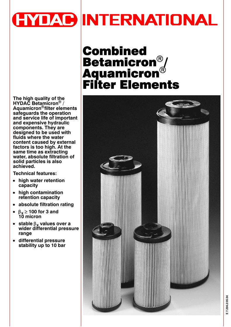
The high quality of the HYDAC Betamicron ® / Aquamicron ® filter elements safeguards the operation and service life of important and expensive hydraulic components. They are designed to be used with fluids where the water content caused by external factors is too high. At the same time as extracting water, absolute filtration of solid particles is also achieved. Technical features: • high water retention capacity • high contamination retention capacity • absolute filtration rating • β x ≥ 100 for 3 and 10 micron • stable β x values over a wider differential pressure range • differential pressure stability up to 10 bar Combined Betamicron ® / Aquamicron ® Filter Elements E 7.204.2/05.04
Transcript of Combined Betamicron Aquamicron Filter Elements - HYDAC · The high quality of the HYDAC...
The high quality of theHYDAC Betamicron® /Aquamicron®filter elementssafeguards the operationand service life of importantand expensive hydrauliccomponents. They aredesigned to be used withfluids where the watercontent caused by externalfactors is too high. At thesame time as extractingwater, absolute filtration ofsolid particles is alsoachieved.Technical features:• high water retentioncapacity
• high contaminationretention capacity
• absolute filtration rating• βx ≥ 100 for 3 and10 micron
• stable βx values over awider differential pressurerange
• differential pressurestability up to 10 bar
CombinedBetamicron®/Aquamicron®
Filter Elements
E7.204.2/05.04

1. ... R ... BN/AMELEMENTS
1.1. GENERALThe presence of water inhydraulic media causes manyproblems, for example, thesaturation of very fine filters or thejamming of valves, and theseproblems are often wronglyattributed to excessive levels ofsolid particle contamination. Inaddition to this the build--up ofrust and the reduction inlubrication on bearings and slidescan lead to considerableimpairment of the functioning of asystem. In other words, alongwith solid particles, water is aserious “contaminant” of hydraulicmedia.Since methods usually employedup to now to extract water have,on the whole, proved to beuneconomical compared with thepurchase price of the system,HYDAC BN/AM technologyprovides an economically sound,yet effective, method ofseparating water from hydraulicmedia, which at the same timeachieves absolute filtration ofsolid particles.
1.1.1. DescriptionBN/AM filter elements arespecially designed to separatewater, and achieve absolutefiltration of solid particles, frommineral oils, HFD--R oils andrapidly biodegradable oils.A super absorber reacts with thewater present in the medium andexpands to form a gel, from whichthe water can no longer beextracted even by increasing thepressure. These filter elementscannot remove dissolved waterfrom the system, i.e. water belowthe saturation level of thehydraulic medium.Solid particle filtration (3 μm,10 μm absolute) is achieved dueto the Betamicron[ filterconstruction.
1.1.2. Principles of the BN/AMcombined filter elements
• BN/AM disposable element basedon inorganic and water--absorbentfibres
• Exemplary absorption of waterfrom mineral oils with the aid of asuper absorber embedded in thefilter material
• Excellent adsorption of finestparticles over a wide differentialpressure range (3 μm, 10 μmabsolute)
• Exemplary Beta stability overwide differential pressure ranges
• Very high contamination retentioncapacity
• Good chemical resistance due tothe use of epoxy resins forimpregnation and bonding
• Element protection due to highburst pressure resistance (e.g.during cold starts and dynamicdifferential pressure surges)
1.1.3. The following principles apply to water separation
1.2. MODEL CODE(also order example)
0660 R 010 BN/AM / --V
Size03300660095013002600
TypeR
Filtration rating in μm003010
Filter materialBN/AM combined Betamicron®/ Aquamicron®
Supplementary details--V seals FPM (Viton)
1.1.2. Principles of the BN/AM combined filter elements
High water content ⇒ high absorption rate
Low water content ⇒ low absorption rate
Unsaturated filter element ⇒ high absorption rate
Saturated filter element ⇒ low absorption rate
Hydraulic filter surface load(l/ i 2)
absorption ratey(l/min cm2) water retention capacity
residual water content
Static pressure absorption rate =p
water retention capacity =
residual water content
Pressure and flow--ratefl t ti t
absorption ratefluctuations present water retention capacity
residual water content
Dispersion / detergent additivet
absorption ratep gpresent water retention capacity =
residual water content
Key to symbols: decreases = constantincreases
2
E7.204.2/05.04

1.3. HYDRAULIC DETAILS
1.3.1. Max. permissible Δpacross the element10 bar
1.3.2. Temperature rangeδmin... δmax... = 0 °C...+100 °C
1.3.3. Compatibility with hydraulicmediaTest criteria to ISO 2943
Flow fatigue resistance toISO 3724High fatigue resistance due tosolid filter material supports onboth sides and high inherentstability of the filter materials.
1.3.4. Cracking pressure of bypassvalvepO = 3 bar + 10%
1.3.5. Water retention --Quick sizing table
Size Recom-mendedfilter flowrate inl/min
Water retentioncapacity in cm3
when Δp = 2.5 barand viscosity =30 mm2/s
0330 13 190
0660 28 400
0950 39 560
1300 54 790
2600 109 1570
1.3.6. Actual contamination retentioncapacity to ISO 4572ISOMTD -- contaminationretention quantity in grams whenΔp = 2.5 bar and underrecommended flow conditions
Size 3μm 10μm
0330 55 60
0660 120 140
0950 170 190
1300 240 270
2600 490 540
1.4. RETENTION RATESAbsolute retention rateThe data in the brochures hasbeen established in line withISO 4572 in the multi--pass test(multi--pass test procedure fordetermination and proof of thefiltration performance, extendedto finest filtration) on the HYDACtest rig.During this test the filter has toretain at least 99% of theparticles larger than the statedmicron rating and up to the givendifferential pressure.A separation rate of 99%corresponds to a βx value of 100(βx = 100), i.e. absolute filtration.The elements guarantee anabsolute filtration over a widedifferential pressure range.
Filtra-tionrating
Specifi--cation
Typicalmeasuredresults(when
Δp = 2.5 bar)
3μm β3 ≥ 100 β3 ≥ 500
10μm β10≥ 100 β10 ≥ 500
1.5. DETERMINATION OF THEWATER CONTENT GWPRESENT IN THE SYSTEMTwo methods can be employed todetermine the water content Gwpresent in the system:-- The hydrogen gas method-- The Karl Fischer method toDIN 51777
The hydrogen gas method can becarried out using portable testequipment, e.g. the HYDACwater test kit WO--1 (order no.637 398), however, readingaccuracy at water contents below500 ppm is limited. The KarlFischer method, on the otherhand, can only be conducted inthe laboratory. It is available fromHYDAC as a laboratory service(order no. 300 757). The watercontent GW is usually given inppm (parts per million) or inpercent (100 ppm correspond to0.01%).
3
E7.204.2/05.04

2.2. ELEMENT GRAPHSThe pressure drop for the clean filter elements is determinedaccording to the following formula:
Δpel = Q x kelΔpel = element differential pressure in bar
Q = flow rate in l/min
kel = gradient coefficient in barl/min
2.2.1. Gradient coefficient for element pressure dropThe gradient coefficients apply to mineral oil with a kinematicviscosity of 30 mm2/s. ...R..BN/AM
Size 3 μm 10 μm
0330 0.0087 0.0030
0660 0.0035 0.0012
0950 0.0024 0.00082
1300 0.0016 0.00061
2600 0.00095 0.00034
3. NOTEAll details given in this brochure are subject to technical modifications.
2. FILTER CALCULATION2.1. TOTAL DIFFERENTIAL PRESSURE ACROSS COMPLETE FILTER
The total differential pressure with clean element is the sum of thehousing differential pressure and the element differential pressure atoperating viscosity.
Δptotal = Δphousing at Q + f x Δpelement at QΔptotal = total differential pressure across complete filterΔphousing at Q = housing differential pressure at max. flow rate in l/min:(determined with the aid of the housing graphs, see relevant brochure)Δpelement at Q = element differential pressure at 30 mm2/s
at max. flow rate in l/min:determined with the aid of the gradient coefficients, see 2.2.1.Q = max. flow rate in l/min through the filterf = viscosity conversion factor, see point 2.1.1.
2.1.1. Viscosity conversion factor f
operating viscosity (mm2/s)
factorf
4
E7.204.2/05.04