Cod. 6316191 - 08/2013 BRAVA DGT HE 25 - 30 - 35 · brava dgt he 25 - 30 - 35 199838 installation...
56
BRAVA DGT HE 25 - 30 - 35 199838 INSTALLATION AND SERVICING INSTRUCTIONS ENSURE THAT THESE INSTRUCTIONS ARE LEFT FOR THE USER AFTER COMPLETION OF THE BENCHMARK SECTION PLEASE READ THE IMPORTANT NOTICE WITHIN THIS GUIDE REGARDING YOUR BOILER WARRANTY UK Cod. 6316191 - 08/2013
Transcript of Cod. 6316191 - 08/2013 BRAVA DGT HE 25 - 30 - 35 · brava dgt he 25 - 30 - 35 199838 installation...
BRAVA DGT HE25 - 30 - 35
199838
INSTALLATION AND SERVICING INSTRUCTIONS
ENSURE THAT THESE INSTRUCTIONS ARE LEFT
FOR THE USER AFTER COMPLETION OF THE
BENCHMARK SECTION
PLEASE READ THE IMPORTANT NOTICE WITHIN THIS GUIDE
REGARDING YOUR BOILER WARRANTY
UKCod. 6316191 - 08/2013

All descriptions and illustrations provided in this manual have been carefully prepared but we reserve the right to make changesand improvements in our products that may affect the accuracy of the information contained in this manual.
This boiler may require 2 or more operatives to move it into its installation site, remove it from its packaging and duringmovement into its installation location. Manoeuvring the boiler may include the use of a sack truck and involve lifting pushingand pulling.Caution should be exercised during these operations.
Operatives should be knowledgeable in handling techniques when performing these tasks and the following precautionsshould be considered:– Grip the boiler at the base– Be physically capable– Use personal protective equipment as appropriate e.g. gloves, safety footwear.
During all manoeuvres and handling actions, every attempt should be made to ensure the following unless unavoidableand/or the weight is light.– Keep back straight– Avoid twisting at the waist– Always grip with the palm of the hand– Keep load as close to the body as possible– Always use assistance
WARNINGCaution should be exercised when performing any work on this appliance.Protective gloves and safety glasses are recommended.– Avoid direct contact with sharp edges.– Avoid contact with any hot surfaces.
NOTICEPlease be aware that due to the wet testing of the appliance, there may some residual water in the hydraulic circuit.– Protect any surfaces, carpets or floorings.– Use a suitable container to catch any water that escape when removing the protective caps from the connections.
SAFE HANDLING
IMPORTANT NOTICE
For the first year all of our appliances are protected by our manufacturer’s guarantee which covers both parts andlabour.As you would expect from Sime Ltd, it is our aim to provide our valued customers with the best in after sales andservice.To take advantage of any extended warranty offered, all you have to do is to adhere to these 3 simple conditions:
• The installation must be carried out to Manufacturers/Benchmark Standards by a Gas Safe RegisteredEngineer, and recorded in the installation manual.
• The appliance must be registered with both Sime Ltd and Gas Safe within 30 days of installation.
• The appliance must be serviced annually, by either Sime Ltd or a Gas Safe registered engineer- ensuring that theBenchmark service record in the installation manual is completed.
Failure to comply with the above will result in only the 12 month warranty being offered.In the absence of any proof of purchase, the 12 month warranty period will commence from the date of manufactureof the boiler as shown on the appliance data plate.


The Benchmark Scheme
Sime Ltd is a licensed member of the Benchmark Scheme which aims to improve the standards of installation andcommissioning of domestic heating and hot water systems in the UK and to encourage regular servicing to optimi-se safety, efficiency and performance.
Benchmark is managed and promoted by the Heating and Hotwater Industry Council.
For more information visit www.centralheating.co.uk
Please refer to commissioning instructions for filling in the checklist at the back of this installation guide.Note: All Gas Safe registered installers carry a ID Card.
You can check your installer is Gas Safe Registered by calling 0800 408 5577
CONTENTS
1 DESCRIPTION OF THE BOILER . . . . . . . . . . . . . . . . . . . . . . . . . . . . . . . . . . . . . . . . . . . . . . . . . . . . . . . . . . . . . . . . . . . . . . . . pag. 62 INSTALLATION . . . . . . . . . . . . . . . . . . . . . . . . . . . . . . . . . . . . . . . . . . . . . . . . . . . . . . . . . . . . . . . . . . . . . . . . . . . . . . . . . . . . . . . pag. 103 CHARACTERISTICS . . . . . . . . . . . . . . . . . . . . . . . . . . . . . . . . . . . . . . . . . . . . . . . . . . . . . . . . . . . . . . . . . . . . . . . . . . . . . . . . . . . pag. 214 USE, MAINTENANCE (including BENCHMARK) AND COMMISSIONING . . . . . . . . . . . . . . . . . . . . . . . . . . . . . . . . . . pag. 235 FAULT FINDING . . . . . . . . . . . . . . . . . . . . . . . . . . . . . . . . . . . . . . . . . . . . . . . . . . . . . . . . . . . . . . . . . . . . . . . . . . . . . . . . . . . . . . pag. 296 REPLACEMENT OF PARTS . . . . . . . . . . . . . . . . . . . . . . . . . . . . . . . . . . . . . . . . . . . . . . . . . . . . . . . . . . . . . . . . . . . . . . . . . . . . pag. 297 EXPLODED VIEWS . . . . . . . . . . . . . . . . . . . . . . . . . . . . . . . . . . . . . . . . . . . . . . . . . . . . . . . . . . . . . . . . . . . . . . . . . . . . . . . . . . . pag. 328 APPENDIX 1 (GUIDANCE HHIC) . . . . . . . . . . . . . . . . . . . . . . . . . . . . . . . . . . . . . . . . . . . . . . . . . . . . . . . . . . . . . . . . . . . . . . . pag. 419 APPENDIX 2 . . . . . . . . . . . . . . . . . . . . . . . . . . . . . . . . . . . . . . . . . . . . . . . . . . . . . . . . . . . . . . . . . . . . . . . . . . . . . . . . . . . . . . . . . pag. 53
SIME COMBINATION BOILERSInstaller checklist
Please remember to carry out the following checks after installation. This will achieve complete customer satis-
faction, and avoid unnecessary service calls. A charge will be made for a service visit where the fault is not due to
a manufacturing defect.
– Has a correct by-pass been fitted and adjusted?
– Has the system and boiler been flushed?
– Is the system and boiler full of water, and the correct pressure showing on the pressure gauge?
– Is the Auto Air Vent open?
– Has the pump been rotated manually?
– Is the gas supply working pressure correct?
– Is the boiler wired correctly? (See installation manual).
– Has the D.H.W. flow rate been set to the customer requirements?
– Has the customer been fully advised on the correct use of the boiler, system and controls?
– Has the Benchmark Checklist in the use and maintenance section of this manual, been completed ?
IPX4D
Important InformationIT IS A STATUTORY REQUIREMENT THAT ALL GAS APPLIANCES ARE INSTALLED BY COMPETENT PERSONS, INACCORDANCE WITH THE GAS SAFETY (INSTALLATION AND USE) REGULATIONS (CURRENT EDITION). The manu-facturer’s instructions must not be taken as overriding any statutory requirements, and failure to comply with theseregulations may lead to prosecution.
No modifications to the appliance should be made unless they are fully approved by the manufacturer.
GAS LEAKS: DO NOT OPERATE ANY ELECTRICAL SWITCH, OR USE A NAKED FLAME. TURN OFF THE GAS SUPPLYAND VENTILATE THE AREA BY OPENING DOORS AND WINDOWS CONTACT THE GAS EMERGENCY SERVICE ON0800111999.
Brava DGT HE 25: Gas Council number 47-283-38
Brava DGT HE 30: Gas Council number 47-283-39
Brava DGT HE 35: Gas Council number 47-283-40
These appliances comply with the S.E.D.B.U.K. scheme, band “A”

TABLE 2 - Minimum clearances
For servicingABOVE THE APPLIANCE CASING 300 mmAT THE R.H.S. 15 mmAT THE L.H.S. 15 mmBELOW THE APPLIANCE CASING 200 mmIN FRONT OF THE APPLIANCE 500 mm
TABLE 1 - Connections
R C.H. return 22 mm CompressionM C.H. flow 22 mm CompressionG Gas connection 15 mm CompressionE D.H.W. inlet 15 mm CompressionU D.H.W. outlet 15 mm CompressionS3 Condensation outlet ø 20S Safety valve discharge pipe ø 15
6
1.1 INTRODUCTION
BRAVA DGT HE are premixed gas conden-sation thermal modules that employ amicroprocessor-based technology to con-
trol and manage all the functions. All modu-les are compliant with European Directives2009/142/CE, 2004/108/CE,2006/95/CE and 92/42/CE. For opti-mum installation and operation, always fol-
low the instruct ions provided in thismanual. The products manufactured andsold by Sime do not contain any bannedmaterials or substances (ie they complywith ISO9000:2000).
1 DESCRIPTION OF THE BOILER
63 194
18360/100
450
A 60
P 70 70 70 70≠= ≠=
B
39 D 30
10
75
09
7
79
4
S3
C
S
S
S3 G
R M G E U
Fig. 1
1.2 DIMENSIONS (fig. 1)
BRAVA DGT HE 25 30 35A mm 100 100 155B mm 139 139 130C mm 15 15 20D mm 50 50 -P mm 290 290 345
7
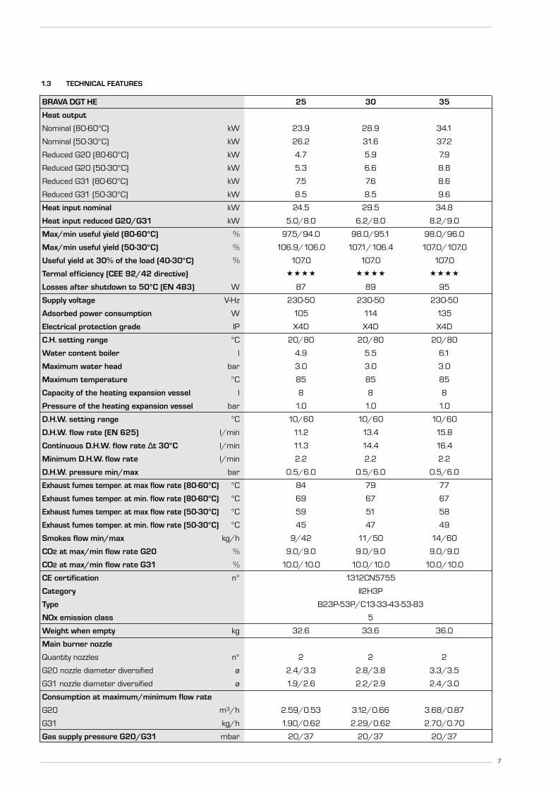
BRAVA DGT HE 25 30 35
Heat output
Nominal (80-60°C) kW 23.9 28.9 34.1
Nominal (50-30°C) kW 26.2 31.6 37.2
Reduced G20 (80-60°C) kW 4.7 5.9 7.9
Reduced G20 (50-30°C) kW 5.3 6.6 8.8
Reduced G31 (80-60°C) kW 7.5 7.6 8.6
Reduced G31 (50-30°C) kW 8.5 8.5 9.6
Heat input nominal kW 24.5 29.5 34.8
Heat input reduced G20/G31 kW 5.0/8.0 6.2/8.0 8.2/9.0
Max/min useful yield (80-60°C) % 97.5/94.0 98.0/95.1 98.0/96.0
Max/min useful yield (50-30°C) % 106.9/106.0 107.1/106.4 107.0/107.0
Useful yield at 30% of the load (40-30°C) % 107.0 107.0 107.0
Termal efficiency (CEE 92/42 directive)
Losses after shutdown to 50°C (EN 483) W 87 89 95
Supply voltage V-Hz 230-50 230-50 230-50
Adsorbed power consumption W 105 114 135
Electrical protection grade IP X4D X4D X4D
C.H. setting range °C 20/80 20/80 20/80
Water content boiler l 4.9 5.5 6.1
Maximum water head bar 3.0 3.0 3.0
Maximum temperature °C 85 85 85
Capacity of the heating expansion vessel l 8 8 8
Pressure of the heating expansion vessel bar 1.0 1.0 1.0
D.H.W. setting range °C 10/60 10/60 10/60
D.H.W. flow rate (EN 625) l/min 11.2 13.4 15.8
Continuous D.H.W. flow rate ∆t 30°C l/min 11.3 14.4 16.4
Minimum D.H.W. flow rate l/min 2.2 2.2 2.2
D.H.W. pressure min/max bar 0.5/6.0 0.5/6.0 0.5/6.0
Exhaust fumes temper. at max flow rate (80-60°C) °C 84 79 77
Exhaust fumes temper. at min. flow rate (80-60°C) °C 69 67 67
Exhaust fumes temper. at max flow rate (50-30°C) °C 59 51 58
Exhaust fumes temper. at min. flow rate (50-30°C) °C 45 47 49
Smokes flow min/max kg/h 9/42 11/50 14/60
CO2 at max/min flow rate G20 % 9.0/9.0 9.0/9.0 9.0/9.0
CO2 at max/min flow rate G31 % 10.0/10.0 10.0/10.0 10.0/10.0
CE certification n° 1312CN5755
Category II2H3P
Type B23P-53P/C13-33-43-53-83
NOx emission class 5
Weight when empty kg 32.6 33.6 36.0
Main burner nozzle
Quantity nozzles n° 2 2 2
G20 nozzle diameter diversified ø 2.4/3.3 2.8/3.8 3.3/3.5
G31 nozzle diameter diversified ø 1.9/2.6 2.2/2.9 2.4/3.0
Consumption at maximum/minimum flow rate
G20 m3/h 2.59/0.53 3.12/0.66 3.68/0.87
G31 kg/h 1.90/0.62 2.29/0.62 2.70/0.70
Gas supply pressure G20/G31 mbar 20/37 20/37 20/37
1.3 TECHNICAL FEATURES

3
1
4 9
10
18
1917
1615
87
11
12
5
14
6
2122 23 24
U E G M R S3S
2
1.4 FUNCTIONAL DIAGRAM (fig. 2)
Fig. 2
8
KEY1 Fan2 Limit stat3 Primary exchanger4 C.H. sensor (SM)5 Gas valve6 D.H.W. exchanger7 Heating water filter 8 Diverter valve9 Safety thermostat
10 Pump with air release vent11 D.H.W. flow meter12 Water inlet filter14 Pressure relief valve15 Water pressure switch16 Automatic bypass
17 Drain vent18 Expansion vessel19 Condensate drain trap21 D.H.W. isolation valve22 Gas isolation valve23 C.H. flow isolation valve24 C.H. return isolation valve
CONNECTIONSR C.H. returnM C.H. flowG Gas connectionE D.H.W. inletU D.H.W. outletS3 Condensation outletS Safety valve discharge

9
1
2
3
4
5
6
78
9
10
11
12
13
14
15
16
17
Fig. 3
1.5 MAIN COMPONENTS (fig. 3)
KEY1 Control panel2 Condensate drain trap3 Sensor (SM)4 Safety thermostat5 Ignition electrode6 Primary exchanger7 Air relief valve8 Limit stat9 Exhaust temperature sensor
10 Smoke chamber11 Expansion vessel12 Air inlet13 Ionisation electrode14 Fan15 Diverter valve16 Pump17 Programming clock
0 4
1 3
2bar
NOTE: Analogue pressure gauge

It is important that the boiler is initiallyfilled and started for the first time usingthe method shown in 2.3.3 section e).This procedure should also be used whenrefilling after draining a boiler.The boiler must be installed in a fixed loca-tion and only by specialized and qualified per-son in compliance with all instructions con-tained in this manual. The installation of this boiler must be inaccordance with the relevant requirementsof the current Gas Safety (installation anduse), the local building regulations, and andI.E.E. wiring regulations. Detailled recom-mendations for air supply are given inBS5440:2. The following notes are for gen-eral guidance: it is not necessary to have apurpose provided air vent in the room orcompartment in which the appliance isinstalled.
2.1 ANTI-FREEZE FUNCTION
The boilers are equipped with anti-freezefunction which activates the pump and theburner when the temperature of the watercontained inside the appliance drops tobelow value PAR 10. The anti-freeze function can only operate if:– the boiler is correctly connected to the
gas and electricity supply circuits;– the boiler is switched on;– the boiler ignition is not locked out;– the essential components of the boiler
are all in working order.
In these conditions the boiler is protectedagainst frost down to an environmentaltemperature of -5°C.
ATTENTION: In the case of installation in a place wherethe temperature drops below 0°C, theconnection pipes must be protected.
2.2 FIXING THE WALLMOUNTING BRACKET (fig. 4)
– Mark the position of the two wall mount-ing bracket fixing holes and the flue/airduct hole on the appropriate wall(s).
– Drill the two fixing holes using a 10 mmmasonry drill and fit the plastic plugs provided.
– Accurately measure the wall thickness,and note this dimension for later use.
– Secure the wall mounting bracket inposition using the screws provided.Ensure that it is the correct way up, asindicated in fig. 4.
2.3 CONNECTING UP SYSTEM
Before connecting the boiler it is recom-mended that the system be flushed inaccordance to BS 7593, to eliminate anyforeign bodies that may be detrimental tothe operating efficiency of the appliance.When connecting up the boiler the clear-ances in fig 1 should be respected. The boiler is supplied with a valve pack partnumber 5184817A. The boiler can be filledand pressure tested prior to any electricalsupply being connected with the use of theanalogue pressure gauge.A safety valve set at 3 bar is fitted to theappliance, the discharge pipe providedshould be extended to terminate safelyaway from the appliance and where a dis-charge would not cause damage to per-sons or property but would be detected. The pipe should be a minimum of 15 mm Øand should be able to withstand boilingwater, any should avoid sharp corners orupward pipe runs where water may beretained.
Gas ConnectionThe gas connection must be made using
seamless steel or copper pipe. Where the piping has to pass through walls,a suitable insulating sleeve must be provid-ed. When sizing gas piping, from the meterto the boiler, take into account both the vol-ume flow rates (consumption) in m3/h andthe relative density of the gas in question.The sections of the piping making up the sys-tem must be such as to guarantee a supplyof gas sufficient to cover the maximumdemand, limiting pressure loss between thegas meter and any apparatus being used tonot greater than 1.0 mbar for family II gases(natural gas). An adhesive data badge is sited inside thefront panel; it contains all the technical dataidentifying the boiler and the type of gas forwhich the boiler is arranged.
2.3.1 Connection of condensation water trap
To ensure safe disposal of the condensateproduced by the flue gases, referenceshould be made to BS6798:2009. The boiler incorporates a condensate trapwhich has a seal of 75 mm, therefore noadditional trap is required. The advisedmethod of connection to the condensatetrap is by using 20 mm overflow pipe with asocket attached to cover the condensatetrap connection. The condensate should ideally be dis-charged internally into an internal wastepipe(washing machine/sink waste) or a soilpipe to avoid the risk of freezing. External pipe runs should be avoided, butif it is necessary, the pipework should beat least 32mm and protected from therisc of freezing with a waterproof insula-tion and the length kept to a minimumand not exceeding 3 m. terminationshould be into an external gully or pur-pose made soakaway.
2 INSTALLATION
10
12
34
KEY1 Wall mounting bracket2 Plastic wall plug (2 Off)3 Woodscrew (2 Off)4 Washer (2 Off)
Fig. 4

NOTE: All pipework must have a continu-ous fall from the boiler and must be resis-tant to corrosion by condensate, copperor steel is NOT suitable. It should be noted that the connection of acondensate pipe to a drain may be subjectto local building control requirements.
2.3.2 Dealing with condensate
See APPENDIX A for guidance on the dis-posal of condensate.
2.3.3 Requirements for sealed watersystems (fig. 5)
The heating system design should be basedon the following information:a) The available pump head is given in fig.
14.b) The burner starts if the system pres-
sure is sufficient to operate the pres-sure switch.
c) The appliance is equipped with an inter-nal by-pass that operates with systemheads (H) greater than 3 m. The maxi-mum flow through the by-pass is about300 l/h. If thermostatic radiator valvesare to be installed, at least one radiatorshould be without a thermostatic valve
(usually the bathroom radiator or theradiator in the room containing theroom thermostat).
d) A sealed system must only be filled by acompetent person using a method simi-lar to that shown in fig. 5. The systemdesign should incorporate the connec-tions appropriate to one of these meth-ods.
e) It is most important that the boiler isnot allowed to ignite until it and theheating system is filled.Ensure that the electrical supply to theboiler is turned off.Open the auto air vent, D fig 15.Fill the system to approximately 1.5 bar.Use the manual air vent located on theuppermost connection to the primaryheat exchanger ( i tem 7 f ig . 3) torelease any air retained, and ensurethat all the radiators are vented.Top up the system pressure to 1.5 bar.Turn on the power supply to the boilerand put the boiler in the Summer mode.While in the Summer mode, adjust theheating flow temperature to its mini-mum 20 degrees. Put the boiler intothe Winter mode and allow it to ignite.Run the boiler in this mode for approxi-mately 30 minutes, regularly checkingthat trapped any air is released. andgradually increasing the flow tempera-
ture to 60 degrees. When inhibitor isadded repeat this procedure with theinitial flow temperature at 20 degrees.The flow temperature should then beset to the desired value.
2.4 CHARACTERISTICS OF FEEDWATER
– All recirculatory systems will be subjectto corrosion unless an appropriatewater treatment is applied. This means that the efficiency of thesystem will deteriorate as corrosionsludge accumulates within the system,risking damage to pump and valves, boil-er noise and circulation problems.
– For optimum performance after instal-lation this boiler and its associated cen-tral heating system must be flushed inaccordance with the guidelines given inBS 7593 “Treatment of water indomestic hot water central heating sys-tems”.Sime Ltd recommend only the use ofFERNOX products for the flushing andfinal treatment of the system water.This is particularly important in hardwater areas. Artificially softened water must not beused to fill the heating system.
11
METHOD OF FILLING A SEALED SYSTEM
Fig. 5

12
– It is important to check the inhibitorconcentration after installation, systemmodification and at every service inaccordance with the manufacturer’sinstructions (Test kits are available frominhibitor stockists).
– At every service the filter (4.5.2) shouldbe checked and cleaned.
2.5 INSTALLATION COAXIAL DUCTø 60/100 - ø 80/125 (fig. 6)
The coaxial suction and discharge pipes aresupplied in a special kit (that can be purcha-sed separately) a long with assemblyinstructions.
The diagrams of f ig. 6 illustrate someexamples of different types of fluing optionsallowed and the maximum lengths that canbe reached.
2.6 INSTALLATION OF SEPARATE DUCTS ø 80 (fig. 7)
The kit with dedicated pipes enables toseparate the exhaust fumes pipes from theair suction pipes (fig. 7): –for ø 80 pipes, divider code 8093050 is
provided upon request.
The maximum overall length, resultingfrom the sum of all the suction and
discharge pipes, is determined by theload losses of the single connected acces-sories and should not exceed 15 mm H2O(version 25-30-35) (ATTENTION: the totallength of each pipe should not exceed 50m, even if the total loss is below the maxi-mum applicable loss.)
See Table 3 for information on the load los-ses of single accessories (fig. 8).
2.6.1 Separate ducts kit (fig. 8)
The diagrams of Figure 8 show a couple ofexamples of the permitted exhausts confi-gurations.
C33
6
5
3
2
C43
3
4 2
x
y
x + y = L (m)
H (m
)
C13
12
1
L (m)
2
LIST OF ø 60/100 ACCESSORIES
1a Coaxial duct kit L. 790 code 8096250 1b Special coaxial duct kit L. 695 code 8098604/05 2a Extension L. 1000 code 80961502b Extension L. 500 code 80961513 Vertical extension L. 140 with coupling code 80869505 Tile for joint code 80913006 Terminal for roof exit L. 1285 code 8091212
(includes 8086950)
Model Length of pipe Length of pipeø 60/100 ø 80/125
H V H VMin Max Min Max
BRAVA DGT HE 25 6 m 1.3 m 8 m 12 m 1.2 m 15 mBRAVA DGT HE 30 5 m 1.3 m 7 m 10 m 1.2 m 13 mBRAVA DGT HE 35 4 m 1.3 m 6 m 10 m 1.2 m 13 m
LIST OF ø 80/125 ACCESSORIES
1 Coaxial duct kit L. 785 code 80962532a Extension L. 1000 code 80961712b Extension L. 500 code 80961703 Adapter for ø 80/125 code 80931505 Tile for joint code 80913006 Terminal for roof exit L. 1285 code 8091212A
(includes 8093150)
H (Horizontal) m
V (
Vert
ical
) m
IMPORTANT:– The insertion of each additional 90° bend with a diameter of 60/100 (code 8095850)
reduces the available section by 1.5 meters.– The insertion of each additional 90° bend with a diameter of 80/125 (code 8095870)
reduces the available section by 2 meters.– Each additional 45° curve installed a diameter of 60/100 (code 8095550) reduces the
available length by 1.0 metres.– Each additional 45° curve installed a diameter of 80/125 (code 8095970) reduces the
available length by 1.0 metres.
HORIZONTAL FLUES MUST BE LEVEL
NOTE: Before connecting accessories, it is always advisable to lubricate the internal part ofthe gaskets with silicon products. Avoid using oils and greases.
Fig. 6

2.7 POSITIONING THE OUTLET TERMINALS (fig. 9)
The outlet terminals for forced-draughtappliances may be located in the externalperimeter walls of the building.To provide some indications of possible solu-tions, Table 4 gives the minimum distancesto be observed, with reference to the typeof building shown in fig. 9.
2.9 ELECTRICAL CONNECTION
The boiler is supplied with an electric cable.Should this require replacement, it must bereplaced with one of similar type and dimen-sions. The electric power supply to the boiler mustbe 230V - 50Hz single-phase through a 3 ampfused main switch, with at least 3 mm spacingbetween contacts.
Respect the L and N polarities and the earthconnection.
NOTE: SIME declines all responsibility for injuryor damage to persons, animals or property,resulting from the failure to provide for properearthing of the appliance, or incorrect connec-tion of external controls. Any fault or compo-nent failure due to incorrect connection ofexternal controls is not covered in the warranty.
120183
139
185
185
80
80
1
2
3
CS CA13
0 (v
ers.
HE
35
)
Fig. 7
KEY1 Divider with vent2 Air intake3 Exhaust
CA InletCS Outlet
13
9
CC33
11
10
3
1 1
3
37
3
12 12
12
Fig. 8
C13
3
2
3
1
14
12
1312
NOTEBefore connecting accessories, it isalways advisable to lubricate the inter-nal part of the gaskets with siliconproducts. Avoid using oils and grea-ses.
TABLE 3 DGT HE 25 DGT HE 30 DGT HE 35Load loss - mm H2O Load loss - mm H2O Load loss - mm H2O
Inlet Exhaust Inlet Exhaust Inlet Exhaust
1 Air/smoke divider, code 8093050 0 0 0 0 0 02 90° bend, code 8077450 0.20 0.25 0.25 0.30 0.30 0.40
3 a Extension 80mm L. 1000, code 8077351 0.15 0.15 0.20 0.20 0.25 0.253 b Extension 80mm L. 500, code 8077350 0.075 0.075 0.10 0.10 0.125 0.125
7 45° bend, code 8077451 0.15 0.15 0.20 0.20 0.25 0.259 Inlet/ exhaust fitting, code 8091401 -- -- -- -- -- --
10 Articulated tile, code 8091300 -- -- -- -- -- --11 Vertical roof terminal, code 8091212B * 0.80 0.10 1.10 0.15 1.50 0.2013 Inlet/ exhaust fitting, code 8091401 -- -- -- -- -- --14 Coaxial Terminal, code 8096253A * 0.80 0.10 1.10 0.15 1.50 0.20
* This loss includes the losses with use of item 9 or 13

2.9.1 External controls (fig. 10)
Including connection of the RF clock kit Simepart number 7102604 (BCG part 138493). The heating demand on BRAVA DGT HE boi-lers can be controlled externally by either avoltage free or 240 volt demand. In either
case the boiler MUST have a permanentpower supply.
2.9.2 Connection of RF Clock (fig. 10)
Ensure that the boiler is isolated from the
power supply. Mount the receiver close tothe boiler at least 1.5 metres above thefloor. Avoid any location that would causereceptions problems. Connect the boiler tothe receiver as shown. Remove the wirelink in the TA connection at the boiler anddo not forget to link the “L” and “1” termi-
– If the terminal discharges into a pathway or passageway check that combustionproducts will not cause nuisance and that the terminal will not obstruct the pas-sageway.
– Where the lowest part of the terminal is fitted less than 2 m (78 in) aboveground, above a balcony or above a flat roof to which people have access, theterminal MUST be protected by a purpose designed guard.
– Where the terminal is fitted within 850 mm (34 in) of a plastic or painted gut-ter, or 450 mm (18 in) of painted eaves, an aluminium shield at least 1,500 mm(59 in) long must be fitted to the underside of the painted surface.
– The air inlet/outlet flue duct MUST NOT be closer than 10 mm (0.4 in) to com-bustible material.
– In certain weather conditions the terminal may emit a plume of steam. This isnormal but positions where this would cause a nuisance should be avoided.
Terminal position Minimum spacingA Directly below an openable window, air vent
or any other ventilation opening 300 mm 12 inB Below guttering, drain pipes or soil pipes (*) 75 mm 3 inC/D Below eaves, balconies or carport roof 200 mm 8 inE From vertical drain pipes or soil pipes 75 mm 3 inF From internal or external corners 300 mm 12 inG Above adjacent ground, roof or balcony level 300 mm 12 inH From a boundary or surface facing the boiler 600 mm 24 inI From a terminal facing the terminal 1,200 mm 48 inJ From an opening in the carport
(eg door, window into dwelling) 1,200 mm 48 inK Vertically from a terminal on the same wall 1,500 mm 60 inL Horizontally from a terminal on the same wall 300 mm 12 inM Horizontally from a vertical terminal to a wall 300 mm 12 inN Horizontally from an openable window or other opening 300 mm 12 inP Above an openable window or other opening 300 mm 12 inQ From an adjacent vertical terminal 600 mm 24 in
(*) For condensing boilers this distance can be reduced to 25 mm without effecting boiler per-formance, but it will be necessary to protect the surfaces from the effects of condensate
TABLE 4
Fig. 9
14

Fig. 10
Board programming clock (code 6301460)
15

16
2 BASIC SYSTEMMULTI-ZONE SYSTEM WITH VALVE, ROOM THERMOSTAT AND EXTERNAL SENSOR (Code 8094101)
TA
R M
SE
TA
VZ
TA1
VZ1
TA2
VZ2
1 BASIC SYSTEMSYSTEM WITH A DIRECT ZONE AND ROOM THERMOSTAT, OR WITH A REMOTE CONTROL (Code 8092219), KITEXPANSION REMOTE CONTROL (Code 8092240) AND EXTERNAL SENSOR (Code 8094101)
R M
SE
TA
CR
EXP
nals at the RF Receiver (fig. 10). The fittedtime clock can be disabled by linking termi-nal 7 & 8 on the terminal block.
2.9.3 Climatic control option
The boiler is designed for connection to anexternal temperature sensor, supplied onrequest (code 8094101) in conjunctionwith remote control (code 8092226),which can automatically regulate the tem-perature value of the boiler output accor-ding to the external temperature. For installation, follow the instruction in thepackage. Expansion control kit 8092240will also be required.
2.9.4 External wired controls
The heating function of the boiler can becontrolled by a 240v input connected to theexpansion board, terminal 1 and removal ofthe TA link on terminals 5 & 6 on the termi-nal block. A voltage free signal, TA, can beconnected to terminals 5 & 6 after remo-val of the link.
2.9.5 Use with different electronic systems
Some examples are given below of boilersystems combined with different electronicsystems. Where necessary, the parame-ters to be set in the boiler are given. The
electrical connections to the boiler refer tothe wording on the diagrams (fig. 11). Zonevalve control is activated with every hea-ting request from remote control. Descrip-tion of the letters indicating the compo-nents shown on the system diagrams 1 to3:M C.H. flowR C.H. returnCR Remote control CR 63SE External temperature sensorTA 1-2 Zone room thermostatVZ 1-2 Zone valveRL 1-2 Zone relaySl Hydraulic separatorP 1-2 Zone pumpEXP Expansion card
(code 8092240)

17
TA
R MSE
TA1 TA2TA
P2
RL
SI
RL1 RL2
P1P
3 BASIC SYSTEMMULTI-ZONE SYSTEM WITH PUMP, ROOM THERMOSTATS AND EXTERNAL SENSOR (Code 8094101)
18
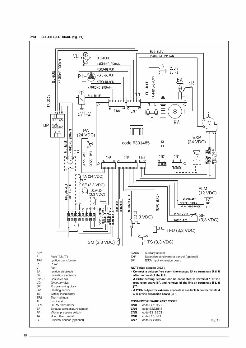
2.10 BOILER ELECTRICAL (fig. 11)
SM (3,3 VDC)
TFU (3,3 VDC)
TS (3,3 VDC)
SF(3,3 VDC)
FLM(12 VDC)
PA(24 VDC)
S.AUX(3,3 VDC)
SE (3,3 VDC)
TA (24 VDC)
EXP(24 VDC)code 6301485
BP code6301460
TL(3,3 VDC)
Fig. 11
KEYF Fuse (1.6 AT)TRA Ignition transformerPI PumpV FanEA Ignition electrodeER Ionisation electrodeEV1-2 Gas valve coilVD Divertor valveOP Programming clockSM Heating sensorTS Safety thermostatTFU Thermal fuseTL Limit statFLM D.H.W. flow meterSF Exhaust temperature sensorPA Water pressure switchTA Room thermostatSE External sensor (optional)
S.AUX Auxiliary sensorEXP Expansion card remote control (optional)BP 230v input expansion board
NOTE (See section 2.9.1): - Connect a voltage free room thermostat TA to terminals 5 & 6
after removal of the link.- A 230v heating demand can be connected to terminal 1 of the
expansion board BP, and removal of the link on terminals 5 & 6(TA
- A 230v output for external controls is available from terminals 4& 5 of the expansion board (BP).
CONNECTOR SPARE PART CODES:CN3 code 6319158CN4 code 6323814CN5 code 6316253CN6 code 6316266CN7 code 6323813

19
3 CHARACTERISTICS
3.1 CONTROL PANEL (fig. 12)
1 23
4
1 - DESCRIPTION OF DISPLAY ICONS
SUMMER MODE ICON
WINTER MODE ICON
D.H.W. MODE ICON
HEATING MODE ICON
BURNER LIT ICON
LOCKOUT DUE TO NOIGNITION/FLAME DETECTION
RESET REQUIRED
MAIN DIGITS
Fig. 12
2 - DESCRIPTION OF CONTROLS
OPERATING MODE/RESETPress this key repeatedly to step from standby tosummer to winter. The green LED will flash accompa-nied by a audible signal, to indicate that the key hasbeen pressed. Press the key for more than twoseconds to enter standby. RESET is only available if are-settable error is signalled.
D.H.W. SET Press the key to display the D.H.W. temperaturevalue set
HEATING SETPress the key to display the heating flow temperaturevalue set (value not realtive to the remote control)
DECREASEPressing this key decreases the value set
INCREASEPressing this key increases the value set
3 - LED GREEN
ON = Indicates the presence of electrical voltage. It switches of momentarily every time the keys are pressed. It can be disabled by setting PAR 3 = 0.
4 - LED RED
OFF = Normal operationON = Boiler error signalledFlashing when the control panel buttons are pressed inside thePARAMETERS SECTION.

20
3.2 ACCESS TO INSTALLER'S PARAMETERS
For access to the installer's parameters,press simultaneously the ( and ) keysfor 5 seconds.The red LED flashes and the display shows :
The parameters can be scrolled with or . To enter the parameter press or .The value set flashes, the display shows :
Proceed as follows to change the set value:– set the new value using or . – confirm the set value using or .
Press to exit the parameters section. Thedisplay is shown automatically after 5 minu-tes. The parameters section contains thealarms log, info and meters (display only).
3.2.1 Replacing the board or RESETTING parameters
If the electronic board is replaced or resetor the type of gas used is changed, it isnecessary to configure PAR 01 and PAR02 by associating the following values toeach type of boiler to be able to restart theboiler:
NOTE: the boiler panel has a label withthe values that have to be set for PAR 01and PAR 02 (fig. 19).
BOILER PAR 2
25-30-35 01
25-30-35combined with 02
sun-panel system
with storage tank 03
heating only 04
PARAMETERS INSTALLER
FAST CONFIGURATIONPAR DESCRIPTION RANGE UNIT OF INC/DEC DEFAULT
MEASUREMENT UNIT SETTING01 Combustion configuration -- = ND = = “--”
1 ... 2002 Hydraulic configuration -- = ND = = “--”
1 ... 1403 Disabling of the green LED 0 = Disabled = = 01
1 = Enabled04 Correction of external probe values -5 ... 05 °C 1 0005 Default time for keypad locking -- = Disabled Min. 1 15
1 ... 9909 Fan rpm Step ignition 00 .... 81 rpm x 100 0,1 from 0,1 to 19,9 00
1 from 20 to 81D.H.W. - HEATINGPAR DESCRIPTION RANGE UNIT OF INC/DEC DEFAULT
MEASUREMENT UNIT SETTING10 Frost protection temperature 0 ... 10 °C 1 0311 External sensor antifreeze -- = Disabled °C 1 - 2
- 9 ... 0512 Climatic curve setting 03 ... 40 = 1 2013 Minimum heating temperature 20 ... PAR 14 °C 1 2014 Maximum heating temperature PAR 13 ... 80 °C 1 8015 Maximum heating power 30 ... 99 % 1 9916 Post-circulation time 0 ... 99 10 sec. 1 0317 Pump heating activation delay 0 ... 99 10 sec. 1 0118 Re-ignition delay 0 ... 10 Min. 1 0319 Flow meter modulation saturation band 0 ... 99 % 1 3029 Anti-legionella (only D.H.W. tank) O = Disabled = = 0
1 = Enabled
PARAMETERS RE-SETPAR DESCRIPTION RANGE UNIT OF INC/DEC DEFAULT
MEASUREMENT UNIT SETTING49 * Reset default parameters -- , 1 = = =
(PAR 01 - PAR 02 equal “---”)
* To reset the circuit board to the default settings, set PAR49 to 1.PAR1 and PAR2 will need to be set as shown in 3.2.1.
ALARMS (Display)PAR DESCRIPTION RANGE UNIT OF INC/DEC DEFAULT
MEASUREMENT UNIT SETTINGA0 Code of last error = = = =A1 Code of last error - 1 = = = =A2 Code of last error - 2 = = = =A3 Code of last error - 3 = = = =A4 Code of last error - 4 = = = =A5 Code of last error - 5 = = = =A6 Code of last error - 6 = = = =A7 Code of last error - 7 = = = =A8 Code of last error - 8 = = = =A9 Code of last error - 9 = = = =
INFO (Display)PAR DESCRIPTION RANGE UNIT OF INC/DEC DEFAULT
MEASUREMENT UNIT SETTINGi0 External sensor temperature -9 ... 99 °C 1 =i1 C.H. 1 sensor temperature -9 ... 99 °C 1 =i2 C.H. 2 sensor temperature -9 ... 99 °C 1 =i3 Fumes sensor temperature -9 ... 99 °C 1 =i4 Auxiliary sensor AUX temperature -9 ... 99 °C 1 =i5 Set of effective heating temperature PAR 13 ... PAR 14 °C 1 =i6 Level ionization flame 00 ... 99 % 1 =i7 Fan speed 00 ... 99 100 rpm 1 =i8 Flow rate D.H.W. flow meter 00 ... 99 l/min 1 =
COUNTERS (Display)PAR DESCRIPTION RANGE UNIT OF INC/DEC DEFAULT
MEASUREMENT UNIT SETTINGc0 Number hours of operation of the burner 00 ... 99 h x 100 0,1 from 0,0 to 9,9 00
1 from 10 to 99c1 Number of ignitions of the burner 00 ... 99 x 1000 0,1 from 0,0 to 9,9 00
1 from 10 to 99c2 Total number of errors 00 ... 99 x 1 1 00c3 Number accesses of Installer parameters 00 ... 99 x 1 1 00c4 Number of accesses of OEM parameters 00 ... 99 x 1 1 00
GAS MODELS PAR 1
METHANE 25 01(G20) 30 02
35 03
PROPANE 25 04(G31) 30 05
35 06

21
3.3 EXTERNAL SENSOR (fig. 13)
If there is an external sensor, the heatingsettings SET can be taken from the climaticcurves according to the external tempera-ture and, limited to with the range valuesdescribed in point 3.2 (parameters PAR 13and PAR 14). The climatic curve to be set can be selectedfrom a value of 3 and 40 (at step 1).Increasing the steepness of the curves offig. 14 will increase the output temperatureas the external temperature decreases.
3.5 CARD FUNCTIONING
The electronic card has the followingfunctions:
– Antifreeze protection of the heating cir-cuits.
– Ignition and flame detection system.– Control panel setting for the power and
the gas for boiler functioning.– Anti-jammed for the pump which is fed
for a few seconds (10”) after 48 hours ofinactivity.
– Chimney sweep function which can beactivated from the control panel.
– Temperature which can be shifted withthe external sensor connected.
– Automatic regulation of the ignitionpower and maximum heating. Adjustments are managed automaticallyby the electronic card to guarantee maxi-mum flexibility in use of the system.
– Interface with the following electronicsystems: remote control CR 73 combi-ned with expansion card kit code8092240.
3.6 TEMPERATURE DETECTION SENSOR
Table 4 shows the resistance values of theheating, D.H.W. and fumes sensor.
If the heating sensor (SM) and fumes sen-sor (SF) is faulty or open circuit, the boi-ler will not function on either heating orD.H.W.
3.6 ELECTRONIC IGNITION
Ignition and flame detection is controlled byelectrodes on the burner which guaranteesreaction in the case of accidental extinctionor lack of gas within one second.
3.6.1 Functioning cycle
Burner ignition should occur within 10seconds of the opening of the gas valve. Ifafter three attempts the ignition is notdetected the boiler will lockout (ALL 06):
– Lack of gasThe ignition electrode will discharge for amaximum of 10 seconds. If after threeattempts the ignition is not detected theboiler will lockout (ALL 06). This can happen the first time a boiler isswitched on, or after long periods of inac-tivity. It can also be caused by a closedgas cock or a gas valve not operating.
– No ionisationThe boiler will spark for 10 seconds, ifafter 3 attempts the ionisation is notdetected, the boiler will lockout (ALL 06).This could be due to a poor connection orbreak in the ionisation cable. Check also that the cable is not shorted,badly worn or distorted.
In the case of a sudden loss of voltage, the
burner will immediately switch off. Whenthe voltage is restored, the boiler will auto-matically start up again.
3.7 HEAD AVAILABLE TO SYSTEM (fig. 14 - fig. 15)
Residual head for the heating system isshown as a function of rate of flow in thegraph in fig. 14. To obtain the maximum head available tothe system, turn off the by-pass by turningthe union to the vertical position (fig. 15).
3.8 WATER PRESSURE SWITCH (fig. 15)
The water pressure switch (C fig. 15) inter-venes, blocking burner functioning, if itdetects that there is insufficient pressurein the boiler (< 0,6 bar).To restore the boiler operation, increasethe system pressure to 1 - 1,2 bar.
TABLE 4 (SM - SF sensors)
Temperature (°C) Resistance (Ω)20 12.09030 8.31340 5.82850 4.16160 3.02170 2.22980 1.669
Fig. 13
ATTENTION: curves are calculated at an ambient temperature of 20°C.The user can act on the boiler controls to change the environment setfor which the bend has been calculated by ±5°C.

22
0
600
200 12001000800600400
PORTATA (l/h)
PR
EVA
LEN
ZA
RES
IDU
A (m
bar)
500
400
100
200
300
Bra
va D
GT
HE
35
HE 35
0
600
200 12001000800600400
PORTATA (l/h)
PR
EVA
LEN
ZA
RES
IDU
A (m
bar)
500
400
100
200
300
Bra
va D
GT
HE
25
-30
HE 30
HE 25
con by-passsenza by-pass
con by-passsenza by-pass
A
B
C
RIFERIMENTO POSIZIONE BY-PASS
D
Fig. 15
Fig. 14
LEGENDAA By-pass onB By-pass offC Water pressure switchD Auto air vent
REFERENCE POSITION BY-PASS
RES
IDU
AL
HEA
D (
mba
r)
FLOW RATE (l/h)
By-pass on
By-pass off
RES
IDU
AL
HEA
D (
mba
r)
FLOW RATE (l/h)
By-pass on
By-pass off

23
PLEASE NOTE: During routine servicing andafter any maintenance or change of part ofthe combustion circuit, the following mustbe checked:- The integrity of the flue system and the
flue seals- The integrity of the boiler combustion cir-
cuit and relevant seals.- The operational working gas pressure as
described in section 4.7.1- The combustion performance as descri-
bed in section 4.8.1
4.1 GAS VALVE (fig. 16)
The boiler is supplied as standard with agas valve, model SIT 848 SIGMA (Fig. 16).
4.2 GAS CONVERSION (fig. 17)
This operation must be performed byauthorised personnel using original Simecomponents.To convert from natural gas to LPG or viceversa, perform the following operations– Close the gas cock.– Replace the two differential nozzles (1-2)
and relative seal o-rings (3) with thosesupplied in the transformation kit. NOTE: the difference in the shape of thehead of the nozzles, avoid reversalduring assembly.
– Reset PAR as shown in 4.2.1.– Apply the nameplate with the new gas
flow layout.– Calibrate the maximum and minimum
pressures of the gas valve following theinstructions provided in paragraph 4.2.2.
4.2.1 New fuel configuration
Access the parameters section by pres-sing the control panel keys ( and ) at
the same time for 5 seconds. The red LEDflashes and the display shows :
Scroll the parameters using or . To enter the fuel configuration paramaterPAR 01, use or . The set value flashes a BRAVA DGT HE 30on natural gas will be show as :
For a BRAVA DGT HE 30 boiler to functionwith LPG, press until 05 appears.Confirm this value using or .Exit the parameters section by pressing .
The table below gives the values to setwhen the supply gas is changed:
4.2.2 Calibrating the gas valve pressures (See 4.8.1)
This can only be done using a flue gas analy-ser. If the combustion reading is greaterthan the acceptable value AND the integrityof the complete flue system and combu-
stion seals have been verified, and the inletgas pressure has been verified then adjust-ments to the gas valve can be made asdescribed below. Make only small adjust-ments (1/8 turn max), and allow time forthe combustion analysis to be made beforemaking further adjustments.
Sequence of operations:
1) Press buttons and at the sametime for 5 seconds. Chimney sweep mode,see 4.5.1 (Lo) will appear on the displayand the boiler will work at minimum power.
2) Press button to raise the boiler tomaximum power (Hi).
3) Determine the CO2 values at max powerstated below, if required adjust using thecapacity step (5 fig. 16):
4) Press button to bring the boiler tominimum power (Lo).
5) Determine the CO2 values at min powerstated below, if required adjust using theOFF-SET adjustment screw (6 fig. 16):
6) Press buttons and several timesto verify the pressures; if necessary,make the appropriate corrections.
7) Press button to exit the function.
4.3 RATIO
Fig. 16
KEY1 Upstream pressure intake2 Intermediate pressure intake3 Air signal inlet (VENT)4 Downstream pressure intake5 Capacity step6 OFF-SET
4 USE, MAINTENANCE (including BENCHMARK) AND COMMISSIONIG
1
2
3
4 5
6
MAX powerBoiler CO2 CO2
model (Methane) (Propane)25-30-35 9,0 ±0,3 10,0 ±0,3
MIN powerBoiler CO2 CO2
model (Methane) (Propane)25-30-35 9,0 ±0,3 10,0 ±0,3
GAS MODELS PAR 1
METHANE 25 01(G20) 30 02
35 03
PROPANE 25 04(G31) 30 05
35 06
CO ppm
100 400
0,0011 0,0044
0,0010 0,0040
1
2
3
3Fig. 17

24
4.4 DISASSEMBLING THE SHELL (fig. 19)
To simplify maintenance operations on theboiler, it is also possible to completely remo-ve the shell, as shown in figure 19. Removethe screws securing the control panel andtilt it forward and be able to access theinternal components of the boiler.
4.5 MAINTENANCE (fig. 20)
To guarantee the operation and efficiencyof the appliance and to conform to anyextended warranty, it must be servicedregularly, dependant on usage, but at leastannually by a qualified Gas Safe Registeredengneer.
During maintenance operations, it isimportant to verify that the condensatetrap contains water (this check is particu-larly important if the generator has not
been used for extended periods of time). Ifnecessary, the condensate trap can be fil-led using the filling point provided (fig. 20).
4.5.1 Chimney sweep function (see also 4.8.1)
To check boiler combustion, press at thesame time the installer's key ( e ) for afew seconds. The chimney sweep functionwill switch on and will continue for 15 minu-tes. During the 15 minutes functioning ofchimney sweep function, pressing the keys( and ) take the boiler respective atmaximum (Hi) and at minimum (Lo) power.From that moment, the boiler will startworking in heating mode at maximumpower, with cut off at 80°C and re-ignitionat 70°C.
Before activating the chimney sweep func-tion make sure that the radiator valves orzone valves are open.
The test can also be carried out with theboiler working in D.H.W. mode. For this, after activating the chimney sweepfunction, open one or more hot water taps.
2
4 x
1
Fig. 19
Codice/Code 8111800Modello/Model BRAVA DGT HE 25Matricola/Serial n. 9999999999
PAR 1 = 01 (METANO)/ 04 (GPL)PAR 2 = 01
Fig. 20

25
Under these conditions, the boiler will func-tion at maximum power with the D.H.W.kept at between 60°C and 50°C. Duringthe test, the hot water taps must remainopen. For exit to the chimney sweep func-tion press the key of the control panel.
The chimney sweep function will automa-tically switch off after 15 minutes fromthe activation.
4.5.2 Clean heating water filter (fig. 21)
To clean the filter, turn of f the systemflow/return valves, turn control boardpower off, remove the casing and emptythe boiler through the relevant drain. Place a collecting vessel under the filter. Use pliers to remove the filter clean it remo-ving impurities and lime scale deposits.
4.6 FUNCTIONING ERRORS
When there is a functioning error, an alarmappears on the display and switch on thered led. Descriptions of the errors withrelative alarms and solutions are givenbelow (if a error persists contact a authori-sed service engineer):
– LOW WATER PRESSURE ERROR ALARM 02 (fig. 22/a)If the pressure detected by the waterpressure valve is lower than 0.5 bar, theboiler stops and the display shows thealarm “AL 02”. Increase the system pressure tobetween 1.0 and 1.2 bar (use pressuregauge, fig 22/a) using the external fillingloop. The boiler will automatically resumeoperating.
– HEATING SENSOR ERROR ALARM 05 When C.H. sensor (SM) is open or shortcircuited, the boiler will not function andthe display will show the alarm “AL 05”.
– LOCKOUT ALARM 06 (fig. 22/b)If the flame control has not detected the presence of the flame after a completeignition sequence, or for any other rea-son the card cannot “see” the flame, theboiler will stop and the display will showthe alarm “AL 06”. Press the key ofthe controls to start up the boiler again.
– SAFETY THERMOSTAT ERROR ALARM 07 (fig. 22/c)Opening of the safety thermostat willturn of the burner, the display will showAL07. If the problem persists for morethan one minute, the boiler will stop and
the red LED will turn on. Press the key of the controls to startup the boiler again.
– FLAME DETECTION ERROR ALARM 08 If a flame is detected when one shouldnot be present, the boiler will stop andthe display will show "AL 08"
– AUXILIARY SENSOR ERROR ALARM 10 ONLY FOR BOILER WITH SOLAR PLANTCOUPLING (PAR 2 = 2): D.H.W. inlet probe anomaly. When theprobe is open or short circuited the boi-ler looses the solar function and thedisplay shows anomaly AL 10.
– ACTIVATION OF THE EXHAUST TEMPE-RATURE SENSOR ERROR “AL 13” (fig.22/d)The activation of the exhaust fumes sen-
Fig. 21
Fig. 22/b Fig. 22/c
0 4
1 3
2bar
Fig. 22/a

26
sor causes the boiler to stop and thedisplay will show AL 13.Press the key of the controls to startup the boiler again.
– EXHAUST TEMPERATURE SENSOR ERROR “AL 14”When the exhaust fumes sensor is ope-ned or short-circuited, the boiler stopsand the displays shows anomaly AL 14.
– FAN ERROR “AL 15”If the fan speed is not within the ratedspeed range , the display will show "AL15. If the problem persists for morethan two minutes the boiler will stop forthirty minutes and then attempt to resu-me working.
4.7 COMMISSIONING AND ROUTINE SERVICE
Commissioning and servicing can only bedone by a qualified engineer.
4.7.1 Commissioning
PLEASE NOTE: The combustion for thisappliance has been checked, adjusted andpreset at the factory for operation on thegas type defined on the appliance dataplate. However it is advisable to check for correctcombustion having first checked:- That the boiler has been installed in
accordance with these instructions.- The integrity of the flue system and the
flue seals.- The integrity of the boiler combustion cir-
cuit and all the relevant seals.
The following procedure should be doneafter installation a gas purge and tight-ness/drop test have been made.Ensure that the auto air vent (12 fig. 3) isopened, turn the electrical supply on.With the boiler on standby fill the systemand pressurise to 1.5 bar.Ensure that the pump has been manuallyrotated.Open the gas cock, press the “ modekey” (fig. 12).Check the operational (working) gas inlet
pressure.Set up the boiler to operate at maximumrate as descr ibed in 4.5.1 (Chimneysweep]).With the boiler operating in the maximumrate condition check that the operational(working) gas pressure at the inlet testpoint (see fig 16 item 1) is 21 mb +/- 2mb.Ensure that this inlet pressure can beobtained with all other gas appliances inthe property working.The boiler will attempt to light.Press “ mode key” (fig. 12).The burner will extinguish.Turn on a DHW tap fully (preferably thebath tap).Set the controls to the required values asshown in the user guide.Complete the Benchmark sheet enclosedin this manual.Explain controls and operation to the user.Leave all documentation with the user.
4.8 ROUTINE SERVICE
To comply with the conditions of any exten-ded warranty offered and to ensure conti-nued safe and efficient operation, the boilermust be serviced at regular intervals, atleast once a year. This service must berecorded in the Benchmark section of thismanual.It is the law that a competent person suchas a Gas Safe Register registered engineer,must carry out any service work.
4.8.1 Combustion Check (fig. 23)
Competence to carry out the check of com-bustion performance.PLEASE NOTE: BS 6798: 2009 Specifica-tion fro installation and maintenance ofgas-fired boilers of rated input not excee-ding 70 kw net advises that:* The person carrying out a combustion
measurement should have been asses-sed as competent in the use of a flue gasanalyser and the interpretation of theresults;
* The flue gas analyser should be one mee-
ting the requirements of BS7927 or BS-EN50379-3 and be calibrated in accor-dance with the analyser manufacturersrequirements, and
* Competence can be demonstrated bysatisfactory completion of the CPA1 ACSassessment which covers the use ofelectronic portable combustion gasanalysers in accordance with BS7967,parts 1 to 4.
Conduct a flue gas analysis as detailed inAppendix 2.See 4.5.1 "Chimney sweep" for details howto set the boiler to minimum and maximumoutputs.
4.8.2 Burner inspection
– Isolate from mains – Remove case cover– Isolate gas– Drop down control case– Remove ignition and ionisation lead – Disconnect gas pipe from gas valve to
burner mixing arm,– Disconnect air sensing tube– Remove air inlet to fan and disconnect
the fan wiring– Remove the four nuts securing the bur-
ner to the heat exchanger.– Carefully lift out the burner.– Check seals and replace if necessary– Replace in reverse order
Test for gas tightness.
4.8.3 Combustion Chamber
Remove any loose debris from the combu-stion chamber using a soft brush and avacuum cleaner. Take care not to damage the rear insula-tion panel.
4.8.4 Condensate Trap
The condensate trap would not normallyrequire removal during service, but can bechecked whilst the burner assembly isremoved.Carefully pour water into the heat exchan-ger and check that it flows freely to thedrain. Should it require removal, firstly removethe two wire clips securing the condensatedrain rubber pipe to the heat exchangerand the condensate trap.Remove the pipe.Remove the 1/2” nut securing the conden-sate trap to the bracket.Disconnect the drain pipe from the trap.Clean the trap and refit in reverse order.
Fig. 22/d
Fig. 23
27
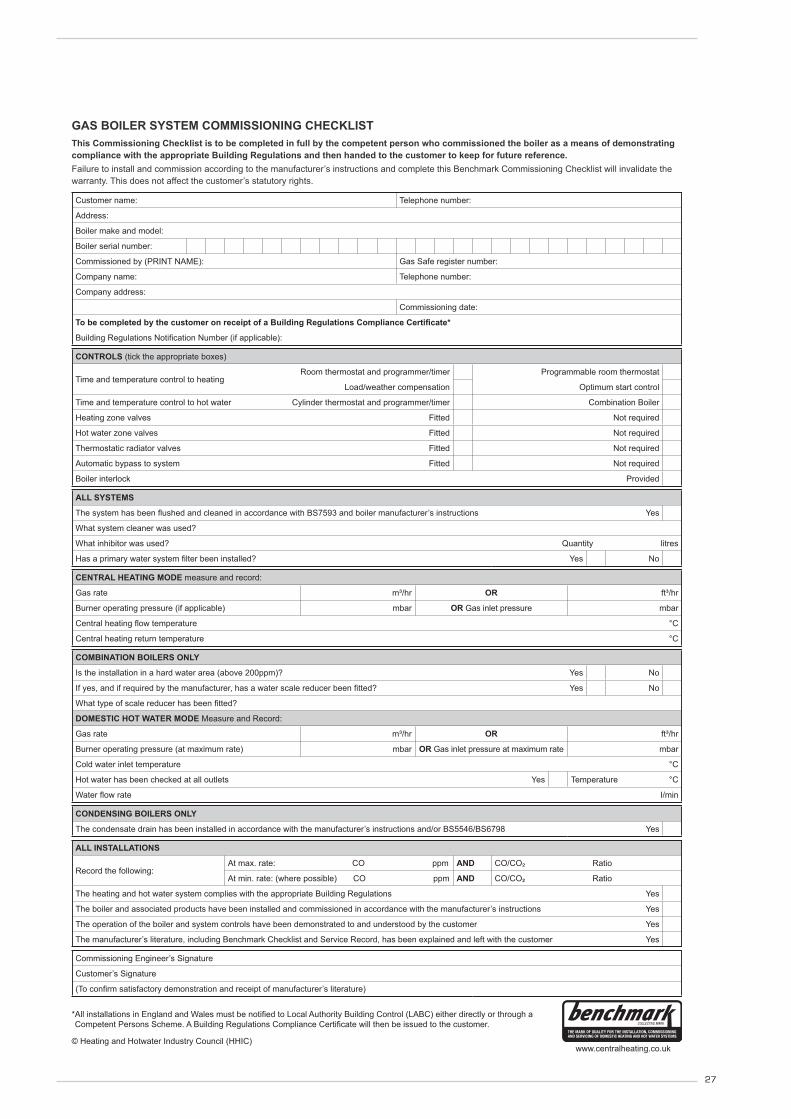
*All installations in England and Wales must be to Local Authority Building Control (LABC) either directly or through aCompetent Persons Scheme. A Building Regulations Compliance will then be issued to the customer.
www.centralheating.co.uk© Heating and Hotwater Industry Council (HHIC)
This Commissioning Checklist is to be completed in full by the competent person who commissioned the boiler as a means of demonstrating compliance with the appropriate Building Regulations and then handed to the customer to keep for future reference.Failure to install and commission according to the manufacturer’s instructions and complete this Benchmark Commissioning Checklist will invalidate the warranty. This does not affect the customer’s statutory rights.
GAS BOILER SYSTEM COMMISSIONING CHECKLIST
Customer name: Telephone number:
Address:
Boiler make and model:
Boiler serial number:
Commissioned by (PRINT NAME): Gas Safe register number:
Company name: Telephone number:
Company address:
Commissioning date:
CONTROLS (tick the appropriate boxes)
Time and temperature control to heatingRoom thermostat and programmer/timer Programmable room thermostat
Load/weather compensation Optimum start control
Time and temperature control to hot water Cylinder thermostat and programmer/timer Combination Boiler
Heating zone valves Fitted Not required
Hot water zone valves Fitted Not required
Thermostatic radiator valves Fitted Not required
Automatic bypass to system Fitted Not required
Boiler interlock Provided
ALL SYSTEMS
’s instructions Yes
What system cleaner was used?
What inhibitor was used? Quantity litres
Yes No
CENTRAL HEATING MODE measure and record:
Gas rate m³/hr OR ft³/hr
Burner operating pressure (if applicable) mbar OR Gas inlet pressure mbar
°C
Central heating return temperature °C
COMBINATION BOILERS ONLY
Is the installation in a hard water area (above 200ppm)? Yes No
Yes No
DOMESTIC HOT WATER MODE Measure and Record:
Gas rate m³/hr OR ft³/hr
Burner operating pressure (at maximum rate) mbar OR Gas inlet pressure at maximum rate mbar
Cold water inlet temperature °C
Hot water has been checked at all outlets Yes Temperature °C
I/min
CONDENSING BOILERS ONLY
The condensate drain has been installed in accordance with the manufacturer’s instructions and/or BS5546/BS6798 Yes
ALL INSTALLATIONS
Record the following:At max. rate: CO ppm AND CO/CO² Ratio
At min. rate: (where possible) CO ppm AND CO/CO² Ratio
The heating and hot water system complies with the appropriate Building Regulations Yes
The boiler and associated products have been installed and commissioned in accordance with the manufacturer’s instructions Yes
The operation of the boiler and system controls have been demonstrated to and understood by the customer Yes
The manufacturer’s literature, including Benchmark Checklist and Service Record, has been explained and left with the customer Yes
Commissioning Engineer’s Signature
Customer’s Signature

28
*All installations in England and Wales must be to Local Authority Building Control (LABC) either directly or through aCompetent Persons Scheme. A Building Regulations Compliance will then be issued to the customer.
© Heating and Hotwater Industry Council (HHIC)www.centralheating.co.uk
It is recommended that your heating system is serviced regularly and that the appropriate Service Interval Record is completed.Service ProviderBefore completing the appropriate Service Record below, please ensure you have carried out the service as described in the manufacturer’s instructions.
SERVICE RECORD
SERVICE 01 Date:
Engineer name:Company name:Telephone No:Gas safe register No:
Record:At max. rate: CO ppm AND CO² %At min. rate: (Where Possible) CO ppm AND CO² %
Comments:
Signature
SERVICE 02 Date:
Engineer name:Company name:Telephone No:Gas safe register No:
Record:At max. rate: CO ppm AND CO² %At min. rate: (Where Possible) CO ppm AND CO² %
Comments:
Signature
SERVICE 03 Date:
Engineer name:Company name:Telephone No:Gas safe register No:
Record:At max. rate: CO ppm AND CO² %At min. rate: (Where Possible) CO ppm AND CO² %
Comments:
Signature
SERVICE 04 Date:
Engineer name:Company name:Telephone No:Gas safe register No:
Record:At max. rate: CO ppm AND CO² %At min. rate: (Where Possible) CO ppm AND CO² %
Comments:
Signature
SERVICE 05 Date:
Engineer name:Company name:Telephone No:Gas safe register No:
Record:At max. rate: CO ppm AND CO² %At min. rate: (Where Possible) CO ppm AND CO² %
Comments:
Signature
SERVICE 06 Date:
Engineer name:Company name:Telephone No:Gas safe register No:
Record:At max. rate: CO ppm AND CO² %At min. rate: (Where Possible) CO ppm AND CO² %
Comments:
Signature
SERVICE 07 Date:
Engineer name:Company name:Telephone No:Gas safe register No:
Record:At max. rate: CO ppm AND CO² %At min. rate: (Where Possible) CO ppm AND CO² %
Comments:
Signature
SERVICE 08 Date:
Engineer name:Company name:Telephone No:Gas safe register No:
Record:At max. rate: CO ppm AND CO² %At min. rate: (Where Possible) CO ppm AND CO² %
Comments:
Signature
SERVICE 09 Date:
Engineer name:Company name:Telephone No:Gas safe register No:
Record:At max. rate: CO ppm AND CO² %At min. rate: (Where Possible) CO ppm AND CO² %
Comments:
Signature
SERVICE 10 Date:
Engineer name:Company name:Telephone No:Gas safe register No:
Record:At max. rate: CO ppm AND CO² %At min. rate: (Where Possible) CO ppm AND CO² %
Comments:
Signature

29
If an electrical fault occurs on the appliancethe preliminary electrical system checksmust be carried out first. When any service or replacement of elec-trical components which has required thebreaking and re-making of electrical con-nections has taken place, the following testsmust be repeated:– earth continuity;– short circuit;– polarity;– resistance to earth.
5.1 EARTH CONTINUITY CHECK
Appliances must be electrically disconnect-ed, meter set on Ω (ohm) x 1 scale andadjust zero if necessary. Tests leads fromany appliance earth point (e.g. inside controlbox) see wiring diagrams (section 7) toearth pin on plug. Resistance should be less than 1 Ω (ohm). Ifthe resistance is greater than 1 Ω (ohm)check all earth wires for continuity and allcontacts are clean and tight. If the resis-tance to earth is still greater than 1 Ω(ohm) then this should be investigatedfuther.
5.2 SHORT CIRCUIT CHECK
Switches turned FULL ON - meter set on Ω(ohms) x 1 scale. Test leads from L to N onappliance terminal block, if meter reads 0then there is a short circuit.Meter set on Ω (ohm) x 100 scale. Repeatit with leads from L to E. If meter reads lessthan infinity (∞) there is a fault.
NOTE: Should it be found that the fuse hasfailed but no fault is indicated, a detailedcontinuity check (i.e. by disconnecting andchecking each component) is required totrace the faulty component.It is possible that a fault could occur as aresult of local burning/arcing but no faultcould be found under test. However, adetailed visual inspection should revealevidence of burning around the fault.
5.3 POLARITY CHECK
Appliance reconnected to mains supply andmeter set on 300 V ac scale. Test at appli-ance terminal block.– Test leads from L to N meter reads
approx.: 240 V ac.– Test leads from L to E “ ” meter reads
approx. 240 V ac.– Test leads from N to E “ ” meter reads
from 0 to 15 V ac.
5.4 RESISTANCE TO EARTH CHECK
Appliance must be disconnected from mainsupply and meter on Ω (ohm) x 100 scale. All switches including thermostat on testleads from L to E - if meter reads other thaninfinity (∞) there is a fault which should beisolated. A detailed continuity check is required totrace the faulty component.
IMPORTANT: These series of checks are the first elec-trical checks to be carried out during afault finding procedure. On completionof the service/fault finding task whichhas required the breaking and remakingof electrical connections then thechecks 5.1 Earth continuity, 5.3 Polarityand 5.4 Resistance to earth must berepeated.
5 FAULT FINDING
6.1 REMOVAL OF BURNER ASSEMBLY
– Isolate from mains – Remove case cover– Isolate gas– Drop down control case– Remove ignition and ionisation lead – Disconnect gas pipe from gas valve to
burner mixing arm,– Disconnect air sensing tube– Remove air inlet to fan and disconnect
fan wiring– Remove the four nuts securing the bur-
ner to the heat exchanger – Carefully remove the burner assembly– Check seals and replace if necessary– Replace in reverse order – Test for gas tightness
6.2 REMOVAL OF FAN UNIT
– Isolate from mains– Remove case cover– Isolate gas supply– Drop down control cover– Remove the burner as described in 6.1– Loosen 2 x 8mm bolts from fan and
remove 2 – Remove fan – Transfer air hose connector and restric-
tor if fitted to now fan– Refit in reverse order– Re commission boiler– Test for gas tightness
6.3 HEATING THERMISTOR (SM SENSOR)
– Remove case cover– Unclip thermistor from flow pipe– Disconnect cable– Refit in reverse order
6.5 SAFETY STAT
– Isolate from mains– Remove case cover– Pull clip forwards slide stat upwards– Remove 2 black wires connected– Apply heat sink compound to new stat– Replace in reverse order
6.6 EXHAUST TEMPERATURE SENSOR
– Isolate from mains– Remove case cover– Unplug cable from sensor– Unscrew sensor
– Refit in reverse order
6.7 IGNITION ELECTRODE
– Turn off power supply– Remove case cover– Disconnect electrode from the PCB– Pull lead through grommet– Remove electrode fixing screw– Carefully remove electrode from bur-
ner– Replace in reverse order.
6.8 IONISATION ELECTRODE
– Turn off power supply– Remove case cover– Disconnect electrode – Remove electrode fixing screw– Carefully remove electrode from bur-
ner– Replace in reverse order.
6.9 EXPANSION VESSEL
– Isolate from mains– Remove case cover– Isolate flow and return valves– Drain boiler using fitted drain vent
6 REPLACEMENT OF PARTS

30
– Disconnect expansion pipe– Remove expansion securing nut– Remove vessel– Check new vessel for correct pressure
1-1.25 bar– Refit in reverse order
6.10 GAS VALVE (fig. 24)
– Isolate from mains– Remove cover– Isolate gas supply– Disconnect leads from gas valve– Disconnect sensing tube– Remove gas valve– Refit in reverse order ensuring seals are
replaced as required fit in reverse orderensuring seals are replaced as required
– Setting the gas valve procedure forBRAVA DGT HE:1. Remove the heating sensor from
the flow pipe. 2. Open the downstream test point
(4 fig. 24) and connect a digitalmanometer set on the mmH20scale. Ensure the meter iszeroed.
3. Simultaneously press the - and +buttons for 5 seconds to enter“chimney sweep”. “Lo” will appearon the display and the boiler runsat minimum power.
4. Press the + button and the boilerwill go to maximum power “Hi” willbe displayed.
5. Fully open the SHUTTER (5 fig.24) - turn anti clockwise.
6. With the shutter fully open, adjustthe OFF-SET (6 fig. 24) to obtainthe first pressure value shown inTable 1 - OFF-SET column, ensurethat the value is correct for thegas being used. If these figuresare not obtainable, confirm thatthe working inlet gas pressure iscorrect.
7. Close the SHUTTER (5 fig. 24) toobtain the second pressure rea-ding indicated in Table 1 – SHUT-TER column.
8. Once these adjustments havebeen obtained, a flue gas analysismust be done. See section 4.2.2.
9. Press the - button to return theboiler to minimum output “Lo” willbe displayed.
10. Check the analyzer CO2/Ratioand compare to values reportedin Table 1. Make any final adjust-ments by small adjustments tothe OFF-SET screw.
11. Press the + button and verify thatthe CO2/Ratio has remained sta-ble.
12. Press the Standby key to exit.13. Refit the heating sensor to the
flow pipe. 14. Remove the manometer, close
the test point, and check fortightness.
6.11 MAIN HEAT EXCHANGER
– Turn off power supply– Isolate gas supply– Isolate flow and return valves– Drain boiler using drain vent– Remove burner assembly as described
in 6.1– Remove flue connection– Disconnect flue sensor– Disconnect limit stat– Remove condensate drain connections– Disconnect flow and return connections– Remove two fixing brackets– Lift out heat exchanger– Refit in reverse order– Recommission boiler– Test for gas tightness.
6.12 PUMP HEAD
– Isolate boiler– Remove cover– Isolate flow and return valves– Drain boiler using drain vent– Remove electrical lead from pump– Remove 4 x fixing screws from pump
housing catching any excess water– Pull pump forward – Refit in reverse order
6.13 DOMESTIC HEAT EXCHANGER
– Isolate boiler– Remove cover– Isolate flow and return– Turn on D.H.W tap– Close cold water supply isolation valve– Drain boiler using drain vent– Remove 2 screws securing plate heat
exchanger– Remove plate heat exchanger catching
any excess water– Ensure that the four O rings are remo-
ved from the technil assembly– Fit new O rings supplied with new heat
exchanger to the heat exchanger– Refit in reverse order6.14 SAFETY VALVE
– Isolate from mains– Remove cover– Isolate flow and return valves
Fig. 24
KEY1 Upstream pressure intake2 Intermediate pressure intake3 Air signal inlet (VENT)4 Downstream pressure intake5 Capacity step6 OFF-SET
1
2
3
4 5
6

31
– Drain boiler using drain vent– Disconnect pipe from safety valve– Remove safety valve securing clip– Remove safety valve– Refit in reverse order
6.15 DIVERTER VALVE MOTOR HEAD
– Isolate mains– Remove cover– Remove pin from valve head body – Disconnect lead – Lift motor upwards– Refit in reverse order
6.16 AUTO AIR VENT
– Isolate boiler– Remove cover– Isolate flow and return valves– Drain boiler using drain vents– Pull clip forwards and lift auto air vent
upwards– Refit in reverse order
6.17 DIVERTER CARTRIDGE
– Isolate boiler– Remove cover– Isolate flow and return valves– Drain boiler using drain vent– Remove air inlet duct– Disconnect return pipe from pump hou-
sing– Disconnect water gauge pipe from
pump housing – Unplug pump removing top cover– Remove 2 x screws holding pump and
pull forwards catching any excess water– Remove motor head as 6.14– Remove pin lift cartridge housing
upwards catching any excess water– Refit in reverse order ensure cartridge
is locked in position
6.18 WATER PRESSURE SWITCH
– Isolate boiler– Remove cover– Isolate flow and return valves – Drain boiler using drain vent– Remove clip below the switch – Disconnect the wiring – Lift switch upwards– Refit in reverse order
6.19 DHW FLOW SENSOR
– Isolate boiler– Remove cover– Remove cable from flow sensor and pull
forward– Lift flow sensor blue clip pull forward– Refit in reverse order
6.20 CONDENSE TRAP
– Isolate boiler – Remove cover– Remove 2 condense pipes from con-
dense trap– Remove locking nut holding trap to
bracket– Refit in reverse order
6.21 FLUE HOOD
– Isolate boiler– Remove cover– Remove air inlet duct– Remove flue– Remove condense pipe left hand side
of duct– Remove 2 screws rear of flue duct – Remove 2 screws top of boiler case– Lift out flue duct– Refit in reverse order– Checking seals
6.22 MANUAL BY-PASS
– Isolate boiler– Remove cover– Isolate flow and return valves – Drain boiler using drain vent– Remove clip – Pull bypass valve forward– Refit in reverse order– Checking seals

32
8111800 CALD.MUR.MET. BRAVA DGT HE 25
Posiz. Codice Descrizione
001 6318350 Left hand side frame part
002 6318300 Right hand side frame part
003 6267161 Main exchanger rear brachet
004 6010830 Main exchanger supporting brack
005 6112330 Bush thermostatic
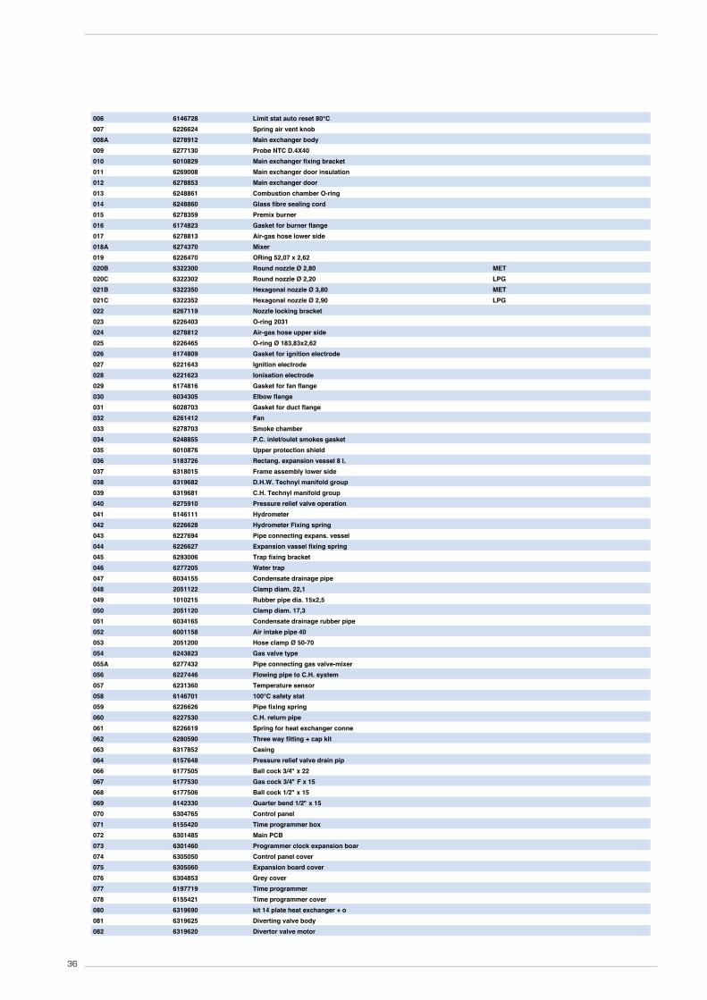
7 EXPLODED VIEWS

33
006 6146728 Limit stat auto reset 80°C
007 6226624 Spring air vent knob
008 6278913 Main exchanger body
009 6277130 Probe NTC D.4X40
010 6010829 Main exchanger fixing bracket
011 6269008 Main exchanger door insulation
012 6278853 Main exchanger door
013 6248861 Combustion chamber O-ring
014 6248860 Glass fibre sealing cord
015 6278359 Premix burner
016 6174823 Gasket for burner flange
017 6278813 Air-gas hose lower side
018 6274372 Mixer
019 6226470 ORing 52,07 x 2,62
020 6322306 Round nozzle Ø 2,40 MET
020A 6322308 Round nozzle Ø 1,90 LPG
021 6322356 Hexagonal nozzle Ø 3,30 MET
021A 6322358 Hexagonal nozzle Ø 2,60 LPG
022 6267119 Nozzle locking bracket
023 6226403 O-ring 2031
024 6278812 Air-gas hose upper side
025 6226465 O-ring Ø 183,83x2,62
026 6174809 Gasket for ignition electrode
027 6221643 Ignition electrode
028 6221623 Ionisation electrode
029 6174816 Gasket for fan flange
030 6034305 Elbow flange
031 6028703 Gasket for duct flange
032 6261412 Fan
033 6278703 Smoke chamber
034 6248855 P.C. inlet/oulet smokes gasket
035 6010876 Upper protection shield
036 5183726 Rectang. expansion vessel 8 l.
037 6318015 Frame assembly lower side
038 6319682 D.H.W. Technyl manifold group
039 6319681 C.H. Technyl manifold group
040 6275910 Pressure relief valve operation
041 6146111 Hydrometer
042 6226628 Hydrometer Fixing spring
043 6227694 Pipe connecting expans. vessel
044 6226627 Expansion vassel fixing spring
045 6293006 Trap fixing bracket
046 6277205 Water trap
047 6034155 Condensate drainage pipe
048 2051122 Clamp diam. 22,1
049 1010215 Rubber pipe dia. 15x2,5
050 2051120 Clamp diam. 17,3
051 6034165 Condensate drainage rubber pipe
052 6001158 Air intake pipe 40
053 2051200 Hose clamp Ø 50-70
054 6243823 Gas valve type
055 6277431 Pipe connecting gas valve-mixer
056 6227446 Flowing pipe to C.H. system
057 6231360 Temperature sensor
058 6146701 100°C safety stat
059 6226626 Pipe fixing spring
060 6227530 C.H. return pipe
061 6226619 Spring for heat exchanger conne
062 6280590 Three way fitting + cap kit
063 6317852 Casing
064 6157648 Pressure relief valve drain pip
066 6177505 Ball cock 3/4" x 22
067 6177530 Gas cock 3/4" F x 15
068 6177506 Ball cock 1/2" x 15
069 6142330 Quarter bend 1/2" x 15
070 6304765 Control panel
071 6155420 Time programmer box
072 6301485 Main PCB
073 6301460 Programmer clock expansion boar
074 6305050 Control panel cover
075 6305060 Expansion board cover
076 6304853 Grey cover
077 6197719 Time programmer
078 6155421 Time programmer cover
080 6319690 kit 14 plate heat exchanger + o
081 6319625 Diverting valve body
082 6319620 Divertor valve motor

34
083 6037504 Water pressure switch
084 6226635 Water press.switch fix. spring
085 6319630 Flowmeter
086 6319603 Discharger cock
087 6120533 C.H Nipple
088 6120532 D.H.W. Nipple
089 6120534 D.H.W. Nipple exit
090 6319601 Sensor hall complete
091 6319618 Primary filter component
092 6040211 Pressure relief valve 3 bar
093 6319641 By-pass 2 (new)
094 6272315 Circulating pump
095 6013182 Automatic air vent
700 5199570 Complete control panel
701 6316266 6 pole cable connector CN6
702 6316253 9 pole Stocko connector
703 6323814 14 pole cable connector
704 6319158 4 pole cable connector
705 6323813 5 pole cable connector
706 6245374 Circulating pump connector
707 6285002 Ionisation lead L=1100
708 5185138 Conversion kit to LPG
709 5198696 Technyl hydraulic group
710 6319699 Split pin kit for hydraulic gro
711 6319698 O-ring kit for hydraulic group
712 6281534 Gaskets kit
713 6319695 Murelle-Format-.....o-ring kit
714 6211793 Hydr.group Bitron caps kit exp

35
8111802 CALD.MUR.MET. BRAVA DGT HE 30
Posiz. Codice Descrizione
001 6318350 Left hand side frame part
002 6318300 Right hand side frame part
003 6267161 Main exchanger rear brachet
004A 6010833 Main exchanger supporting brack
005 6112330 Bush thermostatic
36
006 6146728 Limit stat auto reset 80°C
007 6226624 Spring air vent knob
008A 6278912 Main exchanger body
009 6277130 Probe NTC D.4X40
010 6010829 Main exchanger fixing bracket
011 6269008 Main exchanger door insulation
012 6278853 Main exchanger door
013 6248861 Combustion chamber O-ring
014 6248860 Glass fibre sealing cord
015 6278359 Premix burner
016 6174823 Gasket for burner flange
017 6278813 Air-gas hose lower side
018A 6274370 Mixer
019 6226470 ORing 52,07 x 2,62
020B 6322300 Round nozzle Ø 2,80 MET
020C 6322302 Round nozzle Ø 2,20 LPG
021B 6322350 Hexagonal nozzle Ø 3,80 MET
021C 6322352 Hexagonal nozzle Ø 2,90 LPG
022 6267119 Nozzle locking bracket
023 6226403 O-ring 2031
024 6278812 Air-gas hose upper side
025 6226465 O-ring Ø 183,83x2,62
026 6174809 Gasket for ignition electrode
027 6221643 Ignition electrode
028 6221623 Ionisation electrode
029 6174816 Gasket for fan flange
030 6034305 Elbow flange
031 6028703 Gasket for duct flange
032 6261412 Fan
033 6278703 Smoke chamber
034 6248855 P.C. inlet/oulet smokes gasket
035 6010876 Upper protection shield
036 5183726 Rectang. expansion vessel 8 l.
037 6318015 Frame assembly lower side
038 6319682 D.H.W. Technyl manifold group
039 6319681 C.H. Technyl manifold group
040 6275910 Pressure relief valve operation
041 6146111 Hydrometer
042 6226628 Hydrometer Fixing spring
043 6227694 Pipe connecting expans. vessel
044 6226627 Expansion vassel fixing spring
045 6293006 Trap fixing bracket
046 6277205 Water trap
047 6034155 Condensate drainage pipe
048 2051122 Clamp diam. 22,1
049 1010215 Rubber pipe dia. 15x2,5
050 2051120 Clamp diam. 17,3
051 6034165 Condensate drainage rubber pipe
052 6001158 Air intake pipe 40
053 2051200 Hose clamp Ø 50-70
054 6243823 Gas valve type
055A 6277432 Pipe connecting gas valve-mixer
056 6227446 Flowing pipe to C.H. system
057 6231360 Temperature sensor
058 6146701 100°C safety stat
059 6226626 Pipe fixing spring
060 6227530 C.H. return pipe
061 6226619 Spring for heat exchanger conne
062 6280590 Three way fitting + cap kit
063 6317852 Casing
064 6157648 Pressure relief valve drain pip
066 6177505 Ball cock 3/4" x 22
067 6177530 Gas cock 3/4" F x 15
068 6177506 Ball cock 1/2" x 15
069 6142330 Quarter bend 1/2" x 15
070 6304765 Control panel
071 6155420 Time programmer box
072 6301485 Main PCB
073 6301460 Programmer clock expansion boar
074 6305050 Control panel cover
075 6305060 Expansion board cover
076 6304853 Grey cover
077 6197719 Time programmer
078 6155421 Time programmer cover
080 6319690 kit 14 plate heat exchanger + o
081 6319625 Diverting valve body
082 6319620 Divertor valve motor

37
083 6037504 Water pressure switch
084 6226635 Water press.switch fix. spring
085A 6319631 Flowmeter
086 6319603 Discharger cock
087 6120533 C.H Nipple
088 6120532 D.H.W. Nipple
089 6120534 D.H.W. Nipple exit
090 6319601 Sensor hall complete
091 6319618 Primary filter component
092 6040211 Pressure relief valve 3 bar
093 6319641 By-pass 2 (new)
094 6272315 Circulating pump
095 6013182 Automatic air vent
701 6316266 6 pole cable connector CN6
702 6316253 9 pole Stocko connector
703 6323814 14 pole cable connector
704 6319158 4 pole cable connector
705 6323813 5 pole cable connector
706 6245374 Circulating pump connector
707 6285002 Ionisation lead L=1100
708 5185138 Conversion kit to LPG
709 5198696 Technyl hydraulic group
710 6319699 Split pin kit for hydraulic gro
711 6319698 O-ring kit for hydraulic group
712 6281534 Gaskets kit
713 6319695 Murelle-Format-.....o-ring kit
714 6211793 Hydr.group Bitron caps kit exp
715 5199571 Complete control panel
716 5185139 Conversion kit to LPG

38
8111804 CALD.MUR.MET. BRAVA DGT HE 35
Posiz. Codice Descrizione
001 6292543 Left rear frame part
002 6292553 Right rear frame part
003 6267163 Main exchanger supporting brack
004 6010831 Main exchanger supporting brack
005 6112330 Bush thermostatic

39
006 6146728 Limit stat auto reset 80°C
007 6226624 Spring air vent knob
008 6278910 Main exchanger body
009 6277130 Probe NTC D.4X40
010 6010829 Main exchanger fixing bracket
011 6269008 Main exchanger door insulation
012 6278853 Main exchanger door
013 6248861 Combustion chamber O-ring
014 6248860 Glass fibre sealing cord
015 6278351 Burner
016 6174823 Gasket for burner flange
017 6278813 Air-gas hose lower side
018 6274371 Mixer
019 6226470 ORing 52,07 x 2,62
020 6322303 Round nozzle Ø 3,50 MET
020A 6322300 Round nozzle Ø 2,80 LPG
021 6322353 Hexagonal nozzle Ø 4,00 MET
021A 6322354 Hexagonal nozzle Ø 3,00 LPG
022 6267119 Nozzle locking bracket
023 6226403 O-ring 2031
024 6278812 Air-gas hose upper side
025 6226465 O-ring Ø 183,83x2,62
026 6174809 Gasket for ignition electrode
027 6221643 Ignition electrode
028 6221623 Ionisation electrode
029 6174816 Gasket for fan flange
030 6083055 Duct flange 60
031 6028703 Gasket for duct flange
032 6261412 Fan
033 6278703 Smoke chamber
034 6248855 P.C. inlet/oulet smokes gasket
035 6010877 Upper protection shield
036 5183726 Rectang. expansion vessel 8 l.
037 6318015 Frame assembly lower side
038 6319682 D.H.W. Technyl manifold group
039 6319681 C.H. Technyl manifold group
040 6275910 Pressure relief valve operation
041 6146111 Hydrometer
042 6226628 Hydrometer Fixing spring
043 6227694 Pipe connecting expans. vessel
044 6226627 Expansion vassel fixing spring
045 6293006 Trap fixing bracket
046 6277205 Water trap
047 6034155 Condensate drainage pipe
048 2051122 Clamp diam. 22,1
049 1010215 Rubber pipe dia. 15x2,5
050 2051120 Clamp diam. 17,3
051 6034165 Condensate drainage rubber pipe
052 6001159 Air intake pipe 50
053 2051200 Hose clamp Ø 50-70
054 6243823 Gas valve type
055 6277431 Pipe connecting gas valve-mixer
056 6227449 Flowing pipe to C.H. system
057 6231360 Temperature sensor
058 6146701 100°C safety stat
059 6226626 Pipe fixing spring
060 6227531 C.H. return pipe
061 6226619 Spring for heat exchanger conne
062 6280590 Three way fitting + cap kit
063 6317852 Casing
064 6157648 Pressure relief valve drain pip
065 6140015 Casing fixing bracket
066 6177505 Ball cock 3/4" x 22
067 6177530 Gas cock 3/4" F x 15
068 6177506 Ball cock 1/2" x 15
069 6142330 Quarter bend 1/2" x 15
070 6304765 Control panel
071 6155420 Time programmer box
072 6301485 Main PCB
073 6301460 Programmer clock expansion boar
074 6305050 Control panel cover
075 6305060 Expansion board cover
076 6304853 Grey cover
077 6197719 Time programmer
078 6155421 Time programmer cover
080 6319692 Kit 18 plate heat exchanger + o
081 6319625 Diverting valve body

40
082 6319620 Divertor valve motor
083 6037504 Water pressure switch
084 6226635 Water press.switch fix. spring
085 6319632 Flowmeter
086 6319603 Discharger cock
087 6120533 C.H Nipple
088 6120532 D.H.W. Nipple
089 6120534 D.H.W. Nipple exit
090 6319601 Sensor hall complete
091 6319618 Primary filter component
092 6040211 Pressure relief valve 3 bar
093 6319641 By-pass 2 (new)
094 6272315 Circulating pump
095 6013182 Automatic air vent
700 5199572 Complete control panel
701 6316266 6 pole cable connector CN6
702 6316253 9 pole Stocko connector
703 6323814 14 pole cable connector
704 6319158 4 pole cable connector
705 6323813 5 pole cable connector
706 6245374 Circulating pump connector
707 6285002 Ionisation lead L=1100
708 5185140 Conversion kit to LPG
709 5198696 Technyl hydraulic group
710 6319699 Split pin kit for hydraulic gro
711 6319698 O-ring kit for hydraulic group
712 6281534 Gaskets kit
713 6319695 Murelle-Format-.....o-ring kit
714 6211793 Hydr.group Bitron caps kit exp

IND GUIDE INST 10-11 HHIC REF T11/0027BRev8
INDUSTRY GUIDANCE FOR INSTALLERS ON CONDENSATE
DRAINAGE PIPE INSTALLATION
This guidance is endorsed by HHIC members.
1. BACKGROUND
During recent winters the UK has experienced prolonged spells of extremely cold weather - down to minus 20oC and below in many areas. This resulted in a significant increase in the number of calls to boiler manufacturers and heating engineers from householders with condensing (high efficiency) boilers where the condensate drainage pipe had frozen andbecome blocked with ice, causing the boiler to shut down. In the vast majority of cases such problems occur where the condensate drainage pipe is located externally to the building for some part of its length.
British Standards, Building Regulations etc. currently allow condensate drainage pipes to berun either internally or externally, or a combination of these. These documents give guidance on how to install the pipes in order to reduce the possibility of freezing. However this guidance may not be sufficient to prevent freezing in extreme conditions - with widespread and prolonged very low temperatures.
In view of the possibility that UK weather patterns will show more “extremes” in future due to the effects of global climate change, the following guidance updates previous recommendations on condensate drainage pipe installation. All other technical requirements for condensate drain installation given in British Standard BS 6798:2009, or in boiler manufacturers’ installation instructions should still be followed.
2. REVISED GUIDANCE ON CONDENSATE DRAINAGE PIPE INSTALLATION
Where a new or replacement boiler is being installed, access to an internal “gravity discharge” termination should be one of the main factors considered when determining potential boiler locations, so that the condensate drainage pipe can be terminated as recommended below. On an existing installation, the guidance below should also be followed if work is carried out to “upgrade” the condensate drain age system to reduce the risk of freezing in extreme conditions.
Internal condensate drainage pipework must be a minimum of 19mm ID (typically 22mm OD) plastic pipe and this should “fall” at least 45 mm per metre away from the boiler, taking the shortest practicable route to the termination point.
In order to minimise the risk of freezing during prolonged very cold spells, one of the following methods of terminating condensate drainage pipe should be adopted -
8 APPENDIX 1 (GUIDANCE HHIC)
41

42
IND GUIDE INST 10-11 HHIC REF T11/0027BRev8
2.1 INTERNAL TERMINATION:
Wherever possible, the condensate drainage pipe should be terminated at a suitable internal foul water discharge point such as (a) an internal soil and vent stack or (b) an internal kitchen or bathroom waste pipe, washing machine waste pipe etc. A suitable permanent connection to the foul waste pipe should be used. Figures 1, 2(a), 2(b) show appropriate connection methods.
The possibility of waste pipes freezing downstream of the connection point should beconsidered when determining a suitable connection point - e.g. a slightly longer pipe run to an internal soil stack may be preferable to a shorter run connecting into a kitchen waste pipe discharging directly through the wall to an external drain.
Where “gravity discharge” to an internal termination is not physically possible (e.g. the discharge point is above the appliance location, or access is obstructed by a doorway), or where very long internal pipe runs would be required to reach a suitable discharge point, the following measures may be adopted -
2.2 USE OF A CONDENSATE PUMP (TO AN INTERNAL TERMINATION):
Condensate can be removed using a proprietary condensate pump, of a specification recommended by the boiler or pump manufacturer.
The pump outlet should discharge to a suitable internal foul water discharge point, such as (a) an internal soil and vent stack or (b) an internal kitchen or bathroom waste pipe, washing machine waste pipe etc. Figure 3 shows a typical connection method.
A suitable permanent connection to the foul waste pipe should be used and the manufacturer’s detailed installation instructions for the pump should be followed.
2.3 EXTERNAL TERMINATION:
The use of an externally-run condensate drainage pipe, terminating at a suitable foul water discharge point or purpose-designed soakaway, may be also be considered; however if this termination method is chosen then the following measures should be adopted -
The pipe should be run internally as far as possible before going externally and the pipe diameter should be increased to a minimum of 30mm ID (typically 32mm OD) before it passes through the wall.
The external run should be kept as short as possible, taking the most direct and “most vertical” route possible to the discharge point, with no horizontal sections in which condensate might collect.
The external pipe should be insulated using suitable waterproof and weatherproof insulation (“Class O” pipe insulation is suitable for this purpose) .

43
IND GUIDE INST 10-11 HHIC REF T11/0027BRev8
The use of fittings, elbows etc should be kept to a minimum and any internal “burrs” on cut pipework should be removed so that the internal pipe section is as smooth as possible.
The customer/householder should be advised that even with the above measures this type of installation could freeze, and that if this were to occur then boiler shutdown could result, requiring remedial action - possibly involving a chargeable engineer call-out.
Where there are likely to be extremes of temperature or wind-chill, the use of a proprietary trace-heating system for external condensate drainage pipework, incorporating an external frost thermostat, should therefore be considered. If such a system is used then the installation instructions of the trace heating manufacturer and any specific recommendations regarding pipe diameter, insulation, etc. should be followed. All other relevant guidance on condensate drainage pipe installation should also be followed.
Other cold weather protection methods approved or endorsed by boiler manufacturers and/or service organisations may be adopted if these are considered suitable by the parties involved.
If an external soil/vent stack is used as the external termination then the connection method shown in Figure 4 should be used, together with the measures on insulation etc. as described above and shown in the diagram.
When a rain water downpipe is used as the termination (NB only permissible if this downpipe passes to a combined foul and rainwater drainage system) an air break must be installed between the condensate drainage pipe and the downpipe to avoid reverse flow of rainwater into the boiler should the downpipe itself become flooded or frozen. Figure 5 shows a suitable connection method.
Where the condensate drainage pipe is terminated over an open foul drain or gully, the pipe should terminate below the grating level, but above water level, in order to minimise “wind chill” at the open end. Pipe drainage will be improved if the end is cut at 45o as opposed to a straight cut. The use of a drain cover (such as those used to prevent blockage by leaves) may offer further protection from wind chill. Figure 6 shows a suitable connection method.
Where the condensate drain pipe terminates in a purpose-designed soakaway (see BS 6798:2009 or boiler installation manual for soakaway design requirements) any above-ground section of condensate drainage pipe should be run and insulated as described above. Figure 7 shows a suitable connection method.
3. UNHEATED INTERNAL AREAS:
Internal condensate drainage pipes run in unheated areas such as lofts, basements and garages should be treated as external pipe.

44
IND GUIDE INST 10-11 HHIC REF T11/0027BRev8
NOTES
The Benchmark Commissioning Checklist (located at the back of the boiler installation manual) should be completed as required to record details of the condensate drainage pipe installation.
Where an external condensate drainage pipe is installed, the customer should be made aware of the risks and consequences of its freezing and offered the option to fit trace heating (or other measures approved by the boiler manufacturer or service organisation).
Separate guidance has been published for householders on remedial actions which can be taken if a condensate drainage pipe freezes. This may result in requests for alteration to condensate drainage pipework, in which case the guidance above should be followed.
In some instances (e.g. where an elderly person’s heating needs to be reinstated as an emergency measure) condensate drainage pipes may have been cut in order to bypass any blockage and allow re-ignition of the boiler, with condensate being collected in a suitable container as a temporary solution.
While not unsafe, this is not recommended practice and if such action has been taken then the condensate drainage pipe must be reinstated as soon as possible, using the above guidance to reduce risk of freezing in future.

45
IND GUIDE INST 10-11 HHIC REF T11/0027BRev8
Figure 1 – Connection of condensate drainage pipe to internal soil and vent stack
Key1 Boiler2 Visible air break3 75 mm trap4 Visible air break and trap not required if there is a trap with a minimum condensate
seal of 75 mm incorporated into the boiler5 Soil and vent stack6 Invert7 450 mm minimum up to three storeys8 Minimum internal diameter 19 mm

46
IND GUIDE INST 10-11 HHIC REF T11/0027BRev8
Figure 2(a) – Connection of a condensate drainage pipe downstream of a sink, basin, bath or shower waste trap
Key1 Boiler2 Visible air break3 75 mm trap4 Visible air break and trap not required if there is a trap with a minimum condensate
seal of 75 mm incorporated into the boiler. In this case the 100 mm is measured to the trap in the boiler.
5 Sink, basin, bath or shower6 Open end of condensate drainage pipe direct into gully 25 mm min below grating but
above water level; end cut at 45 °7 Sink lip8 Minimum internal diameter 19 mm9 Pipe size transition10 Minimum internal diameter 30 mm11 Water/weather proof insulation

47
IND GUIDE INST 10-11 HHIC REF T11/0027BRev8
Figure 2(b) – Connection of a condensate drainage pipe upstream of a sink, basin, bath or shower waste trap
Key1 Boiler2 Visible air break at plug-hole3 75 mm sink, basin, bath or shower waste trap4 Sink, basin, bath or shower with integral overflow5 Open end of condensate drainage pipe direct into gully 25 mm min below grating but
above water level; end cut at 45 °6 Minimum internal diameter 19 mm7 Pipe size transition8 Minimum internal diameter 30 mm9 Water/weather proof insulation

48
IND GUIDE INST 10-11 HHIC REF T11/0027BRev8
Figure 3 – Connection of a condensate pump - typical method (NB manufacturer’s detailed instructions should be followed).
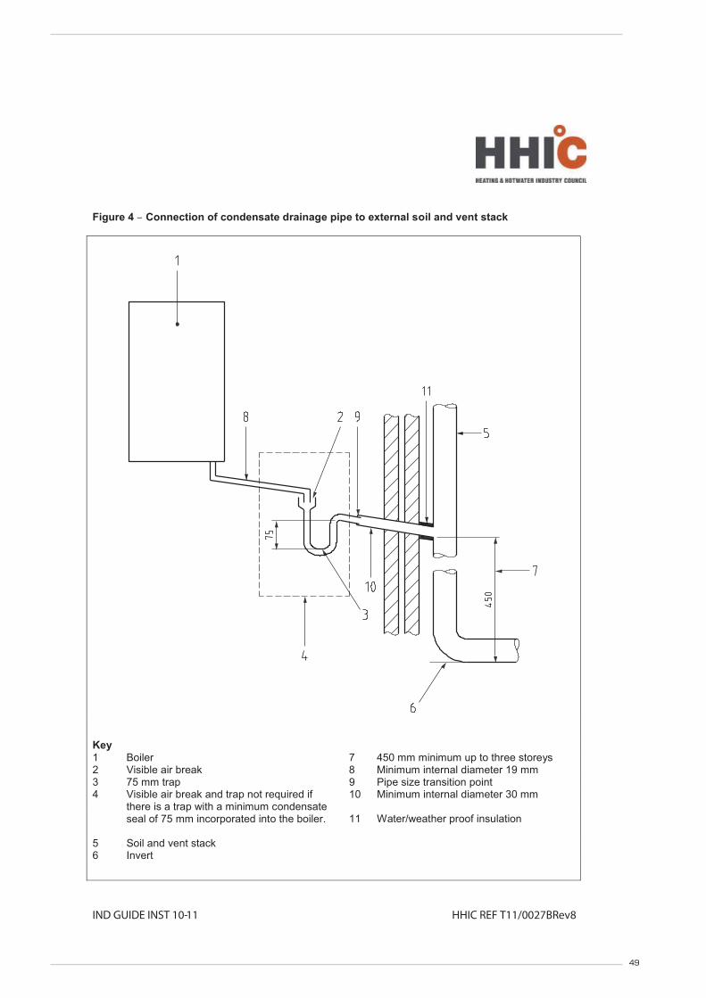
49
IND GUIDE INST 10-11 HHIC REF T11/0027BRev8
Figure 4 – Connection of condensate drainage pipe to external soil and vent stack
Key1 Boiler 7 450 mm minimum up to three storeys2 Visible air break 8 Minimum internal diameter 19 mm3 75 mm trap 9 Pipe size transition point4 Visible air break and trap not required if
there is a trap with a minimum condensate seal of 75 mm incorporated into the boiler.
10 Minimum internal diameter 30 mm
11 Water/weather proof insulation
5 Soil and vent stack6 Invert

50
IND GUIDE INST 10-11 HHIC REF T11/0027BRev8
Figure 5 – External termination to rainwater downpipe (NB only combined foul/rainwater drain)
Key1 Condensate discharge pipe from boiler 7 Air gap2 Pipe size transition point 8 68 mm PVCu strap-on fitting3 Water/weather proof insulation 9 Minimum internal diameter 19 mm4 43 mm 90° male/female bend 10 Minimum internal diameter 30 mm5 External rain water pipe into foul water 11 End cut at 45 °6 External air break

51
IND GUIDE INST 10-11 HHIC REF T11/0027BRev8
Figure 6 – External drain, gully or rainwater hopper
Key
1 Boiler2 Visible air break3 38 mm minimum trap4 Visible air break and trap not required if there is a trap with a minimum condensate
seal of 38 mm incorporated into the boiler5 External length of pipe 3 m maximum6 Open end of condensate drainage pipe direct into gully 25 mm min below grating but
above water level; end cut at 45 °7 Minimum internal diameter 19 mm8 Pipe size transition point9 Minimum internal diameter 30 mm10 Water/weather proof insulation

52
IND GUIDE INST 10-11 HHIC REF T11/0027BRev8
Figure 7 – Example of a purpose-made soakaway
Key
1 Condensate discharge pipe from boiler2 Ground (this section of the condensate drainage pipe may be run either above or
below ground level); End cut at 45 °3 Diameter 100 mm minimum plastic tube4 Bottom of tube sealed5 Limestone chippings6 Two rows of three 12 mm holes at 25 mm centres, 50 mm from bottom of tube and
facing away from house7 Hole depth 400 mm minimum by 300 mm diameter8 Minimum internal diameter 19 mm9 Pipe size transition point10 Minimum internal diameter 30 mm11 Water/weather proof insulation

53
9 APPENDIX 2
$),1!& -/ $,- !, +" !,* 0./',+ - /', !&#!( ,+ !,**'..',+'+% !,+"#+.'+%
NO
YES
YES
NO
NO
YES
YES
NO
NO
YES
PRIOR TO CO AND COMBUSTION RATIO CHECK
The installation instructions should have been followed, gas type verified and gas supply pressure/rate checked as required prior to commissioning.
As part of the installation process, ESPECIALLY WHERE A FLUE HAS BEEN FITTED BY PERSONS OTHER THAN THE BOILER INSTALLER, visually check the integrity
of the whole flue system to confirm that all components are correctly asembled, fixed and supported. Check that manufacturer's maximum flue lengths
have not been exceeded and all guidance has been followed (e.g. Gas Safe Technical Bulletin TB008).
The flue gas analyser should be of the correct type, as specified by BS 7967.
Prior to its use, the flue gas analyser should have been maintained and calibrated as specified by the manufacturer.
The installer must have the relevant competence for use of the analyser.
Check and zero the analyser IN FRESH AIR as per analyser manufacturer's instructions.
SET BOILER TO MAXIMUM RATE
Set the boiler to operate at maximum rate (full load condition). Allow sufficient time for combustion to stablilise.
NOTE - Do not insert analyser probe during this period to avoid possible "flooding" of sensor.
CARRY OUT FLUE INTEGRITY CHECK USING ANALYSER
Insert analyser probe into the air inlet test point and allow readings to stabilise.
NOTE - The flue must always be installed with flue test point. This will be located within the
first piece connected to the boiler.
Is O2 less than or equal
to 20.6% and
CO2 less than 0.2%
VERIFY FLUE INTEGRITY
Analyser readings indicate that combustion products and inlet air must be mixing.
Further investigation of the flue is therefore required.
Check that flue components are assembled, fixed and supported as per boiler/flue
manufacturer's instructions.
Is O2 less than or
equal to 20.6%
and
CO2 less than 0.2%
CHECK CO AND COMBUSTION RATIO AT MAXIMUM RATE
With boiler still set at maximum rate, insert analyser probe into flue
gas samplng point. Allow readings to stablise before recording .
Turn off appliance and call
SIME LTD Technical
HelplIne for advice.
the appliance must not be
commissioned or used,
until problems are
identified and resolved.
Is CO less than
350ppm AND
CO/CO2 ratio
less than 0.004
Is CO less than
350ppm
AND
CO/CO2 ratio
less than 0.004
Check all seals
around the appliance
burner, internal flue
seals, door and case
seals. Rectify where
necessary.
SET BOILER TO MINIMUM RATE
In accordance with boiler instructions, set boiler to operate at minimum rate (to minimum load
condition). Allow sufficient time for combustion to stablilise.
NOTE
If manufacturer's instructions do not specify how to set boiler to minimum rate contact
Technical Helpline for advice.
CHECK CO AND COMBUSTION RATIO AT MINIMUM RATE
With boiler set at minimum rate, insert analyser probe into flue gas samplng point. Allow readings to
stablise before recording.
NOTE - if no flue gas sampling point is present and the correct procedure is not specified in the
manual, contact Sime LTD Technical Helpline for advice.
Is CO less than
350ppm AND
CO/CO2 ratio
less than 0.004
BOILER IS OPERATING SATISFACTORILY
no further actions required.
Ensure test points are capped, boiler case is correctly repleced and all other
commissioning procedures are completed.
Complete Benchmark Checklist, recording CO and combustion ratio
readings as required.
NOTE
the air gas ratio valve is factory-set and must not be
adjusted DURING COMMISSIONING unless this action is
recommended after discussions with Sime LTD.
If any such adjustment is recommended and further
checking of the boiler is required the installer/service
engineer must be competent to carry out this work and to
use the flue gas analyser accordingly.
If the boiler requires conversion to operate with a different
gas family (e.g. conversion from natural gas to LPG)
separate guidance will be provided by the boiler.
Turn off appliance and call SIME LTD
Technical HelplIne for advice.
the appliance must not be commissioned or
used until problems are identified and
resolved.
NOTE
Check and record CO and combustion ratio
at both maximum AND minimum rate before
contacting Sime LTD.

54
NOTES


Sime Ltd1a Blue Ridge ParkThunderhead Ridge Glasshoughton, Castleford, WF10 4UA
Phone: 0845 9011114Fax: 0845 9011115
www.sime.co.ukEmail: [email protected]