UK BRAVA DGT HE
60
199838 ENSURE THAT THESE INSTRUCTIONS ARE LEFT FOR THE USER AFTER COMPLETION OF THE BENCHMARK SECTION PLEASE READ THE IMPORTANT NOTICE WITHIN THIS GUIDE REGARDING YOUR BOILER WARRANTY 6322851 - 05/2015 - R1 UK please position here a sticker from installation pack BOILER DETAILS USER, INSTALLATION AND SERVICING INSTRUCTIONS MURELLE PRO HE R ErP Condensing wall mounted boiler Cod.
Transcript of UK BRAVA DGT HE

BRAVA DGT HE25 - 30 - 35
199838
INSTALLATION AND SERVICING INSTRUCTIONS
ENSURE THAT THESE INSTRUCTIONS ARE LEFT
FOR THE USER AFTER COMPLETION OF THE
BENCHMARK SECTION
PLEASE READ THE IMPORTANT NOTICE WITHIN THIS GUIDE
REGARDING YOUR BOILER WARRANTY
UKCod. 6316191 - 08/2013
BRAVA DGT HE25 - 30 - 35
199838
INSTALLATION AND SERVICING INSTRUCTIONS
ENSURE THAT THESE INSTRUCTIONS ARE LEFT
FOR THE USER AFTER COMPLETION OF THE
BENCHMARK SECTION
PLEASE READ THE IMPORTANT NOTICE WITHIN THIS GUIDE
REGARDING YOUR BOILER WARRANTY
UKCod. 6316191 - 08/2013
6322851 - 05/2015 - R1
BRAVA DGT HE25 - 30 - 35
199838
INSTALLATION AND SERVICING INSTRUCTIONS
ENSURE THAT THESE INSTRUCTIONS ARE LEFT
FOR THE USER AFTER COMPLETION OF THE
BENCHMARK SECTION
PLEASE READ THE IMPORTANT NOTICE WITHIN THIS GUIDE
REGARDING YOUR BOILER WARRANTY
UKCod. 6316191 - 08/2013
BRAVA DGT HE25 - 30 - 35
199838
INSTALLATION AND SERVICING INSTRUCTIONS
ENSURE THAT THESE INSTRUCTIONS ARE LEFT
FOR THE USER AFTER COMPLETION OF THE
BENCHMARK SECTION
PLEASE READ THE IMPORTANT NOTICE WITHIN THIS GUIDE
REGARDING YOUR BOILER WARRANTY
UKCod. 6316191 - 08/2013
please position here a stickerfrom installation pack
BOILER DETAILS
USER, INSTALLATION AND SERVICING INSTRUCTIONS
MURELLE PRO HE R ErPCondensing wall mounted boiler
Cod.
2
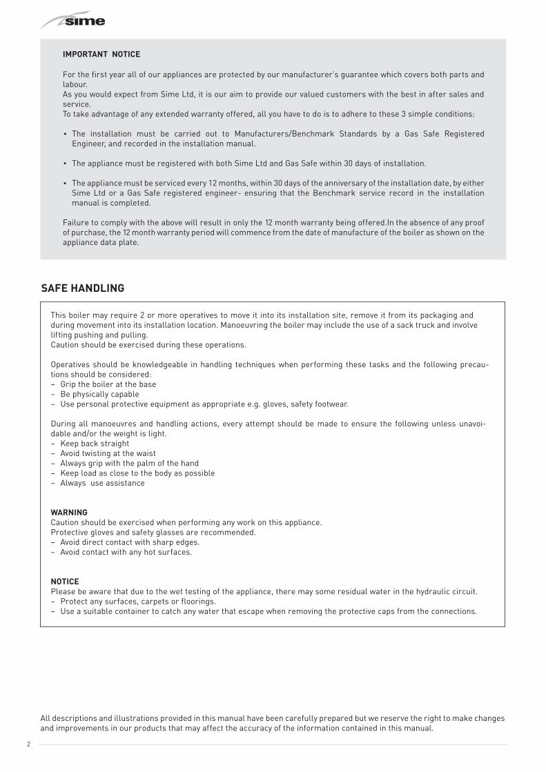
SAFE HANDLING
IMPORTANT NOTICE
For the first year all of our appliances are protected by our manufacturer’s guarantee which covers both parts and labour.As you would expect from Sime Ltd, it is our aim to provide our valued customers with the best in after sales and service.To take advantage of any extended warranty offered, all you have to do is to adhere to these 3 simple conditions:
The installation must be carried out to Manufacturers/Benchmark Standards by a Gas Safe Registered Engineer, and recorded in the installation manual.
The appliance must be registered with both Sime Ltd and Gas Safe within 30 days of installation.
The appliance must be serviced every 12 months, within 30 days of the anniversary of the installation date, by either Sime Ltd or a Gas Safe registered engineer- ensuring that the Benchmark service record in the installation manual is completed.
Failure to comply with the above will result in only the 12 month warranty being offered.In the absence of any proof of purchase, the 12 month warranty period will commence from the date of manufacture of the boiler as shown on the appliance data plate.
This boiler may require 2 or more operatives to move it into its installation site, remove it from its packaging and during movement into its installation location. Manoeuvring the boiler may include the use of a sack truck and involve lifting pushing and pulling.Caution should be exercised during these operations.
Operatives should be knowledgeable in handling techniques when performing these tasks and the following precau-tions should be considered:– Grip the boiler at the base– Be physically capable– Use personal protective equipment as appropriate e.g. gloves, safety footwear.
During all manoeuvres and handling actions, every attempt should be made to ensure the following unless unavoi-dable and/or the weight is light.– Keep back straight– Avoid twisting at the waist– Always grip with the palm of the hand– Keep load as close to the body as possible– Always use assistance
WARNINGCaution should be exercised when performing any work on this appliance.Protective gloves and safety glasses are recommended.– Avoid direct contact with sharp edges.– Avoid contact with any hot surfaces.
NOTICEPlease be aware that due to the wet testing of the appliance, there may some residual water in the hydraulic circuit.– Protect any surfaces, carpets or floorings.– Use a suitable container to catch any water that escape when removing the protective caps from the connections.
All descriptions and illustrations provided in this manual have been carefully prepared but we reserve the right to make changes and improvements in our products that may affect the accuracy of the information contained in this manual.

3
4
The Benchmark Scheme
Sime Ltd is a licensed member of the Benchmark Scheme which aims to improve the standards of installation and commissioning of domestic heating and hot water systems in the UK and to encourage regular servicing to optimisesafety, efficiency and performance.Benchmark is managed and promoted by the Heating and Hotwater Industry Council.For more information visit www.centralheating.co.uk.Please ensure that the installer has fully completed the Benchmark Checklist in the use and maintenance section of the installation instructions supplied with the product and that you have signed it to say that you have received a full and clear explanation of its operation.The installer is legally required to complete a commissioning checklist as a means of complyng with the appropriate Building Regulations (England and Wales).All installations must be notified to Local Area Building Control either directly or through a Competent Persons Scheme.A Building Regulations Compliance Certificate will then be issued to the customer who should, on receipt, write the Notification Number on the Benchmark Checklist.This product should be serviced regularly to optimise its safety, efficiency and performance.The service engineer should complete the relevant Service Record on the Benchmark Checklist after each service.The Benchmark Checklist may be required in the event of any warranty work and as supporting documentation relating to home improvements in the optional documents section of the Home Information Pack.
Please refer to commissioning instructions for filling in the checklist at the back of this installation guide.Note: All Gas Safe registered installers carry a ID Card.
You can check your installer is Gas Safe Registered by calling 0800 408 5577
SIME COMBINATION BOILERSInstaller checklist
Important InformationIT IS A STATUTORY REQUIREMENT THAT ALL GAS APPLIANCES ARE INSTALLED BY COMPETENT PERSONS, IN ACCORDANCE WITH THE GAS SAFETY (INSTALLATION AND USE) REGULATIONS (CURRENT EDITION). The manufacturer’s instructions must not be taken as overriding any statutory requirements, and failure to comply with these regulations may lead to prosecution.
No modifications to the appliance should be made unless they are fully approved by the manufacturer.
GAS LEAKS: DO NOT OPERATE ANY ELECTRICAL SWITCH, OR USE A NAKED FLAME. TURN OFF THE GAS SUPPLY AND VENTILATE THE AREA BY OPENING DOORS AND WINDOWS CONTACT THE GAS EMERGENCY SERVICE ON 0800111999.
Please remember to carry out the following checks after installation. This will achieve complete customer satisfaction, and avoid unnecessary service calls. A charge will be made for a service visit where the fault is not due to a manufacturing defect.
Has a correct by-pass been fitted and adjusted?Has the system and boiler been flushed?Is the system and boiler full of water, and the correct pressure showing on the pressure gauge?Is the Auto Air Vent open?Has the pump been rotated manually?Is the gas supply working pressure correct?Is the boiler wired correctly? (See installation manual).Has the D.H.W. flow rate been set to the customer requirements?Has the customer been fully advised on the correct use of the boiler, system and controls?Has the Benchmark Checklist in the use and maintenance section of this manual, been completed?
––

5
SAFETY WARNINGS AND REGULATIONS
mWARNINGS– After having unpacked the boiler ensure that it
is undamaged and complete including the valve pack, hanging bracket and template.
– The appliance must be used as intended. Sime Ltd declines all responsible for any injury or damage to persons, animals,or property as a result of improper installation, adjustment, maintenance or use.
– In the event of water leaks, disconnect the appliance from the mains power supply, close the water mains and seek help from a qualified engineer.
– Periodically check that the operating pressure of the water heating system when cold is 1-1,2 bar. If required, increase the pressure or seek help from a qualified engineer (sealed systems).
– If the appliance is not used for a long period of time, the following operations must be carried out:- set the main isolation switch to "OFF";- close the gas cock.
– To ensure continued efficient operation of the appliance it is recommended that it is serviced regularly, at least once a year. This is also a condition of the boiler warranty.
– It is the law that any service or repair is carried out by a Gas Safe Registered engineer.
– Services must be recorded in the maintenance section of this installation guide.
mWARNINGS– This manual is an integral part of the appliance. It
must therefore be kept for future reference and must always accompany the appliance in the event the appliance is transferred or sold to another Owner or User or is installed on another system.
– Installation and maintenance of this appliance must be carried out by a Gas Safe Registered Engineer in accordance with the instructions contained in the manual. On completing the installation the boiler should be commissioned and details recorded in the Benchmark section of this manual. This is a condition of the warranty
RESTRICTIONS
dDO NOT– Do not allow appliance to be used by children or
unassisted disabled persons.– Do not use electrical devices or appliances such
as switches, electrical appliances etc if you can smell gas. If this should happen:- open the doors and windows to air the room;- close the gas isolation device;- seek help from a qualified engineer.
– Do not touch the appliance with bare feet or with any wet part of the body.
– Do not carry out any repair, maintenance or cleaning operation before having disconnected the appliance from the mains power by setting the main switch to "OFF", and closing the gas supply.
– Do not modify the safety or adjustment devices without authorization and instructions from the manufacturer.
– Do not block the condensate drain.– Do not pull, detach or twist the electrical cables
coming out of the appliance even if the appliance is disconnected from the mains power supply.
– Do not expose the boiler to atmospheric agents. These boilers can also be installed in partially covered areas, as per EN 15502, with a maximum ambient temperature of 60°C and a minimum ambient temperature of - 5°C. It is generally advisable to install the boilers below weathered roofs, on the balcony or in a protected niche, to protect them from exposure to weathering agents (rain, hail and snow). All boilers provide a standard antifreeze function.
– Do not block or reduce the size of the ventilation openings of the room where the appliance is installed, if present.
– Remove the mains power and gas supply from the appliance if the external temperature could fall below ZERO (risk of freezing).
– Do not leave containers with flammable substances in the room where the appliance is installed.
– Do not place or store items on or close to the appliance.
SYMBOLS
aDANGERTo indicate actions which, if not carried out correctly, can result in injury of a general nature or may damage or cause the appliance to malfunction; these actions therefore require particular caution and adequate preparation.
fDANGERTo indicate actions which, if not carried out correctly, could lead to injury of an electrical nature; these actions therefore require particular caution and adequate preparation.
dDO NOTTo indicate actions which MUST NOT BE carried out.
mCAUTIONTo indicate particularly important and useful information.

6
RANGE
MODEL CODE GAS COUNCIL NUMBER
Murelle Pro HE 20 R ErP(G20) 8114242 41-283-39
Murelle Pro HE 30 R ErP(G20) 8114244 41-283-40
COMPLIANCEMurelle Pro HE R ErP boilers comply with:– Gas Appliances Directive 2009/142/EC– Boiler Efficiency Directive 92/42/EEC– Low Voltage Directive 2006/95/EC– Electromagnetic Compatibility Directive 2004/108/EC– Thermal Efficiency – Classified as "Condensing"– Class NOx 5 (< 70 mg/kWh)
1312
Please refer to the technical data plate for the serial number and year of manufacture.
EC DECLARATION OF CONFORMITYIn accordance with "Gas Appliances" Directive 2009/142/EC, "Electromagnetic Compatibility" Directive 2004/108/EC, "Boiler Efficiency" Directive 92/42/EC and "Low Voltage" Directive 2006/95/EC, the manufacturer Fonderie SIME S.p.A., via Garbo 27, 37045 Legnago (VR), DECLARES THAT the boiler models Murelle Pro HE R ErP comply with the European Directives.
These appliances comply with the S.E.D.B.U.K. scheme, band “A”.
The Technical Manager(Franco Macchi)
MANUAL STRUCTUREThis manual is organized as follows.
USER INSTRUCTIONSTABLE OF CONTENTS 7
DESCRIPTION OF THE APPLIANCETABLE OF CONTENTS 11
INSTALLATION AND SERVICING INSTRUCTIONSTABLE OF CONTENTS 21
7
USER INSTRUCTIONS
TABLE OF CONTENTS
1 OPERATING THE MURELLE PRO HE R ErP 81.1 Control panel . . . . . . . . . . . . . . . . . . . . . . . . . . . . . . . . . . . 81.2 Preliminary checks . . . . . . . . . . . . . . . . . . . . . . . . . . . . . . 81.3 Ignition . . . . . . . . . . . . . . . . . . . . . . . . . . . . . . . . . . . . . . . . 91.4 Adjusting the delivery temperature . . . . . . . . . . . . . . . . . 91.5 Fault / malfunction codes . . . . . . . . . . . . . . . . . . . . . . . . . 9
2 SHUTDOWN 92.1 Temporary shutdown. . . . . . . . . . . . . . . . . . . . . . . . . . . . . 92.2 Shutting down for long periods . . . . . . . . . . . . . . . . . . . . 9
3 MAINTENANCE 103.1 Servicing. . . . . . . . . . . . . . . . . . . . . . . . . . . . . . . . . . . . . . 103.2 External cleaning. . . . . . . . . . . . . . . . . . . . . . . . . . . . . . . 10
3.2.1 Cleaning the case . . . . . . . . . . . . . . . . . . . . . 10
4 DISPOSAL 104.1 Disposal of the equipment (European Directive
2002/96/CE. . . . . . . . . . . . . . . . . . . . . . . . . . . . . . . . . . . . 10

8
1 OPERATING THE MURELLE PRO HE R ErP
1.1 Control panel
1 4
2 2
2 2
2
3
Fig. 1
1 KNOBS
t The heating knob allows the user to set the flow temperature to between 20 and 80°C during normal operation.
2 FUNCTIONAL BUTTONS
s Press for more than one second and release to step through the operating modes (Stand-by – Summer – Winter).
< This allows the engineer to scroll through the parameters or decrease the values.
> This allows the engineer to scroll through the parameters or increase the values.
o This allows the engineer to confirm the selected parameter or to modify the value or to reset the appliances from a lockout failure.
c Programming connector cover plug.
NB: pressing any one of these buttons for more than 30 seconds generates a fault on the display without preventing boiler operation. The warning disappears when the button is released.
3 DISPLAY
l “SUMMER”. This function is NOT USED on these boilers. This symbol appears when the boiler is operating in Summer mode (used when commissioning the boiler). If the symbols l and n are flashing, this indicates that the chimney sweep function is active.
n “WINTER”. This symbol appears when the boiler is operating in Winter mode. If no operating modes have been enabled both symbols l and n will be off.
R “RESET REQUIRED”. This message only appears if there is a malfunction which must be or may be restored manually.
r “DOMESTIC HOT WATER”. This function IS NOT USED on these boiler models.
t “HEATING”. This symbol is present during heating operation or when the chimney sweep function is operating; it flashes during the heating set point selection.
f “LOCKOUT” DUE TO NO FLAME.
F “FLAME LIT”.
K “ALARM”. This indicates that a fault has occurred. The number specifies the cause which generated the alarm (see section "Fault / malfunction codes".
4 (Not used on these boilers)
1.2 Preliminary checksPrior to use the Murelle Pro HE R ErP boiler must be installed and commissioned by a Gas Safe Registered engineer. It may be necessary for the user to occasionally have to start the boiler, for instance after a holiday or after an interruption of the gas supply. In these cases the following operations must be carried out.– check that the gas isolation valve is open– using the pressure gauge (1) check that the pressure in the
heating system, when cold, is 1-1.2 bar. If the pressure is less than this use the external filling device to repressurise the system to 1-1.2 bar
– ensure that the filling device is turned off after use.
1Fig. 2

9
1.3 IgnitionAfter having carried out the preliminary checks, proceed as follows:– set the main system switch to "ON"– put the boiler into "WINTER" mode n, by pressing the
button s twice for at least one second each time, until the "WINTER" n, is displayed. The internal boiler temperature will be appear on the display
– ensure that any timers and room thermostats are in the on position. The t will appear on the display and the boiler will ignite.
1.4 Adjusting the delivery temperatureThe temperature of the heating water can be adjusted by turning the t knob on the control panel.
Fig. 3
1.5 Fault / malfunction codesIf a fault/malfunction is detected during boiler operation, the message “AL” will appear on the display followed by the fault code (eg. “06” - no flame detected).If the message “RESET” also appears, press and hold the button o R for more than 3 seconds and check that the normal operating condition is restored.
If this operation is not successful, ONLY ONE MORE ATTEMPT can be made, therefore:– close the gas cock– isolate the power supply– contact the Qualified Technical Personnel.
mCAUTIONThe table with the fault codes and the corresponding description is provided in the specific section of the INSTALLATION AND SERVICING INSTRUCTIONS.
2 SHUTDOWN
2.1 Temporary shutdownTo temporarily interupt the boiler operation press and hold the button s for at least one second, once if in "WINTER mode" n. “- -” will appear on the display the boiler will be in STAND-BY. The boiler anti freeze function will be enabled.
fDANGERThe boiler will still be powered.
mCAUTIONIf the outside temperature might fall below ZERO, since the appliance is equipped with an "antifreeze function"– ONLY PUT THE BOILER INTO STAND-BY– leave the main system switch set to "ON" (boiler
is powered)– leave the gas cock open.
2.2 Shutting down for long periodsIf the boiler is to be left unused for a long period, the following operations need to be carried out:– press and hold the button y for at least 1 second, once if
in "WINTER mode" n to put the boiler into stand-by “- -” will appear on the display
– isolate the power supply– isolate the gas cock– drain the heating and domestic hot water system if there is
the risk of freezing.
mCAUTIONContact the Qualified Technical Personnel if the procedure described above cannot be easily carried out.
10
3 MAINTENANCE
3.1 ServicingAs a condition of the warranty and to ensure correct operation and efficiency, it is important that the boiler is serviced every 12 months, within 30 days of the anniversary of the installation date ensure the required information is recorded in the Gas Boiler System Commissioning Checklist (Benchmark).
mCAUTIONMaintenance interventions must ONLY be carried out by professionally qualified personnel who will follow the indications provided in the INSTALLATION AND MAINTENANCE MANUAL.
3.2 External cleaning
3.2.1 Cleaning the caseWhen cleaning the cladding, use a cloth dampened with soap and water or alcohol for stubborn marks.
dDO NOTDo not use abrasive products.
4 DISPOSAL
4.1 Disposal of the equipment (European Directive 2002/96/CE
Once it reaches the end of its operating life, the equipment MUST BE RECYCLED in line with current legislation.IT MUST NOT be disposed of together with urban waste.It can be handed over to recycling centres, if there are any, or to retailers that offer this service.Recycling prevents potential damage to the environment and health. It allows to recover a number of recyclable materials, with considerable savings in terms of money and energy.

11
DESCRIPTION OF THE APPLIANCE
TABLE OF CONTENTS
5 DESCRIPTION OF THE APPLIANCE 125.1 Characteristics . . . . . . . . . . . . . . . . . . . . . . . . . . . . . . . . 125.2 Check and safety devices . . . . . . . . . . . . . . . . . . . . . . . . 125.3 Identification . . . . . . . . . . . . . . . . . . . . . . . . . . . . . . . . . . 12
5.3.1 Technical Data Plate. . . . . . . . . . . . . . . . . . . 135.4 Structure . . . . . . . . . . . . . . . . . . . . . . . . . . . . . . . . . . . . . 145.5 Technical features . . . . . . . . . . . . . . . . . . . . . . . . . . . . . . 155.6 Main water circuit . . . . . . . . . . . . . . . . . . . . . . . . . . . . . . 16
5.7 Sensors. . . . . . . . . . . . . . . . . . . . . . . . . . . . . . . . . . . . . . . 165.8 Expansion vessel . . . . . . . . . . . . . . . . . . . . . . . . . . . . . . . 165.9 Circulation pump . . . . . . . . . . . . . . . . . . . . . . . . . . . . . . . 17
5.9.1 Pump equipped with LED. . . . . . . . . . . . . . . 175.10 Control panel . . . . . . . . . . . . . . . . . . . . . . . . . . . . . . . . . . 175.11 Wiring diagram . . . . . . . . . . . . . . . . . . . . . . . . . . . . . . . . 19
6 PRODUCT DATA SHEET 20

12
5 DESCRIPTION OF THE APPLIANCE
5.1 CharacteristicsMurelle Pro HE R ErP are condensing wall mounted boilers which Sime Ltd has produced for installation into domestic properties for system heating. The main design choices made by Sime Ltd for the Murelle Pro HE R ErP boilers are:– the total pre-mix microflame burner combined with a steel
heat exchanger– room sealed, Type C appliance. Suitable for use on sealed
heating systemsOther special features of the Murelle Pro HE R ErP boilers are:– the anti-freeze function which activates automatically if
the temperature of the water inside the boiler falls below the threshold of the value set at parameter "tS 1.0" and , if there is an external sensor, if the external temperature falls below the threshold of the value set at parameter "tS 1.1".
– anti jamming function of the pump. This activates automatically every 24 hours if no request for heat has been made
– the chimney sweep function lasts 15 minutes and makes the job of the qualified technician easier when measuring the parameters and combustion efficiency
– screen display of the operating and self-diagnostic parameters with error code display when the fault occurs. This makes repair interventions easier and allows appliance operation to be restored correctly.
5.2 Check and safety devicesThe Murelle Pro HE R ErP boilers are equipped with the following check and safety devices:– thermal safety thermostat 90±3°C– delivery sensor (SM)– exhaust sensor (SF)– water pressure switch– system relief valve.
dDO NOTDo not commission or operate the appliance with safety devices which do not work or which have been tampered with.
aDANGERSafety device may only be replaced by professional qualified personnel using Sime Ltd original spare parts.
5.3 IdentificationThe Murelle Pro HE R ErP boilers can be identified by means of:1 Packaging label: this is located on the outside of the
packaging and provides a code, the serial number of the boiler and the bar code
2 Energy Efficiency Label: this is positioned on the outside of the packaging to notify the User of the level of energy savings and reduced environmental pollution produced by the appliance
3 Technical Data Plate: this is located inside the front panel of the boiler and provides the technical specification, appliance performance and any other information required by law.
3 4
1
3
4
CodeModelSerial/N.GC No
_ _ _ _ _ _ _ _ _ _ _ _ _ _ _ _ _ _ __ _ _ _ _ _ _ _ _ _ - _ _ _ - _ _
1
I I I
A B C D E F G
2015 811/2013
Cod. 6244745
dB
kW
A++
A+
A B C D E F G
2
2
Fig. 4
KEY:1 Packaging label2 Energy Efficiency Label3 Technical Data Plate4 Steaker of product identification

13
5.3.1 Technical Data Plate
REFERENCE DIRECTIVECODE
APPLIANCE TYPE
MAX OPERATING TEMPERATUREMIN USEFUL INPUT (50-30°C)
MAX D.H.W. TEMPERATUREMIN HEAT INPUT
MIN USEFUL OUTPUT (80-60°C)
APPLIANCE CLASSIFICATION
TYPE OF GASSUPPLY PRESSURE
MIN HEAT INPUT
NOx CLASSGAS COUNCIL NUMBER CODE (UK)WRAS CERTIFICATION (UK)
ELECTRICAL PROTECTION DEGREE
PIN NO.
YEAR OF MANUFACTURESERIAL NUMBER
NAME
MAX USEFUL OUTPUT (50-30°C)MAX OPERATING PRESSURE
MAX USEFUL OUTPUT (80-60°C)MAX HEAT INPUT
WATER CONTENT IN BOILER
FLOW RATEMAX OPERATING PRESSURE
ELECTRICAL SUPPLYMAXIMUM ABSORBED POWER
MAX HEAT INPUT
COUNTRY OF INTENDED INSTALLTION
APPLIANCE CATEGORY
D.H.W. CONTENT
Fig. 5
mCAUTIONTampering with, removing or failing to display the identification plate or carrying out any other operation which does not allow safe identification of the product or which may hinder installation and maintenance operations.

14
5.4 Structure
1
2
3
4
5
7
10
8
9
6
12 13
15
1617
14
18
19
20
21
22
232425
11
1 Heat exchanger bleed point2 Heat exchanger3 Combustion chamber door4 Air/gas duct5 Flame viewing window6 Ignition/detection electrode7 Safety thermostat (TS)8 Delivery sensor (SM)9 Fan10 Condensate siphon11 Automatic by-pass12 Control panel13 Gas valve
14 System relief valve15 Boiler drain16 Pump17 Water pressure switch18 Automatic bleed valve19 Air-gas mixer20 Expansion vessel21 Air inlet pipe22 Air-smoke chamber23 Exhaust sensor (SF)24 Air inlet25 Exhaust outlet
Fig. 6

15
5.5 Technical features
DESCRIPTIONMurelle Pro HE R ErP
20 30CERTIFICATIONSCountry of intended installation GBFuel G20 - G31PIN number (CE) 1312CP5936Category II2H3PType C13 - C33Class NOx 5 (< 70 mg/kWh)HEATING PERFORMANCE(*) HEAT INPUTNominal flow [Qn max] kW 20.0 30.0Minimum flow [Qn min] kW 4.0 6.0HEAT OUTPUTNominal (80-60°C) [Pn max] kW 19.7 29.5Nominal (50-30°C) [Pn max] kW 21.4 32.2Minimum G20 (80-60°C) [Pn min] kW 3.9 5.9Minimum G20 (50-30°C) [Pn min] kW 4.3 6.5Minimum G31 (80-60°C) [Pn min] kW 3.9 5.9Minimum G31 (50-30°C) [Pn min] kW 4.3 6.5EFFICIENCYMax useful efficiency (80-60°C) % 98.5 98.3Min useful efficiency (80-60°C) % 97.5 98.3Max useful efficiency (50-30°C) % 107.0 107.3Min useful efficiency (50-30°C) % 107.5 108.3Useful efficiency at 30% of load (40-30°C) % 107.0 107.0Thermal efficiency (EEC 92/42) Losses after shutdown at 50°C W 84 88ENERGY PERFORMANCEHEATINGHeating seasonal energy efficiency class A AHeating seasonal energy efficiency % 91 92Sound power db(A) 54 53DOMESTIC HOT WATER - -Domestic hot water energy efficiency class - -Domestic hot water energy efficiency % - -Stated domestic hot water profile load - -ELECTRICAL SPECIFICATIONSPower supply voltage V 230Frequency Hz 50Absorbed electrical power Qn max W 65 78Absorbed electrical power Qn min W 52 52Absorbed electrical power in stand-by W 3,6 3,6Electrical protection degree IP X5DCOMBUSTION DATASmoke temperature at Max/Min flow (80-60°C) °C 82 / 66 77 / 67Smoke temperature at Max/Min flow (50-30°C) °C 59 / 45 58 / 49Maximum smoke flow Min/Max g/s 11.2 / 1.9 16.3 / 2.8CO2 at Max/Min flow rate (G20) % 9.0 / 9.0 9.0 / 9.0CO2 at Max/Min flow rate (G31) % 10.0 /10.0 10.0 / 10.0NOx measured mg/kWh 39 41NOZZLES - GASNumber of nozzles No. 1 1Nozzle diameter (G20-G31) mm 5.3 5.3Gas consumption at Max/Min flow rate (G20) m3/h 2.53 / 0.42 3.70 / 0.63Gas consumption at Max/Min flow rate (G31) Kg/h 1.86 / 0.31 2.71 / 0.46
Gas supply pressure (G20/G31)mbar 20 / 37 20 / 37
kpa 2 / 3.7 2 / 3.7TEMPERATURE - PRESSUREMax operating temperature [T max] °C 85Heating adjustment range °C 20÷80

16
Max operating pressure [PMS]bar 2.5kpa 250
Water content in boiler l 4.60 4.60
(*) Heat input calculated using the lower heat output (Hi)Lower Heat Output (Hi)G20 Hi. 9.45 kW/m3 (15°C, 1013 mbar) - G31 Hi. 12.87 kW/kg (15°C, 1013 mbar)
5.6 Main water circuit
3
45
11
12
13
98
7
10
14
15 16 17
6
M G RSc S
21
Fig. 7
KEY:M System flowR System returnG Gas supplySc Condensate outletS Safety valve outlet
1 Condensing heat exchanger2 Combustion chamber3 Fan4 Thermal safety thermostat (TS)5 Delivery sensor (SM)6 Automatic by-pass7 Water pressure switch8 Automatic bleed valve9 Pump10 System expansion vessel11 Gas valve12 Boiler drain13 System relief valve14 Condensate siphon outlet15 System flow cock16 Gas cock17 System return cock
5.7 SensorsThe sensors installed have the following characteristics:– Dual sensor (thermal safety/output) NTC R25°C; 10kΩ– domestic hot water sensor NTC R25°C; 10kΩ– external sensor NTC R25°C; 10kΩ
Correspondence of Temperature Detected/ResistanceExamples of reading:TR=75°C → R=1925ΩTR=80°C → R=1669Ω.
TR 0°C 1°C 2°C 3°C 4°C 5°C 6°C 7°C 8°C 9°C
Resi
stan
ce R
(Ω)
0°C 2727917959120908313582841613021222916691266973
2613517245116348016563040262928216416221232
2504416563111997731544038972839210115771199
2400415912107817458525837732753204015341168
2301415289103827196508236532669198214911137
220691469499996944491335382589192514511108
211681412696336702475134262512187014111079
203091358292816470459533192437181713731051
194891306289456247444432162365176613361024
18706125658622603343003116229617171300998
10°C20°C30°C40°C50°C60°C70°C80°C90°C
100°C
5.8 Expansion vesselThe expansion vessel installed on the boilers has the following characteristics:
Description U/MMurelle Pro HE R ErP
20 30Total capacity l 9,0
Prefilling pressurekPa 100bar 1,0
Useful capacity l 5,0Maximum system content (*) l 124
(*) Conditions of: Average maximum temperature of the system 85°C Start temperature at system filling 10°C.
mCAUTION– For systems with water content exceeding the
maximum system content (as indicated in the table) an additional expansion vessel must be fitted.
– The difference in height between the relief valve and the highest point of the system cannot exceed 6 metres. If the difference is greater than 6 metres, increase the prefilling pressure of the expansion vessel and the system when cold by 0.1 bar for each meter increase.

17
5.9 Circulation pumpThe flow-head performance curve available for the heating system is shown in the graph below.
RESIDUAL HEAD (mbar)
00 800 1000 1200600400200
100
200
300
400
500
600
HE 20HE 30
FLOW (l/h)
Fig. 8
mCAUTIONThe appliance is equipped with a by-pass which ensures water circulation in the boiler when thermostatic valves are used in the system. The heating system design should incorporate a room thermostat. Thermostatic radiator valves fitted to all radiators except the room where the room thermostat is fitted. Properties with floor areas exceeding 150squre metres should be zoned.
5.9.1 Pump equipped with LEDMurelle Pro HE 30 R ErP boilers use the pump equipped with LED warning lights which indicate:
LED
Fig. 9
LED colour Status Trouble-shooting
LED off No electrical power
Green Permanently on Normal operation
Red/Green Flashing "Transient safety shutdown"
Anomaly in progressRed Flashing Permanent safety shutdown
For the "Any pump faults and possible solutions" see the relevant section at the end of the manual.
5.10 Control panel
1 4
2 2
2 2
2
3
Fig. 10
1 KNOBS
t The heating knob allows the user to set the flow temperature to between 20 and 80°C during normal operation.
2 FUNCTIONAL BUTTONS
s Press for more than one second and release to step through the operating modes (Stand-by – Summer – Winter).
< This allows the engineer to scroll through the parameters or decrease the values.
> This allows the engineer to scroll through the parameters or increase the values.
o This allows the engineer to confirm the selected parameter or to modify the value or to reset the appliances from a lockout failure.
c Programming connector cover plug.
NB: pressing any one of these buttons for more than 30 seconds generates a fault on the display without preventing boiler operation. The warning disappears when the button is released.

18
1 DISPLAY
l “SUMMER”. This function is NOT USED on these boilers. This symbol appears when the boiler is operating in Summer mode (used when commissioning the boiler). If the symbols l and n are flashing, this indicates that the chimney sweep function is active.
n “WINTER”. This symbol appears when the boiler is operating in Winter mode. If no operating modes have been enabled both symbols l and n will be off.
R “RESET REQUIRED”. This message only appears if there is a malfunction which must be or may be restored manually.
r “DOMESTIC HOT WATER”. This function IS NOT USED on these boiler models.
t “HEATING”. This symbol is present during heating operation or when the chimney sweep function is operating; it flashes during the heating set point selection.
f “LOCKOUT” DUE TO NO FLAME.
F “FLAME LIT”.
K “ALARM”. This indicates that a fault has occurred. The number specifies the cause which generated the alarm (see section "Fault / malfunction codes".
2 (Not used on these boilers)

19
5.11 Wiring diagram
TRA
EV
F
CN11
BLUE
BROWN
230V
- 5
0Hz
L
N
CN6
CN5CN17
CN1
CN15CN14
CN13CN12
CN2
TA2
CN3
CN4
RED
RED
V
SF
TS
TFUSM
BLAC
K
BLAC
K
BLUE
RED
GREE
NBL
ACK
BLUE
BLUE
4 3 2 1
BLUE
BLAC
K
BLACKBLACK
GREE
NRE
D
BLUE
BROWN
EAR
BLACK
BROWN
BLACK
BLAC
KBL
ACK
BLUEBLUE
65
1
2 3
678
345
21
4
43
OP
BLUE
BROWN
PI TA
SETA 230V
PA
RED
RED
BLUE
L LiveN NeutralF Fuse (3.15AT)TRA Ignition transformerPI PumpV FanEAR Ignition / Detection electrodeEV Gas solenoid valveSM Delivery sensor (SM)
PA Water pressure switchTS Safety thermostatTFU Thermal fuseSF Exhaust sensor (SF)TA-TA2 Room ThermostatSE External sensorCR Remote control (instead of room
thermostat)OP Mechanical timer (accessory)
The heating demand is connected to TA 230V (see page 29).Fig. 11
mCAUTIONInstaller must:– Connect the boiler to a 230v -50Hz single phase
power supply through a fused mains switch, with at least 3mm spacing between contacts, fused at 3amps
– Respect the connections L (Live) - N (Neutral)– Ensure that the special power cable is only
replaced with a cable ordered as a spare part and connected by professionally qualified personnel
– Connect the earth wire to an effective earthing system. Sime Ltd declines all responsible for any injury or damage to persons, animals,or property as a result of failure to provide adequate earthing of the appliance.
dDO NOTDo not use water pipes for earthing the appliance.

20
6 PRODUCT DATA SHEET
Murelle PRO HE
Classe efficienza energetica stagionale riscaldamentoC.H. energy efficiency class
Potenza termica (kW)Heat output (kW)
Efficienza energetica stagionale riscaldamento (%)C.H. seasonal energy efficiency (%)
Consumo annuo di energia riscaldamento (kWh)C.H. annual energy consumption (kWh)
Potenza sonora dB(A)Sound power dB(A)
Specifiche precauzioni da adottare al momento del montaggio, dell’installazione o della manutenzione del-l’apparecchio sono contenute all’interno del manuale di istruzioni della caldaiaSpecific precautionary measures to be adopted at the time of assembly, installation or maintenance of theequipment are contained in the boiler instruction manual
Conforme all’allegato IV (punto 2) del regolamento delegato (UE) N° 811/2013 che integra la Direttiva2010/30/UEConforming to Annex IV (item 2) of the Delegated Regulations (EU) No. 811/2013 which supplementsDirective 2010/30/EU
20 R ErP
20
91
103
54
30 R ErP
30
92
155
53

21
INSTALLATION AND SERVICING INSTRUCTIONS
TABLE OF CONTENTS
7 INSTALLATION 227.1 Receiving the product . . . . . . . . . . . . . . . . . . . . . . . . . . . 227.2 Dimensions and weight. . . . . . . . . . . . . . . . . . . . . . . . . . 227.3 Handling . . . . . . . . . . . . . . . . . . . . . . . . . . . . . . . . . . . . . . 227.4 Ventilation requirements . . . . . . . . . . . . . . . . . . . . . . . . 227.5 New installation or installation of a replacement
appliance . . . . . . . . . . . . . . . . . . . . . . . . . . . . . . . . . . . . . 237.6 Cleaning the system . . . . . . . . . . . . . . . . . . . . . . . . . . . . 237.7 Characteristics of feedwater and system treatment . . 237.8 Boiler installation . . . . . . . . . . . . . . . . . . . . . . . . . . . . . . 237.9 Plumbing connections. . . . . . . . . . . . . . . . . . . . . . . . . . . 24
7.9.1 Plumbing accessories (optional) . . . . . . . . . 247.10 Condensate outlet/collection . . . . . . . . . . . . . . . . . . . . . 247.11 Gas supply . . . . . . . . . . . . . . . . . . . . . . . . . . . . . . . . . . . . 247.12 Connecting the flue . . . . . . . . . . . . . . . . . . . . . . . . . . . . . 25
7.12.1 Flue Terminal Positions . . . . . . . . . . . . . . . . 257.12.2 Installation of coaxial flues 60/100mm –
80/125mm . . . . . . . . . . . . . . . . . . . . . . . . . . . 267.12.3 Installation of separate ducts 80mm. . . . . . 27
7.13 Electrical connections and External controls . . . . . . . . 287.13.1 Heating demand . . . . . . . . . . . . . . . . . . . . . . 29
7.14 Refilling or emptying. . . . . . . . . . . . . . . . . . . . . . . . . . . . 297.15 Method of filling a sealed system. . . . . . . . . . . . . . . . . . 29
7.15.1 SYSTEM Filling . . . . . . . . . . . . . . . . . . . . . . . 297.15.2 EMPTYING operations . . . . . . . . . . . . . . . . . 30
8 COMMISSIONING 318.1 Preliminary operations . . . . . . . . . . . . . . . . . . . . . . . . . . 318.2 Before commissioning . . . . . . . . . . . . . . . . . . . . . . . . . . 31
8.2.1 Self-calibrating procedure . . . . . . . . . . . . . . 318.3 Parameter setting and display . . . . . . . . . . . . . . . . . . . . 328.4 List of parameters. . . . . . . . . . . . . . . . . . . . . . . . . . . . . . 328.5 Fault / malfunction codes . . . . . . . . . . . . . . . . . . . . . . . . 338.6 Display of operating data and counters. . . . . . . . . . . . . 348.7 Checks . . . . . . . . . . . . . . . . . . . . . . . . . . . . . . . . . . . . . . . 34
8.7.1 Chimney sweep function . . . . . . . . . . . . . . . 348.8 Gas conversion. . . . . . . . . . . . . . . . . . . . . . . . . . . . . . . . . 358.9 Heating power output adjustment . . . . . . . . . . . . . . . . . 35
9 MAINTENANCE 369.1 Servicing. . . . . . . . . . . . . . . . . . . . . . . . . . . . . . . . . . . . . . 369.2 External cleaning. . . . . . . . . . . . . . . . . . . . . . . . . . . . . . . 36
9.2.1 Cleaning the case . . . . . . . . . . . . . . . . . . . . . 369.3 Burner Inspection . . . . . . . . . . . . . . . . . . . . . . . . . . . . . . 36
9.3.1 Burner access. . . . . . . . . . . . . . . . . . . . . . . . 369.3.2 Cleaning the burner and the combustion
chamber . . . . . . . . . . . . . . . . . . . . . . . . . . . . 379.3.3 Checking the ignition/detection electrode . 379.3.4 Final operations . . . . . . . . . . . . . . . . . . . . . . 37
9.4 Checks . . . . . . . . . . . . . . . . . . . . . . . . . . . . . . . . . . . . . . . 379.4.1 Checking the flue . . . . . . . . . . . . . . . . . . . . . 379.4.2 Checking the expansion vessel pressure . . 379.4.3 System Inhibiter concentration . . . . . . . . . . 37
9.5 Circuit Board Replacement . . . . . . . . . . . . . . . . . . . . . . 389.6 Possible faults and solutions . . . . . . . . . . . . . . . . . . . . . 389.7 Any pump faults and possible solutions . . . . . . . . . . . . 39
10 EXPLODED VIEWS 42
11 APPENDIX 1 (GUIDANCE HHIC) 47
12 APPENDIX 2 59

22
7 INSTALLATION
7.1 Receiving the productMurelle Pro HE R ErP appliances are delivered in a single unit protected by cardboard packaging.
Fig. 12
The plastic bag found inside the packaging contains the following:– Installation, use and maintenance manual– Paper template for boiler installation– Bracket for mounting the boiler on the wall– Certificate of warranty– Hydrostatic test certificate– Hanging Bracket– Connection pack
dDO NOTDo not leave packaging material around or near children since it could be dangerous. Dispose of it as prescribed by legislation in force.
7.2 Dimensions and weight
H
WD
Fig. 13
Description Murelle Pro HE 20 R ErP
Murelle Pro HE 30 R ErP
W (mm) 400D (mm) 250H (mm) 700Weight (kg) 27.5 29
7.3 HandlingOnce the packaging has been removed, the appliance is to be handled manually, tilting it slightly, lifting it and applying pressure in the points indicated in the figure.
Fig. 14
dDO NOTDo not hold onto the appliance casing but use the "solid" parts such as the base and the rear structure.
aDANGERUse suitable tools and personal protection when removing the packaging and when handling the appliance.
7.4 Ventilation requirementsDetailed recommendations for the air supply are given in BS 5440-2. The following note is given for guidance. It is not necessary to have purpose provided air vents in the room or compartment that the appliance is installed.The minimum temperature of the installation room must NOT be lower than -5 °C.
mCAUTIONObserve the required clearances (see Fig. 15).

23
APPROXIMATE MINIMUM DISTANCES
≥ 15 mm
≥ 200 mm
≥ 200 mm
Fig. 15
7.5 New installation or installation of a replacement appliance
The boiler must be installed in a fixed location and only by specialized and qualified person in compliance with all instructions contained in this manual.The installation of this boiler must be in accordance with the relevant requirements of the current Gas Safety (installation and use), the local building regulations and I.E.E. wiring regulations.Detailed recommendations for air supply and fluing are given in BS5440.The following notes are for general guidance: it is not necessary to have a purpose provided air vent in the room or compartment in which the appliance is installed.
mCAUTIONIt is a condition of the warranty that the boiler is installed in accordance with the instructions in this manual. The boiler must be registered with Gas Safe Register, the Benchmark record must be completed and the boiler is serviced annually and recorded in this manual.
7.6 Cleaning the systemBefore connecting the boiler it is recommended that the system be flushed in accordance to BS 7593, to eliminate any foreign bodies that may be detrimental to the operating efficiency of the appliance.
mCAUTIONFailure to flush and add inhibiter to the system may invalidate the warranty.
7.7 Characteristics of feedwater and system treatment
– All recirculatory systems will be subject to corrosion unless an appropriate water treatment is applied. This means that the efficiency of the system will deteriorate as corrosion sludge accumulates within the system, risking damage to pump and valves, boiler noise and circulation problems.
– Before connecting the boiler the associated central heating system must be flushed in accordance with the guidelines given in BS 7593 “Treatment of water in domestic hot water central heating systems”.
– Sime Ltd recommends only the use of FERNOX products for the flushing and final treatment of the system water. This is particularly important in hard water areas. Failure to flush and add inhibitor to the system may invalidate the appliance warranty. Artificially softened water must not be used to fill the heating system. Naturally soft water areas can corrode aluminium heat exchangers. Adding Fernox F1 or Mb-1 will guard against corrosion.
– Sime Ltd promote the fitting of TF1 System filter with any new boiler installation.
– It is important to check the inhibitor concentration after installation, system modification and annually on a service visit in accordance with the manufacturer’s instructions. (Note on benchmark service record this has been complete). Test kits are available from inhibitor stockists; the return of the Fernox test report should be kept with the Benchmark to validate warranty.
– Where Central heating systems are susceptible to freezing a mixture of inhibitor and anti-freeze should be added in accordance with the DWTA code of practice and the Manufactures instructions.
– The addition of sealing agents to system water is not recommended because deposits can be left in heat exchanger causing circulation issues.
7.8 Boiler installationMurelle Pro HE R ErP are supplied with a hanging bracket and a template to assist installation.For installation:– place the template on the wall (2), ensuring that it is level.
mark the fixing holes– drill the holes (10mm), insert the expansion plugs (3) secure
the bracket (1) to the wall– hook the boiler onto the pins (4) and secure it using the nuts
and washers supplied.
1
2
3
4
Fig. 16

24
mCAUTION– The boiler should be located observing the
required clearances, and provide safe, adequate service access.
7.9 Plumbing connectionsThe plumbing connections have the following characteristics and dimensions.
175
95
130 130 ==
48
400
M
Sc
Sc
G R
Fig. 17
DescriptionMurelle Pro HE R ErP20 30
M - System flow Ø 22 mmR - System return Ø 22 mmG - Gas cock connection Ø 15 mmSc - Condensate outlet Ø 21.5 mm
mCAUTIONA sealed system must only be filled by a competent person (see section Method of filling a sealed system page 30).
7.9.1 Plumbing accessories (optional)To facilitate plumbing and gas connections to the systems, the accessories as shown in the table below are available and are to be ordered separately from the boiler.
DESCRIPTION CODEStand off frame (25 mm) 8082212Valve cover 8094530
NB: kit instructions are supplied with the accessory itself or are to be found on the packaging.
7.10 Condensate outlet/collectionTo ensure safe disposal of the condensate produced by the flue gases, reference should be made to BS6798:2009.The boiler incorporates a condensate trap which has a seal of 75 mm, therefore no additional trap is required.The condensate trap can be filled prior to the installation of the flue by carefully pouring 1 litre of water into the exhaust connection.
NOTE: All pipework must have a continuous fall from the boiler and must be resistant to corrosion by condensate, copper or steel is NOT suitable. It should be noted that the connection of a condensate pipe to a drain may be subject to local building control requirements (Dealing with Condensate - see Appendix 1).
7.11 Gas supplyMurelle Pro HE R ErP boilers leave the factory prearranged for gas G20 (methane) and can also work with G31 (propane) without the need for any type of mechanical conversion.Simply select parameter “03” (see “Parameter setting and display" page 38) and set the type of gas to be used.If changing the type of gas to be used, carry out the entire appliance “COMMISSIONING” phase (page 37).The gas connection must be made using seamless steel or copper tube.Where the piping has to pass through walls, a suitable insulating sleeve must be provided.When sizing gas piping, from the meter to the boiler, take into account both the volume flow rates (consumption) in m3/h and the relative density of the gas in question.The sections of the piping making up the system must be such as to guarantee a supply of gas sufficient to cover the maximum output available from the boiler, limiting pressure loss between the gas meter and any apparatus being used to not greater than 1.0 mbar for family II gases (natural gas).An adhesive data badge is sited inside the front panel; it contains all the technical data identifying the boiler and the type of gas for which the boiler is arranged.
25
7.12 Connecting the flue
mCAUTION– The appliance must be installed as a room sealed
device and unless stated in writing from the manufacturer, in accordance with the current edition of BS 5440-1. The information shown in this manual is for guidance and parts identification.
– Prior to fitting the flue, the condensate trap can be filled by carefully pouring water into the exhaust section of the flue connection.
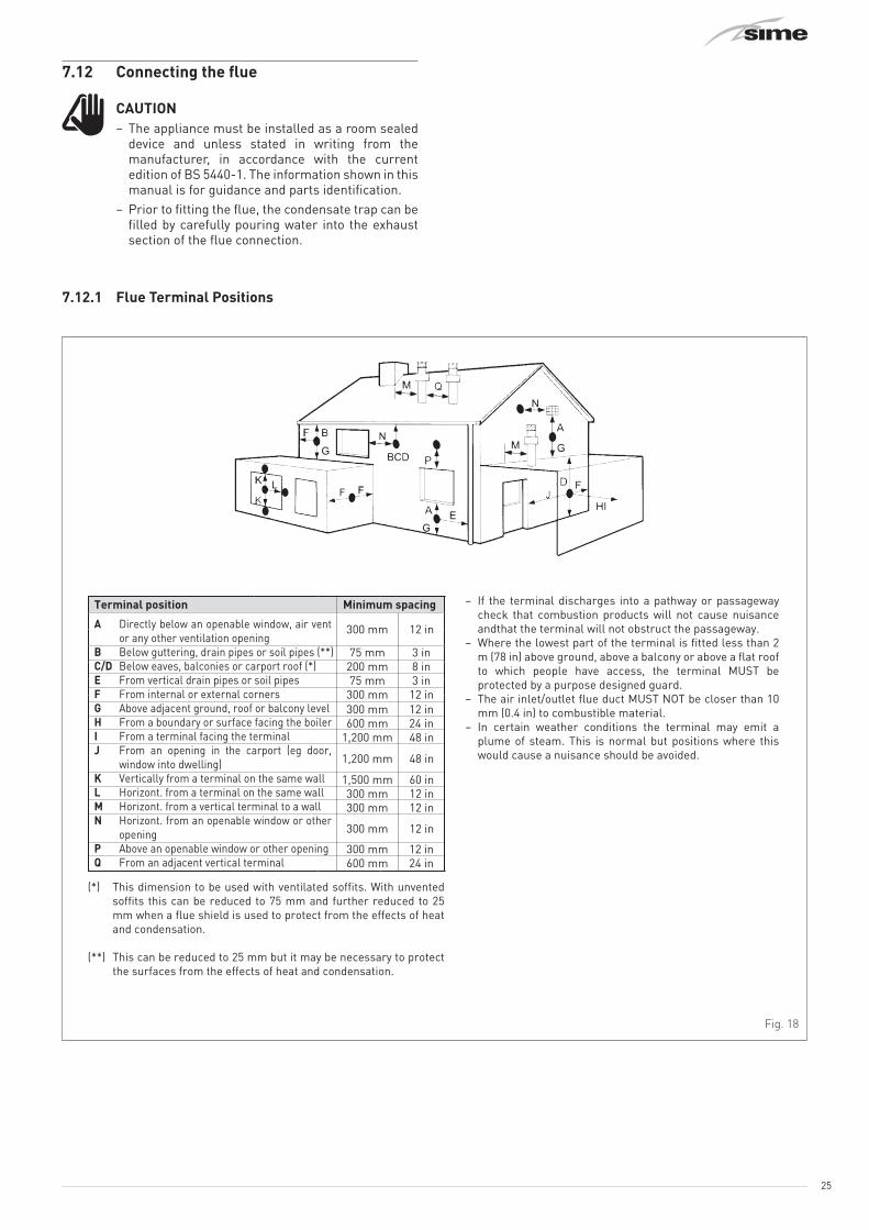
7.12.1 Flue Terminal Positions
Terminal position Minimum spacing – If the terminal discharges into a pathway or passageway check that combustion products will not cause nuisance andthat the terminal will not obstruct the passageway.
– Where the lowest part of the terminal is fitted less than 2 m (78 in) above ground, above a balcony or above a flat roof to which people have access, the terminal MUST be protected by a purpose designed guard.
– The air inlet/outlet flue duct MUST NOT be closer than 10 mm (0.4 in) to combustible material.
– In certain weather conditions the terminal may emit a plume of steam. This is normal but positions where this would cause a nuisance should be avoided.
75 mm200 mm75 mm
300 mm
1,200 mm
600 mm
300 mm600 mm
1,200 mm
300 mm
3 in8 in3 in
12 in
48 in
24 in300 mm 12 in
12 in24 in
48 in
300 mm 12 in
1,500 mm300 mm300 mm
60 in12 in12 in
12 inA Directly below an openable window, air vent or any other ventilation opening
B Below guttering, drain pipes or soil pipes (**)C/D Below eaves, balconies or carport roof (*)E From vertical drain pipes or soil pipesF From internal or external cornersG Above adjacent ground, roof or balcony levelH From a boundary or surface facing the boilerI From a terminal facing the terminalJ From an opening in the carport (eg door,
window into dwelling)K Vertically from a terminal on the same wallL Horizont. from a terminal on the same wallM Horizont. from a vertical terminal to a wallN Horizont. from an openable window or other
openingP Above an openable window or other openingQ From an adjacent vertical terminal
(*) This dimension to be used with ventilated soffits. With unvented soffits this can be reduced to 75 mm and further reduced to 25 mm when a flue shield is used to protect from the effects of heat and condensation.
(**) This can be reduced to 25 mm but it may be necessary to protect the surfaces from the effects of heat and condensation.
Fig. 18
26
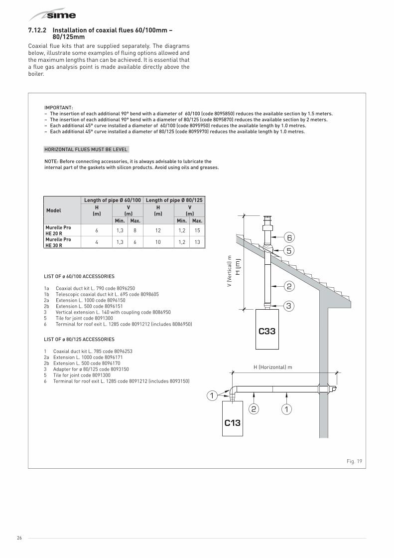
7.12.2 Installation of coaxial flues 60/100mm – 80/125mm
Coaxial flue kits that are supplied separately. The diagrams below, illustrate some examples of fluing options allowed and the maximum lengths than can be achieved. It is essential that a flue gas analysis point is made available directly above the boiler.
C33
6
5
3
2
C43
3
4 2
x
y
x + y = L (m)
H (m
)
C13
12
1
L (m)
2
H (Horizontal) m
IMPORTANT:– The insertion of each additional 90° bend with a diameter of 60/100 (code 8095850) reduces the available section by 1.5 meters.– The insertion of each additional 90° bend with a diameter of 80/125 (code 8095870) reduces the available section by 2 meters.– Each additional 45° curve installed a diameter of 60/100 (code 8095950) reduces the available length by 1.0 metres.– Each additional 45° curve installed a diameter of 80/125 (code 8095970) reduces the available length by 1.0 metres.
HORIZONTAL FLUES MUST BE LEVEL
NOTE: Before connecting accessories, it is always advisable to lubricate the internal part of the gaskets with silicon products. Avoid using oils and greases.
V (V
ertic
al) m
LIST OF ø 60/100 ACCESSORIES
1a Coaxial duct kit L. 790 code 80962501b Telescopic coaxial duct kit L. 695 code 80986052a Extension L. 1000 code 80961502b Extension L. 500 code 80961513 Vertical extension L. 140 with coupling code 80869505 Tile for joint code 80913006 Terminal for roof exit L. 1285 code 8091212 (includes 8086950)
LIST OF ø 80/125 ACCESSORIES
1 Coaxial duct kit L. 785 code 80962532a Extension L. 1000 code 80961712b Extension L. 500 code 80961703 Adapter for ø 80/125 code 80931505 Tile for joint code 80913006 Terminal for roof exit L. 1285 code 8091212 (includes 8093150)
Model
Length of pipe Ø 60/100 Length of pipe Ø 80/125H
(m)V
(m)H
(m)V
(m)Min. Max. Min. Max.
Murelle Pro HE 20 R 6 1,3 8 12 1,2 15
4 1,3 6 10 1,2 13Murelle Pro HE 30 R
Fig. 19

27
7.12.3 Installation of separate ducts 80mmThe boiler can be installed with separate air inlet and exhaust ducts. The figure below illustrate some examples of the fluing options allowed and the associated losses of the accessories. The total load loss is the sum of the load losses of the accessories used. The maximum load loss must not exceed 15 mm H2O, and the maximum flue length must not exceed 25 m inlet and exhaust.
9
CC33
11
10
3
1 1
3
37
3
12 12
12C13
3
2
3
1
12
12
912
NOTEBefore connecting accessories, it is always advisable to lubricate the internal part of the gaskets with silicon products. Avoid using oils and greases.
Load loss - mm H2O Load loss - mm H2OInlet Exhaust Inlet Exhaust
1 Air/smoke divider, code 8093050 0 0 0 0
2 90° bend, code 8077450 0.20 0.25 0.25 0.30
3 a Extension 80mm L. 1000, code 8077351 0.15 0.15 0.20 0.20
3 b Extension 80mm L. 500, code 8077350 0.075 0.075 0.10 0.10
7 45° bend, code 8077451 0.15 0.15 0.20 0.20
9 Inlet/ exhaust fitting, code 8091401 -- -- -- --
10 Articulated tile, code 8091300 -- -- -- --
11 Vertical roof terminal, code 8091204 * 0.80 0.10 1.10 0.15
12 Coaxial Terminal, code 8096253 * 0.80 0.10 1.10 0.15
* This loss includes the losses with use of item 9
Murelle Pro HE 20 R Murelle Pro HE 30 R
Fig. 20
It is essential that flue gas analysis points are made available directly above the boiler, these are incorporated in the twin flue adaptor code 8093050.
1
2 34
Fig. 21
1 Twin pipe adaptor with test points 80930502 Air inlet3 Exhaust4 Test point
mCAUTION– The maximum overall length is determined by
the sum of the load losses of the individual flue components must not exceed 15 mm H2O.
– The maximum flue length must not exceed 25m – air intake, 25m –exhaust.
120
Ø 80 Ø 80
250400
169
169
Fig. 22

28
7.13 Electrical connections and External controls
The boiler is supplied with a mains cable. Connect the boiler to a 230V -50Hz single phase power supply through a fused mains switch, with at least 3 mm spacing between contacts, fused at 3 amps.If this cable needs to be replaced, an original spare must be requested from Sime Ltd (part code 6325602).The heating control of the boiler can be achieved by a 230V switched control to the 230V TA connection.
mCAUTIONOnly qualified persons in compliance with the instructions contained in this manual are permitted to install, commission and maintain this boiler. The installation of this boiler must be in accordance with the relevant requirements of the current Gas Safety(installation and use), the local building regulations, and I.E.E. wiring regulations.
aDANGERBefore carrying out any interventions described:– isolate the power supply– isolate the gas cock– avoid contact with any hot surfaces.
To make the electrical connections:– remove the two screws (1), pull the front panel (2) forwards
and release it from the top by lifting it
1
2
Fig. 23
– remove the screws (3) securing the control panel (4)– move the panel (4) upwards (a) but keeping it in the side
guides (5) to the end of travel– bring it forwards and down (b) until it is horizontal
3a
b
5
4
Fig. 24
– disconnect the electrode cable by pulling the appropriate connector on the rear of the control panel
– remove the screw (6)– press on the tabs (7) and remove the rear cover (8) of the
control panel
68
7
7Fig. 25
– insert the connection wires through the grommet (8) and the opening (9) on the control panel
– connect the component wires to the terminal board (10)1
23
45 TA 230V
89
10
Fig. 26
– place the rear cover of the control panel and secure it with the screw previously removed
– bring the control panel (4) to the original position and secure it with the screws (3) which were removed previously.
3
4
3Fig. 27
29
mCAUTIONIt is compulsory:– to connect the boiler to a 230v -50Hz single phase
power supply through a fused mains switch, with at least 3mm spacing between contacts, fused at 3amps
– if the power cable is to be replaced, that ONLY a special cable is used with a factory produced re-wired connector, ordered as a spare part and connected by a professionally qualified person
– to connect the earth wire to an effective earthing system (*)
– that before any work is done on the boiler, the mains power is disconnected by setting the main system switch to "OFF".
(*) Sime Ltd declines all responsible for any injury or damage to persons, animals,or property as a result of failure to provide adequate earthing of the appliance.
dDO NOTDo not use water pipes for earthing the appliance.
7.13.1 Heating demandThe heating demand is made by applying 230V to connection- TA 230V.
7.14 Refilling or emptyingBefore carrying out the operation described below, isolate the boiler power supply.Ensure that the inhibiter concentration is correct on refilling.
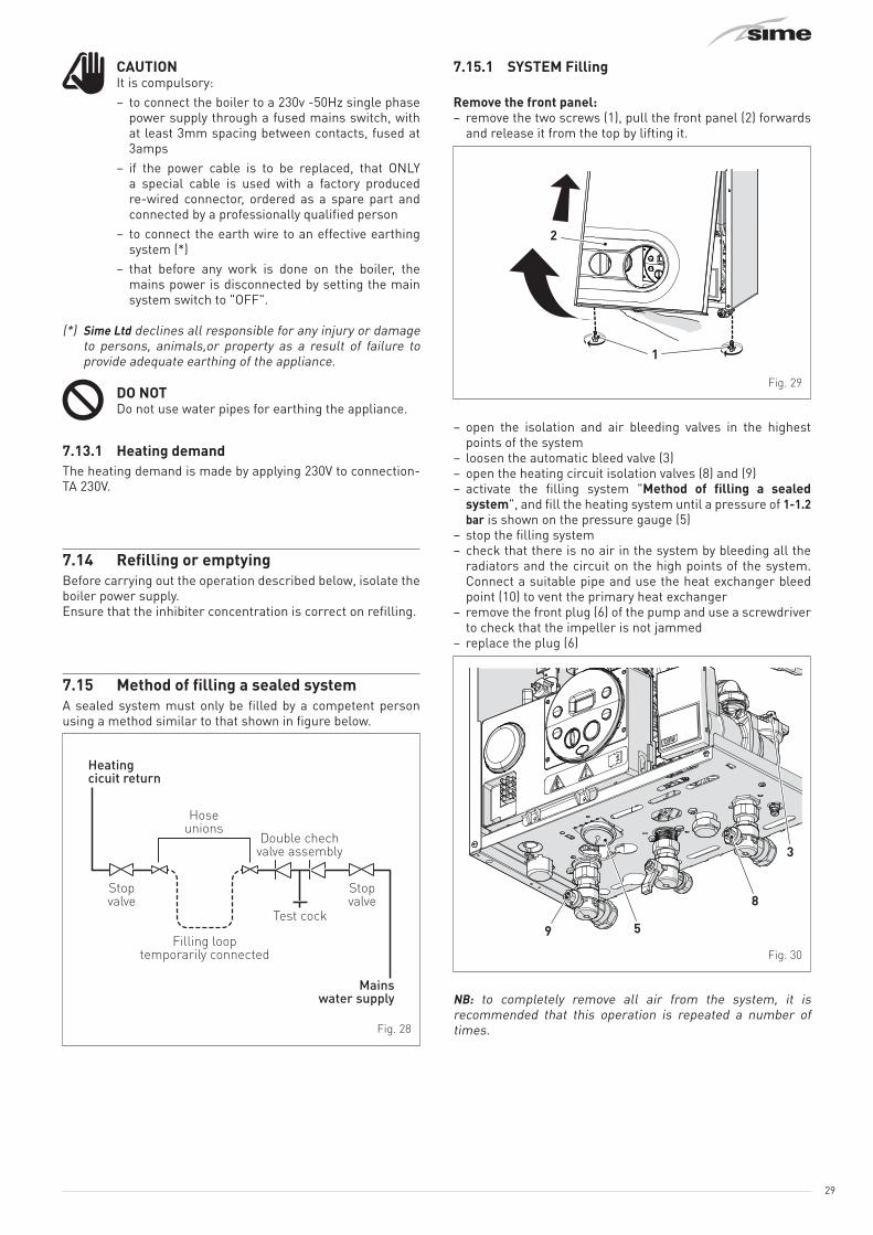
7.15 Method of filling a sealed systemA sealed system must only be filled by a competent person using a method similar to that shown in figure below.
Stopvalve
Stopvalve
Test cock
Hoseunions
Double chechvalve assembly
Filling looptemporarily connected
Mainswater supply
Heatingcicuit return
Fig. 28
7.15.1 SYSTEM Filling
Remove the front panel:– remove the two screws (1), pull the front panel (2) forwards
and release it from the top by lifting it.
1
2
Fig. 29
– open the isolation and air bleeding valves in the highest points of the system
– loosen the automatic bleed valve (3)– open the heating circuit isolation valves (8) and (9)– activate the filling system "Method of filling a sealed
system", and fill the heating system until a pressure of 1-1.2 bar is shown on the pressure gauge (5)
– stop the filling system– check that there is no air in the system by bleeding all the
radiators and the circuit on the high points of the system. Connect a suitable pipe and use the heat exchanger bleed point (10) to vent the primary heat exchanger
– remove the front plug (6) of the pump and use a screwdriver to check that the impeller is not jammed
– replace the plug (6)
3
8
59
Fig. 30
NB: to completely remove all air from the system, it is recommended that this operation is repeated a number of times.

30
10
Fig. 31
– check the pressure on the pressure gauge (5) and if necessary top up until the correct pressure reading appears
– close the automatic bleed valve (3)– it is recommended that the condensate trap is filled prior to
fitting the flue, by carefully pouring water into the exhaust connection.
Refit the front panel of the boiler hooking it on at the top, pushing it forwards and securing it with the screw (1) which was removed previously.
7.15.2 EMPTYING operations– loosen the automatic bleed valve (3)– close the heating circuit isolation valves (8) and (9)– connect a rubber hose to the boiler drain valve (7) and open
it– when it has fully emptied, close the drain valve (7).
3
8
59
7
Fig. 32

31
8 COMMISSIONING
8.1 Preliminary operations
Before commissioning the appliance, check that:– the type of gas is correct for the appliance– the gas isolation valve is open– check that the system pressure as shown on the pressure
gauge when the system is cold , is between 1 and 1.2 bar– the pump impeller rotates freely– the siphon has been filled– the flue is fitted correctly.
8.2 Before commissioningAfter having carried out the preliminary operations, proceed as follows:– set the main system switch to "ON" and ensure that there is
a heating demand– the type of gas for which the boiler has been calibrated, “nG”
(methane) or “LG” (LPG,) will appear followed by the power. Finally “- -”will appear on the display
– press the button s once for at least 1 second to select "SUMMER mode" l. The value of the delivery sensor detected at that moment will appear on the display
mWARNINGThe self calibration procedure must be done in the SUMMER mode with the system valves open to ensure heat is taken from the boiler. It is recommended that this procedure is done with a cold system. The system heating demand can be on, but there must not be a demand at the boiler.
8.2.1 Self-calibrating procedureCarry out the "Automatic self-calibrating procedure" as follows:– turn the heating knob as far as it will go t– press and hold down the buttons o and > at the same time
for approximately 12 seconds until the flashing symbols l and n appear on the display
– as soon as the symbols begin to flash, release the buttons o and > and press the button s, within 3 seconds
– the "Automatic self-calibrating procedure" starts– ensure that there is a system heating demand and that the
system valves are open– the values flash on the display: “99” (maximum value),
followed by an "intermediate value" and finally “00” (minimum value)
It may take up 15 minutes for the "self-calibrating procedure" to end and the message "SUMMER mode" lto reappear on the display Once the procedure has terminated:– set the heating demand to off and check that the appliance
shuts down.If there is a fault, the message “AL” will appear on the display followed by the fault code (eg. “06” - no flame detected).
mCAUTIONTo restore the start conditions press and hold the button o R for more than 3 seconds. This operation can be performed up to a maximum of 6 times without the "self-calibrating procedure" being interrupted.
– press the button s twice for at least 1 second to select "WINTER mode" n. The value of the delivery sensor detected at that moment will appear on the display
– operate the heating controls and check that the boiler starts and operates correctly
– using the procedure shown in section"Chimney sweep function"complete inlet working gas pressure test and a flue gas analysis.

32
8.3 Parameter setting and displayTo go into the parameter menu:– from the selected mode (eg. WINTER)
– press the buttons < and o (approximately 5 seconds) at the same time until “tS” (installer) appears on the 2 digits of the display which alternate with “0.1” (parameter number) and a “2” (set value)
– press the button > to scroll up the list of parameters and then < to scroll down the list
NB: holding the buttons > or < increases the speed of the scrolling movement.
– once the required parameter has been reached, press the button o for approximately 3 seconds to confirm and access the set value which will then flash and can then be modified
– to modify the value in the permitted range, press the buttons > to increase it or < to decrease it
– once the required value has been reached, press the button o to confirm.
When all the parameter modifications have been made, exit the parameter menu by pressing and holding down the buttons < and o at the same time for approximately 5 seconds until the initial screen is displayed.
8.4 List of parameters
Type No. Description Range U/M Step DefaultCONFIGURATION
tS 0.1 Index showing boiler power in kW1 = 20 R; 2 = 30 R 1 .. 2 - 1 1 or 2
tS 0.2
Hydraulic configuration0 = combi1 = system2 = N/A3 = N/A4 = N/A5 = N/A
0 .. 5 - 1 1
tS 0.3 Gas Type Configuration0 = G20; 1 = G31 0 .. 1 - 1 0
tS 0.4 Combustion configuration0 = sealed chamber with combustion control - - - 0
tS 0.8 External sensor value correction -5 .. +5 °C 1 0tS 0.9 Ignition fan speed 80 .. 160 RPMx25 1 128
DOMESTIC HOT WATER - HEATINGtS 1.0 Boiler Antifreeze Threshold 0 .. +10 °C 1 3
tS 1.1 External Sensor Antifreeze Threshold-- = Disabled -9 .. +5 °C 1 -2
tS 1.2 Heating Curve Incline 0 .. 80 - 1 20tS 1.3 Minimum Heating Temperature Adjustment 20 .. Par tS 1.4 °C 1 20tS 1.4 Maximum Heating Temperature Adjustment Par tS 1.3 .. 80 °C 1 80tS 1.5 Maximum power in CH mode 0 .. 100 % 1 100
tS 1.6 Heating Post-Circulation Time 0 .. 99 seconds x 10 1 3
tS 1.7 Heating Pump Activation Delay 0 .. 60 seconds x 10 1 0
33
Type No. Description Range U/M Step DefaulttS 1.8 Re-ignition Delay 0 .. 60 Min 1 3
tS 1.9Domestic Hot Water Modulation with Flow meter0 = Disabled1 = Enabled
0 .. 1 - 1 1
tS 2.0 Maximum power domestic hot water 0 .. 100 % 1 100tS 2.1 Minimum power heating/domestic hot water (premixed) 0 .. 100 % 1 0
tS 2.2 Domestic hot water preheating enabling0 = OFF; 1 = ON 0 .. 1 - 1 0
tS 2.5
Auxiliary TA function0 = according to TA1 = TA Antifreeze2 = domestic hot water disabled
0 .. 2 - 1 0
tS 2.6 Zone Valve / Pump Relaunch Delay 0 .. 99 Min 1 1tS 2.8 DHW activation delay with solar power 0 .. 30 Min 1 0
tS 2.9 Anti-legionella Function (Only hot water tank)-- = Disabled 50 .. 80 - 1 --
tS 3.0 Maximum domestic hot water temperature 35 .. 67 °C 1 60
tS 3.5
Digital / analogue Pressure switch0 = water pressure switch1 = water pressure transducer (with ALL 09)2 = water pressure transducer (without ALL 09)
0 .. 2 - 1 0
tS 4.0 Modulating Pump Speed-- = No modulationAU = Automatic 30
.. 100% 10 AU
tS 4.1 ∆T Modulating pump delivery/Return 10 .. 40 % 1 20
tS 4.7System pump forcing (only in winter mode)0 = Disabled1 = Enabled
0 .. 1 - 1 0
RESETtS 4.8 INST Parameter set to default 0 .. 1 - 1 0
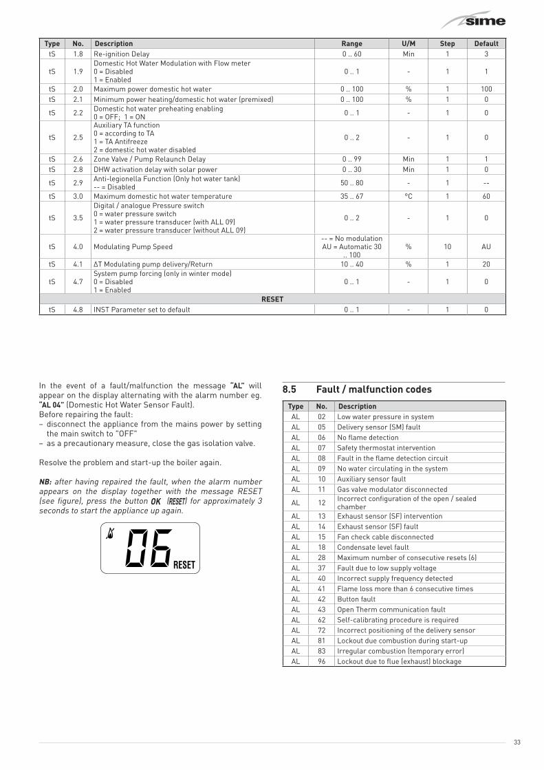
In the event of a fault/malfunction the message “AL” will appear on the display alternating with the alarm number eg. “AL 04” (Domestic Hot Water Sensor Fault).Before repairing the fault:– disconnect the appliance from the mains power by setting
the main switch to "OFF"– as a precautionary measure, close the gas isolation valve.
Resolve the problem and start-up the boiler again.
NB: after having repaired the fault, when the alarm number appears on the display together with the message RESET (see figure), press the button o (R) for approximately 3 seconds to start the appliance up again.
8.5 Fault / malfunction codes
Type No. DescriptionAL 02 Low water pressure in systemAL 05 Delivery sensor (SM) faultAL 06 No flame detectionAL 07 Safety thermostat interventionAL 08 Fault in the flame detection circuitAL 09 No water circulating in the systemAL 10 Auxiliary sensor faultAL 11 Gas valve modulator disconnected
AL 12 Incorrect configuration of the open / sealed chamber
AL 13 Exhaust sensor (SF) interventionAL 14 Exhaust sensor (SF) faultAL 15 Fan check cable disconnectedAL 18 Condensate level faultAL 28 Maximum number of consecutive resets (6)AL 37 Fault due to low supply voltageAL 40 Incorrect supply frequency detectedAL 41 Flame loss more than 6 consecutive timesAL 42 Button faultAL 43 Open Therm communication faultAL 62 Self-calibrating procedure is requiredAL 72 Incorrect positioning of the delivery sensorAL 81 Lockout due combustion during start-upAL 83 Irregular combustion (temporary error)AL 96 Lockout due to flue (exhaust) blockage

34
8.6 Display of operating data and countersAccess the operating data “In” and the counters “CO” as follows:– from the operating screen in the "WINTER moden"
– go into “INFO” by pressing the buttons > and < at the same time for more than 3 seconds until “In” appears alternating with “0.0” (information number) and “25” (eg. value)
From this point, the technician has 2 options:– scroll through the list of “info” and “counters” by pressing
the button >. This way, scrolling will be in sequence– display the “activated alarms” (no more than 10) by pressing
the button <. Once in this section, proceed with button > or <.
When all the values have been displayed, exit the menu by pressing and holding down the button o for approximately 5 seconds until the initial screen is displayed.
TABLE OF INFORMATION DISPLAYED
Type No. Description Range U/M StepIn 0.0 SW version
In 0.1 External sensor (SE)
- 9 .. 99 °C 1
In 0.2 Delivery sensor 1 temperature (SM)
- 9 .. 99 °C 1
In 0.3 Exhaust temperature (SF)
- 9 .. 99 °C 1
In 0.4 N/A - 9 .. 99 °C 1
In 0.5 N/A - 9 .. 99 °C 1
In 0.6 Actual heating SET temperature
Par. 13 … Par. 14
°C 1
In 0.7 Power level 0 .. 99 % 1
In 0.8 DHW Flow rate (N/A)
0 .. 99 l/min 0.1
In 0.9Water pressure transducer reading (when fitted)
0…99 bar 0.1
In 1.0 Actual speed fan number
0 .. 99
RPM x 100 1
TABLE OF COUNTER DISPLAYED
Type No. Description Range U/M Step
CO 0.0 total no. of boiler operating hours
0 .. 99 h x 1000
0.1; from 0.0 to 9.9; 1; from
10 to 99
CO 0.1 total no. of burner operating hours
0 .. 99 h x 1000
0.1; from 0.0 to 9.9; 1; from
10 to 99
CO 0.2 total no. of burner ignitions
0 .. 99 h x 1000
0.1; from 0.0 to 9.9; 1; from
10 to 99
CO 0.3 total no. faults 0 .. 99 x 1 1
CO 0.4
total no. of times installer parameters "tS"accessed
0 .. 99 x 1 1
CO 0.5total no. of times OEM parameters accessed
0 .. 99 x 1 1
CO 0.6 Countdown to the next service
1 .. 199 months 1
TABLE OF ACTIVATED ALARMS/FAULTS
Type No. DescriptionAL 00 Last activated alarm/faultAL 01 Last but one activated alarm/faultAL 02 Third from last activated alarm/faultAL 03 Previous activated alarm/faultAL 04 Previous activated alarm/faultAL 05 Previous activated alarm/faultAL 06 Previous activated alarm/faultAL 07 Previous activated alarm/faultAL 08 Previous activated alarm/faultAL 09 Previous activated alarm/fault
8.7 Checks
8.7.1 Chimney sweep functionThe chimney sweep function is used by the qualified maintenance technician to check the mains gas pressure, detect the combustion parameters and to measure the combustion efficiency. A combustion analysis should not be conducted until a satisfactory inlet working pressure test has been completed.
This function lasts 15 minutes and is activated by proceeding as follows:– if the panel (2) has not already been removed, remove the
two screws (1), pull the front panel (2) forwards and release it from the top by lifting it
1
2
Fig. 33

35
– remove the screws (3) securing the control panel (4)– move the panel (4) upwards (a) but keeping it in the side
guides (5) to the end of travel– bring it forwards and down (b) until it is horizontal
3a
b
5
4
Fig. 34
– isolate the gas cock– loosen the screw of the "mains pressure" point (6) and
connect a pressure gauge
6
Fig. 35
– open the gas cock– power the boiler by setting the main switch to "ON"– press the button s twice until "WINTER" mode nhas been
selected– press and hold down the buttons o and > at the same
time for approximately 10 seconds until the message “Hi” appears on the display together with the flashing symbols l and n
– press the button > to make the boiler operate at maximum power "Hi" and check that the mains gas pressure value on the pressure gauge is correct.
– press the button < to make the boiler operate at minimum power "Lo". The message “Lo” will appear on the display together with the flashing symbols l and n
– take the combustion data reading– press the button s to exit the "Chimney sweep Procedure”.
The boiler water delivery temperature will appear on the display
– disconnect the pressure gauge, carefully close the pressure point (6) and test for gas tightness. Now conduct a flue gas analysis as detailed in APPENDIX 2
– ensure the required information is recorded in the Gas Boiler System Commissioning Checklist( Benchmark).
Gas supply pressure
Type of gas G20 G31Pressure (mbar) 19 36
NOTE: There are negligeable losses of working gas pressure attributable to the boiler as the gas cock is connected directly to the gas valve.
8.8 Gas conversionMurelle Pro HE R ErP models can work with G20 or G31 without the need for any mechanical conversion. Simply select parameter”0.3” (see "Parameter setting and display" page 38) and set the type of gas to be used.If changing the type of gas to be used, carry out the entire appliance “COMMISSIONING” phase (page 37).
8.9 Heating power output adjustmentTo comply with Building regulations, the heating output must be set according to the requirements of the installed heating system.This is done by adjustment of "parameter 15" (tS 1.5).Calculate the heating requirements of the heating system in kW. Determine what that value is, as a % of the nominal heat output of the boiler, see table "Technical features" page 16. Access the parameters as shown in "Parameter setting and display" page 38, and adjust the parameter 15 (tS 1.5) to that % value
Example:– Heating system with 8 radiators, average 1.5 kW per radiator
total heat– Requirement 12 kW (8 x 1.5)– Maximum nominal heat output of boiler = 29.5 kW– Parameter 15 (tS 1.5) = 12/29.5 = 40.7%. Set tS 1.5 to 41%.

36
9 MAINTENANCE
9.1 ServicingAs a condition of the warranty and to ensure correct operation and efficiency, it is important that the boiler is serviced every 12 months, within 30 days of the anniversary of the installation date ensure the required information is recorded in the Gas Boiler System Commissioning Checklist (Benchmark).
mCAUTIONOnly qualified persons in compliance with the instructions contained in this manual are permitted to install, commission and maintain this boiler. The installation of this boiler must be in accordance with the relevant requirements of the current Gas Safety(installation and use), the local building regulations, and I.E.E. wiring regulations.
aDANGERBefore carrying out any interventions described:– isolate the power supply– isolate the gas cock– avoid contact with any hot surfaces.
9.2 External cleaning
9.2.1 Cleaning the caseWhen cleaning the cladding, use a cloth dampened with soap and water or alcohol for stubborn marks.
dDO NOTDo not use abrasive products.
9.3 Burner Inspection
9.3.1 Burner accessTo access the internal parts of the boiler:– remove the two screws (1), pull the front panel (2) forwards
and release it from the top by lifting it
1
2
Fig. 36
– remove the screws (3) securing the control panel (4)– move the panel (4) upwards (a) but keeping it in the side
guides (5) to the end of travel– bring it forwards and down (b) until it is horizontal
3a
b
5
4
Fig. 37

37
– loosen the clips (6) and extract the air inlet pipe (7)– unscrew the swivel joint (8)– extract the connectors (9) from the fan and disconnect the
electrode cable (10)
10
9 6
6
7
8
Fig. 38
– Unscrew the four nuts (11) securing the combustion chamber door (12)
– pull the fan-sleeve-door assembly (13) forwards and remove it.
11
11
13
12
Fig. 39
mCAUTIONWork carefully when removing the assembly (13) to prevent any damage occurring to the internal insulation of the combustion chamber and the door seal.
9.3.2 Cleaning the burner and the combustion chamber
The combustion chamber and the burner do not require any particular maintenance. Simply brush them with a soft brush.
9.3.3 Checking the ignition/detection electrodeCheck the state of the ignition/detection electrode and replace if necessary. Check the measurements as per the drawing whether the ignition/detection electrode is replaced or not.
6 +0,5-0,5
4,5 +0,5-0,5
Fig. 40
9.3.4 Final operationsAfter having cleaned the combustion chamber and the burner:– remove any carbon residue– check that the seal and the insulation of the door (12) to the
combustion chamber are undamaged. Replace if necessary– refit the assembly by carrying out the same operations for
removal but in the reverse order and tighten the screws (11) of the door to the combustion chamber
– reconnect the connections to the fan and the electrode.
9.4 Checks
9.4.1 Checking the flueCheck that the flue is undamaged and complete.
9.4.2 Checking the expansion vessel pressureClose the flow and return valves and drain the boiler. Check the expansion vessel pressure is not less than 1 bar. If this is not the case, pressurize it to the correct value.
9.4.3 System Inhibiter concentrationCheck and if required correct the inhibiter concentration.
Once the checks described above have been completed:– refill the boiler as described in section "SYSTEM Filling
page 30"– check that the siphon has been filled correctly– activate the "Chimney sweep function" page 40 and carry
out combustion analysis as detailed in Appendix 2– refit the front panel securing it with the two screws which
were removed previously– complete the service record in this manual.

38
9.5 Circuit Board ReplacementShould the circuit board be replace, the engineer MUST set the parameters as indicated in this table.
Type No. DescriptionSetting for Murelle
Pro HE R ErP20 30
tS 0.1Index showing boiler power in kW1 = 20 R; 2 = 30 R
1 2
tS 0.2
Hydraulic configuration0 = combi1 = system2 = N/A3 = N/A4 = N/A5 = N/A
1
tS 0.3 Gas Type Configuration0 = G20; 1 = G31 0 or 1
To enter "Parameter setting and display" see page 38.Once the parameters in the table have been set, you must carry out the entire phase of "Self-calibrating procedure" described at page 37.If the gas valve and/or the ignition/detection electrode, and/or the burner, and/or the fan are replaced, the engineer must still carry out the entire phase of "Self-calibrating procedure" described at page 37.
9.6 Possible faults and solutionsLIST OF MALFUNCTION/FAULT ALARMS
Type No. Fault Solution
AL 02 Low water pressure in system
- Restore pressure- Check for any leaks in
the system
AL 05 Delivery sensor (SM) fault
- Check connections- Replace the sensor
AL 06 No flame detection
- Check the integrity of the electrode and check that it is not grounded
- Check gas availability and pressure
- Check the operation of the gas valve
AL 07 Safety thermostat (TS), intervention
- Check the sensor or thermostat connections
- Deaerate the system- Check the bleed valve- Replace the sensor or
the thermostat- Check that the pump
impeller is not blocked
AL 08 Fault in the flame detection circuit
- Check the integrity of the electrode and check that it is not grounded
- Check gas availability and pressure
- Check the operation of the gas valve
AL 09 No water circulating in the system
- Check for any water in the system
- Check the rotation of the system pump impeller
- Check the electrical connections
- Replace the pump
Type No. Fault Solution
AL 10 Auxiliary sensor fault
- Check the hydraulic configuration using "tS 0.2"
- Check the electrical connection
AL 11 Gas valve modulator disconnected
- Check the electrical connection
AL 12Incorrect configuration of the open / sealed chamber
- Set the parameter tS 0.4 (Combustion configuration) to 0
AL 13 Exhaust sensor (SF) intervention
- Replace the smoke probe
- Contact the Technical Assistance Centre
AL 14 Exhaust sensor (SF) fault
- Replace the smoke probe
- Check the electrical connection of the smoke probe, if the problem is not resolved, contact the Assistance Centre
AL 15 Fan check cable disconnected
- Check the connection cable between the fan and the board
AL 18 Condensate level fault
- Check for any clogging in the pipe which takes the condensate to the siphon
- Check that the siphon is not clogged
AL 28Maximum number of consecutive resets reached (6)
- Contact the Technical Assistance Centre
AL 37 Fault due to low network voltage.
- Check with tester- Contact network
provider (ENEL)
AL 40 Incorrect supply frequency detected
- Contact network provider (ENEL)
AL 41 Flame loss more than 6 consecutive times
- Check the detection electrode
- Check the gas supply (open valve)
- Check mains gas pressure
AL 42 Button fault - Check that buttons are working
AL 43 Open Therm communication fault
- Check the electrical connection of the remote control
AL 62 Self-calibrating procedure is required
- Carry out the self-calibrating procedure (see the specific section)
AL 72 Incorrect positioning of the delivery sensor
- Check that the delivery sensor is attached to the delivery pipe
AL 81 Block due to combustion during start-up
- Check for blockage in flue
- Bleed the air from the gas circuit
AL 83 Irregular combustion (temporary error)
- Check for blockage in flue
AL 96 Lockout due to flue (exhaust) blockage
- Check for blockage in flue
- - Frequent relief valve intervention
- Check circuit pressure- Check expansion
vessel
- - Limited production of domestic hot water
- Check the diverter valve
- Check that plate heat exchanger is clean
- Check domestic hot water circuit valve

39
9.7 Any pump faults and possible solutions
LED colour Pump status Fault Possible solution
Red-Green flashing
"Transient safety shutdown"; Anomaly in progress
After eliminating the anomaly,
the pump restarts automatically
Network voltage too high or too low;(160V > Vn > 280V) - Check network voltage
Motor overload; rotor friction or blockage due to the presence of debris
- Check the characteristics of the system water; clean the system of any debris
Excessive speed; the pump rotor is actuated by an external factor and is rotating at a speed exceeding the maximum permitted speed
- Check that there is no external flow in the system (no other pump in operation)
Overcurrent; stator winding is in short circuit due to water - Check for leaks in the system
The temperature inside the motor is too high
- Check the water temperature in relation to ambient temperature
The pump is obstructed by an external flow (> 1200l/h) in the opposite direction
- Eliminate or reduce the external flow (< 1200l/h)
Flashing red "Permanent safety shutdown"Pump blocked due to debris in the system - Remove and reconnect the electrical
power supply (OFF - ON)Fault in the electronic board and/or the motor
- If the "red LED" continues to flash:- REPLACE THE PUMP
LED off Stationary
No electrical power - Check the electrical power connection
LED faulty - Check if the pump can operate
Electronic board faulty - REPLACE THE PUMP

40
*All installations in England and Wales must be to Local Authority Building Control (LABC) either directly or through aCompetent Persons Scheme. A Building Regulations Compliance will then be issued to the customer.
www.centralheating.co.uk© Heating and Hotwater Industry Council (HHIC)
GAS BOILER SYSTEM COMMISSIONING CHECKLIST
Customer name: Telephone number:
Address:
Boiler make and model:
Boiler serial number:
Commissioned by (PRINT NAME): Gas Safe register number:
Company name: Telephone number:
Company address:
Commissioning date:
CONTROLS (tick the appropriate boxes)
Time and temperature control to heatingtatsomreht moor elbammargorPremit/remmargorp dna tatsomreht mooR
lortnoc trats mumitpOnoitasnepmoc rehtaew/daoL
relioB noitanibmoCremit/remmargorp dna tatsomreht rednilyCretaw toh ot lortnoc erutarepmet dna emiT
Heating zone valves deriuqer toNdettiF
Hot water zone valves deriuqer toNdettiF
deriuqer toNdettiFsevlav rotaidar citatsomrehT
deriuqer toNdettiFmetsys ot ssapyb citamotuA
Boiler interlock Provided
ALL SYSTEMS
’s instructions Yes
What system cleaner was used?
What inhibitor was used? Quantity litres
Yes No
CENTRAL HEATING MODE measure and record:
Gas rate m³/hr OR ft³/hr
Burner operating pressure (if applicable) mbar OR Gas inlet pressure mbar
°C
Central heating return temperature °C
COMBINATION BOILERS ONLY
Is the installation in a hard water area (above 200ppm)? Yes No
Yes No
DOMESTIC HOT WATER MODE Measure and Record:
Gas rate m³/hr OR ft³/hr
rabm)etar mumixam ta( erusserp gnitarepo renruB OR rabmetar mumixam ta erusserp telni saG
Cold water inlet temperature °C
Hot water has been checked at all outlets Yes Temperature °C
I/min
CONDENSING BOILERS ONLY
seY8976SB/6455SB ro/dna snoitcurtsni s’rerutcafunam eht htiw ecnadrocca ni dellatsni neeb sah niard etasnednoc ehT
ALL INSTALLATIONS
Record the following:At max. rate: CO ppm AND CO/CO² Ratio
At min. rate: (where possible) CO ppm AND CO/CO² Ratio
seYsnoitalugeR gnidliuB etairporppa eht htiw seilpmoc metsys retaw toh dna gnitaeh ehT
seYsnoitcurtsni s’rerutcafunam eht htiw ecnadrocca ni denoissimmoc dna dellatsni neeb evah stcudorp detaicossa dna reliob ehT
seYremotsuc eht yb dootsrednu dna ot detartsnomed neeb evah slortnoc metsys dna reliob eht fo noitarepo ehT
Yremotsuc eht htiw tfel dna denialpxe neeb sah ,droceR ecivreS dna tsilkcehC kramhcneB gnidulcni ,erutaretil s’rerutcafunam ehT es
Commissioning Engineer’s Signature
Customer’s Signature
This Commissioning Checklist is to be completed in full by the competent person who commissioned the boiler as a means of demonstrating compliance with the appropriate Building Regulations and then handed to the customer to keep for future reference.Failure to install and commission according to the manufacturer’s instructions and complete this Benchmark Commissioning Checklist will invalidate the warranty. This does not affect the customer’s statutory rights.

41
*All installations in England and Wales must be to Local Authority Building Control (LABC) either directly or through aCompetent Persons Scheme. A Building Regulations Compliance will then be issued to the customer.
www.centralheating.co.uk© Heating and Hotwater Industry Council (HHIC)
SERVICE RECORDIt is recommended that your heating system is serviced regularly and that the appropriate Service Interval Record is completed.Service ProviderBefore completing the appropriate Service Record below, please ensure you have carried out the service as described in the manufacturer’s instructions.Always use the manufacturer’s specified spare part when replacing controls.
SERVICE 01 Date:
Engineer name:Company name:Telephone No:Gas safe register No:
Record:At max. rate: CO ppm AND CO² %At min. rate: (Where Possible) CO ppm AND CO² %
Comments:
Signature
SERVICE 02 Date:
Engineer name:Company name:Telephone No:Gas safe register No:
Record:At max. rate: CO ppm AND CO² %At min. rate: (Where Possible) CO ppm AND CO² %
Comments:
Signature
SERVICE 03 Date:
Engineer name:Company name:Telephone No:Gas safe register No:
Record:At max. rate: CO ppm AND CO² %At min. rate: (Where Possible) CO ppm AND CO² %
Comments:
Signature
SERVICE 04 Date:
Engineer name:Company name:Telephone No:Gas safe register No:
Record:At max. rate: CO ppm AND CO² %At min. rate: (Where Possible) CO ppm AND CO² %
Comments:
Signature
SERVICE 05 Date:
Engineer name:Company name:Telephone No:Gas safe register No:
Record:At max. rate: CO ppm AND CO² %At min. rate: (Where Possible) CO ppm AND CO² %
Comments:
Signature
SERVICE 06 Date:
Engineer name:Company name:Telephone No:Gas safe register No:
Record:At max. rate: CO ppm AND CO² %At min. rate: (Where Possible) CO ppm AND CO² %
Comments:
Signature
SERVICE 07 Date:
Engineer name:Company name:Telephone No:Gas safe register No:
Record:At max. rate: CO ppm AND CO² %At min. rate: (Where Possible) CO ppm AND CO² %
Comments:
Signature
SERVICE 08 Date:
Engineer name:Company name:Telephone No:Gas safe register No:
Record:At max. rate: CO ppm AND CO² %At min. rate: (Where Possible) CO ppm AND CO² %
Comments:
Signature
SERVICE 09 Date:
Engineer name:Company name:Telephone No:Gas safe register No:
Record:At max. rate: CO ppm AND CO² %At min. rate: (Where Possible) CO ppm AND CO² %
Comments:
Signature
SERVICE 10 Date:
Engineer name:Company name:Telephone No:Gas safe register No:
Record:At max. rate: CO ppm AND CO² %At min. rate: (Where Possible) CO ppm AND CO² %
Comments:
Signature

42
10 EXPLODED VIEWS
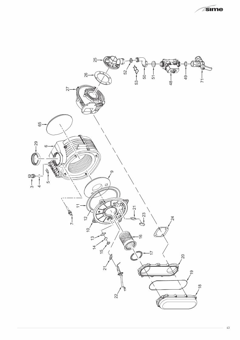
43

44

45

46
Pos. Code DescriptionMurelle Pro HE
20 R 30 R1 6264560 Boiler fixing bracket x x2 6010890 Support exchangers bracket x2 6010891 Support exchangers bracket x3 6147412 Plug for air vent connection x x4 6226464 O-ring 115 diam. 11,91x2,62 x x5 6226624 Spring air vent knob x x6 6278913 Main exchanger body x6 6278912 Main exchanger body x7 6277130 Probe NTC D.4X40 x x8 6010892 Support exchangers bracket x x9 6269008 Main exchanger door insulation x x
10 5188360 Main exchanger door x x11 6248870 Combustion chamber O-ring x x12 6248871 Glass fibre sealing cord x x13 6311810 Glass fixing flange x x14 6020103 Sight glass x x15 6248872 Sight glass gasket x x16 6278370 Premix burner x16 6278359 Premix burner x17 6174828 Gasket for burner flange x x18 6278892 Air-gas hose x x19 6174819 Air-gas hose gasket x x20 6278891 Side low air-gas hose x x21 6174809 Gasket for ignition electrode x x22 6221670 Ignition-ionisation electrode x x23 6285950 Bracket x x24 6174816 Gasket for fan flange x x25 6274390 Air/gas mixer x25 6274391 Air/gas mixer x26 6028703 Gasket for duct flange x x27 6261412 Fan x x28 6278703 Smoke chamber x x29 6248855 P.C. inlet/oulet smokes gasket x x30 6291150 Upper protection shield x x31 5183729 Rectang. expans.vessel 9 l. 3/8" M x x32 6146101 Hydrometer x x33 6226628 Hydrometer Fixing spring x x34 6037510 Water pressure switch x x35 6226639 Spring clip x x36 6226476 ORing diam.15x2 x x37 6017405 Flexible pipe M.F. 3/8" L=300 x x38 6226643 Pipe fixing spring x x39 2030226 Gasket Ø 10,2x14,8x2 x x40 6277211 Water trap x x41 6119381 Cap G 1/2" x x42 6034155 Condensate drainage pipe x x43 2051123 Clamp diam. 24,2 x x44 1010215 Rubber pipe dia. 15x2,5 x x45 2051120 Clamp diam. 17,3 x x46 6001162 Air intake pipe 40 x x47 2051203 Hose clamp Ø 40-60 x x48 6243838 Gas valve x x49 2030249 Gasket Ø 24x17x3 x x50 6277445 Pipe connecting gas valve-mixer x50 6277444 Pipe connecting gas valve-mixer x51 6050471 Nozzle 530 x51 6050472 Nozzle 650 x52 6226477 Rubber gasket OR Ø 17x3 x x53 6226636 D.H.W. elektrovalve fix.spring x x
Pos. Code DescriptionMurelle Pro HE
20 R 30 R54 6227462 Flowing pipe to C.H. system x x55 6226412 O-ring 3068 x x56 6231372 Temperature sensor x x57 6146729 100° C safety stat x x
58 6226601 Spring for heat exchanger con-nection x x
59 6227539 Return pipe from C.H. system x x
60 6226619 Spring for heat exchanger con-nection x x
61 2030267 Piracriten gasket Ø 30x17x2 x x62 6229500 Plug 1/2" x x63 6304480 casing left/right side panel x x64 6325050 Front panel x x65 6281545 Replacement rear insulat. kit x x66 6265895 Flowing to C.H. system manifold x x67 6265835 C.H. return manifold x x68 6277798 Pipe connecting x x69 6226475 ORing diam.18,64x3,53 x x71 6177530 Gas cock 3/4" F x 15 x x72 6247380 Cap for knob hole x x73 6040211 Pressure relief valve 3 bar x x75 6226626 Pipe fixing spring x x77 6120560 Pump nipple 3/4" x x78 6272360 Modulating circulating pump x78 6272323 Modulating circulating pump x79 6013182 Automatic air vent x x80 6226644 Spring clip for rotating connection x x81 6034167 Condensate drainage pipe x x
84 6275910 Pressure relief valve operation lever x x
85 6319643 Discharger cock x x86 2030227 Gasket Ø 12x18x2 x x87 2030228 Gasket Ø 17x24x2 x x88 6157653 Pressure relief valve drain pipe x x90 6304720 Control panel x x91 6324930 Main PCB x x92 6305130 Rubber button x x93 6304834 Interface panel x x94 6290150 Knob Ø 25 x x95 6305140 Rubber cap x x98 6177505 Ball cock 3/4" x 22 x x
101 6247370 Cap for programmer clock x x102 6301461 Programmer clock expansion board x x700 6281534 Gaskets kit x x701 6319695 Murelle-Format-.....o-ring kit x x702 6211794 Peephole kit x x706 6323876 4 pole cable connector CN14 x x707 6323872 9 pole cable connector CN1 x x708 6323873 6 pole cable connector CN2 x x709 6325602 6 pole cable connector CN12 x x710 6325603 14 pole cable connect.CN15+CN5 x x712 6319700 Springs / clamps kit DIN x x714 5202527 Complete control panel x x715 6325626 4 pole cable connector CN13 x x

47
11 APPENDIX 1 (GUIDANCE HHIC)
40
IND GUIDE INST 10-11 HHIC REF T11/0027BRev8
INDUSTRY GUIDANCE FOR INSTALLERS ON CONDENSATE
DRAINAGE PIPE INSTALLATION
This guidance is endorsed by HHIC members.
1. BACKGROUND
During recent winters the UK has experienced prolonged spells of extremely cold weather - down to minus 20oC and below in many areas. This resulted in a significant increase in the number of calls to boiler manufacturers and heating engineers from householders with condensing (high efficiency) boilers where the condensate drainage pipe had frozen andbecome blocked with ice, causing the boiler to shut down. In the vast majority of cases such problems occur where the condensate drainage pipe is located externally to the building for some part of its length.
British Standards, Building Regulations etc. currently allow condensate drainage pipes to berun either internally or externally, or a combination of these. These documents give guidance on how to install the pipes in order to reduce the possibility of freezing. However this guidance may not be sufficient to prevent freezing in extreme conditions - with widespread and prolonged very low temperatures.
In view of the possibility that UK weather patterns will show more “extremes” in future due to the effects of global climate change, the following guidance updates previous recommendations on condensate drainage pipe installation. All other technical requirements for condensate drain installation given in British Standard BS 6798:2009, or in boiler manufacturers’ installation instructions should still be followed.
2. REVISED GUIDANCE ON CONDENSATE DRAINAGE PIPE INSTALLATION
Where a new or replacement boiler is being installed, access to an internal “gravity discharge” termination should be one of the main factors considered when determining potential boiler locations, so that the condensate drainage pipe can be terminated as recommended below. On an existing installation, the guidance below should also be followed if work is carried out to “upgrade” the condensate drain age system to reduce the risk of freezing in extreme conditions.
Internal condensate drainage pipework must be a minimum of 19mm ID (typically 22mm OD) plastic pipe and this should “fall” at least 45 mm per metre away from the boiler, taking the shortest practicable route to the termination point.
In order to minimise the risk of freezing during prolonged very cold spells, one of the following methods of terminating condensate drainage pipe should be adopted -
8 APPENDIX 1 (GUIDANCE HHIC)

48 40
IND GUIDE INST 10-11 HHIC REF T11/0027BRev8
INDUSTRY GUIDANCE FOR INSTALLERS ON CONDENSATE
DRAINAGE PIPE INSTALLATION
This guidance is endorsed by HHIC members.
1. BACKGROUND
During recent winters the UK has experienced prolonged spells of extremely cold weather - down to minus 20oC and below in many areas. This resulted in a significant increase in the number of calls to boiler manufacturers and heating engineers from householders with condensing (high efficiency) boilers where the condensate drainage pipe had frozen andbecome blocked with ice, causing the boiler to shut down. In the vast majority of cases such problems occur where the condensate drainage pipe is located externally to the building for some part of its length.
British Standards, Building Regulations etc. currently allow condensate drainage pipes to berun either internally or externally, or a combination of these. These documents give guidance on how to install the pipes in order to reduce the possibility of freezing. However this guidance may not be sufficient to prevent freezing in extreme conditions - with widespread and prolonged very low temperatures.
In view of the possibility that UK weather patterns will show more “extremes” in future due to the effects of global climate change, the following guidance updates previous recommendations on condensate drainage pipe installation. All other technical requirements for condensate drain installation given in British Standard BS 6798:2009, or in boiler manufacturers’ installation instructions should still be followed.
2. REVISED GUIDANCE ON CONDENSATE DRAINAGE PIPE INSTALLATION
Where a new or replacement boiler is being installed, access to an internal “gravity discharge” termination should be one of the main factors considered when determining potential boiler locations, so that the condensate drainage pipe can be terminated as recommended below. On an existing installation, the guidance below should also be followed if work is carried out to “upgrade” the condensate drain age system to reduce the risk of freezing in extreme conditions.
Internal condensate drainage pipework must be a minimum of 19mm ID (typically 22mm OD) plastic pipe and this should “fall” at least 45 mm per metre away from the boiler, taking the shortest practicable route to the termination point.
In order to minimise the risk of freezing during prolonged very cold spells, one of the following methods of terminating condensate drainage pipe should be adopted -
8 APPENDIX 1 (GUIDANCE HHIC)
40
IND GUIDE INST 10-11 HHIC REF T11/0027BRev8
INDUSTRY GUIDANCE FOR INSTALLERS ON CONDENSATE
DRAINAGE PIPE INSTALLATION
This guidance is endorsed by HHIC members.
1. BACKGROUND
During recent winters the UK has experienced prolonged spells of extremely cold weather - down to minus 20oC and below in many areas. This resulted in a significant increase in the number of calls to boiler manufacturers and heating engineers from householders with condensing (high efficiency) boilers where the condensate drainage pipe had frozen andbecome blocked with ice, causing the boiler to shut down. In the vast majority of cases such problems occur where the condensate drainage pipe is located externally to the building for some part of its length.
British Standards, Building Regulations etc. currently allow condensate drainage pipes to berun either internally or externally, or a combination of these. These documents give guidance on how to install the pipes in order to reduce the possibility of freezing. However this guidance may not be sufficient to prevent freezing in extreme conditions - with widespread and prolonged very low temperatures.
In view of the possibility that UK weather patterns will show more “extremes” in future due to the effects of global climate change, the following guidance updates previous recommendations on condensate drainage pipe installation. All other technical requirements for condensate drain installation given in British Standard BS 6798:2009, or in boiler manufacturers’ installation instructions should still be followed.
2. REVISED GUIDANCE ON CONDENSATE DRAINAGE PIPE INSTALLATION
Where a new or replacement boiler is being installed, access to an internal “gravity discharge” termination should be one of the main factors considered when determining potential boiler locations, so that the condensate drainage pipe can be terminated as recommended below. On an existing installation, the guidance below should also be followed if work is carried out to “upgrade” the condensate drain age system to reduce the risk of freezing in extreme conditions.
Internal condensate drainage pipework must be a minimum of 19mm ID (typically 22mm OD) plastic pipe and this should “fall” at least 45 mm per metre away from the boiler, taking the shortest practicable route to the termination point.
In order to minimise the risk of freezing during prolonged very cold spells, one of the following methods of terminating condensate drainage pipe should be adopted -
8 APPENDIX 1 (GUIDANCE HHIC)
41
IND GUIDE INST 10-11 HHIC REF T11/0027BRev8
2.1 INTERNAL TERMINATION:
Wherever possible, the condensate drainage pipe should be terminated at a suitable internal foul water discharge point such as (a) an internal soil and vent stack or (b) an internal kitchen or bathroom waste pipe, washing machine waste pipe etc. A suitable permanent connection to the foul waste pipe should be used. Figures 1, 2(a), 2(b) show appropriate connection methods.
The possibility of waste pipes freezing downstream of the connection point should beconsidered when determining a suitable connection point - e.g. a slightly longer pipe run to an internal soil stack may be preferable to a shorter run connecting into a kitchen waste pipe discharging directly through the wall to an external drain.
Where “gravity discharge” to an internal termination is not physically possible (e.g. the discharge point is above the appliance location, or access is obstructed by a doorway), or where very long internal pipe runs would be required to reach a suitable discharge point, the following measures may be adopted -
2.2 USE OF A CONDENSATE PUMP (TO AN INTERNAL TERMINATION):
Condensate can be removed using a proprietary condensate pump, of a specification recommended by the boiler or pump manufacturer.
The pump outlet should discharge to a suitable internal foul water discharge point, such as (a) an internal soil and vent stack or (b) an internal kitchen or bathroom waste pipe, washing machine waste pipe etc. Figure 3 shows a typical connection method.
A suitable permanent connection to the foul waste pipe should be used and the manufacturer’s detailed installation instructions for the pump should be followed.
2.3 EXTERNAL TERMINATION:
The use of an externally-run condensate drainage pipe, terminating at a suitable foul water discharge point or purpose-designed soakaway, may be also be considered; however if this termination method is chosen then the following measures should be adopted -
The pipe should be run internally as far as possible before going externally and the pipe diameter should be increased to a minimum of 30mm ID (typically 32mm OD) before it passes through the wall.
The external run should be kept as short as possible, taking the most direct and “most vertical” route possible to the discharge point, with no horizontal sections in which condensate might collect.
The external pipe should be insulated using suitable waterproof and weatherproof insulation (“Class O” pipe insulation is suitable for this purpose) .

4940
IND GUIDE INST 10-11 HHIC REF T11/0027BRev8
INDUSTRY GUIDANCE FOR INSTALLERS ON CONDENSATE
DRAINAGE PIPE INSTALLATION
This guidance is endorsed by HHIC members.
1. BACKGROUND
During recent winters the UK has experienced prolonged spells of extremely cold weather - down to minus 20oC and below in many areas. This resulted in a significant increase in the number of calls to boiler manufacturers and heating engineers from householders with condensing (high efficiency) boilers where the condensate drainage pipe had frozen andbecome blocked with ice, causing the boiler to shut down. In the vast majority of cases such problems occur where the condensate drainage pipe is located externally to the building for some part of its length.
British Standards, Building Regulations etc. currently allow condensate drainage pipes to berun either internally or externally, or a combination of these. These documents give guidance on how to install the pipes in order to reduce the possibility of freezing. However this guidance may not be sufficient to prevent freezing in extreme conditions - with widespread and prolonged very low temperatures.
In view of the possibility that UK weather patterns will show more “extremes” in future due to the effects of global climate change, the following guidance updates previous recommendations on condensate drainage pipe installation. All other technical requirements for condensate drain installation given in British Standard BS 6798:2009, or in boiler manufacturers’ installation instructions should still be followed.
2. REVISED GUIDANCE ON CONDENSATE DRAINAGE PIPE INSTALLATION
Where a new or replacement boiler is being installed, access to an internal “gravity discharge” termination should be one of the main factors considered when determining potential boiler locations, so that the condensate drainage pipe can be terminated as recommended below. On an existing installation, the guidance below should also be followed if work is carried out to “upgrade” the condensate drain age system to reduce the risk of freezing in extreme conditions.
Internal condensate drainage pipework must be a minimum of 19mm ID (typically 22mm OD) plastic pipe and this should “fall” at least 45 mm per metre away from the boiler, taking the shortest practicable route to the termination point.
In order to minimise the risk of freezing during prolonged very cold spells, one of the following methods of terminating condensate drainage pipe should be adopted -
8 APPENDIX 1 (GUIDANCE HHIC)
40
IND GUIDE INST 10-11 HHIC REF T11/0027BRev8
INDUSTRY GUIDANCE FOR INSTALLERS ON CONDENSATE
DRAINAGE PIPE INSTALLATION
This guidance is endorsed by HHIC members.
1. BACKGROUND
During recent winters the UK has experienced prolonged spells of extremely cold weather - down to minus 20oC and below in many areas. This resulted in a significant increase in the number of calls to boiler manufacturers and heating engineers from householders with condensing (high efficiency) boilers where the condensate drainage pipe had frozen andbecome blocked with ice, causing the boiler to shut down. In the vast majority of cases such problems occur where the condensate drainage pipe is located externally to the building for some part of its length.
British Standards, Building Regulations etc. currently allow condensate drainage pipes to berun either internally or externally, or a combination of these. These documents give guidance on how to install the pipes in order to reduce the possibility of freezing. However this guidance may not be sufficient to prevent freezing in extreme conditions - with widespread and prolonged very low temperatures.
In view of the possibility that UK weather patterns will show more “extremes” in future due to the effects of global climate change, the following guidance updates previous recommendations on condensate drainage pipe installation. All other technical requirements for condensate drain installation given in British Standard BS 6798:2009, or in boiler manufacturers’ installation instructions should still be followed.
2. REVISED GUIDANCE ON CONDENSATE DRAINAGE PIPE INSTALLATION
Where a new or replacement boiler is being installed, access to an internal “gravity discharge” termination should be one of the main factors considered when determining potential boiler locations, so that the condensate drainage pipe can be terminated as recommended below. On an existing installation, the guidance below should also be followed if work is carried out to “upgrade” the condensate drain age system to reduce the risk of freezing in extreme conditions.
Internal condensate drainage pipework must be a minimum of 19mm ID (typically 22mm OD) plastic pipe and this should “fall” at least 45 mm per metre away from the boiler, taking the shortest practicable route to the termination point.
In order to minimise the risk of freezing during prolonged very cold spells, one of the following methods of terminating condensate drainage pipe should be adopted -
8 APPENDIX 1 (GUIDANCE HHIC)
42
IND GUIDE INST 10-11 HHIC REF T11/0027BRev8
The use of fittings, elbows etc should be kept to a minimum and any internal “burrs” on cut pipework should be removed so that the internal pipe section is as smooth as possible.
The customer/householder should be advised that even with the above measures this type of installation could freeze, and that if this were to occur then boiler shutdown could result, requiring remedial action - possibly involving a chargeable engineer call-out.
Where there are likely to be extremes of temperature or wind-chill, the use of a proprietary trace-heating system for external condensate drainage pipework, incorporating an external frost thermostat, should therefore be considered. If such a system is used then the installation instructions of the trace heating manufacturer and any specific recommendations regarding pipe diameter, insulation, etc. should be followed. All other relevant guidance on condensate drainage pipe installation should also be followed.
Other cold weather protection methods approved or endorsed by boiler manufacturers and/or service organisations may be adopted if these are considered suitable by the parties involved.
If an external soil/vent stack is used as the external termination then the connection method shown in Figure 4 should be used, together with the measures on insulation etc. as described above and shown in the diagram.
When a rain water downpipe is used as the termination (NB only permissible if this downpipe passes to a combined foul and rainwater drainage system) an air break must be installed between the condensate drainage pipe and the downpipe to avoid reverse flow of rainwater into the boiler should the downpipe itself become flooded or frozen. Figure 5 shows a suitable connection method.
Where the condensate drainage pipe is terminated over an open foul drain or gully, the pipe should terminate below the grating level, but above water level, in order to minimise “wind chill” at the open end. Pipe drainage will be improved if the end is cut at 45o as opposed to a straight cut. The use of a drain cover (such as those used to prevent blockage by leaves) may offer further protection from wind chill. Figure 6 shows a suitable connection method.
Where the condensate drain pipe terminates in a purpose-designed soakaway (see BS 6798:2009 or boiler installation manual for soakaway design requirements) any above-ground section of condensate drainage pipe should be run and insulated as described above. Figure 7 shows a suitable connection method.
3. UNHEATED INTERNAL AREAS:
Internal condensate drainage pipes run in unheated areas such as lofts, basements and garages should be treated as external pipe.

50 40
IND GUIDE INST 10-11 HHIC REF T11/0027BRev8
INDUSTRY GUIDANCE FOR INSTALLERS ON CONDENSATE
DRAINAGE PIPE INSTALLATION
This guidance is endorsed by HHIC members.
1. BACKGROUND
During recent winters the UK has experienced prolonged spells of extremely cold weather - down to minus 20oC and below in many areas. This resulted in a significant increase in the number of calls to boiler manufacturers and heating engineers from householders with condensing (high efficiency) boilers where the condensate drainage pipe had frozen andbecome blocked with ice, causing the boiler to shut down. In the vast majority of cases such problems occur where the condensate drainage pipe is located externally to the building for some part of its length.
British Standards, Building Regulations etc. currently allow condensate drainage pipes to berun either internally or externally, or a combination of these. These documents give guidance on how to install the pipes in order to reduce the possibility of freezing. However this guidance may not be sufficient to prevent freezing in extreme conditions - with widespread and prolonged very low temperatures.
In view of the possibility that UK weather patterns will show more “extremes” in future due to the effects of global climate change, the following guidance updates previous recommendations on condensate drainage pipe installation. All other technical requirements for condensate drain installation given in British Standard BS 6798:2009, or in boiler manufacturers’ installation instructions should still be followed.
2. REVISED GUIDANCE ON CONDENSATE DRAINAGE PIPE INSTALLATION
Where a new or replacement boiler is being installed, access to an internal “gravity discharge” termination should be one of the main factors considered when determining potential boiler locations, so that the condensate drainage pipe can be terminated as recommended below. On an existing installation, the guidance below should also be followed if work is carried out to “upgrade” the condensate drain age system to reduce the risk of freezing in extreme conditions.
Internal condensate drainage pipework must be a minimum of 19mm ID (typically 22mm OD) plastic pipe and this should “fall” at least 45 mm per metre away from the boiler, taking the shortest practicable route to the termination point.
In order to minimise the risk of freezing during prolonged very cold spells, one of the following methods of terminating condensate drainage pipe should be adopted -
8 APPENDIX 1 (GUIDANCE HHIC)
40
IND GUIDE INST 10-11 HHIC REF T11/0027BRev8
INDUSTRY GUIDANCE FOR INSTALLERS ON CONDENSATE
DRAINAGE PIPE INSTALLATION
This guidance is endorsed by HHIC members.
1. BACKGROUND
During recent winters the UK has experienced prolonged spells of extremely cold weather - down to minus 20oC and below in many areas. This resulted in a significant increase in the number of calls to boiler manufacturers and heating engineers from householders with condensing (high efficiency) boilers where the condensate drainage pipe had frozen andbecome blocked with ice, causing the boiler to shut down. In the vast majority of cases such problems occur where the condensate drainage pipe is located externally to the building for some part of its length.
British Standards, Building Regulations etc. currently allow condensate drainage pipes to berun either internally or externally, or a combination of these. These documents give guidance on how to install the pipes in order to reduce the possibility of freezing. However this guidance may not be sufficient to prevent freezing in extreme conditions - with widespread and prolonged very low temperatures.
In view of the possibility that UK weather patterns will show more “extremes” in future due to the effects of global climate change, the following guidance updates previous recommendations on condensate drainage pipe installation. All other technical requirements for condensate drain installation given in British Standard BS 6798:2009, or in boiler manufacturers’ installation instructions should still be followed.
2. REVISED GUIDANCE ON CONDENSATE DRAINAGE PIPE INSTALLATION
Where a new or replacement boiler is being installed, access to an internal “gravity discharge” termination should be one of the main factors considered when determining potential boiler locations, so that the condensate drainage pipe can be terminated as recommended below. On an existing installation, the guidance below should also be followed if work is carried out to “upgrade” the condensate drain age system to reduce the risk of freezing in extreme conditions.
Internal condensate drainage pipework must be a minimum of 19mm ID (typically 22mm OD) plastic pipe and this should “fall” at least 45 mm per metre away from the boiler, taking the shortest practicable route to the termination point.
In order to minimise the risk of freezing during prolonged very cold spells, one of the following methods of terminating condensate drainage pipe should be adopted -
8 APPENDIX 1 (GUIDANCE HHIC)
43
IND GUIDE INST 10-11 HHIC REF T11/0027BRev8
NOTES
The Benchmark Commissioning Checklist should be completed as required torecord details of the condensate drainage pipe installation.
Where an external condensate drainage pipe is installed, the customer should be made aware of the risks and consequences of its freezing and offered the option to fit trace heating (or other measures approved by the boiler manufacturer or service organisation).
Separate guidance has been published for householders on remedial actions which can be taken if a condensate drainage pipe freezes. This may result in requests for alteration to condensate drainage pipework, in which case the guidance above should be followed.
In some instances (e.g. where an elderly person’s heating needs to be reinstated as an emergency measure) condensate drainage pipes may have been cut in order to bypass any blockage and allow re-ignition of the boiler, with condensate being collected in a suitable container as a temporary solution.
While not unsafe, this is not recommended practice and if such action has been taken then the condensate drainage pipe must be reinstated as soon as possible, using the above guidance to reduce risk of freezing in future.

5140
IND GUIDE INST 10-11 HHIC REF T11/0027BRev8
INDUSTRY GUIDANCE FOR INSTALLERS ON CONDENSATE
DRAINAGE PIPE INSTALLATION
This guidance is endorsed by HHIC members.
1. BACKGROUND
During recent winters the UK has experienced prolonged spells of extremely cold weather - down to minus 20oC and below in many areas. This resulted in a significant increase in the number of calls to boiler manufacturers and heating engineers from householders with condensing (high efficiency) boilers where the condensate drainage pipe had frozen andbecome blocked with ice, causing the boiler to shut down. In the vast majority of cases such problems occur where the condensate drainage pipe is located externally to the building for some part of its length.
British Standards, Building Regulations etc. currently allow condensate drainage pipes to berun either internally or externally, or a combination of these. These documents give guidance on how to install the pipes in order to reduce the possibility of freezing. However this guidance may not be sufficient to prevent freezing in extreme conditions - with widespread and prolonged very low temperatures.
In view of the possibility that UK weather patterns will show more “extremes” in future due to the effects of global climate change, the following guidance updates previous recommendations on condensate drainage pipe installation. All other technical requirements for condensate drain installation given in British Standard BS 6798:2009, or in boiler manufacturers’ installation instructions should still be followed.
2. REVISED GUIDANCE ON CONDENSATE DRAINAGE PIPE INSTALLATION
Where a new or replacement boiler is being installed, access to an internal “gravity discharge” termination should be one of the main factors considered when determining potential boiler locations, so that the condensate drainage pipe can be terminated as recommended below. On an existing installation, the guidance below should also be followed if work is carried out to “upgrade” the condensate drain age system to reduce the risk of freezing in extreme conditions.
Internal condensate drainage pipework must be a minimum of 19mm ID (typically 22mm OD) plastic pipe and this should “fall” at least 45 mm per metre away from the boiler, taking the shortest practicable route to the termination point.
In order to minimise the risk of freezing during prolonged very cold spells, one of the following methods of terminating condensate drainage pipe should be adopted -
8 APPENDIX 1 (GUIDANCE HHIC)
40
IND GUIDE INST 10-11 HHIC REF T11/0027BRev8
INDUSTRY GUIDANCE FOR INSTALLERS ON CONDENSATE
DRAINAGE PIPE INSTALLATION
This guidance is endorsed by HHIC members.
1. BACKGROUND
During recent winters the UK has experienced prolonged spells of extremely cold weather - down to minus 20oC and below in many areas. This resulted in a significant increase in the number of calls to boiler manufacturers and heating engineers from householders with condensing (high efficiency) boilers where the condensate drainage pipe had frozen andbecome blocked with ice, causing the boiler to shut down. In the vast majority of cases such problems occur where the condensate drainage pipe is located externally to the building for some part of its length.
British Standards, Building Regulations etc. currently allow condensate drainage pipes to berun either internally or externally, or a combination of these. These documents give guidance on how to install the pipes in order to reduce the possibility of freezing. However this guidance may not be sufficient to prevent freezing in extreme conditions - with widespread and prolonged very low temperatures.
In view of the possibility that UK weather patterns will show more “extremes” in future due to the effects of global climate change, the following guidance updates previous recommendations on condensate drainage pipe installation. All other technical requirements for condensate drain installation given in British Standard BS 6798:2009, or in boiler manufacturers’ installation instructions should still be followed.
2. REVISED GUIDANCE ON CONDENSATE DRAINAGE PIPE INSTALLATION
Where a new or replacement boiler is being installed, access to an internal “gravity discharge” termination should be one of the main factors considered when determining potential boiler locations, so that the condensate drainage pipe can be terminated as recommended below. On an existing installation, the guidance below should also be followed if work is carried out to “upgrade” the condensate drain age system to reduce the risk of freezing in extreme conditions.
Internal condensate drainage pipework must be a minimum of 19mm ID (typically 22mm OD) plastic pipe and this should “fall” at least 45 mm per metre away from the boiler, taking the shortest practicable route to the termination point.
In order to minimise the risk of freezing during prolonged very cold spells, one of the following methods of terminating condensate drainage pipe should be adopted -
8 APPENDIX 1 (GUIDANCE HHIC)
44
IND GUIDE INST 10-11 HHIC REF T11/0027BRev8
Figure 1 – Connection of condensate drainage pipe to internal soil and vent stack
Key1 Boiler2 Visible air break3 75 mm trap4 Visible air break and trap not required if there is a trap with a minimum condensate
seal of 75 mm incorporated into the boiler5 Soil and vent stack6 Invert7 450 mm minimum up to three storeys8 Minimum internal diameter 19 mm

52 40
IND GUIDE INST 10-11 HHIC REF T11/0027BRev8
INDUSTRY GUIDANCE FOR INSTALLERS ON CONDENSATE
DRAINAGE PIPE INSTALLATION
This guidance is endorsed by HHIC members.
1. BACKGROUND
During recent winters the UK has experienced prolonged spells of extremely cold weather - down to minus 20oC and below in many areas. This resulted in a significant increase in the number of calls to boiler manufacturers and heating engineers from householders with condensing (high efficiency) boilers where the condensate drainage pipe had frozen andbecome blocked with ice, causing the boiler to shut down. In the vast majority of cases such problems occur where the condensate drainage pipe is located externally to the building for some part of its length.
British Standards, Building Regulations etc. currently allow condensate drainage pipes to berun either internally or externally, or a combination of these. These documents give guidance on how to install the pipes in order to reduce the possibility of freezing. However this guidance may not be sufficient to prevent freezing in extreme conditions - with widespread and prolonged very low temperatures.
In view of the possibility that UK weather patterns will show more “extremes” in future due to the effects of global climate change, the following guidance updates previous recommendations on condensate drainage pipe installation. All other technical requirements for condensate drain installation given in British Standard BS 6798:2009, or in boiler manufacturers’ installation instructions should still be followed.
2. REVISED GUIDANCE ON CONDENSATE DRAINAGE PIPE INSTALLATION
Where a new or replacement boiler is being installed, access to an internal “gravity discharge” termination should be one of the main factors considered when determining potential boiler locations, so that the condensate drainage pipe can be terminated as recommended below. On an existing installation, the guidance below should also be followed if work is carried out to “upgrade” the condensate drain age system to reduce the risk of freezing in extreme conditions.
Internal condensate drainage pipework must be a minimum of 19mm ID (typically 22mm OD) plastic pipe and this should “fall” at least 45 mm per metre away from the boiler, taking the shortest practicable route to the termination point.
In order to minimise the risk of freezing during prolonged very cold spells, one of the following methods of terminating condensate drainage pipe should be adopted -
8 APPENDIX 1 (GUIDANCE HHIC)
40
IND GUIDE INST 10-11 HHIC REF T11/0027BRev8
INDUSTRY GUIDANCE FOR INSTALLERS ON CONDENSATE
DRAINAGE PIPE INSTALLATION
This guidance is endorsed by HHIC members.
1. BACKGROUND
During recent winters the UK has experienced prolonged spells of extremely cold weather - down to minus 20oC and below in many areas. This resulted in a significant increase in the number of calls to boiler manufacturers and heating engineers from householders with condensing (high efficiency) boilers where the condensate drainage pipe had frozen andbecome blocked with ice, causing the boiler to shut down. In the vast majority of cases such problems occur where the condensate drainage pipe is located externally to the building for some part of its length.
British Standards, Building Regulations etc. currently allow condensate drainage pipes to berun either internally or externally, or a combination of these. These documents give guidance on how to install the pipes in order to reduce the possibility of freezing. However this guidance may not be sufficient to prevent freezing in extreme conditions - with widespread and prolonged very low temperatures.
In view of the possibility that UK weather patterns will show more “extremes” in future due to the effects of global climate change, the following guidance updates previous recommendations on condensate drainage pipe installation. All other technical requirements for condensate drain installation given in British Standard BS 6798:2009, or in boiler manufacturers’ installation instructions should still be followed.
2. REVISED GUIDANCE ON CONDENSATE DRAINAGE PIPE INSTALLATION
Where a new or replacement boiler is being installed, access to an internal “gravity discharge” termination should be one of the main factors considered when determining potential boiler locations, so that the condensate drainage pipe can be terminated as recommended below. On an existing installation, the guidance below should also be followed if work is carried out to “upgrade” the condensate drain age system to reduce the risk of freezing in extreme conditions.
Internal condensate drainage pipework must be a minimum of 19mm ID (typically 22mm OD) plastic pipe and this should “fall” at least 45 mm per metre away from the boiler, taking the shortest practicable route to the termination point.
In order to minimise the risk of freezing during prolonged very cold spells, one of the following methods of terminating condensate drainage pipe should be adopted -
8 APPENDIX 1 (GUIDANCE HHIC)
45
IND GUIDE INST 10-11 HHIC REF T11/0027BRev8
Figure 2(a) – Connection of a condensate drainage pipe downstream of a sink, basin, bath or shower waste trap
Key1 Boiler2 Visible air break3 75 mm trap4 Visible air break and trap not required if there is a trap with a minimum condensate
seal of 75 mm incorporated into the boiler. In this case the 100 mm is measured to the trap in the boiler.
5 Sink, basin, bath or shower6 Open end of condensate drainage pipe direct into gully 25 mm min below grating but
above water level; end cut at 45 °7 Sink lip8 Minimum internal diameter 19 mm9 Pipe size transition10 Minimum internal diameter 30 mm11 Water/weather proof insulation

5340
IND GUIDE INST 10-11 HHIC REF T11/0027BRev8
INDUSTRY GUIDANCE FOR INSTALLERS ON CONDENSATE
DRAINAGE PIPE INSTALLATION
This guidance is endorsed by HHIC members.
1. BACKGROUND
During recent winters the UK has experienced prolonged spells of extremely cold weather - down to minus 20oC and below in many areas. This resulted in a significant increase in the number of calls to boiler manufacturers and heating engineers from householders with condensing (high efficiency) boilers where the condensate drainage pipe had frozen andbecome blocked with ice, causing the boiler to shut down. In the vast majority of cases such problems occur where the condensate drainage pipe is located externally to the building for some part of its length.
British Standards, Building Regulations etc. currently allow condensate drainage pipes to berun either internally or externally, or a combination of these. These documents give guidance on how to install the pipes in order to reduce the possibility of freezing. However this guidance may not be sufficient to prevent freezing in extreme conditions - with widespread and prolonged very low temperatures.
In view of the possibility that UK weather patterns will show more “extremes” in future due to the effects of global climate change, the following guidance updates previous recommendations on condensate drainage pipe installation. All other technical requirements for condensate drain installation given in British Standard BS 6798:2009, or in boiler manufacturers’ installation instructions should still be followed.
2. REVISED GUIDANCE ON CONDENSATE DRAINAGE PIPE INSTALLATION
Where a new or replacement boiler is being installed, access to an internal “gravity discharge” termination should be one of the main factors considered when determining potential boiler locations, so that the condensate drainage pipe can be terminated as recommended below. On an existing installation, the guidance below should also be followed if work is carried out to “upgrade” the condensate drain age system to reduce the risk of freezing in extreme conditions.
Internal condensate drainage pipework must be a minimum of 19mm ID (typically 22mm OD) plastic pipe and this should “fall” at least 45 mm per metre away from the boiler, taking the shortest practicable route to the termination point.
In order to minimise the risk of freezing during prolonged very cold spells, one of the following methods of terminating condensate drainage pipe should be adopted -
8 APPENDIX 1 (GUIDANCE HHIC)
40
IND GUIDE INST 10-11 HHIC REF T11/0027BRev8
INDUSTRY GUIDANCE FOR INSTALLERS ON CONDENSATE
DRAINAGE PIPE INSTALLATION
This guidance is endorsed by HHIC members.
1. BACKGROUND
During recent winters the UK has experienced prolonged spells of extremely cold weather - down to minus 20oC and below in many areas. This resulted in a significant increase in the number of calls to boiler manufacturers and heating engineers from householders with condensing (high efficiency) boilers where the condensate drainage pipe had frozen andbecome blocked with ice, causing the boiler to shut down. In the vast majority of cases such problems occur where the condensate drainage pipe is located externally to the building for some part of its length.
British Standards, Building Regulations etc. currently allow condensate drainage pipes to berun either internally or externally, or a combination of these. These documents give guidance on how to install the pipes in order to reduce the possibility of freezing. However this guidance may not be sufficient to prevent freezing in extreme conditions - with widespread and prolonged very low temperatures.
In view of the possibility that UK weather patterns will show more “extremes” in future due to the effects of global climate change, the following guidance updates previous recommendations on condensate drainage pipe installation. All other technical requirements for condensate drain installation given in British Standard BS 6798:2009, or in boiler manufacturers’ installation instructions should still be followed.
2. REVISED GUIDANCE ON CONDENSATE DRAINAGE PIPE INSTALLATION
Where a new or replacement boiler is being installed, access to an internal “gravity discharge” termination should be one of the main factors considered when determining potential boiler locations, so that the condensate drainage pipe can be terminated as recommended below. On an existing installation, the guidance below should also be followed if work is carried out to “upgrade” the condensate drain age system to reduce the risk of freezing in extreme conditions.
Internal condensate drainage pipework must be a minimum of 19mm ID (typically 22mm OD) plastic pipe and this should “fall” at least 45 mm per metre away from the boiler, taking the shortest practicable route to the termination point.
In order to minimise the risk of freezing during prolonged very cold spells, one of the following methods of terminating condensate drainage pipe should be adopted -
8 APPENDIX 1 (GUIDANCE HHIC)
46
IND GUIDE INST 10-11 HHIC REF T11/0027BRev8
Figure 2(b) – Connection of a condensate drainage pipe upstream of a sink, basin, bath or shower waste trap
Key1 Boiler2 Visible air break at plug-hole3 75 mm sink, basin, bath or shower waste trap4 Sink, basin, bath or shower with integral overflow5 Open end of condensate drainage pipe direct into gully 25 mm min below grating but
above water level; end cut at 45 °6 Minimum internal diameter 19 mm7 Pipe size transition8 Minimum internal diameter 30 mm9 Water/weather proof insulation

54 40
IND GUIDE INST 10-11 HHIC REF T11/0027BRev8
INDUSTRY GUIDANCE FOR INSTALLERS ON CONDENSATE
DRAINAGE PIPE INSTALLATION
This guidance is endorsed by HHIC members.
1. BACKGROUND
During recent winters the UK has experienced prolonged spells of extremely cold weather - down to minus 20oC and below in many areas. This resulted in a significant increase in the number of calls to boiler manufacturers and heating engineers from householders with condensing (high efficiency) boilers where the condensate drainage pipe had frozen andbecome blocked with ice, causing the boiler to shut down. In the vast majority of cases such problems occur where the condensate drainage pipe is located externally to the building for some part of its length.
British Standards, Building Regulations etc. currently allow condensate drainage pipes to berun either internally or externally, or a combination of these. These documents give guidance on how to install the pipes in order to reduce the possibility of freezing. However this guidance may not be sufficient to prevent freezing in extreme conditions - with widespread and prolonged very low temperatures.
In view of the possibility that UK weather patterns will show more “extremes” in future due to the effects of global climate change, the following guidance updates previous recommendations on condensate drainage pipe installation. All other technical requirements for condensate drain installation given in British Standard BS 6798:2009, or in boiler manufacturers’ installation instructions should still be followed.
2. REVISED GUIDANCE ON CONDENSATE DRAINAGE PIPE INSTALLATION
Where a new or replacement boiler is being installed, access to an internal “gravity discharge” termination should be one of the main factors considered when determining potential boiler locations, so that the condensate drainage pipe can be terminated as recommended below. On an existing installation, the guidance below should also be followed if work is carried out to “upgrade” the condensate drain age system to reduce the risk of freezing in extreme conditions.
Internal condensate drainage pipework must be a minimum of 19mm ID (typically 22mm OD) plastic pipe and this should “fall” at least 45 mm per metre away from the boiler, taking the shortest practicable route to the termination point.
In order to minimise the risk of freezing during prolonged very cold spells, one of the following methods of terminating condensate drainage pipe should be adopted -
8 APPENDIX 1 (GUIDANCE HHIC)
40
IND GUIDE INST 10-11 HHIC REF T11/0027BRev8
INDUSTRY GUIDANCE FOR INSTALLERS ON CONDENSATE
DRAINAGE PIPE INSTALLATION
This guidance is endorsed by HHIC members.
1. BACKGROUND
During recent winters the UK has experienced prolonged spells of extremely cold weather - down to minus 20oC and below in many areas. This resulted in a significant increase in the number of calls to boiler manufacturers and heating engineers from householders with condensing (high efficiency) boilers where the condensate drainage pipe had frozen andbecome blocked with ice, causing the boiler to shut down. In the vast majority of cases such problems occur where the condensate drainage pipe is located externally to the building for some part of its length.
British Standards, Building Regulations etc. currently allow condensate drainage pipes to berun either internally or externally, or a combination of these. These documents give guidance on how to install the pipes in order to reduce the possibility of freezing. However this guidance may not be sufficient to prevent freezing in extreme conditions - with widespread and prolonged very low temperatures.
In view of the possibility that UK weather patterns will show more “extremes” in future due to the effects of global climate change, the following guidance updates previous recommendations on condensate drainage pipe installation. All other technical requirements for condensate drain installation given in British Standard BS 6798:2009, or in boiler manufacturers’ installation instructions should still be followed.
2. REVISED GUIDANCE ON CONDENSATE DRAINAGE PIPE INSTALLATION
Where a new or replacement boiler is being installed, access to an internal “gravity discharge” termination should be one of the main factors considered when determining potential boiler locations, so that the condensate drainage pipe can be terminated as recommended below. On an existing installation, the guidance below should also be followed if work is carried out to “upgrade” the condensate drain age system to reduce the risk of freezing in extreme conditions.
Internal condensate drainage pipework must be a minimum of 19mm ID (typically 22mm OD) plastic pipe and this should “fall” at least 45 mm per metre away from the boiler, taking the shortest practicable route to the termination point.
In order to minimise the risk of freezing during prolonged very cold spells, one of the following methods of terminating condensate drainage pipe should be adopted -
8 APPENDIX 1 (GUIDANCE HHIC)
47
IND GUIDE INST 10-11 HHIC REF T11/0027BRev8
Figure 3 – Connection of a condensate pump - typical method (NB manufacturer’s detailed instructions should be followed).

5540
IND GUIDE INST 10-11 HHIC REF T11/0027BRev8
INDUSTRY GUIDANCE FOR INSTALLERS ON CONDENSATE
DRAINAGE PIPE INSTALLATION
This guidance is endorsed by HHIC members.
1. BACKGROUND
During recent winters the UK has experienced prolonged spells of extremely cold weather - down to minus 20oC and below in many areas. This resulted in a significant increase in the number of calls to boiler manufacturers and heating engineers from householders with condensing (high efficiency) boilers where the condensate drainage pipe had frozen andbecome blocked with ice, causing the boiler to shut down. In the vast majority of cases such problems occur where the condensate drainage pipe is located externally to the building for some part of its length.
British Standards, Building Regulations etc. currently allow condensate drainage pipes to berun either internally or externally, or a combination of these. These documents give guidance on how to install the pipes in order to reduce the possibility of freezing. However this guidance may not be sufficient to prevent freezing in extreme conditions - with widespread and prolonged very low temperatures.
In view of the possibility that UK weather patterns will show more “extremes” in future due to the effects of global climate change, the following guidance updates previous recommendations on condensate drainage pipe installation. All other technical requirements for condensate drain installation given in British Standard BS 6798:2009, or in boiler manufacturers’ installation instructions should still be followed.
2. REVISED GUIDANCE ON CONDENSATE DRAINAGE PIPE INSTALLATION
Where a new or replacement boiler is being installed, access to an internal “gravity discharge” termination should be one of the main factors considered when determining potential boiler locations, so that the condensate drainage pipe can be terminated as recommended below. On an existing installation, the guidance below should also be followed if work is carried out to “upgrade” the condensate drain age system to reduce the risk of freezing in extreme conditions.
Internal condensate drainage pipework must be a minimum of 19mm ID (typically 22mm OD) plastic pipe and this should “fall” at least 45 mm per metre away from the boiler, taking the shortest practicable route to the termination point.
In order to minimise the risk of freezing during prolonged very cold spells, one of the following methods of terminating condensate drainage pipe should be adopted -
8 APPENDIX 1 (GUIDANCE HHIC)
40
IND GUIDE INST 10-11 HHIC REF T11/0027BRev8
INDUSTRY GUIDANCE FOR INSTALLERS ON CONDENSATE
DRAINAGE PIPE INSTALLATION
This guidance is endorsed by HHIC members.
1. BACKGROUND
During recent winters the UK has experienced prolonged spells of extremely cold weather - down to minus 20oC and below in many areas. This resulted in a significant increase in the number of calls to boiler manufacturers and heating engineers from householders with condensing (high efficiency) boilers where the condensate drainage pipe had frozen andbecome blocked with ice, causing the boiler to shut down. In the vast majority of cases such problems occur where the condensate drainage pipe is located externally to the building for some part of its length.
British Standards, Building Regulations etc. currently allow condensate drainage pipes to berun either internally or externally, or a combination of these. These documents give guidance on how to install the pipes in order to reduce the possibility of freezing. However this guidance may not be sufficient to prevent freezing in extreme conditions - with widespread and prolonged very low temperatures.
In view of the possibility that UK weather patterns will show more “extremes” in future due to the effects of global climate change, the following guidance updates previous recommendations on condensate drainage pipe installation. All other technical requirements for condensate drain installation given in British Standard BS 6798:2009, or in boiler manufacturers’ installation instructions should still be followed.
2. REVISED GUIDANCE ON CONDENSATE DRAINAGE PIPE INSTALLATION
Where a new or replacement boiler is being installed, access to an internal “gravity discharge” termination should be one of the main factors considered when determining potential boiler locations, so that the condensate drainage pipe can be terminated as recommended below. On an existing installation, the guidance below should also be followed if work is carried out to “upgrade” the condensate drain age system to reduce the risk of freezing in extreme conditions.
Internal condensate drainage pipework must be a minimum of 19mm ID (typically 22mm OD) plastic pipe and this should “fall” at least 45 mm per metre away from the boiler, taking the shortest practicable route to the termination point.
In order to minimise the risk of freezing during prolonged very cold spells, one of the following methods of terminating condensate drainage pipe should be adopted -
8 APPENDIX 1 (GUIDANCE HHIC)
48
IND GUIDE INST 10-11 HHIC REF T11/0027BRev8
Figure 4 – Connection of condensate drainage pipe to external soil and vent stack
Key1 Boiler 7 450 mm minimum up to three storeys2 Visible air break 8 Minimum internal diameter 19 mm3 75 mm trap 9 Pipe size transition point4 Visible air break and trap not required if
there is a trap with a minimum condensate seal of 75 mm incorporated into the boiler.
10 Minimum internal diameter 30 mm
11 Water/weather proof insulation
5 Soil and vent stack6 Invert

56 40
IND GUIDE INST 10-11 HHIC REF T11/0027BRev8
INDUSTRY GUIDANCE FOR INSTALLERS ON CONDENSATE
DRAINAGE PIPE INSTALLATION
This guidance is endorsed by HHIC members.
1. BACKGROUND
During recent winters the UK has experienced prolonged spells of extremely cold weather - down to minus 20oC and below in many areas. This resulted in a significant increase in the number of calls to boiler manufacturers and heating engineers from householders with condensing (high efficiency) boilers where the condensate drainage pipe had frozen andbecome blocked with ice, causing the boiler to shut down. In the vast majority of cases such problems occur where the condensate drainage pipe is located externally to the building for some part of its length.
British Standards, Building Regulations etc. currently allow condensate drainage pipes to berun either internally or externally, or a combination of these. These documents give guidance on how to install the pipes in order to reduce the possibility of freezing. However this guidance may not be sufficient to prevent freezing in extreme conditions - with widespread and prolonged very low temperatures.
In view of the possibility that UK weather patterns will show more “extremes” in future due to the effects of global climate change, the following guidance updates previous recommendations on condensate drainage pipe installation. All other technical requirements for condensate drain installation given in British Standard BS 6798:2009, or in boiler manufacturers’ installation instructions should still be followed.
2. REVISED GUIDANCE ON CONDENSATE DRAINAGE PIPE INSTALLATION
Where a new or replacement boiler is being installed, access to an internal “gravity discharge” termination should be one of the main factors considered when determining potential boiler locations, so that the condensate drainage pipe can be terminated as recommended below. On an existing installation, the guidance below should also be followed if work is carried out to “upgrade” the condensate drain age system to reduce the risk of freezing in extreme conditions.
Internal condensate drainage pipework must be a minimum of 19mm ID (typically 22mm OD) plastic pipe and this should “fall” at least 45 mm per metre away from the boiler, taking the shortest practicable route to the termination point.
In order to minimise the risk of freezing during prolonged very cold spells, one of the following methods of terminating condensate drainage pipe should be adopted -
8 APPENDIX 1 (GUIDANCE HHIC)
40
IND GUIDE INST 10-11 HHIC REF T11/0027BRev8
INDUSTRY GUIDANCE FOR INSTALLERS ON CONDENSATE
DRAINAGE PIPE INSTALLATION
This guidance is endorsed by HHIC members.
1. BACKGROUND
During recent winters the UK has experienced prolonged spells of extremely cold weather - down to minus 20oC and below in many areas. This resulted in a significant increase in the number of calls to boiler manufacturers and heating engineers from householders with condensing (high efficiency) boilers where the condensate drainage pipe had frozen andbecome blocked with ice, causing the boiler to shut down. In the vast majority of cases such problems occur where the condensate drainage pipe is located externally to the building for some part of its length.
British Standards, Building Regulations etc. currently allow condensate drainage pipes to berun either internally or externally, or a combination of these. These documents give guidance on how to install the pipes in order to reduce the possibility of freezing. However this guidance may not be sufficient to prevent freezing in extreme conditions - with widespread and prolonged very low temperatures.
In view of the possibility that UK weather patterns will show more “extremes” in future due to the effects of global climate change, the following guidance updates previous recommendations on condensate drainage pipe installation. All other technical requirements for condensate drain installation given in British Standard BS 6798:2009, or in boiler manufacturers’ installation instructions should still be followed.
2. REVISED GUIDANCE ON CONDENSATE DRAINAGE PIPE INSTALLATION
Where a new or replacement boiler is being installed, access to an internal “gravity discharge” termination should be one of the main factors considered when determining potential boiler locations, so that the condensate drainage pipe can be terminated as recommended below. On an existing installation, the guidance below should also be followed if work is carried out to “upgrade” the condensate drain age system to reduce the risk of freezing in extreme conditions.
Internal condensate drainage pipework must be a minimum of 19mm ID (typically 22mm OD) plastic pipe and this should “fall” at least 45 mm per metre away from the boiler, taking the shortest practicable route to the termination point.
In order to minimise the risk of freezing during prolonged very cold spells, one of the following methods of terminating condensate drainage pipe should be adopted -
8 APPENDIX 1 (GUIDANCE HHIC)
49
IND GUIDE INST 10-11 HHIC REF T11/0027BRev8
Figure 5 – External termination to rainwater downpipe (NB only combined foul/rainwater drain)
Key1 Condensate discharge pipe from boiler 7 Air gap2 Pipe size transition point 8 68 mm PVCu strap-on fitting3 Water/weather proof insulation 9 Minimum internal diameter 19 mm4 43 mm 90° male/female bend 10 Minimum internal diameter 30 mm5 External rain water pipe into foul water 11 End cut at 45 °6 External air break

5740
IND GUIDE INST 10-11 HHIC REF T11/0027BRev8
INDUSTRY GUIDANCE FOR INSTALLERS ON CONDENSATE
DRAINAGE PIPE INSTALLATION
This guidance is endorsed by HHIC members.
1. BACKGROUND
During recent winters the UK has experienced prolonged spells of extremely cold weather - down to minus 20oC and below in many areas. This resulted in a significant increase in the number of calls to boiler manufacturers and heating engineers from householders with condensing (high efficiency) boilers where the condensate drainage pipe had frozen andbecome blocked with ice, causing the boiler to shut down. In the vast majority of cases such problems occur where the condensate drainage pipe is located externally to the building for some part of its length.
British Standards, Building Regulations etc. currently allow condensate drainage pipes to berun either internally or externally, or a combination of these. These documents give guidance on how to install the pipes in order to reduce the possibility of freezing. However this guidance may not be sufficient to prevent freezing in extreme conditions - with widespread and prolonged very low temperatures.
In view of the possibility that UK weather patterns will show more “extremes” in future due to the effects of global climate change, the following guidance updates previous recommendations on condensate drainage pipe installation. All other technical requirements for condensate drain installation given in British Standard BS 6798:2009, or in boiler manufacturers’ installation instructions should still be followed.
2. REVISED GUIDANCE ON CONDENSATE DRAINAGE PIPE INSTALLATION
Where a new or replacement boiler is being installed, access to an internal “gravity discharge” termination should be one of the main factors considered when determining potential boiler locations, so that the condensate drainage pipe can be terminated as recommended below. On an existing installation, the guidance below should also be followed if work is carried out to “upgrade” the condensate drain age system to reduce the risk of freezing in extreme conditions.
Internal condensate drainage pipework must be a minimum of 19mm ID (typically 22mm OD) plastic pipe and this should “fall” at least 45 mm per metre away from the boiler, taking the shortest practicable route to the termination point.
In order to minimise the risk of freezing during prolonged very cold spells, one of the following methods of terminating condensate drainage pipe should be adopted -
8 APPENDIX 1 (GUIDANCE HHIC)
40
IND GUIDE INST 10-11 HHIC REF T11/0027BRev8
INDUSTRY GUIDANCE FOR INSTALLERS ON CONDENSATE
DRAINAGE PIPE INSTALLATION
This guidance is endorsed by HHIC members.
1. BACKGROUND
During recent winters the UK has experienced prolonged spells of extremely cold weather - down to minus 20oC and below in many areas. This resulted in a significant increase in the number of calls to boiler manufacturers and heating engineers from householders with condensing (high efficiency) boilers where the condensate drainage pipe had frozen andbecome blocked with ice, causing the boiler to shut down. In the vast majority of cases such problems occur where the condensate drainage pipe is located externally to the building for some part of its length.
British Standards, Building Regulations etc. currently allow condensate drainage pipes to berun either internally or externally, or a combination of these. These documents give guidance on how to install the pipes in order to reduce the possibility of freezing. However this guidance may not be sufficient to prevent freezing in extreme conditions - with widespread and prolonged very low temperatures.
In view of the possibility that UK weather patterns will show more “extremes” in future due to the effects of global climate change, the following guidance updates previous recommendations on condensate drainage pipe installation. All other technical requirements for condensate drain installation given in British Standard BS 6798:2009, or in boiler manufacturers’ installation instructions should still be followed.
2. REVISED GUIDANCE ON CONDENSATE DRAINAGE PIPE INSTALLATION
Where a new or replacement boiler is being installed, access to an internal “gravity discharge” termination should be one of the main factors considered when determining potential boiler locations, so that the condensate drainage pipe can be terminated as recommended below. On an existing installation, the guidance below should also be followed if work is carried out to “upgrade” the condensate drain age system to reduce the risk of freezing in extreme conditions.
Internal condensate drainage pipework must be a minimum of 19mm ID (typically 22mm OD) plastic pipe and this should “fall” at least 45 mm per metre away from the boiler, taking the shortest practicable route to the termination point.
In order to minimise the risk of freezing during prolonged very cold spells, one of the following methods of terminating condensate drainage pipe should be adopted -
8 APPENDIX 1 (GUIDANCE HHIC)
50
IND GUIDE INST 10-11 HHIC REF T11/0027BRev8
Figure 6 – External drain, gully or rainwater hopper
Key
1 Boiler2 Visible air break3 38 mm minimum trap4 Visible air break and trap not required if there is a trap with a minimum condensate
seal of 38 mm incorporated into the boiler5 External length of pipe 3 m maximum6 Open end of condensate drainage pipe direct into gully 25 mm min below grating but
above water level; end cut at 45 °7 Minimum internal diameter 19 mm8 Pipe size transition point9 Minimum internal diameter 30 mm10 Water/weather proof insulation
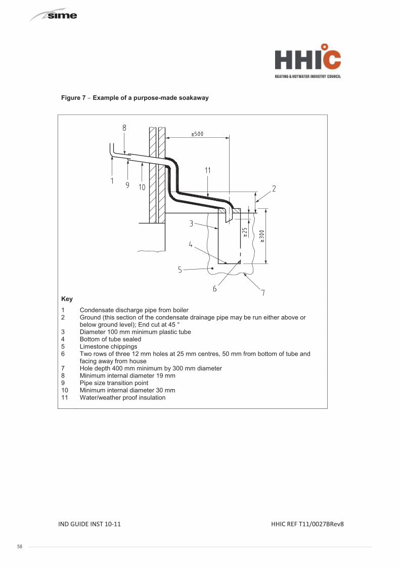
58 40
IND GUIDE INST 10-11 HHIC REF T11/0027BRev8
INDUSTRY GUIDANCE FOR INSTALLERS ON CONDENSATE
DRAINAGE PIPE INSTALLATION
This guidance is endorsed by HHIC members.
1. BACKGROUND
During recent winters the UK has experienced prolonged spells of extremely cold weather - down to minus 20oC and below in many areas. This resulted in a significant increase in the number of calls to boiler manufacturers and heating engineers from householders with condensing (high efficiency) boilers where the condensate drainage pipe had frozen andbecome blocked with ice, causing the boiler to shut down. In the vast majority of cases such problems occur where the condensate drainage pipe is located externally to the building for some part of its length.
British Standards, Building Regulations etc. currently allow condensate drainage pipes to berun either internally or externally, or a combination of these. These documents give guidance on how to install the pipes in order to reduce the possibility of freezing. However this guidance may not be sufficient to prevent freezing in extreme conditions - with widespread and prolonged very low temperatures.
In view of the possibility that UK weather patterns will show more “extremes” in future due to the effects of global climate change, the following guidance updates previous recommendations on condensate drainage pipe installation. All other technical requirements for condensate drain installation given in British Standard BS 6798:2009, or in boiler manufacturers’ installation instructions should still be followed.
2. REVISED GUIDANCE ON CONDENSATE DRAINAGE PIPE INSTALLATION
Where a new or replacement boiler is being installed, access to an internal “gravity discharge” termination should be one of the main factors considered when determining potential boiler locations, so that the condensate drainage pipe can be terminated as recommended below. On an existing installation, the guidance below should also be followed if work is carried out to “upgrade” the condensate drain age system to reduce the risk of freezing in extreme conditions.
Internal condensate drainage pipework must be a minimum of 19mm ID (typically 22mm OD) plastic pipe and this should “fall” at least 45 mm per metre away from the boiler, taking the shortest practicable route to the termination point.
In order to minimise the risk of freezing during prolonged very cold spells, one of the following methods of terminating condensate drainage pipe should be adopted -
8 APPENDIX 1 (GUIDANCE HHIC)
40
IND GUIDE INST 10-11 HHIC REF T11/0027BRev8
INDUSTRY GUIDANCE FOR INSTALLERS ON CONDENSATE
DRAINAGE PIPE INSTALLATION
This guidance is endorsed by HHIC members.
1. BACKGROUND
During recent winters the UK has experienced prolonged spells of extremely cold weather - down to minus 20oC and below in many areas. This resulted in a significant increase in the number of calls to boiler manufacturers and heating engineers from householders with condensing (high efficiency) boilers where the condensate drainage pipe had frozen andbecome blocked with ice, causing the boiler to shut down. In the vast majority of cases such problems occur where the condensate drainage pipe is located externally to the building for some part of its length.
British Standards, Building Regulations etc. currently allow condensate drainage pipes to berun either internally or externally, or a combination of these. These documents give guidance on how to install the pipes in order to reduce the possibility of freezing. However this guidance may not be sufficient to prevent freezing in extreme conditions - with widespread and prolonged very low temperatures.
In view of the possibility that UK weather patterns will show more “extremes” in future due to the effects of global climate change, the following guidance updates previous recommendations on condensate drainage pipe installation. All other technical requirements for condensate drain installation given in British Standard BS 6798:2009, or in boiler manufacturers’ installation instructions should still be followed.
2. REVISED GUIDANCE ON CONDENSATE DRAINAGE PIPE INSTALLATION
Where a new or replacement boiler is being installed, access to an internal “gravity discharge” termination should be one of the main factors considered when determining potential boiler locations, so that the condensate drainage pipe can be terminated as recommended below. On an existing installation, the guidance below should also be followed if work is carried out to “upgrade” the condensate drain age system to reduce the risk of freezing in extreme conditions.
Internal condensate drainage pipework must be a minimum of 19mm ID (typically 22mm OD) plastic pipe and this should “fall” at least 45 mm per metre away from the boiler, taking the shortest practicable route to the termination point.
In order to minimise the risk of freezing during prolonged very cold spells, one of the following methods of terminating condensate drainage pipe should be adopted -
8 APPENDIX 1 (GUIDANCE HHIC)
51
IND GUIDE INST 10-11 HHIC REF T11/0027BRev8
Figure 7 – Example of a purpose-made soakaway
Key
1 Condensate discharge pipe from boiler2 Ground (this section of the condensate drainage pipe may be run either above or
below ground level); End cut at 45 °3 Diameter 100 mm minimum plastic tube4 Bottom of tube sealed5 Limestone chippings6 Two rows of three 12 mm holes at 25 mm centres, 50 mm from bottom of tube and
facing away from house7 Hole depth 400 mm minimum by 300 mm diameter8 Minimum internal diameter 19 mm9 Pipe size transition point10 Minimum internal diameter 30 mm11 Water/weather proof insulation
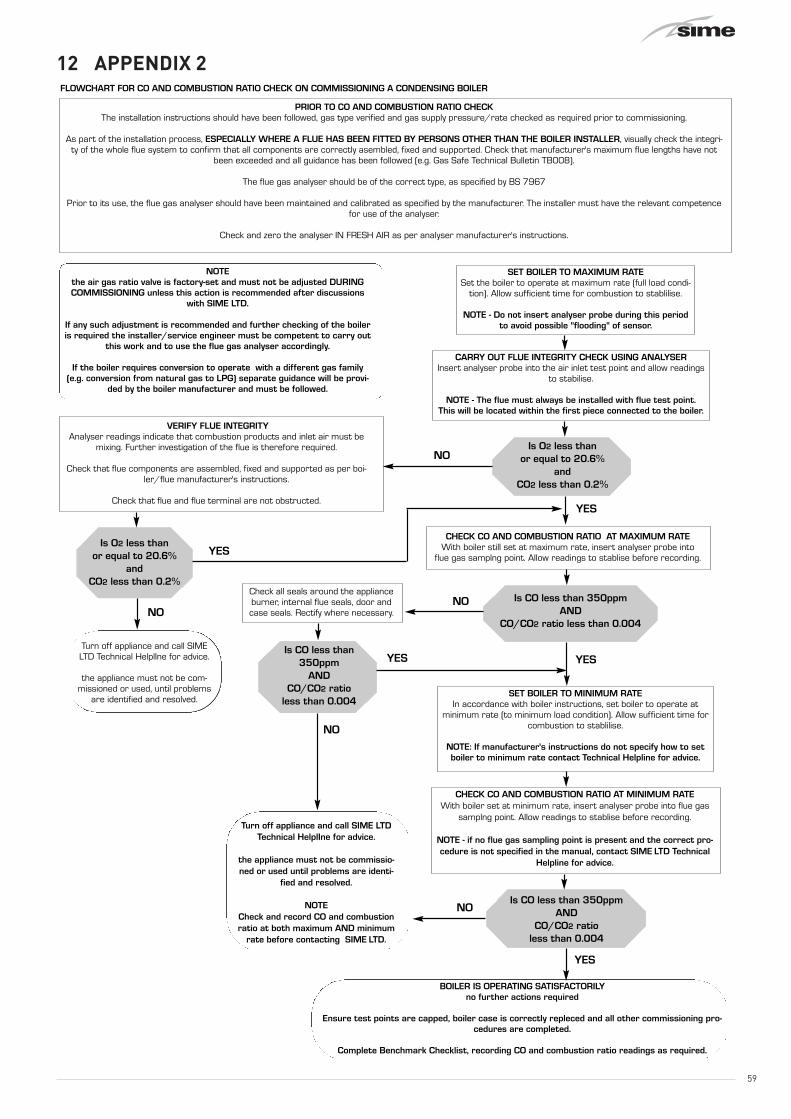
59
12 APPENDIX 2
52
9 APPENDIX 2
FLOWCHART FOR CO AND COMBUSTION RATIO CHECK ON COMMISSIONING A CONDENSING BOILER
PRIOR TO CO AND COMBUSTION RATIO CHECKThe installation instructions should have been followed, gas type verified and gas supply pressure/rate checked as required prior to commissioning.
As part of the installation process, ESPECIALLY WHERE A FLUE HAS BEEN FITTED BY PERSONS OTHER THAN THE BOILER INSTALLER, visually check the integri-ty of the whole flue system to confirm that all components are correctly asembled, fixed and supported. Check that manufacturer's maximum flue lengths have not
been exceeded and all guidance has been followed (e.g. Gas Safe Technical Bulletin TB008).
The flue gas analyser should be of the correct type, as specified by BS 7967
Prior to its use, the flue gas analyser should have been maintained and calibrated as specified by the manufacturer. The installer must have the relevant competencefor use of the analyser.
Check and zero the analyser IN FRESH AIR as per analyser manufacturer's instructions.
NOTE the air gas ratio valve is factory-set and must not be adjusted DURINGCOMMISSIONING unless this action is recommended after discussions
with SIME LTD.
If any such adjustment is recommended and further checking of the boileris required the installer/service engineer must be competent to carry out
this work and to use the flue gas analyser accordingly.
If the boiler requires conversion to operate with a different gas family(e.g. conversion from natural gas to LPG) separate guidance will be provi-
ded by the boiler manufacturer and must be followed.
SET BOILER TO MAXIMUM RATESet the boiler to operate at maximum rate (full load condi-
tion). Allow sufficient time for combustion to stablilise.
NOTE - Do not insert analyser probe during this periodto avoid possible "flooding" of sensor.
CARRY OUT FLUE INTEGRITY CHECK USING ANALYSERInsert analyser probe into the air inlet test point and allow readings
to stabilise.
NOTE - The flue must always be installed with flue test point.This will be located within the first piece connected to the boiler.
Is O2 less than or equal to 20.6%
and CO2 less than 0.2%
VERIFY FLUE INTEGRITY Analyser readings indicate that combustion products and inlet air must be
mixing. Further investigation of the flue is therefore required.
Check that flue components are assembled, fixed and supported as per boi-ler/flue manufacturer's instructions.
Check that flue and flue terminal are not obstructed.
Is O2 less than or equal to 20.6%
and CO2 less than 0.2%
CHECK CO AND COMBUSTION RATIO AT MAXIMUM RATEWith boiler still set at maximum rate, insert analyser probe into
flue gas samplng point. Allow readings to stablise before recording.
Turn off appliance and call SIMELTD Technical HelplIne for advice.
the appliance must not be com-missioned or used, until problems
are identified and resolved.
Is CO less than 350ppm AND
CO/CO2 ratio less than 0.004
Check all seals around the applianceburner, internal flue seals, door andcase seals. Rectify where necessary.
SET BOILER TO MINIMUM RATEIn accordance with boiler instructions, set boiler to operate at
minimum rate (to minimum load condition). Allow sufficient time forcombustion to stablilise.
NOTE: If manufacturer's instructions do not specify how to setboiler to minimum rate contact Technical Helpline for advice.
CHECK CO AND COMBUSTION RATIO AT MINIMUM RATEWith boiler set at minimum rate, insert analyser probe into flue gas
samplng point. Allow readings to stablise before recording.
NOTE - if no flue gas sampling point is present and the correct pro-cedure is not specified in the manual, contact SIME LTD Technical
Helpline for advice.
Is CO less than350ppm
ANDCO/CO2 ratio
less than 0.004
Turn off appliance and call SIME LTDTechnical HelplIne for advice.
the appliance must not be commissio-ned or used until problems are identi-
fied and resolved.
NOTECheck and record CO and combustionratio at both maximum AND minimum
rate before contacting SIME LTD.
Is CO less than 350ppm AND
CO/CO2 ratio less than 0.004
BOILER IS OPERATING SATISFACTORILY no further actions required
Ensure test points are capped, boiler case is correctly repleced and all other commissioning pro-cedures are completed.
Complete Benchmark Checklist, recording CO and combustion ratio readings as required.
NO
YES
YES
NONO
YESYES
NO
NO
YES

Sime Ltd1a Blue Ridge ParkThunderhead RidgeGlasshoughton, Castleford, WF10 4UA
Phone: 0845 9011114Fax: 0845 9011115
www.sime.co.ukEmail: [email protected]