CNC QuickStart
100
Inventory and Reporting Cisco Network Collector 4.0 Quick Start Guide July 7, 2006 Corporate Headquarters Cisco Systems, Inc. 170 West Tasman Drive San Jose, CA 95134-1706 USA http://www.cisco.com
-
Upload
guilherme-rodrigues-campos -
Category
Documents
-
view
34 -
download
0
Transcript of CNC QuickStart

Inventory and ReportingCisco Network Collector 4.0 Quick Start Guide July 7, 2006
Corporate Headquarters Cisco Systems, Inc. 170 West Tasman Drive San Jose, CA 95134-1706 USA http://www.cisco.com

CNC Quick Start Guide
TABLE OF CONTENTS About this Guide................................................................................ ............................................................. 1 Introduction to Inventory and Reporting and the Role of CNC ...................................................................... 1 Access CNC and Begin Discovery.......................................................................................................................... 2 Collect Network Inventory .............................................................................................................................. 9 Appendix A1: About Device Discovery Administration, Protocols and Recommended Methodologies ......................12 A2: Device Manager.................................................................................................................................................................18 A3: System Setup..................................................................................................................................................................... 63 A4: Reports.................................................................................................................................................................78 A5: Data Transfer ............................................................................................................................................ 91A6: CNC Update.............................................................................................................................................92
© 2006 Cisco Systems, Inc. All rights reserved. Important notices, privacy statements, and trademarks of Cisco Systems, Inc. can be found on
cisco.com
Page i

CNC Quick Start Guide
About this Guide
The Cisco Network Collector (CNC) Quick Start Guide is a simple step-by-step guide to help you quickly start using the CNC Version 4.0 GUI to perform network hardware and software discoveries and inventories. Depending on your entitlement certificate, some of the functionality described in this guide may not be available in your instance of CNC.
Introduction to Inventory and Reporting and the Role of CNC
Cisco Inventory and Reporting delivers the tools and technology to discover, collect, and analyze Cisco network elements and provide Network Aware Information. Per the below diagram, there are 4 main components to Inventory and Reporting: Cisco Network Collector (CNC), the Transport Gateway, the Cisco Back End, and the secure Web Portal.
The first component , CNC, is software used for network discovery and inventory. CNC tracks all network elements discovered or added from a seed file. Version 4.0 of CNC, used for the Inventory and Reporting market trials, is Java-based. It is supported on Windows 2000 Pro, Windows XP, Windows 2003, and Solaris platforms, with the Java Runtime Engine, and Microsoft Internet Explorer web browser. Note that discovery is currently limited to a maximum of 5000 devices.
Data collected and/or inventoried from CNC is securely uploaded to the Cisco Back End via the second component, the Transport Gateway. The Transport Gateway uses 128 bit encryption to securely upload all collected and/or inventoried data that is collected by CNC. The third componrnt of Inventory and Reporting, the Cisco Back End, contains four services that process the data collected by CNC and transported by the Transport Gateway. The web portal, the fourth component, provides a secure interface that lets users select a variety of reports based on their network inventory.
Page 1
makessler
Placed Image

CNC Quick Start Guide
Access CNC and Begin Discovery To start CNC, navigate to http://localhost:8000 or go to Start Cisco Network Collector. Enter natkadmin for the user name and natkadmin for the password. If your installation was successful, you should now be running CNC.
Note: For security, you should change the default password at Security User Management Change My Password.
Recommended: Change CNC PC Port Configuration
It is highly recommended that you change the CNC port configuration before using CNC. Frequently, users cannot start CNC and the web browser displays the error message "The page can not be displayed,” which is usually because the web server could not start due to the unavailability of port 8000 (http) and/or port 8001 (https). The ports are probably already used by other processes. In this case, try the following steps:
a. Open the DOS command prompt. b. Switch to the CNC installation directory with the command:
cd to <CNC Installation Directory>\CSCONsap\bin c. Run the following command:
run perl configure_httpd -p 8003 d. If the resulting message says "The SAWebServer service was started successfully", then the web server is up and
the user can proceed to Step 4. If an error occurs and the resulting message says "Port is in use", then choose a different port number and run the above command again.
e. Go back to the web browser and change the port identification in the URL to 8003 (http) or 8004 (https). The CNC web browser GUI should be accessible now.
NOTE: When running CNC, no other web applications should be running.
Page 2
makessler
Placed Image

CNC Quick Start Guide
Procedure Access CNC and Begin Discovery
Step 1. Start Cisco Network Collector (CNC) by double-clicking the icon on your desktop.
Step 2. Use the following default login name and password for this initial login session:
• User Name: natkadmin
• Password: natkadmin
A successful login will take you to the CNC Device Manager page.
Page 3

CNC Quick Start Guide
Procedure Access CNC and Begin Discovery
Step 3. At the CNC Device Manager tab, select the Discovery option from the menu to go to the Device Discovery screen.
Step 4. At the Device Discovery screen, click the Device Discovery Administration option to go to the Discovery Administration screen.
For initial discovery sessions, combine the CDP and Routing Table discovery methods to generate fast, effective results. For more information about Device Discovery Administration and Methodology, please see Section 1 of Appendix.
Page 4

CNC Quick Start Guide
Step 5. Click Submit to create a new profile, or select an existing profile and click Submit, You will then be directed to the Select Protocols screen.
Step 6. At the Select Protocols screen, select the method(s) that best matches your network for discovery. (Help for each discovery method is available on the left of the screen next to selected methods.) After selecting all the discovery methods to be used, click Next. For more information about Device Discovery Methodology, please see
Section 1 of Appendix.
You will see help on the left panel of this screen for each item that you check.
Note: Some discoveresources, asmethods. Seediscovery met
Page 5
ry methods require greater time and does the application of multiple discovery Appendix A for more details abouthod selections.

CNC Quick Start Guide
Step 7. An example of using one of the protocols, CDP. At the Cisco Discovery Protocol screen, enter each starting IP address, and the number of CDP hops to discover away from each IP address. After entering all of the starting IP addresses, click Next to go to the SNMP Communities Screen.
Step 8. At the SNMP Communities Screen, enter each expected SNMP read-only (RO) community name configured on the network devices and click Add. Note that SNMP community names are case sensitive.
Enter each starting IP address and number of CDP hops here, and click Add. You can add multiple addresses.
SNMP Community names are case-sensitive.
SNMP access is crucial to network discovery and inventory. Verify that the CNC tool’s PC IP address has permission to conduct SNMP queries of network devices. Network devices may have permissions set as part of their SNMP configurations to limit which network management devices (IP address, host names) may request SNMP queries.
Page 6

CNC Quick Start Guide
Step 9 You may choose only Advanced Setting and Seed File Creation optional Setting or skip them Do not check Password /Usename optional setting .Password information is not required for IPR report. Click Next to be directed to the Schedule Discovery Screen.
Step 10. At the Schedule Discovery screen, click Next to start a manual discovery.
Page 7

CNC Quick Start Guide
Step 11. At the Summary screen, review and verify the displayed configuration. If you need to make configuration corrections, use the Back button to go back and correct the configuration. If the configuration is correct, click Finish to begin network discovery.
Step 12. The Discovery Status Screen appears next, allowing you to keep track of the progress and view the discovery process.
For all other details and aspects of discovery configuration, such as additional options, filters, scheduling, etc., please refer to Section 1of the Appendix. .
Page 8

CNC Quick Start Guide
Collect Network Inventory This section describes how to view inventory progress on devices, and collect inventory data via SNMP. Once discovery completes, inventory of the discovered devices is initiated.
To View the current inventory status of discovered devices, use the following procedure:
Step 1. If you are not already viewing the Device Manager tab, click that tab to view that screen. Next, click Inventory and then click View Inventory Status from the TOC menu.
Step 2. The status bar now displays
the inventory status. When the entire bar is red and the status says Ready, the inventory is complete for all network devices.
Page 9

CNC Quick Start Guide
Step 3. When the inventory is complete, select View Inventory Details from the TOC menu. You should now see an inventory status of all devices, Review the status screen to confirm that all the devices inventoried are listed in “Active Device” state. (Configurations are not necessary for IOS/CatOS report generation). See the explanation of device states reported below.
Step 4. IMPORTANT: Confirm that Inventory Profile is complete: The Inventory Collection task is separate from the Inventory Profile task, which is run about every 30 minutes. You must make sure an Inventory Profile task runs after the inventory is complete, or the data transfer will fail. Data transfer should be started only after a final profiling run. The time between profiling runs is about 30 minutes or less. To avoid waiting, manually run Profile_Inventory_System_Task from Schedule task screen. To makes sure all devices are profiled, go to Device Manager/Device List screen and check the time stamp in Last Inventory Collected Time column. All reachable profiled devices should have a time stamp.
Page 10

CNC Quick Start Guide
The IP address of each device is listed in the Available Devices column of the Device Inventory Viewer screen.
The Inventory Summary screen lists a summary of devices, giving the following information:
• TOTAL DEVICES. The total number of devices in inventory collection.
• ACTIVE DEVICES. The total number of active devices.
• CONFIG COLLECTED: Number of devices for which configuration information was collected
• NON-CISCO DEVICES: The number of devices that were supplied by a vendor other than Cisco.
• DEVICE ADDED: The number of devices added to the database that do not have any inventory yet.
• DEVICE NOT REACHABLE: The number of devices with access problems, which may be due to factors such as incorrect SNMP RO string, access list on the device, NAT or Firewall issues in the network, for example.
• CONFIG FAILED: The number of devices for which configuration collection failed.
Page 11

Inventory and ReportingCisco Network Collector 4.0 Quick Start Guide - Appendix

CNC Quick Start Guide
About Device Discovery Administration, Protocols and Recommended Methodologies The CNC discovery process uses a clue-based algorithm whereby it maintains tables of network information (such as IP addresses, subnet address, device lists, and so forth). For each device discovered on your network, the device's system MIB, interface MIB and address entry MIB are collected and added to the discovery information tables. Different discovery methods are selectable based on IP address ranges.
During discovery, CNC introduces light network traffic load, which may have some affect on network utilization, especially over slow serial lines. Additionally, the SNMP queries impact performance of the various device CPUs. Network discovery sessions should therefore be restricted to hours or locations that minimize the impact of these problems on your networks.
Factors That Influence Discovery Capability
Issue Description Device Accessibility
Each device on the network must be accessible via Telnet, SNMP or Ping. SNMP read-only access is not optional; devices have to be reachable by SNMP in order for CNC device discovery to find them. The devices need to be Pingable as well. With regard to SNMP the CNC requires that Read-Only community strings be configured.
Limited Methodologies
Using only one discovery method is likely to produce incomplete results. For example, using a method that limits discovery only to those devices compatible with the technology-range of the method will produce results that ignore all other device types on the network.
Barriers Firewalls and ACLs. VPN technologies. Those devices running MPLS are likely to be discovered; those using default routing to an inaccessible Service Provider carrier network will not be discovered.
Seed Devices Complete read-only access must be configured to the seed devices. No SNMP-VIEWs enabled (not restricting to required MIBs). Combined seed devices produce detailed un-summarized routing information (for example, one seed device may have the complete routing table for one AS or area and another seed device may have the complete table for another AS or area).
Network Stability
Discovery should be conducted only on a stable network. Where network devices are in a DOWN state the discovery process will be unable to discover the entire network.
Factors That Influence Discovery Time
The length of time required to discover a network is dependent on various factors that are not necessarily tied to the device population size. For example, one cannot assume that 200 devices can be discovered in 2 hours simply because the initial 100 devices detected in a session might have been discovered in 1 hour. The underlying threads processes of a discovery session may result in requiring 1 hour for the initial 100 devices, and only 10 minutes for the remaining 100.
Page 12
makessler
Placed Image
CNC Quick Start Guide
Typical factors that impact the amount of time to run a discovery process on a network include the following:
• Link speed. When deploying a discovery session across WAN links, link speed and latency result in slower discovery.
• Bandwidth controls. Where discovery is set for low speeds, discovery throttles how much traffic it is creating on the network.
• Device focus. Looking only for specific network elements results in slower discovery time.
• Firewalls and ACLs and possible blocking of SNMP traffic. Other factors, as associated with specific discovery methods, are described throughout this chapter.
Device Selection
When selecting seed devices, it is helpful to remember that the start of the discovery process relies on complete Cisco Discovery Protocol (CDP) and/or routing table information from one or several key devices. These devices need not be core devices but should be devices that contain complete routing tables and/or CDP neighbor tables. Aggregate devices, rather than core devices, may be the wiser choice for use as seed devices. Concern about the effect of SNMP queries on the seed device may be settled by observing the effect on the SNMP process or a test device, running the same version of software, and containing SNMP tables loaded using a test tool to generate IP route or ARP entries. A good option for seed devices may be a redundant core device (one that is in hot standby with full knowledge of the network routing tables but not actually handling the majority of the network traffic. This will reduce potential SNMP network traffic.)
Configuring Discovery Methods
The best method of discovery uses various methods of discovery and/or numerous sessions. When attempting to isolate the cause of halted discovery processes, run the discovery session more than once and/or use the various discovery methods available from the CNC discovery tool set.
CDP (Cisco Discovery Protocol) Discovery
A Cisco device that supports this protocol both transmits and listens for CDP messages. As a result each Cisco device is aware of its immediately connected neighbors. The CNC discovery engine collects the CDP information from devices by using SNMP queries to form a list of all neighbors of the queried device. This list contains all devices that have advertised their presence on the network and provides clues about other devices to be discovered.
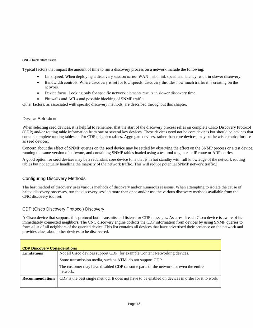
CDP Discovery Considerations Limitations Not all Cisco devices support CDP, for example Content Networking devices.
Some transmission media, such as ATM, do not support CDP. The customer may have disabled CDP on some parts of the network, or even the entire network.
Recommendations CDP is the best single method. It does not have to be enabled on devices in order for it to work.
Page 13

CNC Quick Start Guide
Routing Table Discovery
The Routing Table method uses the routing table from seed devices and retrieves the subnet address and subnet mask from the Routing Table MIB. It then compares each subnet against the list of subnets already discovered. If the connection point for the subnet is not found, it then uses SNMP to retrieve the next hop address, then it then compares the next hop address with the IP addresses already discovered. If the next hop address is not discovered it is added to a list of devices to be discovered.
Routing Table Discovery Considerations Limitations Summarization
Recommendations Routing protocol neighbor lookup is also very effective but will not find Layer 2 devices and only currently supports the OSPF and BGP protocols (the EIGRP protocol does not have a neighbor MIB).
ARP Discovery
The ARP method looks at devices discovered and retrieves the ARP table using the "at" address table MIB. This method retrieves the list of all IP addresses the device has in its cache and compares the MAC address to a list of known Cisco MAC address prefixes. If the MAC address prefix matches, the IP address it is added to the list of devices to be discovered.
ARP Discovery Considerations Limitations Not very efficient for use as a discovery tool.
Devices for which ARP entries have timed out will not be discovered.
Recommendations It is useful for finding devices that:
• Do not route
• Do not support CDP
• Have CDP disabled
OSPF Discovery
OSPF (Open Shortest Path First) is an Internal Gateway Protocol. If OSPF is active in a network, OSPF Discovery is the preferred method to determine neighbor information. Discovery uses the OSPF MIB information, which maintains a list of all neighbors. This list contains clues for further device discovery.
OSPF Discovery Considerations Limitations Discovery will be ineffective if OSPF is not running on the network.
OSPF discovery method only uses OSPF neighbor information.
Recommendations Use generic route-table instead of table-specific method.
Page 14

CNC Quick Start Guide
BGP Discovery
BGP (Border Gateway Protocol) is a routing protocol used predominately in the Internet backbone. Customers may use BGP in internal networks primarily to scale routing domains. If BGP is active in a network, BGP Discovery is the preferred method to determine neighbor information. Discovery uses the BGP MIB information, which maintains a list of all BGP neighbors. This list contains clues for further devices to be discovered.
BGP Discovery Considerations Limitations Discovery will be ineffective if BGP is not running on the network.
BGP discovery method only uses BGP neighbor information.
Recommendations
Use generic route-table instead of table-specific method.
Ping Sweep Discovery
The CNC Ping Sweep Discovery tools provide two types of Ping Sweep to allow you to base collections either from a specified IP address range or a specified starting IP address. Both methods issue sequential pings to the IP addresses. If an address responds, discovery then attempts to communicate with the device at the IP address by SNMP. If SNMP communication is successful, the device is then considered to be manageable. The CNC Discovery tool provides the following two Ping Sweep methods:
• Ping Sweep Starting IP Address This method starts from an IP address and continues pinging new addresses.
• Ping Sweep Address Range This method uses a range of IP address, from the starting address and ending with the last IP address. This pings each IP address sequentially but does not exceed the range
ICMP Ping Sweep Discovery Considerations Limitations Not very efficient, but given enough time and if ICMP messaging is not blocked, it will find everything on the
network. Depending on how network devices have been configured, and the addressing scheme in the network, the network may start responding with ICMP unreachable and redirect messages. Proxy ARP may cause problems by falsely representing certain IP addresses.
Recommendations Allow plenty of time for this method to scan the entire customer network.
Recommended Discovery Methods
For Initial Discovery Process
For initial discovery sessions, combine the CDP and Routing Table discovery methods to generate fast, effective results.
Page 15

CNC Quick Start Guide
Allow the initial discovery to run to completion. The customer should have an approximate idea of how many devices should be discovered.
1. At completion look at what devices are listed as 'Unmanaged'. Unmanaged devices appear for two reasons, they are not Cisco devices or the discovery configuration is missing credentials (SNMP community strings).
2. If the 'Unmanaged' IP addresses are Cisco devices, determine their credentials, and add them to discovery configuration.
3. If not enough devices have been discovered, adding additional seed devices or discovery methods should help.
4. Perform a second discovery and repeat the steps listed above.
CDP Disabled Network-Wide
Where CDP is disabled throughout the customer network, try the following discovery methods:
• Use combined CDP, Routing Protocol, and ARP discovery methods.
• For networks using BGP, use the BGP discovery method.
• For networks using OSPF, use the OSPF discovery method.
• Use the ARP discovery method for Layer 2 devices that do not support CDP.
CDP Enabled Network-Wide but Some Devices Do Not Support CDP
CDP does not need to be enabled network-wide to use it. So when CDP is enabled throughout the customer network, but certain devices that do not support CDP impede the discover process, try the following discovery methods:
• Use CDP.
• Use combined CDP/Routing Protocol/ARP.
• For networks using BGP, use the BGP discovery method.
• For networks using OSPF, use the OSPF discovery method.
• Use the ARP discovery method for Layer 2 devices that do not support CDP.
Highly Summarized Network
Where the network is highly summarized, try the following discovery methods:
• Use CDP.
• Use combined CDP/Routing Protocol/ARP with one seed device for each summarized domain.
• For networks using BGP, use the BGP discovery method.
• For networks using OSPF, use the OSPF discovery method.
• Use the ARP discovery method for Layer 2 devices that do not support CDP.
Page 16

CNC Quick Start Guide
Firewalls and ACLs in the Network
Firewalls and ACLs can place certain restrictions on network discovery that result in either blocking discovery methods (by blocking SNMP and ICMP), or preventing the discovery from getting past the control points. The firewall or ACL may allow traffic to cross but may not allow for responses to the SNMP queries, therefore devices blocked by firewalls or ACLs will not be discovered.
• Ensure that the security control points allow SNMP and ICMP traffic through. Include a seed device from the other side of the security control point.
• ICMP is only required if using the ICMP Ping Sweep discovery method.
Page 17

Page 18
2Device Manager
Use the Device Manager tab to access tools with which to collect and store software and hardware information about network devices.
Figure 2-1 CNC Device Manager Tab
This section describes the Device Manager tools in the following topics:
• Discovery
• Device List
• Access Verification
• Inventory
• Grouping
• Credentials
• Aliases
18Cisco Network Collector

Device Manager Discovery
DiscoveryUse the Discovery option of the Device Manager tab to access the screens to view discovery status, and to configure discovery methods to collect details to form reports about the customer network.
This section describes the Discovery tools in the following topics:
• Device Discovery Administration
• Device Discovery Status
• Import Discovered Devices
• Discovery Summary Report
• Delta Report
• Last Completed Run Report
• Debug Log Viewer
• Error Log Viewer
• Create Visio DB
• Find Device
Device Discovery AdministrationUse the Discovery tool Device Discovery Administration to start the Device Discovery Wizard. Follow along with the Wizard and choose your parameters for device discovery.
Figure 2-2 Device Discovery Administration Screen
19CNC Quick Start Guide
Page 19

Device Manager Discovery
Since there are many factors to consider when choosing discovery methods, read and understand the sections below before continuing with the Device Discovery Wizard:
• Factors That Influence Discovery Capability
• Factors That Influence Discovery Time
• Device Selection
• Configuring Discovery Methods
• Recommended Discovery Methods
The CNC discovery process uses a clue-based algorithm whereby it maintains tables of network information (such as IP addresses, subnet address, device lists, and so forth). For each device discovered on the customer network, the device's system MIB, interface MIB and address entry MIB are collected and added to the discovery information tables. Different discovery methods are selectable based on IP address ranges.
During discovery, CNC introduces light network traffic load, which may have some affect on network utilization, especially over slow serial lines. Additionally, the SNMP queries impact performance of the various device CPUs. Network discovery sessions should therefore be restricted to hours or locations that minimize the impact of these problems on customer networks. The scheduling mechanism provided in CNC facilitates this.
Factors That Influence Discovery Capability
Table 2-1 FactorsFactors That Influence Discovery Capability
Issue Description
Device Accessibility Each device on the network must be accessible via Telnet, SNMP or Ping. SNMP read-only access is not optional; devices have to be reachable by SNMP in order for CNC device discovery to find them. The devices need to be Pingable as well. With regard to SNMP the CNC requires that Read-Only community strings be configured.
Limited Methodologies Using only one discovery method is likely to produce incomplete results. For example, using a method that limits discovery only to those devices compatible with the technology-range of the method will produce results that ignore all other device types on the network.
Barriers Firewalls and ACLs.
VPN technologies. Those devices running MPLS are likely to be discovered; those using default routing to an inaccessible Service Provider carrier network will not be discovered.
Seed Devices Complete read-only access must be configured to the seed devices. No SNMP-VIEWs enabled (not restricting to required MIBs).
Combined seed devices produce detailed un-summarized routing information (for example, one seed device may have the complete routing table for one AS or area and another seed device may have the complete table for another AS or area).
Network Stability Discovery should be conducted only on a stable network. Where network
20CNC Quick Start Guide
devices are in a DOWN state the discovery process will be unable to discover the entire network.

Device Manager Discovery
Factors That Influence Discovery Time
The length of time required to discover a network is dependent on various factors that are not necessarily tied to the device population size. For example, one cannot assume that 200 devices can be discovered in 2 hours simply because the initial 100 devices detected in a session might have been discovered in 1 hour. The underlying threads processes of a discovery session may result in requiring 1 hour for the initial 100 devices, and only 10 minutes for the remaining 100.
Typical factors that impact the amount of time to run a discovery process on a network include the following:
• Link speed. When deploying a discovery session across WAN links, link speed and latency result in slower discovery.
• Bandwidth controls. Where discovery is set for low speeds, discovery throttles how much traffic it is creating on the network.
• Device focus. Looking only for specific network elements results in slower discovery time.
• Firewalls and ACLs and possible blocking of SNMP traffic.
Other factors, as associated with specific discovery methods, are described throughout this chapter.
Device Selection
When selecting seed devices, it is helpful to remember that the start of the discovery process relies on complete Cisco Discovery Protocol (CDP) and/or routing table information from one or several key devices. These devices need not be core devices but should be devices that contain complete routing tables and/or CDP neighbor tables. Aggregate devices, rather than core devices, may be the wiser choice for use as seed devices.
Concern about the effect of SNMP queries on the seed device may be settled by observing the effect on the SNMP process or a test device, running the same version of software, and containing SNMP tables loaded using a test tool to generate IP route or ARP entries.
A good option for seed devices may be a redundant core device (one that is in hot standby with full knowledge of the network routing tables but not actually handling the majority of the network traffic. This will reduce potential SNMP network traffic.)
Configuring Discovery MethodsThe best method of discovery uses various methods of discovery and/or numerous sessions. When attempting to isolate the cause of halted discovery processes, run the discovery session more than once and/or use the various discovery methods available from the CNC discovery tool set.
CDP (Cisco Discovery Protocol) Discovery
A Cisco device that supports this protocol both transmits and listens for CDP messages. As a result each Cisco device is aware of its immediately connected neighbors. The CNC discovery engine collects the CDP information from devices by using SNMP queries to form a list of all neighbors of the queried device. This list contains all devices that have advertised their presence on the network and provides clues about other devices to be discovered.
21CNC Quick Start Guide
Page 21

Device Manager Discovery
Routing Table Discovery
The Routing Table method uses the routing table from seed devices and retrieves the subnet address and subnet mask from the Routing Table MIB. It then compares each subnet against the list of subnets already discovered. If the connection point for the subnet is not found, it then uses SNMP to retrieve the next hop address, then it then compares the next hop address with the IP addresses already discovered. If the next hop address is not discovered it is added to a list of devices to be discovered.
ARP Discovery
The ARP method looks at devices discovered and retrieves the ARP table using the “at” address table MIB. This method retrieves the list of all IP addresses the device has in its cache and compares the MAC address to a list of known Cisco MAC address prefixes. If the MAC address prefix matches, the IP address it is added to the list of devices to be discovered.
OSPF Discovery
OSPF (Open Shortest Path First) is an Internal Gateway Protocol. If OSPF is active in a network, OSPF Discovery is the preferred method to determine neighbor information. Discovery uses the OSPF MIB
Table 2-2 CDP Discovery Considerations
Limitations Not all Cisco devices support CDP, for example Content Networking devices.
Some transmission media, such as ATM, do not support CDP.
The customer may have disabled CDP on some parts of the network, or even the entire network.
Recommendations CDP is the best single method of discovery. CDP does not have to be enabled on devices in order for it to work.
Table 2-3 Routing Table Discovery Considerations
Limitations Summarization
Recommendations Routing protocol neighbor lookup is also very effective but will not find Layer 2 devices and only currently supports the OSPF and BGP protocols (the EIGRP protocol does not have a neighbor MIB).
Table 2-4 ARP Discovery Considerations
Limitations Not very efficient for use as a discovery tool.
Devices for which ARP entries have timed out will not be discovered.
Recommendations It is useful for finding devices that:
• Do not route
• Do not support CDP
• Have CDP disabled
22CNC Quick Start Guide
information, which maintains a list of all neighbors. This list contains clues for further device discovery.Page 22

Device Manager Discovery
BGP Discovery
BGP (Border Gateway Protocol) is a routing protocol used predominately in the Internet backbone. Customers may use BGP in internal networks primarily to scale routing domains. If BGP is active in a network, BGP Discovery is the preferred method to determine neighbor information. Discovery uses the BGP MIB information, which maintains a list of all BGP neighbors. This list contains clues for further devices to be discovered.
Ping Sweep Discovery
The CNC Ping Sweep Discovery tools provide two types of Ping Sweep to allow you to base collections either from a specified IP address range or a specified starting IP address. Both methods issue sequential pings to the IP addresses. If an address responds, discovery then attempts to communicate with the device at the IP address by SNMP. If SNMP communication is successful, the device is then considered to be manageable.
The CNC Discovery tool provides the following two Ping Sweep methods:
• Ping Sweep Starting IP AddressThis method starts from an IP address and continues pinging new addresses.
• Ping Sweep Address RangeThis method uses a range of IP address, from the starting address and ending with the last IP address. This pings each IP address sequentially but does not exceed the range
Table 2-5 OSPF Discovery Considerations
Limitations Discovery will be ineffective if OSPF is not running on the network.
OSPF discovery method only uses OSPF neighbor information.
Recommendations Use generic route-table instead of table-specific method.
Table 2-6 BGP Discovery Considerations
Limitations Discovery will be ineffective if BGP is not running on the network.
BGP discovery method only uses BGP neighbor information.
Recommendations Use generic route-table instead of table-specific method.
Table 2-7 ICMP Ping Sweep Discovery Considerations
Limitations Not very efficient, but given enough time and if ICMP messaging is not blocked, it will find everything on the network. Depending on how network devices have been configured, and the addressing scheme in the network, the network may start responding with ICMP unreachable and redirect messages.
Proxy ARP may cause problems by falsely representing certain IP addresses.
23Cisco Network Collector
78-xxxxx-xx
Recommendations Allow plenty of time for this method to scan the entire customer network.
Page 23

Device Manager Discovery
Recommended Discovery Methods
For Initial Discovery Process
For initial discovery sessions, combine the CDP and Routing Table discovery methods to generate fast, effective results.
Step 1 Allow the initial discovery to run to completion. The customer should have an approximate idea of how many devices should be discovered.
Step 2 At completion look at what devices are listed as 'Unmanaged'. Unmanaged devices appear for two reasons, they are not Cisco devices or the discovery configuration is missing credentials (SNMP community strings).
Step 3 If the 'Unmanaged' IP addresses are Cisco devices, determine their credentials, and add them to discovery configuration.
Step 4 If not enough devices have been discovered, adding additional seed devices or discovery methods should help.
Step 5 Perform a second discovery and repeat the steps listed above.
CDP Disabled Network-Wide
Where CDP is disabled throughout the customer network, try the following discovery methods:
• Use combined CDP, Routing Protocol, and ARP discovery methods.
• For networks using BGP, use the BGP discovery method.
• For networks using OSPF, use the OSPF discovery method.
• Use the ARP discovery method for Layer 2 devices that do not support CDP.
CDP Enabled Network-Wide but Some Devices Do Not Support CDP
CDP does not need to be enabled network-wide to use it. So when CDP is enabled throughout the customer network, but certain devices that do not support CDP impede the discover process, try the following discovery methods:
• Use CDP.
• Use combined CDP/Routing Protocol/ARP.
• For networks using BGP, use the BGP discovery method.
• For networks using OSPF, use the OSPF discovery method.
• Use the ARP discovery method for Layer 2 devices that do not support CDP.
Highly Summarized Network
Where the network is highly summarized, try the following discovery methods:
• Use CDP.
• Use combined CDP/Routing Protocol/ARP with one seed device for each summarized domain.
2-7Cisco Network Collector
78-xxxxx-xx
• For networks using BGP, use the BGP discovery method.
• For networks using OSPF, use the OSPF discovery method.
• Use the ARP discovery method for Layer 2 devices that do not support CDP.

Device Manager Discovery
Firewalls and ACLs in the Network
Firewalls and ACLs can place certain restrictions on network discovery that result in either blocking discovery methods (by blocking SNMP and ICMP), or preventing the discovery from getting past the control points. The firewall or ACL may allow traffic to cross but may not allow for responses to the SNMP queries, therefore devices blocked by firewalls or ACLs will not be discovered.
• Ensure that the security control points allow SNMP and ICMP traffic through. Include a seed device from the other side of the security control point.
• ICMP is only required if using the ICMP Ping Sweep discovery method.
Device Discovery StatusUse the Discovery Status screen to view information about the most recent discovery session. The displayed information includes the discovery duration and current operative status.
Figure 2-3 Discovery Status Screen
Table 2-8 Discovery Status Screen
Field Description
Mode The current discovery mode.
Start Time The date and time of most recent discovery start. This timestamp is based on the time zone of the server that is running this discovery session.
End Time The date and time of most recent discovery completion. If the discovery process is still running this field remains blank. The displayed timestamp is based on the time zone of the server that conducted this discovery session.
Time Slot1 The first time period that Discovery is schedule to run.
Time Slot2 The second time period that Discovery is schedule to run.
2-8Cisco Network Collector
78-xxxxx-xx
Current Time The current system time.
Periodic Type The periodic type of the scheduled discovery.

Device Manager Discovery
Import Discovered DevicesUse the Discovery tool Import Discovered Devices to add discovered devices to CNC. This option displays the Import Discovered Devices screen.
Figure 2-4 Import Discovered Devices Screen
To Import Discovered Devices:
Step 1 Select the devices to import from the Available Devices list, and click Add to Selected Devices.
Step 2 The devices move to the Selected Devices list. If necessary, they can be removed by clicking Remove from Selected Devices.
Step 3 Select Perform Full Inventory Now to perform a full inventory when importing devices.
Step 4 Click Add to System.
Periodic Count The periodic count of the scheduled discovery.
Dependency Any dependencies for the discovery.
Current Status Status message indicating current operational status of the discovery process as Ready, Processing, Paused or Stopped.
Number of Devices Discovered
The current number of devices discovered so far.
Table 2-8 Discovery Status Screen
Field Description
2-9Cisco Network Collector
78-xxxxx-xx
Page 26

Device Manager Discovery
Discovery Summary ReportThe Discovery Summary Report displays counts of all devices discovered which are now stored in the discovery database. Use the Discovery Reports tool Discovery Summary Report to access specific device reports as described below.
Figure 2-5 Discovery Summary Report Screen
Table 2-9 Discovery Summary Report Screen
Field Description
Managed Number of devices discovered that are using a configured SNMP read-only string or other configured credential.
Unmanaged Number of devices discovered that cannot be accessed via configured credentials.
CDP Number of devices discovered by the CDP discovery method.
Routing Table Number of devices discovered by the routing table discovery method.
ARP Number of devices discovered by the ARP discovery method.
OSPF Number of devices discovered by the OSPF discovery method.
BGP Number of devices discovered by the BGP discovery method.
Pingsweep WithHop Number of devices discovered by the Ping Sweep with Hop discovery method.
PingsweepRange Number of devices discovered by the Ping Sweep Range discovery method.
SNMP Number of devices discovered by SNMP.
Device Family The family to which the devices belong.
Device Count The count of devices in each family.
2-10Cisco Network Collector
78-xxxxx-xx
Page 27

Device Manager Discovery
Click on any number in the Device Count column to view the Device Details List screen.
Figure 2-6 Device Details List Screen
Delta ReportThe Delta Report displays devices discovered from the current session as well as the previous session. Use the Discovery Reports tool Delta Report to compare collected data between successive discovery sessions.
Figure 2-7 Delta Report Screen
2-11Cisco Network Collector
78-xxxxx-xx
Page 28

Device Manager Discovery
You can save the information in the Delta Report Screen by clicking Download to CSV.
Last Completed Run Report Use the Discovery Reports tool Last Completed Run Report to display the device families and associated device lists for the most recently completed discovery session. In addition to the basic product lists, you can also use this report to view other session information, as shown in the following screen.
Figure 2-8 Last Completed Run Report Screen
Table 2-10 Delta Report Screen Components
Field Description
Current Devices Lists the devices discovered during the current run.
Previous Devices Lists the devices discovered during the previous run.
Devices Added to Previous Lists the devices added to the device list from the previous run.
Devices Missing From Previous Lists the devices missing from the device list from the previous run.
2-12Cisco Network Collector
78-xxxxx-xx
Page 29
Device Manager Discovery
You can save the information in the Last Completed Run Report Screen by clicking Download to CSV.
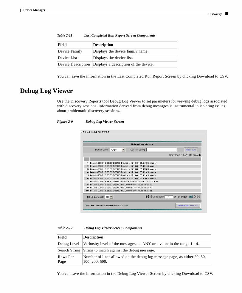
Debug Log ViewerUse the Discovery Reports tool Debug Log Viewer to set parameters for viewing debug logs associated with discovery sessions. Information derived from debug messages is instrumental in isolating issues about problematic discovery sessions.
Figure 2-9 Debug Log Viewer Screen
Table 2-11 Last Completed Run Report Screen Components
Field Description
Device Family Displays the device family name.
Device List Displays the device list.
Device Description Displays a description of the device.
Table 2-12 Debug Log Viewer Screen Components
Field Description
Debug Level Verbosity level of the messages, as ANY or a value in the range 1 - 4.
Search String String to match against the debug message.
Rows Per Page
Number of lines allowed on the debug log message page, as either 20, 50, 100, 200, 500.
2-13Cisco Network Collector
78-xxxxx-xx
You can save the information in the Debug Log Viewer Screen by clicking Download to CSV.

Device Manager Discovery
Error Log ViewerUse the Discovery Reports tool Error Log Viewer to set parameters for error log messages. A high incidence of error log messages may indicate significant problems encountered during discovery processing.
Figure 2-10 Error Log Viewer Screen
You can save the information in the Error Log Viewer Screen by clicking Download to CSV.
Potentially severe error messages may include the following:
Error:
Discovery Alert: SNMPNotSupported: See ip nn.nn.nn.nn does not support SNMP.
Meaning:
Seed device could not be reached via SNMP.
Error:
Discovery Alert: SNMPNotSupported: Seed ip nn.nn.nn.nn does not support CDP.
Meaning:
Seed device could not be reached via CDP.
Error:
Table 2-13 Error Log Viewer Components
Field Description
Error Level Severity level of the messages.
Search String String to match against the error message.
Rows Per Page
Number of lines allowed on the error log message page, as either 20, 50, 100, 200, 500.
2-14Cisco Network Collector
78-xxxxx-xx
DiscoveryAlert: CDPSNMPNotSupported: Default router(s) does not support SNMP/CDP.
Meaning:

Device Manager Discovery
Default device could not be reached by either SNMP or CDP.
Error:
DiscMgrService: callCallback got exception.
Meaning:
Discovery was not able to return the status of a process.
Error:
DiscMgrService: runSeedFileCreation got exception.
Meaning:
An exception was generated while creating the seedfile.
Error:
DiscMgrService: stopSeedFileCreation got exception.
Meaning:
When stopping seedfile creation got exception.
Error:
DiscMgrService: startDiscovery - got exception detail message.
Meaning:
Discovery was not able to start.
Create Visio DBUse the Discovery Reports tool Create Visio DB to create Visio files from the CNC discovery database.
Figure 2-11 Create Visio DB Screen
To Create Visio Files:
Step 1 Click Create File.
Step 2 At the VisioDB screen, click on the type of file you want to download.
Step 3 Locate the download, as indicated at the bottom edge of the Create Visio DB dialog screen.
2-15Cisco Network Collector
78-xxxxx-xx
Page 32

Device Manager Device List
Find DeviceUse the Discovery Reports tool Find Device to locate a device associated with a specified IP address.
Figure 2-12 Find Device Screen
To Find Devices:
Step 1 Enter an IP address into the Enter IP Address box.
Step 2 Click Find IP Address.
Device ListUse the Device Manger tool Device List to view the list of devices and perform operations on them.
This section describes the CNC Device List tools, in the following topics:
• Add Devices
• Edit Devices
• Delete Devices
• Device Import Status
• Export Devices
• Device Launch Pad
2-16Cisco Network Collector
78-xxxxx-xx
Page 33

Device Manager Device List
Figure 2-13 Device List Screen
Add DevicesUse the Device List tool Add Devices to define new devices, authentication information, and to enable authentication. You can add a new Device by the following methods:
• Adding Devices Manually
• Adding Devices by Importing from a Seed File
• Adding Devices by Importing from NMS
Figure 2-14 Add Devices Screen
2-17Cisco Network Collector
78-xxxxx-xx
Device Manager Device List
Adding Devices Manually
Step 1 Select the Manual radio button.
Step 2 In the Integrate Now box, enter the IP Addresses of the devices you want to add.
Step 3 Select Previously Stored Credentials, or enter a New Credential Name.
Step 4 Enter the following information for the new devices:
• Domain Name
• SNMP ReadOnly
• SNMP Read/Write
• Primary User Name
• Primary User Password
• Secondary User Name
• Secondary User Password
• Login Password (VTY)
• Enable Password
• User 1 Field
• User 2 Field
• User 3 Field
• User 4 Field
Step 5 Select the action to take if the device already exists (Use Existing Credentials or Overwrite the Credentials).
Step 6 Select the check box if you want to make this your default device credentials.
Step 7 Select the check box if you want to perform a full inventory.
Step 8 Click Apply.
2-18Cisco Network Collector
78-xxxxx-xx
Page 35

Device Manager Device List
Adding Devices by Importing from a Seed File
Step 1 Select the Import from Seed File radio button. This option displays the Select a File screen.
Figure 2-15 Select a File Screen
Step 2 Enter or browse for a Seed File from your local desktop or CNC server.
Step 3 Select from the following options:
• If device exists, choose to use existing credentials or overwrite the credentials.
• View Device List before Import
• Perform Full Inventory Now
Step 4 Click Import.
Adding Devices by Importing from NMS
Step 1 Select the Import from NMS radio button. This option displays the Integrate Now screen.
Figure 2-16 Integrate Now Screen
Step 2 Select an existing NMS name from the NMS Name drop list, or enter the IP Address of an NMS Host and enter an IP Port.
Step 3 Select from the following options:
• Seed File Integration
• Store & Forward Inventory
2-19Cisco Network Collector
78-xxxxx-xx
Step 4 Click Start Now.
Page 36

Device Manager Device List
Edit DevicesUse the Device List tool Edit Devices to define to change device and/or authentication parameters. This option displays the Select Devices Screen.
Figure 2-17 Select Devices Screen
To Select Devices to Edit:
Step 1 If needed, select a Group Name from the drop-list.
Step 2 If needed, select a Filter Source or use the Advanced Filter option to narrow down the list of available devices.
Step 3 Select the devices to edit from the Available Devices list, and click Add to Selected Devices.
The devices move to the Selected Devices list. If necessary, they can be removed by clicking Remove from Selected Devices.
Step 4 Click Submit. The Edit Devices Screen appears.
2-20Cisco Network Collector
78-xxxxx-xx
Page 37

Device Manager Device List
Figure 2-18 Edit Devices Screen
To Edit Devices:
Step 1 Select Previously Stored Credentials, or enter a New Credential Name.
Step 2 Enter a Domain Name.
Step 3 Change any of the following information for the new devices:
• SNMP ReadOnly
• SNMP Read/Write
• Primary User Name
• Primary User Password
• Backup User Name
• Backup User Password
• Login Password (VTY)
• Enable Password
• User 1 Field
• User 2 Field
• User 3 Field
• User 4 Field
Step 4 Click Apply.
2-21Cisco Network Collector
78-xxxxx-xx
Page 38

Device Manager Device List
Delete Devices Use the Device List tool Delete Device to remove any or all devices from the device manager database. This option presents the Delete Device screen.
Figure 2-19 Delete Device Screen
To Delete Devices:
Step 1 If needed, select a Group Name from the drop-list.
Step 2 If needed, select a Filter Source or use the Advanced Filter option to narrow down the list of available devices.
Step 3 Select the devices to delete from the Available Devices list, and click Add to Selected Devices.
The devices move to the Selected Devices list. If necessary, they can be removed by clicking Remove from Selected Devices.
Step 4 Click Submit. The devices are deleted.
Device Import StatusUse the Device List tool Import Status to view details on imported devices. This option displays the Import Status Screen.
2-22Cisco Network Collector
78-xxxxx-xx
Page 39

Device Manager Device List
Figure 2-20 Import Status Screen
Export DevicesUse the Device List tool Export Devices to export a Seed File. This option displays the Export Seed File Screen.
Figure 2-21 Import Status Screen
To export the Seed File, enter a file name and click Export.
Table 2-14 Import Status Screen Components
Field Description
Devices Displays a list of devices added to the Device List.
Import Status Displays the import status of the device.
Last Addition Method Displays the method by which the device was added.
Last Added Time Displays the time the device was added.
2-23Cisco Network Collector
78-xxxxx-xx
Page 40

Device Manager Device List
Device Launch PadUse the Device List tool Device Launchpad to view report details. This option displays the Device Launch Pad Screen.
To View Reports:
Step 1 If needed, select a Group Name from the drop-list.
Step 2 If needed, select a Filter Source or use the Advanced Filter option to narrow down the list of available devices.
Step 3 Select the devices to include in the reports from the list.
Step 4 Select a report from the Report Types list.
Step 5 Click OK.
2-24Cisco Network Collector
78-xxxxx-xx
Page 41

Device Manager Access Verification
Access VerificationThe Device Manager tool Access Verification is used to determine whether some or all devices are accessible via Telnet, SNMP, Ping and SSH at a designated time.
This section describes the CNC Access Verification tools, in the following topics:
• Modify Access Method
• Modify Access Setup
• Access Verification Report
• Exclude Devices
Figure 2-22 Access Verification Screen
Modify Access MethodThe Access Verification tool Modify Access Method is used to select devices and disable access verification on them by Ping, SSH and Telnet. This option displays the Select Devices screen.
2-25Cisco Network Collector
78-xxxxx-xx
Page 42

Device Manager Access Verification
Figure 2-23 Modify Access Method Screen
To Modify Access Methods:
Step 1 If needed, select a Group Name from the drop-list.
Step 2 If needed, select a Filter Source or use the Advanced Filter option to narrow down the list of available devices.
Step 3 Select the devices to modify from the Available Devices list, and click Add to Selected Devices.
The devices move to the Selected Devices list. If necessary, they can be removed by clicking Remove from Selected Devices.
Step 4 Click Submit. The Modify Access Method/Device Access Config screen appears.
Figure 2-24 Device Access Config Screen
2-26Cisco Network Collector
78-xxxxx-xx
Page 43

Device Manager Access Verification
Step 5 The access methods Ping, SSH and Telnet are listed for each device. Select the check box of any access method that you want to disable for that device, and click Apply.
Note By default the SNMP RO access method is always enabled unless the device has been excluded from access verification.
Ping runs the Ping program to test if the device is reachable. The program sends an ICMP echo request to the device, expecting that an ICMP echo reply will be returned. If successful, PASS appears in the appropriate column of the Access Verification screen.
SSH causes CNC to attempt a Secure Shell connection to the device. CNC then checks local user/password (as defined in the seed file or database) as applicable. If successful, PASS appears in the appropriate column of the Access Verification screen, otherwise the reason for the failure appears in the column.
Telnet causes CNC to attempt a telnet connection to the device. CNC then checks TACACS username/password, login password, and enable password as applicable. If successful, PASS appears in the appropriate column of the Access Verification screen, otherwise the reason for the failure appears in the column.
Modify Access SetupThe Access Verification tool Modify Access setup is used to change the Telnet, SNMP, Ping and SSH retries and timeouts. This option displays the Modify Access Setup screen.
Figure 2-25 Modify Access Setup
To Modify Access Setup:
Step 1 Click Default to restore the settings to their defaults, or change any of the Telnet, SNMP, Ping and SSH
2-27Cisco Network Collector
78-xxxxx-xx
retries or timeout settings.
Step 2 Click Apply.Page 44

Device Manager Access Verification
Access Verification ReportThe Access Verification tool Verify is used to verify access to the devices selected. This option displays the Verify screen.
Figure 2-26 Verify Screen
To create an Access Verification Report, select a device type and a time interval, and click Run.
Exclude DevicesThe Access Verification tool Exclude Devices is used to select devices to exclude from Access Verification. This option displays the Exclude Devices screen.
Figure 2-27 Exclude Devices Screen
2-28Cisco Network Collector
78-xxxxx-xx
Page 45

Device Manager Access Verification
To Select Devices To Exclude From Access Verification:
Step 1 Chose whether to select devices based on Device Type, Device Name, or Device IP Range.
Step 2 Specify the devices to exclude in one of the following ways:
• If selecting devices to exclude by Device Type, select the devices to exclude from the Available Device list, and click Add to Selected Devices. The devices move to the Selected Device list. If necessary, they can be removed by clicking Remove from Selected Devices. Optionally, enter a SysObj ID in the Add NewSysObj ID box.
• If excluding devices by Device Name, select the devices to exclude from the Available Device list, and click Add to Selected Devices. The devices move to the Selected Device list. If necessary, they can be removed by clicking Remove from Selected Devices. Optionally, enter a new device name in the Add New Device box.
• If excluding devices by Device IP Range, in the Enter IP Range for Devices you wish to Exclude section, enter a Start IP Address and an End IP Address.
Step 3 Click Apply.
2-29Cisco Network Collector
78-xxxxx-xx
Page 46

Device Manager Inventory
Inventory Device inventory data is collected following completion of a scheduled full or partial inventory task. Because inventory is collected on a network-wide basis, all Cisco devices are inventoried.
Generally the SNMP R/0 community string is used to collect inventory elements, except in the following cases:
• Device Configuration - CNC uses SNMP/telnet/SSH based on the preferred config collection method.
• Inventory Command Outputs - CNC uses telnet/SSH based on the preferred config collection method.
• Installed Memory for IOS devices - CNC uses “show version” using telnet/SSH based on the preferred config collection method.
• OS Name (image name) for CatOS 5000 - CNC uses “show image” using telnet/SSH based on the preferred config collection method.
• ROM Version, Version and SystemImageFile for IOS XR - CNC uses “show version” using telnet/SSH based on the preferred config collection method.
For config collection, CNC uses SNMP RW (the TFTP port to the device must be open) or telnet/SSH enable level access.
Use the Device Manager tool Inventory to manage device inventory configurations, as described in the following topics:
• View Device Inventory Status
• View Device Inventory Details
• Device Inventory Collection
• Exclude Devices
• Change Detection
• Delete Device Inventory
2-30Cisco Network Collector
78-xxxxx-xx
Page 47

Device Manager Inventory
Figure 2-28 Device Inventory Screen
The Device Inventory Screen displays your network device inventory. You can then choose to view the inventory data reports for various devices, or create profiles of selected reports.
View Device Inventory Status Use the Inventory tool View Device Inventory Status to view counts relevant to the number of total, completed and pending requests for inventory records, and current status and number of devices inventoried. This option displays the View Inventory Status screen.
2-31Cisco Network Collector
78-xxxxx-xx
Page 48

Device Manager Inventory
Figure 2-29 View Inventory Status Screen
Table 2-15 View Inventory Status Screen Inventory Summary Components
Field Description
Total Devices Total number of devices added into CNC.
Active Devices All devices which are currently in active status.
All devices which are currently accessible via the given SNMP RO string.
Config Collected All devices for which config is collected, that is, either running or startup config.
Managed devices All devices which are either currently active or was active earlier.
Non-Cisco devices All devices which are neither Cisco device nor parent company is Cisco.
Devices Added All devices which are added into CNC but inventory collection is not started.
Devices Unreachable
All devices which are currently not accessible via the given SNMP RO string.
Config Failed All devices for which config collection is tried but config collection failed.
Unmanaged Devices
Devices for which inventory is not collected at all or devices which are always in “not reachable” state or devices which are always in “device added” state, that is, all devices which are not listed in managed devices are unmanaged.
Inventory Status Displays details on the current run of inventory collection.
2-32Cisco Network Collector
78-xxxxx-xx
Page 49

Device Manager Inventory
View Device Inventory Details Use the Inventory tool View Device Inventory Details to view selected information on selected inventoried devices. This option displays the View Inventory screen.
Figure 2-30 View Inventory Screen
To View Selected Inventory Details:
Step 1 If needed, select a Group Name.
Step 2 If needed, select a Filter Source or use the Advanced Filter option to narrow down the list of available devices.
Step 3 Select the devices to view from the Available Devices list, and click Add to Selected Devices.
The devices move to the Selected Devices list. If necessary, they can be removed by clicking Remove from Selected Devices.
Step 4 To limit the details displayed, you can choose to view specific types of details by selecting them from the View Selected Information list. For example, to view Network Element Configuration details, select NE Configuration.
Step 5 Click View to view the inventory details, or click Download to CSV to save them to a file.
Step 6 If you chose to view the inventory details, the Inventory Detail Screen appears. Scroll to the right and click a Device Configuration link. Click the link in the “2” row for startup configuration, or the link in the “4” row for latest configuration.
2-33Cisco Network Collector
78-xxxxx-xx
Page 50

Device Manager Inventory
Device Inventory Collection Use the Inventory tool Device Inventory Collection to select devices and inventory data modules for collection. This option displays the Inventory Collection screen.
Figure 2-31 Inventory Collection Screen
Table 2-16 View Inventory Status Screen Inventory Summary Components
Field Description
Total Devices Total number of devices added into CNC.
Active Devices All devices which are currently in active status.
All devices which are currently accessible via the given SNMP RO string.
Config Collected All devices for which config is collected, that is, either running or startup config.
Managed devices All devices which are either currently active or was active earlier.
Non-Cisco devices All devices which are neither Cisco device nor parent company is Cisco.
Devices Added All devices which are added into CNC but inventory collection is not started.
Devices Unreachable
All devices which are currently not accessible via the given SNMP RO string.
Config Failed All devices for which config collection is tried but config collection failed.
Unmanaged Devices
Devices for which inventory is not collected at all or devices which are always in “not reachable” state or devices which are always in “device added” state, that is, all devices which are not listed in managed devices are unmanaged.
2-34Cisco Network Collector
78-xxxxx-xx
Page 51

Device Manager Inventory
To Select Devices And Inventory Data Modules:
Step 1 If needed, select a Group Name.
Step 2 If needed, select a Filter Source or use the Advanced Filter option to narrow down the list of available devices.
Step 3 Select the devices to view from the Available Devices list, and click Add to Selected Devices.
The devices move to the Selected Devices list. If necessary, they can be removed by clicking Remove from Selected Devices.
Step 4 To limit the details displayed, you can choose to view specific types of details by selecting them from the View Selected Information list.
Step 5 Click Submit.
Exclude DevicesUse the Inventory tool Exclude Devices to select devices to be excluded from inventory collection. This option displays the Exclude Devices screen.
Figure 2-32 Exclude Devices Screen
To Select Devices To Exclude From Inventory:
Step 1 Chose whether to select devices based on Device Type, Device Name, or Device IP Range.
Step 2 Specify the devices to exclude in one of the following ways:
• If selecting devices to exclude by Device Type, select the devices to exclude from the Available Device list, and click Add to Selected Devices. The devices move to the Selected Device list. If
2-35Cisco Network Collector
78-xxxxx-xx
necessary, they can be removed by clicking Remove from Selected Devices. Optionally, enter a SysObj ID in the Add NewSysObj ID box.

Device Manager Inventory
• If excluding devices by Device Name, select the devices to exclude from the Available Device list, and click Add to Selected Devices. The devices move to the Selected Device list. If necessary, they can be removed by clicking Remove from Selected Devices. Optionally, enter a new device name in the Add New Device box.
• If excluding devices by Device IP Range, in the Enter IP Range for Devices you wish to Exclude section, enter a Start IP Address and an End IP Address.
Step 3 Click Apply.
Change Detection
Use the Inventory tool Change Detection to select devices for inventory change detection. This option displays the Inventory Change Detection screen.
Figure 2-33 Inventory Change Detection Screen
To Select Devices for Change Detection:
Step 1 If needed, chose a Group Name for the devices to select.
Step 2 If needed, select a Filter Source and enter a string in to the Filter box to narrow down your choices.
Step 3 Select the devices to delete from the Available Device list, and click Add to Selected Devices. The devices move to the Selected Device list. If necessary, they can be removed by clicking Remove from Selected Devices.
Step 4 Select a Start Time
2-36Cisco Network Collector
78-xxxxx-xx
Step 5 Select an End Time
Step 6 Select a Periodic Type.

Device Manager Inventory
Step 7 Select a Periodic Interval
Step 8 Click Submit.
Delete Device InventoryUse the Inventory tool Delete Inventory to select devices to be deleted from inventory. This option displays the Delete Inventory screen.
Figure 2-34 Delete Inventory Screen
To Select Devices To Delete From Inventory:
Step 1 If needed, chose a Group Name for the devices to delete.
Step 2 If needed, select a Filter Source and enter a string in to the Filter box to narrow down your choices.
Step 3 Select the devices to delete from the Available Device list, and click Add to Selected Devices. The devices move to the Selected Device list. If necessary, they can be removed by clicking Remove from Selected Devices.
Step 4 Click Delete.
2-37Cisco Network Collector
78-xxxxx-xx
Page 54

Device Manager Grouping
GroupingUse the Device Manager tool Grouping to manage contents and availability of device groups for use in discovery sessions.
This section describes the CNC grouping tools, in the following topics:
• View Device Grouping
• Add Device Grouping
• Edit Device Grouping
• Delete Device Grouping
View Device GroupingTo view Device Grouping, click the Grouping tab. This option displays the Device Grouping screen.
Figure 2-35 Device Grouping Screen
Add Device GroupingTo add a device group, from the Device Grouping screen, click Add. This option displays the Add Device Group screen.
2-38Cisco Network Collector
78-xxxxx-xx
Page 55

Device Manager Grouping
Figure 2-36 Add Device Group Screen
To Add A Device Group:
Step 1 If needed, create or select a Group Name.
Step 2 If needed, select a Filter Source or use the Advanced Filter option to narrow down the list of available devices.
Step 3 Select the devices to add to the new group for the Available Devices list, and click Add to Selected Devices.
The devices move to the Selected Devices list. If necessary, the can be removed by clicking Remove from Selected Devices.
Step 4 Click Next. The Group Definition screen appears.
Figure 2-37 Group Definition Screen
2-39Cisco Network Collector
78-xxxxx-xx
Page 56

Device Manager Grouping
Step 5 Select to either create the new group Based on Existing Group, or enter the following parameters:
• New Group Name
• New Group Definition
• Group Details
Step 6 To add filter properties for the new group, select a value for the Filter Properties, or enter an Expression, and click Add.
Step 7 Click Save Group.
Edit Device GroupingTo edit a device group, from the Device Grouping screen, select a device group and click Edit. This option displays the Edit Device Group screen.
Figure 2-38 Edit Device Group Screen
To Edit A Device Group:
Step 1 Edit any of the following information for the Group:
• Group Name
• Group Definition
• Device Name
• Filter Property
• Value
2-40Cisco Network Collector
78-xxxxx-xx
• Operation
• Expression
Step 2 Click Save Group.

Device Manager Credentials
Delete Device GroupingTo delete a Device Group, from the Device Group screen, select a Device Name and click Delete.
CredentialsUse the Device Manager tool Credentials to manage device credentials.
This section describes the CNC credential management tools, in the following topics:
• View Device Credentials
• Add Device Credentials
• Edit Device Credentials
• Delete Device Credentials
View Device CredentialsTo view Credentials, click the Credentials tab. This option displays the Credential Name screen.
Figure 2-39 Credential Name Screen
Add Device CredentialsTo add credentials, from the Credential Name screen, click Add. This option displays the Add Device Credentials Screen.
2-41Cisco Network Collector
78-xxxxx-xx
Page 58

Device Manager Credentials
Figure 2-40 Add Device Credentials Screen
To Add Credentials:
Step 1 Enter the following information for the new Credential:
• Device Credential Name
• Domain Name
• SNMP ReadOnly
• SNMP Read/Write
• Primary User Name
• Primary User Password
• Secondary User Name
• Secondary User Password
• Login Password
• Enable Password
• User 1 Field
• User 2 Field
• User 3 Field
• User 4 Field
Step 2 Select the check box if you want to make this your default device credentials.
Step 3 Click Apply.
2-42Cisco Network Collector
78-xxxxx-xx
Page 59
Device Manager Credentials
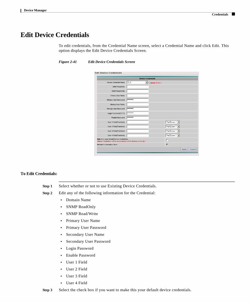
Edit Device CredentialsTo edit credentials, from the Credential Name screen, select a Credential Name and click Edit. This option displays the Edit Device Credentials Screen.
Figure 2-41 Edit Device Credentials Screen
To Edit Credentials:
Step 1 Select whether or not to use Existing Device Credentials.
Step 2 Edit any of the following information for the Credential:
• Domain Name
• SNMP ReadOnly
• SNMP Read/Write
• Primary User Name
• Primary User Password
• Secondary User Name
• Secondary User Password
• Login Password
• Enable Password
• User 1 Field
• User 2 Field
2-43Cisco Network Collector
78-xxxxx-xx
• User 3 Field
• User 4 Field
Step 3 Select the check box if you want to make this your default device credentials.

Device Manager Aliases
Step 4 Select the check box if you want to perform a full inventory now.
Step 5 Click Apply.
Delete Device Credentials
To Delete Credentials:
From the Credential Name screen, select a Credential Name and click Delete.
AliasesUse the Device Manager tool Aliases to view and edit the display names for your devices. This option displays the Device Aliases Screen.
Figure 2-42 Device Aliases Screen
Table 2-17 Device Aliases Screen Components
Field Description
Display Name The Display Name for the device.
Primary Name The Primary Name for the device.
2-44Cisco Network Collector
78-xxxxx-xx
Click View to view your device aliases. This option displays the View Device Aliases screen.
Page 61

Device Manager Aliases
Figure 2-43 View Device Aliases Screen
Select a device and click Edit to add or modify your device aliases. This option displays the Edit Device Alias screen.
Figure 2-44 Edit Device Aliases Screen
To Edit Device Aliases:
Step 1 Select a name from the Primary Name list.
Step 2 Enter a display name in the Enter Name box, or select a Given Alias from the list.
Step 3 Click Submit.
2-45Cisco Network Collector
78-xxxxx-xx
Page 62

78-xxxxx-xx
Page 63
3System Setup
Use the System Setup tab to access tools for global setup and maintenance of the CNC system.
Figure 3-1 CNC System Setup Tab
This section describes the System Setup tools in the following topics:
• Scheduled Tasks
• Server Status
• Config Filter
• Security
• Global Policy
• Entitlement
3-1Cisco Network Collector

System Setup Scheduled Tasks
Scheduled TasksUse the System Setup tool Scheduled Tasks to access the Scheduled Tasks screen in which to view the scheduled tasks details. You can click on any name listed under the Task name column to display more details about a task.
Figure 3-2 Scheduled Tasks Screen
To edit a Scheduled Task, select a Task ID, and click Edit. The Change Task Context screen appears.
Table 3-1 Scheduled Tasks Screen Components
Column Description
Task ID Task ID assigned by the Scheduler.
Task Name Nickname of the task, as defined in your configuration for the task or profile.
Task Module The module the task effects.
Creator The creator of the task.
Status Current status of the scheduled task, as either ACTIVE, DEACTIVE, or RUNNING.
Start Time Day, date, time, and year the scheduled task began.
End Time Day, date, time, and year the scheduled task concluded.
Last Execute Time
Previous ending time for the scheduled task.
Next Start Time Next scheduled day, date, time and year for task execution.
Periodic Interval Frequency by which to execute the scheduled task.
3-7Cisco Network Collector
78-xxxxx-xx
Page 64

System Setup Scheduled Tasks
Change Task ContextUse the Scheduled Tasks tool Change Task Context to modify the status of a task to assist in determining how the task is being handled. This option presents the Change Task Context screen.
Figure 3-3 Change Task Context Screen
Table 3-2 Change Task Context Screen Components
Column Description
Task ID The number of the task.
Task Name The name of the task.
Process The task process name.
Task Status The current status of the task.
Status Sets the status of the task to Active, Inactive or Delete in the Scheduler.
Start Time The start time of the task.
End Time The end time of the task
Periodic Type The interval in which that the task will be run.
Periodic Unit The number of times in the above interval in which the task will run.
3-8Cisco Network Collector
78-xxxxx-xx
Page 65

System Setup Server Status
To change any of the task details:
Step 1 Select or enter the following criteria:
• Status
• Start Time
• End Time
• Periodic Type
• Periodic Unit
• Run Time
Step 2 Click Submit.
Server Status Use the System Setup tool Server Status to view the status and scheduling of servers running on the network. This option displays the Server Status screen.
Figure 3-4 Server Status Screen
Table 3-3 Server Status Screen Components
Field Description
S. No Displays the number of the server.
Server Name Displays the name of the server.
Scheduled? Displays scheduling information.
Status Displays status information.
3-9Cisco Network Collector
78-xxxxx-xx
Page 66

System Setup Config Filter
Config FilterUse the System Setup tool Config Filter to view and edit configuration filters. This option displays the Config Filter screen.
Figure 3-5 Config Filter Screen
Table 3-4 Config Filter Screen Components
Field Description
Edit/Delete Select this option to add or delete the Config Filter.
Filter ID Displays the filter ID number.
Filter (Selection/Regex) Displays the filter string.
Action Displays the action taken by the filter.
Occurrence Displays the occurrences of the filter.
Apply Displays the manner in which the filter is applied.
3-10Cisco Network Collector
78-xxxxx-xx
Page 67

System Setup Config Filter
Add Config FilterTo Add a Config Filter, from the Config Filter screen, click Add. This option presents the Add Config Filter screen.
Figure 3-6 Add Config Filter Screen
To add a Config Filter:
Step 1 From the SOL (Start of Line) drop list, select a type of line start and enter an expression into the box that appears to the right of it. Continue adding as many line start expressions as needed.
Step 2 Click the EOL (End of Line) button.
Step 3 Select the Action as either Delete or Replace. If you select Replace, type in a Replacement String.
Step 4 Select an Occurrence.
Step 5 Click Submit.
3-11Cisco Network Collector
78-xxxxx-xx
Page 68

System Setup Config Filter
Edit Config FilterTo Edit a Config Filter, select a filter from the Config Filter screen, and click Edit. This option presents the Edit Config Filter screen.
Figure 3-7 Edit Config Filter Screen
To edit a Config Filter:
Step 1 From the SOL (Start of Line) drop list, change any type of line start and expressions necessary.
Step 2 Change the Action as necessary. If you select Replace, type in a Replacement String.
Step 3 Change the Occurrence as necessary.
Step 4 Click Submit.
Delete Config FilterTo delete a Config Filter:
Step 1 From the Config Filter screen, select the filter you want to delete.
Step 2 Click Delete.
3-12Cisco Network Collector
78-xxxxx-xx
Page 69

System Setup Security
SecurityUse the System Setup tool Security to manage users and passwords.
This section describes the Security tools, in the following topics:
• Password Management
• User Security Management
• Role Security Management
Password Management Use the Security tool Security to change your login password. This option presents the Enter the password details screen.
Figure 3-8 Enter the Password Details Screen
To Change Your Password:
Step 1 Enter your password in the Old Password field.
Step 2 Enter the new password you want to use in the Password field.
Step 3 Re-type the new password in the Retype Password field.
Step 4 Click Modify User Details.
User Security ManagementUse the Security tool User Security Management to control CNC user access and administrative roles, as described in the following topics:
• Adding a User
• Deleting a User
• Editing a User
3-13Cisco Network Collector
78-xxxxx-xx
Page 70

System Setup Security
Figure 3-9 User Management Screen
Adding a User
To add a user, from the User Management screen click Add. The Add User screen appears.
Note Only users configured as admin role may use this tool.
Figure 3-10 Add User Screen
Table 3-5 Add User Screen Components
Column Description
User User name, consisting of up to 20 characters, to be used when logging in to CNC.
Role Select a Role for the user.
Password Case-sensitive password to be used in conjunction with the user ID when logging in to CNC.
Confirm Password
Verification entry: exact match of password to be used by this user.
3-14Cisco Network Collector
78-xxxxx-xx
Page 71

System Setup Security
Step 1 Complete all four fields of the Add User screen.
Step 2 Click OK to create the new user ID.
Deleting a User
Step 1 In the User Management screen, select the User ID of the user you want to delete.
Step 2 Click Delete.
Note It is recommended that the “natkadmin” user be deleted for security purposes. At the very least the password should be changed (removing the admin privilege) once new users are created. The operations team should be notified of the new password.
Editing a User
Step 1 In the User Management screen, select the User ID of the user you want to edit and click Edit. The Edit User screen appears.
Figure 3-11 Edit User Screen
Step 2 Edit any user information needed, and click OK.
Role Security ManagementUse the Security tool Role Security Management to manage role assignments for CNC users, as described in the following topics:
• Adding a New Role
• Editing a Role
• Deleting a Role
3-15Cisco Network Collector
78-xxxxx-xx
Page 72

System Setup Security
Figure 3-12 Role Management Screen
Adding a New Role
Step 1 In the Role Management screen, click Add. The Add a New Role screen appears.
Note Only users configured as admin role may use this tool.
Figure 3-13 Add a New Role Screen
Step 2 Select Resources to assign to the role from the list on the left.
Step 3 Type a role name in the Role Name field.
Step 4 Type a description in the Description field.
Step 5 Click Save As Role.
Editing a Role
Step 1 In the Role Management screen, select the role you want to edit and click Edit. The Edit a Role screen appears.
3-16Cisco Network Collector
78-xxxxx-xx
Note Only users configured as admin role may use this tool.Page 73

System Setup Global Policy
Figure 3-14 Edit a Role Screen
Step 2 Edit any of the role details necessary.
Step 3 Click Save.
Deleting a Role
Step 1 In the Role Management screen, select the role you want to delete.
Step 2 Click Delete.
Global PolicyUse the System Setup tool Global Policy to set system-wide CNC options. This option displays the Global Policy Screen.
Figure 3-15 Global Policy Screen
3-17Cisco Network Collector
78-xxxxx-xx

System Setup Global Policy
To Set Global Policy
Step 1 Select the Collect Inventory Automatic upon Import checkbox to enable this feature.
Step 2 Select the Non Cisco Device Support checkbox to enable this feature.
Step 3 Click Apply.
Set Collection MethodUse the Global Policy tool Set Collection Method to select your preferred collection method. This option displays the Preferred Collection Method Screen.
Figure 3-16 Preferred Collection Method Screen
To Set Preferred Collection Method:
Step 1 Select a Config Collection method from the following options:
• CLI Access
• SNMP (Read/Write)
Step 2 Select a CLI Access method from the following options:
• Telnet
• SSH:
– Access SSH Mode
– Access SSH Enable Mode
Step 3 Click Apply.
Purge DataUse the Global Policy tool Purge Data to set parameters for data deletion. This option displays the Purge Screen.
3-18Cisco Network Collector
78-xxxxx-xx
Page 75

System Setup Entitlement
Figure 3-17 Purge Data Screen
To Set Purge Data Parameters:
Step 1 In the Purge Data Older Than column, enter a number days older than which to delete data.
Step 2 Click the Apply check boxes corresponding to the Modules for which to delete data.
Step 3 Click Apply.
EntitlementUse the System Setup tool Entitlement to view your entitlement certificate.
View EntitlementUse the System Setup tool View Entitlement to view details on entitlement certificates. This option displays the View Entitlement Screen.
Figure 3-18 View Entitlement Screen
3-19Cisco Network Collector
78-xxxxx-xx
Page 76

System Setup Entitlement
To view the Entitlement Summary, from the View Entitlement screen, select an Entitlement ID and click View. The View Entitlement Summary screen appears.
Figure 3-19 View Entitlement Summary Screen
Table 3-6 View Entitlement Screen Components
Column Description
Entitlement ID The entitlement certificate ID number.
Customer Name The customer name for that entitlement certificate ID number.
Party ID The party ID for that entitlement certificate ID number.
Collector ID The collector ID number for that entitlement certificate ID number.
3-20Cisco Network Collector
78-xxxxx-xx
Page 77

78-xxxxx-xx
Page 78
4 ReportsUse the Reports tab to access tools with which to generate reports on various CNC operations.
Figure 4-1 CNC Reports Tab
This section describes the Reports tools in the following topics:
• Network Profile
• Exceptions
• Logs and Errors
5-1Cisco Network Collector

Reports Network Profile
Network ProfileUse the Reports tab Network Profile tool to display the Network Profile Summary screen.
Network Profile Summary The Network Profile Summary screen displays consolidated summaries of the hardware, software, and technologies associated with the customer network. Combined, this information comprises the current customer profile with which to weigh collected criteria against device defects published by Cisco backend systems, and to provide proactive analysis and reporting.
You can access the following reports from the Network Profile Summary page:
• Device Count Report
• Type Count Report
• Feature Count Report
Figure 4-2 Network Profile Summary Screen
5-2Cisco Network Collector
78-xxxxx-xx
Page 79

Reports Network Profile
Table 4-1 Network Profile Summary Screen Components
Section Description
Software Collected number of Cisco IOS versions or CatOS versions currently in use by each device on the network that CNC is managing.
Device Count: Number of devices on the network managed by CNC that are running specific software types.
• Click on a blue value in this column to view the Device Count report associated with a software type.
Type Count: Number of devices on the network that are running specific products.
• Click on a blue value in this column to access the Type Count report associated with a software type.
5-3Cisco Network Collector
78-xxxxx-xx
Page 80

Reports Network Profile
Hardware Collected number of devices found in the network, including associated Product Type, Card, and Interface for each device.
• Product Type
Device Count: Total number of devices, within specific product families, that are currently in place on the network.
– Click on a blue value in this column to view the Device Count report associated with a chassis family.
– Type Count: Number of specific product types currently in place on the network.
– Click on a blue value in this column to access the Type Count report associated with a chassis family.
• Cards
Card Count: Number of devices on the network that are running specific software types.
Type Count: Number of specific card types currently in place on the network.
– Click on a blue value in this column to access the Type Count report associated with a card type.
• Interfaces
Interface Count: Number of router, switch, and WAN interfaces currently configured on the network.
Type Count: Number of specific interface types currently in place on the network.
– Click on a blue value in this column to access the Type Count report associated with an interface type.
Table 4-1 Network Profile Summary Screen Components
Section Description
5-4Cisco Network Collector
78-xxxxx-xx
Page 81

Reports Network Profile
Technology Collected number of devices using specific networking protocols, and technologies associated with security and services.
Device Count: Total number of devices, within technologies, that are currently in place on the network.
• Click on a blue value to view the device count report associated with a technology type.
Feature Count: Total number of specific features.
Table 4-1 Network Profile Summary Screen Components
Section Description
5-5Cisco Network Collector
78-xxxxx-xx
Page 82

Reports Network Profile
Device Count ReportUse the Device Count Report screen to view device details associated with Cisco software, hardware, or technology. You access a Device Count report by clicking a device count value in the Network Profile Summary screen.
Figure 4-3 Device Count Report Screen
Table 4-1 Network Profile Summary Screen Components
Section Description
5-6Cisco Network Collector
78-xxxxx-xx
Page 83

Reports Network Profile
Type Count Report Use the Type Count report to view release-version details associated with discovered Cisco devices. You access a Type Count report by clicking a type count value in the Network Profile Summary screen.
Figure 4-4 Type Count Report Screen
Table 4-2 Device Count Report Components
Section Description
Device Name Device ID. Click the column label to sort the list in ascending or descending order.
IP Address Network address of the device.
HW Family Product suite name associated with the device (product) type.
Product Type Actual name of the product discovered on the customer network.
Image Name ID of the image currently running on the device.
Serial No. Cisco manufacturer's serial number assigned to the device.
OS Version Version of control software currently running on the device.
OS Type Type of control software currently running on the device, as either IOS or CatOS.
Technology If applicable, technology type running on the device.
Last InventoryCollected Time
Date and time of most recent inventory collection.
The date is formatted to show the year, month, and day.
The time is formatted to show the hour, minute, and second.
5-7Cisco Network Collector
78-xxxxx-xx
Page 84

Reports Network Profile
Figure 4-5 Product Family Report Screen
Feature Count ReportUse the Feature Count report to view network-technology details associated with discovered Cisco devices. You access a Feature Type count report by clicking a feature count value in the Network Profile Summary screen.
Table 4-3 Type Count Report Components
Section Description
Product Family Product family name associated with the type count.
Device Count Number of devices currently running in that product family.
% of Total Percentage of devices of that product family running on the network.
Type Count The type count for that product family. Click a number in the Type Count column to go to the Product Family Report screen.
5-8Cisco Network Collector
78-xxxxx-xx
Page 85

Reports Network Profile
Figure 4-6 Feature Count Report Screen
Table 4-4 Feature Count Report Components
Section Description
Feature Name of network technology currently running on the customer site.
Feature OS Type Type of control software supporting the technology as either IOS or CatOS.
Device Count Number of devices currently deploying the network technology.
5-9Cisco Network Collector
78-xxxxx-xx
Page 86

Reports Exceptions
Search ExceptionsUse the Exception tool Search Exceptions to search for specific Network and Collector Exceptions. This option displays the Search Exceptions screen.
Figure 4-7 Search Exceptions Screen
To Search For Specific Exceptions:
Step 1 Select an Exception Period From date and time, and To date and time.
Step 2 Select an Exception Type from the drop list.
Step 3 Select or enter search criteria in to any of the following optional fields:
• Exception Severity
• Exception Name (Simple or Regex)
• Exception Description (Simple or Regex)
• Exception Cause (Simple or Regex)
• Device Name (Simple or Regex)
• Module
• State
• Maximum Records (default number is 1000)
Step 4 Click Search to view your search results.
5-22Cisco Network Collector
78-xxxxx-xx
Page 87

Reports Exceptions
Search Exception Result
Figure 4-8 Search Exception Result Screen
The Search Exception Result screen displays the following information on Exceptions:
You can click the Time column title to list exceptions in ascending or descending order based on when the occurred. You can also click the Details link to get detailed information on that exception, as shown
Table 4-5 Network and Collector Exceptions
Field Description
Details Click the Details link to view additional details on the exception.
Time The date and time the exception occurred.
Device The IP Address of the device on which the exception occurred.
Module That name of the module in which the exception occurred.
Severity The severity of the exception, from 1 to 6.
Name The name of the exception.
Description A brief description of the exception.
5-23Cisco Network Collector
78-xxxxx-xx
below:
Page 88

Reports Exceptions
Figure 4-9 Exception Details Screen
Filter ExceptionsIn the Search Exception Result screen, you can filter the information displayed by using the Filter dialog box that appears at the top of the screen.
Figure 4-10 Filter Exceptions Dialog Box
To Filter Exceptions:
Step 1 Select any of the following optional criteria:
• Filter Property
• Filter Pattern
• Severity
• Module
Step 2 Click Filter.
5-24Cisco Network Collector
78-xxxxx-xx
Page 89

Reports Logs and Errors
Logs and ErrorsUse the System Setup tool Logs and Errors to view or reset the system error log. This option displays the Log Viewer screen.
Figure 4-11 Log Viewer Screen
Select Log Selection Criteria and Log period and click View. The Correlation Engine Log screen appears.
Figure 4-12 Correlation Engine Log Screen
5-25Cisco Network Collector
78-xxxxx-xx
Page 90

78-xxxxx-xx
Page 91
5Data Transfer
Secure data transfer from CNC to Cisco is managed via the Transport Gateway for Inventory and Reporting. The information in the Data Transfer tab is therefore not applicable in your instance of CNC.
6-1Cisco Network Collector
makessler
Placed Image

78-xxxxx-xx
Page 92
6Update CNC
Use the Update CNC tab to display current updates, select settings for automatic and manual updates, and view installed module names and versions.
Figure 6-1 Update CNC Tab
This section describes the Update CNC tools, in the following topics:
• Software and Rule Updates
• Automatic Update Policy
• Manual Updater
• Installed Modules
7-1Cisco Network Collector

Update CNC Software and Rule Updates
Software and Rule UpdatesUse the Update CNC tool to display the following information about software and rule updates. This option displays the Software and Rule Updates screen.
Figure 6-2 Software and Rule Updates Screen
Table 6-1 Software and Rule Updates Screen Components
Field Description
Package The type of package (Rules, Software, and so forth) for which the current updates are displayed.
Version The version number of the package displayed.
Time The date and time the package was checked for updates.
Status The status of the package.
Error Message Any error message associated with the update.
7-2Cisco Network Collector
78-xxxxx-xx
Page 93

Update CNC Automatic Update Policy
Automatic Update PolicyUse the Update CNC tool Automatic Update Policy to select settings for automatic updates. This option displays the Automatic Update Policy screen.
Figure 6-3 Automatic Update Policy Screen
To Change Automatic Update Policy:
Step 1 Select whether you want to enable rule updates, and whether or not to install the rules automatically.
Step 2 Select whether you want to enable software updates.
Step 3 Select a frequency for the automatic updates, from 30 minutes to 24 hours.
Step 4 Click Apply to make changes to your rule update settings, or click Reset to clear the screen and enter new selections.
7-3Cisco Network Collector
78-xxxxx-xx
Page 94

Update CNC Manual Updater
Manual UpdaterUse the Update CNC tool Manual Updater to check and get manual updates. This option displays the Manual Updater screen.
Figure 6-4 Manual Update Screen
At the Manual Update screen you can perform any of the following actions:
• Click Check Update to check the current rule version.
• Click Get Update to update CNC to the most recent rule version on the server.
• Click Run Update to install the latest rule version.
• Click Restore Backup to revert to your previous rule version.
• Click Cancel to discard any changes made and return to the Current Version screen.
7-4Cisco Network Collector
78-xxxxx-xx
Page 95

Update CNC Installed Modules
Installed ModulesUse the Update CNC tool Installed Modules to check the name and version of installed CNC modules. This option displays the View Installed Modules screen.
Figure 6-5 View Installed Modules Screen
Table 6-2 View Installed Modules Screen Components
Field Description
Module Name The name of a currently installed CNC module.
Version The version number of the installed module.
7-5Cisco Network Collector
78-xxxxx-xx
Page 96

7-6Cisco Network Collector
78-xxxxx-xx