CNC 8055 ·T· - Fagor · PDF fileThis product uses the following source code,...
360
CNC 8055 ·T· Programming manual Ref.1711 Soft: V02.2x
Transcript of CNC 8055 ·T· - Fagor · PDF fileThis product uses the following source code,...
CNC 8055 ·T·
Programming manual
Ref.1711Soft: V02.2x
This product uses the following source code, subject to the terms of the GPL license. The applications busybox V0.60.2;dosfstools V2.9; linux-ftpd V0.17; ppp V2.4.0; utelnet V0.1.1. The librarygrx V2.4.4. The linux kernel V2.4.4. The linux bootppcboot V1.1.3. If you would like to have a CD copy of this source code sent to you, send 10 Euros to Fagor Automationfor shipping and handling.
All rights reserved. No part of this documentation may be transmitted,transcribed, stored in a backup device or translated into another languagewithout Fagor Automation’s consent. Unauthorized copying or distributing of thissoftware is prohibited.
The information described in this manual may be subject to changes due totechnical modifications. Fagor Automation reserves the right to change thecontents of this manual without prior notice.
All the trade marks appearing in the manual belong to the corresponding owners.The use of these marks by third parties for their own purpose could violate therights of the owners.
It is possible that CNC can execute more functions than those described in itsassociated documentation; however, Fagor Automation does not guarantee thevalidity of those applications. Therefore, except under the express permissionfrom Fagor Automation, any CNC application that is not described in thedocumentation must be considered as "impossible". In any case, FagorAutomation shall not be held responsible for any personal injuries or physicaldamage caused or suffered by the CNC if it is used in any way other than asexplained in the related documentation.
The content of this manual and its validity for the product described here has beenverified. Even so, involuntary errors are possible, hence no absolute match isguaranteed. However, the contents of this document are regularly checked andupdated implementing the necessary corrections in a later edition. We appreciateyour suggestions for improvement.
The examples described in this manual are for learning purposes. Before usingthem in industrial applications, they must be properly adapted making sure thatthe safety regulations are fully met.
DUAL-USE PRODUCTS
Products manufactured by FAGOR AUTOMATION since April 1st 2014 willinclude "-MDU" in their identification if they are included on the list of dual-useproducts according to regulation UE 428/2009 and require an export licensedepending on destination.
Programming manual
CNC 8055CNC 8055i
SOFT: V02.2X
·3·
I N D E X
About the product ......................................................................................................................... 7Declaration of conformity and Warranty conditions ...................................................................... 9Version history ............................................................................................................................ 11Safety conditions ........................................................................................................................ 15Returning conditions ................................................................................................................... 19Additional notes .......................................................................................................................... 21Fagor documentation.................................................................................................................. 23
CHAPTER 1 GENERAL CONCEPTS
1.1 Part programs ................................................................................................................ 261.1.1 Considerations regarding the Ethernet connection .................................................... 281.2 DNC connection............................................................................................................. 291.3 Communication protocol via DNC or peripheral device ................................................. 30
CHAPTER 2 CREATING A PROGRAM
2.1 Program structure at the CNC ....................................................................................... 322.1.1 Block header .............................................................................................................. 322.1.2 Program block ............................................................................................................ 332.1.3 End of block ............................................................................................................... 342.2 Local subroutines within a program ............................................................................... 35
CHAPTER 3 AXES AND COORDINATE SYSTEMS
3.1 Axis nomenclature ......................................................................................................... 383.1.1 Axis selection ............................................................................................................. 393.2 Plane selection (G16, G17, G18, G19) .......................................................................... 403.3 Part dimensioning. Millimeters (G71) or inches (G70) ................................................... 413.4 Absolute/incremental programming (G90, G91) ............................................................ 423.5 Programming in radius or in diameters (G152, G151) ................................................... 433.6 Coordinate programming ............................................................................................... 443.6.1 Cartesian coordinates ................................................................................................ 453.6.2 Polar coordinates ....................................................................................................... 463.6.3 Angle and Cartesian coordinate................................................................................. 483.7 Rotary axes.................................................................................................................... 493.8 Work zones .................................................................................................................... 503.8.1 Definition of the work zones ....................................................................................... 503.8.2 Using the work zones................................................................................................. 51
CHAPTER 4 REFERENCE SYSTEMS
4.1 Reference points............................................................................................................ 534.2 Machine reference (Home) search (G74) ...................................................................... 544.3 Programming with respect to machine zero (G53) ........................................................ 554.4 Coordinate preset and zero offsets................................................................................ 564.4.1 Coordinate preset and S value limitation (G92) ......................................................... 574.4.2 Zero offsets (G54..G59 and G159) ............................................................................ 584.5 Polar origin preset (G93)................................................................................................ 62
CHAPTER 5 ISO CODE PROGRAMMING
5.1 Preparatory functions..................................................................................................... 645.2 Feedrate F ..................................................................................................................... 665.2.1 Feedrate in mm/min or inches/min (G94)................................................................... 675.2.2 Feedrate in mm/rev.or inches/rev (G95) .................................................................... 685.3 Spindle turning speed (S) .............................................................................................. 695.3.1 Constant surface speed (G96) ................................................................................... 705.3.2 Spindle speed in rpm (G97) ....................................................................................... 715.4 Spindle selection (G28, G29)......................................................................................... 725.5 Synchronized spindles (G30, G77S, G78S) .................................................................. 735.6 Tool number (T) and tool offset (D)................................................................................ 74
·4·
Programming manual
CNC 8055CNC 8055i
SOFT: V02.2X
5.7 Auxiliary function (M) ..................................................................................................... 765.7.1 M00. Program stop .................................................................................................... 775.7.2 M01. Conditional program stop.................................................................................. 775.7.3 M02. End of program ................................................................................................. 775.7.4 M30. End of program with return to the first block ..................................................... 775.7.5 M03, M4, M5. Spindle start and stop ......................................................................... 775.7.6 M06. Tool change code ............................................................................................. 795.7.7 M19. Spindle orientation ............................................................................................ 805.7.8 M41, M42, M43, M44. Spindle gear change .............................................................. 815.7.9 M45. Auxiliary spindle / Live tool................................................................................ 82
CHAPTER 6 PATH CONTROL
6.1 Rapid traverse (G00) ..................................................................................................... 846.2 Linear interpolation (G01) .............................................................................................. 856.3 Circular interpolation (G02, G03)................................................................................... 866.4 Circular interpolation with absolute arc center coordinates (G06) ................................. 906.5 Arc tangent to previous path (G08)................................................................................ 916.6 Arc defined by three points (G09).................................................................................. 926.7 Helical interpolation ....................................................................................................... 936.8 Tangential entry at the beginning of a machining operation (G37)................................ 946.9 Tangential exit at the end of a machining operator (G38) ............................................. 956.10 Automatic radius blend (G36) ........................................................................................ 966.11 Chamfer (G39)............................................................................................................... 976.12 Threading (G33) ............................................................................................................ 986.13 Withdrawal of axes when interrupting a threading operation (G233)........................... 1016.14 Variable pitch threads (G34)........................................................................................ 1036.15 Activates the C axis (G15). .......................................................................................... 1046.15.1 Machining on the side of the part. ............................................................................ 1056.15.2 Machining on the face of the part............................................................................. 1066.16 Move to hardstop (G52)............................................................................................... 1076.17 Feedrate "F" as an inverted function of time (G32)...................................................... 1086.18 Tangential control (G45) .............................................................................................. 1096.18.1 Considerations about the G45 function.................................................................... 1116.19 G145. Temporary cancellation of tangential control .................................................... 112
CHAPTER 7 ADDITIONAL PREPARATORY FUNCTIONS
7.1 Interruption of block preparation (G04)........................................................................ 1137.1.1 G04 K0: Block preparation interruption and coordinate update ............................... 1157.2 Dwell (G04 K) .............................................................................................................. 1167.3 Working with square (G07) and round (G05,G50) corners.......................................... 1177.3.1 G07 (square corner)................................................................................................. 1177.3.2 G05 (round corner) .................................................................................................. 1187.3.3 Controlled round corner (G50) ................................................................................. 1197.4 Look-ahead (G51)........................................................................................................ 1207.4.1 Advanced look-ahead algorithm (integrating Fagor filters) ...................................... 1227.4.2 Look-ahead operation with Fagor filters active ........................................................ 1237.5 Mirror image (G10, G11. G12, G13, G14) ................................................................... 1247.6 Scaling factor (G72)..................................................................................................... 1257.6.1 Scaling factor applied to all axes. ............................................................................ 1267.6.2 Scaling factor applied to one or more axes.............................................................. 1277.7 Electronic axis coupling/uncoupling............................................................................. 1297.7.1 Electronic axis coupling, slaving, (G77) ................................................................... 1307.7.2 Cancellation of the electronic axis coupling, slaving, (G78)..................................... 1317.8 Axes toggle G28-G29 .................................................................................................. 132
CHAPTER 8 TOOL COMPENSATION
8.1 Tool length compensation............................................................................................ 1338.2 Tool radius compensation............................................................................................ 1348.2.1 The location code of the tool (tool type)................................................................... 1358.2.2 Working without tool radius compensation .............................................................. 1388.2.3 Working with tool radius compensation ................................................................... 1398.2.4 Beginning of tool radius compensation (G41, G42) ................................................. 1408.2.5 Sections of tool radius compensation ...................................................................... 1438.2.6 Cancellation of tool radius compensation (G40) ...................................................... 1448.2.7 Temporary cancellation of tool compensation with G00 .......................................... 1488.2.8 Change of type of radius compensation while machining........................................ 1508.2.9 Tool compensation in any plane .............................................................................. 1518.3 Collision detection (G41 N, G42 N) ............................................................................. 152
Programming manual
CNC 8055CNC 8055i
SOFT: V02.2X
·5·
CHAPTER 9 CANNED CYCLES
9.1 G66. Pattern repeat canned cycle ............................................................................... 1549.1.1 Basic operation ........................................................................................................ 1589.1.2 Profile programming syntax ..................................................................................... 1609.2 G68. Stock removal cycle along X axis........................................................................ 1619.2.1 Basic operation ........................................................................................................ 1659.2.2 Profile programming syntax ..................................................................................... 1689.3 G69. Z axis roughing canned cycle.............................................................................. 1699.3.1 Basic operation ........................................................................................................ 1729.3.2 Profile programming syntax ..................................................................................... 1759.4 G81. Turning canned cycle for straight sections.......................................................... 1769.4.1 Basic operation ........................................................................................................ 1789.5 G82. Facing canned cycle for straight sections ........................................................... 1809.5.1 Basic operation ........................................................................................................ 1829.6 G83. Axial drilling and tapping canned cycle ............................................................... 1849.6.1 Basic operation ........................................................................................................ 1869.7 G84. Turning canned cycle for curved sections........................................................... 1879.7.1 Basic operation ........................................................................................................ 1899.8 G85. Facing canned cycle for curved sections ............................................................ 1919.8.1 Basic operation ........................................................................................................ 1939.9 G86. Longitudinal threading canned cycle................................................................... 1959.9.1 Basic operation ........................................................................................................ 2009.10 G87. Face threading canned cycle .............................................................................. 2019.10.1 Basic operation ........................................................................................................ 2079.11 G88. X axis grooving canned cycle.............................................................................. 2089.11.1 Basic operation ........................................................................................................ 2099.12 G89. Z axis grooving canned cycle.............................................................................. 2109.12.1 Basic operation ........................................................................................................ 2119.13 G60. Axial drilling / tapping (on the face) ..................................................................... 2129.13.1 Basic operation ........................................................................................................ 2149.14 G61. Radial drilling/ tapping (on the side of the part)................................................... 2169.14.1 Basic operation ........................................................................................................ 2189.15 G62. Slot milling canned cycle on the side of the part ................................................. 2209.15.1 Basic operation ........................................................................................................ 2229.16 G63. Slot milling canned cycle on the face of the part................................................. 2239.17 Basic operation ............................................................................................................ 225
CHAPTER 10 PROBING
10.1 Probing (G75, G76)...................................................................................................... 22810.2 Probing canned cycles................................................................................................. 22910.3 PROBE 1. Tool calibration canned cycle ..................................................................... 23010.3.1 Basic operation ........................................................................................................ 23310.4 PROBE 2. Probe calibration canned cycle. ................................................................. 23610.4.1 Basic operation ........................................................................................................ 23710.5 PROBE 3. Canned cycle for part measuring and tool correction on the X axis ........... 23910.5.1 Basic operation ........................................................................................................ 24010.6 PROBE 4. Canned cycle for part measuring and tool correction on the Z axis ........... 24110.6.1 Basic operation ........................................................................................................ 242
CHAPTER 11 HIGH-LEVEL LANGUAGE PROGRAMMING
11.1 Lexical description ....................................................................................................... 24311.2 Variables ...................................................................................................................... 24511.2.1 General purpose parameters or variables................................................................ 24611.2.2 Variables associated with tools. ............................................................................... 24811.2.3 Variables associated with zero offsets. .................................................................... 25111.2.4 Variables associated with machine parameters....................................................... 25311.2.5 Variables associated with work zones ..................................................................... 25411.2.6 Variables associated with feedrates......................................................................... 25611.2.7 Variables associated with coordinates ..................................................................... 25811.2.8 Variables associated with electronic handwheels .................................................... 26011.2.9 Variables associated with feedback ......................................................................... 26211.2.10 Variables associated with the main spindle ............................................................. 26311.2.11 Variables associated with the second spindle.......................................................... 26611.2.12 Variables associated with the live tool ..................................................................... 26911.2.13 PLC related variables............................................................................................... 27011.2.14 Variables associated with local parameters ............................................................. 27211.2.15 Sercos variables....................................................................................................... 27311.2.16 Software & hardware configuration variables........................................................... 27411.2.17 Variables associated with telediagnosis................................................................... 27711.2.18 Operating-mode related variables............................................................................ 28011.2.19 Other variables......................................................................................................... 28411.3 CONSTANTS............................................................................................................... 293
·6·
Programming manual
CNC 8055CNC 8055i
SOFT: V02.2X
11.4 Operators..................................................................................................................... 29411.5 Expressions ................................................................................................................. 29611.5.1 Arithmetic expressions............................................................................................. 29611.5.2 Relational expressions............................................................................................. 297
CHAPTER 12 PROGRAM CONTROL INSTRUCTIONS
12.1 Assignment instructions............................................................................................... 30012.2 Display instructions...................................................................................................... 30112.3 Enable-disable instructions.......................................................................................... 30212.4 Flow control instructions .............................................................................................. 30312.5 Subroutine instructions ................................................................................................ 30512.5.1 Calls to subroutines using G functions..................................................................... 30912.6 Probe related instructions ............................................................................................ 31012.7 Interruption-subroutine instructions ............................................................................. 31112.8 Program instructions.................................................................................................... 31212.9 Screen customizing instructions .................................................................................. 315
CHAPTER 13 ANGULAR TRANSFORMATION OF AN INCLINE AXIS
13.1 Turning angular transformation on and off................................................................... 32313.2 Freezing the angular transformation............................................................................ 324
APPENDIX
A ISO code programming................................................................................................ 327B Program control instructions ........................................................................................ 329C Summary of internal CNC variables. ........................................................................... 333D Key code...................................................................................................................... 341E Programming assistance screens of the system. ........................................................ 351F Maintenance ................................................................................................................ 355
CNC 8055CNC 8055i
·7·
ABOUT THE PRODUCT
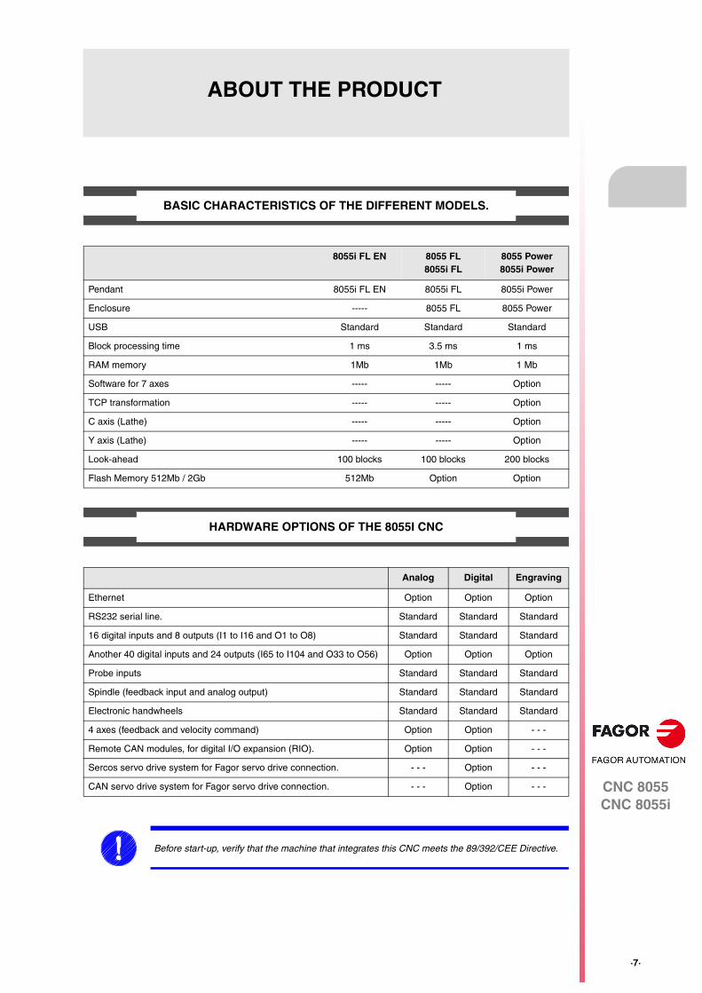
BASIC CHARACTERISTICS OF THE DIFFERENT MODELS.
HARDWARE OPTIONS OF THE 8055I CNC
8055i FL EN 8055 FL8055i FL
8055 Power8055i Power
Pendant 8055i FL EN 8055i FL 8055i Power
Enclosure ----- 8055 FL 8055 Power
USB Standard Standard Standard
Block processing time 1 ms 3.5 ms 1 ms
RAM memory 1Mb 1Mb 1 Mb
Software for 7 axes ----- ----- Option
TCP transformation ----- ----- Option
C axis (Lathe) ----- ----- Option
Y axis (Lathe) ----- ----- Option
Look-ahead 100 blocks 100 blocks 200 blocks
Flash Memory 512Mb / 2Gb 512Mb Option Option
Analog Digital Engraving
Ethernet Option Option Option
RS232 serial line. Standard Standard Standard
16 digital inputs and 8 outputs (I1 to I16 and O1 to O8) Standard Standard Standard
Another 40 digital inputs and 24 outputs (I65 to I104 and O33 to O56) Option Option Option
Probe inputs Standard Standard Standard
Spindle (feedback input and analog output) Standard Standard Standard
Electronic handwheels Standard Standard Standard
4 axes (feedback and velocity command) Option Option - - -
Remote CAN modules, for digital I/O expansion (RIO). Option Option - - -
Sercos servo drive system for Fagor servo drive connection. - - - Option - - -
CAN servo drive system for Fagor servo drive connection. - - - Option - - -
Before start-up, verify that the machine that integrates this CNC meets the 89/392/CEE Directive.
·8·
CNC 8055CNC 8055i
Abo
ut th
e pr
oduc
t
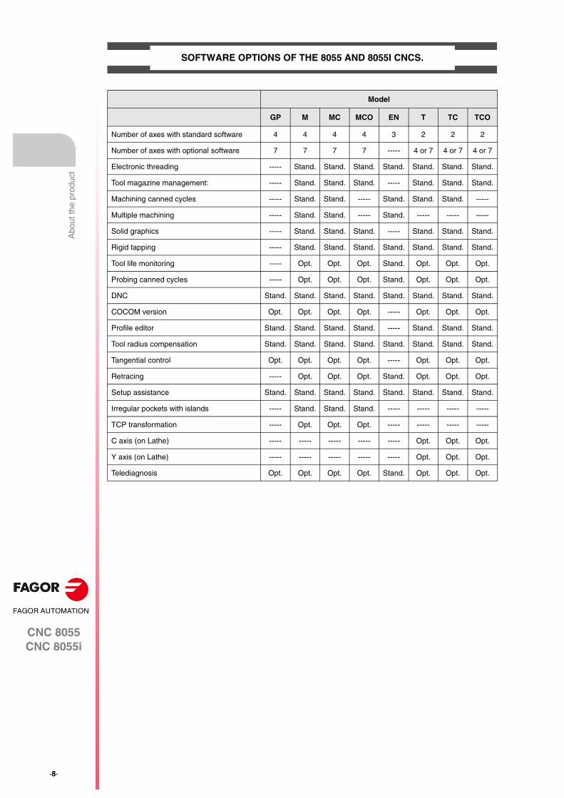
SOFTWARE OPTIONS OF THE 8055 AND 8055I CNCS.
Model
GP M MC MCO EN T TC TCO
Number of axes with standard software 4 4 4 4 3 2 2 2
Number of axes with optional software 7 7 7 7 ----- 4 or 7 4 or 7 4 or 7
Electronic threading ----- Stand. Stand. Stand. Stand. Stand. Stand. Stand.
Tool magazine management: ----- Stand. Stand. Stand. ----- Stand. Stand. Stand.
Machining canned cycles ----- Stand. Stand. ----- Stand. Stand. Stand. -----
Multiple machining ----- Stand. Stand. ----- Stand. ----- ----- -----
Solid graphics ----- Stand. Stand. Stand. ----- Stand. Stand. Stand.
Rigid tapping ----- Stand. Stand. Stand. Stand. Stand. Stand. Stand.
Tool life monitoring ----- Opt. Opt. Opt. Stand. Opt. Opt. Opt.
Probing canned cycles ----- Opt. Opt. Opt. Stand. Opt. Opt. Opt.
DNC Stand. Stand. Stand. Stand. Stand. Stand. Stand. Stand.
COCOM version Opt. Opt. Opt. Opt. ----- Opt. Opt. Opt.
Profile editor Stand. Stand. Stand. Stand. ----- Stand. Stand. Stand.
Tool radius compensation Stand. Stand. Stand. Stand. Stand. Stand. Stand. Stand.
Tangential control Opt. Opt. Opt. Opt. ----- Opt. Opt. Opt.
Retracing ----- Opt. Opt. Opt. Stand. Opt. Opt. Opt.
Setup assistance Stand. Stand. Stand. Stand. Stand. Stand. Stand. Stand.
Irregular pockets with islands ----- Stand. Stand. Stand. ----- ----- ----- -----
TCP transformation ----- Opt. Opt. Opt. ----- ----- ----- -----
C axis (on Lathe) ----- ----- ----- ----- ----- Opt. Opt. Opt.
Y axis (on Lathe) ----- ----- ----- ----- ----- Opt. Opt. Opt.
Telediagnosis Opt. Opt. Opt. Opt. Stand. Opt. Opt. Opt.
CNC 8055CNC 8055i
·9·
DECLARATION OF CONFORMITY AND WARRANTY CONDITIONS
DECLARATION OF CONFORMITY
The declaration of conformity for the CNC is available in the downloads section of FAGOR’S corporatewebsite at http://www.fagorautomation.com. (Type of file: Declaration of conformity).
WARRANTY TERMS
The warranty conditions for the CNC are available in the downloads section of FAGOR’s corporate websiteat http://www.fagorautomation.com. (Type of file: General sales-warranty conditions).
·10·
CNC 8055CNC 8055i
Dec
lara
tion
of c
onfo
rmity
and
War
rant
y co
nditi
ons
CNC 8055CNC 8055i
·11·
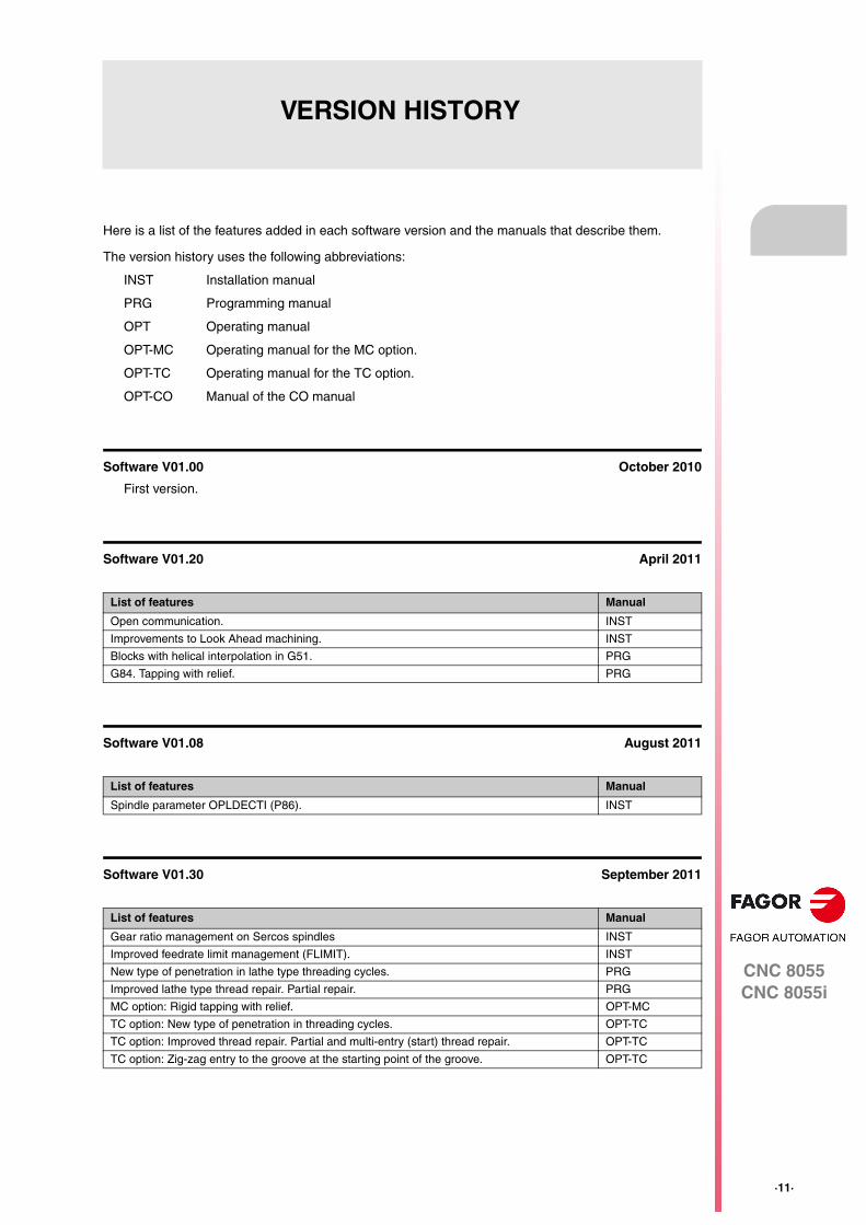
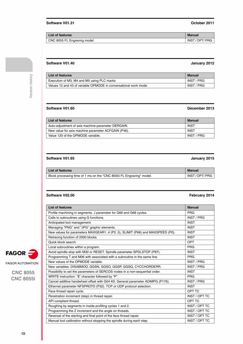
VERSION HISTORY
Here is a list of the features added in each software version and the manuals that describe them.
The version history uses the following abbreviations:
INST Installation manual
PRG Programming manual
OPT Operating manual
OPT-MC Operating manual for the MC option.
OPT-TC Operating manual for the TC option.
OPT-CO Manual of the CO manual
Software V01.00 October 2010
First version.
Software V01.20 April 2011
Software V01.08 August 2011
Software V01.30 September 2011
List of features Manual
Open communication. INST
Improvements to Look Ahead machining. INST
Blocks with helical interpolation in G51. PRG
G84. Tapping with relief. PRG
List of features Manual
Spindle parameter OPLDECTI (P86). INST
List of features Manual
Gear ratio management on Sercos spindles INST
Improved feedrate limit management (FLIMIT). INST
New type of penetration in lathe type threading cycles. PRG
Improved lathe type thread repair. Partial repair. PRG
MC option: Rigid tapping with relief. OPT-MC
TC option: New type of penetration in threading cycles. OPT-TC
TC option: Improved thread repair. Partial and multi-entry (start) thread repair. OPT-TC
TC option: Zig-zag entry to the groove at the starting point of the groove. OPT-TC
·12·
CNC 8055CNC 8055i
Ver
sion
his
tory
Software V01.31 October 2011
Software V01.40 January 2012
Software V01.60 December 2013
Software V01.65 January 2015
Software V02.00 February 2014
List of features Manual
CNC 8055 FL Engraving model INST / OPT/ PRG
List of features Manual
Execution of M3, M4 and M5 using PLC marks INST / PRG
Values 12 and 43 of variable OPMODE in conversational work mode. INST / PRG
List of features Manual
Auto-adjustment of axis machine parameter DERGAIN. INST
New value for axis machine parameter ACFGAIN (P46). INST
Value 120 of the OPMODE variable. INST / PRG
List of features Manual
Block processing time of 1 ms on the "CNC 8055i FL Engraving" model. INST / OPT/ PRG
List of features Manual
Profile machining in segments. J parameter for G66 and G68 cycles. PRG
Calls to subroutines using G functions. INST / PRG
Anticipated tool management. INST
Managing "PNG" and "JPG" graphic elements. INST
New values for parameters MAXGEAR1..4 (P2..5), SLIMIT (P66) and MAXSPEED (P0). INST
Retracing function of 2000 blocks. INST
Quick block search. OPT
Local subroutines within a program. PRG
Avoid spindle stop with M30 or RESET. Spindle parameter SPDLSTOP (P87). INST
Programming T and M06 with associated with a subroutine in the same line. PRG
New values of the OPMODE variable. INST / PRG
New variables: DISABMOD, GGSN, GGSO, GGSP, GGSQ, CYCCHORDERR. INST / PRG
Possibility to set the parameters of SERCOS nodes in a non-sequential order. INST
WRITE instruction: “$” character followed by “P”. PRG
Cancel additive handwheel offset with G04 K0. General parameter ADIMPG (P176). INST / PRG
Ethernet parameter NFSPROTO (P32). TCP or UDP protocol selection. INST
Face thread repair cycle. OPT TC
Penetration increment (step) in thread repair. INST / OPT TC
API compliant thread. OPT TC
Roughing by segments in inside profiling cycles 1 and 2. INST / OPT TC
Programming the Z increment and the angle on threads. INST / OPT TC
Reversal of the starting and final point of the face thread repair. INST / OPT TC
Manual tool calibration without stopping the spindle during each step. INST / OPT TC
CNC 8055CNC 8055i
·13·
Ver
sion
his
tory
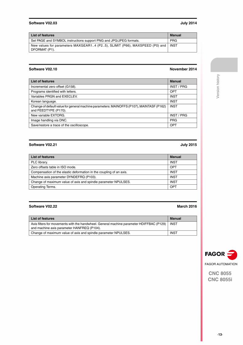
Software V02.03 July 2014
Software V02.10 November 2014
Software V02.21 July 2015
Software V02.22 March 2016
List of features Manual
Set PAGE and SYMBOL instructions support PNG and JPG/JPEG formats. PRG
New values for parameters MAXGEAR1..4 (P2..5), SLIMIT (P66), MAXSPEED (P0) andDFORMAT (P1).
INST
List of features Manual
Incremental zero offset (G158). INST / PRG
Programs identified with letters. OPT
Variables PRGN and EXECLEV. INST
Korean language. INST
Change of default value for general machine parameters: MAINOFFS (P107), MAINTASF (P162)and FEEDTYPE (P170).
INST
New variable EXTORG. INST / PRG
Image handling via DNC. PRG
Save/restore a trace of the oscilloscope. OPT
List of features Manual
PLC library. INST
Zero offsets table in ISO mode. OPT
Compensation of the elastic deformation in the coupling of an axis. INST
Machine axis parameter DYNDEFRQ (P103). INST
Change of maximum value of axis and spindle parameter NPULSES. INST
Operating Terms. OPT
List of features Manual
Axis filters for movements with the handwheel. General machine parameter HDIFFBAC (P129)and machine axis parameter HANFREQ (P104).
INST
Change of maximum value of axis and spindle parameter NPULSES. INST

·14·
CNC 8055CNC 8055i
Ver
sion
his
tory
CNC 8055CNC 8055i
·15·
SAFETY CONDITIONS
Read the following safety measures in order to prevent harming people or damage to this product and thoseproducts connected to it.
The unit can only be repaired by personnel authorized by Fagor Automation.
Fagor Automation shall not be held responsible of any physical or material damage originated from notcomplying with these basic safety rules.
PRECAUTIONS AGAINST PERSONAL HARM
• Interconnection of modules.
Use the connection cables provided with the unit.
• Use proper Mains AC power cables
To avoid risks, use only the Mains AC cables recommended for this unit.
• Avoid electric shocks.
In order to avoid electrical discharges and fire hazards, do not apply electrical voltage outside the rangeselected on the rear panel of the central unit.
• Ground connection.
In order to avoid electrical discharges, connect the ground terminals of all the modules to the mainground terminal. Before connecting the inputs and outputs of this unit, make sure that all the groundingconnections are properly made.
• Before powering the unit up, make sure that it is connected to ground.
In order to avoid electrical discharges, make sure that all the grounding connections are properly made.
• Do not work in humid environments.
In order to avoid electrical discharges, always work under 90% of relative humidity (non-condensing)and 45 ºC (113º F).
• Do not operate this unit in explosive environments.
In order to avoid risks, harm or damages, do not work in explosive environments.
·16·
CNC 8055CNC 8055i
Saf
ety
cond
ition
s
PRECAUTIONS AGAINST PRODUCT DAMAGE
• Work environment.
This unit is ready to be used in industrial environments complying with the directives and regulationseffective in the European Community.
Fagor Automation shall not be held responsible for any damage that could suffer or cause when installedunder other conditions (residential or domestic environments).
• Install this unit in the proper place.
It is recommended, whenever possible, to install the CNC away from coolants, chemical product, blows,etc. that could damage it.
This unit meets the European directives on electromagnetic compatibility. Nevertheless, it isrecommended to keep it away from sources of electromagnetic disturbance, such as:
Powerful loads connected to the same mains as the unit.
Nearby portable transmitters (radio-telephones, Ham radio transmitters).
Nearby radio / TC transmitters.
Nearby arc welding machines.
Nearby high voltage lines.
Etc.
• Enclosures.
It is up to the manufacturer to guarantee that the enclosure where the unit has been installed meetsall the relevant directives of the European Union.
• Avoid disturbances coming from the machine tool.
The machine-tool must have all the interference generating elements (relay coils, contactors, motors,etc.) uncoupled.
DC relay coils. Diode type 1N4000.
AC relay coils. RC connected as close to the coils as possible with approximate values of R=220 1 W y C=0,2 µF / 600 V.
AC motors. RC connected between phases, with values of R=300 / 6 W y C=0,47 µF / 600 V.
• Use the proper power supply.
Use an external regulated 24 Vdc power supply for the inputs and outputs.
• Connecting the power supply to ground.
The zero Volt point of the external power supply must be connected to the main ground point of themachine.
• Analog inputs and outputs connection.
It is recommended to connect them using shielded cables and connecting their shields (mesh) to thecorresponding pin.
• Ambient conditions.
The working temperature must be between +5 ºC and +40 ºC (41ºF and 104º F)
The storage temperature must be between -25 ºC and +70 ºC. (-13 ºF and 158 ºF)
• Monitor enclosure (CNC 8055) or central unit ( CNC 8055i)
Guarantee the required gaps between the monitor or the central unit and each wall of the enclosure.Use a DC fan to improve enclosure ventilation.
• Power switch.
This power switch must be mounted in such a way that it is easily accessed and at a distance between0.7 meters (27.5 inches) and 1.7 meters (5.5ft) off the floor.
CNC 8055CNC 8055i
·17·
Saf
ety
cond
ition
s
PROTECTIONS OF THE UNIT ITSELF (8055)
• "Axes" and "Inputs-Outputs" modules.
All the digital inputs and outputs have galvanic isolation via optocouplers between the CNC circuitryand the outside.
They are protected by an external fast fuse (F) of 3.15 A 250V against overvoltage of the external powersupply (over 33 Vdc) and against reverse connection of the power supply.
• Monitor.
The type of protection fuse depends on the type of monitor. See identification label of the unit itself.
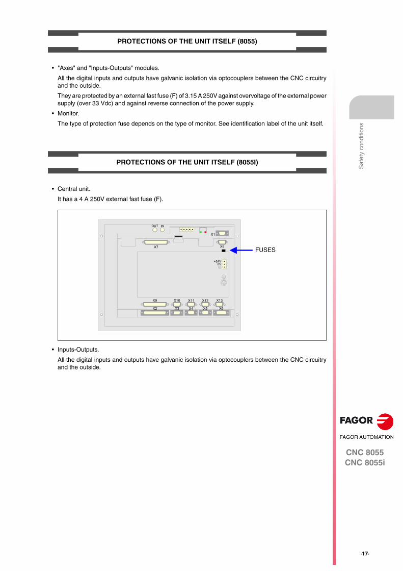
PROTECTIONS OF THE UNIT ITSELF (8055I)
• Central unit.
It has a 4 A 250V external fast fuse (F).
• Inputs-Outputs.
All the digital inputs and outputs have galvanic isolation via optocouplers between the CNC circuitryand the outside.
OUT IN
X7
X1
X8
X9
X2
X10
X3
X11
X4
X12
X5
X13
X6
+24V0V
FUSIBLEFUSES
·18·
CNC 8055CNC 8055i
Saf
ety
cond
ition
s
PRECAUTIONS DURING REPAIRS
SAFETY SYMBOLS
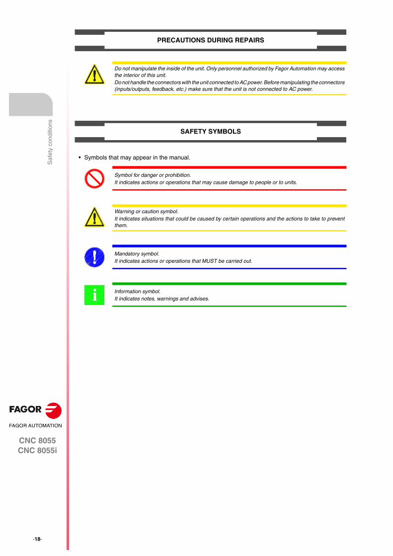
• Symbols that may appear in the manual.
Do not manipulate the inside of the unit. Only personnel authorized by Fagor Automation may accessthe interior of this unit.Do not handle the connectors with the unit connected to AC power. Before manipulating the connectors(inputs/outputs, feedback, etc.) make sure that the unit is not connected to AC power.
Symbol for danger or prohibition.It indicates actions or operations that may cause damage to people or to units.
Warning or caution symbol.It indicates situations that could be caused by certain operations and the actions to take to preventthem.
Mandatory symbol.It indicates actions or operations that MUST be carried out.
Information symbol.It indicates notes, warnings and advises.i
CNC 8055CNC 8055i
·19·
RETURNING CONDITIONS
When sending the central nit or the remote modules, pack them in its original package and packagingmaterial. If you do not have the original packaging material, pack it as follows:
1. Get a cardboard box whose 3 inside dimensions are at least 15 cm (6 inches) larger than those of theunit itself. The cardboard being used to make the box must have a resistance of 170 kg. (375 pounds).
2. Attach a label indicating the owner of the unit, person to contact, type of unit and serial number.
3. In case of failure, also indicate the symptom and a short description of the failure.
4. Protect the unit wrapping it up with a roll of polyethylene or with similar material.
5. When sending the central unit, protect especially the screen.
6. Pad the unit inside the cardboard box with polyurethane foam on all sides.
7. Seal the cardboard box with packaging tape or with industrial staples.

·20·
CNC 8055CNC 8055i
Ret
urni
ng c
ondi
tions
CNC 8055CNC 8055i
·21·
ADDITIONAL NOTES
Mount the CNC away from coolants, chemical products, blows, etc. which could damage it. Before turningthe unit on, verify that the ground connections have been made properly.
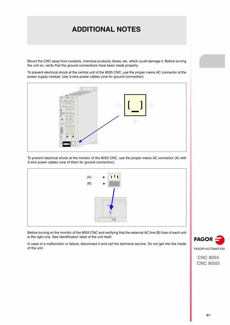
To prevent electrical shock at the central unit of the 8055 CNC, use the proper mains AC connector at thepower supply module. Use 3-wire power cables (one for ground connection).
To prevent electrical shock at the monitor of the 8055 CNC, use the proper mains AC connector (A) with3-wire power cables (one of them for ground connection).
Before turning on the monitor of the 8055 CNC and verifying that the external AC line (B) fuse of each unitis the right one. See identification label of the unit itself.
In case of a malfunction or failure, disconnect it and call the technical service. Do not get into the insideof the unit.
FAGOR
I/O
X1
X2
X3
AXES
X1 X2
X3 X4
X5 X6
X7 X8
X9X10
CPU
X1 X2
CMPCTFLASH
ETH
COM1
X3
CDEF0
BA98 1
7 26 354
IN
OUT
NODE
USB
(A)
(B)
X1
W1
·22·
CNC 8055CNC 8055i
Add
ition
al n
otes
CNC 8055CNC 8055i
·23·
FAGOR DOCUMENTATION
OEM manual
It is directed to the machine builder or person in charge of installing and starting-up the CNC.
USER-M manual
Directed to the end user.
It describes how to operate and program in M mode.
USER-T manual
Directed to the end user.
It describes how to operate and program in T mode.
MC Manual
Directed to the end user.
It describes how to operate and program in MC mode.
It contains a self-teaching manual.
TC Manual
Directed to the end user.
It describes how to operate and program in TC mode.
It contains a self-teaching manual.
MCO/TCO model
Directed to the end user.
It describes how to operate and program in MCO and TCO mode.
Examples-M manual
Directed to the end user.
It contains programming examples for the M mode.
Examples-T manual
Directed to the end user.
It contains programming examples for the T mode.
WINDNC Manual
It is directed to people using the optional DNC communications software.
It is supplied in a floppy disk with the application.
WINDRAW55 Manual
Directed to people who use the WINDRAW55 to create screens.
It is supplied in a floppy disk with the application.

·24·
CNC 8055CNC 8055i
Fag
or d
ocum
enta
tion
CNC 8055CNC 8055i
·T· MODELSOFT: V02.2X
1
·25·
GENERAL CONCEPTS
The CNC may be programmed at the machine (from the front panel) and from a peripheral(computer). Memory available to the user for carrying out the part programs is 1 Mbyte.
The part programs and the values in the tables which the CNC has can be entered from the frontpanel, from a pc (DNC) or from a peripheral.
Entering programs and tables from the front panel.
Once the editing mode or desired table has been selected, the CNC allows you to enter data fromthe keyboard.
Entering programs and tables from a Computer (DNC) or peripheral device.
The CNC allows data to be exchanged with a computer or peripheral device, using the RS232C serialline.
If this is controlled from the CNC, it is necessary to preset the corresponding table or part programdirectory (utilities) you want to communicate with.
Depending on the type of communication required, the serial port machine parameter "PROTOCOL"should be set.
"PROTOCOL" = 0 if the communication is with a peripheral device.
"PROTOCOL" = 1 if the communication is via DNC.
·26·
Programming manual
CNC 8055CNC 8055i
1.
GE
NE
RA
L C
ON
CE
PT
S
·T· MODELSOFT: V02.2X
Par
t pro
gram
s
1.1 Part programs
The operating manual describes the different operating modes. Refer to that manual for furtherinformation.
Editing a part-program
To create a part-program, access the –Edit– mode.
The new part-program edited is stored in the CNC's RAM memory. A copy of the part-programs maybe stored in the hard disk (KeyCF) at a PC connected through the serial line or in the USB disk.
To transmit a program to a PC through the serial, proceed as follows:
1. Execute the "WinDNC.exe" application program at the PC.
2. Activate DNC communications at the CNC.
3. Select the work directory at the CNC. It is selected from the –Utilities– mode, option Directory\Serial L \Change directory
In –Edit– mode, it is possible to modify part-programs residing in the CNC's RAM memory. To modifya program stored in the hard disk (KeyCF), in a PC or in the USB disk, it must be previously copiedinto RAM memory.
Executing and editing a part-program
Part-programs stored anywhere may be executed or simulated. Simulation is carried out in the–Simulation– mode, whereas the execution is done in the –Automatic– mode
When executing or simulating a part-program, bear in mind the following points:
• Only subroutines stored in the CNC's RAM memory can be executed. Therefore, to execute asubroutine stored in the hard disk (KeyCF), in a PC or in the USB disk, it must be first copiedinto the CNC's RAM memory.
• The GOTO and RPT instructions cannot be used in programs that are executed from a PCconnected through the serial line.
• From a program in execution, it is possible to execute another program located in RAM memory,in the hard disk (KeyCF) or in a PC using the EXEC instruction.
The user customizing programs must be in RAM memory so the CNC can execute them.
–Utilities– operating mode.
The –Utilities– mode, lets display the part-program directory of all the devices, make copies, delete,rename and even set the protections for any of them.
Programming manual
CNC 8055CNC 8055i
GE
NE
RA
L C
ON
CE
PT
S
1.
·T· MODELSOFT: V02.2X
·27·
Par
t pro
gram
s
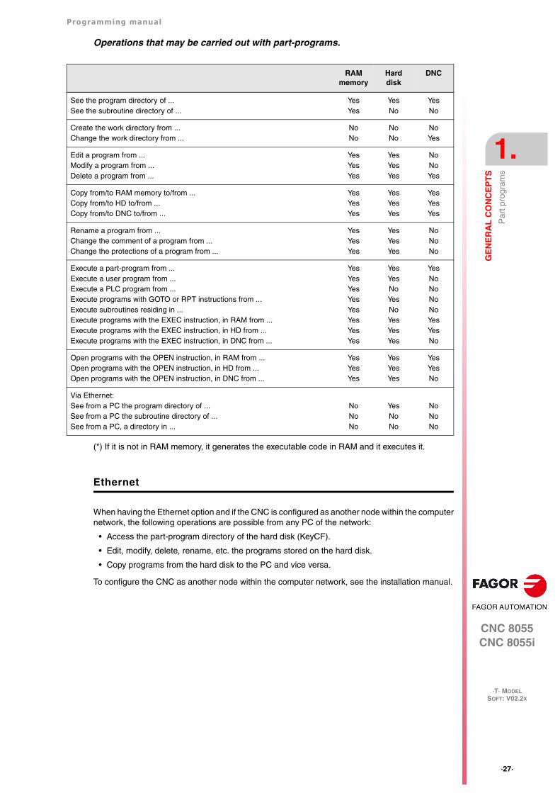
Operations that may be carried out with part-programs.
(*) If it is not in RAM memory, it generates the executable code in RAM and it executes it.
Ethernet
When having the Ethernet option and if the CNC is configured as another node within the computernetwork, the following operations are possible from any PC of the network:
• Access the part-program directory of the hard disk (KeyCF).
• Edit, modify, delete, rename, etc. the programs stored on the hard disk.
• Copy programs from the hard disk to the PC and vice versa.
To configure the CNC as another node within the computer network, see the installation manual.
RAM memory
Hard disk
DNC
See the program directory of ...See the subroutine directory of ...
YesYes
YesNo
YesNo
Create the work directory from ...Change the work directory from ...
NoNo
NoNo
NoYes
Edit a program from ...Modify a program from ...Delete a program from ...
YesYesYes
YesYesYes
NoNoYes
Copy from/to RAM memory to/from ...Copy from/to HD to/from ...Copy from/to DNC to/from ...
YesYesYes
YesYesYes
YesYesYes
Rename a program from ...Change the comment of a program from ...Change the protections of a program from ...
YesYesYes
YesYesYes
NoNoNo
Execute a part-program from ...Execute a user program from ...Execute a PLC program from ...Execute programs with GOTO or RPT instructions from ...Execute subroutines residing in ...Execute programs with the EXEC instruction, in RAM from ...Execute programs with the EXEC instruction, in HD from ...Execute programs with the EXEC instruction, in DNC from ...
YesYesYesYesYesYesYesYes
YesYesNoYesNoYesYesYes
YesNoNoNoNoYesYesNo
Open programs with the OPEN instruction, in RAM from ...Open programs with the OPEN instruction, in HD from ...Open programs with the OPEN instruction, in DNC from ...
YesYesYes
YesYesYes
YesYesNo
Via Ethernet:See from a PC the program directory of ...See from a PC the subroutine directory of ...See from a PC, a directory in ...
NoNoNo
YesNoNo
NoNoNo
·28·
Programming manual
CNC 8055CNC 8055i
1.
GE
NE
RA
L C
ON
CE
PT
S
·T· MODELSOFT: V02.2X
Par
t pro
gram
s
1.1.1 Considerations regarding the Ethernet connection
When configuring the CNC as another node in the computer network, the programs stored in thehard disk (KeyCF) may be edited and modified from any PC.
Instructions for setting up a PC to access CNC directories
To set up the PC to access the CNC directories, we recommend to proceed as follows.
1. Open the "Windows Explorer"
2. On the "Tools" menu, select the "Connect to Network Drives" option.
3. Select the drive, for example "D".
4. Indicate the path. The path will be the CNC name followed by the name of the shared directory.
For example: \\FAGORCNC\CNCHD
5. When selecting the option: "Connect again when initiating the session", the selected CNC willappear on each power-up as another path of the "Windows Explorer" without having to defineit again.
Data format
This connection is established through Ethernet and, therefore, the CNC does not control the syntaxof the programs while they are received or modified. However, whenever accessing the programdirectory of the Hard Disk (HD), the following verification takes place:
File name.
The file number must always have 6 digits and the extension PIM (for milling) or PIT (for lathe).
Examples: 001204.PIM 000100.PIM 123456.PIT 020150.PIT
If the file has been given the wrong name, for example: 1204.PIM or 100.PIT, the CNC will not changeit, but it will display it with the comment "****************". The file name cannot be modifiedat the CNC; it must be edited from the PC to correct the error.
File size.
If the file is empty (size = 0) the CNC will display it with the comment "********************".
The file can be edited or deleted either from the CNC or from the PC.
First line of the program.
The first line of the program must have the % character, the comment associated with the file (upto 20 characters) and between the two commas (,) the program attributes O (OEM), H (hidden), M(modifiable), X (executable).
Examples: %Comment ,MX,
% ,OMX,
If the first line does not exist, the CNC will display the program with an empty comment and withthe modifiable (M) and executable (X) attributes.
When the format of the first line is wrong, the CNC does not modify it, but it displays it with thecomment "****************". The file can be edited or deleted either from the CNC or from thePC.
The format is incorrect when the comment has more than 20 characters, a comma (,) is missingto group the attributes or there is a strange character in the attributes.
Programming manual
CNC 8055CNC 8055i
GE
NE
RA
L C
ON
CE
PT
S
1.
·T· MODELSOFT: V02.2X
·29·
DN
C c
onne
ctio
n
1.2 DNC connection
The CNC offers as optional feature the possibility of working in DNC (Distributed Numerical Control),enabling communication between the CNC and a computer to carry out the following functions:
• Directory and delete commands.
• Transfer of programs and tables between the CNC and a computer.
• Remote control of the machine.
• The ability to supervise the status of advanced DNC systems.
·30·
Programming manual
CNC 8055CNC 8055i
1.
GE
NE
RA
L C
ON
CE
PT
S
·T· MODELSOFT: V02.2X
Com
mun
icat
ion
prot
ocol
via
DN
C o
r pe
riphe
ral d
evic
e
1.3 Communication protocol via DNC or peripheral device
This type of communication enables program-and-table transfer commands, plus the organizationof CNC directories such as the computer directory, for copying/deleting programs, etc. to be doneeither from the CNC or the computer.
When you want to transfer files, it is necessary to follow this protocol:
• The "%" symbol will be used to start the file, followed by the program comment (optional), of upto 20 characters.
Then, and separated by a comma ",", comes the protection of each file, read, write, etc. Theseprotections are optional, since their programming is not obligatory.
To end the file header, RT (RETURN ) or LF (LINE FEED) characters should be sent separatedby a comma (",").
Example: %Fagor Automation, MX, RT
• Following the header, the file blocks should be programmed. These will all be programmedaccording to the programming rules indicated in this manual. After each block, to separate it fromthe others, the RT (RETURN ) or LF (LINE FEED) characters should be used.
Example: N20 G90 G01 X100 Y200 F2000 LF
(RPT N10, N20) N3 LF
If communication is made with a peripheral device, you will need to send the ‘end of file’ command.This command is selected via the machine parameter for the serial port: "EOFCHR", and can beone of the following characters :
ESC ESCAPE
EOT END OF TRANSMISSION
SUB SUBSTITUTE
EXT END OF TRANSMISSION
Image handling via DNC
While using WinDNC (version V6.01 or later), it is possible to send and receive PNG, JPG/JPEGand BMP type images via DNC.
WinDNC software:
Version V6.01 of WinDNC supports files with extension bmp, png, jpg and jpeg. The maximum lengthor the file name is 16 characters (including the dot and the extension).
The application scans all image type files in the work folder. When sending the files, if the nameof any file is too long, it will ask the user to enter a new shorter name (up to 16 characters). It mustalso keep the original extension.
CNC 8055CNC 8055i
·T· MODELSOFT: V02.2X
2
·31·
CREATING A PROGRAM
A CNC program consists of a series of blocks or instructions. These blocks or instructions are madeof words composed of capital letters and numerical format.
The CNC’s numerical format consists of :
• The signs . (decimal points, + (plus), - (minus).
• Digits 0 1 2 3 4 5 6 7 8 9.
Programming allows spaces between letters, numbers and symbols, in addition to ignoring thenumerical format if it has zero value, or a symbol if it is positive.
The numeric format of a word may be replaced by an arithmetic parameter when programming. Lateron, during execution, the CNC will replace the arithmetic parameter by its value. For example, if XP3has been programmed, during execution the CNC will replace P3 by its numerical value, obtainingresults such as X20, X20.567, X-0.003, etc.
·32·
Programming manual
CNC 8055CNC 8055i
2.
CR
EA
TIN
G A
PR
OG
RA
M
·T· MODELSOFT: V02.2X
Pro
gram
str
uctu
re a
t the
CN
C
2.1 Program structure at the CNC
All the blocks which make up the program have the following structure:
Block header + program block + end of block
2.1.1 Block header
The block header is optional, and may consist of one or more block skip conditions and by the blocknumber or label. Both must be programmed in this order.
Block skip condition. "/", "/1", "/2", "/3".
These three block skip conditions, given that "/" and "/1" are the same, they are governed by themarks BLKSKIP1, BLKSKIP2 and BLKSKIP3 of the PLC. If any of these marks is active, the CNCwill not execute the block or blocks in which it has been programmed; the execution takes place inthe following block.
Up to 3 skip conditions can be programmed in one block; they will be evaluated one by one,respecting the order in which they have been programmed.
The control reads 200 blocks ahead of the one being executed in order to calculate in advance thepath to be run. The condition for block skip will be analyzed at the time when the block is read i.e.200 blocks before execution.
If the block skip needs to be analyzed at the time of execution, it is necessary to interrupt the blockpreparation, by programming G4 in the previous block.
Label or block number. N(0-99999999).
This is used to identify the block, and is only used when block references or jumps are made. Theyare represented by the letter N followed by up to 8 digits (0-99999999).
No particular order is required and the numbers need not be sequential. If two or more blocks withthe same label number are present in the same program, the CNC will always give priority to thefirst number.
Although it is not necessary to program it, by using a softkey the CNC allows the automaticprogramming of labels. The programmer can select the initial number and the step between labels.
Restrictions:
• Displaying the active block number at the top window on the screen:
When executing a program in ISO mode, when the label number is higher than 9999, itdisplays N**** .
On the "DISPLAY / SUBROUTINES" window, when displaying an RPT that has a label higherthan 9999, it displays it with ****.
• Canned cycles G66, G68 and G69 can only be edited with 4-digit labels.
Programming manual
CNC 8055CNC 8055i
CR
EA
TIN
G A
PR
OG
RA
M
2.
·T· MODELSOFT: V02.2X
·33·
Pro
gram
str
uctu
re a
t the
CN
C
2.1.2 Program block
This is written with commands in ISO and high level languages. To prepare a program, blocks writtenin both languages will be used, although each one should be edited with commands in just onelanguage.
ISO language
This language is specially designed to control axis movement, as it gives information and movementconditions, in addition to data on feedrate. It offers the following types of functions.
• Preparatory functions for movement, used to determine geometry and working conditions, suchas linear and circular interpolations, threading, etc.
• Control functions for axis feedrate and spindle speeds.
• Tool control functions.
• Complementary functions, with technological instructions.
High level language
This enables access to general purpose variables and to system tables and variables.
It gives the user a number of control sentences which are similar to the terminology used in otherlanguages, such as IF, GOTO, CALL, etc. Also, it allows the use of any type of arithmetic, relationalor logical expression.
It also has instructions for the construction of loops, plus subroutines with local variables. A localvariable is one that is only recognized by the subroutine in which it has been defined.
It is also possible to create libraries, grouping subroutines with useful and tested functions, whichcan be accessed from any program.
·34·
Programming manual
CNC 8055CNC 8055i
2.
CR
EA
TIN
G A
PR
OG
RA
M
·T· MODELSOFT: V02.2X
Pro
gram
str
uctu
re a
t the
CN
C
2.1.3 End of block
The end of block is optional and may consist of the indication of number of repetitions of the blockand of the block comment. Both must be programmed in this order.
Number of block repetitions. N(0-9999)
This indicates the number of times the block will be executed. The number of repetitions isrepresented by the letter N followed by up to 4 digits (0-9999). The active machining operation doesnot take place if N0 is programmed; only the movement programmed within the block takes place.
Movement blocks can only be repeated which, at the time of their execution, are under the influenceof a modal subroutine. In these cases, the CNC executes the programmed move and the activemachining operation (canned cycle or modal subroutine) the indicated number of times.
Block comment
The CNC allows you to incorporate any kind of information into all blocks in the form of a comment.The comment is programmed at the end of the block, and should begin with the character ";"(semicolon).
If a block begins with ";" all its contents will be considered as a comment, and it will not be executed.
Empty blocks are not permitted. They should contain at least one comment.
Programming manual
CNC 8055CNC 8055i
CR
EA
TIN
G A
PR
OG
RA
M
2.
·T· MODELSOFT: V02.2X
·35·
Loca
l sub
rout
ines
with
in a
pro
gram
2.2 Local subroutines within a program
A subroutine is a part of a program which, being properly identified, can be called from any positionof a program to be executed.
Local subroutines may be defined within a program. These subroutines are executed from RAM orhard disk memory.
The local subroutines are defined as part of a program. These subroutines may only be called uponfrom the program where it has been defined.
Programming
The local subroutines are located at the beginning of the program, before the actual beginning ofthe program. Local subroutines are defined by programming (LSUB n), where n indicates thesubroutine number. Followed by the contents of the subroutine.
The range of local subroutines is from 0 to 9999.
(LSUB 0)(LSUB 9999)
The actual beginning of the program is identified with the % sign. Any text may follow this character.
A local subroutine may be called upon using the commands CALL, PCALL or MCALL. Whenexecuting the calls, it first looks for the subroutines defined as local in that program and havingmatching names. If there aren't any, it will look among the global subroutines.
To execute a local subroutine directly, program (LL n). This way, only the local subroutine will beexecuted. If this subroutine does not exist, it will not execute anything and it will issue an errormessage indicating undefined subroutine.
Up to 100 local subroutines may be defined in a program. The maximum local subroutine nestinglevel is 15.
Examples:
Example 1:
(LSUB9505)X100(RET)
%**** ; beginning of program(CALL 9505) M30
Example 2:
(LSUB9505)X100(RET)
%**** ; beginning of program(LL9505)M30
·36·
Programming manual
CNC 8055CNC 8055i
2.
CR
EA
TIN
G A
PR
OG
RA
M
·T· MODELSOFT: V02.2X
Loca
l sub
rout
ines
with
in a
pro
gram
Executing programs:
Limitations:
A local subroutine can call a global subroutine but a global subroutine cannot call a local subroutineexcept if that local subroutine is defined in the root program; in other words, in the first program thatis executed.
Local subroutines defined inside a program that has been called with the "EXEC" command areignored. It only takes into account the ones defined in the root program.
It only takes into account local subroutines that are in programs that are executed from the CNCexecution channel, either in ISO mode or in conversational mode. Local subroutines cannot beexecuted from the PLC channel.
(LL n) Call to a local subroutine.Parameters cannot be initialized with this command.
(CALL n) Call to a local or global subroutine.Parameters cannot be initialized with this command.
(PCALL n ...) Call to a global or local subroutine.Local parameters can be initialized with this command.
(MCALL n ...) Modal call to a local or global subroutine.Local parameters can be initialized with this command.
CNC 8055CNC 8055i
·T· MODELSOFT: V02.2X
3
·37·
AXES AND COORDINATE SYSTEMS
Given that the purpose of the CNC is to control the movement and positioning of axes, it is necessaryto determine the position of the point to be reached through its coordinates.
The CNC allows you to use absolute, relative or incremental coordinates throughout the sameprogram.
·38·
Programming manual
CNC 8055CNC 8055i
3.
AX
ES
AN
D C
OO
RD
INA
TE
SY
ST
EM
S
·T· MODELSOFT: V02.2X
Axi
s no
men
clat
ure
3.1 Axis nomenclature
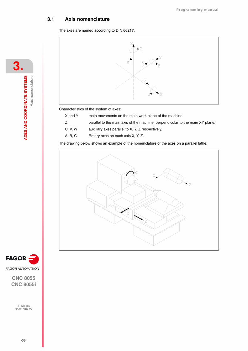
The axes are named according to DIN 66217.
Characteristics of the system of axes:
X and Y main movements on the main work plane of the machine.
Z parallel to the main axis of the machine, perpendicular to the main XY plane.
U, V, W auxiliary axes parallel to X, Y, Z respectively.
A, B, C Rotary axes on each axis X, Y, Z.
The drawing below shows an example of the nomenclature of the axes on a parallel lathe.
Programming manual
CNC 8055CNC 8055i
AX
ES
AN
D C
OO
RD
INA
TE
SY
ST
EM
S
3.
·T· MODELSOFT: V02.2X
·39·
Axi
s no
men
clat
ure
3.1.1 Axis selection
Of the 9 possible axes that may exist, the CNC allows the manufacturer to select up to 7 of them.
Moreover, all the axes should be suitably defined as linear/rotary, etc. through the axis machineparameters which appear in the Installation and Start-up Manual.
There is no limitation to the programming of the axes, and up to 7 axes may be interpolated at thesame time.
·40·
Programming manual
CNC 8055CNC 8055i
3.
AX
ES
AN
D C
OO
RD
INA
TE
SY
ST
EM
S
·T· MODELSOFT: V02.2X
Pla
ne s
elec
tion
(G16
, G17
, G18
, G19
)
3.2 Plane selection (G16, G17, G18, G19)
Plane selection should be made when the following are carried out :
• Circular interpolations.
• Controlled corner rounding.
• Tangential entry and exit.
• Chamfer.
• Coordinate programming in Polar coordinates.
• Rotation of the coordinate system.
• Tool radius compensation.
• Tool length compensation.
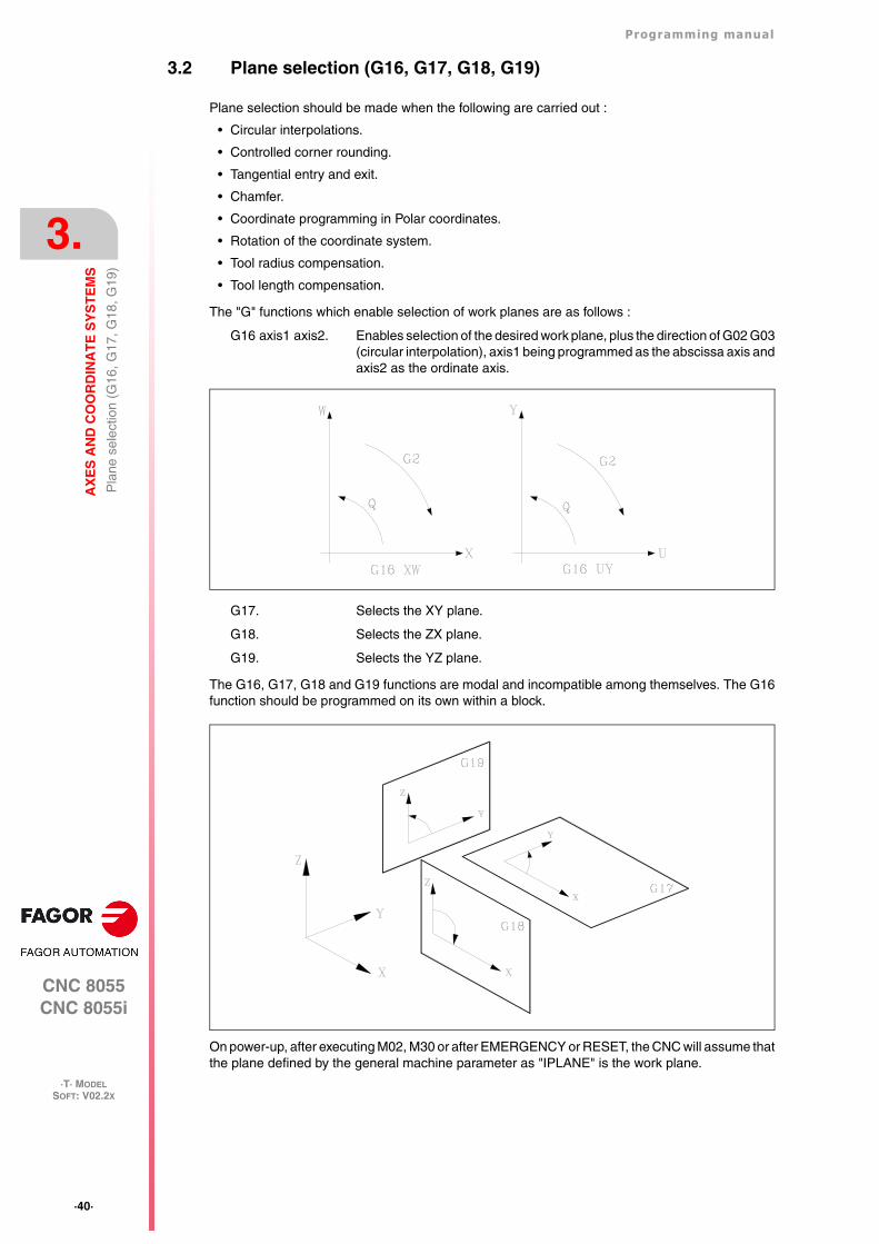
The "G" functions which enable selection of work planes are as follows :
G16 axis1 axis2. Enables selection of the desired work plane, plus the direction of G02 G03(circular interpolation), axis1 being programmed as the abscissa axis andaxis2 as the ordinate axis.
G17. Selects the XY plane.
G18. Selects the ZX plane.
G19. Selects the YZ plane.
The G16, G17, G18 and G19 functions are modal and incompatible among themselves. The G16function should be programmed on its own within a block.
On power-up, after executing M02, M30 or after EMERGENCY or RESET, the CNC will assume thatthe plane defined by the general machine parameter as "IPLANE" is the work plane.
Programming manual
CNC 8055CNC 8055i
AX
ES
AN
D C
OO
RD
INA
TE
SY
ST
EM
S
3.
·T· MODELSOFT: V02.2X
·41·
Par
t dim
ensi
onin
g. M
illim
eter
s (G
71)
or in
ches
(G
70)
3.3 Part dimensioning. Millimeters (G71) or inches (G70)
The CNC allows you to enter units of measurement with the programming, either in millimeters orinches.
It has a general machine parameter "INCHES" to define the unit of measurement of the CNC.
However, these units of measurement can be changed at any time in the program. Two functionsare supplied for this purpose :
• G70. Programming in inches.
• G71. Programming in millimeters.
Depending on whether G70 or G71 has been programmed, the CNC assumes the correspondingset of units for all the blocks programmed from that moment on.
The G70 and G71 functions are modal and are incompatible.
The CNC allows you to program figures from 0.00001 to 99999.9999 with or without sign, workingin millimeters (G71), called format +/-5.4, or either from 0.00001 to 3937.00787 with or without signif the programming is done in inches (G70), called format +/-4.5.
However, and to simplify the instructions, we can say that the CNC admits +/- 5.5 format, therebyadmitting +/- 5.4 in millimeters and +/- 4.5 in inches.
On power-up, after executing M02, M30 or after EMERGENCY or RESET, the CNC will assume thatthe system of units of measurement is the one defined by the general machine parameter "INCHES".
·42·
Programming manual
CNC 8055CNC 8055i
3.
AX
ES
AN
D C
OO
RD
INA
TE
SY
ST
EM
S
·T· MODELSOFT: V02.2X
Abs
olut
e/in
crem
enta
l pro
gram
min
g (G
90, G
91)
3.4 Absolute/incremental programming (G90, G91)
The CNC allows the programming of the coordinates of one point either with absolute G90 orincremental G91 values.
When working with absolute coordinates (G90), the point coordinates refer to a point of origin ofestablished coordinates, often the part zero (datum).
When working in incremental coordinates (G91), the numerical value programmed corresponds tothe movement information for the distance to be traveled from the point where the tool is situatedat that time. The sign in front shows the direction of movement.
The G90/G91 functions are modal and incompatible with each other.
On power-up, after executing M02, M30 or after an EMERGENCY or RESET, the CNC will assumeG90 or G91 according to the definition by the general machine parameter "ISYSTEM".
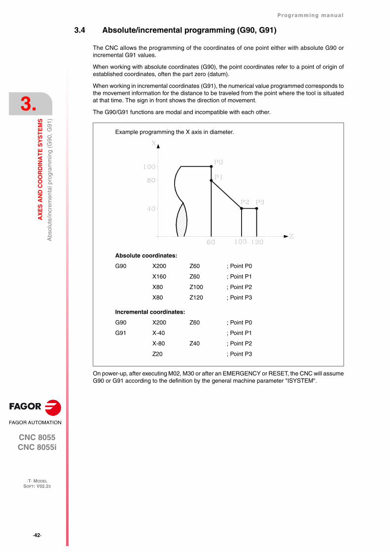
Absolute coordinates:
G90 X200 Z60 ; Point P0
X160 Z60 ; Point P1
X80 Z100 ; Point P2
X80 Z120 ; Point P3
Incremental coordinates:
G90 X200 Z60 ; Point P0
G91 X-40 ; Point P1
X-80 Z40 ; Point P2
Z20 ; Point P3
Example programming the X axis in diameter.
Programming manual
CNC 8055CNC 8055i
AX
ES
AN
D C
OO
RD
INA
TE
SY
ST
EM
S
3.
·T· MODELSOFT: V02.2X
·43·
Pro
gram
min
g in
rad
ius
or in
dia
met
ers
(G15
2, G
151)
3.5 Programming in radius or in diameters (G152, G151)
The X axis coordinates may be programmed in radius or diameter. The following functions may beused for that.
• G151. Programming the X axis in diameter.
• G152. Programming the X axis in radius.
It is carried out by interpolating the main spindle (that is turning) with the Z axis. After the executionof one of these functions, the CNC assumes the relevant programming mode for the blocksprogrammed afterwards.
The change of units is also taken into account in the following cases.
• Displaying the real X value of in the part's coordinate system.
• Reading of the variable PPOSX (programmed coordinate).
Functions G151 and G152 are modal and incompatible with each other.
On power-up, after executing an M02, M30 or after an emergency or reset, the CNC assumes G151or G152 depending on the setting of X axis machine parameter "DFORMAT".
·44·
Programming manual
CNC 8055CNC 8055i
3.
AX
ES
AN
D C
OO
RD
INA
TE
SY
ST
EM
S
·T· MODELSOFT: V02.2X
Coo
rdin
ate
prog
ram
min
g
3.6 Coordinate programming
The CNC allows the selection of up to 7 of the 9 possible axes X, Y, Z, U, V, W, A, B, C.
Each of these may be linear, linear to position only, normal rotary, rotary to position only or rotarywith hirth toothing (positioning in complete degrees), according to the specification in the machineparameter of each "AXISTYPE" axis.
With the aim of always selecting the most suitable coordinate programming system, the CNC hasthe following types :
• Cartesian coordinates
• Polar coordinates
• Angle and Cartesian coordinate
Programming manual
CNC 8055CNC 8055i
AX
ES
AN
D C
OO
RD
INA
TE
SY
ST
EM
S
3.
·T· MODELSOFT: V02.2X
·45·
Coo
rdin
ate
prog
ram
min
g
3.6.1 Cartesian coordinates
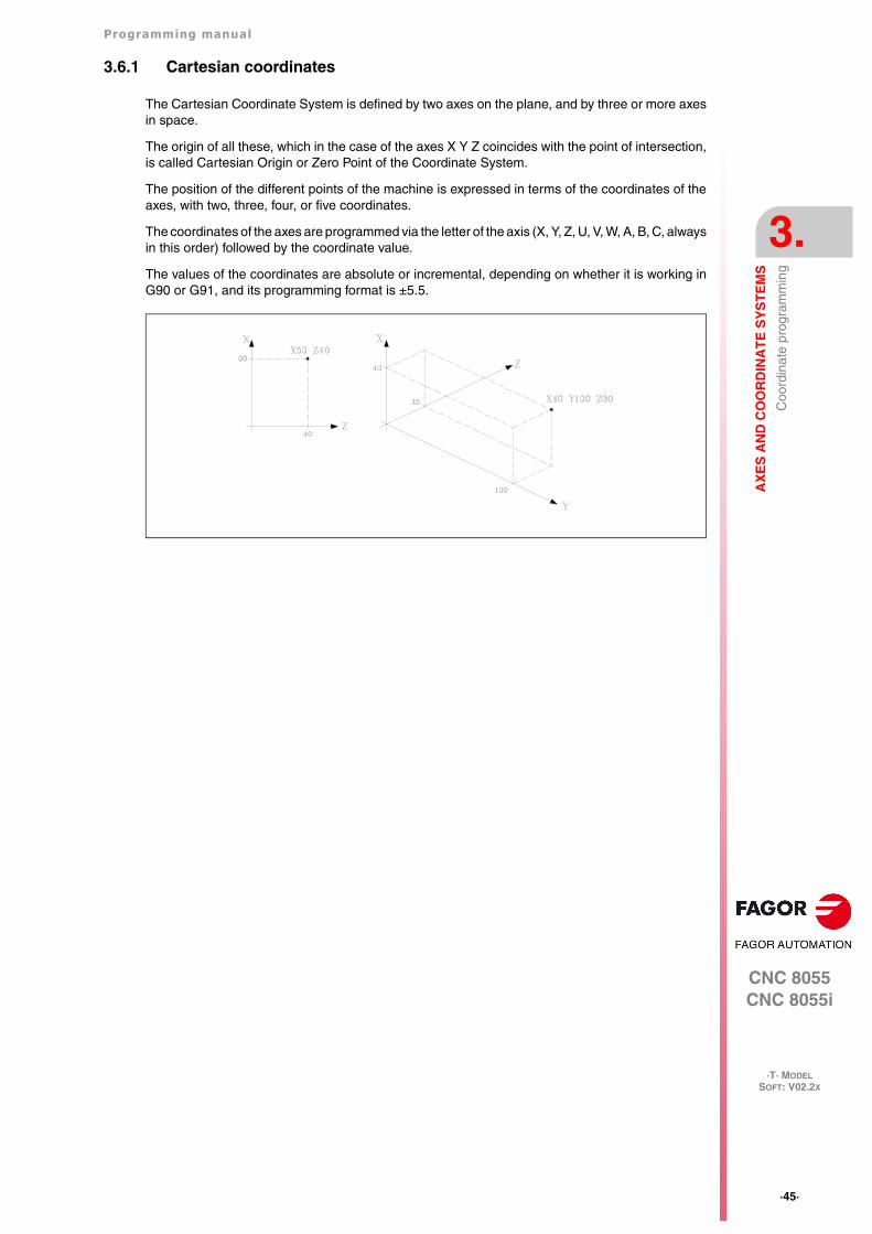
The Cartesian Coordinate System is defined by two axes on the plane, and by three or more axesin space.
The origin of all these, which in the case of the axes X Y Z coincides with the point of intersection,is called Cartesian Origin or Zero Point of the Coordinate System.
The position of the different points of the machine is expressed in terms of the coordinates of theaxes, with two, three, four, or five coordinates.
The coordinates of the axes are programmed via the letter of the axis (X, Y, Z, U, V, W, A, B, C, alwaysin this order) followed by the coordinate value.
The values of the coordinates are absolute or incremental, depending on whether it is working inG90 or G91, and its programming format is ±5.5.
·46·
Programming manual
CNC 8055CNC 8055i
3.
AX
ES
AN
D C
OO
RD
INA
TE
SY
ST
EM
S
·T· MODELSOFT: V02.2X
Coo
rdin
ate
prog
ram
min
g
3.6.2 Polar coordinates
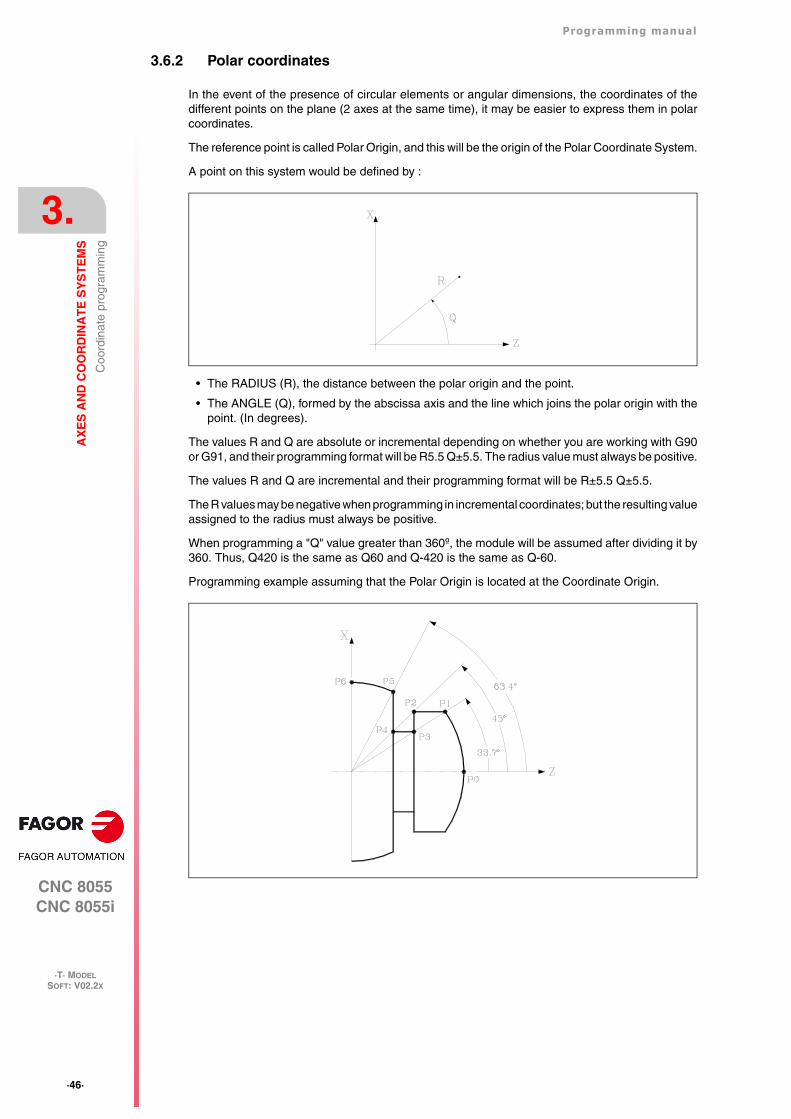
In the event of the presence of circular elements or angular dimensions, the coordinates of thedifferent points on the plane (2 axes at the same time), it may be easier to express them in polarcoordinates.
The reference point is called Polar Origin, and this will be the origin of the Polar Coordinate System.
A point on this system would be defined by :
• The RADIUS (R), the distance between the polar origin and the point.
• The ANGLE (Q), formed by the abscissa axis and the line which joins the polar origin with thepoint. (In degrees).
The values R and Q are absolute or incremental depending on whether you are working with G90or G91, and their programming format will be R5.5 Q±5.5. The radius value must always be positive.
The values R and Q are incremental and their programming format will be R±5.5 Q±5.5.
The R values may be negative when programming in incremental coordinates; but the resulting valueassigned to the radius must always be positive.
When programming a "Q" value greater than 360º, the module will be assumed after dividing it by360. Thus, Q420 is the same as Q60 and Q-420 is the same as Q-60.
Programming example assuming that the Polar Origin is located at the Coordinate Origin.
Programming manual
CNC 8055CNC 8055i
AX
ES
AN
D C
OO
RD
INA
TE
SY
ST
EM
S
3.
·T· MODELSOFT: V02.2X
·47·
Coo
rdin
ate
prog
ram
min
g
Absolute coordinates:
G90 R430 Q0 ; Point P0
G03 Q33.7 ; Point P1, in an arc (G03)
G01 R340 Q45 ; Point P2, in a straight line (G01)
G01 R290 Q33.7 ; Point P3, in a straight line (G01)
G01 R230 Q45 ; Point P4, in a straight line (G01)
G01 R360 Q63.4 ; Point P5, in a straight line (G01)
G03 Q90 ; Point P6, in arc (G03)
Incremental coordinates:
G90 R430 Q0 ; Point 0
G91 G03 Q33.7 ; Point P1, in an arc (G03)
G01 R-90 Q11.3 ; Point P2, in a straight line (G01)
G01 R-50 Q-11.3 ; Point P3, in a straight line (G01)
G01 R-60 Q11.3 ; Point P4, in a straight line (G01)
G01 R130 Q18.4 ; Point P5, in a straight line (G01)
G03 Q26.6 ; Point P6, in arc (G03)
The polar origin, apart from being able to be preset using function G93 (described later) can bemodified in the following cases :
• On power-up, after executing M02, M30 EMERGENCY or RESET, the CNC will assume, as thepolar origin, the coordinate origin of the work plane defined by the general machineparameter"IPLANE".
• Every time the work plane is changed (G16,G17,G18 or G19), the CNC assumes the coordinateorigin of the new work plane selected as the polar origin.
• When executing a circular interpolation (G02 or G03), and if the general machine parameter"PORGMOVE" has a value of 1, the center of the arc will become the new polar origin.
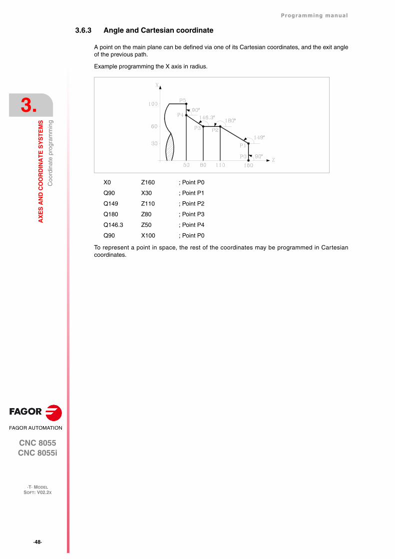
·48·
Programming manual
CNC 8055CNC 8055i
3.
AX
ES
AN
D C
OO
RD
INA
TE
SY
ST
EM
S
·T· MODELSOFT: V02.2X
Coo
rdin
ate
prog
ram
min
g
3.6.3 Angle and Cartesian coordinate
A point on the main plane can be defined via one of its Cartesian coordinates, and the exit angleof the previous path.
Example programming the X axis in radius.
X0 Z160 ; Point P0
Q90 X30 ; Point P1
Q149 Z110 ; Point P2
Q180 Z80 ; Point P3
Q146.3 Z50 ; Point P4
Q90 X100 ; Point P0
To represent a point in space, the rest of the coordinates may be programmed in Cartesiancoordinates.
Programming manual
CNC 8055CNC 8055i
AX
ES
AN
D C
OO
RD
INA
TE
SY
ST
EM
S
3.
·T· MODELSOFT: V02.2X
·49·
Rot
ary
axes
3.7 Rotary axes
The types of rotary axes available are:
Normal rotary axis.
Positioning-only rotary axis.
Rotary HIRTH axis.
Each one of them can be divided into:
Rollover When it is displayed between 0º and 360º.
Non Rollover When it may be displayed between -99999º and 99999º.
They are all programmed in degrees. Therefore, their readings are not affected by the inch/mmconversion.
Normal rotary axes
They can interpolate with linear axes.
Movement: In G00 and G01.
Rollover axis programming:
G90 The sign indicates the turning direction and the target position (between 0 and359.9999).
G91 The sign indicates the turning direction. If the programmed movement exceeds360º, the axis will rotate more than one turn before positioning at the desired point.
Non-rollover axis programming.
In G90 and G91 like a linear axis.
Positioning-only rotary axis
They cannot be interpolated with linear axes.
Movement: Always in G00 and they do not admit tool radius compensation (G41, G42).
Rollover axis programming:
G90 Always positive and in the shortest direction. End coordinate between 0 and359.9999.
G91 The sign indicates the turning direction. If the programmed movement exceeds360º, the axis will rotate more than one turn before positioning at the desired point.
Non-rollover axis programming.
In G90 and G91 like a linear axis.
Rotary Hirth axis
They work like the positioning-only axis except that they do not admit decimal position values(coordinates).
More than one hirth axis can be used, but they can only be moved one at a time.
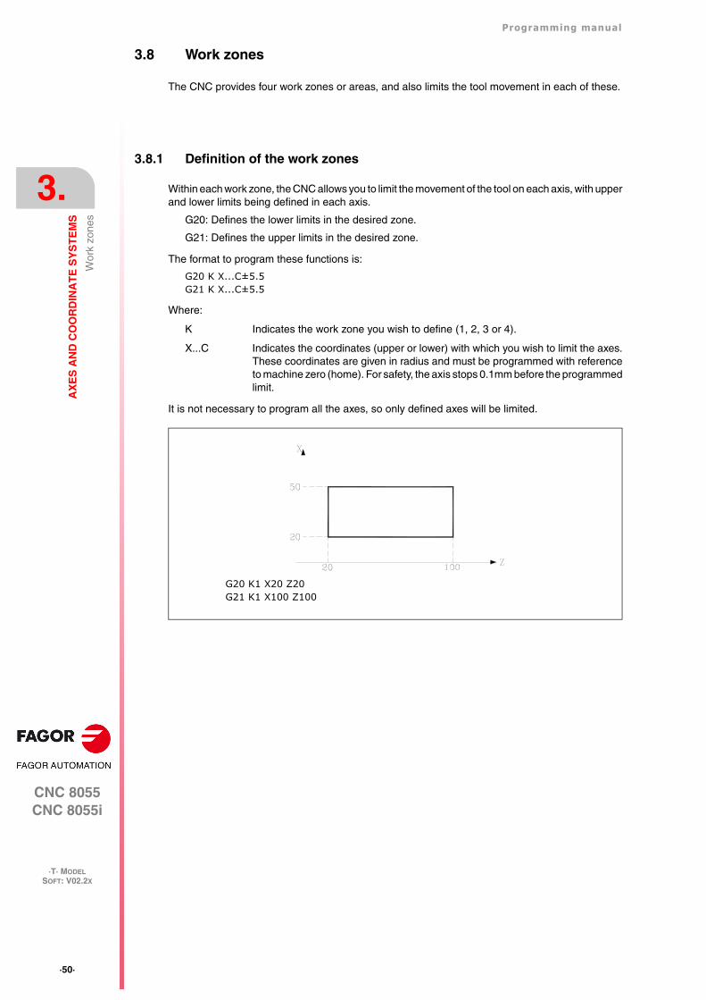
·50·
Programming manual
CNC 8055CNC 8055i
3.
AX
ES
AN
D C
OO
RD
INA
TE
SY
ST
EM
S
·T· MODELSOFT: V02.2X
Wor
k zo
nes
3.8 Work zones
The CNC provides four work zones or areas, and also limits the tool movement in each of these.
3.8.1 Definition of the work zones
Within each work zone, the CNC allows you to limit the movement of the tool on each axis, with upperand lower limits being defined in each axis.
G20: Defines the lower limits in the desired zone.
G21: Defines the upper limits in the desired zone.
The format to program these functions is:
G20 K X...C±5.5G21 K X...C±5.5
Where:
K Indicates the work zone you wish to define (1, 2, 3 or 4).
X...C Indicates the coordinates (upper or lower) with which you wish to limit the axes.These coordinates are given in radius and must be programmed with referenceto machine zero (home). For safety, the axis stops 0.1mm before the programmedlimit.
It is not necessary to program all the axes, so only defined axes will be limited.
G20 K1 X20 Z20G21 K1 X100 Z100
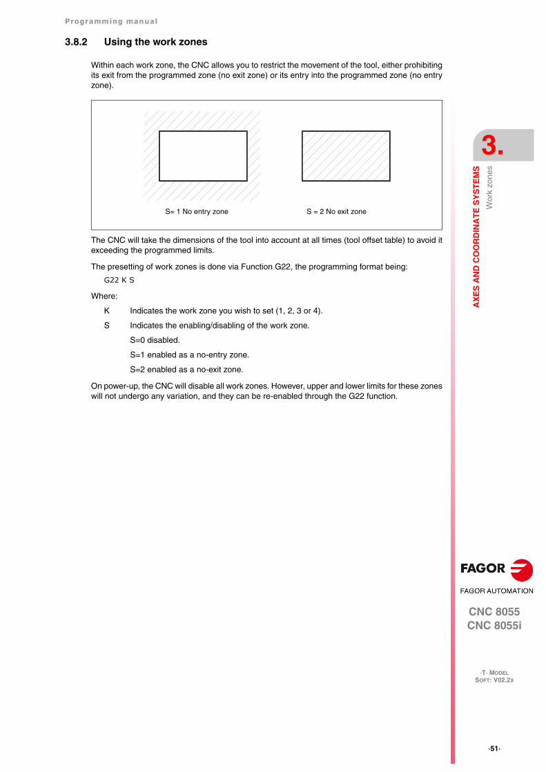
Programming manual
CNC 8055CNC 8055i
AX
ES
AN
D C
OO
RD
INA
TE
SY
ST
EM
S
3.
·T· MODELSOFT: V02.2X
·51·
Wor
k zo
nes
3.8.2 Using the work zones
Within each work zone, the CNC allows you to restrict the movement of the tool, either prohibitingits exit from the programmed zone (no exit zone) or its entry into the programmed zone (no entryzone).
The CNC will take the dimensions of the tool into account at all times (tool offset table) to avoid itexceeding the programmed limits.
The presetting of work zones is done via Function G22, the programming format being:
G22 K S
Where:
K Indicates the work zone you wish to set (1, 2, 3 or 4).
S Indicates the enabling/disabling of the work zone.
S=0 disabled.
S=1 enabled as a no-entry zone.
S=2 enabled as a no-exit zone.
On power-up, the CNC will disable all work zones. However, upper and lower limits for these zoneswill not undergo any variation, and they can be re-enabled through the G22 function.
S= 1 No entry zone S = 2 No exit zone
·52·
Programming manual
CNC 8055CNC 8055i
3.
AX
ES
AN
D C
OO
RD
INA
TE
SY
ST
EM
S
·T· MODELSOFT: V02.2X
Wor
k zo
nes
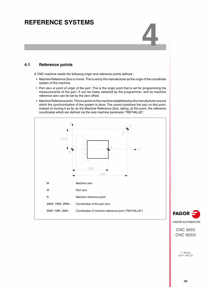
CNC 8055CNC 8055i
·T· MODELSOFT: V02.2X
4
·53·
REFERENCE SYSTEMS
4.1 Reference points
A CNC machine needs the following origin and reference points defined :
• Machine Reference Zero or home. This is set by the manufacturer as the origin of the coordinatesystem of the machine.
• Part zero or point of origin of the part. This is the origin point that is set for programming themeasurements of the part. It can be freely selected by the programmer, and its machinereference zero can be set by the zero offset.
• Machine Reference point. This is a point on the machine established by the manufacturer aroundwhich the synchronization of the system is done. The control positions the axis on this point,instead of moving it as far as the Machine Reference Zero, taking, at this point, the referencecoordinates which are defined via the axis machine parameter "REFVALUE".
M Machine zero
W Part zero
R Machine reference point
XMW, YMW, ZMW... Coordinates of the part zero
XMR, YMR, ZMR... Coordinates of machine reference point ("REFVALUE")
·54·
Programming manual
CNC 8055CNC 8055i
4.
RE
FE
RE
NC
E S
YS
TE
MS
·T· MODELSOFT: V02.2X
Mac
hine
ref
eren
ce (
Hom
e) s
earc
h (G
74)
4.2 Machine reference (Home) search (G74)
The CNC allows you to program the machine reference search in two ways :
• Machine reference (home) search of one or more axes in a particular order.
G74 is programmed followed by the axes in which you want to carry out the reference search.For example: G74 X Z.
The CNC begins the movement of all the selected axes which have a machine reference switch(machine axis parameter "DECINPUT") and in the direction indicated by the axis machineparameter "REFDIREC".
This movement is carried out at the feedrate indicated by the axis machine parameter"REFEED1" for each axis until the home switch is hit.
Next, the home search (marker pulse or home) will be carried out in the programmed order.
This second movement will be carried out one axis at a time, at the feedrate indicated in the axismachine parameter "REFEED2" until the machine reference point is reached (i.e. the markerpulse is found).
• Home search using the associated subroutine.
The G74 function will be programmed alone in the block, and the CNC will automatically executethe subroutine whose number appears in the general machine parameter "REFPSUB". In thissubroutine it is possible to program the machine reference searches required, and also in therequired order.
In a block in which G74 has been programmed, no other preparatory function may appear.
If the machine reference search is done in JOG mode, the part zero selected is lost. The coordinatesof the reference point indicated in the machine axis parameter "REFVALUE" is displayed. In all othercases, the active part zero will be maintained and the CNC will display the position values withrespect to that part zero.
If the G74 command is executed in MDI, the display of coordinates depends on the mode in whichit is executed : Jog, Execution, or Simulation.
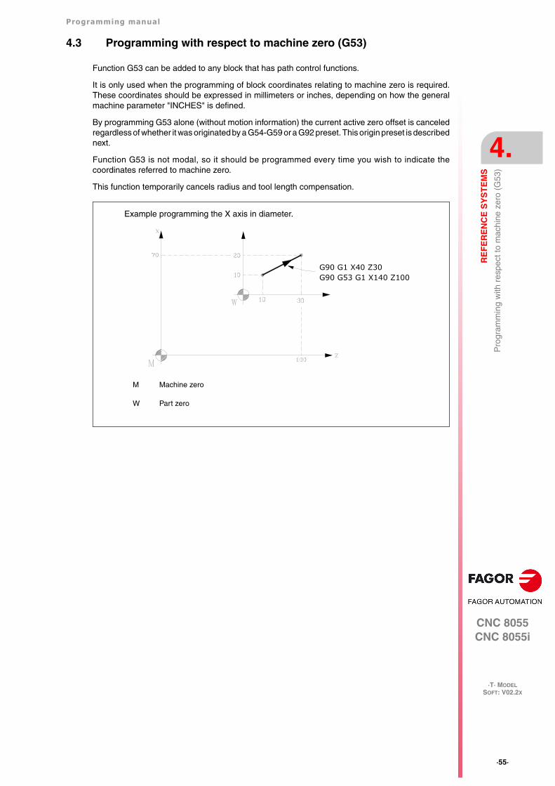
Programming manual
CNC 8055CNC 8055i
RE
FE
RE
NC
E S
YS
TE
MS
4.
·T· MODELSOFT: V02.2X
·55·
Pro
gram
min
g w
ith r
espe
ct to
mac
hine
zer
o (G
53)
4.3 Programming with respect to machine zero (G53)
Function G53 can be added to any block that has path control functions.
It is only used when the programming of block coordinates relating to machine zero is required.These coordinates should be expressed in millimeters or inches, depending on how the generalmachine parameter "INCHES" is defined.
By programming G53 alone (without motion information) the current active zero offset is canceledregardless of whether it was originated by a G54-G59 or a G92 preset. This origin preset is describednext.
Function G53 is not modal, so it should be programmed every time you wish to indicate thecoordinates referred to machine zero.
This function temporarily cancels radius and tool length compensation.
M Machine zero
W Part zero
Example programming the X axis in diameter.
G90 G1 X40 Z30G90 G53 G1 X140 Z100
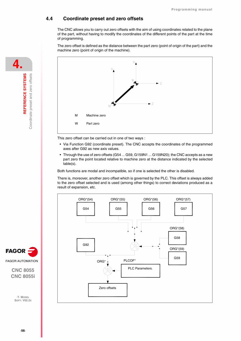
·56·
Programming manual
CNC 8055CNC 8055i
4.
RE
FE
RE
NC
E S
YS
TE
MS
·T· MODELSOFT: V02.2X
Coo
rdin
ate
pres
et a
nd z
ero
offs
ets
4.4 Coordinate preset and zero offsets
The CNC allows you to carry out zero offsets with the aim of using coordinates related to the planeof the part, without having to modify the coordinates of the different points of the part at the timeof programming.
The zero offset is defined as the distance between the part zero (point of origin of the part) and themachine zero (point of origin of the machine).
This zero offset can be carried out in one of two ways :
• Via Function G92 (coordinate preset). The CNC accepts the coordinates of the programmedaxes after G92 as new axis values.
• Through the use of zero offsets (G54 ... G59, G159N1 ... G159N20); the CNC accepts as a newpart zero the point located relative to machine zero at the distance indicated by the selectedtable(s).
Both functions are modal and incompatible, so if one is selected the other is disabled.
There is, moreover, another zero offset which is governed by the PLC. This offset is always addedto the zero offset selected and is used (among other things) to correct deviations produced as aresult of expansion, etc.
M Machine zero
W Part zero
Zero offsets
PLC Parameters.
G59
G58
G92ORG*(59)
ORG*(58)
ORG* PLCOF*
ORG*(54) ORG*(55) ORG*(56) ORG*(57)
G54 G55 G56 G57
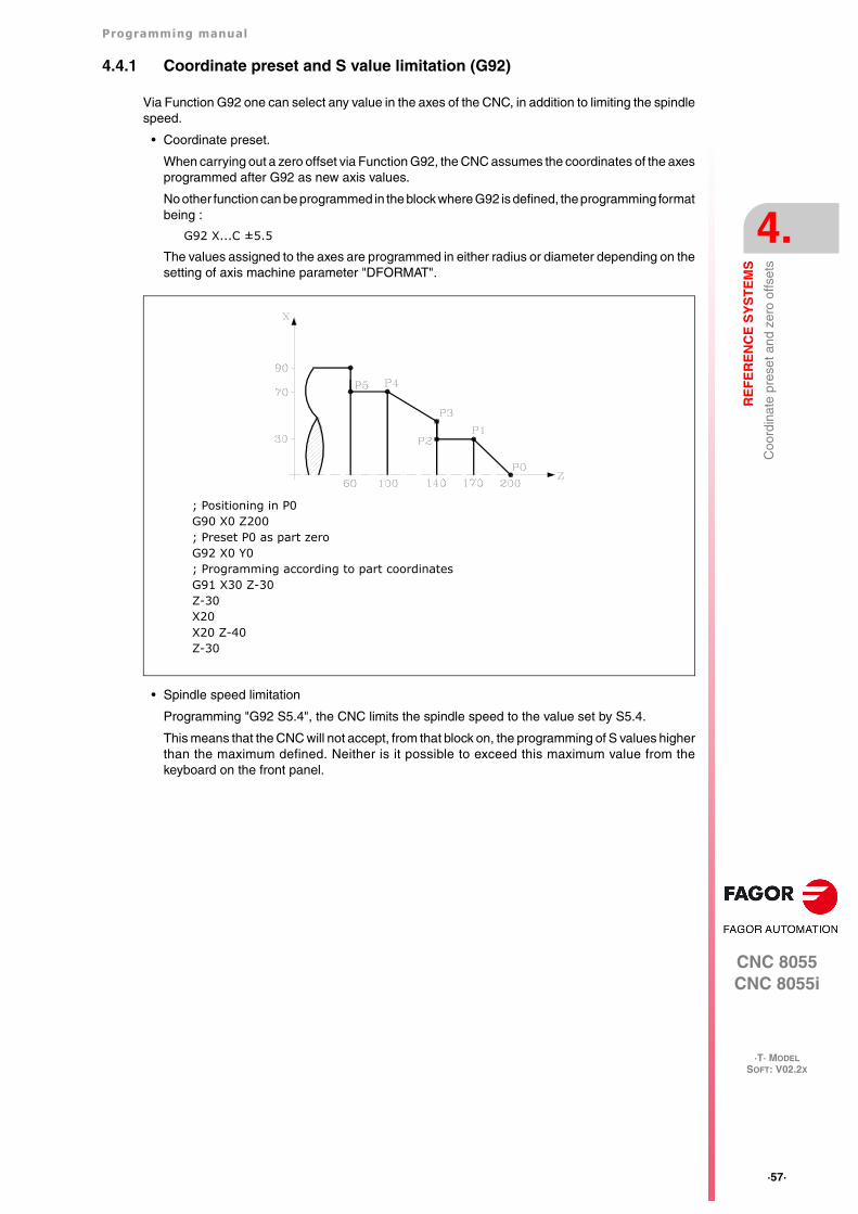
Programming manual
CNC 8055CNC 8055i
RE
FE
RE
NC
E S
YS
TE
MS
4.
·T· MODELSOFT: V02.2X
·57·
Coo
rdin
ate
pres
et a
nd z
ero
offs
ets
4.4.1 Coordinate preset and S value limitation (G92)
Via Function G92 one can select any value in the axes of the CNC, in addition to limiting the spindlespeed.
• Coordinate preset.
When carrying out a zero offset via Function G92, the CNC assumes the coordinates of the axesprogrammed after G92 as new axis values.
No other function can be programmed in the block where G92 is defined, the programming formatbeing :
G92 X...C ±5.5
The values assigned to the axes are programmed in either radius or diameter depending on thesetting of axis machine parameter "DFORMAT".
• Spindle speed limitation
Programming "G92 S5.4", the CNC limits the spindle speed to the value set by S5.4.
This means that the CNC will not accept, from that block on, the programming of S values higherthan the maximum defined. Neither is it possible to exceed this maximum value from thekeyboard on the front panel.
; Positioning in P0G90 X0 Z200; Preset P0 as part zeroG92 X0 Y0; Programming according to part coordinatesG91 X30 Z-30Z-30X20X20 Z-40Z-30
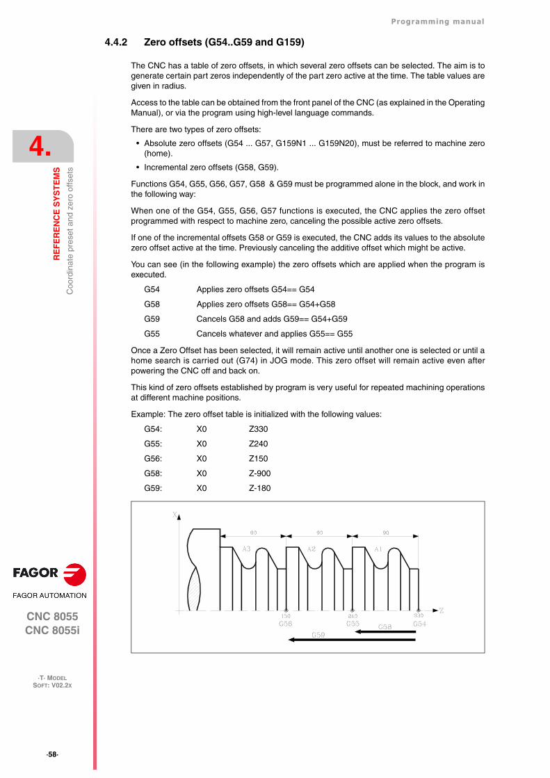
·58·
Programming manual
CNC 8055CNC 8055i
4.
RE
FE
RE
NC
E S
YS
TE
MS
·T· MODELSOFT: V02.2X
Coo
rdin
ate
pres
et a
nd z
ero
offs
ets
4.4.2 Zero offsets (G54..G59 and G159)
The CNC has a table of zero offsets, in which several zero offsets can be selected. The aim is togenerate certain part zeros independently of the part zero active at the time. The table values aregiven in radius.
Access to the table can be obtained from the front panel of the CNC (as explained in the OperatingManual), or via the program using high-level language commands.
There are two types of zero offsets:
• Absolute zero offsets (G54 ... G57, G159N1 ... G159N20), must be referred to machine zero(home).
• Incremental zero offsets (G58, G59).
Functions G54, G55, G56, G57, G58 & G59 must be programmed alone in the block, and work inthe following way:
When one of the G54, G55, G56, G57 functions is executed, the CNC applies the zero offsetprogrammed with respect to machine zero, canceling the possible active zero offsets.
If one of the incremental offsets G58 or G59 is executed, the CNC adds its values to the absolutezero offset active at the time. Previously canceling the additive offset which might be active.
You can see (in the following example) the zero offsets which are applied when the program isexecuted.
G54 Applies zero offsets G54== G54
G58 Applies zero offsets G58== G54+G58
G59 Cancels G58 and adds G59== G54+G59
G55 Cancels whatever and applies G55== G55
Once a Zero Offset has been selected, it will remain active until another one is selected or until ahome search is carried out (G74) in JOG mode. This zero offset will remain active even afterpowering the CNC off and back on.
This kind of zero offsets established by program is very useful for repeated machining operationsat different machine positions.
Example: The zero offset table is initialized with the following values:
G54: X0 Z330
G55: X0 Z240
G56: X0 Z150
G58: X0 Z-900
G59: X0 Z-180
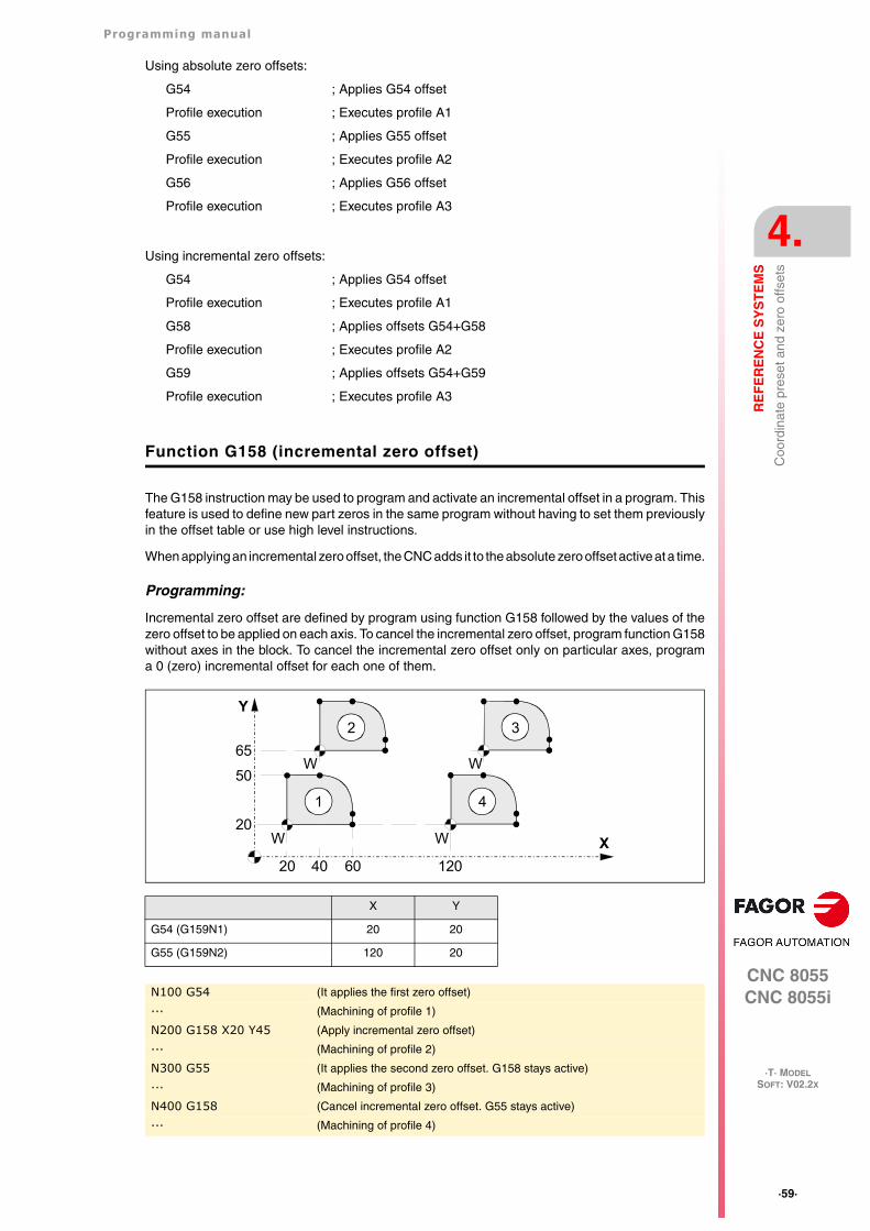
Programming manual
CNC 8055CNC 8055i
RE
FE
RE
NC
E S
YS
TE
MS
4.
·T· MODELSOFT: V02.2X
·59·
Coo
rdin
ate
pres
et a
nd z
ero
offs
ets
Using absolute zero offsets:
G54 ; Applies G54 offset
Profile execution ; Executes profile A1
G55 ; Applies G55 offset
Profile execution ; Executes profile A2
G56 ; Applies G56 offset
Profile execution ; Executes profile A3
Using incremental zero offsets:
G54 ; Applies G54 offset
Profile execution ; Executes profile A1
G58 ; Applies offsets G54+G58
Profile execution ; Executes profile A2
G59 ; Applies offsets G54+G59
Profile execution ; Executes profile A3
Function G158 (incremental zero offset)
The G158 instruction may be used to program and activate an incremental offset in a program. Thisfeature is used to define new part zeros in the same program without having to set them previouslyin the offset table or use high level instructions.
When applying an incremental zero offset, the CNC adds it to the absolute zero offset active at a time.
Programming:
Incremental zero offset are defined by program using function G158 followed by the values of thezero offset to be applied on each axis. To cancel the incremental zero offset, program function G158without axes in the block. To cancel the incremental zero offset only on particular axes, programa 0 (zero) incremental offset for each one of them.
X Y
G54 (G159N1) 20 20
G55 (G159N2) 120 20
N100 G54 (It applies the first zero offset)
··· (Machining of profile 1)
N200 G158 X20 Y45 (Apply incremental zero offset)
··· (Machining of profile 2)
N300 G55 (It applies the second zero offset. G158 stays active)
··· (Machining of profile 3)
N400 G158 (Cancel incremental zero offset. G55 stays active)
··· (Machining of profile 4)
Y
X
65
W
WW
W
50
20
20 40 60 120
1
2 3
4
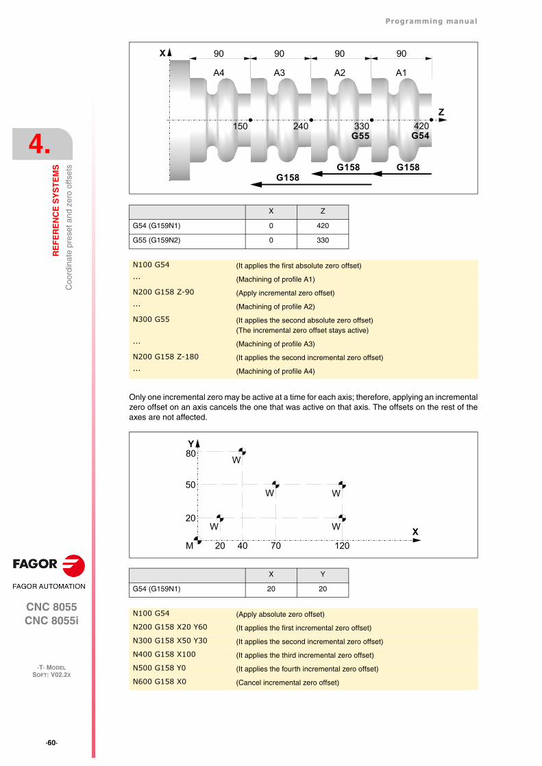
·60·
Programming manual
CNC 8055CNC 8055i
4.
RE
FE
RE
NC
E S
YS
TE
MS
·T· MODELSOFT: V02.2X
Coo
rdin
ate
pres
et a
nd z
ero
offs
ets
Only one incremental zero may be active at a time for each axis; therefore, applying an incrementalzero offset on an axis cancels the one that was active on that axis. The offsets on the rest of theaxes are not affected.
X Z
G54 (G159N1) 0 420
G55 (G159N2) 0 330
N100 G54 (It applies the first absolute zero offset)
··· (Machining of profile A1)
N200 G158 Z-90 (Apply incremental zero offset)
··· (Machining of profile A2)
N300 G55 (It applies the second absolute zero offset)(The incremental zero offset stays active)
··· (Machining of profile A3)
N200 G158 Z-180 (It applies the second incremental zero offset)
··· (Machining of profile A4)
X Y
G54 (G159N1) 20 20
N100 G54 (Apply absolute zero offset)
N200 G158 X20 Y60 (It applies the first incremental zero offset)
N300 G158 X50 Y30 (It applies the second incremental zero offset)
N400 G158 X100 (It applies the third incremental zero offset)
N500 G158 Y0 (It applies the fourth incremental zero offset)
N600 G158 X0 (Cancel incremental zero offset)
X
Z
90 9090
150 240 330
A2A3A4
90
A1
420G54
G158G158
G55
G158
Y
X
80
W
50
20
20 40 70 120
WW
W
W
M
Programming manual
CNC 8055CNC 8055i
RE
FE
RE
NC
E S
YS
TE
MS
4.
·T· MODELSOFT: V02.2X
·61·
Coo
rdin
ate
pres
et a
nd z
ero
offs
ets
The incremental zero offset is not canceled after applying a new absolute zero offset (G54-G57or G159Nx).
As described earlier, only one incremental zero offset may be active; therefore, instructions G58and G59 are incompatible with G158. This way, the last incremental zero offset programmedcancels the incremental zero offset that is currently active.
Programming the G158 function alone in the block or G158 with a 0 value in the axes cancels theincremental zero offset G158 activated earlier. Those instructions also cancel the incremental zerooffsets G58/G59 that are currently active.
Considerations:
An incremental zero offset, by itself, does not cause any axis movement.
When homing an axis in JOG mode, the incremental zero offset for that axis is canceled.
Function properties:
G158 is modal and incompatible with G53.
On power-up, the CNC assumes the incremental zero offset that was active when the CNC wasturned off. On the other hand, the incremental zero offset is neither affected by functions M02 andM30 nor by RESETTING the CNC.
Display in the zero offset table:
In ISO mode and conversational mode, the zero offset table is one line over the the G54 positionwhere it identifies the G158 with its values X, Y, Z, etc.
This line cannot be modified from the table, it can only be modified by programming G158.
Function G159
To apply any zero offset defined in the table.
The first six zero offsets are the same as programming G54 through G59, except that the valuesof G58 and G59 are absolute. This is because function G159 cancels functions G54 through G57and, consequently, there is no active zero offset to add the G58 or G59 to.
Function G159 is programmed as follows:
G159 Nn Where n is a number from 1 to 20 that indicates the number of the zero offset beingapplied.
Function G159 is modal, it is programmed alone in the block and is incompatible with functions G53,G54, G55, G56, G57, G58, G59 and G92.
On power-up, the CNC assumes the zero offset that was active when the CNC was turned off. Onthe other hand, the zero offset is neither affected by functions M02 and M30 nor by RESET.
This function is displayed in the history like G159Nn where the n is the active zero offset.
Examples:
G159 N1 It applies the first zero offset. It is the same as programming G54.
G159 N6 It applies the sixth zero offset. It is the same as programming G59, but it is appliedin absolute.
G159 N20 It applies the 20th zero offset.
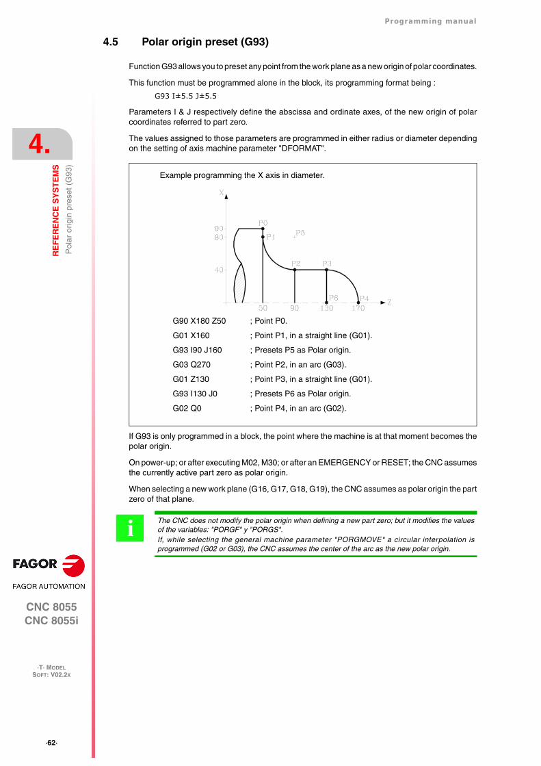
·62·
Programming manual
CNC 8055CNC 8055i
4.
RE
FE
RE
NC
E S
YS
TE
MS
·T· MODELSOFT: V02.2X
Pol
ar o
rigin
pre
set (
G93
)
4.5 Polar origin preset (G93)
Function G93 allows you to preset any point from the work plane as a new origin of polar coordinates.
This function must be programmed alone in the block, its programming format being :
G93 I±5.5 J±5.5
Parameters I & J respectively define the abscissa and ordinate axes, of the new origin of polarcoordinates referred to part zero.
The values assigned to those parameters are programmed in either radius or diameter dependingon the setting of axis machine parameter "DFORMAT".
If G93 is only programmed in a block, the point where the machine is at that moment becomes thepolar origin.
On power-up; or after executing M02, M30; or after an EMERGENCY or RESET; the CNC assumesthe currently active part zero as polar origin.
When selecting a new work plane (G16, G17, G18, G19), the CNC assumes as polar origin the partzero of that plane.
G90 X180 Z50 ; Point P0.
G01 X160 ; Point P1, in a straight line (G01).
G93 I90 J160 ; Presets P5 as Polar origin.
G03 Q270 ; Point P2, in an arc (G03).
G01 Z130 ; Point P3, in a straight line (G01).
G93 I130 J0 ; Presets P6 as Polar origin.
G02 Q0 ; Point P4, in an arc (G02).
Example programming the X axis in diameter.
The CNC does not modify the polar origin when defining a new part zero; but it modifies the valuesof the variables: "PORGF" y "PORGS".If, while selecting the general machine parameter "PORGMOVE" a circular interpolation isprogrammed (G02 or G03), the CNC assumes the center of the arc as the new polar origin.
i
CNC 8055CNC 8055i
·T· MODELSOFT: V02.2X
5
·63·
ISO CODE PROGRAMMING
A block programmed in ISO language can consist of:
• Preparatory (G) functions
• Axis coordinates (X...C)
• Feedrate (F)
• Spindle speed (S)
• Tool number (T)
• Tool offset number (D)
• Auxiliary functions (M)
This order should be maintained within each block, although it is not necessary for every block tocontain the information.
The CNC allows you to program figures from 0.00001 to 99999.9999 with or without sign, workingin millimeters (G71), called format +/-5.4, or either from 0.00001 to 3937.00787 with or without signif the programming is done in inches (G70), called format +/-4.5.
However, and to simplify the instructions, we can say that the CNC admits +/- 5.5 format, therebyadmitting +/- 5.4 in millimeters and +/- 4.5 in inches.
Any function with parameters can also be programmed in a block, apart from the number of the labelor block. Thus, when the block is executed the CNC substitutes the arithmetic parameter for its valueat that time.
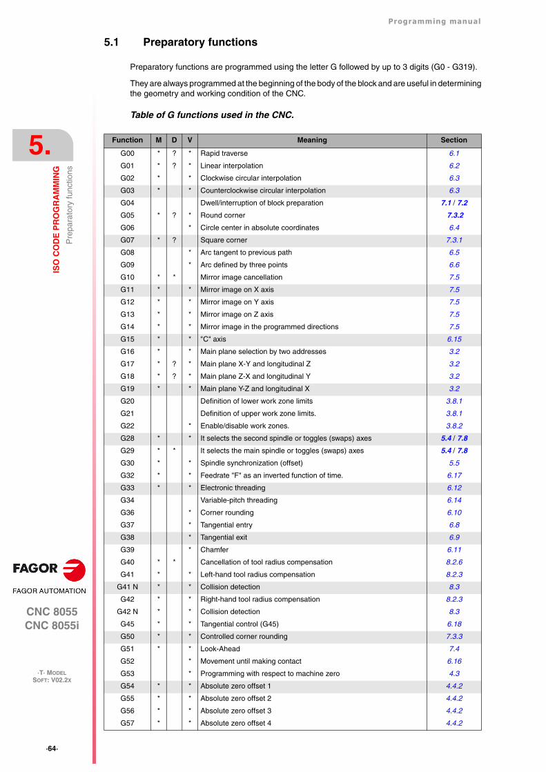
·64·
Programming manual
CNC 8055CNC 8055i
5.
ISO
CO
DE
PR
OG
RA
MM
ING
·T· MODELSOFT: V02.2X
Pre
para
tory
func
tions
5.1 Preparatory functions
Preparatory functions are programmed using the letter G followed by up to 3 digits (G0 - G319).
They are always programmed at the beginning of the body of the block and are useful in determiningthe geometry and working condition of the CNC.
Table of G functions used in the CNC.
Function M D V Meaning Section
G00 * ? * Rapid traverse 6.1
G01 * ? * Linear interpolation 6.2
G02 * * Clockwise circular interpolation 6.3
G03 * * Counterclockwise circular interpolation 6.3
G04 Dwell/interruption of block preparation 7.1 / 7.2
G05 * ? * Round corner 7.3.2
G06 * Circle center in absolute coordinates 6.4
G07 * ? Square corner 7.3.1
G08 * Arc tangent to previous path 6.5
G09 * Arc defined by three points 6.6
G10 * * Mirror image cancellation 7.5
G11 * * Mirror image on X axis 7.5
G12 * * Mirror image on Y axis 7.5
G13 * * Mirror image on Z axis 7.5
G14 * * Mirror image in the programmed directions 7.5
G15 * * "C" axis 6.15
G16 * * Main plane selection by two addresses 3.2
G17 * ? * Main plane X-Y and longitudinal Z 3.2
G18 * ? * Main plane Z-X and longitudinal Y 3.2
G19 * * Main plane Y-Z and longitudinal X 3.2
G20 Definition of lower work zone limits 3.8.1
G21 Definition of upper work zone limits. 3.8.1
G22 * Enable/disable work zones. 3.8.2
G28 * * It selects the second spindle or toggles (swaps) axes 5.4 / 7.8
G29 * * It selects the main spindle or toggles (swaps) axes 5.4 / 7.8
G30 * * Spindle synchronization (offset) 5.5
G32 * * Feedrate "F" as an inverted function of time. 6.17
G33 * * Electronic threading 6.12
G34 Variable-pitch threading 6.14
G36 * Corner rounding 6.10
G37 * Tangential entry 6.8
G38 * Tangential exit 6.9
G39 * Chamfer 6.11
G40 * * Cancellation of tool radius compensation 8.2.6
G41 * * Left-hand tool radius compensation 8.2.3
G41 N * * Collision detection 8.3
G42 * * Right-hand tool radius compensation 8.2.3
G42 N * * Collision detection 8.3
G45 * * Tangential control (G45) 6.18
G50 * * Controlled corner rounding 7.3.3
G51 * * Look-Ahead 7.4
G52 * Movement until making contact 6.16
G53 * Programming with respect to machine zero 4.3
G54 * * Absolute zero offset 1 4.4.2
G55 * * Absolute zero offset 2 4.4.2
G56 * * Absolute zero offset 3 4.4.2
G57 * * Absolute zero offset 4 4.4.2
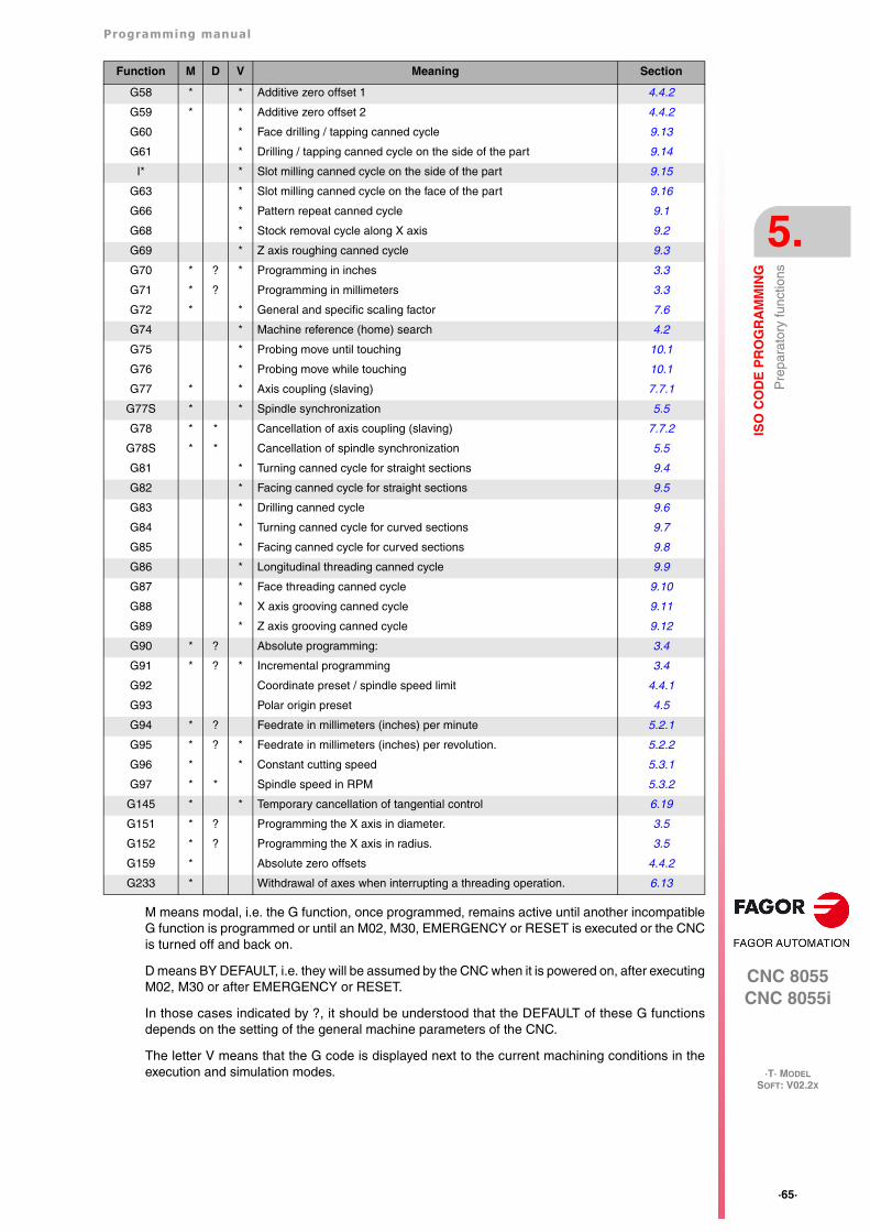
Programming manual
CNC 8055CNC 8055i
ISO
CO
DE
PR
OG
RA
MM
ING
5.
·T· MODELSOFT: V02.2X
·65·
Pre
para
tory
func
tions
M means modal, i.e. the G function, once programmed, remains active until another incompatibleG function is programmed or until an M02, M30, EMERGENCY or RESET is executed or the CNCis turned off and back on.
D means BY DEFAULT, i.e. they will be assumed by the CNC when it is powered on, after executingM02, M30 or after EMERGENCY or RESET.
In those cases indicated by ?, it should be understood that the DEFAULT of these G functionsdepends on the setting of the general machine parameters of the CNC.
The letter V means that the G code is displayed next to the current machining conditions in theexecution and simulation modes.
G58 * * Additive zero offset 1 4.4.2
G59 * * Additive zero offset 2 4.4.2
G60 * Face drilling / tapping canned cycle 9.13
G61 * Drilling / tapping canned cycle on the side of the part 9.14
I* * Slot milling canned cycle on the side of the part 9.15
G63 * Slot milling canned cycle on the face of the part 9.16
G66 * Pattern repeat canned cycle 9.1
G68 * Stock removal cycle along X axis 9.2
G69 * Z axis roughing canned cycle 9.3
G70 * ? * Programming in inches 3.3
G71 * ? Programming in millimeters 3.3
G72 * * General and specific scaling factor 7.6
G74 * Machine reference (home) search 4.2
G75 * Probing move until touching 10.1
G76 * Probing move while touching 10.1
G77 * * Axis coupling (slaving) 7.7.1
G77S * * Spindle synchronization 5.5
G78 * * Cancellation of axis coupling (slaving) 7.7.2
G78S * * Cancellation of spindle synchronization 5.5
G81 * Turning canned cycle for straight sections 9.4
G82 * Facing canned cycle for straight sections 9.5
G83 * Drilling canned cycle 9.6
G84 * Turning canned cycle for curved sections 9.7
G85 * Facing canned cycle for curved sections 9.8
G86 * Longitudinal threading canned cycle 9.9
G87 * Face threading canned cycle 9.10
G88 * X axis grooving canned cycle 9.11
G89 * Z axis grooving canned cycle 9.12
G90 * ? Absolute programming: 3.4
G91 * ? * Incremental programming 3.4
G92 Coordinate preset / spindle speed limit 4.4.1
G93 Polar origin preset 4.5
G94 * ? Feedrate in millimeters (inches) per minute 5.2.1
G95 * ? * Feedrate in millimeters (inches) per revolution. 5.2.2
G96 * * Constant cutting speed 5.3.1
G97 * * Spindle speed in RPM 5.3.2
G145 * * Temporary cancellation of tangential control 6.19
G151 * ? Programming the X axis in diameter. 3.5
G152 * ? Programming the X axis in radius. 3.5
G159 * Absolute zero offsets 4.4.2
G233 * Withdrawal of axes when interrupting a threading operation. 6.13
Function M D V Meaning Section
·66·
Programming manual
CNC 8055CNC 8055i
5.
ISO
CO
DE
PR
OG
RA
MM
ING
·T· MODELSOFT: V02.2X
Fee
drat
e F
5.2 Feedrate F
The machining feedrate can be selected from the program. It remains active until another feedrateis programmed. It is represented by the letter F and Depending on whether it is working in G94 orG95, it is programmed in mm/minute (inches/minute) or in mm/revolution (inches/revolution).
Its programming format is 5.5; in other words, 5.4 when programmed in mm and 4.5 whenprogrammed in inches.
The maximum operating feedrate of the machine, limited on each axis by the axis machineparameter "MAXFEED", may be programmed via code F0, or by giving F the corresponding value.
The programmed feedrate F is effective working in linear (G01) or circular (G02, G03) interpolation.If function F is not programmed, the CNC assumes the feedrate to be F0. When working in rapidtravel (G00), the machine will move at the rapid feedrate indicated by the axis machine parameter"G00FEED", apart from the F programmed.
The programmed feedrate F may be varied between 0% and 255% via the PLC, or by DNC, orbetween 0% and 120% via the switch located on the Operator Panel of the CNC.
The CNC, however, is equipped with the general machine parameter "MAXFOVR" to limit maximumfeedrate variation.
If you are working in rapid travel (G00), rapid feedrate will be fixed at 100%, alternatively it can bevaried between 0% and 100%, depending on how the machine parameter "RAPIDOVR" is set.
When functions G33 (electronic threading), G34 (variable-pitch threading), G86 (longitudinalthreading canned cycle) or G87 (face threading canned cycle) are executed the feedrate cannot bemodified; it works at 100% of programmed F.
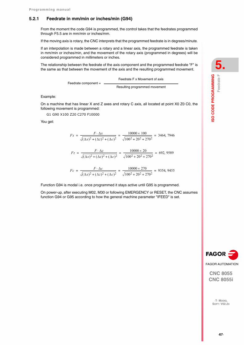
Programming manual
CNC 8055CNC 8055i
ISO
CO
DE
PR
OG
RA
MM
ING
5.
·T· MODELSOFT: V02.2X
·67·
Fee
drat
e F
5.2.1 Feedrate in mm/min or inches/min (G94)
From the moment the code G94 is programmed, the control takes that the feedrates programmedthrough F5.5 are in mm/min or inches/mm.
If the moving axis is rotary, the CNC interprets that the programmed feedrate is in degrees/minute.
If an interpolation is made between a rotary and a linear axis, the programmed feedrate is takenin mm/min or inches/min, and the movement of the rotary axis (programmed in degrees) will beconsidered programmed in millimeters or inches.
The relationship between the feedrate of the axis component and the programmed feedrate "F" isthe same as that between the movement of the axis and the resulting programmed movement.
Example:
On a machine that has linear X and Z axes and rotary C axis, all located at point X0 Z0 C0, thefollowing movement is programmed:
G1 G90 X100 Z20 C270 F10000
You get:
Function G94 is modal i.e. once programmed it stays active until G95 is programmed.
On power-up, after executing M02, M30 or following EMERGENCY or RESET, the CNC assumesfunction G94 or G95 according to how the general machine parameter "IFEED" is set.
Feedrate component =Feedrate F x Movement of axis
Resulting programmed movement
Fx F x
x 2 z 2 c 2+ +----------------------------------------------------------- 10000 100
1002 202 2702+ +------------------------------------------------ 3464 7946= = =
Fz F z
x 2 z 2 c 2+ +----------------------------------------------------------- 10000 20
1002 202 2702+ +------------------------------------------------ 692 9589= = =
Fc F c
x 2 z 2 c 2+ +----------------------------------------------------------- 10000 270
1002 202 2702+ +------------------------------------------------ 9354 9455= = =
·68·
Programming manual
CNC 8055CNC 8055i
5.
ISO
CO
DE
PR
OG
RA
MM
ING
·T· MODELSOFT: V02.2X
Fee
drat
e F
5.2.2 Feedrate in mm/rev.or inches/rev (G95)
From the moment when the code G95 is programmed, the control assumes that the feedratesprogrammed through F5.5 are in mm/rev or inches/mm.
This function does not affect the rapid moves (G00) which will be made in mm/min or inch/min. Bythe same token, it will not be applied to moves made in the JOG mode, during tool inspection, etc.
Function G95 is modal i.e. once programmed it stays active until G94 is programmed.
On power-up, after executing M02, M30 or following EMERGENCY or RESET, the CNC assumesfunction G94 or G95 according to how the general machine parameter "IFEED" is set.
Jogging in G95
If the axis to be jogged does not belong to the active plane, the movement is carried out inmm/minute; thus, it is not necessary to program an S at the spindle.
Also, if any axis of the plane is the Y axis, it is not necessary either to program the S for jog movementsin any axis, regardless of whether it belongs to the plane or not.
This is especially interesting for auxiliary axes, center rests and tailstocks, because, in those cases,the S has no effect.
Programming manual
CNC 8055CNC 8055i
ISO
CO
DE
PR
OG
RA
MM
ING
5.
·T· MODELSOFT: V02.2X
·69·
Spi
ndle
turn
ing
spee
d (S
)
5.3 Spindle turning speed (S)
The turning speed of the spindle is programmed directly in rpm via code S5.4 (G97) or in m/min(ft/min when working in inches) when in constant surface speed mode (G96).
The maximum value is limited by spindle machine parameters "MAXGEAR1", MAXGEAR2,MAXGEAR 3 and MAXGEAR4", in each case depending on the spindle range selected.
It is also possible to limit this maximum value from the program by using function G92 S5.4.
The programmed turning speed S may be varied from the PLC, DNC, or by the SPINDLE keys "+"and "-" on the Operator Panel of the CNC.
This speed variation is made between the maximum and minimum values established by spindlemachine parameters "MINSOVR" and "MAXSOVR".
The incremental pitch associated with the SPINDLE keys "+" and "-" on the CNC Operator Panelin order to vary the programmed S value is fixed by the spindle machine parameter "SOVRSTEP".
When functions G33 (electronic threading), G34 (variable-pitch threading), G86 (longitudinalthreading canned cycle) or G87 (face threading canned cycle) are executed the programmed speedcannot be modified; it works at 100% of programmed S.
·70·
Programming manual
CNC 8055CNC 8055i
5.
ISO
CO
DE
PR
OG
RA
MM
ING
·T· MODELSOFT: V02.2X
Spi
ndle
turn
ing
spee
d (S
)
5.3.1 Constant surface speed (G96)
When programming G96, the CNC assumes that the spindle speed programmed with S5.4 is inm/min or ft/min and the lathe starts working in constant surface speed mode.
It is recommended to program the spindle speed S5.4 in the same block where G96 is programmed;the corresponding spindle gear (M41, M42, M43, M44) must be selected in the same block or ina previous one.
If no spindle speed is programmed in the block containing the G96, the CNC assumes as spindlespeed the last one used in constant surface speed mode.
If no spindle speed is programmed and there is no previous one or the corresponding spindle gearis not selected, the CNC will show the corresponding error message.
Function G96 is modal i.e. once programmed it stays active until G97 is programmed.
On power-up, after executing M02, M30 or following EMERGENCY or RESET, the CNC assumesfunction G97.
Programming manual
CNC 8055CNC 8055i
ISO
CO
DE
PR
OG
RA
MM
ING
5.
·T· MODELSOFT: V02.2X
·71·
Spi
ndle
turn
ing
spee
d (S
)
5.3.2 Spindle speed in rpm (G97)
When programming G97, the CNC assumes that the spindle speed programmed with S5.4 is in rpm.
If no spindle speed S5.4 is programmed in the block containing the G97, the CNC assumes asprogrammed speed at which the spindle was turning at the time.
Function G97 is modal i.e. once programmed it stays active until G96 is programmed.
On power-up, after executing M02, M30 or following EMERGENCY or RESET, the CNC assumesfunction G97.
·72·
Programming manual
CNC 8055CNC 8055i
5.
ISO
CO
DE
PR
OG
RA
MM
ING
·T· MODELSOFT: V02.2X
Spi
ndle
sel
ectio
n (G
28, G
29)
5.4 Spindle selection (G28, G29)
The lathe model can have two spindles: main and second. They both can be operativesimultaneously, but only one can be controlled at a time.
This selection is made using functions G28 and G29.
G28: Second spindle selection.
G29: Main spindle selection.
Once the desired spindle has been selected, it can be acted upon from the keyboard or by meansof the following functions:
M3, M4, M5, M19S****G33, G34, G94, G95, G96, G97
Both spindles can work in open and closed loop. Only the main spindle can work as a C axis.
Functions G28 and G29 are modal and incompatible with each other.
Function G28 and G29 must be programmed alone in the block.
No more information can be programmed in that block. On power-up, after executing an M02, M30or after an EMERGENCY or RESET, the CNC assumes function G29 (selects the main spindle).
Operating example for when 2 spindles are used.
On power-up, the CNC assumes function G29 selecting the main spindle.
All the keyboard actions and by spindle related functions affect the main spindle.
Example: S1000 M3
Main spindle clockwise at 1000 rpm.
To select the second spindle, execute function G28.
From then on, All the keyboard actions and spindle related functions affect the second spindle.
The main spindle remains in its previous status.
Example: S1500 M4
Second spindle turns counterclockwise at 1500 rpm.
The main spindle keeps turning at 1000 rpm.
To select the main spindle again, execute function G29.
From then on, all the keyboard actions and spindle related functions affect the main spindle.
The second spindle stays in its previous status.
Example: S2000
The main spindle keeps turning clockwise but at 2000 rpm.
The second spindle keeps turning at 1500 rpm.
Programming manual
CNC 8055CNC 8055i
ISO
CO
DE
PR
OG
RA
MM
ING
5.
·T· MODELSOFT: V02.2X
·73·
Syn
chro
nize
d sp
indl
es (
G30
, G77
S, G
78S
)
5.5 Synchronized spindles (G30, G77S, G78S)
With function G77S, two spindles (main and secondary) may be synchronized in speed; thissynchronism may be cancelled with function G78S. Always program G77S and G78S becausefunctions G77, G78 to slave and unslave the axes.
When the spindles are synchronized in speed, the second one turns at the same speed as the mainspindle.
Function G77S may be executed at any time, open loop (M3, M4) or closed loop (M19), the spindlesmay even have different ranges (gears).
General output "SYNSPEED (M5560)" will be high while the spindle are in synch (same speed).
When this synchronism is cancelled (G78S), the second spindle recovers its previous speed andstatus (M3, M4, M5, M19) and the main spindle stays in the current status.
If while in synchronism, an S is programmed greater than the maximum allowed, the CNC appliesthe maximum value while they are synchronized. When canceling this synchronism, the limit is nolonger applied and the main spindle assumes the programmed speed.
While the spindles are synchronized in speed, function G77S active, with G30 they may also besynchronized in position and set an angular offset between them so the second spindle follows themain spindle at this set offset distance.
Programming format: G30 D ±359.9999 (offset in degrees)
For example, with G30 D90 the second spindle will turn 90º behind the main spindle.
Considerations:
Before activating the synchronism, both spindles must be homed (referenced).
The spindles cannot be synchronized if the XC or ZC (C axis) plane is selected.
To synchronized the spindles in position (G30) they must be synchronized in speed already (G77S).
To synchronize two spindles, the SERVOSON and SERVOSO2 signals must be activated already.When the spindle synchronization is active, only the main spindle signals PLCCNTL, SPDLINH,SPDLREV, etc., will be addressed. Also, if a thread is wanted to be made, only the feedback andthe input of the main spindle will be used.
While the spindle synchronism is active, it is possible to:
• Execute functions G94, G95, G96, G97, M3, M4, M5, M19 S***.
• Change the spindle speed via DNC, PLC or CNC (S).
• Change the spindle speed override via DNC, PLC, CNC or keyboard.
• Change the spindle speed limit via DNC, PLC or CNC (G92 S)
But the following cannot be done:
• Toggle the spindles: G28, G29.
• Change gears: M41, M42, M43, M44.
• Define the XC or ZC plane in "C" axis mode.
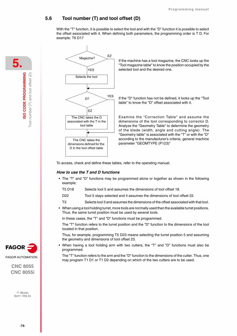
·74·
Programming manual
CNC 8055CNC 8055i
5.
ISO
CO
DE
PR
OG
RA
MM
ING
·T· MODELSOFT: V02.2X
Too
l num
ber
(T)
and
tool
offs
et (
D)
5.6 Tool number (T) and tool offset (D)
With the "T" function, it is possible to select the tool and with the "D" function it is possible to selectthe offset associated with it. When defining both parameters, the programming order is T D. Forexample: T6 D17
To access, check and define these tables, refer to the operating manual.
How to use the T and D functions
• The "T" and "D" functions may be programmed alone or together as shown in the followingexample:
T5 D18 Selects tool 5 and assumes the dimensions of tool offset 18.
D22 Tool 5 stays selected and it assumes the dimensions of tool offset 22.
T3 Selects tool 3 and assumes the dimensions of the offset associated with that tool.
• When using a tool holding turret, more tools are normally used than the available turret positions.Thus, the same turret position must be used by several tools.
In these cases, the "T" and "D" functions must be programmed.
The "T" function refers to the turret position and the "D" function to the dimensions of the toollocated in that position.
Thus, for example, programming T5 D23 means selecting the turret position 5 and assumingthe geometry and dimensions of tool offset 23.
• When having a tool holding arm with two cutters, the "T" and "D" functions must also beprogrammed.
The "T" function refers to the arm and the "D" function to the dimensions of the cutter. Thus, onemay program T1 D1 or T1 D2 depending on which of the two cutters are to be used.
If the machine has a tool magazine, the CNC looks up the"Tool magazine table" to know the position occupied by theselected tool and the desired one.
If the "D" function has not be defined, it looks up the "Tooltable" to know the "D" offset associated with it.
Examine the “Correction Table" and assume thedimensions of the tool corresponding to corrector D.Analyze the “Geometry Table" to determine the geometryof the blade (width, angle and cutting angle). The"Geometry table" is associated with the "T" or with the "D"according to the manufacturer's criteria, general machineparameter "GEOMTYPE (P123)"
Selects the tool
Magazine?EZ
YES
YES
EZ
D?
The CNC takes the D associated with the T in the
tool table
The CNC takes the dimensions defined for the
D in the tool offset table
Programming manual
CNC 8055CNC 8055i
ISO
CO
DE
PR
OG
RA
MM
ING
5.
·T· MODELSOFT: V02.2X
·75·
Too
l num
ber
(T)
and
tool
offs
et (
D)
Tool length and radius compensation.
The CNC looks up the "tool offset table" and assumes the tool dimensions corresponding to theactive "D" offset.
Tool length compensation is applied all the time, whereas tool radius compensation must be selectedby the user by means of functions G40, G41 and G42.
If there is no tool selected or D0 is defined, neither tool length nor radius compensation is applied.
For further detail refer to See chapter "8 Tool Compensation".
·76·
Programming manual
CNC 8055CNC 8055i
5.
ISO
CO
DE
PR
OG
RA
MM
ING
·T· MODELSOFT: V02.2X
Aux
iliar
y fu
nctio
n (M
)
5.7 Auxiliary function (M)
The miscellaneous functions are programmed by means of the M4 Code, it being possible toprogram up to 7 functions in the same block.
When more than one function has been programmed in one block, the CNC executes thesecorrelatively to the order in which they have been programmed.
The CNC is provided with an M functions table with "NMISCFUN" (general machine parameter)components, specifying for each element:
• The number (0-9999) of the defined miscellaneous M function.
• The number of the subroutine which is required to associate to this miscellaneous function.
• An indicator which determines if the M function is executed before or after the movement blockin which it is programmed.
• An indicator which determines if the execution of the M function interrupts block preparation ornot.
• An indicator which determines if the M function is executed or not, after the execution of theassociated subroutine.
• An indicator which determines if the CNC must wait for the signal AUX END or not (ExecutedM signal, coming from the PLC), to continue the execution of the program.
If, when executing the M miscellaneous function, this is not defined in the M functions table, theprogrammed function will be executed at the beginning of the block and the CNC will wait for theAUX END to continue the execution of the program.
Some of the miscellaneous functions are assigned an internal meaning in the CNC.
If, while executing the associated subroutine of an "M" miscellaneous function, there is a blockcontaining the same "M", this will be executed but not the associated subroutine.
All the miscellaneous "M" functions which have an associated subroutine must be programmed alonein a block.In the case of functions M41 through M44 with associated subroutine, the S that generates the gearchange must be programmed alone in the block. Otherwise, the CNC will display error 1031.
i
Programming manual
CNC 8055CNC 8055i
ISO
CO
DE
PR
OG
RA
MM
ING
5.
·T· MODELSOFT: V02.2X
·77·
Aux
iliar
y fu
nctio
n (M
)
5.7.1 M00. Program stop
When the CNC reads code M00 in a block, it interrupts the program. To start up again, press CYCLESTART.
We recommend that you set this function in the table of M functions, in such a way that it is executedat the end of the block in which it is programmed.
5.7.2 M01. Conditional program stop
This is identical to M00, except that the CNC only takes notice of it if the signal M01 STOP fromthe PLC is active (high logic level).
5.7.3 M02. End of program
This code indicates the end of program and carries out a "General Reset" function of the CNC(returning it to original state). It also carries out the M05 function.
We recommend that you set this function in the table of M functions, in such a way that it is executedat the end of the block in which it is programmed.
5.7.4 M30. End of program with return to the first block
Identical to M02 except that the CNC returns to the first block of the program.
5.7.5 M03, M4, M5. Spindle start and stop
M03. Clockwise spindle rotation
This code represents clockwise spindle start.
We recommend that you set this function in the table of M functions, so that it is executed at thebeginning of the block in which it is programmed.
M04. Counterclockwise spindle rotation
This code represents counterclockwise spindle start. We recommend that you set this function inthe table of M functions, so that it is executed at the beginning of the block in which it is programmed.
M05. Spindle stop
We recommend that you set this function in the table of M functions, in such a way that it is executedat the end of the block in which it is programmed.
Execution of M03, M04 and M05 using PLC marks
Auxiliary functions M03, M04 and M05 may be executed using the following PLC marks:
·78·
Programming manual
CNC 8055CNC 8055i
5.
ISO
CO
DE
PR
OG
RA
MM
ING
·T· MODELSOFT: V02.2X
Aux
iliar
y fu
nctio
n (M
)
• First spindle: PLCM3 (M5070), PLCM4 (M5071) and PLCM5 (M5072).
• Second spindle: PLCM3SP2 (M5073), PLCM4SP2 (M5074) and PLCM5SP2 (M5075).
• Auxiliary spindle: PLCM45 (M5076) to stop the auxiliary spindle and PLCM45S (M5077) to startit up.
The PLC activates these marks to indicate to the CNC that it must execute the corresponding Mfunction at the indicated spindle.
If that spindle is not the main spindle at that moment, it changes the M in the execution history, itactivates the corresponding PLC mark DM3/4//5 and executes the transfer with the PLC (it writesthe M number in the MBCD1 (R550) register, it activates the MSTROBE signal, it waits for theAUXEND signal to go up and it cancels the MSTROBE signal; if the M function is set as not to waitfor AUXEND in the M function table, it waits for the time period set with MINAENDW and cancelsthe MSTROBE).
When acting upon the secondary spindle, it executes the same operation, but having activated themark S2MAIN (M5536) first and then cancelling it at the end. This operation is done automatically;i.e. there is no need to program it at the PLC.
Even if the M3, M4 or M5 function has an associated subroutine in the M function table, thatsubroutine will not be executed when they are executed using the PLC marks.
When executing M3, M4 or M5 using the PLC marks, the gear change that could be required bythe new S is not output to the PLC even if the gear change is automatic.
The CNC will admit the M functions from the PLC as long as it is not in an error state or with LOPEN(M5506) high, whether there is an execution active or not, either in manual or automatic. If the Mfunction is executed during a tool inspection and the spindle turning direction is changed, the changewill be identified in repositioning and it will offer the choice to change it again.
If when activating the M3, M4 or M5 marks via PLC, the main channel is transferring something tothe PLC, the PLC keeps the mark active until the CNC can attend to it. Once the M function isexecuted, the CNC deactivates the mark.
In the following cases, the CNC ignores these PLC marks and deletes the mark so the request isnot left as pending:
• When the spindle is working as a lathe C axis.
• When the spindle is threading in electronic threading (G33).
• When it is doing a rigid tapping or a regular tapping.
• When the CNC is in error state or when LOPEN (M5506) is high.
If several marks of different spindles are activated at the same time, the below order will be followed:first the first spindle, then the second spindle and finally the auxiliary spindle.
When receiving contradictory marks, they will all be ignored. When receiving several marks at thesame time and there is a stop (PLCM5 / PLCM45) between them, only this will be considered andthe rest will be ignored and not saved.
If the spindle has M19TYPE=1, the spindle is homed with the first M3 or M4 after start-up, as longas that M function is executed in manual or automatic mode. If the M function is executed using oneof the PLC marks, the spindle will not be homed.
When activating the PLC marks while homing the spindle, the PLC command stays waiting for thehoming operation to be over. If the home search is associated with the first M3 or M4 after start-up, the PLC command stays waiting for the homing operation is over.
If there are synchronized spindles, it acts upon the command of the main and secondary spindlesat the same time.
While executing the M function, it is possible to abort the process by deactivating the PLC mark thathas initiated it.
Note:
The PLCM5 mark is used to handle the open-door safety operation defined by Fagor Automation.
If the CNC is started up with no gear being active yet, because no M3 or M4 has been executed inthe main channel, the CNC will issue an error message even if it has been configured as AUTOGEAR.
Programming manual
CNC 8055CNC 8055i
ISO
CO
DE
PR
OG
RA
MM
ING
5.
·T· MODELSOFT: V02.2X
·79·
Aux
iliar
y fu
nctio
n (M
)
5.7.6 M06. Tool change code
If the general machine parameter "TOFFM06" (indicating that it is a machining center) is active, theCNC sends instructions to the tool changer and updates the table corresponding to the toolmagazine.
It is recommended to set this function in the table of M functions, so that the subroutinecorresponding to the tool changer installed in the machine is executed.
The functions T and M06 may be programmed in the same block, regardless if they have anassociated subroutine or not. In a block where the functions T and M06 are programmed, nothingelse may be programmed.
·80·
Programming manual
CNC 8055CNC 8055i
5.
ISO
CO
DE
PR
OG
RA
MM
ING
·T· MODELSOFT: V02.2X
Aux
iliar
y fu
nctio
n (M
)
5.7.7 M19. Spindle orientation
With this CNC it is possible to work with the spindle in open loop (M3, M4) and with the spindle inclosed loop (M19).
In order to work in closed loop, it is necessary to have a rotary encoder installed on the spindle ofthe machine.
To switch from open loop to closed loop, execute function M19 or M19 S±5.5. The CNC will act asfollows:
• If the spindle has a home switch, the CNC modifies the spindle speed until it reaches the oneset by spindle machine parameter "REFEED1".
It then searches for actual marker pulse (Io) of the spindle encoder at the turning speed set byspindle machine parameter REFEED2.
And, finally, it positions the spindle at the programmed S±5.5 point.
• If the spindle does not have a home switch, it searches the encoder marker pulse at the turningspeed set by spindle machine parameter REFEED2.
And, then, it positions the spindle at the programmed S±5.5 point.
If only M19 is executed, the spindle is oriented after having "found" the home switch (I0).
To, now, orient the spindle to another position, program M19 S±5.5, the CNC will not perform thehome search since it is already in closed loop and it will orient the spindle to the indicated position.(S±5.5).
The S±5.5 code indicates the spindle position, in degrees, from the spindle reference point (markerpulse).
The sign indicates the counting direction and the 5.5 value is always considered to be absolutecoordinates regardless of the type of units currently selected.
Example:
S1000 M3
Spindle in open loop.
M19 S100
The spindle switches to closed loop. Home search and positioning (orientation) at 100º.
M19 S -30
The spindle orients to -30º, passing through 0º.
M19 S400
The spindle turns a whole revolution and positions at 40º.
During the M19 process the screen will display the warning: “M19 in execution"i
Programming manual
CNC 8055CNC 8055i
ISO
CO
DE
PR
OG
RA
MM
ING
5.
·T· MODELSOFT: V02.2X
·81·
Aux
iliar
y fu
nctio
n (M
)
5.7.8 M41, M42, M43, M44. Spindle gear change
The CNC offers 4 spindle speed ranges M41, M42, M43 and M44 with maximum speed limits setby the spindle machine parameters "MAXGEAR1", MAXGEAR2", "MAXGEAR3" and"MAXGEAR4".
If machine parameter "AUTOGEAR" is set so the CNC executes the range change automatically,M41 thru M44 will be sent out automatically by the CNC without having to be programmed.
If this machine parameter is set for non-automatic gear change, M41 thru M44 will have to beprogrammed every time a gear change is required. Bear in mind that the maximum velocitycommand value assigned to machine parameter "MAXVOLT" corresponds to the maximum speedindicated for each one of the speed ranges (machine parameters "MAXGEAR1" thru"MAXGEAR4").
Regardless of whether the gear change is automatic or not, functions M41 through M44 may havean associated subroutine. If the function M41 through M44 is programmed and then an Scorresponding to that gear, it does not generate the automatic gear change and it does not executethe associated subroutine.
·82·
Programming manual
CNC 8055CNC 8055i
5.
ISO
CO
DE
PR
OG
RA
MM
ING
·T· MODELSOFT: V02.2X
Aux
iliar
y fu
nctio
n (M
)
5.7.9 M45. Auxiliary spindle / Live tool
In order to use this miscellaneous function, it is necessary to set one of the axes of the machineas auxiliary spindle or live tool (general machine parameter P0 thru P7).
To use the auxiliary spindle or live tool, execute the command: M45 S±5.5 where S indicates theturning speed in rpm and the sign indicates the turning direction.
The CNC will output the velocity command corresponding to the selected speed according to thevalue assigned to the machine parameter "MAXSPEED" for the auxiliary spindle.
To stop the auxiliary spindle, program M45 or M45 S0.
Whenever the auxiliary spindle or live tool is active, the CNC will let the PLC know by activating thegeneral logic output "DM45" (M5548).
Also, it is possible to set the machine parameter for the auxiliary spindle "SPDLOVR" so the Overridekeys of the front panel can modify the currently active turning speed of the auxiliary spindle.
CNC 8055CNC 8055i
·T· MODELSOFT: V02.2X
6
·83·
PATH CONTROL
The CNC allows you to program movements on one axis only or several at the same time.
Only those axes which intervene in the required movement are programmed. The programmingorder of the axes is as follows :
X, Y, Z, U, V, W, A, B, C
The coordinates of each axis are programmed in either radius or diameter depending on the settingof axis machine parameter "DFORMAT".
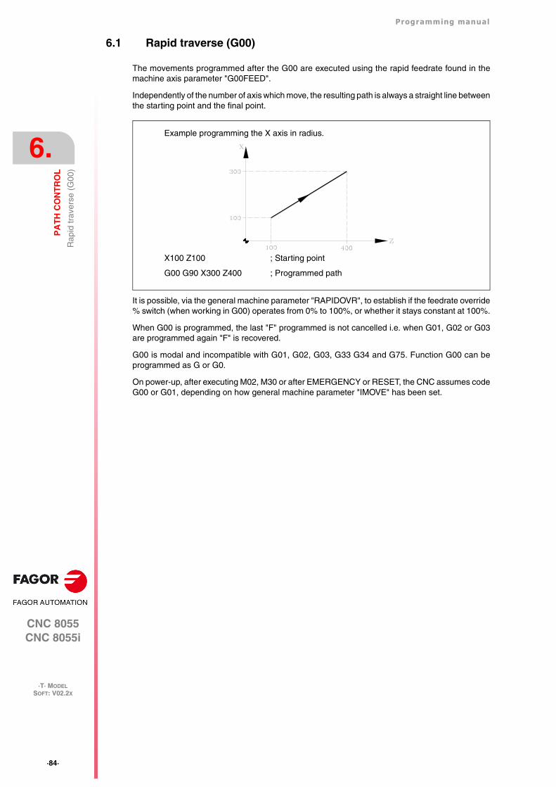
·84·
Programming manual
CNC 8055CNC 8055i
6.
PA
TH
CO
NT
RO
L
·T· MODELSOFT: V02.2X
Rap
id tr
aver
se (
G00
)
6.1 Rapid traverse (G00)
The movements programmed after the G00 are executed using the rapid feedrate found in themachine axis parameter "G00FEED".
Independently of the number of axis which move, the resulting path is always a straight line betweenthe starting point and the final point.
It is possible, via the general machine parameter "RAPIDOVR", to establish if the feedrate override% switch (when working in G00) operates from 0% to 100%, or whether it stays constant at 100%.
When G00 is programmed, the last "F" programmed is not cancelled i.e. when G01, G02 or G03are programmed again "F" is recovered.
G00 is modal and incompatible with G01, G02, G03, G33 G34 and G75. Function G00 can beprogrammed as G or G0.
On power-up, after executing M02, M30 or after EMERGENCY or RESET, the CNC assumes codeG00 or G01, depending on how general machine parameter "IMOVE" has been set.
X100 Z100 ; Starting point
G00 G90 X300 Z400 ; Programmed path
Example programming the X axis in radius.
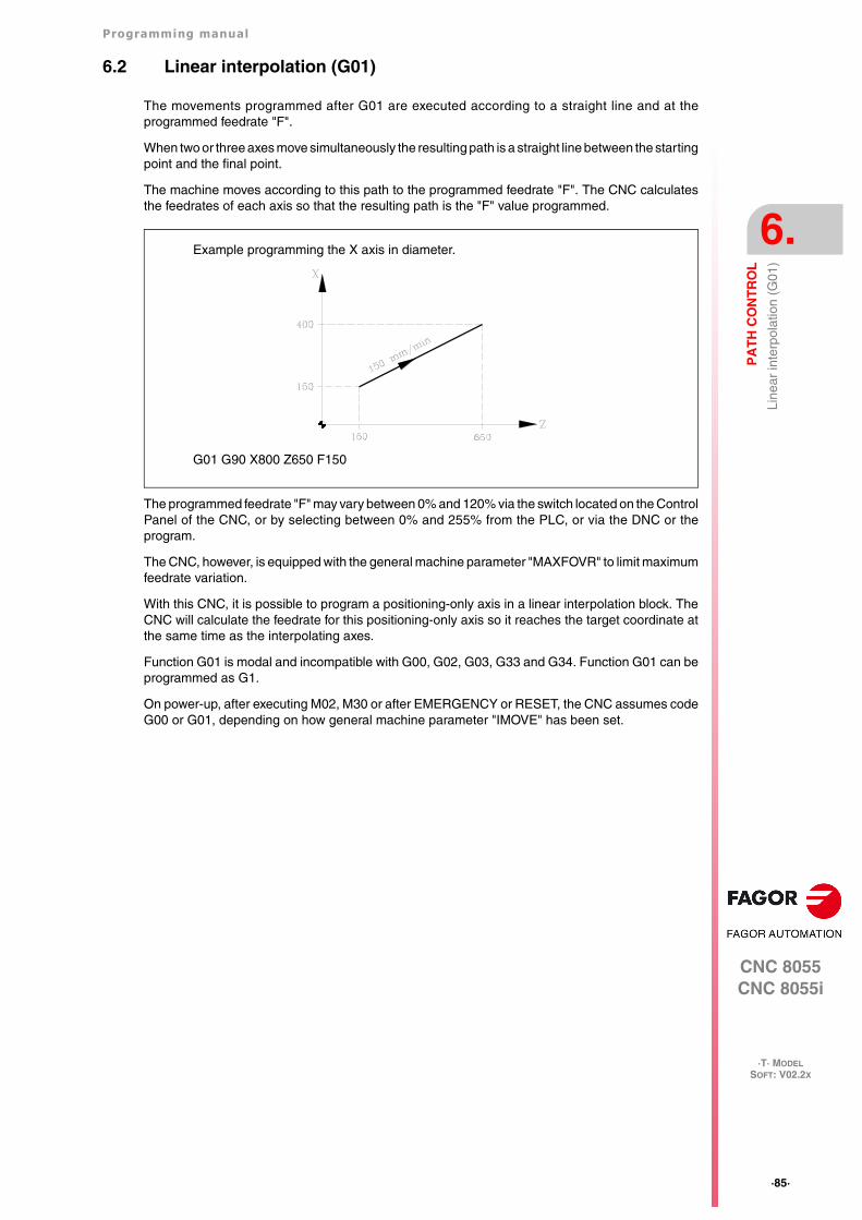
Programming manual
CNC 8055CNC 8055i
PA
TH
CO
NT
RO
L
6.
·T· MODELSOFT: V02.2X
·85·
Line
ar in
terp
olat
ion
(G01
)
6.2 Linear interpolation (G01)
The movements programmed after G01 are executed according to a straight line and at theprogrammed feedrate "F".
When two or three axes move simultaneously the resulting path is a straight line between the startingpoint and the final point.
The machine moves according to this path to the programmed feedrate "F". The CNC calculatesthe feedrates of each axis so that the resulting path is the "F" value programmed.
The programmed feedrate "F" may vary between 0% and 120% via the switch located on the ControlPanel of the CNC, or by selecting between 0% and 255% from the PLC, or via the DNC or theprogram.
The CNC, however, is equipped with the general machine parameter "MAXFOVR" to limit maximumfeedrate variation.
With this CNC, it is possible to program a positioning-only axis in a linear interpolation block. TheCNC will calculate the feedrate for this positioning-only axis so it reaches the target coordinate atthe same time as the interpolating axes.
Function G01 is modal and incompatible with G00, G02, G03, G33 and G34. Function G01 can beprogrammed as G1.
On power-up, after executing M02, M30 or after EMERGENCY or RESET, the CNC assumes codeG00 or G01, depending on how general machine parameter "IMOVE" has been set.
G01 G90 X800 Z650 F150
Example programming the X axis in diameter.
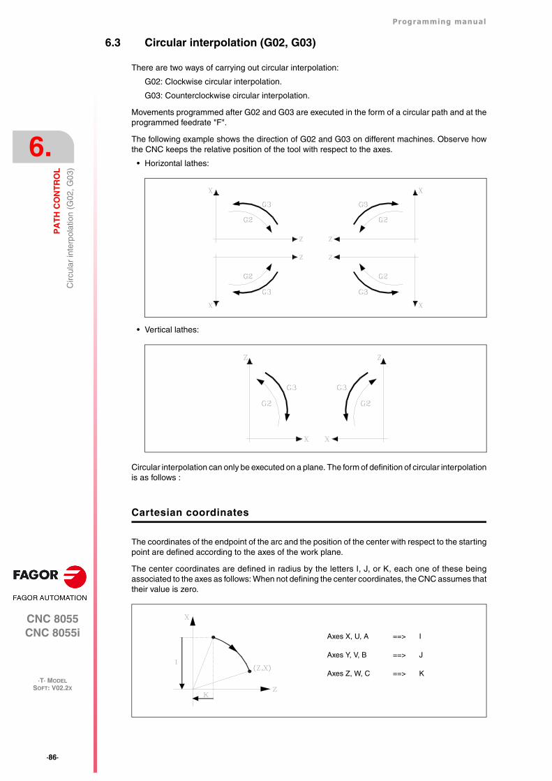
·86·
Programming manual
CNC 8055CNC 8055i
6.
PA
TH
CO
NT
RO
L
·T· MODELSOFT: V02.2X
Circ
ular
inte
rpol
atio
n (G
02, G
03)
6.3 Circular interpolation (G02, G03)
There are two ways of carrying out circular interpolation:
G02: Clockwise circular interpolation.
G03: Counterclockwise circular interpolation.
Movements programmed after G02 and G03 are executed in the form of a circular path and at theprogrammed feedrate "F".
The following example shows the direction of G02 and G03 on different machines. Observe howthe CNC keeps the relative position of the tool with respect to the axes.
• Horizontal lathes:
• Vertical lathes:
Circular interpolation can only be executed on a plane. The form of definition of circular interpolationis as follows :
Cartesian coordinates
The coordinates of the endpoint of the arc and the position of the center with respect to the startingpoint are defined according to the axes of the work plane.
The center coordinates are defined in radius by the letters I, J, or K, each one of these beingassociated to the axes as follows: When not defining the center coordinates, the CNC assumes thattheir value is zero.
Axes X, U, A ==> I
Axes Y, V, B ==> J
Axes Z, W, C ==> K
Programming manual
CNC 8055CNC 8055i
PA
TH
CO
NT
RO
L
6.
·T· MODELSOFT: V02.2X
·87·
Circ
ular
inte
rpol
atio
n (G
02, G
03)
Programming format:
The programming order of the axes is always maintained regardless of the plane selected,, as arethe respective center coordinates.
Polar coordinates
It is necessary to define the angle to be traveled Q and the distance from the starting point to thecenter (optional), according to the axes of the work plane.
The center coordinates are defined in radius by the letters I, J, or K, each one of these beingassociated to the axes as follows:
If the center of the arc is not defined, the CNC will assume that it coincides with the current polarorigin.
Programming format:
Cartesian coordinates with radius programming
The coordinates of the endpoint of the arc and radius R are defined.
Programming format:
If a complete circle is programmed, with radius programming, the CNC will show the correspondingerror, as infinite solutions exist.
Plane XY: G02(G03) X±5.5 Y±5.5 I±6.5 J±6.5
Plane ZX: G02(G03) X±5.5 Z±5.5 I±6.5 K±6.5
Plane YZ: G02(G03) Y±5.5 Z±5.5 J±6.5 K±6.5
Plane AY: G02(G03) Y±5.5 A±5.5 J±6.5 I±6.5
Plane XU: G02(G03) X±5.5 U±5.5 I±6.5 I±6.5
Axes X, U, A ==> I
Axes Y, V, B ==> J
Axes Z, W, C ==> K
Plane XY: G02(G03) Q±5.5 I±6.5 J±6.5
Plane ZX: G02(G03) Q±5.5 I±6.5 K±6.5
Plane YZ: G02(G03) Q±5.5 J±6.5 K±6.5
Plane XY: G02(G03) X±5.5 Y±5.5 R±6.5
Plane ZX: G02(G03) X±5.5 Z±5.5 R±6.5
Plane YZ: G02(G03) Y±5.5 Z±5.5 R±6.5
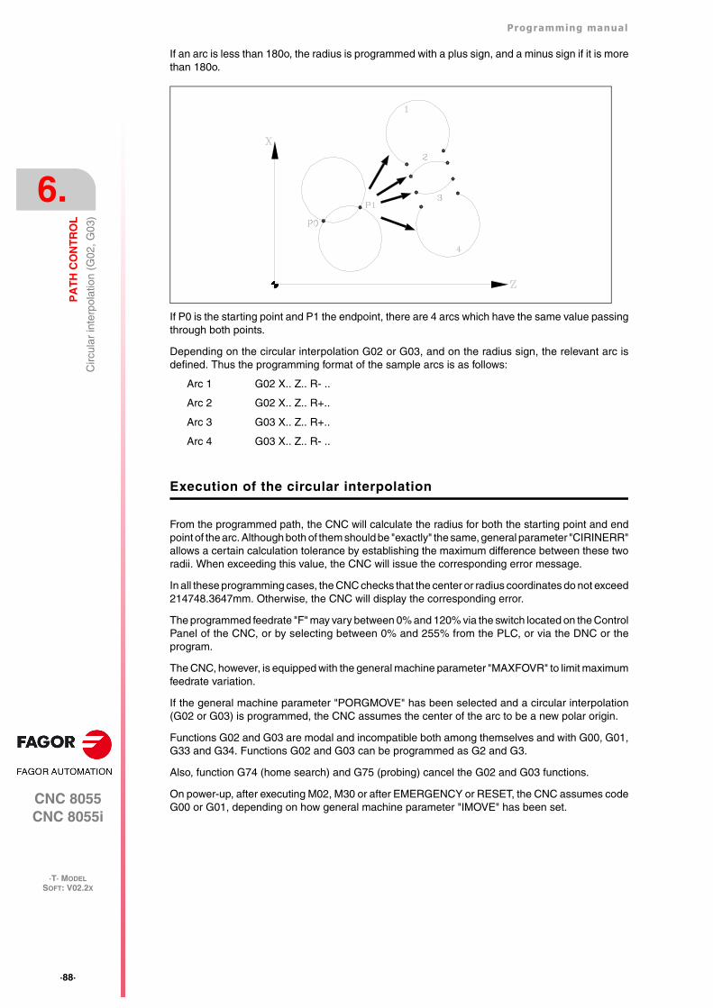
·88·
Programming manual
CNC 8055CNC 8055i
6.
PA
TH
CO
NT
RO
L
·T· MODELSOFT: V02.2X
Circ
ular
inte
rpol
atio
n (G
02, G
03)
If an arc is less than 180o, the radius is programmed with a plus sign, and a minus sign if it is morethan 180o.
If P0 is the starting point and P1 the endpoint, there are 4 arcs which have the same value passingthrough both points.
Depending on the circular interpolation G02 or G03, and on the radius sign, the relevant arc isdefined. Thus the programming format of the sample arcs is as follows:
Arc 1 G02 X.. Z.. R- ..
Arc 2 G02 X.. Z.. R+..
Arc 3 G03 X.. Z.. R+..
Arc 4 G03 X.. Z.. R- ..
Execution of the circular interpolation
From the programmed path, the CNC will calculate the radius for both the starting point and endpoint of the arc. Although both of them should be "exactly" the same, general parameter "CIRINERR"allows a certain calculation tolerance by establishing the maximum difference between these tworadii. When exceeding this value, the CNC will issue the corresponding error message.
In all these programming cases, the CNC checks that the center or radius coordinates do not exceed214748.3647mm. Otherwise, the CNC will display the corresponding error.
The programmed feedrate "F" may vary between 0% and 120% via the switch located on the ControlPanel of the CNC, or by selecting between 0% and 255% from the PLC, or via the DNC or theprogram.
The CNC, however, is equipped with the general machine parameter "MAXFOVR" to limit maximumfeedrate variation.
If the general machine parameter "PORGMOVE" has been selected and a circular interpolation(G02 or G03) is programmed, the CNC assumes the center of the arc to be a new polar origin.
Functions G02 and G03 are modal and incompatible both among themselves and with G00, G01,G33 and G34. Functions G02 and G03 can be programmed as G2 and G3.
Also, function G74 (home search) and G75 (probing) cancel the G02 and G03 functions.
On power-up, after executing M02, M30 or after EMERGENCY or RESET, the CNC assumes codeG00 or G01, depending on how general machine parameter "IMOVE" has been set.
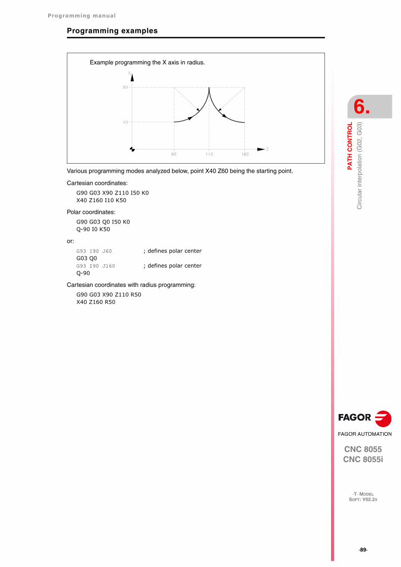
Programming manual
CNC 8055CNC 8055i
PA
TH
CO
NT
RO
L
6.
·T· MODELSOFT: V02.2X
·89·
Circ
ular
inte
rpol
atio
n (G
02, G
03)
Programming examples
Various programming modes analyzed below, point X40 Z60 being the starting point.
Cartesian coordinates:
G90 G03 X90 Z110 I50 K0X40 Z160 I10 K50
Polar coordinates:
G90 G03 Q0 I50 K0Q-90 I0 K50
or:
G93 I90 J60 ; defines polar centerG03 Q0G93 I90 J160 ; defines polar centerQ-90
Cartesian coordinates with radius programming:
G90 G03 X90 Z110 R50X40 Z160 R50
Example programming the X axis in radius.
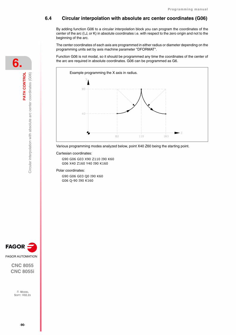
·90·
Programming manual
CNC 8055CNC 8055i
6.
PA
TH
CO
NT
RO
L
·T· MODELSOFT: V02.2X
Circ
ular
inte
rpol
atio
n w
ith a
bsol
ute
arc
cent
er c
oord
inat
es (
G06
)
6.4 Circular interpolation with absolute arc center coordinates (G06)
By adding function G06 to a circular interpolation block you can program the coordinates of thecenter of the arc (I,J, or K) in absolute coordinates i.e. with respect to the zero origin and not to thebeginning of the arc.
The center coordinates of each axis are programmed in either radius or diameter depending on theprogramming units set by axis machine parameter "DFORMAT".
Function G06 is not modal, so it should be programmed any time the coordinates of the center ofthe arc are required in absolute coordinates. G06 can be programmed as G6.
Various programming modes analyzed below, point X40 Z60 being the starting point.
Cartesian coordinates:
G90 G06 G03 X90 Z110 I90 K60G06 X40 Z160 Y40 I90 K160
Polar coordinates:
G90 G06 G03 Q0 I90 K60G06 Q-90 I90 K160
Example programming the X axis in radius.
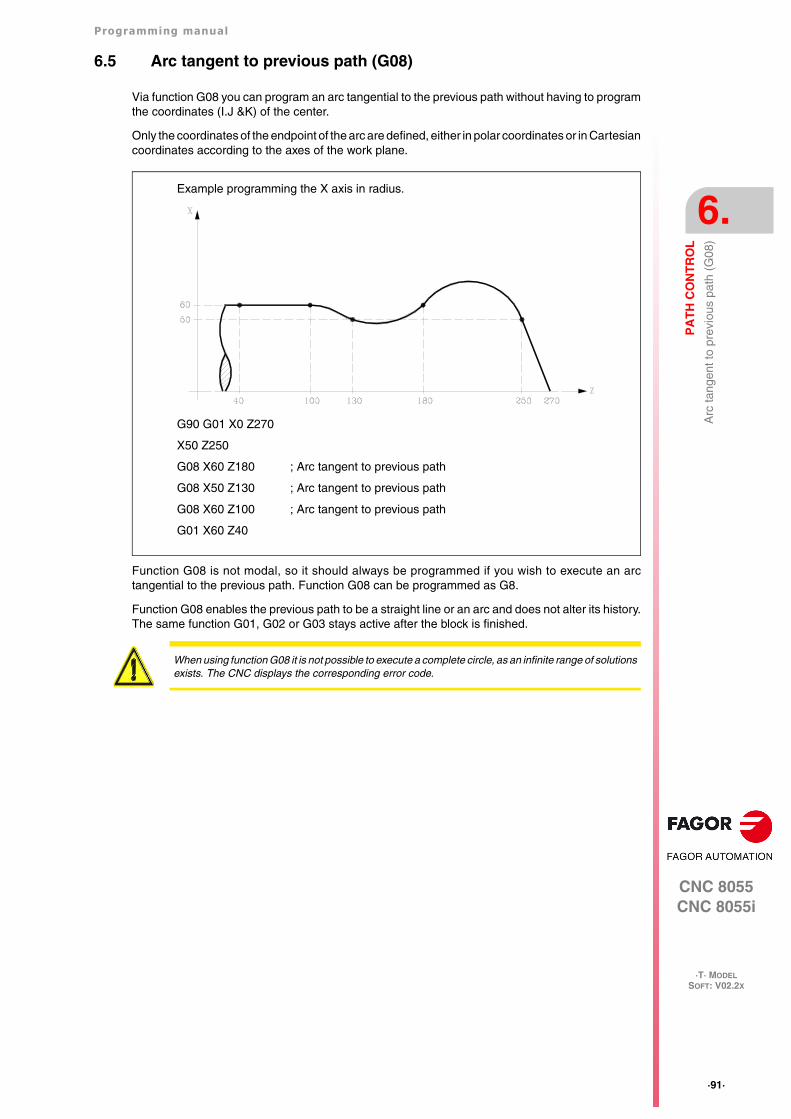
Programming manual
CNC 8055CNC 8055i
PA
TH
CO
NT
RO
L
6.
·T· MODELSOFT: V02.2X
·91·
Arc
tang
ent t
o pr
evio
us p
ath
(G08
)
6.5 Arc tangent to previous path (G08)
Via function G08 you can program an arc tangential to the previous path without having to programthe coordinates (I.J &K) of the center.
Only the coordinates of the endpoint of the arc are defined, either in polar coordinates or in Cartesiancoordinates according to the axes of the work plane.
Function G08 is not modal, so it should always be programmed if you wish to execute an arctangential to the previous path. Function G08 can be programmed as G8.
Function G08 enables the previous path to be a straight line or an arc and does not alter its history.The same function G01, G02 or G03 stays active after the block is finished.
Example programming the X axis in radius.
G90 G01 X0 Z270
X50 Z250
G08 X60 Z180 ; Arc tangent to previous path
G08 X50 Z130 ; Arc tangent to previous path
G08 X60 Z100 ; Arc tangent to previous path
G01 X60 Z40
When using function G08 it is not possible to execute a complete circle, as an infinite range of solutionsexists. The CNC displays the corresponding error code.
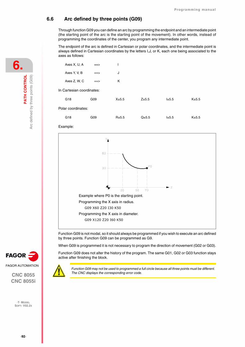
·92·
Programming manual
CNC 8055CNC 8055i
6.
PA
TH
CO
NT
RO
L
·T· MODELSOFT: V02.2X
Arc
def
ined
by
thre
e po
ints
(G
09)
6.6 Arc defined by three points (G09)
Through function G09 you can define an arc by programming the endpoint and an intermediate point(the starting point of the arc is the starting point of the movement). In other words, instead ofprogramming the coordinates of the center, you program any intermediate point.
The endpoint of the arc is defined in Cartesian or polar coordinates, and the intermediate point isalways defined in Cartesian coordinates by the letters I,J, or K, each one being associated to theaxes as follows:
In Cartesian coordinates:
Polar coordinates:
Example:
Function G09 is not modal, so it should always be programmed if you wish to execute an arc definedby three points. Function G09 can be programmed as G9.
When G09 is programmed it is not necessary to program the direction of movement (G02 or G03).
Function G09 does not alter the history of the program. The same G01, G02 or G03 function staysactive after finishing the block.
Axes X, U, A ==> I
Axes Y, V, B ==> J
Axes Z, W, C ==> K
G18 G09 X±5.5 Z±5.5 I±5.5 K±5.5
G18 G09 R±5.5 Q±5.5 I±5.5 K±5.5
Example where P0 is the starting point.
Programming the X axis in radius.
G09 X60 Z20 I30 K50
Programming the X axis in diameter.
G09 X120 Z20 I60 K50
Function G09 may not be used to programmed a full circle because all three points must be different.The CNC displays the corresponding error code.
Programming manual
CNC 8055CNC 8055i
PA
TH
CO
NT
RO
L
6.
·T· MODELSOFT: V02.2X
·93·
Hel
ical
inte
rpol
atio
n
6.7 Helical interpolation
A helical interpolation consists in a circular interpolation in the work plane while moving the rest ofthe programmed axes.
Normally used on special machines that have an auxiliary axis.
The helical interpolation is programmed in a block.
• The circular interpolation by means of functions: G02, G03, G08 or G09.
• Movement of the other axis or axes.
Example of a circular interpolation in the YZ plane and movement of the X axis:
G02 Y Z J K X
If the helical interpolation is supposed to make more than one turn, the linear movement of anotheraxis must also be programmed (one axis only).
On the other hand, the pitch along the linear axis must also be set (format 5.5) by means of the I,J and K letters. Each one of these letters is associated with the axes as follows:
It is now possible to program helical interpolations while Look Ahead is active (G51). Thanks to this,CAN/CAM programs that contain this type of paths may be executed while look-ahead is active.
Example:
Example of a circular interpolation in the YZ plane and movement of the X axis with a helical pitchof 5 mm:
G02 Y Z J K X I5
Axes X, U, A ==> I
Axes Y, V, B ==> J
Axes Z, W, C ==> K
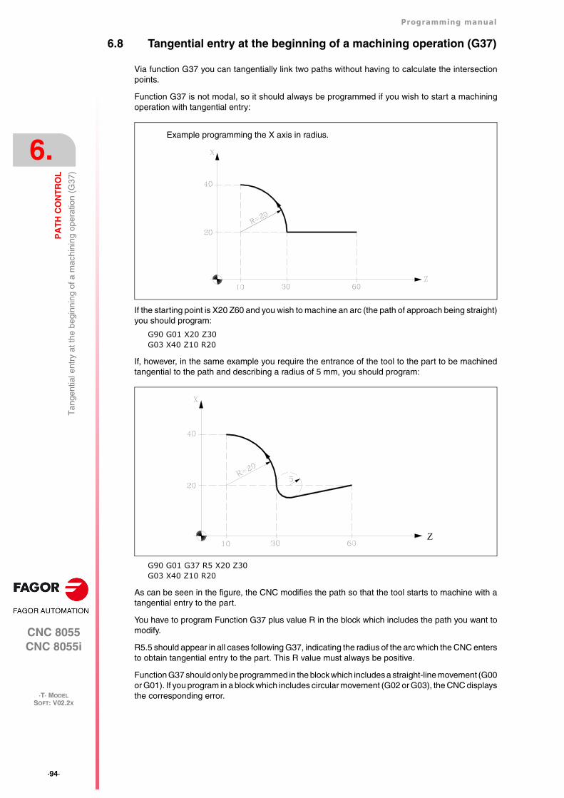
·94·
Programming manual
CNC 8055CNC 8055i
6.
PA
TH
CO
NT
RO
L
·T· MODELSOFT: V02.2X
Tan
gent
ial e
ntry
at t
he b
egin
ning
of a
mac
hini
ng o
pera
tion
(G37
)
6.8 Tangential entry at the beginning of a machining operation (G37)
Via function G37 you can tangentially link two paths without having to calculate the intersectionpoints.
Function G37 is not modal, so it should always be programmed if you wish to start a machiningoperation with tangential entry:
If the starting point is X20 Z60 and you wish to machine an arc (the path of approach being straight)you should program:
G90 G01 X20 Z30G03 X40 Z10 R20
If, however, in the same example you require the entrance of the tool to the part to be machinedtangential to the path and describing a radius of 5 mm, you should program:
G90 G01 G37 R5 X20 Z30G03 X40 Z10 R20
As can be seen in the figure, the CNC modifies the path so that the tool starts to machine with atangential entry to the part.
You have to program Function G37 plus value R in the block which includes the path you want tomodify.
R5.5 should appear in all cases following G37, indicating the radius of the arc which the CNC entersto obtain tangential entry to the part. This R value must always be positive.
Function G37 should only be programmed in the block which includes a straight-line movement (G00or G01). If you program in a block which includes circular movement (G02 or G03), the CNC displaysthe corresponding error.
Example programming the X axis in radius.
Z
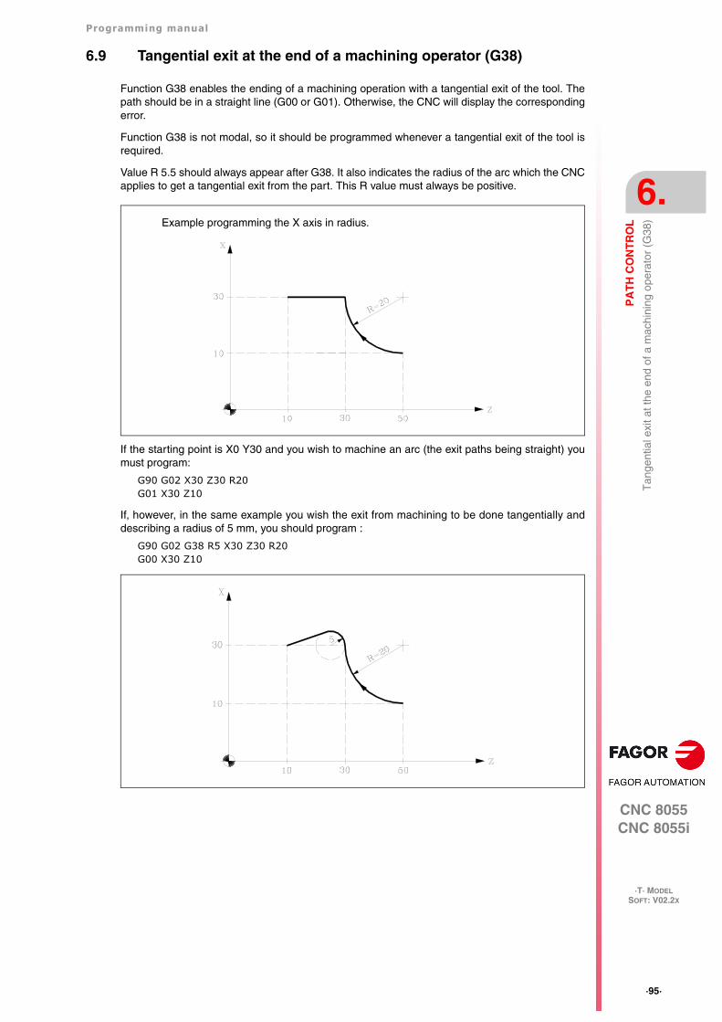
Programming manual
CNC 8055CNC 8055i
PA
TH
CO
NT
RO
L
6.
·T· MODELSOFT: V02.2X
·95·
Tan
gent
ial e
xit a
t the
end
of a
mac
hini
ng o
pera
tor
(G38
)
6.9 Tangential exit at the end of a machining operator (G38)
Function G38 enables the ending of a machining operation with a tangential exit of the tool. Thepath should be in a straight line (G00 or G01). Otherwise, the CNC will display the correspondingerror.
Function G38 is not modal, so it should be programmed whenever a tangential exit of the tool isrequired.
Value R 5.5 should always appear after G38. It also indicates the radius of the arc which the CNCapplies to get a tangential exit from the part. This R value must always be positive.
If the starting point is X0 Y30 and you wish to machine an arc (the exit paths being straight) youmust program:
G90 G02 X30 Z30 R20G01 X30 Z10
If, however, in the same example you wish the exit from machining to be done tangentially anddescribing a radius of 5 mm, you should program :
G90 G02 G38 R5 X30 Z30 R20G00 X30 Z10
Example programming the X axis in radius.
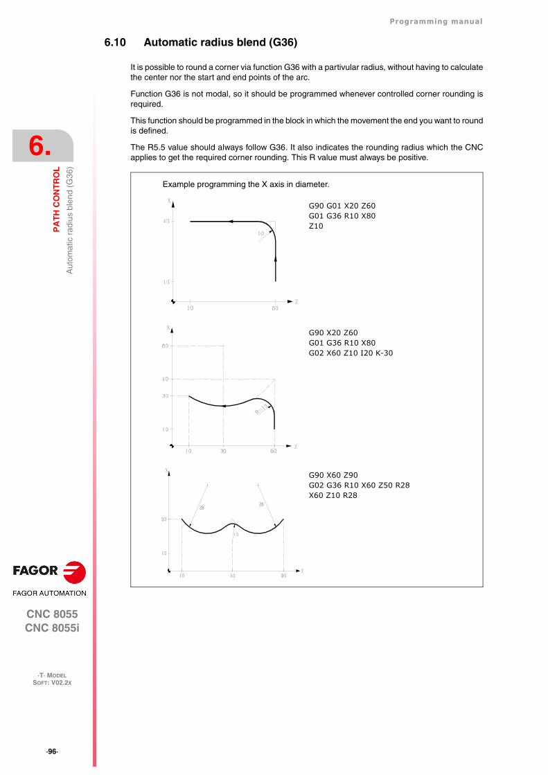
·96·
Programming manual
CNC 8055CNC 8055i
6.
PA
TH
CO
NT
RO
L
·T· MODELSOFT: V02.2X
Aut
omat
ic r
adiu
s bl
end
(G36
)
6.10 Automatic radius blend (G36)
It is possible to round a corner via function G36 with a partivular radius, without having to calculatethe center nor the start and end points of the arc.
Function G36 is not modal, so it should be programmed whenever controlled corner rounding isrequired.
This function should be programmed in the block in which the movement the end you want to roundis defined.
The R5.5 value should always follow G36. It also indicates the rounding radius which the CNCapplies to get the required corner rounding. This R value must always be positive.
G90 G01 X20 Z60G01 G36 R10 X80Z10
G90 X20 Z60G01 G36 R10 X80G02 X60 Z10 I20 K-30
Example programming the X axis in diameter.
G90 X60 Z90G02 G36 R10 X60 Z50 R28X60 Z10 R28
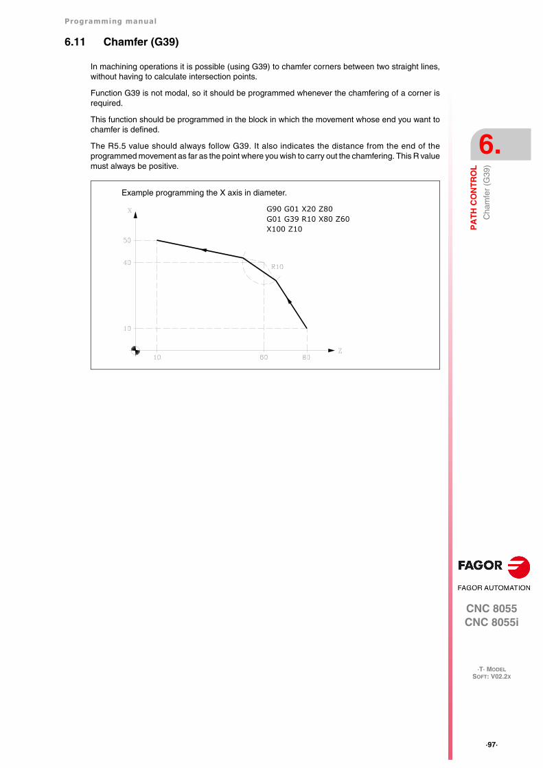
Programming manual
CNC 8055CNC 8055i
PA
TH
CO
NT
RO
L
6.
·T· MODELSOFT: V02.2X
·97·
Cha
mfe
r (G
39)
6.11 Chamfer (G39)
In machining operations it is possible (using G39) to chamfer corners between two straight lines,without having to calculate intersection points.
Function G39 is not modal, so it should be programmed whenever the chamfering of a corner isrequired.
This function should be programmed in the block in which the movement whose end you want tochamfer is defined.
The R5.5 value should always follow G39. It also indicates the distance from the end of theprogrammed movement as far as the point where you wish to carry out the chamfering. This R valuemust always be positive.
G90 G01 X20 Z80G01 G39 R10 X80 Z60X100 Z10
Example programming the X axis in diameter.
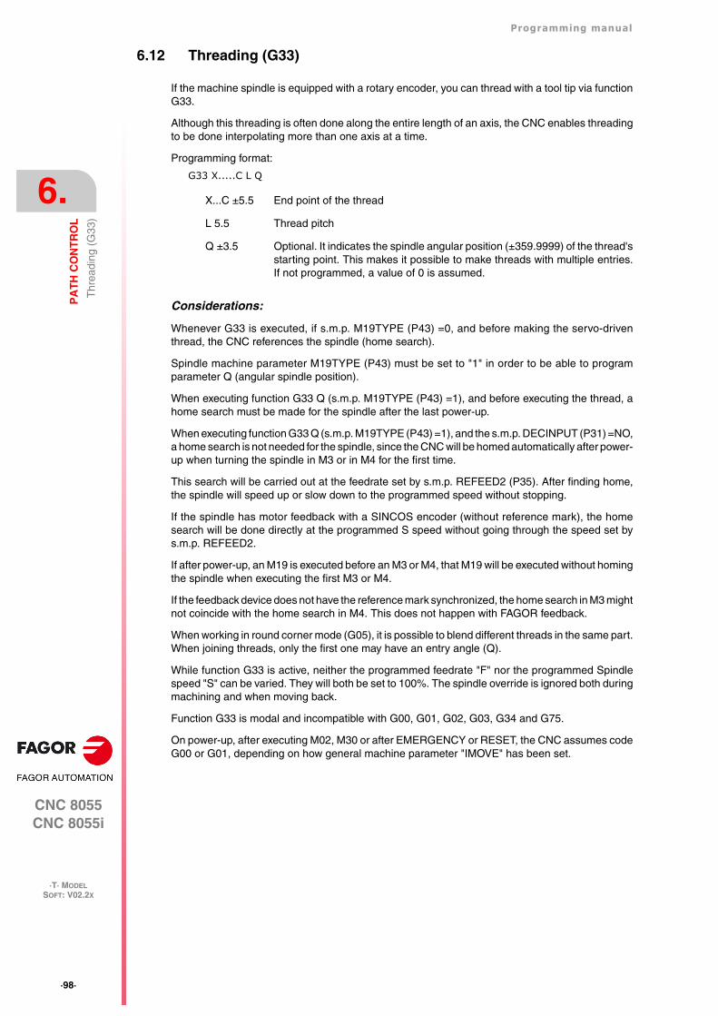
·98·
Programming manual
CNC 8055CNC 8055i
6.
PA
TH
CO
NT
RO
L
·T· MODELSOFT: V02.2X
Thr
eadi
ng (
G33
)
6.12 Threading (G33)
If the machine spindle is equipped with a rotary encoder, you can thread with a tool tip via functionG33.
Although this threading is often done along the entire length of an axis, the CNC enables threadingto be done interpolating more than one axis at a time.
Programming format:
G33 X.....C L Q
Considerations:
Whenever G33 is executed, if s.m.p. M19TYPE (P43) =0, and before making the servo-driventhread, the CNC references the spindle (home search).
Spindle machine parameter M19TYPE (P43) must be set to "1" in order to be able to programparameter Q (angular spindle position).
When executing function G33 Q (s.m.p. M19TYPE (P43) =1), and before executing the thread, ahome search must be made for the spindle after the last power-up.
When executing function G33 Q (s.m.p. M19TYPE (P43) =1), and the s.m.p. DECINPUT (P31) =NO,a home search is not needed for the spindle, since the CNC will be homed automatically after power-up when turning the spindle in M3 or in M4 for the first time.
This search will be carried out at the feedrate set by s.m.p. REFEED2 (P35). After finding home,the spindle will speed up or slow down to the programmed speed without stopping.
If the spindle has motor feedback with a SINCOS encoder (without reference mark), the homesearch will be done directly at the programmed S speed without going through the speed set bys.m.p. REFEED2.
If after power-up, an M19 is executed before an M3 or M4, that M19 will be executed without homingthe spindle when executing the first M3 or M4.
If the feedback device does not have the reference mark synchronized, the home search in M3 mightnot coincide with the home search in M4. This does not happen with FAGOR feedback.
When working in round corner mode (G05), it is possible to blend different threads in the same part.When joining threads, only the first one may have an entry angle (Q).
While function G33 is active, neither the programmed feedrate "F" nor the programmed Spindlespeed "S" can be varied. They will both be set to 100%. The spindle override is ignored both duringmachining and when moving back.
Function G33 is modal and incompatible with G00, G01, G02, G03, G34 and G75.
On power-up, after executing M02, M30 or after EMERGENCY or RESET, the CNC assumes codeG00 or G01, depending on how general machine parameter "IMOVE" has been set.
X...C ±5.5 End point of the thread
L 5.5 Thread pitch
Q ±3.5 Optional. It indicates the spindle angular position (±359.9999) of the thread'sstarting point. This makes it possible to make threads with multiple entries.If not programmed, a value of 0 is assumed.
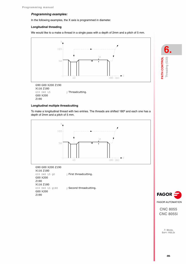
Programming manual
CNC 8055CNC 8055i
PA
TH
CO
NT
RO
L
6.
·T· MODELSOFT: V02.2X
·99·
Thr
eadi
ng (
G33
)
Programming examples:
In the following examples, the X axis is programmed in diameter.
Longitudinal threading
We would like to a make a thread in a single pass with a depth of 2mm and a pitch of 5 mm.
G90 G00 X200 Z190X116 Z180G33 Z40 L5 ; Threadcutting.G00 X200Z190
Longitudinal multiple threadcutting
To make a longitudinal thread with two entries. The threads are shifted 180º and each one has adepth of 2mm and a pitch of 5 mm.
G90 G00 X200 Z190X116 Z180G33 Z40 L5 Q0 ; First threadcutting.G00 X200Z190X116 Z180G33 Z40 L5 Q180 ; Second threadcutting.G00 X200Z190
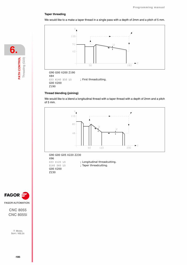
·100·
Programming manual
CNC 8055CNC 8055i
6.
PA
TH
CO
NT
RO
L
·T· MODELSOFT: V02.2X
Thr
eadi
ng (
G33
)
Taper threading
We would like to a make a taper thread in a single pass with a depth of 2mm and a pitch of 5 mm.
G90 G00 X200 Z190X84G33 X140 Z50 L5 ; First threadcutting.G00 X200Z190
Thread blending (joining)
We would like to a blend a longitudinal thread with a taper thread with a depth of 2mm and a pitchof 5 mm.
G90 G00 G05 X220 Z230X96G33 Z120 L5 ; Longitudinal threadcutting.Z160 Z60 L5 ; Taper threadcutting.G00 X200Z230
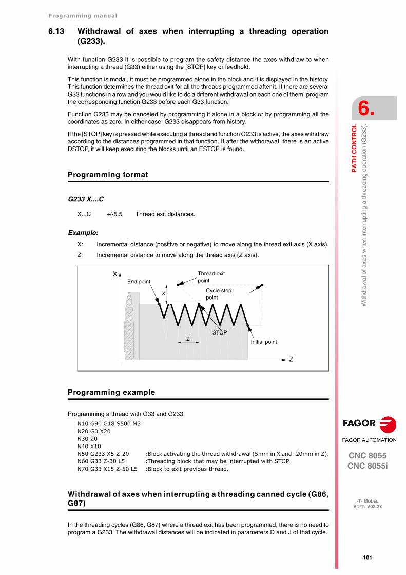
Programming manual
CNC 8055CNC 8055i
PA
TH
CO
NT
RO
L
6.
·T· MODELSOFT: V02.2X
·101·
With
draw
al o
f axe
s w
hen
inte
rrup
ting
a th
read
ing
oper
atio
n (G
233)
.
6.13 Withdrawal of axes when interrupting a threading operation(G233).
With function G233 it is possible to program the safety distance the axes withdraw to wheninterrupting a thread (G33) either using the [STOP] key or feedhold.
This function is modal, it must be programmed alone in the block and it is displayed in the history.This function determines the thread exit for all the threads programmed after it. If there are severalG33 functions in a row and you would like to do a different withdrawal on each one of them, programthe corresponding function G233 before each G33 function.
Function G233 may be canceled by programming it alone in a block or by programming all thecoordinates as zero. In either case, G233 disappears from history.
If the [STOP] key is pressed while executing a thread and function G233 is active, the axes withdrawaccording to the distances programmed in that function. If after the withdrawal, there is an activeDSTOP, it will keep executing the blocks until an ESTOP is found.
Programming format
G233 X....C
Example:
X: Incremental distance (positive or negative) to move along the thread exit axis (X axis).
Z: Incremental distance to move along the thread axis (Z axis).
Programming example
Programming a thread with G33 and G233.
N10 G90 G18 S500 M3N20 G0 X20N30 Z0N40 X10N50 G233 X5 Z-20 ;Block activating the thread withdrawal (5mm in X and -20mm in Z).N60 G33 Z-30 L5 ;Threading block that may be interrupted with STOP.N70 G33 X15 Z-50 L5 ;Block to exit previous thread.
Withdrawal of axes when interrupting a threading canned cycle (G86,G87)
In the threading cycles (G86, G87) where a thread exit has been programmed, there is no need toprogram a G233. The withdrawal distances will be indicated in parameters D and J of that cycle.
X...C +/-5.5 Thread exit distances.
Z
X
STOP
Z
XEnd point
Thread exitpoint
Cycle stoppoint
Initial point
·102·
Programming manual
CNC 8055CNC 8055i
6.
PA
TH
CO
NT
RO
L
·T· MODELSOFT: V02.2X
With
draw
al o
f axe
s w
hen
inte
rrup
ting
a th
read
ing
oper
atio
n (G
233)
.
While executing those cycles, when pressing the [STOP] key or feedhold, once the tool has beenwithdrawn, it returns to the starting point of the cycle. Then, the machine remains stopped waitingfor the [START] command to repeat the interrupted pass.
Programming manual
CNC 8055CNC 8055i
PA
TH
CO
NT
RO
L
6.
·T· MODELSOFT: V02.2X
·103·
Var
iabl
e pi
tch
thre
ads
(G34
)
6.14 Variable pitch threads (G34)
To make variable-pitch threads, the spindle of the machine must have a rotary encoder.
Although this threading is often done along the entire length of an axis, the CNC enables threadingto be done interpolating more than one axis at a time.
Programming format:
G34 X.....C L Q K
Considerations:
Whenever G34 is executed and before making the thread, the CNC references the spindle (homesearch) and positions the spindle at the angular position indicated by parameter Q.
Parameter "Q" is available when spindle machine parameter "M19TYPE" has been set to "1".
When working in round corner mode (G05), it is possible to blend different threads in the same part.
While function G34 is active, neither the programmed feedrate "F" nor the programmed Spindlespeed "S" can be varied. They will both be set to 100%.
Function G34 is modal and incompatible with G00, G01, G02, G03, G33 and G75.
On power-up, after executing M02, M30 or after EMERGENCY or RESET, the CNC assumes codeG00 or G01, depending on how general machine parameter "IMOVE" has been set.
Blending a fixed-pitch thread (G33) with a variable-pitch thread (G34).
The starting thread pitch (L) of the G34 must coincide with the thread pitch of the G33.
The pitch increase in the first turn of the spindle in variable pitch will be half and increment (K/2)and in the rest of the turns it will be the full increment K.
Blending a variable-pitch thread (G34) with a fixed-pitch thread.
It is used to finish a variable-pitch thread (G34) with a portion of the thread keeping the final pitchof the previous thread. The fixed-pitch thread is not programmed with G33 but with G34 ... L0 K0.
Blending two variable-pitch threads (G34).
Two variable-pitch threads (G34) cannot be blended together.
X...C ±5.5 End point of the thread
L 5.5 Thread pitch
Q ±3.5 Optional. It indicates the spindle angular position (±359.9999) of the thread'sstarting point. If not programmed, a value of "0" is assumed.
K ±5.5 Thread pitch increase or decrease per spindle turn.
·104·
Programming manual
CNC 8055CNC 8055i
6.
PA
TH
CO
NT
RO
L
·T· MODELSOFT: V02.2X
Act
ivat
es th
e C
axi
s (G
15).
6.15 Activates the C axis (G15).
The preparatory function G15 activates the C axis so it can machine on the side of the part or onits face.
This feature is optional and requires a software that can control 4 or more axes.
In order to use this preparatory function, it is necessary to set one of the axes of the machine asC axis (general machine parameter P0 through P7) and define that axis as a regular rotary axis (Caxis machine parameter "AXISTYPE").
When activating the C axis with preparatory function G15, the CNC executes a home search on theC axis if it was working as a spindle before. If it was already in C axis mode, the home search willnot be carried out.
The G15 function is modal and it will keep active the spindle logic output "CAXIS (M5955) all thetime while the C axis is active.
No more auxiliary functions may be programmed in the same block that defined function G15.
The CNC cancels the C axis and it returns it to spindle mode after executing one of these spindlefunctions (M03, M04, M05, etc.).
Also, if general machine parameter "PERCAX=NO", the CNC will also cancel the C function afterturning the CNC off and back on, after an emergency or reset or after executing functions M02 andM30.
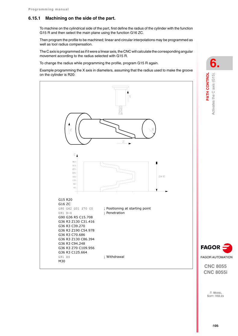
Programming manual
CNC 8055CNC 8055i
PA
TH
CO
NT
RO
L
6.
·T· MODELSOFT: V02.2X
·105·
Act
ivat
es th
e C
axi
s (G
15).
6.15.1 Machining on the side of the part.
To machine on the cylindrical side of the part, first define the radius of the cylinder with the functionG15 R and then select the main plane using the function G16 ZC.
Then program the profile to be machined; linear and circular interpolations may be programmed aswell as tool radius compensation.
The C axis is programmed as if it were a linear axis, the CNC will calculate the corresponding angularmovement according to the radius selected with G15 R.
To change the radius while programming the profile, program G15 R again.
Example programming the X axis in diameters, assuming that the radius used to make the grooveon the cylinder is R20:
G15 R20G16 ZCG90 G42 G01 Z70 C0 ; Positioning at starting pointG91 X-4 ; PenetrationG90 G36 R5 C15.708G36 R3 Z130 C31.416G36 R3 C39.270G36 R3 Z190 C54.978G36 R3 C70.686G36 R3 Z130 C86.394G36 R3 C94.248G36 R3 Z70 C109.956G36 R3 C125.664G91 X4 ; WithdrawalM30
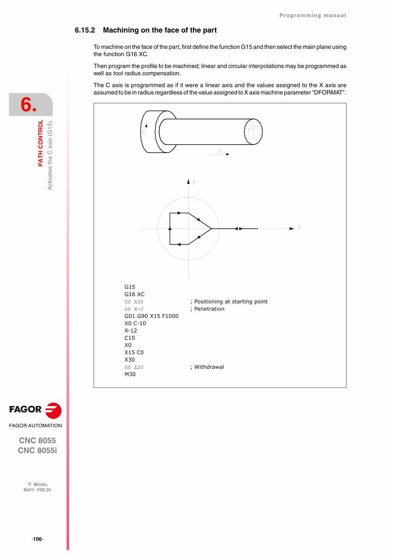
·106·
Programming manual
CNC 8055CNC 8055i
6.
PA
TH
CO
NT
RO
L
·T· MODELSOFT: V02.2X
Act
ivat
es th
e C
axi
s (G
15).
6.15.2 Machining on the face of the part
To machine on the face of the part, first define the function G15 and then select the main plane usingthe function G16 XC.
Then program the profile to be machined; linear and circular interpolations may be programmed aswell as tool radius compensation.
The C axis is programmed as if it were a linear axis and the values assigned to the X axis areassumed to be in radius regardless of the value assigned to X axis machine parameter "DFORMAT".
G15G16 XCG0 X30 ; Positioning at starting pointG0 X-2 ; PenetrationG01 G90 X15 F1000X0 C-10X-12C10X0X15 C0X30G0 Z20 ; WithdrawalM30
Programming manual
CNC 8055CNC 8055i
PA
TH
CO
NT
RO
L
6.
·T· MODELSOFT: V02.2X
·107·
Mov
e to
har
dsto
p (G
52)
6.16 Move to hardstop (G52)
By means of function G52 it is possible to program the movement of an axis until running into anobject. This feature may be interesting for forming machines, live tailstocks, bar feeders, etc.
The programming format is:
G52 X..C ±5.5
After G52, program the desired axis as well as the target coordinate of the move.
The axis will move towards the programmed target coordinate until running into something. If theaxis reaches the programmed target coordinate without running into the hardstop it will stop.
Function G52 is not modal; therefore, it must be programmed every time this operation is to becarried out.
Also, it assumes functions G01 and G40 modifying the program history. It is incompatible withfunctions G00, G02, G03, G33, G34, G41, G42, G75 and G76.
·108·
Programming manual
CNC 8055CNC 8055i
6.
PA
TH
CO
NT
RO
L
·T· MODELSOFT: V02.2X
Fee
drat
e "F
" as
an
inve
rted
func
tion
of ti
me
(G32
)
6.17 Feedrate "F" as an inverted function of time (G32)
There are instances when it is easier to define the time required by the various axes of the machineto reach the target point instead of defining a common feedrate for all of them.
A typical case may be when a linear axis (X, Z) has to move together (interpolated) with a rotaryaxis programmed in degrees.
Function G32 indicates that the "F" functions programmed next set the time it takes to reach thetarget point.
In order for a greater value of "F" to indicate a greater feedrate, the value assigned to "F" is definedas "Inverted function of time" and it is assumed as the activation of this feature.
"F" units: 1/min
Example: G32 X22 F4
indicates that the movement must be executed in 1/4 minute; i.e. in 0.25 minutes.
Function G32 is modal and incompatible with G94 and G95.
On power-up, after executing M02, M30 or after an Emergency or Reset, the CNC assumes G94or G95 depending on the setting of general machine parameter "IFFED".
Considerations:
The CNC variable PROGFIN will show the feedrate programmed as an inverted function of time andvariable FEED will show the resulting feedrate in mm/min or inches/min.
If the resulting feedrate of any axis exceeds the maximum value set by machine parameter"MAXFEED", the CNC will apply this maximum value.
The programmed "F" is ignored on G00 movements. All the movements will be carried out at thefeedrate set by axis machine parameter "G00FEED".
When programming "F0" the movement will be carried out at the feedrate set by axis machineparameter "MAXFEED".
Function G32 may be programmed and executed in the PLC channel.
Function G32 is canceled in JOG mode.
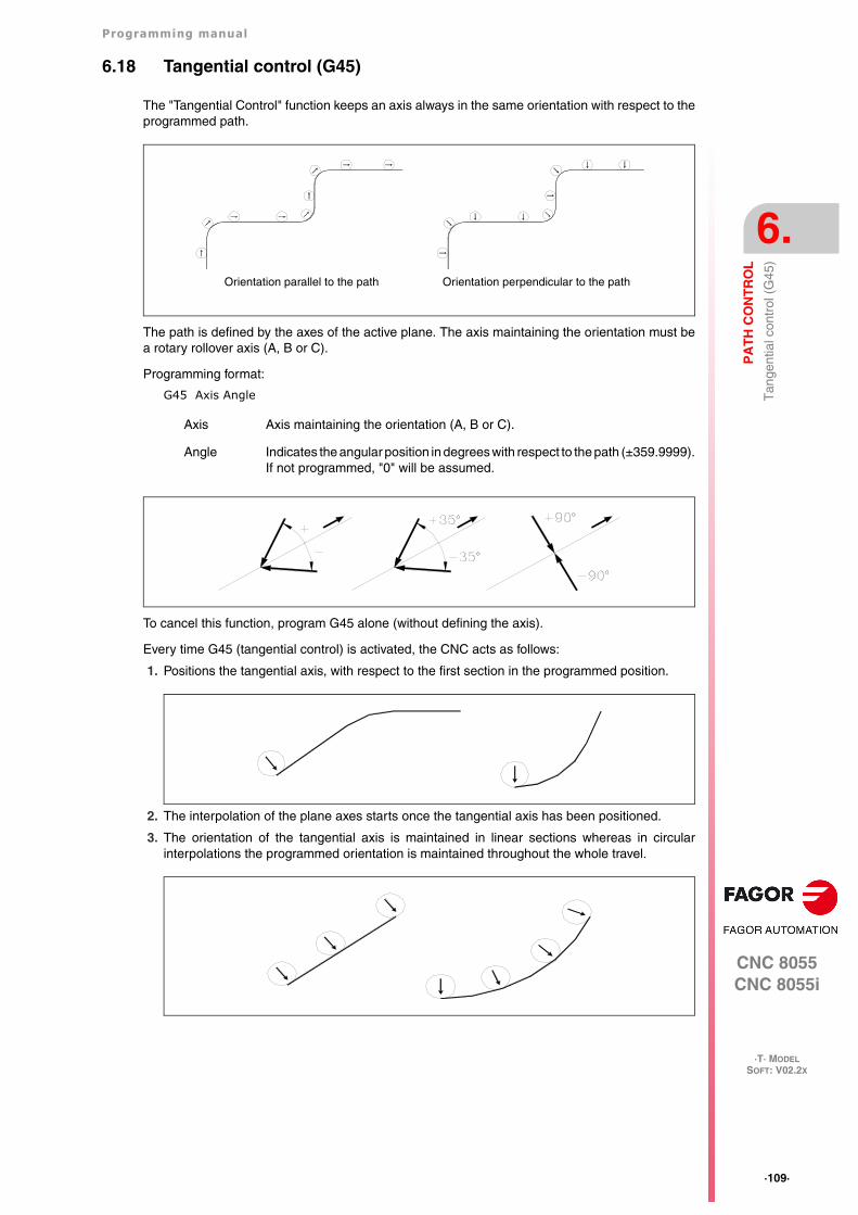
Programming manual
CNC 8055CNC 8055i
PA
TH
CO
NT
RO
L
6.
·T· MODELSOFT: V02.2X
·109·
Tan
gent
ial c
ontr
ol (
G45
)
6.18 Tangential control (G45)
The "Tangential Control" function keeps an axis always in the same orientation with respect to theprogrammed path.
The path is defined by the axes of the active plane. The axis maintaining the orientation must bea rotary rollover axis (A, B or C).
Programming format:
G45 Axis Angle
To cancel this function, program G45 alone (without defining the axis).
Every time G45 (tangential control) is activated, the CNC acts as follows:
1. Positions the tangential axis, with respect to the first section in the programmed position.
2. The interpolation of the plane axes starts once the tangential axis has been positioned.
3. The orientation of the tangential axis is maintained in linear sections whereas in circularinterpolations the programmed orientation is maintained throughout the whole travel.
Axis Axis maintaining the orientation (A, B or C).
Angle Indicates the angular position in degrees with respect to the path (±359.9999).If not programmed, "0" will be assumed.
Orientation parallel to the path Orientation perpendicular to the path
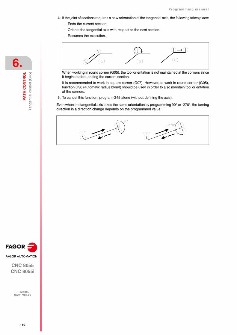
·110·
Programming manual
CNC 8055CNC 8055i
6.
PA
TH
CO
NT
RO
L
·T· MODELSOFT: V02.2X
Tan
gent
ial c
ontr
ol (
G45
)
4. If the joint of sections requires a new orientation of the tangential axis, the following takes place:
Ends the current section.
Orients the tangential axis with respect to the next section.
Resumes the execution.
When working in round corner (G05), the tool orientation is not maintained at the corners sinceit begins before ending the current section.
It is recommended to work in square corner (G07). However, to work in round corner (G05),function G36 (automatic radius blend) should be used in order to also maintain tool orientationat the corners.
5. To cancel this function, program G45 alone (without defining the axis).
Even when the tangential axis takes the same orientation by programming 90° or -270°, the turningdirection in a direction change depends on the programmed value.
Programming manual
CNC 8055CNC 8055i
PA
TH
CO
NT
RO
L
6.
·T· MODELSOFT: V02.2X
·111·
Tan
gent
ial c
ontr
ol (
G45
)
6.18.1 Considerations about the G45 function
Tangential control, G45, is optional. It can only be executed in the main channel and is compatiblewith:
• Tool radius and length compensation (G40, 41, 42, 43, 44).
• Mirror image (G10, 11, 12, 13 14).
• Gantry axes , including the gantry axis associated with the tangential rotary axis.
The maximum feedrate while orienting the tangential axis is defined by machine parameterMAXFEED for that axis.
While tangential control is active, tool inspection is also possible. When accessing tool inspection,the tangential control is deactivated, the axes are free and when quitting tool inspection, tangentialcontrol may be activated again.
While in JOG mode, tangential control may be activated in MDI mode and the axes may be movedby programming blocks in MDI.
Tangential control is canceled when jogging the axes with the jog keys (not in MDI). Once themovement is over, tangential control is recovered.
Likewise, the following is NOT possible:
• To define as tangential axis, one of the plane axes, the longitudinal axis or any other axis whichis not rotary.
• To jog the tangential axis in JOG mode or by program using another G code while tangentialcontrol is active.
• Inclined planes.
The TANGAN variable is read-only, from the CNC, PLC and DNC, associated with function G45.It indicates the angular position, in degrees, referred to the programmed path.
Also, general logic output TANGACT (M5558) indicates to the PLC that function G45 is active.
Function G45 is modal and is canceled when executing G45 alone (without defining the axis), onpower-up, after executing an M02 or M30 or after an EMERGENCY or RESET.
·112·
Programming manual
CNC 8055CNC 8055i
6.
PA
TH
CO
NT
RO
L
·T· MODELSOFT: V02.2X
G14
5. T
empo
rary
can
cella
tion
of ta
ngen
tial c
ontr
ol
6.19 G145. Temporary cancellation of tangential control
Function G145 may be used to cancel the tangential control (G415) temporarily:
G145 K0
It cancels the tangential control temporarily. Function G45 stays in the history and the new functionG145 comes up in it.
If no G45 has been programmed, G145 is ignored. If K is not programmed, K0 will be assumed.
G145 K1
It resumes the tangential control of the axis with the angle it had before it was canceled. Then, G145disappears from history.
CNC 8055CNC 8055i
·T· MODELSOFT: V02.2X
7
·113·
ADDITIONAL PREPARATORY FUNCTIONS
7.1 Interruption of block preparation (G04)
The CNC reads up to 20 blocks ahead of the one it is executing, with the aim of calculatingbeforehand the path to be followed.
Each block is evaluated (in its absence) at the time it is read, but if you wish to evaluate it at thetime of execution of the block you use function G04.
This function holds up the preparation of blocks and waits for the block in question to be executedin order to start the preparation of blocks once more.
A case in point is the evaluation of the "status of block-skip inputs" which is defined in the blockheader.
Example:
.
.G04; Interrupts block preparation
/1 G01 X10 Z20 ; block-skip condition "/1"..
Function G04 is not modal, so it should be programmed whenever you wish to interrupt blockpreparation.
It should be programmed on its own and in the block previous to the one in which the evaluationin execution is required. Function G04 can be programmed as G4.
Every time G04 is programmed, active radius and length compensation are cancelled.
For this reason, care needs to be taken when using this function, because if it is introduced betweenmachining blocks which work with compensation, unwanted profiles may be produced.
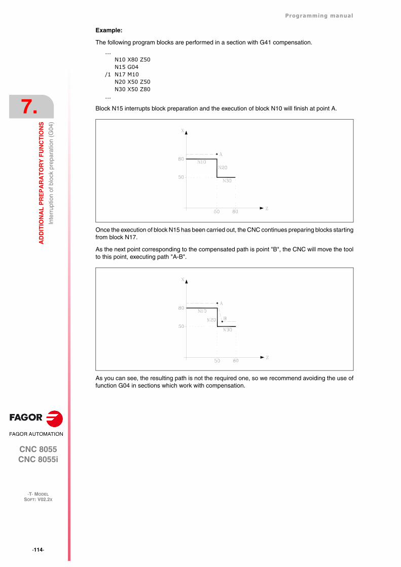
·114·
Programming manual
CNC 8055CNC 8055i
7.
AD
DIT
ION
AL
PR
EP
AR
AT
OR
Y F
UN
CT
ION
S
·T· MODELSOFT: V02.2X
Inte
rrup
tion
of b
lock
pre
para
tion
(G04
)
Example:
The following program blocks are performed in a section with G41 compensation.
...N10 X80 Z50N15 G04
/1 N17 M10N20 X50 Z50N30 X50 Z80
...
Block N15 interrupts block preparation and the execution of block N10 will finish at point A.
Once the execution of block N15 has been carried out, the CNC continues preparing blocks startingfrom block N17.
As the next point corresponding to the compensated path is point "B", the CNC will move the toolto this point, executing path "A-B".
As you can see, the resulting path is not the required one, so we recommend avoiding the use offunction G04 in sections which work with compensation.
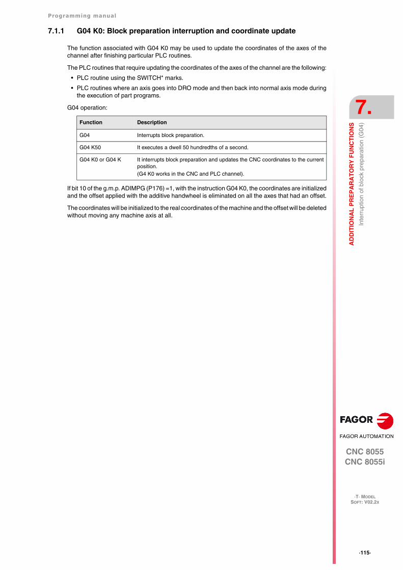
Programming manual
CNC 8055CNC 8055i
AD
DIT
ION
AL
PR
EP
AR
AT
OR
Y F
UN
CT
ION
S
7.
·T· MODELSOFT: V02.2X
·115·
Inte
rrup
tion
of b
lock
pre
para
tion
(G04
)
7.1.1 G04 K0: Block preparation interruption and coordinate update
The function associated with G04 K0 may be used to update the coordinates of the axes of thechannel after finishing particular PLC routines.
The PLC routines that require updating the coordinates of the axes of the channel are the following:
• PLC routine using the SWITCH* marks.
• PLC routines where an axis goes into DRO mode and then back into normal axis mode duringthe execution of part programs.
G04 operation:
If bit 10 of the g.m.p. ADIMPG (P176) =1, with the instruction G04 K0, the coordinates are initializedand the offset applied with the additive handwheel is eliminated on all the axes that had an offset.
The coordinates will be initialized to the real coordinates of the machine and the offset will be deletedwithout moving any machine axis at all.
Function Description
G04 Interrupts block preparation.
G04 K50 It executes a dwell 50 hundredths of a second.
G04 K0 or G04 K It interrupts block preparation and updates the CNC coordinates to the currentposition.(G4 K0 works in the CNC and PLC channel).
·116·
Programming manual
CNC 8055CNC 8055i
7.
AD
DIT
ION
AL
PR
EP
AR
AT
OR
Y F
UN
CT
ION
S
·T· MODELSOFT: V02.2X
Dw
ell (
G04
K)
7.2 Dwell (G04 K)
A dwell can be programmed via function G04 K.
The dwell value is programmed in hundredths of a second via format K5 (1..99999).
Example:
G04 K50 ; Dwell of 50 hundredths of a second (0.5 seconds)G04 K200 ; Dwell of 200 hundredths of a second (2 seconds)
Function G04 K is not modal, so it should be programmed whenever a dwell is required. FunctionG04 K can be programmed as G4 K.
The dwell is executed at the beginning of the block in which it is programmed.
Note: When programming G04 K0 or G04 K, instead of applying a delay, it only interrupts blockpreparation and it will refresh the coordinates. See "7.1.1 G04 K0: Block preparationinterruption and coordinate update" on page 115.
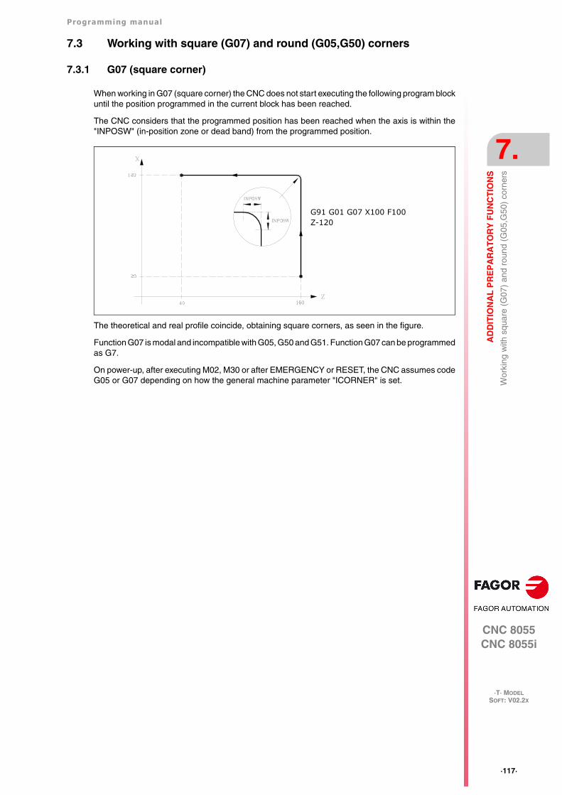
Programming manual
CNC 8055CNC 8055i
AD
DIT
ION
AL
PR
EP
AR
AT
OR
Y F
UN
CT
ION
S
7.
·T· MODELSOFT: V02.2X
·117·
Wor
king
with
squ
are
(G07
) an
d ro
und
(G05
,G50
) co
rner
s
7.3 Working with square (G07) and round (G05,G50) corners
7.3.1 G07 (square corner)
When working in G07 (square corner) the CNC does not start executing the following program blockuntil the position programmed in the current block has been reached.
The CNC considers that the programmed position has been reached when the axis is within the"INPOSW" (in-position zone or dead band) from the programmed position.
The theoretical and real profile coincide, obtaining square corners, as seen in the figure.
Function G07 is modal and incompatible with G05, G50 and G51. Function G07 can be programmedas G7.
On power-up, after executing M02, M30 or after EMERGENCY or RESET, the CNC assumes codeG05 or G07 depending on how the general machine parameter "ICORNER" is set.
G91 G01 G07 X100 F100Z-120
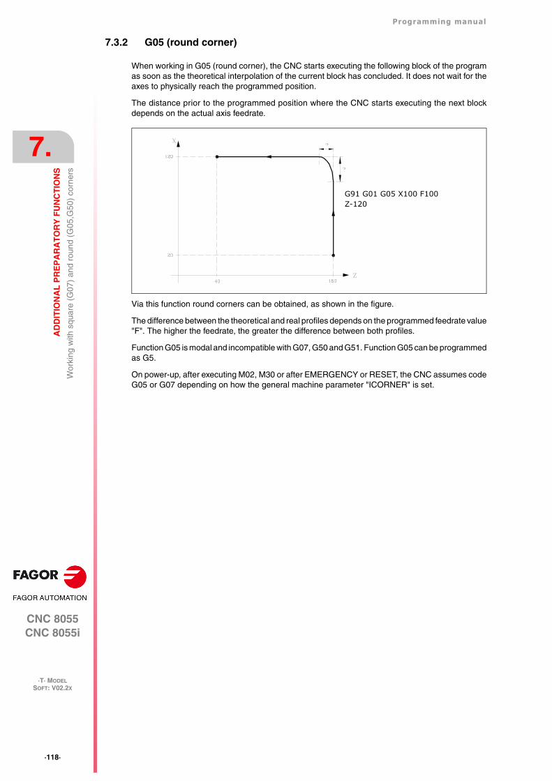
·118·
Programming manual
CNC 8055CNC 8055i
7.
AD
DIT
ION
AL
PR
EP
AR
AT
OR
Y F
UN
CT
ION
S
·T· MODELSOFT: V02.2X
Wor
king
with
squ
are
(G07
) an
d ro
und
(G05
,G50
) co
rner
s
7.3.2 G05 (round corner)
When working in G05 (round corner), the CNC starts executing the following block of the programas soon as the theoretical interpolation of the current block has concluded. It does not wait for theaxes to physically reach the programmed position.
The distance prior to the programmed position where the CNC starts executing the next blockdepends on the actual axis feedrate.
Via this function round corners can be obtained, as shown in the figure.
The difference between the theoretical and real profiles depends on the programmed feedrate value"F". The higher the feedrate, the greater the difference between both profiles.
Function G05 is modal and incompatible with G07, G50 and G51. Function G05 can be programmedas G5.
On power-up, after executing M02, M30 or after EMERGENCY or RESET, the CNC assumes codeG05 or G07 depending on how the general machine parameter "ICORNER" is set.
G91 G01 G05 X100 F100Z-120
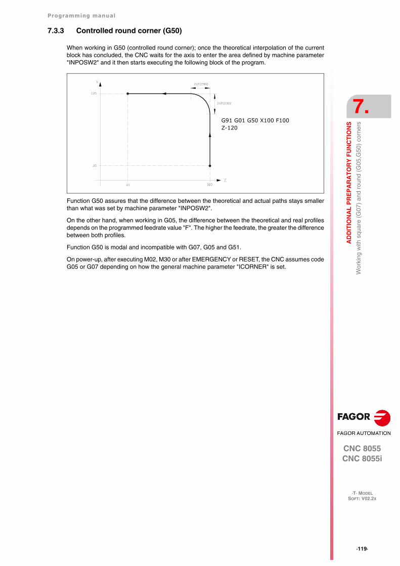
Programming manual
CNC 8055CNC 8055i
AD
DIT
ION
AL
PR
EP
AR
AT
OR
Y F
UN
CT
ION
S
7.
·T· MODELSOFT: V02.2X
·119·
Wor
king
with
squ
are
(G07
) an
d ro
und
(G05
,G50
) co
rner
s
7.3.3 Controlled round corner (G50)
When working in G50 (controlled round corner); once the theoretical interpolation of the currentblock has concluded, the CNC waits for the axis to enter the area defined by machine parameter"INPOSW2" and it then starts executing the following block of the program.
Function G50 assures that the difference between the theoretical and actual paths stays smallerthan what was set by machine parameter "INPOSW2".
On the other hand, when working in G05, the difference between the theoretical and real profilesdepends on the programmed feedrate value "F". The higher the feedrate, the greater the differencebetween both profiles.
Function G50 is modal and incompatible with G07, G05 and G51.
On power-up, after executing M02, M30 or after EMERGENCY or RESET, the CNC assumes codeG05 or G07 depending on how the general machine parameter "ICORNER" is set.
G91 G01 G50 X100 F100Z-120
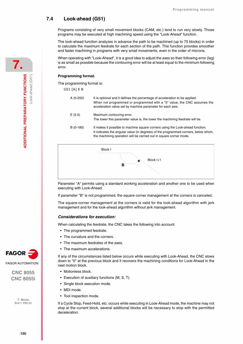
·120·
Programming manual
CNC 8055CNC 8055i
7.
AD
DIT
ION
AL
PR
EP
AR
AT
OR
Y F
UN
CT
ION
S
·T· MODELSOFT: V02.2X
Look
-ahe
ad (
G51
)
7.4 Look-ahead (G51)
Programs consisting of very small movement blocks (CAM, etc.) tend to run very slowly. Thoseprograms may be executed at high machining speed using the "Look-Ahead" function.
The look-ahead function analyzes in advance the path to be machined (up to 75 blocks) in orderto calculate the maximum feedrate for each section of the path. This function provides smootherand faster machining in programs with very small movements, even in the order of microns.
When operating with "Look-Ahead", it is a good idea to adjust the axes so their following error (lag)is as small as possible because the contouring error will be at least equal to the minimum followingerror.
Programming format.
The programming format is:
G51 [A] E B
Parameter "A" permits using a standard working acceleration and another one to be used whenexecuting with Look-Ahead.
If parameter "B" is not programmed, the square corner management at the corners is canceled.
The square-corner management at the corners is valid for the look-ahead algorithm with jerkmanagement and for the look-ahead algorithm without jerk management.
Considerations for execution:
When calculating the feedrate, the CNC takes the following into account:
• The programmed feedrate.
• The curvature and the corners.
• The maximum feedrates of the axes.
• The maximum accelerations.
If any of the circumstances listed below occurs while executing with Look-Ahead, the CNC slowsdown to "0" at the previous block and it recovers the machining conditions for Look-Ahead in thenext motion block.
• Motionless block.
• Execution of auxiliary functions (M, S, T).
• Single block execution mode.
• MDI mode.
• Tool inspection mode.
If a Cycle Stop, Feed-Hold, etc. occurs while executing in Look-Ahead mode, the machine may notstop at the current block, several additional blocks will be necessary to stop with the permitteddeceleration.
A (0-255) It is optional and it defines the percentage of acceleration to be applied.When not programmed or programmed with a "0" value, the CNC assumes theacceleration value set by machine parameter for each axis.
E (5.5) Maximum contouring error.The lower this parameter value is, the lower the machining feedrate will be.
B (0-180) It makes it possible to machine square corners using the Look-ahead function.It indicates the angular value (in degrees) of the programmed corners, below which,the machining operation will be carried out in square corner mode.
BBlock I+1
Block I
Programming manual
CNC 8055CNC 8055i
AD
DIT
ION
AL
PR
EP
AR
AT
OR
Y F
UN
CT
ION
S
7.
·T· MODELSOFT: V02.2X
·121·
Look
-ahe
ad (
G51
)
To prevent motionless blocks from causing a square-corner effect, change bit 0 of general machineparameter MANTFCON (P189).
Function properties.
Function G51 is modal and incompatible with G05, G07 and G50. Should any of them beprogrammed, function G51 will be canceled and the new one will be selected.
Function G51 must be programmed alone in a block and there must be no more information in thatblock.
On power-up, after executing an M02, M30, of after an EMERGENCY or RESET, the CNC will cancelG51, if it was active, and it will assume G05 or G07 according to the setting of general machineparameter "ICORNER".
On the other hand, the CNC will issue Error 7 (Incompatible G functions) when programming anyof the following functions while G51 is active:
G33 Electronic threading (G33)
G34 Variable-pitch threading.
G52 Move to hardstop.
G95 Feedrate per revolution.
·122·
Programming manual
CNC 8055CNC 8055i
7.
AD
DIT
ION
AL
PR
EP
AR
AT
OR
Y F
UN
CT
ION
S
·T· MODELSOFT: V02.2X
Look
-ahe
ad (
G51
)
7.4.1 Advanced look-ahead algorithm (integrating Fagor filters)
This mode is indicated when machining accuracy is required, especially if Fagor filters have beenset for the axes by machine parameters.
The advanced look-ahead algorithm calculates the feedrates at the corners so as to take the effectof those filters into consideration. When programming G51 E, the contouring errors when machiningcorners will be closer to the value programmed in that G51 function depending on the filters.
To activate the advanced look-ahead algorithm, use bit 15 of g.m.p. LOOKATYP (P160).
Considerations
• If there are no Fagor filters set by machine parameters in the axes of the main channel, activatingthe advanced look-ahead algorithm will internally activate FIR filters of the 5th order and afrequency of 30 Hz in all the axes of the channel.
• If there are Fagor filters set by machine parameters, activating the advanced look-aheadalgorithm will keep the values of those filters as long as their frequency is not higher than 30Hz
If their frequency is higher than 30 Hz, it will assume the values of 5th order and a frequencyof 30 Hz.
If there are several filters defined in the axes of the channel, the one with the lowest frequencywill be assumed as long as it is not higher than 30Hz.
• Even if the advanced look-ahead algorithm (using Fagor filters) is active with bit 15 of g.m.p.LOOKATYP (P160), it will not start working in the following cases:
If g.m.p. IPOTIME (P73) = 1.
If any of the axes of the main channel has a.m.p. SMOTIME (P58) not equal to 0.
If any of the axes of the main channel has defined by parameter a non-Fagor type filter, a.m.p.TYPE (P71) not equal to 2.
In these cases, when activating G51, the CNC will issue the corresponding error message.
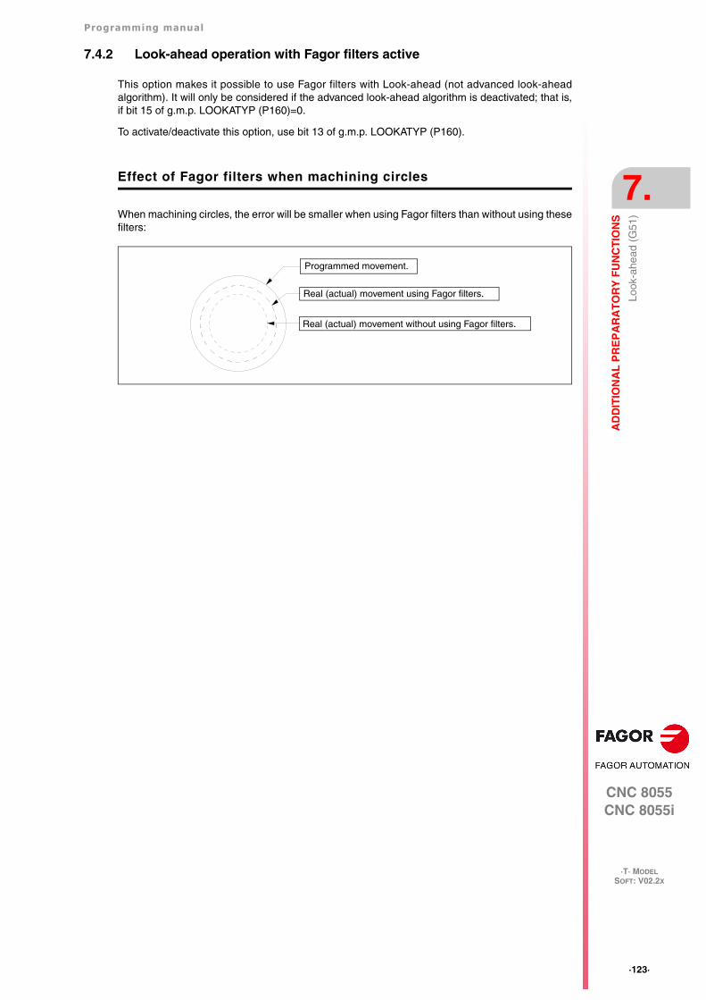
Programming manual
CNC 8055CNC 8055i
AD
DIT
ION
AL
PR
EP
AR
AT
OR
Y F
UN
CT
ION
S
7.
·T· MODELSOFT: V02.2X
·123·
Look
-ahe
ad (
G51
)
7.4.2 Look-ahead operation with Fagor filters active
This option makes it possible to use Fagor filters with Look-ahead (not advanced look-aheadalgorithm). It will only be considered if the advanced look-ahead algorithm is deactivated; that is,if bit 15 of g.m.p. LOOKATYP (P160)=0.
To activate/deactivate this option, use bit 13 of g.m.p. LOOKATYP (P160).
Effect of Fagor filters when machining circles
When machining circles, the error will be smaller when using Fagor filters than without using thesefilters:
Programmed movement.
Real (actual) movement using Fagor filters.
Real (actual) movement without using Fagor filters.
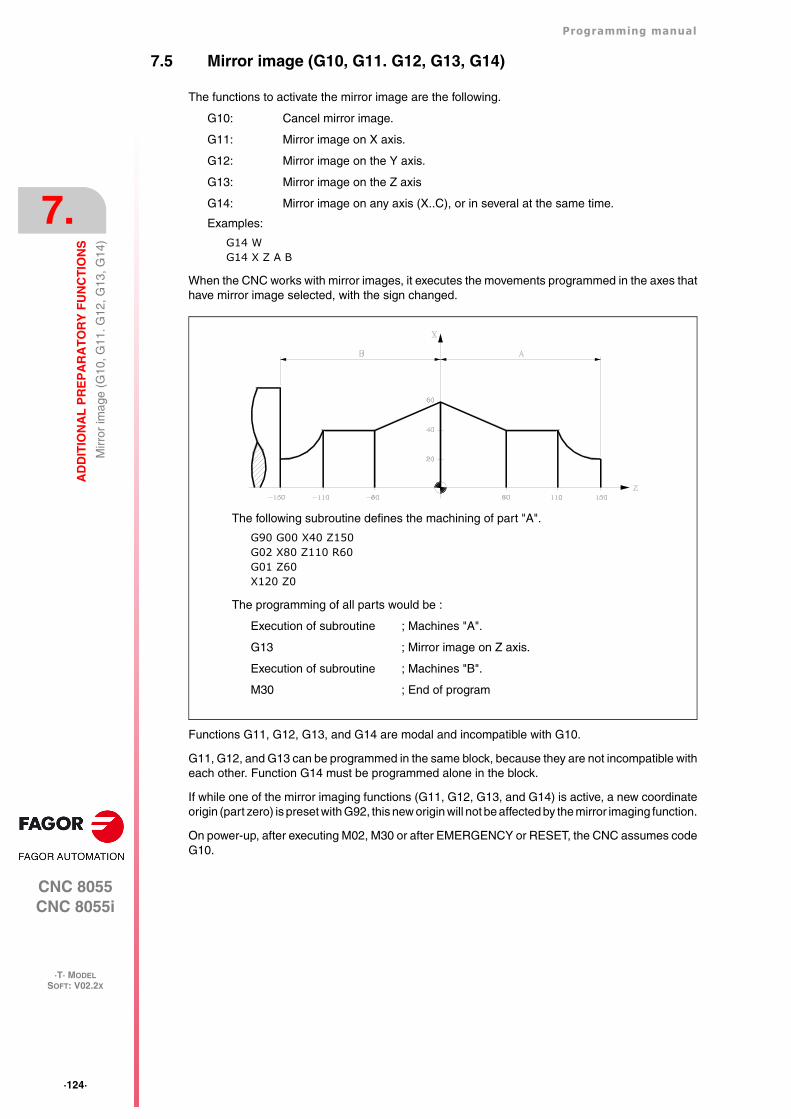
·124·
Programming manual
CNC 8055CNC 8055i
7.
AD
DIT
ION
AL
PR
EP
AR
AT
OR
Y F
UN
CT
ION
S
·T· MODELSOFT: V02.2X
Mirr
or im
age
(G10
, G11
. G12
, G13
, G14
)
7.5 Mirror image (G10, G11. G12, G13, G14)
The functions to activate the mirror image are the following.
G10: Cancel mirror image.
G11: Mirror image on X axis.
G12: Mirror image on the Y axis.
G13: Mirror image on the Z axis
G14: Mirror image on any axis (X..C), or in several at the same time.
Examples:
G14 WG14 X Z A B
When the CNC works with mirror images, it executes the movements programmed in the axes thathave mirror image selected, with the sign changed.
Functions G11, G12, G13, and G14 are modal and incompatible with G10.
G11, G12, and G13 can be programmed in the same block, because they are not incompatible witheach other. Function G14 must be programmed alone in the block.
If while one of the mirror imaging functions (G11, G12, G13, and G14) is active, a new coordinateorigin (part zero) is preset with G92, this new origin will not be affected by the mirror imaging function.
On power-up, after executing M02, M30 or after EMERGENCY or RESET, the CNC assumes codeG10.
The following subroutine defines the machining of part "A".
G90 G00 X40 Z150G02 X80 Z110 R60G01 Z60X120 Z0
The programming of all parts would be :
Execution of subroutine ; Machines "A".
G13 ; Mirror image on Z axis.
Execution of subroutine ; Machines "B".
M30 ; End of program
Programming manual
CNC 8055CNC 8055i
AD
DIT
ION
AL
PR
EP
AR
AT
OR
Y F
UN
CT
ION
S
7.
·T· MODELSOFT: V02.2X
·125·
Sca
ling
fact
or (
G72
)
7.6 Scaling factor (G72)
By using function G72 you can enlarge or reduce programmed parts.
In this way, you can produce families of parts which are similar in shape but of different sizes witha single program.
Function G72 should be programmed on its own in a block. There are two formats for programmingG72 :
• Scaling factor applied to all axes.
• Scaling factor applied to one or more axes.
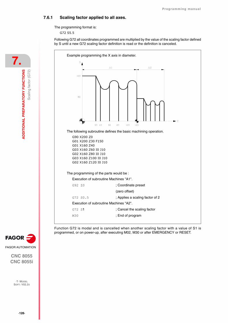
·126·
Programming manual
CNC 8055CNC 8055i
7.
AD
DIT
ION
AL
PR
EP
AR
AT
OR
Y F
UN
CT
ION
S
·T· MODELSOFT: V02.2X
Sca
ling
fact
or (
G72
)
7.6.1 Scaling factor applied to all axes.
The programming format is:
G72 S5.5
Following G72 all coordinates programmed are multiplied by the value of the scaling factor definedby S until a new G72 scaling factor definition is read or the definition is canceled.
Function G72 is modal and is cancelled when another scaling factor with a value of S1 isprogrammed, or on power-up, after executing M02, M30 or after EMERGENCY or RESET.
The following subroutine defines the basic machining operation.
G90 X200 Z0G01 X200 Z30 F150G01 X160 Z40G03 X160 Z60 I0 J10G02 X160 Z80 I0 J10G03 X160 Z100 I0 J10G02 X160 Z120 I0 J10
The programming of the parts would be :
Execution of subroutine Machines "A1".
G92 Z0 ; Coordinate preset
(zero offset)
G72 S0.5 ; Applies a scaling factor of 2
Execution of subroutine Machines "A2".
G72 S1 ; Cancel the scaling factor
M30 ; End of program
Example programming the X axis in diameter.
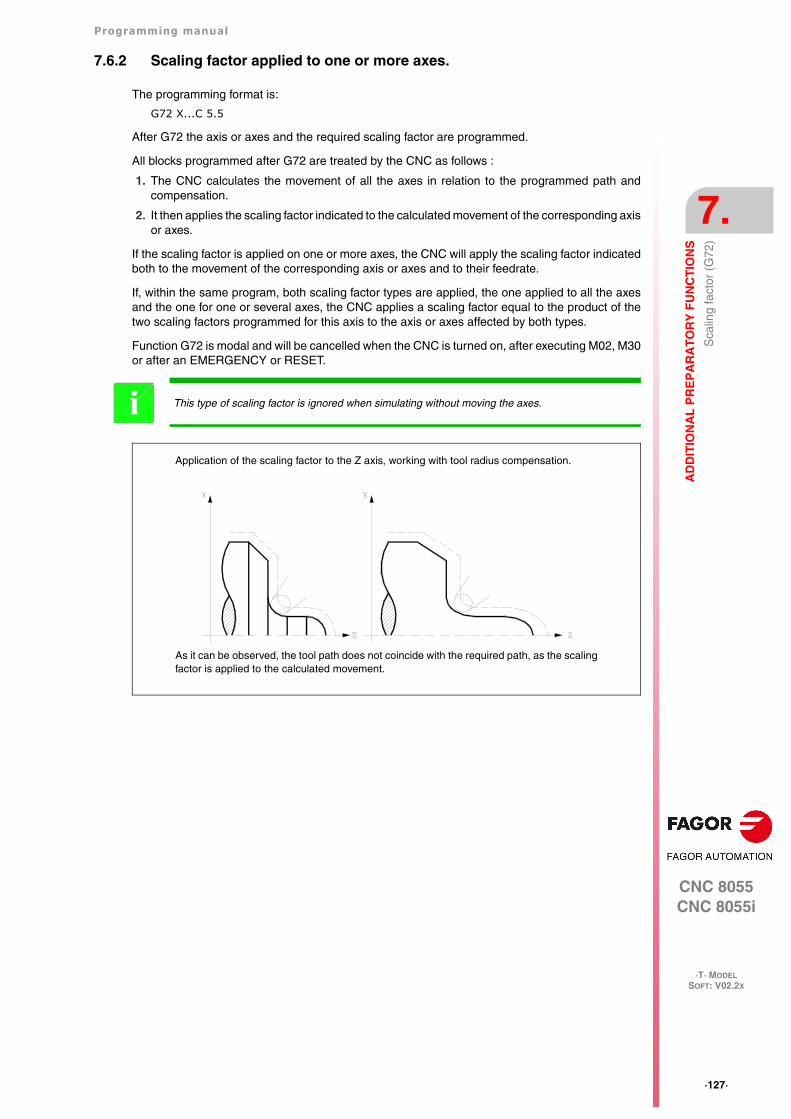
Programming manual
CNC 8055CNC 8055i
AD
DIT
ION
AL
PR
EP
AR
AT
OR
Y F
UN
CT
ION
S
7.
·T· MODELSOFT: V02.2X
·127·
Sca
ling
fact
or (
G72
)
7.6.2 Scaling factor applied to one or more axes.
The programming format is:
G72 X...C 5.5
After G72 the axis or axes and the required scaling factor are programmed.
All blocks programmed after G72 are treated by the CNC as follows :
1. The CNC calculates the movement of all the axes in relation to the programmed path andcompensation.
2. It then applies the scaling factor indicated to the calculated movement of the corresponding axisor axes.
If the scaling factor is applied on one or more axes, the CNC will apply the scaling factor indicatedboth to the movement of the corresponding axis or axes and to their feedrate.
If, within the same program, both scaling factor types are applied, the one applied to all the axesand the one for one or several axes, the CNC applies a scaling factor equal to the product of thetwo scaling factors programmed for this axis to the axis or axes affected by both types.
Function G72 is modal and will be cancelled when the CNC is turned on, after executing M02, M30or after an EMERGENCY or RESET.
This type of scaling factor is ignored when simulating without moving the axes.i
As it can be observed, the tool path does not coincide with the required path, as the scalingfactor is applied to the calculated movement.
Application of the scaling factor to the Z axis, working with tool radius compensation.
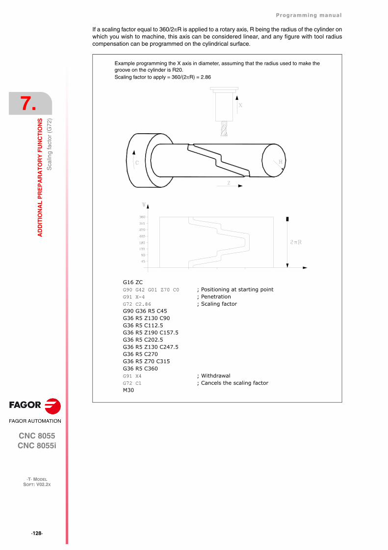
·128·
Programming manual
CNC 8055CNC 8055i
7.
AD
DIT
ION
AL
PR
EP
AR
AT
OR
Y F
UN
CT
ION
S
·T· MODELSOFT: V02.2X
Sca
ling
fact
or (
G72
)
If a scaling factor equal to 360/2R is applied to a rotary axis, R being the radius of the cylinder onwhich you wish to machine, this axis can be considered linear, and any figure with tool radiuscompensation can be programmed on the cylindrical surface.
Example programming the X axis in diameter, assuming that the radius used to make thegroove on the cylinder is R20.Scaling factor to apply = 360/(2R) = 2.86
G16 ZCG90 G42 G01 Z70 C0 ; Positioning at starting pointG91 X-4 ; PenetrationG72 C2.86 ; Scaling factorG90 G36 R5 C45G36 R5 Z130 C90G36 R5 C112.5G36 R5 Z190 C157.5G36 R5 C202.5G36 R5 Z130 C247.5G36 R5 C270G36 R5 Z70 C315G36 R5 C360G91 X4 ; WithdrawalG72 C1 ; Cancels the scaling factorM30
Programming manual
CNC 8055CNC 8055i
AD
DIT
ION
AL
PR
EP
AR
AT
OR
Y F
UN
CT
ION
S
7.
·T· MODELSOFT: V02.2X
·129·
Ele
ctro
nic
axis
cou
plin
g/un
coup
ling
7.7 Electronic axis coupling/uncoupling
The CNC enables two or more axes to be coupled together. The movement of all axes issubordinated to the movement of the axis to which they were coupled.
There are three possible ways of coupling axes :
• Mechanical coupling. This is imposed by the manufacturer of the machine, and is selected viathe axis machine parameter "GANTRY".
• By PLC. This enables the coupling and uncoupling of each axis through logic input on the CNC"SYNCHRO1", "SYNCHRO2", "SYNCHRO3", "SYNCHRO4", and "SYNCHRO5". Each axis iscoupled to the one indicated in the axis machine parameter "SYNCHRO".
• By program. This enables electronic coupling and uncoupling between two or more axes,through functions G77 and G78.
·130·
Programming manual
CNC 8055CNC 8055i
7.
AD
DIT
ION
AL
PR
EP
AR
AT
OR
Y F
UN
CT
ION
S
·T· MODELSOFT: V02.2X
Ele
ctro
nic
axis
cou
plin
g/un
coup
ling
7.7.1 Electronic axis coupling, slaving, (G77)
Function G77 allows the selection of both the master axis and the slaved axis (axes). Theprogramming format is as follows :
G77 <Axis 1> <Axis 2> <Axis 3> <Axis 4> <Axis 5>
Where <Axis 2>, <Axis 3>, <Axis 4> and <Axis 5> will indicate the axes to be coupled to <Axis1>. You have to define <Axis 1> and <Axis 2>, the programming of the rest of the axes beingoptional.
Example:
G77 X Y U ; Couples the Y and U axes to the X axis
The following rules should be observed when slaving axes electronically:
• You may use one or two different electronic couplings.
G77 X Y U ; Couples the Y and U axes to the X axis
G77 V Z ; Couples the Z axis to the V axis.
• You cannot couple one axis to two others at the same time.
G77 V Y ; Couples the Y axis to the V axis.
G77 X Y ; Gives an error signal, because the Y axis is coupled to the V axis.
• You can couple several axes to one in successive steps.
G77 X Z ; Couples the Z axis to the X axis.
G77 X U ; Couples the U axis to the X axis — Z U coupled to X.
G77 X Y ; Couples the Y axis to the X axis —Y Z U coupled to X.
• A pair of axes which are already coupled to each other cannot be coupled to another axis.
G77 Y U ; Couples the U axis to the Y axis.
G77 X Y ; Issues an error because Y axis is coupled to U axis.
Programming manual
CNC 8055CNC 8055i
AD
DIT
ION
AL
PR
EP
AR
AT
OR
Y F
UN
CT
ION
S
7.
·T· MODELSOFT: V02.2X
·131·
Ele
ctro
nic
axis
cou
plin
g/un
coup
ling
7.7.2 Cancellation of the electronic axis coupling, slaving, (G78)
Function G78 enables you to uncouple all the axes that are coupled (slaved), or only uncoupleindicated axes.
Example.
G77 X Y U ; Couples the Y and U axes to the X axis
G77 V Z ; Couples the Z axis to the V axis
G78 Y ; Uncouples Y axis, but U stays coupled to X and Z to V.
G78 ; Uncouples all axes
G78 Uncouples all slaved axes.
G78 <Axis1> <Axis2> <Axis3> <Axis4> Only uncouples the indicated axes.
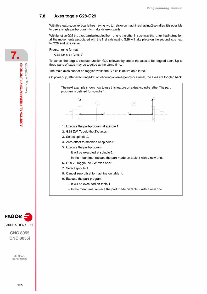
·132·
Programming manual
CNC 8055CNC 8055i
7.
AD
DIT
ION
AL
PR
EP
AR
AT
OR
Y F
UN
CT
ION
S
·T· MODELSOFT: V02.2X
Axe
s to
ggle
G28
-G29
7.8 Axes toggle G28-G29
With this feature, on vertical lathes having two turrets or on machines having 2 spindles, it is possibleto use a single part-program to make different parts.
With function G28 the axes can be toggled from one to the other in such way that after that instructionall the movements associated with the first axis next to G28 will take place on the second axis nextto G28 and vice versa.
Programming format:
G28 (axis 1) (axis 2)
To cancel the toggle, execute function G29 followed by one of the axes to be toggled back. Up tothree pairs of axes may be toggled at the same time.
The main axes cannot be toggled while the C axis is active on a lathe.
On power-up, after executing M30 or following an emergency or a reset, the axes are toggled back.
The next example shows how to use this feature on a dual-spindle lathe. The partprogram is defined for spindle 1.
1. Execute the part-program at spindle 1.
2. G28 ZW. Toggle the ZW axes.
3. Select spindle 2.
4. Zero offset to machine at spindle 2.
5. Execute the part-program.
It will be executed at spindle 2.
In the meantime, replace the part made on table 1 with a new one.
6. G29 Z. Toggle the ZW axes back.
7. Select spindle 1.
8. Cancel zero offset to machine on table 1.
9. Execute the part-program.
It will be executed on table 1.
In the meantime, replace the part made on table 2 with a new one.
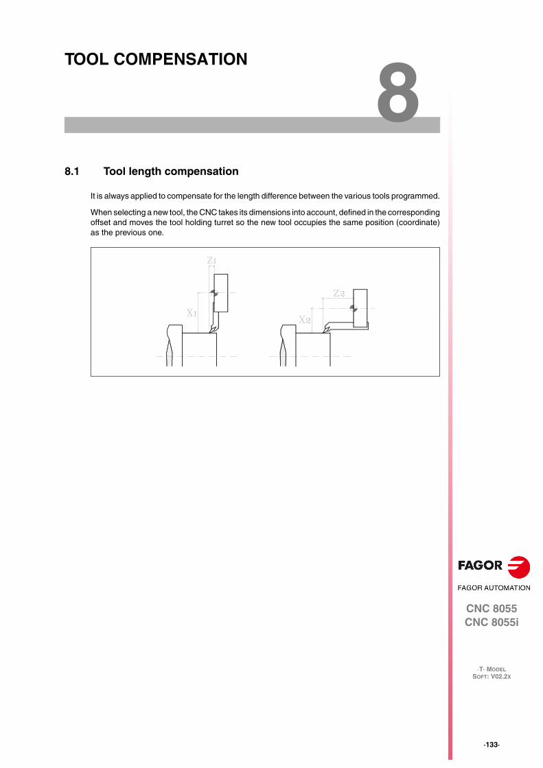
CNC 8055CNC 8055i
·T· MODELSOFT: V02.2X
8
·133·
TOOL COMPENSATION
8.1 Tool length compensation
It is always applied to compensate for the length difference between the various tools programmed.
When selecting a new tool, the CNC takes its dimensions into account, defined in the correspondingoffset and moves the tool holding turret so the new tool occupies the same position (coordinate)as the previous one.
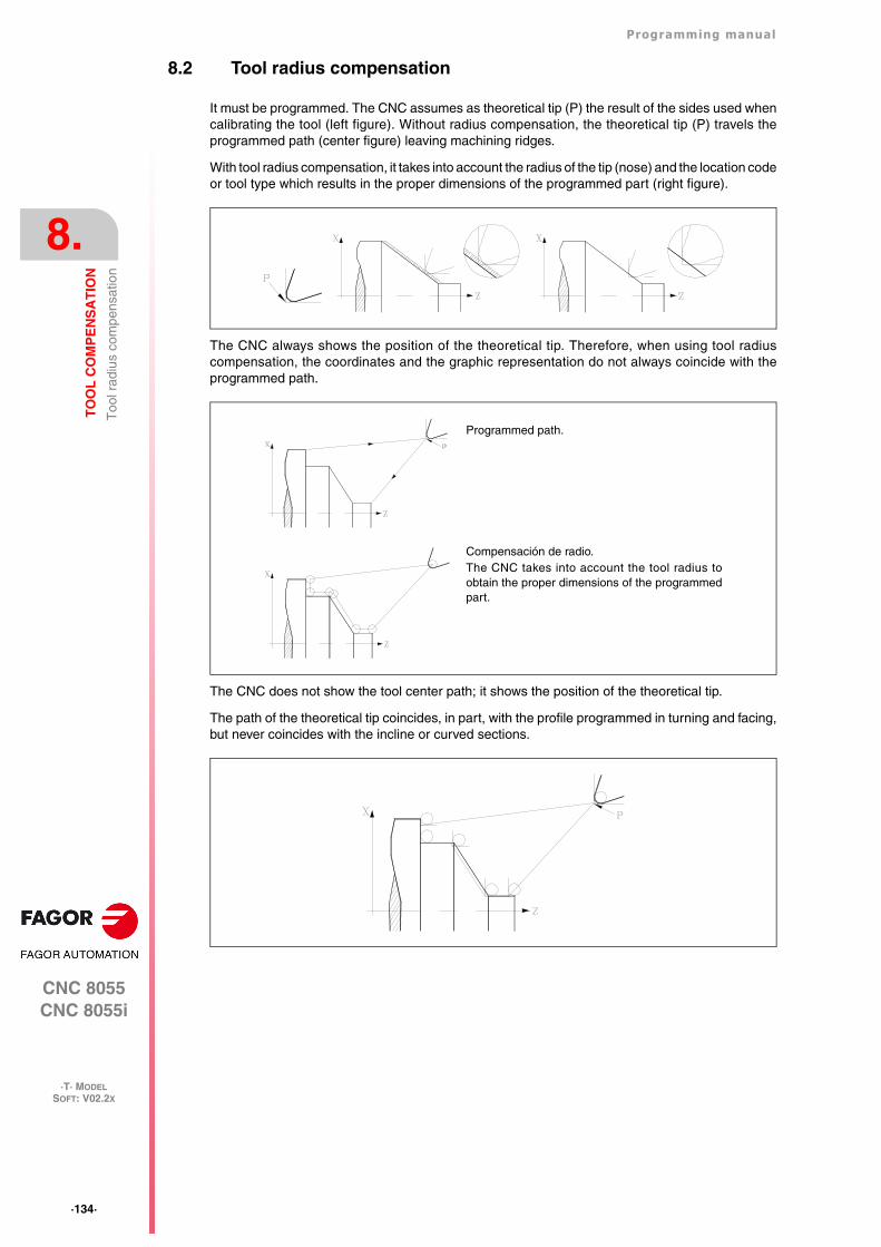
·134·
Programming manual
CNC 8055CNC 8055i
8.
TO
OL
CO
MP
EN
SA
TIO
N
·T· MODELSOFT: V02.2X
Too
l rad
ius
com
pens
atio
n
8.2 Tool radius compensation
It must be programmed. The CNC assumes as theoretical tip (P) the result of the sides used whencalibrating the tool (left figure). Without radius compensation, the theoretical tip (P) travels theprogrammed path (center figure) leaving machining ridges.
With tool radius compensation, it takes into account the radius of the tip (nose) and the location codeor tool type which results in the proper dimensions of the programmed part (right figure).
The CNC always shows the position of the theoretical tip. Therefore, when using tool radiuscompensation, the coordinates and the graphic representation do not always coincide with theprogrammed path.
The CNC does not show the tool center path; it shows the position of the theoretical tip.
The path of the theoretical tip coincides, in part, with the profile programmed in turning and facing,but never coincides with the incline or curved sections.
Programmed path.
Compensación de radio.The CNC takes into account the tool radius toobtain the proper dimensions of the programmedpart.

Programming manual
CNC 8055CNC 8055i
TO
OL
CO
MP
EN
SA
TIO
N
8.
·T· MODELSOFT: V02.2X
·135·
Too
l rad
ius
com
pens
atio
n
8.2.1 The location code of the tool (tool type)
The location code indicates the type of tool and the sides used to calibrate it. It depends on theposition of the tool and the orientation of the axes on the machine.
The next example shows the location code F3 on different machines. Observe how the CNC keepsthe relative position of the tool with respect to the axes.
Horizontal lathes:
Vertical lathes:
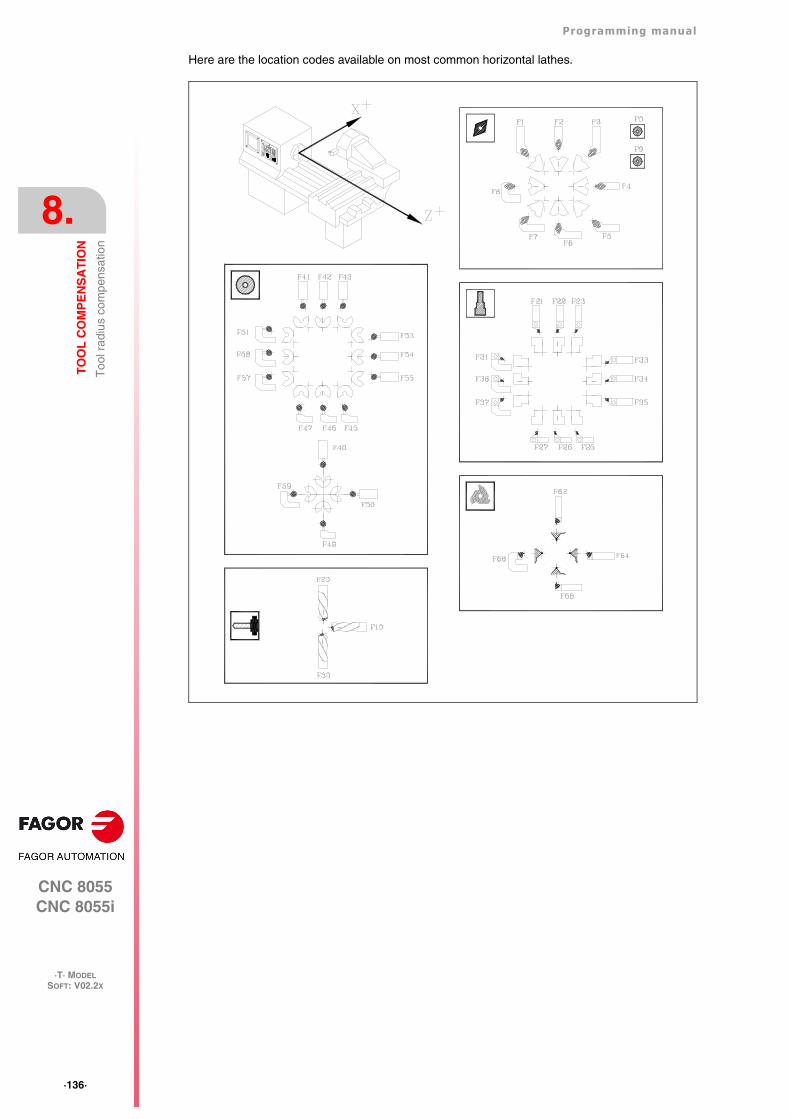
·136·
Programming manual
CNC 8055CNC 8055i
8.
TO
OL
CO
MP
EN
SA
TIO
N
·T· MODELSOFT: V02.2X
Too
l rad
ius
com
pens
atio
n
Here are the location codes available on most common horizontal lathes.
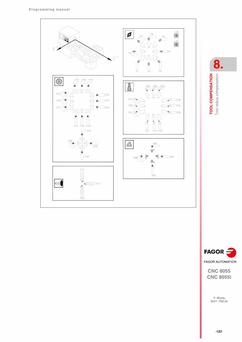
Programming manual
CNC 8055CNC 8055i
TO
OL
CO
MP
EN
SA
TIO
N
8.
·T· MODELSOFT: V02.2X
·137·
Too
l rad
ius
com
pens
atio
n
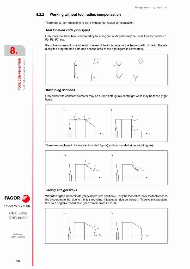
·138·
Programming manual
CNC 8055CNC 8055i
8.
TO
OL
CO
MP
EN
SA
TIO
N
·T· MODELSOFT: V02.2X
Too
l rad
ius
com
pens
atio
n
8.2.2 Working without tool radius compensation
There are certain limitations to work without tool radius compensation.
Tool location code (tool type).
Only tools that have been calibrated by touching two of its sides may be used, location codes F1,F3, F5, F7, etc.
It is not recommend to machine with the rest of the tools because the theoretical tip of the tool travelsalong the programmed path (the shaded area of the right figure is eliminated).
Machining sections.
Only sides with constant diameter may be turned (left figure) or straight walls may be faced (rightfigure).
There are problems in incline sections (left figure) and on rounded sides (right figure).
Facing straight walls.
When facing to a 0 coordinate (for example from position 40 to 0) the theoretical tip of the tool reachesthe 0 coordinate, but due to the tip's rounding, it leaves a ridge on the part. To solve this problem,face to a negative coordinate (for example from 40 to -3).
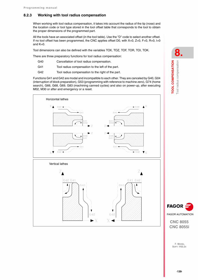
Programming manual
CNC 8055CNC 8055i
TO
OL
CO
MP
EN
SA
TIO
N
8.
·T· MODELSOFT: V02.2X
·139·
Too
l rad
ius
com
pens
atio
n
8.2.3 Working with tool radius compensation
When working with tool radius compensation, it takes into account the radius of the tip (nose) andthe location code or tool type stored in the tool offset table that corresponds to the tool to obtainthe proper dimensions of the programmed part.
All the tools have an associated offset (in the tool table). Use the "D" code to select another offset.If no tool offset has been programmed, the CNC applies offset D0, with X=0, Z=0, F=0, R=0, I=0and K=0.
Tool dimensions can also be defined with the variables TOX, TOZ, TOF, TOR, TOI, TOK.
There are three preparatory functions for tool radius compensation:
G40 Cancellation of tool radius compensation.
G41 Tool radius compensation to the left of the part.
G42 Tool radius compensation to the right of the part.
Functions G41 and G42 are modal and incompatible to each other. They are canceled by G40, G04(interruption of block preparation), G53 (programming with reference to machine zero), G74 (homesearch), G66, G68, G69, G83 (machining canned cycles) and also on power-up, after executingM02, M30 or after and emergency or a reset.
Horizontal lathes
Vertical lathes
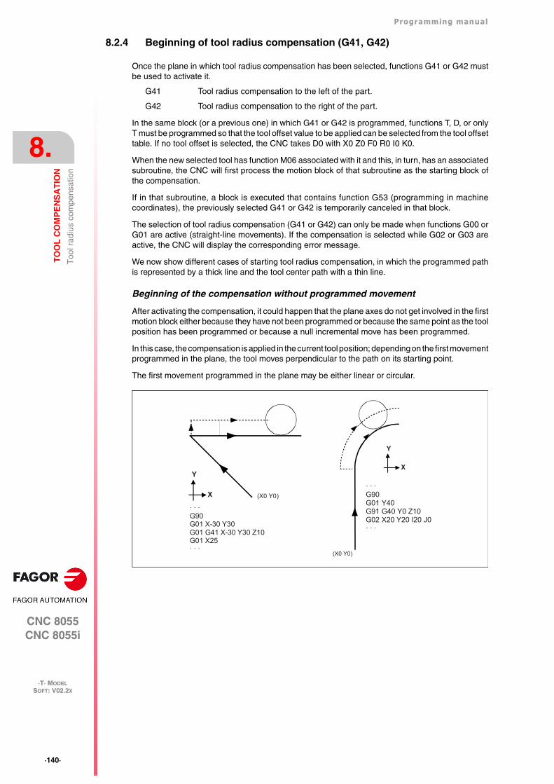
·140·
Programming manual
CNC 8055CNC 8055i
8.
TO
OL
CO
MP
EN
SA
TIO
N
·T· MODELSOFT: V02.2X
Too
l rad
ius
com
pens
atio
n
8.2.4 Beginning of tool radius compensation (G41, G42)
Once the plane in which tool radius compensation has been selected, functions G41 or G42 mustbe used to activate it.
G41 Tool radius compensation to the left of the part.
G42 Tool radius compensation to the right of the part.
In the same block (or a previous one) in which G41 or G42 is programmed, functions T, D, or onlyT must be programmed so that the tool offset value to be applied can be selected from the tool offsettable. If no tool offset is selected, the CNC takes D0 with X0 Z0 F0 R0 I0 K0.
When the new selected tool has function M06 associated with it and this, in turn, has an associatedsubroutine, the CNC will first process the motion block of that subroutine as the starting block ofthe compensation.
If in that subroutine, a block is executed that contains function G53 (programming in machinecoordinates), the previously selected G41 or G42 is temporarily canceled in that block.
The selection of tool radius compensation (G41 or G42) can only be made when functions G00 orG01 are active (straight-line movements). If the compensation is selected while G02 or G03 areactive, the CNC will display the corresponding error message.
We now show different cases of starting tool radius compensation, in which the programmed pathis represented by a thick line and the tool center path with a thin line.
Beginning of the compensation without programmed movement
After activating the compensation, it could happen that the plane axes do not get involved in the firstmotion block either because they have not been programmed or because the same point as the toolposition has been programmed or because a null incremental move has been programmed.
In this case, the compensation is applied in the current tool position; depending on the first movementprogrammed in the plane, the tool moves perpendicular to the path on its starting point.
The first movement programmed in the plane may be either linear or circular.
· · ·G90G01 Y40G91 G40 Y0 Z10G02 X20 Y20 I20 J0· · ·
(X0 Y0)
Y
X
· · ·G90G01 X-30 Y30G01 G41 X-30 Y30 Z10G01 X25· · ·
(X0 Y0)
Y
X
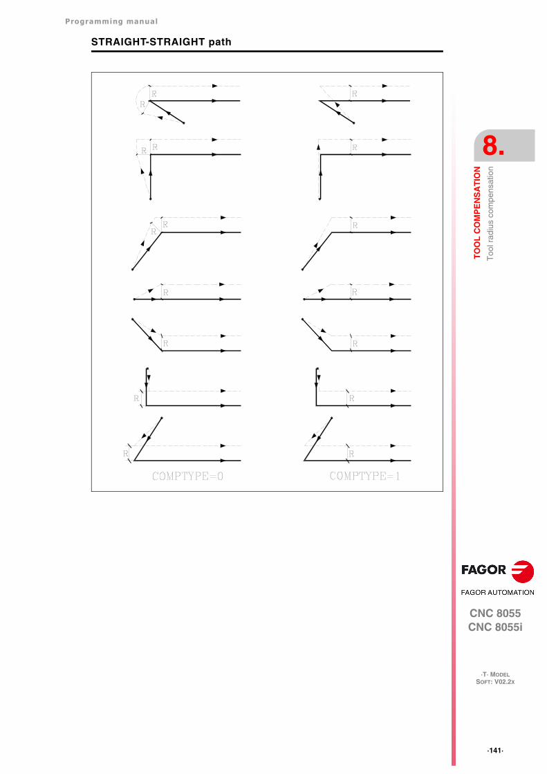
Programming manual
CNC 8055CNC 8055i
TO
OL
CO
MP
EN
SA
TIO
N
8.
·T· MODELSOFT: V02.2X
·141·
Too
l rad
ius
com
pens
atio
n
STRAIGHT-STRAIGHT path
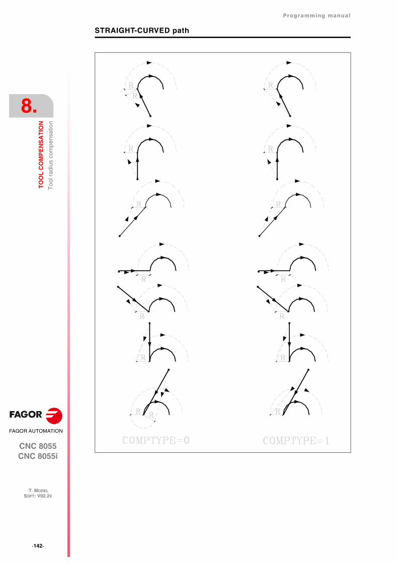
·142·
Programming manual
CNC 8055CNC 8055i
8.
TO
OL
CO
MP
EN
SA
TIO
N
·T· MODELSOFT: V02.2X
Too
l rad
ius
com
pens
atio
n
STRAIGHT-CURVED path
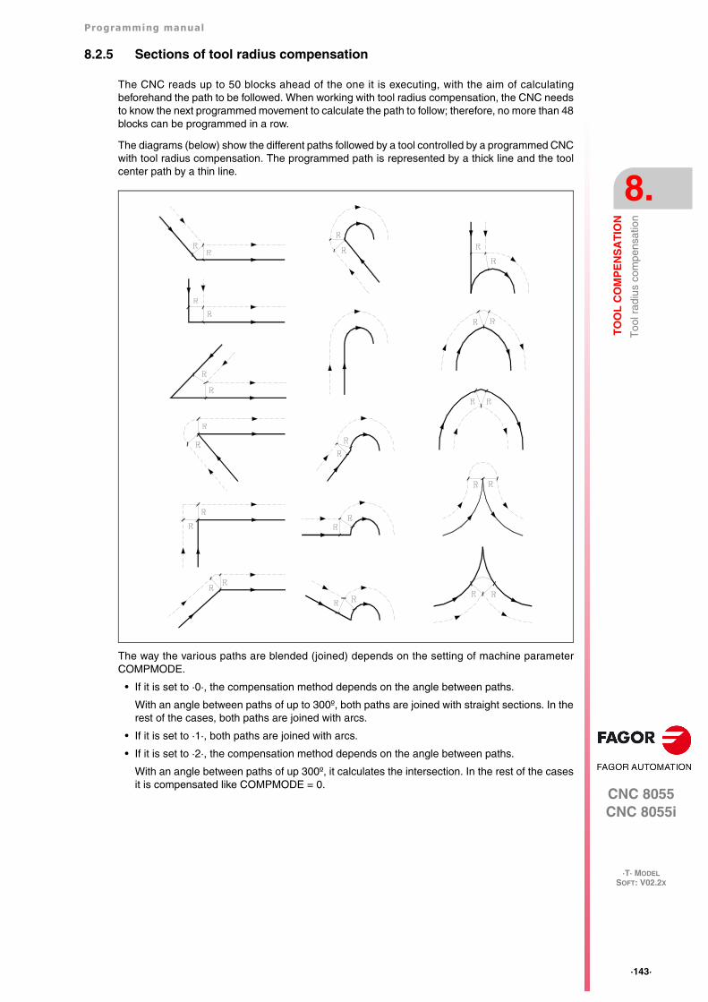
Programming manual
CNC 8055CNC 8055i
TO
OL
CO
MP
EN
SA
TIO
N
8.
·T· MODELSOFT: V02.2X
·143·
Too
l rad
ius
com
pens
atio
n
8.2.5 Sections of tool radius compensation
The CNC reads up to 50 blocks ahead of the one it is executing, with the aim of calculatingbeforehand the path to be followed. When working with tool radius compensation, the CNC needsto know the next programmed movement to calculate the path to follow; therefore, no more than 48blocks can be programmed in a row.
The diagrams (below) show the different paths followed by a tool controlled by a programmed CNCwith tool radius compensation. The programmed path is represented by a thick line and the toolcenter path by a thin line.
The way the various paths are blended (joined) depends on the setting of machine parameterCOMPMODE.
• If it is set to ·0·, the compensation method depends on the angle between paths.
With an angle between paths of up to 300º, both paths are joined with straight sections. In therest of the cases, both paths are joined with arcs.
• If it is set to ·1·, both paths are joined with arcs.
• If it is set to ·2·, the compensation method depends on the angle between paths.
With an angle between paths of up 300º, it calculates the intersection. In the rest of the casesit is compensated like COMPMODE = 0.
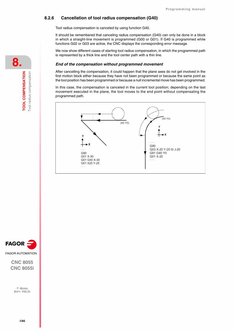
·144·
Programming manual
CNC 8055CNC 8055i
8.
TO
OL
CO
MP
EN
SA
TIO
N
·T· MODELSOFT: V02.2X
Too
l rad
ius
com
pens
atio
n
8.2.6 Cancellation of tool radius compensation (G40)
Tool radius compensation is canceled by using function G40.
It should be remembered that canceling radius compensation (G40) can only be done in a blockin which a straight-line movement is programmed (G00 or G01). If G40 is programmed whilefunctions G02 or G03 are active, the CNC displays the corresponding error message.
We now show different cases of starting tool radius compensation, in which the programmed pathis represented by a thick line and the tool center path with a thin line.
End of the compensation without programmed movement
After cancelling the compensation, it could happen that the plane axes do not get involved in thefirst motion block either because they have not been programmed or because the same point asthe tool position has been programmed or because a null incremental move has been programmed.
In this case, the compensation is canceled in the current tool position; depending on the lastmovement executed in the plane, the tool moves to the end point without compensating theprogrammed path.
· · ·G90G03 X-20 Y-20 I0 J-20G91 G40 Y0G01 X-20· · ·
(X0 Y0)
Y
X
· · ·G90G01 X-30G01 G40 X-30G01 X25 Y-25· · ·
(X0 Y0)
Y
X
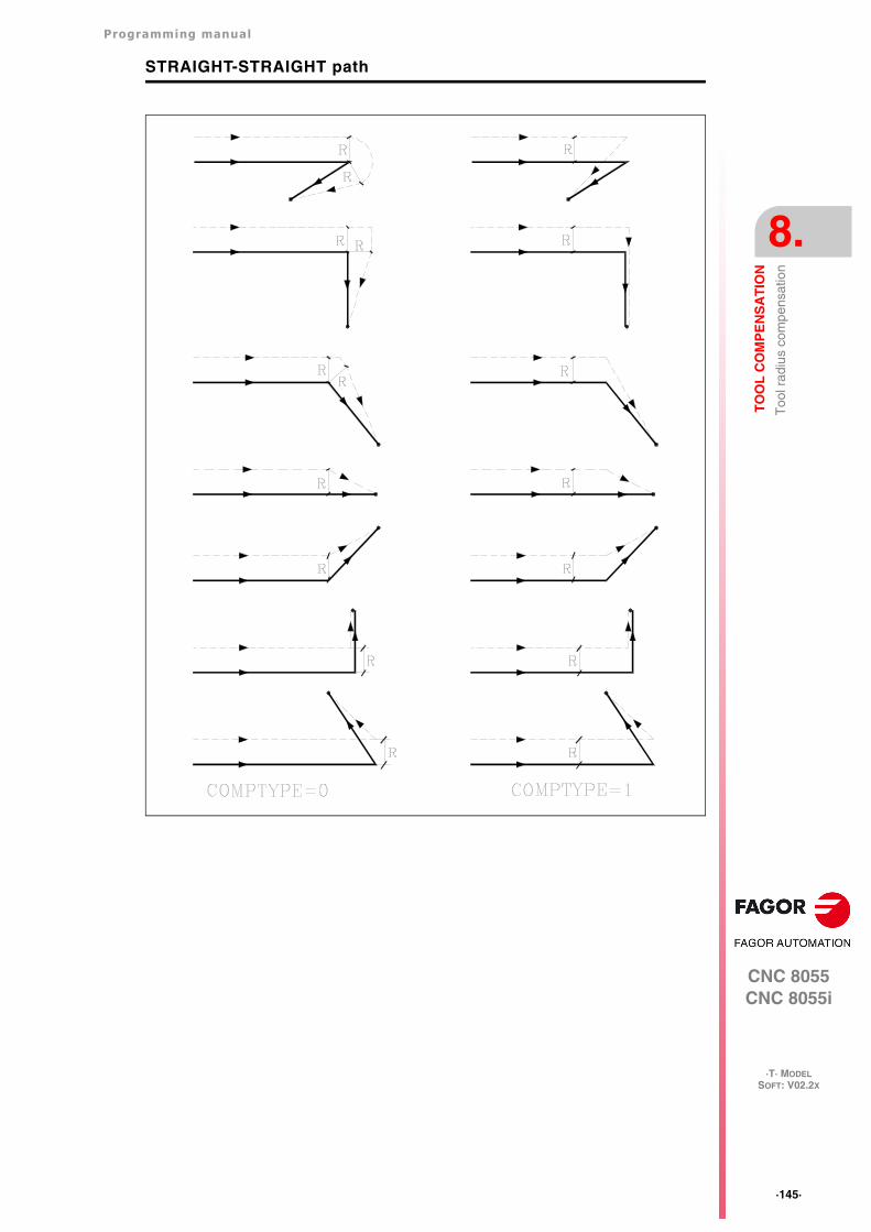
Programming manual
CNC 8055CNC 8055i
TO
OL
CO
MP
EN
SA
TIO
N
8.
·T· MODELSOFT: V02.2X
·145·
Too
l rad
ius
com
pens
atio
n
STRAIGHT-STRAIGHT path
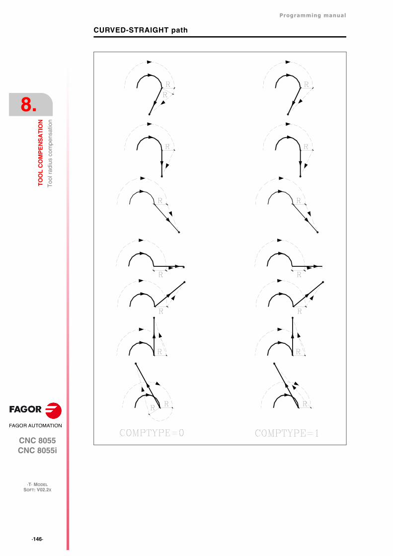
·146·
Programming manual
CNC 8055CNC 8055i
8.
TO
OL
CO
MP
EN
SA
TIO
N
·T· MODELSOFT: V02.2X
Too
l rad
ius
com
pens
atio
n
CURVED-STRAIGHT path
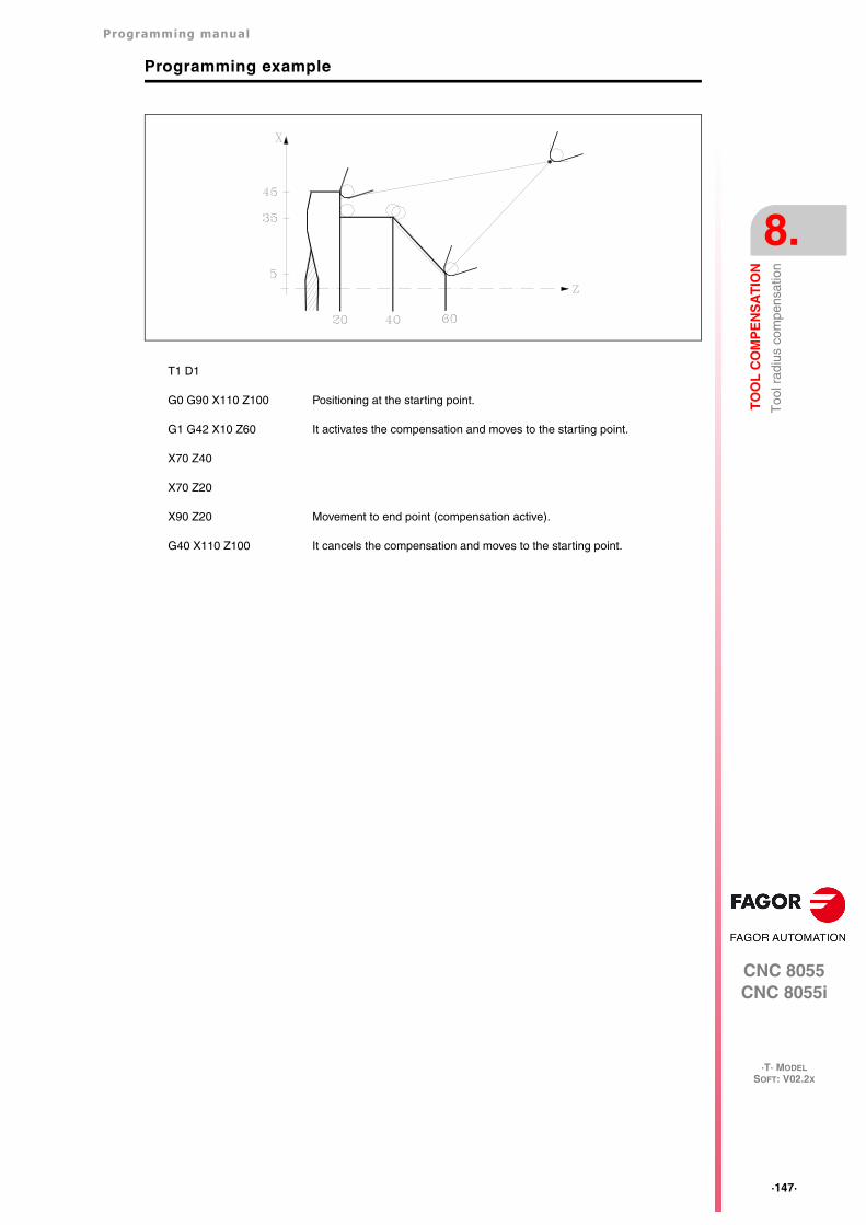
Programming manual
CNC 8055CNC 8055i
TO
OL
CO
MP
EN
SA
TIO
N
8.
·T· MODELSOFT: V02.2X
·147·
Too
l rad
ius
com
pens
atio
n
Programming example
T1 D1
G0 G90 X110 Z100 Positioning at the starting point.
G1 G42 X10 Z60 It activates the compensation and moves to the starting point.
X70 Z40
X70 Z20
X90 Z20 Movement to end point (compensation active).
G40 X110 Z100 It cancels the compensation and moves to the starting point.
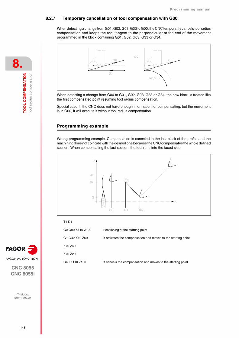
·148·
Programming manual
CNC 8055CNC 8055i
8.
TO
OL
CO
MP
EN
SA
TIO
N
·T· MODELSOFT: V02.2X
Too
l rad
ius
com
pens
atio
n
8.2.7 Temporary cancellation of tool compensation with G00
When detecting a change from G01, G02, G03, G33 to G00, the CNC temporarily cancels tool radiuscompensation and keeps the tool tangent to the perpendicular at the end of the movementprogrammed in the block containing G01, G02, G03, G33 or G34.
When detecting a change from G00 to G01, G02, G03, G33 or G34, the new block is treated likethe first compensated point resuming tool radius compensation.
Special case: If the CNC does not have enough information for compensating, but the movementis in G00, it will execute it without tool radius compensation.
Programming example
Wrong programming example. Compensation is canceled in the last block of the profile and themachining does not coincide with the desired one because the CNC compensates the whole definedsection. When compensating the last section, the tool runs into the faced side.
T1 D1
G0 G90 X110 Z100 Positioning at the starting point
G1 G42 X10 Z60 It activates the compensation and moves to the starting point
X70 Z40
X70 Z20
G40 X110 Z100 It cancels the compensation and moves to the starting point
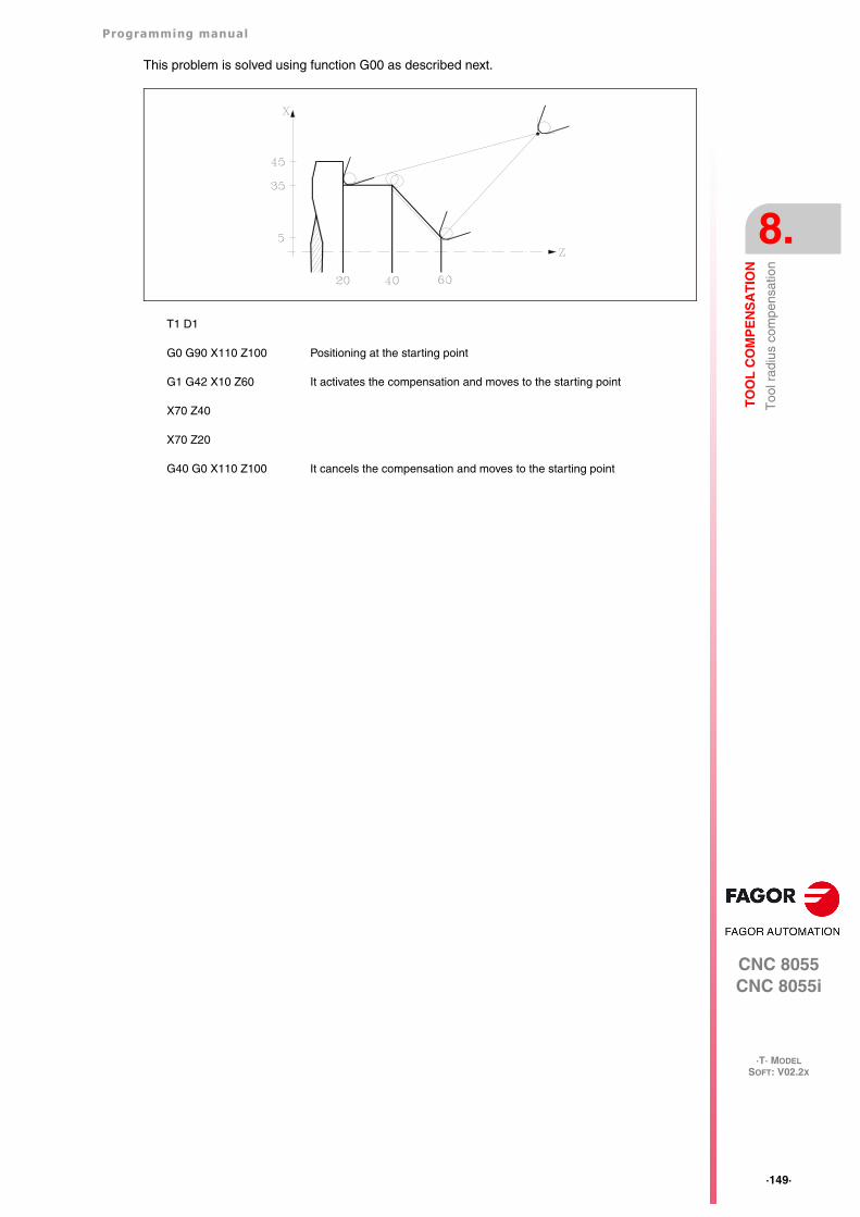
Programming manual
CNC 8055CNC 8055i
TO
OL
CO
MP
EN
SA
TIO
N
8.
·T· MODELSOFT: V02.2X
·149·
Too
l rad
ius
com
pens
atio
n
This problem is solved using function G00 as described next.
T1 D1
G0 G90 X110 Z100 Positioning at the starting point
G1 G42 X10 Z60 It activates the compensation and moves to the starting point
X70 Z40
X70 Z20
G40 G0 X110 Z100 It cancels the compensation and moves to the starting point
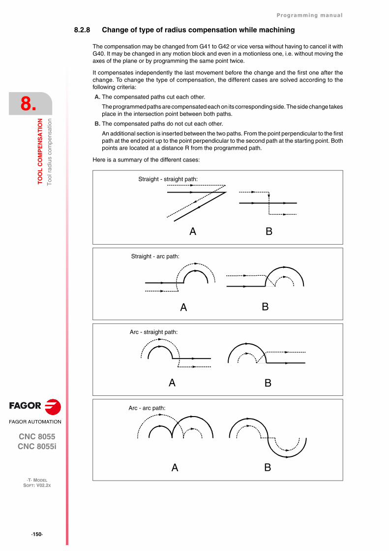
·150·
Programming manual
CNC 8055CNC 8055i
8.
TO
OL
CO
MP
EN
SA
TIO
N
·T· MODELSOFT: V02.2X
Too
l rad
ius
com
pens
atio
n
8.2.8 Change of type of radius compensation while machining
The compensation may be changed from G41 to G42 or vice versa without having to cancel it withG40. It may be changed in any motion block and even in a motionless one, i.e. without moving theaxes of the plane or by programming the same point twice.
It compensates independently the last movement before the change and the first one after thechange. To change the type of compensation, the different cases are solved according to thefollowing criteria:
A. The compensated paths cut each other.
The programmed paths are compensated each on its corresponding side. The side change takesplace in the intersection point between both paths.
B. The compensated paths do not cut each other.
An additional section is inserted between the two paths. From the point perpendicular to the firstpath at the end point up to the point perpendicular to the second path at the starting point. Bothpoints are located at a distance R from the programmed path.
Here is a summary of the different cases:
Straight - straight path:
A B
Straight - arc path:
A B
Arc - straight path:
A B
Arc - arc path:
A B
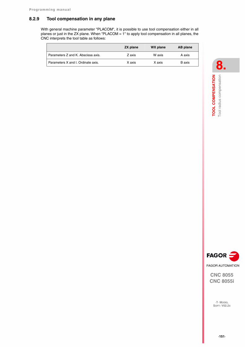
Programming manual
CNC 8055CNC 8055i
TO
OL
CO
MP
EN
SA
TIO
N
8.
·T· MODELSOFT: V02.2X
·151·
Too
l rad
ius
com
pens
atio
n
8.2.9 Tool compensation in any plane
With general machine parameter "PLACOM", it is possible to use tool compensation either in allplanes or just in the ZX plane. When "PLACOM = 1" to apply tool compensation in all planes, theCNC interprets the tool table as follows:
ZX plane WX plane AB plane
Parameters Z and K. Abscissa axis. Z axis W axis A axis
Parameters X and I. Ordinate axis. X axis X axis B axis
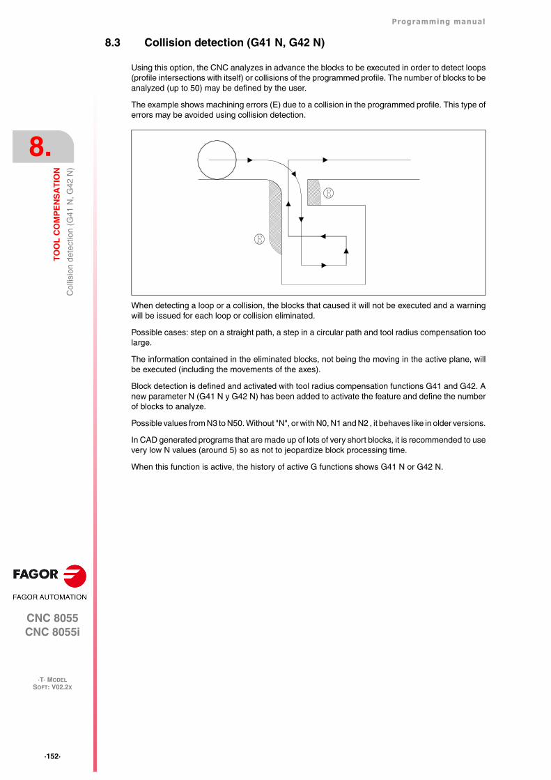
·152·
Programming manual
CNC 8055CNC 8055i
8.
TO
OL
CO
MP
EN
SA
TIO
N
·T· MODELSOFT: V02.2X
Col
lisio
n de
tect
ion
(G41
N, G
42 N
)
8.3 Collision detection (G41 N, G42 N)
Using this option, the CNC analyzes in advance the blocks to be executed in order to detect loops(profile intersections with itself) or collisions of the programmed profile. The number of blocks to beanalyzed (up to 50) may be defined by the user.
The example shows machining errors (E) due to a collision in the programmed profile. This type oferrors may be avoided using collision detection.
When detecting a loop or a collision, the blocks that caused it will not be executed and a warningwill be issued for each loop or collision eliminated.
Possible cases: step on a straight path, a step in a circular path and tool radius compensation toolarge.
The information contained in the eliminated blocks, not being the moving in the active plane, willbe executed (including the movements of the axes).
Block detection is defined and activated with tool radius compensation functions G41 and G42. Anew parameter N (G41 N y G42 N) has been added to activate the feature and define the numberof blocks to analyze.
Possible values from N3 to N50. Without "N", or with N0, N1 and N2 , it behaves like in older versions.
In CAD generated programs that are made up of lots of very short blocks, it is recommended to usevery low N values (around 5) so as not to jeopardize block processing time.
When this function is active, the history of active G functions shows G41 N or G42 N.
CNC 8055CNC 8055i
·T· MODELSOFT: V02.2X
9
·153·
CANNED CYCLES
This CNC offers the following machining canned cycles:
G66 Pattern repeat canned cycle.
G68 X axis roughing canned cycle.
G69 Z axis roughing canned cycle.
G81 Turning canned cycle for straight sections.
G82 Facing canned cycle for straight sections.
G81 Drilling canned cycle.
G84 Turning canned cycle for curved sections.
G85 Facing canned cycle for curved sections.
G86 Longitudinal threading canned cycle.
G87 Face threading canned cycle.
G88 X axis grooving canned cycle.
G89 Z axis grooving canned cycle.
Machining canned cycles with live tool:
G60 Drilling / tapping canned cycle on the face of the part
G61 Drilling / tapping canned cycle along the side of the part
G62 Slot milling canned cycle along the side of the part.
G63 Slot milling canned cycle on the face of the part.
A canned cycle is defined by the G function indicating the canned cycle and its correspondingparameters. A canned cycle may be defined anywhere in the program, that is, in the main programas well as in a subroutine.
When working in a plane other than the ZX, for example: G16 WX, the CNC interprets the cannedcycle parameters as follows:
ZX plane WX plane AB plane
Parameter Z and all those related to it, with the abscissaaxis.
Z axis W axis A axis
Parameter Z and all those related to it, with the ordinateaxis.
X axis X axis B axis
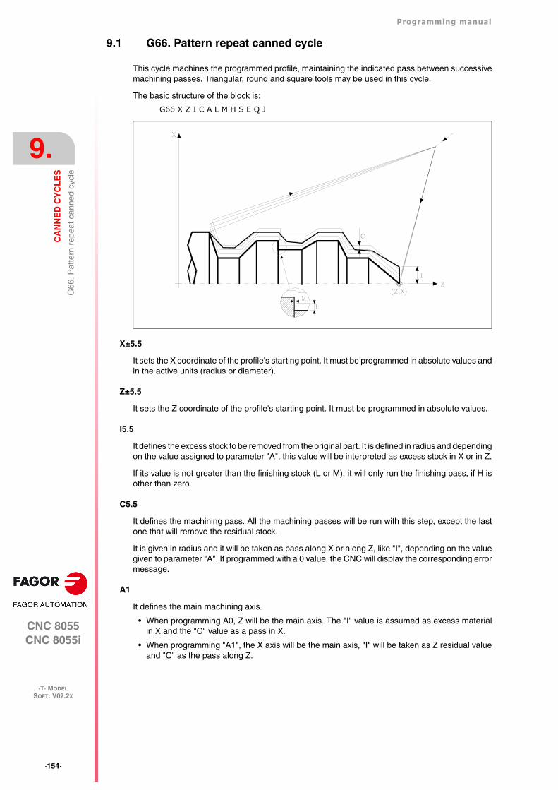
·154·
Programming manual
CNC 8055CNC 8055i
9.
CA
NN
ED
CY
CL
ES
·T· MODELSOFT: V02.2X
G66
. Pat
tern
rep
eat c
anne
d cy
cle
9.1 G66. Pattern repeat canned cycle
This cycle machines the programmed profile, maintaining the indicated pass between successivemachining passes. Triangular, round and square tools may be used in this cycle.
The basic structure of the block is:
G66 X Z I C A L M H S E Q J
X±5.5
It sets the X coordinate of the profile's starting point. It must be programmed in absolute values andin the active units (radius or diameter).
Z±5.5
It sets the Z coordinate of the profile's starting point. It must be programmed in absolute values.
I5.5
It defines the excess stock to be removed from the original part. It is defined in radius and dependingon the value assigned to parameter "A", this value will be interpreted as excess stock in X or in Z.
If its value is not greater than the finishing stock (L or M), it will only run the finishing pass, if H isother than zero.
C5.5
It defines the machining pass. All the machining passes will be run with this step, except the lastone that will remove the residual stock.
It is given in radius and it will be taken as pass along X or along Z, like "I", depending on the valuegiven to parameter "A". If programmed with a 0 value, the CNC will display the corresponding errormessage.
A1
It defines the main machining axis.
• When programming A0, Z will be the main axis. The "I" value is assumed as excess materialin X and the "C" value as a pass in X.
• When programming "A1", the X axis will be the main axis, "I" will be taken as Z residual valueand "C" as the pass along Z.
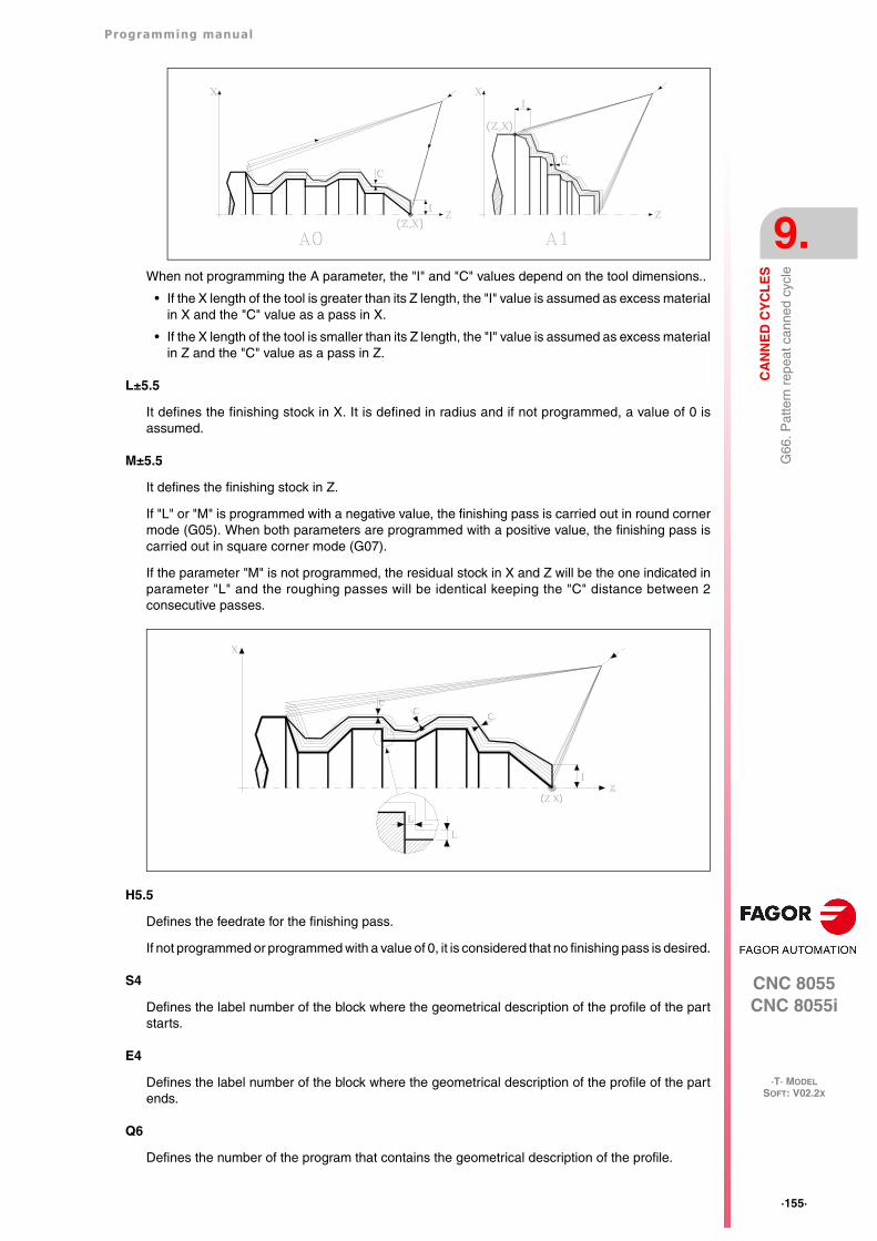
Programming manual
CNC 8055CNC 8055i
CA
NN
ED
CY
CL
ES
9.
·T· MODELSOFT: V02.2X
·155·
G66
. Pat
tern
rep
eat c
anne
d cy
cleWhen not programming the A parameter, the "I" and "C" values depend on the tool dimensions..
• If the X length of the tool is greater than its Z length, the "I" value is assumed as excess materialin X and the "C" value as a pass in X.
• If the X length of the tool is smaller than its Z length, the "I" value is assumed as excess materialin Z and the "C" value as a pass in Z.
L±5.5
It defines the finishing stock in X. It is defined in radius and if not programmed, a value of 0 isassumed.
M±5.5
It defines the finishing stock in Z.
If "L" or "M" is programmed with a negative value, the finishing pass is carried out in round cornermode (G05). When both parameters are programmed with a positive value, the finishing pass iscarried out in square corner mode (G07).
If the parameter "M" is not programmed, the residual stock in X and Z will be the one indicated inparameter "L" and the roughing passes will be identical keeping the "C" distance between 2consecutive passes.
H5.5
Defines the feedrate for the finishing pass.
If not programmed or programmed with a value of 0, it is considered that no finishing pass is desired.
S4
Defines the label number of the block where the geometrical description of the profile of the partstarts.
E4
Defines the label number of the block where the geometrical description of the profile of the partends.
Q6
Defines the number of the program that contains the geometrical description of the profile.
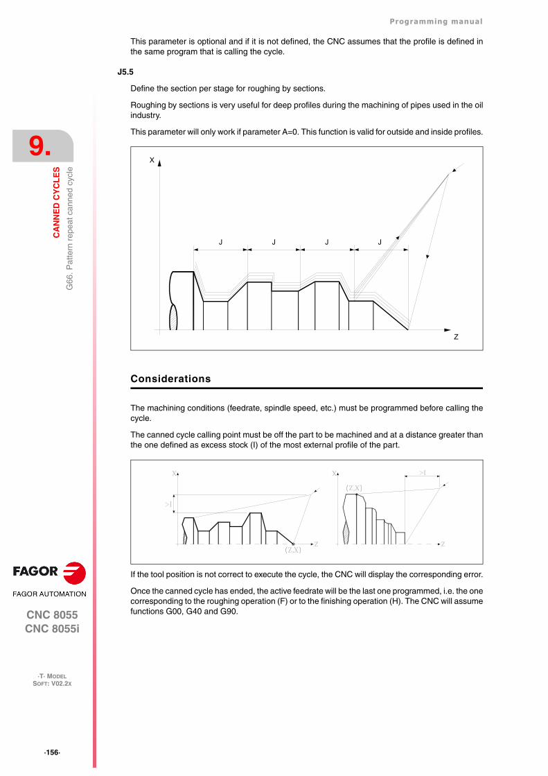
·156·
Programming manual
CNC 8055CNC 8055i
9.
CA
NN
ED
CY
CL
ES
·T· MODELSOFT: V02.2X
G66
. Pat
tern
rep
eat c
anne
d cy
cle
This parameter is optional and if it is not defined, the CNC assumes that the profile is defined inthe same program that is calling the cycle.
J5.5
Define the section per stage for roughing by sections.
Roughing by sections is very useful for deep profiles during the machining of pipes used in the oilindustry.
This parameter will only work if parameter A=0. This function is valid for outside and inside profiles.
Considerations
The machining conditions (feedrate, spindle speed, etc.) must be programmed before calling thecycle.
The canned cycle calling point must be off the part to be machined and at a distance greater thanthe one defined as excess stock (I) of the most external profile of the part.
If the tool position is not correct to execute the cycle, the CNC will display the corresponding error.
Once the canned cycle has ended, the active feedrate will be the last one programmed, i.e. the onecorresponding to the roughing operation (F) or to the finishing operation (H). The CNC will assumefunctions G00, G40 and G90.
JJJJ
X
Z
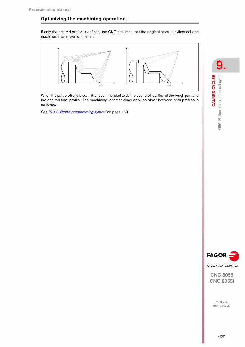
Programming manual
CNC 8055CNC 8055i
CA
NN
ED
CY
CL
ES
9.
·T· MODELSOFT: V02.2X
·157·
G66
. Pat
tern
rep
eat c
anne
d cy
cle
Optimizing the machining operation.
If only the desired profile is defined, the CNC assumes that the original stock is cylindrical andmachines it as shown on the left.
When the part profile is known, it is recommended to define both profiles, that of the rough part andthe desired final profile. The machining is faster since only the stock between both profiles isremoved.
See "9.1.2 Profile programming syntax" on page 160.
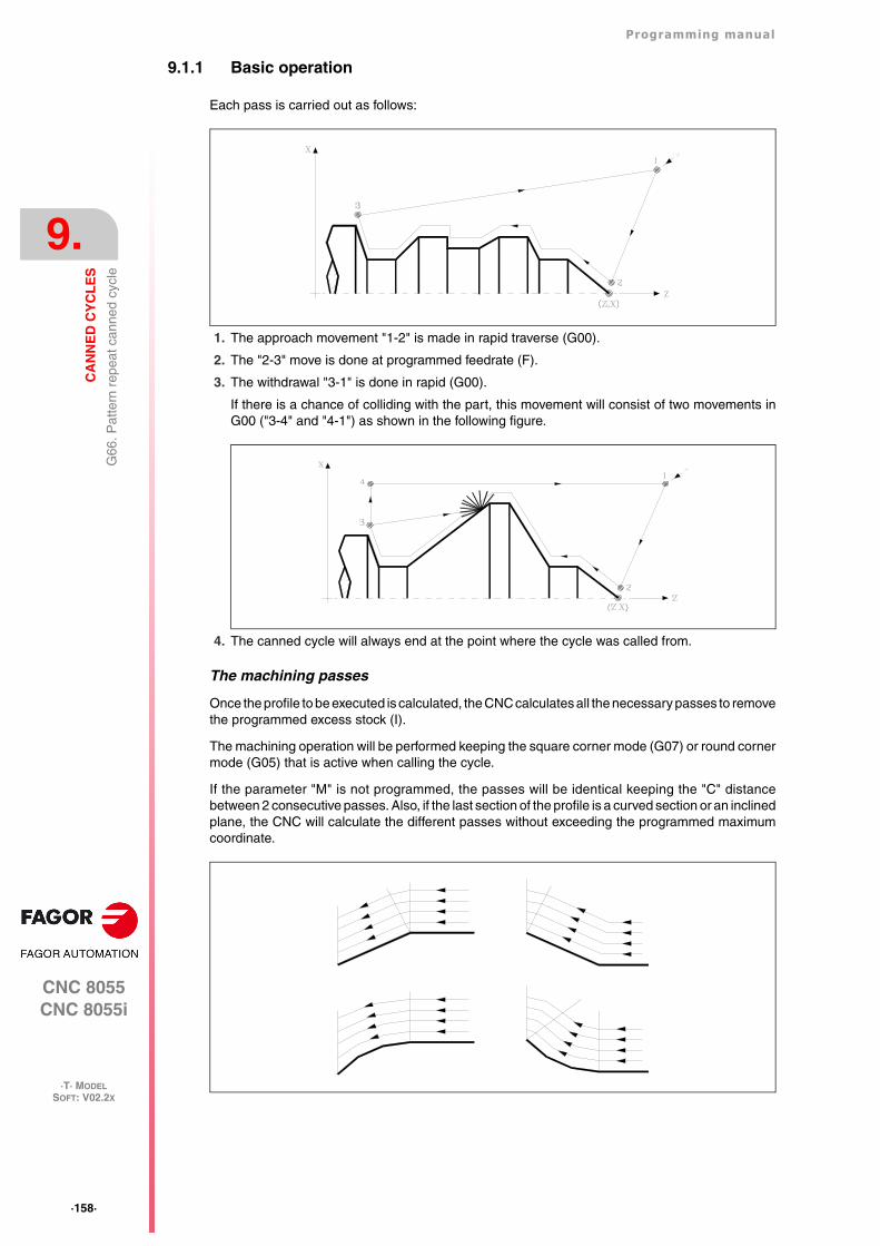
·158·
Programming manual
CNC 8055CNC 8055i
9.
CA
NN
ED
CY
CL
ES
·T· MODELSOFT: V02.2X
G66
. Pat
tern
rep
eat c
anne
d cy
cle
9.1.1 Basic operation
Each pass is carried out as follows:
1. The approach movement "1-2" is made in rapid traverse (G00).
2. The "2-3" move is done at programmed feedrate (F).
3. The withdrawal "3-1" is done in rapid (G00).
If there is a chance of colliding with the part, this movement will consist of two movements inG00 ("3-4" and "4-1") as shown in the following figure.
4. The canned cycle will always end at the point where the cycle was called from.
The machining passes
Once the profile to be executed is calculated, the CNC calculates all the necessary passes to removethe programmed excess stock (I).
The machining operation will be performed keeping the square corner mode (G07) or round cornermode (G05) that is active when calling the cycle.
If the parameter "M" is not programmed, the passes will be identical keeping the "C" distancebetween 2 consecutive passes. Also, if the last section of the profile is a curved section or an inclinedplane, the CNC will calculate the different passes without exceeding the programmed maximumcoordinate.
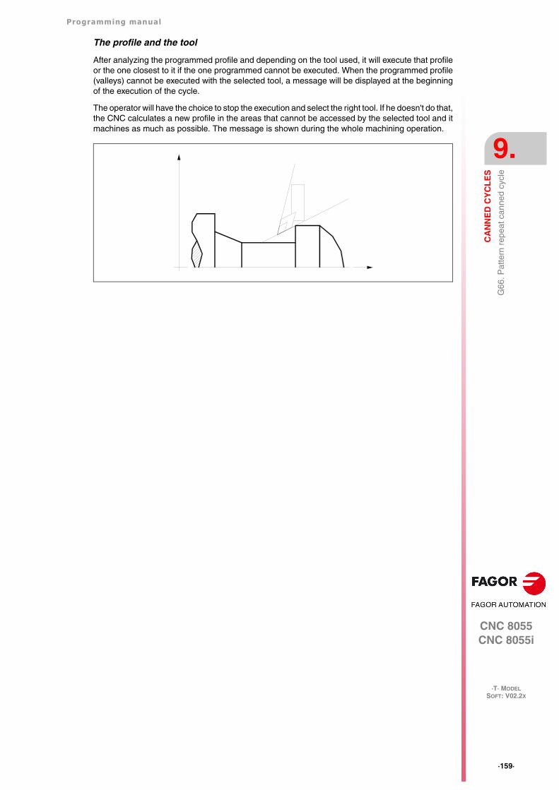
Programming manual
CNC 8055CNC 8055i
CA
NN
ED
CY
CL
ES
9.
·T· MODELSOFT: V02.2X
·159·
G66
. Pat
tern
rep
eat c
anne
d cy
cle
The profile and the tool
After analyzing the programmed profile and depending on the tool used, it will execute that profileor the one closest to it if the one programmed cannot be executed. When the programmed profile(valleys) cannot be executed with the selected tool, a message will be displayed at the beginningof the execution of the cycle.
The operator will have the choice to stop the execution and select the right tool. If he doesn't do that,the CNC calculates a new profile in the areas that cannot be accessed by the selected tool and itmachines as much as possible. The message is shown during the whole machining operation.
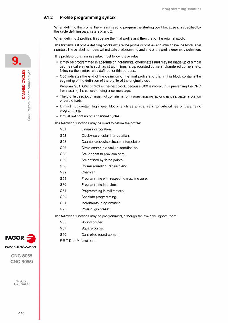
·160·
Programming manual
CNC 8055CNC 8055i
9.
CA
NN
ED
CY
CL
ES
·T· MODELSOFT: V02.2X
G66
. Pat
tern
rep
eat c
anne
d cy
cle
9.1.2 Profile programming syntax
When defining the profile, there is no need to program the starting point because it is specified bythe cycle defining parameters X and Z.
When defining 2 profiles, first define the final profile and then that of the original stock.
The first and last profile defining blocks (where the profile or profiles end) must have the block labelnumber. These label numbers will indicate the beginning and end of the profile geometry definition.
The profile programming syntax must follow these rules:
• It may be programmed in absolute or incremental coordinates and may be made up of simplegeometrical elements such as straight lines, arcs, rounded corners, chamfered corners, etc.following the syntax rules defined for this purpose.
• G00 indicates the end of the definition of the final profile and that in this block contains thebeginning of the definition of the profile of the original stock.
Program G01, G02 or G03 in the next block, because G00 is modal, thus preventing the CNCfrom issuing the corresponding error message.
• The profile description must not contain mirror images, scaling factor changes, pattern rotationor zero offsets.
• It must not contain high level blocks such as jumps, calls to subroutines or parametricprogramming.
• It must not contain other canned cycles.
The following functions may be used to define the profile:
G01 Linear interpolation.
G02 Clockwise circular interpolation.
G03 Counter-clockwise circular interpolation.
G06 Circle center in absolute coordinates.
G08 Arc tangent to previous path.
G09 Arc defined by three points.
G36 Corner rounding, radius blend.
G39 Chamfer.
G53 Programming with respect to machine zero.
G70 Programming in inches.
G71 Programming in millimeters.
G90 Absolute programming.
G91 Incremental programming.
G93 Polar origin preset.
The following functions may be programmed, although the cycle will ignore them.
G05 Round corner.
G07 Square corner.
G50 Controlled round corner.
F S T D or M functions.
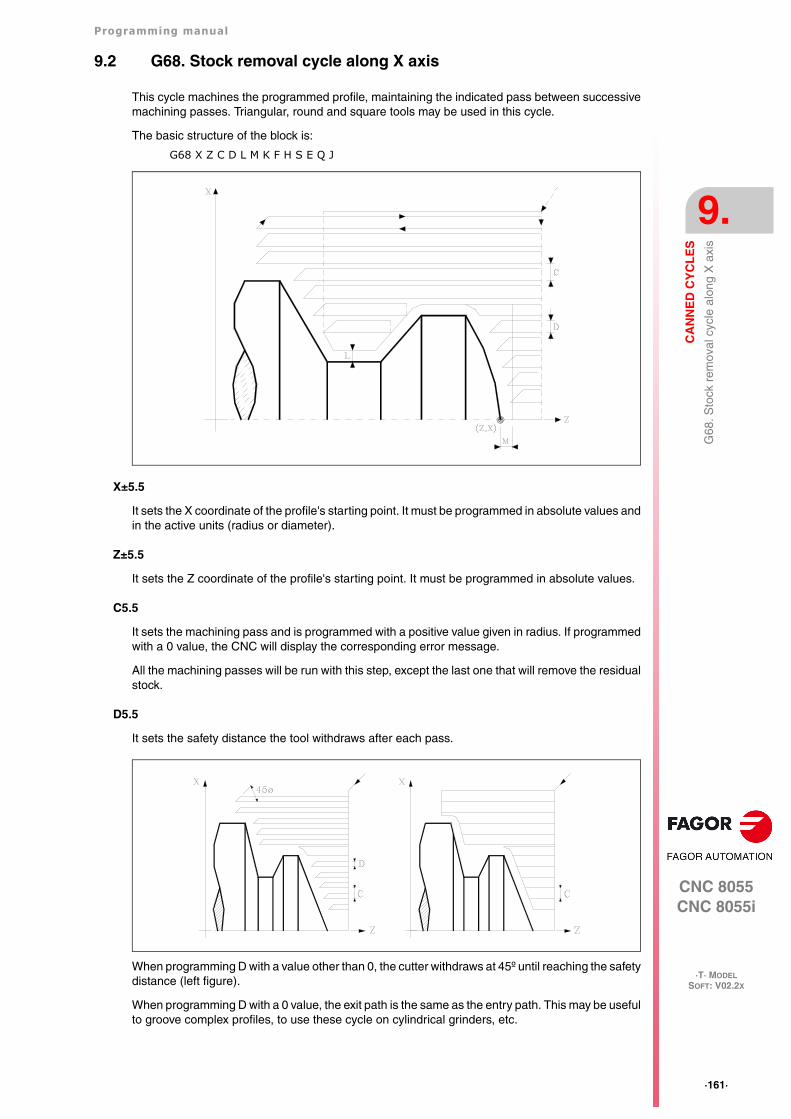
Programming manual
CNC 8055CNC 8055i
CA
NN
ED
CY
CL
ES
9.
·T· MODELSOFT: V02.2X
·161·
G68
. Sto
ck r
emov
al c
ycle
alo
ng X
axi
s
9.2 G68. Stock removal cycle along X axis
This cycle machines the programmed profile, maintaining the indicated pass between successivemachining passes. Triangular, round and square tools may be used in this cycle.
The basic structure of the block is:
G68 X Z C D L M K F H S E Q J
X±5.5
It sets the X coordinate of the profile's starting point. It must be programmed in absolute values andin the active units (radius or diameter).
Z±5.5
It sets the Z coordinate of the profile's starting point. It must be programmed in absolute values.
C5.5
It sets the machining pass and is programmed with a positive value given in radius. If programmedwith a 0 value, the CNC will display the corresponding error message.
All the machining passes will be run with this step, except the last one that will remove the residualstock.
D5.5
It sets the safety distance the tool withdraws after each pass.
When programming D with a value other than 0, the cutter withdraws at 45º until reaching the safetydistance (left figure).
When programming D with a 0 value, the exit path is the same as the entry path. This may be usefulto groove complex profiles, to use these cycle on cylindrical grinders, etc.
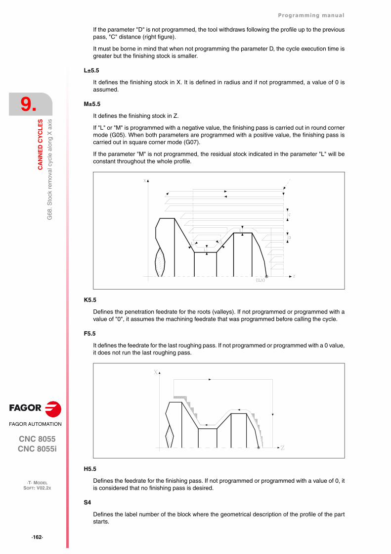
·162·
Programming manual
CNC 8055CNC 8055i
9.
CA
NN
ED
CY
CL
ES
·T· MODELSOFT: V02.2X
G68
. Sto
ck r
emov
al c
ycle
alo
ng X
axi
s
If the parameter "D" is not programmed, the tool withdraws following the profile up to the previouspass, "C" distance (right figure).
It must be borne in mind that when not programming the parameter D, the cycle execution time isgreater but the finishing stock is smaller.
L±5.5
It defines the finishing stock in X. It is defined in radius and if not programmed, a value of 0 isassumed.
M±5.5
It defines the finishing stock in Z.
If "L" or "M" is programmed with a negative value, the finishing pass is carried out in round cornermode (G05). When both parameters are programmed with a positive value, the finishing pass iscarried out in square corner mode (G07).
If the parameter "M" is not programmed, the residual stock indicated in the parameter "L" will beconstant throughout the whole profile.
K5.5
Defines the penetration feedrate for the roots (valleys). If not programmed or programmed with avalue of "0", it assumes the machining feedrate that was programmed before calling the cycle.
F5.5
It defines the feedrate for the last roughing pass. If not programmed or programmed with a 0 value,it does not run the last roughing pass.
H5.5
Defines the feedrate for the finishing pass. If not programmed or programmed with a value of 0, itis considered that no finishing pass is desired.
S4
Defines the label number of the block where the geometrical description of the profile of the partstarts.
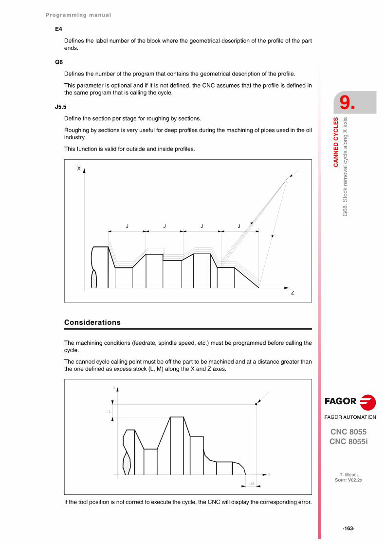
Programming manual
CNC 8055CNC 8055i
CA
NN
ED
CY
CL
ES
9.
·T· MODELSOFT: V02.2X
·163·
G68
. Sto
ck r
emov
al c
ycle
alo
ng X
axi
s
E4
Defines the label number of the block where the geometrical description of the profile of the partends.
Q6
Defines the number of the program that contains the geometrical description of the profile.
This parameter is optional and if it is not defined, the CNC assumes that the profile is defined inthe same program that is calling the cycle.
J5.5
Define the section per stage for roughing by sections.
Roughing by sections is very useful for deep profiles during the machining of pipes used in the oilindustry.
This function is valid for outside and inside profiles.
Considerations
The machining conditions (feedrate, spindle speed, etc.) must be programmed before calling thecycle.
The canned cycle calling point must be off the part to be machined and at a distance greater thanthe one defined as excess stock (L, M) along the X and Z axes.
If the tool position is not correct to execute the cycle, the CNC will display the corresponding error.
JJJJ
X
Z
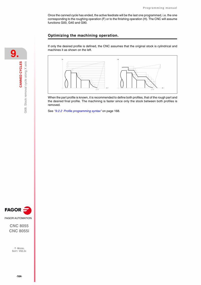
·164·
Programming manual
CNC 8055CNC 8055i
9.
CA
NN
ED
CY
CL
ES
·T· MODELSOFT: V02.2X
G68
. Sto
ck r
emov
al c
ycle
alo
ng X
axi
s
Once the canned cycle has ended, the active feedrate will be the last one programmed, i.e. the onecorresponding to the roughing operation (F) or to the finishing operation (H). The CNC will assumefunctions G00, G40 and G90.
Optimizing the machining operation.
If only the desired profile is defined, the CNC assumes that the original stock is cylindrical andmachines it as shown on the left.
When the part profile is known, it is recommended to define both profiles, that of the rough part andthe desired final profile. The machining is faster since only the stock between both profiles isremoved.
See "9.2.2 Profile programming syntax" on page 168.
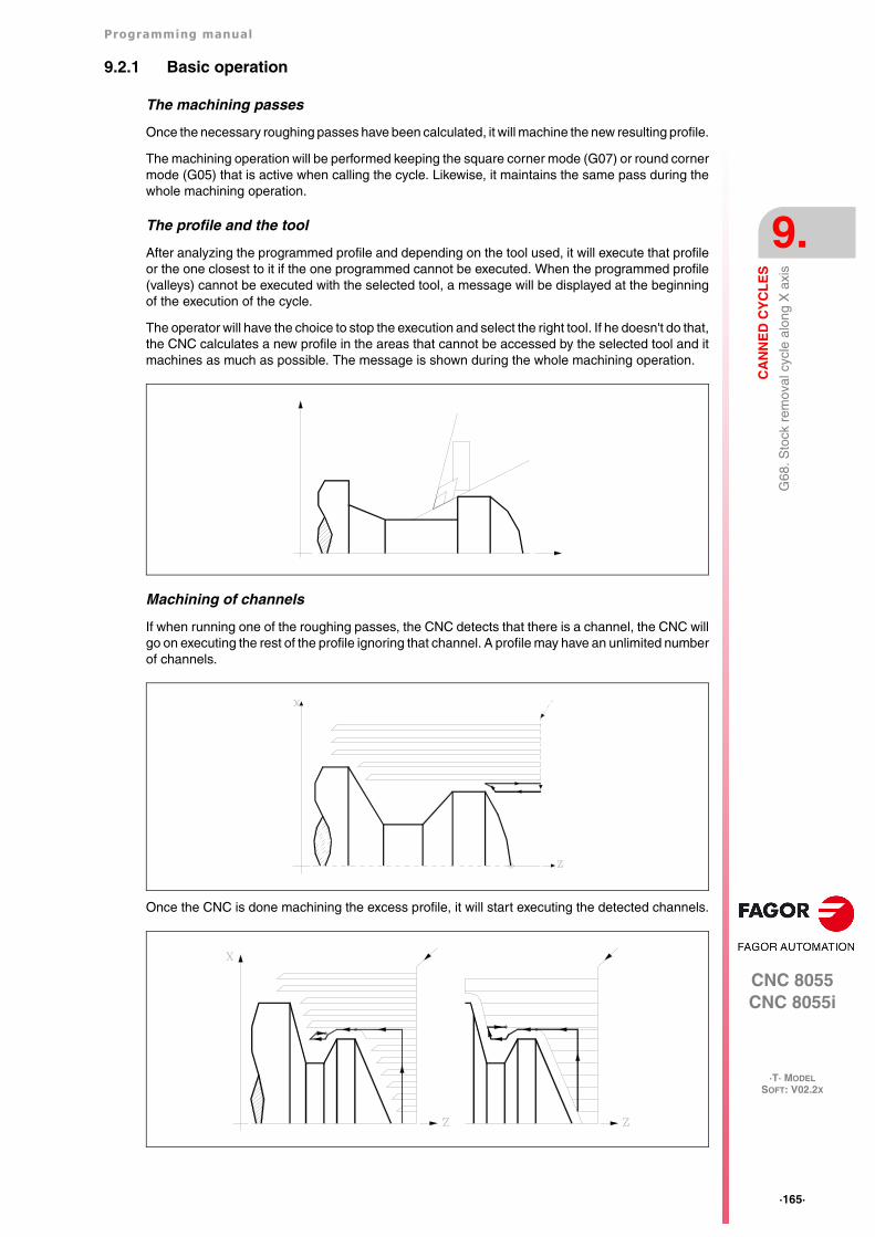
Programming manual
CNC 8055CNC 8055i
CA
NN
ED
CY
CL
ES
9.
·T· MODELSOFT: V02.2X
·165·
G68
. Sto
ck r
emov
al c
ycle
alo
ng X
axi
s
9.2.1 Basic operation
The machining passes
Once the necessary roughing passes have been calculated, it will machine the new resulting profile.
The machining operation will be performed keeping the square corner mode (G07) or round cornermode (G05) that is active when calling the cycle. Likewise, it maintains the same pass during thewhole machining operation.
The profile and the tool
After analyzing the programmed profile and depending on the tool used, it will execute that profileor the one closest to it if the one programmed cannot be executed. When the programmed profile(valleys) cannot be executed with the selected tool, a message will be displayed at the beginningof the execution of the cycle.
The operator will have the choice to stop the execution and select the right tool. If he doesn't do that,the CNC calculates a new profile in the areas that cannot be accessed by the selected tool and itmachines as much as possible. The message is shown during the whole machining operation.
Machining of channels
If when running one of the roughing passes, the CNC detects that there is a channel, the CNC willgo on executing the rest of the profile ignoring that channel. A profile may have an unlimited numberof channels.
Once the CNC is done machining the excess profile, it will start executing the detected channels.
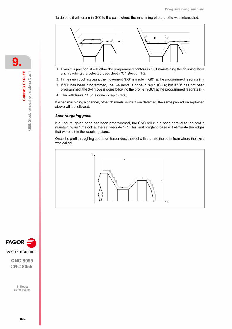
·166·
Programming manual
CNC 8055CNC 8055i
9.
CA
NN
ED
CY
CL
ES
·T· MODELSOFT: V02.2X
G68
. Sto
ck r
emov
al c
ycle
alo
ng X
axi
s
To do this, it will return in G00 to the point where the machining of the profile was interrupted.
1. From this point on, it will follow the programmed contour in G01 maintaining the finishing stockuntil reaching the selected pass depth "C". Section 1-2.
2. In the new roughing pass, the movement "2-3" is made in G01 at the programmed feedrate (F).
3. If "D" has been programmed, the 3-4 move is done in rapid (G00); but if "D" has not beenprogrammed, the 3-4 move is done following the profile in G01 at the programmed feedrate (F).
4. The withdrawal "4-5" is done in rapid (G00).
If when machining a channel, other channels inside it are detected, the same procedure explainedabove will be followed.
Last roughing pass
If a final roughing pass has been programmed, the CNC will run a pass parallel to the profilemaintaining an "L" stock at the set feedrate "F". This final roughing pass will eliminate the ridgesthat were left in the roughing stage.
Once the profile roughing operation has ended, the tool will return to the point from where the cyclewas called.
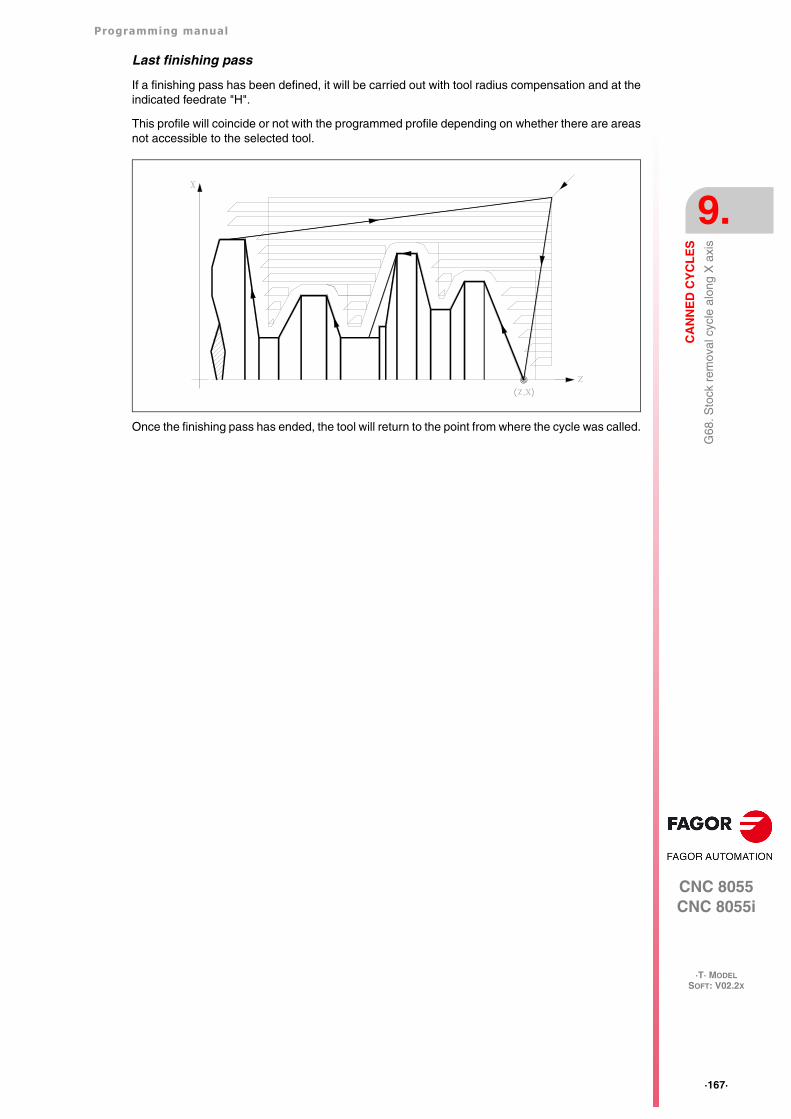
Programming manual
CNC 8055CNC 8055i
CA
NN
ED
CY
CL
ES
9.
·T· MODELSOFT: V02.2X
·167·
G68
. Sto
ck r
emov
al c
ycle
alo
ng X
axi
s
Last finishing pass
If a finishing pass has been defined, it will be carried out with tool radius compensation and at theindicated feedrate "H".
This profile will coincide or not with the programmed profile depending on whether there are areasnot accessible to the selected tool.
Once the finishing pass has ended, the tool will return to the point from where the cycle was called.
·168·
Programming manual
CNC 8055CNC 8055i
9.
CA
NN
ED
CY
CL
ES
·T· MODELSOFT: V02.2X
G68
. Sto
ck r
emov
al c
ycle
alo
ng X
axi
s
9.2.2 Profile programming syntax
When defining the profile, there is no need to program the starting point because it is specified bythe cycle defining parameters X and Z.
When defining 2 profiles, first define the final profile and then that of the original stock.
The first and last profile defining blocks (where the profile or profiles end) must have the block labelnumber. These label numbers will indicate the beginning and end of the profile geometry definition.
The profile programming syntax must follow these rules:
• It may be programmed in absolute or incremental coordinates and may be made up of simplegeometrical elements such as straight lines, arcs, rounded corners, chamfered corners, etc.following the syntax rules defined for this purpose.
• G00 indicates the end of the definition of the final profile and that in this block contains thebeginning of the definition of the profile of the original stock.
Program G01, G02 or G03 in the next block, because G00 is modal, thus preventing the CNCfrom issuing the corresponding error message.
• The profile description must not contain mirror images, scaling factor changes, pattern rotationor zero offsets.
• It must not contain high level blocks such as jumps, calls to subroutines or parametricprogramming.
• It must not contain other canned cycles.
The following functions may be used to define the profile:
G01 Linear interpolation.
G02 Clockwise circular interpolation.
G03 Counter-clockwise circular interpolation.
G06 Circle center in absolute coordinates.
G08 Arc tangent to previous path.
G09 Arc defined by three points.
G36 Corner rounding, radius blend.
G39 Chamfer.
G53 Programming with respect to machine zero.
G70 Programming in inches.
G71 Programming in millimeters.
G90 Absolute programming.
G91 Incremental programming.
G93 Polar origin preset.
The following functions may be programmed, although the cycle will ignore them.
G05 Round corner.
G07 Square corner.
G50 Controlled round corner.
F S T D or M functions.
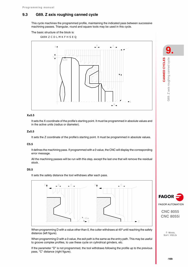
Programming manual
CNC 8055CNC 8055i
CA
NN
ED
CY
CL
ES
9.
·T· MODELSOFT: V02.2X
·169·
G69
. Z a
xis
roug
hing
can
ned
cycl
e
9.3 G69. Z axis roughing canned cycle
This cycle machines the programmed profile, maintaining the indicated pass between successivemachining passes. Triangular, round and square tools may be used in this cycle.
The basic structure of the block is:
G69X Z C D L M K F H S E Q
X±5.5
It sets the X coordinate of the profile's starting point. It must be programmed in absolute values andin the active units (radius or diameter).
Z±5.5
It sets the Z coordinate of the profile's starting point. It must be programmed in absolute values.
C5.5
It defines the machining pass. If programmed with a 0 value, the CNC will display the correspondingerror message.
All the machining passes will be run with this step, except the last one that will remove the residualstock.
D5.5
It sets the safety distance the tool withdraws after each pass.
When programming D with a value other than 0, the cutter withdraws at 45º until reaching the safetydistance (left figure).
When programming D with a 0 value, the exit path is the same as the entry path. This may be usefulto groove complex profiles, to use these cycle on cylindrical grinders, etc.
If the parameter "D" is not programmed, the tool withdraws following the profile up to the previouspass, "C" distance (right figure).
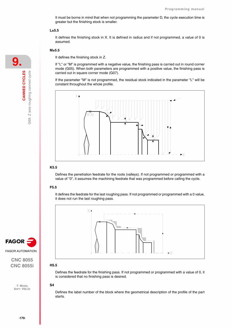
·170·
Programming manual
CNC 8055CNC 8055i
9.
CA
NN
ED
CY
CL
ES
·T· MODELSOFT: V02.2X
G69
. Z a
xis
roug
hing
can
ned
cycl
e
It must be borne in mind that when not programming the parameter D, the cycle execution time isgreater but the finishing stock is smaller.
L±5.5
It defines the finishing stock in X. It is defined in radius and if not programmed, a value of 0 isassumed.
M±5.5
It defines the finishing stock in Z.
If "L" or "M" is programmed with a negative value, the finishing pass is carried out in round cornermode (G05). When both parameters are programmed with a positive value, the finishing pass iscarried out in square corner mode (G07).
If the parameter "M" is not programmed, the residual stock indicated in the parameter "L" will beconstant throughout the whole profile.
K5.5
Defines the penetration feedrate for the roots (valleys). If not programmed or programmed with avalue of "0", it assumes the machining feedrate that was programmed before calling the cycle.
F5.5
It defines the feedrate for the last roughing pass. If not programmed or programmed with a 0 value,it does not run the last roughing pass.
H5.5
Defines the feedrate for the finishing pass. If not programmed or programmed with a value of 0, itis considered that no finishing pass is desired.
S4
Defines the label number of the block where the geometrical description of the profile of the partstarts.
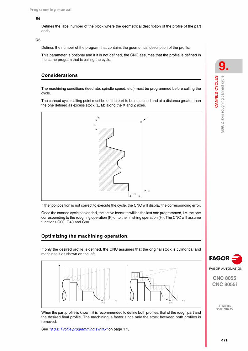
Programming manual
CNC 8055CNC 8055i
CA
NN
ED
CY
CL
ES
9.
·T· MODELSOFT: V02.2X
·171·
G69
. Z a
xis
roug
hing
can
ned
cycl
e
E4
Defines the label number of the block where the geometrical description of the profile of the partends.
Q6
Defines the number of the program that contains the geometrical description of the profile.
This parameter is optional and if it is not defined, the CNC assumes that the profile is defined inthe same program that is calling the cycle.
Considerations
The machining conditions (feedrate, spindle speed, etc.) must be programmed before calling thecycle.
The canned cycle calling point must be off the part to be machined and at a distance greater thanthe one defined as excess stock (L, M) along the X and Z axes.
If the tool position is not correct to execute the cycle, the CNC will display the corresponding error.
Once the canned cycle has ended, the active feedrate will be the last one programmed, i.e. the onecorresponding to the roughing operation (F) or to the finishing operation (H). The CNC will assumefunctions G00, G40 and G90.
Optimizing the machining operation.
If only the desired profile is defined, the CNC assumes that the original stock is cylindrical andmachines it as shown on the left.
When the part profile is known, it is recommended to define both profiles, that of the rough part andthe desired final profile. The machining is faster since only the stock between both profiles isremoved.
See "9.3.2 Profile programming syntax" on page 175.
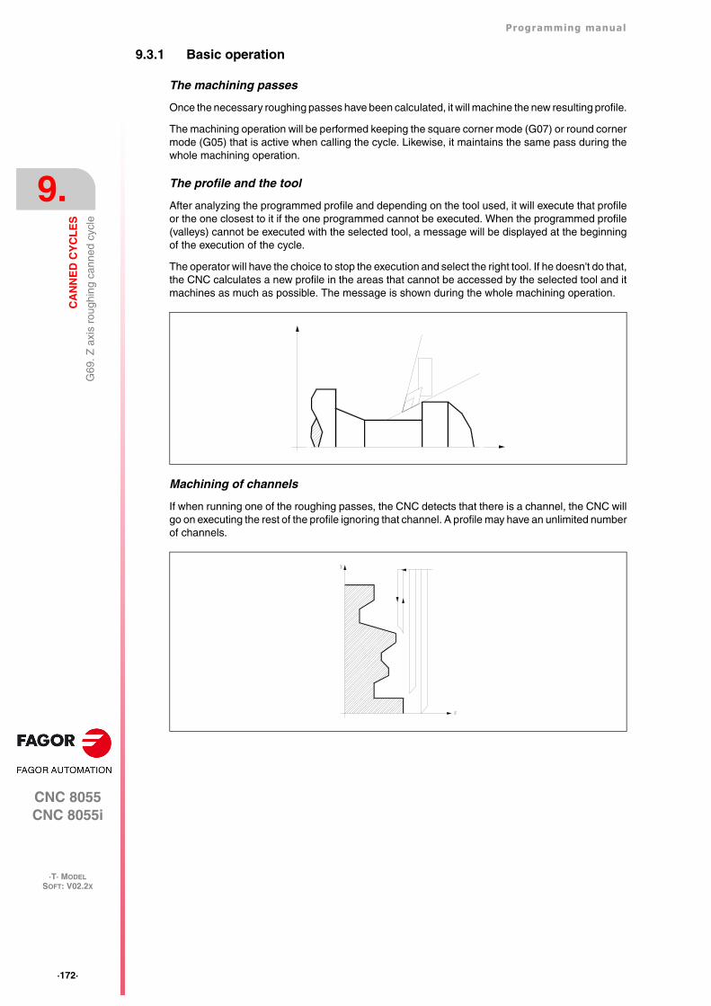
·172·
Programming manual
CNC 8055CNC 8055i
9.
CA
NN
ED
CY
CL
ES
·T· MODELSOFT: V02.2X
G69
. Z a
xis
roug
hing
can
ned
cycl
e
9.3.1 Basic operation
The machining passes
Once the necessary roughing passes have been calculated, it will machine the new resulting profile.
The machining operation will be performed keeping the square corner mode (G07) or round cornermode (G05) that is active when calling the cycle. Likewise, it maintains the same pass during thewhole machining operation.
The profile and the tool
After analyzing the programmed profile and depending on the tool used, it will execute that profileor the one closest to it if the one programmed cannot be executed. When the programmed profile(valleys) cannot be executed with the selected tool, a message will be displayed at the beginningof the execution of the cycle.
The operator will have the choice to stop the execution and select the right tool. If he doesn't do that,the CNC calculates a new profile in the areas that cannot be accessed by the selected tool and itmachines as much as possible. The message is shown during the whole machining operation.
Machining of channels
If when running one of the roughing passes, the CNC detects that there is a channel, the CNC willgo on executing the rest of the profile ignoring that channel. A profile may have an unlimited numberof channels.
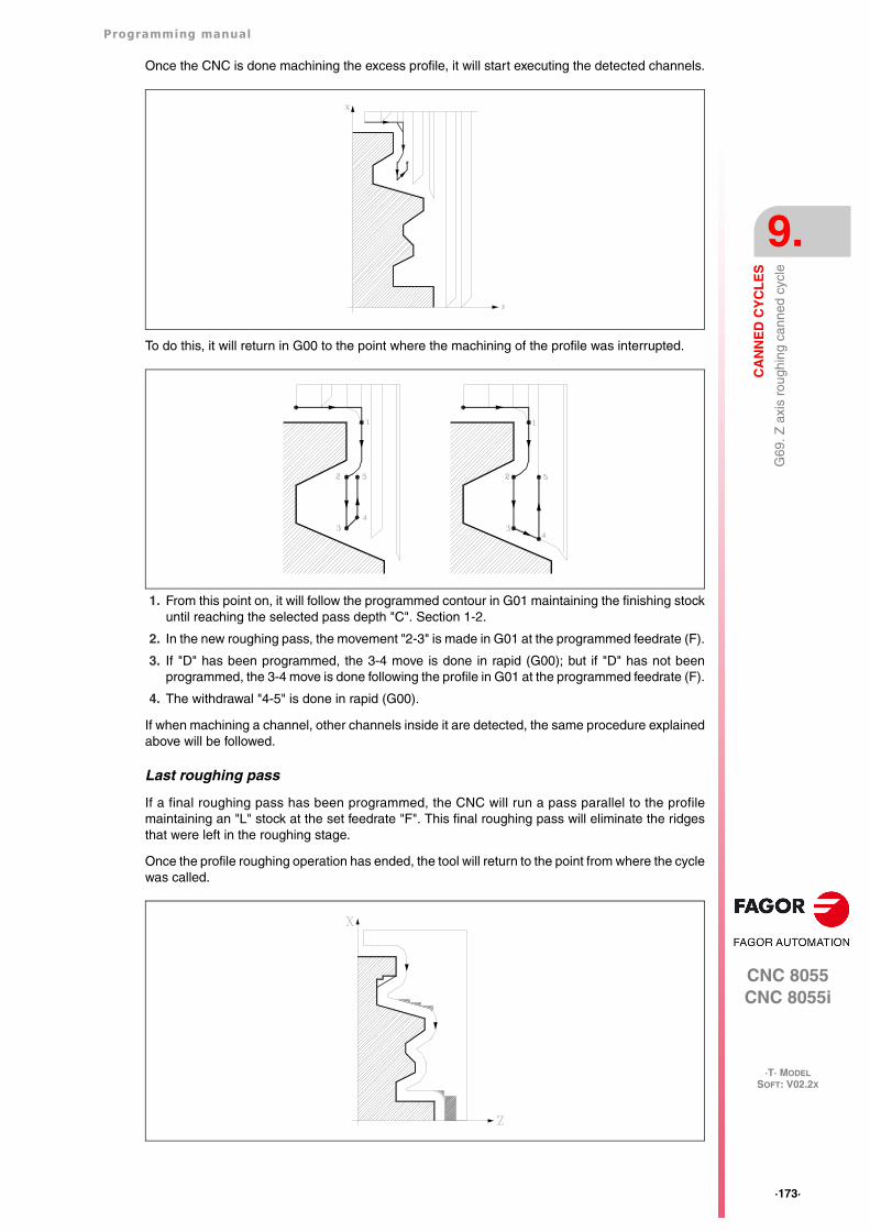
Programming manual
CNC 8055CNC 8055i
CA
NN
ED
CY
CL
ES
9.
·T· MODELSOFT: V02.2X
·173·
G69
. Z a
xis
roug
hing
can
ned
cycl
e
Once the CNC is done machining the excess profile, it will start executing the detected channels.
To do this, it will return in G00 to the point where the machining of the profile was interrupted.
1. From this point on, it will follow the programmed contour in G01 maintaining the finishing stockuntil reaching the selected pass depth "C". Section 1-2.
2. In the new roughing pass, the movement "2-3" is made in G01 at the programmed feedrate (F).
3. If "D" has been programmed, the 3-4 move is done in rapid (G00); but if "D" has not beenprogrammed, the 3-4 move is done following the profile in G01 at the programmed feedrate (F).
4. The withdrawal "4-5" is done in rapid (G00).
If when machining a channel, other channels inside it are detected, the same procedure explainedabove will be followed.
Last roughing pass
If a final roughing pass has been programmed, the CNC will run a pass parallel to the profilemaintaining an "L" stock at the set feedrate "F". This final roughing pass will eliminate the ridgesthat were left in the roughing stage.
Once the profile roughing operation has ended, the tool will return to the point from where the cyclewas called.
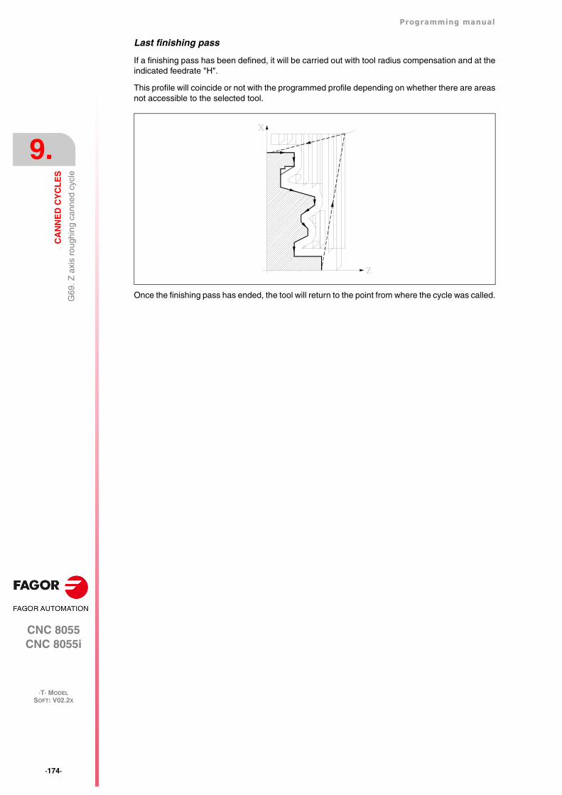
·174·
Programming manual
CNC 8055CNC 8055i
9.
CA
NN
ED
CY
CL
ES
·T· MODELSOFT: V02.2X
G69
. Z a
xis
roug
hing
can
ned
cycl
e
Last finishing pass
If a finishing pass has been defined, it will be carried out with tool radius compensation and at theindicated feedrate "H".
This profile will coincide or not with the programmed profile depending on whether there are areasnot accessible to the selected tool.
Once the finishing pass has ended, the tool will return to the point from where the cycle was called.
Programming manual
CNC 8055CNC 8055i
CA
NN
ED
CY
CL
ES
9.
·T· MODELSOFT: V02.2X
·175·
G69
. Z a
xis
roug
hing
can
ned
cycl
e
9.3.2 Profile programming syntax
When defining the profile, there is no need to program the starting point because it is specified bythe cycle defining parameters X and Z.
When defining 2 profiles, first define the final profile and then that of the original stock.
The first and last profile defining blocks (where the profile or profiles end) must have the block labelnumber. These label numbers will indicate the beginning and end of the profile geometry definition.
The profile programming syntax must follow these rules:
• It may be programmed in absolute or incremental coordinates and may be made up of simplegeometrical elements such as straight lines, arcs, rounded corners, chamfered corners, etc.following the syntax rules defined for this purpose.
• G00 indicates the end of the definition of the final profile and that in this block contains thebeginning of the definition of the profile of the original stock.
Program G01, G02 or G03 in the next block, because G00 is modal, thus preventing the CNCfrom issuing the corresponding error message.
• The profile description must not contain mirror images, scaling factor changes, pattern rotationor zero offsets.
• It must not contain high level blocks such as jumps, calls to subroutines or parametricprogramming.
• It must not contain other canned cycles.
The following functions may be used to define the profile:
G01 Linear interpolation.
G02 Clockwise circular interpolation.
G03 Counter-clockwise circular interpolation.
G06 Circle center in absolute coordinates.
G08 Arc tangent to previous path.
G09 Arc defined by three points.
G36 Corner rounding, radius blend.
G39 Chamfer.
G53 Programming with respect to machine zero.
G70 Programming in inches.
G71 Programming in millimeters.
G90 Absolute programming.
G91 Incremental programming.
G93 Polar origin preset.
The following functions may be programmed, although the cycle will ignore them.
G05 Round corner.
G07 Square corner.
G50 Controlled round corner.
F S T D or M functions.
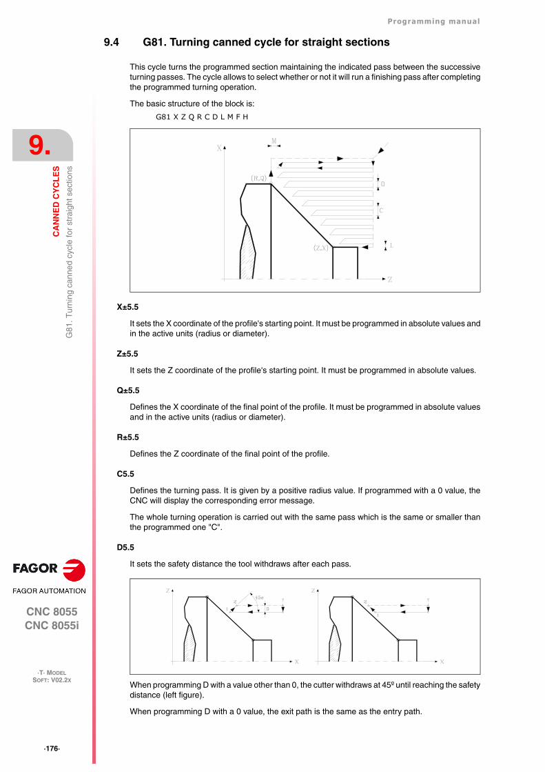
·176·
Programming manual
CNC 8055CNC 8055i
9.
CA
NN
ED
CY
CL
ES
·T· MODELSOFT: V02.2X
G81
. Tur
ning
can
ned
cycl
e fo
r st
raig
ht s
ectio
ns
9.4 G81. Turning canned cycle for straight sections
This cycle turns the programmed section maintaining the indicated pass between the successiveturning passes. The cycle allows to select whether or not it will run a finishing pass after completingthe programmed turning operation.
The basic structure of the block is:
G81 X Z Q R C D L M F H
X±5.5
It sets the X coordinate of the profile's starting point. It must be programmed in absolute values andin the active units (radius or diameter).
Z±5.5
It sets the Z coordinate of the profile's starting point. It must be programmed in absolute values.
Q±5.5
Defines the X coordinate of the final point of the profile. It must be programmed in absolute valuesand in the active units (radius or diameter).
R±5.5
Defines the Z coordinate of the final point of the profile.
C5.5
Defines the turning pass. It is given by a positive radius value. If programmed with a 0 value, theCNC will display the corresponding error message.
The whole turning operation is carried out with the same pass which is the same or smaller thanthe programmed one "C".
D5.5
It sets the safety distance the tool withdraws after each pass.
When programming D with a value other than 0, the cutter withdraws at 45º until reaching the safetydistance (left figure).
When programming D with a 0 value, the exit path is the same as the entry path.

Programming manual
CNC 8055CNC 8055i
CA
NN
ED
CY
CL
ES
9.
·T· MODELSOFT: V02.2X
·177·
G81
. Tur
ning
can
ned
cycl
e fo
r st
raig
ht s
ectio
ns
If the parameter "D" is not programmed, the tool withdraws following the profile up to the previouspass, "C" distance (right figure).
It must be borne in mind that when not programming the parameter D, the cycle execution time isgreater but the finishing stock is smaller.
L5.5
Defines the finishing stock along X and it is given in radius.
If not programmed, a value of 0 is assumed.
M5.5
Defines the finishing stock along Z.
If not programmed, a value of 0 is assumed.
F5.5
It defines the feedrate for the last roughing pass. If not programmed or programmed with a 0 value,it does not run the last roughing pass.
H5.5
Defines the feedrate for the finishing pass.
If not programmed or programmed with a value of 0, it is considered that no finishing pass is desired.
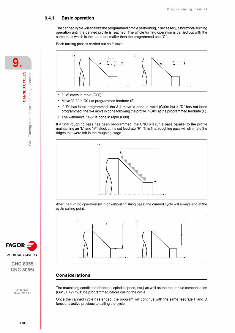
·178·
Programming manual
CNC 8055CNC 8055i
9.
CA
NN
ED
CY
CL
ES
·T· MODELSOFT: V02.2X
G81
. Tur
ning
can
ned
cycl
e fo
r st
raig
ht s
ectio
ns
9.4.1 Basic operation
The canned cycle will analyze the programmed profile performing, if necessary, a horizontal turningoperation until the defined profile is reached. The whole turning operation is carried out with thesame pass which is the same or smaller than the programmed one "C".
Each turning pass is carried out as follows:
• "1-2" move in rapid (G00).
• Move "2-3" in G01 at programmed feedrate (F).
• If "D" has been programmed, the 3-4 move is done in rapid (G00); but if "D" has not beenprogrammed, the 3-4 move is done following the profile in G01 at the programmed feedrate (F).
• The withdrawal "4-5" is done in rapid (G00).
If a final roughing pass has been programmed, the CNC will run a pass parallel to the profilemaintaining an "L" and "M" stock at the set feedrate "F". This final roughing pass will eliminate theridges that were left in the roughing stage.
After the turning operation (with or without finishing pass) the canned cycle will always end at thecycle calling point.
Considerations
The machining conditions (feedrate, spindle speed, etc.) as well as the tool radius compensation(G41, G42) must be programmed before calling the cycle.
Once the canned cycle has ended, the program will continue with the same feedrate F and Gfunctions active previous to calling the cycle.
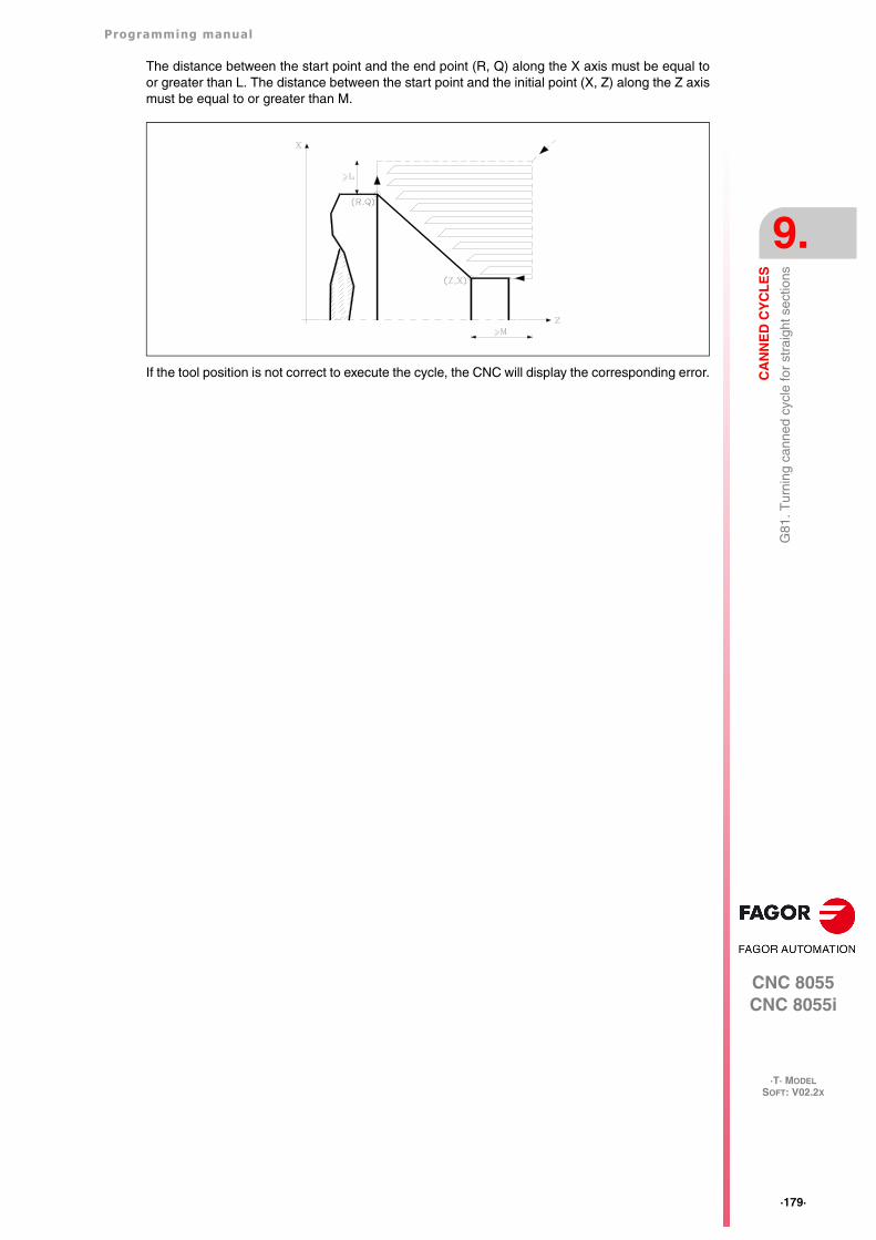
Programming manual
CNC 8055CNC 8055i
CA
NN
ED
CY
CL
ES
9.
·T· MODELSOFT: V02.2X
·179·
G81
. Tur
ning
can
ned
cycl
e fo
r st
raig
ht s
ectio
ns
The distance between the start point and the end point (R, Q) along the X axis must be equal toor greater than L. The distance between the start point and the initial point (X, Z) along the Z axismust be equal to or greater than M.
If the tool position is not correct to execute the cycle, the CNC will display the corresponding error.
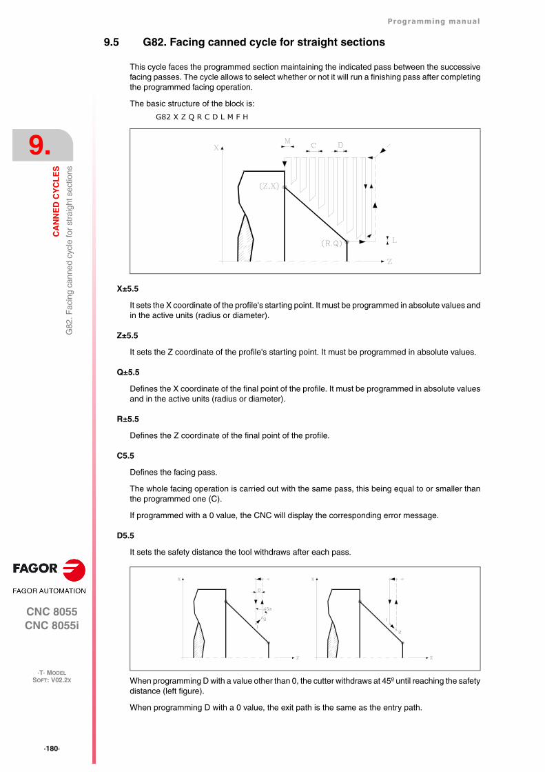
·180·
Programming manual
CNC 8055CNC 8055i
9.
CA
NN
ED
CY
CL
ES
·T· MODELSOFT: V02.2X
G82
. Fac
ing
cann
ed c
ycle
for
stra
ight
sec
tions
9.5 G82. Facing canned cycle for straight sections
This cycle faces the programmed section maintaining the indicated pass between the successivefacing passes. The cycle allows to select whether or not it will run a finishing pass after completingthe programmed facing operation.
The basic structure of the block is:
G82 X Z Q R C D L M F H
X±5.5
It sets the X coordinate of the profile's starting point. It must be programmed in absolute values andin the active units (radius or diameter).
Z±5.5
It sets the Z coordinate of the profile's starting point. It must be programmed in absolute values.
Q±5.5
Defines the X coordinate of the final point of the profile. It must be programmed in absolute valuesand in the active units (radius or diameter).
R±5.5
Defines the Z coordinate of the final point of the profile.
C5.5
Defines the facing pass.
The whole facing operation is carried out with the same pass, this being equal to or smaller thanthe programmed one (C).
If programmed with a 0 value, the CNC will display the corresponding error message.
D5.5
It sets the safety distance the tool withdraws after each pass.
When programming D with a value other than 0, the cutter withdraws at 45º until reaching the safetydistance (left figure).
When programming D with a 0 value, the exit path is the same as the entry path.
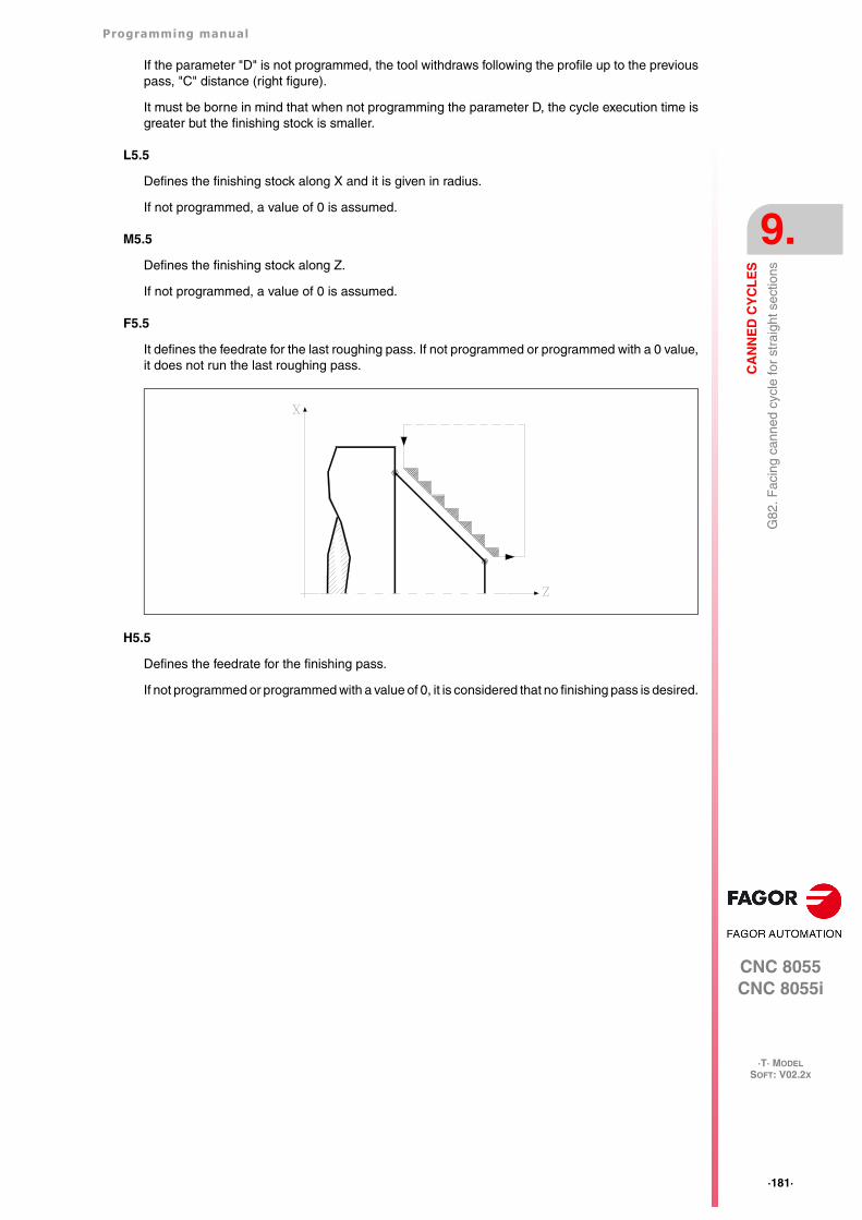
Programming manual
CNC 8055CNC 8055i
CA
NN
ED
CY
CL
ES
9.
·T· MODELSOFT: V02.2X
·181·
G82
. Fac
ing
cann
ed c
ycle
for
stra
ight
sec
tions
If the parameter "D" is not programmed, the tool withdraws following the profile up to the previouspass, "C" distance (right figure).
It must be borne in mind that when not programming the parameter D, the cycle execution time isgreater but the finishing stock is smaller.
L5.5
Defines the finishing stock along X and it is given in radius.
If not programmed, a value of 0 is assumed.
M5.5
Defines the finishing stock along Z.
If not programmed, a value of 0 is assumed.
F5.5
It defines the feedrate for the last roughing pass. If not programmed or programmed with a 0 value,it does not run the last roughing pass.
H5.5
Defines the feedrate for the finishing pass.
If not programmed or programmed with a value of 0, it is considered that no finishing pass is desired.
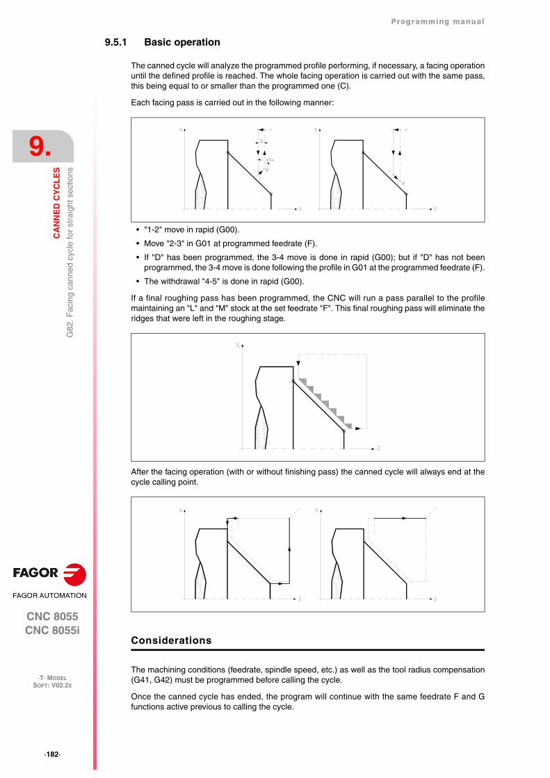
·182·
Programming manual
CNC 8055CNC 8055i
9.
CA
NN
ED
CY
CL
ES
·T· MODELSOFT: V02.2X
G82
. Fac
ing
cann
ed c
ycle
for
stra
ight
sec
tions
9.5.1 Basic operation
The canned cycle will analyze the programmed profile performing, if necessary, a facing operationuntil the defined profile is reached. The whole facing operation is carried out with the same pass,this being equal to or smaller than the programmed one (C).
Each facing pass is carried out in the following manner:
• "1-2" move in rapid (G00).
• Move "2-3" in G01 at programmed feedrate (F).
• If "D" has been programmed, the 3-4 move is done in rapid (G00); but if "D" has not beenprogrammed, the 3-4 move is done following the profile in G01 at the programmed feedrate (F).
• The withdrawal "4-5" is done in rapid (G00).
If a final roughing pass has been programmed, the CNC will run a pass parallel to the profilemaintaining an "L" and "M" stock at the set feedrate "F". This final roughing pass will eliminate theridges that were left in the roughing stage.
After the facing operation (with or without finishing pass) the canned cycle will always end at thecycle calling point.
Considerations
The machining conditions (feedrate, spindle speed, etc.) as well as the tool radius compensation(G41, G42) must be programmed before calling the cycle.
Once the canned cycle has ended, the program will continue with the same feedrate F and Gfunctions active previous to calling the cycle.
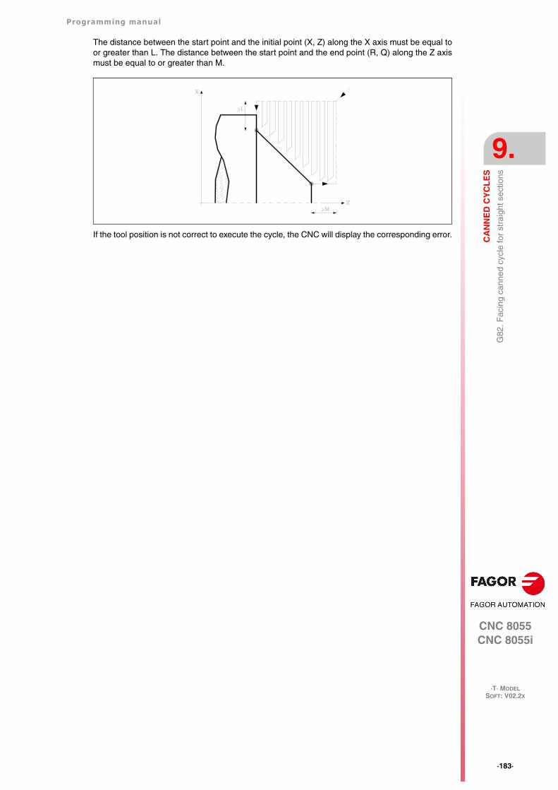
Programming manual
CNC 8055CNC 8055i
CA
NN
ED
CY
CL
ES
9.
·T· MODELSOFT: V02.2X
·183·
G82
. Fac
ing
cann
ed c
ycle
for
stra
ight
sec
tions
The distance between the start point and the initial point (X, Z) along the X axis must be equal toor greater than L. The distance between the start point and the end point (R, Q) along the Z axismust be equal to or greater than M.
If the tool position is not correct to execute the cycle, the CNC will display the corresponding error.
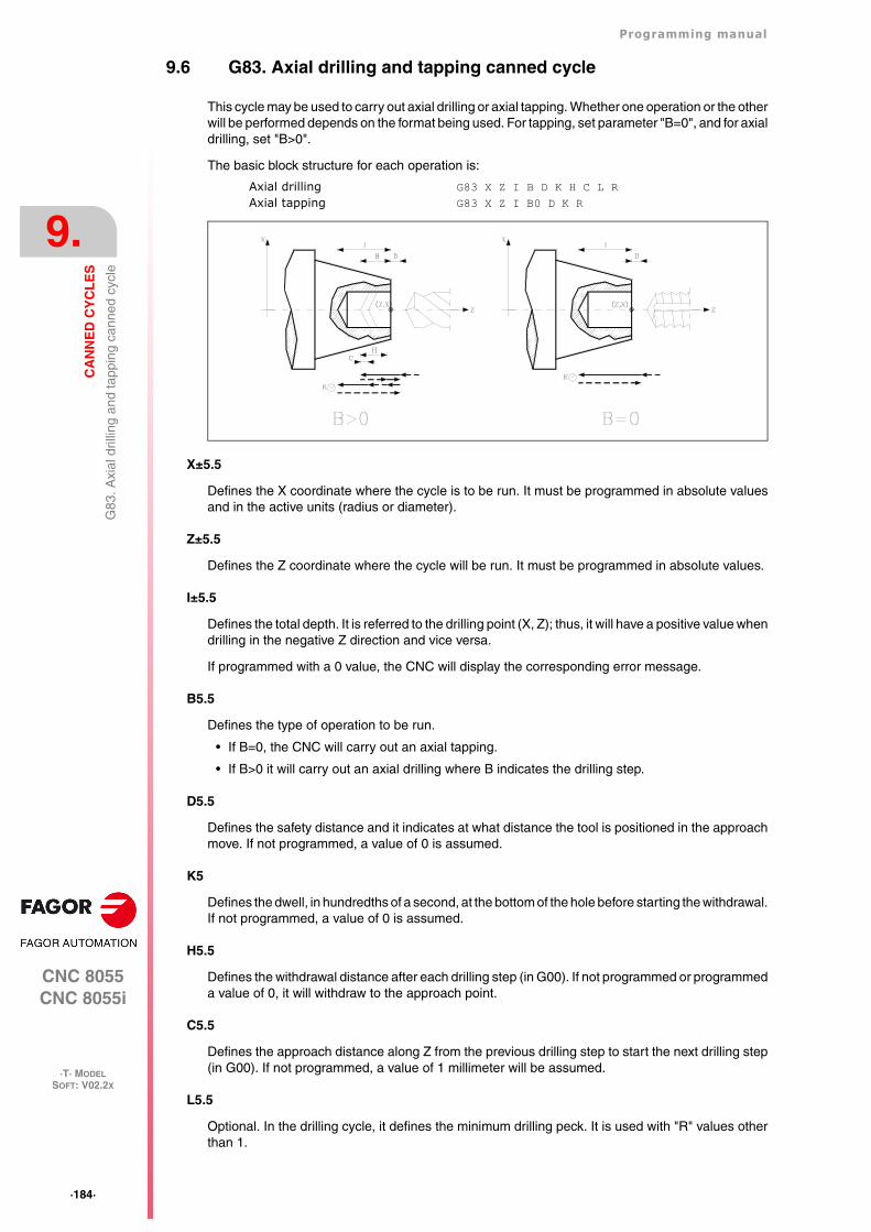
·184·
Programming manual
CNC 8055CNC 8055i
9.
CA
NN
ED
CY
CL
ES
·T· MODELSOFT: V02.2X
G83
. Axi
al d
rillin
g an
d ta
ppin
g ca
nned
cyc
le
9.6 G83. Axial drilling and tapping canned cycle
This cycle may be used to carry out axial drilling or axial tapping. Whether one operation or the otherwill be performed depends on the format being used. For tapping, set parameter "B=0", and for axialdrilling, set "B>0".
The basic block structure for each operation is:
Axial drilling G83 X Z I B D K H C L RAxial tapping G83 X Z I B0 D K R
X±5.5
Defines the X coordinate where the cycle is to be run. It must be programmed in absolute valuesand in the active units (radius or diameter).
Z±5.5
Defines the Z coordinate where the cycle will be run. It must be programmed in absolute values.
I±5.5
Defines the total depth. It is referred to the drilling point (X, Z); thus, it will have a positive value whendrilling in the negative Z direction and vice versa.
If programmed with a 0 value, the CNC will display the corresponding error message.
B5.5
Defines the type of operation to be run.
• If B=0, the CNC will carry out an axial tapping.
• If B>0 it will carry out an axial drilling where B indicates the drilling step.
D5.5
Defines the safety distance and it indicates at what distance the tool is positioned in the approachmove. If not programmed, a value of 0 is assumed.
K5
Defines the dwell, in hundredths of a second, at the bottom of the hole before starting the withdrawal.If not programmed, a value of 0 is assumed.
H5.5
Defines the withdrawal distance after each drilling step (in G00). If not programmed or programmeda value of 0, it will withdraw to the approach point.
C5.5
Defines the approach distance along Z from the previous drilling step to start the next drilling step(in G00). If not programmed, a value of 1 millimeter will be assumed.
L5.5
Optional. In the drilling cycle, it defines the minimum drilling peck. It is used with "R" values otherthan 1.
Programming manual
CNC 8055CNC 8055i
CA
NN
ED
CY
CL
ES
9.
·T· MODELSOFT: V02.2X
·185·
G83
. Axi
al d
rillin
g an
d ta
ppin
g ca
nned
cyc
le
If not programmed, a value of 0 is assumed.
R5.5
In the drilling cycle, it indicates the step that reduces the drilling peck "B". If it is not programmedor is programmed with a value of "0", it assumes a value of "1".
• With R =1, all the drilling pecks will be the same (the programmed "B" value).
• If R is other than 1, the first drilling peck will be "B", the second one "R B", The third one "R(RB)" and so on. In other words, from the second peck on, the new peck will be the product ofthe R factor times the previous peck.
In the tapping cycle it defines the type of tapping to be done. If not programmed, it takes the valueof "0", regular tapping.
• With R0, regular tapping.
• With R1, rigid tapping. The CNC stops the tool with M19 and orients it to begin tapping.
• With R2, rigid tapping. If the tool is turning in M3 or M4, the CNC does not stop it nor orient itto begin tapping. This option does not allow thread repair, even if the part has not been releasedbecause the thread start (entry) will coincide with the one machined earlier.
In order to execute a rigid tapping, the relevant spindle (main or secondary) must be ready to operatein closed loop. In other words, that it must have a servo drive-motor system with rotary encoder.
·186·
Programming manual
CNC 8055CNC 8055i
9.
CA
NN
ED
CY
CL
ES
·T· MODELSOFT: V02.2X
G83
. Axi
al d
rillin
g an
d ta
ppin
g ca
nned
cyc
le
9.6.1 Basic operation
Drilling 1
1. Rapid move to the approach point located at a "D" distance from the first hole position.
2. First drilling operation. The drilling axis moves in G01 to the programmed incremental depth"D+B".
3. Drilling loop. The following steps will be repeated until the programmed depth "I" is reached.
It first withdraws in rapid (G00) a distance "H" or to the approach point. Rapid approach (G00)to a "C" distance from the next peck.
New drilling step. G1 move to the next incremental depth "B" and "R".
4. Dwell K in hundredths of a second at the bottom of the hole, if programmed.
5. Withdrawal in rapid (G00) to the approach point.
Tapping
1. Rapid movement to the approach point located at a safety distance "D" from the tap point.
2. Tapping. The drilling axis moves in G01 to the programmed incremental depth "D+B".
3. The spindle reverses turning direction.
If "K" has been programmed, the spindle stops and after the programmed dwell has elapsed,the spindle starts turning in the other way.
4. Withdrawal in work feedrate to the approach point.
Rigid tapping
1. Tapping takes place at the center of the part (X0). Rapid movement to the approach point locatedat a safety distance "D" from the tap point.
2. Tapping. Tapping to the incremental depth programmed in "D+B".
It is carried out by interpolating the main spindle (that is turning) with the Z axis. Rigid tappingcannot be interrupted, nor the machining conditions be changed. It is done at 100% of theprogrammed "S" and "F".
3. The spindle reverses turning direction.
If "K" has been programmed, the spindle stops and after the programmed dwell has elapsed,the spindle starts turning in the other way.
4. Withdrawal in work feedrate to the approach point.
Rigid tapping is drawn with the color used for "uncompensated tool path". When the cycle iscompleted, the spindle stops (M5).
Considerations
The machining conditions (feedrate, spindle speed, etc.) must be programmed before calling thecycle.
When tapping (regular or rigid), the general logic output "TAPPING" (M5517) stays active duringthe execution of the cycle.
Once the canned cycle has ended, the program will continue with the same feedrate F and Gfunctions active previous to calling the cycle. Only the tool radius compensation will be canceled(G40) if it was active.
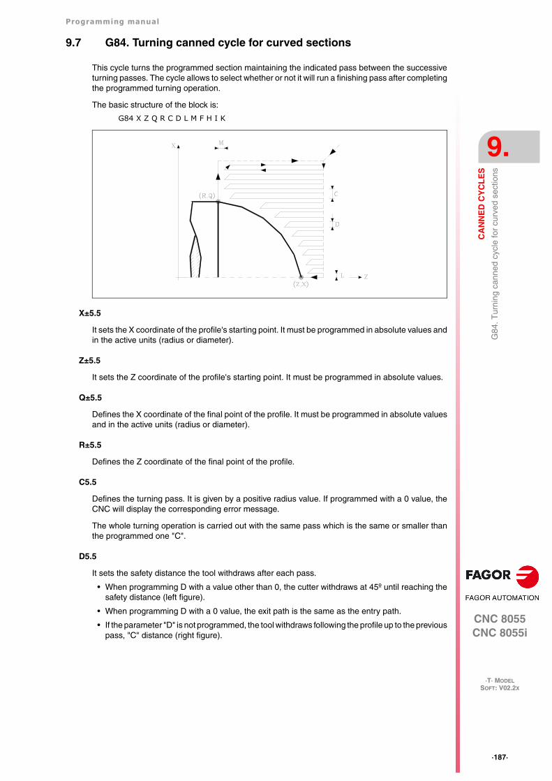
Programming manual
CNC 8055CNC 8055i
CA
NN
ED
CY
CL
ES
9.
·T· MODELSOFT: V02.2X
·187·
G84
. Tur
ning
can
ned
cycl
e fo
r cu
rved
sec
tions
9.7 G84. Turning canned cycle for curved sections
This cycle turns the programmed section maintaining the indicated pass between the successiveturning passes. The cycle allows to select whether or not it will run a finishing pass after completingthe programmed turning operation.
The basic structure of the block is:
G84 X Z Q R C D L M F H I K
X±5.5
It sets the X coordinate of the profile's starting point. It must be programmed in absolute values andin the active units (radius or diameter).
Z±5.5
It sets the Z coordinate of the profile's starting point. It must be programmed in absolute values.
Q±5.5
Defines the X coordinate of the final point of the profile. It must be programmed in absolute valuesand in the active units (radius or diameter).
R±5.5
Defines the Z coordinate of the final point of the profile.
C5.5
Defines the turning pass. It is given by a positive radius value. If programmed with a 0 value, theCNC will display the corresponding error message.
The whole turning operation is carried out with the same pass which is the same or smaller thanthe programmed one "C".
D5.5
It sets the safety distance the tool withdraws after each pass.
• When programming D with a value other than 0, the cutter withdraws at 45º until reaching thesafety distance (left figure).
• When programming D with a 0 value, the exit path is the same as the entry path.
• If the parameter "D" is not programmed, the tool withdraws following the profile up to the previouspass, "C" distance (right figure).
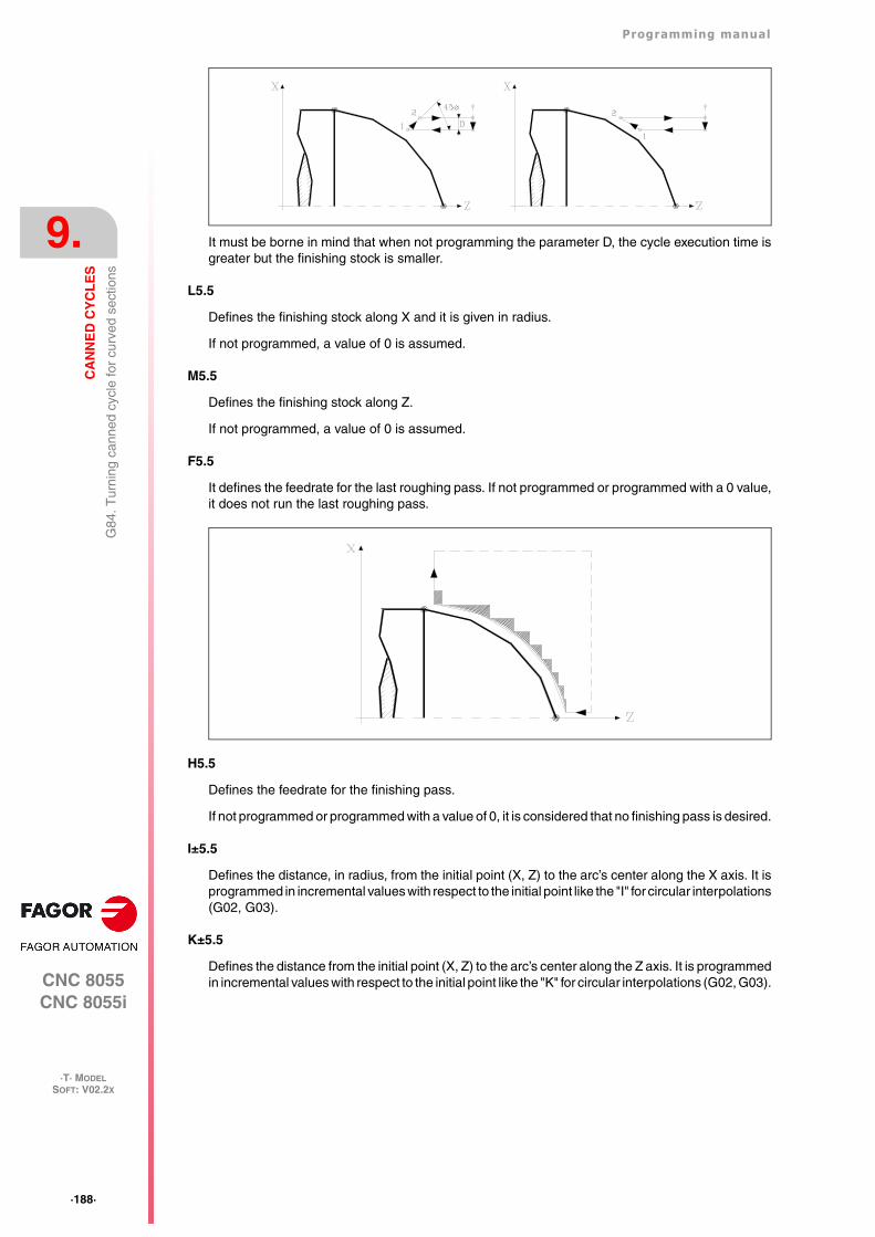
·188·
Programming manual
CNC 8055CNC 8055i
9.
CA
NN
ED
CY
CL
ES
·T· MODELSOFT: V02.2X
G84
. Tur
ning
can
ned
cycl
e fo
r cu
rved
sec
tions
It must be borne in mind that when not programming the parameter D, the cycle execution time isgreater but the finishing stock is smaller.
L5.5
Defines the finishing stock along X and it is given in radius.
If not programmed, a value of 0 is assumed.
M5.5
Defines the finishing stock along Z.
If not programmed, a value of 0 is assumed.
F5.5
It defines the feedrate for the last roughing pass. If not programmed or programmed with a 0 value,it does not run the last roughing pass.
H5.5
Defines the feedrate for the finishing pass.
If not programmed or programmed with a value of 0, it is considered that no finishing pass is desired.
I±5.5
Defines the distance, in radius, from the initial point (X, Z) to the arc’s center along the X axis. It isprogrammed in incremental values with respect to the initial point like the "I" for circular interpolations(G02, G03).
K±5.5
Defines the distance from the initial point (X, Z) to the arc’s center along the Z axis. It is programmedin incremental values with respect to the initial point like the "K" for circular interpolations (G02, G03).
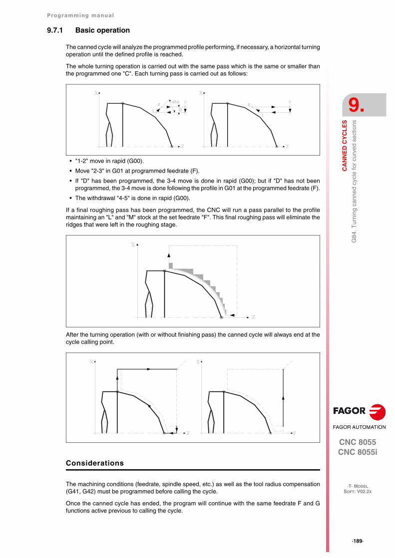
Programming manual
CNC 8055CNC 8055i
CA
NN
ED
CY
CL
ES
9.
·T· MODELSOFT: V02.2X
·189·
G84
. Tur
ning
can
ned
cycl
e fo
r cu
rved
sec
tions
9.7.1 Basic operation
The canned cycle will analyze the programmed profile performing, if necessary, a horizontal turningoperation until the defined profile is reached.
The whole turning operation is carried out with the same pass which is the same or smaller thanthe programmed one "C". Each turning pass is carried out as follows:
• "1-2" move in rapid (G00).
• Move "2-3" in G01 at programmed feedrate (F).
• If "D" has been programmed, the 3-4 move is done in rapid (G00); but if "D" has not beenprogrammed, the 3-4 move is done following the profile in G01 at the programmed feedrate (F).
• The withdrawal "4-5" is done in rapid (G00).
If a final roughing pass has been programmed, the CNC will run a pass parallel to the profilemaintaining an "L" and "M" stock at the set feedrate "F". This final roughing pass will eliminate theridges that were left in the roughing stage.
After the turning operation (with or without finishing pass) the canned cycle will always end at thecycle calling point.
Considerations
The machining conditions (feedrate, spindle speed, etc.) as well as the tool radius compensation(G41, G42) must be programmed before calling the cycle.
Once the canned cycle has ended, the program will continue with the same feedrate F and Gfunctions active previous to calling the cycle.
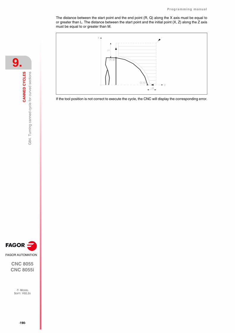
·190·
Programming manual
CNC 8055CNC 8055i
9.
CA
NN
ED
CY
CL
ES
·T· MODELSOFT: V02.2X
G84
. Tur
ning
can
ned
cycl
e fo
r cu
rved
sec
tions
The distance between the start point and the end point (R, Q) along the X axis must be equal toor greater than L. The distance between the start point and the initial point (X, Z) along the Z axismust be equal to or greater than M.
If the tool position is not correct to execute the cycle, the CNC will display the corresponding error.
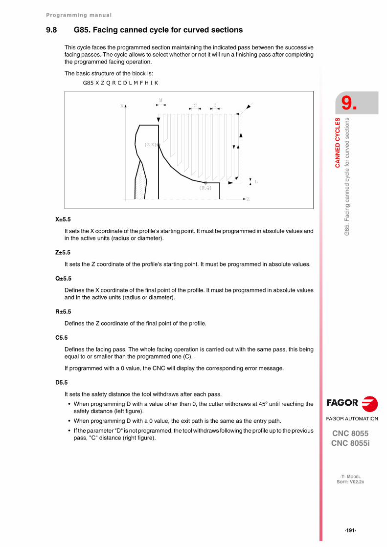
Programming manual
CNC 8055CNC 8055i
CA
NN
ED
CY
CL
ES
9.
·T· MODELSOFT: V02.2X
·191·
G85
. Fac
ing
cann
ed c
ycle
for
curv
ed s
ectio
ns
9.8 G85. Facing canned cycle for curved sections
This cycle faces the programmed section maintaining the indicated pass between the successivefacing passes. The cycle allows to select whether or not it will run a finishing pass after completingthe programmed facing operation.
The basic structure of the block is:
G85 X Z Q R C D L M F H I K
X±5.5
It sets the X coordinate of the profile's starting point. It must be programmed in absolute values andin the active units (radius or diameter).
Z±5.5
It sets the Z coordinate of the profile's starting point. It must be programmed in absolute values.
Q±5.5
Defines the X coordinate of the final point of the profile. It must be programmed in absolute valuesand in the active units (radius or diameter).
R±5.5
Defines the Z coordinate of the final point of the profile.
C5.5
Defines the facing pass. The whole facing operation is carried out with the same pass, this beingequal to or smaller than the programmed one (C).
If programmed with a 0 value, the CNC will display the corresponding error message.
D5.5
It sets the safety distance the tool withdraws after each pass.
• When programming D with a value other than 0, the cutter withdraws at 45º until reaching thesafety distance (left figure).
• When programming D with a 0 value, the exit path is the same as the entry path.
• If the parameter "D" is not programmed, the tool withdraws following the profile up to the previouspass, "C" distance (right figure).
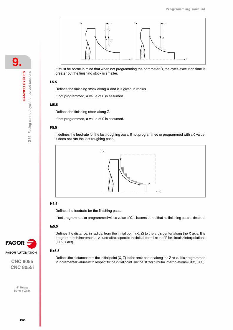
·192·
Programming manual
CNC 8055CNC 8055i
9.
CA
NN
ED
CY
CL
ES
·T· MODELSOFT: V02.2X
G85
. Fac
ing
cann
ed c
ycle
for
curv
ed s
ectio
ns
It must be borne in mind that when not programming the parameter D, the cycle execution time isgreater but the finishing stock is smaller.
L5.5
Defines the finishing stock along X and it is given in radius.
If not programmed, a value of 0 is assumed.
M5.5
Defines the finishing stock along Z.
If not programmed, a value of 0 is assumed.
F5.5
It defines the feedrate for the last roughing pass. If not programmed or programmed with a 0 value,it does not run the last roughing pass.
H5.5
Defines the feedrate for the finishing pass.
If not programmed or programmed with a value of 0, it is considered that no finishing pass is desired.
I±5.5
Defines the distance, in radius, from the initial point (X, Z) to the arc’s center along the X axis. It isprogrammed in incremental values with respect to the initial point like the "I" for circular interpolations(G02, G03).
K±5.5
Defines the distance from the initial point (X, Z) to the arc’s center along the Z axis. It is programmedin incremental values with respect to the initial point like the "K" for circular interpolations (G02, G03).
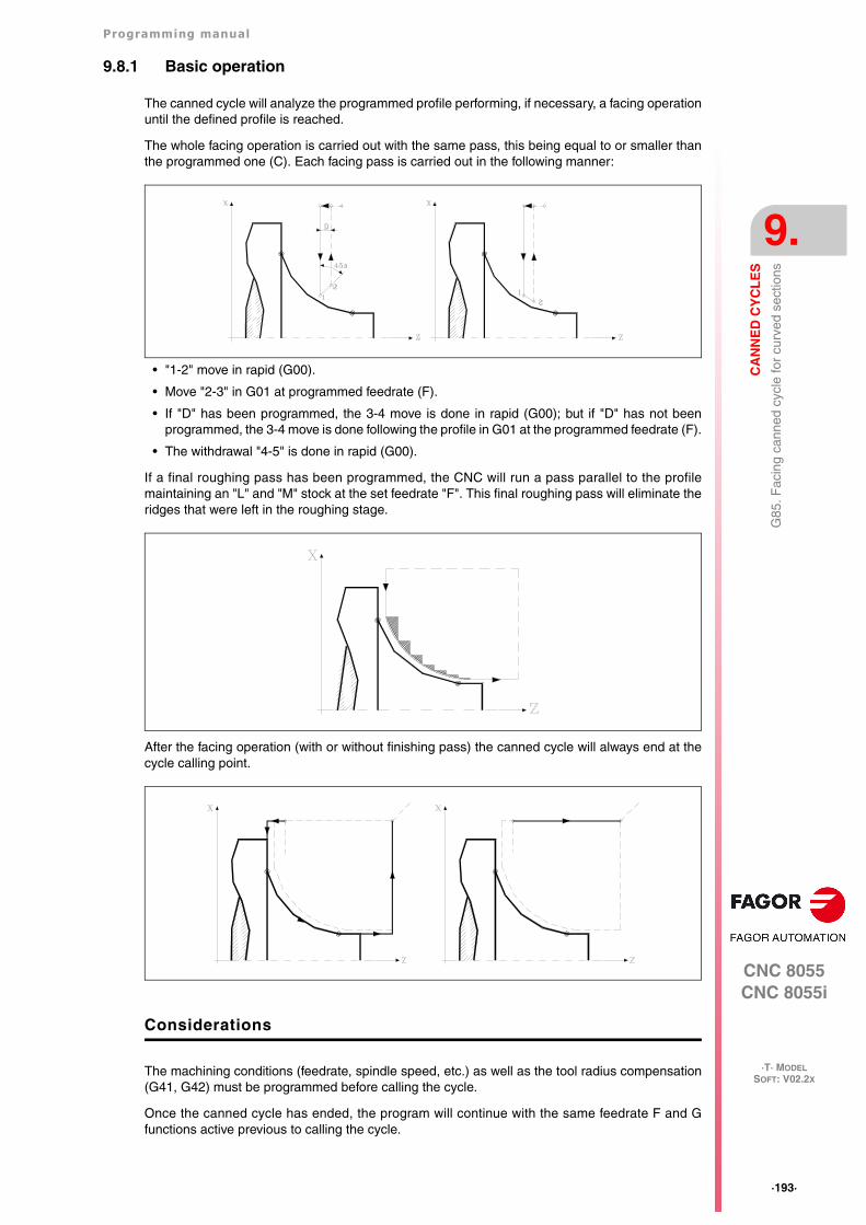
Programming manual
CNC 8055CNC 8055i
CA
NN
ED
CY
CL
ES
9.
·T· MODELSOFT: V02.2X
·193·
G85
. Fac
ing
cann
ed c
ycle
for
curv
ed s
ectio
ns
9.8.1 Basic operation
The canned cycle will analyze the programmed profile performing, if necessary, a facing operationuntil the defined profile is reached.
The whole facing operation is carried out with the same pass, this being equal to or smaller thanthe programmed one (C). Each facing pass is carried out in the following manner:
• "1-2" move in rapid (G00).
• Move "2-3" in G01 at programmed feedrate (F).
• If "D" has been programmed, the 3-4 move is done in rapid (G00); but if "D" has not beenprogrammed, the 3-4 move is done following the profile in G01 at the programmed feedrate (F).
• The withdrawal "4-5" is done in rapid (G00).
If a final roughing pass has been programmed, the CNC will run a pass parallel to the profilemaintaining an "L" and "M" stock at the set feedrate "F". This final roughing pass will eliminate theridges that were left in the roughing stage.
After the facing operation (with or without finishing pass) the canned cycle will always end at thecycle calling point.
Considerations
The machining conditions (feedrate, spindle speed, etc.) as well as the tool radius compensation(G41, G42) must be programmed before calling the cycle.
Once the canned cycle has ended, the program will continue with the same feedrate F and Gfunctions active previous to calling the cycle.
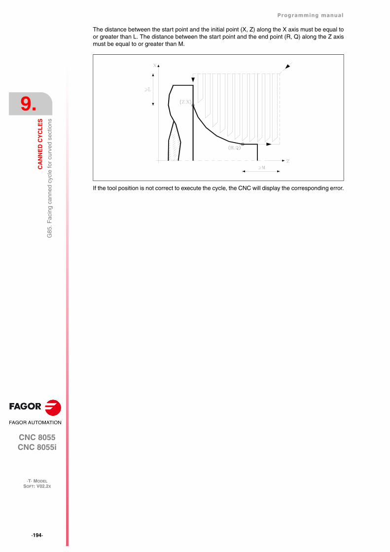
·194·
Programming manual
CNC 8055CNC 8055i
9.
CA
NN
ED
CY
CL
ES
·T· MODELSOFT: V02.2X
G85
. Fac
ing
cann
ed c
ycle
for
curv
ed s
ectio
ns
The distance between the start point and the initial point (X, Z) along the X axis must be equal toor greater than L. The distance between the start point and the end point (R, Q) along the Z axismust be equal to or greater than M.
If the tool position is not correct to execute the cycle, the CNC will display the corresponding error.
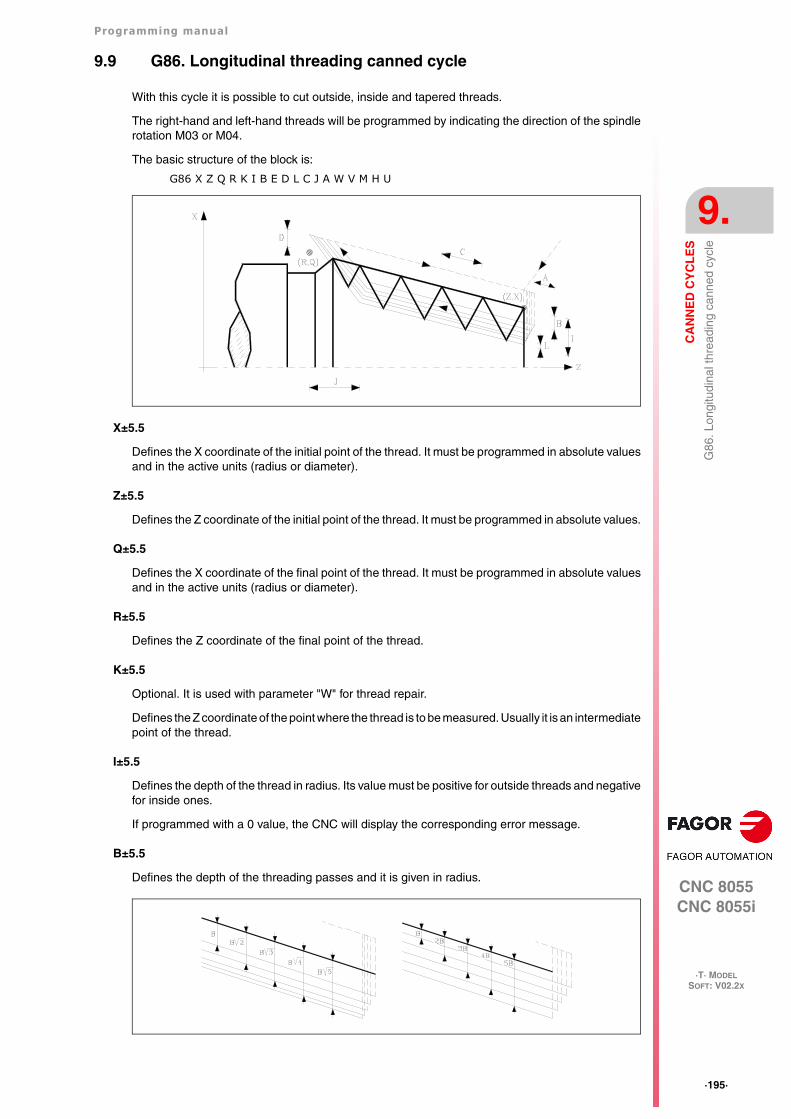
Programming manual
CNC 8055CNC 8055i
CA
NN
ED
CY
CL
ES
9.
·T· MODELSOFT: V02.2X
·195·
G86
. Lon
gitu
dina
l thr
eadi
ng c
anne
d cy
cle
9.9 G86. Longitudinal threading canned cycle
With this cycle it is possible to cut outside, inside and tapered threads.
The right-hand and left-hand threads will be programmed by indicating the direction of the spindlerotation M03 or M04.
The basic structure of the block is:
G86 X Z Q R K I B E D L C J A W V M H U
X±5.5
Defines the X coordinate of the initial point of the thread. It must be programmed in absolute valuesand in the active units (radius or diameter).
Z±5.5
Defines the Z coordinate of the initial point of the thread. It must be programmed in absolute values.
Q±5.5
Defines the X coordinate of the final point of the thread. It must be programmed in absolute valuesand in the active units (radius or diameter).
R±5.5
Defines the Z coordinate of the final point of the thread.
K±5.5
Optional. It is used with parameter "W" for thread repair.
Defines the Z coordinate of the point where the thread is to be measured. Usually it is an intermediatepoint of the thread.
I±5.5
Defines the depth of the thread in radius. Its value must be positive for outside threads and negativefor inside ones.
If programmed with a 0 value, the CNC will display the corresponding error message.
B±5.5
Defines the depth of the threading passes and it is given in radius.
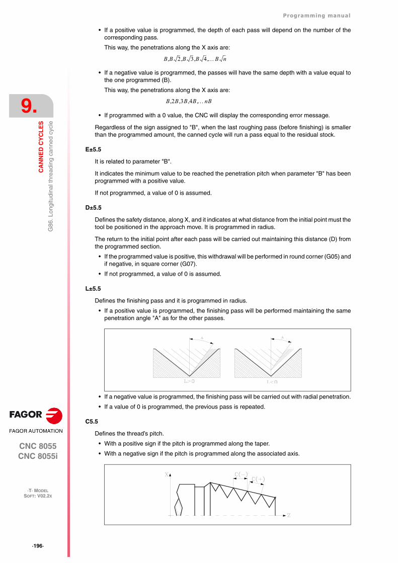
·196·
Programming manual
CNC 8055CNC 8055i
9.
CA
NN
ED
CY
CL
ES
·T· MODELSOFT: V02.2X
G86
. Lon
gitu
dina
l thr
eadi
ng c
anne
d cy
cle
• If a positive value is programmed, the depth of each pass will depend on the number of thecorresponding pass.
This way, the penetrations along the X axis are:
• If a negative value is programmed, the passes will have the same depth with a value equal tothe one programmed (B).
This way, the penetrations along the X axis are:
• If programmed with a 0 value, the CNC will display the corresponding error message.
Regardless of the sign assigned to "B", when the last roughing pass (before finishing) is smallerthan the programmed amount, the canned cycle will run a pass equal to the residual stock.
E±5.5
It is related to parameter "B".
It indicates the minimum value to be reached the penetration pitch when parameter "B" has beenprogrammed with a positive value.
If not programmed, a value of 0 is assumed.
D±5.5
Defines the safety distance, along X, and it indicates at what distance from the initial point must thetool be positioned in the approach move. It is programmed in radius.
The return to the initial point after each pass will be carried out maintaining this distance (D) fromthe programmed section.
• If the programmed value is positive, this withdrawal will be performed in round corner (G05) andif negative, in square corner (G07).
• If not programmed, a value of 0 is assumed.
L±5.5
Defines the finishing pass and it is programmed in radius.
• If a positive value is programmed, the finishing pass will be performed maintaining the samepenetration angle "A" as for the other passes.
• If a negative value is programmed, the finishing pass will be carried out with radial penetration.
• If a value of 0 is programmed, the previous pass is repeated.
C5.5
Defines the thread’s pitch.
• With a positive sign if the pitch is programmed along the taper.
• With a negative sign if the pitch is programmed along the associated axis.
B B 2 B 3 B 4 B n,,,,
B 2B 3B 4B nB,,,,
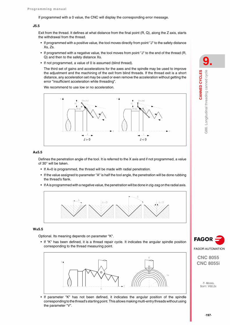
Programming manual
CNC 8055CNC 8055i
CA
NN
ED
CY
CL
ES
9.
·T· MODELSOFT: V02.2X
·197·
G86
. Lon
gitu
dina
l thr
eadi
ng c
anne
d cy
cle
If programmed with a 0 value, the CNC will display the corresponding error message.
J5.5
Exit from the thread. It defines at what distance from the final point (R, Q), along the Z axis, startsthe withdrawal from the thread.
• If programmed with a positive value, the tool moves directly from point "J" to the safety distanceXs, Zs.
• If programmed with a negative value, the tool moves from point "J" to the end of the thread (R,Q) and then to the safety distance Xs.
• If not programmed, a value of 0 is assumed (blind thread).
The third set of gains and accelerations for the axes and the spindle may be used to improvethe adjustment and the machining of the exit from blind threads. If the thread exit is a shortdistance, any acceleration set may be used or even remove the acceleration without getting theerror "insufficient acceleration while threading".
We recommend to use low or no acceleration.
A±5.5
Defines the penetration angle of the tool. It is referred to the X axis and if not programmed, a valueof 30° will be taken.
• If A=0 is programmed, the thread will be made with radial penetration.
• If the value assigned to parameter "A" is half the tool angle, the penetration will be done rubbingthe thread’s flank.
• If A is programmed with a negative value, the penetration will be done in zig-zag on the radial axis.
W±5.5
Optional. Its meaning depends on parameter "K".
• If "K" has been defined, it is a thread repair cycle. It indicates the angular spindle positioncorresponding to the thread measuring point.
• If parameter "K" has not been defined, it indicates the angular position of the spindlecorresponding to the thread's starting point. This allows making multi-entry threads without usingthe parameter "V".
J > 0 J < 0
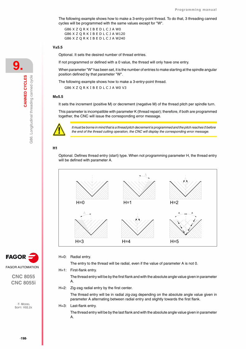
·198·
Programming manual
CNC 8055CNC 8055i
9.
CA
NN
ED
CY
CL
ES
·T· MODELSOFT: V02.2X
G86
. Lon
gitu
dina
l thr
eadi
ng c
anne
d cy
cle
The following example shows how to make a 3-entry-point thread. To do that, 3 threading cannedcycles will be programmed with the same values except for "W".
G86 X Z Q R K I B E D L C J A W0G86 X Z Q R K I B E D L C J A W120G86 X Z Q R K I B E D L C J A W240
V±5.5
Optional. It sets the desired number of thread entries.
If not programmed or defined with a 0 value, the thread will only have one entry.
When parameter "W" has been set, it is the number of entries to make starting at the spindle angularposition defined by that parameter "W".
The following example shows how to make a 3-entry-point thread.
G86 X Z Q R K I B E D L C J A W0 V3
M±5.5
It sets the increment (positive M) or decrement (negative M) of the thread pitch per spindle turn.
This parameter is incompatible with parameter K (thread repair); therefore, if both are programmedtogether, the CNC will issue the corresponding error message.
H1
Optional. Defines thread entry (start) type. When not programming parameter H, the thread entrywill be defined with parameter A.
H=0: Radial entry.
The entry to the thread will be radial, even if the value of parameter A is not 0.
H=1: First-flank entry.
The thread entry will be by the first flank and with the absolute angle value given in parameterA.
H=2: Zig-zag radial entry by the first center.
The thread entry will be in radial zig-zag depending on the absolute angle value given inparameter A alternating between radial entry and slightly towards the first flank.
H=3: Last-flank entry.
The thread entry will be by the last flank and with the absolute angle value given in parameterA.
It must be borne in mind that is a thread pitch decrement is programmed and the pitch reaches 0 beforethe end of the thread cutting operation, the CNC will display the corresponding error message.
H=0 H=1 H=2
H=3 H=4
AA
H=5
Programming manual
CNC 8055CNC 8055i
CA
NN
ED
CY
CL
ES
9.
·T· MODELSOFT: V02.2X
·199·
G86
. Lon
gitu
dina
l thr
eadi
ng c
anne
d cy
cle
H=4: Zig-zag radial entry by the last center.
The thread entry will be in radial zig-zag depending on the absolute angle value given inparameter A alternating between radial entry and slightly towards the last flank.
H=5: Zig-zag entry by the flanks.
The thread entry will be in zig-zag by the flanks depending on the absolute angle value givenin parameter A alternating between the first and last flanks.
Alternating flank-flank, instead of center-flank, extends tool life as compared to radial zig-zag entries (H=2 and H=4).
For this type of entry, the tool being used must have the shape of the thread to be obtainedso it fits perfectly at the bottom of the thread. Before executing this cycle, it may be necessaryto pre-empty the thread with a regular trapezoidal tool. This way, this cycle will eliminate thematerial remaining on the flanks of the thread.
U1
Optional. Partial thread repair.
When repairing a lead screw by welding one part of the thread, after that, the lead screw must berepaired using the thread repair cycle.
The thread repair operation is only required in a very small portion of the leadscrew vs its total length.Partial thread repair saves time because it is possible to repair the portion of the lead screw thathas been welded.
This option can also be used to machine a thread on a cylinder but entering directly into the cylinderwithout doing it from the outside.
Using this option requires setting an entry point and an exit point, at intermediate points betweenthe beginning and the exit of the lead screw where the tool goes in and out following a slanted pathwith respect to the part so as not to damage the thread during the operation.
U=0: When not programmed or programmed with a 0 value, the thread is done beginning in thesame direction as its geometry and ending in the same direction or in the direction set fo theprogrammed thread exit.
U=1: The beginning of each pass is done with the necessary angle segment so it reaches the depthof the thread during the first step of the last pass; the end of each pass is done with thenecessary angle segment so during it reaches the surface of the thread in the last step ofthe last pass.
When programming the thread exit, it will be taken into account, otherwise the cycle willcalculate the exit path as it does for the entry.
Using the U1 option offers two types of machining:
A partial thread repair, in which case K and W must be programmed.
Make a thread on a cylinder but entering directly into the cylinder without doing it from theoutside. In this case, K needs not be programmed.
·200·
Programming manual
CNC 8055CNC 8055i
9.
CA
NN
ED
CY
CL
ES
·T· MODELSOFT: V02.2X
G86
. Lon
gitu
dina
l thr
eadi
ng c
anne
d cy
cle
9.9.1 Basic operation
1. Rapid move (G00) to the approach point located at a safety distance "D" from the initial point(X, Z).
2. Threading loop. The following steps will be repeated until the finishing coordinate is reached;programmed depth "I" minus the finishing stock "L".
Rapid move (G00) to the programmed depth indicated by "B". This move will be madeaccording to the penetration angle of the selected tool (A).
It threads the programmed section with the selected exit (J). The feedrate F cannot be variedwith the feedrate override switch while threading; it will stay at 100%. At the beginning of themachining operation on large lathes, when cutting long threads, the spindle speed may beoverridden in the first passes to prevent the part from bending.
Withdrawal in rapid (G00) to the approach point.
3. Thread finishing. Rapid move (G00) to the programmed depth coordinate "I".
This move will be radial or according to the tool penetration angle (A) which depends on the signassigned to parameter "L".
4. It threads the programmed section with the selected exit (J).
The feedrate F cannot be varied with the feedrate override switch while threading; it will stay at100%. It will not be possible to vary the spindle speed override in the last threading pass, it willbe set to the value imposed in the previous pass.
5. Withdrawal in rapid (G00) to the approach point.
Thread repair
To do a thread repair, proceed as follows:
1. Home (reference) the spindle.
2. Measure the angle of the root of the thread, K W parameters.
3. Define the G87 cycle for thread repair.
4. Execute the canned cycle.
Considerations
The machining conditions (feedrate, spindle speed, etc.) must be programmed before calling thecycle.
Once the canned cycle has ended, the program will continue with the same feedrate F and Gfunctions active previous to calling the cycle. Only the tool radius compensation will be canceled(G40) if it was active.
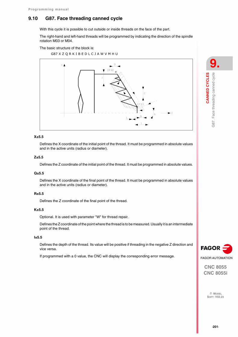
Programming manual
CNC 8055CNC 8055i
CA
NN
ED
CY
CL
ES
9.
·T· MODELSOFT: V02.2X
·201·
G87
. Fac
e th
read
ing
cann
ed c
ycle
9.10 G87. Face threading canned cycle
With this cycle it is possible to cut outside or inside threads on the face of the part.
The right-hand and left-hand threads will be programmed by indicating the direction of the spindlerotation M03 or M04.
The basic structure of the block is:
G87 X Z Q R K I B E D L C J A W V M H U
X±5.5
Defines the X coordinate of the initial point of the thread. It must be programmed in absolute valuesand in the active units (radius or diameter).
Z±5.5
Defines the Z coordinate of the initial point of the thread. It must be programmed in absolute values.
Q±5.5
Defines the X coordinate of the final point of the thread. It must be programmed in absolute valuesand in the active units (radius or diameter).
R±5.5
Defines the Z coordinate of the final point of the thread.
K±5.5
Optional. It is used with parameter "W" for thread repair.
Defines the Z coordinate of the point where the thread is to be measured. Usually it is an intermediatepoint of the thread.
I±5.5
Defines the depth of the thread. Its value will be positive if threading in the negative Z direction andvice versa.
If programmed with a 0 value, the CNC will display the corresponding error message.
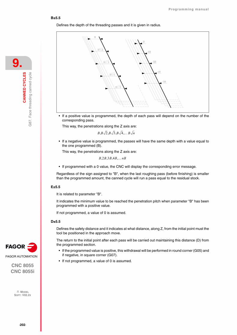
·202·
Programming manual
CNC 8055CNC 8055i
9.
CA
NN
ED
CY
CL
ES
·T· MODELSOFT: V02.2X
G87
. Fac
e th
read
ing
cann
ed c
ycle
B±5.5
Defines the depth of the threading passes and it is given in radius.
• If a positive value is programmed, the depth of each pass will depend on the number of thecorresponding pass.
This way, the penetrations along the Z axis are:
• If a negative value is programmed, the passes will have the same depth with a value equal tothe one programmed (B).
This way, the penetrations along the Z axis are:
• If programmed with a 0 value, the CNC will display the corresponding error message.
Regardless of the sign assigned to "B", when the last roughing pass (before finishing) is smallerthan the programmed amount, the canned cycle will run a pass equal to the residual stock.
E±5.5
It is related to parameter "B".
It indicates the minimum value to be reached the penetration pitch when parameter "B" has beenprogrammed with a positive value.
If not programmed, a value of 0 is assumed.
D±5.5
Defines the safety distance and it indicates at what distance, along Z, from the initial point must thetool be positioned in the approach move.
The return to the initial point after each pass will be carried out maintaining this distance (D) fromthe programmed section.
• If the programmed value is positive, this withdrawal will be performed in round corner (G05) andif negative, in square corner (G07).
• If not programmed, a value of 0 is assumed.
B B 2 B 3 B 4 B n,,,,
B 2B 3B 4B nB,,,,
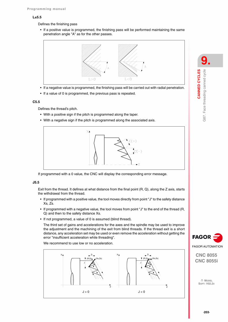
Programming manual
CNC 8055CNC 8055i
CA
NN
ED
CY
CL
ES
9.
·T· MODELSOFT: V02.2X
·203·
G87
. Fac
e th
read
ing
cann
ed c
ycle
L±5.5
Defines the finishing pass
• If a positive value is programmed, the finishing pass will be performed maintaining the samepenetration angle "A" as for the other passes.
• If a negative value is programmed, the finishing pass will be carried out with radial penetration.
• If a value of 0 is programmed, the previous pass is repeated.
C5.5
Defines the thread’s pitch.
• With a positive sign if the pitch is programmed along the taper.
• With a negative sign if the pitch is programmed along the associated axis.
If programmed with a 0 value, the CNC will display the corresponding error message.
J5.5
Exit from the thread. It defines at what distance from the final point (R, Q), along the Z axis, startsthe withdrawal from the thread.
• If programmed with a positive value, the tool moves directly from point "J" to the safety distanceXs, Zs.
• If programmed with a negative value, the tool moves from point "J" to the end of the thread (R,Q) and then to the safety distance Xs.
• If not programmed, a value of 0 is assumed (blind thread).
The third set of gains and accelerations for the axes and the spindle may be used to improvethe adjustment and the machining of the exit from blind threads. If the thread exit is a shortdistance, any acceleration set may be used or even remove the acceleration without getting theerror "insufficient acceleration while threading".
We recommend to use low or no acceleration.
J > 0 J < 0
DX
J
(R,Q) (Xs,Zs)
Z
DX
J
(R,Q) (Xs,Zs)
Z
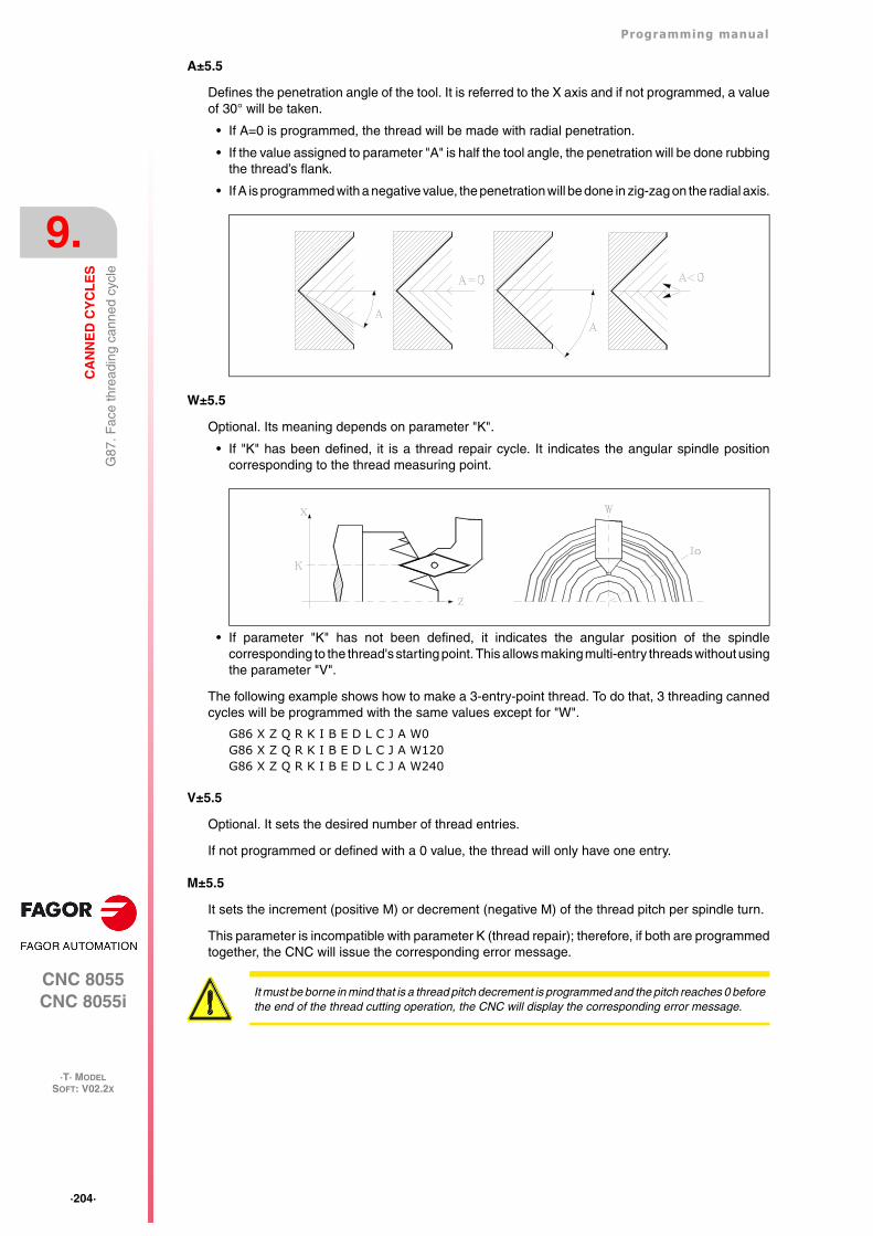
·204·
Programming manual
CNC 8055CNC 8055i
9.
CA
NN
ED
CY
CL
ES
·T· MODELSOFT: V02.2X
G87
. Fac
e th
read
ing
cann
ed c
ycle
A±5.5
Defines the penetration angle of the tool. It is referred to the X axis and if not programmed, a valueof 30° will be taken.
• If A=0 is programmed, the thread will be made with radial penetration.
• If the value assigned to parameter "A" is half the tool angle, the penetration will be done rubbingthe thread’s flank.
• If A is programmed with a negative value, the penetration will be done in zig-zag on the radial axis.
W±5.5
Optional. Its meaning depends on parameter "K".
• If "K" has been defined, it is a thread repair cycle. It indicates the angular spindle positioncorresponding to the thread measuring point.
• If parameter "K" has not been defined, it indicates the angular position of the spindlecorresponding to the thread's starting point. This allows making multi-entry threads without usingthe parameter "V".
The following example shows how to make a 3-entry-point thread. To do that, 3 threading cannedcycles will be programmed with the same values except for "W".
G86 X Z Q R K I B E D L C J A W0G86 X Z Q R K I B E D L C J A W120G86 X Z Q R K I B E D L C J A W240
V±5.5
Optional. It sets the desired number of thread entries.
If not programmed or defined with a 0 value, the thread will only have one entry.
M±5.5
It sets the increment (positive M) or decrement (negative M) of the thread pitch per spindle turn.
This parameter is incompatible with parameter K (thread repair); therefore, if both are programmedtogether, the CNC will issue the corresponding error message.
It must be borne in mind that is a thread pitch decrement is programmed and the pitch reaches 0 beforethe end of the thread cutting operation, the CNC will display the corresponding error message.
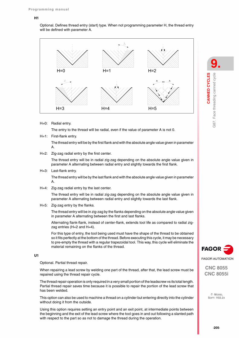
Programming manual
CNC 8055CNC 8055i
CA
NN
ED
CY
CL
ES
9.
·T· MODELSOFT: V02.2X
·205·
G87
. Fac
e th
read
ing
cann
ed c
ycle
H1
Optional. Defines thread entry (start) type. When not programming parameter H, the thread entrywill be defined with parameter A.
H=0: Radial entry.
The entry to the thread will be radial, even if the value of parameter A is not 0.
H=1: First-flank entry.
The thread entry will be by the first flank and with the absolute angle value given in parameterA.
H=2: Zig-zag radial entry by the first center.
The thread entry will be in radial zig-zag depending on the absolute angle value given inparameter A alternating between radial entry and slightly towards the first flank.
H=3: Last-flank entry.
The thread entry will be by the last flank and with the absolute angle value given in parameterA.
H=4: Zig-zag radial entry by the last center.
The thread entry will be in radial zig-zag depending on the absolute angle value given inparameter A alternating between radial entry and slightly towards the last flank.
H=5: Zig-zag entry by the flanks.
The thread entry will be in zig-zag by the flanks depending on the absolute angle value givenin parameter A alternating between the first and last flanks.
Alternating flank-flank, instead of center-flank, extends tool life as compared to radial zig-zag entries (H=2 and H=4).
For this type of entry, the tool being used must have the shape of the thread to be obtainedso it fits perfectly at the bottom of the thread. Before executing this cycle, it may be necessaryto pre-empty the thread with a regular trapezoidal tool. This way, this cycle will eliminate thematerial remaining on the flanks of the thread.
U1
Optional. Partial thread repair.
When repairing a lead screw by welding one part of the thread, after that, the lead screw must berepaired using the thread repair cycle.
The thread repair operation is only required in a very small portion of the leadscrew vs its total length.Partial thread repair saves time because it is possible to repair the portion of the lead screw thathas been welded.
This option can also be used to machine a thread on a cylinder but entering directly into the cylinderwithout doing it from the outside.
Using this option requires setting an entry point and an exit point, at intermediate points betweenthe beginning and the exit of the lead screw where the tool goes in and out following a slanted pathwith respect to the part so as not to damage the thread during the operation.
H=0 H=1 H=2
H=3 H=4
AA
H=5
·206·
Programming manual
CNC 8055CNC 8055i
9.
CA
NN
ED
CY
CL
ES
·T· MODELSOFT: V02.2X
G87
. Fac
e th
read
ing
cann
ed c
ycle
U=0: When not programmed or programmed with a 0 value, the thread is done beginning in thesame direction as its geometry and ending in the same direction or in the direction set fo theprogrammed thread exit.
U=1: The beginning of each pass is done with the necessary angle segment so it reaches the depthof the thread during the first step of the last pass; the end of each pass is done with thenecessary angle segment so during it reaches the surface of the thread in the last step ofthe last pass.
When programming the thread exit, it will be taken into account, otherwise the cycle willcalculate the exit path as it does for the entry.
Using the U1 option offers two types of machining:
A partial thread repair, in which case K and W must be programmed.
Make a thread on a cylinder but entering directly into the cylinder without doing it from theoutside. In this case, K needs not be programmed.
Programming manual
CNC 8055CNC 8055i
CA
NN
ED
CY
CL
ES
9.
·T· MODELSOFT: V02.2X
·207·
G87
. Fac
e th
read
ing
cann
ed c
ycle
9.10.1 Basic operation
1. Rapid move (G00) to the approach point located at a safety distance "D" from the initial point(X, Z).
2. Threading loop. The following steps will be repeated until the finishing coordinate is reached;programmed depth "I" minus the finishing stock "L".
Rapid move (G00) to the programmed depth indicated by "B". This move will be madeaccording to the penetration angle of the selected tool (A).
It threads the programmed section with the selected exit (J). The feedrate F cannot be variedwith the feedrate override switch while threading; it will stay at 100%. At the beginning of themachining operation on large lathes, when cutting long threads, the spindle speed may beoverridden in the first passes to prevent the part from bending.
Withdrawal in rapid (G00) to the approach point.
3. Thread finishing. Rapid move (G00) to the programmed depth coordinate "I".
This move will be radial or according to the tool penetration angle (A) which depends on the signassigned to parameter "L".
4. It threads the programmed section with the selected exit (J).
The feedrate F cannot be varied with the feedrate override switch while threading; it will stay at100%. It will not be possible to vary the spindle speed override in the last threading pass, it willbe set to the value imposed in the previous pass.
5. Withdrawal in rapid (G00) to the approach point.
Thread repair
To do a thread repair, proceed as follows:
1. Home (reference) the spindle.
2. Measure the angle of the root of the thread, K W parameters.
3. Define the G87 cycle for thread repair.
4. Execute the canned cycle.
Considerations
The machining conditions (feedrate, spindle speed, etc.) must be programmed before calling thecycle.
Once the canned cycle has ended, the program will continue with the same feedrate F and Gfunctions active previous to calling the cycle. Only the tool radius compensation will be canceled(G40) if it was active.
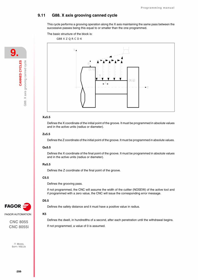
·208·
Programming manual
CNC 8055CNC 8055i
9.
CA
NN
ED
CY
CL
ES
·T· MODELSOFT: V02.2X
G88
. X a
xis
groo
ving
can
ned
cycl
e
9.11 G88. X axis grooving canned cycle
This cycle performs a grooving operation along the X axis maintaining the same pass between thesuccessive passes being this equal to or smaller than the one programmed.
The basic structure of the block is:
G88 X Z Q R C D K
X±5.5
Defines the X coordinate of the initial point of the groove. It must be programmed in absolute valuesand in the active units (radius or diameter).
Z±5.5
Defines the Z coordinate of the initial point of the groove. It must be programmed in absolute values.
Q±5.5
Defines the X coordinate of the final point of the groove. It must be programmed in absolute valuesand in the active units (radius or diameter).
R±5.5
Defines the Z coordinate of the final point of the groove.
C5.5
Defines the grooving pass.
If not programmed, the CNC will assume the width of the cuttter (NOSEW) of the active tool andif programmed with a zero value, the CNC will issue the corresponding error message.
D5.5
Defines the safety distance and it must have a positive value in radius.
K5
Defines the dwell, in hundredths of a second, after each penetration until the withdrawal begins.
If not programmed, a value of 0 is assumed.
Programming manual
CNC 8055CNC 8055i
CA
NN
ED
CY
CL
ES
9.
·T· MODELSOFT: V02.2X
·209·
G88
. X a
xis
groo
ving
can
ned
cycl
e
9.11.1 Basic operation
The whole grooving operation is done with the same pass being this equal to or smaller than "C".Each grooving pass is carried out in the following manner:
• The penetration is done at programmed feedrate (F).
• The withdrawal and the move to the next penetration point are done in rapid (G00).
After completing the grooving operation, the canned cycle will always end at the cycle callingpoint.
Considerations
The machining conditions (feedrate, spindle speed, etc.) must be programmed before calling thecycle.
Once the canned cycle has ended, the program will continue with the same feedrate F and Gfunctions active previous to calling the cycle. Only the tool radius compensation will be canceled(G40) if it was active.
The tool must be located at a distance, along X, equal to or greater than the one indicated by cannedcycle parameter "D" (safety distance) with respect to the part.
If the depth of the groove is 0, the CNC will display the corresponding error message.
If the width of the groove is smaller than the width of the cutter (NOSEW), the CNC will display thecorresponding error message.
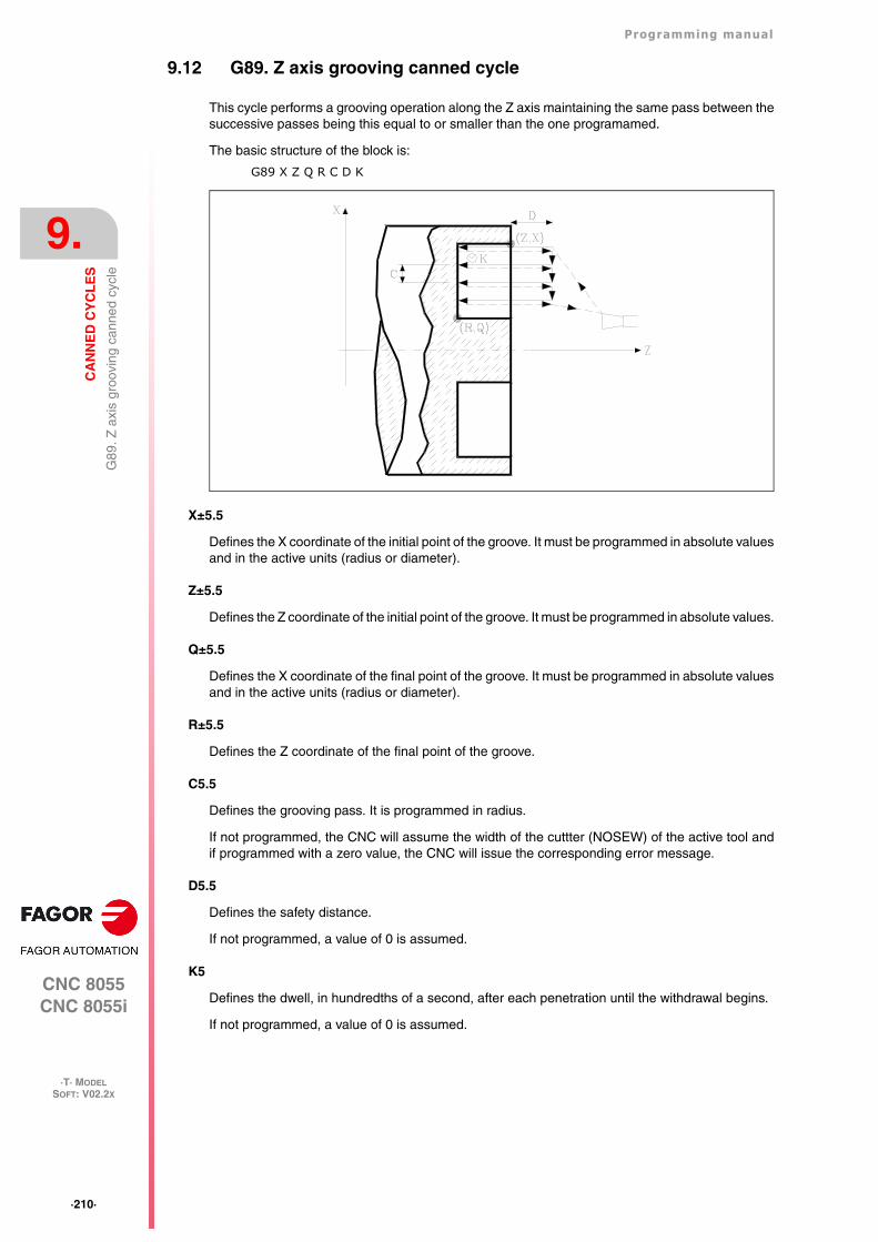
·210·
Programming manual
CNC 8055CNC 8055i
9.
CA
NN
ED
CY
CL
ES
·T· MODELSOFT: V02.2X
G89
. Z a
xis
groo
ving
can
ned
cycl
e
9.12 G89. Z axis grooving canned cycle
This cycle performs a grooving operation along the Z axis maintaining the same pass between thesuccessive passes being this equal to or smaller than the one programamed.
The basic structure of the block is:
G89 X Z Q R C D K
X±5.5
Defines the X coordinate of the initial point of the groove. It must be programmed in absolute valuesand in the active units (radius or diameter).
Z±5.5
Defines the Z coordinate of the initial point of the groove. It must be programmed in absolute values.
Q±5.5
Defines the X coordinate of the final point of the groove. It must be programmed in absolute valuesand in the active units (radius or diameter).
R±5.5
Defines the Z coordinate of the final point of the groove.
C5.5
Defines the grooving pass. It is programmed in radius.
If not programmed, the CNC will assume the width of the cuttter (NOSEW) of the active tool andif programmed with a zero value, the CNC will issue the corresponding error message.
D5.5
Defines the safety distance.
If not programmed, a value of 0 is assumed.
K5
Defines the dwell, in hundredths of a second, after each penetration until the withdrawal begins.
If not programmed, a value of 0 is assumed.
Programming manual
CNC 8055CNC 8055i
CA
NN
ED
CY
CL
ES
9.
·T· MODELSOFT: V02.2X
·211·
G89
. Z a
xis
groo
ving
can
ned
cycl
e
9.12.1 Basic operation
The whole grooving operation is done with the same pass being this equal to or smaller than "C".Each grooving pass is carried out in the following manner:
• The penetration is done at programmed feedrate (F).
• The withdrawal and the move to the next penetration point are done in rapid (G00).
After completing the grooving operation, the canned cycle will always end at the cycle callingpoint.
Considerations
The machining conditions (feedrate, spindle speed, etc.) must be programmed before calling thecycle.
Once the canned cycle has ended, the program will continue with the same feedrate F and Gfunctions active previous to calling the cycle. Only the tool radius compensation will be canceled(G40) if it was active.
The tool must be located at a distance, along Z, equal to or greater than the one indicated by cannedcycle parameter "D" (safety distance) with respect to the part.
If the depth of the groove is 0, the CNC will display the corresponding error message.
If the width of the groove is smaller than the width of the cutter (NOSEW), the CNC will display thecorresponding error message.
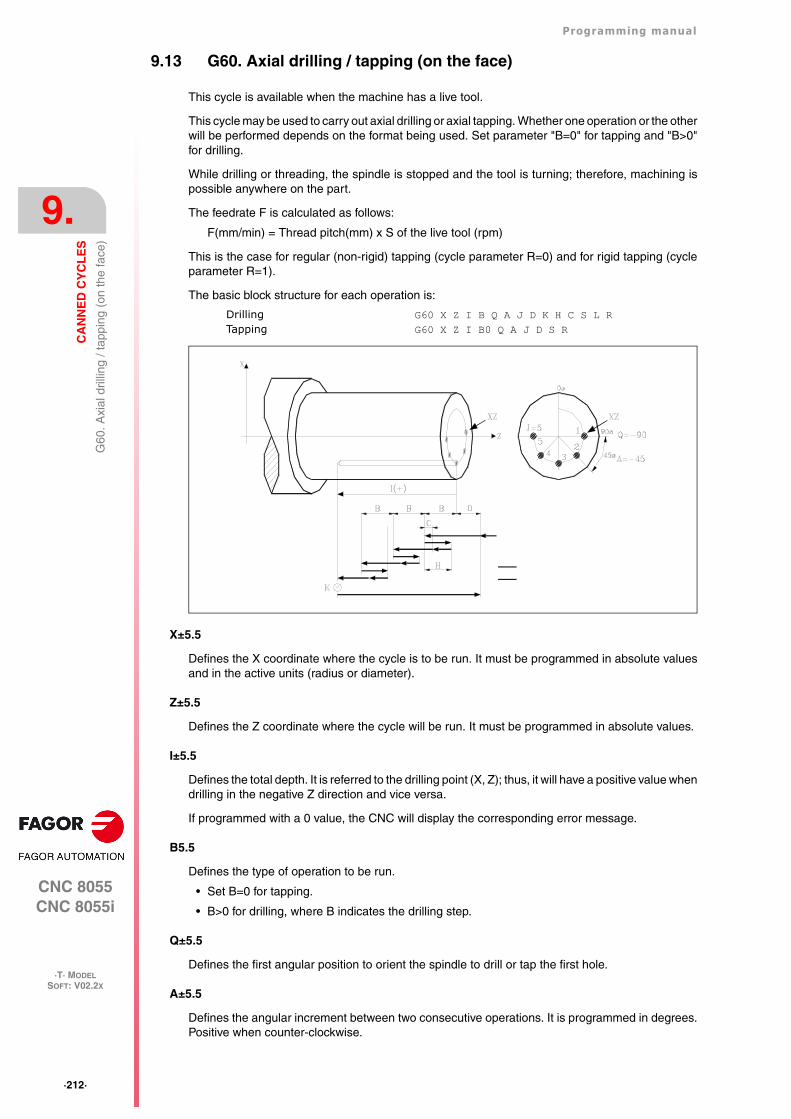
·212·
Programming manual
CNC 8055CNC 8055i
9.
CA
NN
ED
CY
CL
ES
·T· MODELSOFT: V02.2X
G60
. Axi
al d
rillin
g / t
appi
ng (
on th
e fa
ce)
9.13 G60. Axial drilling / tapping (on the face)
This cycle is available when the machine has a live tool.
This cycle may be used to carry out axial drilling or axial tapping. Whether one operation or the otherwill be performed depends on the format being used. Set parameter "B=0" for tapping and "B>0"for drilling.
While drilling or threading, the spindle is stopped and the tool is turning; therefore, machining ispossible anywhere on the part.
The feedrate F is calculated as follows:
F(mm/min) = Thread pitch(mm) x S of the live tool (rpm)
This is the case for regular (non-rigid) tapping (cycle parameter R=0) and for rigid tapping (cycleparameter R=1).
The basic block structure for each operation is:
Drilling G60 X Z I B Q A J D K H C S L RTapping G60 X Z I B0 Q A J D S R
X±5.5
Defines the X coordinate where the cycle is to be run. It must be programmed in absolute valuesand in the active units (radius or diameter).
Z±5.5
Defines the Z coordinate where the cycle will be run. It must be programmed in absolute values.
I±5.5
Defines the total depth. It is referred to the drilling point (X, Z); thus, it will have a positive value whendrilling in the negative Z direction and vice versa.
If programmed with a 0 value, the CNC will display the corresponding error message.
B5.5
Defines the type of operation to be run.
• Set B=0 for tapping.
• B>0 for drilling, where B indicates the drilling step.
Q±5.5
Defines the first angular position to orient the spindle to drill or tap the first hole.
A±5.5
Defines the angular increment between two consecutive operations. It is programmed in degrees.Positive when counter-clockwise.
Programming manual
CNC 8055CNC 8055i
CA
NN
ED
CY
CL
ES
9.
·T· MODELSOFT: V02.2X
·213·
G60
. Axi
al d
rillin
g / t
appi
ng (
on th
e fa
ce)
J4
Defines the number of holes to be drilled or tapped, including the first one.
If programmed with a 0 value, the CNC will display the corresponding error message.
D5.5
Defines the safety distance along the Z axis and indicates how far from the starting point (Z, X) thetool will approach the part. If not programmed, a value of 0 is assumed.
K5
Defines the dwell, in hundredths of a second, at the bottom of the hole before starting the withdrawal.If not programmed, a value of 0 is assumed.
The tapping operation ignores this parameter, thus not being necessary to program it. Ifprogrammed, it will be ignored.
H5.5
Defines the rapid (in G00) withdrawing distance along the Z axis after each drilling peck. If notprogrammed or programmed a value of 0, it will withdraw to the approach point.
The tapping operation ignores this parameter, thus not being necessary to program it. Ifprogrammed, it will be ignored.
C5.5
Defines the rapid approaching distance for successive drilling pecks. If not programmed, a valueof 1 millimeter will be assumed.
The tapping operation ignores this parameter, thus not being necessary to program it. Ifprogrammed, it will be ignored.
S±5.5
RPM and turning direction (sign) of the live tool.
L5.5
Optional. In the drilling cycle, it defines the minimum drilling peck. It is used with "R" values otherthan 1.
If not programmed, a value of 0 is assumed.
R5.5
In the drilling cycle, it indicates the step that reduces the drilling peck "B". If it is not programmedor is programmed with a value of "0", it assumes a value of "1".
• With R =1, all the drilling pecks will be the same (the programmed "B" value).
• If R is other than 1, the first drilling peck will be "B", the second one "R B", The third one "R(RB)" and so on. In other words, from the second peck on, the new peck will be the product ofthe R factor times the previous peck.
In the tapping cycle it defines the type of tapping to be done. If not programmed, it takes the valueof "0", regular tapping.
• With R0, regular tapping.
• With R1, rigid tapping. The CNC stops the tool with M19 and orients it to begin tapping.
• With R2, rigid tapping. If the tool is turning in M3 or M4, the CNC does not stop it nor orient itto begin tapping. This option does not allow thread repair, even if the part has not been releasedbecause the thread start (entry) will coincide with the one machined earlier.
In order to execute a rigid tapping, the relevant spindle (main or secondary) must be ready to operatein closed loop. In other words, that it must have a servo drive-motor system with rotary encoder.
·214·
Programming manual
CNC 8055CNC 8055i
9.
CA
NN
ED
CY
CL
ES
·T· MODELSOFT: V02.2X
G60
. Axi
al d
rillin
g / t
appi
ng (
on th
e fa
ce)
9.13.1 Basic operation
Drilling 1
1. Rapid move to the approach point located at a "D" distance from the first hole position.
2. The CNC turns on the live tool at the rpm and in the turning direction indicated by parameter "S".
3. Orients the spindle at the angular position set by "Q". If the spindle was turning, it will stop.
4. First drilling operation. The drilling axis moves in G01 to the programmed incremental depth"D+B".
5. Drilling loop. The following steps will be repeated until the programmed depth "I" is reached.
Withdrawal in rapid (G00) a distance "H" or to the approach point.
Rapid approach (G00) to a "C" distance from the next peck.
New drilling step. G1 move to the next incremental depth "B" and "R".
6. Dwell "K" at the bottom of the hole in hundredths of a second, if programmed.
7. Withdrawal in rapid (G00) to the approach point.
8. Depending on the value assigned to "J" (number of holes to be drilled):
The spindle turns to a new position. Angular increment "A".
Repeats the movements indicated in steps 4, 5, 6 and 7.
9. The live tool stops.
Tapping
1. Rapid move to the approach point located at a "D" distance from the first hole position.
2. The CNC turns on the live tool at the rpm and in the turning direction indicated by parameter "S".
3. Orients the spindle at the angular position set by "Q". If the spindle was turning, it will stop.
4. Tapping. Movement of the tapping axis to the bottom of the hole "I". MFO, SSO, FEED-HOLDand CYCLE STOP are disabled.
5. Reversal of the turning direction of the live tool.
6. Withdrawal in work feedrate to the approach point.
7. Depending on the value assigned to "J" (number of holes to be tapped).
The spindle turns to a new position. Angular increment "A".
Repeats the movements indicated in steps 4, 5, 6 and 7.
8. The live tool stops.
Rigid tapping
1. Rapid movement to the approach point located at a safety distance "D" from the tap point.
2. Orients the spindle at the angular position set by "Q". If the spindle was turning, it will stop.
3. Tapping. Interpolation of the second spindle (live tool) with the Z axis.
The second spindle must have an encoder and general machine parameter AUXTYPE must beat "1" (otherwise, it issues error 1042: Wrong parameter value in the canned cycle).
The feedrate "F" must be programmed before the cycle and the spindle speed "S" is implicit inthe definition of the cycle. The cycle assumes functions G94 and G97.
Rigid tapping cannot be interrupted, nor the machining conditions be changed. It is done at 100%of the programmed "S" and "F".
4. Reversal of the turning direction of the live tool.
5. Withdrawal in work feedrate to the approach point.
6. Depending on the value assigned to "J" (number of holes to be tapped).
The spindle turns to a new position. Angular increment "A".
Repeats the movements indicated in steps 4, 5, 6 and 7.
Programming manual
CNC 8055CNC 8055i
CA
NN
ED
CY
CL
ES
9.
·T· MODELSOFT: V02.2X
·215·
G60
. Axi
al d
rillin
g / t
appi
ng (
on th
e fa
ce)
7. The live tool stops.
Rigid tapping is drawn with the color used for "uncompensated tool path".
When the cycle is completed, the second spindle stops (M5). The main spindle keeps working inM19.
Considerations
The machining conditions (feedrate, live tool rpm, etc.) must be programmed prior to the calling thecycle.
If when executing the cycle, it is working in G95 and it has not been working in G94 before, the CNCshows "error 1039. The F has not been programmed in G94".
When tapping (regular or rigid), the general logic output "TAPPING" (M5517) stays active duringthe execution of the cycle.
Once the canned cycle has ended, the program will continue with the same feedrate F and Gfunctions active previous to calling the cycle. Only the tool radius compensation will be canceled(G40) if it was active.
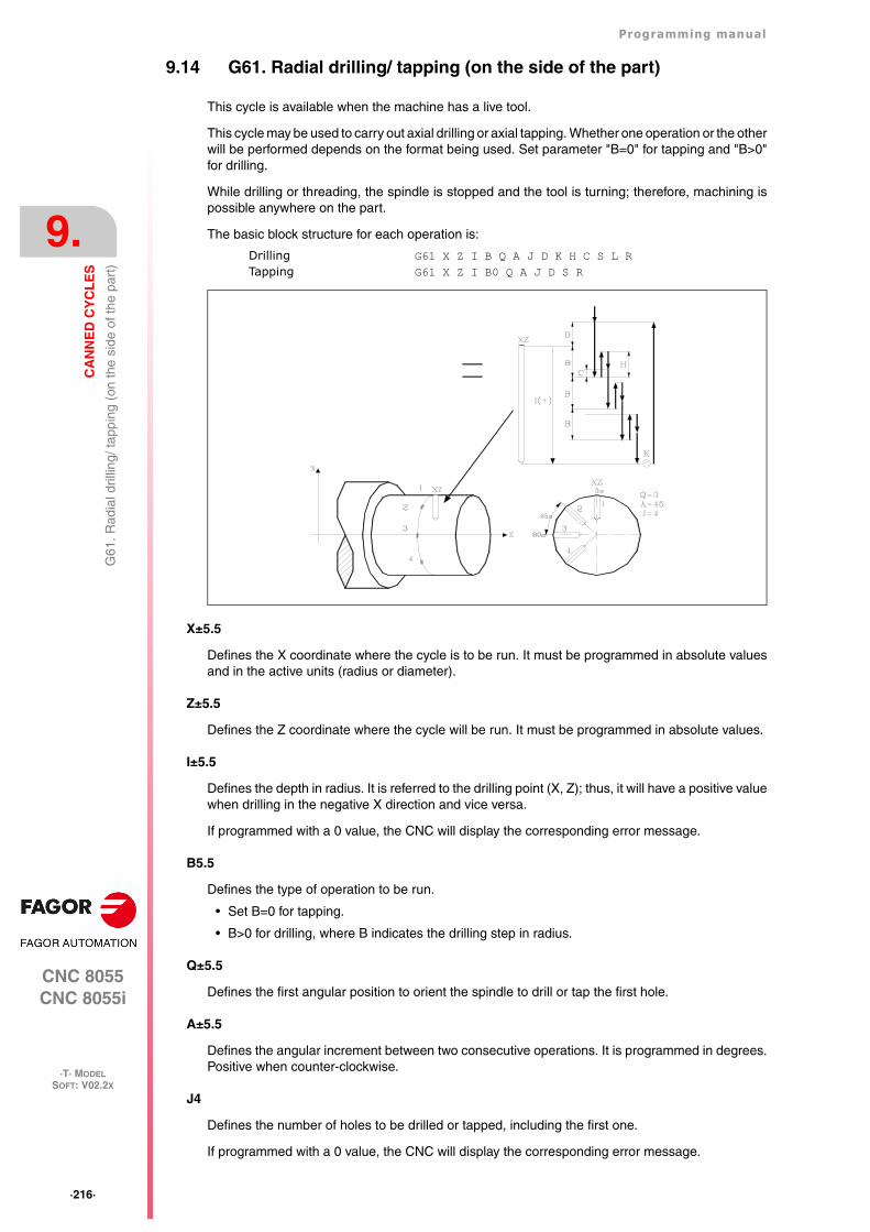
·216·
Programming manual
CNC 8055CNC 8055i
9.
CA
NN
ED
CY
CL
ES
·T· MODELSOFT: V02.2X
G61
. Rad
ial d
rillin
g/ ta
ppin
g (o
n th
e si
de o
f the
par
t)
9.14 G61. Radial drilling/ tapping (on the side of the part)
This cycle is available when the machine has a live tool.
This cycle may be used to carry out axial drilling or axial tapping. Whether one operation or the otherwill be performed depends on the format being used. Set parameter "B=0" for tapping and "B>0"for drilling.
While drilling or threading, the spindle is stopped and the tool is turning; therefore, machining ispossible anywhere on the part.
The basic block structure for each operation is:
Drilling G61 X Z I B Q A J D K H C S L RTapping G61 X Z I B0 Q A J D S R
X±5.5
Defines the X coordinate where the cycle is to be run. It must be programmed in absolute valuesand in the active units (radius or diameter).
Z±5.5
Defines the Z coordinate where the cycle will be run. It must be programmed in absolute values.
I±5.5
Defines the depth in radius. It is referred to the drilling point (X, Z); thus, it will have a positive valuewhen drilling in the negative X direction and vice versa.
If programmed with a 0 value, the CNC will display the corresponding error message.
B5.5
Defines the type of operation to be run.
• Set B=0 for tapping.
• B>0 for drilling, where B indicates the drilling step in radius.
Q±5.5
Defines the first angular position to orient the spindle to drill or tap the first hole.
A±5.5
Defines the angular increment between two consecutive operations. It is programmed in degrees.Positive when counter-clockwise.
J4
Defines the number of holes to be drilled or tapped, including the first one.
If programmed with a 0 value, the CNC will display the corresponding error message.
Programming manual
CNC 8055CNC 8055i
CA
NN
ED
CY
CL
ES
9.
·T· MODELSOFT: V02.2X
·217·
G61
. Rad
ial d
rillin
g/ ta
ppin
g (o
n th
e si
de o
f the
par
t)
D5.5
Defines (in radius) the safety distance along the X axis and indicates how far from the starting point(Z, X) the tool will approach the part. If not programmed, a value of 0 is assumed.
K5
Defines the dwell, in hundredths of a second, at the bottom of the hole before starting the withdrawal.If not programmed, a value of 0 is assumed.
The tapping operation ignores this parameter, thus not being necessary to program it. Ifprogrammed, it will be ignored.
H5.5
Defines (in radius) the rapid (in G00) withdrawing distance along the X axis after each drilling peck.If not programmed or programmed a value of 0, it will withdraw to the approach point.
The tapping operation ignores this parameter, thus not being necessary to program it. Ifprogrammed, it will be ignored.
C5.5
Defines (in radius) the rapid approaching distance for successive drilling pecks. If not programmed,a value of 1 millimeter will be assumed.
The tapping operation ignores this parameter, thus not being necessary to program it. Ifprogrammed, it will be ignored.
S±5.5
RPM and turning direction (sign) of the live tool.
L5.5
Optional. In the drilling cycle, it defines the minimum drilling peck. It is used with "R" values otherthan 1.
If not programmed, a value of 0 is assumed.
R5.5
In the drilling cycle, it indicates the step that reduces the drilling peck "B". If it is not programmedor is programmed with a value of "0", it assumes a value of "1".
• With R =1, all the drilling pecks will be the same (the programmed "B" value).
• If R is other than 1, the first drilling peck will be "B", the second one "R B", The third one "R(RB)" and so on. In other words, from the second peck on, the new peck will be the product ofthe R factor times the previous peck.
In the tapping cycle it defines the type of tapping to be done. If not programmed, it takes the valueof "0", regular tapping.
• With R0, regular tapping.
• With R1, rigid tapping. The CNC stops the tool with M19 and orients it to begin tapping.
• With R2, rigid tapping. If the tool is turning in M3 or M4, the CNC does not stop it nor orient itto begin tapping. This option does not allow thread repair, even if the part has not been releasedbecause the thread start (entry) will coincide with the one machined earlier.
In order to execute a rigid tapping, the relevant spindle (main or secondary) must be ready to operatein closed loop. In other words, that it must have a servo drive-motor system with rotary encoder.
·218·
Programming manual
CNC 8055CNC 8055i
9.
CA
NN
ED
CY
CL
ES
·T· MODELSOFT: V02.2X
G61
. Rad
ial d
rillin
g/ ta
ppin
g (o
n th
e si
de o
f the
par
t)
9.14.1 Basic operation
Drilling 1
1. Rapid move to the approach point located at a "D" distance from the first hole position.
2. The CNC turns on the live tool at the rpm and in the turning direction indicated by parameter "S".
3. Orients the spindle at the angular position set by "Q". If the spindle was turning, it will stop.
4. First drilling operation. The drilling axis moves in G01 to the programmed incremental depth "D"+ "B".
5. Drilling loop. The following steps will be repeated until the programmed depth "I" is reached.
Withdrawal in rapid (G00) a distance "H" or to the approach point.
Rapid approach (G00) to a "C" distance from the next peck.
New drilling step. G1 move to the next incremental depth “B and R”.
6. Dwell "K" at the bottom of the hole in hundredths of a second, if programmed.
7. Withdrawal in rapid (G00) to the approach point.
8. Depending on the value assigned to "J" (number of holes to be drilled):
The spindle turns to a new position. Angular increment "A".
Repeats the movements indicated in steps 4, 5, 6 and 7.
9. The live tool stops.
Tapping
1. Rapid move to the approach point located at a "D" distance from the first hole position.
2. The CNC turns on the live tool at the rpm and in the turning direction indicated by parameter "S".
3. Orients the spindle at the angular position set by "Q". If the spindle was turning, it will stop.
4. Tapping. Movement of the tapping axis to the bottom of the hole "I".
5. Reversal of the turning direction of the live tool.
6. Withdrawal in work feedrate to the approach point.
7. Depending on the value assigned to "J" (number of holes to be tapped).
The spindle turns to a new position. Angular increment "A".
Repeats the movements indicated in steps 4, 5, 6 and 7.
8. The live tool stops.
Rigid tapping
1. Rapid movement to the approach point located at a safety distance "D" from the tap point.
2. Orients the spindle at the angular position set by "Q". If the spindle was turning, it will stop.
3. Tapping. Interpolation of the second spindle (live tool) with the Z axis.
The second spindle must have an encoder and general machine parameter AUXTYPE must beat "1" (otherwise, it issues error 1042: Wrong parameter value in the canned cycle).
The feedrate "F" must be programmed before the cycle and the spindle speed "S" is implicit inthe definition of the cycle. The cycle assumes functions G94 and G97.
Rigid tapping cannot be interrupted, nor the machining conditions be changed. It is done at 100%of the programmed "S" and "F".
4. Reversal of the turning direction of the live tool.
5. Withdrawal in work feedrate to the approach point.
6. Depending on the value assigned to "J" (number of holes to be tapped).
The spindle turns to a new position. Angular increment "A".
Repeats the movements indicated in steps 4, 5, 6 and 7.
Programming manual
CNC 8055CNC 8055i
CA
NN
ED
CY
CL
ES
9.
·T· MODELSOFT: V02.2X
·219·
G61
. Rad
ial d
rillin
g/ ta
ppin
g (o
n th
e si
de o
f the
par
t)
7. The live tool stops.
Rigid tapping is drawn with the color used for "uncompensated tool path".
When the cycle is completed, the second spindle stops (M5). The main spindle keeps working inM19.
Considerations
The machining conditions (feedrate, live tool rpm, etc.) must be programmed prior to the calling thecycle.
If when executing the cycle, it is working in G95 and it has not been working in G94 before, the CNCshows "error 1039. The F has not been programmed in G94".
When tapping (regular or rigid), the general logic output "TAPPING" (M5517) stays active duringthe execution of the cycle.
Once the canned cycle has ended, the program will continue with the same feedrate F and Gfunctions active previous to calling the cycle. Only the tool radius compensation will be canceled(G40) if it was active.
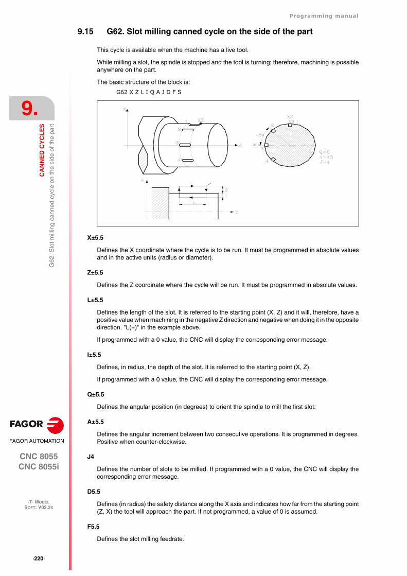
·220·
Programming manual
CNC 8055CNC 8055i
9.
CA
NN
ED
CY
CL
ES
·T· MODELSOFT: V02.2X
G62
. Slo
t mill
ing
cann
ed c
ycle
on
the
side
of t
he p
art
9.15 G62. Slot milling canned cycle on the side of the part
This cycle is available when the machine has a live tool.
While milling a slot, the spindle is stopped and the tool is turning; therefore, machining is possibleanywhere on the part.
The basic structure of the block is:
G62 X Z L I Q A J D F S
X±5.5
Defines the X coordinate where the cycle is to be run. It must be programmed in absolute valuesand in the active units (radius or diameter).
Z±5.5
Defines the Z coordinate where the cycle will be run. It must be programmed in absolute values.
L±5.5
Defines the length of the slot. It is referred to the starting point (X, Z) and it will, therefore, have apositive value when machining in the negative Z direction and negative when doing it in the oppositedirection. "L(+)" in the example above.
If programmed with a 0 value, the CNC will display the corresponding error message.
I±5.5
Defines, in radius, the depth of the slot. It is referred to the starting point (X, Z).
If programmed with a 0 value, the CNC will display the corresponding error message.
Q±5.5
Defines the angular position (in degrees) to orient the spindle to mill the first slot.
A±5.5
Defines the angular increment between two consecutive operations. It is programmed in degrees.Positive when counter-clockwise.
J4
Defines the number of slots to be milled. If programmed with a 0 value, the CNC will display thecorresponding error message.
D5.5
Defines (in radius) the safety distance along the X axis and indicates how far from the starting point(Z, X) the tool will approach the part. If not programmed, a value of 0 is assumed.
F5.5
Defines the slot milling feedrate.
Programming manual
CNC 8055CNC 8055i
CA
NN
ED
CY
CL
ES
9.
·T· MODELSOFT: V02.2X
·221·
G62
. Slo
t mill
ing
cann
ed c
ycle
on
the
side
of t
he p
art
S±5.5
RPM and turning direction (sign) of the live tool.
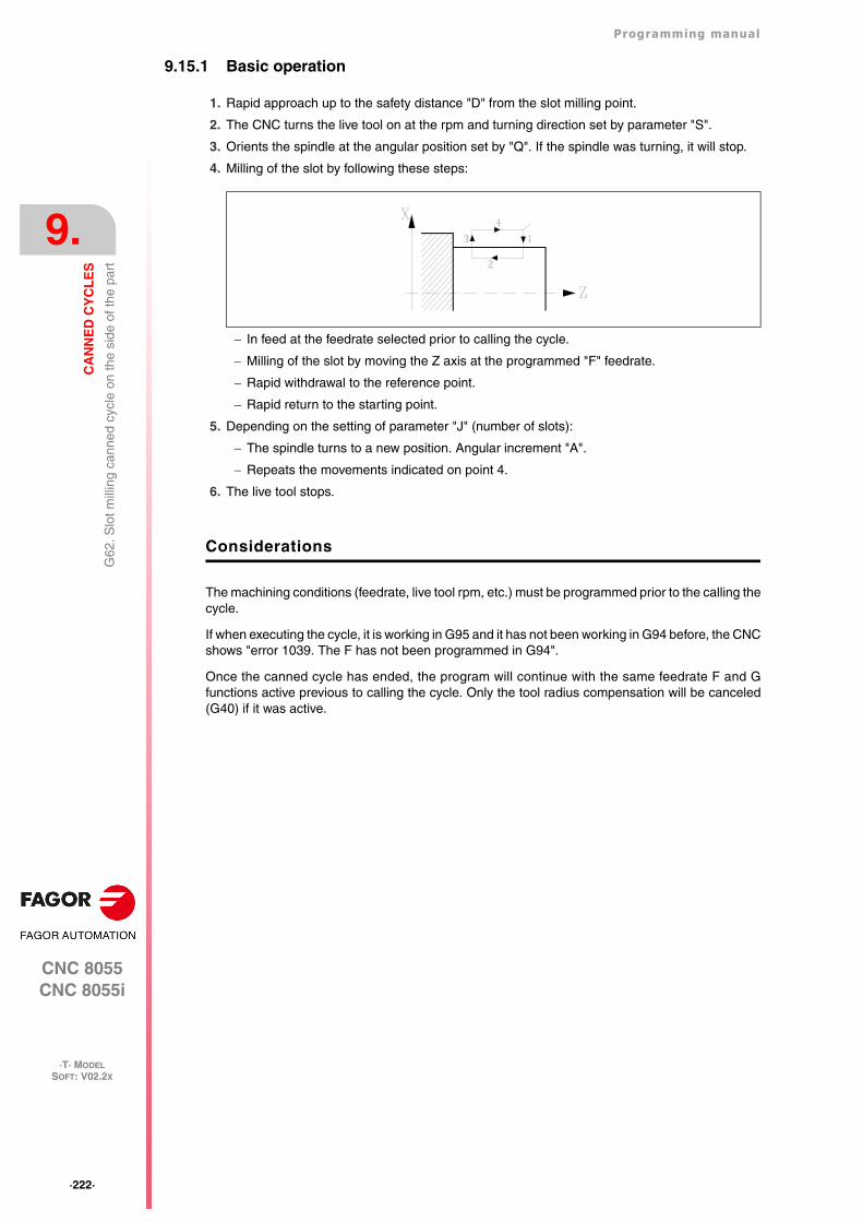
·222·
Programming manual
CNC 8055CNC 8055i
9.
CA
NN
ED
CY
CL
ES
·T· MODELSOFT: V02.2X
G62
. Slo
t mill
ing
cann
ed c
ycle
on
the
side
of t
he p
art
9.15.1 Basic operation
1. Rapid approach up to the safety distance "D" from the slot milling point.
2. The CNC turns the live tool on at the rpm and turning direction set by parameter "S".
3. Orients the spindle at the angular position set by "Q". If the spindle was turning, it will stop.
4. Milling of the slot by following these steps:
In feed at the feedrate selected prior to calling the cycle.
Milling of the slot by moving the Z axis at the programmed "F" feedrate.
Rapid withdrawal to the reference point.
Rapid return to the starting point.
5. Depending on the setting of parameter "J" (number of slots):
The spindle turns to a new position. Angular increment "A".
Repeats the movements indicated on point 4.
6. The live tool stops.
Considerations
The machining conditions (feedrate, live tool rpm, etc.) must be programmed prior to the calling thecycle.
If when executing the cycle, it is working in G95 and it has not been working in G94 before, the CNCshows "error 1039. The F has not been programmed in G94".
Once the canned cycle has ended, the program will continue with the same feedrate F and Gfunctions active previous to calling the cycle. Only the tool radius compensation will be canceled(G40) if it was active.
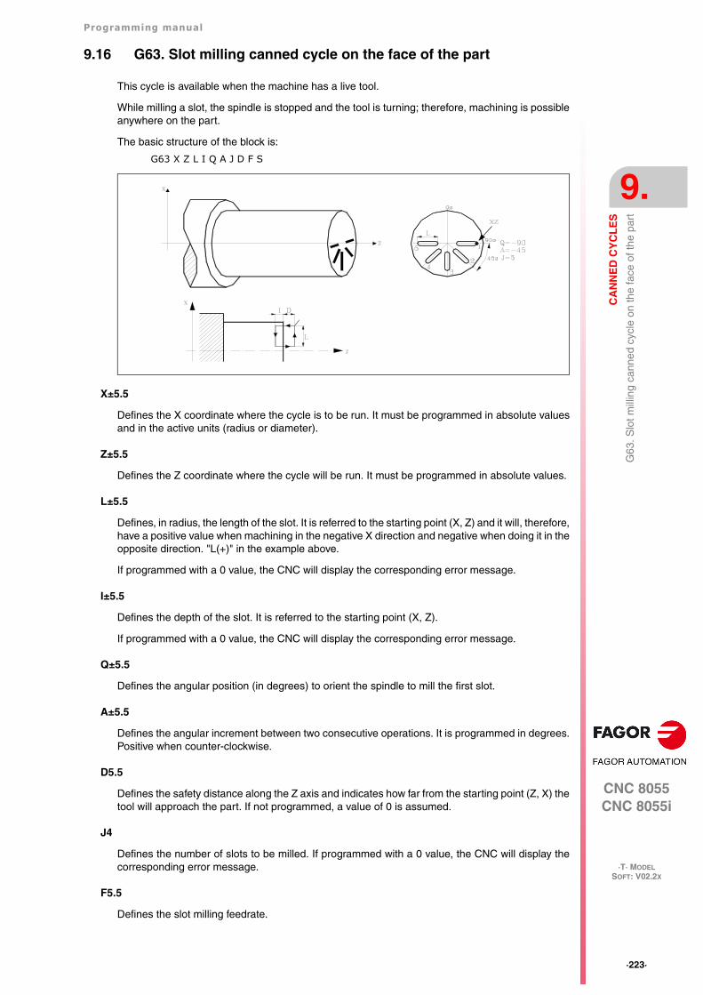
Programming manual
CNC 8055CNC 8055i
CA
NN
ED
CY
CL
ES
9.
·T· MODELSOFT: V02.2X
·223·
G63
. Slo
t mill
ing
cann
ed c
ycle
on
the
face
of t
he p
art
9.16 G63. Slot milling canned cycle on the face of the part
This cycle is available when the machine has a live tool.
While milling a slot, the spindle is stopped and the tool is turning; therefore, machining is possibleanywhere on the part.
The basic structure of the block is:
G63 X Z L I Q A J D F S
X±5.5
Defines the X coordinate where the cycle is to be run. It must be programmed in absolute valuesand in the active units (radius or diameter).
Z±5.5
Defines the Z coordinate where the cycle will be run. It must be programmed in absolute values.
L±5.5
Defines, in radius, the length of the slot. It is referred to the starting point (X, Z) and it will, therefore,have a positive value when machining in the negative X direction and negative when doing it in theopposite direction. "L(+)" in the example above.
If programmed with a 0 value, the CNC will display the corresponding error message.
I±5.5
Defines the depth of the slot. It is referred to the starting point (X, Z).
If programmed with a 0 value, the CNC will display the corresponding error message.
Q±5.5
Defines the angular position (in degrees) to orient the spindle to mill the first slot.
A±5.5
Defines the angular increment between two consecutive operations. It is programmed in degrees.Positive when counter-clockwise.
D5.5
Defines the safety distance along the Z axis and indicates how far from the starting point (Z, X) thetool will approach the part. If not programmed, a value of 0 is assumed.
J4
Defines the number of slots to be milled. If programmed with a 0 value, the CNC will display thecorresponding error message.
F5.5
Defines the slot milling feedrate.
·224·
Programming manual
CNC 8055CNC 8055i
9.
CA
NN
ED
CY
CL
ES
·T· MODELSOFT: V02.2X
G63
. Slo
t mill
ing
cann
ed c
ycle
on
the
face
of t
he p
art
S±5.5
RPM and turning direction (sign) of the live tool.
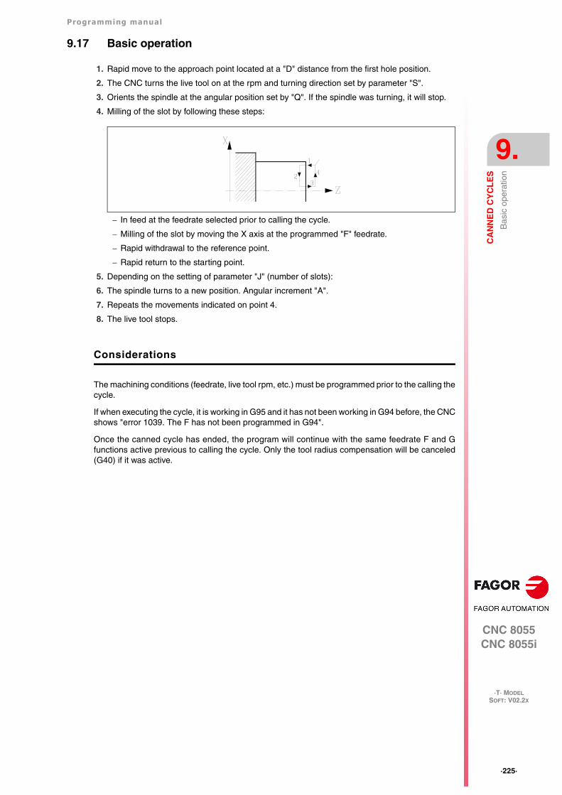
Programming manual
CNC 8055CNC 8055i
CA
NN
ED
CY
CL
ES
9.
·T· MODELSOFT: V02.2X
·225·
Bas
ic o
pera
tion
9.17 Basic operation
1. Rapid move to the approach point located at a "D" distance from the first hole position.
2. The CNC turns the live tool on at the rpm and turning direction set by parameter "S".
3. Orients the spindle at the angular position set by "Q". If the spindle was turning, it will stop.
4. Milling of the slot by following these steps:
In feed at the feedrate selected prior to calling the cycle.
Milling of the slot by moving the X axis at the programmed "F" feedrate.
Rapid withdrawal to the reference point.
Rapid return to the starting point.
5. Depending on the setting of parameter "J" (number of slots):
6. The spindle turns to a new position. Angular increment "A".
7. Repeats the movements indicated on point 4.
8. The live tool stops.
Considerations
The machining conditions (feedrate, live tool rpm, etc.) must be programmed prior to the calling thecycle.
If when executing the cycle, it is working in G95 and it has not been working in G94 before, the CNCshows "error 1039. The F has not been programmed in G94".
Once the canned cycle has ended, the program will continue with the same feedrate F and Gfunctions active previous to calling the cycle. Only the tool radius compensation will be canceled(G40) if it was active.
·226·
Programming manual
CNC 8055CNC 8055i
9.
CA
NN
ED
CY
CL
ES
·T· MODELSOFT: V02.2X
Bas
ic o
pera
tion
CNC 8055CNC 8055i
·T· MODELSOFT: V02.2X
10
·227·
PROBING
The CNC has two probe inputs, one for TTL-type 5Vdc signals and another for 24 Vdc signals.
The connection of the different types of probes to these inputs are explained in the appendix to theInstallation manual.
This control allows the following operations to be performed, by using probes:
• Programming probing blocks with functions G75 and G76.
• Several tool calibration and part-measurement cycles by means of high-level languageprogramming.
·228·
Programming manual
CNC 8055CNC 8055i
10.
PR
OB
ING
·T· MODELSOFT: V02.2X
Pro
bing
(G
75, G
76)
10.1 Probing (G75, G76)
The G75 function allows movements to be programmed that will end after the CNC receives thesignal from the measuring probe used.
The G76 function allows movements to be programmed that will end after the CNC no longerreceives the signal from the measuring probe used.
Their definition format is:
G75 X..C ±5.5G76 X..C ±5.5
After G75 or G76, the required axis or axes will be programmed, as well as the coordinates of theseaxes that will define the end point of the programmed movement.
The machine will move according to the programmed path until it receives the signal from the probe(G75) or until it no longer receives the probe signal (G76). At this time, the CNC will consider theblock finished, taking as the theoretical position of the axes the real position they have at that time.
If the axes reach the programmed position before receiving or while receiving the external signalfrom the probe, the CNC will stop the movement of the axes.
This type of movement with probing blocks are very useful when it is required to generatemeasurement or verification programs for tools and parts.
Functions G75 and G76 are not modal and, therefore, must be programmed whenever it is wishedto probe.
Functions G75 and G76 are incompatible with each other and with G00, G02, G03, G33, G34, G41and G42 functions. In addition, once this has been performed, the CNC will assume functions G01and G40.
During G75 or G76 moves, the operation of the feedrate override switch depends on the setting ofOEM machine parameter FOVRG75.
Programming manual
CNC 8055CNC 8055i
PR
OB
ING
10.
·T· MODELSOFT: V02.2X
·229·
Pro
bing
can
ned
cycl
es
10.2 Probing canned cycles
The CNC offers the following probing canned cycles:
• Tool calibration canned cycle.
• Probe calibrating canned cycle.
• Canned cycle for part measuring and tool correction along the X axis.
• Canned cycle for part measuring and tool correction along the Z axis.
All the movements of these probing canned cycles will be performed in the X, Y, Z axes and the workplane must be formed by 2 of these axes (XY, XZ, YZ, YX, ZX, ZY). The other axis must beperpendicular and it must be selected as the longitudinal axis.
Canned cycles will be programmed by means of the high level mnemonic, PROBE, which has thefollowing programming format:
(PROBE (expression), (assignment instruction),...)
This instruction PROBE calls the probing cycle indicated by means of a number or any expressionwhich results in a number. Besides, it allows the parameters of this cycle to be initialized with thevalues required to perform it, by means of assignment instructions.
Some general points to consider
Probing canned cycles are not modal; therefore, they must be programmed every time any of themis to be executed.
The probes used in the performance of these cycles are:
• Probe placed on a fixed position on the machine, used for calibrating tools.
• Probe placed in the spindle, will be treated as a tool and will be used in the different measuringcycles.
The execution of a probing canned cycle does not alter the history of previous "G" functions, exceptfor the radius compensation functions G41 and G42.
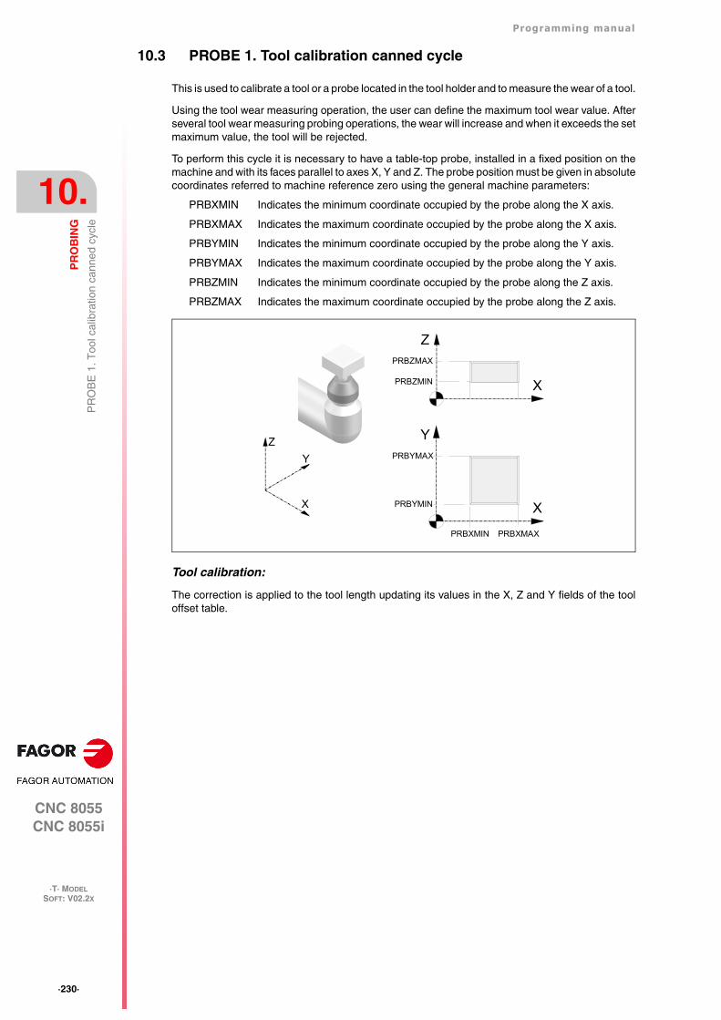
·230·
Programming manual
CNC 8055CNC 8055i
10.
PR
OB
ING
·T· MODELSOFT: V02.2X
PR
OB
E 1
. Too
l cal
ibra
tion
cann
ed c
ycle
10.3 PROBE 1. Tool calibration canned cycle
This is used to calibrate a tool or a probe located in the tool holder and to measure the wear of a tool.
Using the tool wear measuring operation, the user can define the maximum tool wear value. Afterseveral tool wear measuring probing operations, the wear will increase and when it exceeds the setmaximum value, the tool will be rejected.
To perform this cycle it is necessary to have a table-top probe, installed in a fixed position on themachine and with its faces parallel to axes X, Y and Z. The probe position must be given in absolutecoordinates referred to machine reference zero using the general machine parameters:
PRBXMIN Indicates the minimum coordinate occupied by the probe along the X axis.
PRBXMAX Indicates the maximum coordinate occupied by the probe along the X axis.
PRBYMIN Indicates the minimum coordinate occupied by the probe along the Y axis.
PRBYMAX Indicates the maximum coordinate occupied by the probe along the Y axis.
PRBZMIN Indicates the minimum coordinate occupied by the probe along the Z axis.
PRBZMAX Indicates the maximum coordinate occupied by the probe along the Z axis.
Tool calibration:
The correction is applied to the tool length updating its values in the X, Z and Y fields of the tooloffset table.
X
ZPRBZMAX
PRBZMIN
X
Y
PRBXMAXPRBXMIN
PRBYMAX
PRBYMIN
Z
X
Y
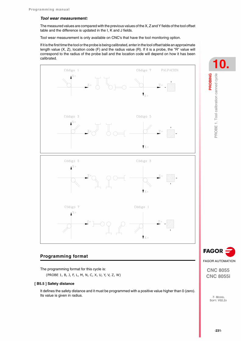
Programming manual
CNC 8055CNC 8055i
PR
OB
ING
10.
·T· MODELSOFT: V02.2X
·231·
PR
OB
E 1
. Too
l cal
ibra
tion
cann
ed c
ycle
Tool wear measurement:
The measured values are compared with the previous values of the X, Z and Y fields of the tool offsettable and the difference is updated in the I, K and J fields.
Tool wear measurement is only available on CNC's that have the tool monitoring option.
If it is the first time the tool or the probe is being calibrated, enter in the tool offset table an approximatelength value (X, Z), location code (F) and the radius value (R). If it is a probe, the "R" value willcorrespond to the radius of the probe ball and the location code will depend on how it has beencalibrated.
Programming format
The programming format for this cycle is:
(PROBE 1, B, J, F, L, M, N, C, X, U, Y, V, Z, W)
[ B5.5 ] Safety distance
It defines the safety distance and it must be programmed with a positive value higher than 0 (zero).Its value is given in radius.
·232·
Programming manual
CNC 8055CNC 8055i
10.
PR
OB
ING
·T· MODELSOFT: V02.2X
PR
OB
E 1
. Too
l cal
ibra
tion
cann
ed c
ycle
[ J ] Type of operation
It may be used to select either tool calibration or tool wear measurement.
J=0 Tool calibration.
J=1 Wear measurement.
If not programmed, the cycle will assume the J0 value.
[ F5.5 ] Probing feedrate
It sets the probing feedrate. It must be programmed in mm/minute or inches/minute.
[ L5.5 ] Maximum length wear allowed on the X axis
When set to zero, the tool will not be rejected due to length wear. When the measured wear is greaterthan the defined value, the tool will be rejected.
Only if J1 has been defined and tool life monitoring is being used. If not programmed, the cannedcycle will assume the L0 value.
[ M5.5 ] Maximum length wear allowed on the Z axis
When set to zero, the tool will not be rejected due to length wear. When the measured wear is greaterthan the defined value, the tool will be rejected.
Only if J1 has been defined and tool life monitoring is being used. If not programmed, a value ofM0 will be assumed.
[ N5.5 ] Maximum length wear allowed on the Y axis
When set to zero, the tool will not be rejected due to length wear. When the measured wear is greaterthan the defined value, the tool will be rejected.
Only if J1 has been defined and tool life monitoring is being used. If not programmed, the cannedcycle will assume the N0 value.
[ C ] Behavior when exceeding the amount of wear allowed
Only if "L", "M" or "N" has been set to other than zero.
C=0 It interrupts the execution for the user to select another tool.
C=1 The cycle replaces the tool with another one of the same family.
If not programmed, the cycle will assume the C0 value.
[ X U Y V Z W ] Probe position
Define the position of the probe. They are optional parameters that usually need not be defined.On certain machines, due to lack of repeatability in the mechanical positioning of the probe, theprobe must be calibrated again before each tool calibration.
Instead of redefining machine parameters PRBXMIN, PRBXMAX, PRBYMIN, PRBYMAX,PRBZMIN and PRBZMAX every time the probe is calibrated, those coordinates may be indicatedin parameters X, U, Y, V, Z and W, respectively.
The CNC does not modify the machine parameters. The CNC only takes into account thecoordinates indicated in X, U, Y, V, Z, W during this calibration. If any of the X, U, Y, V, Z, W fieldsis left out, the CNC takes the value assigned to the corresponding machine parameter.
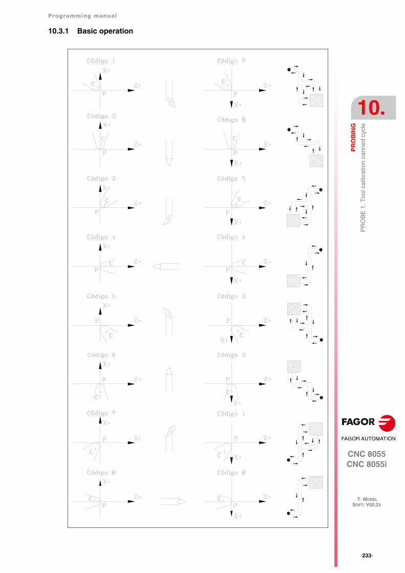
Programming manual
CNC 8055CNC 8055i
PR
OB
ING
10.
·T· MODELSOFT: V02.2X
·233·
PR
OB
E 1
. Too
l cal
ibra
tion
cann
ed c
ycle
10.3.1 Basic operation
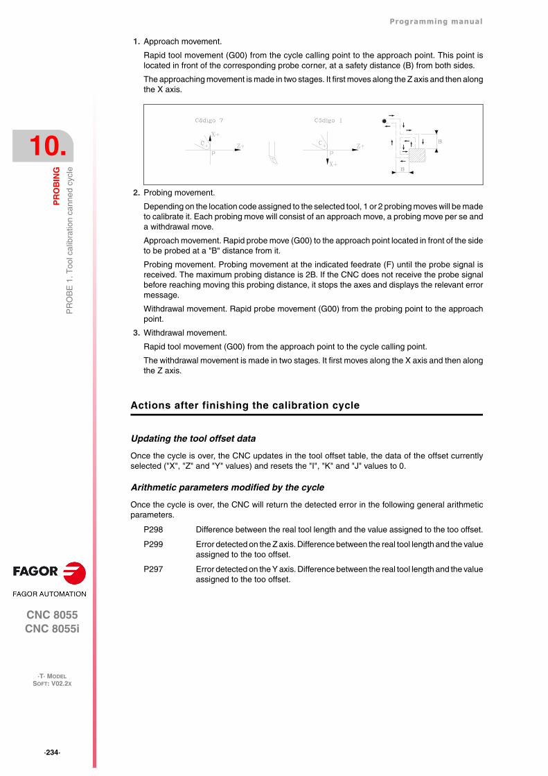
·234·
Programming manual
CNC 8055CNC 8055i
10.
PR
OB
ING
·T· MODELSOFT: V02.2X
PR
OB
E 1
. Too
l cal
ibra
tion
cann
ed c
ycle
1. Approach movement.
Rapid tool movement (G00) from the cycle calling point to the approach point. This point islocated in front of the corresponding probe corner, at a safety distance (B) from both sides.
The approaching movement is made in two stages. It first moves along the Z axis and then alongthe X axis.
2. Probing movement.
Depending on the location code assigned to the selected tool, 1 or 2 probing moves will be madeto calibrate it. Each probing move will consist of an approach move, a probing move per se anda withdrawal move.
Approach movement. Rapid probe move (G00) to the approach point located in front of the sideto be probed at a "B" distance from it.
Probing movement. Probing movement at the indicated feedrate (F) until the probe signal isreceived. The maximum probing distance is 2B. If the CNC does not receive the probe signalbefore reaching moving this probing distance, it stops the axes and displays the relevant errormessage.
Withdrawal movement. Rapid probe movement (G00) from the probing point to the approachpoint.
3. Withdrawal movement.
Rapid tool movement (G00) from the approach point to the cycle calling point.
The withdrawal movement is made in two stages. It first moves along the X axis and then alongthe Z axis.
Actions after finishing the calibration cycle
Updating the tool offset data
Once the cycle is over, the CNC updates in the tool offset table, the data of the offset currentlyselected ("X", "Z" and "Y" values) and resets the "I", "K" and "J" values to 0.
Arithmetic parameters modified by the cycle
Once the cycle is over, the CNC will return the detected error in the following general arithmeticparameters.
P298 Difference between the real tool length and the value assigned to the too offset.
P299 Error detected on the Z axis. Difference between the real tool length and the valueassigned to the too offset.
P297 Error detected on the Y axis. Difference between the real tool length and the valueassigned to the too offset.
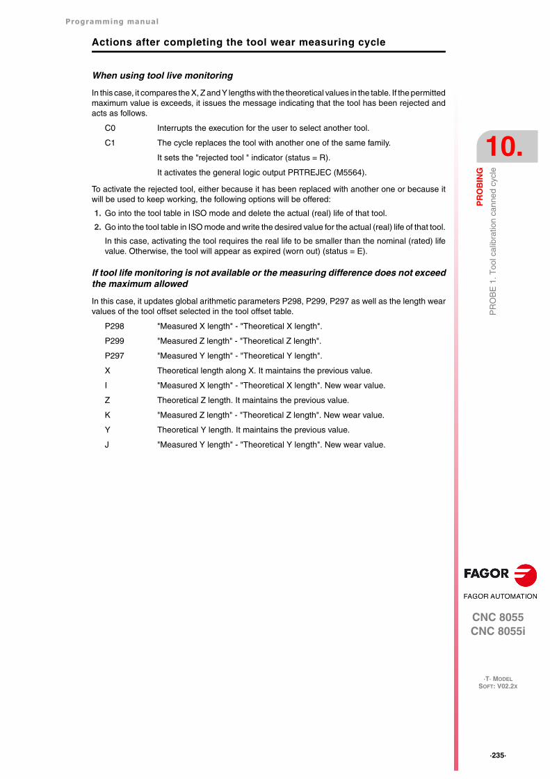
Programming manual
CNC 8055CNC 8055i
PR
OB
ING
10.
·T· MODELSOFT: V02.2X
·235·
PR
OB
E 1
. Too
l cal
ibra
tion
cann
ed c
ycle
Actions after completing the tool wear measuring cycle
When using tool live monitoring
In this case, it compares the X, Z and Y lengths with the theoretical values in the table. If the permittedmaximum value is exceeds, it issues the message indicating that the tool has been rejected andacts as follows.
C0 Interrupts the execution for the user to select another tool.
C1 The cycle replaces the tool with another one of the same family.
It sets the "rejected tool " indicator (status = R).
It activates the general logic output PRTREJEC (M5564).
To activate the rejected tool, either because it has been replaced with another one or because itwill be used to keep working, the following options will be offered:
1. Go into the tool table in ISO mode and delete the actual (real) life of that tool.
2. Go into the tool table in ISO mode and write the desired value for the actual (real) life of that tool.
In this case, activating the tool requires the real life to be smaller than the nominal (rated) lifevalue. Otherwise, the tool will appear as expired (worn out) (status = E).
If tool life monitoring is not available or the measuring difference does not exceedthe maximum allowed
In this case, it updates global arithmetic parameters P298, P299, P297 as well as the length wearvalues of the tool offset selected in the tool offset table.
P298 "Measured X length" - "Theoretical X length".
P299 "Measured Z length" - "Theoretical Z length".
P297 "Measured Y length" - "Theoretical Y length".
X Theoretical length along X. It maintains the previous value.
I "Measured X length" - "Theoretical X length". New wear value.
Z Theoretical Z length. It maintains the previous value.
K "Measured Z length" - "Theoretical Z length". New wear value.
Y Theoretical Y length. It maintains the previous value.
J "Measured Y length" - "Theoretical Y length". New wear value.
·236·
Programming manual
CNC 8055CNC 8055i
10.
PR
OB
ING
·T· MODELSOFT: V02.2X
PR
OB
E 2
. Pro
be c
alib
ratio
n ca
nned
cyc
le.
10.4 PROBE 2. Probe calibration canned cycle.
It may be used to calibrate the sides of the table-top probe, installed in a fixed position of the tableand with its sides parallel to the X and Z axes. This probe will be the one used in the tool calibrationcanned cycle.
The probe position must be given in absolute coordinates referred to machine reference zero usingthe general machine parameters:
PRBXMIN Probe’s minimum X coordinate.
PRBXMAX Probe’s maximum X coordinate.
PRBZMIN Probe’s minimum Z coordinate.
PRBZMAX Probe’s maximum Z coordinate.
To execute the cycle, a master tool of known dimensions will be used with its relevant valuespreviously entered in the selected offset. Since the probe needs to be calibrated along the X andZ axes, the location code (F) of the selected master tool must be F1, F3, F5 or F7.
Programming format
The programming format for this cycle is:
(PROBE 2, B, F, X, U, Z, W)
[ B5.5 ] Safety distance
It defines the safety distance and it must be programmed with a positive value higher than 0 (zero).Its value is given in radius.
[ F5.5 ] Probing feedrate
It sets the probing feedrate. It must be programmed in mm/minute or inches/minute.
[ X, U, Z, W ] Probe position
They are optional parameters that usually need not be defined. On certain machines, due to lackof repeatability in the mechanical positioning of the probe, the probe must be calibrated again beforeeach tool calibration.
Instead of having to set again machine parameters PRBXMIN, PRBXMAX, PRBZMAX andPRBZMIN every time the probe is calibrated, those coordinates may be specified in parameters X,U, Y, V, Z and W respectively.
The CNC does not modify the machine parameters. The CNC considers the coordinates indicatedin X, U, Z, W only during this calibration. If any of the X, U, Z, W fields is left out, the CNC takesthe value assigned to the corresponding machine parameter.
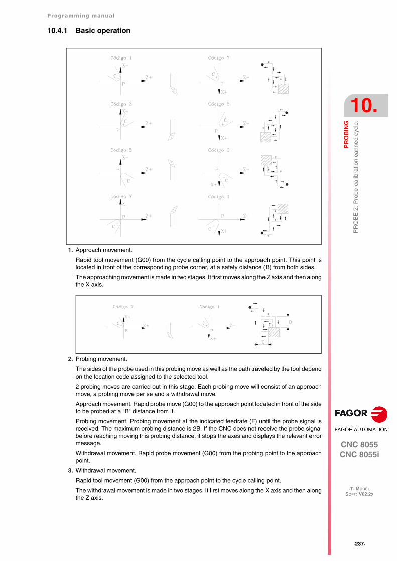
Programming manual
CNC 8055CNC 8055i
PR
OB
ING
10.
·T· MODELSOFT: V02.2X
·237·
PR
OB
E 2
. Pro
be c
alib
ratio
n ca
nned
cyc
le.
10.4.1 Basic operation
1. Approach movement.
Rapid tool movement (G00) from the cycle calling point to the approach point. This point islocated in front of the corresponding probe corner, at a safety distance (B) from both sides.
The approaching movement is made in two stages. It first moves along the Z axis and then alongthe X axis.
2. Probing movement.
The sides of the probe used in this probing move as well as the path traveled by the tool dependon the location code assigned to the selected tool.
2 probing moves are carried out in this stage. Each probing move will consist of an approachmove, a probing move per se and a withdrawal move.
Approach movement. Rapid probe move (G00) to the approach point located in front of the sideto be probed at a "B" distance from it.
Probing movement. Probing movement at the indicated feedrate (F) until the probe signal isreceived. The maximum probing distance is 2B. If the CNC does not receive the probe signalbefore reaching moving this probing distance, it stops the axes and displays the relevant errormessage.
Withdrawal movement. Rapid probe movement (G00) from the probing point to the approachpoint.
3. Withdrawal movement.
Rapid tool movement (G00) from the approach point to the cycle calling point.
The withdrawal movement is made in two stages. It first moves along the X axis and then alongthe Z axis.

·238·
Programming manual
CNC 8055CNC 8055i
10.
PR
OB
ING
·T· MODELSOFT: V02.2X
PR
OB
E 2
. Pro
be c
alib
ratio
n ca
nned
cyc
le.
Arithmetic parameters modified by the cycle
Once the cycle is over, the CNC will return the measured values in the following general arithmeticparameters.
Define the probe position
Once the values of parameters P298 and P297 and the probe dimensions are known, the user mustcalculate the coordinates of the other two sides and update the general machine parameters:
PRBXMIN Probe’s minimum X coordinate.
PRBXMAX Probe’s maximum X coordinate.
PRBZMIN Probe’s minimum Z coordinate.
PRBZMAX Probe’s maximum Z coordinate.
P298 Real X coordinate of the measured side. This value is given in absolute coordinatesand in radius.
P299 Real Z coordinate of the measured side. This value is given in absolute coordinates.
Example:
If the tool used has a location code F3 and the probe is square with 40 mm sides,the values to be assigned to these general machine parameters will be:
PRBXMIN = P298 - 40
PRBXMAX = P298
PRBZMIN = P299 - 40
PRBZMAX = P299
Programming manual
CNC 8055CNC 8055i
PR
OB
ING
10.
·T· MODELSOFT: V02.2X
·239·
PR
OB
E 3
. Can
ned
cycl
e fo
r pa
rt m
easu
ring
and
tool
cor
rect
ion
onth
e X
axi
s
10.5 PROBE 3. Canned cycle for part measuring and tool correction onthe X axis
A probe mounted in the tool holding spindle must be used, it must be previously calibrated with thetool calibration canned cycle (PROBE 1).
This cycle, besides measuring the part along the X axis allows correcting the offset value of the toolused to machine that surface. This correction will be used only when the measurement error exceedsa programmed value.
Programming format
The programming format for this cycle is:
(PROBE 3, X, Z, B, F, L, D)
[ X±5.5 ] Theoretical coordinate, along the X axis, of the point over which it is required tomeasure.
This value is given in the active units, radius or diameter.
[ Z±5.5 ] Theoretical coordinate, along the Z axis, of the point over which it is required to measure.
[ B5.5 ] Safety distance
It defines the safety distance and it must be programmed with a positive value higher than 0 (zero).Its value is given in radius.
[ F5.5 ] Probing feedrate
It sets the probing feedrate. It must be programmed in mm/minute or inches/minute.
[ L5.5 ] Error tolerance
Defines the tolerance that will be applied to the error measured. It will be programmed with anabsolute value and the tool offset will be corrected only when the error exceeds this value.
If this is not programmed, the canned cycle will take the value of 0.
[ D4 ] Tool offset
Defines the number of the tool offset to be corrected, once the measurement cycle is completed.If this is not programmed or is programmed with a value of 0, the CNC will understand that it is notrequired to make this correction.
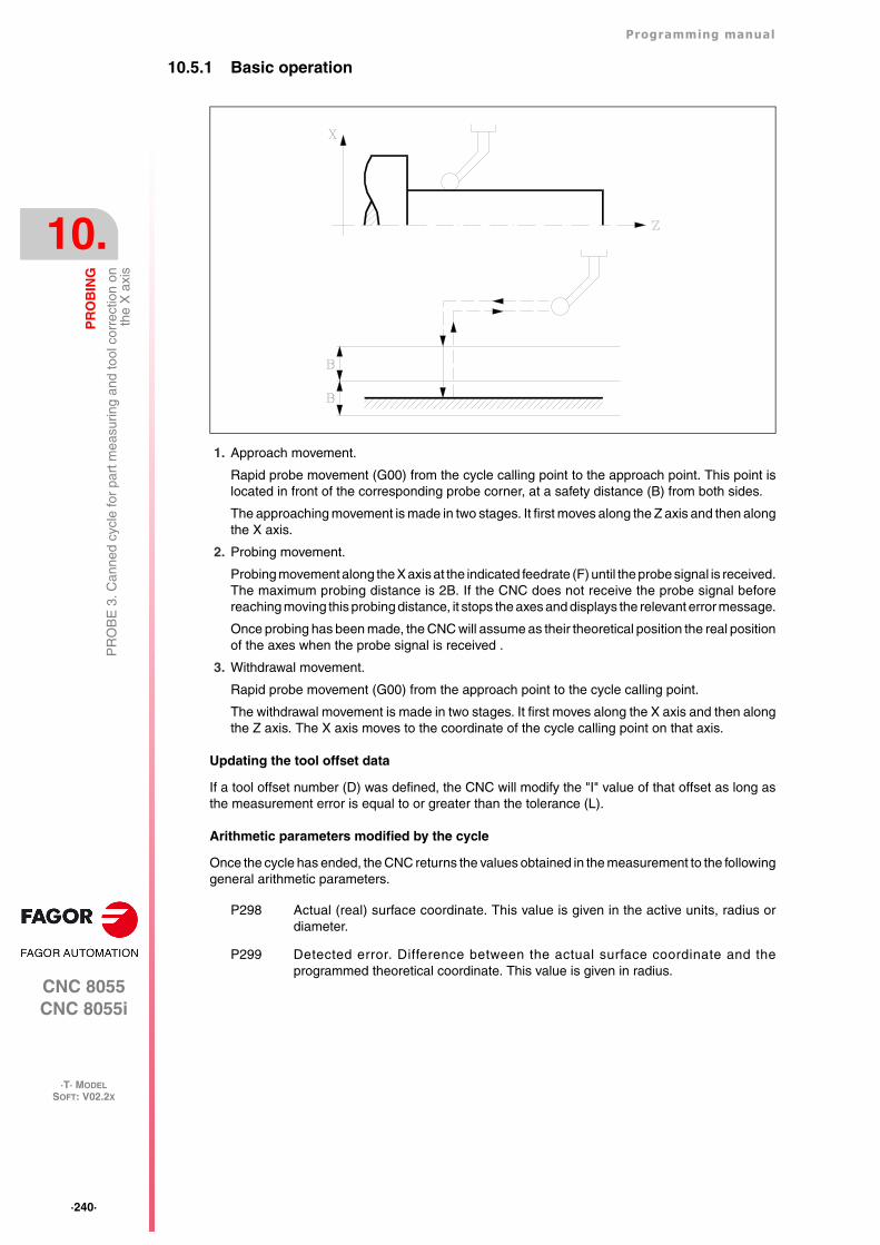
·240·
Programming manual
CNC 8055CNC 8055i
10.
PR
OB
ING
·T· MODELSOFT: V02.2X
PR
OB
E 3
. Can
ned
cycl
e fo
r pa
rt m
easu
ring
and
tool
cor
rect
ion
onth
e X
axi
s
10.5.1 Basic operation
1. Approach movement.
Rapid probe movement (G00) from the cycle calling point to the approach point. This point islocated in front of the corresponding probe corner, at a safety distance (B) from both sides.
The approaching movement is made in two stages. It first moves along the Z axis and then alongthe X axis.
2. Probing movement.
Probing movement along the X axis at the indicated feedrate (F) until the probe signal is received.The maximum probing distance is 2B. If the CNC does not receive the probe signal beforereaching moving this probing distance, it stops the axes and displays the relevant error message.
Once probing has been made, the CNC will assume as their theoretical position the real positionof the axes when the probe signal is received .
3. Withdrawal movement.
Rapid probe movement (G00) from the approach point to the cycle calling point.
The withdrawal movement is made in two stages. It first moves along the X axis and then alongthe Z axis. The X axis moves to the coordinate of the cycle calling point on that axis.
Updating the tool offset data
If a tool offset number (D) was defined, the CNC will modify the "I" value of that offset as long asthe measurement error is equal to or greater than the tolerance (L).
Arithmetic parameters modified by the cycle
Once the cycle has ended, the CNC returns the values obtained in the measurement to the followinggeneral arithmetic parameters.
P298 Actual (real) surface coordinate. This value is given in the active units, radius ordiameter.
P299 Detected error. Difference between the actual surface coordinate and theprogrammed theoretical coordinate. This value is given in radius.

Programming manual
CNC 8055CNC 8055i
PR
OB
ING
10.
·T· MODELSOFT: V02.2X
·241·
PR
OB
E 4
. Can
ned
cycl
e fo
r pa
rt m
easu
ring
and
tool
cor
rect
ion
onth
e Z
axi
s
10.6 PROBE 4. Canned cycle for part measuring and tool correction onthe Z axis
A probe mounted in the tool holding spindle must be used, it must be previously calibrated with thetool calibration canned cycle (PROBE 1).
This cycle, besides measuring the part along the Z axis allows correcting the offset value of the toolused to machine that surface. This correction will be used only when the measurement error exceedsa programmed value.
Programming format
The programming format for this cycle is:
(PROBE 4, X, Z, B, F, L, D)
[ X±5.5 ] Theoretical coordinate, along the X axis, of the point over which it is required tomeasure.
This value is given in the active units, radius or diameter.
[ Z±5.5 ] Theoretical coordinate, along the Z axis, of the point over which it is required to measure.
[ B5.5 ] Safety distance
It defines the safety distance and it must be programmed with a positive value higher than 0 (zero).Its value is given in radius.
[ F5.5 ] Probing feedrate
It sets the probing feedrate. It must be programmed in mm/minute or inches/minute.
[ L5.5 ] Error tolerance
Defines the tolerance that will be applied to the error measured. It will be programmed with anabsolute value and the tool offset will be corrected only when the error exceeds this value.
If this is not programmed, the canned cycle will take the value of 0.
[ D4 ] Tool offset
Defines the number of the tool offset to be corrected, once the measurement cycle is completed.If this is not programmed or is programmed with a value of 0, the CNC will understand that it is notrequired to make this correction.
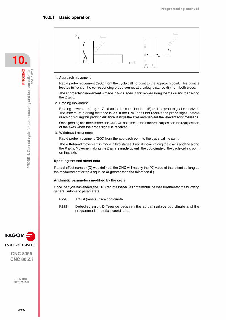
·242·
Programming manual
CNC 8055CNC 8055i
10.
PR
OB
ING
·T· MODELSOFT: V02.2X
PR
OB
E 4
. Can
ned
cycl
e fo
r pa
rt m
easu
ring
and
tool
cor
rect
ion
onth
e Z
axi
s
10.6.1 Basic operation
1. Approach movement.
Rapid probe movement (G00) from the cycle calling point to the approach point. This point islocated in front of the corresponding probe corner, at a safety distance (B) from both sides.
The approaching movement is made in two stages. It first moves along the X axis and then alongthe Z axis.
2. Probing movement.
Probing movement along the Z axis at the indicated feedrate (F) until the probe signal is received.The maximum probing distance is 2B. If the CNC does not receive the probe signal beforereaching moving this probing distance, it stops the axes and displays the relevant error message.
Once probing has been made, the CNC will assume as their theoretical position the real positionof the axes when the probe signal is received .
3. Withdrawal movement.
Rapid probe movement (G00) from the approach point to the cycle calling point.
The withdrawal movement is made in two stages. First, it moves along the Z axis and the alongthe X axis. Movement along the Z axis is made up until the coordinate of the cycle calling pointon that axis.
Updating the tool offset data
If a tool offset number (D) was defined, the CNC will modify the "K" value of that offset as long asthe measurement error is equal to or greater than the tolerance (L).
Arithmetic parameters modified by the cycle
Once the cycle has ended, the CNC returns the values obtained in the measurement to the followinggeneral arithmetic parameters.
P298 Actual (real) surface coordinate.
P299 Detected error. Difference between the actual surface coordinate and theprogrammed theoretical coordinate.
CNC 8055CNC 8055i
·T· MODELSOFT: V02.2X
11
·243·
HIGH-LEVEL LANGUAGE PROGRAMMING
11.1 Lexical description
All the words that make up the high-level language of the numerical control must be written in capitalletters except for associated texts which may be written in upper and lower case letters.
The following elements are available for high-level programming:
• Reserved words.
• Numerical constants.
• Symbols.
Reserved words
Reserved words are those that the CNC uses in high-level programming for naming systemvariables, operators, control instructions, etc.
All the letters of the alphabet A-Z are also reserved words, as they can make up a high-level languageword when used alone.
Numerical constants
Blocks programmed in high-level language admit numbers in decimal format and in hexadecimalformat.
• The numbers in decimal format must not exceed the ±6.5 format (6 digits to the left of the decimalpoint and 5 decimals).
• The numbers in hexadecimal format must be preceded by the $ symbol and they must not havemore than 8 digits.
A constant higher than the format ±6,5 must be assigned to a variable by means of arithmeticparameters by means of arithmetic expressions or by means of constants in hexadecimal format.
If the CNC operates in the metric system (millimeters), the resolution is a tenth of a micron and thefigures will be programmed in the ±5.4 format (positive or negative with 5 digits to the left of thedecimal point and 4 decimals).
If the CNC operates in inches, the resolution is a hundred-thousandths of an inch (ten millionthsof an inch) and the figures will be programmed in the ±4.5 format (positive or negative with 4 digitsto the left of the decimal point and 5 decimals).
For the convenience of the programmer, this control always allows the format ±5.5 (positive ornegative, with 5 integers and 5 decimals), adjusting each number appropriately to the working unitsevery time they are used.
To assign the value 100000000 to the variable "TIMER", It can be done in one of the followingways:
(TIMER = $5F5E100)(TIMER = 10000 * 10000)(P100 = 10000 * 10000)(TIMER = P100)
·244·
Programming manual
CNC 8055CNC 8055i
11.
HIG
H-L
EV
EL
LA
NG
UA
GE
PR
OG
RA
MM
ING
·T· MODELSOFT: V02.2X
Lexi
cal d
escr
iptio
n
Simbols
The symbols used in high-level language are:
( ) “ = + - * / ,
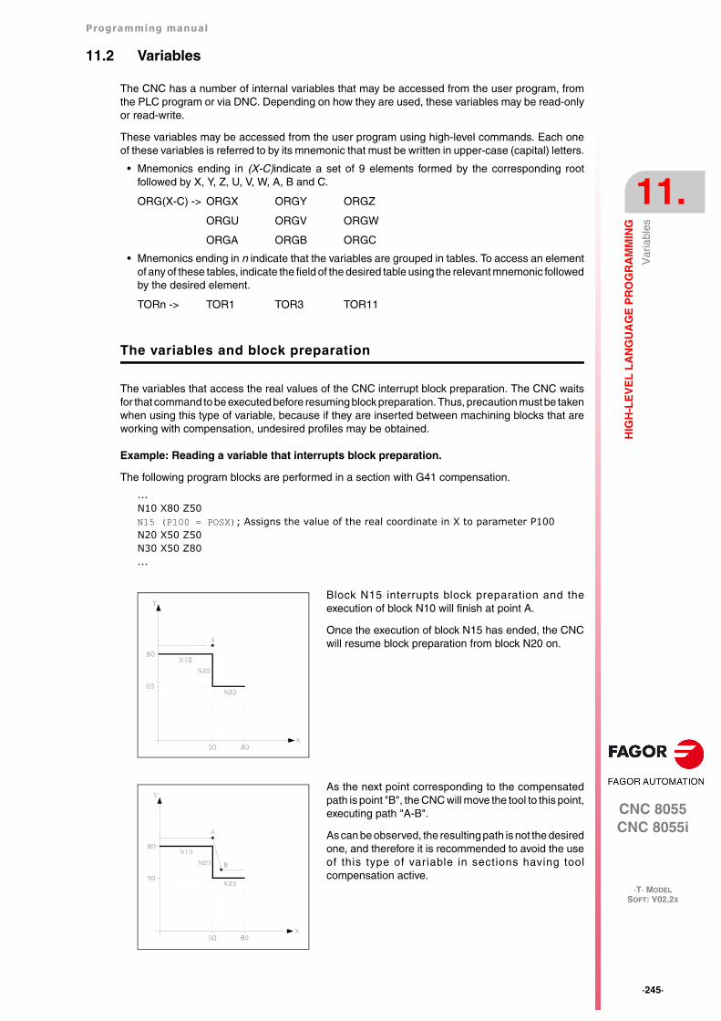
Programming manual
CNC 8055CNC 8055i
HIG
H-L
EV
EL
LA
NG
UA
GE
PR
OG
RA
MM
ING
11.
·T· MODELSOFT: V02.2X
·245·
Var
iabl
es
11.2 Variables
The CNC has a number of internal variables that may be accessed from the user program, fromthe PLC program or via DNC. Depending on how they are used, these variables may be read-onlyor read-write.
These variables may be accessed from the user program using high-level commands. Each oneof these variables is referred to by its mnemonic that must be written in upper-case (capital) letters.
• Mnemonics ending in (X-C)indicate a set of 9 elements formed by the corresponding rootfollowed by X, Y, Z, U, V, W, A, B and C.
ORG(X-C) -> ORGX ORGY ORGZ
ORGU ORGV ORGW
ORGA ORGB ORGC
• Mnemonics ending in n indicate that the variables are grouped in tables. To access an elementof any of these tables, indicate the field of the desired table using the relevant mnemonic followedby the desired element.
TORn -> TOR1 TOR3 TOR11
The variables and block preparation
The variables that access the real values of the CNC interrupt block preparation. The CNC waitsfor that command to be executed before resuming block preparation. Thus, precaution must be takenwhen using this type of variable, because if they are inserted between machining blocks that areworking with compensation, undesired profiles may be obtained.
Example: Reading a variable that interrupts block preparation.
The following program blocks are performed in a section with G41 compensation.
...N10 X80 Z50N15 (P100 = POSX); Assigns the value of the real coordinate in X to parameter P100N20 X50 Z50N30 X50 Z80...
Block N15 interrupts block preparation and theexecution of block N10 will finish at point A.
Once the execution of block N15 has ended, the CNCwill resume block preparation from block N20 on.
As the next point corresponding to the compensatedpath is point "B", the CNC will move the tool to this point,executing path "A-B".
As can be observed, the resulting path is not the desiredone, and therefore it is recommended to avoid the useof this type of variable in sections having toolcompensation active.
·246·
Programming manual
CNC 8055CNC 8055i
11.
HIG
H-L
EV
EL
LA
NG
UA
GE
PR
OG
RA
MM
ING
·T· MODELSOFT: V02.2X
Var
iabl
es
11.2.1 General purpose parameters or variables
General purpose variables are referred to with the letter "P" followed by an integer number. The CNChas four types of general purpose variables.
Blocks programmed in ISO code allow associating parameters to the G F S T D M fields andcoordinates of the axes. The block label number must be defined with a numeric value. If parametersare used in blocks programmed in high-level language, they can be programmed within anyexpression.
Programmers may use general purpose variables when editing their own programs. Later on, duringexecution, the CNC will replace these variables with the values assigned to them at the time.
Using these general purpose variables will depend on the type of block in which they areprogrammed and the channel of execution. Programs that are executed in the user channel maycontain any global, OEM or user parameter, but may not use local parameters.
Types of arithmetic parameters
Local parameters
Local parameters can only be accessed from the program or subroutine where they have beenprogrammed. There are seven groups of parameters.
Local parameters used in high-level language may be defined either using the above format or byusing the letter A-Z, except for Ñ, so that A is equal to P0 and Z to P25.
The following example shows these two methods of definition:
(IF ((P0+P1)* P2/P3 EQ P4) GOTO N100)(IF ((A+B)* C/D EQ E) GOTO N100)
When using a parameter name (letter) for assigning a value to it (A instead of P0, for example), ifthe arithmetic expression is a constant, the instruction can be abbreviated as follows:
(P0=13.7) ==> (A=13.7) ==> (A13.7)
Be careful when using parenthesis since M30 is not the same as (M30). The CNC interprets (M30)as a high level instruction meaning (P12 = 30) and not the execution of the miscellaneous M30function.
Global parameters
Global parameters can be accessed from any program and subroutine called from a program.
Global parameters may be used by the user, by the OEM or by the CNC cycles.
User parameters
These parameters are an expansion of the global parameters but they are not used by the CNCcycles.
OEM (manufacturer's) parameters
OEM parameters and subroutines with OEM parameters can only be used in OEM programs; thosedefined with the [O] attribute. Modifying one of these parameters in the tables requires an OEMpassword.
Parameter type Range
Local parameters P0-P25
Global parameters P100-P299
User parameters P1000-P1255
OEM (manufacturer's) parameters P2000-P2255
When programming...
GP0 XP1 Z100(IF (P100 * P101 EQ P102) GOTO N100)
When executing...
G1 X-12.5 Z100(IF (2 * 5 EQ 12) GOTO N100)
Programming manual
CNC 8055CNC 8055i
HIG
H-L
EV
EL
LA
NG
UA
GE
PR
OG
RA
MM
ING
11.
·T· MODELSOFT: V02.2X
·247·
Var
iabl
es
Using arithmetic parameters by the cycles
Multiple machining cycles (G60 through G65) and the machining canned cycles (G69, G81 to G89)use the sixth nesting level of local parameters when they are active.
Machining canned cycles use the global parameter P299 for internal calculations and probingcanned cycles use global parameters P294 to P299.
Updating arithmetic parameter tables
The CNC will update the parameter table after processing the operations indicated in the block thatis in preparation. This operation is always done before executing the block and for this reason, thevalues shown in the table do not necessarily have to correspond to the block being executed.
If the execution mode is abandoned after interrupting the execution of the program, the CNC willupdate the parameter tables with values corresponding to the block that was being executed.
When accessing the local parameter and global parameter table, the value assigned to eachparameter may be expressed in decimal notation (4127.423) or in scientific notation (0.23476 E-3).
Arithmetic parameters in the subroutines
The CNC offers high level instructions for defining and using subroutines that may be called uponfrom the main program (or a subroutine) and another subroutine from this one and so on, the CNClimits the number of these calls to a maximum of 15 nesting levels. The CNC limitation is 20 nestinglevels.
Up to 26 (P0-P25) local parameters may be assigned to a subroutine. These parameters, that willbe unknown for blocks outside the subroutine, may be referred to by the blocks that make up thesubroutine.
Local parameters may be assigned to more than one subroutine up to 6 parameter nesting levelswithin the 15 subroutine nesting levels.
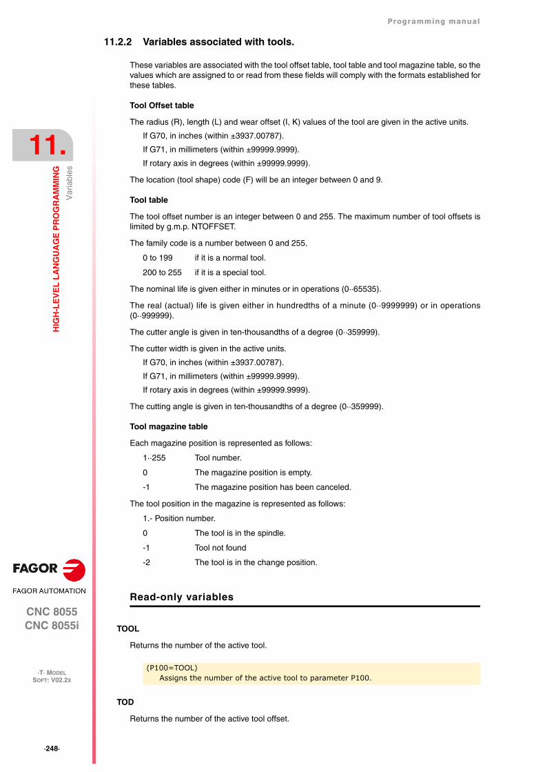
·248·
Programming manual
CNC 8055CNC 8055i
11.
HIG
H-L
EV
EL
LA
NG
UA
GE
PR
OG
RA
MM
ING
·T· MODELSOFT: V02.2X
Var
iabl
es
11.2.2 Variables associated with tools.
These variables are associated with the tool offset table, tool table and tool magazine table, so thevalues which are assigned to or read from these fields will comply with the formats established forthese tables.
Tool Offset table
The radius (R), length (L) and wear offset (I, K) values of the tool are given in the active units.
If G70, in inches (within ±3937.00787).
If G71, in millimeters (within ±99999.9999).
If rotary axis in degrees (within ±99999.9999).
The location (tool shape) code (F) will be an integer between 0 and 9.
Tool table
The tool offset number is an integer between 0 and 255. The maximum number of tool offsets islimited by g.m.p. NTOFFSET.
The family code is a number between 0 and 255.
0 to 199 if it is a normal tool.
200 to 255 if it is a special tool.
The nominal life is given either in minutes or in operations (0··65535).
The real (actual) life is given either in hundredths of a minute (0··9999999) or in operations(0··999999).
The cutter angle is given in ten-thousandths of a degree (0··359999).
The cutter width is given in the active units.
If G70, in inches (within ±3937.00787).
If G71, in millimeters (within ±99999.9999).
If rotary axis in degrees (within ±99999.9999).
The cutting angle is given in ten-thousandths of a degree (0··359999).
Tool magazine table
Each magazine position is represented as follows:
1··255 Tool number.
0 The magazine position is empty.
-1 The magazine position has been canceled.
The tool position in the magazine is represented as follows:
1.- Position number.
0 The tool is in the spindle.
-1 Tool not found
-2 The tool is in the change position.
Read-only variables
TOOL
Returns the number of the active tool.
TOD
Returns the number of the active tool offset.
(P100=TOOL)Assigns the number of the active tool to parameter P100.
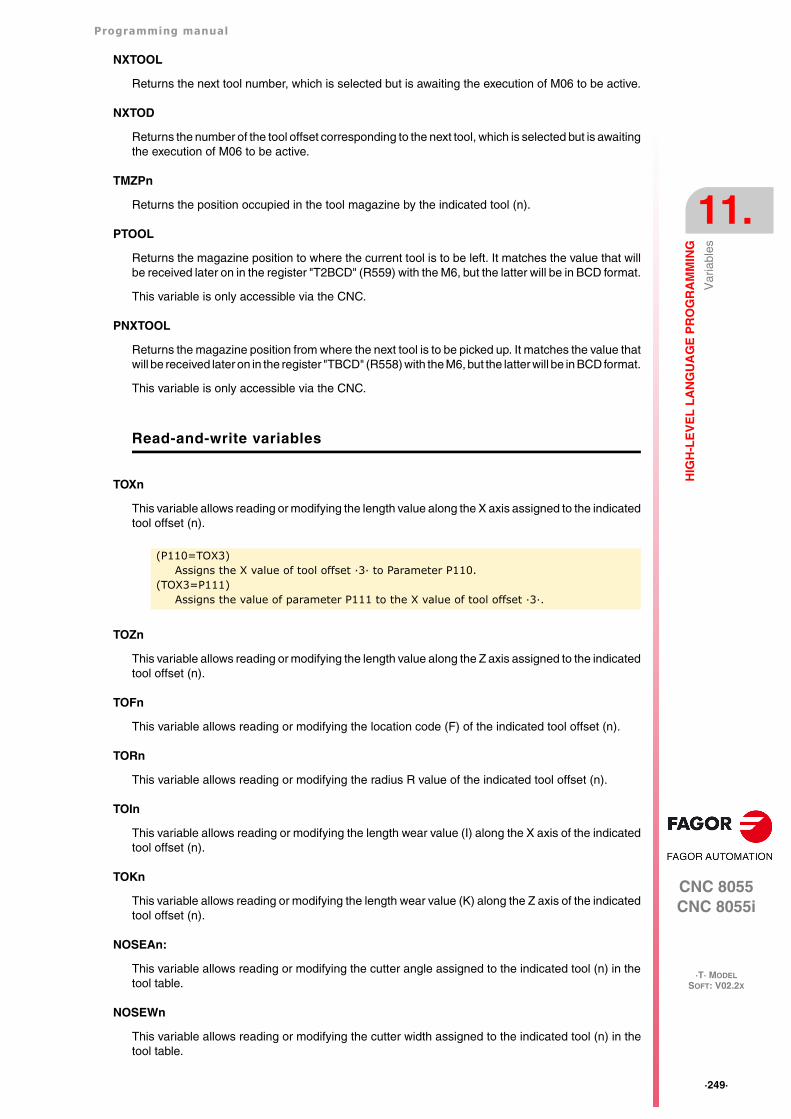
Programming manual
CNC 8055CNC 8055i
HIG
H-L
EV
EL
LA
NG
UA
GE
PR
OG
RA
MM
ING
11.
·T· MODELSOFT: V02.2X
·249·
Var
iabl
es
NXTOOL
Returns the next tool number, which is selected but is awaiting the execution of M06 to be active.
NXTOD
Returns the number of the tool offset corresponding to the next tool, which is selected but is awaitingthe execution of M06 to be active.
TMZPn
Returns the position occupied in the tool magazine by the indicated tool (n).
PTOOL
Returns the magazine position to where the current tool is to be left. It matches the value that willbe received later on in the register "T2BCD" (R559) with the M6, but the latter will be in BCD format.
This variable is only accessible via the CNC.
PNXTOOL
Returns the magazine position from where the next tool is to be picked up. It matches the value thatwill be received later on in the register "TBCD" (R558) with the M6, but the latter will be in BCD format.
This variable is only accessible via the CNC.
Read-and-write variables
TOXn
This variable allows reading or modifying the length value along the X axis assigned to the indicatedtool offset (n).
TOZn
This variable allows reading or modifying the length value along the Z axis assigned to the indicatedtool offset (n).
TOFn
This variable allows reading or modifying the location code (F) of the indicated tool offset (n).
TORn
This variable allows reading or modifying the radius R value of the indicated tool offset (n).
TOIn
This variable allows reading or modifying the length wear value (I) along the X axis of the indicatedtool offset (n).
TOKn
This variable allows reading or modifying the length wear value (K) along the Z axis of the indicatedtool offset (n).
NOSEAn:
This variable allows reading or modifying the cutter angle assigned to the indicated tool (n) in thetool table.
NOSEWn
This variable allows reading or modifying the cutter width assigned to the indicated tool (n) in thetool table.
(P110=TOX3)Assigns the X value of tool offset ·3· to Parameter P110.
(TOX3=P111)Assigns the value of parameter P111 to the X value of tool offset ·3·.
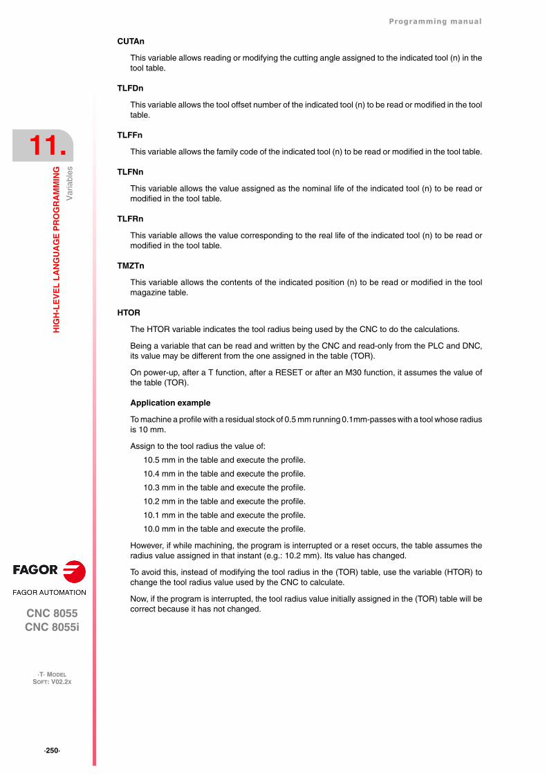
·250·
Programming manual
CNC 8055CNC 8055i
11.
HIG
H-L
EV
EL
LA
NG
UA
GE
PR
OG
RA
MM
ING
·T· MODELSOFT: V02.2X
Var
iabl
es
CUTAn
This variable allows reading or modifying the cutting angle assigned to the indicated tool (n) in thetool table.
TLFDn
This variable allows the tool offset number of the indicated tool (n) to be read or modified in the tooltable.
TLFFn
This variable allows the family code of the indicated tool (n) to be read or modified in the tool table.
TLFNn
This variable allows the value assigned as the nominal life of the indicated tool (n) to be read ormodified in the tool table.
TLFRn
This variable allows the value corresponding to the real life of the indicated tool (n) to be read ormodified in the tool table.
TMZTn
This variable allows the contents of the indicated position (n) to be read or modified in the toolmagazine table.
HTOR
The HTOR variable indicates the tool radius being used by the CNC to do the calculations.
Being a variable that can be read and written by the CNC and read-only from the PLC and DNC,its value may be different from the one assigned in the table (TOR).
On power-up, after a T function, after a RESET or after an M30 function, it assumes the value ofthe table (TOR).
Application example
To machine a profile with a residual stock of 0.5 mm running 0.1mm-passes with a tool whose radiusis 10 mm.
Assign to the tool radius the value of:
10.5 mm in the table and execute the profile.
10.4 mm in the table and execute the profile.
10.3 mm in the table and execute the profile.
10.2 mm in the table and execute the profile.
10.1 mm in the table and execute the profile.
10.0 mm in the table and execute the profile.
However, if while machining, the program is interrupted or a reset occurs, the table assumes theradius value assigned in that instant (e.g.: 10.2 mm). Its value has changed.
To avoid this, instead of modifying the tool radius in the (TOR) table, use the variable (HTOR) tochange the tool radius value used by the CNC to calculate.
Now, if the program is interrupted, the tool radius value initially assigned in the (TOR) table will becorrect because it has not changed.
Programming manual
CNC 8055CNC 8055i
HIG
H-L
EV
EL
LA
NG
UA
GE
PR
OG
RA
MM
ING
11.
·T· MODELSOFT: V02.2X
·251·
Var
iabl
es
11.2.3 Variables associated with zero offsets.
These variables are associated with the zero offsets and may correspond to the table values or tothose currently preset either by means of function G92 or manually in the JOG mode.
The possible zero offsets in addition to the additive offset indicated by the PLC, are G54, G55, G56,G57, G58 and G59.
The values for each axis are given in the active units:
If G70, in inches (within ±3937.00787).
If G71, in millimeters (within ±99999.9999).
If rotary axis in degrees (within ±99999.9999).
Although there are variables which refer to each axis, the CNC only allows those referring to theaxes selected at the CNC. Thus, if the CNC controls axes X, Y, Z, U and B, it only allows the variablesORGX, ORGY, ORGZ,. ORGU and ORGB in the case of ORG(X-C).
Read-only variables
ORG(X-C)
Returns the value of the active zero offset in the selected axis. The value of the additive offsetindicated by the PLC or by the additive handwheel is not included in this value.
PORGF
Returns the abscissa value of the polar coordinate origin with respect to the Cartesian origin.
This value is given in radius or diameter depending on the setting of axis machine parameter"DFORMAT".
PORGS
Returns the ordinate value of the polar coordinate origin with respect to the Cartesian origin.
This value is given in radius or diameter depending on the setting of axis machine parameter"DFORMAT".
ADIOF(X-C)
It returns the value of the zero offset generated by the additive handwheel in the selected axis.
ADDORG (X-C)
Returns the value of the active incremental zero offset corresponding to the axis selected at the time.It is read-only variable that can be read from the CNC, PLC and DNC.
(P100=ORGX)It assigns to P100 the X value of the part zero active for the X axis. This value could have been set either manually, by means of function G92 or by the variable "ORG(X-C)n".
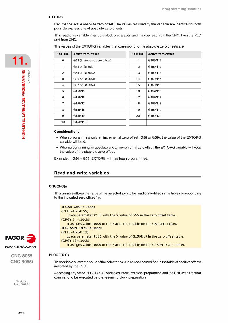
·252·
Programming manual
CNC 8055CNC 8055i
11.
HIG
H-L
EV
EL
LA
NG
UA
GE
PR
OG
RA
MM
ING
·T· MODELSOFT: V02.2X
Var
iabl
es
EXTORG
Returns the active absolute zero offset. The values returned by the variable are identical for bothpossible expressions of absolute zero offsets.
This read-only variable interrupts block preparation and may be read from the CNC, from the PLCand from DNC.
The values of the EXTORG variables that correspond to the absolute zero offsets are:
Considerations:
• When programming only an incremental zero offset (G58 or G59), the value of the EXTORGvariable will be 0.
• When programming an absolute and an incremental zero offset, the EXTORG variable will keepthe value of the absolute zero offset.
Example: If G54 + G58, EXTORG = 1 has been programmed.
Read-and-write variables
ORG(X-C)n
This variable allows the value of the selected axis to be read or modified in the table correspondingto the indicated zero offset (n).
PLCOF(X-C)
This variable allows the value of the selected axis to be read or modified in the table of additive offsetsindicated by the PLC.
Accessing any of the PLCOF(X-C) variables interrupts block preparation and the CNC waits for thatcommand to be executed before resuming block preparation.
EXTORG Active zero offset EXTORG Active zero offset
0 G53 (there is no zero offset) 11 G159N11
1 G54 or G159N1 12 G159N12
2 G55 or G159N2 13 G159N13
3 G56 or G159N3 14 G159N14
4 G57 or G159N4 15 G159N15
5 G159N5 16 G159N16
6 G159N6 17 G159N17
7 G159N7 18 G159N18
8 G159N8 19 G159N19
9 G159N9 20 G159N20
10 G159N10
If G54-G59 is used:(P110=ORGX 55)
Loads parameter P100 with the X value of G55 in the zero offset table.(ORGY 54=100.8)
It assigns value 100.8 to the Y axis in the table for the G54 zero offset.If G159N1-N20 is used:(P110=ORGX 19)
Loads parameter P110 with the X value of G159N19 in the zero offset table.(ORGY 19=100.8)
It assigns value 100.8 to the Y axis in the table for the G159N19 zero offset.
Programming manual
CNC 8055CNC 8055i
HIG
H-L
EV
EL
LA
NG
UA
GE
PR
OG
RA
MM
ING
11.
·T· MODELSOFT: V02.2X
·253·
Var
iabl
es
11.2.4 Variables associated with machine parameters
These variables associated with machine parameters are read-only variables. These variables maybe read and written when executed inside an OEM program or subroutine.
Refer to the installation and start-up manual to know the format of the values returned. The valuesof 1/0 correspond to the parameters that are set as YES/NO, +/- or ON/OFF.
The coordinate and feedrate values are given in the active units:
If G70, in inches (within ±3937.00787).
If G71, in millimeters (within ±99999.9999).
If rotary axis in degrees (within ±99999.9999).
Modify the machine parameters from an OEM program or subroutine.
These variables may be read and written when executed inside an OEM program or subroutine. Inthis case, these variables can be used to modify the value of certain machine parameters. Referto the installation manual for the list of machine parameters that may be modified.
In order to be able to modify these parameters via PLC, an OEM subroutine containing the relevantvariables must be executed using the CNCEX command.
Read-only variables
MPGn
Returns the value assigned to general machine parameter (n).
MP(X-C)n
Returns the value assigned to the machine parameter (n) of the indicated axis (X-C).
MPSn
Returns the value assigned to the indicated machine parameter (n) of the main spindle.
MPSSn
Returns the value assigned to the indicated machine parameter (n) of the second spindle.
MPASn
Returns the value of the indicated machine parameter (n) of the auxiliary spindle.
MPLCn
Returns the value assigned to the indicated machine parameter (n) of the PLC.
(P110=MPG8)It assigns the value of the general machine parameter P8 "INCHES" to parameter P110, if millimeters P110=0 and if inches P110=1.
(P110=MPY 1)Assigns the value of Y axis machine parameter P1 "DFORMAT" to parameter P110.
·254·
Programming manual
CNC 8055CNC 8055i
11.
HIG
H-L
EV
EL
LA
NG
UA
GE
PR
OG
RA
MM
ING
·T· MODELSOFT: V02.2X
Var
iabl
es
11.2.5 Variables associated with work zones
Variables associated with work zones are read-only variables.
The values of the limits are given in the active units:
If G70, in inches (within ±3937.00787).
If G71, in millimeters (within ±99999.9999).
If rotary axis in degrees (within ±99999.9999).
The status of the work zones are defined according to the following code:
0 = Disabled.
1 = Enabled as no-entry zone.
2 = Enabled as no-exit zone.
Read-only variables
FZONE
It returns the status of work zone 1.
FZLO(X-C)
Lower limit of zone 1 along the selected axis (X-C).
FZUP(X-C)
Upper limit of zone 1 along the selected axis (X-C).
SZONE
Status of work zone 2.
SZLO(X-C)
Lower limit of zone 2 along the selected axis (X-C).
SZUP(X-C)
Upper limit of zone 2 along the selected axis (X-C).
TZONE
Status of work zone 3.
TZLO(X-C)
Lower limit of zone 3 along the selected axis (X-C).
TZUP(X-C)
Upper limit of zone 3 along the selected axis (X-C).
FOZONE
Status of work zone 4.
FOZLO(X-C)
Lower limit of zone 4 along the selected axis (X-C).
FOZUP(X-C)
Upper limit of zone 4 along the selected axis (X-C).
(P100=FZONE) ; It assigns to parameter P100 the status of work zone 1.(P101=FZOLOX) ; It assigns the lower limit of zone 1 to parameter P101.(P102=FZUPZ) ; It assigns the upper limit of zone 1 to parameter P102.
Programming manual
CNC 8055CNC 8055i
HIG
H-L
EV
EL
LA
NG
UA
GE
PR
OG
RA
MM
ING
11.
·T· MODELSOFT: V02.2X
·255·
Var
iabl
es
FIZONE
Status of work zone 5.
FIZLO(X-C)
Lower limit of zone 5 along the selected axis (X-C).
FIZUP(X-C)
Upper limit of zone 5 along the selected axis (X-C).
·256·
Programming manual
CNC 8055CNC 8055i
11.
HIG
H-L
EV
EL
LA
NG
UA
GE
PR
OG
RA
MM
ING
·T· MODELSOFT: V02.2X
Var
iabl
es
11.2.6 Variables associated with feedrates
Read-only variables associated with the real (actual) feedrate
FREAL
It returns the CNC's real feedrate. In mm/minute or inches/minute.
FREAL(X-C)
It returns the actual (real) CNC feedrate of the selected axis.
FTEO(X-C)
It returns the theoretical CNC feedrate of the selected axis.
Read-only variables associated with function G94
FEED
It returns the feedrate selected at the CNC by function G94. In mm/minute or inches/minute.
This feedrate may be indicated by program, by PLC or by DNC; the CNC selects one of them, theone indicated by DNC has the highest priority and the one indicated by program has the lowestpriority.
DNCF
It returns the feedrate, in mm/minute or inches/minute selected by DNC. If it has a value of 0 it meansthat it is not selected.
PLCF
It returns the feedrate, in mm/minute or inches/minute selected by PLC. If it has a value of 0 it meansthat it is not selected.
PRGF
It returns the feedrate, in mm/minute or inches/minute selected by program.
Read-only variables associated with function G95
FPREV
It returns the feedrate selected at the CNC by function G95. In mm/turn or inches/turn.
This feedrate may be indicated by program, by PLC or by DNC; the CNC selects one of them, theone indicated by DNC has the highest priority and the one indicated by program has the lowestpriority.
DNCFPR
It returns the feedrate, in mm/turn or inches/turn selected by DNC. If it has a value of 0 it meansthat it is not selected.
PLCFPR
It returns the feedrate, in mm/turn or inches/turn selected by PLC. If it has a value of 0 it means thatit is not selected.
(P100=FREAL)It assigns the real feedrate value of the CNC to parameter P100.
Programming manual
CNC 8055CNC 8055i
HIG
H-L
EV
EL
LA
NG
UA
GE
PR
OG
RA
MM
ING
11.
·T· MODELSOFT: V02.2X
·257·
Var
iabl
es
PRGFPR
It returns the feedrate, in mm/turn or inches/turn selected by program.
Read-only variables associated with function G32
PRGFIN
It returns the feedrate selected by program, in 1/min.
Likewise, the CNC variable FEED, associated with G94, indicates the resulting feedrate in mm/minor inches/min.
Read-only variables associated with the override
FRO
It returns the feedrate override (%) currently selected at the CNC. It is given in integer values between0 and "MAXFOVR" (maximum 255).
This feedrate percentage may be indicated by program, by PLC, by DNC or from the front panel;the CNC selects one of them, where the priority (from the highest to the lowest) is: by program, byDNC, by PLC and from the switch.
DNCFRO
It returns the feedrate override % currently selected by the DNC. If it has a value of 0 it means thatit is not selected.
PLCFRO
It returns the feedrate override % currently selected by the PLC. If it has a value of 0 it means thatit is not selected.
CNCFRO
It returns the feedrate override % currently selected by the switch.
PLCCFR
It returns the feedrate percentage currently selected by the PLC's execution channel.
Read-write variables associated with the override
PRGFRO
This variable may be used to read or modify the feedrate override percentage currently selectedby program. It is given in integer values between 0 and "MAXFOVR" (maximum 255). If it has a valueof 0 it means that it is not selected.
(P110=PRGFRO)It assigns to P110 the % of feedrate override selected by program.
(PRGFRO=P111)It sets the feedrate override % selected by program to the value of P111.
·258·
Programming manual
CNC 8055CNC 8055i
11.
HIG
H-L
EV
EL
LA
NG
UA
GE
PR
OG
RA
MM
ING
·T· MODELSOFT: V02.2X
Var
iabl
es
11.2.7 Variables associated with coordinates
The coordinate values for each axis are given in the active units:
If G70, in inches (within ±3937.00787).
If G71, in millimeters (within ±99999.9999).
If rotary axis in degrees (within ±99999.9999).
Read-only variables
Accessing any of the variables POS(X-C), TPOS(X-C), APOS(X-C), ATPOS(X-C) or FLWE(X-C)interrupts block preparation and the CNC waits for that command to be executed before resumingblock preparation.
The coordinates provided by the variables PPOS(X-C), POS(X-C), TPOS(X-C), APOS(X-C) andATPOS(X-C) are given in the active units system (radius or diameter). Check the DIAM variable toknow the active units system.
PPOS(X-C)
Returns the programmed theoretical coordinate of the selected axis.
POS(X-C)
It returns the real tool base position value referred to machine reference zero (home).
On limit-less rotary axes, this variable takes into account the value of the active zero offset. Thevalues of the variable are between the active zero offset and ±360º (ORG* ± 360º).
If ORG* = 20º it displays between 20º and 380º / displays between -340º and 20º.
If ORG* = -60º it displays between -60º and 300º / displays between -420 and -60º
TPOS(X-C)
It returns the theoretical position value (real coordinate + following error) of the tool base referredto machine reference zero (home).
On limit-less rotary axes, this variable takes into account the value of the active zero offset. Thevalues of the variable are between the active zero offset and ±360º (ORG* ± 360º).
If ORG* = 20º it displays between 20º and 380º / displays between -340º and 20º.
If ORG* = -60º it displays between -60º and 300º / displays between -420 and -60º
APOS(X-C)
It returns the real tool base position value, referred to part zero, of the selected axis.
ATPOS(X-C)
It returns the theoretical position value (real coordinate + following error) of the tool base referredto part zero.
FLWE(X-C)
It returns the following error of the selected axis.
DPLY(X-C)
It returns the position value (coordinate) shown on the screen for the selected axis.
DRPO(X-C)
It returns the position indicated by the Sercos drive of the selected axis (variable PV51 or PV53 ofthe drive).
(P110=PPOSX)It assigns to P100 the programmed theoretical position of the X axis.
Programming manual
CNC 8055CNC 8055i
HIG
H-L
EV
EL
LA
NG
UA
GE
PR
OG
RA
MM
ING
11.
·T· MODELSOFT: V02.2X
·259·
Var
iabl
es
GPOS(X-C)n p
Programmed coordinate for a particular axis in the indicated (n) block of the (p) program.
Only programs located in the CNC's RAM memory may be consulted.
If the defined program or block does not exist, it shows the relevant error message. If the indicatedblock does not contain the requested axis, it returns the value 100000.0000.
Read-and-write variables
DIST(X-C)
These variables may be used to read or modify the distance traveled by the selected axis. This valueis accumulative and is very useful when it is required to perform an operation which depends onthe distance traveled by the axes, their lubrication for example.
Accessing any of the DIST(X-C) variables interrupts block preparation and the CNC waits for thatcommand to be executed before resuming block preparation.
LIMPL(X-C) LIMMI(X-C)
With these variables, it is possible to set a second travel limit for each axis: LIMPL for the upper limitand LIMMI for the lower one.
Since the second limits are activated or deactivated from the PLC, through general logic inputACTLIM2 (M5052), besides setting the limits, an auxiliary M code must be executed to let it know.
It is also recommended to execute function G4 after the change so the CNC executes the followingblocks with the new limits.
The second travel limit will be taken into account if the first one has been set using axis machineparameters LIMIT+ (P5) and LIMIT- (P6).
(P80=GPOSX N99 P100)It assigns to parameter P88 the value of the coordinate programmed for the X axis in the block having the label N99 and located in program P100.
(P110=DISTX)It assigns to P110 the distance traveled by the X axis
(DISTX=P111)It presets the variable indicating the distance traveled by the Z axis with the value of arithmetic parameter P111.
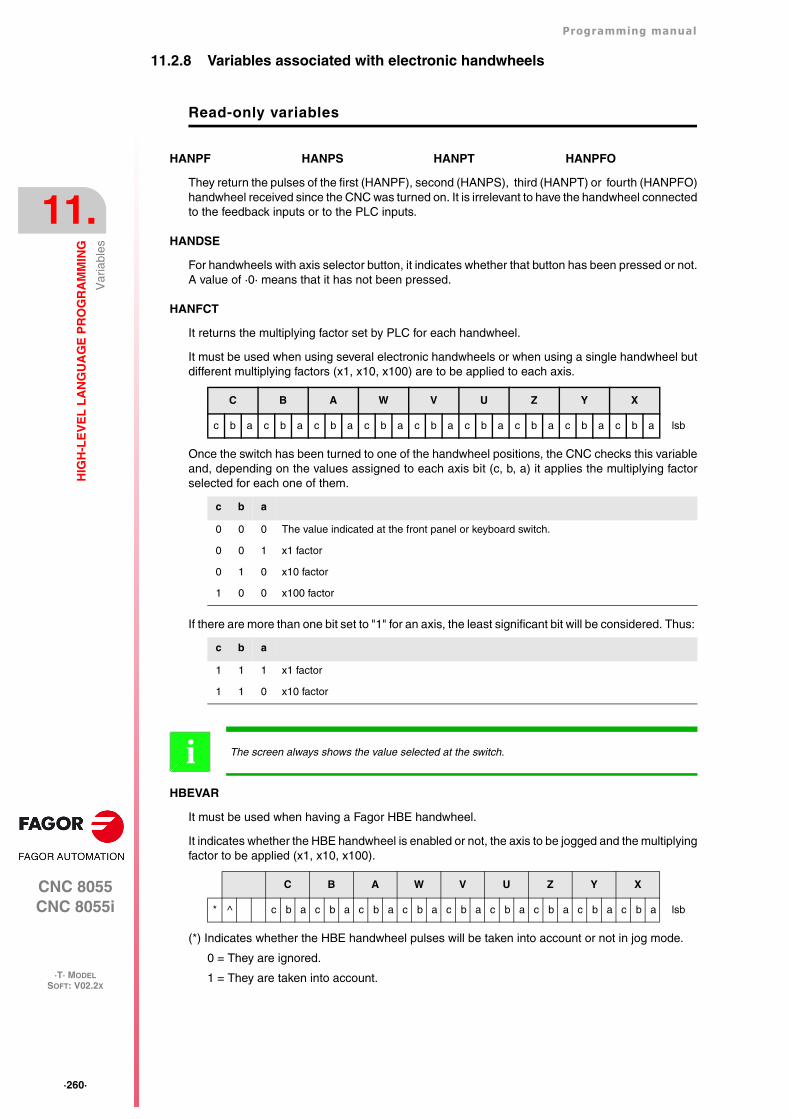
·260·
Programming manual
CNC 8055CNC 8055i
11.
HIG
H-L
EV
EL
LA
NG
UA
GE
PR
OG
RA
MM
ING
·T· MODELSOFT: V02.2X
Var
iabl
es
11.2.8 Variables associated with electronic handwheels
Read-only variables
HANPF HANPS HANPT HANPFO
They return the pulses of the first (HANPF), second (HANPS), third (HANPT) or fourth (HANPFO)handwheel received since the CNC was turned on. It is irrelevant to have the handwheel connectedto the feedback inputs or to the PLC inputs.
HANDSE
For handwheels with axis selector button, it indicates whether that button has been pressed or not.A value of ·0· means that it has not been pressed.
HANFCT
It returns the multiplying factor set by PLC for each handwheel.
It must be used when using several electronic handwheels or when using a single handwheel butdifferent multiplying factors (x1, x10, x100) are to be applied to each axis.
Once the switch has been turned to one of the handwheel positions, the CNC checks this variableand, depending on the values assigned to each axis bit (c, b, a) it applies the multiplying factorselected for each one of them.
If there are more than one bit set to "1" for an axis, the least significant bit will be considered. Thus:
HBEVAR
It must be used when having a Fagor HBE handwheel.
It indicates whether the HBE handwheel is enabled or not, the axis to be jogged and the multiplyingfactor to be applied (x1, x10, x100).
(*) Indicates whether the HBE handwheel pulses will be taken into account or not in jog mode.
0 = They are ignored.
1 = They are taken into account.
C B A W V U Z Y X
c b a c b a c b a c b a c b a c b a c b a c b a c b a lsb
c b a
0 0 0 The value indicated at the front panel or keyboard switch.
0 0 1 x1 factor
0 1 0 x10 factor
1 0 0 x100 factor
c b a
1 1 1 x1 factor
1 1 0 x10 factor
The screen always shows the value selected at the switch.i
C B A W V U Z Y X
* ^ c b a c b a c b a c b a c b a c b a c b a c b a c b a lsb
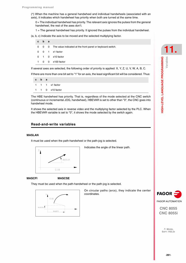
Programming manual
CNC 8055CNC 8055i
HIG
H-L
EV
EL
LA
NG
UA
GE
PR
OG
RA
MM
ING
11.
·T· MODELSOFT: V02.2X
·261·
Var
iabl
es
(^) When the machine has a general handwheel and individual handwheels (associated with anaxis), it indicates which handwheel has priority when both are turned at the same time.
0 = The individual handwheel has priority. The relevant axis ignores the pulses from the generalhandwheel, the rest of the axes don’t.
1 = The general handwheel has priority. It ignored the pulses from the individual handwheel.
(a, b, c) Indicate the axis to be moved and the selected multiplying factor.
If several axes are selected, the following order of priority is applied: X, Y, Z, U, V, W, A, B, C.
If there are more than one bit set to "1" for an axis, the least significant bit will be considered. Thus:
The HBE handwheel has priority. That is, regardless of the mode selected at the CNC switch(continuous or incremental JOG, handwheel), HBEVAR is set to other than "0", the CNC goes intohandwheel mode.
It shows the selected axis in reverse video and the multiplying factor selected by the PLC. Whenthe HBEVAR variable is set to "0", it shows the mode selected by the switch again.
Read-and-write variables
MASLAN
It must be used when the path-handwheel or the path-jog is selected.
MASCFI MASCSE
They must be used when the path-handwheel or the path-jog is selected.
c b a
0 0 0 The value indicated at the front panel or keyboard switch.
0 0 1 x1 factor
0 1 0 x10 factor
1 0 0 x100 factor
c b a
1 1 1 x1 factor
1 1 0 x10 factor
Indicates the angle of the linear path.
On circular paths (arcs), they indicate the centercoordinates.
·262·
Programming manual
CNC 8055CNC 8055i
11.
HIG
H-L
EV
EL
LA
NG
UA
GE
PR
OG
RA
MM
ING
·T· MODELSOFT: V02.2X
Var
iabl
es
11.2.9 Variables associated with feedback
ASIN(X-C)
"A" signal of the CNC's sinusoidal feedback for the X-C axis.
BSIN(X-C)
"B" signal of the CNC's sinusoidal feedback for the X-C axis.
ASINS
"A" signal of the CNC's sinusoidal feedback for the spindle.
BSINS
"B" signal of the CNC's sinusoidal feedback for the spindle.
SASINS
"A" signal of the CNC sinusoidal feedback for the second spindle.
SBSINS
"B" signal of the CNC sinusoidal feedback for the second spindle.
Programming manual
CNC 8055CNC 8055i
HIG
H-L
EV
EL
LA
NG
UA
GE
PR
OG
RA
MM
ING
11.
·T· MODELSOFT: V02.2X
·263·
Var
iabl
es
11.2.10 Variables associated with the main spindle
In these variables associated with the spindle, their values are given in revolutions per minute andthe main spindle override values are given in integers from 0 to 255.
Certain variables interrupt block preparation (it is indicated in each one) and the CNC waits for thatcommand to be executed before resuming block preparation.
Read-only variables
SREAL
Returns the real main spindle turning speed in revolutions per minute. It interrupts block preparation.
FTEOS
It returns the theoretical turning speed of the main spindle.
SPEED
Returns, in revolutions per minute, the main spindle speed selected at the CNC.
This turning speed may be indicated by program, by PLC or by DNC; the CNC selects one of them,the one indicated by DNC has the highest priority and the one indicated by program has the lowestpriority.
DNCS
Returns the turning speed in revolutions per minute, selected by DNC. If it has a value of 0 it meansthat it is not selected.
PLCS
Returns the turning speed in revolutions per minute selected by PLC. If it has a value of 0 it meansthat it is not selected.
PRGS
Returns the turning speed in revolutions per minute, selected by program.
CSS
It returns the constant surface speed selected at the CNC. Its value is given in the active units (ft/minor m/min).
This constant surface speed may be indicated by program, by PLC or by DNC; the CNC selects oneof them, the one indicated by DNC has the highest priority and the one indicated by program hasthe lowest priority.
DNCCSS
It returns the constant surface speed selected via DNC. Its value is given in m/min or ft/min and itis 0 it means that it is not currently selected.
PLCCSS
It returns the constant surface speed selected by PLC. Its value is given in m/min or ft/min.
PRGCSS
It returns the constant surface speed selected by program. Its value is given in m/min or ft/min.
SSO
It returns the turning speed override (%) of the main spindle currently selected at the CNC. It is givenin integer values between 0 and "MAXFOVR" (maximum 255).
(P100=SREAL)It assigns to P100 the real turning speed of the main spindle.
·264·
Programming manual
CNC 8055CNC 8055i
11.
HIG
H-L
EV
EL
LA
NG
UA
GE
PR
OG
RA
MM
ING
·T· MODELSOFT: V02.2X
Var
iabl
es
This turning speed percentage of the main spindle may be indicated by program, by PLC, by DNCor by the front panel; the CNC selects one of them and the priority (from the highest to the lowest)is: by program, by DNC, by PLC and from the panel frontal.
DNCSSO
It returns the turning speed override % of the main spindle currently selected via DNC. If it has avalue of 0 it means that it is not selected.
PLCSSO
It returns the turning speed override % of the main spindle currently selected by PLC. If it has a valueof 0 it means that it is not selected.
CNCSSO
It returns the turning speed override % of the main spindle currently selected from the front panel.
SLIMIT
It returns the value set in rpm at the CNC for the turning speed limit of the main spindle.
This limit may be indicated by program, by PLC or by DNC; the CNC selects one of them, the oneindicated by DNC has the highest priority and the one indicated by program has the lowest priority.
DNCSL
It returns the speed limit of the main spindle in rpm currently selected via DNC. If it has a value of0 it means that it is not selected.
PLCSL
It returns the speed limit of the main spindle in rpm currently selected by PLC. If it has a value of0 it means that it is not selected.
PRGSL
It returns the speed limit of the main spindle in rpm currently selected by program.
MDISL
Maximum machining spindle speed. This variable is also updated (refreshed) when programmingfunction G92 via MDI.
POSS
It returns the real position of the main spindle. Its value may be within ±99999.9999°. It interruptsblock preparation.
RPOSS
It returns the real position of the main spindle. Its value is given in 0.0001 degree units (between-360º and 360º). It interrupts block preparation.
TPOSS
It returns the theoretical position of the main spindle (real position + lag). Its value may be within±99999.9999º. It interrupts block preparation.
RTPOSS
It returns the theoretical position of the main spindle (real position + lag) in 360º module. Its valuemay be between 0 and 360º. It interrupts block preparation.
DRPOS
Position indicated by the Sercos drive of the main spindle.
PRGSP
Position programmed in M19 via program for the main spindle. This variable may be read from theCNC, from the PLC and from DNC.
Programming manual
CNC 8055CNC 8055i
HIG
H-L
EV
EL
LA
NG
UA
GE
PR
OG
RA
MM
ING
11.
·T· MODELSOFT: V02.2X
·265·
Var
iabl
es
FLWES
It returns the main spindle's following error in degrees (within ±99999.9999). It interrupts blockpreparation.
SYNCER
It returns, in degrees (within ±99999.9999), the following error of the second spindle with respectto the main spindle when they are synchronized in position.
Read-and-write variables
PRGSSO
This variable may be used to read or modify the speed override percentage of the main spindlecurrently selected by program. It is given in integer values between 0 and "MAXFOVR" (maximum255). If it has a value of 0 it means that it is not selected.
(P110=PRGSSO)It assigns to P110 the % of the main spindle speed selected by program.
(PRGSSO=P111)It sets the value indicating the main spindle speed % selected by program to the value of arithmetic parameter P111.
·266·
Programming manual
CNC 8055CNC 8055i
11.
HIG
H-L
EV
EL
LA
NG
UA
GE
PR
OG
RA
MM
ING
·T· MODELSOFT: V02.2X
Var
iabl
es
11.2.11 Variables associated with the second spindle
In these variables associated with the spindle, their values are given in revolutions per minute andthe 2nd spindle override values are given in integers from 0 to 255.
Read-only variables
SSREAL
Returns the real 2nd spindle turning speed in revolutions per minute.
If this variable is accessed, block preparation is interrupted and the CNC waits for this commandto be executed to resume block preparation.
SFTEOS
It returns the theoretical turning speed of the second spindle.
SSPEED
Returns, in revolutions per minute, the 2nd spindle speed selected at the CNC.
This turning speed may be indicated by program, by PLC or by DNC; the CNC selects one of them,the one indicated by DNC has the highest priority and the one indicated by program has the lowestpriority.
SDNCS
Returns the turning speed in revolutions per minute, selected by DNC. If it has a value of 0 it meansthat it is not selected.
SPLCS
Returns the turning speed in revolutions per minute selected by PLC. If it has a value of 0 it meansthat it is not selected.
SPRGS
Returns the turning speed in revolutions per minute, selected by program.
SCSS
It returns the constant surface speed selected at the CNC. Its value is given in the active units (ft/minor m/min).
This constant surface speed may be indicated by program, by PLC or by DNC; the CNC selects oneof them, the one indicated by DNC has the highest priority and the one indicated by program hasthe lowest priority.
SDNCCS
It returns the constant surface speed selected via DNC. Its value is given in m/min or ft/min and itis 0 it means that it is not currently selected.
SPLCCS
It returns the constant surface speed selected by PLC. Its value is given in m/min or ft/min.
SPRGCS
It returns the constant surface speed selected by program. Its value is given in m/min or ft/min.
SSSO
It returns the turning speed override (%) of the second spindle currently selected at the CNC. It isgiven in integer values between 0 and "MAXFOVR" (maximum 255).
(P100=SSREAL)It assigns to P100 the real turning speed of the second spindle.
Programming manual
CNC 8055CNC 8055i
HIG
H-L
EV
EL
LA
NG
UA
GE
PR
OG
RA
MM
ING
11.
·T· MODELSOFT: V02.2X
·267·
Var
iabl
es
This turning speed percentage of the second spindle may be indicated by program, by PLC, by DNCor by the front panel; the CNC selects one of them and the priority (from the highest to the lowest)is: by program, by DNC, by PLC and from the panel frontal.
SDNCSO
It returns the turning speed override % of the second spindle currently selected via DNC. If it hasa value of 0 it means that it is not selected.
SPLCSO
It returns the turning speed override % of the second spindle currently selected by PLC. If it has avalue of 0 it means that it is not selected.
SCNCSO
It returns the turning speed override % of the second spindle currently selected from the front panel.
SSLIMI
It returns the value set in rpm at the CNC for the turning speed limit of the second spindle.
This limit may be indicated by program, by PLC or by DNC; the CNC selects one of them, the oneindicated by DNC has the highest priority and the one indicated by program has the lowest priority.
SDNCSL
It returns the speed limit of the second spindle in rpm currently selected via DNC. If it has a valueof 0 it means that it is not selected.
SPLCSL
It returns the speed limit of the second spindle in rpm currently selected by PLC. If it has a valueof 0 it means that it is not selected.
SPRGSL
It returns the speed limit of the second spindle in rpm currently selected by program.
SPOSS
It returns the real position of the second spindle. Its value may be within ±99999.9999°.
SRPOSS
It returns the real position of the second spindle. Its value is given in 0.0001 degree units (between-360º and 360º).
STPOSS
It returns the theoretical position of the second spindle (real position + lag). Its value may be within±99999.9999º.
SRTPOS
Returns the second spindle's theoretical position value (real coordinate+ following error) in a 360ºmodule. Its value may be between 0 and 360º.
SDRPOS
Position indicated by the Sercos drive of the second spindle.
SPRGSP
Position programmed in M19 via program for the second spindle. This variable may be read fromthe CNC, from the PLC and from DNC.
SFLWES
It returns the second spindle's following error in degrees (within ±99999.9999).
When accessing one of these variables SPOSS, SRPOSS, STPOSS, SRTPOSS or SFLWES, blockpreparation is interrupted and the CNC waits for that command to be executed before resuming blockpreparation.
·268·
Programming manual
CNC 8055CNC 8055i
11.
HIG
H-L
EV
EL
LA
NG
UA
GE
PR
OG
RA
MM
ING
·T· MODELSOFT: V02.2X
Var
iabl
es
Read-and-write variables
SPRGSO
This variable may be used to read or modify the speed override percentage of the second spindlecurrently selected by program. It is given in integer values between 0 and "MAXFOVR" (maximum255). If it has a value of 0 it means that it is not selected.
(P110=SPRGSO)It assigns to P110 the % of the second spindle speed selected by program.
(SPRGSO=P111)It sets the value indicating the second spindle speed % selected by program to the value of arithmetic parameter P111.
Programming manual
CNC 8055CNC 8055i
HIG
H-L
EV
EL
LA
NG
UA
GE
PR
OG
RA
MM
ING
11.
·T· MODELSOFT: V02.2X
·269·
Var
iabl
es
11.2.12 Variables associated with the live tool
Read-only variables
ASPROG
It must be used inside the subroutine associated with function M45.
Returns the revolutions per minute programmed in M45 S. If programmed only in M45, the value0 will be used.
The ASPROG variable is updated just before executing the M45 function so it is already updatedwhen executing its associated subroutine.
LIVRPM
It must be used when operating in TC mode.
It returns the rpm selected by the user for the live tool when in TC mode.
·270·
Programming manual
CNC 8055CNC 8055i
11.
HIG
H-L
EV
EL
LA
NG
UA
GE
PR
OG
RA
MM
ING
·T· MODELSOFT: V02.2X
Var
iabl
es
11.2.13 PLC related variables
It should be borne in mind that the PLC has the following resources:
(I1 thru I512) Inputs.
(O1 thru O512) Outputs.
M1 thru M5957) Marks.
(R1 thru R499) 32-bit registers.
(T1 thru T512) Timers with a timing count in 32 bits.
(C1 thru C256) Counters with a count in 32 bits.
If any variable is accessed which allows the status of a PLC variable to be read or modified(I,O,M,R,T,C), block preparation is interrupted and the CNC waits for this command to be executedin order to restart block preparation.
Read-only variables
PLCMSG
Returns the number of the active PLC message with the highest priority and will coincide with thenumber displayed on screen (1··128). If there is none, it returns 0.
Read-and-write variables
PLCIn
This variable allows 32 PLC inputs to be read or modified starting with the one indicated (n).
The value of the inputs which are used by the electrical cabinet cannot be modified as their valuesare determined by it. Nevertheless, the status of the remaining inputs can be modified.
PLCOn
This variable allows 32 PLC outputs to be read or modified starting from the one indicated (n).
PLCMn
This variable allows 32 PLC marks to be read or modified starting from the one indicated (n).
PLCRn
This variable allows the status of 32 register bits to be read or modified starting from the one indicated(n).
PLCTn
This variable allows the timer count to be read or modified starting from the one indicated (n).
(P110=PLCMSG)It assigns to P100 the number of the active PLC message with the highest priority.
(P110=PLCO 22)It assigns to parameter P110 the value of outputs O22 through O53 (32 outputs) of the PLC.
(PLCO 22=$F)It sets outputs O22 through O25 to "1" and outputs O26 through O53 to "0".
Bit 31 30 29 28 27 26 25 24 23 22 ... 5 4 3 2 1 0
0 0 0 0 0 0 0 0 0 0 .... 0 0 1 1 1 1
Output 53 52 51 50 49 48 47 46 45 44 .... 27 26 25 24 23 22
Programming manual
CNC 8055CNC 8055i
HIG
H-L
EV
EL
LA
NG
UA
GE
PR
OG
RA
MM
ING
11.
·T· MODELSOFT: V02.2X
·271·
Var
iabl
es
PLCCn
This variable allows the counter count to be read or modified starting from the one indicated (n).
PLCMMn
This variable permits reading or modifying the PLC mark (n).
(PLMM4=1)It sets mark M4 to ·1· and leaves the rest untouched.
(PLCM4=1)It sets mark M4 to ·1· and the following 31 marks (M5, through M35) to ·0·
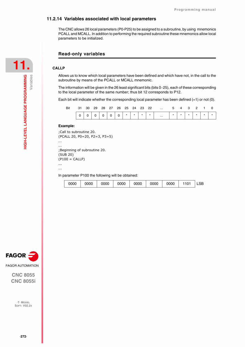
·272·
Programming manual
CNC 8055CNC 8055i
11.
HIG
H-L
EV
EL
LA
NG
UA
GE
PR
OG
RA
MM
ING
·T· MODELSOFT: V02.2X
Var
iabl
es
11.2.14 Variables associated with local parameters
The CNC allows 26 local parameters (P0-P25) to be assigned to a subroutine, by using mnemonicsPCALL and MCALL. In addition to performing the required subroutine these mnemonics allow localparameters to be initialized.
Read-only variables
CALLP
Allows us to know which local parameters have been defined and which have not, in the call to thesubroutine by means of the PCALL or MCALL mnemonic.
The information will be given in the 26 least significant bits (bits 0··25), each of these correspondingto the local parameter of the same number; thus bit 12 corresponds to P12.
Each bit will indicate whether the corresponding local parameter has been defined (=1) or not (0).
Example:
;Call to subroutine 20.(PCALL 20, P0=20, P2=3, P3=5)......;Beginning of subroutine 20.(SUB 20)(P100 = CALLP)......
In parameter P100 the following will be obtained:
Bit 31 30 29 28 27 26 25 24 23 22 ... 5 4 3 2 1 0
0 0 0 0 0 0 * * * * ... * * * * * *
0000 0000 0000 0000 0000 0000 0000 1101 LSB
Programming manual
CNC 8055CNC 8055i
HIG
H-L
EV
EL
LA
NG
UA
GE
PR
OG
RA
MM
ING
11.
·T· MODELSOFT: V02.2X
·273·
Var
iabl
es
11.2.15 Sercos variables
They are used in the data exchange via Sercos between the CNC and the drives.
Read-only variables
TSVAR(X-C) TSVARS TSSVAR
It returns the third attribute of the Sercos variable corresponding to the "identifier". The third attributeis used in particular software applications and its information is coded according to the Sercosstandard.
TSVAR(X-C) identifier ... for the axes.
TSVARS identifier ... for the main spindle.
TSSVAR identifier ... for the second spindle.
Write variables
SETGE(X-C) SETGES SSETGS
The drive may have up to 8 gear ratios (0 through 7). Sercos identifier 218, GearRatioPreselection.
I t may a lso have up to 8 parameter sets (0 th rough 7) . Sercos ident i f ie r 217,ParameterSetPreselection.
With these variables the work range or gear ratio and the parameter set of each drive may bemodified.
SETGE(X-C) ... for the axes.
SETGES ... for the main spindle.
SSETGS ... for the second spindle
The 4 least significant bits of these variables indicate the gear ratio and the other 4 the parameterset to be selected.
Read-and-write variables
SVAR(X-C) SVARS SSVARS
They permit reading or modifying the value of the Sercos variable corresponding to the axis identifier.
SVAR(X-C) identifier ... for the axes.
SVARS identifier ... for the main spindle.
SSVARS identifier ... for the second spindle.
(P110=SVARX 40)It assigns to parameter P110 the third attribute of the Sercos variable of identifier 40 of the X axis which corresponds to "VelocityFeedback"
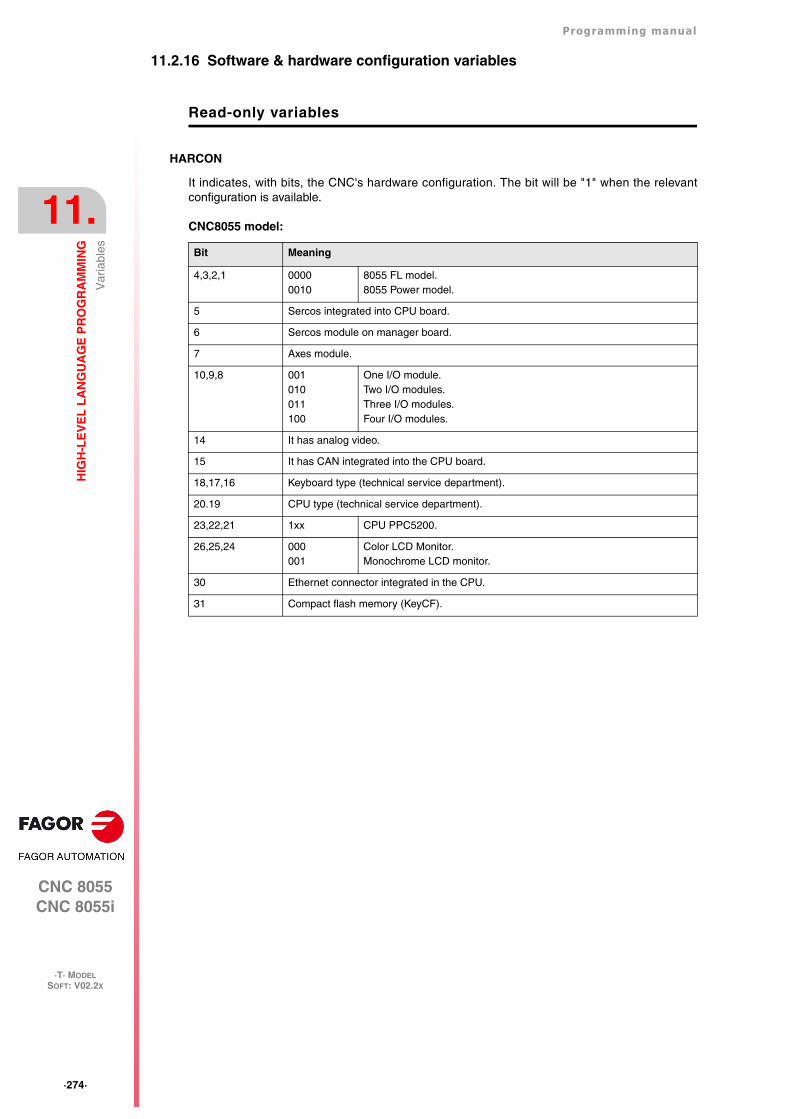
·274·
Programming manual
CNC 8055CNC 8055i
11.
HIG
H-L
EV
EL
LA
NG
UA
GE
PR
OG
RA
MM
ING
·T· MODELSOFT: V02.2X
Var
iabl
es
11.2.16 Software & hardware configuration variables
Read-only variables
HARCON
It indicates, with bits, the CNC's hardware configuration. The bit will be "1" when the relevantconfiguration is available.
CNC8055 model:
Bit Meaning
4,3,2,1 00000010
8055 FL model.8055 Power model.
5 Sercos integrated into CPU board.
6 Sercos module on manager board.
7 Axes module.
10,9,8 001010011100
One I/O module.Two I/O modules.Three I/O modules.Four I/O modules.
14 It has analog video.
15 It has CAN integrated into the CPU board.
18,17,16 Keyboard type (technical service department).
20.19 CPU type (technical service department).
23,22,21 1xx CPU PPC5200.
26,25,24 000001
Color LCD Monitor.Monochrome LCD monitor.
30 Ethernet connector integrated in the CPU.
31 Compact flash memory (KeyCF).
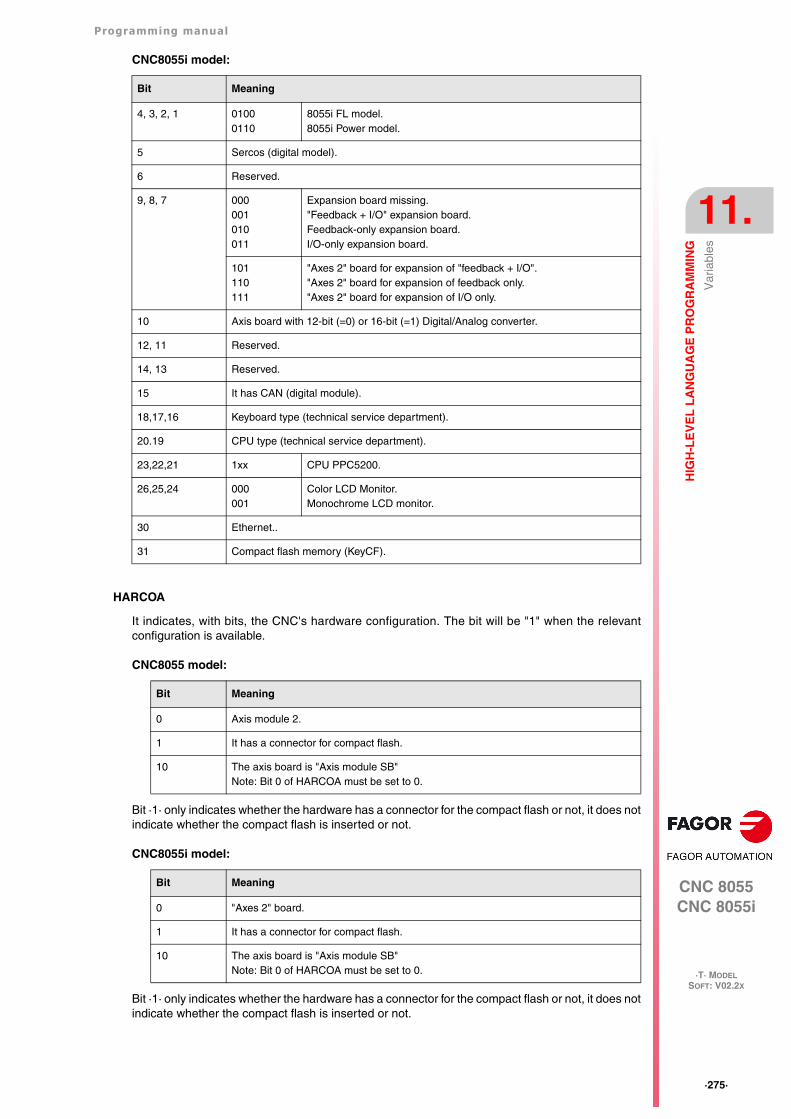
Programming manual
CNC 8055CNC 8055i
HIG
H-L
EV
EL
LA
NG
UA
GE
PR
OG
RA
MM
ING
11.
·T· MODELSOFT: V02.2X
·275·
Var
iabl
es
CNC8055i model:
HARCOA
It indicates, with bits, the CNC's hardware configuration. The bit will be "1" when the relevantconfiguration is available.
CNC8055 model:
Bit ·1· only indicates whether the hardware has a connector for the compact flash or not, it does notindicate whether the compact flash is inserted or not.
CNC8055i model:
Bit ·1· only indicates whether the hardware has a connector for the compact flash or not, it does notindicate whether the compact flash is inserted or not.
Bit Meaning
4, 3, 2, 1 01000110
8055i FL model.8055i Power model.
5 Sercos (digital model).
6 Reserved.
9, 8, 7 000001010011
Expansion board missing."Feedback + I/O" expansion board.Feedback-only expansion board.I/O-only expansion board.
101110111
"Axes 2" board for expansion of "feedback + I/O"."Axes 2" board for expansion of feedback only."Axes 2" board for expansion of I/O only.
10 Axis board with 12-bit (=0) or 16-bit (=1) Digital/Analog converter.
12, 11 Reserved.
14, 13 Reserved.
15 It has CAN (digital module).
18,17,16 Keyboard type (technical service department).
20.19 CPU type (technical service department).
23,22,21 1xx CPU PPC5200.
26,25,24 000001
Color LCD Monitor.Monochrome LCD monitor.
30 Ethernet..
31 Compact flash memory (KeyCF).
Bit Meaning
0 Axis module 2.
1 It has a connector for compact flash.
10 The axis board is "Axis module SB"Note: Bit 0 of HARCOA must be set to 0.
Bit Meaning
0 "Axes 2" board.
1 It has a connector for compact flash.
10 The axis board is "Axis module SB"Note: Bit 0 of HARCOA must be set to 0.
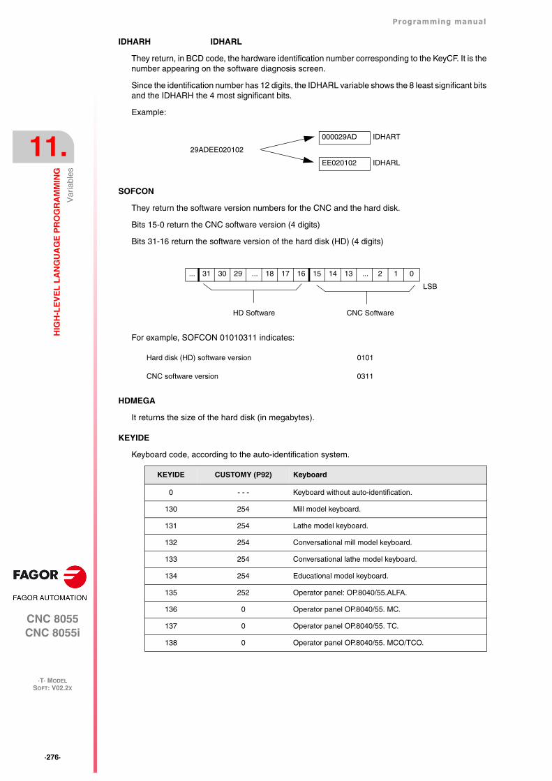
·276·
Programming manual
CNC 8055CNC 8055i
11.
HIG
H-L
EV
EL
LA
NG
UA
GE
PR
OG
RA
MM
ING
·T· MODELSOFT: V02.2X
Var
iabl
es
IDHARH IDHARL
They return, in BCD code, the hardware identification number corresponding to the KeyCF. It is thenumber appearing on the software diagnosis screen.
Since the identification number has 12 digits, the IDHARL variable shows the 8 least significant bitsand the IDHARH the 4 most significant bits.
Example:
SOFCON
They return the software version numbers for the CNC and the hard disk.
Bits 15-0 return the CNC software version (4 digits)
Bits 31-16 return the software version of the hard disk (HD) (4 digits)
For example, SOFCON 01010311 indicates:
HDMEGA
It returns the size of the hard disk (in megabytes).
KEYIDE
Keyboard code, according to the auto-identification system.
000029AD IDHART
29ADEE020102
EE020102 IDHARL
Hard disk (HD) software version 0101
CNC software version 0311
... 31 30 29 ... 18 17 16 15 14 13 ... 2 1 0
LSB
HD Software CNC Software
KEYIDE CUSTOMY (P92) Keyboard
0 - - - Keyboard without auto-identification.
130 254 Mill model keyboard.
131 254 Lathe model keyboard.
132 254 Conversational mill model keyboard.
133 254 Conversational lathe model keyboard.
134 254 Educational model keyboard.
135 252 Operator panel: OP.8040/55.ALFA.
136 0 Operator panel OP.8040/55. MC.
137 0 Operator panel OP.8040/55. TC.
138 0 Operator panel OP.8040/55. MCO/TCO.
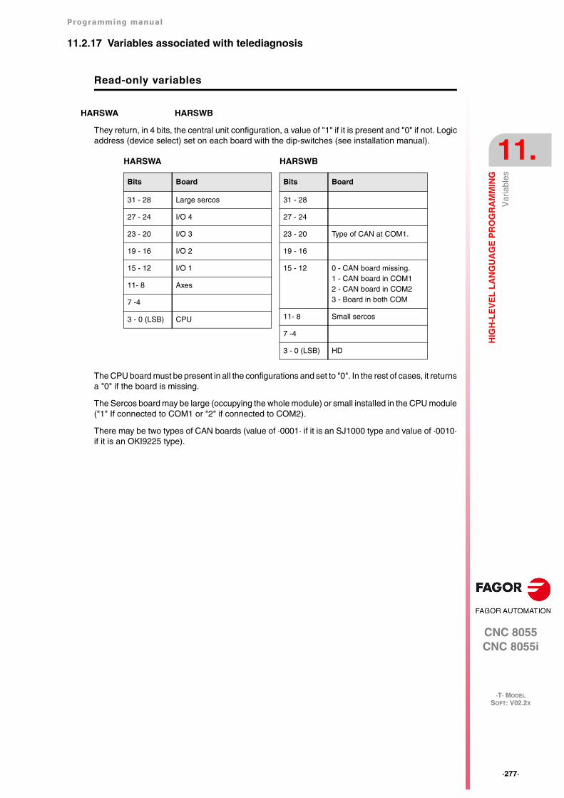
Programming manual
CNC 8055CNC 8055i
HIG
H-L
EV
EL
LA
NG
UA
GE
PR
OG
RA
MM
ING
11.
·T· MODELSOFT: V02.2X
·277·
Var
iabl
es
11.2.17 Variables associated with telediagnosis
Read-only variables
HARSWA HARSWB
They return, in 4 bits, the central unit configuration, a value of "1" if it is present and "0" if not. Logicaddress (device select) set on each board with the dip-switches (see installation manual).
The CPU board must be present in all the configurations and set to "0". In the rest of cases, it returnsa "0" if the board is missing.
The Sercos board may be large (occupying the whole module) or small installed in the CPU module("1" If connected to COM1 or "2" if connected to COM2).
There may be two types of CAN boards (value of ·0001· if it is an SJ1000 type and value of ·0010·if it is an OKI9225 type).
HARSWB
Bits Board
31 - 28
27 - 24
23 - 20 Type of CAN at COM1.
19 - 16
15 - 12 0 - CAN board missing.1 - CAN board in COM12 - CAN board in COM23 - Board in both COM
11- 8 Small sercos
7 -4
3 - 0 (LSB) HD
HARSWA
Bits Board
31 - 28 Large sercos
27 - 24 I/O 4
23 - 20 I/O 3
19 - 16 I/O 2
15 - 12 I/O 1
11- 8 Axes
7 -4
3 - 0 (LSB) CPU
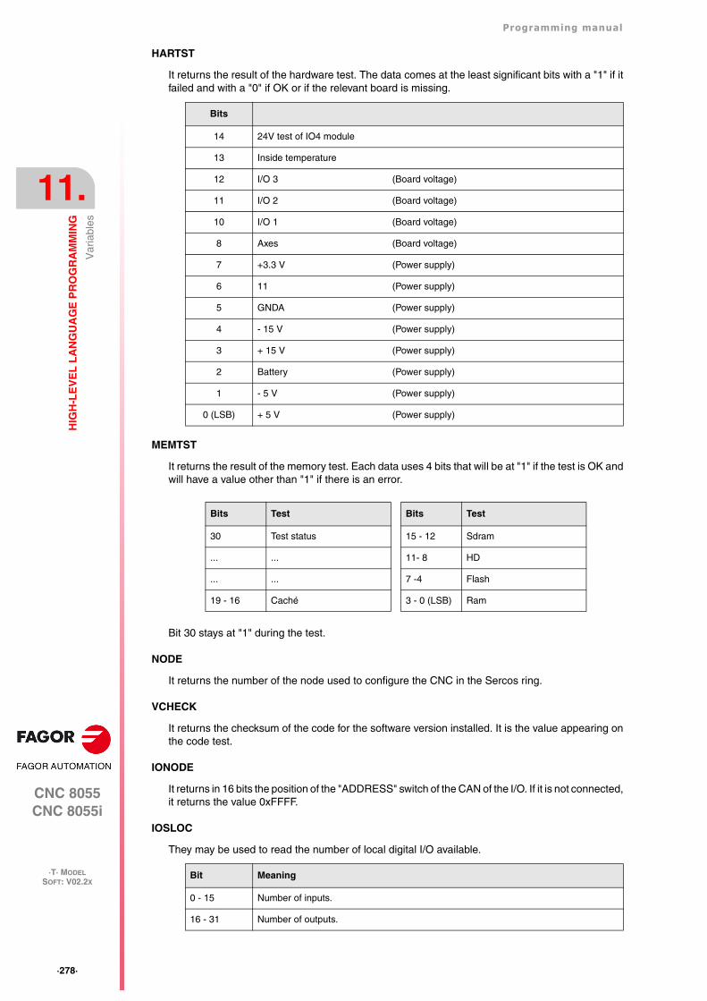
·278·
Programming manual
CNC 8055CNC 8055i
11.
HIG
H-L
EV
EL
LA
NG
UA
GE
PR
OG
RA
MM
ING
·T· MODELSOFT: V02.2X
Var
iabl
es
HARTST
It returns the result of the hardware test. The data comes at the least significant bits with a "1" if itfailed and with a "0" if OK or if the relevant board is missing.
MEMTST
It returns the result of the memory test. Each data uses 4 bits that will be at "1" if the test is OK andwill have a value other than "1" if there is an error.
Bit 30 stays at "1" during the test.
NODE
It returns the number of the node used to configure the CNC in the Sercos ring.
VCHECK
It returns the checksum of the code for the software version installed. It is the value appearing onthe code test.
IONODE
It returns in 16 bits the position of the "ADDRESS" switch of the CAN of the I/O. If it is not connected,it returns the value 0xFFFF.
IOSLOC
They may be used to read the number of local digital I/O available.
Bits
14 24V test of IO4 module
13 Inside temperature
12 I/O 3 (Board voltage)
11 I/O 2 (Board voltage)
10 I/O 1 (Board voltage)
8 Axes (Board voltage)
7 +3.3 V (Power supply)
6 11 (Power supply)
5 GNDA (Power supply)
4 - 15 V (Power supply)
3 + 15 V (Power supply)
2 Battery (Power supply)
1 - 5 V (Power supply)
0 (LSB) + 5 V (Power supply)
Bits Test
30 Test status
... ...
... ...
19 - 16 Caché
Bits Test
15 - 12 Sdram
11- 8 HD
7 -4 Flash
3 - 0 (LSB) Ram
Bit Meaning
0 - 15 Number of inputs.
16 - 31 Number of outputs.
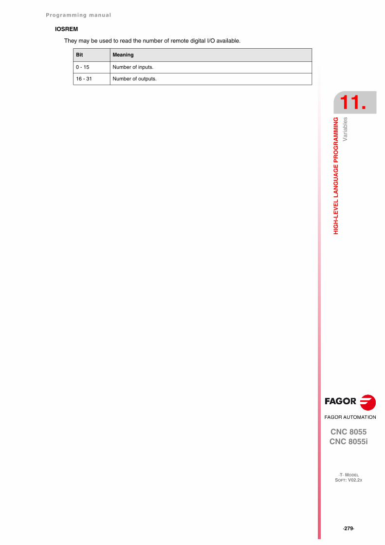
Programming manual
CNC 8055CNC 8055i
HIG
H-L
EV
EL
LA
NG
UA
GE
PR
OG
RA
MM
ING
11.
·T· MODELSOFT: V02.2X
·279·
Var
iabl
es
IOSREM
They may be used to read the number of remote digital I/O available.
Bit Meaning
0 - 15 Number of inputs.
16 - 31 Number of outputs.
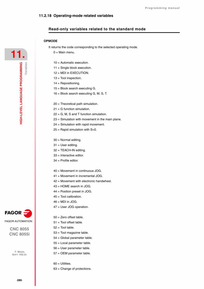
·280·
Programming manual
CNC 8055CNC 8055i
11.
HIG
H-L
EV
EL
LA
NG
UA
GE
PR
OG
RA
MM
ING
·T· MODELSOFT: V02.2X
Var
iabl
es
11.2.18 Operating-mode related variables
Read-only variables related to the standard mode
OPMODE
It returns the code corresponding to the selected operating mode.
0 = Main menu.
10 = Automatic execution.
11 = Single block execution.
12 = MDI in EXECUTION.
13 = Tool inspection.
14 = Repositioning.
15 = Block search executing G.
16 = Block search executing G, M, S, T.
20 = Theoretical path simulation.
21 = G function simulation.
22 = G, M, S and T function simulation.
23 = Simulation with movement in the main plane.
24 = Simulation with rapid movement.
25 = Rapid simulation with S=0.
30 = Normal editing.
31 = User editing.
32 = TEACH-IN editing.
33 = Interactive editor.
34 = Profile editor.
40 = Movement in continuous JOG.
41 = Movement in incremental JOG.
42 = Movement with electronic handwheel.
43 = HOME search in JOG.
44 = Position preset in JOG.
45 = Tool calibration.
46 = MDI in JOG.
47 = User JOG operation.
50 = Zero offset table.
51 = Tool offset table.
52 = Tool table.
53 = Tool magazine table.
54 = Global parameter table.
55 = Local parameter table.
56 = User parameter table.
57 = OEM parameter table.
60 = Utilities.
63 = Change of protections.
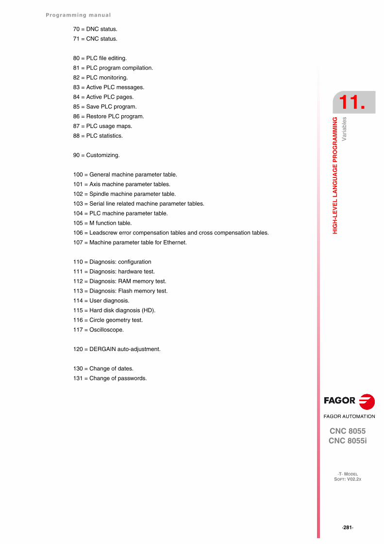
Programming manual
CNC 8055CNC 8055i
HIG
H-L
EV
EL
LA
NG
UA
GE
PR
OG
RA
MM
ING
11.
·T· MODELSOFT: V02.2X
·281·
Var
iabl
es
70 = DNC status.
71 = CNC status.
80 = PLC file editing.
81 = PLC program compilation.
82 = PLC monitoring.
83 = Active PLC messages.
84 = Active PLC pages.
85 = Save PLC program.
86 = Restore PLC program.
87 = PLC usage maps.
88 = PLC statistics.
90 = Customizing.
100 = General machine parameter table.
101 = Axis machine parameter tables.
102 = Spindle machine parameter table.
103 = Serial line related machine parameter tables.
104 = PLC machine parameter table.
105 = M function table.
106 = Leadscrew error compensation tables and cross compensation tables.
107 = Machine parameter table for Ethernet.
110 = Diagnosis: configuration
111 = Diagnosis: hardware test.
112 = Diagnosis: RAM memory test.
113 = Diagnosis: Flash memory test.
114 = User diagnosis.
115 = Hard disk diagnosis (HD).
116 = Circle geometry test.
117 = Oscilloscope.
120 = DERGAIN auto-adjustment.
130 = Change of dates.
131 = Change of passwords.
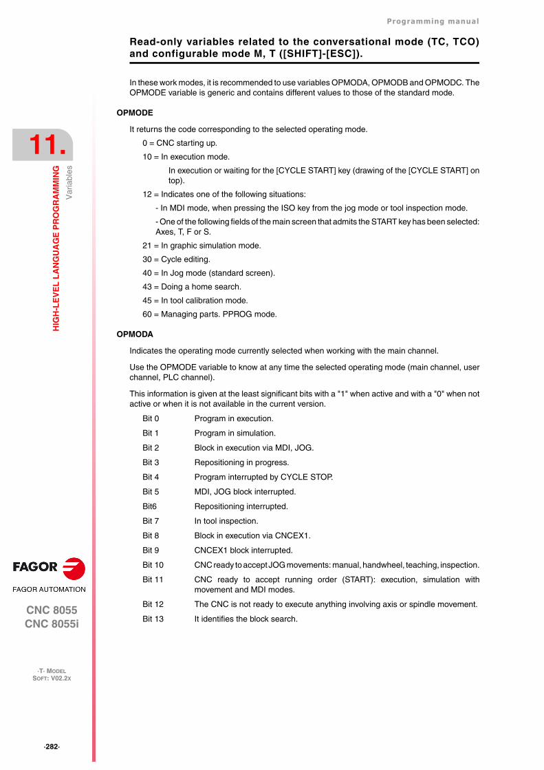
·282·
Programming manual
CNC 8055CNC 8055i
11.
HIG
H-L
EV
EL
LA
NG
UA
GE
PR
OG
RA
MM
ING
·T· MODELSOFT: V02.2X
Var
iabl
es
Read-only variables related to the conversational mode (TC, TCO)and configurable mode M, T ([SHIFT]-[ESC]).
In these work modes, it is recommended to use variables OPMODA, OPMODB and OPMODC. TheOPMODE variable is generic and contains different values to those of the standard mode.
OPMODE
It returns the code corresponding to the selected operating mode.
0 = CNC starting up.
10 = In execution mode.
In execution or waiting for the [CYCLE START] key (drawing of the [CYCLE START] ontop).
12 = Indicates one of the following situations:
- In MDI mode, when pressing the ISO key from the jog mode or tool inspection mode.
- One of the following fields of the main screen that admits the START key has been selected:Axes, T, F or S.
21 = In graphic simulation mode.
30 = Cycle editing.
40 = In Jog mode (standard screen).
43 = Doing a home search.
45 = In tool calibration mode.
60 = Managing parts. PPROG mode.
OPMODA
Indicates the operating mode currently selected when working with the main channel.
Use the OPMODE variable to know at any time the selected operating mode (main channel, userchannel, PLC channel).
This information is given at the least significant bits with a "1" when active and with a "0" when notactive or when it is not available in the current version.
Bit 0 Program in execution.
Bit 1 Program in simulation.
Bit 2 Block in execution via MDI, JOG.
Bit 3 Repositioning in progress.
Bit 4 Program interrupted by CYCLE STOP.
Bit 5 MDI, JOG block interrupted.
Bit6 Repositioning interrupted.
Bit 7 In tool inspection.
Bit 8 Block in execution via CNCEX1.
Bit 9 CNCEX1 block interrupted.
Bit 10 CNC ready to accept JOG movements: manual, handwheel, teaching, inspection.
Bit 11 CNC ready to accept running order (START): execution, simulation withmovement and MDI modes.
Bit 12 The CNC is not ready to execute anything involving axis or spindle movement.
Bit 13 It identifies the block search.
Programming manual
CNC 8055CNC 8055i
HIG
H-L
EV
EL
LA
NG
UA
GE
PR
OG
RA
MM
ING
11.
·T· MODELSOFT: V02.2X
·283·
Var
iabl
es
OPMODB
Indicates the type of simulation currently selected. This information is given at the least significantbits indicating with a "1" the one currently selected.
Bit 0 Theoretical path.
Bit 1 G functions.
Bit 2 G M S T functions.
Bit 3
Bit 4 Rapid.
Bit 5 Rapid (S=0).
OPMODC
Indicates the axes selected by handwheel. This information is given at the least significant bitsindicating with a "1" the one currently selected.
Bit 0 Axis 1.
Bit 1 Axis 2.
Bit 2 Axis 3.
Bit 3 Axis 4.
Bit 4 Axis 5.
Bit 5 Axis 6.
Bit 6 Axis 7.
Bit 7
Bit 8
The axis name corresponds to the number according to the programming order for them.
Example: If the CNC controls axes X, Y, Z, U, B, C, axis 1=X, axis2=Y, axis3=Z, axis4=U, axis5=B,axis6=C.
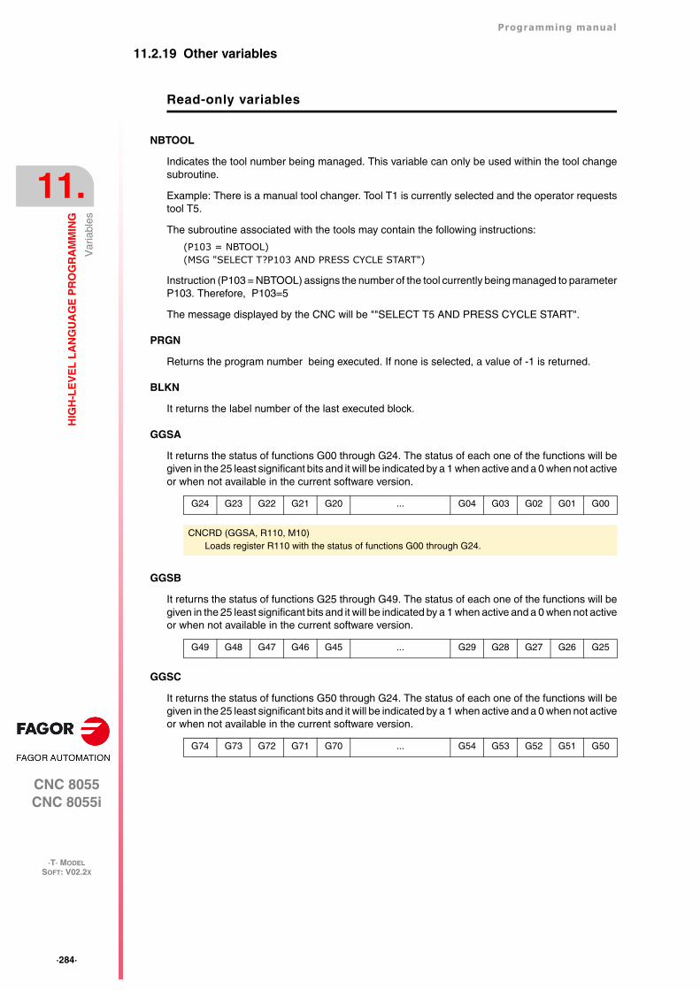
·284·
Programming manual
CNC 8055CNC 8055i
11.
HIG
H-L
EV
EL
LA
NG
UA
GE
PR
OG
RA
MM
ING
·T· MODELSOFT: V02.2X
Var
iabl
es
11.2.19 Other variables
Read-only variables
NBTOOL
Indicates the tool number being managed. This variable can only be used within the tool changesubroutine.
Example: There is a manual tool changer. Tool T1 is currently selected and the operator requeststool T5.
The subroutine associated with the tools may contain the following instructions:
(P103 = NBTOOL)(MSG "SELECT T?P103 AND PRESS CYCLE START")
Instruction (P103 = NBTOOL) assigns the number of the tool currently being managed to parameterP103. Therefore, P103=5
The message displayed by the CNC will be ""SELECT T5 AND PRESS CYCLE START".
PRGN
Returns the program number being executed. If none is selected, a value of -1 is returned.
BLKN
It returns the label number of the last executed block.
GGSA
It returns the status of functions G00 through G24. The status of each one of the functions will begiven in the 25 least significant bits and it will be indicated by a 1 when active and a 0 when not activeor when not available in the current software version.
GGSB
It returns the status of functions G25 through G49. The status of each one of the functions will begiven in the 25 least significant bits and it will be indicated by a 1 when active and a 0 when not activeor when not available in the current software version.
GGSC
It returns the status of functions G50 through G24. The status of each one of the functions will begiven in the 25 least significant bits and it will be indicated by a 1 when active and a 0 when not activeor when not available in the current software version.
G24 G23 G22 G21 G20 ... G04 G03 G02 G01 G00
CNCRD (GGSA, R110, M10)Loads register R110 with the status of functions G00 through G24.
G49 G48 G47 G46 G45 ... G29 G28 G27 G26 G25
G74 G73 G72 G71 G70 ... G54 G53 G52 G51 G50
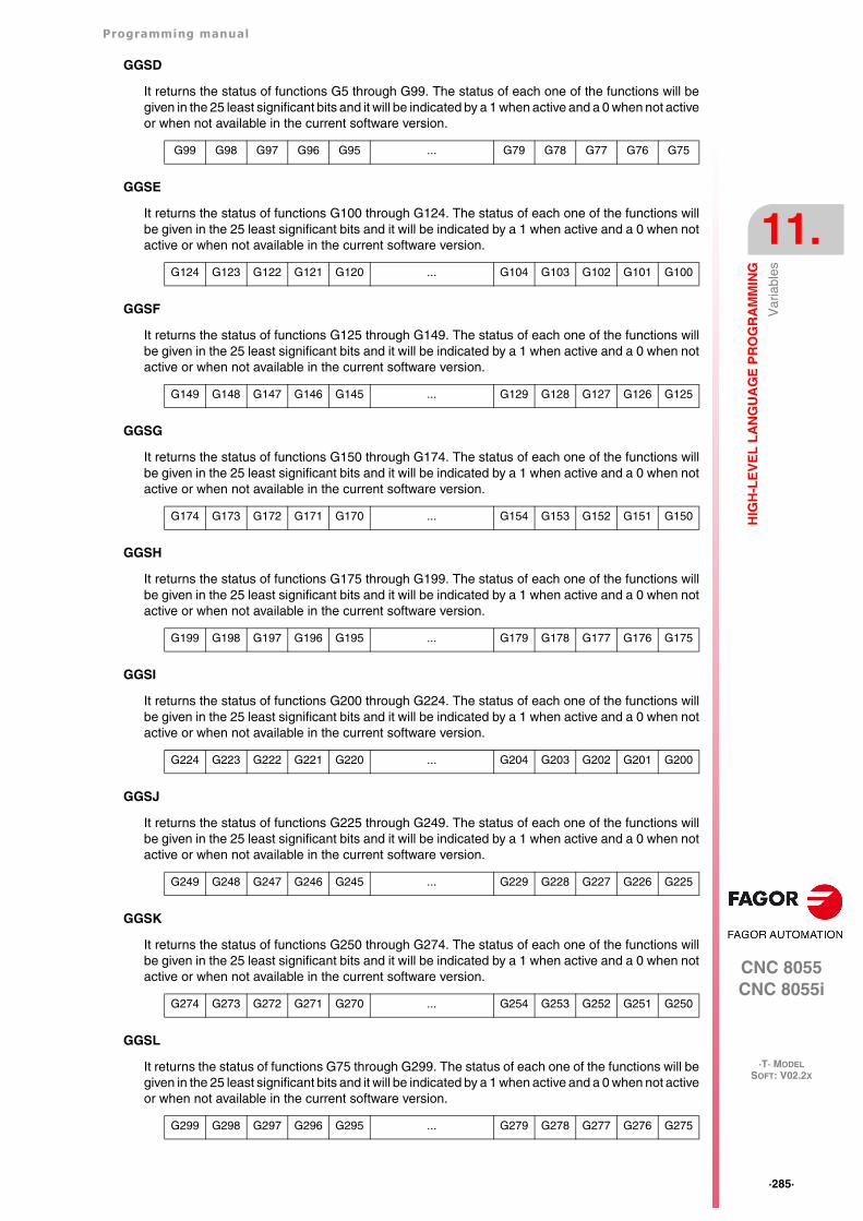
Programming manual
CNC 8055CNC 8055i
HIG
H-L
EV
EL
LA
NG
UA
GE
PR
OG
RA
MM
ING
11.
·T· MODELSOFT: V02.2X
·285·
Var
iabl
es
GGSD
It returns the status of functions G5 through G99. The status of each one of the functions will begiven in the 25 least significant bits and it will be indicated by a 1 when active and a 0 when not activeor when not available in the current software version.
GGSE
It returns the status of functions G100 through G124. The status of each one of the functions willbe given in the 25 least significant bits and it will be indicated by a 1 when active and a 0 when notactive or when not available in the current software version.
GGSF
It returns the status of functions G125 through G149. The status of each one of the functions willbe given in the 25 least significant bits and it will be indicated by a 1 when active and a 0 when notactive or when not available in the current software version.
GGSG
It returns the status of functions G150 through G174. The status of each one of the functions willbe given in the 25 least significant bits and it will be indicated by a 1 when active and a 0 when notactive or when not available in the current software version.
GGSH
It returns the status of functions G175 through G199. The status of each one of the functions willbe given in the 25 least significant bits and it will be indicated by a 1 when active and a 0 when notactive or when not available in the current software version.
GGSI
It returns the status of functions G200 through G224. The status of each one of the functions willbe given in the 25 least significant bits and it will be indicated by a 1 when active and a 0 when notactive or when not available in the current software version.
GGSJ
It returns the status of functions G225 through G249. The status of each one of the functions willbe given in the 25 least significant bits and it will be indicated by a 1 when active and a 0 when notactive or when not available in the current software version.
GGSK
It returns the status of functions G250 through G274. The status of each one of the functions willbe given in the 25 least significant bits and it will be indicated by a 1 when active and a 0 when notactive or when not available in the current software version.
GGSL
It returns the status of functions G75 through G299. The status of each one of the functions will begiven in the 25 least significant bits and it will be indicated by a 1 when active and a 0 when not activeor when not available in the current software version.
G99 G98 G97 G96 G95 ... G79 G78 G77 G76 G75
G124 G123 G122 G121 G120 ... G104 G103 G102 G101 G100
G149 G148 G147 G146 G145 ... G129 G128 G127 G126 G125
G174 G173 G172 G171 G170 ... G154 G153 G152 G151 G150
G199 G198 G197 G196 G195 ... G179 G178 G177 G176 G175
G224 G223 G222 G221 G220 ... G204 G203 G202 G201 G200
G249 G248 G247 G246 G245 ... G229 G228 G227 G226 G225
G274 G273 G272 G271 G270 ... G254 G253 G252 G251 G250
G299 G298 G297 G296 G295 ... G279 G278 G277 G276 G275
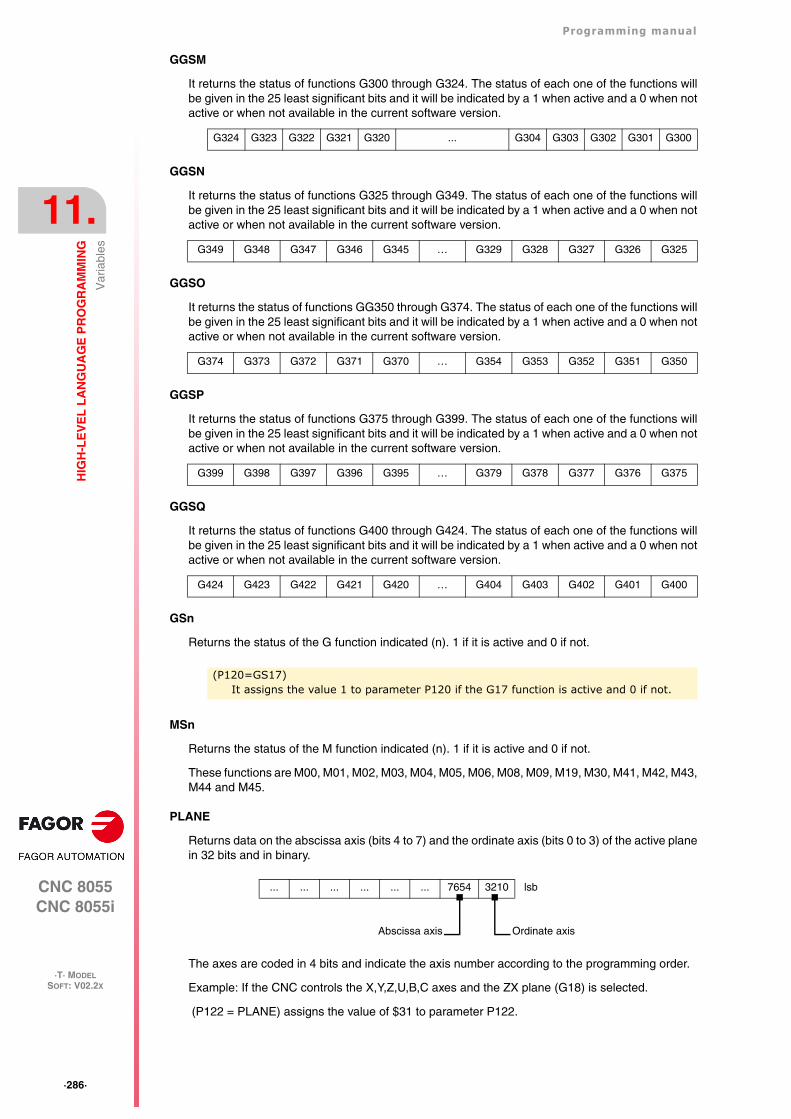
·286·
Programming manual
CNC 8055CNC 8055i
11.
HIG
H-L
EV
EL
LA
NG
UA
GE
PR
OG
RA
MM
ING
·T· MODELSOFT: V02.2X
Var
iabl
es
GGSM
It returns the status of functions G300 through G324. The status of each one of the functions willbe given in the 25 least significant bits and it will be indicated by a 1 when active and a 0 when notactive or when not available in the current software version.
GGSN
It returns the status of functions G325 through G349. The status of each one of the functions willbe given in the 25 least significant bits and it will be indicated by a 1 when active and a 0 when notactive or when not available in the current software version.
GGSO
It returns the status of functions GG350 through G374. The status of each one of the functions willbe given in the 25 least significant bits and it will be indicated by a 1 when active and a 0 when notactive or when not available in the current software version.
GGSP
It returns the status of functions G375 through G399. The status of each one of the functions willbe given in the 25 least significant bits and it will be indicated by a 1 when active and a 0 when notactive or when not available in the current software version.
GGSQ
It returns the status of functions G400 through G424. The status of each one of the functions willbe given in the 25 least significant bits and it will be indicated by a 1 when active and a 0 when notactive or when not available in the current software version.
GSn
Returns the status of the G function indicated (n). 1 if it is active and 0 if not.
MSn
Returns the status of the M function indicated (n). 1 if it is active and 0 if not.
These functions are M00, M01, M02, M03, M04, M05, M06, M08, M09, M19, M30, M41, M42, M43,M44 and M45.
PLANE
Returns data on the abscissa axis (bits 4 to 7) and the ordinate axis (bits 0 to 3) of the active planein 32 bits and in binary.
The axes are coded in 4 bits and indicate the axis number according to the programming order.
Example: If the CNC controls the X,Y,Z,U,B,C axes and the ZX plane (G18) is selected.
(P122 = PLANE) assigns the value of $31 to parameter P122.
G324 G323 G322 G321 G320 ... G304 G303 G302 G301 G300
G349 G348 G347 G346 G345 … G329 G328 G327 G326 G325
G374 G373 G372 G371 G370 … G354 G353 G352 G351 G350
G399 G398 G397 G396 G395 … G379 G378 G377 G376 G375
G424 G423 G422 G421 G420 … G404 G403 G402 G401 G400
(P120=GS17)It assigns the value 1 to parameter P120 if the G17 function is active and 0 if not.
... ... ... ... ... ... 7654 3210 lsb
Ordinate axisAbscissa axis
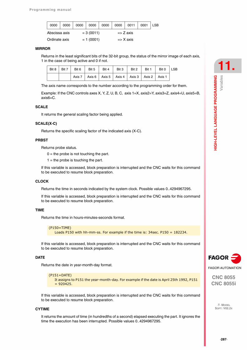
Programming manual
CNC 8055CNC 8055i
HIG
H-L
EV
EL
LA
NG
UA
GE
PR
OG
RA
MM
ING
11.
·T· MODELSOFT: V02.2X
·287·
Var
iabl
es
Abscissa axis = 3 (0011) => Z axis
Ordinate axis = 1 (0001) => X axis
MIRROR
Returns in the least significant bits of the 32-bit group, the status of the mirror image of each axis,1 in the case of being active and 0 if not.
The axis name corresponds to the number according to the programming order for them.
Example: If the CNC controls axes X, Y, Z, U, B, C, axis 1=X, axis2=Y, axis3=Z, axis4=U, axis5=B,axis6=C.
SCALE
It returns the general scaling factor being applied.
SCALE(X-C)
Returns the specific scaling factor of the indicated axis (X-C).
PRBST
Returns probe status.
0 = the probe is not touching the part.
1 = the probe is touching the part.
If this variable is accessed, block preparation is interrupted and the CNC waits for this commandto be executed to resume block preparation.
CLOCK
Returns the time in seconds indicated by the system clock. Possible values 0..4294967295.
If this variable is accessed, block preparation is interrupted and the CNC waits for this commandto be executed to resume block preparation.
TIME
Returns the time in hours-minutes-seconds format.
If this variable is accessed, block preparation is interrupted and the CNC waits for this commandto be executed to resume block preparation.
DATE
Returns the date in year-month-day format.
If this variable is accessed, block preparation is interrupted and the CNC waits for this commandto be executed to resume block preparation.
CYTIME
It returns the amount of time (in hundredths of a second) elapsed executing the part. It ignores thetime the execution has been interrupted. Possible values 0..4294967295.
0000 0000 0000 0000 0000 0000 0011 0001 LSB
Bit 8 Bit 7 Bit 6 Bit 5 Bit 4 Bit 3 Bit 2 Bit 1 Bit 0 LSB
Axis 7 Axis 6 Axis 5 Axis 4 Axis 3 Axis 2 Axis 1
(P150=TIME)Loads P150 with hh-mm-ss. For example if the time is: 34sec. P150 = 182234.
(P151=DATE)It assigns to P151 the year-month-day. For example if the date is April 25th 1992, P151 = 920425.
·288·
Programming manual
CNC 8055CNC 8055i
11.
HIG
H-L
EV
EL
LA
NG
UA
GE
PR
OG
RA
MM
ING
·T· MODELSOFT: V02.2X
Var
iabl
es
If this variable is accessed, block preparation is interrupted and the CNC waits for this commandto be executed to resume block preparation.
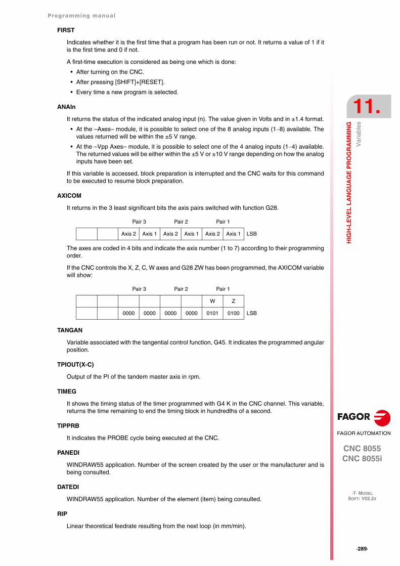
Programming manual
CNC 8055CNC 8055i
HIG
H-L
EV
EL
LA
NG
UA
GE
PR
OG
RA
MM
ING
11.
·T· MODELSOFT: V02.2X
·289·
Var
iabl
es
FIRST
Indicates whether it is the first time that a program has been run or not. It returns a value of 1 if itis the first time and 0 if not.
A first-time execution is considered as being one which is done:
• After turning on the CNC.
• After pressing [SHIFT]+[RESET].
• Every time a new program is selected.
ANAIn
It returns the status of the indicated analog input (n). The value given in Volts and in ±1.4 format.
• At the –Axes– module, it is possible to select one of the 8 analog inputs (1··8) available. Thevalues returned will be within the ±5 V range.
• At the –Vpp Axes– module, it is possible to select one of the 4 analog inputs (1··4) available.The returned values will be either within the ±5 V or ±10 V range depending on how the analoginputs have been set.
If this variable is accessed, block preparation is interrupted and the CNC waits for this commandto be executed to resume block preparation.
AXICOM
It returns in the 3 least significant bits the axis pairs switched with function G28.
The axes are coded in 4 bits and indicate the axis number (1 to 7) according to their programmingorder.
If the CNC controls the X, Z, C, W axes and G28 ZW has been programmed, the AXICOM variablewill show:
TANGAN
Variable associated with the tangential control function, G45. It indicates the programmed angularposition.
TPIOUT(X-C)
Output of the PI of the tandem master axis in rpm.
TIMEG
It shows the timing status of the timer programmed with G4 K in the CNC channel. This variable,returns the time remaining to end the timing block in hundredths of a second.
TIPPRB
It indicates the PROBE cycle being executed at the CNC.
PANEDI
WINDRAW55 application. Number of the screen created by the user or the manufacturer and isbeing consulted.
DATEDI
WINDRAW55 application. Number of the element (item) being consulted.
RIP
Linear theoretical feedrate resulting from the next loop (in mm/min).
Pair 3 Pair 2 Pair 1
Axis 2 Axis 1 Axis 2 Axis 1 Axis 2 Axis 1 LSB
Pair 3 Pair 2 Pair 1
W Z
0000 0000 0000 0000 0101 0100 LSB
·290·
Programming manual
CNC 8055CNC 8055i
11.
HIG
H-L
EV
EL
LA
NG
UA
GE
PR
OG
RA
MM
ING
·T· MODELSOFT: V02.2X
Var
iabl
es
The calculation of the resulting feedrate ignores the rotary axes, slave axes (gantry, coupled andsynchronized) as well as DRO axes.
TEMPIn
It returns the temperature in tenths of a degree detected by the PT100. It is possible to select oneof the 4 temperature inputs (1··4) available.
Read-and-write variables
TIMER
This variable allows reading or modifying the time, in seconds, indicated by the clock enabled bythe PLC. Possible values 0..4294967295.
If this variable is accessed, block preparation is interrupted and the CNC waits for this commandto be executed to resume block preparation.
PARTC
The CNC has a part counter whose count increases, in all modes except simulation, every time M30or M02 is executed and this variable allows its value to be read or modified. This value will be between0 and 4294967295
If this variable is accessed, block preparation is interrupted and the CNC waits for this commandto be executed to resume block preparation.
KEY
Returns the code of the last key accepted.
This variable may be used as a write variable only inside a customizing program (user channel).
If this variable is accessed, block preparation is interrupted and the CNC waits for this commandto be executed to resume block preparation.
KEYSRC
This variable allows reading or modifying the source of keystrokes, possible values being:
0 = Keyboard.
1 = PLC.
2 = DNC.
The CNC only allows modification of this variable if this is at 0.
ANAOn
This variable allows the required analog output (n) to be read or modified. The value assigned willbe expressed in volts and in the ±2.4 format (±10 V).
The analog outputs which are free among the eight (1 through 8) available at the CNC may bemodified, the corresponding error being displayed if an attempt is made to write in one which isoccupied.
If this variable is accessed, block preparation is interrupted and the CNC waits for this commandto be executed to resume block preparation.
SELPRO
When having two probe inputs, it allows selecting the active input.
On power-up, it assumes the value of ·1· thus selecting the first probe input. To select the secondprobe input, set it to a value of ·2·.
Accessing this variable from the CNC interrupts block preparation.
DIAM
It changes the programming mode for X axis coordinates between radius and diameter. Whenchanging the value of this variable, the CNC assumes the new way to program the following blocks.
Programming manual
CNC 8055CNC 8055i
HIG
H-L
EV
EL
LA
NG
UA
GE
PR
OG
RA
MM
ING
11.
·T· MODELSOFT: V02.2X
·291·
Var
iabl
es
When the variable is set to ·1·, the programmed coordinates are assumed in diameter; when is setto ·0·, the programmed coordinates are assumed in radius.
This variable affects the display of the real value of the X axis in the coordinate system of the partand the reading of variables PPOSX, TPOSX and POSX.
On power-up, after executing an M02 or M30 and after an emergency or a reset, the variable isinitialized according to the value of the DFORMAT parameter of the X axis. If this parameter hasa value equal to or greater than 4, the variable takes a value of 1; otherwise, it takes the value of ·0·.
PRBMOD
It indicates whether a probing error is to issued or not in the following cases, even if general machineparameter PROBERR (P119) =YES.
• When a G75 probing move finishes before the probe has touched part.
• When a G76 probing move finishes but the probe is still touching the part.
The PRBMOD variable takes the following values.
The PRBMOD variable can be read and written from the CNC and the PLC an read from the DNC.
DISABMOD
This variable is used to disable some actions or modes by setting the corresponding bit value to1. This variable may be written from the PLC and read from the PLC, DNC and CNC.
The following table shows the meaning of each bit:
CYCCHORDERR
This variable defines the chordal error of the canned cycles. It may be read and written from thepart-program.
The CYCCHORDERR variable lets modify the chordal error of the cycles so the user can increaseor decrease it for the parts as needed.
Using this variable is necessary, for example, on parts with curved areas using the 3D pocket cycle.On these parts, if the radius is very large, the segments are noticeable. The parts get better bydecreasing the chordal error.
Using this variable, the user can decrease the chordal error on the part as needed. Decreasing thechordal error can increase machining time.
Once the value of this variable has been changed, it remains active until the CNC is turned off.
Default value of the CYCCHORDERR variable (250 tenths of a micron).
Value Meaning
0 An error message is issued.
1 No error message is issued.
Default value 0.
Bit Meaning
0 If 1, the PLC program cannot be displayed. The PLC in ladder (contacts) diagram cannotbe displayed either.
1 If 1, the date cannot be changed, although it displays the access softkey. It is valid forthe explorer and for "UTILITIES".
2 If 1, the passwords cannot be changed. The passwords cannot be seen or changedalthough it displays the access softkey. It is valid for the explorer and for "UTILITIES".
·292·
Programming manual
CNC 8055CNC 8055i
11.
HIG
H-L
EV
EL
LA
NG
UA
GE
PR
OG
RA
MM
ING
·T· MODELSOFT: V02.2X
Var
iabl
es
Programming example:
It is recommended to use a CYCCHORDERR value of 25 tenths of a micron. This value improvespart finish and it does not increase machining time too much.
(CYCCHORDERR = 25)(PCALL 9986, P200=0)M30
Programming manual
CNC 8055CNC 8055i
HIG
H-L
EV
EL
LA
NG
UA
GE
PR
OG
RA
MM
ING
11.
·T· MODELSOFT: V02.2X
·293·
CO
NS
TA
NT
S
11.3 CONSTANTS
Constants are defined as being all those fixed values which cannot be altered by a program. Thefollowing are considered as constants:
• Numbers expressed in the decimal system.
• Hexadecimal numbers.
• PI constant.
• Read-only tables and variables as their value cannot be altered with a program.
·294·
Programming manual
CNC 8055CNC 8055i
11.
HIG
H-L
EV
EL
LA
NG
UA
GE
PR
OG
RA
MM
ING
·T· MODELSOFT: V02.2X
Ope
rato
rs
11.4 Operators
An operator is a symbol that indicates the mathematical or logic operations to carry out. The CNChas arithmetic, relational, logic, binary, trigonometric operators and special operators.
Arithmetic operators.
Relational operators.
Logic and binary operators.
NOT, OR, AND, XOR: The act as logic operators between conditions and as binary operatorsbetween variables and constants.
IF (FIRST AND GS1 EQ 1) GOTO N100P5 = (P1 AND (NOT P2 OR P3))
Trigonometric functions.
There are two functions for calculating the arc tangent ATAN which returns the result between ±90°and ARG given between 0 and 360°.
+ add. P1=3 + 4 P1=7
- subtraction, also a negative value. P2=5 - 2P3= -(2 * 3)
P2=3P3=-6
* multiplication. P4=2 * 3 P4=6
/ division. P5=9 / 2 P5=4.5
MOD Module or remainder of the division. P6=7 MOD 4 P6=3
EXP exponential. P7=2 EXP 3 P7=8
EQ equal.
NE different.
GT greater than.
GE greater than or equal to.
LT Less than.
LE Less than or equal to.
SIN sine. P1=SIN 30 P1=0.5
COS cosine. P2=COS 30 P2=0.8660
TAN tangent. P3=TAN 30 P3=0.5773
ASIN arc sine. P4=ASIN 1 P4=90
ACOS arc cosine. P5=ACOS 1 P5=0
ATAN arc tangent. P6=ATAN 1 P6=45
ARG ARG(x,y) arctangent y/x. P7=ARG(-1,-2) P7=243.4349
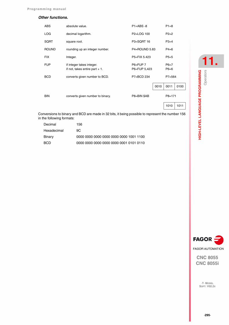
Programming manual
CNC 8055CNC 8055i
HIG
H-L
EV
EL
LA
NG
UA
GE
PR
OG
RA
MM
ING
11.
·T· MODELSOFT: V02.2X
·295·
Ope
rato
rs
Other functions.
Conversions to binary and BCD are made in 32 bits, it being possible to represent the number 156in the following formats:
Decimal 156
Hexadecimal 9C
Binary 0000 0000 0000 0000 0000 0000 1001 1100
BCD 0000 0000 0000 0000 0000 0001 0101 0110
ABS absolute value. P1=ABS -8 P1=8
LOG decimal logarithm. P2=LOG 100 P2=2
SQRT square root. P3=SQRT 16 P3=4
ROUND rounding up an integer number. P4=ROUND 5.83 P4=6
FIX Integer. P5=FIX 5.423 P5=5
FUP if integer takes integer.if not, takes entire part + 1.
P6=FUP 7P6=FUP 5,423
P6=7P6=6
BCD converts given number to BCD. P7=BCD 234 P7=564
0010 0011 0100
BIN converts given number to binary. P8=BIN $AB P8=171
1010 1011
·296·
Programming manual
CNC 8055CNC 8055i
11.
HIG
H-L
EV
EL
LA
NG
UA
GE
PR
OG
RA
MM
ING
·T· MODELSOFT: V02.2X
Exp
ress
ions
11.5 Expressions
An expression is any valid combination of operators, constants, parameters and variables.
All expressions must be placed between brackets, but if the expression is reduced to an integer,the brackets can be removed.
11.5.1 Arithmetic expressions
These are formed by combining functions and arithmetic, binary and trigonometric operators withthe constants and variables of the language.
The priorities of the operators and the way they can be associated determine how these expressionsare calculated:
Brackets should be used in order to clarify the order in which the expression is to be evaluated.
(P3 = P4/P5 - P6 * P7 - P8/P9 )(P3 = (P4/P5)-(P6 * P7)-(P8/P9))
Using redundant or additional brackets will neither cause errors nor slow down the execution.
In functions, brackets must be used except when these are applied to a numerical constant, in whichcase they are optional.
(SIN 45) (SIN (45)) these are both valid and equivalent.(SIN 10+5) the same as ((SIN 10)+5).
Expressions can be used also to reference parameters and tables:
(P100 = P9)(P100 = P(P7))(P100 = P(P8 + SIN(P8 * 20)))(P100 = ORGX 55)(P100 = ORGX (12+P9))(PLCM5008 = PLCM5008 OR 1)
; Selects single block execution mode (M5008=1)(PLCM5010 = PLCM5010 AND $FFFFFFFE)
; Frees feedrate override (M5010=0)
Priority from highest to lowest To be associated
NOT, functions, - (negative) from right to left.
EXP, MOD from left to right.
* , / from left to right.
+,- (add, subtract) from left to right.
Relational operators from left to right.
AND, XOR from left to right.
OR from left to right.
Programming manual
CNC 8055CNC 8055i
HIG
H-L
EV
EL
LA
NG
UA
GE
PR
OG
RA
MM
ING
11.
·T· MODELSOFT: V02.2X
·297·
Exp
ress
ions
11.5.2 Relational expressions
These are arithmetic expressions joined by relational operators.
(IF (P8 EQ 12.8); It checks if the value of P8 is equal to 12.8.
(IF (ABS(SIN(P24)) GT SPEED);Analyzes if the sine is greater than the spindle speed.
(IF (CLOCK LT (P9 * 10.99)); Analyzes if the clock count is less than (P9 * 10.99)
At the same time these conditions can be joined by means of logic operators.
(IF ((P8 EQ 12.8) OR (ABS(SIN(P24)) GT SPEED)) AND (CLOCK LT (P9 * 10.99)) ...
The result of these expressions is either true or false.
·298·
Programming manual
CNC 8055CNC 8055i
11.
HIG
H-L
EV
EL
LA
NG
UA
GE
PR
OG
RA
MM
ING
·T· MODELSOFT: V02.2X
Exp
ress
ions
CNC 8055CNC 8055i
·T· MODELSOFT: V02.2X
12
·299·
PROGRAM CONTROL INSTRUCTIONS
The control instructions available to high-level programming can be grouped as follows:
• Assignment instructions.
• Display instructions.
• Enable-disable instructions.
• Flow control instructions.
• Subroutine instructions.
• Probe related instructions.
• Interruption-subroutine instructions.
• Program instructions.
• Screen customizing instructions.
Only one instruction can be programmed in each block, and no other additional information maybe programmed in this block.
·300·
Programming manual
CNC 8055CNC 8055i
12.
PR
OG
RA
M C
ON
TR
OL
INS
TR
UC
TIO
NS
·T· MODELSOFT: V02.2X
Ass
ignm
ent i
nstr
uctio
ns
12.1 Assignment instructions
This is the simplest type of instruction and can be defined as:
(target = arithmetic expression)
A local or global parameter or a read-write variable may be selected as target. The arithmeticexpression may be as complex as required or a simple numerical constant.
(P102 = FZLOX)(ORGX 55 = (ORGX 54 + P100))
In the specific case of designating a local parameter using its name (A instead of P0, for example)and the arithmetic expression being a numerical constant, the instruction can be abbreviated asfollows:
(P0=13.7) ==> (A=13.7) ==> (A13.7)
Within a single block, up to 26 assignments can be made to different targets, a single assignmentbeing interpreted as the set of assignments made to the same target.
(P1=P1+P2, P1=P1+P3, P1=P1*P4, P1=P1/P5)It is the same as saying:
(P1=(P1+P2+P3)*P4/P5).
The different assignments which are made in the same block will be separated by commas ",".
Programming manual
CNC 8055CNC 8055i
PR
OG
RA
M C
ON
TR
OL
INS
TR
UC
TIO
NS
12.
·T· MODELSOFT: V02.2X
·301·
Dis
play
inst
ruct
ions
12.2 Display instructions
(ERROR integer, "error text")
This instruction stops the execution of the program and displays the indicated error, it being possibleto select this error in the following ways:
(ERROR integer)
This will display the error number indicated and the text associated to this number accordingto the CNC error code (should there be one).
(ERROR integer, "error text")
This will display the number and the error text indicated, it being necessary to write the textbetween quote marks "".
(ERROR "error text").
This will display the error text only.
The error number may be defined by means of a numerical constant or an arithmetic parameter.When using a local parameter, its numeric format must be used (P0 thru P25 instead of A thru Z).
Programming examples:
(ERROR 5)
(ERROR P100)
(ERROR "User error")
(ERROR 3, "User error")
(ERROR P120, "User error)
(MSG "message")
This instruction will display the message indicated between quote marks.
The CNC screen is provided with an area for displaying DNC or user program messages, and alwaysdisplays the last message received irrespective of where it has come from.
Example: (MSG "Check tool")
( DGWZ expression 1, expression 2, expression 3, expression 4 )
The DGWZ instruction (Define Graphic Work Zone) defines the graphics area.
Each expression forming the instruction syntax correspond to one of the limits and they must bedefined in millimeters or inches.
expression 1 Z minimum
expression 2 Z maximum
expression 3 Inside radius or inside diameter.
expression 4 Outside radius or outside diameter.
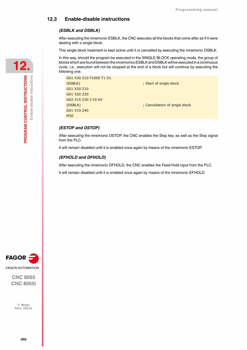
·302·
Programming manual
CNC 8055CNC 8055i
12.
PR
OG
RA
M C
ON
TR
OL
INS
TR
UC
TIO
NS
·T· MODELSOFT: V02.2X
Ena
ble-
disa
ble
inst
ruct
ions
12.3 Enable-disable instructions
(ESBLK and DSBLK)
After executing the mnemonic ESBLK, the CNC executes all the blocks that come after as if it weredealing with a single block.
This single block treatment is kept active until it is cancelled by executing the mnemonic DSBLK.
In this way, should the program be executed in the SINGLE BLOCK operating mode, the group ofblocks which are found between the mnemonics ESBLK and DSBLK will be executed in a continuouscycle, i.e., execution will not be stopped at the end of a block but will continue by executing thefollowing one.
(ESTOP and DSTOP)
After executing the mnemonic DSTOP, the CNC enables the Stop key, as well as the Stop signalfrom the PLC.
It will remain disabled until it is enabled once again by means of the mnemonic ESTOP.
(EFHOLD and DFHOLD)
After executing the mnemonic DFHOLD, the CNC enables the Feed-Hold input from the PLC.
It will remain disabled until it is enabled once again by means of the mnemonic EFHOLD.
G01 X30 Z10 F1000 T1 D1(ESBLK) ; Start of single blockG01 X20 Z10G01 X20 Z20G02 X10 Z30 I-10 K0(DSBLK) ; Cancellation of single blockG01 X10 Z40M30
Programming manual
CNC 8055CNC 8055i
PR
OG
RA
M C
ON
TR
OL
INS
TR
UC
TIO
NS
12.
·T· MODELSOFT: V02.2X
·303·
Flo
w c
ontr
ol in
stru
ctio
ns
12.4 Flow control instructions
The GOTO and RPT instructions cannot be used in programs that are executed from a PC connectedthrough the serial lines.
( GOTO N(expression) )
The mnemonic GOTO causes a jump within the same program, to the block defined by the labelN(expression). The execution of the program will continue after the jump, from the indicated block.
The jump label can be addressed by means of a number or by any expression which results in anumber.
( RPT N(expression), N(expression), P(expression) )
The mnemonic RPT executes the part of the program between the blocks defined by means of thelabels N(expression). The blocks to be executed may be in the execution program or in a RAMmemory program.
The label P(expression) indicates the number of the program containing the blocks to be executed.If not defined, the CNC interprets that the portion to be repeated is located in the same program.
All the labels can be indicated by means of a number or by any expression which results in a number.The part of the program selected by means of the two labels must belong to the same program, byfirst defining the initial block and then the final block.
The execution of the program will continue in the block following the one in which the mnemonicRPT was programmed, once the selected part of the program has been executed.
(IF condition <action1> ELSE <action2>)
This instruction analyzes the given condition that must be a relational expression. If the conditionis true (result equal to 1), <action1> will be executed, otherwise (result equal to 0) <action2> willbe executed.
Example:
(IF (P8 EQ 12.8) CALL 3 ELSE PCALL 5, A2, B5, D8)If P8 = 12.8 executes the mnemonic (CALL3)If P8<>12.8 executes the mnemonic (PCALL 5, A2, B5, D8)
G00 X30 Z10 T2 D4X30 Z20(GOTO N22) ; Jump instructionX20 Z20 ; It is not executedX20 Z10 ; It is not executed
N22 G01 X10 Z10 F1000 ; Continues execution in this blockG02 X0 Z40 I-105 K0...
N10 G00 X10Z20G01 X5G00 Z0
N20 X0N30 (RPT N10, N20) N3N40 G01 X20
M30When reaching block N30, the program will execute section N10-N20 three times. Once this has been completed, the program will continue execution in block N40.
Since the RPT instruction does not interrupt block preparation or tool compensation, it may be usedwhen using the EXEC instruction and while needing to maintain tool compensation active.i
·304·
Programming manual
CNC 8055CNC 8055i
12.
PR
OG
RA
M C
ON
TR
OL
INS
TR
UC
TIO
NS
·T· MODELSOFT: V02.2X
Flo
w c
ontr
ol in
stru
ctio
ns
The instruction can lack the ELSE part, i.e., it will be enough to program IF condition <action1>.
Example:
(IF (P8 EQ 12.8) CALL 3)
Both <action1> and <action2> can be expressions or instructions, except for mnemonics IF andSUB.
Due to the fact that in a high level block local parameters can be named by means of letters,expressions of this type can be obtained:
(IF (E EQ 10) M10)
If the condition of parameter P5 (E) having a value of 10 is met, the miscellaneous function M10will not be executed, since a high level block cannot have ISO code commands. In this case M10represents the assignment of value 10 to parameter P12, i.e., one can program either:
(IF (E EQ 10) M10) ó (IF (P5 EQ 10) P12=10)
Programming manual
CNC 8055CNC 8055i
PR
OG
RA
M C
ON
TR
OL
INS
TR
UC
TIO
NS
12.
·T· MODELSOFT: V02.2X
·305·
Sub
rout
ine
inst
ruct
ions
12.5 Subroutine instructions
A subroutine is a part of a program which, being properly identified, can be called from any positionof a program to be executed.
A subroutine can be kept in the memory of the CNC as an independent part of a program and becalled one or several times, from different positions of a program or different programs.
Only subroutines stored in the CNC's RAM memory can be executed. Therefore, to execute asubroutine stored in the hard disk (KeyCF) or in a PC connected through the serial line, copy it firstinto the CNC's RAM memory.
If the subroutine is too large to be copied into RAM, it must be converted into a program and thenthe EXEC instruction must be used.
(SUB integer)
The SUB instruction defines as subroutine the set of program blocks programmed next until reachingthe RET subroutine. The subroutine is identified with an integer which also defines the type ofsubroutine; either general or OEM.
The OEM subroutines are treated like the general ones, but with the following restrictions:
• They can only be defined in OEM programs, having the [O] attribute. Otherwise, the CNC willdisplay the corresponding error.
Error 63: Program subroutine number 1 thru 9999.
• To execute an OEM subroutine using CALL, PCALL or MCALL, it must be inside an OEMprogram. Otherwise, the CNC will display the corresponding error.
Error 1255: Subroutine restricted to an OEM program.
There can not be two subroutines with the same identification number in the CNC memory, evenwhen they belong to different programs.
( RET )
The mnemonic RET indicates that the subroutine which was defined by the mnemonic SUB, finishesin this block.
Range of general subroutines SUB 0000 - SUB 9999
Range of OEM (manufacturer's) subroutines SUB 10000 - SUB 20000
(SUB 12) ; Definition of subroutine 12G91 G01 XP0 F5000ZP1XP0ZP1(RET) ; End of subroutine
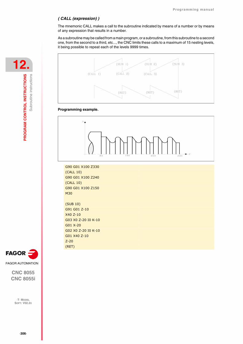
·306·
Programming manual
CNC 8055CNC 8055i
12.
PR
OG
RA
M C
ON
TR
OL
INS
TR
UC
TIO
NS
·T· MODELSOFT: V02.2X
Sub
rout
ine
inst
ruct
ions
( CALL (expression) )
The mnemonic CALL makes a call to the subroutine indicated by means of a number or by meansof any expression that results in a number.
As a subroutine may be called from a main program, or a subroutine, from this subroutine to a secondone, from the second to a third, etc..., the CNC limits these calls to a maximum of 15 nesting levels,it being possible to repeat each of the levels 9999 times.
Programming example.
G90 G01 X100 Z330(CALL 10)G90 G01 X100 Z240(CALL 10)G90 G01 X100 Z150M30
(SUB 10)G91 G01 Z-10X40 Z-10G03 X0 Z-20 I0 K-10G01 X-20G02 X0 Z-20 I0 K-10G01 X40 Z-10Z-20(RET)
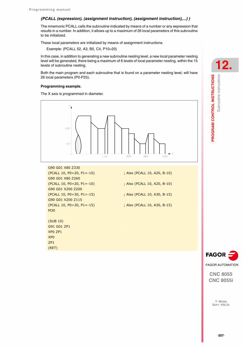
Programming manual
CNC 8055CNC 8055i
PR
OG
RA
M C
ON
TR
OL
INS
TR
UC
TIO
NS
12.
·T· MODELSOFT: V02.2X
·307·
Sub
rout
ine
inst
ruct
ions
(PCALL (expression), (assignment instruction), (assignment instruction),...) )
The mnemonic PCALL calls the subroutine indicated by means of a number or any expression thatresults in a number. In addition, it allows up to a maximum of 26 local parameters of this subroutineto be initialized.
These local parameters are initialized by means of assignment instructions.
Example: (PCALL 52, A3, B5, C4, P10=20)
In this case, in addition to generating a new subroutine nesting level, a new local parameter nestinglevel will be generated, there being a maximum of 6 levels of local parameter nesting, within the 15levels of subroutine nesting.
Both the main program and each subroutine that is found on a parameter nesting level, will have26 local parameters (P0-P25).
Programming example.
The X axis is programmed in diameter.
G90 G01 X80 Z330(PCALL 10, P0=20, P1=-10) ; Also (PCALL 10, A20, B-10)G90 G01 X80 Z260(PCALL 10, P0=20, P1=-10) ; Also (PCALL 10, A20, B-10)G90 G01 X200 Z200(PCALL 10, P0=30, P1=-15) ; Also (PCALL 10, A30, B-15)G90 G01 X200 Z115(PCALL 10, P0=30, P1=-15) ; Also (PCALL 10, A30, B-15)M30
(SUB 10)G91 G01 ZP1XP0 ZP1XP0ZP1(RET)
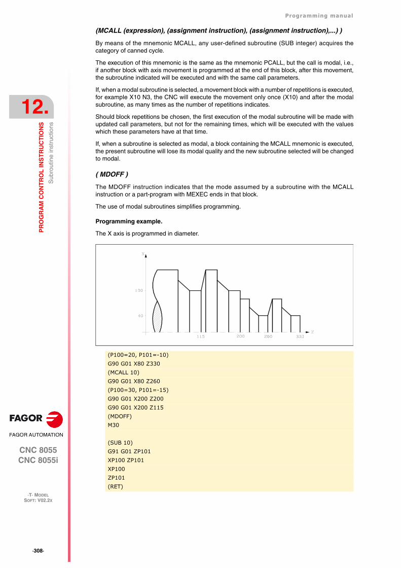
·308·
Programming manual
CNC 8055CNC 8055i
12.
PR
OG
RA
M C
ON
TR
OL
INS
TR
UC
TIO
NS
·T· MODELSOFT: V02.2X
Sub
rout
ine
inst
ruct
ions
(MCALL (expression), (assignment instruction), (assignment instruction),...) )
By means of the mnemonic MCALL, any user-defined subroutine (SUB integer) acquires thecategory of canned cycle.
The execution of this mnemonic is the same as the mnemonic PCALL, but the call is modal, i.e.,if another block with axis movement is programmed at the end of this block, after this movement,the subroutine indicated will be executed and with the same call parameters.
If, when a modal subroutine is selected, a movement block with a number of repetitions is executed,for example X10 N3, the CNC will execute the movement only once (X10) and after the modalsubroutine, as many times as the number of repetitions indicates.
Should block repetitions be chosen, the first execution of the modal subroutine will be made withupdated call parameters, but not for the remaining times, which will be executed with the valueswhich these parameters have at that time.
If, when a subroutine is selected as modal, a block containing the MCALL mnemonic is executed,the present subroutine will lose its modal quality and the new subroutine selected will be changedto modal.
( MDOFF )
The MDOFF instruction indicates that the mode assumed by a subroutine with the MCALLinstruction or a part-program with MEXEC ends in that block.
The use of modal subroutines simplifies programming.
Programming example.
The X axis is programmed in diameter.
(P100=20, P101=-10)G90 G01 X80 Z330(MCALL 10)G90 G01 X80 Z260(P100=30, P101=-15)G90 G01 X200 Z200G90 G01 X200 Z115(MDOFF)M30
(SUB 10)G91 G01 ZP101XP100 ZP101XP100ZP101(RET)
Programming manual
CNC 8055CNC 8055i
PR
OG
RA
M C
ON
TR
OL
INS
TR
UC
TIO
NS
12.
·T· MODELSOFT: V02.2X
·309·
Sub
rout
ine
inst
ruct
ions
12.5.1 Calls to subroutines using G functions
Subroutine calls are made using the CALL and PCALL instructions. In addition to using thesestatements, it is also possible to make subroutine calls using specific G functions. This way, the callsto subroutines are more similar to machine tool language.
Functions G180-G189 and G380-G399 can call the associated OEM and user subroutine as longas they are global subroutines. G functions cannot be used to call local subroutines.
Up to 30 subroutines may be defined and associated with functions G180-G189 and G380-G399,and it is also possible to initialize local parameters for each subroutine.
When executing one of these functions, its associated subroutine will be executed.
Functions G180-G189 and G380-G399 are not modal.
Programming format
The programming format is the following:
G180 <P0..Pn><P0..Pn> Optional. Initializing parameters.
Example:
G183 P1=12.3 P2=6G187 A12.3 B45.3 P10=6
Defining local parameters.
The values of the parameters are defined after the call function and they may be defined using thename of the parameter (P0-P25) or using letters (A-Z) so "A" is the same as P0 and "Z" is the sameas P25.
Plus, parameters may also be programmed as follows:
• S=P100
• SP100
In either case, local parameter P18(S) would assume the established global parameter value P100.
The definitions described here may be combined in the same block.
Nesting levels
If the functions initialize local parameters, this instruction generates a new nesting level .
The maximum parameter nesting level is 6, within the 15 nesting level of the subroutines, just likePCALL instructions.
Identification via PLC
All the G functions are identified through GGS* read-only variables . GGSH and GGSP read-onlyvariables are used to identify the new G functions via PLC; these variables return the status of theG functions.
Executing a call
Each function G180-G189 and G380-G399, has its corresponding subroutine associated with it.Calling a G function means calling the subroutine of the same name.
·310·
Programming manual
CNC 8055CNC 8055i
12.
PR
OG
RA
M C
ON
TR
OL
INS
TR
UC
TIO
NS
·T· MODELSOFT: V02.2X
Pro
be r
elat
ed in
stru
ctio
ns
12.6 Probe related instructions
(PROBE (expression), (assignment instruction), (assignment instruction),...) )
The mnemonic PROBE calls the probe cycle indicated by means of a number or any expressionthat results in a number. In addition, it allows the local parameters of this subroutine to be initializedby means of assignment instructions.
This instruction also generates a new subroutine nesting level.
Programming manual
CNC 8055CNC 8055i
PR
OG
RA
M C
ON
TR
OL
INS
TR
UC
TIO
NS
12.
·T· MODELSOFT: V02.2X
·311·
Inte
rrup
tion-
subr
outin
e in
stru
ctio
ns
12.7 Interruption-subroutine instructions
Whenever one of the general interruption logic input is activated, "INT1" (M5024), "INT2" (M5025),"INT3" (M5026) or "INT4 (M5027), the CNC temporarily interrupts the execution of the program inprogress and starts executing the interruption subroutine whose number is indicated by thecorresponding general parameter.
With INT1 (M5024) the one indicated by machine parameter INT1SUB (P35)
With INT2 (M5025) the one indicated by machine parameter INT2SUB (P36)
With INT3 (M5026) the one indicated by machine parameter INT3SUB (P37)
With INT4 (M5027) the one indicated by machine parameter INT4SUB (P38)
The interruption subroutines are defined like any other subroutine by using the instructions: "(SUBinteger)" and "(RET)".
These interruption subroutines do not change the nesting level of local parameters, thus only globalparameters must be used in them.
Within an interruption subroutine, it is possible to use the "(REPOS X, Y, Z, ...)" instruction describednext.
Once the execution of the subroutine is over, the CNC resumes the execution of the program whichwas interrupted.
( REPOS X, Y, Z, ... )
The REPOS instruction must always be used inside an interruption subroutine and facilitates therepositioning of the machine axes to the point of interruption.
When executing this instruction, the CNC moves the axes to the point where the program wasinterrupted.
Inside the REPOS instruction, indicate the order the axes must move to the point where the programwas interrupted.
• The axes move one by one.
• It is not necessary to define all the axes, only those to be repositioned.
• The axes that make up the main plane of the machine move together. Both axes need not bedefined because the CNC moves the first one. The movement is not repeated when definingthe second one, it is ignored.
Example:
The main plane is formed by the X and Y axes, the Z axis is the longitudinal (perpendicular) axisand the machine uses the C and W axes as auxiliary axes. It is desired to first move the C axis,then the X and Y axes and finally the Z axis.
This repositioning move may be defined in any of the following ways:
(REPOS C, X, Y, Z)(REPOS C, X, Z)(REPOS C, Y, Z)
If the REPOS instruction is detected while executing a subroutine not activated by an interruptioninput, the CNC will issue the corresponding error message.
·312·
Programming manual
CNC 8055CNC 8055i
12.
PR
OG
RA
M C
ON
TR
OL
INS
TR
UC
TIO
NS
·T· MODELSOFT: V02.2X
Pro
gram
inst
ruct
ions
12.8 Program instructions
With this CNC, from a program in execution, it is possible to:
• Execute another program. Instruction (EXEC P.....)
• Execute another program in modal mode. Instruction (MEXEC P.....)
• Generate a new program. Instruction (OPEN P.....)
• Add blocks to an existing program. Instruction (WRITE P.....)
( EXEC P(expression), (directory) )
The EXEC P instruction executes the part-program of the indicated directory
The part-program may be defined by a number or any expression resulting in a number.
By default, the CNC interprets that the part-program is in the CNC's RAM memory. If it is in anotherdevice, it must be indicated in (directory).
HD in the Hard Disk.
DNC2 in a PC connected through the serial line.
DNCE in a PC connected through Ethernet.
( MEXEC P(expression), (directory) )
The MEXEC instruction executes the part-program of the indicated directory and it also becomesmodal; i.e. if after this block, another one is programmed with axis movement; after this movement,it will execute the indicated program again.
The part-program may be defined with a number or with an expression whose result is a number.
By default, the CNC interprets that the part-program is in the CNC's RAM memory. If it is in anotherdevice, it must be so indicated in (directory):
HD in the Hard Disk.
DNC2 in a PC connected through the serial line.
DNCE in a PC connected through Ethernet.
If while the modal part-program is selected, a motion block is executed with a number of repetitions(for example X10 N3), the CNC ignores the number of repetitions and executes the movement andthe modal part-program only once.
If while a part-program is selected as modal, a block containing the MEXEC instruction is executedfrom the main program, the current part-program stops being modal and the part-program calledupon with MEXEC will then become modal.
If within the modal part-program, an attempt is made to execute a block using the MEXEC instruction,it will issue the relevant error message.
1064: The program cannot be executed.
( MDOFF )
The MDOFF instruction indicates that the mode assumed by a subroutine with the MCALLinstruction or a part-program with MEXEC ends in that block.
( OPEN P(expression), (destination directory), A/D, "program comment" )
The OPEN instruction begins editing a part-program. The part-program number may be indicatedby a number or any expression resulting in a number.
By default, the new part-program edited will be stored in the CNC's RAM memory. To store it anotherdevice, it must be indicated in (destination directory).
HD in the Hard Disk.
DNC2 in a PC connected through the serial line.
DNCE in a PC connected through Ethernet.
Programming manual
CNC 8055CNC 8055i
PR
OG
RA
M C
ON
TR
OL
INS
TR
UC
TIO
NS
12.
·T· MODELSOFT: V02.2X
·313·
Pro
gram
inst
ruct
ions
Parameter A/D is used when the program to be edited already exists.
A The CNC appends the new blocks after the ones already existing.
D The CNC deletes the existing program and starts editing a new one.
A program comment may also be associated with it; this comment will later be displayed next to itin the program directory.
The OPEN instruction allows generating a program from a program already in execution. Thatgenerated program will depend on the values assumed by the program being executed.
To edit blocks, the WRITE instruction must be used as described next.
Notes:
If the program to be edited already exists and the A/D parameters are not defined, the CNC willdisplay an error message when executing the block.
The program opened with the OPEN instruction is closed when executing an M30, or anotherOPEN instruction and after an Emergency or Reset.
From a PC, only programs stored in the CNC'S RAM memory or in the hard disk (HD) can beopened.
( WRITE <block text> )
The mnemonic WRITE adds, after the last block of the program which began to be edited by meansof the mnemonic OPEN P, the information contained in <block text> as a new program block.
When it is an ISO coded parametric block, all the parameters (global and local) are replaced by thenumeric value they have at the time.
(WRITE G1 XP100 ZP101 F100) => G1 X10 Z20 F100
When it is a parametric block edited in high level, use the "?" character to indicate that the parameteris supposed to be replaced by the numeric value it has at the time.
If the mnemonic WRITE is programmed without having programmed the mnemonic OPENpreviously, the CNC will display the corresponding error, except when editing a user customizedprogram, in which case a new block is added to the program being edited.
Using the character "$" in the WRITE instruction to write the number of a parameter:
While using the character "$" in the WRITE instruction, it will be possible to write the parameternumber directly. For that, use the "$" character followed by "P" as long is it is preceded by an axis.
For example, programming (WRITE X$P100) the result will be: XP100.
To show something in $, the value must be programmed after the $ sign. But, to take the value froma parameter, put a space between the "$" sign and the parameter.
In short, these are the options:
• When programmed $P, it will output $P.
• When programmed $[space]P, it will output $[space] and the content of P.
• When programmed $[number], it will output $[number].
(WRITE (SUB P102)) => (SUB P102)(WRITE (SUB ?P102)) => (SUB 55)
(WRITE (ORGX54=P103)) => (ORGX54=P103)(WRITE (ORGX54=?P103)) => (ORGX54=222)
(WRITE (PCALL P104)) => (PCALL P104)(WRITE (PCALL ?P104)) => (PCALL 25)
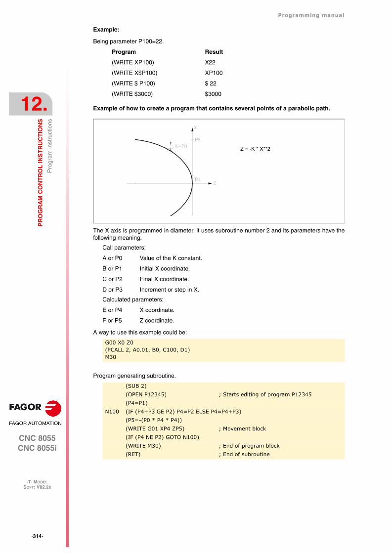
·314·
Programming manual
CNC 8055CNC 8055i
12.
PR
OG
RA
M C
ON
TR
OL
INS
TR
UC
TIO
NS
·T· MODELSOFT: V02.2X
Pro
gram
inst
ruct
ions
Example:
Being parameter P100=22.
Program Result
(WRITE XP100) X22
(WRITE X$P100) XP100
(WRITE $ P100) $ 22
(WRITE $3000) $3000
Example of how to create a program that contains several points of a parabolic path.
The X axis is programmed in diameter, it uses subroutine number 2 and its parameters have thefollowing meaning:
Call parameters:
A or P0 Value of the K constant.
B or P1 Initial X coordinate.
C or P2 Final X coordinate.
D or P3 Increment or step in X.
Calculated parameters:
E or P4 X coordinate.
F or P5 Z coordinate.
A way to use this example could be:
Program generating subroutine.
G00 X0 Z0(PCALL 2, A0.01, B0, C100, D1)M30
(SUB 2)(OPEN P12345) ; Starts editing of program P12345(P4=P1)
N100 (IF (P4+P3 GE P2) P4=P2 ELSE P4=P4+P3)(P5=-(P0 * P4 * P4))(WRITE G01 XP4 ZP5) ; Movement block(IF (P4 NE P2) GOTO N100)(WRITE M30) ; End of program block(RET) ; End of subroutine
Z = -K * X**2
Programming manual
CNC 8055CNC 8055i
PR
OG
RA
M C
ON
TR
OL
INS
TR
UC
TIO
NS
12.
·T· MODELSOFT: V02.2X
·315·
Scr
een
cust
omiz
ing
inst
ruct
ions
12.9 Screen customizing instructions
Customizing instructions may be used only when customizing programs made by the user.
These customizing programs must be stored in the CNC's RAM memory and they may utilize the"Programming Instructions" and they will be executed in the special channel designed for this use;the program selected in each case will be indicated in the following general machine parameters.
In "USERDPLY" the program to be executed in the Execution Mode will be indicated.
In "USEREDIT" the program to be executed in the Editing Mode will be indicated.
In "USERMAN" the program to be executed in the Manual (JOG) Mode will be indicated.
In "USERDIAG" the program to be executed in the Diagnosis Mode will be indicated.
The customizing programs may have up to five nesting levels besides their current one. Also, thecustomizing instructions do not allow local parameters, nevertheless all global parameters may beused to define them.
( PAGE (expression) )
The mnemonic PAGE displays the page number indicated by means of a number or by means ofany expression resulting in a number.
From V02.03 and following versions, the JPG/JPEG formats are supported. This way, if there is an"n.jpg", "n.jpeg" or "n.pan", the screen will display this file. When having several files, the order ofpriorities will be the following:
1. "n.jpg".
2. "n.jpeg".
3. "n.pan".
The format of the JPG/JPEG files must be a 3 digit number. For example "001.jpg" for page 1. Thesize of the page must be 638x335.
User-defined pages will be from page 0 to page 255 and will be defined from the CNC keyboardin the Graphic Editor mode and as indicated in the Operating Manual.
System pages will be defined by a number greater than 1000. See the corresponding appendix.
( SYMBOL (expression 1), (expression 2), (expression 3) )
The mnemonic SYMBOL displays the symbol whose number is indicated by means of the value ofexpression 1 once this has been evaluated.
Its position on screen is also defined by expression 2 (column) and by expression 3 (row).
Expression 1, expression 2 and expression 3 may contain a number or any expression resulting ina number.
From V02.03 and following versions, the PNG format is supported. This way, if there is an "n.png"file, it will be displayed in the position indicated by the expressions 2 and 3. If it is missing, it will displaythe "n.sim" file. The format of the PNG files must be a 3 digit number.
The CNC allows displaying any user-defined symbol (0-255) defined at the CNC keyboard in theGraphic Editor mode such as is indicated in the Operating Manual.
In order to position it within the display area its pixels must be defined, 0-639 for columns (expression2) and 0-335 for rows (expression 3).
(IB (expression) = INPUT "text", format)
The CNC has 26 data entry variables (IBO-1B25)
The IB mnemonic displays the text indicated in the data input window and stores the data input bythe user in the entry variable indicated by means of a number or by means of any expression resultingin a number.
·316·
Programming manual
CNC 8055CNC 8055i
12.
PR
OG
RA
M C
ON
TR
OL
INS
TR
UC
TIO
NS
·T· MODELSOFT: V02.2X
Scr
een
cust
omiz
ing
inst
ruct
ions
The wait for data entry will only occur when programming the format of the requested data. Thisformat may have a sign, integer part and decimal part.
If it bears the "-" sign, it will allow positive and negative values, and if it does not have a sign,it will only allow positive values.
The integer part indicates the maximum number of digits (0-6) desired to the left of the decimalpoint.
The decimal part indicates the maximum number of digits (0-5) desired to the right of the decimalpoint.
If the numerical format is not programmed; for example: (IB1 =INPUT "text"), the mnemonic will onlydisplay the indicated text without waiting for the data to be entered.
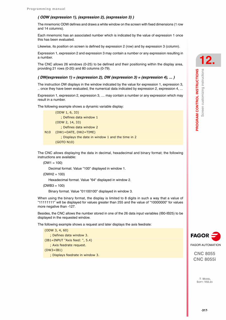
Programming manual
CNC 8055CNC 8055i
PR
OG
RA
M C
ON
TR
OL
INS
TR
UC
TIO
NS
12.
·T· MODELSOFT: V02.2X
·317·
Scr
een
cust
omiz
ing
inst
ruct
ions
( ODW (expression 1), (expression 2), (expression 3) )
The mnemonic ODW defines and draws a white window on the screen with fixed dimensions (1 rowand 14 columns).
Each mnemonic has an associated number which is indicated by the value of expression 1 oncethis has been evaluated.
Likewise, its position on screen is defined by expression 2 (row) and by expression 3 (column).
Expression 1, expression 2 and expression 3 may contain a number or any expression resulting ina number.
The CNC allows 26 windows (0-25) to be defined and their positioning within the display area,providing 21 rows (0-20) and 80 columns (0-79).
( DW(expression 1) = (expression 2), DW (expression 3) = (expression 4), ... )
The instruction DW displays in the window indicated by the value for expression 1, expression 3,.. once they have been evaluated, the numerical data indicated by expression 2, expression 4, ...
Expression 1, expression 2, expression 3, .... may contain a number or any expression which mayresult in a number.
The following example shows a dynamic variable display:
The CNC allows displaying the data in decimal, hexadecimal and binary format; the followinginstructions are available:
(DW1 = 100)
Decimal format. Value "100" displayed in window 1.
(DWH2 = 100)
Hexadecimal format. Value "64" displayed in window 2.
(DWB3 = 100)
Binary format. Value "01100100" displayed in window 3.
When using the binary format, the display is limited to 8 digits in such a way that a value of"11111111" will be displayed for values greater than 255 and the value of "10000000" for valuesmore negative than -127.
Besides, the CNC allows the number stored in one of the 26 data input variables (IB0-IB25) to bedisplayed in the requested window.
The following example shows a request and later displays the axis feedrate:
(ODW 1, 6, 33); Defines data window 1
(ODW 2, 14, 33); Defines data window 2
N10 (DW1=DATE, DW2=TIME); Displays the date in window 1 and the time in 2
(GOTO N10)
(ODW 3, 4, 60); Defines data window 3.
(IB1=INPUT "Axis feed: ", 5.4); Axis feedrate request.
(DW3=IB1); Displays feedrate in window 3.
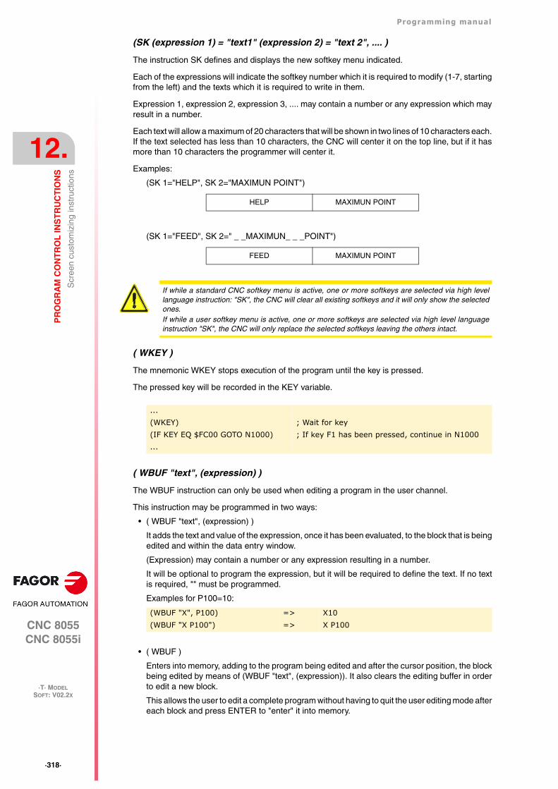
·318·
Programming manual
CNC 8055CNC 8055i
12.
PR
OG
RA
M C
ON
TR
OL
INS
TR
UC
TIO
NS
·T· MODELSOFT: V02.2X
Scr
een
cust
omiz
ing
inst
ruct
ions
(SK (expression 1) = "text1" (expression 2) = "text 2", .... )
The instruction SK defines and displays the new softkey menu indicated.
Each of the expressions will indicate the softkey number which it is required to modify (1-7, startingfrom the left) and the texts which it is required to write in them.
Expression 1, expression 2, expression 3, .... may contain a number or any expression which mayresult in a number.
Each text will allow a maximum of 20 characters that will be shown in two lines of 10 characters each.If the text selected has less than 10 characters, the CNC will center it on the top line, but if it hasmore than 10 characters the programmer will center it.
Examples:
(SK 1="HELP", SK 2="MAXIMUN POINT")
(SK 1="FEED", SK 2=" _ _MAXIMUN_ _ _POINT")
( WKEY )
The mnemonic WKEY stops execution of the program until the key is pressed.
The pressed key will be recorded in the KEY variable.
( WBUF "text", (expression) )
The WBUF instruction can only be used when editing a program in the user channel.
This instruction may be programmed in two ways:
• ( WBUF "text", (expression) )
It adds the text and value of the expression, once it has been evaluated, to the block that is beingedited and within the data entry window.
(Expression) may contain a number or any expression resulting in a number.
It will be optional to program the expression, but it will be required to define the text. If no textis required, "" must be programmed.
Examples for P100=10:
• ( WBUF )
Enters into memory, adding to the program being edited and after the cursor position, the blockbeing edited by means of (WBUF "text", (expression)). It also clears the editing buffer in orderto edit a new block.
This allows the user to edit a complete program without having to quit the user editing mode aftereach block and press ENTER to "enter" it into memory.
HELP MAXIMUN POINT
FEED MAXIMUN POINT
If while a standard CNC softkey menu is active, one or more softkeys are selected via high levellanguage instruction: "SK", the CNC will clear all existing softkeys and it will only show the selectedones.If while a user softkey menu is active, one or more softkeys are selected via high level languageinstruction "SK", the CNC will only replace the selected softkeys leaving the others intact.
...(WKEY) ; Wait for key(IF KEY EQ $FC00 GOTO N1000) ; If key F1 has been pressed, continue in N1000...
(WBUF "X", P100) => X10(WBUF "X P100") => X P100
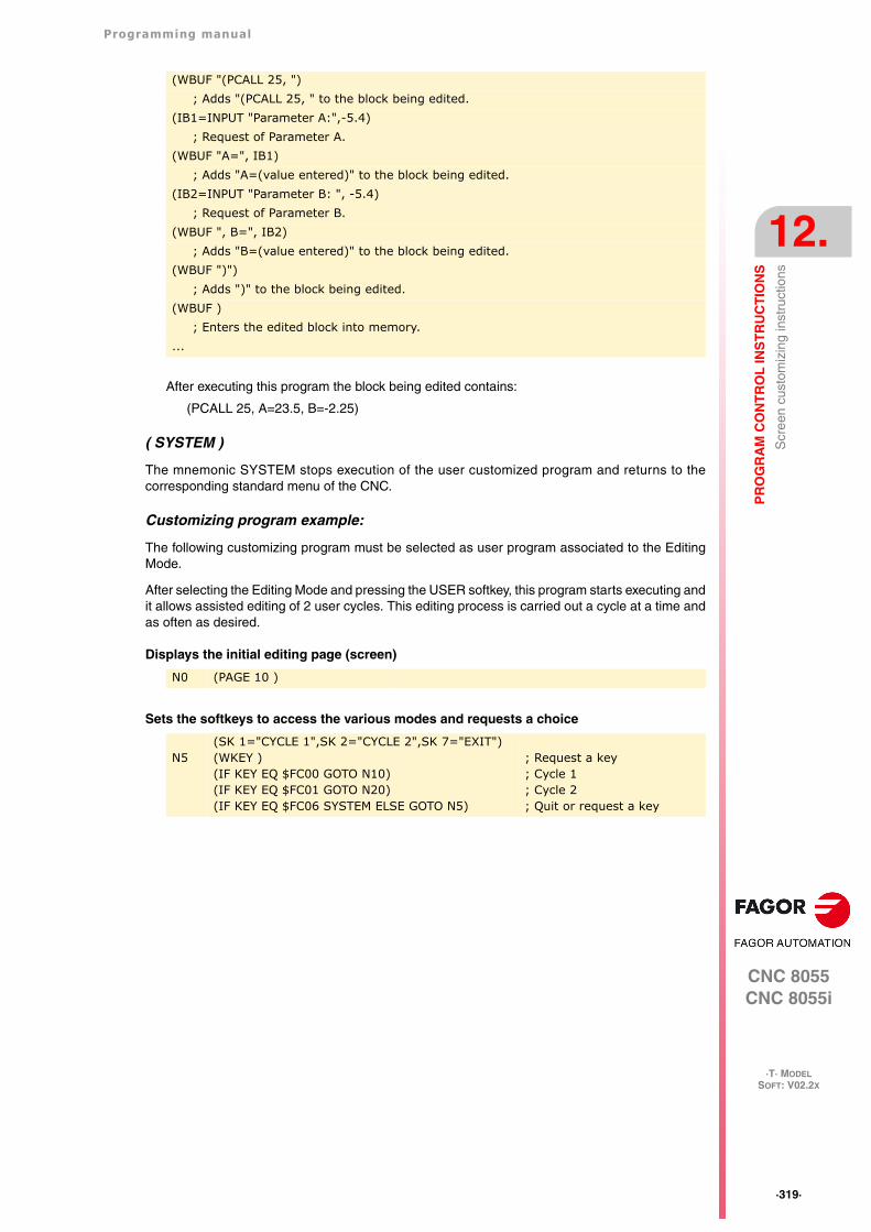
Programming manual
CNC 8055CNC 8055i
PR
OG
RA
M C
ON
TR
OL
INS
TR
UC
TIO
NS
12.
·T· MODELSOFT: V02.2X
·319·
Scr
een
cust
omiz
ing
inst
ruct
ions
After executing this program the block being edited contains:
(PCALL 25, A=23.5, B=-2.25)
( SYSTEM )
The mnemonic SYSTEM stops execution of the user customized program and returns to thecorresponding standard menu of the CNC.
Customizing program example:
The following customizing program must be selected as user program associated to the EditingMode.
After selecting the Editing Mode and pressing the USER softkey, this program starts executing andit allows assisted editing of 2 user cycles. This editing process is carried out a cycle at a time andas often as desired.
Displays the initial editing page (screen)
Sets the softkeys to access the various modes and requests a choice
(WBUF "(PCALL 25, "); Adds "(PCALL 25, " to the block being edited.
(IB1=INPUT "Parameter A:",-5.4); Request of Parameter A.
(WBUF "A=", IB1); Adds "A=(value entered)" to the block being edited.
(IB2=INPUT "Parameter B: ", -5.4); Request of Parameter B.
(WBUF ", B=", IB2); Adds "B=(value entered)" to the block being edited.
(WBUF ")"); Adds ")" to the block being edited.
(WBUF ); Enters the edited block into memory.
...
N0 (PAGE 10 )
N5(SK 1="CYCLE 1",SK 2="CYCLE 2",SK 7="EXIT")(WKEY )(IF KEY EQ $FC00 GOTO N10)(IF KEY EQ $FC01 GOTO N20)(IF KEY EQ $FC06 SYSTEM ELSE GOTO N5)
; Request a key; Cycle 1; Cycle 2; Quit or request a key
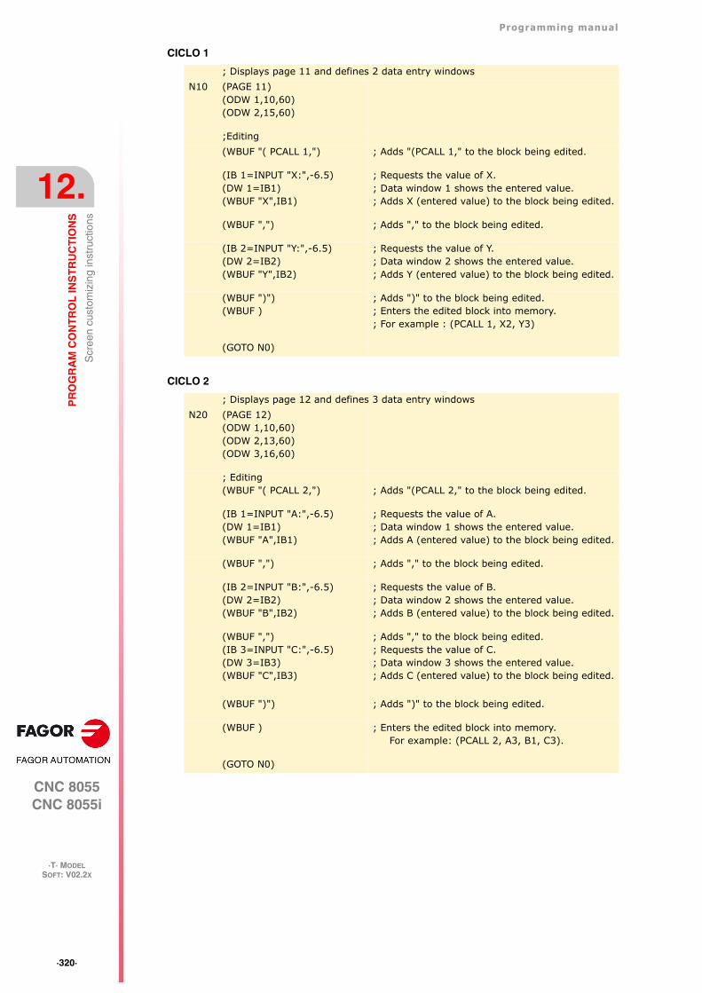
·320·
Programming manual
CNC 8055CNC 8055i
12.
PR
OG
RA
M C
ON
TR
OL
INS
TR
UC
TIO
NS
·T· MODELSOFT: V02.2X
Scr
een
cust
omiz
ing
inst
ruct
ions
CICLO 1
CICLO 2
; Displays page 11 and defines 2 data entry windowsN10 (PAGE 11)
(ODW 1,10,60)(ODW 2,15,60)
;Editing(WBUF "( PCALL 1,") ; Adds "(PCALL 1," to the block being edited.
(IB 1=INPUT "X:",-6.5)(DW 1=IB1)(WBUF "X",IB1)
; Requests the value of X.; Data window 1 shows the entered value.; Adds X (entered value) to the block being edited.
(WBUF ",") ; Adds "," to the block being edited.
(IB 2=INPUT "Y:",-6.5)(DW 2=IB2)(WBUF "Y",IB2)
; Requests the value of Y.; Data window 2 shows the entered value.; Adds Y (entered value) to the block being edited.
(WBUF ")")(WBUF )
; Adds ")" to the block being edited.; Enters the edited block into memory.; For example : (PCALL 1, X2, Y3)
(GOTO N0)
; Displays page 12 and defines 3 data entry windowsN20 (PAGE 12)
(ODW 1,10,60)(ODW 2,13,60)(ODW 3,16,60)
; Editing(WBUF "( PCALL 2,") ; Adds "(PCALL 2," to the block being edited.
(IB 1=INPUT "A:",-6.5)(DW 1=IB1)(WBUF "A",IB1)
; Requests the value of A.; Data window 1 shows the entered value.; Adds A (entered value) to the block being edited.
(WBUF ",") ; Adds "," to the block being edited.
(IB 2=INPUT "B:",-6.5)(DW 2=IB2)(WBUF "B",IB2)
; Requests the value of B.; Data window 2 shows the entered value.; Adds B (entered value) to the block being edited.
(WBUF ",")(IB 3=INPUT "C:",-6.5)(DW 3=IB3)(WBUF "C",IB3)
; Adds "," to the block being edited.; Requests the value of C.; Data window 3 shows the entered value.; Adds C (entered value) to the block being edited.
(WBUF ")") ; Adds ")" to the block being edited.
(WBUF ) ; Enters the edited block into memory.For example: (PCALL 2, A3, B1, C3).
(GOTO N0)
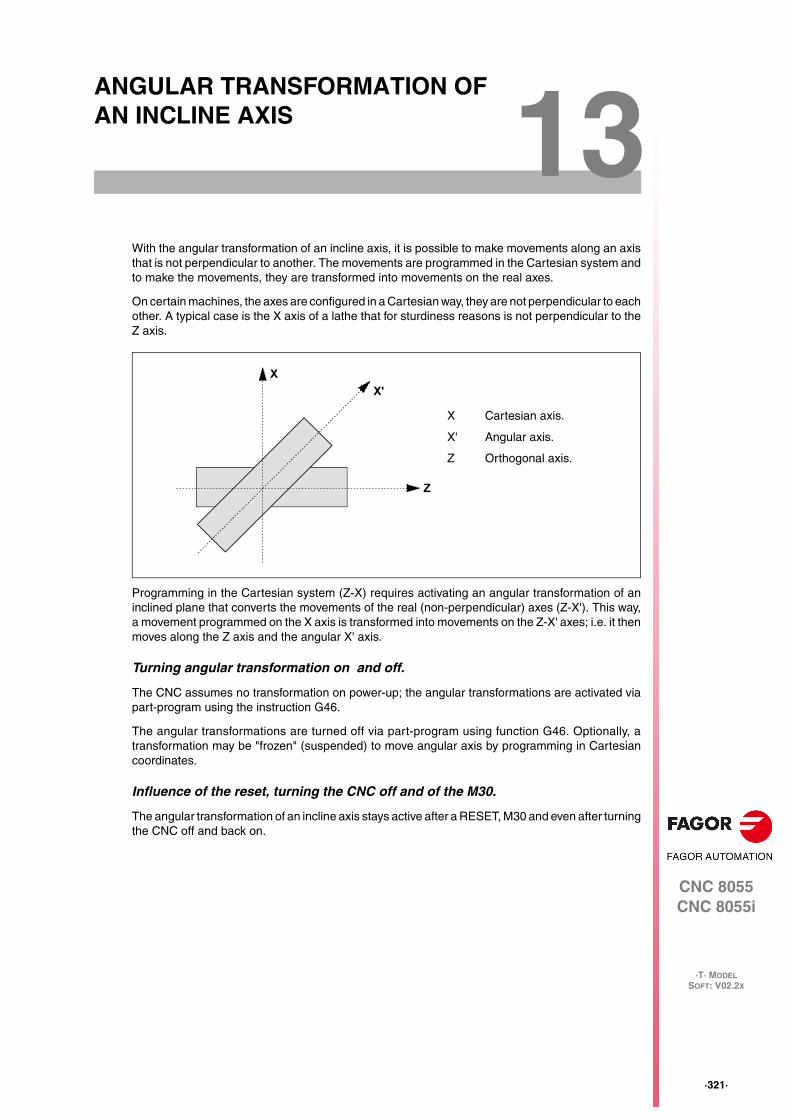
CNC 8055CNC 8055i
·T· MODELSOFT: V02.2X
13
·321·
ANGULAR TRANSFORMATION OF AN INCLINE AXIS
With the angular transformation of an incline axis, it is possible to make movements along an axisthat is not perpendicular to another. The movements are programmed in the Cartesian system andto make the movements, they are transformed into movements on the real axes.
On certain machines, the axes are configured in a Cartesian way, they are not perpendicular to eachother. A typical case is the X axis of a lathe that for sturdiness reasons is not perpendicular to theZ axis.
Programming in the Cartesian system (Z-X) requires activating an angular transformation of aninclined plane that converts the movements of the real (non-perpendicular) axes (Z-X'). This way,a movement programmed on the X axis is transformed into movements on the Z-X' axes; i.e. it thenmoves along the Z axis and the angular X' axis.
Turning angular transformation on and off.
The CNC assumes no transformation on power-up; the angular transformations are activated viapart-program using the instruction G46.
The angular transformations are turned off via part-program using function G46. Optionally, atransformation may be "frozen" (suspended) to move angular axis by programming in Cartesiancoordinates.
Influence of the reset, turning the CNC off and of the M30.
The angular transformation of an incline axis stays active after a RESET, M30 and even after turningthe CNC off and back on.
X Cartesian axis.
X' Angular axis.
Z Orthogonal axis.
Z
X'X
·322·
Programming manual
CNC 8055CNC 8055i
13.
AN
GU
LA
R T
RA
NS
FO
RM
AT
ION
OF
AN
INC
LIN
E A
XIS
·T· MODELSOFT: V02.2X
Considerations for the angular transformation of an incline axis.
The axes involved in an angular transformation must be linear. Both axes may have Gantry axesassociated with them, the may be slaved (coupled) or synchronized by PLC.
If the angular transformation is active, the coordinates displayed will be those of the Cartesiansystem. Otherwise, it will display the coordinates of the real axes.
The following operations are possible while the transformation is active:
• Zero offsets.
• Coordinate preset.
• Activate the C axis.
• Movements in continuous / incremental jog and handwheels.
Movements to hardstop are not possible while the transformation is active.
Machine reference (home) search
Function G46 is canceled when homing an axis that is involved in the angular transformation(machine parameters ANGAXNA and ORTAXNA). When homing the axes that are not involved inthe angular axis transformation, function G46 stays active.
While searching home, only the real axes move.
Jogging and handwheel movements.
Either the real or the Cartesian axes may be jogged depending on how they've been set by themanufacturer. It is selected via PLC (MACHMOVE) and it may be available, for example, from a userkey.
Programming manual
CNC 8055CNC 8055i
AN
GU
LA
R T
RA
NS
FO
RM
AT
ION
OF
AN
INC
LIN
E A
XIS
13.
·T· MODELSOFT: V02.2X
·323·
Tur
ning
ang
ular
tran
sfor
mat
ion
on a
nd o
ff
13.1 Turning angular transformation on and off
Turn angular transformation on
When the transformation is on, the movements are programmed in the Cartesian system and tomake the movements, the CNC transforms them into movements on the real axes. The coordinatesdisplayed on the screen will be those of the Cartesian system.
The angular transformation is turned on using function G46 whose programming format is:
G46 S1
This instruction turns a "frozen" (suspended) transformation on again. See "13.2 Freezing theangular transformation" on page 324.
Turning the angular transformation off
If the transformation is off, the movements are programmed and executed in the system of the realaxes. The coordinates displayed on the screen will be those of the real axes.
The angular transformation is turned off using function G46 whose programming format is:
G46 S0G46
The angular transformation of an incline axis stays active after a RESET, M30 and even after turningthe CNC off and back on.
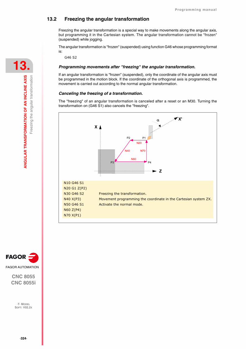
·324·
Programming manual
CNC 8055CNC 8055i
13.
AN
GU
LA
R T
RA
NS
FO
RM
AT
ION
OF
AN
INC
LIN
E A
XIS
·T· MODELSOFT: V02.2X
Fre
ezin
g th
e an
gula
r tr
ansf
orm
atio
n
13.2 Freezing the angular transformation
Freezing the angular transformation is a special way to make movements along the angular axis,but programming it in the Cartesian system. The angular transformation cannot be "frozen"(suspended) while jogging.
The angular transformation is "frozen" (suspended) using function G46 whose programming formatis:
G46 S2
Programming movements after "freezing" the angular transformation.
If an angular transformation is "frozen" (suspended), only the coordinate of the angular axis mustbe programmed in the motion block. If the coordinate of the orthogonal axis is programmed, themovement is carried out according to the normal angular transformation.
Canceling the freezing of a transformation.
The "freezing" of an angular transformation is canceled after a reset or an M30. Turning thetransformation on (G46 S1) also cancels the "freezing".
N10 G46 S1N20 G1 Z(P2)N30 G46 S2 Freezing the transformation.N40 X(P3) Movement programming the coordinate in the Cartesian system ZX.N50 G46 S1 Activate the normal mode.N60 Z(P4)N70 X(P1)
Z
X
P1P2
P3 P4
N40
N60
N20
N70
X'
Programming manual
CNC 8055CNC 8055i
SOFT: V02.2X
·325·
APPENDIX
A. ISO code programming............................................................................ 327
B. Program control instructions.................................................................... 329
C. Summary of internal CNC variables........................................................ 333
D. Key code .................................................................................................. 341
E. Programming assistance screens of the system. ...................................... 351
F. Maintenance............................................................................................. 355

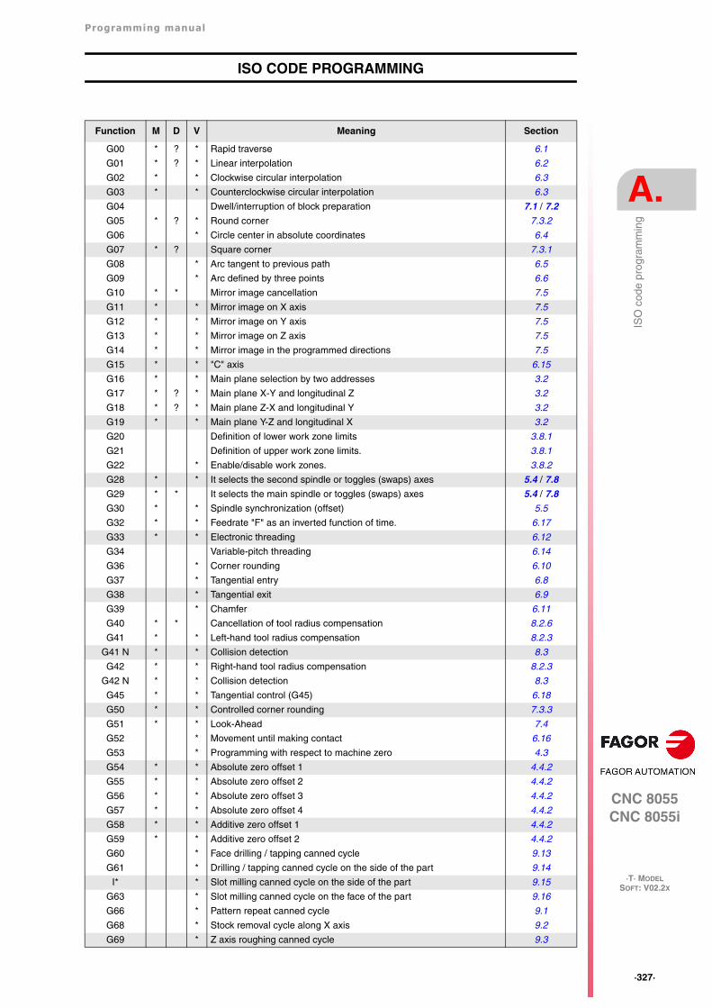
Programming manual
CNC 8055CNC 8055i
A.
·T· MODELSOFT: V02.2X
·327·
ISO
cod
e pr
ogra
mm
ing
ISO CODE PROGRAMMING
Function M D V Meaning Section
G00 * ? * Rapid traverse 6.1
G01 * ? * Linear interpolation 6.2
G02 * * Clockwise circular interpolation 6.3
G03 * * Counterclockwise circular interpolation 6.3
G04 Dwell/interruption of block preparation 7.1 / 7.2
G05 * ? * Round corner 7.3.2
G06 * Circle center in absolute coordinates 6.4
G07 * ? Square corner 7.3.1
G08 * Arc tangent to previous path 6.5
G09 * Arc defined by three points 6.6
G10 * * Mirror image cancellation 7.5
G11 * * Mirror image on X axis 7.5
G12 * * Mirror image on Y axis 7.5
G13 * * Mirror image on Z axis 7.5
G14 * * Mirror image in the programmed directions 7.5
G15 * * "C" axis 6.15
G16 * * Main plane selection by two addresses 3.2
G17 * ? * Main plane X-Y and longitudinal Z 3.2
G18 * ? * Main plane Z-X and longitudinal Y 3.2
G19 * * Main plane Y-Z and longitudinal X 3.2
G20 Definition of lower work zone limits 3.8.1
G21 Definition of upper work zone limits. 3.8.1
G22 * Enable/disable work zones. 3.8.2
G28 * * It selects the second spindle or toggles (swaps) axes 5.4 / 7.8
G29 * * It selects the main spindle or toggles (swaps) axes 5.4 / 7.8
G30 * * Spindle synchronization (offset) 5.5
G32 * * Feedrate "F" as an inverted function of time. 6.17
G33 * * Electronic threading 6.12
G34 Variable-pitch threading 6.14
G36 * Corner rounding 6.10
G37 * Tangential entry 6.8
G38 * Tangential exit 6.9
G39 * Chamfer 6.11
G40 * * Cancellation of tool radius compensation 8.2.6
G41 * * Left-hand tool radius compensation 8.2.3
G41 N * * Collision detection 8.3
G42 * * Right-hand tool radius compensation 8.2.3
G42 N * * Collision detection 8.3
G45 * * Tangential control (G45) 6.18
G50 * * Controlled corner rounding 7.3.3
G51 * * Look-Ahead 7.4
G52 * Movement until making contact 6.16
G53 * Programming with respect to machine zero 4.3
G54 * * Absolute zero offset 1 4.4.2
G55 * * Absolute zero offset 2 4.4.2
G56 * * Absolute zero offset 3 4.4.2
G57 * * Absolute zero offset 4 4.4.2
G58 * * Additive zero offset 1 4.4.2
G59 * * Additive zero offset 2 4.4.2
G60 * Face drilling / tapping canned cycle 9.13
G61 * Drilling / tapping canned cycle on the side of the part 9.14
I* * Slot milling canned cycle on the side of the part 9.15
G63 * Slot milling canned cycle on the face of the part 9.16
G66 * Pattern repeat canned cycle 9.1
G68 * Stock removal cycle along X axis 9.2
G69 * Z axis roughing canned cycle 9.3
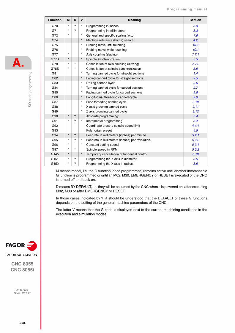
·328·
Programming manual
CNC 8055CNC 8055i
A.
·T· MODELSOFT: V02.2X
ISO
cod
e pr
ogra
mm
ing
M means modal, i.e. the G function, once programmed, remains active until another incompatibleG function is programmed or until an M02, M30, EMERGENCY or RESET is executed or the CNCis turned off and back on.
D means BY DEFAULT, i.e. they will be assumed by the CNC when it is powered on, after executingM02, M30 or after EMERGENCY or RESET.
In those cases indicated by ?, it should be understood that the DEFAULT of these G functionsdepends on the setting of the general machine parameters of the CNC.
The letter V means that the G code is displayed next to the current machining conditions in theexecution and simulation modes.
G70 * ? * Programming in inches 3.3
G71 * ? Programming in millimeters 3.3
G72 * * General and specific scaling factor 7.6
G74 * Machine reference (home) search 4.2
G75 * Probing move until touching 10.1
G76 * Probing move while touching 10.1
G77 * * Axis coupling (slaving) 7.7.1
G77S * * Spindle synchronization 5.5
G78 * * Cancellation of axis coupling (slaving) 7.7.2
G78S * * Cancellation of spindle synchronization 5.5
G81 * Turning canned cycle for straight sections 9.4
G82 * Facing canned cycle for straight sections 9.5
G83 * Drilling canned cycle 9.6
G84 * Turning canned cycle for curved sections 9.7
G85 * Facing canned cycle for curved sections 9.8
G86 * Longitudinal threading canned cycle 9.9
G87 * Face threading canned cycle 9.10
G88 * X axis grooving canned cycle 9.11
G89 * Z axis grooving canned cycle 9.12
G90 * ? Absolute programming: 3.4
G91 * ? * Incremental programming 3.4
G92 Coordinate preset / spindle speed limit 4.4.1
G93 Polar origin preset 4.5
G94 * ? Feedrate in millimeters (inches) per minute 5.2.1
G95 * ? * Feedrate in millimeters (inches) per revolution. 5.2.2
G96 * * Constant cutting speed 5.3.1
G97 * * Spindle speed in RPM 5.3.2
G145 * * Temporary cancellation of tangential control 6.19
G151 * ? Programming the X axis in diameter. 3.5
G152 * ? Programming the X axis in radius. 3.5
Function M D V Meaning Section
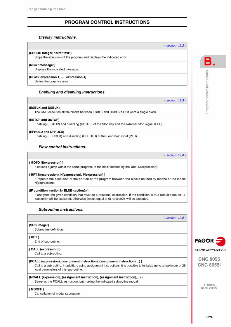
Programming manual
CNC 8055CNC 8055i
B.
·T· MODELSOFT: V02.2X
·329·
Pro
gram
con
trol
inst
ruct
ions
PROGRAM CONTROL INSTRUCTIONS
Display instructions.
Enabling and disabling instructions.
Flow control instructions.
Subroutine instructions.
( section 12.2 )
(ERROR integer, "error text")Stops the execution of the program and displays the indicated error.
(MSG "message")Displays the indicated message.
(DGWZ expression 1, ..... expression 4)Define the graphics area.
( section 12.3 )
(ESBLK and DSBLK)The CNC executes all the blocks between ESBLK and DSBLK as if it were a single block.
(ESTOP and DSTOP)Enabling (ESTOP) and disabling (DSTOP) of the Stop key and the external Stop signal (PLC).
(EFHOLD and DFHOLD)Enabling (EFHOLD) and disabling (DFHOLD) of the Feed-hold input (PLC).
( section 12.4 )
( GOTO N(expression) )It causes a jump within the same program, to the block defined by the label N(expression).
( RPT N(expression), N(expression), P(expression) )It repeats the execution of the portion of the program between the blocks defined by means of the labelsN(expression).
(IF condition <action1> ELSE <action2>)It analyzes the given condition that must be a relational expression. If the condition is true (result equal to 1),<action1> will be executed, otherwise (result equal to 0) <action2> will be executed.
( section 12.5 )
(SUB integer)Subroutine definition.
( RET )End of subroutine.
( CALL (expression) )Call to a subroutine.
(PCALL (expression), (assignment instruction), (assignment instruction),...) )Call to a subroutine. In addition, using assignment instructions, it is possible to initialize up to a maximum of 26local parameters of this subroutine.
(MCALL (expression), (assignment instruction), (assignment instruction),...) )Same as the PCALL instruction, but making the indicated subroutine modal.
( MDOFF )Cancellation of modal subroutine.
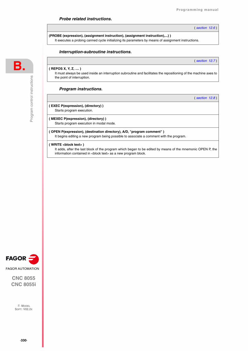
·330·
Programming manual
CNC 8055CNC 8055i
B.
·T· MODELSOFT: V02.2X
Pro
gram
con
trol
inst
ruct
ions
Probe related instructions.
Interruption-subroutine instructions.
Program instructions.
( section 12.6 )
(PROBE (expression), (assignment instruction), (assignment instruction),...) )It executes a probing canned cycle initializing its parameters by means of assignment instructions.
( section 12.7 )
( REPOS X, Y, Z, .... )It must always be used inside an interruption subroutine and facilitates the repositioning of the machine axes tothe point of interruption.
( section 12.8 )
( EXEC P(expression), (directory) )Starts program execution.
( MEXEC P(expression), (directory) )Starts program execution in modal mode.
( OPEN P(expression), (destination directory), A/D, "program comment" )It begins editing a new program being possible to associate a comment with the program.
( WRITE <block text> )It adds, after the last block of the program which began to be edited by means of the mnemonic OPEN P, theinformation contained in <block text> as a new program block.
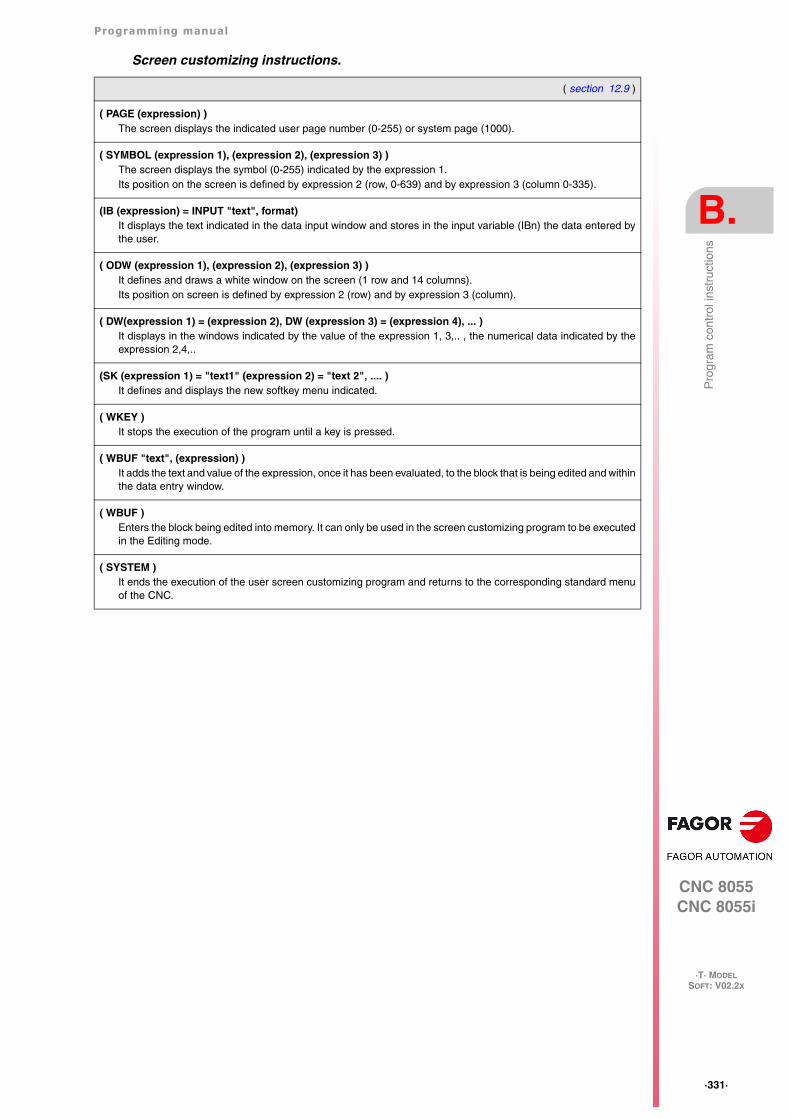
Programming manual
CNC 8055CNC 8055i
B.
·T· MODELSOFT: V02.2X
·331·
Pro
gram
con
trol
inst
ruct
ions
Screen customizing instructions.
( section 12.9 )
( PAGE (expression) )The screen displays the indicated user page number (0-255) or system page (1000).
( SYMBOL (expression 1), (expression 2), (expression 3) )The screen displays the symbol (0-255) indicated by the expression 1.Its position on the screen is defined by expression 2 (row, 0-639) and by expression 3 (column 0-335).
(IB (expression) = INPUT "text", format)It displays the text indicated in the data input window and stores in the input variable (IBn) the data entered bythe user.
( ODW (expression 1), (expression 2), (expression 3) )It defines and draws a white window on the screen (1 row and 14 columns).Its position on screen is defined by expression 2 (row) and by expression 3 (column).
( DW(expression 1) = (expression 2), DW (expression 3) = (expression 4), ... )It displays in the windows indicated by the value of the expression 1, 3,.. , the numerical data indicated by theexpression 2,4,..
(SK (expression 1) = "text1" (expression 2) = "text 2", .... )It defines and displays the new softkey menu indicated.
( WKEY )It stops the execution of the program until a key is pressed.
( WBUF "text", (expression) )It adds the text and value of the expression, once it has been evaluated, to the block that is being edited and withinthe data entry window.
( WBUF )Enters the block being edited into memory. It can only be used in the screen customizing program to be executedin the Editing mode.
( SYSTEM )It ends the execution of the user screen customizing program and returns to the corresponding standard menuof the CNC.
·332·
Programming manual
CNC 8055CNC 8055i
B.
·T· MODELSOFT: V02.2X
Pro
gram
con
trol
inst
ruct
ions
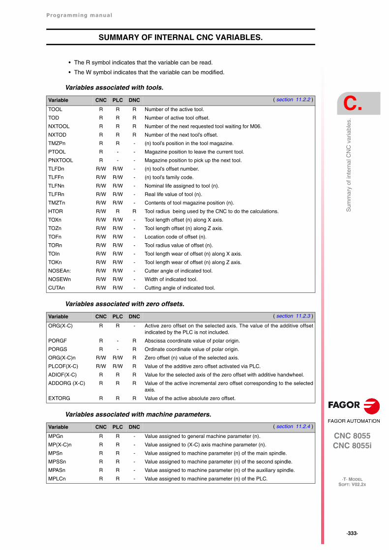
Programming manual
CNC 8055CNC 8055i
C.
·T· MODELSOFT: V02.2X
·333·
Sum
mar
y of
inte
rnal
CN
C v
aria
bles
.
SUMMARY OF INTERNAL CNC VARIABLES.
• The R symbol indicates that the variable can be read.
• The W symbol indicates that the variable can be modified.
Variables associated with tools.
Variables associated with zero offsets.
Variables associated with machine parameters.
Variable CNC PLC DNC ( section 11.2.2 )
TOOL R R R Number of the active tool.
TOD R R R Number of active tool offset.
NXTOOL R R R Number of the next requested tool waiting for M06.
NXTOD R R R Number of the next tool’s offset.
TMZPn R R - (n) tool’s position in the tool magazine.
PTOOL R - - Magazine position to leave the current tool.
PNXTOOL R - - Magazine position to pick up the next tool.
TLFDn R/W R/W - (n) tool’s offset number.
TLFFn R/W R/W - (n) tool’s family code.
TLFNn R/W R/W - Nominal life assigned to tool (n).
TLFRn R/W R/W - Real life value of tool (n).
TMZTn R/W R/W - Contents of tool magazine position (n).
HTOR R/W R R Tool radius being used by the CNC to do the calculations.
TOXn R/W R/W - Tool length offset (n) along X axis.
TOZn R/W R/W - Tool length offset (n) along Z axis.
TOFn R/W R/W - Location code of offset (n).
TORn R/W R/W - Tool radius value of offset (n).
TOIn R/W R/W - Tool length wear of offset (n) along X axis.
TOKn R/W R/W - Tool length wear of offset (n) along Z axis.
NOSEAn: R/W R/W - Cutter angle of indicated tool.
NOSEWn R/W R/W - Width of indicated tool.
CUTAn R/W R/W - Cutting angle of indicated tool.
Variable CNC PLC DNC ( section 11.2.3 )
ORG(X-C) R R - Active zero offset on the selected axis. The value of the additive offsetindicated by the PLC is not included.
PORGF R - R Abscissa coordinate value of polar origin.
PORGS R - R Ordinate coordinate value of polar origin.
ORG(X-C)n R/W R/W R Zero offset (n) value of the selected axis.
PLCOF(X-C) R/W R/W R Value of the additive zero offset activated via PLC.
ADIOF(X-C) R R R Value for the selected axis of the zero offset with additive handwheel.
ADDORG (X-C) R R R Value of the active incremental zero offset corresponding to the selectedaxis.
EXTORG R R R Value of the active absolute zero offset.
Variable CNC PLC DNC ( section 11.2.4 )
MPGn R R - Value assigned to general machine parameter (n).
MP(X-C)n R R - Value assigned to (X-C) axis machine parameter (n).
MPSn R R - Value assigned to machine parameter (n) of the main spindle.
MPSSn R R - Value assigned to machine parameter (n) of the second spindle.
MPASn R R - Value assigned to machine parameter (n) of the auxiliary spindle.
MPLCn R R - Value assigned to machine parameter (n) of the PLC.
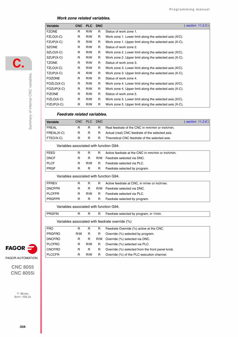
·334·
Programming manual
CNC 8055CNC 8055i
C.
·T· MODELSOFT: V02.2X
Sum
mar
y of
inte
rnal
CN
C v
aria
bles
.
Work zone related variables.
Feedrate related variables.
Variables associated with function G94.
Variables associated with function G94.
Variables associated with function G94.
Variables associated with feedrate override (%)
Variable CNC PLC DNC ( section 11.2.5 )
FZONE R R/W R Status of work zone 1.
FZLO(X-C) R R/W R Work zone 1. Lower limit along the selected axis (X/C).
FZUP(X-C) R R/W R Work zone 1. Upper limit along the selected axis (X-C).
SZONE R R/W R Status of work zone 2.
SZLO(X-C) R R/W R Work zone 2. Lower limit along the selected axis (X/C).
SZUP(X-C) R R/W R Work zone 2. Upper limit along the selected axis (X-C).
TZONE R R/W R Status of work zone 3.
TZLO(X-C) R R/W R Work zone 3. Lower limit along the selected axis (X/C).
TZUP(X-C) R R/W R Work zone 3. Upper limit along the selected axis (X-C).
FOZONE R R/W R Status of work zone 4.
FOZLO(X-C) R R/W R Work zone 4. Lower limit along the selected axis (X/C).
FOZUP(X-C) R R/W R Work zone 4. Upper limit along the selected axis (X-C).
FIZONE R R/W R Status of work zone 5.
FIZLO(X-C) R R/W R Work zone 5. Lower limit along the selected axis (X/C).
FIZUP(X-C) R R/W R Work zone 5. Upper limit along the selected axis (X-C).
Variable CNC PLC DNC ( section 11.2.6 )
FREAL R R R Real feedrate of the CNC in mm/min or inch/min.
FREAL(X-C) R R R Actual (real) CNC feedrate of the selected axis.
FTEO/X-C) R R R Theoretical CNC feedrate of the selected axis.
FEED R R R Active feedrate at the CNC in mm/min or inch/min.
DNCF R R R/W Feedrate selected via DNC.
PLCF R R/W R Feedrate selected via PLC.
PRGF R R R Feedrate selected by program.
FPREV R R R Active feedrate at CNC, in m/rev or inch/rev.
DNCFPR R R R/W Feedrate selected via DNC.
PLCFPR R R/W R Feedrate selected via PLC.
PRGFPR R R R Feedrate selected by program.
PRGFIN R R R Feedrate selected by program, in 1/min.
FRO R R R Feedrate Override (%) active at the CNC.
PRGFRO R/W R R Override (%) selected by program.
DNCFRO R R R/W Override (%) selected via DNC.
PLCFRO R R/W R Override (%) selected via PLC.
CNCFRO R R R Override (%) selected from the front panel knob.
PLCCFR R R/W R Override (%) of the PLC execution channel.
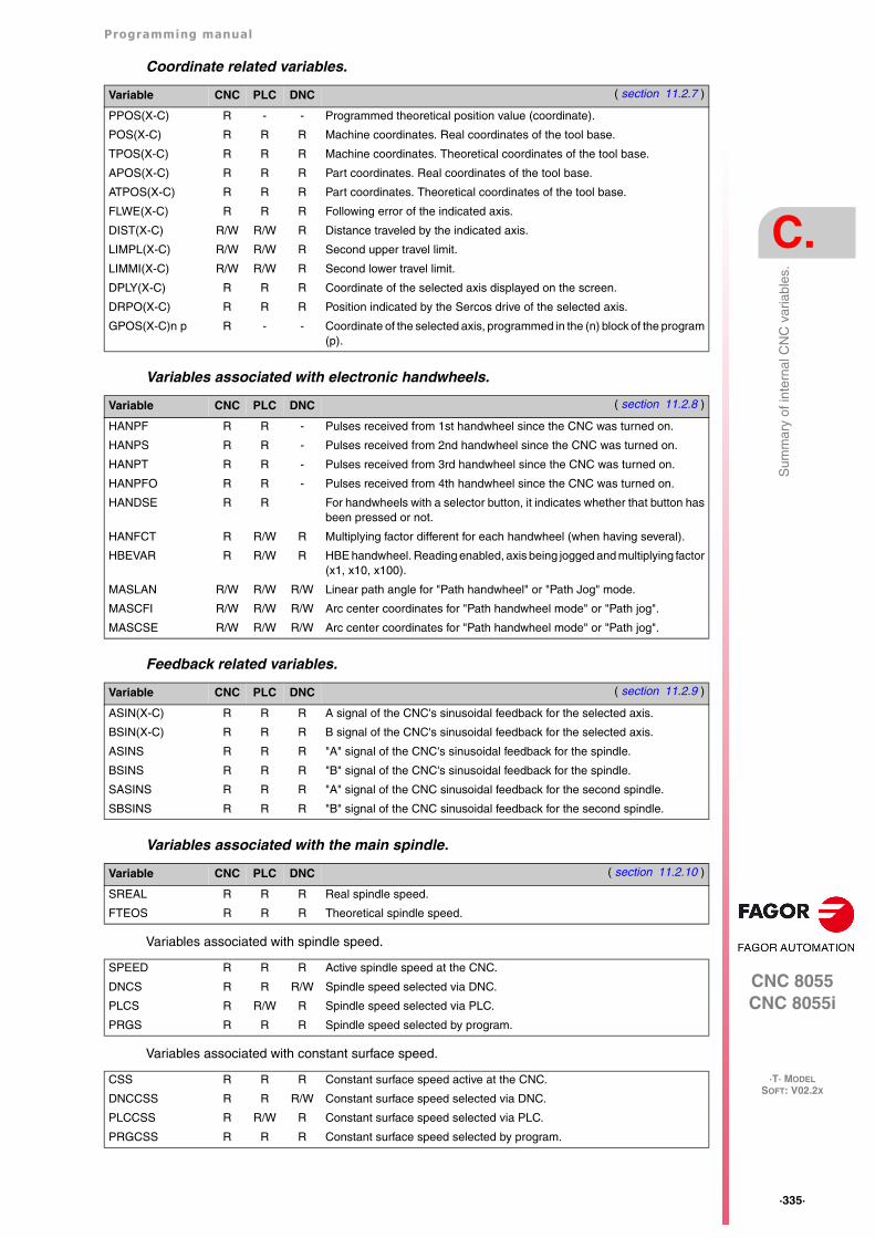
Programming manual
CNC 8055CNC 8055i
C.
·T· MODELSOFT: V02.2X
·335·
Sum
mar
y of
inte
rnal
CN
C v
aria
bles
.
Coordinate related variables.
Variables associated with electronic handwheels.
Feedback related variables.
Variables associated with the main spindle.
Variables associated with spindle speed.
Variables associated with constant surface speed.
Variable CNC PLC DNC ( section 11.2.7 )
PPOS(X-C) R - - Programmed theoretical position value (coordinate).
POS(X-C) R R R Machine coordinates. Real coordinates of the tool base.
TPOS(X-C) R R R Machine coordinates. Theoretical coordinates of the tool base.
APOS(X-C) R R R Part coordinates. Real coordinates of the tool base.
ATPOS(X-C) R R R Part coordinates. Theoretical coordinates of the tool base.
FLWE(X-C) R R R Following error of the indicated axis.
DIST(X-C) R/W R/W R Distance traveled by the indicated axis.
LIMPL(X-C) R/W R/W R Second upper travel limit.
LIMMI(X-C) R/W R/W R Second lower travel limit.
DPLY(X-C) R R R Coordinate of the selected axis displayed on the screen.
DRPO(X-C) R R R Position indicated by the Sercos drive of the selected axis.
GPOS(X-C)n p R - - Coordinate of the selected axis, programmed in the (n) block of the program(p).
Variable CNC PLC DNC ( section 11.2.8 )
HANPF R R - Pulses received from 1st handwheel since the CNC was turned on.
HANPS R R - Pulses received from 2nd handwheel since the CNC was turned on.
HANPT R R - Pulses received from 3rd handwheel since the CNC was turned on.
HANPFO R R - Pulses received from 4th handwheel since the CNC was turned on.
HANDSE R R For handwheels with a selector button, it indicates whether that button hasbeen pressed or not.
HANFCT R R/W R Multiplying factor different for each handwheel (when having several).
HBEVAR R R/W R HBE handwheel. Reading enabled, axis being jogged and multiplying factor(x1, x10, x100).
MASLAN R/W R/W R/W Linear path angle for "Path handwheel" or "Path Jog" mode.
MASCFI R/W R/W R/W Arc center coordinates for "Path handwheel mode" or "Path jog".
MASCSE R/W R/W R/W Arc center coordinates for "Path handwheel mode" or "Path jog".
Variable CNC PLC DNC ( section 11.2.9 )
ASIN(X-C) R R R A signal of the CNC's sinusoidal feedback for the selected axis.
BSIN(X-C) R R R B signal of the CNC's sinusoidal feedback for the selected axis.
ASINS R R R "A" signal of the CNC's sinusoidal feedback for the spindle.
BSINS R R R "B" signal of the CNC's sinusoidal feedback for the spindle.
SASINS R R R "A" signal of the CNC sinusoidal feedback for the second spindle.
SBSINS R R R "B" signal of the CNC sinusoidal feedback for the second spindle.
Variable CNC PLC DNC ( section 11.2.10 )
SREAL R R R Real spindle speed.
FTEOS R R R Theoretical spindle speed.
SPEED R R R Active spindle speed at the CNC.
DNCS R R R/W Spindle speed selected via DNC.
PLCS R R/W R Spindle speed selected via PLC.
PRGS R R R Spindle speed selected by program.
CSS R R R Constant surface speed active at the CNC.
DNCCSS R R R/W Constant surface speed selected via DNC.
PLCCSS R R/W R Constant surface speed selected via PLC.
PRGCSS R R R Constant surface speed selected by program.
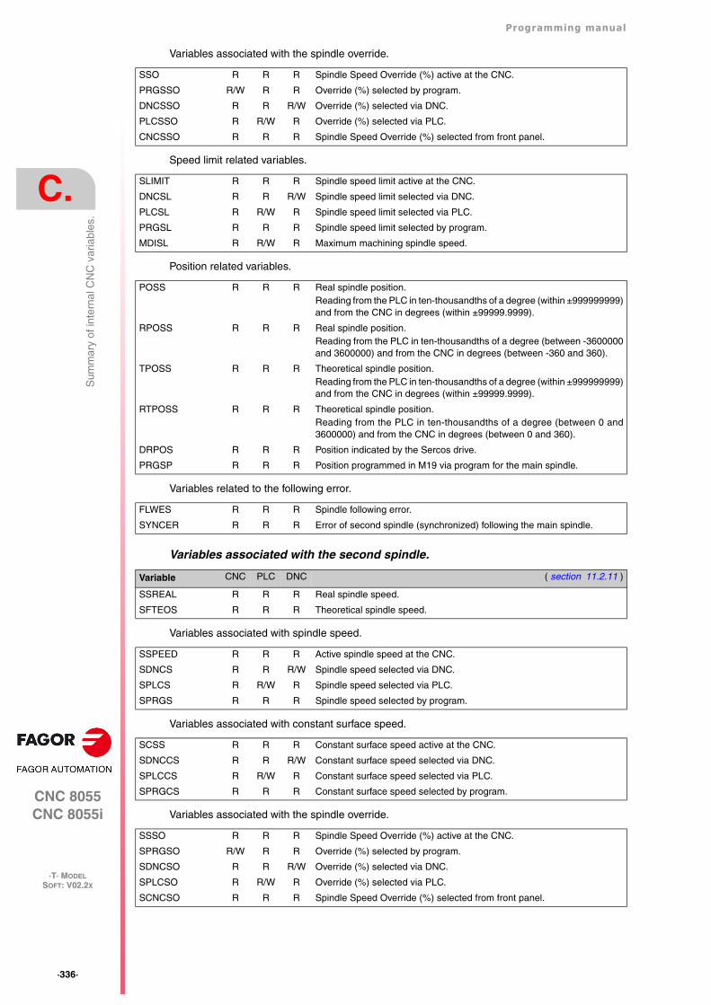
·336·
Programming manual
CNC 8055CNC 8055i
C.
·T· MODELSOFT: V02.2X
Sum
mar
y of
inte
rnal
CN
C v
aria
bles
.
Variables associated with the spindle override.
Speed limit related variables.
Position related variables.
Variables related to the following error.
Variables associated with the second spindle.
Variables associated with spindle speed.
Variables associated with constant surface speed.
Variables associated with the spindle override.
SSO R R R Spindle Speed Override (%) active at the CNC.
PRGSSO R/W R R Override (%) selected by program.
DNCSSO R R R/W Override (%) selected via DNC.
PLCSSO R R/W R Override (%) selected via PLC.
CNCSSO R R R Spindle Speed Override (%) selected from front panel.
SLIMIT R R R Spindle speed limit active at the CNC.
DNCSL R R R/W Spindle speed limit selected via DNC.
PLCSL R R/W R Spindle speed limit selected via PLC.
PRGSL R R R Spindle speed limit selected by program.
MDISL R R/W R Maximum machining spindle speed.
POSS R R R Real spindle position.Reading from the PLC in ten-thousandths of a degree (within ±999999999)and from the CNC in degrees (within ±99999.9999).
RPOSS R R R Real spindle position.Reading from the PLC in ten-thousandths of a degree (between -3600000and 3600000) and from the CNC in degrees (between -360 and 360).
TPOSS R R R Theoretical spindle position.Reading from the PLC in ten-thousandths of a degree (within ±999999999)and from the CNC in degrees (within ±99999.9999).
RTPOSS R R R Theoretical spindle position.Reading from the PLC in ten-thousandths of a degree (between 0 and3600000) and from the CNC in degrees (between 0 and 360).
DRPOS R R R Position indicated by the Sercos drive.
PRGSP R R R Position programmed in M19 via program for the main spindle.
FLWES R R R Spindle following error.
SYNCER R R R Error of second spindle (synchronized) following the main spindle.
Variable CNC PLC DNC ( section 11.2.11 )
SSREAL R R R Real spindle speed.
SFTEOS R R R Theoretical spindle speed.
SSPEED R R R Active spindle speed at the CNC.
SDNCS R R R/W Spindle speed selected via DNC.
SPLCS R R/W R Spindle speed selected via PLC.
SPRGS R R R Spindle speed selected by program.
SCSS R R R Constant surface speed active at the CNC.
SDNCCS R R R/W Constant surface speed selected via DNC.
SPLCCS R R/W R Constant surface speed selected via PLC.
SPRGCS R R R Constant surface speed selected by program.
SSSO R R R Spindle Speed Override (%) active at the CNC.
SPRGSO R/W R R Override (%) selected by program.
SDNCSO R R R/W Override (%) selected via DNC.
SPLCSO R R/W R Override (%) selected via PLC.
SCNCSO R R R Spindle Speed Override (%) selected from front panel.
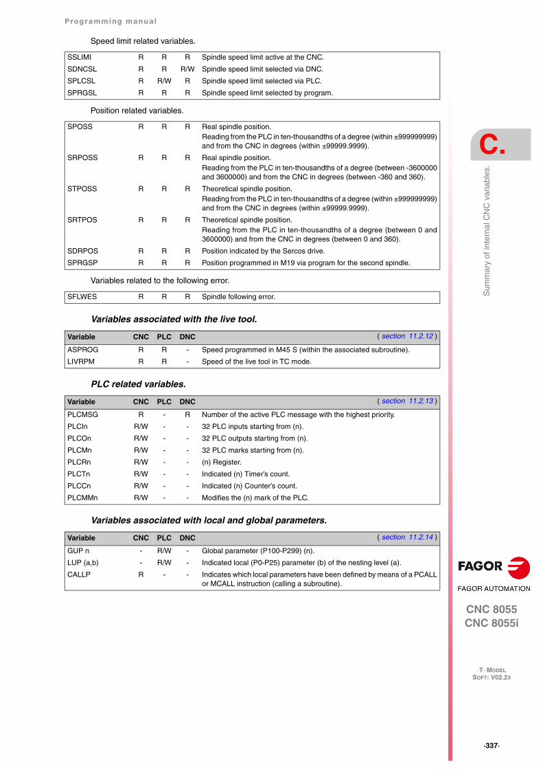
Programming manual
CNC 8055CNC 8055i
C.
·T· MODELSOFT: V02.2X
·337·
Sum
mar
y of
inte
rnal
CN
C v
aria
bles
.
Speed limit related variables.
Position related variables.
Variables related to the following error.
Variables associated with the live tool.
PLC related variables.
Variables associated with local and global parameters.
SSLIMI R R R Spindle speed limit active at the CNC.
SDNCSL R R R/W Spindle speed limit selected via DNC.
SPLCSL R R/W R Spindle speed limit selected via PLC.
SPRGSL R R R Spindle speed limit selected by program.
SPOSS R R R Real spindle position.Reading from the PLC in ten-thousandths of a degree (within ±999999999)and from the CNC in degrees (within ±99999.9999).
SRPOSS R R R Real spindle position.Reading from the PLC in ten-thousandths of a degree (between -3600000and 3600000) and from the CNC in degrees (between -360 and 360).
STPOSS R R R Theoretical spindle position.Reading from the PLC in ten-thousandths of a degree (within ±999999999)and from the CNC in degrees (within ±99999.9999).
SRTPOS R R R Theoretical spindle position.Reading from the PLC in ten-thousandths of a degree (between 0 and3600000) and from the CNC in degrees (between 0 and 360).
SDRPOS R R R Position indicated by the Sercos drive.
SPRGSP R R R Position programmed in M19 via program for the second spindle.
SFLWES R R R Spindle following error.
Variable CNC PLC DNC ( section 11.2.12 )
ASPROG R R - Speed programmed in M45 S (within the associated subroutine).
LIVRPM R R - Speed of the live tool in TC mode.
Variable CNC PLC DNC ( section 11.2.13 )
PLCMSG R - R Number of the active PLC message with the highest priority.
PLCIn R/W - - 32 PLC inputs starting from (n).
PLCOn R/W - - 32 PLC outputs starting from (n).
PLCMn R/W - - 32 PLC marks starting from (n).
PLCRn R/W - - (n) Register.
PLCTn R/W - - Indicated (n) Timer’s count.
PLCCn R/W - - Indicated (n) Counter’s count.
PLCMMn R/W - - Modifies the (n) mark of the PLC.
Variable CNC PLC DNC ( section 11.2.14 )
GUP n - R/W - Global parameter (P100-P299) (n).
LUP (a,b) - R/W - Indicated local (P0-P25) parameter (b) of the nesting level (a).
CALLP R - - Indicates which local parameters have been defined by means of a PCALLor MCALL instruction (calling a subroutine).

·338·
Programming manual
CNC 8055CNC 8055i
C.
·T· MODELSOFT: V02.2X
Sum
mar
y of
inte
rnal
CN
C v
aria
bles
.
Sercos variables.
Software & hardware configuration variables.
Variables associated with telediagnosis.
Operating-mode related variables.
Variable CNC PLC DNC ( section 11.2.15 )
SETGE(X-C) W W - Gear ratio and parameter set of the (X-C) axis drive
SETGES W W - Gear ratio and parameter set of the main spindle
SSETGS W W - Gear ratio and parameter set of the second spindle
SVAR(X-C) id R/W - - Sercos variable sercos for the (X-C) axis "id"
SVARS id R/W - - Sercos variable sercos for the main spindle "id"
SSVARS id R/W - - Sercos variable sercos for the second spindle "id"
TSVAR(X-C) id R - - Third attribute of the sercos variable for the (X-C) axis "id"
TSVARS id R - - Third attribute of the sercos variable for the main spindle "id"
TSSVAR id R - - Third attribute of the sercos variable for the second spindle "id"
Variable CNC PLC DNC ( section 11.2.16 )
HARCON R R R It indicates, with bits, the CNC's hardware configuration.
HARCOA R R R It indicates, with bits, the CNC's hardware configuration.
IDHARH R R R Hardware identifier (8 least significant bits).
IDHARL R R R Hardware identifier (4 most significant bits).
SOFCON R R R Software version of the CNC (bits 15-0) and HD (bits 31-16)
HDMEGA R R R Hard disk size (in megabytes).
KEYIDE R R R Keyboard code, according to the auto-identification system.
MODEL R R R It identifies the CNC model, mill or lather.
Variable CNC PLC DNC ( section 11.2.17 )
HARSWA R R R Hardware configuration.
HARSWB R R R Hardware configuration.
HARTST R R R Hardware test.
MEMTST R R R Memory test.
NODE R R R Node number in the Sercos ring.
VCHECK R R R Software version checksum.
IONODE R R R Position of the "ADDRESS" switch of the I/O CAN bus.
IOSLOC R R R Number of local I/O available.
IOSREM R R R Number of remote I/O available.
Variable CNC PLC DNC ( section 11.2.18 )
OPMODE R R R Operation mode.
OPMODA R R R Operating mode when working in the main channel.
OPMODB R R R Type of simulation.
OPMODC R R R Axes selected by handwheel.
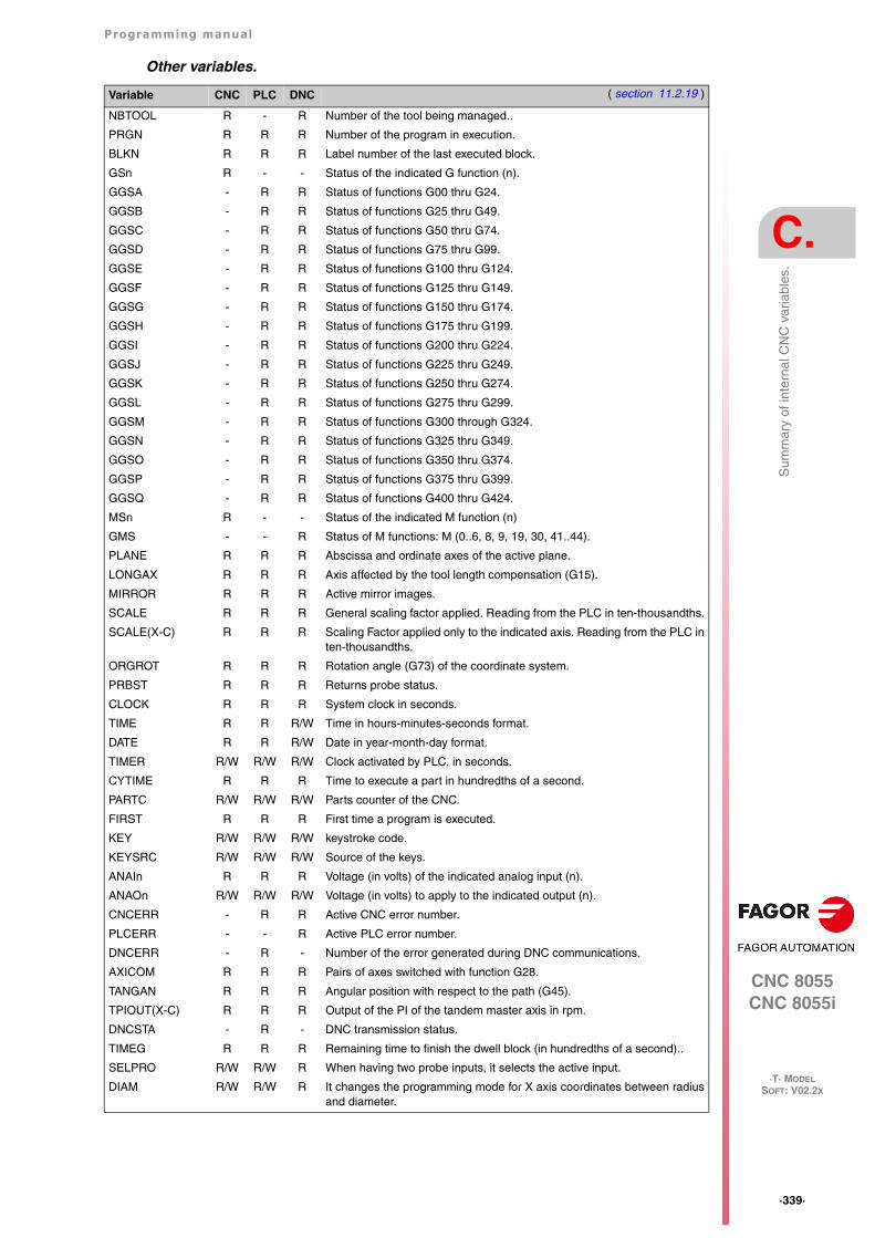
Programming manual
CNC 8055CNC 8055i
C.
·T· MODELSOFT: V02.2X
·339·
Sum
mar
y of
inte
rnal
CN
C v
aria
bles
.
Other variables.
Variable CNC PLC DNC ( section 11.2.19 )
NBTOOL R - R Number of the tool being managed..
PRGN R R R Number of the program in execution.
BLKN R R R Label number of the last executed block.
GSn R - - Status of the indicated G function (n).
GGSA - R R Status of functions G00 thru G24.
GGSB - R R Status of functions G25 thru G49.
GGSC - R R Status of functions G50 thru G74.
GGSD - R R Status of functions G75 thru G99.
GGSE - R R Status of functions G100 thru G124.
GGSF - R R Status of functions G125 thru G149.
GGSG - R R Status of functions G150 thru G174.
GGSH - R R Status of functions G175 thru G199.
GGSI - R R Status of functions G200 thru G224.
GGSJ - R R Status of functions G225 thru G249.
GGSK - R R Status of functions G250 thru G274.
GGSL - R R Status of functions G275 thru G299.
GGSM - R R Status of functions G300 through G324.
GGSN - R R Status of functions G325 thru G349.
GGSO - R R Status of functions G350 thru G374.
GGSP - R R Status of functions G375 thru G399.
GGSQ - R R Status of functions G400 thru G424.
MSn R - - Status of the indicated M function (n)
GMS - - R Status of M functions: M (0..6, 8, 9, 19, 30, 41..44).
PLANE R R R Abscissa and ordinate axes of the active plane.
LONGAX R R R Axis affected by the tool length compensation (G15).
MIRROR R R R Active mirror images.
SCALE R R R General scaling factor applied. Reading from the PLC in ten-thousandths.
SCALE(X-C) R R R Scaling Factor applied only to the indicated axis. Reading from the PLC inten-thousandths.
ORGROT R R R Rotation angle (G73) of the coordinate system.
PRBST R R R Returns probe status.
CLOCK R R R System clock in seconds.
TIME R R R/W Time in hours-minutes-seconds format.
DATE R R R/W Date in year-month-day format.
TIMER R/W R/W R/W Clock activated by PLC, in seconds.
CYTIME R R R Time to execute a part in hundredths of a second.
PARTC R/W R/W R/W Parts counter of the CNC.
FIRST R R R First time a program is executed.
KEY R/W R/W R/W keystroke code.
KEYSRC R/W R/W R/W Source of the keys.
ANAIn R R R Voltage (in volts) of the indicated analog input (n).
ANAOn R/W R/W R/W Voltage (in volts) to apply to the indicated output (n).
CNCERR - R R Active CNC error number.
PLCERR - - R Active PLC error number.
DNCERR - R - Number of the error generated during DNC communications.
AXICOM R R R Pairs of axes switched with function G28.
TANGAN R R R Angular position with respect to the path (G45).
TPIOUT(X-C) R R R Output of the PI of the tandem master axis in rpm.
DNCSTA - R - DNC transmission status.
TIMEG R R R Remaining time to finish the dwell block (in hundredths of a second)..
SELPRO R/W R/W R When having two probe inputs, it selects the active input.
DIAM R/W R/W R It changes the programming mode for X axis coordinates between radiusand diameter.
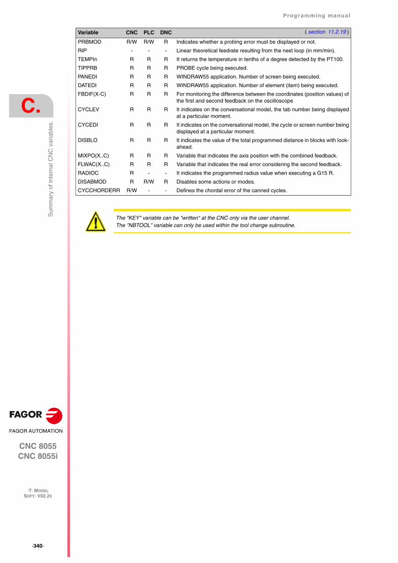
·340·
Programming manual
CNC 8055CNC 8055i
C.
·T· MODELSOFT: V02.2X
Sum
mar
y of
inte
rnal
CN
C v
aria
bles
.PRBMOD R/W R/W R Indicates whether a probing error must be displayed or not.
RIP - - - Linear theoretical feedrate resulting from the next loop (in mm/min).
TEMPIn R R R It returns the temperature in tenths of a degree detected by the PT100.
TIPPRB R R R PROBE cycle being executed.
PANEDI R R R WINDRAW55 application. Number of screen being executed.
DATEDI R R R WINDRAW55 application. Number of element (item) being executed.
FBDIF(X-C) R R R For monitoring the difference between the coordinates (position values) ofthe first and second feedback on the oscilloscope
CYCLEV R R R It indicates on the conversational model, the tab number being displayedat a particular moment.
CYCEDI R R R It indicates on the conversational model, the cycle or screen number beingdisplayed at a particular moment.
DISBLO R R R It indicates the value of the total programmed distance in blocks with look-ahead.
MIXPO(X..C) R R R Variable that indicates the axis position with the combined feedback.
FLWAC(X..C) R R R Variable that indicates the real error considering the second feedback.
RADIOC R - - It indicates the programmed radius value when executing a G15 R.
DISABMOD R R/W R Disables some actions or modes.
CYCCHORDERR R/W - - Defines the chordal error of the canned cycles.
Variable CNC PLC DNC ( section 11.2.19 )
The "KEY" variable can be "written" at the CNC only via the user channel.The "NBTOOL" variable can only be used within the tool change subroutine.
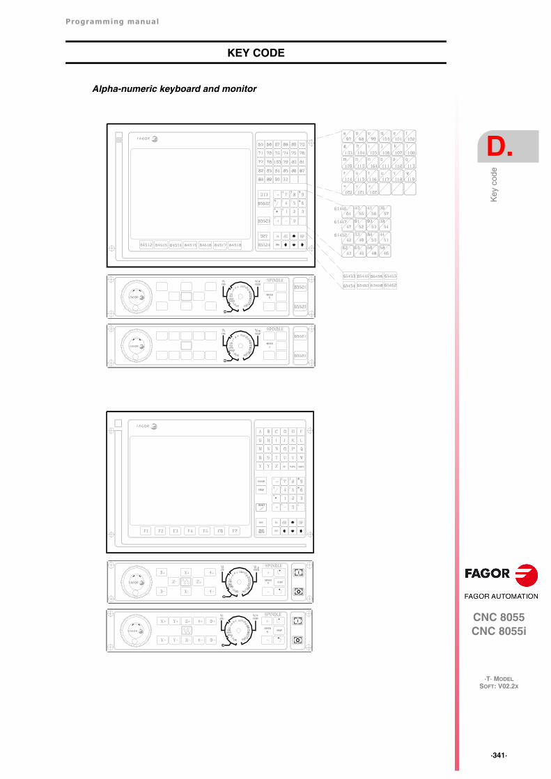
Programming manual
CNC 8055CNC 8055i
D.
·T· MODELSOFT: V02.2X
·341·
Key
cod
e
KEY CODE
Alpha-numeric keyboard and monitor
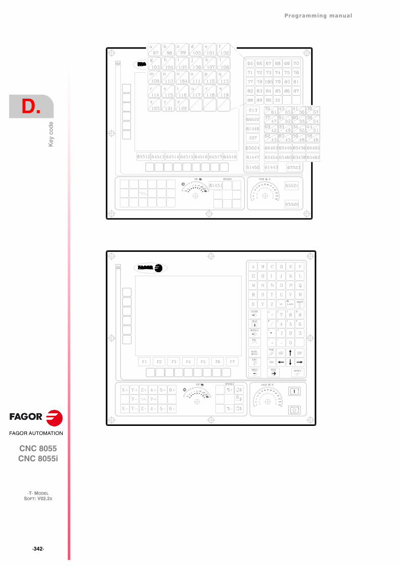
·342·
Programming manual
CNC 8055CNC 8055i
D.
·T· MODELSOFT: V02.2X
Key
cod
e
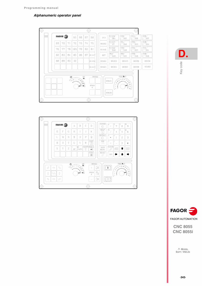
Programming manual
CNC 8055CNC 8055i
D.
·T· MODELSOFT: V02.2X
·343·
Key
cod
e
Alphanumeric operator panel
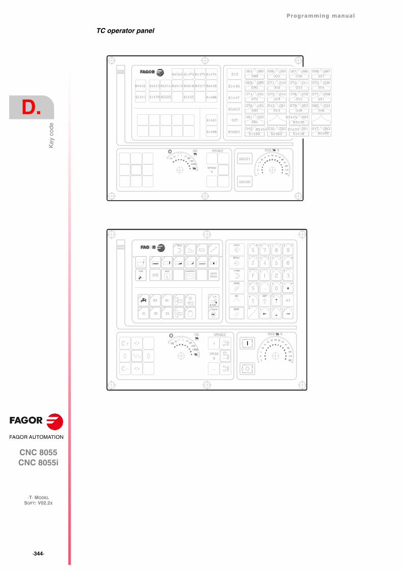
·344·
Programming manual
CNC 8055CNC 8055i
D.
·T· MODELSOFT: V02.2X
Key
cod
e
TC operator panel
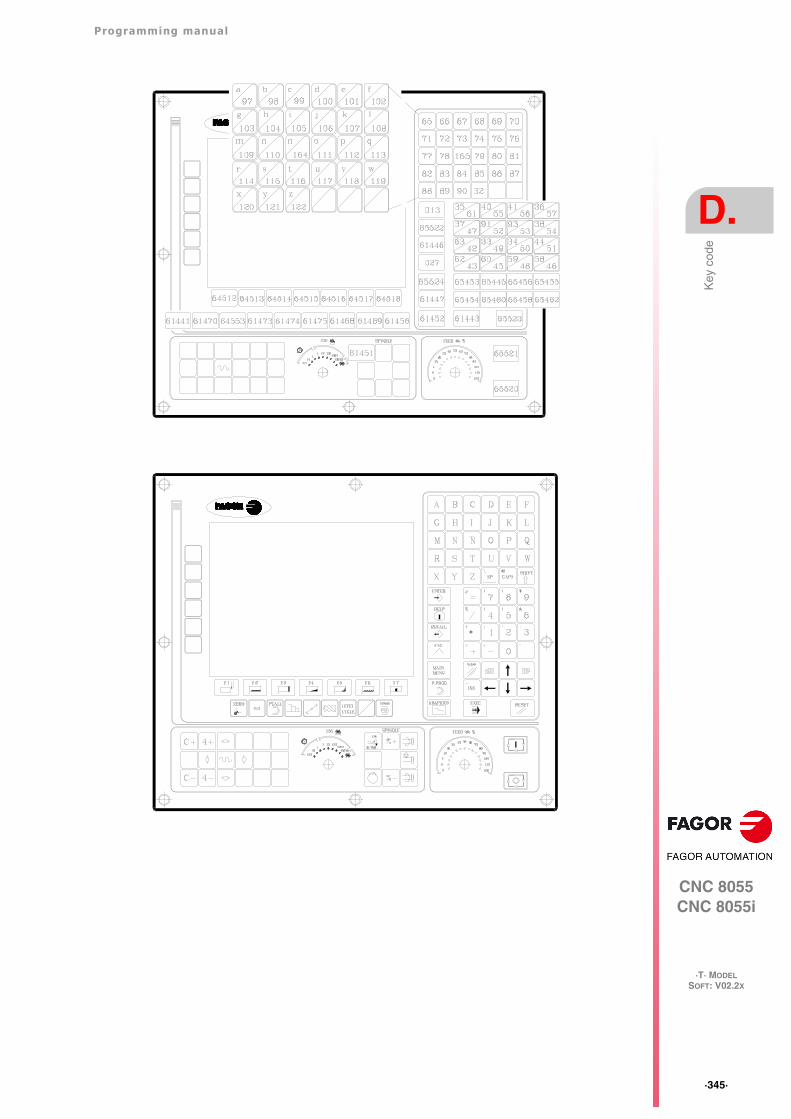
Programming manual
CNC 8055CNC 8055i
D.
·T· MODELSOFT: V02.2X
·345·
Key
cod
e
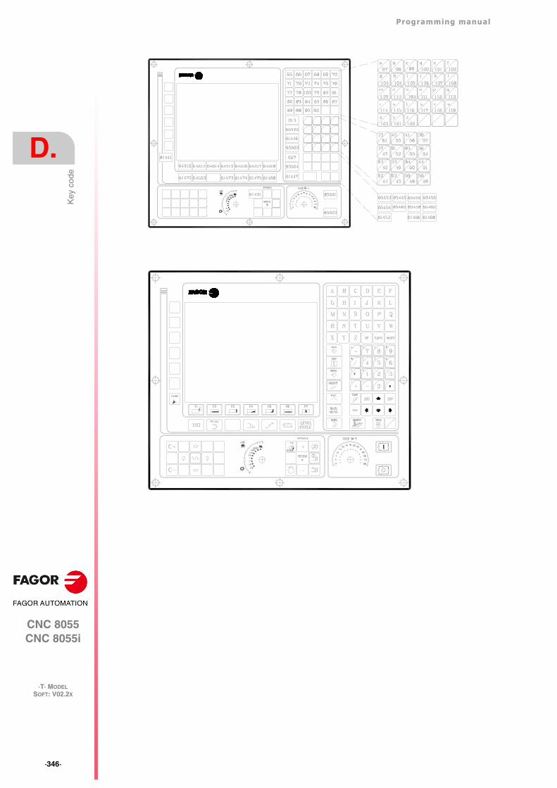
·346·
Programming manual
CNC 8055CNC 8055i
D.
·T· MODELSOFT: V02.2X
Key
cod
e
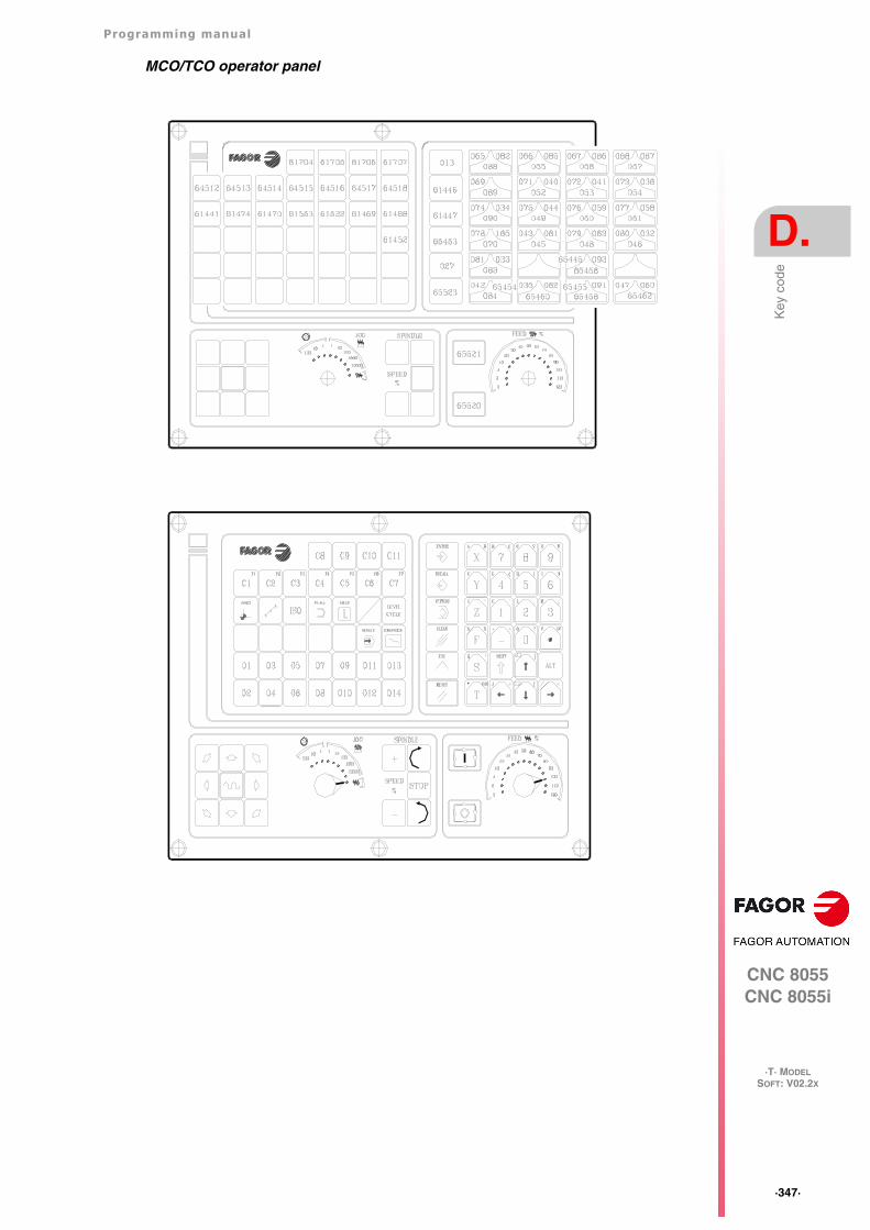
Programming manual
CNC 8055CNC 8055i
D.
·T· MODELSOFT: V02.2X
·347·
Key
cod
e
MCO/TCO operator panel
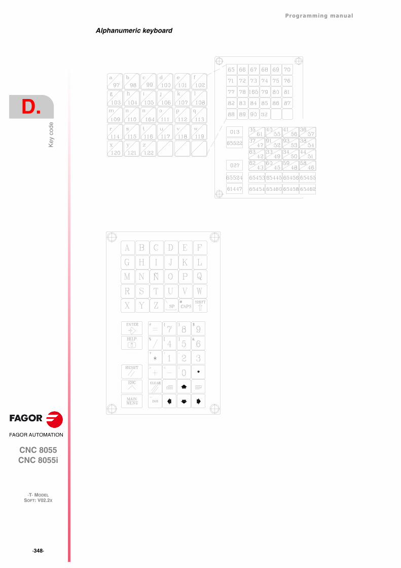
·348·
Programming manual
CNC 8055CNC 8055i
D.
·T· MODELSOFT: V02.2X
Key
cod
e
Alphanumeric keyboard
Programming manual
CNC 8055CNC 8055i
D.
·T· MODELSOFT: V02.2X
·349·
Key
cod
e
11" LCD Monitor
·350·
Programming manual
CNC 8055CNC 8055i
D.
·T· MODELSOFT: V02.2X
Key
cod
e
Programming manual
CNC 8055CNC 8055i
E.
·T· MODELSOFT: V02.2X
·351·
Pro
gram
min
g as
sist
ance
scr
eens
of t
he s
yste
m.
PROGRAMMING ASSISTANCE SCREENS OF THE SYSTEM.
These screens (pages) may be displayed using the high level instruction “PAGE”. They all belongto the CNC system and are used as help screens of the corresponding functions.
Syntax-graphics help screens
Page 1000 Preparatory functions G00-G09.
Page 1001 Preparatory functions G10-G19.
Page 1002 Preparatory functions G20-G44.
Page 1003 Preparatory functions G53-G59.
Page 1004 Preparatory functions G60-G69.
Page 1005 Preparatory functions G70-G79.
Page 1006 Preparatory functions G80-G89.
Page 1007 Preparatory functions G90-G99.
Page 1008 Auxiliary (miscellaneous) M functions.
Page 1009 Auxiliary (miscellaneous) M functions with the "next page" symbol.
Page 1010 Same as number 250 of the directory if there is one.
Page 1011 Same as number 251 of the directory if there is one.
Page 1012 Same as number 252 of the directory if there is one.
Page 1013 Same as number 253 of the directory if there is one.
Page 1014 Same as number 254 of the directory if there is one.
Page 1015 Same as number 255 of the directory if there is one.
Page 1016 High level language dictionary (from A to G).
Page 1017 High level language dictionary (from H to N).
Page 1018 High level language dictionary (from O to S).
Page 1019 High level language dictionary (from T to Z).
Page 1020 Variables that may be accessed through high level language (part 1).
Page 1021 Variables that may be accessed through high level language (part 2).
Page 1022 Variables that may be accessed through high level language (part 3).
Page 1023 Variables that may be accessed through high level language (part 4).
Page 1024 Variables that may be accessed through high level language (part 5).
Page 1025 Variables that may be accessed through high level language (part 6).
Page 1026 Variables that may be accessed through high level language (part 7).
Page 1027 Variables that may be accessed through high level language (part 8).
Page 1028 Variables that may be accessed through high level language (part 9).
Page 1029 Variables that may be accessed through high level language (part 10).
Page 1030 Variables that may be accessed through high level language (part 11).
Page 1031 Variables that may be accessed through high level language (part 12).
Page 1032 Mathematical operators.
·352·
Programming manual
CNC 8055CNC 8055i
E.
·T· MODELSOFT: V02.2X
Pro
gram
min
g as
sist
ance
scr
eens
of t
he s
yste
m.
Syntax help: ISO language
Page 1033 Structure of a program block.
Page 1034 Positioning and linear interpolation: G00, G01 (part 1).
Page 1035 Positioning and linear interpolation: G00, G01 (part 2).
Page 1036 Circular interpolation: G02, G03 (part 1).
Page 1037 Circular interpolation: G02, G03 (part 2).
Page 1038 Circular interpolation: G02, G03 (part 3).
Page 1039 Circular tangent path: G08 (part 1).
Page 1040 Circular tangent path: G08 (part 2).
Page 1041 Circular path through 3 points: G09 (part 1).
Page 1042 Circular path through 3 points: G09 (part 2).
Page 1043 Electronic threading: G33.
Page 1044 Rounding: G36.
Page 1045 Tangential entry: G37.
Page 1046 Tangential exit: G38.
Page 1047 Chamfer: G39.
Page 1048 Dwell/interruption of block preparation: G04, G04K.
Page 1049 Square/round corner: G07, G05.
Page 1050 Mirror image: G11, G12, G13, G14.
Page 1051 Programming of planes and longitudinal axis: G16, G17, G18, G19, G15.
Page 1052 Work zones: G21, G22.
Page 1053 Tool radius compensation: G40, G41, G42.
Page 1054 Zero offsets.
Page 1055 Millimeters/inches G71, G70.
Page 1056 Scaling factor: G72.
Page 1057 Home search: G74.
Page 1058 Probing: G75.
Page 1059 Axis coupling (slaving): G77, G78.
Page 1060 Absolute/incremental: G90, G91.
Page 1061 Coordinate preset and Polar origin: G92, G93.
Page 1062 Feedrate programming: G94, G95.
Page 1063 Programming of auxiliary functions F, S, T and D.
Page 1064 Programming of auxiliary (miscellaneous) M functions.
Syntax help: CNC tables
Page 1090 Tool offset table.
Page 1091 Tool table.
Page 1092 Tool magazine table.
Page 1093 Auxiliary (miscellaneous) M function table.
Page 1094 Zero offset table.
Page 1095 Leadscrew error compensation tables.
Page 1096 Cross compensation table.
Page 1097 Machine parameter tables.
Page 1098 User parameter tables.
Page 1099 Passwords table.
Programming manual
CNC 8055CNC 8055i
E.
·T· MODELSOFT: V02.2X
·353·
Pro
gram
min
g as
sist
ance
scr
eens
of t
he s
yste
m.
Syntax aids: high-level language
Page 1100 ERROR and MSG instructions.
Page 1101 GOTO and RPT instructions.
Page 1102 OPEN and WRITE instructions.
Page 1103 SUB and RET instructions.
Page 1104 CALL, PCALL, MCALL, MDOFF and PROBE instructions.
Page 1105 DSBLK, ESBLK, DSTOP, ESTOP, DFHOLD and EFHOLD instructions.
Page 1106 IF instruction.
Page 1107 Assignment blocks.
Page 1108 Mathematical expressions.
Page 1109 PAGE instruction.
Page 1110 ODW instruction.
Page 1111 DW instruction.
Page 1112 IB instruction.
Page 1113 SK instruction.
Page 1114 WKEY and SYSTEM instructions.
Page 1115 KEYSRC instruction.
Page 1116 WBUF instruction.
Page 1117 SYMBOL instruction.
Syntax help: Canned cycles
Page 1076 Pattern repeat cycle canned cycle: G66..
Page 1078 X axis roughing canned cycle: G68.
Page 1079 Z axis roughing canned cycle: G69.
Page 1080 Turning canned cycle for straight sections: G81.
Page 1081 Facing canned cycle for straight sections: G82.
Page 1082 Drilling canned cycle: G83.
Page 1083 Turning canned cycle for curved sections: G84.
Page 1084 Facing canned cycle for curved sections: G85.
Page 1085 Longitudinal threading canned cycle: G86.
Page 1086 Face threading canned cycle: G87.
Page 1087 X axis grooving canned cycle: G88.
Page 1088 Z axis grooving canned cycle: G89.
Page 1089 Tool geometry page.
·354·
Programming manual
CNC 8055CNC 8055i
E.
·T· MODELSOFT: V02.2X
Pro
gram
min
g as
sist
ance
scr
eens
of t
he s
yste
m.
Programming manual
CNC 8055CNC 8055i
F.
·T· MODELSOFT: V02.2X
·355·
Mai
nten
ance
MAINTENANCE
Cleaning
The accumulated dirt inside the unit may act as a screen preventing the proper dissipation of theheat generated by the internal circuitry which could result in a harmful overheating of the CNC and,consequently, possible malfunctions.
On the other hand, accumulated dirt can sometimes act as an electrical conductor and short-circuitthe internal circuitry, especially under high humidity conditions.
To clean the operator panel and the monitor, a smooth cloth should be used which has been dippedinto de-ionized water and /or non abrasive dish-washer soap (liquid, never powder) or 75º alcohol.
Never use air compressed at high pressure to clean the unit because it could cause the accumulationof electrostatic charges that could result in electrostatic shocks.
The plastics used on the front panel are resistant to :
• Grease and mineral oils.
• Bases and bleach.
• Dissolved detergents.
• Alcohol.
Fagor Automation shall not be held responsible for any material or physical damage derived from theviolation of these basic safety requirements.To check the fuses, first unplug the unit from mains If the CNC does not turn on when flipping the powerswitch, check that the fuses are the right ones and they are in good condition.Avoid solvents. The action of solvents such as chlorine hydrocarbons, benzole, esters and ether maydamage the plastics used to make the front panel of the unit.Do not manipulate the inside of the unit. Only personnel authorized by Fagor Automation may accessthe interior of this unit.Do not handle the connectors with the unit connected to AC power. Before handling these connectors(I/O, feedback, etc.), make sure that the unit is not connected to main AC power.
·356·
Programming manual
CNC 8055CNC 8055i
F.
·T· MODELSOFT: V02.2X
Mai
nten
ance
Programming manual
CNC 8055CNC 8055i
F.
SOFT: V02.2X
·357·
·358·
Programming manual
CNC 8055CNC 8055i
F.
SOFT: V02.2X


Fagor Automation S. Coop.
Bº San Andrés, 19 - Apdo. 144E-20500 Arrasate-Mondragón, SpainTel: +34 943 719 200
+34 943 039 800Fax: +34 943 791 712E-mail: [email protected]
FAGOR AUTOMATION


![CNC 8055 MC - ACERonline … · CNC 8055 MC 1. CONTOURS EXAMPLE: PROFILE MILLING USING THE PROFILE EDITOR REF. 0601 8 When the drawing is completed, we press [END] and the CNC will](https://static.fdocuments.in/doc/165x107/5eb75375a234a53a906276fb/cnc-8055-mc-aceronline-cnc-8055-mc-1-contours-example-profile-milling-using.jpg)