CNC 8055 M Operator Manual
705
CNC 8055 M Operating Manual Ref. 9909 (in)
Transcript of CNC 8055 M Operator Manual

8/21/2019 CNC 8055 M Operator Manual
http://slidepdf.com/reader/full/cnc-8055-m-operator-manual 1/702
CNC 8055 MOperating Manual
Ref. 9909 (in)

8/21/2019 CNC 8055 M Operator Manual
http://slidepdf.com/reader/full/cnc-8055-m-operator-manual 2/702
ii
Please note that the availability of some of the features described inthis manual depends on the software options you just obtained.
---------- o ----------The information described in this manual may be subject to variations
due to technical modifications.
FAGOR AUTOMATION, S.Coop. Ltda. reserves the right to modify the contents of the manual without prior notice.
LEDOM LEDOM LEDOM LEDOM LEDOM PGPGPGPGPG MMMMM
gnidaerhtcinortcelE elbaliavatoN elbaliavA
tnemeganamenizagamlooT elbaliavatoN elbaliavA
scihparGdiloS elbaliavatoN noitpO
selcycdennacgninihcaM elbaliavatoN elbaliavA
gninihcamelpitluM elbaliavatoN elbaliavA
selcycdennacgniborP elbaliavatoN noitpO
gnirotinomefillooT elbaliavatoN noitpO
sdnalsihtiwstekcopralugerrI elbaliavatoN noitpO
gnizitigiD elbaliavatoN noitpO
gnicarT elbaliavatoN noitpO
noitamrofsnartPCT elbaliavatoN noitpO
noitasnepmocsuidarlooT noitpO elbaliavACND noitpO noitpO
sexa7roferawtfoS noitpO noitpO
rotideeliforP noitpO noitpO
gnippatdigiR noitpO noitpO
lortnoclaitnegnaT elbaliavatoN noitpO
)ledomCM(erawtfoSlanoitasrevnoC elbaliavatoN noitpO

8/21/2019 CNC 8055 M Operator Manual
http://slidepdf.com/reader/full/cnc-8055-m-operator-manual 3/702
i i i
INDEX
VERSION HISTORY
INTRODUCTION
Safety conditions ........................................................................................................................ 3
Material returning terms .............................................................................................................. 5
Fagor documentation for the CNC ............................................................................................... 6
Manual contents ......................................................................................................................... 7
1. OVERVIEW
1.1 Part-programs ................................................................................................................................ 1
1.2 Monitor information layout...........................................................................................................4
1.3 Keyboard layout ...........................................................................................................................6
1.4 Operator panel layout ...................................................................................................................8
2 OPERATING MODES
2.1 Help systems .................................................................................................................................3
2.2 Software update ............................................................................................................................5
3 EXECUTE / SIMULATE
3.1 Block selection and stop condition ...............................................................................................4
3.2 Display selection .......................................................................................................................... 7
3.2.1 Standard display mode ..................................................................................................................9
3.2.2 Position display mode .................................................................................................................10
3.2.3. Part program display mode ..........................................................................................................10
3.2.4. Subroutine display mode .............................................................................................................113.2.5 Following error display mode ......................................................................................................14
3.2.6 User display mode .......................................................................................................................14
3.2.7 Execution time display mode ......................................................................................................15
3.3 Mdi .............................................................................................................................................17
3.4 Tool inspection ...........................................................................................................................18
3.5 Graphics ...................................................................................................................................... 20
3.5.1 Type of graphics..........................................................................................................................21
3.5.2 Display area ................................................................................................................................ 26
3.5.3 Zoom ..........................................................................................................................................27
3.5.4 Viewpoint ...................................................................................................................................28
3.5.5 Graphic parameters......................................................................................................................29
3.5.6 Clear screen ................................................................................................................................ 31
3.5.7 Deactivate graphics .....................................................................................................................31
3.5.8 Measure ...................................................................................................................................... 32
3.6 Single block................................................................................................................................33
Section Page

8/21/2019 CNC 8055 M Operator Manual
http://slidepdf.com/reader/full/cnc-8055-m-operator-manual 4/702
iv
4. EDIT
4.1 Edit ...............................................................................................................................................2
4.1.1 Editing in cnc language ................................................................................................................ 2
4.1.2 Teach-in editing ............................................................................................................................ 3
4.1.3 Interactive editor ........................................................................................................................... 4
4.1.4 Profile editor ................................................................................................................................. 5
4.1.4.1 Operation with the profile editor ................................................................................................... 6
4.1.4.2 Profile editing ............................................................................................................................... 7
4.1.4.3 Definition of a straight section ...................................................................................................... 8
4.1.4.4 Definition of a circular section ...................................................................................................... 9
4.1.4.5 Corners ....................................................................................................................................... 10
4.1.4.6 Modify........................................................................................................................................ 11
4.1.4.7 Finish .........................................................................................................................................13
4.1.4.8 Examples of profile definition ..................................................................................................... 14
4.2 Modify........................................................................................................................................18
4.3 Find ............................................................................................................................................ 194.4 Replace ....................................................................................................................................... 20
4.5 Delete block................................................................................................................................ 21
4.6 Move block ................................................................................................................................ 22
4.7 Copy block ................................................................................................................................. 23
4.8 Copy to program .........................................................................................................................24
4.9 Include program .......................................................................................................................... 25
4.10 Editor parameters ........................................................................................................................26
4.10.1 Autonumbering ........................................................................................................................... 26
4.10.2 Axes selection for teach-in editing ..............................................................................................27
5. JOG5.1 Jogging the axes ........................................................................................................................... 9
5.1.1 Continuous jog .............................................................................................................................9
5.1.2 Incremental jog ........................................................................................................................... 10
5.1.3 Jogging with electronic handwheel ............................................................................................. 11
5.1.3.1 The machine has one electronic handwheel ................................................................................. 11
5.1.3.2 The machine has several handwheels ........................................................................................... 12
5.2. Manual control of the spindle .....................................................................................................13
6. TABLES
6.1 Zero offset table ............................................................................................................................ 2
6.2 Tool offset table ............................................................................................................................ 3
6.3 Tool table...................................................................................................................................... 4
6.4 Tool magazine table ...................................................................................................................... 6
6.5 Global and local parameter tables .................................................................................................. 7
6.6 How to edit tables .........................................................................................................................8
Section Page

8/21/2019 CNC 8055 M Operator Manual
http://slidepdf.com/reader/full/cnc-8055-m-operator-manual 5/702
v
7. UTILITIES
7.1 Directory .......................................................................................................................................1
7.1.1 Directory of the external devices ...................................................................................................3
7.2 Copy.............................................................................................................................................4
7.3 Delete ...........................................................................................................................................4
7.4 Rename.........................................................................................................................................5
7.5 Protections ....................................................................................................................................6
7.6 Change date ..................................................................................................................................7
8. STATUS
8.1 CNC..............................................................................................................................................1
8.2 DNC..............................................................................................................................................2
9. PLC
9.1 Edit ...............................................................................................................................................2
9.2 Compile ........................................................................................................................................9
9.3 Monitoring .................................................................................................................................10
9.3.1 Monitoring with the plc in operation and with the plc stopped ....................................................17
9.4 Active messages .......................................................................................................................... 19
9.5 Active pages (screens) .................................................................................................................19
9.6 Save program ..............................................................................................................................19
9.7 Restore program .......................................................................................................................... 20
9.8 Resources in use..........................................................................................................................20
9.9 Statistics .....................................................................................................................................219.10 Logic analyzer ............................................................................................................................23
9.10.1 Description of the work screen..................................................................................................... 23
9.10.2 Selection of variables and trigger conditions ............................................................................... 26
9.10.2.1 Variable selection....................................................................................................................... 26
9.10.2.2 Selection of trigger condition..................................................................................................... 28
9.10.2.3 Selection of time base ................................................................................................................ 30
9.10.3 Execute trace ..............................................................................................................................31
9.10.3.1 Data capture ............................................................................................................................... 32
9.10.3.2 Modes of operation .................................................................................................................... 33
9.10.3.3 Trace representation ................................................................................................................... 34
9.10.4 Analyze trace ............................................................................................................................... 35
10. SCREEN EDITOR
10.1 Utilities.........................................................................................................................................3
10.2 Editing custom screens (pages) and symbols.................................................................................. 5
10.3 Graphic elements ........................................................................................................................10
10.4 Texts ...........................................................................................................................................15
10.5 Modifications .............................................................................................................................18
Section Page

8/21/2019 CNC 8055 M Operator Manual
http://slidepdf.com/reader/full/cnc-8055-m-operator-manual 6/702
vi
11. MACHINE PARAMETERS
11.1 Machine parameter tables .............................................................................................................. 2
11.2 Miscellaneous function tables .......................................................................................................3
11.3 Leadscrew error compensation tables ............................................................................................. 4
11.4 Cross compensation tables ............................................................................................................5
11.5 Operation with parameter tables ....................................................................................................6
12. DIAGNOSIS
12.1 Configuration ...............................................................................................................................2
12.1.1 Hardware configuration .................................................................................................................2
12.1.2 Software configuration ..................................................................................................................3
12.2 Hardware test ................................................................................................................................ 4
12.3 Memory test .................................................................................................................................. 5
12.4 Flash memory test .........................................................................................................................5
12.5 User .............................................................................................................................................. 5
12.6 Hard disk ...................................................................................................................................... 5
12.7 Interesting notes............................................................................................................................6
Section Page

8/21/2019 CNC 8055 M Operator Manual
http://slidepdf.com/reader/full/cnc-8055-m-operator-manual 7/702
Version history (M) - 1
VERSION HISTORY (M)
(MILL MODEL)
Date: May 1999 Software Version: 3.0x
ERUTAEF ERUTAEF ERUTAEF ERUTAEF ERUTAEF SRETPAHC&LAUNAMDETCEFFA SRETPAHC&LAUNAMDETCEFFA SRETPAHC&LAUNAMDETCEFFA SRETPAHC&LAUNAMDETCEFFA SRETPAHC&LAUNAMDETCEFFA
egaugnaleseugutroP launaMnoitallatsnI 3retpahC
lortnoClaitnegnaT launaMnoitallatsnI
launaMgnimmargorPxidneppA,01,9sretpahCxidneppA,31,6sretpahC
niderotinomerastimillevarterawtf osehT.senalpenilcnI.stnemevomGOJ
994Rhguorht1RsretsigerresU.CLP launaMnoitallatsnI
launaMgnimmargorPxidneppA,7,6sretpahC
31retpahC
neercssutatsCNC launaMnoitarepO 8retpahC
)DH(k siddraH launaMnoitallatsnI xidneppA,3,1sretpahC
sisongaiDDH launaMnoitarepO 21retpahC
k rowtenCPedistuonaotniDHehtetargetnI launaMnoitallatsnI 3retpahC
nismargorpypocdnaemaner,eteled,seirotceridtlusnoCecivedrehtoroemaseht
launaMnoitarepOlaunaMgnimmargorP
7,1sretpahC1retpahC
yek meM,yromemMARmorf noicalumisdnanoituce jE.enillairesroDH,draC
launaMnoitarepO ,3,1sretpahC
a)NEPO(nepodna)CEXE(etucexeotelbissopsitI.ecivedynaniderots)detideebot(margorp
launaMgnimmargorP xidneppA,41retpahC
.neercsnoitarbilaclooT.noitpoCMdezilaitinieraKdnaI;LdnaRgninif ednehW
dezilaitinieraKdnaI;0=Kdna0=If IlaunaMnoitarepO 3retpahC
IDMsaosla,tnemeganamOSI.noitpoCM launaMnoitarepOCM 3retpahC
.senalpytef aseldnahotyawweN.noitpoCM launaMnoitarepOCM 4retpahC
.syek cif icepsrof sedocweN.noitpoCM launaMnoitarepOCM xidneppA

8/21/2019 CNC 8055 M Operator Manual
http://slidepdf.com/reader/full/cnc-8055-m-operator-manual 8/702
I n t roduct ion - 1
INTRODUCTION
8/21/2019 CNC 8055 M Operator Manual
http://slidepdf.com/reader/full/cnc-8055-m-operator-manual 9/702
In trod uc ti on - 3
SAFETY CONDITIONS
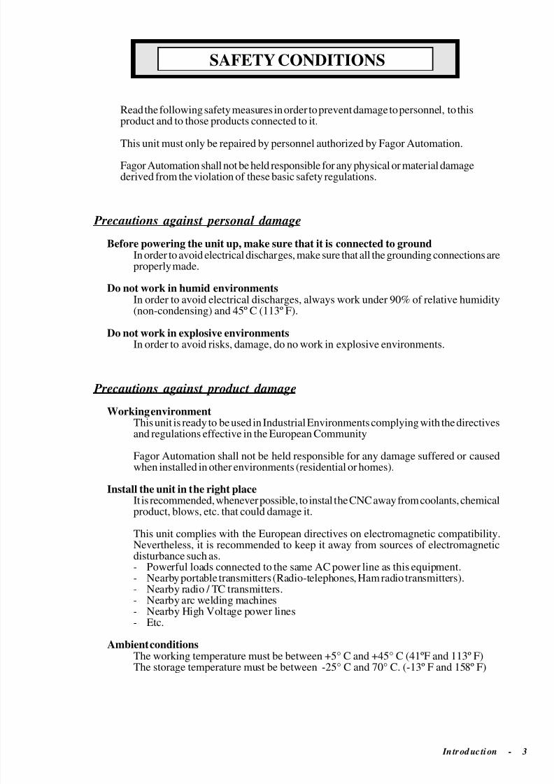
Read the following safety measures in order to prevent damage to personnel, to thisproduct and to those products connected to it.
This unit must only be repaired by personnel authorized by Fagor Automation.
Fagor Automation shall not be held responsible for any physical or material damagederived from the violation of these basic safety regulations.
Precautions against personal damage
Before powering the unit up, make sure that it is connected to groundIn order to avoid electrical discharges, make sure that all the grounding connections areproperly made.
Do not work in humid environmentsIn order to avoid electrical discharges, always work under 90% of relative humidity(non-condensing) and 45º C (113º F).
Do not work in explosive environmentsIn order to avoid risks, damage, do no work in explosive environments.
Precautions against product damage
Working environmentThis unit is ready to be used in Industrial Environments complying with the directivesand regulations effective in the European Community
Fagor Automation shall not be held responsible for any damage suffered or causedwhen installed in other environments (residential or homes).
Install the unit in the right placeIt is recommended, whenever possible, to instal the CNC away from coolants, chemicalproduct, blows, etc. that could damage it.
This unit complies with the European directives on electromagnetic compatibility.
Nevertheless, it is recommended to keep it away from sources of electromagneticdisturbance such as.- Powerful loads connected to the same AC power line as this equipment.- Nearby portable transmitters (Radio-telephones, Ham radio transmitters).- Nearby radio / TC transmitters.- Nearby arc welding machines- Nearby High Voltage power lines- Etc.
Ambient conditionsThe working temperature must be between +5° C and +45° C (41ºF and 113º F)The storage temperature must be between -25° C and 70° C. (-13º F and 158º F)

8/21/2019 CNC 8055 M Operator Manual
http://slidepdf.com/reader/full/cnc-8055-m-operator-manual 10/702
In troduc ti on - 4
Protections of the unit itself
Power Supply ModuleIt carries two fast fuses of 3.15 Amp./ 250V. to protect the mains AC input
Axes moduleAll the digital inputs and outputs have galvanic isolation via optocouplers between theCNC circuitry and the outside.They are protected by an external fast fuse (F) of 3.15 Amp./ 250V. against reverseconnection of the power supply.
Input / Output ModuleAll the digital inputs and outputs have galvanic isolation via optocouplers between theCNC circuitry and the outside.They are protected by an external fast fuse (F) of 3.15 Amp./ 250V. against a voltageoverload (greater than 33Vdc) and against reverse connection of the power supply.
Input / Output and Tracing ModuleAll the digital inputs and outputs have galvanic isolation via optocouplers between theCNC circuitry and the outside.
They are protected by an external fast fuse (F) of 3.15 Amp./ 250V. against a voltageoverload (greater than 33Vdc) and against reverse connection of the power supply.
Fan ModuleIt carries 1 or 2 external fuses depending on modelThe fuses are fast (F), of 0.4 Amp./ 250V. to protect the fans.
MonitorThe type of protection fuse depends on the type of monitor. See the identification labelof the unit itself.
Precautions during repair
Do not manipulate the inside of the unitOnly personnel authorized by Fagor Automation may manipulate theinside of this unit.
Do not manipulate the connectors with the unit connected to AC power.Before manipulating the connectors (inputs/outputs, feedback, etc.)make sure that the unit is not connected to AC power.
Safety symbols
Symbols which may appear on the manual
WARNING. symbolIt has an associated text indicating those actions or operations may hurt peopleor damage products.
Symbols that may be carried on the product
WARNING. symbolIt has an associated text indicating those actions or operations may hurt peopleor damage products.
"Electrical Shock" symbolIt indicates that point may be under electrical voltage
"Ground Protection" symbolIt indicates that point must be connected to the main ground point of themachine as protection for people and units.
8/21/2019 CNC 8055 M Operator Manual
http://slidepdf.com/reader/full/cnc-8055-m-operator-manual 11/702
In trod uc ti on - 5
MATERIAL RETURNING TERMS
When returning the Monitor or the Central Unit, pack it in its original package and with itsoriginal packaging material. If not available, pack it as follows:
1.- Get a cardboard box whose three inside dimensions are at least 15 cm (6 inches) largerthan those of the unit. The cardboard being used to make the box must have a resistanceof 170 Kg (375 lb.).
2.- When sending it to a Fagor Automation office for repair, attach a label indicating theowner of the unit, person to contact, type of unit, serial number, symptom and a brief description of the problem.
3.- Wrap the unit in a polyethylene roll or similar material to protect it.
When sending the monitor, especially protect the CRT glass
4.- Pad the unit inside the cardboard box with poly-utherane foam on all sides.
5.- Seal the cardboard box with packing tape or industrial staples.

8/21/2019 CNC 8055 M Operator Manual
http://slidepdf.com/reader/full/cnc-8055-m-operator-manual 12/702
In troduc ti on - 6
FAGOR DOCUMENTATIONFOR THE CNC
OEM Manual Is directed to the machine builder or person in charge of installing and starting-up the CNC.
USER Manual Is directed to the end user or CNC operator.
It contains 2 manuals:Operating Manual describing how to operate the CNC.Programming Manual describing how to program the CNC.
DNC Software Manual Is directed to people using the optional DNC communications software.
DNC Protocol Manual Is directed to people wishing to design their own DNC communications softwareto communicate with the CNC.
FLOPPY DISK Manual Is directed to people using the Fagor Floppy Disk Unit and it shows how to useit.

8/21/2019 CNC 8055 M Operator Manual
http://slidepdf.com/reader/full/cnc-8055-m-operator-manual 13/702
In trod uc ti on - 7
MANUAL CONTENTS
The operating Manual for the Mill model CNC contains the following chapters:
Index
New features and modifications for the Mill Model.
Introduction Summary of safety conditionsShipping termsFagor documentation for the CNCManual contents.
Chapter 1 OverviewLocation of the part-programs, how to edit and execute them.It indicates the layout of the keyboard, operator panel and of the data on the monitor.
Chapter 2 Operating modes.Description of the different operating modes of the CNC.
Chapter 3 Execute / SimulateIt describes how to operate in the "Execution" and "Simulation" modes.Both operations may be performed in automatic or single block mode.
Chapter 4 EditDescription of the "Edit" mode of operation.The different ways to edit a part-program are: in CNC language, in Teach-in mode,using the Interactive editor and the Profile editor.
Chapter 5 JogDescription of the "Jog" mode of operation.This is the operating mode to be used whenever the machine is to be controlledmanually to move the axes of the machine as well as to control the spindle.
Chapter 6 Tables
Description of the "Tables" mode of operation.It allows access to the various data tables of the CNC: Zero offsets, Tool offsets, Tooltable, tool magazine and global and local arithmetic parameters.
Chapter 7 UtilitiesDescription of the "Utilities" mode of operation.It allows access to the directory of part-programs, subroutines and to the part-program directory of the PC or peripheral device connected to the CNC. It is alsopossible to copy, delete, move or rename part-programs.It indicates the protections that could be assigned to a part-program.It shows the various ways to operate with the Flash memory.
Chapter 8 StatusIt shows the status of the "CNC" and DNC communication lines.It describes the "DNC" mode of operation and how to operate via serial interfaces.
Chapter 9 PLCDescription of the "PLC" mode of operation.It shows how to edit and compile the PLC programIt is possible to verify how the PLC program works and the status of its numerousvariables.It shows the date the PLC program was edited, its memory size and the executiontimes (cycle times) for its different modules.It offers a detailed description of the logic analyzer.
8/21/2019 CNC 8055 M Operator Manual
http://slidepdf.com/reader/full/cnc-8055-m-operator-manual 14/702
In troduc ti on - 8
Chapter 10 Graphic EditorDescription of the "Graphic Editor" mode of operation".It indicates how to create user defined pages (screens) and symbols to create userscreens.It shows how to use user pages in customizing programs, how to display a user pageon power-up and how to activate user pages from the PLC.
Chapter 11 Machine parametersDescription of the "Machine parameters" mode.
It is possible to access and operate with the tables for machine parameters, miscel-laneous "M" functions, leadscrew error compensation and cross compensation.
Chapter 12 DiagnosisDescription of the "Diagnosis" modeIt is possible to know the CNC configuration and run a system test.

8/21/2019 CNC 8055 M Operator Manual
http://slidepdf.com/reader/full/cnc-8055-m-operator-manual 15/702
PageChapter: 1
OVERVIEW
Section:
1
1. OVERVIEW
In this manual an explanation is given of how to operate the CNC by means of its Monitor-Keyboard unit and the Operator Panel.
The Monitor-Keyboard unit consists of:
* The Monitor or CRT screen, which is used to show the required system information.
* The Keyboard, which allows communication with the CNC, allowing information tobe requested by means of commands or by changing the CNC status by generating newinstructions.
1.1 PART-PROGRAMS
Editing
To create a part-program, access the Edit mode. See chapter 5 in this manual.
The new part-program edited is stored in the CNC's RAM memory.
A copy of the part-programs may be stored in the "MemKey Card", at a PCconnected through serial line 1 or 2 or in the hard disk (HD module). See chapter7 in this manual.
When using a PC through serial line 1 or 2, proceed as follows:• Execute the "Fagor50.exe" applications program at the PC.• Activate DNC communications at the CNC. See chapter 8 in this manual.• Select the work directory as shown in chapter 7 of this manual. Option: Utilities\
Directory\ Serial L.\ Change directory.
With the Edit mode of operation, part-programs residing in the CNC's RAM
memory may be modified. To modify a program stored in the "MemKey Card", ina PC or in the hard disk, it must be previously copied into RAM memory.
Execution
Part-programs stored anywhere may be executed or simulated. See chapter 3 in thismanual.
The user customizing programs must be in RAM memory so the CNC can executethem.
The GOTO and RPT instructions cannot be used in programs executed from a PC
connected through the serial lines. See chapter 14 of the programming manual.
8/21/2019 CNC 8055 M Operator Manual
http://slidepdf.com/reader/full/cnc-8055-m-operator-manual 16/702
Section:
OVERVIEWChapter: 1
2Page
The subroutines can only be executed if they reside in the CNC's RAM memory.Therefore, to execute a subroutine stored in the "MemKey Card", in a PC or in the harddisk, it must be first copied into the CNC's RAM memory.
From a program in execution, another program can be executed which is in RAMmemory, in the "MemKey Card", in a PC or in the hard disk using the EXECinstruction. See chapter 14 of the programming manual.
Utilities
This operating mode, chapter 7 of this manual, lets display the part-programdirectory of all the devices, make copies, delete, rename and even set the protectionsfor any of them.
Ethernet
When having the Ethernet option and if the CNC is configured as another nodewithin the computer network, the following operations are possible from any PCof the network:
• Access the part-program directory of the Hard Disk(HD).• Edit, modify, delete, rename, etc.the programs stored on the hard disk (HD).• Copy programs from the hard disk to the PC and vice versa.
To configure the CNC as another node within the computer network, see section 3.3.4of the installation manual.
8/21/2019 CNC 8055 M Operator Manual
http://slidepdf.com/reader/full/cnc-8055-m-operator-manual 17/702
PageChapter: 1
OVERVIEW
Section:
3
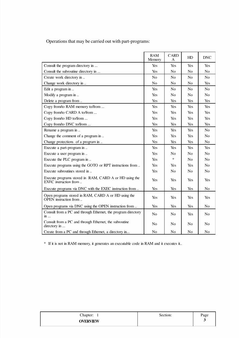
Operations that may be carried out with part-programs:
MAR
yromeM
DRAC
A DH CND
...niyrotceridmargorpehttlusnoC seY seY seY seY
...niyrotceridenituorbusehttlusnoC seY oN oN oN
..niyrotceridk rowetaerC oN oN oN oN
..niyrotceridk rowegnahC oN oN oN seY
..nimargorpatidE seY oN oN oN
..nimargorpayf idoM seY oN oN oN
..morf margorpaeteleD seY seY seY seY
...morf / otyromemMARot / morf ypoC seY seY seY seY
...morf / otADRACot / morf ypoC seY seY seY seY
...morf / otDHot / morf ypoC seY seY seY seY...morf / otCNDot / morf ypoC seY seY seY seY
..nimargorpaemaneR seY seY seY oN
..nimargorpaf otnemmocehtegnahC seY seY seY oN
..nimargorpaf osnoitcetorpegnahC seY seY seY oN
..nimargorp-trapaetucexE seY seY seY seY
..nimargorpresuaetucexE seY oN oN oN
..nimargorpCLPehtetucexE seY * oN oN
..morf snoitcurtsniTPRroOTOGehtgnisusmargorpetucexE seY seY seY oN
..niderotssenituorbusetucexE seY oN oN oN
ehtgnisuDHroADRAC,MARniderotssmargorpetucexE..morf noitcurtsniCEXE
seY seY seY seY
..morf noitcurtsniCEXEehthtiwCNDaivsmargorpetucexE seY seY seY oN
ehtgnisuDHroADRAC,MARniderotssmargorpnepO..morf noitcurtsniNEPO
seY seY seY seY
..morf noitcurtsniNEPOehtgnisuCNDaivsmargorpnepO seY seY seY oN
yrotceridmargorpeht,tenrehtEhguorhtdnaCPamorf tlusnoC...ni
oN oN seY oN
enituorbuseht,tenrehtEhguorhtdnaCPamorf tlusnoC...niyrotcerid
oN oN oN oN
...niyrotcerida,tenrehtEhguorhtdnaCPamorf etaerC oN oN oN oN
..tisetucexetidnaMARniedocelbatucexenasetarenegti,yromemMARnitonsitif I*

8/21/2019 CNC 8055 M Operator Manual
http://slidepdf.com/reader/full/cnc-8055-m-operator-manual 18/702
Section:
OVERVIEWChapter: 1
4Page
1.2 MONITOR INFORMATION LAYOUT
The monitor is divided into the following areas or display windows:
1.- This window indicates the selected operating mode, as well as the program number andthe number of active blocks.
The program status is also indicated (in execution or interrupted) and if the DNC is active.
2.- This window indicates the time in the “ hours : minutes : seconds “ format.
3.- This window displays the Messages sent to the operator from the part program or via DNC.
The last message received will be shown regardless of where it has come from.
4.- This window will display messages from the PLC.
If the PLC activates two or more messages, the CNC will always display the one withthe highest priority, which is the message with the smallest number. In this way, MSG1will have the highest priority and MSG128 will have the lowest.
In this case the CNC will display the character+ (plus sign), indicating that there are more
messages activated by the PLC, it being possible to display them if the ACTIVE
MONITOR INFORMATIONLAYOUT

8/21/2019 CNC 8055 M Operator Manual
http://slidepdf.com/reader/full/cnc-8055-m-operator-manual 19/702
PageChapter: 1
OVERVIEW
Section:
5
MESSAGE option is accessed in the PLC mode.
In this window the CNC will also display the character * (asterisk), to indicate that at leastone of the 256 user-defined screens is active.
The screens which are active will be displayed, one by one, if the ACTIVE PAGESoption is accessed in the PLC mode.
5.-Main window.
Depending on the operating mode, the CNC will show in this window all the informationnecessary.
When a CNC or PLC error is produced the system displays this in a superimposedhorizontal window.
The CNC will always display the most important error and it will show:
* The "down arrow" key to indicate that another less important error has also occurredand to press this key to view its message.
* The "up arrow" key to indicate that another more important error has also occurredand to press this key to view its message.
6.-Editing window.
In some operating modes the last four lines of the main window are used as editing area.
7.-CNC communications window (errors detected in edition, nonexistent program, etc.)8.-This window displays the following information:
SHF Indicates that the SHIFT key has been pressed to activate the secondfunction of the keys.
For example, if key is pressed after the SHIFT key, the CNC willunderstand that the “$” character is required.
CAP This indicates capital letters (CAPS key). The CNC will understand thatcapital letters are required whenever this is active.
INS/REP Indicates if it is insert mode (INS) or substitution (REP) mode. It isselected by means of the INS key.
MM/INCH Indicates the unit system (millimeters or inches) selected for display.
9.-Shows the different options which can be selected with soft-keys F1 thru F7.
MONITOR INFORMATIONLAYOUT

8/21/2019 CNC 8055 M Operator Manual
http://slidepdf.com/reader/full/cnc-8055-m-operator-manual 20/702
Section:
OVERVIEWChapter: 1
6Page
1.3 KEYBOARD LAYOUT
In accordance with the use of the different keys, it can be understood that the CNC keyboardis divided in the following way:
1.-Alphanumeric keyboard for the data entry in memory, selection of axes, tool offset, etc.
2.-Keys which allow the information shown on screen to be moved forward or backward,page to page or line to line, as well as moving the cursor all over the screen.
The CL key allows the character over which the cursor is positioned or the last oneintroduced, if the cursor is at the end of the line, to be erased.
The INS key allows the insert or substitution mode to be selected.
3.-Group of keys which due to their characteristics and importance are detailed below:
KEYBOARD LAYOUT
4 3
2
1

8/21/2019 CNC 8055 M Operator Manual
http://slidepdf.com/reader/full/cnc-8055-m-operator-manual 21/702
PageChapter: 1
OVERVIEW
Section:
7KEYBOARD LAYOUT
ENTER Used to validate CNC and PLC commands generated in the editionWindow.
HELP Allows access to the help system in any operating mode.
RESET Used for initializing the history of the program in execution, byassigning it the values defined by machine parameters. It is necessary forthe program to be stopped for the CNC to accept this key.
ESC Allows going back to the previous operating option shown on the monitor.
MAIN MENU When this key is pressed we can access the main CNC menu directly.
4.-SOFTKEYS or function keys which allow different operating options to be selected andwhich are shown on the monitor.
In addition, there are the following special keyboard sequences:
SHIFT RESET The result of this keystroke sequence is the same as if the CNC is turnedoff and turned back on. This option must be used after modifying themachine parameters of the CNC for these to be effective.
SHIFT CL With this keystroke sequence the display on the CRT screen disappears.To restore the normal state just press any key.
If, when the screen is off, an error is produced or a message from thePLC or CNC is received, the normal status of the screen will be restored.
SHIFT This allows the position of the axes to be displayed on the right hand sideof the screen as well as the status of the program being executed.
This can be used in any operating mode.
In order to recover the previous display it is necessary to press the keysusing the same sequence.

8/21/2019 CNC 8055 M Operator Manual
http://slidepdf.com/reader/full/cnc-8055-m-operator-manual 22/702
Section:
OVERVIEWChapter: 1
8Page
1.4 OPERATOR PANEL LAYOUT
According to the utility which the different parts have, it can be considered that the OperatorPanel of the CNC is divided in the following way:
1.- Position of the emergency button or electronic handwheel.
2.-Keyboard for manual movement of axes.
3.-Selector switch with the following functions:
Select the multiplication factor of the number of pulses from the electronic handwheel(1, 10 or 100).
Select the incremental value of the movement of the axes in movements made in the
“JOG” mode.Modify the programmed axis feedrate between 0% and 120%
4.-Keyboard which allows the spindle to be controlled, it being possible to activate it in thedesired direction, stop it or vary the programmed turning speed between percentagevalues established by means of spindle machine parameters “MINSOVR” and“MAXOVR”, with an incremental step established by means of the spindle machineparameter “SOVRSTEP”.
5.-Keyboard for CYCLE START and CYCLE STOP of the block or program to beexecuted.
OPERATOR PANELLAYOUT
1 32 4 5

8/21/2019 CNC 8055 M Operator Manual
http://slidepdf.com/reader/full/cnc-8055-m-operator-manual 23/702
PageChapter: 2
OPERATING MODE
Section:
1
2. OPERATING MODES
After turning on the CNC, or after pressing the sequence of SHIFT-RESET keys, theFAGOR logo will appear in the main window of the monitor or the screen previouslyprepared as page 0 by means of the GRAPHIC EDITOR.
If the CNC shows the message “ Initialize? (ENTER / ESC) “, it should be borne in mindthat after pressing the ENTER key, all the information stored in memory and the machineparameters are initialized to default values indicated in the installation manual.
On the lower part of the screen the main CNC menu will be shown, it being possible to selectthe different operating modes by means of the softkeys F1 thru F7.
Whenever the CNC menu has more options than number of softkeys (7), the character “+”will appear in softkey f7. If this softkey is pressed the CNC will show the rest of the optionsavailable.
The options which the main CNC menu will show after turning it on, after pressing the keysequence SHIFT-RESET or after pressing the “MAIN MENU” softkey are:
EXECUTE Allows the execution of part programs in automatic or single block.
SIMULATE Allows simulation of parts programs in several modes.EDIT Allows editing new and already-existing part programs.
JOG Allows manual control of the machine by means of the Control Panel keys.
TABLES Allows CNC tables relating to part programs (Zero Offsets, Tool Offsets, Tools,Tool Magazine and global or local arithmetic parameters) to be manipulated.
UTILITIES Allows program manipulation (copy, delete, rename, etc.)
STATUS It shows the CNC status and that of the DNC communication lines. It also letsactivate and deactivate the communication with a PC through DNC.
DNC Allows communication with a computer via DNC to be activated or deactivated.
PLC Allows operation with the PLC (edit the program, monitor, change the status of itsvariables, access to the active messages, errors, pages, etc).

8/21/2019 CNC 8055 M Operator Manual
http://slidepdf.com/reader/full/cnc-8055-m-operator-manual 24/702
Section:
OPERATING MODESChapter: 2
2Page
GRAPHIC EDITOR Allows, by means of a simple graphics editor, the creation of user-defined screens (pages), which can later be activated from the PLC, used in customizedprograms or presented when the unit is powered on (page 0).
MACHINE PARAMETERS Allows the machine parameters to be set to adapt the CNCto the machine.
DIAGNOSIS Makes a test of the CNC.
While the CNC is executing or simulating a part program it allows any other type of operating mode to be accessed without stopping the execution of the program.
In this way it is possible to edit a program while another is being executed or simulated.
It is not possible to edit the program which is being executed or simulated, nor execute or
simulate two part programs at the same time.

8/21/2019 CNC 8055 M Operator Manual
http://slidepdf.com/reader/full/cnc-8055-m-operator-manual 25/702
PageChapter: 2
OPERATING MODE
Section:
3
2.1 HELP SYSTEMS
The CNC allows access to the help system (main menu, operating mode, editing of commands, etc.) at any time.
To do this, you must press the HELP key and the corresponding help page will be shownin the main window of the screen.
If the help consists of more than one page of information, the symbol indicating that
this key can be pressed to access the following page or the indicating that it is possible
to press this key to access the previous page.
The following help is available:
* OPERATING HELP
This is accessed from the operating mode menu, or when one of these has been selectedbut none of the options shown have been selected. In all these cases, the softkeys havea blue background color.
It offers information on the operating mode or corresponding option.
While this information is available on screen it is not possible to continue operating theCNC via the softkeys, it being necessary to press the HELP key again to recover theinformation which was on the main screen before requesting help and continuing withthe operation of the CNC.
The help system can also be abandoned by pressing the ESC key or the MAIN MENUkey.
* EDITING HELP
This is accessed once one of the editing options has been selected (part programs, PLCprogram, tables, machine parameters, etc.) In all these cases, the softkeys have a whitebackground.
It offers information on the corresponding option.
While this information is available, it is possible to continue operating with the CNC.
If the HELP key is pressed again, the CNC analyzes if the present editing statuscorresponds to the same help page or not.
If another page corresponds to it, it displays this instead of the previous one and if thesame one corresponds, it recovers the information which was in the main windowbefore requesting help.
The help menu can also be abandoned after pressing the ESC key, to return to theprevious operating option, or the MAIN MENU key to return to the main menu.
HELP SYSTEMS

8/21/2019 CNC 8055 M Operator Manual
http://slidepdf.com/reader/full/cnc-8055-m-operator-manual 26/702
Section:
OPERATING MODESChapter: 2
4Page
* CANNED CYCLES EDITING HELP
It is possible to access this help when editing a canned cycle.
It offers information on the corresponding canned cycle and an editing assistance forthe selected canned cycle is obtained at this point.
For the user’s own cycles a similar editing assistance can be obtained by means of a userprogram. This program must be prepared with screen customizing instructions.
Once all the fields or parameters of the canned cycle have been defined the CNC willshow the information which exists in the main window before requesting help.
The canned cycle which is programmed by means of editing assistance will be shownin the editing window, and the operator can modify or complete this block beforeentering it in memory by pressing the ENTER key.
Editing assistance can be abandoned at any time by pressing the HELP key. The CNCwill show the information which existed on the main window before requesting helpand allows programming of the canned cycle to continue in the editing window.
The help menu can also be abandoned after pressing the ESC key, to return to theprevious operating option, or the MAIN MENU key to return to the main menu.
HELP SYSTEMS
8/21/2019 CNC 8055 M Operator Manual
http://slidepdf.com/reader/full/cnc-8055-m-operator-manual 27/702
PageChapter: 2
OPERATING MODE
Section:
5
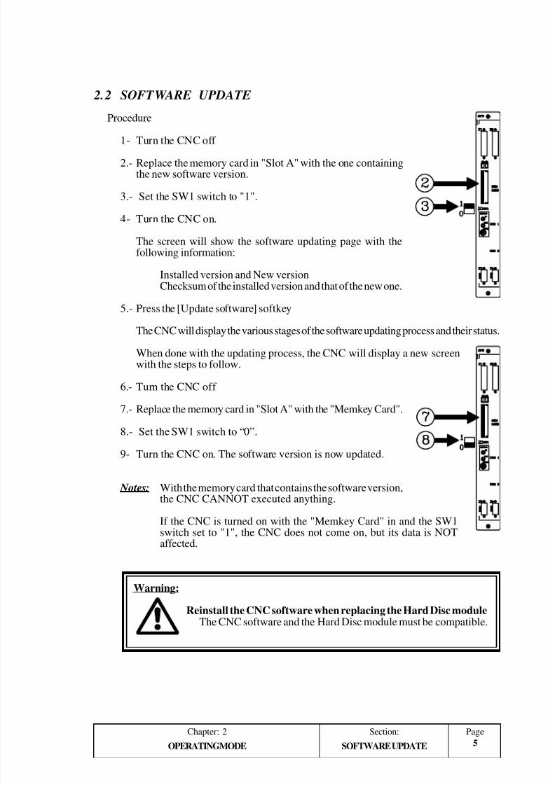
2.2 SOFTWARE UPDATE
Procedure
1- Turn the CNC off
2.- Replace the memory card in "Slot A" with the one containingthe new software version.
3.- Set the SW1 switch to "1".
4- Turn the CNC on.
The screen will show the software updating page with thefollowing information:
Installed version and New versionChecksum of the installed version and that of the new one.
5.- Press the [Update software] softkey
The CNC will display the various stages of the software updating process and their status.
When done with the updating process, the CNC will display a new screenwith the steps to follow.
6.- Turn the CNC off
7.- Replace the memory card in "Slot A" with the "Memkey Card".
8.- Set the SW1 switch to “0”.
9- Turn the CNC on. The software version is now updated.
Notes: With the memory card that contains the software version,the CNC CANNOT executed anything.
If the CNC is turned on with the "Memkey Card" in and the SW1switch set to "1", the CNC does not come on, but its data is NOTaffected.
Warning:
Reinstall the CNC software when replacing the Hard Disc moduleThe CNC software and the Hard Disc module must be compatible.
SOFTWARE UPDATE

8/21/2019 CNC 8055 M Operator Manual
http://slidepdf.com/reader/full/cnc-8055-m-operator-manual 28/702
PageChapter: 3
EXECUTE / SIMULATE
Section:
1
3 EXECUTE / SIMULATE
The EXECUTE operating mode allows the execution of part programs in automatic modeor in single block mode.
The SIMULATE operating mode allows the simulation of part-programs in automatic orsingle block mode.
When selecting one of these operating modes, one must indicate the location of the part-
program to be executed or simulated.
The part program may be stored in the CNC's internal RAM memory, in the "MemkeyCard", in PC connected through serial line 1 or 2, or in the hard disk (HD module).
After pressing one of these softkeys, the CNC displayes the corresponding part-programdirectory.
The program may be selected by:
• Keying in its number and pressing [ENTER] or• Positioning the cursor of the scren over the desired program and pressing [ENTER].
When wished to SIMULATE a part-program, the CNC will request the type of simulationto be carried out as shown on the next page.
The executing or simulating conditions (fist block, type of graphics, etc.) may be set beforeexecuting or simulating the part-program. These conditions may also be modified if theexecution or simulation is interrupted.
To execute or simulate a part-program, press
Note: To switch to JOG mode once executed or simulated a part program (or a section of it), the CNC will maintain the machining conditions (type of movement, feedrates,
etc.) selected while executing or simulating it.
8/21/2019 CNC 8055 M Operator Manual
http://slidepdf.com/reader/full/cnc-8055-m-operator-manual 29/702
Section:
EXECUTE / SIMULATEChapter: 3
2Page
The executing or simulating conditions (fist block, type of graphics, etc.) that may be setbefore executing or simulating the part-program are:
THEORETICAL PATH
Simulates the execution of the program without moving the axes, without taking toolradius compensation into consideration and without executing the auxiliary M, S, Tfunctions.
G FUNCTIONS
Simulates the execution of the program without moving the axes, by executing theprogrammed G functions and without executing the auxiliary M, S, T functions.
G, M, S, T FUNCTIONS
Simulates the execution of the program without moving the axes, by executing the Gfunctions and programmed auxiliary M, S, T functions.
MAIN PLANE
This option executes the selected part-program moving only the axes forming the mainplane and executing the programmed M, S, T and G functions.
The axes movement will be carried out at top F0 feedrate regardless of the F0 valueprogrammed. This feedrate can be modified by means of the feedrate override switch.
RAPID
Verifies the execution of the program by moving the axes, executing the G functionsand the programmed auxiliary M, S, T functions.
Movements of the axes will be executed at the maximum feedrate permitted F0,regardless of the programmed F feedrates, thus allowing this feedrate to be varied bymeans of the FEEDRATE OVERRIDE switch.
8/21/2019 CNC 8055 M Operator Manual
http://slidepdf.com/reader/full/cnc-8055-m-operator-manual 30/702
PageChapter: 3
EXECUTE / SIMULATE
Section:
3
Once the required program has been selected in the EXECUTION or SIMULATION
modes and before pressing the key (cycle start) on the Operator Panel in order
for the CNC to execute it, the following operations will be available:
BLOCK SELECTION
It allows selecting the block in which the execution or the simulation of the programwill start.
STOP CONDITION
It allows selecting the block in which the execution or the simulation of the programwill stop.
DISPLAY SELECTION
It allows the display mode to be selected.
MDI
It allows any type of block (ISO or high level) to be edited with programmingassistance by means of softkeys.
Once a block has been edited and after pressing the key (cycle start), the CNC
will execute this block without leaving this operating mode.
TOOL INSPECTIONOnce the execution of the program has been interrupted, this option allows the tool tobe inspected and changed should this be necessary.
GRAPHICS
This option carries out a graphic representation of the part during the execution orsimulation of the selected part program.
It also allows selecting the type of graphic, the area to be displayed, the viewpoint andgraphic parameters.
SINGLE BLOCK
Allows the part program to be executed one block at a time or continuously.

8/21/2019 CNC 8055 M Operator Manual
http://slidepdf.com/reader/full/cnc-8055-m-operator-manual 31/702
Section:
EXECUTE / SIMULATEChapter: 3
4Page
BLOCK SELECTION AND STOPCONDITION
3.1 BLOCK SELECTION AND STOP CONDITION
The CNC will start to execute the required block from the first line of the program and willfinish it when one of the program end functions M02 or M30 is executed.
If it is required to modify one of these conditions the BLOCK SELECTION and STOPCONDITION functions must be used.
BLOCK SELECTION
With this option it is possible to indicate the beginning block of the selected programexecution or simulation. This cannot be used when the CNC is already executing orsimulating the selected program.
When this option is selected, the CNC will show the selected program since the initialblock must always belong to this program.
The operator must select with the cursor the block where the execution or simulationof the program will be started.
To do this, the cursor can be moved line by line with the up and down arrow keys orpage by page with the page-up and page-down keys.
The “find” softkey options are also available:
BEGINNING: By pressing this key, the cursor will position at the first line of theprogram.
END: By pressing this key, the cursor will position at the last line of the program.
TEXT: With this function it is possible to search for a text or character sequencestarting at the current cursor position.
When this softkey is pressed, the CNC requests the character sequence to befound.
Once this text has been keyed in, press the "END OF TEXT" softkey and thecursor will position over the first occurrence of the keyed text.
The found text will be highlighted and it will be possible to continue (by pressing"ENTER") with the search all along the program or quit by pressing either the
"ESC" key or "ABORT" softkey.
The search can be done as many times as it is desired. Once searched to the endof the program, it will continue the search from the beginning.
When quitting the search mode, the cursor will be positioned at the last matchingtext found.
LINE NUMBER: After pressing this key, the CNC will request the number of theline to be found. Key in the desired line number and press ENTER. The cursorwill, then, be positioned at the desired line.
Once the desired starting block is selected, press ENTER to validate it.
8/21/2019 CNC 8055 M Operator Manual
http://slidepdf.com/reader/full/cnc-8055-m-operator-manual 32/702
PageChapter: 3
EXECUTE / SIMULATE
Section:
5
STOP CONDITION
With this option it is possible to indicate the final execution or simulation block of the selected program. This cannot be used when the CNC is already executing orsimulating the selected program.
When selecting this option, the CNC will show the following softkey functions:
PROGRAM SELECTION
This option will be used when the final execution or simulation block belongs toanother program or to a subroutine resident in another program.
The CNC shows the part-program directory of the RAM memory. Use the cursorto select the desired program and press ENTER.
Then, carry out the BLOCK SELECTION as described next.
BLOCK SELECTION
Use the cursor to select the last program block to be executed.
Use the up and down arrow keys or page by page with the page-up and page-downkeys.
The “find” softkey options are also available:
BEGINNING: By pressing this key, the cursor will position at the first line of the
program.END: By pressing this key, the cursor will position at the last line of the
program.
LINE NUMBER: After pressing this key, the CNC will request the number of the line to be found. Key in the desired line number and pressENTER. The cursor will, then, be positioned at the desired line.
Once the desired final block has been selected, press ENTER to validate it.
BLOCK SELECTION AND STOPCONDITION

8/21/2019 CNC 8055 M Operator Manual
http://slidepdf.com/reader/full/cnc-8055-m-operator-manual 33/702
Section:
EXECUTE / SIMULATEChapter: 3
6Page
NUMBER OF TIMES
This function will be used to indicate that the execution or simulation of theselected program must stop after executing the “end block” a specific number of times.
When selecting this function, the CNC will request the number of times to beexecuted or simulated.
If a canned cycle or a call to a subroutine has been selected as the end block of the program, the CNC will stop after executing the complete canned cycle or theindicated subroutine.
If the selected block has a number of block repetitions, the program will stop afterdoing all the repetitions indicated.
BLOCK SELECTION AND STOPCONDITION

8/21/2019 CNC 8055 M Operator Manual
http://slidepdf.com/reader/full/cnc-8055-m-operator-manual 34/702
PageChapter: 3
EXECUTE / SIMULATE
Section:
7DISPLAY SELECTION
3.2 DISPLAY SELECTION
With this option, it is possible to select the most appropriate display mode at any time evenduring execution or simulation of a part program.
The display modes available at the CNC and which can be selected with softkeys are:
STANDARDPOSITIONPART PROGRAMSUBROUTINESFOLLOWING ERRORSUSEREXECUTION TIMES
All the display modes have a window at the bottom of the CRT which shows the history
with the conditions in which machining is being done. The information shown is as follows:
F and % Programmed feedrate and selected feedrate OVERRIDE %.
S and % Programmed spindle speed and selected spindle OVERRIDE %
T Number of active tool.
D Number of active tool offset.NT Number of the next tool
This field will be displayed when having a machining center and it will
show the tool being selected but which is waiting for the execution of theM06 to make it active.
ND Tool offset number corresponding to the next tool.
This field will be displayed when having a machining center and it willshow the tool being selected but which is waiting for the execution of theM06 to make it active.
S RPM Real speed of the spindle in RPM.
When working in M19 this indicates the position of the spindle indegrees.
G All displayable G functions which are active.
8/21/2019 CNC 8055 M Operator Manual
http://slidepdf.com/reader/full/cnc-8055-m-operator-manual 35/702
Section:
EXECUTE / SIMULATEChapter: 3
8Page
M All active M functions.
PARTC Parts counter. It indicates the number of consecutive parts executed withthe same part-program.
Every time a new program is selected, this variable is reset to "0".
With this CNC variable (PARTC) it is possible to modify this counterfrom the PLC, from the CNC program and via DNC.
CYTIME Time elapsed during the execution of the part in “hours : minutes :seconds : hundredths of a second” format.
Every time a part-program execution starts, even when repetitive, thisvariable is reset to "0".
TIMER Time indicated by the PLC-enabled clock in “hours: minutes : seconds”format.
DISPLAY SELECTION
8/21/2019 CNC 8055 M Operator Manual
http://slidepdf.com/reader/full/cnc-8055-m-operator-manual 36/702
PageChapter: 3
EXECUTE / SIMULATE
Section:
9
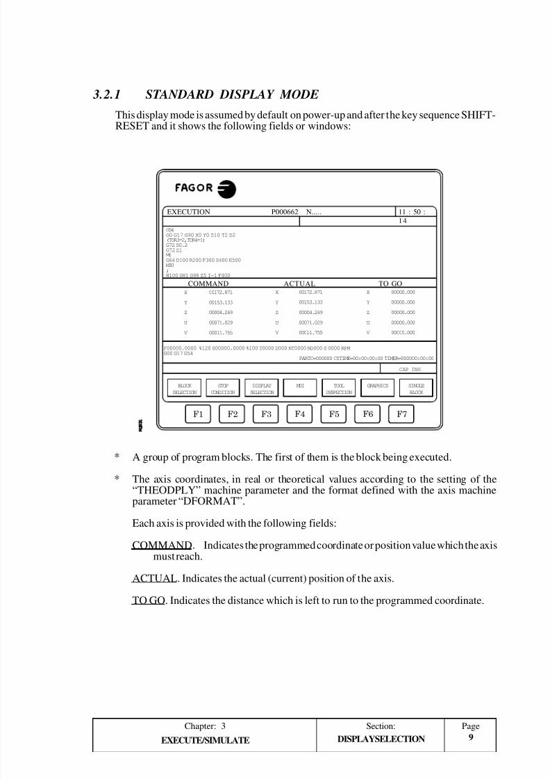
3.2.1 STANDARD DISPLAY MODE
This display mode is assumed by default on power-up and after the key sequence SHIFT-RESET and it shows the following fields or windows:
DISPLAY SELECTION
11 : 50 :
14
X 00172.871
Y 00153.133
Z 00004.269
U 00071.029
V 00011.755
X 00172.871
Y 00153.133
Z 00004.269
U 00071.029
V 00011.755
X 00000.000
Y 00000.000
Z 00000.000
U 00000.000
V 00000.000
ACTUAL
G54G0 G17 G90 X0 Y0 Z10 T2 D2(TOR3=2,TOR4=1)G72 S0.2G72 Z1M6G66 D100 R200 F300 S400 E500M30;N100 G81 G98 Z5 I-1 F400
P000662 N.....EXECUTION
COMMAND TO GO
SINGLE
BLOCK
GRAPHICSTOOL
INSPECTION
MDIDISPLAY
SELECTION
STOP
CONDITION
BLOCK
SELECTION
F00000.0000 %120 S00000.0000 %100 T0000 D000 NT0000 ND000 S 0000 RPMG00 G17 G54
PARTC=000000 CYTIME=00:00:00:00 TIMER=000000:00:00
CAP INS
* A group of program blocks. The first of them is the block being executed.
* The axis coordinates, in real or theoretical values according to the setting of the“THEODPLY” machine parameter and the format defined with the axis machineparameter “DFORMAT”.
Each axis is provided with the following fields:
COMMAND. Indicates the programmed coordinate or position value which the axismust reach.
ACTUAL. Indicates the actual (current) position of the axis.
TO GO. Indicates the distance which is left to run to the programmed coordinate.

8/21/2019 CNC 8055 M Operator Manual
http://slidepdf.com/reader/full/cnc-8055-m-operator-manual 37/702
Section:
EXECUTE / SIMULATEChapter: 3
10Page
DISPLAY SELECTION
CAP INS
11 : 50 :
14
P000662 N.....EXECUTION
PART ZERO REFERENCE ZERO
SINGLE
BLOCK
GRAPHICSTOOL
INSPECTION
MDIDISPLAY
SELECTION
STOP
CONDITION
BLOCK
SELECTION
X 00172.871
Y 00153.133
Z 00004.269
U 00071.029
V 00011.755
X 00100.000
Y 00150.000Z 00004.269
U 00071.029
V 00011.755F00000.0000 %120 S00000.0000 %100 T0000 D000 NT0000 ND000 S 0000 RPMG00 G17 G54
PARTC=000000 CYTIME=00:00:00:00 TIMER=000000:00:00
3.2.2 POSITION DISPLAY MODE
This display mode shows the position values of the axes.
This display mode shows the following fields or windows:
* The axis coordinates, in real or theoretical values according to the setting of the“THEODPLY” machine parameter and the format defined with the axis machineparameter “DFORMAT”.
Each axis has the following fields:
PART ZERO This field shows the real axis position with respect to part zero.
MACHINE ZERO This field shows the real axis position with the respect to machinereference zero (home).
3.2.3. PART PROGRAM DISPLAY MODE
Displays a page of program blocks among which the block being executed ishighlighted.

8/21/2019 CNC 8055 M Operator Manual
http://slidepdf.com/reader/full/cnc-8055-m-operator-manual 38/702
PageChapter: 3
EXECUTE / SIMULATE
Section:
11DISPLAY SELECTION
3.2.4. SUBROUTINE DISPLAY MODE
This display mode shows information regarding the following commands:
(RPT N10,N20) This function executes the program section between blocks N10 thruN20.
(CALL 25) This function executes subroutine number 25.
G87 ... This function the corresponding canned cycle.
(PCALL 30) This function executes subroutine 30 in a local parameter level.
When this mode is selected, the following must be considered:
The CNC allows the definition and usage of subroutines which can be called upon froma main program or from another subroutine and this can, in turn, call upon a second oneand so forth up to 15 nesting levels (each subroutine call represents a nesting level).
When the machining canned cycles: G66, G68, G69, G81, G82, G83, G84, G85, G86,G87, G88 and G89 are active, they use the sixth nesting level of local parameters.
8/21/2019 CNC 8055 M Operator Manual
http://slidepdf.com/reader/full/cnc-8055-m-operator-manual 39/702
Section:
EXECUTE / SIMULATEChapter: 3
12Page
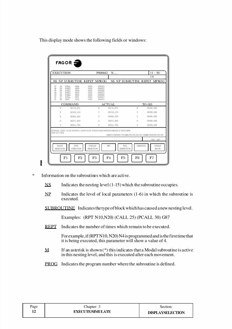
This display mode shows the following fields or windows:
DISPLAY SELECTION
11 : 50 :
14
P000662 N.....
F00000.0000 %120 S00000.0000 %100 T0000 D000 NT0000 ND000 S 0000 RPMG00 G17 G54
PARTC=000000 CYTIME=00:00:00:00 TIMER=000000:00:00
CAP INS
X 00172.871
Y 00153.133
Z 00004.269
U 00071.029
V 00011.755
X 00172.871
Y 00153.133
Z 00004.269
U 00071.029
V 00011.755
X 00000.000
Y 00000.000
Z 00000.000
U 00000.000
V 00000.000
ACTUAL
07 06 PCALL 0006 0001 00000206 05 PCALL 0005 0001 00000205 04 PCALL 0004 0001 00000204 03 PCALL 0003 0001 00000203 02 PCALL 0002 0001 00000202 01 PCALL 0001 0001 00000201 00 CALL 0101 0001 000002
EXECUTION
NS NP SUBRUTINE REPET MPROG NS NP SUBRUTINE REPET MPROG
COMMAND TO GO
SINGLE
BLOCK
GRAPHICSTOOL
INSPECTION
MDIDISPLAY
SELECTION
STOP
CONDITION
BLOCK
SELECTION
* Information on the subroutines which are active.
NS Indicates the nesting level (1-15) which the subroutine occupies.
NP Indicates the level of local parameters (1-6) in which the subroutine isexecuted.
SUBROUTINE Indicates the type of block which has caused a new nesting level.
Examples: (RPT N10,N20) (CALL 25) (PCALL 30) G87
REPT Indicates the number of times which remain to be executed.
For example, if (RPT N10, N20) N4 is programmed and is the first time thatit is being executed, this parameter will show a value of 4.
M If an asterisk is shown (*) this indicates that a Modal subroutine is activein this nesting level, and this is executed after each movement.
PROG Indicates the program number where the subroutine is defined.

8/21/2019 CNC 8055 M Operator Manual
http://slidepdf.com/reader/full/cnc-8055-m-operator-manual 40/702
PageChapter: 3
EXECUTE / SIMULATE
Section:
13
* The axis coordinates, in real or theoretical values according to the setting of the“THEODPLY” machine parameter and in the format determined by the axismachine parameter “DFORMAT”.
Each axis is provided with the following fields:
COMMAND. Indicates the programmed coordinate or position which the axis mustreach.
ACTUAL. Indicates the actual (current) position of the axis.
TO GO. Indicates the distance which is left to run to the programmed coordinate.
DISPLAY SELECTION

8/21/2019 CNC 8055 M Operator Manual
http://slidepdf.com/reader/full/cnc-8055-m-operator-manual 41/702
Section:
EXECUTE / SIMULATEChapter: 3
14Page
DISPLAY SELECTION
P000662 N.....EXECUTION
FOLLOWING ERROR
CAP INS
SINGLE
BLOCK
GRAPHICSTOOL
INSPECTION
MDI
DISPLAY
SELECTION
STOP
CONDITION
BLOCK
SELECTION
F03000.0000 %100 S00000.0000 %100 T0000 D000 NT0000 ND000 S 0000 RPMG00 G17 G54
PARTC=000000 CYTIME=00:00:00:00 TIMER=000000:00:00
11 : 50 :
14
DEFLECTIONS FACTORS
MOVEMENT IN CONTINUOUS JOG
3.2.5 FOLLOWING ERROR DISPLAY MODE
This display mode shows the following error (difference between the theoretical value andthe real value of their position) of the axes and the spindle.
Also, when having the tracing option, this mode shows, to the right of the screen, a windowwith the values corresponding to the tracing probe.
The display format is determined by the axis machine parameter “DFORMAT”.
The correction factors of the probe do not depend on the work units.
The display format for the probe deflections on each axis (X, Y, Z) as well as the totaldeflection "D" is set by axis machine parameter "DFORMAT".
3.2.6 USER DISPLAY MODE
This option will execute the program which is selected by means of the general machineparameter “USERDPLY” in the user channel.
To quit this mode and return to the previous menu, press ESC.
8/21/2019 CNC 8055 M Operator Manual
http://slidepdf.com/reader/full/cnc-8055-m-operator-manual 42/702
PageChapter: 3
EXECUTE / SIMULATE
Section:
15
11 : 50 :
14
P000662 N.....
F00000.0000 %120 S00000.0000 %100 T0000 D000 NT0000 ND000 S 0000 RPMG00 G17 G54
PARTC=000000 CYTIME=00:00:00:00 TIMER=000000:00:00
CAP INS
X 00172.871
Y 00153.133
Z 00004.269
U 00071.029
V 00011.755
X 00172.871
Y 00153.133
Z 00004.269
U 00071.029
V 00011.755
X 00000.000
Y 00000.000
Z 00000.000
U 00000.000
V 00000.000
ACTUAL
EXECUTION
COMMAND TO GO
SINGLE
BLOCK
GRAPHICSTOOL
INSPECTION
MDIDISPLAY
SELECTION
STOP
CONDITION
BLOCK
SELECTION
TOOL POS.TIME MACH.TIME
TOTAL TIME 00:00:00
TOOL POS.TIME MACH.TIME
TOOL CHANGES 0
TOOL POS.TIME MACH.TIME
M FUNCTIONS 0038
DISPLAY SELECTION
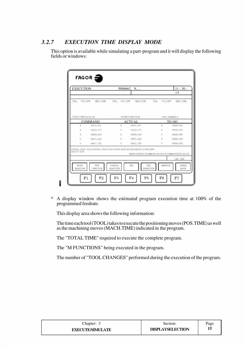
3.2.7 EXECUTION TIME DISPLAY MODE
This option is available while simulating a part-program and it will display the followingfields or windows:
* A display window shows the estimated program execution time at 100% of theprogrammed feedrate.
This display area shows the following information:
The time each tool (TOOL) takes to execute the positioning moves (POS.TIME) as wellas the machining moves (MACH.TIME) indicated in the program.
The "TOTAL TIME" required to execute the complete program.
The "M FUNCTIONS" being executed in the program.
The number of "TOOL CHANGES" performed during the execution of the program.

8/21/2019 CNC 8055 M Operator Manual
http://slidepdf.com/reader/full/cnc-8055-m-operator-manual 43/702
Section:
EXECUTE / SIMULATEChapter: 3
16Page
DISPLAY SELECTION
* The position values for the axes of the machine.
It must be borne in mind that the display format for the axes is established by machineparameter "DFORMAT" and that real or theoretical position values will be showndepending on the setting of machine parameter "THEODPLY".
Each axis has the following fields:
COMMAND. Indicates the programmed coordinate or position which the axis mustreach.
ACTUAL. Indicates the actual (current) position of the axis.
TO GO. Indicates the distance which is left to run to the programmedcoordinate.
8/21/2019 CNC 8055 M Operator Manual
http://slidepdf.com/reader/full/cnc-8055-m-operator-manual 44/702
PageChapter: 3
EXECUTE / SIMULATE
Section:
17
3.3 MDI
This function is not available in the SIMULATION mode. Besides, if a program is being
executed, it must be interrupted in order to access this function.
It is possible to execute any block (ISO or high level) and it provides information on thecorresponding format via the softkeys.
Once the block has been edited and after the key has been pressed the CNC will
execute this block without quitting this operating mode.
MDI

8/21/2019 CNC 8055 M Operator Manual
http://slidepdf.com/reader/full/cnc-8055-m-operator-manual 45/702
Section:
EXECUTE / SIMULATEChapter: 3
18Page
3.4 TOOL INSPECTION
This function is not available in the SIMULATION mode. Besides, if a program is beingexecuted, it must be interrupted in order to access this function.
This operating mode allows all the machine movements to be controlled manually, andenabling the axis control keys on the Operator Panel (X+, X-, Y+, Y-, Z+, Z-, 4+, 4-, etc.).
Also, the CNC will show the softkeys to access the CNC tables, edit and execute a block in MDI as well as repositioning the axes of the machine to the position from where thisfunction was called.
One of the ways to make the tool change is as follows:
* Move the tool to the required tool change position
This move may be made by jogging the axes from the operator panel or in MDI.
* Gain access to CNC tables (tools. Tool offsets, etc.) in order to find another tool withthe similar characteristics.
* Select, in MDI, the new tool as the active one.
* Make the tool change
This operation will be performed depending on the type of tool changer used. It ispossible to execute the tool change in MDI in this step.
* Return the axes to the position where the tool inspection began (REPOSITIONING).
* Continue executing the program ( )
Note: If during tool inspection, the spindle is stopped, the CNC will restart it in the sameturning direction (M3 or M4) while repositioning.
The CNC offers the following options by means of softkeys:
MDI
Allows to edit blocks in ISO or high level (except those associated with subroutines)providing information on the corresponding format by means of softkeys.
Once the block has been edited and after the key has been pressed the CNC will
execute this block without quitting this operating mode.
TOOL INSPECTION

8/21/2019 CNC 8055 M Operator Manual
http://slidepdf.com/reader/full/cnc-8055-m-operator-manual 46/702
PageChapter: 3
EXECUTE / SIMULATE
Section:
19
TABLES
Allows access to any of the CNC tables associated with part programs (Zero offsets,Tool offsets, Tools, Tool magazine, Global and Local Parameters).
Once the desired table has been selected, all editing commands will be available for itsverification and modification.
In order to return to the previous menu the ESC key must be pressed.
REPOSITIONING.
Positions the axes at the point where tool inspection started.
Once this option is selected, the CNC will show the axes to be repositioned and willrequest the order in which they will move.
The “PLANE” softkey will appear for the main plane movements and another softkeyfor each one of the rest of the axes to be repositioned.
Once repositioning has been completed the key is pressed to continue with the
execution of the rest of the program.
TOOL INSPECTION

8/21/2019 CNC 8055 M Operator Manual
http://slidepdf.com/reader/full/cnc-8055-m-operator-manual 47/702
Section:
EXECUTE / SIMULATEChapter: 3
20Page
3.5 GRAPHICS
With this function it is possible to select the type of graphic to be used as well as to defineall the parameters for the corresponding graphic display.
To do so, the CNC must NOT be executing or simulating a part program; otherwise, it mustbe interrupted.
Once the type of graphics has been selected and its parameters defined, this function canbe accessed even during the execution or simulation of a part program should the type of graphic or any graphic parameters be changed
After selecting this function, the CNC will display the following softkey options:
* Type of graphic* Display area
* Zoom* Point of view* Graphic parameters* Clear Screen* Deactivate graphics
One of the different ways that could be used to define graphics is the following:
1.- Define the DISPLAY AREA. It will depend on the dimensions of the part and itscoordinate values will be referred to the part zero being currently active .
2.- Select the TYPE OF GRAPHICS to be displayed.
3.- Define the VIEWPOINT to be used. This option is available in types of graphics suchas 3D and SOLID.
4.- Select the drawing colors to be used by means of the GRAPHIC PARAMETERS.
Once the part-program execution or simulation has been started, it is possible to interruptit and define another type of graphic or select another graphic display area by means of theZOOM option.
GRAPHICS

8/21/2019 CNC 8055 M Operator Manual
http://slidepdf.com/reader/full/cnc-8055-m-operator-manual 48/702
PageChapter: 3
EXECUTE / SIMULATE
Section:
21
3.5.1 TYPE OF GRAPHICS
This CNC offers two types of graphics: line and solid graphics. They both are totallyindependent from each other in such a way that an execution or simulation performed ineither one does not affect the other.
The CNC will show all the possible softkey options in order to select one of them.
The type of graphic will remain active until another type is selected or graphics aredeactivated (with its corresponding softkey) or the CNC is turned off.
Every time a type of graphic is selected, the CNC recovers all the graphic conditions (zoom,graphic parameters and display area) which were active during the last type of graphicselected.
The selected type of graphics will display the following information to the right of the screen:
EXECUTION P000662 N..... 11 : 50 : 14
X 00172.871Y 00153.133Z 00004.269
F 03000.000S 0000.000T 0000D 000
CAP INS
X
Z
Y
DISPLAY
AREA
TYPE OF
GRAPHIC
ZOOM CLEAR
SCREEN
DEACTIVATE
GRAPHICS
VIEWP OINT GRAPHIC
PARAMETERS
GRAPHICS
8/21/2019 CNC 8055 M Operator Manual
http://slidepdf.com/reader/full/cnc-8055-m-operator-manual 49/702
Section:
EXECUTE / SIMULATEChapter: 3
22Page
* The current real axes position. The tool position values will indicate the position of thetool tip.
* The axes feedrate (F) and the spindle speed (S) currently selected.
* The active tool (T) and tool offset (D).
* The point of view used for the graphic display. It is defined by the X, Y, Z axes and itcan be modified by means of the VIEWPOINT softkey.
* Two cubes or rectangles depending on the type of point of view selected.
The cube, whose sides are colored, indicates the graphic area currently selected and theone drawn only with lines shows the size of display area being selected.
When the point of view shows a single cube side or when the selected type of graphics
corresponds to one of the XY, XZ or YZ planes, the CNC will display two rectanglesindicating the graphic area (colored rectangle) and the display area being selected (non-colored rectangle).
GRAPHICS
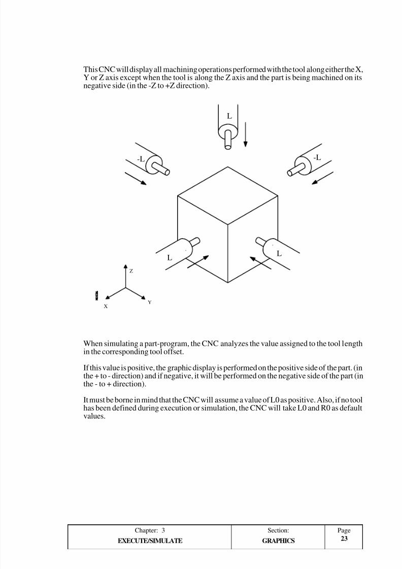
8/21/2019 CNC 8055 M Operator Manual
http://slidepdf.com/reader/full/cnc-8055-m-operator-manual 50/702
PageChapter: 3
EXECUTE / SIMULATE
Section:
23
This CNC will display all machining operations performed with the tool along either the X,Y or Z axis except when the tool is along the Z axis and the part is being machined on itsnegative side (in the -Z to +Z direction).
-L
LL
L
-L
Z
YX
When simulating a part-program, the CNC analyzes the value assigned to the tool lengthin the corresponding tool offset.
If this value is positive, the graphic display is performed on the positive side of the part. (inthe + to - direction) and if negative, it will be performed on the negative side of the part (inthe - to + direction).
It must be borne in mind that the CNC will assume a value of L0 as positive. Also, if no toolhas been defined during execution or simulation, the CNC will take L0 and R0 as defaultvalues.
GRAPHICS

8/21/2019 CNC 8055 M Operator Manual
http://slidepdf.com/reader/full/cnc-8055-m-operator-manual 51/702
Section:
EXECUTE / SIMULATEChapter: 3
24Page
LINE GRAPHICS
This type of graphics draws the tool path on the selected planes (XY, XZ, YZ) by meansof color lines.
The possible types of line graphics are:
3D Displays a three-dimensional view of the tool path.
XY,XZ,YZ Display the tool path on the selected plane.
COMBINED VIEW This option divides the screen in four quadrants displaying inthem the XY, XZ, YZ and 3D views simultaneously.
The generated graphics is lost in the following circumstances:
* When clearing the screen (softkey: CLEAR SCREEN).* When deactivating graphics (softkey: DEACTIVATE GRAPHICS).* When redefining a new display area (softkey: DISPLAY AREA).* When selecting a new type of solid graphic (top view or solid)
SOLID GRAPHICS
This type of graphics offer the same information in two different ways: as a three-dimensional solid (SOLID) or as a section view of the part (SECTION VIEW).
When simulating or executing a program in any of these modes, it is possible to displayits graphics in either mode.
The section view is usually drawn faster than the solid view, therefore, it is recommendedto first run the program in section view and then switch to solid graphics. The end resultwill be the same.
The graphic generated after executing or simulating a program is lost in the followinginstances:
* When clearing the screen (softkey CLEAR SCREEN).* When deactivating the graphics (softkey DEACTIVATE GRAPHICS).* When redefining a new display area (softkey DISPLAY AREA).* When selecting a new line graphics (3D, XY, XZ, YZ, Combined).
GRAPHICS

8/21/2019 CNC 8055 M Operator Manual
http://slidepdf.com/reader/full/cnc-8055-m-operator-manual 52/702
PageChapter: 3
EXECUTE / SIMULATE
Section:
25
SECTION VIEW
This option displays a section view of the part on the XY plane drawn in different shadesof gray which indicate the depth of the part.
The other plane views are also shown (XZ and YZ) which correspond to the sectionsindicated by the vertical and horizontal indicator lines.
These vertical and horizontal indicator lines can be moved left and right or up and downrespectively by means of the corresponding arrow keys.
These indicator lines can be moved at any time even while executing or simulating thepart-program and the CNC will display “live” the new sections corresponding to the newindicator line positions.
Once the execution or simulation has finished or it has been interrupted, the CNC
redraws the section view in order to achieve a better color definition and better sense of depth.
This type of graphics will not show the machining operations performed with the toolpositioned along the X or Y axis but only when positioned along the Z axis. However,when switching to SOLID, afterwards, all machining operations will be shown.
SOLID
This option shows a three-dimensional block which will be “machined” as the part-program is being run.
If no tool has been selected while executing or simulating the part-program, the CNC willassume a default tool offset value of L0, R0. With these values, the CNC will only showthe programmed tool path and the block will not be “machined” since the tool is assumedto have no radius (R0).
The screen refresh is done periodically depending on the simulation speed and alwaysfrom left to right regardless of the movement direction of the tool.
It must be borne in mind that when executing or simulating a new program (other thanthe current one), it will be “machined” over the existing “already-machined” block.However, a new “unmachined” block can be obtained by deleting the screen with theCLEAR SCREEN softkey.
GRAPHICS

8/21/2019 CNC 8055 M Operator Manual
http://slidepdf.com/reader/full/cnc-8055-m-operator-manual 53/702
Section:
EXECUTE / SIMULATEChapter: 3
26Page
3.5.2 DISPLAY AREA
In order to use this option, the CNC must not be executing or simulating a part-program. If so, it must be interrupted.
With this option it is possible to define the display area by assigning the desired values tomaximum and minimum coordinates for each axis. These coordinate values must bereferred to part zero.
This maximum and minimum coordinate assignment will be done in the windows displayedto the right of the screen which show their current values.
Use the up and down arrow keys to select the desired field whose value is to be changed.
Once the desired values for all the desired fields have been keyed in, press ENTER tovalidate them.
To quit this mode without making any changes, press ESC.
While SOLID GRAPHICS or SECTION VIEW is selected, it must be borne in mind thatif a new display area is defined, the CNC will reset the graphic representation returning toits initial status, “unmachined”.
In linear graphics (3D, XY, XZ, YZ, combined) there is a softkey [optimum area] whichredefines the display area that contains, in all planes, all the tool paths already executed.
GRAPHICS
8/21/2019 CNC 8055 M Operator Manual
http://slidepdf.com/reader/full/cnc-8055-m-operator-manual 54/702
PageChapter: 3
EXECUTE / SIMULATE
Section:
27
3.5.3 ZOOM
In order to use this option, the CNC must not be executing or simulating a part-program. If so, it must be interrupted.
With this option, it is possible to enlarge or reduce the graphics display area. It cannot beused in either COMBINED VIEW or SECTION VIEW types of graphics.
When selecting this option, the CNC will show a window superimposed on the currentgraphics and another one over the drawing at the lower right-hand side of the screen. Thesenew windows indicate the new display area being selected.
Use the [zoom +] and [zoom-] keys to either enlarge or reduce the size of the new displayarea and the arrow keys to move the zoom window around to the desired location on thescreen.
By pressing the softkey [INITIAL VALUE], it assumes the values set by means of [DISPLAY AREA]. The CNC shows that value, but it does not quit the zoom mode.
Once the new display area has been defined, press ENTER to validate the new values.
Press ESC to quit this ZOOM mode without making any changes to the initial values.
Every time a Zoom is carried out in 3D, XY, XZ, YZ graphics, it redraws the machiningexecuted up to that point. If the number of points to be redrawn exceeds the amount of memory reserved for it, only the last points will be redrawn and the older ones will be lost.
When zooming into a solid graphics, the drawing will be initialized showing a new
unmachined 3D block.
GRAPHICS

8/21/2019 CNC 8055 M Operator Manual
http://slidepdf.com/reader/full/cnc-8055-m-operator-manual 55/702
Section:
EXECUTE / SIMULATEChapter: 3
28Page
3.5.4 VIEWPOINT
In order to use this option, the CNC must not be executing or simulating a part-program. If so, it must be interrupted.
This option can be used with any three-dimensional graphics (3D, COMBINED VIEW orSOLID) and it allows to change the point of view (perspective) of the part by shifting theX, Y and Z axes.
When selecting this option, the CNC will highlight the current viewpoint on the right-handside of the screen.
Use the right and left arrow keys to rotate the XY plane around the Z axis up to 360°.
Use the up and down arrow keys to tilt the Z axis up to 90°.
Once the new viewpoint has been selected, press ENTER to validate it.
If SOLID GRAPHICS was selected before or it is selected again, the CNC will refresh thescreen showing the same part but from the new viewpoint (with new perspective).
When the selected type of graphics is 3D or COMBINED VIEW, the CNC will maintainedthe current drawing. The new viewpoint will be applied when executing the next blocks.These blocks will be drawn over the existing graphics. However, the screen can be clearedby using the CLEAR SCREEN softkey in order to start drawing with an “unmachined”part.
To quit this mode without making any changes, press ESC.
GRAPHICS

8/21/2019 CNC 8055 M Operator Manual
http://slidepdf.com/reader/full/cnc-8055-m-operator-manual 56/702
PageChapter: 3
EXECUTE / SIMULATE
Section:
29
3.5.5 GRAPHIC PARAMETERS
This function can be used any time, even during part program execution or simulation:
With this function it is possible to modify the simulation speed and the colors used to drawthe tool paths.
The modifications made to any parameter are immediately assumed by the CNC and canbe made during the execution or simulation of the part program.
The softkey options displayed by the CNC are:
SIMULATION SPEED
With this option it is possible to modify the percentage of the speed used by the CNC
to execute the part programs in the simulation modes.
The CNC will display a window at the top right-hand side of the screen indicating thecurrent % of simulation speed.
This value can be modified by using the right and left arrow keys. Once the desiredvalue is selected, press ENTER to validate the new value.
Press ESC to quit this function without making any changes to this field.
It is also possible to change the simulation speed while it is redrawing after a zoom. Thislets you check the machining of a particular operation.
PATH COLORS
With this option it is possible to modify the colors used to draw the various tool pathsin the execution and simulation modes. They can only be used in line graphics XZ. Theavailable parameters are:
The color for representing rapid movesThe color for representing path without compensationThe color for representing path with compensationThe color for representing threadingThe color for representing canned cycles
The CNC will show a series of windows for the definition of graphics parameters.
Among the various colors to choose from, there is a black or “transparent” one. If thisone is chosen for a particular path, this path will not be displayed on the screen.
If any of them is to be modified, first select the corresponding window using the up anddown keys and then use right and left arrow keys to select the desired color.
Once the desired colors have been selected, press ENTER to validate the new choicesor ESC to ignore the changes and leave this function with the original values intact.
GRAPHICS

8/21/2019 CNC 8055 M Operator Manual
http://slidepdf.com/reader/full/cnc-8055-m-operator-manual 57/702
Section:
EXECUTE / SIMULATEChapter: 3
30Page
SOLID COLORS
With this option it is possible to modify the colors used in the three-dimensional solidgraphics. These colors will be considered when in execution or simulation and will onlybe used in SOLID graphics mode. The available parameters are the following:
Color for the external X sideColor for the external Y sideColor for the external Z sideColor for the internal X side, machined sideColor for the internal Y side, machined sideColor for the internal Z side, machined side
The CNC will show to the right of the screen a series of windows to select theseparameters indicating as well the colors currently selected.
Among the various color choices, the black one indicates that the machining operationsdone with this color will not be shown graphically (invisible).
To modify any of these parameters, select the corresponding field by using the up anddown arrow keys and use the right and left arrow keys to select the color within thedesired field or window.
Once the desired colors for the desired solid sides have been selected, press ENTER tovalidate them.
Press ESC to quit this color selection mode without making any changes to the originalsettings.
GRAPHICS
8/21/2019 CNC 8055 M Operator Manual
http://slidepdf.com/reader/full/cnc-8055-m-operator-manual 58/702
PageChapter: 3
EXECUTE / SIMULATE
Section:
31
3.5.6 CLEAR SCREEN
In order to use this function, no part program may be in execution or simulation. If this isthe case, it must be interrupted.
Erases the screen or graphic representation shown.
If the solid graphic mode is selected, it will return to its initial status showing the unmachinedpart.
3.5.7 DEACTIVATE GRAPHICS
It allows the graphic representation to be deactivated at any time, even during execution orsimulation of a part program.
To activate this function again, the “GRAPHICS” softkey must be pressed again. To do
this, the CNC must not be executing or simulating a part program. If this is the case, it mustbe interrupted.
GRAPHICS

8/21/2019 CNC 8055 M Operator Manual
http://slidepdf.com/reader/full/cnc-8055-m-operator-manual 59/702
Section:
EXECUTE / SIMULATEChapter: 3
32Page
GRAPHICS
3.5.8 MEASURE
To use this function, a "Line Graphics" (planes XY, XZ or YZ) must be selected and theCNC must not be executing or simulating the part-program. If it is, it must be interrupted.
Once this function is selected, the CNC shows the following information on the screen:
The center of the CRT shows a dotted line with two cursors, the section to be measured.Also, the right-hand side of the screen shows:
* The coordinates of those two cursors with respect to part-zero.
* The distance "D" between them and the components of this distance along the axes of
the selected plane " X" and " Y".
* The cursor step " " corresponding to the selected display area. It is given in the work units, millimeters or inches.
The CNC shows the selected cursor and its coordinates in red.
To select the other cursor, press the "+" or "-" key. The CNC shows the new selected cursorand its coordinates in red.
To move the selected cursor, use the up, down, right and left arrow keys.
Also, with the keystroke sequences: Shift-Up arrow, Shift-Down arrow, Shift-Right arrowand Shift-Left arrow, it is possible to move the cursor to the corresponding end.
To quit this command and return to the graphics menu, press [ESC]
Also, if is pressed, the CNC exits this work mode and returns to the graphics menu.
8/21/2019 CNC 8055 M Operator Manual
http://slidepdf.com/reader/full/cnc-8055-m-operator-manual 60/702
PageChapter: 3
EXECUTE / SIMULATE
Section:
33
3.6 SINGLE BLOCK
When actuating on this option, the CNC toggles between single block mode and continuousrun mode. This function can be used at any time, even during the execution or simulation
of a part program.
If the single block mode is selected, the CNC will only execute one line of the program every
time the is pressed.
The upper window of the screen will show the selected mode of operation. If continuousexecution, no message will appear and if SINGLE BLOCK, it will display the message:SINGLE BLOCK.
SINGLE BLOCK
8/21/2019 CNC 8055 M Operator Manual
http://slidepdf.com/reader/full/cnc-8055-m-operator-manual 61/702
PageChapter: 4
EDIT
Section:
1
4. EDIT
This operating mode will be used to edit, modify or look at a part-program stored in theCNC's RAM memory.
To edit a part-program stored in the "Memkey Card" (CARD A) or in the hard disk (HD),it must be previously copied into RAM memory.
To edit a part-program, enter the program number (up to 6 digits) from the keyboard or byselecting it with the cursor from the CNC's part-program directory and then pressing ENTER.
Move the cursor on the screen line by line with the “up and down” arrow keys or page bypage with the “page up” and “page down” keys.
Once the program number has been entered, the CNC will display the softkeys for thefollowing options:
EDIT (See section 4.1)To edit new lines in the selected program.
MODIFY (See section 4.2)To modify an existing line of the program.
FIND (See section 4.3)To search a string of characters within a program.
REPLACE (See section 4.4)To replace a string of characters with another.
DELETE BLOCK (See section 4.5)To delete a block or group of blocks.
MOVE BLOCK (See section 4.6)To move a block or group of blocks within a program.
COPY BLOCK (See section 4.7)To copy a block or group of blocks to another program position.
COPY TO PROGRAM (See section 4.8)To copy a block or group of blocks into a different program.
INCLUDE PROGRAM (See section 4.9)To insert the contents of another program into the one currently selected.
EDITOR PARAMETERS (See section 4.10)To select the editing parameters (automatic numbering and axes for Teach-in editing).

8/21/2019 CNC 8055 M Operator Manual
http://slidepdf.com/reader/full/cnc-8055-m-operator-manual 62/702
Section:
EDITChapter: 4
2Page
4.1 EDIT
With this option it is possible to edit new lines or blocks of the selected program.
Select with the cursor the block after which the new ones will be added and press the softkeycorresponding to one of the available editing modes.
CNC LANGUAGE ........................................................................ (See section 4.1.1)The program is edited in ISO code or high level language.
TEACH-IN .....................................................................................(See section 4.1.2)The machine is jogged to the desired position and, then, the new axis position maybe assigned to the block.
INTERACTIVE............................................................................. (See section 4.1.3)Editing mode assisted by the CNC.
PROFILES .....................................................................................(See section 4.1.4)To edit a new profileAfter defining the known profile data, the CNC generates its corresponding ISO-coded program.
PROFILE SELECTIONTo modify an existing profile.The CNC requests the first and last blocks of the profile.Once they are both defined, the CNC will show the corresponding graphics.Section 4.1.4 describes how to operate with the profile.
USERWhen selecting this option, the CNC will execute, in the user channel, thecustomizing program selected by general machine parameter “USEREDIT”.(Seesection 4.1.1)This is edited in ISO-code or high level language.
4.1.1 EDITING IN CNC LANGUAGE
A program will be edited block by block and each block can be written either in ISO codeor high level language or it can be just a program comment.
Once this option has been selected, the softkeys will change colors and they will appear over white
background showing the information corresponding to the type of editing possible at that point.
Also, editing help will be available at any time by just pressing theHELP key. To quit thishelp mode, press HELP again.
If ESC is pressed while editing a block, the block editing mode is abandoned and the block currently being edited will not be added to the program.
Once the block has been edited, press ENTER. This new block will be added to theprogram after the one indicated by the cursor.
The cursor will position over the new edited block and the editing area (window) will be
cleared so another block can be written.
To quit the block editing mode, press ESC or MAIN MENU.
EDITING IN CNCLANGUAGE

8/21/2019 CNC 8055 M Operator Manual
http://slidepdf.com/reader/full/cnc-8055-m-operator-manual 63/702
PageChapter: 4
EDIT
Section:
3TEACH-IN EDITING
4.1.2 TEACH-IN EDITING
It is basically identical to the previous option (editing in CNC language), except whatregards the programming of position coordinate values.
This option shows the current position values of each one of the axes of the machine.
It permits to enter the axes position values from the CNC keyboard (as when editing in CNClanguage) or, also, use the TEACH-IN editing format as described next.
* Jog the machine axes with the jogging keys or with the electronic handwheel up to thedesired position.
* Press the softkey corresponding to the axis to be defined.
* The CNC will assign to this axis its current physical position as the program position
value.
Either position value programming methods can be used at any time while defining a block.
When the block being edited has no information (empty editing area or window), theENTER key may be pressed in which case the CNC will generate a new block with thecurrent position values of the axes.
This block will be added automatically to the program and it will be inserted after the block indicated by the cursor.
The cursor will position over the new edited block and the editing area will be cleared soanother can be written.
When the position values of all the axes are not to be programmed in this fashion, the CNCpermits to select the desired axes. To do this, in this operating mode and within the“EDITOR PARAMETERS” option there is a soft key for “TEACH-IN AXES”
8/21/2019 CNC 8055 M Operator Manual
http://slidepdf.com/reader/full/cnc-8055-m-operator-manual 64/702
Section:
EDITChapter: 4
4Page
INTERACTIVE EDITOR
4.1.3 INTERACTIVE EDITOR
This editor leads the operator through the program editing process by means of questionshe/she will answer.
This type of editing offers the following advantages:
* No knowledge of the CNC programming language is required.
* The CNC only admits the data it is requesting, thus no erroneous data can be entered.
* The programmer has, at all times, the appropriate programming aide by means of screens and messages.
When selecting this option, the CNC displays in the main window, a series of graphicoptions selectable by softkey.
If the selected option has more menus, the CNC will keep showing new graphic optionsuntil the desired one is selected.
From this moment, the information corresponding to this option will appear in the mainwindow and it will start requesting the data necessary to program it.
As the requested data is entered, the editing window will show, in CNC language, the block being edited.
The CNC will generate all necessary blocks and it will add them to the program once theediting of this option is done and it will insert them after the one indicated by the cursor.
The main window will show again the graphic options corresponding to the main menubeing possible to continue editing the program.
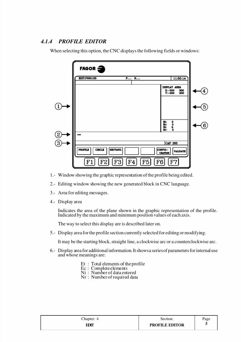
8/21/2019 CNC 8055 M Operator Manual
http://slidepdf.com/reader/full/cnc-8055-m-operator-manual 65/702
PageChapter: 4
EDIT
Section:
5PROFILE EDITOR
4.1.4 PROFILE EDITOR
When selecting this option, the CNC displays the following fields or windows:
1.- Window showing the graphic representation of the profile being edited.
2.- Editing window showing the new generated block in CNC language.
3.- Area for editing messages.
4.- Display area
Indicates the area of the plane shown in the graphic representation of the profile.Indicated by the maximum and minimum position values of each axis.
The way to select this display are is described later on.
5.- Display area for the profile section currently selected for editing or modifying.
It may be the starting block, straight line, a clockwise arc or a counterclockwise arc.
6.- Display area for additional information. It shows a series of parameters for internal useand whose meanings are:
Et : Total elements of the profileEc : Complete elementsNi : Number of data enteredNr : Number of required data
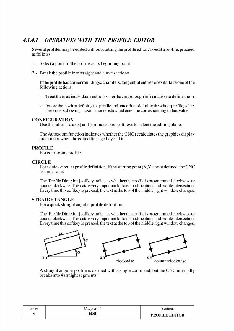
8/21/2019 CNC 8055 M Operator Manual
http://slidepdf.com/reader/full/cnc-8055-m-operator-manual 66/702
Section:
EDITChapter: 4
6Page
PROFILE EDITOR
4.1.4.1 OPERATION WITH THE PROFILE EDITOR
Several profiles may be edited without quitting the profile editor. To edit a profile, proceedas follows:
1.- Select a point of the profile as its beginning point.
2.- Break the profile into straight and curve sections.
If the profile has corner roundings, chamfers, tangential entries or exits, take one of thefollowing actions:
- Treat them as individual sections when having enough information to define them.
- Ignore them when defining the profile and, once done defining the whole profile, selectthe corners showing those characteristics and enter the corresponding radius value.
CONFIGURATIONUse the [abscissa axis] and [ordinate axis] softkeys to select the editing plane.
The Autozoom function indicates whether the CNC recalculates the graphics displayarea or not when the edited lines go beyond it.
PROFILEFor editing any profile.
CIRCLEFor a quick circular profile definition. If the starting point (X,Y) is not defined, the CNCassumes one.
The [Profile Direction] softkey indicates whether the profile is programmed clockwise orcounterclockwise. This data is very important for later modifications and profile intersection.Every time this softkey is pressed, the text at the top of the middle right window changes.
STRAIGHTANGLEFor a quick straight angular profile definition.
The [Profile Direction] softkey indicates whether the profile is programmed clockwise orcounterclockwise. This data is very important for later modifications and profile intersection.Every time this softkey is pressed, the text at the top of the middle right window changes.
clockwise counterclockwise
A straight angular profile is defined with a single command, but the CNC internallybreaks into 4 straight segments.

8/21/2019 CNC 8055 M Operator Manual
http://slidepdf.com/reader/full/cnc-8055-m-operator-manual 67/702
PageChapter: 4
EDIT
Section:
7PROFILE EDITOR
4.1.4.2 PROFILE EDITING
When pressing the [PROFILE] softkey, the CNC requests the starting point of the profile.To define it, use the corresponding softkeys.
For example, if when working in the XY plane the new desired starting point is (20,50):[X] 20 [ENTER][Z] 50 [ENTER]
The values may be set by means of a numeric constant or by means of any expression.Examples:
X 100X 10 * cos 45X 20 + 30 * sine 30X 2 * (20 + 30 * sine 30)
Once the starting point has been set, press the [VALIDATE]
The CNC will show a filled circle in the graphics area to indicate the starting point of theprofile.
Also, the softkeys will show the following options:
[STRAIGHT LINE] To edit a straight section.
[CLOCKWISE ARC] To edit a clockwise arc.
[COUNTERCLOCKWISE ARC] To edit a counterclockwise arc.[CORNERS] To insert roundings, chamfers, tangential entries and exits.
[MODIFY] To modify the starting point.Modify any profile element, even the type of element(straight line, clockwise or counterclockwise arc)Insert a new element (straight line or arc) in any position of theprofile.Delete any profile element.Add a new additional text to any section of the profile.Modify the display area.
[NEW PROFILE] To edit a new profile.
[FINISH] It must be pressed when all the sections of the profile have beendefined.It must be indicated whether the edited profile or profiles mustbe saved or not.The CNC quits the profile editor and adds to the program theISO code corresponding to the profile just edited .

8/21/2019 CNC 8055 M Operator Manual
http://slidepdf.com/reader/full/cnc-8055-m-operator-manual 68/702
Section:
EDITChapter: 4
8Page
PROFILE EDITOR
DISPLAY AREA
X: -300 300
Y: -200 200
STRAIGHT LINE
X1: 50.000
Y1: 60.000
X2:
Y2:
α :
TANGENCY: NO
Et: 0
Er: 0
Ni: 2
Nr: 2
4.1.4.3 DEFINITION OF A STRAIGHT SECTION
When pressing the [STRAIGHT LINE] softkey, the CNC displaysthe data shown on the right margin of this page.
X1, Y1 Coordinates of starting point of the line.They cannot be modified because they correspondto the last point of the previous section.
X2, Y2 Coordinates of the end point of the section.
ααααα Angle of the line referred to the abscissa axis.
TANGENCY Indicates whether the line to be drawn is tangentto the previous section or not.
All these parameters need not be defined, but all the known onesshould be defined.
To define a parameter, press the corresponding softkey, key in thedesired value and press [ENTER].
The value may be defined by a numeric constant or by any expression.Examples: X 100
X 10 * cos 45X 20 + 30 * sine 30X 2 * (20 + 30 * sine 30)
Once all known parameters are set, press the [VALIDATE] softkey and the CNC will showthe defined section, if possible.
If there is not enough data to show the section, the CNC will show a dotted line indicatingits orientation.
Example X1=0Y1=0X2Y2α = 60
If there are more than one possibility, all the possible options will be shown and the desiredone (framed in red) must be selected using the right and left arrow keys.
Example X1Y1X2Y2α = 60TANGENCY = YES
Use the up and down arrow keys to choose whether all the possible options are shown oronly the one framed in red.
Once the desired option is selected, press [ENTER] for the CNC to assume it.
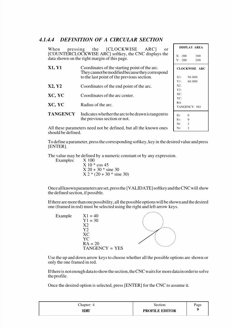
8/21/2019 CNC 8055 M Operator Manual
http://slidepdf.com/reader/full/cnc-8055-m-operator-manual 69/702
PageChapter: 4
EDIT
Section:
9PROFILE EDITOR
DISPLAY AREA
X: -300 300Y: -200 200
CLOCKWISE ARC
X1: 50.000
Y1: 60.000
X2:
Y2:
XC:
YC:
RA
TANGENCY: NO
Et: 0
Er: 0
Ni: 2
Nr: 2
4.1.4.4 DEFINITION OF A CIRCULAR SECTION
When pressing the [CLOCKWISE ARC] or[COUNTERCLOCKWISE ARC] softkey, the CNC displays thedata shown on the right margin of this page.
X1, Y1 Coordinates of the starting point of the arc.They cannot be modified because they correspondto the last point of the previous section.
X2, Y2 Coordinates of the end point of the arc.
XC, YC Coordinates of the arc center.
XC, YC Radius of the arc.
TANGENCY Indicates whether the arc to be drawn is tangent tothe previous section or not.
All these parameters need not be defined, but all the known onesshould be defined.
To define a parameter, press the corresponding softkey, key in the desired value and press[ENTER].
The value may be defined by a numeric constant or by any expression.Examples: X 100
X 10 * cos 45
X 20 + 30 * sine 30X 2 * (20 + 30 * sine 30)
Once all known parameters are set, press the [VALIDATE] softkey and the CNC will showthe defined section, if possible.
If there are more than one possibility, all the possible options will be shown and the desiredone (framed in red) must be selected using the right and left arrow keys.
Example X1 = 40Y1 = 30X2
Y2XCYCRA = 20TANGENCY = YES
Use the up and down arrow keys to choose whether all the possible options are shown oronly the one framed in red.
If there is not enough data to show the section, the CNC waits for more data in order to solvethe profile.
Once the desired option is selected, press [ENTER] for the CNC to assume it.

8/21/2019 CNC 8055 M Operator Manual
http://slidepdf.com/reader/full/cnc-8055-m-operator-manual 70/702
Section:
EDITChapter: 4
10Page
4.1.4.5 CORNERS
When selecting this option, the CNC shows the following option softkeys:
Rounding For rounding any corners of the profile.Chamfer For adding chamfers at any corner of the profile.Tangential Entry To add a tangential tool entry when machining.Tangential Exit To add a tangential tool exit at the end of the machining operation.
When selecting one of these, one of the corners of the profiles will appear highlighted.To select another corner of the same profile, use the up/down and left/right arrow keys.To select a corner of another profile, use the [page up] and [page down] keys.
To define the rounding, enter the rounding radius and press [ENTER].
To define the chamfer, enter the chamfer radius and press [ENTER].
To define the tangential entry, enter the radius of the path that the tool has to follow whendoing a tangential entry and press [ENTER].
To define the tangential exit, enter the radius of the path that the tool has to follow whendoing a tangential exit and press [ENTER].
To quit the CORNER mode, press [ESC].
PROFILE EDITOR

8/21/2019 CNC 8055 M Operator Manual
http://slidepdf.com/reader/full/cnc-8055-m-operator-manual 71/702
PageChapter: 4
EDIT
Section:
11
4.1.4.6 MODIFY
When selecting this option, the CNC shows the following softkey options:
Starting Point To modify the starting point of the profile.Modify element To modify any element of the profile, even the type of element
(straight lines, clockwise or counterclockwise arcs).Insert element To insert a new element (straight line or arc) in any position of the
profile.Delete element To delete any element of the profile.Additional Text To add additional text to any section of the profile.Configuration To add a new editing plane or redefine the Autozoom option.Display area To change the display area.
When selecting one of these options, one of the profile elements will be highlighted.To select another element of the same profile, use the up/down and left/right arrow keys.
To select an element of another profile, use the [page up] and [page down] keys.
Starting point• Select the desired element. The CNC shows the values used to define it.• Select the starting point of the desired profile. The CNC shows the values used to
define it.• Modify the desired values and press the [VALIDATE] softkey.
Modify element• Select the desired element. The CNC shows the values used to define it.• It is possible to: change the type of section (straight or arc), redefine the existing data, define a new
data or delete an existing one.• To delete data, press the softkey that defines it and press [ESC]
• Once the element has been modified, press the [VALIDATE] softkey. The CNCrecalculates the new profile with the data used to define that section and the next one(tangency, angle, etc.).
Insert element• Select the point, or corner, after which the new one is to be inserted.• Select the type of section (straight or arc), define it and press the [VALIDATE] softkey.
• The CNC recalculates the new profile with the data used to define that section andthe next one (tangency, angle, etc).
Delete element• Select the element to be deleted and confirm the command.• The CNC recalculates the new profile.
Additional text• Select the desired element. The CNC shows the ISO code corresponding to that
section in the editing area.• Add the desired text. Functions F, S, T, D, M or program comments may be added.• Press the [VALIDATE] softkey.
PROFILE EDITOR

8/21/2019 CNC 8055 M Operator Manual
http://slidepdf.com/reader/full/cnc-8055-m-operator-manual 72/702
Section:
EDITChapter: 4
12Page
Display areaWhen selecting this option, the following softkey options are shown:• [Zoom +] to enlarge the image on the screen.• [Zoom -] to reduce the image on the screen.• [Optimum area] to show the full profile on the screen.• The display area may be moved around with the [left arrow], [right arrow], [up
arrow] and [down arrow] keys.• Press the [VALIDATE] softkey. The CNC updates the values indicated in the upper
right-hand window (DISPLAYED AREA).
To quit the MODIFY mode, press [ESC].
PROFILE EDITOR
8/21/2019 CNC 8055 M Operator Manual
http://slidepdf.com/reader/full/cnc-8055-m-operator-manual 73/702
PageChapter: 4
EDIT
Section:
13PROFILE EDITOR
4.1.4.7 FINISH
This softkey must be pressed once all the sections of the profile have been defined.
The CNC will try to calculate the requested profile by previously solving all the unknowns.
If it finds several possibilities for certain sections, the CNC will show them for each sectionand the desired option (framed in red) will have to be chosen using the right and left arrowkeys.
Once the whole profile has been solved, the CNC will show the code of the part programcurrently being edited.
The ISO-coded program for the edited profile is contained between these lines:
;************************** START **********************
;************************** END **********************
If a profile cannot be solved due to lack of data, the CNC will issue the corresponding errormessage.
Warning:
When pressing the [FINISH] softkey, the CNC quits the profile editor andadds to the program the ISO-code corresponding to the profile just edited.
To quit the profile editor without changing the part-program, press [ESC]and the CNC will request confirmation of this command.
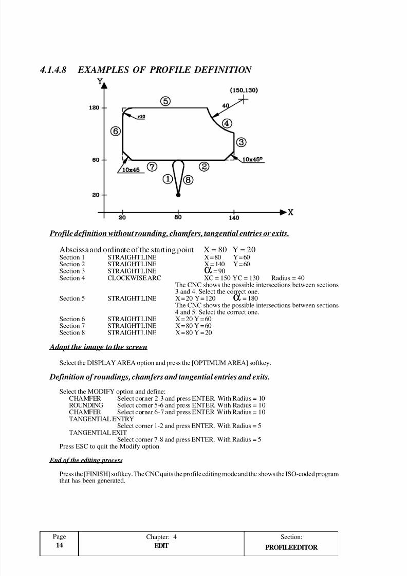
8/21/2019 CNC 8055 M Operator Manual
http://slidepdf.com/reader/full/cnc-8055-m-operator-manual 74/702
Section:
EDITChapter: 4
14Page
PROFILE EDITOR
4.1.4.8 EXAMPLES OF PROFILE DEFINITION
Profile definition without rounding, chamfers, tangential entries or exits.
Abscissa and ordinate of the starting point X = 80 Y = 20Section 1 STRAIGHT LINE X = 80 Y = 60Section 2 STRAIGHT LINE X = 140 Y = 60Section 3 STRAIGHT LINE α = 90Section 4 CLOCKWISE ARC XC = 150 YC = 130 Radius = 40
The CNC shows the possible intersections between sections3 and 4. Select the correct one.
Section 5 STRAIGHT LINE X = 20 Y = 120 α
= 180
The CNC shows the possible intersections between sections4 and 5. Select the correct one.
Section 6 STRAIGHT LINE X = 20 Y = 60Section 7 STRAIGHT LINE X = 80 Y = 60Section 8 STRAIGHT LINE X = 80 Y = 20
Adapt the image to the screen
Select the DISPLAY AREA option and press the [OPTIMUM AREA] softkey.
Definition of roundings, chamfers and tangential entries and exits.
Select the MODIFY option and define:CHAMFER Select corner 2-3 and press ENTER. With Radius = 10
ROUNDING Select corner 5-6 and press ENTER. With Radius = 10CHAMFER Select corner 6-7 and press ENTER With Radius = 10TANGENTIAL ENTRY
Select corner 1-2 and press ENTER. With Radius = 5TANGENTIAL EXIT
Select corner 7-8 and press ENTER. With Radius = 5Press ESC to quit the Modify option.
End of the editing process
Press the [FINISH] softkey. The CNC quits the profile editing mode and the shows the ISO-coded programthat has been generated.

8/21/2019 CNC 8055 M Operator Manual
http://slidepdf.com/reader/full/cnc-8055-m-operator-manual 75/702
PageChapter: 4
EDIT
Section:
15PROFILE EDITOR
Profile definition without rounding
Abscissa and ordinate of the starting point X = 0 Y = 68Section 1 STRAIGHT LINE X = 0 Y = 0Section 2 STRAIGHT LINE X = 30 Y = 0Section 3 STRAIGHT LINE α = 90Section 4 CLOCKWISE ARC RA=12 Tangent = YesSection 5 STRAIGHT LINE X = 80 Y = 0 α = -35 Tangent = YesThe CNC shows the possible solutions for section 4. Select the correct one.Section 6 STRAIGHT LINE X = 140 Y = 0Section 7 STRAIGHT LINE α
= 120
Section 8 COUNTERCLOCKWISE ARC RA=25 Tangent = YesSection 9 CLOCKWISE ARC XC = 85 YC = 50 RA=20 Tangent = YesThe CNC shows the possible solutions for section 8. Select the correct one.Section 10 COUNTERCLOCKWISE ARC RA=15 Tangent = YesSection 11 STRAIGHT LINE X = 0 Y = 68 α = 180 Tangent = YesThe CNC shows the possible solutions for section 10. Select the correct one.
Adapt the image to the screen
Select the DISPLAY AREA option and press the [OPTIMUM AREA] softkey.
Rounding definition
Select the MODIFY option and define:ROUNDING Select the A corner and press ENTER With Radius = 10
ROUNDING Select the B corner and press ENTER With Radius = 5ROUNDING Select the C corner and press ENTER With Radius = 20ROUNDING Select the D corner and press ENTER With Radius = 8
Press ESC to quit the Modify option.
End of the editing process
Select the FINISH softkey. The CNC quits the profile editing mode and shows the ISO coded program thathas been generated.

8/21/2019 CNC 8055 M Operator Manual
http://slidepdf.com/reader/full/cnc-8055-m-operator-manual 76/702
Section:
EDITChapter: 4
16Page
PROFILE EDITOR
Example of how to define a profile and modify it later:
ConfigurationAbscissa axis: X Ordinate axis: Y Autozoom: Yes Validate
Profile (outside profile)Starting point X 0 Y 100 ValidateStraight X 0 Y 0 ValidateStraight X 340 Y 0 ValidateClockwise arc Xf 390 Yf 50 R 50 Validate
(choose the right arc)Straight X 390 Y 200 ValidateStraight X 0 Y 160 ValidateStraight X 0 Y 100 Validate
New Profile (rectangle)Rectangle X 60 Y 60 Lx 100 Ly 40 Validate
New Profile (triangle)ProfileStarting point X 200 Y 60 ValidateStraight X 320 Y 60 ValidateStraight X 260 Y 130 ValidateStraight X 200 Y 60 Validate
Corners (roundings and chamfers)Chamfer
Select the first profile with the page up/down keys.Select the lower left corner with the up&down and left/right arrow keys EnterChamfer 30Escape
RoundingSelect the second profile (rectangle) the upper right corner EnterRadius 20EscapeEscape

8/21/2019 CNC 8055 M Operator Manual
http://slidepdf.com/reader/full/cnc-8055-m-operator-manual 77/702
PageChapter: 4
EDIT
Section:
17PROFILE EDITOR
Modify
(modify first profile)Modify element
Select the lower line on the first profile EnterStraight X 330 Validate (choose arc)
Modify - Modify elementSelect the arc of the lower right corner EnterClockwise arc Yf 60 R 60 Validate (choose arc)
Modify - Modify elementSelect right line EnterStraight Y 160 Validate
(modify second profile)
Modify - Insert elementSelect the second profileSelect the theoretical upper right corner EnterStraight X 90 Y 130 Validate
(modify third profile)Modify - Modify element.
Select the right side of the triangle on the third profile EnterStraight Y Escape (to delete) Angle 150 Validate
Finish.

8/21/2019 CNC 8055 M Operator Manual
http://slidepdf.com/reader/full/cnc-8055-m-operator-manual 78/702
Section:
EDITChapter: 4
18Page
4.2 MODIFY
This option permits modifying the contents of a selected program block.
Before pressing this softkey, select with the cursor the block to be modified .
Once this option is selected, the softkeys will change their color showing their type of modifying option over a white background.
Also, it is possible to get more editing assistance by pressing HELP. Press HELP againto exit the editing assistance mode.
By pressingESC, the information corresponding to that block and which was shown in theediting area will be cleared. It will then be possible to modify its contents again.
To quit the block modifying mode, press CL or ESC to clear the editing window and then
press ESC again. This way, the selected block will not be modified.
Once the block contents have been modified, press ENTER so the new contents replacethe old ones.
MODIFY

8/21/2019 CNC 8055 M Operator Manual
http://slidepdf.com/reader/full/cnc-8055-m-operator-manual 79/702
PageChapter: 4
EDIT
Section:
19
4.3 FIND
This option is used to find a specific text within the selected program.
When selecting this option, the softkeys will show the following options:
BEGINNING This softkey positions the cursor over the first program block which isthen selected quitting the “find” option.
END This softkey positions the cursor over the last program block which is thenselected quitting the “find” option.
TEXT With this function it is possible to search a text or character sequence startingfrom the block indicated by the cursor.
When this key is selected, the CNC requests the character sequence to be found.
When the text is defined, press the “END OF TEXT” softkey and the cursor willbe positioned over the first occurrence of that text.
The search will begin at the current block.
The text found will be highlighted being possible to continue with the search orto quit it.
Press ENTER to continue the search up to the end of the program. It is possibleto search as many times as wished and when the end of the program is reached,it will start from the first block.
Press the “EXIT” softkey or the ESC key to quit the search mode. The cursor willbe positioned where the indicated text was found last.
LINE NUMBER After pressing this key, the CNC requests the number of the block to be found. After keying in the desired number and pressing ENTER, the cursorwill position over that block which will then be selected quitting the search mode.
FIND
8/21/2019 CNC 8055 M Operator Manual
http://slidepdf.com/reader/full/cnc-8055-m-operator-manual 80/702
Section:
EDITChapter: 4
20Page
4.4 REPLACE
With this function it is possible to replace a character sequence with another throughoutthe selected program.
When selecting this option, the CNC requests the character sequence to be replaced.
Once the text to be replaced is indicated, press the “WITH” softkey and the CNC willrequest the character sequence which will replace the previous one.
Once this text is keyed in, press the “END OF TEXT” softkey and the cursor will bepositioned over the first occurrence of the searched text.
The search will begin at the current block.
The found text will be highlighted and the following softkey options will appear:
REPLACE Will replace the highlighted text and will continue the search from thispoint to the end of the program.
If no more occurrences of the text to be replaced are found, the CNC will quit thismode.
If another occurrence of the text is found, it will be highlighted showing the same“replacing” or “not replacing” options.
DO NOT REPLACE Will not replace the highlighted text and will continue the searchfrom this point to the end of the program.
If no more occurrences of the text to be replaced are found, the CNC will quit thismode.
If another occurrence of the text is found, it will be highlighted showing the same“replacing” or “not replacing” options.
TO THE END This function will automatically replace all the matching text from thecurrent block to the end of the program without offering the option of not replacingit.
ABORT This function will not replace the highlighted text and it will quit the “find andreplace” mode.
REPLACE

8/21/2019 CNC 8055 M Operator Manual
http://slidepdf.com/reader/full/cnc-8055-m-operator-manual 81/702
PageChapter: 4
EDIT
Section:
21
4.5 DELETE BLOCK
With this function it is possible to delete a block or group of blocks.
To delete only one block, just position the cursor over it and press ENTER.
To delete a group of blocks, indicate the first and last blocks to be deleted. To do so,follow these steps:
* Position the cursor over the first block to be deleted and press the “INITIALBLOCK” softkey.
* Position the cursor over the last block to be deleted and press the “FINAL BLOCK”softkey.
If the last block to be deleted is also the last one of the program, it can also be selected
by pressing the “TO THE END” softkey.
* Once the first and last blocks are selected, the CNC will highlight the selected blocksrequesting confirmation to delete them.
DELETE BLOCK

8/21/2019 CNC 8055 M Operator Manual
http://slidepdf.com/reader/full/cnc-8055-m-operator-manual 82/702
Section:
EDITChapter: 4
22Page
4.6 MOVE BLOCK
With this option it is possible to move a block or group of blocks by previouslyindicating the first and last blocks to be moved. To do so, follow these steps:
* Position the cursor over the first block to be moved and press the “INITIALBLOCK” softkey.
* Position the cursor over the last block to be moved and press the “FINAL BLOCK”softkey.
If the last block to be moved is also the last one of the program, it can also be selectedby pressing the “TO THE END” softkey.
To move only one block, the “initial block” and the “final block” will be the sameone.
* Once the first and last blocks are selected, the CNC will highlight the selected blocksrequesting confirmation to move them.
Then, indicate the block after which this group of blocks must be placed.
* Press the “START OPERATION” softkey to carry out the move.
MOVE BLOCK

8/21/2019 CNC 8055 M Operator Manual
http://slidepdf.com/reader/full/cnc-8055-m-operator-manual 83/702
PageChapter: 4
EDIT
Section:
23
4.7 COPY BLOCK
With this option it is possible to copy a block or group of blocks by previously indicatingthe first and last blocks to be copied. To do so, follow these steps:
* Position the cursor over the first block to be copied and press the “INITIALBLOCK” softkey.
* Position the cursor over the last block to be copied and press the “FINAL BLOCK”softkey.
If the last block to be copied is also the last one of the program, it can also be selectedby pressing the “TO THE END” softkey.
To copy only one block, the “initial block” and the “final block” will be the sameone.
* Once the first and last blocks are selected, the CNC will highlight the selected blocksrequesting confirmation to copy them.
Then, indicate the block after which this group of blocks must be placed.
* Press the “START OPERATION” softkey to carry out this command.
COPY BLOCK
8/21/2019 CNC 8055 M Operator Manual
http://slidepdf.com/reader/full/cnc-8055-m-operator-manual 84/702
Section:
EDITChapter: 4
24Page
4.8 COPY TO PROGRAM
With this option it is possible to copy a block or group of blocks of one program intoanother program.
When selecting this option, the CNC will request the number of the destination programwhere the selected block or blocks are to be copied. After entering the program numberpress ENTER.
Next, indicate the first and last blocks to copy by following these steps:
* Position the cursor over the first block to be copied and press the “INITIALBLOCK” softkey.
* Position the cursor over the last block to be copied and press the “FINAL BLOCK”softkey.
If the last block to be copied is also the last one of the program, it can also be selectedby pressing the “TO THE END” softkey.
To copy only one block, the “initial block” and the “final block” will be the sameone.
* Once the first and last blocks are selected, the CNC will highlight the selected blocksand will execute the command.
If the destination program already exists, the following options will be displayed:
* Write over the existing program. All the blocks of the destination program will beerased and will be replaced by the copied blocks.
* Append (add) the copied blocks behind the ones existing at the destination program.
* Abort or cancel the command without copying the blocks.
COPY TO PROGRAM
8/21/2019 CNC 8055 M Operator Manual
http://slidepdf.com/reader/full/cnc-8055-m-operator-manual 85/702
PageChapter: 4
EDIT
Section:
25
4.9 INCLUDE PROGRAM
With this option it is possible to include or merge the contents of another program intothe one currently selected.
Once this option is selected, the CNC will request the number of the source programto be merged. After keying in that number press ENTER.
Next, indicate with the cursor the block after which the source program will be included.
Finally, press the “START OPERATION” softkey to execute the command.
INCLUDE PROGRAM

8/21/2019 CNC 8055 M Operator Manual
http://slidepdf.com/reader/full/cnc-8055-m-operator-manual 86/702
Section:
EDITChapter: 4
26Page
4.10 EDITOR PARAMETERS
With this option it is possible to select the editing parameters used in this operatingmode.
The options or parameters available are described here and they are selected bysoftkeys.
4.10.1 AUTONUMBERING
With this option it is possible to have the CNC automatically number (label) the blocksafter the one being edited.
Once this option is selected, the CNC will display the “ON” and “OFF” softkeys to
either activate or deactivate this function.
Once this function is activated, the following options will appear on the CRT:
STEP After pressing this softkey, Enter the desired numbering step between twoconsecutive blocks and press ENTER.
The default value is 10.
STARTING After pressing this softkey, Enter the starting block number to be usedon the next block to be edited.
The default value is 0.When setting both parameters, select the STEP first and then the STARTINGblock number.
Example: STEP = 12, STARTING= 56; generated blocks: N56, N68, N80,...
Warning:
This function will not number the already existing blocks.
EDITOR PARAMETERS
8/21/2019 CNC 8055 M Operator Manual
http://slidepdf.com/reader/full/cnc-8055-m-operator-manual 87/702
PageChapter: 4
EDIT
Section:
27
4.10.2 AXES SELECTION FOR TEACH-IN EDITING
Remember that in the TEACH-IN editing mode, the following feature is available:
When the block being edited has no information (editing area empty), the "ENTER"key can be pressed. In this case, the CNC will generate a new block with the currentposition values of the axes.
The option described here, permits the selection of the axes whose position values will beautomatically entered in said block.
After pressing the "TEACH-IN AXES" softkey, the CNC shows all the axes of themachine.
The operator must eliminate, pressing the corresponding softkeys, the axis or axes notdesired. Every time a softkey is pressed, the CNC will eliminate the corresponding axis
displaying only the selected ones.
To end this operation, press "ENTER".
The CNC will assume from now on and whenever editing in TEACH-IN, the selected axes.To change those values, access this option again and select the new axes.
EDITOR PARAMETERS
8/21/2019 CNC 8055 M Operator Manual
http://slidepdf.com/reader/full/cnc-8055-m-operator-manual 88/702
PageChapter: 5
JOG
Section:
1HOME SEARCH
5. JOG
This mode of operation will be used whenever the manual control of the machine is desired.
Once this mode of operation is selected, the CNC allows the movement of all the axes bymeans of the axes control keys (X+, X-, Y+, Y-, Z+, Z-, 4+, 4-) located on the operatorpanel, or by means of the electronic handwheel (if available).
This mode of operation offers the following softkey options:
With the MDI option it is possible to modify the machining conditions (type of moves,feedrates, etc.) being selected. Also, the CNC will maintain the ones selected in this modewhen switching to "EXECUTION" or "SIMULATION" modes.
This operating mode offers the following softkey options:

8/21/2019 CNC 8055 M Operator Manual
http://slidepdf.com/reader/full/cnc-8055-m-operator-manual 89/702
Section:Chapter: 5
2Page
JOG
REFERENCE SEARCH
With this option it is possible to perform a home search on the desired axis or axes.
The CNC offers two ways to search the machine reference (home):
* Using the subroutine associated with function G74. The number of this subroutinewill defined by the general machine parameter “REFSUB”.
* By selecting the axis or axes to be referenced.
Once the Reference search function is selected, the CNC will show a softkey for eachaxis and the softkey “ALL”.
If the “ALL” softkey is selected, the CNC will highlight (in reverse video) the names of all
axes and after pressing the key, it will execute the subroutine associated with G74.
On the other hand, to search the reference anywhere from one to all axes at once(without executing the associated subroutine), the softkeys corresponding to those axesmust be pressed.
After pressing each softkey, the CNC will highlight the name of the selected axis.
If an unwanted axis has been selected, press ESC to cancel that selection and return toselect “REFERENCE SEARCH”.
Once all the desired axes have been selected, press .
The CNC will start the home search by moving all selected axes at once until the homereference switches for all axes are pressed and, from then on, the CNC will continuethe home search one axis at a time.
Warning:
When searching home using the "ALL" softkey, the CNC will maintain thepart zero or zero offset active at the time. However, if the axes have beenselected one by one, the CNC will assume the "home" position as the new partzero.
PRESET
With this function it is possible to preset the desired axis position value.
Once this option is selected, the CNC will show the softkey corresponding to each axis.
After pressing the softkey of the corresponding axis to be preset, the CNC will requestthe position value to be preset with.
Press ENTER after the value has been keyed in so the new value is assumed by theCNC.
REFERENCE SEARCH ANDPRESET
8/21/2019 CNC 8055 M Operator Manual
http://slidepdf.com/reader/full/cnc-8055-m-operator-manual 90/702
PageChapter: 5
JOG
Section:
3
TOOL CALIBRATION
With this function it is possible to calibrate the length of the selected tool by using a partof known dimensions for this purpose.
Before pressing this softkey, the tool to be calibrated must be selected.
The tool calibration will be performed on the selected axis by means of the G15 functionas longitudinal axis (by default: the Z axis).
When using a probe for tool calibration, the following machine parameters must beproperly set: "PRBXMIN", "PRBXMAX", "PRBYMIN", PRBYMAX","PRBZMIN" , "PRBZMAX" and "PRBMOVE".
Tool calibration without a probe
Follow these steps:
* Press the softkey corresponding to the axis to be calibrated.
* The CNC will request the position value of the known part at the touch point.
Once this value has been keyed in, press ENTER for this value to be assumed bythe CNC.
* Jog the tool with the jog-keys (X+, X- Y+, Y-, Z+, Z-, 4+, 4-) until touching the part.
* Press the “LOAD” softkey corresponding to this axis.
The CNC will perform the necessary calculations and it will assign the new valueto the selected tool length offset.
Tool calibration with a probe
It may be done in two ways, as described in "calibration without a probe" or as follows:
* Press the softkey which indicates the direction of the tool calibration along thelongitudinal axis.
* The CNC will move the tool at the feedrate indicated by the machine parameter forthat axis "PRBFEED" until touching the probe.
The maximum distance the tool can move is set by machine parameter “PRBMOVE”.
* When the tool touches the probe, the CNC stops the axis and, after making thepertinent calculations, it will assign the new tool length value to its correspondingoffset.
TOOL CALIBRATION
8/21/2019 CNC 8055 M Operator Manual
http://slidepdf.com/reader/full/cnc-8055-m-operator-manual 91/702
Section:Chapter: 5
4Page
JOG
MDI
With this function it is possible to edit and execute a block (ISO or high-level) providingthe necessary information by means of softkeys.
Once the block has been edited, press to execute it without leaving this operation mode.
Warning:
When searching home "G74", the CNC will maintain the part zero or zerooffset active at the time.
USER
When selecting this option, the CNC will execute, in the user channel, the programwhose number is indicated in the general machine parameter “USERMAN”.
To quit its execution and return to the previous menu, press ESC.
MDI / USER

8/21/2019 CNC 8055 M Operator Manual
http://slidepdf.com/reader/full/cnc-8055-m-operator-manual 92/702
PageChapter: 5
JOG
Section:
5DISPLAY SELECTION
DISPLAY SELECTION
With this function it is possible to monitor the PLC by pressing the correspondingsoftkey. Once in that mode, operate as described in the chapter regarding the monitoringof the PLC.
It is also possible to select with the corresponding softkey one of the following positionvalue (coordinate) displays:
ACTUAL
When selecting this option, the CNC will show the current position of the axeswith respect to part zero.
DISPLAY
SELECTION
USERMDITOOL
CALIBRAT.
PRESET
CAP INS MM
11 : 50 : 14P..... N.....
F03000.0000 %100 S00000.0000 %100 T0000 D000 NT0000 ND000 S 0000 RPMG00 G17 G54
PARTC=000000 CYTIME=00:00:00:00 TIMER=000000:00:00
X 00100.000
Y 00150.000
Z 00004.269
U 00071.029
V 00011.755
CONTINUOUS JOG MOVE
MM/ INCHES
ACTUAL
JOG
REFERENCE
SEARCH

8/21/2019 CNC 8055 M Operator Manual
http://slidepdf.com/reader/full/cnc-8055-m-operator-manual 93/702
Section:Chapter: 5
6Page
JOG DISPLAY SELECTION
FOLLOWING ERROR
When selecting this option, the CNC will show the following error (differencebetween the theoretical and real positions of the axes) for each axis and the spindle.
Also, when having the tracing option, this mode shows, to the right of the screen,a window with the values corresponding to the tracing probe.
The display format is determined by the axis machine parameter “DFORMAT”.
The correction factors of the probe do not depend on the work units.
The display format for the probe deflections on each axis (X, Y, Z) as well as thetotal deflection "D" is set by axis machine parameter "DFORMAT".
P000662 N.....EXECUTION
FOLLOWING ERROR
CAP INS
SINGLE
BLOCK
GRAPHICSTOOL
INSPECTION
MDI
DISPLAY
SELECTION
STOP
CONDITION
BLOCK
SELECTION
F03000.0000 %100 S00000.0000 %100 T0000 D000 NT0000 ND000 S 0000 RPMG00 G17 G54
PARTC=000000 CYTIME=00:00:00:00 TIMER=000000:00:00
11 : 50 : 14
DEFLECTIONS FACTORS
MOVEMENT IN CONTINUOUS JOG

8/21/2019 CNC 8055 M Operator Manual
http://slidepdf.com/reader/full/cnc-8055-m-operator-manual 94/702
PageChapter: 5
JOG
Section:
7DISPLAY SELECTION
ACTUAL AND FOLLOWING ERROR
When selecting this option, the CNC will show both the actual axes positions andtheir following errors.
DISPLAY
SELECTION
USERMDITOOL
CALIBRAT.
PRESETREFERENCE
SEARCH
11 : 50 : 14P..... N.....
F03000.0000 %100 S00000.0000 %100 T0000 D000 NT0000 ND000 S 0000 RPMG00 G17 G54
PARTC=000000 CYTIME=00:00:00:00 TIMER=000000:00:00
X 00100.000 X 00000.002
Y 00150.000 Y-00000.003
Z 00004.269 Z 00000.003
U 00071.029 U 00000.001
V 00011.755 V -00000.002
FOLLOWING ERRORACTUAL
JOG
CONTINUOUS JOG MOVE CAP INS MM
MM/ INCHES

8/21/2019 CNC 8055 M Operator Manual
http://slidepdf.com/reader/full/cnc-8055-m-operator-manual 95/702
Section:Chapter: 5
8Page
JOG MM/INCHES
MM/INCHES
This softkey toggles the display units for the linear axes from millimeters to inches andvice versa.
The lower right-hand window will indicate which units are selected at all times.
Note that this switching obviously does not affect the rotary axes which are shown indegrees.

8/21/2019 CNC 8055 M Operator Manual
http://slidepdf.com/reader/full/cnc-8055-m-operator-manual 96/702
PageChapter: 5
JOG
Section:
9
5.1 JOGGING THE AXES
5.1.1 CONTINUOUS JOG
Once the % override of the jogging feedrate (indicated by axis-machine parameter“JOGFEED”) has been selected with the switch at the Operator Panel , press the jog keyscorresponding to the desired axis and to the desired jogging direction (X+, X-, Y+, Y-, Z+,Z-, 4+, 4- etc.).
The axes can be jogged one at a time and in different ways depending on the status of thegeneral logic input “LATCHMAN”:
* If the PLC sets this mark low, the axes will be jogged while pressing the correspondingJog key.
** If the PLC sets this mark high, the axes will be jogged from the time the corresponding
Jog key is pressed until the key is pressed or another jog key is pressed. In this
case, the movement will be transferred to the axis corresponding to the new jog key.
If while jogging an axis, the key is pressed, the axis will move at the feedrate established
by machine parameter “G00FEED” for this axis as long as this key stays pressed. When
releasing this key, the axis will recover the previous feedrate (with its override %).
CONTINUOUS JOG

8/21/2019 CNC 8055 M Operator Manual
http://slidepdf.com/reader/full/cnc-8055-m-operator-manual 97/702
Section:Chapter: 5
10Page
JOG
5.1.2 INCREMENTAL JOG
It allows to jog the selected axis in the selected direction an incremental step selected by theFeedrate Override switch and at the feedrate indicated by machine Parameter for that axis“JOGFEED”.
The available positions are: 1, 10, 100, 1000 and 10000 corresponding to display resolutionunits.
Example:
Display format: 5.3 in mm or 4.4 in inches
Switch position Movement
1 0.001 mm or 0.0001 inch
10 0.010 mm or 0.0010 inch 100 0.100 mm or 0.0100 inch 1000 1.000 mm or 0.1000 inch 10000 10.000 mm or 1.0000 inch
The maximum permitted step is 10 mm or 1 inch regardless of the selected display format(for example: 5.2 in mm or 4.3 in inches).
After selecting the desired incremental move at the switch, if a jog key is pressed (X+, X-, Y+, Y-, Z+, Z-, 4+, 4- etc.), the corresponding axis will move the selected distance in theselected direction.
If while jogging an axis, the key is pressed, the axis will move at a feedrate establishedby machine parameter “G00FEED” for this axis as long as this key stays pressed. Whenreleasing this key, the axis will recover the previous feedrate (with its override %).
INCREMENTAL JOG

8/21/2019 CNC 8055 M Operator Manual
http://slidepdf.com/reader/full/cnc-8055-m-operator-manual 98/702
PageChapter: 5
JOG
Section:
11
5.1.3 JOGGING WITH ELECTRONIC HANDWHEEL
With this CNC, it is possible to govern a machine with one or more electronic handwheels.
5.1.3.1 THE MACHINE HAS ONE ELECTRONIC HANDWHEEL
Set the MFO switch to one of the handwheel positions
Positions 1, 10 and 100, indicate the multiplying factor applied to the pulses suppliedby the electronic handwheel.
For example, if the manufacturer has set an equivalence of 0.100mm/turn for position 1 or 0.0100 inch/turn, the result will be:
Switch position Distance traveled per turn
1 0.100 mm or 0.0100 inch10 1.000 mm or 0.1000 inch
100 10.000 mm or 1.0000 inch
Select the axis to be jogged
Press one of the JOG keys of the axis to be jogged. The selected axis will appearhighlighted.
When using a Fagor handwheel with axis selector button, the axis to be moved can beselected as follows:
By pressing the push-button on the back of the handwheel. The CNC selects the firstaxis and it highlights it.
By pressing the button again, the CNC selects the next axis and so on going fromthe last axis back to the first one.
By holding the button pressed for more than 2 seconds, the CNC will de-select that axis.
Move the axis
Once the axis has been selected, the machine will move it as the handwheel is beingturned while respecting the turning direction applied to it.
Warning:It could happen that depending on how fast the handwheel is turned and onthe switch position, the CNC may be demanded to move the axes faster thanthe maximum feedrate allowed by axis machine parameter "G00FEED". Inthat case, the CNC will move the axis the distance indicated, but it will limitits feedrate to that maximum value.
JOGGING WITHELECTRONIC HANDWHEEL

8/21/2019 CNC 8055 M Operator Manual
http://slidepdf.com/reader/full/cnc-8055-m-operator-manual 99/702
Section:Chapter: 5
12Page
JOG
5.1.3.2 THE MACHINE HAS SEVERAL HANDWHEELS
When the machine has several electronic handhweels, each one is associated with a specificaxis (up to 3 handwheels).
Place the MFO switch to one of the handwheel positions
Positions 1, 10 and 100, indicate the multiplying factor applied to the pulses suppliedby the electronic handwheel.
For example, if the manufacturer has set an equivalence of 0.100mm/turn for position1 or 0.0100 inch/turn, the result will be:
Switch position Distance traveled per turn1 0.100 mm or 0.0100 inch
10 1.000 mm or 0.1000 inch
100 10.000 mm or 1.0000 inch
Move the axis
La máquina desplazará cada uno de los ejes según se vaya girando el volantecorrespondiente, teniendo en cuenta la posición seleccionada en el conmutador yrespetándose además el sentido de giro aplicado.
Warning:It could happen that depending on how fast the handwheel is turned and onthe switch position, the CNC may be demanded to move the axes faster than
the maximum feedrate allowed by axis machine parameter "G00FEED". Inthat case, the CNC will move the axis the distance indicated, but it will limitits feedrate to that maximum value.
JOGGING WITH ELECTRONICHANDWHEEL
8/21/2019 CNC 8055 M Operator Manual
http://slidepdf.com/reader/full/cnc-8055-m-operator-manual 100/702
PageChapter: 5
JOG
Section:
13MANUAL CONTROL OF THESPINDLE
5.2 MANUAL CONTROL OF THE SPINDLE
It is possible to control the spindle by means of the following Operator-Panel keys withoutthe need to execute M03, M04 or M05.
is similar to executing M03. It starts the spindle clockwise and it displaysM03 in the history of machining conditions.
is similar to Executing M04. It starts the spindle counter-clockwise and itdisplays M04 in the history of machining conditions.
is similar to executing M05. It stops the spindle.
and vary the programmed spindle speed between the % set in spindle machine
parameters “MINSOVR” and “MAXSOVR with incremental steps set inspindle machine parameter “SOVRSTEP”.
It is recommended to define the spindle speed before selecting the turning direction in orderto avoid an abrupt start.
8/21/2019 CNC 8055 M Operator Manual
http://slidepdf.com/reader/full/cnc-8055-m-operator-manual 101/702
Page
1
Section:
TABLES
Chapter: 6
6. TABLES
In order to select a new tool, tool offset or zero offset, it is necessary that those values bepreviously stored at the CNC.
The tables available at the CNC are:
* Zero offset table* Tool offset table* Tool table
* Tool magazine table* Global and local parameter table
It is recommended to save the tables in the "Memkey Card" or out to a peripheral device or PC.
When accessing the TABLES operating mode, the CNC shows all the tables saved into the"Memkey Card" (CARD A)
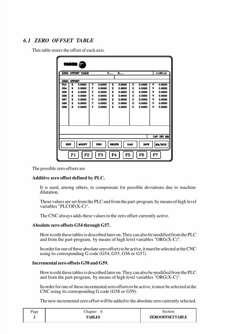
8/21/2019 CNC 8055 M Operator Manual
http://slidepdf.com/reader/full/cnc-8055-m-operator-manual 102/702
Page
2 TABLES
Chapter: 6 Section:
6.1 ZERO OFFSET TABLE
This table stores the offset of each axis.
The possible zero offsets are
Additive zero offset defined by PLC.
It is used, among others, to compensate for possible deviations due to machinedilatation.
These values are set from the PLC and from the part-program, by means of high levelvariables "PLCOF(X-C)".
The CNC always adds these values to the zero offset currently active.
Absolute zero offsets G54 through G57.
How to edit these tables is described later on. They can also be modified from the PLCand from the part-program, by means of high level variables "ORG(X-C)".
In order for one of these absolute zero offsets to be active, it must be selected at the CNCusing its corresponding G code (G54, G55, G56 or G57).
Incremental zero offsets G58 and G59.
How to edit these tables is described later on. They can also be modified from the PLCand from the part-program, by means of high level variables "ORG(X-C)".
In order for one of these incremental zero offsets to be active, it must be selected at the
CNC using its corresponding G code (G58 or G59).
The new incremental zero offset will be added to the absolute zero currently selected.
ZERO OFFSET TABLE

8/21/2019 CNC 8055 M Operator Manual
http://slidepdf.com/reader/full/cnc-8055-m-operator-manual 103/702
Page
3
Section:
TABLES
Chapter: 6
6.2 TOOL OFFSET TABLE
This table stores the dimensions of each tool.
Each offset has a number of fields containing the tool dimensions. These fields are:
Tool radius.
Tool length.
Tool radius wear
The CNC will add this value to the nominal radius to calculate the real tool radius (R+I).
Tool length wear.
The CNC will add this value to the nominal length to calculate the real tool length(Z+K).
How to edit these values will be described later on. They can also be modified from the PLCand from the part-program by means of the high level variables associated with the tools.
TOOL OFFSET TABLE

8/21/2019 CNC 8055 M Operator Manual
http://slidepdf.com/reader/full/cnc-8055-m-operator-manual 104/702
Page
4 TABLES
Chapter: 6 Section:
6.3 TOOL TABLE
This table stores information about the tools available indicating the type of tool offsetassociated with them, their family, etc.
Each tool has the following data fields:Offset number associated with the tool.
Every time a tool is selected, the CNC will assume its dimensions as they appear in thetool offset table for the specified tool offset.
Family code.
It will be used when having an automatic tool changer and it will allow replacing theworn out tool with another one with similar characteristics.
There are two types of families:
* Those for normal tools whose codes are between 0 and 199.
* Those for special tools (which occupy more than one magazine pocket), whosenumbers are between 200 and 255.
Every time a new tool is selected, the CNC checks whether it is worn out ("real life"greater than "nominal life"). If that is the case, it will not select it, but it will select anotherone of the same family, instead.
If while machining a part, the PLC "asks" the CNC to reject the current tool (byactivating the logic input “TREJECT”), the CNC will display the message "rejected"
in the "STATUS" field and it will replace it with the next tool of the same family that
TOOL TABLE
8/21/2019 CNC 8055 M Operator Manual
http://slidepdf.com/reader/full/cnc-8055-m-operator-manual 105/702
Page
5
Section:
TABLES
Chapter: 6
appear in the tool table. This change will take place the next time that tool is selected.
Nominal tool life.
It indicates the machining time (in minutes) or the number of operations that that toolis calculated to last.
Real tool life.
It indicates the machining time (in minutes) or the number of operations already carriedout by that tool.
Tool status.
It indicates the size of the tool and its status:
The tool size depends on the number of pockets it takes in the magazine and it is definedas follows:
N = Normal (family 0-199)S = Special (family 200-255)
The tool status is defined as follows:
A = AvailableE = Expired (“real life” greater than “nominal life”)R = Rejected by the PLC
How to edit these values is described later on.
TOOL TABLE

8/21/2019 CNC 8055 M Operator Manual
http://slidepdf.com/reader/full/cnc-8055-m-operator-manual 106/702
Page
6 TABLES
Chapter: 6 Section:
6.4 TOOL MAGAZINE TABLE
This table contains information about the tool magazine indicating all the tools of themagazine and their position in it.
Magazine positionBesides indicating each position in the magazine, it indicates the active tool and the oneselected for the following operations.The next tool will be placed in the spindle after executing auxiliary function M06.
ToolIt indicates the number of the tool occupying that position (pocket).The empty pockets appear with the letter "T" and the canceled ones with the charactersT****.
Status
The first letter indicates the tool size and the second one its status.
The size depends on the number of pockets it occupies in the magazine.
N = Normal (family 0-199) S = Special (family 200-255)
The tool status is defined as following:A = AvailableE = Expired (“real life” greater than “nominal life”)R = Rejected by the PLC
How to edit these values is described later on.
TOOL MAGAZINE TABLE

8/21/2019 CNC 8055 M Operator Manual
http://slidepdf.com/reader/full/cnc-8055-m-operator-manual 107/702
Page
7
Section:
TABLES
Chapter: 6
6.5 GLOBAL AND LOCAL PARAMETER TABLES
The CNC has two types of general purpose variables:
Local parameters P0-P25 (7 levels)Global parameters P100-P299.
The CNC updates the parameter tables after carrying out the operations indicated in theblock in preparation. This operation is always carried out before executing the block.Therefore, the values shown in the table may not coincide with those of the block beingexecuted.
When quitting the Execution mode after interrupting program execution, the CNC updatesthe parameter tables with the values corresponding to the block that was being executed.
In the global and local parameter tables, the values of the parameters may be displayed in
decimal (4127.423) or in scientific notation (0.23476 E-3).
The CNC generates a new nesting level of local parameters every time parameters areassigned to a subroutine. Up to a maximum of 6 nesting levels of local parameters arepossible.
Machining canned cycles G66, G68, G69, G81, G82, G83, G84, G85, G86, G87, G88 andG89 use the sixth nesting level of local parameters when they are active.
To access the different local parameter tables, the corresponding level must be indicated (0through 6).
While programming in high level, local parameters may be referred to as P0-P25, or asA-Z,"A" being the same as "P0" and "Z" the same as "P25".
To do that, the local parameter tables show the letter associated to them, in brackets, nextto the parameter number. In the tables, the parameter can only referred to as P0-P25, lettersare not allowed.
GLOBAL AND LOCALPARAMETER TABLE

8/21/2019 CNC 8055 M Operator Manual
http://slidepdf.com/reader/full/cnc-8055-m-operator-manual 108/702
Page
8 TABLES
Chapter: 6 Section:
6.6 HOW TO EDIT TABLES
The screen may be scrolled up and down line by line using the up/down arrow keys or pageby page using the page up/down keys.
There are several ways to edit or modify a line which will be described next.
Once the user has selected any of those options, a editing area is available on the screenwhich may be scrolled up and down using the up/down arrow keys. On the other hand, withthe up arrow key, the cursor may be placed over the first character of the editing windowand, with the down arrow key over the last character.
EDIT
Once this option has been selected, the softkeys change color appearing over a white
background and they show the information corresponding to the type of editing thatmay be done.
On the other hand, more information on the editing commands can be obtained at anytime by pressing [HELP]. To quit this help mode, press [HELP] again.
Press [ESC] to quit the editing mode and maintain the table with the previous values.
Once the editing is done, press [ENTER]. The values assigned will be entered into thetable.
MODIFYOnce this option has been selected, the softkeys change color appearing over a whitebackground and showing the information corresponding to each field.
On the other hand, more information on the editing commands can be obtained at anytime by pressing [HELP]. To quit this help mode, press [HELP] again.
By pressing [ESC], the information shown in the editing area is deleted. From this pointon, the selected line may be edited again.
To quit the "modify" option, the information appearing in the editing area must bedeleted by pressing [CL] or [ESC] and then [ESC]. The table will keep its previous
values.
Once the modification is over, press [ENTER]. The new values assigned will beentered into the table.
HOW TO EDIT TABLES
8/21/2019 CNC 8055 M Operator Manual
http://slidepdf.com/reader/full/cnc-8055-m-operator-manual 109/702
Page
9
Section:
TABLES
Chapter: 6
FIND
Once this option has been selected, the softkeys will show the following options:
BEGINNING When pressing this softkey, the cursor is placed over the first line of thetable that can be edited.
END When pressing this softkey, the cursor is placed over the last line of the table.
ZERO OFFSET, TOOL OFFSET, TOOL, POSITION, PARAMETERWhen pressing one of these softkeys, the CNC requests the field number to befound. Once the field has been defined, press [ENTER].
The CNC searches for the requested field and places the cursor over it (whenfound).
DELETE
When deleting a line, the CNC sets all the fields to "0".
To delete a line, indicate its number and press [ENTER]
To delete several lines, indicate the beginning, press the [UP TO] softkey, indicate thelast line to be deleted and press [ENTER]
To delete all the lines, press the "ALL" softkey. The CNC requests confirmation of thecommand.
INITIALIZE
It deletes all the data of the table by setting them all to "0". The CNC requestsconfirmation of the command.
LOAD
The tables may be loaded from the "Memkey Card" (CARD A) or a peripheral deviceor a PC through the two serial communications lines (RS232C or RS422).
The transmission starts after pressing the corresponding softkey. When using a serialline, the receptor must be ready before starting the transmission.
To interrupt the transmission, press the "ABORT" softkey.
If the length of the table received does not coincide with the current table length, theCNC will act as follows:
If the table received is shorter than the current one, the received lines are modifiedand the rest remain with their previous values.
If the table received is longer than the current one, all the lines of the table are
modified and when detecting that there is no more room, the CNC will issue thecorresponding error message
HOW TO EDIT TABLES

8/21/2019 CNC 8055 M Operator Manual
http://slidepdf.com/reader/full/cnc-8055-m-operator-manual 110/702
Page
10 TABLES
Chapter: 6 Section:
SAVE
The tables may be saved into the "Memkey Card" (CARD A) or out to a peripheraldevice or PC through the two serial lines (RS232C or RS422).
The transmission starts after pressing the corresponding softkey. When using a serialline, the receptor must be ready before starting the transmission.
To interrupt the transmission, press the "ABORT" softkey.
MM/INCHES
It toggles the display units for the data. The lower right-hand side window shows theunits selected (MM/INCH).
HOW TO EDIT TABLES

8/21/2019 CNC 8055 M Operator Manual
http://slidepdf.com/reader/full/cnc-8055-m-operator-manual 111/702
Page
1
Section:
UTILITIES
Chapter: 7
7 . UTILITIES
In this operating mode, one can access the programs stored in the CNC's RAM memory,in the "Memkey Card" (CARD A), in the hard disk (HD) and in external devices (throughthe serial lines 1 and 2).
They can be deleted, renamed or their protection changed. It is also possible to make copieswithin the same device or from one to another.
7.1 DIRECTORY
To access the program directory of the CNC's RAM memory, the "Memkey Card" (CARD
A), the hard disk (HD) and of the external devices (through serial lines 1 and 2).
The subroutine directory of the CNC can also be accessed.
Program directory.By default, the CNC shows the program directory of the RAM memory, to view anotherdirectory, press the corresponding softkey.
On each directory, the CNC shows all the programs visible (not hidden) to the user, that is:Part programsCustomizing programsThe PLC program (PLC_PRG)The PLC error file (PLC_ERR)
The PLC message file (PLC_MSG)
DIRECTORY
8/21/2019 CNC 8055 M Operator Manual
http://slidepdf.com/reader/full/cnc-8055-m-operator-manual 112/702
Page
2 UTILITIES
Chapter: 7 Section:
The program directory has the following definition fields:
ProgramIt shows the number when it is a part-program or a customizing program and thecorresponding mnemonic when it is a PLC program, the PLC error file or the PLCmessage file.
CommentAny program may have a comment associated with it for its identification.The comments may be defined when editing the program or in this operating modeusing the Rename option as described later on.
SizeIt indicates, in bytes, the size of the program text. It must be borne in mind that the actualsize of the program is slightly greater because this field does not include the spaceoccupied by some variables used internally (header, etc.).
The date and the time when the program was edited (last changed)
AttributesThey show information about the source and usefulness of each program. The attributesare defined in this operating mode by means of the Protections option as described lateron.
* The program is running, either because it is the main program or because it containsa subroutine which has been called upon from that program or from anothersubroutine.
O The program was created by the machine manufacturer.H The program is hidden and cannot be displayed in any directory.
Since a hidden program can nevertheless be edited or deleted if its number isknown, it is recommended to remove the "Modifiable" attribute to prevent it frombeing edited or deleted.
M The program may be modified. In other words, it may be edited, copied, etc.
If a program does not have this attribute, the operator cannot see or modify itscontents.
X Indicates that the program may be executed.
A program not having this attribute cannot be executed by the operator.
Only the attributes currently selected will be shown, the ones not selected will appear as"-".
Example: O—X Indicates that the program was created by the manufacturer, it will bedisplayed in the directory (not hidden), it cannot be modified, but it may be executed.
DIRECTORY
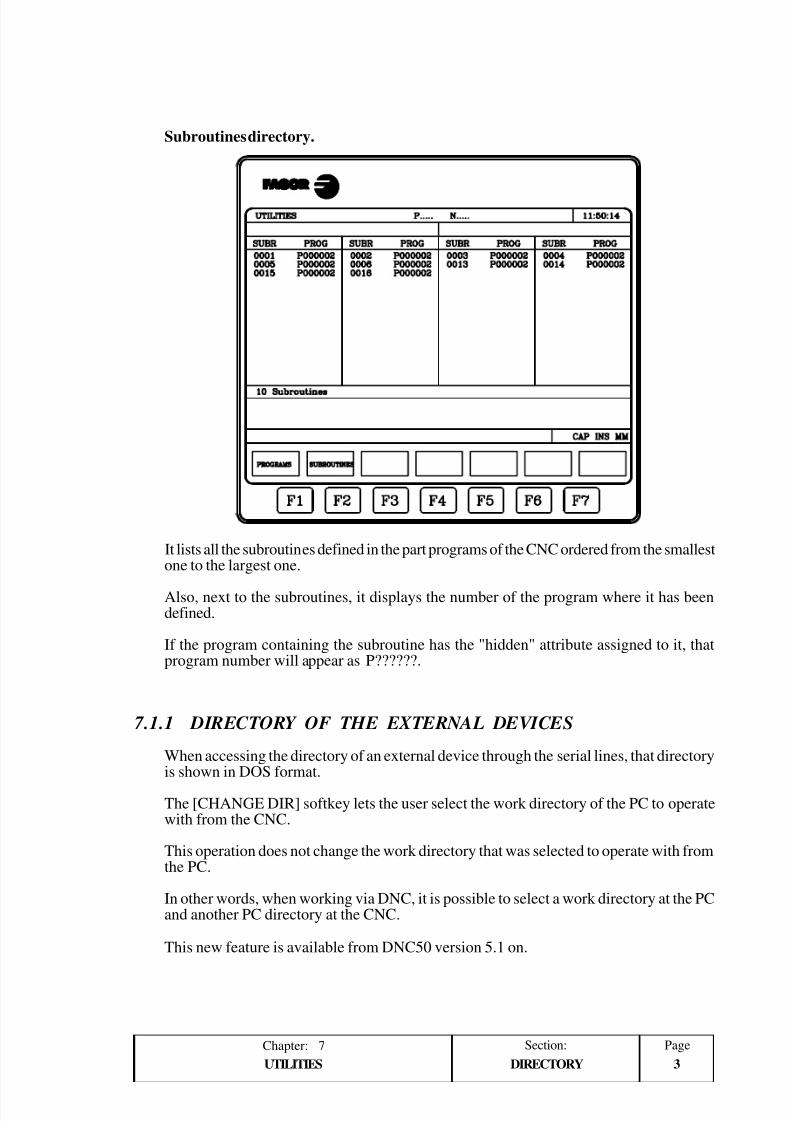
8/21/2019 CNC 8055 M Operator Manual
http://slidepdf.com/reader/full/cnc-8055-m-operator-manual 113/702
Page
3
Section:
UTILITIES
Chapter: 7
Subroutines directory.
It lists all the subroutines defined in the part programs of the CNC ordered from the smallestone to the largest one.
Also, next to the subroutines, it displays the number of the program where it has beendefined.
If the program containing the subroutine has the "hidden" attribute assigned to it, thatprogram number will appear as P??????.
7.1.1 DIRECTORY OF THE EXTERNAL DEVICES
When accessing the directory of an external device through the serial lines, that directoryis shown in DOS format.
The [CHANGE DIR] softkey lets the user select the work directory of the PC to operatewith from the CNC.
This operation does not change the work directory that was selected to operate with fromthe PC.
In other words, when working via DNC, it is possible to select a work directory at the PCand another PC directory at the CNC.
This new feature is available from DNC50 version 5.1 on.
DIRECTORY

8/21/2019 CNC 8055 M Operator Manual
http://slidepdf.com/reader/full/cnc-8055-m-operator-manual 114/702
Page
4 UTILITIES
Chapter: 7 Section:
7.2 COPY
To copy programs in the same directory or between directories of different devices.
The copies may be made between:The CNC's RAM memory, "Memkey Card" (CARD A), hard disk (HD) and externaldevices (serial lines)
To make a copy, proceed as follows:
Press the [COPY] softkeyIndicate the location of the program to be copied (RAM memory, CARD A, HD orDNC)key in the program number to be copiedPress the [IN] softkeyIndicate the destination of the copy (RAM memory, CARD A, HD or DNC)
Key in the program numberPress [ENTER]
Example to copy program 200103, from the CNC's RAM memory out to the "MemkeyCard" with the number 14
COPY (MEMORY) P200103 IN (CARD A) P14 ENTER
If a program with the same number already exists, the CNC will display a warning message.On the other hand, if that program is in execution, the CNC will display a message indicatingthat it is not possible.
Two subroutines may not have the same name in RAM memory. To make a copy and
change the name of the copied subroutine, write the subroutine defining block as a commentbefore making the copy.
7.3 DELETE
A program may be deleted from the CNC' RAM memory, from the "Memkey Card"(CARD A), from the Hard Disk (HD) or from the external devices (through the serial lines1 and 2).
To delete a program, proceed as follows:
Press the [DELETE] softkeyIndicate the location of the program to be deleted (RAM, CARD A, HD or DNC).Key in the number of the program to be deleted or place the cursor over it.Press [ENTER]
Example to delete program 200103 from the "Memkey Card"DELETE (CARD A) P200103 ENTER
Only programs that can be modified ("M" attribute) can be deleted.
COPY - DELETE
8/21/2019 CNC 8055 M Operator Manual
http://slidepdf.com/reader/full/cnc-8055-m-operator-manual 115/702
Page
5
Section:
UTILITIES
Chapter: 7
7.4 RENAME
To rename or assign a new comment to a program stored in the CNC's RAM memory,"Memkey Card" (CARD A), or in the Hard Disk (HD).
To rename a program, proceed as follows:
Press the [RENAME] softkey.Indicate the location of the program (RAM, CARD A, HD or DNC).Key in the number of the program to be renamedPress the [TO] softkey.Press either the [NEW NUMBER] or the [NEW COMMENT] softkeyKey in the new number or the new commentPress [ENTER].
The files associated with the PLC (program, messages and errors) are always referred to
with their associated mnemonics. Therefore, only their comment may be renamed.
If there is a program with the same number, the CNC will issue a warning message and itwill offer the chance to modify the command.
Examples:To change the name of program 200103 from the "Memkey Card"
RENAME (CARD A) P200103 TO NEW NUMBER P12 ENTER
to change the comment of program 100453 from the CNCRENAME (MEMORY) P100453 TO NEW COMMENT "Test" ENTER
RENAME
8/21/2019 CNC 8055 M Operator Manual
http://slidepdf.com/reader/full/cnc-8055-m-operator-manual 116/702
Page
6 UTILITIES
Chapter: 7 Section:
7.5 PROTECTIONS
To prevent certain programs from being manipulated and restrict access to the operator tocertain CNC commands.
It is possible to protect programs stored in the CNC's RAM memory, in the "Memkey card"(CARD A) or in the Hard Disk (HD).
USER PERMISSIONS
Lets the operator see those CNC programs that have been created by the operator andsets their attributes.
To modify the attributes of a program, proceed as follows:Press the [USER PERMISSION] softkeyIndicate the location of the program (RAM MEMORY, CARD A or HD)
Key in the number of the program whose attribute is to be changedPress the softkeys
F2 to change the (H) attribute hidden/visible programF3 to change the (M) attribute modifiable programF4 to change the (X) attribute executable program
Press [ENTER]
OEM PERMISSION
Lets see all the programs stored at the CNC whether they are created by the OEM orby the operator and set their attributes.
To modify the attributes of a program, proceed as follows:Press the [OEM PERMISSION] softkeyIndicate the location of the program (RAM MEMORY, CARD A or HD)Key in the number of the program whose attribute is to be changedPress the softkeys
F1 to change the (O) attribute OEM programF2 to change the (H) attribute hidden/visible programF3 to change the (M) attribute modifiable programF4 to change the (X) attribute executable program
Press [ENTER]
PASSWORDS
Lets define each of the passwords that the operator must key in before accessing thevarious CNC commands.
General access password (MASTERPSW)It is requested when trying to access this password option.
(Utilities mode / Protections / Passwords).
OEM password (OEMPSW)It is requested when trying to access OEM permissions
(Utilities mode / Protections / OEM permissions).
User password (USERPSW)It is requested when trying to access user permissions(Utilities mode / Protections / User permissions).
PROTECTIONS

8/21/2019 CNC 8055 M Operator Manual
http://slidepdf.com/reader/full/cnc-8055-m-operator-manual 117/702
Page
7
Section:
UTILITIES
Chapter: 7
PLC access password (PLCPSW)It is requested in the following cases:
• When editing the PLC program, the PLC message program and the PLC errorprogram.
• When compiling the PLC program.• When trying to change the status of a resource or execute a program execution
controlling command.
Customizing password (CUSTOMPSW)It is requested when trying to access the Customizing mode.
Machine parameter access password (SETUPPSW)It is requested when trying to access the options to modify the table values (Edit,Modify, Initialize, Delete and Load) except for tables of the serial lines which are notprotected.
To change or delete the passwords, use the following softkeys:
Change password.Select the desired password and enter the new one.
Delete password.Lets delete (eliminate) one of several codes from the table.• To delete a password, indicate its number and press [ENTER].• To delete several passwords (they must be in a row), indicate the number of the
first one to be delete, press the "UPTO" softkey, indicate the number of the lastone to be deleted and press [ENTER].
• To delete a password, indicate its number and press [ENTER].Clear all.
Lets delete all the passwords. The CNC will request confirmation of the commandand it will delete them after pressing [ENTER].
7.6 CHANGE DATE
Lets change the system date and time.
First, the date will be shown as day/month/year (12/04/1998). After changing it, press
[ENTER] to validate it. If it is not to be changed, press [ESC].
Next, the time will be shown as hours/minutes/seconds (08/30/00). After changing it, press[ENTER] to validate it. If it is not to be changed, press [ESC].
CHANGE DATE

8/21/2019 CNC 8055 M Operator Manual
http://slidepdf.com/reader/full/cnc-8055-m-operator-manual 118/702
PageChapter: 8
STATUS
Section:
1
8. DNC
This operating mode shows the CNC status after a power outage and the status of the DNCcommunication lines. It also lets activate and deactivate DNC communications with a PC.
8.1 CNC
This screen shows the number of the line that was being executed last time an executionerror or a power outage occurred.
The CNC shows the program number and line number that was executing as well as where
the program is stored.
On the other hand, if that program called upon a subroutine and the CNC was executingit, it will display:
The subroutine number, the program containing its definition and the line or block of the subroutine being executed.
Example:
Device Program Line number SubroutineCARD A 000012 7
MEMORY 001000 15 0033Indicates that the CNC was executing line 7 of program 12 of CARD A.
That program line called to subroutine 15 and it was executing its line number 33. Thatsubroutine is defined (contained) in program 1000 which is stored in the CNC's RAMmemory.

8/21/2019 CNC 8055 M Operator Manual
http://slidepdf.com/reader/full/cnc-8055-m-operator-manual 119/702
Section:
STATUSChapter: 8
2
Page
8.2 DNC
With this CNC, it is possible to access this operating mode when at least one of the seriallines (RS232C or RS422) is set to work in the DNC mode or to communicate with theFAGOR Floppy Disk Unit.
When accessing this mode, the CNC shows the following screen:
The left-hand side of the screen corresponds to serial line 1 and the right-hand side to serialline 2.
In the example of the figure above, serial line 1 is used to communicate with a FagorFloppy Disk Unit; and serial line 2 to communicate via DNC.
The upper area, 1, indicates:
* The status of the serial line: Active / Inactive.
* The type of operation in progress:Sending program / Receiving program / Sending directory / Receiving directory / etc.
The lower area, 2, indicates the last operation and the type of error occurred if any.
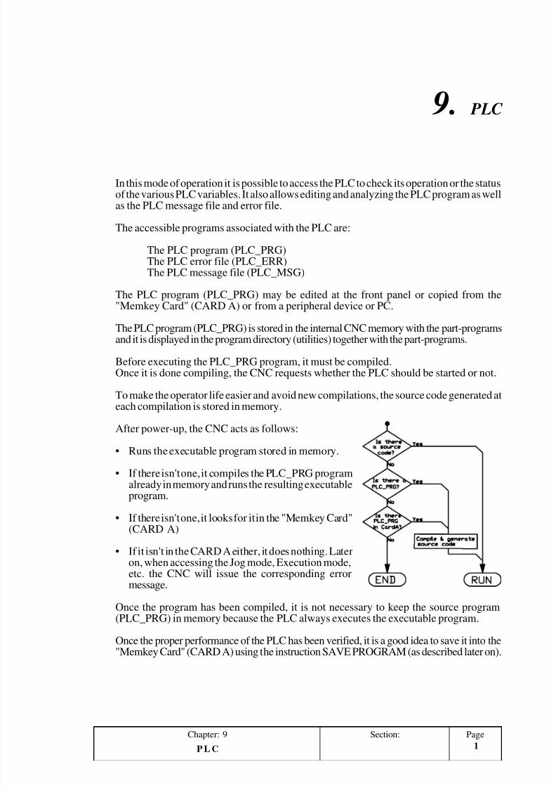
8/21/2019 CNC 8055 M Operator Manual
http://slidepdf.com/reader/full/cnc-8055-m-operator-manual 120/702
PageChapter: 9
P L C
Section:
1
9. PLC
In this mode of operation it is possible to access the PLC to check its operation or the statusof the various PLC variables. It also allows editing and analyzing the PLC program as wellas the PLC message file and error file.
The accessible programs associated with the PLC are:
The PLC program (PLC_PRG)The PLC error file (PLC_ERR)
The PLC message file (PLC_MSG)
The PLC program (PLC_PRG) may be edited at the front panel or copied from the"Memkey Card" (CARD A) or from a peripheral device or PC.
The PLC program (PLC_PRG) is stored in the internal CNC memory with the part-programsand it is displayed in the program directory (utilities) together with the part-programs.
Before executing the PLC_PRG program, it must be compiled.Once it is done compiling, the CNC requests whether the PLC should be started or not.
To make the operator life easier and avoid new compilations, the source code generated ateach compilation is stored in memory.
After power-up, the CNC acts as follows:
• Runs the executable program stored in memory.
• If there isn't one, it compiles the PLC_PRG programalready in memory and runs the resulting executableprogram.
• If there isn't one, it looks for it in the "Memkey Card"(CARD A)
• If it isn't in the CARD A either, it does nothing. Lateron, when accessing the Jog mode, Execution mode,etc. the CNC will issue the corresponding errormessage.
Once the program has been compiled, it is not necessary to keep the source program(PLC_PRG) in memory because the PLC always executes the executable program.
Once the proper performance of the PLC has been verified, it is a good idea to save it into the"Memkey Card" (CARD A) using the instruction SAVE PROGRAM (as described later on).

8/21/2019 CNC 8055 M Operator Manual
http://slidepdf.com/reader/full/cnc-8055-m-operator-manual 121/702
Section:
P L CChapter: 9Page
2
9.1 EDIT
Once this option is selected, indicate with the corresponding softkey the PLC program tobe edited.
The PLC program (PLC_PRG)The PLC error file (PLC_ERR)The PLC message file (PLC_MSG)
The cursor can be moved line by line with the “up and down” arrow keys or page by pagewith the “page up” and “page down” keys.
The cursor position or line number will be displayed in a white window inside thecommunications window ( bottom of the screen) next to the CAP/INS indicator window.
This operating mode offers various options which are described next.
Once any of these functions is selected, the CNC shows an editing area on the CRT wherethe cursor may be moved by using the up/down and right/left arrow keys. Also, the up-arrow key positions the cursor over the first character of the editing area and the down-arrowkey positions the cursor over the last character.
EDIT
With this option it is possible to edit new lines or blocks of the selected program.
Before pressing this softkey, the block after which the new ones will be added must beselected with the cursor.
The program will be edited (written) a block at a time and each block can be written inISO language, High Level language or it can be just a program comment.
Once this option is selected, the softkeys will change their color showing their type of editing option over a white background.
Also, it is possible to get more editing assistance by pressing HELP. Press HELP againto exit the editing assistance mode.
Press the ESC key to exit the block editing mode when writing a block and this block will not be added to the program.
Once the block has been edited, press ENTER to add it to the program behind the block previously indicated by the cursor.
The cursor will be positioned at the new block (just edited) and the editing window (area)will be cleared In order to edit a new block.
Press ESC or MAIN MENU to quit the block editing mode.
EDIT

8/21/2019 CNC 8055 M Operator Manual
http://slidepdf.com/reader/full/cnc-8055-m-operator-manual 122/702
PageChapter: 9
P L C
Section:
3
MODIFY
This option permits modifying the contents of a selected program block.
Before pressing this softkey, select with the cursor the block to be modified .
Once this option is selected, the softkeys will change their color showing their type of modifying option over a white background.
Also, it is possible to get more editing assistance by pressing HELP. Press HELP againto exit the editing assistance mode.
By pressing ESC, the information corresponding to that block and which was shown inthe editing area will be cleared. It will then be possible to modify its contents again.
To quit the block modifying mode, press CL or ESC to clear the editing window and
then press ESC again. This way, the selected block will not be modified.
Once the block contents have been modified, press ENTER so the new contents replacethe old ones.
EDIT

8/21/2019 CNC 8055 M Operator Manual
http://slidepdf.com/reader/full/cnc-8055-m-operator-manual 123/702
Section:
P L CChapter: 9Page
4
FIND
This option is used to find a specific text within the selected program.
When selecting this option, the following options will appear:
BEGINNING This softkey positions the cursor over the first program block which isthen selected quitting the “find” option.
END This softkey positions the cursor over the last program block which is then selectedquitting the “find” option.
TEXT With this function it is possible to search a text or character sequence starting fromthe block indicated by the cursor.
When this key is selected, the CNC requests the character sequence to be found.
When the text is defined, press the “END OF TEXT” softkey and the cursor will bepositioned over the first occurrence of that text.
The search will begin at the current block.
The text found will be highlighted being possible to continue with the search or to quitit.
Press ENTER to continue the search up to the end of the program. It is possible tosearch as many times as wished and when the end of the program is reached, it willstart from the first block.
Press the “EXIT” softkey or the ESC key to quit the search mode. The cursor willbe positioned where the indicated text was found last.
LINE NUMBER After pressing this key, the CNC requests the number of the block tobe found. After keying in the desired number and pressing ENTER, the cursor willposition over that block which will then be selected quitting the search mode.
EDIT
8/21/2019 CNC 8055 M Operator Manual
http://slidepdf.com/reader/full/cnc-8055-m-operator-manual 124/702
PageChapter: 9
P L C
Section:
5
REPLACE
With this function it is possible to replace a character sequence with another throughoutthe selected program.
When selecting this option, the CNC requests the character sequence to be replaced.
Once the text to be replaced is indicated, press the “WITH” softkey and the CNC willrequest the character sequence which will replace the previous one.
Once this text is keyed in, press the “END OF TEXT” softkey and the cursor will bepositioned over the first occurrence of the searched text.
The search will begin at the current block.
The found text will be highlighted and the following softkey options will appear:
REPLACE Will replace the highlighted text and will continue the search from this pointto the end of the program.
If no more occurrences of the text to be replaced are found, the CNC will quit thismode.
If another occurrence of the text is found, it will be highlighted showing the same“replacing” or “not replacing” options.
DO NOT REPLACE Will not replace the highlighted text and will continue the searchfrom this point to the end of the program.
If no more occurrences of the text to be replaced are found, the CNC will quit thismode.
If another occurrence of the text is found, it will be highlighted showing the same“replacing” or “not replacing” options.
TO THE END This function will automatically replace all the matching text from thecurrent block to the end of the program without offering the option of not replacingit.
ABORT This function will not replace the highlighted text and it will quit the “find andreplace” mode.
EDIT
8/21/2019 CNC 8055 M Operator Manual
http://slidepdf.com/reader/full/cnc-8055-m-operator-manual 125/702
Section:
P L CChapter: 9Page
6
DELETE BLOCK
With this function it is possible to delete a block or group of blocks.
To delete only one block, just position the cursor over it and press ENTER.
To delete a group of blocks, indicate the first and last blocks to be deleted. To do so,follow these steps:
* Position the cursor over the first block to be deleted and press the “INITIALBLOCK” softkey.
* Position the cursor over the last block to be deleted and press the “FINAL BLOCK”softkey.
If the last block to be deleted is also the last one of the program, it can also be selected
by pressing the “TO THE END” softkey.
* Once the first and last blocks are selected, the CNC will highlight the selected blocksrequesting confirmation to delete them.
MOVE BLOCK
With this option it is possible to move a block or group of blocks by previously indicatingthe first and last blocks to be moved. To do so, follow these steps:
* Position the cursor over the first block to be moved and press the “INITIAL BLOCK”softkey.
* Position the cursor over the last block to be moved and press the “FINAL BLOCK”softkey.
If the last block to be moved is also the last one of the program, it can also be selectedby pressing the “TO THE END” softkey.
To move only one block, the “initial block” and the “final block” will be the same one.
* Once the first and last blocks are selected, the CNC will highlight the selected blocksrequesting confirmation to move them.
Then, indicate the block after which this group of blocks must be placed.
* Press the “START OPERATION” softkey to carry out the move.
EDIT
8/21/2019 CNC 8055 M Operator Manual
http://slidepdf.com/reader/full/cnc-8055-m-operator-manual 126/702
PageChapter: 9
P L C
Section:
7
COPY BLOCK
With this option it is possible to copy a block or group of blocks by previously indicatingthe first and last blocks to be copied. To do so, follow these steps:
* Position the cursor over the first block to be copied and press the “INITIAL BLOCK”softkey.
* Position the cursor over the last block to be copied and press the “FINAL BLOCK”softkey.
If the last block to be copied is also the last one of the program, it can also be selectedby pressing the “TO THE END” softkey.
To copy only one block, the “initial block” and the “final block” will be the same one.
* Once the first and last blocks are selected, the CNC will highlight the selected blocksrequesting confirmation to copy them.
Then, indicate the block after which this group of blocks must be placed.
* Press the “START OPERATION” softkey to carry out this command.
EDIT

8/21/2019 CNC 8055 M Operator Manual
http://slidepdf.com/reader/full/cnc-8055-m-operator-manual 127/702
Section:
P L CChapter: 9Page
8
COPY TO PROGRAM
With this option it is possible to copy a block or group of blocks of one program intoanother program.
When selecting this option, the CNC will request the number of the destination programwhere the selected block or blocks are to be copied. After entering the program numberpress ENTER.
Next, indicate the first and last blocks to copy by following these steps:
* Position the cursor over the first block to be copied and press the “INITIAL BLOCK”softkey.
* Position the cursor over the last block to be copied and press the “FINAL BLOCK”softkey.
If the last block to be copied is also the last one of the program, it can also be selectedby pressing the “TO THE END” softkey.
To copy only one block, the “initial block” and the “final block” will be the same one.
* Once the first and last blocks are selected, the CNC will highlight the selected blocksand will execute the command.
If the destination program already exists, the following options will be displayed:
* Write over the existing program. All the blocks of the destination program will be
erased and will be replaced by the copied blocks.* Append (add) the copied blocks behind the ones existing at the destination program.
* Abort or cancel the command without copying the blocks.
INCLUDE PROGRAM
With this option it is possible to include or merge the contents of another program intothe one currently selected.
Once this option is selected, the CNC will request the number of the source program tobe merged. After keying in that number press ENTER.
Next, indicate with the cursor the block after which the source program will be included.
Finally, press the “START OPERATION” softkey to execute the command.
EDIT

8/21/2019 CNC 8055 M Operator Manual
http://slidepdf.com/reader/full/cnc-8055-m-operator-manual 128/702
PageChapter: 9
P L C
Section:
9
9.2 COMPILE
With this option it is possible to compile the PLC source program “PLC_PRG”.
The PLC program must be stopped in order to compile it, otherwise, the CNC will “ask”if it is desired to stop it.
Once the source program compiled, the CNC will generate the executable PLC program(object program).
If while compiling, some errors are detected, the CNC will not create the object programand the detected errors (up to 15) will appear on the screen.
If the errors do not affect the proper program execution (such as non-referenced labels, etc.),the CNC will display the corresponding warning messages but it will generate the objectprogram.
After a successful compilation, the CNC will “ask” whether the PLC program must bestarted or not.
COMPILE

8/21/2019 CNC 8055 M Operator Manual
http://slidepdf.com/reader/full/cnc-8055-m-operator-manual 129/702
Section:
P L CChapter: 9Page
10
9.3 MONITORING
With this option it is possible to display the PLC program and analyze the status of thedifferent PLC resources and variables.
Once this option has been selected, the CNC will show the source program that correspondsto the executable program (object) even when that program (source) has been deleted ormodified at the CNC.
The CNC will also display all the variable consultations at logic level 1 (including those notbeing executed) and the actions whose conditions are met.
To display the program from a specific line on, press the “L” key followed by that linenumber and then press ENTER.
The operator can move the cursor around the CRT a line at a time with the up/down arrow
keys and a page at a time with the page-up and page-down keys.
The various monitoring options available are described next.
Once any of the those options has been selected, the operator has an editing window wherethe cursor may be moved with the right and left arrow keys. The up arrow will position thecursor over the first character of the editing window and the down arrow over the last one.
MODIFY THE STATUS OF THE RESOURCES
The CNC has the following instructions to modify the status of the different PLCresources.
I 1/256 = 0/1 Alters the status (0/1) of the indicated input. For example:I120 = 0, sets input I120 to 0.
I 1/256.1/256 = 0/1 Alters the status (0/1) of a the indicated group of inputs. Forexample: I100.103 = 1, sets inputs I101, I102 and I103 to1.
O 1/256 = 0/1 Alters the status (0/1) of the indicated output. For example:O20 = 0, sets output O20 to 0.
O 1/256.1/256 = 0/1 Alters the status (0/1) of the indicated group of outputs. Forexample: O22.25= 1 sets outputs O22 thru O25 to 1.
M 1/5957 = 0/1 Alters the status (0/1) of the indicated mark. For example:M330 = 0 sets Mark M330 to 0.
M 1/5957.1/5957 = 0/1 Alters the status (0/1) of the indicated group of marks. Forexample: M400.403=1 sets marks M400 thru M403 to 1.
TEN 1/256 = 0/1 Alters the status (0/1) of the ENABLE input of the indicatedtimer. For example: TEN12 = 1, sets the Enable input of timer T12 to 1.
MONITORING
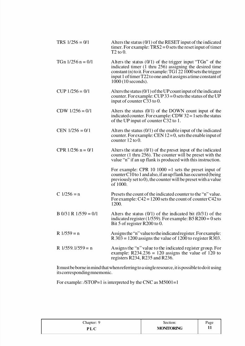
8/21/2019 CNC 8055 M Operator Manual
http://slidepdf.com/reader/full/cnc-8055-m-operator-manual 130/702
PageChapter: 9
P L C
Section:
11
TRS 1/256 = 0/1 Alters the status (0/1) of the RESET input of the indicatedtimer. For example: TRS2 = 0 sets the reset input of timerT2 to 0.
TGn 1/256 n = 0/1 Alters the status (0/1) of the trigger input “TGn” of theindicated timer (1 thru 256) assigning the desired timeconstant (n) to it. For example: TG1 22 1000 sets the triggerinput 1 of timer T22 to one and it assigns a time constant of 1000 (10 seconds).
CUP 1/256 = 0/1 Alters the status (0/1) of the UP count input of the indicatedcounter. For example: CUP 33 = 0 sets the status of the UPinput of counter C33 to 0.
CDW 1/256 = 0/1 Alters the status (0/1) of the DOWN count input of theindicated counter. For example: CDW 32 = 1 sets the status
of the UP input of counter C32 to 1.
CEN 1/256 = 0/1 Alters the status (0/1) of the enable input of the indicatedcounter. For example: CEN 12 = 0, sets the enable input of counter 12 to 0.
CPR 1/256 n = 0/1 Alters the status (0/1) of the preset input of the indicatedcounter (1 thru 256). The counter will be preset with thevalue “n” if an up flank is produced with this instruction.
For example: CPR 10 1000 =1 sets the preset input of counter C10 to 1 and also, if an up flank has occurred (being
previously set to 0), the counter will be preset with a valueof 1000.
C 1/256 = n Presets the count of the indicated counter to the “n” value.For example: C42 = 1200 sets the count of counter C42 to1200.
B 0/31 R 1/559 = 0/1 Alters the status (0/1) of the indicated bit (0/31) of theindicated register (1/559). For example: B5 R200 = 0 setsBit 5 of register R200 to 0.
R 1/559 = n Assigns the “n” value to the indicated register. For example:R 303 = 1200 assigns the value of 1200 to register R303.
R 1/559.1/559 = n Assigns the “n” value to the indicated register group. Forexample: R234.236 = 120 assigns the value of 120 toregisters R234, R235 and R236.
It must be borne in mind that when referring to a single resource, it is possible to do it usingits corresponding mnemonic.
For example: /STOP=1 is interpreted by the CNC as M5001=1
MONITORING
8/21/2019 CNC 8055 M Operator Manual
http://slidepdf.com/reader/full/cnc-8055-m-operator-manual 131/702
Section:
P L CChapter: 9Page
12
CREATE WINDOW
This CNC allows the possibility of creating windows to display the status of the variousPLC resources.
These windows will be shown overlapping the PLC program and the informationdisplayed in them will be updated dynamically.
The options “MODIFY WINDOW”, “ACTIVE WINDOW” and “ACTIVATESYMBOLS” allow the manipulation of these windows.
Every time a new window is created, the CNC will assign 2 data lines to it in order todisplay the status of the desired resources.
There are two types of windows which can be selected with softkeys.
WINDOW TO DISPLAY TIMERS AND REGISTERS
This window is divided into two sections, one to display Timers and the other one todisplay Registers.
Timer. It will show one timer per line showing the following information for each oneof them:
TG Indicates the logic status of the active trigger input.M Indicates the status of the timer: “S” means stopped, “T” means timing
and “D” means disabled.TEN Indicates the logic status of the Enable input.TRS Indicates the logic status of the Reset input.T Indicates the logic status of the status output of the timer.ET Indicates the elapsed time.TO Indicates the remaining time.
Key in the command T 1/256 or T 1/256.1/256 to request the data on a timer or groupof timers and then press ENTER.
Register. It will display one register per line showing the following information fieldsfor each of them:
HEX Indicates the hexadecimal value of its contents.
DEC Indicates the decimal value of its contents (with sign).
Key in R 1/559 orR 1/559.1/559 to request information on one or more registers and,then, press ENTER.
MONITORING

8/21/2019 CNC 8055 M Operator Manual
http://slidepdf.com/reader/full/cnc-8055-m-operator-manual 132/702
PageChapter: 9
P L C
Section:
13
WINDOW TO DISPLAY COUNTERS AND BINARY DATA
This window is divided into two sections, one to display Counters and the other oneto display Binary Data.
Counter. It will display one counter per line showing the following information fieldsfor each of them:
CEN Indicates the logic status of the ENABLE input.CUP Indicates the logic status of the UP COUNT input.CDW Indicates the logic status of the DOWN COUNT input.CPR Indicates the logic status of the PRESET input.S Indicates the status of the counter. “1” when its internal count is 0 and
0 for all other cases.C Indicates its count value.
Key in C 1/256 or C 1/256.1/256 to request information on one or more counter and,then, press ENTER.
Binary Data. It will show one data line per resource or group of resources requested.
The instructions available to request information of the various resources are:
I 1/256 or I 1/256.1/256 It shows the status of the selected input or groupof inputs.
O 1/256 or O 1/256.1/256 It shows the status of the selected output or group
of outputs.M 1/5957 or M 1/5957.1/5957 It shows the status of the selected mark or group
of marks.
B 0/31 R 1/559 It shows the status of the selected bit of theindicated register.
When requesting the status of one or more inputs, outputs or marks, the CNC willshow complete data lines even when all of them have not been requested.
When using generic denominators (I / O / M) to display resources, the CNC willdisplay 20 of them per line and 3 when using their associated mnemonics (symbols).
In the latter case, the generic denomination will be displayed when no mnemonic isassociated to a resource.
When requesting the status of a register bit, the CNC will display only the requestedbit on the corresponding line.
MONITORING
8/21/2019 CNC 8055 M Operator Manual
http://slidepdf.com/reader/full/cnc-8055-m-operator-manual 133/702
Section:
P L CChapter: 9Page
14
MODIFY WINDOW
With this option it is possible to manipulate the active window (the one selected) byenlarging it, reducing it, clearing it or even eliminating (closing) it.
To do so, the following softkey options are available:
ENLARGE To enlarge the size of the window by one line every time this softkeyis pressed.
REDUCE To reduce the size of the window by one line every time this softkey ispressed (minimum 2 lines).
CLEAR To clear the contents of the active window.
CLOSE To close the active window, the CNC will no longer display it.
ACTIVE WINDOW
With this option it is possible to select between the PLC program and each one of thewindows being displayed (timers, registers, counters and binary data) in order to operatewith it.
Bear in mind that the operator can only operate with the active window.
Once the active window has been selected, it Will be possible to:
Move the cursor (if the PLC program is the one active) or shift the display area with
the up and down arrow keys.Execute any command of the “MODIFY WINDOW” option.
MONITORING

8/21/2019 CNC 8055 M Operator Manual
http://slidepdf.com/reader/full/cnc-8055-m-operator-manual 134/702
PageChapter: 9
P L C
Section:
15
FIND
This option will be executed regardless of which is the active window and it offers thefollowing searching options:
BEGINNING This softkey positions the cursor over the first program block which isthen selected quitting the “find” option.
END This softkey positions the cursor over the last program block which is then selectedquitting the “find” option.
TEXT With this function it is possible to search a text or character sequence starting fromthe block indicated by the cursor.
When this key is selected, the CNC requests the character sequence to be found.
The CNC will consider a text found when it is isolated by blank spaces or separators.Thus, When looking for “I1” it will not find or stop at “I12” or “I123”, but only at “I1”.
When the text is defined, Press the “END OF TEXT” softkey and the cursor will bepositioned over the first occurrence of that text.
The search will begin at the current block.
The text found will be highlighted being possible to continue with the search or to quitit.
Press ENTER to continue the search up to the end of the program. It is possible to
search as many times as wished and when the end of the program is reached, it willstart from the first block.
Press the “EXIT” softkey or the ESC key to quit the search mode.
MONITORING

8/21/2019 CNC 8055 M Operator Manual
http://slidepdf.com/reader/full/cnc-8055-m-operator-manual 135/702
Section:
P L CChapter: 9Page
16
ACTIVATE / DEACTIVATE SYMBOLS
With this option it is possible to display in all available windows the symbols ormnemonics associated to the various resources.
The names of the resources may be displayed in two ways: using their generic names (I,O, M, T, C , R) by deactivating symbols or using their associated symbols byactivatingthem.
When a resource has no mnemonic associated to it, it will always be displayed with itsgeneric name.
This softkey will toggle between ACTIVATE SYMBOL and DEACTIVATESYMBOL every time is pressed in order to show which option is available.
LOGIC ANALYZER
It is especially suited to help in the machine startup and for troubleshooting errors andcritical situations in signal behavior.
START PLC
When selecting this option, the CNC will start executing the PLC program from thebeginning, including the CY1 cycle.
The CNC will ignore this command when it is already executing the PLC program.
FIRST CYCLE
When selecting this option, the CNC will execute only the initial cycle of the PLCprogram (CY1).
The CNC will ignore this command when it is already executing the PLC program.
SINGLE CYCLE
When selecting this option, the CNC will execute the main cycle of the PLC program(PRG) only once.
The CNC will ignore this command when it is already executing the PLC program.
STOP PLC
This softkey interrupts the execution of the PLC program.
CONTINUE
This softkey resumes the execution of the PLC program.
MONITORING

8/21/2019 CNC 8055 M Operator Manual
http://slidepdf.com/reader/full/cnc-8055-m-operator-manual 136/702
PageChapter: 9
P L C
Section:
17
9.3.1 MONITORING WITH THE PLC IN OPERATION AND WITH THE PLC STOPPED
It must be borne in mind that the CNC initializes all physical outputs and the PLC resourceson power-up, after the key sequence SHIFT-RESET and after detecting a WATCHDOGerror at the PLC.
The initialization process sets all resources to “0” except those active low. They will be setto “1”.
During the monitoring of the PLC program and the various PLC resources, the CNC willalways show the real values of the resources.
If the PLC is on, note that a program cycle is processed in the following way:
* The PLC updates the real input values after reading the physical inputs (from the
electrical cabinet).
* It updates the values of resources M5000 thru M5957 and R500 thru R559 with thevalues of the CNC logic outputs (internal variables).
* Executes the program cycle.
* It updates the CNC logic inputs (internal variables) with the real values of resourcesM5000 thru M5957 and R500 thru R559.
* It assigns to the physical outputs (electrical cabinet) the real values of the corresponding“O” resources.
* It copies the real values of resources I, O, M into their own images.
MONITORING : PLC INOPERATION PLC STOPPED

8/21/2019 CNC 8055 M Operator Manual
http://slidepdf.com/reader/full/cnc-8055-m-operator-manual 137/702
Section:
P L CChapter: 9Page
18 MONITORING : PLC INOPERATION PLC STOPPED
If the PLC is stopped, it will work as follows:
* The real values of the “I” resources corresponding to the physical inputs will be updatedevery 10 milliseconds.
* The physical outputs will be updated every 10 milliseconds with the real values of thecorresponding “O” resources.
* The PLC will attend to all requests and modifications of its internal variables.
8/21/2019 CNC 8055 M Operator Manual
http://slidepdf.com/reader/full/cnc-8055-m-operator-manual 138/702
PageChapter: 9
P L C
Section:
19
9.4 ACTIVE MESSAGES
When selecting this option, the CNC will display a page (or screen) showing dynamicallyall the active messages generated by the PLC.
These messages will be listed by priority always starting from the one with the smallestnumber (highest priority).
The operator can move the cursor a line at a time with the up and down arrow keys or pageby page with the page-up and page-down keys.
To delete one of the displayed messages, select it with the cursor and press the “DELETEMESSAGE” softkey.
Note that the CNC dynamically updates the active messages.
9.5 ACTIVE PAGES (SCREENS)
When selecting this option, the CNC will show the active page with the lowest number.
To delete a page or access the other active pages, the CNC will display the following softkeyoptions:
NEXT PAGE Press this softkey to display the next active page.
PREVIOUS PAGE Press this softkey to display the previous active page.
CLEAR PAGE Press this softkey to deactivate the page being displayed.
Note that the CNC dynamically updates the active pages.
9.6 SAVE PROGRAM
Press this softkey to save the PLC_PRG program into the user "Memkey Card" (CARDA).
The PLC program must be stopped before attempting to save it. If it is running, the CNCwill ask whether it is desired to stop it or not.
The PLC program must be compiled, otherwise, the CNC will issue an warning message
If the PLC program is running, the CNC requests it to be stopped.
OPTIONS

8/21/2019 CNC 8055 M Operator Manual
http://slidepdf.com/reader/full/cnc-8055-m-operator-manual 139/702
Section:
P L CChapter: 9Page
20
9.7 RESTORE PROGRAM
Press this softkey to restore (recover) the PLC program (PLC_PRG) from the user"Memkey Card" (CARD A) .
The PLC program must not be running any PLC program, otherwise, the CNC will ask whether it is desired to stop it or not.
After executing this instruction, the new source program recovered will replace the one thatthe PLC previously had. This new one must be compiled and started in order for the PLCto execute it.
9.8 RESOURCES IN USE
When selecting this option, the CNC will offer the softkeys to select the table of resourcesused in the PLC program.
The following resource tables are available:
INPUTS (I)OUTPUTS (O)MARKS (M)REGISTERS (R)TIMERS (T)COUNTERS (C)
OPTIONS

8/21/2019 CNC 8055 M Operator Manual
http://slidepdf.com/reader/full/cnc-8055-m-operator-manual 140/702
PageChapter: 9
P L C
Section:
21
9.9 STATISTICS
This option shows the PLC memory distribution, the execution time of the various PLCmodules, the PLC program status and the date when it was edited.
GENERAL CYCLE
This section shows the time (maximum, minimum and average) it takes the PLC toexecute a program cycle.
This cycle includes:
* Updating the resources with the values of the physical inputs and internal CNCvariables.
* Executing both the main cycle (PRG) and the periodic module.
* Updating the internal CNC variables and the physical outputs with the resourcevariables.
* Copying the resources into their corresponding images.
This section also shows the watchdog time selected by the PLC machine parameter
“WDGPRG”.
STATISTICS

8/21/2019 CNC 8055 M Operator Manual
http://slidepdf.com/reader/full/cnc-8055-m-operator-manual 141/702
Section:
P L CChapter: 9Page
22
PERIODIC MODULE
This section shows the time (maximum, minimum and average) that it takes to executethe periodic module of the PLC.
It also shows the period assigned to this module by means of the directive instruction “PEt”. This period indicates how frequently the periodic module will be executed (every “t”milliseconds).
It also shows the watchdog time for this module selected by the PLC machine parameter“WDGPER”.
STATUS
Provides information on the PLC program status indicating whether it is compiled or notand whether it is stopped or in execution.
When the PLC does not have its own CPU (integrated into CPU-CNC), it will alsoindicate the time that the CNC’s CPU dedicates to the PLC. This value Will defined bythe PLC machine parameter “CPUTIME”.
RAM MEMORY
This section indicates the system’s RAM memory available for the exclusive use of thePLC (installed) and it also indicates how much free memory there is.
The object program (executable) is obtained when compiling the source program and isthe one executed by the PLC. This section shows the date when it was generated and the
RAM memory space it occupies (size).MEMORY CARD A
This section also shows the date the PLC program (PLC_PRG) was saved into the"Memkey Card" and its size.
SOURCE PROGRAM
This section indicates the date when it was last edited and its size.
The PLC source program is stored in the CNC’s RAM memory.
STATISTICS

8/21/2019 CNC 8055 M Operator Manual
http://slidepdf.com/reader/full/cnc-8055-m-operator-manual 142/702
PageChapter: 9
P L C
Section:
23
9.10 LOGIC ANALYZER
The logic analyzer is especially indicated to perform the machine setup and to determineerrors and critical situations in the behavior of the various signals.
With this option it is possible to analyze the behavior of the logic signals of the PLCaccording to a time base and some trigger conditions established by the user.
Up to 8 signals can be monitored simultaneously. The results are displayed using a graphicinterface to simplify the interpretation of the obtained data.
9.10.1 DESCRIPTION OF THE WORK SCREEN
The screen for the logic analyzer can be divided into the following display windows orareas:
1.- Status window
It displays the graphic representation of the status of each one of the selected signals.
* The variable area shows the names or symbols of the logic signals to be analyzed.
P . . . . . . N . . . . 12 : 16 :
37
PLC IN EXECUTION
M 2009
M 2010
T 1
M 2011
C 10
MSTROBE
/ALARM
I 5
Cycles
CAP INS
TIME BASEVARIABLE
SELECTION
TRIGGER
CONDITION
EXECUTE
TRACE
ANALYZE
TRACE
Cursor Offset:
Trigger type: CENTER
TRIGGER: NOT /ALARM
Time base : 300 ms
Trace Status: COMPLETE
LOGIC ANALYZER

8/21/2019 CNC 8055 M Operator Manual
http://slidepdf.com/reader/full/cnc-8055-m-operator-manual 143/702
Section:
P L CChapter: 9Page
24
* The status area shows the status of each variable in the shape of square waves.The line corresponding to logic level 0 is shown with a thicker line.
Also, a vertical red line is displayed to indicate the TRIGGER point and a verticalgreen line indicating the cursor position.
The green cursor line can be slid right and left along the trace and it can be usedto measure the time difference between two of its points.
The status area is divided in several vertical sections. Each of them represents the
amount of time established by the “time base” constant.
This constant determines the resolution of the logic signals and, after beingdefined by the user, can be modified at will. The relationship between the “timebase” and the signal resolution is inversely proportional in such way that thesmaller the time base, the greater the signal resolution is and vice versa.
2.- Cycle window
This window displays a series of vertical lines “|”. Each one of them indicates theinstant when a new PLC program cycle starts being executed.
It allows to maintain a relationship between the flow of the logic signals and theduration of each PLC execution cycle.
3.- Information window
This window provides general information about the trace being shown at the time.The shown data is the following:
Trigger It shows the trigger condition set by the user to do the trace.
Time Base Indicates the time base set by the user and used to show the currenttrace.
Trace Status Indicates the current trace status. The shown texts and their meaningsare as follows:
Empty There is no calculated trace.Capturing There is one trace in progress.Complete One stored trace is available.
LOGIC ANALYZER
8/21/2019 CNC 8055 M Operator Manual
http://slidepdf.com/reader/full/cnc-8055-m-operator-manual 144/702
PageChapter: 9
P L C
Section:
25
Cursor Offset Indicates the time difference, in milliseconds, between the cursorposition (green line) and the trigger position (red line).
Trigger Type Indicates the type of trigger selected. The texts shown and theirmeanings are the following:
Before The trigger is positioned at the beginning of the trace.After The trigger is positioned at the end of the trace.Center The trigger is positioned at the center of the trace.Default When no trigger condition has been specified.
4.- Editing window
It is the standard CNC editing window. It is used for all the processes requiring dataentry.
5.- Message window
The CNC uses this window to display a warning or error message.
LOGIC ANALYZER
8/21/2019 CNC 8055 M Operator Manual
http://slidepdf.com/reader/full/cnc-8055-m-operator-manual 145/702
Section:
P L CChapter: 9Page
26
9.10.2 SELECTION OF VARIABLES AND TRIGGER CONDITIONS
Before requesting a trace, it is necessary to define the variables to be analyzed, the trigger
type and conditions and the time base to be used to display the captured data.
To do this, the following softkey options are available: “VARIABLE SELECTION”,“TRIGGER CONDITION” and “TIME BASE”.
9.10.2.1 VARIABLE SELECTION
With this option it is possible to select up to 8 variables to be analyzed later.
It displays a cursor over the variable area and it can be slid up and down by means of the
up and down arrow keys. The following softkey options will appear:
EDIT
With this option it is possible to edit a new variable or modify one of the currently definedvariables.
Before pressing this softkey, we must select, with the cursor, the location where thatvariable will be shown.
Once this option is selected, the softkeys will change their background color to white andthey will show the information corresponding to the editing type possible.
It is possible to analyze any logic signal of the PLC (I3, B1R120, TEN 3, CDW 4, DFUM200, etc.) and it can be referred to by its name or by its associated symbol.
It is also possible to analyze logic expressions, formed with one or more consultationswhich must follow the syntax and rules used to write the PLC equations.
M100 AND (NOT I15 OR I5) AND CPS C1 EQ 100
Although it might seem difficult to understand the processing of expressions andconsultations at a logic analyzer, it should be borne in mind that it could prove very usefulwhen it comes to finding out the status of a whole expression..
It is not possible to use more than 16 flank (edge) detecting instructions (DFU and DFD)among all the selected variable definitions and trigger conditions.
By pressing the ESC key, the variable being edited will be deleted. From this point on,that variable can be edited again.
LOGIC ANALYZER

8/21/2019 CNC 8055 M Operator Manual
http://slidepdf.com/reader/full/cnc-8055-m-operator-manual 146/702
PageChapter: 9
P L C
Section:
27
Once the variable has been edited, press the ENTER key. The new variable will appearin the cursor position inside the variable area.
Only the first 8 characters of the selected variable or expression are shown even whenit has more than 8.
The cursor will position at the next variable which will be shown in the editing window,thus being possible to continue editing new variables.
To quit this option, the editing area must be empty. If it is not empty, delete its contentsby pressing ESC and then press ESC again.
DELETE
Use this option to delete a variable.
Before pressing this softkey, use the cursor to select the variable to be deleted.
To delete more variables, repeat these steps for each one of them.
CLEAR ALL
This option deletes all variables from the status window.
LOGIC ANALYZER

8/21/2019 CNC 8055 M Operator Manual
http://slidepdf.com/reader/full/cnc-8055-m-operator-manual 147/702
Section:
P L CChapter: 9Page
28
9.10.2.2 SELECTION OF TRIGGER CONDITION
The trigger condition as defined is that around which the data capture takes place. This datacapture can be done before after or both before and after having met the selected triggercondition.
With this option it is possible to select the trigger type and condition of the logic analyzer.To do this, the following softkey options appear:
EDIT
With this option it is possible to edit the trigger condition around which the data capturewill take place.
Once this option is selected, the softkeys will change their background color to white and
they will show the information corresponding to the editing type possible.
It is possible to analyze logic expressions, formed with one or more consultations whichmust follow the syntax and rules used to write the PLC equations.
Examples of expressions and trigger conditions:
M100 The trigger occurs when M100 = 1NOT M100 The trigger occurs when M100 = 0CPS R100 EQ 1 The trigger occurs when R100 = 1NOT I20 AND I5 The trigger occurs when the expression is true
It is not possible to use more than 16 flank (edge) detecting instructions (DFU and DFD)among all the selected variable definitions and trigger conditions.
By pressing the ESC key, the trigger condition being edited will be deleted. From thispoint on, that condition can be edited again.
Once the trigger condition has been edited, press ENTER. The new trigger conditionwill appear at the information window.
If no trigger condition has been specified, the system assumes one by default and itdisplays the message: “Trigger type: DEFAULT” in the information window. Besides,it will not permit the selection of any other possible types of trigger (before, center orafter).
TRIGGER BEFORE
The CNC starts the data capture once (after) the selected trigger condition is met.
Then, once the trace has been executed, the trigger (vertical red line) will be positionedat the beginning of the trace.
LOGIC ANALYZER

8/21/2019 CNC 8055 M Operator Manual
http://slidepdf.com/reader/full/cnc-8055-m-operator-manual 148/702
PageChapter: 9
P L C
Section:
29
TRIGGER AFTER
The CNC starts the data capture at the very instant the user selects the option to executethe trace (before the trigger condition is met).
The trace will be considered done when the selected trigger condition is met.
The trigger (vertical red line) will be positioned at the end of the trace.
TRIGGER CENTER
The CNC starts the data capture at the very instant the user selects the option to executethe trace.
Then, once the trace has been executed, the trigger (vertical red line) will be positioned
in the center of the trace.
LOGIC ANALYZER

8/21/2019 CNC 8055 M Operator Manual
http://slidepdf.com/reader/full/cnc-8055-m-operator-manual 149/702
Section:
P L CChapter: 9Page
30
9.10.2.3 SELECTION OF TIME BASE
By means of this parameter, the user specifies the amount of time represented by each of vertical intervals.
Since the CRT width of these intervals is always the same, the signal resolution will beestablished by this time base in such way that the smaller the time base, the greater the signalresolution will be.
Example: Having a Mark whose status changes every 2 milliseconds.
With a time base of 10 milliseconds, it will appear as follows:
With a time base of 20 milliseconds, it will appear as follows:
With a time base of 4 milliseconds, it will appear as follows:
The time base is given in milliseconds and the information window will show the selectedvalue. By default, the CNC assumes a time base of 10 milliseconds.
It is possible to set a time base equal to the frequency of the signal to be monitored and thenchange it to obtain a finer signal resolution when analyzing the trace.
LOGIC ANALYZER

8/21/2019 CNC 8055 M Operator Manual
http://slidepdf.com/reader/full/cnc-8055-m-operator-manual 150/702
PageChapter: 9
P L C
Section:
31
9.10.3 EXECUTE TRACE
Once having selected the variables and trigger conditions desired, press the “EXECUTETRACE” softkey to indicate to the CNC to begin the data capture.
When the selected trigger condition is met, the trigger line displayed at the informationwindow will change its color.
While the trace is being executed, the information window will display the message: “TraceStatus: CAPTURING”.
The trace will be completed when the internal memory buffer, dedicated to this function,is full or it is interrupted by pressing the "STOP TRACE" softkey. At this point, theinformation window will show the message: “Trace Status: COMPLETE”.
LOGIC ANALYZER

8/21/2019 CNC 8055 M Operator Manual
http://slidepdf.com/reader/full/cnc-8055-m-operator-manual 151/702
Section:
P L CChapter: 9Page
32
9.10.3.1 DATA CAPTURE
The data capture takes place at the beginning of each cycle (PRG and PE), after reading thephysical inputs and updating the marks corresponding to the CNC logic outputs and justbefore starting the PLC program execution.
Use this instruction to carry out another data capture while executing the PLC cycle.
This instruction permits the data capture of signals changing at frequencies greater than thecycle time as well as of those changing status during the execution of the cycle while keepingit the same at the beginning and at the end of the cycle.
Example of how to use the “TRACE” instruction:
PRG—————
—————TRACE ; Data capture——————————TRACE ; Data capture——————————TRACE ; Data capture——————————
END
PE5—————TRACE ; Data capture—————
END
The data capture in the execution of the trace in this program takes place:
- At the beginning of each PRG cycle- Every time the periodic cycle (PE) is executed (every 5 milliseconds)- 3 times while executing the PRG module.- Once while executing the PE module.
This way, by means of the “TRACE” instruction the data capture can be doneany time, especially at those program points considered more critical.
This instruction must only be used when debugging the PLC program and itshould be avoided once the PLC program is fully debugged.
LOGIC ANALYZER
8/21/2019 CNC 8055 M Operator Manual
http://slidepdf.com/reader/full/cnc-8055-m-operator-manual 152/702
PageChapter: 9
P L C
Section:
33
9.10.3.2 MODES OF OPERATION
The way the data is captured depends on the type of trigger selected. This section describesthe different types of trigger being used as well as the way the data capture is done in eachcase.
Trigger Before The data capture begins as soon as the selected trigger condition ismet, that is when the trigger line shown at the information windowchanges its color.
The trace will be completed when the trace buffer is full or when theuser interrupts it with the “STOP TRACE” softkey.
If interrupted before the trigger occurs, the trace will be empty.
Trigger after The data capture begins the instant the user presses the “EXECUTE
TRACE” softkey.
The trace will be completed when the selected trigger condition ismet or it is interrupted by pressing the “STOP TRACE” softkey.
If interrupted before the trigger occurs, a trace will be shown withdata but without the trigger position (vertical red line).
Trigger center The data capture begins the instant the user presses the “EXECUTETRACE” softkey.
The CNC will enable half the trace buffer to store the data
corresponding to the trace prior to the trigger and the other half forthe data corresponding to the trace after the trigger.
The trace is completed when its buffer is full or when it is interruptedby pressing the “STOP TRACE” softkey.
If interrupted before the trigger occurs, a trace will be shown withdata but without the trigger position (vertical red line).
Trigger by Default The CNC carries out this type of trace when no trigger condition hasbeen specified.
The data capture begins the instant the “EXECUTE TRACE”
softkey is pressed.
The trace is completed when interrupted by pressing the “STOPTRACE” showing a trace with data but without the trigger position(vertical red line).
LOGIC ANALYZER
8/21/2019 CNC 8055 M Operator Manual
http://slidepdf.com/reader/full/cnc-8055-m-operator-manual 153/702
Section:
P L CChapter: 9Page
34
9.10.3.3 TRACE REPRESENTATION
Once the data capture is done, the CNC will display graphically in the status window thestatus of the signals based on the trace calculated for the analyzed variables.
Also, a vertical red line indicating the trigger position and a vertical green line indicating thecursor position will appear superimposed on the trace.
The cursor position (vertical green line) can be slid along the trace by means of the followingkeys:
Left arrow Moves the cursor one pixel to the left.
While keeping this key pressed, the cursor will advanceautomatically one pixel at a time and increasing its speed.
If the cursor is positioned at the left end, the trace will be shifted tothe right while the cursor stays in the same position.
Right arrow Moves the cursor one pixel to the right.
While keeping this key pressed, the cursor will advanceautomatically one pixel at a time and increasing its speed.
If the cursor is positioned at the right end, the trace will be shiftedto the left while the cursor stays in the same position.
Previous page Moves the cursor one screen to the left.
Next page Moves the cursor one screen to the right.
The CNC will show at all times, in the information window, the cursor position (verticalgreen line) with respect to the trigger position (vertical red line). This information will appearas “Cursor Offset” and it will be given in milliseconds.
LOGIC ANALYZER

8/21/2019 CNC 8055 M Operator Manual
http://slidepdf.com/reader/full/cnc-8055-m-operator-manual 154/702
PageChapter: 9
P L C
Section:
35
9.10.4 ANALYZE TRACE
Once the data capture is done, the CNC, besides displaying the status window, will enablethe “ANALYZE TRACE” softkey.
With this option it is possible to position the cursor (vertical green line) at the beginning of the trace, at the end of it or at a specific point along the trace. It is also possible to changethe time base for the trace or calculate the time difference between two points of the trace.
To do this, the following softkey options are available:
Find beginning The cursor will position at the beginning of the trace being shown.
Find End It will show the last section of the trace and the cursor will position atthe end of it.
Find Trigger It will show the area of the trace corresponding to the trigger zone. Thetrigger position will appear as a vertical red line over the trace.
The CNC will execute this option when a trigger occurs whileanalyzing the trace.
Find Time Base When pressing this key, the CNC will request the cursor position withrespect to the trigger point. This value is given in milliseconds.
For example: Having selected a “Find time base” of -1000 milliseconds,the CNC will show the trace section corresponding to 1 second priorto the trigger instant.
If no trigger occurred while analyzing the trace, the CNC will assumethat the indicated position is referred to the beginning of the trace.
Calculate Times With this option it is possible to find out the time between two pointsof the trace. To do this, follow these steps in order to set the initial andfinal points of the calculation.
Position the cursor at the initial point of calculation and press the“MARK BEGINNING” softkey to validate it. Use the “left arrow”,“right arrow”, “page-up” and “page down” keys to move the cursor.
Position the cursor at the final point of calculation and press the“MARK END” softkey to validate it.
The CNC will display in the message window the time differencebetween those two points. It will be given in milliseconds.
This feature can prove very useful to calculate exactly the rise and falltimes of a signal, times between two signals, times between the triggerof a signal and the beginning of a cycle, etc.
Modify Time Base This option permits the “Time Base” to be modified.
The status area is divided into several vertical sections. Each of thesesections represents a time pitch determined by the “Time Base” constant.
The relationship between the “Time Base” and the signal resolution isinversely proportional in such way that the smaller the “time base”, thegreater the signal resolution and vice versa.
When pressing this softkey, the CNC will request the new value for thetime base. This value must be given in milliseconds.
LOGIC ANALYZER

8/21/2019 CNC 8055 M Operator Manual
http://slidepdf.com/reader/full/cnc-8055-m-operator-manual 155/702
PageChapter: 10 Section:
1SCREEN EDITOR
10. SCREEN EDITOR
In this operating mode, the operator can create up to 256 pages (screens) which will be storedin the "Memkey Card".
The operator can also create up to 256 SYMBOLS to be used when creating the userscreens. These symbols are also stored in the "Memkey Card".
The information contained in a page or symbol cannot occupy more than 4Kb of memory.Otherwise, the CNC will issue the corresponding error message.
The user screens stored in the "Memkey Card" may be:
* Used in the screen customizing programs as described next.
* Displayed on power-up (page 0) instead of the FAGOR logo.
* Activated from the PLC.
The PLC has 256 marks, with their corresponding mnemonics, to select the userscreens. These marks are:
M4700 PIC0M4701 PIC1
M4702 PIC2——- ————- ——-M4953 PIC253M4954 PIC254M4955 PIC255
When any of these marks is set high, its corresponding screen (page) is activated.
* Used to complete the M function assistance system (screens 250-255).
When requesting programming assistance for the auxiliary M functions by pressing the
[HELP] key, the CNC will show the corresponding internal screen (page).
When user page 250 is defined, that information will also include the symbol
indicating that more help pages are available. By pressing this key, the CNC will display
user screen 250.
The CNC will keep showing that indicator as long as there are more user screensdefined (250-255).
These screens must be defined in a row always starting from page 250. If one of themis missing, the CNC will interpret that there are no more screens defined.
8/21/2019 CNC 8055 M Operator Manual
http://slidepdf.com/reader/full/cnc-8055-m-operator-manual 156/702
Section:
SCREEN EDITORChapter: 10
2Page
The user screens activated from the PLC may be displayed with the ACTIVE PAGESoption of the PLC.
The various options available in this operating mode are:
* UTILITIES to manipulate user symbols and screens (edit, copy, delete, etc.).
* GRAPHIC ELEMENTS to insert graphic elements in the selected symbol or screen.
* TEXTS to insert texts in the selected symbol or screen.
* MODIFICATIONS to modify the selected symbol or screen.

8/21/2019 CNC 8055 M Operator Manual
http://slidepdf.com/reader/full/cnc-8055-m-operator-manual 157/702
PageChapter: 10 Section:
3SCREEN EDITOR
10.1 UTILITIES
The various options available in this mode are:
DIRECTORY
To display the directory of user screens and symbols that are stored in the "MemkeyCard" (CARD A) or in external devices through the serial lines.
Select the desired device and directory.
The CNC shows the size (in bytes) of each user screen (page) and symbol.
COPY
To make copies within the "Memkey Card" (CARD A) or between the "CARD A" andthe external devices.
Examples:to copy screen (page) 5 from the "Memkey Card" to serial line 2
COPY PAGE 5 IN SERIAL LINE 2 (DNC)
to copy screen (page) 50 from serial line 2 into the "Memkey Card"COPY SERIAL LINE 2 (DNC) IN PAGE 50 ENTER
to copy symbol 15 as symbol 16 within the "Memkey Card"COPY SYMBOL 15 IN SYMBOL 16 ENTER
DELETE
To delete a screen or symbol from the "Memkey Card". To do that, proceed as follows:
• Press the [DELETE] softkey• Press the [PAGE] or [SYMBOL] softkey• Key in the page or screen number to be deleted and press [ENTER]
The CNC will request confirmation of the command.
UTILITIES

8/21/2019 CNC 8055 M Operator Manual
http://slidepdf.com/reader/full/cnc-8055-m-operator-manual 158/702
Section:
SCREEN EDITORChapter: 10
4Page
RENAME
To assign a new name or comment to a page or symbol of the "Memkey Card".
If there is another one with the same number, the CNC will display a warning messageand it will offer the chance to modify the command.
Examples:to change the page number from 20 to 55
RENAME PAGE 20 TO NEW NUMBER 55 ENTER
to change the comment of symbol 10RENAME SYMBOL 10 TO NEW COMMENT "Test" ENTER
EDIT
To edit a new user screen (page) or symbol proceed as follows:
• Press the [EDIT] softkey• Press the [PAGE] or [SYMBOL] softkey• Key in the page or symbol number• Press [ENTER]
If the page or symbol does not exists, an empty page will appear in the editing area.
How to edit user screens and symbols is described later on in this chapter.
If the selected screen or symbol has been changed, the CNC will request whether it isto be saved or not in the following instances:
• When exiting the screen editor.• When selecting another screen (page) or symbol.
SAVE
To save the page or symbol being edited into the "Memkey Card".
UTILITIES
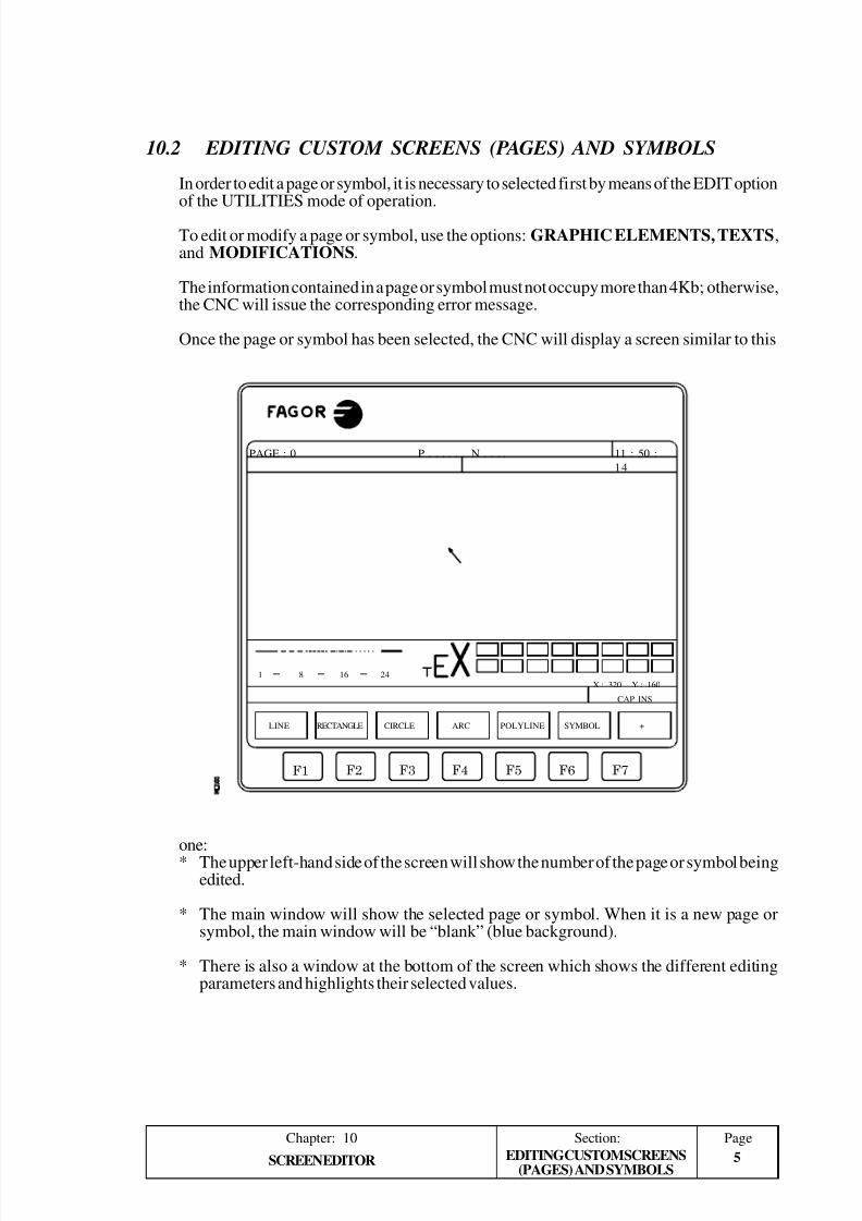
8/21/2019 CNC 8055 M Operator Manual
http://slidepdf.com/reader/full/cnc-8055-m-operator-manual 159/702
PageChapter: 10 Section:
5SCREEN EDITOR EDITING CUSTOM SCREENS(PAGES) AND SYMBOLS
10.2 EDITING CUSTOM SCREENS (PAGES) AND SYMBOLS
In order to edit a page or symbol, it is necessary to selected first by means of the EDIT optionof the UTILITIES mode of operation.
To edit or modify a page or symbol, use the options: GRAPHIC ELEMENTS, TEXTS,and MODIFICATIONS.
The information contained in a page or symbol must not occupy more than 4Kb; otherwise,the CNC will issue the corresponding error message.
Once the page or symbol has been selected, the CNC will display a screen similar to this
CAP INS
11 : 50 :
14
P . . . . . . N . . . .
X : 320 Y : 160
1 8 16 24
PAGE : 0
+SYMBOLPOLYLINEARCCIRCLERECTANGLELINE
one:* The upper left-hand side of the screen will show the number of the page or symbol being
edited.
* The main window will show the selected page or symbol. When it is a new page orsymbol, the main window will be “blank” (blue background).
* There is also a window at the bottom of the screen which shows the different editingparameters and highlights their selected values.

8/21/2019 CNC 8055 M Operator Manual
http://slidepdf.com/reader/full/cnc-8055-m-operator-manual 160/702
Section:
SCREEN EDITORChapter: 10
6Page
The various parameters available are:
* The type of drawing line used when defining the graphic elements.
* The cursor moving steps (cursor advance) in pixels.
* The letter size to create the texts for the pages and symbols.
* The background and foreground (main) colors for the graphic elements and for the letters.
One of the color rectangles shown has another rectangle in it. The inside rectangleindicates the selected main color and the outside rectangle indicates the selectedbackground color.
This window also shows The cursor position coordinates in pixels. The horizontal
position is indicated by the X value (1 through 638) and the vertical position by the Yvalue (0 through 334).
Once one of the options (GRAPHIC ELEMENTS, TEXTS or MODIFICATIONS)has been selected, it will be possible to modify the editing parameters any time.
This way, it will be possible to edit texts and shapes of different color and size.
Press INS to access this menu.
Once in this mode, the CNC will show the softkeys corresponding to the various optionsto modify these parameters. These options are described next.
Press INS again to quit this mode and return to the previous menu.
CURSOR ADVANCE
With this option it is possible to select the cursor moving step in pixels (1, 8, 16, 24).
Follow these steps after pressing this softkey:
1.- Use the right and left arrow keys to select the desired step.
The currently selected step will be highlighted.
2.- Press ENTER to validate the selected step or ESC to quit this mode leaving theprevious selection intact.
When editing a new page or symbol, the CNC assumes the default value of 8.
EDITING CUSTOM SCREENS(PAGES) AND SYMBOLS
8/21/2019 CNC 8055 M Operator Manual
http://slidepdf.com/reader/full/cnc-8055-m-operator-manual 161/702
PageChapter: 10 Section:
7SCREEN EDITOR
TYPE OF LINE
With this option it is possible to select the type of line used to define the graphic elements.
Follow these steps after pressing this softkey:
1.- Use the right and left arrow keys to select the desired type of line.
The currently selected line type will be highlighted.
2.- Press ENTER to validate the selected step or ESC to quit this mode leaving theprevious selection intact.
When editing a new page or symbol, the CNC assumes the “fine line” by default.
It is not possible to use the thick line to draw polylines or polygons. They are always
drawn in fine line.
TEXT SIZE
With this option it is possible to select the size of the letters used to write the texts to beinserted in the pages or symbols.
Three sizes are available:
* Normal size.
All the characters of the keyboard, numbers, signs, upper and lower case letters, canbe written in this size.
* Double and triple sizes.
Only capital letters A through Z, numbers 0 through 9 ; the “*”, “+”, “-”, “.”, “:”, "#", "%", "/", "<", ">", "?" signs and the special characters: "Ç", "Ä", "Ö","Ü", "ß" can be written in these sizes.
When selecting lower case letters for these sizes, the CNC will convert themautomatically into upper case.
Follow these steps to select the text size after pressing this softkey:
1.-Use the right and left arrow keys to select the desired size.
The currently selected size will be highlighted.
2.-Press ENTER to validate the selected step or ESC to quit this mode leaving theprevious selection intact.
When editing a new page or symbol, the CNC assumes the normal size by default.
EDITING CUSTOM SCREENS(PAGES) AND SYMBOLS

8/21/2019 CNC 8055 M Operator Manual
http://slidepdf.com/reader/full/cnc-8055-m-operator-manual 162/702
Section:
SCREEN EDITORChapter: 10
8Page
BACKGROUND COLOR
With this option it is possible to select the background color over which the differentgraphic elements and texts will be edited.
It is not possible to select the background color when editing a symbol since it is anattribute of the page and not of the symbol. Therefore, when inserting a symbol into apage, the symbol will take the background of that page.
If the desired background color is WHITE, it is recommended to use a different colorwhile creating the page since the cursor the “drawing” cursor is always white and willbecome invisible with this background color. Once the complete page (screen) is created,the background color can be changed to the desired one.
One of the color rectangles shown has another rectangle in it. The inside rectangleindicates the selected main color and the outside rectangle indicates the selected
background color.
To select the background color, follow these steps:
1.- Use the right and left arrow keys to select the desired color among the 16 shown.
The CNC will show the background color being selected by placing the main-colorrectangle inside the rectangle corresponding to the background color being selected.
2.- Press ENTER to validate the selected color or ESC to quit this mode leaving theprevious selection intact.
When editing a new page or symbol, the CNC assumes a blue background color bydefault.
EDITING CUSTOM SCREENS(PAGES) AND SYMBOLS

8/21/2019 CNC 8055 M Operator Manual
http://slidepdf.com/reader/full/cnc-8055-m-operator-manual 163/702
PageChapter: 10 Section:
9SCREEN EDITOR
MAIN COLOR
With this option it is possible to select the color used to draw and write texts on the page(screen) or symbol.
One of the color rectangles shown has another rectangle in it. The inside rectangleindicates the selected main color and the outside rectangle indicates the selectedbackground color.
To select the main color, follow these steps:
1.- Use the right and left arrow keys to select the desired color among the 16 shown.
The CNC will show the main color being selected by placing a white inside rectangle.It will also display the rectangle containing both the selected background color andthe main color being selected here.
2.- Press ENTER to validate the selected color or ESC to quit this mode leaving theprevious selection intact.
When editing a new page or symbol, the CNC assumes white as the main color bydefault.
GRID
This softkey superimposes a grid over the screen in order to facilitate the lay out of thedifferent components of the page or symbol being created or modified. This grid is
formed by white or black points (depending on the background color) separated 16pixels from each-other.
The grid points will be white when the selected background color corresponds to one of the 8 upper color rectangles and they will be black when the selected background colorcorresponds to one of the 8 lower color rectangles.
Press this softkey again to get rid of the grid.
Every time the grid is displayed, the CNC will reset the cursor advance (step) to 16 pixels.
Therefore, the cursor will move from grid point to grid point every time the arrow keysare pressed to position it on the screen. However, the cursor advance may be modified
afterwards by selecting it with the CURSOR ADVANCE softkey.
EDITING CUSTOM SCREENS(PAGES) AND SYMBOLS

8/21/2019 CNC 8055 M Operator Manual
http://slidepdf.com/reader/full/cnc-8055-m-operator-manual 164/702
Section:
SCREEN EDITORChapter: 10
10Page
10.3 GRAPHIC ELEMENTS
Before accessing this option, it is necessary to select the page or symbol to be edited ormodified by means of the EDIT option of the UTILITIES mode of operation.
With this option it is possible to include graphic elements in the selected page or symbol.The CNC displays a screen 80 columns wide (640 pixels for X coordinate) by 21 rows high(336 pixels for Y coordinate).
When editing a new page, the CNC will position the cursor in the center of the screen andwhen editing a new symbol, it will position it at the upper left-hand corner.
The cursor is white and can be moved around with the up and down arrow keys and the leftand right arrow keys.
The cursor can also be moved by using the following keystroke combinations:
SHIFT Positions the cursor at the last column (X638)
SHIFT Positions the cursor at the first column (X1)
SHIFT Positions the cursor at the first row (Y0).
SHIFT Positions the cursor at the last row (Y334).
It is also possible to key in the XY coordinates of the point where the cursor is to bepositioned. To do this, follow these steps:
* Press “X” or “Y”.The CNC will highlight, in the editing parameter display window, the cursor positionalong the selected axis (column or row).
* Key in the position value corresponding to the point where the cursor is to be placedalong this axis.
The horizontal position is defined as the X value between 1 and 638 and the verticalposition as the Y value between 0 and 334.
Once these coordinates have been keyed in, press ENTER and the CNC will positionthe cursor at the indicated coordinates.
Once this option is selected, it is possible to modify the editing parameters at any time evenwhile defining the graphic elements. This way, it is possible to edit shapes of different lineand color.
Press INS to access this menu.
Once in this mode, press the corresponding softkey to modify those parameters.
Press INS again to quit this mode and return to the previous menu.
GRAPHIC ELEMENTS

8/21/2019 CNC 8055 M Operator Manual
http://slidepdf.com/reader/full/cnc-8055-m-operator-manual 165/702
PageChapter: 10 Section:
11SCREEN EDITOR GRAPHIC ELEMENTS
The possible graphic elements which can be used to create a page or symbol are selectedwith the softkeys and are the following:
LINE
Follow these steps after pressing this softkey:
1.- Place the cursor at the beginning of the line and press ENTER to validate it.
2.- Move the cursor to the end of the line (the CNC will continuously show the line beingdrawn).
3.- Press ENTER to validate the line or ESC to cancel it.
Repeat the preceding steps to draw more lines. If no more lines are desired, press ESC
to return to the previous menu.
RECTANGLE
Follow these steps after pressing this softkey:
1.- Place the cursor on one of the corners of the rectangle and pressENTER to validateit.
2.- Move the cursor to the opposite corner. The CNC will continuously show therectangle being drawn.
3.- Press ENTER to validate the rectangle or ESC to cancel it.
Repeat these steps to draw more rectangles. If no more rectangles are desired, press ESCto return to the previous menu.
CIRCLE
Follow these steps after pressing this softkey:
1.- Place the cursor at the center of the circle and press ENTER to validate it.
2.- Move the cursor in order to define the radius. As the cursor moves, the CNC willshow the circle corresponding to that radius.
3.- Press ENTER to validate the circle or ESC to cancel it.
Once the circle is validated, the cursor is positioned at its center in order to facilitatethe drawing of concentric circles.
Repeat these steps to draw more circles. If no more circles are desired, press ESC toreturn to the previous menu.
8/21/2019 CNC 8055 M Operator Manual
http://slidepdf.com/reader/full/cnc-8055-m-operator-manual 166/702
Section:
SCREEN EDITORChapter: 10
12Page
GRAPHIC ELEMENTS
ARC
Follow these steps after pressing this softkey:
1.- Place the cursor at one of the arc’s ends and press ENTER to validate it.
2.- Move the cursor to the other end of the arc (the CNC will show a line joining bothends) and press ENTER to validate it.
The cursor is now positioned automatically at the center of that line.
3.- Move the cursor to define the curvature. The line will become an arc passing through3 points (the two ends and the cursor point).
4.- Press ENTER to validate it or ESC to cancel it.
Repeat these steps to draw more arcs. If no more arcs are desired, press ESC to returnto the previous menu.
POLYLINE
A polyline consists of several lines where the last point of one of them is the beginningpoint for the next one.
Follow these steps after pressing this softkey:
1.- Place the cursor at one of the ends of the polyline and press ENTER to validate it.
2.- Move the cursor to the end of the first line (which will be the beginning of the nextone). The CNC will continuously show the line being drawn.
Press ENTER to validate the line or ESC to quit this option (which will delete thecomplete polyline).
3.- Repeat steps 1 and 2 for the rest of the lines.
Note that the maximum number of lines in a polyline is 127.
Once the polyline is drawn, press ENTER again to validate it or ESC to quit this optiondeleting the complete polyline.
Repeat these steps to draw more polylines and if no more polylines are desired, pressESC to return to the previous menu.

8/21/2019 CNC 8055 M Operator Manual
http://slidepdf.com/reader/full/cnc-8055-m-operator-manual 167/702
PageChapter: 10 Section:
13SCREEN EDITOR
SYMBOL
This option allows a symbol to be drawn in the page or symbol being edited.
After pressing this softkey, the following steps will be taken.
1.- Enter the number of the symbol to include in the page or symbol being edited andpress the ENTER key to validate it.
The CNC will show the cursor situated at the reference point corresponding to thesymbol (upper left hand corner of the symbol).
2.- Move the cursor to the position where it is required to place the symbol. In this move,only the cursor will move and not the symbol.
3.- Press the ENTER key to validate it or the ESC key if you wish to quit.
Once the symbol has been validated the CNC will show it in the place indicated.
4.- To include more symbols, repeat the above operations.
5.- Press the ESC key to quit and go back to the previous menu.
If a symbol is being edited this symbol cannot be included in itself. Therefore, if symbol4 is being edited, any symbol can be included except symbol 4.
Warning:If a symbol is deleted, the CNC will update all the pages or symbols that containit because all the calls to it will remain active.
When displaying a page or symbol which has a call to a nonexistent symbol(deleted or not defined), that area of the page will appear blank.
If this symbol is edited again later, the new representation assigned to thesymbol will appear in all the pages and symbols which contain a call to it.
GRAPHIC ELEMENTS

8/21/2019 CNC 8055 M Operator Manual
http://slidepdf.com/reader/full/cnc-8055-m-operator-manual 168/702
Section:
SCREEN EDITORChapter: 10
14Page
GRAPHIC ELEMENTS
POLYGON
A polygon is a closed polyline whose beginning and end points coincide.
After pressing the softkey, the following steps will be taken:
1.- Place the cursor on one of the vertices of the polygon and press the ENTER key tovalidate it.
2.- Move the cursor to the following vertex of the polygon (the CNC will show the lineyou are trying to draw).
Press the ENTER key to validate the line or the ESC key if you wish to abandon.
3.- Repeat step 2 for the remaining vertices.
Once all vertices are defined, press the ENTER key and the CNC will complete thepolygon or the ESC key if you wish to quit.
The maximum number of sides on the polygon is limited to 127.
FILLED POLYGON
After pressing this softkey, follow the steps as in the POLYGON option, but in this case,after completing the definition of the polygon it will be filled with the color used for itsdefinition.
FILLED CIRCLE
After pressing this softkey follow the steps as in the CIRCLE option, but in this case, aftercompleting the definition of the circle it will be filled with the color used for its definition.
FILLED RECTANGLE
After pressing this softkey follow the steps as in the RECTANGLE option, but in thiscase, after completing the definition of the rectangle it will be filled with the color usedfor its definition.

8/21/2019 CNC 8055 M Operator Manual
http://slidepdf.com/reader/full/cnc-8055-m-operator-manual 169/702
PageChapter: 10 Section:
15SCREEN EDITOR
10.4 TEXTS
Before accessing this option, it is necessary to select the page or symbol to be edited ormodified by means of the EDIT option of the UTILITIES mode of operation.
With this option it is possible to include texts in the selected page or symbol. The CNCdisplays a screen 80 columns wide (640 pixels for X coordinate) by 21 rows high (336 pixelsfor Y coordinate).
When editing a new page, the CNC will position the cursor in the center of the screen andwhen editing a new symbol, it will position it at the upper left-hand corner.
The cursor is white and can be moved around with the up and down arrow keys and the leftand right arrow keys.
The cursor can also be moved by using the following keystroke combinations:
SHIFT Positions the cursor at the last column (X638)
SHIFT Positions the cursor at the first column (X1)
SHIFT Positions the cursor at the first row (Y0).
SHIFT Positions The cursor at the last row (Y334).
It is also possible to key in the XY coordinates of the point where the cursor is to bepositioned. To do this, follow these steps:
* Press “X” or “Y”.The CNC will highlight, in the editing parameter display window, the cursor positionalong the selected axis (column or row).
* Key in the position value corresponding to the point where the cursor is to be placedalong this axis.
The horizontal position is defined as the X value between 1 and 638 and the verticalposition as the Y value between 0 and 334.
Once these coordinates have been keyed in, press ENTER and the CNC will positionthe cursor at the indicated coordinates.
Once this option is selected, it is possible to modify the editing parameters at any time evenwhile defining the graphic elements. This way, it is possible to edit texts of different size andcolor.
Press INS to access this menu.
Once in this mode, press the corresponding softkey to modify those parameters.
Press INS again to quit this mode and return to the previous menu.
It is also possible to insert one of the texts available at the CNC or a text previously keyed
in by the user. To do this, the following softkey options are available:
TEXTS

8/21/2019 CNC 8055 M Operator Manual
http://slidepdf.com/reader/full/cnc-8055-m-operator-manual 170/702
Section:
SCREEN EDITORChapter: 10
16Page
USER DEFINED TEXT
Follow these steps to insert the desired text:
1.- Press ENTER.
The CNC will display a text editing window. The cursor within this window can bemoved with right and left arrow keys.
2.- “Type” the desired text.
A rectangle will be displayed which will enlarge as the text is “typed” in the editingwindow thus indicating the screen space that this text will occupy.
Press ESC to cancel this option and the previous menu will be displayed.
3.- Press ENTER once the text has been correctly “typed in”.
The typed text will remain in the editing window and the cursor will be positionedin the main window.
4.- Position the rectangle by moving the cursor.
5.- Press ENTER to validate this command and the text will replace the rectangle onthe screen.
Note that once the text has been “entered”, neither its size nor its color can be modified.Therefore, these options must be selected before pressing ENTER.
TEXTS
8/21/2019 CNC 8055 M Operator Manual
http://slidepdf.com/reader/full/cnc-8055-m-operator-manual 171/702
PageChapter: 10 Section:
17SCREEN EDITOR
TEXT NUMBER
With this option it is possible to select a text used by the CNC itself in its various operatingmodes and insert it into the current page or symbol.
To insert one of these predetermined texts, follow these steps:
1.- Press the corresponding softkey.
The CNC will show a screen area to indicate the text number. The cursor may bemoved within this area with the right and left arrow keys.
2.- Indicate the desired number by keying it in from the keyboard and press ENTER.
The CNC will display the text corresponding to this number and the rectangleindicating the screen space it occupies.
If another text is desired, key in the other number and press ENTER again.
Press ESC to quit this option without inserting the text and the CNC will show theprevious menu.
3.- Once the desired text has been selected, press ENTER.
The typed text will remain in the editing window and the cursor will be positionedin the main window.
4.- Position the rectangle by moving the cursor.
5.- Press ENTER to validate this command and the text will replace the rectangle onthe screen.
Observe that once the text has been “entered”, neither its size nor its color can bemodified. Therefore, these options must be selected before pressing ENTER.
Warning:
This application may be useful when the pages or symbols being edited are tobe shown in other languages since the CNC will translate them into the chosen
language.
Usually, when the texts are to be shown in one single language, it is morepractical to simply write them up instead of searching them in a list of more than1500 predetermined messages.
However, should anyone desire the printout of these predetermined texts, feelfree to request it from Fagor Automation.
TEXTS
8/21/2019 CNC 8055 M Operator Manual
http://slidepdf.com/reader/full/cnc-8055-m-operator-manual 172/702
Section:
SCREEN EDITORChapter: 10
18Page
10.5 MODIFICATIONS
Before accessing this option, it is necessary to select the page or symbol to be edited ormodified by means of the EDIT option of the UTILITIES mode of operation.
With this option it is possible to include texts in the selected page or symbol. The CNCdisplays a screen 80 columns wide (640 pixels for X coordinate) by 21 rows high (336 pixelsfor Y coordinate).
When editing a new page, the CNC will position the cursor in the center of the screen andwhen editing a new symbol, it will position it at the upper left-hand corner.
The cursor is white and can be moved around with the up and down arrow keys and the leftand right arrow keys.
The cursor can also be moved by using the following keystroke combinations:
SHIFT Positions the cursor at the last column (X638)
SHIFT Positions the cursor at the first column (X1)
SHIFT Positions the cursor at the first row (Y0).
SHIFT Positions the cursor at the last row (Y334).
It is also possible to key in the XY coordinates of the point where the cursor is to bepositioned. To do this, follow these steps:
* Press “X” or “Y”.
The CNC will highlight, in the editing parameter display window, the cursor positionalong the selected axis (column or row).
* Key in the position value corresponding to the point where the cursor is to be placedalong this axis.
The horizontal position is defined as the X value between 1 and 638 and the verticalposition as the Y value between 0 and 334.
Once these coordinates have been keyed in, press ENTER and the cursor will bepositioned at the indicated coordinates.
The possible options to modify a page or symbol are:
CLEAR PAGE
Allows the selected page or symbol to be deleted.
Once this softkey has been pressed, the CNC will request an OK before executing theindicated operation.
If this option is executed, the CNC will delete the page or symbol being edited, but it will
keep in the "Memkey Card" the contents of that page or symbol the last time the "SAVE”command was executed.
MODIFICATIONS

8/21/2019 CNC 8055 M Operator Manual
http://slidepdf.com/reader/full/cnc-8055-m-operator-manual 173/702
PageChapter: 10 Section:
19SCREEN EDITOR
DELETE ELEMENTS
This option allows an element of the displayed page or symbol to be selected and thendeleted.
To do this follow these steps:
1.- Place the cursor in the position to delete an element and press the ENTER key tovalidate it.
An area of between ± 8 pixels from the position indicated will be analyzed.
If the element to be deleted is a filled circle or a filled polygon, the cursor must bepositioned on a point on the circumference or external polygon (periphery).
2.- If any graphic element or text exists in this area, this will be highlighted and you will
be asked if you wish to delete it.
Press the ENTER key to delete this element, otherwise the ESC key.
Should there be several elements in this area, the CNC will highlight them insuccession and it will ask for confirmation before deleting any of them.
MOVE SCREEN
With this option it is possible to reposition the whole page (not its individual elementsseparately) and it can only be used to move pages and not symbols.
It allows the entire page to be moved with the right, left, up and down arrow keys.
The center of the page is taken as a reference for this movement.
To do this follow these steps:
1.- The CNC will show the page with the cursor placed in the middle of the screen.
2.- Move the cursor to the position to place the page reference point.
Press ESC to quit this option without making any changes and the CNC will showthe previous menu.
Repeat these steps to perform more moves, otherwise, press ESC and the CNC will showthe previous menu.
MODIFICATIONS

8/21/2019 CNC 8055 M Operator Manual
http://slidepdf.com/reader/full/cnc-8055-m-operator-manual 174/702
PageChapter: 11
MACHINE PARAMETERS
Section:
1
11. MACHINE PARAMETERS
In order for the machine tool to execute the programmed instructions correctly, the CNCmust know specific data on the machine such as feedrates, accelerations, feedbacks,automatic tool changes, etc.
This data is determined by the manufacturer of the machine and must be stored in themachine parameter tables.
These tables may be edited in this work mode or copied into the "Memkey Card" or a PCas described later on.
The CNC has the following groups of machine parameters:
* General machine parameters* Axis parameters (one table per axis)* Spindle parameters* RS-422 and RS-232-C serial port configurations* Ethernet configuration parameters* PLC parameters* M miscellaneous functions* Leadscrew error compensation (one table per axis)
* Cross Compensations between two axes (for example: Beam sag).
First, the general machine parameters must be set as by means of these the machine axesare defined and therefore the Axis Parameter tables.
It must also be defined whether the machine has cross compensation and between whichaxes, and the CNC will generate the corresponding cross compensation parameters.
By means of the general machine parameters, the table lengths for the Tool Magazine,Tools, Tool Offsets and the miscellaneous M functions are defined.
By means of the Axis Parameters it is defined whether the axis has Leadscrew error
Compensation or not and the length of the corresponding table.Once the general machine parameters are defined, press SHIFT RESET for the CNC toenable the required tables.
It is recommended to save the tables in the "Memkey Card" or out to a peripheral deviceor PC.
When accessing this operating mode, the CNC will show the tables that are saved in the"Memkey Card" (CARD A).

8/21/2019 CNC 8055 M Operator Manual
http://slidepdf.com/reader/full/cnc-8055-m-operator-manual 175/702
Section:
MACHINE PARAMETERSChapter: 11
2Page
11.1 MACHINE PARAMETER TABLES
The General, Axis, Spindle, Serial ports and PLC tables have the following structure:
P..... N..... 11 : 50 :
14
P000P001P002P003P004P005P006P007P008
P009P010P011P012P013P014P015P016P017P018P019
01020304051011000
0000001
000YES120
00000
AXIS1AXIS2AXIS3AXIS4AXIS5AXIS6AXIS7AXIS8INCHES
IMOVEICORNERIPLANEILCOMPISYSTEMIFEEDTHEODPLYGRAPHICSRAPIDOVRMAXFOVRCIRINLIM
CAP INS MM
GENERAL PARAMETERS
PARAMETER VALUE NAME
MM/INCHSAVELOADINITIALIZEFINDMODIFYEDIT
Where the parameter number is indicated, the value assigned to it and the name or mnemonicassociated with this parameter.
MACHINE PARAMETERTABLES

8/21/2019 CNC 8055 M Operator Manual
http://slidepdf.com/reader/full/cnc-8055-m-operator-manual 176/702
PageChapter: 11
MACHINE PARAMETERS
Section:
3
11.2 MISCELLANEOUS FUNCTION TABLES
The table corresponding to the miscellaneous M functions has the following structure:
MISCELLANEOUS FUNCTIONTABLES
The number of M functions in the table is defined by means of the general machineparameter “NMISCFUN”. The following is defined for each line:
* The number (0-9999) of the defined miscellaneous M functions:
If an M function is not defined, the CNC will show M????.
* The number of the subroutine to be associated with this miscellaneous function.
* 8 customizing bits x x x x x x x x7 6 5 4 3 2 1 0
Bit 0 Indicates whether the CNC must (=0) or must not (=1) wait for the signal
AUXEND (signal of the M executed) to resume program execution.
Bit 1 Indicates whether the M function is executed before (=0) or after (=1) themovement of the block in which it is programmed.
Bit 2 Indicates whether the execution of the M function interrupts (=1) or not (=0)the preparation of the blocks.
Bit 3 Indicates whether the M function is executed after calling the associatedsubroutine (=0) or only the associated subroutine is executed (=1).
Bit 4 When bit 2 is set to "1", it indicates whether block preparation is to beinterrupted until the "M" function starts executing (=0) or until its executionis finished (=1).
The rest of the bits are not being used at this time.

8/21/2019 CNC 8055 M Operator Manual
http://slidepdf.com/reader/full/cnc-8055-m-operator-manual 177/702
Section:
MACHINE PARAMETERSChapter: 11
4Page
11.3 LEADSCREW ERROR COMPENSATION TABLES
The tables for leadscrew error compensation have the following structure:
LEADSCREW ERRORCOMPENSATION TABLES
The number of points of each of these is defined by means of the axis machine parameter“NPOINTS”. The following is defined for each of line:
* Position of the axis to be compensated.
* Error of this axis in this position.
Also, the current position of the selected axis is displayed and updated as the machine axis
moves.

8/21/2019 CNC 8055 M Operator Manual
http://slidepdf.com/reader/full/cnc-8055-m-operator-manual 178/702
PageChapter: 11
MACHINE PARAMETERS
Section:
5
11.4 CROSS COMPENSATION TABLES
The tables corresponding to cross compensation have the following structure.
CROSS COMPENSATIONTABLES
The number of points of each table is defined by means of the general machine parameter“NPCROSS”, "NPCROSS2" and "NPCROSS3" respectively.
Each table defines:
* The position of the axis causing the error.
* The error suffered by the axis at that point.
Also, the current position of the selected axis is displayed. This position is updated as theaxis moves.

8/21/2019 CNC 8055 M Operator Manual
http://slidepdf.com/reader/full/cnc-8055-m-operator-manual 179/702
Section:
MACHINE PARAMETERSChapter: 11
6Page
11.5 OPERATION WITH PARAMETER TABLES
Once one of the tables has been selected, the cursor can be moved over the screen line byline by means of the “up and down arrow keys” or move from page to page by means of the “page up and page down keys”.
In addition, the user has an area of the screen for editing, it being possible to move the cursorover the screen by means of the “right arrow key and left arrow key”.
The CNC offers the following softkey options for each table:
EDIT
The desired parameter.
When selecting this option, the softkeys will change their color to a white backgroundand they will show the various editing options.
In those tables corresponding to leadscrew and cross compensation, the position valuesof the axis must be edited as follows:
* Move the axis and when the error is found large enough to be considered, press thesoftkey corresponding to this axis.
* The CNC will include, in the editing area, the name of the axis followed by theposition value corresponding to that point.
This value can be modified if so desired.* Press the softkey corresponding to the error and key in its value.
Once the parameter is edited, press ENTER. This new parameter will be included in thetable and the cursor will be positioned over it. The editing area will be cleared, thusallowing other parameters to be edited.
Press ESC to quit this mode.
OPERATION WITHPARAMETER TABLES
8/21/2019 CNC 8055 M Operator Manual
http://slidepdf.com/reader/full/cnc-8055-m-operator-manual 180/702
PageChapter: 11
MACHINE PARAMETERS
Section:
7
MODIFY
With this option it is possible to modify the selected parameter.
Before pressing this softkey, the desired parameter must be selected.
When selecting this option, the softkeys will change their color to a white backgroundand they will show the various editing options.
By pressingESC, the information displayed in the editing window (corresponding to theselected parameter) will be cleared. From this point on, a new value can be entered.
To quit this option, first clear the editing window using the CL key or the ESC key andthen press ESC again. The selected parameter will not be modified.
Once this modification has concluded, press the ENTER key to validate it.
FIND
The beginning or end of the table, or the parameter whose number is indicated bypositioning the cursor on the required parameter.
BEGINNING When pressing this softkey, the cursor positions over the first parameterof the table quitting this option.
END When pressing this softkey, the cursor positions over the last parameter of the tablequitting this option.
PARAMETER When pressing this softkey, the CNC will request the number of theparameter to be found. Key in that number and press ENTER. The cursor will bepositioned over the indicated parameter quitting this option.
INITIALIZE
With this option it is possible to reset all the parameters of the selected table to their defaultvalues.
These default values are indicated in the chapter corresponding to machine parametersin the installation manual.
OPERATION WITHPARAMETER TABLES

8/21/2019 CNC 8055 M Operator Manual
http://slidepdf.com/reader/full/cnc-8055-m-operator-manual 181/702
Section:
MACHINE PARAMETERSChapter: 11
8Page
LOAD
To load tables stored in the "Memkey Card" (CARD A) or in a peripheral device or PCthrough the two serial lines (RS232C or RS422).
The transmission begins after pressing the corresponding softkey. When using a serialline, the receptor must be ready before starting the transmission.
To interrupt the transmission, press the [ABORT] softkey.
If the length of the table received does not coincide with the length of the current table,the CNC will acts as follows:
If the table received is shorter than the current one, the received lines are modifiedand the rest keep their previous values.
If the table received is longer than the current one, the CNC updates all the lines of the current table and when detecting that there is no more room, the CNC issues thecorresponding error message.
SAVE
The tables may be saved in the "Memkey Card" (CARD A) or in a peripheral deviceor PC through the two serial lines (RS232C or RS422).
The transmission begins after pressing the corresponding softkey. When using a serialline, the receptor must be ready before starting the transmission.
To interrupt the transmission, press the [ABORT] softkey.
MM/INCHES
Every time this softkey is pressed, the CNC will change the display format of thoseparameters affected by these units from millimeters to inches and vice versa.
The lower right-hand window will show the units currently selected.
Note that this change does not affect the general machine parameter “INCHES” whichindicates the measuring units by default.
OPERATION WITHPARAMETER TABLES

8/21/2019 CNC 8055 M Operator Manual
http://slidepdf.com/reader/full/cnc-8055-m-operator-manual 182/702
PageChapter: 12
DIAGNOSIS
Section:
1
12. DIAGNOSIS
In this operating mode it is possible to know the configuration of the CNC as well as testingthe system.
The CNC offers the following softkey options:
System ConfigurationHardware testMemory testFlash memory testHard Disk

8/21/2019 CNC 8055 M Operator Manual
http://slidepdf.com/reader/full/cnc-8055-m-operator-manual 183/702
Section:
DIAGNOSISChapter: 12
2Page
12.1 CONFIGURATION
This option shows the current system configuration.
Once this option has been chosen, two new softkeys will appear in order to select thehardware configuration or the software configuration of the system.
12.1.1 HARDWARE CONFIGURATION
This option shows the system configuration displaying the following information:
CONFIGURATION OF THE CENTRAL UNIT
It indicates the modules making up the new configuration of the central unit of the CNC.
The numbers which appear in brackets next to some of the modules and options indicatethe logic address assigned to each of them.
CNC RESOURCES
It indicates the RAM memory (in Kb) available for the system and for the user.
It also indicates the memory of the "Memkey Card" in Kb.
CONFIGURATION

8/21/2019 CNC 8055 M Operator Manual
http://slidepdf.com/reader/full/cnc-8055-m-operator-manual 184/702
PageChapter: 12
DIAGNOSIS
Section:
3CONFIGURATION
12.1.2 SOFTWARE CONFIGURATION
This option shows:
* All available software options.
* The CNC and Hard Disk module software versions installed.
* The id codes of the unit. They are only to be used by the Service Department.
The [CODE VALIDATION] softkey must be used after consulting with the ServiceDepartment when wishing to implement more software features.

8/21/2019 CNC 8055 M Operator Manual
http://slidepdf.com/reader/full/cnc-8055-m-operator-manual 185/702
Section:
DIAGNOSISChapter: 12
4Page
12.2 HARDWARE TEST
This option checks the power supply voltages corresponding to the system and to the boardsas well as the internal temperature of the central unit. It displays the following information:
SUPPLY VOLTAGE
It indicates the voltage of the lithium battery and the voltages supplied by the PowerSupply Module.
The voltages supplied by the Power Supply module are internally used by the CNC.
Next to the voltages, it displays the value range (maximum and minimum values), thereal value and whether it is OK or not.
BOARD VOLTAGE
This section indicates whether the AXES module, the I/O TRACING module and theI/O modules are supplied or not with 24 V.
The lack of these 24V may be because the connectors have not been supplied orbecause the protection fuse for the corresponding module is blown.
INSIDE TEMPERATURE
It shows the value range (maximum and minimum values), the inside temperature of the
Central Unit and whether that value is OK or not.
TEST

8/21/2019 CNC 8055 M Operator Manual
http://slidepdf.com/reader/full/cnc-8055-m-operator-manual 186/702
PageChapter: 12
DIAGNOSIS
Section:
5
12.3 MEMORY TEST
This option checks the status of the internal CNC memory, that of the memory available forthe User and for the System.
To carry out this verification, the PLC program must be stopped, otherwise, the CNC willask the operator whether this operation is to be carried out or not.
12.4 FLASH MEMORY TEST
This option checks the status of the internal CNC Flash memory. These memories containthe CNC software version currently installed.
12.5 USER
This option will execute the program which is selected with the general machine parameter“USERDIAG” in the user channel.
To quit its execution and return to the previous menu, press ESC
12.6 HARD DISK
Once this option has been selected, two softkeys will be displayed:
Test It check the status of the hard disk (user memory available). It takesabout 30 minutes.In order to perform this test, the PLC program must be stopped. If it is
running, the CNC will ask the operator whether it is to be stopped ornot.
Compress It compresses the hard disk by defragmenting it. It also includes a harddisk surface check. The duration of this test depends on the number of files it contains and on how defragmented the hard disk is.
TEST
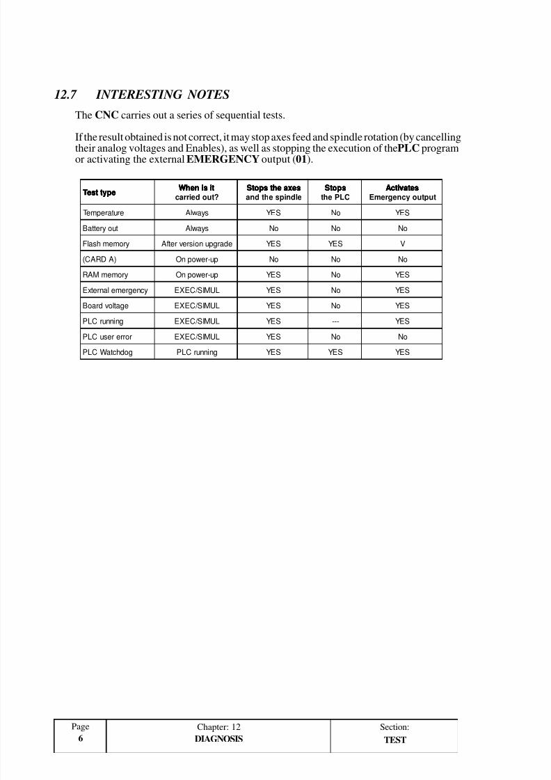
8/21/2019 CNC 8055 M Operator Manual
http://slidepdf.com/reader/full/cnc-8055-m-operator-manual 187/702
Section:
DIAGNOSISChapter: 12
6Page
12.7 INTERESTING NOTES
The CNC carries out a series of sequential tests.
If the result obtained is not correct, it may stop axes feed and spindle rotation (by cancellingtheir analog voltages and Enables), as well as stopping the execution of the PLC programor activating the external EMERGENCY output (01).
epyttseT epyttseT epyttseT epyttseT epyttseT tisinehW tisinehW tisinehW tisinehW tisinehW
?tuodeirracsexaehtspotS sexaehtspotS sexaehtspotS sexaehtspotS sexaehtspotSeldnipsehtdna
spotS spotS spotS spotS spotSCLPeht
setavitcA setavitcA setavitcA setavitcA setavitcAtuptuoycnegremE
erutarepmeT syawlA SEY oN SEY
tuoyrettaB syawlA oN oN oN
yromemhsalF edargpunoisrevretfA SEY SEY V
)ADRAC( pu-rewopnO oN oN oN
yromemMAR pu-rewopnO SEY oN SEY
ycnegremelanretxE LUMIS / CEXE SEY oN SEY
egatlovdraoB LUMIS / CEXE SEY oN SEY
gninnurCLP LUMIS / CEXE SEY --- SEY
rorreresuCLP LUMIS / CEXE SEY oN oN
godhctaWCLP gninnurCLP SEY SEY SEY
TEST

8/21/2019 CNC 8055 M Operator Manual
http://slidepdf.com/reader/full/cnc-8055-m-operator-manual 188/702
CNC 8055 MProgramming Manual
Ref. 9909 (in)

8/21/2019 CNC 8055 M Operator Manual
http://slidepdf.com/reader/full/cnc-8055-m-operator-manual 189/702
i i
Please note that the availability of some of the features described inthis manual depends on the software options you just obtained.
---------- o ----------
The information described in this manual may be subject to variations due to technical modifications.
FAGOR AUTOMATION, S.Coop. Ltda. reserves the right to modify the contents of the manual without prior notice.
MODEL GP M
Electronic threading Not available Available
Tool magazine management Not available Available
Solid Graphics Not available Option
Machining canned cycles Not available Available
Multiple machining Not available Available
Probing canned cycles Not available Option
Tool life monitoring Not available Option
Irregular pockets with islands Not available Option
Digitizing Not available Option
Tracing Not available Option
TCP transformation Not available Option
Tool radius compensation Option Available
DNC Option Option
Software for 7 axes Option Option
Profile editor Option Option
Rigid tapping Option Option
Tangential control Not available Option
Conversational Software (MC model) Not available Option
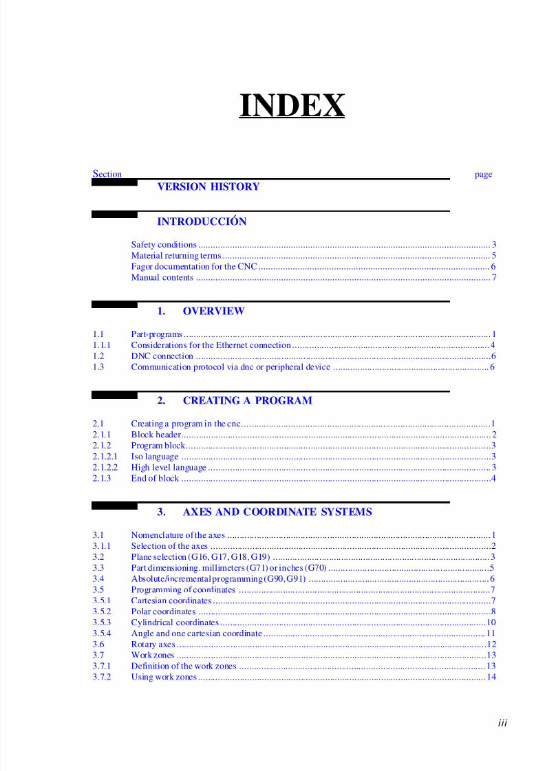
8/21/2019 CNC 8055 M Operator Manual
http://slidepdf.com/reader/full/cnc-8055-m-operator-manual 190/702
i i i
INDEX
Section page
VERSION HISTORY
INTRODUCCIÓN
Safety conditions ........................................................................................................................ 3
Material returning terms .............................................................................................................. 5
Fagor documentation for the CNC ............................................................................................... 6Manual contents ......................................................................................................................... 7
1. OVERVIEW
1.1 Part-programs .............................................................................................................................. 1
1.1.1 Considerations for the Ethernet connection ................................................................................. 4
1.2 DNC connection .........................................................................................................................6
1.3 Communication protocol via dnc or peripheral device ................................................................ 6
2. CREATING A PROGRAM2.1 Creating a program in the cnc......................................................................................................1
2.1.1 Block header...............................................................................................................................2
2.1.2 Program block.............................................................................................................................3
2.1.2.1 Iso language ...............................................................................................................................3
2.1.2.2 High level language .................................................................................................................... 3
2.1.3 End of block ...............................................................................................................................4
3. AXES AND COORDINATE SYSTEMS
3.1 Nomenclature of the axes ............................................................................................................ 1
3.1.1 Selection of the axes ...................................................................................................................2
3.2 Plane selection (G16, G17, G18, G19) ......................................................................................... 3
3.3 Part dimensioning. millimeters (G71) or inches (G70) ..................................................................5
3.4 Absolute/incremental programming (G90, G91) .......................................................................... 6
3.5 Programming of coordinates .......................................................................................................7
3.5.1 Cartesian coordinates ..................................................................................................................7
3.5.2 Polar coordinates ........................................................................................................................8
3.5.3 Cylindrical coordinates .............................................................................................................10
3.5.4 Angle and one cartesian coordinate ........................................................................................... 11
3.6 Rotary axes ...............................................................................................................................12
3.7 Work zones ...............................................................................................................................13
3.7.1 Definition of the work zones .....................................................................................................13
3.7.2 Using work zones ...................................................................................................................... 14

8/21/2019 CNC 8055 M Operator Manual
http://slidepdf.com/reader/full/cnc-8055-m-operator-manual 191/702
iv
4. REFERENCE SYSTEMS
4.1 Reference points .........................................................................................................................1
4.2 Machine reference search (G74) .................................................................................................. 2
4.3 Programming with respect to machine zero (G53) ........................................................................3
4.4 Presetting of coordinates and zero offsets ....................................................................................4
4.4.1 Coordinate preset and limitation of the s value (G92) ..................................................................6
4.4.2 Zero offsets (G54..G59) ............................................................................................................... 7
4.5 Polar origin preset (G93) .............................................................................................................9
5. PROGRAMMING BY ISO CODE
5.1 Preparatory functions .................................................................................................................. 2
5.2 Feedrate functions (G94, G95) ..................................................................................................... 4
5.2.1 Feedrate in mm/min or inches/min (G94) ....................................................................................4
5.2.2 Feedrate in mm/rev.or inches/rev (G95) ....................................................................................... 5
5.3 Spindle selection (G28, G29) ...................................................................................................... 6
5.4 Constant speed functions (G96,G97) ........................................................................................... 7
5.4.1 Constant surface speed (G96) ......................................................................................................7
5.4.2 Constant tool-center speed (G97) ................................................................................................7
5.5 Complementary functions ........................................................................................................... 8
5.5.1 Feedrate F ...................................................................................................................................8
5.5.2 Spindle speed and spindle orientation (S).................................................................................... 9
5.5.3 Tool number (T) ........................................................................................................................10
5.5.4 tool offset number (D) ............................................................................................................... 11
5.5.5 Miscellaneous function (M) ......................................................................................................12
5.5.5.1 M00. Program stop .................................................................................................................... 13
5.5.5.2 M01. Conditional program stop ................................................................................................135.5.5.3 M02. End of program ................................................................................................................ 13
5.5.5.4 M30. End of program with return to first block .......................................................................... 13
5.5.5.5 M03. Clockwise spindle rotation ..............................................................................................13
5.5.5.6 M04. Counter-clockwise spindle rotation ..................................................................................13
5.5.5.7 M05. Spindle stop ..................................................................................................................... 13
5.5.5.8 M06. Tool change ........................................................................................................................ 14
5.5.5.9 M19. Spindle orientation .......................................................................................................... 14
5.5.5.10 M41, M42, M43, M44. Spindle speed range change .................................................................. 15
5.5.5.11 M45 auxiliary spindle / live tool ............................................................................................... 15
6. PATH CONTROL6.1 Rapid travel (G00) ......................................................................................................................1
6.2 linear interpolation (G01)............................................................................................................ 2
6.3 Circular interpolation (G02. G03)................................................................................................ 3
6.4 Circular interpolation by programming the center of the arc in absolute coordinates (G06) .......... 9
6.5 Arc tangent to the previous path (G08) ...................................................................................... 10
6.6 Arc defined by three points (G09) .............................................................................................. 11
6.7 Helical interpolation ................................................................................................................. 12
6.8 Tangential entry at beginning of a machining operation (G37) .................................................. 14
6.9 Tangential exit at the end of a machining operation (G38)......................................................... 16
6.10 Automatic radius blend (G36) ................................................................................................... 18
6.11 Automatic chamfer blend (G39) ................................................................................................19
6.12 Threading (G33) .......................................................................................................................20
6.13 Move to hardstop (G52) ............................................................................................................21
6.14 Feedrate "F" as an inverted function of time (G32) ..................................................................... 22
Section page

8/21/2019 CNC 8055 M Operator Manual
http://slidepdf.com/reader/full/cnc-8055-m-operator-manual 192/702
v
6.15 Tangential control (G45) ...........................................................................................................23
6.15.1 Considerations about function G45........................................................................................... 25
7. ADDITIONAL PREPARATORY FUNCTIONS
7.1 Interruption of block preparation (G04) .......................................................................................1
7.2 Dwell (G04 K)............................................................................................................................. 3
7.3 Working with square (G07) and round (G05,G50) corners ............................................................4
7.3.1 Square corner (G07) .................................................................................................................... 4
7.3.2 Round corner (G05) .................................................................................................................... 5
7.3.3 Controlled round corner (G50) ....................................................................................................6
7.4 Look-ahead (G51) ....................................................................................................................... 7
7.5 Mirror image (G10, G11. G12, G13, G14) ....................................................................................9
7.6 Scaling factor (G72) .................................................................................................................. 11
7.6.1 Scaling factor applied to all axes ...............................................................................................12
7.6.2 Scaling factor applied to one or more axes ................................................................................ 147.7 Pattern rotation (G73) ............................................................................................................... 16
7.8 Slaved axis/cancellation of slaved axis ..................................................................................... 18
7.8.1 Slaved axis (G77)......................................................................................................................19
7.8.2 Slaved axis cancellation (G78) .................................................................................................. 20
7.9 Axes toggle. G28-G29 .............................................................................................................. 21
8. TOOL COMPENSATION
8.1 Tool radius compensation (G40, G41, G42) .................................................................................2
8.1.1 Activating tool radius compensation ........................................................................................... 3
8.1.2 Tool radius compensation sections ..............................................................................................68.1.3 Cancelling tool radius compensation ..........................................................................................9
8.2 Tool length compensation (G43, G44, G15) ..............................................................................15
9. CANNED CYCLES
9.1 Definition of a canned cycle .......................................................................................................1
9.2 Canned cycle area of influence .................................................................................................... 2
9.2.1 G79. Modification of canned cycle parameters ............................................................................2
9.3 Canned cycle cancellation ..........................................................................................................4
9.4 General considerations ................................................................................................................5
9.5 Machining canned cycles ........................................................................................................... 69.5.1 G69. Complex deep hole drilling cycle ....................................................................................... 8
9.5.2 G81 drilling canned cycle ......................................................................................................... 12
9.5.3 G82. Drilling canned cycle with dwell ...................................................................................... 14
9.5.4 G83. Simple deep hole drilling .................................................................................................. 16
9.5.5 G84. Tapping canned cycle .......................................................................................................19
9.5.6 G85. Reaming cycle ..................................................................................................................22
9.5.7 G86. Boring cycle with withdrawal in rapid (G00) .................................................................... 24
9.5.8 G87. Rectangular pocket canned cycle ...................................................................................... 26
9.5.9 G88. Circular pocket canned cycle ............................................................................................ 34
9.5.10 G89. Boring cycle with withdrawal at working feedrate (G01) ................................................... 41
Section page

8/21/2019 CNC 8055 M Operator Manual
http://slidepdf.com/reader/full/cnc-8055-m-operator-manual 193/702
vi
10. MULTIPLE MACHINING
10.1 G60: Multiple machining in a straight line pattern ......................................................................2
10.2 G61: Multiple machining in a rectangular pattern .......................................................................5
10.3 G62: Multiple machining in a grid pattern ..................................................................................8
10.4 G63: Multiple machining in a circular (bolt-hole) pattern.......................................................... 11
10.5 G64: Multiple machining in an arc pattern ................................................................................ 14
10.6 G65: Machining programmed by means of an arc chord ............................................................17
11. IRREGULAR POCKET CANNED CYCLE (WITH ISLANDS)
11.1 2D pockets .................................................................................................................................. 2
11.1.1 Drilling operation .......................................................................................................................5
11.1.2 Roughing operation .................................................................................................................... 6
11.1.3 Finishing operation.....................................................................................................................9
11.1.4 Profile programming rules ......................................................................................................... 12
11.1.5 Intersection of profiles .............................................................................................................. 13
11.1.5.1 Basic profile intersection (k=0) ................................................................................................. 13
11.1.5.2 Advanced profile intersection (k=1) ......................................................................................... 14
11.1.5.3 Resulting profile ....................................................................................................................... 16
11.1.6 Profile programming syntax ......................................................................................................17
11.1.7 Errors ........................................................................................................................................ 19
11.1.8 Programming examples .............................................................................................................21
11.2 3D pockets ................................................................................................................................ 25
11.2.1 Roughing operation ..................................................................................................................29
11.2.2 Semi-finishing operation...........................................................................................................32
11.2.3 Finishing operation................................................................................................................... 34
11.2.4 Profile or contour geometry .......................................................................................................3611.2.5 Profile programming rules ......................................................................................................... 37
11.2.5.1 Programming examples ............................................................................................................. 39
11.2.6 Composite 3d profiles ............................................................................................................... 42
11.2.6.1 Profile intesecting rules............. ................................................................................................ 43
11.2.7 Stacked profiles ........................................................................................................................45
11.2.8 Profile programming syntax ......................................................................................................46
11.2.9 Examples .................................................................................................................................. 48
11.2.10 Errors ........................................................................................................................................ 59
12. WORKING WITH A PROBE
12.1 Probing (G75,G76) ...................................................................................................................... 2
12.2 Probing canned cycles ................................................................................................................ 3
12.3 Tool length calibration canned cycle ..........................................................................................4
12.4 Probe calibrating canned cycle ....................................................................................................7
12.5 Surface measuring canned cycle ................................................................................................11
12.6 Outside corner measuring canned cycle ..................................................................................... 15
12.7 Inside corner measuring canned cycle ....................................................................................... 18
12.8 Angle measuring canned cycle .................................................................................................. 21
12.9 Outside corner and angle measuring canned cycle ..................................................................... 24
12.10 Hole measuring canned cycle .................................................................................................... 28
12.11 Boss measuring canned cycle .................................................................................................... 32
Section page

8/21/2019 CNC 8055 M Operator Manual
http://slidepdf.com/reader/full/cnc-8055-m-operator-manual 194/702
vii
13. PROGRAMMING IN HIGH-LEVEL LANGUAGE
13.1 Lexical description ..................................................................................................................... 1
13.1.1 Reserved words ........................................................................................................................... 2
13.1.2 Numerical constants .................................................................................................................... 3
13.1.3. Symbols ...................................................................................................................................... 3
13.2 Variables .....................................................................................................................................4
13.2.1 General purpose parameters or variables ...................................................................................... 6
13.2.2 Variables associated with tools ....................................................................................................8
13.2.3 Variables associated with zero offsets ........................................................................................10
13.2.4 Variables associated with function g49......................................................................................11
13.2.5 Variables associated with machine parameters ........................................................................... 12
13.2.6 Variables associated with work zones ........................................................................................13
13.2.7 Variables associated with feedrates ............................................................................................ 14
13.2.8 Variables associated with coordinates ........................................................................................16
13.2.9 Variables associated with the electronic handwheels .................................................................17
13.2.10 Variables associated with the main spindle ................................................................................ 18 13.2.11 Variables associated with the 2nd spindle .................................................................................. 20
13.2.12 Variables associated with the plc ...............................................................................................22
13.2.13 Variables associated with local parameters ................................................................................ 23
13.2.14 Sercos variables ........................................................................................................................24
13.2.15 Other variables .......................................................................................................................... 25
13.3 Constants .................................................................................................................................. 32
13.4 Operators ..................................................................................................................................32
13.5 Expressions ..............................................................................................................................34
13.5.1 Arithmetic expressions .............................................................................................................. 34
13.5.2 Relational expressions .............................................................................................................. 35
14. PROGRAM CONTROL STATEMENTS
14.1 Assignment statements ................................................................................................................ 1
14.2 Display statements ...................................................................................................................... 2
14.3 Enabling-disabling statements ....................................................................................................3
14.4 Flow control statements .............................................................................................................. 4
14.5 Subroutine statements .................................................................................................................6
14.5.1 Interruption subroutine statements ............................................................................................ 12
14.6 Program statements ...................................................................................................................13
14.7 Screen customizing statements (graphic editor) ......................................................................... 16
15. DIGITIZING CYCLES
15.1 Digitizing cycle in a grid pattern ................................................................................................. 2
15.2 Digitizing cycle in an arc pattern ................................................................................................5
Section page

8/21/2019 CNC 8055 M Operator Manual
http://slidepdf.com/reader/full/cnc-8055-m-operator-manual 195/702
viii
16. TRACING AND DIGITIZING
16.1 Introduction................................................................................................................................ 1
16.1.1 General considerations ................................................................................................................ 7
16.2 G26. Calibration of the tracing probe ..........................................................................................9
16.3 G23. Activate tracing ................................................................................................................ 11
16.3.1 G23. Activate manual tracing .................................................................................................... 12
16.3.2 G23. Activate one-dimensional tracing ...................................................................................... 14
16.3.3 G23. Activate two-dimensional tracing ...................................................................................... 16
16.3.4 G23. Activate three-dimensional tracing.................................................................................... 18
16.4 G27. Tracing contour definition ................................................................................................20
16.5 G25. Deactivate tracing............................................................................................................. 24
16.6 G24. Activate digitizing ............................................................................................................25
16.7 Tracing and digitizing canned cycles ........................................................................................28
16.7.1 Grid -pattern tracing canned cycle ............................................................................................. 29
16.7.2 Arc pattern tracing canned cycle ...............................................................................................34
16.7.3 Profile tracing canned cycle along a plane ................................................................................. 4016.7.4 3D profile tracing canned cycle ................................................................................................. 45
16.7.5 Tracing canned cycle with polygonal sweep .............................................................................50
16.7.5.1 Profile programming rules ......................................................................................................... 55
16.7.5.2 Profile programming syntax ..................................................................................................... 56
17. COORDINATE TRANSFORMATION
17.1 Movement in the Incline Plane ....................................................................................................7
17.1.1 Incline plane definition (G49) .....................................................................................................8
17.1.2 Considerations for function G49 ...............................................................................................12
17.1.3 Variables associated with function G49 ..................................................................................... 1317.1.4 Parameters associated with function G49 ...................................................................................13
17.1.5 Programming example .............................................................................................................. 14
17.2 Movement according to the tool coordinate system (G47) ......................................................... 15
17.3 TCP Transformation (G48) ........................................................................................................ 16
17.3.1 Considerations for function G48 ...............................................................................................20
APPENDIX
A. Iso code programming.................................................................................................................3
B. Variables associated with tools ....................................................................................................5
C. High level programming ...........................................................................................................10D. Key codes ................................................................................................................................. 12
E. Logic outputs for key code status ..............................................................................................13
F. Key inhibiting codes .................................................................................................................14
G. Programming assistance system pages ....................................................................................... 15
H. Maintenance .............................................................................................................................18
Section page

8/21/2019 CNC 8055 M Operator Manual
http://slidepdf.com/reader/full/cnc-8055-m-operator-manual 196/702
Version history (M) - 1
VERSION HISTORY (M)
(MILL MODEL)
Date: May 1999 Software Version: 3.0x
ERUTAEF ERUTAEF ERUTAEF ERUTAEF ERUTAEF SRETPAHC&LAUNAMDETCEFFA SRETPAHC&LAUNAMDETCEFFA SRETPAHC&LAUNAMDETCEFFA SRETPAHC&LAUNAMDETCEFFA SRETPAHC&LAUNAMDETCEFFA
egaugnaleseugutroP launaMnoitallatsnI 3retpahC
lortnoClaitnegnaT launaMnoitallatsnI
launaMgnimmargorPxidneppA,01,9sretpahCxidneppA,31,6sretpahC
niderotinomerastimillevarterawtf osehT.senalpenilcnI.stnemevomGOJ
994Rhguorht1RsretsigerresU.CLP launaMnoitallatsnI
launaMgnimmargorPxidneppA,7,6sretpahC
31retpahC
neercssutatsCNC launaMnoitarepO 8retpahC
)DH(k siddraH launaMnoitallatsnI xidneppA,3,1sretpahC
sisongaiDDH launaMnoitarepO 21retpahC
k rowtenCPedistuonaotniDHehtetargetnI launaMnoitallatsnI 3retpahC
nismargorpypocdnaemaner,eteled,seirotceridtlusnoCecivedrehtoroemaseht
launaMnoitarepOlaunaMgnimmargorP
7,1sretpahC1retpahC
yek meM,yromemMARmorf noicalumisdnanoituce jE.enillairesroDH,draC
launaMnoitarepO ,3,1sretpahC
a)NEPO(nepodna)CEXE(etucexeotelbissopsitI.ecivedynaniderots)detideebot(margorp
launaMgnimmargorP xidneppA,41retpahC
.neercsnoitarbilaclooT.noitpoCMdezilaitinieraKdnaI;LdnaRgninif ednehW
dezilaitinieraKdnaI;0=Kdna0=If IlaunaMnoitarepO 3retpahC
IDMsaosla,tnemeganamOSI.noitpoCM launaMnoitarepOCM 3retpahC
.senalpytef aseldnahotyawweN.noitpoCM launaMnoitarepOCM 4retpahC
.syek cif icepsrof sedocweN.noitpoCM launaMnoitarepOCM xidneppA
8/21/2019 CNC 8055 M Operator Manual
http://slidepdf.com/reader/full/cnc-8055-m-operator-manual 197/702
I ntroduction - 1
INTRODUCTION

8/21/2019 CNC 8055 M Operator Manual
http://slidepdf.com/reader/full/cnc-8055-m-operator-manual 198/702
Introduction - 3
SAFETY CONDITIONS
Read the following safety measures in order to prevent damage to personnel, to thisproduct and to those products connected to it.
This unit must only be repaired by personnel authorized by Fagor Automation.
Fagor Automation shall not be held responsible for any physical or material damagederived from the violation of these basic safety regulations.
Precautions against personal damage
Before powering the unit up, make sure that it is connected to groundIn order to avoid electrical discharges, make sure that all the grounding connections areproperly made.
Do not work in humid environmentsIn order to avoid electrical discharges, always work under 90% of relative humidity(non-condensing) and 45º C (113º F).
Do not work in explosive environmentsIn order to avoid risks, damage, do no work in explosive environments.
Precautions against product damage
Working environmentThis unit is ready to be used in Industrial Environments complying with the directivesand regulations effective in the European Community
Fagor Automation shall not be held responsible for any damage suffered or causedwhen installed in other environments (residential or homes).
Install the unit in the right placeIt is recommended, whenever possible, to instal the CNC away from coolants, chemicalproduct, blows, etc. that could damage it.
This unit complies with the European directives on electromagnetic compatibility.
Nevertheless, it is recommended to keep it away from sources of electromagneticdisturbance such as.- Powerful loads connected to the same AC power line as this equipment.- Nearby portable transmitters (Radio-telephones, Ham radio transmitters).- Nearby radio / TC transmitters.- Nearby arc welding machines- Nearby High Voltage power lines- Etc.
Ambient conditionsThe working temperature must be between +5° C and +45° C (41ºF and 113º F)The storage temperature must be between -25° C and 70° C. (-13º F and 158º F)
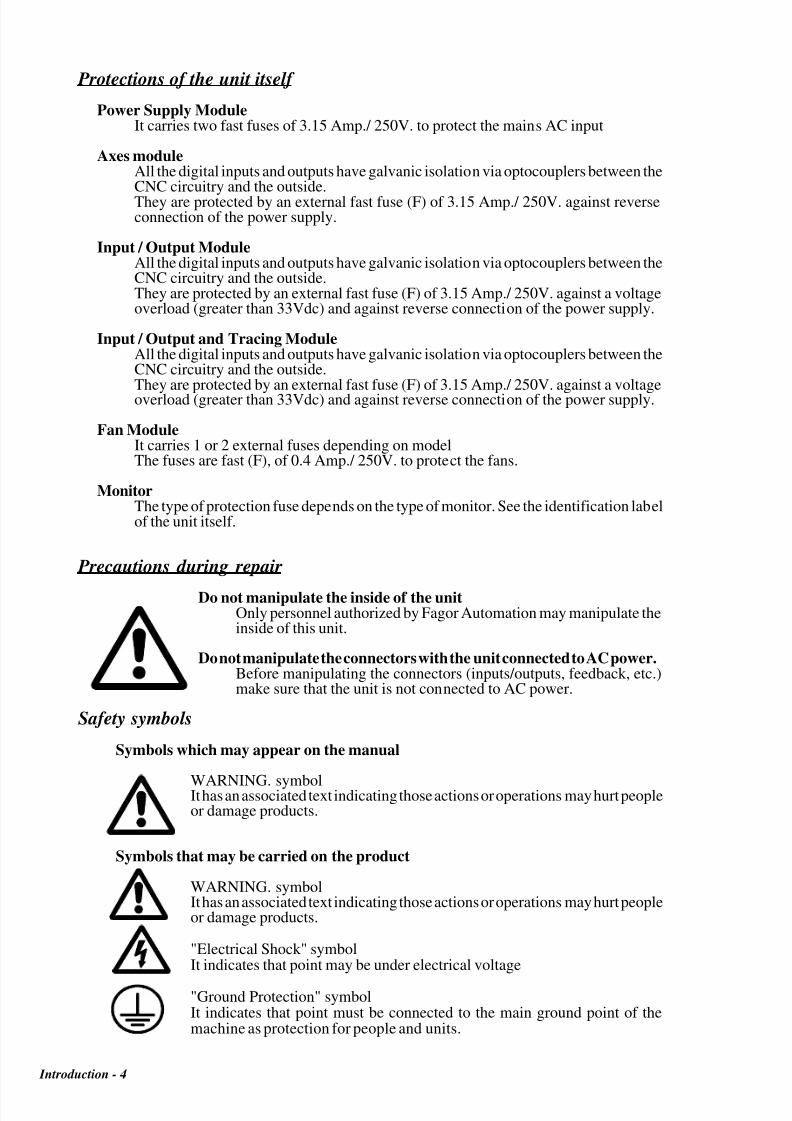
8/21/2019 CNC 8055 M Operator Manual
http://slidepdf.com/reader/full/cnc-8055-m-operator-manual 199/702
Introduction - 4
Protections of the unit itself
Power Supply ModuleIt carries two fast fuses of 3.15 Amp./ 250V. to protect the mains AC input
Axes moduleAll the digital inputs and outputs have galvanic isolation via optocouplers between theCNC circuitry and the outside.They are protected by an external fast fuse (F) of 3.15 Amp./ 250V. against reverseconnection of the power supply.
Input / Output ModuleAll the digital inputs and outputs have galvanic isolation via optocouplers between theCNC circuitry and the outside.They are protected by an external fast fuse (F) of 3.15 Amp./ 250V. against a voltageoverload (greater than 33Vdc) and against reverse connection of the power supply.
Input / Output and Tracing ModuleAll the digital inputs and outputs have galvanic isolation via optocouplers between theCNC circuitry and the outside.
They are protected by an external fast fuse (F) of 3.15 Amp./ 250V. against a voltageoverload (greater than 33Vdc) and against reverse connection of the power supply.
Fan ModuleIt carries 1 or 2 external fuses depending on modelThe fuses are fast (F), of 0.4 Amp./ 250V. to protect the fans.
MonitorThe type of protection fuse depends on the type of monitor. See the identification labelof the unit itself.
Precautions during repair
Do not manipulate the inside of the unitOnly personnel authorized by Fagor Automation may manipulate theinside of this unit.
Do not manipulate the connectors with the unit connected to AC power.Before manipulating the connectors (inputs/outputs, feedback, etc.)make sure that the unit is not connected to AC power.
Safety symbols
Symbols which may appear on the manual
WARNING. symbolIt has an associated text indicating those actions or operations may hurt peopleor damage products.
Symbols that may be carried on the product
WARNING. symbolIt has an associated text indicating those actions or operations may hurt peopleor damage products.
"Electrical Shock" symbolIt indicates that point may be under electrical voltage
"Ground Protection" symbolIt indicates that point must be connected to the main ground point of themachine as protection for people and units.
8/21/2019 CNC 8055 M Operator Manual
http://slidepdf.com/reader/full/cnc-8055-m-operator-manual 200/702
Introduction - 5
MATERIAL RETURNING TERMS
When returning the Monitor or the Central Unit, pack it in its original package and with itsoriginal packaging material. If not available, pack it as follows:
1.- Get a cardboard box whose three inside dimensions are at least 15 cm (6 inches) largerthan those of the unit. The cardboard being used to make the box must have a resistanceof 170 Kg (375 lb.).
2.- When sending it to a Fagor Automation office for repair, attach a label indicating theowner of the unit, person to contact, type of unit, serial number, symptom and a brief description of the problem.
3.- Wrap the unit in a polyethylene roll or similar material to protect it.
When sending the monitor, especially protect the CRT glass
4.- Pad the unit inside the cardboard box with poly-utherane foam on all sides.
5.- Seal the cardboard box with packing tape or industrial staples.
8/21/2019 CNC 8055 M Operator Manual
http://slidepdf.com/reader/full/cnc-8055-m-operator-manual 201/702
Introduction - 6
FAGOR DOCUMENTATIONFOR THE CNC
OEM Manual Is directed to the machine builder or person in charge of installing and starting-up the CNC.
USER Manual Is directed to the end user or CNC operator.
It contains 2 manuals:Operating Manual describing how to operate the CNC.Programming Manual describing how to program the CNC.
DNC Software Manual Is directed to people using the optional DNC communications software.
DNC Protocol Manual Is directed to people wishing to design their own DNC communications softwareto communicate with the CNC.
FLOPPY DISK Manual Is directed to people using the Fagor Floppy Disk Unit and it shows how to use it.
8/21/2019 CNC 8055 M Operator Manual
http://slidepdf.com/reader/full/cnc-8055-m-operator-manual 202/702
Introduction - 7
MANUAL CONTENTS
The Programming Manual for the Mill model CNC contains the following chapters:
Index
New Features and Modifications for the Mill Model
Introduction Summary of safety conditionsShipping termsFagor documentation for the CNC.Manual contents
Chapter 1 OverviewIt shows how to enter part-programs from the keyboard or via DNC.Location of part-programs, how to edit them and execute them.It indicates the protocol to be used in DNC communications.
Chapter 2 Creating a program
It indicates the structure for a part-program and all its blocks.It shows the languages that could be used to program the parts: ISO coded and High-Level languages
Chapter 3 Axes and coordinate systemsIt indicates the nomenclature of the axes and how to select them.It shows how to select the working planes, work units, type of programming system(absolute /incremental).It describes the coordinates systems that could be used for programming: Cartesian,polar, cylindric, angle plus Cartesian coordinate.It shows how to operate with rotary axes and how to define and use work zones.
Chapter 4 Reference systemsIt indicates the machine reference (home) and datum points to be set at the CNC.
It shows how to program a home search, how to program coordinates with respectto home, how to preset coordinates, zero offsets and polar origins.
Chapter 5 Programming by ISO codeIt shows how to program preparatory functions for feedrate and constant speed aswell as additional functions such as "F, S, T, D and M".It describes how to select the main spindle or the auxiliary spindle
Chapter 6 Path controlIt shows how to program rapid traverse, linear, circular and helical interpolations.It shows how to program tangential entries and exits as well as corner rounding andchamferingIt shows how to program electronic threading and movements against hard stop.
It shows how to program the feedrate as an inverted function of time.It shows how to program the tangential control
Chapter 7 Additional preparatory functionsIt shows how to interrupt block preparation and how to program a dwell.It shows how to program a part in square corner, round corner or with an automaticradius blend.It describes how to program the look-ahead, mirror image, scaling factor, patternrotation and the electronic slaving / unslaving of the axes.
Chapter 8 Tool compensationIt shows how to program tool radius and length compensation.
Chapter 9 Canned cycles
It shows how to program the different machining canned cycles.

8/21/2019 CNC 8055 M Operator Manual
http://slidepdf.com/reader/full/cnc-8055-m-operator-manual 203/702
Introduction - 8
Chapter 10 Multiple machiningIt shows how to program the different multiple machining cycles.
Chapter 11 Irregular pocket canned cycles (with islands)It shows how to program the different 2-D and 3-D pocket canned cycles.
Chapter 12 Working with a probeIt shows how to carry out probing moves and how to program the probing canned
cycles.
Chapter 13 Programming in high level languageIt shows all the variables, symbols, operators, etc. to be used when programming inhigh level language.
Chapter 14 Program control statementsIt shows the control sequences that can be used in high-level language. The availableinstructions are: for assignment, display enable/disable, flow control, subroutinesand for generating programs and screens.
Chapter 15 Digitizing cyclesIt shows how to program the various digitizing cycles.
Chapter 16 Tracing and DigitizingIt shows how to program the various digitizing and tracing cycles.
Chapter 17 Coordinate transformationIt describes coordinate transformation.It shows how to select incline planes.It shows how to make movements along the tool axes.It shows how to work with TCP (Tool Center Point) transformation.
Appendix A ISO code programmingB Internal CNC variablesC High level programmingD Key codes
E Programming assistance system pages

8/21/2019 CNC 8055 M Operator Manual
http://slidepdf.com/reader/full/cnc-8055-m-operator-manual 204/702
PageChapter: 1
OVERVIEWSection:
1
1. OVERVIEW
The CNC can be programmed both at the machine (from the front panel) or from externalperipheral devices (tape reader/cassette recorder, computer, etc. Memory available to theuser for carrying out the part programs is 1 Mbyte.
The part programs and the values in the tables which the CNC has can be entered as follows:
* From the front panel. Once the editing mode or table required has been selected, theCNC allows you to enter data from the keyboard.
* From a Computer (DNC) or Peripheral Device. The CNC allows data to beinterchanged with a computer or peripheral device, using RS232C and RS422 cables.
If this is controlled from the CNC, it is necessary to preset the corresponding table orpart program directory (utilities) you want to communicate with.
Depending on the type of communication required, the serial port machine parameter“PROTOCOL” should be selected.
“PROTOCOL” = 0 if the communication is with a peripheral device.“PROTOCOL” = 1 if the communication is via DNC.
1.1 PART-PROGRAMS
Editing
To create a part-program, access the Edit mode. See chapter 5 in this manual.
The new part-program edited is stored in the CNC's RAM memory.
A copy of the part-programs may be stored in the "MemKey Card", at a PCconnected through serial line 1 or 2 or in the hard disk (HD module). See
chapter 7 in this manual.
When using a PC through serial line 1 or 2, proceed as follows:
• Execute the "Fagor50.exe" applications program at the PC.
• Activate DNC communications at the CNC. See chapter 8 in this manual.
• Select the work directory as shown in chapter 7 of this manual. Option:
Utilities\ Directory\ Serial L.\ Change directory.

8/21/2019 CNC 8055 M Operator Manual
http://slidepdf.com/reader/full/cnc-8055-m-operator-manual 205/702
Section:
OVERVIEWChapter: 1
2Page
With the Edit mode of operation, part-programs residing in the CNC's RAM
memory may be modified. To modify a program stored in the "MemKey Card",
in a PC or in the hard disk, it must be previously copied into RAM memory.
Execution
Part-programs stored anywhere may be executed or simulated. See chapter 3 in
this manual.
The user customizing programs must be in RAM memory so the CNC can
execute them.
The GOTO and RPT instructions cannot be used in programs executed from a PCconnected through the serial lines. See chapter 14 of the programming manual.
The subroutines can only be executed if they reside in the CNC's RAM memory.Therefore, to execute a subroutine stored in the "MemKey Card", in a PC or in the harddisk, it must be first copied into the CNC's RAM memory.
From a program in execution, another program can be executed which is in RAMmemory, in the "MemKey Card", in a PC or in the hard disk using the EXECinstruction. See chapter 14 of the programming manual.
Utilities
This operating mode, chapter 7 of this manual, lets display the part-program
directory of all the devices, make copies, delete, rename and even set the
protections for any of them.
Ethernet
When having the Ethernet option and if the CNC is configured as another node
within the computer network, the following operations are possible from any
PC of the network:
• Access the part-program directory of the Hard Disk(HD).
• Edit, modify, delete, rename, etc.the programs stored on the hard disk (HD).• Copy programs from the hard disk to the PC and vice versa.
To configure the CNC as another node within the computer network, see section
3.3.4 of the installation manual.
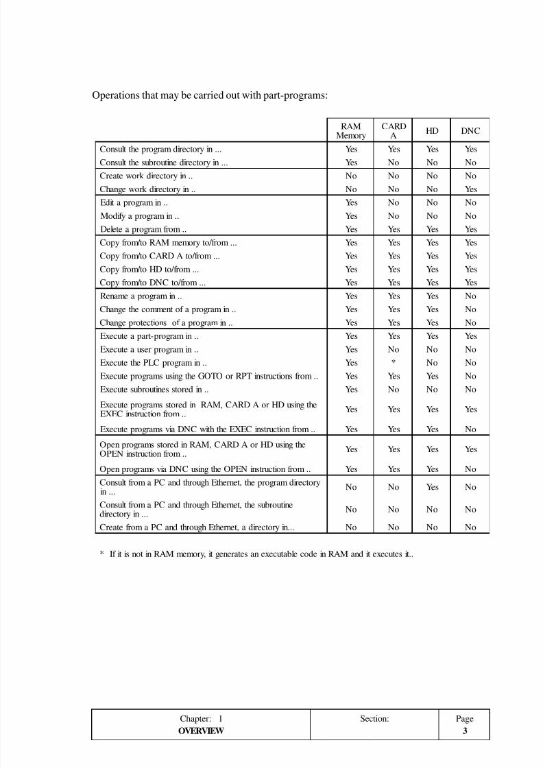
8/21/2019 CNC 8055 M Operator Manual
http://slidepdf.com/reader/full/cnc-8055-m-operator-manual 206/702
PageChapter: 1
OVERVIEWSection:
3
Operations that may be carried out with part-programs:
MAR
yromeM
DRAC
A DH CND
...niyrotceridmargorpehttlusnoC seY seY seY seY
...niyrotceridenituorbusehttlusnoC seY oN oN oN
..niyrotceridk rowetaerC oN oN oN oN
..niyrotceridk rowegnahC oN oN oN seY
..nimargorpatidE seY oN oN oN
..nimargorpayf idoM seY oN oN oN
..morf margorpaeteleD seY seY seY seY
...morf / otyromemMARot / morf ypoC seY seY seY seY
...morf / otADRACot / morf ypoC seY seY seY seY
...morf / otDHot / morf ypoC seY seY seY seY...morf / otCNDot / morf ypoC seY seY seY seY
..nimargorpaemaneR seY seY seY oN
..nimargorpaf otnemmocehtegnahC seY seY seY oN
..nimargorpaf osnoitcetorpegnahC seY seY seY oN
..nimargorp-trapaetucexE seY seY seY seY
..nimargorpresuaetucexE seY oN oN oN
..nimargorpCLPehtetucexE seY * oN oN
..morf snoitcurtsniTPRroOTOGehtgnisusmargorpetucexE seY seY seY oN
..niderotssenituorbusetucexE seY oN oN oN
ehtgnisuDHroADRAC,MARniderotssmargorpetucexE..morf noitcurtsniCEXE
seY seY seY seY
..morf noitcurtsniCEXEehthtiwCNDaivsmargorpetucexE seY seY seY oN
ehtgnisuDHroADRAC,MARniderotssmargorpnepO..morf noitcurtsniNEPO
seY seY seY seY
..morf noitcurtsniNEPOehtgnisuCNDaivsmargorpnepO seY seY seY oN
yrotceridmargorpeht,tenrehtEhguorhtdnaCPamorf tlusnoC...ni
oN oN seY oN
enituorbuseht,tenrehtEhguorhtdnaCPamorf tlusnoC...niyrotcerid
oN oN oN oN
...niyrotcerida,tenrehtEhguorhtdnaCPamorf etaerC oN oN oN oN
..tisetucexetidnaMARniedocelbatucexenasetarenegti,yromemMARnitonsitif I*
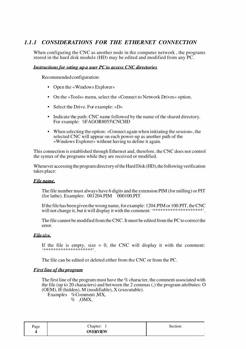
8/21/2019 CNC 8055 M Operator Manual
http://slidepdf.com/reader/full/cnc-8055-m-operator-manual 207/702
Section:
OVERVIEWChapter: 1
4Page
1.1.1 CONSIDERATIONS FOR THE ETHERNET CONNECTION
When configuring the CNC as another node in the computer network , the programsstored in the hard disk module (HD) may be edited and modified from any PC.
Instructions for seting up a user PC to access CNC directories
Recommended configuration:
• Open the «Windows Explorer»
• On the «Tools» menu, select the «Connect to Network Drives» option.
• Select the Drive. For example: «D»
• Indicate the path: CNC name followed by the name of the shared directory.
For example: \\FAGOR8055\CNCHD
• When selecting the option: «Connect again when initiating the session», theselected CNC will appear on each power-up as another path of the«Windows Explorer» without having to define it again.
This connection is established through Ethernet and, therefore, the CNC does not controlthe syntax of the programs while they are received or modified.
Whenever accessing the program directory of the Hard Disk (HD), the following verificationtakes place:
File name.The file number must always have 6 digits and the extension PIM (for milling) or PIT(for lathe). Examples: 001204.PIM 000100.PIT
If the file has been given the wrong name, for example: 1204.PIM or 100.PIT, the CNCwill not change it, but it will display it with the comment: ‘********************’.
The file cannot be modified from the CNC. It must be edited from the PC to correct theerror.
File size.
If the file is empty, size = 0, the CNC will display it with the comment:‘********************’.
The file can be edited or deleted either from the CNC or from the PC.
First line of the program
The first line of the program must have the % character, the comment associated withthe file (up to 20 characters) and between the 2 commas (,) the program attributes: O(OEM), H (hidden), M (modifiable), X (executable).
Examples %Comment ,MX,% ,OMX,

8/21/2019 CNC 8055 M Operator Manual
http://slidepdf.com/reader/full/cnc-8055-m-operator-manual 208/702
PageChapter: 1
OVERVIEWSection:
5
If the first line does not exist. The CNC will display it with an empty comment and withthe modifiable (M) and executable (X) attributes.
When the format of the first line is wrong, the CNC does not modify it, but it displaysit with the comment: ‘********************’. The file can be modified or deletedfrom the CNC or from the PC.
It is the wrong format when:the comment has more than 20 charactersa comma (,) is missing for separating the attributesthe attributes have a strange character

8/21/2019 CNC 8055 M Operator Manual
http://slidepdf.com/reader/full/cnc-8055-m-operator-manual 209/702
Section:
OVERVIEWChapter: 1
6Page
1.2 DNC CONNECTION
The CNC offers as optional feature the possibility of working in DNC (DistributedNumerical Control), enabling communication between the CNC and a computer to carryout the following functions :
* Directory and delete commands.
* Transfer of programs and tables between the CNC and a computer.
* Remote control of the machine.
* The ability to supervise the status of advanced DNC systems.
1.3 COMMUNICATION PROTOCOL VIA DNC OR PERIPHERAL
DEVICE
This type of communication enables program-and-table transfer commands, plus theorganization of CNC directories such as the Computer Directory, for copying/deletingprograms, etc. to be done either from the CNC or the computer.
When you want to transfer files, it is necessary to follow this protocol :
* The “%” symbol will be used to start the file, followed by the program comment(optional), of up to 20 characters.
Then, and separated by a comma “,”, comes the attribute (protection) each file has:
reading, modifying, etc. This protection is optional and does not have to programmed.To end the file header, RETURN (RT) or LINE FEED (LF) characters should besent separated by a comma (“,”).
Example :
%Fagor Automation, -MX, RT
* Following the header, the file blocks should be programmed. These will all beprogrammed according to the programming rules indicated in this manual. Aftereach block, to separate it from the others, theRETURN (RT) or LINE FEED (LF)characters should be used.
Example :
N20 G90 G01 X100 Y200 F2000 LF(RPT N10, N20) N3 LF
If communication is made with a peripheral device, you will need to send the ‘end of file’command. This command is selected via the machine parameter for the serial port:“EOFCHR”, and can be one of the following characters :
ESC ESCAPEEOT END OF TRANSMISSION
SUB SUBSTITUTEEXT END OF TRANSMISSION.

8/21/2019 CNC 8055 M Operator Manual
http://slidepdf.com/reader/full/cnc-8055-m-operator-manual 210/702
PageChapter: 2
CREATING A PROGRAM
Section:
1
2. CREATING A PROGRAM
A CNC (numerical control) program consists of a series of blocks or instructions.
These blocks or instructions are made of words composed of capital letters and numericalformat.
The CNC’s numerical format consists of :
- the symbols . + -- the figures 0 1 2 3 4 5 6 7 8 9
Programming allows spaces between letters, numbers and symbols, in addition to ignoringthe numerical format if it has zero value, or a symbol if it is positive.
The numerical format of a word can be replaced by an arithmetic parameter in programming.Later and during basic execution, the control will replace the arithmetic parameter by itsvalue, for example :
If XP3 has been programmed, during execution the CNC will replace P3 by its numericalvalue, obtaining results such as X20, X20.567, X-0.003, etc.
2.1 CREATING A PROGRAM IN THE CNC
All the blocks which make up the program have the following structure :
Block header + program block + end of block
8/21/2019 CNC 8055 M Operator Manual
http://slidepdf.com/reader/full/cnc-8055-m-operator-manual 211/702
Section:
CREATING A PROGRAMChapter: 2
2Page
2.1.1 BLOCK HEADER
The block header is optional, and may consist of one or more block skip conditions andby the block number or label. Both can be programmed in this order.
CONDITION FOR BLOCK SKIP, /, /1, /2, /3.
These three block skip conditions, given that “/” and “/1” is the same, are governedby the marks BLKSKIP1, BLKSKIP2 and BLKSKIP3 of the PLC.
If any of these marks is active, the CNC will not execute the block or blocks in whichit has been programmed. The execution takes place in the following block.
Up to 3 skip conditions can be programmed in one block. These will be evaluated one
by one, respecting the order in which they have been programmed.
The control reads 20 blocks ahead of the one being executed in order to calculate inadvance the path to be run.
The condition for block skip will be analyzed at the time when the block is read i.e.20 blocks before execution.
If the block skip needs to be analyzed at the time of execution, it is necessary tointerrupt the block preparation, by programming G4 in the previous block.
BLOCK LABEL OR NUMBER N(0-9999)This is used to identify the block, and is only used when block references or jumps aremade.
They are represented by the letter N followed by up to 4 figures (0-9999). It is notnecessary to follow any order, and randomly arranged numbers are allowed.
If two or more blocks with the same label number are present in the same program, theCNC will always give priority to the first number.
Although it is not necessary to program it, by using a SOFTKEY the CNC allows theautomatic programming of labels. The programmer can select the initial number and
the step between labels.

8/21/2019 CNC 8055 M Operator Manual
http://slidepdf.com/reader/full/cnc-8055-m-operator-manual 212/702
PageChapter: 2
CREATING A PROGRAM
Section:
3
2.1.2 PROGRAM BLOCK
This is written with commands in ISO and High Level languages.
To prepare a program, blocks written in both languages will be used, although each oneshould be edited with commands in just one language.
2.1.2.1 ISO LANGUAGE
This language is specially designed to control axis movement, as it gives information andmovement conditions, in addition to data on feedrate. It includes :
* Preparatory functions for movement, used to determine geometry and workingconditions, such as linear and circular interpolations, threading, etc.
* Control functions for axis feedrate and spindle speeds.
* Tool control functions.
* Complementary functions, with technological instructions.
2.1.2.2 HIGH LEVEL LANGUAGE
This enables access to general purpose variables and to system tables and variables.
It gives the user a number of control sentences which are similar to the terminology usedin other languages, such as : IF, GOTO, CALL, etc.
It also allows the use of any type of expression (arithmetic, referential, or logical).
It also has instructions for the construction of loops, plus subroutines with local variables.“Local variable” is understood to mean one which is only recognized by the subroutine inwhich it has been defined.
It is also possible to create libraries, grouping subroutines with useful and tested functions,which can be accessed from any program.

8/21/2019 CNC 8055 M Operator Manual
http://slidepdf.com/reader/full/cnc-8055-m-operator-manual 213/702
Section:
CREATING A PROGRAMChapter: 2
4Page
2.1.3 END OF BLOCK
The end of block is optional and may consist of the indication of number of repetitionsof the block and of the block comment. Both must be programmed in this order.
NUMBER OF REPETITIONS OF THE BLOCK, N(0-9999)
This indicates the number of times the block will be executed.
Movement blocks can only be repeated which, at the time of their execution, are underthe influence of a modal subroutine.
In these cases, the CNC executes the programmed move and the active machiningoperation (canned cycle or modal subroutine) the indicated number of times.
The number of repetitions is represented by the letter N followed by up to 4 digits (0-9999).
The active machining operation does not take place if N0 is programmed. Only themovement programmed within the block takes place.
BLOCK COMMENT
The CNC allows you to incorporate any kind of information into all blocks in the formof a comment.
The comment is programmed at the end of the block, and should begin with thecharacter “;”.
If a block begins with “;”, all its contents will be considered as a comment, and it willnot be executed.
Empty blocks are not permitted. They should contain at least one comment.
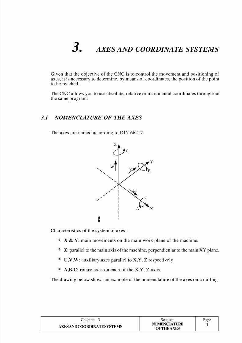
8/21/2019 CNC 8055 M Operator Manual
http://slidepdf.com/reader/full/cnc-8055-m-operator-manual 214/702
PageChapter: 3
AXES AND COORDINATE SYSTEMS
Section:
1
Z
C
WV B
XA
U
Y
NOMENCLATUREOF THE AXES
3. AXES AND COORDINATE SYSTEMS
Given that the objective of the CNC is to control the movement and positioning of axes, it is necessary to determine, by means of coordinates, the position of the pointto be reached.
The CNC allows you to use absolute, relative or incremental coordinates throughoutthe same program.
3.1 NOMENCLATURE OF THE AXES
The axes are named according to DIN 66217.
Characteristics of the system of axes :
* X & Y: main movements on the main work plane of the machine.
* Z: parallel to the main axis of the machine, perpendicular to the main XY plane.
* U,V,W: auxiliary axes parallel to X,Y, Z respectively
* A,B,C: rotary axes on each of the X,Y, Z axes.
The drawing below shows an example of the nomenclature of the axes on a milling-
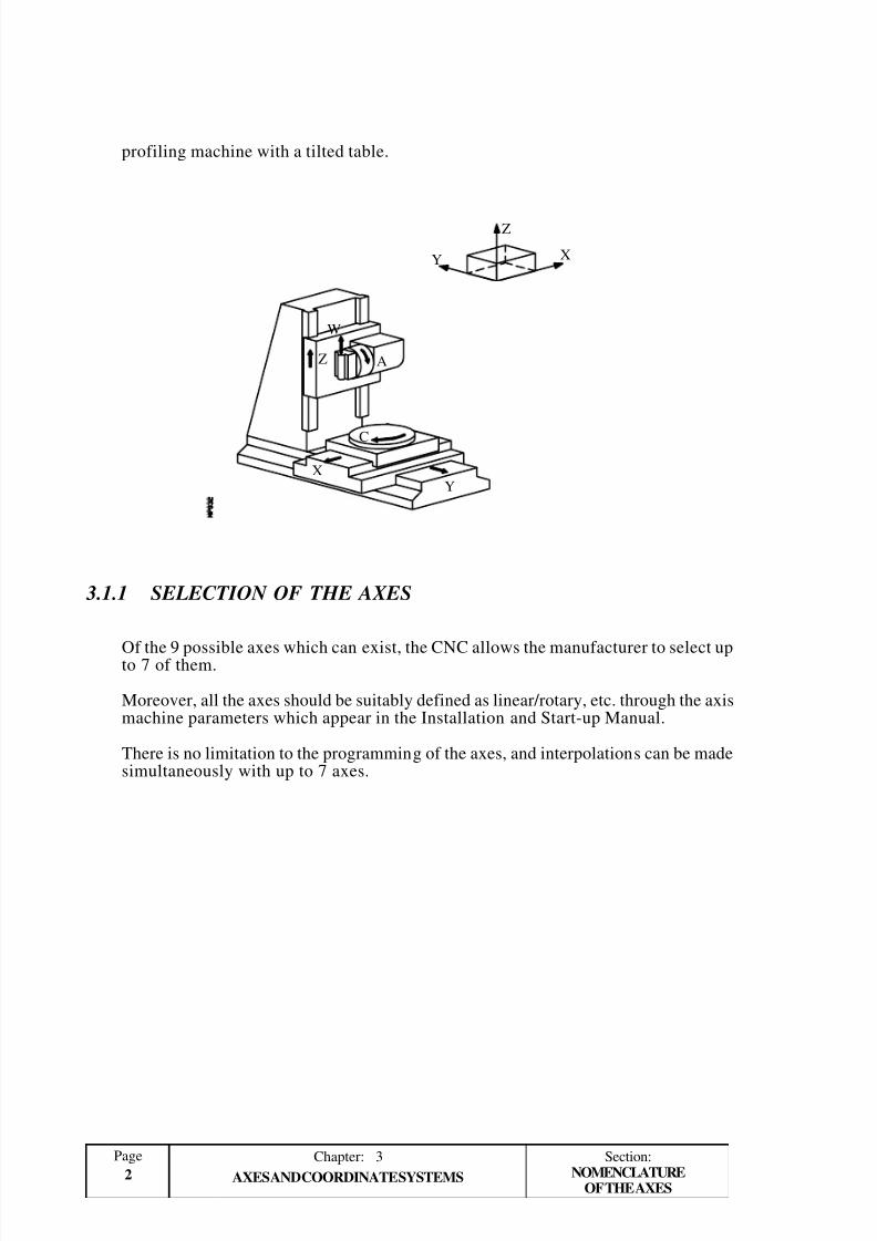
8/21/2019 CNC 8055 M Operator Manual
http://slidepdf.com/reader/full/cnc-8055-m-operator-manual 215/702
Section:Chapter: 3
2Page
AXES AND COORDINATE SYSTEMS
Z
Y X
A
C
X
Z
W
Y
NOMENCLATUREOF THE AXES
profiling machine with a tilted table.
3.1.1 SELECTION OF THE AXES
Of the 9 possible axes which can exist, the CNC allows the manufacturer to select upto 7 of them.
Moreover, all the axes should be suitably defined as linear/rotary, etc. through the axismachine parameters which appear in the Installation and Start-up Manual.
There is no limitation to the programming of the axes, and interpolations can be madesimultaneously with up to 7 axes.

8/21/2019 CNC 8055 M Operator Manual
http://slidepdf.com/reader/full/cnc-8055-m-operator-manual 216/702
PageChapter: 3
AXES AND COORDINATE SYSTEMS
Section:
3
YW
X U
Q
G2G2
Q
G16 XW G16 UY
PLANE SELECTION(G16, G17, G18, G19)
3.2 PLANE SELECTION (G16, G17, G18, G19)
Plane selection should be made when the following are carried out :
- Circular interpolations.
- Controlled corner rounding.
- Tangential entry and exit.
- Chamfer blend.
- Machining canned cycles.
- Pattern rotation.
- Tool radius Compensation.
- Tool length compensation.
The “G” functions which enable selection of work planes are as follows :
* G16 axis1 axis2. Enables selection of the desired work plane, plus the directionof G02 G03 (circular interpolation), axis1 being programmed as the abscissaaxis and axis2 as the ordinate axis.
* G17. Selects the XY plane
* G18. Selects the ZX plane
* G19. Selects the YZ plane

8/21/2019 CNC 8055 M Operator Manual
http://slidepdf.com/reader/full/cnc-8055-m-operator-manual 217/702
Section:Chapter: 3
4Page
AXES AND COORDINATE SYSTEMS
The G16, G17, G18 and G19 functions are modal and incompatible among themselves.The G16 function should be programmed on its own within a block.
The G17, G18, and G19 functions define two of the three main axes (X, Y, Z) asbelonging to the work plane, and the other as the perpendicular axis to the same.
When radius compensation is done on the work plane, and length compensation on
the perpendicular axis, the CNC does not allow functions G17, G18, and G19 if anyone of the X, Y, or Z axes is not selected as being controlled by the CNC.
On power-up, after executing M02, M30 or after EMERGENCY or RESET, the CNCwill assume that the plane defined by the general machine parameter as “IPLANE”is the work plane.
Note: To machine incline planes, function G49 must be used, coordinate transformation,See chapter 17 "Incline planes" on this manual.
Y
PLANE SELECTION(G16, G17, G18, G19)
Z
Z

8/21/2019 CNC 8055 M Operator Manual
http://slidepdf.com/reader/full/cnc-8055-m-operator-manual 218/702
PageChapter: 3
AXES AND COORDINATE SYSTEMS
Section:
5MILLIMETERS (G71) / INCHES (G70)
3.3 PART DIMENSIONING. MILLIMETERS (G71) OR INCHES (G70)
The CNC allows you to enter units of measurement with the programming, either inmillimeters or inches.
It has a general machine parameter “INCHES” to define the unit of measurement of the CNC.
However, these units of measurement can be changed at any time in the program.Two functions are supplied for this purpose :
* G70 : Programming in inches.* G71 : Programming in millimeters.
Depending on whether G70 or G71 has been programmed, the CNC assumes the
corresponding set of units for all the blocks programmed from that moment on.
The G70 and G71 functions are modal and are incompatible.
The CNC allows the programming of figures from 0.0001 to 99999.9999 (with orwithout sign) when it works in millimeters (G71). This is called format +/- 5.4, orfrom 0.00001 to 3937.00787 (with or without sign) if it is programmed in inches(G70). This is called format +/- 4.5.
However, and to simplify the instructions, we can say that the CNC admits +/- 5.5format, thereby admitting +/- 5.4 in millimeters and +/- 4.5 in inches.
On power-up, after executing M02, M30 or after EMERGENCY or RESET, the CNCwill assume that the system of units of measurement is the one defined by the generalmachine parameter “INCHES”.

8/21/2019 CNC 8055 M Operator Manual
http://slidepdf.com/reader/full/cnc-8055-m-operator-manual 219/702
Section:Chapter: 3
6Page
AXES AND COORDINATE SYSTEMS
3.4 ABSOLUTE/INCREMENTAL PROGRAMMING (G90, G91)
The CNC allows the programming of the coordinates of one point either with absolute
G90 or incremental G91 values.
When working with absolute coordinates (G90), the point coordinates refer to a pointof origin of established coordinates, often the part zero (datum).
When working in incremental coordinates (G91), the numerical value programmedcorresponds to the movement information for the distance to be travelled from thepoint where the tool is situated at that time. The sign in front shows the direction of movement.
Functions G90/G91 are modal and incompatible.
Example :
Absolute coordinates
G90 XO YO ; Point P0X150.5 Y200 ; Point P1X300 ; Point P2X0 Y0 ; Point P0
Incremental coordinates
G90 X0 Y0 ; Point P0G91 X150.5 Y200 ; Point P1
X149.5 ; Point P2X-300 Y-200 ; Point P0
On power-up, after executing M02, M30 or after an EMERGENCY or RESET, theCNC will assume G90 or G91 according to the definition by the general machine
parameter “ISYSTEM”.
X
Y
P1 P2
P0
ABSOLUTE (G90)/ INCREMENTAL (G91)
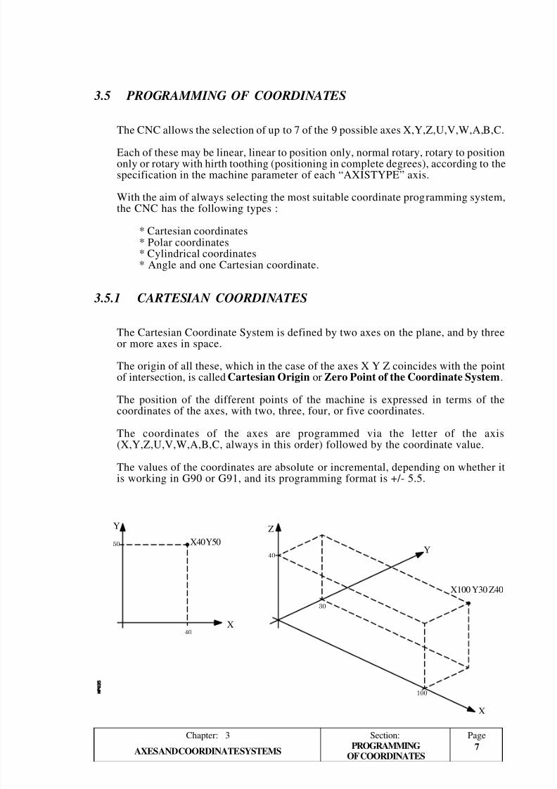
8/21/2019 CNC 8055 M Operator Manual
http://slidepdf.com/reader/full/cnc-8055-m-operator-manual 220/702
PageChapter: 3
AXES AND COORDINATE SYSTEMS
Section:
7PROGRAMMINGOF COORDINATES
Y
Z
Y
X
X40 Y50
X100 Y30 Z40
X
3.5 PROGRAMMING OF COORDINATES
The CNC allows the selection of up to 7 of the 9 possible axes X,Y,Z,U,V,W,A,B,C.
Each of these may be linear, linear to position only, normal rotary, rotary to positiononly or rotary with hirth toothing (positioning in complete degrees), according to thespecification in the machine parameter of each “AXISTYPE” axis.
With the aim of always selecting the most suitable coordinate programming system,the CNC has the following types :
* Cartesian coordinates* Polar coordinates* Cylindrical coordinates* Angle and one Cartesian coordinate.
3.5.1 CARTESIAN COORDINATES
The Cartesian Coordinate System is defined by two axes on the plane, and by threeor more axes in space.
The origin of all these, which in the case of the axes X Y Z coincides with the pointof intersection, is called Cartesian Origin or Zero Point of the Coordinate System.
The position of the different points of the machine is expressed in terms of the
coordinates of the axes, with two, three, four, or five coordinates.
The coordinates of the axes are programmed via the letter of the axis(X,Y,Z,U,V,W,A,B,C, always in this order) followed by the coordinate value.
The values of the coordinates are absolute or incremental, depending on whether itis working in G90 or G91, and its programming format is +/- 5.5.

8/21/2019 CNC 8055 M Operator Manual
http://slidepdf.com/reader/full/cnc-8055-m-operator-manual 221/702
Section:Chapter: 3
8Page
AXES AND COORDINATE SYSTEMS
X
Y
Q
R
PROGRAMMINGOF COORDINATES
3.5.2 POLAR COORDINATES
In the event of the presence of circular elements or angular dimensions, the coordinatesof the different points on the plane (2 axes at the same time), it may be easier toexpress them in polar coordinates.
The reference point is called Polar Origin, and this will be the origin of the PolarCoordinate System.
A point on this system would be defined by :
- The RADIUS (R), the distance between the polar origin and the point.
- The ANGLE (Q), formed by the abscissa axis and the line which joins the polarorigin with the point (in degrees).
The values R and Q are absolute or incremental depending on whether you are workingwith G90 or G91, and their programming format will be R +/- 5.5 Q+/- 5.5.
The R values may be negative when programming in incremental coordinates; butthe resulting value assigned to the radius must always be positive.
If a Q value over 3600 is programmed, the module will be taken after dividing it by360. Thus, Q420 is the same a Q60, and Q-240 is the same as Q-60.
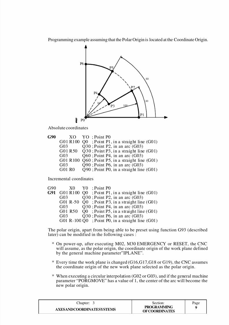
8/21/2019 CNC 8055 M Operator Manual
http://slidepdf.com/reader/full/cnc-8055-m-operator-manual 222/702
PageChapter: 3
AXES AND COORDINATE SYSTEMS
Section:
9
P1
P6P5
P2
P4
P3
P0
PROGRAMMINGOF COORDINATES
Programming example assuming that the Polar Origin is located at the Coordinate Origin.
Absolute coordinates
G90 XO YO ; Point P0G01 R100 Q0 ; Point P1, in a straight line (G01)G03 Q30 ; Point P2, in an arc (G03)G01 R50 Q30 ; Point P3, in a straight line (G01)G03 Q60 ; Point P4, in an arc (G03)G01 R100 Q60 ; Point P5, in a straight line (G01)G03 Q90 ; Point P6, in an arc (G03)
G01 R0 Q90 ; Point P0, in a straight line (G01)
Incremental coordinates
G90 X0 Y0 ; Point P0G91 G01 R100 Q0 ; Point P1, in a straight line (G01)
G03 Q30 ; Point P2, in an arc (G03)G01 R-50 Q0 ; Point P3, in a straight line (G01)G03 Q30 ; Point P4, in an arc (G03)G01 R50 Q0 ; Point P5, in a straight line (G01)G03 Q30 ; Point P6, in an arc (G03)G01 R-100 Q0 ; Point P0, in a straight line (G01)
The polar origin, apart from being able to be preset using function G93 (describedlater) can be modified in the following cases :
* On power-up, after executing M02, M30 EMERGENCY or RESET, the CNCwill assume, as the polar origin, the coordinate origin of the work plane definedby the general machine parameter”IPLANE”.
* Every time the work plane is changed (G16,G17,G18 or G19), the CNC assumesthe coordinate origin of the new work plane selected as the polar origin.
* When executing a circular interpolation (G02 or G03), and if the general machineparameter “PORGMOVE” has a value of 1, the center of the arc will become the
new polar origin.

8/21/2019 CNC 8055 M Operator Manual
http://slidepdf.com/reader/full/cnc-8055-m-operator-manual 223/702
Section:Chapter: 3
10Page
AXES AND COORDINATE SYSTEMS
Z
Y
X
Z
P
R Q
PROGRAMMINGOF COORDINATES
3.5.3 CYLINDRICAL COORDINATES
To define a point in space, the system of cylindrical coordinates can be used as wellas the Cartesian coordinate system.
A point in this system would be defined by :
* The projection of this point on the main plane, which should be defined in polarcoordinates (R Q).
* Rest of axes in cartesian coordinates.
Examples : R30 Q10 Z100 R20 Q45 Z10 V30 A20

8/21/2019 CNC 8055 M Operator Manual
http://slidepdf.com/reader/full/cnc-8055-m-operator-manual 224/702
PageChapter: 3
AXES AND COORDINATE SYSTEMS
Section:
11
Y
X
P
P
P P
P
PROGRAMMINGOF COORDINATES
3.5.4 ANGLE AND ONE CARTESIAN COORDINATE
A point on the main plane can be defined via one of its cartesian coordinates, and theexit angle of the previous path.
Example of programming assuming that the main plane is XY:
X10 Y20 ; Point P0, starting pointQ45 X30 ; Point P1Q90 Y60 ; Point P2Q-45 X50 ; Point P3Q-135 Y20 ; Point P4Q180 X10 ; Point P0
If you wish to represent a point in space, the remaining coordinates can be programmedin cartesian coordinates.

8/21/2019 CNC 8055 M Operator Manual
http://slidepdf.com/reader/full/cnc-8055-m-operator-manual 225/702
Section:Chapter: 3
12Page
AXES AND COORDINATE SYSTEMS ROTARY AXES
3.6 ROTARY AXES
The types of rotary axes available are:
Normal rotary axis.Positioning-only rotary axis.Hirth rotary axis.
Each one of them can be divided into:Rollover When their position reading goes from 0º to 360º.No rollover When their position reading goes from -99999º to 99999º
They are all programmed in degrees. Therefore, their readings are not affected by theinch/mm conversion.
Normal rotary axes
They can be interpolated with linear axes.Movement: in G00 and G01Rollover axis programming:
G90 The sign indicates the turning direction and the target position (between0 and 359.9999).
G91 The sign indicates the turning direction. If the programmed movementexceeds 360º, the axis will rotate more than one turn before positioningat the desired point.
Non-rollover axis programming: In G90 and G91 like a linear axis.
Positioning-only AxesThey cannot be interpolated with linear axes.Movement: Always in G00 and they do not admit tool radius compensation (G41,
G42).Rollover axis programming:
G90 Always positive and via the shortest path. End coordinate between 0 &359.9999
G91 The sign indicates the turning direction. If the programmed movementexceeds 360º, the axis will rotate more than one turn before positioningat the desired point.
Non-rollover axis programming: In G90 and G91 like a linear axis.
HIRTH axes
They work like the positioning-only axis except that they do not admit decimalposition values (coordinates).
More than one hirth axis can be used, but they can only be moved one at a time.

8/21/2019 CNC 8055 M Operator Manual
http://slidepdf.com/reader/full/cnc-8055-m-operator-manual 226/702
PageChapter: 3
AXES AND COORDINATE SYSTEMS
Section:
13
X
Y
WORK ZONES
3.7 WORK ZONES
The CNC provides four work zones or areas, and also limits the tool movement ineach of these.
3.7.1 DEFINITION OF THE WORK ZONES
Within each work zone, the CNC allows you to limit the movement of the tool oneach axis, with upper and lower limits being defined in each axis.
G20: Defines the lower limits in the desired zone.G21: Defines the upper limits in the desired zone.
The format to program these functions is:
G20 K X...C +/- 5.5G20 K X...C +/- 5.5
In which :
* K Indicates the work zone you wish to define (1, 2, 3 or 4)
* X...C Indicates the coordinates (upper or lower) with which you wish to limitthe axes. These coordinates will be programmed with reference tomachine zero (home).
It is not necessary to program all the axes, so only defined axes will be limited.
Example:
G20 K1 X20 Y20G21 K1 X100 Y50

8/21/2019 CNC 8055 M Operator Manual
http://slidepdf.com/reader/full/cnc-8055-m-operator-manual 227/702
Section:Chapter: 3
14Page
AXES AND COORDINATE SYSTEMS WORK ZONES
3.7.2 USING WORK ZONES
Within each work zone, the CNC allows you to restrict the movement of the tool,either prohibiting its exit from the programmed zone (no exit zone) or its entry intothe programmed zone (no entry zone).
S= 1 No entry zone S = 2 No exit zone
The CNC will take the dimensions of the tool into account at all times (tool offsettable) to avoid it exceeding the programmed limits.
The presetting of work zones is done via Function G22, the programming formatbeing:
G22 K SIn which :
* K Indicates the work zone you wish to define (1, 2, 3 or 4)
* S Indicates the enabling/disabling of the work zone:
- S=0 disabled.
- S=1 enabled as a no-entry zone.
- S=2 enabled as a no-exit zone.
On power-up, the CNC will disable all work zones. However, upper and lower limitsfor these zones will not undergo any variation, and they can be re-enabled throughthe G22 function.
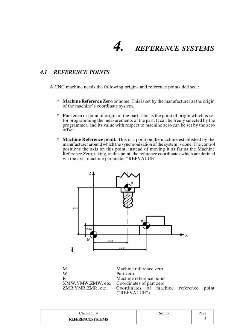
8/21/2019 CNC 8055 M Operator Manual
http://slidepdf.com/reader/full/cnc-8055-m-operator-manual 228/702
PageChapter: 4
REFERENCE SYSTEMS
Section:
1
Z
R
W
MX
ZMR
ZMW
XMW
XMR
4. REFERENCE SYSTEMS
4.1 REFERENCE POINTS
A CNC machine needs the following origins and reference points defined :
* Machine Reference Zero or home. This is set by the manufacturer as the originof the machine’s coordinate system.
* Part zero or point of origin of the part. This is the point of origin which is setfor programming the measurements of the part. It can be freely selected by theprogrammer, and its value with respect to machine zero can be set by the zerooffset.
* Machine Reference point. This is a point on the machine established by themanufacturer around which the synchronization of the system is done. The controlpositions the axis on this point, instead of moving it as far as the MachineReference Zero, taking, at this point, the reference coordinates which are definedvia the axis machine parameter “REFVALUE”.
M Machine reference zeroW Part zeroR Machine reference pointXMW,YMW,ZMW, etc. Coordinates of part zeroZMR,YMR,ZMR, etc. Coordinates of machine reference point
(“REFVALUE”)

8/21/2019 CNC 8055 M Operator Manual
http://slidepdf.com/reader/full/cnc-8055-m-operator-manual 229/702
Section:
REFERENCE SYSTEMSChapter: 4
2Page
4.2 MACHINE REFERENCE SEARCH (G74)
The CNC allows you to program the machine reference search in two ways :
* MACHINE REFERENCE SEARCH OF ONE OR MORE AXES IN APARTICULAR ORDER
G74 is programmed followed by the axes in which you want to carry out thereference search. For example : G74 X Z C Y
The CNC begins the movement of all the selected axes which have a machinereference switch (machine axis parameter “DECINPUT”) and in the directionindicated by the axis machine parameter “REFDIREC”.
This movement is carried out at the feedrate indicated by the axis machineparameter “REFEED1” for each axis until the home switch is hit.
Next, the home search (marker pulse or home) will be carried out in theprogrammed order.
This second movement will be carried out one axis at a time, at the feedrateindicated in the axis machine parameter “REFEED2” until the machine referencepoint is reached (i.e. the marker pulse is found).
* MACHINE REFERENCE SEARCH USING THE ASSOCIATED
SUBROUTINE.The G74 function will be programmed alone in the block, and the CNC willautomatically execute the subroutine whose number appears in the generalmachine parameter “REFPSUB”. In this subroutine it is possible to programthe machine reference searches required, and also in the required order.
In a block in which G74 has been programmed, no other preparatory function mayappear.
If the machine reference search is done in JOG mode, the part zero selected is lost.The coordinates of the reference point indicated in the machine axis parameter“REFVALUE” is displayed. In all other cases, the part zero selected is maintained,so the displayed coordinates refer to this part zero.
If the G74 command is executed in MDI, the display of coordinates depends on themode in which it is executed : Jog, Execution, or Simulation.

8/21/2019 CNC 8055 M Operator Manual
http://slidepdf.com/reader/full/cnc-8055-m-operator-manual 230/702
PageChapter: 4
REFERENCE SYSTEMS
Section:
3
4.3 PROGRAMMING WITH RESPECT TO MACHINE ZERO (G53)
Function G53 can be added to any block which has path control functions.
It is only used when the programming of block coordinates relating to machine zerois required. These coordinates should be expressed in millimeters or inches, dependingon how the general machine parameter “INCHES” is defined.
By programming G53 alone (without motion information) the current active zero offsetis canceled regardless of whether it was originated by a G54-G59 or a G92 preset.This G92 origin preset is described next. Once a Zero Offset has been selected, it willremain active until another one is selected or until a home search is carried out (G74).This Zero Offset will remain active even after powering the CNC off.
Function G53 is not modal, so it should be programmed every time you wish to indicate
the coordinates referred to machine zero.
This function temporarily cancels radius and tool length compensation.
Example:
M Machine Reference Zero (home)
W Part Zero.
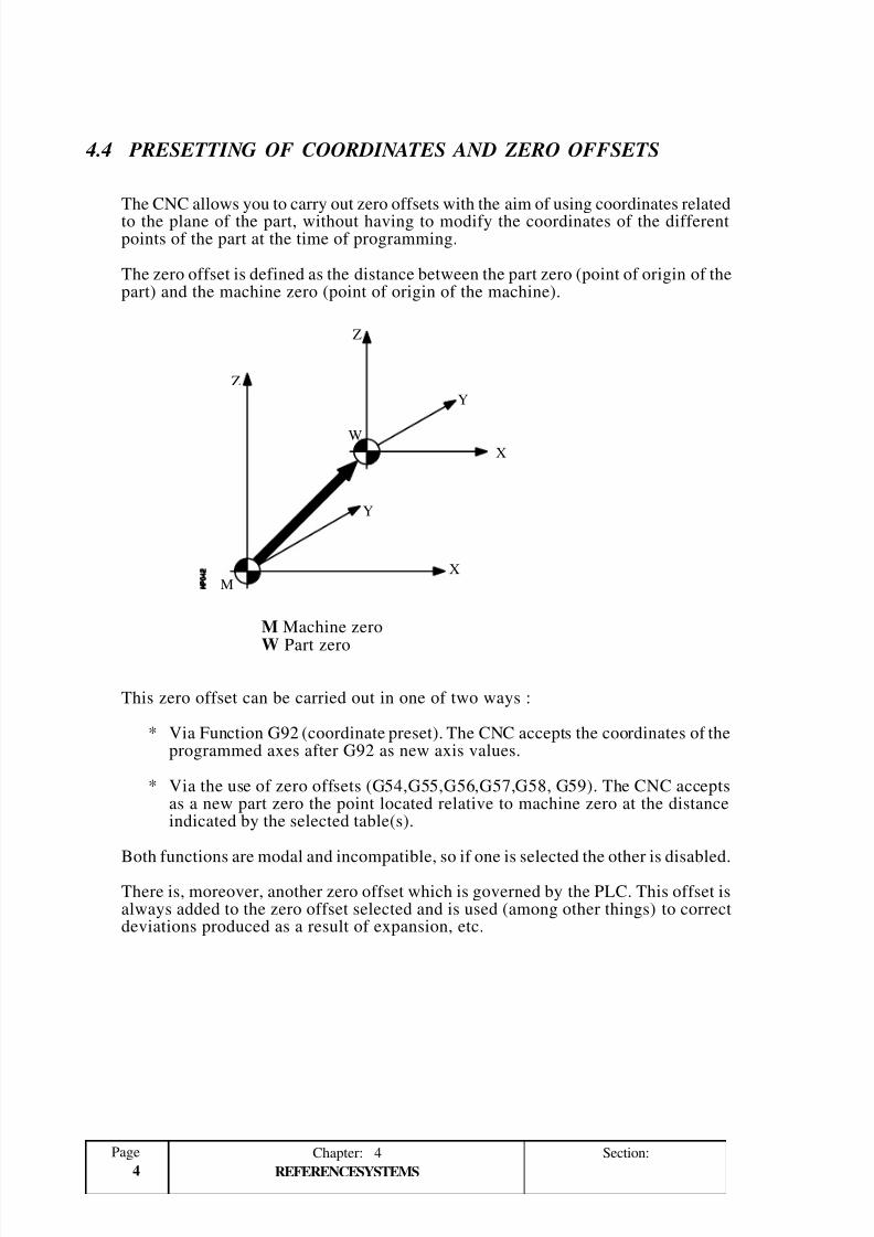
8/21/2019 CNC 8055 M Operator Manual
http://slidepdf.com/reader/full/cnc-8055-m-operator-manual 231/702
Section:
REFERENCE SYSTEMSChapter: 4
4Page
Y
Z
XM
Z
X
Y
W
4.4 PRESETTING OF COORDINATES AND ZERO OFFSETS
The CNC allows you to carry out zero offsets with the aim of using coordinates relatedto the plane of the part, without having to modify the coordinates of the differentpoints of the part at the time of programming.
The zero offset is defined as the distance between the part zero (point of origin of thepart) and the machine zero (point of origin of the machine).
M Machine zero
W Part zero
This zero offset can be carried out in one of two ways :
* Via Function G92 (coordinate preset). The CNC accepts the coordinates of theprogrammed axes after G92 as new axis values.
* Via the use of zero offsets (G54,G55,G56,G57,G58, G59). The CNC acceptsas a new part zero the point located relative to machine zero at the distanceindicated by the selected table(s).
Both functions are modal and incompatible, so if one is selected the other is disabled.
There is, moreover, another zero offset which is governed by the PLC. This offset isalways added to the zero offset selected and is used (among other things) to correctdeviations produced as a result of expansion, etc.
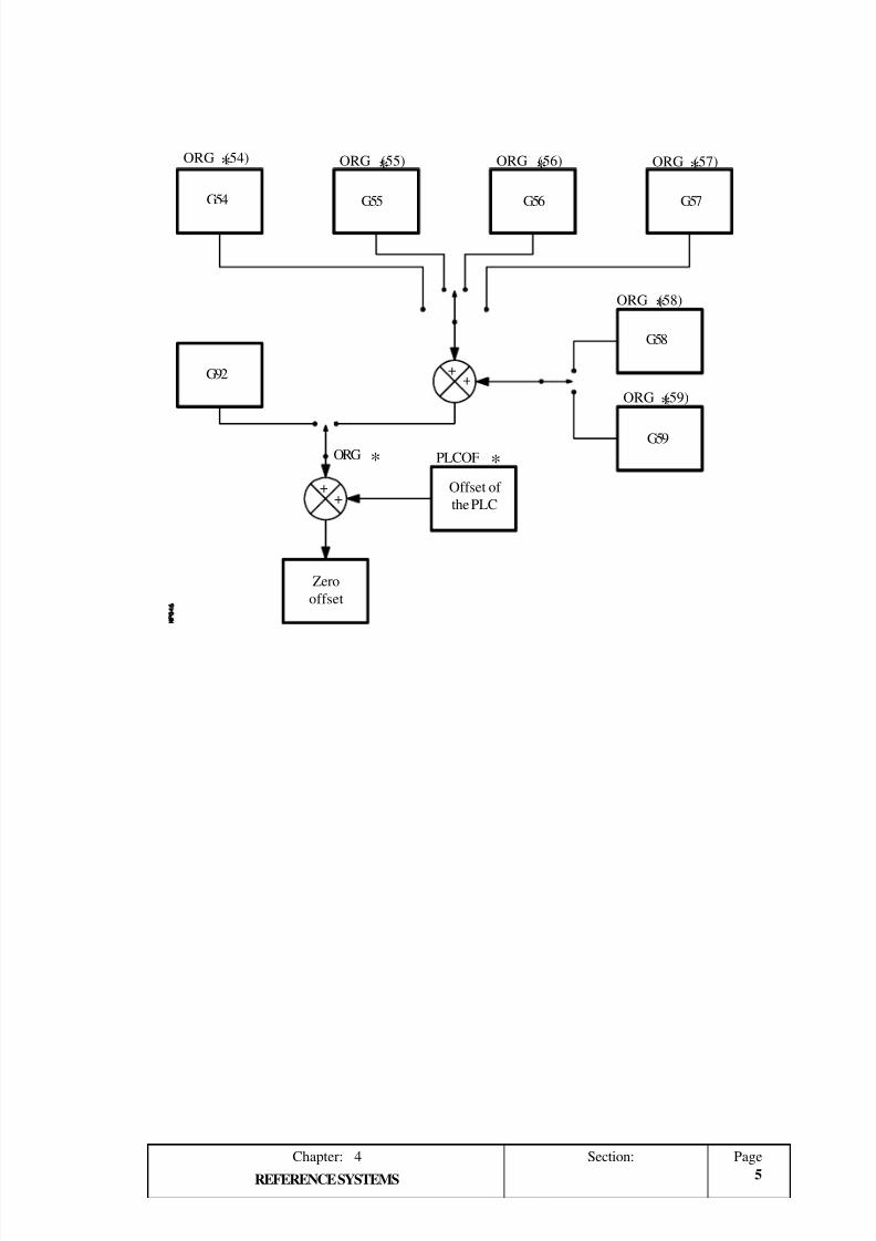
8/21/2019 CNC 8055 M Operator Manual
http://slidepdf.com/reader/full/cnc-8055-m-operator-manual 232/702
PageChapter: 4
REFERENCE SYSTEMS
Section:
5
G54
G58
G59
G92
ORG (54)* ORG (56)ORG (55) ORG (57)*
ORG (58)*
ORG (59)*
ORG * PLCOF
Offset of
the PLC
Zero
offset
++
++
G55 G56 G57
* *
*

8/21/2019 CNC 8055 M Operator Manual
http://slidepdf.com/reader/full/cnc-8055-m-operator-manual 233/702
Section:
REFERENCE SYSTEMSChapter: 4
6Page
4.4.1 COORDINATE PRESET AND LIMITATION OF THE S VALUE(G92)
Via Function G92 one can select any value in the axes of the CNC, in addition tolimiting the spindle speed.
* COORDINATE PRESET
When carrying out a zero offset via Function G92, the CNC assumes thecoordinates of the axes programmed after G92 as new axis values.
No other function can be programmed in the block where G92 is defined, theprogramming format being :
G92X...C +/- 5.5
Example :
G90 X50 Y40 ; Positioning in P0 G92 X0 Y0 ; Preset P0 as part zero G91 X30 ; Programming according to part coordinates
X20 Y20X-20 Y20X-30
Y-40
* LIMITATION OF SPINDLE SPEED
When executing a "G92 S5.4" type block, the CNC limits the spindle speedfrom that instant on to the value set by S5.4.
If later on, a block is to be executed at a greater "S", the CNC will executethat block at the maximum "S" set with function G92S
Neither is it possible to exceed this maximum value from the keyboard onthe front panel.

8/21/2019 CNC 8055 M Operator Manual
http://slidepdf.com/reader/full/cnc-8055-m-operator-manual 234/702
PageChapter: 4
REFERENCE SYSTEMS
Section:
7
4.4.2 ZERO OFFSETS (G54..G59)
The CNC has a table of zero offsets, in which several zero offsets can be selected.The aim is to generate certain part zeros independently of the part zero active at thetime.
Access to the table can be obtained from the front panel of the CNC (as explained inthe Operating Manual), or via the program using high-level language commands.
There are two kinds of zero offsets :
Absolute zero offsets (G54,G55,G56 & G57), which must be referred to machinezero.
Additive zero offsets (G58,G59).
Functions G54, G55, G56, G57, G58 & G59 must be programmed alone in the block,and work in the following way:
When one of the G54, G55, G56, G57 functions is executed, the CNC applies thezero offset programmed with respect to machine zero, cancelling the possible activezero offsets.
If one of the additive offsets G58 or G59 is executed, the CNC adds its values to theabsolute zero offset active at the time. Previously cancelling the additive offset whichmight be active.
You can see (in the following example) the zero offsets which are applied when theprogram is executed.
G54 Applies zero offsets G54 ------------------ > G54G58 Adds zero offsets G58 --------------------- > G54+G58G59 Cancels G58 and adds G59 --------------- > G54+G59G55 Cancels whatever and applies G55 ------ > G55
Once a Zero Offset has been selected, it will remain active until another one is selectedor until a home search is carried out (G74) in JOG mode. This Zero Offset will remainactive even after powering the CNC off.
This kind of zero offsets established by program is very useful for repeated machiningoperations at different machine positions.
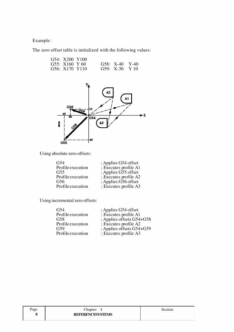
8/21/2019 CNC 8055 M Operator Manual
http://slidepdf.com/reader/full/cnc-8055-m-operator-manual 235/702
Section:
REFERENCE SYSTEMSChapter: 4
8Page
Example :
The zero offset table is initialized with the following values:
G54: X200 Y100G55: X160 Y 60 G58: X-40 Y-40G56: X170 Y110 G59: X-30 Y 10
Using absolute zero offsets:
G54 ; Applies G54 offsetProfile execution ; Executes profile A1
G55 ; Applies G55 offsetProfile execution ; Executes profile A2G56 ; Applies G56 offsetProfile execution ; Executes profile A3
Using incremental zero offsets:
G54 ; Applies G54 offsetProfile execution ; Executes profile A1G58 ; Applies offsets G54+G58Profile execution ; Executes profile A2G59 ; Applies offsets G54+G59
Profile execution ; Executes profile A3

8/21/2019 CNC 8055 M Operator Manual
http://slidepdf.com/reader/full/cnc-8055-m-operator-manual 236/702
PageChapter: 4
REFERENCE SYSTEMS
Section:
9
4.5 POLAR ORIGIN PRESET (G93)
Function G93 allows you to preset any point from the work plane as a new origin
of polar coordinates.
This function must be programmed alone in the block, its format being :
G93 I+/-5.5 J+/-5.5
Parameters I & J respectively define the abscissa and ordinate axes, of the new originof polar coordinates.
Example :
Assuming that the tool is at X0 Y0
G93 I35 J30 ; Preset P3 as polar originG90G01 R25 Q0 ; Point P1, in a straight line (G01)
G03 Q90 ; Point P2, in an arc (G03)G01 X0 Y0 ; Point P0, in a straight line (G01)
If G93 is only programmed in a block, the point where the machine is at that momentbecomes the polar origin.
Warning:
The CNC does not modify the polar origin when defining a new part zero;but it modifies the values of the variables: "PORGF" y "PORGS".
If, while selecting the general machine parameter “PORGMOVE” a circularinterpolation is programmed (G02 or G03), the CNC assumes the centerof the arc as the new polar origin.
On power-up; or after executing M02, M30; or after an EMERGENCYor RESET; the CNC assumes the currently active part zero as polar origin.
When selecting a new work plane (G16, G17, G18, G19), the CNC assumesas polar origin the part zero of that plane.
P2
P1P3
P0
8/21/2019 CNC 8055 M Operator Manual
http://slidepdf.com/reader/full/cnc-8055-m-operator-manual 237/702
PageChapter: 5
PROGRAMMING BY ISO CODE
Section:
1
5. PROGRAMMING BY ISO CODE
A programmed block in ISO language can consist of :
Preparatory functions (G)Axis coordinates (X...C)Feedrate (F)Spindle speed (S)Tool number (T)Tool offset number (D)Auxiliary functions (M)
This order should be maintained within each block, although it is not necessary forevery block to contain the information.
The CNC allows you to program figures from 0.00001 to 99999.9999 with or withoutsign, working in millimeters (G71), called format +/-5.4, or either from 0.00001 to3937.00787 with or without sign if the programming is done in inches (G70), calledformat +/-4.5.
Nevertheless, and in order to simplify explanations, we can say that the CNC admits
Format +/-5.5, meaning that it admits +/-5.4 in millimeters and +/-4.5 in inches.
Any function with parameters can also be programmed in a block, apart from thenumber of the label or block. Thus, when the block is executed the CNC substitutesthe arithmetic parameter for its value at that time.
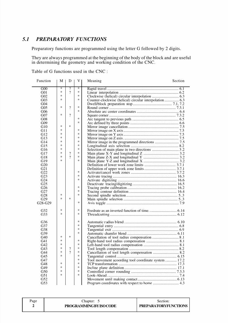
8/21/2019 CNC 8055 M Operator Manual
http://slidepdf.com/reader/full/cnc-8055-m-operator-manual 238/702
Section:
PROGRAMMING BY ISO CODEChapter: 5
2Page
5.1 PREPARATORY FUNCTIONS
Preparatory functions are programmed using the letter G followed by 2 digits.
They are always programmed at the beginning of the body of the block and are usefulin determining the geometry and working condition of the CNC.
Table of G functions used in the CNC :
Function M D V Meaning Section
G00 * ? * Rapid travel ........................................................................... 6.1G01 * ? * Linear interpolation .............................................................. 6.2G02 * * Clockwise (helical) circular interpolation ............................ 6.3G03 * * Counter-clockwise (helical) circular interpolation ............... 6.3G04 Dwell/block preparation stop ......................................... 7.1, 7.2G05 * ? * Round corner ...................................................................... 7.3.1
G06 * Absolute arc center coordinates ............................................ 6.4G07 * ? Square corner ...................................................................... 7.3.2G08 * Arc tangent to previous path . ................................................ 6.5G09 * Arc defined by three points ................................................... 6.6G10 * * Mirror image cancellation ..................................................... 7.5G11 * * Mirror image on X axis .......................................................... 7.5G12 * * Mirror image on Y axis .......................................................... 7.5G13 * * Mirror image on Z axis . ......................................................... 7.5G14 * * Mirror image in the programmed directions ......................... 7.5G15 * * Longitudinal axis selection .................................................. 8.2G16 * * Selection of main plane in two directions ............................ 3 .2G17 * ? * Main plane X-Y and longitudinal Z ..................................... 3.2G18 * ? * Main plane Z-X and longitudinal Y ..................................... 3.2G19 * * Main plane Y-Z and longitudinal X ..................................... 3.2G20 Definition of lower work zone limits ................................. 3.7.1
G21 Definition of upper work zone limits ................................. 3.7.1G22 * Activate/cancel work zones ............................................... 3.7.2G23 * Activate tracing ................................................................... 16.3G24 * Activate digitizing .............................................................. 16.6G25 Deactivate tracing/digitizing .............................................. 16.5G26 * Tracing probe calibration .................................................... 16.2G27 * Tracing contour definition .................................................. 16.4G28 * * Second spindle selection ...................................................... 5..3G29 * * Main spindle selection ......................................................... 5..3
G28-G29 * Axis toggle ............................................................................ 7.9
G32 * * Feedrate as an inverted function of time. ............................ 6.14G33 * * Threadcutting ...................................................................... 6.12
G36 * Automatic r adius b lend ....................................................... 6.10
G37 * Tangential entry .................................................................... 6.8G38 * Tangential exit ...................................................................... 6.9G39 * Automatic chamfer blend .................................................... 6.11G40 * * Cancellation of tool radius compensation ............................ 8 .1G41 * * Right-hand tool radius compensation .................................. 8.1G42 * * Left-hand tool radius compensation ..................................... 8.1G43 * ? * Tool length compensation .................................................... 8.2G44 * ? * Cancellation of tool length compensation ........................... 8.2G45 * * Tangential control ............................................................... 6.15G47 * Tool movement acoording tool coordinate system ............ 17.2G48 * * TCP transformation ............................................................. 17.3G49 * * Incline plane definition ....................................................... 17.1G50 * * Controlled corner rounding ............................................... 7.3.3G51 * * Look-Ahead. .......................................................................... 7.4G52 Movement until making contact ......................................... 6 .13
G53 Program coordinates with respect to home ........................... 4.3
PREPARATORY FUNCTIONS
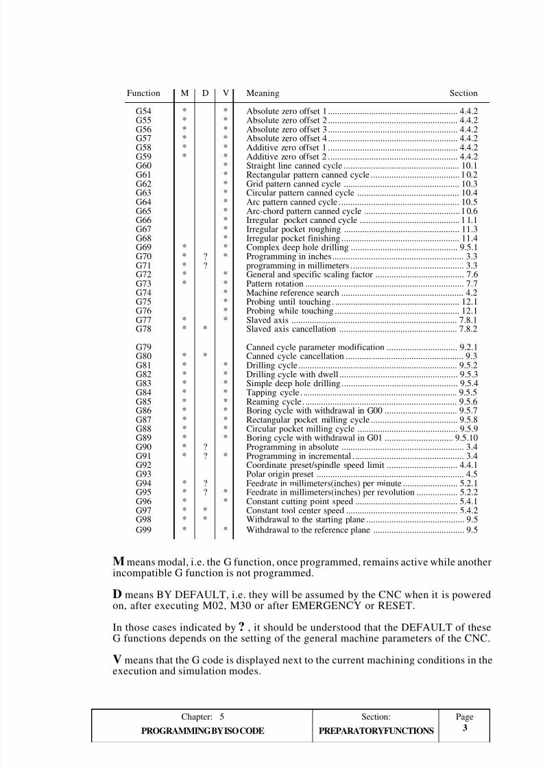
8/21/2019 CNC 8055 M Operator Manual
http://slidepdf.com/reader/full/cnc-8055-m-operator-manual 239/702
PageChapter: 5
PROGRAMMING BY ISO CODE
Section:
3PREPARATORY FUNCTIONS
Function M D V Meaning Section
G54 * * Absolute zero offset 1 ......................................................... 4.4.2G55 * * Absolute zero offset 2 ......................................................... 4.4.2G56 * * Absolute zero offset 3 ......................................................... 4.4.2G57 * * Absolute zero offset 4 ......................................................... 4.4.2G58 * * Additive zero offset 1 ......................................................... 4.4.2G59 * * Additive zero offset 2 ......................................................... 4.4.2G60 * Straight line canned cycle ................................................... 10.1G61 * Rectangular pattern canned cycle ....................................... 1 0.2G62 * Grid pattern canned cycle ................................................... 10.3G63 * Circular pattern canned cycle ............................................. 10.4G64 * Arc pattern canned cycle ..................................................... 10.5G65 * Arc-chord pattern canned cycle .......................................... 1 0.6G66 * Irregular pocket canned cycle ............................................ 1 1.1G67 * Irregular pocket roughing ................................................... 11.3G68 * Irregular pocket finishing .................................................... 11.4G69 * * Complex deep hole drilling ............................................... 9.5.1G70 * ? * Programming in inches .......................................................... 3.3
G71 * ? programming in millimeters .................................................. 3.3G72 * * General and specific scaling factor ....................................... 7.6G73 * * Pattern rotation ...................................................................... 7.7G74 * Machine reference search ...................................................... 4.2G75 * Probing until touching . ....................................................... 12.1G76 * Probing while touching ....................................................... 12.1G77 * * Slaved axis ......................................................................... 7.8.1G78 * * Slaved axis cancellation .................................................... 7.8.2
G79 Canned cycle parameter modification ............................... 9.2.1G80 * * Canned cycle cancellation .................................................... 9.3G81 * * Drilling cycle ...................................................................... 9.5.2G82 * * Drilling cycle with dwell .................................................... 9.5.3G83 * * Simple deep hole drilling ................................................... 9.5.4G84 * * Tapping cycle . .................................................................... 9.5.5
G85 * * Reaming cycle . ................................................................... 9.5.6G86 * * Boring cycle with withdrawal in G00 ................................ 9.5.7G87 * * Rectangular pocket milling cycle ...................................... 9.5.8G88 * * Circular pocket milling cycle ............................................ 9.5.9G89 * * Boring cycle with withdrawal in G01 .............................. 9.5.10G90 * ? Programming in absolute ...................................................... 3.4G91 * ? * Programming in incremental . ................................................ 3.4G92 Coordinate preset/spindle speed limit ............................... 4.4.1G93 Polar origin preset ................................................................. 4.5G94 * ? Feedrate in millimeters(inches) per minute ........................ 5.2.1G95 * ? * Feedrate in millimeters(inches) per revolution .................. 5.2.2G96 * * Constant cutting point speed ............................................. 5.4.1G97 * * Constant tool center speed ................................................. 5.4.2G98 * * Withdrawal to the starting plane ........................................... 9.5G99 * * Withdrawal to the reference plane ........................................ 9.5
M means modal, i.e. the G function, once programmed, remains active while anotherincompatible G function is not programmed.
D means BY DEFAULT, i.e. they will be assumed by the CNC when it is poweredon, after executing M02, M30 or after EMERGENCY or RESET.
In those cases indicated by ? , it should be understood that the DEFAULT of theseG functions depends on the setting of the general machine parameters of the CNC.
V means that the G code is displayed next to the current machining conditions in the
execution and simulation modes.

8/21/2019 CNC 8055 M Operator Manual
http://slidepdf.com/reader/full/cnc-8055-m-operator-manual 240/702
Section:
PROGRAMMING BY ISO CODEChapter: 5
4Page
F x
( x)2 + ( y)2 + ( c)2 1002 + 202 + 2702
10000 x 100
F y
( x)2 + ( y)2 + ( c)2
10000 x 20
F c
( x)2 + ( y)2 + ( c)2 1002 + 202 + 2702
10000 x 270
1002 + 202 + 2702
FEEDRATE FUNCTIONS(G94,G95)
5.2 FEEDRATE FUNCTIONS (G94,G95)
The CNC allows programming the feedrate of the axes in mm/minute and mm/revolutionwhen working in millimeters, or in inches/minute and inches/revolution when workingin inches.
5.2.1 FEEDRATE IN MM/MIN OR INCHES/MIN (G94)
From the moment the code G94 is programmed, the control takes that the feedratesprogrammed through F5.5 are in mm/min or inches/mm.
If the movement corresponds to a rotary axis, the CNC interprets the feedrate as beingprogrammed in degrees/min.
If an interpolation is made between a rotary and a linear axis, the programmed feedrateis taken in mm/min or inches/min, and the movement of the rotary axis (programmedin degrees) will be considered programmed in millimeters or inches.
The relationship between the feedrate of the axis component and the programmedfeedrate “F” is the same as that between the movement of the axis and the resultingprogrammed movement.
Feedrate F x Movement of axisFeedrate component =
Resulting programmed movement
Example :
On a machine which has linear X and Y axes and rotary C axis, all located atpoint X0 Y0 C0, the following movement is programmed :
G1 G90 X100 Y20 C270 F10000
You get:
Function G94 is modal i.e. once programmed it stays active until G95 is programmed.
On power-up, after executing M02, M30 or following EMERGENCY or RESET, theCNC assumes function G94 or G95 according to how the general machine parameter
“IFEED” is set.
= 3464.7946
= 692.9589
= 9354.9455

8/21/2019 CNC 8055 M Operator Manual
http://slidepdf.com/reader/full/cnc-8055-m-operator-manual 241/702
PageChapter: 5
PROGRAMMING BY ISO CODE
Section:
5FEEDRATE FUNCTIONS(G94,G95)
5.2.2 FEEDRATE IN MM/REV.OR INCHES/REV (G95)
From the moment when the code G95 is programmed, the control assumes that thefeedrates programmed through F5.5 are in mm/rev or inches/mm.
This function does not affect the rapid moves (G00) which will be made in mm/min or inch/ min. By the same token, it will not be applied to moves made in the JOG mode, during toolinspection, etc.
Function G95 is modal i.e. once programmed it stays active until G94 is programmed.
On power-up, after executing M02, M30 or following EMERGENCY or RESET, theCNC assumes function G94 or G95 according to the general machine parameter“IFEED”.
8/21/2019 CNC 8055 M Operator Manual
http://slidepdf.com/reader/full/cnc-8055-m-operator-manual 242/702
Section:
PROGRAMMING BY ISO CODEChapter: 5
6Page
5.3 SPINDLE SELECTION (G28, G29)
This CNC can govern two spindles: the main one and the second one. Both can be runningat the same time but it can only control one at the time.
This selection is done by functions: G28 and G29.
G28: Selects the Second SpindleG29: Selects the Main Spindle.
Once the desired spindle has been selected, it can be acted upon from the keyboard or bymeans of the following functions:
M3, M4, M5, M19S****G33, G94, G95, G96, G97
Both spindles can work in open and closed loop.
Functions G28 and G29 are modal and incompatible with each other.
Function G28 and G29 must be programmed alone in the block. No more information canbe programmed in that block.
On power-up, after executing and M02, M30 or after an EMERGENCY or RESET, theCNC assumes function G29 (selects the main spindle).
Operating example for when 2 spindles are used:On power-up, the CNC assumes function G29 selecting the main spindle.
All the actions upon the keys or functions associated with the spindle will be appliedon to the main spindle.Example: S1000 M3 Main spindle clockwise at 1000 rpm
To select the second spindle, execute function G28.From this moment on, all the actions upon the keys or functions associated with thespindle will be applied on to the second spindle.The main spindle keeps turning (in its previous status).Example: S1500 M4 Second spindle counter-clockwise at 1500 rpm.
The main spindle keeps turning clockwise at 1000 rpm
To select the main spindle again, execute function G29.
From this moment on, all the actions upon the keys or functions associated with thespindle will be applied on to the main spindle.The second spindle keeps turning (in its previous status).Example: S2000 The main spindle keeps turning clockwise but now at 2000 rpm.
The second spindle keeps turning counter-clockwise at 1500rpm.
SPINDLE SELECTION(G28, G29)
8/21/2019 CNC 8055 M Operator Manual
http://slidepdf.com/reader/full/cnc-8055-m-operator-manual 243/702
PageChapter: 5
PROGRAMMING BY ISO CODE
Section:
7
5.4 CONSTANT SPEED FUNCTIONS (G96,G97)
The CNC, through functions G96 and G97, allows you to maintain constant speed attool center, or maintain constant speed of the cutting point of the tool.
5.4.1 CONSTANT SURFACE SPEED (G96)
When G96 is programmed the CNC takes the F5.5 feedrate as corresponding to thecutting point of the tool on the part.
By using this function, the finished surface is uniform in curved sections.
In this manner (working in function G96) the speed of the center of the tool in theinside or outside curved sections will change in order to keep the cutting point constant.
Function G96 is modal i.e. once programmed, it is active until G97 is programmed.
On power-up, after executing M02, M30 or following EMERGENCY or RESET, theCNC assumes function G97.
5.4.2 CONSTANT TOOL-CENTER SPEED (G97)
When G97 is programmed the CNC takes the programmed F5.5 feedrate ascorresponding to the feedrate of the center of the tool.
In this manner (working in function G97) the speed of the cutting point on the insideor outside curved sections is reduced, keeping the speed of the center of the tool constant.
Function G97 is modal i.e. once programmed it is active until G96 is programmed.
On power-up, after executing M02, M30 or following EMERGENCY or RESET, theCNC assumes function G97.
SPEED FUNCTIONS (G96,G97)

8/21/2019 CNC 8055 M Operator Manual
http://slidepdf.com/reader/full/cnc-8055-m-operator-manual 244/702
Section:
PROGRAMMING BY ISO CODEChapter: 5
8Page
5.5 COMPLEMENTARY FUNCTIONS
The CNC is equipped with the following complementary functions :
Feedrate FSpindle speed STool number TTool offset number DMiscellaneous function M
This order should be maintained in each block, although it is not necessary for eachblock to hold all the information.
5.5.1 FEEDRATE F
The machining feedrate can be selected from the program. It remains active until anotherfeedrate is programmed.
It is represented by the letter F. Depending on whether it is working in G94 or G95,it is programmed in mm/minute (inches/minute) or in mm/revolution (inches/revolution).
It’s programming format is 5.5 in mm. and 4.5 in inches.
The maximum operating feedrate of the machine, limited on each axis by the axis
machine parameter “MAXFEED”, may be programmed via code F0, or by giving Fthe corresponding value.
The programmed feedrate F is effective working in linear (G01) or circular (G02,G03) interpolation. If function F is not programmed, the CNC assumes the feedrateto be F0. When working in rapid travel (G00), the machine will move at the rapidfeedrate indicated by the axis machine parameter “G00FEED”, apart from the Fprogrammed.
The programmed feedrate F may be varied between 0% and 255% via the PLC, orby DNC, or between 0% and 120% via the switch located on the Operator Panel of the CNC.
The CNC, however, is equipped with the general machine parameter “MAXFOVR”to limit maximum feedrate variation.
If you are working in rapid travel (G00), rapid feedrate will be fixed at 100%, alternativelyit can be varied between 0% and 100%, depending on how the machine parameter“RAPIDOVR” is set.
When functions G33 (electronic threading) or G84 (tapping canned cycle) are executedthe feedrate cannot be modified. It functions at 100% of programmed F.
COMPLEMENTARYFUNCTIONS F,S,T,D,M
8/21/2019 CNC 8055 M Operator Manual
http://slidepdf.com/reader/full/cnc-8055-m-operator-manual 245/702
PageChapter: 5
PROGRAMMING BY ISO CODE
Section:
9
5.5.2 SPINDLE SPEED AND SPINDLE ORIENTATION (S)
Code S has two meanings :
a) TURNING SPEED OF THE SPINDLE
The turning speed of the spindle is programmed directly in rpm via code S5.4.
The maximum value is limited by spindle machine parameters “MAXGEAR1”,MAXGEAR2, MAXGEAR 3 and MAXGEAR4", in each case depending on thespindle range selected.
It is also possible to limit this maximum value from the program by using functionG92 S5.4.
The programmed turning speed S may be varied from the PLC, DNC, or by theSPINDLE keys “+” and “-” on the Operator Panel of the CNC.
This speed variation is made between the maximum and minimum values establishedby spindle machine parameters “MINSOVR and MAXSOVR”.
The incremental pitch associated with the SPINDLE keys “+” and “-” on the CNCOperator Panel in order to vary the programmed S value is fixed by the spindlemachine parameter “SOVRSTEP”.
When functions G33 (threading) or G84 (tapping cycle) are executed the speedcannot be modified. It functions at 100% of programmed S.
b) SPINDLE ORIENTATION
If S±5.5 is programmed after M19, code S±5.5 indicates the spindle orientationposition in degrees starting from the machine reference pulse from the encoder.
To carry out this function you need a rotary encoder coupled to the machine spindle.
If you do not have a reference switch, the spindle moves at the turning speedindicated by the spindle machine parameter “REFEED1” until the spindle is locatedat the point defined via S±5.5.
If you have a ref. switch, the spindle moves at the turning speed indicated by
spindle machine parameter “REFEED1” until it reaches the switch, and then at theone indicated by spindle machine parameters “REFEED2” until the spindle is atthe point defined via S±5.5.
The “REFEED1” movement until the reference switch is reached is always doneprovided M19 is programmed after the spindle has operated in open loop (M3,M4, M5). This movement is not made between consecutive M19s.
COMPLEMENTARYFUNCTIONS F,S,T,D,M

8/21/2019 CNC 8055 M Operator Manual
http://slidepdf.com/reader/full/cnc-8055-m-operator-manual 246/702
Section:
PROGRAMMING BY ISO CODEChapter: 5
10Page
5.5.3 TOOL NUMBER (T)
The CNC enables you to select the tool or tools required for each machining operationvia function T4.
There is a tool magazine table whose number of components is established by“NPOCKET” (general machine parameter), specifying the following for eachcomponent:
* The contents of the box, indicating tool number or if the box is empty or cancelled.
* The size of the tool. N if it is a normal tool and S if it is special.
* The status of the tool. A if it is available, E if it is worn out (life expired) andR if it has been rejected.
It also has a tool table. The number of components in this table is establishedby “NTOOL” (general machine parameter), specifying the following for eachcomponent:
* The offset associated with each tool:
family code 0<n<200 —> normal toolfamily code 200<n<255—> special tool
* Nominal tool life calculated for this tool, defined in terms of machining minutesor depending on the number of operations to be carried out. This is selected by
the general machine parameter “TOOLMONI”.* Real working life of the tool, defined in machining minutes or depending on
the number of operations carried out. This is selected by the general machineparameter “TOOLMONI”.
* The size of the tool. N if it is a normal tool and S if it is special.
* The status of the tool. A if it is available, E if it is worn out (life expired) andR if it has been rejected by the PLC.
COMPLEMENTARYFUNCTIONS F,S,T,D,M

8/21/2019 CNC 8055 M Operator Manual
http://slidepdf.com/reader/full/cnc-8055-m-operator-manual 247/702
PageChapter: 5
PROGRAMMING BY ISO CODE
Section:
11
5.5.4 TOOL OFFSET NUMBER (D)
By using function D4, the CNC enables the application of the required offset to theselected tool. To do this you have to program T4 D4, selecting the required tool andtool offset. If you only program function T4, the CNC will take the tool offset indicatedby the selected tool in the tool table.
The CNC has a tool offset table with “NTOFFSET” (general machine parameter)components. The following is specified for each tool offset:
* The nominal radius of the tool in the measuring units indicated by the generalparameter “INCHES”, the format being R±5.5.
* The nominal length of the tool in the measuring units indicated by the generalparameter “INCHES”, the format being L±5.5.
* Tool radius wear in the measuring units indicated by the general parameter“INCHES”, the format being I±5.5. The CNC adds this value to the nominalradius (R) to calculate the real radius (R+I).
* Tool length wear in the measuring units indicated by the general parameter“INCHES”, the format being K±5.5. The CNC adds this value to the nominallength (L) to calculate the real length (L+K).
When tool radius compensation is required (G41 or G42) the CNC applies as acompensation value the sum of the R+I values of the selected tool offset.
When compensation of tool length is required (G43) the CNC applies as a compensationvalue the sum of the L+K values of the selected tool offset.
If no tool offset has been defined, the CNC applies tool offset D0, with R=0, L=0,I=0 and K=0.
COMPLEMENTARYFUNCTIONS F,S,T,D,M

8/21/2019 CNC 8055 M Operator Manual
http://slidepdf.com/reader/full/cnc-8055-m-operator-manual 248/702
Section:
PROGRAMMING BY ISO CODEChapter: 5
12Page
5.5.5 MISCELLANEOUS FUNCTION (M)
The miscellaneous functions are programmed by means of the M4 Code, it beingpossible to program up to 7 functions in the same block.
When more than one function has been programmed in one block, the CNC executesthese correlatively to the order in which they have been programmed.
The CNC is provided with an M functions table with “NMISCFUN” (general machineparameter) components, specifying for each element:
* The number (0-9999) of the defined miscellaneous M function.
* The number of the subroutine which is required to associate to this miscellaneousfunction.
* An indicator which determines if the M function is executed before or after themovement block in which it is programmed.
* An indicator which determines if the execution of the M function interruptsblock preparation or not.
* An indicator which determines if the M function is executed or not, after theexecution of the associated subroutine.
* An indicator which determines if the CNC must wait for the signal AUX ENDor not (Executed M signal, coming from the PLC), to continue the execution
of the program.If, when executing the M miscellaneous function, this is not defined in the M functionstable, the programmed function will be executed at the beginning of the block and theCNC will wait for the AUX END to continue the execution of the program.
Some of the miscellaneous functions are assigned an internal meaning in the CNC.
If, while executing the associated subroutine of an “M” miscellaneous function, thereis a block containing the same “M”, this will be executed but not the associatedsubroutine.
Warning:
All the miscellaneous “M” functions which have an associated subroutinemust be programmed alone in a block.
COMPLEMENTARYFUNCTIONS F,S,T,D,M
8/21/2019 CNC 8055 M Operator Manual
http://slidepdf.com/reader/full/cnc-8055-m-operator-manual 249/702
PageChapter: 5
PROGRAMMING BY ISO CODE
Section:
13
5.5.5.1 M00. PROGRAM STOP
When the CNC reads code M00 in a block, it interrupts the program. To start upagain, press CYCLE START.
We recommend that you set this function in the table of M functions, in such a waythat it is executed at the end of the block in which it is programmed.
5.5.5.2 M01. CONDITIONAL PROGRAM STOP
This is identical to M00, except that the CNC only takes notice of it if the signal M01STOP from the PLC is active (high logic level).
5.5.5.3 M02. END OF PROGRAM
This code indicates the end of program and carries out a “General Reset” function of the CNC (returning it to original state). It also carries out the M05 function.
It is recommended to set this function in the table of M functions, in such a way thatit is executed at the end of the block in which it is programmed.
5.5.5.4 M30. END OF PROGRAM WITH RETURN TO FIRST BLOCK
Identical to M02 except that the CNC returns to the first block of the program.
5.5.5.5 M03. CLOCKWISE SPINDLE ROTATION
This code represents clockwise spindle start. As explained in the corresponding section,the CNC automatically executes this code in the machining canned cycles.
It is recommended to set this function in the table of M functions, so that it is executedat the beginning of the block in which it is programmed.
5.5.5.6 M04. COUNTER-CLOCKWISE SPINDLE ROTATION
This code represents counter-clockwise spindle start. We recommend that you set this
function in the table of M functions, so that it is executed at the beginning of the block in which it is programmed.
5.5.5.7 M05. SPINDLE STOP
It is recommended to set this function in the table of M functions, so that it is executedat the end of the block in which it is programmed.
COMPLEMENTARYFUNCTIONS F,S,T,D,M

8/21/2019 CNC 8055 M Operator Manual
http://slidepdf.com/reader/full/cnc-8055-m-operator-manual 250/702
Section:
PROGRAMMING BY ISO CODEChapter: 5
14Page
5.5.5.8 M06. TOOL CHANGE
If the general machine parameter “TOFFM06” (indicating that it is a machining center)is active, the CNC sends instructions to the tool changer and updates the tablecorresponding to the tool magazine.
It is recommended to set this function in the table of M functions, so that the subroutinecorresponding to the tool changer installed in the machine is executed.
5.5.5.9 M19. SPINDLE ORIENTATION
With this CNC it is possible to work with the spindle in open loop (M3, M4) and withthe spindle in closed loop (M19).
In order to work in closed loop, it is necessary to have a rotary encoder installed on
the spindle of the machine.
To switch from open loop to closed loop, execute function M19 or M19 S±5.5. TheCNC will act as follows:
* If the spindle does not have a home switch, the CNC changes the spindle speeduntil it reaches the one set by spindle machine parameter "REFEED2; finds themarker pulse (home) and, then, orients the spindle to the position defined by S±5.5.
* If the spindle has a home switch, the CNC modifies the spindle speed until itreaches the one set by spindle machine parameter "REFEED1". Then, it carriesout the search for the home switch at this speed. Next, it looks for the marker pulse
(home) at the speed set by spindle machine parameter "REFEED2" and, finally,it orients the spindle to the position defined by S±5.5.
If only M19 is executed, the spindle is oriented to position "S0" after having "found"the home switch.
To, now, orient the spindle to another position, program M19 S±5.5, the CNC willnot perform the home search since it is already in closed loop and it will orient thespindle to the indicated position. (S±5.5).
The S±5.5 code indicates the spindle orient position, in degrees, from the encoder'smarker pulse position (S0).
The sign indicates the counting direction and the 5.5 value is always considered to beabsolute coordinates regardless of the type of units currently selected.
Example:
S1000 M3 Spindle in open loopM19 S100 The spindle switches to closed loop. Home search and positioning
(orientation) at 100ºM19 S-30 The spindle orients to -30º, passing through 0º.M19 S400 The spindle turns a whole revolution and positions at 40º.
COMPLEMENTARYFUNCTIONS F,S,T,D,M

8/21/2019 CNC 8055 M Operator Manual
http://slidepdf.com/reader/full/cnc-8055-m-operator-manual 251/702
PageChapter: 5
PROGRAMMING BY ISO CODE
Section:
15
5.5.5.10 M41, M42, M43, M44. SPINDLE SPEED RANGE CHANGE
The CNC offers 4 spindle speed ranges M41, M42, M43 and M44 with maximumspeed limits set by the spindle machine parameters “MAXGEAR1”, MAXGEAR2",“MAXGEAR3” and “MAXGEAR4”.
If machine parameter “AUTOGEAR” is set so the CNC executes the range changeautomatically, M41 thru M44 will be sent out automatically by the CNC without havingto be programmed.
If this machine parameter is set for non-automatic gear change, M41 thru M44 willhave to be programmed every time a gear change is required. Bear in mind that themaximum voltage value assigned to machine parameter “MAXVOLT” correspondsto the maximum speed indicated for each one of the speed ranges (machine parameters“MAXGEAR1” thru “MAXGEAR4”).
5.5.5.11 M45 AUXILIARY SPINDLE / LIVE TOOL
In order to use this miscellaneous function, it is necessary to set one of the axes of themachine as auxiliary spindle or live tool (general machine parameter P0 thru P7).
To use the auxiliary spindle or live tool, execute the command: M45 S±5.5 where Sindicates the turning speed in rpm and the sign indicates the turning direction.
The CNC will output the analog voltage corresponding to the selected speed accordingto the value assigned to the machine parameter "MAXSPEED" for the auxiliary spindle.
To stop the auxiliary spindle, program M45 or M45 S0.
Whenever the auxiliary spindle or live tool is active, the CNC will let the PLC knowby activating the general logic output "DM45" (M5548).
Also, it is possible to set the machine parameter for the auxiliary spindle "SPDLOVR"so the Override keys of the front panel can modify the currently active turning speedof the auxiliary spindle.
COMPLEMENTARYFUNCTIONS F,S,T,D,M

8/21/2019 CNC 8055 M Operator Manual
http://slidepdf.com/reader/full/cnc-8055-m-operator-manual 252/702
PageChapter: 6
PATH CONTROL
Section:
1RAPID TRAVEL (G00)
Y
X
6. PATH CONTROL
The CNC allows you to program movements on one axis only or several at the same time.
Only those axes which intervene in the required movement are programmed. Theprogramming order of the axes is as follows :
X, Y, Z, U, V, W, A, B, C
6.1 RAPID TRAVEL (G00)
The movements programmed after G00 are executed at the rapid feedrate indicated in theaxis machine parameter “G00FEED”.
Independently of the number of axis which move, the resulting path is always a straight linebetween the starting point and the final point.
Example:
X100 Y100 ; Starting point
G00 G90 X400 Y300 ; Programmed path
It is possible, via the general machine parameter “RAPIDOVR”, to establish if the feedrateoverride % switch (when working in G00) operates from 0% to 100%, or whether it staysconstant at 100%.
When G00 is programmed, the last “F” programmed is not cancelled i.e. when G01, G02or G03 are programmed again “F” is recovered.
G00 is modal and incompatible with G01, G02, G03, G33 and G75. Function G00 can beprogrammed as G or G0.
On power-up, after executing M02, M30 or after EMERGENCY or RESET, the CNC
assumes code G00 or G01, depending on how general machine parameter “IMOVE” hasbeen set.
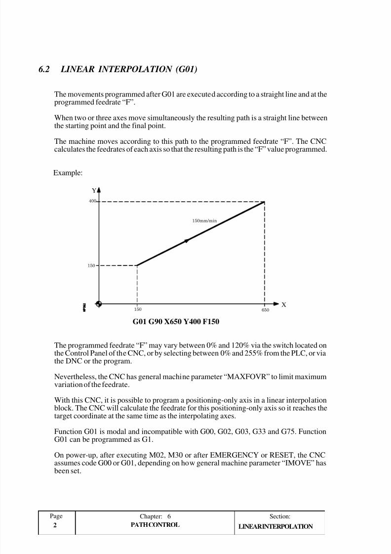
8/21/2019 CNC 8055 M Operator Manual
http://slidepdf.com/reader/full/cnc-8055-m-operator-manual 253/702
Section:
PATH CONTROLChapter: 6
2
Page
LINEAR INTERPOLATION
X
Y
6.2 LINEAR INTERPOLATION (G01)
The movements programmed after G01 are executed according to a straight line and at theprogrammed feedrate “F”.
When two or three axes move simultaneously the resulting path is a straight line betweenthe starting point and the final point.
The machine moves according to this path to the programmed feedrate “F”. The CNCcalculates the feedrates of each axis so that the resulting path is the “F” value programmed.
Example:
G01 G90 X650 Y400 F150
The programmed feedrate “F” may vary between 0% and 120% via the switch located onthe Control Panel of the CNC, or by selecting between 0% and 255% from the PLC, or viathe DNC or the program.
Nevertheless, the CNC has general machine parameter “MAXFOVR” to limit maximum
variation of the feedrate.With this CNC, it is possible to program a positioning-only axis in a linear interpolationblock. The CNC will calculate the feedrate for this positioning-only axis so it reaches thetarget coordinate at the same time as the interpolating axes.
Function G01 is modal and incompatible with G00, G02, G03, G33 and G75. FunctionG01 can be programmed as G1.
On power-up, after executing M02, M30 or after EMERGENCY or RESET, the CNCassumes code G00 or G01, depending on how general machine parameter “IMOVE” hasbeen set.
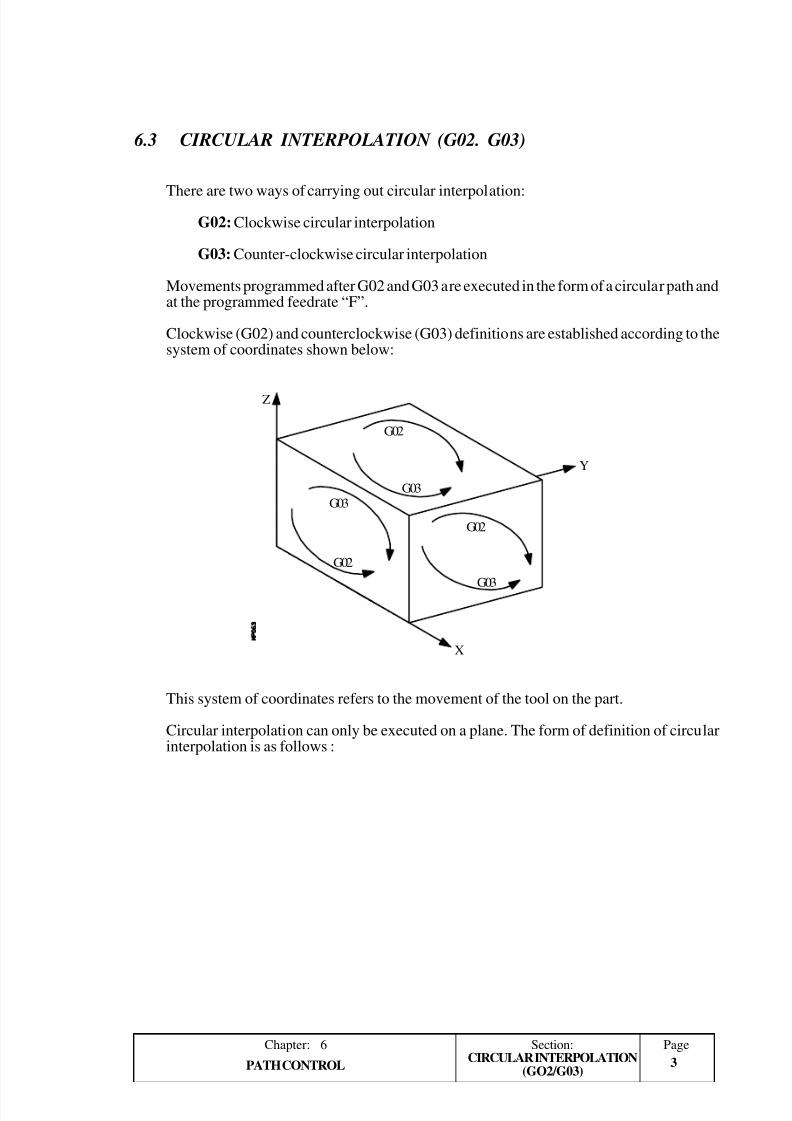
8/21/2019 CNC 8055 M Operator Manual
http://slidepdf.com/reader/full/cnc-8055-m-operator-manual 254/702
PageChapter: 6
PATH CONTROL
Section:
3CIRCULAR INTERPOLATION(GO2/G03)
Z
Y
X
G02
G03
G02
G02
G03
G03
6.3 CIRCULAR INTERPOLATION (G02. G03)
There are two ways of carrying out circular interpolation:
G02: Clockwise circular interpolation
G03: Counter-clockwise circular interpolation
Movements programmed after G02 and G03 are executed in the form of a circular path andat the programmed feedrate “F”.
Clockwise (G02) and counterclockwise (G03) definitions are established according to thesystem of coordinates shown below:
This system of coordinates refers to the movement of the tool on the part.
Circular interpolation can only be executed on a plane. The form of definition of circularinterpolation is as follows :

8/21/2019 CNC 8055 M Operator Manual
http://slidepdf.com/reader/full/cnc-8055-m-operator-manual 255/702
Section:
PATH CONTROLChapter: 6
4
PageCIRCULAR INTERPOLATION
(G02/G03)
a) CARTESIAN COORDINATES
The coordinates of the endpoint of the arc and the position of the center with respect tothe starting point are defined according to the axes of the work plane.
The center coordinates (which should always be programmed even if they have “0”value) are defined by the letters I, J, or K, each one of these being associated to the axesas follows:
Axes X,U,A --> IAxes Y,V,B —>JAxes Z,W,C —>K
Programming format:
Plane XY: G02(G03) X±5.5 Y±5.5 I±5.5 J±5.5
Plane ZX: G02(G03) X±5.5 Z±5.5 I±5.5 K±5.5Plane YZ: G02(G03) Y±5.5 Z±5.5 J±5.5 K±5.5
The programming order of the axes is always maintained regardless of the planeselected,, as are the respective center coordinates.
Plane AY: G02(G03) Y±5.5 A±5.5 J±5.5 I±5.5Plane XU: G02(G03) X±5.5 U±5.5 I±5.5 I±5.5
b) POLAR COORDINATES
It is necessary to define the angle to be travelled Q and the distance from the startingpoint to the center (optional), according to the axes of the work plane.
The center coordinates are defined by the letters I, J, or K, each one of these beingassociated to the axes as follows:
Axes X,U,A —>IAxes Y,V,B —>JAxes Z,W,C —> K
If the center of the arc is not defined, the CNC will assume it that this coincideswith the current polar origin.
Programming format:
Plane XY: G02(G03) Q±5.5 I±5.5 J±5.5Plane ZX: G02(G03) Q±5.5 I±5.5 K±5.5Plane YZ: G02(G03) Q±5.5 J±5.5 K±5.5

8/21/2019 CNC 8055 M Operator Manual
http://slidepdf.com/reader/full/cnc-8055-m-operator-manual 256/702
PageChapter: 6
PATH CONTROL
Section:
5CIRCULAR INTERPOLATION (G02/G03)
Y
X
P1 (XY)
P0
1
2
3
4
c) CARTESIAN COORDINATES WITH RADIUS PROGRAMMING
The coordinates of the endpoint of the arc and radius R are defined.
Programming format:
Plane XY: G02(G03) X±5.5 Y±5.5 R±5.5Plane ZX: G02(G03) X±5.5 Z±5.5 R±5.5Plane YZ: G02(G03) Y±5.5 Y±5.5 R±5.5
If a complete circle is programmed, with radius programming, the CNC will showthe corresponding error, as infinite solutions exist.
If an arc is less than 180o, the radius is programmed with a plus sign, and a minussign if it is more than 180o.
If P0 is the starting point and P1 the endpoint, there are 4 arcs which have thesame value passing through both points.
Depending on the circular interpolation G02 or G03, and on the radius sign, therelevant arc is defined. Thus the programming format of the sample arcs is asfollows:
Arc 1 G02 X.. Y.. R -..Arc 2 G02 X.. Y.. R +..Arc 3 G03 X.. Y.. R +..Arc 4 G03 X.. Y.. R -..
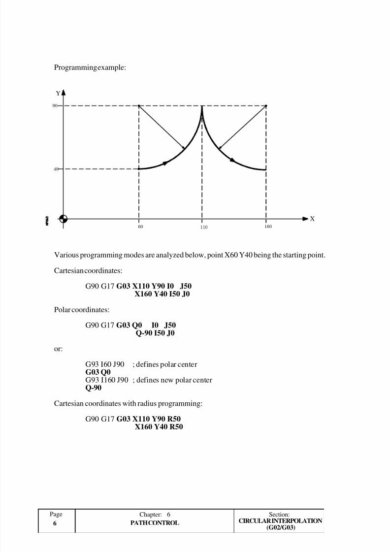
8/21/2019 CNC 8055 M Operator Manual
http://slidepdf.com/reader/full/cnc-8055-m-operator-manual 257/702
Section:
PATH CONTROLChapter: 6
6
PageCIRCULAR INTERPOLATION
(G02/G03)
Y
X
Programming example:
Various programming modes are analyzed below, point X60 Y40 being the starting point.
Cartesian coordinates:
G90 G17 G03 X110 Y90 I0 J50 X160 Y40 I50 J0
Polar coordinates:
G90 G17 G03 Q0 I0 J50 Q-90 I50 J0
or:
G93 I60 J90 ; defines polar centerG03 Q0G93 I160 J90 ; defines new polar center
Q-90
Cartesian coordinates with radius programming:
G90 G17 G03 X110 Y90 R50 X160 Y40 R50

8/21/2019 CNC 8055 M Operator Manual
http://slidepdf.com/reader/full/cnc-8055-m-operator-manual 258/702
PageChapter: 6
PATH CONTROL
Section:
7CIRCULAR INTERPOLATION (G02/G03)
Y
X
Example:
Programming of a (complete) circle in just one block:
Various programming modes analyzed below, point X170 Y80 being the starting Point.
Cartesian coordinates:
G90 G17 G02 X170 Y80 I-50 J0
or:
G90 G17 G02 I-50 J0
Polar coordinates:
G90 G17 G02 Q360 I-50 J0
or:
G93 I120 J80 ; defines polar centerG02 Q360
Cartesian coordinates with radius programming:
A complete circle cannot be programmed as there is an infinite range of solutions.

8/21/2019 CNC 8055 M Operator Manual
http://slidepdf.com/reader/full/cnc-8055-m-operator-manual 259/702
Section:
PATH CONTROLChapter: 6
8
PageCIRCULAR INTERPOLATION
(G02/G03)
The CNC calculates, depending on the programmed arc, the radii of the starting point andendpoint. Although in theory both points should be exactly the same, the CNC enables youto select with the general machine parameter “CIRINERR”, the maximum differencepermissible between both radii, If this value is exceeded, the CNC displays the correspondingerror.
The programmed feedrate “F” can be varied between 0% and 120% by using the switchlocated on the Operator Panel of the CNC, or by selecting it between 0% and 255% fromthe PLC, via the DNC or from the program.
The CNC, however, has general machine parameter “MAXFOVR” to limit the maximumvariation of the feedrate.
If the general machine parameter “PORGMOVE” has been selected and a circularinterpolation (G02 or G03) is programmed, the CNC assumes the center of the arc to be anew polar origin.
Functions G02 and G03 are modal and incompatible both among themselves and with G00,G01, and G33. Functions G02 and G03 can be programmed as G2 and G3.
On power-up, after executing M02, M30 or after EMERGENCY or RESET, the CNCassumes code G00 or G01, depending on how general machine parameter “IMOVE” hasbeen set.
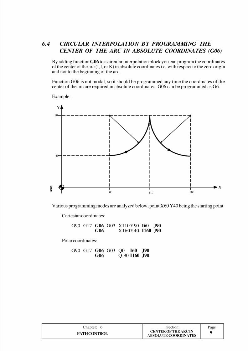
8/21/2019 CNC 8055 M Operator Manual
http://slidepdf.com/reader/full/cnc-8055-m-operator-manual 260/702
PageChapter: 6
PATH CONTROL
Section:
9CENTER OF THE ARC INABSOLUTE COORDINATES
Y
X
6.4 CIRCULAR INTERPOLATION BY PROGRAMMING THE
CENTER OF THE ARC IN ABSOLUTE COORDINATES (G06)
By adding function G06 to a circular interpolation block you can program the coordinatesof the center of the arc (I,J, or K) in absolute coordinates i.e. with respect to the zero originand not to the beginning of the arc.
Function G06 is not modal, so it should be programmed any time the coordinates of thecenter of the arc are required in absolute coordinates. G06 can be programmed as G6.
Example:
Various programming modes are analyzed below, point X60 Y40 being the starting point.
Cartesian coordinates:
G90 G17 G06 G03 X110Y90 I60 J90G06 X160Y40 I160 J90
Polar coordinates:
G90 G17 G06 G03 Q0 I60 J90G06 Q-90 I160 J90

8/21/2019 CNC 8055 M Operator Manual
http://slidepdf.com/reader/full/cnc-8055-m-operator-manual 261/702
Section:
PATH CONTROLChapter: 6
10
PageARC TANGENT TO THEPREVIOUS PATH (G08)
Y
X
6.5 ARC TANGENT TO THE PREVIOUS PATH (G08)
Via function G08 you can program an arc tangential to the previous path without havingto program the coordinates (I.J &K) of the center.
Only the coordinates of the endpoint of the arc are defined, either in polar coordinates orin Cartesian coordinates according to the axes of the work plane.
Example:
Supposing that the starting point is X0 Y40, you wish to program a straight line, thenan arc tangential to the line and finally an arc tangential to the previous one.
G90 G01 X70G08 X90 Y60 ; arc tangential to previous pathG08 X110 Y60 ; arc tangential to previous path
Function G08 is not modal, so it should always be programmed if you wish to execute an
arc tangential to the previous path. Function G08 can be programmed as G8.Function G08 enables the previous path to be a straight line or an arc and does not alter itshistory. The same function G01, G02 or G03 stays active after the block is finished.
Warning:
When using function G08 it is not possible to execute a complete circle, as aninfinite range of solutions exists. The CNC displays the corresponding errorcode.

8/21/2019 CNC 8055 M Operator Manual
http://slidepdf.com/reader/full/cnc-8055-m-operator-manual 262/702
PageChapter: 6
PATH CONTROL
Section:
11ARC DEFINED BY THREE POINTS (G09)
6.6 ARC DEFINED BY THREE POINTS (G09)
Through functionG09 you can define an arc by programming the endpoint and an intermediate
point (the starting point of the arc is the starting point of the movement). In other words, insteadof programming the coordinates of the center, you program any intermediate point.
The endpoint of the arc is defined in Cartesian or polar coordinates, and the intermediatepoint is always defined in Cartesian coordinates by the letters I,J, or K, each one beingassociated to the axes as follows:
Axes X,U,A —> IAxes Y,V,B —> JAxes Z,W,C —> K
In Cartesian coordinates:
G17 G09 X±5.5 Y±5.5 I±5.5 J±5.5
Polar coordinates:
G17 G09 R±5.5 Q±5.5 I±5.5 J±5.5
Example:
Being initial point X-50 Y0.
G09 X35 Y20 I-15 J25
Function G09 is not modal, so it should always be programmed if you wish to execute anarc defined by three points. Function G09 can be programmed as G9.
When G09 is programmed it is not necessary to program the direction of movement (G02 orG03).
Function G09 does not alter the history of the program. The same G01, G02 or G03 functionstays active after finishing the block.
Warning:
When using function G09 it is not possible to execute a complete circle, as you
have to program three different points. The CNC displays the correspondingerror code.
Y
X
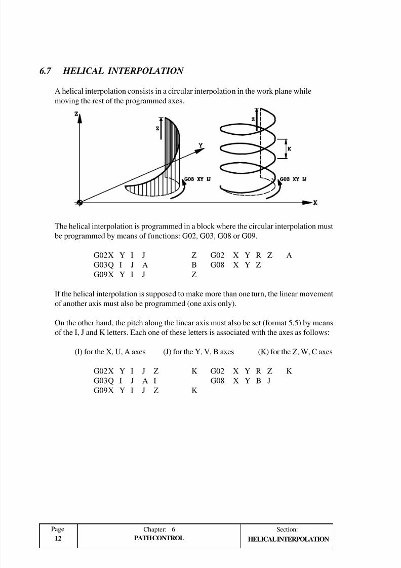
8/21/2019 CNC 8055 M Operator Manual
http://slidepdf.com/reader/full/cnc-8055-m-operator-manual 263/702
Section:
PATH CONTROLChapter: 6
12
Page
HELICAL INTERPOLATION
6.7 HELICAL INTERPOLATION
A helical interpolation consists in a circular interpolation in the work plane while
moving the rest of the programmed axes.
The helical interpolation is programmed in a block where the circular interpolation must
be programmed by means of functions: G02, G03, G08 or G09.
G02X Y I J Z G02 X Y R Z A
G03Q I J A B G08 X Y Z
G09X Y I J Z
If the helical interpolation is supposed to make more than one turn, the linear movement
of another axis must also be programmed (one axis only).
On the other hand, the pitch along the linear axis must also be set (format 5.5) by means
of the I, J and K letters. Each one of these letters is associated with the axes as follows:
(I) for the X, U, A axes (J) for the Y, V, B axes (K) for the Z, W, C axes
G02X Y I J Z K G02 X Y R Z K
G03Q I J A I G08 X Y B J
G09X Y I J Z K

8/21/2019 CNC 8055 M Operator Manual
http://slidepdf.com/reader/full/cnc-8055-m-operator-manual 264/702
PageChapter: 6
PATH CONTROL
Section:
13HELICAL INTERPOLATION
X
Y
Z
Example:
Programming in Cartesian and polar coordinates, the starting point being X0 Y0 Z0.
Cartesian coordinates:
G03 X0 Y0 I15 Z50 K5
Polar coordinates:G03 Q180 I15 J0 Z50 K5

8/21/2019 CNC 8055 M Operator Manual
http://slidepdf.com/reader/full/cnc-8055-m-operator-manual 265/702
Section:
PATH CONTROLChapter: 6
14
Page
TANGENTIAL ENTRY (G37)
Y
X
6.8 TANGENTIAL ENTRY AT BEGINNING OF A MACHINING
OPERATION (G37)
Via function G37 you can tangentially link two paths without having to calculate theintersection points.
Function G37 is not modal, so it should always be programmed if you wish to start amachining operation with tangential entry:
Example:
If the starting point is X0 Y30 and you wish to machine an arc (the path of approach beingstraight) you should program:
G90 G01 X40G02 X60 Y10 I20 J0
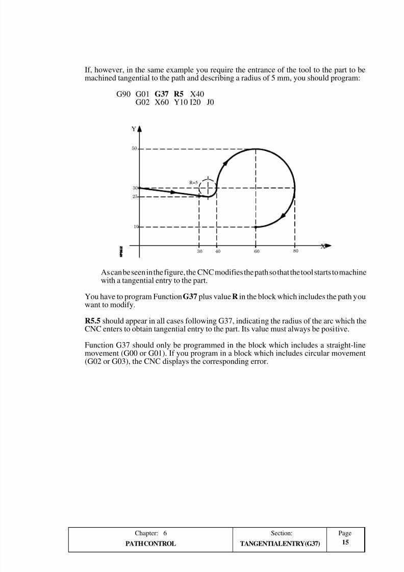
8/21/2019 CNC 8055 M Operator Manual
http://slidepdf.com/reader/full/cnc-8055-m-operator-manual 266/702
PageChapter: 6
PATH CONTROL
Section:
15TANGENTIAL ENTRY (G37)
X
Y
R=5
If, however, in the same example you require the entrance of the tool to the part to bemachined tangential to the path and describing a radius of 5 mm, you should program:
G90 G01 G37 R5 X40G02 X60 Y10 I20 J0
As can be seen in the figure, the CNC modifies the path so that the tool starts to machinewith a tangential entry to the part.
You have to program Function G37 plus value R in the block which includes the path youwant to modify.
R5.5 should appear in all cases following G37, indicating the radius of the arc which theCNC enters to obtain tangential entry to the part. Its value must always be positive.
Function G37 should only be programmed in the block which includes a straight-linemovement (G00 or G01). If you program in a block which includes circular movement(G02 or G03), the CNC displays the corresponding error.

8/21/2019 CNC 8055 M Operator Manual
http://slidepdf.com/reader/full/cnc-8055-m-operator-manual 267/702
Section:
PATH CONTROLChapter: 6
16
Page
TANGENTIAL EXIT (G38)
6.9 TANGENTIAL EXIT AT THE END OF A MACHINING OP-
ERATION (G38)
FunctionG38 enables the ending of a machining operation with a tangential exit of the tool.The path should be in a straight line (G00 or G01). Otherwise, the CNC will display thecorresponding error.
Function G38 is not modal, so it should be programmed whenever a tangential exit of thetool is required.
Value R 5.5 should always appear after G38. It also indicates the radius of the arc whichthe CNC applies to get a tangential exit from the part. This R value must always be positive.
Example:
If the starting point is X0 Y30 and you wish to machine an arc (with the approach andexit paths in a straight line), you should program :
G90 G01 X40G02 X80 I20 J0
G00 X120
Y
X

8/21/2019 CNC 8055 M Operator Manual
http://slidepdf.com/reader/full/cnc-8055-m-operator-manual 268/702
PageChapter: 6
PATH CONTROL
Section:
17TANGENTIAL EXIT (G38)
Y
X
If, however, in the same example you wish the exit from machining to be done tangentiallyand describing a radius of 5 mm, you should program :
G90 G01 X40G02 G38 R5 X80 I20 J0G00 X120
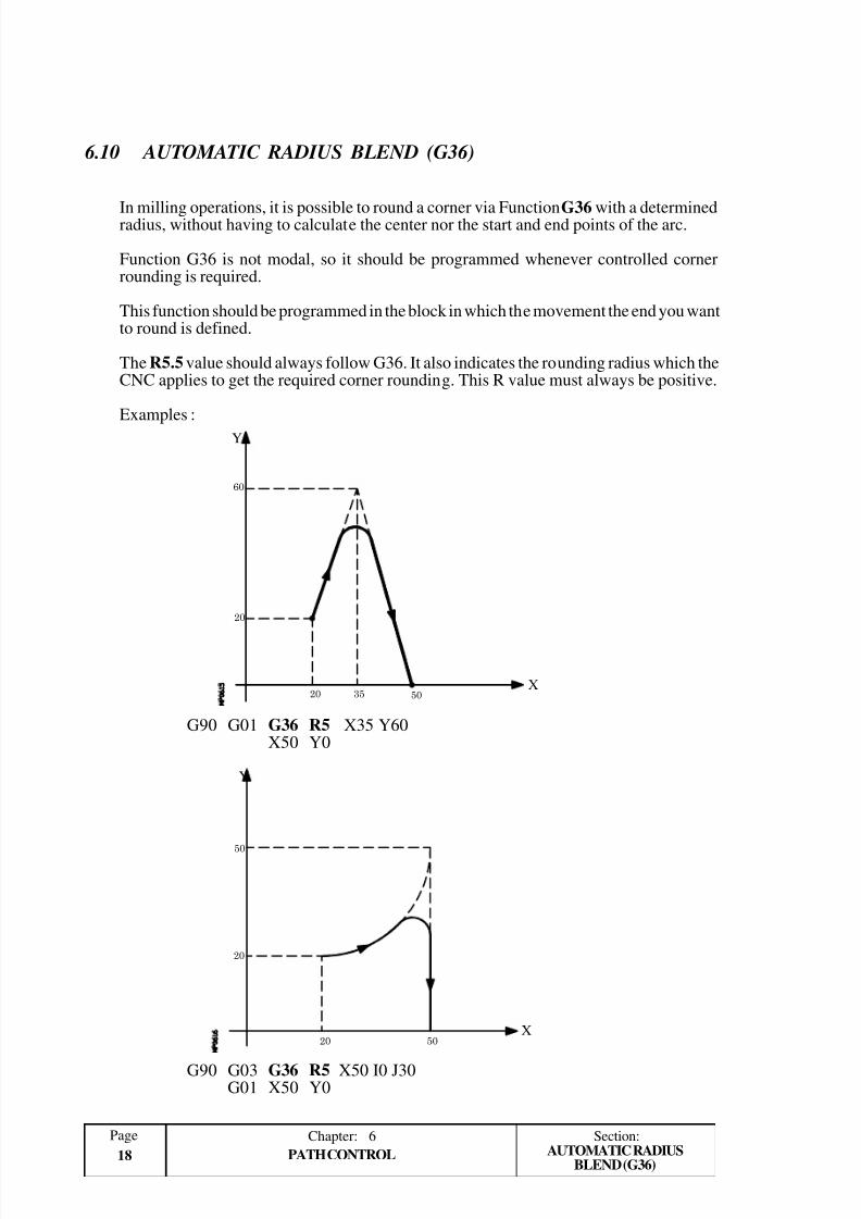
8/21/2019 CNC 8055 M Operator Manual
http://slidepdf.com/reader/full/cnc-8055-m-operator-manual 269/702
Section:
PATH CONTROLChapter: 6
18
PageAUTOMATIC RADIUS
BLEND (G36)
6.10 AUTOMATIC RADIUS BLEND (G36)
In milling operations, it is possible to round a corner via Function G36 with a determinedradius, without having to calculate the center nor the start and end points of the arc.
Function G36 is not modal, so it should be programmed whenever controlled cornerrounding is required.
This function should be programmed in the block in which the movement the end you wantto round is defined.
The R5.5 value should always follow G36. It also indicates the rounding radius which theCNC applies to get the required corner rounding. This R value must always be positive.
Examples :
G90 G01 G36 R5 X35 Y60X50 Y0
G90 G03 G36 R5 X50 I0 J30G01 X50 Y0
Y
X
X
Y

8/21/2019 CNC 8055 M Operator Manual
http://slidepdf.com/reader/full/cnc-8055-m-operator-manual 270/702
PageChapter: 6
PATH CONTROL
Section:
19CHANFER BLEND (G39)
Y
X
6.11 AUTOMATIC CHAMFER BLEND (G39)
In machining operations it is possible (using G39) to chamfer corners between two straightlines, without having to calculate intersection points.
Function G39 is not modal, so it should be programmed whenever the chamfering of acorner is required.
This function should be programmed in the block in which the movement whose end youwant to chamfer is defined.
The R5.5 value should always follow G39. It also indicates the distance from the end of the programmed movement as far as the point where you wish to carry out the chamfering.This R value must always be positive.
Example :
G90 G01 G39 R5 X35 Y60 X50 Y0

8/21/2019 CNC 8055 M Operator Manual
http://slidepdf.com/reader/full/cnc-8055-m-operator-manual 271/702
Section:
PATH CONTROLChapter: 6
20
Page
THREADING (G33)
6.12 THREADING (G33)
If the machine spindle is equipped with a rotary encoder, you can thread with a tool tip via
functionG33.
Although this threading is often done along the entire length of an axis, the CNC enablesthreading to be done interpolating more than one axis at a time.
Programming format: G33 X.....C L Q
X...C ±5.5 End point of the threadL5.5 Thread pitchQ ±3.5 Optional. It indicates the spindle angular position (±359.9999) of the thread's
starting point. If not programmed, a value of "0" is assumed.
Considerations:
Whenever G33 is executed and before making the thread, the CNC referenced the spindle(home search) and positions the spindle at the angular position indicated by parameter Q.
Parameter "Q" is available when spindle machine parameter "M19TYPE" has been set to "1".
If the threads are blended together in round corner, only the first one can have an entry angle(Q).
While function G33 is active, neither the programmed feedrate "F" nor the programmedSpindle speed "S" can be varied. They will both be set to 100%.
Function G33 is modal and incompatible with G00, G01, G02, G03 and G75.
On power-up, after executing M02, M30 or after an EMERGENCY or RESET, the CNCassumes G00 or G01 depending on the setting of general machine parameter “IMOVE”
Example:
To make a 100mm deep and 5 mm pitch thread in a singlepass at X0 Y0 Z0 with a threading tool located at Z10:
G90 G0 X Y Z ; PositioningG33 Z-100 L5 ; Threading
M19 ; Spindle orientationG00 X3 ; Cutter withdrawalZ30 ; Withdrawal (exit the hole)

8/21/2019 CNC 8055 M Operator Manual
http://slidepdf.com/reader/full/cnc-8055-m-operator-manual 272/702
PageChapter: 6
PATH CONTROL
Section:
21
6.13 MOVE TO HARDSTOP (G52)
By means of function G52 it is possible to program the movement of an axis until
running into an object. This feature may be interesting for forming machines, livetailstocks, bar feeders, etc.
Its programming format is: G52 X..C ±5.5
After G52, program the desired axis as well as the target coordinate of the move.
The axis will move towards the programmed target coordinate until running intosomething. If the axis reaches the programmed target coordinate without running intothe hardstop it will stop.
Function G52 is not modal; therefore, it must be programmed every time this operationis to be carried out.
Also, it assumes functions G01 and G40 modifying the program history.It is incompatible with functions G00, G02, G03, G41, G42, G75 and G76.
MOVE TO HARDSTOP (G52)
8/21/2019 CNC 8055 M Operator Manual
http://slidepdf.com/reader/full/cnc-8055-m-operator-manual 273/702
Section:
PATH CONTROLChapter: 6
22
PageFEEDRATE AS AN INVERTED
FUNCTION OF TIME (G32)
6.14 FEEDRATE "F" AS AN INVERTED FUNCTION OF TIME(G32)
There are instances when it is easier to define the time required by the various axes of the machine to reach the target point instead of defining a common feedrate for all of them.
A typical case may be when a linear axis (X, Y, Z) has to move together (interpolated)with a rotary axis programmed in degrees.
Function G32 indicates that the "F" functions programmed next set the time it takes toreach the target point.
In order for a greater value of "F" to indicate a greater feedrate, the value assigned to"F" is defined as "Inverted function of time" and it is assumed as the activation of thisfeature.
"F" units: 1/min
Example: G32 X22 F4 indicates that the movement must be executed in ¼ minute.That is, in 0.25 minutes.
Function G32 is modal and incompatible with G94 and G95.
On power-up, after executing M02, M30 or after an Emergency or Reset, the CNCassumes G94 or G95 depending on the setting of general machine parameter "IFFED".
Considerations:
The CNC variable PROGFIN will show the feedrate programmed as an invertedfunction of time and variable FEED will show the resulting feedrate in mm/min orinches/min.
If the resulting feedrate of any axis exceeds the maximum value set by machineparameter "MAXFEED", the CNC will apply this maximum value.
The programmed "F" is ignored on G00 movements. All the movements will becarried out at the feedrate set by axis machine parameter "G00FEED".
When programming "F0" the movement will be carried out at the feedrate set byaxis machine parameter “MAXFEED”.
Function G32 may be programmed and executed in the PLC channel.
Function G32 is canceled in JOG mode.
G32 is canceled when tracing. If it is programmed while tracing is active, the CNCwill issue an error message.

8/21/2019 CNC 8055 M Operator Manual
http://slidepdf.com/reader/full/cnc-8055-m-operator-manual 274/702
PageChapter: 6
PATH CONTROL
Section:
23TANGENTIAL CONTROL (G45)
6.15 TANGENTIAL CONTROL (G45)
With the "Tangential control" feature, the axis may maintain the same orientation with respectto the programmed path.
Orientation parallel to the path Orientation perpendicular to the path
The path is defined by the axes of the active plane. The axis maintaining the orientation mustbe a rotary rollover axis (A, B or C).
Programming format: G45 Axis Angle
Axis axis maintaining the orientation (A, B or C)Angle Indicates the angular position in degrees with respect to the path (±359.9999).
If not programmed, "0" will be assumed.
To cancel this function, program G45 alone (without defining the axis).
Every time G45 (tangential control) is activated, the CNC acts as follows:
1.- Positions the tangential axis, with respect to the first section in the programmed position.
2.- The interpolation of the axes in the plane starts once the tangential axis has beenpositioned.
3.- On linear sections, the orientation of the tangential axis is maintained and in circularinterpolations, the programmed orientation is maintained for the whole path.

8/21/2019 CNC 8055 M Operator Manual
http://slidepdf.com/reader/full/cnc-8055-m-operator-manual 275/702
Section:
PATH CONTROLChapter: 6
24
Page
TANGENTIAL CONTROL (G45)
4.- If the joint of sections requires a new orientation of the tangential axis, the followingtakes place:
a) ends the current section.b) orients the tangential axis with respect to the next section.c) resumes execution.
When working in round corner (G05), the tool orientation is not maintained at thecorners since it begins before ending the current section.
It is recommended to work in square corner (G07). However, to work in round corner(G05), function G36 (automatic radius blend) should be used in order to also maintaintool orientation at the corners.
5.- To cancel the tangential control function, program G45 alone (without defining the axis).
Even when the tangential axis takes the same orientation by programming 90° or -270°, theturning direction in a direction change depends on the programmed value.

8/21/2019 CNC 8055 M Operator Manual
http://slidepdf.com/reader/full/cnc-8055-m-operator-manual 276/702
PageChapter: 6
PATH CONTROL
Section:
25TANGENTIAL CONTROL (G45)
6.15.1 CONSIDERATIONS ABOUT FUNCTION G45
Tangential control, G45, is optional. It can only be executed in the main channel and iscompatible with:
• Tool radius and length compensation (G40, 41, 42, 43, 44)• Mirror image (G10, 11, 12, 13 14)• Gantry axes , including the gantry axis associated with the tangential rotary axis.
The maximum feedrate while orienting the tangential axis is defined by machine parameterMAXFEED for that axis.
While tangential control is active, tool inspection is also possible. When accessing toolinspection, the tangential control is deactivated, the axes are free and when quitting toolinspection, tangential control may be activated again.
While in JOG mode, tangential control may be activated in MDI mode and the axes may bemoved by programming blocks in MDI.
Tangential control is canceled when jogging the axes with the jog keys (not in MDI). Oncethe movement is over, tangential control is recovered.
On the other hand, the following is NOT possible:
• To define as tangential axis, one of the plane axes, the longitudinal axis or any other axiswhich is not rotary.
• To jog the tangential axis in JOG mode or by program using another G code whiletangential control is active.
• Incline planes.
The TANGAN variable is read-only, from the CNC, PLC and DNC, associated withfunction G45. It indicates the angular position, in degrees, referred to the programmed path.
Also, general logic output TANGACT (M5558) indicates to the PLC that function G45 isactive.
Function G45 is modal and is canceled when executing G45 alone (without defining the axis),on power-up, after executing an M02 or M30 or after an EMERGENCY or RESET.

8/21/2019 CNC 8055 M Operator Manual
http://slidepdf.com/reader/full/cnc-8055-m-operator-manual 277/702
PageChapter: 7
ADDITIONAL PREPARATORY FUNCTIONS
Section:
1G04 AND G04K
7. ADDITIONAL PREPARATORY FUNCTIONS
7.1 INTERRUPTION OF BLOCK PREPARATION (G04)
The CNC reads up to 20 blocks ahead of the one it is executing, with the aim of calculating beforehand the path to be followed.
Each block is evaluated (in its absence) at the time it is read, but if you wish to evaluate
it at the time of execution of the block you use function G04.
This function holds up the preparation of blocks and waits for the block in questionto be executed in order to start the preparation of blocks once more.
A case in point is the evaluation of the “status of block-skip inputs” which is definedin the block header.
Example:...
G04 ; interrupts block preparation /1 G01 X10 Y20; block-skip condition “/1”..
Function G04 is not modal, so it should be programmed whenever you wish to interruptblock preparation.
It should be programmed on its own and in the block previous to the one in whichthe evaluation in execution is required. Function G04 can be programmed as G4.
Every time G04 is programmed, active radius and length compensation are cancelled.
For this reason, care needs to be taken when using this function, because if it isintroduced between machining blocks which work with compensation, unwantedprofiles may be produced.
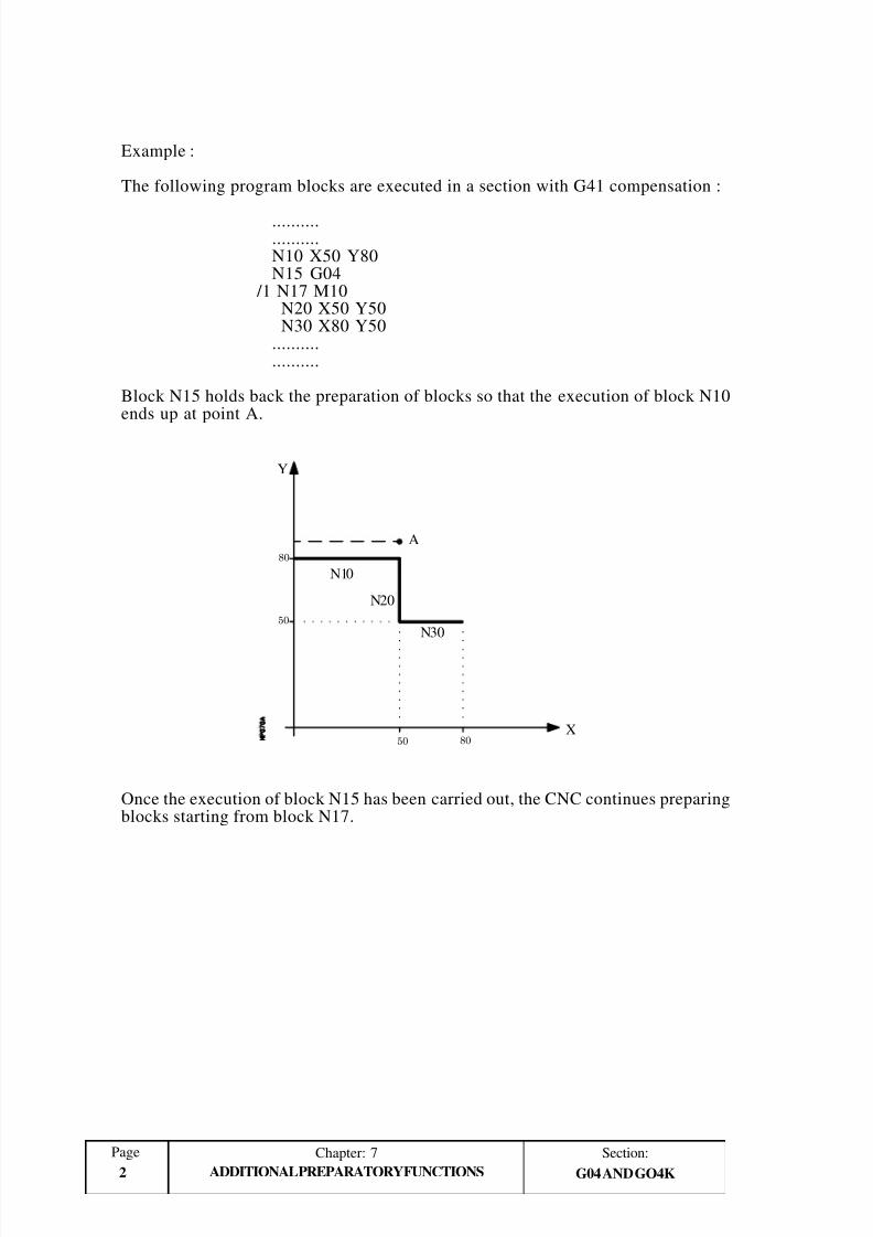
8/21/2019 CNC 8055 M Operator Manual
http://slidepdf.com/reader/full/cnc-8055-m-operator-manual 278/702
Section:
ADDITIONAL PREPARATORY FUNCTIONSChapter: 7
2
Page
G04 AND GO4K
X
Y
N30
N20
A
N10
Example :
The following program blocks are executed in a section with G41 compensation :
..........
..........N10 X50 Y80N15 G04
/1 N17 M10 N20 X50 Y50 N30 X80 Y50
..........
..........
Block N15 holds back the preparation of blocks so that the execution of block N10ends up at point A.
Once the execution of block N15 has been carried out, the CNC continues preparingblocks starting from block N17.

8/21/2019 CNC 8055 M Operator Manual
http://slidepdf.com/reader/full/cnc-8055-m-operator-manual 279/702
PageChapter: 7
ADDITIONAL PREPARATORY FUNCTIONS
Section:
3G04 AND GO4K
Y
N10
N20
X
N30
A
B
Given that the next point corresponding to the compensated path is point “B”, theCNC moves the tool to this point, executing path “A-B”.
As you can see, the resulting path is not the required one, so we recommend avoidingthe use of function G04 in sections which work with compensation.
7.2 DWELL (G04 K)
Timing can be programmed via function G04 K.
The timing value is programmed in hundredths of a second via format K5 (0..99999).
Example :
G04 K50 ; Timing of 50 hundredths of a second (0.5 seconds)G04 K200 ; Timing of 200 hundredths of a second (2 seconds)
Function G04 K is not modal, so it should be programmed whenever timing is required.
Function G04 K can be programmed as G4 K.Timing is executed at the beginning of the block in which it is programmed.

8/21/2019 CNC 8055 M Operator Manual
http://slidepdf.com/reader/full/cnc-8055-m-operator-manual 280/702
Section:
ADDITIONAL PREPARATORY FUNCTIONSChapter: 7
4
Page
7.3 WORKING WITH SQUARE (G07) AND ROUND (G05,G50)
CORNERS
7.3.1 SQUARE CORNER (G07)
When working in G07 (square corner) the CNC does not start executing the followingprogram block until the position programmed in the current block has been reached.
The CNC considers that the programmed position has been reached when the axis iswithin the "INPOSW" (in-position zone or dead band) from the programmed position.
Example:
G91 G01 G07 Y70 F100 X90
The theoretical and real profile coincide, obtaining square corners, as seen in the figure.
Function G07 is modal and incompatible with G05 and G50. Function G07 can beprogrammed as G7.
On power-up, after executing M02, M30 or after EMERGENCY or RESET, the CNCassumes code G05 or G07 depending on how the general machine parameter“ICORNER” is set.
SQUARE CORNER (G07)ROUND CORNER (G05/G50)

8/21/2019 CNC 8055 M Operator Manual
http://slidepdf.com/reader/full/cnc-8055-m-operator-manual 281/702
PageChapter: 7
ADDITIONAL PREPARATORY FUNCTIONS
Section:
5
7.3.2 ROUND CORNER (G05)
When working in G05 (round corner), the CNC starts executing the following block
of the program as soon as the theoretical interpolation of the current block has concluded.It does not wait for the axes to physically reach the programmed position.
The distance prior to the programmed position where the CNC starts executing thenext block depends on the actual axis feedrate.
Example :
G91 G01 G05 Y50 F100 X90
Via this function round corners can be obtained, as shown in the figure.
The difference between the theoretical and real profiles depends on the programmedfeedrate value “F”. The higher the feedrate, the greater the difference between bothprofiles.
Function G05 is modal and incompatible with G07 and G50. Function G05 can be
programmed as G5.On power-up, after executing M02, M30 or after EMERGENCY or RESET, the CNCassumes code G05 or G07 depending on how the general machine parameter“ICORNER” is set.
SQUARE CORNER (G07)ROUND CORNER (G05/G50)
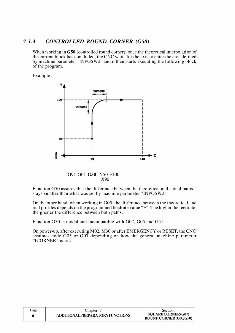
8/21/2019 CNC 8055 M Operator Manual
http://slidepdf.com/reader/full/cnc-8055-m-operator-manual 282/702
Section:
ADDITIONAL PREPARATORY FUNCTIONSChapter: 7
6
PageSQUARE CORNER (G07)
ROUND CORNER (G05/G50)
7.3.3 CONTROLLED ROUND CORNER (G50)
When working in G50 (controlled round corner); once the theoretical interpolation of
the current block has concluded, the CNC waits for the axis to enter the area definedby machine parameter "INPOSW2" and it then starts executing the following block of the program.
Example :
G91 G01 G50 Y50 F100 X90
Function G50 assures that the difference between the theoretical and actual pathsstays smaller than what was set by machine parameter "INPOSW2".
On the other hand, when working in G05, the difference between the theoretical andreal profiles depends on the programmed feedrate value “F”. The higher the feedrate,the greater the difference between both paths.
Function G50 is modal and incompatible with G07, G05 and G51.
On power-up, after executing M02, M30 or after EMERGENCY or RESET, the CNCassumes code G05 or G07 depending on how the general machine parameter“ICORNER” is set.

8/21/2019 CNC 8055 M Operator Manual
http://slidepdf.com/reader/full/cnc-8055-m-operator-manual 283/702
PageChapter: 7
ADDITIONAL PREPARATORY FUNCTIONS
Section:
7
7.4 LOOK-AHEAD (G51)
Usually, a program consisting of very small movement blocks (CAM, digitizing, etc.) runvery slowly.
With this feature, high speed machining is possible for this type of programs.
It is recommended to have the CPU-TURBO feature when using LOOK-AHEADbecause the CNC has to analyze the machining path ahead of time (up to 50 blocks) in orderto calculate the maximum feedrate for each section of the path.
The programming format is: G51 [A] E
A (0-255) Is optional and it defines the percentage of acceleration to be applied.When not programmed or programmed with a "0" value, the CNC assumesthe acceleration value set by machine parameter for each axis.
E (5.5) Maximum contouring error allowed.
Parameter "A" permits using a standard working acceleration and another one to be usedwhen executing with Look-Ahead.
The smaller the "E" parameter value, the lower the machining feedrate.
When operating with "Look-Ahead", it is a good idea to adjust the axes so their followingerror (lag) is as small as possible because the contouring error will be at least equal to theminimum following error.
When calculating the axis feedrate, the CNC takes into consideration the following aspects:
* The programmed feedrate.* The curvature and the corners.* The maximum feedrates of the axes.* The maximum accelerations.
If any of the circumstances listed below occurs while executing with Look-Ahead, theCNC slows down to "0" at the previous block and it recovers the machining conditions forLook-Ahead in the next motion block.
* Motionless block.
* Execution of auxiliary functions (M, S, T).* Single block execution mode.* MDI mode.* TOOL INSPECTION mode.
If a Cycle Stop, Feed-Hold, etc. occurs while executing in Look-Ahead mode, the machinemay not stop at the current block, several additional blocks will be necessary to stop withthe permitted deceleration.
Function G51 is modal and incompatible with G05, G07 and G50. Should any of them beprogrammed, function G51 will be canceled and the new one will be selected.
On the other hand, the CNC will issue Error 7 (Incompatible G functions) when
programming any of the following functions while G51 is active:
LOOK AHEAD (G51)
8/21/2019 CNC 8055 M Operator Manual
http://slidepdf.com/reader/full/cnc-8055-m-operator-manual 284/702
Section:
ADDITIONAL PREPARATORY FUNCTIONSChapter: 7
8
Page
* G23, G26, G27 Tracing* G33 Electronic threading* G52 Movement against hardstop* G74 Home search* G75, G76 Probing* G95 Feedrate per revolution
Function G51 must be programmed alone in a block and there must be no more informationin that block.
On power-up, after executing an M02, M30, of after an EMERGENCY or RESET, theCNC will cancel G51, if it was active, and it will assume G05 or G07 according to the settingof general machine parameter “ICORNER”.
LOOK AHEAD (G51)
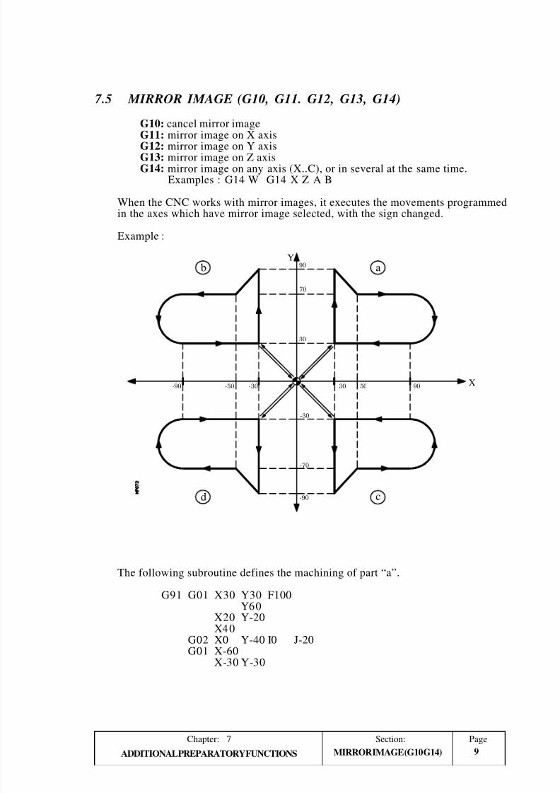
8/21/2019 CNC 8055 M Operator Manual
http://slidepdf.com/reader/full/cnc-8055-m-operator-manual 285/702
PageChapter: 7
ADDITIONAL PREPARATORY FUNCTIONS
Section:
9
X
Y
ab
d c
MIRROR IMAGE (G10 G14)
7.5 MIRROR IMAGE (G10, G11. G12, G13, G14)
G10: cancel mirror image
G11: mirror image on X axisG12: mirror image on Y axisG13: mirror image on Z axisG14: mirror image on any axis (X..C), or in several at the same time.
Examples : G14 W G14 X Z A B
When the CNC works with mirror images, it executes the movements programmedin the axes which have mirror image selected, with the sign changed.
Example :
The following subroutine defines the machining of part “a”.
G91 G01 X30 Y30 F100Y60
X20 Y-20X40
G02 X0 Y-40 I0 J-20G01 X-60
X-30 Y-30
8/21/2019 CNC 8055 M Operator Manual
http://slidepdf.com/reader/full/cnc-8055-m-operator-manual 286/702
Section:
ADDITIONAL PREPARATORY FUNCTIONSChapter: 7
10
Page
The programming of all parts would be :
Execution of subroutine ; machines “a”G11 ; mirror image on X axis.
Execution of subroutine ; machines “bG10 G12 ; mirror image on Y axis.
Execution of subroutine ; machines “c”G11 ; mirror image on X and Y axes.
Execution of subroutine ; machines “d”M30 ; end of program.
Functions G11, G12, G13, and G14 are modal and incompatible with G10.
G11, G12, and G13 can be programmed in the same block, because they are notincompatible with each other. Function G14 must be programmed alone in the block.
If function G73 (pattern rotation) is also active in a mirror image program, the CNCfirst applies the mirror image function and then the pattern rotation.
If while one of the mirror imaging functions (G11, G12, G13, and G14) is active, anew coordinate origin (part zero) is preset with G92, this new origin will not be affectedby the mirror imaging function.
On power-up, after executing M02, M30 or after EMERGENCY or RESET, the CNCassumes code G10.
MIRROR IMAGE (G10 G14)

8/21/2019 CNC 8055 M Operator Manual
http://slidepdf.com/reader/full/cnc-8055-m-operator-manual 287/702
PageChapter: 7
ADDITIONAL PREPARATORY FUNCTIONS
Section:
11
7.6 SCALING FACTOR (G72)
By using function G72 you can enlarge or reduce programmed parts.
In this way, you can produce families of parts which are similar in shape but of differentsizes with a single program.
Function G72 should be programmed on its own in a block. There are two formatsfor programming G72 :
Scaling factor applied to all axes.Scaling factor applied to one or more axes.
SCALING FACTOR (G72)

8/21/2019 CNC 8055 M Operator Manual
http://slidepdf.com/reader/full/cnc-8055-m-operator-manual 288/702
Section:
ADDITIONAL PREPARATORY FUNCTIONSChapter: 7
12
Page
Y
X
Y'
X'
b
a
7.6.1 SCALING FACTOR APPLIED TO ALL AXES
The programming format is as follows :
G72 S5.5
Following G72 all coordinates programmed are multiplied by the value of the scalingfactor defined by S until a new G72 scaling factor definition is read or the definitionis cancelled.
Programming example (starting point X-30 Y10)
The following subroutine defines the machining of the part.
G90 X-19 Y0G01 X0 Y10 F150G02 X0 Y-10 I0 J-10
G01 X-19Y0
The programming of the parts would be :
Execution of subroutine ; machines “a”G92 X-79 Y-30 ; coordinate preset
(zero offset)G72 S2 ; applies scaling factor 2
Execution of subroutine ; machines “b”G72 S1 ; cancels scaling factorM30 ; end of program
SCALING FACTOR (G72)

8/21/2019 CNC 8055 M Operator Manual
http://slidepdf.com/reader/full/cnc-8055-m-operator-manual 289/702
PageChapter: 7
ADDITIONAL PREPARATORY FUNCTIONS
Section:
13
Y Y
XX
Examples of application of the scaling factor.
G90 G00 X0 Y0 G90 G00 X20 Y20
N10 G91 G01 X20 Y10 N10 G91 G01 X-10
Y10 X-10 Y-20
X-10 X20 Y10
N20 X-10 Y-20 N20 Y10
G72 S0.5 G72 S0.5 ; scaling factor
(RPT N10,20) (RPT N10,20) ; repeats from
; block 10
; to block 20
M30 M30
Function G72 is modal and is cancelled when another scaling factor with a value of S1 is programmed, or on power-up, after executing M02, M30 or after EMERGENCYor RESET.
SCALING FACTOR (G72)

8/21/2019 CNC 8055 M Operator Manual
http://slidepdf.com/reader/full/cnc-8055-m-operator-manual 290/702
Section:
ADDITIONAL PREPARATORY FUNCTIONSChapter: 7
14
Page
7.6.2 SCALING FACTOR APPLIED TO ONE OR MORE AXES
The programming format is :
G72 X...C 5.5
After G72 the axis or axes and the required scaling factor are programmed.
All blocks programmed after G72 are treated by the CNC as follows :
The CNC calculates the movement of all the axes in relation to the programmedpath and compensation.
It then applies the scaling factor indicated to the calculated movement of thecorresponding axis or axes.
If the scaling factor is applied on one or more axes, the CNC will apply the scalingfactor indicated both to the movement of the corresponding axis or axes and to theirfeedrate.
If, within the same program, both scaling factor types are applied, the one applied toall the axes and the one for one or several axes, the CNC applies a scaling factor equalto the product of the two scaling factors programmed for this axis to the axis or axesaffected by both types.
Function G72 is modal and will be cancelled when the CNC is turned on, after executingM02, M30 or after an EMERGENCY or RESET.
Example:
Application of the scaling factor to a plane axis, working with tool radiuscompensation.
As it can be observed, the tool path does not coincide with the required path,as the scaling factor is applied to the calculated movement.
SCALING FACTOR (G72)

8/21/2019 CNC 8055 M Operator Manual
http://slidepdf.com/reader/full/cnc-8055-m-operator-manual 291/702
PageChapter: 7
ADDITIONAL PREPARATORY FUNCTIONS
Section:
15
However, if a scaling factor equal to 360/(2¶R) is applied to a rotary axis, R beingthe radius of the cylinder on which you wish to machine, this axis can be consideredlinear, and any figure with tool radius compensation can be programmed on the cylindricalsurface.
SCALING FACTOR (G72)
Z
WR
X
W
X
2¶R
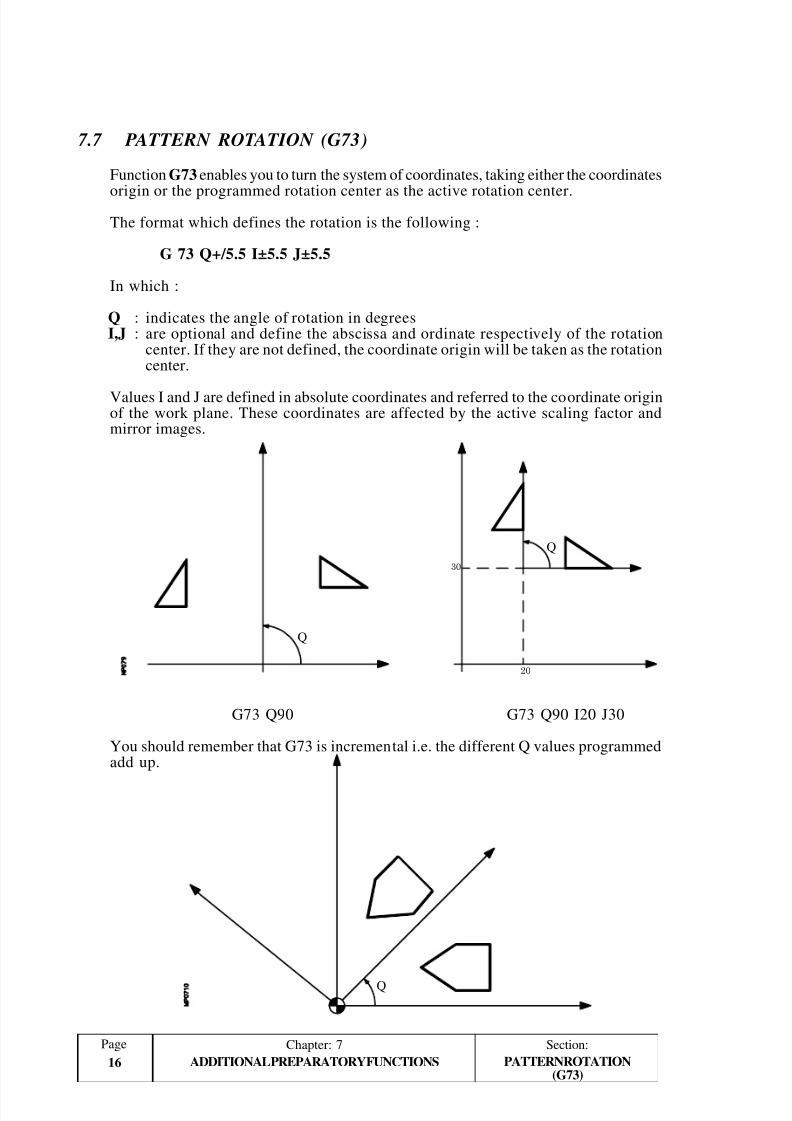
8/21/2019 CNC 8055 M Operator Manual
http://slidepdf.com/reader/full/cnc-8055-m-operator-manual 292/702
Section:
ADDITIONAL PREPARATORY FUNCTIONSChapter: 7
16
Page
Q
Q
Q
7.7 PATTERN ROTATION (G73)
Function G73 enables you to turn the system of coordinates, taking either the coordinates
origin or the programmed rotation center as the active rotation center.
The format which defines the rotation is the following :
G 73 Q+/5.5 I±5.5 J±5.5
In which :
Q : indicates the angle of rotation in degreesI,J : are optional and define the abscissa and ordinate respectively of the rotation
center. If they are not defined, the coordinate origin will be taken as the rotationcenter.
Values I and J are defined in absolute coordinates and referred to the coordinate originof the work plane. These coordinates are affected by the active scaling factor andmirror images.
G73 Q90 G73 Q90 I20 J30
You should remember that G73 is incremental i.e. the different Q values programmedadd up.
PATTERN ROTATION(G73)
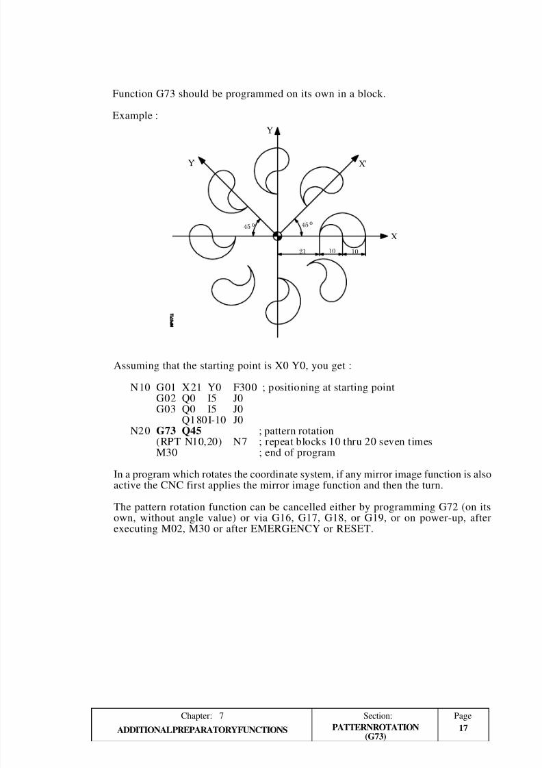
8/21/2019 CNC 8055 M Operator Manual
http://slidepdf.com/reader/full/cnc-8055-m-operator-manual 293/702
PageChapter: 7
ADDITIONAL PREPARATORY FUNCTIONS
Section:
17
Y
Y'
X
X'
Function G73 should be programmed on its own in a block.
Example :
Assuming that the starting point is X0 Y0, you get :
N10 G01 X21 Y0 F300 ; positioning at starting point
G02 Q0 I5 J0G03 Q0 I5 J0Q180I-10 J0
N20 G73 Q45 ; pattern rotation(RPT N10,20) N7 ; repeat blocks 10 thru 20 seven timesM30 ; end of program
In a program which rotates the coordinate system, if any mirror image function is alsoactive the CNC first applies the mirror image function and then the turn.
The pattern rotation function can be cancelled either by programming G72 (on itsown, without angle value) or via G16, G17, G18, or G19, or on power-up, afterexecuting M02, M30 or after EMERGENCY or RESET.
PATTERN ROTATION(G73)
8/21/2019 CNC 8055 M Operator Manual
http://slidepdf.com/reader/full/cnc-8055-m-operator-manual 294/702
Section:
ADDITIONAL PREPARATORY FUNCTIONSChapter: 7
18
Page
7.8 SLAVED AXIS/CANCELLATION OF SLAVED AXIS
The CNC enables two or more axes to be coupled together. The movement of all axesis subordinated to the movement of the axis to which they were coupled.
There are three possible ways of coupling axes :
Mechanical coupling. This is imposed by the manufacturer of the machine, andis selected via the axis machine parameter “GANTRY”.
By means of the PLC. This enables the coupling and uncoupling of each axisthrough logic input on the CNC “SYNCHRO1”, “SYNCHRO2”, “SYNCHRO3”,“SYNCHRO4”, and “SYNCHRO5”. Each axis is coupled to the one indicatedin the axis machine parameter “SYNCHRO”.
By means of the program. This enables electronic coupling and uncoupling betweentwo or more axes, through functions G77 and G78.
SLAVED AXIS

8/21/2019 CNC 8055 M Operator Manual
http://slidepdf.com/reader/full/cnc-8055-m-operator-manual 295/702
PageChapter: 7
ADDITIONAL PREPARATORY FUNCTIONS
Section:
19
7.8.1 SLAVED AXIS (G77)
Function G77 allows the selection of both the master axis and the slaved axis (axes).The programming format is as follows :
G77 < Axis 1 > < Axis 2 > < Axis 3 > < Axis 4 > < Axis 5>
In which < Axis 2 > < Axis 3 > < Axis 4 > < Axis 5> indicate the slave axes youwish to couple to the master axis < Axis 1 >. You have to define < Axis 1 > and< Axis 2 >, the programming of the rest of the axes being optional.
Example :
G77 X Y U ; couples Y and U axes to X axis
The following rules should be observed when doing electronic axis couplings :
You may use one or two different electronic couplings.
G77 X Y U ; couples Y and U axes to X axisG77 V Z ; couples Z axis to V axis
You cannot couple one axis to two others at the same time.
G77 V Y ; couples Y axis to V axisG77 X Y ; gives an error signal, because Y axis is coupled to V axis.
You can couple several axes to one in successive steps.
G77 X Z ; couples Z axis to X axisG77 X U ; couples U axis to X axis —> Z U coupled to XG77 X Y ; couples Y axis to X axis —> Y Z U coupled to X
A pair of axes which are already coupled to each other cannot be coupled to another axis.
G77 Y U ; couples U axis to Y axisG77 X Y ; gives an error signal, because Y axis is coupled to U axis.
SLAVED AXIS

8/21/2019 CNC 8055 M Operator Manual
http://slidepdf.com/reader/full/cnc-8055-m-operator-manual 296/702
Section:
ADDITIONAL PREPARATORY FUNCTIONSChapter: 7
20
Page
7.8.2 SLAVED AXIS CANCELLATION (G78)
Function G78 enables you to uncouple all the axes which are coupled (slaved), oronly uncouple indicated axes.
G78 Uncouples all slaved axes.
G78 <Axis 1><Axis 2><Axis 3><Axis 4> Only uncouples indicated axes.
Example :
G77 X Y U ; slaves Y and U axes to X axisG77 V Z ; slaves Z axis to V axisG78 Y ; uncouples Y axis, but U stays slaved to X and Z to V.G78 ; uncouples all axes.
SLAVED AXIS

8/21/2019 CNC 8055 M Operator Manual
http://slidepdf.com/reader/full/cnc-8055-m-operator-manual 297/702
PageChapter: 7
ADDITIONAL PREPARATORY FUNCTIONS
Section:
21AXES TOGGLE: G28-G29
7.9 AXES TOGGLE. G28-G29
With this feature, on machines having two machining tables, it is possible to use a single part-
program to make the same parts on both tables.
With function G28 the axes can be toggled from one to the other in such way that after thatinstruction all the movements associated with the first axis next to G28 will take place onthe second axis next to G28 and vice versa.
Programming format: G28 (axis 1) (axis 2)
To cancel the toggle, execute function G29 followed by one of the axes to be toggled back.
Up to three pairs of axes may be toggled at the same time.
The main axes cannot be toggled in the following cases: While tracing, while function G48or G49 is active or when the "C" axis is active on a lathe.
On power-up, after executing an M30 or after an emergency or reset, the axes are toggled
back as long as G48 or G49 is not active.
Example. Let us suppose that the part program is defined for table 1.
Execute the part-program on table 1G28 BC Toggle the "B" and "C" axesZero offset for machining on table 2Execute the part-program It will be executed on table 2
In the meantime, replace the part made on table 1 witha new one
G29 B Toggle the "B" and "C" axes back Cancel the zero offset for machining on table 1
Execute the part-program It will be executed on table 1In the meantime, replace the part made on table 2 witha new one

8/21/2019 CNC 8055 M Operator Manual
http://slidepdf.com/reader/full/cnc-8055-m-operator-manual 298/702
PageChapter: 8
TOOL COMPENSATION
Section:
1
8. TOOL COMPENSATION
The CNC has a tool offset table, its number of components being defined via the generalmachine parameter “NTOFFSET”. The following is specified for each tool offset :
* Tool radius, in work units, in R±5.5 format
* Tool length, in work units, in L±5.5 format.
* Wear of tool radius, in work units, in I±5.5 format. The CNC adds this value to thetheoretical radius (R) to calculate the real radius (R+I).
* Wear of tool length, in work units, in K±5.5 format. The CNC adds this value to thetheoretical length (L) to calculate the real length (L+K).
When tool radius compensation is required (G41 or G42), the CNC applies the sum of R+Ivalues of the selected tool offset as the compensation value.
When tool length compensation is required (G43), the CNC applies the sum of L+K valuesof the selected tool offset as the compensation value.
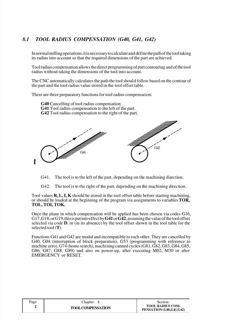
8/21/2019 CNC 8055 M Operator Manual
http://slidepdf.com/reader/full/cnc-8055-m-operator-manual 299/702
Section:Chapter: 8
2Page
TOOL COMPENSATION
G41G42
TOOL RADIUS COM-PENSATION (G40,G41,G42)
8.1 TOOL RADIUS COMPENSATION (G40, G41, G42)
In normal milling operations, it is necessary to calculate and define the path of the tool takingits radius into account so that the required dimensions of the part are achieved.
Tool radius compensation allows the direct programming of part contouring and of the toolradius without taking the dimensions of the tool into account.
The CNC automatically calculates the path the tool should follow based on the contour of the part and the tool radius value stored in the tool offset table.
There are three preparatory functions for tool radius compensation:
G40 Cancelling of tool radius compensationG41 Tool radius compensation to the left of the part.
G42 Tool radius compensation to the right of the part.
G41. The tool is to the left of the part, depending on the machining direction.
G42. The tool is to the right of the part, depending on the machining direction.
Tool values R, L, I, K should be stored in the tool offset table before starting machining,or should be loaded at the beginning of the program via assignments to variables TOR,TOL, TOI, TOK.
Once the plane in which compensation will be applied has been chosen via codes G16,G17, G18, or G19, this is put into effect by G41 or G42, assuming the value of the tool offsetselected via code D, or (in its absence) by the tool offset shown in the tool table for the
selected tool (T).
Functions G41 and G42 are modal and incompatible to each other. They are cancelled byG40, G04 (interruption of block preparation), G53 (programming with reference tomachine zero), G74 (home search), machining canned cycles (G81, G82, G83, G84, G85,G86, G87, G88, G89) and also on power-up, after executing M02, M30 or afterEMERGENCY or RESET.

8/21/2019 CNC 8055 M Operator Manual
http://slidepdf.com/reader/full/cnc-8055-m-operator-manual 300/702
PageChapter: 8
TOOL COMPENSATION
Section:
3TOOL RADIUS COM-PENSATION (G40,G41,G42)
8.1.1 ACTIVATING TOOL RADIUS COMPENSATION
Once the plane in which tool radius compensation has been selected (via G16, G17, G18,or G19), functions G41 or G42 must be used to activate it.
G41 Compensation of tool radius compensation to the left.G42 Compensation of tool radius compensation to the right.
In the same block (or a previous one) in which G41 or G42 is programmed, functions T,D, or only T must be programmed so that the tool offset value to be applied can be selectedfrom the tool offset table. If no tool offset is selected, the CNC takes D0 with R0 L0 I0 K0.
The selection of tool radius compensation (G41 or G42) can only be made when functionsG00 or G01 are active (straight-line movements).
If the compensation is selected while G02 or G03 are active, the CNC will display thecorresponding error message.
The following pages show different cases of starting tool radius compensation, in which theprogrammed path is represented by a solid line and the compensated path with a dotted line.
When the new selected tool has an M06 associated to it and this M06, in turn, has asubroutine associated to it; the CNC will activate the tool radius compensation at the firstmovement block of that subroutine.
If that subroutine has a G53 programmed in a block (position values referred to MachineReference Zero, home), the CNC will cancel any tool radius compensation (G41 or G42)selected previously.

8/21/2019 CNC 8055 M Operator Manual
http://slidepdf.com/reader/full/cnc-8055-m-operator-manual 301/702
Section:Chapter: 8
4Page
TOOL COMPENSATIONTOOL RADIUS COM-
PENSATION (G40,G41,G42)
STRAIGHT-STRAIGHT path

8/21/2019 CNC 8055 M Operator Manual
http://slidepdf.com/reader/full/cnc-8055-m-operator-manual 302/702
PageChapter: 8
TOOL COMPENSATION
Section:
5TOOL RADIUS COM-PENSATION (G40,G41,G42)
STRAIGHT-CURVED path

8/21/2019 CNC 8055 M Operator Manual
http://slidepdf.com/reader/full/cnc-8055-m-operator-manual 303/702
Section:Chapter: 8
6Page
TOOL COMPENSATION TOOL RADIUS COM-PENSATION (G40,G41,G42)
8.1.2 TOOL RADIUS COMPENSATION SECTIONS
The diagrams (below) show the different paths followed by a tool controlled by aprogrammed CNC with tool radius compensation.
The programmed path is represented by a solid line and the compensated path by a dottedline.
RR
R
R
R
R
R
R
RR
RR

8/21/2019 CNC 8055 M Operator Manual
http://slidepdf.com/reader/full/cnc-8055-m-operator-manual 304/702
PageChapter: 8
TOOL COMPENSATION
Section:
7
R
R
R
R
R
R
RR
TOOL RADIUS COM-PENSATION (G40,G41,G42)
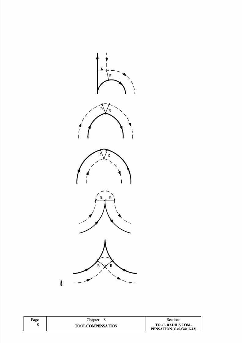
8/21/2019 CNC 8055 M Operator Manual
http://slidepdf.com/reader/full/cnc-8055-m-operator-manual 305/702
Section:Chapter: 8
8Page
TOOL COMPENSATION
R
R
R R
R
R R
R
R R
TOOL RADIUS COM-PENSATION (G40,G41,G42)

8/21/2019 CNC 8055 M Operator Manual
http://slidepdf.com/reader/full/cnc-8055-m-operator-manual 306/702
PageChapter: 8
TOOL COMPENSATION
Section:
9TOOL RADIUS COM-PENSATION (G40,G41,G42)
The CNC reads up to 20 blocks ahead of the one it is executing, with the aim of calculatingin advance the path to be followed.
When the CNC works with compensation it needs to know the next programmed movementto calculate the path to be followed. For this reason, no more than 17 consecutive blocks canbe programmed without movement.
8.1.3 CANCELLING TOOL RADIUS COMPENSATION
Tool radius compensation is cancelled by using function G40.
It should be remembered that cancelling radius compensation (G40) can only be done ina block in which a straight-line movement is programmed (G00 or G01).
If G40 is programmed while functions G02 or G03 are active, the CNC displays thecorresponding error message.
The following pages show different cases of cancelling tool radius compensation, in whichthe programmed path is represented by a solid line and the compensated path with a dottedline.
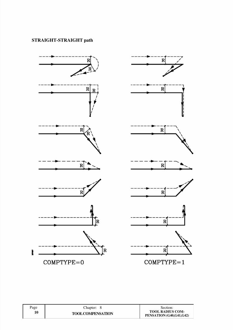
8/21/2019 CNC 8055 M Operator Manual
http://slidepdf.com/reader/full/cnc-8055-m-operator-manual 307/702
Section:Chapter: 8
10Page
TOOL COMPENSATIONTOOL RADIUS COM-
PENSATION (G40,G41,G42)
STRAIGHT-STRAIGHT path

8/21/2019 CNC 8055 M Operator Manual
http://slidepdf.com/reader/full/cnc-8055-m-operator-manual 308/702
PageChapter: 8
TOOL COMPENSATION
Section:
11TOOL RADIUS COM-PENSATION (G40,G41,G42)
CURVED-STRAIGHT path
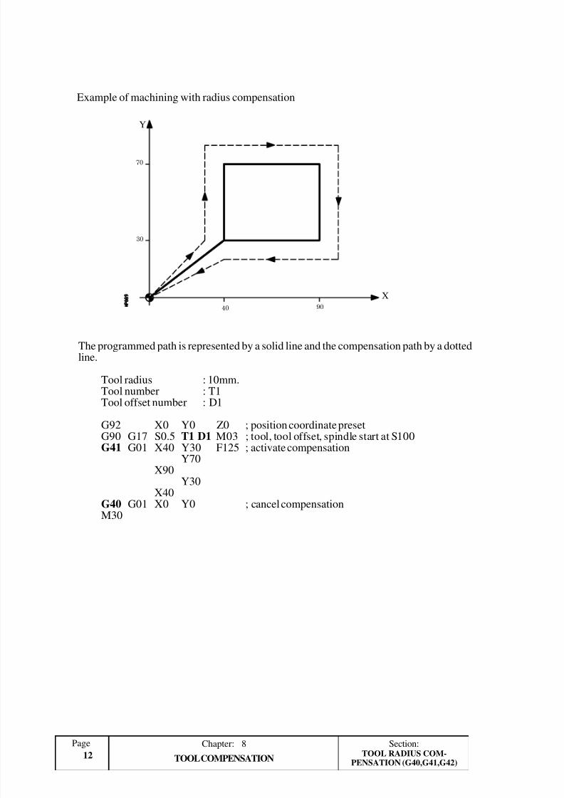
8/21/2019 CNC 8055 M Operator Manual
http://slidepdf.com/reader/full/cnc-8055-m-operator-manual 309/702
Section:Chapter: 8
12Page
TOOL COMPENSATIONTOOL RADIUS COM-
PENSATION (G40,G41,G42)
Example of machining with radius compensation
The programmed path is represented by a solid line and the compensation path by a dottedline.
Tool radius : 10mm.Tool number : T1Tool offset number : D1
G92 X0 Y0 Z0 ; position coordinate presetG90 G17 S0.5 T1 D1 M03 ; tool, tool offset, spindle start at S100G41 G01 X40 Y30 F125 ; activate compensation
Y70X90
Y30X40
G40 G01 X0 Y0 ; cancel compensationM30
Y
X

8/21/2019 CNC 8055 M Operator Manual
http://slidepdf.com/reader/full/cnc-8055-m-operator-manual 310/702
PageChapter: 8
TOOL COMPENSATION
Section:
13TOOL RADIUS COM-PENSATION (G40,G41,G42)
Example of machining with radius compensation :
The programmed path is represented by a solid line and the compensation path by a dottedline.
Tool radius : 10mm.Tool number : T1Tool offset number : D1
G92 X0 Y0 Z0 ; coordinate presetG90 G17 G01 F150 S100 T1 D1 M03 ; tool, tool offset, spindle,..G42 X30 Y30 ; activate compensation
X50Y60
X80X100Y40X140X120Y70X30
Y30G40 G00 X0 Y0 ; cancel compensation
M30
Y
X
R
R
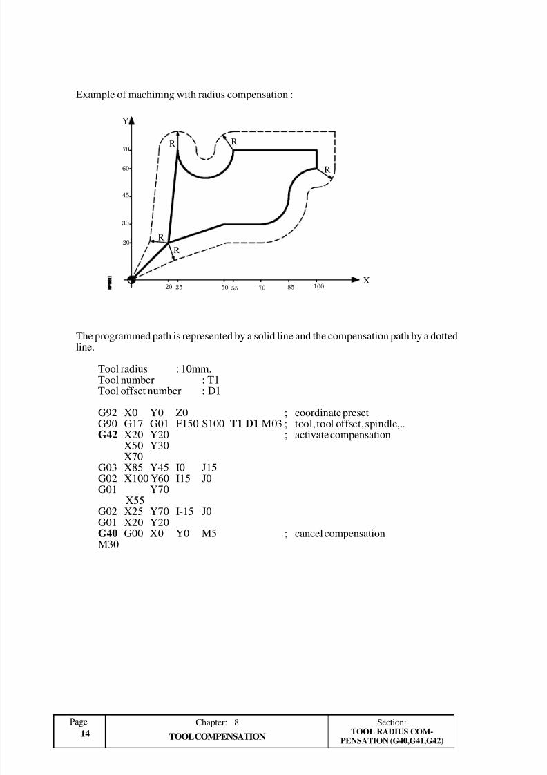
8/21/2019 CNC 8055 M Operator Manual
http://slidepdf.com/reader/full/cnc-8055-m-operator-manual 311/702
Section:Chapter: 8
14Page
TOOL COMPENSATIONTOOL RADIUS COM-
PENSATION (G40,G41,G42)
Example of machining with radius compensation :
The programmed path is represented by a solid line and the compensation path by a dottedline.
Tool radius : 10mm.Tool number : T1Tool offset number : D1
G92 X0 Y0 Z0 ; coordinate presetG90 G17 G01 F150 S100 T1 D1 M03 ; tool, tool offset, spindle,..G42 X20 Y20 ; activate compensation
X50 Y30X70
G03 X85 Y45 I0 J15G02 X100 Y60 I15 J0G01 Y70 X55G02 X25 Y70 I-15 J0G01 X20 Y20G40 G00 X0 Y0 M5 ; cancel compensation
M30
Y
R
R
X
R
R
R
8/21/2019 CNC 8055 M Operator Manual
http://slidepdf.com/reader/full/cnc-8055-m-operator-manual 312/702
PageChapter: 8
TOOL COMPENSATION
Section:
15LENGTH COMPENSATION(G43,G44,G15)
8.2 TOOL LENGTH COMPENSATION (G43, G44, G15)
With this function it is possible to compensate possible differences in length between theprogrammed tool and the tool being used.
The tool length compensation is applied on to the axis indicated by function G15 or, in itsabsence, to the axis perpendicular to the main plane.
If G17, tool length compensation on the Z axis.If G18, tool length compensation on the Y axisIf G19, tool length compensation on the X axis.
Whenever one of functions G17, G18 or G19 is programmed, the CNC assumes as newlongitudinal axis (upon which tool length compensation will be applied) the one perpendicularto the selected plane.
On the other hand, if function G15 is executed while functions G17, G18 or G19 are active,the new longitudinal axis (selected with G15) will replace the previous one.
The function codes used in length compensation are as follows:
G43 Activate tool length compensation.G44 Cancelling tool length compensation.
Function G43 only indicates that a longitudinal compensation is to be applied. TheCNC starts applying it when the longitudinal (perpendicular) axis starts moving.
Example: G92 X0 Y0 Z50 ; PresetG90 G17 G01 F150 S100 T1 D1 M03 ; Tool, Tool offset, etc.G43 X20 Y20 ; Selects compensationX70Z30 ; Applies compensation
When G43 is programmed, the CNC compensates the length in accordance with the valueof the tool offset selected with code D, or (in its absence) the tool offset shown in the tooltable for the selected tool (T).
Tool values R, L, I, K must be stored in the tool offset table before starting machining, ormust be loaded at the beginning of the program via assignments to variables TOR, TOL,TOI, TOK.
In the event of no tool offset being selected, the CNC takes D0 with values R0 L0 I0 K0.
Function G43 is modal and can be canceled via G44 and G74 (home search). If generalmachine parameter "ILCOMP=0", it is also canceled on power-up, after executing M02,M30 or after EMERGENCY or RESET.
G53 (programming with respect to machine zero) temporarily cancels G43 only whileexecuting a block which contains a G53.
Length compensation can be used together with canned cycles, although here care shouldbe taken to apply this compensation before starting the cycle.

8/21/2019 CNC 8055 M Operator Manual
http://slidepdf.com/reader/full/cnc-8055-m-operator-manual 313/702
Section:Chapter: 8
16Page
TOOL COMPENSATION LENGTH COMPENSATION(G43,G44,G15)
Example of machining with length compensation :
It is assumed that the tool used is 4mm shorter than the programmed one.
Tool length : -4mm.Tool number : T1Tool offset number : D1
G92 X0 Y0 Z0 ; coordinate presetG91 G00 G05 X50 Y35 S500 M03G43 Z-25 T1 D1 ; activate compensationG01 G07 Z-12 F100G00 Z12
X40G01 Z-17G00 G05 G44 Z42 M05 ; cancel compensationG90 G07 X0 Y0M30
Y
X
Z
8/21/2019 CNC 8055 M Operator Manual
http://slidepdf.com/reader/full/cnc-8055-m-operator-manual 314/702
PageChapter: 9 Section:
CANNED CYCLES 1
9. CANNED CYCLES
These canned cycles can be performed on any plane, the depth being along the axis selectedas longitudinal via function G15 or, in its absence, along the axis perpendicular to this plane.
The CNC offers the following machining canned cycles :
G69 Complex deep hole drilling
G81 Drilling cycle
G82 Drilling cycle with dwell
G83 Simple deep hole drilling
G84 Tapping cycle
G85 Reaming cycle
G86 Boring cycle with withdrawal in G00
G87 Rectangular pocket milling cycle
G88 Circular pocket milling cycle
G89 Boring cycle with withdrawal in G01
It also offers the following functions that can be used with the machining canned cycles:
G79 Modification of the canned cycle parametersG98 Return to the starting plane at the end of the canned cycleG99 Return to the reference plane at the end of the canned cycle.
9.1 DEFINITION OF A CANNED CYCLE
A canned cycle is defined by the G function indicating the canned cycle and its correspondingparameters.
A canned cycle cannot be defined in a block which has non-linear movements (G02, G03,G08, G09, or G33).
Also, a canned cycle cannot be executed while function G02, G03 or G33 is active. TheCNC will issue the corresponding error message.
However, once a canned cycle has been defined in a block and following blocks, functionsG02, G03, G08 or G09 can be programmed.
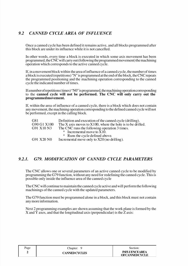
8/21/2019 CNC 8055 M Operator Manual
http://slidepdf.com/reader/full/cnc-8055-m-operator-manual 315/702
Section:Page
2Chapter: 9
CANNED CYCLES
9.2 CANNED CYCLE AREA OF INFLUENCE
Once a canned cycle has been defined it remains active, and all blocks programmed afterthis block are under its influence while it is not cancelled.
In other words, every time a block is executed in which some axis movement has beenprogrammed, the CNC will carry out (following the programmed movement) the machiningoperation which corresponds to the active canned cycle.
If, in a movement block within the area of influence of a canned cycle, the number of timesa block is executed (repetitions) "N" is programmed at the end of the block, the CNC repeatsthe programmed positioning and the machining operation corresponding to the cannedcycle the indicated number of times.
If a number of repetitions (times) “N0” is programmed, the machining operation correspondingto the canned cycle will not be performed. The CNC will only carry out theprogrammed movement.
If, within the area of influence of a canned cycle, there is a block which does not containany movement, the machining operation corresponding to the defined canned cycle will notbe performed, except in the calling block.
G81 Definition and execution of the canned cycle (drilling).G90 G1 X100 The X axis moves to X100, where the hole is to be drilled.G91 X10 N3 The CNC runs the following operation 3 times.
* Incremental move to X10.* Runs the cycle defined above.
G91 X20 N0 Incremental move only to X20 (no drilling).
9.2.1. G79. MODIFICATION OF CANNED CYCLE PARAMETERS
The CNC allows one or several parameters of an active canned cycle to be modified byprogramming the G79 function, without any need for redefining the canned cycle. This ispossible only inside the influence area of the canned cycle
The CNC will continue to maintain the canned cycle active and will perform the followingmachinings of the canned cycle with the updated parameters.
The G79 function must be programmed alone in a block, and this block must not containany more information.
Next 2 programming examples are shown assuming that the work plane is formed by theX and Y axes, and that the longitudinal axis (perpendicular) is the Z axis:
INFLUENCE AREAOF CANNED CYCLE

8/21/2019 CNC 8055 M Operator Manual
http://slidepdf.com/reader/full/cnc-8055-m-operator-manual 316/702
PageChapter: 9 Section:
CANNED CYCLES 3
Z
X
Z = - 2 8
I = - 1 4
X
Z
DC
A B E F
FEBA
C D
INFLUENCE AREAOF CANNED CYCLE
T1M6
G00 G90 X0 Y0 Z60 ; Starting point
G81 G99 G91 X15 Y25 Z-28 I-14 ; Defines drilling cycle. Drills in A
G98 G90 X25 ; Drills in B
G79 Z52 ; Modifies reference plane and machining depth
G99 X35 ; Drills in C
G98 X45 ; Drills in D
G79 Z32 ; Modifies reference plane and machining depth
G99 X55 ; Drills in E
G98 X65 ; Drills in F
M30
T1
M6
G00 G90 X0 Y0 Z60 ; Starting point
G81 G99 G90 X15 Y25 Z32 I18 ; Defines drilling cycle. Drills in A
G98 X25 ; Drills in B
G79 Z52 ; Modifies reference plane
G99 X35 ; Drills in C
G98 X45 ; Drills in D
G79 Z32 ; Modifies reference plane
G99 X55 ; Drills in E
G98 X65 ; Drills in FM30
8/21/2019 CNC 8055 M Operator Manual
http://slidepdf.com/reader/full/cnc-8055-m-operator-manual 317/702
Section:Page
4Chapter: 9
CANNED CYCLES
9.3 CANNED CYCLE CANCELLATION
A canned cycle can be cancelled via :
- Function G80, which can be programmed in any block.
- After defining a new canned cycle. This will cancel and replace any other which may beactive.
- After executing M02, M30, or after EMERGENCY or RESET.
- When searching home with function G74.
- Selecting a new work plane via functions G16, G17, G18, or G19.
CANNED CYCLECANCELLATION
8/21/2019 CNC 8055 M Operator Manual
http://slidepdf.com/reader/full/cnc-8055-m-operator-manual 318/702
PageChapter: 9 Section:
CANNED CYCLES 5
9.4 GENERAL CONSIDERATIONS
1. A canned cycle can be defined at any point in a program, i.e., it can be defined both inthe main program and in a subroutine.
2. Calls to subroutines can be made from a block within the influence of a canned cyclewithout implying the cancellation of the canned cycle.
3. The execution of a canned cycle will not alter the history of previous “G” functions.
4. Nor will the spindle turning direction be altered. A canned cycle can be entered withany turning direction (M03 or M04), leaving in the same direction in which the cyclewas entered.
Should a canned cycle be entered with the spindle stopped, it will start in a clockwisedirection (M03), and maintain the same turning direction until the cycle is completed.
5. Should it be required to apply a scaling factor when working with canned cycles, it isadvisable that this scale factor be common to all the axes involved.
6. The execution of a canned cycle cancels radius compensation (G41 and G42). It isequivalent to G40.
7. If tool length compensation (G43) is to be used, this function must be programmed inthe same block or in the one before the definition of the canned cycle.
The CNC applies the tool length compensation when the longitudinal (perpendicular)
axis starts moving. Therefore, it is recommended to position the tool outside the cannedcycle area when defining function G43 for the canned cycle.
8. The execution of any canned cycle will alter the global parameter P299.
GENERAL CONSIDERATIONS
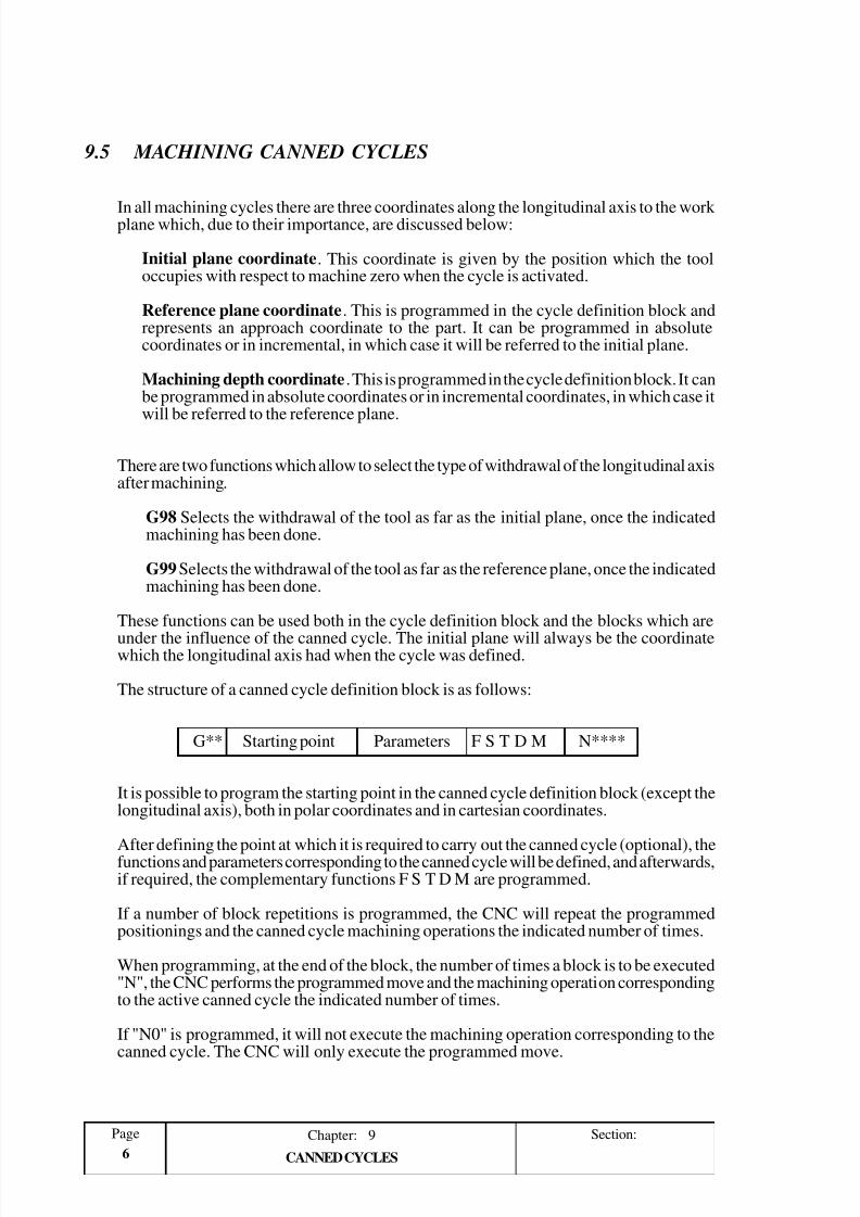
8/21/2019 CNC 8055 M Operator Manual
http://slidepdf.com/reader/full/cnc-8055-m-operator-manual 319/702
Section:Page
6Chapter: 9
CANNED CYCLES
9.5 MACHINING CANNED CYCLES
In all machining cycles there are three coordinates along the longitudinal axis to the work plane which, due to their importance, are discussed below:
Initial plane coordinate. This coordinate is given by the position which the tooloccupies with respect to machine zero when the cycle is activated.
Reference plane coordinate. This is programmed in the cycle definition block andrepresents an approach coordinate to the part. It can be programmed in absolutecoordinates or in incremental, in which case it will be referred to the initial plane.
Machining depth coordinate. This is programmed in the cycle definition block. It canbe programmed in absolute coordinates or in incremental coordinates, in which case itwill be referred to the reference plane.
There are two functions which allow to select the type of withdrawal of the longitudinal axisafter machining.
G98 Selects the withdrawal of the tool as far as the initial plane, once the indicatedmachining has been done.
G99 Selects the withdrawal of the tool as far as the reference plane, once the indicatedmachining has been done.
These functions can be used both in the cycle definition block and the blocks which are
under the influence of the canned cycle. The initial plane will always be the coordinatewhich the longitudinal axis had when the cycle was defined.
The structure of a canned cycle definition block is as follows:
G** Starting point Parameters F S T D M N****
It is possible to program the starting point in the canned cycle definition block (except thelongitudinal axis), both in polar coordinates and in cartesian coordinates.
After defining the point at which it is required to carry out the canned cycle (optional), thefunctions and parameters corresponding to the canned cycle will be defined, and afterwards,if required, the complementary functions F S T D M are programmed.
If a number of block repetitions is programmed, the CNC will repeat the programmedpositionings and the canned cycle machining operations the indicated number of times.
When programming, at the end of the block, the number of times a block is to be executed"N", the CNC performs the programmed move and the machining operation correspondingto the active canned cycle the indicated number of times.
If "N0" is programmed, it will not execute the machining operation corresponding to thecanned cycle. The CNC will only execute the programmed move.

8/21/2019 CNC 8055 M Operator Manual
http://slidepdf.com/reader/full/cnc-8055-m-operator-manual 320/702
PageChapter: 9 Section:
CANNED CYCLES 7
The general operation for all the cycles is as follows:
* If the spindle was in operation previously, its turning direction is maintained. If it was notin movement, it will start by turning clockwise (M03).
* Positioning (if programmed) at the starting point for the programmed cycle.
* Rapid movement of the longitudinal axis from the initial plane to the reference plane.
* Execution of the programmed machining cycle.
* Rapid withdrawal of the longitudinal axis to the initial plane or reference plane,depending on whether G98 or G99 has been programmed.
Below, a detailed explanation is given of machining canned cycles, assuming in all casesthat the work plane is made up of the X and Y axes and that the longitudinal axis is the Z
axis.

8/21/2019 CNC 8055 M Operator Manual
http://slidepdf.com/reader/full/cnc-8055-m-operator-manual 321/702
Section:Page
8Chapter: 9
CANNED CYCLES
9.5.1 G69. COMPLEX DEEP HOLE DRILLING CYCLE
This cycle makes successive drilling steps until the final coordinate is reached.
The tool withdraws a fixed amount after each drilling operation, it being possible to selectthat every J drillings it withdraws to the reference plane.
A dwell can also be programmed after every drilling.
Working in cartesian coordinates, the basic structure of the block is as follows:
G69 G98/G99 X Y Z I B C D H J K L R
G98 The tool withdraws to the Initial Plane, once the hole has been drilled.
G99 The tool withdraws to the Reference Plane, once the hole has been drilled.
XY±5.5 These are optional and define the movement of the axes of the main plane to
position the tool at the machining point.This point can be programmed in cartesian coordinates or in polar coordinates,and the coordinates may be absolute or incremental, according to whether themachine is operating in G90 or G91.
Z±5.5 Defines the reference plane coordinate. It can be programmed in absolutecoordinates or incremental coordinates, in which case it will be referred to theinitial plane.
If this is not programmed, the CNC will take the position occupied by the tool atthat moment as the reference plane.
I±5.5 Defines the total drilling depth. It can be programmed in absolute coordinates orincremental coordinates and in this case will be referred to the reference plane.
G99
G98
G00
G01
M04
M03
K
K
D
C
COMPLEX DEEP HOLEDRILLING (G69)
8/21/2019 CNC 8055 M Operator Manual
http://slidepdf.com/reader/full/cnc-8055-m-operator-manual 322/702
PageChapter: 9 Section:
CANNED CYCLES 9
B5.5 Defines the drilling step in the axis longitudinal to the main plane.
C5.5 Defines to what distance from the previous drilling step, the longitudinal axis willtravel in rapid feed (G00) in its approach to the part to make another drilling step.
If this is not programmed, the value of 1 mm (0.040 inch) will be taken. If programmed with a value of 0, the CNC will display the corresponding error.
D5.5 Defines the distance between the reference plane and the surface of the part wherethe drilling is to be done.
In the first drilling, this amount will be added to “B” drilling step. If it is notprogrammed, a value of 0 will be taken.
H5.5 Distance which the longitudinal axis will withdraw in rapid (G00) after eachdrilling step.
If this is not programmed, the longitudinal axis will withdraw to the referenceplane. If programmed with a value of 0, the CNC will display the correspondingerror.
J4 Defines after how many drilling steps the tool withdraws to the reference planein G00. A value of between 0 and 9999 can be programmed.
If this is not programmed or is programmed with a value of 0, a value of 1 willbe taken, i.e., it will return to the reference plane after each drilling step.
K5 Defines the dwell time, in hundredths of a second, after each drilling step, until
the withdrawal begins. Should this not be programmed, the CNC will take a valueof K0.
L5.5 Defines the minimum value which the drilling step can acquire. This parameteris used with R values other than 1mm (0.040 inch). If this is not programmed orprogrammed with a value of 0, a value of 1 will be taken.
R5.5 Factor which reduces the drilling step “B”. If this is not programmed orprogrammed with a value of 0, a value of 1 will be taken.
If R equals 1, all the drilling steps will be the same and the programmed value “B”.
If R is not equal to 1, the first drilling step will be “B”, the second, “R B”, the
third “R (RB)”, and so on, i.e., after the second step, the new step will be theproduct of factor R by the previous step.
If R is selected with a value other than 1, the CNC will not allow smaller stepsthan that programmed in L.
COMPLEX DEEP HOLEDRILLING (G69)

8/21/2019 CNC 8055 M Operator Manual
http://slidepdf.com/reader/full/cnc-8055-m-operator-manual 323/702
Section:Page
10Chapter: 9
CANNED CYCLES COMPLEX DEEP HOLEDRILLING (G69)
Basic operation:
1. If the spindle was in operation previously, its turning direction is maintained. If it wasnot in movement, it will start by turning clockwise (M03).
2. Rapid movement of the longitudinal axis from the initial plane to the reference plane.
3. First drilling operation. Movement at working feedrate of the longitudinal axis to theprogrammed incremental depth in “B+D”.
This movement will be carried out either in G07 or G50 depending on the valueassigned to the longitudinal axis "INPOSW2(P51)"
If P51 =0, in G7 (square corner) If P51=1, in G50 (controlled round corner).

8/21/2019 CNC 8055 M Operator Manual
http://slidepdf.com/reader/full/cnc-8055-m-operator-manual 324/702
PageChapter: 9 Section:
CANNED CYCLES 11
4. Drilling loop. The following steps will be repeated until the machining depth coordinateprogrammed in I is reached.
4.1. Dwell K in hundredths of a second, if this has been programmed.
4.2. Withdrawal of the longitudinal axis in rapid (G00) as far as the reference plane,if the number of drillings programmed in J were made, otherwise it withdraws thedistance programmed in “H”.
4.3. Longitudinal axis approach in rapid (G00) as far as a distance “C” of the previousdrilling step.
4.4. Another drilling step. Movement of the longitudinal axis, at the working feedrate(G01) until the next incremental drilling according to “B and R”.
This movement will be carried out in either in G07 or in G50 depending on the
value assigned to the parameter of the longitudinal axis "INPOSW2(P51)".
If P51=0 in G7 (square corner). If P51=1, in G50 (controlled round corner).
5. Dwell time K in hundredths of a second, if this has been programmed.
6. Withdrawal at rapid feedrate (G00) of the longitudinal axis to the initial or referenceplane, depending on whether G98 or G99 has been programmed.
If a scaling factor is applied to this cycle, it should be borne in mind that this scaling factorwill only affect the reference plane coordinates and drilling depth.
Therefore, and due to the fact that parameter “D” is not affected by the scaling factor, thesurface coordinate of the part will not be proportional to the programmed cycle.
Programming example supposing that the work plane is formed by the X and Y axes, thatthe longitudinal axis is the Z axis and that the starting point is X0 Y0 Z0:
T1M6G0 G90 X0 Y0 Z0 ..................................................... ; Starting pointG69 G98 G91 X100 Y25 Z-98 I-52 B12 C2 D2
H5 J2 K150 L3 R0.8 F100 S500 M8 ...... ; Canned cycle definitionG80 ............................................................................. ; Canned cycle cancellationG90 X0 Y0 .................................................................; Positioning
M30 ............................................................................ ; End of program
COMPLEX DEEP HOLEDRILLING (G69)

8/21/2019 CNC 8055 M Operator Manual
http://slidepdf.com/reader/full/cnc-8055-m-operator-manual 325/702
Section:Page
12Chapter: 9
CANNED CYCLES DRILLING (G81)
9.5.2. G81 DRILLING CANNED CYCLE
This cycle drills at the point indicated until the final programmed coordinate is reached.
It is possible to program a dwell at the bottom of the drill hole.
Working in cartesian coordinates, the basic structure of the block is as follows:
G81 G98/G99 X Y Z I K
G98 The tool withdraws to the Initial Plane, once the hole has been drilled.
G99 The tool withdraws to the Reference Plane, once the hole has been drilled.
XY±5.5 These are optional and define the movement of the axes of the main plane toposition the tool at the machining point.
This point can be programmed in cartesian coordinates or in polar coordinates,and the coordinates may be absolute or incremental, according to whether themachine is operating in G90 or G91.
Z±5.5 Defines the reference plane coordinate. It can be programmed in absolutecoordinates or incremental coordinates and in this case will be referred to theinitial plane.
If this is not programmed, the CNC will take the position occupied by the tool atthat moment as the reference plane.
I±5.5 Defines drilling depth. It can be programmed in absolute coordinates or incrementalcoordinates and in this case will be referred to the reference plane.
K5 Defines the dwell time, in hundredths of a second, after each drilling step, untilthe withdrawal begins. Should this not be programmed, the CNC will take a valueof K0.
K
G98
G99
G00
G01
M03M04

8/21/2019 CNC 8055 M Operator Manual
http://slidepdf.com/reader/full/cnc-8055-m-operator-manual 326/702
PageChapter: 9 Section:
CANNED CYCLES 13DRILLING (G81)
Basic operation:
1. If the spindle was in operation previously, its turning direction is maintained. If it wasnot in movement, it will start by turning clockwise (M03).
2. Rapid movement of the longitudinal axis from the initial plane to the reference plane.
3. The hole is drilled. Movement at working feedrate of the longitudinal axis to theprogrammed machining depth I.
4. Dwell time K in hundredths of a second, if this has been programmed.
5. Withdrawal at rapid feedrate (G00) of the longitudinal axis to the initial or referenceplane, depending on whether G98 or G99 has been programmed.
Programming example assuming that the work plane is formed by the X and Y axes, thatthe longitudinal axis is the Z axis and that the starting point is X0 Y0 Z0:
T1M6G0 G90 X0 Y0 Z0 ................................................................. ; Starting pointG81 G98 G00 G91 X250 Y350 Z-98 I-22 F100 S500 ........ ; Positioning and definition of canned cycleG93 I250 J250 ...................................................................... ; Sets polar coordinate originQ-45 N3 ................................................................................. ; Turn and canned cycle, 3 timesG80 ........................................................................................ ; Cancels canned cycleG90 X0 Y0 ............................................................................ ; PositioningM30 ....................................................................................... ; End of program

8/21/2019 CNC 8055 M Operator Manual
http://slidepdf.com/reader/full/cnc-8055-m-operator-manual 327/702
Section:Page
14Chapter: 9
CANNED CYCLES
9.5.3. G82. DRILLING CANNED CYCLE WITH DWELL
This cycle drills at the point indicated until the final programmed coordinate is reached.
Then it executes a dwell at the bottom of the drill hole.
Working in cartesian coordinates, the basic structure of the block is as follows:
G82 G98/G99 X Y Z I K
G98 The tool withdraws to the Initial Plane, once the hole has been drilled.
G99 The tool withdraws to the Reference Plane, once the hole has been drilled.
XY±5.5 These are optional and define the movement of the axes of the main plane toposition the tool at the machining point.
This point can be programmed in cartesian coordinates or in polar coordinates,and the coordinates may be absolute or incremental, according to whether themachine is operating in G90 or G91.
Z±5.5 Defines the reference plane coordinate. It can be programmed in absolutecoordinates or incremental coordinates and in this case will be referred to theinitial plane.
If this is not programmed, the CNC will take the position occupied by the tool atthat moment as the reference plane.
I±5.5 Defines drilling depth. It can be programmed in absolute coordinates or incrementalcoordinates and in this case will be referred to the reference plane.
K5 Defines the dwell time, in hundredths of a second, after each drilling step, untilthe withdrawal begins. Should this not be programmed, the CNC will take a valueof K0.
K
G98
G99
G00
G01
M03
M04
DRILLING WITH DWELL (G82)

8/21/2019 CNC 8055 M Operator Manual
http://slidepdf.com/reader/full/cnc-8055-m-operator-manual 328/702
PageChapter: 9 Section:
CANNED CYCLES 15DRILLING WITH DWELL (G82)
Basic operation:
1. If the spindle was in operation previously, its turning direction is maintained. If it wasnot in movement, it will start by turning clockwise (M03).
2. Rapid movement of the longitudinal axis from the initial plane to the reference plane.
3. The hole is drilled. Movement at working feedrate of the longitudinal axis to the bottomof the machined hole, programmed in I.
4. Dwell time K in hundredths of a second.
5. Withdrawal at rapid feedrate (G00) of the longitudinal axis to the initial or referenceplane, according to whether G98 or G99 has been programmed.
Programming example assuming that the work plane is formed by the X and Y axes, that
the longitudinal axis is the Z axis and that the starting point is X0 Y0 Z0:
T1M6G0 G90 X0 Y0 Z0 ....................................................................... ; Starting pointG82 G99 G00 G91 X50 Y50 Z-98 I-22 K150 F100 S500 N3 .... ; 3 machining positionsG98 G90 G00 X500 Y500 .......................................................... ; Positioning and canned cycleG80 .............................................................................................. ; Cancels canned cycle
G90 X0 Y0 .................................................................................. ; PositioningM30 ............................................................................................. ; End of program
X
Z
Z=0 98 mm
2 mm
20 mm
Y

8/21/2019 CNC 8055 M Operator Manual
http://slidepdf.com/reader/full/cnc-8055-m-operator-manual 329/702
Section:Chapter: 9
16
Page
CANNED CYCLES SIMPLE DEEP HOLE DRILLING(G83)
G01
G00
M03
M04G98
G99
9.5.4. G83. SIMPLE DEEP HOLE DRILLING
This cycle performs successive drilling steps until the final programmed coordinate is reached.
The tool withdraws as far as the reference plane after each drilling step.
Working in cartesian coordinates, the basic structure of the block is as follows:
G83 G98/G99 X Y Z I J
G98 The tool withdraws to the Initial Plane, once the hole has been drilled.
G99 The tool withdraws to the Reference Plane, once the hole has been drilled.
XY±5.5 These are optional and define the movement of the axes of the main plane toposition the tool at the machining point.
This point can be programmed in cartesian coordinates or in polar coordinates,and the coordinates may be absolute or incremental, according to whether themachine is operating in G90 or G91.
Z±5.5 Defines the reference plane coordinate. It can be programmed in absolutecoordinates or incremental coordinates and in this case will be referred to theinitial plane.
If this is not programmed, the CNC will take the position occupied by the tool atthat moment as the reference plane.
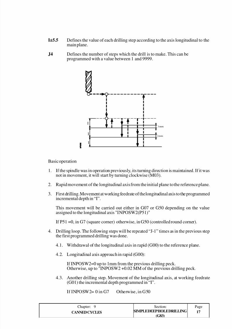
8/21/2019 CNC 8055 M Operator Manual
http://slidepdf.com/reader/full/cnc-8055-m-operator-manual 330/702
PageChapter: 9 Section:
17CANNED CYCLES
1 mm
1 mm
I
I
I
SIMPLE DEEP HOLE DRILLING(G83)
I±5.5 Defines the value of each drilling step according to the axis longitudinal to themain plane.
J4 Defines the number of steps which the drill is to make. This can beprogrammed with a value between 1 and 9999.
Basic operation
1. If the spindle was in operation previously, its turning direction is maintained. If it wasnot in movement, it will start by turning clockwise (M03).
2. Rapid movement of the longitudinal axis from the initial plane to the reference plane.
3. First drilling. Movement at working feedrate of the longitudinal axis to the programmedincremental depth in “I”.
This movement will be carried out either in G07 or G50 depending on the valueassigned to the longitudinal axis "INPOSW2(P51)"
If P51 =0, in G7 (square corner) otherwise, in G50 (controlled round corner).
4. Drilling loop. The following steps will be repeated “J-1” times as in the previous stepthe first programmed drilling was done.
4.1. Withdrawal of the longitudinal axis in rapid (G00) to the reference plane.
4.2. Longitudinal axis approach in rapid (G00):
If INPOSW2=0 up to 1mm from the previous drilling peck.Otherwise, up to "INPOSW2 +0.02 MM of the previous drilling peck.
4.3. Another drilling step. Movement of the longitudinal axis, at working feedrate(G01) the incremental depth programmed in “I”.
If INPOSW2= 0 in G7 Otherwise, in G50
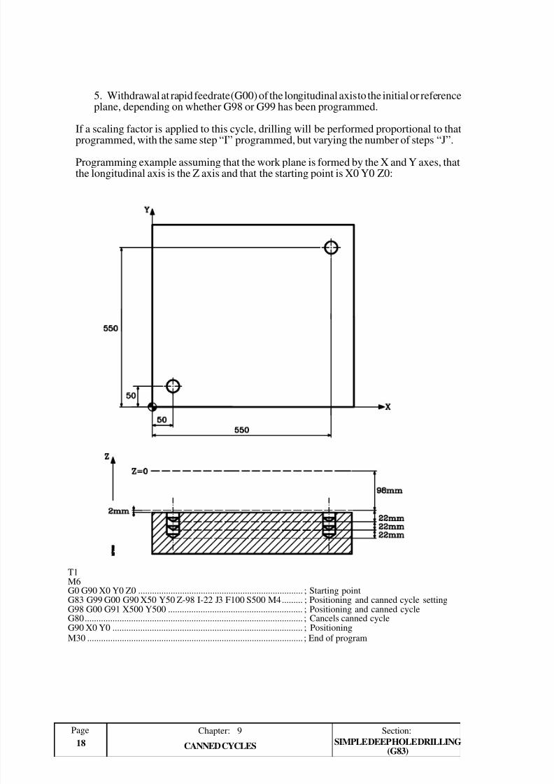
8/21/2019 CNC 8055 M Operator Manual
http://slidepdf.com/reader/full/cnc-8055-m-operator-manual 331/702
Section:Chapter: 9
18
Page
CANNED CYCLES
5. Withdrawal at rapid feedrate (G00) of the longitudinal axis to the initial or referenceplane, depending on whether G98 or G99 has been programmed.
If a scaling factor is applied to this cycle, drilling will be performed proportional to thatprogrammed, with the same step “I” programmed, but varying the number of steps “J”.
Programming example assuming that the work plane is formed by the X and Y axes, thatthe longitudinal axis is the Z axis and that the starting point is X0 Y0 Z0:
T1M6G0 G90 X0 Y0 Z0 ....................................................................... ; Starting pointG83 G99 G00 G90 X50 Y50 Z-98 I-22 J3 F100 S500 M4......... ; Positioning and canned cycle settingG98 G00 G91 X500 Y500 .......................................................... ; Positioning and canned cycleG80.............................................................................................. ; Cancels canned cycleG90 X0 Y0 .................................................................................. ; PositioningM30 ............................................................................................. ; End of program
SIMPLE DEEP HOLE DRILLING(G83)
8/21/2019 CNC 8055 M Operator Manual
http://slidepdf.com/reader/full/cnc-8055-m-operator-manual 332/702
PageChapter: 9 Section:
19CANNED CYCLES
9.5.5. G84. TAPPING CANNED CYCLE
This cycle taps at the point indicated until the final programmed coordinate is reached. Thegeneral logic output "TAPPING" (M5517) will stay active during this cycle.
Due to the fact that the tapping tool turns in two directions (one when tapping and the otherwhen withdrawing from the thread), by means of the machine parameter of the spindle“SREVM05” it is possible to select whether the change in turning direction is made withthe intermediate spindle stop, or directly.
General machine parameter "STOPAP(P116)" indicates whether general inputs /STOP, /FEEDHOL and /XFERINH are enabled or not while executing function G84.
It is possible to program a dwell before each reversal of the spindle turning direction, i.e.,at the bottom of the thread hole and when returning to the reference plane.
Working in cartesian coordinates, the basic structure of the block is as follows:
G84 G98/G99 X Y Z I K R
G98 The tool withdraws to the Initial Plane, once the hole has been tapped.
G99 The tool withdraws to the Reference Plane, once the hole has been tapped.
XY±5.5 These are optional and define the movement of the axes of the main plane toposition the tool at the machining point.
This point can be programmed in cartesian coordinates or in polar coordinates,and the coordinates may be absolute or incremental, according to whether themachine is operating in G90 or G91.
Z±5.5 Defines the reference plane coordinate. It can be programmed in absolutecoordinates or incremental coordinates and in this case will be referred to theinitial plane.
If this is not programmed, the CNC will take the position occupied by the tool atthat moment as the reference plane.
I±5.5 Defines tapping depth. It can be programmed in absolute coordinates or
incremental coordinates and in this case will be referred to the reference plane.K5 Defines the dwell time, in hundredths of a second, after each drilling step, until
the withdrawal begins. Should this not be programmed, the CNC will take a valueof K0.
R Defines the type of tapping cycle to be performEd: normal if “R0” and rigid if “R1”.
To perform a rigid tapping cycle, the spindle must be installed so it can work in closedloop; i.e. with encoder and servo drive.
During rigid tapping the CNC interpolates the longitudinal axis with the spindle
rotation.
TAPPING CANNED CYCLE(G 84)
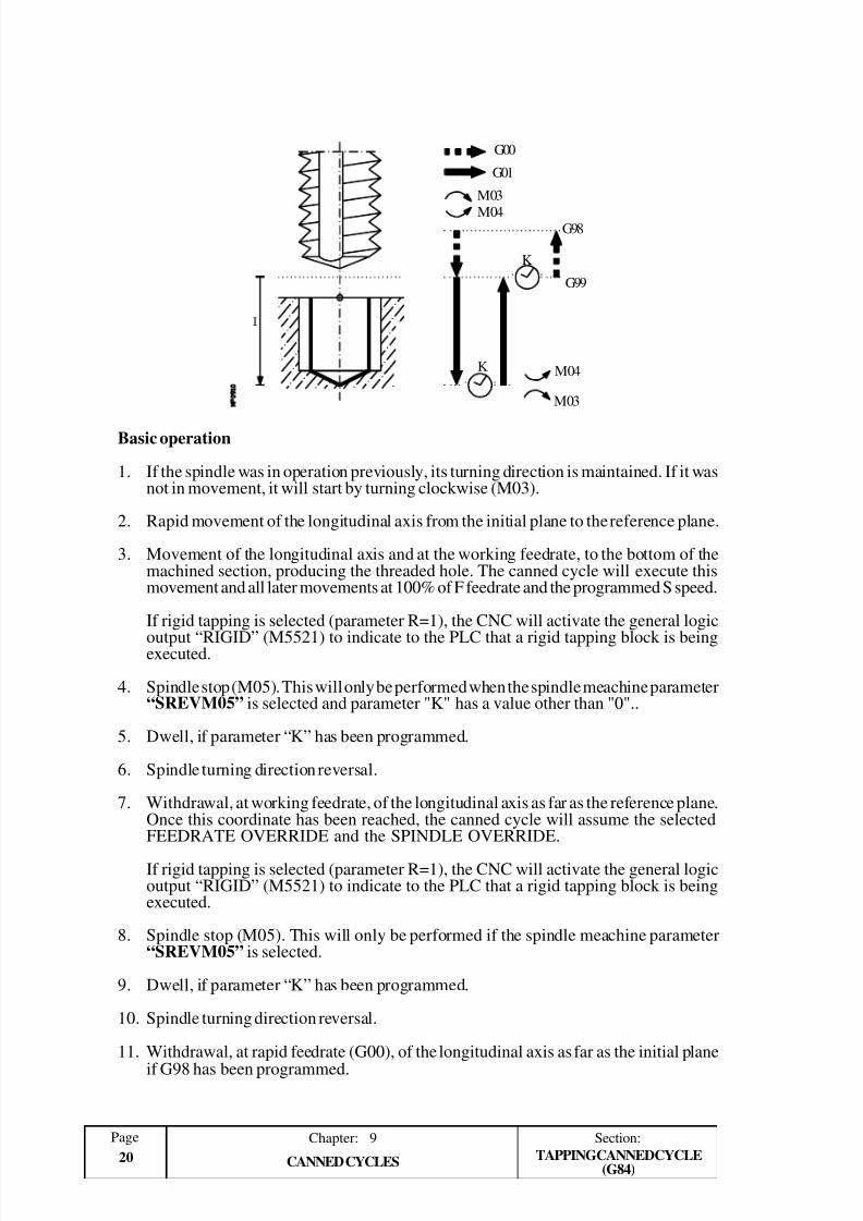
8/21/2019 CNC 8055 M Operator Manual
http://slidepdf.com/reader/full/cnc-8055-m-operator-manual 333/702
Section:Chapter: 9
20
Page
CANNED CYCLES
G01
G00
M04
M03
G98
G99
K M04
M03
K
TAPPING CANNED CYCLE(G84)
Basic operation
1. If the spindle was in operation previously, its turning direction is maintained. If it wasnot in movement, it will start by turning clockwise (M03).
2. Rapid movement of the longitudinal axis from the initial plane to the reference plane.
3. Movement of the longitudinal axis and at the working feedrate, to the bottom of themachined section, producing the threaded hole. The canned cycle will execute thismovement and all later movements at 100% of F feedrate and the programmed S speed.
If rigid tapping is selected (parameter R=1), the CNC will activate the general logic
output “RIGID” (M5521) to indicate to the PLC that a rigid tapping block is beingexecuted.
4. Spindle stop (M05). This will only be performed when the spindle meachine parameter“SREVM05” is selected and parameter "K" has a value other than "0"..
5. Dwell, if parameter “K” has been programmed.
6. Spindle turning direction reversal.
7. Withdrawal, at working feedrate, of the longitudinal axis as far as the reference plane.Once this coordinate has been reached, the canned cycle will assume the selectedFEEDRATE OVERRIDE and the SPINDLE OVERRIDE.
If rigid tapping is selected (parameter R=1), the CNC will activate the general logicoutput “RIGID” (M5521) to indicate to the PLC that a rigid tapping block is beingexecuted.
8. Spindle stop (M05). This will only be performed if the spindle meachine parameter“SREVM05” is selected.
9. Dwell, if parameter “K” has been programmed.
10. Spindle turning direction reversal.
11. Withdrawal, at rapid feedrate (G00), of the longitudinal axis as far as the initial plane
if G98 has been programmed.

8/21/2019 CNC 8055 M Operator Manual
http://slidepdf.com/reader/full/cnc-8055-m-operator-manual 334/702
PageChapter: 9 Section:
21CANNED CYCLES
Programming example assuming that the work plane is formed by the X and Y axes, thatthe longitudinal axis is the Z axis and that the starting point is X0 Y0 Z0:
T1M6G0 G90 X0 Y0 Z0 ......................................................................... ; Starting pointG84 G99 G00 G91 X50 Y50 Z-98 I-22 K150 F350 S500 N3 ...... ; 3 machining positionsG98 G00 G90 X500 Y500 ............................................................ ; Positioning and canned cycleG80 ............................................................................................... ; Cancels canned cycleG90 X0 Y0 .................................................................................... ; Positioning
M30 .............................................................................................. ; End of program
TAPPING CANNED CYCLE(G84)

8/21/2019 CNC 8055 M Operator Manual
http://slidepdf.com/reader/full/cnc-8055-m-operator-manual 335/702
Section:Chapter: 9
22
Page
CANNED CYCLES REAMING (G85)
9.5.6. G85. REAMING CYCLE
This cycle reams at the point indicated until the final programmed coordinate is reached.
It is possible to program a dwell at the bottom of the machined hole.
Working in cartesian coordinates, the basic structure of the block is as follows:
G85 G98/G99 X Y Z I K
G98 The tool withdraws to the Initial Plane, once the hole has been reamed.
G99 The tool withdraws to the Reference Plane, once the hole has been reamed.
XY±5.5 These are optional and define the movement of the axes of the main plane toposition the tool at the machining point.
This point can be programmed in cartesian coordinates or in polar coordinates,and the coordinates may be absolute or incremental, according to whether themachine is operating in G90 or G91.
Z±5.5 Defines the reference plane coordinate. It can be programmed in absolutecoordinates or incremental coordinates and in this case will be referred to theinitial plane.
If this is not programmed, the CNC will take the position occupied by the tool atthat moment as the reference plane.
I±5.5 Defines reaming depth. It can be programmed in absolute coordinates orincremental coordinates and in this case will be referred to the reference plane.
K5 Defines the dwell time, in hundredths of a second, after each drilling step, untilthe withdrawal begins. Should this not be programmed, the CNC will take a valueof K0.
G01
G00
M03M04
G98
G99
K
8/21/2019 CNC 8055 M Operator Manual
http://slidepdf.com/reader/full/cnc-8055-m-operator-manual 336/702
PageChapter: 9 Section:
23CANNED CYCLES REAMING (G85)
Basic operation
1. If the spindle was in operation previously, its turning direction is maintained. If it wasnot in movement, it will start by turning clockwise (M03).
2. Rapid movement of the longitudinal axis from the initial plane to the reference plane.
3. Movement at the working feedrate (G01) of the longitudinal axis to the bottom of themachined hole, and reaming.
4. Dwell, if parameter “K” has been programmed.
5. Withdrawal at working feedrate, of the longitudinal axis as far as the reference plane.
6. Withdrawal, at rapid feedrate (G00), of the longitudinal axis as far as the initial plane
if G98 has been programmed.
Programming example assuming that the work plane is formed by the X and Y axes, thatthe longitudinal axis is the Z axis and that the starting point is X0 Y0 Z0:
T1M6G0 G90 X0 Y0 Z0 ......................................................... ;Starting pointG85 G98 G91 X250 Y350 Z-98 I-22 F100 S500 .......... ;Canned cycle definitionG80 ................................................................................. ;Canned cycle cancellation
G90 X0 Y0 ..................................................................... ;PositioningM30 ................................................................................ ;End of program

8/21/2019 CNC 8055 M Operator Manual
http://slidepdf.com/reader/full/cnc-8055-m-operator-manual 337/702
Section:Chapter: 9
24
Page
CANNED CYCLES
9.5.7. G86. BORING CYCLE WITH WITHDRAWAL IN RAPID (G00)
This cycle bores at the point indicated until the final programmed coordinate is reached.
It is possible to program a dwell at the bottom of the machined hole.
Working in cartesian coordinates, the basic structure of the block is as follows:
G86 G98/G99 X Y Z I K
G98 The tool withdraws to the Initial Plane, once the hole has been bored.
G99 The tool withdraws to the Reference Plane, once the hole has been bored.
XY±5.5 These are optional and define the movement of the axes of the main plane toposition the tool at the machining point.
This point can be programmed in cartesian coordinates or in polar coordinates,and the coordinates may be absolute or incremental, according to whether themachine is operating in G90 or G91.
Z±5.5 Defines the reference plane coordinate. It can be programmed in absolutecoordinates or incremental coordinates and in this case will be referred to theinitial plane.
If this is not programmed, the CNC will take the position occupied by the tool atthat moment as the reference plane.
I±5.5 Defines boring depth. It can be programmed in absolute coordinates or incrementalcoordinates and in this case will be referred to the reference plane.
K5 Defines the dwell time, in hundredths of a second, after each drilling step, untilthe withdrawal begins. Should this not be programmed, the CNC will take a valueof K0.
Basic operation
G01
G00
G98
G99
K
BORING WITH RAPIDWITHDRAWAL (G86)
8/21/2019 CNC 8055 M Operator Manual
http://slidepdf.com/reader/full/cnc-8055-m-operator-manual 338/702
PageChapter: 9 Section:
25CANNED CYCLES
1. If the spindle was in operation previously, its turning direction is maintained. If it wasnot in movement, it will start by turning clockwise (M03).
2. Rapid movement of the longitudinal axis from the initial plane to the reference plane.
3. Movement at the working feedrate (G01) of the longitudinal axis to the bottom of themachined hole, and boring.
4. Spindle stop (M05).
5. Dwell, if parameter “K” has been programmed.
6. Withdrawal, at rapid feedrate (G00), of the longitudinal axis as far as the initial planeor the reference plane, depending on whether G98 or G99 has been programmed.
7. When spindle withdrawal has been completed, it will start in the same direction in which
it was turning before.
Programming example assuming that the work plane is formed by the X and Y axes, thatthe longitudinal axis is the Z axis and that the starting point is X0 Y0 Z0:
T1M6G0 G90 X0 Y0 Z0 ......................................................... ;Starting pointG86 G98 G91 X250 Y350 Z-98 I-22 K20 F100 S500 .. ;Canned cycle definitionG80 ................................................................................. ;Canned cycle cancellationG90 X0 Y0 ..................................................................... ;PositioningM30 ................................................................................ ;End of program
BORING WITH RAPIDWITHDRAWAL (G86)

8/21/2019 CNC 8055 M Operator Manual
http://slidepdf.com/reader/full/cnc-8055-m-operator-manual 339/702
Section:Page Chapter: 9
CANNED CYCLES26
9.5.8. G87. RECTANGULAR POCKET CANNED CYCLE
This cycle executes a rectangular pocket at the point indicated until the final programmedcoordinate is reached.
It is possible to program, in addition to milling pass and feedrate, a final finishing step withits corresponding milling feedrate.
In order to obtain a good finish in the machining of the pocket walls, the CNC will applya tangential entry and exit to the last milling step during each cutting operation.
Working in cartesian coordinates, the basic structure of the block is as follows:
G87 G98/G99 X Y Z I J K B C D H L V
G98 The tool withdraws to the Initial Plane, once the pocket has been made.
G99 The tool withdraws to the Reference Plane, once the pocket has been made.
XY±5.5 These are optional and define the movement of the axes of the main plane to
position the tool at the machining point.This point can be programmed in cartesian coordinates or in polar coordinates,and the coordinates may be absolute or incremental, according to whether themachine is operating in G90 or G91.
Z±5.5 Defines the reference plane coordinate.
When programmed in absolute coordinates, it will be referred to the part zero andwhen programmed in incremental coordinates, it will be referred to the startingplane (P.P.).
G00
G01(F)
G98
G99
G01(H)
D
CL
J
RECTANGULAR POCKET (G87)

8/21/2019 CNC 8055 M Operator Manual
http://slidepdf.com/reader/full/cnc-8055-m-operator-manual 340/702
PageChapter: 9 Section:
CANNED CYCLES 27
If this is not programmed, the CNC will take the position occupied by the tool atthat moment as the reference plane. Thus, the starting plane (P.P.) and thereference plane (P.R.) wil be the same.
I±5.5 Defines machining depth.
When programmed in absolute coordinates, it will be referred to the part zero andwhen programmed in incremental coordinates, it will be referred to the startingplane (P.P.).
J±5.5 Defines the distance from the center to the edge of the pocket according to theabscissa axis. The sign indicates the pocket machining direction.
J with “+” sign J with “-” sign
K5.5 Defines the distance from the center to the edge of the pocket according to the
ordinate axis.
RECTANGULAR POCKET (G87)
J J

8/21/2019 CNC 8055 M Operator Manual
http://slidepdf.com/reader/full/cnc-8055-m-operator-manual 341/702
Section:Page Chapter: 9
CANNED CYCLES28
C
B±5.5 Defines the cutting depth according to the longitudinal axis.
- If this is programmed with a positive sign, the entire cycle will be executedwith the same machining pass, this being equal to or less than that programmed.
- If this is programmed with a negative sign, the entire pocket will be executedwith the given pass, except for the last pass which will machine the rest.
C±5.5 Defines the milling pass along the main plane.
- If the value is positive, the entire cycle will be executed with the same millingstep, this being equal to or less than that programmed.
- If the value is negative, the entire pocket will be executed with the given step,except for the last step which will machine whatever remains.
If this is not programmed, the CNC will assume 3/4 of the diameter of the diameterof the selected tool.
If programmed with a value greater than the tool diameter, the CNC will issue thecorresponding error.
If programmed with a value of 0, the CNC will show the corresponding error.
RECTANGULAR POCKET (G87)
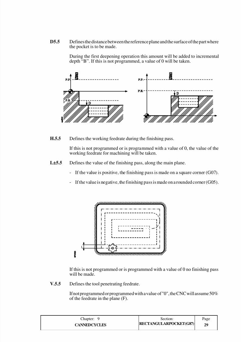
8/21/2019 CNC 8055 M Operator Manual
http://slidepdf.com/reader/full/cnc-8055-m-operator-manual 342/702
PageChapter: 9 Section:
CANNED CYCLES 29
L
D5.5 Defines the distance between the reference plane and the surface of the part wherethe pocket is to be made.
During the first deepening operation this amount will be added to incrementaldepth “B”. If this is not programmed, a value of 0 will be taken.
H.5.5 Defines the working feedrate during the finishing pass.
If this is not programmed or is programmed with a value of 0, the value of theworking feedrate for machining will be taken.
L±5.5 Defines the value of the finishing pass, along the main plane.
- If the value is positive, the finishing pass is made on a square corner (G07).
- If the value is negative, the finishing pass is made on a rounded corner (G05).
If this is not programmed or is programmed with a value of 0 no finishing passwill be made.
V.5.5 Defines the tool penetrating feedrate.
If not programmed or programmed with a value of "0", the CNC will assume 50%
of the feedrate in the plane (F).
RECTANGULAR POCKET (G87)

8/21/2019 CNC 8055 M Operator Manual
http://slidepdf.com/reader/full/cnc-8055-m-operator-manual 343/702
Section:Page Chapter: 9
CANNED CYCLES30 RECTANGULAR POCKET (G87)
Basic operation
1. If the spindle was in operation previously, its turning direction is maintained. If it wasnot in movement, it will start by turning clockwise (M03).
2. Rapid movement of the longitudinal axis from the initial plane to the reference plane.
3. First deepening operation. Movement of longitudinal axis at the feedrate indicated by"V" to the incremental depth programmed in “B+D”.
4. Milling at the working feedrate of the surface of the pocket in steps defined by meansof “C” as far as a distance “L” (finishing pass) from the pocket wall.
5. Milling of the “L” finishing pass with the working feedrate defined in “H”.
6. Once the finishing pass has been completed, the tool withdraws at the rapid feedrate
(G00) to the center of the pocket, the longitudinal axis being separated 1 mm (0.040inch) from the machined surface.
7. Further milling runs until the total depth of the pocket is reached.
- Movement of the longitudinal axis at the feedrate indicated by "V", up to a distance“B” from the previous surface.
- Milling of a new surface following the steps indicated in paragraphs 4, 5 and 6.
1mm

8/21/2019 CNC 8055 M Operator Manual
http://slidepdf.com/reader/full/cnc-8055-m-operator-manual 344/702
PageChapter: 9 Section:
CANNED CYCLES 31
G98
G99
I(G91)
I(G90)
8. Withdrawal at rapid feedrate (G00) of the longitudinal axis to the initial or referenceplane, along depending on G98 or G99 has been programmed.
1mm
1mm
1mm
D
RECTANGULAR POCKET (G87)

8/21/2019 CNC 8055 M Operator Manual
http://slidepdf.com/reader/full/cnc-8055-m-operator-manual 345/702
Section:Page Chapter: 9
CANNED CYCLES32
D=2
D+B=14
J
L
C
Y
Z
X
X
Programming example assuming that the work plane is formed by the X and Y axes, thatthe longitudinal axis is the Z axis and that the starting point is X0 Y0 Z0:
(TOR1=6, TOT1=0)T1 D1M6G0 G90 X0 Y0 Z0 .................................................................... ; Starting pointG87 G98 G00 G90 X90 Y60 Z-48 I-90 J52.5 K37.5 B12
C10 D2 H100 L5 V100 F300 S1000 T1 D1 M03 ..... ; Canned cycle definitionG80 ................................................................................... ;Cancels canned cycleG90 X0 Y0 ............................................................................... ; Positioning
M30 ................................................................................... ; End of program
RECTANGULAR POCKET (G87)

8/21/2019 CNC 8055 M Operator Manual
http://slidepdf.com/reader/full/cnc-8055-m-operator-manual 346/702
PageChapter: 9 Section:
CANNED CYCLES 33
X
Z
Programming example assuming that the starting point is X0 Y0 Z0.
(TOR1=6, TOT1=0)T1 D1M6G0 G90 X0 Y0 Z0 ....................................................................... ; Starting pointG18 ............................................................................................. ; Work plane
N10 G87 G98 G00 G90 X200 Y-48 Z0 I-90 J52.5 K37.5 B12C10 D2 H100 L5 V50 F300 ....................................................... ; Canned cycle definition
N20 G73 Q45 ..................................................................................... ; Turn(RPT N10 N20) N7 ..................................................................... ; Repeat 7 timesG80 ............................................................................................. ; Canned cycle CancellationG90 X0 Y0 .................................................................................. ; PositioningM30 ............................................................................................ ; End of program
RECTANGULAR POCKET (G87)

8/21/2019 CNC 8055 M Operator Manual
http://slidepdf.com/reader/full/cnc-8055-m-operator-manual 347/702
Section:Page Chapter: 9
CANNED CYCLES34 CIRCULAR POCKET (G88)
J
C
L
B
D
G00
G01(H)
G01(F)
G99
G98
9.5.9. G88. CIRCULAR POCKET CANNED CYCLE
This cycle executes a circular pocket at the point indicated until the final programmedcoordinate is reached.
It is possible to program, in addition to milling step and feedrate, a final finishing pass withits corresponding milling feedrate.
Working in cartesian coordinates, the basic structure of the block is as follows:
G88 G98/G99 X Y Z I J B C D H L V
G98 The tool withdraws to the Initial Plane, once the pocket has been made.
G99 The tool withdraws to the Reference Plane, once the pocket has been made.
XY±5.5 These are optional and define the movement of the axes of the main plane toposition the tool at the machining point.
This point can be programmed in cartesian coordinates or in polar coordinates,and the coordinates may be absolute or incremental, depending on whether themachine is operating in G90 or G91.
1mm
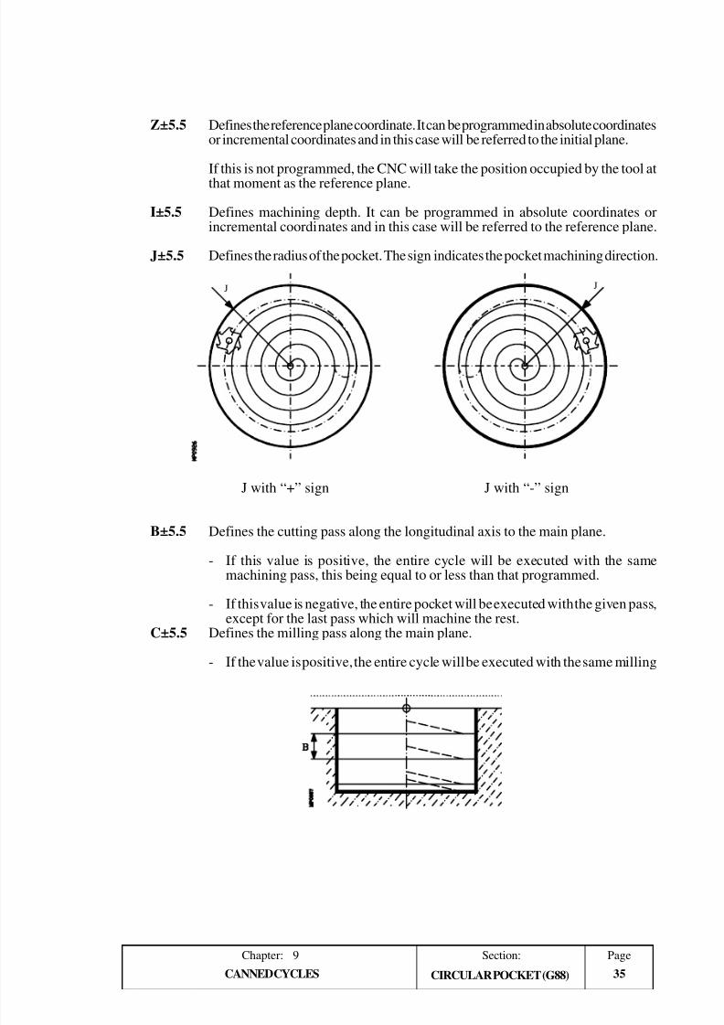
8/21/2019 CNC 8055 M Operator Manual
http://slidepdf.com/reader/full/cnc-8055-m-operator-manual 348/702
PageChapter: 9 Section:
CANNED CYCLES 35CIRCULAR POCKET (G88)
Z±5.5 Defines the reference plane coordinate. It can be programmed in absolute coordinatesor incremental coordinates and in this case will be referred to the initial plane.
If this is not programmed, the CNC will take the position occupied by the tool atthat moment as the reference plane.
I±5.5 Defines machining depth. It can be programmed in absolute coordinates orincremental coordinates and in this case will be referred to the reference plane.
J±5.5 Defines the radius of the pocket. The sign indicates the pocket machining direction.
J with “+” sign J with “-” sign
B±5.5 Defines the cutting pass along the longitudinal axis to the main plane.- If this value is positive, the entire cycle will be executed with the same
machining pass, this being equal to or less than that programmed.
- If this value is negative, the entire pocket will be executed with the given pass,except for the last pass which will machine the rest.
C±5.5 Defines the milling pass along the main plane.
- If the value is positive, the entire cycle will be executed with the same milling
J J

8/21/2019 CNC 8055 M Operator Manual
http://slidepdf.com/reader/full/cnc-8055-m-operator-manual 349/702
Section:Page Chapter: 9
CANNED CYCLES36 CIRCULAR POCKET (G88)
C
pass, this being equal to or less than that programmed.
- If the value is negative, the entire pocket will be executed with the given pass,except for the last pass which will machine whatever remains.
If this is not programmed, the CNC will assume 3/4 of the diameter of the diameterof the selected tool.
If programmed with a value greater than the tool diameter, the CNC will issue thecorresponding error.
If programmed with a value of 0, the CNC will show the corresponding error.
D5.5 Defines the distance between the reference plane and the surface of the part wherethe pocket is to be made.
During the first deepening operation this amount will be added to incrementaldepth “B”. If this is not programmed, a value of 0 will be taken.
H.5 Defines the working feedrate during the finishing pass.
If this is not programmed or is programmed with a value of 0, the value of theworking feedrate for machining will be taken.
D

8/21/2019 CNC 8055 M Operator Manual
http://slidepdf.com/reader/full/cnc-8055-m-operator-manual 350/702
PageChapter: 9 Section:
CANNED CYCLES 37CIRCULAR POCKET (G88)
L5.5 Defines the value of the finishing pass, along the main plane.
If this is not programmed or is programmed with a value of 0 no finishing passwill be made.
V.5.5 Defines the tool penetrating feedrate.
If not programmed or programmed with a value of "0", the CNC will assume 50%of the feedrate in the plane (F).

8/21/2019 CNC 8055 M Operator Manual
http://slidepdf.com/reader/full/cnc-8055-m-operator-manual 351/702
Section:Page Chapter: 9
CANNED CYCLES38
J
CL
G98
G99D
B
B
B
1mm
Z
I(G90)
I(G91)
1mm
CIRCULAR POCKET (G88)
1mm
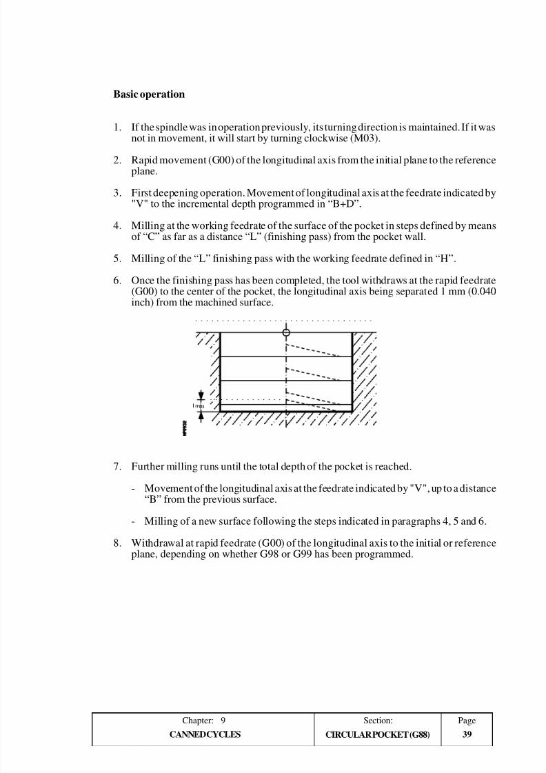
8/21/2019 CNC 8055 M Operator Manual
http://slidepdf.com/reader/full/cnc-8055-m-operator-manual 352/702
PageChapter: 9 Section:
CANNED CYCLES 39CIRCULAR POCKET (G88)
1mm
Basic operation
1. If the spindle was in operation previously, its turning direction is maintained. If it wasnot in movement, it will start by turning clockwise (M03).
2. Rapid movement (G00) of the longitudinal axis from the initial plane to the referenceplane.
3. First deepening operation. Movement of longitudinal axis at the feedrate indicated by"V" to the incremental depth programmed in “B+D”.
4. Milling at the working feedrate of the surface of the pocket in steps defined by meansof “C” as far as a distance “L” (finishing pass) from the pocket wall.
5. Milling of the “L” finishing pass with the working feedrate defined in “H”.
6. Once the finishing pass has been completed, the tool withdraws at the rapid feedrate(G00) to the center of the pocket, the longitudinal axis being separated 1 mm (0.040inch) from the machined surface.
7. Further milling runs until the total depth of the pocket is reached.
- Movement of the longitudinal axis at the feedrate indicated by "V", up to a distance“B” from the previous surface.
- Milling of a new surface following the steps indicated in paragraphs 4, 5 and 6.
8. Withdrawal at rapid feedrate (G00) of the longitudinal axis to the initial or referenceplane, depending on whether G98 or G99 has been programmed.

8/21/2019 CNC 8055 M Operator Manual
http://slidepdf.com/reader/full/cnc-8055-m-operator-manual 353/702
Section:Page Chapter: 9
CANNED CYCLES40
Programming example assuming that the work plane is formed by the X and Y axes, thatthe longitudinal axis is the Z axis and that the starting point is X0 Y0 Z0:
(TOR1=6, TOT1=0)
T1 D1M6G0 G90 X0 Y0 Z0 ............................................................................... ; Starting point
G88 G98 G00 G90 X90 Y80 Z-48 I-90 J70 B12 C10
D2 H100 L5 V100 F300 S1000 T1 D1 M03 .............................. Canned cycle definition
G80 .................................................................................................... ; Canned cycle cancellation
G90 X0 Y0 .......................................................................................... ; Positioning
M30 .................................................................................................... ; End of program
CIRCULAR POCKET (G88)

8/21/2019 CNC 8055 M Operator Manual
http://slidepdf.com/reader/full/cnc-8055-m-operator-manual 354/702
PageChapter: 9 Section:
CANNED CYCLES 41
G00
G01
G98
G99
K
9.5.10. G89. BORING CYCLE WITH WITHDRAWAL AT WORKING
FEEDRATE (G01)
This cycle bores at the point indicated until the final programmed coordinate is reached.
It is possible to program a dwell at the bottom of the machined hole.
Working in cartesian coordinates, the basic structure of the block is as follows:
G89 G98/G99 X Y Z I K
G98 The tool withdraws to the Initial Plane, once the hole has been bored.
G99 The tool withdraws to the Reference Plane, once the hole has been bored.
XY±5.5 These are optional and define the movement of the axes of the main plane toposition the tool at the machining point.
This point can be programmed in cartesian coordinates or in polar coordinates,and the coordinates may be absolute or incremental, along whether the machineis operating in G90 or G91.
Z±5.5 Defines the reference plane coordinate. It can be programmed in absolutecoordinates or incremental coordinates and in this case will be referred to theinitial plane.
If this is not programmed, the CNC will take the position occupied by the tool atthat moment as the reference plane.
I±5.5 Defines boring depth. It can be programmed in absolute coordinates or incrementalcoordinates and in this case will be referred to the reference plane.
K5 Defines the dwell time, in hundredths of a second, after each boring step, until thewithdrawal begins. Should this not be programmed, the CNC will take a valueof K0.
BORING WITH WITHDRAWALIN G01 (G89)

8/21/2019 CNC 8055 M Operator Manual
http://slidepdf.com/reader/full/cnc-8055-m-operator-manual 355/702
Section:Page Chapter: 9
CANNED CYCLES42
Basic operation
1. If the spindle was in operation previously, its turning direction is maintained. If it wasnot in movement, it will start by turning clockwise (M03).
2. Rapid movement of the longitudinal axis from the initial plane to the reference plane.
3. Movement at the working feedrate (G01) of the longitudinal axis to the bottom of themachined hole, and boring.
4. Spindle stop (M05).
5. Withdrawal at working feedrate of the longitudinal axis to the reference plane.
6. Withdrawal, at rapid feedrate (G00), of the longitudinal axis as far as the initial plane
if G98 has been programmed.
Programming example assuming that the work plane is formed by the X and Y axes, thatthe longitudinal axis is the Z axis and that the starting point is X0 Y0 Z0:
T1M6G0 G90 X0 Y0 Z0 ......................................................... ;Starting pointG89 G98 G91 X250 Y350 Z-98 I-22 K20 F100 S500 .. ;Canned cycle definitionG80 ................................................................................. ;Canned cycle cancellationG90 X0 Y0 ..................................................................... ;Positioning
M30 ................................................................................ ;End of program
BORING WITH WITHDRAWALIN G01 (G89)

8/21/2019 CNC 8055 M Operator Manual
http://slidepdf.com/reader/full/cnc-8055-m-operator-manual 356/702
PageChapter: 10
MULTIPLE MACHINING
Section:
1
10. MULTIPLE MACHINING
Multiple functions are defined as a series of functions which allow a machining operationto be repeated along a given path.
The programmer will select the type of machining, which can be a canned cycle or asubroutine (which must be programmed as a modal subroutine) defined by the user.
Machining subroutines are defined by the following functions:
G60: multiple machining in a straight line pattern.G61: multiple machining in a rectangular pattern.G62: multiple machining in a grid pattern.G63: multiple machining in a circular pattern.G64: multiple machining in an arc pattern.G65: multiple machining in an arc-chord pattern.
These functions can be performed on any work plane and must be defined every time theyare used, as they are not modal.
It is absolutely essential for the machining which it is required to repeat to be active. In otherwords, these functions will only make sense if they are under the influence of a canned cycleor under the influence of a modal subroutine.
To perform multiple machining, follow these steps:
1.- Move the tool to the first point of the multiple machining operation.
2- Define the canned cycle or modal subroutine to be repeated at all the points.
3.- Define the multiple operation to be performed.
All machining operations programmed with these functions will be done under the sameworking conditions (T,D,F,S) which were selected when defining the canned cycle ormodal subroutine.
Once the multiple machining operation has been performed, the program will recover thehistory it had before starting this machining, even when the canned cycle or modalsubroutine will remain active. Now feedrate F corresponds to the feedrate programmed forthe canned cycle or modal subroutine.
Likewise, the tool will be positioned at the last point where the programmed machiningoperation was done.
If multiple machining of a modal subroutine is performed in the Single Block mode, thissubroutine will be performed complete (not block by block) after each programmedmovement.
A detailed explanation is given on the next page of multiple machining operations, assumingin each case, that the work plane is formed by X and Y axes.
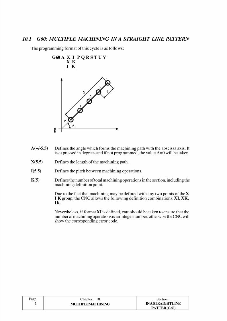
8/21/2019 CNC 8055 M Operator Manual
http://slidepdf.com/reader/full/cnc-8055-m-operator-manual 357/702
Section:
MULTIPLE MACHININGChapter: 10
2Page
A
IX
1
2
3
4
IN A STRAIGHT LINE PATTER (G60)
P0
10.1 G60: MULTIPLE MACHINING IN A STRAIGHT LINE PATTERN
The programming format of this cycle is as follows:
G60 A X I P Q R S T U VX KI K
A(+/-5.5) Defines the angle which forms the machining path with the abscissa axis. Itis expressed in degrees and if not programmed, the value A=0 will be taken.
X(5.5) Defines the length of the machining path.
I(5.5) Defines the pitch between machining operations.
K(5) Defines the number of total machining operations in the section, including themachining definition point.
Due to the fact that machining may be defined with any two points of the XI K group, the CNC allows the following definition combinations: XI, XK,IK.
Nevertheless, if format XI is defined, care should be taken to ensure that thenumber of machining operations is an integer number, otherwise the CNC willshow the corresponding error code.

8/21/2019 CNC 8055 M Operator Manual
http://slidepdf.com/reader/full/cnc-8055-m-operator-manual 358/702
PageChapter: 10
MULTIPLE MACHINING
Section:
3IN A STRAIGHT LINE PATTERN (G60)
P,Q,R,S,T,U,V These parameters are optional and are used to indicate at which pointsor between which those programmed points it is not required to machine.
Thus, programming P7 indicates that it is not required to do machining at point7, and programming Q10.013 indicates that machining is not required from point10 to 13, or expressed in another way, that no machining is required at points 10,11, 12 and 13.
When it is required to define a group of points (Q10.013), care should be takento define the final point with three digits, as if Q10.13 is programmed, multiplemachining understands Q10.130.
The programming order for these parameters is P Q R S T U V, it also beingnecessary to maintain the order in which the points assigned to these arenumbered, i.e., the numbering order of the points assigned to Q must be greaterthan that assigned to P and less than that assigned to R.
Example:
Proper programming P5.006 Q12.015 R20.022Improper programming P5.006 Q20.022 R12.015
If these parameters are not programmed, the CNC understands that it mustperform machining at all the points along the programmed path.
Basic operation:
1. Multiple machining calculates the next point of those programmed where it is wishedto machine.
2. Rapid traverse (G00) to this point.
3. Multiple machining will perform the canned cycle or modal subroutine selected afterthis movement.
4. The CNC will repeat steps 1-2-3 until the programmed path has been completed.
After completing multiple machining, the tool will be positioned at the last point alongthe programmed path where machining was performed.

8/21/2019 CNC 8055 M Operator Manual
http://slidepdf.com/reader/full/cnc-8055-m-operator-manual 359/702
Section:
MULTIPLE MACHININGChapter: 10
4Page
Y
X
Programming example assuming that the work plane is formed by the X and Y axes, thatthe longitudinal axis is Z and that the starting point is X0 Y0 Z0.
G81 G98 G00 G91 X200 Y300 Z-8 I-22 F100 S500 ;Canned cycle positioning and definition
G60 A30 X1200 I100 P2.003 Q6 R12 ;Defines multiple machining
G80 ;Cancels canned cycle
G90 X0 Y0 ;Positioning
M30 ;End of program
It is also possible to write the multiple machining definition block in the following ways:
G60 A30 X1200 K13 P2.003 Q6 R12
G60 A30 I100 K13 P2.003 Q6 R12
IN A STRAIGHT LINE PATTERN (G60)

8/21/2019 CNC 8055 M Operator Manual
http://slidepdf.com/reader/full/cnc-8055-m-operator-manual 360/702
PageChapter: 10
MULTIPLE MACHINING
Section:
5IN A RECTANGULAR PATTERN (G61)
X
B
Y
J
P0
A
I
10.2 G61: MULTIPLE MACHINING IN A RECTANGULAR PATTERN
The programming format of this cycle is as follows:
G61 A B X I Y J P Q R S T U VX K Y DI K J D
A(+/-5.5) Defines the angle formed by the machining path with the abscissa axis. It isexpressed in degrees and if not programmed, the value A=0 will be taken.
B(+/-5.5) Defines the angle formed by the two machining paths. It is expressed indegrees and if not programmed, the value B=90 will be taken.
X(5.5) Defines the length of the machining path according to the abscissa axis.
I(5.5) Defines the pitch between machining operations according to the abscissaaxis.
K(5) Defines the number of total machining operations in the abscissa axis,including the machining definition point.
Due to the fact that machining may be defined according to the abscissa axiswith any two points of the X I K group, the CNC allows the followingdefinition combinations: XI, XK, IK.
Nevertheless, if format XI is defined, care should be taken to ensure that thenumber of machining operations is an integer number, otherwise the CNC willshow the corresponding error code.
Y(5.5) Defines the length of the machining path according to the ordinate axis.
J(5.5) Defines the pitch between machining operations according to the ordinateaxis.
8/21/2019 CNC 8055 M Operator Manual
http://slidepdf.com/reader/full/cnc-8055-m-operator-manual 361/702
Section:
MULTIPLE MACHININGChapter: 10
6Page
IN A RECTANGULAR PATTERN (G61)
D(5) Defines the number of total machining operations in the ordinate axis, includingthe machining definition point.
Due to the fact that machining may be defined according to the ordinate axis withany two points of the Y J D group, the CNC allows the following definitioncombinations: YJ, YD, JD.
Nevertheless, if format YJ is defined, care should be taken to ensure that thenumber of machining operations is an integer number, otherwise the CNC willshow the corresponding error code.
P,Q,R,S,T,U,V These parameters are optional and are used to indicate at which pointsor between which of those programmed points it is not required to machine.
Thus, programming P7 indicates that it is not required to do machining at point7, and programming Q10.013 indicates that machining is not required from point
10 to 13, or expressed in another way, that no machining is required at points 10,11, 12 and 13.
When it is required to define a group of points (Q10.013), care should be takento define the final point with three digits, as if Q10.13 is programmed, multiplemachining understands Q10.130.
The programming order for these parameters is P Q R S T U V, it also beingnecessary to maintain the order in which the points assigned to these arenumbered, i.e., the numbering order of the points assigned to Q must be greaterthan that assigned to P and less than that assigned to R.
Example:Proper programming P5.006 Q12.015 R20.022Improper programming P5.006 Q20.022 R12.015
If these parameters are not programmed, the CNC understands that it mustperform machining at all the points along the programmed path.
Basic operation:
1. Multiple machining calculates the next point of those programmed where it is wishedto machine.
2. Rapid traverse (G00) to this point.
3. Multiple machining will perform the canned cycle or modal subroutine selected afterthis movement.
4. The CNC will repeat steps 1-2-3 until the programmed path has been completed.
After completing multiple machining, the tool will be positioned at the last point alongthe programmed path where machining was performed.
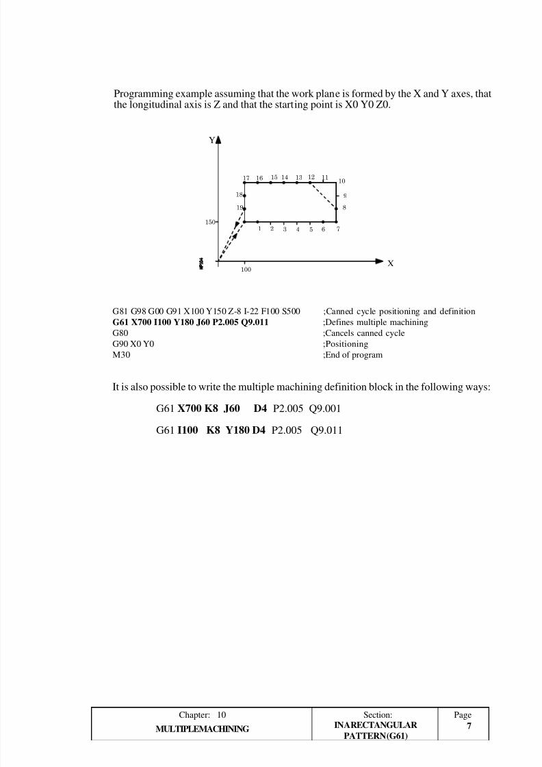
8/21/2019 CNC 8055 M Operator Manual
http://slidepdf.com/reader/full/cnc-8055-m-operator-manual 362/702
PageChapter: 10
MULTIPLE MACHINING
Section:
7IN A RECTANGULAR PATTERN (G61)
X
Y
Programming example assuming that the work plane is formed by the X and Y axes, thatthe longitudinal axis is Z and that the starting point is X0 Y0 Z0.
G81 G98 G00 G91 X100 Y150 Z-8 I-22 F100 S500 ;Canned cycle positioning and definition
G61 X700 I100 Y180 J60 P2.005 Q9.011 ;Defines multiple machining
G80 ;Cancels canned cycle
G90 X0 Y0 ;Positioning
M30 ;End of program
It is also possible to write the multiple machining definition block in the following ways:
G61 X700 K8 J60 D4 P2.005 Q9.001
G61 I100 K8 Y180 D4 P2.005 Q9.011

8/21/2019 CNC 8055 M Operator Manual
http://slidepdf.com/reader/full/cnc-8055-m-operator-manual 363/702
Section:
MULTIPLE MACHININGChapter: 10
8Page
X
Y
J
I
A
B
P0
10.3 G62: MULTIPLE MACHINING IN A GRID PATTERN
The programming format of this cycle is as follows:
G62 A B X I Y J P Q R S T U VX K Y DI K J D
A(+/-5.5) Defines the angle formed by the machining path with the abscissa axis. It isexpressed in degrees and if not programmed, the value A=0 will be taken.
B(+/-5.5) Defines the angle formed by the two machining paths. It is expressed indegrees and if not programmed, the value B=90 will be taken.
X(5.5) Defines the length of the machining path according to the abscissa axis.
I(5.5) Defines the pitch between machining operations according to the abscissaaxis.
K(5) Defines the number of total machining operations in the abscissa axis,including the machining definition point.
Due to the fact that machining may be defined according to the abscissa axis
with any two points of the X I K group, the CNC allows the followingdefinition combinations: XI, XK, IK.
Nevertheless, if format XI is defined, care should be taken to ensure that thenumber of machining operations is an integer number, otherwise the CNC willshow the corresponding error code.
Y(5.5) Defines the length of the machining path according to the ordinate axis.
J(5.5) Defines the pitch between machining operations according to the ordinateaxis.
IN A GRID PATTERN(G62)

8/21/2019 CNC 8055 M Operator Manual
http://slidepdf.com/reader/full/cnc-8055-m-operator-manual 364/702
PageChapter: 10
MULTIPLE MACHINING
Section:
9
D(5) Defines the number of total machining operations in the ordinate axis, includingthe machining definition point.
Due to the fact that machining may be defined according to the ordinate axis withany two points of the Y J D group, the CNC allows the following definitioncombinations: YJ, YD, JD.
Nevertheless, if format YJ is defined, care should be taken to ensure that thenumber of machining operations is an integer number, otherwise the CNC willshow the corresponding error code.
P,Q,R,S,T,U,V These parameters are optional and are used to indicate at which points orbetween which of those programmed points it is not required to machine.
Thus, programming P7 indicates that it is not required to do machining at point7, and programming Q10.013 indicates that machining is not required from point
10 to 13, or expressed in another way, that no machining is required at points 10,11, 12 and 13.
When it is required to define a group of points (Q10.013), care should be takento define the final point with three digits, as if Q10.13 is programmed, multiplemachining understands Q10.130.
The programming order for these parameters is P Q R S T U V, it also beingnecessary to maintain the order in which the points assigned to these arenumbered, i.e., the numbering order of the points assigned to Q must be greaterthan that assigned to P and less than that assigned to R.
Example:Proper programmingP5.006 Q12.015 R20.022Improper programming P5.006 Q20.022 R12.015
If these parameters are not programmed, the CNC understands that it mustperform machining at all the points along the programmed path.
Basic operation:
1. Multiple machining calculates the next point of those programmed where it is wishedto machine.
2. Rapid rapid traverse (G00) to this point.
3. Multiple machining will perform the canned cycle or modal subroutine selected afterthis movement.
4. The CNC will repeat steps 1-2-3 until the programmed path has been completed.
After completing multiple machining, the tool will be positioned at the last point alongthe programmed path where machining was performed.
IN A GRID PATTERN(G62)
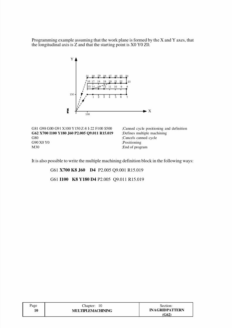
8/21/2019 CNC 8055 M Operator Manual
http://slidepdf.com/reader/full/cnc-8055-m-operator-manual 365/702
Section:
MULTIPLE MACHININGChapter: 10
10Page
IN A GRID PATTERN(G62)
X
Y
Programming example assuming that the work plane is formed by the X and Y axes, thatthe longitudinal axis is Z and that the starting point is X0 Y0 Z0.
G81 G98 G00 G91 X100 Y150 Z-8 I-22 F100 S500 ;Canned cycle positioning and definition
G62 X700 I100 Y180 J60 P2.005 Q9.011 R15.019 ;Defines multiple machining
G80 ;Cancels canned cycle
G90 X0 Y0 ;Positioning
M30 ;End of program
It is also possible to write the multiple machining definition block in the following ways:
G61 X700 K8 J60 D4 P2.005 Q9.001 R15.019G61 I100 K8 Y180 D4 P2.005 Q9.011 R15.019
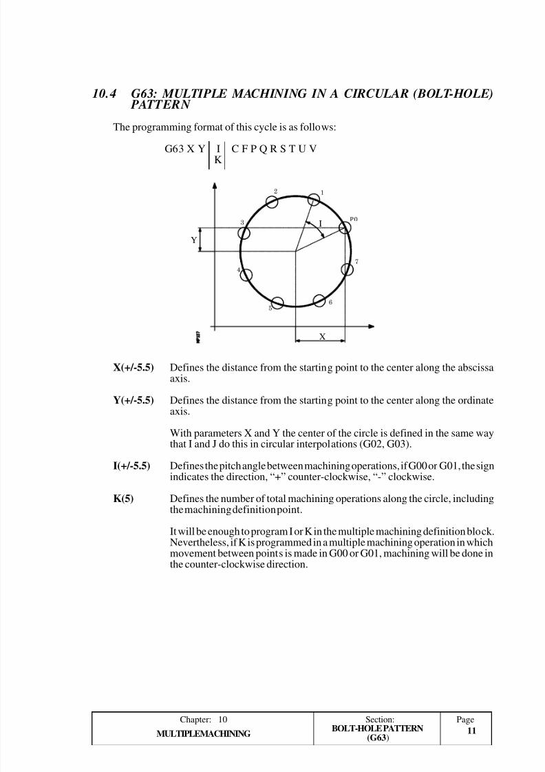
8/21/2019 CNC 8055 M Operator Manual
http://slidepdf.com/reader/full/cnc-8055-m-operator-manual 366/702
PageChapter: 10
MULTIPLE MACHINING
Section:
11
10.4 G63: MULTIPLE MACHINING IN A CIRCULAR (BOLT-HOLE) PATTERN
The programming format of this cycle is as follows:
G63 X Y I C F P Q R S T U V K
X(+/-5.5) Defines the distance from the starting point to the center along the abscissaaxis.
Y(+/-5.5) Defines the distance from the starting point to the center along the ordinateaxis.
With parameters X and Y the center of the circle is defined in the same waythat I and J do this in circular interpolations (G02, G03).
I(+/-5.5) Defines the pitch angle between machining operations, if G00 or G01, the signindicates the direction, “+” counter-clockwise, “-” clockwise.
K(5) Defines the number of total machining operations along the circle, includingthe machining definition point.
It will be enough to program I or K in the multiple machining definition block.
Nevertheless, if K is programmed in a multiple machining operation in whichmovement between points is made in G00 or G01, machining will be done inthe counter-clockwise direction.
P0
I
Y
X
BOLT-HOLE PATTERN (G63)
8/21/2019 CNC 8055 M Operator Manual
http://slidepdf.com/reader/full/cnc-8055-m-operator-manual 367/702
Section:
MULTIPLE MACHININGChapter: 10
12Page
C Indicates how movement is made between machining points. If it is notprogrammed, the value C=0 will be taken.
C=0: Movement is made in rapid feedrate (G00)C=1: Movement is made in linear interpolation (G01).C=2: Movement is made in clockwise circular interpolation (G02)C=3: Movement is made in counter-clockwise circular interpolation (G03)
F(5.5) Defines the feedrate which is used for moving between points. Obviously, it willonly apply for “C” values other than zero. If it is not programmed, the value F0will be taken, maximum feedrate selected by the “MAXFEED” axis machineparameter.
P,Q,R,S,T,U,V These parameters are optional and are used to indicate at which points orbetween which of those programmed points it is not required to machine.
Thus, programming P7 indicates that it is not required to do machining at point7, and programming Q10.013 indicates that machining is not required from point10 to 13, or expressed in another way, that no machining is required at points 10,11, 12 and 13.
When it is required to define a group of points (Q10.013), care should be takento define the final point with three digits, as if Q10.13 is programmed, multiplemachining understands Q10.130.
The programming order for these parameters is P Q R S T U V, it also beingnecessary to maintain the order in which the points assigned to these arenumbered, i.e., the numbering order of the points assigned to Q must be greater
than that assigned to P and less than that assigned to R.Example:
Proper programmingP5.006 Q12.015 R20.022Improper programming P5.006 Q20.022 R12.015
If these parameters are not programmed, the CNC understands that it mustperform machining at all the points along the programmed path.
BOLT-HOLE PATTERN (G63)
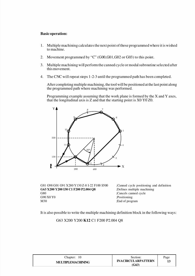
8/21/2019 CNC 8055 M Operator Manual
http://slidepdf.com/reader/full/cnc-8055-m-operator-manual 368/702
PageChapter: 10
MULTIPLE MACHINING
Section:
13
Y
X
IN A CIRCULAR PATTERN (G63)
Basic operation:
1. Multiple machining calculates the next point of those programmed where it is wishedto machine.
2. Movement programmed by “C” (G00,G01,G02 or G03) to this point.
3. Multiple machining will perform the canned cycle or modal subroutine selected afterthis movement.
4. The CNC will repeat steps 1-2-3 until the programmed path has been completed.
After completing multiple machining, the tool will be positioned at the last point alongthe programmed path where machining was performed.
Programming example assuming that the work plane is formed by the X and Y axes,that the longitudinal axis is Z and that the starting point is X0 Y0 Z0.
G81 G98 G01 G91 X280 Y130 Z-8 I-22 F100 S500 ;Canned cycle positioning and definition
G63 X200 Y200 I30 C1 F200 P2.004 Q8 ;Defines multiple machining
G80 ;Cancels canned cycleG90 X0 Y0 ;Positioning
M30 ;End of program
It is also possible to write the multiple machining definition block in the following ways:
G63 X200 Y200 K12 C1 F200 P2.004 Q8

8/21/2019 CNC 8055 M Operator Manual
http://slidepdf.com/reader/full/cnc-8055-m-operator-manual 369/702
Section:
MULTIPLE MACHININGChapter: 10
14Page
IN AN ARC PATTERN (G64)
P0
Y
I
X
B
10.5 G64: MULTIPLE MACHINING IN AN ARC PATTERN
The programming format of this cycle is as follows:
G64 X Y B I C F P Q R S T U V K
X(+/-5.5) Defines the distance from the starting point to the center along the abscissa
axis.
Y(+/-5.5) Defines the distance from the starting point to the center along the ordinateaxis.
With parameters X and Y the center of the circle is defined in the same waythat I and J do this in circular interpolations (G02, G03).
B(5.5) Defines the angular stroke of the machining path and is expressed in degrees.
I(+/-5.5) Defines the pitch angle between machining operations, if G00 or G01, the signindicates the direction, “+” counter-clockwise, “-” clockwise.
K(5) Defines the number of total machining operations along the circle, includingthe machining definition point.
It will be enough to program I or K in the multiple machining definition block.Nevertheless, if K is programmed in a multiple machining operation in whichmovement between points is made in G00 or G01, machining will be done inthe counter-clockwise direction.

8/21/2019 CNC 8055 M Operator Manual
http://slidepdf.com/reader/full/cnc-8055-m-operator-manual 370/702
PageChapter: 10
MULTIPLE MACHINING
Section:
15IN AN ARC PATTERN (G64)
C Indicates how movement is made between machining points. If it is notprogrammed, the value C=0 will be taken.
C=0: Movement is made in rapid feedrate (G00)C=1: Movement is made in linear interpolation (G01).C=2: Movement is made in clockwise circular interpolation (G02)C=3: Movement is made in counter-clockwise circular interpolation (G03)
F(5.5) Defines the feedrate which is used for moving between points. Obviously, it willonly have value for “C” values other than zero. If it is not programmed, the valueF0 will be taken, maximum feedrate selected by the “MAXFEED” axis machineparameter.
P,Q,R,S,T,U,V These parameters are optional and are used to indicate at which points orbetween which of those programmed points it is not required to machine.
Thus, programming P7 indicates that it is not required to do machining at point7, and programming Q10.013 indicates that machining is not required from point10 to 13, or expressed in another way, that no machining is required at points 10,11, 12 and 13.
When it is required to define a group of points (Q10.013), care should be takento define the final point with three digits, as if Q10.13 is programmed, multiplemachining understands Q10.130.
The programming order for these parameters is P Q R S T U V, it also beingnecessary to maintain the order in which the points assigned to these arenumbered, i.e., the numbering order of the points assigned to Q must be greater
than that assigned to P and less than that assigned to R.Example:
Proper programmingP5.006 Q12.015 R20.022Improper programming P5.006 Q20.022 R12.015
If these parameters are not programmed, the CNC understands that it mustperform machining at all the points along the programmed path.

8/21/2019 CNC 8055 M Operator Manual
http://slidepdf.com/reader/full/cnc-8055-m-operator-manual 371/702
Section:
MULTIPLE MACHININGChapter: 10
16Page
X
Y
IN AN ARC PATTERN (G64)
Basic operation:
1. Multiple machining calculates the next point of those programmed where it is wishedto machine.
2. Movement programmed by “C” (G00,G01,G02 or G03) to this point.
3. Multiple machining will perform the canned cycle or modal subroutine selected afterthis movement.
4. The CNC will repeat steps 1-2-3 until the programmed path has been completed.
After completing multiple machining, the tool will be positioned at the last point alongthe programmed path where machining was performed.
Programming example assuming that the work plane is formed by the X and Y axes,
that the longitudinal axis is Z and that the starting point is X0 Y0 Z0.
G81 G98 G01 G91 X280 Y130 Z-8 I-22 F100 S500 ;Canned cycle positioning and definition
G64 X200 Y200 B225 K6 C3 F200 P2 ;Defines multiple machining
G80 ;Cancels canned cycleG90 X0 Y0 ;Positioning
M30 ;End of program
It is also possible to write the multiple machining definition block in the following ways:
G64 X200 Y200 B225 K6 C3 F200 P2

8/21/2019 CNC 8055 M Operator Manual
http://slidepdf.com/reader/full/cnc-8055-m-operator-manual 372/702
PageChapter: 10
MULTIPLE MACHINING
Section:
17
X
AY
I
P0
10.6 G65: MACHINING PROGRAMMED BY MEANS OF AN ARC CHORD
This function allows activated machining to be performed at a point programmed by meansof an arc chord. Only one machining operation will be performed, its programming formatbeing:
G65 X Y A C FI
X(+/-5.5) Defines the distance from the starting point to the center along the abscissa
axis.Y(+/-5.5) Defines the distance from the starting point to the center along the ordinate
axis.
With parameters X and Y the center of the circle is defined in the same waythat I and J do this in circular interpolations (G02, G03).
A(+/-5.5) Defines the angle formed by the perpendicular bisector of the chord with theabscissa axis and is expressed in degrees.
I(+/-5.5) Defines the chord length. When moving in G00 or G01, the sign indicates thedirection, “+” counter-clockwise, “-” clockwise.
C Indicates how movement is made between machining points. If it is notprogrammed, the value C=0 will be taken.
C=0: Movement is made in rapid feedrate (G00)
C=1: Movement is made in linear interpolation (G01).
C=2: Movement is made in clockwise circular interpolation (G02)
C=3: Movement is made in counter-clockwise circular interpolation (G03)
F(5.5) Defines the feedrate which is used for moving between points. Obviously, itwill only apply for “C” values other than zero. If it is not programmed, thevalue F0 will be taken, maximum feedrate selected by the “MAXFEED” axis
machine parameter.
BY MEANS OF AN ARCCHORD (G65)

8/21/2019 CNC 8055 M Operator Manual
http://slidepdf.com/reader/full/cnc-8055-m-operator-manual 373/702
Section:
MULTIPLE MACHININGChapter: 10
18Page
Basic operation:
1. Multiple machining calculates the next point of those programmed where it is wishedto machine.
2. Movement programmed by “C” (G00,G01,G02 or G03) to this point.
3. Multiple machining will perform the canned cycle or modal subroutine selected afterthis movement.
After completing multiple machining, the tool will be positioned at the programmedpoint.
Programming example assuming that the work plane is formed by the X and Y axes,that the longitudinal axis is Z and that the starting point is X0 Y0 Z0.
G81 G98 G01 G91 X890 Y500 Z-8 I-22 F100 S500 ;Canned cycle positioning and definition
G65 X280 Y-40 A60 C1 F200 ;Defines multiple machining
G80 ;Cancels canned cycle
G90 X0 Y0 ;Positioning
M30 ;End of program
It is also possible to write the multiple machining definition block in the following ways:
G65 X-280 Y40 I430 C1 F200
BY MEANS OF AN ARCCHORD (G65)
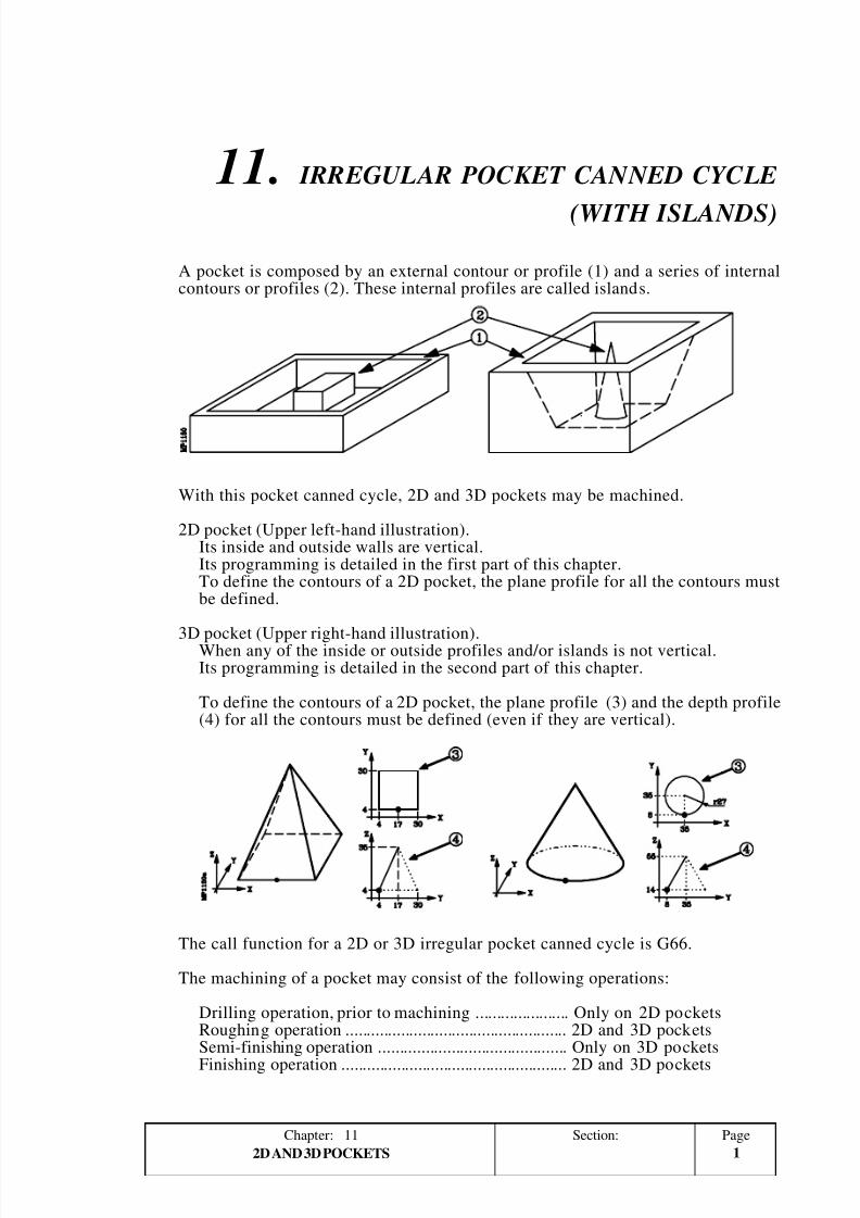
8/21/2019 CNC 8055 M Operator Manual
http://slidepdf.com/reader/full/cnc-8055-m-operator-manual 374/702
PageChapter: 11 Section:
12D AND 3D POCKETS
11. IRREGULAR POCKET CANNED CYCLE
(WITH ISLANDS)
A pocket is composed by an external contour or profile (1) and a series of internalcontours or profiles (2). These internal profiles are called islands.
With this pocket canned cycle, 2D and 3D pockets may be machined.
2D pocket (Upper left-hand illustration).Its inside and outside walls are vertical.Its programming is detailed in the first part of this chapter.To define the contours of a 2D pocket, the plane profile for all the contours mustbe defined.
3D pocket (Upper right-hand illustration).When any of the inside or outside profiles and/or islands is not vertical.Its programming is detailed in the second part of this chapter.
To define the contours of a 2D pocket, the plane profile (3) and the depth profile(4) for all the contours must be defined (even if they are vertical).
The call function for a 2D or 3D irregular pocket canned cycle is G66.
The machining of a pocket may consist of the following operations:
Drilling operation, prior to machining ...................... Only on 2D pocketsRoughing operation .................................................... 2D and 3D pocketsSemi-finishing operation ............................................ Only on 3D pockets
Finishing operation ..................................................... 2D and 3D pockets

8/21/2019 CNC 8055 M Operator Manual
http://slidepdf.com/reader/full/cnc-8055-m-operator-manual 375/702
Section:
2Page
2D AND 3D POCKETSChapter: 11
11.1 2D POCKETS
The G66 function is not modal, therefore it must be programmed whenever it is required toperform a 2D pocket.
In a block defining an irregular pocket canned cycle, no other function can be programmed,its structure definition being:
G66 D H R I F K S E Q
D (0-9999) & H (0-9999) Label number of the first block (D) and last block (H) definingthe drilling operation.
When not setting "H" only block "D" is executed.When not setting "D" there is no drilling operation.
R (0-9999) & I (0-9999) Label number of the first block (R) and last block (I) defining
the roughing operation.When not setting "I" only block "R" is executed.When not setting "R" there is no roughing operation.
F (0-9999) & K (0-9999) Label number of the first block (F) and last block (K) definingthe finishing operation.
When not setting "K" only block "F" is executed.When not setting "F" there is no finishing operation.
S (0-9999) & E (0-9999) Label number of the first block (S) and last block (E) definingthe geometry of the profiles forming the pocket.
Both parameters must be set.
Q (0-9999) Number of the program containing the geometry definition,parameters S and E.
If it is in the same program, "Q" need not be defined.
Programming example:
G00 G90 X100 Y200 Z50 F5000 T1 D2 ;Initial positioningM06G66 D100 R200 I210 F300 S400 E500 ;Definition of irregular pocket canned cycleM30 ;End of program
N100 G81 ........... ;Defines the drilling operationN200 ................... ;Starts the roughing operation
G67 ...........N210 ................... ;End the roughing operationN300 G68 ............ ;Defines the finishing operationN400 G0 G90 X300 Y50 Z3 ;Starts the geometry description
...................
...................N500 G2 G6 X300 Y50 I150 J0 ;End of geometry description
2D POCKETS

8/21/2019 CNC 8055 M Operator Manual
http://slidepdf.com/reader/full/cnc-8055-m-operator-manual 376/702
PageChapter: 11 Section:
32D AND 3D POCKETS
Basic operation:
1.- Drilling operation. Only if it has been programmed.
After analyzing the geometry of the pocket with islands, the tool radius and the angleof the path programmed in the roughing operation, the CNC will calculate thecoordinates of the point where the selected drilling operation must be performed.
2.- Roughing operation. Only if it has been programmed.
It consists of several surface milling passes, until the total depth programmed has beenreached. On each surface milling pass, the steps below will be followed depending onthe type of machining that has been programmed:
Case A: When the machining paths are linear and maintain a certain angle with the abscissa axis.
* It first contours the external profile of the part.
If the finishing operation has been selected on the cycle call, this contouring isperformed leaving the finishing stock programmed for the finishing pass.
* Next the milling operation, with the programmed feed and steps.
If, while milling, an island is run into for the first time, it will be contoured.
After the contouring and the remaining times, the tool will pass over the island,withdrawing along the longitudinal axis, to the reference plane, and will continuemachining once the island has been cleared.
2D POCKETS
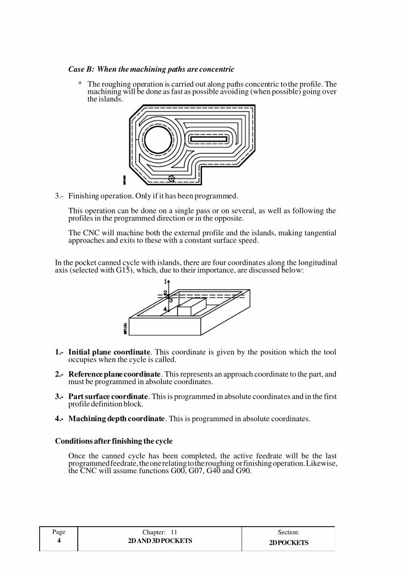
8/21/2019 CNC 8055 M Operator Manual
http://slidepdf.com/reader/full/cnc-8055-m-operator-manual 377/702
Section:
4Page
2D AND 3D POCKETSChapter: 11
Case B: When the machining paths are concentric
* The roughing operation is carried out along paths concentric to the profile. Themachining will be done as fast as possible avoiding (when possible) going over
the islands.
3.- Finishing operation. Only if it has been programmed.
This operation can be done on a single pass or on several, as well as following theprofiles in the programmed direction or in the opposite.
The CNC will machine both the external profile and the islands, making tangentialapproaches and exits to these with a constant surface speed.
In the pocket canned cycle with islands, there are four coordinates along the longitudinalaxis (selected with G15), which, due to their importance, are discussed below:
1.- Initial plane coordinate. This coordinate is given by the position which the tooloccupies when the cycle is called.
2.- Reference plane coordinate. This represents an approach coordinate to the part, andmust be programmed in absolute coordinates.
3.- Part surface coordinate. This is programmed in absolute coordinates and in the firstprofile definition block.
4.- Machining depth coordinate. This is programmed in absolute coordinates.
Conditions after finishing the cycle
Once the canned cycle has been completed, the active feedrate will be the lastprogrammed feedrate, the one relating to the roughing or finishing operation. Likewise,the CNC will assume functions G00, G07, G40 and G90.
2D POCKETS
8/21/2019 CNC 8055 M Operator Manual
http://slidepdf.com/reader/full/cnc-8055-m-operator-manual 378/702
PageChapter: 11 Section:
52D AND 3D POCKETS 2D POCKETS (DRILLING)
11.1.1 DRILLING OPERATION
This operation is optional and in order to be executed it is necessary to also programa roughing operation.
It is mainly used when the tool programmed in the roughing operation does not machinealong the longitudinal axis, allowing, by means of this operation, the access of thistool to the surface to be roughed off.
It will be programmed in a block which will need to bear a label number in order toindicate to the canned cycle the block where the drilling operation is defined.
Example: G66 D100 R200 F300 S400 E500 ; Definition of the irregular pocket cycle.N100 G81 ........ ; Definition of the drilling operation.
The drilling canned cycles that can be programmed are:
- G69 Complex deep hole drilling canned cycle (with variable step).- G81 Drilling canned cycle.- G82 Drilling canned cycle with dwell.- G83 Simple deep hole drilling canned cycle (with constant step).
When defining the drilling operation, the corresponding definition parameters must beprogrammed together with the required function.
In a block of this type, only cycle definition parameters must be programmed, without
defining XY positioning, as the canned cycle itself will calculate the coordinate of thepoint or points to be drilled according to the programmed profile and the roughingangle.
After the definition parameters, auxiliary F S T D M functions can be programmed,if so wished. No M function can be programmed if it has an associated subroutine.
It is possible to program the M06 function in this block (if it does not have an associatedsubroutine), to make the tool change. Otherwise, the CNC will show the correspondingerror. If the M06 has an associated subroutine, the drilling tool “T” must be selectedbefore calling the cycle.
Examples:
N100 G69 G98 G91 Z-4 I-90 B1.5 C0.5 D2 H2 J4 K100 F500 S3000 M3N120 G81 G99 G91 Z-5 I-30 F400 S2000 T3 D3 M3N220 G82 G99 G91 Z-5 I-30 K100 F400 S2000 T2 D2 M6N200 G83 G98 G91 Z-4 I-5 J6 T2 D4

8/21/2019 CNC 8055 M Operator Manual
http://slidepdf.com/reader/full/cnc-8055-m-operator-manual 379/702
Section:
6Page
2D AND 3D POCKETSChapter: 11
11.1.2 ROUGHING OPERATION
This is the main operation in the machining of an irregular pocket, and its programmingis optional.
This operation will be carried out in either square corner (G07) or round corner (G05)as it is currently selected. However, the canned cycle will assign the G07 format tothe necessary movements.
It will be programmed in a block which will need to bear a label number in order toindicate to the canned cycle the block where the roughing operation is defined.
Example: G66 D100 R200 F300 S400 E500 ; Definition of the irregular pocket cycle.N200 G67 .......... ; Definition of the roughing operation.
The function for the roughing operation is G67 and its programming format:
G67 A B C I R K V F S T D M
A(+/-5.5) Defines the angle which forms the roughing path with the abscissa axis.
If parameter "A" is not programmed, the roughing operation is carried outfollowing concentric paths. It will be machined as fast as possible since itdoes not have to go over the islands.
A
2D POCKETS (ROUGHING)
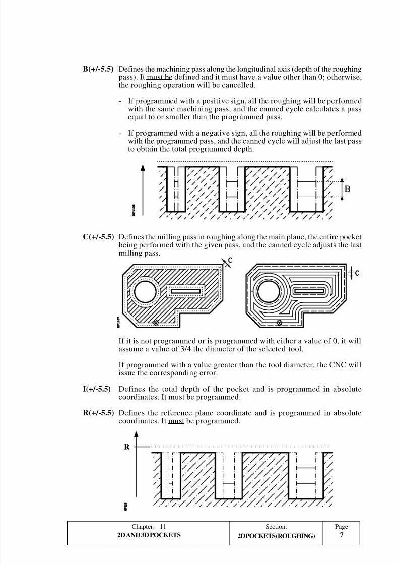
8/21/2019 CNC 8055 M Operator Manual
http://slidepdf.com/reader/full/cnc-8055-m-operator-manual 380/702
PageChapter: 11 Section:
72D AND 3D POCKETS
B(+/-5.5) Defines the machining pass along the longitudinal axis (depth of the roughingpass). It must be defined and it must have a value other than 0; otherwise,the roughing operation will be cancelled.
- If programmed with a positive sign, all the roughing will be performedwith the same machining pass, and the canned cycle calculates a passequal to or smaller than the programmed pass.
- If programmed with a negative sign, all the roughing will be performedwith the programmed pass, and the canned cycle will adjust the last passto obtain the total programmed depth.
C(+/-5.5) Defines the milling pass in roughing along the main plane, the entire pocketbeing performed with the given pass, and the canned cycle adjusts the lastmilling pass.
If it is not programmed or is programmed with either a value of 0, it willassume a value of 3/4 the diameter of the selected tool.
If programmed with a value greater than the tool diameter, the CNC willissue the corresponding error.
I(+/-5.5) Defines the total depth of the pocket and is programmed in absolute
coordinates. It must be programmed.
R(+/-5.5) Defines the reference plane coordinate and is programmed in absolutecoordinates. It must be programmed.
2D POCKETS (ROUGHING)
R

8/21/2019 CNC 8055 M Operator Manual
http://slidepdf.com/reader/full/cnc-8055-m-operator-manual 381/702
Section:
8Page
2D AND 3D POCKETSChapter: 11
K(1) Defines the type of profile intersection to be used.
0 = Basic profile intersection.1 = Advanced profile intersection.
If not programmed, a value of 0 will be assumed. Both intersection typeswill be discussed later on.
V (5.5) Defines the tool penetrating feedrate.
If not programmed or programmed with a value of "0", the CNC will assume 50%of the feedrate in the plane (F).
F (5.5) Optional. Defines the machining feedrate in the plane.
S (5.5) Optional. Defines the spindle speed.
T (4) Defines the tool used for the roughing operation. It must be programmed.
D (4) Optional. Defines the tool offset number.
M Optional. Up to 7 miscellaneous M functions can be programmed.
This operation allows M06 with an associated subroutine to be defined, and thetool change is performed before beginning the roughing operation.
C
2D POCKETS (ROUGHING)
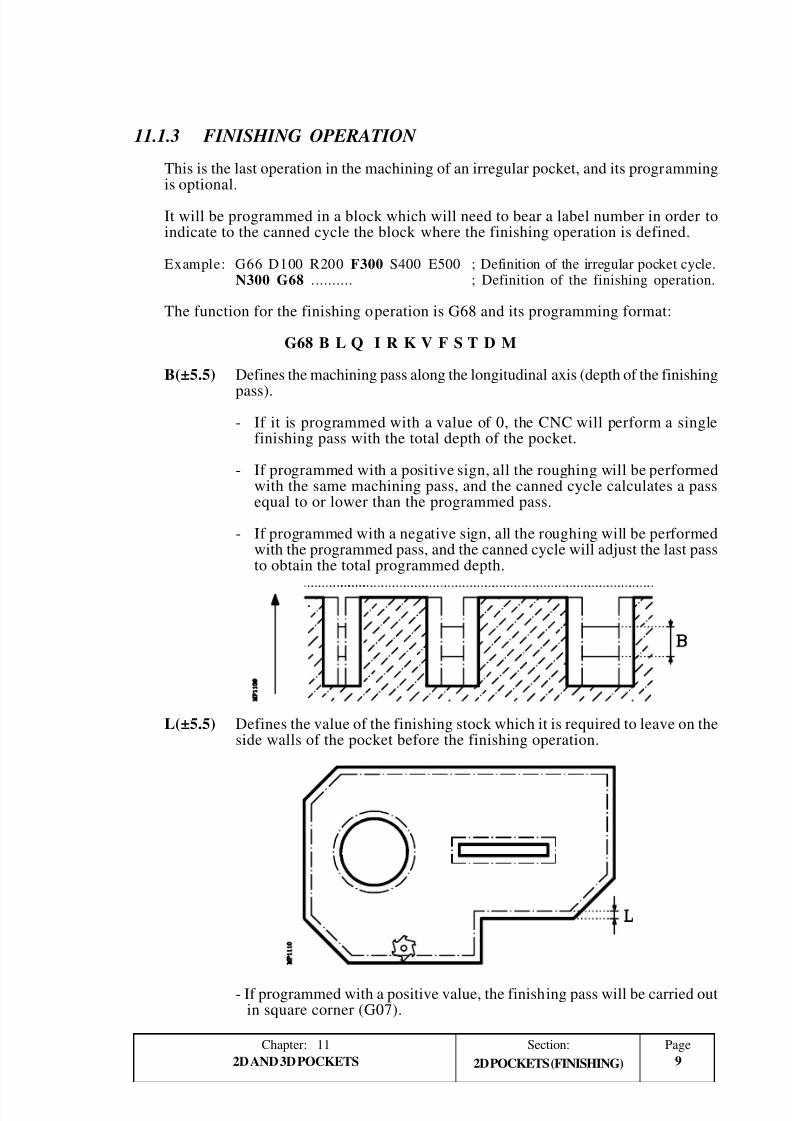
8/21/2019 CNC 8055 M Operator Manual
http://slidepdf.com/reader/full/cnc-8055-m-operator-manual 382/702
PageChapter: 11 Section:
92D AND 3D POCKETS
11.1.3 FINISHING OPERATION
This is the last operation in the machining of an irregular pocket, and its programmingis optional.
It will be programmed in a block which will need to bear a label number in order toindicate to the canned cycle the block where the finishing operation is defined.
Example: G66 D100 R200 F300 S400 E500 ; Definition of the irregular pocket cycle.N300 G68 .......... ; Definition of the finishing operation.
The function for the finishing operation is G68 and its programming format:
G68 B L Q I R K V F S T D M
B(±5.5) Defines the machining pass along the longitudinal axis (depth of the finishing
pass).
- If it is programmed with a value of 0, the CNC will perform a singlefinishing pass with the total depth of the pocket.
- If programmed with a positive sign, all the roughing will be performedwith the same machining pass, and the canned cycle calculates a passequal to or lower than the programmed pass.
- If programmed with a negative sign, all the roughing will be performedwith the programmed pass, and the canned cycle will adjust the last passto obtain the total programmed depth.
L(±5.5) Defines the value of the finishing stock which it is required to leave on theside walls of the pocket before the finishing operation.
- If programmed with a positive value, the finishing pass will be carried outin square corner (G07).
2D POCKETS (FINISHING)

8/21/2019 CNC 8055 M Operator Manual
http://slidepdf.com/reader/full/cnc-8055-m-operator-manual 383/702
Section:
10Page
2D AND 3D POCKETSChapter: 11
2D POCKETS (FINISHING)
- If programmed with a negative value, the finishing pass will be carriedout in round corner (G05).
- If programmed with a value of 0, no finishing pass will be carried out.
Q Indicates the direction of the finishing pass.The finishing pass on the islandsis always carried out in the opposite direction.
Q = 0 The finishing pass is carried out in the same direction as the outside profilewas programmed.
Q = 1 The finishing pass is carried out in the opposite direction to the oneprogrammed.
Q = 2 Reserved.
Any other value will generate the corresponding error message. If parameter "Q"is not programmed, the cycle assumes Q0.
I(±5.5) Defines the total depth of the island and it is given in absolute coordinates.
- If the island has a roughing operation, it is not necessary to define thisparameter since it has been programmed in that operation. However, if programmed in both operations, the canned cycle will assume the particulardepth indicated for each operation.
- If the island has no roughing operation, it is necessary to define this parameter.
R (±5.5) Defines the coordinate of the reference plane and it is given in absolute values.- If the island has a roughing operation, it is not necessary to define this
parameter since it has been programmed in that operation. However, if programmed in both operations, the canned cycle will assume the particulardepth indicated for each operation.
- If the island has no roughing operation, it is necessary to define this parameter.
K(1) Defines the type of profile intersection to be used.
0 = Basic profile intersection.1 = Advanced profile intersection.

8/21/2019 CNC 8055 M Operator Manual
http://slidepdf.com/reader/full/cnc-8055-m-operator-manual 384/702
PageChapter: 11 Section:
112D AND 3D POCKETS 2D POCKETS (FINISHING)
If the island has a roughing operation, it is not necessary to define this parameter sinceit has been programmed in that operation. However, if programmed in bothoperations, the canned cycle will assume the one defined for the roughing operation.
If no roughing operation has been defined and this parameter is not programmed,the canned cycle will assume a K0 value. Both types of intersection aredescribed later on.
V (5.5) Defines the tool penetrating feedrate.
If not programmed or programmed with a value of "0", the CNC will assume 50%of the feedrate in the plane (F).
F (5.5) Optional. Defines the machining feedrate in the plane.
S (5.5) Optional. Defines the spindle speed.
T (4) Defines the tool used for the roughing operation. It must be programmed.
D (4) Optional. Defines the tool offset number.
M Optional. Up to 7 miscellaneous M functions can be programmed.
This operation allows M06 with an associated subroutine to be defined, and the
tool change is performed before beginning the roughing operation.
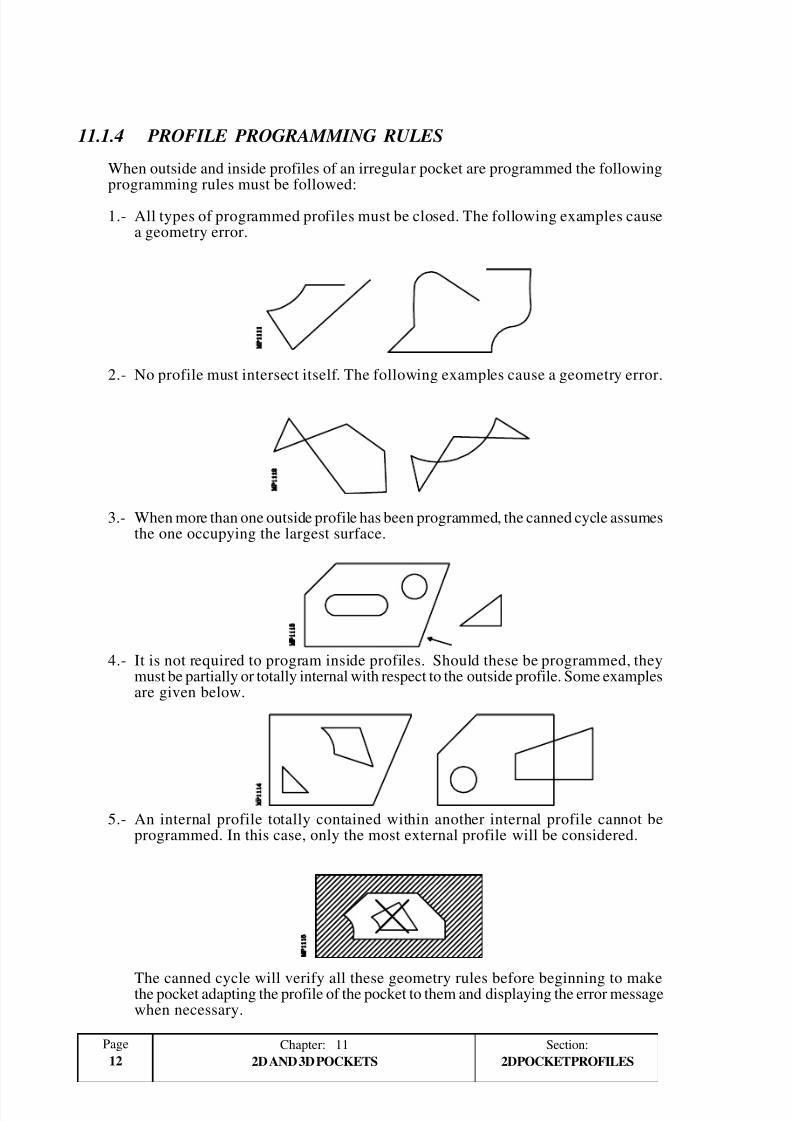
8/21/2019 CNC 8055 M Operator Manual
http://slidepdf.com/reader/full/cnc-8055-m-operator-manual 385/702
Section:
12Page
2D AND 3D POCKETSChapter: 11
11.1.4 PROFILE PROGRAMMING RULES
When outside and inside profiles of an irregular pocket are programmed the followingprogramming rules must be followed:
1.- All types of programmed profiles must be closed. The following examples causea geometry error.
2.- No profile must intersect itself. The following examples cause a geometry error.
3.- When more than one outside profile has been programmed, the canned cycle assumesthe one occupying the largest surface.
4.- It is not required to program inside profiles. Should these be programmed, theymust be partially or totally internal with respect to the outside profile. Some examplesare given below.
5.- An internal profile totally contained within another internal profile cannot beprogrammed. In this case, only the most external profile will be considered.
The canned cycle will verify all these geometry rules before beginning to makethe pocket adapting the profile of the pocket to them and displaying the error messagewhen necessary.
2D POCKET PROFILES

8/21/2019 CNC 8055 M Operator Manual
http://slidepdf.com/reader/full/cnc-8055-m-operator-manual 386/702
PageChapter: 11 Section:
132D AND 3D POCKETS
11.1.5 INTERSECTION OF PROFILES
In order to facilitate the programming of profiles, the canned cycle allows the profilesto intersect one another and the external profile.
The two available types of intersection can be selected by parameter "K"
11.1.5.1 BASIC PROFILE INTERSECTION (K=0)
When selecting this type, the following profile intersecting rules are to be followed:
1.- The intersection of islands generates a new inside profile which is their booleanunion. Example:
2.- The intersection between an internal and an external profile generates a new externalprofile as a result of the difference between the external and the internal profiles.Example:
3.- If there is an inside profile which has an intersection with another inside profileand with the external profile, the canned cycle first makes the intersection betweenthe inside profiles and then the intersection of these with the external profile.
4.- As a result of the intersection of the inside profiles with the outside one, a singlepocket will be obtained which corresponds to the outside profile having the largestsurface. The rest will be ignored.
5.- If the finishing operation has been programmed, the profile of the resulting pocket
must comply with all the tool compensation rules, since if a profile is programmedwhich cannot be machined by the programmed finishing tool, the CNC will showthe corresponding error.
2D POCKET PROFILES

8/21/2019 CNC 8055 M Operator Manual
http://slidepdf.com/reader/full/cnc-8055-m-operator-manual 387/702
Section:
14Page
2D AND 3D POCKETSChapter: 11
11.1.5.2 ADVANCED PROFILE INTERSECTION (K=1)
When selecting this type, the following profile intersecting rules are to be followed:
1.- The initial point of each contour determines the section to be selected.
In a profile intersection, each contour is divided into several lines that could be grouped as:
- Lines external to the other contour.- Lines internal to the other contour.
This type of profile intersection selects in each contour the group of lines where theprofile defining point is included.
The following example shows the explained selection process. The solid lines indicatethe lines external to the other contour and the dashes indicate the internal lines. The
initial point of each contour is indicated with an "x".
Examples of profile intersections:
Boolean Addition:
Boolean Subtraction:
2D POCKET PROFILES
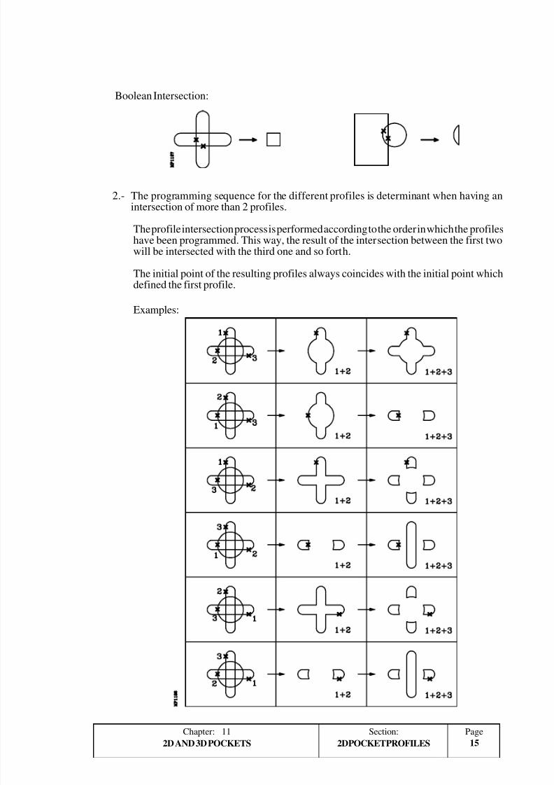
8/21/2019 CNC 8055 M Operator Manual
http://slidepdf.com/reader/full/cnc-8055-m-operator-manual 388/702
PageChapter: 11 Section:
152D AND 3D POCKETS
Boolean Intersection:
2.- The programming sequence for the different profiles is determinant when having anintersection of more than 2 profiles.
The profile intersection process is performed according to the order in which the profileshave been programmed. This way, the result of the intersection between the first twowill be intersected with the third one and so forth.
The initial point of the resulting profiles always coincides with the initial point whichdefined the first profile.
Examples:
2D POCKET PROFILES
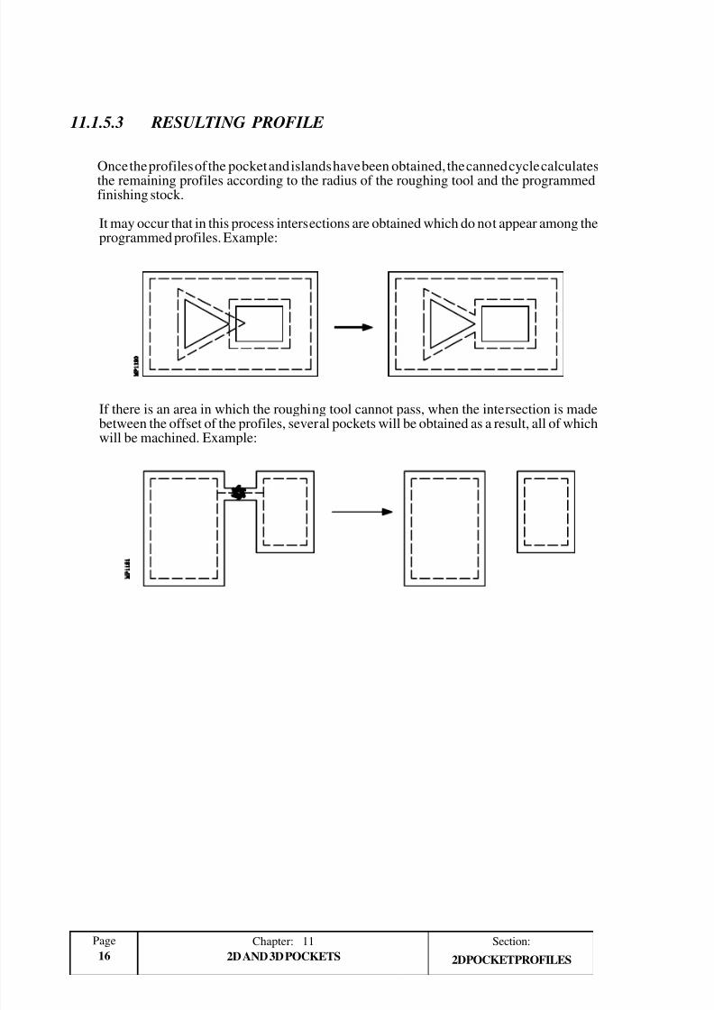
8/21/2019 CNC 8055 M Operator Manual
http://slidepdf.com/reader/full/cnc-8055-m-operator-manual 389/702
Section:
16Page
2D AND 3D POCKETSChapter: 11
11.1.5.3 RESULTING PROFILE
Once the profiles of the pocket and islands have been obtained, the canned cycle calculatesthe remaining profiles according to the radius of the roughing tool and the programmedfinishing stock.
It may occur that in this process intersections are obtained which do not appear among theprogrammed profiles. Example:
If there is an area in which the roughing tool cannot pass, when the intersection is madebetween the offset of the profiles, several pockets will be obtained as a result, all of whichwill be machined. Example:
2D POCKET PROFILES

8/21/2019 CNC 8055 M Operator Manual
http://slidepdf.com/reader/full/cnc-8055-m-operator-manual 390/702
PageChapter: 11 Section:
172D AND 3D POCKETS 2D POCKET PROFILES
11.1.6 PROFILE PROGRAMMING SYNTAX
The outside profile and the inside profiles or islands which are programmed must bedefined by simple geometrical elements such as straight lines or arcs.
The first definition block (where the external profile starts) and the last (where the lastprofile defined ends) must be provided with the block label number. These label numberswill be those which indicate to the canned cycle the beginning and end of the geometricdescription of the profiles which make up the pocket.
Example: G66 D100 R200 F300 S400 E500 ;Definition of irregular pocketN400 G0 G90 X300 Y50 Z3 ;Beginning of geometric description------ ----- ---- ---N500 G2 G6 X300 Y50 I150 J0 ;End of geometric description
The profile programming syntax must comply with the following rules:
1.- The external profile must begin in the first definition block of the geometricdescription of the part profiles. This block will be assigned a label number in orderto indicate canned cycle G66 the beginning of the geometric description.
2.- The part surface coordinate will be programmed in this block.
3.- All the internal profiles which are required may be programmed, one after theother. Each of these must commence with a block containing the G00 function(indicating the beginning of the profile).
Warning:Care must be taken to program G01, G02 or G03 in the block followingthe definition of the beginning, as G00 is modal, thus preventing the CNCfrom interpreting the following blocks as the beginnings of a new profile.
4.- Once the definition of the profiles has been completed, a label number must beassigned to the last block programmed, in order to indicate the canned cycle G66the end of the geometric description.Example
G0 G17 G90 X-350 Y0 Z50
G66 D100 R200 F300 S400 E500 ........... ;Description of cycleG0 G90 X0 Y0 Z50M30
N400 G0 G90 X-260 Y-190 Z4.5 ............ ;Beginning of first profile .......... .......... G0 X230 Y170 .................................... ;Beginning of another profile G1........ .......... G0 X-120 Y90 ..................................... ;Beginning of another profile G2........
..........N500 G1 X-120 Y90 ................................. ;End of geometric description

8/21/2019 CNC 8055 M Operator Manual
http://slidepdf.com/reader/full/cnc-8055-m-operator-manual 391/702
Section:
18Page
2D AND 3D POCKETSChapter: 11
5.- Profiles are described as programmed paths, it being possible to include cornerrounding, chamfers, etc., following the syntax rules defined for this purpose.
6.- Mirror images, scaling factor changes, rotation of coordinate system, zero offsets,etc., cannot be programmed in the description of profiles.
7.- Nor is it possible to program blocks in high level language, such as jumps, subroutinecalls or parametric programming.
8.- Other canned cycles cannot be programmed.
In addition to the G00 function, which has a special meaning, the irregular pocketcanned cycle allows the use of the following functions for the definition of profiles.
G01 Linear interpolationG02 Clockwise circular interpolationG03 Counter-clockwise circular interpolationG06 Arc center in absolute coordinatesG08 Arc tangent to previous path.G09 Arc defined by three pointsG36 Controlled corner roundingG39 ChamferG53 Programming with respect to machine reference zero (home)G70 Programming in inchesG71 Programming in millimetersG90 Absolute programming
G91 Incremental programmingG93 Polar origin preset
2D POCKET PROFILES

8/21/2019 CNC 8055 M Operator Manual
http://slidepdf.com/reader/full/cnc-8055-m-operator-manual 392/702
PageChapter: 11 Section:
192D AND 3D POCKETS
11.1.7 ERRORS
The CNC will issue the following errors:
ERROR 1023 : G67. Tool radius too large.When selecting a wrong roughing tool.
ERROR 1024 : G68. Tool radius too large.When selecting a wrong finishing tool.
ERROR 1025 : A tool of no radius has been programmed.When using a tool with "0" radius while machining a pocket.
ERROR 1026 : A step greater than the tool diameter has been programmed.When parameter "C" of the roughing operation is greater than the diameter of theroughing tool.
ERROR 1041 : A mandatory parameter not programmed in the canned cycle.It comes up in the following instances:- When parameters "I" and "R" have not been programmed in the roughing operation.- When not using a roughing operation and not programming the "I" and "R"
parameters for the finishing operation.
ERROR 1042 : Wrong canned cycle parameter value.It comes up in the following instances:- When parameter "Q" of the finishing operation has the wrong value.- When parameter "B" of the finishing operation has a "0" value.- When parameter "J" of the finishing operation has been programmed with a value
greater than the finishing tool radius.ERROR 1044 : The plane profile intersects itself in an irregular pocket with islands.
It comes up when any of the plane profiles of the programmed contours intersects itself.
ERROR 1046 : Wrong tool position prior to the canned cycle.It comes up when calling the G66 cycle if the tool is positioned between the referenceplane and the depth coordinate (bottom) of any of the operations.
ERROR 1047 : Open plane profile in an irregular pocket with islands.It comes up when any of the programmed contours does not begin and end at the samepoint. It may be because G1 has not been programmed after the beginning, with G0,on any of the profiles.
ERROR 1048 : The part surface coordinate (top) has not been programmed in anirregular pocket with islands.It comes up when the first point of the geometry does not include the pocket topcoordinate.
ERROR 1049 : Wrong reference plane coordinate for the canned cycle.It comes up when the coordinate of the reference plane is located between the part's"top" and "bottom" in any of the operations.
2D POCKET (ERRORS)
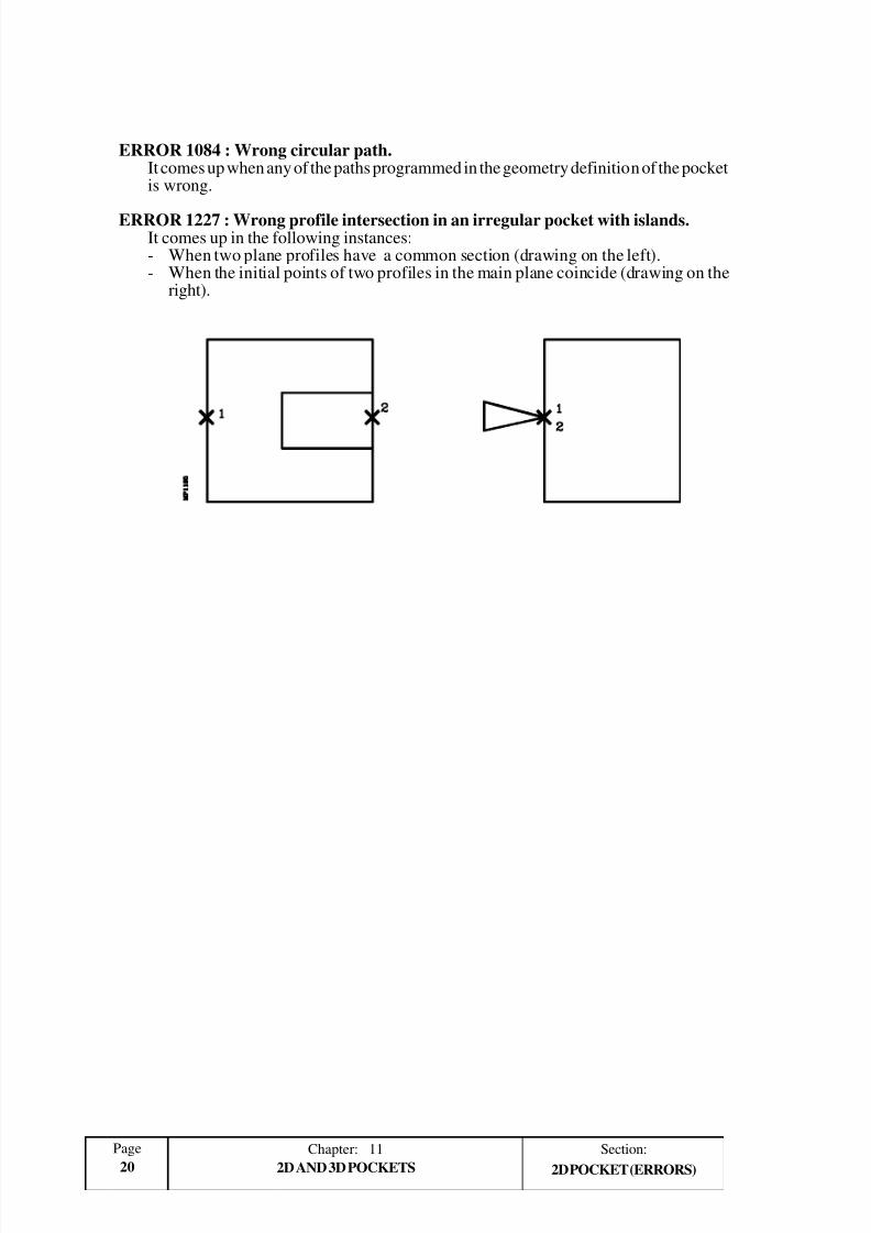
8/21/2019 CNC 8055 M Operator Manual
http://slidepdf.com/reader/full/cnc-8055-m-operator-manual 393/702
Section:
20Page
2D AND 3D POCKETSChapter: 11
ERROR 1084 : Wrong circular path.It comes up when any of the paths programmed in the geometry definition of the pocketis wrong.
ERROR 1227 : Wrong profile intersection in an irregular pocket with islands.It comes up in the following instances:- When two plane profiles have a common section (drawing on the left).- When the initial points of two profiles in the main plane coincide (drawing on the
right).
2D POCKET (ERRORS)
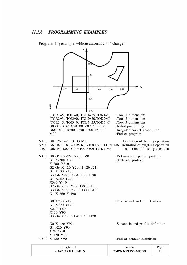
8/21/2019 CNC 8055 M Operator Manual
http://slidepdf.com/reader/full/cnc-8055-m-operator-manual 394/702
PageChapter: 11 Section:
212D AND 3D POCKETS
11.1.8 PROGRAMMING EXAMPLES
Programming example, without automatic tool changer
(TOR1=5, TOI1=0, TOL1=25,TOK1=0) ;Tool 1 dimensions(TOR2=3, TOI2=0, TOL2=20,TOK2=0) ;Tool 2 dimensions(TOR3=5, TOI3=0, TOL3=25,TOK3=0) ;Tool 3 dimensionsG0 G17 G43 G90 X0 Y0 Z25 S800 ;Initial posi tioningG66 D100 R200 F300 S400 E500 ;Irregular pocket descriptionM30 ;End of program
N100 G81 Z5 I-40 T3 D3 M6 ;Definition of drilling operationN2 00 G67 B20 C8 I-40 R5 K0 V100 F500 T1 D1 M6 ;Definition of roughing operationN30 0 G68 B0 L0.5 Q0 V100 F300 T2 D2 M6 ;Definition of finishing operation
N400 G0 G90 X-260 Y-190 Z0 ;Definition of pocket profilesG1 X-200 Y30 ;(External profile)X-200 Y210G2 G6 X-120 Y290 I-120 J210G1 X100 Y170G3 G6 X220 Y290 I100 J290G1 X360 Y290X360 Y-10
G2 G6 X300 Y-70 I300 J-10G3 G6 X180 Y-190 I300 J-190G1 X-260 Y-190
G0 X230 Y170 ;First island profile definitionG1 X290 Y170X230 Y50X150 Y90G3 G6 X230 Y170 I150 J170
G0 X-120 Y90 ;Second island profile definitionG1 X20 Y90
X20 Y-50X-120 Y-50N500 X-120 Y90 ;End of contour definition
2D POCKET EXAMPLES
Y
X

8/21/2019 CNC 8055 M Operator Manual
http://slidepdf.com/reader/full/cnc-8055-m-operator-manual 395/702
Section:
22Page
2D AND 3D POCKETSChapter: 11
2D POCKET EXAMPLES
X
Y
Programming example, with automatic tool changer. The "x" of the figure indicate theinitial points of each profile.
(TOR1=9, TOI1=0, TOL1=25,TOK1=0) ;Tool 1 dimensions(TOR2=3.6, TOI2=0, TOL2=20,TOK2=0) ;Tool 2 dimensions(TOR3=9, TOI3=0, TOL3=25,TOK3=0) ;Tool 3 dimensionsG0 G17 G43 G90 X0 Y0 Z25 S800 ;Initia l posi tioningG66 D100 R200 F300 S400 E500 ;Irregular pocket descriptionM30 ;End of program
N100 G81 Z5 I-40 T3 D3 M6 ;Definition of drilling operationN2 00 G67 B10 C5 I-40 R5 K1 V100 F500 T1 D1 M6 ;Definition of roughing operationN300 G68 B0 L0.5 Q1 V100 F300 T2 D2 M6 ;Definition of finishing operation
N400 G0 G90 X-300 Y50 Z3 ;Definition of pocket profilesG1 Y190 ;(External profile)G2 G6 X-270 Y220 I-270 J190G1 X170X300 Y150Y50G3 G6 X300 Y-50 I300 J0G1 G36 R50 Y-220X-30G39 R50 X-100 Y-150X-170 Y-220X-270
G2 G6 X-300 Y-190 I-270 J-190G1 Y-50X-240Y50X-300
G0 X-120 Y80 ;First island contour definitionG2 G6 X-80 Y80 I-100 J80 ;(Contour a)G1 Y-80G2 G6 X-120 Y-80 I-100 J-80G1 Y80
8/21/2019 CNC 8055 M Operator Manual
http://slidepdf.com/reader/full/cnc-8055-m-operator-manual 396/702
PageChapter: 11 Section:
232D AND 3D POCKETS
G0 X-40 Y0 ;(Contour b)G2 G6 X-40 Y0 I-100 J0G0 X-180 Y20 ;(Contour c)G1 X-20
G2 G6 X-20 Y-20 I-20 J0G1 X-180G2 G6 X-180 Y20 I-180 J0
G0 X150 Y140 ;Second island profile definitionG1 X170 Y110 ;(Contour d)Y-110X150 Y-140X130 Y-110Y110X150 Y140G0 X110 Y0 ;(Contour e)
N500 G2 G6 X110 Y0 I150 J0 ;End of contour definition
2D POCKET EXAMPLES
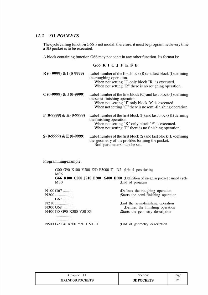
8/21/2019 CNC 8055 M Operator Manual
http://slidepdf.com/reader/full/cnc-8055-m-operator-manual 397/702
Page
25
Section:Chapter: 11
2D AND 3D POCKETS
11.2 3D POCKETS
The cycle calling function G66 is not modal; therefore, it must be programmed every timea 3D pocket is to be executed.
A block containing function G66 may not contain any other function. Its format is:
G66 R I C J F K S E
R (0-9999) & I (0-9999) Label number of the first block (R) and last block (I) definingthe roughing operation.
When not setting "I" only block "R" is executed.When not setting "R" there is no roughing operation.
C (0-9999) & J (0-9999) Label number of the first block (C) and last block (J) definingthe semi-finishing operation.
When not setting "J" only block "c" is executed.When not setting "C" there is no semi-finishing operation.
F (0-9999) & K (0-9999) Label number of the first block (F) and last block (K) definingthe finishing operation.
When not setting "K" only block "F" is executed.When not setting "F" there is no finishing operation.
S (0-9999) & E (0-9999) Label number of the first block (S) and last block (E) definingthe geometry of the profiles forming the pocket.
Both parameters must be set.
Programming example:
G00 G90 X100 Y200 Z50 F5000 T1 D2 ;Initial positioningM06G66 R100 C200 J210 F300 S400 E500 ;Definition of irregular pocket canned cycleM30 ;End of program
N100 G67 ........... ;Defines the roughing operationN200 ................... ;Starts the semi-finishing operation
G67 ...........N210 ................... ;End the semi-finishing operation
N300 G68 ............ ;Defines the finishing operationN400 G0 G90 X300 Y50 Z3 ;Starts the geometry description
...................
...................N500 G2 G6 X300 Y50 I150 J0 ;End of geometry description
3D POCKETS

8/21/2019 CNC 8055 M Operator Manual
http://slidepdf.com/reader/full/cnc-8055-m-operator-manual 398/702
Page Chapter: 11 Section:
26 2D AND 3D POCKETS
Basic operation:
1.- Roughing operation. Only if it has been programmed.
It consists of several surface milling passes, until the total depth programmed has beenreached. On each surface milling pass, the steps below will be followed depending onthe type of machining that has been programmed:
Case A: When the machining paths are linear and maintain a certain angle with the abscissa axis.
* It first contours the external profile of the part.
If the finishing operation has been selected on the cycle call, this contouring isperformed leaving the finishing stock programmed for the finishing pass.
* Next the milling operation, with the programmed feed and steps.
If, while milling, an island is run into for the first time, it will be contoured.
After the contouring and the remaining times, the tool will pass over the island,withdrawing along the longitudinal axis, to the reference plane, and will continuemachining once the island has been cleared.
3D POCKETS

8/21/2019 CNC 8055 M Operator Manual
http://slidepdf.com/reader/full/cnc-8055-m-operator-manual 399/702
Page
27
Section:Chapter: 11
2D AND 3D POCKETS 3D POCKETS
Case B: When using concentric machining paths
* The roughing operation is carried out following paths concentric to the profile.It will done as fast as possible without going over the islands if possible.
2.- Semi-finishing operation. Only if it has been programmed.After the roughing, some ridges appear on the external profile as well as on the islandsthemselves as shown in the illustration below:
With the semi-finishing operation, it is possible to minimize these ridges by runningseveral contouring passes at different depths.
3.- Finishing operation. Only if it has been programmed.
It runs consecutive finishing passes in 3D. Either inward or outward machiningdirection may be selected or both may be alternated.
The CNC will machine both the outside profile and the islands by performing tangentialentries and exits to them at constant surface speed.

8/21/2019 CNC 8055 M Operator Manual
http://slidepdf.com/reader/full/cnc-8055-m-operator-manual 400/702
Page Chapter: 11 Section:
28 2D AND 3D POCKETS
After cycle conditions
Once the canned cycle has ended, the active feedrate will be the last one programmed. Theone corresponding to the roughing or finishing operation. On the other hand, the CNC willassume functions G00, G40 and G90.
Reference coordinates
The irregular pocket canned cycle has four coordinates along the longitudinal axis,usually perpendicular to the plane (selected with G15), which, due to their importance,are described next:
1.- Starting plane coordinate. Given by the tool position at the beginning of the cycle.
2.- Reference plane coordinate. It must be programmed in absolute values and itrepresents a part approaching coordinate.
3.- Part surface coordinate (top). It is programmed in absolute values and in the firstprofile defining block.
4.- Machining depth coordinate (bottom. It must be programmed in absolute values.
3D POCKETS

8/21/2019 CNC 8055 M Operator Manual
http://slidepdf.com/reader/full/cnc-8055-m-operator-manual 401/702
Page
29
Section:Chapter: 11
2D AND 3D POCKETS
11.2.1 ROUGHING OPERATION
This is the main operation in the machining of an irregular pocket, and its programmingis optional.
It will be programmed in a block which will need to bear a label number in order toindicate to the canned cycle the block where the roughing operation is defined.
Example: G66 R100 C200 F300 S400 E500 ; Definition of the irregular pocket cycle.N100 G67 .......... ; Definition of the roughing operation.
The function for the roughing operation is G67 and it cannot be executed independentlyfrom the G66.Its programming format: G67 A B C I R V F S T D M
A(+/-5.5) Defines the angle which forms the roughing path with the abscissa axis.
If parameter "A" is not programmed, the roughing operation is carried outfollowing concentric paths. It will be machined as fast as possible since itdoes not have to go over the islands.
3D POCKETS(ROUGHING)

8/21/2019 CNC 8055 M Operator Manual
http://slidepdf.com/reader/full/cnc-8055-m-operator-manual 402/702
Page Chapter: 11 Section:
30 2D AND 3D POCKETS
B(+/-5.5) Defines the machining pass along the longitudinal axis (depth of the roughingpass). It must be defined and it must have a value other than 0; otherwise,the roughing operation will be cancelled.
- If programmed with a positive sign, all the roughing will be performedwith the same machining pass, and the canned cycle calculates a passequal to or smaller than the programmed pass.
- If programmed with a negative sign, all the roughing will be performedwith the programmed pass, and the canned cycle will adjust the last passto obtain the total programmed depth.
- If done with B(+), the ridges will appear only on the pocket walls; but,if done with B(-), they could also show up above the islands.
C(+/-5.5) Defines the milling pass in roughing along the main plane, the entire pocketbeing performed with the given pass, and the canned cycle adjusts the lastmilling pass.
If it is not programmed or is programmed with either a value of 0, it willassume a value of 3/4 the diameter of the selected tool.
If programmed with a value greater than the tool diameter, the CNC willissue the corresponding error.
I(+/-5.5) Defines the total depth of the pocket and is programmed in absolutecoordinates. It must be programmed.
3D POCKETS(ROUGHING)

8/21/2019 CNC 8055 M Operator Manual
http://slidepdf.com/reader/full/cnc-8055-m-operator-manual 403/702
Page
31
Section:Chapter: 11
2D AND 3D POCKETS
R(+/-5.5) Defines the reference plane coordinate and is programmed in absolutecoordinates. It must be programmed.
V (5.5) Defines the tool penetrating feedrate.
If not programmed or programmed with a value of "0", the CNC will assume 50%of the feedrate in the plane (F).
F (5.5) Optional. Defines the machining feedrate in the plane.
S (5.5) Optional. Defines the spindle speed.
T (4) Defines the tool used for the roughing operation. It must be programmed.
D (4) Optional. Defines the tool offset number.
M Optional. Up to 7 miscellaneous M functions can be programmed.
This operation allows M06 with an associated subroutine to be defined, and thetool change is performed before beginning the roughing operation.
3D POCKETS(ROUGHING)

8/21/2019 CNC 8055 M Operator Manual
http://slidepdf.com/reader/full/cnc-8055-m-operator-manual 404/702
Page Chapter: 11 Section:
32 2D AND 3D POCKETS
11.2.2 SEMI-FINISHING OPERATION
This operation is optional.
It will be programmed in a block which will need to bear a label number in order toindicate to the canned cycle the block where the roughing operation is defined.
Example: G66 R100 C200 F300 S400 E500 ; Definition of the irregular pocket cycle.N200 G67 . ......... ; Definition of the semi-finish operation.
The function for the semi-finishing operation is G67 and it cannot be executedindependently from the G66.
Both the roughing and the semi-finishing operations are defined with G67; but, in differentblocks. It is function G66 who indicates which is which by means of parameters "R" and "C".
Its programming format is: G67 B I R V F S T D MB (±5.5) Defines the machining step along the longitudinal axis (semi-finishing pass). It
must be programmed and with a value other than "0". Otherwise, the semi-finishing operation will be canceled.
- If programmed with a positive sign, the whole semi-finish operation will becarried out with the same machining pass and the canned cycle will calculatea pass equal or smaller than the one programmed.
- If programmed with a negative sign, the whole semi-finish operation will berun with the programmed pass. The canned cycle will adjust the last pass toobtain the total programmed depth.
I (±5.5) Defines the total pocket depth and it is programmed in absolute coordinates.
If there is a roughing operation and it is not programmed, the CNC takes the valuedefined for the roughing operation.
If there is no roughing operation, it must be programmed.
R (±5.5) Defines the coordinate of the reference plane and it is programmed in absolutevalues.
If there is a roughing operation and it is not programmed, the CNC takes the valuedefined for the roughing operation.
If there is no roughing operation, it must be programmed.
3D POCKETS(SEMIFINISH)
8/21/2019 CNC 8055 M Operator Manual
http://slidepdf.com/reader/full/cnc-8055-m-operator-manual 405/702
Page
33
Section:Chapter: 11
2D AND 3D POCKETS
V (5.5) Defines the tool penetrating feedrate.
If not programmed or programmed with a value of "0", the CNC will assume 50%of the feedrate in the plane (F).
F (5.5) Optional. Defines the machining feedrate in the plane.
S (5.5) Optional. Defines the spindle speed.
T (4) Defines the tool used for the semi-finishing operation. It must be programmed.
D (4) Optional. Defines the tool offset number.
M Optional. Up to 7 miscellaneous M functions can be programmed.
This operation allows M06 with an associated subroutine to be defined, and the
tool change is performed before beginning the semi-finishing operation.
3D POCKETS(SEMIFINISH)
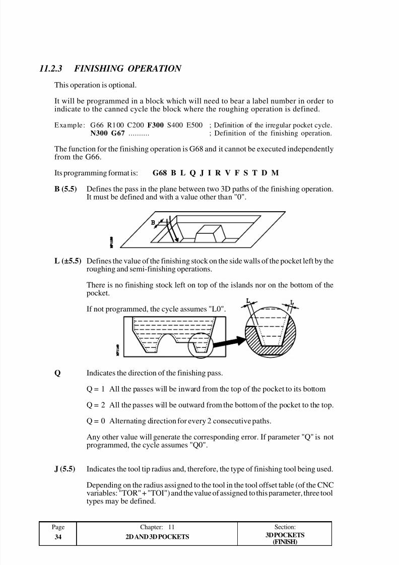
8/21/2019 CNC 8055 M Operator Manual
http://slidepdf.com/reader/full/cnc-8055-m-operator-manual 406/702
Page Chapter: 11 Section:
34 2D AND 3D POCKETS 3D POCKETS(FINISH)
11.2.3 FINISHING OPERATION
This operation is optional.
It will be programmed in a block which will need to bear a label number in order toindicate to the canned cycle the block where the roughing operation is defined.
Example: G66 R100 C200 F300 S400 E500 ; Definition of the irregular pocket cycle.N300 G67 .......... ; Definition of the finishing operation.
The function for the finishing operation is G68 and it cannot be executed independentlyfrom the G66.
Its programming format is: G68 B L Q J I R V F S T D M
B (5.5) Defines the pass in the plane between two 3D paths of the finishing operation.
It must be defined and with a value other than "0".
L (±5.5) Defines the value of the finishing stock on the side walls of the pocket left by theroughing and semi-finishing operations.
There is no finishing stock left on top of the islands nor on the bottom of the
pocket.If not programmed, the cycle assumes "L0".
Q Indicates the direction of the finishing pass.
Q = 1 All the passes will be inward from the top of the pocket to its bottom
Q = 2 All the passes will be outward from the bottom of the pocket to the top.
Q = 0 Alternating direction for every 2 consecutive paths.
Any other value will generate the corresponding error. If parameter "Q" is notprogrammed, the cycle assumes "Q0".
J (5.5) Indicates the tool tip radius and, therefore, the type of finishing tool being used.
Depending on the radius assigned to the tool in the tool offset table (of the CNC
variables: "TOR" + "TOI") and the value of assigned to this parameter, three tooltypes may be defined.

8/21/2019 CNC 8055 M Operator Manual
http://slidepdf.com/reader/full/cnc-8055-m-operator-manual 407/702
Page
35
Section:Chapter: 11
2D AND 3D POCKETS 3D POCKETS(FINISH)
FLAT ................................... If J is not programmed or J = 0BALL-END ......................... If J = RTORIC (Corner rounding).... If J <> 0 (other than 0) and J < R
I (±5.5) Defines the total pocket depth and it is given in absolute coordinates.
- If defined, the cycle will take it into account during the finishing operation.
- If not defined and the pocket has a roughing operation, the cycle will assumethe value defined for the roughing operation.
- If not defined and the pocket has no roughing operation, but it has a semi-finishing operation, the cycle will assume the one define in the semi-finishingoperation.
- If the pocket has neither roughing nor semi-finishing operation, this parametermust be defined.
R (±5.5) Defines the coordinate of the reference plane and it must be given in absolutevalues.
- If defined, the cycle will take it into account during the finishing operation.
- If not defined and the pocket has a roughing operation, the cycle will assumethe value defined for the roughing operation.
- If not defined and the pocket has no roughing operation, but it has a semi-finishing operation, the cycle will assume the one define in the semi-finishingoperation.
- If the pocket has neither roughing nor semi-finishing operation, this parametermust be defined.
V (5.5) Defines the tool penetrating feedrate.
If not programmed or programmed with a value of "0", the CNC will assume 50%of the feedrate in the plane (F).
F (5.5) Optional. Defines the machining feedrate in the plane.
S (5.5) Optional. Defines the spindle speed.
T (4) Defines the tool used for the finishing operation. It must be programmed.
D (4) Optional. Defines the tool offset number.
M Optional. Up to 7 miscellaneous M functions can be programmed.
This operation allows M06 with an associated subroutine to be defined, and thetool change is performed before beginning the finishing operation.
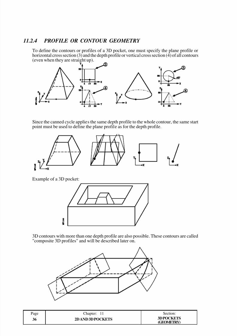
8/21/2019 CNC 8055 M Operator Manual
http://slidepdf.com/reader/full/cnc-8055-m-operator-manual 408/702
Page Chapter: 11 Section:
36 2D AND 3D POCKETS
11.2.4 PROFILE OR CONTOUR GEOMETRY
To define the contours or profiles of a 3D pocket, one must specify the plane profile orhorizontal cross section (3) and the depth profile or vertical cross section (4) of all contours(even when they are straight up).
Since the canned cycle applies the same depth profile to the whole contour, the same startpoint must be used to define the plane profile as for the depth profile.
Example of a 3D pocket:
3D contours with more than one depth profile are also possible. These contours are called"composite 3D profiles" and will be described later on.
3D POCKETS(GEOMETRY)

8/21/2019 CNC 8055 M Operator Manual
http://slidepdf.com/reader/full/cnc-8055-m-operator-manual 409/702
Page
37
Section:Chapter: 11
2D AND 3D POCKETS
11.2.5 PROFILE PROGRAMMING RULES
When programming inside or outside contours of an irregular 3D pocket (with islands) , thefollowing rules must be complied with:
1.- The profile in the main plane indicates the shape of the contour.
Since a 3D contour has an infinite number of different profiles (1 per each depthcoordinate), the following must be programmed:
* For the outside contour of the pocket: the one corresponding to the surfacecoordinate or top of the part (1).
* For the inside contours: the one corresponding to the base or bottom (2).
2.- The profile in the plane must be closed (same starting and end points) and it must notintersect itself. Examples:
The following examples cause a geometry error:
3.- The depth profile (vertical cross section) must be programmed with any of the axes of the active plane. If the active plane is the XY and the perpendicular axis is the Z axis,
one must program: G16XZ or G16YZ.
All profiles, plane and depth, must start with the definition of the plane containing it.
Example: G16 XY ......................Beginning of the outside profile definition----- plane profile definition -----G16 XZ------ depth profile definition ----
G16 XY ......................Beginning of the island definition----- plane profile definition -----G16 XZ
------ depth profile definition ----
3D POCKETS(PROGRAMMING RULES)
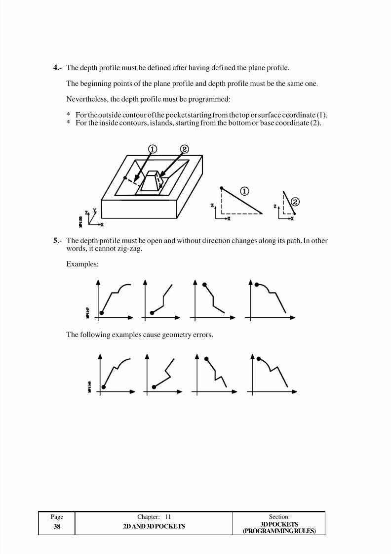
8/21/2019 CNC 8055 M Operator Manual
http://slidepdf.com/reader/full/cnc-8055-m-operator-manual 410/702
Page Chapter: 11 Section:
38 2D AND 3D POCKETS
4.- The depth profile must be defined after having defined the plane profile.
The beginning points of the plane profile and depth profile must be the same one.
Nevertheless, the depth profile must be programmed:
* For the outside contour of the pocket starting from the top or surface coordinate (1).* For the inside contours, islands, starting from the bottom or base coordinate (2).
5.- The depth profile must be open and without direction changes along its path. In otherwords, it cannot zig-zag.
Examples:
The following examples cause geometry errors.
3D POCKETS(PROGRAMMING RULES)
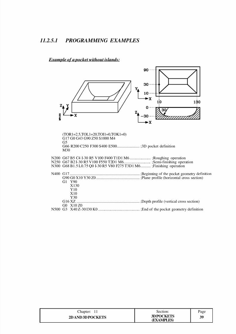
8/21/2019 CNC 8055 M Operator Manual
http://slidepdf.com/reader/full/cnc-8055-m-operator-manual 411/702
Page
39
Section:Chapter: 11
2D AND 3D POCKETS
11.2.5.1 PROGRAMMING EXAMPLES
Example of a pocket without islands:
(TOR1=2.5,TOL1=20,TOI1=0,TOK1=0)G17 G0 G43 G90 Z50 S1000 M4G5G66 R200 C250 F300 S400 E500....................... ;3D pocket definitionM30
N200 G67 B5 C4 I-30 R5 V100 F400 T1D1 M6 ..................... ;Roughing operationN250 G67 B2 I-30 R5 V100 F550 T2D1 M6........................... ;Semi-finishing operationN300 G68 B1.5 L0.75 Q0 I-30 R5 V80 F275 T3D1 M6.......... ;Finishing operation
N400 G17....................................................................... ;Beginning of the pocket geometry definitionG90 G0 X10 Y30 Z0 ............................................ ;Plane profile (horizontal cross section)G1 Y90
X130Y10X10Y30
G16 XZ ................................................................ ;Depth profile (vertical cross section)G0 X10 Z0
N500 G3 X40 Z-30 I30 K0 .......................................... ;End of the pocket geometry definition
3D POCKETS(EXAMPLES)
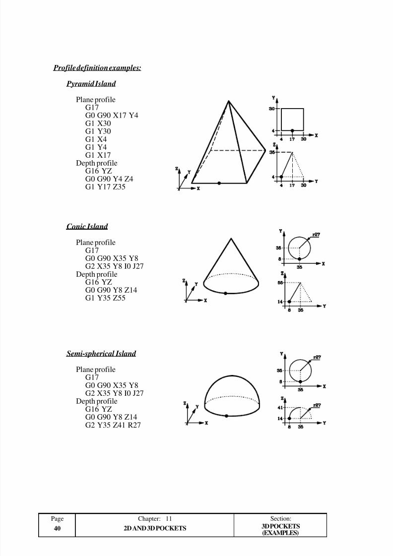
8/21/2019 CNC 8055 M Operator Manual
http://slidepdf.com/reader/full/cnc-8055-m-operator-manual 412/702
Page Chapter: 11 Section:
40 2D AND 3D POCKETS
Profile definition examples:
Pyramid Island
Plane profileG17G0 G90 X17 Y4G1 X30G1 Y30G1 X4G1 Y4G1 X17
Depth profileG16 YZG0 G90 Y4 Z4G1 Y17 Z35
Conic Island
Plane profileG17G0 G90 X35 Y8G2 X35 Y8 I0 J27
Depth profileG16 YZ
G0 G90 Y8 Z14G1 Y35 Z55
Semi-spherical Island
Plane profileG17G0 G90 X35 Y8G2 X35 Y8 I0 J27
Depth profileG16 YZG0 G90 Y8 Z14G2 Y35 Z41 R27
3D POCKETS(EXAMPLES)

8/21/2019 CNC 8055 M Operator Manual
http://slidepdf.com/reader/full/cnc-8055-m-operator-manual 413/702
Page
41
Section:Chapter: 11
2D AND 3D POCKETS
Example of a 3D pocket with islands:
(TOR1=2.5,TOL1=20,TOI1=0,TOK1=0)G17 G0 G43 G90 Z50 S1000 M4G5G66 R200 C250 F300 S400 E500....................... ;3D pocket definitionM30
N200 G67 B5 C4 I9 R25 V100 F400 T1D1 M6 ...................... ;Roughing operationN250 G67 B2 I9 R25 V100 F550 T2D1 M6 ............................ ;Semi-finishing operationN300 G68 B1.5 L0.75 Q0 I9 R25 V50 F275 T3D1 M6 ........... ;Finishing operation
N400 G17....................................................................... ;Beginning of the pocket geometry definitionG90 G0 X10 Y30 Z24.......................................... ;Outside contour (plane profile)G1 Y50
X70Y10X10Y30
G16 XZ ................................................................ ;Depth profileG0 X10 Z24G1 X15 Z9
G17 ..................................................................... ;Island definitionG90 G0 X30 Y30 ................................................. ;Plane profileG2 X30 Y30 I10 K0G16 XZ ................................................................ ;Depth profileG90 G0 X30 Z9
N500 G1 X35 Z20 ....................................................... ;End of the pocket geometry definition
3D POCKETS(EXAMPLES)

8/21/2019 CNC 8055 M Operator Manual
http://slidepdf.com/reader/full/cnc-8055-m-operator-manual 414/702
Page Chapter: 11 Section:
42 2D AND 3D POCKETS
11.2.6 COMPOSITE 3D PROFILES
A composite 3D profile is a 3D contour with more than one depth profile.
It is defined by means of the intersection of several contours with different depth profiles.
Each contour is defined by a profile in the plane and a depth profile. All the contours must
meet the following conditions:
· The plane profile must contain the corresponding sides completely.· Only a depth profile per contour must be defined.· The plane profile and the depth profile of the contour gathering several sides must start
at the same point.
The resulting plane profile will be formed by the intersection of the plane profiles of eachelement or contour.
Each wall of the resulting profile will assume the corresponding depth profile.
3D POCKETS(COMPOSITE PROFILES)

8/21/2019 CNC 8055 M Operator Manual
http://slidepdf.com/reader/full/cnc-8055-m-operator-manual 415/702
Page
43
Section:Chapter: 11
2D AND 3D POCKETS
11.2.6.1 PROFILE INTESECTING RULES
The plane profile intersecting rules are:
1.- At a profile intersection, each contour is divided into several lines which could begrouped as:
- Lines external to the other contour.- Lines internal to the other contour.
The starting point of each contour (x) determines the group of lines to be selected.
The following example shows the selection process using a solid line for the linesexternal to the other contour and a dotted line the internal ones.
Profile intersection examples:
Boolean addition
Boolean subtraction
Boolean intersection
3D POCKETS(COMPOSITE PROFILES)
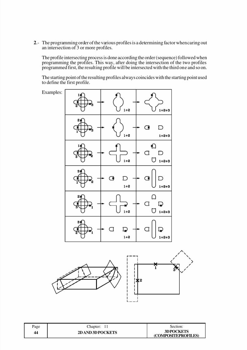
8/21/2019 CNC 8055 M Operator Manual
http://slidepdf.com/reader/full/cnc-8055-m-operator-manual 416/702
Page Chapter: 11 Section:
44 2D AND 3D POCKETS
2.- The programming order of the various profiles is a determining factor when caring outan intersection of 3 or more profiles.
The profile intersecting process is done according the order (sequence) followed whenprogramming the profiles. This way, after doing the intersection of the two profilesprogrammed first, the resulting profile will be intersected with the third one and so on.
The starting point of the resulting profiles always coincides with the starting point usedto define the first profile.
Examples:
3D POCKETS(COMPOSITE PROFILES)

8/21/2019 CNC 8055 M Operator Manual
http://slidepdf.com/reader/full/cnc-8055-m-operator-manual 417/702
Page
45
Section:Chapter: 11
2D AND 3D POCKETS
11.2.7 STACKED PROFILES
When 2 or more profiles stack on top of each other) the following considerations must betaken into account.
For clarity sakes, refer to the drawing on the rightwhich consists of 2 stacked profiles: 1 and 2.
The base coordinate of the top profile (2) mustcoincide with the surface coordinate of the bottom profile (1).
If there is a gap between them, the cycle will consider that they are 2 different profiles andit will eliminate the top profile when executing the bottom one.
If the profiles mix, the canned cycle will make a groove around the top profile when runningthe finishing pass.
3D POCKETS(STACKED PROFILES)
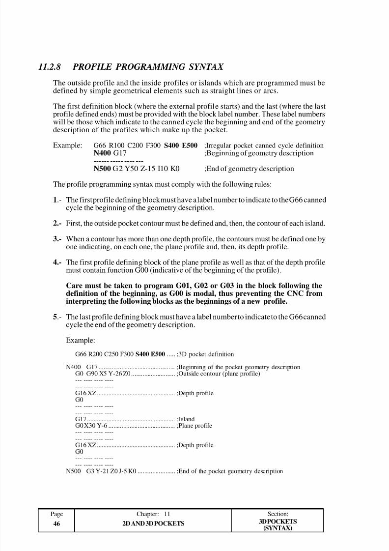
8/21/2019 CNC 8055 M Operator Manual
http://slidepdf.com/reader/full/cnc-8055-m-operator-manual 418/702
Page Chapter: 11 Section:
46 2D AND 3D POCKETS
11.2.8 PROFILE PROGRAMMING SYNTAX
The outside profile and the inside profiles or islands which are programmed must bedefined by simple geometrical elements such as straight lines or arcs.
The first definition block (where the external profile starts) and the last (where the lastprofile defined ends) must be provided with the block label number. These label numberswill be those which indicate to the canned cycle the beginning and end of the geometrydescription of the profiles which make up the pocket.
Example: G66 R100 C200 F300 S400 E500 ;Irregular pocket canned cycle definitionN400 G17 ;Beginning of geometry description------ ----- ---- ---N500 G2 Y50 Z-15 I10 K0 ;End of geometry description
The profile programming syntax must comply with the following rules:
1.- The first profile defining block must have a label number to indicate to the G66 cannedcycle the beginning of the geometry description.
2.- First, the outside pocket contour must be defined and, then, the contour of each island.
3.- When a contour has more than one depth profile, the contours must be defined one byone indicating, on each one, the plane profile and, then, its depth profile.
4.- The first profile defining block of the plane profile as well as that of the depth profilemust contain function G00 (indicative of the beginning of the profile).
Care must be taken to program G01, G02 or G03 in the block following thedefinition of the beginning, as G00 is modal, thus preventing the CNC frominterpreting the following blocks as the beginnings of a new profile.
5.- The last profile defining block must have a label number to indicate to the G66 cannedcycle the end of the geometry description.
Example:
G66 R200 C250 F300 S400 E500 ..... ;3D pocket definition
N400 G17 ............................................... ;Beginning of the pocket geometry descriptionG0 G90 X5 Y-26 Z0 ........................... ;Outside contour (plane profile)--- ---- ---- ----
--- ---- ---- ----G16 XZ................................................ ;Depth profileG0--- ---- ---- ------- ---- ---- ----G17...................................................... ;IslandG0 X30 Y-6 ......................................... ;Plane profile--- ---- ---- ------- ---- ---- ----G16 XZ................................................ ;Depth profileG0--- ---- ---- ------- ---- ---- ----
N500 G3 Y-21 Z0 J-5 K0 ....................... ;End of the pocket geometry description
3D POCKETS(SYNTAX)
8/21/2019 CNC 8055 M Operator Manual
http://slidepdf.com/reader/full/cnc-8055-m-operator-manual 419/702
Page
47
Section:Chapter: 11
2D AND 3D POCKETS
6.- Profiles are described as programmed paths, it being possible to include cornerrounding, chamfers, etc., following the syntax rules defined for this purpose.
7.- Mirror images, scaling factor changes, rotation of coordinate system, zero offsets,etc., cannot be programmed in the description of profiles.
8.- Nor is it possible to program blocks in high level language, such as jumps, subroutinecalls or parametric programming.
9.- Other canned cycles cannot be programmed.
In addition to the G00 function, which has a special meaning, the irregular pocketcanned cycle allows the use of the following functions for the definition of profiles.
G01 Linear interpolation
G02 Clockwise circular interpolationG03 Counter-clockwise circular interpolationG06 Arc center in absolute coordinatesG08 Arc tangent to previous path.G09 Arc defined by three pointsG16 Main plane section by two directionsG17 Main plane X-Y and longitudinal Z (perpendicular)G18 Main plane Z-X and longitudinal Y (perpendicular)G19 Main plane Y-Z and longitudinal X (perpendicular)G36 Automatic radius blend (controlled corner rounding)G39 ChamferG53 Programming with respect to machine reference zero (home)
G70 Programming in inchesG71 Programming in millimetersG90 Absolute programmingG91 Incremental programmingG93 Polar origin preset
3D POCKETS(SYNTAX)

8/21/2019 CNC 8055 M Operator Manual
http://slidepdf.com/reader/full/cnc-8055-m-operator-manual 420/702
Page Chapter: 11 Section:
48 2D AND 3D POCKETS
11.2.9 EXAMPLES
Example 1, Pocket without islands:
In this example, the island has 3 types of depth profiles: A, B and C.
3 contours are used to define the island: A-type contour, B-type contour and C-typecontour.
3D POCKETS(EXAMPLES)

8/21/2019 CNC 8055 M Operator Manual
http://slidepdf.com/reader/full/cnc-8055-m-operator-manual 421/702
Page
49
Section:Chapter: 11
2D AND 3D POCKETS
(TOR1=2.5,TOL1=20,TOI1=0,TOK1=0)G17 G0 G43 G90 Z50 S1000 M4G5G66 R200 C250 F300 S400 E500....................... ;3D pocket definitionM30
N200 G67 B5 C4 I-20 R5 V100 F400 T1D1 M6 ..................... ;Roughing operationN250 G67 B2 I-20 R5 V100 F550 T2D1 M6........................... ;Semi-finishing operationN300 G68 B1.5 L0.75 Q0 I-20 R5 V80 F275 T3D1 M6 .......... ;Finishing operation
N400 G17 ..................................... ;Beginning of pocket geometry definitionG0 G90 X50 Y90 Z0 .......... ;A-type contour (Plane profile)G1 X0
Y10X100Y90X50
G16 YZ ............................... ;Depth profile
G0 G90 Y90 Z0G1 Z-20
G17 ..................................... ;B-type contourG0 G90 X10 Y50................ ;Plane profileG1 Y100
X-10Y0X10Y50
G16 XZ ............................... ;Depth profileG0 G90 X10 Z0G1 X20 Z-20
G17 ..................................... ;C-type contourG0 G90 X90 Y50................ ;Plane profileG1 Y100
X110Y0X90Y50
G16 XZ ............................... ;Depth profileG0 G90 X90 Z0
N500 G2 X70 Z-20 I-20 K0 ......... ;End of pocket geometry definition
3D POCKETS(EXAMPLES)

8/21/2019 CNC 8055 M Operator Manual
http://slidepdf.com/reader/full/cnc-8055-m-operator-manual 422/702
Page Chapter: 11 Section:
50 2D AND 3D POCKETS
Example 2:
In this example, the island has 3 types of depth profiles: A, Band C.
3 contours are used to define the island: A-type contour, B-type contour and C-type contour.
(TOR1=7.5,TOI1=0,TOR2=5,TOI2=0,TOR3=2.5,TOI3=0)G17 G0 G43 G90 Z50 S1000 M4G5G66 R200 C250 F300 S400 E500 ....................... ;3D pocket definitionM30
N200 G67 B7 C14 I-25 R3 V100 F500 T1D1 M6 ............. ;Roughing operationN250 G67 B3 I-25 R3 V100 F625 T2D2 M6 ..................... ;Semi-finishing operationN300 G68 B1 L1 Q0 J0 I-25 R3 V100 F350 T3D3 M6 ..... ;Finishing operation
3D POCKETS(EXAMPLES)

8/21/2019 CNC 8055 M Operator Manual
http://slidepdf.com/reader/full/cnc-8055-m-operator-manual 423/702
Page
51
Section:Chapter: 11
2D AND 3D POCKETS
N400 G17 ..................................... ;Beginning of pocket geometry definitionG0 G90 X0 Y0 Z0 .............. ;Outside contour (plane profile)G1 X150
Y100X0Y0
G16 XZ ............................... ;Depth profileG0 G90 X0 Z0G1 X10 Z-10
Z-25
G17 ..................................... ;A-type profileG0 G90 X50 Y30................ ;Plane profileG1 X70
Y70X35Y30X50
G16 YZ ............................... ;Depth profileG0 G90 Y30 Z-25G2 Y50 Z-5 J20 K0
G17 ..................................... ;B-type profileG0 G90 X40 Y50................ ;Plane profileG1 Y25
X65Y75X40Y50
G16 XZ ............................... ;Depth profileG0 G90 X40 Z-25G1 Z-5
G17 ..................................... ;C-type profileG0 G90 X80 Y40................ ;Plane profileG1 X96
Y60X60Y40X80
G16 YZ ............................... ;Depth profileG0 G90 Y40 Z-25
N500 G2 Y50 Z-15 J10 K0 .......... ;End of pocket geometry definition
3D POCKETS(EXAMPLES)

8/21/2019 CNC 8055 M Operator Manual
http://slidepdf.com/reader/full/cnc-8055-m-operator-manual 424/702
Page Chapter: 11 Section:
52 2D AND 3D POCKETS
Example 3:
In this example, the island has 3 types of depth profiles: A, B and C.
3 contours are used to define the island: A-type contour, B-type contour and C-typecontour.
3D POCKETS(EXAMPLES)

8/21/2019 CNC 8055 M Operator Manual
http://slidepdf.com/reader/full/cnc-8055-m-operator-manual 425/702
Page
53
Section:Chapter: 11
2D AND 3D POCKETS
(TOR1=4,TOI1=0,TOR2=2.5,TOI2=0)G17 G0 G43 G90 Z25 S1000 M3G66 R200 C250 F300 S400 E500 ....................... ;3D pocket definitionM30
N200 G67 B5 C4 I-20 R5 V100 F700 T1D1 M6 ..................... ;Roughing operationN250 G67 B2 I-20 R5 V100 F850 T1D1 M6 ........................... ;Semi-finishing operationN300 G68 B1.5 L0.25 Q0 I-20 R5 V100 F500 T2D2 M6 ........ ;Finishing operation;
N400 G17 ..................................... ;Beginning of pocket geometry definitionG0 G90 X0 Y0 Z0 .............. ;Outside contour (plane profile)G1 X105
Y62X0Y0
G16 XZ ............................... ;Depth profileG0 X0 Z0G2 X5 Z-5 I0 K-5
G1 X7.5 Z-20
G17 ..................................... ;A-type contourG90 G0 X37 Y19................ ;Plane profileG2 I0 J12G16 YZ ............................... ;Depth profileG0 Y19 Z-20G1 Z-16G2 Y31 Z-4 R12 ................. ;End of pocket geometry definition
G17 ..................................... ;B-type contourG90 G0 X60 Y37................ ;Plane profileG1 X75
Y25X40Y37X60
G16 YZ ............................... ;Depth profileG0 Y37 Z-20G1 Z-13G3 Y34 Z-10 J-3 K0
G17 ..................................... ;C-type contourG0 X70 Y31 ....................... ;Plane profileG1 Y40
X80Y20
X70Y31G16 XZ ............................... ;Depth profileG0 X70 Z-20
N500 G1 X65 Z-10 ...................... ;End of pocket geometry definition
3D POCKETS(EXAMPLES)

8/21/2019 CNC 8055 M Operator Manual
http://slidepdf.com/reader/full/cnc-8055-m-operator-manual 426/702
Page Chapter: 11 Section:
54 2D AND 3D POCKETS
Example 4:
To define the island 10 contours are used as shown here:
3D POCKETS(EXAMPLES)

8/21/2019 CNC 8055 M Operator Manual
http://slidepdf.com/reader/full/cnc-8055-m-operator-manual 427/702
Page
55
Section:Chapter: 11
2D AND 3D POCKETS
(TOR1=4,TOI1=0,TOR2=2.5,TOI2=0)G17 G0 G43 G90 Z25 S1000 M3G66 R200 C250 F300 S400 E500 ............................ ;Definition of the 3D pocketM30
N200 G67 B5 C0 I-30 R5 V100 F700 T1D1 M6 ................. ;Roughing OperationN250 G67 B1.15 I-29 R5 V100 F850 T1D1 M6 ................. ;Semi-finishing OperationN300 G68 B1.5 L0.25 Q0 I-30 R5 V100 F500 T2D2 M6 ... ;Finishing Operation
N400 G17 ............................................................................. ;Beginning of the pocket geometry definitionG90 G0 X-70 Y20 Z0 ................................................ ;Outside contour (plane profile)G1 X70
Y-90X-70Y20
G17 ........................................................................... ;Contour number 1G90 G0 X42.5 Y5...................................................... ;Plane profileG1 G91 X-16
Y-60X32Y60X-16
G16YZ....................................................................... ;Depth profileG0 G90 Y5 Z-30G3 Y-25 Z0 J-30 K0
G17 ........................................................................... ;Contour number 2G0 X27.5 Y-25G1 G91 Y31G1 X-2
Y-62X2Y31
G16XZ....................................................................... ;Depth profile
G0 G90 X27.5 Z-30G1 Z0
3D POCKETS(EXAMPLES)

8/21/2019 CNC 8055 M Operator Manual
http://slidepdf.com/reader/full/cnc-8055-m-operator-manual 428/702
Page Chapter: 11 Section:
56 2D AND 3D POCKETS 3D POCKETS(EXAMPLES)
G17 ................... ;Contour number 3G0 X57.5 Y-25G1 G91 Y-31
X2Y62X-2Y-31
G16XZ ............... ;Depth profileG0 G90 X57.5 Z-30G1 Z0
G17 ................... ;Contour number 4G0 X0 Y-75G1 G91 X-31
Y-2X62Y2X-31
G16YZ ............... ;Depth profile
G0 G90 Y-75 Z-30G1 Z0
G17 ................... ;Contour number 5G0 X-30 Y-60G1 G91 Y-16
X60Y32X-60Y-16
G16XZ ............... ;Depth profileG0 G90 X-30 Z-30G2 X0 Z0 I30 K0
G17 ................... ;Contour number 6
G0 X0 Y-45G1 G91 X31Y2X-62Y-2X31
G16YZ ............... ;Depth profileG0 G90 Y-45 Z-30G1 Z0
G17 ................... ;Contour number 7G0 X-57.5 Y-25G1 G91 Y31
X-2Y-62X2Y31
G16XZ ............... ;Depth profileG0 G90 X-57.5 Z-30G1 Z0
G17 ................... ;Contour number 8G0 X-42.5 Y5G1 G91 X-16
Y-60X32Y60X-16
G16YZ
G0 G90 Y5 Z-30G3 Y-25 Z0 J-30 K0
G17 ................... ;Contour number 9G0 X-27.5 Y-25G1 G91 Y-31
X2Y62X-2Y-31
G16XZ ............... ;Depth profileG0 G90 X27.5 Z-30G1 Z0
G17 ................... ;Contour number 10
G0 X0 Y0G1 X-28Y-50X28Y0X0
G16YZ ............... ;Depth profileG0 Y0 Z-30
N500 G3 Y-25 Z-5 J-25 K0

8/21/2019 CNC 8055 M Operator Manual
http://slidepdf.com/reader/full/cnc-8055-m-operator-manual 429/702
Page
57
Section:Chapter: 11
2D AND 3D POCKETS
Example 5:
In this example, the island has 2 types of depth profiles: A and B.
2 contours are used to define the island: the low contour (A-type) and the high contour (B-type).
(TOR1=2.5,TOL1=20,TOI1=0,TOK1=0)G17 G0 G43 G90 Z50 S1000 M4G5G66 R200 C250 F300 S400 E500....................... ;3D pocket definitionM30
N200 G67 B5 C4 I-25 R5 V100 F400 T1D1 M6 ..................... ;Roughing operationN250 G67 B2 I-25 R5 V100 F550 T2D1 M6........................... ;Semi-finishing operationN300 G68 B1.5 L0.75 Q0 I-25 R5 V100 F275 T3D1 M6 ........ ;Finishing operation
3D POCKETS(EXAMPLES)

8/21/2019 CNC 8055 M Operator Manual
http://slidepdf.com/reader/full/cnc-8055-m-operator-manual 430/702
Page Chapter: 11 Section:
58 2D AND 3D POCKETS
N400 G17 ........................................................... ;Beginning of pocket geometry definitionG90 G0 X5 Y-26 Z0 ................................. ;Outside contour (plane profile)G1 Y25
X160Y-75X5Y-26
G17 .......................................................... ;Low contour (A type)G90 G0 X30 Y-6 ...................................... ;Plane profileG1 Y-46
X130Y-6X30
G16 XZ ..................................................... ;Depth profileG0 X30 Z-25G1 Z-20G2 X39 Z-11 I9 K0
G17 .......................................................... ;High contour (B-type)G90 G0 X80 Y-16 .................................... ;Plane profileG2 I0 J-10G16 YZ ..................................................... ;Depth profileG0 Y-16 Z-11G1 Y-16 Z-5
N500 G3 Y-21 Z0 J-5 K0 ................................. ;End of pocket geometry definition
3D POCKETS(EXAMPLES)

8/21/2019 CNC 8055 M Operator Manual
http://slidepdf.com/reader/full/cnc-8055-m-operator-manual 431/702
Page
59
Section:Chapter: 11
2D AND 3D POCKETS 3D POCKETS(ERRORS)
11.2.10 ERRORS
The CNC will issue the following errors:
ERROR 1025 : A tool of no radius has been programmed.When using a tool with "0" radius while machining a pocket.
ERROR 1026 : A step greater than the tool diameter has been programmed.When parameter "C" of the roughing operation is greater than the diameter of theroughing tool.
ERROR 1041 : A mandatory parameter not programmed in the canned cycle.It comes up in the following instances:- When parameters "I" and "R" have not been programmed in the roughing operation.- When not using a roughing operation and not programming the "I" and "R"
parameters for the semi-finishing operation.
- When not using a semi-finishing operation and not programming the "I" and "R"parameters for the finishing operation.- When parameter "B" has not been programmed in the finishing operation.
ERROR 1042 : Wrong canned cycle parameter value.It comes up in the following instances:- When parameter "Q" of the finishing operation has the wrong value.- When parameter "B" of the finishing operation has a "0" value.- When parameter "J" of the finishing operation has been programmed with a value
greater than the finishing tool radius.
ERROR 1043 : Wrong depth profile in an irregular pocket with islands
It comes up in the following instances:- When the depth profiles of 2 sections of the same contour (simple or composite)cross each other
- When the finishing operation cannot be performed with the programmed tool.A typical case is a spherical mold with a non-spherical tool (parameter "J" not equalto the radius).
ERROR 1044 : The plane profile intersects itself in an irregular pocket with islands.It comes up when any of the plane profiles of the programmed contours intersects itself.
ERROR 1046 : Wrong tool position prior to the canned cycle.It comes up when calling the G66 cycle if the tool is positioned between the referenceplane and the depth coordinate (bottom) of any of the operations.
ERROR 1047 : Open plane profile in an irregular pocket with islands.It comes up when any of the programmed contours does not begin and end at the samepoint. It may be because G1 has not been programmed after the beginning, with G0,on any of the profiles.
ERROR 1048 : The part surface coordinate (top) has not been programmed in anirregular pocket with islands.It comes up when the first point of the geometry does not include the pocket topcoordinate.
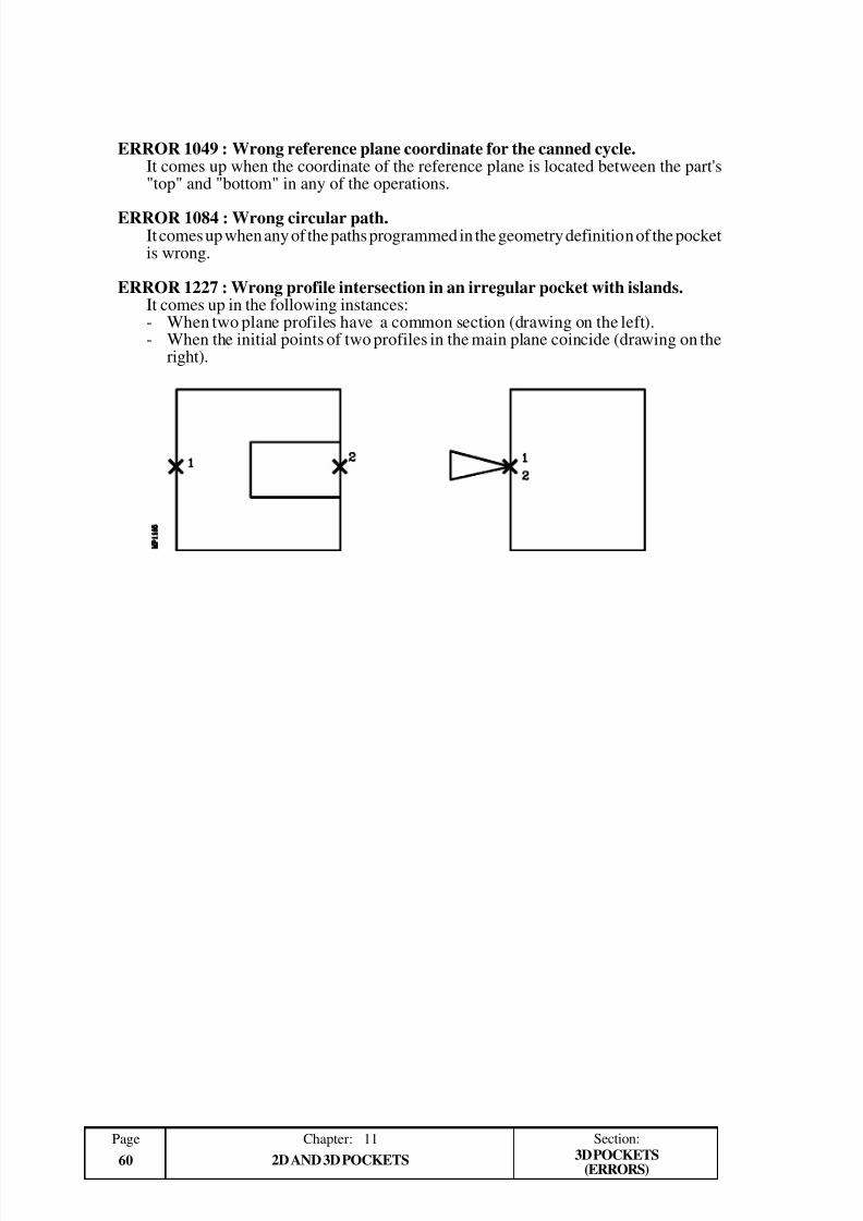
8/21/2019 CNC 8055 M Operator Manual
http://slidepdf.com/reader/full/cnc-8055-m-operator-manual 432/702
Page Chapter: 11 Section:
60 2D AND 3D POCKETS
ERROR 1049 : Wrong reference plane coordinate for the canned cycle.It comes up when the coordinate of the reference plane is located between the part's"top" and "bottom" in any of the operations.
ERROR 1084 : Wrong circular path.It comes up when any of the paths programmed in the geometry definition of the pocketis wrong.
ERROR 1227 : Wrong profile intersection in an irregular pocket with islands.It comes up in the following instances:- When two plane profiles have a common section (drawing on the left).- When the initial points of two profiles in the main plane coincide (drawing on the
right).
3D POCKETS(ERRORS)

8/21/2019 CNC 8055 M Operator Manual
http://slidepdf.com/reader/full/cnc-8055-m-operator-manual 433/702
PageChapter: 12
WORKING WITH A PROBE
Section:
1PROBING
12. WORKING WITH A PROBE
The CNC has two probe inputs, one for TTL-type 5V DC signals and another for 24 V DCsignals.
The connection of the different types of probes to these inputs are explained in the appendixto the Installation and Start-up manual.
This control allows the following operations to be performed, by using probes:
* Programming probing blocks with functions G75 and G76.
* Several tool calibration and part-measurement cycles by means of high-level languageprogramming.

8/21/2019 CNC 8055 M Operator Manual
http://slidepdf.com/reader/full/cnc-8055-m-operator-manual 434/702
Section:
WORKING WITH A PROBEChapter: 12
2
Page
12.1 PROBING (G75,G76)
The G75 function allows movements to be programmed which will end after the CNC
receives the signal from the measuring probe used.
The G76 function allows movements to be programmed which will end after the CNC nolonger receives the signal from the measuring probe used.
Their definition format is:
G75 X..C # 5.5G76 X..C # 5.5
After G75 orG76, the required axis or axes will be programmed, as well as the coordinatesof these axes which will define the end point of the programmed movement.
The machine will move according to the programmed path until it receives the signal fromthe probe (G75) or until it no longer receives the probe signal (G76). At this time, the CNCwill consider the block finished, taking as the theoretical position of the axes the real positionwhich they have at that time.
If the axes reach the programmed position before receiving (G75) or while receiving (G76)the external signal from the probe, the CNC will stop the movement of the axes.
This type of movement with probing blocks are very useful when it is required to generatemeasurement or verification programs for tools and parts.
Functions G75 and G76 are not modal and, therefore, must be programmed whenever it is
wished to probe.
It is not possible to vary the Feedrate Override while either G75 or G76 is active. It staysset at 100 %.
Functions G75 and G76 are incompatible with each other and with G00, G02, G03, G33,G41 and G42 functions. In addition, once this has been performed, the CNC will assumefunctions G01 and G40.
PROBING

8/21/2019 CNC 8055 M Operator Manual
http://slidepdf.com/reader/full/cnc-8055-m-operator-manual 435/702
PageChapter: 12
WORKING WITH A PROBE
Section:
3
12.2 PROBING CANNED CYCLES
The CNC has the following probing canned cycles:
1 Tool length calibration canned cycle.
2 Probe calibration canned cycle
3 Surface measuring canned cycle
4 Outside corner measuring canned cycle
5 Inside corner measuring canned cycle
6 Angle measuring canned cycle
7 Corner and angle measuring canned cycle
8 Hole measuring canned cycle
9 Boss measuring canned cycle
All the movements of these probing canned cycles will be performed in the X, Y, Z axes andthe work plane must be formed by 2 of these axes (XY, XZ, YZ, YX, ZX, ZY). The other axis,which must be perpendicular to this plane, must be selected as the longitudinal axis.
Canned cycles will be programmed by means of the high level mnemonic,PROBE, which
has the following programming format:
(PROBE(expression),(assignment statement),...)
This statement calls the probing cycle indicated by means of a number or any expressionwhich results in a number. Besides, it allows the parameters of this cycle to be initialized withthe values required to perform it, by means of assignment statements.
General considerations
Probing canned cycles are not modal, and therefore must be programmed whenever it is
required to perform any of them.The probes used in the performance of these cycles are:
* Probe placed on a fixed position on the machine, used for calibrating tools.
* Probe placed in the spindle, will be treated as a tool and will be used in the differentmeasuring cycles.
The execution of a probing canned cycle does not alter the history of previous “G”functions, except for the radius compensation functions G41 and G42.
PROBING CANNED CYCLES

8/21/2019 CNC 8055 M Operator Manual
http://slidepdf.com/reader/full/cnc-8055-m-operator-manual 436/702
Section:
WORKING WITH A PROBEChapter: 12
4
Page
12.3 TOOL LENGTH CALIBRATION CANNED CYCLE
This is used to calibrate the length of the selected tool. Once the cycle has ended, the value(L) corresponding to the tool offset which is selected will be updated on the tool offset table.
To perform this cycle it is necessary to have a table-top probe, installed in a fixed positionon the machine and with its faces parallel to axes X, Y, Z.
Its position will be indicated in absolute coordinates with respect to machine zero by meansof the general machine parameters:
PRBXMIN Indicates the minimum coordinate occupied by the probe along the X axis.PRBXMAX Indicates the maximum coordinate occupied by the probe along the X axis.PRBYMIN Indicates the minimum coordinate occupied by the probe along the Y axis.PRBYMAX Indicates the maximum coordinate occupied by the probe along the Y axis.PRBZMIN Indicates the minimum coordinate occupied by the probe along the Z axis.PRBZMAX Indicates the maximum coordinate occupied by the probe along the Z axis.
If it is the first time that the tool length has been calibrated, it is advisable to include anapproximate value of its length (L) in the tool offset table.
The programming format for this cycle is as follows:(PROBE 1, B, I, F)
B5.5 Defines the safety distance. It must be programmed with a positive value and greaterthan 0.
YZ
X
Z
Y
X
X
PRBZMAX
PRBZMIN
PRBXMIN
PRBYMAX
PRBYMIN
PRBXMAX
PRBXMAX PRBXMIN
TOOL LENGTH CALIBRATION

8/21/2019 CNC 8055 M Operator Manual
http://slidepdf.com/reader/full/cnc-8055-m-operator-manual 437/702
PageChapter: 12
WORKING WITH A PROBE
Section:
5
R
I1I0
B
I Indicates how the calibration canned cycle will be executed.
0= Tool calibration on its center.1= Tool calibration on its end.
If this is not programmed, the cycle will take the IO value.
F5.5 Defines probing feedrate in mm/min or inch/min.
Basic operation:
TOOL LENGTH CALIBRATION

8/21/2019 CNC 8055 M Operator Manual
http://slidepdf.com/reader/full/cnc-8055-m-operator-manual 438/702
Section:
WORKING WITH A PROBEChapter: 12
6
Page
1.- Approach
Movement of the probe in rapid (G00) from the point where the cycle is called to theapproach point.
This point is to be found opposite the point where it is wished to measure, at a safetydistance (B) from it and along the longitudinal axis.
The approaching movement is made in two stages:
1st Movement in the main work plane.2nd Movement along the longitudinal axis.
2.- Probing
Movement of the probe along the longitudinal axis at the indicated feedrate (F), untilthe probe signal is received.
The maximum distance to be travelled in the probing movement is 2B. If, after travellingthat distance, the CNC does not receive the probe signal, it will display the correspondingerror code and stop the movement of the axes.
3.- Withdrawal
Movement of the probe in rapid (G00) from the point where it probed to the point wherethe cycle was called.
The withdrawal movement is made in two stages:
1st Movement along the longitudinal axis to the coordinate of the point (along thisaxis) from where the cycle was called.
2nd Movement in the main work plane to the point where the cycle is called.
Once the cycle has been completed, the CNC will have updated the tool offset selected atthe time on the tool offset table, value (L) and initialized the value of (K) to 0, it also returnsthe value of the global arithmetic parameter:
P299 Error detected. Difference between the measured tool length and the one
assigned to it in the table.
TOOL LENGTH CALIBRATION

8/21/2019 CNC 8055 M Operator Manual
http://slidepdf.com/reader/full/cnc-8055-m-operator-manual 439/702
PageChapter: 12
WORKING WITH A PROBE
Section:
7
K
I
12.4 PROBE CALIBRATING CANNED CYCLE
This is used to calibrate the probe situated in the spindle. This probe which previously mustbe calibrated in length, will be the one used in probe measuring canned cycles.
The cycle measures the deviation which the probe ball axis has with respect to the toolholder axis, using a previously machined hole with known center and dimensions for itscalibration.
The CNC will treat each measuring probe used as just one more tool. The tool offset tablefields corresponding to each probe will have the following meaning:
R Radius of the sphere (ball) of the probe. This value will be loaded into the table
manually.
L Length of the probe. This value will be indicated by the tool length calibration cycle.
I Deviation of the probe ball with respect to the tool-holder axis, along the abscissaaxis. This value will be indicated by the cycle.
K Deviation of the probe ball with respect to the tool holder axis, along the ordinateaxis. This value will be indicated by the cycle.
The following steps will be followed for its calibration:
1.- Once the characteristics of the probe have been consulted, the value for the sphereradius (R) will be entered manually in the corresponding tool offset.
2.- After selecting the corresponding tool number and tool offset the Tool LengthCalibration Cycle will be performed, the value of (L) will be updated and the valueof (K) will be initialized to 0.
3.- Execution of the probe calibration canned cycle, updating the “I” and “K” values.
PROBE CALIBRATION

8/21/2019 CNC 8055 M Operator Manual
http://slidepdf.com/reader/full/cnc-8055-m-operator-manual 440/702
Section:
WORKING WITH A PROBEChapter: 12
8
Page
The programming format for this cycle is:
(PROBE 2,X,Y,Z,B,J,E,H,F)
X+/-5.5 Real coordinate, along the X axis, of the hole center.
Y+/-5.5 Real coordinate, along the Y axis, of the hole center.
Z+/-5.5 Real coordinate, along the Z axis, of the hole center.
B5.5 Defines the safety distance. Must be programmed with a positive value and over0.
J5.5 Defines the real diameter of the hole. Must be programmed with a positive valueand over 0.
E.5.5 Defines the distance which the probe moves back after initial probing. Must beprogrammed with a positive value and over 0.
H5.5 Defines the feedrate for the initial probing movement. Must be programmed inmm/minute or in inches/minute.
F5.5 Defines the probing feedrate. Must be programmed in mm/minute or in inches/ minute.
Basic operation:
1
Z
Z
X
Y
8
4
XX
26
Y
PROBE CALIBRATION
8/21/2019 CNC 8055 M Operator Manual
http://slidepdf.com/reader/full/cnc-8055-m-operator-manual 441/702
PageChapter: 12
WORKING WITH A PROBE
Section:
9
1.- Approach
Movement of the probe in rapid (G00) from the point where the cycle is called to thecenter of the hole.
The approaching movement is made in two stages:
1st Movement in the main work plane.
2nd Movement along the longitudinal axis.
2.- Probing
This movement consists of:
* Movement of the probe along the ordinate axis at the indicated feedrate (H), until theprobe signal is received.
The maximum distance to be travelled in the probing movement is "B+(J/2)". If, aftertravelling that distance, the CNC does not receive the probe signal, it will display thecorresponding error code and stop the movement of the axes.
* Return of the probe in rapid (G00) the distance indicated in (E).
* Movement of the probe along the ordinate axis at the indicated feedrate (F), until theprobe signal is received.
3.- Withdrawal
Movement of the probe in rapid (G00) from the point where it probed to the real centerof the hole.
4.- Second probing movement.
Same as above.
5.- Withdrawal
Movement of the probe in rapid (G00) from the point where it probed to the real centerof the hole along the ordinate axis.
6.- Third probing movement.
Same as above.
PROBE CALIBRATION

8/21/2019 CNC 8055 M Operator Manual
http://slidepdf.com/reader/full/cnc-8055-m-operator-manual 442/702
Section:
WORKING WITH A PROBEChapter: 12
10
Page
7.- Withdrawal
Movement of the probe in rapid (G00) from the point where it probed to the real centerof the hole.
8.- Fourth probing movement.
Same as above.
9.- Withdrawal
This movement consists of:
* Movement of the probe in rapid (G00) from the point where it probed to the real
center of the hole.
* Movement along the longitudinal axis to the coordinate of the point (along this axis)from where the cycle was called.
* Movement in the main work plane to the point where the cycle was called.
Once the cycle has been completed, the CNC will have updated the “I” and “K” valuescorresponding to the tool offset selected at the time on the tool offset table.
On the other hand, arithmetic parameter P299 returns the best value to be assigned to general
machine parameter PRODEL.
PROBE CALIBRATION
8/21/2019 CNC 8055 M Operator Manual
http://slidepdf.com/reader/full/cnc-8055-m-operator-manual 443/702
PageChapter: 12
WORKING WITH A PROBE
Section:
11
12.5 SURFACE MEASURING CANNED CYCLE
A probe placed in the spindle will be used, which must be previously calibrated by meansof canned cycles:
Canned cycle for calibrating tool length.Canned cycle for calibrating probe.
This cycle allows correcting the value of the tool offset of the tool which has been used inthe surface machining process. This correction will be used only when the measurementerror exceeds a programmed value.
The programming format for this cycle is:
(PROBE 3,X,Y,Z,B,K,F,C,D,L)
X+/-5.5 Theoretical coordinate, along the X axis, of the point over which it is required tomeasure.
Y+/-5.5 Theoretical coordinate, along the Y axis, of the point over which it is required tomeasure.
Z+/-5.5 Theoretical coordinate, along the Z axis, of the point over which it is required tomeasure.
B5.5 Defines the safety distance. Must be programmed with a positive value and over
0.
The probe must be placed, with respect to the point to be measured, at a distancegreater than this value when the cycle is called.
SURFACE MEASURING

8/21/2019 CNC 8055 M Operator Manual
http://slidepdf.com/reader/full/cnc-8055-m-operator-manual 444/702
Section:
WORKING WITH A PROBEChapter: 12
12
Page
Y
X
Z
K2
K0K1
K Defines the axis with which it is required to measure the surface and will bedefined by means of the following code:
0= With the abscissa axis of the work plane.1= With the ordinate axis of the work plane.2= With the longitudinal axis of the work plane.
If this is not programmed, the canned cycle will take the value of K0.
F5.5 Defines the probing feedrate in mm/min. or inches/min.C Indicates where the probing cycle must finish.
0= Will return to the same point where the call to the cycle was made.1= The cycle will finish over the measured point returning the longitudinal axis
to the cycle calling point.
If this is not programmed, the canned cycle will take the value of C0.
D4 Defines the number of the tool offset to be corrected, once the measurement cycleis completed.
If this is not programmed or is programmed with a value of 0, the CNC willunderstand that it is not required to make this correction.
L5.5 Defines the tolerance which will be applied to the error measured. It will beprogrammed with an absolute value and the tool offset will be corrected onlywhen the error exceeds this value.
If this is not programmed, the canned cycle will take the value of 0.
SURFACE MEASURING

8/21/2019 CNC 8055 M Operator Manual
http://slidepdf.com/reader/full/cnc-8055-m-operator-manual 445/702
PageChapter: 12
WORKING WITH A PROBE
Section:
13
B
B
Basic operation:
1.- Approach
Movement of the probe in rapid (G00) from the point where the cycle is called to theapproach point.
This point is to be found opposite the point where it is wished to measure, at a safetydistance (B) from this and along the probing axis (K).
The approaching movement is made in two stages:1stMovement in the main work plane.2nd Movement along the longitudinal axis.
2.- Probing
Movement of the probe along the selected axis (K) at the indicated feedrate (F), untilthe probe signal is received.
The maximum distance to be travelled in the probing movement is 2B. If, after travellingthat distance, the CNC does not receive the probe signal, it will display the corresponding
error code and stop the movement of the axes.
Once probing has been made, the CNC will assume as their theoretical position the realposition of the axes when the probe signal is received .
SURFACE MEASURING

8/21/2019 CNC 8055 M Operator Manual
http://slidepdf.com/reader/full/cnc-8055-m-operator-manual 446/702
Section:
WORKING WITH A PROBEChapter: 12
14
Page
3. Withdrawal
Movement of the probe in rapid (G00) from the point where it probed to the point wherethe cycle was called.
The withdrawal movement is made in three stages:
1st Movement along the probing axis to the approach point.
2nd Movement along the longitudinal axis to the coordinate of the point (along thisaxis) from where the cycle was called.
3rd When (C0) is programmed, movement is made in the main work plane to the pointwhere the cycle is called.
Once the cycle has been completed, the CNC will return the real values obtained aftermeasurement, in the following global arithmetic parameters.
P298 Real surface coordinate.
P299 Error detected. Difference between the real coordinate of the surface and thetheoretical programmed coordinate.
If the Tool Offset Number (D) was selected, the CNC will modify the values of this tooloffset, whenever the measurement error is equal to or greater than the tolerance (L).
Depending on the axis the measurement is made with (K), the correction will be made onthe length or radius value.
* If the measurement is made with the axis longitudinal to the work plane, the lengthwear (K) of the indicated tool offset (D) will be modified.
* If the measurement is made with one of the axes which make up the work plane, theradius wear (I) of the indicated tool offset (D) will be modified.
SURFACE MEASURING
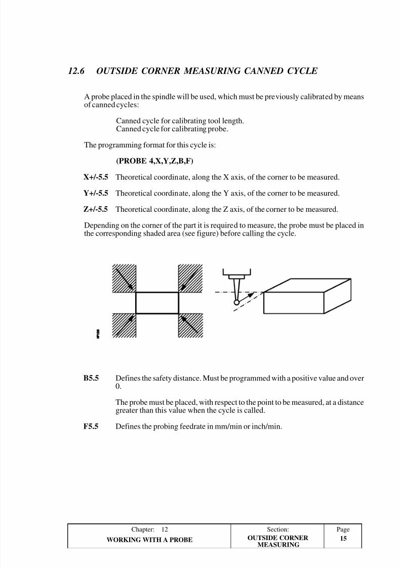
8/21/2019 CNC 8055 M Operator Manual
http://slidepdf.com/reader/full/cnc-8055-m-operator-manual 447/702
PageChapter: 12
WORKING WITH A PROBE
Section:
15
12.6 OUTSIDE CORNER MEASURING CANNED CYCLE
A probe placed in the spindle will be used, which must be previously calibrated by meansof canned cycles:
Canned cycle for calibrating tool length.Canned cycle for calibrating probe.
The programming format for this cycle is:
(PROBE 4,X,Y,Z,B,F)
X+/-5.5 Theoretical coordinate, along the X axis, of the corner to be measured.
Y+/-5.5 Theoretical coordinate, along the Y axis, of the corner to be measured.
Z+/-5.5 Theoretical coordinate, along the Z axis, of the corner to be measured.
Depending on the corner of the part it is required to measure, the probe must be placed inthe corresponding shaded area (see figure) before calling the cycle.
B5.5 Defines the safety distance. Must be programmed with a positive value and over0.
The probe must be placed, with respect to the point to be measured, at a distancegreater than this value when the cycle is called.
F5.5 Defines the probing feedrate in mm/min or inch/min.
OUTSIDE CORNER MEASURING
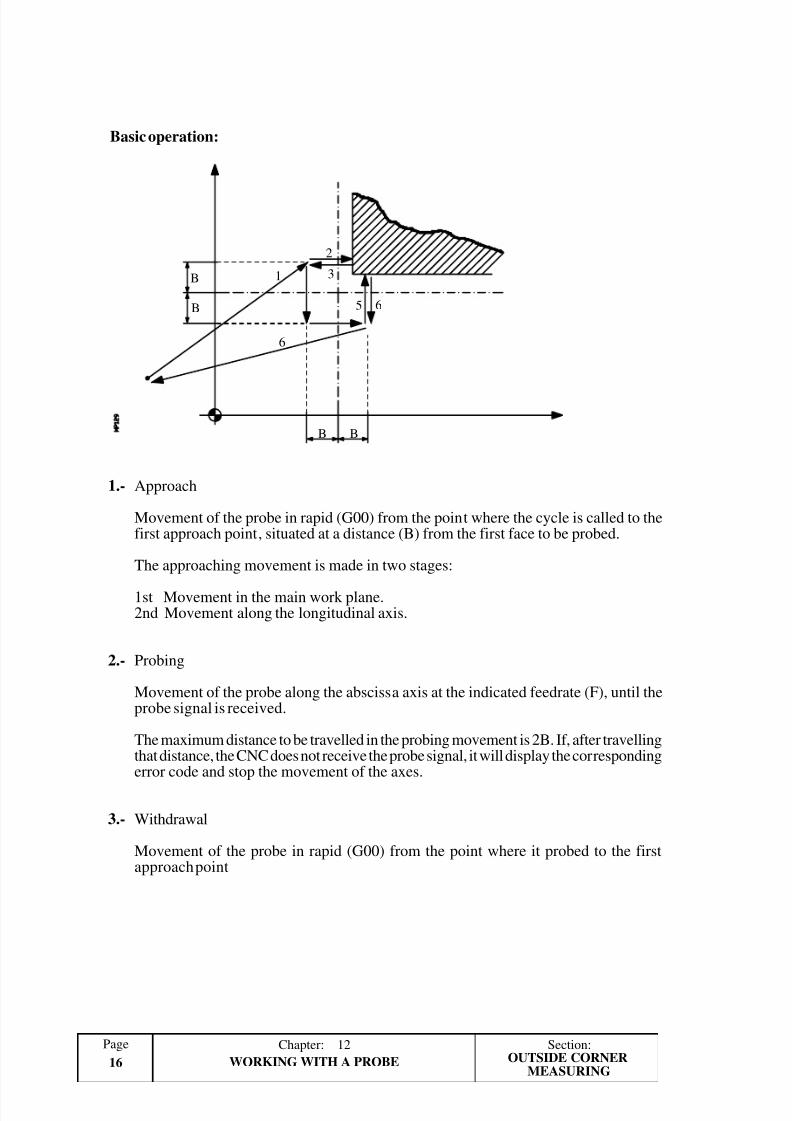
8/21/2019 CNC 8055 M Operator Manual
http://slidepdf.com/reader/full/cnc-8055-m-operator-manual 448/702
Section:
WORKING WITH A PROBEChapter: 12
16
Page
B
B
B B
2
31
5
6
6
Basic operation:
1.- Approach
Movement of the probe in rapid (G00) from the point where the cycle is called to thefirst approach point, situated at a distance (B) from the first face to be probed.
The approaching movement is made in two stages:
1st Movement in the main work plane.2nd Movement along the longitudinal axis.
2.- Probing
Movement of the probe along the abscissa axis at the indicated feedrate (F), until theprobe signal is received.
The maximum distance to be travelled in the probing movement is 2B. If, after travellingthat distance, the CNC does not receive the probe signal, it will display the correspondingerror code and stop the movement of the axes.
3.- Withdrawal
Movement of the probe in rapid (G00) from the point where it probed to the firstapproach point
OUTSIDE CORNER MEASURING
8/21/2019 CNC 8055 M Operator Manual
http://slidepdf.com/reader/full/cnc-8055-m-operator-manual 449/702
PageChapter: 12
WORKING WITH A PROBE
Section:
17
4.- Second approach
Movement of the probe in rapid (G00) from the first approach point to the second.
The approaching movement is made in two stages:
1st Movement along the ordinate plane.2nd Movement along the abscissa axis.
5.- Second probing
Movement of the probe along the abscissa axis at the indicated feedrate (F), until theprobe signal is received.
The maximum distance to be travelled in the probing movement is 2B. If, after travelling
that distance, the CNC does not receive the probe signal, it will display the correspondingerror code and stop the movement of the axes.
6.- Withdrawal
Movement of the probe in rapid (G00) from the point where it probed for the secondtime to the point where the cycle was called.
The withdrawal movement is made in three stages:
1st Movement along the probing axis to the second approach point.
2nd Movement along the longitudinal axis to the coordinate of the point correspondingto this axis where the cycle is called.
3rd Movement in the main work plane to the point where the cycle is called.
Once the cycle has been completed, the CNC will return the real values obtained aftermeasurement, in the following global arithmetic parameters.
P296 Real coordinate of the corner along the abscissa axis.
P297 Real coordinate of the corner along the ordinate axis.
P298 Error detected along the abscissa axis. Difference between the real coordinateof the corner and the theoretical programmed coordinate.
P299 Error detected along the ordinate axis. Difference between the realcoordinate of the corner and the theoretical programmed coordinate.
OUTSIDE CORNER MEASURING
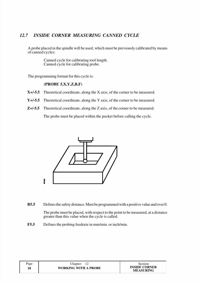
8/21/2019 CNC 8055 M Operator Manual
http://slidepdf.com/reader/full/cnc-8055-m-operator-manual 450/702
Section:
WORKING WITH A PROBEChapter: 12
18
Page
12.7 INSIDE CORNER MEASURING CANNED CYCLE
A probe placed in the spindle will be used, which must be previously calibrated by meansof canned cycles:
Canned cycle for calibrating tool length.Canned cycle for calibrating probe.
The programming format for this cycle is:
(PROBE 5,X,Y,Z,B,F)
X+/-5.5 Theoretical coordinate, along the X axis, of the corner to be measured.
Y+/-5.5 Theoretical coordinate, along the Y axis, of the corner to be measured.
Z+/-5.5 Theoretical coordinate, along the Z axis, of the corner to be measured.
The probe must be placed within the pocket before calling the cycle.
B5.5 Defines the safety distance. Must be programmed with a positive value and over 0.
The probe must be placed, with respect to the point to be measured, at a distancegreater than this value when the cycle is called.
F5.5 Defines the probing feedrate in mm/min. or inch/min.
INSIDE CORNERMEASURING
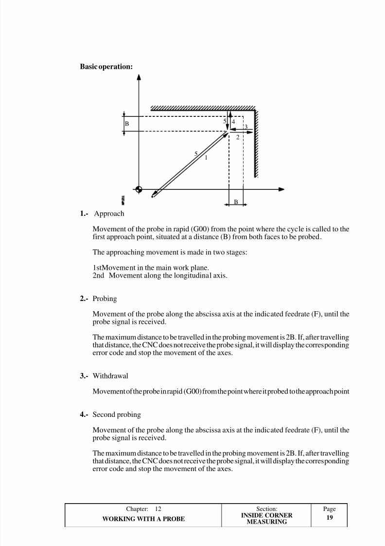
8/21/2019 CNC 8055 M Operator Manual
http://slidepdf.com/reader/full/cnc-8055-m-operator-manual 451/702
PageChapter: 12
WORKING WITH A PROBE
Section:
19
51
B
B 5 4
2
3
Basic operation:
1.- Approach
Movement of the probe in rapid (G00) from the point where the cycle is called to thefirst approach point, situated at a distance (B) from both faces to be probed.
The approaching movement is made in two stages:
1stMovement in the main work plane.2nd Movement along the longitudinal axis.
2.- Probing
Movement of the probe along the abscissa axis at the indicated feedrate (F), until theprobe signal is received.
The maximum distance to be travelled in the probing movement is 2B. If, after travellingthat distance, the CNC does not receive the probe signal, it will display the correspondingerror code and stop the movement of the axes.
3.- Withdrawal
Movement of the probe in rapid (G00) from the point where it probed to the approach point
4.- Second probing
Movement of the probe along the abscissa axis at the indicated feedrate (F), until theprobe signal is received.
The maximum distance to be travelled in the probing movement is 2B. If, after travellingthat distance, the CNC does not receive the probe signal, it will display the correspondingerror code and stop the movement of the axes.
INSIDE CORNERMEASURING

8/21/2019 CNC 8055 M Operator Manual
http://slidepdf.com/reader/full/cnc-8055-m-operator-manual 452/702
Section:
WORKING WITH A PROBEChapter: 12
20
Page
5.- Withdrawal
Movement of the probe in rapid (G00) from the point where it probed for the secondtime to the point where the cycle was called.
The withdrawal movement is made in three stages:
1st Movement along the probing axis to the approach point.
2nd Movement along the longitudinal axis to the coordinate of the point correspondingto this axis where the cycle is called.
3rd Movement in the main work plane to the point where the cycle is called.
Once the cycle has been completed, the CNC will return the real values obtained after
measurement, in the following global arithmetic parameters.
P296 Real coordinate of the corner along the abscissa axis.
P297 Real coordinate of the corner along the ordinate axis.
P298 Error detected along the abscissa axis. Difference between the real coordinateof the corner and the theoretical programmed coordinate.
P299 Error detected along the ordinate axis. Difference between the realcoordinate of the corner and the theoretical programmed coordinate.
INSIDE CORNERMEASURING

8/21/2019 CNC 8055 M Operator Manual
http://slidepdf.com/reader/full/cnc-8055-m-operator-manual 453/702
PageChapter: 12
WORKING WITH A PROBE
Section:
21
12.8 ANGLE MEASURING CANNED CYCLE
A probe placed in the spindle will be used, which must be previously calibrated by meansof canned cycles:
Canned cycle for calibrating tool length.Canned cycle for calibrating probe.
The programming format for this cycle is:
(PROBE 6,X,Y,Z,B,F)
X+/-5.5 Theoretical coordinate, along the X axis, of the angle to be measured.
Y+/-5.5 Theoretical coordinate, along the Y axis, of the angle to be measured.
Z+/-5.5 Theoretical coordinate, along the Z axis, of the angle to be measured.
B5.5 Defines the safety distance. Must be programmed with a positive value and over 0.
The probe must be placed, with respect to the point to be measured, at a distancegreater than double this value when the cycle is called.
F5.5 Defines the probing feedrate in mm/min. or inch/min.
ANGLE MEASURING

8/21/2019 CNC 8055 M Operator Manual
http://slidepdf.com/reader/full/cnc-8055-m-operator-manual 454/702
Section:
WORKING WITH A PROBEChapter: 12
22
Page
532 6
P295
6
4
B B
2B
Basic operation:
1.- Approach
Movement of the probe in rapid (G00) from the point where the cycle is called to thefirst approach point, situated at a distance (B) from the programmed vertex and at (2B)from the face to be probed.
The approaching movement is made in two stages:
1st Movement in the main work plane.2nd Movement along the longitudinal axis.
2.- Probing
Movement of the probe along the ordinate axis at the indicated feedrate (F), until theprobe signal is received.
The maximum distance to be travelled in the probing movement is 3B. If, after travellingthat distance, the CNC does not receive the probe signal, it will display the correspondingerror code and stop the movement of the axes.
3.- Withdrawal
Movement of the probe in rapid (G00) from the point where it probed to the firstapproach point
4.- Second approach
Movement of the probe in rapid (G00) from the first approach point to the second. It isat a distance (B) from the first one.
ANGLE MEASURING

8/21/2019 CNC 8055 M Operator Manual
http://slidepdf.com/reader/full/cnc-8055-m-operator-manual 455/702
PageChapter: 12
WORKING WITH A PROBE
Section:
23
5.- Second probing
Movement of the probe along the abscissa axis at the indicated feedrate (F), until theprobe signal is received.
The maximum distance to be travelled in the probing movement is 4B. If, after travellingthat distance, the CNC does not receive the probe signal, it will display the correspondingerror code and stop the movement of the axes.
6.- Withdrawal
Movement of the probe in rapid (G00) from the point where it probed for the secondtime to the point where the cycle was called.
The withdrawal movement is made in three stages:
1st Movement along the probing axis to the second approach point.
2nd Movement along the longitudinal axis to the coordinate of the point (along thisaxis) from where the cycle was called.
3rd Movement in the main work plane to the point where the cycle is called.
Once the cycle has been completed, the CNC will return the real values obtained aftermeasurement, in the following global arithmetic parameter.
P295 Inclination angle which the part has in relation to the abscissa axis.
This cycle allows angles between ±45° to be measured.
If the angle to be measured is > 45°, the CNC will display the corresponding error.
If the angle to be measured is <-45°, the probe will collide with the part.
ANGLE MEASURING

8/21/2019 CNC 8055 M Operator Manual
http://slidepdf.com/reader/full/cnc-8055-m-operator-manual 456/702
Section:
WORKING WITH A PROBEChapter: 12
24
Page
12.9 OUTSIDE CORNER AND ANGLE MEASURING CANNED CYCLE
A probe placed in the spindle will be used, which must be previously calibrated by meansof canned cycles:
Canned cycle for calibrating tool length.Canned cycle for calibrating probe.
The programming format for this cycle is:
(PROBE 7,X,Y,Z,B,F)
X±5.5 Theoretical coordinate, along the X axis, of the corner to be measured.
Y±5.5 Theoretical coordinate, along the Y axis, of the corner to be measured.
Z±5.5 Theoretical coordinate, along the Z axis, of the corner to be measured.
Depending on the corner of the part it is required to measure, the probe must be placed inthe corresponding shaded area (see figure) before calling the cycle.
B5.5 Defines the safety distance. Must be programmed with a positive value and over 0.
The probe must be placed, with respect to the point to be measured, at a distancegreater than double this value when the cycle is called.
F5.5 Defines the probing feedrate in mm/min. or inch/min.
OUTSIDE CORNER ANDANGLE MEASURING

8/21/2019 CNC 8055 M Operator Manual
http://slidepdf.com/reader/full/cnc-8055-m-operator-manual 457/702
PageChapter: 12
WORKING WITH A PROBE
Section:
25
2B
B
B B2B
2
3
1
5 68 9
9
Basic operation:
1.- Approach
Movement of the probe in rapid (G00) from the point where the cycle is called to the
first approach point, situated at a distance (B) from the first face to be probed.The approaching movement is made in two stages:
1st Movement in the main work plane.2nd Movement along the longitudinal axis.
2.- Probing
Movement of the probe along the abscissa axis at the indicated feedrate (F), until theprobe signal is received.
The maximum distance to be travelled in the probing movement is 3B. If, after travellingthat distance, the CNC does not receive the probe signal, it will display the correspondingerror code and stop the movement of the axes.
3.- Withdrawal
Movement of the probe in rapid (G00) from the point where it probed to the firstapproach point.
OUTSIDE CORNER ANDANGLE MEASURING
8/21/2019 CNC 8055 M Operator Manual
http://slidepdf.com/reader/full/cnc-8055-m-operator-manual 458/702
Section:
WORKING WITH A PROBEChapter: 12
26
Page
4.- Second approach
Movement of the probe in rapid (G00) from the first approach point to the second,situated at a distance (2B) from the second face to be probed.
The approaching movement is made in two stages:
1st Movement along the ordinate plane.2nd Movement along the abscissa axis.
5.- Second probing
Movement of the probe along the abscissa axis at the indicated feedrate (F), until theprobe signal is received.
The maximum distance to be travelled in the probing movement is 3B. If, after travellingthat distance, the CNC does not receive the probe signal, it will display the correspondingerror code and stop the movement of the axes.
6.- Withdrawal
Movement of the probe in rapid (G00) from the point where it probed to the second pointof approach.
7.- Third approach
Movement of the probe in rapid (G00) from the second approach point to the third,situated at a distance (B) from the previous point.
8.- Third probing
Movement of the probe along the ordinate axis at the indicated feedrate (F), until theprobe signal is received.
The maximum distance to be travelled in the probing movement is 4B. If, after travellingthat distance, the CNC does not receive the probe signal, it will display the correspondingerror code and stop the movement of the axes.
OUTSIDE CORNER ANDANGLE MEASURING

8/21/2019 CNC 8055 M Operator Manual
http://slidepdf.com/reader/full/cnc-8055-m-operator-manual 459/702
PageChapter: 12
WORKING WITH A PROBE
Section:
27
9.- Withdrawal
Movement of the probe in rapid (G00) from the third probing point to the point wherethe cycle was called.
The withdrawal movement is made in three stages:
1st Movement along probing axis to the third approach point.
2nd Movement along the longitudinal axis to the coordinate of the point (along thisaxis) from where the cycle was called.
3rd Movement in the main work plane to the point where the cycle is called.
Once the cycle has been completed, the CNC will return the real values obtained after
measurement, in the following global arithmetic parameter.
P295 Inclination angle which the part has in relation to the abscissa axis.
P296 Real coordinate of the corner along the abscissa axis.
P297 Real coordinate of the corner along the ordinate axis.
P298 Error detected along the abscissa axis. Difference between the real coordinateof the corner and the programmed theoretical coordinate.
P299 Error detected along the ordinate axis. Difference between the real
coordinate of the corner and the programmed theoretical coordinate.This cycle allows angles between ±45° to be measured.
If the angle to be measured is > 45° the CNC will display the corresponding error.
If the angle to be measured is <-45°, the probe will collide with the part.
OUTSIDE CORNER ANDANGLE MEASURING

8/21/2019 CNC 8055 M Operator Manual
http://slidepdf.com/reader/full/cnc-8055-m-operator-manual 460/702
Section:
WORKING WITH A PROBEChapter: 12
28
Page
12.10 HOLE MEASURING CANNED CYCLE
A probe placed in the spindle will be used, which must be previously calibrated by meansof canned cycles:
Canned cycle for calibrating tool length.Canned cycle for calibrating probe.
The programming format for this cycle is:
(PROBE 8,X,Y,Z,B,J,E,C,H,F)
X±5.5 Theoretical coordinate, along the X axis, of the center of the hole.
Y±5.5 Theoretical coordinate, along the Y axis, of the center of the hole.
Z±5.5 Theoretical coordinate, along the Z axis, of the center of the hole.
B5.5 Defines the safety distance. Must be programmed with a positive value and over 0.
J5.5 Defines the theoretical diameter of the hole. Must be programmed with a positivevalue and over 0.
This cycle allows holes to be measured with diameters of no more than (J+B).
E.5.5 Defines the distance which the probe moves back after initial probing. Must beprogrammed with a positive value and over 0.
C Indicates where the probing cycle must finish.
0= Will return to the same point where the call to the cycle was made.1= The cycle will finish over the measured point returning the longitudinal axis
to the cycle calling point.
If this is not programmed, the canned cycle will take the value of C0.
H5.5 Defines the initial probing feedrate in mm/min or in inch/min.
F5.5 Defines the probing feedrate in mm/min or inch/min.
HOLE MEASURING

8/21/2019 CNC 8055 M Operator Manual
http://slidepdf.com/reader/full/cnc-8055-m-operator-manual 461/702
PageChapter: 12
WORKING WITH A PROBE
Section:
29
28
4
XX
Y
6
X
Z
Z
1
Y
Basic operation:
1.- Approach
Movement of the probe in rapid (G00) from the point where the cycle is called to thecenter of the hole.
The approaching movement is made in two stages:
1st Movement in the main work plane.2nd Movement along the longitudinal axis.
HOLE MEASURING

8/21/2019 CNC 8055 M Operator Manual
http://slidepdf.com/reader/full/cnc-8055-m-operator-manual 462/702
Section:
WORKING WITH A PROBEChapter: 12
30
Page
2.- Probing
This movement consists of:
* Movement of the probe along the ordinate axis at the indicated feedrate (H), until theprobe signal is received.
The maximum distance to be travelled in the probing movement is "B+(J/2)". If, aftertravelling that distance, the CNC does not receive the probe signal, it will display thecorresponding error code and stop the movement of the axes.
* Return of the probe in rapid (G00) the distance indicated in (E).
* Movement of the probe along the ordinate axis at the indicated feedrate (F), until theprobe signal is received.
3.- Withdrawal
Movement of the probe in rapid (G00) from the point where it probed to the theoreticalcenter of the hole.
4.- Second probing movement.
Same as above.
5.- WithdrawalMovement of the probe in rapid (G00) from the point where it probed to the realcenter (calculated) of the hole along the ordinate axis.
6.- Third probing movement.
Same as above.
7.- Withdrawal
Movement of the probe in rapid (G00) from the point where it probed to the theoreticalcenter of the hole.
HOLE MEASURING

8/21/2019 CNC 8055 M Operator Manual
http://slidepdf.com/reader/full/cnc-8055-m-operator-manual 463/702
PageChapter: 12
WORKING WITH A PROBE
Section:
31
8.- Fourth probing movement.
Same as above.
9.- Withdrawal
This movement consists of:
* Movement of the probe in rapid (G00) from the point where it probed to the realcenter (calculated) of the hole.
* Should (C0) be programmed, the probe will be moved to the point where the cyclewas called.
1st Movement along the longitudinal axis to the coordinate of the point (along this
axis) from where the cycle was called.
2nd Movement on the main work plane to the point where the cycle was called.
Once the cycle has been completed, the CNC will return the real values obtained aftermeasurement, in the following global arithmetic parameter.
P294 Hole diameter.
P295 Hole diameter error. Difference between the real diameter and programmeddiameter.
P296 Real coordinate of the center along the abscissa axis.
P297 Real coordinate of the center along the ordinate axis.
P298 Error detected along the abscissa axis. Difference between the real coordinateof the center and the programmed theoretical coordinate.
P299 Error detected along the ordinate axis. Difference between the realcoordinate of the center and the programmed theoretical coordinate.
HOLE MEASURING
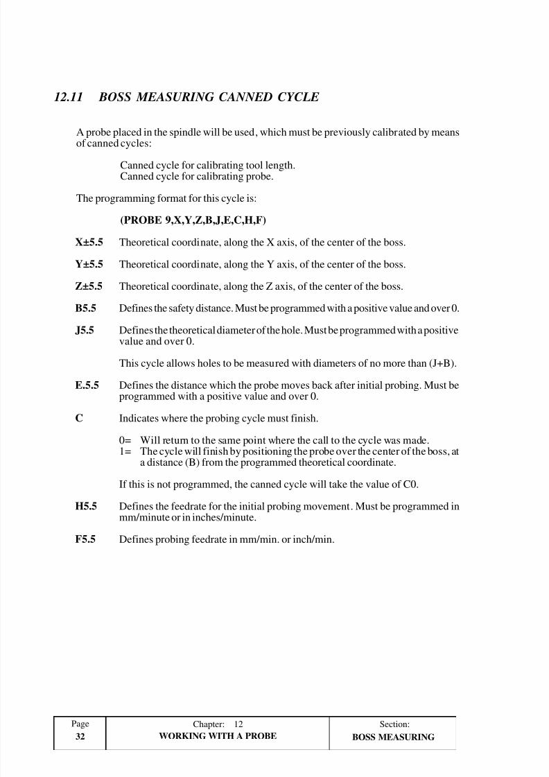
8/21/2019 CNC 8055 M Operator Manual
http://slidepdf.com/reader/full/cnc-8055-m-operator-manual 464/702
Section:
WORKING WITH A PROBEChapter: 12
32
Page
12.11 BOSS MEASURING CANNED CYCLE
A probe placed in the spindle will be used, which must be previously calibrated by meansof canned cycles:
Canned cycle for calibrating tool length.Canned cycle for calibrating probe.
The programming format for this cycle is:
(PROBE 9,X,Y,Z,B,J,E,C,H,F)
X±5.5 Theoretical coordinate, along the X axis, of the center of the boss.
Y±5.5 Theoretical coordinate, along the Y axis, of the center of the boss.
Z±5.5 Theoretical coordinate, along the Z axis, of the center of the boss.
B5.5 Defines the safety distance. Must be programmed with a positive value and over 0.
J5.5 Defines the theoretical diameter of the hole. Must be programmed with a positivevalue and over 0.
This cycle allows holes to be measured with diameters of no more than (J+B).
E.5.5 Defines the distance which the probe moves back after initial probing. Must beprogrammed with a positive value and over 0.
C Indicates where the probing cycle must finish.
0= Will return to the same point where the call to the cycle was made.1= The cycle will finish by positioning the probe over the center of the boss, at
a distance (B) from the programmed theoretical coordinate.
If this is not programmed, the canned cycle will take the value of C0.
H5.5 Defines the feedrate for the initial probing movement. Must be programmed inmm/minute or in inches/minute.
F5.5 Defines probing feedrate in mm/min. or inch/min.
BOSS MEASURING
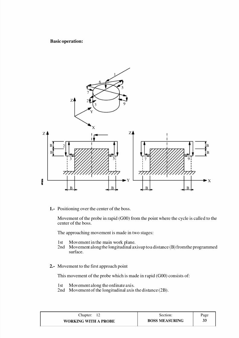
8/21/2019 CNC 8055 M Operator Manual
http://slidepdf.com/reader/full/cnc-8055-m-operator-manual 465/702
PageChapter: 12
WORKING WITH A PROBE
Section:
33
X
Y
Z
1
2
6
9
5
3
7
X
Z
Y
2
3 7 9
B
B
B B B B
Z
5
B
B
Basic operation:
1.- Positioning over the center of the boss.
Movement of the probe in rapid (G00) from the point where the cycle is called to thecenter of the boss.
The approaching movement is made in two stages:
1st Movement in the main work plane.2nd Movement along the longitudinal axis up to a distance (B) from the programmed
surface.
2.- Movement to the first approach point
This movement of the probe which is made in rapid (G00) consists of:
1st Movement along the ordinate axis.2nd Movement of the longitudinal axis the distance (2B).
BOSS MEASURING
8/21/2019 CNC 8055 M Operator Manual
http://slidepdf.com/reader/full/cnc-8055-m-operator-manual 466/702
Section:
WORKING WITH A PROBEChapter: 12
34
Page
3.- Probing
This movement consists of:
* Movement of the probe along the ordinate axis at the indicated feedrate (H), until theprobe signal is received.
The maximum distance to be travelled in the probing movement is "B+(J/2)". If, aftertravelling that distance, the CNC does not receive the probe signal, it will display thecorresponding error code and stop the movement of the axes.
* Return of the probe in rapid (G00) the distance indicated in (E).
* Movement of the probe along the ordinate axis at the indicated feedrate (F), until theprobe signal is received.
4.-Movement to second approach point
This movement of the probe which is made in rapid (G00) consists of:
* Withdrawal to the first approach point.
* Movement to a distance (B) above the boss, to the second approach point.
5.- Second probing movement.
Same as the first probing.
6.- Third approach movement.
Same as above.
7.- Third probing movement.
Same as above.
8.- Fourth approach movement.
Same as above.
9.- Fourth probing movement.
Same as above.
BOSS MEASURING
8/21/2019 CNC 8055 M Operator Manual
http://slidepdf.com/reader/full/cnc-8055-m-operator-manual 467/702
PageChapter: 12
WORKING WITH A PROBE
Section:
35
10.-Withdrawal
This movement consists of:
* Withdrawal to the fourth approach point.
* Movement of the probe in rapid (G00) and at a distance (B) above the boss to thereal center (calculated) of the boss.
* Should (C0) be programmed, the probe will be moved to the point where the cyclewas called.
1st Movement along the longitudinal axis to the coordinate of the point (along thisaxis) from where the cycle was called.
2nd Movement on the main work plane to the point where the cycle was called.
Once the cycle has been completed, the CNC will return the real values obtained aftermeasurement, in the following global arithmetic parameter.
P294 Boss diameter.
P295 Boss diameter error. Difference between the real diameter and programmeddiameter.
P296 Real coordinate of the center along the abscissa axis.
P297 Real coordinate of the center along the ordinate axis.P298 Error detected along the abscissa axis. Difference between the real coordinate
of the center and the programmed theoretical coordinate.
P299 Error detected along the ordinate axis. Difference between the realcoordinate of the center and the programmed theoretical coordinate.
BOSS MEASURING

8/21/2019 CNC 8055 M Operator Manual
http://slidepdf.com/reader/full/cnc-8055-m-operator-manual 468/702
PageChapter: 13 Section:
1PROGRAMMING IN HIGH-LEVEL LANGUAGE LEXICAL DESCRIPTION
13. PROGRAMMING IN HIGH-LEVEL LANGUAGE
The CNC has a series of internal variables which can be accessed from the user program,from the PLC program or through DNC.
Access to these variables from the user program is gained with high-level commands.
Each of the system variables which can be accessed will be referred to by means of itsmnemonic, and will be separated, according to their use, into read-only variables and read-write variables.
13.1 LEXICAL DESCRIPTION
All the words which form the high-level language of the numerical control must be writtenin capital letters except for associated texts which may be written in upper and lower caseletters.
The following elements are available for high-level programming:
- Reserved words.- Numerical constants- Symbols

8/21/2019 CNC 8055 M Operator Manual
http://slidepdf.com/reader/full/cnc-8055-m-operator-manual 469/702
Section:Chapter: 13
2Page
PROGRAMMING IN HIGH-LEVEL LANGUAGE LEXICAL DESCRIPTION
13.1.1 RESERVED WORDS
The set of words which the CNC uses in high-level programming for naming systemvariables, operators, control mnemonics, etc. are as follows:
ANAIn ANAOn BLKN CALL CALLP CLOCKCNCERR CNCFRO CNCSSO CYTIME DATE DEFLEXDEFLEY DEFLEZ DFHOLD DIGIT DIST(X-C) DNCERRDNCF DNCFPR DNCFRO DNCS DNCSL DNCSSODPOS(X-C) DSBLK DSTOP DW EFHOLD ERRORESBLK ESTOP EXEC FEED FIRST FLWE(X-C)FLWES FOZLO(X-C) FOZONE FOZUP(X-C) FPREV FROFZLO(X-C) FZONE FZUP(X-C) GGSA GGSB GGSCGGSD GMS GOTO GSn GTRATY GUP nIB IF INPUT KEY KEYSRC LONGAX
LUP (a,b) MCALL MDOFF MIRROR MP(X-C)n MPASnMPGn MPLCn MPSn MPSSn MSG MSnNBTOOL NXTOD NXTOOL ODW OPEN OPMODAOPMODB OPMODC OPMODE ORG(X-C) ORG(X-C)n ORGROAORGROB ORGROC ORGROI ORGROJ ORGROK ORGROQORGROR ORGROS ORGROT ORGROX ORGROY ORGROZPAGE PARTC PCALL PLANE PLCCn PLCERRPLCF PLCFPR PLCFRO PLCIn PLCMn PLCMSGPLCOF(X-C) PLCOn PLCRn PLCS PLCSL PLCSSOPLCTn PORGF PORGS POS(X-C) POSS PPOS(X-C)PRBST PRGF PRGFIN PRGFPR PRGFRO PRGNPRGS PRGSL PRGSSO PROBE REPOS RETROTPF ROTPS RPOSS RPT RTPOSS SCALESCALE(X-C) SCNCSO SDNCS SDNCSL SDNCSO SFLWESSK SLIMIT SPEED SPLCS SPLCSL SPLCSOSPOSS SPRGS SPRGSL SPRGSO SREAL SRPOSSSRTPOS SSLIMI SSO SSPEED SSREAL SSSOSTPOSS SUB SYMBOL SYSTEM SZLO(X-C) SZONESZUP(X-C) TIME TIMER TLFDn TLFFn TLFNnTLFRn TMZPn TMZTn TOD TOIn TOKnTOLn TOOL TOOROF TOOROS TORn TPOS(X-C)TPOSS TRACE TZLO(X-C) TZONE TZUP(X-C) WBUFWBUF WKEY WRITE
Words ending in (X-C) indicate a set of 9 elements formed by the corresponding rootfollowed by X,Y,Z,U,V,W,A,B and C.
ORG(X-C)-> ORGX,ORGY,ORGZ,ORGU,ORGV,ORGW,ORGA,ORGB,ORGC
All the letters of the alphabet A-Z are also reserved words, as they can make up a high-levellanguage word when used alone.

8/21/2019 CNC 8055 M Operator Manual
http://slidepdf.com/reader/full/cnc-8055-m-operator-manual 470/702
PageChapter: 13 Section:
3PROGRAMMING IN HIGH-LEVEL LANGUAGE LEXICAL DESCRIPTION
13.1.2 NUMERICAL CONSTANTS
The blocks programmed in high-level language allow numbers in decimal format which donot exceed the format ±6.5 and numbers in hexadecimal format, in which case they mustbe preceded by the $ sign, with a maximum of 8 digits.
The assignment to a variable of a constant higher than the format ±6,5 will bemade by meansof arithmetic parameters, by means of arithmetic expressions or by means of constantsexpressed in hexadecimal format.
Example: To assign the value 100000000 to the variable “TIMER”, It can be done in oneof the following ways:
(TIMER = $5F5E100)(TIMER = 10000 * 10000)
(P100 = 10000 * 10000)(TIMER = P100)
When the CNC is working in metric system (mm) resolution is in tenths of a micron, and figuresare programmed in the format ±5.4 (positive or negative, with 5 integers and 4 decimals), andif the CNC is operating in inches, resolution is in 0.00001 inches, figures being programmed withthe format ±4.5 (positive or negative, with 4 integers and 5 decimals).
For the convenience of the programmer, this control always allows the format ±5.5 (positiveor negative, with 5 integers and 5 decimals), adjusting each number appropriately to theworking units every time they are used.
13.1.3. SYMBOLS
The symbols used in high-level language are:
( ) “ = + - * / ,

8/21/2019 CNC 8055 M Operator Manual
http://slidepdf.com/reader/full/cnc-8055-m-operator-manual 471/702
Section:Chapter: 13
4Page
PROGRAMMING IN HIGH-LEVEL LANGUAGE VARIABLES
13.2 VARIABLES
The internal CNC variables which can be accessed by high-level language are grouped intables and can be read-only or read-write variables.
There is a group of mnemonics for showing the different fields of the table of variables. Inthis way, if it is required to access an element from one of these tables, the required field willbe indicated by means of the corresponding mnemonic (for example TOR) and then therequired element (TOR3).
The variables available at the CNC can be classified in the following way:
- General purpose parameters or variables- Variables associated with tools.- Variables associated with zero offsets.
- Variables associated with machine parameters- Variables associated with work zones- Variables associated with feedrates- Variables associated with position coordinates- Variables associated with the spindle- Variables associated with the PLC- Variables associated with local parameters- Other variables
Variables which access to real values of the CNC interrupt the preparation of blocks andthe CNC waits for each command to be performed before restarting block preparation.
Thus, precaution must be taken when using this type of variable, as should they be placedbetween machining blocks which are working with compensation, undesired profiles maybe obtained.
Example:
The following program blocks are performed in a section with G41 compensation.
.......
.......N10 X50 Y80N15 (P100=POSX);Assigns the value of the real coordinate in X to parameter P100N20 X50 Y590
N30 X80 Y50..............

8/21/2019 CNC 8055 M Operator Manual
http://slidepdf.com/reader/full/cnc-8055-m-operator-manual 472/702
PageChapter: 13 Section:
5PROGRAMMING IN HIGH-LEVEL LANGUAGE VARIABLES
X
Y
N10
N20
N30
A
Block N15 interrupts block preparation and the execution of block N10 will finish at pointA.
Once the execution of block N15 has ended, the CNC will continue block preparation fromblock N20 on.
As the next point corresponding to the compensated path is point “B”, the CNC will movethe tool to this point, executing path “A-B”.
As can be observed, the resulting path is not the desired one, and therefore it isrecommended to avoid the use of this type of variable in sections requiring tool compensation.
Y
N10
N20
X
N30
A
B

8/21/2019 CNC 8055 M Operator Manual
http://slidepdf.com/reader/full/cnc-8055-m-operator-manual 473/702
Section:Chapter: 13
6Page
PROGRAMMING IN HIGH-LEVEL LANGUAGE
13.2.1 GENERAL PURPOSE PARAMETERS OR VARIABLES
The CNC has two types of general purpose variables: local parameters P0-P25 and globalparameters P100-P299.
Programmers may use general purpose variables when editing their own programs. Laterand during execution, the CNC will replace these variables with the values assigned to itat that time.
Example:
GP0 XP1 Y100 —> G1 X-12.5 Y100(IF(P100*P101 EQ P102)GOTO N100) —> (IF(2*5 EQ 12)GOTO N100)
The use of these global purpose variables will depend on the type of block in which they
are programmed and the channel of execution.
In block programmed in ISO code parameters can be associated with all fields, G X..C FS T D M. The block label number will be defined with a numerical value.
If parameters are used in blocks programmed in high-level language, these can beprogrammed within any expression.
Programmes which are executed in the user channel may contain any global parameter, butmay not use local parameters.
The CNC will update the parameter table after processing the operations indicated in the
block which is in preparation. This operation is always done before executing the block andfor this reason, the values shown in the table do not necessarily have to correspond to theblock being executed.
If the Execution Mode is abandoned after interrupting the execution of the program, theCNC will update the parameter tables with values corresponding to the block which wasbeing executed.
When accessing the local parameter and global parameter table, the value assigned to eachparameter may be expressed in decimal notation (4127.423) or in scientific notation(=23476 E-3).
This CNC has high level statements which allow the definition and use of subroutines
which can be called from the main program, or from another subroutine, it also beingpossible to call a second subroutine, from the second to a third, etc. The CNC limits thesecalls, allowing up to a maximum of 15 nesting levels.
26 local parameters (P0-P25) can be assigned to a subroutine. These parameters which willbe unknown for blocks external to the subroutine may be referenced by the blocks of thissubroutine.
The CNC allows local parameters to be assigned to more than one subroutine, 6 nestinglevels of local parameters being possible, within the 15 nesting levels of a subroutine.
Local parameters used in high-level language may be defined either using the above format
or by using the letter A-Z, except for N, so that A is equal to P0 and Z to P25.
GENERAL PURPOSE VARIABLES
8/21/2019 CNC 8055 M Operator Manual
http://slidepdf.com/reader/full/cnc-8055-m-operator-manual 474/702
PageChapter: 13 Section:
7PROGRAMMING IN HIGH-LEVEL LANGUAGE
The following example shows these two methods of definition:
(IF((P0+P1) * P2/P3 EQ P4) GOTO N100)(IF((A+B) * C/D EQ E) GOTO N100)
When using a parameter name (letter) for assigning a value to it (A instead of P0, forexample), if the arithmetic expression is a constant, the statement can be abbreviated asfollows:
(P0 = 13.7) —> (A = 13.7) —> (A13.7)
Be careful when using parenthesis since M30 is not the same as (M30). The CNC interprets(M30) as a high level statement meaning (P12 = 30) and not the execution of themiscellaneous M30 function.
The global parameter (P100-P299) can be used throughout the program by any block,
irrespective of the nesting level.
Multiple machining (G60, G61, G62, G63, G64, G65) and machining canned cycles (G69,G81 ... G89) use a local parameter nesting level when active.
Machining canned cycles use the global parameter P299 for internal calculations andprobing canned cycles use global parameters P294 to P299.
GENERAL PURPOSEVARIABLES

8/21/2019 CNC 8055 M Operator Manual
http://slidepdf.com/reader/full/cnc-8055-m-operator-manual 475/702
Section:Chapter: 13
8Page
PROGRAMMING IN HIGH-LEVEL LANGUAGE
13.2.2 VARIABLES ASSOCIATED WITH TOOLS
These variables are associated with the tool offset table, tool table and tool magazine table,so the values which are assigned to or read from these fields will comply with the formatsestablished for these tables.
Tool offset table:
R,L,I,K They are given in the active units:If G70, in inches. Max.: ±3937.00787If G71, in millimeters. Max.: ±99999.9999If rotary axis in degrees. Max.: ±99999.9999
Tool table
Tool offset number 0...NT OFFSET (maximum 255)Family code If normal tool 0 < n < 200If special tool 200 < n < 255
Nominal life 0...65535 minutes or operations.Real life 0.99999.99 minutes or 99999 operations
Tool magazine table
Contents of each magazine positionTool number 1 ...NTOOL
(maximum 255)0 Empty
-1 CancelledPosition of tool in magazine
Position number 1 ..NPOCKET(maximum 255)
0 On spindle-1 Not found-2 In change position
Read-only variables
TOOL: Returns the active tool number
(P100 = TOOL); assigns the number of the active tool to P100
TOD: Returns the active tool offset number
NXTOOL: Returns the next tool number, selected but is awaiting the executionof M06 to be active.
NXTOD: Returns the number of the tool offset corresponding to the next tool,selected but is awaiting the execution of M06 to be active.
TMZPn: Returns the position occupied in the tool magazine by the indicatedtool (n).
VARIABLES FOR TOOLS

8/21/2019 CNC 8055 M Operator Manual
http://slidepdf.com/reader/full/cnc-8055-m-operator-manual 476/702
PageChapter: 13 Section:
9PROGRAMMING IN HIGH-LEVEL LANGUAGE
Read-write variables
TORn: This variable allows the value assigned to the Radius of the indicatedtool offset (n) on the tool offset table to be read or modified.
(P110 = TOR3); Assigns the R value of tool offset 3 to Parameter 3).(TOR3 = P111); Assigns the value of parameter P111 to R of tool
offset 3)
TOLn: This variable allows the value assigned to the Length of the indicatedtool offset (n) to be read or modified on the tool offset table.
TOIn: This variable allows the value assigned to the radius wear (I) of theindicated tool offset (n) to be read or modified on the tool offset table.
TOKn: This variable allows the value assigned to the length wear (K) of the
indicated tool offset (n) to be read or modified on the tool offset table.
TLFDn: This variable allows the tool offset number of the indicated tool (n)to be read or modified on the tool table.
TLFFn: This variable allows the family code of the indicated tool (n) to beread or modified on the tool table.
TLFNn: This variable allows the value assigned as the nominal life of theindicated tool (n) to be read or modified on the tool table.
TLFRn: This variable allows the value corresponding to the real life of the
indicated tool (n) to be read or modified on the tool table.TMZTn: This variable allows the contents of the indicated position (n) to be
read or modified on the tool magazine table.
VARIABLES FOR TOOLS
8/21/2019 CNC 8055 M Operator Manual
http://slidepdf.com/reader/full/cnc-8055-m-operator-manual 477/702
Section:Chapter: 13
10Page
PROGRAMMING IN HIGH-LEVEL LANGUAGE
13.2.3 VARIABLES ASSOCIATED WITH ZERO OFFSETS
These variables are associated with the zero offsets and may correspond to the table values
or to those currently preset either by means of function G92 or manually in the JOG mode.
The zero offsets which are possible in addition to the additive offset indicated by the PLC,are G54, G55, G56, G57, G58 and G59.
The values for each axis are given in the active units:
If G70, in inches. Max.: ±3937.00787If G71, in millimeters. Max.: ±99999.9999If rotary axis in degrees. Max.: ±99999.9999
Although there are variables which refer to each axis, the CNC only allows those referring tothe selected axes in the CNC. Thus, if the CNC controls axes X, Y, Z, U and B, it only allowsthe variables ORGX, ORGY, ORGZ,. ORGU and ORGB in the case of ORG(X-C).
Read-only variables
ORG(X-C) Returns the value of the active zero offset in the selected axis. The valueof the additive offset indicated by the PLC is not included in this value.
(P100 = ORGX); assigns to P100 the X value of the part zero activefor the X axis. This value could have been set either by means of function G92 or by the variable "ORG(X-C)n".
PORGF: Returns the abscissa value of the polar coordinate origin with respectto the Cartesian origin.
PORGS: Returns the ordinate value of the polar coordinate origin with respectto the cartesian origin.
Read-write variables
ORG(X-C)n: This variable allows the value of the selected axis to be read ormodified on the table corresponding to the indicated zero offset (n).
(P110 = ORGX55); Assigns the value of X to parameter P110 on thetable corresponding to zero offset G55.
(ORGY 54 = P111); Assigns the value of parameter P111 to the Yaxis on the table corresponding to G54 zero offset.
PLCOF(X-C) This variable allows the value of the selected axis to be read ormodified on the additive zero offset table indicated by the PLC.
If any of the PLCOF(X-C) variables are accessed, block preparationis interrupted and the CNC waits for this command to be executedto begin block preparation again.
VARIABLES FORZERO OFFSETS

8/21/2019 CNC 8055 M Operator Manual
http://slidepdf.com/reader/full/cnc-8055-m-operator-manual 478/702
PageChapter: 13 Section:
11PROGRAMMING IN HIGH-LEVEL LANGUAGE VARIABLES ASOCIADASA LA FUNCION G49
13.2.4 VARIABLES ASSOCIATED WITH FUNCTION G49
With function G49, it is possible to define a coordinate transformation or, in other words,the incline plane resulting from that transformation.
Read-only variables associated with the definition of function G49:
ORGROX X coordinate of the new part zero referred to home.ORGROY Y coordinate of the new part zero referred to home.ORGROZ Z coordinate of the new part zero referred to home.
ORGROA Value assigned to parameter AORGROB Value assigned to parameter BORGROC Value assigned to parameter C
ORGROI Value assigned to parameter I
ORGROJ Value assigned to parameter JORGROK Value assigned to parameter K
ORGROQ Value assigned to parameter QORGROR Value assigned to parameter RORGROS Value assigned to parameter S
GTRATY Type of G49 programmed 0 = no G49 programmed1= G49 X Y Z A B C 2= G49 X Y Z Q R S3= G49 T X Y Z S 4= G49 X Y Z I J K R S
Every time G49 is programmed, the CNC updates the values of the parameters
that have be defined.
For example, when programming G49 XYZ ABCThe CNC updates the following variables
ORGROX, ORGROY, ORGROZORGROA, ORGROB, ORGROC
The rest of the variables keep their previous values.
Read-Write variables updated by the CNC once function G49 is executed:
When having a swivel or angled spindle, machine parameter "XFORM (P93) with avalue of 2 or 3, the CNC shows the following information:
TOOROF Indicates the position to be occupied by the main rotary axis of the spindle inorder for the tool to be positioned perpendicular to the indicated incline plane.
TOOROS Indicates the position to be occupied by the secondary rotary axis of thespindle in order for the tool to be positioned perpendicular to the indicatedincline plane.
By accessing variable TOOROF or TOOROS, the CNC interrupts block preparation and waits for that command to be executed before resumingblock preparation.

8/21/2019 CNC 8055 M Operator Manual
http://slidepdf.com/reader/full/cnc-8055-m-operator-manual 479/702
Section:Chapter: 13
12Page
PROGRAMMING IN HIGH-LEVEL LANGUAGE
13.2.5 VARIABLES ASSOCIATED WITH MACHINE PARAMETERS
Variables associated with machine parameters are read-only variables.
In order to become familiar with the values returned it is advisable to consult the installationand start-up manual.
Values 1/0 correspond to the parameters which are defined with YES/NO, +/- and ON/OFF.
The coordinate and feedrate values are given in the active units:
If G70, in inches. Max.: ±3937.00787If G71, in millimeters. Max.: ±99999.9999If rotary axis in degrees. Max.: ±99999.9999
Read-only variables
MPGn: Returns the value assigned to the general machine parameter (n).
(P110=MPG 8);assigns the value of the general machine parameter“INCHES” to parameter P110, if millimeters P110=0 and if inchesP110=1.
MP(X-C)n Returns the value which was assigned to the machine parameter (n)of the indicated axes.
(P110=MPY 1); assigns the value of the machine parameter P1 toarithmetic parameter P110 of the Y axis “DFORMAT”, whichindicates the format used in its display.
MPSn: Returns the value which was assigned to the main spindle machineparameter (n).
MPSSn: Returns the value which was assigned to the secondary spindlemachine parameter (n).
MPASn: Returns the value of the machine parameter (n) for the auxiliaryspindle.
MPLCn: Returns the value which was assigned to the PLC machine parameter(n)
VARIABLES FORMACHINE PARAMETERS

8/21/2019 CNC 8055 M Operator Manual
http://slidepdf.com/reader/full/cnc-8055-m-operator-manual 480/702
PageChapter: 13 Section:
13PROGRAMMING IN HIGH-LEVEL LANGUAGE
13.2.6 VARIABLES ASSOCIATED WITH WORK ZONES
Variables associated with work zones are read-only variables.
The values of the limits are given in the active units:
If G70, in inches. Max.: ±3937.00787If G71, in millimeters. Max.: ±99999.9999If rotary axis in degrees. Max.: ±99999.9999
The status of the work zones is determined according to the following code:
0 = Disabled.1 = Enabled as no-entry zone.2 = Enabled as no-exit zone.
Read-only variables
FZONE: Returns the status of work zone 1.(P100=FZONE); assigns to parameter P100 the status of work zone 1.
FZLO(X-C) Returns the value of the lower limit of Zone 1 according to theselected axis (X-C).
FZUP(X-C) Returns the value of the upper limit of Zone 1 according to theselected axis (X-C).
SZONE: Returns the status of work zone 2.
SZLO(X-C) Returns the value of the lower limit of Zone 2 according to theselected axis (X-C).
SZUP(X-C) Returns the value of the upper limit of Zone 2 according to theselected axis (X-C).
TZONE: Returns the status of work zone 3.
TZLO(X-C) Returns the value of the lower limit of Zone 3 according to theselected axis (X-C).
TZUP(X-C) Returns the value of the upper limit of Zone 3 according to theselected axis (X-C).
FOZONE: Returns the status of work zone 4.
FOZLO(X-C) Returns the value of the lower limit of Zone 4 according to theselected axis (X-C).
FOZUP(X-C) Returns the value of the upper limit of Zone 4 according to theselected axis (X-C).
VARIABLES FORWORK ZONES

8/21/2019 CNC 8055 M Operator Manual
http://slidepdf.com/reader/full/cnc-8055-m-operator-manual 481/702
Section:Chapter: 13
14Page
PROGRAMMING IN HIGH-LEVEL LANGUAGE
13.2.7 VARIABLES ASSOCIATED WITH FEEDRATES
Read-only variables associated with the actual feedrate
FREAL: Returns the real feedrate of the CNC in mm/min. or inches/min.
(P100 = FREAL); Assigns the real feedrate value of the CNC toparameter P100
Read-only variables associated with function G49
FEED: Returns the feedrate selected in the CNC by means of the G94function. This will be in mm/minute or inches/minute.
This feedrate can be indicated by program, by the PLC or DNC, and
the CNC selects one of these, the one with the highest priority beingthat indicated by DNC and the one with the lowest priority thatindicated by program.
DNCF: Returns the feedrate, in mm/minute or inches/minute, selected byDNC. If this has a value of 0 it means that it is not selected.
PLCF: Returns the feedrate, in mm/minute or inches/minute, selected byPLC. If this has a value of 0 it means that it is not selected.
PRGF: Returns the feedrate, in mm/minute or inches/minute, selected byprogram.
Read-only variables associated with function G95
FPREV: Returns the feedrate selected in the CNC by means of the G95function. This will be in mm/rev. or inches/rev.
This advance can be indicated by program, by the PLC or DNC, andthe CNC selects one of these, the one with the highest priority beingthat indicated by DNC and the one with the lowest priority thatindicated by program.
DNCFPR: Returns the feedrate, in mm/rev. or inches/rev., selected by DNC. If this has a value of 0 it means that it is not selected.
PLCFPR: Returns the feedrate, in mm/rev. or inches/rev., selected by PLC. If this has a value of 0 it means that it is not selected.
Read-only variables associated with function G32
PRGFIN: Returns the feedrate, in 1/min selected by program.
Also, the CNC variable FEED associated with G94 will show theresulting feedrate in mm/min or inches/min.
VARIABLES FORFEEDRATES

8/21/2019 CNC 8055 M Operator Manual
http://slidepdf.com/reader/full/cnc-8055-m-operator-manual 482/702
PageChapter: 13 Section:
15PROGRAMMING IN HIGH-LEVEL LANGUAGE
Read-only variables associated with Feedrate Override
PRGFPR: Returns the feedrate, in mm/rev. or inches/rev., selected by program.
FRO: Returns the Feedrate Override (%) selected at the CNC. This will begiven by an integer between 0 and “MAXFOVR” (maximum 255).
This feedrate percentage may be indicated by the PLC, by DNC orfrom the front panel, and the CNC will select one of them, the orderof priority (from highest to lowest) being: by program, by DNC, byPLC and from the switch.
DNCFRO: Returns the Feedrate Override % selected by DNC. If this has a valueof 0 it means that it is not selected.
PLCFRO: Returns the Feedrate Override % selected by PLC. If this has a value
of 0 it means that it is not selected.
CNCFR0: Returns the Feedrate Override % selected from the switch at theCNC Operator Panel.
Read-write variables
PRGFRO: This variable allows the feedrate percentage selected by program tobe read or modified. This will be given by an integer between 0 and“MAXFOVR” (maximum 255). If it has a value of 0 this means that
it is not selected.(P110 = PRGFRO); assigns to P110 the % of feedrate overrideselected by program
(PFRGFRO = P111); sets the feedrate override % selected byprogram to the value of P111.
VARIABLES FORFEEDRATES

8/21/2019 CNC 8055 M Operator Manual
http://slidepdf.com/reader/full/cnc-8055-m-operator-manual 483/702
Section:Chapter: 13
16Page
PROGRAMMING IN HIGH-LEVEL LANGUAGE
13.2.8 VARIABLES ASSOCIATED WITH COORDINATES
The coordinate values for each axis are given in the active units:
If G70, in inches. Max.: ±3937.00787If G71, in millimeters. Max.: ±99999.9999If rotary axis in degrees. Max.: ±99999.9999
Read-only variables
PPOS(X-C) Returns the programmed theoretical coordinate of the selected axis.
(P100) = PPOSX); assigns to P100 the programmed theoreticalposition of the X axis.
POS(X-C) Returns the real coordinate of the selected axis referred to machinereference zero (home).
TPOS(X-C) Returns the theoretical coordinate (real + following error) of theselected axis referred to machine reference zero (home).
DPOS(X-C) The CNC updates this variable whenever probing operations arecarried out, same as with G75, G76 functions and probing cycles(Probe, Digit).
When the digital probe and the CNC communicate with each othervia infrared beams, there could be a delay of a few milliseconds fromwhen the probe touches the part until the moment the CNC receivesthe probe signal.
Although the probe keeps moving until the CNC receives the probesignal, the CNC assumes the value assigned to general machineparameter PRODEL and provides the following information (vari-ables associated with coordinates):
TPOS Actual position of the probe when the CNC receives theprobe signal.
DPOS Theoretical position of the probe when it touched the part.
FLWE(X-C) Returns the amount of following error of the selected axis.
DEFLEXDEFLEYDEFLEZ: They return the current deflection of the Renishaw probe SP2 along
each axis, X, Y, Z.
When accessing one of these variables (POS(X-C), TPOS(X-C), DPOS(X-C),
FLWE(X-C), DEFLEX, DEFLEY or DEFLEZ), block preparation is interruptedand the CNC waits for that command to be executed before resuming block preparation.
VARIABLES FOR COORDINATES
8/21/2019 CNC 8055 M Operator Manual
http://slidepdf.com/reader/full/cnc-8055-m-operator-manual 484/702
PageChapter: 13 Section:
17PROGRAMMING IN HIGH-LEVEL LANGUAGE
Read-write variables
DIST(X-C) These variables allow the distance travelled by the selected axis to beread or modified. This value is accumulative and it is very usefulwhen it is required to perform an operation which depends on thedistance travelled by the axes, for example: in their lubrication.
(P100= DISTX); assigns to P100 the distance travelled by the X axis
(DISTZ = P111); presets the variable indicating the distance travelledby the Z axis with the value of arithmetic parameter P111.
If any of the DIST(X-C) variables are accessed, block preparationis interrupted and the CNC waits for this command to be executedto resume block preparation.
LIMPL(X-C):LIMMI(X-C): With these variables, it is possible to set a second travel limit for eachaxis, LIMPL for the upper limit and LIMMI for the lower limit.
Since the second limits are activated or deactivated from the PLC,through general logic input ACTLIM2 (M5052), besides setting thelimits, an auxiliary M code must be executed to let it know.
It is also recommended to execute function G4 after the change so theCNC executes the following blocks with the new limits.
The second travel limit will be taken into consideration when the first
one has been set using axis machine parameters LIMIT+ (P5) andLIMIT- (P6).
13.2.9 VARIABLES ASSOCIATED WITH THE ELECTRONIC HANDWHEELS
Read-only variables
HANPFHANPSHANPTHANPFO They return the number of pulses of the first (HANPF), second
(HANPS), third (HANPT) or fourth (HANPFO) handwheelreceived since the CNC was turned on. Regardless of whether thehandwheel is connected to the AXES module or to the I/Omodule.
VARIABLES FOR COORDINATES
8/21/2019 CNC 8055 M Operator Manual
http://slidepdf.com/reader/full/cnc-8055-m-operator-manual 485/702
Section:Chapter: 13
18Page
PROGRAMMING IN HIGH-LEVEL LANGUAGE
13.2.10 VARIABLES ASSOCIATED WITH THE MAIN SPINDLE
In these variables associated with the spindle, their values are given in revolutions perminute and the main spindle override values are given in integers from 0 to 255.
Read-only variables
SREAL: Returns the real main spindle turning speed in revolutions perminute.
(P100 = SREAL); assigns to P100 the real turning speed of the mainspindle.
If this variable is accessed, block preparation is interrupted andthe CNC waits for this command to be executed to resume block
preparation.
SPEED: Returns, in revolutions per minute, the main spindle speed selectedat the CNC.
This turning speed can be indicated by program, by the PLC orDNC, and the CNC selects one of these, the one with the highestpriority being that indicated by DNC and the one with the lowestpriority that indicated by program.
DNCS: Returns the turning speed in revolutions per minute, selected byDNC. If this has a value of 0 it means that it is not selected.
PLCS: Returns the turning speed in revolutions per minute selected by PLC.If this has a value of 0 it means that it is not selected.
PRGS: Returns the turning speed in revolutions per minute, selected byprogram.
SSO: Returns the Override (%) of the main spindle speed selected at theCNC. This will be given by an integer between 0 and “MAXSOVR”(maximum 255).
This spindle speed percentage may be indicated by the PLC, byDNC or from the front panel, and the CNC will select one of them,
the order of priority (from highest to lowest) being: by program, byDNC, by PLC and from the front panel.
DNCSSO: Returns the main spindle speed percentage selected by DNC. If thishas a value of 0 it means that it is not selected.
PLCSSO: Returns the main spindle speed percentage selected by PLC. If thishas a value of 0 it means that it is not selected.
CNCSSO: Returns the main spindle speed percentage selected from the frontpanel.
VARIABLES FORTHE MAIN SPINDLE

8/21/2019 CNC 8055 M Operator Manual
http://slidepdf.com/reader/full/cnc-8055-m-operator-manual 486/702
PageChapter: 13 Section:
19PROGRAMMING IN HIGH-LEVEL LANGUAGE
SLIMIT: Returns, in revolutions per minute, the value established for the mainspindle speed limit selected at the CNC.
This limit can be indicated by program, by the PLC or DNC, and theCNC selects one of these, the one with the highest priority being thatindicated by DNC and the one with the lowest priority that indicatedby program.
DNCSL: Returns the main spindle speed limit in revolutions per minute,selected by DNC. If this has a value of 0 it means that it is not selected.
PLCSL: Returns the main spindle speed limit in revolutions per minuteselected by PLC. If this has a value of 0 it means that it is not selected.
PRGSL: Returns the main spindle speed limit in revolutions per minute,selected by program.
POSS: Returns the main spindle real position value, when it is in closed loop(M19). Its value will be given in 0.0001 degree units between±999999999.
RPOSS: Returns the main spindle real position value. Its value will be givenin 0.0001 degree units between 0 and 360º,
TPOSS: Returns the main spindle theoretical position value. Its value will begiven in 0.0001 degree units between ±999999999.
RTPOSS: Returns the main spindle theoretical position value. Its value will be
given in 0.0001 degree units between 0 and 360º.FLWES: Returns the spindle following error when it is operating in closed
loop (M19).
When accessing one of these variables (POSS, RPOSS, TPOSS RTPOSS or FLWES),block preparation is interrupted and the CNC waits for that command to be executedbefore resuming block preparation.
Read-write variables
PRGSSO: This variable allows the percentage of the main spindle speedselected by program to be read or modified. This will be given by an
integer between 0 and “MAXSOVR” (maximum 255). If this has avalue of 0 it means that it is not selected.
(P110 = PRGSSO); assigns to P110 the % of the main spindle speedselected by program.
(PRGSSO = P111); sets the value indicating the main spindle speed% seleceted by program to the value of arithmetic parameter P111.
VARIABLES FORTHE MAIN SPINDLE

8/21/2019 CNC 8055 M Operator Manual
http://slidepdf.com/reader/full/cnc-8055-m-operator-manual 487/702
Section:Chapter: 13
20Page
PROGRAMMING IN HIGH-LEVEL LANGUAGE
13.2.11 VARIABLES ASSOCIATED WITH THE 2ND SPINDLE
In these variables associated with the spindle, their values are given in revolutions perminute and the 2nd spindle override values are given in integers from 0 to 255.
Read-only variables
SSREAL: Returns the real 2nd spindle turning speed in revolutions per minute.
(P100 = SRSEAL); assigns to P100 the real turning speed of the 2ndspindle.
If this variable is accessed, block preparation is interrupted andthe CNC waits for this command to be executed to resume block preparation.
SSPEED: Returns, in revolutions per minute, the 2nd spindle speed selected atthe CNC.
This turning speed can be indicated by program, by the PLC orDNC, and the CNC selects one of these, the one with the highestpriority being that indicated by DNC and the one with the lowestpriority that indicated by program.
SDNCS: Returns the turning speed in revolutions per minute, selected byDNC. If this has a value of 0 it means that it is not selected.
SPLCS: Returns the turning speed in revolutions per minute selected by PLC.If this has a value of 0 it means that it is not selected.
SPRGS: Returns the turning speed in revolutions per minute, selected byprogram.
SSSO: Returns the Override (%) of the 2nd spindle speed selected at theCNC. This will be given by an integer between 0 and “MAXSOVR”(maximum 255).
This spindle speed percentage may be indicated by the PLC, byDNC or from the front panel, and the CNC will select one of them,the order of priority (from highest to lowest) being: by program, by
DNC, by PLC and from the front panel.
SDNCSO: Returns the 2nd spindle speed percentage selected by DNC. If thishas a value of 0 it means that it is not selected.
SPLCSO: Returns the 2nd spindle speed percentage selected by PLC. If thishas a value of 0 it means that it is not selected.
SCNCSO: Returns the 2nd spindle speed percentage selected from the frontpanel.
VARIABLES FORTHE 2nd SPINDLE
8/21/2019 CNC 8055 M Operator Manual
http://slidepdf.com/reader/full/cnc-8055-m-operator-manual 488/702
PageChapter: 13 Section:
21PROGRAMMING IN HIGH-LEVEL LANGUAGE
SSLIMI: Returns, in revolutions per minute, the value established for the 2ndspindle speed limit selected at the CNC.
This limit can be indicated by program, by the PLC or DNC, and theCNC selects one of these, the one with the highest priority being thatindicated by DNC and the one with the lowest priority that indicatedby program.
SDNCSL: Returns the 2nd spindle speed limit in revolutions per minute,selected by DNC. If this has a value of 0 it means that it is not selected.
SPLCSL: Returns the 2nd spindle speed limit in revolutions per minuteselected by PLC. If this has a value of 0 it means that it is not selected.
SPRGSL: Returns the 2nd spindle speed limit in revolutions per minute,selected by program.
SPOSS: Returns the 2nd spindle real position value, when it is in closed loop(M19). Its value will be given in 0.0001 degree units between±999999999.
SRPOSS: Returns the 2nd spindle real position value. Its value will be given in0.0001 degree units between 0 and 360º,
TPOSS: Returns the 2nd spindle theoretical position value. Its value will begiven in 0.0001 degree units between ±999999999.
SRTPOS: Returns the 2nd spindle theoretical position value. Its value will be
given in 0.0001 degree units between 0 and 360º.SFLWES: Returns the spindle following error when it is operating in closed
loop (M19).
When accessing one of these variables (SPOSS, SRPOS, STPOSS, SRTPOS orSFLWES), block preparation is interrupted and the CNC waits for that commandto be executed before resuming block preparation.
Read-write variables
SPRGSO: This variable allows the percentage of the 2nd spindle speed selectedby program to be read or modified. This will be given by an integer
between 0 and “MAXSOVR” (maximum 255). If this has a value of 0 it means that it is not selected.
(P110 = SPRGSO); assigns to P110 the % of the 2nd spindle speedselected by program.
(SPRGSO = P111); sets the value indicating the 2nd spindle speed% seleceted by program to the value of arithmetic parameter P111.
VARIABLES FORTHE 2nd SPINDLE

8/21/2019 CNC 8055 M Operator Manual
http://slidepdf.com/reader/full/cnc-8055-m-operator-manual 489/702
Section:Chapter: 13
22Page
PROGRAMMING IN HIGH-LEVEL LANGUAGE
13.2.12 VARIABLES ASSOCIATED WITH THE PLC
It should be borne in mind that the PLC has the following resources:
Inputs (I1 thru I256)Outputs (O1 thru O256).Marks M1 thru M5957)Registers (R1 thru R499) of 32 bits each.Timers (T1 thru T256) with a timer count in 32 bits.Counters (C1 thru C256) with a counter count in 32 bits.
If any variable is accessed which allows the status of a PLC variable to be read ormodified (I,O,M,R,T,C), block preparation is interrupted and the CNC waits for thiscommand to be executed in order to restart block preparation.
Read-only variablesPLCMSG: Returns the number of the active PLC message with the highest
priority and will coincide with the number displayed on screen(1...128). If there is none, it returns 0.
(P100 = PLCMSG); assigns to P100 the number of the active PLCmessage with the highest priority.
Read-write variables
PLCIn: This variable allows 32 PLC inputs to be read or modified startingwith the one indicated (n).
The value of the inputs which are used by the electrical cabinetcannot be modified as their values are determined by it. Nevertheless,the status of the remaining inputs can be modified.
PLCOn: This variable allows 32 PLC outputs to be read or modified startingfrom the one indicated (n).
Bit 31 30 29 28 27 26 25 24 23 22 21 20 6 5 4 3 2 1 0
0 0 0 0 0 0 0 0 0 0 0 0 0 0 0 1 1 1 1
Output 53 52 51 50 49 48 47 46 45 44 43 42 28 27 26 25 24 23
22
PLCMn: This variable allows 32 PLC marks to be read or modified startingfrom the one indicated (n).
PLCRn: This variable allows the status of 32 register bits to be read ormodified starting from the one indicated (n).
PLCTn: This variable allows the timer count to be read or modified startingfrom the one indicated (n).
PLCCn: This variable allows the counter count to be read or modified starting
from the one indicated (n).
VARIABLES FOR THE PLC
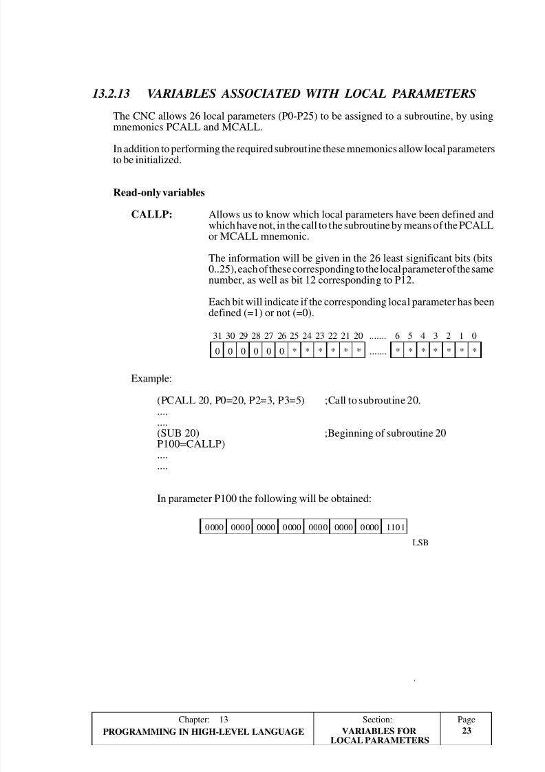
8/21/2019 CNC 8055 M Operator Manual
http://slidepdf.com/reader/full/cnc-8055-m-operator-manual 490/702
PageChapter: 13 Section:
23PROGRAMMING IN HIGH-LEVEL LANGUAGE
13.2.13 VARIABLES ASSOCIATED WITH LOCAL PARAMETERS
The CNC allows 26 local parameters (P0-P25) to be assigned to a subroutine, by usingmnemonics PCALL and MCALL.
In addition to performing the required subroutine these mnemonics allow local parametersto be initialized.
Read-only variables
CALLP: Allows us to know which local parameters have been defined andwhich have not, in the call to the subroutine by means of the PCALLor MCALL mnemonic.
The information will be given in the 26 least significant bits (bits
0..25), each of these corresponding to the local parameter of the samenumber, as well as bit 12 corresponding to P12.
Each bit will indicate if the corresponding local parameter has beendefined (=1) or not (=0).
Example:
(PCALL 20, P0=20, P2=3, P3=5) ;Call to subroutine 20.........(SUB 20) ;Beginning of subroutine 20P100=CALLP)........
In parameter P100 the following will be obtained:
VARIABLES FOR LOCAL PARAMETERS
31 30 29 28 27 26 25 24 23 22 21 20 ....... 6 5 4 3 2 1 0
0 0 0 0 0 0 * * * * * * ....... * * * * * * *
0 000 000 0 0000 0 000 000 0 0000 0 000 110 1
LSB
8/21/2019 CNC 8055 M Operator Manual
http://slidepdf.com/reader/full/cnc-8055-m-operator-manual 491/702
Section:Chapter: 13
24Page
PROGRAMMING IN HIGH-LEVEL LANGUAGE
13.2.14 SERCOS VARIABLES
They are used for data exchange between the CNC and the servo drives via Sercosinterface.
Read-only variables
TSVAR(X-C) identifier .................... for the axesTSVARS identifier .................... for the main spindleTSSVAR identifier .................... for the second spindle
It returns the third attribute of the sercos variable corresponding to the"identifier". The third attribute is used in particular software applications andits information is coded according to the Sercos standard.
(P110=SVARX 40) assigns to parameter P110 the third attribute of the sercos
variable of identifier 40 of the X axis which corresponds to "VelocityFeedback"
Write-only variables
SETGE(X-C) ........................... for the axesSETGES .................................. for the main spindleSSETGS ................................... for the second spindle
The drive may have up to 8 work ranges or gears (0 through 7). Sercosidentifier 218, GearRatioPreselection.
It may also have up to 8 parameter sets (0 through 7). Sercos indentifier 217,ParameterSetPreselection.
These variables permit changing the work range (gear) or the paramete set foreach drive.
The 4 least significant bits of these variables must indicate the work gear andthe 4 most significant bits the parameter set to be selected.
Read-Write variables
SVAR(X-C) identifier .................... for the axes
SVARS identifier .................... for the main spindleSSVAR identifier .................... for the second spindle
They permit reading or modifying the value of the sercos variable correspondingto the axis identifier.
(P110=SVARX 40) assigns to parameter P110 the value of the sercos variableof identifier 40 of the X axis which corresponds to the "VelocityFeedback"
SERCOS VARIABLES

8/21/2019 CNC 8055 M Operator Manual
http://slidepdf.com/reader/full/cnc-8055-m-operator-manual 492/702
PageChapter: 13 Section:
25PROGRAMMING IN HIGH-LEVEL LANGUAGE OTHER VARIABLES
13.2.15 OTHER VARIABLES
Read-only variables
OPMODE: Returns the code corresponding to the selected operating Mode.
0 = Main menu.
10 = Automatic execution.11 = Single block execution.12 = MDI in EXECUTION13 = Tool inspection
20 = Theoretical path movement simulation21 = G functions simulation
22 = G, M, S and T functions simulation23 = Simulation with movement on main plane24 = Simulation with rapid movement
30 = Normal editing31 = User editing32 = TEACH-IN editing33 = Interactive editor34 = Profile editor
40 = Movement in continuous JOG41 = Movement in incremental JOG
42 = Movement with electronic handwheel43 = HOME search in JOG44 = Position preset in JOG45 = Tool calibration46 = MDI in JOG47 = JOG user operation
50 = Zero offset table51 = Tool Offset table52 = Tool table53 = Tool magazine table54 = Global parameter table55 = Local parameter table
60 = Utilities
70 = DNC status71 = CNC status
80 = Editing PLC files81 = Compiling PLC program82 = PLC monitoring83 = Active PLC messages84 = Active PLC pages85 = Save PLC program
86 = Restore PLC program87 = “PLC resources in use” mode88 = PLC statistics

8/21/2019 CNC 8055 M Operator Manual
http://slidepdf.com/reader/full/cnc-8055-m-operator-manual 493/702
Section:Chapter: 13
26Page
PROGRAMMING IN HIGH-LEVEL LANGUAGE OTHER VARIABLES
90 = Graphic Editor
100 = General machine parameter table101 = Axis machine parameter tables102 = Spindle machine parameter tables103 = Serial port machine parameter tables104 = PLC machine parameter table105 = M function table106 = Spindle and cross compensation table107 = Machine parameter table for Ethernet
110 = Diagnosis: configuration111 = Diagnosis: hardware test112 = Diagnosis: RAM memory test113 = Diagnosis: FLASH memory test114 = User diagnosis
115 = Hard Disk diagnosis (HD)
OPMODA Indicates the operating mode currently selected when working with themain channel.
Use the OPMODE variable to know at any time the selected operatingmode (main channel, user channel, PLC channel).
This information is given at the least significant bits with a "1" whenactive and with a "0" when not active or when it is not available in thecurrent version.
bit 0 Program in execution.bit 1 Program in simulation.bit 2 Block in execution via MDI, JOGbit 3 Repositioning in progress.bit 4 Program interrupted, by CYCLE STOPbit 5 MDI, JOG Block interruptedbit 6 Repositioning interruptedbit 7 In tool inspectionbit 8 Block in execution via CNCEX1bit 9 Block via CNCEX1 interruptedbit 10 CNC ready to accept JOG movements: jog, handwheel, teach-
in, inspection.bit 11 CNC ready to receive the CYCLE START command: execu-
tion, simulation and MDI modes.bit 12 The CNC is not ready to execute anything involving axis or
spindle movement.
OPMODB Indicates the type of simulation currently selected. This information isgiven at the least significant bits with a "1" indicating the currentlyselected one.
bit 0 Theoretical pathbit 1 G functionsbit 2 G M S T functionsbit 3 Main plane
bit 4 Rapid

8/21/2019 CNC 8055 M Operator Manual
http://slidepdf.com/reader/full/cnc-8055-m-operator-manual 494/702
PageChapter: 13 Section:
27PROGRAMMING IN HIGH-LEVEL LANGUAGE
OPMODC Indicates the axes selected by Handwheel. This information is given atthe least significant bits indicating with a "1" the one currently selected.
The axis number corresponds to the order it is programmed.Example: If the CNC controls the X, Y, Z, U, B, C axes, Axis 1 will be
the X axis, Axis 2= Y, Axis 3=Z, Axis 4= U, Axis 5= B, Axis6= C.
NBTOOL Indicates the tool number being managed.
Example: There is a manual tool changer. Tool T1 is currently selectedand the operator requests tool T5.
The subroutine associated with the tools may contain the followinginstructions:
(P103 = NBTOOL)(MSG “SELECT T?P103 AND PRESS CYCLE START”)
Instruction (P103 = NBTOOL) assigns the number of the toolcurrently being managed to parameter P103. Therefore, P103=5
The message displayed by the CNC will be “”SELECT T5 ANDPRESS CYCLE START”.
PRGN: Returns the program number being executed. Should none beselected, a value of -1 is returned.
BLKN: Returns the label number of the last block executed.
GSn: Returns the status of the G function indicated (n). 1 if it is active and0 if not.
(P120=GS17); assigns the value 1 to parameter P120 if the G17function is active and 0 if not.
MSn: Returns the status of the M function indicated (n). 1 if it is active and0 if not.
This variable provides the status of M00, M01, M02, M03, M04,M05, M06, M08, M09, M19, M30, M41, M42, M43, M44 and M45functions.
OTHER VARIABLES
8tib 7tib 6tib 5tib 4tib 3tib tib 1tib 0tib
7sixA 6sixA 5sixA 4sixA 3sixA 2sixA 1sixA

8/21/2019 CNC 8055 M Operator Manual
http://slidepdf.com/reader/full/cnc-8055-m-operator-manual 495/702
Section:Chapter: 13
28Page
PROGRAMMING IN HIGH-LEVEL LANGUAGE
.... .... .... .... .... .... 7654 3210
LSB
Ordinate axis
Abscissa axis
0000 0000 0000 0000 0000 0000 0011 0001
LSB
PLANE: Returns data on the abscissa axis (bits 4 to 7) and the ordinate axis(bits 0 to 3) of the active plane in 32 bits and in binary.
The axes are coded in 4 bits and indicate the axis number (from 1 to6) according to the programming order.
Example: If the CNC controls the X,Y,Z,U,B,C axes and is selected
in the ZX plane (G18).
(P122 = PLANE) assigns value $31 to parameter P122.
LONGAX: Returns the number (1 to 6) according to the programming ordercorresponding to the longitudinal axis. This will be the one selectedwith the G15 function and, by default, the axis perpendicular to theactive plane, if this is XY, ZX or YZ.
Example: If the CNC controls the X, Y, Z, U, B,C axes and the Uaxis is selected.
(P122 = LONGAX) assigns the value 4 to parameter 122.
MIRROR Returns in the least significant bits in a group of 32 bits, the status of the mirror image of each axis, 1 in the case of being active and 0 if not.
The name of the axis corresponds to the number according to theirprogramming order.
Example: If the CNC controls axes X, Y, Z, U, B, CAxis 1=X, Axis2=Y, Axis3=Z, Axis4=U, Axis5=B, Axis6=C.
OTHER VARIABLES
8tib 7tib 6tib 5tib 4tib 3tib tib 1tib 0tib
7sixA 6sixA 5sixA 4sixA 3sixA 2sixA 1sixA

8/21/2019 CNC 8055 M Operator Manual
http://slidepdf.com/reader/full/cnc-8055-m-operator-manual 496/702
PageChapter: 13 Section:
29PROGRAMMING IN HIGH-LEVEL LANGUAGE
SCALE: Returns the general scaling factor applied.
SCALE(X-C): Returns the specific scaling factor of the axis indicated (X-C).
ORGROT:Returns the turning angle of the coordinate system selected with theG73 function. Its value is given in degrees. Max. ±99999.9999º
ROTPF: Returns the abscissa value of the rotation center with respect tothe cartesian coordinate origin. It is given in the active units:
If G70, in inches. Max. ±3937.00787If G71, in millimeters. Max. ±99999.9999
ROTPS: Returns the ordinate value of the rotation center with respect tothe cartesian coordinate origin. It is given in the active units:
If G70, in inches. Max. ±3937.00787If G71, in millimeters. Max. ±99999.9999
PRBST: Returns the status of the probe.
0 = The probe is not touching the part.1 = The probe is touching the part.
CLOCK: Returns in seconds the time indicated by the system clock. Possiblevalues 0...4294967295
If this variable is accessed, block preparation is interrupted and
the CNC waits for this command to be executed to resume block preparation.
TIME: Returns the time in hours-minutes-seconds format.
(P150=TIME); assigns hh-mm-ss to P150. For example if the timeis 18h 22m 34 sec., P150 will contain 182234.
If this variable is accessed, block preparation is interrupted andthe CNC waits for this command to be executed to resume block preparation.
DATE: Returns the date in year-month-day format.
(P151=DATE); assigns year-month-day to P151. For example if thedate is April 25th 1992, P151 will contain 920425.
If this variable is accessed, block preparation is interrupted andthe CNC waits for this command to be executed to resume block preparation.
OTHER VARIABLES

8/21/2019 CNC 8055 M Operator Manual
http://slidepdf.com/reader/full/cnc-8055-m-operator-manual 497/702
Section:Chapter: 13
30Page
PROGRAMMING IN HIGH-LEVEL LANGUAGE
CYTIME: Returns in hundredths of a second the time it has taken to make thepart. Possible values 0...4294967295
If this variable is accessed, block preparation is interrupted andthe CNC waits for this command to be executed to resume block preparation.
FIRST: Indicates whether it is the first time that a program has been run. Itreturns a value of 1 if it is the first time and 0 for the remainder of times.
A first-time execution is considered as being one made:
After turning on the CNC.After pressing the “Shift-Reset” keys.Every time a new program is selected.
ANAIn: Returns in volts and in ±1.4 format (values ±5 Volts), the status of the analog input indicated (n), it being possible to select one amongeight (1...8) analog inputs.
If this variable is accessed, block preparation is interrupted andthe CNC waits for this command to be executed to resume block preparation.
AXICOM Returns in the 3 least significant bytes the axis pairs toggled withfunction G28.
The axes are coded in 4 bits and indicate the axis number (1 through7) according to the order they are programmed.
If the CNC controls the X, Y, Z, B, C axes and G28 BC has beenprogrammed, the AXICOM variable will show the followinginformation:
TANGAN Variable associated with the tangential control (G45). It indicates theprogrammed angular position.
OTHER VARIABLES
3riaP 2riaP 1riaP
2sixA 1sixA 2sixA 1sixA 2sixA 1sixA
3riaP 2riaP 1riaP
C B
0000 0000 0000 0000 0000 0000 1010 0010

8/21/2019 CNC 8055 M Operator Manual
http://slidepdf.com/reader/full/cnc-8055-m-operator-manual 498/702
PageChapter: 13 Section:
31PROGRAMMING IN HIGH-LEVEL LANGUAGE
Read-write variables
TIMER: This variable allows time, in seconds, indicated by the clock enabledby the PLC to be read or modified. Possible values 0...4294967295
If this variable is accessed, block preparation is interrupted andthe CNC waits for this command to be executed to resume block preparation.
PARTC: The CNC has a part counter whose count increases every time M30or M02 is executed and this variable allows it value to be read ormodified, which will be given by a number between 0 and4294967295
If this variable is accessed, block preparation is interrupted andthe CNC waits for this command to be executed to resume block
preparation.
KEY: Returns the code of the last key accepted.
If this variable is accessed, block preparation is interrupted andthe CNC waits for this command to be executed to resume block preparation.
KEYSRC: This variable allows the origin of keys to be read or modified,possible values being:
0 = Keyboard
1 = PLC2 = DNC
The CNC only allows modification of this variable if this is at 0.
ANAOn: This variable allows the required analog output (n) to be modified.The value assigned will be expressed in volts and in the ±2.4 format(±10 Volts).
The analog outputs which are free among the eight (1..8) availableat the CNC may be modified, the corresponding error being displayedif an attempt is made to write in one occupied.
If this variable is accessed, block preparation is interrupted andthe CNC waits for this command to be executed to resume block preparation.
OTHER VARIABLES
8/21/2019 CNC 8055 M Operator Manual
http://slidepdf.com/reader/full/cnc-8055-m-operator-manual 499/702
Section:Chapter: 13
32Page
PROGRAMMING IN HIGH-LEVEL LANGUAGE
13.3 CONSTANTS
Constants are defined as being all those fixed values which cannot be altered by a program.The following are considered as constants:
- Numbers expressed in the decimal system.- Hexadecimal numbers.- PI (¶) constant.- Read-only tables and variables as their value cannot be altered with a program.
13.4 OPERATORS
An operator is a symbol which indicates mathematical or logic manipulations which must
bemade. The CNC has arithmetic, relational, logic, binary, trigonometric operators andspecial operators.
Arithmetic operators
+ : add. P1=3 + 4 —> P1=7- : subtraction, also to indicate P2=5 - 2 —> P2=3
a negative number P3=-(2*3) —> P3=-6* : multiplication P4=2*3 —> P4=6
/ : division P5=9 / 2 —> P5=4.5MOD : module (remainder of a division) P6=7 MOD 4 —> P6=3EXP : exponential P7=2 EXP 3 —> P7=8
Relational operators
EQ : equalNE : differentGT : greater thanGE : greater than or equal toLT : less thanLE : less than or equal to
Logic or binary operators
NOT, OR, AND, XOR: act as logic operators between conditions and as binaryoperators between variables and constants.
IF (FIRST AND GS1 EQ 1) GOTO N100P5 = (P1 AND (NOT P2 OR P3))
CONSTANTS ANDOPERATORS
8/21/2019 CNC 8055 M Operator Manual
http://slidepdf.com/reader/full/cnc-8055-m-operator-manual 500/702
PageChapter: 13 Section:
33PROGRAMMING IN HIGH-LEVEL LANGUAGE
Trigonometric functions
SIN : sine P1=SIN 30 —> P1=0.5COS : cosine P2=COS 30 —> P2=0.8660
TAN : tangent P3=TAN 30 —> P3=0.5773ASIN : arc sine P4=ASIN 1 —> P4=90ACOS : arc cosine P5=ACOS 1 —> P5=0ATAN : arc tangent P6=ATAN 1 —> P6=45ARG : ARG (x,y) arc tangent y/x P7=ARG(-1,-2) —> P7=243.4349
There are two functions for calculating the arc tangent: ATAN which returns the resultbetween ±90° and ARG given between 0 and 360°.
Other functions
ABS : absolute value P1=ABS -8 —> P1=8LOG : decimal logarithm P2=LOG 100 —> P2=2SQRT : square root P3=SQRT 16 —> P3=4ROUND : rounding up a number P4=ROUND 5 .83 —> P4=6FIX : integer P5=FIX 5.423 —> P5=5FUP : if integer takes integer P6=FUP 7 —> P6=7
if not, takes entire part + 1 P6=FUP 5.423 —> P6=6
BCD : converts given number to BCD P7=BCD 234 —> P7=564
BIN : converts given number to binary P8=BIN $AB —> P8=171
Conversions to binary and BCD are made in 32 bits, it being possible to represent thenumber 156 in the following formats:
Decimal 156Hexadecimal 9CBinary 0000 0000 0000 0000 0000 0000 1001 1100BCD 0000 0000 0000 0000 0000 0001 0101 0110
OPERATORS
1010 1011
0010 0011 0100
8/21/2019 CNC 8055 M Operator Manual
http://slidepdf.com/reader/full/cnc-8055-m-operator-manual 501/702
Section:Chapter: 13
34Page
PROGRAMMING IN HIGH-LEVEL LANGUAGE
13.5 EXPRESSIONS
An expression is any valid combination between operators, constants and variables.
All expressions must be placed between brackets, but if the expression is reduced to aninteger, the brackets can be removed.
13.5.1 ARITHMETIC EXPRESSIONS
These are formed by combining functions and arithmetic, binary and trigonometricoperators with the constants and variables of the language.
The way to operate with these expressions is established by operator priorities and their
associativity:
Priority from highest to lowest Associativity
NOT, functions, - (negative) from right to leftEXP, MOD from left to right*,/ from left to right+,-(add, subtract) from left to rightrelational operators from left to rightAND, XOR from left to rightOR from left to right
It is advisable to use brackets to clarify the order in which the evaluation of the expressionis done.
(P3 = P4/P5 - P6*P7 - P8/P9)(P3 = (P4/P5)-(P6*P7)-(P8/P9))
The use of repetitive or additional brackets will not produce errors nor will they slow downexecution.
In functions, brackets must be used except when these are applied to a numerical constant,in which case they are optional.
(SIN 45) (SIN (45)) both are valid and equivalent.
(SIN 10+5) the same as ((SIN 10)+5).
Expressions can be used also to reference parameters and tables:
(P100 = P9)(P100 = P(P7))(P100 = P(P8 + SIN (P8 *20)))(P100 = ORGX 55)(P100 = ORGX (12+P9))(PLCM5008 = PLCM5008 OR 1); selects Single Block execution (M5008=1)(PLCM5010 = PLCM5010 AND $FFFFFFFE); Frees feedrate Override
(M5010=0)
EXPRESSIONS

8/21/2019 CNC 8055 M Operator Manual
http://slidepdf.com/reader/full/cnc-8055-m-operator-manual 502/702
PageChapter: 13 Section:
35PROGRAMMING IN HIGH-LEVEL LANGUAGE
13.5.2 RELATIONAL EXPRESSIONS
These are arithmetic expressions joined by relational operators
(IF (P8 EQ 12.8) .... ;Analyzes if the value of P8 is equal to 12.8(IF (ABS(SIN(P24)) GT SPEED) ... ;Analyzes if the sine is greater than the spindle speed.(IF (CLOCK LT(P9*10.99)) .... ;Analyzes if the clock count is less than (P9*10.99)
At the same time these conditions can be joined by means of logic operators.
(IF ((P8EQ12.8) OR (ABS(SIN(P24)) GT SPEED)) AND (CLOCK LT (P9*10.99)) ....
The result of these expressions is either true or false.
EXPRESSIONS

8/21/2019 CNC 8055 M Operator Manual
http://slidepdf.com/reader/full/cnc-8055-m-operator-manual 503/702
Page
PROGRAM CONTROL STATEMENTS
Section:
1Chapter: 14
ASSIGNMENT STATEMENTS
14. PROGRAM CONTROL STATEMENTS
The control statements available to high-level programming can be grouped as follows:
* Programming statements consisting of:
Assignment statementsDisplay statementsEnable-disable statementsFlow control statementsSubroutine statementsStatements for generating programsScreen customizing statements
* Screen customizing statements
Only one statement can be programmed in each block, and no other additional informationmay be programmed in this block.
14.1 ASSIGNMENT STATEMENTS
This is the simplest type of statement and can be defined as:
(target=arithmetic expression)
A local or global parameter or a read-write variable may be selected as target. The arithmeticexpression may be as complex as required or a simple numerical constant.
(P102 = FZLOY)(ORGY 55 = (ORGY 54 + P100))
In the specific case of designating a local parameter using its name (A instead of P0, for
example) and the arithmetic expression being a numerical constant, the statement can beabbreviated as follows:
(P0=13.7) ==> (A=13.7) ==> (A13.7)
Within a single block, up to 26 assignments can be made to different targets, a singleassignment being interpreted as the set of assignments made to the same target.
(P1=P1+P2, P1=P1+P3,P1=P*P4,P1=P1/p5) is the same as (P1=(P1+P2+P3)*P4/P5).
The different assignments which are made in the same block will be separated by commas “,”.

8/21/2019 CNC 8055 M Operator Manual
http://slidepdf.com/reader/full/cnc-8055-m-operator-manual 504/702
Section:
PROGRAM CONTROL STATEMENTSChapter: 14Page
2 DISPLAY STATEMENTS
14.2 DISPLAY STATEMENTS
(ERROR integer, “error text”
This statement stops the execution of the program and displays the indicated error, itbeing possible to select this error in the following ways:
(ERROR integer). This will display the error number indicated and the textassociated to this number according to the CNC error code (should there be one).
(ERROR integer “error text”). This will display the number and the error textindicated, it being necessary to write the text between quote marks “”.
(ERROR “error text”). This will display the error text only.
The error number may be defined by means of a numerical constant or an arithmeticparameter. When using a local parameter, its numeric format must be used (P0 thru P25instead of A thru Z).
Programming Examples:
(ERROR 5)(ERROR P100)(ERROR "Operator error")(ERROR 3, "Operator error")(ERROR P120, "Operator error)
(MSG “message”)
This statement will display the message indicated between quote marks.
The CNC screen is provided with an area for displaying DNC or user programmessages, and always displays the last message received irrespective of where it hascome from.
Example:
(MSG “Check tool”)
(DGWZ expression 1, expression 2, expression 3, expression 4, expression 5,expression 6)
The DGWZ instruction (Define Graphic Work Zone) defines the graphics area.
Each expression forming the instruction syntax correspond to one of the limits and theymust be defined in millimeters or inches.
expression 1 X minimumexpression 2 X maximumexpression 3 Y minimum
expression 4 Y maximumexpression 5 Z minimumexpression 6 Z maximum

8/21/2019 CNC 8055 M Operator Manual
http://slidepdf.com/reader/full/cnc-8055-m-operator-manual 505/702
Page
PROGRAM CONTROL STATEMENTS
Section:
3Chapter: 14
ENABLING -DISABLING STATEMENTS
14.3 ENABLING-DISABLING STATEMENTS
(ESBLK and DSBLK)
After executing the mnemonic ESBLK, the CNC executes all the blocks which comeafter as if it were dealing with a single block.
This single block treatment is kept active until it is cancelled by executing the mnemonicDSBLK.
In this way, should the program be executed in the SINGLE BLOCK operating mode,the group of blocks which are found between the mnemonics ESBLK and DSBLK willbe executed in a continuous cycle, i.e., execution will not be stopped at the end of ablock but will continue by executing the following one.
Example:
G01 X10 Y10 F800 T1 D1(ESBLK) ; Start of single block G02 X20 Y20 I20 J-10G01 X40 Y20G01 X40 Y40 F10000G01 X20 Y40 F8000(DSBLK) ; Cancellation of single block G01 X10 Y10M30
(ESTOP and DSTOP)
After executing the mnemonic DSTOP, the CNC enables the Stop key, as well as theStop signal from the PLC.
It will remain disabled until it is enabled once again by means of the mnemonic ESTOP.
(EFHOLD and DFHOLD)
After executing the mnemonicDFHOLD, the CNC enables the Feed-Hold input fromthe PLC.
It will remain disabled until it is enabled once again by means of the mnemonicEFHOLD.
8/21/2019 CNC 8055 M Operator Manual
http://slidepdf.com/reader/full/cnc-8055-m-operator-manual 506/702
Section:
PROGRAM CONTROL STATEMENTSChapter: 14Page
4 FLOW CONTROLSTATEMENTS
14.4 FLOW CONTROL STATEMENTS
The GOTO and RPT instructions cannot be used in programs that are executed from a PCconnected through the serial lines.
(GOTO N(expression))
The mnemonic GOTO causes a jump within the same program, to the block definedby the label N(expression).
The execution of the program will continue after the jump, from the indicated block.
The jump label can be addressed by means of a number or by any expression whichresults in a number.
Example:
G00 X0 Y0 Z0 T2 D4X10
(GOTO N22) ; Jump statementX15 Y20 ; Is not executedY22 Z50 ; Is not executed
N22 G01 X30 Y40 Z40 F10000 ; Continues execution in this block G02 X20 Y40 I-5 J-5........................
(RPT N(expression), N(expression))
The mnemonic RPT executes, within the same program, the part of the program whichexists between the blocks defined by means of the labels N(expression).
Both labels can be indicated by means of a number or by any expression which resultsin a number.
The part of the program selected by means of the two labels must belong to the sameprogram, by first defining the initial block and then the final block.
The execution of the program will continue in the block following the one in which the
mnemonic RPT was programmed, once the selected part of the program has been executed.
Example:
N10 G00 X10Z20G01 X5G00 Z0
N20 X0N30 (RPT N10, N20) N3N40 G01 X20
M30
When reaching block N30, the program will execute section N10-N20 three times. Oncethis has been completed, the program will continue execution in block N40.

8/21/2019 CNC 8055 M Operator Manual
http://slidepdf.com/reader/full/cnc-8055-m-operator-manual 507/702
Page
PROGRAM CONTROL STATEMENTS
Section:
5Chapter: 14
FLOW CONTROLSTATEMENTS
(IF condition <action1> ELSE <action2>)
This statement analyzes the given condition which must be a relational expression. If the condition is true (result equal to 1), <action1> will be executed, otherwise (resultequal to 0) <action2> will be executed.
Example:
(IF(P8 EQ 12.8) CALL 3 ELSE PCALL 5, A2, B5, D8)
If P8 = 12.8 executes the mnemonic (CALL3)If P8 <> 12.8 executes the mnemonic (PCALL 5, A2, B5, D8)
The statement can lack the ELSE part, i.e., it will be enough to program IF condition<action1>.
Example:
(IF(P8 EQ 12.8)CALL 3)
Both <action1> and <action2> can be expressions or statements, except for mnemonicsIF and SUB.
Due to the fact that in a high level block local parameters can be named by means of letters, expressions of this type can be obtained:
(IF (E EQ 10)M10)
If the condition of parameter P5 (E) having a value of 10 is met, the miscellaneousfunction M10 will not be executed, since a high level block cannot have ISO codecommands. In this case M10 represents the assignment of value 10 to parameter P12,i.e., one can program either:
(IF(E EQ 10)M10) or (IF(P5 EQ 10) P12=10)

8/21/2019 CNC 8055 M Operator Manual
http://slidepdf.com/reader/full/cnc-8055-m-operator-manual 508/702
Section:
PROGRAM CONTROL STATEMENTSChapter: 14Page
6 SUBRUTINE STATEMENTS
14.5 SUBROUTINE STATEMENTS
A subroutine is a part of a program which, being properly identified, can be called from anyposition of a program to be executed.
A subroutine can be kept in the memory of the CNC as an independent part of a programand be called one or several times, from different positions of a program or differentprograms.
Only subroutines stored in the CNC's RAM memory can be executed. Therefore, toexecute a subroutine stored in the Memkey Card, HD or in a PC connected through theserial lines, it must be copied first into the CNC's RAM memory.
If the subroutine is too large to be copied into RAM, it must be converted into a programand then the EXEC instruction must be used as described in section 14.6
(SUB integer)
The mnemonic SUB defines the set of program blocks which are programmed after thisblock as a subroutine by identifying this subroutine with an integer, between 0 and9999, which is specified after it:
There can not be two subroutines with the same identification number in the CNCmemory, even when they belong to different programs.
(RET)
The mnemonic RET indicates that the subroutine which was defined by the mnemonicSUB, finishes in this block.
Example:
(SUB 12) ; Definition of subroutine 12G91 G01 XP0 F5000
YP1X-P0Y-P1
(RET) ; End of subroutine
(CALL (expression))
The mnemonic CALL makes a call to the subroutine indicated by means of a numberor by means of any expression which results in a number.
As a subroutine may be called from a main program, or a subroutine, from this subroutineto a second one, from the second to a third, etc..., the CNC limits these calls to a maximumof 15 nesting levels, it being possible to repeat each of the levels 9999 times.

8/21/2019 CNC 8055 M Operator Manual
http://slidepdf.com/reader/full/cnc-8055-m-operator-manual 509/702
Page
PROGRAM CONTROL STATEMENTS
Section:
7Chapter: 14
(CALL 1) (CALL 2) (CALL 3)
(SUB 1) (SUB 2) (SUB 3)
(RET)(RET)(RET)
X
Z
Y
SUBRUTINE STATEMENTS
Example
G90 G00 X30 Y20 Z10(CALL 10)G90 G00 X60 Y20 Z10(CALL 10)M30
(SUB 10)G91 G01 X20 F5000(CALL 11) ; Drilling and threading
G91 G01 Y10(CALL 11) ; Drilling and threadingG91 G01 X-20(CALL 11) ; Drilling and threadingG91 G01 Y-10(CALL 11) ; Drilling and threadingRET
(SUB 11)G81 G98 G91 Z-8 I-22 F1000 S5000 T1 D1 ; Drilling canned cycleG84 Z-8 I-22 K15 F500 S2000 T2 D2 ; Threading canned cycleG80
(RET)

8/21/2019 CNC 8055 M Operator Manual
http://slidepdf.com/reader/full/cnc-8055-m-operator-manual 510/702
Section:
PROGRAM CONTROL STATEMENTSChapter: 14Page
8 SUBRUTINE STATEMENTS
(PCALL (expression), (assignment statement), (assignment statement),...)
The mnemonic PCALL calls the subroutine indicated by means of a number or anyexpression which results in a number. In addition, it allows up to a maximum of 26 localparameters of this subroutine to be initialized.
These local parameters are initialized by means of assignment statements.
Example: (PCALL 52, A3, B5, C4, P10=20)
In this case, in addition to generating a new subroutine nesting level, a new localparameter nesting level will be generated, there being a maximum of 6 levels of localparameter nesting, within the 15 levels of subroutine nesting.
Both the main program and each subroutine which is found on a parameter nestinglevel, will have 26 local parameters (P0-P25).
Example:

8/21/2019 CNC 8055 M Operator Manual
http://slidepdf.com/reader/full/cnc-8055-m-operator-manual 511/702
Page
PROGRAM CONTROL STATEMENTS
Section:
9Chapter: 14
SUBRUTINE STATEMENTS
G90 G00 X30 Y50 Z0(PCALL 10, P0=20, P1=10) ; or also (PCALL 10, A20, B10)G90 G00 X60 Y50 Z0(PCALL 10, P0=10 P1=20) ; or also (PCALL 10, A10 B20)M30
(SUB 10)G91 G01 XP0 F5000(CALL 11)G91 G01 YP1(CALL 11)G91 G01 X-P0(CALL 11)G91 G01 Y-P1(CALL 11)RET
(SUB 11)G81 G98 G91 Z-8 I-22 F1000 S5000 T1 D1 ; Drilling canned cycleG84 Z-8 I-22 K15 F500 S2000 T2 D2 ; Threading canned cycleG80(RET)
(MCALL (expression), (assignment statement), (assignment statement),...)
By means of the mnemonic MCALL, any user-defined subroutine (SUB integer)acquires the category of canned cycle.
The execution of this mnemonic is the same as the mnemonic PCALL, but the call ismodal, i.e., if another block with axis movement is programmed at the end of this block,after this movement, the subroutine indicated will be executed and with the same callparameters.
If, when a modal subroutine is selected, a movement block with a number of repetitionsis executed, for example X10 N3, the CNC will execute the movement only once (X10)and after the modal subroutine, as many times as the number of repetitions indicates.
Should block repetitions be chosen, the first execution of the modal subroutine will bemade with updated call parameters, but not for the remaining times, which will beexecuted with the values which these parameters have at that time.
If, when a subroutine is selected as modal, a block containing the MCALL mnemonicis executed, the present subroutine will lose its modal quality and the new subroutineselected will be changed to modal.
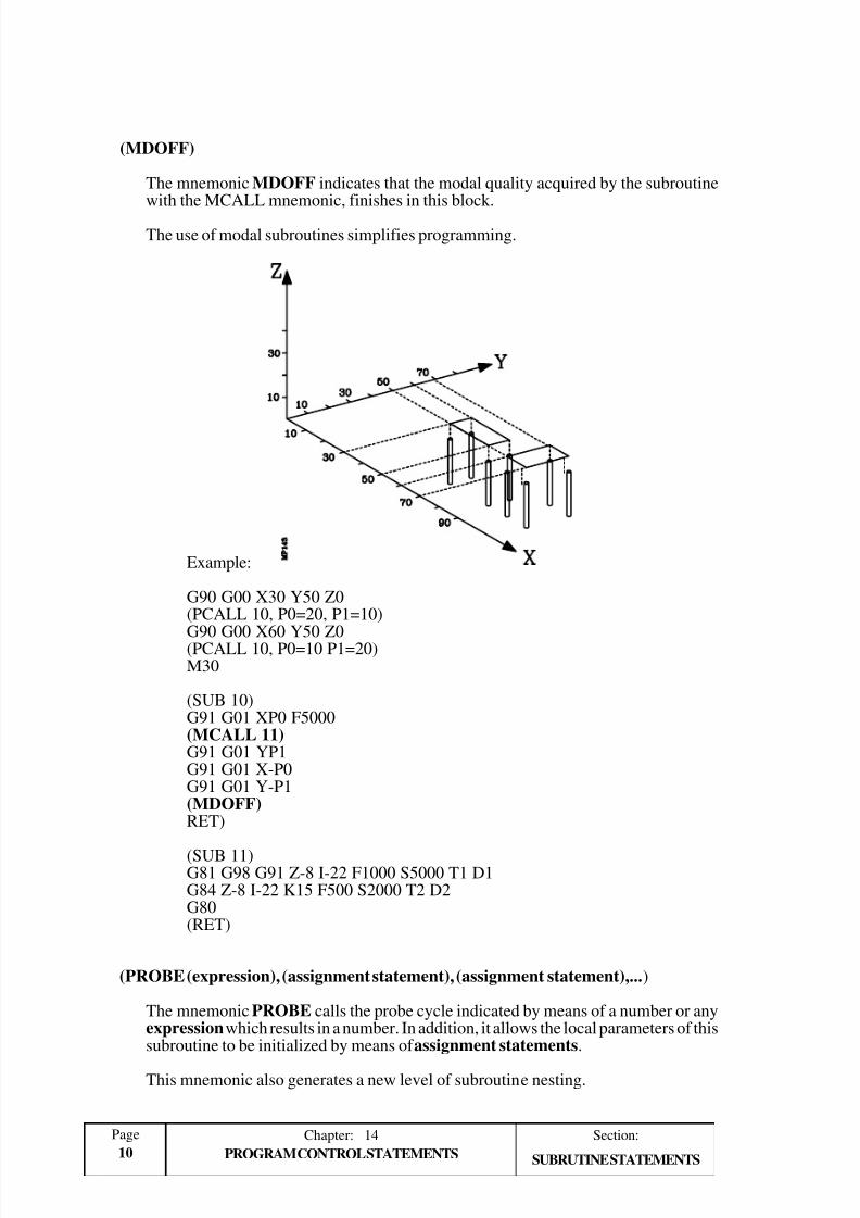
8/21/2019 CNC 8055 M Operator Manual
http://slidepdf.com/reader/full/cnc-8055-m-operator-manual 512/702
Section:
PROGRAM CONTROL STATEMENTSChapter: 14Page
10 SUBRUTINE STATEMENTS
(MDOFF)
The mnemonic MDOFF indicates that the modal quality acquired by the subroutinewith the MCALL mnemonic, finishes in this block.
The use of modal subroutines simplifies programming.
Example:
G90 G00 X30 Y50 Z0(PCALL 10, P0=20, P1=10)
G90 G00 X60 Y50 Z0(PCALL 10, P0=10 P1=20)M30
(SUB 10)G91 G01 XP0 F5000(MCALL 11)G91 G01 YP1G91 G01 X-P0G91 G01 Y-P1(MDOFF)RET)
(SUB 11)G81 G98 G91 Z-8 I-22 F1000 S5000 T1 D1G84 Z-8 I-22 K15 F500 S2000 T2 D2G80(RET)
(PROBE (expression), (assignment statement), (assignment statement),...)
The mnemonic PROBE calls the probe cycle indicated by means of a number or anyexpression which results in a number. In addition, it allows the local parameters of thissubroutine to be initialized by means of assignment statements.
This mnemonic also generates a new level of subroutine nesting.
8/21/2019 CNC 8055 M Operator Manual
http://slidepdf.com/reader/full/cnc-8055-m-operator-manual 513/702
Page
PROGRAM CONTROL STATEMENTS
Section:
11Chapter: 14
SUBRUTINE STATEMENTS
(DIGIT (expression), (assignment statement), (assignment statement),...)
The mnemonic DIGIT calls the digitizing cycle by means of a number or anyexpression which results in a number. It also allows resetting the local parameters of such cycle by means of the assignment statements.
The digitized points are sent to the program (in memory or via DNC) previously openedwith the following statement:
(OPEN P(expression), (destination directory), A/D, "program comment")
This statement will also generate a new nesting level of subroutines.
(TRACE (expression), (assignment statement), (assignment statement),...)
The mnemonic TRACE calls the tracing cycle by means of a number or anyexpression which results in a number. It also allows resetting the local parameters of such cycle by means of the assignment statements.
The digitized points are sent to the program (in memory or via DNC) previously openedwith the following statement:
(OPEN P(expression), (destination directory), A/D, "program comment")
This statement will also generate a new nesting level of subroutines.
8/21/2019 CNC 8055 M Operator Manual
http://slidepdf.com/reader/full/cnc-8055-m-operator-manual 514/702
Section:
PROGRAM CONTROL STATEMENTSChapter: 14Page
12 SUBROUTINE STATEMENTS
14.5.1 INTERRUPTION SUBROUTINE STATEMENTS
Whenever one of the general interruption logic input is activated, "INT1" (M5024), "INT2"(M5025), "INT3" (M5026) or "INT4 (M5027), the CNC temporarily interrupts theexecution of the program in progress and starts executing the interruption subroutine whosenumber is indicated by the corresponding general parameter.
With INT1 (M5024) the one indicated by machine parameter INT1SUB (P35)With INT2 (M5025) the one indicated by machine parameter INT2SUB (P36)With INT3 (M5026) the one indicated by machine parameter INT3SUB (P37)With INT4 (M5027) the one indicated by machine parameter INT4SUB (P38)
The interruption subroutines are defined like any other subroutine by using the statements:"(SUB integer)" and "(RET)".
The interruption subroutines do not change the level of the local arithmetic parameters; thusthey can only contain global arithmetic parameters.
Within an interruption subroutine, it is possible to use the "(REPOS X, Y, Z, ...)" statementdescribed next.
Once the execution of the subroutine is over, the CNC resumes the execution of the programwhich was interrupted.
(REPOS X, Y, Z, ...)
The REPOS statement must always be used inside an interruption subroutine andfacilitates the repositioning of the machine axes to the point of interruption.
When executing this statement, the CNC moves the axes to the point where the programwas interrupted.
* The axes are repositioned one at a time.
* It is not necessary to define all the axes, only those to be repositioned.
* The axes forming the main plane move together; thus, it is not required to programboth axes since the CNC moves both of them with the first one. The movement isnot repeated when defining the second one, it is ignored.
Example: The main plane is formed by the X and Y axes, the Z axis is the longitudinal(perpendicular) axis and the machine uses the C and W axes as auxiliaryaxes. It is desired to first move the C axis, then the X and Y axes and finallythe Z axis..
This repositioning move may be defined in any of the following ways:
(REPOS C, X, Y, Z) (REPOS C, X, Z) (REPOS C, Y, Z)
If the REPOS statement is detected while executing a subroutine not activated by aninterruption input, the CNC will issue the corresponding error message.

8/21/2019 CNC 8055 M Operator Manual
http://slidepdf.com/reader/full/cnc-8055-m-operator-manual 515/702
Page
PROGRAM CONTROL STATEMENTS
Section:
13Chapter: 14
STATEMENTS FOR GENERATING PROGRAMS
14.6 PROGRAM STATEMENTS
With this CNC, from a program in execution one can:Execute another program ................................................ Statement (EXEC P........)Generate a new program ................................................. Statement (OPEN P........)Add blocks to an existing program ................................. Statement (WRITE........)
( EXEC P(expression), (directory)
The EXEC P statement executes the part-program of the indicated directory
The part-program may be defined by a number or any expression resulting in a number.
By default, the CNC assumes that the part-program is in the CNC's RAM memory.
If it is in another device, it must be indicated in (directory).CARDA in the "Memkey CARD"HD on the hard disk DNC1 at a PC connected through serial line 1DNC2 at a PC connected through serial line 2
(OPEN P(expression), (destination directory), A/D, “program comment”)
This statement starts editing a part-program whose number will be given by any numberor expression resulting in a number.
By default, the new part-program edited will be stored in the CNC's RAM memory.
To store it another device, it must be indicated in (destination directory).CARDA in the "Memkey CARD"HD on the hard disk DNC1 at a PC connected through serial line 1DNC2 at a PC connected through serial line 2
Parameter A/D is used when the program to be edited already exists.A The CNC appends the new blocks after the ones already existingD The CNC deletes the existing program and starts editing a new one.
A program comment may also be associated with it. This comment will later bedisplayed next to it on the program directory.
The OPEN statement is very useful when digitizing parts because it allows generatinga program from a program already in execution. That generated program will dependon the values assumed by the program being executed.
To edit blocks, the WRITE statement must be used as described next.
Notes: If the program to be edited already exists and the A/D parameters are notdefined, the CNC will display an error message when executing the block.
The program opened with the OPEN statement is closed when executing anM30, or another OPEN statement and after an Emergency or Reset.
From a PC, only programs stored in the CNC'S RAM memory, in the CARDA, or in the Hard Disk module can be opened

8/21/2019 CNC 8055 M Operator Manual
http://slidepdf.com/reader/full/cnc-8055-m-operator-manual 516/702
Section:
PROGRAM CONTROL STATEMENTSChapter: 14Page
14 PROGRAM STATEMENTS
(WRITE <block text>)
The mnemonic WRITE adds, after the last block of the program which began to beedited by means of the mnemonic OPEN P, the information contained in <block text>as a new program block.
If parametric programming is used within the <block text> and it has been edited in ISOcode, when executing the block, all the parameters (global and local) are replaced withthe value they have at time. Blocks edited in high level language are NOT replaced.
In the customizing programs edited by the operator, the IB instruction may be used sothe blocks edited in high level assume the parameter value.
Examples for P100=10, P101=20 y P102=55
(WRITE G1 XP100 YP101 F100) => G1 X10 Y20 F100
(WRITE (IF (P100 EQ P101) CALL 3)) => (IF (P100 EQ P101) CALL 3)(WRITE (SUB P102)) => (SUB P102)(IB1=(P102))(WRITE (SUB (IB1)) => (SUB 55)
If the mnemonic WRITE is programmed without having programmed the mnemonicOPEN previously, the CNC will display the corresponding error, except when editing a usercustomized program, in which case a new block is added to the program being edited.
Example of the creation of a program which contains several points of a cardioidwhose formula is:
Subroutine number 2 is used, its parameters having the following meaning:
A or P0 Value of angle Q.B or P1 Value of BC or P2 Angular increment
for calculationD or P3 Axis feedrate
R=B cos (Q/2)
B
Q
R
Y
X
8/21/2019 CNC 8055 M Operator Manual
http://slidepdf.com/reader/full/cnc-8055-m-operator-manual 517/702
Page
PROGRAM CONTROL STATEMENTS
Section:
15Chapter: 14
A way to use this example could be:
G00 X0 Y0G93(PCALL 2, A0, B30, C5, D500)M30
Program generation subroutine:
(SUB 2)(OPEN P12345) ; Starts editing of program P12345(WRITE FP3) ; Selects machining feedrate
N100 (P10=P1*(ABS(COS(P0/2))) ; Calculates R(WRITE G01 G05 RP10 QP0) ; Movement block (P0=P0+P2) ; New angle(IF (P0 LT 365) GOTO N100) ; If angle less than 365°, calculates new
; point(WRITE M30) ; End of program block (RET) ; End of subroutine
PROGRAM STATEMENTS
8/21/2019 CNC 8055 M Operator Manual
http://slidepdf.com/reader/full/cnc-8055-m-operator-manual 518/702
Section:
PROGRAM CONTROL STATEMENTSChapter: 14Page
16 SCREEN CUSTOMIZING STATEMENTS
14.7 SCREEN CUSTOMIZING STATEMENTS (GRAPHIC EDITOR)
Customizing statements may be used only when customizing programs made by the user.
These customizing programs must be stored in the CNC'S RAM memory and they mayutilize the "Programming Statements" and they will be executed in the special channeldesigned for this use. The program selected in each case will be indicated in the followinggeneral machine parameters.
In “USERDPLY” the program to be executed in the Execution Mode will be indicated.
In “USEREDIT” the program to be executed in the Editing Mode will be indicated.
In “USERMAN” the program to be executed in the Manual (JOG) Mode will beindicated.
In “USERDIAG” the program to be executed in the Diagnosis Mode will be indicated.
The customizing programs may have up to five nesting levels besides their current one.Also, the customizing statements do not allow local parameters, nevertheless all globalparameters may be used to define them.
(PAGE (expression))
The mnemonic PAGE displays the page number indicated by means of a number or bymeans of any expression which results in a number.
User-defined pages will be from page 0 to page 255 and will be defined from the CNCkeyboard in the Grahic Editor mode and as indicated in the Operating Manual.
System pages will be defined by a number greater than 1000. See the correspondingappendix.
(SYMBOL (expression 1), (expression 2), (expression 3))
The mnemonic SYMBOL displays the symbol whose number is indicated by meansof the value of expression 1 once this has been evaluated.
Its position on screen is also defined by expression 2 (column) and by expression 3 (row).
Expression 1, expression 2 and expression 3 may contain a number or any expressionwhich results in a number.
The CNC allows to display any user-defined symbol (0-255) defined at the CNCkeyboard in the Graphic Editor mode such as is indicated in the Operating Manual.
In order to position it within the display area its pixels must be defined, 0-639 forcolumns (expression 2) and 0-335 for rows (expression 3).
(IB (expression) = INPUT “text”, format))
The CNC has 26 data entry variables (IBO-1B25)
The IB mnemonic displays the text indicated in the data input window and stores thedata input by the user in the entry variable indicated by means of a number or by meansof any expression which results in a number.

8/21/2019 CNC 8055 M Operator Manual
http://slidepdf.com/reader/full/cnc-8055-m-operator-manual 519/702
Page
PROGRAM CONTROL STATEMENTS
Section:
17Chapter: 14
SCREEN CUSTOMIZING STATEMENTS
The wait for data entry will only occur when programming the format of the requesteddata. This format may have a sign, integer part and decimal part.
If it bears the “minus” sign, it will allow positive and negative values, and if it doesnot have a sign, it will only allow positive values.
The integer part indicates the maximum number of digits (0-6) desired to the leftof the decimal point.
The decimal part indicates the maximum number of digits (0-5) desired to the rightof the decimal point.
If the numerical format is not programmed; for example: (IB1 =INPUT "text"), themnemonic will only display the indicated text without waiting for the data to be entered.
(ODW (expression 1), (expression 2), (expression 3))The mnemonic ODW defines and draws a white window on the screen with fixeddimensions (1 row and 14 columns).
Each mnemonic has an associated number which is indicated by the value of expression 1 once this has been evaluated.
Likewise, its position on screen is defined by expression 2 (row) and by expression3 (column).
Expression 1, expression 2 and expression 3 may contain a number or any expression
which results in a number.The CNC allows 26 windows (0-25) to be defined and their positioning within thedisplay area, providing 21 rows (0-20) and 80 columns (0-79).

8/21/2019 CNC 8055 M Operator Manual
http://slidepdf.com/reader/full/cnc-8055-m-operator-manual 520/702
Section:
PROGRAM CONTROL STATEMENTSChapter: 14Page
18 SCREEN CUSTOMIZING STATEMENTS
(DW(expression 1) = (expression 2), DW (expression 3) = (expression 4),...)
The mnemonic DW displays in the window indicated by the value for expression 1,expression 3, .. once they have been evaluated, the numerical data indicated byexpression 2, expression 4, ...
Expression 1, expression 2, expression 3, .... may contain a number or any expressionwhich may result in a number.
The following example shows a dynamic variable display:
(ODW 1,6,33) ; Defines data window 1(ODW 2,14,33) ; Defines data window 2
N10 (DW1=DATE,DW2=TIME) ; Displays the date in window 1 and the time in 2(GOTO N10)
The CNC allows displaying the data in decimal, hexadecimal and binary format. Thefollowing instructions are available:
(DW1 = 100) Decimal format. Value “100” displayed in window 1.(DWH2=100) Hexadecimal format. Value “64” displayed in window 2.(DWB3=100) Binary format. Value “01100100” displayed in window 3.
When using the binary format, the display is limited to 8 digits in such a way that a valueof “11111111” will be displayed for values greater than 255 and the value of “10000000” for values more negative than -127.
Besides, the CNC allows the number stored in one of the 26 data input variables (IB0-
IB25) to be displayed in the requested window.The following example shows a request and later display of axis feedrate.
(ODW3,4,60) ; Defines data window 3(IB1=INPUT”Axis feed:”,5.4) ; Axis feedrate request(DW3=IB1) ; Displays feedrate in window 3

8/21/2019 CNC 8055 M Operator Manual
http://slidepdf.com/reader/full/cnc-8055-m-operator-manual 521/702
Page
PROGRAM CONTROL STATEMENTS
Section:
19Chapter: 14
SCREEN CUSTOMIZING STATEMENTS
MAXIMUM
COORDINATEFEEDRATE
HELP MAXIMUM CO
ORDINATE
(SK(expression 1) = “text1” (expression 2) = “text 2”, ...)
The mnemonic SK defines and displays the new softkey menu indicated.
Each of the expressions will indicate the softkey number which it is required to modify(1-7, starting from the left) and the texts which it is required to write in them.
Expression 1, expression 2, expression 3, .... may contain a number or any expressionwhich may result in a number.
Each text will allow a maximum of 20 characters which will be shown on two lines of 10 characters each. If the text selected has less than 10 characters, the CNC will centerit on the top line, but if it has more than 10 characters the programmer will center it.
Examples:
(SK 1=”HELP”, SK 2=”MAXIMUM COORDINATE”)
(SK 1=”FEEDRATE”,SK 2=”_MAXIMUM__COORDINATE”)
Warning:
If while a standard CNC softkey menu is active, one or more softkeys are
selected via high level language statement: "SK", the CNC will clear allexisting softkeys and it will only show the selected ones.
If while a user softkey menu is active, one or more softkeys are selected via highlevel language statement "SK", the CNC will only replace the selected softkeysleaving the others intact.
(WKEY)
The mnemonic WKEY stops execution of the program until the key is pressed.
The pressed key will be recorded in the KEY variable.
Example
....
....(WKEY) ; Wait for key8IF KEY EQ $FC00 GOTO N1000 ; If key F1 has been pressed, continue in
N1000........

8/21/2019 CNC 8055 M Operator Manual
http://slidepdf.com/reader/full/cnc-8055-m-operator-manual 522/702
Section:
PROGRAM CONTROL STATEMENTSChapter: 14Page
20 SCREEN CUSTOMIZING STATEMENTS
(WBUF “text”, (expression))
The WBUF statement can only be used when editing a program in the user channel.
This mnemonic may be programmed in two ways:
(WBUF “text”, (expression))
This statement adds the text and value of the expression once this has beenevaluated, to the block which is being edited and within the data input window.
(Expression) may contain a number or any expression which results in a number.
It will be optional to program the expression, but it will be required to define thetext. If no text is required, “” must be programmed.
Examples for P100=10 (WBUF "X", P100) => X10(WBUF "XP100") => XP100
(WBUF)
Enters into memory, adding to the program being edited and after the cursorposition, the block being edited by means of (WBUF "text", (expression)). It alsoclears the editing buffer in order to edit a new block.
This allows the user to edit a complete program without having to quit the userediting mode after each block and press ENTER to "enter" it into memory.
Example:
(WBUF”(PCALL 25,”) ; Adds “(PCALL 25,” to the block beingedited
(IB1=INPUT “Parameter A:”,-5.4) ; Request of Parameter A(WBUF “A=”,IB1) ; Adds “A=(value entered) to the block being
edited.(IB2=INPUT”Parameter B:”,-5.4) ; Request of Parameter B(WBUF”,B=”,IB2 ; Adds “B=(value entered)” to the block being
edited(WBUF”)”) ; Adds “)” to the block being edited(WBUF) ; Enters the edited block into memory------------------------
After executing this program the block being edited contains:
(PCALL 25, A=23.5, B=-2.25)
(SYSTEM)
The mnemonic SYSTEM stops execution of the user customized program and returnsto the corresponding standard menu of the CNC.
8/21/2019 CNC 8055 M Operator Manual
http://slidepdf.com/reader/full/cnc-8055-m-operator-manual 523/702
Page
PROGRAM CONTROL STATEMENTS
Section:
21Chapter: 14
SCREEN CUSTOMIZING STATEMENTS
Customizing program example
The following customizing program must be selected as user program associated to theEditing Mode.
After selecting the Editing Mode and pressing the USER softkey, this program startsexecuting and it allows assisted editing of 2 user cycles. This editing process is carried outa cycle at a time and as often as desired.
; Displays the initial editing page (screen)N0 (PAGE 10)
; Sets the softkeys to access the various modes and requests a choice(SK 1=”CYCLE 1",SK 2=”CYCLE 2",SK 7=”EXIT”)
N5 (WKEY ) ;Request a key
(IF KEY EQ $FC00 GOTO N10) ;Cycle 1
(IF KEY EQ $FC01 GOTO N20) ;Cycle 2
(IF KEY EQ $FC06 SYSTEM ELSE GOTO N5) ;Quit or request a key
; CYCLE 1
; Displays page 11 and defines 2 data entry windowsN10 (PAGE 11)
(ODW 1,10,60)(ODW 2,15,60)
;Editing(WBUF “( PCALL 1,”) ; Adds (PCALL 1, to the block being edited
(IB 1=INPUT “X:”,-6.5) ; Requests the value of X
(DW 1=IB1) ; Data window 1 shows the entered value
(WBUF “X”,IB1) ; Adds X (entered value) to the block being edited
(WBUF “,”) ; Adds , to the block being edited
(IB 2=INPUT “Y:”,-6.5) ; Requests the value of Y
(DW 2=IB2) ; Data window 2 shows the entered value
(WBUF “Y”,IB2) ; Adds Y (entered value) to the block being edited
(WBUF “)”) ; Adds ) to the block being edited
(WBUF ) ; Enters the edited block into memory. For example: (PCALL 1, X2, Y3)
(GOTO N0)
;(This sample program continues on next page)
8/21/2019 CNC 8055 M Operator Manual
http://slidepdf.com/reader/full/cnc-8055-m-operator-manual 524/702
Section:
PROGRAM CONTROL STATEMENTSChapter: 14Page
22 SCREEN CUSTOMIZING STATEMENTS
; CYCLE 2
; Displays page 12 and defines 3 data entry windowsN20 (PAGE 12)
(ODW 1,10,60)(ODW 2,13,60)(ODW 3,16,60)
;Editing(WBUF “( PCALL 2,”) ; Adds (PCALL 2, to the block being edited
(IB 1=INPUT “A:”,-6.5) ; Requests the value of A
(DW 1=IB1) ; Data window 1 shows the entered value
(WBUF “A”,IB1) ; Adds A (entered value) to the block being edited
(WBUF “,”) ; Adds , to the block being edited
(IB 2=INPUT “B:”,-6.5) ; Requests the value of B
(DW 2=IB2) ; Data window 2 shows the entered value
(WBUF “B”,IB2) ; Adds B (entered value) to the block being edited
(WBUF “,”) ; Adds , to the block being edited
(IB 3=INPUT “C:”,-6.5) ; Requests the value of C
(DW 3=IB3) ; Data window 3 shows the entered value
(WBUF “C”,IB3) ; Adds C (entered value) to the block being edited
(WBUF “)”) ; Adds ) to the block being edited
(WBUF ) ; Enters the edited block into memory. Example: (PCALL 2, A3, B1, C3)
(GOTO N0)
8/21/2019 CNC 8055 M Operator Manual
http://slidepdf.com/reader/full/cnc-8055-m-operator-manual 525/702
PageChapter: 15 Section:
1 DIGITIZING CYCLES
15. DIGITIZING CYCLES
This CNC offers the following digitizing cycles:
1 Digitizing cycle in a grid pattern.2 Digitizing cycle in an arc pattern.
These cycle must be programmed by means of the High Level Language instructionDIGIT and its programming format is:
(DIGIT (expression), (assignment statement), ...)
This statement calls upon the indicated digitizing cycle by means of a number or anexpression resulting in a number. It also allows presetting its parameters with the desiredvalues by using assignment statements.
General considerations
All movements of these digitizing cycles must be made along the X, Y, or Z axes andthe work plane must be formed by two of these axes (XY, XZ, YZ, YX, ZX, ZY).
The other axis must be perpendicular to this plane and it must be selected aslongitudinal axis.
The machining conditions for the digitizing cycle must be defined before calling it.
During the execution of a digitizing cycle, the coordinates of the collected (probed)points are stored in a program. This program must be “opened” before calling the cycleby means of the (OPEN P) statement.
If instead of storing the digitized data in the program memory of the CNC it is desiredto send it out to a peripheral or computer via DNC, it must be indicated so whendefining the (OPEN P) statement.
It is advisable to indicate the machining conditions of the digitized program (openedwith the (OPEN P) statement) by using the (WRITE) statement on the necessaryblocks of the digitizing cycle.
Once the digitizing cycle has finished, the probe will be positioned where it was beforeexecuting the cycle.
The execution of a digitizing cycle does not alter the history of the previous “G”functions.
It must be borne in mind that the program blocks generated by the digitizing cycle areall positioning blocks. Therefore, to end the generated program, another block
containing an M02 or M30 must be added.

8/21/2019 CNC 8055 M Operator Manual
http://slidepdf.com/reader/full/cnc-8055-m-operator-manual 526/702
Section:Chapter: 15
2Page
DIGITIZING CYCLES
C
J
B
K
I
(X,Y)
(X,Y,Z)
15.1 DIGITIZING CYCLE IN A GRID PATTERN
The programming format is as follows:
(DIGIT 1, X, Y, Z, I, J, K, B, C, D, F)
X±5.5 Theoretical position value, along the abscissa axis, of the first digitized point. It mustbe defined in absolute coordinates and it must coincide with one of the corners of the grid.
Y±5.5 Theoretical position value, along the ordinate axis, of the first digitized point. It must
be defined in absolute coordinates and it must coincide with one of the corners of the grid.
Z±5.5 Theoretical position value, along the probing axis, where the probe will be positionedbefore starting to digitize. It must be defined in absolute coordinates.
When defining this position value, both the maximum height of the part and theclearance to be maintained with respect to it must be taken into account.
DIGITIZING CYCLE IN AGRID PATTERN
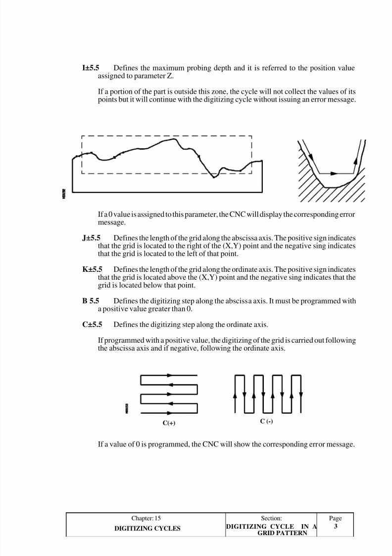
8/21/2019 CNC 8055 M Operator Manual
http://slidepdf.com/reader/full/cnc-8055-m-operator-manual 527/702
PageChapter: 15 Section:
3 DIGITIZING CYCLES
I±5.5 Defines the maximum probing depth and it is referred to the position valueassigned to parameter Z.
If a portion of the part is outside this zone, the cycle will not collect the values of itspoints but it will continue with the digitizing cycle without issuing an error message.
If a 0 value is assigned to this parameter, the CNC will display the corresponding errormessage.
J±5.5 Defines the length of the grid along the abscissa axis. The positive sign indicatesthat the grid is located to the right of the (X,Y) point and the negative sing indicatesthat the grid is located to the left of that point.
K±5.5 Defines the length of the grid along the ordinate axis. The positive sign indicatesthat the grid is located above the (X,Y) point and the negative sing indicates that thegrid is located below that point.
B 5.5 Defines the digitizing step along the abscissa axis. It must be programmed witha positive value greater than 0.
C±5.5 Defines the digitizing step along the ordinate axis.
If programmed with a positive value, the digitizing of the grid is carried out followingthe abscissa axis and if negative, following the ordinate axis.
If a value of 0 is programmed, the CNC will show the corresponding error message.
DIGITIZING CYCLE IN AGRID PATTERN
C (-)C(+)
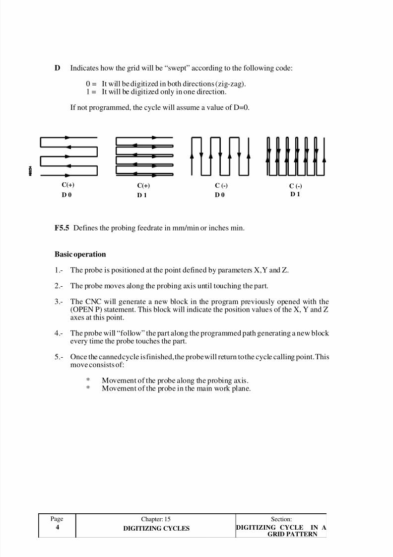
8/21/2019 CNC 8055 M Operator Manual
http://slidepdf.com/reader/full/cnc-8055-m-operator-manual 528/702
Section:Chapter: 15
4Page
DIGITIZING CYCLES
C(+) C(+) C (-)
D 0 D 0D 1
C (-)
D 1
D Indicates how the grid will be “swept” according to the following code:
0 = It will be digitized in both directions (zig-zag).1 = It will be digitized only in one direction.
If not programmed, the cycle will assume a value of D=0.
F5.5 Defines the probing feedrate in mm/min or inches min.
Basic operation
1.- The probe is positioned at the point defined by parameters X,Y and Z.
2.- The probe moves along the probing axis until touching the part.
3.- The CNC will generate a new block in the program previously opened with the(OPEN P) statement. This block will indicate the position values of the X, Y and Zaxes at this point.
4.- The probe will “follow” the part along the programmed path generating a new block every time the probe touches the part.
5.- Once the canned cycle is finished, the probe will return to the cycle calling point. Thismove consists of:
* Movement of the probe along the probing axis.
* Movement of the probe in the main work plane.
DIGITIZING CYCLE IN AGRID PATTERN
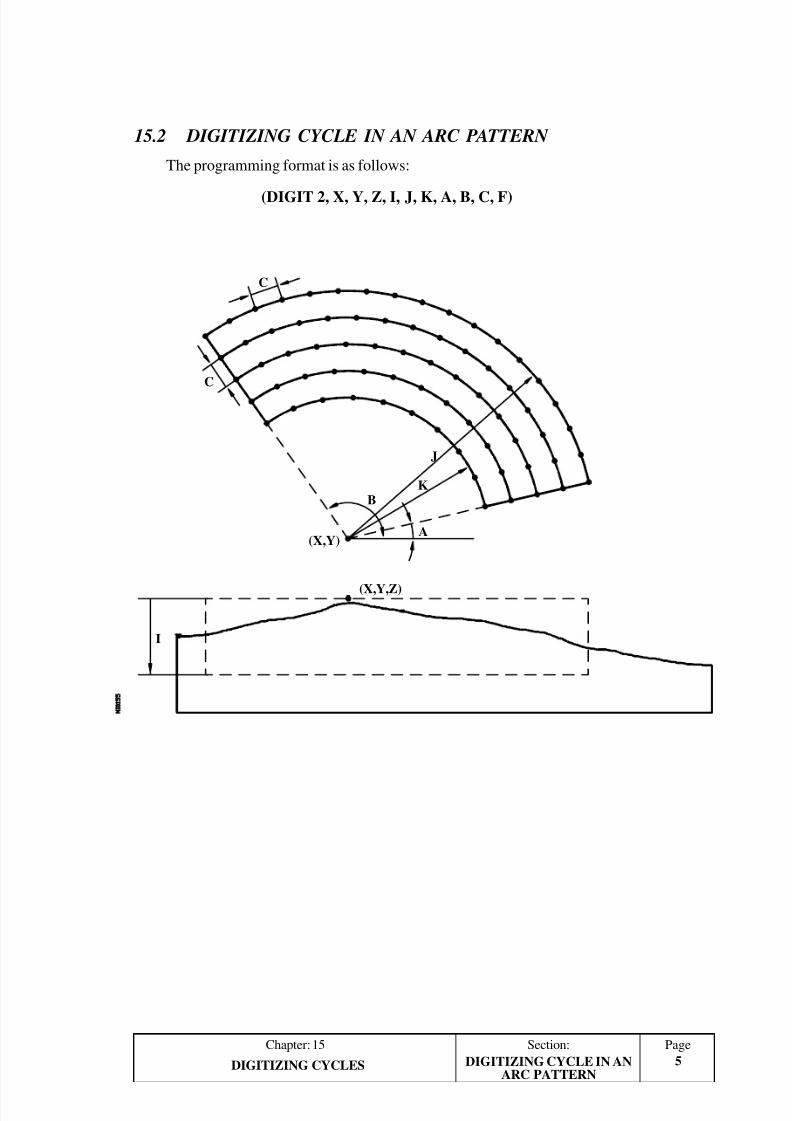
8/21/2019 CNC 8055 M Operator Manual
http://slidepdf.com/reader/full/cnc-8055-m-operator-manual 529/702
PageChapter: 15 Section:
5 DIGITIZING CYCLES
C
C
B
A
J
K
(X,Y)
(X,Y,Z)
I
15.2 DIGITIZING CYCLE IN AN ARC PATTERN
The programming format is as follows:
(DIGIT 2, X, Y, Z, I, J, K, A, B, C, F)
DIGITIZING CYCLE IN ANARC PATTERN

8/21/2019 CNC 8055 M Operator Manual
http://slidepdf.com/reader/full/cnc-8055-m-operator-manual 530/702
Section:Chapter: 15
6Page
DIGITIZING CYCLES
X±5.5 Theoretical position value of the arc’s center along the abscissa axis. It must bedefined in absolute coordinates.
Y±5.5 Theoretical position value of the arc’s center along the ordinate axis. It must bedefined in absolute coordinates.
Z±5.5 Theoretical position value, along the probing axis, where the probe will bepositioned before starting to digitize. It must be defined in absolute coordinates.
When defining this position value, both the maximum height of the part and theclearance to be maintained with respect to it must be taken into account.
I±5.5 Defines the maximum probing depth and it is referred to the position valueassigned to parameter Z.
If a portion of the part is outside this zone, the cycle will not collect the values of its
points but it will continue with the digitizing cycle without issuing an error message.
If a 0 value is assigned to this parameter, the CNC will display the corresponding errormessage.
J 5.5 Defines the outside radius of the circular zone (arc). It must be a positive valuegreater than 0.
K 5.5 Defines the inside radius of the circular zone (arc). It must be positive.
If no value is programmed, a value of 0 will be assumed by the canned cycle..
A 5.5 Defines the angular position of the first digitizing point with respect to theabscissa axis.
If not programmed, a value of A=0 will be assumed.
DIGITIZING CYCLE IN ANARC PATTERN

8/21/2019 CNC 8055 M Operator Manual
http://slidepdf.com/reader/full/cnc-8055-m-operator-manual 531/702
PageChapter: 15 Section:
7 DIGITIZING CYCLES DIGITIZING CYCLE IN ANARC PATTERN
B 5.5 Defines the angular position of the other end of the arc zone (sector) withrespect to the abscissa axis.
When defining parameters A and B, it must be borne in mind that the initial digitizingpath is followed in the counter-clockwise direction.
When not programming a complete circle, the digitizing paths will be followed in bothdirections (in a zig-zag manner) and, when programming a complete circle, they willbe scanned concentrically.
If not programmed, a value of B=360 will be assumed.
To digitize a complete circle, A and B must be assigned the same value or none at allso the default values are assumed (A0 B360).
C 5.5 Defines the digitizing step. That is, the distance between consecutive arcs andbetween consecutive points.
F5.5 Defines the probing feedrate in mm/min or inches min.
8/21/2019 CNC 8055 M Operator Manual
http://slidepdf.com/reader/full/cnc-8055-m-operator-manual 532/702
Section:Chapter: 15
8Page
DIGITIZING CYCLES DIGITIZING CYCLE IN ANARC PATTERN
Basic operation
1.- The probe is positioned at the point defined by parameters X,Y and Z.
2.- The probe moves along the probing axis until touching the part.
3.- The CNC will generate a new block in the program previously opened with the(OPEN P) statement. This block will indicate the position values of the X, Y and Zaxes at this point.
4.- The probe will “follow” the part along the programmed path generating a new block every time the probe touches the part.
5.- Once the canned cycle is finished, the probe will return to the cycle calling point. Thismove consists of:
* Movement of the probe along the probing axis.* Movement of the probe in the main work plane.
8/21/2019 CNC 8055 M Operator Manual
http://slidepdf.com/reader/full/cnc-8055-m-operator-manual 533/702
PageChapter: 16 Section:
1TRACING AND DIGITIZING INTRODUCTION
16. TRACING AND DIGITIZING
16.1 INTRODUCTION
In order to clarify the terminology used throughout this chapter, the following definitionsare provided:
Tracing: The probe moves following the indicated path and keeping its stylus in contactwith the model surface at all times.
Copying: It requires a machine with a second spindle or with a copying arm where thetracing probe is mounted while the machining tool goes on the main spindle.
Copying consists in machining a part while tracing a model. The machined part will bea copy of the traced model.
Digitizing: Consists in capturing the machine coordinates of the part while beingtraced and send them to a file previously opened by means of the "OPEN P" instruction.
In order to digitize, the tracing function G23 must be activated whether the part is goingto be copied or not.
The model can be traced and digitized in two ways:
Manually.
It allows the operator to move the probe by hand on and along the surface of the model.
Automatically.
The probe movements are controlled by the CNC which offers the following choices:
By activating one of these canned cycles:
TRACE 1 Tracing/Digitizing in a grid pattern.TRACE 2 Tracing/Digitizing in an arc pattern.TRACE 3 Profile Tracing/Digitizing in the plane.TRACE 4 3-D Profile Tracing/Digitizing (in space)
TRACE 5 Profile Tracing/Digitizing with polygonal sweep
By activating the tracing (G23) and digitizing (G24) functions.
In this case the path to be followed by the probe must be defined. The availableoptions are:
One-dimensional tracing/digitizing.Two-dimensional tracing/digitizing.Three-dimensional tracing/digitizing.
All these tracing/digitizing types are being described next.

8/21/2019 CNC 8055 M Operator Manual
http://slidepdf.com/reader/full/cnc-8055-m-operator-manual 534/702
Section:Chapter: 16Page
TRACING AND DIGITIZING2
* Manual Tracing / Digitizing.
It allows the operator to move the probe by hand on and long the surface of the modelbeing possible to limit the manual movement of the probe to 1, 2 or 3 axes.
With this type of tracing it is possible to capture points of the model, to make paralleltracing passes, two-dimensional or three-dimensional contouring, roughing operations,etc.
With this option it is possible to digitize the model either point by point or continuously.
The continuous digitizing is carried out by the CNC according to the values assignedto the digitizing parameters. Function G24.
To digitize point by point, function G24 must be defined without parameters. The pointcapture is carried out by the operator by pressing the "READ-POINT-BY-POINT"softkey or by activating an external push-button.
INTRODUCTION
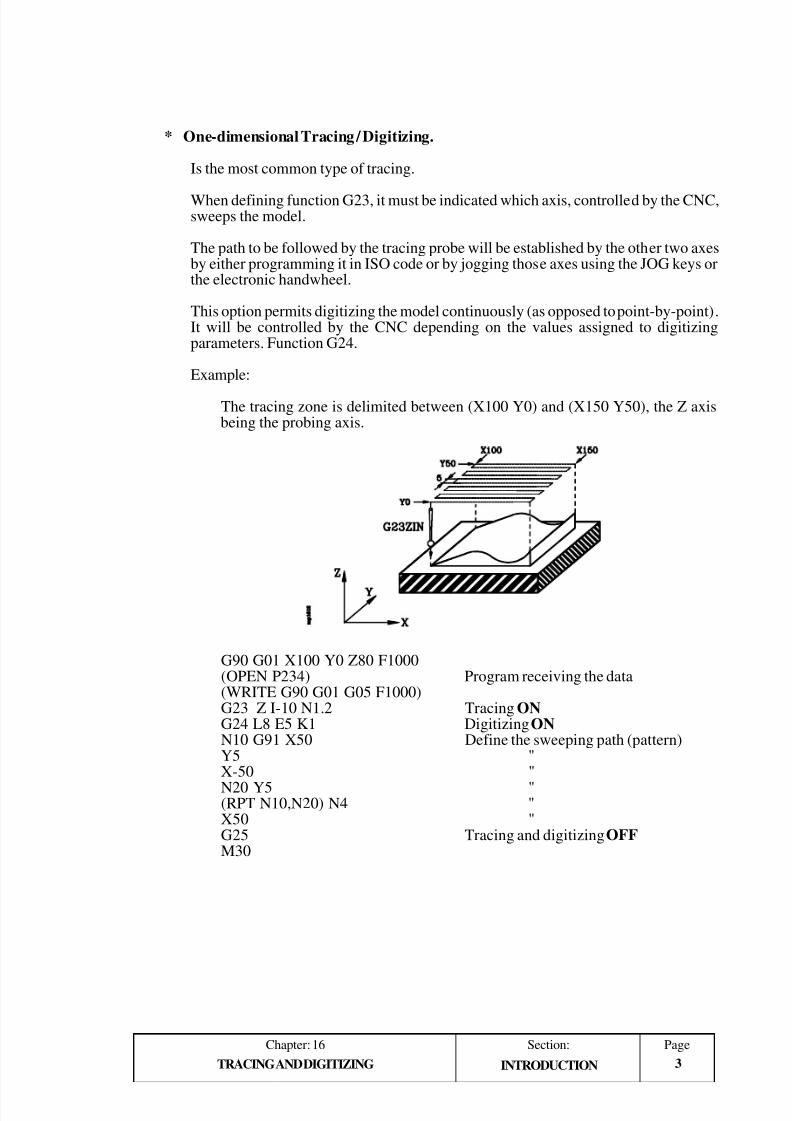
8/21/2019 CNC 8055 M Operator Manual
http://slidepdf.com/reader/full/cnc-8055-m-operator-manual 535/702
PageChapter: 16 Section:
3TRACING AND DIGITIZING
* One-dimensional Tracing / Digitizing.
Is the most common type of tracing.
When defining function G23, it must be indicated which axis, controlled by the CNC,sweeps the model.
The path to be followed by the tracing probe will be established by the other two axesby either programming it in ISO code or by jogging those axes using the JOG keys orthe electronic handwheel.
This option permits digitizing the model continuously (as opposed to point-by-point).It will be controlled by the CNC depending on the values assigned to digitizingparameters. Function G24.
Example:
The tracing zone is delimited between (X100 Y0) and (X150 Y50), the Z axisbeing the probing axis.
G90 G01 X100 Y0 Z80 F1000(OPEN P234) Program receiving the data(WRITE G90 G01 G05 F1000)G23 Z I-10 N1.2 Tracing ONG24 L8 E5 K1 Digitizing ONN10 G91 X50 Define the sweeping path (pattern)Y5 "X-50 "
N20 Y5 "(RPT N10,N20) N4 "X50 "G25 Tracing and digitizing OFFM30
INTRODUCTION

8/21/2019 CNC 8055 M Operator Manual
http://slidepdf.com/reader/full/cnc-8055-m-operator-manual 536/702
Section:Chapter: 16Page
TRACING AND DIGITIZING4
* Two-dimensional Tracing / Digitizing.
It contours the model. To do this, it is necessary to define the 2 axes which, beingcontrolled by the CNC, follow the profile.
The contour, defined by function G27, may be either closed (where the initial and finalpoints are the same) or open (where the initial and final points are not the same).
With this option it is possible to carry out a continuous digitizing of the model whichwill be controlled by the CNC depending on the values assigned to the digitizingparameters. Function G24
Example of a closed contour:
G23 XY I50 J8 N0.8 ;Two-dimensional tracing definitionG24 L8 E5 K1 ;Digitizing definitionG27 S0 ;Closed contour definition
G25 ;Deactivate tracing and digitizing
Example of an open contour:
G23 XY I60 J20 N0.8 ;Two-dimensional tracing definitionG24 L8 E5 K1 ;Digitizing definitionG27 S0 Q10 R25 J15 K0 ;Open contour definitionG25 ;Deactivate tracing and digitizing
INTRODUCTION
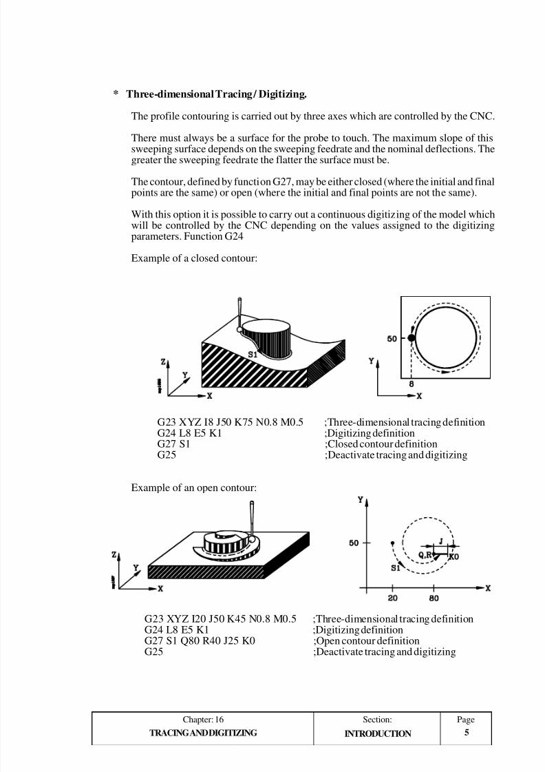
8/21/2019 CNC 8055 M Operator Manual
http://slidepdf.com/reader/full/cnc-8055-m-operator-manual 537/702
PageChapter: 16 Section:
5TRACING AND DIGITIZING
* Three-dimensional Tracing / Digitizing.
The profile contouring is carried out by three axes which are controlled by the CNC.
There must always be a surface for the probe to touch. The maximum slope of thissweeping surface depends on the sweeping feedrate and the nominal deflections. Thegreater the sweeping feedrate the flatter the surface must be.
The contour, defined by function G27, may be either closed (where the initial and finalpoints are the same) or open (where the initial and final points are not the same).
With this option it is possible to carry out a continuous digitizing of the model whichwill be controlled by the CNC depending on the values assigned to the digitizingparameters. Function G24
Example of a closed contour:
G23 XYZ I8 J50 K75 N0.8 M0.5 ;Three-dimensional tracing definitionG24 L8 E5 K1 ;Digitizing definitionG27 S1 ;Closed contour definitionG25 ;Deactivate tracing and digitizing
Example of an open contour:
G23 XYZ I20 J50 K45 N0.8 M0.5 ;Three-dimensional tracing definitionG24 L8 E5 K1 ;Digitizing definitionG27 S1 Q80 R40 J25 K0 ;Open contour definitionG25 ;Deactivate tracing and digitizing
INTRODUCTION

8/21/2019 CNC 8055 M Operator Manual
http://slidepdf.com/reader/full/cnc-8055-m-operator-manual 538/702
Section:Chapter: 16Page
TRACING AND DIGITIZING6
* Tracing / Digitizing canned cycles
The tracing/digitizing canned cycles offered by this CNC are based on the types of tracing described earlier and they are the following:
TRACE 1 Tracing / digitizing in a grid patternTRACE 2 Tracing / digitizing in an arc pattern.TRACE 3 Profile tracing / digitizing in the planeTRACE 4 3-D Profile tracing / digitizing (in space)TRACE 5 Tracing / digitizing with polygonal sweep.
They are programmed by means of the high level instruction TRACE. The cyclenumber may be indicated either by a number (1, 2, 3, 4, 5) or by an expression whoseresult is one of these numbers.
They all have a series of parameters defining the tracing path and the digitizing
conditions.
To just trace the part without digitizing it, the digitizing parameters must be set to "0".
To digitize the model, besides setting the digitizing parameters, it is required to open theprogram storing the digitized data by means of the "OPEN P" statement.
INTRODUCTION
8/21/2019 CNC 8055 M Operator Manual
http://slidepdf.com/reader/full/cnc-8055-m-operator-manual 539/702
PageChapter: 16 Section:
7TRACING AND DIGITIZING
16.1.1 GENERAL CONSIDERATIONS
The CNC offers the following preparatory functions to trace / digitize parts:
G26 Calibrate the tracing probeG23 Activate the tracing functionG24 Activate the digitizing functionG27 Define the tracing contourG25 Deactivate the tracing / digitizing function
It also offers the following tracing canned cycles:
TRACE 1 Tracing / digitizing in a grid patternTRACE 2 Tracing / digitizing in an arc pattern.TRACE 3 Profile tracing / digitizing in the planeTRACE 4 3-D Profile tracing / digitizing (in space)
TRACE 5 Tracing / digitizing with polygonal sweep.
About tracing
While tracing the model, the CNC only controls the movements of the X, Y and Z axes.Thus, the main plane (work plane) must be formed by two of these axes (XY, XZ, YZ, YX,ZX, ZY). The other axis must be perpendicular to that plane and set as longitudinal axis.
The tracing probe must always be mounted on that perpendicular axis.
The tracing probe must be calibrated (G26) every time it is installed on the machine, it
is changed or reoriented and every time the CNC is powered-upOnce function G23 is executed (tracing), the CNC maintains the probe in contact withthe surface of the model following the selected path at all times.
When tracing automatically (not by hand), it is necessary to define the path to befollowed by the tracing probe by either programming it in ISO code or by jogging theaxes with the JOG keys or with the electronic handwheel.
To deactivate the tracing previously activated with function G23, execute functionG25.
When executing one of the tracing / digitizing canned cycles it is not necessary to
execute function G23, G25, or to define the tracing path since it is already taken careof by the canned cycle itself.
When copying (machining while tracing) it is not possible to compensate for probedeflection. Therefore, it is recommended to use a machining tool whose radius is equalto or smaller than the radius of the probe tip (ball) minus the amount of stylus deflectionbeing applied.
For example: When using a 10 mm diameter ball (5 mm radius) with a maximumdeflection of 1mm, a 8mm-diameter (4 mm radius) tool should be used
CONSIDERATIONS

8/21/2019 CNC 8055 M Operator Manual
http://slidepdf.com/reader/full/cnc-8055-m-operator-manual 540/702
Section:Chapter: 16Page
TRACING AND DIGITIZING8
About digitizing
Digitizing consists in taking (capturing) points (coordinates) of the machine during thetracing process and send them to a file previously opened with the "OPEN P"statement.
In order to digitize a model it is necessary to either execute one of the tracing/digitizingcanned cycles (TRACE) or, define the path to be followed by the probe on the surfaceof the model once the tracing (G23) and digitizing (G24) functions have been activated.
The CNC captures points on the model surface depending on the parameters indicatedwhen defining function G24 or, in the JOG mode, whenever the operator presses theexternal push-button or corresponding softkey.
During the digitizing of the model, the CNC only controls the movements of the X, Yand Z axes. Therefore, the generated program blocks will only contain the information
on some or all three axes: X, Y and Z.
Besides, the CNC takes into account the deflections of the probe when calculating thecoordinates of the new digitized point.
The CNC does not take any points automatically while the probe is searching for themodel or when it is off its surface.
CONSIDERATIONS
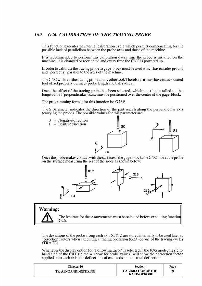
8/21/2019 CNC 8055 M Operator Manual
http://slidepdf.com/reader/full/cnc-8055-m-operator-manual 541/702
PageChapter: 16 Section:
9TRACING AND DIGITIZING
16.2 G26. CALIBRATION OF THE TRACING PROBE
This function executes an internal calibration cycle which permits compensating for the
possible lack of parallelism between the probe axes and those of the machine.
It is recommended to perform this calibration every time the probe is installed on themachine, it is changed or reoriented and every time the CNC is powered up.
In order to calibrate the tracing probe, a gage-block must be used which has its sides groundand "perfectly" parallel to the axes of the machine.
The CNC will treat the tracing probe as any other tool. Therefore, it must have its associatedtool offset properly defined (probe length and ball radius).
Once the offset of the tracing probe has been selected, which must be installed on thelongitudinal (perpendicular) axis, must be positioned over the center of the gage-block.
The programming format for this function is: G26 S
The S parameter indicates the direction of the part search along the perpendicular axis(carrying the probe). The possible values for this parameter are:
0 = Negative direction1 = Positive direction
Once the probe makes contact with the surface of the gage-block, the CNC moves the probeon the surface measuring the rest of the sides as shown below:
Warning:
The feedrate for these movements must be selected before executing functionG26.
The deviations of the probe along each axis X, Y, Z are stored internally to be used later ascorrection factors when executing a tracing operation (G23) or one of the tracing cycles(TRACE).
Whenever the display option for "Following Error" is selected in the JOG mode, the right-hand side of the CRT (in the window for probe values) will show the correction factorapplied onto each axis, the deflections of each axis and the total deflection.
CALIBRATION OF THETRACING PROBE
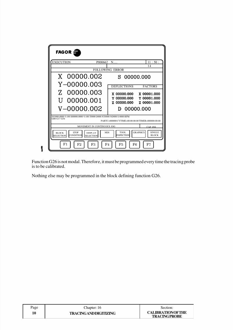
8/21/2019 CNC 8055 M Operator Manual
http://slidepdf.com/reader/full/cnc-8055-m-operator-manual 542/702
Section:Chapter: 16Page
TRACING AND DIGITIZING10
Function G26 is not modal. Therefore, it must be programmed every time the tracing probeis to be calibrated.
Nothing else may be programmed in the block defining function G26.
CALIBRATION OF THETRACING PROBE
P000662 N.....EXECUTION
FOLLOWING ERROR
CAP INS
SINGLE
BLOCKGRAPHICSTOOL
INSPECTIONMDI
DISPLAY
SELECTION
STOP
CONDITIONBLOCK
SELECTION
F03000.0000 %100 S00000.0000 %100 T0000 D000 NT0000 ND000 S 0000 RPMG00 G17 G54
PARTC=000000 CYTIME=00:00:00:00 TIMER=000000:00:00
11 : 50 :
14
DEFLECTIONS FACTORS
MOVEMENT IN CONTINUOUS JOG
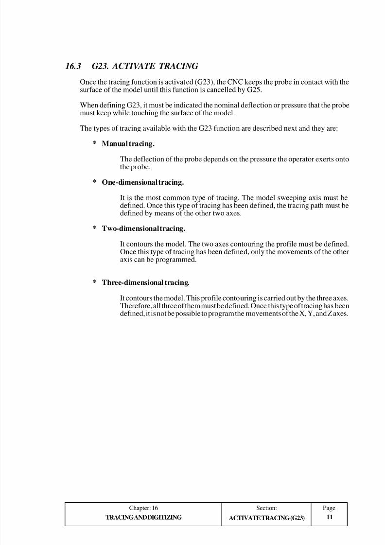
8/21/2019 CNC 8055 M Operator Manual
http://slidepdf.com/reader/full/cnc-8055-m-operator-manual 543/702
PageChapter: 16 Section:
11TRACING AND DIGITIZING
16.3 G23. ACTIVATE TRACING
Once the tracing function is activated (G23), the CNC keeps the probe in contact with thesurface of the model until this function is cancelled by G25.
When defining G23, it must be indicated the nominal deflection or pressure that the probemust keep while touching the surface of the model.
The types of tracing available with the G23 function are described next and they are:
* Manual tracing.
The deflection of the probe depends on the pressure the operator exerts ontothe probe.
* One-dimensional tracing.
It is the most common type of tracing. The model sweeping axis must bedefined. Once this type of tracing has been defined, the tracing path must bedefined by means of the other two axes.
* Two-dimensional tracing.
It contours the model. The two axes contouring the profile must be defined.Once this type of tracing has been defined, only the movements of the otheraxis can be programmed.
* Three-dimensional tracing.It contours the model. This profile contouring is carried out by the three axes.Therefore, all three of them must be defined. Once this type of tracing has beendefined, it is not be possible to program the movements of the X, Y, and Z axes.
ACTIVATE TRACING (G23)
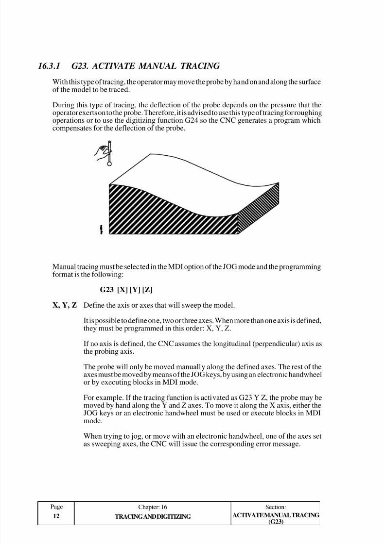
8/21/2019 CNC 8055 M Operator Manual
http://slidepdf.com/reader/full/cnc-8055-m-operator-manual 544/702
Section:Chapter: 16Page
TRACING AND DIGITIZING12
16.3.1 G23. ACTIVATE MANUAL TRACING
With this type of tracing, the operator may move the probe by hand on and along the surfaceof the model to be traced.
During this type of tracing, the deflection of the probe depends on the pressure that theoperator exerts on to the probe. Therefore, it is advised to use this type of tracing for roughingoperations or to use the digitizing function G24 so the CNC generates a program whichcompensates for the deflection of the probe.
Manual tracing must be selected in the MDI option of the JOG mode and the programmingformat is the following:
G23 [X] [Y] [Z]
X, Y, Z Define the axis or axes that will sweep the model.
It is possible to define one, two or three axes. When more than one axis is defined,they must be programmed in this order: X, Y, Z.
If no axis is defined, the CNC assumes the longitudinal (perpendicular) axis asthe probing axis.
The probe will only be moved manually along the defined axes. The rest of theaxes must be moved by means of the JOG keys, by using an electronic handwheel
or by executing blocks in MDI mode.
For example. If the tracing function is activated as G23 Y Z, the probe may bemoved by hand along the Y and Z axes. To move it along the X axis, either theJOG keys or an electronic handwheel must be used or execute blocks in MDImode.
When trying to jog, or move with an electronic handwheel, one of the axes setas sweeping axes, the CNC will issue the corresponding error message.
ACTIVATE MANUAL TRACING(G23)

8/21/2019 CNC 8055 M Operator Manual
http://slidepdf.com/reader/full/cnc-8055-m-operator-manual 545/702
PageChapter: 16 Section:
13TRACING AND DIGITIZING
Examples:
G23 X Y Z
* This option is very interesting to performroughing operations or 3-D contouring.
* The operator may move the probe by hand inall directions.
* It is not possible to jog the X, Y, Z axes ormove them with an electronic handwheel.
G23 X Y, G23 X Z , G23 YZ
* With this option it is possible to perform two-dimensional contouring or parallel tracingpasses.
* The operator may move the probe by handalong the selected axes (Y and Z in the exampleof parallel tracing passes).
* It is only possible to move, by using the JOGkeys or an electronic handwheel, the axis not
selected (X in the example of parallel tracingpasses).
* To make parallel tracing passes, the other axismust be moved by using the JOG keys or anelectronic handwheel.
G23 X , G23 Y , G23 Z
* With this option it is possible to take (capture)data on specific points of the model.
* The operator may move the probe by handonly along the selected axis.
* The other two axes must be moved using theJOG keys or an electronic handwheel.
ACTIVATE MANUAL TRACING(G23)
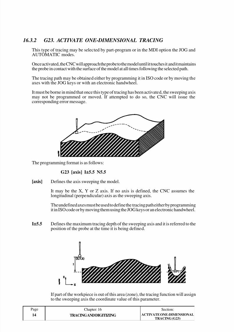
8/21/2019 CNC 8055 M Operator Manual
http://slidepdf.com/reader/full/cnc-8055-m-operator-manual 546/702
Section:Chapter: 16Page
TRACING AND DIGITIZING14
16.3.2 G23. ACTIVATE ONE-DIMENSIONAL TRACING
This type of tracing may be selected by part-program or in the MDI option the JOG andAUTOMATIC modes.
Once activated, the CNC will approach the probe to the model until it touches it and it maintainsthe probe in contact with the surface of the model at all times following the selected path.
The tracing path may be obtained either by programming it in ISO code or by moving theaxes with the JOG keys or with an electronic handwheel.
It must be borne in mind that once this type of tracing has been activated, the sweeping axismay not be programmed or moved. If attempted to do so, the CNC will issue thecorresponding error message.
The programming format is as follows:
G23 [axis] I±5.5 N5.5[axis] Defines the axis sweeping the model.
It may be the X, Y or Z axis. If no axis is defined, the CNC assumes thelongitudinal (perpendicular) axis as the sweeping axis.
The undefined axes must be used to define the tracing path either by programmingit in ISO code or by moving them using the JOG keys or an electronic handwheel.
I±5.5 Defines the maximum tracing depth of the sweeping axis and it is referred to theposition of the probe at the time it is being defined.
If part of the workpiece is out of this area (zone), the tracing function will assignto the sweeping axis the coordinate value of this parameter.
ACTIVATE ONE-DIMENSIONALTRACING (G23)
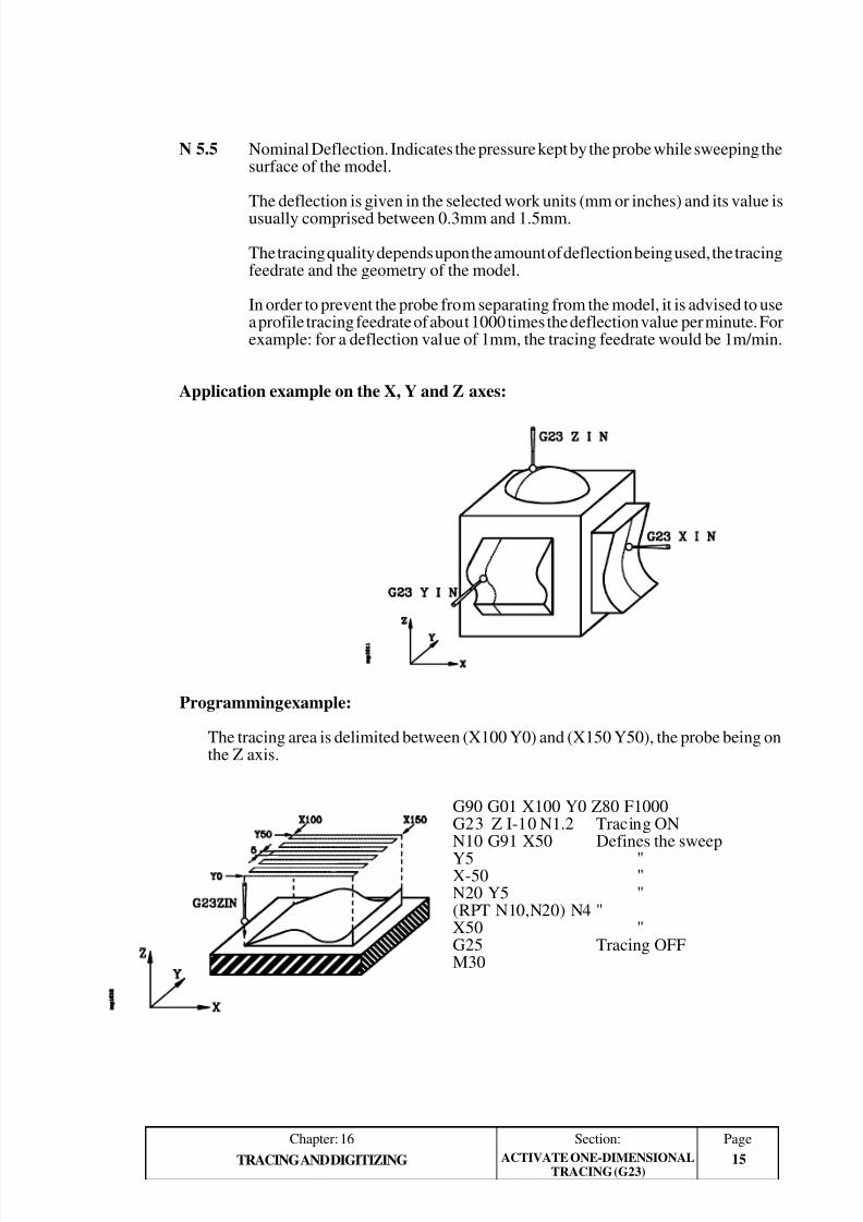
8/21/2019 CNC 8055 M Operator Manual
http://slidepdf.com/reader/full/cnc-8055-m-operator-manual 547/702
PageChapter: 16 Section:
15TRACING AND DIGITIZING
N 5.5 Nominal Deflection. Indicates the pressure kept by the probe while sweeping thesurface of the model.
The deflection is given in the selected work units (mm or inches) and its value isusually comprised between 0.3mm and 1.5mm.
The tracing quality depends upon the amount of deflection being used, the tracingfeedrate and the geometry of the model.
In order to prevent the probe from separating from the model, it is advised to usea profile tracing feedrate of about 1000 times the deflection value per minute. Forexample: for a deflection value of 1mm, the tracing feedrate would be 1m/min.
Application example on the X, Y and Z axes:
Programming example:
The tracing area is delimited between (X100 Y0) and (X150 Y50), the probe being onthe Z axis.
G90 G01 X100 Y0 Z80 F1000G23 Z I-10 N1.2 Tracing ONN10 G91 X50 Defines the sweep
Y5 "X-50 "N20 Y5 "(RPT N10,N20) N4 "X50 "G25 Tracing OFFM30
ACTIVATE ONE-DIMENSIONALTRACING (G23)
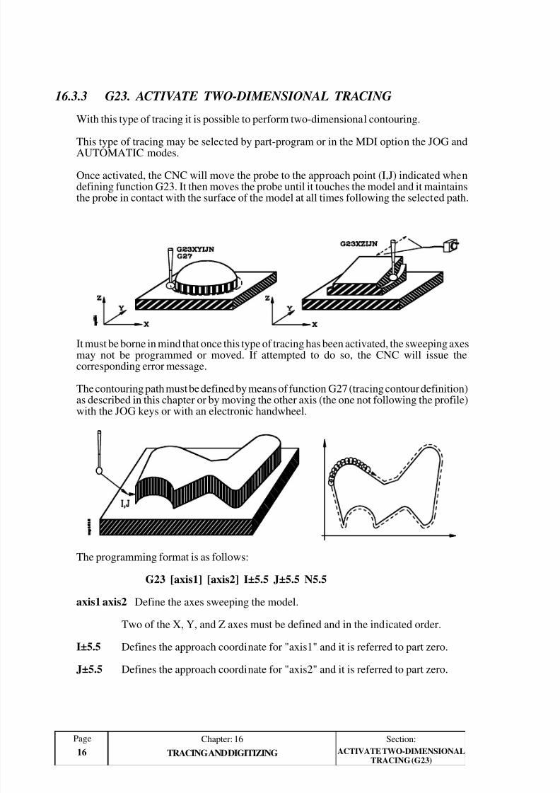
8/21/2019 CNC 8055 M Operator Manual
http://slidepdf.com/reader/full/cnc-8055-m-operator-manual 548/702
Section:Chapter: 16Page
TRACING AND DIGITIZING16
16.3.3 G23. ACTIVATE TWO-DIMENSIONAL TRACING
With this type of tracing it is possible to perform two-dimensional contouring.
This type of tracing may be selected by part-program or in the MDI option the JOG andAUTOMATIC modes.
Once activated, the CNC will move the probe to the approach point (I,J) indicated whendefining function G23. It then moves the probe until it touches the model and it maintainsthe probe in contact with the surface of the model at all times following the selected path.
It must be borne in mind that once this type of tracing has been activated, the sweeping axesmay not be programmed or moved. If attempted to do so, the CNC will issue thecorresponding error message.
The contouring path must be defined by means of function G27 (tracing contour definition)as described in this chapter or by moving the other axis (the one not following the profile)
with the JOG keys or with an electronic handwheel.
The programming format is as follows:
G23 [axis1] [axis2] I±5.5 J±5.5 N5.5
axis1 axis2 Define the axes sweeping the model.
Two of the X, Y, and Z axes must be defined and in the indicated order.
I±5.5 Defines the approach coordinate for "axis1" and it is referred to part zero.
J±5.5 Defines the approach coordinate for "axis2" and it is referred to part zero.
ACTIVATE TWO-DIMENSIONALTRACING (G23)
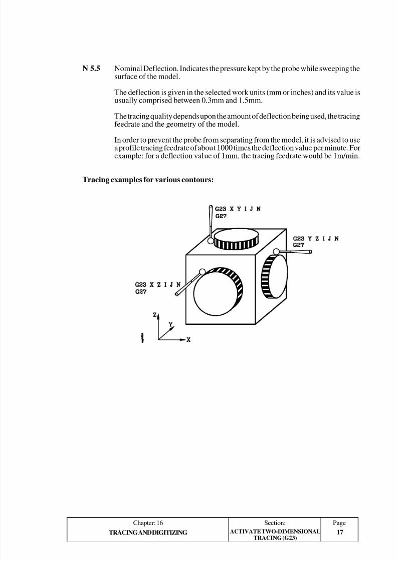
8/21/2019 CNC 8055 M Operator Manual
http://slidepdf.com/reader/full/cnc-8055-m-operator-manual 549/702
PageChapter: 16 Section:
17TRACING AND DIGITIZING
N 5.5 Nominal Deflection. Indicates the pressure kept by the probe while sweeping thesurface of the model.
The deflection is given in the selected work units (mm or inches) and its value isusually comprised between 0.3mm and 1.5mm.
The tracing quality depends upon the amount of deflection being used, the tracingfeedrate and the geometry of the model.
In order to prevent the probe from separating from the model, it is advised to usea profile tracing feedrate of about 1000 times the deflection value per minute. Forexample: for a deflection value of 1mm, the tracing feedrate would be 1m/min.
Tracing examples for various contours:
ACTIVATE TWO-DIMENSIONALTRACING (G23)
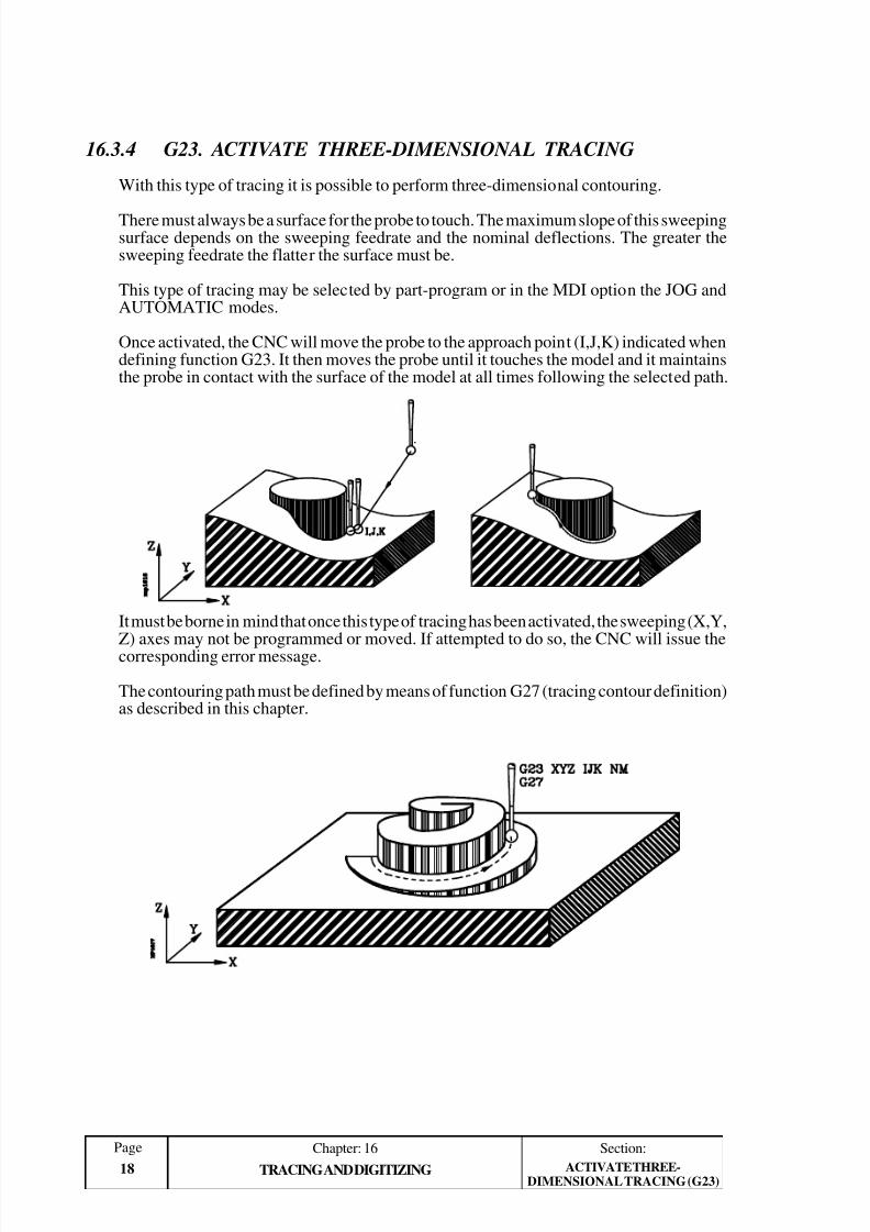
8/21/2019 CNC 8055 M Operator Manual
http://slidepdf.com/reader/full/cnc-8055-m-operator-manual 550/702
Section:Chapter: 16Page
TRACING AND DIGITIZING18
16.3.4 G23. ACTIVATE THREE-DIMENSIONAL TRACING
With this type of tracing it is possible to perform three-dimensional contouring.
There must always be a surface for the probe to touch. The maximum slope of this sweepingsurface depends on the sweeping feedrate and the nominal deflections. The greater thesweeping feedrate the flatter the surface must be.
This type of tracing may be selected by part-program or in the MDI option the JOG andAUTOMATIC modes.
Once activated, the CNC will move the probe to the approach point (I,J,K) indicated whendefining function G23. It then moves the probe until it touches the model and it maintainsthe probe in contact with the surface of the model at all times following the selected path.
It must be borne in mind that once this type of tracing has been activated, the sweeping (X,Y,
Z) axes may not be programmed or moved. If attempted to do so, the CNC will issue thecorresponding error message.
The contouring path must be defined by means of function G27 (tracing contour definition)as described in this chapter.
ACTIVATE THREE-DIMENSIONAL TRACING (G23)
8/21/2019 CNC 8055 M Operator Manual
http://slidepdf.com/reader/full/cnc-8055-m-operator-manual 551/702
PageChapter: 16 Section:
19TRACING AND DIGITIZING
The programming format is as follows:
G23 X Y Z I±5.5 J±5.5 K ±5.5 N5.5 M5.5
X, Y, Z Define the axes sweeping the model.
All three axes (X, Y, and Z) must be defined and in this order.
I±5.5 Defines the approach coordinate for X and it is referred to part zero.
J±5.5 Defines the approach coordinate for Y and it is referred to part zero.
K±5.5 Defines the approach coordinate for Z and it is referred to part zero.
N5.5 Nominal deflection for the axes forming the plane.
M 5.5 Nominal Deflection for the longitudinal (perpendicular) axis.
The N and M deflection values indicate the pressure kept by the probe whilesweeping the surface of the model.
The deflection is given in the selected work units (mm or inches) and its value isusually comprised between 0.3mm and 1.5mm.
The tracing quality depends upon the amount of deflection being used, the tracingfeedrate and the geometry of the model.
In order to prevent the probe from separating from the model, it is advised to use
a profile tracing feedrate of about 1000 times the deflection value per minute. Forexample: for a deflection value of 1mm, the tracing feedrate would be 1m/min.
ACTIVATE THREE-DIMENSIONAL TRACING (G23)

8/21/2019 CNC 8055 M Operator Manual
http://slidepdf.com/reader/full/cnc-8055-m-operator-manual 552/702
Section:Chapter: 16Page
TRACING AND DIGITIZING20
16.4 G27. TRACING CONTOUR DEFINITION
Whenever a two-dimensional or three-dimensional tracing function is activated, it isnecessary to define the tracing contour by means of function G27.
The tracing probe starts moving around the model keeping in constant contact with it in theindicated direction.
It is possible to define a closed contour (where the initial and final points are the same) oran open contour (where the initial and final points are not the same).
Example of a closed contour:
In the case of an open contour, it is necessary to define the end of the contour by means of a segment parallel to the axes. The tracing pass will end when the probe crosses this segment.
TRACING CONTOURDEFINITION
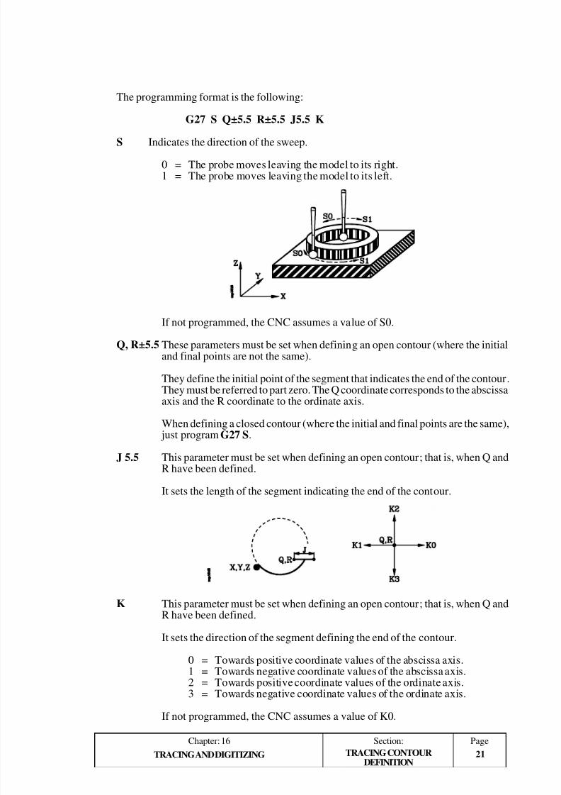
8/21/2019 CNC 8055 M Operator Manual
http://slidepdf.com/reader/full/cnc-8055-m-operator-manual 553/702
PageChapter: 16 Section:
21TRACING AND DIGITIZING
The programming format is the following:
G27 S Q±5.5 R±5.5 J5.5 K
S Indicates the direction of the sweep.
0 = The probe moves leaving the model to its right.1 = The probe moves leaving the model to its left.
If not programmed, the CNC assumes a value of S0.
Q, R±5.5 These parameters must be set when defining an open contour (where the initialand final points are not the same).
They define the initial point of the segment that indicates the end of the contour.They must be referred to part zero. The Q coordinate corresponds to the abscissaaxis and the R coordinate to the ordinate axis.
When defining a closed contour (where the initial and final points are the same), just program G27 S.
J 5.5 This parameter must be set when defining an open contour; that is, when Q andR have been defined.
It sets the length of the segment indicating the end of the contour.
K This parameter must be set when defining an open contour; that is, when Q andR have been defined.
It sets the direction of the segment defining the end of the contour.
0 = Towards positive coordinate values of the abscissa axis.1 = Towards negative coordinate values of the abscissa axis.2 = Towards positive coordinate values of the ordinate axis.
3 = Towards negative coordinate values of the ordinate axis.
If not programmed, the CNC assumes a value of K0.
TRACING CONTOURDEFINITION

8/21/2019 CNC 8055 M Operator Manual
http://slidepdf.com/reader/full/cnc-8055-m-operator-manual 554/702
Section:Chapter: 16Page
TRACING AND DIGITIZING22
Two-dimensional programming examples:
Closed two-dimensional contour:
G23 XY I50 J8 N0.8 ;Two-dimensional tracing definitionG24 L8 E5 K1 ;Digitizing definitionG27 S0 ;Closed contour definitionG25 ;Deactivate tracing and digitizing
Open two-dimensional contour:
G23 XY I60 J20 N0.8 ;Two-dimensional tracing definitionG24 L8 E5 K1 ;Digitizing definitionG27 S0 Q10 R25 J15 K0 ;Open contour definitionG25 ;Deactivate tracing and digitizing
TRACING CONTOURDEFINITION

8/21/2019 CNC 8055 M Operator Manual
http://slidepdf.com/reader/full/cnc-8055-m-operator-manual 555/702
PageChapter: 16 Section:
23TRACING AND DIGITIZING
Three-dimensional programming examples:
Closed three-dimensional contour:
G23 XYZ I8 J50 K75 N0.8 ;Three-dimensional tracing definitionG24 L8 E5 K1 ;Digitizing definitionG27 S1 ;Closed contour definitionG25 ;Deactivate tracing and digitizing
Open three-dimensional contour:
G23 XYZ I20 J50 K45 N0.8 M0.5 ;Three-dimensional tracing definitionG24 L8 E5 K1 ;Digitizing definitionG27 S1 Q80 R40 J25 K0 ;Open contour definition
G25 ;Deactivate tracing and digitizing
TRACING CONTOURDEFINITION
8/21/2019 CNC 8055 M Operator Manual
http://slidepdf.com/reader/full/cnc-8055-m-operator-manual 556/702
Section:Chapter: 16Page
TRACING AND DIGITIZING24
16.5 G25. DEACTIVATE TRACING
The tracing function can be cancelled (deactivated):
- By means of function G25 which can be programmed in any block.
- By selecting a new work plane (G16, G17, G18, G19).
- When selecting a new longitudinal (perpendicular) axis (G15).
- After executing an end of program (M02, M30).
- After an EMERGENCY or RESET.
When cancelling the tracing function (G23), the digitizing function (G24) will also be
cancelled if it was active.
DEACTIVATE TRACING (G25)
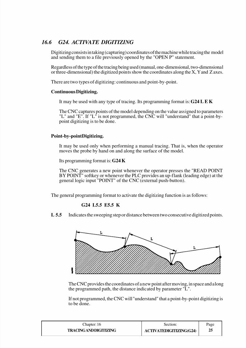
8/21/2019 CNC 8055 M Operator Manual
http://slidepdf.com/reader/full/cnc-8055-m-operator-manual 557/702
PageChapter: 16 Section:
25TRACING AND DIGITIZING
16.6 G24. ACTIVATE DIGITIZING
Digitizing consists in taking (capturing) coordinates of the machine while tracing the modeland sending them to a file previously opened by the "OPEN P" statement.
Regardless of the type of the tracing being used (manual, one-dimensional, two-dimensionalor three-dimensional) the digitized points show the coordinates along the X, Y and Z axes.
There are two types of digitizing: continuous and point-by-point.
Continuous Digitizing.
It may be used with any type of tracing. Its programming format is: G24 L E K
The CNC captures points of the model depending on the value assigned to parameters"L" and "E". If "L" is not programmed, the CNC will "understand" that a point-by-
point digitizing is to be done.
Point-by-point Digitizing.
It may be used only when performing a manual tracing. That is, when the operatormoves the probe by hand on and along the surface of the model.
Its programming format is: G24 K
The CNC generates a new point whenever the operator presses the "READ POINTBY POINT" softkey or whenever the PLC provides an up-flank (leading edge) at the
general logic input "POINT" of the CNC (external push-button).
The general programming format to activate the digitizing function is as follows:
G24 L5.5 E5.5 K
L 5.5 Indicates the sweeping step or distance between two consecutive digitized points.
The CNC provides the coordinates of a new point after moving, in space and alongthe programmed path, the distance indicated by parameter "L".
If not programmed, the CNC will "understand" that a point-by-point digitizing is
to be done.
ACTIVATE DIGITIZING (G24)

8/21/2019 CNC 8055 M Operator Manual
http://slidepdf.com/reader/full/cnc-8055-m-operator-manual 558/702
Section:Chapter: 16Page
TRACING AND DIGITIZING26
E 5.5 Indicates the chordal error or maximum difference allowed between the surface of the model and the segment joining two consecutive digitized points. It is given inthe selected work units (millimeters or inches).
If not programmed or programmed with a value of "0", the chordal error will beignored providing a new point after moving, in space and along the programmedpath, the distance indicated by parameter "L".
K Indicates the storing format for the digitized points in the program selected bymeans of the "OPEN P" statement.
K=0 Absolute format.
All points will be programmed in absolute coordinates (G90) and defined
by the X, Y and Z axes.K=1 Absolute filtered format.
All points will be programmed in absolute coordinates (G90); but onlythose axes whose positions have changed with respect to the previousdigitized point will be defined.
K=2 Incremental filtered format.
All points will be programmed in incremental coordinates (G91) andreferred to the previous digitized point. Only those axes whose positionshave changed with respect to the previous digitized point will be defined.
If not programmed, the canned cycle will assume a value of K0.
Basic concepts:
* Function G24 must be defined just before the block where the digitizing begins.
* Before activating the digitizing function (G24), it is necessary to open, by means of the "OPEN P" statement, the program which will store the digitized points.
ACTIVATE DIGITIZING (G24)

8/21/2019 CNC 8055 M Operator Manual
http://slidepdf.com/reader/full/cnc-8055-m-operator-manual 559/702
PageChapter: 16 Section:
27TRACING AND DIGITIZING
If instead of storing the digitized points in a CNC program, it is desired to store themin a peripheral device or PC via DNC, it must be so indicated when defining the"OPEN P" statement.
When communicating via DNC, if the data transmission rate is lower than the dataacquisition (capture) speed, the resulting tracing operation will be slower.
* During the digitizing of the model, the CNC only controls the movements of the X,Y, Z axes. Therefore, the generated program blocks will only contain some or all of these axes.
* No points will be generated while the probe is seeking the model or when it is off the surface of the model.
* The CNC takes into account the deflections of the probe when calculating thecoordinates of the new digitized point.
* To deactivate the digitizing function, program G25.
The digitizing function is also cancelled (deactivated) when deactivating the tracingfunction (G23) and, consequently, in the following instances:
- When selecting a new work plane (G16, G17, G18, G19).
- When selecting a new longitudinal (perpendicular) axis (G15).
- After executing an end of program (M02, M30).
- After an EMERGENCY or RESET.
Programming example:
G17 Selects the Z axis as longitudinal (perpendicular)G90 G01 X65 Y0 F1000 Positioning(OPEN P12345) Program receiving (storing) digitized data(WRITE G01 G05 F1000)G23 Z I-10 N1 Tracing ONG24 L8 E5 K1 Digitizing ONG1 X100 Y35 Define tracing path
" "
" "G25 Cancel tracing and digitizingM30
ACTIVATE DIGITIZING (G24)
8/21/2019 CNC 8055 M Operator Manual
http://slidepdf.com/reader/full/cnc-8055-m-operator-manual 560/702
Section:Chapter: 16Page
TRACING AND DIGITIZING28
16.7 TRACING AND DIGITIZING CANNED CYCLES
The tracing/digitizing canned cycles offered by this CNC are based on the types of tracingdescribed earlier and they are the following:
TRACE 1 Tracing / digitizing in a grid patternTRACE 2 Tracing / digitizing in an arc pattern.TRACE 3 Profile tracing / digitizing in the planeTRACE 4 3-D Profile tracing / digitizing (in space)TRACE 5 Tracing / digitizing with polygonal sweep.
They are programmed by means of the high level instruction TRACE. The cycle numbermay be indicated either by a number (1, 2, 3, 4, 5) or by an expression whose result is oneof these numbers.
They all have a series of parameters defining the tracing path and the digitizing conditions.
To just trace the part without digitizing it, the digitizing parameters must be set to "0".
To digitize the model, besides setting the digitizing parameters, the following points mustbe considered:
* Before calling the canned cycle, it is required to open the program which will storethe digitized data by means of the "OPEN P" statement.
* If the captured data is supposed to be stored at a peripheral device or computer viaDNC instead of doing it at the CNC part-memory, it must be so indicated whendefining the "OPEN P" statement.
* It must be borne in mind that the generated program blocks are positioning only (G01X Y Z). Therefore, it is convenient to also include in such program the machiningconditions by using the "WRITE" statement.
* Once the digitizing process is over, an end-of-program (M02 or M30) must also bewritten by means of the "WRITE" statement.
Once the tracing cycle is over, the probe will be positioned where it was before executingthe cycle.
The execution of a tracing canned cycle does not change the history of the previous "G"functions.
TRACING & DIGITIZINGCANNED CYCLES

8/21/2019 CNC 8055 M Operator Manual
http://slidepdf.com/reader/full/cnc-8055-m-operator-manual 561/702
PageChapter: 16 Section:
29TRACING AND DIGITIZING
16.7.1 GRID -PATTERN TRACING CANNED CYCLE
The programming format for this cycle is as follows:
(TRACE 1, X, Y, Z, I, J, K, A, C, Q, D, N, L, E, G, H, F)
X±5.5 Theoretical absolute coordinate value along the abscissa axis of the first probingpoint. It must coincide with one of the corners of the grid.
Y±5.5 Theoretical absolute coordinate value along the ordinate axis of the first probing
point. It must coincide with one of the corners of the grid.Z±5.5 Theoretical coordinate value along the probing axis (longitudinal/perpendicular)
where the probe is to be positioned before starting the tracing operation.
It is given in absolute values and it must be off the model maintaining a safetydistance from its outermost surface.
I±5.5 Defines the maximum tracing depth and it is referred to the coordinate value givento parameter Z.
If part of the model is out of this area, the tracing will assign this maximum depthto the probing axis and will continue executing the tracing cycle without issuingan error.
If programmed with a value of "0", the CNC will issue the corresponding error.
GRID PATTERN TRACINGCANNED CYCLE

8/21/2019 CNC 8055 M Operator Manual
http://slidepdf.com/reader/full/cnc-8055-m-operator-manual 562/702
Section:Chapter: 16Page
TRACING AND DIGITIZING30
J±5.5 Defines the length of the grid along the abscissa axis. The positive sign indicatesthat the grid is located to the right of the point (X, Y) and the negative sign that itis to the left of that point.
K±5.5 Defines the length of the grid along the ordinate axis. The positive sign indicates thatthe grid is located above the point (X, Y) and the negative sign that it is below that point.
A 5.5 Defines the angle of the sweeping path.
It must be comprised between 0º (included) and 90º (not included). If notprogrammed, the canned cycle will assume a value of "A0".
C±5.5 Defines the distance which will be maintained between two tracing passes.
If programmed with a positive value, the tracing operation will be carried out alongthe abscissa axis and the distance will be taken along the ordinate axis. On the otherhand, if programmed with a negative value, the tracing operation will be carriedout along the ordinate axis and the distance will be taken along the abscissa axis.
If programmed with a value of 0, the CNC will issue the corresponding error.
Q 5.5 Defines the angle of the incremental path.
It must be comprised between 0º and 45º (both included). If not programmed orif an one-directional tracing is programmed (D=1), the canned cycle will assumea value of "Q0".
GRID PATTERN TRACINGCANNED CYCLE

8/21/2019 CNC 8055 M Operator Manual
http://slidepdf.com/reader/full/cnc-8055-m-operator-manual 563/702
PageChapter: 16 Section:
31TRACING AND DIGITIZING
D Indicates how the grid is followed according to this code:
0 = The tracing is carried out in both directions (zig-zag).1 = The tracing is carried out following the grid in one direction.
If not programmed, the canned cycle assumes a value of "D0".
N 5.5 Nominal Deflection. Indicates the pressure kept by the probe while sweeping thesurface of the model.
The deflection is given in the selected work units (mm or inches) and its value isusually comprised between 0.3mm and 1.5mm.
The tracing quality depends upon the amount of deflection being used, the tracingfeedrate and the geometry of the model.
In order to prevent the probe from separating from the model, it is advised to usea profile tracing feedrate of about 1000 times the deflection value per minute. Forexample: for a deflection value of 1mm, the tracing feedrate would be 1m/min.
If not programmed, the canned cycle will assume a value of 1mm (0.03937").
L 5.5 This parameter must be defined when digitizing a part besides tracing it.
It indicates the sweeping step or distance between two consecutive digitizedpoints.
GRID PATTERN TRACINGCANNED CYCLE

8/21/2019 CNC 8055 M Operator Manual
http://slidepdf.com/reader/full/cnc-8055-m-operator-manual 564/702
Section:Chapter: 16Page
TRACING AND DIGITIZING32
The CNC keeps the probe in constant contact with the surface of the model andit provides the coordinates of a new point after moving, in space and along theprogrammed path, the distance indicated by parameter "L".
If not programmed or programmed with a value of "0", the canned cycle willassume that the model is not to be digitized.
E 5.5 This parameter must be defined when digitizing the model besides tracing it.
It indicates the chordal error or maximum difference allowed between the surfaceof the model and the segment joining two consecutive digitized points. It is givenin the selected work units (millimeters or inches).
If not programmed or programmed with a value of "0", the chordal error will beignored and a new point will be provided after moving the "L" distance in spaceand along the programmed path.
G This parameter must be defined when digitizing the model besides tracing it.
Indicates the storing format for the digitized points in the program selected bymeans of the "OPEN P" statement.
G=0 Absolute format.
All points will be programmed in absolute coordinates (G90) and definedby the X, Y and Z axes.
G=1 Absolute filtered format.
All points will be programmed in absolute coordinates (G90); but onlythose axes whose positions have changed with respect to the previousdigitized point will be defined.
GRID PATTERN TRACINGCANNED CYCLE
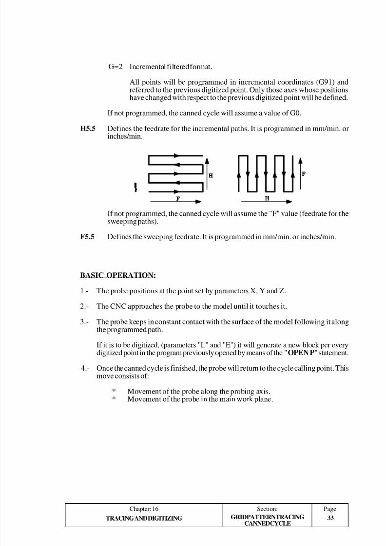
8/21/2019 CNC 8055 M Operator Manual
http://slidepdf.com/reader/full/cnc-8055-m-operator-manual 565/702
PageChapter: 16 Section:
33TRACING AND DIGITIZING
G=2 Incremental filtered format.
All points will be programmed in incremental coordinates (G91) andreferred to the previous digitized point. Only those axes whose positionshave changed with respect to the previous digitized point will be defined.
If not programmed, the canned cycle will assume a value of G0.
H5.5 Defines the feedrate for the incremental paths. It is programmed in mm/min. orinches/min.
If not programmed, the canned cycle will assume the "F" value (feedrate for thesweeping paths).
F5.5 Defines the sweeping feedrate. It is programmed in mm/min. or inches/min.
BASIC OPERATION:
1.- The probe positions at the point set by parameters X, Y and Z.
2.- The CNC approaches the probe to the model until it touches it.
3.- The probe keeps in constant contact with the surface of the model following it alongthe programmed path.
If it is to be digitized, (parameters "L" and "E") it will generate a new block per everydigitized point in the program previously opened by means of the "OPEN P" statement.
4.- Once the canned cycle is finished, the probe will return to the cycle calling point. Thismove consists of:
* Movement of the probe along the probing axis.* Movement of the probe in the main work plane.
GRID PATTERN TRACINGCANNED CYCLE

8/21/2019 CNC 8055 M Operator Manual
http://slidepdf.com/reader/full/cnc-8055-m-operator-manual 566/702
Section:Chapter: 16Page
TRACING AND DIGITIZING34
16.7.2 ARC PATTERN TRACING CANNED CYCLE
The programming format for this cycle is as follows:
(TRACE 2, X, Y, Z, I, J, K, A, B, C, D, R, N, L, E, G, H, F)
X±5.5 Theoretical absolute coordinate of the arc center along the abscissa axis.
Y±5.5 Theoretical absolute coordinate of the arc center along the ordinate axis.
Z±5.5 Theoretical coordinate along the probing axis (longitudinal / perpendicular) where
the probe is to be positioned before starting the tracing operation.It is given in absolute values and it must be off the model at a safety distance fromits outermost surface.
I±5.5 Defines the maximum tracing depth and it is referred to the coordinate value givento parameter Z.
If part of the model is out of this area, the tracing will assign this maximum depth to theprobing axis and will continue executing the tracing cycle without issuing an error.
ARC PATTERN TRACINGCANNED CYCLE

8/21/2019 CNC 8055 M Operator Manual
http://slidepdf.com/reader/full/cnc-8055-m-operator-manual 567/702
PageChapter: 16 Section:
35TRACING AND DIGITIZING
If programmed with a value of "0", the CNC will issue the corresponding error.
J 5.5 Defines the radius of the outermost tracing arc. It must be given a positive valuegreater than "0".
K 5.5 Defines the radius of the inmost tracing arc. It must be given a positive value.
If not programmed, the canned cycle will assume a value of K0.
A 5.5 Defines the angle formed by the starting point of the tracing operation and theabscissa axis.
If not programmed, the canned cycle will assume a value of "A0".
B 5.5 Defines the angle formed by the other end of the arcs and the abscissa axis.
If not programmed, the canned cycle will assume a value of "B360".
To trace around a complete circle, A and B must be assigned either the same valueor none. Thus, the canned cycle will assume, by default A0 and B360.
C 5.5 Defines the distance between two consecutive tracing passes.
It is programmed in millimeters or inches when defining circular paths (R0) and indegrees when linear paths (R1). It must be set to a positive value greater than "0".
ARC PATTERN TRACINGCANNED CYCLE
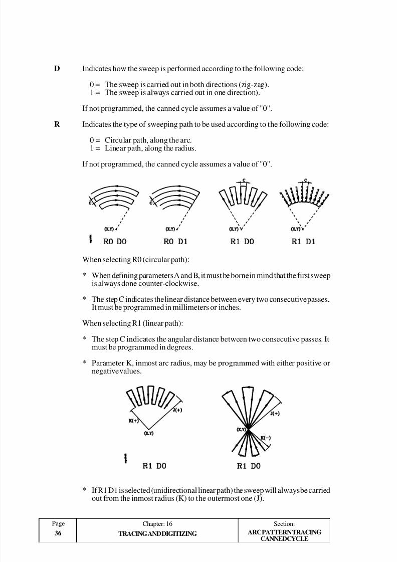
8/21/2019 CNC 8055 M Operator Manual
http://slidepdf.com/reader/full/cnc-8055-m-operator-manual 568/702
Section:Chapter: 16Page
TRACING AND DIGITIZING36
D Indicates how the sweep is performed according to the following code:
0 = The sweep is carried out in both directions (zig-zag).1 = The sweep is always carried out in one direction).
If not programmed, the canned cycle assumes a value of "0".
R Indicates the type of sweeping path to be used according to the following code:
0 = Circular path, along the arc.1 = Linear path, along the radius.
If not programmed, the canned cycle assumes a value of "0".
When selecting R0 (circular path):
* When defining parameters A and B, it must be borne in mind that the first sweepis always done counter-clockwise.
* The step C indicates the linear distance between every two consecutive passes.It must be programmed in millimeters or inches.
When selecting R1 (linear path):
* The step C indicates the angular distance between two consecutive passes. Itmust be programmed in degrees.
* Parameter K, inmost arc radius, may be programmed with either positive ornegative values.
* If R1 D1 is selected (unidirectional linear path) the sweep will always be carriedout from the inmost radius (K) to the outermost one (J).
ARC PATTERN TRACINGCANNED CYCLE

8/21/2019 CNC 8055 M Operator Manual
http://slidepdf.com/reader/full/cnc-8055-m-operator-manual 569/702
PageChapter: 16 Section:
37TRACING AND DIGITIZING
N 5.5 Nominal Deflection. Indicates the pressure kept by the probe while sweeping thesurface of the model.
The deflection is given in the selected work units (mm or inches) and its value isusually comprised between 0.3mm and 1.5mm.
The tracing quality depends upon the amount of deflection being used, the tracingfeedrate and the geometry of the model.
In order to prevent the probe from separating from the model, it is advised to usea profile tracing feedrate of about 1000 times the deflection value per minute. Forexample: for a deflection value of 1mm, the tracing feedrate would be 1m/min.
If not programmed, the canned cycle will assume the value of 1mm (0.03937").
L 5.5 This parameter must be defined when digitizing a part besides tracing it.
It indicates the sweeping step of distance between two consecutive digitizedpoints.
The CNC keeps the probe in constant contact with the surface of the model andit provides the coordinates of a new point after moving, in space and along theprogrammed path, the distance indicated by parameter "L".
If not programmed or programmed with a value of "0", the canned cycle willassume that the model is not to be digitized.
E 5.5 This parameter must be defined when digitizing a part besides tracing it.
It indicates the chordal error or maximum difference allowed between the surfaceof the model and the segment joining two consecutive digitized points. It is givenin the selected work units (millimeters or inches).
ARC PATTERN TRACINGCANNED CYCLE

8/21/2019 CNC 8055 M Operator Manual
http://slidepdf.com/reader/full/cnc-8055-m-operator-manual 570/702
Section:Chapter: 16Page
TRACING AND DIGITIZING38
If not programmed or programmed with a value of "0", the chordal error will beignored and a new point will be provided after moving the "L" distance in spaceand along the programmed path.
G This parameter must be defined when digitizing the model besides tracing it.
Indicates the storing format for the digitized points in the program selected bymeans of the "OPEN P" statement.
G=0 Absolute format.
All points will be programmed in absolute coordinates (G90) and definedby the X, Y and Z axes.
G=1 Absolute filtered format..
All points will be programmed in absolute coordinates (G90); but onlythose axes whose positions have changed with respect to the previousdigitized point will be defined.
G=2 Incremental filtered format..
All points will be programmed in incremental coordinates (G91) andreferred to the previous digitized point. Only those axes whose positionshave changed with respect to the previous digitized point will be defined.
If not programmed, the canned cycle will assume a value of G0.
H5.5 Defines the feedrate for the incremental paths. It is programmed in mm/min. orinches/min.
ARC PATTERN TRACINGCANNED CYCLE

8/21/2019 CNC 8055 M Operator Manual
http://slidepdf.com/reader/full/cnc-8055-m-operator-manual 571/702
PageChapter: 16 Section:
39TRACING AND DIGITIZING
If not programmed, the canned cycle will assume the F value (feedrate for thesweeping paths).
F5.5 Defines the sweeping feedrate. It is given in mm/min or inches/min.
BASIC OPERATION:
1.- The probe positions at the point set by parameters X, Y and Z.
2.- The CNC approaches the probe to the model until it touches it.
3.- The probe keeps in constant contact with the surface of the model following it alongthe programmed path.
If it is to be digitized, (parameters "L" and "E") it will generate a new block per everydigitized point in the program previously opened by means of the "OPEN P"statement.
4.- Once the canned cycle is finished, the probe will return to the cycle calling point. Thismove consists of:
* Movement of the probe along the probing axis.* Movement of the probe in the main work plane.
ARC PATTERN TRACINGCANNED CYCLE

8/21/2019 CNC 8055 M Operator Manual
http://slidepdf.com/reader/full/cnc-8055-m-operator-manual 572/702
Section:Chapter: 16Page
TRACING AND DIGITIZING40
16.7.3 PROFILE TRACING CANNED CYCLE ALONG A PLANE
The programming format for this cycle is as follows:
(TRACE 3, X, Y, Z, I, D, B, A, C, S, Q, R, J, K, N, L, E, G, H, F)
X±5.5 Absolute theoretical coordinate value along the abscissa axis of the approachpoint. It must be off the model.
Y±5.5 Absolute theoretical coordinate value along the ordinate axis of the approachpoint. It must be off the model.
Z±5.5 Absolute theoretical coordinate value along the probing axis (longitudinal / perpendicular)where the probe is to be positioned before starting the tracing operation.
It must be off the model at a safety distance from its outermost surface.
I±5.5 Theoretical coordinate value along the probing axis (longitudinal / perpendicular)where the final tracing pass will be carried out.
D 5.5 Defines, along the probing axis, the distance between the "Z" position of the probe(described above) and the plane where the first tracing pass will be carried out.
If not programmed, the CNC will only make one tracing pass at the heightindicated by parameter "I".
B 5.5 This parameters must be defined whenever parameter "D" is defined.
Defines, along the probing axis, the distance between two consecutive tracingpasses.
If programmed with a value of "0", the CNC will issue the corresponding error.
A Indicates the tracing direction of the probe after positioning at X Y Z and having comedown to the plane where the first tracing pass will be carried out seeking the model.
PLANE PROFILE TRACINGCANNED CYCLE
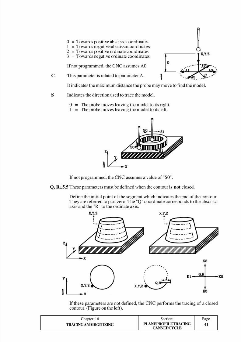
8/21/2019 CNC 8055 M Operator Manual
http://slidepdf.com/reader/full/cnc-8055-m-operator-manual 573/702
PageChapter: 16 Section:
41TRACING AND DIGITIZING
0 = Towards positive abscissa coordinates1 = Towards negative abscissa coordinates2 = Towards positive ordinate coordinates3 = Towards negative ordinate coordinates
If not programmed, the CNC assumes A0
C This parameter is related to parameter A.
It indicates the maximum distance the probe may move to find the model.
S Indicates the direction used to trace the model.
0 = The probe moves leaving the model to its right.1 = The probe moves leaving the model to its left.
If not programmed, the CNC assumes a value of "S0".Q, R±5.5 These parameters must be defined when the contour is not closed.
Define the initial point of the segment which indicates the end of the contour.They are referred to part zero. The "Q" coordinate corresponds to the abscissaaxis and the "R" to the ordinate axis.
If these parameters are not defined, the CNC performs the tracing of a closedcontour. (Figure on the left).
PLANE PROFILE TRACINGCANNED CYCLE
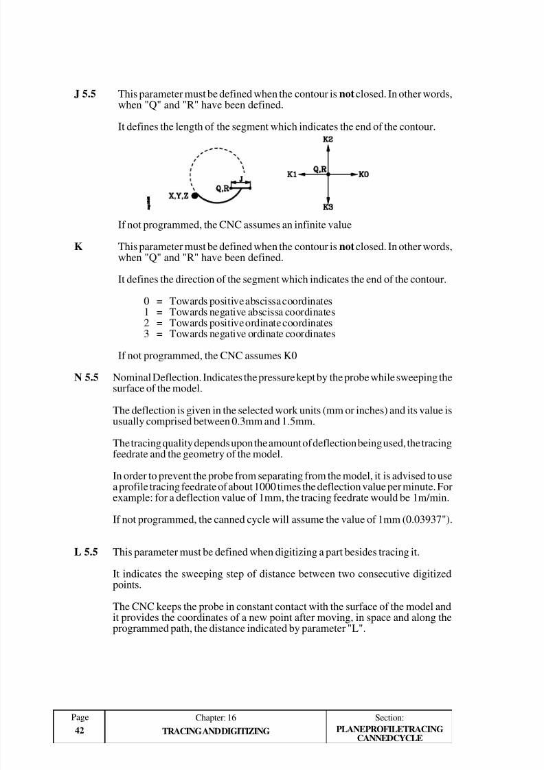
8/21/2019 CNC 8055 M Operator Manual
http://slidepdf.com/reader/full/cnc-8055-m-operator-manual 574/702
Section:Chapter: 16Page
TRACING AND DIGITIZING42
J 5.5 This parameter must be defined when the contour is not closed. In other words,when "Q" and "R" have been defined.
It defines the length of the segment which indicates the end of the contour.
If not programmed, the CNC assumes an infinite value
K This parameter must be defined when the contour is not closed. In other words,when "Q" and "R" have been defined.
It defines the direction of the segment which indicates the end of the contour.
0 = Towards positive abscissa coordinates1 = Towards negative abscissa coordinates2 = Towards positive ordinate coordinates3 = Towards negative ordinate coordinates
If not programmed, the CNC assumes K0
N 5.5 Nominal Deflection. Indicates the pressure kept by the probe while sweeping thesurface of the model.
The deflection is given in the selected work units (mm or inches) and its value isusually comprised between 0.3mm and 1.5mm.
The tracing quality depends upon the amount of deflection being used, the tracingfeedrate and the geometry of the model.
In order to prevent the probe from separating from the model, it is advised to usea profile tracing feedrate of about 1000 times the deflection value per minute. Forexample: for a deflection value of 1mm, the tracing feedrate would be 1m/min.
If not programmed, the canned cycle will assume the value of 1mm (0.03937").
L 5.5 This parameter must be defined when digitizing a part besides tracing it.
It indicates the sweeping step of distance between two consecutive digitizedpoints.
The CNC keeps the probe in constant contact with the surface of the model andit provides the coordinates of a new point after moving, in space and along theprogrammed path, the distance indicated by parameter "L".
PLANE PROFILE TRACINGCANNED CYCLE
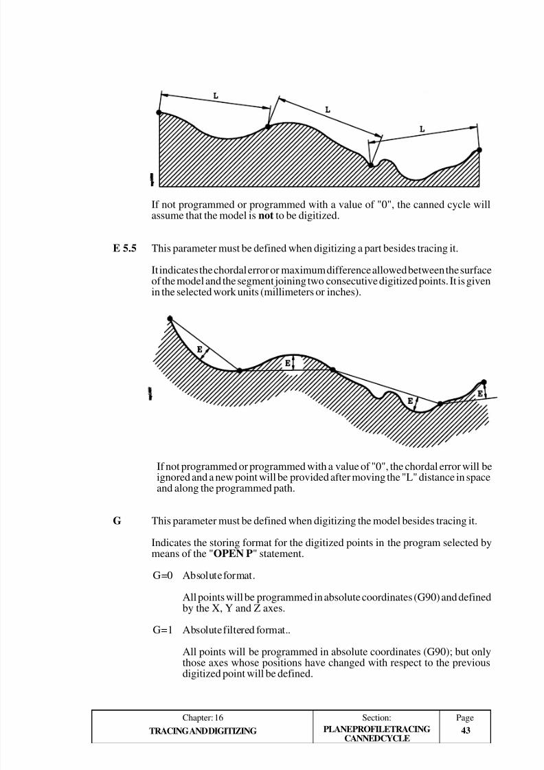
8/21/2019 CNC 8055 M Operator Manual
http://slidepdf.com/reader/full/cnc-8055-m-operator-manual 575/702
PageChapter: 16 Section:
43TRACING AND DIGITIZING
If not programmed or programmed with a value of "0", the canned cycle willassume that the model is not to be digitized.
E 5.5 This parameter must be defined when digitizing a part besides tracing it.
It indicates the chordal error or maximum difference allowed between the surfaceof the model and the segment joining two consecutive digitized points. It is givenin the selected work units (millimeters or inches).
If not programmed or programmed with a value of "0", the chordal error will beignored and a new point will be provided after moving the "L" distance in spaceand along the programmed path.
G This parameter must be defined when digitizing the model besides tracing it.
Indicates the storing format for the digitized points in the program selected bymeans of the "OPEN P" statement.
G=0 Absolute format.
All points will be programmed in absolute coordinates (G90) and definedby the X, Y and Z axes.
G=1 Absolute filtered format..
All points will be programmed in absolute coordinates (G90); but onlythose axes whose positions have changed with respect to the previous
digitized point will be defined.
PLANE PROFILE TRACINGCANNED CYCLE

8/21/2019 CNC 8055 M Operator Manual
http://slidepdf.com/reader/full/cnc-8055-m-operator-manual 576/702
Section:Chapter: 16Page
TRACING AND DIGITIZING44
G=2 Incremental filtered format..
All points will be programmed in incremental coordinates (G91) andreferred to the previous digitized point. Only those axes whose positionshave changed with respect to the previous digitized point will be defined.
If not programmed, the canned cycle will assume a value of G0.
H5.5 Defines the feedrate for the incremental paths. It is programmed in mm/min. orinches/min.
If not programmed, the canned cycle will assume the F value (feedrate for thesweeping paths).
F5.5 Defines the sweeping feedrate. It is given in mm/min or inches/min.
BASIC OPERATION:
1.- The probe positions at the point set by parameters X, Y and Z.
2.- The CNC approaches the probe to the model until it touches it.
3.- The probe keeps in constant contact with the surface of the model following it alongthe programmed path.
If it is to be digitized, (parameters "L" and "E") it will generate a new block per everydigitized point in the program previously opened by means of the "OPEN P"statement.
4.- Once the canned cycle is finished, the probe will return to the cycle calling point. Thismove consists of:
* Movement of the probe along the probing axis.* Movement of the probe in the main work plane.
PLANE PROFILE TRACINGCANNED CYCLE

8/21/2019 CNC 8055 M Operator Manual
http://slidepdf.com/reader/full/cnc-8055-m-operator-manual 577/702
PageChapter: 16 Section:
45TRACING AND DIGITIZING
16.7.4 3-D PROFILE TRACING CANNED CYCLE
The programming format for this cycle is as follows:
(TRACE 4, X, Y, Z, I, A, C, S, Q, R, J, K, M, N, L, E, G, F)
X±5.5 Absolute theoretical coordinate value along the abscissa axis of the approachpoint. It must be off the model.
Y±5.5 Absolute theoretical coordinate value along the ordinate axis of the approachpoint. It must be off the model.
Z±5.5 Absolute theoretical coordinate value along the probing axis (longitudinal / perpendicular) of the approach point.
It must be off the model and over it since the first movement, to seek the model,is carried out in the work plane.
I±5.5 Defines the maximum tracing depth and it is referred to the coordinate value givento parameter Z.
If part of the model is out of this area, the tracing will assign this maximum depthto the probing axis and will continue executing the tracing cycle without issuingan error.
If programmed with a value of "0", the CNC will issue the corresponding error.
3-D PROFILE TRACINGCANNED CYCLE
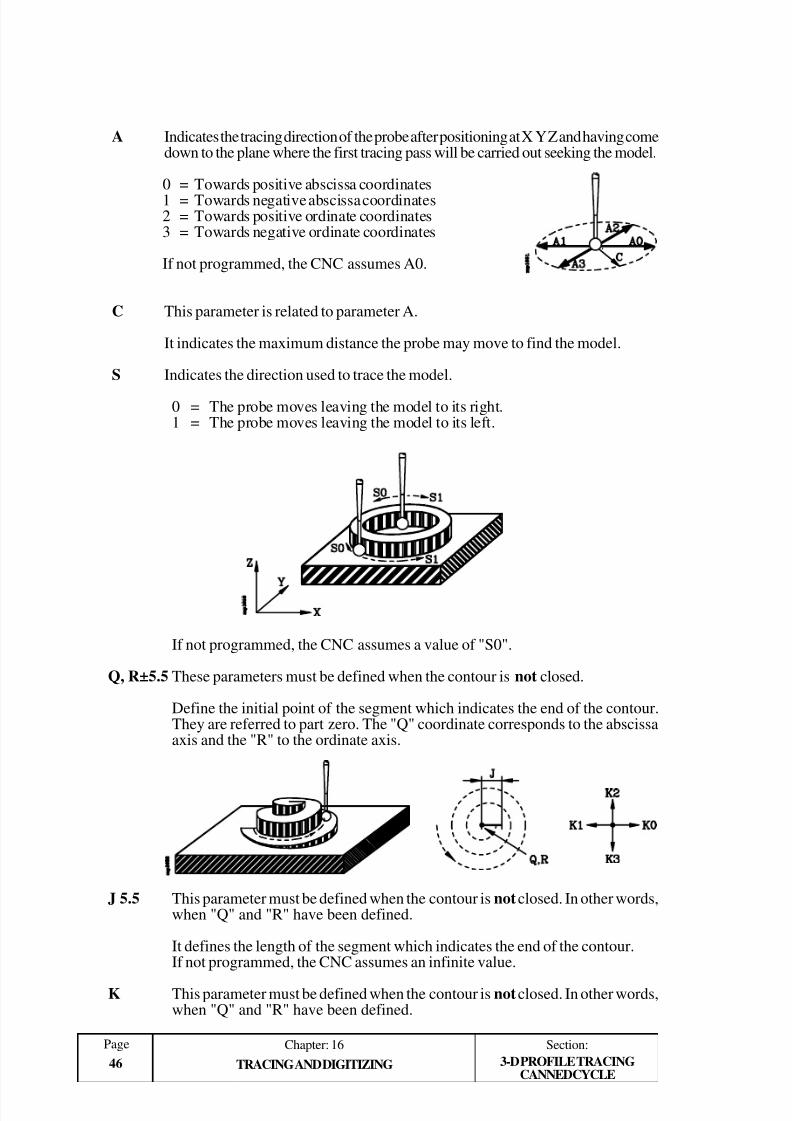
8/21/2019 CNC 8055 M Operator Manual
http://slidepdf.com/reader/full/cnc-8055-m-operator-manual 578/702
Section:Chapter: 16Page
TRACING AND DIGITIZING46
A Indicates the tracing direction of the probe after positioning at X Y Z and having comedown to the plane where the first tracing pass will be carried out seeking the model.
0 = Towards positive abscissa coordinates1 = Towards negative abscissa coordinates2 = Towards positive ordinate coordinates3 = Towards negative ordinate coordinates
If not programmed, the CNC assumes A0.
C This parameter is related to parameter A.
It indicates the maximum distance the probe may move to find the model.
S Indicates the direction used to trace the model.
0 = The probe moves leaving the model to its right.1 = The probe moves leaving the model to its left.
If not programmed, the CNC assumes a value of "S0".
Q, R±5.5 These parameters must be defined when the contour is not closed.
Define the initial point of the segment which indicates the end of the contour.They are referred to part zero. The "Q" coordinate corresponds to the abscissaaxis and the "R" to the ordinate axis.
J 5.5 This parameter must be defined when the contour is not closed. In other words,when "Q" and "R" have been defined.
It defines the length of the segment which indicates the end of the contour.If not programmed, the CNC assumes an infinite value.
K This parameter must be defined when the contour is not closed. In other words,when "Q" and "R" have been defined.
3-D PROFILE TRACINGCANNED CYCLE
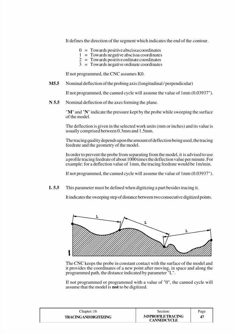
8/21/2019 CNC 8055 M Operator Manual
http://slidepdf.com/reader/full/cnc-8055-m-operator-manual 579/702
PageChapter: 16 Section:
47TRACING AND DIGITIZING
It defines the direction of the segment which indicates the end of the contour.
0 = Towards positive abscissa coordinates1 = Towards negative abscissa coordinates2 = Towards positive ordinate coordinates3 = Towards negative ordinate coordinates
If not programmed, the CNC assumes K0.
M5.5 Nominal deflection of the probing axis (longitudinal / perpendicular)
If not programmed, the canned cycle will assume the value of 1mm (0.03937").
N 5.5 Nominal deflection of the axes forming the plane.
"M" and "N" indicate the pressure kept by the probe while sweeping the surface
of the model.
The deflection is given in the selected work units (mm or inches) and its value isusually comprised between 0.3mm and 1.5mm.
The tracing quality depends upon the amount of deflection being used, the tracingfeedrate and the geometry of the model.
In order to prevent the probe from separating from the model, it is advised to usea profile tracing feedrate of about 1000 times the deflection value per minute. Forexample: for a deflection value of 1mm, the tracing feedrate would be 1m/min.
If not programmed, the canned cycle will assume the value of 1mm (0.03937").
L 5.5 This parameter must be defined when digitizing a part besides tracing it.
It indicates the sweeping step of distance between two consecutive digitized points.
The CNC keeps the probe in constant contact with the surface of the model andit provides the coordinates of a new point after moving, in space and along theprogrammed path, the distance indicated by parameter "L".
If not programmed or programmed with a value of "0", the canned cycle willassume that the model is not to be digitized.
3-D PROFILE TRACINGCANNED CYCLE

8/21/2019 CNC 8055 M Operator Manual
http://slidepdf.com/reader/full/cnc-8055-m-operator-manual 580/702
Section:Chapter: 16Page
TRACING AND DIGITIZING48
E 5.5 This parameter must be defined when digitizing a part besides tracing it.
It indicates the chordal error or maximum difference allowed between the surfaceof the model and the segment joining two consecutive digitized points. It is givenin the selected work units (millimeters or inches).
If not programmed or programmed with a value of "0", the chordal error will beignored and a new point will be provided after moving the "L" distance in spaceand along the programmed path.
G This parameter must be defined when digitizing the model besides tracing it.
Indicates the storing format for the digitized points in the program selected by
means of the "OPEN P" statement.G=0 Absolute format.
All points will be programmed in absolute coordinates (G90) and definedby the X, Y and Z axes.
G=1 Absolute filtered format..
All points will be programmed in absolute coordinates (G90); but onlythose axes whose positions have changed with respect to the previousdigitized point will be defined.
G=2 Incremental filtered format..
All points will be programmed in incremental coordinates (G91) andreferred to the previous digitized point. Only those axes whose positionshave changed with respect to the previous digitized point will be defined.
If not programmed, the canned cycle will assume a value of G0.
F5.5 Defines the sweeping feedrate. It is given in mm/min or inches/min.
3-D PROFILE TRACINGCANNED CYCLE

8/21/2019 CNC 8055 M Operator Manual
http://slidepdf.com/reader/full/cnc-8055-m-operator-manual 581/702
PageChapter: 16 Section:
49TRACING AND DIGITIZING
BASIC OPERATION:
1.- The probe positions at the point set by parameters X, Y and Z.
2.- The CNC approaches the probe to the model until it touches it.
3.- The probe keeps in constant contact with the surface of the model following it alongthe programmed path.
If it is to be digitized, (parameters "L" and "E") it will generate a new block per everydigitized point in the program previously opened by means of the "OPEN P"statement.
4.- Once the canned cycle is finished, the probe will return to the cycle calling point. Thismove consists of:
* Movement of the probe along the probing axis.* Movement of the probe in the main work plane.
3-D PROFILE TRACINGCANNED CYCLE

8/21/2019 CNC 8055 M Operator Manual
http://slidepdf.com/reader/full/cnc-8055-m-operator-manual 582/702
Section:Chapter: 16Page
TRACING AND DIGITIZING50
16.7.5 TRACING CANNED CYCLE WITH POLYGONAL SWEEP
With this option it is possible to delimit the tracing area by means of simple geometricelements (straight lines and arcs).
It is also possible to define some zones inside the main tracing area which are not to betraced. These inside zones will be referred to as islands.
The programming format for this cycle is as follows:
(TRACE 5, A, Z, I, C, D, N, L, E, G, H, F, P, U)
A±5.5 Defines the angle of the sweeping paths with respect to the abscissa axis.
If not programmed, the CNC assumes a value of "A0".
Z±5.5 Absolute theoretical coordinate along the probing axis (longitudinal / perpendicular)where the probe is to be positioned before starting to trace.
It must be off the model and at a safety distance from its outermost surface.
I±5.5 Defines the maximum tracing depth and it will be referred to the coordinate value
set by parameter "Z".
TRACING CANNED CYCLEWITH POLYGONAL SWEEP

8/21/2019 CNC 8055 M Operator Manual
http://slidepdf.com/reader/full/cnc-8055-m-operator-manual 583/702
PageChapter: 16 Section:
51TRACING AND DIGITIZING
If part of the model is out of this area, the tracing will assign this maximum depthto the probing axis and will continue executing the tracing cycle without issuingan error.
If programmed with a value of "0", the CNC will issue the corresponding error.
C Defines the distance between two consecutive tracing passes.
If programmed with a value of "0", the CNC will issue the corresponding error.
D Indicates how the grid is followed according to the following code:
0 = The tracing is carried out in both directions (zig-zag).1 = The tracing is carried out following the grid in one direction.
If not programmed, the CNC assumes D0.
N 5.5 Nominal Deflection. Indicates the pressure kept by the probe while sweeping thesurface of the model.
The deflection is given in the selected work units (mm or inches) and its value isusually comprised between 0.3mm and 1.5mm.
The tracing quality depends upon the amount of deflection being used, the tracingfeedrate and the geometry of the model.
In order to prevent the probe from separating from the model, it is advised to usea profile tracing feedrate of about 1000 times the deflection value per minute. Forexample: for a deflection value of 1mm, the tracing feedrate would be 1m/min.
If not programmed, the canned cycle will assume a value of 1mm (0.03937").
TRACING CANNED CYCLEWITH POLYGONAL SWEEP
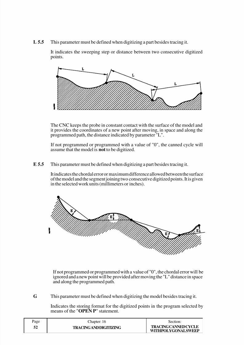
8/21/2019 CNC 8055 M Operator Manual
http://slidepdf.com/reader/full/cnc-8055-m-operator-manual 584/702
Section:Chapter: 16Page
TRACING AND DIGITIZING52
L 5.5 This parameter must be defined when digitizing a part besides tracing it.
It indicates the sweeping step or distance between two consecutive digitizedpoints.
The CNC keeps the probe in constant contact with the surface of the model andit provides the coordinates of a new point after moving, in space and along theprogrammed path, the distance indicated by parameter "L".
If not programmed or programmed with a value of "0", the canned cycle willassume that the model is not to be digitized.
E 5.5 This parameter must be defined when digitizing a part besides tracing it.
It indicates the chordal error or maximum difference allowed between the surface
of the model and the segment joining two consecutive digitized points. It is givenin the selected work units (millimeters or inches).
If not programmed or programmed with a value of "0", the chordal error will beignored and a new point will be provided after moving the "L" distance in spaceand along the programmed path.
G This parameter must be defined when digitizing the model besides tracing it.
Indicates the storing format for the digitized points in the program selected bymeans of the "OPEN P" statement.
TRACING CANNED CYCLEWITH POLYGONAL SWEEP

8/21/2019 CNC 8055 M Operator Manual
http://slidepdf.com/reader/full/cnc-8055-m-operator-manual 585/702
PageChapter: 16 Section:
53TRACING AND DIGITIZING
G=0 Absolute format.
All points will be programmed in absolute coordinates (G90) and definedby the X, Y and Z axes.
G=1 Absolute filtered format..
All points will be programmed in absolute coordinates (G90); but onlythose axes whose positions have changed with respect to the previousdigitized point will be defined.
G=2 Incremental filtered format..
All points will be programmed in incremental coordinates (G91) andreferred to the previous digitized point. Only those axes whose positionshave changed with respect to the previous digitized point will be defined.
If not programmed, the canned cycle will assume a value of G0.
H5.5 Defines the feedrate for the incremental paths. It is given in mm/min or inches/min.
If not programmed, the canned cycle assumes the "F" value (sweeping feedrate).
F5.5 Defines the sweeping feedrate. It is given in mm/min or inches/min.
P (0-9999) Defines the label number of the block where the geometric description of thevarious profiles of the part starts.
U (0-9999) Defines the label number of the block where the geometric description of the
various profiles of the part ends.
All the programmed profiles (outside and islands) must be closed.
The profile programming rules as well as the programming syntax are describedlater on.
TRACING CANNED CYCLEWITH POLYGONAL SWEEP

8/21/2019 CNC 8055 M Operator Manual
http://slidepdf.com/reader/full/cnc-8055-m-operator-manual 586/702
Section:Chapter: 16Page
TRACING AND DIGITIZING54
BASIC OPERATION:
1.- The probe positions at the point set by parameters X, Y and Z.
2.- The CNC approaches the probe to the model until it touches it.
3.- The probe keeps in constant contact with the surface of the model following it alongthe programmed path.
If it is to be digitized, (parameters "L" and "E") it will generate a new block per everydigitized point in the program previously opened by means of the "OPEN P"statement.
4.- Once the canned cycle is finished, the probe will return to the cycle calling point. Thismove consists of:
* Movement of the probe along the probing axis.* Movement of the probe in the main work plane.
TRACING CANNED CYCLEWITH POLYGONAL SWEEP
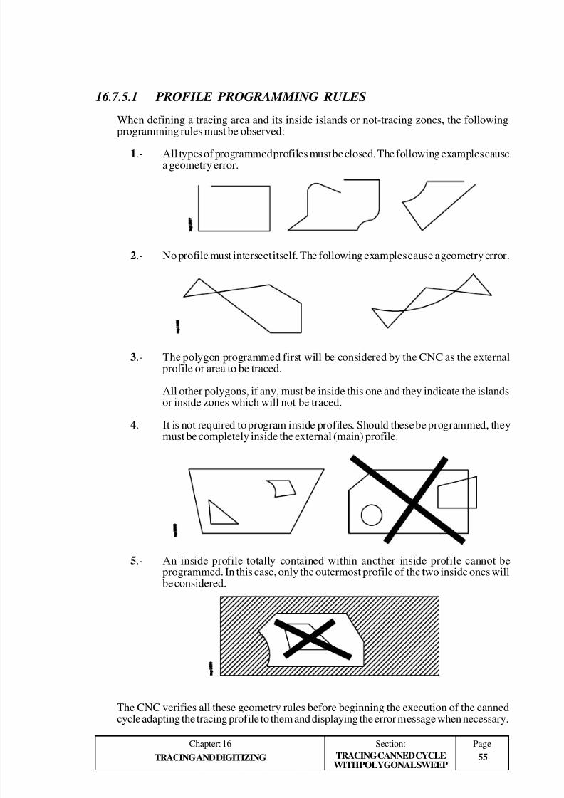
8/21/2019 CNC 8055 M Operator Manual
http://slidepdf.com/reader/full/cnc-8055-m-operator-manual 587/702
PageChapter: 16 Section:
55TRACING AND DIGITIZING
16.7.5.1 PROFILE PROGRAMMING RULES
When defining a tracing area and its inside islands or not-tracing zones, the followingprogramming rules must be observed:
1.- All types of programmed profiles must be closed. The following examples causea geometry error.
2.- No profile must intersect itself. The following examples cause a geometry error.
3.- The polygon programmed first will be considered by the CNC as the externalprofile or area to be traced.
All other polygons, if any, must be inside this one and they indicate the islandsor inside zones which will not be traced.
4.- It is not required to program inside profiles. Should these be programmed, theymust be completely inside the external (main) profile.
5.- An inside profile totally contained within another inside profile cannot beprogrammed. In this case, only the outermost profile of the two inside ones willbe considered.
The CNC verifies all these geometry rules before beginning the execution of the cannedcycle adapting the tracing profile to them and displaying the error message when necessary.
TRACING CANNED CYCLEWITH POLYGONAL SWEEP

8/21/2019 CNC 8055 M Operator Manual
http://slidepdf.com/reader/full/cnc-8055-m-operator-manual 588/702
Section:Chapter: 16Page
TRACING AND DIGITIZING56
16.7.5.2 PROFILE PROGRAMMING SYNTAX
The outside profile as well as the inside ones or islands must be defined by means of simplegeometric elements (straight lines and arcs).
The profile programming syntax must observe the following rules:
1.- The block where the geometric description starts must have a label number. Thisnumber must be assigned to parameter "P" when defining the canned cycle.
2.- The outside (main) profile or tracing area must be defined first.
No function must be programmed to indicate the end of the profile definition. TheCNC considers that the profile has ended when programming function G00 whichindicates the beginning of a new profile.
3.- All the inside profiles may be programmed one after another and each one of themmust start with function G00 (which indicates the beginning of a profile).
Warning:
Be sure to program G01, G02 or G03 on the block following the one definingthe profile since G00 is modal and the CNC might interpret the followingblocks as beginnings of new profiles.
4.- Once the profiles have been defined, assign a label number to the last programmedblock. This label number must be assigned to parameter "U" when defining the
canned cycle.5.- The profiles are described as programmed paths and may include the following
functions:
G01 Linear interpolationG02 Clockwise circular interpolationG03 Counter-clockwise circular interpolationG06 Absolute arc center coordinatesG08 Arc tangent to previous pathG09 Arc defined by three pointsG36 Automatic radius blend (controlled corner rounding)G39 Chamfer
G53 Programming with respect to machine reference zero (home)G70 Inch programmingG71 Metric programmingG90 Absolute programmingG91 Incremental programmingG93 Polar origin preset
6.- The profile description does not allow mirror image, scaling factors, pattern rotation,zero offsets, etc.
7.- It is not possible either to program blocks in high level language such as jumps, callsto subroutines or parametric programming.
8.- No other canned cycles can be programmed.
TRACING CANNED CYCLEWITH POLYGONAL SWEEP

8/21/2019 CNC 8055 M Operator Manual
http://slidepdf.com/reader/full/cnc-8055-m-operator-manual 589/702
PageChapter: 16 Section:
57TRACING AND DIGITIZING
Programming example:
(TRACE 5, A, Z, I, C, D, N, L, E, G, H, F, P400, U500)
N400 X-260 Y-190 Z4.5 ; Beginning of first outside profileG1.................G0 X230 Y170 ; Beginning of an inside profileG1.................G0 X-120 Y90 ; Beginning of another inside profileG2..................
N500 X-120 Y90 ; End of geometric description
TRACING CANNED CYCLEWITH POLYGONAL SWEEP
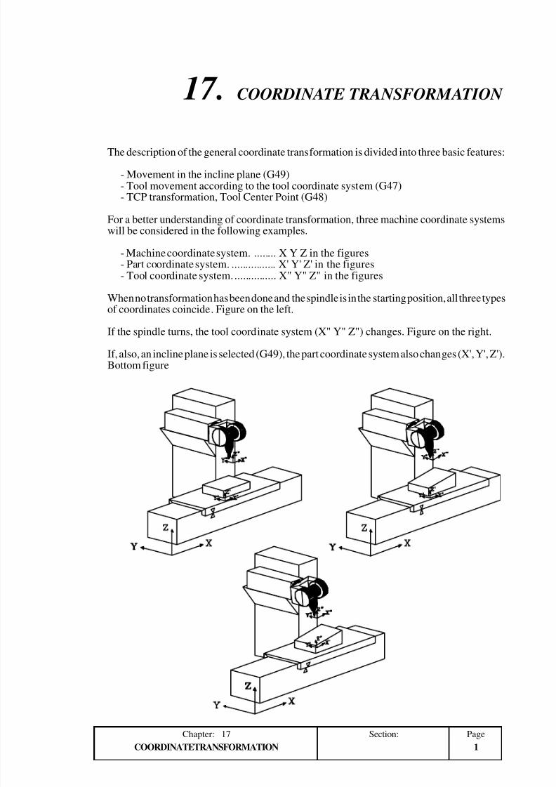
8/21/2019 CNC 8055 M Operator Manual
http://slidepdf.com/reader/full/cnc-8055-m-operator-manual 590/702
Page
1
Section:Chapter: 17
COORDINATE TRANSFORMATION
17. COORDINATE TRANSFORMATION
The description of the general coordinate transformation is divided into three basic features:
- Movement in the incline plane (G49)- Tool movement according to the tool coordinate system (G47)- TCP transformation, Tool Center Point (G48)
For a better understanding of coordinate transformation, three machine coordinate systemswill be considered in the following examples.
- Machine coordinate system. ........ X Y Z in the figures- Part coordinate system. ................ X' Y' Z' in the figures
- Tool coordinate system. ............... X" Y" Z" in the figures
When no transformation has been done and the spindle is in the starting position, all three typesof coordinates coincide. Figure on the left.
If the spindle turns, the tool coordinate system (X" Y" Z") changes. Figure on the right.
If, also, an incline plane is selected (G49), the part coordinate system also changes (X', Y', Z').Bottom figure

8/21/2019 CNC 8055 M Operator Manual
http://slidepdf.com/reader/full/cnc-8055-m-operator-manual 591/702
Page
2
Chapter: 17
COORDINATE TRANSFORMATION
Section:
Case a) No transformation has taken place and the spindle is turned.
If a Z axis movement is programmed (G01 Z), this axis will move according to the partcoordinate system which, in this case, coincides with machine coordinates.
Now, to move the tool according to the tool coordinate system, function G47 must be usedwhen programming the movement of the Z axis (G01 G47 Z).
The Z axis will move with respect to the tool coordinates.
In this type of movements, when the tool coordinate system does not coincide with themachine coordinate system, the CNC moves several axes in order to move the toolaccording to the part coordinates. In the example, the X and Z axes move.
Function G47 is not modal and only affects the programmed movement.
In order for the jog movements, to be carried out according to the tool coordinate system,the CNC general logic input "TOOLMOVE (M5021" must be activated at the PLC.
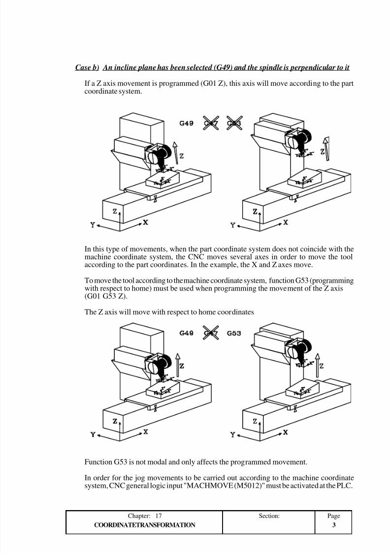
8/21/2019 CNC 8055 M Operator Manual
http://slidepdf.com/reader/full/cnc-8055-m-operator-manual 592/702
Page
3
Section:Chapter: 17
COORDINATE TRANSFORMATION
Case b) An incline plane has been selected (G49) and the spindle is perpendicular to it
If a Z axis movement is programmed (G01 Z), this axis will move according to the partcoordinate system.
In this type of movements, when the part coordinate system does not coincide with themachine coordinate system, the CNC moves several axes in order to move the toolaccording to the part coordinates. In the example, the X and Z axes move.
To move the tool according to the machine coordinate system, function G53 (programming
with respect to home) must be used when programming the movement of the Z axis(G01 G53 Z).
The Z axis will move with respect to home coordinates
Function G53 is not modal and only affects the programmed movement.
In order for the jog movements to be carried out according to the machine coordinate
system, CNC general logic input "MACHMOVE (M5012)" must be activated at the PLC.

8/21/2019 CNC 8055 M Operator Manual
http://slidepdf.com/reader/full/cnc-8055-m-operator-manual 593/702
Page
4
Chapter: 17
COORDINATE TRANSFORMATION
Section:
Case c) Incline plane selected (G49) and spindle not perpendicular to it
If a Z axis movement is programmed (G01 Z), this axis will move according to the partcoordinate system.
In this type of movements, when the part coordinate system does not coincide with themachine coordinate system, the CNC moves several axes in order to move the toolaccording to the part coordinates. In the example, the X and Z axes move.
To move the tool according to the tool coordinate system, function G47 must be used when
programming the Z axis movement (G01 G47 Z).
In this type of movements, when the tool coordinate system does not coincide with themachine coordinate system, the CNC moves several axes in order to move the toolaccording to the part coordinates. In the example, the X and Z axes move.
Function G47 is not modal and only affects the programmed movement.
In order for the jog movements, to be carried out according to the tool coordinate system,
the CNC general logic input "TOOLMOVE (M5021" must be activated at the PLC.

8/21/2019 CNC 8055 M Operator Manual
http://slidepdf.com/reader/full/cnc-8055-m-operator-manual 594/702
Page
5
Section:Chapter: 17
COORDINATE TRANSFORMATION
To move the tool according to the machine coordinate system, function G53 must be used(programming with respect to home) when programming the Z axis movement (G01 G53 Z).
Function G53 is not modal and it only acts in the programmed movement.
In order for the jog movements to be carried out according to the machine coordinate
system, CNC general logic input "MACHMOVE (M5012)" must be activated at the PLC.

8/21/2019 CNC 8055 M Operator Manual
http://slidepdf.com/reader/full/cnc-8055-m-operator-manual 595/702
Page
6
Chapter: 17
COORDINATE TRANSFORMATION
Section:
Case d) Working with TCP transformation, Tool Center Point
When working with TCP transformation, function G48 active, the CNC allows changingthe tool orientation without changing the position of its tool tip (part coordinates).
Obviously, the CNC must move several axes of the machine in order to maintain the tooltip position.
Function G48, as described later on, is modal and it indicates when the TCP transformationbecomes active and when it is canceled.
Function G48, TCP transformation, may be used together with function G49 (movementin the Incline Plane) and G47 (movement along the tool axes)

8/21/2019 CNC 8055 M Operator Manual
http://slidepdf.com/reader/full/cnc-8055-m-operator-manual 596/702
Page
7
Section:Chapter: 17
COORDINATE TRANSFORMATION
17.1 MOVEMENT IN THE INCLINE PLANE
An incline plane is any plane resulting from a coordinate transformation of the X, Y and Z axes.
With this CNC any plane in space may be selected and any machining performed in it.
The coordinates are programmed as if it were a regular XY plane, but the program will beexecuted in the indicated incline plane.
To work with incline planes, always proceed as follows:
1.- Define, with G49, the incline plane corresponding to the machining operation. G49 isdescribed later on in this chapter.
2.- The CNC variables TOOROF, TOOROS and parameters P297, P298 show theposition to be occupied by the spindle rotary axes (main and secondary spindlerespectively) in order to orient the tool perpendicular to the indicated incline plane.
3.- To work with the tool perpendicular to the incline plane, rotate the spindle rotary axesto the indicated position.
From this moment on, the X Y axes movements will be carried out along the selected inclineplane and the Z axis movement will be perpendicular to it.
MOVEMENT IN INCLINE PLANE
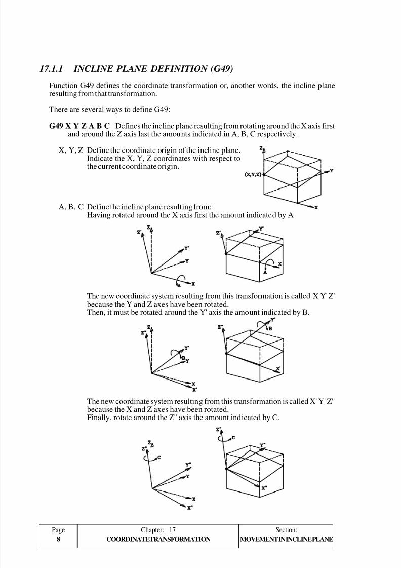
8/21/2019 CNC 8055 M Operator Manual
http://slidepdf.com/reader/full/cnc-8055-m-operator-manual 597/702
Page
8
Chapter: 17
COORDINATE TRANSFORMATION
Section:
17.1.1 INCLINE PLANE DEFINITION (G49)
Function G49 defines the coordinate transformation or, another words, the incline planeresulting from that transformation.
There are several ways to define G49:
G49 X Y Z A B C Defines the incline plane resulting from rotating around the X axis firstand around the Z axis last the amounts indicated in A, B, C respectively.
X, Y, Z Define the coordinate origin of the incline plane.Indicate the X, Y, Z coordinates with respect tothe current coordinate origin.
A, B, C Define the incline plane resulting from:Having rotated around the X axis first the amount indicated by A
The new coordinate system resulting from this transformation is called X Y' Z'because the Y and Z axes have been rotated.Then, it must be rotated around the Y' axis the amount indicated by B.
The new coordinate system resulting from this transformation is called X' Y' Z''because the X and Z axes have been rotated.Finally, rotate around the Z'' axis the amount indicated by C.
MOVEMENT IN INCLINE PLANE

8/21/2019 CNC 8055 M Operator Manual
http://slidepdf.com/reader/full/cnc-8055-m-operator-manual 598/702
Page
9
Section:Chapter: 17
COORDINATE TRANSFORMATION
G49 X Y Z Q R S Spheric coordinates. Defines the incline plane resulting from rotatingaround the Z axis first, then around the Y axis and again around the Z axis the amountsindicated by Q, R, S respectively.
X, Y, Z Define the coordinate origin of the incline plane.They indicate the X, Y, Z coordinates with respectto the current coordinate origin.
Q, R, S Define the incline plane resulting from:Having rotated around the Z axis first the amount indicated by Q.
The new coordinate system resulting from this transformation is called X' Y' Zbecause the X and Y axes have been rotated.Then, it must be rotated around the Y' axis the amount indicated by R.
The new coordinate system resulting from this transformation is called X'' Y' Z'because the X and Z axes have been rotatedFinally, rotate around the Z' the amount indicated by S
MOVEMENT IN INCLINE PLANE
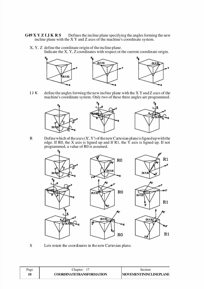
8/21/2019 CNC 8055 M Operator Manual
http://slidepdf.com/reader/full/cnc-8055-m-operator-manual 599/702
Page
10
Chapter: 17
COORDINATE TRANSFORMATION
Section:
G49 X Y Z I J K R S Defines the incline plane specifying the angles forming the newincline plane with the X Y and Z axes of the machine's coordinate system.
X, Y, Z define the coordinate origin of the incline plane.Indicate the X, Y, Z coordinates with respect ot the current coordinate origin.
I J K define the angles forming the new incline plane with the X Y and Z axes of themachine's coordinate system. Only two of these three angles are programmed.
R Define which of the axes (X', Y') of the new Cartesian plane is ligned up with theedge. If R0, the X axis is ligned up and If R1, the Y axis is ligned up. If notprogrammed, a value of R0 is assumed.
S Lets rotate the coordinates in the new Cartesian plane.
MOVEMENT IN INCLINE PLANE
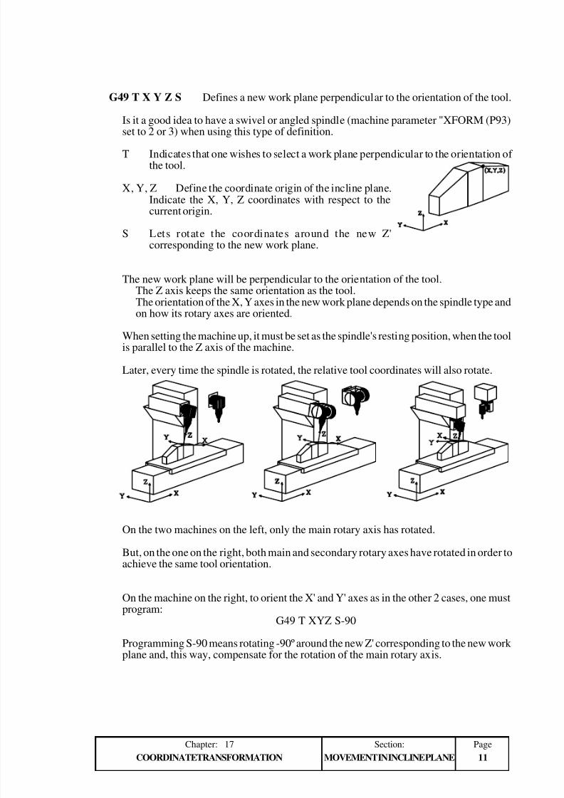
8/21/2019 CNC 8055 M Operator Manual
http://slidepdf.com/reader/full/cnc-8055-m-operator-manual 600/702
Page
11
Section:Chapter: 17
COORDINATE TRANSFORMATION
G49 T X Y Z S Defines a new work plane perpendicular to the orientation of the tool.
Is it a good idea to have a swivel or angled spindle (machine parameter "XFORM (P93)set to 2 or 3) when using this type of definition.
T Indicates that one wishes to select a work plane perpendicular to the orientation of the tool.
X, Y, Z Define the coordinate origin of the incline plane.Indicate the X, Y, Z coordinates with respect to thecurrent origin.
S Lets rotate the coordinates around the new Z'corresponding to the new work plane.
The new work plane will be perpendicular to the orientation of the tool.The Z axis keeps the same orientation as the tool.The orientation of the X, Y axes in the new work plane depends on the spindle type andon how its rotary axes are oriented.
When setting the machine up, it must be set as the spindle's resting position, when the toolis parallel to the Z axis of the machine.
Later, every time the spindle is rotated, the relative tool coordinates will also rotate.
On the two machines on the left, only the main rotary axis has rotated.
But, on the one on the right, both main and secondary rotary axes have rotated in order toachieve the same tool orientation.
On the machine on the right, to orient the X' and Y' axes as in the other 2 cases, one mustprogram:
G49 T XYZ S-90
Programming S-90 means rotating -90º around the new Z' corresponding to the new work plane and, this way, compensate for the rotation of the main rotary axis.
MOVEMENT IN INCLINE PLANE

8/21/2019 CNC 8055 M Operator Manual
http://slidepdf.com/reader/full/cnc-8055-m-operator-manual 601/702
Page
12
Chapter: 17
COORDINATE TRANSFORMATION
Section:
17.1.2 CONSIDERATIONS FOR FUNCTION G49
G49 cannot be programmed in the following instances:At the GP model CNCFrom the PLC channel (although it can be programmed from the user channel).Within a profile definition for pockets or other cycles.
In order to work with coordinate transformation (G49) the X, Y, Z axes must be defined, formthe active trihedron and be linear. The X, Y and Z axes may have GANTRY axes, coupledor synchronized via PLC, associated with them.
When working with coordinate transformation and performing rigid tapping in incline planes,all axes gains (not only for the Z axis) must be adjusted by using the second gains andaccelerations.
The parameters associated with G49 are optional. When programming G49 without parameters,
the active coordinate transformation is canceled.
G49 is modal and must be programmed alone in the block.
Coordinate transformation is kept active even after turning the CNC off and back on.
To cancel it, G49 must be programmed without parameters. It is also canceled after a homesearch (G74).
When canceling G49, the CNC recovers the part zero active before G49 was activated.
Zero offsets G54-G59, pattern rotation (G73) and presets (G92, G93) are possible while
coordinate transformation is active.
But the following cannot be done:Program a new coordinate transformation without previously canceling the previous one.Perform tracing operations (G23 through G27).Probing (G75).Movement against hardstop (G52).
MOVEMENT IN INCLINE PLANE
8/21/2019 CNC 8055 M Operator Manual
http://slidepdf.com/reader/full/cnc-8055-m-operator-manual 602/702
Page
13
Section:Chapter: 17
COORDINATE TRANSFORMATION
17.1.3 VARIABLES ASSOCIATED WITH FUNCTION G49
Read-only variables associated with the definition of G49:
ORGROX, ORGROY, ORGROZ New part zero coordinates with respect to home.ORGROA, ORGROB, ORGROC Values assigned to parameters A, B, CORGROI, ORGROJ, ORGROK Values assigned to parameters I, J, KORGROQ, ORGROR, ORGROS Values assigned to parameters Q, R, SGTRATY type of G49 programmed 0 = no G49 has been defined
1 = G49 X Y Z A B C 2 = G49 X Y Z Q R S3 = G49 T X Y Z S 4 = G49 X Y Z I J K R S
Every time G49 is programmed, the CNC updates the values of the parameters that havebeen defined.
For example, when programming G49 XYZ ABC, the CNC
Updates variables ORGROX, Y, Z, A, B, CThe rest of the variables keep their previous values.
Read-Write variables updated by the CNC once G49 has been executed:
When using a swivel or angled spindle, general machine parameter "XFORM (P93)" setto 2 or 3, the CNC shows the following information.
TOOROF Indicates the position to be occupied by the spindle's main rotary axis to orientthe tool perpendicular to the indicated incline plane.
TOOROS Indicates the position to be occupied by the spindle's secondary rotary axis toorient the tool perpendicular to the indicated incline plane.
When accessing variable TOOROF or TOOROS the CNC interrupts block preparationand it waits for that command to be executed before resuming block preparation.
17.1.4 PARAMETERS ASSOCIATED WITH FUNCTION G49
Once G49 has been executed, the CNC updates global parameters P297 and P298:
P297 Indicates the position to be occupied by the spindle's main rotary axis to orient thetool perpendicular to the indicated incline plane. It is the same value as shown bythe TOOROF variable.
P298 Indicates the position to be occupied by the spindle's secondary rotary axis toorient the tool perpendicular to the indicated incline plane. It is the same value asshown by the TOOROS variable.
Warning: These parameters are global. Therefore, they can be modified by the useror even by probing cycles of the CNC itself.They should be used after executing G49.Otherwise, variables TOOROF and TOOROS should be used.
MOVEMENT IN INCLINE PLANE
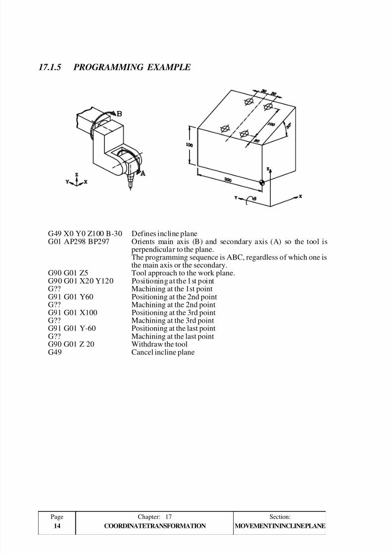
8/21/2019 CNC 8055 M Operator Manual
http://slidepdf.com/reader/full/cnc-8055-m-operator-manual 603/702
Page
14
Chapter: 17
COORDINATE TRANSFORMATION
Section:
17.1.5 PROGRAMMING EXAMPLE
G49 X0 Y0 Z100 B-30 Defines incline planeG01 AP298 BP297 Orients main axis (B) and secondary axis (A) so the tool is
perpendicular to the plane.The programming sequence is ABC, regardless of which one isthe main axis or the secondary.
G90 G01 Z5 Tool approach to the work plane.G90 G01 X20 Y120 Positioning at the 1st point
G?? Machining at the 1st pointG91 G01 Y60 Positioning at the 2nd pointG?? Machining at the 2nd pointG91 G01 X100 Positioning at the 3rd pointG?? Machining at the 3rd pointG91 G01 Y-60 Positioning at the last pointG?? Machining at the last pointG90 G01 Z 20 Withdraw the toolG49 Cancel incline plane
MOVEMENT IN INCLINE PLANE

8/21/2019 CNC 8055 M Operator Manual
http://slidepdf.com/reader/full/cnc-8055-m-operator-manual 604/702
Page
15
Section:Chapter: 17
COORDINATE TRANSFORMATION MOVEMENT ACCORDING TOTOOL COORD. SYSTEM
17.2 MOVEMENT ACCORDING TO THE TOOL COORDINATE SYSTEM (G47)
To move the tool according to the tool coordinate system, function G47 must be used whenprogramming a movement of the Z axis (G01 G47 Z).
When using this function, a swivel or angled spindle should be utilized (general machineparameter "XFORM (P93)" set to 2 or 3).
When not using this function, the tool moves according to the part coordinate system
In the example on the left, the part coordinates coincide with those of the machine and in the
example on the right, an incline plane is active (G49).
To move the tool according to the tool coordinate system, function G47 must be used whenprogramming a movement of the Z axis (G01 G47 Z).
The movements programmed with G47 are always incremental.
Function G47 is not modal and it only acts within the block (linear path) where it has beenprogrammed.
G47 can also be programmed while G48 and G49 are active.

8/21/2019 CNC 8055 M Operator Manual
http://slidepdf.com/reader/full/cnc-8055-m-operator-manual 605/702
Page
16
Chapter: 17
COORDINATE TRANSFORMATION
Section:
17.3 TCP TRANSFORMATION (G48)
In order to use this feature, the spindle articulations must have encoders and they must becontrolled by the CNC.
When working with TCP transformation, Tool Center Point, the tool orientation may bemodified without changing the position of its tip (part coordinates).
Obviously, the spindle must be swivel or angled and general machine parameter "XFORM(P93)" set to a value other than "0".
To orient the tool without changing its tip position, the CNC must move several axes of the machine.
TCP transformation is activated and deactivated by function G48:
G48 S1 TCP transformation ONG48 S0 TCP transformation OFF
TCP transformation is also turned off by programming G48 without parameters.
G48 is modal and it must be programmed alone in the block.
Once TCP is on, it is possible to combine spindle orientation with linear and circular interpolations.
To orient the spindle, one must program the target angular position for the main rotary axisand for the secondary axis of the spindle.
The example described next, an angled spindle is being used:
TCP TRANSFORMATION
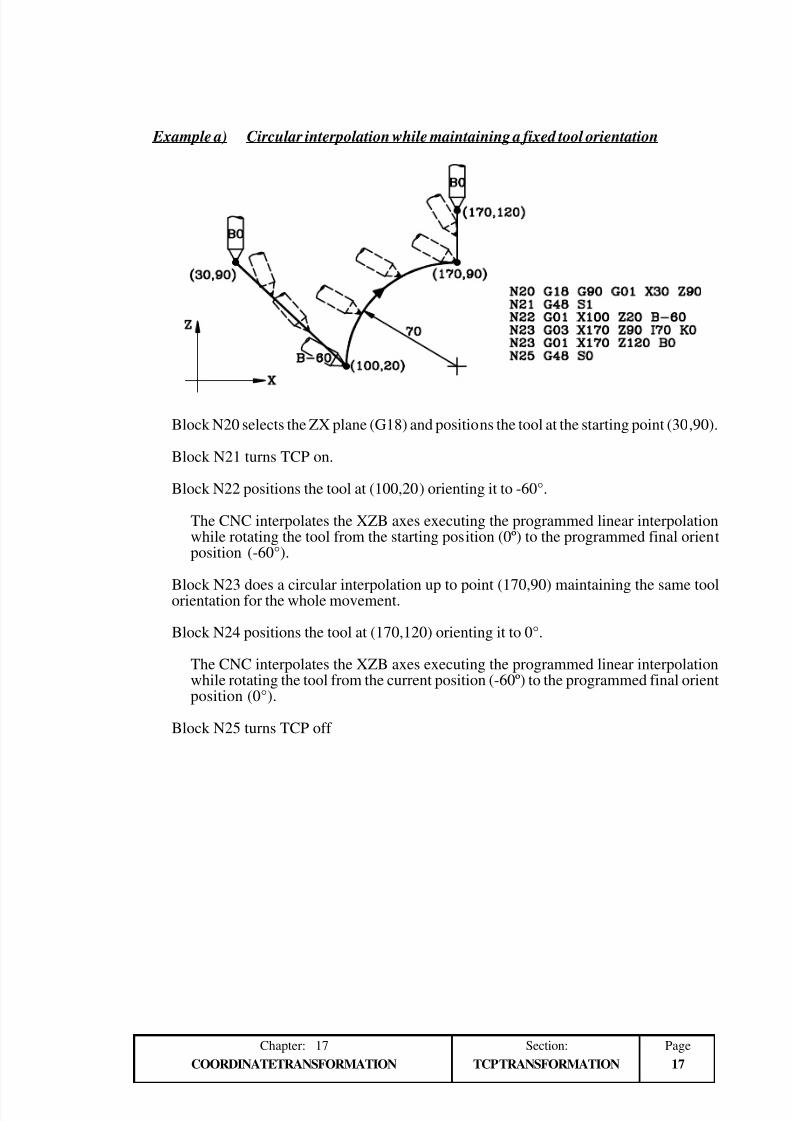
8/21/2019 CNC 8055 M Operator Manual
http://slidepdf.com/reader/full/cnc-8055-m-operator-manual 606/702
Page
17
Section:Chapter: 17
COORDINATE TRANSFORMATION
Example a) Circular interpolation while maintaining a fixed tool orientation
Block N20 selects the ZX plane (G18) and positions the tool at the starting point (30,90).
Block N21 turns TCP on.
Block N22 positions the tool at (100,20) orienting it to -60°.
The CNC interpolates the XZB axes executing the programmed linear interpolationwhile rotating the tool from the starting position (0º) to the programmed final orientposition (-60°).
Block N23 does a circular interpolation up to point (170,90) maintaining the same toolorientation for the whole movement.
Block N24 positions the tool at (170,120) orienting it to 0°.
The CNC interpolates the XZB axes executing the programmed linear interpolationwhile rotating the tool from the current position (-60º) to the programmed final orientposition (0°).
Block N25 turns TCP off
TCP TRANSFORMATION
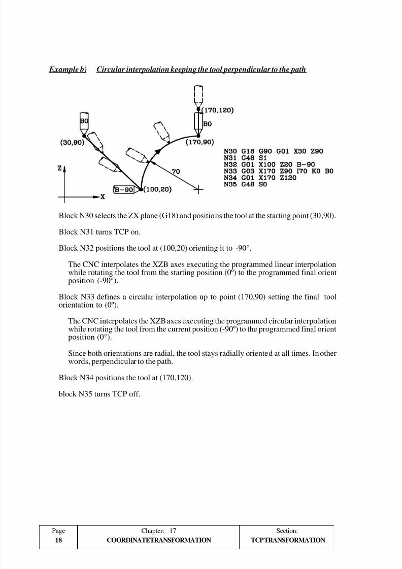
8/21/2019 CNC 8055 M Operator Manual
http://slidepdf.com/reader/full/cnc-8055-m-operator-manual 607/702
Page
18
Chapter: 17
COORDINATE TRANSFORMATION
Section:
Example b) Circular interpolation keeping the tool perpendicular to the path
Block N30 selects the ZX plane (G18) and positions the tool at the starting point (30,90).
Block N31 turns TCP on.
Block N32 positions the tool at (100,20) orienting it to -90°.
The CNC interpolates the XZB axes executing the programmed linear interpolationwhile rotating the tool from the starting position (0º) to the programmed final orientposition (-90°).
Block N33 defines a circular interpolation up to point (170,90) setting the final toolorientation to (0º).
The CNC interpolates the XZB axes executing the programmed circular interpolationwhile rotating the tool from the current position (-90º) to the programmed final orientposition (0°).
Since both orientations are radial, the tool stays radially oriented at all times. In otherwords, perpendicular to the path.
Block N34 positions the tool at (170,120).
block N35 turns TCP off.
TCP TRANSFORMATION

8/21/2019 CNC 8055 M Operator Manual
http://slidepdf.com/reader/full/cnc-8055-m-operator-manual 608/702
Page
19
Section:Chapter: 17
COORDINATE TRANSFORMATION
Example c) Machining a profile
G18 G90 ........................ selects the ZX plane (G18)G48 S1 .......................... turns TCP on.G01 X40 Z0 B0 ........... positions the tool at (40,0) orienting it to (0°)
X100 .................... movement to (100,0) with the tool oriented at (0°)B-35 ..................... orients the tool to (-35°)X200 Z70 ............. movement to (200,70) with the tool orientated to (-35°)B90....................... orients the tool to (90°)
G02 X270 Z0 R70 B0 . circular interpolation up to (270,0) keeping the tool perpendicularto the path.
G01 X340 .................... movement to (340,0) with the tool oriented at "0°"
G48 S0 .......................... turns TCP on.
TCP TRANSFORMATION

8/21/2019 CNC 8055 M Operator Manual
http://slidepdf.com/reader/full/cnc-8055-m-operator-manual 609/702
Page
20
Chapter: 17
COORDINATE TRANSFORMATION
Section:
17.3.1 CONSIDERATIONS FOR FUNCTION G48
G48 cannot be programmed in the following instances:At the GP CNC model.From the PLC channel (although it can be programmed from the user channel).
In order to work with TCP transformation (G48) the X, Y, Z axes must be defined, form theactive trihedron and be linear. The X, Y and Z axes may have GANTRY axes, coupled orsynchronized via PLC, associated with them.
When working with TCP transformation and performing rigid tapping in incline planes, allaxes gains (not only for the Z axis) must be adjusted by using the second gains andaccelerations.
TCP transformation is kept active even after turning the CNC off and back on.
G48 can be programmed while G49 is active and vice versa.
To cancel TCP, program "G48 S0" or G48 without parameters. It is also canceled after a homesearch (G74).
While TCP is on, it is possible to:Apply zero offsets G54-G59Rotate the pattern (coordinate system) (G73)Preset (G92, G93).JOG in continuous or incremental moves and by electronic handwheel.
But, it is not possible to:
Perform tracing operations (G23 a G27).Probe (G75).Do corner rounding or chamfering because in these instances tool orientation has to bemaintained.Compensate for tool length (G43) because TCP already implies a particular lengthcompensation. CAD/CAM programs usually program the coordinates of the spindle base.
Special care must be taken when turning G48 on and off.When G48 is on, the CNC shows the coordinates of the tool tip.When G48 is off, the CNC shows the coordinates of the tool base or theoretical tip(unturned tool).
1.- G48 off. The CNC shows the coordinates of the tool tip.2.- G48 is turned on. The CNC still shows the coordinates of the tool tip.3.- The tool is turned. Since G48 is already on, the CNC still shows the coordinates of the
tool tip.
4.- G48 is turned off. The CNC shows the coordinates of the theoretical tip (unturnedtool).
TCP TRANSFORMATION

8/21/2019 CNC 8055 M Operator Manual
http://slidepdf.com/reader/full/cnc-8055-m-operator-manual 610/702
Page
21
Section:Chapter: 17
COORDINATE TRANSFORMATION
When working with incline planes and TCP transformation, the following programmingorder should be used:
G48 S1 Activate TCP transformationG49 ..... Define the incline planeG01 AP298 BP297 Position the tool perpendicular to the planeG ............... Start the machining operation................... Finish the machining operationG49 Cancel the incline planeG48 S0Cancel TCP transformationM30 End of part program
TCP transformation should be activated first because it lets orient the tool without changingthe position of its tip, thus avoiding undesired collisions.
TCP TRANSFORMATION

8/21/2019 CNC 8055 M Operator Manual
http://slidepdf.com/reader/full/cnc-8055-m-operator-manual 611/702
1
APPENDIX
A. ISO CODE PROGRAMMING ....................................................... 3
B. VARIABLES ASSOCIATED WITH TOOLS ................................ 5
C. HIGH LEVEL PROGRAMMING ............................................... 10
D. KEY CODES ................................................................................. 12
E. LOGIC OUTPUTS FOR KEY CODE STATUS ......................... 13
F. KEY INHIBITING CODES ......................................................... 14
G. PROGRAMMING ASSISTANCE SYSTEM PAGES ................. 15
H. MAINTENANCE.......................................................................... 18
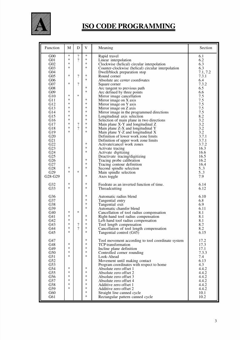
8/21/2019 CNC 8055 M Operator Manual
http://slidepdf.com/reader/full/cnc-8055-m-operator-manual 612/702
3
ISO CODE PROGRAMMING
Function M D V Meaning Section
G00 * ? * Rapid travel 6.1
G01 * ? * Linear interpolation 6.2G02 * * Clockwise (helical) circular interpolation 6.3G03 * * Counter-clockwise (helical) circular interpolation 6.3G04 Dwell/block preparation stop 7.1, 7.2G05 * ? * Round corner 7.3.1G06 * Absolute arc center coordinates 6.4G07 * ? Square corner 7.3.2G08 * Arc tangent to previous path 6.5G09 * Arc defined by three points 6.6G10 * * Mirror image cancellation 7.5G11 * * Mirror image on X axis 7.5G12 * * Mirror image on Y axis 7.5G13 * * Mirror image on Z axis 7.5G14 * * Mirror image in the programmed directions 7.5G15 * * Longitudinal axis selection 8.2G16 * * Selection of main plane in two directions 3.2G17 * ? * Main plane X-Y and longitudinal Z 3.2G18 * ? * Main plane Z-X and longitudinal Y 3.2G19 * * Main plane Y-Z and longitudinal X 3.2G20 Definition of lower work zone limits 3.7.1G21 Definition of upper work zone limits 3.7.1G22 * Activate/cancel work zones 3.7.2G23 * Activate tracing 16.3G24 * Activate digitizing 16.6G25 Deactivate tracing/digitizing 16.5G26 * Tracing probe calibration 16.2G27 * Tracing contour definition 16.4G28 * * Second spindle selection 5..3G29 * * Main spindle selection 5..3
G28-G29 * Axes toggle 7.9
G32 * * Feedrate as an inverted function of time. 6.14G33 * * Threadcutting 6.12
G36 * Automatic radius blend 6.10G37 * Tangential entry 6.8G38 * Tangential exit 6.9G39 * Automatic chamfer blend 6.11G40 * * Cancellation of tool radius compensation 8.1G41 * * Right-hand tool radius compensation 8.1G42 * * Left-hand tool radius compensation 8.1G43 * ? * Tool length compensation 8.2G44 * ? * Cancellation of tool length compensation 8.2G45 * * Tangential control (G45) 6.15
G47 * Tool movement according to tool coordinate system 17.2G48 * * TCP transformation 17.3G49 * * Incline plane definition 17.1G50 * * Controlled corner rounding 7.3.3G51 * * Look-Ahead 7.4G52 Movement until making contact 6.13G53 Program coordinates with respect to home 4.3G54 * * Absolute zero offset 1 4.4.2G55 * * Absolute zero offset 2 4.4.2G56 * * Absolute zero offset 3 4.4.2G57 * * Absolute zero offset 4 4.4.2G58 * * Additive zero offset 1 4.4.2G59 * * Additive zero offset 2 4.4.2G60 * Straight line canned cycle 10.1
G61 * Rectangular pattern canned cycle 10.2
1 2 3 4 5 6 7 8 9 0 1 2 3 4 5
1 2 3 4 5 6 7 8 9 0 1 2 3 4 5
1 2 3 4 5 6 7 8 9 0 1 2 3 4 5
1 2 3 4 5 6 7 8 9 0 1 2 3 4 5
1 2 3 4 5 6 7 8 9 0 1 2 3 4 5
1 2 3 4 5 6 7 8 9 0 1 2 3 4 5
1 2 3 4 5 6 7 8 9 0 1 2 3 4 5
1 2 3 4 5 6 7 8 9 0 1 2 3 4 5
1 2 3 4 5 6 7 8 9 0 1 2 3 4 5
1 2 3 4 5 6 7 8 9 0 1 2 3 4 5
1 2 3 4 5 6 7 8 9 0 1 2 3 4 5
1 2 3 4 5 6 7 8 9 0 1 2 3 4 5
1 2 3 4 5 6 7 8 9 0 1 2 3 4 5
1 2 3 4 5 6 7 8 9 0 1 2 3 4 5
1 2 3 4 5 6 7 8 9 0 1 2 3 4 5
1 2 3 4 5 6 7 8 9 0 1 2 3 4 5
1 2 3 4 5 6 7 8 9 0 1 2 3 4 5
A

8/21/2019 CNC 8055 M Operator Manual
http://slidepdf.com/reader/full/cnc-8055-m-operator-manual 613/702
4
Function M D V Meaning Section
G62 * Grid pattern canned cycle 10.3G63 * Circular pattern canned cycle 10.4G64 * Arc pattern canned cycle 10.5G65 * Arc-chord pattern canned cycle 10.6G66 * Irregular pocket canned cycle 11.1G67 * Irregular pocket roughing 11.3
G68 * Irregular pocket finishing 11.4G69 * * Complex deep hole drilling 9.5.1G70 * ? * Programming in inches 3.3G71 * ? programming in millimeters 3.3G72 * * General and specific scaling factor 7.6G73 * * Pattern rotation 7.7G74 * Machine reference search 4.2G75 * Probing until touching 12.1G76 * Probing while touching 12.1G77 * * Slaved axis 7.8.1G78 * * Slaved axis cancellation 7.8.2
G79 Canned cycle parameter modification 9.2.1G80 * * Canned cycle cancellation 9.3G81 * * Drilling cycle 9.5.2
G82 * * Drilling cycle with dwell 9.5.3G83 * * Simple deep hole drilling 9.5.4G84 * * Tapping cycle 9.5.5G85 * * Reaming cycle 9.5.6G86 * * Boring cycle with withdrawal in G00 9.5.7G87 * * Rectangular pocket milling cycle 9.5.8G88 * * Circular pocket milling cycle 9.5.9G89 * * Boring cycle with withdrawal in G01 9.5.10G90 * ? Programming in absolute 3.4G91 * ? * Programming in incremental 3.4G92 Coordinate preset/spindle speed limit 4.4.1G93 Polar origin preset 4.5G94 * ? Feedrate in millimeters(inches) per minute 5.2.1G95 * ? * Feedrate in millimeters(inches) per revolution 5.2.2G96 * * Constant cutting point speed 5.4.1
G97 * * Constant tool center speed 5.4.2G98 * * Withdrawal to the starting plane 9.5G99 * * Withdrawal to the reference plane 9.5
M means MODAL, i.e., that once programmed, the G function remains active as long as anotherincompatible G function is not programmed, M02, M30, EMERGENCY, RESET are notprogrammed or the CNC is not turned on or off.
Letter D means BY DEFAULT, i.e., that these will be assumed by the CNC when turned on,after executing M02, M30 or after EMERGENCY or RESET.
In cases indicated with ? it must be interpreted that the DEFAULT of these G functions dependson the settings of the general CNC machine parameters.
V means that the G function is displayed next to the machining conditions in the execution andsimulation modes.
INTERNAL CNC VARIABLES
R indicates that the variable can be read.W indicates that the variable can be modified.

8/21/2019 CNC 8055 M Operator Manual
http://slidepdf.com/reader/full/cnc-8055-m-operator-manual 614/702
5
Section (13.2.2)
VARIABLES ASSOCIATED WITH TOOLS
Variable CNC PLC DNC
TOOL R R R Number of active tool.
TOD R R R Number of active tool offset.
NXTOOL R R R Number of the next requested tool waiting for M06.
NXTOD R R R Number of the next tool’s offset.
TMZPn R R - (n) tool’s position in the tool magazine.
TLFDn R/W R/W - (n) tool’s offset number.
TLFFn R/W R/W - (n) tool’s family code.
TLFNn R/W R/W - Nominal life assigned to tool (n).
TLFRn R/W R/W - Real life value of tool (n).
TMZTn R/W R/W - Contents of tool magazine position (n).
TORn R/W R/W - Tool radius (R) value of offset (n).
TOLn R/W R/W - Tool length (L) value of offset (n).
TOIn R/W R/W - Tool radius wear (I) of offset (n).
TOKn R/W R/W - Tool length wear (K) of offset (n).
VARIABLES ASSOCIATED WITH ZERO OFFSETS (Section 13.2.3)
Variable CNC PLC DNC
ORG(X-C) R R - Zero offset active on the selected axis without including the
additive Zero offset activated via PLC.
PORGF R - R Abscissa coordinate value of polar origin.
PORGS R - R Ordinate coordinate value of polar origin.
ORG(X-C)n R/W R/W R Zero offset (n) value of the selected axis.
PLCOF(X-C) R/W R/W R Value of the additive Zero Offset activated via PLC.
1 2 3 4 5 6 7 8 9 0 1 2 3 4 5
1 2 3 4 5 6 7 8 9 0 1 2 3 4 5
1 2 3 4 5 6 7 8 9 0 1 2 3 4 5
1 2 3 4 5 6 7 8 9 0 1 2 3 4 5
1 2 3 4 5 6 7 8 9 0 1 2 3 4 5
1 2 3 4 5 6 7 8 9 0 1 2 3 4 5
1 2 3 4 5 6 7 8 9 0 1 2 3 4 5
1 2 3 4 5 6 7 8 9 0 1 2 3 4 5
1 2 3 4 5 6 7 8 9 0 1 2 3 4 5
1 2 3 4 5 6 7 8 9 0 1 2 3 4 5
1 2 3 4 5 6 7 8 9 0 1 2 3 4 5
1 2 3 4 5 6 7 8 9 0 1 2 3 4 5
1 2 3 4 5 6 7 8 9 0 1 2 3 4 5
1 2 3 4 5 6 7 8 9 0 1 2 3 4 5
1 2 3 4 5 6 7 8 9 0 1 2 3 4 5
1 2 3 4 5 6 7 8 9 0 1 2 3 4 5
1 2 3 4 5 6 7 8 9 0 1 2 3 4 5
B
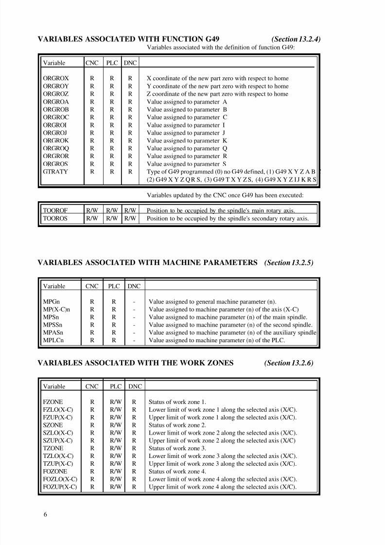
8/21/2019 CNC 8055 M Operator Manual
http://slidepdf.com/reader/full/cnc-8055-m-operator-manual 615/702
6
VARIABLES ASSOCIATED WITH FUNCTION G49 (Section 13.2.4)Variables associated with the definition of function G49:
Variable CNC PLC DNC
ORGROX R R R X coordinate of the new part zero with respect to home
ORGROY R R R Y coordinate of the new part zero with respect to home
ORGROZ R R R Z coordinate of the new part zero with respect to homeORGROA R R R Value assigned to parameter A
ORGROB R R R Value assigned to parameter B
ORGROC R R R Value assigned to parameter C
ORGROI R R R Value assigned to parameter I
ORGROJ R R R Value assigned to parameter J
ORGROK R R R Value assigned to parameter K
ORGROQ R R R Value assigned to parameter Q
ORGROR R R R Value assigned to parameter R
ORGROS R R R Value assigned to parameter S
GTRATY R R R Type of G49 programmed (0) no G49 defined, (1) G49 X Y Z A B C
(2) G49 X Y Z Q R S, (3) G49 T X Y Z S, (4) G49 X Y Z I J K R S
Variables updated by the CNC once G49 has been executed:
TOOROF R/W R/W R/W Position to be occupied by the spindle's main rotary axis.
TOOROS R/W R/W R/W Position to be occupied by the spindle's secondary rotary axis.
VARIABLES ASSOCIATED WITH MACHINE PARAMETERS (Section 13.2.5)
Variable CNC PLC DNC
MPGn R R - Value assigned to general machine parameter (n).
MP(X-C)n R R - Value assigned to machine parameter (n) of the axis (X-C)
MPSn R R - Value assigned to machine parameter (n) of the main spindle.
MPSSn R R - Value assigned to machine parameter (n) of the second spindle.
MPASn R R - Value assigned to machine parameter (n) of the auxiliary spindle.
MPLCn R R - Value assigned to machine parameter (n) of the PLC.
VARIABLES ASSOCIATED WITH THE WORK ZONES (Section 13.2.6)
Variable CNC PLC DNC
FZONE R R/W R Status of work zone 1.
FZLO(X-C) R R/W R Lower limit of work zone 1 along the selected axis (X/C).
FZUP(X-C) R R/W R Upper limit of work zone 1 along the selected axis (X/C).
SZONE R R/W R Status of work zone 2.
SZLO(X-C) R R/W R Lower limit of work zone 2 along the selected axis (X/C).
SZUP(X-C) R R/W R Upper limit of work zone 2 along the selected axis (X/C)
TZONE R R/W R Status of work zone 3.
TZLO(X-C) R R/W R Lower limit of work zone 3 along the selected axis (X/C).
TZUP(X-C) R R/W R Upper limit of work zone 3 along the selected axis (X/C).
FOZONE R R/W R Status of work zone 4.
FOZLO(X-C) R R/W R Lower limit of work zone 4 along the selected axis (X/C).FOZUP(X-C) R R/W R Upper limit of work zone 4 along the selected axis (X/C).

8/21/2019 CNC 8055 M Operator Manual
http://slidepdf.com/reader/full/cnc-8055-m-operator-manual 616/702
7
VARIABLES ASSOCIATED WITH FEEDRATES
Variable CNC PLC DNC
Variables associated with function G94
FEED R R R Active feedrate at the CNC (G94) in mm/min or inch/min.
DNCF R R R/W Feedrate selected via DNC.
PLCF R R/W R Feedrate selected via PLC.
PRGF R R R Feedrate selected by program.
Variables associated with function G95
FPREV R R R Active feedrate at CNC (G95), in m/rev or inch/rev.
DNCFPR R R R/W Feedrate selected via DNC.
PLCFPR R R/W R Feedrate selected via PLC.
PRGFPR R R R Feedrate selected by program.
Variables associated with function G32
PRGFIN R R R Feedrate selected by program. In 1/min.
Variables associated with Feedrate Override
FRO R R R Feedrate Override (%) active at the CNC.
PRGFRO R/W R R Feedrate Override (%) selected by program.
DNCFRO R R R/W Feedrate Override (%) selected by DNC.
PLCFRO R R/W R Feedrate Override (%) selected by PLC.
CNCFRO R R R Feedrate Override (%) selected from the front panel knob.
VARIABLES ASSOCIATED WITH POSITION VALUES Section (13.2.8)
Variable CNC PLC DNC
PPOS(X-C) R - - Theoretical programmed position value (coordinate).
POS(X-C) R R R Real position value of the indicated axis.
TPOS(X-C) R R R Theoretical (real + lag) position value of the indicated axis.
FLWE(X-C) R R R Following error of the indicated axis.
DEFLEX R R R Probe deflection along the X axis.
DEFLEY R R R Probe deflection along the Y axis.DEFLEZ R R R Probe deflection along the Z axis.
DIST(X-C) R/W R/W R Distance travelled by the indicated axis.
LIMPL(X-C) R/W R/W R Upper second travel limit.
LIMMI(X-C) R/W R/W R Lower second travel limit.
VARIABLES ASSOCIATED WITH HANDWHEELS (Section13.2.9)
Variable CNC PLC DNC
HANPF R - - 1st handwheel pulses received since CNC power-up.
HANPS R - - 2nd handwheel pulses received since CNC power-up.
HANPT R - - 3rd handwheel pulses received since CNC power-up.
HANPFO R - - 4th handwheel pulses received since CNC power-up.
FREAL R R R Real feedrate of the CNC in mm/min or inch/min.
Section (13.2.7)

8/21/2019 CNC 8055 M Operator Manual
http://slidepdf.com/reader/full/cnc-8055-m-operator-manual 617/702
8
VARIABLES ASSOCIATED WITH THE MAIN SPINDLE (Section 13.2.10)
Variable CNC PLC DNC
SREAL R R R Real spindle speed in r.p.m.SPEED R R R Active spindle speed at the CNC.DNCS R R R/W Spindle speed selected via DNC.PLCS R R/W R Spindle speed selected via PLC.PRGS R R R Spindle speed selected by program.SSO R R R Spindle Speed Override (%) active at the CNC.PRGSSO R/W R R Spindle Speed Override (%) selected by program.DNCSSO R R R/W Spindle Speed Override (%) selected via DNC.PLCSSO R R/W R Spindle Speed Override (%) selected via PLC.CNCSSO R R R Spindle Speed Override (%) selected from front panel.SLIMIT R R R Spindle speed limit, in rpm, active at the CNC.DNCSL R R R/W Spindle speed limit selected via DNC.PLCSL R R/W R Spindle speed limit selected via PLC.PRGSL R R R Spindle speed limit selected by program.POSS R R R Real Spindle position. Between ±999999999 ten-thousandths ºRPOSS R R R Real Spindle position. Between 0 and 360º (in ten-thousandths º )TPOSS R R R Theoretical Spindle position (real + lag)
Between ±999999999 ten-thousandths of a degree.RTPOSS R R R Theoretical Spindle position (real + lag). Between 0 and 360º (in ten-thousandths of a degree.
FLWES R R R spindle following error in Closed Loop (M19) in degrees.
VARIABLES ASSOCIATED WITH THE SECOND SPINDLE (Section 13.2.11
Variable CNC PLC DNC
SSREAL R R R Real spindle speed in r.p.m.SSPEED R R R Active spindle speed at the CNC.SDNCS R R R/W Spindle speed selected via DNC.SPLCS R R/W R Spindle speed selected via PLC.SPRGS R R R Spindle speed selected by program.SSSO R R R Spindle Speed Override (%) active at the CNC.SPRGSO R/W R R Spindle Speed Override (%) selected by program.SDNCSO R R R/W Spindle Speed Override (%) selected via DNC.SPLCSO R R/W R Spindle Speed Override (%) selected via PLC.SCNCSO R R R Spindle Speed Override (%) selected from front panel.SSLIMI R R R Spindle speed limit, in rpm, active at the CNC.SDNCSL R R R/W Spindle speed limit selected via DNC.SPLCSL R R/W R Spindle speed limit selected via PLC.SPRGSL R R R Spindle speed limit selected by program.SPOSS R R R Real Spindle position. Between ±999999999 ten-thousandths ºSRPOSS R R R Real Spindle position. Between 0 and 360º (in ten-thousandths º )STPOSS R R R Theoretical Spindle position (real + lag)
Between ±999999999 ten-thousandths of a degree.SRTPOS R R R Theoretical Spindle position (real + lag).
Between 0 and 360º (in ten-thousandths of a degree.
SFLWES R R R spindle following error in Closed Loop (M19) in degrees.
VARIABLES ASSOCIATED WITH THE PLC Section (13.2.12)
Variable CNC PLC DNC
PLCMSG R - R Number of the active PLC message with the highest priority.PLCIn R/W - - 32 PLC inputs starting from (n).PLCOn R/W - - 32 PLC outputs starting from (n).PLCMn R/W - - 32 PLC marks starting from (n).PLCRn R/W - - Indicated (n) Register.PLCTn R/W - - Indicated (n) Timer’s count.
PLCCn R/W - - Indicated (n) Counter’s count.
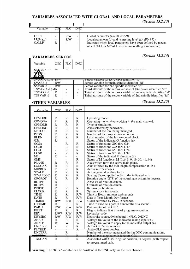
8/21/2019 CNC 8055 M Operator Manual
http://slidepdf.com/reader/full/cnc-8055-m-operator-manual 618/702
9
(Section 13.2.13)
(Section 13.2.14)
(Section 13.2.15)
VARIABLES ASSOCIATED WITH GLOBAL AND LOCAL PARAMETERS
Variable CNC PLC DNC
GUP n - R/W - Global parameter (n) (100-P299).LUP (a,b) - R/W - Local parameter (b) and its nesting level (a). (P0-P25).CALLP R - - Indicates which local parameters have been defined by means
of a PCALL or MCALL instruction (calling a subroutine).
VARIABLES SERCOS
Variable CNC PLC DNC
SETGE(X-C) W W - Work gear and parameter set for (X-C) axis driveSETGES W W - Work gear and parameter set for main spindle driveSSETGS W W - Work gear and parameter set for 2nd spindle driveSVAR(X-C) id R/W - - Sercos variable for (X-C) axis identifier "id"SVARS id R/W - - Sercos variable for main spindle identifier "id"SSVAR id R/W - - Sercos variable for 2nd spindle identifier "id"TSVAR(X-C) idR - - Third attribute of the sercos variable of (X-C) axis identifier "id"TSVARS id R - - Third attribute of the sercos variable of main spindle identifier "id"TSSVAR id R - - Third attribute of the sercos variable of 2nd spindle identifier "id"
OTHER VARIABLES
Variable CNC PLC DNC
OPMODE R R R Operating mode.OPMODA R R R Operating mode when working in the main channel.OPMODB R R R Type of simulation.OPMODC R R R Axes selected by handwheel.NBTOOL R R R Number of the tool being managedPRGN R R R Number of the program in execution.BLKN R R R Label number of the last executed block.
GSn R - - Status of the indicated G function (n).GGSA - R R Status of functions G00 thru G24.GGSB - R R Status of functions G25 thru G49.GGSC - R R Status of functions G50 thru G74.GGSD - R R Status of functions G75 thru G99.MSn R - - Status of the indicated M function (n)GMS - - R Status of M functions: M (0..6, 8, 9, 19, 30, 41..44)PLANE R R R Axes which form the active main plane.LONGAX R R R Axis affected by the tool length compensation (G15).MIRROR R R R Active mirror images.SCALE R R R Active general Scaling factor.SCALE(X-C) R R R Scaling Factor applied only to the indicated axis.ORGROT R R R Rotation angle (G73) of the coordinate system in degrees.ROTPF R - - Abscissa of rotation center.ROTPS R - - Ordinate of rotation center.
PRBST R R R Returns probe status.CLOCK R R R System clock in seconds.TIME R R R/W Time in Hours, minutes and seconds.DATE R R R/W Date in Year-Month-Day formatTIMER R/W R/W R/W Clock activated by PLC, in seconds.CYTIME R R R Time to execute a part in hundredths of a second.PARTC R/W R/W R/W Part counter of the CNC.FIRST R R R Flag to indicate first time of program execution.KEY R/W* R/W R/W keystroke code.KEYSRC R/W R/W R/W Keystroke source, 0=keyboard, 1=PLC, 2=DNCANAIn R R R Voltage (in volts) of the indicated analog input (n).ANAOn W W W Voltage (in volts) to apply to the indicated output (n).CNCERR - R R Active CNC error number.PLCERR - - R Active PLC error number.DNCERR - R - Number of the error generated during DNC communications.
AXICOM R R R Pair of axes toggled with function G28TANGAN R R R Associated with G45. Angular position, in degrees, with respect
to programmed path.
Warning: The "KEY" variable can be "written" at the CNC only via the user channel.

8/21/2019 CNC 8055 M Operator Manual
http://slidepdf.com/reader/full/cnc-8055-m-operator-manual 619/702
10
HIGH LEVEL PROGRAMMING
DISPLAY STATEMENTS
(ERROR whole number, “error text”) Stops execution of program and displays indicated error.
(MSG “message”) Displays indicated message.
(DGWZ expression 1, .... expression 6) Define the graphics display area
ENABLING/DISABLING STATEMENTS
(ESBLK and DSBLK) The CNC executes all the blocks which are found between ESBLK andDSBLK as if they were a single block.
(ESTOP and DSTOP) Enable (ESTOP) and disable (DSTOP) of the Stop key and the externalStop signal (PLC)
(EFHOLD and DFHOLD) Enable (EFHOLD) and disable (DFHOLD) of the Feed-Hold input (PLC)
FLOW CONTROLLING STATEMENTS
(GOTO N(expression)) Causes a jump within the same program, to the block defined by label N(expression)
(RPT N(expression), N(expression)) Repeats the execution of the part of a program existingbetween two blocks defined by means of labelsN(expression)
(IF condition <action1> ELSE <action2>) Analyzes the given condition which must be a relationalexpression. If the condition is true (result equals 1),<action1> will be executed, otherwise (result equals 0)<action2> will be executed.
SUBROUTINE STATEMENTS
(SUB integer) Definition of subroutine
(RET) End of subroutine
(CALL (expression)) Call to subroutine
(PCALL (expression, (assignment statement), (assignment statement),...) Call to a subroutine.Besides, allows the initialization, by means of assignment statements, of up to26 local parameters of this subroutine.
(MCALL (expression), (assignment statement), (assignment statement),...) The same as PCALL,but converting the subroutine indicated into a modal subroutine.
(MDOFF) Cancellation of modal subroutine
(PROBE (expression),(assignment statement), (assignment statement),...) Executes a probingcanned cycle, its parameters being initialized by means of assignment statements.
(DIGIT (expression),(assignment statement), (assignment statement),...)Executes a digitizing cannedcycle, its parameters being initialized by means of assignment statements.
(TRACE (expression),(assignment statement), (assignment statement),...) Executes a tracingcanned cycle, its parameters being initialized by means of assignment statements.
(REPOS X, Y, Z, ...) It must always be used inside interruption subroutines and it facilitates therepositioning of the machine axes to the interruption point.
(Section 14.2)
(Section 14.3)
(Section 14.4)
(Section 14.5)
1 2 3 4 5 6 7 8 9 0 1 2 3 4 5
1 2 3 4 5 6 7 8 9 0 1 2 3 4 5
1 2 3 4 5 6 7 8 9 0 1 2 3 4 5
1 2 3 4 5 6 7 8 9 0 1 2 3 4 5
1 2 3 4 5 6 7 8 9 0 1 2 3 4 5
1 2 3 4 5 6 7 8 9 0 1 2 3 4 5
1 2 3 4 5 6 7 8 9 0 1 2 3 4 5
1 2 3 4 5 6 7 8 9 0 1 2 3 4 5
1 2 3 4 5 6 7 8 9 0 1 2 3 4 5
1 2 3 4 5 6 7 8 9 0 1 2 3 4 5
1 2 3 4 5 6 7 8 9 0 1 2 3 4 5
1 2 3 4 5 6 7 8 9 0 1 2 3 4 5
1 2 3 4 5 6 7 8 9 0 1 2 3 4 5
1 2 3 4 5 6 7 8 9 0 1 2 3 4 5
1 2 3 4 5 6 7 8 9 0 1 2 3 4 5
1 2 3 4 5 6 7 8 9 0 1 2 3 4 5
1 2 3 4 5 6 7 8 9 0 1 2 3 4 5
C

8/21/2019 CNC 8055 M Operator Manual
http://slidepdf.com/reader/full/cnc-8055-m-operator-manual 620/702
11
PROGRAM STATEMENTS
(EXECP(expression), (directory) Starts the execution of the program
(OPEN P(expression), (destination directory), A/D, “program comment”) Starts generating anew program and allows it to be associated with a program comment.
(WRITE <block text>) Adds the information contained in <block text> after the last program block of the program which was being generated with OPEN P, as a new programblock.
CUSTOMIZING STATEMENTS
(PAGE(expression)) Displays the user page number (0-255) or system page number (>1000)indicated.
(SYMBOL (expression 1),(expression 2),(expression 3) Displays the symbol (0-255) indicated byexpression 1
Its position on the screen is defined by expression 2 (row,0-639) and byexpression 3(column,0-335).
(IB(expression)=INPUT”text”,format) Displays the text indicated in the data input window andstores the data input by the user in the input variable (IBn).
(ODW(expression 1), (expression 2), (expression 3) Defines and draws a white window on screen (1 rowx 14 columns).
Its position on screen is defined by expression 2(row) and by expression3 (column).
(DW (expression 1)=(expression 2), DW(expression 3) = (expression 4),...) Displays the numerical dataindicated by expression 2,4,.. in windows indicated by the value of expression 1,3....
(SK (expression 1)=”text 1", (expression 2)=”text 2",...)Defines and displays the new softkey menu
indicated.
(WKEY) Stops the execution of a program until a key is pressed.
(WBUF”text”(expression)) Adds the text and the value of the expression, once this has been evaluated,to the block which is being edited and in the data input window.
(SYSTEM) Ends the execution of user customized program and returns to standardCNC menu.
(Section 14.6)
(Section 14.7)

8/21/2019 CNC 8055 M Operator Manual
http://slidepdf.com/reader/full/cnc-8055-m-operator-manual 621/702
12
1 2 3 4 5 6 7 8 9 0 1 2 3 4 5
1 2 3 4 5 6 7 8 9 0 1 2 3 4 5
1 2 3 4 5 6 7 8 9 0 1 2 3 4 5
1 2 3 4 5 6 7 8 9 0 1 2 3 4 5
1 2 3 4 5 6 7 8 9 0 1 2 3 4 5
1 2 3 4 5 6 7 8 9 0 1 2 3 4 5
1 2 3 4 5 6 7 8 9 0 1 2 3 4 5
1 2 3 4 5 6 7 8 9 0 1 2 3 4 5
1 2 3 4 5 6 7 8 9 0 1 2 3 4 5
1 2 3 4 5 6 7 8 9 0 1 2 3 4 5
1 2 3 4 5 6 7 8 9 0 1 2 3 4 5
1 2 3 4 5 6 7 8 9 0 1 2 3 4 5
1 2 3 4 5 6 7 8 9 0 1 2 3 4 5
1 2 3 4 5 6 7 8 9 0 1 2 3 4 5
1 2 3 4 5 6 7 8 9 0 1 2 3 4 5
1 2 3 4 5 6 7 8 9 0 1 2 3 4 5
1 2 3 4 5 6 7 8 9 0 1 2 3 4 5
D KEY CODES

8/21/2019 CNC 8055 M Operator Manual
http://slidepdf.com/reader/full/cnc-8055-m-operator-manual 622/702
13
1 2 3 4 5 6 7 8 9 0 1 2 3 4 5
1 2 3 4 5 6 7 8 9 0 1 2 3 4 5
1 2 3 4 5 6 7 8 9 0 1 2 3 4 5
1 2 3 4 5 6 7 8 9 0 1 2 3 4 5
1 2 3 4 5 6 7 8 9 0 1 2 3 4 5
1 2 3 4 5 6 7 8 9 0 1 2 3 4 5
1 2 3 4 5 6 7 8 9 0 1 2 3 4 5
1 2 3 4 5 6 7 8 9 0 1 2 3 4 5
1 2 3 4 5 6 7 8 9 0 1 2 3 4 5
1 2 3 4 5 6 7 8 9 0 1 2 3 4 5
1 2 3 4 5 6 7 8 9 0 1 2 3 4 5
1 2 3 4 5 6 7 8 9 0 1 2 3 4 5
1 2 3 4 5 6 7 8 9 0 1 2 3 4 5
1 2 3 4 5 6 7 8 9 0 1 2 3 4 5
1 2 3 4 5 6 7 8 9 0 1 2 3 4 5
1 2 3 4 5 6 7 8 9 0 1 2 3 4 5
1 2 3 4 5 6 7 8 9 0 1 2 3 4 5
E LOGIC OUTPUTS FOR KEY CODE STATUS

8/21/2019 CNC 8055 M Operator Manual
http://slidepdf.com/reader/full/cnc-8055-m-operator-manual 623/702
14
1 2 3 4 5 6 7 8 9 0 1 2 3 4 5
1 2 3 4 5 6 7 8 9 0 1 2 3 4 5
1 2 3 4 5 6 7 8 9 0 1 2 3 4 5
1 2 3 4 5 6 7 8 9 0 1 2 3 4 5
1 2 3 4 5 6 7 8 9 0 1 2 3 4 5
1 2 3 4 5 6 7 8 9 0 1 2 3 4 5
1 2 3 4 5 6 7 8 9 0 1 2 3 4 5
1 2 3 4 5 6 7 8 9 0 1 2 3 4 5
1 2 3 4 5 6 7 8 9 0 1 2 3 4 5
1 2 3 4 5 6 7 8 9 0 1 2 3 4 5
1 2 3 4 5 6 7 8 9 0 1 2 3 4 5
1 2 3 4 5 6 7 8 9 0 1 2 3 4 5
1 2 3 4 5 6 7 8 9 0 1 2 3 4 5
1 2 3 4 5 6 7 8 9 0 1 2 3 4 5
1 2 3 4 5 6 7 8 9 0 1 2 3 4 5
1 2 3 4 5 6 7 8 9 0 1 2 3 4 5
1 2 3 4 5 6 7 8 9 0 1 2 3 4 5
F KEY INHIBITING CODES

8/21/2019 CNC 8055 M Operator Manual
http://slidepdf.com/reader/full/cnc-8055-m-operator-manual 624/702
15
PROGRAMMING ASSISTANCE SYSTEM PAGES
These pages can be displayed by means of the high level mnemonic “PAGE”. They all belongto the CNC system and are used as help pages for their respective functions.
GLOSSARY HELP
Page 1000 Preparatory functions G00-G09.Page 1001 Preparatory functions G10-G19.Page 1002 Preparatory functions G20-G44.Page 1003 Preparatory functions G53-G59.Page 1004 Preparatory functions G60-G69.Page 1005 Preparatory functions G70-079.Page 1006 Preparatory functions G80-G89.Page 1007 Preparatory functions G90-G99.Page 1008 Miscellaneous (auxiliary) functions M.Page 1009 Miscellaneous M functions with the symbol for next page.
Page 1010 Coincides with 250 of the directory if it exists.Page 1011 Coincides with 251 of the directory if it exists.Page 1012 Coincides with 252 of the directory if it exists.Page 1013 Coincides with 253 of the directory if it exists.Page 1014 Coincides with 254 of the directory if it exists.Page 1015 Coincides with 255 of the directory if it exists.Page 1016 High level language listing (from A to G)Page 1017 High level language listing (from H to N)Page 1018 High level language listing (from 0 to S)Page 1019 High level language listing (from T to Z)Page 1020 High level accessible variables (1st part)Page 1021 High level accessible variables (2nd part)
Page 1022 High level accessible variables (3rd part)Page 1023 High level accessible variables (4th part)Page 1024 High level accessible variables (5th part)Page 1025 High level accessible variables (6th part)Page 1026 High level accessible variables (7th part)Page 1027 High level accessible variables (8th part)Page 1028 High level accessible variables (9th part)Page 1029 High level accessible variables (10th part)Page 1030 High level accessible variables (11th part).Page 1031 High level accessible variables (12th part).Page 1032 Arithmetic operators.
1 2 3 4 5 6 7 8 9 0 1 2 3 4 5
1 2 3 4 5 6 7 8 9 0 1 2 3 4 5
1 2 3 4 5 6 7 8 9 0 1 2 3 4 5
1 2 3 4 5 6 7 8 9 0 1 2 3 4 5
1 2 3 4 5 6 7 8 9 0 1 2 3 4 5
1 2 3 4 5 6 7 8 9 0 1 2 3 4 5
1 2 3 4 5 6 7 8 9 0 1 2 3 4 5
1 2 3 4 5 6 7 8 9 0 1 2 3 4 5
1 2 3 4 5 6 7 8 9 0 1 2 3 4 5
1 2 3 4 5 6 7 8 9 0 1 2 3 4 5
1 2 3 4 5 6 7 8 9 0 1 2 3 4 5
1 2 3 4 5 6 7 8 9 0 1 2 3 4 5
1 2 3 4 5 6 7 8 9 0 1 2 3 4 5
1 2 3 4 5 6 7 8 9 0 1 2 3 4 5
1 2 3 4 5 6 7 8 9 0 1 2 3 4 5
1 2 3 4 5 6 7 8 9 0 1 2 3 4 5
1 2 3 4 5 6 7 8 9 0 1 2 3 4 5
G
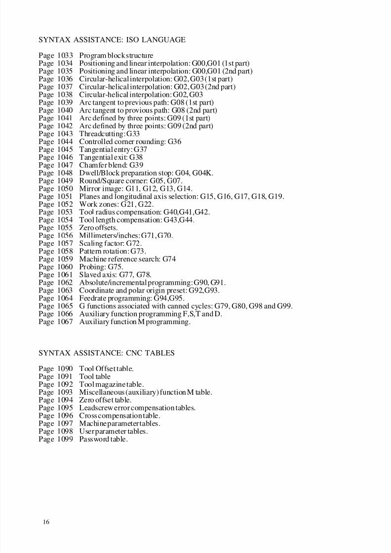
8/21/2019 CNC 8055 M Operator Manual
http://slidepdf.com/reader/full/cnc-8055-m-operator-manual 625/702
16
SYNTAX ASSISTANCE: ISO LANGUAGE
Page 1033 Program block structurePage 1034 Positioning and linear interpolation: G00,G01 (1st part)Page 1035 Positioning and linear interpolation: G00,G01 (2nd part)Page 1036 Circular-helical interpolation: G02, G03 (1st part)Page 1037 Circular-helical interpolation: G02, G03 (2nd part)
Page 1038 Circular-helical interpolation: G02, G03Page 1039 Arc tangent to previous path: G08 (1st part)Page 1040 Arc tangent to provious path: G08 (2nd part)Page 1041 Arc defined by three points: G09 (1st part)Page 1042 Arc defined by three points: G09 (2nd part)Page 1043 Threadcutting: G33Page 1044 Controlled corner rounding: G36Page 1045 Tangential entry: G37Page 1046 Tangential exit: G38Page 1047 Chamfer blend: G39Page 1048 Dwell/Block preparation stop: G04, G04K.Page 1049 Round/Square corner: G05, G07.Page 1050 Mirror image: G11, G12, G13, G14.Page 1051 Planes and longitudinal axis selection: G15, G16, G17, G18, G19.Page 1052 Work zones: G21, G22.Page 1053 Tool radius compensation: G40,G41,G42.Page 1054 Tool length compensation: G43,G44.Page 1055 Zero offsets.Page 1056 Millimeters/inches: G71, G70.Page 1057 Scaling factor: G72.Page 1058 Pattern rotation: G73.Page 1059 Machine reference search: G74Page 1060 Probing: G75.Page 1061 Slaved axis: G77, G78.Page 1062 Absolute/incremental programming: G90, G91.
Page 1063 Coordinate and polar origin preset: G92,G93.Page 1064 Feedrate programming: G94,G95.Page 1065 G functions associated with canned cycles: G79, G80, G98 and G99.Page 1066 Auxiliary function programming F,S,T and D.Page 1067 Auxiliary function M programming.
SYNTAX ASSISTANCE: CNC TABLES
Page 1090 Tool Offset table.Page 1091 Tool table
Page 1092 Tool magazine table.Page 1093 Miscellaneous (auxiliary) function M table.Page 1094 Zero offset table.Page 1095 Leadscrew error compensation tables.Page 1096 Cross compensation table.Page 1097 Machine parameter tables.Page 1098 User parameter tables.Page 1099 Password table.

8/21/2019 CNC 8055 M Operator Manual
http://slidepdf.com/reader/full/cnc-8055-m-operator-manual 626/702
17
SYNTAX ASSISTANCE: HIGH LEVEL
Page 1100 : ERROR and MSG mnemonics.Page 1101 : GOTO and RPT mnemonics.Page 1102 : OPEN and WRITE mnemonics.Page 1103 : SUB and RET mnemonics.Page 1104 : CALL, PCALL, MCALL, MDOFF and PROBE mnemonics.
Page 1105 : DSBLK, ESBLK, DSTOP, ESTOP, DFHOLD, EFHOLD mnemonics.Page 1106 : IF statement.Page 1107 : Assignment blocks.Page 1108 : Mathematical expressions.Page 1109 : PAGE mnemonic.Page 1110 : ODW mnemonic.Page 1111 : DW mnemonic.Page 1112 : IB mnemonic.Page 1113 : SK mnemonic.Page 1114 : WKEY and SYSTEM mnemonics.Page 1115 : KEYSRC mnemonic.Page 1116 : WBUF mnemonic.Page 1117 : SYMBOL mnemonic.
SYNTAX ASSISTANCE: CANNED CYCLES
Page 1070 : Straight line pattern canned cycle: G60.Page 1071 : Rectangular pattern canned cycle: G61.Page 1072 : Grid pattern canned cycle: G62.Page 1073 : Circular pattern canned cycle: G63.Page 1074 : Arc pattern canned cycle: G64.Page 1075 : Arc-chord pattern canned cycle: G65.Page 1076 : Irregular pocket (with islands) canned cycle: G66.
Page 1077 : Irregular pocket roughing cycle: G67.Page 1078 : Irregular pocket finishing cycle: G68.Page 1079 : Complex deep hole drilling cycle: G69.Page 1080 : Drilling cycle: G81.Page 1081 : Drilling cycle with dwell: G82.Page 1082 : Simple deep hole drilling cycle: G83Page 1083 : Tapping cycle: G84Page 1084 : Reaming cycle: G85.Page 1085 : Boring cycle with withdrawal in G00: G86.Page 1086 : Rectangular pocket canned cycle: G87.Page 1087 : Circular pocket canned cycle: G88.Page 1088 : Boring cycle with withdrawal in G01: G89.

8/21/2019 CNC 8055 M Operator Manual
http://slidepdf.com/reader/full/cnc-8055-m-operator-manual 627/702
18
MAINTENANCE
Cleaning:
The accumulated dirt inside the unit may act as a screen preventing the proper dissipation
of the heat generated by the internal circuitry which could result in a harmful overheatingof the CNC and, consequently, possible malfunctions.
On the other hand, accumulated dirt can sometimes act as an electrical conductor andshortcircuit the internal circuitry, especially under high humidity conditions.
To clean the operator panel and the monitor, a smooth cloth should be used which has beendipped into de-ionized water and /or non abrasive dish-washer soap (liquid, never powder)or 75º alcohol.
Do not use highly compressed air to clean the unit because it could generate electrostaticdischarges.
The plastics used on the front panel are resistant to :
1.- Grease and mineral oils2.- Bases and bleach3.- Dissolved detergents4.- Alcohol
Avoid the action of solvents such as Chlorine hydrocarbons , Benzole ,Esters and Ether which can damage the plastics used to make the unit’s frontpanel.
Preventive Inspection:
If the CNC does not turn on when actuating the start-up switch, verify that the monitorfuses are in good condition and that they are the right ones.
To check the fuses, first disconnect the power to the CNC.
Do not open this unit.Only personnel authorized by Fagor Automation may open this mo-
dule.
Do not handle the connectors with the unit connected to main ACpower.
Before handling these connectors, make sure that the unit is notconnected to main AC power.
Note :Fagor Automation shall not be held responsible for any material orphysical damage derived from the violation of these basic safetyrequirements.
1 2 3 4 5 6 7 8 9 0 1 2 3 4 5
1 2 3 4 5 6 7 8 9 0 1 2 3 4 5
1 2 3 4 5 6 7 8 9 0 1 2 3 4 5
1 2 3 4 5 6 7 8 9 0 1 2 3 4 5
1 2 3 4 5 6 7 8 9 0 1 2 3 4 5
1 2 3 4 5 6 7 8 9 0 1 2 3 4 5
1 2 3 4 5 6 7 8 9 0 1 2 3 4 5
1 2 3 4 5 6 7 8 9 0 1 2 3 4 5
1 2 3 4 5 6 7 8 9 0 1 2 3 4 5
1 2 3 4 5 6 7 8 9 0 1 2 3 4 5
1 2 3 4 5 6 7 8 9 0 1 2 3 4 5
1 2 3 4 5 6 7 8 9 0 1 2 3 4 5
1 2 3 4 5 6 7 8 9 0 1 2 3 4 5
1 2 3 4 5 6 7 8 9 0 1 2 3 4 5
1 2 3 4 5 6 7 8 9 0 1 2 3 4 5
1 2 3 4 5 6 7 8 9 0 1 2 3 4 5
1 2 3 4 5 6 7 8 9 0 1 2 3 4 5
H
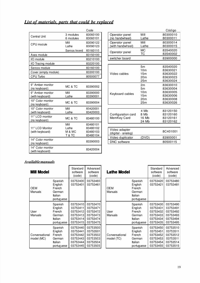
8/21/2019 CNC 8055 M Operator Manual
http://slidepdf.com/reader/full/cnc-8055-m-operator-manual 628/702
19
List of materials, parts that could be replaced
Available manuals
ledoMlliM ledoMlliM ledoMlliM ledoMlliM ledoMlliMdradnatSerawtfos)edoc(
decnavdAerawtfos)edoc(
ledoMehtaL ledoMehtaL ledoMehtaL ledoMehtaL ledoMehtaLdradnatSerawtfos)edoc(
decnavdAerawtfos)edoc(
MEOslaunaM
hsinapShsilgnEhcnerF
namreGnailatI
eseugutrop
0043573010435730
0643573016435730
MEOslaunaM
hsinapShsilgnEhcnerF
namreGnailatI
eseugutrop
0243573012435730
0843573018435730
resUslaunaM
hsinapShsilgnEhcnerF
namreGnailatI
eseugutrop
014357301143573021435730314357304143573051435730
074357301743573027435730374357304743573057435730
resUslaunaM
hsinapShsilgnEhcnerF
namreGnailatI
eseugutrop
034357301343573023435730334357304343573053435730
094357301943573029435730394357304943573059435730
lanoitasrevnoC)CM(ledom
hsinapShsilgnEhcnerF
namreGnailatI
eseugutrop
044357301443573024435730344357304443573054435730
005357301053573020535730305357304053573050535730
lanoitasrevnoC)CT(ledom
hsinapShsilgnEhcnerF
namreGnailatI
eseugutrop
054357301543573025435730354357304543573055435730
015357301153573021535730115357304153573051535730
edoC
tinUlartneC seludom3
seludom60010603810106038
eludomUPC lliM
ehtaL2210903832109038
draobsocreS 01106138
eludomsexA 00105138
eludomO / I 00101238
eludomgnicarTO / I 00102238
eludomsocreS 00106138
)eludomytpme(revoC 00100338
obruTUPC 77000508
rotinomrebmA"9)draobyekon(
CT&CM 20009338
rotinomrebmA"9)draobyekhtiw(
lliMehtaL
0000933810009338
rotinomroloC"01)draobyekon(
CT&CM 40009338
rotinomroloC"01)draobyekhtiw(
lliMehtaL
1000243830002438
rotinomDCL"11)draobyekon(
CT&CM 00108438
rotinoMDCL"11)draobyekhtiw(
lliMehtaL
CM&MCT&T
10108438201084383010843840108438
rotinomroloC"41)draobyekon(
30009338
rotinomroloC"41 )draobyekhtiw( 40002438
ogidóC
lenaprotarepO)leehwdnahon(
lliMehtaL
0100030811000308
lenaprotarepO)leehwdnahhtiw(
lliMehtaL
4100030851000308
lenaprotarepO CMCT
0200453820004538
draobrehctiws 00000938
selbacoediV
m5m01m51m02m52
0200453812003638220036383200363842003638
selbacdraobyeK
m2m5
m01m51
m02m52
01003638400036385000363860003638
8000363862003638
dracnoitarugifnoCdraCyeKmeM
bM4bM8
bM61bM42
05102138061021381610213826102138
retpadaoediV)golana-latigid(
100104C8
rotacilpudoediV )DVD( 10000938
erawtfosCND 51100508

8/21/2019 CNC 8055 M Operator Manual
http://slidepdf.com/reader/full/cnc-8055-m-operator-manual 629/702
8055M CNC
ERROR TROUBLESHOOTING MANUAL
Ref. 9905 (ing)
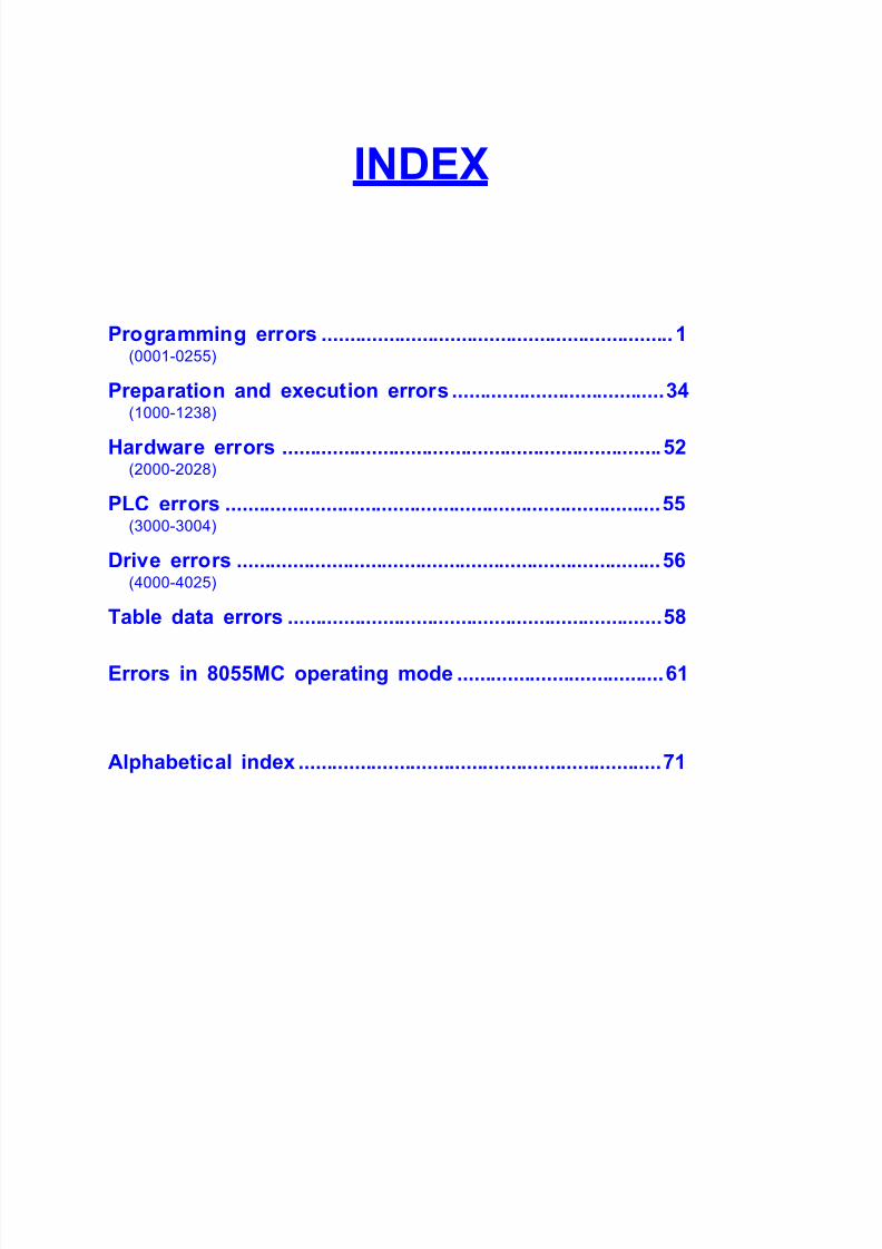
8/21/2019 CNC 8055 M Operator Manual
http://slidepdf.com/reader/full/cnc-8055-m-operator-manual 630/702
INDEX
Programming errors ............................................................... 1(0001-0255)
Preparation and execution errors ......................................34(1000-1238)
Hardware errors ....................................................................52(2000-2028)
PLC errors ..............................................................................55(3000-3004)
Drive errors ............................................................................56(4000-4025)
Table data errors ...................................................................58
Errors in 8055MC operating mode .....................................61
Alphabetical index .................................................................71

8/21/2019 CNC 8055 M Operator Manual
http://slidepdf.com/reader/full/cnc-8055-m-operator-manual 631/702
ERROR TROUBLESHOOTING MANUAL 1
8055M CNC
0001 ‘Empty line.’
DETECTED While editing at the CNC or while executing a program transmitted via DNC.
CAUSE/S The various causes might be:
1.- When trying to enter into a program or execute an empty block or containing the label (block number).
2.- Within the «Irregular pocket canned cycle with islands (G66)», when parameter “S” (beginning of the profile) is
greater than parameter “E” (end of profile).
SOLUTION The solution for each cause is:
1.- The CNC cannot enter into the program or execute an empty line. To do that, use the «;» symbol at the beginning
of that block. The CNC will ignore the rest of the block.
2.- The value of parameter “S” (block where the profile definition begins) must be lower than the value of parameter
“E” (block where the profile definition ends).
0002 ‘Improper data’
DETECTED While editing at the CNC or while executing a program transmitted via DNC.
CAUSE/S The various causes might be:
1.- When editing an axis coordinate after the cutting conditions (F, S, T or D) or the «M» functions.
2.- When the marks of the block skip (conditional block /1, /2 or /3) are not at the beginning of the block.
3.- When programming a block number greater than 9999 while programming in ISO code.
4.- When trying to define the coordinates of the machining starting point in the finishing operation (G68) of the
«Irregular pocket canned cycle».
5.- While programming in high-level, the value of the RPT instruction exceeds 9999.
SOLUTION The solution for each cause is:
1/2.- Remember that the programming order is:
1.- Block skip (conditional block /1, /2 or /3).2.- Label (N).
3.- «G» functions.
4.- Axes coordinates (X, Y, Z…).
5.- Machining conditions (F, S, T, D).
6.- «M» functions.
All the data need not be programmed.
3.- Correct the block syntax. Program the labels between 0 and 9999
4.- No point can be programmed within the definition of the finishing cycle (G68) for the «Irregular pocket canned
cycle». The CNC selects the point where it will start machining. The programming format is:
G68 B— L— Q— I— R— K— V—
And then the cutting conditions.
5.- Correct the block syntax. Program the labels between 0 and 9999
0003 ‘Improper data order.’
DETECTED While editing at the CNC or while executing a program transmitted via DNC.
CAUSE The machining conditions or the tool data have been programmed in the wrong order.
SOLUTION Remember that the programming order is:
… F— S— T— D— …
All the data need not be programmed.
PROGRAMMING ERRORS

8/21/2019 CNC 8055 M Operator Manual
http://slidepdf.com/reader/full/cnc-8055-m-operator-manual 632/702
2 ERROR TROUBLESHOOTING MANUAL
8055M CNC
0004 ‘No more information allowed in the block.’
DETECTED While editing at the CNC or while executing a program transmitted via DNC.
CAUSE/S The various causes might be:
1.- When editing a «G» function after an axis coordinate.
2.- When trying to edit some data after a «G» function (or after its associated parameters) which must go alone in the
block (or which only admits its own associated data).
3.- When assigning a numeric value to a parameter that does not need it.
SOLUTION The solution for each cause is:
1.- Remember that the programming order is:
1.- Block skip (conditional block /1, /2 or /3).
2.- Label (N).
3.- «G» functions.
4.- Axes coordinates. (X, Y, Z…).
5.- Machining conditions (F, S, T, D).
6.- «M» functions.
All the data need not be programmed.
2.- There are some «G» functions which carry associated data in the block. Maybe, this type of functions do not let
program other type of information after their associated parameters. On the other hand, neither machining conditions,
(F, S), tool data (T, D) nor «M» functions may be programmed.
3.- There are some «G» functions having certain parameters associated to them which do not need to be defined withvalues.
0005 ‘Repeated information’
DETECTED While editing at the CNC or while executing a program transmitted via DNC.
CAUSE The same data has been entered twice in a block.
SOLUTION Correct the syntax of the block. The same data cannot be defined twice in a block.
0006 ‘Improper data format’
DETECTED While editing at the CNC or while executing a program transmitted via DNC.
CAUSE While defining the parameters of a machining canned cycle, a negative value has been assigned to a parameter whichonly admits positive values.
SOLUTION Verify the format of the canned cycle. In some canned cycles, there are parameters which only accept positive values.
0007 ‘Incompatible G functions.’
DETECTED While editing at the CNC or while executing a program transmitted via DNC.
CAUSE/S The various causes might be:
1.- When programming in the same block two «G» functions which are incompatible with each other.
2.- When trying to define a canned cycle in a block containing a nonlinear movement (G02, G03, G08, G09, G33).
SOLUTION The solution for each cause is:
1.- There are groups of «G» functions which cannot go together in the block because they involve actions incompatible
with each other. For example:G01/G02: Linear and circular interpolation
G41/G42: Left-hand or right-hand tool radius compensation.
This type of functions must be programmed in different blocks.
2.- A canned cycle must be defined in a block containing a linear movement. In other words, to define a cycle, a “G00”
or a “G01” must be active. Nonlinear movements (G02, G03, G08 and G09) may be defined in the blocks
following the profile definition.

8/21/2019 CNC 8055 M Operator Manual
http://slidepdf.com/reader/full/cnc-8055-m-operator-manual 633/702
ERROR TROUBLESHOOTING MANUAL 3
8055M CNC
0008 ‘Nonexistent G function’
DETECTED While editing at the CNC or while executing a program transmitted via DNC.
CAUSE A nonexistent «G» function has been programmed.
SOLUTION Check the syntax of the block and verify that a different «G» function is not being edited by mistake.
0009 ‘No more G functions allowed in the block’
DETECTED While editing at the CNC or while executing a program transmitted via DNC.
CAUSE A «G» function has been programmed after the machining conditions or after the tool data.
SOLUTION Remember that the programming order is:
1.- Block skip (conditional block /1, /2 or /3).
2.- Label (N).
3.- «G» functions.
4.- Axes coordinates. (X, Y, Z…).
5.- Machining conditions (F, S, T, D).
6.- «M» functions.
All the data need not be programmed.
0010 ‘No more M functions allowed in the block’
DETECTED While editing at the CNC or while executing a program transmitted via DNC.
CAUSE More than 7 «M» functions have been programmed in a block.
SOLUTION The CNC does not let program more than 7 «M» functions in a block. To do so, write them in a separate block. The
«M» functions may go alone in a block.
0011 ‘This G or M function must be alone.’
DETECTED While editing at the CNC or while executing a program transmitted via DNC.
CAUSE The block contains either a «G» or an «M» function that must go alone in the block.
SOLUTION Write it alone in the block.
0012 ‘Program F, S, T, D before the M functions.’
DETECTED While editing at the CNC or while executing a program transmitted via DNC.
CAUSE A machining condition (F, S) or tool data (T, D) has been programmed after the «M» functions.
SOLUTION Remember that the programming order is:
… F— S— T— D— M—
Up to 7 «M» functions may be programmed .
All the data need not be programmed.
0014 ‘Do not program labels by parameters.’
DETECTED While editing at the CNC or while executing a program transmitted via DNC.
CAUSE A label (block number) has been defined with a parameter.
SOLUTION The programming of a block number is optional, but it cannot be defined with a parameter, only with a number between
0 and 9999.
0015 ‘Number of repetitions not possible.’
DETECTED While editing at the CNC or while executing a program transmitted via DNC.
CAUSE A repetition has been programmed wrong or the block does not admit repetitions.
SOLUTION High level instructions do not admit a number of repetitions at the end of the block. To do a repetition, assign to the
block to be repeated a label (block number) and use the RPT instruction.

8/21/2019 CNC 8055 M Operator Manual
http://slidepdf.com/reader/full/cnc-8055-m-operator-manual 634/702
4 ERROR TROUBLESHOOTING MANUAL
8055M CNC
0016 ‘Program: G15 axis.’
DETECTED While editing at the CNC or while executing a program transmitted via DNC.
CAUSE In the function «Longitudinal axis selection (G15)» the parameter for the axis has not been programmed.
SOLUTION Check the syntax of the block. The definition of the “G15” function requires the name of the new longitudinal axis.
0017 ‘Program: G16 axis-axis.’
DETECTED While editing at the CNC or while executing a program transmitted via DNC.
CAUSE In the function «Main plane selection by two axes (G16)» one of the two parameters for the axes has not been
programmed.
SOLUTION Check the syntax of the block. The definition of the “G16” function requires the name of the axes defining the new
work plane.
0018 ‘Program: G22 K(1/2/3/4) S(0/1/2).’
DETECTED While editing at the CNC or while executing a program transmitted via DNC.
CAUSE In the function «Enable/Disable work zones (G22)» the type of enable or disable of the work zone has not been defined
or it has been assigned the wrong value.SOLUTION The parameter for enabling or disabling the work zones “S” must always be programmed and it may take the following
values.
- S=0: The work zone is disabled.
- S=1: It is enabled as a no-entry zone.
- S=2: It is enabled as a no-exit zone.
0019 ‘Program: work zone K1, K2, K3 or K4.’
DETECTED While editing at the CNC or while executing a program transmitted via DNC.
CAUSE/S The various causes might be:
1.- A “G20”, “G21” or “G22” function has been programmed without defining the work zone K1, K2, K3 or K4.
2.- The programmed work zone is smaller than 0 or greater than 4.
SOLUTION The solution for each cause is:
1.- The programming format for functions “G20”, “G21” and “G22” is:
G20 K— X...C±5.5 (Definition of lower work zone limits).
G21 K— X...C±5.5 (Definition of upper work zone limits).
G22 K— S— (Enable/disable work zones).
Where:
- K : Is the work zone.
- X...C : Are the axes where the limits are defined.
- S : Is the type of work zone enable.
2.- The “K” work zone may only have the values of K1, K2, K3 or K4.
0020 ‘Program G36-G39 with R+5.5.’
DETECTED While editing at the CNC or while executing a program transmitted via DNC.
CAUSE In the “G36” or “G39” function, the “R” parameter has not been programmed or it has been assigned a negative value.
SOLUTION To define “G36” or “G39”, parameter “R” must also be defined and with a positive value).
G36: R= Rounding radius.
G39: R= Distance between the end of the programmed path and the point to be chamfered.

8/21/2019 CNC 8055 M Operator Manual
http://slidepdf.com/reader/full/cnc-8055-m-operator-manual 635/702
ERROR TROUBLESHOOTING MANUAL 5
8055M CNC
0021 ‘Program: G72 S5.5 or axes.’
DETECTED While editing at the CNC or while executing a program transmitted via DNC.
CAUSE/S The various causes might be:
1.- When programming a general scaling factor (G72) without the scaling factor to apply.
2.- When programming a particular scaling factor (G72) to several axes, but the axes have been defined in the wrong
order.
SOLUTION Remember that this function must be programmed in the following order:
- “G72 S5.5” When applying a general scaling factor (to all axes).
- “G72 X…C5.5” When applying a particular scaling factor to one or several axes.
0022 ‘Program: G73 Q (angle) I J (center).’
DETECTED While editing at the CNC or while executing a program transmitted via DNC.
CAUSE/S The parameters of the «Pattern rotation (G73)» function have been programmed wrong. The causes may be:
1.- The rotation angle has not been defined.
2.- Only one of the rotation center coordinates has been defined.
3.- The rotation center coordinates have been defined in the wrong order.
SOLUTION The programming format for this function is:
G73 Q (angle) [I J] (center)The “Q” value must always be programmed.
The “I”, “J” values are optional, but if programmed, both must be programmed.
0023 ‘Block incompatible when defining a profile.’
DETECTED While editing at the CNC or while executing a program transmitted via DNC.
CAUSE In the set of blocks defining a pocket profile, there is a block containing a «G» function that cannot be part of the profile
definition.
SOLUTION The “G” functions available in the profile definition of a pocket (2D/3D) are:
G00: Beginning of the profile.
G01: Linear interpolation.
G02/G03: Clockwise/counterclockwise interpolation.
G06: Circle center in absolute coordinates.
G08: Arc tangent to previous path.
G09: Three point arc.
G36: Controlled corner rounding
G39: Chamfer.
G53: Programming with respect to home.
G70/G71: Inch/metric programming.
G90/G91: Programming in absolute/incremental coordinates.
G93: Polar origin preset.
And also, in the 3D pocket profile:
G16: Main plane selection by two axes.
G17: Main plane X-Y and longitudinal Z.
G18: Main plane Z-X and longitudinal Y.
G19: Main plane Y-Z and longitudinal X.
0024 ‘High level blocks not allowed when defining a profile.’
DETECTED While editing at the CNC or while executing a program transmitted via DNC.
CAUSE Within the set of blocks defining a pocket profile, a high level block has been programmed.
SOLUTION The pocket profile must be defined in ISO code. High level instructions are not allowed (GOTO, MSG, RPT ...).

8/21/2019 CNC 8055 M Operator Manual
http://slidepdf.com/reader/full/cnc-8055-m-operator-manual 636/702
6 ERROR TROUBLESHOOTING MANUAL
8055M CNC
0025 ‘Program: G77 axes (2 thru 6).’
DETECTED While editing at the CNC or while executing a program transmitted via DNC.
CAUSE In the «Axis slaving (G77)» function, the parameters for the axes have not been programmed.
SOLUTION The programming of “G77” function requires at least two axes.
0026 ‘Program: G93 I J.’
DETECTED While editing at the CNC or while executing a program transmitted via DNC.
CAUSE In the «Polar origin preset (G93)» function, some of the parameters for the new polar origin have not been programmed.
SOLUTION Remember that the programming format for this function is:
G93 I— J—
The “I”, “J” values are optional, but if programmed, both must be programmed and they indicate the new polar origin.
0027 ‘G49 T X Y Z S, X Y Z A B C ‘, or, ‘ X Y Z Q R S.’
DETECTED While editing at the CNC or while executing a program transmitted via DNC.
CAUSE In the «Incline plane definition (G49)» function, a parameter has been programmed twice.
SOLUTION Check the syntax of the block. The programming formats are:T X Y Z S X Y Z A B C X Y Z Q R S
0028 ‘G2 or G3 not allowed when programming a canned cycle.’
DETECTED While editing at the CNC or while executing a program transmitted via DNC.
CAUSE A canned cycle has been attempted to execute while the “G02”, “G03” or “G33” functions were active.
SOLUTION To execute a canned cycle, “G00” or “G01” must be active. Maybe, a “G02” or “G03” function was activated in the M
code history instead. Check that these functions are not active when the canned cycle is defined.
0029 ‘G60: [A] /X I K/(2) [P Q R S T U V].’
DETECTED While editing at the CNC or while executing a program transmitted via DNC.
CAUSE The parameters of the «Multiple machining in a straight line (G60)» have been programmed wrong. These are the
possible causes:
1.- Some mandatory parameter is missing.
2.- The parameters of the cycle have not been edited in the correct order.
3.- Some data might be superfluous.
SOLUTION In this type of machining, two of the following parameters must always be programmed:
X : Path length.
I : Step between machining operations.
K : Number of machining operations.
The rest of the parameters are optional. The parameters must be programmed in the order shown by the error message.

8/21/2019 CNC 8055 M Operator Manual
http://slidepdf.com/reader/full/cnc-8055-m-operator-manual 637/702
ERROR TROUBLESHOOTING MANUAL 7
8055M CNC
0030 ‘G61-2: [A B] /X I J/(2) Y J D (2)/ [P Q R S T U V].’
DETECTED While editing at the CNC or while executing a program transmitted via DNC.
CAUSE The parameters of the «Multiple machining in a parallelogram pattern (G61)» or «Multiple machining in a grid pattern
(G62)» cycle have been programmed wrong. These may be the probable causes:
1.- Some mandatory parameter is missing.
2.- The parameters of the cycle have not been edited in the correct order.
3.- Some data might be superfluous.
SOLUTION This type of machining requires the programming of two parameters of each group (X, I, K) and (Y, J, D).
X/Y : Path length.
I/J : Step between machining operations.
K /D : Number of machining operations.
The rest of the parameters are optional. The parameters must be edited in the order indicated by the error message.
0031 ‘G63: X Y /I K/(1) [C P][P Q R S T U V].’
DETECTED While editing at the CNC or while executing a program transmitted via DNC.
CAUSE The parameters of the «Multiple machining in a circle (G63)» cycle have been programmed wrong. These may be the
probable causes:
1.- Some mandatory parameter is missing.2.- The parameters of the cycle have not been edited in the correct order.
3.- Some data might be superfluous.
SOLUTION This type of machining requires the programming of:
X/Y : Distance from the center to the first hole.
And one of the following data:
I : Angular step between machining operations.
K : Number of machining operations.
The rest of the parameters are optional. The parameters must be edited in the order indicated by the error message.
0032 ‘G64: X Y /I K/(1) [C P][P Q R S T U V.’
DETECTED While editing at the CNC or while executing a program transmitted via DNC.
CAUSE The parameters of the «multiple machining in an arc (G64)» cycle have been programmed wrong. These may be theprobable causes:
1.- Some mandatory parameter is missing.
2.- The parameters of the cycle have not been edited in the correct order.
3.- Some data might be superfluous.
SOLUTION This type of machining requires the programming of:
X/Y : Distance from the center to the first hole.
B : Total angular travel.
And one of the following data:
I : Angular step between machining operations.
K : Number of machining operations.
The rest of the parameters are optional. The parameters must be edited in the order indicated by the error message.
8/21/2019 CNC 8055 M Operator Manual
http://slidepdf.com/reader/full/cnc-8055-m-operator-manual 638/702
8 ERROR TROUBLESHOOTING MANUAL
8055M CNC
0033 ‘G65: X Y /A I/(1) [C P].’
DETECTED While editing at the CNC or while executing a program transmitted via DNC.
CAUSE The parameters of the «Multiple machining programmed by means of an arc chord (G65)» cycle have been programmed
wrong. These may be the probable causes:
1.- Some mandatory parameter is missing.
2.- The parameters of the cycle have not been edited in the correct order.
3.- Some data might be superfluous.
SOLUTION This type of machining requires the programming of:
X/Y : Distance from the center to the first hole.
And one of the following data:
A : Angle of the matrix of the chord with the abscissa axis (in degrees).
I : Chord length.
The rest of the parameters are optional. The parameters must be edited in the order indicated by the error message.
0034 ‘G66: [D H][R I][C J][F K] S E [Q].’
DETECTED While editing at the CNC or while executing a program transmitted via DNC.
CAUSE The parameters of the «Irregular pocket canned cycle with islands (G66)» have been programmed wrong. These may
be the probable causes:
1.- Some mandatory parameter is missing.
2.- The parameters of the cycle have not been edited in the correct order.
3.- Some data might be superfluous.
SOLUTION This machining cycle requires the programming of :
S : First block of the description of the geometry of the profiles making up the pocket.
E : End block of the description of the geometry of the profiles making up the pocket.
The rest of the parameters are optional. The parameters must be edited in the order indicated by the error message. Also,
the following parameters cannot be defined:
H if D has not been defined.
I if R has not been defined.
J if C has not been defined.
K if F has not been defined.
The (X...C) position where the machining takes place cannot be programmed either.
0035 ‘G67: [A] B [C] [I] [R] [K] [V].’
DETECTED While editing at the CNC or while executing a program transmitted via DNC.
CAUSE The parameters of the roughing (2D/3D pocket) or semi-finishing (3D pocket) operation have been programmed
wrong in the «Irregular pocket canned cycle with islands». These may be the probable causes:
1.- Some mandatory parameter is missing.
2.- The parameters of the cycle have not been edited in the correct order.
3.- Some data might be superfluous.
SOLUTION This machining cycle requires the programming of :
ROUGING OPERATION (2D or 3D pockets)
B : Machining pass.
I : Total pocket depth.
R : Coordinate of the reference plane.SEMI-FINISHING OPERATION (3D pockets)
B : Machining pass.
I : Total pocket depth (if no roughing operation has been defined).
R : Coordinate of the reference plane (if no roughing operation has been defined).
The rest of the parameters are optional. The parameters must be edited in the order indicated by the error message. The
(X...C) position where the machining takes place cannot be programmed in this cycle.

8/21/2019 CNC 8055 M Operator Manual
http://slidepdf.com/reader/full/cnc-8055-m-operator-manual 639/702
ERROR TROUBLESHOOTING MANUAL 9
8055M CNC
0036 ‘G68: [B] [L] [Q] [J] [I] [R] [K].’
DETECTED While editing at the CNC or while executing a program transmitted via DNC.
CAUSE The parameters for the finishing operation (2D/3D pocket) have been programmed wrong in the «Irregular pocket
cycle with islands. These may be the probable causes:
1.- A parameter has been programmed which does not match the calling format.
2.- Some mandatory parameter is missing.
3.- The parameters of the cycle have not been edited in the correct order.
SOLUTION This machining cycle requires the programming of :
2D pockets
B : Cutting pass (if no roughing operation has been defined).
I : Total pocket depth (if no roughing operation has been defined).
R : Coordinate of the reference plane (if no roughing operation has been defined).
3D pockets
B : Cutting pass
I : Total pocket depth (if no roughing or semi-finishing operation has been defined).
R : Coordinate of the reference plane (if no roughing or semi-finishing operation has been defined).
The rest of the parameters are optional. The parameters must be edited in the order indicated by the error message. The
(X...C) position where the machining takes place cannot be programmed in this cycle.
0037 ‘G69: I B [C D H J K L R].’
DETECTED While editing at the CNC or while executing a program transmitted via DNC.
CAUSE The parameters of the «Deep hole drilling cycle with variable peck (G69)». These may be the probable causes:
1.- Some mandatory parameter is missing.
2.- The parameters of the cycle have not been edited in the correct order.
SOLUTION This type of machining requires the programming of:
I : Machining depth.
B : Drilling peck.
The rest of the parameters are optional. The parameters must be edited in the order indicated by the error message. The
(X...C) position where the machining takes place can be programmed in this cycle.
0038 ‘G81-84-85-86-89: I [K].’DETECTED While editing at the CNC or while executing a program transmitted via DNC.
CAUSE The parameters have been programmed wrong in the following cycles: drilling (G81), tapping (G84), reaming (G85)
or boring (G86/G89). This could be because parameter “I : Machining depth” is missing in the canned cycle being
edited.
SOLUTION This type of machining requires the programming of:
I : Machining depth.
The rest of the parameters are optional. The parameters must be edited in the order indicated by the error message. The
(X...C) position where the machining takes place can be programmed in this cycle.
0039 ‘G82: I K.’
DETECTED While editing at the CNC or while executing a program transmitted via DNC.
CAUSE The parameters have been programmed wrong in the «Drilling cycle with dwell (G82)». This could be because some
parameter is missing.
SOLUTION Both parameters must be programmed in this cycle:
I : Machining depth.
K : Dwell at the bottom.
To program a drilling operation without dwell at the bottom, use function G81.
The parameters must be edited in the order indicated by the error message. The (X...C) position where the machining
takes place can be programmed in this cycle.

8/21/2019 CNC 8055 M Operator Manual
http://slidepdf.com/reader/full/cnc-8055-m-operator-manual 640/702
10 ERROR TROUBLESHOOTING MANUAL
8055M CNC
0040 ‘G83: I J.’
DETECTED While editing at the CNC or while executing a program transmitted via DNC.
CAUSE The parameters have been programmed wrong in the «Deep hole drilling with constant peck (G83)». This could be
because some parameter is missing.
SOLUTION This type of machining requires the programming of:
I : Machining depth.J : Number of pecks.
The parameters must be edited in the order indicated by the error message. The (X...C) position where the machining
takes place can be programmed in this cycle.
0041 ‘G87: I J K B [C] [D] [H] [L] [V].’
DETECTED While editing at the CNC or while executing a program transmitted via DNC.
CAUSE The parameters have been programmed wrong in the «Rectangular pocket canned cycle (G87)». These may be the
probable causes:
1.- Some mandatory parameter is missing.
2.- The parameters of the cycle have not been edited in the correct order.
SOLUTION This type of machining requires the programming of:
I : Pocket Depth.J : Distance from the center to the edge of the pocket along the abscissa axis.
K : Distance from the center to the edge of the pocket along the ordinate axis.
B : Defines the machining pass along the longitudinal axis.
The rest of the parameters are optional. The parameters must be edited in the order indicated by the error message. The
(X...C) position where the machining takes place can be programmed in this cycle.
0042 ‘G88: I J B [C] [D] [H] [L] [V].’
DETECTED While editing at the CNC or while executing a program transmitted via DNC.
CAUSE The parameters have been programmed wrong in the «Circular pocket canned cycle (G88)». These may be the
probable causes:
1.- Some mandatory parameter is missing.
2.- The parameters of the cycle have not been edited in the correct order.
SOLUTION This type of machining requires the programming of:
I : Pocket depth.
J : Pocket radius.
B : Defines the machining pass along the longitudinal axis.
The rest of the parameters are optional. The parameters must be edited in the order indicated by the error message. The
(X...C) position where the machining takes place can be programmed in this cycle.
0043 ‘Incomplete Coordinates.’
DETECTED While editing at the CNC or while executing a program transmitted via DNC.
CAUSE/S The various causes might be:
1.- During simulation or execution, when trying to make a movement defined with only one coordinate of the end
point or without defining the arc radius while a «circular interpolation (G02/G03) is active.
2.- During editing, when editing a circular movement (G02/G03) by defining only one coordinate of the end point or
not defining the arc radius.
SOLUTION The solution for each cause is:
1.- A “G02” or “G03” function may be programmed previously in the program history. In this case, to make a move,
both coordinates of the end point and the arc radius must be defined. To make a linear movement, program “G01”.
2.- To make a circular movement (G02/G03), both coordinates of the end point and the arc radius must be programmed.

8/21/2019 CNC 8055 M Operator Manual
http://slidepdf.com/reader/full/cnc-8055-m-operator-manual 641/702
ERROR TROUBLESHOOTING MANUAL 11
8055M CNC
0044 ‘Incorrect Coordinates.’
DETECTED While editing at the CNC or while executing a program transmitted via DNC.
CAUSE The “I : Machining depth” parameter is missing in the definition of a machining canned cycle (G81-G89)
SOLUTION This type of machining requires the programming of:
I : Machining depth.
The rest of the parameters are optional. The parameters must be edited in the order indicated by the error message. The(X...C) position where the machining takes place can be programmed in this cycle.
0045 ‘Polar coordinates not allowed.’
DETECTED While editing at the CNC or while executing a program transmitted via DNC.
CAUSE When «Programming with respect to home (G53)», the end point has been defined in polar or cylindrical coordinates
or in Cartesian coordinates with an angle.
SOLUTION When programming with respect to home, only Cartesian coordinates may be programmed.
0046 ‘Axis does not exist.’
DETECTED While editing at the CNC or while executing a program transmitted via DNC.CAUSE/S The various causes might be:
1.- When editing a block whose execution involves the movement of a nonexistent axis.
2.- Sometimes, this error comes up while editing a block that is missing a parameter of the «G» function. This is
because some parameters with an axis name have a special meaning inside certain «G» functions. For example:
G69 I— B—.In this case, parameter “B” has a special meaning after “I“. If the “I” parameter is left out, the CNC assumes “B”
as the position where the machining takes place on that axis. If that axis does not exist, it will issue this error
message.
SOLUTION The solution for each cause is:
1.- Check that the axis name being edited is correct.
2.- Check the block syntax and make sure that all the mandatory parameters have been programmed.
0047 ‘Program axes.’DETECTED While editing at the CNC or while executing a program transmitted via DNC.
CAUSE No axis has been programmed in a function requiring an axis.
SOLUTION Some instructions require the programming of axes (REPOS, G14, G20, G21…).
0048 ‘Incorrect order of axes.’
DETECTED While editing at the CNC or while executing a program transmitted via DNC.
CAUSE The axis coordinates have not been programmed in the correct order or an axis has been programmed twice in the same
block.
SOLUTION Remember that the correct programming order for the axes is:
X— Y— Z— U— V— W— A— B— C—All axes need not be programmed:

8/21/2019 CNC 8055 M Operator Manual
http://slidepdf.com/reader/full/cnc-8055-m-operator-manual 642/702
12 ERROR TROUBLESHOOTING MANUAL
8055M CNC
0049 ‘Point incompatible with active plane.’
DETECTED While editing at the CNC or while executing a program transmitted via DNC.
CAUSE/S The various causes might be:
1.- When trying to do a circular interpolation, the end point is not in the active plane.
2.- When trying to do a tangential exit in a path that is not in the active plane.
SOLUTION The solution for each cause is:1.- Maybe a plane has been defined with “G16”, “G17”, “G18” or “G19”. In this case, circular interpolations can only
be carried out on the main axes defining that plane. To define a circular interpolation in another plane, it must be
defined beforehand.
2.- Maybe a plane has been defined with “G16”, “G17”, “G18” or “G19”. In this case, corner rounding, chamfers and
tangential entries/exits can only be carried out on the main axes defining that plane. To do it in another plane, it must
be defined beforehand.
0053 ‘Program pitch.’
DETECTED While editing at the CNC or while executing a program transmitted via DNC.
CAUSE In the «Electronic threading cycle (G33)» the parameter for the thread pitch is missing.
SOLUTION Remember that the programming format for this function is:
G33 X...C— L—Where:
L : Is the thread pitch.
0054 ‘Pitch programmed incorrectly.’
DETECTED While editing at the CNC or while executing a program transmitted via DNC.
CAUSE A helical interpolation has been programmed with the wrong or negative pitch.
SOLUTION Remember that the programming format is:
G02/G03 X— Y— I— J— Z— K—
Where:
K : is the helical pitch (always positive value).
0057 ‘Do not program a slaved axis.’
DETECTED While editing at the CNC or while executing a program transmitted via DNC.
CAUSE The various causes might be:
1.- When trying to move an axis alone while being slaved to another one.
2.- When trying to slave an axis that is already slaved using the G77 function «Electronic axis slaving».
SOLUTION The solution for each cause is:
1.- A slaved axis cannot be moved separately. To move a slaved axis, its master axis must be moved. Both axes will
move at the same time.
Example: If the Y axis is slaved to the X axis, an X axis move must be programmed in order to move the
Y axis (together with the X axis).
To unslave the axis, program “G78”.
2.- An axis cannot be slaved to two different axes at the same time. To unslave the axes, program “G78”.
8/21/2019 CNC 8055 M Operator Manual
http://slidepdf.com/reader/full/cnc-8055-m-operator-manual 643/702
ERROR TROUBLESHOOTING MANUAL 13
8055M CNC
0058 ‘Do not program a GANTRY axis.’
DETECTED While editing at the CNC or while executing a program transmitted via DNC.
CAUSE/S The various causes might be:
1.- When trying to move an axis alone while being slaved to another one as a GANTRY axis
2.- When defining an operation on a GANTRY axis. (Definition of work zone limits, planes, etc.).
SOLUTION The solution for each cause is:1.- A GANTRY axis cannot be moved separately. To move a GANTRY axis, its associated axis must be moved. Both
axes will move at the same time.
Example: If the Y axis is a GANTRY axis associated with the X axis, an X axis move must be programmed
in order to move the Y axis (together with the X axis).
GANTRY axes are defined by machine parameter.
2.- The axes defined as GANTRY cannot be used in the definition of operations or movements. These operations are
defined with the main axis that the GANTRY axis is associated with.
0059 ‘HIRTH axis: program only integer values.’
DETECTED While editing at the CNC or while executing a program transmitted via DNC.
CAUSE A rotation of a HIRTH axis has been programmed with a decimal value.
SOLUTION HIRTH axes do not accept decimal angular values. They must be full degrees.
0061 ‘ELSE not associated with IF.’
DETECTED While editing at the CNC or while executing a program transmitted via DNC.
CAUSE/S The various causes might be:
1.- While editing in High level language, when editing the “ELSE” instruction without having previously programmed
an “IF”.
2.- When programming in high level language, an “IF“ is programmed without associating it with any action after the
condition.
SOLUTION Remember that the programming formats for this instruction are:
(IF (condition) <action1>)
(IF (condition) <action1> ELSE <action2>)
If the condition is true, it executes the <action1>, otherwise, it executes the <action2>.
0062 ‘Program label N(0-9999).’
DETECTED While editing at the CNC or while executing a program transmitted via DNC.
CAUSE While programming in high level language, a block number out of the 0-9999 range has been programmed in the
“RPT” or “GOTO” instruction.
SOLUTION Remember that the programming formats for these instructions are:
(RPT N(block number), N(block number))
(GOTO N(block number))
The block number (label) must be between 0 and 9999.
0063 ‘Program subroutine number 1 thru 9999.’
DETECTED While editing at the CNC or while executing a program transmitted via DNC.
CAUSE While programming in high level language, a subroutine number out of the 0-9999 range has been programmed in the
“SUB“ instruction.
SOLUTION Remember that the programming format for this instruction is:
(SUB (integer))
The subroutine number must be between 0 and 9999.

8/21/2019 CNC 8055 M Operator Manual
http://slidepdf.com/reader/full/cnc-8055-m-operator-manual 644/702
14 ERROR TROUBLESHOOTING MANUAL
8055M CNC
0064 ‘Repeated subroutine.’
DETECTED While editing at the CNC or while executing a program transmitted via DNC.
CAUSE There has been an attempt to define a subroutine already existing in another program of the memory.
SOLUTION In the CNC memory, there could not be more than one subroutine with the same identifying number even if they are
contained in different programs.
0065 ‘The main program cannot have a subroutine.’
DETECTED In execution or while executing programs transmitted via DNC.
CAUSE/S The various causes might be:
1.- An attempt has been made to define a subroutine in the MDI execution mode.
2.- A subroutine has been defined in the main program.
SOLUTION The solution for each cause is:
1.- Subroutines cannot be defined from the «MDI execution» option of the menu.
2.- Subroutines must be defined after the main program or in a separate program. They cannot be defined before or
inside the main program.
0066 ‘Expecting a message.’DETECTED While editing at the CNC or while executing a program transmitted via DNC.
CAUSE While programming in high level, the “MSG” or “ERROR” instruction has been edited but without the message to be
displayed.
SOLUTION Remember that the programming format of these instructions is:
(MSG “message”)
(ERROR integer, “error message”)
Although it can also be programmed like:
(ERROR integer)
(ERROR “error message”)
0067 ‘OPEN is missing.’
DETECTED In execution or while executing programs transmitted via DNC.
CAUSE While programming in high level, a “WRITE” instruction has been edited, but the OPEN instruction has not been
written previously to tell it where that instruction has to be executed.
SOLUTION The “OPEN“ instruction must be edited before the “WRITE” instruction to «tell» the CNC where (in which program)
it must execute the “WRITE” instruction.
0069 ‘Program does not exist.’
DETECTED In execution or while executing programs transmitted via DNC.
CAUSE Inside the «Irregular pocket with islands cycle (G66)», it has been programmed that the profiles defining the irregular
pocket are in another program (parameter “Q”), but that program does not exist.
SOLUTION Parameter “Q” defines which program contains the definition of the profiles that, in turn, define the irregular pocketwith islands. If this parameter is programmed, that program number must exist and it must contain the labels defined
by parameters “S” and “E”.
0070 ‘Program already exists.’
DETECTED In execution or while executing programs transmitted via DNC.
CAUSE This error comes up during execution when using the “OPEN” instruction (While programming in high level language)
to create an already existing program.
SOLUTION Change the program number or use parameters A/D in the “OPEN” instruction:
(OPEN P———,A/D,… )
Where:
- A: Appends new blocks after the existing ones.
- D: Deletes the existing program and it opens it as a new one.

8/21/2019 CNC 8055 M Operator Manual
http://slidepdf.com/reader/full/cnc-8055-m-operator-manual 645/702
ERROR TROUBLESHOOTING MANUAL 15
8055M CNC
0071 ‘Expecting a parameter’
DETECTED While editing at the CNC or while executing a program transmitted via DNC.
CAUSE/S The various causes might be:
1.- When defining the function «Modification of canned cycle parameters (G79)», the parameter to be modified has
not been indicated.
2.- While editing the machine parameter table, the wrong parameter number has been entered (maybe the “P” character
is missing) or another action is being carried out (moving around in the table) before quitting the table editing
mode.
SOLUTION The solution for each cause is:
1.- To define the “G79” function, the cycle parameter to be modified must be indicated as well as its new value.
2.- Enter the parameter number to be edited or press [ESC] to quit this mode.
0072 ‘Parameter does not exist.’
DETECTED While editing at the CNC or while executing a program transmitted via DNC.
CAUSE While programming in high level language, the “ERROR” instruction has been edited, but the error number to be
displayed has been defined either with a local parameter greater than 25 or with a global parameter greater than 299.
SOLUTION The parameters used by the CNC are:
- Local: 0-25-Global: 100-299
0075 ‘Read-only variable.’
DETECTED While editing at the CNC or while executing a program transmitted via DNC.
CAUSE An attempt has been made to assign a value to a read-only variable.
SOLUTION Read-only variables cannot be assigned any values through programming. However, their values can be assigned to
a parameter.
0077 ‘Analog output not available.’
DETECTED While editing at the CNC or while executing a program transmitted via DNC.
CAUSE An attempt has been made to write to an analog output currently being used by the CNC.
SOLUTION The selected analog output may be currently used by an axis or a spindle. Select another analog output between 1 and
8.
0078 ‘Program channel 0(CNC),1(PLC) or 2(DNC).’
DETECTED While editing at the CNC or while executing a program transmitted via DNC.
CAUSE While programming in high level language, the “KEYSCR” instruction has been programmed, but the source of the
keys is missing.
SOLUTION When programming the “KEYSCR” instruction, the parameter for the source of the keys must always be programmed:
(KEYSCR=0) : CNC keyboard
(KEYSCR=1) : PLC(KEYSCR=2) : DNC
The CNC only lets modifying the contents of this variable if it is «zero»

8/21/2019 CNC 8055 M Operator Manual
http://slidepdf.com/reader/full/cnc-8055-m-operator-manual 646/702
16 ERROR TROUBLESHOOTING MANUAL
8055M CNC
0079 ‘Program error number 0 thru 9999.’
DETECTED While editing at the CNC or while executing a program transmitted via DNC.
CAUSE While programming in high level language, the “ERROR” instruction has been programmed, but the error number to
be displayed is missing.
SOLUTION Remember that the programming format for this instruction is:
(ERROR integer, “error message”)Although it can also be programmed as follows:
(ERROR integer)
(ERROR “error message“)
0081 ‘Incorrect expression.’
DETECTED While editing at the CNC or while executing a program transmitted via DNC.
CAUSE While programming in high level language, an expression has been edited with the wrong format.
SOLUTION Correct the block syntax.
0082 ‘Incorrect operation.’
DETECTED While editing at the CNC or while executing a program transmitted via DNC.
CAUSE/S The various causes might be:
1.- While programming in high level language, the assignment of a value to a parameter is incomplete.
2.- While programming in high level language, the call to a subroutine is incomplete.
SOLUTION Correct (complete) the format to assign a value to a parameter or a call to a subroutine.
0083 ‘Incomplete operation.’
DETECTED While editing at the CNC or while executing a program transmitted via DNC.
CAUSE/S The various causes might be:
1.- While programming in high level language, the “IF” instruction has been edited without the condition between
brackets.
2.- While programming in high level language, the “DIGIT” instruction has been edited without assigning a value to
some parameter.
SOLUTION The solution for each cause is:
1.- Remember that the programming format for this instruction are:
(IF (condition) <action1>)
(IF (condition) <action1> ELSE <action2>)
If the condition is true, it executes the <action1>, otherwise, it executes <action2>.
2.- Correct the syntax of the block. All the parameters defined within the “DIGIT” instruction must have a value
assigned to them.
0084 ‘Expecting “=”.’
DETECTED While editing at the CNC or while executing a program transmitted via DNC.
CAUSE While programming in high level language, a symbol or data has been entered that does not match the syntax of the
block.
SOLUTION Enter the “=” symbol in the right place.
0085 ‘Expecting “)”.’
DETECTED While editing at the CNC or while executing a program transmitted via DNC.
CAUSE While programming in high level language, a symbol or data has been entered that does not match the syntax of the
block.
SOLUTION Enter the “)” symbol in the right place.

8/21/2019 CNC 8055 M Operator Manual
http://slidepdf.com/reader/full/cnc-8055-m-operator-manual 647/702
ERROR TROUBLESHOOTING MANUAL 17
8055M CNC
0086 ‘Expecting “(”.’
DETECTED While editing at the CNC or while executing a program transmitted via DNC.
CAUSE While programming in high level language, a symbol or data has been entered that does not match the syntax of the
block.
SOLUTION Enter the “(” symbol in the right place.
0087 ‘Expecting “,”.’
DETECTED While editing at the CNC or while executing a program transmitted via DNC.
CAUSE/S The various causes might be:
1.- While programming in high level language, a symbol or data has been entered that does not match the syntax of the
block.
2.- While programming in high level language, an ISO-coded instruction has been programmed.
3.- While programming in high level language, an operation has been assigned either to a local parameter greater than
25 or to a global parameter greater 299.
SOLUTION The solution for each cause is:
1.- Enter the “,” symbol in the right place.
2.- A block cannot contain high level language instructions and ISO-coded instructions at the same time.
3.- The parameters used by the CNC are:- Local: 0-25.
- Global: 100-299.
Other parameters out of this range cannot be used in operations.
0089 ‘Logarithm of zero or negative number.’
DETECTED While editing at the CNC or while executing a program transmitted via DNC.
CAUSE An operation has been programmed which involves the calculation of a negative number or a zero.
SOLUTION Only logarithms of numbers greater than zero can be calculated. When working with parameters, that parameter may
have already acquired a negative value or zero. Check that the parameter does not reach the operation with that value.
0090 ‘Square root of a negative number.’
DETECTED While editing at the CNC or while executing a program transmitted via DNC.
CAUSE An operation has been programmed which involves the calculation of the square root of a negative number.
SOLUTION Only the square root of numbers greater than zero can be calculated. When working with parameters, that parameter
may have already acquired a negative value or zero. Check that the parameter does not reach the operation with that
value.
0091 ‘Division by zero.’
DETECTED While editing at the CNC or while executing a program transmitted via DNC.
CAUSE An operation has been programmed which involves a division by zero.SOLUTION Only divisions by numbers other than zero are allowed. When working with parameters, that parameter may have
already acquired a negative value or zero. Check that the parameter does not reach the operation with that value.
0092 ‘Base zero with positive exponent.’
DETECTED While editing at the CNC or while executing a program transmitted via DNC.
CAUSE An operation has been programmed which involves elevating zero to a negative exponent (or zero).
SOLUTION Zero can only be elevated to positive exponents greater than zero. When working with parameters, that parameter may
have already acquired a negative value or zero. Check that the parameter does not reach the operation with that value.

8/21/2019 CNC 8055 M Operator Manual
http://slidepdf.com/reader/full/cnc-8055-m-operator-manual 648/702
18 ERROR TROUBLESHOOTING MANUAL
8055M CNC
0093 ‘Negative base with decimal exponent.’
DETECTED While editing at the CNC or while executing a program transmitted via DNC.
CAUSE An operation has been programmed which involves elevating a negative number to a decimal exponent.
SOLUTION Negative numbers can only be elevated to integer exponents. When working with parameters, that parameter may have
already acquired a negative value or zero. Check that the parameter does not reach the operation with that value.
0094 ‘ASIN/ACOS range exceeded.’
DETECTED While editing at the CNC or while executing a program transmitted via DNC.
CAUSE An operation has been programmed which involves calculating the arcsine or arccosine of a number out of the ±1
range.
SOLUTION Only the arcsine (ASIN) or arccosine (ACOS) of numbers between ±1 can be calculated. When working with
parameters, that parameter may have already acquired a negative value or zero. Check that the parameter does not reach
the operation with that value.
0095 ‘Program row number.’
DETECTED While editing at the CNC or while executing a program transmitted via DNC.
CAUSE While editing a customizing program, a window has been programmed with the “ODW” instruction, but the vertical
position of the window on the screen is missing.
SOLUTION The vertical position of the window on the screen is defined by rows (0-25).
0096 ‘Program column number.’
DETECTED While editing at the CNC or while executing a program transmitted via DNC.
CAUSE While editing a customizing program, a window has been programmed with the “ODW” instruction, but the horizontal
position of the window on the screen is missing.
SOLUTION The horizontal position of the window on the screen is defined by columns (0-79).
0097 ‘Program another softkey.’
DETECTED While editing at the CNC or while executing a program transmitted via DNC.
CAUSE While editing a customizing program, the programming format for the “SK” instruction has not been respected.
SOLUTION Correct the syntax of the block. The programming format is:
(SK1=(text 1), SK2=(text 2)…)
If the “,” character is entered after a text, the CNC expects the name of another softkey.
0098 ‘Program softkeys 1 thru 7.’
DETECTED While executing in the user channel.
CAUSE In the block syntax, a softkey has been programmed out of the 1 to 7 range.SOLUTION Only softkeys within the 1 to 7 range can be programmed.
0099 ‘Program another window.’
DETECTED While editing at the CNC or while executing a program transmitted via DNC.
CAUSE While editing a customizing program, the programming format for the “DW” instruction has not been respected.
SOLUTION Correct the syntax of the block. The programming format is:
(DW1=(assignment), DW2=(assignment)…)
If the “,” character is entered after an assignment, the CNC expects the name of another window.

8/21/2019 CNC 8055 M Operator Manual
http://slidepdf.com/reader/full/cnc-8055-m-operator-manual 649/702
ERROR TROUBLESHOOTING MANUAL 19
8055M CNC
0100 ‘Program windows 0 thru 25.’
DETECTED While executing in the user channel.
CAUSE In the block syntax, a window has been programmed out of the 0 to 25 range.
SOLUTION Only windows within the 0 to 25 range can be programmed.
0101 ‘Program rows 0 thru 20.’
DETECTED While executing in the user channel.
CAUSE In the block syntax, a row has been programmed out of the 0 to 20 range.
SOLUTION Only rows within the 0 to 20 range can be programmed.
0102 ‘Program columns 0 thru 79.’
DETECTED While executing in the user channel.
CAUSE In the block syntax, a column has been programmed out of the 0 to 79 range.
SOLUTION Only columns within the 0 to 79 range can be programmed.
0103 ‘Program pages 0 thru 255.’
DETECTED While executing in the user channel.
CAUSE In the block syntax, a page has been programmed out of the 0 to 255 range.
SOLUTION Only pages within the 0 to 255 range can be programmed.
0104 ‘Program INPUT.’
DETECTED While editing at the CNC or while executing a program transmitted via DNC.
CAUSE While programming in high level language, an “IB” instruction has been edited without associating an “INPUT” to it.
SOLUTION Remember that the programming formats for this instruction are:
(IB (expression) = INPUT “text”, format)(IB (expression) = INPUT “text”)
0105 ‘Program inputs 0 thru 25.’
DETECTED While executing in the user channel.
CAUSE In the block syntax, an input has been programmed out of the 0 to 25 range.
SOLUTION Only inputs within the 0 to 25 range can be programmed.
0106 ‘Program numerical format.’
DETECTED While editing at the CNC or while executing a program transmitted via DNC.
CAUSE While programming in high level language, an “IB” instruction has been edited with non-numeric format.SOLUTION Remember that the programming format for this instruction is:
(IB (expression) = INPUT “text”, format)
Where «format» must be a signed number with 6 entire digits and 5 decimals at the most.
If the “,” character is entered after the text, the CNC expects the format.
0107 ‘Do not program formats greater than 6.5 .’
DETECTED While executing in the user channel.
CAUSE While programming in high level language, an “IB” instruction has been edited in a format with more than 6 entire
digits or more than 5 decimals.
SOLUTION Remember that the programming format for this instruction is:
(IB (expression) = INPUT “text”, format)
Where «format» must be a signed number with 6 entire digits and 5 decimals at the most.

8/21/2019 CNC 8055 M Operator Manual
http://slidepdf.com/reader/full/cnc-8055-m-operator-manual 650/702
20 ERROR TROUBLESHOOTING MANUAL
8055M CNC
0108 ‘This command can only be executed in the user channel.’
DETECTED During execution.
CAUSE An attempt has been made to execute a block containing information that can only be executed through the user
channel.
SOLUTION There are specific expressions for customizing programs that can only be executed inside the user program.
0109 ‘User channel: Do not program geometric aides, comp. or cycles’
DETECTED While executing in the user channel.
CAUSE An attempt has been made to execute a block containing geometric aide, tool radius/length compensation or machining
canned cycles.
SOLUTION Inside a customizing program the following cannot be programmed:
- Neither geometric assistance nor movements.
- Neither tool radius nor length compensation.
- Canned cycles.
0110 ‘Local parameters not allowed.’
DETECTED While editing at the CNC or while executing a program transmitted via DNC.
CAUSE Some functions can only be programmed with global parameters.
SOLUTION Global parameters are the ones included in the 100-299 range.
0111 ‘Block cannot be executed while running another program’
DETECTED While executing in MDI mode.
CAUSE An attempt has been made to execute a customizing instruction from MDI mode while the user channel program is
running.
SOLUTION Customizing instructions can only be executed through the user channel.
0112 ‘WBUF can only be executed in user channel while editing’DETECTED During execution or user channel execution.
CAUSE An attempt has been made to execute the “WBUF” instruction.
SOLUTION The “WBUF” instruction cannot be executed. It can only be used in the editing stage through the user input.
0113 ‘Table limits exceeded.’
DETECTED While editing tables.
CAUSE/S The various causes might be:
1.- In the tool offset table, an attempt has been made to define a tool offset with a greater number than allowed by the
manufacturer.
2.- In the parameter tables, an attempt has been made to define a nonexistent parameter.SOLUTION The tool offset number must be smaller than the one allowed by the manufacturer.
0114 ‘Offset: D3 R L I K.’
DETECTED While editing tables.
CAUSE In the tool offset table, the parameter editing order has not been respected.
SOLUTION Enter the table parameters in the right order.
0115 ‘Tool: T4 D3 F3 N5 R5(.2).’
DETECTED While editing tables.
CAUSE In the tool table, the parameter editing order has not been respected.
SOLUTION Enter the table parameters in the right order.

8/21/2019 CNC 8055 M Operator Manual
http://slidepdf.com/reader/full/cnc-8055-m-operator-manual 651/702
ERROR TROUBLESHOOTING MANUAL 21
8055M CNC
0116 ‘Zero offset: G54-59 axes (1-5).’
DETECTED While editing tables.
CAUSE In the Zero offset table, the zero offset to be defined (G54-G59) has not be selected.
SOLUTION Enter the table parameters in the right order. To fill out the zero offset table, first select the offset to be defined (G54-
G59) and then the zero offset position for each axis.
0117 ‘M function: M4 S4 bits(8).’
DETECTED While editing tables.
CAUSE In the «M» function table, the parameter editing order has not been respected.
SOLUTION Edit table following the format:
M1234 (associated subroutine) (customizing bits)
0118 ‘G51 [A] E’
DETECTED In execution or while executing programs transmitted via DNC.
CAUSE In the «Look-Ahead (G51)» function, the parameter for the maximum contouring error is missing.
SOLUTION This type of machining requires the programming of:E : Maximum contouring error.
The rest of the parameters are optional. The parameters must be edited in the order indicated by the error message.
0119 ‘Leadscrew: Position-Error.’
DETECTED While editing tables.
CAUSE In the leadscrew compensation tables, the parameter editing order has not been respected.
SOLUTION Enter the table parameters in the right order
P123 (position of the axis to be compensated) (leadscrew error at that point)
0120 ‘Incorrect axis.’
DETECTED While editing tables.
CAUSE In the leadscrew compensation tables, an attempt has been made to edit a different axis from the one corresponding to
that table.
SOLUTION Each axis has its own table for leadscrew compensation. The table for each axis can only contain the positions for that
axis.
0121 ‘Program P3 = value.’
DETECTED While editing tables.
CAUSE In the machine parameter table, the editing format has not been respected.
SOLUTION Enter the table parameters in the right order.
P123 = (parameter value)
0122 ‘Magazine: P(1-255) = T(1-9999).’
DETECTED While editing tables.
CAUSE In the tool magazine table, the editing format has not been respected or some data is missing.
SOLUTION Enter the table parameters in the right order.

8/21/2019 CNC 8055 M Operator Manual
http://slidepdf.com/reader/full/cnc-8055-m-operator-manual 652/702
22 ERROR TROUBLESHOOTING MANUAL
8055M CNC
0123 ‘Tool T0 does not exist.’
DETECTED While editing tables.
CAUSE In the tool table, an attempt has been made to edit a tool as T0.
SOLUTION No tool can be edited as T0. The first tool must be T1.
0124 ‘Offset D0 does not exist.’
DETECTED While editing tables.
CAUSE In the tool table, an attempt has been made to edit a tool offset as D0.
SOLUTION No tool offset can be edited as D0. The first tool offset must be D1.
0125 ‘Do not modify the active tool or the next one.’
DETECTED During execution.
CAUSE In the tool magazine table, an attempt has been made to change the active tool or the next one.
SOLUTION During execution, neither the active tool nor the next one may be changed.
0126 ‘Tool not defined.’
DETECTED While editing tables.
CAUSE In the tool magazine table, an attempt has been made to assign to the magazine position a tool that is not defined in the
tool table.
SOLUTION Define the tool in the tool table.
0127 ‘Magazine is not RANDOM.’
DETECTED While editing tables.
CAUSE There is no RANDOM magazine and, in the tool magazine table, the tool number does not match the tool magazine
position.
SOLUTION When the tool magazine is not RANDOM, the tool number must be the same as the magazine position (pocket
number).
0128 ‘The position of a special tool is set.’
DETECTED While editing tables.
CAUSE In the tool magazine table, an attempt has been made to place a tool in a magazine position reserved for a special tool.
SOLUTION When a special tool occupies more than one position in the magazine, it has a reserved position in the magazine. No
other tool can be placed in this position.
0129 ‘Next tool only possible in machining centers.’
DETECTED During execution.
CAUSE A tool change has been programmed with M06 and the machine is not a machining center (it is not expecting the next
tool).
SOLUTION When the machining is not a machining center, the tool change is done automatically when programming the tool
number «T».
0130 ‘Write 0/1.’
DETECTED While editing machine parameters
CAUSE An attempt has been made to assign the wrong value to a parameter.
SOLUTION The parameter only admits values of 0 or 1.
8/21/2019 CNC 8055 M Operator Manual
http://slidepdf.com/reader/full/cnc-8055-m-operator-manual 653/702
ERROR TROUBLESHOOTING MANUAL 23
8055M CNC
0131 ‘Write +/-.’
DETECTED While editing machine parameters
CAUSE An attempt has been made to assign the wrong value to a parameter.
SOLUTION The parameter only admits values of + or -.
0132 ‘Write YES/NO.’
DETECTED While editing machine parameters
CAUSE An attempt has been made to assign the wrong value to a parameter.
SOLUTION The parameter only admits values of YES or NO.
0133 ‘Write ON/OFF.’
DETECTED While editing machine parameters
CAUSE An attempt has been made to assign the wrong value to a parameter.
SOLUTION The parameter only admits values of ON or OFF.
0134 ‘Values 0 thru 2.’
DETECTED While editing machine parameters
CAUSE An attempt has been made to assign the wrong value to a parameter.
SOLUTION The parameter only admits values between 0 and 2.
0135 ‘Values 0 thru 3.’
DETECTED While editing machine parameters
CAUSE An attempt has been made to assign the wrong value to a parameter.
SOLUTION The parameter only admits values between 0 and 3.
0136 ‘Values 0 thru 4.’
DETECTED While editing machine parameters
CAUSE An attempt has been made to assign the wrong value to a parameter.
SOLUTION The parameter only admits values between 0 and 4.
0137 ‘Values 0 thru 9.’
DETECTED While editing machine parameters
CAUSE An attempt has been made to assign the wrong value to a parameter.
SOLUTION The parameter only admits values between 0 and 9.
0139 ‘Values 0 thru 100.’
DETECTED While editing machine parameters
CAUSE An attempt has been made to assign the wrong value to a parameter.
SOLUTION The parameter only admits values between 0 and 100.
0140 ‘Values 0 thru 255.’
DETECTED While editing machine parameters
CAUSE An attempt has been made to assign the wrong value to a parameter.
SOLUTION The parameter only admits values between 0 and 255.

8/21/2019 CNC 8055 M Operator Manual
http://slidepdf.com/reader/full/cnc-8055-m-operator-manual 654/702
24 ERROR TROUBLESHOOTING MANUAL
8055M CNC
0141 ‘Values 0 thru 9999.’
DETECTED While editing machine parameters
CAUSE/S The various causes might be:
1.- An attempt has been made to assign the wrong value to a parameter.
2.- During execution, when inside the program a call has been to a subroutine (MCALL, PCALL) greater than 9999.
SOLUTION The solution for each cause is:1.- The parameter only admits values between 0 and 9999.
2.- The subroutine number must be between 1 and 9999.
0142 ‘Values 0 thru 32767.’
DETECTED While editing machine parameters
CAUSE An attempt has been made to assign the wrong value to a parameter.
SOLUTION The parameter only admits values between 0 and 32767.
0144 ‘Values 0 thru 65535.’
DETECTED While editing machine parametersCAUSE An attempt has been made to assign the wrong value to a parameter.
SOLUTION The parameter only admits values between 0 and 65535.
0145 ‘Format +/- 5.5.’
DETECTED While editing machine parameters
CAUSE An attempt has been made to assign the wrong value to a parameter.
SOLUTION The parameter only admits values with the format: ± 5.5.
0147 ‘Numerical format exceeded.’
DETECTED While editing at the CNC or while executing a program transmitted via DNC.
CAUSE A data or parameter has been assigned a value greater than the established format.
SOLUTION Correct the syntax of the block. Most of the time, the numeric format will be 5.4 (5 integers and 4 decimals).
0148 ‘Text too long.’
DETECTED While editing at the CNC or while executing a program transmitted via DNC.
CAUSE While programming in high level language, the “ERROR” or “MSG” instruction has been assigned a text with more
than 59 characters.
SOLUTION Correct the syntax of the block. The “ERROR” and “MSG” instructions cannot be assigned texts longer than 59
characters.
0149 ‘Incorrect message.’
DETECTED While editing at the CNC or while executing a program transmitted via DNC.
CAUSE While programming in high level language, the text associated with the “ERROR” or “MSG” instruction has been
edited wrong.
SOLUTION Correct the syntax of the block. The programming format is:
(MSG “message”)
(ERROR number, “message”)
The message must be between “ ”.

8/21/2019 CNC 8055 M Operator Manual
http://slidepdf.com/reader/full/cnc-8055-m-operator-manual 655/702
ERROR TROUBLESHOOTING MANUAL 25
8055M CNC
0150 ‘Incorrect number of bits.’
DETECTED While editing tables.
CAUSE/S The various causes might be:
1.- In the «M» function table, in the section on customizing bits:
- The number does not have 8 bits.
- The number does not consist of 0’s and 1’s.
2.- In the machine parameter table, an attempt has been made to assign the wrong value of bit to a parameter.
SOLUTION The solution for each cause is:
1.- The customizing bits must consist of 8 digits of 0’s and 1’s.
2.- The parameter only admits 8-bit or 16-bit numbers.
0152 ‘Incorrect parametric programming.’
DETECTED During execution.
CAUSE The parameter has a value that is incompatible with the function it has been assigned to.
SOLUTION This parameter may have taken the wrong value, in the program history. Correct the program so this parameter does not
reach the function with that value.
0154 ‘Insufficient memory.’
DETECTED During execution.
CAUSE The CNC does not have enough memory to internally calculate the paths.
SOLUTION Sometimes, this error is taken care of by changing the machining conditions.
0156 ‘Don’t program G33 ,G95 or M19 S with no spindle encoder’
DETECTED While editing at the CNC or while executing a program transmitted via DNC.
CAUSE A “G33”, “G95” or “M19 S” has been programmed without having an encoder on the spindle.
SOLUTION If the spindle does not have an encoder, functions “M19 S”, “G33” or “G95”. Spindle machine parameter “NPULSES
(P13)” indicates the number of encoder pulses per turn.
0157 ‘G79 not allowed when there is no active canned cycle.’
DETECTED During execution.
CAUSE An attempt has been made to execute the «Modification of canned cycle parameters (G79)» function without any
canned cycle being active.
SOLUTION The “G79” function modifies the values of a canned cycle; therefore, there must be an active canned cycle and the
“G79” must be programmed in the influence zone of that canned cycle.
0158 ‘Tool T must be programmed with G67 and G68.’
DETECTED While editing at the CNC or while executing a program transmitted via DNC.
CAUSE In the «Irregular pocket canned cycle with islands (G66)» the tool has not been defined for roughing “G67” (2D/3D
pockets) for semi-finishing “G67” (3D pocket) or finishing “G68” (2D/3D pocket).
SOLUTION The irregular pocket canned cycle with islands requires the programming of the roughing tool “G67” (2D/3D pockets),
the semi-finishing tool “G67” (3D pocket) and the finishing tool “G68” (2D/3D pocket).
0159 ‘Inch programming limit exceeded.’
DETECTED During execution.
CAUSE An attempt has been made to execute in inches a program edited in millimeters.
SOLUTION Enter function G70 (inch programming) or G71 (mm programming) at the beginning of the program.

8/21/2019 CNC 8055 M Operator Manual
http://slidepdf.com/reader/full/cnc-8055-m-operator-manual 656/702
26 ERROR TROUBLESHOOTING MANUAL
8055M CNC
0161 ‘G66 must be programmed before G67 and G68.’
DETECTED During execution.
CAUSE A roughing operation “G67” (2D/3D pockets), a semi-finishing operation “G67” (3D pocket) or a finishing operation
“G68” (2D/3D pocket) has been programmed without having previous programmed the call to an «Irregular pocket
canned cycle with islands (G66)».
SOLUTION When working with irregular pockets, before programming the aforementioned cycles, the call to the «Irregular cannedcycle with islands (G66)» must be programmed.
0162 ‘No negative radius allowed with absolute coordinates’
DETECTED During execution.
CAUSE While operating with absolute polar coordinates, a movement with a negative radius has been programmed.
SOLUTION Negative radius cannot be programmed when using absolute polar coordinates.
0163 ‘The programmed axis is not longitudinal.’
DETECTED During execution.
CAUSE An attempt has been made to modify the coordinates of the point where the canned cycle is to be executed using the«Modification of the canned cycle parameters (G79)»function.
SOLUTION With “G79”, the parameters defining a canned cycle may be modified, except the coordinates of the point where it will
be executed. To change those coordinates, program only the new coordinates.
0164 ‘Wrong password.’
DETECTED While assigning protections.
CAUSE [ENTER] has been pressed before selecting the type of code to be assigned a password.
SOLUTION Use the softkeys to select the type of code to which a password is to be assigned.
0165 ‘Password: use uppercase/lowercase letters or digits.’
DETECTED While assigning protections.
CAUSE A bad character has been entered in the password.
SOLUTION The password can only consist of letters (upper and lower case) or digits.
0166 ‘Only one HIRTH axis per block is allowed.’
DETECTED While editing at the CNC or while executing a program transmitted via DNC.
CAUSE A movement has been programmed which involves the movement of two HIRTH axes simultaneously.
SOLUTION Only one HIRTH axis can be moved at a time.
0167 ‘Position-only rotary axis: Absolute values 0 - 359.9999’DETECTED During execution.
CAUSE A movement of a positioning-only rotary axis has been programmed. The movement has been programmed in absolute
coordinates (G90) and the target coordinate of the movement is not within the 0 to 359.9999 range.
SOLUTION Positioning-only rotary axes: In absolute coordinates, only movements within the 0 to 359.9999 range are possible.
8/21/2019 CNC 8055 M Operator Manual
http://slidepdf.com/reader/full/cnc-8055-m-operator-manual 657/702
ERROR TROUBLESHOOTING MANUAL 27
8055M CNC
0168 ‘Rotary axis: Absolute values (G90) within +/-359.9999.’
DETECTED During execution.
CAUSE A movement of a rotary axis has been programmed. The movement has been programmed in absolute coordinates
(G90) and the target coordinate of the movement is not within the 0 to 359.9999 range.
SOLUTION Rotary axes: In absolute coordinates, only movements within the 0 to 359.9999 range are possible.
0169 ‘Modal subroutines cannot be programmed.’
DETECTED While executing in MDI mode
CAUSE An attempt has been made to call upon a modal subroutine (MCALL).
SOLUTION MCALL modal subroutines cannot be executed from the menu option «MDI execution».
0171 ‘The window must be previously defined.’
DETECTED During normal execution or execution through the user channel.
CAUSE An attempt has been made to write in a window (DW) that has not been previously defined (ODW).
SOLUTION It is not possible to write in a window that has not been previously defined. Check that the window to write in (DW)
has been previously defined.
0172 ‘The program is not accessible’
DETECTED During execution.
CAUSE An attempt has been made to execute a program that cannot be executed.
SOLUTION The program may be protected against execution. To know if the program can be executed, check the attributes column,
if the letter «X» is missing, it means that it cannot be executed.
0174 ‘Circular (helical) interpolation not possible.’
DETECTED During execution.
CAUSE An attempt has been made to execute a helical interpolation while the «LOOK-AHEAD (G51)» function was active.
SOLUTION Helical interpolations are not possible while the «LOOK-AHEAD (G51)» function is active.
0175 ‘Analog inputs: ANAI(1-8) = +/-5 Volts.’
DETECTED During execution.
CAUSE An analog input has taken a value out of the ±5V range.
SOLUTION Analog inputs may only take values within the ±5V range.
0176 ‘Analog outputs: ANAO(1-8) = +/-10 Volts.’
DETECTED During execution.CAUSE An analog output has been assigned a value out of the ±10V range.
SOLUTION Analog outputs may only take values within the ±10V range.
0178 ‘G96 only possible with analog spindle.’
DETECTED During execution.
CAUSE The “G96” function has been programmed but either the spindle speed is not controlled or the spindle does not have
an encoder.
SOLUTION To operate with the “G96” function, the spindle speed must be controlled (SPDLTYPE(P0)=0) and the spindle must
have an encoder (NPULSES(P13) other than zero).
8/21/2019 CNC 8055 M Operator Manual
http://slidepdf.com/reader/full/cnc-8055-m-operator-manual 658/702
28 ERROR TROUBLESHOOTING MANUAL
8055M CNC
0180 ‘Program DNC1/2, HD or CARD A (optional).’
DETECTED While editing or executing.
CAUSE While programming in high level language, in the “OPEN” and “EXEC” instructions, an attempt has been made to
program a parameter other than DNC1/2, HD or CARD A, or the DNC parameter has been assigned a value other than
1 or 2.
SOLUTION Check the syntax of the block.
0181 ‘Program A (append) or D (delete).’
DETECTED While editing at the CNC or while executing a program transmitted via DNC.
CAUSE In the “OPEN” instruction the A/D parameter is missing.
SOLUTION Check the syntax of the block. The programming format is:
(OPEN P———,A/D,… )
Where:
- A : Appends new blocks after the existing ones.
- D : Deletes the existing program and it opens it as a new one.
0182 ‘Option not available.’DETECTED While editing at the CNC or while executing a program transmitted via DNC.
CAUSE A «G» function has been defined which is not a software option.
0183 ‘Cycle does not exist.’
DETECTED While editing at the CNC or while executing a program transmitted via DNC.
CAUSE In the “DIGIT” instruction, a digitizing cycle has been defined which is not available.
SOLUTION The “DIGIT” instruction only admits two types of digitizing:
(DIGIT 1,…) : Grid pattern digitizing cycle.
(DIGIT 2,…) : Arc pattern digitizing cycle.
0185 ‘Tool offset does not exist’
DETECTED While editing at the CNC or while executing a program transmitted via DNC.
CAUSE Within the block syntax, a tool offset has been called upon which is greater than the ones allowed by the manufacturer.
SOLUTION Program a new smaller tool offset.
0188 ‘Function not possible from PLC.’
DETECTED During execution.
CAUSE From the PLC channel and using the “CNCEX” instruction, an attempt has been made to execute a function that is
incompatible with the PLC channel execution.
SOLUTION The installation manual (chapter 11.1.2) offers a list of the functions and instructions that may be executed through thePLC channel.
0190 ‘Programming not allowed while in tracing mode.’
DETECTED During execution.
CAUSE Among the blocks defining the «Tracing and digitizing canned cycles (TRACE)», there is block that contains a «G»
function which does not belong in the profile definition.
SOLUTION The «G» functions available in the profile definition are:
G00 G01 G02 G03 G06 G08
G09 G36 G39 G53 G70 G71
G90 G91 G93

8/21/2019 CNC 8055 M Operator Manual
http://slidepdf.com/reader/full/cnc-8055-m-operator-manual 659/702
ERROR TROUBLESHOOTING MANUAL 29
8055M CNC
0191 ‘Do not program tracing axes.’
DETECTED During execution.
CAUSE An attempt has been made to move an axis that has been defined as a tracing axis using the “G23” function.
SOLUTION The tracing axes are controlled by the CNC. To deactivate the tracing axes, use the “G25” function..
0192 ‘Incorrect active plane and longitudinal axis.’
DETECTED During execution.
CAUSE While programming in high level language, an attempt has been made to execute a probing cycle using the “PROBE”
instruction, but the longitudinal axis is included in the active plane.
SOLUTION The “PROBE” probing canned cycles are executed on the X, Y, Z axes, the active plane being formed by two of them.
The other axis must be perpendicular and it must be selected as the longitudinal axis.
0193 ‘G23 has not been programmed.’
DETECTED During execution.
CAUSE Digitizing “G24” has been activated or a tracing contour “G27” has been programmed, but without previously
activating the tracing function “G23”.SOLUTION To digitize or operate with a contour, the tracing function must be activated previously.
0194 ‘Repositioning not allowed.’
DETECTED During execution.
CAUSE The axes cannot be repositioned using the “REPOS” instruction because the subroutine has not been activated with one
of the interruption inputs.
SOLUTION Before executing the “REPOS” instruction, one of the interruption inputs must be activated.
0195 ‘Axes X, Y or Z slaved or synchronized.’
DETECTED During execution.
CAUSE While programming in high level language, an attempt has been made to execute a probing cycle using the “PROBE”
instruction, but one of the X, Y or Z axis is slaved or synchronized.
SOLUTION To execute the “PROBE”¨ instruction, the X, Y, Z axes must not be slaved or synchronized. To unslave the axes,
program “G78”.
0196 ‘Axes X, Y and Z must exist.’
DETECTED While editing at the CNC or while executing a program transmitted via DNC.
CAUSE While programming in high level language, an attempt has been made to edit the “PROBE” instruction, but one of the
X, Y or Z axis is missing.
SOLUTION To operate with the “PROBE” instruction, the X, Y, Z axes must be defined.
0198 ‘Deflection out of range.’
DETECTED During execution.
CAUSE In the tracing cycle “G23”, a nominal probe deflection has been defined which is greater than the value set by machine
parameter.
SOLUTION Program a smaller nominal probe deflection.
8/21/2019 CNC 8055 M Operator Manual
http://slidepdf.com/reader/full/cnc-8055-m-operator-manual 660/702
30 ERROR TROUBLESHOOTING MANUAL
8055M CNC
0199 ‘Preset of rotary axes: Values between 0-359.9999. ’
DETECTED While presetting coordinates.
CAUSE An attempt has been made preset the coordinates of a rotary axis with a value out of the 0 to 359.9999 range.
SOLUTION The preset value of rotary axes must be within the 0 to 359.9999 range.
0200 ‘Program: G52 axis +/-5.5.’
DETECTED While editing at the CNC or while executing a program transmitted via DNC.
CAUSE When programming the «Movement against a hard stop (G52)», either the axis to be moved has not been programmed
or several axes have been programmed.
SOLUTION When programming the “G52” function, the axis to be moved must be programmed but only one axis at a time.
0202 ‘Program G27 only when tracing a profile.’
DETECTED During execution.
CAUSE A tracing contour (G27) has been defined, but the tracing function is neither bi-dimensional nor three-dimensional.
SOLUTION The «Definition of a tracing contour (G27)» function must only be defined when tracing or digitizing in two or three
dimensions.
0204 ‘Incorrect tracing method.’
DETECTED During execution.
CAUSE While executing a manual tracing “G23”, an attempt has been made to jog a «follower» axis with the jog keys or the
electronic handwheels.
SOLUTION When executing a manual tracing, the axes selected as followers are moved by hand. The rest may be jogged with the
jog keys or the electronic handwheels.
0205 ‘Incorrect digitizing method.’
DETECTED During execution.
CAUSE Point-to-point digitizing has been defined, but the CNC is not in jog mode (it is in either in simulation or execution
mode, instead).
SOLUTION To execute point-to-point digitizing, the CNC must be in jog mode.
0206 ‘Values 0 thru 6.’
DETECTED While editing machine parameters
CAUSE An attempt has been made to assign the wrong value to a parameter.
SOLUTION The parameter only admits values between 0 and 6.
0207 ‘Complete Table.’DETECTED While editing tables.
CAUSE In the tables for «M» functions or tool offsets, an attempt has been made to define more data than those allowed by the
manufacturer by means of machine parameters. When loading a table via DNC, the CNC does not delete the previous
table, it replaces the existing values and it copies the new data in the free positions of the table.
SOLUTION The maximum number of data that can be defined is limited by the machine parameters:
- Maximum number of «M» functions : NMISCFUN(P29).
- Maximum number of : NTOOL(P23).
- Maximum number of tool offset : NTOFFSET(P27).
- Maximum number of magazine positions : NPOCKET(P25).
To load a new table via DNC, the previous table should be deleted.
8/21/2019 CNC 8055 M Operator Manual
http://slidepdf.com/reader/full/cnc-8055-m-operator-manual 661/702
ERROR TROUBLESHOOTING MANUAL 31
8055M CNC
0208 ‘Program A from 0 to 255’
DETECTED During execution.
CAUSE In the «LOOK-AHEAD (G51)» function, parameter “A” (% of acceleration to be applied) has been programmed with
a value greater than 255.
SOLUTION Parameter “A” is optional, but when programmed, it must have a value between 0 and 255.
0209 ‘Program nesting not allowed.’
DETECTED During execution.
CAUSE From a running program, an attempt has been made to execute another program with the “EXEC” instruction which in
turn also has an “EXEC” instruction.
SOLUTION Another program cannot be called upon from a program being executed using the “EXEC” instruction.
0210 ‘No compensation is permitted.’
DETECTED While editing at the CNC or while executing a program transmitted via DNC.
CAUSE An attempt has been made to activate or cancel tool radius compensation (G41, G42, G40) in a block containing a
nonlinear movement.SOLUTION Tool radius compensation must be activated/deactivated in linear movements (G00, G01).
0211 ‘Do not program a zero offset without cancelling the previous one.’
DETECTED During execution.
CAUSE An attempt has been made to define an incline plane using the «Definition of the incline plane (G49)» function while
another one was already defined.
SOLUTION To define a new incline plane, the one previously defined must be canceled first. To cancel an incline plane, program
“G49” without parameters.
0212 ‘Programming not permitted while G47-G49 are active.’
DETECTED During execution.
CAUSE While programming in high level language, an attempt has been made to execute a probing cycle with the “PROBE”
instruction while function “G48” or “G49” was active.
SOLUTION The digitizing cycles “PROBE” are carried out on the X, Y, Z axes. Therefore, neither the “G48” nor the “G49”
function may be active when executing them.
0213 ‘For G28 or G29, a second spindle is required.’
DETECTED While editing at the CNC or while executing a program transmitted via DNC.
CAUSE An attempt has been made to select the work spindle with “G28/G29”, but the machine only has one work spindle.
SOLUTION If the machine only has one work spindle, the “G28/ G29” functions cannot be programmed.
0214 ‘Invalid G function when selecting a profile’
DETECTED While restoring a profile.
CAUSE Within the group of blocks selected to restore the profile, there is a block containing a «G» code that does not belong
in the profile definition.
SOLUTION The «G» functions available in the profile definition are:
G00 G01 G02 G03 G06 G08
G09 G36 G37 G38 G39 G90
G91 G93
8/21/2019 CNC 8055 M Operator Manual
http://slidepdf.com/reader/full/cnc-8055-m-operator-manual 662/702
32 ERROR TROUBLESHOOTING MANUAL
8055M CNC
0215 ‘Invalid G function after first point of profile’
DETECTED While restoring a profile.
CAUSE Within the selected blocks for restoring the profile, and after the starting point of a profile, there is a block containing
a «G» function that does not belong in the profile definition.
SOLUTION The «G» functions available in the profile definition are:
G00 G01 G02 G03 G06 G08G09 G36 G37 G38 G39 G90
G91 G93
0216 ‘Nonparametric assignment after first point of profile’
DETECTED While restoring a profile.
CAUSE Within the selected blocks for restoring the profile, and after the starting point of a profile, a nonparametric assignment
has been programmed in high level language (a local or global parameter).
SOLUTION The only high level instructions that can be edited are assignments to local parameters (P0 thru P25) and global
parameters (P100 thru P299).
0217 ‘Invalid programming after first point of profile’DETECTED While restoring a profile.
CAUSE Within the selected blocks for restoring the profile, and after the starting point of a profile, there is a high level block
that is not an assignment.
SOLUTION The only high level instructions that can be edited are assignments to local parameters (P0 thru P25) and global
parameters (P100 thru P299).
0218 ‘The axis cannot be programmed after first point of profile’
DETECTED While restoring a profile.
CAUSE Within the selected blocks for restoring the profile, and after the starting point of a profile, a position has been defined
on an axis that does not belong to the active plane. A surface coordinate may have been defined after the starting point
of the profile.
SOLUTION The surface coordinate of the profiles is only defined in the starting block of the first profile, the one corresponding to
the starting point of the outside profile.
0219 ‘First point programmed wrong when selecting profile’
DETECTED While selecting a profile.
CAUSE The starting point of the profile has been programmed wrong. One of the two coordinates defining its position is
missing.
SOLUTION The starting point of a profile must be defined on the two axes forming the active plane.
0226 ‘A tool cannot be programmed with G48 active’DETECTED During execution.
CAUSE A tool change has been programmed while the «TCP transformation (G48)» function is active.
SOLUTION A tool change cannot take place while TCP transformation is active. To make a tool change, cancel TCP transformation
first.
0227 ‘Program Q between +/-359.9999.’
DETECTED While editing at the CNC or while executing a program transmitted via DNC.
CAUSE In the «Electronic threading (G33)» function, the entry angle “Q” has been programmed with a value out of the
±359.9999 range.
SOLUTION Program an entry angle within the ±359.9999 range.
8/21/2019 CNC 8055 M Operator Manual
http://slidepdf.com/reader/full/cnc-8055-m-operator-manual 663/702
ERROR TROUBLESHOOTING MANUAL 33
8055M CNC
0228 ‘Do not program "Q" with parameter M19TYPE=0.’
DETECTED While editing at the CNC or while executing a program transmitted via DNC.
CAUSE In the «Electronic threading (G33)» function, an entry angle “Q” has been programmed, but the type of spindle
orientation available does not allow this operation.
SOLUTION In order to define an entry angle, spindle machine parameter M19TYPE(P43) must be set to «1».
0229 ‘Program maximum X’0230 ‘Program minimum Y’0231 ‘Program maximum Y’0232 ‘Program minimum Z’0233 ‘Program maximum Z’
DETECTED While editing at the CNC or while executing a program transmitted via DNC.
CAUSE While programming in high level language, in the “DGWZ” instruction, the indicated limit is missing or it has been
defined with a non-numerical value.
SOLUTION Check the syntax of the block.
0234 ‘Wrong graphic limits’
DETECTED During execution.
CAUSE One of the lower limits defined with the “DGWZ” instruction is greater than its corresponding upper limit.
SOLUTION Program the upper limit of the graphics display area greater than the lower ones.

8/21/2019 CNC 8055 M Operator Manual
http://slidepdf.com/reader/full/cnc-8055-m-operator-manual 664/702
34 ERROR TROUBLESHOOTING MANUAL
8055M CNC
1000 ‘Not enough information about the path’
DETECTED During execution.
CAUSE The program has too many consecutive blocks without path data to apply tool radius compensation, rounding,
chamfers or tangential entry / exit.
SOLUTION In order to carry out these operations, the CNC needs to know the path in advance; therefore, there cannot be more than
48 consecutive blocks without the path to be followed.
1001 ‘Plane change during rounding or chamfering’
DETECTED During execution.
CAUSE A plane change has been programmed on the path following a «Controlled corner rounding (G36)» or a «Chamfer(G39)».
SOLUTION The plane cannot be changed while executing a rounding or a chamfer. The path following the definition of a corner
rounding or chamfer must be in the same plane as the rounding or chamfer.
1002 ‘Rounding radius too large '
DETECTED During execution.
CAUSE In the «Controlled corner rounding (G36)» function, a rounding radius has been programmed larger than one of the
paths where it is defined.
SOLUTION The rounding radius must be smaller than the paths defining it.
1003 ‘Rounding in last block’DETECTED During execution.
CAUSE A «Controlled corner rounding (G36)» or a «Chamfer (G39)» has been defined on the last path of the program or
when the CNC cannot find information about the path following the definition of the corner rounding or chamfer.
SOLUTION A corner rounding or chamfer must be defined between two paths.
1004 ‘Tangential exit programmed incorrectly’
DETECTED During execution.
CAUSE The movement following a tangential exit (G38) is a circular path.
SOLUTION The movement following a tangential exit (G38) must be straight line.
1005 ‘Chamfer programmed incorrectly’
DETECTED During execution.
CAUSE The movement following a chamfer (G39) is a circular path.
SOLUTION The movement following a chamfer (G39) must be a straight line.
1006 ‘Chamfer value too large’
DETECTED During execution.
CAUSE In the «Chamfer (G39)» function, a chamfer has been programmed larger than the paths where it has been defined.
SOLUTION The chamfer must be smaller than the paths defining it.
PREPARATION AND EXECUTION ERRORS
8/21/2019 CNC 8055 M Operator Manual
http://slidepdf.com/reader/full/cnc-8055-m-operator-manual 665/702
ERROR TROUBLESHOOTING MANUAL 35
8055M CNC
1007 ‘G8 defined incorrectly’
DETECTED During execution.
CAUSE/S The probable causes might be:
1.- When programming a full circle with the «Arc tangent to previous path (G08)» function.
2.- When the tangent path ends at one point of the previous path or on its extension (In straight line).
3.- While operating with an irregular pocket with islands, when programming a “G08” function in the block following
the definition of the beginning of the profile (G00).
SOLUTION The solution for each cause is:
1.- Full circles cannot be programmed using function “G08”.
2.- The tangent path cannot end at one point of the previous path or on its extension (In straight line).
3.- The CNC does not have information about the previous path and it cannot execute a tangent arc.
1008 ‘There is no information on previous path’
DETECTED During execution.
CAUSE An arc tangent to the previous path has been programmed with “G08”, but there isn’t enough information about the
previous path.
SOLUTION In order to make a path tangent to a previous one, there must be information about the previous path and it must be in
the 48 blocks prior to the tangent path.
1009 ‘There is no information for arctangent in irregular pocket’
DETECTED During execution.
CAUSE Within the set of blocks defining a profile of an irregular pocket with islands, an arc tangent has been programmed, but
some data is missing or there is not enough information on the previous path.
SOLUTION Check the profile defining data.
1010 ‘Wrong plane in tangential path’
DETECTED During execution.
CAUSE A plane change has been programmed between the definition of the «Arc tangent to previous path (G08)» function and
the previous path.
SOLUTION The plane change cannot be done between both paths.
1011 ‘Jog movement out of limits’
DETECTED During execution.
CAUSE After defining an incline plane, the tool stays positioned at a point out of the work limits and an attempt has been made
to jog an axis that does not position the tool inside the area defined by the work limits.
SOLUTION Jog the axis that allows positioning the tool inside the work limits.
1012 ‘G48 cannot be programmed with G43 active’DETECTED During execution.
CAUSE An attempt has been made to activate TCP transformation (G48) while tool length compensation (G43) is active.
SOLUTION To activate TCP transformation (G48), tool length compensation must be canceled because TCP itself already implies
a specific tool length compensation.
1013 ‘G43 cannot be programmed with G48 active’
DETECTED During execution.
CAUSE An attempt has been made to activate tool length compensation (G43) while TCP transformation (G48) is active.
SOLUTION Tool length compensation (G43) cannot be activated while TCP transformation (G48) is active because TCP itself
already implies a specific tool length compensation.

8/21/2019 CNC 8055 M Operator Manual
http://slidepdf.com/reader/full/cnc-8055-m-operator-manual 666/702
36 ERROR TROUBLESHOOTING MANUAL
8055M CNC
1015 ‘Tool not defined in tool table’
DETECTED During execution.
CAUSE A tool change has been defined, but the new tool is not defined in the tool table.
SOLUTION Define the new tool in the tool table.
1016 ‘The tool is not in the tool magazine’
DETECTED During execution.
CAUSE A tool change has been defined, but the new tool is not defined in any table position of the tool magazine.
SOLUTION Define the new tool in the tool magazine table.
1017 ‘There is no empty pocket in the tool magazine’
DETECTED During execution.
CAUSE A tool change has been defined, but there isn’t any pockets in the magazine to place the tool that currently is in the
spindle.
SOLUTION The new tool may be defined in the tool table as special and more than magazine position may be reserved for it. In that
case, that position is fixed for that tool and it cannot be occupied by another tool. To avoid this error message, a freeposition should be left in the tool magazine.
1018 ‘A tool change has been programmed without M06’
DETECTED During execution.
CAUSE After searching for a tool and before searching for the next one, an M06 has not been programmed.
SOLUTION This error comes up when having a machining center (general machine parameter TOFFM06(P28)=YES) which has
a cyclic automatic tool changer (general machine parameter CYCATC(P61)=YES). In that case, after searching for a
tool and before searching for the next one, a tool change has to be made using an M06.
1019 ‘There is no tool of the same family to replace it’
DETECTED During execution.
CAUSE The real life of the requested tool exceeds its nominal life. The CNC has tried to replace it with another one of the same
family (type), it has found none.
SOLUTION Replace the tool or define another one of the same family.
1020 ‘Do not use high level to change active tool or next one’
DETECTED During execution.
CAUSE While programming in high level language using the “TMZT” variable, an attempt has been made to assign the active
tool (or the next one) to a magazine position.
SOLUTION To change the active tool or the next one, use the «T» function. The active tool or the next one cannot be moved to the
magazine using the “TMZT” variable.
1021 ‘The canned cycle is missing a tool offset’
DETECTED During execution.
CAUSE A probing canned cycle “PROBE” has been programmed for tool calibration, but no tool offset has been selected.
SOLUTION To execute the «Tool calibration canned cycle (PROBE)», the tool offset that is supposed to store the data of the
probing cycle must be previously selected.

8/21/2019 CNC 8055 M Operator Manual
http://slidepdf.com/reader/full/cnc-8055-m-operator-manual 667/702
ERROR TROUBLESHOOTING MANUAL 37
8055M CNC
1023 ‘G67. Tool radius too large’
DETECTED During execution.
CAUSE In the «Irregular pocket canned cycle with islands (G66), a tool has been selected with too large of a radius for the
roughing operation “G67” (2D pocket). The tool does not fit in the pocket.
SOLUTION Select a smaller tool radius.
1024 ‘G68. Tool radius too large’
DETECTED During execution.
CAUSE In the «Irregular pocket canned cycle with islands (G66)», a tool has been selected with too large of a radius for the
finishing operation “G68” (2D pocket). Somewhere in the machining operation, the distance between the outside
profile and the profile of an island is smaller than the tool diameter.
SOLUTION Select a smaller tool radius.
1025 ‘A tool with no radius has been programmed’
DETECTED During execution.
CAUSE In the «Irregular pocket canned cycle with islands (G66)», an operation has been programmed (G67/G68) with a toolhaving a «0» radius.
SOLUTION Correct the tool geometry in tool table, or select another tool for that operation.
1026 ‘A step greater than the tool diameter has been programmed’
DETECTED During execution.
CAUSE In the «Rectangular pocket canned cycle (G87)», in the «Circular pocket canned cycle (G88)» or in a «Irregular pocket
canned cycle with islands (G66)», parameter “C” has been programmed with a value larger than the tool diameter being
used for that operation.
SOLUTION Correct the block syntax. The machining step “C” must be smaller than or equal to the tool diameter.
1027 ‘A tool cannot be programmed with G48 active’DETECTED During execution.
CAUSE A tool change has been programmed while «TCP transformation (G48)» is active.
SOLUTION A tool change is not possible while TCP transformation is active. TCP transformation must be canceled before making
tool change.
1028 ‘Do not switch axes over or back while G15, G23, G48 or G49 are active’
DETECTED During execution.
CAUSE An attempt has been made to switch an axis or switch it back (G28/G29) while the “G15”, “G23”, “G48” or “G49”
function was active.
SOLUTION The axes cannot be switched while the “G15”, “G23”, “G48”, “G49” are active.
1029 ‘Do not switch axes already switched over’
DETECTED During execution.
CAUSE An attempt has been made to switch an axis (G28) which is already switched with another one.
SOLUTION An axis switched with another one cannot be directly switched with a third one. It must be switched back first. (G29
axis).
8/21/2019 CNC 8055 M Operator Manual
http://slidepdf.com/reader/full/cnc-8055-m-operator-manual 668/702
38 ERROR TROUBLESHOOTING MANUAL
8055M CNC
1030 ‘Not enough room for the automatic range change M code’
DETECTED During execution.
CAUSE While using an automatic gear change and having programmed in a block seven «M» functions and an «S» function
involving a tool change, the CNC cannot include the «M» for the automatic tool change in that block.
SOLUTION Program one of the «M» functions or the «S» function in a separate block.
1031 ‘A subroutine is not allowed for automatic range change’
DETECTED During execution.
CAUSE In machines using an automatic gear change, when programming an «S» speed that involves a gear change and the
«M» function for the automatic gear change has a subroutine associated with it.
SOLUTION When using an automatic gear change, the «M» functions for the gear change cannot have an associated subroutine.
1032 ‘Spindle speed range not defined for M19’
DETECTED During execution.
CAUSE An “M19” has been programmed, but none of the gear change functions is active (“M41”, “M42”, “M43” or “M44”).
SOLUTION On power-up, the CNC does not assume any gear. Therefore, if the gear change function is not automatically generated(spindle parameter AUTOGEAR(P6)=NO), the auxiliary functions must be programmed for the gear change (“M41”,
“M42”, “M43” or “M44”).
1033 ‘Incorrect range change’
DETECTED During execution.
CAUSE/S The various probable causes are:
1.- When trying to make a gear change and the machine parameters for the gears (MAXGEAR1, MAXGEAR2,
MAXGEAR3, or MAXGEAR4) are set wrong. All the gears have not be used and the unused ones have been set
to maximum speed of zero.
2.- When a gear change has been programmed (“M41”, “M42”, “M43” or “M44”), but the PLC has not responded
with corresponding active gear signal (GEAR1, GEAR2, GEAR3 or GEAR4).
SOLUTION The solution for each cause is:
1.- When not using all four gears, the lowest ones must be used starting with “MAXGEAR1”, and the unused gears
must be assigned the highest value of the ones used.
2.- Check the PLC program.
1034 ‘S has been programmed without an active range’
DETECTED During execution.
CAUSE An attempt has been made to start the spindle, but no gear has been selected.
SOLUTION On power-up, the CNC does not assume any gear. Therefore, if the gear change function is not automatically generated
(spindle parameter AUTOGEAR(P6)=NO), the auxiliary functions must be programmed for the gear change (“M41”,
“M42”, “M43” or “M44”).
1035 ‘S programmed too large’
DETECTED During execution.
CAUSE An «S» value has been programmed that is greater than the maximum value allowed for the last active range (gear).
SOLUTION Program a smaller «S» value.

8/21/2019 CNC 8055 M Operator Manual
http://slidepdf.com/reader/full/cnc-8055-m-operator-manual 669/702
ERROR TROUBLESHOOTING MANUAL 39
8055M CNC
1036 ‘S not programmed in G95 or threadcutting’
DETECTED During execution.
CAUSE Either the feedrate has been programmed in mm (inches) per rev. (G95) or the «Electronic threading (G33)» without
having a spindle speed selected.
SOLUTION Working in mm/rev. (G95) or making an thread (using G33) requires the programming of an “S” speed.
1040 ‘Canned cycle does not exist’
DETECTED During execution in MDI mode.
CAUSE An attempt has been made to execute a canned cycle (G8x) after interrupting a program while executing a canned cycle
(G8x) and then doing a plane change.
SOLUTION Do not interrupt the program while executing a canned cycle.
1041 ‘A parameter required by the canned cycle has not been programmed’
DETECTED During execution.
CAUSE/S The probable causes might be:
1.- Some parameter is missing in the «irregular pocket canned cycle with islands».2D POCKETS
- In the roughing operation “G67”, either parameter “I” or “R” has not been programmed.
3D POCKETS
- In the roughing operation “G67”, either parameter “I” or “R” has not been programmed.
- There is no roughing operation and the semifinishing operation “G67” has either the “I” or “R” parameter
missing.
- There is no roughing operation and the finishing operation “G68” has either the “I” or “R” parameter missing.
- The finishing operation “G68” has the “B” parameter missing.
2.- The digitizing canned cycle has some parameter missing.
SOLUTION Correct the parameter definition.
Pocket with islands (finishing operation)
This cycle requires the programming of parameters “I” and “R” in the roughing operation. If there is no
roughing operation, they must be defined in the finishing operation (2D) or in the semifinishing operation (3D).
If there is no semifinishing operation (3D), they must be defined in the finishing operation. In 3D pockets,
parameter “B” must be programmed in the finishing operation.
Digitizing cycles
Check the syntax of the block. The programming formats are:
(DIGIT 1,X,Y,Z,I,J,K,B,C,D,F)
(DIGIT 2,X,Y,Z,I,J,K,A,B,C,F)

8/21/2019 CNC 8055 M Operator Manual
http://slidepdf.com/reader/full/cnc-8055-m-operator-manual 670/702
40 ERROR TROUBLESHOOTING MANUAL
8055M CNC
1042 ‘Invalid parameter value in canned cycle’
DETECTED During execution.
CAUSE/S The probable causes might be:
1.- In the «Irregular pocket canned cycle with islands» when defining a parameter with the wrong value in the
finishing operation “G68”. Maybe it has been assigned a negative (or zero) value when it only admits positive
values.
2.- In the «Irregular pocket canned cycle with islands», when parameter “B”, “C” or “H” has been defined with zero
value in the drilling operation (G69).
3.- In the rectangular (G87) or circular (G88) pocket canned cycles, either parameter “C” or a pocket dimension has
been defined with zero value.
4.- In the «Deep hole drilling canned cycle with variable peck (G69)», parameter “C” has been defined with zero
value.
5.- In the digitizing canned cycle, some parameter has been assigned the wrong value. Maybe it has been assigned a
negative (or zero) value when it only admits positive values.
SOLUTION Correct the parameter definition.
Pocket with islands (finishing operation)
Parameter “Q” only admits values: 0, 1 or 2.
Parameter “B” only admits values other than zero.
Parameter “J” must be smaller than the tool radius used for that operation
Grid pattern digitizing.Parameter “B” only admits positive values greater than zero.
Parameter “C” only admits positive values greater than zero.
Parameter “D” only admits values: 0 or 1.
Arc pattern digitizing
Parameter “J” and “C” only admit positive values greater than zero.
Parameter “K”, “A” and “B” only admits positive values.
1043 ‘Wrong depth-profile in irregular pocket’
DETECTED During execution.
CAUSE In «Irregular pocket canned cycle with islands» (3D):
- The depth profiles of two sections of the same contour (simple or composite) intersect.
- The finishing of a contour cannot be done with the programmed tool (spheric path with a non-spheric tool).
SOLUTION The depth profiles of two sections of the same profile cannot intersect. On the other hand, the depth profile must be
defined after the plane profile and the same starting point must be used on both profiles. Check that the selected tool tip
is the most appropriate for the programmed depth profile.
1044 ‘Self-intersecting plane-profile in irregular pocket’
DETECTED During execution.
CAUSE In the profiles set defining a pocket with islands, there is a profile that intersects itself.
SOLUTION Check the profile definition. The profile of a pocket with islands cannot intersect itself.
1045 ‘Error when programming drilling an irregular pocket’
DETECTED During execution.
CAUSE In the «Irregular pocket canned cycle with islands (G66)», a canned cycle has been defined which is not a drilling
canned cycle.
SOLUTION In the drilling operation, only “G81”, “G82”, “G83” or “G69” may be defined.
1046 ‘Wrong tool position prior to canned cycle’
DETECTED During execution.
CAUSE When calling a canned cycle, the tool is positioned between the reference plane and the final depth coordinate (bottom)
of some operation.
SOLUTION When calling a canned cycle, the tool must be positioned above the reference plane.
8/21/2019 CNC 8055 M Operator Manual
http://slidepdf.com/reader/full/cnc-8055-m-operator-manual 671/702
ERROR TROUBLESHOOTING MANUAL 41
8055M CNC
1047 ‘Plane profile open in irregular pocket’
DETECTED During execution.
CAUSE In the profile set defining a pocket with islands, there is a profile that doesn’t start and finish at the same point.
SOLUTION Check the profile definition. The profiles defining the pockets with islands must be closed. This error may come up
because “G01” has not been programmed after starting a profile with “G00”.
1048 ‘Part surface coordinate not programmed in irregular pocket’
DETECTED During execution.
CAUSE The surface coordinate of the pocket has not been programmed at the first point of the geometry definition.
SOLUTION The data corresponding to the surface coordinate must be defined in the first block defining the pocket profile (in
absolute coordinates).
1049 ‘Wrong reference plane coordinate in canned cycle’
DETECTED During execution.
CAUSE In some operation of the «Irregular pocket canned cycle with islands (G66)», the coordinate of the reference plane is
between the part surface coordinate and the final depth of some operation.SOLUTION The reference plane must be above the part surface. Sometimes this error comes up as a result of programmed the part
surface in incremental coordinates. The pocket surface data must be programmed in absolute coordinates.
1050 ‘Incorrect variable value’
DETECTED During execution.
CAUSE Too high a value has been assigned to a variable by means of parameters.
SOLUTION Check the program history, and make sure that that parameter does not reach the assignment block with that value.
1051 ‘Incorrect access to PLC variables’
DETECTED During execution.
CAUSE An attempt has been made to read a PLC variable from the CNC, but it was not defined in the PLC program.
1052 ‘Access to a variable with non-permitted index’
DETECTED While editing.
CAUSE While programming in high level language, an operation is carried out with either a local parameter greater than 25 or
with a global parameter greater than 299.
SOLUTION The CNC uses the following parameters:
- Local: 0-25.
- Global: 100-299.
No other parameters can be used in the operations.
1053 ‘Local parameters not accessible’
DETECTED During execution in the user channel.
CAUSE An attempt has been made to execute a block containing an operation with local parameters.
SOLUTION The program executed in the user channel cannot carry out operations with local parameters (P0 through P25).

8/21/2019 CNC 8055 M Operator Manual
http://slidepdf.com/reader/full/cnc-8055-m-operator-manual 672/702
42 ERROR TROUBLESHOOTING MANUAL
8055M CNC
1054 ‘Local parameters not accessible’
DETECTED During execution.
CAUSE While programming in high level language, more than 6 nesting levels have been used with the “PCALL” statement
within the same loop.
SOLUTION No more than 6 nesting levels are possible with local parameters within the 15 nesting levels for subroutines. Every
time a call is made with the “PCALL” statement, a new nesting loop is generated for local parameters as well as for thesubroutines.
1055 ‘Nesting exceeded.’
DETECTED During execution.
CAUSE While programming in high level language, more than 15 nesting levels have been used with the “CALL”, “PCALL”
or “MCALL” statements within the same loop.
SOLUTION No more than 15 nesting levels are possible. Every time a called is made with the “CALL”, “PCALL” or “MCALL”
statements, a new nesting level is generated.
1056 ‘RET not associated to a subroutine’
DETECTED During execution.
CAUSE The “RET” instruction has been edited without having previously edited the “SUB” instruction.
SOLUTION To use the “RET” instruction (end of subroutine), the subroutine must start with the “SUB” instruction (subroutine
number).
1057 ‘Subroutine not defined’
DETECTED During execution.
CAUSE A call has been made (CALL, PCALL…) to a subroutine that is not defined in the CNC’s memory.
SOLUTION Check that the name of the subroutine is correct and that it exists in the CNC’s memory (not necessarily in the same
program making the call).
1059 ‘Jump to an undefined label’
DETECTED During execution.
CAUSE While programming in high level language, the “GOTO N—” instruction has been programmed, but the programmed
block number (N) does not exist.
SOLUTION When programming the “GOTO N—” instruction, the block it refers to must be defined in the same program.
1060 ‘Label not defined’
DETECTED During execution.
CAUSE/S The probable causes might be:
1.- While programming in high level language, the “RPTN—, N—” instruction has been programmed, but theprogrammed block number (N) does not exist.
2.- When in an «Irregular pocket canned cycle with islands (G66)» “G66 … S–– E––” has been programmed, but
one of the data defining the beginning or end of the profiles.
SOLUTION The solution for each cause is:
1.- When programming the “RPTN—, N—” instruction, the block it refers to must be defined in the same program.
2.- Check the program. Edit the label for the “S” parameter at the beginning of the profile definition and the label for
the “E” parameter at the end of the profile definition.

8/21/2019 CNC 8055 M Operator Manual
http://slidepdf.com/reader/full/cnc-8055-m-operator-manual 673/702
ERROR TROUBLESHOOTING MANUAL 43
8055M CNC
1061 ‘Label cannot be searched’
DETECTED During execution in MDI mode
CAUSE While programming in high level language, an “RPT N—, N—” or “GOTO N—” instruction has been defined
SOLUTION “RPT” or “GOTO” type instructions cannot be programmed in MDI mode.
1062 ‘Subroutine not available in program’
DETECTED During execution.
CAUSE A subroutine has been called which is contained in a program that is currently being used by the DNC.
SOLUTION Wait for the DNC to be done with the program, If the subroutine is going to be used often, it is advisable to keep it in
a separate program.
1063 ‘Program cannot be opened.’
DETECTED During execution.
CAUSE While running a program in infinite mode, an attempt has been made to execute another infinite program using the
“EXEC” instruction at the running program.
SOLUTION Only one infinite program may be run at a time.
1064 ‘The program cannot be executed.’
DETECTED During execution.
CAUSE An attempt has been made to execute a program from another one using the “EXEC” instruction, but the program does
not exit or is protected against execution.
SOLUTION The program to be executed with the “EXEC” instruction must be in CNC memory and it must be executable.
1065 ‘Beginning of compensation without a straight path’
DETECTED During execution.
CAUSE The first movement in the work plane after activating tool radius compensation (G41/G42) is not a linear movement.
SOLUTION The first movement after activating tool radius compensation (G41/G42) must be a linear movement.
1066 ‘End of compensation without a straight path’
DETECTED During execution.
CAUSE The first movement in the work plane after canceling tool radius compensation (G40) is not a linear movement.
SOLUTION The first movement after canceling tool radius compensation (G40) must be a linear movement.
1067 ‘Compensation radius too large’
DETECTED During execution.CAUSE While working with tool radius compensation (G41/G42) an inside arc has been programmed with a radius smaller
than the tool radius.
SOLUTION Use a tool with a smaller radius. When working with tool radius compensation (G41/G42), the arc radius must be
greater than the tool radius. Otherwise, the tool cannot machine along the programmed path

8/21/2019 CNC 8055 M Operator Manual
http://slidepdf.com/reader/full/cnc-8055-m-operator-manual 674/702
44 ERROR TROUBLESHOOTING MANUAL
8055M CNC
1068 ‘Step in a straight path’
DETECTED During execution.
CAUSE While working with tool radius compensation (G41/G42), the profile has a straight section that cannot be machined
because the tool diameter is too large.
SOLUTION Use a tool with a smaller radius.
1070 ‘Step in circular path’
DETECTED During execution.
CAUSE While working with tool radius compensation (G41/G42), the profile has a circular section that cannot be machined
because the tool diameter is too large.
SOLUTION Use a tool with a smaller radius.
1071 ‘Compensation plane change’
DETECTED During execution.
CAUSE While working with tool radius compensation (G41/G42), another work plane has been selected.
SOLUTION To change the work plane, tool radius compensation must be canceled (G40).
1072 ‘Radius comp. not possible when positioning rotary axis’
DETECTED During execution.
CAUSE An attempt has been made to move a positioning-only rotary axis while tool radius compensation (G41/G42) is on.
SOLUTION Positioning-only rotary axes do not admit tool radius compensation. To cancel it, use the “G40” function.
1076 ‘Angle coordinate programmed incorrectly’
DETECTED During execution.
CAUSE While programming in the «angle-coordinate» format, an axis movement has been programmed with an angle
perpendicular to that axis (v.g. the main plane is formed by the X, Y axes and the X axis is programmed to move at 90º).
SOLUTION Check and correct the definition of the movement in the program. When working with parameters, check that they
reach the definition of the movement with the right values.
1077 ‘Arc programmed with radius too small or complete circle’
DETECTED During execution.
CAUSE/S The probable causes might be:
1.- When programming a full circle with the format: “G02/G03 X Y R”.
2.- When programming with the format “G02/G03 X Y R”, but the distance to the arc’s end point is greater than
the diameter of the programmed circle.
SOLUTION The solution for each cause is:
1.- With this format, full circles cannot be made. Program the end point with different coordinates from those of thestarting point.
2.- The diameter of the circle must be greater than the distance to the arc’s end point.
1078 ‘Negative radius in polar coordinates’
DETECTED During execution.
CAUSE While working in incremental polar coordinates, a block is executed which gives a negative final radius position.
SOLUTION When programming incremental polar coordinates, negative radius can be programmed, but the final (absolute)
position of the radius must be positive.
8/21/2019 CNC 8055 M Operator Manual
http://slidepdf.com/reader/full/cnc-8055-m-operator-manual 675/702
ERROR TROUBLESHOOTING MANUAL 45
8055M CNC
1079 ‘There is no subroutine associated with G74’
DETECTED While executing a home search.
CAUSE/S The probable causes might be
1.- When trying to carry out a home search (on all axes) manually, but the associated subroutine indicating the
searching sequence does not exist.
2.- Function “G74” has been programmed, but the associated subroutine indicating the searching sequence does not
exist.
SOLUTION The solution for each cause is:
1.- To execute function “G74”, its associated subroutine must be defined.
2.- If function “G74” is to be executed from a program, the home searching sequence for the axes may be defined.
1080 ‘Plane change during tool inspection’
DETECTED While executing the «tool inspection» option.
CAUSE The work plane has been changed, but it has not been restored before resuming execution.
SOLUTION Before resuming execution, the plane that was active before doing the «tool inspection» must be restored.
1081 ‘Block not allowed in MDI or during tool inspection’DETECTED While executing the «tool inspection» option.
CAUSE An attempt has been made to execute the “RET” instruction.
SOLUTION This instruction cannot be executed within the «tool inspection» option.
1082 ‘Probe signal has not been received’
DETECTED During execution.
CAUSE/S The probable causes might be:
1.- A “PROBE” probing canned cycle has been programmed, but the probe has moved the maximum safety distance
of the cycle without sending the probe signal to the CNC.
2.- When programming the “G75” function, the end coordinate has been reached without receiving the probe signal.
(Only when general machine parameter PROBERR(P119)=YES).
SOLUTION The solution for each cause is:
1.- Check that the probe is connected properly.
The maximum probing distance (in the PROBE cycles) depends on the safety distance “B”. To increase this
distance, increase the safety distance.
2.- If PROBERR(P119)=NO, no error will be issued when this end coordinate is reached without receiving the probe
signal (only with the “G75” function).
1083 ‘Range exceeded’
DETECTED During execution.
CAUSE The distance to travel for the axes very long and the programmed feedrate for that movement is very low.
SOLUTION Program a higher feedrate for this movement.

8/21/2019 CNC 8055 M Operator Manual
http://slidepdf.com/reader/full/cnc-8055-m-operator-manual 676/702
46 ERROR TROUBLESHOOTING MANUAL
8055M CNC
1084 ‘Circular path programmed incorrectly’
DETECTED During execution.
CAUSE/S The probable causes might be:
1.- When programming an arc using the format: “G02/G03 X Y I J”, an arc cannot be made with the programmed
radius and end point.
2.- When programming an arc using the format: “G09 X Y I J”, The three points of the arc are in line or there are
identical points.
3.- When trying to make a rounding or a tangential entry on a path not belonging to the active plane.
4.- When programming a tangential exit and the next path is tangent to (and on the linear extension of) the one prior
to the tangential exit.
If the error comes up in the block calling the «Irregular pocket canned cycle with islands», it is because one of the
aforementioned cases occurs in the set of blocks defining the profile of an irregular pocket with islands.
SOLUTION The solution for each cause is:
1.- Correct the syntax of the block. The coordinates of the end point or of the radius are defined wrong.
2.- The three points used to define the arc must be different and cannot be in line.
3.- Maybe a plane has been defined using “G16”, “G17”, “G18” or “G19”. In that case, rounding, chamfers, and
tangential entries/exits can be carried out on the main axes defining that plane. To make them in another plane, it
must be selected before.
4.- The path after the tangential exit may be tangent, but it cannot be on the straight extension of the previous path.
1085 ‘Helical path programmed incorrectly’
DETECTED During execution.
CAUSE When programming an arc with the format: “G02/G03 X Y I J Z K” the programmed helical path cannot be carried
out. The desired height cannot be reached with the programmed helical pitch.
SOLUTION Correct the syntax of the block. The height of the interpolation and the coordinates of the end point in the plane must
be related taking the helical pitch into consideration.
1086 ‘The Spindle cannot be referenced (homed)’
CAUSE Spindle machine parameter REFEED1(P34) is set to «0».
1087 ‘Circle with zero radius’
DETECTED During execution.
CAUSE/S The probable causes might be:
1.- When programming an arc with the format: “G02/G03 X Y I J”, a circular interpolation has been programmed
with «zero» radius.
2.- While working with tool radius compensation, an inside arc has been programmed with a radius equal to the tool
radius.
SOLUTION The solution for each cause is:
1.- Arcs with zero radius cannot be programmed. Program a radius value other than zero.
2.- When working with tool radius compensation, the arc radius must be greater than the tool radius.
Otherwise, the tool cannot machine the programmed path because the tool would have to machine an arc with zero
radius.
1088 ‘Zero offset range exceeded’
DETECTED During execution.
CAUSE A zero offset has been programmed and the end position has too high a value.
SOLUTION Check that the values assigned to the zero offsets (G54-G59) are correct. If the offset values have been assigned from
a program using parameters, check that the parameter values are correct. If an absolute zero offset (G54-G57) has been
programmed and an incremental one (G58-G59), check that the sum of both does not exceed the travel limits of the
machine.

8/21/2019 CNC 8055 M Operator Manual
http://slidepdf.com/reader/full/cnc-8055-m-operator-manual 677/702
ERROR TROUBLESHOOTING MANUAL 47
8055M CNC
1089 ‘Work zone limit range exceeded’
DETECTED During execution.
CAUSE Work zone limits “G20” or “G21” have been programmed using parameters and the value of the parameter is greater
than the one allowed for this function.
SOLUTION Check the program history so this parameter does not reach with that value to the block defining those limits.
1090 ‘Point within the forbidden zone 1’
DETECTED During execution.
CAUSE An attempt has been made to move an axis to a point located inside the work zone 1 which has been defined as «no
entry zone».
SOLUTION In the history of the program, work zone 1 (defined with G20/G21) has been defined as «no entry zone» (G22 K1 S1).
To disable it, program “G22 K1 S0”.
1091 ‘Point within the forbidden zone 2’
DETECTED During execution.
CAUSE An attempt has been made to move an axis to a point located inside the work zone 2 which has been defined as «noentry zone».
SOLUTION In the history of the program, work zone 2 (defined with G20/G21) has been defined as «no entry zone» (G22 K2
S1). To disable it, program “G22 K2 S0”.
1092 ‘Insufficient accelerations for the programmed threadcutting feedrate’
DETECTED During execution.
CAUSE A threading operation has been programmed with not enough room to accelerate and decelerate.
SOLUTION Program a lower feedrate.
1095 ‘Probe axes out of alignment.’
DETECTED During the probe calibration process.
CAUSE An axis has been moved touching the cube and some axis that has not moved registers a deflection greater than the
value allowed by machine parameter MINDEFLE(P66). This is because the probing axes are not parallel enough to the
axes of the machine.
SOLUTION Correct the parallelism between the probing axes and those of the machine.
1096 ‘Point within the forbidden zone 3’
DETECTED During execution.
CAUSE An attempt has been made to move an axis to a point located inside the work zone 3 which has been defined as «no
entry zone».
SOLUTION In the history of the program, work zone 3 (defined with G20/G21) has been defined as «no entry zone» (G22 K3S1). To disable it, program “G22 K3 S0”.
1097 ‘Point within the forbidden zone 4’
DETECTED During execution.
CAUSE An attempt has been made to move an axis to a point located inside the work zone 4 which has been defined as «no
entry zone».
SOLUTION In the history of the program, work zone 4 (defined with G20/G21) has been defined as «no entry zone» (G22 K4
S1). To disable it, program “G22 K4 S0”.

8/21/2019 CNC 8055 M Operator Manual
http://slidepdf.com/reader/full/cnc-8055-m-operator-manual 678/702
48 ERROR TROUBLESHOOTING MANUAL
8055M CNC
1098 ‘Wrong work zone boundaries’
DETECTED During execution.
CAUSE The upper limits (G21) of the work zone defined are equal to or less than its lower limits (G20)
SOLUTION The upper limits (G21) of the work zone must always be greater than its lower limits (G20).
1099 ‘Do not program a slaved axis’
DETECTED During execution.
CAUSE While working with polar coordinates, a movement has been programmed which implies moving an axis which is
slaved to another one.
SOLUTION The movements in polar coordinates are carried out on the main axes of the work plane. Therefore, the axes defining
a plane cannot be slaved to each other or to a third axis. To free the axes, program “G78”.
1100 ‘Spindle travel limit overrun’
DETECTED During execution.
CAUSE An attempt has been made to exceed the physical travel limits of the spindle. Consequently, the PLC activates the
spindle marks: “LIMIT+S” or “LIMIT-S” (“LIMIT+S2” or “LIMIT-S2” when working with the second spindle)
1101 ‘Spindle locked’
DETECTED During execution.
CAUSE The CNC tries to output the analog voltage to the drive while the spindle input SERVOSON is still low. The error may
come up due to an error in the PLC program where this signal is treated wrong or maybe the value of the spindle
parameter DWELL(P17) is too low.
1102 ‘Spindle following error limit overrun’
DETECTED During execution.
CAUSE While the spindle is operating in closed loop (M19), its following error is greater than the values indicated by spindleparameters MAXFLWE1(P21) or MAXFLE2(P22). The probable causes for this error are:
DRIVE FAILURE MOTOR FAILURE
Defective drive. Defective motor.
Enable signals missing. Power wiring.
Power supply missing.
Poor drive adjustment.
Velocity command signal missing.
FEEDBACK FAILURE CNC FAILURE
Defective feedback device. Defective CNC.
Defective feedback cable. Wrong parameter setting.
MECHANICAL FAILUREMechanical friction.
Spindle mechanically locked up
1110-1118 ‘* axis range exceeded’
DETECTED During execution.
CAUSE A movement has been defined using parameters and the value of the parameter is greater than the maximum axis travel
allowed.
SOLUTION Check the history of the program so that parameter does not reach with that value to the block where that movement has
been programmed.

8/21/2019 CNC 8055 M Operator Manual
http://slidepdf.com/reader/full/cnc-8055-m-operator-manual 679/702
ERROR TROUBLESHOOTING MANUAL 49
8055M CNC
1119-1127 ‘* axis cannot be synchronized’
DETECTED During execution.
CAUSE/S The probable causes might be:
1.- An attempt has been made to synchronize an axis with another one from the PLC, but the axis is already slaved to
another one with function “G77”.
2.- When programming or trying to move an axis already synchronized with another one.
1128-1136 ‘* axis maximum feed exceeded’
DETECTED During execution.
CAUSE The resulting feedrate of some axis after applying the particular scaling factor exceeds the maximum value indicated by
axis machine parameter MAXFEED (P42).
1137-1145 ‘Incorrect * axis feedrate parameter’
DETECTED During execution.
CAUSE “G00” has been programmed with axis parameter G00FEED(P38)=0 or “G1 F00” has been programmed with axis
machine parameter MAXFEED(P42) = 0.
1146-1154 ‘* axis locked’
DETECTED During execution.
CAUSE The CNC tries to output the velocity command to the drive while the spindle input SERVO(n)ON is still low. The error
may come up due to an error in the PLC program where this signal is treated wrong or maybe the value of the spindle
parameter DWELL(P17) is too low.
1155-1163 ‘* axis soft limit overrun’
DETECTED During execution.
CAUSE A coordinate has been programmed which is beyond the limits defined by axis machine parameters LIMIT+(P5) and
LIMIT-(P6).
1164-1172 ‘* axis work zone 1 overrun’
DETECTED During execution.
CAUSE An attempt has been made to move an axis to a point located inside the work zone 1 which has been defined as «no exit
zone».
SOLUTION In the history of the program, work zone 1 (defined with G20/G21) has been defined as «no exit zone» (G22 K1 S2).
To disable it, program “G22 K1 S0”.
1173-1181 ‘* axis work zone 2 overrun’
DETECTED During execution.
CAUSE An attempt has been made to move an axis to a point located inside the work zone 2 which has been defined as «no exit
zone».
SOLUTION In the history of the program, work zone 2 (defined with G20/G21) has been defined as «no exit zone» (G22 K2 S2).
To disable it, program “G22 K2 S0”.

8/21/2019 CNC 8055 M Operator Manual
http://slidepdf.com/reader/full/cnc-8055-m-operator-manual 680/702
50 ERROR TROUBLESHOOTING MANUAL
8055M CNC
1182-1190 ‘* axis following error limit overrun’
DETECTED During execution.
CAUSE The following error of the axis is greater than the values indicated by spindle parameters MAXFLWE1(P21) or
MAXFLE2(P22). The probable causes for this error are:
DRIVE FAILURE MOTOR FAILURE
Defective drive. Defective motor.
Enable signals missing. Power wiring.
Power supply missing.
Poor drive adjustment.
Velocity command signal missing.
FEEDBACK FAILURE CNC FAILURE
Defective feedback device. Defective CNC.
Defective feedback cable. Wrong parameter setting.
MECHANICAL FAILURE
Mechanical friction.
Axis mechanically locked up
1191-1199 ‘Coupled * axis following error difference too large’
CAUSE The «n» axis is electronically coupled to another one or it is slaved to a Gantry axis and the difference between their
following errors is greater than the value set by axis machine parameter MAXCOUPE(P45).
1200-1208 ‘* axis hard limit overrun’
DETECTED During execution.
CAUSE An attempt has been made to exceed the physical travel limits of the axis. Consequently, the PLC activates the axis
marks: “LIMIT+1” or “LIMIT-1”
1209-1217 ‘* axis servo error’CAUSE The actual axis speed, after a time period indicated by axis machine parameter FBALTIME(P12), is below 50% or
over 200% of the programmed value.
1218-1226 ‘* axis work zone 3 overrun’
DETECTED During execution.
CAUSE An attempt has been made to move an axis to a point located inside the work zone 3 which has been defined as «no exit
zone».
SOLUTION In the history of the program, work zone 3 (defined with G20/G21) has been defined as «no exit zone» (G22 K3 S2).
To disable it, program “G22 K3 S0”.
1227 ‘Wrong profile intersection in irregular pocket with islands’
DETECTED During execution.
CAUSE In the «Irregular pocket canned cycle with islands (G66)», there are two profiles in the plane which have the starting
point or some section in common.
SOLUTION Define the profiles again. Two plane profiles cannot start at the same point or have sections in common.

8/21/2019 CNC 8055 M Operator Manual
http://slidepdf.com/reader/full/cnc-8055-m-operator-manual 681/702
ERROR TROUBLESHOOTING MANUAL 51
8055M CNC
1228-1236 ‘* axis work zone 4 overrun’
DETECTED During execution
CAUSE An attempt has been made to move an axis to a point located inside the work zone 4 which has been defined as «no exit
zone».
SOLUTION In the history of the program, work zone 4 (defined with G20/G21) has been defined as «no exit zone» (G22 K4 S2).
To disable it, program “G22 K4 S0”.
1238 ‘Parameter range protected. Cannot be written. P297, P298’
DETECTED During execution
CAUSE An attempt has been made to execute the «definition of an incline plane (G49), but parameters P297 and P298 are
write-protected with machine parameters ROPARMIN(P51) and ROPARMAX(P52).
SOLUTION During the definition of an incline plane, the CNC updates parameters P297 and P298. Therefore, these two parameters
must not be write-protected.
8/21/2019 CNC 8055 M Operator Manual
http://slidepdf.com/reader/full/cnc-8055-m-operator-manual 682/702
52 ERROR TROUBLESHOOTING MANUAL
8055M CNC
2000 ‘External emergency activated’
DETECTED During execution.
CAUSE PLC input I1 has been set to zero (possible E-stop button) or the PLC mark M5000(/EMERGEN) has been set to zero.
SOLUTION Check at the PLC why these inputs are set to zero. (Maybe power is missing).
2001-2009 ‘* axis feedback error’
DETECTED During execution.
CAUSE The CNC does not receive feedback signals from the axes.
SOLUTION Check the feedback connections.
NOTE:This error comes up on differential feedback signals (double-ended signals), DIFFBACK(P9)=YES, andsinewave feedback signals SINMAGNI(P10) other than zero, when parameter FBACKAL(P11)=ON. This
error can be avoided by setting parameter FBACKAL(P11)=OFF, although this solution is only temporary.
2010 ‘Spindle feedback error’
DETECTED During execution.
CAUSE The CNC does not receive the spindle feedback signals.
SOLUTION Check the feedback connections.
NOTE:This error comes up on differential feedback signals (double-ended signals), DIFFBACK(P14)=YES,
when parameter FBACKAL(P15)=ON. This error can be avoided by setting parameter FBACKAL(P15)=OFF,
although this solution is only temporary.
2011 ‘Maximum temperature exceeded’
DETECTED Any time.
CAUSE The maximum internal CNC temperature exceeded. The probable causes might be:
- Poor ventilation of the electrical cabinet (enclosure).
- Axis board with some defective component.
SOLUTION Turn the CNC off and wait until it cools off. If the error persists, some component of the board may be defective. In
that case, contact the Service Department to replace the board.
2012 ‘Axes board without voltage’
DETECTED During execution.
CAUSE The 24V are missing from the outputs of the axes board. The fuse might be blown.
SOLUTION Supply the outputs of the axes board with 24V. If the fuse is blown, replace it.
2013 ‘I/O 1 board without voltage’2014 ‘I/O 2 board without voltage’2015 ‘I/O 3 board without voltage’
DETECTED During execution.
CAUSE The 24V are missing from the outputs of the corresponding I/O board. The fuse might be blown.
SOLUTION Supply the outputs of the corresponding I/O board with 24V. If the fuse is blown, replace it.
HARDWARE ERRORS

8/21/2019 CNC 8055 M Operator Manual
http://slidepdf.com/reader/full/cnc-8055-m-operator-manual 683/702
ERROR TROUBLESHOOTING MANUAL 53
8055M CNC
2016 ‘PLC not ready.’
DETECTED During execution.
CAUSE The PLC program is not running. The probable causes might be:
- There is no PLC program
- WATCHDOG error
- The program has been stopped from the monitoring mode.
SOLUTION Restart the PLC program by restarting the PLC.
2017 ‘CNC RAM memory error’
DETECTED While starting the CNC up or during diagnosis.
CAUSE A RAM memory problem has been detected at the CNC.
SOLUTION Change the CPU board. Contact the Service Department.
2018 ‘CNC EPROM memory error’
DETECTED While starting the CNC up or during diagnosis..
CAUSE An EPROM memory problem has been detected at the CNC.SOLUTION Change the EPROM. Contact the Service Department.
2019 ‘PLC RAM memory error’
DETECTED While starting the CNC up or during diagnosis..
CAUSE A RAM memory problem has been detected at the PLC.
SOLUTION Change the PLC board. Contact the Service Department.
2020 ‘PLC EPROM memory error’
DETECTED While starting the CNC up or during diagnosis..
CAUSE An EPROM memory problem has been detected at the PLC.
SOLUTION Change the EPROM. Contact the Service Department.
2021 ‘USER RAM memory error at the CNC. Press any key.’
DETECTED While starting the CNC up or during diagnosis..
CAUSE A user RAM memory problem has been detected at the CNC.
SOLUTION Contact the Service Department.
2022 ‘CNC system RAM memory error. Press any key.’
DETECTED While starting the CNC up or during diagnosis..CAUSE A system RAM memory problem has been detected at the CNC.
SOLUTION Contact the Service Department.
2023 ‘PLC RAM error. Press any key.’
DETECTED While starting the CNC up or during diagnosis..
CAUSE A RAM memory problem has been detected at the PLC.
SOLUTION Contact the Service Department.
8/21/2019 CNC 8055 M Operator Manual
http://slidepdf.com/reader/full/cnc-8055-m-operator-manual 684/702
54 ERROR TROUBLESHOOTING MANUAL
8055M CNC
2024 ‘The tracing module has no voltage’
DETECTED During execution.
CAUSE The 24V are missing from the outputs of the tracing board. The fuse might be blown.
SOLUTION Supply the outputs of the tracing board with 24V. If the fuse is blown, replace it.
2025 ‘Probe feedback error’
DETECTED During execution.
CAUSE The tracing probe is not connected or some cable is connected wrong.
SOLUTION Check the probe connections.
2026 ‘Maximum probe travel overrun’
DETECTED During execution.
CAUSE The probe has exceeded the maximum deflection allowed by machine parameter.
SOLUTION Reduce the feedrate and check that the probe is not damaged.
2027 ‘SERCOS chip RAM Error. Press a key.’
DETECTED While starting the CNC up or during diagnosis..
CAUSE A RAM memory problem has been detected at the SERCOS chip.
SOLUTION Change the SERCOS board. Contact the Service Department.
2028 ‘SERCOS chip version Error. Press a key.’
DETECTED While starting the CNC up.
CAUSE The SERCOS chip version is old.
SOLUTION Change the SERCOS chip. Contact the Service Department.

8/21/2019 CNC 8055 M Operator Manual
http://slidepdf.com/reader/full/cnc-8055-m-operator-manual 685/702
ERROR TROUBLESHOOTING MANUAL 55
8055M CNC
PLC ERRORS
3000 ‘(PLC_ERR without description)’
DETECTED During execution.
CAUSE Marks ERR1 through ERR64 have been set to “1”.
SOLUTION Check why these marks are set to “1” in the PLC program and act accordingly.
3001 ‘WATCHDOG in Main Module (PRG).’
DETECTED At any time.
CAUSE/S The probable causes might be:
1.- The main PLC program execution takes longer than the time period set by PLC parameter WAGPRG(P0).
2.- The program is in a loop.SOLUTION Increase the time period of PLC parameter WAGPRG(P0) or increase the PLC processing speed.
• Insert the CPU TURBO.
• Change the PLC parameter CPUTIME(P26) or general parameter LOOPTIME(P72).
3002 ‘WATCHDOG in Periodic Module (PE).’
DETECTED At any time.
CAUSE/S The probable causes might be:
1.- The periodic PLC program execution takes longer than the time period set by PLC parameter WAGPER(P1).
2.- The program is in a loop.
SOLUTION Increase the time period of PLC parameter WAGPER(P1) or increase the PLC processing speed.
• Insert the CPU TURBO.
• Change the PLC parameter CPUTIME(P26) or general parameter LOOPTIME(P72).
3003 ‘Division by zero in PLC.’
DETECTED At any time.
CAUSE The PLC program contains a line whose execution involves a division by zero.
SOLUTION When working with registers, that register may have receive the zero value throughout the program history. Check that
the register does not reach the operation with that value.
3004 ‘PLC Error -> ’
DETECTED At any time.
CAUSE An error has been detected on the PLC board.
SOLUTION Change the PLC board. Contact the Service Department.
8/21/2019 CNC 8055 M Operator Manual
http://slidepdf.com/reader/full/cnc-8055-m-operator-manual 686/702
56 ERROR TROUBLESHOOTING MANUAL
8055M CNC
4000 ‘SERCOS ring error’
DETECTED During execution.
CAUSE SERCOS communication has been interrupted. This could be because there has been an interruption in the connection
ring (disconnected or broken fiber link) or the wrong configuration:
1.- The node selector switch position does not match the sercosid.
2.- Parameter P120 (SERSPD) does not match the transmission speed.
3.- The drive version is not compatible with the CNC.
4.- An error has been detected on the SERCOS board.
5.- The transmission speeds are different at the drive and at the CNC.
SOLUTION To check that the connection ring has not been interrupted, verify that the light travels through the optical fiber. If it is
due to the wrong configuration, contact the Service Department.
4002 ‘Drive overload ( 201 )’4003 ‘Drive overtemperature ( 107 )’4004 ‘Motor overtemperature ( 108 )’4005 ‘Heat-sink overtemperature ( 106 )’4006 ‘Voltage control error (100...105)’4007 ‘Feedback error ( 600...606 )’4008 ‘Power bus error ( 213...215 )’4009 ‘Overcurrent ( 212 )’4010 ‘Power bus overvoltage ( 304/306 )’4011 ‘Power bus undervoltage ( 307 )’
DETECTED During execution.
CAUSE An error has been detected at the drive. The number in brackets indicates the standard error number of the drive. Refer
to the drive manual for further information.
SOLUTION These types of errors come with messages 4019, 4021, 4022 or 4023 which indicate at which axis drive or spindle
drive the error has come up. Refer to the drive manual for the error (number in brackets) and act accordingly.
4016 ‘Error, undefined class 1’
DETECTED During execution.
CAUSE The drive has detected an error, but it cannot identify it.
SOLUTION Contact the Service Department.
4017 ‘Drive error’
DETECTED During execution.
CAUSE An error has been detected at the drive which does not match the standard SERCOS errors.
SOLUTION These types of errors come with messages 4019, 4021, 4022 or 4023 which indicate at which axis drive or spindle
drive the error has come up. Refer to the drive manual for the error and act accordingly.
DRIVE ERRORS
8/21/2019 CNC 8055 M Operator Manual
http://slidepdf.com/reader/full/cnc-8055-m-operator-manual 687/702
ERROR TROUBLESHOOTING MANUAL 57
8055M CNC
4018 ‘Sercos variable accessing error’
DETECTED During execution.
CAUSE An attempt has been made to read (or write) a SERCOS variable from the CNC, but:
1.- The variable does not exist.
2.- The maximum/minimum values have been exceeded.
3.- The SERCOS variable has variable length
4.- the variable is read-only and cannot be written.
SOLUTION Check that the variable is of the right type for that particular action.
4019 ‘Axis drive error on: ’
DETECTED During execution.
CAUSE These messages come with errors 4002 - 4011. When one of those errors come up, it indicates on which axis it came
up.
4021 ‘Spindle drive error’4022 ‘2nd spindle drive error’
4023 ‘Auxiliary spindle drive error’DETECTED During execution.
CAUSE These messages come with errors 4002 - 4011. When one of those errors come up, it indicates on which spindle it came
up.
4024 ‘SERCOS error when homing’
DETECTED During execution.
CAUSE The SERCOS home searching command has been executed wrong.
4025 ‘SERCOS ring error 1’
DETECTED During execution.
CAUSE The time it takes to calculate the axis speed exceeds the cycle time set to transmit to the drive.
SOLUTION Contact the Service Department.

8/21/2019 CNC 8055 M Operator Manual
http://slidepdf.com/reader/full/cnc-8055-m-operator-manual 688/702
58 ERROR TROUBLESHOOTING MANUAL
8055M CNC
echk_gen ‘CHECKSUM ERROR: GENERAL PARAMETERS Initialize? (ENTER/ESC)’echk_cab ‘CHECKSUM ERROR: SPINDLE PARAMETERS Initialize? (ENTER/ESC)’echk_cab2 ‘CHECKSUM ERROR:2nd SPINDLE PARAMETERS Initialize? (ENTER/ESC)’echk_cax ‘CHECKSUM ERROR:AUX.SPINDLE PARAMETERS Initialize? (ENTER/ESC)’echk_rs1 ‘CHECKSUM ERROR:SERIAL LINE 1 PARAMETERS Initialize? (ENTER/ESC)’echk_rs2 ‘CHECKSUM ERROR:SERIAL LINE 2 PARAMETERS Initialize? (ENTER/ESC)’echk_plc ‘CHECKSUM ERROR:PLC PARAMETERS Initialize? (ENTER/ESC)’
DETECTED While starting the CNC up.
CAUSE Data lost in the tables. Possible RAM error.
SOLUTION By pressing [ENTER] the tables are loaded with default values. If the error persists, contact the Service Department.
echk_org ‘CHECKSUM ERROR:ZERO OFFSET TABLE Initialize? (ENTER/ESC)’echk_psw ‘CHECKSUM ERROR:PASSWORD TABLE Initialize? (ENTER/ESC)’
DETECTED While starting the CNC up.
CAUSE Data lost in the tables. Possible RAM error.
SOLUTION By pressing [ENTER] the tables are loaded with default values. If the error persists, contact the Service Department.
echk_ejex ‘CHECKSUM ERROR:AXIS X PARAMETERS Initialize? (ENTER/ESC)’echk_ejey ‘CHECKSUM ERROR:AXIS Y PARAMETERS Initialize? (ENTER/ESC)’echk_ejez ‘CHECKSUM ERROR:AXIS Z PARAMETERS Initialize? (ENTER/ESC)’
echk_ejeu ‘CHECKSUM ERROR:AXIS U PARAMETERS Initialize? (ENTER/ESC)’echk_ejev ‘CHECKSUM ERROR:AXIS V PARAMETERS Initialize? (ENTER/ESC)’echk_ejew ‘CHECKSUM ERROR:AXIS W PARAMETERS Initialize? (ENTER/ESC)’echk_ejea ‘CHECKSUM ERROR:AXIS A PARAMETERS Initialize? (ENTER/ESC)’echk_ejeb ‘CHECKSUM ERROR:AXIS B PARAMETERS Initialize? (ENTER/ESC)’echk_ejec ‘CHECKSUM ERROR:AXIS C PARAMETERS Initialize? (ENTER/ESC)’
DETECTED While starting the CNC up.
CAUSE Data lost in the axis parameter tables. Possible RAM error.
SOLUTION By pressing [ENTER] the tables are loaded with default values. If the error persists, contact the Service Department.
TABLE DATA ERRORS

8/21/2019 CNC 8055 M Operator Manual
http://slidepdf.com/reader/full/cnc-8055-m-operator-manual 689/702
ERROR TROUBLESHOOTING MANUAL 59
8055M CNC
echk_herr ‘CHECKSUM ERROR:TOOL TABLE Initialize? (ENTER/ESC)'’echk_corr ‘CHECKSUM ERROR:TOOL OFFSET TABLE Initialize? (ENTER/ESC)’echk_alm ‘CHECKSUM ERROR:MAGAZINE TABLE Initialize? (ENTER/ESC)’echk_aux ‘CHECKSUM ERROR:M FUNCTION TABLE Initialize? (ENTER/ESC)’echk_husx ‘CHECKSUM ERROR:LEADSCREW X TABLE Initialize? (ENTER/ESC)’echk_husy ‘CHECKSUM ERROR:LEADSCREW Y TABLE Initialize? (ENTER/ESC)’echk_husz ‘CHECKSUM ERROR:LEADSCREW Z TABLE Initialize? (ENTER/ESC)’echk_husu ‘CHECKSUM ERROR:LEADSCREW U TABLE Initialize? (ENTER/ESC)’echk_husv ‘CHECKSUM ERROR:LEADSCREW V TABLE Initialize? (ENTER/ESC)’echk_husw ‘CHECKSUM ERROR:LEADSCREW W TABLE Initialize? (ENTER/ESC)’echk_husa ‘CHECKSUM ERROR:LEADSCREW A TABLE Initialize? (ENTER/ESC)’echk_husb ‘CHECKSUM ERROR:LEADSCREW B TABLE Initialize? (ENTER/ESC)’echk_husc ‘CHECKSUM ERROR:LEADSCREW C TABLE Initialize? (ENTER/ESC)’echk_cru1 ‘CHECKSUM ERROR:CROSS COMP. TABLE 1 Initialize? (ENTER/ESC)’echk_cru2 ‘CHECKSUM ERROR:CROSS COMP. TABLE 2 Initialize? (ENTER/ESC)’echk_cru3 ‘CHECKSUM ERROR:CROSS COMP. TABLE 3 Initialize? (ENTER/ESC)’
DETECTED While starting the CNC up.CAUSE Data lost in the tables. Possible RAM error.
SOLUTION By pressing [ENTER] the tables are loaded with default values. If the error persists, contact the Service Department.
eincx ‘Incorrect X axis leadscrew table. Press any key’eincy ‘Incorrect Y axis leadscrew table. Press any key’eincz ‘Incorrect Z axis leadscrew table. Press any key’eincu ‘Incorrect U axis leadscrew table. Press any key’eincv ‘Incorrect V axis leadscrew table. Press any key’eincw ‘Incorrect W axis leadscrew table. Press any key’einca ‘Incorrect A axis leadscrew table. Press any key’
eincb ‘Incorrect B axis leadscrew table. Press any key’eincc ‘Incorrect C axis leadscrew table. Press any key’
DETECTED While starting the CNC up.
CAUSE Wrong data in the leadscrew compensation table.
SOLUTION The points must be defined in the table as follows:
- They must be ordered according to their position on the axis starting from the most negative or least positive point
to be compensated for.
- The machine reference point must have an error value of zero.
- The error difference between two points cannot be greater than the distance between them.
einx1 ‘Incorrect cross compensation table 1’
einx2 ‘Incorrect cross compensation table 2’einx3 ‘Incorrect cross compensation table 3’
DETECTED While starting the CNC up.
CAUSE Wrong data in the cross compensation table.
SOLUTION The points must be defined in the table as follows:
- They must be ordered according to their position on the axis starting from the most negative or least positive point
to be compensated for.
- The machine reference point must have an error value of zero.
8/21/2019 CNC 8055 M Operator Manual
http://slidepdf.com/reader/full/cnc-8055-m-operator-manual 690/702
60 ERROR TROUBLESHOOTING MANUAL
8055M CNC
einxx ‘Incorrect cross compensation table parameters’
DETECTED While starting the CNC up.
CAUSE The parameters indicating which axis take part in the cross compensation are defined wrong.
SOLUTION A nonexistent axis might have been defined or that the axis affected by the compensation is the same as the one causing
the error.
esercos ‘Wrong sercosid parameters for axes and spindle’
DETECTED While starting the CNC up.
CAUSE The sercosid parameters are wrong.
SOLUTION The sercosid parameters—:
- must start from 1.
- must be consecutive.
- must not be repeated. (Except on lathes with a “C” axis. The spindle and the “C” axis may share the same sercosid).
8/21/2019 CNC 8055 M Operator Manual
http://slidepdf.com/reader/full/cnc-8055-m-operator-manual 691/702
ERROR TROUBLESHOOTING MANUAL 61
8055M CNC
Errors in the surface milling operation.
‘SURFACE MILLING: F=0’DETECTED During execution.
CAUSE Feedrate «F» has the wrong value.
SOLUTION Program a positive feedrate «F» other than zero.
‘SURFACE MILLING: S=0’DETECTED During execution.
CAUSE Spindle speed «S» has the wrong value.
SOLUTION Program a positive «S» other than zero.
‘SURFACE MILLING: T=0’
DETECTED During execution.CAUSE The tool number «T» has not been defined.
SOLUTION The tool number «T» must be other than zero.
‘SURFACE MILLING: P=0’DETECTED During execution.
CAUSE The depth of the SURFACE MILLING «P» has not been defined.
SOLUTION The depth of the SURFACE MILLING «P» must be other than zero.
Errors in the profiling operation 1.
‘PROFILING 1: F=0’DETECTED During execution.
CAUSE Feedrate «F» has the wrong value.
SOLUTION Program a positive feedrate «F» other than zero.
‘PROFILING 1: S=0’DETECTED During execution.
CAUSE Spindle speed «S» has the wrong value.
SOLUTION Program a positive «S» other than zero.
‘PROFILING 1: T=0’DETECTED During execution.
CAUSE The tool number «T» has not been defined.
SOLUTION The tool number «T» must be other than zero.
‘PROFILING 1: P=0’DETECTED During execution.
CAUSE The milling depth «P» has not been defined.SOLUTION The milling depth «P» must be other than zero.
‘PROFILING 1: No profile’DETECTED During execution.
CAUSE The profile to be machined has not been defined.
SOLUTION The profile must be formed by two points besides the ones for the entry and the exit.
Errors in the profiling operation 2.
‘PROFILING 2: T=0’DETECTED During execution.
CAUSE The tool number «T» has not been defined.
SOLUTION The tool number «T» must be other than zero.
ERRORS IN 8055MC OPERATING MODE
8/21/2019 CNC 8055 M Operator Manual
http://slidepdf.com/reader/full/cnc-8055-m-operator-manual 692/702
62 ERROR TROUBLESHOOTING MANUAL
8055M CNC
‘PROFILING 2: F=0’DETECTED During execution.
CAUSE Feedrate «F» has the wrong value.
SOLUTION Program a positive feedrate «F» other than zero.
‘PROFILING 2: S=0’DETECTED During execution.
CAUSE Spindle speed «S» has the wrong value.SOLUTION Program a positive «S» other than zero.
‘PROFILING 2: P=0’DETECTED During execution.
CAUSE The milling depth «P» has not been defined.
SOLUTION The milling depth «P» must be other than zero.
Errors in the pocket profiling operation.
‘POCKET PROFILE: F=0’DETECTED During execution.
CAUSE Feedrate «F» has the wrong value.
SOLUTION Program a positive feedrate «F» other than zero.
‘POCKET PROFILE: S=0’DETECTED During execution.
CAUSE Spindle speed «S» has the wrong value.
SOLUTION Program a positive «S» other than zero.
‘POCKET PROFILE: P=0’DETECTED During execution.
CAUSE The pocket depth «P» has not been defined.
SOLUTION The pocket depth «P» must be other than zero.
‘POCKET PROFILE: Wrong penetration angle value’DETECTED During execution.
CAUSE A penetration angle smaller than 0º or greater than 90º has been programmed.
SOLUTION Program a penetration angle «β» and «Θ» within the 0º to 90º range.
‘POCKET PROFILE: Tool diameter smaller than ∆∆’DETECTED During execution.
CAUSE The programmed milling step «∆» is larger than the tool diameter.
SOLUTION Program a milling step «∆» smaller than the tool diameter or choose a tool with a larger diameter.
‘POCKET PROFILE: Finishing tool diameter smaller than δδ’DETECTED During execution.
CAUSE The programmed finishing stock «δ» is greater than the tool diameter.
SOLUTION Program a finishing stock «δ» smaller than the tool diameter or choose a tool with a larger diameter.
Errors in the 3D POCKET PROFILE operation.
‘3D POCKET PROFILE: F=0’DETECTED During execution.
CAUSE Feedrate «F» has the wrong value.
SOLUTION Program a positive feedrate «F» other than zero.
‘3D POCKET PROFILE: S=0’DETECTED During execution.
CAUSE Spindle speed «S» has the wrong value.
SOLUTION Program a positive «S» other than zero.
‘3D POCKET PROFILE: P=0’DETECTED During execution.
CAUSE The pocket depth «P» has not been defined.
SOLUTION The pocket depth «P» must be other than zero.

8/21/2019 CNC 8055 M Operator Manual
http://slidepdf.com/reader/full/cnc-8055-m-operator-manual 693/702
ERROR TROUBLESHOOTING MANUAL 63
8055M CNC
‘3D POCKET PROFILE: Wrong penetration angle value’DETECTED During execution.
CAUSE A penetration angle smaller than 0º or greater than 90º has been programmed
SOLUTION Program a penetration angle «β» and «Θ» within the 0º to 90º range.
‘3D POCKET PROFILE: Tool diameter smaller than ∆∆’DETECTED During execution.
CAUSE The programmed milling step «∆» is larger than the tool diameter.SOLUTION Program a milling step «∆» smaller than the tool diameter or choose a tool with a larger diameter.
‘3D POCKET PROFILE: Finishing tool smaller than δδ’DETECTED During execution.
CAUSE The programmed finishing stock «δ» is greater than the tool diameter.
SOLUTION Program a finishing stock «δ» smaller than the tool diameter or choose a tool with a larger diameter.
Errors in the rectangular pocket operation 1.
‘RECTANGULAR POCKET 1: F=0’DETECTED During execution.
CAUSE Feedrate «F» has the wrong value.
SOLUTION Program a positive feedrate «F» other than zero.
‘RECTANGULAR POCKET 1: S=0’DETECTED During execution.
CAUSE Spindle speed «S» has the wrong value.
SOLUTION Program a positive «S» other than zero.
‘RECTANGULAR POCKET 1: T=0’DETECTED During execution.
CAUSE The tool number «T» has not been defined.
SOLUTION The tool number «T» must be other than zero.
‘RECTANGULAR POCKET 1: P=0’DETECTED During execution.
CAUSE The pocket depth «P» has not been defined.
SOLUTION The pocket depth «P» must be other than zero.
‘RECTANGULAR POCKET 1: Tool diameter smaller than ∆∆’DETECTED During execution.
CAUSE The programmed milling step «∆» is larger than the tool diameter.
SOLUTION Program a milling step «∆» smaller than the tool diameter or choose a tool with a larger diameter.
‘RECTANGULAR POCKET 1: Tool diameter larger than the pocket’DETECTED During execution.
CAUSE The tool diameter is greater than one of the «H» or «L» dimensions of the pocket.
SOLUTION Choose a tool with a smaller diameter to machine the pocket.
‘RECTANGULAR POCKET 1: Finishing tool diameter smaller than δδ’DETECTED During execution.
CAUSE The programmed finishing stock «δ» is greater than the tool diameter.SOLUTION Program a finishing stock «δ» smaller than the tool diameter or choose a tool with a larger diameter.
Errors in the rectangular pocket operation 2.
‘RECTANGULAR POCKET 2: F=0’DETECTED During execution.
CAUSE Feedrate «F» has the wrong value.
SOLUTION Program a positive feedrate «F» other than zero.

8/21/2019 CNC 8055 M Operator Manual
http://slidepdf.com/reader/full/cnc-8055-m-operator-manual 694/702
64 ERROR TROUBLESHOOTING MANUAL
8055M CNC
‘RECTANGULAR POCKET 2: S=0’DETECTED During execution.
CAUSE Spindle speed «S» has the wrong value.
SOLUTION Program a positive «S» other than zero.
‘RECTANGULAR POCKET 2: P=0’DETECTED During execution.
CAUSE The pocket depth «P» has not been defined.SOLUTION The pocket depth «P» must be other than zero.
‘RECTANGULAR POCKET 2: Wrong penetration angle value’DETECTED During execution.
CAUSE A penetration angle smaller than 0º or greater than 90º has been programmed
SOLUTION Program a penetration angle «β» and «Θ» within the 0º to 90º range.
‘RECTANGULAR POCKET 2: Tool diameter smaller than ∆∆’DETECTED During execution.
CAUSE The programmed milling step «∆» is larger than the tool diameter.
SOLUTION Program a milling step «∆» smaller than the tool diameter or choose a tool with a larger diameter.
‘RECTANGULAR POCKET 2: Tool diameter larger than the pocket’
DETECTED During execution.CAUSE The tool diameter is greater than one of the «H» or «L» dimensions of the pocket.
SOLUTION Choose a tool with a smaller diameter to machine the pocket.
‘RECTANGULAR POCKET 2: Finishing tool diameter smaller than δδ’DETECTED During execution.
CAUSE The programmed finishing stock «δ» is greater than the tool diameter.
SOLUTION Program a finishing stock «δ» smaller than the tool diameter or choose a tool with a larger diameter.
Errors in the circular pocket operation.
‘CIRCULAR POCKET: F=0’DETECTED During execution.
CAUSE Feedrate «F» has the wrong value.
SOLUTION Program a positive feedrate «F» other than zero.
‘CIRCULAR POCKET: S=0’DETECTED During execution.
CAUSE Spindle speed «S» has the wrong value.
SOLUTION Program a positive «S» other than zero.
‘CIRCULAR POCKET: P=0’DETECTED During execution.
CAUSE The pocket depth «P» has not been defined.
SOLUTION The pocket depth «P» must be other than zero.
‘CIRCULAR POCKET: Wrong penetration angle value’DETECTED During execution.
CAUSE A penetration angle smaller than 0º or greater than 90º has been programmedSOLUTION Program a penetration angle «β» and «Θ» withi ν the 0º to 90º range.
‘CIRCULAR POCKET: Tool diameter smaller than ∆∆’DETECTED During execution.
CAUSE The programmed milling step «∆» is larger than the tool diameter.
SOLUTION Program a milling step «∆» smaller than the tool diameter or choose a tool with a larger diameter.
‘CIRCULAR POCKET: Tool diameter larger than the pocket’DETECTED During execution.
CAUSE The tool radius is larger than the pocket radius «R».
SOLUTION Choose a tool with a smaller diameter to machine the pocket.

8/21/2019 CNC 8055 M Operator Manual
http://slidepdf.com/reader/full/cnc-8055-m-operator-manual 695/702
ERROR TROUBLESHOOTING MANUAL 65
8055M CNC
‘CIRCULAR POCKET: Finishing tool smaller than δδ’DETECTED During execution.
CAUSE The programmed finishing stock «δ» is greater than the tool diameter.
SOLUTION Program a finishing stock «δ» smaller than the tool diameter or choose a tool with a larger diameter.
Errors in the rectangular boss milling operation.
‘RECTANGULAR BOSS: F=0’DETECTED During execution.
CAUSE Feedrate «F» has the wrong value.
SOLUTION Program a positive feedrate «F» other than zero.
‘RECTANGULAR BOSS: S=0’DETECTED During execution.
CAUSE Spindle speed «S» has the wrong value.
SOLUTION Program a positive «S» other than zero.
‘RECTANGULAR BOSS: P=0’DETECTED During execution.
CAUSE The height of the boss «P» has not been defined.
SOLUTION The height of the boss «P» must be other than zero.
‘RECTANGULAR BOSS: Tool diameter smaller than ∆∆’DETECTED During execution.
CAUSE The programmed milling step «∆» is larger than the tool diameter.
SOLUTION Program a milling step «∆» smaller than the tool diameter or choose a tool with a larger diameter.
‘RECTANGULAR BOSS: Finishing tool diameter smaller than δδ’DETECTED During execution.
CAUSE The programmed finishing stock «δ» is greater than the tool diameter.
SOLUTION Program a finishing stock «δ» smaller than the tool diameter or choose a tool with a larger diameter.
Errors in the circular boss milling operation.
‘CIRCULAR BOSS: F=0’DETECTED During execution.
CAUSE Feedrate «F» has the wrong value.
SOLUTION Program a positive feedrate «F» other than zero.
‘CIRCULAR BOSS: S=0’DETECTED During execution.
CAUSE Spindle speed «S» has the wrong value.
SOLUTION Program a positive «S» other than zero.
‘CIRCULAR BOSS: P=0’DETECTED During execution.
CAUSE The height of the boss «P» has not been defined.
SOLUTION The height of the boss «P» must be other than zero.
‘CIRCULAR BOSS: Tool diameter smaller than ∆∆’DETECTED During execution.
CAUSE The programmed milling step «∆» is larger than the tool diameter.
SOLUTION Program a milling step «∆» smaller than the tool diameter or choose a tool with a larger diameter.
‘CIRCULAR BOSS: Finishing tool smaller than δδ’DETECTED During execution.
CAUSE The programmed finishing stock «δ» is greater than the tool diameter.
SOLUTION Program a finishing stock «δ» smaller than the tool diameter or choose a tool with a larger diameter.

8/21/2019 CNC 8055 M Operator Manual
http://slidepdf.com/reader/full/cnc-8055-m-operator-manual 696/702
66 ERROR TROUBLESHOOTING MANUAL
8055M CNC
Errors in the center punching operation.
‘CENTER PUNCHING: F=0’DETECTED During execution.
CAUSE Feedrate «F» has the wrong value.
SOLUTION Program a positive feedrate «F» other than zero.
‘CENTER PUNCHING: S=0’DETECTED During execution.
CAUSE Spindle speed «S» has the wrong value.
SOLUTION Program a positive «S» other than zero.
‘CENTER PUNCHING: T=0’DETECTED During execution.
CAUSE The tool number «T» has not been defined.
SOLUTION The tool number «T» must be other than zero.
‘CENTER PUNCHING: P=0’DETECTED During execution.
CAUSE The depth of the CENTER PUNCHING operation «P» has not been defined.
SOLUTION The depth of the CENTER PUNCHING operation «P» must be other than zero.
‘CENTER PUNCHING: ø=0’DETECTED During execution.
CAUSE The point diameter «ø» has not been defined.
SOLUTION The point diameter «ø» must be positive and other than zero.
‘CENTER PUNCHING: αα=0’DETECTED During execution.
CAUSE The angle of the punch tip «α» has not been defined.
SOLUTION The angle of the punch tip «α» must be positive and other than zero.
Errors in the drilling operation 1.
‘DRILLING 1: F=0’DETECTED During execution.CAUSE Feedrate «F» has the wrong value.
SOLUTION Program a positive feedrate «F» other than zero.
‘DRILLING 1: S=0’DETECTED During execution.
CAUSE Spindle speed «S» has the wrong value.
SOLUTION Program a positive «S» other than zero.
‘DRILLING 1: T=0’DETECTED During execution.
CAUSE The tool number «T» has not been defined.
SOLUTION The tool number «T» must be other than zero.
‘DRILLING 1: P=0’DETECTED During execution.
CAUSE The DRILLING depth «P» has not been defined.
SOLUTION The DRILLING depth «P» must be other than zero.
Errors in the drilling operation 2
‘DRILLING 2: F=0’DETECTED During execution.
CAUSE Feedrate «F» has the wrong value.
SOLUTION Program a positive feedrate «F» other than zero.
‘DRILLING 2: S=0’DETECTED During execution.
CAUSE Spindle speed «S» has the wrong value.
SOLUTION Program a positive «S» other than zero.

8/21/2019 CNC 8055 M Operator Manual
http://slidepdf.com/reader/full/cnc-8055-m-operator-manual 697/702
ERROR TROUBLESHOOTING MANUAL 67
8055M CNC
‘DRILLING 2: T=0’DETECTED During execution.
CAUSE The tool number «T» has not been defined.
SOLUTION The tool number «T» must be other than zero.
‘DRILLING 2: P=0’DETECTED During execution.
CAUSE The DRILLING depth «P» has not been defined.SOLUTION The DRILLING depth «P» must be other than zero.
‘DRILLING 2: B=0’DETECTED During execution.
CAUSE The withdrawal distance «B» after each drilling peck has not been defined.
SOLUTION The withdrawal distance «B» after each drilling peck must be other than zero.
Errors in the tapping operation.
‘TAPPING: F=0’DETECTED During execution.
CAUSE Feedrate «F» has the wrong value.
SOLUTION Program a positive feedrate «F» other than zero.
‘TAPPING: S=0’DETECTED During execution.
CAUSE Spindle speed «F» has the wrong value.
SOLUTION Program a positive «F» other than zero.
‘TAPPING: T=0’DETECTED During execution.
CAUSE The tool number «T» has not been defined.
SOLUTION The tool number «T» must be other than zero.
‘TAPPING: P=0’DETECTED During execution.
CAUSE The TAPPING depth «P» has not been defined.
SOLUTION The TAPPING depth «P» must be other than zero.
Errors in the reaming operation.
‘REAMING: F=0’DETECTED During execution.
CAUSE Feedrate «F» has the wrong value.
SOLUTION Program a positive feedrate «F» other than zero.
‘REAMING: S=0’DETECTED During execution.
CAUSE Spindle speed «S» has the wrong value.
SOLUTION Program a positive «S» other than zero.
‘REAMING: T=0’DETECTED During execution.
CAUSE The tool number «T» has not been defined.
SOLUTION The tool number «T» must be other than zero.
‘REAMING: P=0’DETECTED During execution.
CAUSE The REAMING depth «P» has not been defined.
SOLUTION The REAMING depth «P» must be other than zero.
Errors in the boring operation.
‘BORING: F=0’DETECTED During execution.CAUSE Feedrate «F» has the wrong value.
SOLUTION Program a positive feedrate «F» other than zero.

8/21/2019 CNC 8055 M Operator Manual
http://slidepdf.com/reader/full/cnc-8055-m-operator-manual 698/702
68 ERROR TROUBLESHOOTING MANUAL
8055M CNC
‘BORING: S=0’DETECTED During execution.
CAUSE Spindle speed «S» has the wrong value.
SOLUTION Program a positive «S» other than zero.
‘BORING: T=0’DETECTED During execution.
CAUSE The tool number «T» has not been defined.SOLUTION The tool number «T» must be other than zero.
‘BORING: P=0’DETECTED During execution.
CAUSE The BORING depth «P» has not been defined.
SOLUTION The BORING depth «P» must be other than zero.
Errors in the positioning operations.
‘LINEAR POSITIONING: Wrong I value’DETECTED During execution.
CAUSE The distance between points «I» has the wrong value and it does not allow machining an entire number of points.
SOLUTION Check the data entered.
‘CIRCULAR POSITIONING: Wrong ß value’DETECTED During execution.
CAUSE The angular distance between points «β» has the wrong value and it does not allow machining an entire number
of points.
SOLUTION Check the data entered.
‘RECTANGULAR POSITIONING: Wrong Ix/Iy value’DETECTED During execution.
CAUSE One of the distances between points «Ix/Iy» has the wrong value and it does not allow machining an entire number
of points.
SOLUTION Check the data entered.
‘GRID PATTERN POSITIONING: Wrong Ix/Iy value’DETECTED During execution.
CAUSE One of the distances between points «Ix/Iy» has the wrong value and it does not allow machining an entire number
of points.
SOLUTION Check the data entered.

8/21/2019 CNC 8055 M Operator Manual
http://slidepdf.com/reader/full/cnc-8055-m-operator-manual 699/702
ERROR TROUBLESHOOTING MANUAL 69
8055M CNC
NOTES

8/21/2019 CNC 8055 M Operator Manual
http://slidepdf.com/reader/full/cnc-8055-m-operator-manual 700/702
70 ERROR TROUBLESHOOTING MANUAL
8055M CNC
NOTES
8/21/2019 CNC 8055 M Operator Manual
http://slidepdf.com/reader/full/cnc-8055-m-operator-manual 701/702
ERROR TROUBLESHOOTING MANUAL 71
8055M CNC
ALPHABETICAL INDEX
‘* axis cannot be synchronized’ ........................................................ 49‘* axis feedback error’ ......................................................................... 52
‘* axis following e rror limit overrun’ .............................................. 50
‘* axis hard limit overrun’ .................................................................. 50
‘* axis locked’ ....................................................................................... 49
‘* axis maximum feed exceeded’ ...................................................... 49
‘* axis range exceeded’ ....................................................................... 48
‘* axis servo error’ ............................................................................... 50
‘* axis soft limit overrun’ ................................................................... 49
‘* axis work zone 1 overrun’ ............................................................. 49
‘* axis work zone 2 overrun’ ............................................................. 49
‘* axis work zone 3 overrun’ ............................................................. 50
‘* axis work zone 4 overrun’ ............................................................. 51
‘2nd spindle drive error’ ..................................................................... 57
‘3D POCKET PROFILE: F=0’ ........................................................... 62
‘3D POCKET PROFILE: Finishing tool smaller than δ’ ............... 63
‘3D POCKET PROFILE: P=0’ ........................................................... 62‘3D POCKET PROFILE: S=0’ ........................................................... 62
‘3D POCKET PROFILE: Tool diameter smaller than ∆’ .............. 63
‘3D POCKET PROFILE: Wrong penetration angle value’ .......... 63
A
‘A parameter required by the canned cycle has not been
programmed’ .................................................................................. 39
‘A step greater than the tool diameter has been programmed’ .... 37
‘A subroutine is not allowed for automatic range change’ ........... 38
‘A tool cannot be programmed with G48 active’ ........................... 32
‘A tool cannot be programmed with G48 active’ ........................... 37
‘A tool change has been programmed without M06’ .................... 36
‘A tool with no radius has been programmed’ ............................... 37
‘Access to a variable with non-permitted index’ ............................ 41‘Analog inputs: ANAI(1-8) = +/-5 Volts.’ ......................................... 27
‘Analog output not available.’ ............................................................ 15
‘Analog outputs: ANAO(1-8) = +/-10 Volts.’ ................................... 27
‘Angle coordinate programmed incorrectly’ ................................... 44
‘Arc programmed with radius too small or complete circle’ ........ 44
‘ASIN/ACOS range exceeded.’ .......................................................... 18
‘Auxiliary spindle drive error’ ........................................................... 57
‘Axes board without voltage’ ............................................................. 52
‘Axes X, Y and Z must exist.’ ............................................................. 29
‘Axes X, Y or Z slaved or synchronized.’ ........................................ 29
‘Axis does not exist.’ ............................................................................ 11
‘Axis drive error on: ’ .......................................................................... 57
B
‘Base zero with positive exponent.’ ................................................... 17‘Beginning of compensation without a straight path’ ................... 43
‘Block cannot be executed while running another program’ ...... 20
‘Block incompatible when defining a profile. ’ ..................................5
‘Block not allowed in MDI or during tool inspection’ ................. 45
‘BORING: F=0’ ..................................................................................... 67
‘BORING: P=0’ ..................................................................................... 68
‘BORING: S=0’ ..................................................................................... 68
‘BORING: T=0’ ..................................................................................... 68
C
‘Canned cycle does not exist’ ............................................................. 39
‘CENTER PUNCHING: ∗∗α=0’ ......................................................... 66
‘CENTER PUNCHING: F=0’ ............................................................. 66
‘CENTER PUNCHING: ø=0’ ............................................................. 66‘CENTER PUNCHING: P=0’ ............................................................. 66
‘CENTER PUNCHING: S=0’ ............................................................. 66
‘CENTER PUNCHING: T=0’ ............................................................. 66
‘Chamfer pr ogrammed incorrectly’ .................................................. 34‘Chamfer value too large’ ................................................................... 34
‘CHECKSUM ERROR: GENERAL PARAMETERS ’ .................. 58
‘CHECKSUM ERROR: SPINDLE PARAMETERS ’ .................... 58
‘CHECKSUM ERROR:2nd SPINDLE PARAMETERS ’ ............. 58
‘CHECKSUM ERROR:AUX.SPINDLE PARAMETERS ’ ........... 58
‘CHECKSUM ERROR:AXIS * PARAMETERS ’ ......................... 58
‘CHECKSUM ERROR:CROSS COMP. TABLE 1 ’ ....................... 59
‘CHECKSUM ERROR:CROSS COMP. TABLE 2 ’ ....................... 59
‘CHECKSUM ERROR:CROSS COMP. TABLE 3 ’ ....................... 59
‘CHECKSUM ERROR:LEADSCREW * TABLE ’ ........................ 59
‘CHECKSUM ERROR:M FUNCTION TABLE ’ .......................... 59
‘CHECKSUM ERROR:MAGAZINE TABLE ’ .............................. 59
‘CHECKSUM ERROR:PASSWORD TABLE ’ ............................... 58
‘CHECKSUM ERROR:PLC PARAMETERS ’ ............................... 58
‘CHECKSUM ERROR:SERIAL LINE 1 PARAMETERS ’ ......... 58
‘CHECKSUM ERROR:SERIAL LINE 2 PARAMETERS ’ ......... 58‘CHECKSUM ERROR:TOOL OFFSET TABLE ’ ......................... 59
‘CHECKSUM ERROR:TOOL TABLE ’’ ......................................... 59
‘CHECKSUM ERROR:ZERO OFFSET TABLE ’ ......................... 58
‘Circle with zero radius’ ...................................................................... 46
‘Circular (helical) interpolation not possible.’ ................................. 27
‘CIRCULAR BOSS: F=0’ .................................................................... 65
‘CIRCULAR BOSS: Finishing tool smaller than δ’ ........................ 65
‘CIRCULAR BOSS: P=0’ .................................................................... 65
‘CIRCULAR BOSS: S=0’ .................................................................... 65
‘CIRCULAR BOSS: Tool diameter smaller than ∆’ ....................... 65
‘Circular path programmed incorrec tly’ .......................................... 46
‘CIRCULAR POCKET: F=0’ .............................................................. 64
‘CIRCULAR POCKET: Finishing tool smaller than δ’ .................. 65
‘CIRCULAR POCKET: P=0’ .............................................................. 64
‘CIRCULAR POCKET: S=0’ .............................................................. 64‘CIRCULAR POCKET: Tool diameter larger than the pocket’ .... 64
‘CIRCULAR POCKET: Tool diameter smaller than ∆’ ................. 64
‘CIRCULAR POCKET: Wrong penetration angle value’ .............. 64
‘CIRCULAR POSITIONING: Wrong ß value’ ............................... 68
‘CNC EPROM memory error ’ ............................................................ 53
‘CNC RAM memory error’ ................................................................. 53
‘CNC system RAM memory error. Press any key.’ ......................... 53
‘Compensation plane change’ ............................................................ 44
‘Compensation radius too large’ ........................................................ 43
‘Complete Table.’ .................................................................................. 30
‘Coupled * axis following error difference too large’ .................. 50
‘Cycle does not exist.’ .......................................................................... 28
D
‘Deflection out of range.’ .................................................................... 29‘Division by zero in PLC.’ .................................................................. 55
‘Divis ion by zero.’ ................................................................................ 17
‘Do not modify the active tool or the next one.’ ............................ 22
‘Do not program «Q» with parameter M19TYPE=0.’ .................. 33
‘Do not program a GANTRY axis.’ ................................................... 13
‘Do not program a slaved axis.’ ......................................................... 12
‘Do not program a slaved axis’ .......................................................... 48
‘Do not program a zero offset without cancelling the previous
one.’ .................................................................................................. 31
‘Do not program formats greater than 6.5 .’ ................................... 19
‘Do not program labels by parameters.’ .............................................. 3
‘Do not program tracing axes.’ .......................................................... 29
‘Do not switch axes already switched over’ .................................... 37
‘Do not switch axes over or back while G15, G23, G48 or G49 are
active’ ............................................................................................... 37‘Do not use high level to change active tool or next one’ ............ 36
‘Don’t program G33 ,G95 or M19 S with no spindle encoder’ . 25
‘DRILLING 1: F=0’ ............................................................................. 66

8/21/2019 CNC 8055 M Operator Manual
http://slidepdf.com/reader/full/cnc-8055-m-operator-manual 702/702
8055M CNC
‘DRILLING 1: P=0’ ............................................................................. 66
‘DRILLING 1: S=0’ ............................................................................. 66
‘DRILLING 1: T=0’ ............................................................................. 66
‘DRILLING 2: B=0’ ............................................................................. 67
‘DRILLING 2: F=0’ ............................................................................. 66
‘DRILLING 2: P=0’ ............................................................................. 67
‘DRILLING 2: S=0’ ............................................................................. 66
‘DRILLING 2: T=0’ ............................................................................. 67
‘Drive error’ ........................................................................................... 56
‘Drive overload ( 201 )’ ...................................................................... 56
‘Drive overtemperature ( 107 )’ ........................................................ 56
E
‘ELSE not associated with IF.’ ............................................................ 13
‘Empty line.’ .............................................................................................1
‘End of compensa tion without a straight path’ ............................... 43
‘Error when programming drilling an irregular pocket’ .............. 40
‘Error, undefined class 1’ ................................................................... 56
‘Expecting “(”.’ ..................................................................................... 17
‘Expecting “)”.’ ..................................................................................... 16
‘Expecting “,”.’ ...................................................................................... 17
‘Expecting “=”.’ .................................................................................... 16
‘Expecting a message.’ ......................................................................... 14‘Expect ing a parameter ’ ...................................................................... 15
‘External emergency activated’ ......................................................... 52
F
‘Feedback error ( 600...606 )’ ........................................................... 56
‘First point programmed wrong when selecting profile’ .............. 32
‘For G28 or G29, a second spindle is required.’ ............................ 31
‘Format +/- 5.5.’ .................................................................................... 24
‘Function not possible from PLC.’ .................................................... 28
G
‘G2 or G3 not allowed when programming a canned cycle.’ ......... 6
‘G23 has not been programmed.’ ...................................................... 29
‘G43 cannot be programmed with G48 active’ .............................. 35
‘G48 cannot be programmed with G43 active’ .............................. 35
‘G49 T X Y Z S, X Y Z A B C , or, X Y Z Q R S.’ ............................ 6
‘G51 [A] E’ ............................................................................................ 21
‘G60: [A] /X I K/(2) [P Q R S T U V].’ ...............................................6
‘G61-2: [A B] /X I J/(2) Y J D (2)/ [P Q R S T U V].’ .....................7
‘G63: X Y /I K/(1) [C P][P Q R S T U V].’ ......................................... 7
‘G64: X Y /I K/(1) [C P][P Q R S T U V.’ ........................................... 7
‘G65: X Y /A I/(1) [C P].’ ...................................................................... 8
‘G66 must be programmed before G67 and G68.’ ........................ 26
‘G66: [D H][R I][C J][F K] S E [Q].’ ...................................................8
‘G67. Tool radius too large’ ............................................................... 37
‘G67: [A] B [C] [I] [R] [K] [V].’ .......................................................... 8
‘G68. Tool radius too large’ ............................................................... 37
‘G68: [B] [L] [Q] [J] [I] [R] [K].’ ........................................................ 9
‘G69: I B [C D H J K L R].’ ................................................................... 9‘G79 not allowed when there is no active canned cycle.’ ............. 25
‘G8 defined incorrectly’ ...................................................................... 35
‘G81-84-85-86-89: I [K].’ .....................................................................9
‘G82: I K.’ ................................................................................................. 9
‘G83: I J.’ ................................................................................................ 10
‘G87: I J K B [C] [D] [H] [L] [V].’ ................................................... 10
‘G88: I J B [C] [D] [H] [L] [V].’ ....................................................... 10
‘G96 only possible with analog spindle.’ ......................................... 27
‘GRID PATTERN POSITIONING: Wrong Ix/Iy value’................ 68
I
‘I/O 1 board without voltage’ ............................................................ 52
‘I/O 2 board without voltage’ ............................................................ 52
‘I/O 3 board without voltage’ ............................................................ 52
‘Improper data format’ ........................................................................... 2
‘Improper data order.’ ............................................................................. 1
‘Impro per data’ ........................................................................................ 1
‘Inch programming limi t exceeded.’ ................................................ 25‘Incompatible G func tions.’ ................................................................... 2
‘Incomple te Coordinates.’ ................................................................... 10
‘Incomplete operation.’ ....................................................................... 16
‘Incorrect * axis feedrate parameter’ ................................................ 49
‘Incorrect * axis leadscrew table. Press any key’ ........................... 59
‘Incorrect access to PLC variables’ ................................................... 41
‘Incorrect active plane and longitudinal axis.’ ................................ 29
‘Incorrect axis.’ ..................................................................................... 21
‘Incorrect Coordinates .’ ....................................................................... 11
‘Incorrect cross compensation table 1’ ............................................. 59
‘Incorrect cross compensation table 2’ ............................................. 59
‘Incorrect cross compensation table 3’ ............................................. 59
‘Incorrect cross compensa tion table parameters’ ............................ 60
‘Incorrect digitizing method.’ ............................................................ 30
‘Incorrect expression.’ ......................................................................... 16‘Incorrect message.’ .............................................................................. 24
‘Incorrec t number of bits. ’ .................................................................. 25
‘Incorrect operation.’ ........................................................................... 16
‘Incorrec t order of axes.’ ..................................................................... 11
‘Incor rect parametric programming.’ ............................................... 25
‘Incor rect range change’ ..................................................................... 38
‘Incorrec t tracing method.’ ................................................................. 30
‘Incorrect variable value’ .................................................................... 41
‘Insufficient accelerations for the programmed threadcutting
feedrate’ ........................................................................................... 47
‘Insufficient memory.’ ......................................................................... 25
‘Invalid G function after first point of profile’ ............................... 32
‘Invalid G function when selecting a profile’ ................................. 31
‘Invalid parameter value in canned cycle’ ....................................... 40
‘Invalid programming after first point of profile’ ......................... 32
J
‘Jog movement out of limits’ ............................................................. 35
‘Jump to an undefined label’ .............................................................. 42
L
‘Labe l cannot be searched’ ................................................................. 43
‘Label not defined’ ............................................................................... 42
‘Leadscrew: Position-Error.’ ............................................................... 21
‘LINEAR POSITIONING: Wrong I value’ ..................................... 68
‘Local parameters not accessible’ ...................................................... 41
‘Local parameters not accessible’ ...................................................... 42
‘Local parameters not allowed.’ ......................................................... 20
‘Logarithm of zero or negative number.’ ........................................ 17
M
‘M function: M4 S4 bits(8) .’ ............................................................. 21
‘Magazine is not RANDOM.’ ............................................................. 22
‘Magazine: P(1-255) = T(1-9999).’ .................................................. 21
‘Maximum pro be travel overrun’ ..................................................... 54
‘Maximu m temperature exceeded’ ................................................... 52
‘Modal subroutines cannot be programmed.’ ................................. 27
‘Motor overtemperature ( 108 )’ 56