CITY OF ROCKVILLE, MARYLAND
850
Transcript of CITY OF ROCKVILLE, MARYLAND

32041-002\TOC: February 2013 00003-1 ROCKVILLE WTP PHASE I UPGRADES
CITY OF ROCKVILLE, MARYLAND
ROCKVILLE WTP – RESIDUALS HANDLING PHASE I, AIR SCOUR UPGRADES AND
FERRIC CHLORIDE FEED SYSTEM
SECTION 00003
TABLE OF CONTENTS BIDDING AND CONTRACT REQUIREMENTS Invitation for Bids General Conditions and Instructions to Bidders Special Provisions Technical Specifications (Summary of Work) Bid Proposal Form
GENERAL REQUIREMENTS
Division
Section
Title
1 GENERAL REQUIREMENTS 01010 Summary of Work 01035 Modification Procedures 01040 Coordination 01070 Abbreviations 01090 Reference Standards 01200 Project Meetings 01300 Submittals 01320 Progress Schedules 01400 Quality Control 01510 Temporary Utilities 01520 Maintenance of Utility Operations During Construction 01530 Protection of Existing Facilities 01540 Demolition and Removal of Existing Structures and Equipment 01550 Site Access and Storage 01560 Temporary Environmental Controls 01590 Field Office, Equipment and Services 01600 Materials and Equipment 01700 Project Closeout

32041-002\TOC: February 2013 00003-2 ROCKVILLE WTP PHASE I UPGRADES
TECHNICAL SPECIFICATIONS
Division
Section
Title
2 SITEWORK 02050 Demolition 02100 Clearing, Grubbing, and Site Preparation 02200 Earthwork 02207 Aggregate Materials 02274 Geotextiles 02276 Erosion and Sedimentation Control 02500 Surface Restoration 02510 Paving and Surfacing 02604 Utility Structures 02910 Final Grading and Landscaping
3
CONCRETE 03100 Concrete Formwork 03200 Reinforcing Steel 03250 Concrete Accessories
03290 Joints in Concrete 03300 Cast-In-Place Concrete 03350 Concrete Finishes 03370 Concrete Curing 03400 Precast Concrete 03600 Grout 03732 Concrete Repairs
4
MASONRY (NOT USED)
5
METALS 05010 Metal Materials 05035 Galvanizing 05050 Metal Fastening 05061 Stainless Steel 05120 Structural Steel 05140 Structural Aluminum 05500 Metal Fabrications 05510 Metal Stairs 05520 Handrails and Railings
05531 Gratings 05540 Castings 05550 Stair Treads and Nosings 05830 Bearing Devices
6
WOOD AND PLASTICS 06610 Glass Fiber and Resin Fabrications

32041-002\TOC: February 2013 00003-3 ROCKVILLE WTP PHASE I UPGRADES
Division Section Title
7
THERMAL AND MOISTURE PROTECTION 07900 Joint Fillers, Sealants and Caulking
8
DOORS AND WINDOWS (NOT USED)
9
FINISHES 09960 Containment Liner 09900 Painting
10
SPECIALTIES 10400 Identifying Devices 10524 Emergency Shower Eyewash Stations
11
EQUIPMENT 11000 Equipment General Provisions 11100 Pumps General 11103 Magnetic Drive Centrifugal Transfer Pump 11136 Submersible Chemical Sump Pumps 11170 Liquid Chemical Metering Pumps 11280 Positive Displacement Blower Packages 11400 Gravity Thickener 11501 Chemical Injection Quills
12
FURNISHINGS
(NOT USED)
13
SPECIAL CONSTRUCTION 13209 Fiberglass Reinforced Plastic Storage Tanks 13313 Gravity Thickener Cover 13400 Air Scour System 13450 Disinfection of Water Treatment Facilities
14
CONVEYING SYSTEMS 14600 Cranes and Hoists
15
MECHANICAL 15000 Basic Mechanical Requirements 15002 Reinforced Concrete Pipe 15006 Ductile Iron Pipe 15008 PVC/CPVC Pipe 15010 Copper Pipe 15012 Steel Pipe 15020 Pipe Supports 15030 Piping and Equipment Identification Systems 15095 Valves, General 15100 Valve Operators and Electric Valve Actuators 15101 Butterfly Valves
Division Section Title

32041-002\TOC: February 2013 00003-4 ROCKVILLE WTP PHASE I UPGRADES
15
MECHANICAL (con’t)
15108 Pressure Regulating Valves 15109 Plug Valves 15114 Miscellaneous Valves 15115 PVC/CPVC Valves 15170 Electric Motors 15290 Insulation 15390 Schedules
16
ELECTRICAL 16000 Basic Electrical Requirements 16055 Power System Studies 16111 Conduit 16118 Underground Ducts and Manholes 16123 Building Wire and Cable 16130 Boxes 16141 Wiring Devices 16170 Grounding and Bonding 16190 Supporting Devices 16195 Electrical-Identification 16440 Disconnect Switches 16461 Dry Type Distribution Transformers 16470 Panelboards 16481 Individual Motor Controllers 16495 Variable Frequency Drive Systems 16500 Lighting 16902 Electric Controls and Relays
17 INSTRUMENTATION 17000 Control and Information System Scope and General
Requirements 17030 Control and Information System Submittals 17040 Control and Information System Training Requirements 17060 Signal Coordination Requirements 17070 Control and Information System Testing-General 17072 Field Testing 17073 Final Acceptance Test 17080 Quality Assurance 17120 Programmable Logic Controllers 17180 Plant Control System Networks 17190 Uninterruptible Power Systems 17200 Control and Information System Software Requirements 17500 Enclosures, General 17510 Cabinets and Panels 17520 Field Panels 17550 Panel Instruments and Accessories 17560 Surge Protection Devices 17600 Instruments, General 17635 Rotameters

32041-002\TOC: February 2013 00003-5 ROCKVILLE WTP PHASE I UPGRADES
Division Section Title
17 INSTRUMENTATION (con’t) 17650 Pressure Gauges 17670 Level Switches (Suspended Float Type) 17675 Pressure Switches 17698 Instrumentation and Control System Accessories 17701 Magnetic Flow Meters 17710 Thermal Dispersion Gas Flow Meters 17740 Ultrasonic Liquid Level Measurement Systems 17910 Instrument Schedule 17920 Control System Input/Output Schedule 17950 Functional Control Description

THIS PAGE INTENTIONALLY LEFT BLANK.

32041-002\01010: February 2013 01010-1 ROCKVILLE WTP PHASE I UPGRADES
SECTION 01010
SUMMARY OF WORK PART 1 -- GENERAL 1.01 THE REQUIREMENT
A. The Work to be done under this Contract and in accordance with the Contract Documents consists of furnishing all equipment, superintendence, labor, skill, material and all other items necessary for the Residuals Upgrades Phase I, Air Scour and Ferric Chloride Feed System project as described herein and as indicated in the Contract Documents.
The Contractor shall perform all work required for such construction in accordance with the Contract Documents and subject to the terms and conditions of the Contract.
B. The principal features of the Work to be performed include:
NEW GRAVITY THICKENER: The construction of a new 57-foot diameter gravity thickener with cover. This work includes the excavation of soil and rock to accommodate the construction of the new gravity thickener and re-grading of the area around and adjacent to the new gravity thickener as indicated on the Contract Drawings. EXISTING GRAVITY THICKENER: Modifications to the influent feedwell of the existing 35-foot gravity thickener including the elimination of the scum inlet port at the top of the well and the addition of a new baffle at the influent feed pipe. Work includes the removal of rust from the existing feedwell and the cleaning and coating of the well per section 09900 and the drawings. Additional work includes the repair of sections of the well that have become separated. FILTERS: Removal of existing filter surface agitators and surface wash piping; installation of a new air scour system including air piping, and modules for four (4) dual-cell filters; installation of two (2) positive displacement blowers and ancillary valves and equipment; installation of air piping, fittings, manual valves, and electrically-actuated air scour supply butterfly valves; installation of all associated structural work with that required for the work described herein; and installation of all electrical, instrumentation, and control equipment, conduit, and wiring required for the work described herein. STORM WATER CULVERTS: The demolition and removal of sections of the existing storm water culvert and a manhole to accommodate the construction of the new gravity thickener. Installation of a new storm water culvert and manholes as indicated on the Contract Drawings. Work also includes the excavation of soil and rock to accommodate the new culvert and the connection of the new culvert to the existing storm drain manholes. PIPING: The replacement/modification of existing gravity thickener feed piping and the addition of new gravity thickener feed piping YARD PIPING: Demolition of, and modifications to existing yard piping and the installation of

32041-002\01010: February 2013 01010-2 ROCKVILLE WTP PHASE I UPGRADES
new yard piping as shown on the Contract Drawings. Work also includes providing connections between new and existing yard piping and/or valves. THICKENER FEED PUMP VARIABLE FREQUENCY DRIVES (VFDs) AND MOTORS: Installation of a new VFD and motor for each thickener feed pump. Work includes updating the boiler room power distribution system to accommodate the new VFDs and incorporating the new VFD signals into the existing plant PLCs. GRAVITY THICKENER FEED LINE VALVES: Installation of two new electric motor operated valves; one on each gravity thickener feed line. MAGNETIC FLOW METERS: Removal of the existing magnetic flow meter located on the existing thickener feed line and the installation of three new magnetic flow meters, one on the gravity thickener feed line and one on each thickener feed pump discharge line. Work includes integrating all three meter signals into the existing plant PLC. EXISTING ELECTRICAL UTILITIES: Demolition and relocation of two existing electrical ductbanks, including conduit, wire and testing of the functionality of the signals and wire between the Clarifier Gallery and the existing gravity thickener control panel and between the Dewatering Building and the existing gravity thickener control panel. BACKFLOW PREVENTERS: Addition of backflow preventers on the plant water lines and the modification of the existing piping to accommodate these additions. Work also includes removing and capping existing water connections and/or piping in the Clarifier Gallery EXISTING EQUALIZATION BASIN PUMPS: Modification of the existing discharge piping on the equalization basin pumps, installation of air piping and the addition of new vale operators on the two existing 6” butterfly valves. FILTER AND CLARIFIER VALVE ACTUATORS: Replacing the existing actuators on the filter influent and backwash isolation valves and the clarifier influent valves. This work also includes removing the existing manual and electric valve actuators and replacing them with new manual and electric valve actuators, and connecting the new valve actuators to the main plant SCADA, installing remote control stations and modifying the valve actuator power supply and control wiring. CHEMICAL STORAGE AREA: Demolition of the existing chemical storage tank facility and equipment therein including chemical pumps, piping and storage tanks. Work also includes the construction of a new chemical storage facility and the installation of two new 10,500 gallon Ferric Chloride tanks, two new 9000 gallon sodium hydroxide storage tanks, chemical transfer pumps, piping, sump pumps, eyewashes and other associated equipment. EXISTING CHEMICAL BUILDING: Demolition of chemical storage silos, dust collectors, piping and HVAC equipment. Work includes the relocation of existing dust collection equipment and chemical feed equipment and the cleaning of the existing lime silo and associated appurtenances. Work also includes the installation of two 100 gallon chemical storage tanks, chemical feed and sump pumps, piping, eyewashes and other associated equipment. EXISTING CLARIFIERS: Work includes the installation of a ferric chloride resistant coating

32041-002\01010: February 2013 01010-3 ROCKVILLE WTP PHASE I UPGRADES
system in both clarifier tanks. Work also includes concrete repair work as required to facilitate installation of the ferric chloride resistant coating system.
C. The foregoing description(s) shall not be construed as a complete description of all work required.
1.02 CONTRACT DOCUMENTS A. The Work is indicated in the set of Drawings (two volumes total) and corresponding Contract
Specifications entitled: “City of Rockville, Maryland Rockville Water Treatment Plant Residuals Phase I and Air Scour Upgrades” and “City of Rockville, Maryland Rockville Water Treatment Plant Residuals Phase I and Air Scour Upgrades Volume 2: Ferric Chloride Feed System”. The numbers and titles of all Drawings appear on the index sheet of the Drawings, Drawing G1. All drawings and specifications shall be considered an integral part of the Contact Documents as defined herein.
B. Certain Document Sections refer to Divisions of the Contract Specifications. Sections are
each individually numbered portions of the Specifications (numerically) such as 08110, 13182, 15206, etc. The term Division is used as a convenience term meaning all Sections within a numerical grouping. Division 16 would thus include Sections 16000 through 16903.
C. Where references in the Contract Documents are made to the Contractor for specific
disciplines of work (i.e. Electrical Contractor, etc.), these references shall be interpreted to be the single prime Contractor when the project is bid or awarded as a single prime contract.
1.03 GENERAL ARRANGEMENT
A. Drawings indicate the extent and general arrangement of the work. If any departures from the Drawings are deemed necessary by the Contractor to accommodate the materials and equipment he proposes to furnish, details of such departures and reasons therefore shall be submitted as soon as practicable to the Engineer for consideration. No such departures shall be made without the prior written approval of the Engineer. A contract price adjustment of proposed modifications agreement may be required for acceptance.
B. The specific equipment proposed for use by the Contractor on the project may require
changes in structures, auxiliary equipment, piping, electrical, mechanical, controls or other work to provide a complete satisfactory operating installation. The Contractor shall submit to the Engineer, for approval, all necessary Drawings and details showing such changes to verify conformance with the overall project structural and architectural requirements and overall project operating performance. The Bid Price shall include all costs in connection with the preparation of new drawings and details and all changes to construction work to accommodate the proposed equipment, including increases in the costs of other Contracts.
1.04 CONSTRUCTION PERMITS, EASEMENTS AND ENCROACHMENTS
A. The Owner shall obtain or cause to be obtained all permanent and temporary construction easements as shown on the Drawings. The Contractor shall verify that these agreements have been obtained and shall comply with the conditions set forth in each agreement.

32041-002\01010: February 2013 01010-4 ROCKVILLE WTP PHASE I UPGRADES
B. The Contractor shall obtain, keep current and pay all fees for any necessary construction permits from those authorities, agencies, or municipalities having jurisdiction over land areas, utilities, or structures which are located within the Contract limits and which will be occupied, encountered, used, or temporarily interrupted by the Contractor's operations unless otherwise stated. Record copies of all permits shall be furnished to the Engineer.
C. When construction permits are accompanied by regulations or requirements issued by a
particular authority, agency or municipality, it shall be the Contractor's responsibility to familiarize himself and comply with such regulations or requirements as they apply to his operations on this Project.
D. Montgomery County 1. Building/Electrical/Plumbing: The Contractor shall obtain and pay for all applicable permits
required by Montgomery County and not provided by the Owner prior to the kickoff meeting for the various trades involved. If no permit is required, Contractor shall obtain a waiver statement.
a. Contractor shall display all permits conspicuously on the work site and promptly
supply the Engineer with copies of each permit or waiver and all approval signatures obtained.
2. The City of Rockville has obtained a Sediment Control Permit for the work under this
Contract from the Montgomery County, Maryland, Department of Permitting Services. A copy of the permit and the associated special conditions will be provided prior to commencement of construction.
1.05 ADDITIONAL ENGINEERING SERVICES
A. In the event that the Engineer is required to provide additional engineering services to evaluate substitute of materials or equipment, or changes by the Contractor in dimension, weight, power requirements, etc., of the equipment and accessories furnished, or if the Engineer is required to examine and evaluate any changes proposed by the Contractor for the convenience of the Contractor, then the Engineer's charges in connection with such additional services may be charged to the Contractor by the Owner.
B. Structural design indicated on the Contract Drawings is based upon typical weights for major
items of equipment as indicated on the Contract Drawings and specified. If Contractor proposes equipment that exceeds the weights of specified equipment, the Contractor may be required to assume the responsibility for all costs of redesign and for any construction changes required to accommodate the equipment furnished, including the Engineer's expenses in connection therewith.
C. In the event that the Engineer is required to provide additional engineering services as a
result of Contractor's errors, omissions, or failure to conform to the requirements of the Contract Documents, or if the Engineer is required to examine and evaluate any changes proposed by the Contractor solely for the convenience of the Contractor, then the Engineer's charges in connection with such additional services may be charged to the Contractor by the Owner.

32041-002\01010: February 2013 01010-5 ROCKVILLE WTP PHASE I UPGRADES
1.06 ADDITIONAL OWNER'S EXPENSES
A. In the event the Work of this Contract is not completed within the time set forth in the Contract or within the time to which such completion may have been extended in accordance with the Contract Documents, the additional engineering or inspection charges incurred by the Owner may be charged to the Contractor and deducted from the monies due him. Extra work or supplemental Contract work added to the original Contract, as well as extenuating circumstances beyond the control of the Contractor, will be given due consideration by the Owner before assessing engineering and inspection charges against the Contractor.
B. Unless otherwise specifically permitted, the normal time of work under this Contract is limited
to 8 hours per day, Monday through Friday. The Contractor may elect to work four 10 hour days in lieu of five 8 hour days, and/or may elect to work more than 8 hours five days per week. The Contractor shall coordinate this request with the City for approval prior to construction. Work beyond these hours will result in additional expense to the Owner. Any expenses and/or damages, including the cost of the Engineer's on site personnel, arising from the Contractor's operations beyond the hours and days specified above shall be borne by the Contractor.
C. Charges assessed to the Contractor for additional engineering and inspection costs will be
determined based on actual hours charged to the job by the Engineer. Daily rates will depend on the number and classifications of employees involved, but in no case shall such charges exceed $650 per day for field personnel and $850 per day for engineering personnel, based on an eight hour workday.
D. Charges for additional Owner's expenses shall be in addition to any liquidated damages
assessed in accordance with the Contract. 1.07 TIME OF WORK
A. The normal time of work for this Contract is limited to 40 hours per week and shall generally be between the hours of 7:00 a.m. and 4:00 p.m., Monday through Friday. The Contractor may elect to work beyond these hours or on weekends provided that all costs incurred by the Owner for additional engineering shall be borne by the Contractor and is subject to Owner Approval.
1. The Owner shall deduct the cost of additional engineering costs from monies due the
Contractor B. If it shall become imperative to perform work at night, the Owner and Engineer shall be
informed a reasonable time in advance of the beginning of such work. Temporary lighting and all other necessary facilities for performing and inspecting the work shall be provided and maintained by the Contractor, at the Contractor’s expense and subject to Owner Approval.
C. Unless otherwise specifically permitted, all work that would be subject to damage shall be
stopped during inclement, stormy or freezing weather. Only such work as will not suffer injury to workmanship or materials will be permitted. Contractor shall carefully protect his work against damage or injury from the weather, and when work is permitted during freezing

32041-002\01010: February 2013 01010-6 ROCKVILLE WTP PHASE I UPGRADES
weather, he shall provide and maintain approved facilities for heating the materials and for protecting the finished work.
1.08 SUBSURFACE DATA
A. Subsurface data, if provided, is offered in good faith solely for placing the Bidder in receipt of all information available to the Owner and Engineer and in no event is to be considered as part of the Contract Documents.
B. The Bidder must interpret such subsurface data according to his own judgment and
acknowledge that he is not relying upon the same as accurately describing the subsurface conditions, which may be found to exist.
1. The test boring logs present factual information of the subsurface conditions at the
specific test boring location only. The Bidder should not consider, or conclude, that the subsurface conditions will be consistent between test boring locations.
C. The Bidder further acknowledges the assumption of all risks contingent upon the nature of
the sub-surface conditions to be encountered in performing the work covered by the Contract, and such actual conditions may result in the Bidder performing more or less work than he originally anticipated.
D. In making this data available, the Owner makes no guarantee, either expressed or implied,
as to their accuracy or to the accuracy of any interpretation thereof.
1.09 SURVEYS AND LAYOUT
A. All work under this Contract shall be constructed in accordance with the lines and grades indicated on the Drawings or as directed by the Engineer. Elevation of existing ground and appurtenances are believed to be reasonably correct but are not guaranteed to be absolute and therefore are presented only as an approximation. Any error or apparent discrepancy in the data shown or omissions of data required for accurately accomplishing the stake out survey shall be referred immediately to the Engineer for interpretation or correction.
B. All survey work for construction control purposes shall be made by the Contractor at his
expense. The Contractor shall provide a Licensed Surveyor as Chief of Party, competently qualified men, all necessary instruments, stakes, and other material to perform the work.
C. Contractor shall establish all baselines for the location of the principal component parts of
the work together with a suitable number of bench marks and batter boards adjacent to the work. Based upon the information provided by the Contract Drawings, the Contractor shall develop and make all detail surveys necessary for construction, including slope stakes, batter boards, stakes for all working points, lines and elevations.
D. Contractor shall have the responsibility to carefully preserve the bench marks, reference
points and stakes, and in the case of destruction thereof by the Contractor or resulting from his negligence, the Contractor shall be charged with the expense and damage resulting therefrom and shall be responsible for any mistakes that may be caused by the unnecessary loss or disturbance of such bench marks, reference points and stakes.

32041-002\01010: February 2013 01010-7 ROCKVILLE WTP PHASE I UPGRADES
E. Existing or new control points, property markers and monuments that will be or are
destroyed during the normal causes of construction shall be reestablished by the Contractor and all reference ties recorded therefore shall be furnished to the Engineer. All computations necessary to establish the exact position of the work shall be made and preserved by the Contractor.
F. The Engineer may check all or any portion of the work and the Contractor shall afford all
necessary assistance to the Engineer in carrying out such checks. Any necessary corrections to the work shall be immediately made by the Contractor. Such checking by the Engineer shall not relieve the Contractor of any responsibilities for the accuracy or completeness of his work.
G. At completion of the work, the Contractor shall furnish Record Drawings indicating the final
layout of all structures, roads, all structures, existing bench marks, etc. The Record Drawings shall indicate all critical elevations of piping, structures, finish grades, etc.
1.10 FIRE PROTECTION
A. Contractor shall take all necessary precautions to prevent fires at or adjacent to the work, buildings, etc., and shall provide adequate facilities for extinguishing fires which do occur. Burning is not permitted at the site.
B. When fire or explosion hazards are created in the vicinity of the work as a result of the
locations of fuel tanks, or similar hazardous utilities or devices, the Contractor shall immediately alert the local Fire Marshal, the Engineer, and the Owner of such tank or device. The Contractor shall exercise all safety precautions and shall comply with all instructions issued by the Fire Marshal and shall cooperate with the Owner of the tank or device to prevent the occurrence of fire or explosion.
1.11 CHEMICALS
A. All chemicals used during project construction or furnished for project operation, whether herbicide, pesticide, disinfectant, polymer, or reactant of other classification, must show approval of either the EPA or USDA. Material Safety Data Sheets (MSDS) shall be supplied to the Engineer and Owner in addition to conspicuous posting of such material in accordance with OSHA requirements. Use of all such chemicals and disposal of residues shall be in strict conformance with all applicable rules and regulations.
1.12 FIRST AID FACILITIES AND ACCIDENTS
A. First Aid Facilities
1. The Contractor shall provide at the site such equipment and facilities as are necessary to supply first aid to any of his personnel who may be injured in connection with the work.
B. Accidents

32041-002\01010: February 2013 01010-8 ROCKVILLE WTP PHASE I UPGRADES
1. The Contractor shall promptly report, in writing, to the Engineer and Owner all accidents whatsoever out of, or in connection with, the performance of the work, whether on or adjacent to the site, which cause death, personal injury or property damage, giving full details and statements of witnesses.
2. If death, serious injuries, or serious damages are caused, the accident shall be
reported immediately by telephone or messenger to both the Owner and the Engineer.
3. If any claim is made by anyone against the Contractor or a Subcontractor on account
of any accidents, the Contractor shall promptly report the facts, in writing, to the Engineer and Owner, giving full details of the claim.
1.13 LIMITS OF WORK AREA
A. The Contractor shall confine construction operations within the Contract limits indicated on the Drawings. Storage of equipment and materials, or erection and use of sheds outside of the Contract limits, if such areas are the property of the Owner, shall be used only with the Owner's approval. Such storage or temporary structures, even within the Contract's limits, shall be confined to the Owner's property and shall not be placed on properties designated as easements or rights-of-way unless specifically permitted elsewhere in the Contract Documents.
1.14 WEATHER CONDITIONS
A. No work shall be done when the weather is unsuitable. The Contractor shall take necessary precautions (in the event of impending storms) to protect all work, materials, or equipment from damage or deterioration due to floods, driving rain, or wind, and snow storms. The Owner reserves the right, through the opinion of the Engineer, to order that additional protection measures over and beyond those proposed by the Contractor, be taken to safeguard all components of the Project. The Contractor shall not claim any compensation for such precautionary measures so ordered, nor claim any compensation from the Owner for damage to the work from weather elements.
B. The mixing and placing of concrete or pavement courses, the laying of masonry, and
installation of yard piping shall be avoided during rainstorms and all freshly placed work shall be protected by canvas or other suitable covering in such manner as to prevent rain or running water from coming in contact with it. Sufficient coverings and berms shall be provided for this purpose. The limitations and requirements for mixing and placing concrete, or laying of masonry, in cold and hot weather shall be as described elsewhere in these Specifications.
1.15 PERIODIC CLEANUP: BASIC SITE RESTORATION
A. During construction, the Contractor shall regularly remove from the site of the work all accumulated debris and surplus materials of any kind which result from his operations. Unused equipment and tools shall be stored at the Contractor's yard or base of operations for the Project.

32041-002\01010: February 2013 01010-9 ROCKVILLE WTP PHASE I UPGRADES
B. When the work involves installation of sewers, drains, water mains, manholes, underground structures, or other disturbance of existing features in or across streets, rights-of-way, easements, or private property, the Contractor shall (as the work progresses) promptly backfill, compact, grade, and otherwise restore the disturbed area to the basic condition which will permit resumption of pedestrian or vehicular traffic and any other critical activity or functions consistent with the original use of the land. The requirements for temporary paving of streets, walks, and driveways are specified elsewhere. Unsightly mounds of earth, large stones, boulders, and debris shall be removed so that the site presents a neat appearance.
C. The Contractor shall perform the cleanup work on a regular basis and as frequently as
ordered by the Engineer. Basic site restoration in a particular area shall be accomplished immediately following the installation or completion of the required facilities in that area. Furthermore, such work shall also be accomplished, when ordered by the Engineer, if partially completed facilities must remain incomplete for some time period due to unforeseen circumstances.
D. Upon failure of the Contractor to perform periodic cleanup and basic restoration of the site to
the Engineer's satisfaction, the Owner may, upon five (5) days prior written notice to the Contractor, without prejudice to any other rights or remedies of the Owner, cause such work for which the Contractor is responsible to be accomplished to the extent deemed necessary by the Engineer, and all costs resulting therefrom shall be charged to the Contractor and deducted from the amounts of money that may be due him.
1.16 USE OF FACILITIES BEFORE COMPLETION
A. The Owner reserves the right to enter and use any portion of the constructed facilities before final completion of the whole work to be done under this Contract. However, only those portions of the facilities which have been completed to the Engineer's satisfaction, as evidenced by his issuing a Certificate of Substantial Completion covering that part of the work, shall be placed in service.
B. It shall be the Owner's responsibility to prevent premature connections to or use of any
portion of the installed facilities by private or public parties, persons or groups of persons, before the Engineer issues his Certificate of Substantial Completion covering that portion of the work to be placed in service.
C. Consistent with the approved progress schedule, the Contractor shall cooperate with the
Owner, his agents, and the Engineer to accelerate completion of those facilities, or portions thereof, which have been designated for early use by the Owner.
1.17 CONSTRUCTION VIDEO
A. The Contractor shall video the entire project site including all concrete and asphalt pavements, curb and gutter, fencing to remain, structures to be demolished, and existing structures that are to be modified. The original video image shall be turned over to the Engineer prior to beginning construction activities. The video shall be provided as an Audio Video Interleave File (.avi) and shall be provided on DVD+R/DVD-ROM compatible media only. The video shall clearly identify existing site and structural conditions prior to construction.

32041-002\01010: February 2013 01010-10 ROCKVILLE WTP PHASE I UPGRADES
1.18 HAZARD COMMUNICATION PROGRAM A. The City of Rockville is required, in accordance with 29 CFR 1910.1200, to inform Owner
and Contractor personnel that the Facility has hazardous chemicals onsite. Owner and Contractor personnel may be exposed to these hazardous chemicals while working at the site. A written Hazard Communication Program has been developed to inform personnel of the specific hazardous chemicals at the Facility and the related safety information, including protective measures, special precautions, and emergency procedures to be observed. The Hazard Communication Program, including Material Safety Data Sheets for each hazardous chemical at the Facility, will be available to Contractors. Contractor is responsible for communicating the information contained in the Material Safety Data Sheets to their personnel working at the Facility. The Owner has identified the following chemicals and potentially hazardous substances used or generated at the Water Treatment Plant:
1. Chlorine (gas) 2. Caustic soda (25%) 3. Polyaluminum chloride 4. Polymer 5. Powdered activated carbon 6. Potassium permanganate 7. Fluoride 8. Corrosion inhibitor 9. Ferric Chloride
1.19 TRAINING REQUIREMENTS
A. The objective of all specified training is to provide Owner’s operational and maintenance personnel with sufficient information and skills training of the theory, design and site specific operation and maintenance practices to assure that the equipment can be efficiently and effectively operated and maintained by the trainees upon completion of the training. Training shall be a combination of classroom, field and “hands-on” training necessary to achieve this objective.
Copies of the following information shall be submitted as a shop drawing to the Engineer by the Contractor to assist the Owner in determining the quality and applicability of training to be provided.
1. A detailed training outline indicating the topics to be discussed and the expected
duration of each training task. The outline shall also include the type or location of training, i.e., “hands-on”, field or classroom training.
2. The name and qualifications of the proposed instructor. Sales representatives will
not be considered acceptable unless their qualifications as submitted indicate substantial knowledge and experience in equipment servicing.
3. A trainee manual that includes all pertinent information needed to operate and maintain the
equipment. One copy of the trainee manual shall be given to each trainee. Note that this manual may be different than the Operating and Maintenance Instructions and Parts Lists, as the training manual should include only the information related to the discipline being trained.

32041-002\01010: February 2013 01010-11 ROCKVILLE WTP PHASE I UPGRADES
a. There will be a total of 10 trainees. b. Training will not be scheduled until receipt of an acceptable training and Operations
& Maintenance Manual submittal as here before described. c. All costs associated with the service of manufacturers’ representative shall be borne
by the Contractor.
B. As a minimum, the Contractor shall arrange for professionally prepared and delivered training sessions on equipment listed below.
a. Gravity Thickener b. Gravity Thickener Cover c. Gravity thickener feed pumps & VFDs d. Filter Valves and Actuators e. Clarifier Valves and Actuators f. Filter Air Scour System g. Chemical Metering Pumps h. Chemical Transfer Pumps i. Chemical Tanks and Appurtenances
PART 2 -- PRODUCTS (NOT USED) PART 3 -- EXECUTION (NOT USED)
- END OF SECTION -

THIS PAGE INTENTIONALLY LEFT BLANK.

32041-002\01035: February 2013 01035-1 ROCKVILLE WTP PHASE I UPGRADES
SECTION 01035 MODIFICATION PROCEDURES PART 1 -- GENERAL 1.01 THE REQUIREMENT
A. Work includes all labor, materials, equipment and appurtenances required for the complete execution of additions, modifications and alterations to existing buildings and structures as indicated on the Drawings and specified under the various Sections of the Contract Specifications and as required by conditions at the site.
B. The Contractor shall have examined all work to be performed to the existing structures and
familiarize himself with the nature and extent to which the existing structures will be modified, items removed or rearranged due to the work under his Contract and that of other Contracts.
1. Cutting and patching shall conform to the requirements of the General Conditions,
Supplemental Conditions, and as specified herein.
2. Patching work shall be performed with similar materials and in the same manner as adjoining work. Joints between old and new work shall be neat, straight and practically invisible. All due caution shall be taken to obtain a bond between old and new work.
C. Major portions of the work are indicated on the Drawings and the accompanying
Specifications thereto. All work must be complete in all respects and executed with high quality workmanship.
D. Work not specifically indicated by details or general notes on the Drawings may include the
following:
1. Removing loose rust, sealants or peeling paint from surfaces by scraping, sanding or wire brushing; re-sealing, priming and repainting surface (inside and outside) as specified under Division 9 - Finishes.
2. Cutting concrete/masonry and installing new expansion and/or control joints.
3. Patching, cleaning, sealing and resurfacing concrete floors, walls, lintels, sills and
trim and installing new replacement materials.
4. Cutting in new and/or modifying existing wall openings as necessary to receive new work and providing new lintels, doors, frames, etc.
5. Patching and/or replacing broken, spalled, cracked and disintegrating concrete.
6. Cleaning and repainting steel handrailing, brackets, sleeves, etc. Replacing existing railing with new aluminum railing, brackets, sleeves, etc.

32041-002\01035: February 2013 01035-2 ROCKVILLE WTP PHASE I UPGRADES
7. Re-pointing brickwork; removing and replacing broken, cracked, disintegrating and
missing brickwork, utilizing mortar and face brick as specified under Division 4, Masonry.
8. Removing cracked and/or disintegrating sealant materials around window frames
and panes of glass thereto; replacing missing and broken panes of glass; re-caulking and sealing window frames and glazing with sealants specified under Division 7 - Thermal and Moisture Protection and Division 8 - Doors and Windows
9. Patching existing doors and frames and refinishing as required. 10. Patching, refinishing and/or replacing ceilings. 11. Patching and repairing existing membrane or built-up roofing, metal flashing;
correcting pitch of roof areas to eliminate ponding; cleaning out and/or replacing unusable roof drains, etc. Roofing materials shall be as specified under Division 7 - Thermal and Moisture Protection.
12. Removing existing and constructing new parapet walls and copings; clean and patch
copings where practicable and replacing copings where broken.
1.02 SITE AND BUILDINGS
A. Site Visit
1. Prior to submission of Bids, the Contractor shall have visited the site and thoroughly acquainted himself with the exact nature of the work indicated on the Drawings and the Specifications requirements. Failure to comply with the aforementioned requirements shall not constitute a basis for claims for additional compensation.
B. Measurements
1. Prior to ordering any materials or doing any work, the Contractor shall verify all
measurements, dimensions and other conditions of each building scheduled for work as may be necessary or required in connection with his work. The Contractor shall be responsible for the correctness of same.
1.03 MATERIALS
A. All materials to perform and complete the work shall be new. Salvaged materials, such as brick, stone copings, granite sills, may be used under certain conditions subject to the approval of the Owner and Engineer.
B. All salvaged materials shall be sound and undamaged. Materials to be reused shall be
stored and protected as directed by the Engineer. Care shall be taken to prevent damage to materials or equipment to be reused.
1.04 SHORING, UNDERPINNING AND BRACING

32041-002\01035: February 2013 01035-3 ROCKVILLE WTP PHASE I UPGRADES
A. When necessary and required, the Contractor shall provide underpinning and temporary shoring and bracings, all in accordance with code requirements, and as approved by the Engineer.
B. Shoring and bracing shall be of such form and so installed as to safely support the work and
interfere as little as possible with the progress of the work. Suitable means shall be provided to adjust any settlement in the shoring supports. Temporary shoring shall consist of sound timbers or rolled shapes of required dimensions which shall be removed after necessity for same ceases to exist. All work removed or damaged through installation of temporary shoring or through improper shoring shall be replaced or repaired after the shoring is removed, at no additional cost to the Owner.
1.05 WORK PREPARATION AND TEMPORARY ACCESS
A. The Contractor, before commencing work, shall prepare and submit for approval a progress schedule in accordance with the requirements of Section 01300 - Submittals, in order to coordinate the work of all trades and to insure completion on or before the completion date. The Owner and the Engineer reserve the right to revise or modify such schedules as required to expedite each phase of work and to coordinate such work with the partial use of the building for purposes as directed.
B. No facility such as toilets, corridors, etc., shall be barricaded or access restricted without
providing other temporary or interim means of access. It is further required that no work specified hereinafter shall disturb or interfere with the operation of the existing mechanical installation until proposed new work has been completed or satisfactorily installed. Exception may be made to this requirement only by written approval from the Owner and Engineer.
C. Detailed sequence of availability of areas within the present buildings where work is to be
performed under each Contract shall be in accordance with Section 01520, Maintenance of Utility Operations During Construction, but may be modified by the Contractor, upon authorization by the Owner and Engineer as the work progresses.
D. Existing built-in equipment to remain in the final work, but requiring temporary removal for
the installation of new construction, alterations, repairs and/or renovations, shall be disconnected by the Electrical Contractor (Subcontractor) and removed by the Contractor to temporary storage areas designated by the Owner. Resetting of existing equipment under this heading shall be performed by the Contractor and connecting to electric service lines shall be performed by the Electrical Contractor (Subcontractor).
E. The Contractor shall furnish and install all temporary fire exits, fire extinguishers, hose and
safety devices as may be required by authorities having jurisdiction.
F. Work within existing buildings to be performed, once started, shall be completed as quickly as practicable and each trade shall determine before work is started that all required materials are at hand or readily obtainable to avoid delays.
G. Shutdowns of existing services within existing buildings which may be occupied during
construction will be permitted only upon approval by the Owner subject to at least three weeks notice in writing to the Owner in each case. Shutdowns will be limited to times which

32041-002\01035: February 2013 01035-4 ROCKVILLE WTP PHASE I UPGRADES
will result in the least interference with normal operations. Refer to Section 01520 - Maintenance of Utility Operations During Construction for additional requirements.
1.06 DUST-PROOF PARTITIONS
A. The Contractor shall furnish and erect all necessary temporary dust-proof partitions where
required to protect unaltered portions of existing buildings and structures or as directed by the Owner or Engineer.
B. Partitions shall be constructed of wood studs with plywood on both sides. Partitions shall
extend from floor to ceiling with a closure plate at floor and ceiling. The Contractor shall furnish and install one door in each enclosure complete with hardware attached and keyed as directed. Such enclosures will be required in areas of major demolition work and for protection of existing equipment.
1.07 WEATHER PROTECTION
A. Where exterior walls or roofs are being altered, or disturbed for any adjacent alteration, the Contractor shall provide temporary weather protection in those areas to keep interior of buildings absolutely dry and unaffected by the weather. The Contractor will be held responsible for any damage caused by improper protection against weather.
B. Where existing exterior walls or roofs are disturbed due to alterations, disturbances shall be
kept to a minimum and walls or roofs shall be repaired and patched in such a manner that the buildings will be absolutely watertight and meet the conditions of the existing roofing flashing and waterproofing bonds and guarantees.
1.08 CUTTING, PATCHING, REPAIRING, AND REFINISHING
A. The Contractor shall be responsible for cutting all openings in walls, floors and ceilings to accommodate alteration work under his Contract in accordance with the requirements of the General Conditions, Supplemental Conditions, and as hereinafter specified. Rough patching and all finish patching shall be by the Contractor.
1. Where new openings are to occur in existing exterior and interior concrete and
masonry bearing walls and structural concrete floor, the Contractor will be required to notify the Owner and Engineer in writing and shall obtain approval prior to cutting operations. The Engineer will determine whether such openings affect the structural stability or load bearing capacities of walls and floors.
2. All holes and openings to be cut in existing walls, floors and ceilings of any nature
shall be geometrically correct and no larger than necessary to accommodate the new work.
3. No cutting of finished or structural work may be done without the approval of the
Engineer.
B. Major demolition and removal work such as demolition of buildings and structures, complete or nearly complete removal of floors, walls and ceilings indicated on the Drawings, shall be performed by the Contractor. The Contractor shall also be responsible for all finish patching operations of holes and openings in existing floors, walls, ceilings and roofs to

32041-002\01035: February 2013 01035-5 ROCKVILLE WTP PHASE I UPGRADES
accommodate the alteration work under the Plumbing, HVAC and Electrical Sections as well as that required for the Contractor's work hereinafter specified.
C. Each Contractor and/or his Subcontractors shall provide sleeves, forms and inserts for
installation by the General Contractor as specified in Section 01010, Summary of Work. 1.09 EXISTING EQUIPMENT AND FURNISHINGS
A. All unsalvageable equipment shall become the property of the Contractor in accordance with the requirements of Section 01540, Demolition and Removal of Existing Structures and Equipment, and shall be removed from each building and away from the site. Equipment to be retained, or relocated, shall be as shown on the Drawings or as specified.
1.10 SCHEDULE OF INTERIOR FINISHES FOR EXISTING BUILDINGS
A. Unless otherwise specified, all materials required for the work in the existing buildings shall be new, and where required shall match existing adjacent finishes.
B. As indicated on the Drawings, specified or otherwise required to complete the work, the
Contractor shall cut new openings and block up existing openings in floors, walls, partitions and ceilings; remove existing floors; remove, relocate existing and/or install new windows, doors, frames, transoms, access doors, partition sash and trim.
C. The Contractor shall remove window sash, frame, sill, stool and trim at exterior door
openings to be blocked up; remove door, frame and trim and, unless otherwise hereinafter specified or indicated on the Drawings to be blocked up with other materials, window and door openings shall be blocked up with brick and/or masonry block.
1. At door, sash and other openings in interior partitions and walls to be closed, block
up such openings with same materials and construction as adjacent, unless otherwise indicated on the Drawings. Plaster and finishes applied at blocked up openings shall finish even and straight, flush with and of the same texture or other surface characteristics of existing adjacent finishes.
D. Existing finishes or subfloor surfaces which are scheduled to receive new floor finishes shall
be repaired, patched with concrete, asphalt latex type emulsion and underlayment as required to suit existing surfaces or the new floor surfacing material to be applied.
E. Concrete and floors disturbed by alterations shall be patched to finish even, straight and
flush with adjacent surfaces.
F. Where new ceramic tile flooring or base is to be installed over present concrete floors or base, and where a cove exists at the floor, the Contractor shall cut away part of the cove by grinding or other approved means to the extent required for installation of the new flooring or base.
G. Existing partitions to be removed shall be removed for their entire height.
H. Where existing bases and other trim are removed and grounds are exposed and will not be
covered by new finishing materials such as resilient base, new trim, or wall covering,

32041-002\01035: February 2013 01035-6 ROCKVILLE WTP PHASE I UPGRADES
grounds shall be removed and wall surfaces patched with plaster to finished even, straight and flush with adjacent existing plaster surfaces. Where existing plaster ceilings are scheduled to be removed, the ceilings shall be replaced with new metal furring, lathing and plaster finish or acoustical ceilings or other ceiling system as indicated on the Drawings.
I. Where partitions or walls are removed and existing ceiling on each side of the partition or
wall is to remain, the gap shall be patched; a vertical break shall be provided if the ceilings are at different levels. Where the ceiling on one side is to remain and a new ceiling is scheduled for the area on the other side, the new ceiling shall be constructed so that the new and existing finished ceiling areas will be at the same level.
J. Existing floors, walls and ceilings shall be cut as required for removal of existing services
and for installation of new plumbing, heating, ventilating and air conditioning, and electrical work and related piping, duct work, conduits, fixtures and equipment.
K. In addition to work specifically called for in the finish schedule on the Drawings, all finishes
disturbed in the performance of any alterations or new work by any Contractor shall be patched or repaired to match existing surfaces or finishes. Holes, slots, chases, etc., in floors, walls and ceilings left by the removal of existing, or installation of new piping, plumbing fixtures, radiators, duct work, registers, grills, conduit, receptacles, switches, lighting fixtures and other items of the other Contracts shall also be patched or repaired by the Contractor.
L. Existing spaces not listed on the finish schedule on the Drawings may require no work other
than complete painting and patching by the Contractor of surfaces damaged in performance of any work included under this Contract.
PART 2 -- PRODUCTS (NOT USED) PART 3 -- EXECUTION (NOT USED) - END OF SECTION -

32041-002\01040: February 2013 01040-1 ROCKVILLE WTP PHASE I UPGRADES
SECTION 01040 COORDINATION PART 1 -- GENERAL 1.01 THE REQUIREMENT
A. The Contractor shall allow the Owner or his agents, and other project Contractors or their agents, to enter upon the work for the purpose of constructing, operating, maintaining, removing, repairing, altering, or replacing such pipes, sewers, conduits, manholes, wires, poles, or other structures and appliances which may be required to be installed at or in the work. The Contractor shall cooperate with all aforesaid parties and shall allow reasonable provisions for the prosecution of any other work by the Owner, or others, to be done in connection with his work, or in connection with normal use of the facilities.
B. Each Contractor shall cooperate fully with the Owner, the Engineer, and all other Contractors
employed on the work, to effect proper coordination and progress to complete the project on schedule and in proper sequence. Insofar as possible, decisions of all kinds required from the Engineer shall be anticipated by the Contractor to provide ample time for inspection, or the preparation of instructions.
C. Each Contractor shall assume full responsibility for the coordination of all parts of his work
with that of other Contractors. Each Contractor's superintendent shall correlate all work with other Contractors in the laying out of work. Each Contractor shall lay out his own work in accordance with the Drawings, Specifications, and instructions of latest issue and with due regard to the work of other Contractors.
D. Periodic coordinating conferences shall be held per Section 01200, Project Meetings, of
these Contract Documents. PART 2 -- PRODUCTS (NOT USED) PART 3 -- EXECUTION (NOT USED)
- END OF SECTION -

THIS PAGE LEFT INTENTIONALLY BLANK

32041-002\01070: February 2013 01070-1 ROCKVILLE WTP PHASE I UPGRADES
SECTION 01070 ABBREVIATIONS PART 1 -- GENERAL 1.01 THE REQUIREMENT
A. The following is a partial list of typical abbreviations which may be used in the Specifications, and the organizations to which they refer:
AASHTO - American Association of State Highway and Transportation Officials ACI - American Concrete Institute ACIFS - American Cast Iron Flange Standards AFBMA - Anti-Friction Bearing Manufacturer's Association AGA - American Gas Association AGMA - American Gear Manufacturers Association AIA - American Institute of Architects AISC - American Institute of Steel Construction AISI - American Iron and Steel Institute ANSI - American National Standard Institute API - American Petroleum Institute ASCE - American Society of Civil Engineers ASHRAE - American Society of Heating, Refrigeration, and Air Conditioning
Engineers ASME - American Society of Mechanical Engineers ASTM - American Society for Testing and Materials AWS - American Welding Society AWWA - American Water Works Association CEMA - Conveyor Equipment Manufacturer's Association CRSI - Concrete Reinforcing Steel Institute DIPRA - Ductile Iron Pipe Research Association Fed Spec - Federal Specifications IEEE - Institute of Electrical and Electronic Engineers IPCEA - Insulated Power Cable Engineers Association ISO - Insurance Services Offices MDE - Maryland Department of Environment MDOT - Maryland Department of Transportation NBS - National Bureau of Standards NEC - National Electric Code NEMA - National Electrical Manufacturers Association OSHA - Occupational Safety and Health Act PCI - Precast Concrete Institute SHA - State Highway Administration UL - Underwriters Laboratories, Inc. USGS - United States Geological Survey

32041-002\01070: February 2013 01070-2 ROCKVILLE WTP PHASE I UPGRADES
PART 2 -- PRODUCTS (NOT USED) PART 3 -- EXECUTION (NOT USED) - END OF SECTION -

32041-002\01090: February 2013 01090-1 ROCKVILLE WTP PHASE I UPGRADES
SECTION 01090
REFERENCE STANDARDS
PART 1 -- GENERAL 1.01 THE REQUIREMENT
A. Wherever reference is made to any published standards, codes, or standard specifications, it shall mean the latest standard code, specification, or tentative specification of the technical society, organization, or body referred to, which is in effect at the date of invitation for Bids.
B. All materials, products, and procedures used or incorporated in the work shall be in strict
conformance with applicable codes, regulations, specifications, and standards.
C. A partial listing of codes, regulations, specifications, and standards includes the following:
Air Conditioning and Refrigeration Institute (ARI)
Air Diffusion Council (ADC)
Air Moving and Conditioning Association (AMCA)
The Aluminum Association (AA)
American Architectural Manufacturers Association (AAMA)
American Concrete Institute (ACI)
American Gear Manufacturers Association (AGMA)
American Hot Dip Galvanizers Association (AHDGA)
American Institute of Steel Construction, Inc. (AISC)
American Iron and Steel Institute (AISI)
American National Standards Institute (ANSI)
American Society of Civil Engineers (ASCE)
American Society of Heating, Refrigerating and Air-Conditioning Engineers, Inc. (ASHRAE)
American Society of Mechanical Engineers (ASME)
American Society for Testing and Materials (ASTM)
American Standards Association (ASA)

32041-002\01090: February 2013 01090-2 ROCKVILLE WTP PHASE I UPGRADES
American Water Works Association (AWWA)
American Welding Society (AWS)
American Wood-Preserver's Association (AWPA)
Anti-Friction Bearing Manufacturers Association (AFBMA)
Building Officials and Code Administrators (BOCA) Consumer Product Safety Commission (CPSC)
Factory Mutual (FM)
Federal Specifications (FS)
Instrument Society of America (ISA)
Institute of Electrical and Electronics Engineers (IEEE)
National and Local Fire Codes
Lightning Protection Institute (LPI)
National Electrical Code (NEC)
National Electrical Manufacturer's Association (NEMA)
National Electrical Safety Code (NESC)
National Electrical Testing Association (NETA)
National Fire Protection Association (NFiPA) National Sanitation Foundation (NSF) Regulations and Standards of the Occupational Safety and Health Act (OSHA)
Southern Building Code Congress International, Inc. (SBCCI)
Sheet Metal & Air Conditioning Contractors National Association (SMACCNA)
Standard Building Code
Standard Mechanical Code
Standard Plumbing Code
Uniform Building Code (UBC)

32041-002\01090: February 2013 01090-3 ROCKVILLE WTP PHASE I UPGRADES
Underwriters Laboratories Inc. (UL)
D. Contractor shall, when required, furnish evidence satisfactory to the Engineer that materials and methods are in accordance with such standards where so specified.
E. In the event any questions arise as to the application of these standards or codes, copies
shall be supplied on-site by the Contractor. PART 2 -- PRODUCTS (NOT USED) PART 3 -- EXECUTION (NOT USED)
- END OF SECTION -

THIS PAGE LEFT INTENTIONALLY BLANK

32041-002\01200: February 2013 01200-1 ROCKVILLE WTP PHASE I UPGRADES
SECTION 01200 PROJECT MEETINGS PART 1 -- GENERAL 1.01 PRE-BID MEETING
A. A pre-bid meeting will be held at the time and place to be designated in the Instructions to Bidders.
B. The Engineer will be available to discuss the project and answer pertinent questions. No
oral interpretation will be made as to the meaning of the Documents. Interpretation, if deemed necessary by the Engineer, will be in the form of an Addendum to the Contract Documents.
1.02 PRECONSTRUCTION MEETING
A. A preconstruction meeting will be held after Award of Contract, but prior to starting work at the site.
B. Attendance:
1. Owner
2. Engineer
3. Contractor
4. Major subcontractors
5. Safety representative
6. Representatives of governmental or other regulatory agencies.
C. Minimum Agenda:
1. Tentative construction schedule
2. Critical work sequencing
3. Designation of responsible personnel
4. Processing of Field Decisions and Change Orders
5. Adequacy of distribution of Contract Documents
6. Submittal of Shop Drawings and samples

32041-002\01200: February 2013 01200-2 ROCKVILLE WTP PHASE I UPGRADES
7. Procedures for maintaining record documents 8. Use of site and Owner's requirements 9. Major equipment deliveries and priorities
10. Safety and first aid procedures
11. Security procedures
12. Housekeeping procedures
13. Processing of Partial Payment Requests
14. General regard for community relations 15. Procedures for prior notification and planning for plant or partial plant shutdowns
required for the work
1.03 PROGRESS MEETING
A. Progress meetings will be held every two weeks at the Water Treatment Plant during the performance of the work of this Contract. Additional meetings may be called as progress of work dictates.
B. Engineer will preside at meetings and record minutes of proceedings and decisions.
Engineer will distribute copies of minutes to participants.
C. Attendance:
1. Engineer
2. Contractor
3. Subcontractors, only with Engineer's approval or request, as pertinent to the agenda
D. Minimum Agenda:
1. Review and approve minutes of previous meetings.
2. Review progress of Work since last meeting.
3. Review proposed 30-60 day construction schedule.
4. Review list of outstanding or unapproved submittals. 5. Note and identify problems which impede planned progress.

32041-002\01200: February 2013 01200-3 ROCKVILLE WTP PHASE I UPGRADES
6. Notification of any construction activities that may impact plant operations in the two week period following the meeting in accordance with Specification 01520.
7. Develop corrective measures and procedures to regain planned schedule.
8. Revise construction schedule as indicated and plan progress during next work
period.
9. Maintaining of quality and work standards.
10. Complete other current business. 11. Schedule next progress meeting.
PART 2 -- PRODUCTS (NOT USED) PART 3 -- EXECUTION (NOT USED)
- END OF SECTION-

THIS PAGE LEFT INTENTIONALLY BLANK

32041-002\01300: February 2013 01300-1 ROCKVILLE WTP PHASE I RESIDUALS
SECTION 01300
SUBMITTALS PART 1 -- GENERAL 1.01 THE REQUIREMENT
A. Equipment and Material Orders Schedule
1. Contractor shall prepare and submit five (5) copies of his schedule of principal items of equipment and materials to be purchased to the Engineer for review and approval.
2. If so required, the schedule shall be revised until it is approved by the Engineer.
3. Schedule shall be updated monthly and five (5) copies submitted to the Engineer not
later than the fifth day of every month with the application for progress payment.
4. The updated schedule shall be based on the Progress Schedule developed under the requirements of Paragraph 1.01(A) of this Section.
5. Schedule shall be in tabular form with appropriate spaces to insert the following
information for principal items of equipment and materials:
a. Dates on which Shop Drawings are requested and received from the manufacturer.
b. Dates on which certification is received from the manufacturer and
transmitted to the Engineer.
c. Dates on which Shop Drawings are submitted to the Engineer and returned by the Engineer for revision.
d. Dates on which Shop Drawings are revised by manufacturer and resubmitted
to the Engineer.
e. Date on which Shop Drawings are returned by Engineer annotated either "Furnish as Submitted" or "Furnish as Corrected".
f. Date on which accepted Shop Drawings are transmitted to manufacturer.
g. Date of manufacturer's scheduled delivery.
h. Date on which delivery is actually made.
B. Working Drawings
1. Within thirty (30) days after the Notice to Proceed, each prime Contractor shall
prepare and submit five (5) copies of his preliminary schedule of Working Drawing

32041-002\01300: February 2013 01300-2 ROCKVILLE WTP PHASE I RESIDUALS
submittals to the Engineer for review and approval. If so required, the schedule shall be revised until it is accepted by the Engineer.
2. Working Drawings include, but are not limited to, Shop Drawings, layout drawings in
plan and elevation, installation drawings, elementary wiring diagrams, interconnecting wiring diagrams, manufacturer's data, etc. Contractor shall be responsible for securing all of the information, details, dimensions, Drawings, etc., necessary to prepare the Working Drawings required and necessary under this Contract and to fulfill all other requirements of his Contract. Contractor shall secure such information, details, Drawings, etc., from all possible sources including the Drawings, Working Drawings prepared by subcontractors, Engineers, suppliers, etc.
3. Working Drawings shall accurately and clearly present the following:
a. All working and installation dimensions.
b. Arrangement and sectional views.
c. Units of equipment in the proposed positions for installation, details of
required attachments and connections, and dimensioned locations between units and in relation to the structures.
d. Necessary details and information for making connections between the
various trades including, but not limited to, power supplies and interconnecting wiring between units, accessories, appurtenances, etc.
4. In the event that the Engineer is required to provide additional engineering services
as a result of a substitution of materials or equipment by the Contractor, the additional services will be provided in accordance with Section 01010 - Summary of Work, and will be covered in supplementary or revised Drawings which will be issued to the Contractor. All changes indicated that are necessary to accommodate the equipment and appurtenances shall be incorporated into the Working Drawings submitted to the Engineer.
5. Working Drawings specifically prepared for this Project shall be on approved
reproducible material sheets of the same size as the Drawings. Working Drawings shall conform to recognized drafting standards and be neat, legible and drawn to a large enough scale to show in detail the required information.
6. The Drawings are used for engineering and general arrangement purposes only and
are not to be used for Working Drawings.
7. Shop Drawings
a. Contractor shall submit for review by the Engineer Shop Drawings for all fabricated work and for all manufactured items required to be furnished by the Contract Documents.
b. Structural and all other layout Drawings prepared specifically for the Project
shall have a plan scale of not less than 1/4-inch = 1 foot.

32041-002\01300: February 2013 01300-3 ROCKVILLE WTP PHASE I RESIDUALS
d. Where manufacturer's publications in the form of catalogs, brochures, illustrations or other data sheets are submitted in lieu of prepared Shop Drawings, such submittals shall specifically indicate the item for which approval is requested. Identification of items shall be made in ink, and submittals showing only general information are not acceptable.
8. Layout and Installation Drawings
a. Contractor shall prepare and submit for review by the Engineer layout and
installation drawings for all pipes, valves, fittings, sewers, drains, heating and ventilation ducts, all electrical, heating, ventilating and other conduits, plumbing lines, electrical cable trays, lighting fixture layouts, and circuiting, instrumentation, interconnection wiring diagrams, communications, power supply, alarm circuits, etc., under this Contract. The final dimensions, elevation, location, etc., of pipe, valves, fittings, sewers, ducts, conduits, electrical cable trays, equipment, etc., may depend upon the dimensions of equipment and valves to be furnished by the Contractor.
b. Layout and installation drawings are required for both interior and exterior
piping, valves, fittings, sewers, drains, heating and ventilation ducts, conduits, plumbing lines, electrical cable trays, etc.
c. Layout and installation Drawings shall show connections to structures,
equipment, sleeves, valves, fittings, etc.
d. Drawings shall show the location and type of all supports, hangers, foundations, etc., and the required clearances to operate valves, equipment, etc.
e. The Drawings for pipes, ducts, conduits, etc., shall show all 3-inch and larger
electrical conduits and pressure piping, electrical cable trays, heating and ventilation ducts or pipes, structure, manholes or any other feature within four (4) feet (measured as the clear dimension) from the pipe duct, conduit, etc., for which the profile is drawn.
9. Contractor Responsibilities
a. Unless otherwise directed in writing, submit six (6) sets of all submittals directly
to the Engineer. Four (4) sets of marked-up submittals with appropriate review comments will be returned to CONTRACTOR. The CONTRACTOR shall provide the City with two (2) copies of each approved submittal.
b. All submittals from subcontractors, manufacturers or suppliers shall be sent
directly to the Contractor for checking. Contractor shall thoroughly check all Drawings for accuracy and conformance to the intent of the Contract Documents. Drawings found to be inaccurate or otherwise in error shall be returned to the subcontractors, manufacturers, or suppliers by the Contractor for correction before submitting them to the Engineer.
c. ALL SUBMITTALS SHALL BE THOROUGHLY CHECKED BY THE
CONTRACTOR FOR ACCURACY AND CONFORMANCE TO THE INTENT

32041-002\01300: February 2013 01300-4 ROCKVILLE WTP PHASE I RESIDUALS
OF THE CONTRACT DOCUMENTS BEFORE BEING SUBMITTED TO THE ENGINEER AND SHALL BEAR THE CONTRACTOR'S STAMP OF APPROVAL CERTIFYING THAT THEY HAVE BEEN SO CHECKED. SUBMITTALS WITHOUT THE CONTRACTOR'S STAMP OF APPROVAL WILL NOT BE REVIEWED BY THE ENGINEER AND WILL BE RETURNED TO THE CONTRACTOR.
d. Each submittal, or re-submittal, submitted by CONTRACTOR shall have
affixed to it the following Certification Statement, signed by CONTRACTOR:
"Certification Statement: By this submittal, [Contractor Name] I hereby represent that I have determined and verified all field measurements, field construction criteria, materials, dimensions, catalog numbers and similar data and [Contractor Name] have checked and coordinated each item with other applicable approved submittals and all Contract Requirements."
e. All submittals shall be furnished with the following information on the submittal
cover:
1. Number and title of the drawing
2. Date of drawing or revision
3. Name of project building or facility
4. Name of CONTRACTOR and subcontractor submitting drawing
5. Appropriate Specification section (or contract drawing number where
appropriate) and title
6. Clear identification of contents and location of the work
7. CONTRACTOR Certification Statement
8. Submittal Identification Number
9. CPM schedule activity number
f. A 10-character submittal identification numbering system shall be used:
1. The first character shall be an alpha character as follows:
D - Shop Drawings
P - Product Data
W - Working Drawings
32041-002\01300: February 2013 01300-5 ROCKVILLE WTP PHASE I RESIDUALS
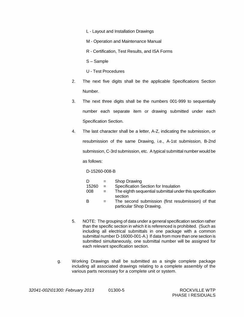
L - Layout and Installation Drawings
M - Operation and Maintenance Manual
R - Certification, Test Results, and ISA Forms
S – Sample
U - Test Procedures
2. The next five digits shall be the applicable Specifications Section
Number.
3. The next three digits shall be the numbers 001-999 to sequentially
number each separate item or drawing submitted under each
Specification Section.
4. The last character shall be a letter, A-Z, indicating the submission, or
resubmission of the same Drawing, i.e., A-1st submission, B-2nd
submission, C-3rd submission, etc. A typical submittal number would be
as follows:
D-15260-008-B D = Shop Drawing 15260 = Specification Section for Insulation
008 = The eighth sequential submittal under this specification section
B = The second submission (first resubmission) of that particular Shop Drawing.
5. NOTE: The grouping of data under a general specification section rather than the specific section in which it is referenced is prohibited. (Such as including all electrical submittals in one package with a common submittal number D-16000-001-A.) If data from more than one section is submitted simultaneously, one submittal number will be assigned for each relevant specification section.
g. Working Drawings shall be submitted as a single complete package including all associated drawings relating to a complete assembly of the various parts necessary for a complete unit or system.

32041-002\01300: February 2013 01300-6 ROCKVILLE WTP PHASE I RESIDUALS
h. Shop Drawings shall be submitted as a single complete package for any operating system and shall include all items of equipment and any mechanical units involved or necessary for the functioning of such system. Where applicable, the submittal shall include elementary wiring diagrams showing circuit functioning and necessary interconnection wiring diagrams for construction.
i. If submittals show variations from Contract requirements because of
standard shop practice or for other reasons, such variations shall be described and justified in the letter of transmittal. If acceptable, proper adjustment in the Contract shall be implemented where appropriate. If CONTRACTOR fails to describe such variations, he shall not be relieved of the responsibility for executing the work in accordance with the Contract, even though such drawings have been reviewed.
j. Data on materials and equipment shall include materials and equipment lists
giving, for each item thereon, the name and location of the supplier or manufacturer, trade name, catalog reference, size, finish and all other pertinent data.
k. For all mechanical and electrical equipment furnished, provide a list including
the equipment name, the address and telephone number of the manufacturer's representative and service company so that service and/or spare parts can be readily obtained.
l. No materials or equipment shall be ordered, fabricated or shipped or any
work performed until the Engineer returns to the Contractor the submittals, herein required, annotated either "Furnish as Submitted" or "Furnish as Corrected".
m. Where errors, deviations, and/or omissions are discovered at a later date in
any of the submittals, the Engineer's prior review of the submittals does not relieve the Contractor of the responsibility for correcting all errors, deviations, and/or omissions.
10. Procedure for Review
a. Submittals shall be transmitted in sufficient time to allow the Engineer at least
thirty (30) working days for review and processing.
b. Contractor shall transmit one (1) reproducible and two (2) prints of each submittal to the Engineer for review for all Drawings greater than 11-inches by 17-inches in size, as well as six (6) copies of all other material.
c. Submittal shall be accompanied by a letter of transmittal, in duplicate,
containing date, project title, Contractor's name, number and titles of submittals, notification of departures and any other pertinent data to facilitate review.
d. Submittals will be annotated by the Engineer in one of the following ways:

32041-002\01300: February 2013 01300-7 ROCKVILLE WTP PHASE I RESIDUALS
"Furnish as Submitted" (FAS) - no exceptions are taken "Furnish as Corrected" (FAC) - minor corrections are noted and shall be made. “Furnished as Corrected Confirm” (FACC) – Minor corrections are noted and confirming/back up/additional information shall be provided as specifically requested.for the record. "Revise and Resubmit" (R&R) - major corrections are noted and a resubmittal is required. "Rejected" (R ) - Based on the information submitted, the submission is not in conformance with the Contract Documents. The deviations from the Contract Documents are too numerous to list and a completely revised submission of the proposed equipment or a submission of other equipment is required. “Receipt Acknowledged”- confirming receipt of supplemental information. "For Information Only – Not Reviewed” (FIO) – submittal was received and was distributed for record purposes without review.
e. If a submittal is satisfactory to the Engineer, the Engineer will annotate the
submittal "Furnish as Submitted" or "Furnish as Corrected", retain two (2) copies and return remaining copies to the Contractor. If reproducibles are submitted, the Engineer will retain the copies and return a reproducible copy to the Contractor.
f. If a resubmittal is required, the Engineer will annotate the submittal "Revise
and Resubmit" and transmit three (3) copies to the Contractor for appropriate action. If reproducible transparencies are submitted, the Engineer will retain the copies and return the reproducible transparencies to the Contractor.
g. Contractor shall revise and resubmit submittals as required by the Engineer
until submittals are acceptable to the Engineer. It is understood by the Contractor that Owner may charge the Contractor the Engineer's charges for review in the event a submittal is not approved (either "Furnish as Submitted" or "Furnish as Corrected") by the third submittal for a system or piece of equipment. These charges shall be for all costs associated with engineering review, meetings with the Contractor or manufacturer, etc., commencing with the fourth submittal of a system or type of equipment submitted for a particular Specification Section.
h. Acceptance of a Working Drawing by the Engineer will constitute acceptance
of the subject matter for which the Drawing was submitted and not for any other structure, material, equipment or appurtenances indicated or shown.
11. Engineer's Review

32041-002\01300: February 2013 01300-8 ROCKVILLE WTP PHASE I RESIDUALS
a. Engineer's review of the Contractor's submittals shall in no way relieve the Contractor of any of his responsibilities under the Contract. An acceptance of a submittal shall be interpreted to mean that the Engineer has no specific objections to the submitted material, subject to conformance with the Contract Drawings and Specifications.
b. Engineer's review will be confined to general arrangement and compliance with the Contract Drawings and Specifications only, and will not be for the purpose of checking dimensions, weights, clearances, fittings, tolerances, interferences, coordination of trades, etc.
12. Record Working Drawings
a. Prior to final payment, the Contractor shall furnish the Engineer one complete
set of all accepted Working Drawings, including Shop Drawings, for equipment, piping, electrical work, heating system, ventilating system, air conditioning system, instrumentation system, plumbing system, structural, interconnection wiring diagrams, etc.
b. Manufacturer's publications, submitted in lieu of prepared Shop Drawings,
will not be required in reproducible form. However, four (4) sets of such material shall be furnished by the Contractor to the Engineer.
c. Working Drawings furnished shall be corrected to include any departures
from previously accepted Drawings.
C. Operation and Maintenance Manuals 1. Operation and Maintenance Manuals, for each item of equipment furnished under
this Contract, shall be submitted to CM per the following schedule:
a. Preliminary Draft Submittal: No later than thirty days after approval of shop drawings, submit two (2) preliminary draft O&M manuals. DESIGN ENGINEER will review draft and one copy with comments will be returned to CONTRACTOR.
b. Final Submittal: Final Operation and Maintenance Manuals shall be provided no less than two week prior to equipment start-up. The contractor shall submit six (6) copies of the final O&M manuals. The final manuals shall reflect the required revisions noted during the Engineer’s review of the preliminary documents. Failure of the final manuals to reflect the required revisions noted by the Engineer during a review of the Preliminary documents will result in the manuals being returned to the Contractor.
2. Manuals shall be prepared specifically for this Project. Obtain the copyright holder's
permission to use all copyrighted material used in the Manuals. CONTRACTOR shall hold OWNER, CM, and DESIGN ENGINEER free of any legal responsibility for the use of the copyrighted material.
3. The preliminary manuals shall be reviewed by the Engineer prior to the Contractor
submitting final copies for distribution to the Owner. Following review of the

32041-002\01300: February 2013 01300-9 ROCKVILLE WTP PHASE I RESIDUALS
preliminary copies of the Operation and Maintenance Manuals, one (1) copy will be returned to the Contractor with required revisions noted, or the acceptance of the Engineer noted.
4. Manuals shall contain complete information regarding assembly, operation,
lubrication, adjustment, maintenance, and repair and shall include wiring diagrams and schematics along with detailed parts lists with drawings or photographs identifying the parts. Provide logical sequence of instructions for each procedure, incorporating manufacturer's instructions. Mark each sheet to clearly identify specific products and component parts, and data applicable to installation. Mark by underlining, checking, use of arrows, or obliteration of data extraneous to the equipment for which the manual is supplied.
5. The format of the manuals shall be as follows:
a. The manuals shall be 8-1/2” x 11” and shall be bound in a durable 3-ring binder.
b. Identify each manual with a typed or printed title, containing the following
data:
i."OPERATION AND MAINTENANCE INSTRUCTIONS",
ii.Title of Project (Rockville Water Treatment Plant Residuals Handling Phase 1 and Air Scour Upgrades),
iii.Subject matter of contents with manufacturer's name,
iv.Owner's equipment tag number(s) with equipment name(s). c. Arrange content by systems under section numbers and sequence of Table of
Contents of the Specifications. Provide tabbed flyleaf for each separate product and system, with typed description of product and major component parts of equipment. Manufacturer's printed data, or typewritten data on 20-pound paper with reinforced edges. Drawings shall be in black and white, clearly legible, and bound in with text. Fold larger drawings to size of text pages.
6. Manuals for materials and finishes shall include:
a. Catalog number b. Size c. Composition d. Color and texture designations e. Product reordering instructions f. Manufacturer's recommendations for cleaning agents and methods

32041-002\01300: February 2013 01300-10 ROCKVILLE WTP PHASE I RESIDUALS
g. Recommended schedule for cleaning and maintenance 7. Manuals for equipment and systems shall include:
a. Description of unit or system, and component parts b. Function of equipment or system c. Normal operating characteristics d. Limiting conditions, such as operational limits of time, speed, pressure,
temperature, etc. e. Performance curves, with engineering data and tests f. Complete nomenclature and commercial number of replaceable parts g. Original manufacturer's illustrations, assembly drawings, and diagrams
required for maintenance
h. Original manufacturers parts list that includes:
i.Part number
ii.Part description
iii.Applicable serial numbers
iv.Current unit prices
v.Recommendations as to spare parts and spare inventory levels, clearly identifying the ones that are actually furnished. Where pertinent, include lead-time, shelf life, preservation, and packing and labeling methods.
vi.Complete instructions for re-ordering specific products or replaceable parts. Instructions shall include name, address, and telephone number of nearest manufacturer's representative, and nearest service and products or spare parts warehouse.
i. Operating procedures which include:
i.Start-up, break-in, and routine normal operating instructions and sequences
ii.Regulation, control, stopping, shut-down, and emergency instructions
iii.Summer, winter, and any special operating instructions
j. Frequency and procedures for preventive maintenance k. Guide for trouble-shooting, including:

32041-002\01300: February 2013 01300-11 ROCKVILLE WTP PHASE I RESIDUALS
i.Disassembly, repair, and re-assembly
ii.Alignment, adjusting and balancing l. Lubrication schedule, and list of lubricants required m. Sequence of operation by controls manufacturer n. Electrical service characteristics, controls and communications o. Complete wiring diagrams and electrical schematics p. Control diagrams by controls manufacturer as installed q. Charts of valve tag numbers, with name and location of each valve, keyed to
flow and control diagrams r. Test and balancing reports as specified in Section 01400 s. Additional requirements as specified in individual product specification
Sections 8. Engineer and the Owner shall be the sole judge of the acceptability and
completeness of the manuals and may reject any submittal for insufficient information included, incorrect references and/or the manner in which the material is assembled.
9. The approved sets of operation and maintenance manuals shall be furnished prior to
final acceptance.
D. Certified Shop Test Reports
1. Each piece of equipment for which pressure, head, capacity, rating, efficiency, performance, function or special requirements are specified or implied shall be tested in the shop of the manufacturer in a manner which shall conclusively prove that its characteristics comply fully with the requirements of the Contract Documents and applicable test codes and standards. Contractor shall keep the Engineer advised of the scheduling of shop tests so that the Engineer may arrange for the witnessing or inspection at the proper time and place.
2. The Contractor shall secure from the manufacturers six (6) copies of the actual test
data, the interpreted results and a complete description of the testing facilities and testing setup, all accompanied by a certificate of authenticity sworn to by a responsible official of the manufacturing company and notarized. These reports shall be forwarded to the Engineer for review.
3. In the event any equipment fails to meet the test requirements, the manufacturer
shall make all necessary changes, adjustments or replacements and the tests shall be repeated, at no additional cost to the Owner or Engineer, until the equipment test requirements are acceptable to the Engineer.

32041-002\01300: February 2013 01300-12 ROCKVILLE WTP PHASE I RESIDUALS
4. No equipment shall be shipped to the Project until the Engineer notifies the
Contractor, in writing, that the shop test reports are acceptable.
E. Samples
1. Contractor shall furnish for review all samples as required by the Contract Documents or requested by the Engineer.
2. Samples shall be of sufficient size or quantity to clearly illustrate the quality, type,
range of color, finish or texture and shall be properly labeled to show the nature of the material, trade name of manufacturer and location of the work where the material represented by the sample will be used.
3. Samples shall be checked by the Contractor for conformance to the Contract
Documents before being submitted to the Engineer and shall bear the Contractor's stamp of approval certifying that they have been so checked. Transportation charges on samples submitted to the Engineer shall be prepaid by the Contractor.
4. Engineer's review will be for compliance with the Contract Documents and his
comments will be transmitted to the Contractor with reasonable promptness. 5. Accepted samples will establish the standards by which the completed work will be
judged. F. Construction Photographs
1. The General Contractor shall take photographs at the locations and at such stages of the construction as directed by the Engineer. All photographs shall be well lit, clear (i.e. good spatial resolution) and in focus. Photographs shall be provided in high resolution digital format. Minimum resolution shall be 6 megapixels (2400pixels x 3000 pixels). The physical orientation of the subject being photographed shall be easily discernible from the photo. Acceptability of all photos shall be determined by the Engineer.
a. At a minimum, Contractor shall provide photos each structure/area to be
disturbed by construction activities prior to commencement of work on/in said structure/areas.
2. Provide the equivalent of 36 different exposures per month for the duration of the
Contract time. When directed by the Engineer, frequency of photographs may be increased to weekly sessions provided that the equivalent number of exposures is not exceeded. Photographs shall be provided on CDs in digital format. In addition, prints of digital pictures may be requested at the discretion of the Engineer. Engineer may waive requirements for photographs during inactive construction periods in favor of increased photographs during active construction sequences.
3. Submittal Requirements
a. As required by Section 1.01.G, the file name of each digital photograph shall
contain the photo capture date, identity the feature represented therein,
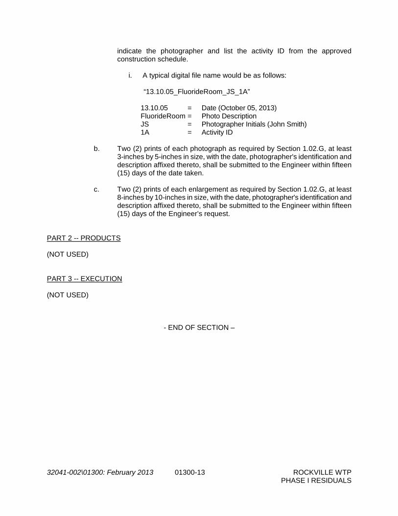
32041-002\01300: February 2013 01300-13 ROCKVILLE WTP PHASE I RESIDUALS
indicate the photographer and list the activity ID from the approved construction schedule.
i. A typical digital file name would be as follows:
“13.10.05_FluorideRoom_JS_1A” 13.10.05 = Date (October 05, 2013) FluorideRoom = Photo Description
JS = Photographer Initials (John Smith) 1A = Activity ID b. Two (2) prints of each photograph as required by Section 1.02.G, at least
3-inches by 5-inches in size, with the date, photographer's identification and description affixed thereto, shall be submitted to the Engineer within fifteen (15) days of the date taken.
c. Two (2) prints of each enlargement as required by Section 1.02.G, at least
8-inches by 10-inches in size, with the date, photographer's identification and description affixed thereto, shall be submitted to the Engineer within fifteen (15) days of the Engineer’s request.
PART 2 -- PRODUCTS (NOT USED) PART 3 -- EXECUTION (NOT USED)
- END OF SECTION –

THIS PAGE INTENTIONALLY LEFT BLANK.

32041-002\01320: February 2013 01320-1 ROCKVILLE WTP PHASE I UPGRADES
SECTION 01320
PROGRESS SCHEDULES PART 1 -- GENERAL 1.01 SECTION INCLUDES
A. This section specifies requirements and procedures in preparing construction schedules and reports for planning, coordinating, executing, and monitoring the progress of the work. Work shall be scheduled using the Critical Path Method (CPM) type of network analysis.
B. Software shall be "Project Planner" (P6), latest Windows version, by Primavera or
Microsoft Project. The Contractor shall employ a trained and experienced construction scheduling person knowledgeable in construction work sequencing, productivity, scheduling, and application of the Primavera software system. This person along with the Contractor's management team is expected to work closely with the Engineer and Owner to deliver acceptable products outlined in this section.
1.02 SCHEDULING RESPONSIBILITIES
A. Critical Path Method: The Critical Path Method type construction schedule will be used to monitor job progress. The Contractor shall be responsible for providing all information concerning the sequencing, logic and duration of all activities as well as providing the initial CPM logic network (in electronic and paper format) diagram and tabular report data. Once the initial logic network diagram is accepted by the Owner, the Contractor shall be responsible for providing monthly update information on logic, percent complete, actual cost of Work performed, budgeted cost of Work Schedule, actual start and finish dates and duration changes. The Contractor shall produce the computerized printout of the schedule updates. Six (6) copies of the schedule updates shall be distributed in addition to electronic files on CD-ROM.
B. Schedule Reports: From the Contractor's initial schedule submittal, and from information
received at the monthly schedule update meetings, the Contractor shall produce computerized and updated tabular schedule reports, and updated network diagrams and barcharts, which will be reviewed by the Owner for accuracy and integrity. It shall at all times remain the Contractor's responsibility to schedule and direct his forces in a manner that will allow for the completion of the Work within the Contract Period.
C. Schedule Accuracy: The initial schedule and all update information shall be provided by
the Contractor. This information shall be a representation of the best efforts of the Contractor and his subcontractors as to how they envision the Work to be accomplished. Similarly, all progress information to be provided by and through the Contractor must be an accurate representation of his or his subcontractor's or supplier's actual performance. The schedule shall at all times remain an accurate reflection of the Contractor's actual or projected sequencing of Work. Once accepted by the Owner, adherence to the established CPM schedule (the "Schedule") shall be obligatory upon the Contractor and his subcontractors for the Work under this Contract. The Owner shall have the right to

32041-002\01320: February 2013 01320-2 ROCKVILLE WTP PHASE I UPGRADES
require the Contractor to revise the schedule if in his judgment the schedule does not accurately reflect the actual prosecution of the Work, or the Contractor is in violation of any provision of this CPM scheduling specification. The Contractor shall revise the Schedule to meet the above performance criteria as often as is necessary during the course of performance of the Work without additional cost to the Owner.
1.03 SUBMITTALS
A. CPM Schedule:
1. Qualifications: The Contractor shall submit a statement of qualifications to perform computerized CPM scheduling. The submittal shall verify that either the Contractor has in-house capability qualified to use CPM technique and the Primavera Project Planner (P3) software or that the Contractor has arranged for the services of a CPM consultant so qualified. In either event the statement shall identify the individual(s) who will perform the CPM scheduling. Capability shall be verified by description of construction projects in which the individual has successfully applied computerized CPM and shall include at least two projects of similar nature, scope, and value, each not less than one-half the Contract Sum of this project. The statement shall also identify the contact persons for the referenced projects with current telephone and address information. The Contractor shall assign the individual who will perform the scheduling to a full-time, onsite position.
2. 90 Day CPM Network Diagram: Within 14 Days after the Notice to Proceed, the
Contractor shall submit to the Owner six (6) prints of his proposed CPM network diagram and tabular reports for the first 90 Days of the Work. This initial logic diagram shall submitted on sheets 24 inches by 36 inches and shall include both procurement and construction activities. The schedule will be the subject of a schedule review meeting with the Contractor and the Owner within 7 days of its submission. The Contractor shall revise and resubmit the 90 day CMP within 3 days of receipt of the Owner’s comments. The Contractor shall revise and resubmit the Schedule until the Owner approves it.
3. Complete CPM Network Diagram: Within 30 days after issuance of the Notice to
Proceed, the Contractor shall submit to the Engineer 6 sets of his proposed CPM logic diagram (also in electronic form) and tabular reports for the entire Contract duration and shall include both procurement and construction activities. The tabular reports shall include the following:
a. Report of activities sorted by activity number. Activity numbers, where
practical, shall correlate to the area numbers designated on the drawings. b. Report of activities sorted by early start date and late start. c. Report of activities sorted by total float. d. Report of activities sorted by responsibility code. Responsibility codes
shall be established for the Contractor, Engineer, Owner, Subcontractors, Suppliers, etc. These codes shall be identified in the network diagram.

32041-002\01320: February 2013 01320-3 ROCKVILLE WTP PHASE I UPGRADES
e. A successor-predecessor report which shall identify the successor and
predecessor activities for each activity and ties between schedule activities.
f. Report of resource loading. g. Report of cost loading. h. Cash flow chart comparing the actual cash flow against projected cash
flow and a cash flow table containing monthly and cumulative expenditures.
i. Activity codes, values, and coding dictionary.
The logic diagram shall be drawn as described herein and will be the subject of a schedule review meeting with the Contractor, the Engineer, and the Owner within 2 weeks of its submission. Contractor shall schedule Work such that Work is completed within the time stated in the Contract Documents. Failure by the Contractor to submit an acceptable schedule may, at the Owner's sole discretion, be cause for the withholding of partial payment otherwise due under the Contract. The accepted schedule will be designated the "original CPM schedule." Acceptance of the CPM schedule by the Engineer and the Owner will not constitute representation that the Work can be completed as indicated on the schedule.
B. Submittal Schedule: The Contractor shall be required to submit a complete and detailed
listing of anticipated submittals during the course of the Contract. The Contractor shall coordinate his submittals with those of his subcontractors and suppliers and shall identify each submittal by Contract drawing number and Specification section number. The anticipated submission due date for each submittal shall be indicated along with the date on which its return is required. For planning purposes, the Owner will endeavor to return shop drawings in an average of 30 consecutive calendar days after receipt. Longer submittal review durations will not be considered basis for a claim unless the project critical path is delayed thereby and then only to the extent that the delay is attributable solely to the Owner. Durations shown for review will be shown to share available float for that path. Submissions, the review of which is on the critical path, shall be clearly marked in red with the words "Critical Path" by the Contractor at the time of submission.
1. Schedule submittal timing: The Submittal Schedule shall be submitted within 30
Days of Notice to Proceed. The Contractor shall revise as required by Owner. The Contractor shall incorporate the dates and review durations into his CPM Schedule following Owner’s approval.
2. The Submittal Schedule, including a detailed listing of submittals, shall be revised
and resubmitted each month for use as a tracking log.
C. The Contractor shall also submit two-week look ahead reports at each Progress Meeting and at times specified by the Owner or by the Engineer at no additional cost to the Owner.
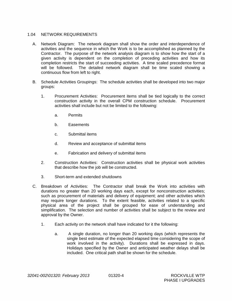
32041-002\01320: February 2013 01320-4 ROCKVILLE WTP PHASE I UPGRADES
1.04 NETWORK REQUIREMENTS
A. Network Diagram: The network diagram shall show the order and interdependence of activities and the sequence in which the Work is to be accomplished as planned by the Contractor. The purpose of the network analysis diagram is to show how the start of a given activity is dependent on the completion of preceding activities and how its completion restricts the start of succeeding activities. A time scaled precedence format will be followed. The detailed network diagram shall be time scaled showing a continuous flow from left to right.
B. Schedule Activities Groupings: The schedule activities shall be developed into two major
groups:
1. Procurement Activities: Procurement items shall be tied logically to the correct construction activity in the overall CPM construction schedule. Procurement activities shall include but not be limited to the following: a. Permits b. Easements c. Submittal items d. Review and acceptance of submittal items e. Fabrication and delivery of submittal items
2. Construction Activities: Construction activities shall be physical work activities
that describe how the job will be constructed. 3. Short-term and extended shutdowns
C. Breakdown of Activities: The Contractor shall break the Work into activities with
durations no greater than 20 working days each, except for nonconstruction activities; such as procurement of materials and delivery of equipment; and other activities which may require longer durations. To the extent feasible, activities related to a specific physical area of the project shall be grouped for ease of understanding and simplification. The selection and number of activities shall be subject to the review and approval by the Owner. 1. Each activity on the network shall have indicated for it the following:
a. A single duration, no longer than 20 working days (which represents the
single best estimate of the expected elapsed time considering the scope of work involved in the activity). Durations shall be expressed in days. Holidays specified by the Owner and anticipated weather delays shall be included. One critical path shall be shown for the schedule.

32041-002\01320: February 2013 01320-5 ROCKVILLE WTP PHASE I UPGRADES
b. An activity I.D. number shall be assigned to each activity. The I.D. number will be numeric with a maximum of 10 alpha-numeric characters.
c. A brief description of the activity shall be included. If this description is
non-definitive, a separate listing of each activity and a descriptive narrative may be required by the Owner.
d. Each activity (except for procurement activities) shall be cost loaded in
accordance with Article 1.05 to indicate the total estimated costs of the activity. No activity shall exceed $75,000 except for equipment item or items approved by the Engineer. Material costs shall be assigned to delivery activities.
D. When preparing the schedule, consider all construction sequence and critical
construction activities requirements. E. Incomplete Schedules: Failure to include on a network any element of work required for
the performance of this Contract shall not excuse the Contractor from completing all Work required within the applicable completion time, notwithstanding the network review and approval by the Engineer or the Owner and his Authorized Representatives.
F. Early Finish Schedules: A CPM schedule which shows a completion of any milestone or
completion dates prior to the contractual completion date for that milestone may be accepted but dates shall not be acceptable as a basis for claim for delay against the Owner and Engineer and any of their Authorized Representatives by the Contractor.
G. The schedule calendar shall be a 5-day work week with holidays corresponding to those
observed by the Owner.
1.05 SCHEDULE OF VALUES
A. Each Activity on the construction schedule shall be allocated a dollar value. Each activity's assigned cost shall consist of labor, equipment, and materials costs, and a pro rata contribution to overhead and profit. The sum of the Activities cost shall be equal to the total Contract Sum. In submitting cost data the Contractor certifies that it is not unbalanced and that the value assigned to each activity represents the Contractor's estimate of the actual costs of performing that activity.
B. The accepted schedule of values, in the best judgement of the Contractor and Owner
shall represent a fair, reasonable and equitable dollar cost allocation for each activity on the Contractor's construction schedule.
C. If, in the opinion of the Owner, the cost data does not meet the requirements for a
balanced bid breakdown, the Contractor shall present documentation to the Owner substantiating any cost allocation on the cost data. Cost allocations shall be considered unbalanced if Activity on the construction schedule has been assigned, in the opinion of the Owner, a disproportionate allocation of direct costs, overhead or profit.
1.06 PROGRESS OF THE WORK

32041-002\01320: February 2013 01320-6 ROCKVILLE WTP PHASE I UPGRADES
A. Start of Work: The work shall be started following the Notice to Proceed. The Work shall be executed with such progress as to prevent delay to other contractors. The Work shall be executed to assure completion of the work within the Contract Period. The Contractor shall schedule and direct his Work so that it provides an orderly progression of the Work to completion within the Contract Period.
B. Delays to Critical Path: Whenever it becomes apparent from the current monthly CPM
Schedule update that delays to the critical path have resulted and these delays are through no fault of the Owner and the Contract completion date will not be met, or when so directed by the Owner, the contractor will submit a recovery Schedule which shall include but not be limited to the following actions, which are subject to the Owner’s approval.
1. Increase construction manpower in such quantities and crafts to eliminate the
delay. 2. Increase the number of working hours per shift; shifts per day, or working days
per week; the amount of construction equipment; the forms for concrete work; etc., or any combination of the foregoing to eliminate the delay.
3. Reschedule activities to achieve maximum practical concurrence of
accomplishment of activities, and comply with the recovery schedule. 4. The Contractor shall submit to the Owner or his Authorized Representatives for
review and approval, a written statement of the steps he intends to take to remove or arrest the delay to the schedule and a recovery schedule. If the Contractor fails to submit a written statement of the steps he intends to take or fails to take such steps, the Owner may direct the level of effort in manpower (trades), equipment, and work schedule (overtime, weekend and holiday work, etc.) to be employed by the Contractor in order to remove or arrest the delay to the critical path in the accepted schedule, and the Contractor shall promptly provide such level of effort at no additional cost to the Owner. In addition, should schedule delays persist, the Contractor's surety may be asked to attend meetings to update the schedule.
5. Failure of the Contractor to comply with the requirements of the Contract
Documents shall subject him to, at the Owner's sole discretion, withholding, in partial or in total, payments otherwise due the Contractor for work performed. Any withholding of monies is not a penalty for noncompliance, but is an assurance for the Owner that funds will be available to implement these requirements should the Contractor fail to do so, since, failure of the Contractor to comply with these requirements shall mean that the Contractor failed to prosecute the Work with such diligence as to ensure its completion within the Contract Period.
1.07 SCHEDULE UPDATES
A. A monthly schedule update meeting will be held in conjunction with a weekly progress meeting at the Site to review and update the CPM schedule. The schedule update meeting will be chaired by the Engineer and attended by the Owner and Contractor.

32041-002\01320: February 2013 01320-7 ROCKVILLE WTP PHASE I UPGRADES
These meetings are considered a critical component of the overall monthly schedule update submittal, and the Contractor shall ensure that appropriate Contractor's personnel attend including the Project Manager, General Superintendent, and Project Scheduler. Actual progress of the previous month shall be recorded and future activities will be reviewed. The duration of activities and their logical connections shall be revised as needed. The Contractor's revisions shall be submitted in writing at the update meeting prior to any modifications to the schedule. The absence of a written submission for logic revisions shall indicate the Contractor's intent that no logic revisions are being considered for this schedule update. Scheduling update decisions made at these meetings and agreed to by all parties shall be incorporated into the project schedule with the exception that no contractual completion dates will be modified without formal written justification by the Contractor and agreement by the Owner that a Change Order should be executed. In the event that a monthly schedule update meeting is not required by the Engineer, the Contractor shall submit update information to the Owner, including at a minimum: (1) Actual start and finish dates for all completed activities; and (2) Actual start dates for all started but uncompleted activities including remaining durations.
B. The Contractor shall provide information on all changes to the schedule logic or activity
durations made from the previous schedule and as a result of decisions made in the Schedule Update Meeting. The Contractor shall provide information on any portions of the CPM schedule which become non-feasible because of activities behind schedule or for any other valid reason.
C. The Owner will include in progress meeting agendas/minutes written reports of the status
of the project based on information provided by the Contractor in conjunction with the revised CPM schedules. Status reports and cost curve may include the following:
1. Activities completed during the previous period. 2. Cost value of each activity completed. 3. Activities in progress this period. 4. Total activity cost value for the previous period and to date totals with remaining
cash flow projection by month and cumulative to project completion. 5. Cost curves including scheduled cash flow sorted by early start date, actual cost
to date, and forecasted costs at completion. 6. Activities scheduled to begin this period. 7. Problem areas. 8. Schedule status (how many days ahead or behind schedule). 9. Specified plans and strategies to recover lost time. 10. Changes to the schedule. 11. The status of major material and equipment procurement.

32041-002\01320: February 2013 01320-8 ROCKVILLE WTP PHASE I UPGRADES
12. The value of materials and equipment properly stored at the Site but not yet
incorporated into the Work. 13. Any delays encountered during the reporting period. 14. An assessment of inclement weather delays and impacts to the progress of the
Work.
D. Upon approval of a Change Order or Work Order, or upon receipt by the Contractor of authorization to proceed with changed work, the change shall be reflected in the Contractor's submission for the next schedule update meeting. The Contractor shall provide information needed to utilize a sub-network in the schedule depicting the changed work and its effect on other activities. This sub-network shall be tied to the main network with appropriate logic so that a true analysis of the critical path can be made.
E. The Contract Period and Milestone Dates will be adjusted only for causes specified in the
Contract Documents. In the event the Contractor requests an extension of any Contract Period or Milestone Date, he shall furnish such justification and supporting evidence as the Owner or Engineer may deem necessary, and as provided for in the General Conditions for a determination as to whether the Contractor is entitled to an extension of time under the provisions of this Contract. The Owner or Engineer will, after receipt of such justification and supporting evidence, make findings of fact and will advise the Contractor in writing thereof. If the Owner or Engineer finds that the Contractor is entitled to any extension of the Contract Period under the provisions of the Contract, the Owner's or Engineer's determination as to the total number of days of extension shall be based upon the current accepted and updated CPM schedule and on all data relevant to the extension. The Contractor acknowledges and agrees that actual delays in activities which, according to the CPM schedule do not affect any contract completion date shown by the critical path in the network, do not have any effect on the Contract completion dates, and therefore, will not be the basis for a change in Contract Period. All information known to the Contractor at the time concerning the nature and extent of the delay shall be submitted in writing in accordance with the General Conditions. Within the time frame stated in the General Conditions but before the date of final payment under this Contract, all information as required above concerning the delay must be submitted to the Engineer. No time extension will be granted for requests which are not submitted with the specified time limits.
F. It may become necessary for the Contract schedule and completion time to be adjusted
by the Owner to reflect the effects of job conditions, acts or omissions of other contractors not directly associated with the Contract, weather, technical difficulties, strikes, unavoidable delays on the part of the Owner or his representatives, and other unforeseeable conditions which may require schedule adjustments and/or extensions of the Contract Period. Under such conditions the Contractor shall reschedule the Work to reflect the changed conditions, and the Contractor shall revise his schedule accordingly. Schedule extensions affecting the Contract Period shall be granted by the Owner in writing. The Owner has the right to accelerate the schedule and the Contractor will be compensated for such acceleration as long as such acceleration is not required through fault of the Contractor.

32041-002\01320: February 2013 01320-9 ROCKVILLE WTP PHASE I UPGRADES
1.08 FLOAT OWNERSHIP
A. Neither the Owner nor the Contractor owns the float time. The Project owns the float time. As such, liability for delay of the project completion date rests with the party actually causing delay to the project completion date.
1.09 TIME EXTENSION FOR UNUSUALLY SEVERE WEATHER
A. This provision specifies the procedure for determination of time extensions for unusually severe weather, for weather dependent contracts, in accordance with the General Conditions. In order for the Owner to award a time extension under this clause, the Engineer must be satisfied that the following conditions exist: 1. The weather experienced at the project site during the Contract period must be
found to be unusually severe, that is, more severe than the adverse weather anticipated for the project location during any given month.
2. The unusually severe weather must actually cause a delay to the completion of
the Contract. The delay must be without fault or negligence of the Contractor. 3. Time extensions for unusually severe weather occurring beyond the contractual
completion date will not be granted if the contract duration has extended beyond the contractual completion date due to Contractor delay.
B. Monthly anticipated adverse weather delays shall be determined by the National Oceanic
and Atmospheric Administration (NOAA) or similar data for the project location and will constitute a baseline for monthly weather time evaluations. The Contractor’s progress schedule must reflect these anticipated adverse weather delays in all weather dependant activities.
C. Upon issuance of the NOA and continuing throughout the Contract, the Contractor will
record on his daily Report, the occurrence of adverse weather and resultant impact to normally scheduled Work. Actual adverse weather delays days must prevent Work on critical activities for fifty percent (50%) or more of the Contractor’s scheduled Workday. The number of actual adverse weather delay days shall include days impacted by actual adverse weather to be calculated chronologically from the first to the last day of each month, and be recorded as full days. If the number of actual adverse weather delay days exceeds the number of days anticipated above, the Owner will convert any qualifying delays to calendar days and issue a time extension in accordance with the General Conditions. Time extensions granted under these conditions are not compensable.
PART 2 -- PRODUCTS (NOT USED) PART 3 -- EXECUTION

32041-002\01320: February 2013 01320-10 ROCKVILLE WTP PHASE I UPGRADES
(NOT USED)
- END OF SECTION -

32041-002\01400: February 2013 01400-1 ROCKVILLE WTP PHASE I UPGRADES
SECTION 01400 QUALITY CONTROL PART 1 -- GENERAL 1.01 THE REQUIREMENT
A. Testing Laboratory Services
1. Laboratory testing and checking required by the Specifications, including the cost of transporting all samples and test specimens, shall be provided and paid for by the Contractor unless otherwise indicated in the Specifications.
2. Materials to be tested include, but are not necessarily limited to the following:
cement, concrete aggregate, concrete, bituminous paving materials, structural and reinforcing steel, waterproofing, select backfill, crushed stone or gravel and sand.
3. Tests required by the Owner shall not relieve the Contractor from the responsibility of
supplying test results and certificates from manufacturers or suppliers to demonstrate conformance with the Specifications.
4. Procedure
a. The Contractor shall plan and conduct his operations to permit taking of field
samples and test specimens, as required, and to allow adequate time for laboratory tests.
b. The collection, field preparation and storage of field samples and test
specimens shall be as directed by the Engineer with the cooperation of the Contractor.
5. Significance of Tests
a. Test results shall be binding on both the Contractor and the Owner, and shall
be considered irrefutable evidence of compliance or noncompliance with the Specification requirements, unless supplementary testing shall prove, to the satisfaction of the Owner, that the initial samples were not representative of actual conditions.
6. Supplementary and Other Testing
a. Nothing shall restrict the Contractor from conducting tests he may require.
Should the Contractor, at any time, request the Owner to consider such test results, the test reports shall be certified by an independent testing laboratory acceptable to the Owner. Testing of this nature shall be conducted at the Contractor's expense.

32041-002\01400: February 2013 01400-2 ROCKVILLE WTP PHASE I UPGRADES
1.02 WATERTIGHTNESS OF STRUCTURES
A. It is the intent of these Specifications that all concrete work and sealing work around built-in items and penetrations be performed as required to insure that groundwater, surface water, and water or liquids in tanks, channels and containers will not intrude into any equipment rooms, pipe galleries, habitable areas or other generally dry areas.
B. The required watertightness shall be achieved by quality concrete construction and proper
sealing of all joints and penetrations. C. Each unit shall be tested separately and the leakage tests shall be made prior to backfilling
and before equipment is installed. Testing water shall be from any potable, non-potable, or natural moving source such as a river or stream, but not from any still water source such as a lake or pond, and not from any wastewater source.
D. All water holding structures shall be tested for leakage by the Contractor. The Contractor
shall provide at his own expense all labor, material, temporary bulkheads, pumps, water measuring devices, etc., necessary to perform the required tests.
E. Hydrostatic Testing (reference ACI 350.1)
1. The design capability of the structure to withstand testing shall be verified for the
pressures to be applied. Another type of test shall not be substituted for hydrostatic testing without approval of the Engineer.
2. The structure shall not be tested before the concrete has attained its specified
compressive strength. 3. Clean the exposed concrete surfaces of the structure, including the floor, of all
foreign material and debris. Prior to testing, standing water inside of the structure that would interfere with the observation of the exposed concrete surfaces of the structure shall be removed. The concrete surfaces and concrete joints shall be thoroughly inspected for potential leakage points. All openings, fittings, and pipe penetrations in the structure shell shall be inspected at both faces of the concrete, if practical. Defective or cracked concrete shall be repaired prior to testing.
4. All structural penetrations and outlets shall be securely sealed to prevent the loss of
water from the structure during the test. All structural penetrations shall be monitored before and during the test to determine the watertightness of these appurtenances. Leakage at these outlets shall be repaired prior to testing. No allowance shall be made in test measurements for uncorrected known points of leakage.
5. The ground water level shall be brought to a level below the top of the base slab and
kept at that elevation or at a lower elevation during the test. 6. The initial filling of a new structure should not exceed a rate of 4 ft/h. Filling shall be
continued until the water surface is at the design maximum liquid level or 4 in. below any fixed overflow level, whichever is lower. The exterior surfaces of the structure

32041-002\01400: February 2013 01400-3 ROCKVILLE WTP PHASE I UPGRADES
shall be inspected during the period of filling the structure. If any flow of water is observed from the structure exterior surfaces, including joints or cracks, the defect causing the leakage shall be repaired prior to testing.
7. The water shall be kept at the test level for at least 3 days prior to testing. 8. The test measurements shall not be scheduled for a period when the forecast is for a
substantial change in the weather pattern. The test shall also not be scheduled when the weather forecast indicates the water surface would be frozen before the test is completed. A restart of the test shall be required when test measurements become unreliable due to unusual precipitation or other weather factors.
9. The vertical distance to the water surface shall be measured from a fixed point on
the structure above the water surface. Measurements shall be recorded at 24-hour intervals.
10. The test period shall be at least the theoretical time required to lower the water
surface 3/8 in. assuming a loss of water at 0.050% of the water volume per 24-hour period. The test period shall not be longer than five days.
11. The water temperature shall be recorded at a depth of 18 in. below the water
surface. 12. A floating, restrained, partially filled, calibrated, open container for evaporation and
precipitation measurement should be positioned in open structures and the water level in the container recorded at 24-hour intervals.
13. The allowable loss of water for tightness tests shall not exceed 0.050% of the test
water volume in 24 hours. 14. The change in water volume in the structure shall be calculated and corrected, if
necessary, for evaporation, precipitation, and temperature based on the change recorded in the water level from the open container. If the loss exceeds the allowable loss, the structure shall be considered to have failed the test. Observed flow or seepage of water from the exterior surface, including that from cracks and joints, should be considered as a failed test. The structure shall also be considered to have failed the test if moisture can be transferred from the exterior surface to a dry hand. Dampness or wetness on top of a footing shall not be considered as a failure test.
15. The Contractor shall be permitted to immediately retest when no visible leakage is
exhibited. If the structure fails the second test or if the Contractor does not exercise the option of immediately retesting after the first test failure, the interior of the structure shall be inspected by a diver or by other means to determine probable areas of leakage. The structure shall only be retested after the most probable areas of leakage are repaired.
16. If the leakage exceeds the allowable limit, the work shall be corrected by methods
approved by the Engineer.

32041-002\01400: February 2013 01400-4 ROCKVILLE WTP PHASE I UPGRADES
17. Upon completion of the necessary remedial work, the leakage test shall be repeated until it is successfully passed.
F. Notification by Engineer
If any leaks, in excess of the specified amount, are not remedied by the Contractor within
four (4) weeks of notification by the Engineer, regardless of whether the cause of these leaks is or is not determined, the Engineer shall have the authority to have these leaks repaired by others. The cost of repairs, by others, shall be deducted from monies due or to become due to the General Contractor.
1.03 FIELD TESTING OF EQUIPMENT
A. All equipment shall be set, aligned and assembled in conformance with the manufacturer's drawings and instructions.
B. Preliminary Field Tests, Yellow Tag
1. As soon as conditions permit, after the equipment has been secured in its
permanent position, the Contractor shall check the equipment for alignment, direction of rotation and that it is free from defects.
2. Contractor shall flush all bearings, gear housings, etc., in accordance with the
manufacturer's recommendations, to remove any foreign matter accumulated during shipment, storage or erection. Lubricants shall be added as required by the manufacturer's instructions.
3. When the Contractor has demonstrated to the Engineer that the equipment is ready
for operation, a yellow tag will be issued. The tag will be signed by the Engineer, or his assigned representative and attached to the equipment. The tag shall not be removed.
4. Preliminary field tests, yellow tag, must be completed before equipment is subjected
to final field tests, blue tag.
C. Final Field Tests, Blue Tag
1. Upon completion of the installation, and at a time approved by the Engineer, equipment will be tested by operating it as a unit with all related piping, ducting, electrical controls and mechanical operations.
2. The equipment will be placed in continuous operation as prescribed or required and
witnessed by the Engineer or his assigned representative and the Owner or his assigned representative.
3. The tests shall prove that the equipment and appurtenances are properly installed,
meet their operating cycles and are free from defects such as overheating, overloading, and undue vibration and noise. Equipment shall be tested for the characteristics as specified for the item.

32041-002\01400: February 2013 01400-5 ROCKVILLE WTP PHASE I UPGRADES
4. Each pump shall be tested at maximum rated speed for at least four points on the pump curve for capacity, head and electric power input. The rated motor nameplate current and power shall not be exceeded at any point within the specified range. Vibrometer readings shall be taken when directed by the Engineer and the results recorded. Additional tests shall be performed as prescribed in other sections of the Specifications.
5. Pumps with drive motors rated at less than five horsepower shall only be tested for
excess current or power when overheating or other malfunction becomes evident in general testing.
6. Until final field tests are acceptable to the Engineer, the Contractor shall make all
necessary changes, readjustments and replacements at no additional cost to the Owner.
7. Defects which cannot be corrected by installation adjustments will be sufficient
grounds for rejection of any equipment.
8. Upon acceptance of the field tests, a blue tag will be issued. The tag will be signed by the Engineer and attached to the unit. The tag shall not be removed and no further construction work will be performed on the unit, except as required during start-up operations and directed by the Engineer.
9. All costs in connection with such tests including all materials, equipment,
instruments, labor, etc., shall be borne by the Contractor. 1.04 IMPERFECT WORK, EQUIPMENT, OR MATERIALS
A. Any defective or imperfect work, equipment, or materials furnished by the Contractor which is discovered before the final acceptance of the work, as established by the Certificate of Substantial Completion, or during the subsequent guarantee period, shall be removed immediately even though it may have been overlooked by the Engineer and estimated for payment. Any equipment or materials condemned or rejected by the Engineer shall be tagged as such and shall be immediately removed from the site. Satisfactory work or materials shall be substituted for that rejected.
B. The Engineer may order tests of imperfect or damaged work, equipment, or materials to
determine the required functional capability for possible acceptance, if there is no other reason for rejection. The cost of such tests shall be borne by the Contractor; and the nature, tester, extent and supervision of the tests will be as determined by the Engineer. If the results of the tests indicate that the required functional capability of the work, equipment, or material was not impaired, consistent with the final general appearance of same, the work, equipment, or materials may be deemed acceptable. If the results of such tests reveal that the required functional capability of the questionable work, equipment, or materials has been impaired, then such work, equipment, or materials shall be deemed imperfect and shall be replaced. The Contractor may elect to replace the imperfect work, equipment, or material in lieu of performing the tests.
1.05 INSPECTION AND TESTS

32041-002\01400: February 2013 01400-6 ROCKVILLE WTP PHASE I UPGRADES
A. The Contractor shall allow the Engineer ample time and opportunity for testing materials and equipment to be used in the work. He shall advise the Engineer promptly upon placing orders for material and equipment so that arrangements may be made, if desired, for inspection before shipment from the place of manufacture. The Contractor shall at all times furnish the Engineer and his representatives, facilities including labor, and allow proper time for inspecting and testing materials, equipment, and workmanship. The Contractor must anticipate possible delays that may be caused in the execution of his work due to the necessity of materials and equipment being inspected and accepted for use. The Contractor shall furnish, at his own expense, all samples of materials required by the Engineer for testing, and shall make his own arrangements for providing water, electric power, or fuel for the various inspections and tests of structures and equipment.
B. The Contractor shall furnish the services of representatives of the manufacturers of certain
equipment, as prescribed in other Sections of the Specifications. The Contractor shall also place his orders for such equipment on the basis that, after the equipment has been tested prior to final acceptance of the work, the manufacturer will furnish the Owner with certified statements that the equipment has been installed properly and is ready to be placed in functional operation. Tests and analyses required of equipment shall be paid for by the Contractor, unless specified otherwise in the Section which covers a particular piece of equipment.
C. Where other tests or analyses are specifically required in other Sections of these
Specifications, the cost thereof shall be borne by the party (Owner or Contractor) so designated in such Sections. The Owner will bear the cost of all tests, inspections, or investigations undertaken by the order of the Engineer for the purpose of determining conformance with the Contract Documents if such tests, inspection, or investigations are not specifically required by the Contract Documents, and if conformance is ascertained thereby. Whenever nonconformance is determined by the Engineer as a result of such tests, inspections, or investigations, the Contractor shall bear the full cost thereof or shall reimburse the Owner for said cost. In this connection, the cost of any additional tests and investigations, which are ordered by the Engineer to ascertain subsequent conformance with the Contract Documents, shall be borne by the Contractor.
PART 2 -- PRODUCTS (NOT USED) PART 3 -- EXECUTION (NOT USED)
- END OF SECTION -

32041-002\01510: February 2013 01510-1 ROCKVILLE WTP PHASE I UPGRADES
SECTION 01510 TEMPORARY UTILITIES PART 1 -- GENERAL 1.01 THE REQUIREMENT
A. The General Contractor shall provide temporary light and power, heating, water service and sanitary facilities for his operations, for the construction operations of the other Contractors of this Project at the site. The temporary services shall be provided for use throughout the construction period.
B. The General Contractor shall coordinate and install all temporary services in accordance
with the requirements of the utility companies having jurisdiction and as required by applicable codes and regulations.
C. At the completion of the work, or when the temporary services are no longer required, the
facilities shall be restored to their original conditions.
D. All costs in connection with the temporary services including, but not limited to, installation, utility company service charges, maintenance, relocation and removal shall be borne by the Contractor at no additional cost to the Owner.
E. Some temporary facilities that may be required may be indicated on the Drawings; however,
the Drawings do not necessarily show any or all of the temporary facilities that the Contractor ultimately uses to complete the work.
F. Temporary Light and Power
1. The temporary general lighting and small power requirements shall be serviced by
120/240 V, 1 phase, 3 wire temporary systems furnished and installed by the General Contractor where an existing service is not available. This service shall be furnished complete with main disconnect, overcurrent protection, meter outlet, branch circuit breakers, and wiring as required; including branch circuit breakers and wiring as required for furnishing temporary power to the various Contractor's field office service connections, all in accordance with the requirements of the servicing power company and applicable standards and codes. The meter for the temporary 120/240 V service for construction purposes shall be registered in the name of the General Contractor and all energy charges for furnishing this temporary electric power shall be borne by the General Contractor. Any Contractor with a need for power other than the 120/240 V, 1 phase, 3 wire shall provide such power at his own expense.
2. The General Contractor shall make all necessary arrangements, and pay for all
permits, inspections, and power company charges for all temporary service installations. All temporary systems shall comply with and meet the approval of the local authorities having jurisdiction. All temporary electrical systems shall consist of wiring, switches, necessary insulated supports, poles, fixtures, sockets, receptacles,

32041-002\01510: February 2013 01510-2 ROCKVILLE WTP PHASE I UPGRADES
lamps, guards, cutouts, and fuses as required to complete such installations. The General Contractor shall furnish lamps and fuses for all temporary systems furnished by him and shall replace broken and burned out lamps, blown fuses, damaged wiring and as required to maintain these systems in adequate and safe operating condition. All such temporary light and power system shall be installed without interfering with the work of the other Contractors.
When it is necessary during the progress of construction that a temporary electrical facility installed under this Division interferes with construction operations, the General Contractor shall relocate the temporary electrical facilities to maintain temporary power as required at no additional cost to the Owner. The General Contractor shall be responsible at all times for any damage or injury to equipment, materials, or personnel caused by improperly protected or installed temporary installations and equipment.
3. The various Contractors doing the work at the site shall be permitted to connect into
the temporary general lighting system small hand tools, such as drills, hammers, and grinders, provided that:
a. Equipment and tools are suitable for 120 V, single phase, 60 Hz operation
and operating input does not exceed 1,500 volt-amperes.
b. Tools are connected to outlets of the system with only one (1) unit connected to a single outlet.
c. In case of overloading of circuits, the General Contractor will restrict use of
equipment and tools as required for correct loading.
4. The General Contractor shall keep the temporary general lighting and power systems energized fifteen minutes before the time that the earliest trade starts in the morning and de-energized fifteen minutes after the time the latest trade stops. This applies to all weekdays, Monday through Friday, inclusive, which are established as regular working days.
Any Contractor requiring temporary light and power before or after the hours set forth hereinbefore, or on a Saturday, Sunday, or holiday, shall pay for the additional cost of keeping the system energized and repaired. If more than one Contractor is involved, the charges shall be prorated, such amounts to be determined from the meter readings or other acceptable means previously agreed upon by the Contractors involved. If it is necessary for any Contractor or his employees to be in any structure after regular working hours and the temporary general lighting system is not required for illumination, that Contractor shall provide such illumination required by means of flashlights, electric lanterns, or other devices not requiring use of electricity from the temporary general lighting system.
5. Each Contractor requiring additional power and lighting other than that specified
herein (including power for temporary heating equipment to be provided by the General Contractor) shall furnish his own service complete with all fuses, cutouts, wiring and other material and equipment necessary for a complete system between the service point and the additional power consumers and shall install his own

32041-002\01510: February 2013 01510-3 ROCKVILLE WTP PHASE I UPGRADES
metering equipment in accordance with the requirements of the servicing power company.
6. The temporary general lighting system shall be installed progressively in structures
as the various areas are enclosed or as lighting becomes necessary because of partial enclosure. Lighting intensities shall be not less than 10 foot candles.
7. The General Contractor shall provide a separate temporary night lighting circuit for
construction security. This system shall be energized at the end of each normal working day and de-energized at the start of each normal working day by the General Contractor. The system is to be left energized over Saturdays, Sundays, and all holidays. Lighting intensities shall be not less than 2 foot candles.
8. Electrical welders provided by each trade used in the erection and fabrication of the
buildings, structures and equipment shall be provided with an independent grounding cable connected directly to the structure on which the weld is being made rather than adjacent conduit piping, etc.
Electricians and other tradesmen necessary for the required connections and operation of welding equipment and generator, standby generators and similar equipment shall be furnished by the individual Contractors. All costs for such labor and equipment shall be borne by the individual Contractors.
9. Upon completion of the work, but prior to acceptance by the Owner, the General
Contractor shall remove all temporary services, security lighting systems, temporary general lighting systems and all temporary electrical work from the premises.
G. Temporary Heating
1. The General Contractor shall provide temporary heating, ventilation coverings and
enclosures necessary to properly protect all work and materials against damage by dampness and cold, to dry out the work and to facilitate work in all structures.
2. The equipment, fuel, materials, operating personnel and methods used shall be at all
times satisfactory and adequate to maintain critical installation temperatures and ventilation for all work in those areas where the same is required.
3. After any structure is enclosed, the minimum temperature to be maintained is 50°F,
unless otherwise specified, where work is actually being performed.
4. Before and during the application of interior finishing, painting, etc., the General Contractor shall provide sufficient heat to maintain a temperature of not less than 65°F.
5. Any work damaged by dampness or insufficient or abnormal heating shall be
replaced by the General Contractor at no additional cost to the Owner.
H. Temporary Sanitary Service
1. Sanitary conveniences, in sufficient numbers, for the use of all persons employed on the work and properly screened from public observation, shall be provided and

32041-002\01510: February 2013 01510-4 ROCKVILLE WTP PHASE I UPGRADES
maintained at suitable locations by the General Contractor, all as prescribed by State Labor Regulations and local ordinances. The contents of same shall be removed and disposed of in a manner consistent with local and state regulations, as the occasion requires. Each Contractor shall rigorously prohibit the committing of nuisances within, on, or about the work. Sanitary facilities shall be removed from the site when no longer required.
I. Temporary Water
1. The General Contractor shall provide temporary water service for construction
purposes, sanitary facilities, fire protection, field offices and cleaning. The Contractor shall make all arrangements for connections to the potable water at the plant site.
The Contractor shall pay all charges associated with the connection and all charges for potable water used under this Contract.
2. Each Contractor shall supply potable water for his employees either by portable
containers or drinking fountains.
3. An adequate number of hose bibbs, hoses, and watertight barrels shall be provided for the distribution of water.
4. Water service shall be protected from freezing and the service shall be extended and
relocated as necessary to meet temporary water requirements. PART 2 -- PRODUCTS (NOT USED) PART 3 -- EXECUTION (NOT USED) - END OF SECTION -

32041-002\01520: February 2013 01520-1 ROCKVILLE WTP PHASE I UPGRADES
SECTION 01520 MAINTENANCE OF PLANT OPERATIONS DURING CONSTRUCTION PART 1 -- GENERAL 1.01 THE REQUIREMENT
A. The existing treatment plant must be maintained in continuous operation during the entire construction period unless otherwise authorized by the Owner. The intent of this section is to outline the minimum requirements necessary to provide continuous treatment, disinfection and pumping of the finished water flow throughout the construction period.
B. Work under this Contract shall be scheduled and conducted by the Contractor so as not to
impede any treatment process, reduce the quality of the finished water or cause other nuisances except as explicitly permitted hereinafter. In performing the work shown and specified, the Contractor shall plan and schedule his work to meet the plant and distribution system operating requirements, and the constraints and construction requirements as outlined in this Section. No discharge of raw or inadequately treated water or conveyance of inadequately disinfected water shall be allowed. The Contractor shall pay all civil penalties, costs, assessments, etc., associated with any discharge of raw or inadequately treated water associated with the Contractor's work.
C. The Contractor shall be responsible for coordinating the general construction and electrical,
HVAC and plumbing construction schedules and for ensuring that permanent or temporary power is available for all existing, proposed, and temporary facilities that are required to be on line at any given time.
D. The Contractor has the option of providing additional temporary facilities that can eliminate a
constraint, provided it is done without cost to the Owner and provided that all requirements of these Specifications are fulfilled. The Contractor shall submit any such plan for providing additional temporary facilities to eliminate a constraint to the Engineer and Owner for review. Such plans must be reviewed by the Engineer and Owner prior to the Contractor proceeding. Work not specifically covered in the following paragraphs may, in general, be done at any time during the contract period, subject to the operating requirements and constraints and construction requirements outlined hereinafter. All references to days in this Section shall be consecutive calendar days.
1.02 GENERAL CONSTRAINTS
A. The Contractor shall schedule the Work so that the plant is maintained in continuous operation. The treatment process shall be maintained in continuous operation during the construction period except during approved process interruptions.
B. Short term shutdowns in plant flow may be allowed for tie-ins to existing facilities, installation
of temporary bulkheads, etc. All such shutdowns shall be scheduled for weekend low-flow periods and shall be limited to less than two (2) hours. Any shutdown of two (2) hours or
32041-002\01520: February 2013 01520-2 ROCKVILLE WTP PHASE I UPGRADES
longer duration shall be defined as a long-term shutdown. The schedule and duration of short-term shutdowns shall be at the discretion of the Owner.
C. All short-term system or partial systems shutdowns and diversions shall be approved by the
Engineer and the Owner. Long-term process shutdowns and diversions shall conform to the requirements hereinafter specified and shall be minimized by the Contractor as much as possible.
a. If in the judgment of the Engineer a requested shutdown is not required for the
Contractor to perform the Work, the Contractor shall utilize approved alternative methods to accomplish the Work. All shutdowns shall be coordinated with and scheduled at times suitable to the Owner. Shutdowns shall not begin until all required materials are on hand and ready for installation. Each shutdown period shall commence at a time approved by the Owner, and the Contractor shall proceed with the Work continuously, start to finish, until the Work is completed and normal operation is restored. If the Contractor completes all required Work before the specified shutdown period has ended, the Owner may immediately place the existing system back into service.
D. The Contractor shall schedule all shutdowns in advance and shall present all desired
shutdowns in the 30 and 60-day schedules at the progress meetings (see Section 01200). E. Any temporary work, facilities, roads, walks, protection of existing structures, piping, blind
flanges, valves, equipment, etc. that may be required within the Contractor's work limits to maintain continuous and dependable plant operation shall be furnished by the Contractor at the direction of the Engineer at no extra cost to the Owner.
F. The Owner shall have the authority to order Work stopped or prohibited that would, in his
opinion, unreasonably result in interrupting the necessary functions of the plant operations. G. If the contractor impairs performance or operation of the plant as a result of not complying
with specified provisions for maintaining plant operations, then the contractor shall immediately make all repairs or replacements and do all work necessary to restore the plant to operation to the satisfaction of the Engineer. Such work shall progress continuously to completion on a 24 hours per day, seven work days per week basis.
H. The Contractor shall provide the services of emergency repair crews on call 24 hours per day.
1.03 GENERAL OPERATING REQUIREMENTS, CONSTRAINTS, AND CONSTRUCTION
REQUIREMENTS
A. Access to the Plant site, roadways, and parking areas shall be as specified herein and in accordance with Section 01550 - Site Access and Storage.
1. An unobstructed traffic route through the Main Gate shall be maintained at all times
for the Owner's operations personnel and maintenance equipment. Parking for personal vehicles of construction personnel shall not be allowed within the fence of the treatment plant. Construction personnel may park on City property outside the plant fence in areas approved by the Engineer. The General Contractor shall be

32041-002\01520: February 2013 01520-3 ROCKVILLE WTP PHASE I UPGRADES
responsible for providing access to and for preparing and maintaining/approved parking areas.
2. An unobstructed traffic route around the plant site shall be maintained at all times for
the Owner's operations personnel and maintenance equipment. Vehicular access to the treatment units and buildings for Owner personnel shall be maintained at all times by the Contractor.
3. The Contractor shall provide temporary measures to protect the existing pavement
by filling over with earthen material or supplying other measures acceptable to the Engineer, and he shall repair any damage to existing paved surfaces that occurs during the construction period. In addition, the Contractor shall take measures to protect and maintain the existing gravel plant access road during the construction period. Any damage to the plant access road caused by construction activities shall be repaired immediately. Any areas disturbed along the shoulders of the access road, interior roads, and elsewhere inside and outside of the plant shall be repaired, graded, seeded, etc. as necessary to match pre-existing conditions.
4. The General Contractor shall not undertake the restoration/construction of new
roadway (paved, gravel, or asphalt overlay) shown on the Contract Drawings, until all other work on the plant improvements has been completed.
B. Personnel Access
1. Treatment plant personnel shall have access to all areas which remain in operation
throughout the construction period. The Contractor shall locate stored material, dispose of construction debris and trash, provide temporary walkways, provide temporary lighting, and other such work as directed by the Engineer to maintain personnel access to areas in operation. Access and adequate parking areas for plant personnel must be maintained throughout construction.
C. Plumbing Facilities
1. Unless otherwise allowed by the Engineer, sanitary facilities in the existing structures
shall be operational at all times for plant operating personnel. All other building plumbing systems such as roof and floor drains, pumping, etc., shall be maintained for all structures.
D. Building Heating and Ventilating
1. Building heating and ventilating for the existing plant structures shall be in service for
the entire construction period. Additional temporary heating and ventilation shall be provided as required to maintain facilities under construction adequately heated and vented. The temperatures to be maintained in any areas occupied by plant operating personnel such as offices, lunchrooms, locker rooms, bathrooms, etc., shall be at least 65°F. The temperatures to be maintained in all other interior plant areas, whether new, existing or temporary, shall be maintained at a minimum of 55°F.
E. Power, Light and Communications Systems (General)

32041-002\01520: February 2013 01520-4 ROCKVILLE WTP PHASE I UPGRADES
1. Electric power, lighting service and communications systems shall be maintained in
uninterrupted operation in all areas which remain in operation. Individual units may be disconnected as required for replacement, but service shall be available at all times including periods when plant elements are out of service. Shutdown of electrical facilities shall be limited to not more than five (5) hours unless otherwise indicated. The Owner may allow longer outages under conditions determined by the Owner by making use of the existing engine-generator at the plant. All costs associated with operation of the engine-generators shall be paid by the Contractor. The Electrical Contractor shall coordinate shutdowns required with the General Contractor to minimize the total number of shutdowns required to complete construction. Owner's phone service to the plant shall be maintained in continuous operation during construction.
F. Draining Process Pipes and Conduits (General)
1. The contents of all pipes and conduits to be removed, replaced or relocated (or
dewatered for a specific purpose) shall be transferred to a suitable facility in a manner approved by the Owner through hoses or piping, or by using pumps if hydraulic conditions so require them. The Contractor shall provide the pumps, piping and hoses at no additional cost to the Owner. No uncontrolled spillage of a pipe or conduit shall be permitted. Any spillage, other than potable water, shall be immediately washed down and flushed into the appropriate process flow train.
G. Potable Water System
1. Potable water service shall be maintained in continuous service at all times during
construction except for short term interruptions required for tie-ins. Shutdown of the potable water system shall be fully planned and coordinated with the Plant Superintendent and shall be limited to not more than two (2) hours unless longer shutdowns are authorized. Existing fire hydrants within the plant site shall be operational at all times, unless otherwise approved by the Owner.
H. Non-potable Water System
1. The existing non-potable water service shall be maintained in continuous operation
during construction except for short term tie-ins of new or temporary facilities to existing facilities, until the new system is brought into service unless otherwise authorized. Temporary non-potable service for the pump seal water systems shall be provided by the Contractor as necessary to insure continuous, uninterrupted service of these critical systems. The Contractor shall furnish any required temporary non-potable water systems at no additional cost to the Owner. The Contractor may require temporary support or relocation or demolition of existing non-potable water facilities to proceed with construction The Contractor shall provide all temporary supports, relocation of existing piping, or demolition of existing non-potable water piping including placement with temporary or permanent non-potable water piping as required at no additional cost to the Owner. Shutdown of the non-potable water system shall be fully coordinated with the Plant Superintendent and shall be limited to not more than four (4) hours unless longer shutdowns are authorized.

32041-002\01520: February 2013 01520-5 ROCKVILLE WTP PHASE I UPGRADES
I. Sump Pumps and Sumps
1. All existing sumps shall be maintained in an operable condition with either existing
pumps or temporary pumps. Interim piping, power and controls shall be provided as required by the staged construction sequence.
J. Seal Water and Service Water Piping
1. A supply of service and seal water and the necessary connections to existing
equipment shall be maintained during construction. Interim piping shall be provided as required.
1.04 SPECIFIC OPERATIONAL CONSTRAINTS
A. The respective Contractors shall schedule the work for the following based on the constraints given in such a manner as to maintain the water treatment plant in continuous operation at all times.
B. Contractor shall provide a minimum of ten (10) calendar days notice to the Engineer and the
Owner prior to shutting down any plant process. Shutdowns shall only be allowed as approved by the Owner, and the Owner shall have the right to cancel a scheduled shutdown for any reason whatsoever.
C. At least one clarifier and one thickener must remain in service at all times. D. BACKFLOW PREVENTERS
1. The installation of backflow preventers on the potable water lines will require
temporary shut downs of individual plant process systems including but not limited to chemical feed, pump seal water and/or eye wash systems.
a. Contractor to verify that each process system can be isolated for backflow preventer installation before submitting his bid. Requests for monies to procure/install additional isolation valves to facilitate backflow preventer installation will not be considered.
b. Only one (1), four (4) hour shut down will be allowed for each of the affected
systems. 2. Only one (1), four (4)-hour, plant wide shut down will be allowed to facilitate the
replacement of the 6” pressure reducing valve located on the high service pump station discharge line at the start of the NPW system.
a. The chlorine system backflow preventers shall be installed during the PRV
Valve replacement.
b. If additional isolation valves are required they shall also be installed during the PRV replacement.

32041-002\01520: February 2013 01520-6 ROCKVILLE WTP PHASE I UPGRADES
E. EXISTING GRAVITY THICKENER OVERFLOW PIPE
1. Thickener overflow capability shall be maintained at all time except for the allowed shut downs as specified herein.
2. Replacement of the existing gravity thickener overflow pipe may require a shut down
of the existing gravity thickener.
a. If required, only two, non-consecutive, shut downs of the existing thickener will be allowed for a maximum of four (4) hours each.
F. BACKWASH DECANT LINE: VALVES AND PIPING
1. Modifications to the valve operators on the backwash decant lines and the addition
of the air release piping to the backwash decant lines may require a shut down of the Plant’s backwash operations.
a. If required, only one(1), forty-eight (48) hour shut down of the backwash
pumps will be allowed to facilitate the air piping tie-ins to the backwash decant lines.
2. Contractor shall run as much of the new air piping as possible before tying the new
air release lines into the existing backwash decant lines.
3. The existing air release valve shall be relocated and placed into service before the new air piping is tied into the existing backwash decant lines.
G. GRAVITY THICKENER FEED LINE: PIPING, VALVES AND MAGMETERS
1. The gravity thickener feed pumps and the equalization basin pumps will need to be
taken offline in order to facilitate their tie-ins to the new gravity thickener feed piping.
a. Contractor shall coordinate with the Owner/Engineer regarding the shut down of the thickener feed pumps and the flow equalization basin pumps.
b. The shutdown of the thickener feed pumps and the flow equalization
basin pumps shall be limited to no more than four (4) hours. A maximum of two, non-consecutive shutdowns will be allowed.
c. Contractor shall install as much of the new thickener feed piping, as
possible, including valves and appurtenances, before attempting to tie the thickener feed or equalization basin pumps into the new thickener feed line.
H. THICKENER FEED PUMP MOTOR REPLACEMENT
1. Only one gravity thickener feed pump shall be allowed to be taken out of service at a time.

32041-002\01520: February 2013 01520-7 ROCKVILLE WTP PHASE I UPGRADES
a. Both thickener feed pump VFDs and associated power/controls shall be installed before the first thickener feed pump is taken out of service.
b. Contractor shall coordinate with the Owner/Engineer regarding which
thickener feed pump will be taken out of service and when.
c. Contractor shall be allowed one shutdown per pump and the shutdown of each pump shall be limited to no more than eight (8) hours.
I. GRAVITY THICKENERS
1. The existing gravity thickener shall remain on-line and operable until the new gravity
thickener has been constructed and placed in service. 2. All new thickener feed piping, valves and magmeters shall be installed in the piping
galleries before the new thickener is placed into service.
3. Cover shall be installed on the new gravity thickener prior to bringing the new gravity thickener on-line.
4. Only one gravity thickener is to be taken out of service at a time. 5. Repairs/modifications to the existing 35-foot gravity thickener shall be performed
after the new 57-foot gravity thickener has been placed into service.
J. STORM SEWER RELOCATION 1. The existing stream shall be relocated before the gravity thickener is constructed.
2. Stream relocation shall be in accordance with the Stream Relocation Permit.
K. FILTERS
1. Only one filter shall be allowed to be taken out of service at a time. All work on each individual filter- including valve/actuator replacement, surface sweep system removal, air scour system installation, and associated filter console work – shall be completed, tested and approved, and the filter shall be fully operational, prior to the removal of the next filter from service.
a. While work is underway on one (1) two-cell filter, the three (3) remaining filters
shall remain in service. b. No work on any of the two-cell filters shall be scheduled or performed during the
months of June, July, August or September.
i. Depending upon system demands and the prior approval of the Owner, the Owner may allow the Contractor to perform work in September.

32041-002\01520: February 2013 01520-8 ROCKVILLE WTP PHASE I UPGRADES
2. Upon completion of work within a two-cell filter, the entire filter including underdrain, air scour system, media, troughs, valves and pipelines, shall be disinfected as specified in Sections 13450 and 15000. The chlorinated water utilized for disinfection shall be dechlorinated in a proper manner, as approved by the Engineer and Owner and as specified in Section 13450.
L. CHEMICAL FEED SYSTEMS
1. Operation of the chemical feed systems shall be maintained at all times. The Contractor shall develop jointly with the Owner and Engineer a sequencing plan for each chemical feed system detailing how the Contractor plans to maintain the system in service. Costs and provisions for temporary chemical feed systems (piping, pumps, etc.) shall be the responsibility of the Contractor. Layout drawings shall be submitted to the Owner and Engineer prior to system installation. Temporary chemical feed systems shall be approved by the Owner. The Contractor shall provide and install all temporary feed system equipment in compliance with all requirements as specified in the Contract Documents, and shall provide training to plant personnel in operating temporary feed systems. The Contractor shall be responsible for ensuring temporary feed system equipment is operating as required and shall service and/or replace equipment as necessary. When use of temporary feed systems are no longer necessary (as determined by the Owner and Engineer), the contents of the chemical tank shall be pumped into a chemical disposal tank for offsite hauling and disposal or similar suitable disposal method. The Contractor shall be responsible for ensuring proper removal of all associated temporary feed system equipment and proper disposal of all chemicals.
a. Poly Aluminum Chloride (PACL) Feed System
i. Prior to commencing with the demolition of the existing PACL feed system, the Contractor shall install, test and start-up a temporary PACL feed system. The temporary system shall be capable of providing a PACL dose of 23.75 mg/L at a maximum plant flow of 7 MGD, and shall have a minimum of five (5) days of storage assuming an average plant flow of 5 MGD.
ii. The temporary PACL feed system shall be maintained in service until the new Ferric Chloride feed system, pipes and application injector have been completely installed, tested and approved. The Contractor shall schedule and inform the Owner regarding the switchover from the existing temporary PACL feed system to the new Ferric feed system. The Owner reserves the right to deny a proposed switchover for any reason.
2. The new ferric chloride and sodium hydroxide day storage tanks, metering pumps, and
related work shall not be installed until the existing dry chemical silos and associated feeders are removed as called for on the plans (M600 series).
3. The existing lime silo is being repurposed for use as a powdered activated carbon (PAC) storage silo. The contents of the existing PAC silo shall be transferred to the existing lime silo prior to demolition of the existing PAC silo and associated dry feed equipment. Prior to transferring the PAC to the lime silo, the following constraints must be satisfied:

32041-002\01520: February 2013 01520-9 ROCKVILLE WTP PHASE I UPGRADES
a. The internals of the lime silo dust collector shall be removed by the Contractor
and turned over to the Owner. The motor mounted to the top of the existing lime silo dust collector shall be similarly removed and turned over to the Owner.
b. Once the internals of the existing dust collector are removed, the existing dust collector coating shall be rehabilitated as called for in the project specifications.
c. The Contractor shall thoroughly clean the existing lime silo and shall dispose offsite at an approved location all cleaning debris/waste resulting from this operation.
d. The existing paddle type level sensors shall be removed and replaced with new sensors as called for in the contract documents.
e. Once all work on the existing lime silo related to cleaning/refurbishment has
been completed, the existing PAC dust collector internals shall be relocated to the lime dust collector and the existing PAC dust collector motor removed and remounted and wired up on the lime dust collector.
f. Contractor shall test the dust collector to ensure that it responds appropriately to run and stop signals from the plant control system and lime system control panel.
g. Once the rehabilitated dust collector has been proven to operate to the
satisfaction of the Owner, the Contractor shall remove the existing lime feed equipment and relocate the existing PAC feed equipment to the pad beneath the lime silo as shown on the Drawings.
h. The Contractor shall perform the preliminary system checks on the relocated
PAC system to ensure operation is per the specifications.
i. Upon satisfactory checkout of the relocated PAC system, the Contractor shall transfer the PAC from the existing PAC silo to the repurposed lime silo. The Contractor shall carefully and slowly transfer the PAC so as to avoid overpowering the refurbished dust collector and generation of a PAC plume. Any PAC spills/plumes created by the Contractor through this transfer operation shall be cleaned up at his expense.
j. The full PAC system shall be tested to ensure operability, first with water and
then with PAC from the silo. Upon satisfactory performance testing of the relocated PAC feed system, the existing two bulk silos and related appurtenances can be demolished.
M. CLARIFIER VALVE AND ACTUATOR REPLACEMENT
1. One clarifier must remain in service at all times.
a. Each clarifier may only be taken out of service for a maximum of 48 consecutive hours (2 days) to facilitate valve and actuator replacement.

32041-002\01520: February 2013 01520-10 ROCKVILLE WTP PHASE I UPGRADES
b. No clarifier valve work shall be scheduled or performed during the months of April through September.
i. Depending upon system demands and the prior approval of the Owner,
the Owner may allow the Contractor to perform work on the valves between April and September.
ii. The period of time from April through September when the Contractor is
restricted from performing work will not be applied to the overall contract time.
c. Each clarifier may only be taken out of service once to facilitate valve and
actuator replacement.
N. CLARIFIER COATING
1. One clarifier must remain in service at all times.
a. Each clarifier may only be taken out of service for a maximum of 15 consecutive days for the clarifier coating installation.
b. No clarifier coating work shall be scheduled or performed during the months of April through September.
i. Depending upon system demands and the prior approval of the Owner,
the Owner may allow the Contractor to perform work on the clarifiers between April and September.
PART 2 – PRODUCTS (NOT USED) PART 3 – EXECUTION (NOT USED)
- END OF SECTION –
32041-002\01530: February 2013 01530-1 ROCKVILLE WTP PHASE I UPGRADES
SECTION 01530 PROTECTION OF EXISTING FACILITIES PART 1 -- GENERAL 1.01 THE REQUIREMENT
A. Contractor shall be responsible for the preservation and protection of property adjacent to the work site against damage or injury as a result of his operations under this Contract. Any damage or injury occurring on account of any act, omission or neglect on the part of the Contractor shall be restored in a proper and satisfactory manner or replaced by and at the expense of the Contractor to an equal or superior condition than previously existed.
B. Contractor shall comply promptly with such safety regulations as may be prescribed by the
Owner or the local authorities having jurisdiction and shall, when so directed, properly correct any unsafe conditions created by, or unsafe practices on the part of, his employees. In the event of the Contractor's failure to comply, the Owner may take the necessary measures to correct the conditions or practices complained of, and all costs thereof will be deducted from any monies due the Contractor. Failure of the Engineer to direct the correction of unsafe conditions or practices shall not relieve the Contractor of his responsibility hereunder.
C. In the event of any claims for damage or alleged damage to property as a result of work
under this Contract, the Contractor shall be responsible for all costs in connection with the settlement of or defense against such claims. Prior to commencement of work in the vicinity of property adjacent to the work site, the Contractor, at his own expense, shall take such surveys as may be necessary to establish the existing condition of the property. Before final payment can be made, the Contractor shall furnish satisfactory evidence that all claims for damage have been legally settled or sufficient funds to cover such claims have been placed in escrow, or that an adequate bond to cover such claims has been obtained.
1.02 PROTECTION OF WORK AND MATERIAL
A. During the progress of the work and up to the date of final payment, the Contractor shall be solely responsible for the care and protection of all work and materials covered by the Contract.
B. All work and materials shall be protected against damage, injury or loss from any cause
whatsoever, and the Contractor shall make good any such damage or loss at his own expense. Protection measures shall be subject to the approval of the Engineer.
1.03 BARRICADES, WARNING SIGNS AND LIGHTS
A. The General Contractor shall provide, erect and maintain as necessary, strong and suitable barricades, danger signs and warning lights along all roads accessible to the public, as required by the authority having jurisdiction, to insure safety to the public. All barricades and obstructions along public roads shall be illuminated at night and all lights for this purpose shall be kept burning from sunset to sunrise.

32041-002\01530: February 2013 01530-2 ROCKVILLE WTP PHASE I UPGRADES
B. Each Contractor shall provide and maintain such other warning signs and barricades in
areas of and around their respective work as may be required for the safety of all those employed in the work, the Owner's operating personnel, or those visiting the site.
1.04 EXISTING UTILITIES AND STRUCTURES
A. The term existing utilities shall be deemed to refer to both publicly-owned and privately-owned utilities such as electric power and lighting, telephone, water, gas, storm drains, process lines, sanitary sewers and all appurtenant structures.
B. Where existing utilities and structures are indicated on the Drawings, it shall be understood
that all of the existing utilities and structures affecting the work may not be shown and that the locations of those shown are approximate only. It shall be the responsibility of the Contractor to ascertain the actual extent and exact location of existing utilities and structures. In every instance, the Contractor shall notify the proper authority having jurisdiction and obtain all necessary directions and approvals before performing any work in the vicinity of existing utilities.
C. Prior to beginning any excavation work, the Contractor shall, through field investigations,
determine any conflicts or interferences between existing utilities and new utilities to be constructed under this project. This determination shall be based on the actual locations, elevations, slopes, etc., of existing utilities as determined in the field investigations, and locations, elevation, slope, etc. of new utilities as shown on the Drawings. If an interference exists, the Contractor shall bring it to the attention of the Engineer as soon as possible. If the Engineer agrees that an interference exists, he shall modify the design as required. Additional costs to the Contractor for this change shall be processed through a Change Order as detailed elsewhere in these Contract Documents. In the event the Contractor fails to bring a potential conflict or interference to the attention of the Engineer prior to beginning excavation work, any actual conflict or interference which does arise during the Project shall be corrected by the Contractor, as directed by the Engineer, at no additional expense to the Owner.
D. The work shall be carried out in a manner to prevent disruption of existing services and to
avoid damage to the existing utilities. Temporary connections shall be provided, as required, to insure uninterruption of existing services. Any damage resulting from the work of this Contract shall be promptly repaired by the Contractor at his own expense in a manner approved by the Engineer and further subject to the requirements of any authority having jurisdiction. Where it is required by the authority having jurisdiction that they perform their own repairs or have them done by others, the Contractor shall be responsible for all costs thereof.
E. Where excavations by the Contractor require any utility lines or appurtenant structures to be
temporarily supported and otherwise protected during the construction work, such support and protection shall be provided by the Contractor. All such work shall be performed in a manner satisfactory to the Engineer and the respective authority having jurisdiction over such work. In the event the Contractor fails to provide proper support or protection to any existing utility, the Engineer may, at his discretion, have the respective authority to provide such support or protection as may be necessary to insure the safety of such utility, and the costs of such measures shall be paid by the Contractor.

32041-002\01530: February 2013 01530-3 ROCKVILLE WTP PHASE I UPGRADES
PART 2 -- PRODUCTS (NOT USED) PART 3 -- EXECUTION (NOT USED) - END OF SECTION -

THIS PAGE LEFT INTENTIONALLY BLANK

32041-002\01540: February 2013 01540-1 ROCKVILLE WTP PHASE I UPGRADES
SECTION 01540 DEMOLITION AND REMOVAL OF EXISTING STRUCTURES AND EQUIPMENT PART 1 -- GENERAL 1.01 THE REQUIREMENT
A. This Section covers the demolition, removal, and disposal of existing buildings, structures, pavement, curbs, and sidewalk, removal and disposal of asbestos materials, and any existing equipment including electrical, plumbing, heating and ventilating equipment and piping not required for the operation of the rehabilitated plant as indicated on the Drawings and as specified hereinafter. The Contractor shall furnish all labor, materials and equipment to modify buildings and structures and to remove fixtures, anchors, supports, piping and accessories designated to be removed on the Drawings.
1.02 TITLE TO EQUIPMENT AND MATERIALS
A. Contractor shall have no right or title to any of the equipment, materials or other items to be removed from the existing buildings or structures unless and until said equipment, materials and other items have been removed from the premises. The Contractor shall not sell or assign, or attempt to sell or assign any interest in the said equipment, materials or other items until the said equipment, materials or other items have been removed.
B. Contractor shall have no claim against the Owner because of the absence of such fixtures
and materials. 1.03 CONDITION OF STRUCTURES AND EQUIPMENT
A. The Owner does not assume responsibility for the actual condition of structures and equipment to be demolished and removed.
B. Conditions existing at the time of inspection for bidding purposes will be maintained by the
Owner so far as practicable.
C. The information regarding the existing structures and equipment shown on the Drawings is based on visual inspection and a walk-through survey only. Neither the Engineer nor the Owner will be responsible for interpretations or conclusions drawn therefrom by the Contractor.
PART 2 -- PRODUCTS (NOT USED)

32041-002\01540: February 2013 01540-2 ROCKVILLE WTP PHASE I UPGRADES
PART 3 -- EXECUTION 3.01 DEMOLITION AND REMOVALS
A. The removal of all equipment and piping, and all materials from the demolition of buildings and structure shall, when released by the Owner and Engineer, be done by the Contractor and shall become the Contractor's property, unless otherwise noted, for disposition in any manner not contrary to the Contract requirements and shall be removed from the site to the Contractor's own place of disposal.
B. The Electrical Contractor (Subcontractor) specifically, shall de-energize all panelboards,
lighting fixtures, switches, circuit breakers, electrical conduits, motors, limit switches, pressure switches, instrumentation such as flow, level and/or other meters, wiring, and similar power equipments prior to removal. Any electric panels or equipment which are to be retained shall be relocated or isolated by the Electrical Contractor (Subcontractor) specifically, prior to the removal of the equipment specified herein.
C. The Contractor shall proceed with the removal of the equipment, piping and appurtenances
in a sequence designed to maintain the plant in continuous operation as described in Section 01520, Maintenance of Plant Operations During Construction, and shall proceed only after approval of the Engineer.
D. Any equipment piping and appurtenances removed without proper authorization, which are
necessary for the operation of the existing facilities shall be replaced to the satisfaction of the Engineer at no cost to the Owner.
E. Excavation caused by demolitions shall be backfilled with fill free from rubbish and debris as
specified in Section 02200, Earthwork. 3.02 PROTECTION
A. Demolition and removal work shall be performed by competent experienced workmen for the various type of demolition and removal work and shall be carried out through to completion with due regard to the safety of Owner employees, workmen on-site and the public. The work shall be performed with as little nuisance as possible.
B. The work shall comply with the applicable provisions and recommendation of ANSI A10.2,
Safety Code for Building Construction, all governing codes, and as hereinafter specified.
C. The Contractor shall make such investigations, explorations and probes as are necessary to ascertain any required protective measures before proceeding with demolition and removal. The Contractor shall give particular attention to shoring and bracing requirements so as to prevent any damage to new or existing construction.
D. The Contractor shall provide, erect, and maintain catch platforms, lights, barriers, weather
protection, warning signs and other items as required for proper protection of the public, occupants of the building, workmen engaged in demolition operations, and adjacent construction.

32041-002\01540: February 2013 01540-3 ROCKVILLE WTP PHASE I UPGRADES
E. The Contractor shall provide and maintain weather protection at exterior openings so as to fully protect the interior premises against damage from the elements until such openings are closed by new construction.
F. The Contractor shall provide and maintain temporary protection of the existing structure
designated to remain where demolition, removal and new work is being done, connections made, materials handled or equipment moved.
G. The Contractor shall take necessary precautions to prevent dust from rising by wetting
demolished masonry, concrete, plaster and similar debris. Unaltered portions of the existing buildings affected by the operations under this Section shall be protected by dust-proof partitions and other adequate means.
H. The Contractor shall provide adequate fire protection in accordance with local Fire
Department requirements.
I. The Contractor shall not close or obstruct walkways, passageways, or stairways and shall not store or place materials in passageways, stairs or other means of egress. The Contractor shall conduct operations with minimum traffic interference.
J. The Contractor shall be responsible for any damage to the existing structure or contents by
reason of the insufficiency of protection provided. 3.03 WORKMANSHIP
A. The demolition and removal work shall be performed as described in the Contract Documents. The work required shall be done with care, and shall include all required shoring, bracing, etc. The Contractor shall be responsible for any damage which may be caused by demolition and removal work to any part or parts of existing structures or items designated for reuse or to remain. The Contractor shall perform patching, restoration and new work in accordance with applicable Technical Sections of the Specifications and in accordance with the details shown on the Drawings. Prior to starting of work, the Contractor shall provide a detailed description of methods and equipment to be used for each operation and the sequence thereof for review by the Engineer.
B. All supports, pedestals and anchors shall be removed with the equipment and piping unless
otherwise specified or required. Concrete bases, anchor bolts and other supports shall be removed to approximately 1-inch below the surrounding finished area and the recesses shall be patched to match the adjacent areas. Superstructure wall and roof openings shall be closed, and damaged surfaces shall be patched to match the adjacent areas, as specified under applicable Sections of these Specifications, as shown on the Drawings, or as directed by the Engineer. Wall sleeves and castings shall be plugged or blanked off, all openings in concrete shall be closed in a manner meeting the requirements of the appropriate Sections of these Specifications, as shown on the Drawings, and as directed and approved by the Engineer.
C. Materials or items designated to remain the property of the Owner shall be as hereinafter
tabulated. Such items shall be removed with care and stored at a location at the site to be designated by the Owner.

32041-002\01540: February 2013 01540-4 ROCKVILLE WTP PHASE I UPGRADES
D. Wherever piping is to be removed for disposition, the piping shall be drained by the
Contractor and adjacent pipe and headers that are to remain in service shall be blanked off or plugged and then anchored in an approved manner.
E. Materials or items demolished and not designated to become the property of the Owner or to
be reinstalled shall become the property of the Contractor and shall be removed from the property and legally disposed of.
F. The Contractor shall execute the work in a careful and orderly manner, with the least
possible disturbance to the public and to the occupants of the building.
G. In general, masonry shall be demolished in small sections, and where necessary to prevent collapse of any construction, the Contractor shall install temporary shores, struts, and bracing.
H. Where alterations occur, or new and old work join, the Contractor shall cut, remove, patch,
repair or refinish the adjacent surfaces to the extent required by the construction conditions, so as to leave the altered work in as good a condition as existed prior to the start of the work. The materials and workmanship employed in the alterations, unless otherwise shown on the Drawing or specified, shall comply with that of the various respective trades which normally perform the particular items or work.
I. The Contractor shall finish adjacent existing surfaces to new work to match the specified
finish for new work. The Contractor shall clean existing surfaces of dirt, grease, loose paint, etc., before refinishing.
J. The Contractor shall cut out embedded anchorage and attachment items as required to
properly provide for patching and repair of the respective finishes.
K. The Contractor shall remove temporary work, such as enclosures, signs, guards, and the like when such temporary work is no longer required or when directed at the completion of the work.
3.04 MAINTENANCE
A. The Contractor shall maintain the buildings, structures and public properties free from accumulations of waste, debris and rubbish, caused by the demolition and removal operations.
B. The Contractor shall provide on-site dump containers for collection of waste materials, debris and rubbish, and he shall wet down dry materials to lay down and prevent blowing dust.
C. At reasonable intervals during the progress of the demolition and removal work or as directed by the Engineer, the Contractor shall clean the site and properties, and dispose of waste materials, debris and rubbish.
3.05 EQUIPMENT AND MATERIALS RETAINED BY OWNER
A. The following equipment and materials are to be removed by the Contractor and returned to the Owner:

32041-002\01540: February 2013 01540-5 ROCKVILLE WTP PHASE I UPGRADES
Thickener Feed Pump Motors Magnetic Flow Meter
- END OF SECTION -

THIS PAGE LEFT INTENTIONALLY BLANK

32041-002\01550: February 2013 01550-1 ROCKVILLE WTP PHASE I UPGRADES
SECTION 01550
SITE ACCESS AND STORAGE PART 1 -- GENERAL 1.01 THE REQUIREMENT
A. Access Roads
1. The General Contractor shall construct and maintain such temporary access roads as required to perform the work of this Contract.
2. Access roads shall be located within the property lines of the Owner unless the
Contractor independently secures easements for his use and convenience. Contractor shall submit written documentation to the Engineer for any Contractor secured easements across privately held property. Easement agreement shall specify terms and conditions of use and provisions for site restoration. A written release from the property owner certifying that all terms of the easement agreement have been complied with by the Contractor shall be furnished to the Engineer prior to final payment.
3. Existing access roads used by the Contractor shall be suitably maintained by the
Contractor at his expense during construction. Contractor shall not be permitted to restrict Owner access to existing facilities. Engineer may direct Contractor to perform maintenance of existing access roads when Engineer determines that such work is required to insure all weather access by the Owner.
B. Parking Areas
1. Contractor shall construct and maintain suitable parking areas for construction
personnel on the project site where approved by the Engineer and the Owner. The Contractor shall be responsible for providing access to and for preparing and maintaining/approved parking areas.
C. Restoration
1. At the completion of the work, the surfaces of land used for access roads and
parking areas shall be restored by the Contractor to its original condition and to the satisfaction of the Engineer. Grounds disturbed by construction shall be provided with proper erosion and sediment controls and permanent ground cover at completion.
D. Traffic Regulations
1. Contractor shall obey all traffic laws and comply with all the requirements, rules and
regulations of MDOT and other local authorities having jurisdiction to maintain adequate warning signs, lights, barriers, etc., for the protection of traffic on public roadways.

32041-002\01550: February 2013 01550-2 ROCKVILLE WTP PHASE I UPGRADES
E. Storage of Equipment and Materials
1. Contractor shall store his equipment and materials at the job site in accordance with
the requirements of the General Conditions, the Supplemental Conditions, and as hereinafter specified. All equipment and materials shall be stored in accordance with manufacturer's recommendations and as directed by the Owner or Engineer, and in conformity to applicable statutes, ordinances, regulations and rulings of the public authority having jurisdiction. Where space or strip heaters are provided within the enclosure for motors, valve operators, motor starters, panels, instruments, or other electrical equipment, the Contractor shall make connections to these heaters from an appropriate power source and operate the heaters with temperature control as necessary until the equipment is installed and being operated according to its intended use.
2. Contractor shall enforce the instructions of Owner and Engineer regarding the
posting of regulatory signs for loadings on structures, fire safety, and smoking areas.
3. Contractor shall not store materials or encroach upon private property without the written consent of the owners of such private property.
4. Contractor must obtain prior approval from Plant Superintendent for any onsite
locations to be utilized for storage materials. At no time shall temporary storage locations impede plant operations or block access required by vehicles delivering products needed to maintain plant operations. In the event the Contractor is required to store materials at on offsite location, any costs associated with offsite storage shall be at the Contractor’s expense.
5. Contractor shall not store unnecessary materials or equipment on the job site, and
shall take care to prevent any structure from being loaded with a weight which will endanger its security or the safety of persons.
6. Materials shall not be placed within ten (10) feet of fire hydrants. Gutters, drainage
channels and inlets shall be kept unobstructed at all times.
7. Contractor shall provide adequate temporary storage buildings/facilities, if required, to protect materials or equipment on the job site.
PART 2 -- PRODUCTS (NOT USED) PART 3 -- EXECUTION (NOT USED)
- END OF SECTION -

32041-002\01560: February 2013 01560-1 ROCKVILLE WTP PHASE I UPGRADES
SECTION 01560
TEMPORARY ENVIRONMENTAL CONTROLS PART 1 -- GENERAL 1.01 THE REQUIREMENT
A. Dust Control
1. Contractor shall take all necessary measures to control dust from his operations, and to prevent spillage of excavated materials on public roads.
2. Contractor shall remove all spillage of excavated materials, debris or dust from
public roads by methods approved by the Engineer.
3. Contractor shall sprinkle water at locations and in such quantities and at such frequencies as may be required by the Engineer to control dust and prevent it from becoming a nuisance to the surrounding area.
4. Dust control and cleaning measures shall be provided at no additional cost to the
Owner. PART 2 -- PRODUCTS (NOT USED) PART 3 -- EXECUTION (NOT USED)
- END OF SECTION -

THIS PAGE LEFT INTENTIONALLY BLANK

32041-002\01590: February 2013 01590-1 ROCKVILLE WTP PHASE I UPGRADES
SECTION 01590 FIELD OFFICE, EQUIPMENT AND SERVICES PART 1 -- GENERAL 1.01 THE REQUIREMENT
A. Contractor's Field Office
1. Contractor shall furnish, equip and maintain a field office at the site of a size required for his operations. Contractor shall provide his own telephone service and shall have readily accessible at the field office, copies of the Contract Documents, latest approved Shop Drawings and all field Project related correspondence, Change Order, etc.
PART 2 -- PRODUCTS (NOT USED) PART 3 -- EXECUTION (NOT USED) - END OF SECTION -
12
20
04
BR

THIS PAGE INTENTIONALLY LEFT BLANK.

32041-002\01600: February 2013 01600-1 ROCKVILLE WTP PHASE I UPGRADES
SECTION 01600
MATERIALS AND EQUIPMENT PART 1 -- GENERAL 1.01 THE REQUIREMENT
A. Furnish and Install
1. Where the words "furnish", "provide", "supply", "replace", or "install" are used, whether singularly or in combination, they shall mean to furnish and install, unless specifically stated otherwise.
2. In the interest of brevity, the explicit direction "to furnish and install" has sometimes
been omitted in specifying materials and/or equipment herein. Unless specifically noted otherwise, it shall be understood that all equipment and/or materials specified or shown on the Drawings shall be furnished and installed under the Contract as designated on the Drawings.
B. Concrete Foundations for Equipment
1. Each Contractor shall provide all concrete foundations shown, specified or required
for all equipment furnished under their respective Contract.
2. Anchor bolts and templates for equipment foundations shall be furnished under the respective Contracts for installation by the respective Contractor. The General Contractor shall cooperate with the respective Contractors to secure a satisfactory installation and to maintain the schedule of construction.
3. All concrete foundations for equipment shall be treated, by the respective Contractor,
with an approved sealer to prevent oil from seeping into the concrete. 1.02 EQUIPMENT AND MATERIALS
A. All equipment, materials, instruments or devices incorporated in this project shall be new and unused, unless indicated otherwise in the Contract Documents. Equipment and materials to be incorporated into the work shall be delivered sufficiently in advance of their installation and use to prevent delay in the execution of the work, and they shall be delivered as nearly as feasible in the order required for executing the work.
B. The Contractor shall protect all equipment and materials from deterioration and damage,
including provisions for temporary storage buildings as needed and as specified in Section 01550, Site Access and Storage. Storage of equipment and materials shall be in locations completely protected from flooding, standing water, excessive dust, falling rock, brush fire, etc. Storage areas shall be located sufficiently distant from all construction activities and the movement of construction vehicles to minimize the potential for accidental damage. Any equipment or materials of whatever kind which may have become damaged

32041-002\01600: February 2013 01600-2 ROCKVILLE WTP PHASE I UPGRADES
or deteriorated from any cause shall be removed and replaced by good and satisfactory items at the Contractor's expense for both labor and materials.
1.03 INSTALLATION OF EQUIPMENT
A. Equipment and materials shall be installed in accordance with the requirements of the General Conditions, Supplemental Conditions and the respective Specification Sections.
B. Concrete Foundations for equipment shall be of approved design and shall be adequate in
size, suitable for the equipment erected thereon, properly reinforced, and tied into floor slabs by means of anchor bolts. Foundation bolts of ample size and strength shall be provided and properly positioned by means of suitable templates and secured during placement of concrete. Foundations shall be built and bolts installed in accordance with the manufacturer's certified drawings.
C. Before mounting equipment on a foundation, the Contractor shall clean the top surface. The
Contractor shall provide a sufficient number of steel plate shims about 2-inches wide and 4-inches long, and of a varying thickness from 1/8 to 1/2-inch. A combination of these shims shall be placed next to each foundation bolt to bring the bottom of the bedplate or frame about 1/8-inch above the final setting. The equipment shall be lowered by changing the combination of shims. Using brass shim stock of various thicknesses, continue to level the equipment a little at a time and in rotation until it is at the correct elevation in both directions. When the equipment is level, tighten down on the foundation bolts a little at a time in rotation to make certain the equipment remains level and does not shift on the shims. A preliminary alignment check shall be made before grout is placed.
D. Equipment shall be set, aligned and assembled in conformance with manufacturer's
drawings or instructions. Run out tolerances by dial indicator method of alignment shall be plus or minus .002-inches, unless otherwise approved by the Engineer.
E. All blocking and wedging required for the proper support and leveling of equipment during
installation shall be furnished by the Contractor. All temporary supports shall be removed, except steel wedges and shims, which may be left in place with the approval of the Engineer.
F. Each piece of equipment or supporting base, bearing on concrete foundations, shall be
bedded in grout. The Contractor shall provide a minimum of 1-1/2-inch thick grouting under the entire baseplate supporting each pump, motor drive unit and other equipment. Grout shall be non-shrink grout, as specified under Section 03600, Grout.
G. When motors are shipped separately from driven equipment, the motors shall be received,
stored, meggered once a month, and the reports submitted to the Engineer. After driven equipment is set, the motors shall be set, mounted, shimmed, millrighted, coupled and connected complete.
1.04 CONNECTIONS TO EQUIPMENT
A. Connections to equipment shall follow manufacturer's recommendations as to size and arrangement of connections and/or as shown in detail on the Drawings or approved Shop

32041-002\01600: February 2013 01600-3 ROCKVILLE WTP PHASE I UPGRADES
Drawings. Piping connections shall be made to permit ready disconnection of equipment with minimum disturbance of adjoining piping and equipment.
B. The Electrical Contractor or General Contractor if no electrical contract exists shall be
responsible for bringing proper electrical service to each item of equipment requiring electrical service as shown on the Drawings or approved Shop Drawings. Electrical connections to equipment requiring electrical service shall be made by the Electrical Contractor, unless otherwise indicated on the Drawings or in the Technical Specifications.
C. The HVAC Contractor or General Contractor if no HVAC Contract exists shall bring and
connect HVAC service to all equipment items requiring same as shown on the Drawings. Electrical connections to equipment requiring electrical service shall be made by the Electrical Contractor, unless otherwise indicated on the Drawings or in the Technical Specifications.
D. The Plumbing Contractor or General Contractor if no plumbing contract exists shall bring
and connect plumbing service to all equipment items requiring same as shown on the Drawings.
1.05 SUBSTITUTIONS
A. Requests for substitutions of equipment or materials shall conform to the requirements of the General Conditions, Supplemental Conditions, and as hereinafter specified.
1. Contractor shall submit for each proposed substitution sufficient details, complete
descriptive literature and performance data together with samples of the materials, where feasible, to enable the Owner and Engineer to determine if the proposed substitution is equal.
2. Contractor shall submit certified tests, where applicable, by an independent
laboratory attesting that the proposed substitution is equal.
3. A list of installations where the proposed substitution is equal.
4. Requests for substitutions shall include full information concerning differences in cost, and any savings in cost resulting from such substitutions shall be passed on to the Owner.
B. Where the approval of a substitution requires revision or redesign of any part of the work,
including that of other Contracts, all such revision and redesign, and all new drawings and details therefore, shall be provided by the Contractor at his own cost and expense, and shall be subject to the approval of the Owner and Engineer.
C. In the event that the Engineer is required to provide additional engineering services, then the
Engineer's charges for such additional services shall be charged to the Contractor by the Owner in accordance with the requirements of the General Conditions, and the Supplemental Conditions.
D. In all cases the Owner and Engineer shall be the judge as to whether a proposed
substitution is to be approved. The Contractor shall abide by their decision when proposed

32041-002\01600: February 2013 01600-4 ROCKVILLE WTP PHASE I UPGRADES
substitute items are judged to be unacceptable and shall in such instances furnish the item specified or indicated. No substitute items shall be used in the work without written approval of the Owner and Engineer.
E. Contractor shall have and make no claim for an extension of time or for damages by reason
of the time taken by the Engineer in considering a substitution proposed by the Contractor or by reason of the failure of the Engineer to approve a substitution proposed by the Contractor.
F. Acceptance of any proposed substitution shall in no way release the Contractor from any of
the provisions of the Contract Documents. PART 2 -- PRODUCTS (NOT USED) PART 3 -- EXECUTION (NOT USED)
- END OF SECTION -

32041-002\01700: February 2013 01700-1 ROCKVILLE WTP PHASE I UPGRADES
SECTION 01700 PROJECT CLOSEOUT PART 1 -- GENERAL 1.01 THE REQUIREMENT
A. Final Cleaning
1. At the completion of the work, the Contractor shall remove all rubbish from and about the site of the work, and all temporary structures, construction signs, tools, scaffolding, materials, supplies and equipment which he or any of his Subcontractors may have used in the performance of the work. Contractor shall broom clean paved surfaces and rake clean other surfaces of grounds.
2. Contractor shall thoroughly clean all materials, equipment and structures; all marred
surfaces shall be touched up to match adjacent surfaces; dirty filters and burned out lights replaced as required; all glass surfaces cleaned and floors cleaned and polished so as to leave work in a clean and new appearing condition.
3. Contractor shall maintain cleaning until project, or portion thereof, is occupied by the
Owner.
B. Lubrication Survey
1. A lubrication survey, made by a lubricant supply firm, subject to the approval of the Owner shall be provided and paid for by the Contractor.
2. The lubrication survey shall list all equipment, the equipment manufacturer's
lubrication recommendations, and an interchangeable lubricants tabulation standardizing and consolidating lubricants whenever possible.
3. The Contractor shall supply all lubricants, applicators and labor for lubricating the
equipment, in accordance with manufacturer's recommendations, for field testing and prior to final acceptance. A supply of required lubricants sufficient for start-up and one year of operation shall also be supplied by the Contractor.
4. Ten (10) copies of the approved lubrication survey shall be furnished to the Engineer
prior to final acceptance.
C. Spare Parts and Special Tools
1. As soon as practicable after approval of the list of equipment, the Contractor shall furnish spare parts data for each different item of equipment listed. The data shall include a complete list of parts and supplies, with current unit prices and source or sources of supply.
32041-002\01700: February 2013 01700-2 ROCKVILLE WTP PHASE I UPGRADES
2. Contractor shall also furnish a list of parts, and supplies that are either normally furnished at no extra cost with the purchase of the equipment or specified to be furnished as part of the Contract and a list of additional items recommended by the manufacturer to assure efficient operation for a period of one-hundred and twenty (120) days for the particular installation.
3. All parts shall be securely boxed and tagged, and clearly marked on the box and
individually for identification as to the name of manufacturer or supplier, applicable equipment, part number, description and location in the equipment. All parts shall be protected and packaged for a shelf life of at least ten (10) years.
4. Contractor shall furnish at no additional cost to the Owner with each piece of
equipment as a minimum, one (1) complete set, or the number of sets called for in the Technical Specifications, of suitably marked special tools and appliances which may be needed to adjust, operate, maintain, or repair the equipment.
5. Contractor shall submit, for approval by the Engineer, a complete list of the special
tools and appliances to be furnished. Such tools and appliances shall be furnished in approved painted steel cases properly labeled and equipped with good grade cylinder locks and duplicate keys.
D. Equipment Start-Up Services
1. Equipment start-up period, for the training of plant personnel, shall begin after
satisfactory completion and acceptance of the field tests and coincidentally with the certified date of substantial completion for the part of the work for which the equipment is included. If the equipment is not covered by a certificate of substantial completion for a part of the work, the period shall begin upon substantial completion of the project.
2. During the equipment start-up period the Contractor shall furnish, at no additional
cost to the Owner the services of factory trained representatives of the equipment manufacturers for the equipment designated in the Specifications to:
a. Assist in the start-up and operations of the equipment.
b. Assist in the training of plant personnel, designated by the Owner in the
proper operation and maintenance of the equipment.
3 The Owner shall:
a. Provide the necessary plant personnel to be instructed in the operation and maintenance of the equipment. The Owner's personnel shall operate all equipment.
b. Pay for all fuel, power and chemicals consumed beyond quantities specified
in the Contract Documents. The Contractor shall pay for fuel, power, and chemicals consumed up to the date of "certified substantial completion" except as otherwise specified herein.

32041-002\01700: February 2013 01700-3 ROCKVILLE WTP PHASE I UPGRADES
4. Contractor shall be available to promptly repair all work during the start-up period so as to cause minimum disruption to the total plant operation.
5. Upon completion of a minimum of ten (10) consecutive and continuous days of
satisfactory operation, or the number of days called for in the Technical Specifications, the Owner will assume operation and operating cost of the equipment. If the equipment malfunctions during this start-up period, the start-up period will be repeated until satisfactory operation is achieved.
6. In the event a system, equipment or component proves defective or is unable to
meet specified performance criteria, the Contractor shall replace the defective item and the minimum one (1) year guarantee period, or the guarantee period called for in the Technical Specifications for the item shall start after satisfactory replacement and testing of the item.
E. Final Cleanup; Site Rehabilitation
1. Before finally leaving the site, the Contractor shall wash and clean all exposed
surfaces which have become soiled or marked, and shall remove from the site of work all accumulated debris and surplus materials of any kind which result from his operation, including construction equipment, tools, sheds, sanitary enclosures, etc. The Contractor shall leave all equipment, fixtures, and work, which he has installed, in a clean condition. The completed project shall be turned over to the Owner in a neat and orderly condition.
2. The site of the work shall be rehabilitated or developed in accordance with other
sections of the Specifications and the Drawings. In the absence of any portion of these requirements, the Contractor shall completely rehabilitate the site to a condition and appearance equal or superior to that which existed just prior to construction, except for those items whose permanent removal or relocation was required in the Contract Documents or ordered by the Owner.
F. Final Inspection
1. Final cleaning and repairing shall be so arranged as to be finished upon completion
of the construction work. The Contractor will make his final cleaning and repairing, and any portion of the work finally inspected and accepted by the Engineer shall be kept clean by the Contractor, until the final acceptance of the entire work.
2. When the Contractor has finally cleaned and repaired the whole or any portion of the
work, he shall notify the Engineer that he is ready for final inspection of the whole or a portion of the work, and the Engineer will thereupon inspect the work. If the work is not found satisfactory, the Engineer will order further cleaning, repairs, or replacement.
3. When such further cleaning or repairing is completed, the Engineer, upon further
notice, will again inspect the work. The "Final Payment" will not be processed until the Contractor has complied with the requirements set forth, and the Engineer has made his final inspection of the entire work and is satisfied that the entire work is properly and satisfactorily constructed in accordance with the requirements of the Contract Documents.

32041-002\01700: February 2013 01700-4 ROCKVILLE WTP PHASE I UPGRADES
G. Project Close Out
1. As construction of the project enters the final stages of completion, the Contractor shall, in concert with accomplishing the requirements set forth in the Contract Documents, attend to or have already completed the following items as they apply to his contract:
a. Scheduling equipment manufacturers' visits to site.
b. Required testing of project components.
c. Scheduling start-up and initial operation.
d. Scheduling and furnishing skilled personnel during initial operation.
e. Correcting or replacing defective work, including completion of items
previously overlooked or work which remains incomplete, all as evidenced by the Engineer's "Punch" Lists.
f. Attend to any other items listed herein or brought to the Contractor's attention
by the Engineer.
2. Just before the Engineer's Certificate of Substantial Completion is issued, the Contractor shall accomplish the cleaning and final adjustment of the various building components as specified in the Specifications and as follows:
a. Clean all glass and adjust all windows and doors for proper operation.
b. Clean all finish hardware after adjustment for proper operation.
c. Touch up marks or defects in painted surfaces and touch up any similar
defects in factory finished surfaces.
d. Wax all resilient flooring materials.
e. Remove bitumen from gravel stops, fascias, and other exposed surfaces.
f. Remove all stains, marks, fingerprints, soil, spots, and blemishes from all finished surfaces, tile, stone, brick, and similar surfaces.
3. In addition, and before the Certificate of Substantial Completion is issued, the
Contractor shall submit to the Engineer (or to the Owner if indicated) certain records, certifications, etc., which are specified elsewhere in the Contract Documents. A partial list of such items appears below, but it shall be the Contractor's responsibility to submit any other items which are required in the Contract Documents:
a. Test results of project components.
b. Performance Affidavits for equipment.

32041-002\01700: February 2013 01700-5 ROCKVILLE WTP PHASE I UPGRADES
c. Certification of equipment or materials in compliance with Contract Documents.
d. Operation and maintenance instructions or manuals for equipment.
e. One set of neatly marked-up record drawings showing as-built changes and
additions to the work under his Contract.
f. Any special guarantees or bonds (Submit to Owner).
4. The Contractor's attention is directed to the fact that required certifications and information under Item 3 above must actually be submitted earlier in accordance with other Sections of the Specifications.
PART 2 -- PRODUCTS (NOT USED) PART 3 -- EXECUTION (NOT USED) - END OF SECTION -

THIS PAGE LEFT INTENTIONALLY BLANK

32041-002\02050: February 2013 02050-1 ROCKVILLE WTP PHASE I UPGRADES
SECTION 02050
DEMOLITION PART 1 -- GENERAL 1.01 THE REQUIREMENT
A. The Contractor shall furnish all labor, materials and equipment in accordance with the requirements of Section 01520 - Maintenance of Plant Operations During Construction and Section 01540 - Demolition and Removal of Existing Structures and Equipment.
B. In addition, the Contractor shall demolish and remove all concrete and asphaltic paving,
curbs, sidewalk, and miscellaneous yard structures as required and shown on the Contract Drawings during the construction work.
1.02 RELATED WORK SPECIFIED ELSEWHERE
A. Section 01090 - Reference Standards
B. Section 01520 - Maintenance of Plant Operations During Construction
C. Section 01540 - Demolition and Removal of Existing Structures and Equipment 1.03 REFERENCE SPECIFICATIONS, CODES, AND STANDARDS
A. References shall be in accordance with reference standards, codes, and specifications as set forth herein and in Section 02100 - Clearing, Grubbing, and Site Preparation.
PART 2 -- EXECUTION 2.01 DEMOLITION
A. Existing concrete and asphaltic paving, curbs, sidewalk and miscellaneous yard structures within the areas designated for new construction work shall be removed as necessary/indicated and all debris removed from the site.
B. Excavation caused by demolition shall be backfilled with select fill free from rubbish and
debris as specified in Section 02200 - Earthwork.
C. Work shall be performed in such manner as not to endanger the safety of the workmen or the public or cause damage to nearby structures.
D. Provide all barriers and precautionary measures in accordance with Owner's requirements
and other authorities having jurisdiction.

32041-002\02050: February 2013 02050-2 ROCKVILLE WTP PHASE I UPGRADES
E. Where parts of existing structures, roadways or sidewalks are to remain in service, demolish the portions to be removed, repair damage, and leave the structure, roadway or sidewalk in proper condition for the intended use. Remove concrete, asphalt, and masonry to the lines designated by drilling, chipping, or other suitable methods. Leave the resulting surfaces reasonably true and even, with sharp straight corners that will result in neat joints with new construction and be satisfactory for the purpose intended. Where existing reinforcing rods are to extend into new construction, remove the concrete so that the reinforcing is clean and undamaged. Cut off other reinforcing 1/2-inch below the surface and fill with epoxy resin binder flush with the surface.
F. Prior to the execution of the work, the Contractor, Owner and Engineer shall jointly survey
the condition of the adjoining and/or nearby structures, roadways and sidewalks. Photographs and records shall be made of any prior settlement or cracking of structures, pavements, sidewalks and the like, that may become the subject of possible damage claims.
2.02 DISPOSAL OF MATERIAL
A. All debris resulting from the demolition and removal work shall be disposed of by the Contractor as part of the work of this Contract. Material designated by the Engineer to be salvaged shall be stored on the construction site as directed. All other material shall be disposed of off site by the Contractor at his expense.
B. Burning of any debris resulting from the demolition will not be permitted at the site.
PART 3 -- EXECUTION (NOT USED)
- END OF SECTION -

32041-002\02100: February 2013 02100-1 ROCKVILLE WTP PHASE I UPGRADES
SECTION 02100
CLEARING, GRUBBING, AND SITE PREPARATION PART 1 -- GENERAL 1.01 THE REQUIREMENT
A. Includes all labor, material, equipment and appliances required for the complete execution of any additions, modifications, or alterations to existing building(s) and new construction work as shown on the Drawings and specified herein.
B. Principal items of work include:
1. Notifying all authorities owning utility lines running to or on the property. Protecting
and maintaining all utility lines to remain and capping those that are not required in accordance with instructions of the Utility Companies, and all other authorities having jurisdiction.
2. Clearing the site within the Contract Limit Lines, including removal of grass, brush,
shrubs, trees, loose debris and other encumbrances except for trees marked to remain.
3. Boxing and protecting all trees, shrubs, lawns and the like within areas to be
preserved. Relocating trees and shrubs, so indicated on the Drawings, to designated areas.
4. Repairing all injury to trees, shrubs, and other plants caused by site preparation
operations shall be repaired immediately. Work shall be done by qualified personnel in accordance with standard horticultural practice and as approved by the Engineer.
5. Removing topsoil to its full depth from designated areas and stockpiling on site
where directed by the Engineer for future use.
6. Disposing from the site all debris resulting from work under this Section. 1.02 RELATED WORK SPECIFIED ELSEWHERE
A. Section 02200 - Earthwork 1.03 REFERENCE SPECIFICATIONS, CODES, AND STANDARDS
A. Code of Maryland Regulations, Title 26, 17.01.01 through 26.17.01.11.
1.04 STREET AND ROAD BLOCKAGE
A. Closing of streets and roads during progress of the work shall be in compliance with the requirements of the Owner and other authorities having jurisdiction. Access shall be provided to all facilities remaining in operation.

32041-002\02100: February 2013 02100-2 ROCKVILLE WTP PHASE I UPGRADES
1.05 PROTECTION OF PERSONS AND PROPERTY
A. All work shall be performed in such a manner to protect all personnel, workmen, pedestrians and adjacent property and structures from possible injury and damage.
B. All conduits, wires, cables and appurtenances above or below ground shall be protected
from damage.
C. Provide warning and barrier fence where shown on the Drawings and as specified herein. PART 2 -- EXECUTION 2.01 CLEARING OF SITE
A. Before removal of topsoil, and start of excavation and grading operations, the areas within the clearing limits shall be cleared and grubbed.
B. Clearing shall consist of cutting, removal, and satisfactory disposal of all trees, fallen timber,
brush, bushes, rubbish, sanitary landfill material, fencing, and other perishable and objectionable material within the areas to be excavated or other designated areas. Prior to the start of construction, the Contractor shall survey the entire Contract site and shall prepare a plan which defines the areas to be cleared and grubbed, trees to be pruned, extent of tree pruning, and/or areas which are to be cleared but not grubbed. Root pruning shall be performed wherever tree roots are encountered. This plan shall be submitted to the Engineer for approval. Should it become necessary to remove a tree, bush, brush or other plants adjacent to the area to be excavated, the Contractor shall do so only after permission has been granted by the Engineer.
C. Excavation resulting from the removal of trees, roots and the like shall be filled with suitable
material, as approved by the Engineer, and thoroughly compacted per the requirements contained in Section 02200 - Earthwork.
D. Unless otherwise shown or specified, the Contractor shall clear and grub a strip at least
15 ft. wide along all permanent fence lines installed under this Contract.
E. In temporary construction easement locations, only those trees and shrubs shall be removed which are in actual interference with excavation or grading work under this Contract, and removal shall be subject to approval by the Engineer. However, the Engineer reserves the right to order additional trees and shrubs removed at no additional cost to the Owner, if such, in his opinion, are too close to the work to be maintained or have become damaged due to the Contractor's operations.
2.02 STRIPPING AND STOCKPILING EXISTING TOPSOIL
A. Existing topsoil and sod on the site within areas designated on the Drawings shall be stripped to whatever depth it may occur, and stored in locations directed by the Engineer.

32041-002\02100: February 2013 02100-3 ROCKVILLE WTP PHASE I UPGRADES
B. The topsoil shall be free of stones, roots, brush, rubbish, or other unsuitable materials before stockpiling the topsoil.
C. Care shall be taken not to contaminate the stockpiled topsoil with any unsuitable materials.
2.03 GRUBBING
A. Grubbing shall consist of the removal and disposal of all stumps, roots, logs, sticks and other perishable materials to a depth of at least 6-inches below ground surfaces.
B. Large stumps located in areas to be excavated may be removed during grading operations,
subject to the approval of the Engineer. 2.04 DISPOSAL OF MATERIAL
A. All debris resulting from the clearing and grubbing work shall be disposed of by the Contractor as part of the work of this Contract. Material designated by the Engineer to be salvaged shall be stored on the construction site as directed by the Engineer for reuse in this Project or removal by others.
B. Burning of any debris resulting from the clearing and grubbing work will not be permitted at
the site. 2.05 WARNING AND BARRIER FENCE
A. The fence shall be made of a visible, lightweight, flexible, high strength polyethylene material. The fence shall be MIRASAFE as manufactured by Mirafi, Inc., or equal.
B. Physical Properties
Fence:
Color: International Orange Roll Size: 4' x 164' Roll weight: 34 lbs. Mesh opening: 1-1/2" x 3"
Posts:
ASTM Designation: ASTM 702 Length: 5 feet long (T-Type) Weight: 1.25 #/Foot (min) Area of Anchor Plate: 14 Sq. In.
C. Drive posts 12 to 18 inches into ground every 10' to 12'. Wrap fence material around first
terminal post allowing overlap of one material opening. Use metal tie wire or plastic tie wrap to fasten material to itself at top, middle and bottom. At final post, cut with utility knife or scissors at a point halfway across an opening. Wrap around and tie at final post in the same way as the first post.

32041-002\02100: February 2013 02100-4 ROCKVILLE WTP PHASE I UPGRADES
D. Use tie wire or tie wrap at intermediate posts and splices as well. Thread ties around a vertical member of the fence material and the post, and bind tightly against the post. For the most secure fastening, tie at top, middle and bottom. Overlap splices a minimum of four fence openings, tie as above, fastening both edges of the fence material splice overlap.
PART 3 -- EXECUTION (NOT USED)
- END OF SECTION -

THIS PAGE INTENTIONALLY LEFT BLANK.

32041-002\02200: February 2013 02200-1 ROCKVILLE WTPPHASE I UPGRADES
SECTION 02200
EARTHWORK
PART 1 -- GENERAL
1.01 THE REQUIREMENT
A. Furnish all labor, equipment and materials required to complete all work associated withexcavation, including off-site borrow excavation, dewatering, backfill, drainage layersbeneath and around structures, foundation and backfill stone, filter fabric, embankments,stockpiling topsoil and any excess suitable material in designated areas, in placecompaction of embankments, backfill and subgrades beneath foundations and roadways,excavation support, disposing from the site all unsuitable materials, providing erosion andsedimentation control grading, site grading and preparation of pavement and structuresubgrade, and other related and incidental work as required to complete the work shown onthe Drawings and specified herein.
B. All excavations shall be in conformity with the lines, grades, and cross sections shown onthe Drawings or established by the Engineer.
C. It is the intent of this Specification that the Contractor conduct the construction activities insuch a manner that erosion of disturbed areas and off-site sedimentation be absolutelyminimized.
D. All work under this Contract shall be done in conformance with and subject to the limitationsof the latest editions of the Maryland Department of Transportation Standard Specificationsfor Construction and Materials, January 2001 or latest edition Maryland Standards andSpecifications for Soil Erosion and Sediment Control 1994 edition or latest.
1.02 RELATED WORK SPECIFIED ELSEWHERE
A. Requirements of related work are included in Division 1 and Division 2 of theseSpecifications.
1.03 REFERENCE SPECIFICATIONS, CODES, AND STANDARDS
A. Without limiting the generality of the other requirements of the Specifications, all work hereinshall conform to the applicable requirements of the following documents. All referencedSpecifications, codes, and standards refer to the most current issue available at the time ofBid.
1. Maryland Standards and Specifications for Soil Erosion and Sediment Control.
2. Maryland Department of Transportation Standard Specifications for Construction andMaterials, latest edition.
3. American Society for Testing and Materials (ASTM):

32041-002\02200: February 2013 02200-2 ROCKVILLE WTPPHASE I UPGRADES
ASTM C 127 Test for Specific Gravity and Absorption of Coarse Aggregate.
ASTM C 136 Test for Sieve Analysis of Fine and Coarse Aggregates.
ASTM D 422 Particle Size Analysis of Soils.
ASTM D 423 Test for Liquid Limit of Soils.
ASTM D 424 Test for Plastic Limit and Plasticity Index of Soils.
ASTM C 535 Test for Resistance to Degradation of Large Size CoarseAggregate by Abrasion and Impact in the Los Angeles Machine.
ASTM D 698 Standard Method of Test for the Moisture - Density Relations ofSoils Using a 5.5 lb. (2.5 kg) Rammer and a 12-inch (305 mm)Drop.
ASTM D1556 Test for Density of Soil in Place by the Sand-Cone Method.
ASTM D1557 Test for Moisture-Density Relations of Soils and Soil AggregateMixtures Using 10-lbs. (4.5 kg) Rammer and 18-inch (457 mm)Drop.
ASTM D2049 Test Method for Relative Density of Cohesionless Soils.
ASTM D2167 Test for Density of Soil in Place by the Rubber-Balloon Method.
ASTM D2216 Test for Laboratory Determination of Water (Moisture) Content ofSoil, Rock, and Soil Aggregate Mixtures.
ASTM D2487 Test for Classification of Soils for Engineering Purposes.
ASTM D2922 Test for Density of Soil and Soil-Aggregate in Place by NuclearMethods (Shallow Depth).
1.04 SUBSURFACE CONDITIONS
A. Information on subsurface conditions is referenced under Division 1, GeneralRequirements.
B. Attention is directed to the fact that there may be water pipes, storm drains and other utilitieslocated in the area of proposed excavation. Perform all repairs to same in the event thatexcavation activities disrupt service.
1.05 SUBMITTALS
A. In accordance with the procedures and requirements set forth in Section 01300 -Submittals, the Contractor shall submit the following:
1. Name and location of all material suppliers.

32041-002\02200: February 2013 02200-3 ROCKVILLE WTPPHASE I UPGRADES
2. Certificate of compliance with the standards specified above for each source of eachmaterial.
3. List of disposal sites for waste and unsuitable materials and all required permits foruse of those sites.
4. Plans and cross sections of open cut excavations showing side slopes and limits ofthe excavation at grade.
5. Samples of geotextile filter fabric with manufacturer's certificates or catalog cutsstating the mechanical and physical properties. Samples shall be at least one (1)foot wide and four (4) feet long taken across the roll with the warp directionappropriately marked.
6. Construction drawings and structural calculations for any types of all excavationsupport, if required. Drawings and calculations shall be sealed by a currentlyregistered Professional Engineer in the State of Maryland.
7. Monitoring plan and pre-construction condition inspection and documentation of alladjacent structures, utilities, and roadways near proposed installation of excavationsupport systems.
8. Dewatering procedures.
1.06 PRODUCT HANDLING
A. Soil and rock material shall be excavated, transported, placed, and stored in a manner so asto prevent contamination, segregation and excessive wetting. Materials which have becomecontaminated or segregated will not be permitted in the performance of the work and shall beremoved from the site.
1.07 USE OF EXPLOSIVES
A. The use of explosives on this project shall be strictly prohibited.
PART 2 -- PRODUCTS
2.01 SELECT FILL
A. Soils from the excavations meeting requirements stipulated herein with the exceptions oftopsoil and organic material may be used as select fill for backfilling, constructingembankments, reconstructing existing embankments, and as structural subgrade support.
B. Select fill used for embankment construction shall be a silty or clayey soil material with aMaximum Liquid Limit (LL) of 50 and a Plasticity Index (PI) between 7 and 20.
C. Select fill used for backfilling shall either be material as described in Paragraph B above or agranular soil material with a Maximum Plasticity Index (PI) of 6.

32041-002\02200: February 2013 02200-4 ROCKVILLE WTPPHASE I UPGRADES
D. Regardless of material used as select fill, materials shall be compacted at a moisturecontent satisfactory to the Engineer, which shall be approximately that required to producethe maximum density except that the moisture content shall not be more than 2% below normore than 2% above the optimum moisture content for the particular material tested inaccordance with the ASTM D698.
E. Select fill used as subgrade support shall be a coarse aggregate material meeting thegradation requirements of #57 or #78 aggregates in accordance with ASTM C-33, or GradedAggregate Base (GAB) as defined in Section 02207 – Aggregate Materials.
F. Where excavated material does not meet requirements for select fill, Contractor shall furnishoff-site borrow material meeting the specified requirements herein. Determination ofwhether the borrow material will be paid for as an extra cost will be made based on Article 4of the General Conditions, as amended by the Supplementary Conditions. When theexcavated material from required excavations is suitable for use as backfill, bedding, orembankments, but is replaced with off-site borrow material for the Contractor’s convenience,the costs associated with such work and material shall be borne by the Contractor.
2.02 TOPSOIL
A. Topsoil shall be considered the surface layer of soil and sod, suitable for use in seeding andplanting. It shall contain no mixture of refuse or any material toxic to plant growth.
2.03 FOUNDATION DRAINAGE SYSTEMS
A. The Contractor shall provide foundation drainage systems as indicated on the Drawings.
2.04 GEOTEXTILES
A. The Contractor shall provide geotextiles as indicated on the Drawings and specified herein.The materials and placement shall be as indicated under Section 02274 - Geotextiles.
PART 3 -- EXECUTION
3.01 STRIPPING OF TOPSOIL
A. In all areas to be excavated, filled, paved, or graveled the topsoil shall be stripped to its fulldepth and shall be deposited in storage piles on the site, at locations designated by theEngineer, for subsequent reuse. Topsoil shall be kept separated from other excavatedmaterials and shall be piled free of roots and other undesirable materials.
3.02 EXCAVATION
A. All material excavated, regardless of its nature or composition, shall be classified asUNCLASSIFIED EXCAVATION. Excavation shall include the removal of all soil, rock,weathered rock, rocks of all types, boulders, conduits, pipe, and all other obstaclesencountered and shown to be removed within the limits of excavation shown on theDrawings or specified herein. The cost of excavation shall be included in the Lump Sum BidPrice and no additional payment will be made for the removal of obstacles encounteredwithin the excavation limits shown on the Drawings and specified herein.

32041-002\02200: February 2013 02200-5 ROCKVILLE WTPPHASE I UPGRADES
B. All suitable material removed in the excavation shall be used as far as practicable in theformation of embankments, subgrades, and shoulders, and at such other places as may beindicated on the Drawings or indicated by the Engineer. No excavation shall be wastedexcept as may be permitted by the Engineer. Refer to the drawings for specific location andplacement of suitable excavated materials in the formation of embankments, backfill, andstructural and roadway foundations. THE ENGINEER WILL DESIGNATE MATERIALSTHAT ARE UNSUITABLE. The Contractor shall furnish off site disposal areas for theunsuitable material. Where suitable materials containing excessive moisture areencountered above grade in cuts, the Contractor shall construct above grade ditch drainsprior to the excavation of the cut material when in the opinion of the Engineer suchmeasures are necessary to provide proper construction.
C. All excavations shall be made in the dry and in such a manner and to such widths as willgive ample room for properly constructing and inspecting the structures and/or piping theyare to contain and for such excavation support, pumping and drainage as may be required.Excavation shall be made in accordance with the grades and details shown on the Drawingsand as specified herein. Excavation along the building foundation shall be by hand orapproved mini-excavation. No trees shall be removed without consent of the Owner.
D. Excavation slopes shall be flat enough to avoid slides that will cause disturbance of thesubgrade or damage of adjacent areas. Excavation requirements and slopes shall be asindicated in the Drawings. The Contractor shall intercept and collect surface runoff both atthe top and bottom of cut slopes. The intersection of slopes with natural ground surfaces,including the beginning and ending of cut slopes, shall be uniformly rounded as shown onthe Drawings or as may be indicated by the Engineer. Concurrent with the excavation ofcuts the Contractor shall construct intercepting berm ditches or earth berms along and ontop of the cut slopes at locations shown on the Drawings or designated by the Engineer. Allslopes shall be finished to reasonably uniform surfaces acceptable for seeding and mulchingoperations. No rock or boulders shall be left in place which protrude more than 1 foot withinthe typical section cut slope lines, and all rock cuts shall be cleaned of loose andoverhanging material. All protruding roots and other objectionable vegetation shall beremoved from slopes. The Contractor shall be required to submit plans of open-cutexcavation for review by the Engineer before approval is given to proceed.
E. It is the intent of these Specifications that all structures shall bear on an aggregate base,crushed stone or screened gravel bedding placed to the thickness shown on the Drawings,specified in these Specifications, or not less than 6-inches.
F. The bottom of all excavations for structures and pipes shall be examined by the Engineer forbearing value and the presence of unsuitable material. If, in the opinion of the Engineer,additional excavation is required due to the low bearing value of the subgrade material, or ifthe in-place soils are soft, yielding, pumping and wet, the Contractor shall remove suchmaterial to the required width and depth and replace it with thoroughly compacted select fill,and/or crushed stone or screened gravel as indicated by the Engineer. Payment for suchadditional work ordered by the Engineer shall be made as an extra by a Change Order inaccordance with the General Conditions and Division 1. No payment will be made forsubgrade disturbance caused by inadequate dewatering or improper construction methods.
G. All cuts shall be brought to the grade and cross section shown on the Drawings, orestablished by the Engineer, prior to final inspection and acceptance by the Engineer.

32041-002\02200: February 2013 02200-6 ROCKVILLE WTPPHASE I UPGRADES
H. Slides and overbreaks which occur due to negligence, carelessness or improperconstruction techniques on the part of the Contractor shall be removed and disposed of bythe Contractor as indicated by the Engineer at no additional cost to the Owner. If gradingoperations are suspended for any reason whatsoever, partially completed cut and fill slopesshall be brought to the required slope and the work of seeding and mulching or otherrequired erosion and sedimentation control operations shall be performed.
3.03 EXCAVATION SUPPORT
A. The Contractor shall furnish, place, and maintain such excavation support which may berequired to support sides of excavation or to protect pipes and structures from possibledamage and to provide safe working conditions. If the Engineer is of the opinion that at anypoint sufficient or proper supports have not been provided, he may order additional supportsput in at the expense of the Contractor. The Contractor shall be responsible for theadequacy of all supports used and for all damage resulting from failure of support system orfrom placing, maintaining and removing it.
B. Selection of and design of any proposed excavation support systems is exclusively theresponsibility of the Contractor. Contractor shall submit drawings and calculations onproposed systems sealed by a Professional Engineer currently registered in the State ofMaryland.
C. The Contractor shall exercise caution in the installation and removal of supports to insurethat excessive or unusual loadings are not transmitted to any new or existing structure. TheContractor shall promptly repair at his expense any and all damage that can be reasonablyattributed to installation or removal of excavation support system.
D. Contractor shall monitor movement in the excavation support systems as well as movementat adjacent structures, utilities and roadways near excavation supports. Contractor shallsubmit a monitoring plan developed by the excavation support design engineer. All pre-construction condition assessment and documentation of adjacent structures on-site and off-site shall be performed by the Contractor. If any sign of distress such as cracking ormovement occurs in any adjacent structure, utility or roadway during installation of supports,subsequent excavation, service period of supports, subsequent backfill and construction, orremoval of supports, Engineer shall be notified immediately. Contractor shall be exclusivelyresponsible for any damage to any roadway, structure, utility, pipes, etc. both on-site and off-site, as a result of his operations.
E. All excavation supports shall be removed upon completion of the work except as indicatedherein. The Engineer may permit supports to be left in place at the request and expense ofthe Contractor. The Engineer may order certain supports left permanently in place inaddition to that required by the Contract. The cost of the materials so ordered left in place,less a reasonable amount for the eliminated expense of the removal work omitted, will bepaid as an extra by a Change Order in accordance with the General Conditions and Division1. Any excavation supports left in place shall be cut off at least two (2) feet below thefinished ground surface or as directed by the Engineer.
3.04 PROTECTION OF SUBGRADE
A. To minimize the disturbance of bearing materials and provide a firm foundation, theContractor shall comply with the following requirements:

32041-002\02200: February 2013 02200-7 ROCKVILLE WTPPHASE I UPGRADES
1. Use of heavy rubber-tired construction equipment shall not be permitted on the finalsubgrade unless it can be demonstrated that drawdown of groundwater throughoutthe entire area of the structure is at least 3 feet below the bottom of the excavation(subgrade). Even then, the use of such equipment shall be prohibited shouldsubgrade disturbance result from concentrated wheel loads.
2. Subgrade soils disturbed through the operations of the Contractor shall beexcavated and replaced with compacted select fill or crushed stone at theContractor's expense as indicated by the Engineer.
3. The Contractor shall provide positive protection against penetration of frost intomaterials below the bearing level during work in winter months. This protection canconsist of a temporary blanket of straw or salt hay covered with a plastic membraneor other acceptable means.
3.05 PROOFROLLING
A. The subgrade of all structures and all areas that will support pavements or select fill shall beproofrolled. After stripping of topsoil, excavation to subgrade and prior to placement of fills,the exposed subgrade shall be carefully inspected by probing and testing as needed. Anytopsoil or other organic material still in place, frozen, wet, soft, or loose soil, and otherundesirable materials shall be removed. The exposed subgrade shall be proofrolled with aheavily loaded tandem-wheeled dump truck to check for pockets of soft material hiddenbeneath a thin crust of better soil. Any unsuitable materials thus exposed shall be removedand replaced with an approved compacted material.
3.06 DEWATERING
A. The Contractor shall do all dewatering as required for the completion of the work.Procedures for dewatering proposed by the Contractor shall be submitted to the Engineer forreview prior to any earthwork operations.
B. The dewatering system shall be of sufficient size and capacity as required to controlgroundwater or seepage to permit proper excavation operations, embankment constructionand reconstruction, subgrade preparation, and to allow concrete to be placed in a drycondition. The system shall include a sump system or other equipment, appurtenances andother related earthwork necessary for the required control of water. The Contractor shalldrawdown groundwater to at least 3 feet below the bottom of excavations (subgrade) at alltimes in order to maintain a dry and undisturbed condition.
C. The Contractor shall control, by acceptable means, all water regardless of source. Watershall be controlled and its disposal provided for at each berm, structure, etc. The entireperiphery of the excavation areas shall be ditched and diked to prevent water from enteringthe excavation. The Contractor shall be fully responsible for disposal of the water and shallprovide all necessary means at no additional expense to the Owner. The Contractor shallbe solely responsible for proper design, installation, proper operation, maintenance, and anyfailure of any component of the system.
D. The Contractor shall be responsible for and shall repair without cost to the Owner, anydamage to work in place and the excavation, including damage to the bottom due to heaveand including removal of material and pumping out of the excavated area. The Contractor

32041-002\02200: February 2013 02200-8 ROCKVILLE WTPPHASE I UPGRADES
shall be responsible for damages to any other area or structure caused by his failure tomaintain and operate the dewatering system proposed and installed by the Contractor.
E. The Contractor shall take all the steps that he considers necessary to familiarize himself withthe surface and subsurface site conditions, and shall obtain the data that is required toanalyze the water and soil environment at the site and to assure that the materials used forthe dewatering systems will not erode, deteriorate, or clog to the extent that the dewateringsystems will not perform properly during the period of dewatering. Copies of logs of boringsand laboratory test results are available to the Contractor. This data is furnished forinformation only, and it is expressly understood that the Owner and Engineer will not be heldresponsible for any interpretations or conclusions drawn therefrom by the Contractor.
F. Prior to the execution of the work, the Contractor, Owner and Engineer shall jointly surveythe condition of adjoining structures. Photographs and records shall be made of any priorsettlement or cracking of structures, pavements, and the like, that may become the subjectof possible damage claims.
3.07 EMBANKMENTS
A. The Contractor shall perform the construction of embankments in such a manner that cutand fill slopes will be completed to final slopes and grade in a continuous operation. Theoperation of removing excavation material from any cut and the placement of embankmentin any fill shall be a continuous operation to completion unless otherwise permitted by theEngineer.
B. Surfaces upon which embankments are to be constructed shall be stripped of topsoil,organic material, rubbish and other extraneous materials. After stripping and prior to placingembankment material, the Contractor shall compact the top 12-inches of in place soil asspecified under Paragraph 3.09, COMPACTION.
C. Any soft or unsuitable materials revealed before or during the in place compaction shall beremoved as indicated by the Engineer and replaced with select fill.
D. Ground surfaces on which embankment is to be placed, shall be scarified or stepped in amanner which will permit bonding of the embankment with the existing surface. Theembankment soils shall be as specified under Part 2 - Products, and shall be deposited andspread in successive, uniform, approximately horizontal layers not exceeding 8-inches incompacted depth for the full width of the cross section, and shall be kept approximately levelby the use of effective spreading equipment. Hauling shall be distributed over the full widthof the embankment, and in no case will deep ruts be allowed to form during the constructionof the embankment. The embankment shall be properly drained at all times. Each layer ofthe embankment shall be thoroughly compacted to the density specified underParagraph 3.09, COMPACTION.
E. The embankment or fill material in the layers shall be of the proper moisture content beforerolling to obtain the prescribed compaction. Wetting or drying of the material andmanipulation when necessary to secure a uniform moisture content throughout the layershall be required. Should the material be too wet to permit proper compaction or rolling, allwork on all portions of the embankment thus affected shall be delayed until the material hasdried to the required moisture content. Samples of all embankment materials for testing,both before and after placement and compaction, will be taken at frequent intervals. From

32041-002\02200: February 2013 02200-9 ROCKVILLE WTPPHASE I UPGRADES
these tests, corrections, adjustments, and modifications of methods, materials, and moisturecontent will be made to construct the embankment.
F. Where embankments are to be placed and compacted on hillsides, or when newembankment is to be compacted against embankments, or when embankment is built in partwidths, the slopes that are steeper than 4:1 shall be loosened or plowed to a minimum depthof 6 inches or, if in the opinion of the Engineer, the nature of the ground is such that greaterprecautions should be taken to bind the fill to the original ground then benches shall be cutin the existing ground as indicated by Engineer.
G. When rock and other embankment material are excavated at approximately the same time,the rock shall be incorporated into the outer portions of the embankments and the othermaterial which meets the requirements for select fill shall be incorporated into the formationof the embankments. Stones or fragmentary rock larger than 4-inches in their greatestdimension will not be allowed within the top 6-inches of the final grade. Stones, fragmentaryrock, or boulders larger than 12-inches in their greatest dimension will not be allowed in anyportions of embankments and shall be disposed of by the Contractor as indicated by theEngineer. When rock fragments or stone are used in embankments, the material shall bebrought up in layers as specified or directed and every effort shall be exerted to fill the voidswith finer material to form a dense, compact mass which meets the densities specified forembankment compaction.
3.08 BACKFILLING
A. All structures and pipes shall be backfilled with the type of materials shown on the Drawingsand specified herein. Select fill shall be deposited in successive, uniform, approximatelyhorizontal layers not exceeding 8-inches in compacted depth for the full width. Stones orfragmentary rock larger than 4-inches in their greatest dimension will not be allowed withinthe top 6-inches of the ground nor within 6 inches of pipes. No stone or fragmentary rocklarger than 12-inches in their greatest dimension will be allowed for any portion of backfill.Compaction shall be in accordance with the requirements of Paragraph 3.09,COMPACTION.
B. Where excavation support is used, the Contractor shall take all reasonable measures toprevent loss of support beneath and adjacent to pipes and existing structures when supportsare removed. If significant volumes of soil cannot be prevented from clinging to theextracted supports, the voids shall be continuously backfilled as rapidly as possible. TheContractor shall thereafter limit the depth below subgrade that supports will be installed insimilar soil conditions or employ other appropriate means to prevent loss of support.
3.09 COMPACTION
A. The Contractor shall compact embankments, backfill, crushed stone, aggregate base, and inplace subgrade in accordance with the requirements of this Section. The densities specifiedherein refer to percentages of maximum density as determined by the noted test methods.Compaction of materials on the project shall be in accordance with the following schedule:

32041-002\02200: February 2013 02200-10 ROCKVILLE WTPPHASE I UPGRADES
Density %Std. Proctor
(D698)
Density %Mod. Proctor
(D1557)
Max. Lift Thicknessas Compacted
Inches
Embankments Beneath Structures* 98 95 8
Other Embankments 95 92 8
Backfill Around Structures 95 92 8
Backfill in Pipe Trenches 95 92 8
Crushed Stone Beneath Structures ** ** 12
Select Sand -- 98 8
Graded Aggregate Base (GAB)Beneath Pavements and Structures
-- 98 8
Crushed Stone Backfill ** ** 12
Crushed Stone Pipe Bedding ** ** 12
In place Subgrade Beneath Structures 98 95 Top 12-inches
* Embankments beneath structures shall be considered to include a zone 10 feet outfrom the foundation of the structure extending down to the natural ground on a 45°slope.
** The aggregate shall be compacted to a degree acceptable to the Engineer by use ofa vibratory compactor and/or crawler tractor.
B. Field density tests will be made by an independent testing company furnished by theContractor and approved by the Engineer to determine if the specified densities have beenachieved, and these tests shall be the basis for accepting or rejecting the compaction. In-place density tests will be performed in accordance with ASTM D 1556, ASTM D 2167, orASTM D 2922. The Engineer will be the sole judge as to which test method will be the mostappropriate. Failure to achieve the specified densities shall require the Contractor tore-compact the material or remove it as required. The Contractor shall, if necessary,increase his compactive effort by increasing the number of passes, using heavier or moresuitable compaction equipment, or by reducing the thickness of the layers. The Contractorshall adjust the moisture contents of the soils to bring them within the optimum range bydrying them or adding water as required.
C. Testing will be performed as frequently as deemed necessary by the Engineer. As aminimum, one in-place density test shall be performed for each 1000 cubic yards ofembankment placed and 500 cubic yards of backfill placed or one test performed each dayfor either.
3.10 REMOVAL OF EXCESS AND UNSUITABLE MATERIALS
A. The Contractor shall remove and dispose of all unsuitable materials in the location shown onthe Drawings. If in the Contractor’s opinion additional off-site disposal sites are needed, theContractor shall within thirty (30) consecutive days after Notice to Proceed submit to the
32041-002\02200: February 2013 02200-11 ROCKVILLE WTPPHASE I UPGRADES
Engineer for review a list of disposal sites for the unsuitable materials and all requiredpermits. If the disposal site is located on private property, the submittal shall also includewritten permission from the owner of record.
B. All unsuitable materials shall be disposed of in locations and under conditions that complywith federal, state and local laws and regulations.
C. All excess and unsuitable materials shall be hauled in trucks of sufficient capacity and tightconstruction to prevent spillage. Trucks shall be covered to prevent the propagation of dust.
D. When all excess and unsuitable material disposal operations are completed, the Contractorshall leave the disposal sites in a condition acceptable to the Owner and Owner(s) of thedisposal site(s).
3.11 BORROW EXCAVATION
A. Description
The work covered by this section consists of the excavation of approved material fromborrow sources and the hauling and utilization of such material as required on the Drawingsor directed by the Engineer. It shall also include the removing, stockpiling, and replacementof topsoil on the borrow source; the satisfactory disposition of material from the borrowsource which is not suitable for use; and the satisfactory restoration of the borrow sourceand haul roads to an acceptable condition upon completion of the work.
Borrow excavation shall not be used before all available suitable unclassified excavation hasbeen used for backfill and incorporated into the embankments.
B. Coordination with Seeding Operations
The Contractor shall coordinate the work covered by this section with the construction ofembankments so that the requirements of Section 02200 – Earthwork are met.
C. Materials
All material shall meet the requirements of Division 2 shown below:
Borrow Material ..................................Section 02200, Subsection 2.01 - Select Fill
D. Construction Methods
1. General
The surface of the borrow area shall be thoroughly cleared and grubbed andcleaned of all unsuitable material including all organics, topsoil, etc., beforebeginning the excavation. Disposal of material resulting from clearing and grubbingshall be in accordance with Section 02100 – Clearing, Grubbing and SitePreparation.
Each borrow operation shall not be allowed to accumulate exposed, erodible slopearea in excess of 1 acre at any one given time without the Contractor's beginning
32041-002\02200: February 2013 02200-12 ROCKVILLE WTPPHASE I UPGRADES
permanent seeding and mulching of the borrow source or other erosion controlmeasures as may be approved by the Engineer.
The topsoil shall be removed and stockpiled at locations that will not interfere withthe borrow operations and that meet the approval of the Engineer. Temporaryerosion control measures shall be installed as may be necessary to prevent theerosion of the stockpile material. Once all borrow has been removed from thesource or portion thereof, the stockpiled topsoil shall be spread uniformly over thesource.
Where it is necessary to haul borrow material over existing roads, the Contractorshall use all necessary precautions to prevent damage to the existing roads. TheContractor shall also conduct his hauling operations in such a manner as to notinterfere with the normal flow of traffic and shall keep the traffic lanes free fromspillage at all times.
2. Owner Furnished Sources
Where borrow sources are furnished by the Owner the location of such sources willbe as designated on the Drawings or as directed by the Engineer.
The Owner will furnish the necessary haul road right-of-way at locations designatedby the Engineer. All haul roads required shall be built, maintained, and whendirected by the Engineer, obliterated, at no cost to the Owner. Where the haul roadis to be reclaimed for cultivation the Contractor shall plow or scarify the area to aminimum depth of 8 inches.
The borrow sources shall be left in a neat and presentable condition after use. Allslopes shall be smoothed, rounded, and constructed not steeper than 3:1. Wherethe source is to be reclaimed for cultivation the source shall be plowed or scarified toa minimum depth of 8 inches, disc harrowed, and terraces constructed. The sourceshall be graded to drain such that no water will collect or stand and a functioningdrainage system shall be provided.
All sources shall be seeded and mulched in accordance with Section 02910.
3. Contractor Furnished Sources
Prior to the approval of any off-site borrow source(s) developed for use on thisproject, the Contractor shall obtain certification from the State Historic PreservationOfficer of the State Department of Cultural Resources certifying that the removal ofthe borrow material from the borrow source(s) will have no effect on any knowndistrict, site building, structure, or object that is included or eligible for inclusion in theNational Register of Historic Places. A copy of this certification shall be furnished tothe Engineer prior to performing any work on the proposed borrow source.
The approval of borrow sources furnished by the Contractor shall be subject to thefollowing conditions:
a. The Contractor shall be responsible for acquiring the right to take thematerial and any rights of access that may be necessary; for locating and

32041-002\02200: February 2013 02200-13 ROCKVILLE WTPPHASE I UPGRADES
developing the source; and any clearing and grubbing and drainage ditchesnecessary.
Such right shall be in writing and shall include an agreement with the Ownerthat the borrow source may be dressed, shaped, seeded, mulched, anddrained as required by these Specifications after all borrow has beenremoved.
b. Except where borrow is to be obtained from a commercial source, theContractor and the property owner shall jointly submit a borrow sourcedevelopment, use, and reclamation plan to the Engineer for his approvalprior to engaging in any land disturbing activity on the proposed source otherthan material sampling that may be necessary. The Contractor's plan shalladdress the following:
(1) Drainage
The source shall be graded to drain such that no water will collect orstand and a functioning drainage system shall be provided. Ifdrainage is not practical, and the source is to serve as a pond, theminimum average depth below the water table shall be 4 feet or thesource graded so as to create wetlands as appropriate.
(2) Slopes
The source shall be dressed and shaped in a continuous manner tocontours which are comparable to and blend in with the adjacenttopography, but in no case will slopes steeper than 3:1 be permitted.
(3) Erosion Control
The plan shall address the temporary and permanent measures thatthe Contractor intends to employ during use of the source and as apart of the reclamation. The Contractor's plan shall provide for theuse of staged permanent seeding and mulching on a continual basiswhile the source is in use and the immediate total reclamation of thesource when no longer needed.
4. Maintenance
During construction and until final acceptance the Contractor shall use anymethods approved by the Engineer which are necessary to maintain thework covered by this section so that the work will not contribute to excessivesoil erosion.
- END OF SECTION -

THIS PAGE INTENTIONALLY LEFT BLANK.

32041-002\02207: February 2013 02207-1 ROCKVILLE WTP PHASE I UPGRADES
SECTION 02207
AGGREGATE MATERIALS PART 1 -- GENERAL 1.01 THE REQUIREMENT
A. The Contractor shall furnish all labor, equipment and materials required to complete all work associated with the installation of aggregate material beneath foundations, as backfill and as roadway subgrades and other related and incidental work as required to complete the work shown on the Drawings and specified herein.
1.02 RELATED WORK SPECIFIED ELSEWHERE
A. Section 01090 - Reference Standards
B. Section 02200 - Earthwork
C. Section 02276 - Erosion and Sedimentation Control
D. Section 02510 - Paving and Surfacing
E. Section 02712 - Foundation Drainage Systems
F. Section 02910 - Final Grading and Landscaping 1.03 REFERENCE SPECIFICATIONS, CODES AND STANDARDS
A. Without limiting the generality of the other requirements of the Specifications, all work herein shall conform to the applicable requirements of the following documents. All referenced specifications, codes, and standards refer to the most current issue available at the time of Bid.
1. Maryland Department of Transportation Standard Specifications for Construction and
Materials. 2. ASTM C 127 Test for Specific Gravity and Absorption of Coarse Aggregate. 3. ASTM C 136 Test for Sieve Analysis of Fine and Coarse Aggregates. 4. ASTM C 535 Test for Resistance to Degradation of Large Size Coarse
Aggregate by Abrasion and Impact in the Los Angeles Machine. 1.04 SUBMITTALS
A. Submit the following in accordance with Section 01300 - Submittals.

32041-002\02207: February 2013 02207-2 ROCKVILLE WTP PHASE I UPGRADES
1. Materials gradation and certification.
2. ASTM C127, ASTM C136, and ASTM C535 test results PART 2 -- PRODUCTS 2.01 CRUSHED STONE, SCREENED GRAVEL AND GRADED AGGREGATE BASE (GAB)
A. Crushed stone or screened gravel shall meet the requirements of Aggregate Standard Size No. 57 as defined by Maryland DOT Standard Specifications for Construction and Materials Section 901.01.
B. GAB shall meet the requirements as defined by Maryland DOT Standard Specifications for
Construction and Materials Section 901.01. 2.02 SELECT SAND
A. Select sand shall meet the requirements of Sections 901.01 of the Maryland DOT Standard Specifications for Construction and Materials.
PART 3 -- EXECUTION 3.01 CRUSHED STONE AND GRADED AGGREGATE FOR BASE COURSE
A. Contractor shall install crushed stone and GAB in accordance with the Maryland DOT Standard Specifications for Construction and Materials and as shown on the Drawings and indicated in the Contract Documents.
1. Unless otherwise stated herein or shown on the Drawings, all mat foundations
(bottom slabs) for the proposed structures shall have a blanket of crushed stone or GAB 6-inches thick minimum placed directly beneath the proposed mat. The blanket shall extend a minimum of 12 inches beyond the extremities of the mat.
2. For subgrade preparation at structures and structural fill, the foundation material
shall be GAB where specifically specified on Drawings, otherwise, crushed stone or screened gravel shall be used.
3. For ground under drains, pipe bedding, and drainage layers beneath structures the
coarse aggregate shall meet the requirements of aggregate standard Size No. 57, as defined by Maryland DOT Standard Specifications for Construction and Materials.
3.02 SELECT SAND
A. Contractor shall install select sand in accordance with the Maryland DOT Standard Specifications for Construction and Materials and as shown on the Drawings and indicated in the Contract Documents.
- END OF SECTION -

32041-002\02274: February 2013 02274-1 ROCKVILLE WTP PHASE I UPGRADES
SECTION 02274
GEOTEXTILES PART 1 -- GENERAL 1.01 THE REQUIREMENT
A. The Contractor shall furnish and install all Geotextiles, including all necessary and incidental items, as detailed or required for the Contractor to complete the installation in accordance with the Drawings and these Specifications.
B. For the location of each type of Geotextile see the Drawings.
1.02 SUBMITTALS
A. Prior to shipping to the site, the Contractor shall submit to the Engineer two copies of a mill certificate or affidavit signed by a legally authorized official of the Manufacturer for each type of Geotextile. The Supplier shall also submit three Geotextile samples of each product, 1 yard square each, seamed and unseamed as appropriate, with the mill certificate for each Geotextile type supplied. The mill certificate or affidavit shall attest that the Geotextile meets the chemical, physical and manufacturing requirements stated in the specifications. The samples shall be labeled with the manufacturer's lot number, machine direction, date of sampling, project number, specifications, manufacturer and product name.
B. The Engineer shall be furnished copies of the delivery tickets or other acceptable receipts as
evidence for materials received that will be incorporated into construction. PART 2 -- MATERIALS 2.01 MATERIALS
A. Filter Geotextile shall be a minimum 6-ounce per square yard nonwoven needle punched synthetic fabric consisting of staple or continuous filament polyester or polypropylene manufactured in a manner accepted by the Engineer and the Owner. The Geotextiles shall be inert and unaffected by long-term exposure to chemicals or liquids with a pH range from 3 to 10. The Geotextiles shall have a minimum threshold water head of 0.25-inches in the "as received" condition.
B. Cushion Geotextile shall be a minimum 16-ounce per square yard nonwoven needle
punched synthetic fabric consisting of continuous filament or staple polyester or polypropylene manufactured in a manner accepted by the Engineer and the Owner. The Geotextiles shall be inert and unaffected by long-term exposure to chemicals or liquids with a pH range from 3 to 10.

32041-002\02274: February 2013 02274-2 ROCKVILLE WTP PHASE I UPGRADES
C. Type I Separator Geotextile shall be a minimum 8-ounce per square yard nonwoven neddlepunched synthetic fabric consisting of staple or continuous filament polyester or polypropylene manufactured in a manner accepted by the Engineer and the Owner. The Geotextiles shall be inert and unaffected by long term exposure to chemicals or liquids with a pH range from 3 to 10.
D. Type II Separator Geotextile shall be a woven slit film or monofilament synthetic fabric
consisting of polyester or polypropylene in a manner approved by the Engineer. Geotextile shall be treated to resist degradation due to exposure to ultraviolet light. Type II Separator Geotextile shall be Mirafi FW700 as manufactured by Mirafi, Inc., or equal.
E. All Geotextiles shall conform to the properties listed using the test methods listed in Table 1.
The Contractor shall be responsible for timely submittals of all confirmation test data for Geotextiles at the time of the Bid.
PART 3 -- EXECUTION 3.01 SHIPPING, HANDLING AND STORAGE
A. During all periods of shipment and storage, all Geotextiles shall be protected from direct sunlight, temperature greater than 140°F. water, mud, dirt, dust, and debris.
B. To the extent possible, the Geotextile shall be maintained wrapped in heavy-duty protective
covering until use. Geotextile delivered to the project site without protective covering shall be rejected. After the protective covering has been removed, the Geotextile shall not be left uncovered for longer than three (3) days, under any circumstances.
C. The Owner shall approve the shipping and delivery schedule prior to shipment. The Owner
shall designate the on-site storage area for the Geotextiles. Unloading and storage of Geotextiles shall be the responsibility of the Contractor.
D. Geotextiles that are damaged during shipping or storage shall be rejected and replaced at
Contractor expense. 3.02 QUALITY ASSURANCE CONFORMANCE TESTING
A. At the option of the Engineer representative samples of Geotextiles shall be obtained and tested by the Engineer to assure that the material properties conform with these Specifications. Conformance testing shall be conducted by the Engineer and paid for by the Owner.
B. Conformance testing shall be completed at a minimum frequency of one sample per
100,000 square feet of Geotextile delivered to the project site. Sampling and testing shall be as directed by the Engineer.
C. Conformance testing of the Geotextiles shall include but not be limited to the following
properties:
1. Mass Per Unit Area (ASTM D3776)

32041-002\02274: February 2013 02274-3 ROCKVILLE WTP PHASE I UPGRADES
2. Thickness (ASTM D5199) 3. Grab Tensile Strength (ASTM D4632) 4. Burst Strength (ASTM D3786) 5. Puncture Resistance (ASTM D4833)
D. The Engineer may add to, remove or revise the test methods used for determination of
conformance properties to allow for use of improved methods.
E. All Geotextile conformance test data shall meet or exceed requirements outlined in Table 1 of these Specifications for the particular category of Geotextile prior to installation. Any materials that do not conform to these requirements shall be retested or rejected at the direction of the Engineer.
F. Each roll of Geotextile will be visually inspected by the Engineer or his representative. The
Engineer reserves the right to sample and test at any time and reject, if necessary, any material based on visual inspection or verification tests.
G. A Geotextile that is rejected shall be removed from the project site and replaced at the
Contractor's expense. Sampling and conformance testing of the Geotextile supplied as replacement for rejected material shall be performed by the Engineer at Contractor's expense.
3.03 INSTALLATION
A. Geotextiles shall be placed to the lines and grades shown on the Drawings. At the time of installation, the Geotextile shall be rejected by the Engineer if it has defects, rips, holes, flaws, evidence of deterioration, or other damage.
B. The Geotextiles shall be placed smooth and free of excessive wrinkles.
C. When the Geotextiles are placed on slopes, the upslope fabric portion shall be lapped such
that it is the upper or exposed Geotextile.
D. Geotextiles shall be temporarily secured in a manner accepted by the Engineer prior to placement of overlying materials.
E. In the absence of specific requirements shown on the Drawings, the following shall be used
for overlaps of adjacent rolls of Geotextile:
GEOTEXTILE TYPE/ APPLICATION
OVERLAP OF ADJACENT ROLLS(1)
(INCHES) TRANSVERSE END OVERLAP (INCHES)
Filter Geotextile 6 min 12 min Cushion Geotextile 12 min 12 min Separator-Roadway Applications
12 min 24 min
Separator-Slope Protection 18 min 24 min

32041-002\02274: February 2013 02274-4 ROCKVILLE WTP PHASE I UPGRADES
Separator Geotextile 12 min 18 min Reinforcing Geotextile (2) (2)
(1) Overlaps may be reduced if adjacent panels are sewn or heat bonded where approved by the Engineer.
(2) Overlap is design-specific and shown on Drawings where applicable. F. Any Geotextile that is torn or punctured shall be repaired or replaced as directed by the
Engineer by the Contractor at no additional cost to the Owner. The repair shall consist of a patch of the same type of Geotextile placed over the failed areas and shall overlap the existing Geotextile a minimum of 12-inches from any point of the rupture.
G. Damage to Reinforcement Geotextile shall be repaired by removal of the entire affected
panel and replaced with new material.
H. Any Geotextile that is subjected to excessive sediment buildup on its surface during construction shall be replaced by the Contractor prior to placement of overlying material.

32041-002\02274: February 2013 02274-5 ROCKVILLE WTP
PHASE I UPGRADES
TABLE 1 - MINIMUM REQUIRED GEOTEXTILE PROPERTIES*
GEOTEXTILE PROPERTY
FILTER GEOTEXTILE
CUSHION GEOTEXTILE
TYPE I SEPARATOR GEOTEXTILE
TYPE II SEPARATOR GEOTEXTILE
Geotextile Construction Nonwoven Needlepunched
Nonwoven Needlepunched
Nonwoven Neddlepunched
Woven
Mass per Unit Area (Unit Weight), ASTM D5261 (oz/yd2)
5.6 15.7 7.8 5.6
Ultraviolet Resistance, (500 hrs.) ASTM D4355, Average % Strength Retention
70 70 70 90
Grab Tensile Strength (lbs.), ASTM D4632
130 340 200 390(1)X250(2)
370X250 Grab Tensile elongation (%) ASTM D4632
50 50 50 20 MAX
Wide Width Tensile Strength, (lbs./in.) ASTM D4595
N/A N/A N/A N/A
Burst Strength, ASTM D3786, Diaphragm Method (psi)
290 500 400 480
Apparent Opening Size (AOS), (mm), ASTM D4751
0.21 N/A 0.21 0.21
Permittivity at 50 mm constant head (sec-1), ASTM D4491
1.6 N/A N/A N/A
Puncture Resistance, ASTM D4833 (lb)
80 200 120 135
* MINIMUM AVERAGE ROLL VALUE (MARV)
(1) Warp Direction (2) Fill Direction
- END OF SECTION -

THIS PAGE INTENTIONALLY LEFT BLANK

32041-002\02276: February 2013 02276-1 ROCKVILLE WTP PHASE I UPGRADES
SECTION 02276
EROSION AND SEDIMENTATION CONTROL PART 1 -- GENERAL 1.01 THE REQUIREMENTS
A. This item covers the Work necessary for the installation of structures and measures for the prevention and control of soil erosion. The Contractor shall furnish all material, labor and equipment necessary for the proper installation, maintenance, inspection, monitoring, reporting, and removal (where applicable) of erosion prevention and control measures.
B. All excavations shall be in conformity with the lines, grades, and cross sections shown on
the Drawings or established by the Engineer.
C. It is the intent of this Specification that the Contractor conduct the construction activities in such a manner that erosion of disturbed areas and off site sedimentation be absolutely minimized. Erosion and sediment control measures shall be applied to all disturbed areas. In addition, the Contractor shall identify all staging and stockpile areas and apply erosion and sediment control measures as approved by the plans and permits.
D. All Work under this Contract shall be done in conformance with and subject to the limitations
of the Maryland Sediment Control Regulations. The Contractor shall assign an employee to the project to serve in the capacity of Erosion and Sediment Control Manager (ESCM). This employee shall have a certification card from the Maryland Department of the Environment (MDE).
E. Due to the nature of the Work required by this Contract, it is anticipated that the location and
nature of the erosion and sedimentation control devices will be adjusted on several occasions to reflect the current phase of construction. The construction schedule adopted by the Contractor will impact the placement and need for specific devices required for the control of erosion. The Contractor shall develop and implement such additional techniques as may be required to minimize erosion and off-site sedimentation. The location and extent of erosion and sedimentation control devices shall be revised at each phase of construction that results in a change in either the quantity or direction of surface runoff from constructed areas. All deviations from the erosion and sedimentation control provisions shown on the Drawings shall have the prior acceptance of the Engineer.
1.02 RELATED WORK SPECIFIED ELSEWHERE
A. Section 02100 - Clearing, Grubbing, and Site Preparation
B. Section 02200 – Earthwork
C. Section 02500 – Surface Restoration
D. Section 02910 - Final Grading and Landscaping

32041-002\02276: February 2013 02276-2 ROCKVILLE WTP PHASE I UPGRADES
1.03 REFERENCE SPECIFICATIONS, CODES AND STANDARDS
A. Without limiting the generality of other requirements of these specifications, all work hereunder shall conform to the applicable requirements of the referenced portions of the following documents, to the extent that the requirements therein are not in conflict with the provisions of this Section.
1. Maryland Department of the Environment Article Section 4-101 through 4-109,
Annotated Code of Maryland 2. COMAR 26.17.01.01 through 26.17.01.11 3. Maryland Standards and Specifications for Soil Erosion and Sediment Control 4. Montgomery County Sediment Control Regulations
B. See Specification Section 01090 - Reference Standards. 1.04 REGULATORY COMPLIANCE A. Land disturbance activities are not authorized to begin until after all required erosion and
sediment control permits are obtained from the United States and the State of Maryland. Contractor is the Co-Primary Permittee and Operator under the provisions of the NPDES Permit. As such, Contractor will be required to sign certain certifications as described in the Permit. Contractor shall comply with requirements specified in the Contract Documents or by the Engineer. Contractor shall also comply with all other laws, rules, regulations, ordinances and requirements concerning soil erosion and sediment control established in the United States and the State of Maryland. The following documents and the documents referenced therein define the regulatory requirements for this Section 02276.
1. NPDES PERMIT: The Maryland Department of the Environment General Permit for
Construction Activity General NPDES governs land disturbance or construction activities of one (1) acre or more. On applicable sites, Contractor is responsible for complying with terms and conditions of this permit.
2. Manual for Erosion and Sediment Control: Contractor shall follow Practices and
Standards of the Maryland Standards and Specifications for Soil Erosion and Sediment Control (MS3ESC), latest edition.
3. When a Storm Water Pollution Prevention Plan is required for the project, a Plan will
be provided to the Contractor, and the Contractor shall follow the practices described within.
1.05 SUBMITTALS A. Prior to the start of the Work, the Contractor shall prepare and submit a plan for applying the
temporary and permanent erosion and siltation control measures as shown on the Owner's approved Erosion and Sediment Control Plan. Construction Work shall not commence until the schedule of Work and the methods of operations have been reviewed and approved.

32041-002\02276: February 2013 02276-3 ROCKVILLE WTP PHASE I UPGRADES
B. In accordance with the procedures and requirements set forth in the General Conditions
Division 1 and Section 01300, the Contractor shall submit the following:
1. Name and location of all material suppliers.
2. Certificate of compliance with the standards specified above for each source of each material.
3. List of disposal sites for waste and unsuitable materials and all required permits for
use of those sites. 1.06 EROSION AND SEDIMENTATION CONTROL DEVICES
A. The following erosion and sedimentation control devices shall be incorporated into the work as required for the project. The Contractor shall consult the Contract Drawings and approved Erosion Control and Storm Water Pollution Prevention Plans, if required, to determine the type and extent of devices required for the project. Other devices, as necessary and acceptable to the Engineer shall be installed as required to reduce erosion and prevent sediment from leaving the project site.
1. Temporary Swales shall be constructed at the locations shown on the Drawings, and
at other locations indicated by the Engineer. Dimensions shall be as shown on the Drawings. All swales transporting sediment-laden runoff shall terminate in Temporary Sediment Traps. Temporary Swales shall be designed, installed and maintained in accordance with the requirements of Sections 2.0 of the MS3ESC.
2. Dikes/Swales shall be constructed at the locations shown on the Drawings, and at
other locations indicated by the Engineer. Dimensions shall be as shown on the Drawings. All Dikes/Swales transporting sediment-laden runoff shall terminate in Temporary Sediment Traps. The maximum tributary drainage area shall be less than 2 acres. Dikes/Swales shall be designed, installed and maintained in accordance with the requirements of Sections 3.0 of the MS3ESC.
3. Pipe Slope Drains shall be installed at the locations shown on the Drawings, and at
other locations indicated by the Engineer. Pipe Slope Drains shall be designed, installed and maintained in accordance with the requirements of Section 5.0 of the MS3ESC.
4. Rip-rap Inflow Protection shall be constructed at the locations shown on the
Drawings and at other locations indicated by the Engineer. Dimensions shall be as shown on the Drawings. Rip-rap Inflow Protection shall be designed, installed and maintained in accordance with the requirements of Section 6.0 of the MS3ESC.
5. Stone Check Dams shall be constructed at the locations shown on the Drawings,
and at other locations indicated by the Engineer. Dimensions shall be as shown on the Drawings. Stone Check Dams shall be designed, installed and maintained in accordance with the requirements of Section 8.0 of the MS3ESC.

32041-002\02276: February 2013 02276-4 ROCKVILLE WTP PHASE I UPGRADES
6. Sediment Traps shall be constructed at the locations shown on the Drawings, at the termination of all Temporary Swales and/or Temporary Dike/Swale diverting sediment laden runoff, and at other locations indicated by the Engineer. Sediment Traps shall be constructed by excavating the appropriate size rectangular basin and constructing a outlet device on the discharge end to form a sediment trap. Sediment Traps shall be spaced to limit the maximum tributary drainage area to less than or equal to 5 acres for Type ST-I and ST-II and between 5 acres and 10 acres for Type ST-III and ST-IV. Sediment Traps shall be designed, installed and maintained in accordance with the requirements of Section 9.0 of the MS3ESC.
7. Silt Fence shall be constructed at the locations shown on the Drawings, and at other
locations indicated by the Engineer. Silt fence shall not be installed across streams, ditches or waterways. Silt Fence shall be designed, installed and maintained in accordance with requirements of Section 15.0 of the MS3ESC.
8. Storm Drain Inlet Protection shall be constructed at the locations shown on the Drawings, and at other locations indicated by the Engineer. Storm Drain Inlet Protection shall be designed, installed and maintained in accordance with the requirements of Section 16.0 of the MS3ESC.
9. Stabilized Construction Entrances shall be located at points where vehicles enter
and leave a construction site and at other locations indicated by the Engineer. Stabilized Construction Entrances shall be designed, installed and maintained in accordance with the requirements of Section 17.0 of the MS3ESC.
10. Rock Outlet Protection shall be installed at the locations shown on the Drawings, and
at other locations indicated by the Engineer. Rock Outlet Protection shall be designed, installed and maintained in accordance with the requirements of Section 18.0 of the MS3ESC.
11. Soil Stabilization Matting shall be installed at the locations shown on the Drawings
and at other locations indicated by the Engineer.
1.07 GUARANTEE
A. All restoration and re-vegetation work shall be subject to the one-year guarantee period of the Contract as specified in the General Conditions.
PART 2 -- MATERIALS 2.01 MATERIALS
A. Materials for use in erosion and sedimentation control devices shall be in accordance with the Maryland Standards and Specifications for Soil Erosion and Sediment Control.
B. Where they appear in the latest MS3ESC, Soil Stabilization Matting will replace Erosion
Control Matting, and Geotextile Class SE will replace Filter Cloth and Geotextile Class C. 2.02 TEMPORARY SWALES
32041-002\02276: February 2013 02276-5 ROCKVILLE WTP PHASE I UPGRADES
A. Temporary Swales shall be constructed as shown on the Drawings and/or as specified herein. Temporary Swales shall be installed and maintained in accordance with Part 3 of this Section, and Section 2.0 of the MS3ESC, to the satisfaction of the Engineer and/or local program administrator until the site has been stabilized. The cost of Temporary Swales shall include excavation and stabilization of channel and all maintenance and restoration activities required.
2.03 DIKES/SWALES
A. Dikes/Swales shall be constructed as shown on the Drawings and/or as specified herein. Dikes/Swales shall be installed and maintained in accordance with Part 3 of this Section, and Section 3.0 of the MS3ESC, to the satisfaction of the Engineer until the site has been stabilized. The cost of Dikes/Swales shall include the excavation of swale, compaction of dike, stabilization of channel and all maintenance and restoration activities required.
2.04 PIPE SLOPE DRAINS A. Pipe Slope Drains shall be constructed as shown on the Drawings and/or as specified
herein. The Pipe Slope Drains shall be constructed and maintained in accordance with Part 3 of this Section, and Section 5.0 of the MS3ESC, to the satisfaction of the Engineer until the site has been stabilized. The cost of the Pipe Slope Drains shall include the piping, earthwork, stone for erosion control, and all maintenance and restoration activities required.
2.05 RIP RAP
A. The Contractor shall place rip rap as shown on the Drawings and as specified in Section 901.02 of the MDOT Standard Specifications for Rip-Rap. The stone for rip-rap shall consist of field stone or rough hewn quarry stone. The stone shall be sound, durable, free from seams, cracks, or other structural defects, and resistant to the action of air and water. Neither the width nor thickness of individual stones shall be less than one-third their length.
2.06 RIP-RAP INFLOW PROTECTION
A. Rip-rap Inflow Protection shall be constructed as shown on the Drawings and/or as specified herein. The Inflow Protection shall be constructed at the downstream end of all swales that outlet into Sediment Traps and shall extend down the entire slope of the trap as indicated in the Contract Documents. Inflow Protection shall be constructed and maintained in accordance with Part 3 of this Section, and Section 6.0 of the MS3ESC, to the satisfaction of the Engineer until the site has been stabilized. The cost of the Rip-Rap Inflow Protection shall include the excavation, grading, rip-rap, geotextile, etc. and all maintenance activities required.
2.07 STONE CHECK DAMS
A. Stone Check Dams shall be constructed as shown on the Drawings and/or as specified herein. Stone Check Dams shall be constructed and maintained in accordance with Part 3 of this Section, and Section 8.0 of the MS3ESC, to the satisfaction of the Engineer until the site has been stabilized. The cost of the Stone Check Dams shall include the excavation, grading, rip-rap, geotextile, etc. and all maintenance activities required.
2.08 SEDIMENT TRAPS

32041-002\02276: February 2013 02276-6 ROCKVILLE WTP PHASE I UPGRADES
A. Sediment Traps shall be constructed as shown on the Drawings and/or as specified herein. The Temporary Sediment Traps shall be constructed and maintained in accordance with Part 3 of this Section, and Section 9.0 of the MS3ESC, to the satisfaction of the Engineer and/or local program administrator until a vegetative ground cover has been established. The cost of the Sediment Traps shall include the excavation, grading, aggregate, stone for erosion control, washed stone, rip-rap, geotextile, etc. and all maintenance activities required.
2.09 SILT FENCE
A. Silt Fence shall be a woven geotextile filter fabric made specifically for sediment control. Filter fabric shall not rot when buried and shall resist attack from soil chemicals, alkalies and acids in the pH range from 2 to 13, and shall resist damage due to prolonged ultraviolet exposure. Filter fabric shall be C-50NW as manufactured by Contech Earth Stabiliztion Solutions, SOILTEX ST 120N as manufactured by Geo-Synthetics, Inc., GT 142 as manufactured by SKAPS Industries, or approved equal. Geotextile shall be fastened securely to each fence post with wire ties or staples at top and mid-section and shall meet the following minimum requirements: Value Test Method Grab Tensile Strength 100 lbs ASTM D 4632 Grab Elongation 50% ASTM D 4632 Trapezoid Tear Strength 50 lbs ASTM D 4533 Puncture Strength 70 lbs ASTM D4833 Survivability Class 3 M 288 Apparent Opening Size 70 mm ASTM D 4751 Permittivity 100 gal.ft2/minute ASTM D 4491 Height 36 inches
B. Fence posts shall be a minimum of 36” long driven 16” minimum into the ground. Wood
posts shall be 1 ½” x 1 ½” square (minimum) cut, or 1-3/4” diameter (minimum) round and shall be of sound quality hardwood. Steel posts will be standard T or U section weighing not less than 1.00 pound per linear foot.
2.10 STORM DRAIN INLET PROTECTION
A. Storm Drain Inlet Protection shall be constructed as shown on the Drawings and/or as specified herein. Storm Drain Inlet Protection shall be constructed and maintained in accordance with Part 3 of this Section, and Section 16.0 of the MS3ESC, to the satisfaction of the Engineer until the site has been stabilized. The cost of the Storm Drain Inlet Protection shall include framing, wiring, geotextile, stone, etc. and all maintenance activities required.

32041-002\02276: February 2013 02276-7 ROCKVILLE WTP PHASE I UPGRADES
2.11 STABLIZED CONSTRUCTION ENTRANCES
A. Stabilized Construction Entrances shall be constructed as shown on the Drawings and/or as specified herein. Stabilized Construction Entrances shall be constructed and maintained in accordance with Part 3 of this Section, and Section 17.0 of the MS3ESC, to the satisfaction of the Engineer until the site has been stabilized. The cost of the Stabilized Construction Entrances shall include the aggregate, geotextile, stone, etc. and all maintenance activities required.
2.12 ROCK OUTLET PROTECTION A. Rock Outlet Protection shall be constructed as shown on the Drawings and/or as specified
herein. Rock Outlet Protection shall be constructed and maintained in accordance with Part 3 of this Section, and Section 18.0 of the MS3ESC, to the satisfaction of the Engineer until the site has been stabilized. The cost of the Rock Outlet Protection shall include grading, rip-rap, filter cloth, etc. and all maintenance activities required.
2.13 STRAW WITH NET TEMPORARY ROLLED EROSION CONTROL MAT (RECM)
A. The Contractor shall place straw with net temporary channel and slope RECM as shown on
the Drawings. The mat shall consist of clean wheat straw from agricultural crops made into a knitted straw mat that is machine assembled. The straw shall be evenly distributed throughout the mat. The mat shall be covered with a photodegradable synthetic mesh attached to the straw with degradable thread.
B. The Contractor shall place the straw with net temporary channel and slope RECM where
directed immediately after the channel or slope has been properly graded and prepared, fertilized, and seeded. If the mat is of single net construction, the netting shall be on top with the straw in contact with the soil.
C. The Contractor will immediately repair or replaced any section of straw with net temporary
channel and slope RECM which is not functioning properly or has been damaged in any way until a stable growth of grass has been established.
D. Straw with net RECM shall be North American Green S150, American Excelsior Co.
Curlex I, Contech SFB1, or equal with a minimum bare soil shear stress value of 1.5 lb/ft2. 2.14 CURLED WOOD OR COCONUT FIBER ROLLED EROSION CONTROL MAT (RECM)
A. The Contractor shall place curled wood or coconut fiber channel and slope RECM in channels or on slopes as shown on the Drawings. The mat shall consist of machine-produced mat of curled wood excelsior or coconut fiber with a majority of the fibers 6 inches or longer with consistent thickness and the fibers evenly distributed over the entire area of the mat. The top of the mat shall be covered with a biodegradable synthetic mesh. The mesh shall be attached to the curled wood excelsior or coconut fiber with photodegradable synthetic yarn.
B. The Contractor shall place the curled wood or coconut fiber channel and slope RECM where
directed immediately after the channel or slope has been properly graded and prepared,

32041-002\02276: February 2013 02276-8 ROCKVILLE WTP PHASE I UPGRADES
fertilized, and seeded. If the mat is of single net construction, the mesh shall be on top with the fibers in contact with the soil.
C. The Contractor will immediately repair or replace any section of curled wood or coconut fiber
RECM which is not functioning properly or has been damaged in any way until a stable growth of grass has been established.
D. Curled wood or coconut fiber RECM shall be American Excelsior Curlex II, North American
Green C125, Contech SCFB2 or equal matting with a minimum bare soil shear stress value of 2.0 lb/ft2.
2.15 SYNTHETIC TURF REINFORCEMENT MAT (TRM)
A. The Contractor shall place synthetic channel and slope TRM in channel r on slope as shown on the Drawings. The mat shall consist of entangled nylon, polypropylene or polyester monofilaments mechanically joined at their intersections forming a three dimensional structure. The mat shall be crush-resistant, pliable, water-permeable, and highly resistant to chemical and environmental degradation.
B. The Contractor shall place the synthetic TRM where directed immediately after the channel
or slope has been properly graded and prepared.
C. After the TRM has been placed, the area shall be properly fertilized and seeded as specified allowing the fertilizer and seeds to drop through the net.
D. The Contractor shall immediately repair or replace section of TRM which is not functioning
properly or has been damaged in any way until a stable growth of grass has been established.
E. Synthetic TRM shall be Enkamat 7210 as manufactured by Colbond Inc., Landlok 450 as
manufactured by Propex, P300 as manufactured by North American Green, or equal matting with a minimum long-term vegetated shear stress value of 5.0 lb./ft.2.
PART 3 -- EXECUTION 3.01 CONTRACTOR RESPONSIBILITIES
A. The Contractor shall have all control measures inspected and approved by the Engineer and the Delegated Authority prior to beginning any other land disturbances. The Contractor shall not remove any erosion or sediment control measure without the approval of the Engineer and Delegated Authority. Refer to the General Provisions for unforeseen conditions.
3.02 SEQUENCE OF CONSTRUCTION
A. The Contractor shall implement the E & S Plan and Sequence of Construction as approved by MDE. Minor adjustments to the sediment control locations may be made in the field with the approval of the Engineer. Major revisions, deletions, or substitutions to the E&S Plan will require a formal review and approval by the Administration and MDE. Changes to the approved E & S Plan shall be submitted to the Administration in writing at least 14 days prior

32041-002\02276: February 2013 02276-9 ROCKVILLE WTP PHASE I UPGRADES
to implementing the change. The Contractor shall obtain approval for changes to the E&S Plan or Sequence of Construction prior to implementing the change.
3.03 EROSION AND SEDIMENT CONTROL MANAGER (ESCM)
A. At least 10 days prior to beginning any work, the name and credentials of the ESCM shall be submitted to the Engineer for approval. Any substitutes for the ESCM will be subject to the approval of the Engineer. The substitution shall be timed to ensure that an ESCM is assigned to the project at all times. The Administration reserves the right to request a reassignment of the ESCM duties to another individual for any reason.
B. The ESCM shall be thoroughly experienced in all aspects of construction and have
satisfactorily completed an Erosion and Sediment Control Training Program either conducted or authorized by MDE pursuant to the appropriate article published in the Annotated Code for the State of Maryland. The ESCM shall have primary responsibility and authority for the implementation of the approved erosion and sediment control plans, schedules and methods of operation for both on-site and off-site activities.
C. ESCM’s duties shall include:
1. Inspect the erosion and sediment controls on a daily basis to ensure that all controls are in place at all times and to develop a list of activities and schedules to ensure conformance with the Contract Documents. This is to include the NPDES Inspection file.
2. Maintain a daily log of these inspections, including actions take, and submit a
written report to the Engineer at the end of the workday. 3. Conduct after storm inspections with the Project Inspector both during and beyond
normal working hours/days and submit a written report to the Engineer. 4. Be assigned the authority by the Contractor to mobilize crews to make immediate
repairs to the controls during working and nonworking hours. 5. When requested, accompany the Project Inspector on Quality Assurance
Inspections and inspections made by the regulating agencies. 6. Coordinate with the Project Inspector to ensure that all corrections are made
immediately and that the project is in compliance with the approved plan at all times.
3.04 SCHEDULE
A. Within 14 days after the Notice of Award, the Contractor shall submit for approval to the project inspector, an Erosion and Sediment Control Schedule to implement the E & S Plan. The schedule shall indicate the sequence of construction, implementation and maintenance of controls, temporary and permanent stabilization, and the various stages of soil disturbance. The schedule shall include the following:
1. Construction of perimeter controls specified in the Contract Documents.

32041-002\02276: February 2013 02276-10 ROCKVILLE WTP PHASE I UPGRADES
2. Remaining clearing and grubbing. 3. Roadway grading (including off-site work). 4. If applicable, utility installation and whether storm drains shall be used or blocked
after construction. 5. Final grading, landscaping, and stabilization. 6. Removal of perimeter controls. No work shall be started, on-site or off-site until the Erosion and Sediment Control schedules and methods of operation have been accepted by the Administration and Delegated Authority.
3.05 MEETINGS
A. At least seven working days prior to the start of work, the Engineer will initiate and conduct an Erosion and Sediment Control Field Meeting. The meeting shall be attended by the ESCM, and representatives of the Montgomery County Soil and Water Conservation Service and/or MDE.
B. In addition to the initial Erosion and Sediment Control Field Meeting, periodic in-field Erosion
and Sediment Control Meetings will be held to review and evaluate the effectiveness of measures already installed, and to plan for the implementation of necessary controls proposed for succeeding areas of soil disturbance.
3.06 INSTALLATION AND MAINTENANCE
A. Erosion and sedimentation control devices shall be established prior to the clearing operations in a given area, as shown on the Contract Drawings and in the approved Erosion and Sedimentation Control Plan. Where such practice is not feasible, the erosion and sedimentation control device(s) shall be established immediately following completion of the clearing operation.
B. The Contractor shall furnish the labor, materials and equipment required for routine
maintenance of all erosion and sedimentation control devices. Maintenance shall be scheduled as required for a particular device to maintain the removal efficiency and intent of the device. Maintenance shall include but not be limited to 1) the removal and satisfactory disposal of trapped sediments from traps or silt barriers and 2) replacement of filter fabrics used for silt fences. Sediment removed from erosion and sedimentation control devices shall be disposed of in locations that will not result in off site sedimentation as acceptable to the Engineer, at no additional cost to the Owner.
C. The Contractor shall provide temporary swales and/or dikes/swales at all locations noted in
the Contract Documents. All temporary swales and/or dikes/swales shall outlet at a temporary sediment trap or other appropriate structure.
1. Inspect temporary swales and/or dikes/swales at least once every 7 days and the
next business day after each runoff producing rainfall event. Immediately remove

32041-002\02276: February 2013 02276-11 ROCKVILLE WTP PHASE I UPGRADES
sediment from the flow area and repair the diversion ridge. Carefully check outlets and make timely repairs as needed. When the area protected is permanently stabilized and permission has been obtained from the plan approving authority, remove the ridge and the channel to blend with the natural ground level and appropriately stabilize it.
2. Stabilization using sod is prohibited.
D. The Contractor shall provide pipe slope drains at all locations noted in the Contract
Documents, and at other locations as may be directed by the Engineer.
1. Inspect the pipe slope drain and supporting diversion at least once every 7 days and the next business day after every runoff producing rainfall event and promptly make necessary repairs. When the protected area has been permanently stabilized, temporary measures may be removed, materials disposed of properly, and all disturbed areas shall be stabilized appropriately.
2. Interceptor berms shall be constructed to direct flow into the flared end section when
slope drains are placed on grade. The geotextile apron shall be keyed into a 4 x 4 inch trench.
E. Riprap shall be graded so that the smaller stones are uniformly distributed through the mass.
The Contractor may place the stone by mechanical methods, augmented by hand placing where necessary or ordered by the Engineer. The placed riprap shall form a properly graded, dense, neat layer of stone. The placed riprap shall have a minimum depth of 24 inches. Geotextile or filter fabric shall be used under all riprap. The geotextile or filter fabric must meet the requirements in the MS3ESC. Gabions are prohibited.
F. Riprap and stone for erosion control shall be dumped and placed in such manner that the
larger rock fragments are uniformly distributed throughout the rock mass and the smaller fragments fill the voids between the larger fragments. Rearranging of individual stones by equipment or by hand shall only be required to the extent necessary to secure the results specified above, to protect structures from damage when rock material is placed against the structures or to protect the underlying geotextile or filter fabric from damage during installation.
G. The Contractor shall provide stone check dams at all locations noted in the Contract
Documents.
1. Inspect stone check dams at least once every 7 days and the next business day after each runoff producing rainfall event. Remove sediment when the sediment has accumulated to one-half the original height of the weir crest. Place the sediment that is removed in a designated disposal area and replace the contaminated part of the aggregate facing.
2. Check the structure for damage from erosion or piping. Stone or riprap displaced
must be replaced immediately.
3. After all sediment-producing areas have been permanently stabilized and permission has been obtained from the plan approving authority, remove the structure and all

32041-002\02276: February 2013 02276-12 ROCKVILLE WTP PHASE I UPGRADES
unstable sediment. Smooth the area to blend with the adjoining areas and stabilize properly.
4. Spacing of stone check dams shall be as noted in the approved plans.
H. The Contractor shall provide sedimentation traps at all locations indicated in the Contract
Documents and for the settling of water pumped from the excavations or intercepted by drainage ditches for keeping water out of the excavations or to protect existing structures. The Contractor shall seed and mulch the earthen embankment with temporary or permanent vegetation immediately after installation. The Contractor shall remove trapped sediment from the basins when the design capacity has been reduced by 25% to maintain their effectiveness or as indicated by the Engineer.
1. Inspect sediment traps at least once every 7 days and the next business day after
each runoff producing rainfall event. Remove sediment and restore the trap to its original dimensions when the sediment has accumulated to one-fourth the design volume of the trap. Place the sediment that is removed in a designated disposal area and replace the contaminated part of the aggregate facing.
2. Check the structure for damage from erosion or piping. Periodically check the depth
of the spillway to ensure it is a minimum of 1.0 ft. below the low point of the embankment. Immediately fill settlement of the embankment to slightly above design grade. Riprap displaced must be replaced immediately.
3. Check rip-rap inflow protection for damage from erosion or piping. Displaced rip-rap
must be replaced immediately. 4. After all sediment-producing areas have been permanently stabilized and permission
has been obtained from the plan approving authority, remove the structure and all unstable sediment. Smooth the area to blend with the adjoining areas and stabilize properly.
I. Silt fence shall be erected as described in the Contract Documents and specified herein.
Silt fence shall be erected and maintained to the satisfaction of the Engineer until a vegetative ground cover has been established. Replacement of the filter fabric, if required by the Engineer, will be at the Contractor's expense.
1. Inspect silt fence at least once every 7 days and the next business day after each
runoff producing rainfall event. Make required repairs immediately. 2. Should the fabric of a silt fence collapse, tear, decompose or become in-effective,
replace it promptly. 3. Remove sediment deposits as necessary to provide adequate storage volume for the
next rain and to reduce pressure on the fence. Take care to avoid undermining the fence during cleanout.
4. Remove all fencing materials and unstable sediment deposits and bring the area to
grade and stabilize it after the contributing drainage area has been properly

32041-002\02276: February 2013 02276-13 ROCKVILLE WTP PHASE I UPGRADES
stabilized. Removal of silt fence shall be permitted only with the prior approval of the Engineer, or the local governing agency.
J. The Contractor shall provide storm drain inlet protection at all locations noted in the Contract
Documents.
1. Inspect storm drain inlet protection at least once every 7 days and the next business day after each runoff producing rainfall event. Remove sediment and restore the inlet protection to its original dimensions when the sediment has accumulated to one-half the design depth. Place the sediment that is removed in a designated disposal area and replace the contaminated part of the gravel facing.
2. Check the structure for damage from erosion or piping. Displaced stone or rip-rap
and/or geotextile must be replaced immediately. 3. After all sediment-producing areas have been permanently stabilized and permission
has been obtained from the plan approving authority, remove the structure and all unstable sediment. Smooth the area to blend with the adjoining areas and stabilize properly.
K. The Contractor shall provide stabilized construction entrances at all locations noted on the
Contract Drawings, and at all other locations as may be directed by the Engineer. 1. Maintain the gravel pad in a condition to prevent mud or sediment from leaving the
construction site. This may require periodic topdressing with aggregate. Inspect each construction entrance at least once every 7 days and the next business day after each runoff producing rainfall event and clean out as necessary. Immediately remove all objectionable materials spilled, washed, or tracked onto public roadways.
L. Engineer may direct the Contractor to place Synthetic TRM’s in permanent channels or on
slopes at other locations not shown on Drawings.
1. All temporary and permanent channel linings shall be unrolled in the ditch in the direction of the flow of water. Temporary and permanent linings shall be installed in accordance with the requirements of Section 22.0 of the MS3ESC and per manufacturer’s specifications.
2. During the establishment period, check grass, TRM-lined channels at least once
every 14 days and the next business day after each runoff producing rainfall event. For grass-lined channel once grass is established, check periodically and after every runoff producing rainfall event. Immediately make repairs. It is particularly important to check the channel outlet and all road crossings for bank stability and evidence of piping and scour holes. Give special attention to the outlet and inlet sections and other points where concentrated flow enters. Remove all significant sediment accumulations to maintain the designed carrying capacity. Keep the grass in a healthy, vigorous condition at all times.
M. Permanent or temporary soil stabilization shall be applied to denuded areas within seven
days as to the surface of all perimeter controls, dikes, swales, ditches, perimeter slopes, and all slopes greater than 3 horizontal to 1 vertical (3:1); and 14 days as to all other disturbed or

32041-002\02276: February 2013 02276-14 ROCKVILLE WTP PHASE I UPGRADES
graded areas on the project site. This does not apply to those areas on which actual construction activities are currently being performed. Preparation of areas for permanent stabilization shall be performed in accordance with Section 20.0 of the MS3ESC.
1. Reseed and mulch temporary seeding areas where seedling emergence is poor, or
where erosion occurs, as soon as possible. Do not mow. Protect from traffic as much as possible.
2. Generally, a stand of vegetation cannot be determined to be fully established until
soil cover has been maintained for one full year from planting. Inspect seeded areas for failure and make necessary repairs and reseedings within the same season, if possible.
3. Reseeding – If a stand has inadequate cover, re-evaluate choice of plant materials
and quantities of lime and fertilizer. Re-establish the stand after seedbed preparation or over-seed the stand. Consider seeding temporary, annual species if the time of year is not appropriate for permanent seeding.
4. If vegetation fails to grow, soil must be tested to determine if acidity or nutrient
imbalance is responsible. 5. Fertilization – On the typical disturbed site, full establishment usually requires
refertilization in the second growing season. Fine turf requires annual maintenance fertilization. Use soil tests if possible or follow the guidelines given for the specific seeding mixture.
N. Additional Requirements
1. All storm sewer piping shall be blocked at the end of every Working day until the inlet is constructed above grade.
2. All streets around the construction area shall be scraped as necessary to prevent
accumulation of dirt and debris. 3. The Contractor shall provide adequate means to prevent sediment from entering
storm drains, curb inlets (curb inlet filter box), ditches, streams, or bodies of water downstream of any area disturbed by construction. Excavation materials shall be placed upstream of trench or other excavation to prevent sedimentation of offsite areas. In areas where a natural buffer area exists between the Work area and the closest stream or water course, this area shall not be disturbed.
4. The Engineer may direct the Contractor to place additional sediment and erosion
control devices at other locations not shown on the Drawings.
5. The Contractor agrees to hold the Owner or any of its agents harmless from any and all liability, loss or damage that may arise out of a violation to the Erosion and Sediment Control Ordinance.

32041-002\02276: February 2013 02276-15 ROCKVILLE WTP PHASE I UPGRADES
6. The Contractor shall monitor and take precautions to control dust, including, but not limited to, use of water or chemical dust palliative, limiting the number of vehicles allowed on site, minimizing the operating speed of all vehicles.
3.07 INSPECTIONS AND MAINTENANCE
A. The Contractor shall be responsible for the implementation of the Maintenance and Inspection Procedures as written by the Engineer. The implementation must comply with guidelines as set forth in Maryland Department of the Environment General Permit for Construction Activity.
B. The Contractor’s ESCM shall perform inspections required by this Section 02276. The
following areas are to be inspected and maintenance performed, if needed, at least once every 7 calendar days and the next business day after every runoff producing storm event.
1. Disturbed areas of the construction site that have not undergone final stabilization
2. Erosion and sediment control structures
3. All locations where vehicles enter or exit the site 4. Material storage and construction laydown areas that are exposed to precipitation
and have not been finally stabilized
C. When a Storm Water Pollution Prevention Plan (SWP3) is required for the project, the Qualified Person shall follow the practices inspection and maintenance requirements described in the SWP3. (The SWP3 shall be provided to the Contractor, if applicable). All appropriate records required by the SWP3 shall be maintained on site.
D. Immediate action will be taken to correct deficiencies to BMP’s. The State reserves the right
to stop all construction activities not related to maintaining BMP’s until such deficiencies are repaired.
E. In areas that have been finally stabilized, inspections and, if necessary, maintenance by
Contractor will occur at least once per month for the duration of the contract or project, whichever is longer.
F. During inspections the following will be observed and appropriate maintenance procedures
taken:
1. The conformance to specifications and current condition of all erosion and sediment control structures.
2. The effectiveness and operational success of all erosion and sediment control
measures.
3. The presence of sediments or other pollutants in storm water runoff at all runoff discharge points.
4. If reasonably accessible, the presence of sediments or other pollutants in receiving

32041-002\02276: February 2013 02276-16 ROCKVILLE WTP PHASE I UPGRADES
Waters.
5. Evidence of off-site tracking at all locations where vehicles enter or exit the site.
G. An inspection checklist is included in the SWP3. This checklist must be completed during each inspection, dated, and signed by the Qualified Person conducting the inspection. Completed inspection checklist shall be kept on-site with the Contract Documents and submitted to the Engineer on a monthly basis. The Contractor will repair deficiencies within 24 hours of inspection.
3.08 MAINTENANCE OF STREAM FLOW
A. During all operations, the Contractor shall maintain the continuous flow of waterways for the locations indicated in the approved plans.
B. Upon completion of construction, and after temporary drainage devices have served their
purpose, the devices shall be removed and disposed of in a manner acceptable to the Project Inspector.
C. The Contract Documents include details for the continuous maintenance of stream flow
during construction, a Temporary Stream Crossing Permit will not be required if the Contractor uses the Contract Documents and does no other work in the waterways. The Contractor may develop a different plan for maintenance of stream flow, but approval from the Engineer and a Temporary Stream Crossing Permit will be required in these cases. A Temporary Stream Crossing Permit may be obtained by the Contractor from the Maryland Department of the Environment – Water Management Administration, Permits Services Center.The application for the permit shall include the following items:
1. Permit Requirements 2 Sequence of construction phases such as channel and structure excavation,
structure and embankment construction. 3. Equipment crossings and storage areas. 4. Methods of maintaining stream flow. 5. Control of dewatering discharges. 6. Control of runoff for various phases preceding permanent stabilization. 7. Methods for controlling erosion and siltation of the waterway.
D. The Notice to Proceed with construction on the structures at the waterway will not be issued until all the necessary permits are approved and received.
E. The Contractor is alerted that the special conditions contained in the permit will control the
time construction activity will be permitted in the stream.
F. The discharge of sediment laden water from newly excavated areas directly into the

32041-002\02276: February 2013 02276-17 ROCKVILLE WTP PHASE I UPGRADES
waterways is prohibited.
G. Conditions. To minimize the effects of discharges of dredged or fill material, the following provisions required by the Department of the Army Nationwide Permit shall be adhered to:
1. That the discharge will not be located in the proximity of a public water supply
intake. 2. That the discharges will not destroy a threatened or endangered species as
identified under the Endangered Species Act, or destroy or adversely modify the critical habitat of these species. In the case of Federal agencies, it is their responsibility to review its activities to determine if the action may affect any listed species or critical habitat. If so, the Federal agency will consult with the Fish and Wildlife Service and the National Marine Fisheries Service.
3. That the discharge will consist of suitable material free from toxic pollutants in toxic
amounts. 4. That the fill created by the discharge will be properly maintained to prevent erosion
and nonpoint sources of pollutants. 5. That the discharge will not occur in a component of the National Wild and Scenic
River System. 6. That the Management Practices listed herein shall be followed to the maximum
extent practicable.
H. Management Practices
1. Discharges of dredged or fill material into waters of the United States shall be avoided or minimized through the use of other practical alternatives.
2. Direct discharge in spawning areas during spawning seasons are forbidden. 3. Discharges shall not restrict or impede the movement of aquatic species indigenous
to the waters or the passage of normal or expected high water flows or cause the relocation of the water (unless the primary purpose of the fill is to impound waters).
4. If the discharge creates an impoundment of water, adverse impacts on the aquatic
system caused by the accelerated passage of water or the restriction of its flow shall be minimized.
I. Discharges in wetlands shall be avoided. J. When working in wetlands heavy equipment shall be placed on mats. K. Discharges into breeding and nesting areas for migratory waterfowl shall be avoided. L. All temporary fills shall be removed in their entirety.
32041-002\02276: February 2013 02276-18 ROCKVILLE WTP PHASE I UPGRADES
3.09 REMOVAL OF TEMPORARY SEDIMENT CONTROL STRUCTURES
A. At such time that temporary erosion and control structures are no longer required under this item, the Contractor shall notify the Engineer of its intent and schedule for the removal of the temporary structures, and obtain the Engineer’s approval in writing prior to removal. Once the Contractor has received such written approval from the Engineer, the Contractor shall remove, as approved, the temporary structures and all sediments accumulated at the removed structure shall be returned upgrade. In areas where temporary control structures are removed, the site shall be left in a condition that will restore original drainage. Such areas shall be evenly graded and seeded as specified in Section 02910 - Final Grading and Landscaping.
3.10 NOTICE OF TERMINATION
A. When all construction activities have ceased, final stabilization has been implemented by the Contractor, and the site is in compliance with the NPDES permit, the Contractor, together with the Engineer shall submit a Notice of Termination.
- END OF SECTION -

32041-002\02500: February 2013 02500-1 ROCKVILLE WTP PHASE I UPGRADES
SECTION 02500
SURFACE RESTORATION PART 1 -- GENERAL 1.01 THE REQUIREMENT
A. Provide all labor, equipment, and materials necessary for final grading, topsoil placement, and miscellaneous site work not included under other Sections but required to complete the work as shown on the Drawings and specified herein.
1.02 RELATED WORK SPECIFIED ELSEWHERE
A. Section 02200 - Earthwork
B. Section 02276 - Erosion and Sedimentation Control
C. Section 02910 - Final Grading and Landscaping PART 2 -- MATERIALS 2.01 TOPSOIL
A. Topsoil shall meet the requirements of Section 02200 – Earthwork. PART 3 -- EXECUTION 3.01 FINAL GRADING
A. Following approval of rough grading the subgrade shall be prepared as follows:
1. For riprap, bare soil 24 inches below finish grade or as directed by Engineer.
2. For topsoil, scarify 2-inches deep at 4 inches below finish grade. 3.02 TOPSOIL PLACEMENT
A. Topsoil shall be placed over all areas disturbed during construction under any contract except those areas which will be paved, graveled or rip rapped.
B. Topsoil shall be spread in place for lawn and road shoulder seed areas at a 4-inch
consolidated depth and at a sufficient quantity for plant beds and backfill for shrubs and trees.
C. Topsoil shall not be placed in a frozen or muddy condition.
32041-002\02500: February 2013 02500-2 ROCKVILLE WTP PHASE I UPGRADES
D. Final surface shall be hand or mechanically raked to an even finished surface to finish grade
as shown on Drawings. E. All stones and roots over 4-inches and rubbish and other deleterious materials shall be
removed and disposed of.
- END OF SECTION -

32041-002\02510: February 2013 02510-1 ROCKVILLE WTP PHASE I UPGRADES
SECTION 02510
PAVING AND SURFACING PART 1 -- GENERAL 1.01 THE REQUIREMENT
A. The Contractor shall furnish all labor, equipment and materials and perform all operations in connection with the construction of asphalt concrete pavement, asphalt concrete overlay, reinforced concrete pavement, gravel roads, concrete curb and gutter, repair and reconstruction of existing asphalt concrete pavement, repair of existing gravel roads, and pavement markings complete as specified herein and as detailed on the Drawings.
B. All new roads including the replacement of portions of the existing roads shall be to the
limits, grades, thicknesses and types as shown on the Drawings. Patches for pipe crossings and areas damaged during the construction work shall be asphalt and/or gravel, depending upon the material encountered, unless otherwise indicated.
1.02 RELATED WORK SPECIFIED ELSEWHERE
A. Requirements of related work are included in Division 1, Division 2 and Division 3 of these Specifications.
1.03 RELATED SECTIONS
A. Section 02200 - Earthwork
B. Section 03300 - Cast-In-Place Concrete
1.04 STANDARD SPECIFICATIONS
A. Except as otherwise provided in the Specifications or on the plans, all work shall be in accordance with the Montgomery County Department of Public Works and Transportation, Standard Specifications for Construction and Materials (MCDPW&T) except that any reference to “Department" or "Unit" shall mean the "Owner". When reference to these Specifications is intended, the description will be “MCDPW&T Section __” or “MCDPW&T Specifications”.
B. Except with the approval of the Engineer, the placing of concrete or asphalt concrete surface paving shall be subject to the Seasonal and Weather Restrictions set forth in MCDPW&T Specifications.
PART 2 -- MATERIALS
2.01 SELECT FILL
A. The Contractor shall place select fill as necessary to complete the embankments, shoulders, subgrade foundation and replacement for removed unsuitable material in accordance with Section 02200 - Earthwork.

32041-002\02510: February 2013 02510-2 ROCKVILLE WTP PHASE I UPGRADES
2.02 CRUSHED STONE, SCREENED GRAVEL and GRADED AGGREGATE BASE (GAB) A. Crushed stone or screened gravel shall meet the requirements of Aggregate Standard Size
No. 57 or No. 67 as defined by Maryland DOT Standard Specifications for Construction and Materials Section 901.01.
B. GAB shall meet the requirements as defined by Maryland DOT Standard Specifications for
Construction and Materials Section 901.01. 2.03 ASPHALT BINDER
A. Performance graded asphalt binders for mixes containing all virgin materials, recycled asphalt pavement materials, or roofing shingles from manufacturing waste shall conform to AASHTO MP 1, Table 1, for the specified performance grade. The asphalt binder recovered from the final plant mixed material will be considered Rolling Thin Film Oven (RTFO) material and shall conform to AASHTO MP 1, Table 1 for the specified performance grade. The performance graded binder shall be preapproved by the County. The Contractor shall submit a certificate of analysis showing conformance with the Performance Graded Binder Specification AASHTO MP 1 and the critical cracking temperature as described in the Binder ETG Draft, Standard Practice for Determination of Low-Temperature Performance Grade (PG) of Asphalt Binder, for the binders specified in the Contract Documents.
B. The PG binder for HMA mixes shall be achieved by the use of Neat Asphalt with elastomer
polymer modifications when needed. 2.04 ASPHALT PAVEMENTS
A. Aggregates shall conform to AASHTO MP2 with the exception that the aggregate retained on the 4.75 mm sieve shall be tested for flat and elongated particles in conformance with D 4791. When recycled asphalt pavement is used in an HMA mix as defined in MSMT 412, it shall be considered an aggregate source.
B. The Contractor shall develop a Superpave mix design in conformance with AASHTO PP 28.
HMA Superpave mixes shall conform to the specification for Superpave Volumetric Mix Design, AASHTO MP 2, and shall be designed for the Equivalent Single Axle Loading (ESAL) range specified in the Contract Documents.
C. The Contractor may elect to use crushed, recycled asphalt pavement (RAP) material or a
maximum of 5 percent roofing shingles from manufacturing waste. The allowable percentage and its suitability for use shall be determined in conformance with MSMT 412. When using 15 percent or less of RAP, binder viscosity adjustments are not required.
D. The use of RAP may be considered for applications where higher polish value aggregates are required. Approval for use will be on an individual project basis. Documentation of RAP stockpile quality and traceability shall be submitted to the Engineer for approval prior to use. Crushed glass shall not be used in surface mixes. RAP and roofing shingles from manufacturing waste shall not be used in gap-graded mixes, surface mixes requiring high polish aggregate, or mixes requiring elastomer type polymer binder.

32041-002\02510: February 2013 02510-3 ROCKVILLE WTP PHASE I UPGRADES
E. The job mix formulas shall be delivered to the Engineer at least two (2) weeks prior to beginning paving operations.
F. At least 30 days prior to the placement of any HMA pavement, the Contractor shall submit a
proposed quality control plan in writing to the Engineer for approval. The plan shall contain a statistically based procedure of random sampling as specified in R 9 and shall show how the Contractor proposes to control the equipment, materials, production and paving operations to ensure conformance with the Specifications. The plan shall contain production plants, location of plants with respect to the project site, personnel qualifications, inspection and record keeping methods, and minimum frequencies of sampling and testing as specified in MSMT 730, Table 3. The plan shall also detail when and how corrective action will be taken for unsatisfactory construction practices and deviations from the material Specifications. Additionally, the plan shall include a quality control plan for the plant which addresses all elements necessary for quality control.
2.05 ASPHALT BASE COURSE
A. The Contractor shall provide mix designs for:
1. Hot Mix Asphalt Superpave with ¾ inch (19 mm) aggregate using PG 64-22 asphalt binder.
2. Hot Mix Asphalt Superpave with ½ inch (12.5 mm) aggregate using PG 64-22
asphalt binder. 3. A design mix shall be developed by the Contractor in conformance with AASHTO T
245, modified by Maryland Department of Transportation, State Highway Administration, Maryland Standard Method of Tests (MSMT) 405. Hot Mix Asphalt Superpave mixes shall conform to the requirements of the Specification for Superpave Volumetric Mix Design AASHTO MP2, and shall be designed for the Equivalent Single Axle Loading (ESAL) range and the 7-Day Average Design High Air Temperature as specified in the Contract Documents. When a Superpave mix is specified in the Contract Documents, the design mix shall be developed by the Contractor in conformance with AASHTO PP 28-95.
4. The Contractor may elect to use crushed, recycled asphalt pavement (RAP) material
or a maximum of 5 percent roofing shingles from manufacturing waste. The allowable percentage and its suitability for use shall be determined in conformance with MSMT 412. When using 15 percent or less of RAP, binder viscosity adjustments are not required.
5. The use of RAP may be considered for applications where higher polish value
aggregates are required. Approval for use will be on an individual project basis. Documentation of RAP stockpile quality and traceability shall be submitted to the Engineer for an approval prior to use.
6. Crushed glass shall not be used in surface mixes. RAP and roofing shingles from
manufacturing waste shall not be used in the following mixes: SC Type A, Open Graded Friction Course, Gap Graded surface mixes, surface mixes requiring high polish aggregate, or mixes requiring polymerized binder.

32041-002\02510: February 2013 02510-4 ROCKVILLE WTP PHASE I UPGRADES
B. Mix Requirements
Mix Designation
Stability (lb, min)
Flow (b) 0.01 in
Voids Mineral
Aggregate (% min)
Compaction Blows Used
per Face
Asphalt Cement (% by weight)
Type of Binder
Hot Mix Asphalt Surface – Coarse (SC)
1500 8 - 18 3 - 5 75 --- PG 64-22
Hot Mix Asphalt Surface – Fine (SF)
1000 8 - 18 3 - 5 50 --- PG 64-22
Hot Mix Asphalt Base – Coarse (BC)
1000 8 - 18 3 - 5 50 --- PG 64-22
Hot Mix Asphalt Base – Fine (BF)
1000 8 - 18 3 - 5 50 --- PG 64-22
Open Grade Friction Course (OGFC)
--- --- --- --- 6 - 9 IB, IIB or IIIB
Surface Rehabilitation
1800 --- 1 - 5 75 5 - 8 PG 64-22
a) MSMT 405 (Marshall Method) or AASHTO PP 28-95 (Superpave Method) shall be used where applicable. The values in the table shall not be used to determine target asphalt content when PP 28-95 is used.
b) The upper limit of the flow requirement will be waived for mixtures using a minimum of 50 percent slag.
c) MSMT 409 shall be used for Open Graded Friction Course. (OGFC) d) May be higher for lightweight or absorptive aggregate.
When RAP or roofing shingles from manufacturing waste are used, the asphalt cement binder shall be selected in conformance with MSMT 412.
C. Voids Mineral Aggregate
Nominal Maximum
Particle size
Design air voids 3.0 4.0 5.0
VOIDS, MINERAL AGGREGATE, % MINIMUM 2 ½ in. 9.0 10.0 11.0 2 in. 9.5 10.5 11.5 1 ½ in. 10.0 11.0 12.0 1 in. 11.0 12.0 13.0 ¾ in. 12.0 13.0 14.0 ½ in 13.0 14.0 15.0 3/8 in. 14.0 15.0 16.0 No. 4 16.0 17.0 18.0 No. 8 19.0 20.0 21.0 No. 10 21.5 22.5 23.5

32041-002\02510: February 2013 02510-5 ROCKVILLE WTP PHASE I UPGRADES
Note: Minimum percent voids in mineral aggregate is based on nominal maximum particle size. The nominal maximum particle size is one size larger than the first sieve to retain more than 10 percent.
D. Design Mix Approval
Documents containing the data from the Contractor’s laboratory study shall be submitted to the Engineer for tentative approval at least one week prior to paving operations, and shall include the following:
1. Mix designation.
2. Source and percentage of aggregate, percentage and grade of performance graded asphalt binder, asphalt release agent, anti-stripping and any other additives.
3. Anticipated gradation and proportion of each component aggregate.
4. Combined Grading, extracted grading, if used.
5. Plant where the HMA mix will be produced.
6. Plant target mixing temperature based on viscosity of 220 centistokes, or 800 centistokes for OGFC.
7. Plant target mixing temperature for OGFC with polymers shall be 265 F.
8. Percent passing No. 200 sieve removed by dust collecting system.
9. Ratio of dust to binder material on effective asphalt
10. Maximum specific gravity at the target asphalt content.
11. Design mix grading plotted on 0.45 power gradation chart.
12. Tensile strength ratio and worksheets.
E. Superpave Mixes: For Superpave mixes, include the following additional information: 1. The gyratory compaction curve for Nmax.
2. The bulk specific gravity at Ndesign gyrations.
3. The air void content (percent Va) at Ninitials, Ndesign, and Nmax. gyrations.
4. The voids in the mineral aggregate (percent VMA) and the voids filled with asphalt (percent VFa) at Ndesign gyrations (TP4).
5. The slope of the gyratory compaction curve.
6. All consensus and source properties.

32041-002\02510: February 2013 02510-6 ROCKVILLE WTP PHASE I UPGRADES
7. Coarse aggregate angularity.
8. Flat and elongated.
9. Sand equivalent.
10. Uncompacted void content of fine aggregate.
11. Bulk and apparent specific gravity of coarse and fine aggregate.
E. Absorption of coarse and fine aggregate. Mix designs excluding OGFC, submitted to the Engineer for approval shall be accompanied by pans necessary to calibrate the nuclear asphalt content gauge. The pans shall be prepared as specified in MSMT 415. The Contractor shall submit the necessary material to perform a one point check and also for an ignition oven calibration. If previous experience has shown the proposed design mix to be unsatisfactory, the Engineer may require the Contractor to submit a more suitable design. If the Contractor proposes to change the source of aggregate used in the mix, a revised design mix shall be submitted with the information required above. The conditions set forth above relative to initial submission shall apply. If a change in the performance grade binder source becomes necessary, a stripping test shall be conducted in conformance with MSMT 410, prior to approval. The Engineer may require an anti-stripping additive test in conformance with D4867 before giving the final approval.
F. Field Verification of Design Mix After receiving the tentative approval for the design mix from the Engineer, the Contractor shall conduct a field verification of the mix at the beginning of production in each plant. Field verification shall be performed by the certified personnel as specified in Section 33.07-3. The verification samples shall be prepared as specified in MSMT 450 for Marshall mix designs and PP28 for Superpave mix designs. The Contractor shall notify the Engineer at least two working days in advance of the scheduled verification.
G. Verification Evaluation
1. Initial verification shall consist of four samples tested for the parameters listed in
MSMT 730, Table 3. These samples shall be randomly drawn from the first day’s production. If the first day of production is less than 1000 tons, the Contractor may choose to spread verification testing or the number of days needed to accumulate 1000 tons. The verification testing shall be completed on the day when production has reached the 1000 tons. The Contractor shall evaluate the verification test results as specified in MSMT 730.
2. If the mix produced by the plant conforms to the parameters listed in MSMT 730,
Table 3 with the Percent Within Specification Limit (PWSL) a minimum of 85, production may proceed without any changes.
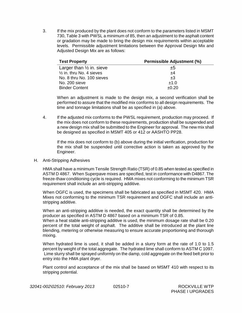
32041-002\02510: February 2013 02510-7 ROCKVILLE WTP PHASE I UPGRADES
3. If the mix produced by the plant does not conform to the parameters listed in MSMT 730, Table 3 with PWSL a minimum of 85, then an adjustment to the asphalt content or gradation may be made to bring the design mix requirements within acceptable levels. Permissible adjustment limitations between the Approval Design Mix and Adjusted Design Mix are as follows:
Test Property Permissible Adjustment (%) Larger than ½ in. sieve ±5 ½ in. thru No. 4 sieves ±4 No. 8 thru No. 100 sieves ±3 No. 200 sieve ±1.0 Binder Content ±0.20
When an adjustment is made to the design mix, a second verification shall be performed to assure that the modified mix conforms to all design requirements. The time and tonnage limitations shall be as specified in (a) above.
4. If the adjusted mix conforms to the PWSL requirement, production may proceed. If
the mix does not conform to these requirements, production shall be suspended and a new design mix shall be submitted to the Engineer for approval. The new mix shall be designed as specified in MSMT 405 or 412 or AASHTO PP28.
If the mix does not conform to (b) above during the initial verification, production for the mix shall be suspended until corrective action is taken as approved by the Engineer.
H. Anti-Stripping Adhesives
HMA shall have a minimum Tensile Strength Ratio (TSR) of 0.85 when tested as specified in ASTM D 4867. When Superpave mixes are specified, test in conformance with D4867. The freeze-thaw conditioning cycle is required. HMA mixes not conforming to the minimum TSR requirement shall include an anti-stripping additive.
When OGFC is used, the specimens shall be fabricated as specified in MSMT 420. HMA Mixes not conforming to the minimum TSR requirement and OGFC shall include an anti-stripping additive.
When an anti-stripping additive is needed, the exact quantity shall be determined by the producer as specified in ASTM D 4867 based on a minimum TSR of 0.85. When a heat stable anti-stripping additive is used, the minimum dosage rate shall be 0.20 percent of the total weight of asphalt. The additive shall be introduced at the plant line blending, metering or otherwise measuring to ensure accurate proportioning and thorough mixing.
When hydrated lime is used, it shall be added in a slurry form at the rate of 1.0 to 1.5 percent by weight of the total aggregate. The hydrated lime shall conform to ASTM C 1097. Lime slurry shall be sprayed uniformly on the damp, cold aggregate on the feed belt prior to entry into the HMA plant dryer.
Plant control and acceptance of the mix shall be based on MSMT 410 with respect to its stripping potential.

32041-002\02510: February 2013 02510-8 ROCKVILLE WTP PHASE I UPGRADES
I. Plant Control
The following tolerances shall apply:
Physical Property Tolerance Passing No. 4 sieve and larger, % ±7 (a) Passing No. 8 thru No. 100 sieve, % ±4 (a) Passing No. 200 sieve, % ±2 Asphalt content, % ±0.4 Ratio of dust to binder material 0.6 to 1.6 Mix temperature leaving plant versus design mix temperature, F
±25
Deviation of maximum specific gravity per lot versus design maximum specific gravity
±0.030
Voids, total mix, % 4±1.2 Voids, total mix, SR mix (VTM) % 3±2 Voids in mineral aggregate, % ±1.2 from design target Voids filled asphalt (VFA) % Within spec.
Note: (a) ±2% for BF on 1 inch sieve.
PWSL computations shall be performed for maximum specific gravity, voids in the total mix, voids in the mineral aggregate, and voids filled with asphalt. This computation shall be performed as specified in Section 504.04.02 of the State Highway Administration Specifications using the moving average of the last three consecutive test values for each parameter. If the PWSL for the three test values fall below 85, corrective action shall be taken to bring the PWSL to at least 85. If the PWSL drops below 68, production shall be suspended until corrective action is taken as approved by the Engineer.
2.06 CONCRETE CURB AND GUTTERS
A. Concrete shall be Class B in accordance with the requirements of Section 03300 - Cast-In-Place Concrete, except that concrete shall be air-entrained to provide an air content of 6% ± 1.5%.
2.07 ASPHALT TACK COAT
A. All work, including materials, associated with asphalt tack coat shall be in accordance with MCDPW&T Section 504.03.04, Asphalt Tack Coat.
PART 3 -- EXECUTION 3.01 EMBANKMENT
A. The embankment shall be constructed in accordance with Section 02200 - Earthwork. 3.02 SUBGRADE
A. The subgrade, where shown on the Drawings, shall be aggregate stabilized by the addition and mixing of coarse aggregate with the top 3-inches of subgrade. Aggregate stabilization

32041-002\02510: February 2013 02510-9 ROCKVILLE WTP PHASE I UPGRADES
shall be applied to the subgrade at a rate of 300-pounds per square yard. Following the application of stabilizer aggregate, the subgrade shall be formed true to crown and grade, and shall be compacted with a minimum of four (4) passes of a 15-ton vibratory roller to conform to the maximum densities determined by AASHTO T99 Standard Specifications.
3.03 BASE COURSE
A. The finished base course of all paving shall be GAB and shall be of the thickness shown on the Drawings, formed true to crown and grade, placed as per Section 501 of the Maryland DOT Standard Specifications for Construction and Materials. Gravel roads, including repair to existing gravel roads shall be GAB and shall be of the thicknesses shown on the Drawings, formed true to crown and grade. No fill material except new GAB shall be placed on top of existing gravel.
3.04 SOIL CEMENT BASE COURSE (INTERMEDIATE COURSE)
A. Soil Cement Concrete Base (or Intermediate Course) shall be placed in accordance with Maryland DOT Standard Specifications for Construction and Materials Section 502. Soil Cement Base (or Intermediate Course) shall be compacted in accordance with Maryland OT Standard Specifications Section 502.03.10, Compaction. Thicknesses shall be as shown on the Drawings.
3.05 RIGID PORTLAND CEMENT CONCRETE
A. The subgrade and base course beneath portland cement concrete pavement shall be prepared in accordance with the applicable Sections of these Specifications and referenced Standard Specifications, except that the Contractor shall use an approved automatically controlled fine grading machine to produce final subgrade and base surfaces meeting the lines, grades, and cross sections (thicknesses) shown on the Drawings or established by the Engineer.
B. The surface of the base shall be damp at the time the concrete is placed. The Contractor
shall sprinkle the base when necessary to provide a damp surface. The Contractor shall satisfactorily correct all soft areas in the subgrade or base prior to placing concrete.
C. Hauling over the base course shall not be allowed except where specifically permitted by
and in writing by the Engineer. The Engineer may allow equipment dumping concrete to operate on the base to the extent and under the conditions the Engineer deems necessary to facilitate placing and spreading the concrete.
D. Installation of the rigid concrete pavement shall be in accordance with the details shown on
the Drawings and Division 3 - Concrete. The rigid concrete pavement shall cure a minimum of ten (10) calendar days and until the concrete has attained a minimum flexural strength of 550 psi as indicated by flexural strength testing. The Contractor shall coordinate and pay for all flexural strength testing with a minimum of four (4) 6-inch by 6-inch by 20-inch beams for every fifty (50) cubic yards of pavement concrete installed.
E. Contraction joints shall be spaced at intervals as shown on the Drawings. Transverse
contraction joints shall be formed by an approved joint insert. Expansion joints shall be

32041-002\02510: February 2013 02510-10 ROCKVILLE WTP PHASE I UPGRADES
placed when the pavement abuts a structure using 1-inch expansion joint material (filler) and sealant as specified herein.
3.06 CONCRETE CURB AND GUTTER
A. The expansion joint filler for concrete curb and gutters shall be cut to conform with the cross section of the curb. Expansion joints shall be spaced at intervals of not more than 25-feet. Formed control joints shall be installed at intervals not exceeding 10 feet. Depth of joint shall be 1/3 the thickness. Curved forms shall be used where radii are indicated; straight segments shall not be permitted. Upon removal of the forms, exposed curb faces shall be immediately rubbed down to a smooth and uniform surface. No plastering shall be permitted.
3.07 UNDERGROUND UTILITY LINES
A. Where an underground utility line is beneath the new roadway, the backfilling shall be carried out with special care, and the final consolidation shall be accomplished by a vibratory roller. Construction of the roadway over the trench shall be deferred as long as practicable.
3.08 JUNCTION WITH OTHER PAVING
A Where new rigid concrete pavement abuts existing rigid concrete or asphalt concrete
paving, the existing paving shall be saw cut straight and true. An expansion joint of a 1/2-inch minimum thickness with filler material and sealant shall be placed between the new concrete pavement and the existing rigid concrete or asphalt concrete paving.
- END OF SECTION -

32041-002\02604: February 2013 02604-1 ROCKVILLE WTP PHASE I UPGRADES
SECTION 02604
UTILITY STRUCTURES PART 1 -- GENERAL 1.01 THE REQUIREMENT
A. Furnish all materials, labor, equipment, and tools required for the design, fabrication, delivery and installment of utility structures and appurtenances in accordance with the Drawings and as specified herein.
1.02 RELATED WORK SPECIFIED ELSEWHERE
A. Section 02200 - Earthwork
B. Section 03200 - Reinforcing Steel
C. Section 03250 - Concrete Accessories
D. Section 03300 - Cast-in-Place Concrete
E. Section 03400 - Precast Concrete
F. Section 05540 - Castings 1.03 REFERENCE SPECIFICATIONS, CODES AND STANDARDS
A. Without limiting the generality of the other requirements of the specifications, all work herein shall conform to the applicable requirements of the following documents. All referenced specifications, codes, and standards refer to the most current issue available at the time of Bid.
1. Federal Specification No. SS-5-00210 - Gaskets
2. ASTM C478 - Specification for Precast Reinforced Concrete Manhole Sections
1.04 SUBMITTALS
A. Submit samples and/or Shop Drawings in accordance with Section 01300, Submittals.
B. In addition to items listed in Section 03400, Precast Concrete, Shop Drawings shall include, but not be limited to:
1. Complete layout and installation Drawings and schedules with clearly marked
dimensions.
2. Material certificates on all piping materials.

32041-002\02604: February 2013 02604-2 ROCKVILLE WTP PHASE I UPGRADES
3. Structural design calculations sealed by a P.E. registered in Maryland. Design calculations for precast manholes and vaults shall include confirmation structures adequately resist flotation when they are totally empty and subjected to groundwater full height of structure.
4. Results of leakage test
PART 2 -- PRODUCTS 2.01 PRECAST MANHOLES, VAULTS, AND METER BOXES
A. Precast utility structures shall be furnished with waterstops, sleeves and openings as noted on the Drawings. Box out for wall pipes shall conform accurately to the sizes and elevations of the adjoining pipes. Precast utility structures shall be watertight and conform to the requirements of ASTM C 478 with the following modifications there to:
1. Materials shall conform to Section 03400, Precast Concrete.
2. Manholes shall meet the following:
a. Manhole section shall have an internal diameter of 8'-0", unless noted
otherwise.
b. Minimum manhole wall thicknesses shall be 12 inches.
c. Manholes shall include ballast concrete and/or other means necessary to insure manholes resist flotation when empty and subjected to groundwater full height of structure.
d. Precast manholes shall be as manufactured by NC Products/Oldcastle,
Tindall Products, or equal.
3. The date and name of manufacturer shall be marked inside each precast section.
4. No more than two lift holes may be cast or drilled in each section.
5. Dimensions shall be as shown on the Drawings.
6. Covers and frames shall be as specified in Section 2.13.
7. Mechanical Details such as piping, electrical, and other details shall be as shown on the Drawings.
B. Joints between manhole riser sections and at base slabs shall be groove type.
2.02 CONCRETE
A. Concrete shall conform to Section 03300, Cast-in-Place Concrete. 2.03 REINFORCING
A. Reinforcing shall conform to Section 03200, Reinforcing Steel.

32041-002\02604: February 2013 02604-3 ROCKVILLE WTP PHASE I UPGRADES
2.04 PRECAST CONCRETE
A. Precast concrete shall conform to Section 03400, Precast Concrete. 2.05 CONCRETE BLOCK
A. Concrete block shall be solid, rectangular concrete masonry units conforming to ASTM C139.
2.06 CASTINGS
A. Castings shall conform to Section 05540, Castings. Casting shall be of the type and size indicated on the Drawings.
2.07 STEPS
A. Steps shall be constructed of Grade 60 steel reinforcing rod (min. 1/2-inch) and completely encapsulated with a wear resistant and chemical resistant rubber.
B. Each step shall have a minimum vertical load resistance of 800 pounds and a minimum pull-
out resistance of 400 pounds.
C. The steps shall have 11-inch minimum tread width and shall be placed at 16-inches on center, as shown on the Drawings.
D. Steps shall be cast in place with the concrete.
E. Steps shall only be installed as shown on the Drawings or required in the Specifications.
2.08 JOINT SEALANT
A. Joint sealant shall be a Preformed Flexible Compound conforming to the requirements of Federal Specifications SS-S-00210, "Sealing Compound, Preformed Plastic for Pipe Joints", Type I, Rope Form.
2.09 FLEXIBLE RUBBER SLEEVE
A. The spring set type shall have a stainless steel interior power sleeve or expander and shall be the PSX assembly by Press-Seal Gasket Corporation, the Kor-N-Seal assembly by National Pollution Control Systems, or Lock Joint Flexible Manhole Sleeve by Interpace Corp.
B. The cast-in-place type shall conform to ASTM C923 and shall include stainless steel take up clamps.
C. Flexible seal assemblies shall permit at least an eight (8) degree deflection from the center line of the opening in any direction while maintaining a watertight connection.
2.10 RUBBER BLADDER
A The rubber bladder seal shall conform to ASTM C923 suitable for pressure testing at 10 psi minimum, with a 3/8 inch minimum wall thickness.

32041-002\02604: February 2013 02604-4 ROCKVILLE WTP PHASE I UPGRADES
B. The rubber bladder seal shall contain an environmentally safe, anti-bacterial compound
which turns into a high viscosity gel when in contact with pressurized water.
C. The rubber bladder seal shall be NPC Contour Seal by Kor-N-Seal, or equal. 2.11 COVERS AND FRAMES
A. Covers and frames shall comply with Section 05540, Castings and shall be provided by the utility structure manufacturer.
B. Manhole covers and frames shall meet the following requirements:
1. Locate so that there is ready access to the manhole steps
2. Clear opening shall be a minimum of 22 inches, unless otherwise indicated on the
Drawings.
3. Watertight manhole frames and covers shall be suitable for 20 psi internal pressure and shall be Neenah Model R-1915, Type P or L or equal cast in place.
4. Non-watertight manhole covers shall be perforated and shall be Neenah Model R-
1668, or equal.
C. Vault covers shall have lifting handles and shall be bolted with stainless steel bolts complying with Section 05050, Metal Fastening.
D. All frames and covers shall be given one shop coat of asphalt or coal tar varnish, unless
otherwise specified.
E. Frames and covers shall be identical throughout the Contract.
2.12 GRATES
A. Grates shall comply with Section 05540, Castings.
2.13 CONCRETE BALLAST
A. Concrete ballast shall be Class B concrete in conformance with Section 03300, Cast-in-Place Concrete. Ballast shall be provided as necessary to insure manhole resists flotation when empty and subjected to full height groundwater conditions.
2.14 FLEXIBLE JOINT SEALER
A. Flexible joint sealer shall be a rubber ring waterstop as manufactured by Fernco Joint Sealer Co., or equal.
2.15 EPOXY BONDING AGENT
A. Epoxy bonding agent shall conform to Section 03250, Concrete Accessories. PART 3 -- EXECUTION

32041-002\02604: February 2013 02604-5 ROCKVILLE WTP PHASE I UPGRADES
3.01 DESIGN CRITERIA
A. Precast items subjected to vehicular traffic shall be designed for H-20 traffic loading. Other precast items shall be designed for a vertical live load of 300 psf.
B. Walls of precast items shall be designed for a vertical surcharge of 100 psf. C. Precast manholes and vaults shall be designed to resist flotation when totally empty and
subjected to groundwater full height of the manhole. 3.02 FABRICATION AND CASTING
A. Fabrication and casting shall conform to Section 03400, Precast Concrete, and to Section 03300, Cast-in-Place Concrete.
B. All base sections designated to receive concrete ballast and all electrical manholes shall
extend monolithically a minimum of 6 inches beyond the outside face of the wall for the entire periphery. All other utility structures shall have a standard base.
C. Utility structures built around existing pipe shall have a cast-in-place base slab.
3.03 HANDLING, TRANSPORTING, AND STORING
A. Handling, transporting and storing of precast items shall comply with Section 03400, Precast Concrete.
3.04 INSTALLATION
A. Installation shall conform with Section 03400, Precast Concrete and with the manufacturer's recommendations or to Section 03300, Cast-in-Place Concrete.
B. Frames and covers or grates shall be set so that tops are at elevations indicated on the
Drawings or flush with finished grade where no elevation is indicated.
C. Joints between riser sections shall be sealed with joint sealant.
D. All openings in utility structures shall have flexible rubber sleeves sized to fit the connecting pipe and installed to provide watertight joints in accordance with the manufacturer's recommendations. The interior of the sleeve shall be filled with Class B concrete.
E. Openings that are too large for flexible rubber sleeves shall utilize rubber bladder seals
which are expanded by water injected using a pressure pump.
F. All units shall be installed plumb and level.
G. All lift holes and joints shall be filled with non-shrink grout conforming to Section 03600, grout inside and out.

32041-002\02604: February 2013 02604-6 ROCKVILLE WTP PHASE I UPGRADES
H. The manhole frames shall be set to their required elevations either with grade rings or with two or three courses of brick masonry laid around the top of the upper wall section. Such brick work shall be given a 1-inch mortar coat on the inside and out.
I. Concrete ballast shall be placed so that it bears directly on the utility structure base against
the outer wall monolithically encircling the structure for the full height indicated on the Drawings. Additional ballast may be required where the depth or elevation of the structure varies from the Drawings.
J. Brick or Concrete Block
Brick or concrete block shall be laid with broken joints and all horizontal and vertical joints filled with cement-sand mortar. Outside of walls shall be plastered with a minimum 1-inch thick coat of cement-sand mortar troweled smooth.
K. Connection to Existing Pipe
1. Verify the diameter and invert elevation of existing pipe to be connected to new utility
structures prior to beginning work on the structures.
2. Provide adequate protection to prevent damage to the existing pipe.
3. Provide adequate means for plugging and/or transferring the existing flow in the pipe to allow for the construction of inverts and grouting.
4. Cut off the existing pipe sufficiently for connection to the new structure and remove.
5. Thoroughly clean all foreign matter and coat the pipe surface with epoxy adhesive
where the pipe joins the new structure.
6. Install a flexible joint sealer around the pipe.
7. Grout inside and outside of wall penetration with nonshrink grout.
L. Backfill structures in accordance with Section 02200, Earthwork.
M. Clean all structures of any accumulation of silt, debris, or foreign matter and keep clean until final acceptance of the work.
N. Excavation shall conform to Section 02200, Earthwork.
O. Structure bases shall bear on a minimum of 8 inches of compacted stone unless otherwise
indicated on the Drawings.
P. Channel Inverts
1. Inverts shall be placed using Class B concrete with forms sufficient to provide a smooth half-round shape as shown on the Drawings. Manhole bases employing full depth precast inverts are acceptable.

32041-002\02604: February 2013 02604-7 ROCKVILLE WTP PHASE I UPGRADES
2. Where the slope of the line does not change through a manhole, a constant slope shall be maintained in the invert. Where slope changes occur within a given manhole, the transition shall be smooth and shall occur at the approximate center of the manhole.
3. Inverts shown on the Drawings are taken at the center of the manhole unless
otherwise noted. 3.05 ADJUSTMENTS TO EXISTING UTILITY STRUCTURES
A. Adjust structures as indicated on the Drawings using concrete or cast iron adjustment rings by approved methods.
B. Clean covers and inlet castings of all foreign material and paint with one coat of coal tar
epoxy. 3.06 ADJUSTING COLLARS AND FINAL ADJUSTMENTS
A. Adjusting collars shall be as shown on the Drawings. Final adjustments shall be made so that the manhole ring and cover will be smooth and flush with the finished grade of the adjacent surface, or as otherwise indicated on the Drawings for manholes shown above grade.
3.07 FLUSHING AND TESTING
A. Obstruction - After backfilling, all sewers shall be inspected for obstructions and shall be flushed with water. Flushing shall be a minimum velocity of 2.5 feet per second for a duration acceptable to the Engineer. Flushing shall remove all dirt, stones, pieces of wood and other debris which accumulated in the sewer during construction. The Contractor shall provide a means acceptable to the Engineer for removal of debris flushed from each section of sewer. If after flushing, any obstructions remain, they shall be removed at the Contractor's expense.
B. Visual Inspection - Sewer lines shall be visually inspected from every manhole by use of
mirrors, television cameras, or other devices for visual inspection, and the lines shall all exhibit a fully circular pattern when viewed from one manhole to the next. Lines which do not exhibit a true line and grade or have structural defects shall be corrected to meet these qualifications.
C. Leakage - Sewers shall be tested for leakage. The program of testing shall fit the conditions
as mutually determined by the Engineer and the Contractor. The Contractor shall take all necessary precautions to prevent any joints from drawing while the sewers or their appurtenances are being tested. The Contractor shall, at his own expense, correct any excess leakage and repair any damage to the pipe and their appurtenances, or to any structures resulting from or caused by these tests.
D. Leakage Test Procedure - Each section of sewer shall be tested by closing the lower end of
the sewer to be tested and the inlet sewer of the upper manhole with stoppers and filling the pipe and manhole with water to a point 6 feet above the crown of the open sewer in the upper manhole, or, if ground water is present, 6 feet above the sections average adjacent ground water level as indicated by a monitor well installed adjacent to each manhole. The

32041-002\02604: February 2013 02604-8 ROCKVILLE WTP PHASE I UPGRADES
line shall be filled with water prior to testing and allowed to stand until the pipe has reached its maximum absorption, but not less than two (2) hours. After maximum absorption has been reached, the head shall be re-established and tested for at least six (6) hours maintaining the head specified above by measured additions of water. The sum of these additions shall be the leakage for the test period.
If ground water is present to a height of at least 6 feet above the crown of the sewer at the upper end of the pipe section to be tested, the leakage test may be made by measuring the rate of infiltration using a suitable weir or other measuring device approved by the Engineer. Whether the test is made by infiltration or exfiltration, the allowable leakage shall not exceed 100 gallons per day per inch of diameter per mile of sewer being tested.
Where the actual leakage exceeds the allowable, the Contractor shall discover the cause and correct it before the sewer will be accepted. For the purpose of this subsection, a section of sewer is defined as that length of sewer between successive manholes or special structures or stubouts for future connections.
E. Low Pressure Compressed Air Test - If the leakage cannot be located by infiltration or
exfiltration testing, this type test may be used. The pipeline shall be considered acceptable, when tested at an average pressure of 3.0 psi greater than the average back pressure of any groundwater that may submerge the pipe, if the section under test does not lose air at a rate greater than 0.0030 cfm per sq. ft. of internal pipe surface.
F. Deflection Test - No sooner than thirty (30) days after final backfill installation, each section
of PVC pipe shall be checked for vertical deflection using an electronic deflecto-meter or a rigid "Go-No-Go" device. Vertical deflection shall not exceed five (5) percent of the inside pipe diameter for PVC pipe.
Where the actual deflection exceeds the allowable, the Contractor shall discover the cause and correct it before the pipe will be acceptable. For the purpose of this subsection, a section of sewer is defined as that length of sewer between successive manholes or special structures or stubouts for future connections.
G. Cost of Testing and Repairs - Any and all work necessary to bring the line into conformance
with the infiltration and deflection specifications shall be performed by the Contractor at no extra cost to the Owner. All apparent sources of infiltration and excessive deflection shall be repaired by the Contractor.
The Contractor shall provide all water, plugs, hoses, pumps, equipment, etc. necessary for the proper flushing and testing of the sewers.
- END OF SECTION -

32041-002\02910: February 2013 02910-1 ROCKVILLE WTP PHASE I UPGRADES
SECTION 02910
FINAL GRADING AND LANDSCAPING PART 1 -- GENERAL 1.01 THE REQUIREMENT
A. Furnish all labor, equipment, and materials necessary for final grading, topsoiling, seeding, and miscellaneous site work not included under other Sections, but required to complete the work as shown on the Drawings and specified herein. Under this Section, all areas of the project site disturbed by excavation, materials storage, temporary roads, etc., shall be reseeded as specified herein.
1.02 RELATED WORK SPECIFIED ELSEWHERE
A. Section 02276 - Erosion and Sedimentation Control.
B. Section 02500 - Surface Restoration. 1.03 SUBMITTALS
A. Submit the following in accordance with Section 01300, Submittals.
1. Product Data
2. Certification of all materials
3. Three (3) copies of composition and germination certification and of test results for grass seed.
PART 2 -- PRODUCTS 2.01 CONTRACTOR'S RESPONSIBILITIES
A. Furnish and submit certification for the materials used as specified in the General Conditions, Division 1 and Division 2.
2.02 TOPSOIL
A. Upon completion and approval of the rough grading, the Contractor shall place the topsoil over all areas disturbed during construction under any contract except those areas which will be paved, graveled or rip rapped. Topsoil shall not be placed in a frozen or muddy condition and shall contain no toxic materials harmful to grass growth. Topsoil shall be as defined under Section 02200, Earthwork.
2.03 WATER

32041-002\02910: February 2013 02910-2 ROCKVILLE WTP PHASE I UPGRADES
A. Water shall be furnished to the Contractor by the Owner from existing facilities as directed by the Engineer.
B. The Contractor shall furnish all hoses and connections necessary to complete the
landscaping work.
2.04 FERTILIZER
A. Fertilizer shall be a complete commercial fertilizer with components derived from commercial sources. Fertilizer composition shall be determined from field soil sampling in appropriate number taken by the Contractor and analyzed by the University of Maryland or by a recognized commercial laboratory. Contractor shall furnish fertilizer in accordance with the recommendations from the above references.
B. Fertilizer shall be uniform in composition, free flowing and suitable for accurate application
by approved equipment. Manure may be substituted for fertilizer with prior approval from the appropriate approval authority. Fertilizers shall be delivered to the site fully labeled according to the applicable state fertilizer laws and shall bear the name, trade name or trademark and warrantee of the producer. Fertilizer shall be stored in weatherproof storage areas and in such a manner that its effectiveness will not be impaired.
2.05 LIME
A. Lime materials shall be ground limestone (hydrated or burnt lime may be substituted) which contains at least 50% total oxides (calcium oxide plus magnesium oxide). Limestone shall be ground to such fineness that at least 50% will pass through a #100 mesh sieve and 98-100% will pass through a #20 sieve.
2.06 GRASS SEED
A. The Contractor shall furnish the kinds and amounts of seed to be seeded in all areas disturbed by the construction work. All seed shall be labeled to show that it meets the requirements of the Maryland Seed Law. All seed must have been tested within six (6) months immediately preceding the planting of such material on the job.
B. The inoculant for treating legume seed mixture shall be a pure culture of nitrogen-fixing
bacteria prepared specifically for the species. Inoculants shall not be used later than the date indicated on the container. Add fresh inoculant as directed on package. Use four time the recommended rate when hydroseeding. It is very important to keep inoculant as cool as possible until used. Temperatures above 75-80°F can weaken bacteria and make the inoculant less effective.
C. The quality of the seed shall conform to the following:
Type
Minimum Seed Purity
(%)
Minimum Germination
(%)
Maximum Weed Seed
(%) Tall Fescue 98 90 2.5 Perennial Ryegrass 98 90 2.5 Kentucky Bluegrass 90 80 2.5

32041-002\02910: February 2013 02910-3 ROCKVILLE WTP PHASE I UPGRADES
D. Permanent seed mixtures to be used on the project shall be as follows:
Seed Mixture (For Hardiness Zone 6a) (From Table 25 of the Maryland Standards and Specifications for Soil Erosion and Sediment
Control)
Fertilizer Rate (10-20-20)
Species Application Rate (lb/ac)
Seeding Dates
Seeding Depths
(in) N P205 K20 Lime Rate
Tall Fescue 125 3/15 to 6/1
8/1 to 10/1 1 90 lbs/ac (2.0 lb/
1000 sf)
175 lb/ac (4 lb/
1000 sf)
175 lb/ac (4 lb/
1000 sf)
2 tons / ac
(100 lb/ 1000 sf) Perennial
Ryegrass 15 3/15 to 6/1 8/1 to 10/1 1
Kentucky Blugress 10 3/15 to 6/1
8/1 to 10/1 1
E. Temporary seed mixture to be used on the project shall be as follows:
Species MINIMUM
SEEDING RATES PLANING DEPTHS
HARDINESS ZONES AND SEEDING DATES
Per Acre
LBS/100 SQ. FT.
Inches 6/2-7/31 10/2-10/31 Fertilizer Rate (10-10-10)
Lime Rate
Rye3 2.5 B.U. (140 LBS)
3.22 1-2 - X 600 lb/ac (15 lb/
1000 sq.ft)
2 tons/ac (100 lb/ 1000 sq.ft.)
Barley or Rye Plus Foxtail Millet4
150 lbs 3.45 1 X X
10/1 X
Weeping Lovegras
s3
4 lbs .09 ¼ - ½ X X -
Annual Ryegrass
50 lbs 1.15 ¼ - ½ - 8/15
Millet6 50 lbs 1.15 ½ X - 1 Applicable on slopes of 3:1 or flatter. 2 Between fall and spring seeding dates, use mulch only if ground is frozen and reseed when thawed. 3 May be used as a nurse crop for late fall/early winter permanent seedlings, add 56 lbs/ac to the permanent seeding mixture. 4 Maryland State Highway Administration Temporary Seed Mix 5 May be used as a nurse crop for mid-summer permanent seedlings. Add 2 lbs/ac to permanent seed mix. 6 May be used as nurse crop for mid-summer permanent seedlings. Add 10lbs/ac to the permanent seeding mix.

32041-002\02910: February 2013 02910-4 ROCKVILLE WTP PHASE I UPGRADES
2.07 WOOD CELLULOSE FIBER MULCH
A. For use in hydroseeding grass seed in combination with fertilizers and other approved additions, shall consist of especially prepared wood cellulose fibers such as "Conwed", "Silva-Fiber", or approved substitute, and have no growth or germination inhibiting factors, and be dyed green.
B. The wood cellulose fiber shall have the additional characteristic of dispersing rapidly in water
to form a homogeneous slurry and remain in such state when agitated in the hydraulic mulching unit, or adequate equal, with the specified materials.
C. When applied, the wood cellulose fiber with additives will form an absorptive mat but not a
plant inhibiting membrane, which will allow moisture, natural or mechanical, to percolate into underlying soil.
D. Fiber mulch can be applied over top of newly seeded areas immediately after seed mixture
is applied to soil bed or applied as part of the hydroseeded slurry containing the seed mixture. Anchored straw mulch shall be used in place of fiber mulch during hot and dry summer months and late fall. Fiber mulch can be used to tack (anchor) straw mulch. All fiber mulch shall adhere to requirements set forth in the MS3ESC.
E. The mulch shall be supplied, compressed in packages containing 50 pounds of material
having an equilibrium air dry moisture content at time of manufacture of 12% plus or minus 2%. Wood cellulose fiber mulch shall be stored in a weatherproof storage area and in such a manner that effectiveness will not be impaired.
2.08 STRAW MULCH
A. Straw used for mulch shall be wheat or oats. Straw shall be undamaged, air dry, threshed straw, free of undesirable weed seed. Straw mulch shall be spread by hand or machine and must be anchored or tacked down. Straw mulch is not required for seeded areas treated with a temporary soil stabilizer. All straw mulch shall adhere to requirements set forth in the MS3ESC.
2.09 TEMPORARY SOIL STABILIZER
A. The temporary agent for soil erosion control shall consist of an especially prepared highly concentrated powder which, when mixed with water, forms a thick liquid such as "Enviroseal 2001" by Enviroseal Corporation, "Terra Control" by Quattro Environmental, Inc., or "CHEM-CRETE ECO-110” by International CHEM-CRETE Corporation, and having no growth or germination inhibiting factors. The agent shall be used for hydroseeding grass seed in combination with other approved amendments resulting in a highly viscous slurry which, when sprayed directly on the soil, forms a gelatinous crust.
2.10 EROSION CONTROL MATTING (ECM)
A. The ECM shall be as specified in Section 02276 - Erosion and Sedimentation Control.

32041-002\02910: February 2013 02910-5 ROCKVILLE WTP PHASE I UPGRADES
2.11 SYNTHETIC TURF REINFORCEMENT MAT (TRM)
A. The TRM shall be as specified in Section 02276 – Erosion and Sedimentation Control.2.11
2.12 RIPRAP AND HERBICIDES
A. Furnish and install sufficient quantity of landscape gravel or riprap to cover over the ground to a minimum 4-inch depth for gravel and 24-inch depth for riprap, unless otherwise noted, or indicated on the Drawings. Also furnish and apply an approved herbicide to the subgrade surface just prior to installing the landscape gravel or riprap.
B. During placing, the stone shall be graded so that the smaller stones are uniformly distributed
through the mass. The Contractor may place the stone by mechanical methods, augmented by hand placing where necessary or ordered by the Engineer. The placed riprap shall form a properly graded, dense, neat layer of stone.
C. All topsoil and vegetative matter shall be removed from the subgrade surfaces prior to the
application of the weed killer (herbicide) and to the placement of landscape gravel or riprap. Apply commercial-type herbicide as preemergence control of miscellaneous grasses and broadleaf weeds in granular or liquid form such as "Treflan", "Dymid", or approved substitute. Methods and rates of application shall be in strict compliance to manufacturer's directions and acceptable to the Engineer.
D. The herbicide selected shall be safe for use around ornamental plantings, have long-lasting
weed control, and shall be resistant to leaching away under excessive rainfall.
E. A second application of the herbicide shall be made on the surface of the landscape gravel or riprap sometime after the first six (6) months, but not later than twelve (12) months. Same methods and rates apply as specified previously.
PART 3 -- EXECUTION 3.01 GRADING
A. After approval of the rough grading, the Contractor shall commence his preparations of the subgrade for the various major conditions of the work as follows:
1. Bare soil for riprap area at subgrade (24-inches below final grade, or as directed by
the Engineer).
2. Topsoil for lawn and road shoulder seed area - scarify 2-inch depth of subgrade (4-inches below final grade) prior to placing topsoil.
B. Final surface grading of the topsoiled, landscape graveled, and riprapped areas shall be
mechanically raked or hand raked to an even finished surface alignment. 3.02 TOPSOIL
A. Topsoil shall be spread in place for quantity required for lawn and road shoulder seed areas
at 4-inch consolidated depth, and sufficient quantity for certain plant beds and backfill for shrubs and trees as specified.
B. Topsoil shall be hospitable as a growth medium meeting all requirements as indicated by Sections 21.0 of MS3ESC.

32041-002\02910: February 2013 02910-6 ROCKVILLE WTP PHASE I UPGRADES
3.03 SEEDBED PREPARATION
A. Contractor shall prepare all areas to receive temporary or permanent seeding measures in accordance with Section 20.0 of the MS3ESC.
3.04 HYDROSEEDING AND GRASS
A. The Contractor shall grow a stand of grass on disturbed areas. The Contractor shall be responsible for the satisfactory growth of grass throughout the period of the one-year guarantee from Contract Closeout.
B. The Contractor's work shall include the preparation of the topsoil and bare soil seed bed,
application of fertilizer, limestone, mulching, inoculant, temporary soil stabilizer, watering, and other operations necessary to provide a satisfactory growth of sod at the end of the one-year maintenance period.
C. When hydraulic seeding method is used, include all additives and amendments required. A
"Reinco", "Finn", or "Bowie" type hydromulcher with adjustable nozzles and extension hoses, or approved substitute, shall be utilized. General capacity of tank should range from 500 to 2,500 gallons, or as approved by the Engineer.
D. Hydraulic seeding shall be carried out in three steps. Step one shall consist of the
application of lime. In step two the seed mixture shall be mixed with the fertilizer, wood cellulose fiber mulch, and any required inoculants and applied to the seed bed. The seed mixture can be applied as a separate process prior to the application of the slurry mixture. Step three shall consist of application of top dressing during the first spring or fall, whichever comes first, after step two.
E. Top dressing shall consist of a commercial grade fertilizer plus nitrogen or other analysis as
may be recommended by soil testing. Types and application rates of seed mixtures shall be as shown in the Seeding Schedule.
F. Ingredients for the mixture and steps should be dumped into a tank of water and thoroughly
mixed to a homogeneous slurry and sprayed out under a minimum of 300-350 pounds pressure, in suitable proportions to accommodate the type and capacity of the hydraulic machine to be used. Applications shall be evenly sprayed over the ground surface. The Contractor shall free the topsoil of stones, roots, rubbish, and other deleterious materials and dispose of same off the site. The bare soil, except existing steep embankment area, shall be rough raked to remove stones, roots, and rubbish over 4-inches in size, and other deleterious materials and dispose of same off the site.
G. No seeding should be undertaken in windy or unfavorable weather, when the ground is too
wet to rake easily, when it is in a frozen condition, or too dry. Any bare spots shown in two to three weeks shall be recultivated, fertilized at half the rate, raked, seeded, and mulched again by mechanical or hand broadcast method acceptable to the Engineer.
H. Areas that have been seeded with a temporary seed mixture shall be mowed to a height of
less than 2-inches and scarified prior to seeding with the permanent seed mixture. I. The Contractor shall provide, at his own expense, protection for all seeded areas against
trespassing and damage at all times until acceptance of the work. Slopes shall be protected

32041-002\02910: February 2013 02910-7 ROCKVILLE WTP PHASE I UPGRADES
from damage due to erosion, settlement, and other causes and shall be repaired promptly at the Contractor's expense.
J. The Contractor shall water newly seeded areas of the lawn and road shoulder mix once a week until the grasses have germinated sufficiently to produce a healthy turf, or unless otherwise directed by the Engineer. Each watering shall provide three (3) gallons per square yard. The Contractor shall furnish all necessary hoses, sprinklers, and connections.
K. The first and second cutting of the lawn grasses only shall be done by the Contractor. All
subsequent cuttings will be done by the Owner's forces in a manner specified by the Contractor.
3.05 EROSION CONTROL MATTING (ECM)
A. All channels and slopes indicated on the Drawings shall be lined with an ECM. The area to be covered shall be properly graded and seeded in accordance with this Specification and Section 20.0 of the MS3ESC before the mat is applied. Installation shall be in accordance with Section 02276 - Erosion and Sedimentation Control and Section 22.0 of the MS3ESC.
3.06 SYNTHETIC TURF REINFORCEMENT MAT (TRM)
A. All channels and slopes indicated on the Drawings shall be lined with a synthetic TRM. The area to be covered shall be properly graded before the TRM is applied. Once the TRM is placed and anchored, the area shall be seeded and mulched in accordance to this Specification and Section 20.0 of the MS3ESC. Installation shall be in accordance with Section 02276 - Erosion and Sediment Control.
3.07 MAINTENANCE
A. The Contractor shall be responsible for maintaining all seeded areas through the end of his warranty period. Maintenance shall include but not be limited to, annual fertilization, repair of seeded areas, irrigation (until permanent vegetation is fully established), and weed control. The Contractor shall provide, at his own expense, protection for all seeded areas against trespassing and damage at all times until acceptance of the work. Slopes shall be protected from damage due to erosion, settlement, and other causes and shall be repaired promptly at the Contractor's expense.
B. Annual fertilization shall consist of an application of 500#/acre of 10-10-10 commercial grade
fertilizer, or its equivalent and 60#/acre of nitrogen in early fall, or other analysis as may be determined by soil test. Annual fertilization shall be in addition to top dressing and shall be performed by the Contractor each fall season after planting until the work is substantially complete.
C. Mowing shall be scheduled so as to maintain a minimum stand height of 4-inches or as
directed by the Engineer. Stand height shall be allowed to reach 8 to 10-inches prior to mowing.
D. Once vegetation is established, the site shall have 95% groundcover to be considered
adequately stabilized. E. If the stand provides less than 40% ground coverage, reestablish following original lime
fertilizer, seedbed preparation and seeding recommendations.

32041-002\02910: February 2013 02910-8 ROCKVILLE WTP PHASE I UPGRADES
F. If the stand provides between 40% and 94% ground coverage, overseeding and fertilizing using half of the rates originally applied may be necessary.
G. All seeded areas shall be inspected on a regular basis and any necessary repairs or
reseedings made within the planting season, if possible. H. Weed growth shall be maintained mechanically and/or with herbicides. When chemicals are
used the Contractor shall follow the current weed control recommendations of the State of Maryland and adhere strictly to the instructions on the label of the herbicide. No herbicide shall be used without prior approval of the Engineer.
3.08 CLEANUP
A. The Contractor shall remove from the site all subsoil excavated from his work and all other debris including, but not limited to, branches, paper, and rubbish in all landscape areas, and remove temporary barricades as the work proceeds.
B. All areas shall be kept in a neat, orderly condition at all times. Prior to final acceptance, the
Contractor shall clean up the entire landscaped area to the satisfaction of the Engineer. 3.09 SEEDING SCHEDULE
A. All seeding and mulching to be completed by the Contractor shall conform to the following schedule. No permanent seeding shall be performed from June 2 - July 31 and October 2 – March 14. Temporary seed mixtures will be used during these times if seeding is necessary. Areas seeded with temporary seed mixtures shall be reseeded by the Contractor at no additional cost to the Owner with permanent seed as directed by the Engineer.
B. Application rates of seed mixtures, lime, fertilizer, mulch and top dressing are shown in the
schedule.

32041-002\02910: February 2013 02910-9 ROCKVILLE WTP
PHASE I UPGRADES
SEEDING SCHEDULE
Application Rates (Pounds/Acre)
Seed Mixture
Planting Season Limea Seed Fertilizer
Strawb
Mulch Topdressinga Annual
Fertilizer Comments P Feb. 15-April 30
Sept. 1-Oct. 31 4000 170 1000 4000 500 of
10-10-10 60 of Nitrogen
Same as Topdressing
Preferred planting seasons are Sept. 1 – Sept. 30 and Feb. 15 – March 30.
TW Jan. 1-May 1 2000 170 750 4000 - - Over seed with Type P seed mixture during next planting season.
TS May 1-Aug. 15 2000 40 750 4000 - - Over seed with Type P seed mixture during next planting season.
TF Aug. 15-Dec. 30 2000 120 1000 4000 - - Over seed with Type P seed mixture during next planting season.
Footnotes: a. Application rates and/or chemical analysis shall be confirmed or established by soil test. b. On cut and fill slopes 2:1 or steeper, add 30#/acre seriocea lespedeza to Type P seed mixture. Use scarified seed for spring plantings and
unscarified for fall plantings. c. Apply asphalt at rate of 0.10 gallon per square yard (10 gal/1000 ft2 ) to tack straw mulch.
- END OF SECTION -

THIS PAGE INTENTIONALLY LEFT BLANK

32041-002\03100: February 2013 03100-1 ROCKVILLE WTP PHASE I UPGRADES
SECTION 03100
CONCRETE FORMWORK PART 1 -- GENERAL 1.01 THE REQUIREMENT
A. Provide materials, labor, and equipment required for the design and construction of all concrete formwork, bracing, shoring and supports in accordance with the provisions of the Contract Documents.
1.02 RELATED WORK SPECIFIED ELSEWHERE
A. Section 03200 - Reinforcing Steel
B. Section 03250 - Concrete Accessories
C. Section 03290 - Joints in Concrete
D. Section 03300 - Cast-in-Place Concrete 1.03 REFERENCE SPECIFICATIONS, CODES AND STANDARDS
A. Without limiting the generality of the other requirements of the specifications, all work herein shall conform to the applicable requirements of the following documents. All referenced specifications, codes, and standards refer to the most current issue available at the time of Bid.
1. Maryland Building Performance Standards
2. ACI 318 - Building Code Requirements for Structural Concrete
3. ACI 301 - Specifications for Structural Concrete for Buildings
4. ACI 347 - Recommended Practice for Concrete Formwork
5. U.S. Product Standard for Concrete Forms, Class I, PS 1
6. ACI 117 - Standard Specifications for Tolerances for Concrete Construction and
Materials 1.04 SUBMITTALS
A. Submit the following in accordance with Section 01300, Submittals.
1. Manufacturer's data on proposed form release agent
2. Manufacturer's data on proposed formwork system including form ties
02
02
10
BR

32041-002\03100: February 2013 03100-2 ROCKVILLE WTP PHASE I UPGRADES
1.05 QUALITY ASSURANCE
A. Concrete formwork shall be in accordance with ACI 301, ACI 318, and ACI 347. PART 2 -- PRODUCTS 2.01 FORMS AND FALSEWORK
A. All forms shall be smooth surface forms unless otherwise specified.
B. Wood materials for concrete forms and falsework shall conform to the following requirements:
1. Lumber for bracing, shoring, or supporting forms shall be Douglas Fir or Southern
Pine, construction grade or better, in conformance with U.S. Product Standard PS20. All lumber used for forms, shoring or bracing shall be new material.
2. Plywood for concrete formwork shall be new, waterproof, synthetic resin bonded,
exterior type Douglas Fir or Southern Pine high density overlaid (HDO) plywood manufactured especially for concrete formwork and shall conform to the requirements of PS1 for Concrete Forms, Class I, and shall be edge sealed. Thickness shall be as required to support concrete at the rate it is placed, but not less than 5/8-inch thick.
C. Other form materials such as metal, fiberglass, or other acceptable material that will not
adversely affect the concrete and will facilitate placement of concrete to the shape, form, line and grade indicated may be submitted to the Engineer for approval, but only materials that will produce a smooth form finish equal or better than the wood materials specified will be considered.
2.02 FORMWORK ACCESSORIES
A. Form ties shall be provided with a plastic cone or other suitable means for forming a conical hole to insure that the form tie may be broken off back of the face of the concrete. The maximum diameter of removable cones for rod ties, or of other removable form-tie fasteners having a circular cross-section, shall not exceed 7/8-inch, and all such fasteners shall be such as to leave holes of regular shape for reaming.
B. Form ties for water-retaining structures shall have integral waterstops. Removable taper ties
may be used when acceptable to the Engineer. A preformed mechanical EPDM rubber plug shall be used to seal the hole left after the removal of the taper tie. Plug shall be X-Plug by the Greenstreak Group, Inc., or approved equal. Friction fit plugs shall not be used.
C. Form release agent shall be a blend of natural and synthetic chemicals that employs a
chemical reaction to provide quick, easy and clean release of concrete from forms. It shall not stain the concrete and shall leave the concrete with a paintable surface. Formulation of the form release agent shall be such that it would minimize formation of "bug holes" in cast-in-place concrete.

32041-002\03100: February 2013 03100-3 ROCKVILLE WTP PHASE I UPGRADES
PART 3 -- EXECUTION 3.01 FORM DESIGN
A. Forms and falsework shall be designed for total dead load, plus all construction live load as outlined in ACI 347. Design and engineering of formwork and safety considerations during construction shall be the responsibility of the Contractor.
B. Forms shall be of sufficient strength and rigidity to maintain their position and shape under
the loads and operations incident to placing and vibrating the concrete. The maximum deflection of facing materials reflected in concrete surfaces exposed to view shall be 1/240 of the span between structural members.
C. All forms shall be designed for predetermined placing rates per hour, considering expected
air temperatures and setting rates. 3.02 CONSTRUCTION
A. The type, size, quality, and strength of all materials from which forms are made shall be subject to the approval of the Engineer. No falsework or forms shall be used which are not clean and suitable. Deformed, broken or defective falsework and forms shall be removed from the work.
B. Forms shall be smooth and free from surface irregularities. Suitable and effective means
shall be provided on all forms for holding adjacent edges and ends of panels and sections tightly together and in accurate alignment so as to prevent the formation of ridges, fins, offsets, or similar surface defects in the finished concrete. Joints between the forms shall be sealed to eliminate any irregularities. The arrangement of the facing material shall be orderly and symmetrical, with the number of seams kept to a practical minimum.
C. Forms shall be true to line and grade, and shall be sufficiently rigid to prevent displacement
and sagging between supports. Curved forms shall be used for curved and circular structures. Straight panels joined at angles will not be acceptable for forming curved structures. Forms shall be properly braced or tied together to maintain their position and shape under a load of freshly-placed concrete. Facing material shall be supported with studs or other backing which shall prevent both visible deflection marks in the concrete and deflections beyond the tolerances specified.
D. Forms shall be mortar tight so as to prevent the loss of water, cement and fines during
placing and vibrating of the concrete. Specifically, the bottom of wall forms that rest on concrete footings or slabs shall be provided with a gasket to prevent loss of fines and paste during placement and vibration of concrete. Such gasket may be a 1 to 1-1/2 inch diameter polyethylene rod held in position to the underside of the wall form.
E. All vertical surfaces of concrete members shall be formed, and side forms shall be provided
for all footings, slab edges and grade beams, except where placement of the concrete against the ground is called for on the Drawings. Not less than 1-inch of concrete shall be added to the thickness of the concrete member as shown where concrete is permitted to be placed against trimmed ground in lieu of forms. Such permission will be granted only for members of comparatively limited height and where the character of the ground is such that it can be trimmed to the required lines and will stand securely without caving or sloughing until the concrete has been placed.

32041-002\03100: February 2013 03100-4 ROCKVILLE WTP PHASE I UPGRADES
F. All forms shall be constructed in such a manner that they can be removed without
hammering or prying against the concrete. Wood forms shall be constructed for wall openings to facilitate loosening and to counteract swelling of the forms.
G. Adequate clean-out holes shall be provided at the bottom of each lift of forms. Temporary
openings shall be provided at the base of column forms and wall forms and at other points to facilitate cleaning and observation immediately before the concrete is deposited. The size, number and location of such clean-outs shall be as acceptable to the Engineer.
H. Construction joints shall not be permitted at locations other than those shown or specified,
except as may be acceptable to the Engineer. When a second lift is placed on hardened concrete, special precautions shall be taken in the way of the number, location and tightening of ties at the top of the old lift and bottom of the new to prevent any unsatisfactory effect whatsoever on the concrete. For flush surfaces at construction joints exposed to view, the contact surface of the form sheathing over the hardened concrete in the previous placement shall be lapped by not more than 1 inch. Forms shall be held against hardened concrete to prevent offset or loss of mortar at construction joints and to maintain a true surface.
I. The formwork shall be cambered to compensate for anticipated deflections in the formwork
due to the weight and pressure of the fresh concrete and due to construction loads. Set forms and intermediate screed strips for slabs accurately to produce the designated elevations and contours of the finished surface. Ensure that edge forms and screed strips are sufficiently strong to support vibrating screeds or roller pipe screeds if the nature of the finish specified requires the use of such equipment. When formwork is cambered, set screeds to a like camber to maintain the proper concrete thickness.
J. Positive means of adjustment (wedges or jacks) for shores and struts shall be provided and
all settlement shall be taken up during concrete placing operation. Shores and struts shall be securely braced against lateral deflections. Wedges shall be fastened firmly in place after final adjustment of forms prior to concrete placement. Formwork shall be anchored to shores or other supporting surfaces or members to prevent upward or lateral movement of any part of the formwork system during concrete placement. If adequate foundation for shores cannot be secured, trussed supports shall be provided.
K. Runways shall be provided for moving equipment with struts or legs. Runways shall be
supported directly on the formwork or structural member without resting on the reinforcing steel.
3.03 TOLERANCES
A. Unless otherwise indicated in the Contract Documents, formwork shall be constructed so that the concrete surfaces will conform to the tolerance limits listed in ACI 117.
B. Structural framing of reinforced concrete around elevators and stairways shall be accurately
plumbed and located within 1/4 in. tolerance from established dimensions.

32041-002\03100: February 2013 03100-5 ROCKVILLE WTP PHASE I UPGRADES
C. The Contractor shall establish and maintain in an undisturbed condition and until final completion and acceptance of the project, sufficient control points and bench marks to be used for reference purposes to check tolerances. Plumb and string lines shall be installed before concrete placement and shall be maintained during placement. Such lines shall be used by Contractor's personnel and by the Engineer and shall be in sufficient number and properly installed. During concrete placement, the Contractor shall continually monitor plumb and string line form positions and immediately correct deficiencies.
D. Regardless of the tolerances specified, no portion of the building shall extend beyond the
legal boundary of the building. 3.04 FORM ACCESSORIES
A. Suitable moldings shall be placed to bevel or round all exposed corners and edges of beams, columns, walls, slabs, and equipment pads. Chamfers shall be 3/4 inch unless otherwise noted.
B. Form ties shall be so constructed that the ends, or end fasteners, can be removed without
causing appreciable spalling at the faces of the concrete. After ends, or end fasteners of form ties have been removed, the embedded portion of the ties shall terminate not less than 2 inches from the formed face of the concrete that is exposed to wastewater or enclosed surfaces above the wastewater, and not less than 1 inch from the formed face of all other concrete. Holes left by the removal of form tie cones shall be reamed with suitable toothed reamers so as to leave the surface of the holes clean and rough before being filled with mortar as specified in Section 03350 - Concrete Finishing. No form-tying device or part thereof, other than metal, shall be left embedded in the concrete. Ties shall not be removed in such manner as to leave a hole extending through the interior of the concrete member. The use of snap-ties which cause spalling of the concrete upon form stripping or tie removal will not be permitted. No snap ties shall be broken off until the concrete is at least three days old. If steel panel forms are used, rubber grommets shall be provided where the ties pass through the form in order to prevent loss of cement paste.
3.05 APPLICATION - FORM RELEASE AGENT
A. Forms for concrete surfaces that will not be subsequently waterproofed shall be coated with a form release agent. Form release agent shall be applied on formwork in accordance with manufacturer's recommendations.
3.06 INSERTS AND EMBEDDED ITEMS
A. Sleeves, pipe stubs, inserts, anchors, expansion joint material, waterstops, and other embedded items shall be positioned accurately and supported against displacement prior to concreting. Voids in sleeves, inserts, and anchor slots shall be filled temporarily with readily removable material to prevent the entry of concrete into the voids.
3.07 FORM CLEANING AND REUSE
A. The inner faces of all forms shall be thoroughly cleaned prior to concreting. Forms may be reused only if in good condition and only if acceptable to the Engineer. Light sanding between uses will be required wherever necessary to obtain uniform surface texture. Unused tie rod holes in forms shall be covered with metal caps or shall be filled by other methods acceptable to the Engineer.

32041-002\03100: February 2013 03100-6 ROCKVILLE WTP PHASE I UPGRADES
3.08 FORM REMOVAL AND SHORING
A. Forms shall not be disturbed until the concrete has attained sufficient strength. Sufficient strength shall be demonstrated by structural analysis considering proposed loads, strength of forming and shoring system, and concrete strength data. Shoring shall not be removed until the supported member has acquired sufficient strength to support its weight and the load upon it. Members subject to additional loads during construction shall be adequately shored to sustain all resulting stresses. Forms shall be removed in such manner as not to impair safety and serviceability of the structure. All concrete to be exposed by form removal shall have sufficient strength not to be damaged thereby.
B. Provided the strength requirements specified above have been met and subject to the
Engineer's approval, forms may be removed at the following minimum times. The Contractor shall assume full responsibility for the strength of all such components from which forms are removed prior to the concrete attaining its full design compressive strength. Shoring may be required at the option of the Engineer beyond these periods.
Ambient Temperature (°F.) During Concrete Placement
Over 95° 70°-95° 60°-70° 50°-60° Below 50°
Walls 5 days 2 days 2 days 3 days Do not remove until directed by Engineer (7 days minimum)
Columns 7 days 2 days 3 days 4 days
Beam Soffits 10 days 7 days 7 days 7 days
Elevated Slabs 12 days 7 days 7 days 7 days
C. When, in the opinion of the Engineer, conditions of the work or weather justify, forms may be
required to remain in place for longer periods of time.
D. An accurate record shall be maintained by the Contractor of the dates of concrete placings and the exact location thereof and the dates of removal of forms. These records shall be available for inspection at all times at the site, and two copies shall be furnished the Engineer upon completion of the concrete work.
3.09 RESHORING
A. When reshoring is permitted or required the operations shall be planned in advance and subjected to approval by the Engineer.
B. Reshores shall be placed after stripping operations are complete but in no case later than
the end of the working day on which stripping occurs.
C. Reshoring for the purpose of early form removal shall be performed so that at no time will large areas of new construction be required to support their own weight. While reshoring is under way, no construction or live loads shall be permitted on the new construction. Reshores shall be tightened to carry their required loads but they shall not be overtightened so that the new construction is overstressed. Reshores shall remain in place until the concrete has reached its specified 28-day strength, unless otherwise specified.

32041-002\03100: February 2013 03100-7 ROCKVILLE WTP PHASE I UPGRADES
D. For floors supporting shores under newly placed concrete, the original supporting shores shall remain in place or reshores shall be placed. The shoring or reshoring system shall have a capacity sufficient to resist the anticipated loads and in all cases shall have a capacity equal to at least one-half of the capacity of the shoring system above. Reshores shall be located directly under a reshore position above unless other locations are permitted.
- END OF SECTION -

THIS PAGE INTENTIONALLY LEFT BLANK.

32041-002\03400: February 2013 03200-1 ROCKVILLE WTP PHASE I UPGRADES
SECTION 03200
REINFORCING STEEL PART 1 -- GENERAL 1.01 THE REQUIREMENTS
A. Provide all concrete reinforcing including all cutting, bending, fastening and any special work necessary to hold the reinforcing steel in place and protect it from injury and corrosion in accordance with the requirements of this section.
B. Provide deformed reinforcing bars to be grouted into reinforced concrete masonry walls.
1.02 RELATED WORK SPECIFIED ELSEWHERE
A. Section 03100 - Concrete Formwork
B. Section 03250 - Concrete Accessories
C. Section 03300 - Cast-in-Place Concrete
D. Section 03400 - Precast Concrete 1.03 REFERENCE SPECIFICATIONS, CODES, AND STANDARDS
A. Without limiting the generality of the other requirements of the specifications, all work herein shall conform to the applicable requirements of the following documents. All referenced specifications, codes, and standards refer to the most current issue available at the time of Bid.
1. Maryland Building Performance Standards
2. CRSI - Concrete Reinforcing Institute Manual of Standard Practice
3. ACI SP66 - ACI Detailing Manual
4. ACI 315 - Details and Detailing of Concrete Reinforcing
5. ACI 318 - Building Code Requirements for Structural Concrete
6. ASTM A 615 - Standard Specification for Deformed and Plain Billet-Steel
Bars for Concrete Reinforcing 1.04 SUBMITTALS
A. Submit the following in accordance with Section 01300, Submittals.
100912BR
32041-002\03400: February 2013 03200-2 ROCKVILLE WTP PHASE I UPGRADES
1. Detailed placing and shop fabricating drawings, prepared in accordance with ACI 315 and ACI Detailing Manual - (SP66), shall be furnished for all concrete reinforcing. These drawings shall be made to such a scale as to clearly show joint locations, openings, and the arrangement, spacing and splicing of the bars.
2. Mill test certificates - 3 copies of each.
3. Description of the reinforcing steel manufacturer's marking pattern.
4. Requests to relocate any bars that cause interferences or that cause placing
tolerances to be violated.
5. Proposed supports for each type of reinforcing.
6. Request to use splices not shown on the Drawings.
7. Request to use mechanical couplers along with manufacturer's literature on mechanical couplers with instructions for installation, and certified test reports on the couplers' capacity.
8. Request for placement of column dowels without the use of templates.
9. Request and procedure to field bend or straighten partially embedded reinforcing. 10. Certification that all installers of dowel adhesive are certified as Adhesive Anchor
Installers in accordance with the ACI-CRSI Anchor Installer Certification Program. 1.05 QUALITY ASSURANCE
A. If requested by the Engineer, the Contractor shall provide samples from each load of reinforcing steel delivered in a quantity adequate for testing. Costs of initial tests will be paid by the Owner. Costs of additional tests due to material failing initial tests shall be paid by the Contractor.
B. Installer Qualifications for Drilled-In Rebar: Drilled-in rebar shall be installed by an Installer
with at least three years of experience performing similar installations. Installer shall be certified as an Adhesive Anchor Installer in accordance with ACI-CRSI Adhesive Anchor Installation Certification Program.
C. Installer Training: Conduct a thorough training with the manufacturer or the manufacturer’s
representative for the Installer on the project. Training shall consist of a review of the complete installation process for drilled-in anchors, to include but not be limited to the following: 1. Hole drilling procedure. 2. Hole preparation and cleaning technique. 3. Adhesive injection technique and dispenser training/maintenance. 4. Rebar doweling preparation and installation.

32041-002\03400: February 2013 03200-3 ROCKVILLE WTP PHASE I UPGRADES
5. Proof loading/torquing.
PART 2 -- PRODUCTS 2.01 REINFORCING STEEL
A. Bar reinforcing shall conform to the requirements of ASTM A 615 for Grade 60 Billet Steel reinforcing. All reinforcing steel shall be from domestic mills and shall have the manufacturer's mill marking rolled into the bar which shall indicate the producer, size, type and grade. All reinforcing bars shall be deformed bars. Smooth reinforcing bars shall not be used unless specifically called for on Drawings.
B. A certified copy of the mill test on each load of reinforcing steel delivered showing physical and chemical analysis shall be provided, prior to shipment. The Engineer reserves the right to require the Contractor to obtain separate test results from an independent testing laboratory in the event of any questionable steel. When such tests are necessary because of failure to comply with this Specification, such as improper identification, the cost of such tests shall be borne by the Contractor.
C. Field welding of reinforcing steel will not be allowed. D. Use of coiled reinforcing steel will not be allowed.
2.02 ACCESSORIES
A. Accessories shall include all necessary chairs, slab bolsters, concrete blocks, tie wires, dips, supports, spacers and other devices to position reinforcing during concrete placement. Slab bolsters shall have gray plastic-coated legs.
B. Concrete blocks (dobies), used to support and position bottom reinforcing steel, shall have
the same or higher compressive strength as specified for the concrete in which it is located. 2.03 MECHANICAL COUPLERS
A. Mechanical couplers shall develop a tensile strength which exceeds 125 percent of the yield strength of the reinforcing bars being spliced at each splice. The reinforcing steel and coupler used shall be compatible for obtaining the required strength of the connection.
B. Where the type of coupler used is composed of more than one component, all components
required for a complete splice shall be supplied. C. Hot-forged sleeve type couplers shall not be used. Acceptable mechanical couplers are
Dayton Superior Dowel Bar Splicer System by Dayton Superior, Dayton, Ohio. Mechanical couplers shall only be used where shown on the Drawings or where specifically approved by the Engineer.

32041-002\03400: February 2013 03200-4 ROCKVILLE WTP PHASE I UPGRADES
2.04 DOWEL ADHESIVE SYSTEM
A. Where shown on the Drawings, reinforcing bars anchored into hardened concrete with a dowel adhesive system shall use a two-component adhesive mix which shall be injected with a static mixing nozzle following manufacturer's instructions. All holes shall be drilled with a carbide bit unless otherwise recommended by the manufacturer. If coring holes is allowed by the manufacturer and approved by the Engineer, cored holes shall be roughened in accordance with manufacturer requirements. Thoroughly clean drill holes of all debris and drill dust with compressed air followed by a wire brush prior to installation of adhesive and reinforcing bar. Degree of hole dampness shall be in strict accordance with manufacturer recommendations. Where depth of hole exceeds the length of the static mixing nozzle, a plastic extension hose shall be used to ensure proper adhesive injection from the back of the hole. Injection of adhesive into the hole shall utilize a piston plug to minimize the formation of air pockets. The embedment depth of the bar shall be per manufacturer's recommendations, so as to provide a minimum allowable bond strength that is equal to 125 percent of the yield strength of the bar, unless noted otherwise on the Drawings. The adhesive system shall be "Epcon System G5" as manufactured by ITW Redhead, " HIT HY 150 MAX Injection Adhesive Anchor System" as manufactured by Hilti, Inc. “SET-XP” as manufactured by Simpson Strong-Tie Co. or “PE-1000+” by Powers Fasteners. Engineer's approval is required for use of this system in locations other than those shown on the Drawings. Fast-set epoxy formulations shall not be acceptable. No or equal products will be considered, unless pre-qualified and approved by Engineer and Owner.
B. Where identified on the Contract Drawings or for installation of concrete where anchorage
failure could present a life-threatening hazard, the adhesive system shall be IBC compliant for use in both cracked and uncracked concrete in all Seismic Design Categories, must comply with the latest revision of ICC-ES Acceptance Criteria AC308, and shall have a valid ICC-ES report in accordance with the applicable building code. The adhesive system shall be “HIT-HY 150 MAX-SD Injection Adhesive Anchoring System” as manufactured by Hilti, Inc. “PE-1000 SD” by Powers Fasteners, “SET-XP” by Simpson Strong-Tie Co. or “Epcon System G5” as manufactured by ITW Redhead. Installation of adhesive system shall be in accordance with manufacturer’s recommendations and as required in Item A above. Alternate adhesive system shall not be acceptable.
C. All individuals installing dowel adhesive system shall be certified as an Adhesive Anchor
Installer in accordance with the ACI-CRSI Anchor Installation Certification Program. PART 3 -- EXECUTION 3.01 TEMPERATURE REINFORCING
A. Unless otherwise shown on the Drawings or in the absence of the concrete reinforcing being shown, the minimum cross sectional area of horizontal and vertical concrete reinforcing in walls shall be 0.0033 times the gross concrete area and the minimum cross sectional area of reinforcing perpendicular to the principal reinforcing in slabs shall be 0.0020 times the gross concrete area. Temperature reinforcing shall not be spaced further apart than five times the slab or wall thickness, nor more than 18 inches.
3.02 FABRICATION

32041-002\03400: February 2013 03200-5 ROCKVILLE WTP PHASE I UPGRADES
A. Reinforcing steel shall be accurately formed to the dimensions and shapes shown on the Drawings and the fabricating details shall be prepared in accordance with ACI 315 and ACI 318, except as modified by the Drawings.
B. The Contractor shall fabricate reinforcing bars for structures in accordance with the bending
diagrams, placing lists and placing Drawings.
C. No fabrication shall commence until approval of Shop Drawings has been obtained. All reinforcing bars shall be shop fabricated unless approved by the Engineer to be bent in the field. Reinforcing bars shall not be straightened or rebent in a manner that will injure the material. Heating of bars will not be permitted.
3.03 DELIVERY, STORAGE AND HANDLING
A. All reinforcing shall be neatly bundled and tagged for placement when delivered to the job site. Bundles shall be properly identified for coordination with mill test reports.
B. Reinforcing steel shall be stored above ground on platforms or other supports and shall be
protected from the weather at all times by suitable covering. It shall be stored in an orderly manner and plainly marked to facilitate identification.
C. Reinforcing steel shall at all times be protected from conditions conducive to corrosion until
concrete is placed around it.
D. The surfaces of all reinforcing steel and other metalwork to be in contact with concrete shall be thoroughly cleaned of all dirt, grease, loose scale and rust, grout, mortar and other foreign substances immediately before the concrete is placed. Where there is delay in depositing concrete, reinforcing shall be reinspected and if necessary recleaned.
3.04 PLACING
A. Reinforcing steel shall be accurately positioned as shown on the Drawings and shall be supported and wired together to prevent displacement, using annealed iron wire ties or suitable clips at intersections. All reinforcing steel shall be supported by concrete, plastic or metal supports, spacers or metal hangers which are strong and rigid enough to prevent any displacement of the reinforcing steel. Where concrete is to be placed on the ground, supporting concrete blocks (or dobies) shall be used in sufficient numbers to support the reinforcing bars without settlement. In no case shall concrete block supports be continuous.
B. The portions of all accessories in contact with the formwork shall be made of plastic or steel
coated with a 1/8 inch minimum thickness of plastic which extends at least 1/2 inch from the concrete surface. Plastic shall be gray in color.
C. Tie wires shall be bent away from the forms in order to provide the specified concrete
coverage.
D. Reinforcing bars additional to those shown on the Drawings, which may be found necessary or desirable by the Contractor for the purpose of securing reinforcing in position, shall be provided by the Contractor at no additional cost to the Owner.

32041-002\03400: February 2013 03200-6 ROCKVILLE WTP PHASE I UPGRADES
E. Reinforcing placing, spacing, and protection tolerances shall be within the limits specified in ACI 318 except where in conflict with the Building Code, unless otherwise specified.
F. Reinforcing bars may be moved within one bar diameter as necessary to avoid interference
with other concrete reinforcing, conduits, or embedded items. If bars are moved more than one bar diameter, or enough to exceed placing tolerances, the resulting arrangement of bars shall be as acceptable to the Engineer.
G. Reinforcing shall not be straightened or rebent unless specifically shown on the drawings or authorized in writing by the Engineer. Bars with kinks or bends not shown on the Drawings shall not be used. Coiled reinforcement shall not be used.
H. Dowel Adhesive System shall be installed in strict conformance with the manufacturer’s
recommendations and as required in Article 2.04.A. above. A representative of the manufacturer must be on site when required by the Engineer. At least 25 percent of the dowels installed shall be proof tested to 1.33 times the allowable load specified by the manufacturer, or as indicated on the Drawings. If the dowels are required to have a hook at the end to be embedded in the new work, an approved mechanical coupler shall be provided at a convenient distance from the face of existing concrete to facilitate the testing.
3.05 SPLICING
A. Reinforcing bar splices shall only be used at locations shown on the Drawings. When it is necessary to splice reinforcing at points other than where shown, the splice shall be as acceptable to the Engineer.
B. The length of lap for reinforcing bars, unless otherwise shown on the Drawings shall be in
accordance with ACI 318 for a class B splice.
C. Mechanical splices shall be used only where shown on the drawings or when approved by
the Engineer.
D. Couplers which are located at a joint face shall be a type which can be set either flush or recessed from the face as shown on the Drawings. The couplers shall be sealed during concrete placement to completely eliminate concrete or cement paste from entering. After the concrete is placed, couplers intended for future connections shall be plugged and sealed to prevent any contact with water or other corrosive materials. Threaded couplers shall be plugged with plastic plugs which have an O-ring seal.
3.06 INSPECTION
A. The Contractor shall advise the Engineer of his intentions to place concrete and shall allow him adequate time to inspect all reinforcing steel before concrete is placed.
B. The Contractor shall advise the Engineer of his intentions to place grout in masonry walls
and shall allow him adequate time to inspect all reinforcing steel before grout is placed. 3.07 CUTTING OF EMBEDDED REBAR

32041-002\03400: February 2013 03200-7 ROCKVILLE WTP PHASE I UPGRADES
A. The Contractor shall not cut embedded rebar cast into structural concrete without prior approval of the Engineer.
- END OF SECTION -

THIS PAGE INTENTIONALLY LEFT BLANK.

32041-002\03250: February 2013 03250-1 ROCKVILLE WTP PHASE I UPGRADES
SECTION 03250
CONCRETE ACCESSORIES PART 1 -- GENERAL 1.01 THE REQUIREMENT
A. Furnish all materials, labor and equipment required to provide all concrete accessories including waterstops, expansion joint material, joint sealants, expansion joint seals, contraction joint inserts, and epoxy bonding agent.
1.02 RELATED WORK SPECIFIED ELSEWHERE
A. Section 03100 - Concrete Formwork B. Section 03290 - Joints in Concrete C. Section 03300 - Cast-in-Place Concrete D. Section 07900 - Joint Fillers, Sealants, and Caulking
1.03 REFERENCE SPECIFICATIONS, CODES AND STANDARDS
A. Without limiting the generality of the other requirements of the specifications, all work herein shall conform to the applicable requirements of the following documents. All referenced specifications, codes, and standards refer to the most current issue available at the time of Bid.
1 Federal Specification TT-S-00227 E (3) 2. ASTM C881 Standard Specification for Epoxy-Resin-Base Bonding Systems
for Concrete 3. ASTM D412 Standard Tests for Rubber Properties in Tension 4. ASTM D 624 Standard Test method for Rubber Property - Tear Resistance 5. ASTM D 638 Standard Test Method for Tensile Properties of Plastics 6. ASTM D1751 Standard Specifications for Preformed Expansion Joint fillers for
Concrete Paving and Structural Construction (nonextruding and resilient bituminous types)
7. ASTM D 1752 Standard Specification for Preformed Sponge Rubber and Cork
Expansion Joint Fillers for Concrete Paving and Structural Construction
111212BR

32041-002\03250: February 2013 03250-2 ROCKVILLE WTP PHASE I UPGRADES
8. ASTM D 1171 Standard Test Method for Ozone Resistance at 500 pphm 9. ASTM D 471 Standard Test Method for Rubber Properties
1.04 SUBMITTALS
A. Submit the following in accordance with Section 01300, Submittals.
1. Manufacturer's literature on all products specified herein including material certifications.
2. Proposed system for supporting PVC waterstops in position during concrete placement
3. Samples of products if requested by the Engineer. PART 2 -- PRODUCTS 2.01 POLYVINYL CHLORIDE (PVC) WATERSTOPS
A. PVC waterstops for construction joints shall be flat ribbed type, 6 inches wide with a minimum thickness at any point of 3/8 inches.
B. Waterstops for expansion joints shall be ribbed with a center bulb. They shall be 9 inches
wide with a minimum thickness at any point of 3/8 inch unless shown or specified otherwise. The center bulb shall have a minimum outside diameter of 1 inch and a minimum inside diameter of 1/2 inch.
C. The waterstops shall be manufactured from virgin polyvinyl chloride plastic compound and
shall not contain any scrap or reclaimed material or pigment whatsoever. The properties of the polyvinyl chloride compound used, as well as the physical properties of the waterstops, shall exceed the requirements of the U.S. Army Corps. of Engineers' Specification CRD-C572. The waterstop material shall have an off-white, milky color.
D. The required minimum physical characteristics for this material are:
1. Tensile strength - 1,750 psi (ASTM D-638). 2. Ultimate elongation - not less than 280% (ASTM D-638).
E. No reclaimed PVC shall be used for the manufacturing of the waterstops. The Contractor shall furnish certification that the proposed waterstops meet the above requirements.
F. PVC waterstops shall be as manufactured by BoMetals, Inc., DuraJoint Concrete
Accessories, or Greenstreak, Inc. G. All waterstop intersections, both vertical and horizontal, shall be made from factory
fabricated corners and transitions. Only straight butt joint splices shall be made in field.

32041-002\03250: February 2013 03250-3 ROCKVILLE WTP PHASE I UPGRADES
2.02 RETROFIT WATERSTOPS
A. Retrofit waterstops shall be used where specifically shown on Drawings for sealing joints between existing concrete construction and new construction.
B. Retrofit waterstops shall be PVC waterstops fabricated from material as described in Section
2.01 of this Specification. C. Retrofit waterstop shall be attached to existing concrete surface as shown on Drawings. D. Use of split waterstop in lieu of specially fabricated retrofit waterstop will not be acceptable. E. Retrofit Waterstop manufacturer must provide a complete system including all Waterstop,
stainless steel anchoring hardware, and epoxy for installation. F. For construction joints, retrofit waterstop shall be style number 609 by Greenstreak, Inc. RF-
638 by BoMetals, Inc., or approved equal. For expansion joints, retrofit waterstop shall be style number 667 by Greenstreak, Inc. or approved equal.
2.03 CHEMICAL RESISTANT WATERSTOPS
A. Where specifically noted on Contract Drawings, chemical resistant waterstops shall be used instead of PVC waterstops.
B. Chemical resistant waterstops for construction joints shall be ribbed with a center bulb. They
shall be 6 inches wide with a minimum thickness at any point of 3/16 inches. C. Chemical resistant waterstops for expansion joints shall be ribbed tear web. They shall be 9
inches wide with a tear web designed to accommodate 1 inch of free movement minimum. D. Chemical resistant waterstops shall be manufactured from a fully crosslinked thermoplastic
vulcanizate rubber. E. Waterstops shall be TPE-R by BoMetals, Inc., Earth Shield TPV/TPE-R by JP Specialties,
Inc. or Westec TPE-R by Westec Barrier Technologies. 2.04 EXPANDING RUBBER WATERSTOP
A. Expanding rubber shall be designed to expand under hydrostatic conditions. Waterstops shall be Adeka Ultra Seal MC-2010M by Adeka Ultra Seal/OCM, Inc., or Hydrotite CJ-1020-2K by Greenstreak, Inc. for concrete thickness greater than nine inches. For thicknesses less than nine inches, Adeka Ultra Seal KBA-1510FF or Hydrotite CJ-1020-2K shall be used.
B. Waterstop shall be a chemically modified natural rubber product with a hydrophilic agent. C. Waterstop has a stainless steel mesh or coextrusion of non-hydrophilic rubber to direct
expansion in the thickness direction and restrict the expansion in the longitudinal direction.

32041-002\03250: February 2013 03250-4 ROCKVILLE WTP PHASE I UPGRADES
2.05 WATERSTOP ADHESIVE
A. Adhesive between waterstops and existing concrete shall be 20+F Contact Cement by Miracle Adhesives Corporation, Neoprene Adhesive 77-198 by JGF Adhesives, Sikadur 31 Hi-Mod Gel by Sika Corporation, DP-605 NS Urethane Adhesive by 3M Adhesive Systems.
2.06 JOINT SEALANTS
A. Joint sealants shall comply with Section 07900, Joint Fillers, Sealants, and Caulking. 2.07 EXPANSION JOINT MATERIAL
A. Preformed expansion joint material shall be non-extruding, and shall be of the following types: 1. Type I - Sponge rubber, conforming to ASTM D1752, Type I. 2. Type II - Cork, conforming to ASTM D1752, Type II. 3. Type III - Self-expanding cork, conforming to ASTM D1752, Type III. 4. Type IV - Bituminous fiber, conforming to ASTM Designation D1751.
2.08 EXPANSION JOINT SEAL
A. Expansion Joint Seal System shall consist of a preformed neoprene profile, installed using
the same dimensions as the joint gap, bonded with a two-component epoxy adhesive and pressurized during the adhesive cure time.
B. The expansion joint system shall be Hydrozo/Jeene Structural Sealing joint system by
Hydrozo/Jeene, Inc. 2.09 CONTRACTION JOINT INSERTS A. Contraction joint inserts shall be Transverse-Control Joints by Greenstreak Plastic Products 2.10 EPOXY BONDING AGENT
A. Epoxy bonding agent shall conform to ASTM C881 and shall be Sikadur 32 Hi-Mod, Sika Corporation, Lyndhurst, N.J.; Euco #452 Epoxy System, Euclid Chemical Company, Cleveland, OH, Concresive LV1 by BASF Construction Chemicals.
2.11 EPOXY RESIN BINDER
A. Epoxy resin binder shall conform to the requirements of ASTM C-881, Type III, Grade 3, Class B and C for epoxy resin binder and shall be Sikadur 23, Low-Mod-Gel, manufactured by the Sika Corporation, Lyndhurst, N.J., Flexocrete Gel manufactured by DuraJoint Concrete Accessories or Euco #352 Gel, Euclid Chemical Company, Concresive Paste LPL or SPL by BASF Construction Chemicals.

32041-002\03250: February 2013 03250-5 ROCKVILLE WTP PHASE I UPGRADES
PART 3 -- EXECUTION 3.01 PVC AND CHEMICAL RESISTANT WATERSTOPS
A. PVC and chemical resistant waterstops shall be provided in all construction and expansion joints in water bearing structures and at other such locations as required by the Drawings.
B. Waterstops shall be carefully positioned so that they are embedded to an equal depth in
concrete on both sides of the joint. They shall be kept free from oil, grease, mortar or other foreign matter. To ensure proper placement, all waterstops shall be secured in correct position at 12" on center along the length of the waterstop on each side, prior to placing concrete. Such method of support shall be submitted to the Engineer for review and approval. Grommets or small pre-punched holes as close to the edges as possible will be acceptable for securing waterstops.
C. Splices in PVC waterstops and chemical resistant waterstops shall be made with a
thermostatically controlled heating element. Only straight butt joint splices will be allowed in the field. Factory fabricated corners and transitions shall be used at all intersections. Splices shall be made in strict accordance with the manufacturer's recommended instructions and procedures. At least three satisfactory sample splices shall be made on the site. The Engineer may require tests on these splices by an approved laboratory. The splices shall exhibit not less than 80 percent of the strength of the unspliced material.
D. All splices in waterstops will be subject to rigid review for misalignment, bubbles, inadequate
bond, porosity, cracks, offsets, and other defects which would reduce the potential resistance of the material to water pressure at any point. All defective joints shall be replaced with material which will pass said review and all faulty material shall be removed from the site and disposed of by the Contractor at no additional cost to the Owner.
E. Retrofit waterstops shall be installed as shown on Contract Drawings using approved
waterstop adhesive and Type 316 stainless steel batten bars and expansion anchors. F. Waterstop installation and splicing defects which are unacceptable include, but are not
limited to the following:
1. Tensile strength not less than 80 percent of parent material. 2. Overlapped (not spliced) Waterstop. 3. Misalignment of Waterstop geometry at any point greater than 1/16 inch. 4. Visible porosity or charred or burnt material in weld area. 5. Visible signs of splice separation when splice (24 hours or greater) is bent by hand at
sharp angle. 3.02 EXPANDING RUBBER WATERSTOPS
A. Waterstops shall be installed only where shown on the Drawings. B. Waterstops shall be installed in strict accordance with manufacturer's recommendations.

32041-002\03250: February 2013 03250-6 ROCKVILLE WTP PHASE I UPGRADES
3.03 WATERSTOP ADHESIVE
A. Adhesive shall be applied to both contact surfaces in strict accordance with manufacturer's recommendations.
B. Adhesive shall be used where waterstops are attached to existing concrete surfaces.
3.04 INSTALLATION OF EXPANSION JOINT MATERIAL AND SEALANTS
A. Type I, II, or III shall be used in all expansion joints in structures and concrete pavements unless specifically shown otherwise on the Drawings. Type IV shall be used in sidewalk and curbing and other locations specifically shown on the Drawings.
B. All expansion joints exposed in the finish work, exterior and interior, shall be sealed with the
specified joint sealant. Expansion joint material and sealants shall be installed in accordance with manufacturer's recommended procedures and as shown on the Drawings.
C. Expansion joint material that will be exposed after removal of forms shall be cut and trimmed
to ensure a neat appearance and shall completely fill the joint except for the space required for the sealant. The material shall be held securely in place and no concrete shall be allowed to enter the joint or the space for the sealant and destroy the proper functions of the joint.
D. A bond breaker shall be used between expansion joint material and sealant. The joint shall
be thoroughly clean and free from dirt and debris before the primer and the sealant are applied. Where the finished joint will be visible, masking of the adjoining surfaces shall be carried out to avoid their discoloration. The sealant shall be neatly tooled into place and its finished surfaces shall present a clean and even appearance.
E. Type 1 joint sealant shall be used in all expansion and contraction joints in concrete, except
where Type 7 or Type 8 is required as stated below, and wherever else specified or shown on the Drawings. It shall be furnished in pour grade or gun grade depending on installation requirements. Primers shall be used as required by the manufacturer. The sealant shall be furnished in colors as directed by the Engineer.
F. Type 8 joint sealant shall be used in all concrete pavements and floors subject to heavy
traffic and wherever else specified or shown on the Drawings. G. Type 7 joint sealant shall be used for all joints in chlorine contact tanks and wherever
specified or shown on the Drawings. 3.05 EXPANSION JOINT SEAL
A. The expansion joint seal system shall be installed as shown on the Drawings in strict accordance with the manufacturer's recommendations.
3.06 CONTRACTION JOINT INSERTS
A. For contraction joints in slabs, inserts shall be floated in fresh concrete during finishing.

32041-002\03250: February 2013 03250-7 ROCKVILLE WTP PHASE I UPGRADES
B. For contraction joints in walls, inserts shall be secured in place prior to casting wall. C. Inserts shall be installed true to line at the locations of all contraction joints as shown on the
Drawings. D. Inserts shall extend into concrete sufficient depth as indicated on the Drawings or specified
in Section 03290, Joints in Concrete. E. Inserts shall not be removed from concrete until concrete has cured sufficiently to prevent
chipping or spalling of joint edges due to inadequate concrete strength. 3.07 EPOXY BONDING AGENT
A. The Contractor shall use an epoxy bonding agent for bonding fresh concrete to existing concrete as shown on the Drawings.
B. Bonding surface shall be clean, sound and free of all dust, laitance, grease, form release
agents, curing compounds, and any other foreign particles. C. Application of bonding agent shall be in strict accordance with manufacturer's
recommendations. D. Fresh concrete shall not be placed against existing concrete if epoxy bonding agent has lost
its tackiness. 3.08 EPOXY RESIN BINDER
A. Epoxy resin binder shall be used to seal all existing rebar cut and burned off during demolition operations. Exposed rebar shall be burned back 1/2-inch minimum into existing concrete and the resulting void filled with epoxy resin binder.
- END OF SECTION -

THIS PAGE INTENTIONALLY LEFT BLANK.

32041-002\03290: February 2013 03290-1 ROCKVILLE WTP PHASE I UPGRADES
SECTION 03290
JOINTS IN CONCRETE PART 1 -- GENERAL 1.01 THE REQUIREMENTS
A. Provide all materials, labor and equipment required for the construction of all joints in concrete specified herein and shown on the Drawings.
B. Types of joints in concrete shall be as follows:
1. Construction Joints - Joints between adjacent concrete placements continuously
connected with reinforcement. 2. Expansion Joints - Joints in concrete which allow thermal expansion and contraction
of concrete. Reinforcement terminates within concrete on each side of joint. 3. Contraction Joints - Joints formed in concrete to provide a weakened plane in
concrete section to control formation of shrinkage cracks. 1.02 RELATED WORK SPECIFIED ELSEWHERE
A. Section 03100 - Concrete Formwork B. Section 03250 - Concrete Accessories C. Section 03300 - Cast-in-Place Concrete D. Section 07900 - Joint Fillers, Sealants and Caulking
1.03 REFERENCE SPECIFICATIONS, CODES AND STANDARDS
A. Without limiting the generality of the other requirements of the specifications, all work herein shall conform to the applicable requirements of the following documents. All referenced specifications, codes, and standards refer to the most current issue available at the time of Bid.
1. ACI 301 - Specifications for Structural Concrete for Buildings 2. ACI 318 - Building Code Requirements for Structural Concrete 3. ACI 350 – Code Requirements for Environmental Engineering Concrete Structures
1.04 SUBMITTALS
A. Submit the following in accordance with Section 01300, Submittals.
021706BR

32041-002\03290: February 2013 03290-2 ROCKVILLE WTP PHASE I UPGRADES
1. Layout drawings showing location and type of all joints to be placed in each
structure. 2. Details of proposed joints in each structure.
PART 2 -- MATERIALS 2.01 MATERIALS
A. All materials required for joint construction shall comply with Section 03250 - Concrete Accessories, and Section 07900 - Joint Fillers, Sealants and Caulking.
PART 3 -- EXECUTION 3.01 CONSTRUCTION JOINTS
A. Construction joints shall be as shown on the Drawings. Otherwise, Contractor shall submit description of the joint and its location to Engineer for approval.
B. Unless noted otherwise on the Drawings, construction joints shall be located near the middle
of the spans of slabs, beams, and girders unless a beam intersects a girder at this point. In this case, the joints in the girders shall be offset a distance equal to twice the width of the beam. Joints in walls and columns shall be at the underside of floors, slabs, beams, or girders and the top of footings or floor slabs unless noted otherwise on Drawings. Beams, girders, brackets, column capitals, haunches, and drop panels shall be placed at the same time as slabs. Joints shall be perpendicular to the main reinforcement.
C. Maximum distance between horizontal joints in slabs and vertical joints in walls shall be
45'-0". For exposed walls with fluid or earth on the opposite side, the spacing between vertical and horizontal joints shall be a maximum of 25’-0”.
D. All corners shall be part of a continuous placement, and should a construction joint be
required, the joint shall not be located closer than five feet from a corner. E. All reinforcing steel and welded wire fabric shall be continued across construction joints.
Keys and inclined dowels shall be provided as shown on the Drawings or as directed by the Engineer. Longitudinal keys shall be provided in all joints in walls and between walls and slabs or footings, except as specifically noted otherwise on the Drawings. Size of keys shall be as shown on the Drawings.
F. All joints in water bearing structures shall have a waterstop. All joints below grade in walls or
slabs which enclose an accessible area shall have a waterstop. 3.02 EXPANSION JOINTS
A. Size and location of expansion joints shall be as shown on the Drawings.

32041-002\03290: February 2013 03290-3 ROCKVILLE WTP PHASE I UPGRADES
B. All expansion joints in water-bearing structures shall have a center-bulb type waterstop. All expansion joints below grade in walls or slabs which enclose an accessible area shall have a center-bulb type waterstop. Waterstop shall be as shown on Drawings and specified in Section 03250, Concrete Accessories.
3.03 CONTRACTION JOINTS
A. Location of contraction joints shall be as shown on the Drawings. B. Contraction joints shall be formed with contraction joint inserts as specified in Section 03250,
Concrete Accessories. C. Sawcutting of contraction joints in lieu of forming will not be allowed unless otherwise noted
on the Drawings. Where sawcutting is allowed, joints shall be sawed as soon as the concrete can support foot traffic without leaving any impression, normally the same day as concrete is placed and in no case longer than 24 hours after concrete is placed.
D. Unless noted otherwise on Drawings, depth of contraction joints shall be 1-1/2 inches in
reinforced concrete and 1/3 of concrete thickness in unreinforced concrete. 3.04 JOINT PREPARATION
A. No concrete shall be allowed to enter the joint or the space for the sealant and destroy the proper functions of the joint.
B. The surface of the concrete at all joints shall be thoroughly cleaned and all laitance removed
by wire brushing, air or light sand blasting. C. The joint shall be thoroughly clean and free from dirt and debris before the primer and the
sealant are applied. Where the finished joint will be visible, masking of the adjoining surfaces shall be carried out to avoid their discoloration. The sealant shall be neatly tooled into place and its finished surface shall present a clean and even appearance.
D. All joints shall be sealed as shown on the Drawings and specified in Section 03250,
Concrete Accessories.
- END OF SECTION -

THIS PAGE INTENTIONALLY LEFT BLANK.

32041-002\03300: February 2013 03300-1 ROCKVILLE WTPPHASE I UPGRADES
SECTION 03300
CAST-IN-PLACE CONCRETE
PART 1 -- GENERAL
1.01 THE REQUIREMENT
A. Provide all labor, equipment, materials and services necessary for the manufacture,transportation and placement of all plain and reinforced concrete work, as shown on theDrawings or as ordered by the Engineer.
B. The requirements in this section shall apply to the following types of concrete:
1. Class A1 Concrete: Normal weight structural concrete to be used in all structures,sidewalks and pavements, except where noted otherwise in the ContractDocuments. All concrete shall be Class A1 concrete unless another class isspecifically called for on Contract Documents or specified herein.
2. Class A3 Concrete: Normal weight structural concrete to be used where specificallycalled for on Contract Drawings or where specifically requested by Contractor andapproved by Engineer. Class A3 concrete shall be similar to Class A1 except ClassA3 concrete shall contain a mandatory addition of high range water reducer to aid inplacement of concrete.
3. Class A4 Concrete: Normal weight structural concrete to be used where specificallycalled for on Contract Drawings or areas where specifically requested by Contractorand approved by Engineer. Class A4 concrete is identical to Class A1 concreteexcept that coarse aggregate specified in Article 2.05 below shall be Size #8 inaccordance with ASTM C33. Class A4 concrete may also require a mandatoryaddition of high range water reducer to aid in placement of concrete.
4. Class A6 Concrete: Normal weight structural concrete used where concrete isplaced under pressure (pumped). Class A6 concrete shall be used only wherespecifically approved by Engineer.
5. Class B Concrete: Normal weight structural concrete used for duct bankencasements, catch basins, fence and guard post embedment, concrete fill, andother areas where specifically noted on Contract Drawings.
1.02 RELATED WORK SPECIFIED ELSEWHERE
A. Section 03100 - Concrete Formwork
B. Section 03200 - Reinforcing Steel
C. Section 03250 - Concrete Accessories
D. Section 03290 - Joints in Concrete
08
30
12
BR

32041-002\03300: February 2013 03300-2 ROCKVILLE WTPPHASE I UPGRADES
E. Section 03350 - Concrete Finishes
F. Section 03370 - Concrete Curing
G. Section 03600 - Grout
1.03 REFERENCE SPECIFICATIONS, CODES AND STANDARDS
A. Without limiting the generality of the Specifications, all work herein shall conform to orexceed the applicable requirements of the following documents. All referencedspecifications, codes, and standards refer to the most current issue available at the time ofBid.
1. Maryland Building Performance Standards
2. ACI 214 Recommended Practice for Evaluation of Strength Test Resultsof Concrete
3. ACI 301 Specifications for Structural Concrete for Buildings
4. ACI 304 Guide for Measuring, Mixing, Transporting, and Placing Concrete
5. ACI 305 Hot Weather Concreting
6. ACI 306 Cold Weather Concreting
7. ACI 309 Recommended Practice for Consolidation of Concrete
8. ACI 318 Building Code Requirements for Structural Concrete
9. ACI 350 Code Requirements for Environmental Engineering ConcreteStructures
10. ASTM C 31 Standard Methods of Making and Curing Concrete TestSpecimens in the Field
11. ASTM C 33 Standard Specification for Concrete Aggregates
12. ASTM C 39 Standard Test Method for Compressive Strength of CylindricalConcrete Specimens
13. ASTM C42 Obtaining and Testing Drilled Cores and Sawed Beams ofConcrete
14. ASTM C 88 Standard Test Method for Soundness of Aggregates by use ofSodium Sulfate or Magnesium Sulfate
15. ASTM C 94 Standard Specification for Ready-Mixed Concrete

32041-002\03300: February 2013 03300-3 ROCKVILLE WTPPHASE I UPGRADES
16. ASTM C 114 Standard Test Method for Chemical Analysis of HydraulicCement
17. ASTM C 136 Standard Method for Sieve Analysis of Fine and CoarseAggregate
18. ASTM C 138 Standard Test Method for Unit Weight, Yield, and Air Content(Gravimetric) of Concrete
19. ASTM C 143 Standard Test Method for Slump of Portland Cement Concrete
20. ASTM C 150 Standard Specification for Portland Cement
21. ASTM C 172 Standard Method of Sampling Fresh Concrete
22. ASTM C 192 Standard Method of Making and Curing Concrete TestSpecimens in the Laboratory
23. ASTM C 231 Standard Test Method for Air Content of Freshly Mixed Concreteby the Pressure Method
24. ASTM C 260 Standard Specification for Air-Entraining Admixtures for Concrete
25. ASTM C 295 Standard Guide for Petrographic Examination of Aggregates forConcrete
26. ASTM C 457 Standard Recommended Practice for MicroscopicalDetermination of Air-Void Content and Parameters of the Air-VoidSystem in Hardened Concrete
27. ASTM C 494 Standard Specification for Chemical Admixtures For Concrete
28. ASTM C 595 Standard Specification for Blended Hydraulic Cements
29. ASTM C 618 Standard Specification for Fly Ash and Raw or Calcined NaturalPozzolan for use as a Mineral Admixture in Portland CementConcrete
30. ASTM C 989 Standard Specification for Slag Cement for Use in Concrete andMortars
31. ASTM C1077 Recommended Practice for Labs Testing Concrete
32. ASTM C 1567 Standard Test Method for Potential Alkali-Silica Reactivity ofCombinations of Cementitious Materials and Aggregate(Accelerated Mortar-Bar Method)
33. Maryland State Highway Administration – Standard Specifications for Constructionand Materials
34. Maryland State Highway Administration – Aggregate Bulletin

32041-002\03300: February 2013 03300-4 ROCKVILLE WTPPHASE I UPGRADES
1.04 SUBMITTALS
A. Submit the following in accordance with Section 01300, Submittals.
1. Sources of all materials and certifications of compliance with specifications for allmaterials.
2. Certified current (less than 1 year old) chemical analysis of the Portland Cement orBlended Cement to be used.
3. Certified current (less than 1 year old) chemical analysis of fly ash or slag cement tobe used.
4. Aggregate test results showing compliance with required standards, i.e., sieveanalysis, aggregate soundness tests, petrographic analysis, mortar bar expansiontesting per ASTM C 1567, ASR value from Maryland State Highway AdministrationAggregate Bulletin, etc.
5. Aggregate test results per Maryland Standard Method of Tests (MSMT) 212 foraggregates with ASR value greater than 0.10 and less than 0.35 percent.Aggregates having an ASR value of 0.35 percent and greater are prohibited for usein concrete mixes.
6. Manufacturer's data on all admixtures stating compliance with required standards.
7. Concrete mix design for each class of concrete specified herein.
8. Field experience records and/or trial mix data for the proposed concrete mixes foreach class of concrete specified herein.
1.05 QUALITY ASSURANCE
A. Tests on materials used in the production of concrete shall be required as specified inPART 2 -- PRODUCTS. These tests shall be performed by an independent testinglaboratory via the Contractor at no additional cost to the Owner.
B. Trial concrete mixes shall be tested when required in accordance with Article 3.01 at noadditional cost to the Owner.
C. Field quality control tests, as specified in Article 3.10, unless otherwise stated, will beperformed by a testing laboratory employed by the Contractor. The Owner shall not beresponsible for the cost of any additional tests and investigation on work performed whichdoes not meet the Specifications. Any individual who samples and tests concrete todetermine if the concrete is being produced in accordance with this Specification shall becertified as a Concrete Field Testing Technician, Grade I, in accordance with ACI CP-2.Testing laboratory shall conform to requirements of ASTM C-1077.

32041-002\03300: February 2013 03300-5 ROCKVILLE WTPPHASE I UPGRADES
PART 2 -- PRODUCTS
2.01 HYDRAULIC CEMENT
A. Portland Cement
1. Portland Cement shall be Type II conforming to ASTM C 150. Type I cement may beused provided either fly ash or slag cement is also included in the mix in accordancewith Articles 2.02 or 2.03 respectively.
2. When potentially reactive aggregates as defined in Article 2.05 are to be used inconcrete mix, cement shall meet the following requirements:
a. For concrete mixed with only Portland Cement, the total alkalies in thecement (calculated as the percentage of NA2O plus 0.658 times thepercentage of K2O) shall not exceed 0.40%.
b. For concrete mixed with Portland Cement and an appropriate amount of flyash (Article 2.02) or slag cement (Article 2.03) the total alkalies in thePortland Cement (calculated as the percentage of NA2O plus 0.658 times thepercentage of K2O) shall not exceed 0.85%.
3. When non-reactive aggregates as defined in Article 2.05 are used in concrete mix,total alkalies in the cement shall not exceed 1.0%.
4. The proposed Portland Cement shall not contain more than 8% tricalcium aluminateand more than 12% tetracalcium aluminoferrite.
B. Blended Cement
1. Blended cements shall be Type IP (Portland Fly Ash Cement) or Type IS (PortlandSlag Cement) conforming to ASTM C 595.
2. Type IP cement shall be an interground blend of Portland Cement and fly ash inwhich the fly ash constituent is between 15% and 25% of the weight of the totalblend.
3. Type IS cement shall be an interground blend of Portland Cement and slag cementin which the slag constituent is between 35% and 50% of the weight of the totalblend.
4. Fly ash and slag cement used in the production of blended cements shall meet therequirements of Articles 2.02 and 2.03, respectively.
5. When reactive aggregates as defined in Article 2.05 are used in concrete mix, thetotal alkalies in the Portland Cement (calculated as the percentage of Na2O plus0.658 times the percentage of K2O) shall not exceed 0.85%. The percentage of flyash or slag cement shall be set to meet provisions of Article 2.05.G.2.
C. Different types of cement shall not be mixed nor shall they be used alternately except whenauthorized in writing by the Engineer. Different brands of cement or the same brand from

32041-002\03300: February 2013 03300-6 ROCKVILLE WTPPHASE I UPGRADES
different mills may be used alternately. A resubmittal will be required if different cements areproposed during the Project.
D. Cement shall be stored in a suitable weather-tight building so as to prevent deterioration orcontamination. Cement which has become caked, partially hydrated, or otherwise damagedwill be rejected.
2.02 FLY ASH
A. Fly ash shall meet the requirements of ASTM C 618 for Class F, except that the loss onignition shall not exceed 4%. Fly ash shall also meet the optional physical requirements foruniformity as shown in Table 3 of ASTM C 618.
B. For fly ash to be used in the production of type IP cement, the Pozzolan Activity Index shallbe greater than 75% as specified in Table 3 of ASTM C 595.
C. Where reactive aggregates as defined in Article 2.05 are used in concrete mix, the fly ashconstituent shall be between 15% and 25% of the total weight of the combined PortlandCement and fly ash. The percentage of fly ash shall be set to meet the provisions of Article2.05.G.2.
D. For concrete to be used in environmental concrete structures, i.e. process structures or fluidcontaining structures, inclusion of fly ash or slag cement in the concrete mix, is mandatory.
E. Additional fly ash shall not be included in concrete mixed with Type IS or IP cement.
2.03 SLAG CEMENT
A. Slag cement shall meet the requirements of ASTM C 989 including tests for effectiveness ofslag in preventing excessive expansion due to alkali-aggregate reactivity as described inAppendix X-3 of ASTM C 989.
B. Where reactive aggregates as defined in Article 2.05 are used in concrete mix, the slagcement constituent shall be between 35% and 40% of the total weight of the combinedPortland Cement and slag. The percentage of slag cement shall be set to meet theprovisions of Article 2.05.G.2.
C. For concrete to be used in environmental concrete structures, i.e. process structures or fluidcontaining structures, inclusion of fly ash or slag cement in the concrete mix, is mandatory.
D. Additional slag cement shall not be included in concrete mixed with type IS or IP cement.
2.04 WATER
A. Water used for mixing concrete shall be clear, potable and free from deleterious substancessuch as objectionable quantities of silty organic matter, alkali, salts and other impurities.
B. Water shall not contain more than 100 PPM chloride.
C. Water shall not contain more than 500 PPM dissolved solids.

32041-002\03300: February 2013 03300-7 ROCKVILLE WTPPHASE I UPGRADES
D. Water shall have a pH in the range of 4.5 to 8.5.
2.05 AGGREGATES
A. All aggregates used in normal weight concrete shall conform to ASTM C 33.
B. Fine Aggregate (Sand) in the various concrete mixes shall consist of natural ormanufactured siliceous sand, clean and free from deleterious substances, and graded withinthe limits of ASTM C 33.
C. Coarse aggregates shall consist of hard, clean, durable gravel, crushed gravel or crushedrock. Coarse aggregate shall be size #57 or #67 as graded within the limits given in ASTMC 33 unless otherwise specified.
D. For Class A4 concrete, coarse aggregate shall be Size #8M in accordance with ASTM C33.
E. Aggregates shall be tested for gradation by sieve analysis tests in conformance withASTM C 136.
F. Aggregates shall be tested for soundness in accordance with ASTM C 88. The lossresulting after five cycles shall not exceed 10 percent for fine or coarse aggregate whenusing magnesium sulfate.
G. Non-reactive aggregates shall meet the following requirements:
1. A petrographic analysis in accordance with ASTM C295 shall be performed toidentify the constituents of the fine and coarse aggregate. Non-reactive aggregatesshall meet the following limitations:
(1) Optically strained, microfractured, or microcrystalline quartz, 5.0%,maximum.
(2) Chert or chalcedony, 3.0%, maximum.
(3) Tridymite or cristobalite, 1.0%, maximum.
(4) Opal, 0.5%, maximum.
(5) Natural volcanic glass in volcanic rocks, 3.0%, maximum.
2. Proposed concrete mix including proposed aggregates shall be evaluated by ASTMC-1567. Mean mortar bar expansions at 16 days shall be less than 0.08%. Testsshall be made using exact proportion of all materials proposed for use on the job indesign mix submitted.
H. All aggregates shall be considered reactive unless they meet the requirements above fornon-reactive aggregates. Aggregates with a lithology essentially similar to sources in thesame region found to be reactive in service shall be considered reactive regardless of theresults of the tests above.

32041-002\03300: February 2013 03300-8 ROCKVILLE WTPPHASE I UPGRADES
I. Contractor shall submit a new trial mix to the Engineer for approval whenever a differentaggregate or gradation is proposed.
2.06 ADMIXTURES
A. Air entraining agent shall be added to all concrete unless noted otherwise. The agent shallconsist of a neutralized vinsol resin solution or a purified hydrocarbon with a cement catalystwhich will provide entrained air in the concrete in accordance with ASTM C 260. Theadmixture proposed shall be selected in advance so that adequate samples may beobtained and the required tests made. Air content of concrete, when placed, shall be withinthe ranges given in the concrete mix design.
B. The following admixtures are required or used for water reduction, slump increase, and/oradjustment of initial set. Admixtures permitted shall confirm to the requirements of ASTM C494. Admixtures shall be non-toxic after 30 days and shall be compatible with and made bythe same manufacturer as the air-entraining admixtures.
1. Water reducing admixture shall conform to ASTM C 494, Type A and shall containno more than 0.05% chloride ions. Acceptable products are “Eucon Series” by theEuclid Chemical Company, “Pozzolith Series” by BASF, and “Plastocrete Series” bySika Corporation.
2. High range water reducer shall be sulfonated polymer conforming to ASTM C 494,Type F or G. The high range water reducer shall be added to the concrete at eitherthe batch plant or at the job site and may be used in conjunction with a waterreducing admixture. The high range water reducer shall be accurately measuredand pressure injected into the mixer as a single dose by an experienced technician.A standby system shall be provided and tested prior to each day’s operation of thejob site system. Concrete shall be mixed at mixing speed for a minimum of 100mixer revolutions after the addition of the high range water reducer. Acceptableproducts are “Eucon 37” or Plastol 5000 by the Euclid Chemical Company,“Rheobuild 1000 or Glenium Series” by BASF, and “Daracem 100 or AdvaflowSeries” by W.R. Grace.
3. A non-chloride, non-corrosive accelerating admixture may be used where specificallyapproved by the Engineer. The admixture shall conform to ASTM C 494, Type C orE, and shall not contain more chloride ions than are present in municipal drinkingwater. The admixture manufacturer must have long-term non-corrosive test datafrom an independent testing laboratory (of at least a year’s duration) using anacceptable accelerated corrosion test method such as that using electrical potentialmeasures. Acceptable products are “Accelguard 80/90 or NCA” by the EuclidChemical Company and “Daraset” by W.R. Grace.
4. A water reducing retarding admixture may be used where specifically approved bythe Engineer. The admixture shall conform to ASTM C494, Type D and shall notcontain more than 0.05% chloride ions. Acceptable products are “Eucon NR orEucon Retarder 100” by the Euclid Chemical Company, “Pozzolith Retarder” byBASF, and “Plastiment” by Sika Corporation.
C. Admixtures containing calcium chloride, thiocyanate or more than 0.05 percent chloride ionsare not permitted. The addition of admixtures to prevent freezing is not permitted.

32041-002\03300: February 2013 03300-9 ROCKVILLE WTPPHASE I UPGRADES
D. The Contractor shall submit manufacturer's data including the chloride ion content of eachadmixture and certification from the admixture manufacturer that all admixtures utilized in thedesign mix are compatible with one another and properly proportioned prior to mix designreview by the Engineer.
2.07 CONCRETE MIX DESIGN
A. The proportions of cement, aggregates, admixtures and water used in the concrete mixesshall be based on the results of field experience or preferably laboratory trial mixes inconformance with Section 5.3. "Proportioning on the Basis of Field Experience and/or TrialMixtures" of ACI 318 and ACI 350. When trial mixes are used they shall also conform toArticle 3.01 of this Section of the Specifications. If field experience records are used,concrete strength results shall be from concrete mixed with all of the ingredients proposedfor use on job used in similar proportions to mix proposed for use on job. Contractor shallsubmit verification confirming this stipulation has been followed. Field experience recordsand/or trial mix data used as the basis for the proposed concrete mix design shall besubmitted to the Engineer along with the proposed mix.
B. Structural concrete shall conform to the following requirements. Cementitious materialsrefer to the total combined weight of all cement, fly ash, and slag cement contained in themix.
1. Compressive Strength (28-Day)
a. Concrete Class A1, A3, A4, A6 4,500 psi (minimum)6,500 psi (maximum)
b. Class B 3,000 psi (minimum)
2. Maximum water/cementitious materials ratio,by weight
a. Concrete Class A1, A3, A4, A6 0.42
b. Class B 0.50
3. Slump range 4" nominal unless high rangewater reducing admixture is used.3" max. before addition of highrange water reducing admixture.
4. Air Content
a. Class A1, A3, A4, A6 6% ±1.5%
b. Class B 3% Max

32041-002\03300: February 2013 03300-10 ROCKVILLE WTPPHASE I UPGRADES
PART 3 -- EXECUTION
3.01 TRIAL MIXES
A. When trial mixes are used to confirm the quality of a proposed concrete mix in accordancewith Section 5.3, "Proportioning on the Basis of Field Experience and/or Trial Mixtures" ofACI 318 and ACI 350, an independent testing laboratory designated by the Contractor andacceptable to the Engineer shall test a trial batch of each of the preliminary concrete mixessubmitted by the Contractor. The trial batches shall be prepared using the aggregates,cement and admixtures proposed for the project. The trial batch materials shall be of aquantity such that the testing laboratory can obtain enough samples to satisfy requirementsstated below. Tests on individual materials stated in PART 2 -- PRODUCTS should alreadybe performed before any trial mix is done. The cost of laboratory trial batch tests for eachspecified concrete mix will be borne by the Contractor and the Contractor shall furnish anddeliver the materials to the testing laboratory at no cost to the Owner.
B. An independent testing laboratory shall prepare a minimum of fifteen (15) standard testcylinders in accordance with ASTM C 31 in addition to conducting slump (ASTM C 143), aircontent (C 231) and unit weight (C 138) tests. Compressive strength test on the cylindersshall subsequently be performed by the same laboratory in accordance with ASTM C 39 asfollows: Test 3 cylinders at age 7 days; test 3 cylinders at age 21 days; test 3 cylinders atage 28 days and test 3 cylinders at 56 days. The cylinders shall be carefully identified as"Trial Mix, Contract No. , Product ." If the average 28-day compressivestrength of the trial mix is less than that specified, or if any single cylinder falls below therequired strength by more than 500 psi, the mix shall be corrected, another trial batchprepared, test cylinders taken, and new tests performed as before. Any such additional trialbatch testing required shall be performed at no additional cost to the Owner. Adjustments tothe mix shall be considered refinements to the mix design and shall not be the basis forextra compensation to the Contractor.
3.02 PRODUCTION OF CONCRETE
A. All concrete shall be machine mixed. Hand mixing of concrete will not be permitted. TheContractor may supply concrete from a ready mix plant or from a site mixed plant. Inselecting the source for concrete production the Contractor shall carefully consider itscapability for providing quality concrete at a rate commensurate with the requirements of theplacements so that well bonded, homogenous concrete, free of cold joints, is assured.
B. Ready-Mixed Concrete
1. At the Contractor's option, ready-mixed concrete may be used meeting therequirements for materials, batching, mixing, transporting, and placing as specifiedherein and in accordance with ASTM C 94.
2. Truck mixers shall be equipped with electrically-actuated counters by which thenumber of revolutions of the drum or blades may be readily verified. The countershall be of the resettable, recording type, and shall be mounted in the driver's cab.The counters shall be actuated at the time of starting mixers at mixing speeds.
3. Each batch of concrete shall be mixed in a truck mixer for not less than 100revolutions of the drum or blades at the rate of rotation designated by the

32041-002\03300: February 2013 03300-11 ROCKVILLE WTPPHASE I UPGRADES
manufacturer of equipment. Additional mixing, if any, shall be at the speeddesignated by the manufacturer of the equipment as agitating speed. All materialsincluding mixing water shall be in the mixer drum before actuating the revolutioncounter for determining the number of revolutions of mixing.
4. Truck mixers and their operation shall be such that the concrete throughout themixed batch, as discharged, is within acceptable limits of uniformity with respect toconsistency, mix and grading. If slump tests taken at approximately the 1/4 and 3/4points of the load during discharge give slumps differing by more than one inch whenthe specified slump is 3 inches or less, or if they differ by more than 2 inches whenthe specified slump is more than 3 inches, the mixer shall not be used on the workunless the causing condition is corrected and satisfactory performance is verified byadditional slump tests. All mechanical details of the mixer, such as water measuringand discharge apparatus, condition of the blades, speed of rotation, generalmechanical condition of the unit and clearance of the drum, shall be checked beforea further attempt to use the unit will be permitted.
5. Ready-mixed concrete shall be delivered to the site for the work and discharge shallbe completed before the drum has been revolved 300 revolutions and within the timerequirements stated in Article 3.03 of this Section.
6. Each and every concrete delivery shall be accompanied by a delivery ticketcontaining at least the following information:
a. Date and truck numberb. Ticket numberc. Mix designation of concreted. Cubic yards of concretee. Cement brand, type and weight in poundsf. Weight in pounds of fine aggregate (sand)g. Weight in pounds of coarse aggregate (stone)h. Air entraining agent, brand, and weight in pounds and ouncesi. Other admixtures, brand, and weight in pounds and ouncesj. Water, in gallons, stored in attached tankk. Water, in gallons, maximum that can be added without exceeding design
water/cement ratiol. Water, in gallons, actually used (by truck driver)m. Time of loadingn. Time of delivery to job (by truck driver)
7. Any truck delivering concrete to the job site, which is not accompanied by a deliveryticket showing the above information will be rejected and such truck shallimmediately depart from the job site.
8. The use of non-agitating equipment for transporting ready-mixed concrete will not bepermitted. Combination truck and trailer equipment for transporting ready-mixedconcrete will not be permitted. The quality and quantity of materials used in ready-mixed concrete and in batch aggregates shall be subject to continuous inspection atthe batching plant by the Engineer.

32041-002\03300: February 2013 03300-12 ROCKVILLE WTPPHASE I UPGRADES
C. Site Mixed Concrete
1. Scales for weighing concrete ingredients shall be accurate when in use within ±0.4percent of their total capacities. Standard test weights shall be available to permitchecking scale accuracy.
2. Operation of batching equipment shall be such that the concrete ingredients areconsistently measured within the following tolerances:
a. Cement, fly ash, or slag cement ± 1 percentb. Water ± 1 percentc. Aggregates ± 2 percentd. Admixtures ± 3 percent
3. Each batch shall be so charged into the mixer that some water will enter in advanceof the cement and aggregates. Water shall continue for a period which may extendto the end of the first 25 percent of the specified mixing time. Controls shall beprovided to prevent batched ingredients from entering the mixer before the previousbatch has been completely discharged.
4. The concrete shall be mixed in a batch mixer capable of thoroughly combining theaggregates, cement, and water into a uniform mass within the specified mixing time,and of discharging the concrete without harmful segregation. The mixer shall bear amanufacturer's rating plate indicating the rate capacity and the recommendedrevolutions per minute and shall be operated in accordance therewith.
5. Mixers with a rate capacity of 1 cu.yd. or larger shall conform to the requirements ofthe Plant Mixer Manufacturers' Division of the Concrete Plant Manufacturers'Bureau.
6. Except as provided below, batches of 1 cu. yd. or less shall be mixed for not lessthan 1 minute. The mixing time shall be increased 15 seconds for each cubic yard orfraction thereof of additional capacity.
7. Shorter mixing time may be permitted provided performance tests made inaccordance with of ASTM C 94 indicate that the time is sufficient to produce uniformconcrete.
8. Controls shall be provided to insure that the batch cannot be discharged until therequired mixing time has elapsed. At least three-quarters of the required mixing timeshall take place after the last of the mixing water has been added.
9. The interior of the mixer shall be free of accumulations that will interfere with mixingaction. Mixer blades shall be replaced when they have lost 10 percent of theiroriginal height.
10. Air-entraining admixtures and other chemical admixtures shall be charged into themixer as solutions and shall be measured by means of an approved mechanicaldispensing device. The liquid shall be considered a part of the mixing water.Admixtures that cannot be added in solution may be weighed or may be measuredby volume if so recommended by the manufacturer.

32041-002\03300: February 2013 03300-13 ROCKVILLE WTPPHASE I UPGRADES
11. If two or more admixtures are used in the concrete, they shall be added separately toavoid possible interaction that might interfere with the efficiency of either admixtureor adversely affect the concrete.
12. Addition of retarding admixtures shall be completed within 1 minute after addition ofwater to the cement has been completed, or prior to the beginning of the last three-quarters of the required mixing, whichever occurs first. Retarding admixtures shallnot be used unless approved by the Engineer.
13. Concrete shall be mixed only in quantities for immediate use and within the time andmixing requirements of ASTM C 94.
3.03 CONCRETE PLACEMENT
A. No concrete shall be placed prior to approval of the concrete mix design. Concreteplacement shall conform to the recommendations of ACI 304.
B. Prior to concrete placement, all reinforcement shall be securely and properly fastened in itscorrect position. Formwork shall be clean, oiled and form ties at construction joints shall beretightened. All bucks, sleeves, castings, hangers, pipe, conduits, bolts, anchors, wire, andany other fixtures required to be embedded therein shall be in place. Forms for openings tobe left in the concrete shall be in place and anchored by the Contractor. All loose debris inbottoms of forms or in keyways shall be removed and all debris, water, snow, ice and foreignmatter shall be removed from the space to be occupied by the concrete. The Contractorshall notify the Engineer in advance of placement, allowing sufficient time for a concurrentinspection and for any corrective measures which are subsequently required.
C. On horizontal joints where concrete is to be placed on hardened concrete, flowing concretecontaining a high range water reducing admixture shall be placed with a slump not less than8 inches for the initial placement at the base of the wall. This concrete shall be worked wellinto the irregularities of the hard surface.
D. All concrete shall be placed during the daylight hours except with the consent of theEngineer. If special permission is obtained to carry on work during the night, adequatelighting must be provided.
E. When concrete arrives at the project with slump below that suitable for placing, as indicatedby the Specifications, water may be added to bring the concrete within the specified slumprange provided that the design water-cement ratio is not exceeded. The water shall beincorporated by additional mixing equal to at least half of the total mixing required. Watermay be added only to full trucks. On-site tempering shall not relieve the Contractor fromfurnishing a concrete mix that meets all specified requirements.
F. Concrete shall be conveyed as rapidly as practicable to the point of deposit by methodswhich prevent the separation or loss of the ingredients. It shall be so deposited thatrehandling will be unnecessary. Discharge of the concrete to its point of deposit shall becompleted within 90 minutes after the addition of the cement to the aggregates. In hotweather, or under conditions contributing to quick stiffening of the concrete, the timebetween the introduction of the cement to the aggregates and discharge shall not exceedthe requirements stated in Article 3.09 of this Section.

32041-002\03300: February 2013 03300-14 ROCKVILLE WTPPHASE I UPGRADES
G. Where concrete is conveyed to position by chutes, a practically continuous flow in the chuteshall be maintained. The angle and discharge arrangement of the chute shall be such as toprevent segregation of the concrete ingredients. The delivery end of the chute shall be asclose as possible to the point of deposit and in no case shall the free pour from the deliveryend of the chute exceed five feet, unless approved otherwise by Engineer.
H. Special care must be exercised to prevent splashing of forms or reinforcement withconcrete, and any such splashes or accumulations of hardened or partially hardenedconcrete on the forms or reinforcement above the general level of the concrete already inplace must be removed before the work proceeds. Concrete shall be placed in all forms insuch way as to prevent any segregation.
I. Placing of concrete shall be so regulated that the pressure caused by the wet concrete shallnot exceed that used in the design of the forms.
J. All concrete for walls shall be placed through openings in the form spaced at frequentintervals or through tremies (heavy duct canvas, rubber, etc.), equipped with suitable hopperheads. Tremies shall be of variable lengths so the free fall shall not exceed five (5) feet anda sufficient number shall be placed in the form to ensure the concrete is kept level at alltimes.
K. When placing concrete which is to be exposed, sufficient illumination shall be provided in theinterior of the forms so the concrete, at places of deposit, is visible from deck and runways.
L. Concrete shall be placed so as to thoroughly embed all reinforcement, inserts, and fixtures.
M. When forms are removed, surfaces shall be even and dense, free from aggregate pocketsor honeycomb. To achieve this, concrete shall be consolidated using mechanical vibration,supplemented by forking and spading by hand in the corners and angle of forms and alongform surfaces while the concrete is plastic under the vibratory action. Consolidation shallconform to ACI 309.
N. Mechanical vibration shall be applied directly to the concrete, unless otherwise approved bythe Engineer. The bottom of vibrators used on floor slabs must not be permitted to ride theform supporting the slab. Vibration shall be applied at the point of deposit and in the area offreshly placed concrete by a vertical penetration of the vibrator. Vibrators shall not be usedto move concrete laterally within the forms.
O. The intensity of vibration shall be sufficient to cause settlement of the concrete into placeand to produce monolithic joining with the preceding layer. It shall be of sufficient duration toaccomplish thorough compaction and complete embedment of reinforcement and fixtureswith a vibrator transmitting not less than 7,500 impulses per minute. Since the duration ofvibration per square foot of surface is dependent on the frequency (impulses per minute),size of vibrator, and slump of concrete, the length of time must therefore be determined inthe field. Vibration, however, shall not be continued in any one location to the extent thatpools of grout are formed.
P. Care shall be taken to prevent cold joints when placing concrete in any portion of the work.The concrete placing rate shall be such as to ensure that each layer is placed while theprevious layer is soft or plastic, so that the two layers can be made monolithic by penetration

32041-002\03300: February 2013 03300-15 ROCKVILLE WTPPHASE I UPGRADES
of the vibrators. Maximum thickness of concrete layers shall be 18 inches. The surface ofthe concrete shall be level whenever a run of concrete is stopped.
Q. To prevent featheredges, construction joints located at the tops of horizontal lifts nearsloping exposed concrete surfaces shall be inclined near the exposed surface, so the anglebetween such inclined surface and the exposed concrete surface will be not less than 50°.
R. In placing unformed concrete on slopes, the concrete shall be placed ahead of a non-vibrated slip-form screed extending approximately 2-1/2 feet back from its leading edge.The method of placement shall provide a uniform finished surface with the deviation from thestraight line less than 1/8 inch in any concrete placement. Concrete ahead of the slip-formscreed shall be consolidated by internal vibrators so as to ensure complete filling under theslip-form. Prior to placement of concrete on sloped walls or slabs, the Contractor shallsubmit a plan specifically detailing methods and sequence of placements, proposedconcrete screed equipment, location of construction joints and waterstops, and/or anyproposed deviations from the aforementioned to the Engineer for review and approval.
S. Concrete shall not be placed during rains sufficiently heavy or prolonged to wash mortarfrom coarse aggregate on the forward slopes of the placement. Once placement of concretehas commenced in a block, placement shall not be interrupted by diverting the placingequipment to other uses.
3.04 PLACING FLOOR SLABS ON GRADE
A. The subgrade for slabs on ground shall be well drained and of adequate and uniformloadbearing nature. The in-place density of the subgrade soils shall be at least the minimumrequired by the specifications. No foundation, slab, or pavement concrete shall be placeduntil the depth and character of the foundation soils have been inspected and approved bythe Engineer.
B. The subgrade shall be free of frost before concrete placing begins. If the temperature insidea building where concrete is to be placed is below freezing it shall be raised and maintainedabove 50° long enough to remove all frost from the subgrade.
C. The subgrade shall be moist at the time of concreting. If necessary, it shall be dampenedwith water in advance of concreting, but there shall be no free water standing on thesubgrade nor any muddy or soft spots when the concrete is placed.
D. Thirty-pound felt paper shall be provided between edges of slab-on-grade and vertical andhorizontal concrete surfaces, unless otherwise indicated on the Drawings.
E. Contraction joints shall be provided in slabs-on-grade at locations indicated on the Drawings.Contraction joints shall be installed as per Section 03290 - Joints in Concrete.
F. Floor slabs shall be screeded level or pitched to drain as indicated on the Drawings.Finishes shall conform with requirements of Section 03350 - Concrete Finishes.
3.05 Left intentionally blank

32041-002\03300: February 2013 03300-16 ROCKVILLE WTPPHASE I UPGRADES
3.06 PLACING CONCRETE UNDER PRESSURE (CLASS A6 CONCRETE)
A. Where concrete is conveyed and placed by mechanically applied pressure, the equipmentshall have the capacity for the operation. The operation of the pump shall be such that acontinuous stream of concrete without air pockets is produced. To obtain the least lineresistance, the layout of the pipeline system shall contain a minimum number of bends withno change in pipe size. If two sizes of pipe must be used, the smaller diameter should beused at the pump end and the larger at the discharge end. When pumping is completed, theconcrete remaining in the pipelines, if it is to be used, shall be ejected in such a manner thatthere will be no contamination of the concrete or separation of the ingredients.
B. Priming of the concrete pumping equipment shall be with cement grout only. Use ofspecialty mix pump primers or pumping aids will not be allowed.
C. No aluminum parts shall be in contact with the concrete during the entire placing of concreteunder pressure at any time.
D. Prior to placing concrete under pressure, the Contractor shall submit the concrete mixdesign together with test results from a recognized testing laboratory proving the proposedmix meets all requirements. In addition, an actual pumping test under field conditions isrequired prior to acceptance of the mix. This test requires a duplication of anticipated siteconditions from beginning to end. The batching and truck mixing shall be the same as willbe used; the same pump and operator shall be present and the pipe and pipe layouts willreflect the maximum height and distance contemplated. All submissions shall be subject toapproval by the Engineer.
E. If the pumped concrete does not produce satisfactory end results, the Contractor shalldiscontinue the pumping operation and proceed with the placing of concrete usingconventional methods.
F. The pumping equipment must have two cylinders and be designed to operate with onecylinder only in case the other one is not functioning. In lieu of this requirement, theContractor may have a standby pump on the site during pumping.
G. The minimum diameter of the hose (conduits) shall be four inches.
H. Pumping equipment and hoses (conduits) that are not functioning properly shall be replaced.
I. Concrete samples for quality control in accordance with Article 3.10 will be taken at theplacement (discharge) end of the line.
3.07 ORDER OF PLACING CONCRETE
A. In order to minimize the effects of shrinkage, the concrete shall be placed in units asbounded by construction joints shown on the Drawings and maximum lengths as indicatedon Drawings. Where required on the Drawings and wherever else practical, the placing ofsuch units shall be done in an alternating or checkerboard pattern. A minimum of 72 hoursshall pass prior to placing concrete directly adjacent to previously placed concrete.

32041-002\03300: February 2013 03300-17 ROCKVILLE WTPPHASE I UPGRADES
3.08 CONCRETE WORK IN COLD WEATHER
A. Cold weather concreting procedures shall conform to the requirements of ACI 306.
B. The Engineer may prohibit the placing of concrete at any time when air temperature is 40°F.or lower. If concrete work is permitted, the concrete shall have a minimum temperature, asplaced, of 55°F. for placements less than 12" thick, 50°F. for placements 12" to 36" thick,and 45°F. for placements greater than 36" thick. The temperature of the concrete as placedshall not exceed the aforementioned minimum values by more than 20°F, unless otherwiseapproved by the Engineer.
C. All aggregate and water shall be preheated. Precautions shall be taken to avoid thepossibility of flash set when aggregate or water are heated to a temperature in excess of100°F. in order to meet concrete temperature requirements. The addition of admixtures tothe concrete to prevent freezing is not permitted. All reinforcement, forms, and concreteaccessories with which the concrete is to come in contact shall be defrosted by an approvedmethod. No concrete shall be placed on frozen ground.
3.09 CONCRETE WORK IN HOT WEATHER
A. Hot weather concreting procedures shall conform to the requirements of ACI 305.
B. When air temperatures exceed 85°F., or when extremely dry conditions exist even at lowertemperatures, particularly if accompanied by high winds, the Contractor and his concretesupplier shall exercise special and precautionary measures in preparing, delivering, placing,finishing, curing and protecting the concrete mix. The Contractor shall consult with theEngineer regarding such measures prior to each day's placing operation and the Engineerreserves the right to modify the proposed measures consistent with the requirements of thisSection of the Specifications. All necessary materials and equipment shall be on hand an inposition prior to each placing operation.
C. Preparatory work at the job site shall include thorough wetting of all forms, reinforcing steeland, in the case of slab pours on ground or subgrade, spraying the ground surface on thepreceding evening and again just prior to placing. No standing puddles of water shall bepermitted in those areas which are to receive the concrete.
D. The temperature of the concrete mix when placed shall not exceed 90°F.
E. Temperature of mixing water and aggregates shall be carefully controlled and monitored atthe supplier's plant, with haul distance to the job site being taken into account. Stockpiledaggregates shall, if necessary, be shaded from the sun and sprinkled intermittently withwater. If ice is used in the mixing water for cooling purposes, it must be entirely melted priorto addition of the water to the dry mix.
F. Delivery schedules shall be carefully planned in advance so that concrete is placed as soonas practical after it is properly mixed. For hot weather concrete work (air temperaturegreater than 85°F), discharge of the concrete to its point of deposit shall be completed within60 minutes from the time the concrete is batched.
G. The Contractor shall arrange for an ample work force to be on hand to accomplishtransporting, vibrating, finishing, and covering of the fresh concrete as rapidly as possible.

32041-002\03300: February 2013 03300-18 ROCKVILLE WTPPHASE I UPGRADES
3.10 QUALITY CONTROL
A. Field Testing of Concrete
1. The Contractor shall furnish the services of an independent testing company, asapproved by the Engineer, for field testing of concrete as described herein.
2. Concrete for testing shall be supplied by the Contractor at no additional cost to theOwner, and the Contractor shall provide assistance to the testing laboratory inobtaining samples. The Contractor shall dispose of and clean up all excess material.
B. Consistency
1. The consistency of the concrete will be checked by the Engineer by standard slumpcone tests. The Contractor shall make any necessary adjustments in the mix as theEngineer may direct and shall upon written order suspend all placing operations inthe event the consistency does not meet the intent of the specifications. No paymentshall be made for any delays, material or labor costs due to such eventualities.
2. Slump tests shall be made in accordance with ASTM C 143. Slump tests will beperformed as deemed necessary by the Engineer and each time compressivestrength samples are taken.
3. Concrete with a specified nominal slump shall be placed having a slump within 1”(higher or lower) of the specified slump. Concrete with a specified maximum slumpshall be placed having a slump less than the specified slump.
C. Unit Weight
1. Samples of freshly mixed concrete shall be tested for unit weight by the Engineer inaccordance with ASTM C 138.
2. Unit weight tests will be performed as deemed necessary by the Engineer and eachtime compressive strength samples are taken.
D. Air Content
1. Samples of freshly mixed concrete will be tested for entrained air content by theEngineer in accordance with ASTM C 231.
2. Air content tests will be performed as deemed necessary by the Engineer and eachtime compressive strength samples are taken.
3. In the event test results are outside the limits specified, additional testing shall occur.Admixture quantity adjustments shall be made immediately upon discovery ofincorrect air entrainment.

32041-002\03300: February 2013 03300-19 ROCKVILLE WTPPHASE I UPGRADES
E. Compressive Strength
1. Samples of freshly mixed concrete will be taken by an independent testing companyfurnished via the Contractor and approved by the Engineer and tested forcompressive strength in accordance with ASTM C 172, C 31 and C 39, except asmodified herein.
2. In general, one sampling shall be taken for each placement in excess of five (5)cubic yards, with a minimum of one (1) sampling for each day of concrete placementoperations, or for each one hundred (100) cubic yards of concrete, or for each 5,000square feet of surface area for slabs or walls, whichever is greater.
3. Each sampling shall consist of at least five (5) 6x12 cylinders or (8) 4x8 cylinders.Each cylinder shall be identified by a tag, which shall be hooked or wired to the sideof the container. The Engineer will fill out the required information on the tag, andthe Contractor shall satisfy himself that such information shown is correct.
4. The Contractor shall be required to furnish labor to the Owner for assisting inpreparing test cylinders for testing. The Contractor shall provide approved curingboxes for storage of cylinders on site. The insulated curing box shall be of sufficientsize and strength to contain all the specimens made in any four consecutive workingdays and to protect the specimens from falling over, being jarred or otherwisedisturbed during the period of initial curing. The box shall be erected, furnished andmaintained by the Contractor. Such box shall be equipped to provide the moistureand to regulate the temperature necessary to maintain the proper curing conditionsrequired by ASTM C 31. Such box shall be located in an area free from vibrationsuch as pile driving and traffic of all kinds and such that all specimen are shieldedfrom direct sunlight and/or radiant heating sources. No concrete requiring inspectionshall be delivered to the site until such storage curing box has been provided.Specimens shall remain undisturbed in the curing box until ready for delivery to thetesting laboratory but not less than sixteen hours.
5. The Contractor shall be responsible for maintaining the temperatures of the curingbox during the initial curing of test specimens with the temperature preservedbetween 60°F and 80°F as measured by a maximum-minimum thermometer. TheContractor shall maintain a written record of curing box temperatures for each daycuring box contains test specimens. Temperature shall be recorded a minimum ofthree times a day with one recording at the start of the work day and one recording atthe end of the work day.
6. When transported, the cylinders shall not be thrown, dropped, allowed to roll, or bedamaged in any way.
7. Compression tests shall be performed in accordance with ASTM C 39. For 6x12cylinders, two test cylinders will be tested at seven days and two at 28 days. For 4x8cylinders, three test cylinders will be tested at seven days, three at 28 days. Theremaining cylinders will be held to verify test results, if needed.

32041-002\03300: February 2013 03300-20 ROCKVILLE WTPPHASE I UPGRADES
F. Evaluation and Acceptance of Concrete
1. Evaluation and acceptance of the compressive strength of concrete shall beaccording to the requirements of ACI 214, ACI 318, and ACI 350.
2. The strength level of concrete will be considered satisfactory if all of the followingconditions are satisfied.
a. Every arithmetic average of any three consecutive strength tests equals orexceeds the minimum specified 28-day compressive strength for the mix(see Article 2.07).
b. No individual compressive strength test results falls below the minimumspecified strength by more than 500 psi.
c. No more than 10% of the compressive tests have strengths greater than themaximum strength specified.
3. In the event any of the conditions listed above are not met, the mix proportions shallbe corrected for the next concrete placing operation.
4. In the event that condition 2B is not met, additional tests in accordance withArticle 3.10, paragraph H shall be performed.
5. When a ratio between 7-day and 28-day strengths has been established by thesetests, the 7-day strengths shall subsequently be taken as a preliminary indication ofthe 28-day strengths. Should the 7-day test strength from any sampling be morethan 10% below the established minimum strength, the Contractor shall:
a. Immediately provide additional periods of curing in the affected area fromwhich the deficient test cylinders were taken.
b. Maintain or add temporary structural support as required.
c. Correct the mix for the next concrete placement operation, if required toremedy the situation.
6. All concrete which fails to meet the ACI requirements and these specifications issubject to removal and replacement at no additional cost to the Owner.
G. When non-compliant concrete is identified, test reports shall be sent immediately to theEngineer for review.
H. Additional Tests
1. When ordered by the Engineer, additional tests on in-place concrete shall beprovided and paid for by the Contractor.
2. In the event the 28-day test cylinders fail to meet the minimum strength requirementsas outlined in Article 3.10, paragraph F, the Contractor shall have concrete corespecimens obtained and tested from the affected area immediately.

32041-002\03300: February 2013 03300-21 ROCKVILLE WTPPHASE I UPGRADES
a. Three cores shall be taken for each sample in which the strengthrequirements were not met.
b. The drilled cores shall be obtained and tested in conformance withASTM C 42. The tests shall be conducted by an independent testinglaboratory to be selected by the Engineer.
c. The location from which each core is taken shall be approved by theEngineer. Each core specimen shall be located, when possible, so its axis isperpendicular to the concrete surface and not near formed joints or obviousedges of a unit of deposit.
d. The core specimens shall be taken, if possible, so no reinforcing steel iswithin the confines of the core.
e. The diameter of core specimens should be at least 3 times the maximumnominal size of the course aggregate used in the concrete, but must be atleast 2-inches in diameter.
f. The length of specimen, when capped, shall be at least twice the diameter ofthe specimen.
g. The core specimens shall be taken to the laboratory and when transported,shall not be thrown, dropped, allowed to roll, or damaged in any way.
h. Two (2) copies of test results shall be mailed directly to the Engineer. Theconcrete in question will be considered acceptable if the averagecompressive strength of a minimum of three test core specimens taken froma given area equal or exceed 85% of the specified 28-day strength and if thelowest core strength is greater than 75% of the specified 28-day strength.
3. In the event that concrete placed by the Contractor is suspected of not having properair content, the Contractor shall engage an independent test laboratory to beselected by the Engineer, to obtain and test samples for air content in accordancewith ASTM Specification C 457.
4. Concrete placed with compressive strengths greater than the maximum strengthspecified shall be removed and replaced or repaired as deemed necessary by theEngineer.
3.11 CARE AND REPAIR OF CONCRETE
A. The Contractor shall protect all concrete against injury or damage from excessive heat, lackof moisture, overstress, or any other cause until final acceptance by the Owner. Particularcare shall be taken to prevent the drying of concrete and to avoid roughening or otherwisedamaging the surface. Care shall be exercised to avoid jarring forms or placing any strainon the ends of projecting reinforcing bars. Any concrete found to be damaged, or which mayhave been originally defective, or which becomes defective at any time prior to the finalacceptance of the completed work, or which departs from the established line or grade, orwhich, for any other reason, does not conform to the requirements of the Contract

32041-002\03300: February 2013 03300-22 ROCKVILLE WTPPHASE I UPGRADES
Documents, shall be satisfactorily repaired or removed and replaced with acceptableconcrete at no additional cost to the Owner.
B. Areas of honeycomb shall be chipped back to sound concrete and repaired as directed bythe Engineer.
C. Concrete formwork blowouts or unacceptable deviations in tolerances for formed surfacesdue to improperly constructed or misaligned formwork shall be repaired as directed by theEngineer. Bulging or protruding areas, which result from slipping or deflecting forms shall beground flush or chipped out and redressed as directed by the Engineer.
D. Areas of concrete in which cracking, spalling, or other signs of deterioration develop prior tofinal acceptance shall be removed and replaced, or repaired as directed by the Engineer.This stipulation includes concrete that has experienced cracking due to drying or thermalshrinkage of the concrete. Structural cracks shall be repaired using an epoxy injectionsystem approved by the Engineer. Non-structural cracks shall be repaired using ahydrophilic resin pressure injected grout system approved by the Engineer, unless othermeans of repair are deemed necessary and approved by the Engineer. Extensive repair orreplacement will be considered for concrete placed having compressive strengths greaterthan maximum strength specified. All repair work shall be performed at no additional cost tothe Owner.
E. Concrete which fails to meet the strength requirements as outlined in Article 3.10,paragraph F, will be analyzed by the Engineer as to its adequacy based upon loadingconditions, resultant stresses and exposure conditions for the particular area of concrete inquestion. If the concrete in question is found unacceptable based upon this analysis, thatportion of the structure shall be strengthened or replaced by the Contractor at no additionalcost to the Owner. The method of strengthening or extent of replacement shall be directedby the Engineer.
- END OF SECTION -

32041-002\03350: February 2013 03350-1 ROCKVILLE WTP PHASE I UPGRADES
SECTION 03350
CONCRETE FINISHES PART 1 -- GENERAL 1.01 THE REQUIREMENT
A. Furnish all materials, labor, and equipment required to provide finishes of all concrete surfaces specified herein and shown on the Drawings.
1.02 RELATED WORK SPECIFIED ELSEWHERE
A. Section 03100 – Concrete Formwork
B. Section 03300 – Cast-in-Place Concrete
C. Section 03600 – Grout 1.03 REFERENCE SPECIFICATIONS, CODES AND STANDARDS
A. Without limiting the generality of the other requirements of the specifications, all work herein shall conform to the applicable requirements of the following documents. All referenced specifications, codes, and standards refer to the most current issue available at the time of Bid.
1. ACI 301 – Specifications for Structural Concrete for Buildings
2. ACI 318 – Building Code Requirements for Structural Concrete
1.04 SUBMITTALS
A. Submit the following in accordance with Section 01300 – Submittals.
1. Manufacturer's literature on all products specified herein. PART 2 -- PRODUCTS 2.01 CONCRETE FLOOR SEALER
A. Floor sealer shall be Diamond Clear VOX or Super Diamond Clear VOX by the Euclid Chemical Company, Sonneborn Kure N Seal 30 by BASF Construction Chemicals.
073012BR

32041-002\03350: February 2013 03350-2 ROCKVILLE WTP PHASE I UPGRADES
2.02 CONCRETE LIQUID DENSIFIER AND SEALANT
A. Concrete liquid densifier and sealant shall be a high performance, deeply penetrating concrete densifier and sealant. Product shall be odorless, colorless, VOC-compliant, non-yellowing siliconate based solution designed to harden, dustproof and protect concrete floors subjected to heavy vehicular traffic and to resist black rubber tire marks on concrete surfaces. The product must contain a minimum solids content of 20% of which 50% is siliconate. Acceptable products are Diamond Hard by the Euclid Chemical Company and Seal Hard by L&M Construction Chemicals.
PART 3 -- EXECUTION 3.01 FINISHES ON FORMED CONCRETE SURFACES
A. After removal of forms, the finishes described below shall be applied in accordance with Article 3.05 - Concrete Finish Schedule. Unless the finish schedule specifies otherwise, all surfaces shall receive at least a Type I finish. The Engineer shall be the sole judge of acceptability of all concrete finish work.
1. Type I - Rough: All fins, burrs, offsets, marks and all other projections left by the
forms shall be removed. Projections, depressions, etc. below finished grade required to be removed will only be those greater than ¼-inch. All holes left by removal of ends of ties, and all other holes, depressions, bugholes, air/blow holes or voids shall be filled solid with cement grout after first being thoroughly wetted and then struck off flush. The only holes below grade to be filled will be tie holes and any other holes larger than ¼-inch in any dimension. Honeycombs shall be chipped back to solid concrete and repaired as directed by the Engineer. All holes shall be filled with tools, such as sponge floats and trowels, that will permit packing the hole solidly with cement grout. Cement grout shall consist of one part cement to three parts sand, epoxy bonding agent (for tie holes only) and the amount of mixing water shall be as little as consistent with the requirements of handling and placing. Color of cement grout shall match the adjacent wall surface.
2. Type II - Grout Cleaned: Where this finish is required, it shall be applied after
completion of Type I finish. After the concrete has been predampened, a slurry consisting of one part cement (including an appropriate quantity of white cement in order to produce a color matching the surrounding concrete) and 1-1/2 parts sand passing the No. 16 sieve, by damp loose volume, shall be spread over the surface with clean burlap pads or sponge rubber floats. Mix proportions shall be submitted to the Engineer after a sample of the work is established and accepted. Any surplus shall be removed by scraping and then rubbing with clean burlap.
3. Type III - Smooth Rubbed: Where this finish is required, it shall be applied after the
completion of the Type I finish. No rubbing shall be done before the concrete is thoroughly hardened and the mortar used for patching is firmly set. A smooth, uniform surface shall be obtained by wetting the surface and rubbing it with a carborundum stone to eliminate irregularities. Unless the nature of the irregularities requires it, the general surface of the concrete shall not be cut into. Corners and

32041-002\03350: February 2013 03350-3 ROCKVILLE WTP PHASE I UPGRADES
edges shall be slightly rounded by the use of the carborundum stone. Brush finishing or painting with grout or neat cement will not be permitted. A 100 square foot example shall be established at the beginning of the project to establish acceptability.
3.02 SLAB AND FLOOR FINISHES
A. The finishes described below shall be applied to floors, slabs, flow channels and top of walls in accordance with Article 3.05 - Concrete Finish Schedule. The Engineer shall be the sole judge of acceptability of all such finish work.
1. Type "A" - Screeded: This finish shall be obtained by placing screeds at frequent
intervals and striking off to the surface elevation required. When a Type "F" finish is subsequently to be applied, the surface of the screeded concrete shall be roughened with a concrete rake to 1/2” minimum deep grooves prior to final set.
2. Type "B" - Wood or Magnesium Floated: This finish shall be obtained after
completion of a Type "A" finish by working a previously screeded surface with a wood or magnesium float or until the desired texture is reached. Floating shall begin when the water sheen has disappeared and when the concrete has sufficiently hardened so that a person's foot leaves only a slight imprint. If wet spots occur, water shall be removed with a squeegee. Care shall be taken to prevent the formation of laitance and excess water on the finished surface. All edges shall be edged with an 1/8-inch tool as directed by the Engineer. The finished surface shall be true, even, and free from blemishes and any other irregularities.
3. Type "C" - Cork Floated: This finish shall be similar to Type "B" but slightly smoother
than that obtained with a wood float. It shall be obtained by power or band floating with cork floats.
4. Type "D" - Steel Troweled: This finish shall be obtained after completion of a Type
"B" finish. When the concrete has hardened sufficiently to prevent excess fine material from working to the surface, the surface shall be compacted and smoothed with not less than two thorough and complete steel troweling operations. In areas which are to receive a floor covering such as tile, resilient flooring, or carpeting, the applicable Specification Sections and Contract Drawings shall be reviewed for the required finishes and degree of flatness. In areas that are intermittently wet such as pump rooms, only one troweling operation is required to provide some trowel marks for slip resistance. All edges shall be edged with an 1/8-inch tool as directed by the Engineer. The finish shall be brought to a smooth, dense surface, free from defects and blemishes.
5. Type "E" - Broom or Belt: This finish shall provide the surface with a transverse
scored texture by drawing a broom or burlap belt across the surface immediately after completion of a Type "B" finish. All edges shall be edged with an 1/8-inch tool as directed by the Engineer.
6. Type "F" - Swept in Grout Topping: This finish shall be applied after a completion of
a Type "A" finish. The concrete surface shall be properly cleaned, washed, and coated with a mixture of water and Portland Cement. Cement grout in accordance

32041-002\03350: February 2013 03350-4 ROCKVILLE WTP PHASE I UPGRADES
with Section 03600 shall then be plowed and swept into neat conformance with the blades or arms of the apparatus by turning or rotating the previously positioned mechanical equipment. Special attention shall be paid to true grades, shapes and tolerances as specified by the manufacturer of the equipment. Before beginning this finish, the Contractor shall notify the Engineer and the equipment manufacturer of the details of the operation and obtain approval and recommendations.
3.03 CONCRETE SEALERS
A. Concrete sealers shall be applied where specifically required on the Contract Drawings or specified herein.
B. Sealers shall be applied after installation of all equipment, piping, etc. and after completion
of any other related construction activities. Application of sealers shall be in strict accordance with manufacturer’s requirements.
C. Sealers shall be applied to all floor slabs not painted and not intended to be immersed. D. Floor slabs subjected to vehicular traffic shall be sealed with the concrete liquid densifier and
sealer. E. All other floor slabs to receive sealer shall be sealed with concrete floor sealer.
3.04 FINISHES ON EQUIPMENT PADS
A. Formed surfaces of equipment pads shall receive a Type III finish.
B. Top surfaces of equipment pads, except those surfaces subsequently required to receive grout and support equipment bases, shall receive a Type "D" finish, unless otherwise noted. Surfaces which will later receive grout shall, before the concrete takes its final set, be made rough by removing the sand and cement that accumulates on the top to the extent that the aggregate will be exposed with irregular indentations in the surface up to 1/2 inch deep.
3.05 CONCRETE FINISH SCHEDULE
Item Type of Finish Inner face of containment areas to receive coating per Specification 09900
I
Inner face of walls of tanks, flow channels, wet wells, perimeter walls, and miscellaneous concrete structures:
II
Exterior concrete walls below grade I
Exterior exposed concrete walls, ceilings, beams, manholes, hand holes, and miscellaneous structures (including top of wall) to one foot below grade. All other exposed concrete surfaces not specified elsewhere
II
All interior exposed concrete walls and vertical surfaces III
Interior exposed ceiling, including beams III

32041-002\03350: February 2013 03350-5 ROCKVILLE WTP PHASE I UPGRADES
Item Type of Finish All interior finish floors of buildings and structures D
Exterior concrete sidewalks, steps, ramps, decks, slabs on grade and landings exposed to weather
E
Floors of process equipment tanks indicated on Drawings to receive grout topping
F
- END OF SECTION -

THIS PAGE INTENTIONALLY LEFT BLANK.

32041-002\03370: February 2013 03370-1 ROCKVILLE WTP PHASE I UPGRADES
SECTION 03370
CONCRETE CURING PART 1 -- GENERAL 1.01 THE REQUIREMENT
A. Protect all freshly deposited concrete from premature drying and from the weather elements. The concrete shall be maintained with minimal moisture loss at a relatively constant temperature for a period of time necessary for the hydration of the cement and proper hardening of the concrete in accordance with the requirements specified herein.
1.02 RELATED WORK SPECIFIED ELSEWHERE
A. Section 03100 – Concrete Formwork
B. Section 03300 – Cast-In-Place Concrete
C. Section 03350 – Concrete Finishes 1.03 REFERENCE SPECIFICATIONS, CODES AND STANDARDS
A. Without limiting the generality of the other requirements of the specifications, all work herein shall conform to the applicable requirements of the following documents. All referenced specifications, codes, and standards refer to the most current issue available at the time of Bid.
1. ACI 301 – Specifications for Structural Concrete for Buildings
2. ACI 304 – Guide for Measuring, Mixing, Transporting, and Placing Concrete
3. ACI 305 – Hot Weather Concreting
4. ACI 306 – Cold Weather Concreting
5. ACI 308 – Standard Practice for Curing Concrete
6. ASTM C171 – Standard Specifications for Sheet Materials for Curing Concrete
7. ASTM C309 – Standard Specification for Liquid Membrane-Forming Compounds for
Curing Concrete
8. Federal Specification TT-C-800 1.04 SUBMITTALS
A. Submit the following in accordance with Section 01300, Submittals.
062911BR

32041-002\03370: February 2013 03370-2 ROCKVILLE WTP PHASE I UPGRADES
1. Proposed procedures for protection of concrete under wet weather placement conditions.
2. Proposed normal procedures for protection and curing of concrete.
3. Proposed special procedures for protection and curing of concrete under hot and
cold weather conditions.
4. Proposed method of measuring concrete surface temperature changes.
5. Manufacturer's literature and material certification for proposed curing compounds. PART 2 -- PRODUCTS 2.01 LIQUID MEMBRANE-FORMING CURING COMPOUND
A. Clear curing and sealing compound shall be a clear styrene acrylate type complying with ASTM C 1315, Type 1, Class A with a minimum solids content of 30%. Moisture loss shall not be greater than 0.40 kg/m2 when applied at 300 sq.ft./gal. Manufacturer’s certification is required. Acceptable products are Super Diamond Clear VOX by the Euclid Chemical Company, Sonneborn Kure N Seal 30 by BASF Construction Chemicals, and Cure & Seal 30 Plus by Symons Corporation.
B. Where specifically approved by Engineer, on slabs to receive subsequent applied finishes,
compound shall conform to ASTM C 309. Acceptable products are “Kurez DR VOX” or “Kurez W VOX” by the Euclid Chemical Company. Install in strict accordance with manufacturer’s requirements.
C. Minimum solids content of curing compounds shall be 30%. Maximum coverage for the
curing and sealing compound shall be 300 square feet per gallon for trowel finishes and 200 square feet per gallon for floated or broom surfaces. Maximum coverage for compounds placed where subsequent coatings will be applied shall be 200 square feet per gallon.
2.02 EVAPORATION REDUCER
A. Evaporation reducer shall be BASF, "Confilm", or Euclid Chemical "Euco-Bar". PART 3 -- EXECUTION 3.01 PROTECTION AND CURING
A. All freshly placed concrete shall be protected from the elements, flowing water and from defacement of any nature during construction operations.
B. As soon as the concrete has been placed and horizontal top surfaces have received their
required finish, provision shall be made for maintaining the concrete in a moist condition for at least a 5-day period thereafter except for high early strength concrete, for which the period shall be at least the first three days after placement. Horizontal surfaces shall be kept covered, and intermittent, localized drying will not be permitted.

32041-002\03370: February 2013 03370-3 ROCKVILLE WTP PHASE I UPGRADES
C. Walls that will be exposed on one side with either fluid or earth backfill on the opposite side
shall be continuously wet cured for a minimum of five days. Use of a curing compound will not be acceptable for applications of this type.
D. The Contractor shall use one of the following methods to insure that the concrete remains in
a moist condition for the minimum period stated above.
1. Ponding or continuous fogging or sprinkling. 2. Application of mats or fabric kept continuously wet. 3. Continuous application of steam (under 150°F). 4. Application of sheet materials conforming to ASTM C171. 5. If approved by the Engineer, application of a curing compound in accordance with
Article 3.04.
E. The Contractor shall keep absorbent wood forms wet until they are removed. After form removal, the concrete shall be cured by one of the methods in paragraph D.
F. Any of the curing procedures used in Paragraph 3.01-D may be replaced by one of the other
curing procedures listed in Paragraph 3.01-D after the concrete is one-day old. However, the concrete surface shall not be permitted to become dry at any time.
3.02 CURING CONCRETE UNDER COLD WEATHER CONDITIONS
A. Suitable means shall be provided for a minimum of 72 hours after placing concrete to maintain it at or above the minimum as placed temperatures specified in Section 03300, Cast-In-Place Concrete, for concrete work in cold weather. During the 72-hour period, the concrete surface shall not be exposed to air more than 20°F above the minimum as placed temperatures.
B. Stripping time for forms and supports shall be increased as necessary to allow for
retardation in concrete strength caused by colder temperatures. This retardation is magnified when using concrete made with blended cements or containing fly ash or ground granulated blast furnace slag. Therefore, curing times and stripping times shall be further increased as necessary when using these types of concrete.
C. The methods of protecting the concrete shall be approved by the Engineer and shall be such
as will prevent local drying. Equipment and materials approved for this purpose shall be on the site in sufficient quantity before the work begins. The Contractor shall assist the Engineer by providing holes in the forms and the concrete in which thermometers can be placed to determine the adequacy of heating and protection. All such thermometers shall be furnished by the Contractor in quantity and type which the Engineer directs.
D. Curing procedures during cold weather conditions shall conform to the requirements of
ACI 306.

32041-002\03370: February 2013 03370-4 ROCKVILLE WTP PHASE I UPGRADES
3.03 CURING CONCRETE UNDER HOT WEATHER CONDITIONS
A. When air temperatures exceed 85°F, the Contractor shall take extra care in placing and finishing techniques to avoid formation of cold joints and plastic shrinkage cracking. If ordered by the Engineer, temporary sun shades and/or windbreakers shall be erected to guard against such developments, including generous use of wet burlap coverings and fog sprays to prevent drying out of the exposed concrete surfaces.
B. Immediately after screeding, horizontal surfaces shall receive an application of evaporation
reducer. Apply in accordance with manufacturer's instructions. Final finish work shall begin as soon as the mix has stiffened sufficiently to support the workmen.
C. Curing and protection of the concrete shall begin immediately after completion of the
finishing operation. Continuous moist-curing consisting of method 1 or 2 listed in paragraph 3.01D is mandatory for at least the first 24 hours. Method 2 may be used only if the finished surface is not marred or blemished during contact with the coverings.
D. At the end of the initial 24-hour period, curing and protection of the concrete shall continue
for at least four (4) additional days using one of the methods listed in paragraph 3.01D.
E. Curing procedures during hot weather conditions shall conform to the requirements of ACI 305.
3.04 USE OF CURING COMPOUND
A. Curing compound shall be used only where specifically approved by the Engineer. Curing compound shall not be used on surfaces to receive subsequent coatings. Curing compound shall never be used for curing exposed walls with fluid or earth backfill on the opposite side. A continuous wet cure for a minimum of five days is required for these applications. Curing compound shall not be used on surfaces exposed to water in potable water storage tanks and treatment plants unless curing compound is certified in accordance with ANSI/NSF Standard 61.
B. When permitted, the curing compound shall maintain the concrete in a moist condition for
the required time period, and the subsequent appearance of the concrete surface shall not be affected.
C. The compound shall be applied in accordance with the manufacturer's recommendations
after water sheen has disappeared from the concrete surface and after finishing operations. The rate of application shall not exceed 300 square feet per gallon. For rough surfaces, apply in two directions at right angles to each other.
3.05. EARLY TERMINATION OF CURING
A. Moisture retention measures may be terminated earlier than the specified times only when at least one of the following conditions is met:
1. The strength of the concrete reaches 85 percent of the specified 28-day
compressive strength in laboratory-cured cylinders representative of the concrete in place, and the temperature of the in-place concrete has been constantly maintained at 50 degrees Fahrenheit or higher.

32041-002\03370: February 2013 03370-5 ROCKVILLE WTP PHASE I UPGRADES
2. The strength of concrete reaches the specified 28-day compressive strength as
determined by accepted nondestructive methods or laboratory-cured cylinder test results.
- END OF SECTION -

THIS PAGE INTENTIONALLY LEFT BLANK.

32041-002\03400: February 2013 03400-1 ROCKVILLE WTP PHASE I UPGRADES
SECTION 03400
PRECAST CONCRETE PART 1 -- GENERAL 1.01 REQUIREMENTS
A. The Contractor shall construct all precast concrete items as required in the Contract Documents, including all appurtenances necessary to make a complete installation.
1.02 RELATED WORK SPECIFIED ELSEWHERE
A. Section 02604 - Utility Structures B. Section 03200 - Reinforcing Steel C. Section 03300 - Cast-in-Place Concrete D. Section 03350 - Concrete Finishes E. Section 03370 - Concrete Curing F. Section 03600 - Grout G. Section 05010 - Metal Materials H. Section 05035 - Galvanizing I. Section 05050 - Metal Fastening J. Section 05830 - Bearing Devices
1.03 REFERENCE SPECIFICATIONS, CODES AND STANDARDS
A. Without limiting the generality of other requirements of these Specifications, all work specified herein shall conform to the applicable requirements of the following documents. All referenced specifications, codes, and standards refer to the most current issue available at the end of the Bid.
1. Maryland Building Performance Standards 2. ACI 318-Building Code Requirements for Structural Concrete 3. PCI Standard MNL-116 - Manual for Quality Control for Plants and Production of
Precast and Prestressed Concrete Products 4. PCI Design Handbook
1.04 SUBMITTALS
09
11
08
BR

32041-002\03400: February 2013 03400-2 ROCKVILLE WTP PHASE I UPGRADES
A. The Contractor shall submit the following for review in accordance with Section 01300,
Submittals.
1. Shop drawings for all precast concrete items showing all dimensions, locations, and type of lifting inserts, and details of reinforcement and joints.
2. A list of the design criteria used by the manufacturer for all manufactured, precast
items. 3. Design calculations, showing at least the design loads and stresses on the item,
shall be submitted. Calculations shall be signed and sealed by a Professional Engineer registered in the State of Maryland.
4. Certified reports for all lifting inserts, indicating allowable design loads. 5. Information on lifting and erection procedures.
1.05 QUALITY ASSURANCE
A. All manufactured precast concrete units shall be produced by an experienced manufacturer regularly engaged in the production of such items. All manufactured precast concrete and site-cast units shall be free of defects, spalls, and cracks. Care shall be taken in the mixing of materials, casting, curing and shipping to avoid any of the above. The Engineer may elect to examine the units at the casting yard or upon arrival of the same at the site. The Engineer shall have the option of rejecting any or all of the precast work if it does not meet with the requirements specified herein or on the Drawings. All rejected work shall be replaced at no additional cost to the Owner.
B. Plant production and engineering must be under direct supervision and control of an
Engineer who possesses a minimum of five years experience in precast concrete work. PART 2 -- PRODUCTS 2.01 CONCRETE
A. Concrete materials including portland cement, aggregates, water, and admixtures shall conform to Section 03300, Cast-in-Place Concrete.
B. Minimum compressive strength of concrete at 28 days shall be 4000 psi unless otherwise
specified. 2.02 GROUT
A. Grout for joints between panels shall be a cement grout in conformance with Section 03600, Grout.
B. Minimum compressive strength of grout at 7 days shall be 3,000 psi.
2.03 REINFORCING STEEL

32041-002\03400: February 2013 03400-3 ROCKVILLE WTP PHASE I UPGRADES
A. Reinforcing steel used for precast concrete construction shall conform to Section 03200, Reinforcing Steel.
2.04 STEEL INSERTS
A. Steel inserts shall be in accordance with Section 05010, Metal Materials. B. All steel inserts protruding from or occurring at the surface of precast units shall be
galvanized in accordance with Section 05035, Galvanizing. 2.05 WELDING
A. Welding shall conform to Section 05050, Metal Fastening. 2.06 BEARING PADS
A. Neoprene bearing pads shall conform to Section 05830, Bearing Devices and Anchors. B. Plastic bearing pads shall be multi-monomer plastic strips which are non-leaching and
support construction loads with no visible overall expansion, manufactured specifically for the purpose of bearing precast concrete.
PART 3 -- EXECUTION 3.01 FABRICATION AND CASTING
A. All precast members shall be fabricated and cast to the shapes, dimensions and lengths shown on the Drawings and in compliance with PCI MNL-116. Precast members shall be straight, true and free from dimensional distortions, except for camber and tolerances permitted later in this clause. All integral appurtenances, reinforcing, openings, etc., shall be accurately located and secured in position with the form work system. Form materials shall be steel and the systems free from leakage during the casting operation.
B. All cover of reinforcing shall be the same as detailed on the Drawings. C. The Contractor shall coordinate the communication of all necessary information concerning
openings, sleeves, or inserts to the manufacturer of the precast members. D. Concrete shall be finished in accordance with Section 03350, Concrete Finishes. Grout all
recesses due to cut tendons which will not otherwise be grouted during erection. E. Curing of precast members shall be in accordance with Section 03370, Concrete Curing.
Use of a membrane curing compound will not be allowed. F. The manufacturer shall provide lifting inserts or other approved means of lifting members.
3.02 HANDLING, TRANSPORTING AND STORING
A. Precast members shall not be transported away from the casting yard until the concrete has reached the minimum required 28 day compressive strength and a period of at least 5 days has elapsed since casting, unless otherwise permitted by the Engineer.

32041-002\03400: February 2013 03400-4 ROCKVILLE WTP PHASE I UPGRADES
B. No precast member shall be transported from the plant to the job site prior to approval of
that member by the plant inspector. This approval will be stamped on the member by the plant inspector.
C. During handling, transporting, and storing, precast concrete members shall be lifted and
supported only at the lifting or supporting points as indicated on the shop drawings. D. All precast members shall be stored on solid, unyielding, storage blocks in a manner to
prevent torsion, objectionable bending, and contact with the ground. E. Precast concrete members shall not be used as storage areas for other materials or
equipment. F. Precast members damaged while being handled or transported will be rejected or shall be
repaired in a manner approved by the Engineer. 3.03 ERECTION
A. Erection shall be carried out by the manufacturer or under his supervision using labor, equipment, tools and materials required for proper execution of the work.
B. Contractor shall prepare all bearing surfaces to a true and level line prior to erection. All
supports of the precast members shall be accurately located and of required size and bearing materials.
C. Installation of the precast members shall be made by leveling the top surface of the
assembled units keeping the units tight and at right angles to the bearing surface. D. Connections which require welding shall be properly made in accordance with
Section 05050, Metal Fastening. E. Grouting between adjacent precast members and along the edges of the assembled precast
members shall be accomplished as indicated on the drawings, care being taken to solidly pack such spaces and to prevent leakage or droppings of grout through the assembled precast members. Any grout which seeps through the precast members shall be removed before it hardens.
F. In no case shall concentrated construction loads, or construction loads exceeding the design
loads, be placed on the precast members. In no case shall loads be placed on the precast members prior to the welding operations associated with erection, and prior to placing of topping (if required).
G. No Contractor, Subcontractor or any of his employees shall arbitrarily cut, drill, punch or
otherwise tamper with the precast members. H. Precast members damaged while being erected will be rejected or shall be repaired in a
manner approved by the Engineer.
- END OF SECTION -
32041-002\03600: February 2013 03600-1 ROCKVILLE WTP PHASE I UPGRADES
SECTION 03600
GROUT PART 1 -- GENERAL 1.01 THE REQUIREMENT
A. Furnish all materials, labor, and equipment required to provide all grout used in concrete work and as bearing surfaces for base plates, in accordance with the Contract Documents.
1.02 RELATED WORK SPECIFIED ELSEWHERE
A. Requirements of related work are included in Division 1 and Division 2 of these Specifications.
1.03 REFERENCE SPECIFICATIONS, CODES AND STANDARDS
A. Without limiting the generality of the other requirements of the specifications, all work herein shall conform to the applicable requirements of the following documents. All referenced specifications, codes, and standards refer to the most current issue available at the time of Bid.
1. CRD-C 621 Corps of Engineers Specification for Non-shrink Grout
2. ASTM C 109 Standard Test Method for Compressive Strength of Hydraulic
Cement Mortars (Using 2 inch or 50 mm cube Specimens)
3. ASTM C 531 Standard Test Method for Linear Shrinkage and Coefficient of Thermal Expansion of Chemical-Resistant Mortars, Grouts and Monolithic Surfacings
4. ASTM C 579 Test Method for Compressive Strength of Chemical-Resistant
Mortars and Monolithic Surfacings
5. ASTM C 827 Standard Test Method for Early Volume Change of Cementitious Mixtures
6. ASTM C 144 Standard Specification for Aggregate for Masonry Mortar
7. ASTM C 1107 Standard Specification for Packaged Dry, Hydraulic Cement
Grout (Nonshrink) 1.04 SUBMITTALS
A. Submit the following in accordance with Section 01300 - Submittals.
1. Certified test results verifying the compressive strength and shrinkage and expansion requirements specified herein.
012108BR

32041-002\03600: February 2013 03600-2 ROCKVILLE WTP PHASE I UPGRADES
2. Manufacturer's literature containing instructions and recommendations on the
mixing, handling, placement and appropriate uses for each type of grout used in the work.
1.05 QUALITY ASSURANCE
A. Field Tests
1. Compression test specimens will be taken during construction from the first placement of each type of grout and at intervals thereafter as selected by the Engineer to insure continued compliance with these Specifications. The specimens will be made by the Engineer or its representative.
a. Compression tests and fabrication of specimens for cement grout and non-
shrink grout will be performed as specified in ASTM C 109 at intervals during construction as selected by the Engineer. A set of three specimens will be made for testing at seven days, 28 days and any additional time period as appropriate.
b. Compression tests and fabrication of specimens for epoxy grout will be
performed as specified in ASTM C 579, Method B, at intervals during construction as selected by the Engineer. A set of three specimens will be made for testing at seven days and any other time period as appropriate.
2. The cost of all laboratory tests on grout will be borne by the Owner, but the
Contractor shall assist the Engineer in obtaining specimens for testing. The Contractor shall be charged for the cost of any additional tests and investigation on work performed which does not meet the specifications. The Contractor shall supply all materials necessary for fabricating the test specimens, at no additional cost to the Owner.
3. All grout, already placed, which fails to meet the requirements of these
Specifications, is subject to removal and replacement at no additional cost to the Owner.
PART 2 -- PRODUCTS 2.01 MATERIALS
A. Cement Grout
1. Cement grout shall be composed of Portland Cement and sand in the proportion specified in the Contract Documents and the minimum amount of water necessary to obtain the desired consistency. If no proportion is indicated, cement grout shall consist of one part Portland Cement to three parts sand. Water amount shall be as required to achieve desired consistency without compromising strength requirements. White portland cement shall be mixed with the Portland Cement as required to match color of adjacent concrete.
32041-002\03600: February 2013 03600-3 ROCKVILLE WTP PHASE I UPGRADES
2. The minimum compressive strength at 28 days shall be 4000 psi.
3. For beds thicker than 1-1/2 inch and/or where free passage of grout will not be obstructed by coarse aggregate, 1-1/2 parts of coarse aggregate having a top size of 3/8 inch should be added. This stipulation does not apply for grout being swept in by a mechanism. These applications shall use a plain cement grout without coarse aggregate regardless of bed thickness.
4. Sand shall conform to the requirements of ASTM C144.
B. Non-Shrink Grout
1. Non-shrink grout shall conform to CRD-C 621 and ASTM C 1107, Grade B or C
when tested at a max. fluid consistency of 30 seconds per CDC 611/ASTM C939 at temperature extremes of 45°F and 90°F and an extended working time of 15 minutes. Grout shall have a min. 28-day strength of 7,000 psi. Non-shrink grout shall be, "Euco N-S" by the Euclid Chemical Company, "Sikagrout 212" by Sika Corporation, Conspec 100 Non-Shrink Non-Metallic Grout by Conspec, Masterflow 555 Grout by BASF Construction Chemicals.
C. Epoxy Grout
1. Epoxy grout shall be "Sikadur 32 Hi-Mod" by Sika Corporation, "Duralcrete LV" by
Tamms Industries, or "Euco #452 Series" by Euclid Chemical, Concresive 1090 by BASF Construction Chemicals.
2. Epoxy grout shall be modified as required for each particular application with
aggregate per manufacturer's instructions.
D. Epoxy Base Plate Grout
1. Epoxy base plate grout shall be Sikadur 42, Grout-Pak by Sika Corporation, or Masterflow MP by BASF Construction Chemicals.
2.02 CURING MATERIALS
A. Curing materials shall be as specified in Section 03370, Concrete Curing for cement grout and as recommended by the manufacturer for prepackaged grouts.
PART 3 -- EXECUTION 3.01 GENERAL
A. The different types of grout shall be used for the applications stated below unless noted otherwise in the Contract Documents. Where grout is called for in the Contract Documents which does not fall under any of the applications stated below, non-shrink grout shall be used unless another type is specifically referenced.
1. Cement grout shall be used for grout toppings and for patching of fresh concrete.

32041-002\03600: February 2013 03600-4 ROCKVILLE WTP PHASE I UPGRADES
2. Non-shrink grout shall be used for grouting beneath base plates of structural metal framing.
3. Epoxy grout shall be used for bonding new concrete to hardened concrete. 4. Epoxy base plate grout shall be used for precision seating of base plates including
base plates for all equipment such as engines, mixers, pumps, vibratory and heavy impact machinery, etc.
B. New concrete surfaces to receive cement grout shall be as specified in Section 03350,
Concrete Finishes, and shall be cleaned of all dirt, grease and oil-like films. Existing concrete surfaces shall likewise be cleaned of all similar contamination and debris, including chipping or roughening the surface if a laitance or poor concrete is evident. The finish of the grout surface shall match that of the adjacent concrete. Curing and protection of cement grout shall be as specified in Section 03370, Concrete Curing.
C. All mixing, surface preparation, handling, placing, consolidation, and other means of
execution for prepackaged grouts shall be done according to the instructions and recommendations of the manufacturer.
D. The Contractor, through the manufacturer of a non-shrink grout and epoxy grout, shall
provide on-site technical assistance upon request, at no additional cost to the Owner. 3.02 CONSISTENCY
A. The consistency of grouts shall be that necessary to completely fill the space to be grouted for the particular application. Dry pack consistency is such that the grout is plastic and moldable but will not flow.
3.03 MEASUREMENT OF INGREDIENTS
A. Measurements for cement grout shall be made accurately by volume using containers. Shovel measurement shall not be allowed.
B. Prepackaged grouts shall have ingredients measured by means recommended by the
manufacturer. 3.04 GROUT INSTALLATION
A. Grout shall be placed quickly and continuously, shall completely fill the space to be grouted and be thoroughly compacted and free of air pockets. The grout may be poured in place, pressure grouted by gravity, or pumped. The use of pneumatic pressure or dry-packed grouting requires approval of the Engineer. For grouting beneath base plates, grout shall be poured form one side only and thence flow across to the open side to avoid air-entrapment.
- END OF SECTION -

32041-002\03732: February 2013 03732-1 ROCKVILLE WTP PHASE I UPGRADES
SECTION 03732
CONCRETE REPAIRS PART 1 -- GENERAL 1.01 THE REQUIREMENT
A. The Contractor shall furnish all materials, labor, equipment, tools, etc., required for the repair, renovation, and replacement of concrete and/or reinforcing steel as indicated on the Drawings, specified herein, and determined by field survey.
The Contractor, in conjunction with the Engineer, shall determine the extent of cracked or deteriorated concrete to be rehabilitated and/or resurfaced. A summary of the work to be performed shall be submitted to the Engineer for review, and such summary shall be approved by the Engineer prior to commencement of the Work.
B. Concrete repairs include the following:
1. Repair existing Thickener No. 1 based on inspection to be performed as indicated on
the drawings. Contractor shall be paid for concrete repair work under unit price bid items for concrete spall repair, concrete spall repair requiring formwork and concrete crack repair.
1.02 RELATED WORK SPECIFIED ELSEWHERE
A. Division 1 - General Requirements
B. Division 3 - Concrete 1.03 REFERENCE SPECIFICATIONS, CODES, AND STANDARDS
A. Shall be as specified in Section 01090, Reference Standards. 1.04 SUBCONTRACTOR/APPLICATOR QUALIFICATIONS
The Contractor shall furnish the name of all subcontractors/applicators which he proposes to use for this work, including necessary evidence and/or experience records to ascertain their qualifications in the application of epoxy, urethane, and polymer-modified mortars and grouts. Approved applicator qualifications shall include:
A. A minimum of 5 years experience in applying epoxy, urethane, and polymer-modified and
cement-based compounds similar to those specified in this Section.
B. A letter from the manufacturer of the specified materials, on the manufacturer's letterhead, signed by an officer of the company, stating that the subcontractor/applicator has been trained in the proper techniques for applying the product, including surface preparation and
091010BR

32041-002\03732: February 2013 03732-2 ROCKVILLE WTP PHASE I UPGRADES
mixing, placing, curing, and caring for the manufacturer's products. This letter shall further state that the subcontractor/applicator is on the manufacturer's approved list of contractors.
1.05 SUBMITTALS
A. Material certifications and technical data sheets on all grouts, mortars, epoxy resins, aggregates and repair products specified in this Section.
B. Subcontractor/Applicator qualifications as specified in Section 1.04.
C. Shop Drawings detailing any planned deviation from the proposed construction sequence
and/or method of repair.
D. The Contractor, based on their experience in their profession, may submit to the Engineer for approval, alternative materials and/or methods of work to assure the durability and watertight integrity of the repair work performed.
1.06 ADDITIONAL GUARANTEE
A. The Contractor shall guarantee all repair work performed under this Contract against defects in workmanship resulting in leakage and/or failure of concrete bond for a period of two years from the date of the Certificate of Substantial Completion.
PART 2 -- MATERIALS 2.01 GENERAL
A. All concrete repair materials shall conform to NSF Standards for contact with potable water supplies.
2.02 WATER
A. The water used for mixing concrete repair products shall be clear, potable, and free of deleterious substances.
2.03 AGGREGATE
A. All aggregate shall conform to ASTM C-33. The aggregate supplier shall submit to the Engineer documentation that the proposed aggregates comply with ASTM C-33 and the requirements listed below:
B. Pea Gravel - Pea gravel shall meet the gradation and material requirements of Standard
Size 14 as defined by ASTM C-33. Pea gravel shall be clean and free from deleterious matter and shall contain no limestone.

32041-002\03732: February 2013 03732-3 ROCKVILLE WTP PHASE I UPGRADES
2.04 EPOXY BONDING AGENT
A. An epoxy bonding agent shall be used when applying fresh concrete to previously placed concrete. Epoxy bonding agent shall conform to ASTM C-881 Type I, II, IV or V; Grade 2 for epoxy resin adhesives, depending on the application. The class of epoxy bonding agent shall be suitable for all ambient and substrate temperatures. The epoxy resin shall be "Sikadur Hi-Mod Series” as manufactured by the Sika Corp, Lyndhurst, NJ, "CR 246" as manufactured by Sto Corporation, Atlanta, GA, "Duralbond" as manufactured by Euclid Chemical Company, Cleveland, OH, “Euco #452 Series” by the Euclid Chemical Company, or “MBT Concresive Series” by BASF Construction Chemicals.
2.05 ANTI-CORROSION REBAR COATING
A. All reinforcing steel cut or exposed during demolition and/or repair operations shall be protected with an anti-corrosive coating. The anti-corrosive coating shall be a two-component, polymer-modified cementitious material such as "Sika Armatec 110 EpoCem " manufactured by Sika Corp., Lyndhurst, NJ, "CR 246" manufactured by Sto Corporation, Atlanta, GA, “Duralprep A.C.” by the Euclid Chemical Company, or “MBT Emaco P24” by BASF Construction Chemicals.
2.06 STRUCTURAL CRACK REPAIR MATERIAL
A. Structural crack repair material shall be a two-component, polymer-modified or silica fume enhanced cementitious mortar and shall conform to EPA/USPHS standards for surface contact with potable water supplies. Structural crack repair material shall be "Sikatop 123 Plus" manufactured by Sika Corp., Lyndhurst, NJ, or “Emaco S88 CI” or “MBT Waterplug” by BASF Construction Chemicals.
2.07 EPOXY CRACK REPAIR BINDER
A. Epoxy crack repair binder shall be a two-component, 100% solids, high-modulus, low viscosity epoxy adhesive designed for structural repair. The epoxy adhesive shall be "Sikadur 52" manufactured by Sika Corp., Lyndhurst, NJ, "Duralcrete LV" manufactured by Euclid Chemical Company, Cleveland, OH, “Sto Poxy Binder CR633” manufactured by Sto Corporation, Atlanta, GA, “Eucopoxy Injection Resin” by the Euclid Chemical Company, or “Concresive Standard LVI” by BASF Construction Chemicals.
2.08 WATERPROOF INJECTION GROUT
A. Waterproof crack repair material shall be a one-component, water-activated polyurethane hydrophilic/hydrophobic (as directed by the Engineer) injection grout capable of 700% expansion. Polyurethane grout shall form a tough flexible/rigid (as directed by the Engineer) foam seal that is impenetrable to water. Hydrophilic injection grout shall be "Prime Flex 900 XLV" manufactured by Prime Resins, Conyers, GA, "Scotch-Seal Chemical Grout 5600" manufactured by Avanti International, Webster, TX, "Hydro-Active Sealfoam" manufactured by De Neef Construction Chemicals, Houston, TX, or “Concresive 1210-IUG” by BASF Construction Chemicals. Hydrophobic injection grout shall be "Prime Flex 920" manufactured by Prime Resins, Conyers, GA, "Sikafix HHLV or “Sikafix HHPlus” manufactured by Sika Corp., Lyndhurst, NJ, "Hydro-Active Flex" manufactured by De Neef
32041-002\03732: February 2013 03732-4 ROCKVILLE WTP PHASE I UPGRADES
Construction Chemicals, Houston, TX, or “Concresive 1230-IUG” by BASF Construction Chemicals.
2.09 SPALL REPAIR PATCHING MATERIAL
A. All spall repairs not requiring formwork shall be repaired using a two-component, polymer-modified cementitious mortar and shall have a minimum 28-day compressive strength of 7,000 psi. Spall repair mortar for use in horizontal applications shall be "Sikatop 122 Plus" manufactured by Sika Corp., Lyndhurst, NJ, "CR 700" manufactured by Sto Corporation, Atlanta, GA, “Eucocrete Supreme” by the Euclid Chemical Company, or MBT SD-2 or Emaco R310 by BASF Construction Chemicals. Spall repair mortar for use in vertical applications shall be "Sikatop 123 Plus" manufactured by Sika Corp., Lyndhurst, NJ, "Duraltop Gel" manufactured by Euclid Chemical Company, "CR 702" manufactured by Sto Concrete Restoration Division, Atlanta, GA, “Verticoat or Verticoat Supreme” by the Euclid Chemical Company, or MBT Gel Patch or HB-2 by BASF Construction Chemicals.
B. All spall repairs requiring formwork shall be repaired using a two-component, polymer-
modified cementitious mortar/pea gravel mixture and shall have a minimum 28-day compressive strength of 7,000 psi. Spall repair mortar shall be "SikaTop 111 PLUS" manufactured by Sika Corp., Lyndhurst, NJ, "Eucocrete Supreme” manufactured by Euclid Chemical Company, Cleveland, OH, “Sto Flowable Mortar CR730” manufactured by Sto Corporation, Atlanta, GA.
C. All spall repair materials shall conform to EPA/USPHS standards for surface contact with
potable water supplies. 2.10 WATERPROOF MEMBRANE PATCH
A. Waterproof membrane patch shall be a hypalon sealing strip secured to the concrete substrate with an epoxy adhesive. Sealing system shall be installed per manufacturer's recommendations and shall be "Sikadur Combiflex" manufactured by Sika Corp., Lyndhurst, NJ.
2.11 CEMENT BASED TEXTURED COATING
A. Cement based textured coating shall be "SikaTop 144" manufactured by Sika Corp., Lyndhurst, NJ, "Thoroseal/Acryl 60" manufactured by BASF Construction Chemicals, "Duraltop Coating" manufactured by Euclid Chemical Company, Cleveland, OH, “Eucoseal or Tamoseal” by the Euclid Chemical Company.
2.12 STORAGE OF MATERIALS
A. The Contractor shall provide an area for repair material storage free from exposure to moisture in any form, before, during, and after delivery to the site. Manufactured materials shall be delivered in unbroken containers labeled with the manufacturer's name and product type. All mortar products shall be stored on raised platforms. Materials susceptible to damage by freezing shall be stored in a dry, heated, insulated area. Any material that has hardened, partially set, become caked and/or has been contaminated or deteriorated shall be rejected. All aggregates shall be stored in clean bins, scows or platforms.

32041-002\03732: February 2013 03732-5 ROCKVILLE WTP PHASE I UPGRADES
PART 3 -- INSTALLATION 3.01 GENERAL REQUIREMENTS
A. No repair work shall be undertaken when ambient temperatures are below manufacturer's safe recommendations. No admixtures, except those required by the manufacturer, shall be used in the repairs specified herein. All products shall be applied in strict accordance with manufacturer's recommendations. The Contractor shall furnish and install safe scaffolding and ladders for the Engineer's prework inspection, the repair work activities, and the Engineer's final inspection
B. Sandblast or waterblast (3000-4000 psi waterjet) deteriorated areas to remove all loose
concrete, existing coatings, unsound material, debris, and laitance. All surfaces shall be clean, free of dirt, grease, loose particles, and deleterious substances and shall be prepared according to manufacturer's requirements.
3.02 EPOXY BONDING AGENT
A. Existing concrete surfaces shall be roughened prior to application of bonding agent. Concrete surface shall be clean and sound, free of all foreign particles and laitance. Repair material shall be placed while bonding agent is still tacky. If bonding agent cures prior to placement of repair material, bonding agent shall be reapplied.
B. Repairing concrete with epoxy mortars shall conform to all the requirements of ACI 503.4
"Standard Specification for Repairing Concrete with Epoxy Mortars" (latest edition), except as modified herein.
3.03 ANTI-CORROSION REBAR COATING
A. Reinforcing steel cut or exposed during demolition and/or repair operations shall be sandblasted and cleaned prior to coating with an anti-corrosive coating. Coating shall thoroughly cover all exposed parts of the steel and shall be applied according to manufacturer's recommendations.
3.04 STRUCTURAL CRACK REPAIR MATERIAL
A. Where indicated on the Drawings, all existing structural cracks 1/16" and wider shall be repaired with a structural crack repair material. Rout crack to 3/4" wide by 3/4" deep V-notch to expose sound concrete. Where rebar has deteriorated, crack shall be routed to expose 3/4" all around rebar. The resulting void in concrete shall be patched flush with the existing concrete surface using structural crack repair material.
3.05 EPOXY CRACK REPAIR BINDER
A. Where indicated on the Drawings, all existing structural cracks 1/4" or smaller shall be repaired by pressure injecting an epoxy crack repair binder into the prepared crack. Seal crack surface and install injection ports per manufacturer's recommendations. Holes drilled for injection ports shall not cut rebar. If rebar is encountered during drilling, the hole shall be abandoned and relocated, and the abandoned hole shall be patched immediately with non-shrink grout flush with the surface of the existing concrete. Once the surface sealing

32041-002\03732: February 2013 03732-6 ROCKVILLE WTP PHASE I UPGRADES
material has cured, inject crack with epoxy crack repair binder using standard pressure injection equipment as directed by the manufacturer.
B. Where indicated on the Drawings, all existing structural cracks wider than 1/4" shall be
repaired by gravity feeding an epoxy crack repair binder into the prepared crack. First rout the concrete surface to form a 1/4" wide by 1/4" deep v-notch and clean the crack to remove all loose and foreign particles. Fill the crack with clean, dry sand and then pour epoxy crack repair binder into V-notch, completely filling crack. As binder penetrates into crack, additional binder shall be applied to the V-notch.
3.06 WATERPROOF INJECTION GROUT
A. All existing, leaking cracks 1/4" or smaller shall be repaired by pressure injecting a waterproof injection grout into the prepared crack. Seal crack surface and install injection ports per manufacturer's recommendations. Holes drilled for injection ports shall not cut rebar. If rebar is encountered during drilling, the hole shall be abandoned and relocated, and the abandoned hole shall be patched immediately with non-shrink grout flush with the surface of the existing concrete. Once the surface sealing material has cured, inject crack with waterproof injection grout using standard pressure injection equipment as directed by the manufacturer.
3.07 SPALL REPAIR PATCHING MATERIAL
A. All voids or spalled areas to be repaired shall be chipped back to sound concrete a minimum 1/8" deep, cleaned and repaired with spall repair patching material according to manufacturer's recommendations. All patching shall provide a final finished surface which is flat, level and even with the existing concrete surface. Repair mortar shall not be feathered to meet existing concrete surface. Final patching on horizontal surfaces shall receive a broom finish consistent with the finish on the existing structure.
3.08 WATERPROOF MEMBRANE PATCH
A. Thoroughly clean the concrete substrate and apply waterproof membrane patch according to manufacturer's recommendations.
3.09 CEMENT BASED TEXTURED COATING
A. Thoroughly clean the concrete substrate and apply cement based textured coating according to manufacturer's recommendations. All necessary concrete repairs as detailed on the Contract Drawings shall be completed prior to applying coating.
3.10 CURING
A. All repair products shall be cured in strict accordance with manufacturer recommendations.

32041-002\03732: February 2013 03732-7 ROCKVILLE WTP PHASE I UPGRADES
3.11 WORK IN CONFINED SPACES
A. The Contractor shall provide and maintain safe working conditions for all employees and subcontractors. Fresh air shall be supplied continuously to confined spaces through the combined use of existing openings, forced-draft fans and temporary ducts to the outside, or by direct air supply to individual workers. Fumes shall be exhausted to the outside from the lowest level of the confined space. Electrical fan motors shall be explosion-proof if in contact with fumes. No smoking or open fires shall be permitted in or near areas where volatile fumes may accumulate.
- END OF SECTION -

THIS PAGE INTENTIONALLY LEFT BLANK.

32041-002\05010: February 2013 05010-1 ROCKVILLE WTP PHASE I UPGRADES
SECTION 05010
METAL MATERIALS PART 1 -- GENERAL 1.01 THE REQUIREMENT
A. Metal materials not otherwise specified shall conform to the requirements of this Section. 1.02 RELATED WORK SPECIFIED ELSEWHERE
A. Materials for fasteners are included in Section 05050, Metal Fastening.
B. Requirements for specific products made from the materials specified herein are included in other sections of the Specifications. See the section for the specific item in question.
1.03 REFERENCE SPECIFICATIONS, CODES AND STANDARDS
A. ASTM A36 Standard Specification for Structural Steel B. ASTM A47 Standard Specification for Malleable Iron Castings C. ASTM A48 Standard Specification for Gray Iron Castings D. ASTM A53 Standard Specification for Pipe, Steel, Black and Hot-Dipped, Zinc-
Coated Welded and Seamless E. ASTM A167 Standard Specification for Stainless and Heat-Resisting Chromium-
Nickel Steel Plate, Sheet, and Strip F. ASTM A276 Standard Specification for Stainless and Heat-Resisting Steel Bars
and Shapes G. ASTM A307 Standard Specification for Carbon Steel Externally Threaded
Standard Fasteners H. ASTM A446 Standard Specification for Steel Sheet, Zinc-Coated (Galvanized) by
the Hot-Dip Process, Structural (Physical) quality I. ASTM A500 Standard Specification for Cold-Formed Welded and Seamless
Carbon Steel Structural Tubing in Rounds and Shapes J. ASTM A501 Standard Specification for Hot-Formed Welded and Seamless Carbon
Steel Structural Tubing K. ASTM A529 Standard Specification for Structural Steel with 42 000 psi (290 Mpa)
Minimum Yield Point (1/2 in. (12.7 mm) Maximum Thickness)
011705BR

32041-002\05010: February 2013 05010-2 ROCKVILLE WTP PHASE I UPGRADES
L. ASTM A536 Standard Specification for Ductile Iron Castings M. ASTM A570 Standard Specification for Hot-Rolled Carbon Steel Sheet and Strip,
Structural Quality N. ASTM A992 Standard Specification for Structural Steel Shapes O. ASTM A666 Standard Specification for Austenitic Stainless Steel, Sheet, Strip,
Plate, and Flat Bar for Structural Applications P. ASTM B26 Standard Specification for Aluminum-Alloy Sand Castings Q. ASTM B85 Standard Specification for Aluminum-Alloy Die Castings R. ASTM B108 Standard Specification for Aluminum-Alloy Permanent Mold Castings S. ASTM B138 Standard Specification for Manganese Bronze Rod, Bar, and Shapes T. ASTM B209 Standard Specification for Aluminum-Alloy Sheet and Plate U. ASTM B221 Standard Specification for Aluminum-Alloy Extruded Bars, Rods, Wire,
Shapes, and Tubes V. ASTM B308 Standard Specification for Aluminum-Alloy Standard Structural
Shapes, Rolled or Extruded W. ASTM B574 Standard Specification for Nickel-Molybdenum-Chromium Alloy Rod X. ASTM F468 Standard Specification for Nonferrous Bolts, Hex Cap Screws, and
Studs for General Use Y. ASTM F593 Standard Specification for Stainless Steel Fasteners
1.04 SUBMITTALS
A. Material certifications shall be submitted along with any shop drawings for metal products and fabrications required by other sections of the Specifications.
1.05 QUALITY ASSURANCE
A. Owner may engage the services of a testing agency to test any metal materials for conformance with the material requirements herein. If the material is found to be in conformance with Specifications the cost of testing will be borne by the Owner. If the material does not conform to the Specifications, the cost of testing shall be paid by the Contractor and all materials not in conformance as determined by the Engineer shall be replaced by the Contractor at no additional cost to the Owner. In lieu of replacing materials the Contractor may request further testing to determine conformance, but any such testing shall be paid for by the Contractor regardless of outcome of such testing.

32041-002\05010: February 2013 05010-3 ROCKVILLE WTP PHASE I UPGRADES
PART 2 -- PRODUCTS 2.01 CARBON AND LOW ALLOY STEEL
A. Material types and ASTM designations shall be as listed below:
1. Structural Fabrications A992
2. Sheet Steel A 570 Grade C
3. Steel Angles and Plates A36
4. Bars and Rods A 36 or A307 Grade A 5. Pipe - Structural Use A53 Type E or S, Grade B
6. Tubes A500 Grade B or A501
7. Cold-Formed Structural Studs and Joists (18-22 gauge) Cold-Formed Structural Studs and Joists (12-16 gauge)
A 446 Grade C A 446 Grade D
2.02 STAINLESS STEEL
A. All stainless steel fabrications exposed to underwater service shall be Type 316. All other stainless steel fabrications shall be Type 304, unless noted otherwise.
B. Material types and ASTM designations are listed below:
1. Plates and Sheets ASTM A167 or A666 Grade A
2. Structural Shapes ASTM A276
3. Fasteners (Bolts, etc.) ASTM F593 2.03 ALUMINUM
A. All aluminum shall be alloy 6061-T6, unless otherwise noted or specified herein.
B. Material types and ASTM designations are listed below:
1. Structural Shapes ASTM B308
2. Castings ASTM B26, B85, or B108
3. Extruded Bars ASTM B221 - Alloy 6061 4. Extruded Rods, Shapes and Tubes ASTM B221 - Alloy 6063
5. Plates ASTM B209 - Alloy 6061
6. Sheets ASTM B221 - Alloy 3003
C. All aluminum structural members shall conform to the requirements of Section 05140, Structural Aluminum.

32041-002\05010: February 2013 05010-4 ROCKVILLE WTP PHASE I UPGRADES
D. All aluminum shall be provided with mill finish unless otherwise noted.
E. Where bolted connections are indicated, aluminum shall be fastened with stainless steel
bolts.
F. Aluminum in contact with dissimilar materials shall be insulated with an approved dielectric.
2.04 CAST IRON
A. Material types and ASTM designations are listed below:
1. Gray ASTM A48 Class 30B
2. Malleable ASTM A47
3. Ductile ASTM A536 Grade 60-40-18 2.05 BRONZE
A. Material types and ASTM designations are listed below:
1. Rods, Bars and Sheets ASTM B138 - Alloy B Soft 2.06 HASTELLOY
A. All Hastelloy shall be Alloy C-276. PART 3 -- EXECUTION (NOT USED) - END OF SECTION -

32041-002\05035: February 2013 05035-1 ROCKVILLE WTP PHASE I UPGRADES
SECTION 05035
GALVANIZING PART 1 -- GENERAL 1.01 THE REQUIREMENT
A. Where galvanizing is called for in the Contract Documents, the galvanizing shall be performed in accordance with the provisions of this Section unless otherwise noted.
1.02 RELATED WORK SPECIFIED ELSEWHERE
A. Further requirements for galvanizing specific items may be included in other Sections of the Specifications. See section for the specific item in question.
1.03 REFERENCE SPECIFICATIONS, CODES, AND STANDARDS
A. Without limiting the generality of the other requirements of the specifications, all work herein shall conform to the applicable requirements of the following documents. All referenced specifications, codes, and standards refer to the most current issue available at the time of Bid.
1. Maryland Building Performance Standards
2. ASTM A123 - Standard Specification for Zinc (Hot-Galvanized) Coatings on
Products Fabricated from Rolled, Pressed, and Forged Steel Shapes, Plates, Bars, and Strip
3. ASTM A153 - Standard Specification for Zinc Coating (Hot-Dip) on Iron and
Steel Hardware
4. ASTM A924 - Standard Specification for General Requirements for Steel Sheet, Metallic-Coated by the Hot-Dip Process
5. ASTM A780 - Standard Practice of Repair of Damaged Hot-Dip Galvanized
Coatings 1.04 SUBMITTALS
A. Submit the following in accordance with Section 01300, Submittals.
1. Certification that the item(s) are galvanized in accordance with the applicable ASTM standards specified herein. This certification may be included as part of any material certification that may be required by other Sections of the Specifications.
050109BR

32041-002\05035: February 2013 05035-2 ROCKVILLE WTP PHASE I UPGRADES
PART 2 -- PRODUCTS 2.01 GALVANIC COATING
A. Material composition of the galvanic coating shall be in accordance with the applicable ASTM standards specified herein.
PART 3 -- EXECUTION 3.01 FABRICATED PRODUCTS
A. Products fabricated from rolled, pressed, and forged steel shapes, plates, bars, and strips, 1/8 inch thick and heavier which are to be galvanized shall be galvanized in accordance with ASTM A123. Products shall be fabricated into the largest unit which is practicable to galvanize before the galvanizing is done. Fabrication shall include all operations necessary to complete the unit such as shearing, cutting, punching, forming, drilling, milling, bending, and welding. Components of bolted or riveted assemblies shall be galvanized separately before assembly. When it is necessary to straighten any sections after galvanizing, such work shall be performed without damage to the zinc coating. The galvanizer shall be a member of American Galvanizers Association.
B. Components with partial surface finishes shall be commercial blast cleaned prior to pickling. C. Sampling and testing of each lot shall be performed prior to shipment from the galvanizer’s
facility per ASTM A123. 3.02 HARDWARE
A. Iron and steel hardware which is to be galvanized shall be galvanized in accordance with ASTM A153.
3.03 ASSEMBLED PRODUCTS
A. Assembled steel products which are to be galvanized shall be galvanized in accordance with ASTM A123 or ASTM A386. All edges of tightly contacting surfaces shall be completely sealed by welding before galvanizing.
3.04 SHEETS
A. Iron or steel sheets which are to be galvanized shall be galvanized in accordance with ASTM A924.

32041-002\05035: February 2013 05035-3 ROCKVILLE WTP PHASE I UPGRADES
3.05 REPAIR OF GALVANIZING
A. Galvanized surfaces that are abraded or damaged at any time after the application of zinc coating shall be repaired by thoroughly wire brushing the damaged areas and removing all loose and cracked coating, after which the cleaned areas shall be painted with 2 coats of zinc rich paint meeting the requirements of Federal Specification DOD-P-21035A and shall be thoroughly mixed prior to application. Zinc rich paint shall not be tinted. The total thickness of the 2 coats shall not be less than 6 mils. In lieu of repairing by painting with zinc rich paint, other methods of repairing galvanized surfaces in accordance with ASTM A780 may be used provided the proposed method is acceptable to the Engineer.
- END OF SECTION -

THIS PAGE INTENTIONALLY LEFT BLANK.

32041-002\05050: February 2013 05050-1 ROCKVILLE WTP PHASE I UPGRADES
SECTION 05050
METAL FASTENING PART 1 -- GENERAL 1.01 THE REQUIREMENT
A. Furnish all materials, labor, and equipment required to provide all metal welds and fasteners not otherwise specified, in accordance with the Contract Documents.
1.02 RELATED WORK SPECIFIED ELSEWHERE
A. Section 05010 - Metal Materials B. Section 05035 - Galvanizing C. Section 05061 – Stainless Steel D. Section 05120 - Structural Steel E. Section 05140 - Structural Aluminum
1.03 REFERENCE SPECIFICATIONS, CODES, AND STANDARDS
A. Without limiting the generality of the other requirements of the specifications, all work herein shall conform to the applicable requirements of the following documents. All referenced specifications, codes, and standards refer to the most current issue available at the time of Bid. 1. Maryland Building Performance Standards 2. AC 193 Acceptance Criteria for Mechanical Anchors in
Concrete Elements 3. AC 308 Acceptance Criteria for Post-Installed Adhesive
Anchors in Concrete Elements 4. ACI 318 Building Code Requirements for Structural
Concrete 5. ACI 355.2 Qualifications of Post-Installed Mechanical Anchors
in Concrete 6. ACI 355.4 Qualifications of Post-Installed Adhesive Anchors in
Concrete 7. AISC 348 The 2009 RCSC Specification for Structural Joints
121212BR

32041-002\05050: February 2013 05050-2 ROCKVILLE WTP PHASE I UPGRADES
8. AISC Code of Standard Practice 9. AWS D1.1 Structural Welding Code - Steel 10. AWS D1.2 Structural Welding Code - Aluminum 11. AWS D1.6 Structural Welding Code – Stainless Steel 12. Aluminum Association Specifications for Aluminum Structures 13. ASTM A572/A572M-94C Standard Specification for High Strength Low-Alloy
Columbium-Vanadium Structural Steel Grade 50 14. ASTM A36 Standard Specification for Carbon Structural Steel 15. ASTM A325 Standard Specification for High-Strength Bolts for
Structural Steel Joints 16. ASTM A489 Standard Specification for Eyebolts 17. ASTM A490 Standard Specification for Quenched and
Tempered Alloy Steel Bolts for Structural Steel Joints
18. ASTM A563 Standard Specifications for Carbon and Alloy Steel
Nuts 19. ASTM D1785 Standard Specification for Polyvinyl Chloride (PVC)
Plastic Pipe 20. ASTM E488 Standard Test Methods for Strength of Anchors in
Concrete and Masonry Elements 21. ASTM F436 Standard Specification for Hardened Steel Washers 22. ASTM F467 Standard Specification for Nonferrous Nuts for
General Use 23. ASTM F593 Standard Specification for Stainless Steel Bolts;
Hex Cap Screws, and Studs 24. ASTM F594 Standard Specification for Stainless Steel Nuts 25. ASTM F1554 Standard Specification for Anchor Bolts, Steel, 36,
55, and 105-ksi Yield Strength 1.04 SUBMITTALS
A. Submit the following in accordance with Section 01300, Submittals.

32041-002\05050: February 2013 05050-3 ROCKVILLE WTP PHASE I UPGRADES
1. Shop Drawings providing the fastener's manufacturer and type and certification of the fastener's material and capacity.
2. Manufacturer’s installation instructions. 3. Copy of valid certification for each person who is to perform field welding. 4. Certified weld inspection reports, when required. 5. Welding procedures.
6. Installer qualifications.
7. Certification of Installer Training.
8. Inspection Reports.
9. Results of Anchor Proof Testing.
1.05 QUALITY ASSURANCE
A. Fasteners not manufactured in the United States shall be tested and certification provided with respect to specified quality and strength standards. Certifications of origin shall be submitted for all U.S. fasteners supplied on the project.
B. Installer Qualifications: Drilled-in anchors shall be installed by an Installer with at least
three years of experience performing similar installations. Installer shall be certified as an Adhesive Anchor Installer in accordance with ACI-CRSI Adhesive Anchor Installation Certification Program.
C. Installer Training: Conduct a thorough training with the manufacturer or the
manufacturer’s representative for the Installer on the project. Training shall consist of a review of the complete installation process for drilled-in anchors, to include but not be limited to the following: 1. Hole drilling procedure. 2. Hole preparation and cleaning technique. 3. Adhesive injection technique and dispenser training/maintenance. 4. Rebar doweling preparation and installation. 5. Proof loading/torquing.
D. All steel welding shall be performed by welders certified in accordance with AWS D1.1.
All aluminum welding shall be performed by welders certified in accordance with AWS D1.2. All stainless steel welding shall be performed by welders certified in accordance with AWS D1.6. Certifications of field welders shall be submitted prior to performing any field welds.

32041-002\05050: February 2013 05050-4 ROCKVILLE WTP PHASE I UPGRADES
E. Welds and high strength bolts used in connections of structural steel will be visually inspected in accordance with Article 3.04.
F. The Owner may engage an independent testing agency to perform testing of welded
connections and to prepare test reports in accordance with AWS. Inadequate welds shall be corrected or redone and retested to the satisfaction of the Engineer and/or an acceptable independent testing laboratory, at no additional cost to the Owner.
G. Provide a welding procedure for each type and thickness of weld. For welds that are not
prequalified, include a Performance Qualification Report. The welding procedure shall be given to each welder performing the weld. The welding procedure shall follow the format in Annex E of AWS D1.1 with relevant information presented.
PART 2 -- PRODUCTS 2.01 ANCHOR RODS (ANCHOR BOLTS)
A. Anchor rods shall conform to ASTM F1554 Grade 36 except where stainless steel or other approved anchor rods are shown on the Drawings. Anchor rods shall have hexagonal heads and shall be supplied with hexagonal nuts meeting the requirements of ASTM A563 Grade A.
B. Where anchor rods are used to anchor galvanized steel or are otherwise specified to be
galvanized, anchor rods and nuts shall be hot-dip galvanized in accordance with ASTM F1554.
C. Where pipe sleeves around anchor rods are shown on the Drawings, pipe sleeves shall
be cut from Schedule 40 PVC plastic piping meeting the requirements of ASTM D1785. 2.02 HIGH STRENGTH BOLTS
A. High strength bolts and associated nuts and washers shall be in accordance with ASTM A325 or ASTM A490. Bolts, nuts and washers shall meet the requirements of AISC 348 "The 2009 RCSC Specification for Structural Joints”.
B. Where high strength bolts are used to connect galvanized steel or are otherwise
specified to be galvanized, bolts, nuts, and washers shall be hot-dip galvanized in accordance with ASTM A325.
2.03 STAINLESS STEEL BOLTS
A. Stainless steel bolts shall conform to ASTM F-593. All underwater fasteners, fasteners in confined areas containing fluid, and fasteners in corrosive environments shall be Type 316 stainless steel unless noted otherwise. Fasteners for aluminum and stainless steel members not subject to the above conditions shall be Type 304 stainless steel unless otherwise noted.
B. Stainless steel bolts shall have hexagonal heads with a raised letter or symbol on the
bolts indicating the manufacturer, and shall be supplied with hexagonal nuts meeting the requirements of ASTM F594. Nuts shall be of the same alloy as the bolts.

32041-002\05050: February 2013 05050-5 ROCKVILLE WTP PHASE I UPGRADES
2.04 CONCRETE ANCHORS
A. General 1. Where concrete anchors are called for on the Drawings, one of the types listed
below shall be used; except, where one of the types listed below is specifically called for on the Drawings, only that type shall be used. The determination of anchors equivalent to those listed below shall be on the basis of test data performed by an approved independent testing laboratory. There are two types used:
a. Expansion anchors shall be mechanical anchors of the wedge, sleeve,
drop-in or undercut type. b. Adhesive anchors shall consist of threaded rods or bolts anchored with an
adhesive system into hardened concrete. Adhesive anchors shall be two part injection type using the manufacturer’s static mixing nozzle and shall be supplied as an entire system.
2. Expansion anchors shall not be used to hang items from above or in any other
situations where direct tension forces are induced in anchor. 3. Unless otherwise noted, all concrete anchors which are submerged or are used
in hanging items or have direct tension induced upon them, or which are subject to vibration from equipment such as pumps and generators, shall be adhesive anchors.
4. Adhesive anchors shall conform to the requirements of ACI 355.4 or alternately
to AC 308. Expansion or mechanical anchors shall conform to the requirements of ACI 355.2 or alternately to AC 193. Anchors in Seismic Design Categories C through F shall conform to IBC 2009 1908.1.9 as applicable, including, seismic test requirements, in accordance with ASTM E488.
5. Fire Resistance: All anchors installed within fire resistant construction shall either
be enclosed in a fire resistant envelope, be protected by approved fire-resistive materials, be used to resist wind and earthquake loads only, or anchor non-structural elements.
B. Concrete Anchor Design:
An anchor design consists of specifying anchor size, quantity, spacing, edge distance and embedment to resist all applicable loads. Where an anchor design is indicated on the Drawings, it shall be considered an engineered design and anchors shall be installed to the prescribed size, spacing, embedment depth and edge distance. If all parts of an anchor design are provided on the Drawings except embedment depth, the anchors will be considered an engineered design and the Contractor shall provide the embedment depth as indicated in Paragraph B.3 unless otherwise directed by the Engineer. Where an anchor design is not indicated by the Engineer on the Drawings, the Contractor shall provide the anchor design per the requirements listed below. 1. Structural Anchors: All concrete anchors shall be considered structural anchors if
they transmit load between structural elements; transmit load between non-

32041-002\05050: February 2013 05050-6 ROCKVILLE WTP PHASE I UPGRADES
structural components that make up a portion of the structure and structural elements; or transmit load between life-safety related attachments and structural elements. Examples of structural concrete anchors include but are not limited to column anchor bolts, anchors supporting non-structural walls, sprinkler piping support anchors, anchors supporting heavy, suspended piping or equipment, anchors supporting barrier rails, etc. For structural anchors, the Contractor shall submit an engineered design with signed and sealed calculations performed by an Engineer currently registered in the State of Maryland. Structural anchors shall be of a type recommended by the anchor manufacturer for use in cracked concrete and shall be designed by the Contractor in accordance with ACI 318 Appendix D.
2. Non-Structural Anchors: All other concrete anchors may be considered non-
structural concrete anchors. The Contractor shall perform an engineered design for non-structural anchors. The Engineer may request the Contractor provide anchor design details for review, but submission of a signed, sealed design is not required. Non-structural anchors shall be designed by the contractor for use in uncracked concrete.
3. Minimum anchor embedment shall be as indicated on the Drawings or
determined by the Contractor’s engineered design. Concrete anchors shall be embedded no less than the manufacturer’s standard embedment (expansion or mechanical anchors) or to provide a minimum allowable bond strength equal to the allowable yield capacity of the rod/bolt (adhesive anchors).
C. Structural Anchors:
1. Mechanical Anchors:
a. Wedge Anchors: Wedge anchors shall be “Kwik Bolt TZ” by Hilti, Inc., “TruBolt +” by ITW Redhead, “Strong-Bolt” or “Strong-Bolt 2” by Simpson Strong-Tie Co. or “Powerstud SD-1” or “Powerstud SD-2” by Powers Fasteners.
b. Screw Anchors: Screw anchors shall be “Kwik HUS-EZ” and “KWIK HUS-
EZ-I” by Hilti, Inc., “Titen HD” by Simpson Strong-Tie Co., or “Wedge-Bolt +” by Powers Fasteners. Bits specifically provided by manufacturer of chosen system shall be used for installation of anchors.
c. Sleeve Anchors: Sleeve anchors shall be “HSL-3 Heavy Duty Sleeve
Anchor” by Hilti, Inc. or “Power-Bolt +” by Powers Fasteners.
d. Undercut Anchors: Undercut anchors shall be “HDA Undercut Anchor” by Hilti, Inc., “Torq-Cut Undercut Anchor” by Simpson Strong-Tie Co., “Atomic + Undercut Anchor” by Powers Fasteners
2. Adhesive Anchors:
a. Adhesive anchors shall be “Epcon G5” by ITW Redhead, “HIT HY-150
Max SD” by Hilti, Inc., “SET-XP” by Simpson Strong-Tie Co., or “Powers 1000+” by Powers Fasteners.

32041-002\05050: February 2013 05050-7 ROCKVILLE WTP PHASE I UPGRADES
b. Structural adhesive anchor systems shall be IBC compliant and capable
of resisting short term wind and seismic loads (Seismic Design Categories A through F) as well as long term and short term sustained static loads in both cracked and uncracked concrete in all Seismic Design Categories. Structural adhesive anchor systems shall comply with the latest revision of ICC-ES Acceptance Criteria AC308, and shall have a valid ICC-ES report in accordance with the applicable building code. No or equal products will be considered unless prequalified and approved by the Engineer and Owner.
D. Non-Structural Anchors: In addition to the acceptable non-structural anchors listed
below, all structural anchors listed above may also be used as non-structural anchors.
1. Mechanical Anchors:
a. Wedge Anchors: Wedge anchors shall be “Kwik Bolt 3” by Hilti, Inc. or “TruBolt” by ITW Redhead.
b. Screw Anchors: Screw anchors shall be “Kwik HUS” by Hilti, Inc.,
“Wedge-Bolt” by Powers Fasteners or “Large Diameter Tapcon (LDT) Anchor” by ITW Redhead. Bits specifically provided by manufacturer of chosen system shall be used for installation of anchors.
c. Sleeve Anchors: Sleeve anchors shall be “HSL Heavy Duty Sleeve
Anchors” by Hilti, Inc. “Power-Bolt” by Powers Fasteners or “Dynabolt Sleeve Anchor” by ITW Redhead.
d. Drop-In Anchors: Drop-in anchors shall be “Drop-In” by Simpson Strong-
Tie Co., “HDI Drop-In Anchor” by Hilti, Inc. or “Multi-Set II Drop-In Anchor” by ITW Redhead.
e. Undercut Anchors: Undercut anchors shall be “HDA Undercut Anchor” by
Hilti, Inc.
2. Adhesive Anchors:
a. Adhesive anchors shall be “Epcon A7” or “Epcon C6” by ITW Redhead, “HIT HY-150 Max” by Hilti, Inc., “SET Epoxy Tie” or “AT” by Simpson Strong-Tie Co., or “Powers AC 100+ Gold” or “T308+ Epoxy” by Powers Fasteners.
b. Non-structural adhesive anchors systems shall be IBC compliant and
capable of resisting short term wind and seismic (Seismic Design Categories A and B) as well as long term and short term sustained static loads in uncracked concrete
c. Non-structural adhesive anchor embedment depth of the rod/bolt shall
provide a minimum allowable bond strength that is equal to the allowable yield capacity of the rod/bolt unless noted otherwise on the Drawings.

32041-002\05050: February 2013 05050-8 ROCKVILLE WTP PHASE I UPGRADES
d. No or equal products will be considered unless prequalified and approved by the Engineer and Owner.
E. Concrete Anchor Rod/Bolt Materials:
1. Concrete anchors used to anchor structural steel shall be a threaded steel rod per manufacturer’s recommendations for proposed adhesive system, but shall not have a yield strength (fy) less than 58 ksi nor an ultimate strength (fu) less than 72.5 ksi, unless noted otherwise. Where steel to be anchored is galvanized, concrete anchors shall also be galvanized unless otherwise indicated on the Drawings.
2. Concrete anchors used to anchor aluminum, FRP, or stainless steel shall be
Type 304 stainless steel unless noted otherwise. All underwater concrete anchors shall be Type 316 stainless steel.
3. Nuts, washers, and other hardware shall be of a material to match the anchors.
2.05 MASONRY ANCHORS
A. Anchors for fastening to solid or grout-filled masonry shall be adhesive anchors as specified above for concrete anchors.
B. Anchors for fastening to hollow masonry or brick shall be adhesive anchors consisting of
threaded rods or bolts anchored with an adhesive system dispensed into a screen tube inserted into the masonry. The adhesive system shall use a two-component adhesive mix and shall inject into the screen tube with a static mixing nozzle. Thoroughly clean drill holes of all debris and drill dust with nylon (not wire) brush prior to installation of adhesive and anchor. Contractor shall follow manufacturer’s installation instructions. The adhesive system shall be “Epcon System A7 or C6” as manufactured by ITW Ramset/Redhead, “HIT HY-70 System” as manufactured by Hilti, Inc., “SET Epoxy-Tie” or “AT Acrylic-Tie” as manufactured by Simpson Strong-Tie Co., or “AC100+ Gold by Powers Fasteners.
C. Masonry anchors used to anchor steel shall be a threaded steel rod per manufacturer’s
recommendations for proposed adhesive system, but shall not have a yield strength (fy) less than 58 ksi nor an ultimate strength (fu) less than 72.5 ksi, unless noted otherwise. Where steel to be anchored is galvanized, masonry anchors shall also be galvanized.
D. Masonry anchors used to anchor aluminum, FRP, or stainless steel shall be Type 304
stainless steel unless noted otherwise. All underwater anchors shall be Type 316 stainless steel.
2.06 WELDS
A. Electrodes for welding structural steel and all ferrous steel shall comply with AWS Code, using E70 series electrodes for shielded metal arc welding (SMAW), or F7 series electrodes for submerged arc welding (SAW).
B. Electrodes for welding aluminum shall comply with the Aluminum Association
Specifications and AWS D1.2.
32041-002\05050: February 2013 05050-9 ROCKVILLE WTP PHASE I UPGRADES
C. Electrodes for welding stainless steel and other metals shall comply with AWS D1.6.
2.07 WELDED STUD CONNECTORS
A. Welded stud connectors shall conform to the requirements of AWS D1.1 Type C. 2.08 EYEBOLTS
A. Eyebolts shall conform to ASTM A489 unless noted otherwise. 2.09 HASTELLOY FASTENERS
A. Hastelloy fasteners and nuts shall be constructed of Hastelloy C-276. 2.10 ANTISEIZE LUBRICANT
A. Antiseize lubricant shall be C5-A Anti-Seize by Loctite Corporation, Molykote P-37 Anti-Seize Paste by Dow Corning, 3M Anti-Seize by 3M, or equal.
PART 3 -- EXECUTION 3.01 MEASUREMENTS
A. The Contractor shall verify all dimensions and review the Drawings and shall report any discrepancies to the Engineer for clarification prior to starting fabrication.
3.02 ANCHOR INSTALLATION
A. Anchor Rods, Concrete Anchors, and Masonry Anchors
1. Anchor rods shall be installed in accordance with AISC "Code of Standard Practice" by setting in concrete while it is being placed and positioned by means of a rigidly held template. Overhead adhesive anchors, and base plates or elements they are anchoring, shall be shored as required and securely held in place during anchor setting to prevent movement during anchor installation. Movement of anchors during curing is prohibited.
2. The Contractor shall verify that all concrete and masonry anchors have been
installed in accordance with the manufacturer's recommendations and that the capacity of the installed anchor meets or exceeds the specified safe holding capacity.
3. Concrete anchors shall not be used in place of anchor rods without Engineer's
approval. 4. All stainless steel threads shall be coated with antiseize lubricant.
B. High Strength Bolts

32041-002\05050: February 2013 05050-10 ROCKVILLE WTP PHASE I UPGRADES
1. All bolted connections for structural steel shall use high strength bolts. High strength bolts shall be installed in accordance with AISC 348 "The 2009 RCSC Specification for Structural Joints”. All bolted joints shall be Type N, snug-tight, bearing connections in accordance with AISC Specifications unless noted otherwise on the Drawings.
C. Concrete Anchors
1. Concrete at time of anchor installation shall be a minimum age of 21 days. 2. Concrete anchors designed by the Contractor shall be classified as structural or
non-structural based on the requirements indicated above. 3. Concrete Anchor Testing:
a. At all locations where concrete anchors meet the requirements for
structural anchors at least 25 percent of all concrete anchors installed shall be proof tested to the value indicated on the Drawings, with a minimum of one tested anchor per anchor group. If no test value is indicated on the Drawings but the installed anchor meets the requirements for structural anchors, the Contractor shall notify the Engineer to allow verification of whether anchor load proof testing is required.
b. Contractor shall submit a plan and schedule indicating locations of
anchors to be tested, load test values and proposed anchor testing procedure (including a diagram of the testing equipment proposed for use) to the Engineer for review prior to conducting any testing. Testing of anchors shall be in accordance with ASTM E488 for the static tension test. If additional tests are required, inclusion of these tests shall be as stipulated on Contract Drawings.
c. Where Contract Documents indicate anchorage design to be the
Contractor’s responsibility and the anchors are considered structural per the above criteria, the Contractor shall submit a plan and schedule indicating locations of anchors to be proof tested and load test values, sealed by a Professional Engineer currently registered in the State of Maryland. The Contractor’s Engineer shall also submit documentation indicating the Contractor’s testing procedures have been reviewed and the proposed procedures are acceptable. Testing procedures shall be in accordance with ASTM E488.
d. Concrete Anchors shall have no visible indications of displacement or
damage during or after the proof test. Concrete cracking in the vicinity of the anchor after loading shall be considered a failure. Anchors exhibiting damage shall be removed and replaced. If more than 5 percent of tested anchors fail, then 100 percent of anchors shall be proof tested.
e. Proof testing of concrete anchors shall be performed by an independent
testing laboratory hired directly by the Contractor and approved by the Engineer. The Contractor shall be responsible for costs of all testing, including additional testing required due to previously failed tests.

32041-002\05050: February 2013 05050-11 ROCKVILLE WTP PHASE I UPGRADES
4. All concrete anchors shall be installed in strict conformance with the
manufacturer’s printed installation instructions. A representative of the manufacturer shall be on site when required by the Engineer.
5. All holes shall be drilled with a carbide bit unless otherwise recommended by the
manufacturer. No cored holes shall be allowed unless specifically approved by the Engineer. If coring holes is allowed by the manufacturer and approved by the Engineer, cored holes shall be roughened in accordance with manufacturer requirements. Thoroughly clean drill holes of all debris and drill dust with compressed air followed by a wire brush prior to installation of adhesive and threaded rod/bolt unless otherwise recommended by the manufacturer. Degree of hole dampness shall be in strict accordance with manufacturer recommendations. Where depth of hole exceeds the length of the static mixing nozzle, a plastic extension hose shall be used to ensure proper adhesive injection from the back of the hole. Injection of adhesive into the hole shall utilize a piston plug to minimize the formation of air pockets. Wipe rod free from oil that may be present from shipping or handling.
D. Other Bolts
1. All dissimilar metal shall be connected with appropriate fasteners and shall be
insulated with a dielectric or approved equal. 2. All stainless steel bolts shall be coated with antiseize lubricant.
3.03 WELDING
A. All welding shall comply with AWS Code for procedures, appearance, quality of welds, qualifications of welders and methods used in correcting welded work.
B. Welded stud connectors shall be installed in accordance with AWS D1.1.
3.04 INSPECTION
A. High strength bolting will be visually inspected in accordance with AISC 348 "The 2009 RCSC Specification for Structural Joints”. Rejected bolts shall be either replaced or retightened as required.
B. Field welds will be visually inspected in accordance with AWS Codes. Inadequate welds
shall be corrected or redone as required in accordance with AWS Codes.
C. Post-installed concrete anchors shall be inspected as required by ACI 318. 3.05 CUTTING OF EMBEDDED REBAR
A. The Contractor shall not cut embedded rebar cast into structural concrete during installation of post-installed fasteners without prior approval of the Engineer.
- END OF SECTION -

THIS PAGE INTENTIONALLY LEFT BLANK.

32041-002\05061: February 2013 05061-1 ROCKVILLE WTP PHASE I UPGRADES
SECTION 05061
STAINLESS STEEL PART 1 -- GENERAL 1.01 SECTION INCLUDES
A. The Contractor shall furnish, install and erect the stainless steel work as shown on the Contract Drawings and specified herein.
B. Stainless steel work shall be furnished complete with all accessories, mountings and
appurtenances of the type of stainless steel and finish as specified or required for a satisfactory installation.
1.02 RELATED WORK SPECIFIED ELSEWHERE
A. Section 01300 - Submittals B. Section 05010 - Metal Materials C. Section 05050 - Metal Fastening D. Section 05500 - Metal Fabrications
1.03 REFERENCES
A. ASTM A193 - Alloy-Steel and Stainless Steel Bolting Materials for High-Temperature Service.
B. ASTM A194 - Carbon and Alloy Steel Nuts for Bolts for High-Pressure and
High-Temperature Service. C. ASTM A262 - Practice for Detecting Susceptibility to Intergranular Attack in
Austenitic Stainless Steel. D. ASTM A276 - Stainless and Heat-Resisting Steel Bars and Shapes. E. ASTM A314 - Stainless and Heat-Resisting Steel Billets and Bars for
Forging. F. ASTM A380 - Practice for Cleaning and Descaling Stainless Steel Parts,
Equipment and Systems. G. ASTM A473 - Stainless and Heat-Resisting Steel Forgings. H. ASTM A666 - Austenitic Stainless Steel, Sheet, Strip, Plate and Flat Bar. I. ASTM A774 - Stainless Steel Pipe Fittings

32041-002\05061: February 2013 05061-2 ROCKVILLE WTP PHASE I UPGRADES
J. ASTM A778 - Stainless Steel Pipe K. ASTM F593 - Stainless Steel Bolts, Hex Cap Screws and Studs. L. ASTM F594 - Stainless Steel Nuts. M. ANSI/ASME B1.1 - Unified Inch Screw Thread (UN and UNR Thread Form).
1.04 TESTS
A. All stainless steel materials, including stainless test welds, shall be checked for compliance with tests for susceptibility to intergranular attack. Such tests shall be Practices A, B and E of ASTM A262. Detailed procedures for the tests shall be submitted to the Engineer for approval prior to start of work. Practice A shall be used only for acceptance of materials but not for rejection of materials, and shall be used for screening material intended for testing in Practice B and Practice E. The maximum acceptable corrosion rate under Practice B shall be 0.004 inch per month, rounded off to the third decimal place. If the certified mill report indicates that such test has been satisfactory performed, the fabricator may not be required to repeat the test. Material passing Practice E shall be acceptable.
B. Sample selection for the susceptibility to intergranular attack tests shall be as follows:
1. One (1) sample per heat per heat treatment lot for plates and forgings; 2. One (1) sample per each Welding Procedure Qualification regardless of the joint
design; 3. If tests indicate a reduction in corrosion resistance, welding procedure shall be
adjusted or heat treatment determined as needed to restore required corrosion resistance.
4. The samples so chosen shall have received all the post-weld heat treatments
identical to the finished part. 1.05 SUBMITTALS
A. The Contractor shall prepare and submit for approval shop drawings for all stainless steel fabrication in accordance with Section 01300, Submittals.
B. Submittals shall include, but not be limited to, the following:
1. Certified test reports for susceptibility to intergranular attack. 2. Affidavit of compliance with type of stainless steel shown on the Contract
Drawings or specified herein. 3. Certified weld inspection reports. 4. Cleaning and handling of stainless steel in accordance with Paragraph 3.04,
Cleaning and Handling.

32041-002\05061: February 2013 05061-3 ROCKVILLE WTP PHASE I UPGRADES
C. Samples of finish, on each type of stainless steel to be furnished, shall be submitted to
the Engineer upon request. 1.06 QUALITY ASSURANCE
A. Shop inspections may be made by the Engineer. The Contractor shall give ample notice
to the Engineer prior to the beginning of any stainless steel fabrication work so that inspection may be provided. The Contractor shall furnish all facilities for the inspection of materials and workmanship in the shop, and the inspectors shall be allowed free access to the necessary parts of the works.
B. Inspectors shall have the authority to reject any materials or work which does not meet
the requirements of the Contract Drawings or the Specifications. C. Inspection at the shop is intended as a means of facilitating the work and avoiding
errors, but is expressly understood that it will in no way relieve the Contractor from his responsibility for furnishing proper materials or workmanship.
1.07 HANDLING, STORAGE AND DELIVERY
A. Mechanical damage (e.g., scratches and gouges) to the stainless steel material shall not be permitted and is cause for rejection. Care shall be taken in the material handling since such mechanical damage will result in the passive oxide film being "punctured" leading to a possible lower resistance to the initiation of corrosion than the surrounding chemically-passivated surface.
B. Stainless steel plates and sheets shall be stored vertically in racks and not be dragged
out of the racks or over one another. Racks shall be protected to prevent iron contamination.
C. Heavy stainless steel plates shall be carefully separated and chocked with wooden
blocks so that the forks of a fork-lift could be inserted between plates without mechanically damaging the surface.
D. Stainless steel plates and sheets laid out for use shall be off the floor and be divided by
wooden planks to prevent surface damage and to facilitate subsequent handling. E. Plate clamps, if used, shall be used with care as the serrated faces can dig in, indent
and gouge the surface. F. Stainless steel fabrications shall be loaded in such a manner that they may be
transported and unloaded without being overstressed, deformed or otherwise damaged. G. Stainless steel fabrications and packaged materials shall be protected from corrosion
and deterioration and shall be stored in a dry area. Materials stored outdoors shall be supported above ground surfaces on wood runners and protected with approved effective and durable covers.
H. Stainless steel fabrications shall not be placed in or on a structure in a manner that might cause distortion or damage to the fabrication. The Contractor shall repair or replace damaged stainless steel fabrications or materials as directed by the Engineer.

32041-002\05061: February 2013 05061-4 ROCKVILLE WTP PHASE I UPGRADES
1.08 FIELD MEASUREMENTS
A. The Contractor shall verify all dimensions and shall make any field measurements necessary and shall be fully responsible for accuracy and layout of the work.
B. The Contractor shall review the Contract Drawings and any discrepancies shall be
reported to the Engineer for clarification prior to starting fabrication. PART 2 -- PRODUCTS 2.01 MATERIALS AND FINISHES
A. Stainless steel shall be Type 304 unless it is used for underwater service. Stainless steel for underwater service shall be Type 316. Minimum mechanical finish shall be No. 4 as stated in Table 2 unless otherwise noted on the Contract Drawings.
B. The basic mill forms (sheet, strip, plate and bar) are classified by size as shown on
Table 1. Tables 2, 3 and 4 identify finishes and conditions in which sheet, bar and plate are available.
C. Tables 2, 3 and 4 show numbered finishes and conditions for sheet, bar and plate.
While there are no specific designations for polished finishes on bar or plate, the sheet finish designations are used to describe the desired effect. This also applies to finishes on ornamental tubing.
D. There are three standard finishes for strip, which are broadly described by the finishing
operations employed:
1. No. 1 Strip Finish
No. 1 strip finish is approximately the same as No. 2D Sheet Finish. It varies in appearance from dull gray matte to a fairly reflective surface, depending largely on alloy composition and amount of cold reduction.
2. No. 2 Strip Finish is approximately the same as a No. 2B sheet finish. It is
smoother, more reflective than No. 1, and likewise varies with alloy composition. 3. Bright annealed finish is a highly reflective finish that is retained by final
annealing in a controlled atmosphere furnace.

32041-002\05061: February 2013 05061-5 ROCKVILLE WTP PHASE I UPGRADES
Table 1
Classification of Stainless Steel Product Form
Item Description
Dimensions
Thickness Width Diameter or
Size Sheet Coils and cut length:
Mill finishes Nos. 1, 2D and 2B Polished finishes Nos. 3, 4, 6, 7 & 8
under 3/16" under 3/16"
24" and over all widths
-- --
Strip Cold finished, coils or cut lengths Polished finishes Nos. 3, 4, 6,7 & 8
under 3/16" under 3/16"
under 24" all widths
-- --
Plate Flat rolled or forged 3/16" and over over 10" -- Bar Hot finished rounds, squares, octagons and
hexagons Hot finished flats Cold finished rounds, squares, octagons and hexagons Cold finished flats
-- 1/8" to 8" incl. -- 1/8" to 4-1/2"
-- 1/4" to 10" incl. -- 3/8" to 4-1/2"
1/4" and over -- over 1/8" --
Wire Cold finishes only: (in coil) Round, square, octagon, hexagon and flat wire under 3/16" under 3/8" --
Pipe & Tubing
Several different classifications, with differing specifications, are available.
Extrusion Not considered “standard” shapes. Currently limited in size to approximately 6-1/2" diameter or structurals.

32041-002\05061: February 2013 05061-6 ROCKVILLE WTP PHASE I UPGRADES
Table 2
Standard Mechanical Sheet Finishes
Unpolished or Rolled Finishes: No. 1 A rough dull surface which results from hot rolling
to the specified thickness followed by annealing and descaling.
No. 4 A polished surface obtained by finishing with a 120-150 mesh abrasive, following initial grinding with coarser abrasives. This is a general purpose bright finish with a visible "grain" which prevents mirror reflection.
No. 2D A dull finish which results from cold rolling followed by annealing and descaling, and may perhaps get a final light roll pass through unpolished rolls. A 2D finish is used where appearance is of no concern.
No. 6 A dull satin finish having lower reflectivity than No. 4 finish. It is produced by Tampico brushing the No. 4 finish in a medium of abrasive and oil. It is used for architectural applications and ornamentation where a high luster is undesirable, and to contrast with brighter finishes.
No. 2B A bright cold-rolled finish resulting in the same manner as No. 2D finish, except that the annealed and descaled sheet receives a final light roll pass through polished rolls. This is the general purpose cold-rolled finish that can be used as is, or as a preliminary step to polishing.
No. 7 A high reflective finish that is obtained by buffing finely ground surfaces but not to the extent of completely removing the "grit" lines. It is used chiefly for architectural and ornamental purposes.
Polished Finishes: No. 3 An intermediate polish surface obtained by
finishing with a 100 grit abrasive. Generally used where a semi-finished polished surface is required. A No. 3 finish usually receives additional polishing during fabrication.
No. 8 The most reflective surface, which is obtained by polishing with successively finer abrasives and buffing extensively until all grit lines from preliminary grinding operations are removed. It is used for applications such as mirrors and reflectors.

32041-002\05061: February 2013 05061-7 ROCKVILLE WTP PHASE I UPGRADES
Table 3
Conditions and Finishes for Bar
Conditions Surface Finishes1
Hot worked only
(a) Scale not removed (excluding spot conditioning) (b) Rough turned2
(c) Pickled or blast cleaned and pickled.
Annealed or otherwise heat treated. (a) Scale not removed (excluding spot conditioning) (b) Rough turned (c) Pickled or blast cleaned and pickled (d) Cold drawn or cold rolled (e) Centerless ground (f) Polished
Annealed and cold worked to high tensile strength3 (d) Cold drawn or cold rolled (e) Centerless ground (f) Polished
1 Surface finishes (b), (e) and (f) are applicable to round bars only. 2 Bars of the 4xx series stainless steels which are highly hardenable, such as Types 414, 420, 420F, 431, 440A, 440B and 440C, are annealed
before rough turning. Other hardenable grades, such as Types 403, 410, 416 and 416Se, may also require annealing depending on their composition and size.
3 Produced in Types 302, 303Se, 304 and 316.

32041-002\05061: February 2013 05061-8 ROCKVILLE WTP PHASE I UPGRADES
Table 4
Conditions and Finishes for Plate
Condition and Finish Description and Remarks Hot rolled Scale not removed. Not heat treated.
Plates not recommended for final use in this condition.4
Hot rolled, annealed or heat treated Scale not removed. Use of plates in this condition is generally confined to heat resisting applications. Scale impairs corrosion resistance.1
Hot rolled, annealed or heat treated, blast cleaned or pickled
Condition and finish commonly preferred for corrosion resisting and most heat resisting applications.
Hot rolled, annealed, descaled and temper passed
Smoother finish for specialized applications.
Hot rolled, annealed, descaled cold rolled, annealed, descaled, optionally temper passed
Smooth finish with greater freedom from surface imperfection than the above.
Hot rolled, annealed or heat treated, surface cleaned and polished
Polished finishes refer to Table 2.
4 Surface inspection is not practicable on plates which have not been pickled or otherwise descaled.
PART 3 -- EXECUTION 3.01 FABRICATION
A. Holes for bolts and screws shall be drilled. Fastenings shall be concealed where practicable. Joints exposed to the weather shall be formed to exclude water.
B. As far as practicable, all fabricated units shall be fitted and assembled in the shop, with
all cuts and bends made to precision measurements in accordance with details shown on approved shop drawings.
C. Work shall be fabricated so that it is installed in a manner that will provide for expansion
and contraction, prevent the shearing of bolts, screws and other fastenings, ensure rigidity, and provide close fitting of sections.
D. All finished and/or machined faces shall be true to line and level. Stainless steel
sections shall be well formed to shape and size with sharp lines and angles; curved work shall be sprung evenly to curves.

32041-002\05061: February 2013 05061-9 ROCKVILLE WTP PHASE I UPGRADES
E. All work shall be fitted together at the shop as far as possible, and delivered complete and ready for erection. Proper care shall be exercised in handling all work so as not to injure the finished surfaces.
3.02 WELDING
A. Welding shall be done in a manner that will prevent buckling and in accordance with Specification 05050 – Metal Fastening, and as modified hereinafter.
B. All welds exposed in the work shall be ground smooth and finished to match the finish of
the adjacent stainless steel surfaces. C. Select weld rods that provide weld filler metal having corrosion resistant properties as
nearly identical or better than the base metal to insure preservation of the corrosion-resistant properties. Provide heat treatment at welds where testing of weld procedure indicates it is required to restore the corrosion resistance.
D. Thermal conductivity of stainless steel is about half that of other steels; and the following
methods may be used to accommodate this situation:
1. Use lower weld current setting. 2. Use skip-weld techniques to minimize heat concentration. 3. Use back-up chill bars or other cooling techniques to dissipate heat.
E. Edges of the stainless steel to be welded shall be cleaned of contaminants.
3.03 FASTENERS
A. Stainless steel fasteners shall be used for joining stainless steel work. B. Stainless steel fasteners shall be made of alloys that are equal to or more corrosion
resistant than the materials they join. 3.04 CLEANING AND HANDLING
A. All stainless steel surfaces shall be precleaned, descaled, passivated and inspected before, during and after fabrication in accordance with the applicable sections of ASTM A380 and as detailed in the procedures to be submitted to the Engineer for approval prior to start of work. Degreasing and passivation of stainless steel articles shall be conducted as the last step after fabrication.
B. Measures to protect cleaned surfaces shall be taken as soon as final cleaning is
completed and shall be maintained during all subsequent handling, storage and shipping.
1. The Contractor shall submit for approval specific procedures listing all the steps
to be followed in detecting contamination and in descaling, cleaning, passivation and protecting of all stainless steel.

32041-002\05061: February 2013 05061-10 ROCKVILLE WTP PHASE I UPGRADES
2. Area showing clear indications of contamination shall be recleaned, repassivated and reinspected.
C. At approved stages in the shop operations, contaminants such as scale, embedded iron,
rust, dirts, oil, grease and any other foreign matter shall be removed from the metal, as directed or approved by the Engineer. The adequacy of these operations shall be checked by the Engineer. Operations in the shop shall be conducted so as to avoid contamination of the stainless steel and to keep the metal surfaces free from dirt and foreign matter.
D. In order to prevent incipient corrosion during fabrication, special efforts shall be made at
all times to keep all stainless steel surfaces from coming in contact with other metals.
1. Stainless steel and stainless steel welds shall be cleaned with clean sand free of iron, stainless steel wool, stainless steel brushes, or other approved means and shall be protected at all times from contamination by any materials, including carbon steel, that shall impair its resistance to corrosion.
2. Approved methods of cutting, grinding and handling shall be used to prevent
contamination. If air-arc, or carbon-arc cutting is used, additional metal shall be removed by approved mechanical means so as to provide clean, weldable edges. All grinding of stainless steel shall be performed with aluminum oxide or silicon carbide grinding wheels bonded with resin or rubber. Grinding wheels used on carbon steel shall not be used on stainless steel.
3. Sand, grinding wheels, brushes and other materials used for cleaning stainless
steel shall be checked periodically by the Engineer for contaminants. Cleaning aids found to contain contaminants shall not be used on the work.
3.05 INSTALLATION
A. All stainless steel fabrications shall be erected square, plumb and true, accurately fitted, adequately anchored in place, set at proper elevations and positions.
B. All inserts, anchor bolts and all other miscellaneous work specified in the Detailed
Specifications or shown on the Contract Drawings or required for the proper completion of the work, which are embedded in concrete, shall be properly set and securely held in position in the forms before the concrete is placed.
C. All stainless steel fabrications shall be installed in conformance with details shown on
the Contract Drawings or on the approved shop drawings.
-END OF SECTION -

32041-002\05120: February 2013 05120-1 ROCKVILLE WTP PHASE I UPGRADES
SECTION 05120
STRUCTURAL STEEL PART 1 -- GENERAL 1.01 THE REQUIREMENT
A. Furnish all equipment, labor, materials, and services required to provide all structural steel work in accordance with the Contract Documents. The term "structural steel" shall include items as defined in the AISC "Code of Standard Practice".
1.02 RELATED WORK SPECIFIED ELSEWHERE
A. Section 05010 - Metal Materials B. Section 05035 - Galvanizing C. Section 05050 - Metal Fastening
1.03 REFERENCE SPECIFICATIONS, CODES, AND STANDARDS
A. Without limiting the generality of the Specifications, all work specified herein shall conform to the applicable requirements of the following documents.
1. Maryland Building Performance Standards 2. AISC - "Code of Standard Practice." 3. AISC - "Specification for Structural Steel Buildings". 4. AISC 348 - "The 2009 RCSC Specification for Structural Joints”. 5. AWS - "Structural Welding Code".
1.04 SUBMITTALS
A. Submit the following in accordance with Section 01300, Submittals.
1. Certified Mill Test Reports 2. Affidavit of Compliance with grade specified 3. Shop Drawings which include the following:
a. Layout drawings indicating all structural shapes, sizes, and dimensions. b. Beam and column schedules.
042312BR

32041-002\05120: February 2013 05120-2 ROCKVILLE WTP PHASE I UPGRADES
c. Detailed drawings indicating jointing, anchoring and connection details. 1.05 QUALITY ASSURANCE
A. Shop inspection may be required by the Owner at his own expense. The Contractor shall give ample notice to the Engineer prior to the beginning of any fabrication work so that inspection may be provided. The Contractor shall furnish all facilities for the inspection of materials and workmanship in the shop, and the inspectors shall be allowed free access to the necessary parts of the work. Inspectors shall have the authority to reject any materials or work which do not meet the requirements of these Specifications. Inspection at the shop is intended as a means of facilitating the work and avoiding errors, but is expressly understood that it will in no way relieve the Contractor from his responsibility for furnishing proper materials or workmanship under this Specification.
B. The erector shall be a qualified installer who participates in the AISC Certification program
and is designated an AISC Certified Erector, Category ACSE.
C. The fabricator shall be a qualified fabricator who participates in the AISC Certification program and is designated an AISC Certified Plant, Category STD.
PART 2 -- PRODUCTS 2.01 MATERIALS
A. Structural Steel
1. Structural steel for W shapes shall conform to ASTM A992 unless otherwise indicated.
2. Structural steel for S, M, and HP shapes and channels shall conform to ASTM A572
Grade 50 unless otherwise indicated. 3. Structural steel for angles and plates shall conform to ASTM A36 unless otherwise
indicated. 4. Steel pipe shall be ASTM A53, Grade B. 5. HSS shall be ASTM A500, Grade B. All members shall be furnished full length
without splices unless otherwise noted or accepted by the Engineer. 6. All unidentified steel will be rejected and shall be removed from the site and replaced
by the Contractor, all at the expense of the Contractor.
7. Fasteners for structural steel shall be in accordance with Section 05050, Metal Fastening.
B. Welds
1. Electrodes for welding shall be in accordance with Section 05050, Metal Fastening.
32041-002\05120: February 2013 05120-3 ROCKVILLE WTP PHASE I UPGRADES
PART 3 -- EXECUTION 3.01 MEASUREMENT
A. The Contractor shall verify all dimensions and shall make any field measurements necessary and shall be fully responsible for accuracy and layout of work. The Contractor shall review the Drawings and any discrepancies shall be reported to the Engineer for clarification prior to starting fabrication.
3.02 FABRICATION
A. Fabrication shall be in accordance with the AISC "Specification for Structural Steel Buildings and AISC "Code of Standard Practice". Fabrication shall begin only after Shop Drawing approval.
B. Except where otherwise noted on the Drawings or in this Specification, all shop connections
shall be welded. C. All holes in structural steel members required for anchors, anchor rods, bolts, sag rods or
other members or for attachment of other work shall be provided by the fabricator and detailed on the Shop Drawings.
D. All materials shall be properly worked and match-marked for field assembly. E. Where galvanizing of structural steel is required, it shall be done in accordance with
Section 05035, Galvanizing. 3.03 DELIVERY, STORAGE AND HANDLING
A. Structural members shall be loaded in such a manner that they may be transported and unloaded without being over-stressed, deformed or otherwise damaged.
B. Structural steel members and packaged materials shall be protected from corrosion and
deterioration. Material shall be stored in a dry area and shall not be placed in direct contact with the ground. Materials shall not be placed on the structure in a manner that might cause distortion or damage to the members or the supporting structures. The Contractor shall repair or replace damaged materials or structures as directed.
3.04 ERECTION
A. The erection of all structural steel shall conform to the applicable requirements of the AISC "Specification for Structural Steel Buildings" and AISC "Code of Standard Practice". All temporary bracing, guys and bolts as may be necessary to ensure the safety of the structure until the permanent connections have been made shall be provided by the Contractor.
B. Structural members shall be set accurately to the lines and elevations indicated. The
various members shall be aligned and adjusted to form a part of a complete frame or structure before permanently fastened.

32041-002\05120: February 2013 05120-4 ROCKVILLE WTP PHASE I UPGRADES
C. No cutting of structural steel members in the field will be allowed except by the written approval of the Engineer.
D. Bearing surfaces and other surfaces which will be in permanent contact shall be cleaned
before assembly. E. Field welding shall not be permitted unless specifically indicated in the Drawings or approved
in writing by the Engineer. All field welding shall comply with Section 05050, Metal Fastening.
F. All bolted connections shall use high strength bolts in accordance with Section 05050, Metal
Fastening. High strength bolts shall be installed in accordance with AISC 348 “The 2009 RCSC Specification for Structural Joints”. Bolts specified or noted on the Drawings to be a tension or slip critical “SC” type connection shall be fully pretensioned with proper preparation of the faying surfaces. All other bolts shall be snug tightened unless otherwise noted on the Drawings.
G. All field connections shall be accurately fitted up before being bolted. Drifting shall be only
such as will bring the parts into position and shall not be sufficient to enlarge the holes or to distort the metal. All unfair holes shall be drilled or reamed.
H. Misfits at Bolted Connections
1. Where misfits in erection bolting are encountered, the Engineer shall be immediately
notified. The Contractor shall submit a method to remedy the misfit for review by the Engineer. The Engineer will determine whether the remedy is acceptable or if the member must be refabricated.
2. Incorrectly sized or misaligned holes in members shall not be enlarged by burning or
by the use of drift pins. The Contractor shall notify the Engineer immediately and shall submit a proposed method of remedy for review by the Engineer.
3. Where misalignment between anchor rods and rod holes in steel members are
encountered, the Engineer shall be immediately notified. The Contractor shall submit a method to remedy the misalignment for review by the Engineer.
I. Grouting of Base Plates and Bearing Plates
1. The bottom surface of the plates shall be cleaned of all foreign materials, and
concrete or masonry bearing surface shall be cleaned of all foreign materials and roughened to improve bonding.
2. Accurately set all base and bearing plates to designated levels with steel wedges or
leveling plates. 3. Baseplates shall be grouted with non-shrink grout to assure full uniform bearing.
Grouting shall be done prior to placing loads on the structure. Non-shrink grout shall conform to Section 03600, Grout.
4. Anchor rods shall be tightened after the supported members have been positioned
and plumbed and the non-shrink grout has attained its specified strength.

32041-002\05120: February 2013 05120-5 ROCKVILLE WTP PHASE I UPGRADES
J. Where finishing is required, assembly shall be completed including bolting and welding of
units before start of finishing operations. 3.05 PAINTING
A. Painting shall be performed according to Section 09900, Painting and the following additional requirements.
1. Concrete Encased Steel: Steel members which will be encased in concrete shall be
cleaned but not painted prior to encasement. 2. Contact Surfaces: Contact surfaces such as at field connections, shall be cleaned
and primed but not painted. 3. Finished Surfaces: Machine finished surfaces shall be protected against corrosion
by a rust-inhibiting coating which is easily removed prior to erection or which has characteristics that make removal unnecessary prior to erection.
4. Surfaces Adjacent to Field Welds: Surfaces within 2 inches of any field weld location
shall be free of materials that would prevent proper welding or produce objectionable fumes while welding is being done.
- END OF SECTION -

THIS PAGE INTENTIONALLY LEFT BLANK.
32041-002\05140: February 2013 05140-1 ROCKVILLE WTP PHASE I UPGRADES
SECTION 05140
STRUCTURAL ALUMINUM PART 1 -- GENERAL 1.01 THE REQUIREMENT
A. Furnish all equipment, labor, materials, and services required to provide all structural aluminum work in accordance with the Contract Documents. The term "structural aluminum" shall include items as defined in the Aluminum Association "Specifications for Aluminum Structures".
1.02 RELATED WORK SPECIFIED ELSEWHERE
A. Section 05010 - Metal Materials B. Section 05050 - Metal Fastening C. Section 09900 - Painting
1.03 REFERENCE SPECIFICATIONS, CODES, AND STANDARDS
A. Without limiting the generality of other requirements of the Specifications, all work specified herein shall conform to the applicable requirements of the following documents. All referenced specifications, codes, and standards refer to the most current issue available at the time of the Bid.
1. Maryland Building Performance Standards 2. Aluminum Association "Specifications for Aluminum Structures" 3. AWS D1.2 - "Structural Welding Code".
1.04 SUBMITTALS
A. Submit the following in accordance with Section 01300, Submittals.
1. Certified Mill Test Reports 2. Affidavit of Compliance with grade specified 3. Shop Drawings which include the following:
a. Layout drawings indicating all structural shapes, sizes, and dimensions. b. Beam and column schedules. c. Detailed drawings indicating jointing, anchoring and connection details.
122109BR

32041-002\05140: February 2013 05140-2 ROCKVILLE WTP PHASE I UPGRADES
1.05 QUALITY ASSURANCE
A. Shop inspection may be required by the Owner at his own expense. The Contractor shall give ample notice to the Engineer prior to the beginning of any fabrication work so that inspection may be provided. The Contractor shall furnish all facilities for the inspection of materials and workmanship in the shop, and the inspectors shall be allowed free access to the necessary parts of the work. Inspectors shall have the authority to reject any materials or work which do not meet the requirements of these Specifications. Inspection at the shop is intended as a means of facilitating the work and avoiding errors, but is expressly understood that it will in no way relieve the Contractor from his responsibility for furnishing proper materials or workmanship under this Specification.
PART 2 -- PRODUCTS 2.01 MATERIALS
A. Structural aluminum shall comply with Section 05010, Metal Materials. B. Fasteners for structural aluminum shall be in accordance with Section 05050, Metal
Fastening. C. Electrodes for welding shall be in accordance with Section 05050, Metal Fastening.
PART 3 -- EXECUTION 3.01 MEASUREMENT
A. The Contractor shall verify all dimensions and shall make any field measurements necessary and shall be fully responsible for accuracy and layout of work. The Contractor shall review the Drawings and any discrepancies shall be reported to the Engineer for clarification prior to starting fabrication.
3.02 FABRICATION
A. Fabrication shall be in accordance with the Aluminum Association "Specifications for Aluminum Structures". Fabrication shall begin only after Shop Drawing approval.
B. Except where otherwise noted on the Drawings or in this Specification, all shop connections
shall be welded. C. All holes in structural aluminum members required for anchors, anchor rods, bolts, or other
members or for attachment of other work shall be provided by the fabricator and detailed on the Shop Drawings.
D. All materials shall be properly worked and match-marked for field assembly.
3.03 DELIVERY, STORAGE AND HANDLING

32041-002\05140: February 2013 05140-3 ROCKVILLE WTP PHASE I UPGRADES
A. Structural members shall be loaded in such a manner that they may be transported and unloaded without being over-stressed, deformed or otherwise damaged.
B. Structural aluminum members and packaged materials shall be protected from corrosion
and deterioration. Material shall be stored in a dry area and shall not be placed in direct contact with the ground. Materials shall not be placed on the structure in a manner that might cause distortion or damage to the members or the supporting structures. The Contractor shall repair or replace damaged materials or structures as directed.
3.04 ERECTION
A. All temporary bracing, guys and bolts as may be necessary to ensure the safety of the structure until the permanent connections have been made shall be provided by the Contractor.
B. Structural members shall be set accurately to the lines and elevations indicated. The
various members shall be aligned and adjusted to form a part of a complete frame or structure before being permanently fastened.
C. No cutting of structural aluminum members in the field will be allowed except by the written
approval of the Engineer. D. Bearing surfaces and other surfaces which will be in permanent contact shall be cleaned
before assembly. E. Field welding shall not be permitted unless specifically indicated in the Drawings or approved
in writing by the Engineer. All field welding shall comply with Section 05050, Metal Fastening.
F. All bolted connections shall comply with Section 05050, Metal Fastening. G. All field connections shall be accurately fitted up before being bolted. Drifting shall be only
such as will bring the parts into position and shall not be sufficient to enlarge the holes or to distort the metal. All unfair holes shall be drilled or reamed.
H. Misfits at Bolted Connections
1. Where misfits in erection bolting are encountered, the Engineer shall be immediately
notified. The Contractor shall submit a method to remedy the misfit for review by the Engineer. The Engineer will determine whether the remedy is acceptable or if the member must be refabricated.
2. Incorrectly sized or misaligned holes in members shall not be enlarged by burning or
by the use of drift pins. The Contractor shall notify the Engineer immediately and shall submit a proposed method of remedy for review by the Engineer.
3. Where misalignment between anchor bolts and bolt holes in aluminum members are
encountered, the Engineer shall be immediately notified. The Contractor shall submit a method to remedy the misalignment for review by the Engineer.

32041-002\05140: February 2013 05140-4 ROCKVILLE WTP PHASE I UPGRADES
I. Grouting of Base Plates and Bearing Plates
1. The bottom surface of the plates shall be cleaned of all foreign materials, and concrete or masonry bearing surface shall be cleaned of all foreign materials and roughened to improve bonding.
2. Accurately set all base and bearing plates to designated levels with steel wedges or
leveling plates. 3. Baseplates shall be grouted with non-shrink grout to assure full uniform bearing.
Grouting shall be done prior to placing loads on the structure. Non-shrink grout shall conform to Section 03600, Grout.
4. Anchor bolts shall be tightened after the supported members have been positioned
and plumbed and the non-shrink grout has attained its specified strength.
J. Where finishing is required, assembly shall be completed including bolting and welding of units before start of finishing operations.
3.05 PAINTING
A. Painting shall be performed according to Section 09900, Painting. B. Aluminum surfaces in contact with concrete or dissimilar metals shall be thoroughly
protected with two coats of epoxy paint with a minimum total thickness of 16 mils or other approved isolating material in accordance with the requirements of Section 09900 - Painting.
- END OF SECTION -

32041-002\05500: February 2013 05500-1 ROCKVILLE WTP PHASE I UPGRADES
SECTION 05500
METAL FABRICATIONS PART 1 -- GENERAL 1.01 REQUIREMENT
A. Furnish all materials, labor, and equipment required to provide all metal fabrications not specifically included in other Sections, complete and in accordance with the requirements of the Contract Documents.
B. Work shall include but may not be limited to lintels, hoppers, and chutes.
1.02 RELATED WORK SPECIFIED ELSEWHERE
A. Section 05010 - Metal Materials B. Section 05050 - Metal Fastening C. Section 05035 - Galvanizing D. Certain specific items are included in other Sections of the Specifications. See the section
for the specific item in question. 1.03 REFERENCE SPECIFICATIONS, CODES AND STANDARDS
A. Without limiting the generality of other requirements of the Specifications, all work specified herein shall conform to the applicable requirements of the following documents. All referenced specifications, codes, and standards refer to the most current issue available at the time of Bid.
1. Maryland Building Performance Standards 2. AISC - Specification for Structural Steel Buildings 3. AISI - Specifications for the Design of Cold-Formed Steel Structural Members 4. Aluminum Association Specifications for Aluminum Structures
1.04 SUBMITTALS
A. Submit the following in accordance with Section 01300, Submittals.
1. Complete fabrication and erection drawings of all metalwork specified herein. 2. Other submittals as required in accordance with Section 05010, Metal Materials, and
Section 05050, Metal Fastening.
011705BR

32041-002\05500: February 2013 05500-2 ROCKVILLE WTP PHASE I UPGRADES
PART 2 -- PRODUCTS 2.01 METAL MATERIALS
A. Metal materials used in metal fabrications shall conform to Section 05010, Metal Materials, unless noted otherwise.
2.02 METAL FASTENING
A. All welds and fasteners used in metal fabrication shall conform to Section 05050, Metal Fastening, unless noted otherwise.
2.03 LINTELS
A. Provide lintels as shown on the Drawings and specified herein with 8 inches minimum bearing each side unless noted otherwise.
B. All lintels shall be steel in accordance with Section 05120, Structural Steel, and shall be
galvanized in accordance with Section 05035, Galvanizing, unless noted otherwise. PART 3 -- EXECUTION 3.01 FABRICATION
A. All measurements and dimensions shall be based on field conditions and shall be verified by the Contractor prior to fabrication. Such verification shall include coordination with adjoining work.
B. All fabricated work shall be shop fitted together as much as practicable, and delivered to the
field, complete and ready for erection. All miscellaneous items such as stiffeners, fillets, connections, brackets, and other details necessary for a complete installation shall be provided.
C. All work shall be fabricated and installed in a manner that will provide for expansion and
contraction, prevent shearing of bolts, screws, and other fastenings, ensure rigidity, and provide a close fit of sections.
D. Finished members shall conform to the lines, angles, and curves shown on the Drawings
and shall be free from distortions of any kind. E. All shearings shall be neat and accurate, with parts exposed to view neatly finished. Flame
cutting is allowed only when performed utilizing a machine. F. All shop connections shall be welded unless otherwise indicated on the Drawings or
specified herein. Bolts and welds shall conform to Section 05050, Metal Fastening. All fastenings shall be concealed where practicable.
G. Fabricated items shall be shop painted when specified in Section 09900, Painting.
3.02 INSTALLATION

32041-002\05500: February 2013 05500-3 ROCKVILLE WTP PHASE I UPGRADES
A. Assembly and installation of fabricated system components shall be performed in strict
accordance with manufacturer's recommendations. B. All miscellaneous metalwork shall be erected square, plumb and true, accurately fitted,
adequately anchored in place, and set at proper elevations and positions C. Metal work shall be field painted when as specified in accordance with Section 09900,
Painting.
- END OF SECTION -

THIS PAGE INTENTIONALLY LEFT BLANK.

32041-002\05510: February 2013 05510-1 ROCKVILLE WTP PHASE I UPGRADES
SECTION 05510
METAL STAIRS PART 1 -- GENERAL 1.01 THE REQUIREMENT
A. Furnish all materials, labor, and equipment required to provide all metal stairs in accordance with the Contract Documents.
1.02 RELATED WORK SPECIFIED ELSEWHERE
A. Section 05010 - Metal Materials B. Section 05035 - Galvanizing C. Section 05050 - Metal Fastening D. Section 05120 - Structural Steel E. Section 05140 - Structural Aluminum F. Section 05520 - Handrails and Railings G. Section 05531 - Gratings, Access Hatches, and Access Doors H. Section 05550 - Stair Treads and Nosings
1.03 REFERENCE SPECIFICATIONS, CODES, AND STANDARDS
A. Without limiting the generality of the other requirements of the specifications, all work herein shall conform to the applicable requirements of the following documents. All referenced specifications, codes, and standards refer to the most current issue available at the time of Bid.
1. Maryland Building Performance Standards 2. AISC Specification for Structural Steel Buildings 3. AISI Specification for the Design of Cold-Formed Steel Structural Members 4. Aluminum Association Specifications for Aluminum Structures
1.04 SUBMITTALS
A. Submit the following in accordance with Section 01300 - Submittals.
1. Complete fabrication and erection drawings of all metal work specified herein.
011705BR

32041-002\05510: February 2013 05510-2 ROCKVILLE WTP PHASE I UPGRADES
2. Other submittals as required in accordance with Section 05010 - Metal Materials,
and Section 05050 - Metal Fastening. PART 2 -- PRODUCTS 2.01 METAL MATERIALS
A. Metal materials used for metal stairs shall conform to Section 05010, Metal Materials, unless noted otherwise.
2.02 METAL FASTENING
A. All welds and fasteners used in metal stairs shall conform to Section 05050, Metal Fastening, unless noted otherwise.
2.03 METAL STAIRS AND LANDINGS
A. Stair stringers and structural framing of landings shall be fabricated from steel or aluminum as indicated on the Drawings.
1. Steel stairs shall be fabricated from steel in accordance with Section 05120,
Structural Steel. 2. Aluminum stairs shall be fabricated from aluminum alloy 6061-T6 in accordance with
Section 05140, Structural Aluminum.
B. Regardless of material of stringers, all stair treads shall be aluminum in accordance with Section 05550, Stair Treads and Nosings.
C. Where metal landings are required as indicated on the Drawings, gratings at landings shall
conform to Section 05531, Gratings, Access Hatches, and Access Doors. D. Handrails for metal stairs shall conform to Section 05520, Handrails and Railings.
Contractor shall coordinate attachment of handrails to metal stairs. E. All clips, anchors, and necessary appurtenances shall be provided for a complete and rigid
installation. F. Closure plates shall be provided for all exposed ends of stringers. G. All exposed connections shall be welded and ground smooth, unless otherwise indicated on
the Drawings. H. Stairs and landings shall be designed to support a 100 psf live load, minimum, unless
otherwise indicated on the Drawings.

32041-002\05510: February 2013 05510-3 ROCKVILLE WTP PHASE I UPGRADES
PART 3 -- EXECUTION 3.01 FABRICATION
A. All measurements and dimensions shall be based on field conditions and shall be verified by the Contractor prior to fabrication. Such verification shall include coordination with all adjoining work.
B. All fabricated work shall be shop fitted together as much as practicable, and delivered to the
field, complete and ready for erection. All miscellaneous items such as stiffeners, fillets, connections, brackets, and other details necessary for a complete installation shall be provided.
C. All work shall be fabricated and installed in a manner that will provide for expansion and
contraction, prevent shearing of bolts, screws, and other fastenings, ensure rigidity, and provide a close fit of sections.
D. Finished members shall conform to the lines, angles, and curves shown on the drawings and
shall be free from distortions of any kind. E. All shearings shall be neat and accurate, with parts exposed to view neatly finished. Flame
cutting is allowed only when performed utilizing a machine. F. All shop connections shall be welded unless otherwise indicated on the Drawings or
specified herein. Bolts and welds shall conform to Section 05050, Metal Fastening. All fastenings shall be concealed where practicable.
G. Fabricated items shall be shop painted when specified in accordance with Section 09900,
Painting. 3.02 INSTALLATION
A. Assembly and installation of metal stairs shall be performed in strict accordance with manufacturer's recommendations.
B. All miscellaneous metalwork shall be erected square, plumb and true, accurately fitted,
adequately anchored in place, and set at proper elevations and positions. C. Metal stairs shall field painted when specified in accordance with Section 09900, Painting.
- END OF SECTION -

THIS PAGE INTENTIONALLY LEFT BLANK.

32041-002\05520: February 2013 05520-1 ROCKVILLE WTP PHASE I UPGRADES
SECTION 05520
HANDRAILS AND RAILINGS PART 1 -- GENERAL 1.01 THE REQUIREMENT
A. Furnish all materials, labor, and equipment required to provide all handrails and railings in accordance with the Contract Documents.
1.02 RELATED WORK SPECIFIED ELSEWHERE
A. Section 05010 - Metal Materials B. Section 05050 - Metal Fastening
1.03 REFERENCE SPECIFICATIONS, CODES, AND STANDARDS
A. Without limiting the generality of the other requirements of the specifications, all work herein shall conform to the applicable requirements of the following documents. All referenced specifications, codes, and standards refer to the most current issue available at the time of Bid.
1. Maryland Building Performance Standards 2. Aluminum Association Specifications for Aluminum Structures 3. Occupational Safety and Health Administration (OSHA) Regulations
1.04 SUBMITTALS
A. Submit the following in accordance with Section 01300, Submittals.
1. Complete fabrication and erection drawings of all metal work specified herein. 2. Other submittals as required in accordance with Section 05010, Metal Materials and
Section 05050, Metal Fastening. PART 2 -- PRODUCTS 2.01 METAL MATERIALS
A. Metal materials used for handrails and railings shall conform to Section 05010, Metal Materials, unless noted otherwise.
032007BR

32041-002\05520: February 2013 05520-2 ROCKVILLE WTP PHASE I UPGRADES
2.02 METAL FASTENING
A. All welds and fasteners used in handrails and railings shall conform to Section 05050, Metal Fastening, unless noted otherwise.
2.03 HANDRAILS AND RAILINGS
A. General - Handrail systems shall consist of all railings, posts, toeboards, baseplates, anchors, and accessories required for a complete and rigid installation.
1. All handrail systems shall be fabricated from extruded aluminum alloy 6061-T6 or
6105-T5, with Aluminum Association M12C22A41 finish, unless otherwise noted. 2. Metal railings shall be fabricated from 1-1/2 inch Schedule 40 pipe. Metal railing
support posts shall be fabricated from 1-1/2 inch Schedule 80 pipe. 3. The centerline of the top guard rail shall be 42 inches above the walking surface for
level rail. For stair rail, the centerline of the top guard rail shall be 42 inches above the leading edge of the tread nosing. Stair handrail shall be 34 inches above the leading edge of the tread nosing. See Standard Detail 0552000.
4. Posts
a. Maximum horizontal spacing between posts for level rail shall be six feet. b. Maximum horizontal spacing between posts for stair rail shall be five feet.
5. All rail joints shall be finished flush and shall occur only at supports. Posts shall not
interrupt the continuation of the top rail at any point along the railing, including corners and end terminations. The top surface of the top railing shall be smooth and shall not be interrupted by projecting fittings.
6. Toeboards
a. Toeboards shall project 4-inches above the walking surface and shall not infringe on the minimum required walkway width.
b. Aluminum toeboards shall be extruded from aluminum alloy 6063-T6 unless
otherwise noted. c. Toeboards shall have a minimum thickness of 1/8" at any point. Geometry of
toeboard shall closely resemble geometry shown on Drawings. 7. Expansion joint splices shall be provided at 30 foot maximum spacing and at all
expansion joints in the structure supporting the handrail. 8. The handrail system shall be designed to resist the design loads specified by both
OSHA and the Maryland Building Performance Standards. 9. Provide handrail extensions at top and bottom of stairs and ramps in accordance
with the Maryland Building Performance Standards.

32041-002\05520: February 2013 05520-3 ROCKVILLE WTP PHASE I UPGRADES
B. For metal handrail, the Contractor shall have the option of providing a handrail system of
either an all welded type construction or a component type construction.
1. With both the all welded or component type construction, the baseplates and toeboards shall be furnished as shown on the Drawings.
2. Component Type System
a. All fittings and brackets shall be designed for stainless steel concealed set screws with internal tyne type connectors.
b. Exposed fittings shall be cast or extruded aluminum, or stainless steel to
match ladder material, except where corrosion-resistant steel is employed as a standard fabricator's item for use.
c. Component type handrail shall be as manufactured by Thompson
Fabricating Company, Inc., or Hollaender Manufacturing Company, Inc. 3. Welded handrail may be field assembled using component type fittings as described
herein.
C. Handrail shall be either Type I or Type II handrail as shown on the Drawings. If no type is indicated on Drawings, handrail shall be Type I.
1. Type I handrail shall be a two-rail system. The centerline of the intermediate rail
shall be 21 inches above the walking surface. 2. Type II handrail shall be a three-rail system with vertical posts spanning between the
two intermediate rails.
a. The centerline of the lower intermediate rail shall be 7 inches above the walking surface.
b. The centerline of the upper intermediate rail shall be 5-3/4" below the
centerline of the top rail. c. Vertical posts spanning between the intermediate rails shall be 1/2" diameter
schedule 40 pipe or fiberglass rod. d. Spacing of vertical posts shall be as required to prevent passage of a 4-inch
sphere at any point.
D. Where gates are required in handrails as shown on the Drawings, they shall be self-closing and shall be provided by the same manufacturer as the handrail. Gates shall swing away from the opening being protected by the handrail.
E. Where safety chains are required in handrails as shown on the Drawings, chains shall be
constructed of Type 304 stainless steel. Chains shall be straight link style, 3/16-inch diameter, with at least twelve links per foot, and with snap hooks on each end. Snap hooks shall be boat type and eye bolts for attachment of chains shall be 3/8-inch bolts with 3/4-inch

32041-002\05520: February 2013 05520-4 ROCKVILLE WTP PHASE I UPGRADES
eye diameter welded to the railing posts. Two (2) chains, four inches longer than the anchorage spacing shall be supplied for each guarded area.
PART 3 -- EXECUTION 3.01 FABRICATION
A. All measurements and dimensions shall be based on field conditions and shall be verified by the Contractor prior to fabrication. Such verification shall include coordination with all adjoining work.
B. All fabricated work shall be shop fitted together as much as practicable, and delivered to the
field, complete and ready for erection. C. All work shall be fabricated and installed in a manner that will provide for expansion and
contraction, prevent shearing of bolts, screws, and other fastenings, ensure rigidity, and provide a close fit of sections.
D. Finished members shall conform to the lines, angles, and curves shown on the drawings and
shall be free from distortions of any kind. E. All shearings shall be neat and accurate, with parts exposed to view neatly finished. Flame
cutting is allowed only when performed utilizing a machine. F. Concrete anchors and bolts for attachment of handrail baseplates to supporting members
shall conform to Section 05050, Metal Fastening. G. All fabricated items shall be shop painted in accordance with Section 09900, Painting.
3.02 INSTALLATION
A. Assembly and installation of handrails and railings shall be performed in strict accordance with manufacturer's recommendations.
B. All handrails and railings shall be erected square, plumb and true, accurately fitted,
adequately anchored in place, and set at proper elevations and positions.
- END OF SECTION -

32041-002\05531: February 2013 05531-1 ROCKVILLE WTP PHASE I UPGRADES
SECTION 05531
GRATINGS PART 1 -- GENERAL 1.01 THE REQUIREMENT
A. Furnish all materials, labor, and equipment required to provide all gratings in accordance with the Contract Documents.
1.02 RELATED WORK SPECIFIED ELSEWHERE
A. Section 05010 - Metal Materials B. Section 05035 - Galvanizing C. Section 05050 - Metal Fastening
1.03 REFERENCE SPECIFICATIONS, CODES AND STANDARDS
A. Without limiting the generality of the other requirements of the specifications, all work herein shall conform to the applicable requirements of the following documents. All referenced specifications, codes, and standards refer to the most current issue available at the time of Bid.
1. Maryland Building Performance Standards 2. Aluminum Association Specifications for Aluminum Structures 3. Occupational Safety and Health Administration (OSHA) Regulations
1.04 SUBMITTALS
A. Submit the following in accordance with Section 01300, Submittals.
1. Complete fabrication and erection Drawings of all gratings specified herein. 2. Other submittals as required in accordance with Section 05010, Metal Materials, and
Section 05050, Metal Fastening. PART 2 -- PRODUCTS 2.01 METAL MATERIALS
A. Metal materials used for gratings shall conform to Section 05010, Metal Materials, unless noted otherwise.
041912BR
32041-002\05531: February 2013 05531-2 ROCKVILLE WTP PHASE I UPGRADES
2.02 METAL FASTENING
A. All welds and fasteners used for gratings shall conform to Section 05050, Metal Fastening, unless noted otherwise.
2.03 GRATING
A. General - Grating, including support frames, fastenings, and all necessary appurtenances for a complete installation, shall be furnished as indicated on the Drawings.
1. All exposed bearing ends of grating shall be enclosed in a perimeter band of the
same dimensions and material as the main bars, including ends at all cutouts. 2. Grating shall be fabricated into easily removable sections and shall be fastened at
each corner and as required with fasteners provided by the grating manufacturer. No fasteners shall be permitted to project above the walking surface.
3. Grating shall be designed for a loading of 150 psf unless otherwise required by the
Drawings. Grating deflection shall not exceed 1/4 inch under a uniform load of 100 psf. Minimum grating depth shall be 1-1/2 inches, unless structural requirements based on clear span require more depth.
B. Aluminum Grating
1. Aluminum grating shall be of I-bar type and shall consist of extruded bearing bars
positioned and locked by crossbars. All supports, cross members, etc. shall be aluminum. Plank clips for grating holddowns or other required attachments, shall be aluminum or stainless steel. Bolts shall be stainless steel.
2. Grating shall be “19-SI-4 I-Bar Swage Locked” by Alabama Metal Industries
Corporation (AMICO), “IB” by Harsco Industrial IKG, “I-Bar 19SGI4", by Ohio Grating Inc., or “I-Bar” by Thompson Fabricating LLC.
C. Heavy Duty Steel Grating
1. Heavy duty steel grating shall be galvanized according to Section 05035, Galvanizing.
2. Main bearing bars shall conform to ASTM A36. Cross bars shall be flush with the
top of the grating. 3. Grating span shall be 36 inches maximum and shall satisfy AASHTO loading for H-
20 truck. 4. Grating shall be manufactured by Harsco Industrial IKG, Alabama Metal Industries
Corporation (AMICO), and Ohio Gratings, Inc.

32041-002\05531: February 2013 05531-3 ROCKVILLE WTP PHASE I UPGRADES
PART 3 -- EXECUTION 3.01 FABRICATION
A. All measurements and dimensions shall be based on field conditions and shall be verified by the Contractor prior to fabrication. Such verification shall include coordination with adjoining work.
B. All fabricated work shall be shop fitted together as much as practicable, and delivered to the field, complete and ready for erection. All miscellaneous items such as stiffeners, fillets, connections, brackets, and other details necessary for a complete installation shall be provided.
C. All work shall be fabricated and installed in a manner that will provide for expansion and contraction, prevent shearing of bolts, screws, and other fastenings, ensure rigidity, and provide a close fit of sections.
D. Finished members shall conform to the lines, angles, and curves shown on the Drawings and shall be free from distortions of any kind.
E. All shearings shall be neat and accurate, with parts exposed to view neatly finished. Flame cutting is allowed only when performed utilizing a machine.
F. All shop connections shall be welded unless otherwise indicated on the Drawings or specified herein. Bolts and welds shall conform to Section 05050, Metal Fastening. All fastenings shall be concealed where practicable.
3.02 INSTALLATION
A. Assembly and installation of fabricated system components shall be performed in strict accordance with manufacturer's recommendations.
B. All gratings shall be erected square, plumb and true, accurately fitted, adequately anchored in place, and set at proper elevations and positions.
C. Grating shall not be field cut or modified unless approved by Engineer.
D. Grating shall not be used for equipment support or anchorage.
- END OF SECTION -

THIS PAGE INTENTIONALLY LEFT BLANK.

32041-002\05540: February 2013 05540-1 ROCKVILLE WTP PHASE I UPGRADES
SECTION 05540
CASTINGS PART 1 -- GENERAL 1.01 REQUIREMENT
A. Furnish all materials, labor, and equipment required to provide all castings in accordance with the requirements of the Contract Documents.
1.02 RELATED WORK SPECIFIED ELSEWHERE
A. Section 02604 – Utility Structures B. Section 05010 - Metal Materials
1.03 REFERENCE SPECIFICATIONS, CODES AND STANDARDS
A. Without limiting the generality of the other requirements of the specifications, all work herein shall conform to the applicable requirements of the following documents. All referenced specifications, codes, and standards refer to the most current issue available at the time of Bid.
1. Maryland Building Performance Standards
1.04 SUBMITTALS
A. Submit the following in accordance with Section 01300, Submittals.
1. Complete fabrication and erection drawings of all castings specified herein. 2. Other submittals as required in accordance with Section 05010, Metal Materials, and
Section 05050, Metal Fastening. PART 2 -- PRODUCTS 2.01 METAL MATERIALS
A. Metal materials used for castings shall conform to Section 05010, Metal Materials, unless noted otherwise.
2.02 METAL FASTENING
A. All welds and fasteners used for castings shall conform to Section 05050, Metal Fastening, unless noted otherwise.
041310BR

32041-002\05540: February 2013 05540-2 ROCKVILLE WTP PHASE I UPGRADES
2.03 IRON CASTINGS
A. General - Iron Castings shall include, but not be limited to frames, covers, and grates for trench drains, catch basins, and inlets/.
1. Castings shall be of gray iron of uniform quality, free from defects, smooth and well
cleaned by shotblasting. 2. Catalog numbers on the Drawings are provided only to show required types and
configuration. All covers shall be cast with raised letters as designated on the Drawings.
3. Castings shall be as manufactured by Dewey Brothers, or Neenah Foundry
Company.
B. Covers and Grates
1. Covers and grates shall be provided with matching frames. Cover shall fit flush with the surrounding finished surface. The cover shall not rock or rattle when loading is applied.
2. Round covers and frames shall have machined bearing surfaces. 3. Design loadings:
a. Where located within a structure, a minimum design loading of 300 psf shall be used, unless noted otherwise.
b. At all locations not within a structure, the design loading shall be a standard
AASHTO H-20 truck loading, unless otherwise noted.
C. Watertight gasketing, bolting, locking devices, patterns, lettering, pickholes, vents, or self-sealing features shall be as detailed on the Drawings.
PART 3 -- EXECUTION 3.01 FABRICATION
A. All measurements and dimensions shall be based on field conditions and shall be verified by the Contractor prior to fabrication. Such verification shall include coordination with adjoining work.
B. All fabricated work shall be shop fitted together as much as practicable, and delivered to the
field, complete and ready for erection. All miscellaneous items such as stiffeners, fillets, connections, brackets, and other details necessary for a complete installation shall be provided.
C. Finished members shall conform to the lines, angles, and curves shown on the Drawings
and shall be free from distortions of any kind.

32041-002\05540: February 2013 05540-3 ROCKVILLE WTP PHASE I UPGRADES
3.02 INSTALLATION
A. Assembly and installation of fabricated system components shall be performed in strict accordance with manufacturer's recommendations.
B. All castings shall be erected square, plumb and true, accurately fitted, adequately anchored
in place, and set at proper elevations and positions.
- END OF SECTION -

THIS PAGE INTENTIONALLY LEFT BLANK.

32041-002\05550: February 2013 05550-1 ROCKVILLE WTP PHASE I UPGRADES
SECTION 05550
STAIR TREADS AND NOSINGS PART 1 -- GENERAL 1.01 REQUIREMENT
A. Furnish all materials, labor, and equipment required to provide all stair treads and nosings in accordance with the requirements of the Contract Documents.
1.02 RELATED WORK SPECIFIED ELSEWHERE
A. Section 05010 - Metal Materials B. Section 05050 - Metal Fastening C. Section 05510 - Metal Stairs D. Section 06610 - Glass Fiber and Resin Fabrications
1.03 REFERENCE SPECIFICATIONS, CODES AND STANDARDS
A. Without limiting the generality of the other requirements of the specifications, all work herein shall conform to the applicable requirements of the following documents. All referenced specifications, codes, and standards refer to the most current issue available at the time of Bid.
1. Maryland Building Performance Standards 2. Aluminum Association Specifications for Aluminum Structures.
1.04 SUBMITTALS
A. Submit the following in accordance with Section 01300, Submittals.
1. Complete fabrication and erection drawings of all work specified herein. 2. Other submittals as required in accordance with Section 05010, Metal Materials, and
Section 05050, Metal Fastening. PART 2 -- PRODUCTS 2.01 METAL MATERIALS
A. Metal materials used for stair treads and nosings shall conform to Section 05010, Metal Materials, unless noted otherwise.
012010BR

32041-002\05550: February 2013 05550-2 ROCKVILLE WTP PHASE I UPGRADES
2.02 METAL FASTENING
A. All welds and fasteners used for stair treads and nosings shall conform to Section 05050, Metal Fastening, unless noted otherwise.
2.03 SAFETY STAIR NOSINGS
A. Abrasive cast aluminum, safety stair nosings shall be provided on all concrete or concrete filled steel pan stairs, including the top stair of metal stairs that attach to concrete, and as shown on the Drawings unless noted otherwise.
B. Nosing shall be 3 inches wide and shall extend the full width of the stairway minus 3 inches
on either side. Nosing shall be cast into the concrete and held in place with butterfly type extruded anchors.
C. The nosing shall be "Style 231-A", by Amstep Products, “Alumogrit Type 101", by Wooster
Products, Inc., "Type AX", by Safe-T-Metal Company. For steel pan concrete filled stairs, nosing shall be "Type 101-SP", Wooster Products, Inc., or "Type AXPE", by Safe-T-Metal Company. For pan stairs, nosing shall be continuous over corner of stair treads to fully protect corner of treads from abrasion. All exposed fasteners shall be Type 304 stainless steel.
2.04 STAIR TREADS
A. Stair treads shall be aluminum with an abrasive nosing as shown on the Drawings. B. Stair treads shall be designed for the live load specified in Section 05510, Metal Stairs. C. Stair treads shall be as manufactured by IKG Industries, or Safe-T-Metal Company.
PART 3 -- EXECUTION 3.01 FABRICATION
A. All measurements and dimensions shall be based on field conditions and shall be verified by the Contractor prior to fabrication. Such verification shall include coordination with adjoining work.
B. All fabricated work shall be shop fitted together as much as practicable, and delivered to the
field, complete and ready for erection. All miscellaneous items such as stiffeners, connections, brackets, and other details necessary for a complete installation shall be provided.
C. All work shall be fabricated and installed in a manner that will provide for expansion and
contraction, prevent shearing of bolts, screws, and other fastenings, ensure rigidity, and provide a close fit of sections.
D. All shearings shall be neat and accurate, with parts exposed to view neatly finished. Flame
cutting is allowed only when performed utilizing a machine.

32041-002\05550: February 2013 05550-3 ROCKVILLE WTP PHASE I UPGRADES
E. All shop connections shall be welded unless otherwise indicated on the Drawings or specified herein. Bolts and welds shall conform to Section 05050, Metal Fastening. All fastenings shall be concealed where practicable.
3.02 INSTALLATION
A. Assembly and installation of stair treads and nosings shall be performed in strict accordance with manufacturer's recommendations.
B. All stair treads and nosings shall be erected square, plumb and true, accurately fitted,
adequately anchored in place, and set at proper elevations and positions.
- END OF SECTION -

THIS PAGE INTENTIONALLY LEFT BLANK.

32041-002\05830: February 2013 05830-1 ROCKVILLE WTP PHASE I UPGRADES
SECTION 05830
BEARING DEVICES PART 1 -- GENERAL 1.01 THE REQUIREMENTS
A. The Contractor shall furnish and install bearing plates, pads, expansion devices, or other devices used in conjunction with bearings at supports in accordance with this item and in conformity with the Drawings.
1.02 RELATED WORK SPECIFIED ELSEWHERE
A. Section 05010 - Metal Materials B. Section 05035 - Galvanizing C. Section 05050 - Metal Fastening D. Section 05120 - Structural Steel E. Section 05140 - Structural Aluminum F. Section 09900 - Painting
1.03 REFERENCE SPECIFICATIONS, CODES, AND STANDARDS
A. Without limiting the generality of other requirements of these Specifications, all work specified hereunder shall conform to the applicable requirements of the following documents to the extent that the provisions of such documents are not in conflict with the requirements of this Section.
1. RMA Rubber A4-F3-T.063-B2, Grade 2, Method B
Handbook 2. ASTM A240, Standard Specification for Heat Resisting Chromium and
Chromium - Nickel Stainless Steel Plate and Sheet 3. ASTM A480 Standard Specification for General Requirements for Flat-
Rolled Stainless and Heat-Resisting Steel Plate, Sheet and Strip
4. ASTM D395, Standard Test for Rubber Property – Compression Set
Method B 5. ASTM D412 Standard Test for Rubber Properties In Tension 6. ASTM D471 Standard Test for Rubber Property - Effect of Liquids

32041-002\05830: February 2013 05830-2 ROCKVILLE WTP PHASE I UPGRADES
7. ASTM D573 Standard Test for Rubber-Deterioration In Air Oven 8. ASTM D575, Standard Test for Rubber Properties In Compression
Method A 9. ASTM D624, Die C Standard Test for Rubber Property - Tear Resistance 10. ASTM D746 Standard Test for Brittleness Temperature of Plastics and
Elastomers by Impact 11. ASTM D792 Standard Test for Specific Gravity and Density of Plastics
by Displacement 12. ASTM D1149 Standard Test for Rubber Deterioration - Surface Ozone
Cracking In a Chamber (Flat Specimens) 13. ASTM D1785 Standard Specification for Poly (Vinyl Chloride) (PVC)
Plastic Pipe, Schedule 40 14. ASTM D2240 Standard Test for Rubber Property - Durometer Hardness 15. ASTM D2256 Standard Test for Breaking Load (Strength) and Elongation
of Yarn by the Single-Strand Method 16. ASTM D4894 Standard Specification for PTFE Granular Molding and
RPM Extension Materials 17. ASTM D4895 Standard Specification for PTFE Resin Produced From
Dispersion 1.04 SUBMITTALS
A. Submit the following in accordance with the requirements of Section 01300, Submittals:
1. Certification of compliance that the materials furnished under this section meet and conform to the property and physical requirements, including all testing, as stated herein and as referenced. Specifically, the certification shall state compliance with the applicable standards (ASTM, ANSI, etc.) for fabrication and testing.
2. Shop Drawings for all materials, including installation and adjustment instructions.
Included with the Shop Drawings shall be all material certifications, mill test results, working drawings, etc., which are required by this and other applicable sections of the Specifications.
PART 2 -- PRODUCTS 2.01 ELASTOMERIC BEARING PADS

32041-002\05830: February 2013 05830-3 ROCKVILLE WTP PHASE I UPGRADES
A. The elastomer portion of pads shall be new neoprene compound. Pads shall be cast under heat and pressure and may be individually molded or cut from pressure-cast stock. Variations from the dimensions shown on the Drawings shall not be more than the following: thickness, ±1/16 inch; width, -1/8 to +1/4 inch; length, -1/8 to +1/4 inch. Tolerances, dimensions, finish and appearance, flash, and rubber-to-metal bonding shall conform to the requirements of A 4-F3-T.063-B2, Grade 2, Method B, in accordance with the RMA Rubber Handbook. Pads shall be furnished in one piece and shall not be laminated unless otherwise specified. Pads shall be furnished in identifiable packages.
B. Adhesive for use with elastomer pads shall be an epoxy-resin compound compatible with the
elastomer having a sufficient shear strength to prevent slippage between pads and adjacent bearing surfaces. Adhesive shall be 20+F Contact Cement by Miracle Adhesives Corporation, Neoprene Adhesive 77-198 by IGI Adhesives, Sikodur 31, Hi-Mod Gel by Sika Corporation, or DP-605 NS Urethane Adhesive by 3M Adhesive Systems.
C. Laminated pads shall consist of alternate laminations of elastomer and hot-rolled steel
sheets molded together as a unit. Outer metal laminations shall be 3/16 inch, and inner laminations shall be 14 gage. Outer laminations of elastomer shall be 1/4 inch, and inner laminations shall be of equal thickness (at least 3/8 but not more than 1/2 inch), depending on the number of laminations and thickness of the pad. Edges of metal laminations shall have a cover of approximately 1/8 inch of elastomer. The top and bottom bearing surfaces shall each have an integral sealing rib approximately 1/8 inch in depth, in addition to the specified total thickness, and 3/16 inch in width around their peripheries. The bond between the elastomer and metal shall be such that failure shall occur in the elastomer and not between the elastomer and steel when tested for separation. Variations from specified dimensions for individual laminations shall not be more than those specified herein. The total thickness of the complete pad shall not vary more than 1/8 inch.
D. Material having a nominal durometer hardness of 70 and 50 shall be used for nonlaminated
pads and laminated pads, respectively. Test samples will be prepared from finished pads. Samples of each thickness will be taken from 2 full-size pads from each shipment of 300 pads or less, with 1 additional pad for each additional increment of 300 pads or fraction thereof. When tested using the ASTM methods designated, samples shall comply with the following physical requirements.
1. Original Physical Properties: Test results for tear resistance, tensile strength, and
ultimate elongation shall not be more than 10 percent below the following specified value:
Nominal
50 Hardness
70 Min. tear resistance, ASTM D624, Die C (lb/in of thickness)
180 200
Hardness, ASTM D2240 (points) 50±5 70±5 Min. tensile strength, ASTM D412 (average psi of longitudinal and transverse)
2,500 2,500
Min. ultimate elongation (%) 400 300
The compressive deflection tested in accordance with ASTM D575, Method A, shall be as follows:

32041-002\05830: February 2013 05830-4 ROCKVILLE WTP PHASE I UPGRADES
a. Laminated Pads: The maximum compression deflection shall be 5 and 7
percent of the total rubber thickness at loads of 500 and 800 pounds per square inch, respectively. The maximum shear resistance shall be 50 pounds per square inch of the plan area at 25 percent shear deformation at –20°F. Test pads shall be subjected to a compressive load of 1.5 times the maximum design load without visible damage to the bearing.
b. Nonlaminated Pads: When loaded within 300 to 800 pounds per square
inch, material shall show a compressive deflection within 20 percent of that given in the charts of Method A, interpolating for actual measured hardness.
2. Changes in Original Physical Properties: When pads are oven aged 70 hours at
212°F in accordance with ASTM D573, changes shall not be more than the following:
Property Value Hardness (points change) 0 to +15 Tensile strength (% change) ±15 Ultimate elongation (% change) -40
3. Extreme Temperature Characteristics: Compression set under constant
deflection, ASTM D395, Method B, 22 hours at 212°F, shall not be more than 35 percent. With the low-temperature brittleness test, ASTM D746, breaks shall not occur above –20°F.
4. Ozone Cracking Resistance: Upon exposure to 100 parts per million of ozone in
air by volume at a strain of 20 percent and a temperature of 100±2°F in a test otherwise in accordance with ASTM D1149, cracks shall not develop within 100 hours. Samples shall be wiped with solvent before the test to remove traces of surface impurities.
5. Oil Swell: The volume change shall not be more than +120 percent when tested in
accordance with ASTM D471 with ASTM Oil No. 3, 70 hours at 212°F. 2.02 TFE BEARING SURFACES
A. TFE resin shall be virgin material conforming to the requirements of ASTM D4894 or D4895. The specific gravity shall be 2.13 to 2.19. The melting point shall be 623±2°F.
B. Filler material shall be milled glass fibers, carbon, or other approved inert filler materials. C. Adhesive material shall be an epoxy resin conforming to FS MMM-A-134, FEB film or equal,
as approved by the Engineer. D. When tested in accordance with ASTM D4894 or D4895, finished unfilled TFE sheets shall
have a tensile strength of at least 2,800 pounds per square inch and an elongation of at least 200 percent.

32041-002\05830: February 2013 05830-5 ROCKVILLE WTP PHASE I UPGRADES
E. Filled TFE sheets shall contain inert filler material uniformly blended with TFE resin. Finished filled TFE sheets containing glass fiber or carbon shall conform to the following:
ASTM
Method 15% Glass
Fibers 25% Carbon Min. tensile strength D4894/D4895 2,000 psi 1,300 psi
Min. elongation D4894/D4895 150% 75%
Min. specific gravity D792 2.20 2.10
Melting point D4894/D4895 327±10°C 317 ±10°C
F. Fabric containing TFE fibers shall be manufactured from oriented multifilament TFE fluorocarbon fibers and other fibers as required by specific designs. When tested in accordance with ASTM D2256, the tensile strength of TFE fibers shall be at least 24,000 pounds per square inch and the elongation shall be at least 75 percent.
G. Where TFE sheets are to be epoxy bonded, one surface of the sheet shall be factory treated
by an approved manufacturer using the sodium naphthalene or sodium ammonia process. H. Stainless steel mating surfaces shall be at least 16 gage in thickness and shall conform to
the requirements of ASTM A240, Type 304. The mating surface shall be a true plane surface with a Brinnell hardness of at least 125 and a surface finish of an at least No. 8 mirror finish in accordance with ASTM A480. Stainless steel mating surfaces shall be polished or rolled as necessary to conform to the friction requirements specified herein. The stainless steel shall be attached to the sole plate by means of a seal weld around the entire perimeter of the facing material.
I. The coefficient of friction for the completed bearing assembly shall not be more than the
following:
Material
Bearing Pressure 500 psi
(3.447 MPa) 2,000 psi
(13.790 Mpa) 3,500 psi
(24.132 MPa) Unfilled TFE, fabric Containing TFE fibers, TFE perforated metal composite
.08 .06 .04
Filled TFE .12 .10 .08 Interlocked bronze and filled TFE structures .10 .07 .05
2.03 PREFORMED FABRIC BEDDING MATERIAL
A. Material shall be composed of multiple layers of 8-ounce cotton duck impregnated and bound with high-quality natural rubber or its equivalent and equally suitable materials compressed into resilient pads of uniform thickness. The number of plys shall be such as to produce the specified thickness after compression and vulcanizing. Finished pads shall withstand compression loads perpendicular to the plane of the laminations of at least 10,000 pounds per square inch without a detrimental reduction in thickness or extrusion.

32041-002\05830: February 2013 05830-6 ROCKVILLE WTP PHASE I UPGRADES
2.04 ANCHOR BOLTS
A. Anchor bolts shall be as specified in Section 05050, Metal Fastening.
2.05 PIPE SLEEVES AND COLLARS
A. Pipe sleeves and collars shall be cut from schedule 40 PVC plastic pipe meeting the requirements of ASTM D1785.
PART 3 -- EXECUTION 3.01 STEEL PLATES, SHAPES, AND BARS
A. Unless galvanizing is indicated on the Drawings, items shall be painted in accordance with the Drawings and Section 09900, Painting.
B. If galvanizing is indicated on the Drawings, steel bearing assemblies for both structural steel
beams and girders and prestressed concrete members shall be galvanized as specified in Section 05035, Galvanizing. Except for attachments of bearing plates to beams, all fabrication and welding of bearing plate assemblies shall be performed before the steel is galvanized. All joints of welded parts shall be sealed with weld material. Welds made for attaching bearing plates to beams or girders shall be cleaned and given 2 coats of zinc rich paint having a minimum total coating thickness of 3 mils.
3.02 BRONZE PLATES
A. Sliding surfaces of bronze plates shall be polished. 3.03 COPPER-ALLOY PLATES
A. Finishing of rolled copper-alloy plates will not be required provided their surfaces are plane, true, and smooth.
3.04 SELF-LUBRICATING PLATES
A. Plates shall be fabricated from cast bronze or rolled copper alloy. B. Sliding surfaces of plates shall be provided with annular grooves or cylindrical recesses or a
combination thereof, which shall be filled with a lubricating compound. The lubricating compound shall be compressed into recesses under sufficient pressure to form a nonplastic lubricating inset. The inset shall comprise at least 25 percent of the total area of the plate. The frictional coefficient shall not be more than 0.10. The compound shall be free from material that will cause abrasive or corrosive action on metal surfaces and able to withstand extremely high pressures and atmospheric elements over long periods of time.
C. Items shall be the standard products of the manufacturer of such materials for the
application. D. Prior to assembly, the steel surface that will bear on the self-lubricating bearing plate shall
be thoroughly lubricated with additional antioxidant lubricant furnished by the manufacturer. Coatings shall be removed before application of antioxidant lubricant.

32041-002\05830: February 2013 05830-7 ROCKVILLE WTP PHASE I UPGRADES
3.05 ELASTOMERIC PADS
A. Care shall be taken in fabricating pads and related metal parts so that effects detrimental to their proper performance, such as uneven bearing and excessive bulging, will not occur.
3.06 PLACEMENT OF BEARING PLATES AND PADS
A. Bearing areas shall be finished to a true level plane which shall not vary perceptibly from a straightedge placed in any direction across the area.
B. Bearing plates or pads shall be set level in exact position and shall have a uniform bearing
over the entire area. Provision shall be made to keep plates or pads in the correct position during erection of beams or placement of concrete.
C. Elastomeric pads and other flexible bearing materials shall be placed directly on masonry
surfaces finished to a roughness equivalent to that of a No. 36 to No. 46 grit. Pads, bearing areas, or bridge seats and metal bearing plates shall be thoroughly cleaned and free from oil, grease, and other foreign materials. Metal bearing plates or bottoms of prefabricated beams that are to bear on elastomeric pads shall be coated with epoxy and then surfaced with a No. 36 to No. 46 silicon carbide or aluminum oxide grit. Bearing areas shall be finished to equivalent roughness.
D. Metal bearing plates shall be bedded on bridge seats as follows:
1. The bridge seat bearing areas shall be thoroughly swabbed with approved paint, and
three layers of duck, 12 to 15 ounce per square yard, shall be placed on it, each layer being thoroughly swabbed with paint on its top surface.
2. Superstructure shoes or pedestals shall be placed in position while paint is plastic.
As an alternate to duct and paint, preformed fabric bedding material at least 1/8 inch in thickness may be used when called for on the Drawings or approved in writing by the Engineer.
3.07 PLACEMENT OF ANCHOR BOLTS
A. All necessary anchor bolts shall be accurately set either in the concrete as it is being placed, in formed holes, or in holes cored after the concrete has set. If set in the concrete, the bolts shall be accurately positioned by means of templates and rigidly held in position while the concrete is being placed. Holes may be formed by inserting in the fresh concrete oiled wooden plugs, metal pipe sleeves, or other approved devices, and withdrawing them after the concrete has partially set. Holes so formed shall be at least 3 inches in diameter. If cored, holes shall be at least 1 inch larger in diameter than the bolt used. Equipment used for coring concrete shall have been approved by the Engineer. Impact tools will not be permitted. Reinforcing steel shall be placed to provide adequate space to core bolt holes without cutting the reinforcing steel.
B. During freezing conditions, anchor bolt holes shall be protected from water accumulations at
all times. C. Anchors which are to be placed in holes after the concrete has set shall be bonded to the
concrete with a non-shrink portland cement grout in accordance with Section 03600, Grout,

32041-002\05830: February 2013 05830-8 ROCKVILLE WTP PHASE I UPGRADES
or shall be adhesive anchors in accordance with Section 05050, Metal Fastening. The grout or adhesive shall completely fill the holes.
D. Anchors that are not designed to project through bearing plates shall be checked for proper
projection above the masonry bearing area immediately prior to placement of bearing plates and beams. Nuts on anchor bolts at expansion ends shall be adjusted to permit free movement of the span.
E. Angles for anchor assemblies to be attached to sides of concrete beams shall not be
installed until beams have received their full dead load and supporting falsework has been removed.
- END OF SECTION -

32041-002\06610: February 2013 06610-1 ROCKVILLE WTP PHASE I UPGRADES
SECTION 06610
GLASS FIBER AND RESIN FABRICATIONS PART 1 -- GENERAL 1.01 THE REQUIREMENT
A. The Contractor shall furnish and install all fiberglass items as specified herein and as shown on the Drawings. The Contractor shall be responsible for the coordination with related work specified elsewhere and to provide all hardware, accessories and appurtenances required for a complete installation, including all fabrication and mounting hardware.
1.02 RELATED WORK SPECIFIED ELSEWHERE
A. Section 05050, Metal Fastening
B. Section 07900, Joint Fillers, Sealants, and Caulking 1.03 REFERENCE SPECIFICATIONS, CODES, AND STANDARDS
A. Without limiting the generality of the other requirements of the specifications, all work herein shall conform to the applicable requirements of the following documents. All referenced specifications, codes, and standards refer to the most current issue available at the time of Bid.
1. PS15 – National Bureau of Standards 2. ASTM D3647 - Standard Practice for Classifying Reinforced Plastic Pultruded
Shapes According to Composition 3. ASTM D3917 - Standard Specification for Dimensional Tolerances of Thermosetting
Glass - Reinforced Plastic Pultruded Shapes 4. ASTM D4385 - Standard Practice for Classifying Visual Defects in Thermosetting
Reinforced Plastic Pultruded Products 1.04 SUBMITTALS
A. The Contractor shall submit shop drawings showing fabrication details and a Performance Affidavit for all items specified herein in accordance with Section 01300, Submittals and Section 11000, Equipment General Provisions.
B. Certification of compliance with ASTM Standards. C. Where specifically requested, design calculations sealed by a currently Registered
Professional Engineer in the State of Maryland. 1.05 QUALITY ASSURANCE
071508BR

32041-002\06610: February 2013 06610-2 ROCKVILLE WTP PHASE I UPGRADES
A. All fiberglass items of the same type provided shall be the products of a single manufacturer
for compatibility.
B. It shall be the Contractor's responsibility to ensure that the fiberglass items and appurtenances furnished shall be compatible and have the necessary operating clearances with the structural elements and equipment shown on the Drawings.
C. Manufacturer shall provide a 3 year warranty on all FRP products against defect in material
and workmanship. PART 2 -- MATERIALS 2.01 GENERAL
A. The manufacturer shall maintain a continuous quality control program and shall, upon request, furnish the Engineer with certified test reports consisting of physical tests of samples.
B. Ultraviolet light resistive resins shall be used for all exterior locations and where specified.
C. All FRP resins shall be flame resistant and shall meet the requirements of ASTM D 635 and
ASTM E 84, Class 1 with a maximum flame spread rating of 25.
D. All edges shall be sealed in the mold where possible. Machined or cut edges shall be sealed with a compatible resin system.
2.02 GRATING
A. Fiberglass grating and treads shall be furnished and installed in areas shown on the Drawings including all FRP angle supports, fasteners and accessories. Gratings and treads shall consist of extruded bearing bars positioned and locked by crossbars. Grating and treads shall be installed in accordance with the manufacturer's recommendations.
B. Grating shall be fabricated into easily removable sections as large as possible up to 150 lbs.
per section.
C. Fasteners shall not project above the walking surface.
D. Fiberglass grating and treads shall be manufactured of vinyl ester resin. Grating shall be produced by IKG Industries, Fibergrate, Inc., IMCO Reinforced Plastics, Inc., or equal.
E. Grating shall be designed for a uniform loading of 100 PSF over the gross projected area
with deflection limited to 0.375” or grating span/240 whichever is less. Fiberglass or PVC support beams shall be provided as required to meet deflection criteria.
F. The grating and tread supplier shall supply all shelf support angles, embedded angles with
anchors, concrete anchors and necessary 316 stainless steel grating clips coated with epoxy paint per Section 09900, Painting, for a complete system.

32041-002\06610: February 2013 06610-3 ROCKVILLE WTP PHASE I UPGRADES
2.03 FIBERGLASS WEIRS AND BAFFLES
A. Fiberglass reinforced polyester (FRP) weirs and baffles shall be installed where shown on the Drawings. All weir plates, scum baffle plates, buff plates, and cover plates shall be FRP. A "low profile" resin system shall be used to insure that all surfaces are smooth, resin rich, free of voids and porosity, without dry spots, crazes, or unreinforced areas to provide increased corrosion and weather resistance. All edges shall be sealed in the mold. Resin shall be of the isopthalic type. Plate thickness shall be 3/8-inch minimum, or as shown on the Drawings. FRP weirs and baffles shall be blue-green in color. Each section shall be of the depth and overall length as indicated on the Drawings. Each section shall be provided with mounting holes at 12 inches on center, unless shown otherwise on the Drawings, to provide a minimum 2-inch vertical or horizontal adjustment. Sections shall be secured to walls or trough with 316 stainless steel anchor bolts and 5-inch minimum diameter washers to prevent short-circuiting. Ends of weir plates shall be secured with 6-inch wide butt plates arranged to allow for horizontal expansion. Type 316 stainless steel anchor bolts shall be furnished by the FRP supplier.
B. Laminate shall contain a glass content of 30+2% using Type "E" glass with chrome or silane
finish. Powdered reinforcements shall consist of 47.5+1% of resin mixture. Final laminate thickness shall be within +10 percent of the nominal specified thickness. Ultraviolet absorbers shall be added to the resin to prevent deterioration from sunlight. Where weir plates are of non-standard length or non-standard mounting hole configuration, such machined or cut edges shall be resin sealed with seal mix.
C. All items shall be manufactured in accordance with ASTM D2996 and ASTM D3917. The
manufacturer shall maintain a continuous quality control program and shall, upon request, furnish the Engineer with certified test reports consisting of physical tests of samples to verify that the laminate has the following minimum physical properties:
Requirement Minimum Results Test Method
Tensile Strength (psi) 14,000 ASTM D 638
Flexural Strength (psi) 25,000 ASTM D 790
Flexural Modulus (psi) 1.0 x 10⁶ ASTM D 790
Impact, Notched, Izod, (foot pound per inch)
15.0 ASTM D 256
Barcol Hardness Minimum, 35 Average, 40
ASTM D2583
Water Absorption, (% 24 hours)
0.1 ASTM D 570
Average coefficient of thermal expansion (inch per inch per °F)
10.5 x 10⁻⁶ ASTM D 696
D. The procedure used in determining the above properties shall be in accordance with the
ASTM Standards, Part 35, using the method designated above. Hardness tests shall be made on the resin rich surfaces of the test samples. Test coupons shall be prepared in accordance with the appropriate ASTM test method.

32041-002\06610: February 2013 06610-4 ROCKVILLE WTP PHASE I UPGRADES
E. Baffle plate lengths shall be made to fit the installation but lengths shall not exceed 10 feet.
Lap plates shall be provided to secure the ends of the plates. Type 316 stainless steel hardware shall be furnished by the FRP supplier for securing baffle plates to 316 SS support brackets and lap plates. Type 316 SS anchor bolts shall be used for anchoring scum baffle supports to the wall.
F. All items furnished under this Section shall be as manufactured by PLASTI-FAB, Inc.,
Warminster Fiberglass, Leopold, or equal. 2.04 FIXED LADDERS
A. The Contractor shall provide fixed ladder systems with all safety cages, landings, mounting clips, fasteners, and necessary appurtenances for a complete and rigid installation.
B. The ladder systems shall be designed to meet or exceed all OSHA requirements.
C. Ladders and cages shall be fabricated from pultruded shapes conforming to Extren Series
625. Shapes shall be manufactured by Strongwell, Inc., or equal.
D. Ladder side rails shall be fabricated from channel members or 2 inch minimum square tube.
E. Side rails shall be anchored with FRP standoff clips manufactured of vinyl ester resin. Clips shall be placed at the top and bottom of the ladder and at 6 foot maximum vertical centers.
F. Rungs
1. Rungs shall be 18 inches long, 8 inches wide, serrated and covered with a silica grit
to produce an anti-skid surface.
2. Rungs shall be uniformly spaced at 12 inches on center.
3. Rungs shall be designed to support a 1,200 pound vertical load applied at midspan.
4. Rungs shall be both mechanically attached and epoxy bonded to the side rails.
G. Fall prevention system and anti-climb guard shall be as specified in Section 05515, Ladders. 2.05 CONNECTIONS
A. All connections shall be non-corrosive, non-staining, and concealed where practicable, as detailed on the Drawings or specified herein.
B. Fiberglass fasteners shall be "Fibrebolt", as manufactured by Strongwell, Inc., or equal.
C. All metal fasteners shall be Type 316 stainless steel.
D. Holes for bolts and screws shall be drilled.
E. Joints exposed to weather shall be formed to exclude water.

32041-002\06610: February 2013 06610-5 ROCKVILLE WTP PHASE I UPGRADES
F. Design and installation of fiberglass items shall provide for expansion and contraction, prevent shearing of bolts, screws and other fastenings, and provide close fitting of sections.
2.06 STRUCTURAL SHAPES AND FLAT SHEETS
A. Shapes shall conform to sizes indicated on Drawings and shall be Extren 625. Shapes shall be manufactured by Strongwell, Inc., or equal.
B. Metal bolted connections shall be made with stainless steel bolts. Bolts shall conform to
Section 05050, Metal Fastening.
C. Adhesive bonded connections shall be made with a compatible epoxy adhesive following manufacturer's instructions.
2.07 FRP HANDRAIL
A. Fiberglass reinforced plastic (FRP) handrail system shall be designed by the Contractor to meet or exceed OSHA requirements with a minimum safety factor equal to 2, and shall be furnished and installed as shown on the Contract Drawings. All rails, posts, kick plates, base plates, fasteners, and necessary appurtenances for a complete and rigid installation shall be provided and installed per manufacturer's recommendations. Handrail systems shall be manufactured by Strongwell, Inc., Bristol, VA, R.W. Fowler Company, Atlantic Beach, FL, IMCO Reinforced Plastics, Inc., Moorestown, NJ, or equal.
B. The handrail system shall consist of pultruded fiberglass shapes manufactured with the
following minimum properties:
Properties Test Method Value
Tensile Stress ASTM D638 30,000 psi Tensile Modulus ASTM D638 2.5 x 10⁶ psi Compressive Strength ASTM D695 30,000 psi Compressive Modulus ASTM D695 2.5 x 10⁶ psi Flexural Stress ASTM D790 30,000 psi Flexural Modulus ASTM D790 2.0 x 10⁶ psi Shear Stress ASTM D2344 4,500 psi Density ASTM D792 .070 lbs/in3 24 hr. Water Absorption ASTM D570 0.6% max Coeff. of Thermal Expansion ASTM D696 6 x 10⁶ in/in/EF Barcol Hardness 50
C. The handrail system shall have two (2) rails, unless otherwise noted on the Contract
Drawings, with the top rail located 42 inches above the walking surface. Rails and posts shall be 2" square tubing with internal fittings for all connections. Kick plates shall be provided where required by OSHA. All rail and kick plate corner joints shall be mitered at a 45° angle and securely fastened to posts. Maximum horizontal spacing between posts shall be 4 feet.

32041-002\06610: February 2013 06610-6 ROCKVILLE WTP PHASE I UPGRADES
D. Handrails shall be erected with true horizontal and vertical alignment and shall be smooth and free of surface defects. All cut edges and holes shall be sealed with a compatible resin system.
PART 3 -- EXECUTION 3.01 FABRICATION
A. All cut edges and holes shall be sealed with a compatible resin.
B. All FRP items shall conform to the dimensions indicated on the Drawings.
C. All fiberglass items described in this Section shall be supplied by a manufacturer that normally fabricates such items so that appearance and quality control are first class.
3.02 HANDLING, TRANSPORTING, AND STORING
A. All FRP items shall be properly packed, labeled and stored in accordance with Divisions 1 and 11, and where directed by the Engineer.
3.03 INSTALLATION
A. Installation of all items shall be according to manufacturer's instructions, unless otherwise noted.
B. Exposed threads of FRP bolts shall be sealed with a compatible resin after installation of the
bolts. Where bolts are attaching removable items, the exposed threads shall be sealed with a light coat of polyurethane sprayed onto the threads.
C. Weirs and baffles shall be installed in full accordance with the manufacturer's
recommendations. Joints between weir plates and concrete and butting weir plates shall be watertight. The Contractor shall seal all weirs with caulk approved by the Engineer after weirs are set, checked for level, and are within specified tolerances.
- END OF SECTION -

32041-002\07900: February 2013 07900-1 ROCKVILLE WTP PHASE I UPGRADES
SECTION 07900
JOINT FILLERS, SEALANTS AND CAULKING PART 1 -- GENERAL 1.01 THE REQUIREMENT
A. Furnish labor, materials, equipment and appliances required for the complete execution of Work shown on the Drawings and specified herein.
1.02 RELATED WORK SPECIFIED ELSEWHERE
A. Section 03250 - Concrete Accessories
B. Section 03290 - Joints in Concrete 1.03 REFERENCE SPECIFICATIONS, CODES AND STANDARDS
A. Without limiting the generality of the other requirements of the specifications, all work herein shall conform to the applicable requirements of the following documents. All referenced specifications, codes, and standards refer to the most current issue available at the time of Bid.
1. ASTM C-920 Elastomeric Joint Sealants 2. ASTM D-1056 Flexible Cellular Materials - Sponge or Expanded Rubber 3. SWRI Sealant and Caulking Guide Specification
4. Federal Specification TT-S-00227 E
1.04 SUBMITTALS
A. In accordance with the procedures and requirements set forth in Section 01300 - Submittals, submit the following:
1. Manufacturers literature and installation instructions.
2. Color samples of each type of sealant.
1.05 QUALITY ASSURANCE
A. Applicator shall be a company specializing in the installation of sealants with a minimum of five years experience.
1.06 DELIVERY, STORAGE AND HANDLING
A. Deliver materials in unopened labeled packages. B. Store materials in location protected from freezing or damages.

32041-002\07900: February 2013 07900-2 ROCKVILLE WTP PHASE I UPGRADES
C. Reject and remove from the site materials within broken or damaged packaging.
PART 2 -- PRODUCTS 2.01 MATERIALS
A. Sealants
1. Type 1: Multi-component, non-sag, low-modulus polyurethane rubber sealant meeting ASTM C-920, Type M, Grade NS, Class 25, use NT, M, A, and O. Capable of withstanding 50% in extension or compression such as Sikaflex-2C NS/SL, Sika Corporation, or Sonolastic NP-2, Sonneborn, or DynaTrol II by Pecora Corporation.
2. Type 2: Single component polyurethane sealant meeting ASTM C-920, Type S,
Grade NS, Class 25, Use NT, M, A, and O. Capable of withstanding 25% in extension or compression such as Sikaflex 1A by Sika Corporation, DynaTrol 1-XL by Pecora Corporation, or Sonolastic NP-1 by BASF Construction Chemicals.
3. Type 3: Single component, low-modulus moisture curing silicone meeting ASTM
C-920, Type S, Grade NS, Class 25, Use NT, M, G, and A. Capable of withstanding 50% extension and compression. Pecora 890 by Pecora Corporation, Sonolastic Omni Seal by BASF Construction Chemicals.
4. Type 4: Single component, mildew resistant, moisture-curing silicone meeting ASTM
C-920, Type S, Grade NS, Class 25, Use NT, M, G, and A. Pecora 898 by Pecora Corporation, Sonolastic Omni Plus by BASF Construction Chemicals.
5. Type 5: Single component, acrylic latex meeting ASTM C-834. AC-20+ Silicone by
Pecora Corporation, Sonneborn Sonolac by BASF Construction Chemicals.
6. Type 6: High grade butyl sealant meeting Federal Specification TT-S-00-1657. BC-158 by Pecora Corporation or equal.
7. Type 7: Multi-component chemical resistant polysulfide sealant conforming to ASTM
C-920, Type M, Grade NS, Class 25 such as Sonolastic Two Part by BASF Construction Chemicals, Tammsflex-L by Tamms, Caulk PSC by Dudick, or Synthacalk GC2+ by Pecora Corporation.
8. Type 8: Nonsag, Multi Component, traffic grade polyurethane sealant meeting
ASTM C920, Type 19, Grate NS, Class 25, use T, M, A, and O. DynaTread by Pecora Corporation, Sonolastic Ultra by BASF Construction Chemicals.
B. Primer: Non-staining primer recommended by sealant manufacturer for the substrates on
this project.
C. Backer Rod: Closed cell foam, nonreactive with caulking materials, non-oily, and approved by the sealant manufacturer. Minimum density shall be 3.24 pounds per cubic foot. Use no asphalt or bitumen-impregnated fiber with sealants.

32041-002\07900: February 2013 07900-3 ROCKVILLE WTP PHASE I UPGRADES
D. Joint Cleaner: Recommended by sealant or caulking compound manufacturer.
E. Bond breaker: Either polyethylene film or plastic tape as recommended by the sealant manufacturer.
F. Color: Where manufacturer’s standard colors do not closely match materials being sealed,
provide a custom color. PART 3 -- EXECUTION 3.01 QUALITY CONTROL
A. Coordinate work with details shown on approved shop drawings prepared by other trades.
B. Verify conditions in the field.
C. Schedule work to follow closely the installation of other trades.
D. Apply sealants and related items in temperatures and dry conditions recommended by the manufacturers.
E. Do not paint sealant, unless recommended by sealant and paint manufacturer.
3.02 PREPARATION
A. Protect finished surfaces adjoining by using masking tape or other suitable materials.
B. Clean and prime joints before starting any caulking or sealing work.
C. Thoroughly clean joints and spaces of mortar and other foreign materials. Cleaning agent shall be Xylol or similar non-contaminating solvent to remove any film from metal surfaces. Masonry or concrete surfaces shall be brushed or air jet cleaned.
D. Joint Requirements
1. All joints and spaces to be sealed in exterior work shall be less than 1/2 inch deep
and not less than 1/4 inch wide. If joints in masonry are less than that specified herein, the mortar shall be cut out to the required width and depth. All joints and spaces to receive sealant shall be completely prepared and thoroughly dry before installation of sealant.
2. Unless otherwise specified, joints and spaces which are open to a depth of 1/2 inch
or greater shall be solidly filled with back-up material to within 1/4 inch of the surface. Back-up material shall be packed tightly and made continuous throughout the length of the joints. Bond breaker shall be applied as required. If joints are less than 1/4 inch deep, the back-up material may be omitted, a bond breaker substituted and the joint completely filled with sealant. The back-up material shall not project beyond the 1/4 inch depth of the open space in any joint. The following width-to-depth ratio table shall be adhered to, unless otherwise recommended by manufacturer.

32041-002\07900: February 2013 07900-4 ROCKVILLE WTP PHASE I UPGRADES
Joint Width Sealant Depth Minimum Maximum
¼ inch 1/4 inch 1/4 inch Over 1/4 inch to 1/2 inch 1/4 inch Equal to width Over 1/2 inch to 1 inch 1/2 inch Equal to width Over 1 inch to 2 inch 1/2 inch 1/2 of width
3.03 APPLICATION
A. Exercise care before, during, and after installation so as not to damage any material by tearing or puncturing. All finished work shall be approved before covering with any other material or construction.
B. Apply sealant by an approved type of gun except where the use of a gun is not practicable,
suitable hand tools shall be used. Avoid applying the compound to any surface outside of the joints or spaces to be sealed. Mask areas where required to prevent overlapping of sealant.
C. All joints shall be waterproof and weathertight.
D. Point sealed joints to make a slightly concave joint, the edges of which are flush with the
surrounding surfaces. Exposed joints in the interior side of the door and other frames shall be neatly pointed flush or to match adjacent jointing work.
E. Adjacent materials which have been soiled shall be cleaned immediately and the work left in
neat and clean condition.
F. Comply with sealant manufacturer's written instructions except where more stringent requirements are shown or specified and except where manufacturer's technical representative directs otherwise.
3.04 ADJUSTMENT AND CLEANING
A. Remove misplaced sealant compounds promptly using methods and materials recommended by the manufacturer, as the work progresses.
B. Allow sealants to cure and remove protective edging, of doors, louvers, saddles windows
etc. as directed by the Engineer. 3.05 SCHEDULE
Schedule of Sealants
Application Sealant Color
Vertical and horizontal joints bordered on both sides by concrete, masonry, precast concrete, natural stone or other porous building material.
Type 2 To closely match adjacent surfaces or mortar and as selected by the Owner.
Vertical and horizontal joints bordered on both sides by painted metals, anodized aluminum,
Type 3 To closely match adjacent surfaces and as selected

32041-002\07900: February 2013 07900-5 ROCKVILLE WTP PHASE I UPGRADES
Application Sealant Color
mill finished aluminum, PVC, glass or other non-porous building material.
by the Owner.
Masonry expansion and control joints less than 1¼" wide.
Type 2 To closely match adjacent surfaces and as selected by the Owner.
Masonry expansion and control joints equal or greater than 1¼ inches wide and not to exceed 2”.
Type 1 To closely match adjacent surfaces and as selected by the Owner.
Interior – wood trim and finish joints. Type 5 Color to be selected by Owner
Sanitary areas, joints in ceramic tile, around plumbing fixtures, countertops, and back splashes. See Note 1.
Type 4 To closely match adjacent surfaces and as selected by the Owner.
Perimeter sealing of doors, windows, louvers, piping, ducts, and electrical conduit. See Note 2.
Type 2 OR Type 3
To closely match adjacent surfaces and as selected by the Owner.
Below thresholds. Type 6 Manufacturer's standard
Submerged in liquids. See Note 4. Type 1 Manufacturer's standard
Submerged in liquids with high concentration of chlorine (> 2 ppm).
Type 7 Manufacturer’s standard
Horizontal Joints exposed to vehicular or pedestrian traffic.
Type 8 To closely match adjacent surfaces.
Other joints indicated on the drawings or customarily sealed but not listed.
Type recommended by manufacturer
To closely match adjacent surfaces and as selected by the Owner.
Note 1. Sealant for Laboratory Countertop shall be as recommended by countertop manufacturer. Note 2. Provide UL approved sealants for penetrations thru fire-rated walls and as specified in
Section 07270. Note 3. Sealants which will come in contact with potable water shall meet the requirements of
NSF 61. Note 4. Where sealant will be immersed in liquid chemicals verify compatibility prior to installation
of sealant. - END OF SECTION -

THIS PAGE LEFT INTENTIONALLY BLANK

32041-002\09900: February 2013 09900-1 ROCKVILLE WTP PHASE I UPGRADES
SECTION 09900
PAINTING PART 1 -- GENERAL 1.01 THE REQUIREMENT
A. Furnish labor, materials, equipment and appliances required for complete execution of Work shown on Drawings and Specified herein.
B. Section Includes:
1. Paint Materials
2. Shop Painting
3. Field Painting
a. Surface Preparation
b. Piping and Equipment Identification
c. Schedule of Colors
d. Work in Confined Spaces
e. OSHA Safety Colors
1.02 RELATED SECTIONS
A. Section 15030 - Piping and Equipment Identification Systems 1.03 REFERENCE SPECIFICATIONS, CODES AND STANDARDS
A. Without limiting the generality of these specifications the Work shall conform to the applicable requirements of the following documents:
1. SSPC – The Society for Protective Coatings Standards
a. SSPC-Vis 1 Pictorial Surface Preparation Standards for Painting
Steel Structures b. SSPC-SP2 Hand Tool Cleaning c. SSPC-SP3 Power Tool Cleaning d. SSPC-SP5 White Metal Blast Cleaning

32041-002\09900: February 2013 09900-2 ROCKVILLE WTP PHASE I UPGRADES
e. SSPC-SP6 Commercial Blast Cleaning f. SSPC-SP10 Near-White Metal Blast g. SSPC-SP13/NACE6 Surface Preparation of Concrete
2. NACE - National Association of Corrosion Engineers
3. ASTM D1737 - Test Method for Elongation of Attached Organic Coatings
with Cylindrical Mandrel Apparatus
4. ASTM B117 - Method of Salt Spray (Fog) Testing
5. ASTM D4060 - Test Method for Abrasion Resistance of Organic Coating by the Taber Abraser
6. ASTM D3359 - Method for Measuring Adhesion by Tape Test
1.04 SUBMITTALS
A. In accordance with the procedures and requirements set forth in Section 01300 - Submittals, submit the following:
1. Manufacturer's literature and Material Safety Data Sheets for each product.
2. Painting schedule identifying surface preparation and paint systems proposed.
Cross-reference with Tables 9-1 and 9-2. Provide the name of the paint manufacturer, and name, address, and telephone number of manufacturer's representative who will inspect the work. Submit schedule for approval as soon as possible following the Award of Contract, so approved schedule may be used to identify colors and specify shop paint systems for fabricated items.
1.05 SYSTEM DESCRIPTION
A. Work shall include surface preparation, paint application, inspection of painted surfaces and corrective action required, protection of adjacent surfaces, cleanup and appurtenant work required for the proper painting of all surfaces to be painted. Surfaces to be painted are designated within the Painting Schedule and may include new and existing piping, miscellaneous metals, equipment, buildings, exterior fiberglass, exposed electrical conduit and appurtenance.
B. Perform Work in strict accordance with manufacturer's published recommendations and
instructions, unless the Engineer stipulates that deviations will be for the benefit of the project.
C. Paint surfaces which are customarily painted, whether indicated to be painted or not, with
painting system applied to similar surfaces, areas and environments, and as approved by Engineer.
D. Piping and equipment shall receive color coding and identification. Equipment shall be the
same color as the piping system.

32041-002\09900: February 2013 09900-3 ROCKVILLE WTP PHASE I UPGRADES
1.06 QUALITY ASSURANCE
A. Painting operations shall be accomplished by skilled craftsman and licensed by the state to perform painting work.
B. Provide a letter indicating that the painting applicator has five years of experience, and 5
references which show previously successful application of the specified or comparable painting systems. Include the name, address, and the telephone number for the Owner of each installation for which the painting applicator provided services.
1.07 STORAGE AND DELIVERY
A. Bring materials to the job site in the original sealed and labeled containers.
B. Container label to include manufacturer's name, type of paint, brand name, lot number, brand code, coverage, surface preparation, drying time, cleanup requirements, color designation, and instructions for mixing and reducing.
C. Store paint materials at minimum ambient temperature of 45 degrees F (7 degrees C) and a
maximum of 90 degrees F (32 degrees C), in ventilated area, and as required by manufacturer's instructions.
PART 2 -- MATERIALS 2.01 GENERAL INFORMATION
A. The term "paint" is defined as both paints and coatings including emulsions, enamels, stains, varnishes, sealers, and other coatings whether organic or inorganic and whether used as prime, intermediate, or finish coats.
B. Purchase paint from an approved manufacturer. Manufacturer shall assign a representative
to inspect application of their product both in the shop and field. The manufacturer's representative shall submit a report to the Engineer at the completion the Work identifying products used and verifying that surfaces were properly prepared, products were properly applied, and the paint systems were proper for the exposure and service.
C. Provide primers and intermediate coats produced by same manufacturer as finish coat. Use
only thinners approved by paint manufacturer, and only within manufacturer's recommended limits.
D. Ensure compatibility of total paint system for each substrate. Test shop primed equipment
delivered to the site for compatibility with final paint system. Provide an acceptable barrier coat or totally remove shop applied paint system when incompatible with system specified, and repaint with specified paint system.
E. Use painting materials suitable for the intended use and recommended by paint
manufacturer for the intended use.
F. Require that personnel perform work in strict accordance with the latest requirements of OSHA Safety and Health Standards for construction. Meet or exceed requirements of regulatory agencies having jurisdiction and the manufacturer's published instructions and

32041-002\09900: February 2013 09900-4 ROCKVILLE WTP PHASE I UPGRADES
recommendations. Maintain a copy of all Material Safety Data Sheets at the job site of each product being used prior to commencement of work. Provide and require that personnel use protective and safety equipment in or about the project site. Provide respiratory devices, eye and face protection, ventilation, ear protection, illumination and other safety devices required to provide a safe work environment.
2.02 ACCEPTABLE MANUFACTURERS
A. Subject to compliance with the Specifications, provide products from one of the following manufacturers:
1. Tnemec Company Inc. 2. Ameron 3. CARBOLINE 4. Sherwin-Williams
PART 3 -- EXECUTION 3.01 SHOP PAINTING
A. Shop prime fabricated steel and equipment with at least one shop coat of prime paint compatible with finish paint system specified. Prepare surface to be shop painted in strict accordance with paint manufacturer's recommendations and as specified. Finish coats may be shop applied, if approved by the Engineer. Package, store and protect shop painted items until they are incorporated into Work. Repair painted surfaces damaged during handling, transporting, storage, or installation to provide a painting system equal to the original painting received at the shop.
B. Identify surface preparation and shop paints on Shop Drawings. Verify compatibility with
field applied paints. 3.02 SURFACE PREPARATION
A. General
1. Surfaces to be painted shall be clean and dry, and free of dust, rust, scale, and foreign matter. No solvent cleaning, power or hand tool cleaning shall be permitted unless approved by the Engineer.
2. Protect or remove, during painting operations, hardware, accessories, machined
surfaces, nameplates, lighting fixtures, and similar items not intended to be painted prior to cleaning and painting. Reposition items removed upon completion of painting operations.
3. Examine surfaces to be coated to determine that surfaces are suitable for specified surface preparation and painting. Report to Engineer surfaces found to be unsuitable in writing. Do not start surface preparation until unsuitable surfaces have

32041-002\09900: February 2013 09900-5 ROCKVILLE WTP PHASE I UPGRADES
been corrected. Starting surface preparation precludes subsequent claim that such surfaces were unsuitable for the specified surface preparation or painting.
4. Surface preparation shall be in accordance with specifications and manufacturer's
recommendations. Provide additional surface preparation, and fill coats where manufacturer recommends additional surface preparation, in addition to requirements of specification.
5. Touch-up shop or field applied coatings damaged by surface preparation or any
other activity, with the same shop or field applied coating; even to the extent of applying an entire coat when required to correct damage prior to application of the next coating. Touch-up coats are in addition to the specified applied systems, and not considered a field coat.
6. Protect motors and other equipment during blasting operation to ensure blasting
material is not blown into motors or other equipment. Inspect motors and other equipment after blasting operations and certify that no damage occurred, or where damage occurred, the proper remedial action was taken.
7. Field paint shop painted equipment in compliance with Color Coding and as
approved by Engineer.
B. Metal Surface Preparation
1. Conform to current The Society for Protective Coatings Standards (SSPC) Specifications for metal surface preparation. Use SSPC-Vis-1 pictorial standards or NACE visual standards TM-01-70 or TM-01-75 to determine cleanliness of abrasive blast cleaned steel.
2. Perform blast cleaning operations for metal when following conditions exist:
a. Moisture is not present on the surface.
b. Relative humidity is below 80%.
c. Ambient and surface temperatures are 5°F or greater than the dew point
temperature.
d. Painting or drying of paint is not being performed in the area.
e. Equipment is in good operating condition.
f. Proper ventilation, illumination, and other safety procedures and equipment are being provided and followed.
3. Sandblast ferrous metals to be shop primed, or component mechanical equipment in
accordance with SSPC-SP5, White Metal Blast. 4. Sandblast field prepared ferrous metals in accordance with SSPC-SP10, Near
White Metal Blast, where metal is to be submerged, in a corrosive environment, or in severe service.

32041-002\09900: February 2013 09900-6 ROCKVILLE WTP PHASE I UPGRADES
5. Sandblast field prepared ferrous metals in accordance with SSPC-SP6 Commercial Blast, where metal is to be used in mild or moderate service, or non-corrosive environment.
6. Clean nonferrous metals, copper, or galvanized metal surfaces in accordance to
SSPC-SP1, Solvent Cleaning, or give one coat of metal passivator or metal conditioner compatible with the complete paint system.
7. Prime cleaned metals immediately after cleaning to prevent rusting.
8. Clean rusted metals down to bright metal by sandblasting and immediately field
primed. C. Concrete Surface Preparation
1. Cure concrete a minimum of 30 days before surface preparation, and painting
begins.
2. Test concrete for moisture content using test method recommended by the paint manufacturer. Do not begin surface preparation, or painting until moisture content is acceptable to manufacturer.
3. Prepare concrete surfaces to receive coatings in accordance with SSPC-13 –
Concrete Surface Preparation. Remove contaminants, open bugholes, surface voids, air pockets, and other subsurface irregularities. Do not expose underlying aggregate. Use dry, oil-free air for blasting operations. Surface texture after blasting shall be similar to that of medium grit sandpaper. Remove residual abrasives, dust, and loose particles by vacuuming or blowing with high pressure air.
4. Acid etch (Reference ASTM D 260) concrete floors to receive paint. Following
method is a minimum requirement. Remove residual dust and dirt. Wet surface of concrete until surface is damp. Etch surface with 15% to 20% muriatic acid solution to produce a "medium sandpaper" texture. Do not allow acid solution to dry on concrete. Rinse concrete when bubbling action of the acid begins to subside. Continue rinsing process until pH is 7 or higher. Remove excess water and allow concrete to thoroughly dry before coating. Other methods may be used, if approved by Engineer.
5. Surface defects, such as hollow areas, bugholes, honeycombs, and voids shall be
filled with polymeric filler compatible with painting system. Complete fill coats may be used in addition to specified painting system and as approved by the Engineer. Fins, form marks, and all protrusions or rough edges shall be removed.
6. Repair existing concrete surfaces which are deteriorated to the point that surface
preparation exposes aggregate with fill coats or patching mortar as recommended by paint manufacturer and as directed by the Engineer.
7. Clean concrete of all dust, form oils, curing compounds, oil, tar, laitance, efflorescence, loose mortar, and other foreign materials before paints are applied.
D. Previously-Painted Surfaces

32041-002\09900: February 2013 09900-7 ROCKVILLE WTP PHASE I UPGRADES
1. Totally remove existing paint when: surface is to be submerged in a severe environment, paint is less than 75% intact, brittle, eroded or has underfilm rusting.
2. Surfaces which are greater than 75% intact require removal of failed paints and then
spot primed. Spot priming is in addition to coats specified. 3. Remove surface contamination such as oil, grease, loose paint, mill scale, dirt,
foreign matter, rust, mold, mildew, mortar, efflorescence, and sealers.
4. Clean and dull glossy surfaces prior to painting in accordance with the manufacturer's recommendations.
5. Check existing paints for compatibility with new paint system. If incompatible, totally
remove existing paint system or apply a barrier coat recommended by the paint manufacturer. Remove existing paints of undetermined origin. Prepare a test patch of approximately 3 square feet over existing paint. Allow test patch to dry thoroughly and test for adhesion. If proper adhesion is not achieved remove existing paint and repaint.
3.03 APPLICATION OF PAINT
A. Apply paint by experienced painters with brushes or other applicators approved by the Engineer, and paint manufacturer.
B. Apply paint without runs, sags, thin spots, or unacceptable marks. C. Apply at rate specified by the manufacturer to achieve at least the minimum dry mil thickness
specified. Apply additional coats, if necessary, to obtain thickness.
D. Special attention shall be given to nuts, bolts, edges, angles, flanges, etc., where insufficient film thicknesses are likely. Stripe paint prior to applying prime coat. Stripe painting shall be in addition to coats specified.
E. Perform thinning in strict accordance with the manufacturer's instructions, and with the full
knowledge and approval of the Engineer and paint manufacturer.
F. Allow paint to dry a minimum of twenty-four hours between application of any two coats of paint on a particular surface, unless shorter time periods are a requirement by the manufacturer. Longer drying times may be required for abnormal conditions as defined by the Engineer and paint manufacturer. Do not exceed manufacturer's recommended drying time between coats.
G. Suspend painting when any of the following conditions exist:
1. Rainy or excessively damp weather. 2. Relative humidity exceeds 85%.
3. General air temperature cannot be maintained at 50°F or above through the drying
period, except on approval by the Engineer and paint manufacturer.

32041-002\09900: February 2013 09900-8 ROCKVILLE WTP PHASE I UPGRADES
4. Relative humidity will exceed 85% or air temperature will drop below 40°F within 18 hours after application of paint.
5. Surface temperature of item is within 5 degrees of dewpoint.
6. Dew or moisture condensation are anticipated.
7. Surface temperature exceeds the manufacturer's recommendations.
3.04 INSPECTION
A. Each field coat of paint will be inspected and approved by the Engineer or his authorized representative before succeeding coat is applied. Tint successive coats so that no two coats for a given surface are exactly the same color. Tick-mark surfaces to receive black paint in white between coats.
B. Use magnetic dry film thickness gauges and wet fiber thickness gauges for quality control.
Furnish magnetic dry film thickness gauge for use by the Engineer.
C. Coatings shall pass a holiday detector test.
D. Determination of Film Thickness: Randomly selected areas, each of at least 107.5 contiguous square feet, totaling at least 5% of the entire control area shall be tested. Within this area, at least 5 squares, each of 7.75 square inches, shall be randomly selected. Three readings shall be taken in each square, from which the mean film thickness shall be calculated. No more than 20 percent of the mean film thickness measurements shall be below the specified thickness. No single measurement shall be below 80 percent of the specified film thickness. Total dry film thickness greater than twice the specified film thickness shall not be acceptable. Areas where the measured dry film thickness exceeds twice that specified shall be completely redone unless otherwise approved by the Engineer. When measured dry film thickness is less than that specified additional coats shall be applied as required.
E. Holiday Testing: Holiday test painted ferrous metal surfaces which will be submerged in
water or other liquids, or surfaces which are enclosed in a vapor space in such structures. Mark areas which contain holidays. Repair or repaint in accordance with paint manufacturer's printed instructions and retest.
1. Dry Film Thickness Exceeding 20 Mils: For surfaces having a total dry film thickness
exceeding 20 mils: Pulse-type holiday detector such as Tinker & Rasor Model AP-W, D.E. Stearns Co. Model 14/20, shall be used. The unit shall be adjusted to operate at the voltage required to cause a spark jump across an air gap equal to twice the specified coating thickness.
2. Dry Film Thickness of 20 Mils or Less: For surfaces having a total dry film thickness
of 20 mils or less: Tinker & Rasor Model M1 non-destructive type holiday detector, K-D Bird Dog, shall be used. The unit shall operate at less than 75-volts. For thicknesses between 10 and 20 mils, a non-sudsing type wetting agent, such as Kodak Photo-Flow, shall be added to the water prior to wetting the detector sponge.
F. Paint manufacturer or his representative shall provide their services as required by the
Engineer. Services shall include, but not be limited to, inspecting existing paint,

32041-002\09900: February 2013 09900-9 ROCKVILLE WTP PHASE I UPGRADES
determination of best means of surface preparation, inspection of completed work, and final inspection of painted work 11 months after the job is completed.
3.05 PROTECTION OF ADJACENT PAINT AND FINISHED SURFACES
A. Use covers, masking tape, other method when protection is necessary, or requested by Owner or Engineer. Remove unwanted paint carefully without damage to finished paint or surface. If damage does occur, repair the entire surface adjacent to and including the damaged area without visible lapmarks and without additional cost to the Owner.
B. Take all necessary precautions to contain dispersion of sandblasting debris and paint to the
limits of the work. Take into account the effect of wind and other factors which may cause dispersion of the sandblasting debris and paint. Suspend painting operations when sanding debris or paint cannot be properly confined. Assume all responsibilities and cost associated with damage to adjacent structures, vehicles, or surfaces caused by the surface preparation and painting operations.
3.06 PIPING AND EQUIPMENT IDENTIFICATION
A. Piping and equipment identification shall be in accordance with Section 15030, Piping and Equipment Identification Systems.
3.07 SCHEDULE OF COLORS
A. Match colors indicated. Piping and equipment colors are indicated in Section 15030. Colors which are not indicated shall be selected from the manufacturer's full range of colors by the Engineer. No variation shall be made in colors without the Engineer's approval. Color names and numbers shall be identified according to the appropriate color chart issued by the manufacturer of the particular product in question.
3.08 WORK IN CONFINED SPACES
A. Provide and maintain safe working conditions for all employees. Supply fresh air continuously to confined spaces through the combined use of existing openings, forced-draft fans and temporary ducts to the outside, or direct air supply to individual workers. Exhaust paint fumes to the outside from the lowest level in the contained space. Provide explosion-proof electrical fans, if in contact with fumes. No smoking or open fires will be permitted in, or near, confined spaces where painting is being done. Follow OSHA, state and local regulations at all times.
3.09 OSHA SAFETY COLORS
A. Paint wall around wall-mounted breathing or fire apparatus with the appropriate safety red color; area not exceed 2-feet wide by 3-feet high, unless apparatus covers the area. Fire apparatus include fire hoses, extinguisher, and hydrants.
B. Paint hazardous areas and objects in accordance with OSHA regulations.

32041-002\09900: February 2013 09900-10 ROCKVILLE WTP PHASE I UPGRADES
TABLE 9-1 PAINTING SCHEDULE
SURFACE APPLICATION PAINTING SYSTEM &
NO. OF COATS
PRODUCT REFERENCE (TABLE 9.2)
TOTAL MIN. DRY FILM
THICKNESS (MILS)
Concrete and Masonry Interior masonry and concrete walls and ceilings
All new structures
1 coat sealer 2 coats acrylic epoxy
101 116
75-85 sq.ft./gal. 4-6/coat
Interior masonry and concrete walls in chemical rooms
1 coat sealer 2 coats epoxy polyamide
117 102
60-80 sq.ft./gal. 4-6/coat
Exterior masonry cavity walls on cavity face of inner wythe
All new structures Dampproofing See Section 07150
Exterior below grade if interior is dry
Accessible areas (e.g. pipe galleries, pump rooms, basements, etc.)
Waterproofing See Section 07100
Submerged water Water retaining side of new wall surfaces where opposite side of wall is interior and dry and where indicated "epoxy waterproofing" on drawing
2 coats NSF approved epoxy polyamide Provide filler as required and recommended by manufacturer
105 4-6/coat
Submerged wastewater 2 coats high solids epoxy Provide filler as required and recommended by manufacturer
119 6-10/coat
Chemical Containment Liner Chemical containment floors and walls
See Specification 09960 - -
Clarifier Coating Clarifier 1 and 2 See Specification 09960 - - Metals Interior and exterior nonsubmerged (gloss)
All new blowers, pumps, motors and mechanical equipment, piping, etc.
1 coat epoxy polyamide primer 1 coat epoxy polyamide 1 coat aliphatic polyurethane
104
102 115
4-6 4-6 3-5
Interior insulated 1 coat acrylic latex 103 4 Submerged water All metal piping, and
mechanical equipment, etc.
2 coats NSF approved epoxy polyamide
105
4-6/coat
Submerged Wastewater , including submerged residuals handling equipment (i.e. the gravity thickener)
2 coats high solids epoxy 119 8-10/coat
Steel doors, windows and door frames, steel stairs, monorails, structural steel, misc. metals (steel)
1 coat epoxy polyamide
1 coat aliphatic polyurethane
102
115
5-8 3-4
Aluminum surfaces in contact with concrete
2 coats coal tar 107 26

32041-002\09900: February 2013 09900-11 ROCKVILLE WTP PHASE I UPGRADES
TABLE 9-1
PAINTING SCHEDULE (CONTINUED)
SURFACE APPLICATION PAINTING SYSTEM &
NO. OF COATS
PRODUCT REFERENCE (TABLE 9.2)
TOTAL MIN. DRY FILM
THICKNESS (MILS)
Shop Primed Structural Steel
Pre-Engineered Buildings
1 barrier coat 1 coat epoxy 1 coat epoxy
113 114 120
2-3 3-4 3-4
Other Interior: Gypsum Wallboard
All new structures
2 coats acrylic latex
103
2-3/coat
Interior: Tar-dipped piping where color is required
2 coats epoxy resin sealer 2 coats epoxy polyamide
112
102
5-8/coat 5-8/coat
PVC Piping 1 coat epoxy polyamide 1 coat aliphatic polyurethane
102 115
5-8 3-4

32041-002\09900: February 2013 09900-12 ROCKVILLE WTP
PHASE I UPGRADES
TABLE 9-2
PRODUCT LISTING
PRODUCT
REF. SYSTEM PURPOSE Tnemec Series AMERON CARBOLINE Sherwin-Williams 101 Acrylic filler Primer-sealer 130-6601 AMERCOAT 147 Sanitile 100 Cement-Plex 875 102 Epoxy polyamide Finish coat semi-gloss or gloss 66 AMERCOAT 385 Carboguard 890 Macropoxy 646 103 Acrylic latex Sealer 6 AMERGUARD 220 Carbocrylic
3359DTM DTM Acrylic Primer/Finish
104 Epoxy Polyamide – metal
Primer 66 AMERCOAT 385 Carboguard 893SG Macropoxy 646
105 Epoxy Primer/Finish 20 -- Carboguard 561/56LT
Macropoxy 646 NSF
106 Coal tar epoxy Finish high-coat build 46H-413 AMERCOAT 78HB Bitumastic 300M Hi-Mil Sher Tar Epoxy 107 Coal tar Sealer 46-465 AMERCOAT 78HB Bitumastic 300M Hi-Mil Sher Tar Epoxy 108 Alkyd-medium oil Finish coat 2H AMERCOAT 5401 HS Carbocoat 139 Industrial Enamel 109 Alkyd-long oil Finish coat 23 AMERCOAT 5401 HS Carbocoat 139 Industrial Enamel 110 Epoxy polyamide Primer 66-1211 AMERCOAT 385 Carboguard 893SG Macropoxy 646 112 Epoxy polyamide Sealer 66-1211 AMERCOAT 385 Carboguard 893SG Macropoxy 920 Pre-Prime 113 Urethane Barrier coat 530 -- Rustbond -- 114 Polyamine Epoxy Intermediate coat 27 -- Carboguard 893SG -- 115 Aliphatic Polyurethane Finish coat 1074 or 1075 AMERCOAT 450 HS Carbothane 134HB Acrolon 218HS 116 Acrylic epoxy Finish coat 113 or 114 AMERCOAT 335 Sanitile 255 Water-Based Catalyzed
Epoxy 117 Epoxy block filler Sealer 54-562 AMERLOCK 400 BF Sanitile 600 Cement Plex 875 118 Catalyzed epoxy Finish coat 84 AMERCOAT 320 Carboguard 890 Macropoxy 646 119 High solids epoxy Finish coat 104 AMERLOCK 400 Carboguard 890 Tank Clad HS 120 Epoxy Top coat N69 -- Carboguard 890 --
- END OF SECTION -

32041-002\09960: February 2013 09960-1 ROCKVILLE WTP PHASE I UPGRADES
SECTION 09960
CONTAINMENT LINER PART 1 – GENERAL 1.01 RELATED DOCUMENTS
A. Drawings and general provisions of the Contract, including General and Supplementary Conditions and Division 01 Specification Sections, apply to this Section.
1.02 SUMMARY
A. Section includes surface preparation and application of containment liner systems on the following substrates:
1. Exterior Substrates:
a. Concrete, vertical and horizontal surfaces.
2. Interior Substrates:
a. Concrete, vertical and horizontal surfaces.
b. Concrete masonry units (CMU). 1.03 ACTION SUBMITTALS
A. Product Data: For each type of product indicated. Include preparation requirements and application instructions.
B. Product List: For each product indicated, include the following:
1. Cross-reference to paint system and locations of application areas. Use same
designations indicated on Drawings and in schedules. 2. VOC content.
1.05 DELIVERY, STORAGE, AND HANDLING
A. Store materials not in use in tightly covered containers in well-ventilated areas with ambient temperatures continuously maintained at not less than 50 deg F and not above manufacturer’s recommended high temperature.
1. Maintain containers in clean condition, free of foreign materials and residue. 2. Remove rags and waste from storage areas daily.

32041-002\09960: February 2013 09960-2 ROCKVILLE WTP PHASE I UPGRADES
3. Dispose of materials that were stored at temperatures outside the recommended storage temperatures.
4. clearly indicate on each materials date of manufacture and shelf life. Dispose of
materials that exceed the shelf life of the products. 1.06 FIELD CONDITIONS
A. Apply liners only when temperature of surfaces to be coated and surrounding air temperatures are in accordance with manufacturer’s recommendation.
B. Do not apply liners when relative humidity exceeds 85 percent; at temperatures less
than 5 deg F (3 deg C) above the dew point; or to damp or wet surfaces. C. Do not apply exterior liners in snow, rain, fog, mist, or any other adverse weather
conditions. PART 2 -- PRODUCTS 2.01 MANUFACTURERS
A. Ferric Chloride and Sodium Hydroxide Storage and Metering Pump Containment Areas:
Manufacturers: Subject to compliance with requirements, available manufacturers offering products that may be incorporated into the Work include, but are not limited to, the following:
1. Dudick, Inc. 2. Stonhard 3. Sherwin-Williams
2.02 GENERAL
A. Material Compatibility:
1. Provide materials for use within each liner system that are compatible with one another and substrates indicated, under conditions of service and application as demonstrated by manufacturer, based on testing and field experience.
2. For each coat in a liner system, provide products recommended in writing by
manufacturers of topcoat for use in coating system and on substrate indicated. 3. Provide products of same manufacturer for each coat in a liner system.
B. VOC Content: Products shall comply with VOC limits of authorities having jurisdiction. C. Colors to be selected by Owner.

32041-002\09960: February 2013 09960-3 ROCKVILLE WTP PHASE I UPGRADES
PART 3 -- EXECUTION 3.01 EXAMINATION
A. Examine substrates and conditions, with Applicator present, for compliance with requirements for maximum moisture content and other conditions affecting performance of the Work.
1. Maximum Moisture Content of Substrates: When measured with an electronic
moisture meter as follows:
a. Concrete: 12 percent or as required by liner manufacturer. b. Masonry (Clay and CMU): 12 percent.
B. Verify suitability of substrates, including surface conditions and compatibility with existing
finishes and primers. C. Proceed with liner application only after unsatisfactory conditions have been corrected.
1. Beginning liner application constitutes Contractor's acceptance of substrates and
conditions. 3.02 PREPARATION
A. Comply with manufacturer's written instructions and recommendations in "MPI, Architectural Painting Specification Manual" applicable to substrates indicated.
B. Remove hardware covers, plates, and similar items already in place which are
removable and are not to be painted. If removal is impractical or impossible because of size or weight of item, provide surface-applied protection before surface preparation and painting.
1. After completing painting operations, use workers skilled in the trades involved to
reinstall items that were removed. Remove surface-applied protection.
C. Clean substrates of substances that could impair bond of liner, including dust, dirt, oil, grease, and incompatible paints and encapsulants.
1. Remove incompatible primers and reprime substrate with compatible primers or
apply tie coat as required to produce coating systems indicated.
D. Concrete Substrates: Remove release agents, curing compounds, efflorescence, and chalk. Do not coat surfaces if moisture content or alkalinity of surfaces to be coated exceeds that permitted in manufacturer's written instructions.
1. Abrasive blast clean surfaces to comply with SSPC-SP 13/NACE No. 6, "Surface
Preparation for Concrete". For surfaces scheduled to receive System No. 1, prepare concrete surfaces to a Surface Profile between 7-9 as determined by

32041-002\09960: February 2013 09960-4 ROCKVILLE WTP PHASE I UPGRADES
International Concrete Repair Institute (IRCI) Technical Guideline No. 310.2-1997 and in accordance with manufacturer’s requirements.
2. Abrasive blast clean surfaces to comply with SSPC-SP 13/NACE No. 6, "Surface
Preparation for Concrete". For surfaces scheduled to receive System No. 2, prepare concrete surfaces to a Surface Profile between 5-6 as determined by International Concrete Repair Institute (IRCI) Technical Guideline No. 310.2-1997 and in accordance with manufacturer’s requirements.
E. Steel Substrates: Remove release agents, rust, dust, and chalk. Do not coat surfaces if
the surfaces to be coated exceed that permitted in manufacturer's written instructions.
1. Abrasive blast clean surfaces to comply with SSPC-SP 6/NACE No. 3 and SSPC-SP 10/NACE No. 2, depending on the liner used, provide surface profiles in accordance with manufacturer’s requirements.
F. Surface defects, such as hollow areas, bugholes, honeycombs, and voids shall be filled
with polymeric filler compatible with painting system. Complete fill coats may be used in addition to specified painting system and as approved by the Engineer. Fins, form marks, and all protrusions or rough edges shall be removed.
G. Masonry Substrates: Remove efflorescence and chalk. Do not coat surfaces if moisture content or alkalinity of surfaces or if alkalinity of mortar joints exceed that permitted in manufacturer's written instructions.
3.03 APPLICATION
A. Apply containment liner according to manufacturer's written instructions and recommendations in "MPI Architectural Painting Specification Manual."
1. Use applicators and techniques suited for liner and substrate indicated. 2. Coat surfaces behind movable equipment and furniture same as similar exposed
surfaces. Before final installation, coat surfaces behind permanently fixed equipment or furniture with prime coat only.
3. Do not apply liner over labels of independent testing agencies or equipment
name, identification, performance rating, or nomenclature plates. 4. Inside corners shall be coved with material recommended by coating
manufacturer. Terminate coatings in a chase as recommended by the coating manufacturer.
B. Tint each undercoat, except saturant shall not be tinted, a lighter shade to facilitate
identification of each coat if multiple coats of the same material are to be applied. Tint undercoats to match color of finish coat, but provide sufficient difference in shade of undercoats to distinguish each separate coat.
C. If undercoats or other conditions show through final coat, apply additional coats until
cured film has a uniform coating finish, color, and appearance.
32041-002\09960: February 2013 09960-5 ROCKVILLE WTP PHASE I UPGRADES
D. Apply liner to produce surface films without cloudiness, spotting, holidays, laps, brush marks, runs, sags, ropiness, or other surface imperfections. Produce sharp glass lines and color breaks.
3.04 CLEANING AND PROTECTION
A. At end of each workday, remove rubbish, empty cans, rags, and other discarded materials from Project site.
B. After completing coating application, clean spattered surfaces. Remove spattered
coatings by washing, scraping, or other methods. Do not scratch or damage adjacent finished surfaces.
C. Protect work of other trades against damage from coating operation. Correct damage by
cleaning, repairing, replacing, and recoating, as approved by Architect and or Engineer, and leave in an undamaged condition.
D. At completion of construction activities of other trades, touch up and restore damaged or
defaced coated surfaces. 3.05 SCHEDULE
A. Exterior Ferric Chloride and Sodium Hydroxide Containment Areas: See Room Finish Schedule for additional notes.
System No. 1:
1. Protecto-Flex 800 by Dudick, Inc. consisting of a 1/16” applied basecoat using a
moisture tolerant primer and 100-110 mils of saturated fiberglass mat reinforcement, silica filled epoxy and a topcoat of flake filled vinyl ester epoxy. Substrate and the layers of materials shall be prepared and applied in accordance to manufacturer’s recommendation.
2. Scratch Coat 800 by Dudick, Inc and Protecto-Coat 800 by Dudick, Inc. Scratch
Coat 800 shall be used a primer and vinyl ester resin to provide a smooth, non-slumping fill material for concrete and steel surfaces. The base fill material shall be applied prior to the vinyl ester coating. Protecto-Coat 800 consists of 30-40 mils thick, flake filled thermosetting vinyl ester coating basecoat and 15-20 mils thick, flake-filled thermosetting vinyl ester coating topcoat. Substrate and the layers of materials shall be prepared and applied in accordance to manufacturer’s recommendation.
System No. 2:
1. Stonchem 877 by Stonhard consists of mortar, engineering fabric, saturant, and
mineral topcoat for a total thickness of 120 mil/3 mm vinyl ester lining system. Provide a smooth and even distribution of mortar on horizontal and vertical surfaces and the mortar shall be applied so no clumps or ridges are present prior to the installation of the engineering fabric. The topcoat wet film thickness shall be 10-12 mils. Substrate and the layers of materials shall be prepared and applied in accordance to manufacturer’s recommendation.

32041-002\09960: February 2013 09960-6 ROCKVILLE WTP PHASE I UPGRADES
System No. 3:
1. Sherwin-Williams Mortar Laminate Lining System COR-COTE VEN®.
a. Primer shall be CAROBOND vinyl ester (4-6 mils).
b. Basecoat shall be POLY-GLASS™. Basecoat shall be applied at 1/16” over
concrete and steel for smoothing surfaces. The coating shall consist of a heavy, slump-free consistency. Substrate and the layers of materials shall be prepared and applied in accordance to manufacturer’s recommendation.
c. Mortar shall be COR-COTE® VEN with type M aggregate (60-70 mils).
d. Saturant resin with fabric reinforcement shall be COR-COTE® VEN 1 oz chopped strand mat (20-30mils).
e. Topcoat lining shall be COR-COTE® VEN FF, a flake filled vinyl ester
novolac. Apply 2 coats of the topcoat at 15-20 mils with the Wax Solution applied over the topcoat as recommended by the manufacturer. Substrate and the layers of materials shall be prepared and applied in accordance to manufacturer’s recommendation.
B. Interior Ferric Chloride and Sodium Hydroxide Containment Areas: See Room Finish
Schedule for additional notes.
System No. 1 (Dudick):
1. Use a moisture tolerant primer recommended by Dudick, fill bug holes and imperfections as recommended by Dudick, and apply and two coats of Protecto-Coat 800 at 15-20 mils thick, flake-filled thermosetting vinyl ester coating topcoat. Substrate and the layers of materials shall be prepared and applied in accordance to manufacturer’s recommendation.
System No. 2 (Stonhard):
1. Stonchem 830 by Stonhard consists of a broadcast or aggregate filled
vinyl ester lining system for a total thickness of 60 mils. Provide a smooth and even distribution of vinyl ester coating. Horizontal surfaces are broadcasted twice with aggregate, vertical surfaces integrate a thixatrope and aggregate. The topcoat wet film thickness shall be a minimum 15-20 mils. Slip resistant texture shall be provided on horizontal surfaces. Substrate and the layers of materials shall be prepared and applied in accordance to manufacturer’s recommendation.
System No. 3 (Sherwin Williams):
1. Install a primer CAROBOND vinyl ester (4-6 mils), fill bugholes and imperfections
and apply two coats of COR-COTE® VEN FF, a flake filled vinyl ester novolac at 15-20 mils with the Wax Solution applied over the topcoat as recommended by

32041-002\09960: February 2013 09960-7 ROCKVILLE WTP PHASE I UPGRADES
the manufacturer. Substrate and the layers of materials shall be prepared and applied in accordance to manufacturer’s recommendation.
C. Internal Clarifier Walls:
System No. 1 or equal:
1. Stonchem 510 by Stonhard consisting of primer, mortar and topcoat. Provide a
smooth and even distribution of mortar on horizontal and vertical surfaces. Mortar shall be applied so no clumps or ridges are present prior to the installation of the top coat. The minimum topcoat wet film thickness shall be 10-12 mils. Substrate and the layers of materials shall be prepared and applied in accordance to manufacturer’s recommendation.
- END OF SECTION -

THIS PAGE INTENTIONALLY LEFT BLANK

32041-002\10524: February 2013 10400-1 ROCKVILLE WTP PHASE I UPGRADES
SECTION 10400
IDENTIFYING DEVICES PART 1 -- GENERAL 1.01 THE REQUIREMENT
A. Furnish all labor, materials, equipment and appliances required for the complete execution of the Work as shown on the Drawings and specified herein.
B. Principal items of work include:
1. Safety signs
1.02 SUBMITTALS
A. In accordance with the procedures and requirements set forth in Section 01300 - Submittals, submit the following:
1. Color and finish samples for all nameplates, signs and building name letters.
2. Shop Drawings shall include, but not be limited to:
a. Complete details for all signs and building name letters giving sizes and
styles of lettering and colors.
b. Complete schedules for all nameplates, signs, and building name letters giving location, message, letter, size, color, and method of attachment.
c. Details of fabrication and attachment of all items.
1.03 DELIVERY, STORAGE AND HANDLING
A. Deliver all materials in unopened, unbroken and undamaged original packaging bearing the manufacturer's label and identification for installation.
B. Handle all materials with care to prevent defacement of any nature.
PART 2 -- PRODUCTS 2.01 ACCEPTABLE MANUFACTURERS
A. Subject to compliance with the Specifications, provide products from one of the following manufacturers:
1. Andco Industries Corporation
32041-002\10524: February 2013 10400-2 ROCKVILLE WTP PHASE I UPGRADES
2. Innerface Architectural Signage Incorporated
3. Environmental Sign Systems 2.02 MATERIALS
A. Plastic signs shall be self extinguishing plastic with raised letters meeting the requirements of the American with Disabilities Act of 1990; total thickness minimum of 0.125 inch; rounded corners.
B. Character size and style shall be 3/4 inch high upper case Helvetica. Spacing and
proportions of letters shall be in strict accordance with the Americans with Disabilities Act of 1990.
C. Colors shall be as selected by the Owner from the manufacturer standard colors. D. Materials shall be suitable for exterior or interior exposure as applicable.
2.03 ACCESSORIES
A. Mounting Hardware: Stainless steel screws.
B. Tape Adhesive: Double sided tape, permanent adhesive. 2.04 FABRICATION
A. All items specified herein to be factory fabricated to the extent practicable.
B. Provide all attachments and anchors necessary for concealed installments for door numbers, room name plates, and bulletin boards.
PART 3 -- EXECUTION 3.01 INSTALLATION
A. All materials specified herein shall be installed in compliance with the approved manufacturer's printed specifications. Mounting devices, bolts, screws, nuts and the like shall be of high strength aluminum or stainless steel. The final location of each sign shall be as determined by the Engineer.

32041-002\10524: February 2013 10400-3 ROCKVILLE WTP PHASE I UPGRADES
3.02 ADJUSTMENT AND CLEANING
A. After completion of project, remove all protective devices, touch up as necessary and clean all exposed surfaces with a mild solution of detergent and warm water. Leave all surfaces in a neat and clean condition.
3.03 SCHEDULES
A. SAFETY SIGNS. Signs shall comply with ANSI Z S35 requirements.
Wording Size Quantity Location CHEMICAL PUMP OUT STATION
6x6 1 1. Chemical Pump Out Station
CHEMICAL FILL STATION 6x6 1 1. Chemical Fill Station Panel
NaOH 6x3 2 1. Chemical Fill Station
2. Truck Pump Out Station
NaOH Transfer Pumps 6x3 1 1. FeCl3 Pump Enclosure
FeCl3 6x3 2 1. Chemical Fill Station
FeCl3 Transfer Pumps 6x3 1 1. FeCl3 Pump Enclosure
EMERGENCY SHOWER/EYEWASH
(with pictogram)
7x7 4 1. Chemical Fill Station
SODIUM HYDROXIDE SOLUTION
WEAR PROTECTIVE EQUIPMENT
7x7 2 1. Containment Wall
2. Chemical Building Wall
FLUORIDE CHLORIDE SOLUTION
WEAR PROTECTIVE EQUIPMENT
7x7 2 1. Containment Wall
2. Chemical Building Wall
- END OF SECTION -

THIS PAGE INTENTIONALLY LEFT BLANK

32041-002\10524: February 2013 10524-1 ROCKVILLE WTP PHASE I UPGRADES
SECTION 10524
EMERGENCY SHOWER/EYEWASH STATIONS PART 1 -- GENERAL 1.01 THE REQUIREMENT
A. Furnish and install emergency shower/eyewash stations as shown on the Drawings and as specified herein. Coordinate work in this Section with painting and marking as specified in Section 09900, Painting. Certain equipment items will be field located by Owner, if not otherwise shown on the Drawings.
1.02 SUBMITTALS
A. Submit Shop Drawings, Performance Affidavit, Operation and Maintenance Instructions and other information as specified for all items of equipment in this Section in accordance with Section 11000, Equipment General Provisions and Section 01300, Submittals. Shop Drawings shall also include complete erection, installation, and adjustment instructions and recommendations.
1.03 MANUFACTURERS
A. The materials covered by these Specifications are intended to be standard equipment of proven reliability and as manufactured by reputable manufacturers having experience in the production of such equipment. The equipment furnished shall be designed, constructed, and installed in accordance with the best practices and methods and shall operate satisfactorily when installed as shown on the Drawings and operated per manufacturers' recommendations.
PART 2 -- PRODUCTS 2.01 EMERGENCY SHOWER/EYEWASH STATIONS
A. Combination shower and eyewash stations shall be installed where shown on the Contract Drawings.
B. Each eyewash shall be provided with a flow switch capable of remote alarm indication. Flow
switches shall be provided by the eyewash manufacturer. C. For exterior shower/eyewash units, the drench shower and the eyewash shall be operated
independently by hand actuated flag type handles or push down plates that remain open until manually closed. All exterior shower/eyewash stations shall be freeze proof and shall be Model S19-310NN as manufactured by Bradley, Model 8300FP as manufactured by Haws, or equal. Dual automatic pressure compensation devices shall provide steady water flow under pressures varying from 30 to 75 psi.

32041-002\10524: February 2013 10524-2 ROCKVILLE WTP PHASE I UPGRADES
D. For interior combination shower/eyewash units, the drench shower shall be operated by pull
rod with triangular handle that remains open until manually closed, and the eyewash shall be operated by hand actuated flag type handle or foot treadle that remains open until manually closed. All interior combination shower/eyewash stations shall be Model S19-310UU as manufactured by Bradley, Model 8300 as manufactured by Haws, or equal. Dual automatic pressure compensation devices shall provide steady water flow under pressures varying from 30 to 75 psi.
PART 3 -- EXECUTION 3.01 INSTALLATION
A. Emergency shower/eyewash stations shall be installed where shown on the Drawings or as directed by the Engineer. Where required by OSHA regulations, the background of the mounting location shall be painted the appropriate color.
- END OF SECTION -

32041-002\11000: February 2013 11000-1 ROCKVILLE WTP PHASE I UPGRADES
SECTION 11000
EQUIPMENT GENERAL PROVISIONS PART 1 -- GENERAL 1.01 THE REQUIREMENT
A. The Contractor shall furnish, install, test, and place in acceptable operation all mechanical equipment and all necessary accessories as specified herein, as shown on the Drawings, and as required for a complete and operable system.
B. The mechanical equipment shall be provided complete with all accessories, special
tools, spare parts, mountings, and other appurtenances as specified, and as may be required for a complete and operating installation.
C. It is the intent of these Specifications that the Contractor shall provide the Owner
complete and operational equipment/systems. To this end, it is the responsibility of the Contractor to coordinate all interfaces with related mechanical, structural, electrical, instrumentation and control work and to provide necessary ancillary items such as controls, wiring, etc., to make each piece of equipment operational as intended by the Specifications.
D. The complete installation shall be free from excessive vibration, cavitation, noise, and oil
or water leaks. E. The requirements of this section shall apply to equipment furnished under Divisions 13
and 15. 1.02 REFERENCE SPECIFICATIONS, CODES, AND STANDARDS
A. All equipment, materials, and installations shall conform to the requirements of the most recent editions with latest revisions, supplements, and amendments of the specifications, codes, and standards listed in Section 01090 – Reference Standards.
1.03 PERFORMANCE AFFIDAVITS
A. When required in the individual equipment Specifications, the Contractor shall submit manufacturer's Performance Affidavits for equipment to be furnished.
B. By these affidavits, each manufacturer must certify to the Contractor and the Owner,
jointly, that he has examined the Contract Documents and that the equipment, apparatus, or process he offers to furnish will meet in every way the performance requirements set forth or implied in the Contract Documents.
C. The Contractor must transmit to the Engineer three (3) original copies of the affidavit
given him by the manufacturer or supplier along with the initial Shop Drawing submittals.

32041-002\11000: February 2013 11000-2 ROCKVILLE WTP PHASE I UPGRADES
D. The Performance Affidavit must be signed by an officer of the basic corporation, partnership, or company manufacturing the equipment and witnessed by a notary public.
E. The Performance Affidavit shall have the following format:
Addressed to: (Contractor) and City of Rockville, MDCITY OF ROCKVILLE Reference: ROCKVILLE WTP PHASE I RESIDUALS HANDLING, AIR SCOUR
UPGRADES AND FERRIC CHLORIDE FEED SYSTEM PROJECT Text: (Manufacturer's Name) has examined the Contract Documents and
hereby state that the (Product) meets in every way the performance requirements set forth or implied in Section of the Contract Documents.
Signature: Corporate Officers shall be Vice President, or higher. (Unless
statement authorizing signature is attached.) 1.04 SHOP DRAWINGS
A. Shop Drawings shall be submitted to the Engineer for all equipment in accordance with Section 01300 – Submittals and shall include the following information in addition to the requirements of Section 01300 – Submittals:
1. Performance characteristics and descriptive data. 2. Detailed equipment dimensional drawings and setting plans. 3. General lifting, erection, installation, and adjustment instructions, and
recommendations. 4. Complete information regarding location, type, size, and length of all field welds
in accordance with "Standard Welding Symbols" AWS A2.0 of the American Welding Society. Special conditions shall be fully explained by notes and details.
5. The total uncrated weight of the equipment plus the approximate weight of
shipped materials. Support locations and loads that will be transmitted to bases and foundations. Exact size, placement, and embedment requirements of all anchor bolts.
6. Details on materials of construction of all components including applicable ASTM
designations. 7. Information on bearing types and bearing life. 8. Gear box design and performance criteria and AGMA service factor. 9. Piping schematics. 10. Motor data sheet indicating motor horsepower; enclosure type; voltage; insulation
class; temperature rise and results of dielectric tests; service-rating; rotative

32041-002\11000: February 2013 11000-3 ROCKVILLE WTP PHASE I UPGRADES
speed; motor speed-torque relationship; efficiency and power factor at ½, ¾, and full load; slip at full load; running, full load, and locked rotor current values; and safe running time-current curves.
11. Equipment and motor protective device details. Connection diagrams for motor
and all protective devices. 12. Equipment shop coating systems, interior and exterior. 13. Panel layout drawings, schematic wiring diagrams, and component product data
sheets for control panels. 14. A list of spare parts and special tools to be provided. 15. Any additional information required to show conformance with the equipment
specifications. 16. Warranty documentation including statement of duration of warranty period and
contact phone numbers and addresses for warranty issues.
B. SHOP DRAWINGS ON ITEMS REQUIRING PERFORMANCE AFFIDAVITS WILL NOT BE REVIEWED UNTIL ACCEPTABLE PERFORMANCE AFFIDAVITS ARE RECEIVED.
1.05 OPERATION AND MAINTENANCE INSTRUCTION/MANUALS
A. Operation and Maintenance (O&M) manuals shall be submitted in accordance with Section 01300 – Submittals.
B. O&M manuals shall include instructions, equipment ratings, technical bulletins, and any
other printed matter such as wiring diagrams and schematics, prints or drawings, containing full information required for the proper operation, maintenance, and repair of the equipment. Included in this submission shall be a spare parts diagram, complete spare parts list, bill of materials, OEM part numbers and manufacturer’s catalog information of all equipment components.
C. Each set of instructions shall be bound together in appropriate three-ring binders with a
detailed Table of Contents. D. Written operation and maintenance instructions shall be required for all equipment items
supplied for this project. The amount of detail shall be commensurate with the complexity of the equipment item.
E. Information not applicable to the specific piece of equipment installed on this project
shall be struck from the submission. F. Information provided shall include a source of replacement parts and names of service
representatives, including address and telephone number. G. Extensive pictorial cuts of equipment are required for operator reference in servicing.

32041-002\11000: February 2013 11000-4 ROCKVILLE WTP PHASE I UPGRADES
H. When written instructions include Shop Drawings and other information previously reviewed by the Engineer, only those editions thereof which were approved by the Engineer, and which accurately depict the equipment installed, shall be incorporated in the instructions.
1.06 GENERAL INFORMATION AND DESCRIPTION
A. All parts of the equipment furnished shall, be designed and constructed for the maximum stresses occurring during fabrication, transportation, installation, testing, and all conditions of operation. All materials shall be new, and both workmanship and materials shall be entirely suitable for the service to which the units are to be subjected and shall conform to all applicable sections of these Specifications.
B. All parts of duplicate equipment shall be interchangeable without modification.
Manufacturer's design shall accommodate all the requirements of these Specifications. C. Equipment and appurtenances shall be designed in conformity with ASTM, ASME, AIEE,
NEMA, and other generally accepted applicable standards. D. All bearings and moving parts shall be adequately protected by bushings or other
approved means against wear, and provision shall be made for accessible lubrication by extending lubrication lines and fittings to approximately 30 inches above finished floor elevation.
E. Details shall be designed for appearance as well as utility. Protruding members, joints,
corners, gear covers, etc., shall be finished in appearance. All exposed welds on machinery shall be ground smooth and the corners of structural shapes shall be rounded or chamfered.
F. Machinery parts shall conform within allowable tolerances to the dimensions shown on
the working drawings. G. All machinery and equipment shall be safeguarded in accordance with the safety codes
of the USA and the State in which the project is located. H. All rotating shafts, couplings, or other moving pieces of equipment shall be provided with
suitable protective guards of sheet metal or wire mesh, neatly and rigidly supported. Guards shall be removable as required to provide access for repairs.
I. All equipment greater than 100 pounds shall have lifting lugs, eyebolts, etc., for ease of
lifting, without damage or undue stress exerted on its components. J. All manufactured items provided under this Section shall be new, of current
manufacture, and shall be the products of reputable manufacturers specializing in the manufacture of such products. .
1.07 EQUIPMENT WARRANTIES
A. Warranty requirements may be added to or modified in the individual equipment specifications.

32041-002\11000: February 2013 11000-5 ROCKVILLE WTP PHASE I UPGRADES
B. The equipment furnished under this Contract shall be guaranteed to be free from defects in workmanship, design and/or materials for a period of one (1) year unless otherwise specified in the individual equipment specifications. The period of such warranties shall start on the date the particular equipment is placed in use by the Owner with corresponding start-up certification provided by the manufacturer’s technical representative as specified herein, provided that the equipment demonstrates satisfactory performance during the thirty day operational period after the equipment startup. If the equipment does not perform satisfactorily during the thirty day operational period, the start of the warranty period will be delayed until the equipment demonstrates proper operation. The Equipment Supplier shall repair or replace without charge to the Owner any part of equipment which is defective or showing undue wear within the guarantee period, or replace the equipment with new equipment if the mechanical performance is unsatisfactory; furnishing all parts, materials, labor, etc., necessary to return the equipment to its specified performance level.
C. The Contractor shall provide an equipment warranty log book prepared specifically for
this project and submit two (2) copies of the document to the Engineer prior to final payment. The equipment warranty log book shall include a summary listing of all equipment warranties provided, date received, and start date and end date of warranty period. A copy of each equipment warranty and equipment start-up certification shall also be provided in the document.
D. The Equipment Supplier shall guarantee to the Owner that all equipment offered under
these specifications, or that any process resulting from the use of such equipment in the manner stated is not the subject of patent litigation, and that he has not knowingly offered equipment, the installation or use of which is likely to result in a patent controversy, in which the Owner as user is likely to be made the defendant.
Where patent infringements are likely to occur, each Equipment Supplier shall submit, as a part of his bid, license arrangements between himself, or the manufacturer of the equipment offered, and the patent owner or the controller of the patent, which will permit the use in the specified manner of such mechanical equipment as he may be bidding. Each Equipment Supplier, by submitting his bid, agrees to hold and save the Owner and Engineer or its officers, agents, servants, and employees harmless from liability of any nature or kind, including cost and expenses for, or on account of, any patented or unpatented invention, process, article, or appliance manufactured or used in the performance of the work under this contract, including the use of the same by the Owner.
PART 2 -- PRODUCTS 2.01 ACCEPTABLE MANUFACTURERS
A. The materials covered by these Specifications are intended to be equipment of proven reliability, and as manufactured by reputable manufacturers having experience in the production of such equipment. The Contractor shall, upon request of the Engineer, furnish the names of not less than 5 successful installations of the manufacturer's equipment of the same size and model of that offered under this contract. The equipment furnished shall be designed, constructed, and installed in accordance with the

32041-002\11000: February 2013 11000-6 ROCKVILLE WTP PHASE I UPGRADES
industry accepted practices and shall operate satisfactorily when installed as shown on the Drawings and operated per manufacturer's recommendations.
2.02 ANCHORS AND SUPPORTS
A. The Contractor shall furnish, install, and protect all necessary guides, bearing plates, anchor and attachment bolts, and all other appurtenances required for the installation of the devices included in the equipment specified. Working Drawings for installation shall be furnished by the equipment manufacturer, and suitable templates shall be used by the Contractor when required in the detailed equipment Specifications.
B. Anchor bolts and fasteners shall be furnished in accordance with Section 05050 – Metal
Fastening, and with the individual equipment Specifications. All anchor bolts shall be a minimum of 1/2-inch diameter. All anchor bolts, handrail bolts, washers, clips, clamps, and fasteners of any type shall be constructed of 316 stainless steel, unless otherwise specified the individual equipment Specifications.
C. The Contractor shall provide all concrete pads or pedestals required for equipment
furnished. All concrete equipment pads shall be a minimum of 6” high, unless otherwise shown on the Drawings and shall be doweled.
D. Pipe sleeves or other means of adjusting anchor bolts shall be provided where indicated
or required. Equipment shall be leveled by first using sitting nuts on the anchor bolts, and then filling the space between the equipment base and concrete pedestal with non-shrink grout, unless alternate methods are recommended by the manufacturer and are acceptable to the Engineer (such as shim leveling pumps, or chemical grout). Non-shrink grout shall be as specified in Section 03600 – Grout and in the contract drawings.
2.03 STRUCTURAL STEEL
A. Structural steel used for fabricating equipment shall conform to the requirements of Section 05120 –, Structural Steel.
B. All materials shall conform to applicable provisions of the AISC Specifications for the
design and fabrication of structural steel, and to pertinent ASTM Standard Specifications.
2.04 DISSIMILAR METALS
A. All dissimilar metals shall be properly isolated to the satisfaction of the Engineer. 2.05 GALVANIZING
A. Where required by the equipment specifications, galvanizing shall be performed in accordance with Section 05035 –, Galvanizing.
2.06 STANDARDIZATION OF GREASE FITTINGS
A. The grease fittings on all mechanical equipment shall be such that they can be serviced with a single type of grease gun. Fittings shall be “Zerk” type.
32041-002\11000: February 2013 11000-7 ROCKVILLE WTP PHASE I UPGRADES
2.07 ELECTRICAL REQUIREMENTS
A. All electrical equipment and appurtenances, including but not limited to motors, panels, conduit and wiring, etc., specified in the equipment specifications shall comply with the applicable requirements of the Division 16 specifications and the latest National Electric Code.
B. Motors shall conform to the applicable requirements of Section 15170, Electric Motors.
C. In the individual equipment specifications, specified motor horsepower is intended to be the minimum size motor to be provided. If a larger motor is required to meet the specified operating conditions and performance requirements, the Contractor shall furnish the larger sized motor and shall upgrade the electrical service (conduit, wires, starters, etc.) at no additional cost to the Owner.
D. Where variable frequency drives (VFDs) are specified, the Contractor shall be
responsible for coordinating between equipment supplier and VFD supplier to ensure a complete and operational system. VFDs shall be furnished under Division 16 and shall be as specified in Section 16495, Variable Frequency Drive Systems.
E. Motor starters and controls shall be furnished and installed under Division 16 and
Division 17 unless otherwise specified in the individual pump specifications. 2.08 ACCESSORIES, SPARE PARTS, AND SPECIAL TOOLS
A. Spare parts for equipment shall be furnished where indicated in the equipment Specifications or where recommended by the equipment manufacturer.
B. Spare parts shall be identical and interchangeable with original parts. C. The spare parts shall be packed in containers suitable for long term storage, bearing
labels clearly designating the contents and the pieces of equipment for which they are intended.
D. Painting requirements for spare parts shall be identical to those for original, installed
parts. Where no painting or protective coating is specified, suitable provisions shall be made to protect against corrosion.
E. Spare parts shall be delivered at the same time as the equipment to which they pertain.
Spare parts shall be stored separately in a locked area, maintained by the Contractor, and shall be turned over to the Owner in a group prior to substantial completion. All of these materials shall be properly packed, labeled, and stored where directed by the Owner and Engineer.
F. The Contractor shall furnish all special tools necessary to operate, disassemble, service,
repair, and adjust the equipment in accordance with the manufacturers operation and maintenance manual.
G. The Contractor shall furnish a one year supply of all recommended lubricating oils and
greases. The manufacturer shall submit a list of at least four manufacturer's standard lubricants which may be used interchangeably for each type of lubricant required. All of these materials shall be properly packed, labeled and stored where directed by the Engineer.

32041-002\11000: February 2013 11000-8 ROCKVILLE WTP PHASE I UPGRADES
2.09 EQUIPMENT IDENTIFICATION
A. All mechanical equipment shall be provided with a substantial stainless steel nameplate, mechanically fastened with stainless steel hardware in a conspicuous place, and clearly inscribed with the manufacturer's name, year of manufacture, serial number, and principal rating data.
B. Each pump and other piece of mechanical equipment shall also be identified as to name
and number by a suitable laminated plastic or stainless steel nameplate mechanically fastened with stainless steel hardware; for example, "Raw Water Pump #1". Coordinate name and number with same on remotely located controls, control panel, and other related equipment.
C. Nameplates shall not be painted over.
PART 3 -- EXECUTION 3.01 SHOP TESTING
A. All equipment shall be tested in the shop of the manufacturer in a manner which shall conclusively prove that its characteristics comply fully with the requirements of the Contract Documents and that it will operate in the manner specified or implied.
B. No equipment shall be shipped to the project until the Engineer has been furnished a
certified copy of test results and has notified the Contractor, in writing, that the results of such tests are acceptable.
C. Five (5) certified copies of the manufacturer's actual test data and interpreted results
thereof shall be forwarded to the Engineer for review. D. If required by the individual equipment Specifications, arrangements shall be made for
the Owner/Engineer to witness performance tests in the manufacturer's shop. The Engineer shall be notified ten working days before shop testing commences. Expenses are to be paid by Contractor.
E. Shop testing of electric motors shall be in accordance with applicable requirements of
Section 15170, Electric Motors, and Section 16000, Basic Electrical Requirements. 3.02 STORAGE OF EQUIPMENT AND MATERIALS
A. Contractor shall store his equipment and materials at the job site in strict accordance with the manufacturer's recommendations and as directed by the Owner or Engineer, and in conformity to applicable statutes, ordinances, regulations, and rulings of the public authority having jurisdiction. Equipment and materials shall not be delivered to the site prior to 90 days in advance of the scheduled installation. Partial payment requests will not be processed for materials delivered prior to 90 days before installation or for materials that are not properly stored.
B. Material or equipment stored on the job site is stored at the Contractor's risk. Any
damage sustained of whatever nature shall be repaired to the Engineer's satisfaction at

32041-002\11000: February 2013 11000-9 ROCKVILLE WTP PHASE I UPGRADES
no expense to the Owner. Stored electrical equipment is to be protected from the elements and shall have space heaters energized.
C. Contractor shall not store unnecessary materials or equipment on the job site and shall
take care to prevent any structure from being loaded with a weight which will endanger its security or the safety of persons.
D. Contractor shall observe all regulatory signs for loadings on structures, fire safety, and smoking areas.
E. Contractor shall not store materials or encroach upon private property without the written
consent of the owners of such private property. 3.03 MANUFACTURER’S FIELD SERVICES
A. The Contractor shall arrange for a qualified Technical Representative from each manufacturer or supplier of equipment who is regularly involved in the inspection, installation, start-up, troubleshooting, testing, maintenance, and operation of the specified equipment. Qualification of the Technical Representative shall be appropriate to the type of equipment furnished and subject to the approval of the Engineer and the Owner. Where equipment furnished has significant process complexity, furnish the services of engineering personnel knowledgeable in the process involved and the function of the equipment. When necessary, the Contractor shall schedule multiple Technical Representatives to be present at the same time for the purpose of coordinating the operation of multiple pieces of related equipment.
B. For each site visit, the Technical Representative shall submit jointly to the Owner, the
Engineer, and the Contractor a complete signed report of the results of his inspection, operation, adjustments, and testing. The report shall include detailed descriptions of the points inspected, tests and adjustments made, quantitative results obtained if such are specified.
C. The manufacturer's Technical Representative shall provide the following services.
1. Installation: The Technical Representative shall inspect the installed equipment
to verify that installation is in accordance with the manufacturer’s requirements. Where required by individual equipment specifications, the Technical Representative shall also supervise the installation of the equipment.
2. Testing: After installation of the equipment has been completed and the
equipment is presumably ready for operation, but before it is operated by others, the Technical Representative shall inspect, operate, test, and adjust the equipment as required to prove that the equipment is in proper condition for satisfactory operation under the conditions specified. Unless otherwise noted in the signed site visit report, the report shall constitute a certification that the equipment conforms to the requirements of the Contract and is ready for startup and that nothing in the installation will render the manufacturer's warranty null and void. The report shall include date of final acceptance field test, as well as a listing of all persons present during tests.
3. Startup: The Technical Representative shall start up the equipment for actual
service with the help of the Contractor. In the event that equipment or installation

32041-002\11000: February 2013 11000-10 ROCKVILLE WTP PHASE I UPGRADES
problems are experienced, the Contractor and the representative shall provide the necessary services until the equipment is operating satisfactorily and performing according to the specifications at no additional cost to the Owner. Unless otherwise noted in the signed site visit report, the report shall constitute a certification that the equipment conforms to the requirements of the Contract and is ready for permanent operation and that nothing in the installation will render the manufacturer's warranty null and void.
4. Training: The Technical Representative shall instruct the Owner's operating personnel in correct operation and maintenance procedures. The instruction shall demonstrate start-up, operation, control, adjustment, trouble-shooting, servicing, maintenance, and shutdown of each item of equipment. Such instruction shall be scheduled at a time arranged with the Owner at least 2 weeks in advance of the training and shall be provided while the respective Technical Representative's equipment is fully operational. The Contractor shall have submitted, and had accepted, the O&M Manuals prior to commencement of training. Training shall be provided to the Owner's personnel between the hours of 8:00 A.M. and 1:00 P.M. as necessary. The Contractor shall provide professional video taping of all training sessions. Completed, labeled tapes shall be provided to the Owner for each type of training session.
5. Services after Startup: Where required by the individual equipment
specifications, the Technical Representative shall return to the project site thirty (30) days after the start up date to review the equipment performance, correct any equipment problems, and conduct operation and maintenance classes as required by the Owner. This follow-up trip is required in addition to the specified services of Technical Representative prior to and during equipment startup. At this time, if there are no equipment problems, each manufacturer shall certify to the Owner in writing that his equipment is fully operational and capable of meeting operating requirements. If the equipment is operating incorrectly, the Technical Representative will make no certification to the Owner until the problems are corrected and the equipment demonstrates a successful thirty (30) days operating period.
D. Services of the Technical Representative will require a minimum of two (2) site visits,
one for installation and testing and one for startup and training, and will be for the minimum number of days recommended by the manufacturer and approved by the Engineer but will not be less than the number of days specified in individual equipment sections.
E. The Contract amount shall include the cost of furnishing the Technical Representative
for the minimum number of days specified, and any additional time required to achieve successful installation and operation. The times specified for services by the Technical Representative in the equipment Specifications are exclusive of travel time to and from the facility and shall not be construed as to relieve the manufacturer of any additional visits to provide sufficient service to place the equipment in satisfactory operation.
F. The Contractor shall notify the Engineer at least 14 days in advance of each equipment
test or Owner training session. G. The Technical Representative shall sign in and out at the office of the Engineer's
Resident Project Representative on each day he is at the project.
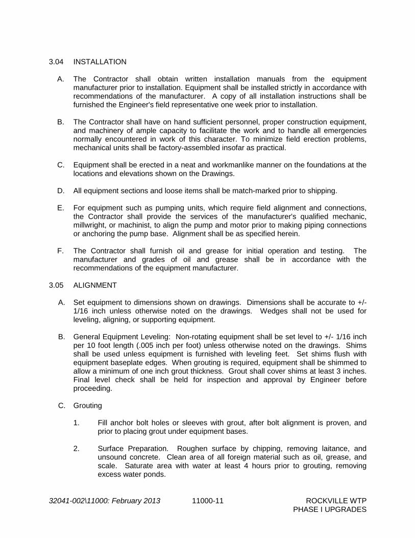
32041-002\11000: February 2013 11000-11 ROCKVILLE WTP PHASE I UPGRADES
3.04 INSTALLATION
A. The Contractor shall obtain written installation manuals from the equipment manufacturer prior to installation. Equipment shall be installed strictly in accordance with recommendations of the manufacturer. A copy of all installation instructions shall be furnished the Engineer's field representative one week prior to installation.
B. The Contractor shall have on hand sufficient personnel, proper construction equipment,
and machinery of ample capacity to facilitate the work and to handle all emergencies normally encountered in work of this character. To minimize field erection problems, mechanical units shall be factory-assembled insofar as practical.
C. Equipment shall be erected in a neat and workmanlike manner on the foundations at the
locations and elevations shown on the Drawings. D. All equipment sections and loose items shall be match-marked prior to shipping. E. For equipment such as pumping units, which require field alignment and connections,
the Contractor shall provide the services of the manufacturer's qualified mechanic, millwright, or machinist, to align the pump and motor prior to making piping connections or anchoring the pump base. Alignment shall be as specified herein.
F. The Contractor shall furnish oil and grease for initial operation and testing. The
manufacturer and grades of oil and grease shall be in accordance with the recommendations of the equipment manufacturer.
3.05 ALIGNMENT
A. Set equipment to dimensions shown on drawings. Dimensions shall be accurate to +/-
1/16 inch unless otherwise noted on the drawings. Wedges shall not be used for leveling, aligning, or supporting equipment.
B. General Equipment Leveling: Non-rotating equipment shall be set level to +/- 1/16 inch
per 10 foot length (.005 inch per foot) unless otherwise noted on the drawings. Shims shall be used unless equipment is furnished with leveling feet. Set shims flush with equipment baseplate edges. When grouting is required, equipment shall be shimmed to allow a minimum of one inch grout thickness. Grout shall cover shims at least 3 inches. Final level check shall be held for inspection and approval by Engineer before proceeding.
C. Grouting
1. Fill anchor bolt holes or sleeves with grout, after bolt alignment is proven, and
prior to placing grout under equipment bases. 2. Surface Preparation. Roughen surface by chipping, removing laitance, and
unsound concrete. Clean area of all foreign material such as oil, grease, and scale. Saturate area with water at least 4 hours prior to grouting, removing excess water ponds.

32041-002\11000: February 2013 11000-12 ROCKVILLE WTP PHASE I UPGRADES
3. Application. Place grout after the equipment base has been set and its alignment and level have been approved. Form around the base, mix grout, and place in accordance with the grout manufacturers published instructions. Eliminate all air or water pockets beneath the base using a drag chain or rope.
4. Finishing. Point the edges of the grout to form a smooth 45 degree slope. 5. After grout has cured (not before 3 days after placement) paint exposed surfaces
of grout with shellac. 6. Level Verification. After grout has cured, and immediately prior to drive
alignment, recheck equipment for level and plumb. Re-level and square as necessary. Hold final checks for inspection and approval by Engineer.
D. Inspect for and remove all machining burrs or thread pulls in female holes on mating
surfaces of mounting frame and machine feet. E. Inspect and clean equipment mounting base pads, feet, and frames to remove all
grease, rust, paint and dirt. F. Assembled equipment shafts shall be set level to .0015 inches per foot of shaft length
(+/- .0005 inches) up to a maximum of 0.015 inches for any length shaft unless the manufacturer’s requirements are more stringent or unless otherwise noted in the equipment specifications. Use the machined surfaces on which the equipment sets for the base/mounting frame leveling plane. Use the machined shaft surface for equipment leveling plane.
G. Sprocket and Sheave Alignment. Check shaft mounted components for face runout and
eccentricity (outside diameter) runout by magnetically mounting a dial indicator on a stationary base and indicating over 360 degrees on a continuous machined surface at the outside diameter of the component. Maximum allowable total indicated face runout and eccentricity for sprockets and sheaves will be per ANSI Standard B29.1-1975.
H. Belt tensioning. Set drive belt tension to manufacturer's specification for the belt type.
Recheck alignment after drive tensioning. I. Thermal/Mechanical Growth. Thermal/mechanical growth corrections for driver and
driven machines will be used in vertical and horizontal alignment where applicable. The equipment manufacturer will determine thermal/mechanical growth applicability for any machine and provide the correction offsets to be used.
J. Rotating Shaft Alignment
1. Fixtures will be set up on the driver and driven machine, machines shaft
surfaces. Machined coupling hubs may be used only if there is no clearance to mount fixtures directly on the shafts.
2. Primary alignment method for direct drive machines is when coupled. Uncoupled
alignment will be used only when approved by the Engineer. 3. Account for possible coupling flex by always rotating coupled machines in the
same direction during alignment.

32041-002\11000: February 2013 11000-13 ROCKVILLE WTP PHASE I UPGRADES
4. Uncoupled machines must be connected so that both shafts turn together without
relative motion during alignment. 5. Indicator bar sag will be measured and included for each reverse indicator
alignment setup.
6. Reverse Dial Indicator. The final maximum allowable misalignment: vertical and horizontal from the desired targets of .000 inches (for a non-thermal growth machine) or from the given target readings (for a thermal growth machine) must meet BOTH of the following conditions simultaneously: 1/2 the final total indicator reading at each indicator will be no more than shown in the table below AND the final remaining correction at each machine foot be no more than .001 inches of required movement.
Machine Speed (RPM) Total Misalignment* (inches)
Up to 1800 .002 1800 and greater .001
* 1/2 indicator reading 3.06 FIELD TESTING
A. All equipment shall be set, aligned and assembled in conformance with the manufacturer's drawings and instructions. Provide all necessary calibrated instruments to execute performance tests. Submit report certified by the pump manufacturer’s representative.
B. Preliminary Field Tests, Yellow Tag
1. As soon as conditions permit, after the equipment has been secured in its permanent position, the Contractor shall:
a. Verify that the equipment is free from defects. b. Check for alignment as specified herein. c. Check for direction of rotation. d. Check motor for no load current draw.
2. Contractor shall flush all bearings, gear housings, etc., in accordance with the
manufacturer's recommendations, to remove any foreign matter accumulated during shipment, storage or erection. Lubricants shall be added as required by the manufacturer's instructions.
3. When the Contractor has demonstrated to the Engineer that the equipment is
ready for operation, a yellow tag will be issued. The tag will be signed by the Engineer, or his assigned representative and attached to the equipment. The tag shall not be removed.

32041-002\11000: February 2013 11000-14 ROCKVILLE WTP PHASE I UPGRADES
4. Preliminary field tests, yellow tag, must be completed before equipment is subjected to final field tests, blue tag.
C. Final Field Tests, Blue Tag
1. Upon completion of the above, and at a time approved by the Engineer, the equipment will be tested by operating it as a unit with all related piping, ducting, electrical and controls, and other ancillary facilities.
2. The equipment will be placed in continuous operation as prescribed or required
and witnessed by the Engineer or his assigned representative and the Owner or his assigned representative.
3. The tests shall prove that the equipment and appurtenances are properly installed, meet their operating cycles and are free from defects such as overheating, overloading, and undue vibration and noise. Operating field tests shall consist of the following:
a. Check equipment for excessive vibration and noise as specified herein. b. Check motor current draw under load conditions. The rated motor
nameplate current shall not be exceeded. c. Recheck alignment with dial indicators where applicable, after unit has
run under load for a minimum of 24 hours.
D. In addition to the above described field tests, any other tests specifically required by individual equipment Specifications or the manufacturer shall be performed.
E. Until final field tests are acceptable to the Engineer, the Contractor shall make all necessary changes, readjustments and replacements at no additional cost to the Owner.
F. Upon acceptance of the field tests, a blue tag will be issued. The tag will be signed by
the Engineer and attached to the unit. The tag shall not be removed and no further construction work will be performed on the unit, except as required during start-up operations and directed by the Engineer.
G. Defects which cannot be corrected by installation adjustments will be sufficient grounds
for rejection of any equipment. H. All costs in connection with field testing of equipment such as lubricants, temporary
instruments, labor, equipment, etc., shall be borne by the Contractor. Power, fuel, chemicals, water, etc. normally consumed by specific equipment shall be supplied by the Owner unless otherwise specified in the individual equipment specifications.
I. The Contractor shall be fully responsible for the proper operation of equipment during
tests and instruction periods and shall neither have nor make any claim for damage which may occur to equipment prior to the time when the Owner formally takes over the operation thereof.
J. Field testing of electric motors shall be in accordance with Section 15170, Electric
Motors and Section 16000, Basic Electrical Requirements.

32041-002\11000: February 2013 11000-15 ROCKVILLE WTP PHASE I UPGRADES
3.07 VIBRATION TESTING
A. Unless specified otherwise in the detailed equipment specifications, each pump, blower, compressor, motor or similar item of stationary rotating equipment having a rated power in excess of 40HP shall be tested after installation for acceptable vibration levels.
B. Vibration testing shall be performed by an experienced factory-trained and authorized
third-party analysis expert (not a sales representative) retained by the Contractor and approved by the Engineer. Each unit or pump system shall be tested separately without duplicate equipment running. All field testing shall be done in the presence of the Engineer. The Engineer shall be furnished with four (4) certified copies of vibration test data for each test performed.
C. For systems with variable speed drives, tests shall be conducted at various speeds between maximum and minimum. For systems with two-speed drives, tests shall be conducted at both speeds. For systems with constant-speed drive, tests shall be conducted under various loading conditions as determined by the Engineer.
D. All field vibration tests shall be performed with the equipment operating on the product
for which it is intended, or a substitute acceptable to the Engineer. E. The term displacement, as used herein, shall mean total peak-to-peak movement of
vibrating equipment, in mils; velocity or speed of the vibration cycle, measured in G's. Displacement and velocity shall be measured by suitable equipment equal to IRD Mechanalysis, Bentley, Nevada.
F. Frequency of vibration, in cycles per minute (cpm), shall be determined when vibration
exceeds specified levels or as otherwise necessary. Vibration shall be measured on the bearing housing, unless other locations are deemed necessary by the vibration analysis expert and Engineer.
G. For all equipment tested, vibration shall be checked in the radial and axial directions.
Unless otherwise specified elsewhere, axial vibration shall not exceed 0.1 in/sec; and radial vibration shall not exceed 0.2 in/sec. For pumps radial vibration shall not exceed that permitted by the Hydraulic Institute Standards except that, at vibration frequencies in excess of 8,000 cpm, the velocity shall not exceed 0.2 in/sec.
H. Copies of test results shall be submitted to the Engineer for review. Should the vibration
field test results exceed shop test results, the manufacturer’s recommendations, or the limits specified herein, the Contractor shall correct the deficiencies within thirty (30) days. After corrections have been completed, the vibration testing shall be re-run and the results re-submitted to the Engineer for review.
I. Noise or vibration in any rotating equipment that the Engineer judges to be excessive or damaging shall be cause for rejection.
3.08 FAILURE OF EQUIPMENT TO PERFORM
A. Any defects in the equipment, or failure to meet the guarantees or performance requirements of the Specifications shall be promptly corrected by the Contractor by replacements or otherwise.
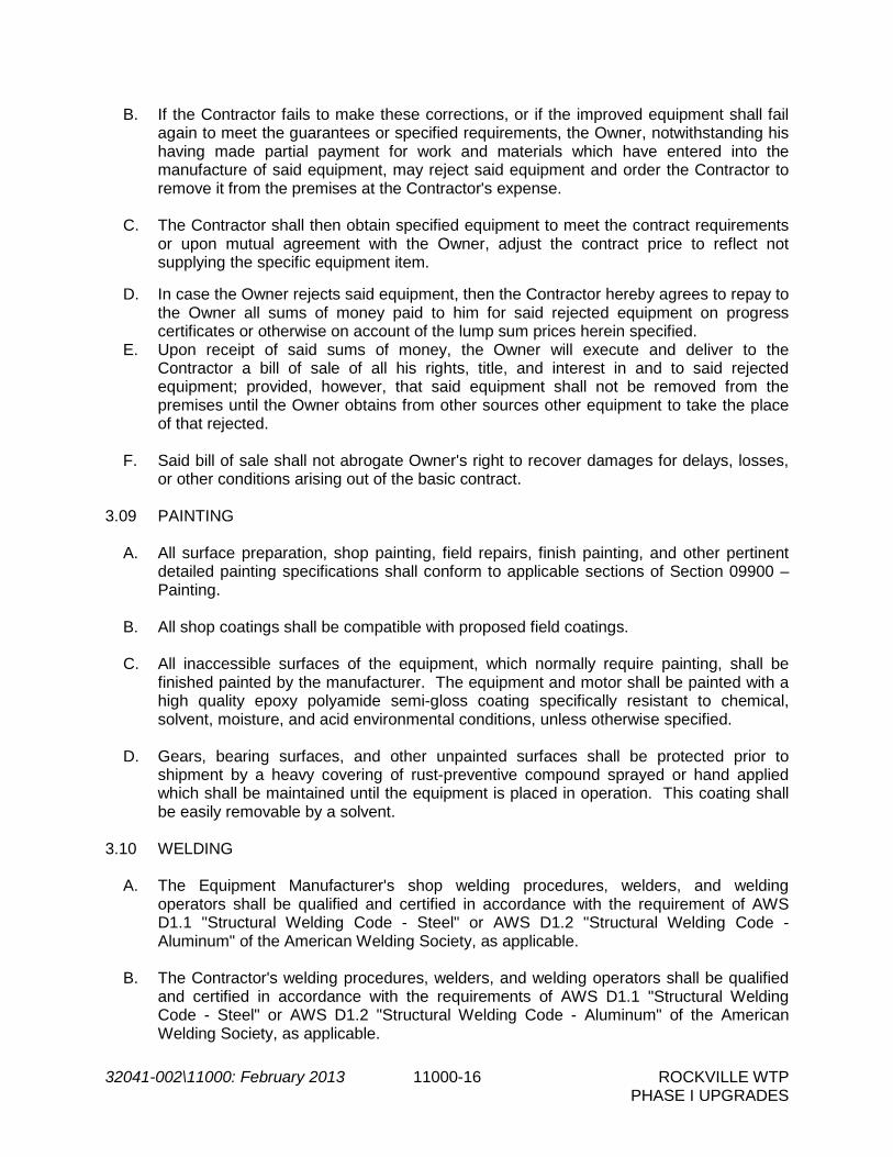
32041-002\11000: February 2013 11000-16 ROCKVILLE WTP PHASE I UPGRADES
B. If the Contractor fails to make these corrections, or if the improved equipment shall fail again to meet the guarantees or specified requirements, the Owner, notwithstanding his having made partial payment for work and materials which have entered into the manufacture of said equipment, may reject said equipment and order the Contractor to remove it from the premises at the Contractor's expense.
C. The Contractor shall then obtain specified equipment to meet the contract requirements
or upon mutual agreement with the Owner, adjust the contract price to reflect not supplying the specific equipment item.
D. In case the Owner rejects said equipment, then the Contractor hereby agrees to repay to
the Owner all sums of money paid to him for said rejected equipment on progress certificates or otherwise on account of the lump sum prices herein specified.
E. Upon receipt of said sums of money, the Owner will execute and deliver to the Contractor a bill of sale of all his rights, title, and interest in and to said rejected equipment; provided, however, that said equipment shall not be removed from the premises until the Owner obtains from other sources other equipment to take the place of that rejected.
F. Said bill of sale shall not abrogate Owner's right to recover damages for delays, losses,
or other conditions arising out of the basic contract. 3.09 PAINTING
A. All surface preparation, shop painting, field repairs, finish painting, and other pertinent detailed painting specifications shall conform to applicable sections of Section 09900 – Painting.
B. All shop coatings shall be compatible with proposed field coatings. C. All inaccessible surfaces of the equipment, which normally require painting, shall be
finished painted by the manufacturer. The equipment and motor shall be painted with a high quality epoxy polyamide semi-gloss coating specifically resistant to chemical, solvent, moisture, and acid environmental conditions, unless otherwise specified.
D. Gears, bearing surfaces, and other unpainted surfaces shall be protected prior to
shipment by a heavy covering of rust-preventive compound sprayed or hand applied which shall be maintained until the equipment is placed in operation. This coating shall be easily removable by a solvent.
3.10 WELDING
A. The Equipment Manufacturer's shop welding procedures, welders, and welding operators shall be qualified and certified in accordance with the requirement of AWS D1.1 "Structural Welding Code - Steel" or AWS D1.2 "Structural Welding Code - Aluminum" of the American Welding Society, as applicable.
B. The Contractor's welding procedures, welders, and welding operators shall be qualified
and certified in accordance with the requirements of AWS D1.1 "Structural Welding Code - Steel" or AWS D1.2 "Structural Welding Code - Aluminum" of the American Welding Society, as applicable.

32041-002\11000: February 2013 11000-17 ROCKVILLE WTP PHASE I UPGRADES
C. The Contractor shall perform all field welding in conformance with the information shown
on the Equipment Manufacturer's drawings regarding location, type, size, and length of all welds in accordance with "Standard Welding Symbols" AWS A2.0 of the American Welding Society, and special conditions, as shown by notes and details.
- END OF SECTION -

THIS PAGE INTENTIONALLY LEFT BLANK.

32041-002\11100: February 2013 11100-1 ROCKVILLE WTP PHASE I UPGRADES
SECTION 11100
PUMPS - GENERAL PART 1 -- GENERAL 1.01 THE REQUIREMENT
A. The Contractor shall furnish, install, test, and make fully operational all pumping equipment, complete with all necessary accessories, in compliance with the Contract Documents.
B. All pumping equipment shall be provided in accordance with the requirements of Section
11000, Equipment General Provisions. C. The provisions of this section shall apply to all pumps and pumping equipment specified
except where specifically noted otherwise in the Contract Documents.
D. The pumps shall be provided complete with all accessories, shims, sheaves, couplings, and other appurtenances as specified, and as may be required for a complete and operating installation.
1.02 SHOP DRAWINGS
A. Shop Drawings shall include the following information in addition to the requirements of Section 01300, Submittals and Section 11000, Equipment General Provisions.
1. Details of shaft sealing system 2. Pump performance curves at rated speed and reduced speed (if reduced speeds are
specified). Curves shall indicate flow, head, efficiency, brake horsepower, NPSH required, and minimum submergence. Curves shall include limits (minimum and maximum flows) for stable operation without cavitation, overheating, recirculation, or excessive vibration.
3. General cutaway sections, materials, dimension of shaft projections, shaft and
keyway dimensions, shaft diameter, dimension between bearings, general dimensions of pump, suction head bolt orientation, and anchor bolt locations and forces.
4. Foundry certificates and results of Brinnell hardness testing showing compliance to
ASTM A 532 (where required in the individual pump specifications). 5. Submersible pump submittals shall also include:
a. Product data sheets for power and control cables and length of cables. b. Details on pump guide rail system and mounting requirements.
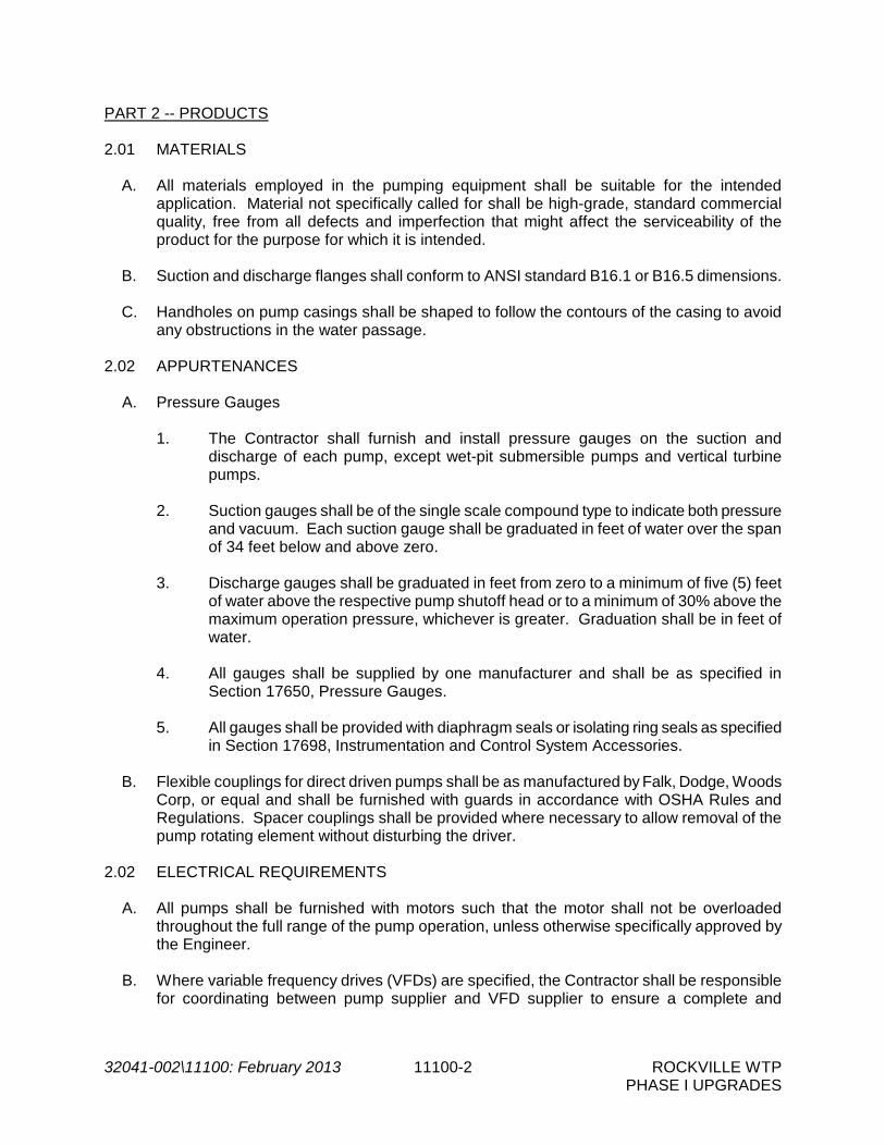
32041-002\11100: February 2013 11100-2 ROCKVILLE WTP PHASE I UPGRADES
PART 2 -- PRODUCTS 2.01 MATERIALS
A. All materials employed in the pumping equipment shall be suitable for the intended application. Material not specifically called for shall be high-grade, standard commercial quality, free from all defects and imperfection that might affect the serviceability of the product for the purpose for which it is intended.
B. Suction and discharge flanges shall conform to ANSI standard B16.1 or B16.5 dimensions.
C. Handholes on pump casings shall be shaped to follow the contours of the casing to avoid
any obstructions in the water passage. 2.02 APPURTENANCES
A. Pressure Gauges
1. The Contractor shall furnish and install pressure gauges on the suction and discharge of each pump, except wet-pit submersible pumps and vertical turbine pumps.
2. Suction gauges shall be of the single scale compound type to indicate both pressure
and vacuum. Each suction gauge shall be graduated in feet of water over the span of 34 feet below and above zero.
3. Discharge gauges shall be graduated in feet from zero to a minimum of five (5) feet
of water above the respective pump shutoff head or to a minimum of 30% above the maximum operation pressure, whichever is greater. Graduation shall be in feet of water.
4. All gauges shall be supplied by one manufacturer and shall be as specified in
Section 17650, Pressure Gauges. 5. All gauges shall be provided with diaphragm seals or isolating ring seals as specified
in Section 17698, Instrumentation and Control System Accessories.
B. Flexible couplings for direct driven pumps shall be as manufactured by Falk, Dodge, Woods Corp, or equal and shall be furnished with guards in accordance with OSHA Rules and Regulations. Spacer couplings shall be provided where necessary to allow removal of the pump rotating element without disturbing the driver.
2.02 ELECTRICAL REQUIREMENTS
A. All pumps shall be furnished with motors such that the motor shall not be overloaded throughout the full range of the pump operation, unless otherwise specifically approved by the Engineer.
B. Where variable frequency drives (VFDs) are specified, the Contractor shall be responsible
for coordinating between pump supplier and VFD supplier to ensure a complete and

32041-002\11100: February 2013 11100-3 ROCKVILLE WTP PHASE I UPGRADES
operational system. VFDs shall be furnished under Division 16 and shall be as specified in Section 16495, Variable Frequency Drive Systems.
C. Motor starters and controls shall be furnished and installed under Division 16 and Division
13 unless otherwise specified in the individual pump specifications. 2.03 EQUIPMENT IDENTIFICATION
A. In addition to the requirements of Section 11000, Equipment General Provisions, nameplate data for each pump shall include the rating in gallons per minute, rated head, speed, and efficiency at the primary design point.
PART 3 -- EXECUTION 3.01 INSTALLATION
A. Drains: All gland seals, air valves, and drains shall be piped to the nearest floor drain or trench drain with galvanized steel pipe or copper tube, properly supported with brackets.
B. Solenoid Valves: Where required, the pump manufacturer shall furnish and install solenoid
valves on the water or oil lubrication lines. Solenoid valve electrical rating shall be compatible with the motor control voltage and shall be furnished complete with all necessary conduit and wiring installation from control panel to solenoid.
3.02 SHOP TESTING
A. Shop tests shall be performed in accordance with Section 11000, Equipment General Provisions, and except where stated otherwise herein, shall be conducted in accordance with applicable methods and standards of the American National Standard for Centrifugal Pump Tests by the Hydraulic Institute, or American National Standard for Vertical Pump Tests by the Hydraulic Institute for Vertical Pumps.
B. Pump testing shall be witnessed by the Owner/Engineer where specified in the individual
pump specifications. The testing procedure shall be submitted to the Engineer for review before scheduling the testing. The Engineer shall be given at least 2 weeks advanced notice of the scheduled testing date.
C. Certified test curves for shall be provided for all centrifugal pumps unless otherwise specified
in the individual pump specifications. Certified tests will not be required for submersible sump pumps (as specified in Section 11136) with motors less than 5 hp.
D. Pumps shall be within the tolerances specified by the Hydraulic Institute Standards with the
following exceptions:
1. At design heads, +10% of design capacities or at design capacities, +5% of design heads.
2. No minus tolerances shall be allowed with respect to capacity, head, or efficiency at
the design points.

32041-002\11100: February 2013 11100-4 ROCKVILLE WTP PHASE I UPGRADES
E. For wet pit submersible pumps and vertical turbine pumps, all tests shall be run at minimum pump submergence specified in the individual pump specifications.
F. Where required in the individual pump specifications, each individual casting shall be
Brinnell tested in a minimum of two places, in an area of representative casting thickness to ASTM Method E-10. Results shall be certified by a registered professional ENGINEER. Test results shall verify the satisfaction of the required Brinnell hardness of the finished product as specified in respective subsections.
3.03 FIELD TESTING
A. Field tests shall be performed in accordance with in Section 11000, Equipment General Provisions and additionally as specified below and in the individual pump specifications.
B. Final acceptance tests shall demonstrate the following:
1. The pumps have been properly installed and are in proper alignment.
2. The pumps operate without overheating or overloading of any parts and without
objectionable vibration. Vibration shall be within the Hydraulic Institute limits, or manufacturer's limits if more stringent.
3. The pumps can meet the specified operating conditions. All pumps shall be checked
at maximum speed for a minimum of four points on the pump curve for capacity, head, and amperage. The rated motor nameplate current shall not be exceeded at any point. Pumps with drive motors rated at less than five horsepower shall only be tested for overcurrent when overheating or other malfunction becomes evident in general testing.
- END OF SECTION -

32041-002/11103: February 2013 11103-1 ROCKVILLE WTP PHASE I UPGRADES
SECTION 11103
MAGNETIC DRIVE CENTRIFUGAL TRANSFER PUMPS PART 1 -- GENERAL 1.01 THE REQUIREMENT
A. The Contractor shall furnish and install magnetic drive centrifugal pumps for transfer of ferric chloride and sodium hydroxide at the locations shown on the Drawings and/or as specified herein. All pumps shall be furnished by the same manufacturer.
B. Equipment shall be provided in accordance with the requirements of Section 11000,
Equipment General Provisions and Section 11100, Pumps - General. C. The complete installation shall be free from excessive vibration, cavitation, noise and oil or
water leaks.
1.02 OPERATING CONDITIONS AND PERFORMANCE REQUIREMENTS
A. Pumps and pump components shall be suitable for use in the chemical service specified herein. The supplier is responsible for the coordination and selection of corrosion resistant materials for the chemical solutions specified herein and shall guarantee the suitability of the materials used in manufacturing the equipment. Pumps shall perform satisfactorily over the full range of solution concentrations specified. Pumps, motors and accessories shall be coated with a heavy duty protective epoxy coating resistant to the specified chemical to prevent corrosion.
B. The pump horsepower required for any point on the pump characteristic curve shall not
exceed the rated horsepower.
C. Total dynamic head and horsepower calculations for the chemical transfer pumps are based on clean water. The pump supplier shall adjust for the specific gravity and viscosity anticipated and shall submit calculations verifying pump head and horsepower.
D. Sodium Hydroxide Transfer Pumps
1. The chemical transfer pumps shall pump solutions of sodium hydroxide in
concentrations ranging from 20 to 30 percent.
2. Chemical properties are as follows: Sodium Hydroxide (25%) pH 14 Specific Gravity (60oF) 1.25 Freezing Point (25%) -14 °F
3. Design Data
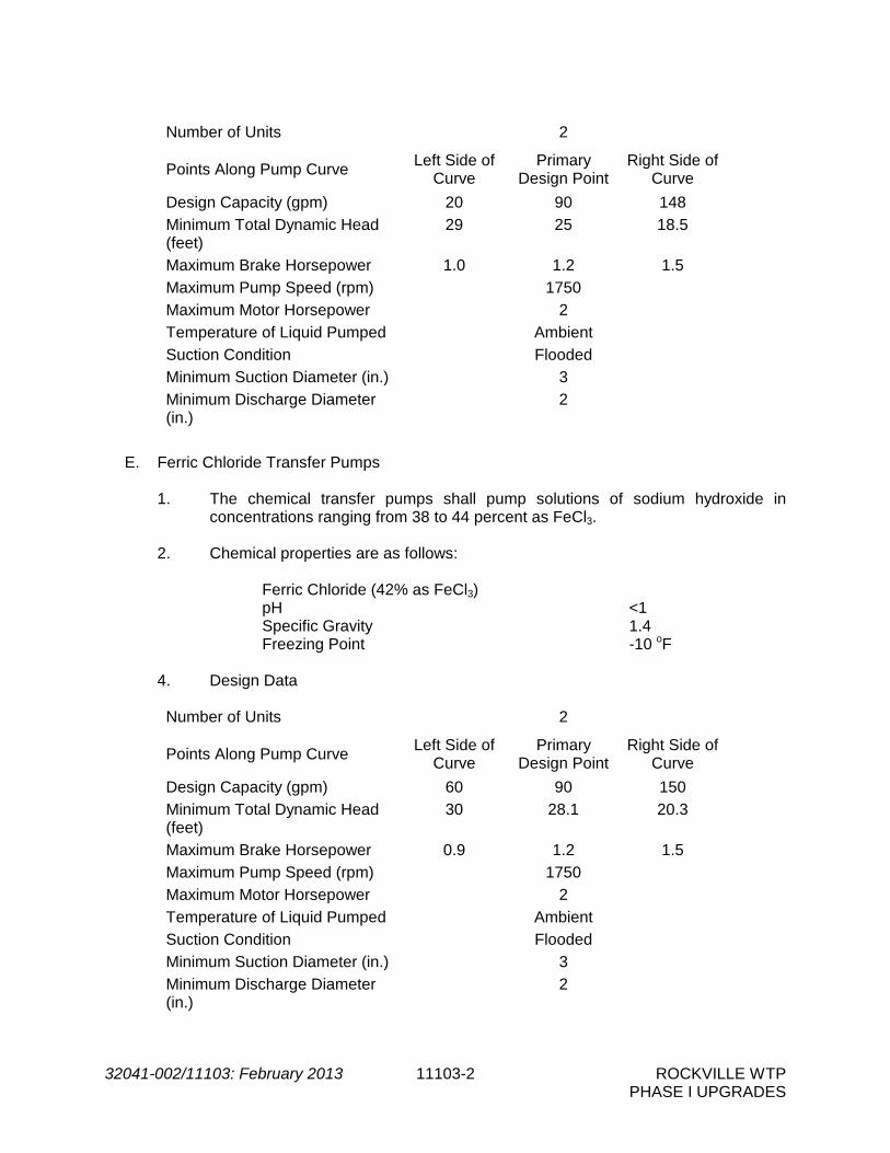
32041-002/11103: February 2013 11103-2 ROCKVILLE WTP PHASE I UPGRADES
Number of Units 2
Points Along Pump Curve Left Side of
Curve Primary
Design Point Right Side of
Curve
Design Capacity (gpm) 20 90 148
Minimum Total Dynamic Head (feet)
29 25 18.5
Maximum Brake Horsepower 1.0 1.2 1.5
Maximum Pump Speed (rpm) 1750
Maximum Motor Horsepower 2
Temperature of Liquid Pumped Ambient
Suction Condition Flooded
Minimum Suction Diameter (in.) 3
Minimum Discharge Diameter (in.)
2
E. Ferric Chloride Transfer Pumps
1. The chemical transfer pumps shall pump solutions of sodium hydroxide in concentrations ranging from 38 to 44 percent as FeCl3.
2. Chemical properties are as follows: Ferric Chloride (42% as FeCl3) pH <1 Specific Gravity 1.4 Freezing Point -10 oF 4. Design Data
Number of Units 2
Points Along Pump Curve Left Side of
Curve Primary
Design Point Right Side of
Curve
Design Capacity (gpm) 60 90 150
Minimum Total Dynamic Head (feet)
30 28.1 20.3
Maximum Brake Horsepower 0.9 1.2 1.5
Maximum Pump Speed (rpm) 1750
Maximum Motor Horsepower 2
Temperature of Liquid Pumped Ambient
Suction Condition Flooded
Minimum Suction Diameter (in.) 3
Minimum Discharge Diameter (in.)
2

32041-002/11103: February 2013 11103-3 ROCKVILLE WTP PHASE I UPGRADES
1.03 SUBMITTALS
A. The Contractor shall submit complete Shop Drawings, Performance Affidavits, Operation and Maintenance Instructions and other information as specified in accordance with Section 11000, Equipment General Provisions; and Section 11100, Pumps – General.
B. Shop Drawings shall include, but not be limited to, the following: 1. Performance data, including capacity, TDH, net positive suction head required
(NPSHR), brake horsepower, and efficiency. 2. Pump dimensions and materials of construction 3. Total weight of the equipment 4. Chemical resistance data for wetted parts 5. Results of shop hydrostatic and performance tests 6. Complete wiring diagrams 7. Complete control descriptions for pump operation
8. Complete erection, installation, and adjustment instructions and recommendations. C. Operation and Maintenance Manuals for the chemical transfer and recirculation pumps shall
be submitted in accordance with Section 01300, Submittals and 11000, Equipment General Provisions.
1.04 WARRANTY AND GUARANTEE
A. Warranty and Guarantee shall be as specified in Section 11000 with the exception that the warranty period shall be for two (2) years.
PART 2 -- PRODUCTS 2.01 ACCEPTABLE MANUFACTURERS
A. The magnetic drive centrifugal pumps for sodium hydroxide shall be or TB-Mag Series as manufactured by Innomag or Model 3298 as manufactured by ITT Goulds Pumps.
2.02 CONSTRUCTION
A. Pump Construction - The pump casing shall be a solid ductile iron casting with a minimum 1/8-inch rotomolded ETFE liner. The pump shall meet ANSI dimensional requirements for flanges and foot position. A pure sintered silicon carbide thrust ring shall be integral with front center support. A ¼" NPT casing drain connection shall be provided. Pumps shall be coated with a heavy duty protective epoxy coating resistant to corrosion by the specified chemicals.
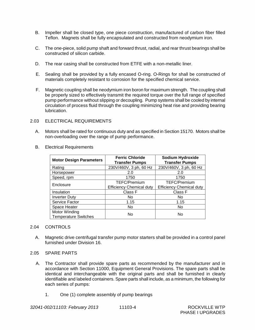
32041-002/11103: February 2013 11103-4 ROCKVILLE WTP PHASE I UPGRADES
B. Impeller shall be closed type, one piece construction, manufactured of carbon fiber filled Teflon. Magnets shall be fully encapsulated and constructed from neodymium iron.
C. The one-piece, solid pump shaft and forward thrust, radial, and rear thrust bearings shall be
constructed of silicon carbide.
D. The rear casing shall be constructed from ETFE with a non-metallic liner. E. Sealing shall be provided by a fully encased O-ring. O-Rings for shall be constructed of
materials completely resistant to corrosion for the specified chemical service.
F. Magnetic coupling shall be neodymium iron boron for maximum strength. The coupling shall be properly sized to effectively transmit the required torque over the full range of specified pump performance without slipping or decoupling. Pump systems shall be cooled by internal circulation of process fluid through the coupling minimizing heat rise and providing bearing lubrication.
2.03 ELECTRICAL REQUIREMENTS
A. Motors shall be rated for continuous duty and as specified in Section 15170. Motors shall be
non-overloading over the range of pump performance.
B. Electrical Requirements
Motor Design Parameters Ferric Chloride Transfer Pumps
Sodium Hydroxide Transfer Pumps
Rating 230V/460V, 3 ph, 60 Hz 230V/460V, 3 ph, 60 Hz Horsepower 2.0 2.0 Speed, rpm 1750 1750
Enclosure TEFC/Premium
Efficiency Chemical duty TEFC/Premium
Efficiency Chemical duty Insulation Class F Class F Inverter Duty No No Service Factor 1.15 1.15 Space Heater No No Motor Winding Temperature Switches
No No
2.04 CONTROLS
A. Magnetic drive centrifugal transfer pump motor starters shall be provided in a control panel furnished under Division 16.
2.05 SPARE PARTS
A. The Contractor shall provide spare parts as recommended by the manufacturer and in accordance with Section 11000, Equipment General Provisions. The spare parts shall be identical and interchangeable with the original parts and shall be furnished in clearly identifiable and labeled containers. Spare parts shall include, as a minimum, the following for each series of pumps:
1. One (1) complete assembly of pump bearings

32041-002/11103: February 2013 11103-5 ROCKVILLE WTP PHASE I UPGRADES
2. Two (2) sets of gaskets for all gasketed covers 3. One (1) set of wearing rings 4. One (1) impeller with nut and washers
PART 3 -- EXECUTION 3.01 SHOP TESTING
A. Shop hydrostatic and performance tests shall be performed as specified herein and in Section 11100, General Process Mechanical Requirements. All tests shall be conducted in accordance with applicable methods and standards of the American National Standard for Centrifugal Pump Tests by the Hydraulic Institute.
B. Certified test curves shall be provided for all centrifugal pumps.
C. Pumps shall be within the tolerances specified by the Hydraulic Institute Standards with the
following exceptions:
1. At design heads, +10% of design capacities or at design capacities, +5% of design heads.
2. No minus tolerances shall be allowed with respect to capacity, head, or efficiency at
the design points. 3.02 MANUFACTURER’S FIELD SERVICES
A. The services of a qualified manufacturer's technical representative shall be provided in accordance with Section 11000, Equipment General Provisions. For each series of pumps, field services shall include the following site visits:
Service Number of Trips Number of Days/Trip Installation and Testing 2 1 Startup 2 1 Services after Startup 1 1
B. The Contractor shall be fully informed and shall be responsible to ensure that all Contractor's
employees, agents, and/or subcontractors are fully informed as to the hazards and proper procedures associated with working with and around the specified chemicals.
C. Training shall be provided as specified in Section 01010, paragraph 1.26.C and as indicated
in Section 01015, paragraph 1.09.B. 3.03 INSTALLATION A. The Contractor shall furnish and install the transfer pumps and all associated equipment and
accessories as required and specified herein in accordance with the manufacturer's instructions and in accordance with Section 11000, Equipment General Provisions. The

32041-002/11103: February 2013 11103-6 ROCKVILLE WTP PHASE I UPGRADES
Contractor shall install the pumps on concrete pedestals as indicated in the Contract Documents. Concrete pedestals shall be built to the required elevation, dimensions, level, and finish. The Contractor shall anchor pumps to the pedestals with 316 SS expansion anchor bolts for sodium hydroxide pumps.
3.04 FIELD TESTING
A. The Contractor shall demonstrate to the Engineer that the completed systems meet the functional requirements intended. The Contractor shall calibrate, operate, adjust and test all controls and instrumentation to assure complete and satisfactory installation and performance. All necessary test equipment, facilities and personnel shall be provided by the Contractor. The Contractor shall make all necessary changes and adjustment to equipment all at no additional cost to the Owner.
B. Tests shall be performed in accordance with Division 17 and Section 11000, Equipment
General Provisions. C. After installation of piping and accessories but before connection of piping to the storage
tank and pumps the Contractor shall completely flush the system to clean and remove all foreign matter from the piping system.
D. After chemical storage tanks are hydrostatically tested and the tanks and piping system are
cleaned, complete system hydrostatic tests and operational tests shall be completed with non-potable water.
E. The Contractor shall field test the transfer pumps as specified herein and in accordance with
the requirements of Section 11100, General Process Mechanical Requirements. Items tested shall include, but not be limited to, the following:
1. Verify start/stop functionality of transfer pumps. 2. Verify transfer pumps respond appropriately to interlocks with chemical day storage
tank high level. 3. Verify Power On, Run, and Fail indicating light functionality.
3.05 FIELD PAINTING
A. All surface preparation, shop painting, field repairs, finish painting and other pertinent detailed painting specifications shall conform to applicable sections of Section 09900 - Painting.
B. All inaccessible surfaces of the equipment which normally require painting shall be finish
painted by the manufacturer. The equipment shall be painted with a high quality epoxy polamide semi-gloss coating specifically resistant to chemical, solvent, moisture and acid environmental conditions.
C. Gears, bearing surfaces, and other unpainted surfaces shall be protected prior to shipment
by a heavy covering of rust-preventive compound sprayed or hand applied which shall be

32041-002/11103: February 2013 11103-7 ROCKVILLE WTP PHASE I UPGRADES
maintained until the equipment is placed in operation. This coating shall be easily removable by a solvent.
- END OF SECTION -

THIS PAGE INTENTIONALLY LEFT BLANK.

32041-002\11136: February 2013 11136-1 ROCKVILLE WTP PHASE I UPGRADES
SECTION 11136
SUBMERSIBLE CHEMICAL SUMP PUMPS PART 1 -- GENERAL 1.01 THE REQUIREMENT
A. The Contractor shall furnish and install chemical-resistant submersible sump pumps at the locations shown on the Drawings and as specified herein. All pumps shall be supplied by the same manufacturer.
B. Equipment shall be provided in accordance with the requirements of Section 11000,
Equipment General Provisions and Section 11100, Pumps - General. 1.02 OPERATING CONDITIONS AND PERFORMANCE REQUIREMENTS
A. Pumps shall be completely resistant to corrosion in the chemical services listed in the pump schedule.
B. Chemical Sump Pump Schedule
Ferric
Chloride Sodium
Hydroxide (Caustic)
No. of Pumps 2 2
Design Capacity (gpm) 21 21
Total Dynamic Head (ft.) 18 18
Motor Horsepower 0.4 0.4
Max. Pump Speed (rpm) 3,600 3,600
Temperature of Liquid Pumped Ambient Ambient
Discharge Connection NPT-F NPT-F
Discharge Diameter (inches) 1.5 1.5
Sump Location
Chemical Building & Chemical
Storage Area
Chemical Building & Chemical
Storage Area
1.03 SUBMITTALS
A. The Contractor shall submit complete shop drawings, operation and maintenance instructions and information as specified in accordance with Section 11000, Equipment General Provisions; Section 11100, Pumps-General and Section 01300, Submittals.
B. Shop Drawings shall include, but are not limited to, the following:
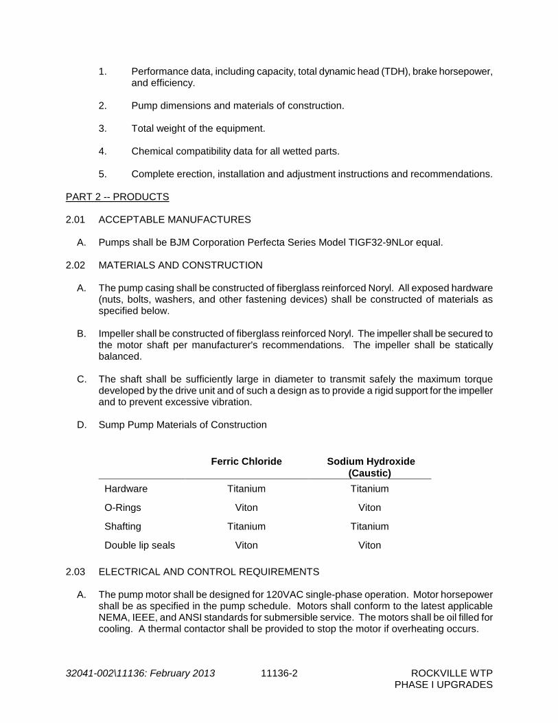
32041-002\11136: February 2013 11136-2 ROCKVILLE WTP PHASE I UPGRADES
1. Performance data, including capacity, total dynamic head (TDH), brake horsepower, and efficiency.
2. Pump dimensions and materials of construction. 3. Total weight of the equipment. 4. Chemical compatibility data for all wetted parts. 5. Complete erection, installation and adjustment instructions and recommendations.
PART 2 -- PRODUCTS 2.01 ACCEPTABLE MANUFACTURES
A. Pumps shall be BJM Corporation Perfecta Series Model TIGF32-9NLor equal. 2.02 MATERIALS AND CONSTRUCTION
A. The pump casing shall be constructed of fiberglass reinforced Noryl. All exposed hardware (nuts, bolts, washers, and other fastening devices) shall be constructed of materials as specified below.
B. Impeller shall be constructed of fiberglass reinforced Noryl. The impeller shall be secured to
the motor shaft per manufacturer's recommendations. The impeller shall be statically balanced.
C. The shaft shall be sufficiently large in diameter to transmit safely the maximum torque
developed by the drive unit and of such a design as to provide a rigid support for the impeller and to prevent excessive vibration.
D. Sump Pump Materials of Construction
Ferric Chloride
Sodium Hydroxide
(Caustic) Hardware Titanium Titanium
O-Rings Viton Viton
Shafting Titanium Titanium
Double lip seals Viton Viton
2.03 ELECTRICAL AND CONTROL REQUIREMENTS A. The pump motor shall be designed for 120VAC single-phase operation. Motor horsepower
shall be as specified in the pump schedule. Motors shall conform to the latest applicable NEMA, IEEE, and ANSI standards for submersible service. The motors shall be oil filled for cooling. A thermal contactor shall be provided to stop the motor if overheating occurs.

32041-002\11136: February 2013 11136-3 ROCKVILLE WTP PHASE I UPGRADES
B. The cable entry water seal design shall insure a watertight and submersible seal. C. Sump pumps shall be hard wired to the local control station as shown on Drawings. D. Sump pump shall not be supplied with an integral float switch/level control.
PART 3 -- EXECUTION 3.01 INSTALLATION
A. Contractor shall provide a union in piping near pump discharge connection to allow for easy removal of pump.
- END OF SECTION -

THIS PAGE INTENTIONALLY LEFT BLANK.

32041-002/11170: February 2013 11170-1 ROCKVILLE WTP PHASE I UPGRADES
SECTION 11170
LIQUID CHEMICAL METERING PUMPS PART 1 -- GENERAL 1.01 THE REQUIREMENT
A. The Contractor shall furnish and install chemical metering pumps at the locations shown on the Drawings and as specified herein. All pumps shall be supplied by the same manufacturer.
B. Equipment shall be provided in accordance with the requirements of Section 11000,
Equipment General Provisions and Section 11100, Pumps - General.
1.02 RELATED WORK SPECIFIED ELSEWHERE
A. Section 17635, Rotameters 1.03 OPERATING CONDITIONS AND PERFORMANCE REQUIREMENTS
A. Chemical Properties
Ferric Chloride
Sodium Hydroxide (Caustic)
Concentration 40% 25% Specific Gravity 1.4 @ 40% 1.25 @ 25% Freezing Point -10°F @ 40% -14°F @ 25% pH <1 14
B. Pump Performance Requirements
Ferric Chloride Sodium Hydroxide
(Low Dose) Sodium Hydroxide
(High Dose) No. of Units 3 2 2 Pump ID FS-1 through FS-3 SH-2, SH-3 SH-1, SH-4 Minimum Capacity 5.4 gph 7.2 gph 5.3 gph Maximum Capacity 42 gph 34 gph 46 gph Actual Pumping Range 5.4 – 34 gph 7.2 – 27 gph 7.2 – 37 gph Maximum Pumping Rate 115 strokes/minute 115 strokes/minute 115 strokes/minute Discharge Pressure 75 psig 75 psig 75 psig Suction Connection* 3/4"-1” MNPT 3/4"-1” MNPT 3/4"-1” MNPT Discharge Connection* 3/4"-1” MNPT 3/4"-1” MNPT 3/4"-1” MNPT Maximum Motor Speed 1,725 rpm 1,725 rpm 1,725 Maximum Motor Horsepower 3/4 HP 3/4 HP 3/4 HP
Drive Type AC, Variable
Speed AC, Variable
Speed AC, Variable
Speed Application Points Refer to Drawings Refer to Drawings Refer to Drawings
05
21
09
BR

32041-002/11170: February 2013 11170-2 ROCKVILLE WTP PHASE I UPGRADES
*Contractor shall coordinate suction/discharge size with pump manufacturer. 1.04 SUBMITTALS
A. The following items shall be submitted with the Shop Drawings in accordance with, or in addition to the submittal requirements specified in Section 01300, Submittals; and Section 11000, Equipment General Provisions: 1. Performance Affidavit
2. Submit pump manufacturer’s hydraulic calculations based on the metering pump
schedule attached in this section for review. 3. Pump dimensions and performance data (discharge pressure, strokes per minute,
etc.)
4. Details on materials of construction of all components including applicable ASTM designations.
5. Chemical resistance data for all wetted pump parts and accessories including, but not limited to; pump housing, pump liquid end material, pump diaphragms, diaphragm valves, check valves, check valve balls and o-rings.
6. Equipment shop coating systems, interior and exterior.
7. Details of shaft sealing system
8. General cutaway sections, materials, dimension of shaft projections, shaft and keyway dimensions, shaft diameter, dimension between bearings, general dimensions of pump, suction head bolt orientation, and anchor bolt locations and forces.
9. The total uncrated weight of the equipment plus the approximate weight of shipped
materials. Support locations and loads that will be transmitted to bases and foundations. Exact size, placement, and embedment requirements of all anchor bolts.
10. Panel layout drawings, schematic wiring diagrams, and component product data sheets for control panels.
11. Motor data sheet indicating motor horsepower; enclosure type; voltage; insulation class; temperature rise and results of dielectric tests; service-rating; rotative speed; motor speed-torque relationship; efficiency and power factor at ½, ¾, and full load; slip at full load; running, full load, and locked rotor current values; and safe running time-current curves.
12. Equipment and motor protective device details. Connection diagrams for motor and all protective devices.
13. Complete wiring diagrams

32041-002/11170: February 2013 11170-3 ROCKVILLE WTP PHASE I UPGRADES
14. Complete control descriptions for pump operation
15. Complete erection, installation, and adjustment instructions and recommendations. 16. Warranty documentation including statement of duration of warranty period and
contact phone numbers and addresses for warranty issues
B. Operation and Maintenance Manuals for the chemical metering pumps shall be submitted in accordance with Section 01300, Submittals, and 11100, General Process Mechanical Requirements.
C. The Contractor shall be responsible for coordinating all interfaces with related mechanical,
structural, electrical and instrumentation and control work. The Contractor shall be responsible for providing all accessory equipment and all work associated with installation of the equipment.
D. Shop drawings shall include all pumps and accessories and shall be submitted as a complete system. Partial submittals will be unacceptable.
1.05 WARRANTY AND GUARANTEE
A. Warranty and Guarantee shall be as specified in Section 11000 with the exception that the warranty period shall be for two (2) years.
PART 2 -- PRODUCTS 2.01 ACCEPTABLE MANUFACTURERS
A. The Manufacturer shall be a company specializing in manufacture, assembly, and field performance of mechanical metering pumps with a minimum of five years experience.
B. The metering pumps shall be Sigma Series pumps as manufactured by Prominent Fluid
Controls, Inc., equivalent by Wallace and Tiernan, Pulsafeeder, or equal. 2.02 MECHANICALLY OPERATED METERING PUMPS
A. Motor operated chemical metering pumps shall be of the positive displacement, mechanical diaphragm type. The stroke frequency adjust mechanism, driven by a direct coupled, variable speed AC motor, shall actuate a convex-shaped, teflon-faced composite diaphragm. Solenoid driven pumps will not be accepted.
B. The supplier is responsible for the coordination of corrosion-resistant materials for the
chemical solutions specified. The manufacturer shall include all features as necessary for satisfactory operation of the pumping systems for chemical solutions specified. Pumps shall perform satisfactorily over the full range of solution concentrations specified. Pumps, motors and accessories shall be coated with a heavy duty protective epoxy coating resistant to the specified chemical to prevent corrosion.

32041-002/11170: February 2013 11170-4 ROCKVILLE WTP PHASE I UPGRADES
C. The metering pumps shall be provided with an oil-lubricated gear reducer and cam-and-spring drive mounted in an aluminum housing. The housing shall be sealed into an outer plastic housing for corrosion protection with heat sink fins for cooling.
D. The liquid ends shall include cartridge-type ball check valves. Conventional threaded valves
will not be allowed. Valve service or removal shall not require any disturbances to the pump head pipeworks.
E. The liquid end shall be physically separated from the drive unit by a back plate with weep hole creating an air gap. An elastomer shaft wiper seal shall prevent contamination of the gear box if the primary diaphragm fails The diaphragm shall be a safety diaphragm such that in event of diaphragm failure, chemical shall be contained in the diaphragm for up to 48 hours and a fault shall be annunciated.
F. The pump and motor shall be mounted on a common concrete equipment pad. The motor shall be direct coupled to the gear box.
G. Each pump and motor shall have a corrosion resistant nameplate giving the manufacturer's
model, serial number, rating, range, speed, and other pertinent data. H. Acceptable materials of construction shall be as follows:
Ferric Chloride Sodium Hydroxide (Caustic)
Diaphragm PTFE faced EPDM
with Steel Core PTFE faced EPDM with
Steel Core Housing Material Glass-filled Luranyl Glass-filled Luranyl Liquid End Material Kynar PVC
Ball Check Valve PVDF with PTFE
faced Viton Gasket Seals
PVDF with PTFE faced Viton Gasket Seals
Ball Check Valve Balls
Teflon Ceramic
O-Ring Seals Viton, EPDM, Buna-N,
Teflon (PCTFE) Teflon (PCTFE), Hypalon,
Buna-N
Hardware Hastelloy C 316 SS
2.03 ELECTRICAL AND CONTROLS REQUIREMENTS
A. The pump controller shall have the following features at a minimum:
1. Keypad
2. Back-lit LCD display
3. Start/stop control via keypad
4. Switching between manual and automatic control modes via keypad
5. Manual stroke rate control through up/down arrows on keypad

32041-002/11170: February 2013 11170-5 ROCKVILLE WTP PHASE I UPGRADES
6. The pump supplier shall provide external separately mounted control panel for each
pump in a NEMA 4X FRP enclosure. All panels and components shall be built in accordance with Section 16902 and Section 17500. Each metering pump shall be provided with local controls as specified below. The control panel shall be wired to provide control interface between the pump standard input and output control signals available with each pump and the plant control system (Refer to Section 17920 – Control System Input/Output Schedule). The control panels shall be wall mounted as shown on Drawings and shall include the following components:
a. A HAND-OFF-AUTO (H-O-A) selector switch. In the HAND position, the
metering pump shall be controlled locally at the pump. In the AUTO position, the pump shall be controlled by a 24 VDC remote start/stop signal from the PLC which shall energize an interposing relay in the control panel. The interposing relay shall control the “start/stop” function of the pump. The pump speed shall be adjusted by an external 4-20 mA analog signal from the PLC.
b. Dry contacts (N.O. and N.C.) shall be provided in the control panel for remote indication of pump RUN status, H-O-A switch in AUTO status, and pump failure alarm condition.
c. Variable Frequency Drive (VFD) pump motor starter and speed control unit
d. The following indicator lights 1. Pump RUN 2. Pump Diaphragm FAIL
e. The control panel shall have the following inputs from the plant PLC:
1. START/STOP signal 2. 4-20mA analog signal to control pump speed
f. The control panel shall have the following outputs to the plant PLC:
1. RUN status 2. AUTO status for the H-O-A switch 3. VFD FAULT 4. 4-20mA analog signal proportional to pump speed
g. An appropriately sized circuit breaker shall be located upstream of the VFD.
h. A power disconnect switch operated by a rotary knob located on the front swing out panel of the enclosure.
B. Metering pump controls shall be microprocessor-based and shall be capable of remote
analog operation.

32041-002/11170: February 2013 11170-6 ROCKVILLE WTP PHASE I UPGRADES
D. Metering pump control panel input voltage shall be 120 VAC, 60 Hz, single phase. Output voltage from the control panel to the pump shall be as required by the metering pump manufacturer.
E. The electronic control system of the metering pump shall be continuously self-monitoring. In
the event of a system error in the microprocessor, the pump shall switch off and an alarm shall be annunciated.
2.04 METERING PUMP ACCESSORIES
A. The metering pump supplier shall furnish accessory equipment as specified herein and as shown on the Drawings including but not limited to the following. Flanged ends, not threaded, will be required for all accessories in sodium hydroxide service.
1. Pressure gauges - Gauges shall be provided on the discharge of metering pumps.
Gauges shall be as specified in Section 17650. Each gauge shall have a range of zero to 100 psi. Each gauge shall be provided with a diaphragm seal as specified in Section 17650 constructed of materials which are completely resistant to corrosion by the chemicals referred to in this section. Each pressure gauge shall also be provided with an isolation valve. Isolation valves shall be PVC with seals that are resistant to the chemical applications.
2. Pressure relief valves – Valves shall be manufactured by the pump manufacturer
and shall be completely resistant to the chemicals for which they are provided. Sizing of the valves shall be the responsibility of the manufacturer and calculations shall be submitted with Shop Drawings.
3. Antisiphon/back pressure valves - Valves shall be manufactured by the pump
manufacturer and shall be completely resistant to the chemicals for which they are provided. Sizing of the valves shall be the responsibility of the manufacturer and calculations shall be submitted with Shop Drawings.
4. Pulsation dampeners - Diaphragm and body materials and configuration shall be
supplied for the specific chemical for which the dampener is used without corrosion, wear, or other cause of abnormally short life. Each dampener shall be equipped with a charging valve and gas pad pressure gauge rated at 0 to 150 psi. Sizing of the pulsation dampeners shall be the responsibility of the manufacturer, and calculations shall be submitted with Shop Drawings.
5. Calibration Column –Calibration columns shall be the ACCUDRAW units as
manufactured by Primary Fluid Systems, Inc. consisting of a glass calibration tube surrounded by an outer shield of acrylic construction, and shall be provided with threaded ends. Graduations shall be in mL. Each calibration column shall be sized such that at 50% pump capacity, the calibration column will be emptied in 60 to 90 seconds.
6. Flexible Connections – Flexible connections shall be supplied on the metering pump
discharge piping and between the chemical injector assembly and the hard piping at the chemical application points. Hose shall be Teflon with Hastelloy C overbraided
32041-002/11170: February 2013 11170-7 ROCKVILLE WTP PHASE I UPGRADES
protection and permanently attached Hastelloy C end fittings as manufactured by Resistoflex Company, Marion, NC.
7. Variable Area Flow Meters (Rotameters) - Variable Area Flow Meters shall be as
specified herein and shall also meet the requirements specified in section 17635 –Rotameters. Rotameters be capable of providing remote flow indication via a 4-20 mA signal.
a. The indicator mechanism shall be isolated from the measuring environment and
only exposed to ambient conditions.
b. Flow meter shall be vertical orientation unless otherwise approved by the Engineer.
c. Provide each meter with manufacturers’ certificate, signed by the Q.C. Inspector
attesting to:
A certified result of meter calibration Materials used in construction Materials traceability (option) Dimensions Results of flow test Results of pressure test Results of leak test Visual inspection Inspection and non-destructive testing of welds (option) Packaging for shipment
2.05 TOOLS, SUPPLIES AND SPARE PARTS
A. The equipment manufacturer shall furnish all special tools necessary to disassemble, service, repair and adjust the equipment.
B. The manufacturer shall furnish spare parts including the following:
• 1 complete VFD for each size of pump supplied or a minimum of 2 complete VFD’s if
all metering pumps are the same size • 2 spare pressure gauges with diaphragm protectors • 1 spare pressure relief valve for each chemical service • 1 spare back pressure valve for each chemical service • 1 spare pulsation dampener for each chemical service • 1 spare parts kit for each chemical service including all components required to
rebuild pump head • 1 spare rotameter of each size furnished under this project

32041-002/11170: February 2013 11170-8 ROCKVILLE WTP PHASE I UPGRADES
PART 3 -- EXECUTION 3.01 MANUFACTURER’S FIELD SERVICES
A. The services of a qualified manufacturer's technical representative shall be provided as follows:
Service Number of Trips* Number of Days/Trip Installation and Testing 2 1 Startup and Training 2 1
* The number of trips for inspection, startup, and training shall be dependent on the construction sequencing requirements
B. The Contractor shall be fully informed and shall be responsible to ensure that all Contractor's employees, agents, and/or subcontractors are fully informed as to the hazards and proper procedures associated with working with and around the specified chemicals.
3.02 INSTALLATION
A. The Contractor shall furnish and install the metering pumps and all associated equipment and accessories as required and specified herein in accordance with manufacturer's instructions and in accordance with Section 11000, Equipment General Provisions. The Contractor shall install the pumps on concrete pedestals as indicated on the Drawings. Concrete pedestals shall be built to the required elevation, dimensions, level, and finish.
B. All metallic fasteners, brackets, mounting hardware, and accessories located in the storage
and feed areas shall be constructed of materials completely resistant to the specified chemicals.
C. The Contractor shall support piping adjacent to pumps such that no weight is carried on
pump casings. 3.03 TESTING, CLEANING, AND START-UP
A. All pumps shall be shop tested for capacity at rated pressure prior to shipment, with documented results provided.
B. The Contractor shall demonstrate to the Engineer that the completed systems meet the
functional requirements intended and that all components of the system are properly calibrated.
C. After installation of piping and accessories but before connection of piping to the storage
tank and pumps the Contractor shall completely flush the system to clean and remove all foreign matter from the piping system.
D. After chemical storage tanks are hydrostatically tested and the tanks and piping system are
cleaned, complete system hydrostatic tests and operational tests shall be completed with potable water. The Contractor shall check the functioning of all pump accessories, valves,

32041-002/11170: February 2013 11170-9 ROCKVILLE WTP PHASE I UPGRADES
and feed points and shall repair or replace all malfunctioning or unsatisfactory components. The Contractor shall repair all leaking joints and components identified during the test and through the one-year guarantee period.
- END OF SECTION -

THIS PAGE INTENTIONALLY LEFT BLANK.

32041-002\112800: February 2013 11280-1 ROCKVILLE WTP PHASE I UPGRADES
SECTION 11280
POSITIVE DISPLACEMENT BLOWER PACKAGES PART 1 -- GENERAL 1.01 THE REQUIREMENT
A. The Contractor shall furnish two (2) positive displacement blower packages. The blower packages shall be provided for filter air scour. Each blower package shall consist of one (1) positive displacement blower housed in a close-fitting acoustical enclosure complete with all accessories including motors, steel bases, inlet filters, inlet silencers, discharge silencers, pressure relief valves, check valves, butterfly valves, pressure gauges, flexible connectors, V-belt drives, belt guards, vibration isolation, and other components for a complete blower package as shown on the Contract Drawings and as specified herein.
B. Blowers shall be as furnished by United Blower, Aerzen, or equal. C. Equipment and manufacturer’s services shall be provided in accordance with the
requirements of Section 11000 – Equipment General Provisions. 1.02 SUBMITTALS
A. In addition to the submittal requirements specified in Section 01300 - Submittals and Section 11000 - Equipment General Provisions, submit the following:
1. Complete shop drawings and operation and maintenance manuals.
2. Support locations and loads that will be transmitted to bases and foundations.
Weights of all system components and the total weight of the operating blowers.
3. Complete electrical field termination drawings.
4. Electrical equipment product data sheets.
5. Overall equipment layout and piping interconnection drawings.
6. Copies of certified shop test reports.
7. Field test results. 1.03 OPERATION AND MAINTENANCE MANUALS
A. Furnish Operation and Maintenance manuals, shop drawings and other material required as specified in Section 01300 and Section 11000.
B. The Contractor shall submit a complete list of additional spare parts beyond those
specified herein, which the manufacturer recommends to be kept on hand and as specified in Section 11000.
32041-002\112800: February 2013 11280-2 ROCKVILLE WTP PHASE I UPGRADES
1.04 CONTRACTOR'S RESPONSIBILITY
A. The Contractor through the manufacturer shall provide the services of qualified service persons with at least five (5) years of experience who are regularly involved in the inspection, installation, start-up, troubleshooting, testing, maintenance, and operation of positive displacement blower systems. The service persons shall:
1. Witness and check installation.
2. Assist the Contractor in conducting field tests and preparing a written report as
specified below.
3. Witness and check start-up of the system.
4. Assist the Contractor in making adjustments and modifications as necessary to optimize operation of system components.
5. Troubleshoot and correct any mechanical or control problems which are noted
during tests and start-up.
6. Submit written certification that the system has been properly installed, tested, and adjusted; and that all controls and protective devices operate properly, including date of final acceptance test, as well as a listing of all persons present during the tests.
7. Investigate and supervise correction of any operating problems which may arise
up to the end of the guarantee period of the equipment.
8. Instruct Owner personnel in the operation and maintenance of the equipment.
B. The services of a qualified manufacturer's technical representative shall be provided at no additional cost to the Owner for a period of not less than four (4) days as follows:
1. At least two trips of one (1) day during installation of the equipment.
2. At least two trips of one (1) day after acceptance of the equipment for start-up
purposes. C. Any additional time required to achieve successful installation and operation shall be at
the expense of the Manufacturer. PART 2 -- PRODUCTS 2.01 EQUIPMENT REQUIREMENTS
A. The Contractor shall furnish two (2) identical positive displacement blower packages complete with all accessories. Each blower shall provide the design requirement of 2,090 scfm at 8.5 psig pressure rise across the blower including inlet filter, inlet/discharge silencers, and discharge check and butterfly valves at the following local conditions:

32041-002\112800: February 2013 11280-3 ROCKVILLE WTP PHASE I UPGRADES
Maximum inlet temperature 100oF Maximum relative humidity 95% Elevation 230’ above MSL
Blower speed shall be a maximum of 1,862 rpm. Blower motor horsepower shall be 125 horsepower. The maximum blower horsepower required at 2,090 scfm and 8.5 psig pressure rise across the blowers including inlet filters, inlet/discharge silencers, and check valve shall be 109.0 horsepower.
2.02 BLOWER MOTORS
A. The blower manufacturer shall be responsible for furnishing the electric motor for each of
the two blowers. The manufacturer shall be responsible for the proper selection, testing, installation, and operation of the motors and for coordinating the motors with the blower equipment. Motors shall be new and both materials and workmanship shall be of the very best quality. Motors shall be XE Premium Efficiency Motors, as manufactured by Reliance, Baldor or equal.
B. Motors shall be horizontal squirrel cage induction motors designed in accordance with
the latest ANSI, NEMA, and IEEE standards. Motors shall be 480 volts, 3-phase, 60 Hz. Motors shall be designed and manufactured for continuous duty for operation under the following conditions: 1. Altitude below 300 ft. 2. Ambient temperature ranging 0 degrees F - 105 degrees F. 3. Voltage variations of ±10 percent. 4. Frequency variation of ±5 percent. 5. Combined voltage and frequency variation of ±10 percent with frequency
variation not exceeding ±5 percent. C. The motor shall provide a service factor of 1.15. Motor horsepower shall be equal to or
greater than the load over the full range of operating conditions. Motor speed shall not exceed 1,780 rpm.
D. Motor torque characteristics shall be at least 20 percent greater than the maximum full
load torque requirements over the full range of operating conditions from start-up to full load.
E. Motor enclosure shall be TEFC corrosion protected. Motor shall be designed for quiet
operation. F. Motors shall provide premium efficiencies and power factors throughout their operating
range. The power factors specified shall be achieved without the use of power factor correction capacitors. Motors shall provide minimum efficiencies and power factors as follows:

32041-002\112800: February 2013 11280-4 ROCKVILLE WTP PHASE I UPGRADES
Full Load Minimum Efficiency
Minimum Power Factor
100% 95.2% 88.0% 75% 96.4% 85.6% 50% 96.0% 78.6%
G. Efficiencies and power factors for each motor shall be verified by shop testing as
specified. H. Motor insulation shall be Class F insulation; however, temperature rise shall be limited to
that of Class B insulation. I. The stator shall be assembled from high grade electrical sheet steel laminations
adequately secured together. Stator windings and end turn connections shall be fully braced to withstand all mechanical, electrical, and thermal stresses. The shaft shall be made of high grade machine steel or steel forging and of size and design adequate to withstand the load stresses. The rotor shall be fabricated of high grade electrical sheet steel laminations adequately fastened together and to the shaft.
J. Bearings shall be grease lube ball bearings. Split bearing housings shall be used such
that bearings can be inspected or replaced without disturbing alignment. K. Motor leads shall be suitably marked and identified. Each motor shall be provided with
an oversized terminal box with space for connections and shall be constructed of cast iron or fabricated steel, neoprene gasketed and bolted.
L. Motors shall be designed and manufactured for operation in the direction required for the
blowers. The phase sequence shall be marked permanently and plainly inside the stator lead junction box.
M. Motors shall have breather and drain plugs to allow for drainage of any moisture from
inside. N. Motors shall include three normally closed temperature switches embedded in the motor
windings. O. Motors shall be supplied with space heaters for 120V operation. P. Motors shall comply with Division 15 requirements, except where modified herein.
2.03 BLOWER CONSTRUCTION
A. A welded steel fabricated base or combination base frame and discharge silencer shall
be provided for mounting the blower, electric drive and driver base. The base shall be of a rigid box section shape. The box section shall be properly stiffened and present large bearing areas for carrying the load on the foundation. The base shall be rigid to prevent deflection during start-up and normal operation that would affect alignment. Resilient isolation pads shall be provided between the concrete mounting and the base of the blower unit. Positioning pins and jackbolts shall be provided to facilitate motor alignment when motor is coupled directly to blower. For V-belt drive, the motor shall be mounted on a hinged support with belt tensioning through an adjustable belt tensioning mechanism.

32041-002\112800: February 2013 11280-5 ROCKVILLE WTP PHASE I UPGRADES
B. The blower casing shall be of one piece with separate headplates, and shall be made of
close-grained cast iron suitably ribbed to prevent distortion under the specified operating conditions. Inlet and outlet shall be flanged connections. The casing shall incorporate a proven means of pulsation cancellation such that the noise measured 3 feet from the front and side panels of the blower package does not exceed 80 dBA. The vibration level as measured at the blower casing, in the X/Y planes of the bearings, shall not exceed 1/2 “/sec RMS when operating at the specified maximum operating pressure and speed in the actual blower package.
C. Each lobe shall be made from a ductile iron casting. Shafts shall be alloy steel forgings.
The lobes shall be of the straight, tri-lobe involute type and shall operate without rubber or liquid seals or lubrication and shall be positively timed by a pair of accurately machine heat-treated alloy steel, helical tooth timing gears. The timing gears shall be mounted on the lobe shafts with a press fit and keyed or mounted by hydraulic expansion onto the blower shafts with a tapered interference fit. One gear shall be equipped with a hub and a gear to facilitate accurate and easy timing. Each lobe/shaft shall be supported by cylindrical roller bearings sized for a minimum of 100,000 hours B-10 life.
D. The lube oil system shall be supplied with a sight glass and ample oil reservoir capacity.
Piston ring oil seal shall be provided at each bearing, designed to prevent lubricant from leaking into the air stream. Rotary piston ring shaft seals shall be provided at the point where the shaft passes through the head plate (air seal). A total of 16 piston ring seals shall be provided for each blower. Further provision shall be made to vent lubricant to the impeller side of the oil seal to atmosphere to eliminate any possible carryover of lubricant into the air stream. Lip seals inside the blower shall not be acceptable. Lip seal is allowed at the drive shaft only complete with wear sleeve.
E. The timing gears and the bearings shall be splash oil lubricated from oil slingers
mounted on the driven shaft and dipping in oil. Grease lubricated bearings shall not be acceptable. To further reduce oil leaks, each bearing shall be equipped with an oil deflector disc.
2.04 BLOWER ACCESSORES
A. Each blower shall be supplied with one combination inlet filter silencer. The inlet filter
silencer shall be mounted directly to the inlet flange of the blower. Filter element shall be washable by maintenance personnel as a preventative maintenance procedure. Silencer shall be located upstream of the inlet filter.
B. Each blower shall be supplied with one combination base frame and discharge silencer
or separate structural steel base and conventional discharge silencer. The silencer shall be a chamber type design for maximum sound attenuation and shall not use fibrous materials or any absorption materials or internal diffusers. The silencer shall feature a single or double shell of pressure vessel quality steel with continuous welds. The temperature rating shall be 250°F. The design of the silencer must accommodate being bolted directly to the blower discharge flange with no intermediary pieces as well as to assure that there will be no disturbing pipe beating noise or pipe harmonics whether one blower or multiple blowers are running. The discharge silencer shall work in conjunction with the acoustic enclosure to reduce the pressure noise level emitted by the blower package. The blower manufacturer shall supply a stainless steel grounding lug fully welded to the base.

32041-002\112800: February 2013 11280-6 ROCKVILLE WTP PHASE I UPGRADES
C. Each blower package shall be connected to the plant piping via flexible connector(s)
located downstream of the discharge silencer. The flexible connectors shall be suitable for the maximum operating temperature and pressure ratings of the equipment in the air stream.
D. Each blower shall be directly connected to the electric motor through an adequately
sized coupling with coupling guard or each blower shall be supplied with a V-belt drive and belt guard that shall be of the high capacity type, oil and heat resistant. Drive shall be designed for a minimum service factor of 1.4 times operating power (bHp), or 1.1 times the motor nameplate Hp, whichever is larger to allow a minimum of 1.4-service factor based on the maximum blower bHp. Belt tensioning shall be easily adjustable for maintaining proper tension. Sheaves shall be dynamically balanced regardless of the operating speed.
E. Each blower shall be supplied with vibration isolating mounts. Blower manufacturer shall
be responsible for attenuating noise and vibration in the blower package. F. Each blower shall be supplied with a single pressure relief valve on the discharge side of
the blower mounted downstream of the discharge silencer and upstream of the check valve. The relief valve shall be set to protect the blower from exceeding its maximum pressure rating. The materials selected for the valve internals shall enable safe and reliable operation at the site conditions. The single valve shall be sized to pass 110% of the design flow. The valve shall be field adjustable, spring loaded or weighted type and have a proportional operating characteristic with respect to the pressure set point. Initial setting of the relief valve shall be 9.25 psig.
G. Ten-inch diameter discharge check valves shall be provided on the discharge of each
blower unit, outside of the acoustical enclosure. Check valve shall be ductile iron with 316 SST shaft, plate, and springs, and EPDM sealing member suitable for 250°F or shall be of the full-bore low pressure drop, flapper type design with a steel body and steel flap embedded in EPDM with full contact seal.
H. Ten-inch diameter discharge butterfly valves shall be provided on the discharge of each
blower unit outside of the acoustic enclosure. Butterfly valve shall be handwheel operated and all components of the valve shall be suitable for temperatures as high as 250°F. Butterfly valve may be wafer style or flanged.
I. Each blower shall receive its initial oil filling at the factory. Oil requirements shall be
such that the oil shall be available from a local source. J. Each blower shall be supplied with a sound enclosure designed for outdoor installation
covering the entire blower package including the drive motor, the inlet silencer, and the discharge silencer. The sound enclosure must be designed for easy inspection and maintenance of all blower package components. 1. Panels shall be made of galvanized steel sheet, internally and externally coated
with a premium coating system. Sound enclosure acoustic material as a minimum shall comply with UL 94 or UL 723 for fire-retardant, self-extinguishing, non-dripping materials. Materials with a lesser rating shall not be acceptable.

32041-002\112800: February 2013 11280-7 ROCKVILLE WTP PHASE I UPGRADES
2. A grounding strap shall be installed between the blower base and the package skid to bypass any vibration isolating mounts.
3. Quick release panels, each less than 50 lbs., shall provide easy and quick
access for routine maintenance of the blower and the package components. For panels heavier than 50 lbs, hinged doors shall be supplied, with the appropriate frame, reinforcements and supporting elements.
4. A high efficiency, blower motor ventilation fan shall provide ventilation and
cooling integral to the sound enclosure and shall operate whenever the blower is operating. The Contractor shall coordinate with the electrical subcontractor for the required interlock between the 480 volt starter for the cooling fan and the 480 volt starter for the blower. The fan shall be capable of limiting the temperature within the acoustical enclosure to 105°F. Cooling fan shall be sized for sufficient heat removal from the sound enclosure. Acoustical louvers shall be furnished and installed to achieve the specified sound level with outer casing of 16 gauge galvanized steel.
5. All enclosure fasteners and anchor bolts shall be Type 316 stainless steel.
K. A high temperature switch for each blower shall be provided as manufactured by
Ashcroft, or approved equal with an operating range of 150° to 325°F. The maximum temperature capability shall be 400°F. Sensor is to be capillary type with remote 3-3/4-inch brass bulb. A ½-inch FPT connection shall be provided in the discharge piping near blower for thermostat well. Piping under 4 inches will require a tee with bushings to mount the well. Piping 4 inches and over may be drilled and tapped. Temperature switch shall be installed by the blower manufacturer on the outside of the acoustical enclosure in the discharge piping installed by others.
L. A high pressure switch for each blower shall be provided as manufactured by Ashcroft,
or approved equal. Pressure switch operating range shall be from 1 to 20 psig. Actuator seal shall be Viton. Pressure switches shall have adjustable deadband, hermetically sealed switching element, and 316 stainless steel pressure port. Pressure switch shall be installed by the blower manufacturer on the outside of the acoustical enclosure in the discharge piping installed by others.
2.05 CONTROL PANELS
A. Each blower shall be supplied with a microprocessor-based control and instrumentation panel with operator interface unit to provide the following functions and features:
1. Monitoring following parameters: differential pressure across inlet filter, blower
inlet and discharge pressure, and blower discharge temperature. Blower supplier shall furnish inlet and discharge pressure monitoring with 4-20 mA transmitters and discharge temperature monitoring with a resistance type sensor (RTD).
2. Displays of operating hours and provide maintenance reminders, fault alarm
indication, discharge pressure, discharge temperature, filter inlet differential pressure readouts, and blower run status. Memory of first-out faults, up to the

32041-002\112800: February 2013 11280-8 ROCKVILLE WTP PHASE I UPGRADES
last 10 occurrences, shall be maintained with display of fault, date and time stamp.
3. A single, dry contact output for a run permissive to the respective blower motor
starter. 4. Local emergency stop button. 5. Fail-safe and shielded wiring of all transmitters: Should the wire and/or
transmitter fail, the controller shall shut down the blower automatically. 6. Selector Switch: A HAND-OFF-AUTO selector switch shall be provided. In
HAND position, the local controller shall issue a run permissive to the respective blower motor starter as described above. In OFF position, the blower shall not run under any condition. In the AUTO position, the local blower controller shall issue a run permissive to the respective blower motor starter when a START command is received from the plant PLC.
7. Password protected. 8. Stainless steel NEMA 4X enclosure and a front-mounted NEMA 4X rated
operator interface unit. 9. Completely factory pre-wired, programmed, and tested prior to shipment. 10. The micro-processor based control system shall not allow the blower to
automatically restart after the power failure.
11. High discharge pressure, and high discharge temperature alarm and indication. PART 3 -- EXECUTION 3.01 INSTALLATION AND FIELD TESTING
A. The equipment shall be installed in accordance with the instructions and drawings of the manufacturer and Section 11000 - Equipment General Provisions.
B. All supports, fasteners, anchors, equipment, hardware, and other devices shall be
furnished for a complete installation. C. Prior to field testing of blower equipment, the Contractor shall take all necessary
precautions to insure that the piping is completely clean and free of any debris, dirt, or other foreign materials which could interfere with acceptable operation.
D. After each blower unit and its accessories have been completely installed and the
electrical connections have been made, it shall be subjected to field tests conducted by the Contractor to determine if it is free from all objectionable vibration, bearing heating, noise or other defects. Vibration shall not exceed 3 mils at any bearing in any plane. Noise level shall be measured along each side of the enclosure to verify conformance to the maximum noise level specified. Each blower unit shall be subjected to running tests under actual operating conditions for a period of 2 hours during the field test. The

32041-002\112800: February 2013 11280-9 ROCKVILLE WTP PHASE I UPGRADES
Contractor shall make such changes or alterations to the blower units or their auxiliaries necessary for satisfactory operation as directed by the Engineer based on the results of the field tests.
3.02 SHOP TEST
A. After assembly, each blower system shall be factory lubricated, aligned and
operationally tested. Each blower shall be provided with a bench test complying with ASME PTC-9 to demonstrate compliance with specified performance requirements. Run time on each blower shall be at least one (1) hour after which each blower shall be rechecked for alignment and tension of V-belts and adjusted if necessary. If adjustments are made, the blower(s) shall be restarted and run an additional 15 minutes, shut down and rechecked again.
B. A report on each blower system shall be furnished with the O&M manuals giving as a
minimum the following readings taken during shop tests:
1. Motor current, per phase
2. Applied motor voltage, phase-to-phase 3. Motor efficiency and power factor 4. Differential and discharge pressures, psi
5. Airflow in icfm/scfm (actual and theoretical)
6. Volumetric efficiency
7. Actual power in horsepower
8. Surface temperatures of motor bearings and blower bearings and blower
discharge air
9. Blower discharge air temperature
10. Noise level in dbA measured at 3 ft from the front and side panels of the blower system
11. Vibration levels in inch/second of blower and motor bearing housing in horizontal,
vertical and axial direction and in six (6) locations specified for noise level measurement, but on the common base
A comparison shall be made of rested performance to specified performance including calculations of variance from specified requirements.
C. Performance tests shall be conducted at the specified blower speed. Tolerances
allowable in testing shall be as approved by the Engineer.

32041-002\112800: February 2013 11280-10 ROCKVILLE WTP PHASE I UPGRADES
D. In case of failure of any unit to meet the test requirements, the manufacturer, at his own expense, shall make such alterations as are necessary and the tests shall be repeated without additional cost to Owner until the equipment is satisfactory.
E. A detailed shop test plan shall be submitted with the Shop Drawings. The shop test plan
shall fully describe the manufacturer's test facilities and the test procedure to be used. F. Complete instrumentation layout and manufacturer's information for all instrumentation
used during testing shall be submitted including the arrangement and device for flow measurement, conversion tables/graphs, and accuracies over the specified flow range. All instruments and measuring devices that the manufacturer proposes to use for shop performance testing shall be calibrated by a laboratory not more than two months prior to the first performance test.
G. The blower manufacturer shall prepare and submit test results, performance curves, and
all calculations with a statement certifying that shop tests were successfully conducted in accordance with the test requirements and that all specified performance conditions were demonstrated for each blower system.
3.03 PAINTING
A. Painting shall be as specified in Section 09900 unless otherwise specified herein. Blowers shall be coated with the manufacturer’s recommended premium paint system suitable for the blowers’ intended use.
B. All inaccessible surfaces of the equipment, which normally require painting, shall be
finished painted by the manufacturer. The equipment and motor shall be painted with a high quality epoxy polyamide semi-gloss coating specifically resistant to chemical, solvent, moisture, and acid environmental conditions, unless otherwise specified.
C. Gears, bearing surfaces, and other unpainted surfaces shall be protected prior to
shipment by a heavy covering of rust-preventive compound sprayed or hand applied which shall be maintained until the equipment is placed in operation. This coating shall be easily removable by a solvent.
3.04 SPARE PARTS
A. Furnish all special tools and appliances necessary to disassemble, service, repair and adjust the equipment and appurtenances.
B. The Contractor shall provide the following spare parts:
• Two (2) filter elements, per blower • One (1) year supply of manufacturers recommended oil, per blower • One (1) belt set, per blower
3.05 EQUIPMENT IDENTIFICATION

32041-002\112800: February 2013 11280-11 ROCKVILLE WTP PHASE I UPGRADES
A. The blowers shall be provided with a substantial brass or stainless steel nameplate, securely fastened in a conspicuous place, and clearly inscribed with the manufacturer’s name, year of manufacture, serial number, design air flow, pressure and rpm.
- END OF SECTION -

THIS PAGE INTENTIONALLY LEFT BLANK.

32041-002\11400: February 2013 11400-1 ROCKVILLE WTP PHASE I UPGRADES
SECTION 11400
GRAVITY THICKENER PART 1 - GENERAL 1.01 THE REQUIREMENT
A. The Contractor shall furnish, install, test, paint, and place in acceptable operation
one (1) gravity thickener mechanism with solids collection system, complete with all necessary accessories in compliance with Section 11000, Equipment General Provisions, as specified herein and/or as shown on the Drawings.
B. The equipment furnished by the manufacturer for the gravity thickener shall
include but not be limited to: walkway and drive platform with handrails, center assembly with drive unit, drive overload protection, stationary center column, influent pipe, feedwell, center cage, and sludge rake arms with pickets.
C. The gravity thickener equipment shall be provided complete with all accessories,
special tools, spare parts, mountings, anchor bolts, supports and other appurtenances as specified and as may be required for a complete and operating installation.
D. The walkway bridge, drive unit, and rake arms shall be the full and undivided
responsibility of the manufacturer of the solids collection mechanism in order to ensure complete coordination of the components and to provide unit responsibility.
E. Equipment shall comply with the requirements of Sections 01300, 09900
&11000. F. All lubricants used shall be food-grade and/or shall be NSF 61 certified for use in
potable water applications.
1.02 OPERATING CONDITIONS AND PERFORMANCE REQUIREMENTS
A. The gravity thickener shall be of the center column side feed and peripheral overflow type and shall have sufficient mechanical ability to separate thickened solids from the clarified overflow.
B. The influent well, distribution ports, piping, and the solids collection mechanism
shall be designed based on the hydraulic design criteria in the table below.

32041-002\11400: February 2013 11400-2 ROCKVILLE WTP PHASE I UPGRADES
C. Gravity Thickener Design Criteria
Number of Gravity Thickeners 1 Tank Dimensions(1) Inside Tank Diameter, ft 57 Inner Channel Weir Wall Diameter 52’-8” Side Water Depth, ft 12 Tank Bottom Slope, in/ft 2.75 Thickener Mechanism Dimensions Center Column Diameter, inches 24 Influent Feedwell Diameter, ft-in 12’-5” Influent Feedwell Depth, ft-in 5’-0” Center Drive Mechanism Rotating Speed, rev/hr 2.4 Minimum Continuous Torque Rating (AGMA), ft-lbs 49,000 Minimum Ball Race Diameter, inches 39 Minimum Ball Diameter, inches 1.25 Structural Design Requirements Walkway Support (I-beam or Pony Truss) I-Beam Walkway/Platform Live Load, lb/sf 100 Wind Load, lb/sf(2) 20 Structural Design Torque, %(3) 200% Walkway Point Load, lbs(4): 5,400 Hydraulic Design Requirements Minimum Flow: Influent Flow, gpm 15 Supernatant Flow, gpm 15 Thickened Solids Underflow, gpm 7 Average Flow: Influent Flow, gpm 150 Supernatant Flow, gpm 150 Thickened Solids Underflow, gpm 20 Maximum Flow(5): Influent Flow, gpm 500 Supernatant Flow, gpm 500 Thickened Solids Underflow, gpm 70 Solids Collection System Head Loss at Max Flow, inch 12
(1) All dimensions are nominal dimensions. Equipment supplied shall conform to the actual dimensions shown on the Contract Drawings.
(2) Wind load on influent well with tank empty. (3) Structural Design Torque is expressed as a percentage of Drive Mechanism Continuous Torque
Rating. At the structural design torque, no members of the center column, cage, or truss arms shall exceed the AISC allowable stress.
(4) Maximum off set of 18” from point load to face edge of bridge (5) Maximum flow conditions occur when one thickener is out of service under future peak hydraulic
loadings.
1.03 SUBMITTALS

32041-002\11400: February 2013 11400-3 ROCKVILLE WTP PHASE I UPGRADES
A. In addition to the requirements of Section 11000, Equipment General Provisions
and Section 01300, Submittals, Shop Drawings shall include:
1. Manufacturer's Performance Affidavit in accordance with section 11000. This item must be received and reviewed by the Engineer prior to equipment fabrication.
2. Certificate of design stamped by a Registered Professional Engineer in
the state of Maryland, stating that the equipment to be provided for this project meets or exceeds all structural design requirements of these specifications. The certificate shall state the respective loads and design criteria. Stamped certificate shall be at no additional cost to the Owner. Stamped certificate must be received and reviewed by the Engineer prior to equipment fabrication.
3. Drive mechanism rating calculations, stamped by a Registered
Professional Engineer in the state of Maryland, verifying the compliance of the drive mechanism and bearings with the specified continuous torque rating and bearing life rating. Stamped calculations shall be at no additional cost to the Owner. Stamped calculations must be received and reviewed by the Engineer prior to equipment fabrication.
4. Details for connections between walkway support beam/truss and
thickener tank wall. Connection shall provide for thermal expansion/contraction as described herein. Connection details shall be provided for any member that spans between the center column of the thickener and the tank wall.
5. Total weight of all rotating parts supported by the drive mechanism. 6. Calculations verifying the hydraulic design requirements for influent pipe
and ports and solids collection system.
7. Design data for the horsepower, voltage, and rotative speed of the motor and the total weight of the equipment plus the approximate weight of the shipped materials.
8. Complete erection, installation, and adjustment instructions and
recommendations, electrical characteristics, connection diagrams, and schematics identifying all items requiring electrical control and power.
9. Two copies of a preliminary Operation and Maintenance Manual
shall be included in the Shop Drawing submittal. PART 2 - PRODUCTS 2.01 MANUFACTURERS

32041-002\11400: February 2013 11400-4 ROCKVILLE WTP PHASE I UPGRADES
A. The materials covered by these Specifications are intended to be of proven reliability and as manufactured by reputable manufacturers having experience in the production of such equipment. The equipment furnished shall be designed, constructed, and installed in accordance with the best practices and methods and shall operate satisfactorily when installed as shown on the Drawings and operated per manufacturer’s recommendations.
B. The gravity thickener mechanism shall be as manufactured by Siemens Water
Technologies, Dorr Oliver Eimco, ClearStream Environmental or approved equal. 2.02 GENERAL INFORMATION AND DESCRIPTION
A. All parts of the mechanism furnished shall be amply designed and constructed for the maximum stresses occurring during fabrication, erection and continuous operation. All materials shall be new, and both workmanship and materials shall be of the very best quality, entirely suitable for the service to which the unit is to be subjected and shall conform to all applicable sections of these Specifications. All parts of duplicate equipment shall be interchangeable without modification. Manufacturer’s design shall accommodate all the requirements of these Specifications.
B. The mechanism shall be designed for installation in a concrete gravity thickener
tank. The thickener mechanism shall have a central driving mechanism which shall support and rotate a center cage with two (2) truss type scraper arms attached. Flow shall enter the center feedwell through an influent feed pipe. All structural steel shall have a minimum thickness of ¼-inch and shall be coated as described in Division 9 and as specified herein.
C. The equipment shall be of sufficient structural and mechanical strength to sweep
in the 2-inch grout layer on the tank bottom under its own power. (This does not mean utilizing the thickener arm for spreading the concrete.) Grouting shall be done in strict accordance with the manufacturer's recommendations.
D. The gravity thickener mechanism shall be designed with no chains, sprockets,
bearings or operating mechanism below the liquid surface or in contact with the liquid. Peripheral or traction drive mechanisms will not be regarded as equal to the center drive mechanisms specified. Major pieces of equipment such as the drive, center well, drive cage, and trusses are to be assembled in the shop, in so far as practical, to ensure proper fitting of parts, marked with erection marks and disassembled for shipment.
E. The mechanism shall be designed so there is no field welding required, except
for bridge splices and field pickets. Field welding will not be permitted except as specifically noted herein.
F. Structural steel used in fabricated parts shall conform to requirements of
"Standard Specifications for Steel for Bridges and Buildings" ASTM Designation A36. All shop welding shall conform to the latest standards of the American Welding Society.
G. Panel lengths and structural member sizes shall be selected such that

32041-002\11400: February 2013 11400-5 ROCKVILLE WTP PHASE I UPGRADES
slenderness ratios do not exceed 200 for compression and 240 for tension. For strength, the controlling member force shall be used to determine member size.
H. All anchor bolts, handrail bolts, washers, clips, clamps and fasteners of any type
shall be constructed of Type 316 stainless steel. All anchor bolts shall be a minimum of 1/2-inch diameter, unless otherwise shown.
I. All structural design calculations shall allow for 1/16” corrosion allowance for all
submerged carbon steel members. 2.03 CENTER COLUMN AND CAGE
A. A cylindrical steel center column shall be furnished for mounting at the center of the tank floor to support the drive mechanism, cage and all rotating parts with no torque transmitted to the walkway. The center column shall have a minimum inside diameter as specified in paragraph 1.02.C. The manufacturer shall furnish the sufficient number of anchor bolts (a minimum of eight 1-inch diameter) required for the torque load and for securing the center column to the concrete floor. Steel thickness of the center column shall be a minimum of 1/4 inch with a 1/16” corrosion allowance.
B. A center cage made up of structural steel members and of an all-welded steel
construction shall be bolted to the internal gear and shall be sufficiently strong and stiff to support and rotate the scraper arms.
2.04 INFLUENT FEED WELL
A. The influent well shall be conform with the dimension specified in section 1.02 C and project 4’-6” minimum below the water level and 6 inches minimum above the maximum water level. The influent well shall be made of minimum 1/4" steel plate with stiffening angles and shall not include any baffled slots. The influent feedwell shall be coated as described in Division 9.
B. The influent feedwell shall be provided with a flanged connection for a 6-inch
diameter influent pipe as shown on the Contract Drawings. The influent pipe shall discharge into an annular distribution trough, designed to diffuse the influent uniformly around the circumference of the feed well. The influent pipe shall be supported from the thickener access walkway.
2.05 CENTER DRIVE MECHANISM
A. General
1. The center drive mechanism shall consist of a primary helical or cycloidal gear reduction unit, an intermediate gear reduction unit and a final reduction unit consisting of a pinion and internal spur gear enclosed in a turntable base.
2. All gearing shall be enclosed in gray cast iron ASTM A-48 Class 40B,
ductile iron or steel housings. Exposed gearing, submerged bearings, and welded steel construction will not be acceptable.

32041-002\11400: February 2013 11400-6 ROCKVILLE WTP PHASE I UPGRADES
3. The top of the turntable base shall provide adequate and convenient access to the drive mechanisms for proper maintenance, including removal and replacement of internal gear, balls and strip liners where applicable.
4. Where applicable, all components of the drive mechanism shall be
designed in accordance with AGMA Standard 6034-B92 (February, 1992) "Practice for Enclosed Cylindrical Worm Gear Speed Reducers and Gearmotors", and Standard 2001-C95 (January, 1995) "Fundamental Rating Factors and Calculation Methods for Involute Spur and Helical Gear Teeth", based on 24-hour continuous, uniform load duty and 20-year design gear life at the specified output speed. The AGMA rated torque of the drive shall be the lowest value computed for worm gear set, spur gear and pinion for strength and durability. The drive AGMA torque rating shall be as specified with a minimum 1.25 service factor.
5. Bending strength and pitting resistance life factors K1 and C2 shall be
based on a minimum of 20 years. 6. All bearings shall be designed for a minimum L-10 life of 200,000 hours. 7. The center drive mechanism shall be designed for the specified
continuous torque without excessive wear. 8. The complete drive shall be assembled in the manufacturer's shop and
tested to assure the drive is running properly and to calibrate the drive control. Completed test report shall be sent to the Engineer verifying the drive meets the quality assurance of the manufacturer and Engineer.
B. Primary Reduction Unit
1. The primary reduction unit shall be a heavy duty helical gear or gearmotor
in a cast housing. 2. All bearings shall be anti-friction type running in oil or grease. 3. The primary reduction unit shall drive the intermediate reduction unit
through a chain and sprocket or direct coupled arrangement. The drive chain shall be #80L self-lubricated roller chain and shall be covered with a non-corrosive OSHA approved removable guard. Proper chain tension shall be provided for by an adjustable steel base mounted on the intermediate reduction unit. A directly coupled cycloidal or helical reducer shall also be acceptable.
C. Intermediate Reduction Unit
1. The intermediate reduction unit shall be a heavy-duty, worm gear speed
reducer in a gray cast iron housing, with grease and oil lubricated, anti-friction type bearings. The unit shall be mounted on a machined face on the top of the final reduction unit and properly aligned to maintain accurate centers for the final reduction gearing. Cycloidal and planetary

32041-002\11400: February 2013 11400-7 ROCKVILLE WTP PHASE I UPGRADES
gears shall also be acceptable. 2. If worm gears are sued, the worm and worm shaft shall be cast as an
integral unit or separate keyed units and shall be heat treated steel (ASTM 4142N) or alloy steel (AISI 8620) with the worm threads surface hardened and finish ground or carbonized, hardened, ductile iron minimum Grade 80-60-04 (ASTM A536). The worm gear shall be a cast ductile iron, ASTM 80-55-06 or centrifugally cast bronze. The worm gear shall be replaceable without disassembly of bearings.
3. The intermediate reduction unit shall be oil or grease lubricated. If worm
gears are used, the worm and worm gear shall operate in an oil bath. An oil sight gauge shall be provided for observation of the oil level in the upper oil reservoir. Readily accessible lubricant fill and drain pipes to 316 stainless steel fittings shall be provided. Lubricant systems that require auxiliary oil pumps or recirculating systems will not be acceptable.
D. Final Reduction Unit
1. The final reduction unit shall be an internal, full depth involute tooth
design, ductile iron or forged steel spur gear driven by a heat treated steel pinion from the slow speed shaft of the intermediate reduction unit. Stub tooth design will not be acceptable.
2. The pinion support bearing(s) shall be adequately sized and supported to
provide the lift specified. 3. At continuous torque, the gear teeth shall not be stressed to more than
30 percent of their yield strength. 4. The drive head bearing shall be rated for the total rotating weight. The
bearing shall have a minimum B-10 life rating of 200,000 hours. 5. The internal gear shall also be machined from a high-grade cast iron or
other approved metallurgy and shall be designed to support the center cage and collector. Where worm gears are used the internal gear shall be driven by a heat-treated metal pinion and shaft keyed to the drive unit worm gear reduction unit mounted on the turntable base.
6. The pinion shall be alloyed steel AISI 8620, carburized, hardened (50-55
Rc). Where worm gears are used the pinion shaft shall be keyed to the worm gear and the pinion shall mesh with and rotate the internal gear. The pinion shaft shall be provided with top and bottom support bearings. Overhung pinions shall not be acceptable.
7. Where applicable, bearings supporting the worm, worm gear and the
pinion shall be precision tapered roller bearings and shall operate in an oil bath. The lower pinion shaft bearing shall be grease lubricated or the bearings, including the shaft bearings, shall operate in an oil bath. An acceptable alternative for the bearings supporting the worm, worm gear and pinion shall be deep groove ball bearings SKF-62 or 63 for worm

32041-002\11400: February 2013 11400-8 ROCKVILLE WTP PHASE I UPGRADES
input, upper pinion, angular contact ball bearing SKF-73 for the worm thrust bearing, and cylindrical roller bearings SKF-N3 for the lower pinion. The lower pinion bearing pocket shall not be lower than the oil dam of the main gear base.
8. The turntable base shall be bolted to the center column and be designed
to support the internal gear with the rotating mechanism and walkway. The main bearing shall be designed for long life, and to adequately support the rakes without the necessity of underwater guide shoes, bumpers, or steady bearings.
9. Where worm gear drives are used, the ball race shall contain balls made
of chrome alloy steel ABMA Grade 500, or equal. The balls shall bear vertically and horizontally on four (4) renewable, specially hardened (38-42 Rockwell C), steel liner strips force-fitted into the turntable base and internal gear. The balls shall run in an oil bath and shall be protected by suitable seals and steel dust shield.
10. An oil level measuring system shall be provided for observation of oil level
in the lower oil reservoir. Readily accessible lubricant fill and drain pipes to 316L stainless steel fittings shall be provided. Lubricant systems that require auxiliary oil pumps or recirculating systems will not be acceptable.
E. Overload Device
1. The drive unit shall be equipped with an electrical mechanical overload
control device. The device shall measure the main gear output torque on a 0 to 100 percent or foot pound graduated scale. The device shall activate an alarm switch and motor cut-out switches. Where worm gear drives are used the device shall be activated by thrust from the worm shaft. A calibrated spring shall react to the worm thrust and allow axial movement of the worm shaft to activate a pointer. The pointer shall be covered by a plexiglass window providing a visual reading of the relative main gear output torque on a 0 to 100 percent graduated scale. The device shall activate an alarm switch and motor cut-out switches.
2. Exposed linkage bars or rods or moving secondary worm gear housings
shall not be accepted. 3. The torque overload indicator shall be visible to an operator in a standing
position beside the thickener drive mechanism. 4. The alarm and motor cut-out switches in the control device shall be
factory calibrated and set to the required torque. Switches shall be normally open, 240VAC rated. The settings shall be as follows:
• Alarm Torque Set at 85% of Mechanism Continuous Torque
(AGMA) • Motor Cut-Out Set at 100% of Mechanism Continuous Torque
(AGMA)

32041-002\11400: February 2013 11400-9 ROCKVILLE WTP PHASE I UPGRADES
• Motor Back-up Safety Shear Pin Device Set at 120% of Mechanism Continuous Torque (AGMA)
5. The pointer control switches and electrical terminals shall be mounted in
NEMA 4X stainless steel enclosure (these shall be integral to the worm gear housing if worm gear drives are provided). The enclosure shall be sealed to the housing to prevent moisture from entering either the overload or drive unit.
2.06 THICKENED SOLIDS RAKE ARMS
A. Two (2) scraper blades shall be bolted to the lower cage section to effectively clean the tank center. Pickets shall be furnished for attachment to the scraper arms.
B. Two (2) structural steel arms of box or triangular truss construction conforming to
the slope of the tank floor shall be rigidly bolted to the center cage without the use of supporting guy or tie rods. The arms shall be provided with ¼-inch steel bolted blades to scrape the settled residuals on the tank bottom to the residuals hopper, where flow is directed to the thickened solids drawoff pipe. The mechanism shall have a scraper in the residuals hopper, as shown on the Contract Drawings.
C. Each scraper arm, with its blades, shall be fully shop welded and shipped in one
piece. The blade setting shall be identical for each arm such that the entire tank bottom is scraped twice for each revolution of the mechanism. Adjustable spring brass or stainless steel squeegees shall be furnished for all blades and they shall project 1-1/2" below the bottom of the blade. Squeegees shall be adjustable and secured by 316 stainless steel bolts and nuts.
D. Dissimilar materials shall be properly isolated. The rotating scraper arms shall
be coated as described in Division 9. 2.07 WALKWAY AND DRIVE PLATFORM
A. Each gravity thickener shall have a walkway spanning from the tank wall to the drive platform. The walkway shall be supported from the center column on one end and from the tank wall on the opposite end. Walkway shall be supported as specified in paragraph 1.02 C and shall be designed to support all light poles, fixtures, and other appurtenances as shown on the Contract Drawings. The walkway shall have a minimum width of 3’-6” and shall be designed to safely withstand all dead load plus the specified live load over the entire span with a maximum deflection of L/360.
B. A drive platform shall be provided around the center assembly and drive control,
which shall provide a minimum clear distance of 2’-6” around all equipment for maintenance and service of the drive assembly. The drive platform shall have removable aluminum grating sections for access to the drive mechanism and be attached to a minimum 1/4" structural steel frame with necessary stiffeners and supports, resting on the center assembly and provided with connections to the walkway. Handrails shall be placed along both sides of the walkway and

32041-002\11400: February 2013 11400-10 ROCKVILLE WTP PHASE I UPGRADES
surrounding the drive platform. Continuous kickplates shall be provided along both sides of the walkway and surrounding the drive platform to keep tools from falling into the tank.
C. Walkway and drive platform shall be provided with serrated aluminum I-Bar
grating. On the drive platform, aluminum grating sections shall be easily removable for access to the equipment.
D. The walkway connection to the outer concrete wall shall provide for thermal
expansion and contraction of the walkway by use of stainless steel self-lubricating plate bearings. A means shall be provided to prevent lateral movement of the bridge at the outer wall. The Contractor shall provide ample size and strength 316 stainless steel anchor bolts for the bridge terminal supports at the concrete tank wall.
E. All structural steel members and all aluminum grating, handrails and kickplates
shall be furnished and installed in accordance with Division 5 - Metals and as shown on the Drawings. All walkway and drive platform structural steel members shall be hot dip galvanized.
2.08 EFFLUENT WEIRS
A. The effluent weir to be furnished and installed under this section shall be as shown on the Contract Drawings and as specified herein.
B. The effluent weir shall consist of FRP sections, fastened to the tank wall with
Type 316 stainless steel anchor bolts and hex nuts and FRP washers to allow for vertical adjustment. The Contractor shall seal all joints between walls and weirs with a suitable sludge resistant and chemical resistant mastic.
C. The effluent weir shall be as specified under Section 06610 - Glass Fiber and
Resin Fabrications. 2.09 STRUCTURAL STEEL
A. All material used in fabricating structural steel shall be new and undamaged. All materials shall conform to applicable provisions of the AISC Specifications for the design and fabrication of structural steel, AWS Welding Specification and to pertinent ASTM Standard Specification including the following:
Material
ASTM Standard Specifications
for
ASTM Designation
Structural steel not welded
Steel for bridges and buildings
A-36
Welded structural steel Structural steel for welding
A-36
Cast iron Grey iron castings
A-48
Machine bolts Low carbon steel fasteners
A325 High Strength
2.10 ELECTRICAL AND CONTROL REQUIREMENTS
A. All conduit, couplings, fittings, and fasteners furnished by the equipment manufacturer
shall conform to the applicable requirements of Section 16111, Conduit.

32041-002\11400: February 2013 11400-11 ROCKVILLE WTP PHASE I UPGRADES
B. Electrical Requirements
Motors Thickener Drives Rating 460V, 3 ph, 60 Hz Horsepower 0.75 HP Speed, rpm 1800 Enclosure TEFC Insulation Class F Service Factor 1.15 Space Heater Yes Motor Winding Temperature Switches
No
C. The drive unit shall be driven by a gear motor through a roller chain drive. Each
gear motor shall be AGMA Class II, mounted with its base at least 3 feet above the liquid level, shall be of ample size to operate the gravity thickener and shall be horizontal type, mounted on top of the worm gear housing. The motor shall have ample power for starting and operating the mechanism under normal operating conditions without exceeding the nameplate rating of the motor. Directly coupled cycloidal reducers shall also be acceptable.
D. The motor shall be suitable for outdoor operation, mill and chemical duty and for
gravity thickener duty in a corrosive atmosphere and high shock loads. The motor shall comply with the applicable provisions of the standards of NEMA and IEEE. Motors shall conform to the applicable requirements of Section 15170, Electric Motors.
E. Auxiliary contacts shall be provided on the thickener drives and equipment for
remote thickener run status, overtorque alarm, and overtorque shutdown indications in a manufacturer provided 304 stainless steel NEMA 4X junction box.
2.11 CONTROL PANEL
A. The control panel for the Gravity Thickener will be furnished under Division 16 by the Electrical Contractor. Refer to Section 17950 – Functional Control Description for a description of the Gravity Thickener controls, and the Electrical Drawings.
2.12 SPARE PARTS
A. Spare parts shall be provided in accordance with Section 11000, Equipment General Provisions and shall include the following for each thickener:
One (1) complete set of all gaskets and seals All sight glasses for oil gauges One (1) set of overload control device switches
PART 3 - EXECUTION 3.01 MANUFACTURER’S FIELD SERVICES

32041-002\11400: February 2013 11400-12 ROCKVILLE WTP PHASE I UPGRADES
A. The services of a qualified manufacturer's technical representative shall be provided in accordance with Section 11000, Equipment General Provisions and shall include the following site visits:
Service Number of Trips Number of Days/Trip Installation and Testing 2 2 Startup and Training 1 1
B. Manufacturer’s representative services during installation and testing shall
include a visit one (1) day prior to grouting. C. Startup and training shall be coordinated with the Owner, and the Owner shall
have final approval authority for the scheduled date(s). D. Any additional time required to achieve successful installation and operation shall
be at the expense of the Contractor. The manufacturer's representative shall sign in and out with the Owner on each day s/he is at the project.
E. A written report covering the representative's findings and installation approval
shall be mailed directly to the Engineer covering all inspection and outlining in detail any deficiencies noted.
F. The times specified are exclusive of travel time to and from the facility and shall
not be construed as to relieve the manufacturer of any additional visits to provide sufficient service to place the equipment in satisfactory operation.
3.02 FIELD TESTING
A. The equipment shall be field tested by the Contractor in accordance with the instructions and drawings of the manufacturer and Section 11000, Equipment General Provisions.
B. Solids collector mechanisms shall be field tested, after erection, and in the
presence of the Engineer and manufacturer's representative to confirm and verify the structural and mechanical compliance to the torque requirements specified. The field acceptance test shall include checking the operation of the warning and drive shut-down circuitry.
1. To accomplish such a test, the Contractor shall be required to secure the
ends of the truss arm(s) to the tank floor. A load shall then be manually applied through the drive mechanism until the specified "Design Torque" is indicated on an approved testing gauge. Complete test procedures and apparatus shall be submitted to the Engineer for approval prior to testing.
C. Field tests for the thickener equipment shall be conducted with the thickener full
to the weir elevation with finished water. The Contractor shall provide all temporary pumps and piping for filling the thickener with finished water for testing. Contractor may complete field tests with the finished water used to check water tightness of structures as approved by the Engineer.

32041-002\11400: February 2013 11400-13 ROCKVILLE WTP PHASE I UPGRADES
1. The Contractor shall demonstrate that the solids collection mechanism
operates properly with finished water.
3.03 WELDING
A. The Equipment Manufacturer's shop welding procedures, welders and welding operators shall be qualified and certified in accordance with the requirement of AWS D1.1 "Structural Welding Code - Steel" of the American Welding Society.
B. The Equipment Manufacturer's shop drawings shall clearly show complete
information regarding location, type, size and length of all welds in accordance with "Standard Welding Symbols" AWS A2.0 of the American Welding Society. Special conditions shall be fully explained by notes and details.
C. The Contractor's welding procedures, welders and welding operators shall be
qualified and certified in accordance with the requirements of AWS D1.1 "Welding in Building Construction" of the American Welding Society.
D. The Contractor shall perform all field welding in conformance with the information
shown on the Equipment Manufacturer's drawings regarding location, type size and length of all welds in accordance with "Standard Welding Symbols" AWS A2.0 of the American Welding Society, and special conditions as shown by notes and details. No field welding will be allowed, except for bridge splices and field pickets.
3.04 PAINTING
A. All surface preparation, shop painting, field repairs, field painting and other pertinent detailed painting specifications shall conform to applicable sections of Division 9 - Finishes.
B. All inaccessible surfaces of the equipment which normally require painting, shall
be finish painted by the manufacturer. Gear motor shall be painted with a high quality epoxy polamide semi-gloss coating specifically resistant to ultra-violet light and chemical, solvent, moisture and acid environmental conditions.
C. Gears, bearing surfaces, and other unpainted surfaces shall be protected prior to
shipment by a heavy covering of rust-preventive compound sprayed or hand-applied which shall be maintained until the equipment is placed in operation. This coating shall be easily removable by a solvent.
D. Coating of the mechanisms will be inspected by the Owner and the Engineer 12
months after placing them in service. The Contractor shall provide surface preparation and repainting of the mechanism in accordance with Division 9 as required if the coating is found to be inadequate.
3.05 EQUIPMENT IDENTIFICATION
A. The gravity thickener shall be provided with a substantial stainless steel nameplate, securely fastened in a conspicuous place and clearly inscribed with

32041-002\11400: February 2013 11400-14 ROCKVILLE WTP PHASE I UPGRADES
the manufacturer's name, year of manufacture, serial number, and principal rating data.
-END OF SECTION-

32041-002\11501: February 2013 11501-1 ROCKVILLE WTP PHASE I UPGRADES
SECTION 11501
CHEMICAL INJECTION QUILLS
PART 1 -- GENERAL 1.01 THE REQUIREMENT
A. The Contractor shall provide chemical injection quills as shown on the Drawings and/or as
specified herein. B. Each injector assembly shall be specifically designed for the particular chemical service for
which it is being supplied. The materials of construction for the injector assemblies shall be compatible with the chemicals being fed.
C. Equipment shall be provided in accordance with Section 11000, Equipment General Provisions.
1.02 OPERATING CONDITIONS AND PERFORMANCE REQUIREMENTS
A. Raw Water Piping Feed
Parameter Ferric Chloride Caustic
Type of Feed Device Injector Injector
Concentration (%) 38% 25%
Quill Main Connection* 1.5” 1.5”
Quill Solution Tube Diameter (Injector)
1” 1”
Solution Pipe Material CPVC CPVC
Max Feed Rate of Solution per Injector (gph)
42 46
Receiving Pipe Diameter (in) 24” 24”
Receiving Pipe Material Ductile Iron Ductile Iron
Location of Feed Point Clarifier Gallery Clarifier Gallery
Maximum Receiving Pipe Pressure (psi)
65 65
Maximum Receiving Pipe Velocity (fps)
4 4
No. of Hours per Day Receiving Pipe in Service
24 24
Does Water Level in Receiving Pipe Vary (Y/N)
No No

32041-002\11501: February 2013 11501-2 ROCKVILLE WTP PHASE I UPGRADES
Parameter Ferric Chloride Caustic
Location of Feed Point into Receiving Pipe
12:00 12:00
Hose Pump Discharge Head
Maximum Flow (gph) 42 46
Maximum Pressure (psi) 75 75
Type of Connection to Injector/Diffuser
Injector Injector
Service Saddle Used (Y/N) N N
Receiving Pipe Already Tapped Y Y
Size of Connection 1* 1*
Carrier Water Used for Dilution of Chemical Solution (Y/N)
No No
*Contractor to field verify size of existing raw water line connections before ordering equipment.
1.03 SUBMITTALS
A. The following items shall be submitted with the Shop Drawings in accordance with, or in
addition to, the submittal requirements specified in Section 01300, Submittals, and Section 11000, Equipment General Provisions:
1. Equipment specifications and data sheets, with identification of all materials of
construction.
2. Complete assembly, layout, installation and shop drawings, with clearly marked dimensions, tolerances, jointing and anchoring details.
3. Chemical resistance data for wetted parts 4. Written Contractor verification of existing corp stop connection sizes on the existing
24” raw water main located in the clarifier gallery. PART 2 -- MATERIALS 2.01 MANUFACTURERS
A. The injection quill and chemical diffuser assemblies shall be Saf-T-Flo Water Services, Inc.
4071E. La Palma Avenue, Suite L, Anaheim, CA 92807 or equal.
2.02 CONSTRUCTION AND MATERIALS A. Each injector/diffuser assembly shall be specifically designed for the particular chemical
service for which it is being supplied. The materials of construction for the assemblies shall be compatible with the chemicals being fed and shall be suitable for the pressure in the chemical solution line and receiving pipe, and the maximum velocity in the receiving pipe.
B. The injector/diffuser assemblies shall be furnished with a corporation stop, solution tube
32041-002\11501: February 2013 11501-3 ROCKVILLE WTP PHASE I UPGRADES
assembly including ball check valve, locking device, and safety chain. The locking device shall connect the solution tube to the corporation stop on the receiving pipe to prevent accidental withdrawal of the solution tube. The stainless steel safety chain shall prevent the solution tube from being withdrawn past the corporation stop. Safety chain length shall be determined by the manufacturer of the equipment.
B. The assemblies shall be sized to match the pump discharge line or injection flow rate and
shall be of the same diameter as the solution piping. The injector assembly solution tubes shall penetrate into the pipe a distance equivalent to 1/3 to 1/2 of the pipe diameter into which the chemicals are being injected. The diffuser assembly shall be provided with orifices in the number and size indicated on the Drawings. The holes shall be equally spaced along the length of the diffuser tube with the first and last diffuser 6” from the end of the respective end of the diffuser.
PART 3 -- EXECUTION 3.01 INSTALLATION
A. The Contractor shall furnish and install the injection quills and all associated equipment and accessories as required and specified herein in accordance with the manufacturer's instructions and in accordance with Section 11000, Equipment General Provisions.
B. Mounting racks shall be provided for chemical feed piping, valves, and appurtenances as
shown on the Drawings and/or as specified herein. The racks shall be constructed of fiberglass channel members, and shall allow valves and appurtenances to be mounted such that they are readily accessible by plant operations personnel for operation and maintenance. The mounting racks shall be as specified in Section 15020, Pipe Supports
-END OF SECTION-

THIS PAGE INTENTIONALLY LEFT BLANK

32041-002\13209: February 2013 13209-1 ROCKVILLE WTP PHASE I UPGRADES
SECTION 13209
FIBERGLASS REINFORCED PLASTIC STORAGE TANKS PART 1 -- GENERAL 1.01 THE REQUIREMENT
A. The Contractor shall furnish, deliver, install, test and place in satisfactory operation fiberglass reinforced plastic storage tanks, complete with all necessary accessories at the locations shown on the Drawings and as specified herein.
B. Equipment shall be provided in accordance with the requirements of Section 11000,
Equipment General Provisions. C. Chemical properties
Ferric Chloride Caustic (Sodium
Hydroxide) Concentration 38% 25% Specific Gravity 1.4 @ 38% 1.5 @ 50%
Freezing Point -5°F @ 38%2 -58°F @ 50% pH < 2 (Neat) 1 (Neat)
A. The bulk storage tanks shall be suitable for storage of either 38% ferric chloride or 50%
ferric sulfate at the volume and tank dimensions indicated in paragraph 1.02. The wall thickness of the bulk storage tanks shall be driven by the chemical with the higher specific gravity.

32041-002\13209: February 2013 13209-2 ROCKVILLE WTP PHASE I UPGRADES
1.02 CONDITIONS OF SERVICE/STORAGE TANK SCHEDULE
Ferric Chloride1
Bulk Storage Tank Ferric Chloride1
Day Tank Caustic
Bulk Storage Tank Caustic
Day Tank
Max Solution Concentration 42% 42% 25% 25% Quantity Two (2) One (1) Two (2) One (1) Type Vertical, Cylindrical Vertical, Cylindrical Vertical, Cylindrical Vertical, Cylindrical
Bottom Configuration Flat Bottom Flat Bottom Flat Bottom Flat Bottom
Top Configuration Dome Top Flat Top Dome Top Flat Top Nominal Capacity 10,500 gallons 1,000 gallons 9,000 gallons 1,000 gallons Nominal Diameter 10’ 5’ 10’ 5’ Sidewall Height 18' 7’-0” 15'-6" 7’-0” Connection Openings:
1) Fill Line 3" 2.5" 3" 2.5" 4) Metering Pump Suction 3" 3" 3" 3" 5) Drain 3” 2” 3” 2” 6) Overflow Line 4" 4" 4" 4" 7) Vent 6" 4" 6" 4" 9) Access Hatch/Manway Diameter (Top)
2'-0" 2'-0" 2'-0" 2'-0"
10) Manway Diameter (Side) 2’-0” - 2’-0” - 11) Ultrasonic Level Instrument * * * *
Magnetic Sight Gauge Connections ** ** ** **
Heating Panels and Insulation Yes No Yes No
Materials of Construction for Metal Parts
Titanium Titanium Titanium Titanium
Internal Sloped Bottom Yes No Yes No
* Coordinate with Instrumentation/Equipment Supplier **Contractor shall install sight gauge in accordance to paragraph 2.03.M of this specification.

32041-002\13209: February 2013 13209-3 ROCKVILLE WTP PHASE I UPGRADES
1.03 REFERENCE SPECIFICATIONS, CODES, AND STANDARDS A. ASTM C581 - Chemical Resistance of Thermosetting Resins Used in Glass Fiber
Reinforced Structures
B. ASTM C582 – Contact Molded Reinforced Thermosetting Plastic Laminates for Corrosion-Resistant Equipment
C. ASTM D3299 – Filament-Wound Glass-Fiber-Reinforced Thermoset Resin Corrosion-
Resistant Tanks
D. ASTM D4097 – Contact-Molded Glass-Fiber-Reinforced Thermoset Resin Corrosion -Resistant Tanks
E. ASME RTP-1 – Reinforced Thermoset Plastic Corrosion Resistant Equipment
F. All referenced specifications, codes and standards refer to the most current issue available at the time of Bid.
1.04 SUBMITTALS
A. Shop Drawings shall be submitted in accordance with the requirements specified in Section 01330, Submittal Procedures; and Section 11000, Equipment General Provisions.
B. Shop Drawings shall include, but not be limited to, the following:
1. Tank dimensions, including wall thicknesses 2. Layout of fittings, nozzles and appurtenances 3. Materials of construction 4. Total weight of each tank 5. Listing of the resins and cure systems used in the construction of each tank 6. Tank manufacturer’s written certification that the resin and curing system are suitable
for the specified applications. 7. Complete erection, installation, and adjustment instructions and recommendations 8. PE stamped calculations for snow, seismic, and hurricane loads/design. A. The tank manufacturer shall be responsible for the design of all tank access ladders and
handrails around the manway at the top of each tank as indicated on the Drawings. Tank manufacturer shall submit structural calculations for the design of handrails for Engineer’s review.
B. The Contractor shall be responsible for coordinating all interfaces with related mechanical, structural, electrical and instrumentation and control work. The Contractor shall be responsible for providing all accessory equipment and all work associated with installation of the equipment.
C. Structural calculations for the design of the storage tank and supports shall be submitted to
the Engineer for review.
1.05 WARRANTY

32041-002\13209: February 2013 13209-4 ROCKVILLE WTP PHASE I UPGRADES
A. Warranty and Guarantee shall be as specified in Section 11000, Equipment General Provisions, with the exception that the warranty period shall be for five (5) years.
PART 2 -- PRODUCTS 2.01 ACCEPTABLE MANUFACTURERS
A. The fiberglass reinforced plastic storage tanks shall be as manufactured by Justin Tanks, LLC, Belco/Ershigs Inc. or equal.
B. The fiberglass reinforced plastic tank manufacturer shall specialize in manufacture,
assembly, and field service of FRP chemical storage tanks and have a minimum of ten years experience. The manufacturer shall have at least five (5) U.S. installations of the type, approximate size, and chemical service being proposed, each with a minimum of five (5) years of satisfactory service. The manufacturer shall submit references for the existing installations with shop drawings.
2.02 MATERIALS AND CONSTRUCTION
A. The Contractor is responsible for the coordination and selection of corrosion resistant materials for the chemical solutions specified below. The fiberglass reinforced plastic storage tank manufacturers shall inform themselves of the characteristics of the specified chemical solutions and guarantee the suitability of the materials used in manufacturing of the tank and appurtenances. The Contractor and manufacturer shall include all features as necessary for satisfactory operation of the tank system for all specified chemical solutions.
B. All tank capacities (volumes) specified shall include only that volume in the straight shell
below the overflow pipe invert elevation and above the top of the outlet pipe. At least four inches of freeboard shall be provided between the invert elevation of the overflow pipe and the top of the straight shell.
C. The resin for fiberglass reinforced plastic storage tanks shall be a commercial-grade, corrosion-resistant thermoset that has either been evaluated in a laminate by testing in accordance with ASTM C-581 or that has been determined by previous documented service to be acceptable for the service conditions.
D. The resin for the ferric chloride fiberglass reinforced plastic storage tanks shall be Derakane
510A manufactured by Ashland, Vipel K026-AA manufactured by AOC Resins, or Engineer approved equal. The tank manufacturer shall certify in writing that the resin and curing system are suitable for the specified applications. The resin used shall not contain any fillers, pigments, dyes, or colorants, which may interfere with visual inspection of laminate quality, except as required for viscosity control. The initiators used will be of the type, manufacturing origin, and amounts specified by the resin manufacturer. Each major composite, or statistically relevant sampling of the composite manufacture, shall be evaluated by the Barcol Hardness Testing method to establish the degree of cure. Degree of cure shall be 90% or greater. Resin pastes used to fill crevices before overlay are permitted. The resin shall conform to a Class 1 flame spread, as specified by the National Fire Protection Agency No. 91.

32041-002\13209: February 2013 13209-5 ROCKVILLE WTP PHASE I UPGRADES
E. The resin for the sodium hydroxide (caustic) fiberglass reinforced plastic storage tanks shall be Derakane 510C-350 manufactured by Ashland, Vipel K022-C manufactured by AOC Resins, or Engineer approved equal. The tank manufacturer shall certify in writing that the resin and curing system are suitable for the specified applications. The resin used shall not contain any fillers, pigments, dyes, or colorants, which may interfere with visual inspection of laminate quality, except as required for viscosity control. The initiators used will be of the type, manufacturing origin, and amounts specified by the resin manufacturer. Each major composite, or statistically relevant sampling of the composite manufacture, shall be evaluated by the Barcol Hardness Testing method to establish the degree of cure. Degree of cure shall be 90% or greater. Resin pastes used to fill crevices before overlay are permitted. The resin shall conform to a Class 1 flame spread, as specified by the National Fire Protection Agency No. 91.
F. The resin shall not contain fillers except as required for viscosity control. The limit of filler shall be 5 percent by weight and shall not interfere with visual inspection. No fillers or bulking agents shall be used in the exterior structural layer to decrease the glass loading ratio. Tanks shall be dry heat post cured in accordance with resin manufacturer's guidelines.
G. The reinforcing material shall be a commercial grade glass fiber having a coupling agent which shall provide a suitable bond between the glass reinforcement and the resin and shall be suitable for the fabrication method used. The reinforcing material shall be comparable to that used to generate corrosion resistance.
H. The inner surface laminate shall be not less than 0.02-inch thick, shall be resin-rich, reinforced with chemically resistant surfacing veil material. The surface shall be smooth, glossy, and free of pits. Material used as reinforcing on the surface exposed to chemical attack shall be a commercial grade chemical resistant glass fiber having a coupling agent.
I. The interior layer shall be not less than 0.1-inch thick, reinforced only with noncontinuous glass strands applied in a minimum of two piles of chopped strand mat or in a minimum of two passes by the spray-up process. Glass strands shall not be shorter than 1.0 inch or longer than 2.0 inches.
J. The combined thickness of inner surface and interior layer shall not be less than 0.12 inch.
K. Before the reinforcement of the exterior layer is applied, the interior layer shall be allowed to cure completely so that the thickness of the corrosion barrier, consisting of the inner surface and interior layer, will not be reduced.
L. The exterior layer shall provide additional strength necessary to meet the tensile and flexural requirements. The reinforcement shall be filament wound, contact molded or a combination of both and may consist of continuous roving, woven roving, chopped strand mat or chopped strands. Where separate layers of reinforcement are used, all layers shall be lapped a minimum of 1.0 inch. Laps shall be staggered as much as possible. If woven roving or cloth is used in successive layers, it shall be alternated with a layer of chopped strand glass.
M. The thickness of the filament wound portion of the tank shell may vary with tank height, provided that all stress and other requirements are met at any height level.
N. Glass content of the exterior layer shall be 50 to 80 percent by weight. All reinforcement used shall be resistant to corrosion by the particular chemical stored in the tank.

32041-002\13209: February 2013 13209-6 ROCKVILLE WTP PHASE I UPGRADES
O. Where balsa cores are necessary, the tank manufacturer shall completely fabricate the
inside tank bottom and the side wall as one complete monolithic unit. No seams or joints will be allowed. The balsa core shall then be applied to the out side of the tank bottom and another fiberglass layer applied to cover the core. The layers shall then be fused together with additional side-wall reinforced knuckles. No other method of construction shall be allowed.
P. No other sandwich-type laminates, containing fillers such as foams, shall be accepted.
Q. The outer surface shall consist of chopped strands or surfacing mat, or both, over which shall be applied a resin-rich coating. The outer surface shall not be pigmented, painted or dyed except to prevent ultraviolet degradation of the tank contents. This surface shall be at least 0.02 inch thick.
R. The tank top shall be flat or domed with openings and connections as shown and specified. The tank top shall be able to support a 250-pound load on a 4-inch by 4-inch area.
S. The tank bottom shall have a seamless attachment to the tank wall. No bottom sidewall seams shall be allowed. The radius of the bottom knuckle of the tank shall not be less than 1-½ inches. Where specified, tanks shall be provided with internal sloped bottoms designed to provide full drainage of the chemical solution. The tank bottom slope shall be 1/4" per foot from high side to low side. The drain connection shall be located on the low side as shown on the Drawings. The bottom slope shall be integrally molded with the tank wall. The tanks shall be mounted on level pads.
T. Each tank shall be provided with integrated built-in reinforcing ribs. Ribs shall be capable of withstanding crushing loads on an empty tank in a flooded containment area. Tank manufacturer shall submit calculations to verify that reinforcing ribs can withstand crushing loads under empty tank, flooded containment area conditions. Along with these calculations, tank manufacturer shall submit empty tank weight, and minimum rib and tank wall thickness
U. Each tank shall be furnished with a continuous FRP anchor ledge around the bottom circumference of the tank, integrally molded with the outer tank shell, with a minimum thickness of 1 inch. Contractor shall install collar lugs along the perimeter of the anchor ledge. The collar lugs shall be anchor bolted into tank pad foundation. Design of collar lugs must be submitted to Engineer for approval before fabrication and installation. Materials of construction of collar lugs shall be resistant to the chemical being stored. Each tank shall also be provided with a minimum of six tie down lugs, restraining cable and all necessary anchor bolts. The tank shall withstand horizontal loadings of 40 pounds per square foot or the maximum wind load at the location in accordance with the latest building code for the area under the worst condition, whichever is greater. Tie-down lugs shall be capable of withstanding buoyancy of empty tank in a flooded containment area. Refer to Drawings for containment wall height. The tank manufacturer shall submit calculations, stamped by a Professional Engineer, to verify that tie-down lugs can withstand buoyancy, seismic, and wind load.
2.03 CONNECTIONS AND ACCESSORIES

32041-002\13209: February 2013 13209-7 ROCKVILLE WTP PHASE I UPGRADES
A. All connections/openings shall be flanged in accordance with ANSI B16.5 125/150 pounds and provided with flanged gasket. Flanged connections, nozzles, and openings shall be FRP gusseted and flat face.
B. All pipe supports, hardware, accessories, etc., shall be provided by the Contractor. Vertical
piping into the tanks shall be supported every five feet and shall be parallel to the tank wall and not less than 6 inches from the tank wall.
C. Tank drain connections shall be siphon drain connections. Each tank drain line shall be
provided with a lockable ball valve, which shall be furnished by the Contractor. Ball valve shall be resistant to corrosion by the specified chemicals
D. Vent lines shall be top-mounted. Each vent shall be extended to the atmosphere and shall
have a 180 degree return and a fiberglass vent insect screen. Vent lines shall be supplied and furnished by the Contractor.
E. Each bulk storage tank fill line shall be provided with a quick connect coupling, isolation ball
valve and a ball check valve. The dry quick connections and valves shall be provided between the delivery vehicle and the chemical storage tanks as shown on the Drawings. The dry quick connections and valves shall be resistant to corrosion by the specified chemicals. The dry quick connections shall be provided with fittings, quick lock coupling and dust cap and chain. All valves shall be furnished by the Contractor.
F. The Contractor shall furnish and install a sign at each chemical fill station to identify the
chemical filled. The signage shall be as specified in Section 10400, Identifying Devices.
G. The Contractor shall provide duckbill non-return check valves for storage tanks as shown on the Drawings. The duckbill non-return check valves shall be installed on the overflow lines and shall be constructed of materials compatible with chemicals stored. The valves shall be as specified in Section 15105, Check Valves.
H. Contractor shall supply a bellows connection joint for the fill and pump supply lines of each tank. Bellows connection shall be a PTFE molded expansion joint with full face 316 stainless steel flanges and 316 stainless steel retaining rings drilled to 150# ANSI standards. Joint shall be PROCO Series 440 Model 443-BD with three convolutions, or approved equal.
I. The instrument and control subcontractor shall provide each tank with a level sensor as indicated on the Drawings and as specified in Division 17. Contractor shall coordinate the mounting and connection requirements with the instrument and control system subcontractor and the tank manufacturer.
J. Each tank shall be provided with flat-faced flanged manways with gaskets and blind flanges that are chemically resistant to the chemical being stored as shown in the Tank Schedule.
K. Each bulk storage tank shall be equipped with an exterior access ladder for access to the manway. The ladders shall be constructed of FRP. Ladder shall meet OSHA requirements, including allowable distance from the concrete floor or grating to the first rung. Ladder shall provide 18 inches between side rails and 12 inches between rungs. Angle clips shall be furnished for mounting the bottom of the ladder to the grating. Ladders shall be furnished with gooseneck handrails at the top. The tank top shall be equipped with ladder clips to bolt

32041-002\13209: February 2013 13209-8 ROCKVILLE WTP PHASE I UPGRADES
ladder handrails thereto. Each tank ladder shall be equipped with a fall prevention system equal to the North Consumer Products "Saf-T-Climb" system.
a. All "Saf-T-Climb" construction materials shall be 316 stainless steel. b. The fall prevention system shall be equipped with rung clamp assemblies at 6 ft.
maximum spacing and a dismount section extending 4’-6” above the landing level or 2 ft. above a railing.
c. The fall prevention system shall meet or exceed federal specification RR-S-001301 and all OSHA regulations. Equipment shall be tested according to ANSI A14.3.
FRP handrail shall be provided on top of each bulk storage tank near the ladder and around manway openings as shown on the Drawings. FRP handrail is specified in Section 06610, Glass Fiber and Resin Fabrications.
L. The tanks shall be provided with tank level gauges which use a magnetic coupling between
an internal float and an external indicator to provide a direct reading of tank level. Materials of construction shall be completely resistant to corrosion by the specified chemicals, shall be suitable for the specified maximum temperature, and shall be constructed of a glass calibration cylinder surrounded by an acrylic outer shield. The sight gauge shall be clearly marked with major graduations with numbers each 500 gallons and minor graduations each 100 gallons for the bulk storage tanks. For day tanks, the sight gauge shall be clearly marked with major graduations with numbers each 100 gallons and minor graduations each 10 gallons. A sampling cock shall be provided. Tank level gauges shall be as manufactured by Metron Technology or equal. Each tank shall be provided with either access hatches or flat-faced flanged manways, as shown in the drawings and specified herein in paragraph 1.02, with gaskets and blind flanges that are chemically resistant.
M. Each tank shall be provided with a minimum of four lifting lugs, three of them around the top
edge of the tank and one at the base of the tanks. Lifting lugs shall be capable of withstanding weight of an empty tank with a safety factor of 3 to 1.
N. The tank shall be provided with a permanently attached label providing the following
information: a. Type of material stored b. Concentration of material stored c. Specific gravity d. Maximum temperature e. Type of liner resin and reinforcement f. Type of surface veil g. Tank capacity h. Manufacturer i. Date of manufacture
O. All metallic parts, fasteners, brackets, mounting hardware, and accessories provided by the
tank manufacturer shall be constructed of corrosion resistant metals as specified in the Tank Schedule.
2.03 INSULATION
A. Where specified in the tank schedule chemical storage tanks shall be provided with heating
panels and insulation. Tank top and sidewalls shall be insulated with 2 inches of 2 lb/ft3

32041-002\13209: February 2013 13209-9 ROCKVILLE WTP PHASE I UPGRADES
polyurethane foam board insulation. The insulation shall be overwrapped with a minimum 100-150 mil thick glass-fiber resin laminate with a light gray pigmented exterior gel coat weatherproof protective coating 10 mils thick.
B. Provide a 1” diameter opening in the insulation located near the temperature sensor for the tank heating panels for manual checking of tank skin temperature. Opening shall be plugged when not in use.
2.04 ELECTRICAL AND CONTROL REQUIREMENTS
A. Where specified in the tank schedule chemical storage tanks shall be provided with heating panels. 120 VAC fully grounded electrical heating panels shall be provided as required to maintain the temperature of the tank contents at 40°F at an outside temperature of -10°F. The system shall be provided with 2 NEMA 4X thermostats, one to control the panels and one high limit. The heat panels shall be low watt density heat panels that shall operate without damage to the tank when the tank is empty. The heating panels shall be manufactured by Chromalox or equal.
PART 3 - EXECUTION 3.01 MANUFACTURER’S FIELD SERVICES
A. The services of a qualified manufacturer's technical representative shall include the following site visits for each series of tanks:
Service Number of Trips Number of Days/Trip Installation and Testing 2 1 Startup and Training 2 1
B. Any additional time required to achieve successful installation shall be at the expense of the
Contractor. 3.02 INSTALLATION
A. The Contractor shall furnish and install the Fiberglass Reinforced Plastic Storage Tanks, and related items in accordance with the manufacturers' recommendations and in accordance with Section 11000, Equipment General Provisions.
B. All piping, valves, fittings, conduit, wiring, etc., required to interconnect system components
shall be furnished and installed by the Contractor.
C. All metallic fasteners, brackets, mounting hardware, and accessories shall be constructed of compatible materials, as defined in section 1.02.
D. The Contractor shall install a minimum of 2 layers of roofing paper between each concrete
pad and storage tank. The tanks shall be installed on level pads.
3.03 INSPECTION AND TESTING
A. Field testing shall be performed in accordance with Section 11000, Equipment General Provisions.

32041-002\13209: February 2013 13209-10 ROCKVILLE WTP PHASE I UPGRADES
B. Upon completion of installation of tank and prior to connecting piping, the Contractor shall
provide blind flanges or other suitable plugs for all openings in the tank, fill tank with potable water from a source approved by the Engineer and conduct a leakage test. Tank shall be filled up to the top of the straight shell and left to sit over a 3 consecutive day test period. There shall be no leakage over the test period. Upon satisfactory completion of leakage test, Contractor shall drain the tank and dispose of water in a suitable manner. Tanks failing to pass the hydrostatic test shall be promptly repaired by the tank manufacturer and shall be re-tested. Any tank that fails to pass the hydrostatic test after three repair attempts shall be removed from the project and replaced with a new tank at no cost to the Owner. This process shall be repeated until all tanks provided to the project pass the hydrostatic test.
C. Quality control for visual defects shall be as the following Table 1: Corrosion liners
requiring rework in excess of 1% of the surface area of the component shall be cause for rejection.
Maximum Allowable Visual Defects
Quality Level 1
Visual Defect Corrosion Liner Structural & Finish Layers Air Bubbles - Bubbles trapped within, on, or between plies. (0.015" dia. and larger) Not to be confused with froth.
None allowed between veil and antiwicking barrier. (Test with pencil point) Max. 1/16" dia., 2 per in2, averaged over 1 ft2 area. In no case, more than 4 per in2.
Practically achievable but not larger than 1/4" dia. Total combined area of all air bubbles not to exceed 10 in2 per yd2 for laminates up to 1/2" thick, and increased proportionately for thicker laminates. In no case more than 4 bubbles per in2.
Blisters - Rounded surface elevations resembling a human skin blister.
None allowed 3/16" dia 1/16" height 1 per yd2
Burned Areas - Dark discoloration and distortion of the laminate from excessive curing temperature.
None allowed None allowed
Chips - Small pieces broken off an edge or surface of the laminate.
None allowed 1/8" dia. 1 per yd2 1/16" deep
Cracks - Material separation or fracture.
None allowed None allowed
Crazing - Fine cracks at or under the surface of the laminate.
None allowed 1" dia. 1 per yd2 1/64" deep
Delaminations - Separation of the layers of material in a laminate.
None allowed None allowed
Dry Spots - Area of surface where the reinforcement has not been wetted with resin. Not to be confused with glinting.
None allowed None allowed
Edge Delamination - Separation of the reinforcement layers at the edge of the laminate.
None allowed None allowed
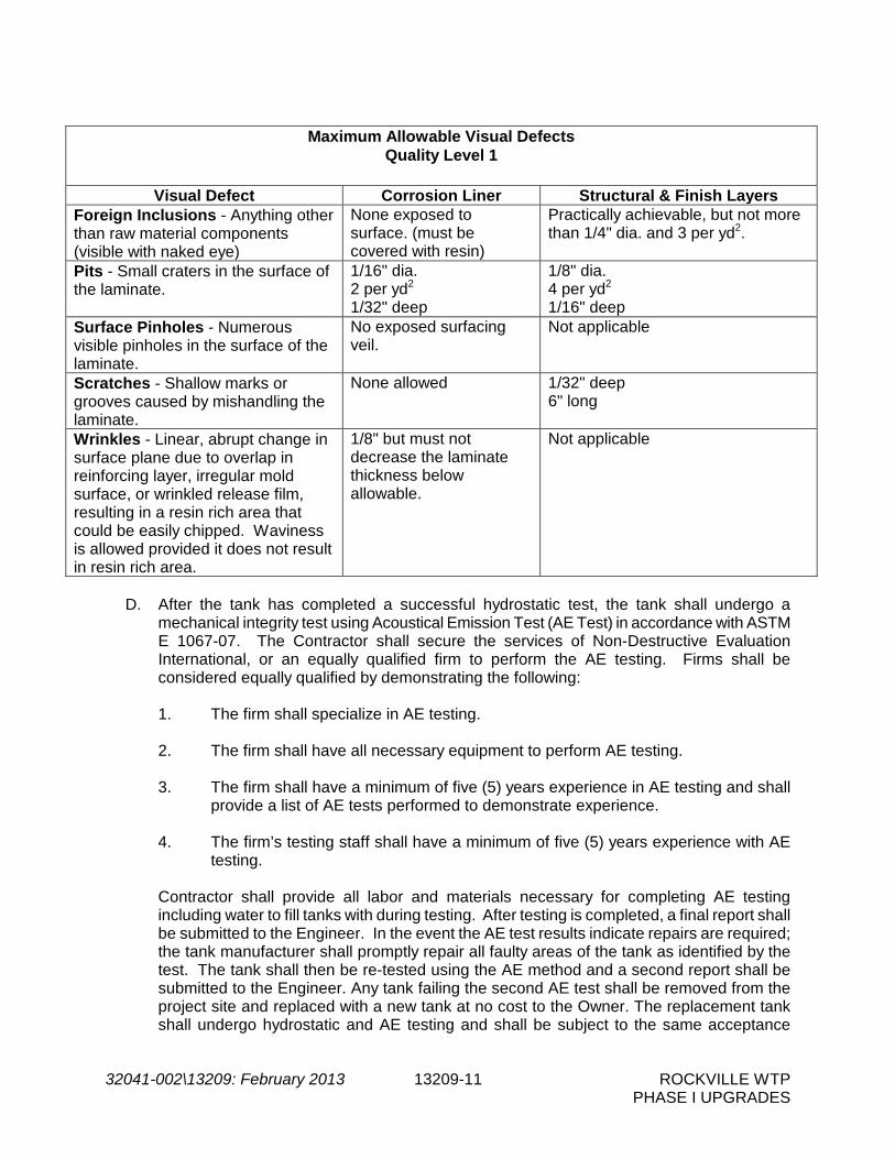
32041-002\13209: February 2013 13209-11 ROCKVILLE WTP PHASE I UPGRADES
Maximum Allowable Visual Defects Quality Level 1
Visual Defect Corrosion Liner Structural & Finish Layers Foreign Inclusions - Anything other than raw material components (visible with naked eye)
None exposed to surface. (must be covered with resin)
Practically achievable, but not more than 1/4" dia. and 3 per yd2.
Pits - Small craters in the surface of the laminate.
1/16" dia. 2 per yd2 1/32" deep
1/8" dia. 4 per yd2 1/16" deep
Surface Pinholes - Numerous visible pinholes in the surface of the laminate.
No exposed surfacing veil.
Not applicable
Scratches - Shallow marks or grooves caused by mishandling the laminate.
None allowed 1/32" deep 6" long
Wrinkles - Linear, abrupt change in surface plane due to overlap in reinforcing layer, irregular mold surface, or wrinkled release film, resulting in a resin rich area that could be easily chipped. Waviness is allowed provided it does not result in resin rich area.
1/8" but must not decrease the laminate thickness below allowable.
Not applicable
D. After the tank has completed a successful hydrostatic test, the tank shall undergo a
mechanical integrity test using Acoustical Emission Test (AE Test) in accordance with ASTM E 1067-07. The Contractor shall secure the services of Non-Destructive Evaluation International, or an equally qualified firm to perform the AE testing. Firms shall be considered equally qualified by demonstrating the following:
1. The firm shall specialize in AE testing.
2. The firm shall have all necessary equipment to perform AE testing.
3. The firm shall have a minimum of five (5) years experience in AE testing and shall
provide a list of AE tests performed to demonstrate experience.
4. The firm’s testing staff shall have a minimum of five (5) years experience with AE testing.
Contractor shall provide all labor and materials necessary for completing AE testing including water to fill tanks with during testing. After testing is completed, a final report shall be submitted to the Engineer. In the event the AE test results indicate repairs are required; the tank manufacturer shall promptly repair all faulty areas of the tank as identified by the test. The tank shall then be re-tested using the AE method and a second report shall be submitted to the Engineer. Any tank failing the second AE test shall be removed from the project site and replaced with a new tank at no cost to the Owner. The replacement tank shall undergo hydrostatic and AE testing and shall be subject to the same acceptance

32041-002\13209: February 2013 13209-12 ROCKVILLE WTP PHASE I UPGRADES
criteria as the initial tank. This process shall be repeated until all tanks provided to the project pass the AE test.
– END OF SECTION –

32041-002\13313: February 2013 13313-1 ROCKVILLE WTP PHASE I UPGRADES
SECTION 13313
GRAVITY THICKENER COVER PART 1 -- GENERAL 1.01 THE REQUIREMENT
A. Furnish all equipment, labor, materials, and services required to provide all Gravity Thickener cover work as specified herein and in accordance with the Contract Documents.
1.02 RELATED WORK SPECIFIED ELSEWHERE
A. Requirements of related work are included in Division 1 of these Specifications.
B. Section 05035 – Galvanized Steel
C. Section 05050 – Metal Fastening
D. Section 05061 – Stainless Steel
E. Section 05120 – Structural Steel
F. Section 05140 – Structural Aluminum
1.03 REFERENCE SPECIFICATIONS, CODES AND STANDARDS
A. Without limiting the generality of other requirements of these Specifications, all work herein shall conform to or exceed the applicable requirements of the following documents to the extent that the provisions therein are not in conflict with the requirements of this Section.
1. Maryland Building Performance Standards
2. American Institute of Steel Construction, "Manual of Steel Construction"
3. American Iron and Steel Institute, "Cold Formed Steel Design Manual"
4. American Welding Society, Structural Welding Code
5. The Aluminum Association, "Aluminum Construction Manual"
1.04 SUBMITTALS
A. Submit the following in accordance with Section 01300 - Submittals.
1. All design data and calculations shall be neatly prepared to facilitate review and shall be signed and stamped with the seal of a Registered Professional Engineer currently registered in the State of Maryland and who is a recognized expert in this type of

32041-002\13313: February 2013 13313-2 ROCKVILLE WTP PHASE I UPGRADES
construction. The calculations shall be submitted to the Engineer prior to fabrication of cover and prior to concrete tank wall placement.
2. Dimensioned shop drawings showing the tank cover plans including brace
centerlines, cover reactions to the tank walls, elevations and cross-sections.
3. Manufacturer's product information, specifications, and installation instructions for tank cover components and accessories.
4. Complete erection drawings showing anchor bolt settings, sidewall, endwall and
cover framing, covering and trim details, and accessory installation details to clearly indicate the proper assembly of tank cover components.
5. Samples of cover fabric. Color shall be selected by the Owner.
6. Warrantees described in Paragraph 1.06 below.
1.05 QUALITY ASSURANCE
A. Shop inspection may be required by the Owner at his own expense. The Contractor shall give ample notice to the Engineer prior to the beginning of any fabrication work so inspection may be provided. The Contractor shall furnish all facilities for the inspection of materials and workmanship in the shop and the inspectors shall be allowed free access to the necessary parts of the work. Inspectors shall have the authority to reject any materials or work which do not meet the requirements of these Specifications. Inspection at the shop is intended as a means of facilitating the work and avoiding errors, but is expressly understood it will in no way relieve the Contractor from his responsibility for furnishing proper materials or workmanship under this Specification.
1.06 WARRANTEES
A. Warrant frame materials and workmanship against defects for a period of 5 years from date of substantial completion of the work.
B. Warrant fabric materials and workmanship against defects for a period of 5 years from the
date of substantial completion of the work. 1.07 MANUFACTURER'S QUALIFICATIONS
A. The manufacturer of the Gravity Thickener cover shall be a manufacturer which has successfully engaged in work of this nature for at least the previous five years.
B. All structural framework and fabric elements are the single source responsibility of the
fabricator.
C. The covers shall be as manufactured by Carroll Awning, Baltimore, MD; Baltimore Canvas, Baltimore, MD; The Awning Factory, Orlando, FL; or approved equal.
1.08 DELIVERY, STORAGE AND HANDLING

32041-002\13313: February 2013 13313-3 ROCKVILLE WTP PHASE I UPGRADES
A. Delivery and Storage: Deliver materials to site in manufacturer’s original, unopened containers and packaging, with labels clearly identifying product name and manufacturer. Store materials in accordance with manufacturer’s instructions, in a clean, dry, well ventilated area, above ground on blocking, and do not allow materials to become wet, stained, or dirty.
B. Handling: Handle materials so as to protect materials, coatings, and finishes during transportation and installation to prevent damage or staining. Handle fabric in accordance with manufacturer’s instructions. Use care in handling of fabric to avoid damage to fabric material and coating.
PART 2 -- GENERAL 2.01 MATERIALS
A. Fabric 1. Cover fabric shall be made of Solution Dyed Acrylic. Material shall be resistant to
UV light, mildew, and water. Material shall be highly breathable and resistant to color fading and deterioration due to UV exposure. Material shall be inherently translucent.
2.02 CLEAR SPAN SUPPORT SYSTEM
A. Frames shall be fabricated from hot rolled galvanized structural steel, shop welded, built-up shapes or structural aluminum built to meet the clear distances and overall shape as shown in the Contract Drawings.
B. Support system shall be designed as pinned base.
C. Shop drill frames for bolted field assembly.
D. Vertical diagonal bracing and horizontal bracing shall be permitted unless shown otherwise
on the Contract drawings. No bracing will be permitted to interfere with the tank cover’s required interior clear height at the access platform.
E. If required, center post support shall be located as shown on the Contract Drawings.
Contractor shall coordinate connection of center post to Gravity Thickener platform. 2.03 ROOF FABRIC SYSTEM
A. The roof construction shall be designed to meet the Maryland Building Performance Standards requirements.
B. The fabric roof covering shall be constructed with a removable type mechanism for the
external 3 foot height perimeter as shown on the drawings so as to provide plant staff access to the launders from the concrete platform encompassing the perimeter of the Gravity Thickener tank. This removable type mechanism shall be able to withstand all

32041-002\13313: February 2013 13313-4 ROCKVILLE WTP PHASE I UPGRADES
loadings as covered in the Maryland Building Performance Standards including uplift from wind and seismic forces.
C. Roof fabric shall have a heat sealable seam design. D. Roof fabric shall be permanently secured to the designed framing system with the exception
of the 3 foot access required for the launders as discussed in paragraph B. Roof fabric shall be permanently secured to the designed framing system with a concealed structural fastening system meeting specified load carrying capacities and allowable deflections.
E. The concealed system shall provide minimal through penetration of the exposed roofing frame system and allow the roof covering to move independently of any differential thermal movement by the structural framing system.
F. Fasteners shall be stainless steel or aluminum screws, bolts or rivets, with weather-seal
washers. Carbon steel shank fasteners with vinyl heads shall also be acceptable. G. Roof slope shall be as indicated on Drawings.
H. The roof fabric supports shall be designed to limit deflection and sagging of the fabric.
2.04 ACCESSORIES
A. General - Coordinate supply and installation of all accessory items. Coordinate framed opening requirements of accessory items with supplier. Provide special members, fasteners, and hardware required for proper securement and installation of accessory items.
B. Pedestrian door allowing access to tank platform shall be fabricated of same fabric material
as the general tank cover and must meet all pedestrian requirements set forth in the Maryland Building Performance Standards. Provide header, jamb, and other structural members required for framed opening. Provide trim and flashing required for a weathertight installation. Door shall be provided with hook that will attach to the aluminum handrail when fully opened so that equipment may pass freely with no obstructions.
PART 3 -- EXECUTION 3.01 DESIGN
A. The tank cover shall be as designed for dead, live, wind, seismic, and snow loads according to the recommendations of the referenced standards with the following exceptions. The tank cover shall be designed for an additional 10 psf of snow load (additional to snow load indicated on drawing S1).
B. Cover framing shall be designed for an additional live load of 5 psf (additional to the live load
indicated on drawing S1) to accommodate piping and lighting. C. The tank cover shall be designed for all loads and equipment shown on the Drawings.
D. The tank cover anchor bolts shall be designed by the tank cover manufacturer to resist all
reactions. Anchor bolts shall be furnished by the Contractor, and shall be installed per recommendations using a manufacturer's supplied template. Engineer shall determine anchor bolt embedment upon receiving reaction loads from the manufacturer.

32041-002\13313: February 2013 13313-5 ROCKVILLE WTP PHASE I UPGRADES
E. The Engineer shall verify the tank wall capacity for the reactions provided by the Tank Cover
Manufacturer. 3.02 FABRICATION
A. Design prefabricated components and necessary field connections required for erection to permit easy assembly and disassembly. Fabricate components in such a manner that once assembled, they may be disassembled, repackaged, and reassembled with a minimum amount of labor.
B. Clearly and legibly mark each piece of the assembly to correspond with previously prepared erection drawings, diagrams, and instruction manuals.
C. Shop connections shall be bolted or welded. D. Field connections shall be bolted. E. All work shall be constructed to dimensions indicated or accepted on the shop drawings,
using proven details of fabrication and support. F. All work shall be true to line and level with accurate angles, surfaces, and edges. G. Weld all corners and seams continuously, complying with AWS recommendations. Grind
and brush all welds. Brazed welds are not acceptable. H. Provide for anchorage type shown, coordinated with supporting structure. Fabricate and
space anchoring devices to provide adequate support for intended use. 3.05 ERECTION
A. Install the Gravity Thickener cover in a manner indicated to comply with manufacturer’s instructions. Position units, level, plumb, secure, and at proper height and location.
B. Proceed with installation of the fabric and associated work only when existing and
forecasted weather conditions will permit work to be performed in accordance with manufacturer’s recommendations. The Gravity Thickener cover shall not be installed when wind conditions are deemed in excess of manufacturer’s determination of safe wind speed erection conditions. It shall be the manufacturer’s sole discretion to determine acceptable and safe wind condition for installation.
C. All structural members shall be accurately set to assure proper fitting and covering. As
erection progresses, the work shall be securely fastened to resist the dead load, wind, seismic, and erection stresses. Erected structural frame work shall be adequately guyed and secured to resist all possible loads due to wind, seismic, and the installation process.
D. Prior to start of installation, check all surfaces of framing members and other rigid
construction elements to be in contact with fabric to ensure all edges are smooth and well rounded. Remove any potential causes for snagging or tearing of the fabric. Properly install all connections and provide all materials and equipment required for the erection and stressing of the fabric. Unroll the fabric in such a manner as to avoid snagging or dragging the fabric over sharp objects during installation. Adequate fabric prestress shall be

32041-002\13313: February 2013 13313-6 ROCKVILLE WTP PHASE I UPGRADES
confirmed by the fabric structure manufacturer and the appearance of the fabric membrane cover shall be smooth and wrinkle free. Creasing or folding the fabric around sharp corners shall be avoided at all times.
E. The installation of the Gravity Thickener cover shall be coordinated with any other work
which may interfere with the installation. F. After installation, restore marred or abraded surfaces to original condition using same paint
or coating as factory-applied finishes, provided the results are acceptable to the Engineer. If unacceptable, damaged equipment shall be removed and replaced.
- END OF SECTION -

32041-002\13400: January 2012 13400-1 ROCKVILLE WTPPHASE I UPGRADES
SECTION 13400
AIR SCOUR SYSTEM
PART 1 -- GENERAL
1.01 THE REQUIREMENT
A. Contractor shall furnish all labor, materials, equipment and incidentals required for theair scour distribution system in the two-cell filters, complete with all necessary supportsand appurtenances required to provide a complete installation as shown on the ContractDrawings and as specified herein. The work includes, but is not limited to, the following:
1. Remove and dispose of existing surface wash agitators and related supports andpiping for the filters as indicated on the Drawing.
2. Furnish and install air scour equipment, piping and supports, and valves for thetwo-cell filters.
B. The Contractor shall provide the following coordination:
1. Contractor shall review requirements and procedures under other Sections andcoordinate with the work in this Section.
2. Contractor shall coordinate all work with plant operating staff to minimizeinterference with plant operation.
3. Only one (1) filter at a time may be taken out of service for work by theContractor unless otherwise directed by the Owner and Engineer. All work shallbe scheduled with the Owner as specified in Section 01520 – Maintenance ofPlant Operations During Construction.
4. Contractor shall provide adequate protection of surrounding areas to protectadjacent filters from contamination.
C. Existing Facilities
1. Design data for the existing filters are as follows:
Number of Filters 4
Number of Cells per Filter 2
Nominal Dimensions of each Filter Cell 8.5 ft. x 41 ft.
Filtration Area per Filter Cell 348.5 ft.2
Total Filtration Area per Filter 697 ft.2
Underdrain Manufacturer Filters 1 and 2 – Roberts
Filters 3 and 4 – Leopold
Type of Underdrain Filters 1 and 2 – Pre-cast Wheeler

32041-002\13400: January 2012 13400-2 ROCKVILLE WTPPHASE I UPGRADES
Filters 3 and 4 – Clay Tile
1.02 RELATED WORK SPECIFIED ELSEWHERE
A. Division 1 - General Requirements
B. Division 3 - Concrete
C. Division 5 - Metals
D. Section 09900 - Painting
E. Division 11 - Equipment General Provision
F. Section 13450 – Disinfection of Water Treatment Facilities
G. Section 15390 - Schedules
H. Division 15 - Mechanical
I. Division 16 - Electrical
J. Division 17 - Control and Information Systems
1.03 REFERENCE SPECIFICATIONS, CODES AND STANDARDS
A. Maryland State Building Code
B. Applicable local building codes
C. Underwriters Laboratories, Inc.
D. As specified in Section 01090 - Reference Standards
1.04 SUBMITTALS
A. The Contractor shall submit to the Engineer for review detailed shop drawings of all filtercomponents in accordance with Section 01300 – Submittals and Section 11000 –Equipment General Provisions. Shop drawings shall include:
1. Performance Affidavit in accordance with Section 11000.
2. Overall plans and sections, materials of construction, installation instructions andrecommendations and leveling requirements for air scour distribution system.
4. Complete headloss data for air flows through the air scour system.
1.05 CONTRACTOR'S RESPONSIBILITY
A. The Contractor shall provide the services of a qualified manufacturer's technicalrepresentative who shall adequately supervise the installation and testing of all air scour

32041-002\13400: January 2012 13400-3 ROCKVILLE WTPPHASE I UPGRADES
equipment furnished under this Contract and instruct the Owner's operating personnel inits maintenance and operation as outlined in the General Conditions and Division 1. Theservices of the manufacturer's representative shall be provided as follows:
1. One (1) trip of five (5) days duration to test, supervise and check installation of airscour system and train Owners' personnel.
B. The Contractor shall schedule the above trips with the Manufacturer and shall coordinatethe trips with Contractor's schedule. Contractor shall have manufacturer's representativepresent at installation and testing of all air scour equipment.
C. Any additional time required to achieve successful installation and operation shall be atthe expense of the Contractor.
D. A written report covering the representative’s findings and installation approval shall bemailed directly to the Engineer covering all inspection and outlining in detail anydeficiencies noted.
E. The times specified are exclusive of travel time to and from the facility and shall not beconstrued as to relieve the manufacturer of any additional visits to provide sufficientservice to place the equipment in satisfactory operation.
1.06 OPERATION AND MAINTENANCE MANUALS
A. The Contractor shall submit operation and maintenance manuals to the Engineer inaccordance with Section 01300.
1.07 ACCEPTABLE MANUFACTURERS
A. The materials covered by these Specifications are intended to be the standard productof reputable manufacturers having experience in the production of such products. Thematerials furnished shall be designed, constructed, and installed in accordance with thebest practices and methods and shall operate satisfactorily when installed as specified inthe Contract Documents and per the manufacturer's recommendations.
B. Air scour equipment for the filters shall be the Aries Managed Air System asmanufactured by Roberts Water Technologies, Inc, or the LeoGrid Air Backwash Systemas manufactured by F.B. Leopold Company, Inc.
D. Instrumentation shall be provided as specified in Division 17.
E. Valves and valve operators shall be provided as specified in Division 15.
PART 2 -- MATERIALS
2.01 AIR DISTRIBUTION PIPING
A. The filter air scour system shall provide for proper cleansing of the filter media at an airflow rate of 3.0 scfm/ft2. Modification or replacement of the existing filter underdrains

32041-002\13400: January 2012 13400-4 ROCKVILLE WTPPHASE I UPGRADES
shall not be allowed.
B. The air scour system shall consist of an air header, drop piping and air diffuser modules.All individual components shall be interlocking to form a complete and independentoperating system.
C. The air scour system shall consist of Schedule 5 Type 304L stainless steel headers andfittings to accommodate Schedule 5/40 Type 304 stainless steel drop pipes. Drop pipesshall be connected to the laterals of the air diffuser modules by means of transitionpieces. Corrosion-resistant, drop pipe stabilizers shall be furnished as needed tosupport the drop pipes from the existing filter troughs. Stabilizer design shall becoordinated with the existing filter trough design accordingly. Each lateral shall becomplete with unitized Type 304 stainless steel air diffusers. All supporting hardwareshall be of Type 304 stainless steel.
D. The air scour system shall be designed to accommodate installation without the need forlower support and securement hardware for air scour modules located within the filterbed.
E. Each air diffuser assembly shall be of one piece Type 304 stainless steel construction.Each diffuser assembly shall contain a metering orifice. The metering orifice shall openinto a larger chamber in the body of the diffuser with Type 304 stainless steel screens atthe discharge ends.
F. Screen and chamber shall be sized as required to prevent clogging by media orextraneous material.
PART 3 -- EXECUTION
3.01 AIR SCOUR SYSTEM INSTALLATION
A. Installation of the equipment shall be supervised and field tested by the Air ScourSystem Manufacturer in accordance with the instructions and drawings of themanufacturer and Section 11000 – Equipment General Provisions.
B. The equipment manufacturer shall furnish the services of a qualified service person withat least three years of experience who is regularly involved in the inspection, installation,start-up, troubleshooting, testing, maintenance, and operation of air scour systems. Theservice person shall:
1. Perform installation of the air scour system.
2. Assist the Contractor in conducting field tests and preparing written reports asspecified below.
3. Witness and check start-up of the system.
4. Assist the Contractor in making adjustments and modifications as necessary tooptimize operation of system components.
32041-002\13400: January 2012 13400-5 ROCKVILLE WTPPHASE I UPGRADES
5. Troubleshoot and correct any problems with the air scour system that are notedduring tests and start-up.
6. Submit written certification that the system has been properly installed, tested,and adjusted including date of final acceptance test, as well as a listing of allpersons present during the tests.
7. Investigate and supervise correction of any operating problems that may arise upto the end of the guarantee period of the equipment. Such services shall befurnished at no additional cost to the Owner.
C. The Contractor shall take precautions as required to prevent breakage or warpage ofany stored or installed air scour system component. Components shall be handledcarefully to prevent damage and shall be stored on platforms supported clear of theground. Only sound, undamaged units shall be installed. Units damaged before finalcompletion of the work shall be removed and replaced with undamaged units by theContractor without additional expense to the Owner.
D. Installation Protocol
1. The Contractor shall install the filter air scour system in strict accordance with theManufacturer’s installation drawings, instructions and recommendations. TheContractor shall obtain the full-time services of a field supervisor employed by thefilter air scour manufacturer for the supervision of Contractor’s installation andstartup. All necessary precautions recommended by the Manufacturer and asspecified herein shall be followed to ensure that the air distribution system andpiping connected thereto is completely clean and free of any debris, dirt, or otherforeign materials which could clog the system or interfere with air flow. Pipingshall be flushed with air only.
2. Following installation of air supply piping within the filter cells, the individualmodules shall be assembled on top of the filter bed. Once assembled, theindividual modules shall be positioned and the backwash flow started andmaintained until the filter bed is fluidized and the modules are lowered into place.The modules shall then be connected to the air supply piping using fittingsfurnished by the Manufacturer.
3. The air scour system shall be tested in the air only mode at 2.5 scfm/ft2 with sixinches of water over the filter bed. Test flow rates shall be sustained forapproximately two minutes while visual observations are made. Tests shall beextended or repeated if required.
4. During each test, the water surface shall present a uniformly turbulentappearance, without dead spots or boils. The Contractor shall take suchmeasures as are necessary to correct any deficiencies revealed by these tests,and shall repeat the specified tests until such deficiencies are corrected.
5. The filter air scour Manufacturer shall maintain a qualified staff of factory trainedfield service personnel. This staff shall include regular, full-time employees of theManufacturer with suitable training and experience with installation and operationof the type of equipment being supplied.

32041-002\13400: January 2012 13400-6 ROCKVILLE WTPPHASE I UPGRADES
6. The filter air scour Manufacturer shall perform the installation of the air scoursystem within the filter cells.
7. The filter air scour Manufacturer shall perform the testing of the air scour systemin the filter cells.
3.02 FIELD TESTING OF AIR SCOUR SYSTEM
A. The Contractor shall conduct all testing specified herein and recommended by themanufacturer, and shall furnish all material, instrumentation, temporary equipment,personnel, etc. for conducting tests as specified herein. The Owner will provide use of itsexisting Backwash Pump and new Air Scour Blowers for testing the air scour system.Finished water shall be used for all field tests in this section. The costs of all work andmaterials to correct deficiencies revealed during testing and the cost of retesting shall beborne by Contractor.
B. The air scour system shall be given a visual air flow distribution test to verify that the airdelivery piping is not clogged with debris and air flow distribution is uniform. Airflow foreach filter shall be observed.
C. The Contractor shall take all necessary measures to correct any deficiencies revealed bythese tests and shall repeat the specified tests until such deficiencies are corrected.
D. Filters shall not be placed into service until filter structure, media, piping, and valveshave been disinfected as specified in Section 13450 and Section 15000.
- END OF SECTION -

32041-002\13450: February 2013 13450-1 ROCKVILLE WTP PHASE I UPGRADES
SECTION 13450
DISINFECTION OF WATER TREATMENT FACILITIES PART 1 -- GENERAL 1.01 GENERAL
A. Clean and disinfect the water treatment facilities including all filter cells, filter media and filter piping and valves within the cells prior to placing the systems into service in accordance with the regulations of the Maryland Department of the Environment (MDE) and as specified herein.
B. Before being placed into service and before Certification of Substantial Completion can be
issued by the Engineer, all new or modified potable water systems shall be disinfected in accordance to the requirements of these Specifications.
1.02 RELATED WORK SPECIFIED ELSEWHERE
A. Division 13 – Special Construction 1.03 REFERENCE SPECIFICATIONS, CODES, AND STANDARDS
A. Without limiting the generality of other requirements of the Specifications, all work hereunder shall conform to the applicable requirements of the following documents to the extent that the requirements therein are not in conflict with the provisions of this Section.
1. AWWA C652 – Disinfection of Water Storage Facilities
2. AWWA B300– Hypochlorites
1.04 SUBMITTALS
A. Submit procedures for completing the disinfection of the plant facilities listed above, including the proposed methods of storing, handling and dispensing the disinfectant.
B. Submit a "Record of Compliance" stating that bacteriological testing had been accomplished
and certifying that the water is free of coliform bacteria contamination. Results of this testing shall meet MDE requirements.
C. Testing and disinfection shall be accomplished in the presence of the Engineer.
PART 2 -- PRODUCTS 2.01 WATER SUPPLY
A. Reasonable quantities of water necessary for initial and subsequent flushing, testing, and disinfection of all facilities associated with this Project shall be provided by the Owner.

32041-002\13450: February 2013 13450-2 ROCKVILLE WTP PHASE I UPGRADES
B. All chemical equipment (pumps, testing kits, etc.) associated with leakage testing, cleaning, or rinsing of the facilities shall be furnished by the Contractor. The Owner has limited facilities for potable water use and reserves the right to limit the volume of water used per day and the times of the day when the use of water is permitted for the project. Disposal of water for leak testing, cleaning and rinsing shall be performed in accordance with all federal, state and local requirements in such a manner as to cause no adverse environmental effects such as fish kills or erosion.
2.02 CHEMICAL
A. All chemicals and chemical feed pumps required for disinfection shall be furnished by the Contractor.
2.03 BACTERIOLOGICAL TESTING A. The Owner shall furnish bacteriological testing for verification of disinfection procedures. PART 3 -- EXECUTION 3.01 GENERAL
A. Materials
1. Chlorine for disinfection shall be in the form of sodium hypochlorite solution, or calcium hypochlorite granules or tablets.
2. Sodium hypochlorite and calcium hypochlorite shall be in accordance with the
requirements of AWWA B300 and C653.
B. Scheduling
1. The Owner and Engineer shall be provided with a detailed flushing, testing, and disinfection plan for approval. The Engineer reserves the right to adjust, modify, and/or alter the proposed plan to serve the best interests of the Owner at no additional cost to the Owner.
2. The Owner shall be given at least 1 week advance notice of the intent to begin
flushing, testing and disinfecting any portion of the system.
3. All flushing, testing and disinfection shall be witnessed by the Engineer and a representative of the Owner. All work shall be coordinated with the Engineer at a time mutually agreeable to the Owner and shall give at least 24 hours advance notice prior to performing any work.
C. Flushing
1. Flush all facilities described herein in accordance with these Specifications. The
times for flushing shall be coordinated through the Engineer, with the Owner. There shall be no claim for monetary compensation from the Owner for the inability of the Owner to provide adequate water at the proposed time of flushing. Compensation is limited to an extension of time to perform flushing activities.
2. Excessive water shall be prevented from flowing onto private property. All materials
required for flushing shall be furnished.

32041-002\13450: February 2013 13450-3 ROCKVILLE WTP PHASE I UPGRADES
D. Filter Basin Filling
1. All pipelines and tanks shall be filled slowly either through an existing valve or through taps. Special care shall be exercised in loading lines and filling the tanks to prevent damage. Coordinate with the Owner the operation of all existing valves. All valve operations shall be performed by the Owner's personnel only.
2. Any equipment used either for disinfection or dechlorination shall be either new or
previously used only for disinfection or dechlorination. All chemicals used for disinfection and dechlorination shall be NSF approved for use in potable water.
3. The Owner shall be advised when the tank or pipe is ready for bacteriological
sampling. The tank or pipe shall be sampled in accordance with AWWA C652.
4. The chlorine disinfection solution shall be thoroughly flushed out prior to placing the tank in service. Spent chlorine solution must be disposed of in such a way as not to be detrimental to animal, plant or fish life. A NSF approved reducing agent may be added to the highly chlorinated water to reduce the chlorine residual to an acceptable level. A water disposal plan shall be submitted to the Engineer prior to tank cleaning, filling or disinfection. All civil penalties, fines, costs, assessments, etc., associated with any discharge of spent chlorine solution associated with this work shall be paid accordingly by the Contractor. Chlorine residual tests will be made after flushing to assure that the chlorine residual is not in excess of 1 ppm.
5. No monetary compensation from the Owner shall be awarded for the inability of the
Owner to provide adequate water at the proposed time of disinfection. Compensation is limited to an extension of time to perform filling activities only.
3.02 DISINFECTION OF FILTERS
A. After placement of the air scour system and before the filter is placed in service, the entire depth of the filter, media, underdrain system, and associated piping in each filter shall be disinfected according to the following procedure unless an alternate procedure is required by the MDE.
1. With all other filter valves closed, the filter shall be filled with finished water pumped
to the filter. Sufficient disinfectant (calcium hypochlorite or sodium hypochlorite) shall be added to the incoming water to achieve a level of 50 mg/l of free chlorine in the disinfecting water. This level of chlorine shall be maintained during the disinfection process.
2. The water level shall be maintained approximately 6 inches below the top of the filter
box for not less than twenty-four (24) hours.
3. Upon completion of disinfection and satisfactorily passing bacteriological testing by the Owner, the filter contents shall be discharged to the plant drain system and properly dechlorinated in a manner acceptable to the Owner and Engineer.
- END OF SECTION -

THIS PAGE LEFT INTENTIONALLY BLANK

32041-002\14600: January 2012 14600-1 ROCKVILLE WTP PHASE I UPGRADES
SECTION 14600
CRANES AND HOISTS PART 1 -- GENERAL 1.01 THE REQUIREMENT
A. The Contractor shall furnish, install and make fully operational the crane and hoist systems in the locations and conditions of service, as shown on the Drawings and as specified in the Crane and Hoist Schedule.
B. These Specifications shall be considered as minimum requirements. The Contractor
shall add such additional features as are necessary for satisfactory operation.
C. Equipment shall be provided in accordance with the requirements of Section 11000 – Equipment General Provisions.
D. All equipment supplied under this Specification shall comply in all respects with the
provisions of the Occupational Safety and Health Act of 1970, including all standards promulgated under the authority of such Act, and shall also meet all applicable industrial codes in the State in which the project is located.
E. The manufacturer and ultimately the Contractor shall be totally responsible for structural
design of the crane and hoist systems, for the compatibility of all equipment, and for verification of required operating clearances.
F. All parts of the mechanism furnished shall be amply designed and constructed for the
maximum stresses occurring during fabrication, erection and continuous operation. All equipment specified herein shall be designed for the Crane Manufacturer's Association of America Duty Classification as specified herein.
G. If the Contractor elects to utilize the crane and hoist equipment in any way during the
erection of piping and installation of equipment, he shall notify the Owner in writing and shall provide for an inspection by the equipment manufacturer and take any steps necessary to return the equipment to "as new" condition. He shall also obtain recertification by the manufacturer and reinstate all warranties and guarantees.
1.02 CAPACITY AND DESIGN LOADS
A. The crane shall be designed to withstand the dead load (caused by the weight of the crane and components themselves), the live load and hoist load, and the inertia forces caused by movement of the crane, components, and loads during standard operation.
B. Standard capacity ratings shall represent the net rated load at the hook of any type of
trolley hoist with the same load rating installed on the crane having a trolley hoist weight within the established limits.

32041-002\14600: January 2012 14600-2 ROCKVILLE WTP PHASE I UPGRADES
C. All design loads shall meet CMAA requirements. The design load for stress calculations shall be based upon the capacity plus 15% for the weight of the hoist and trolley and an additional 25% for impact (capacity x 1.4). Design load for deflection calculations shall be based upon the capacity plus 15% for the weight of the trolley hoist (capacity x 1.15).
D. The rated load capacity of each crane shall be clearly labeled on each crane using a
label size easily read from the floor level and/or loading position. 1.03 CRANE AND HOIST SCHEDULE
Location Blower Pad Clarifier Gallery Roof General Indoor / Outdoor Outdoor Outdoor Capacity, tons 1.5 1.5 Operating Floor Elevation 242.75 242.75/234.00 Crane Crane Type Jib Crane Monorail Mounting Insert N/A CMAA Duty Classification N/A N/A Span, ft 12 N/A Frame Spread, ft N/A N/A Height Under Boom, ft 15 N/A Max Bridge Speed, fpm N/A N/A Trolley Hoist Trolley Type Manual Manual Hoist Type Manual Manual ASME Duty Classification Class H3 Class H3 Hook Elevation
High Point 256.50 251.00 Low Point 242.75 234.00
Operating Speeds Trolley Speed, fpm Manual Manual Hoist Speed(s), fpm Manual Manual
All elevations and spans are approximate. All equipment shall be installed as shown on the Drawings.
1.04 REFERENCE SPECIFICATIONS, CODES, AND STANDARDS
A. Without limiting the generality of other requirements of the Specifications, all work herein shall conform to the applicable requirements of the following documents. All referenced Specifications, codes and standards refer to the most current issue available at the time of the Bid.

32041-002\14600: January 2012 14600-3 ROCKVILLE WTP PHASE I UPGRADES
1. CMAA Crane Manufacturers Association of America 2. AISC “Manual of Steel Construction” 3. ASTM A48 Standard Specifications for Gray Iron Castings 4. ANSI B30.11 Safety Code for Underhung Cranes and Monorail Systems 5. ANSI B30.16 Safety Code for Overhead Hoists 6. MMA MH27.1 Monorail Manufacturers Association 7. OSHA 1910-179 Occupation Safety and Health Administration
1.05 SUBMITTALS
A. The following items shall be submitted with the Shop Drawings in accordance with, or in addition to the submittal requirements specified in Section 01300, Submittals; and Section 11000, Equipment General Provisions:
1. Certification that the systems have been designed to resist all loads implied
herein and loadings stipulated in the applicable building codes of the State in which the project is located. The Certification shall also state that the design has been performed and signed and sealed by a Professional Engineer registered in the State in which the project is located.
B. Certification that the equipment has been field tested and passed.
C. Details and design calculations shall be submitted, signed, and sealed by a Professional
Engineer registered in the State in which the project is located for any of the following components furnished by the Manufacturer:
1. Runway beams. 2. Monorail patented track. 3. Monorail suspension systems. 4. End stops and connections.
1.06 WARRANTY AND GUARANTEE
A. Warranty and Guarantee shall be as specified in Section 11000 with the exception that the warranty period shall be for two (2) years.
PART 2 -- PRODUCTS 2.01 ACCEPTABLE MANUFACTURERS
A. The equipment covered by these Specifications are intended to be standard equipment of proven reliability and as manufactured by reputable manufacturers having experience in the production of such equipment.

32041-002\14600: January 2012 14600-4 ROCKVILLE WTP PHASE I UPGRADES
2.02 GENERAL
A. The crane system shall be constructed of structural steel, in accordance with current AISC (American Institute of Steel Construction) and ASTM (American Society for Testing and Materials) A-36 specifications minimum.
B. All crane components will have properly finished ends and surfaces. C. Welding shall follow the current recommended practices of the AWS (American Welding
Society) D14.1 specifications.
D. Moving members of the crane shall be separated by a clearance of at least 3 inches vertically from any overhead obstruction, and 2 inches horizontally from any lateral obstruction.
2.03 JIB CRANES
A. Jib cranes shall be as manufactured by GORBEL, Inc., or equal.
B. The free standing jib crane shall consist of a stationary mast (pillar), about which a boom and box-style head will rotate. The crane shall be free standing, i.e., the floor/foundation shall be the crane's only means of support.
C. The crane shall provide coverage for a circular work area about the mast, and be
capable of 360° of continuous rotation. The crane shall be designed for manual rotation. The crane's boom shall not drift when at rest, yet will rotate easily when manually pushed or pulled. Optional field-welded steel rotation stops shall be provided to limit the crane's rotation angle, if required.
D. The crane shall have either a base plate mounted, insert mounted, or sleeve insert
mounted style:
1. Base Plate Mounted Cranes: The crane shall stand by means of the mast being welded to a base plate. The base plate shall have a sufficient number of holes for anchor bolts to anchor the crane into the recommended foundation. The crane shall feature full web gussets plates, welded to the mast and base plate, about the mast for stability and reinforcement. Any design with open gussets (bars that support only the outside of the base plate), or any base plates made from rings, will not be acceptable due to their tendency to warp.
2. Insert Mounted Cranes: The crane shall stand by means of the mast being
inserted a specified distance into the recommended foundation, thus permanently imbedding the crane. No plates or gussets shall be required at floor level.
3. Sleeve Insert Mounted Cranes: The crane shall stand by means of the mast
being inserted a specified distance into a sunken cylindrical steel sleeve that has been imbedded into the recommended foundation. No plates or gussets shall be required at floor level.

32041-002\14600: January 2012 14600-5 ROCKVILLE WTP PHASE I UPGRADES
E. The mast assembly shall consist of a round structural steel pipe. Masts shall be plumb and straight, and shall be perpendicular to the bottom. The mast shall remain stationary during rotation and use of the crane.
F The boom shall consist of a standard structural steel I-beam or wide flange, and may be
reinforced with a cap channel for lateral stability. The boom shall bolt to the head assembly.
1. Trolley stops shall be utilized to prevent the trolley hoist from falling off the boom
or contacting any obstruction. 2. The boom shall be level and horizontal (within the specified deflection limits), and
shall permit a trolley hoist to ride upon its flat flange track. Means shall be provided to allow for the slight horizontal adjustment of the boom so that it can be erected and maintained level.
3. The boom’s deflection under the rated load shall not exceed 1/150 of the crane's
span.
G. Head Assembly
1. The head assembly shall consist of two side plates, a top frame weldment, a bottom head channel, a trunnion roller support frame, and a back safety channel, and should provide for bottom entry electrification.
2. A retaining pin shall be utilized in the head assembly to help protect against head
dislodgement. 3. Rotation of the crane shall be accomplished via full-face contact trunnion rollers
working in conjunction with a top pivot bearing assembly with a heavy-duty tapered roller bearing.
4. The rollers shall not curve into the mast during rotation, and a wear ring shall not
be required. Any crane with a wear ring about the mast shall not be acceptable.
H. The rated capacity of the jib crane shall be painted with stencil on both the hoist and the boom beam.
2.04 MONORAILS
A. Unless otherwise indicated on the Drawings, monorail shall be patented track consisting of a top flange, web and hardened 3.25" or 3.33" bottom operation flange. All rails shall be furnished with splices and end stops and shall be designed for spans, thermal expansion and contraction and turning radii as shown on the Drawings. Unless otherwise shown on the Drawings provisions shall be made for connection of monorail suspension system to support locations designated on Drawings. The suspension system shall provide support and bracing of all live, dead, and impact loads. Monorail shall be manufactured by Louden division of ACCO, TC/American Monorail, Cleveland Tramrail division of Gorbel, Tram Beam, or equal. Rated capacity of monorail shall be painted with stencil on both the hoist and the monorail beam.

32041-002\14600: January 2012 14600-6 ROCKVILLE WTP PHASE I UPGRADES
2.05 TROLLEY HOISTS
A. Trolley hoists shall be as manufactured by ACCO Industries, Electrolift, or Yale.
B. All load carrying parts shall be of steel. The wheels shall have hardened treads. Wheels and axles shall be equipped with antifriction bearings which are permanently sealed and lubricated. The gear head of the motor shall have an alloy steel, heat-treated gear train operating in a fully enclosed oil bath. The gear shaft shall have precision, oil lubricated ball bearings. Where monorail track as specified or shown on the Drawings is curved, trolleys shall be the swivel-type to negotiate curved sections.
1. Manual trolleys shall be of hand-driven geared type.
C. The hoist drive shall be of the standard-headroom, single reeved type and shall include
a geared train with inherent or mechanical load brake, hook, wire rope, and drum. Rated capacity shall be stamped on the hoist frame. The frame shall be oil-tight, of cast steel construction, with no part of the load carried by assembly bolts. Gearing shall be machine cut and heat-treated, and shall operate in an oil bath. Except for the drum pinion, no gears shall be cantilever mounted. Shafting shall be ground and polished and all bearings shall be of the antifriction type. Grease fittings and oil reservoir shall be readily accessible. The drum shall be of the large diameter, guarded, flanged type with machine cut grooves to accommodate the hoist cable without overwrapping. Right- and left-hand drum grooving shall be utilized in close-headroom, double-reeved, cross-mounted hoist applications to provide a true vertical lift. The wire ropes shall be of the preformed extra flexible type, have a safety factor of at least five, and be anchored to the hoist drum. The load block shall be of the safety type with guarded sheaves and forged swiveled hooks. Hooks shall open slowly when subjected to heavy overloads.
1. Manual hoists shall include a handwheel and chain and a clutch-type overload
cut-off device to protect hoist from an overload condition.
D. Rated capacity of trolley hoists shall be painted with stencil on the trolley hoist. PART 3 -- EXECUTION 3.01 MANUFACTURER’S FIELD SERVICES
A. The services of a qualified manufacturer's technical representative shall be provided in accordance with Section 11000, Equipment General Provisions and shall include the following site visits for each crane and hoist system:
Service Number of Trips Number of Days/Trip Installation and Testing 1 1 Startup and Training 1 1 Services after Startup 0 0
3.02 INSTALLATION
A. All crane equipment shall be installed in accordance with the applicable sections of Division 5 - Metals, Division 16 – Electrical, and the manufacturer's instructions and recommendations.

32041-002\14600: January 2012 14600-7 ROCKVILLE WTP PHASE I UPGRADES
3.03 FIELD TESTS
A. Field tests shall be conducted in accordance with Section 11000 and the manufacturer's instructions and recommendations. Prior to initial use, all cranes shall be proof-tested at 125% of their rated load in accordance with all OSHA requirements.
3.04 PAINTING
A. The crane shall be painted OSHA safety yellow before shipment.
B. A wire-brushing and/or solvent wipe shall be performed prior to painting to clean and remove debris, mill scale, dirt, and oils.
C. At least one spray can of matching color paint shall be shipped with each crane for field
touch-ups.
D. The crane shall be properly banded and skidded prior to shipment. Any paint damage, scratches, blemishes to the finish of the crane, caused by shipping, transportation via common carrier, etc., shall be repaired by the Contractor.
E. Rated capacity of crane system shall be painted with stencil on all components of crane
system as specified herein.
- END OF SECTION -

THIS PAGE LEFT INTENTIONALLY BLANK

32041-002\15000: February 2013 15000-1 ROCKVILLE WTP PHASE I UPGRADES
SECTION 15000
BASIC MECHANICAL REQUIREMENTS PART 1 -- GENERAL 1.01 THE REQUIREMENT
A. The Contractor shall furnish and install to the required line and grade, all piping together with all fittings and appurtenances, required for a complete installation. All piping located outside the face of structures or building foundations and all piping embedded in concrete within a structure or foundation shall be considered exterior piping.
B. The Contractor shall furnish and install fittings, couplings, connections, sleeves,
adapters, harness rods and closure pieces as required to connect pipelines of dissimilar materials and/or sizes herein included under this Section and other concurrent Contracts for a complete installation.
C. The Contractor shall furnish all labor, materials, equipment, tools, and services required
for the furnishing, installation and testing of all piping as shown on the Drawings, specified in this Section and required for the Work. Piping shall be furnished and installed of the material, sizes, classes, and at the locations shown on the Drawings and/or designated in this Section. Piping shall include all fittings, adapter pieces, couplings, closure pieces, harnessing rods, hardware, bolts, gaskets, wall sleeves, wall pipes, hangers, supports, and other associated appurtenances for required connections to equipment, valves, or structures for a complete installation.
D. Piping assemblies under 4-inch size shall be generally supported on walls and ceilings,
unless otherwise shown on the Drawings or ordered by the Engineer, being kept clear of openings and positioned above "headroom" space. Where practical, such piping shall be run in neat clusters, plumb and level along walls, and parallel to overhead beams.
E. The Contractor shall provide taps on piping where required or shown on the Drawings.
Where pipe or fitting wall thicknesses are insufficient to provide the required number of threads, a boss or pipe saddle shall be installed.
F. The work shall include, but not be limited to, the following:
1. Connections to existing pipelines.
2. Test excavations necessary to locate or verify existing pipe and appurtenances.
3. Installation of all new pipe and materials required for a complete installation.
4. Cleaning, testing and disinfecting as required.
1.02 RELATED WORK SPECIFIED ELSEWHERE

32041-002\15000: February 2013 15000-2 ROCKVILLE WTP PHASE I UPGRADES
A. Division 1, General Requirements
B. Division 2, Sitework
C. Division 9, Finishes
D. Division 11, Equipment
E. Division 16, Electrical
1.03 MATERIAL CERTIFICATION AND SHOP DRAWINGS
A. The Contractor shall furnish to the OWNER (through the Engineer) a Material Certification stating that the pipe materials and specials furnished under this Section conform to all applicable provisions of the corresponding Specifications. Specifically, the Certification shall state compliance with the applicable standards (ASTM, AWWA, etc.) for fabrication and testing.
B. Shop Drawings for major piping (2-inches in diameter and greater) shall be prepared and submitted in accordance with Section 01300 – Submittals. In addition to the requirements of Section 01300 – Submittals, the Contractor shall submit laying schedules and detailed Drawings in plan and profile for all piping as specified and shown on the Drawings.
C. Shop Drawings shall include, but not be limited to, complete piping layout, pipe material, sizes, class, locations, necessary dimensions, elevations, supports, hanger details, pipe joints, and the details of fittings including methods of joint restraint. No fabrication or installation shall begin until Shop Drawings are approved by the Engineer.
1.04 SEISMIC DESIGN REQUIREMENTS
A. The Contractor is advised that all proposed structures, non-building structures, and architectural, mechanical and electrical components and systems, including associated equipment and appurtenances furnished and installed on this project such as piping supports, shall be subject to the requirements of the most current Building Code for the State of Maryland for earthquake design requirements in conjunction with the seismic provisions of the International Building Code (IBC) 2009 and referenced ASCE/SEI 7-05 for earthquake loadings. In designing and detailing non-building, architectural, mechanical and electrical components and systems required to be furnished as performance type submissions, seismic forces and subsequent details shall be developed in accordance with the IBC 2009 Code, Chapter 16, Sections 1601 through 1623 and ASCE 07-05, Chapter 9 in conjunction with the Maryland Building Code to the extent that the most stringent provisions are utilized in developing the design earthquake forces. Contractors shall refer to the Code Data Sheets (G-series Drawings) for site, structure and non-building systems specific seismic design criteria. All calculations, seismic certifications and construction details performed and developed as part of the requirements of performance type submissions shall be prepared and sealed by a Professional Engineer (PE) licensed to practice in the State of Maryland.
PART 2 -- PRODUCTS

32041-002\15000: February 2013 15000-3 ROCKVILLE WTP PHASE I UPGRADES
2.01 GENERAL
A. All specials and every length of pipe shall be marked with the manufacturer's name or trademark, size, class, and the date of manufacture. Special care in handling shall be exercised during delivery, distribution, and storage of pipe to avoid damage and unnecessary stresses. Damaged pipe will be rejected and shall be replaced at the Contractor's expense. Pipe and specials stored prior to use shall be stored in such a manner as to keep the interior free from dirt and foreign matter.
B. Testing of pipe before installation shall be as described in the corresponding ASTM or
AWWA Specifications and in the applicable standard specifications listed in the following sections. Testing after the pipe is installed shall be as specified in Section 3.09.
C. Joints in piping shall be of the type as specified in the appropriate Piping System
Schedule in Section 15390 – Schedules.
D. ALL BURIED EXTERIOR PIPING SHALL HAVE RESTRAINED JOINTS FOR THRUST PROTECTION UNLESS OTHERWISE SPECIFIED OR SHOWN ON THE DRAWINGS. ALL EXPOSED EXTERIOR PIPING SHALL HAVE FLANGED JOINTS, UNLESS OTHERWISE SPECIFIED OR SHOWN ON THE DRAWINGS.
E. The Drawings indicate work affecting existing piping and appurtenances. The
Contractor shall excavate test pits as required of all connections and crossings which may affect the Contractor's work prior to ordering pipe and fittings to determine sufficient information for ordering materials. The Contractor shall take whatever measurements that are required to complete the work as shown or specified.
2.02 WALL PIPES
A. Where wall sleeves or wall pipes occur in walls that are continuously wet on one or both sides, they shall have water stop flanges at the center of the casting or as shown on the Drawings. Ends of wall pipes shall be flanged, mechanical joint, plain end, or bell as shown on the Drawings, or as required for connection to the piping. Wall pipes shall be of the same material as the piping that they are connected to. If welded waterstop flanges are employed, welds shall be 360 degree continuous on both sides of flange. Unless otherwise shown on the Drawings, waterstop flanges shall conform to the minimum dimensions shown below:
Pipe Size Waterstop
Flange Diameter Waterstop
Flange Thickness 4" - 12" OD + 3.10" 0.50"
14" - 24" OD + 4.15" 0.75"
30" - 36" OD + 4.50" 1.00"
42" - 48" OD + 5.00" 1.25"
54" OD + 5.90" 1.50"
2.03 SLEEVES

32041-002\15000: February 2013 15000-4 ROCKVILLE WTP PHASE I UPGRADES
A. Unless shown otherwise, all piping passing through walls and floors shall be installed in sleeves or wall castings accurately located before concrete is poured, or placed in position during construction of masonry walls. Sleeves passing through floors shall extend from the bottom of the floor to a point 3 inches above the finished floor, unless shown otherwise. Water stop flanges are required on all sleeves located in floors or walls which are continually wet or under hydrostatic pressure on one or both sides of the floor or wall.
B. Sleeves shall be cast iron, black steel pipe, or fabricated steel in accordance with details
shown on the Drawings. If not shown on the Drawings, the Contractor shall submit to the Engineer the details of sleeves he proposes to install; and no fabrication or installation thereof shall take place until the Engineer's approval is obtained. Steel sleeves shall be fabricated of structural steel plate in accordance with the standards and procedures of AISC and AWS. Steel sleeve surfaces shall receive a commercial sandblast cleaning and then be shop painted in accordance with Section 09900 – Painting.
C. When shown on the Drawings or otherwise required, the annular space between the
installed piping and sleeve shall be completely sealed against a maximum hydrostatic pressure of 20 psig. Seals shall be mechanically interlocked, solid rubber links, trade name "Link-Seal", as manufactured by the Thunderline Corp., Wayne, Michigan, or equal. Rubber link, seal-type, size, and installation thereof, shall be in strict accordance with the manufacturer's recommendations. For non-fire rated walls and floors, pressure plate shall be glass reinforced nylon plastic with EPDM rubber seal and 304 stainless steel bolts and nuts. For fire rated walls and floors, two independent seals shall be provided consisting of low carbon steel, zinc galvanized pressure plates, silicon rubber seals and low carbon steel, zinc galvanized bolts and nuts.
D. Cast iron mechanical joint adapter sleeves shall be Clow # 1429, as manufactured by
the Clow Corp., or equal. Mechanical joint adapter sleeves shall be provided with suitable gasket, follower ring, and bolts to effect a proper seal. In general, sleeves installed in walls, floors, or roofs against one side of which will develop a hydrostatic pressure, or through which leakage of liquid will occur, shall be so sealed. If welded waterstop flanges are employed, welds shall be 360 degree continuous on both sides of flange.
2.04 SOLID SLEEVE COUPLINGS
A. Solid sleeve couplings shall be used to connect buried service piping where shown on the Drawings. Solid sleeves shall be ductile iron, long body and shall conform to the requirements of ANSI A21.10 (AWWA C110). Unless otherwise shown or specified, solid sleeve couplings shall be Style A11760 as manufactured by American Cast Iron Pipe Co., or equal.
2.05 FLEXIBLE COUPLINGS
A. Flexible couplings shall be as manufactured by the Red Valve Company and shall consist of a molded reinforced fabric of cotton and natural rubber. Galvanized steel retaining rings shall be furnished. End connections shall match ANSI 125 pound flanges with a minimum pressure rating of 140 psi.

32041-002\15000: February 2013 15000-5 ROCKVILLE WTP PHASE I UPGRADES
2.06 SLEEVE TYPE COUPLINGS
A. Sleeve type, flexible couplings shall be furnished and installed where shown on the Drawings or otherwise required to resist internal operating pressures. In addition to that specified herein, harnessed, sleeve type flexible couplings shall be provided on all exposed pipe 3 inches and larger in diameter that spans any expansion joint in a building or structure.
B. Materials shall be of high strength steel and couplings shall be rated for the same
pressures as the connecting piping.
C. Gaskets shall be rubber. Bolts and nuts shall be alloy steel, corrosion-resistant and prime coated.
D. Couplings shall be shop primed with a premium quality primer compatible with the
painting system specified in Section 09900 – Painting. Field painting of wetted area shall be done prior to installation.
E. Harnessing
1. Harness couplings to adjacent flanges as shown, specified or otherwise required
to restrain all pressure piping.
2. Dimensions, sizes, spacing and materials for lugs, tie rods, washers, and nuts shall conform to the standards for the pipe size, and design pressure specified.
3. No less than two (2) bolts shall be furnished for each coupling.
4. Tie bolts, nuts and washers shall be ASTM A 193, Grade B7 steel or better. 5. Harness rods shall have lengths less than 10 feet between adjacent flanged
joints on fittings and shall be coated in accordance with Section 09900 – Painting.
F. Couplings shall be as manufactured by Dresser Industries, Style 38, or equal as required
and shown on the Drawings. All couplings shall be provided without interior pipe stop. 2.07 FLANGED ADAPTERS
A. Flanged adapters shall be furnished as required and as shown on the Drawings.
B. All flanged adapters, 12 inches in diameter and smaller, except as shown on the Drawings or directed by the Engineer, shall be locking type flanged adapters.
C. Pressure and service shall be the same as connected piping.
D. Materials shall be cast iron for pipes up to 12 inch diameter and high strength steel for
pipes larger than 12 inch diameter.

32041-002\15000: February 2013 15000-6 ROCKVILLE WTP PHASE I UPGRADES
E. Flanged adapters shall be shop primed with a premium quality primer compatible with the paint system specified in Section 09900 – Painting. Field painting of wetted area shall be done prior to installation.
F. Bolts and nuts shall be alloy steel, corrosion-resistant and prime coated.
G. Flanged coupling adapters larger than 12 inches in diameter shall be harnessed by tying
the adapter to the nearest pipe joint flange using threaded rods and rod tabs. The threaded rods and rod tabs shall be as shown on the Drawings.
H. Flanged adapters shall be as manufactured by Dresser Industries, Style 127 or 128,
Smith Blair Corporation, or equal. 2.08 MECHANICAL COUPLINGS (SPLIT TYPE - SHOULDERED END)
A. Mechanical couplings (split type-shouldered end) shall be furnished as specified or shown on the Drawings.
B. Materials shall be of malleable iron and couplings shall be rated for the same pressures as the connecting piping.
C. Gaskets shall be rubber. Bolts and nuts shall be heat treated carbon steel track bolts
and shall be plated.
D. After installation, buried couplings shall receive two heavy coats of an approved coal tar which is compatible with the finish of the coupling. Exposed couplings shall be painted in accordance with Section 09900 - Painting.
E. Couplings shall be as manufactured by Victaulic Company of America, Style 44, or
equal. 2.09 TAPPING SLEEVES AND TAPPING SADDLES
A. Tapping sleeves shall be similar to Mueller Outlet Seal, American Uniseal or Kennedy Square Seal. All sleeves shall have a minimum working pressure of 150 psi. All sleeves larger than twelve (12) inches shall be ductile iron. All taps shall be machine drilled; no burned taps will be allowed.
B. Tapping saddles may be used on mains sixteen (16) inches and larger where the
required tap size does not exceed one-half the size of the main (i.e. 8-inch tapping saddle for use on a 16-inch main). Tapping saddles shall be manufactured of ductile iron providing a factor of safety of at least 2.5 at a working pressure of 250 psi. Saddles shall be equipped with a standard AWWA C-110-77 flange connection on the branch. Sealing gaskets shall be "O" ring type, high quality molded rubber having an approximate seventy durometer hardness, placed into a groove on the curved surface of the tapping saddles. Straps shall be of alloy steel. The tapping saddle shall be the American tapping saddle, U.S. Pipe tapping saddle, or equal. All taps shall be machine cut, no burned taps will be allowed.
2.10 UNIONS

32041-002\15000: February 2013 15000-7 ROCKVILLE WTP PHASE I UPGRADES
A. For ductile iron, carbon steel, and grey cast iron pipes assembled with threaded joints and malleable iron fittings, unions shall conform to ANSI B16.39.
B. For copper piping, unions shall have ground joints and conform to ANSI B16.18.
C. For PVC and CPVC piping, unions shall be socket weld type with Viton O-ring.
2.11 THERMOPLASTIC TUBING AND FITTINGS
A. Thermoplastic tubing shall be manufactured from polyallomor tubing. Tubing shall be protected from ultraviolet radiation degradation with a black coating or integral color conforming to ASTM D-1248, Type 1, Class C, Category 3. Fittings and connectors used with thermoplastic tubing shall be the flareless tube type constructed of brass conforming to SAE CA377, SAE CA360 or equal. Brass sleeves shall be used.
B. Assembly of the thermoplastic tubing shall consist of pushing the tubing into the fitting
and hand tightening the nut with final tightening with a wrench. Care shall be taken not to overtighten the nut. Plastic tube racks and bend holders shall be provided for holding the tubing in position. Needle valves used with thermoplastic tubing shall be the globe type constructed with a brass body, stem and seat and Buna-N "O"-ring seals. Installation shall be in accordance with the manufacturer's recommendations. Thermoplastic tubing, shall be the Impolene (polyallomor) system and needle valves, fittings and connectors shall be the Poly-Flo with 261 UB Universal Nut and Sleeve system as manufactured by Imperial Eastman, or equal.
2.12 HEAT TRACED PIPING
A. Exposed pipes shall be protected from freezing by heat tracing and insulation. Freeze protection heat tracing shall consist of twin 16 AWG copper brass wires with a semiconductor polymer core where electrical resistance varies with temperature. The heat tracing shall have a fluoropolymer outer jacket for corrosion resistance. The heat tracing shall be rated for three (3) watts per foot output, self-regulating with a maximum temperature of 150°F, equal to a Chromalox No. SRL3-1CT383400. Maximum length for tape shall be 300 feet for each circuit. Temperature controller shall be provided to sense pipe temperature to determine on or off condition of the heat tracing. Temperature control shall be equal to a Chromalox No. RTBC-2-384729. The heat tracing system shall operate on 120 VAC. See Drawings for installation detail. Heat tracing of piping shall be provided as specified in Section 15390 – Schedules.
2.13 FLEXIBLE RESTRAINED EXPANSION JOINTS
A. Restrained expansion joints shall be manufactured of 60-42-10 ductile iron conforming to material and other applicable requirements of ANSI/AWWA C153/A21.53.
B. Each pressure containing component shall be lined with a minimum of 15 mils of fusion
bonded epoxy conforming to the materials requirements of, and tested in accordance with, ANSI/AWWA C213 and shall meet or exceed the requirements of ANSI/AWWA C550.
C. Seals shall conform to the applicable requirements of ANSI/AWWA C111/A21.11.

32041-002\15000: February 2013 15000-8 ROCKVILLE WTP PHASE I UPGRADES
D. All bolts used in the assemblies shall be stainless steel and shall be coated with a
premium quality epoxy.
E. Flanged ends shall comply with ANSI/AWWA C110/A21.10, with the addition of O-ring groove and O-ring.
F. Mechanical joint ends shall comply with ANSI/AWWA C153/A21.53.
G. Restrained expansion joints shall have a minimum pressure rating of 350 psi with a
minimum safety factor of 3:1. Each assembly shall be tested at 350 psi before shipment.
H. Restrained expansion joints shall provide for self restraint without tie rods and shall provide for expansion and contraction capabilities cast as an integral part of the end connection.
I. Flexible restrained expansion joints shall allow for 8-inches (+6"-2") minimum expansion.
J. Flexible restrained expansion joints shall consist of an expansion joint designed and cast
as an integral part of a ball and socket type flexible joint having a minimum of 15 deflection per ball.
K. Restrained expansion joints shall be the Single Ball or Double Ball FLEX-TEND Expansion Joint as manufactured by EBAA Iron Inc., or equal.
PART 3 -- EXECUTION 3.01 INSTALLATION
A. All piping shall be installed by skilled workmen and in accordance with the best standard practice for piping installation as shown on the Drawings, specified or recommended by the pipe manufacturer. Proper tools and appliances for the safe and convenient handling and installing of the pipe and fittings shall be used. Great care shall be taken to prevent any pipe coating from being damaged on the inside or outside of the pipe and fittings. All pieces shall be carefully examined for defects, and no piece shall be installed which is known to be cracked, damaged, or otherwise defective. If any defective pieces should be discovered after having been installed, it shall be removed and replaced with a sound one in a satisfactory manner by the Contractor and at his own expense. Pipe and fittings shall be thoroughly cleaned before they are installed and shall be kept clean until they are accepted in the complete work. All piping connections to equipment shall be provided with unions or coupling flanges located so that piping may be readily dismantled from the equipment. At certain applications, Dresser, Victaulic, or equal, couplings may also be used. All piping shall be installed in such a manner that it will be free to expand and contract without injury to itself or to structures and equipment to which it is connected. All piping shall be erected to accurate lines and grades with no abrupt changes in line or grade and shall be supported and braced against movement, temporary, or permanent. All exposed piping shall be installed with vertical and horizontal angles properly related to adjoining surfaces or pipes to give the appearance
32041-002\15000: February 2013 15000-9 ROCKVILLE WTP PHASE I UPGRADES
of good workmanship. Unless otherwise shown or approved, provided a minimum headroom clearance under all piping of 7 feet 6 inches.
B. Unless otherwise shown or specified, all waste and vent piping shall pitch uniformly at a
1/4-inch per foot grade and accessible cleanouts shall be furnished and installed as shown and as required by local building codes. Installed length of waste and vent piping shall be determined from field measurements in lieu of the Drawings.
C. All excavation shall be made in such a manner and to such widths as will provide ample
room for properly installing the pipe and permit thorough compaction of backfill around the pipe. The minimum trench widths shall be in strict accordance with the "Trench Width Excavation Limits" as shown on the Drawings. All excavation and trenching shall be done in strict accordance with these specifications and all applicable parts of the OSHA Regulations, 29CFR 1926, Subpart P.
D. ALL EXCAVATION REQUIRED BY THIS CONTRACT SHALL BE UNCLASSIFIED. NO
ADDITIONAL PAYMENT WILL BE MADE FOR ROCK EXCAVATION REQUIRED FOR THE INSTALLATION OF PIPE OR STRUCTURES SHOWN ON THE DRAWINGS.
E. Enlargements of the trench shall be made as needed to give ample space for operations
at pipe joints. The width of the trench shall be limited to the maximum dimensions shown on the Drawings, except where a wider trench is needed for the installation of and work within sheeting and bracing. Except where otherwise specified, excavation slopes shall be flat enough to avoid slides which will cause disturbance of the subgrade, damage to adjacent areas, or endanger the lives or safety of persons in the vicinity.
F. Hand excavation shall be employed wherever, in the opinion of the Engineer, it is
necessary for the protection of existing utilities, poles, trees, pavements, or obstructions.
G. No greater length of trench in any location shall be left open, in advance of pipe laying, than shall be authorized or directed by the Engineer and, in general, such length shall be limited to approximately one hundred (100) feet. The Contractor shall excavate the trenches to the full depth, width and grade indicated on the Drawings including the relevant requirements for bedding. The trench bottoms shall then be examined by the Engineer as to the condition and bearing value before any pipe is laid or bedding is placed.
H. No pressure testing shall be performed until the pipe has been properly backfilled in
place. All pipe passing through walls and/or floors shall be provided with wall pipes or sleeves in accordance with the specifications and the details shown on the Drawings. All wall pipes shall be of ductile iron and shall have a water stop located in the center of the wall. Each wall pipe shall be of the same class, thickness, and interior coating as the piping to which it is joined. All buried wall pipes shall have a coal tar outside coating on exposed surfaces.
I. JOINT DEFLECTION SHALL NOT EXCEED 75 PERCENT OF THE
MANUFACTURERS RECOMMENDED DEFLECTION. Excavation and backfilling shall conform to the requirements of Section 02200 - Earthwork, and as specified herein. Maximum trench widths shall conform to the Trench Width Excavation Limits shown on the Drawings. All exposed, submerged, and buried piping shall be adequately supported

32041-002\15000: February 2013 15000-10 ROCKVILLE WTP PHASE I UPGRADES
and braced by means of hangers, concrete piers, pipe supports, or otherwise as may be required by the location.
J. Following proper preparation of the trench subgrade, pipe and fittings shall be carefully
lowered into the trench so as to prevent dirt and other foreign substances from gaining entrance into the pipe and fittings. Proper facilities shall be provided for lowering sections of pipe into trenches. UNDER NO CIRCUMSTANCES SHALL ANY OF THE MATERIALS BE DROPPED OR DUMPED INTO THE TRENCH.
K. Water shall be kept out of the trench until jointing and backfilling are completed. When
work is not in progress, open ends of pipe, fittings, and valves shall be securely closed so that no water, earth, or other substance will enter the pipes, fitting, or valves. Pipe ends left for future connections shall be valved, plugged, or capped, and anchored as required.
L. All piping shall be installed in such a manner that it will be free to expand and/or contract
without injury to itself or to structures and equipment to which it is connected. All piping shall be erected to accurate lines and grades with no abrupt changes in line or grade and shall be supported and braced against movement, temporary, or permanent. All exposed piping shall be installed with vertical and horizontal angles properly related to adjoining surfaces or pipes to give the appearance of good workmanship. Pipes crossing within a vertical distance of less than or equal to one (1) foot shall be encased and supported with concrete at the point of crossing to prevent damage to the adjacent pipes as shown on the Drawings.
M. The full length of each section of pipe shall rest solidly upon the bed of the trench, with
recesses excavated to accommodate bells, couplings, joints, and fittings. Before joints are made, each pipe shall be well bedded on a solid foundation; and no pipe shall be brought into position until the preceding length has been thoroughly bedded and secured in place. Pipe that has the grade or joint disturbed after laying shall be taken up and relaid by the Contractor at his own expense. Pipe shall not be laid in water or when trench conditions are unsuitable for work.
N. Proper and suitable tools and appliances for the safe convenient handling and laying of
pipe shall be used and shall in general agree with manufacturer's recommendations.
O. AT THE CLOSE OF EACH WORK DAY THE END OF THE PIPELINE SHALL BE TIGHTLY SEALED WITH A CAP OR PLUG SO THAT NO WATER, DIRT, OR OTHER FOREIGN SUBSTANCE MAY ENTER THE PIPELINE, AND THIS PLUG SHALL BE KEPT IN PLACE UNTIL PIPE LAYING IS RESUMED.
P. During the laying of pipe, each pipe manufacturer shall provide his own supervisor to
instruct the Contractor's pipe laying personnel in the correct procedure to be followed.
Q. Ordinarily only full lengths of pipe (as furnished by the pipe manufacturer) shall be used. Exceptions: (closure pieces at manholes and areas where joint deflection is required)
R. For gravity sewer installations, the Contractor shall use a laser device to maintain the
trench and pipe alignment. The laser device shall be re-checked for correct elevation and pipe alignment prior to pipe installation if the device is left in the pipe overnight.

32041-002\15000: February 2013 15000-11 ROCKVILLE WTP PHASE I UPGRADES
Corrected invert elevations at each manhole and any adjustments will be coordinated and approved by the Engineer.
S. ALL PIPING SHALL HAVE TYPE "A" BEDDING AS SHOWN ON THE DRAWINGS,
UNLESS OTHERWISE SPECIFIED HEREIN OR INDICATED ON THE DRAWINGS.
T. Detector tape shall be installed 12 inches below final grade and directly above all buried fluoride and water piping. The tape shall be blue and silver and shall be clearly and permanently labeled "Fluoride" or “Water” depending on the service. Detector tape shall be Lineguard III as manufactured by Lineguard, Inc., or equal.
U. AT THE CLOSE OF WORK EACH DAY PIPELINE TRENCHES SHALL BE
COMPLETELY BACKFILLED. IN PAVED AREAS THE SURFACE SHALL BE RESTORED AS SPECIFIED IN SECTION 02510, PAVING AND SURFACING, TO ALLOW FOR TRAFFIC OVER THE TRENCH DURING NON-WORKING HOURS. UNDER NO CONDITIONS SHALL ANY PIPELINE TRENCH BE LEFT OPEN DURING NON-WORKING HOURS.
3.02 REINFORCED CONCRETE PIPE, CONCRETE CULVERT, AND DRAIN PIPE
A. The laying of reinforced concrete pipe shall conform to the applicable sections of the Concrete Pipe Handbook as published by the American Concrete Pipe Association.
3.03 PRESTRESSED CONCRETE PIPE
A. The laying of prestressed concrete pipe shall be in accordance with the manufacturer's recommendations and shall conform to the applicable sections of AWWA Manual M-9. Prior to assembling the spigot end into the bell end, both ends shall be thoroughly cleaned and the rubber gasket and the bell end of the previously laid pipe shall be coated with vegetable soap furnished by the manufacturer.
B. For each crew that is inexperienced in laying this type of pipe, one reliable man shall be
furnished by the manufacturer's representative with and instructed in the use of a set of steel inserts and feeler gauge to be used in determining if the rubber gasket is in proper position prior to the joint being pushed or pulled home. An experienced crew may omit the use of a feeler gauge. In either method of operation, the Contractor shall be responsible for a good, proper and sound joint. Any joint found in later tests to be faulty shall be repaired to the satisfaction of the Engineer.
C. After the pipe is "home" a cloth diaper (minimum 7-inches wide) supplied by the pipe
manufacturer shall be placed and wired around the outside of the pipe at the joint. This diaper shall serve as a form for pouring a 1:2 cement-sand grout in the external recess.
D. Great care shall be taken to prevent the concrete core or jacket or the steel bell and
spigot rings from being damaged, and any core, jacket or ring damaged in any way shall be repaired or replaced by the Contractor to the satisfaction of the Engineer.
3.04 DUCTILE IRON PIPE

32041-002\15000: February 2013 15000-12 ROCKVILLE WTP PHASE I UPGRADES
A. Ductile iron pipe (DIP) shall be installed in accordance with the requirements of the Ductile Iron Pipe Handbook published by the Ductile Iron Pipe Research Association, and AWWA C600.
B. Where it is necessary to cut ductile iron pipe in the field, such cuts shall be made
carefully in a neat workmanlike manner using approved methods to produce a clean square cut. The outside of the cut end shall be conditioned for use by filing or grinding a small taper, at an angle of approximately 30 degrees.
C. UNLESS OTHERWISE APPROVED BY THE ENGINEER, FIELD WELDING OF
DUCTILE IRON WILL NOT BE PERMITTED. 3.05 PVC/CPVC AND HDPE PIPE
A. Polyvinyl chloride (PVC), chlorinated polyvinyl chloride (CPVC) and High Density Polyethylene (HDPE) pipe shall be laid and joints assembled according to the respective manufacturer's recommendation. PVC pipe installation shall comply with applicable sections of the Uni-Bell PVC Pipe Association Recommended Standard Specifications.
B. Plastic piping shall not be installed when the temperature is less then 60F except as otherwise recommended by the manufacturer and approved by the Engineer.
3.06 CARBON AND STAINLESS STEEL PIPE
A. Installation of steel pipe shall be by skilled workmen and shall conform to the applicable sections of AWWA Manual M-11. Joints for steel piping shall be either screwed, welded, or flanged as shown on the Drawings or as specified.
B. Welding in the field shall be performed only when requested on the shop drawings and
permitted by the Engineer for carbon steel pipe. No welding of stainless steel pipe shall be allowed in the field. All field welds shall be radiographically inspected.
C. Installation of the steel casing pipe shall be by skilled workmen and in accordance with
the best standard practice for steel pipe installation. Joints for steel casing pipe shall be butt welded.
1. The boring equipment to be used for installing the jacked casing shall be of such
size and capacity to allow the boring to proceed in a safe and expeditious manner. The installation of the casing and boring of the hole shall be done simultaneously to avoid cave-ins or settlement and for safety of traffic above.
2. The Contractor shall check the vertical and horizontal alignment of the casing by
survey instrument at least once during each four feet of advance, or as directed by the Engineer. Pits shall be well sheeted and braced as necessary for safe and adequate access for workmen, inspectors and materials and shall be of a size suitable to equipment and material handling requirements.
3. Under no conditions shall jetting or wet boring of encasement under pavement be
allowed.

32041-002\15000: February 2013 15000-13 ROCKVILLE WTP PHASE I UPGRADES
4. After installation of the carrier pipe, each end of the casing pipe shall be made watertight with a brick masonry bulkhead. In addition, a Class B concrete cradle shall be provided from each end of the bulkhead to the first pipe joint outside of the bulkhead.
3.07 COPPER PIPE
A. Installation of copper pipe shall be by skilled workman in accordance with the manufacturer's recommendations. Use teflon tape at all fittings unless otherwise required for intended service. Install unions at the connections to each piece of equipment to allow removal of equipment without dismantling connecting piping.
B. Wall sleeves shall be provided for all piping passing through exterior walls and shall be
of the same material as the piping to which it is joined. All wall sleeves shall be provided with an acceptable waterstop.
C. The Contractor shall provide hot and cold water mains with branches and risers
complete from point indicated on the Drawings running to all fixtures and other outlets indicated. Mains and branches shall be run generally as shown on the Drawings. The Contractor shall provide all interior water piping, branches, and risers as shown on the Drawing and shall make connections to all plumbing fixtures, hose bibs, wall hydrants, and other points requiring water under this and other Divisions of the Specifications.
D. All water mains and branches shall be pitched at least one (1) inch in twenty-five (25)
feet toward fixtures. The piping installation shall be arranged so that the entire system can be drained through fixture supply connections.
E. Unions shall be installed at the connections to each piece of equipment to allow for
removal of equipment without dismantling connecting piping.
F. Joints 1-1/4 inches and larger shall be made with silver solder. For joints less than 1-1/4 inches and all valves (regardless of size) use 95/5 solder. Soldered joints shall be prepared with a non-corrosive paste flux in accordance with manufacturer's instructions. All joints shall be thoroughly cleaned with emery cloth and reamed out before assembly. Acid core solder will not be permitted.
3.08 POLYPROPYLENE AND POLYVINYLIDENE FLUORIDE PIPE
A. The pipe and fittings shall be of the same material for both inner and outer walls of the pipe.
B. Polypropylene pipe shall be black UV stabilized co-polymer conforming to the requirements of ASTM D-4101. Where used in exterior locations, material shall provide a weathering resistance absent of further coating, covering, or wrapping unless specified herein or shown on the Drawings.
C. Polyvinylidene flouride shall comply with ASTM D-3222. The material shall provide a
translucence, thus enabling a visual inspection of liquid in the annular space between the inner and outer walls.

32041-002\15000: February 2013 15000-14 ROCKVILLE WTP PHASE I UPGRADES
D. Where elastomers are selected by the manufacturer, such selection shall be with regard to the application of the chemical solution to be transported.
E. Pipe and associated fittings shall be rated for not less than 75 psi at 73°F. F. Double-walled pipe and fittings shall be molded and used throughout. Molded ribs shall
maintain permanent alignment of the inner and outer walls of the pipe and fittings.
G. Ends of fittings shall be flush, creating a single plane. H. Wall thickness of the inner and outer walls of double-walled pipe shall be identical,
providing identical pressure ratings.
I. Where shown on the Drawings, a leak detection system of the manufacturer's design shall be supplied, complete with vent pipes, manual drain outlet, and electric float switch. Switch shall be rated for 0.080 amps at 120 VAC.
J. Polypropylene and polyvinylidene flouride pipe shall be laid and joints assembled by
skilled workers according to the respective manufacturer's recommendations. Joints shall be butt fusion welded.
K. Plastic piping shall not be installed when the ambient temperature is less than 60°F
except as otherwise recommended by the manufacturer and approved by the Engineer.
L. Wall sleeves shall be provided where piping passes through exterior walls. All sleeves shall be provided with an acceptable waterstop.
M. Double walled pipe shall be Asahi/American or equal. Pipe shall be furnished complete
with flanges or other appurtenant fittings by the same manufacturer and made especially for use with the double walled pipe.
3.09 JOINTS IN PIPING
A. Restrained joints shall be provided on all pipe joints as specified herein and shown on the Drawings. Restrained joints shall be made up similar to that for push-on joints.
B. Push-on joints include a single rubber gasket which fits into the bell end of the pipe. The
gasket shall be wiped clean, flexed and then placed in the socket. Any bulges in the gasket which might interfere with the entry of the plain end of the pipe shall be removed. A thin film of lubricant shall be applied to the gasket surface which will come into contact with the spigot end of the pipe. The lubricant shall be furnished by the pipe manufacturer. The plain end of the pipe, which is tapered for ease of assembly, shall be wiped clean and a thick film of lubricant applied to the outside. The pipe shall be aligned and carefully entered into the socket until it just makes contact with the gasket. The joint assembly shall be completed by entering the pipe past the gasket until it makes contact with the bottom of the socket. The pipe shall be pulled "home" with an approved jack assembly as recommended by the pipe manufacturer. If assembly is not accomplished by reasonable force, the plain end shall be removed and the condition corrected.

32041-002\15000: February 2013 15000-15 ROCKVILLE WTP PHASE I UPGRADES
C. Flanged joints shall be brought to exact alignment and all gaskets and bolts or studs inserted in their proper places. Bolts or studs shall be uniformly tightened around the joints. Where stud bolts are used, the bolts shall be uniformly centered in the connections and equal pressure applied to each nut on the stud. Pipes in all lines subject to temperature changes shall be cut short and cold sprung into place to compensate for expansion when hot.
D. Mechanical joints shall be made up with gaskets, glands and bolts. When a joint is to be
made up, the bell or socket and plain end shall be cleaned and washed with a solution of mild soap in water; the gland and gasket shall be slid onto the plain end and the end then entered into the socket until it is fully "home" on the centering ring. The gasket shall then be painted with soapy water and slid into position, followed by the gland. All bolts shall be inserted and made up hand tight and then tightened alternately to bring the gland into position evenly. Excessive tightening of the bolts shall be avoided. All nuts shall be pulled up using a torque wrench which will not permit unequal stresses in the bolts. Torque shall not exceed the recommendations of the manufacturer of the pipe and bolts for the various sizes. Care shall be taken to assure that the pipe remains fully "home" while the joint is being made. Joints shall conform to the applicable AWWA Specifications.
E. Threaded and/or screwed joints shall have long tapered full depth threads to be made
with the appropriate paste or jointing compound, depending on the type of fluid to be processed through the pipe. All pipe up to, and including 1-1/2-inches, shall be reamed to remove burr and stood on end and well pounded to remove scale and dirt. Wrenches on valves and fittings shall be applied directly over the joint being tightened. Not more than three pipe threads shall be exposed at each connection. Pipe, in all lines subject to temperature changes shall be cut short and cold sprung into place to compensate for expansion when hot. Joints in all piping used for chlorine gas lines shall be made up with a glycerine and litharge cement. Joints in plastic piping (PVC/CPVC) shall be laid and joints made with compounds recommended by the manufacturer. Installation shall conform to the requirements of ASTM D2774 and ASTM D2855. Unions required adjacent to valves and equipment.
F. Soldered joints shall have the burrs removed and both the outside of pipe and the inside
of fittings shall be thoroughly cleaned by proper tools recommended for that purpose. Flux shall be applied to both pipe and inside of fittings and the pipe placed into fittings and rotated to insure equal distribution of flux. Joints shall be heated and solder applied until it shows uniformly around the end of joints between fitting and pipe. All joints shall be allowed to self-cool to prevent the chilling of solder. Combination flux and solder paste manufactured by a reputable manufacturer is acceptable. Unions required adjacent to valves and equipment.
G. Welded joints shall be made by competent operators in a first class workmanlike
manner, in complete accordance with ANSI B31.1 and AWWA C206. Welding electrodes shall conform to ASTM A233, and welding rod shall conform to ASTM A251. Only skilled welders capable of meeting the qualification tests for the type of welding which they are performing shall be employed. Tests, if so required, shall be made at the expense of the Contractor, if so ordered by the Engineer. Unions shall be required adjacent to valves and equipment.

32041-002\15000: February 2013 15000-16 ROCKVILLE WTP PHASE I UPGRADES
H. Copper joints shall be thoroughly cleaned and the end of pipes uniformly flared by a suitable tool to the bevels of the fittings used. Wrenches shall be applied to the bodies of fittings where the joint is being made and in no case to a joint previously made. Dimensions of tubing and copper piping shall be in complete accordance with the fittings used. No flare joints shall be made on piping not suited for flare joints. Installations for propane gas shall be in accordance with NFPA 54 and/or 58.
I. Solvent or adhesive welded joints in plastic piping shall be accomplished in strict
accordance with the pipe manufacturer's recommendations, including necessary field cuttings, sanding of pipe ends, joint support during setting period, etc. Care shall be taken that no droppings or deposits of adhesive or material remain inside the assembled piping. Solvent or adhesive material shall be compatible with the pipe itself, being a product approved by the pipe manufacturer. Unions are required adjacent to valves and equipment. Sleeve-type expansion joints shall be supplied in exposed piping to permit 1-inch minimum of expansion per 100 feet of pipe length.
J. Dielectric unions shall be installed wherever dissimilar metals are connected except for
bronze or brass valves in ferrous piping. Unions shall be provided downstream of each valve with screwed connections. The Contractor shall provide screwed or flanged unions at each piece of equipment, where shown, and where necessary to install or dismantle piping.
K. Eccentric reducers shall be installed where air or water pockets would otherwise occur in
mains because of a reduction in pipe size.
L. Joints in polypropylene and polyvinylidelene fluoride pipe shall be butt fusion weld. All butt welding shall follow the requirements of ASTM D-2657 and the manufacturer's recommendations.
3.10 FLUSHING AND TESTING
A. All piping shall be properly flushed and tested unless specifically exempted elsewhere in the Specifications or otherwise approved by the Engineer. Air and gas pipelines shall be flushed and tested with compressed air. Gravity sewer piping shall be flushed and tested as specified in Section 02604 - Utility Structures. All other liquid conveying pipelines shall be flushed and tested with water. The Contractor shall furnish and install all means and apparatus necessary for getting the air or water into the pipeline for flushing and testing including pumps, compressors, gauges, and meters, any necessary plugs and caps, and any required blow-off piping and fittings, etc., complete with any necessary reaction blocking to prevent pipe movement during the flushing and testing. All pipelines shall be flushed and tested in such lengths or sections as agreed upon among the Owner, Engineer, and Contractor. Test pressures shall be as specified in Section 15390 – Schedules, and shall be measured at the lowest point of the pipe segment being tested. The Contractor shall give the Owner and Engineer reasonable notice of the time when he intends to test portions of the pipelines. The Engineer reserves the right, within reason, to request flushing and testing of any section or portion of a pipeline.
B. The Contractor shall provide water for all flushing and testing of liquid conveying
pipelines. Raw water or non-potable water may be used for flushing and testing liquid

32041-002\15000: February 2013 15000-17 ROCKVILLE WTP PHASE I UPGRADES
pipelines not connected to the potable water system. Only potable water shall be used for flushing and testing the potable water system.
C. Air and gas piping shall be completely and thoroughly cleaned of all foreign matter,
scale, and dirt prior to start-up of the air or gas system.
D. At the conclusion of the installation work, the Contractor shall thoroughly clean all new liquid conveying pipe by flushing with water or other means to remove all dirt, stones, pieces of wood, etc., which may have entered the pipe during the construction period. If after this cleaning any obstructions remain, they shall be corrected by the Contractor, at his own expense, to the satisfaction of the Engineer. Liquid conveying pipelines shall be flushed at the rate of at least 2.5 feet per second for a duration suitable to the Engineer or shall be flushed by other methods approved by the Engineer.
E. Compressed/service air and gas piping shall be flushed by removing end caps from the
distribution lines and operating one (1) compressor, in accordance with the manufacturer's instructions.
F. After flushing, all air piping shall be pressure and leak tested prior to coating and
wrapping of welded joints. Immediately upon successful completion of the pressure and leak test, welded joints shall be thoroughly cleaned of all foreign matter, scale, rust, and discoloration and coated in accordance with the Specifications.
G. All process air piping shall be leak tested by applying a soap solution to each joint. Leak
tests shall be conducted with one (1) blower in service at normal operating pressure.
H. During testing the piping shall show no leakage. Any leaks or defective piping disclosed by the leakage test shall be repaired or replaced by the Contractor, at his own expense, and the test repeated until all such piping shows tight.
I. All buried process air piping shall be pressurized to 25 psig and tested for leaks by
applying a soap solution to each joint. The air supply shall be stopped and the pipe pressure monitored. System pressure shall not fall by more than 0.5% of the 25 psig test pressure over a one-hour test period. Should the system fail to hold the required pressure for one hour, the cause shall be determined and corrected and the test repeated until a successful test of the entire system is obtained.
J. Field leakage tests shall be performed for all submerged process air piping. The
procedure shall consist of operating the system under clear nonpotable water for visual identification of all leaks. All field leakage tests shall be witnessed by the Engineer. All submerged piping shall be installed free of any leaks.
K. After flushing, all liquid conveying pipelines shall be hydrostatically tested at the test
pressure specified in the appropriate Piping System Schedule in Section 15390 – Schedules. The procedure used for the hydrostatic test shall be in accordance with the requirements of AWWA C600. Each pipeline shall be filled with water for a period of no less than 24 hours and then subjected to the specified test pressure for 2 hours. During this test, exposed piping shall show no leakage. Allowable leakage in buried piping shall be in accordance with AWWA C600.
32041-002\15000: February 2013 15000-18 ROCKVILLE WTP PHASE I UPGRADES
L. Any leaks or defective pipe disclosed by the hydrostatic test shall be repaired or replaced by the Contractor, at his own expense, and the test repeated until all such piping shows tight.
M. After flushing, all gas piping shall be leak tested in accordance with all local codes and
regulations and in conformance with the recommendations or requirements of any National Institute or Association for the specific service application.
3.11 DISINFECTION
A. All pipe and fitting connected to and forming a part of a potable water supply shall be disinfected in accordance with the procedures described in AWWA C 651. Disinfection shall also be in accordance with the requirements of the Maryland Department of the Environment (MDE) and the Owner.
B. Disinfection shall be accomplished after the pipe has been flushed, if applicable, and
passed the hydrostatic test. Such piping shall be filled with 50 parts per million (PPM) of chlorine and held in contact for not less than 24 hours. Final tests after 24 hours contact time shall show a minimum residual chlorine content of 10 ppm in all parts of the system. Disinfection shall be repeated as often as necessary, and as directed by the Engineer and/or MDE and/or the Owner until the minimum residual chlorine content of 10 ppm has been reached. The Contractor shall obtain certificates of satisfactory bacteriological tests and furnish them to the Owner before the request is made for acceptance of the work. The Contractor shall furnish and install, at his own expense, all means and apparatus necessary for performing the disinfection. The chlorine solution shall be thoroughly flushed out prior to placing the new sections of pipe in service. The Contractor is cautioned that the spent chlorine solution must be disposed of in such a way as not to be detrimental to animal, plant, or fish life. Chlorine residual tests will be made after flushing to assure that residual is not in excess of 1 ppm at any point in system.
3.12 PAINTING AND COLOR CODING SYSTEM
A. All exposed piping specified shall be color coded in accordance with the Owner's standard color designation system for pipe recognition and in accordance with Section 15030 – Piping and Equipment Identification Systems. In the absence of a standard color designation system, the Engineer will establish a standard color designation for each piping service category from color charts submitted by the Contractor in compliance with Section 09900 – Painting.
B. All piping specified in this Section shall be painted in accordance with Section 09900 –
Painting, except as follows:
1. Copper pipe
2. Stainless steel pipe. Flanges and supports or hangers shall be painted.
-END OF SECTION -

32041-002/15002: February 2013 15002-1 ROCKVILLE WTP PHASE I UPGRADES
SECTION 15002
REINFORCED CONCRETE PIPE PART 1 -- GENERAL 1.01 THE REQUIREMENT
A. Reference Section 15000, Basic Mechanical Requirements. PART 2 -- PRODUCTS 2.01 CONCRETE CULVERT AND DRAIN PIPE
A. All reinforced concrete culvert and drain pipe shall be manufactured in accordance with ASTM C76, Wall Type B or C, and shall be of the class that equals or exceeds the pipe class as specified herein or as shown on the Contract Drawings. Minimum pipe laying lengths shall be four (4) feet. Testing shall be in accordance with Section 02604 – Utility Structures. Portland cement shall conform to ASTM C150, Type II.
B. Joints for the reinforced concrete culvert and drain pipe shall have bell and spigot ends with
flexible plastic gaskets meeting the requirements of AASHTO M198, Type B.
C. All pipe shall be aged at the manufacturing plant for at least fourteen (14) days before delivery to the job site.
PART 3 -- EXECUTION (Not Used)
- END OF SECTION -

THIS PAGE INTENTIONALLY LEFT BLANK.

32041-002/15006: February 2013 15006-1 ROCKVILLE WTP PHASE I UPGRADES
SECTION 15006
DUCTILE IRON PIPE PART 1 -- GENERAL 1.01 THE REQUIREMENT
A. All ductile iron pipe and specials shall be marked with the manufacturer's name or trademark, size, weight, thickness class, the date of manufacture, and the word "Ductile".
B. Ductile iron pipe (DIP) of the sizes shown or specified shall conform to ANSI A21.51
(AWWA C151), Grade 60-42-10 for ductile iron pipe centrifugally cast in metal molds or sand-lined molds. All ductile iron pipe shall conform to ANSI A21.50 (AWWA C150) for thickness design and shall be supplied in 18 or 20 foot nominal lengths or as required to meet the requirements of the Drawings. Fittings and specials shall be cast iron or ductile iron, conforming to the requirements of ANSI A21.10 (AWWA C110) or ANSI A21.53 (AWWA C153) and shall have a minimum rated working pressure of 250 psi.
C. Minimum Class 53 pipe shall be used for flanged spools. D. All ductile iron pipe and fittings shall be polyethylene encased as specified herein.
E.. Reference Section 15000, Basic Mechanical Requirements
PART 2 -- PRODUCT 2.01 DUCTILE IRON PIPE AND FITTINGS
A. All pipe and fittings, with the exception of glass lined pipe and sleeves, shall be cement mortar lined. Linings shall conform to American Standard Specifications for Cement Mortar Lining for Cast Iron Pipe and Ductile Iron Pipe and Fittings, ANSI A21.4 (AWWA C104) and shall be standard thickness. The mortar lining shall be protected with the bituminous seal coat. All buried DIP and fittings shall have a bituminous coating on the exterior surfaces in accordance with ANSI A21.51 (AWWA C151). All exposed DIP and fittings shall have a shop applied prime coat in accordance with Section 09900 - Painting.
B. Glass-lined ductile iron pipe shall be furnished and installed where specified in the Exterior
Piping System Schedule. The finished lining shall be from 0.008-inch to 0.012-inch thick, hardness of from 5 to 6 on the Mohs Scale, density of from 2.5 to 3.0 grams per cubic centimeter as measured in accordance with the requirements of ASTM D792 and be capable of withstanding a thermal shock of 350°F without crazing, blistering, or spalling. The lining shall be Ervite Type SG-14, as manufactured by the Ervite Corporation, Erie, Pa., Ferrock MEH-32, by Water Works Supply & Mfg., Co., Marysville, CA., or equal.
C. Cutting of glass-lined pipe in the field shall be limited to only one piece per run of pipe, and
this shall be for closure purposes only. Spalling of the glass liner shall be no more than

32041-002/15006: February 2013 15006-2 ROCKVILLE WTP PHASE I UPGRADES
1/8-inch back from the cut. Flanges and bolt holes on spool pieces shall be aligned prior to glassing and shall be sealed and tested prior to shipment in accordance with the manufacturer's recommendation. Warping of flanges and/or pipe may be cause for rejection as determined by the Engineer.
D. Pipe and fittings shall be the class that equals or exceeds the pipe class as specified in
Section 15390 - Schedules. Requirements for various types of joints are described in the following paragraphs. UNLESS OTHERWISE NOTED HEREIN OR ON THE DRAWINGS, ALL EXPOSED DUCTILE IRON PIPING SHALL HAVE FLANGED JOINTS.
E. Flanged joints and fittings shall have a minimum pressure rating of 250 psi with 125 lb.
American Standard flanges. Flange thickness shall be appropriate for the test pressures specified in Section 15390. All flanges and fittings shall conform to the requirements of ANSI B16.1. Flanges shall be ductile iron and shall be of the threaded or screw on type. The face of the flanges shall be machined after installation of the flange to the pipe. No raised or serrated surface shall be allowed on flanges. Flanged pipe shall conform to the requirements of ANSI Specification A21.15, (AWWA C115). Pipe lengths shall be fabricated to meet the requirements of the Drawings.
F. Gaskets shall be the "Ring Gasket" type, 1/8-inch minimum thickness, cloth inserted rubber,
red rubber or neoprene and shall be suitable for the service intended. Gaskets for glass lined pipe shall be TORUSEAL flange gasket, or equal. Bolts shall be of the size and length called for and in accordance with the "American Standard" and comply with the requirements of the ANSI/AWWA Standards. The bolts for flanged joints shall be a minimum ASTM A307; Grade B carbon steel and be in accordance with ANSI A21.10, (AWWA C110). The bolts shall have hexagonal heads and nuts, no washers shall be used.
G. Bell and spigot pipe shall be provided with push on, O-ring rubber gasket, compression type
joints and shall conform to the requirements of ANSI A21.11 (AWWA C111). Fittings and specials shall be supplied with mechanical joints as specified for mechanical joint pipe. If required by installation conditions, pipe shall have cast-on lugs for adequately tying it together.
H. Mechanical joints and fittings shall conform to the requirements of ANSI A21.11,
(AWWA C111). Joints shall be made employing a tapered rubber gasket forced into a tapered groove with a ductile iron follower ring. If required by installation conditions, pipe and fittings shall have cast-on lugs for adequately tying the pipe and fittings together. These shall be in conformance with standard practice and as outlined under the appropriate AWWA Specifications.
I. Bolts for mechanical joints shall be high strength corrosion resistant low-alloy steel tee-head
bolts with hexagonal nuts.
J. Mechanical coupling joint pipe and fittings shall be split type, shouldered end. Coupling materials shall be malleable iron. Couplings shall have a minimum pressure rating and service equal to that of the connected piping. Gaskets shall be of rubber. Bolts and nuts shall be heat treated carbon steel track bolts and shall be plated. After installation, buried couplings shall receive two heavy coats of coal tar epoxy (min. 24 mil thickness) which is compatible with the finish of the couplings. Couplings shall be as manufactured by Victaulic Company of America Style 44, or equal.
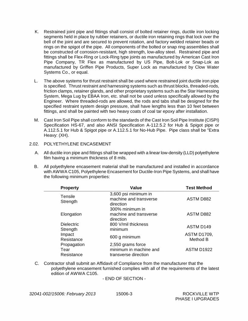
32041-002/15006: February 2013 15006-3 ROCKVILLE WTP PHASE I UPGRADES
K. Restrained joint pipe and fittings shall consist of bolted retainer rings, ductile iron locking segments held in place by rubber retainers, or ductile iron retaining rings that lock over the bell of the joint and are secured to prevent rotation, and factory welded retainer beads or rings on the spigot of the pipe. All components of the bolted or snap ring assemblies shall be constructed of corrosion-resistant, high strength, low-alloy steel. Restrained pipe and fittings shall be Flex-Ring or Lock-Ring type joints as manufactured by American Cast Iron Pipe Company, TR Flex as manufactured by US Pipe, Bolt-Lok or Snap-Lok as manufactured by Griffen Pipe Products, Super Lock as manufactured by Clow Water Systems Co., or equal.
L. The above systems for thrust restraint shall be used where restrained joint ductile iron pipe
is specified. Thrust restraint and harnessing systems such as thrust blocks, threaded-rods, friction clamps, retainer glands, and other proprietary systems such as the Star Harnessing System, Mega Lug by EBAA Iron, etc. shall not be used unless specifically allowed by the Engineer. Where threaded-rods are allowed, the rods and tabs shall be designed for the specified restraint system design pressure, shall have lengths less than 10 feet between fittings, and shall be painted with two heavy coats of coal tar epoxy after installation.
M. Cast Iron Soil Pipe shall conform to the standards of the Cast Iron Soil Pipe Institute (CISPI)
Specification HS-67, and also ANSI Specification A-112.5.2 for Hub & Spigot pipe or A.112.5.1 for Hub & Spigot pipe or A.112.5.1 for No-Hub Pipe. Pipe class shall be "Extra Heavy: (XH).
2.02. POLYETHYLENE ENCASEMENT
A. All ductile iron pipe and fittings shall be wrapped with a linear low-density (LLD) polyethylene
film having a minimum thickness of 8 mils. B. All polyethylene encasement material shall be manufactured and installed in accordance
with AWWA C105, Polyethylene Encasement for Ductile-Iron Pipe Systems, and shall have the following minimum properties:
Property Value Test Method
Tensile Strength
3,600 psi minimum in machine and transverse direction
ASTM D882
Elongation 300% minimum in machine and transverse direction
ASTM D882
Dielectric Strength
800 V/mil thickness minimum ASTM D149
Impact Resistance 600 g minimum ASTM D1709,
Method B Propagation Tear Resistance
2,550 grams force minimum in machine and transverse direction
ASTM D1922
C. Contractor shall submit an Affidavit of Compliance from the manufacturer that the
polyethylene encasement furnished complies with all of the requirements of the latest edition of AWWA C105.
- END OF SECTION -

THIS PAGE LEFT INTENTIONALLY BLANK

32041-002\15008: February 2013 15008-1 ROCKVILLE WTP PHASE I UPGRADES
SECTION 15008
PVC/CPVC PIPE PART 1 -- GENERAL 1.01 THE REQUIREMENT
A. Reference Section 15000 – Basic Mechanical Requirements. PART 2 -- PRODUCTS 2.01 POLYVINYL CHLORIDE (PVC) PIPE AND FITTINGS
A. PVC pipe and fittings shall be manufactured in accordance with ASTM D 1785, D 1784 and F 441, "normal impact" pipe, Schedule 40 or 80 as specified.
B. Fittings used with this pipe shall be socket type or flanged type as specified herein, in
Section 15390 - Schedules, or indicated on the Drawings. Plastic piping shall be installed in full accordance with the manufacturer's recommendations for the specific installation. No field bending or distortion of the pipe will be permitted.
C. PVC pipe shall be Type 1 Grade 1 conforming to ASTM D 1784 and D 1785. Fittings
shall conform to the following standard specifications:
Socket Type (Schedule 40); ASTM D 2466 Socket Type (Schedule 80); ASTM D 2467
D. Provide flanged fittings of the same material as the specified pipe and material
conforming to ANSI B16.5 at all valves and equipment with Teflon filled or natural rubber gaskets. Bolts shall be Type 316 stainless steel for flanged joints. Flanges are not required at true (double) union valves.
E. Solvent cement for socket type joints shall conform to ASTM D 2564 for PVC pipe and
fittings. F. C900-Class 200 shall be in sizes between 4 inches and 12 inches and shall meet the
requirements of AWWA C900 "Poly Vinyl Chloride (PVC) Pressure Pipe" and shall conform to all the requirements of ASTM D1784 and ASTM D2241. The pipe shall be a minimum of DR 14 and shall be capable of withstanding the overburden pressures determined by the depth of burial in the field.
1. Pipe material shall be made from clean, virgin, NSF approved Class 12454-A
PVC compound conforming to resin specification ASTM D1784. Standard laying lengths shall be 20-feet (±1 inch). Random lengths of not more than 15% of the total footage of each size may be shipped in lieu of the standard lengths. Reruns of reclaimed material shall not be accepted.

32041-002\15008: February 2013 15008-2 ROCKVILLE WTP PHASE I UPGRADES
2. The pipe shall have bell and spigot ends with push-on, O-ring rubber gasket, compression type joints conforming to the requirements of ASTM 2672. Elastomeric gaskets shall conform to the requirements of ASTM D1869 and ASTM F477.
3. Minimum pipe stiffness (F/dY) at 5% deflection shall be 914 psi for all sizes when tested in accordance with D2241.
4. The pipe shall be designed to pass a quick burst test pressure of 985 psi applied in 60 to 70 seconds when tested in accordance with ASTM D1599, as referenced in ASTM D2241.
5. Fittings for C900-Class 200, DR 14 shall be ductile iron, bolted mechanical joint.
G. C900-Class 150 shall be in sizes between 4 inches and 12 inches and shall meet the requirements of AWWA C900 "Poly Vinyl Chlorine (PVC) Pressure Pipe" and shall conform to all the requirements of ASTM D1784 and ASTM D2241. The pipe shall be a minimum of DR 18 and shall be capable of withstanding the overburden pressures determined by the depth of burial in the field.
1. Pipe material shall be made from clean, virgin, NSF approved Class 12454-A
PVC compound conforming to resin specification ASTM D1784. Standard laying lengths shall be 20-feet (±1 inch). Random lengths of not more than 15% of the total footage of each size may be shipped in lieu of the standard lengths. Reruns of reclaimed material shall not be accepted.
2. The pipe shall have bell and spigot ends with push-on, O-ring rubber gasket, compression type joints conforming to the requirements of ASTM 2677. Elastomeric gaskets shall conform to the requirements of ASTM D1869 and ASTM F477.
3. Minimum pipe stiffness (F/dY) at 5% deflection shall be 435 psi for all sizes when
tested in accordance with D2241.
4. The pipe shall be designed to pass a quick burst test pressure of 755 psi applied in 60 to 70 seconds when tested in accordance with ASTM D1599, as referenced in ASTM D2241.
5. Fittings for C900-Class 150, DR 18 shall be ductile iron, bolted mechanical joint.
H. PVC pressure rated pipe (PR 160) shall be in sizes between 1 1/2 inches and 12 inches and shall conform to all the requirements of ASTM D1784 and ASTM D2241 and shall be a minimum of SDR 26 and shall be capable of withstanding the overburden pressures determined by the depth of burial in the field.
1. Pipe material shall be made from clean, virgin, NSF approved Class 12454-A PVC compound conforming to resin specification ASTM D1784. Standard laying lengths shall be 20-feet (±1 inch). Random lengths of not more than 15% of the total footage of each size may be shipped in lieu of the standard lengths. Reruns of reclaimed materials shall not be accepted.
2. The pipe shall have bell and spigot ends with push-on, O-ring rubber gasket,

32041-002\15008: February 2013 15008-3 ROCKVILLE WTP PHASE I UPGRADES
compression type joints conforming to the requirements of ASTM 2672. Elastomeric gaskets shall conform to the requirements of ASTM D1869 and ASTM F477.
3. Minimum pipe stiffness (F/dY) at 5% deflection shall be 135 psi for all sizes when tested in accordance with ASTM D2241.
4. The pipe shall be designed to pass a quick burst test pressure of 500 psi applied
in 60 to 70 seconds when tested in accordance with ASTM D1599, as referenced in ASTM D2241.
5. The pipe shall be designed to pass for 1000 hours a sustained test pressure of
340 psi when tested in accordance with ASTM D1598, as referenced in ASTM D2241.
I. Fittings for PR 160, SDR 26 shall be PVC and designed for the pipe being supplied. J. Acrylonitrile-butadiene-styrene (ABS) shall conform to the requirements of ASTM D
2661. Pipe and fittings shall have socket type couplings with solvent cement joints. Solvent cement shall conform to ASTM D 2235.
K. Type PSM polyvinyl chloride (PVC) pipe and fittings shall conform to the requirements of
ASTM D 3034 with a maximum SDR of 35. Pipe and fittings shall have bell and spigot ends with O-ring rubber gasketed, compression type joints. Joints shall conform to the requirements of ASTM Specification D 3212. Reruns of reclaimed materials shall not be accepted. Unless indicated otherwise, PVC wall pipes shall be provided for all piping passing through exterior walls. Wall pipes shall have a water stop solvent-welded to the pipe. Each wall pipe shall be of the same class and type as the piping to which it is joined.
L. Perforated and closed drainage pipe and fittings shall be rigid PVC pipe, Schedule 40
unless otherwise shown or specified with solvent welded type joints, or approved equal. Pipe shall be slotted or have two rows of 1/4-inch diameter holes spaced 4-inches apart along the circumference of the pipe. Longitudinal spacing of holes shall be 5-inches maximum.
2.02 CHLORINATED POLYVINYL CHLORIDE (CPVC) PIPE AND FITTINGS
A. CPVC shall be manufactured in accordance with ASTM D 1785, D 1784 and F 441, "normal impact" pipe, Schedule 40 or 80 as specified.
B. Fittings used with this pipe shall be socket type or flanged type as specified herein or
indicated on the Drawings. Plastic piping shall be installed in full accordance with the manufacturer's recommendations for the specific installation. No field bending or distortion of the pipe will be permitted.
C. CPVC pipe shall be Type 4, Grade 1, Schedule 80, conforming to ASTM D 1784 and
ASTM F 441. CPVC fittings shall be socket type conforming to ASTM F 439. D. Solvent cement for socket type joints shall conform to ASTM F 493 for CPVC pipe and
fittings.

32041-002\15008: February 2013 15008-4 ROCKVILLE WTP PHASE I UPGRADES
PART 3 -- EXECUTION
(NOT USED)
- END OF SECTION -

32041-002/15010: February 2013 15010-1 ROCKVILLE WTP PHASE I UPGRADES
SECTION 15010
COPPER PIPE PART 1 -- GENERAL 1.01 THE REQUIREMENT
A. Reference Section 15000, Basic Mechanical Requirements. PART 2 -- PRODUCTS 2.01 TYPE L COPPER PIPE AND FITTINGS
A. Type L copper piping shall be seamless, hard drawn and shall conform to ASTM B 88. Solder fittings shall be wrought copper conforming to ANSI B.16.22 or cast brass conforming to ANSI B.16.18 95/5. All exposed copper pipe and fittings shall be Type L.
2.02 SOLDER
A. Solder shall consist of 95 percent tin and 5 percent antimony. Silver solder shall consist of 15 percent silver, 80 percent copper, and 5 percent phosphorous in accordance with ASTM B260-62T. Soldering shall be in conformance with Section 3 of the C.A.B.R.A. Copper Tube Handbook.
2.03 SOFT COPPER TUBING
A. Soft copper tubing in all sizes, shall conform to the appropriate ASTM Specifications; and fittings used with this tubing shall be compression or flare type, as manufactured by Swagelock, or equal.
PART 3 -- EXECUTION
(NOT USED)
- END OF SECTION -

THIS PAGE LEFT INTENTIONALLY BLANK

32041-006\15012: February 2013 15012-1 ROCKVILLE WTP PHASE I UPGRADES
SECTION 15012
STEEL PIPE PART 1 -- GENERAL 1.01 THE REQUIREMENT
A. Steel pipe and fittings shall conform to AWWA C200 for nominal pipe sizes 6-inches and larger. Steel pipe shall be new and shall meet or exceed the manufacturer and material requirements of ASTM A53, Grade B or ASTM A139, Grade B.
B. The AWWA Specifications referenced in this section are supplemented as follows:
1. An affidavit of compliance is required from the pipe manufacturer.
2. The steel manufacturer's certification that the material meets the ASTM
Specification will be accepted in lieu of tests on specimens taken from the fabricated pipe.
3. The fabricator may purchase steel plates on the chemical basis only, and shall
furnish to the Owner certified test reports.
4. Joints shall be flanged unless otherwise indicated on the Drawings.
C. All parts of the materials furnished shall be amply designed, manufactured and constructed for the maximum stresses occurring during fabrication and erection. All materials shall be new and both workmanship and materials shall be of the very best quality, entirely suitable for the service to which they will be subjected and shall conform to all applicable sections of these Specifications. Manufacturer's designs shall accommodate all the requirements of these Specifications.
D. The Contractor shall be responsible for the structural design of the steel pipe. The
Contractor shall submit certification that the steel pipe has been designed to resist all loads implied and reasonably anticipated.
E. Reference Section 15000 – Basic Mechanical Requirements.
PART 2 -- PRODUCTS 2. 01 EXTERIOR STEEL PIPE AND FITTINGS (PROCESS AIR AND WATER)
A. Exterior steel pipe shall be fabricated by either the spiral weld or single longitudinal seam method and shall be rated for at least 25 psig and 250°F. Steel pipe shall be fabricated by either the spiral weld or single longitudinal seam method with a minimum yield strength of 35,000 psi. Design stress in the pipe wall at the design pressure shall not exceed 50 percent of the minimum yield strength of the steel.

32041-006\15012: February 2013 15012-2 ROCKVILLE WTP PHASE I UPGRADES
B. Fittings shall be fabricated from the pipe specified and shall conform to AWWA C208, Table 1 (Figure 1). Fittings provided for the purpose of transition to other types of piping shall be in accordance with the applicable portions of AWWA C207 and AWWA C208, unless otherwise shown on the Drawings.
C. Flanges shall be AWWA C207, Standard hub type, slip-on welding flanges, Class B,
unless otherwise required for connection to equipment. Bolts shall be of the size and length called for and in accordance with the "American Standard" and comply with the requirements of the ANSI/AWWA Standards. The bolt for flanged joints shall be a minimum ASTM A307; Grade B carbon steel and be in accordance with ANSI A21.10, (AWWA C110). The bolts shall have hexagonal heads and nuts, no washers shall be used. All gaskets shall be the "Ring-Gasket type, 1/8-inch minimum thickness of material suitable for 250°F continuous service at 25 psig.
D. Welded field connections shall be of the single "V" butt joint type in accordance with
AWWA C206. Welded connections shall not be permitted where such connections would interfere with the removal of valves or equipment or create sections of pipe too large for removal from structures. All field welds shall be radiographically inspected when field welding is permitted.
E. The minimum wall thickness for exterior steel pipe shall be .250-inch for pipe up to 30-
inch diameter and .375-inch for larger than 30-inch diameter.
F. Interior and exterior coatings for exterior steel pipe and fittings shall be as specified in this Section, paragraph 2.03.
2.02 INTERIOR STEEL PIPE AND FITTINGS (PROCESS AIR AND WATER)
A. Steel pipe shall be fabricated by either the spiral weld or single longitudinal seam method with a minimum yield strength of 35,000 psi. Design stress in the pipe wall at the design pressure shall not exceed 50 percent of the minimum yield strength of the steel.
B. Steel pipe shall be manufactured to the nominal pipe sizes listed and shall have the
following minimum wall thicknesses:
Nominal Pipe Size Minimum Sheet or Plate Thickness, inches
Process Air 100 psi Design
Pressure 300 psi Design
Pressure 6 or less 0.125 0.125 0.125 8-14
0.134
0.134
0.134
16
0.134
0.134
0.188 18
0.188
0.188
0.188
20-24
0.250
0.250
0.250 30
0.250
0.250
0.281
36
0.250
0.250
0.344 42
0.250
0.250
0.375
48-54
0.250
0.250
0.500 60-66
0.312
0.312
0.625

32041-006\15012: February 2013 15012-3 ROCKVILLE WTP PHASE I UPGRADES
72-84 0.375 0.375 0.750 90
0.375
0.375
0.8125
C. Fittings shall be fabricated from the pipe specified and shall conform to AWWA C208, Table 1 (Figure 1). Fittings provided for the purpose of transition to other types of piping shall be in accordance with the applicable portions of AWWA C207 and AWWA C208, unless otherwise shown on the Drawings.
D. Flanges shall be AWWA C207, standard hub type slip-on welding flanges, in accordance
with the following table, unless otherwise required for connection to equipment:
Design Pressure Flange Class 86 psi or less (All sizes) B 87 - 149 psi (4 - 12 inch) D 87 - 175 psi (14 inch and larger) D 150 - 275 psi E 276 - 300 psi F
E. All gaskets shall be the "Ring-Gasket" type, 1/8-inch minimum thickness. Bolts shall be
of the size and length called for and in accordance with the "American Standard" and comply with the requirements of the ANSI/AWWA Standards. The bolts for flanged joints shall be a minimum ASTM A307; Grade B, hot-dip galvanized carbon steel in accordance with ANSI A21.10 (AWWA C1110) unless otherwise specified. The bolts shall have hexagonal heads and nuts, no washers shall be used.
F. The piping layout shown on the Drawings is based upon standard fittings available in
ductile iron pipe in the case of water piping and typical fittings available in steel piping for process air. In some instances, flange joints shown may not be required for steel pipe. Welded joints may be substituted for flange joints subject to approval by the Engineer. Welded joints will not be acceptable where such joints would interfere with the removal of valves or equipment or create sections of piping too large for removal from structures as determined by the Engineer.
G. Harnessed flexible couplings may also be used in lieu of flanges at locations approved
by the Engineer. Lugs shall be welded to the pipe in accordance with the requirements of AWWA Manual M11 for Steel pipe where required for harnessing of flexible couplings.
H. Welded field connections shall be of the single "V" butt joint type in accordance with
AWWA C206. Welded connections shall not be permitted where such connections would interfere with the removal of valves or equipment or create sections of pipe too large for removal from structures. All field welds shall be radiographically inspected when field welding is permitted.
I. Interior and exterior coatings for interior steel pipe and fittings shall be as specified in
this Section, paragraph 2.03. 2.03 STEEL PIPE COATINGS

32041-006\15012: February 2013 15012-4 ROCKVILLE WTP PHASE I UPGRADES
A. Exterior and interior coatings for steel pipe and fittings used for water piping shall be as follows:
Type of Service Exterior Coating Interior Coating
Water Shop Prime per Section 09900 – Painting
Cement Mortar AWWA C 205
B. Exterior and interior coatings for steel pipe and fittings used for process air piping shall
be as follows:
1. The steel pipe coatings and lining specified herein apply to all exposed and buried steel process air piping. Steel pipe shall have an interior lining and exterior coating for exposed or buried service as specified. Painting shall be in accordance with Section 09900 – Painting. Inspection of surface preparation and coating application is required in accordance with Section 09900 – Painting.
2. The interior of all steel pipe for process air service shall receive 3 mils (dry) of
inorganic zinc primer service rated for 250°F (dry) and 100°F (wet) continuous which shall be Carbo Zinc 11 as manufactured by Carboline or equal. After the lining has cured, it shall be thoroughly washed with high pressure water to remove all detachable particles.
3. Areas of pipe to be welded shall receive 1 mil (dry) of weldable inorganic zinc
primer such as Carbo Weld 11, as manufactured by Carboline, or equal.
4. Interior steel pipe and fittings:
a. The exterior of all interior steel pipe and fittings shall receive the same prime coat as that specified for the interior except for areas of pipe to be field welded. After welding and pressure and leakage testing are completed, welded joints shall be thoroughly cleaned of all foreign matter and any scale or rust and primed as specified for the pipe. Finish coat and wrap shall be applied to each joint as specified for the pipe for continuous coating and wrapping of all steel piping.
b. Final touch up of inorganic zinc primer shall be with a modified aluminum
epoxy mastic such as Carbomastic 15 as manufactured by Carboline, or equal.
c. Shop coatings and field touch-ups shall be electrically inspected by the
use of a holiday detector in accordance with AWWA C209 and Division 09900 - Painting.
5. Exterior steel pipe and fittings:
The exterior of all exposed steel pipe and fittings shall receive the same prime coat as that specified for interior steel pipe and fittings.

32041-006\15012: February 2013 15012-5 ROCKVILLE WTP PHASE I UPGRADES
a. The exterior of all buried steel pipe and fittings shall receive a prime coat per the exterior tape system manufacturer's recommendations, except for areas of pipe to be field welded.
b. The exterior of buried steel pipe shall receive, over the prime coat, a
multi-layered, cold-applied tape wrap system which shall be shop applied and consist of a rubber and synthetic resin primer, one (20 mils) layer of inner wrapping and two (30 mils each) layer of outer wrap for a total system build in excess of 80 mils. The cold applied type wrap shall operate satisfactorily at a temperature of 250°F. The wrap shall be applied in accordance with AWWA C214 and as specified herein. Windings shall be spiral wrapped with at least 1" of overlap. All fittings shall be wrapped in accordance with AWWA C209. Successive layers shall be applied such that windings are staggered and overlay the midpoints of previous tape widths. Polyethylene backed coatings shall be protected from sunlight at all times. The wrapping shall terminate 6" from field weld sites. The tape wrap system shall be the YG III system as manufactured by the Polyken Division of Kendall Co., Boston MA, or equal.
c. The exterior of exposed exterior steel pipe and fittings shall receive, over
the inorganic zinc prime coat, 3 mils of modified acrylic latex service rated for 300°F (continuous) which shall be Carboline 3359 as manufactured by Carboline or equal, and 1-1/2 mil top coat of modified acrylic, service rated for 300°F (continuous), which shall be Carboline 4685 as manufactured by Carboline, or equal.
d. After welding and pressure and leakage testing are completed, welded
joints shall be thoroughly cleaned of all foreign matter and any scale or rust and primed as specified for the pipe. Finish coat and wrap shall be applied to each joint as specified for the pipe for continuous coating and wrapping of all steel piping.
e. Final touch up of inorganic zinc primer shall be with a modified aluminum
epoxy mastic such as Carbomastic 15 as manufactured by Carboline, or equal.
f. Shop coatings and field touch-ups shall be electrically inspected by the
use of a holiday detector in accordance with AWWA C209 and Section 09900 – Painting.
2.04 STAINLESS STEEL PIPE AND FITTINGS (PROCESS AIR AND WATER)
A. Stainless steel piping for air piping of nominal sizes ranging from three (3) inches to sixty (60) inches shall be manufactured from ASTM A240 annealed and pickled sheets and plates and fabricated in accordance with ASTM A778 in Type 304L stainless steel. Only stainless steel pipe shall be provided; tubing shall not be allowed. Stainless steel pipe, at a minimum, shall be service rated for 250°F at 25 psig. Stainless steel pipe shall be as manufactured by Douglas Brothers, Felker Bros. Corp., or equal.
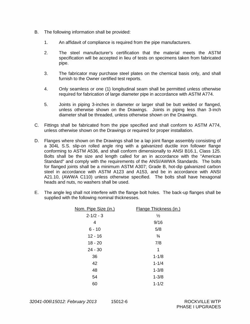
32041-006\15012: February 2013 15012-6 ROCKVILLE WTP PHASE I UPGRADES
B. The following information shall be provided:
1. An affidavit of compliance is required from the pipe manufacturers.
2. The steel manufacturer's certification that the material meets the ASTM specification will be accepted in lieu of tests on specimens taken from fabricated pipe.
3. The fabricator may purchase steel plates on the chemical basis only, and shall
furnish to the Owner certified test reports.
4. Only seamless or one (1) longitudinal seam shall be permitted unless otherwise required for fabrication of large diameter pipe in accordance with ASTM A774.
5. Joints in piping 3-inches in diameter or larger shall be butt welded or flanged,
unless otherwise shown on the Drawings. Joints in piping less than 3-inch diameter shall be threaded, unless otherwise shown on the Drawings.
C. Fittings shall be fabricated from the pipe specified and shall conform to ASTM A774,
unless otherwise shown on the Drawings or required for proper installation.
D. Flanges where shown on the Drawings shall be a lap joint flange assembly consisting of a 304L S.S. slip-on rolled angle ring with a galvanized ductile iron follower flange conforming to ASTM A536, and shall conform dimensionally to ANSI B16.1, Class 125. Bolts shall be the size and length called for an in accordance with the "American Standard" and comply with the requirements of the ANSI/AWWA Standards. The bolts for flanged joints shall be a minimum ASTM A307; Grade B, hot-dip galvanized carbon steel in accordance with ASTM A123 and A153, and be in accordance with ANSI A21.10, (AWWA C110) unless otherwise specified. The bolts shall have hexagonal heads and nuts, no washers shall be used.
E. The angle leg shall not interfere with the flange bolt holes. The back-up flanges shall be
supplied with the following nominal thicknesses.
Nom. Pipe Size (in.) Flange Thickness (in.) 2-1/2 - 3 ½
4 9/16 6 - 10 5/8
12 - 16 ¾ 18 - 20 7/8 24 - 30 1
36 1-1/8 42 1-1/4 48 1-3/8 54 1-3/8 60 1-1/2

32041-006\15012: February 2013 15012-7 ROCKVILLE WTP PHASE I UPGRADES
F. Gaskets for water piping shall be "Ring Gasket" type, 1/8-inch minimum thickness, cloth inserted rubber, red rubber or neoprene and shall be suited for the service intended. For process air, all gaskets shall be 1/8-inch minimum thickness and shall be of a material suitable for 250°F continuous service at 25 psig. Dielectric gasket material service rated for 225°F continuous service at 25 psig shall be provided at all transitions to material other than mild steel.
G. Welding practices for joints shall conform to those specified for the manufacture of the
pipe and fittings in ASTM A774 and A778, and the specifications contained herein. All welds shall be free from burrs, snags or rough projections.
H. Welding shall be performed by AWS certified welders in conformance with standard
procedures. Piping with wall thickness up to 11 gauge (0.125") shall be welded with the TIG (GTAW) process. Heavier walls shall be properly beveled and have a root pass with the TIG (GTAW) process followed by subsequent passes with the TIG (GTAW), MIG (GMAW), or Metallic Arc (SMAW) process. Filler wire of ELC grades only shall be added to all welds to provide a cross section at the weld equal to or greater than the parent metal. Weld deposit shall be greater than the parent metal. Weld deposit shall be smooth and evenly distributed and have a crown of no more than 1/16 inch on the I.D. and 3/32 inch on the O.D. of the piping or fittings. Concavity, undercut, cracks or crevices shall not be allowed. Butt-welds shall have full penetration to the interior surface, and inert gas shielding shall be provided to the interior and exterior of the joint. Excessive weld deposits, slag, spatter and projections shall be removed by grinding. Angle face rings shall be continuously welded on both sides to the pipe or fitting. Welds on gasket surfaces shall be ground smooth.
I. After welding, all welded joints shall be treated with a pickling solution, brushed with
stainless wire brushes and rinsed clean.
J. All fittings shall be welded with 304L filler metal. All elbows through 24 inch size shall be long radius, die formed and shall be automatically butt welded in accordance with ASTM A774 of the same material and thickness as the pipe, using gas tungsten-arc procedures with inert gas backing. Tees, crosses, true Y's and laterals shall be shop fabricated. All short radius, special radius, and reducing elbows and long radius elbows greater than 24 inch shall be mitered construction with at least (5) miter sections for 90 degree bends, (3) mitered sections for 45 and 60 degree bends, and (2) mitered sections for 30 degree and smaller bends. All reducers shall be straight tapered, cone type. Longitudinal welds on all fittings, except elbows, shall be accomplished by the same procedures as listed for pipe. Weld seams shall have full penetration and be free of oxidation, crevices, pits, cracks and protrusions. Fitting dimensions shall be in accordance with ANSI B16.9, and shall be terminated and dimensioned as indicated on the Drawings.
K. Pipe spools shall be manually welded with 304L filler metal, using gas tungsten-arc
procedures with internal gas purge where internal weld seams are not accessible. Where they are accessible, seams shall be welded both inside and outside, using manual shielded metal-arc procedures. Weld seams shall have full penetration and be free of oxidation, crevices, pits, cracks and protrusions.
L. All pipe, fittings and spools shall be completely pickled and passivated by immersion in a
nitric-hydrofluoric bath at the proper temperature and length of time to insure removal of

32041-006\15012: February 2013 15012-8 ROCKVILLE WTP PHASE I UPGRADES
all free iron, weld scale and other impurities and to insure the establishment of a passive surface. A clean water rinse shall follow the acid pickle.
M. The field testing procedure for process air piping shall use air pressure only. Hydrostatic
testing shall be utilized on all other stainless steel piping.
N. The inspection of all welds shall be required. This shall be a visual inspection for crevices, pits, cracks, protrusions and oxidation deposits. Presence of any of these items found in the weld seams shall be considered as grounds for rejection of the joint.
O. All fabricated piping shall have openings plugged and flanges secured for storage and/or
transport after fabrication. All fabricated piping shall be piece marked with identifying numbers or codes which correspond to the Contractor's layout and installation drawings. The marks shall be located on the spools at opposite ends and 180 degrees apart.
P. The piping supplier during manufacturing, fabrication and handling stages, and the
Contractor during handling and installation stages, shall use extreme care to avoid the contact of any ferrous materials with the stainless steel piping. Only manufacturer recommended saws, drills, files, wire brushes, etc. shall be used for stainless steel piping. Pipe storage and fabrication racks shall be non-ferrous or stainless steel or rubber lined. Nylon slings or straps shall be used for handling stainless steel piping. Contact with ferrous items may cause rusting of iron particles embedded in the piping walls. After installation, the Contractor shall wash and rinse all foreign matter from the piping surface. If rusting of embedded iron occurs, the Contractor shall pickle the affected surface with Oakite Deoxidizer SS or equal, scrub with stainless steel brushes and rinse clean.
Q. FIELD WELDING OF STAINLESS STEEL WILL NOT BE PERMITTED.
R. Pipe shall be manufactured to nominal pipe sizes as listed in ANSI B36.19, Table 2, and
shall have the following minimum wall thicknesses:
Nominal Pipe Size Schedule/Gauge/Plate 8-inch diameter and smaller Schedule 5S (.083 inches) 10-inch and 12-inch diameters 12 gauge (.109 inches) 14-inch thru 18-inch diameters 11 gauge (.125 inches) 20-inch diameter 10 gauge (.140 inches) 24-inch thru 36-inch diameters 3/16-inch (.187 inches) 42-inch and 48-inch diameters 1/4-inch (.250 inches) 54-inch and 60-inch diameters 5/16-inch (.312 inches)
S. All parts of the materials furnished shall be amply designed, manufactured and
constructed for the maximum stresses occurring during fabrication and erection. All materials shall be new and both workmanship and materials shall be of the very best quality, entirely suitable for the service to which they will be subjected and shall conform to all applicable sections of these Specifications. Manufacturer's designs shall accommodate all the requirements of these Specifications.

32041-006\15012: February 2013 15012-9 ROCKVILLE WTP PHASE I UPGRADES
T. The Contractor shall be responsible for the structural design of the stainless steel pipe. The Contractor shall submit certification that the stainless steel pipe has been designed to resist all loads implied and reasonably anticipated.
2.05 MISCELLANEOUS STEEL PIPE AND FITTINGS
A. Other steel pipe and fittings not specified elsewhere shall conform to ASTM A120, black or galvanized, as directed by the Engineer, seamless, Schedule 40 or 80 as indicated in the appropriate Piping System Schedule in Section 15390, Schedules.
B. Unless otherwise shown or required, all piping and fitting shall be threaded. Fittings
shall conform to ANSI B16.3, 300 pound class and shall be of the black malleable iron screw type. All threaded joints shall be made tight with an oil and graphite paste or teflon thread tape applied to the male threads only. All pipe 1-1/2 inches and smaller shall be reamed to removed scale and dirt. Pipe to be galvanized shall have a deep galvanized coating applied in full accordance with ASTM A123.
2.06 PROCESS AIR PIPE SUPPORT AND EXPANSION/
CONTRACTION SYSTEM
A. The process air pipe support and expansion/contraction system shall include fixed supports, sliding supports, Split Sleeve Type expansion couplings for buried air piping, and Stainless Steel Bellows Type expansion couplings for exposed air piping as indicated on the Contract Drawings.
B. The pipe support and expansion/contraction system shall consist of expansion couplings
at the spacing and locations shown on the Contract Drawings with one fixed support between each pair of expansion couplings. Fixed support detail shall be as shown on the Contract Drawings. Additional supports shall be sliding supports as shown on the Contract Drawings and according to the support spacing requirements scheduled on the Contract Drawings. Sliding support details shall be as shown on the Contract Drawings and shall be in accordance with the requirements of 05830 – Bearing Devices.
C. Buried expansion couplings shall be Split Sleeve type. Expansion couplings shall be
Depend-O-Lok as manufactured by Victaulic Depend-O-Lok, Atlanta Georgia, or equal.
1. Expansion couplings shall be Type I FxE with a width of 10-inches allowing 1.5 inches of movement for pipe sizes ranging from 16-inches diameter to 20-inches diameter, a width of 10-inches allowing 1.75 inches of movement for pipe sizes ranging from 8-inches diameter to 14-inches diameter and a width of 7.5-inches of movement for a pipe size of 6-inches. Expansion couplings shall be Type 2 FxE with a width of 12-inches allowing 2.0 inches of movement for pipe sizes ranging from 24-inches diameter to 84-inches diameter.
2. Couplings shall be suitable for a pressure of 25 psig and a temperature of 300°F. 3. Couplings shall be bolted, split-sleeve type and shall consist of 4 components;
one-piece housing, gasket assembly, bolts and nuts, and end rings as required for pipe restraint.

32041-006\15012: February 2013 15012-10 ROCKVILLE WTP PHASE I UPGRADES
4. Coupling shall be manufactured from 304L stainless steel using 304 stainless steel bolts and nuts with a minimum tensile strength of 85,000 psi. End rings shall be 304L stainless steel. End rings shall be shop-welded to one end of one pipe installed in the coupling.
5. Buried couplings shall be protected by an encapsulation system that protects the
coupling from grit and debris that could damage the resilient seal while allowing movement of the pipe. Encapsulation system shall be as approved by or shall be furnished by the coupling manufacturer.
6. Couplings shall be provided as shown on the Contract Drawings.
D. Exposed expansion couplings shall be Stainless Steel Bellows Type expansion
couplings, Omniflex as manufactured by Victaulic Depend-O-Lok, Atlanta, GA, FMI Expansion Joints as manufactured by Flexible Meral, Inc., Tucker, GA, Safe-Flex as manufactured by Mid-Atlantic Technical Services, Annapolis, MD, DME Expansion Joints or equal as indicated on the Contract Drawings. 1. Expansion couplings shall be Long Metal Bellows type with fixed flanged end
preparations. The couplings shall provide for a minimum of 2 inches of axial movement for sizes 4-6 inches diameter, and a minimum of 3.5 inches of axial movement for all sizes 8 inches and above. Couplings shall provide for a minimum lateral movement of 0.50 inches for all sizes.
2. Couplings shall be suitable for a pressure of 25 psig and a temperature of 300°F. 3. Coupling and flanges shall be manufactured from 304L stainless steel using 304
stainless steel bolts and nuts with a minimum tensile strength of 85,000 psi. Coupling shall have an air service liner welded on the upstream side of the bellows.
E. Process air piping shall be supported by slide bearings as manufactured by Seismic
Energy Products, (903) 675-8571, ITT Grinnel Corp., Providence, Rhode Island, Con-Serv, Inc, (843) 546-1044, or equal.
F. The slide bearing material shall be 3/32 inch thick, 25 percent glass-fiber reinforced
structural grade teflon. The bearing material shall withstand at least 1000 psi (compression) at 210°F with a coefficient of friction between .05 and .08. The performance of bearing and bonding materials shall be unaffected by continual immersion in water at a temperature of 210°F.
G. The pipe shall be welded to a stainless steel cradle type pipe support with 120° arc
bearing centered on the bottom of the pipe. The pipe support shall be secured to the structural support with a stationary base plate provided with hold-down tabs to engage the base of the sliding support and prevent lateral movement or uplift, while allowing full movement in the longitudinal direction. The bearing material shall be hot press bonded to the bottom of each sliding pipe cradle base plate and the support surface below.
H. Fixed pipe support cradles shall be welded to the pipe and bolted to the structural
support or concrete with 316 stainless steel bolts.

32041-006\15012: February 2013 15012-11 ROCKVILLE WTP PHASE I UPGRADES
I. Wall bracket supports shall be used where shown for pipe to be installed adjacent to a
wall as indicated on the Contract Drawings. Where it is not feasible to install hanger supports, adjustable pipe saddle supports may be used with the permission of the Engineer. Concrete pier supports shall be spaced at a maximum distance of 10 feet and shall be at least one (1) foot square unless otherwise shown on the Drawings.
J. Sliding surfaces shall be protected from accumulation of dirt, grit, or other foreign matter. K. Slide bearings shall be capable of adequately supporting the design loads and shall be
attached to pipe and supports as specified and recommended by the manufacturer. L. The slide bearings shall be installed in the locations shown or indicted on the Drawings,
at required elevations, true to orientation and level, assuring that the correct half of each bearing is in its proper position. The Contractor shall store the bearings to protect them from mechanical damage prior to installation, and shall protect the same during and after installation from contamination and damage due to placing of concrete and other materials. The Contractor shall clean the operating surfaces of bearings thoroughly before final assembly.
M. At least one coupling shall be provided between two fixed supports.
PART 3 -- EXECUTION
(NOT USED)
- END OF SECTION -

THIS PAGE INTENTIONALLY LEFT BLANK

32041-002/15020: February 2013 15020-1 ROCKVILLE WTP PHASE I UPGRADES
SECTION 15020
PIPE SUPPORTS PART 1 -- GENERAL 1.01 THE REQUIREMENT
A. Reference Division 5, Metals. B. Reference Section 15000 – Basic Mechanical Requirements. C. Piping support systems shall be designed in accordance with the requirements of the
most current Building Code for the State of Maryland for earthquake design requirements in conjunction with the seismic provisions of the International Building Code (IBC) 2009 and referenced ASCE/SEI 7-05 for earthquake loadings. Refer to paragraph 1.04.A of Section 15000 for more specific requirements.
1.02 SUBMITTALS A. The following items shall be submitted with the Shop Drawings in accordance with, or in
addition to the submittal requirements specified in Section 01300, Submittals; and Section 15000, Basic Mechanical Requirements:
1. Catalog cut information on all system components such as pipe supports,
hangers, guides, anchors, and channel-type supports. 2. Drawings of the piping support systems, locating each support, brace,
hanger, guide, component and anchor. Identify support, hanger, guide and anchor type by catalog number and Shop Drawing detail number.
3. With each piping support system Shop Drawing, the Contractor shall attach
calculations prepared and sealed by a Professional Engineer licensed in the State of Maryland showing that the piping support system complies with the specified requirements.
4. Table showing the manufacturer’s recommended hanger support spacing for
PVC pipe for the services listed in Section 15390, Schedules. 1.03 QUALITY ASSURANCE
A. Piping support systems shall be designed and Shop Drawings prepared and sealed by a Professional Engineer licensed in the State of Maryland.
011805BR

32041-002/15020: February 2013 15020-2 ROCKVILLE WTP PHASE I UPGRADES
PART 2 -- PRODUCTS 2.01 GENERAL A. The Contractor shall be responsible for the design of all piping support systems. B. No attempt has been made to show all of the required pipe supports either on the
Drawings or in the details. The absence of pipe supports and details on any Drawings shall not relieve the Contractor of the responsibility of providing them throughout the project at no additional cost to the Owner.
C. Where special pipe support fabrications are required, products and execution shall be as
specified in Section 05500, Metal Fabrications. D. Existing piping support systems to support new piping shall only be used if the
Contractor can show that they are adequate for the additional load imposed by the new piping, or if they are strengthened to support the additional load.
E. Design Criteria for Piping Support Systems: 1. Design pipe supports for dead loads imposed by the weight of the pipes
filled with water, except for air and gas pipelines, plus the weight of insulation. 2. Design for the thermal expansion and contraction of the piping and its
associated pipe support and pipe expansion systems. 3. A minimum safety factor of 5, based upon the yield strength of the
support material, shall be used for pipe supports, braces, hangers, and guides as well as for beam and column members used in channel-type support systems.
4. Unless otherwise noted herein or on the Drawings, the horizontal pipe
and hanger and/or floor support spacing shall be as recommended by the pipe manufacturer.
5. Vertical sway bracing shall be provided at maximum 10-foot centers. 6. The design, sizing and spacing of anchor bolts, including concrete
anchors, shall be based on withstanding shear and pullout loads imposed by loading at each particular support. The minimum anchor bolt size shall be ½ inches in diameter.
2.02 HANGERS AND SUPPORTS
A. All piping shall be adequately supported and braced by means of adequate hangers, concrete piers, pipe supports, brackets, or otherwise as may be required by the location. Generally, concrete supports shall be used where pipe centerline is less than 3 feet above floor, and hangers above 6 feet unless specified or shown otherwise. Between 3 ft and 6 ft above finished floor, the Contractor may use a combination of concrete piers and fabricated pipe support assemblies. Supports shall be not more than 10 feet on center for steel and cast iron, feet on center for plastic unless otherwise shown on the Drawings or required by the specific manufacturer. All necessary inserts or appurtenances shall be furnished and installed in the concrete or structures for

32041-002/15020: February 2013 15020-3 ROCKVILLE WTP PHASE I UPGRADES
adequately securing hangers and supports to the structure.
B. If the Contractor chooses to custom fabricate the pipe supports, then the fabricated pipe supports shall be of the same materials of construction and configuration, and shall meet or exceed the general specification requirements, of the prefabricated products. Contractor-fabricated piping support systems shall be designed by a Professional Engineer licensed in the State of Maryland. Each Contractor-fabricated pipe support shall be submitted for review, and each Contractor-fabricated support submittal shall be sealed by the Professional Engineer.
C. Hangers and supports shall conform to the following requirements:
1. All hangers and supports shall be capable of adjustment after installation. Types
of hangers and supports shall be kept to a minimum. 2. Hanger rods shall be straight and vertical. Chain, wire, strap, or perforated bar
hangers shall not be used. Hangers shall not be suspended from other piping. 3. Vertical piping shall be supported at each floor and between floors by stays or
braces to prevent rattling and vibration. 4. Supports and hangers for plastic piping shall include wide saddles or bands as
recommended by the manufacturer and approved by the Engineer to distribute load and thus avoid localized deformation of the pipe.
5. Hanger and supports shall prevent contact between dissimilar metals by use of
copper plated, rubber, vinyl coated or stainless steel hangers. 6. Ferrous pipes to be painted shall be painted in accordance with Section 09900 –
Painting. Ferrous pipes that do not require painting shall be supported by galvanized hangers and supports.
7. Copper piping shall be supported by plastic coated or copper plated steel
hangers and supports. 8. Plastic piping shall be supported by 316 stainless steel or FRP hangars and
supports as approved by the Engineer. Plastic coated steel shall not be permitted.
9. Hangers and supports shall provide for thermal expansion throughout the full
operating temperature range. 10. Expansion type anchors used for pipe hangers and supports shall be Type 304
stainless steel.
D. All metallic hangers and supports shall be standard make by Anvil International, Inc., "Witch" by Carpenter & Paterson, Ltd., B-Line Systems, Inc., or equal; and data on the types and sizes to be used shall be furnished to the Engineer for approval. Metallic support system brackets, rods, support clips, clevis hangers, hardware, etc. shall be cast iron or welded steel construction.

32041-002/15020: February 2013 15020-4 ROCKVILLE WTP PHASE I UPGRADES
E. Non-metallic support system shall be a heavy duty channel framing system. Channel frames shall be manufactured by the pultrusion process using corrosion grade polyester or vinylester resins. All fiberglass construction shall include suitable ultraviolet inhibitors for UV exposure and shall have a flame spread rating of 25 or less per ASTM E84. Piping accessories, pipe clamps, clevis hangers, support posts, support racks, fasteners, etc., shall be constructed of vinylester or polyurethane resin. Non-metallic support systems shall be standard make Aickinstrut by Aickinstrut, Inc., Unistrut Fiberglass by Unistrut, Inc., Enduro Fiberglass Systems, or equal. The Contractor shall submit data on the types and sizes of approval. Unless otherwise shown or specified the Contractor shall provide support spacings in the conformance with the pipe and support system manufacturer's requirements.
2.03 PROCESS AIR PIPE SUPPORTS
A. Process air shall be supported by slide bearings as manufactured by Fluorocarbon Company, Anaheim, California, Anvil International, Inc., Portsmouth, New Hampshire, or equal.
B. The slide bearing material shall be 3/32 inch thick, 25 percent glass-fiber reinforced
structural grade teflon. The bearing material shall withstand at least 1000 psi (compression) at 210°F with a coefficient of friction between 0.05 and 0.08. The performance of bearing and bonding materials shall be unaffected by continual immersion in water at a temperature of 210°F.
C. Non-submerged slide bearing type supports shall be provided with a bearing material
covering a 120° arc centered at the bottom of the pipe. The teflon shall be at least 4 inches wide at the underside of the pipe and 8 inches wide at the top of the support. The teflon material shall be hot press bonded to 10 ga. stainless steel plates for welding to the bottom of the pipe and securing to the top of the support.
D. Submerged slide bearing type supports shall be provided with teflon bonded to the
underside of the hold down strap and the top of the pipe such that the sliding surface is formed between two sheets of teflon. Each surface shall cover a 120° arc centered at the top of the pipe. On the underside of the strap the teflon bearing shall be hot press bonded directly to the stainless steel strap or to a 10 ga. stainless steel plate for welding to the strap. At the top of the pipe, the teflon shall be bonded to a 10 ga. stainless steel plate for welding to the pipe.
E. Pipe straps shall not tightly bind the pipe but shall provide 3/32 inch clearance over the top 180° of the pipe surface.
F. Wall bracket supports shall be used where shown for pipe to be installed adjacent to a
wall. Where it is not feasible to install hanger supports, adjustable pipe saddle supports may be used with the permission of the Engineer. Concrete pier supports shall be spaced at a maximum distance of 10 feet and shall be at least one (1) foot square unless otherwise shown on the Drawings.
G. Small diameter piping (6-inches in diameter or less) shall not be strapped or otherwise
secured directly to walls. Suitable wall offset brackets of an approved type shall be used. Anchors shall not be attached using percussion fasteners.
32041-002/15020: February 2013 15020-5 ROCKVILLE WTP PHASE I UPGRADES
H. Sliding surfaces shall be protected from accumulation of dirt, grit, or other foreign matter. I. Slide bearings shall be capable of adequately supporting the design loads and shall be
attached to pipe and supports as specified and recommended by the manufacturer. J. The slide bearings shall be installed in the locations shown or indicated on the Drawings,
at required elevations, true to orientation and level, assuring that the correct half of each bearing is in its proper position. The Contractor shall store the bearings to protect them from mechanical damage prior to installation, and shall protect the same during and after installation from contamination and damage due to placing of concrete and other materials. The Contractor shall clean the operating surfaces of bearings thoroughly before final assembly.
K. The Contractor shall note that all pipe support locations are not shown on the Drawings,
and shall follow the Specifications herein in locating supports. Where deviations and modifications are required, they shall be made only with the permission of the Engineer. A detailed layout of pipe supports and hangers shall be submitted for approval.
PART 3 -- EXECUTION 3.01 GENERAL INSTALLATION REQUIREMENTS
A. Support large or heavy valves, fittings, flow meters and appurtenances independently of the connected piping.
B. Support piping connections to equipment by pipe support and not by the equipment.
C. Support no pipe from the pipe above it.
D. Support piping at changes in direction or in elevation, adjacent to flexible joints, expansion joints, and couplings, and where shown.
E. Do not install piping supports and hangers in equipment access areas or bridge crane
runs.
F. Brace hanging pipes against horizontal movement by both longitudinal and lateral sway bracing.
G. Install pipe anchors where shown and/or as may otherwise be required to withstand expansion thrust and to direct and control thermal expansion. The Contractor may install additional pipe anchors and flexible couplings to facilitate piping installation, provided that complete details describing location, pipe supports and hydraulic thrust protection are submitted.
- END OF SECTION -

THIS PAGE INTENTIONALLY LEFT BLANK

32041-002/15030: February 2013 15030-1 ROCKVILLE WTP PHASE I UPGRADES
SECTION 15030
PIPING AND EQUIPMENT IDENTIFICATION SYSTEMS PART 1 -- GENERAL 1.01 THE REQUIREMENT
A. The Contractor shall furnish and install all components of the system for identification of piping and equipment as specified hereinafter. The system shall include the application of color coding to all new and altered plant piping. The Contractor shall paint the equipment and piping of all Contracts in the colors herein specified, and in accordance with the requirements of Section 09900 – Painting.
B. In addition to the legends specified herein the Engineer may order the Contractor to
furnish and install additional identification legends and arrows at no additional cost to the Owner. Such additional signs may be requested near completion of the work and shall be limited to no more than five (5) signs for each type specified herein. The legends and color combinations for additional signs shall conform to the requirements specified herein.
C. The Contractor shall submit a schedule of the colors and designations proposed in
accordance with Section 01300 – Submittals, and this Section. A minimum of four (4) color charts with cross-references to the colors listed herein shall be included with the Submittal.
D. Reference Section 15000 – Basic Mechanical Requirements.
PART 2 -- PRODUCTS 2.01 PIPING BAND
A. All new and altered piping shall receive identification bands. Such bands shall be 6-inches wide, neatly made by masking, and spaced at intervals of 30-inches on centers regardless of the diameter of the pipe being painted. The Contractor may use approved precut and prefinished metal bands on piping, in lieu of the masked and painted bands, where approved by the Engineer.
2.02 PIPING IDENTIFICATION LEGEND
A. The Contractor shall apply identification legends to all types and sections of piping as shown on the Drawings or as designated by the Engineer. Such legends shall be in the form of plain block lettering giving the name of the pipe content in full or abbreviated form, and showing the direction of flow by arrows. All lettering and arrows shall be of the plastic snap-on type, Seton nameplate "setmarks", or equal, or they shall be formed by stenciling in an approved manner using white or black as directed and shall have an overall height in inches in accordance with the following table:

32041-002/15030: February 2013 15030-2 ROCKVILLE WTP PHASE I UPGRADES
Diameter of Pipe or Pipe Covering Height of Lettering
3/4 to 1-1/4 inches 1-1/2 to 2-inches 2-1/2 to 6-inches
8 to 10-inches Over 10-inches
1/2-inches 3/4-inches
1-1/4-inches 2-1/2-inches 3-1/2-inches
B. Identification lettering shall be located midway between color coding bands where
possible. Identification lettering and arrows shall be placed as directed by the Engineer, but shall generally be located each fifteen (15) feet in pipe length, and shall be properly inclined to the pipe axis to facilitate easy reading. In the event lettering and arrow identifications are required for piping less than 3/4-inch in diameter, the Contractor shall furnish and attach approved color coded tags where instructed.
C. Piping and Equipment Identification
Service Legend Proposed Color
Process Drains
Thickener Feed
Drain (D)
GTF
Match Existing
Dark Brown
Process Air
Thickened Solids
Process Air (PA)
TS
Coordinate with Owner
Dark Brown
Non Potable Water NPW Safety Blue
Potable Water PW Dark Blue
2.03 VALVE IDENTIFICATION
A. All valves shall be provided with identification tags. Valve tags shall be approximately 19 gauge brass, 2 inches in diameter, with stamped lettering ¾ inches high. Lettering shall correspond to the valve designations required by the Engineer. Valve tags shall be fastened to valves with 4 ply monel wire passing through a small pre-drilled hole through the valve tag and secured with a meter seal. Valve tags hall be Style No. 300-BLNK-G with MSC wire manufactured by the Seton Nameplate Company, Stock No. TG13 with No. 8829 wire of Carlton Industries, Inc., or equal.
PART 3 -- EXECUTION
(NOT USED)
- END OF SECTION -

32041-002/15095: February 2013 15095-1 ROCKVILLE WTP PHASE I UPGRADES
SECTION 15095
VALVES, GENERAL PART 1 -- GENERAL 1.01 THE REQUIREMENT
A. The Contractor shall furnish and install, complete with all assemblies and accessories, all valves shown on the Drawings and specified herein including all fittings, appurtenances and transition pieces required for a complete and operable installation.
B. All valves shall be constructed of first quality materials which have strength, wearing,
and corrosion resistance characteristics entirely suitable for the types of service for which the individual valves are designated. Except where noted otherwise, valves designated for water service shall conform to pertinent sections of the latest revision of AWWA C500 Specifications. Cast iron valve bodies and parts shall meet the requirements of the latest revision of ASTM Designation A-126, "Standard Specifications for Gray Iron Castings for Valves, Flanges, and Pipe Fittings, Class B."
C. All valve body castings shall be clean, sound, and without defects of any kind. No
plugging, welding, or repairing of defects will be allowed.
D. Valves shall have flanged ends for exposed service and mechanical joint ends for buried service, unless otherwise shown on the Drawings or specified herein. Flanged ends shall be flat-faced, 125 lb. American Standard unless otherwise shown or specified in accordance with ANSI B16.1. All bolt heads and nuts shall be hexagonal of American Standard size. The Contractor shall be responsible for coordinating connecting piping. Valves with screwed ends shall be made tight with Teflon tape. Unions are required at all screwed joint valves.
1.02 SUBMITTALS
A. The Contractor shall furnish to the Owner, through the Engineer, a Performance Affidavit where required in individual valve specifications, utilizing the format specified in Section 11000 – Equipment General Provisions. Performance tests shall be conducted in accordance with the latest revision of AWWA C500 and affidavits shall conform to the requirements of the Specifications
B. Shop Drawings conforming to the requirements of Section 01300 – Submittals, are
required for all valves, and accessories. Submittals shall include all layout dimensions, size and materials of construction for all components, information on support and anchoring where necessary, pneumatic and hydraulic characteristics and complete descriptive information to demonstrate full compliance with the Documents. Shop Drawings for electrically operated/controlled valves shall include all details, notes, and diagrams which clearly identify required coordination with the electrical power supply and remote status and alarm indicating devices. Electrical control schematic diagrams shall be submitted with the Shop Drawings for all electrical controls. Diagrams shall be drawn using a ladder-type format in accordance with JIC standards. Shop Drawings for

32041-002/15095: February 2013 15095-2 ROCKVILLE WTP PHASE I UPGRADES
pneumatically operated/controlled valves shall include all details, notes, and diagrams which clearly identify required coordination with the compressed air (service air) system and electrical controls.
C. Operation and maintenance manuals and installation instructions shall be submitted for
all valves and accessories in accordance with the Specifications. The manufacturer(s) shall delete all information which does not apply to the equipment being furnished.
1.03 CONTRACTOR'S RESPONSIBILITIES
A. The Contractor shall provide the services of a qualified representative of the manufacturer(s) of the equipment named below to check out and certify the installation(s), to supervise the initial operation, and to instruct the Owner's operating personnel in proper operation and maintenance procedures in accordance with the following schedule:
Item Valve/Operator Type Minimum On-Site Time Requirements
1. Automatic Control Check Valve One (1) 8-hour day
2. Surge Anticipators One (1) 8-hour day
3. Motor Operated Modulating Valves One (1) 8-hour day
4. Motor Operated Open-Close Valves (required only if manufacturer is other than for Item 3 above)
One (1) 8-hour day
5. Pneumatic Hydraulic Cylinder Operated Valves One (1) 8-hour day
B. Any additional time required to achieve successful installation and operation shall be at
the expense of the Contractor. The manufacturer's representative shall sign in and out at the office of the Engineer's Resident Project Representative on each day he is at the project.
C. A written report covering the representative's findings and installation approval shall be
mailed directly to the Engineer covering all inspection and outlining in detail any deficiencies notes.
D. The times specified are exclusive of travel time to and from the facility and shall not be
construed as to relieve the manufacturer of any additional visits to provide sufficient service to place the equipment in satisfactory operation.
PART 2 -- PRODUCTS 2.01 FLOW INDICATORS
A. Flow indicators shall be the Akron ball-type as manufactured by Brooks Instrument Co., Fischer and Porter, or equal, and shall have bronze bodies, glass dome, and plastic ball.
2.02 CORPORATION STOPS

32041-002/15095: February 2013 15095-3 ROCKVILLE WTP PHASE I UPGRADES
A. Corporation stops shall be PVC with tapered male pipe threads on inlets and outlets. Terminal outlets shall have screwed PVC hex head dust plugs or caps. Unions shall be used on all corporation stop outlets with connecting piping. Corporation stops shall have a minimum working pressure rating of 250 psi and shall be as manufactured by Mueller Co., Hays Mfg. Div. of Zurn Industries, or equal
2.03 FLOOR BOXES
A. Floor boxes shall be provided for all nut operated or floor accessed valves. Floor boxes shall be of the adjustable, sliding type, cast iron, suitable to withstand heavy traffic, as manufactured by James B. Clow & Sons, Kennedy Valve Mfg. Co., or equal. The covers shall be marked with appropriate designations of piping contents (i.e.: water, sewer) and bases shall be the round type. All nut operated valves in this Section shall be clearly identified by stainless steel or laminated plastic identification tags. The tags shall be permanently affixed to the inside of the floor boxes, under grating, etc. and shall bear the embossed letters which clearly identify each valve by its appropriate designation.
B. Two (2) valve operating wrenches shall be supplied in 4 foot lengths with tee handles for
each size nut supplied. Valve wrenches shall be Model No. F-2520 as manufactured by James B. Clow & Sons, Kennedy Valve Mfg. Co., Figure No. 122, or equal.
2.04 VALVE BOXES
A. The Contractor shall furnish and install valve boxes as shown on the Drawings and specified herein.
B. All valve boxes shall be placed so as not to transmit shock or stress to the valve and
shall be centered and plumb over the operating nut of the valve. The ground in the trench upon which the valve boxes rest shall be thoroughly compacted to prevent settlement. The boxes shall be fitted together securely and set so that the cover is flush with the finished grade of the adjacent surface. A concrete pad as detailed on the Drawings shall be provided around the valve box, sloped outwards.
C. All valve boxes shall be 2-piece cast iron, sliding type, 5-1/4" shaft, with heavy duty
traffic weight collar and the lid marked with the appropriate carrier product (i.e.: WATER). Boxes shall be as manufactured by James B. Clow & Sons, Kennedy Valve Mfg. Co., Charlotte Pipe and Foundry Company, or equal.
2.05 STRAINERS
A. Y-Strainers shall be Y-pattern cast iron body, flanged or screwed ends with stainless steel or Monel, 20 mesh strainers. Strainers shall be 200 psi, cold-water service strainers, as manufactured by WATTS, Crane Co., Zurn, or equal.
B. Basket strainers shall be of CPVC construction with flanged ends and conform to NSF/ANSI 61.
1. Strainer shall have a vented, removable cover.
2. O-ring seals shall be EPDM, Viton, Teflon (PCTFE) or Buna N Section 15115.

32041-002/15095: February 2013 15095-4 ROCKVILLE WTP PHASE I UPGRADES
3. Basket openings shall be 1/32” in diameter and basket compartment shall be
furnished with a side drain outlet and plug. 4. Strainer shall be of the simplex type and suitable for 150 psi service. 5. Strainers shall be SB Series as manufactured by Hayward or equal.
2.06 QUICK DISCONNECT COUPLINGS
A. Quick disconnect type coupling for compressed/service air shall be provided where indicated on the Drawings. Coupling shall provide for instantaneous shutoff in socket end when lines are disconnected. Couplings shall be constructed of 316 stainless steel with a BUNA-N O-ring and integral safety lock. Couplings shall comply with Military Specification 4109 (interchangeable with standard plug of the same size).
B. Quick disconnect type coupling for chemical service shall be provided where indicated
on the Drawings. Couplings shall provide for instantaneous shutoff in socket end when lines are disconnected. Materials of construction shall be compatible for use with the specified chemicals.
2.07 BACKFLOW PREVENTERS
A. Backflow preventer shall be the size shown on the Drawings and shall be of the double check valve principle. Backflow preventer installation shall include isolation valves and four test cocks, furnished as an assembly. For backflow preventers less than 2-1/2", the installation assembly also shall include a strainer. Isolation valves for backflow preventers shall be ball valves, except for size 2-1/2" and larger which shall be resilient seat gate valves. Test cocks shall be located as recommended by the manufacturer to facilitate functional testing of the assembly. The backflow preventer shall be a WATTS lead free 709 for valves 2-1/2” and greater and WATTS lead free 719 for valves 2” and smaller, or equal.
B. Reduced Pressure Backflow Preventer shall be of the size shown on the Drawings, and
shall be of the reduced pressure principle type in accordance with AWWA Standards C510 and C511, with two (2) independent operating spring loaded check valves and one (1) spring loaded, diaphragm actuated, differential pressure relief valve shall be installed between the check valves. Backflow preventer shall be bronze body construction, with EPT rubber discs and Buna-N and nylon diaphragm. Screws and springs shall be of stainless steel. End connections shall be screwed, unless otherwise specified or shown on the Drawings. Reduced pressure backflow preventer installations shall include isolation valves and four test cocks, furnished as an assembly. For reduced pressure backflow preventers less than 2-1/2" the installation assembly also shall include a strainer. Isolation valves for reduced pressure backflow preventers shall be ball valves, except for sizes 2-1/2" and larger which shall be resilient seat gate valves. Test cocks shall be located as recommended by the manufacturer to facilitate functional testing of the assembly. The reduced pressure backflow preventer shall be as manufactured by Beeco Division, Hersey Products Inc., Aergap Model 6CM, WATTS 909, or equal.

32041-002/15095: February 2013 15095-5 ROCKVILLE WTP PHASE I UPGRADES
C. Contractor shall field verify space requirements for each backflow preventer and submit the proposed installation configuration, including dimensions, to the Engineer for review prior to installing each backflow preventer.
PART 3 -- EXECUTION 3.01 INSTALLATION
A. Except where noted otherwise herein, all valves shall be installing and tested in accordance with the latest revision of AWWA C500. Before installation, all valves shall be lubricated, manually opened and closed to check their operation and the interior of the valves shall be thoroughly cleaned. Valves shall be placed in the positions shown on the Drawings. Joints shall be made as directed under the Piping Specifications. The valves shall be so located that they are easily accessible for operating purposes, and shall bear no stresses due to loads from the adjacent pipe. The Contractor shall be responsible for coordinating connecting piping.
B. All valves shall be tested at the operating pressures at which the particular line will be
used. Any leakage or "sweating" of joints shall be stopped, and all joints shall be tight. All motor operated and cylinder operated valves shall be tested for control operation as directed by the Engineer.
C. Provide valves in quantity, size, and type with all required accessories as shown on the
Drawings.
D. Install all valves and appurtenances in accordance with manufacturer's instructions. Install suitable corporation stops at all points shown or required where air binding of pipe lines might occur. Install all valves so that operating handwheels or wrenches may be conveniently turned from operating floor but without interfering with access, and as approved by Engineer. Unless otherwise approved, install all valves plumb and level. Valves shall be installed free from distortion and strain caused by misaligned piping, equipment or other causes.
E. Valve boxes shall be set plumb, and centered with the bodies directly over the valves so
that traffic loads are not transmitted to the valve. Earth fill shall be carefully tamped around each valve box to a distance of 4 feet on all sides of the box, or to the undisturbed trench face, if less than 4 feet.
3.02 SHOP AND FIELD TESTING
A. Shop and field testing of valves shall be as follows:
1. Certified factory testing shall be provided for all components of the valve and operator system. Valves and operators shall be shop tested in accordance with the requirements in the latest revision of AWWA C500, including performance tests, leakage test, hydrostatic tests, and proof-of-design tests. The manufacturer through the Contractor shall submit certified copies of the reports covering the test for acceptance by the Engineer.
2. Shop testing shall be provided for the operators consisting of a complete
functional check of each unit. Any deficiencies found in shop testing shall be

32041-002/15095: February 2013 15095-6 ROCKVILLE WTP PHASE I UPGRADES
corrected prior to shipment. The system supplier through the Contractor shall submit written certification that shop tests for the electrical/pneumatic system and all controls were successfully conducted and that these components provide the functions specified and required for proper operation of the valve operator system.
3. The Contractor shall conduct field tests to check and adjust system components,
and to test and adjust operation of the overall system. Preliminary field tests shall be conducted prior to start-up with final field tests conducted during start-up. The factory service representative shall assist the Contractor during all field testing and prepare a written report describing test methods, and changes made during the testing, and summarizing test results. The service representative shall certify proper operation of the valve operator system upon successful completion of the final acceptance field testing.
4. Preliminary and final field tests shall be conducted at a time approved by the
Engineer. The Engineer shall witness all field testing.
5. All costs in connection with field testing of equipment such as energy, light, lubricants, water, instruments, labor, equipment, temporary facilities for test purposes, etc. shall be borne by the Contractor. The Contractor shall be fully responsible for the proper operation of equipment during tests and instruction periods and shall neither have nor make any claim for damage which may occur to equipment prior to the time when the Owner formally takes over the operation thereof.
6. Preliminary field tests shall be conducted prior to start-up and shall include a
functional check of the entire valve operator system and all system components. Preliminary field tests shall demonstrate that the valve operator system performs according to specifications and that all equipment, valves, controls, alarms, interlocks, etc., function properly. The preliminary field test report must be approved by the Engineer prior to conducting final field acceptance tests. Based on results of preliminary field tests, the Contractor shall make any adjustments required to settings, etc., to achieve the required valve closing time and operation specified or otherwise directed by the Engineer.
7. Final field acceptance tests shall be conducted simultaneously with the start-up
and field testing of the pumps, air compressors, process air blowers, etc. Field tests shall be conducted for the full range of operating modes and conditions specified and as directed by the Engineer. Each of the valves shall be tested at minimum, maximum, and normal head/flow conditions, and under all specified conditions of opening and closing. Performance of pneumatic valves and compressed air system under normal operating conditions and during simulated power failures shall be checked.
8. Field testing shall include optimization of opening and closing times of the valves.
The Contractor shall provide the means for accurate measurement of pipeline pressures as directed by the Engineer. Valve opening and closing times shall be adjusted based on process requirements to optimize operation of the valves. Final valve opening and closing times as determined by field tests shall be approved by the Engineer prior to final acceptance of the system.

32041-002/15095: February 2013 15095-7 ROCKVILLE WTP PHASE I UPGRADES
- END OF SECTION –

THIS PAGE INTENTIONALLY LEFT BLANK.

32041-002/15100: February 2013 15100-1 ROCKVILLE WTP PHASE I UPGRADES
SECTION 15100
VALVE OPERATORS AND ELECTRIC VALVE ACTUATORS PART 1 -- GENERAL 1.01 THE REQUIREMENT
A. Equipment shall be provided in accordance with the requirements of Section 11000 –
Equipment General Provisions and Section 15000 – Basic Mechanical Requirements.
B. Reference Section 15390 – Schedules for additional information on valves and operators/actuators.
C. The electric valve actuators shall meet the signal requirements described in Section
17060 – Signal Coordination Requirements, Section 17920 – Control System Input/Output Schedule, and Section 17950 – Functional Control Descriptions.
D. Valve operators and electric valve actuators shall be designed to unseat, open or close,
and seat the valve under the most adverse operating condition to which the valves will be subjected.
E. Operator mounting arrangements shall be as indicated on the Drawings or as directed
by the manufacturer and/or Engineer. There shall be no mounting restrictions on the electric valve actuator.
F. The valve operators and electric actuators shall be the full and undivided responsibility of
the valve manufacturer in order to ensure complete coordination of the components and to provide unit responsibility.
1.02 SUBMITTALS
A. The following items shall be submitted with the Shop Drawings in accordance with, or in addition to the submittal requirements specified in Section 01300 – Submittals; and Section 11000 – Equipment General Provisions:
1. A Performance Affidavit shall be submitted for electric actuators in accordance
with Section 11000, Equipment General Provisions. 2. Certification that the force required to operate all valves is as specified herein. 3. Complete lubricant schedule, including manufacturers of recommended lubricant
and a cross reference table of alternative lubricant manufacturers and brand names for each lubricant recommended. Schedule shall include frequency of lubricant application, type of lubricant, and comments / remarks regarding lubricant application.
1.03 WARRANTY AND GUARANTEE

32041-002/15100: February 2013 15100-2 ROCKVILLE WTP PHASE I UPGRADES
A. Warranty and Guarantee period shall be for two (2) years following the date of Substantial Completion.
PART 2 -- PRODUCTS 2.01 GENERAL
A. Electric actuators shall be provided where specified in the Valve Schedule in Section 15390 – Schedules.
B. Manual operators shall be provided on all valves which do not receive electric actuators.
Manual operator type shall be as specified herein and as shown on the Drawings. C. Quarter turn valves 8” and greater in size shall have geared operators. Gate valves 14”
and greater in size shall have geared operators. D. Operators/actuators shall be furnished with conservatively sized extension bonnets,
extension stems, or torque tubes, and all required appurtenances required for a complete installation. Operators furnished with extension bonnets shall include stainless steel extension stems, or stainless steel torque tubes.
2.02 MANUAL OPERATORS
A. Unless otherwise specified or shown on the Drawings, manual operator type shall be as follows:
1. Buried valves shall be equipped with nut operators, extended stems, and valve
boxes. 2. Exposed valves up to 6-inch shall be lever operated (except gate valves). 3. Exposed valves 8-inches and larger shall be handwheel operated. 4. Exposed gate valves shall be handwheel operated. 5. Valves with centerline of operator located more than 6-feet above the floor or
platform from which it is to be operated shall have a chainwheel operator unless otherwise indicated on the Drawings.
B. Manual operators shall be rigidly attached to the valve body unless otherwise specified
or shown on the Drawings. C. All operators shall turn counter-clockwise to open and shall have the open direction
clearly and permanently marked. D. Valve operators shall be designed so that the force required to operate the handwheel,
lever, or chain (including breakaway torque requirements) does not exceed 80 pounds applied at the extremity of handwheel or chainwheel operator. Design pressures for sizing of valve operators shall be the piping test pressure for the piping in which the valve is to be installed as shown in the Piping Schedule in Section 15390 – Schedules.

32041-002/15100: February 2013 15100-3 ROCKVILLE WTP PHASE I UPGRADES
E. Handwheels for valves operators shall not be less than 12 inches in diameter. The
maximum diameter of any handwheel shall not exceed 24”. F. Nut operators shall have standard 2-inch square AWWA operating nuts designed in
accordance with AWWA C504-94. G. Geared manual operators shall be of the worm gear, traveling nut or scotch yolk type
except manual operators for butterfly valves 18-inch in diameter or larger which shall be worm gear, unless otherwise indicated in the individual valve specification. Gear operators shall be of the worm gear or bevel gear type. Gear box designs incorporating end of travel stops in the housing shall be equipped with AWWA input stops. Each gearbox shall require a minimum of 10 turns for 90 degree rotation or full valve stem travel and shall be equipped with a mechanical valve position indicator.
H. Manual operators on below grade (and vault installed) valves shall be permanently
lubricated and watertight under an external water pressure of 10 psi.
2.03 ELECTRIC VALVE ACTUATORS
A. Electric Actuators shall be open/close service or modulating service as specified in the Valve Schedule in Section 15390 – Schedules.
1. Open/Close (non-modulating) valve actuators shall be IQ series as manufactured
by Rotork, SA series as manufactured by AUMA, or MX series as manufactured by Limitorque. Limitorque QX series is not acceptable.
2. Modulating valve actuators shall be Type IQM as manufactured by Rotork or
Type SAR as manufactured by AUMA, or MX series as manufactured by Limitorque. Limitorque QX series is not acceptable.
B. Performance Requirements
1. The actuators shall be designed for indoor and outdoor service and shall be capable of mounting in any position.
2. Torque capacity of the actuators shall be sufficient to operate the valves with the
maximum pressure differential, as indicated in the Valve Schedule in Section 15390, with a safety factor of 1.5. Actuators in modulating service will be selected such that the required dynamic valve torque is no more than 60% of the electric actuator’s maximum rated breakaway of torque.
3. Operating time for full limits of travel shall be not more than 2 seconds per inch
diameter of the valve, +/- 50 percent through 20 inches; +/- 30 percent for valves 24 inches and larger. Operating time shall not be less than 60 seconds for all modulating valves.
4. Actuators shall be capable of operating in ambient temperatures ranging from 0
degrees F – 250 degrees F.
32041-002/15100: February 2013 15100-4 ROCKVILLE WTP PHASE I UPGRADES
5. For open/close (non-modulating) actuators, the gearing, motor and contactor shall be capable of 60 starts per hour without overheating.
6. For modulating actuators, the gearing, motor and contactor shall be capable of
1,200 starts per hour without overheating.
C. The actuators shall include, in one integral housing, individual compartments for the motor, gearing, wiring terminals, and control circuits. The terminal compartment shall be separated from the inner electrical components of the actuator by means of a watertight seal. The inner seal shall protect the motor and all other internal electrical elements of the actuator from entrance of moisture and dust when the terminal cover is removed. Double cartridge shaft seals shall be provided on the hand wheel and output shafts for weatherproof protection. All external fasteners shall be stainless steel. Compartments shall be provided with moisture and dust-proof rigid cast covers meeting NEMA 6, certified to submergence in 6 ft of water for 30 minutes. Actuators located in classified areas shall be suitable for use in Class 1, Division 1, Group D environments.
D. The actuators shall be provided with externally operable and lockable 480VAC circuit
breakers integral to the control housing or a NEMA 4 remote-mounted disconnect switch.
E. All gearing shall be hardened alloy steel or bronze and shall be rated at twice the output
torque of the operator and shall be designed to withstand the stall torque of the motor without failure. Output drive gearing shall consist of a worm shaft and worm gear pinion operating in an oil bath. The worm gear pinion shall be alloy bronze. Worm gear drive shall be self-locking to prevent creeping of the valve disc in an intermediate position. Heavy-duty grease shall protect gearing and sealed ball bearings of the main shaft for five years without changing. Motor reduction gearing shall be spur or planetary gearing and shall allow for field repair and change in gear ratio. For quarter turn applications, overtravel of the operator shall be prevented by internal mechanical stops cast into the actuator.
F. A mechanical dial position indicator shall be furnished to continuously indicate the
position of the valve at and between the fully open and fully closed positions. The indicator shall be driven by gearing driven off of the main worm gear pinion and shall operate when the actuator is in either the electrical mode or manual mode.
G. A handwheel shall be permanently attached for manual operation. A gear assembly shall
be provided between the handwheel and the worm shaft if required to reduce the force necessary to operate the handwheel to less than 40 pounds. A positive declutch mechanism shall engage the handwheel when required. When the actuator is set in the declutched position for handwheel operation, it shall return automatically to electric operation when actuator motor is energized. The handwheel shall not rotate during electric operation nor shall a fused motor prevent handwheel operation.
H. The drive motor shall be specifically designed for actuator service and shall be
characterized by high starting torque and low inertia. Motors shall be 460 volts, three phase, 60 Hz AC reversible squirrel cage induction type motors and shall be specifically designed for modulating service where indicated on the Valve Schedule in Section 15390. Motors shall be totally enclosed, non-ventilated, with NEMA Class F insulation minimum (Class H for modulating actuators) and a maximum continuous temperature

32041-002/15100: February 2013 15100-5 ROCKVILLE WTP PHASE I UPGRADES
rating of 120 degree C (rise plus ambient). A 120 VAC space heater shall be provided in the motor housing. The electric motor shall have a time rating of at least 15 minutes at 104°F (40°C) or twice the valve stroking time, whichever is longer, at an average load of at least 33% of maximum valve torque. Motor bearings shall be permanently lubricated by premium lubricant. The motor shall have plug and socket electrical connection to facilitate easy removal and replacement. The actuator shall include a device to ensure that the motor runs with the correct rotation for the required direction of valve travel with either phase sequence of the three-phase power supply connected to the actuator. The motor shall include single phase protection. A suitable thermal protection device shall be incorporated in the motor or motor starter circuits, connected to a tripping device. Fast acting fuses shall be provided to protect solid state components. The motor shall be capable of starting against the rated load in either the open or close direction when voltage to the motor terminals is plus or minus ten (10) percent of nameplate rating. 1. Open/Close actuators shall be furnished with electro-mechanical reversing
starters. 2. Modulating actuators shall be furnished with solid state reversing starters utilizing
thyristors.
I. Leads from the motor shall be brought to the control circuit (limit switch) compartment without external piping or conduit box. An adequately sized space heater shall be installed in the control circuit compartment to aid in the prevention of damage resulting in from condensation. The following items shall be located in the control circuit compartment.
1. Torque limit switches shall be provided to de-energize the motor control circuit in
the event of a stall when attempting to unseat a jammed valve and when torque is exceeded during valve travel. Each actuator shall have an open direction torque switch and a close direction torque switch. The torque switches shall be mechanically operated and able to be set in torque units. Torque switches shall be calibrated prior to the actuator’s assembly to the valve.
2. Travel limit switches shall be provided to de-energize the motor control circuit
when the actuator reaches the limits of travel in the open and close directions. The limit switch drive shall be of the counter gear type and “in step’” with the actuator output drive at all times in either the electrical or manual mode of operation. A minimum of six (6) contacts, three (3) normally open and three (3) normally closed, shall be supplied at each end of valve travel. Four (4) additional contacts shall be provided to report end of travel or any desired position between ends of travel.
J. Modulating actuators shall have a position feedback potentiometer mounted directly to
the valve actuator gearing inside the gearing compartment. The potentiometer shall provide a 4-20 mA signal corresponding to valve position. Modulating valve actuators shall be designed to respond to either a 4-20mADC analog signal or a digital pulse signal as specified herein or as required to coordinate with the requirements of Division 17. 1. Modulating valve actuators designed to respond to a 4-20mADC signal shall be
provided with a valve positioner which shall position the valve proportional to an

32041-002/15100: February 2013 15100-6 ROCKVILLE WTP PHASE I UPGRADES
externally generated 4-20mADC signal. The valve positioning control circuitry shall position the valve by comparing the command signal with the present valve position as indicated by the feedback potentiometer. The positioner shall be field adjustable to fail to the “open,” “closed,” or “last” position on loss of 4-20 mADC command signal.
2. Modulating valve actuators designed to respond to “pulse” open/close signals
shall operate the valve during the time the open or close pulse signal is high. Modulating actuators designed to respond to “pulse” open/close signals shall have the latching circuitry described above for open/close actuators disabled.
K. The electrical terminals shall be housed in a double sealed terminal compartment
isolated from the rest of the actuator components. The actuators shall be designed to operate from a single 480VAC, 3-phase source. The actuators shall be furnished with fuses inside of the terminal compartment. A quantity of two – ¾ inch NPT conduit entries shall be furnished.
L. Actuators shall contain wiring and terminals for the following control functions. All dry
contacts shall be rated for 5A at 250VAC. 1. Open, Close, and Stop commands from external dry contacts (utilizing internal
24VDC power supply) and/or from an external signal of 12V to 120V. The inputs for the open, close, stop signals shall be field selectable to be respond to either maintained or momentary remote signals. In momentary mode, the actuator shall have internal latching circuitry that causes the operator to drive the valve to its limit of travel upon receipt of the momentary contact signal unless a stop signal is received.
2. Emergency override input from a normally closed or normally open contact. The
actuator shall either open or close (field selectable) upon receiving the emergency override input.
3. Remote Local-Off-Remote selector switch, Open/Close pushbuttons, and
Open/Closed pilot lights for a remote manual control station (see below). The remote Local-Off-Remote selector switch and Open/Close pushbuttons shall be a dry contact input to the actuator control circuitry. The Open/Closed pilot lights shall be powered from the valve actuator control power.
4. Four (4) unpowered contacts shall be provided which can be selected to indicate
valve “Opened” and “Closed” position, “Remote” status of the actuator, and fail status of the actuator. The fail status contacts shall activate upon motor overtemperature and actuator overtorque as a minimum.
5. Terminals for 4-20mADC position command and 4-20mADC position feedback
as described above for modulating actuators.
M. Local Controls 1. Actuators shall be furnished with a Local-Off-Remote (L-O-R) selector switch;
Open, Close, and Stop pushbuttons for local control; a red lamp indicating closed

32041-002/15100: February 2013 15100-7 ROCKVILLE WTP PHASE I UPGRADES
and a green lamp indicating open. L-O-R switch shall be padlockable in any of the three positions. a. When the L-O-R is in the “Local” position, open/close control shall be by
the open and close pushbuttons on the actuator. The stop push button shall stop the actuator travel.
b. When the L-O-R is in the “Off” position, the actuator shall not operate. c. When the LOR is in the “Remote” position, the actuator shall be controlled
by remote inputs from the PLC or from the remote manual controls station.
2. The local controls shall be arranged so that the direction of travel can be
reversed without the necessity of stopping the actuator.
N. Remote Manual Control Station
1. Where indicated in the Valve Schedule in Section 15390 – Schedules, manual actuator controls shall be furnished in a separate NEMA 4X stainless steel enclosure (NEMA 7 if located in a classified area). Manual control station controls shall include Hand–Off-Auto (H-O-A) Selector switch; Open, Stop, and Close pushbuttons or switch; a red lamp indicating closed and a green lamp indicating open.
a. When the H-O-A is in the “Hand” position, open/close control shall be by
the open and close pushbuttons or switch on the remote manual control station. The stop push button shall stop actuator travel.
b. When the H-O-A is in the “Off” position, the actuator shall not operate. When the H-O-A is in the “Auto” position, the actuator shall be controlled by remote inputs to the valve actuator from the PLC.
2.04 ELECTRIC OPERATORS FOR PVC/CPVC VALVES
A. Automatic electric operators shall be provided for PVC/CPVC valves where specified and/or as shown on the Drawings. Operators shall operate on 120 volt AC, single phase, 60 hertz power and be equipped with solid state electronic internal controls. Motors shall be brushless, capacitor-run, reversing type, suitable for high duty cycle applications and shall be specifically designed for open/close service. Motors shall be provided with integral thermal overload protection with auto-reset. Operator gears and shafts shall be constructed of heat treated high-alloy steel. Operator output shaft shall be electro-less nickel plated. Operator gear trains shall be permanently lubricated. The gear train shall withstand operator stall torque. Operator enclosures shall be NEMA 4. Operators shall be provided with internally wired, thermostatically controlled enclosure heaters to maintain an enclosure temperature of at least 40 degrees F. Operators shall be provided with positive visual position indication markings permanently affixed to the operator body and final output shaft. Operator drive output shall be provided with a declutchable manual override. A manual lever shall be provided for manual valve positioning. Operators shall be failsafe, utilizing a mechanical spring with a clutch

32041-002/15100: February 2013 15100-8 ROCKVILLE WTP PHASE I UPGRADES
mechanism to uncouple the motor during spring return operation, allowing the spring to relax and either open or close the valve. Selection of either fail-opened or fail-closed shall be made by selection of field wiring terminals.
B. Independently adjustable cam-operated position limit switches shall be provided with dry
contacts for remote fully opened and fully closed valve position indication. Operators shall respond to external dry contact open/close controls. The actuator shall have internal latching circuitry that causes the operator to drive the valve to its limit of travel upon receipt of the momentary contact open or close signal unless a stop signal is received. The all actuator control circuitry, including latching circuitry, shall be internal to the valve actuator. Valve control circuits and components mounted in a separate enclosure external to the valve actuator assembly will not be permitted. Connections for external remote controls shall be powered from an internal 24VDC or 120VAC power supply. Limit switches shall be rated for 15 amps at 120 VAC. Valve remote status shall also be provided as specified in Section 17920. The Contractor shall coordinate operator controls with the functional requirements specified in Section 17950 – Functional Control Descriptions.
2.05 SPARE PARTS
A. Manufacturer shall furnish a complete list of all parts, and provide all parts for warranty period.
B. Spare parts shall be provided in accordance with Section 11000 – Equipment General
Provisions and shall include at least the following:
• One (1) torque switch • One (1) limit switch • One (1) seal kit
C. Special Tools: Furnish one set of any special tools required for normal operation and
maintenance. D. Lubricants: Furnish lubricants, greases and hydraulic fluid for initial operation. Products
shall be as recommended by the manufacturer. PART 3 -- EXECUTION 3.01 INSTALLATION
A. All valve actuators shall be installed in accordance with the manufacturer's published recommendations and the applicable specification sections for valves, and motor controls.
3.02 PAINTING
A. Valve actuators shall be factory coated in accordance with the manufacturer’s standard
paint system, suitable for continuous exterior exposure.

32041-002/15100: February 2013 15100-9 ROCKVILLE WTP PHASE I UPGRADES
3.03 SHOP TESTING
A. Shop testing shall be in accordance with Section 11000, Equipment General Provisions; Section 15095, Valves, General; and with the following additional requirements:
1. Conduct a complete functional check of each unit. Correct any deficiencies
found in shop testing prior to shipment. 2. Submit written certification that:
a. Shop tests for the electrical system and all controls were successfully
conducted; b. Electrical system and all controls provide the functions specified and
required for proper operation of the valve operator system.
3. Each actuator shall be performance tested and individual test certificates shall be supplied free of charge. The test equipment shall simulate each typical valve load and the following parameters should be recorded: a. Current at maximum torque setting b. Torque at maximum torque setting c. Flash Test Voltage d. Actuator Output Speed or Operating Time e. In addition, the test certificate should record details of specification, such
as gear ratios for both manual and automatic drive, closing direction, and wiring diagram code number.
f. Verification of actuator torque rating with valve.
3.04 FIELD TESTS
A. Field testing shall be in accordance with Section 11000, Equipment General Provisions; Section 15095, Valves, General; and with the following additional requirements:
1. Valve actuators shall be field-tested together with the associated valves. 2. The Contractor shall calibrate, operate, adjust and test all controls and
instrumentation to assure complete and satisfactory installation and performance. All necessary test equipment, facilities and personnel shall be provided by the Contractor. The Contractor shall make all necessary changes and adjustment to equipment all at no additional cost to the Owner.
2. Calibrate all analyzer and other metering systems to verify that the specified
accuracy of measurement is obtained and that remote readings agree with local values.

32041-002/15100: February 2013 15100-10 ROCKVILLE WTP PHASE I UPGRADES
3. Test each assigned annunciator alarm point successfully, as its field contact(s) or devices are installed, connected and become available for testing.
4. Test all annunciator alarm points after all devices, machines and systems which
are equipped to initiate alarms have been installed, tested and acceptedValve actuators shall be field-tested together with the associated valves.
5. Test all valves at the operating pressures at which the particular line will be used. 6. Test all valves for control operation as directed. 7. Field testing shall include optimization of opening and closing times of the valves.
Valve opening and closing times shall be adjusted based on process requirements to optimize operation of the valves. Final valve opening and closing times as determined by field tests shall be approved by the Engineer prior to final acceptance of the system.
B. Preliminary Field Tests
1. General: Preliminary field tests shall be conducted prior to start-up and shall
include a functional check of the entire valve operator system and all system components.
2. Scope: Preliminary field tests shall demonstrate that the valve operator system
performs according to specifications and that all equipment, valves, controls, alarms, interlocks, etc., function properly.
3. Based on results of preliminary field tests, the Contractor shall make any
adjustments required to settings, etc., to achieve the required valve closing time and operation, as specified or otherwise directed.
C. Final Field Tests
1. Final field tests shall be conducted in accordance with the latest revision of
AWWA C500. 2. Final field tests shall be conducted simultaneously with the start-up and field
testing of the pumps. 3. Final field tests shall be conducted for the full range of operating modes and
conditions specified and as directed by the Engineer. Each of the valves shall be tested at minimum, maximum, and normal head/flow conditions, and under all specified conditions of opening and closing.
4. Certification of Equipment Compliance: After the final field tests are completed
and passed, submit affidavit according to Section 11000. 3.01 MANUFACTURER’S FIELD SERVICES
A. The Contractor shall arrange for the equipment manufacturer to furnish the service of qualified service persons who are regularly involved in the inspection, handling

32041-002/15100: February 2013 15100-11 ROCKVILLE WTP PHASE I UPGRADES
installation, start-up, troubleshooting, testing, maintenance and operation of the equipment. The service persons shall:
1. Witness and check installation of the system. 2. Assist the Contractor in conducting field tests and preparing a written report. 3. Correct any problems with the system noted during the installation, tests, and
start-up. 4. Submit dated written report certifying that the system has been properly installed,
tested, and adjusted. 5. Investigate and supervise correction of any operating problems which may arise
up to the end of the guarantee period of the equipment. 6. Such services shall be furnished at no additional cost to the Owner and shall
entail as many site visits as are necessary.
B. The Contractor shall provide the services of the manufacturer’s representative to instruct the Owner’s operating personnel in proper operation and maintenance procedures in accordance with Sections 01010 and 11000 and for the times specified in Specification Section 15095, Valves General. The times specified are exclusive of travel time to and from the facility and shall not be constructed to include time necessary to test and place the equipment in satisfactory operation. The following site visits shall be included the for electric actuators:
Service Min. Number of Trips*
Min. Number of Days/Trip
Installation and Testing 2 1 Startup and Training 2 1 Services after Startup 1 1
* The number of trips for inspection, startup, and training shall be dependent on the construction sequencing requirements
3.06 SPARE PARTS
A. Manufacturer shall furnish a complete list of all parts, and provide all parts for warranty period.
B. Special Tools: Furnish one set of any special tools required for normal operation and
maintenance. C. Lubricants: Furnish lubricants, greases and hydraulic fluid for initial operation. Products
shall be as recommended by the manufacturer.
- END OF SECTION -

THIS PAGE LEFT INTENTIONALLY BLANK.

32041-002/15101: February 2013 15101-1 ROCKVILLE WTP PHASE I UPGRADES
SECTION 15101
BUTTERFLY VALVES PART 1 -- GENERAL 1.01 THE REQUIREMENT
A. Reference Section 11000, Equipment General Provisions; Section 15000, Basic Mechanical Requirements; and Section 15095, Valves, General.
1.02 SUBMITTALS
A. Furnish a Performance Affidavit for all valves furnished in accordance with Section 11000, Equipment General Provisions.
PART 2 -- PRODUCTS 2.01 BUTTERFLY VALVES (WATER SERVICE)
A. Butterfly valves (water service) shall be of the rubber-seated, tight-closing type conforming to the latest revision of AWWA C504 Specifications. The manufacturer shall have a minimum of 10 years experience in manufacturing butterfly valves of the sizes required in accordance with AWWA C504 Specifications. All butterfly valves shall be the product of one manufacturer. Butterfly valves shall be as manufactured by Henry Pratt (Division of Mueller), Chicagoland, IL; Val-Matic of Elmhurst, IL; or Rodney-Hunt, of Orange, MA.
B. Butterfly valves shall be Class 150B, unless otherwise indicated in the valve schedules, and
of the short body design with flanged ends, as shown on the Drawings.
C. Valve bodies shall be epoxy coated cast iron conforming to ASTM A-126, Grade B, ASTM A-48, Class 40 or Ductile Iron ASTM A536, Grade 65-45-12. Where required to meet design operating conditions, valve bodies shall be manufactured of higher strength materials. Valve bodies shall have integral hubs for housing shaft bearings and seals.
D. Valve discs shall be constructed of epoxy coated ductile iron, ASTM A536, Grade 65-45-12.
Disks shall be of the "offset" design to provide a full 360 degree seating surface with no external ribs transverse to flow, and shall comply with the latest revision of AWWA C504 Specifications. The valve manufacturer shall furnish Shop Drawings which include end clearance dimensions when the disc is in the full open position.
E. The resilient valve seat shall be synthetic rubber designed to seat against a pressure
differential of 150 psi on either side of the valve. The resilient seat shall be mechanically attached to the valve disc or valve body. Seat attachment hardware shall be stainless steel. The resilient seat shall be capable of being adjusted or replaced in the field without moving the valve disc along the shaft axis. The mating seat surface shall be alloy cast iron conforming to ASTM A 436, Type I, or 18-8 stainless steel, Type 304 or 316.
011805BR

32041-002/15101: February 2013 15101-2 ROCKVILLE WTP PHASE I UPGRADES
1. Body seals shall be of one piece construction, simultaneously molded and bonded
into a recessed cavity in the valve body to provide a 360° seating surface. Seats shall be mechanically retained with an epoxy injection process that moves the seat against the disc to conform to the exact radius of the disc with uniform contact pressure.
2. Valve disc seats shall provide a 360° continuous, uninterrupted seating surface.
Seats shall be mechanically retained with a Type 316 stainless steel retaining ring and a Type 316 stainless steel cap screws which shall pass through both the resilient seat and the retaining ring. The resilient seat's mating surface shall be to a 360° continuous, uninterrupted Type 316 stainless steel body seat ring. Resilient seats shall be field adjustable and replaceable and shall not require pressure instruments or vessels to replace or adjust.
The seats shall be factory tested as per AWWA C504 at a test pressure of 150 psig, unless otherwise indicated, and post adjusted for differential pressures indicated in 15390.
F. Valve shafts shall be Type 304 or 316 stainless steel construction, through type, suitably sized to transmit the torques required to operate the valves under the conditions listed in the valve schedule with appropriate safety factor. Shafts shall be securely attached to valve disc by means of conservatively sized corrosion-resistant taper pins, threaded at one end and secured with 316 stainless steel lockwashers and nuts . Provide O-ring seal on taper pin if required to prevent leakage. Shaft key shall be constructed of corrosion-resistant material.
G. Shaft bearings shall be contained in the integral hubs of the valve body and shall be the
permanently self-lubricated, corrosion resistant, sleeve type of teflon or heavy-duty bronze. The valve assembly shall be furnished with a factory set two-way thrust bearing designed to center the valve disc in the valve seat at all times. End cover bolts shall be of stainless steel construction.
H. The shaft seal shall be either the bronze cartridge type with at least two O-rings, monolithic
V-Type, or pull down packing type.
1. If monolithic V-Type or pull down packings are utilized, it shall be self-adjusting, self-compensating type. Packing shall be as manufactured by Chevron, or equal. Butterfly valves with pull down packings shall be designed with an extension bonnet so that repacking can be done without removal of the actuator. Stuffing boxes for pull down packing shall have a depth sufficient to accept at least four rings of self-compensating type packing specifically selected for the operating pressures to be encountered. Stuffing box bolts, studs and nuts shall be stainless steel.
2. The "O" ring type shaft seal shall be contained in a removable bronze cartridge. The
bronze cartridge shall be manufactured from ASTM B505 copper alloy UNS #C93200 and shall meet the requirements of AWWA C504 for bronze, Grade E. The "O" ring material shall be nitrile, BUNA-N rubber, as intended for use with potable water or wastewater and per ASTM D-2000 with a hardness of 70 Shore A Durometer.
I. Manual operators for butterfly valves 18-inches in diameter or larger shall be the worm gear type conforming to AWWA C504. Manual operators for butterfly valves mounted above 6

32041-002/15101: February 2013 15101-3 ROCKVILLE WTP PHASE I UPGRADES
feet from the operating floor shall be equipped with worm gear chainwheel actuators. Operators shall be equipped with adjustable AWWA limit stops, shall be sized according to Table IV for Class 150B, and shall require a minimum of 15 turns for 90 degrees or full stem valve travel. The capacity of the manual operator shall be adequate to drive the valve under the differential pressure of 150 psi and maximum anticipated flow, unless otherwise indicated in the appropriate valve schedule.
2.02 BUTTERFLY VALVES (PROCESS AIR)
A. Isolation valves and throttling valves for low pressure (less than 15 psig) air service shall be rubber seated, conforming to AWWA C504, 25 psi working pressure, with ANSI B16.1 flanges, 125 pound rating. Valves shall otherwise be as described above under Butterfly Valves (Water Service), except that all valve elements including seat shall be capable of withstanding continuous operation at 250°F.
PART 3 – EXECUTION 3.01 PAINTING
A. All internal and external ferrous components and surfaces of the valves, with the exception of stainless steel and finished or bearing surfaces, shall be shop painted with two coats (10 mils min. dry film thickness) of the manufacturer's premium epoxy for corrosion resistance, or primed in accordance with 3.01.B. Damaged surfaces shall be repaired in accordance with the manufacturer's recommendations.
B. Valve exteriors for above ground service shall be coated with a universal primer compatible
with paint system specified in Section 09900. 3.02 SHOP AND FIELD TESTING
A. Valves shall be proof of design tested in accordance with ANSI/AWWA C504. Each valve shall be subjected to performance tests, leakage test, and hydrostatic tests. Each valve shall by hydrostatically tested and tested for bubble tightness after the operator has been mounted and adjusted in accordance with AWWA C504 and Section 15095. In addition to the testing requirements of AWWA C504, each butterfly valve shall be thoroughly cleaned and opened and closed at least three (3) times prior to testing. Certified copies of the test results shall be submitted to the Engineer for approval prior to shipment.
B. Manufacturer's engineer shall sign and seal all copies of test reports and shall certify that
tests were performed in accordance and comply with this specification. Engineer's certification shall show the state of Engineer's registration; registration number and Engineer's name on seal shall be legible. Certifications shall also be signed by an officer of the manufacturer. Certificates shall be furnished to ENGINEER.
C. Field testing shall be performed in accordance with Section 15095, Valves, General.
- END OF SECTION -

THIS PAGE INTENTIONALLY LEFT BLANK.

32041-002/15108: February 2013 15108-1 ROCKVILLE WTP PHASE I UPGRADES
SECTION 15108
PRESSURE REGULATING VALVES PART 1 -- GENERAL 1.01 THE REQUIREMENT
A. Reference Section 15000, Basic Mechanical Requirements.
B. Reference Section 11000, Equipment General Provisions.
1.02 SUBMITTALS
A. Submit Performance Affidavit in accordance with Section 11000 – Equipment General Provisions.
1.03 WARRANTY AND GUARANTEE
A. Warrant the equipment for a period of two (2) years after the Substantial Completion of the project. Warranty shall be submitted with the shop drawings.
PART 2 -- PRODUCTS 2.01 ACCEPTABLE MANUFACTURERS
A. The valve shall be Model 90-01 by Cla-Val Co or equal. 2.02 GENERAL
A. The basic valve shall operate on the hydraulically actuated diaphragm principle. Valves
shall be of the reduced port, globe valve type.
B. Valves shall have stainless steel stems to guide the top and bottom of the diaphragm.
C. The valve shall be capable of operating in any position and shall incorporate only one flanged cover at the valve top from which all internal parts shall be accessible.
D. The valve body and cover shall be of fusion bonded, epoxy coated ductile iron construction
with flanges conforming to the latest ANSI Standards, 150 lb. class. The valve interior trim shall be stainless steel. Valve interior shall also have a fusion bonded, epoxy coating. Valves utilizing internal diaphragms shall be constructed with stainless steel stems, nuts and springs, and shall utilize nylon reinforced Buna-N rubber diaphragms.
E. The valve seat shall be renewable and shall be of solid one piece stainless steel with float
head machine screws holding it in place.

32041-002/15108: February 2013 15108-2 ROCKVILLE WTP PHASE I UPGRADES
F. Valves shall be factory pre-piped, with all shutoff cocks, pressure gauges and accessories, tested, and ready for installation. All components shall be of non-corrosive construction.
G. Pressure reducing pilot and needle valves shall be of bronze construction with stainless
steel seats/trim. I. The pressure reducing valve shall open and close as needed to automatically reduce a
higher inlet pressure to a steady lower discharge pressure, as adjusted on the control pilot, regardless of variations in inlet flow rate or pressure.
1. Pressure adjustment range shall be over a range of differential pressures from 30 to
300 psi. J. Adjustment needle valves shall permit adjustment of the speed of valve opening and closing.
The pressure control shall be by means of a control pilot which directs water to or from the valve cover to open or close the main valve in order to maintain a setpoint downstream pressure.
K. The valve shall open fully if pressure drops far off the set point. If the pressure rises quickly,
the surge shutoff shall assist with closing. A solenoid feature shall be provided to fully open the valve when inlet pressure is low.
2.03 VALVE OPTIONS A. The valve shall be provided with the following options:
2. Isolation Valve 3. Pressure Gauge 4. Valve position Indicator 5. Flow Control 6. “Y” Strainer
PART 3 – EXECUTION 3.01 INSTALLATION
A. All installation shall be in strict compliance with the manufacturer’s written instructions and in accordance with Section 11000, Equipment General Conditions.
B. Align and adjust in accordance with the manufacturer’s installation instructions and
tolerances. C. Insofar as practical, the equipment specified herein shall be factory assembled. The parts
and assemblies that are of necessity shipped unassembled shall be packaged and tagged in a manner that will protect the equipment from damage and facilitate the final assembly in the field. Generally machined and unpainted parts shall be protected from damage by the elements with the application of a strippable protective coating

32041-002/15108: February 2013 15108-3 ROCKVILLE WTP PHASE I UPGRADES
D. The equipment specified herein shall be located as shown in the Contract Drawings and installed in conformance with the manufacturers recommended methods.
F. Prior to plant startup, all equipment shall be inspected for proper alignment, quiet operation,
proper connection, and satisfactory performance. The manufacturer’s authorized representative shall inspect the completed installation and provide written certification to the Engineer that the equipment has been installed in accordance with the manufacturers recommended method and is ready for operation.
3.02 PAINTING
A. Components shall be supplied with the manufacturer's standard finish. Comply with general requirements of Section 09900. All submerged components shall be non-metallic or of stainless steel construction.
3.03 MANUFACTURER’S SERVICE
A. The Contractor shall arrange for the equipment manufacturer to furnish the service of qualified service persons who are regularly involved in the inspection, handling installation, start-up, troubleshooting, testing, maintenance, and operation of the system. The service persons shall:
1. Witness and check installation of the system.
2. Assist the Contractor in conducting field tests and preparing a written report. 3. Correct any problems with the system noted during the installation, tests, and start-
up. 4. Submit dated written report certifying that the system has been properly installed,
tested, and adjusted. 5. Investigate and supervise correction of any operating problems which may arise up
to the end of the guarantee period of the equipment. 6. Such services shall be furnished at no additional cost to the Owner and shall entail
as many site visits as are necessary.
B. Contractor shall provide the services of the manufacturer's representative to instruct the Owner's operating personnel in proper operation and maintenance procedures. Training shall be provided as specified in Section 01010, part 1.19.
3.04 TESTING
A. The Contractor shall arrange for the equipment manufacturer to furnish the service of
qualified service persons who are regularly involved in the inspection, handling installation, start-up, troubleshooting, testing, maintenance, and operation of the system. The service persons shall:
1. Witness and check installation of the system.

32041-002/15108: February 2013 15108-4 ROCKVILLE WTP PHASE I UPGRADES
2. Assist the Contractor in conducting field tests and preparing a written report. 3. Correct any problems with the system noted during the installation, tests, and start-
up.
B. Calibrate instruments and other devices to verify that the specified accuracy of measurement is obtained and that remote readings agree with local values.
C. Tests shall be performed in accordance with Section 11000, Equipment General Provisions.
- END OF SECTION -

32041-002/15109: February 2013 15109-1 ROCKVILLE WTP PHASE I UPGRADES
SECTION 15109
PLUG VALVES PART 1 -- GENERAL 1.01 THE REQUIREMENT
A. Reference Section 15000, Basic Mechanical Requirements. PART 2 -- PRODUCTS 2.01 PLUG VALVES
A. Plug valves shall be of the non-lubricated, eccentric seating plug type with synthetic rubber-faced plugs as manufactured by DeZurik Company, Pratt, or equal. All valves shall be provided with limit stops and rotate 90° from fully open to fully shut. The minimum working pressure for all valves shall be 150 psi, and the test pressure shall be at least 270 psi for valves up through 12-inch. The port area of valves shall be 100 percent of full pipe area for. The body materials shall be of epoxy coated cast iron or semi-steel, unless specified otherwise. Seats shall have a welded overlay of 90 percent pure nickel and machined to a finish containing no stress cracks. Plug facings shall be of Hycar, or equal and completely suitable for use with domestic sewage.
B. The shaft seal shall be either the bronze cartridge type with at least two O-Rings, monolithic
V-Type, or pull down packing type. If monolithic V-Type or pull down packings are utilized, it shall be self-adjusting, self-compensating type. Packing shall be as manufactured by Chevron, or equal. Plug valves with pull down packings shall be designed with an extension bonnet so that repacking can be done without removal of the actuator.
C. All buried valves shall have mechanical joint ends (unless otherwise shown), conforming to
ANSI A21.11. (AWWA C 111), and shall be operated with a standard AWWA 2-inch square nut through a totally enclosed worm gear actuator. Valve boxes shall be installed with all buried plug valves and shall be as specified herein.
D. Unless otherwise shown, all exposed valves 4-inches in diameter and larger shall have
flanged ends conforming to ANSI B16.1-125/150 pound standard with face-to-face dimensions of standard plug valves.
E. Valves 6-inches in diameter and smaller shall have lever operators, unless otherwise
specified or noted on the Drawings. Manual operators for plug valves mounted above 6 feet from the operating floor shall be equipped with worm gear chainwheel actuators.
F. The manufacturer shall certify that the plug valves are capable of operating in continuous
duty service under these pressures and flow conditions.
32041-002/15109: February 2013 15109-2 ROCKVILLE WTP PHASE I UPGRADES
G. Each valve shall by hydrostatically tested and tested for bubble tightness after the operator has been mounted and adjusted. Copies of the hydrostatic and leakage test certification and certification of conformance shall be submitted to the Engineer prior to shipment.
H. All internal and external ferrous components and surfaces of the valves, with the exception
of stainless steel and finished or bearing surfaces, shall be shop painted with two coats (10 mils min. dry film thickness) of the manufacturer's premium epoxy for corrosion resistance. Damaged surfaces shall be repaired in accordance with the manufacturer's recommendations.
PART 3 -- EXECUTION
(NOT USED)
- END OF SECTION -

32041-002/15114: February 2013 15114-1 ROCKVILLE WTP PHASE I UPGRADES
SECTION 15114
MISCELLANEOUS VALVES PART 1 -- GENERAL 1.01 THE REQUIREMENT
A. Reference Section 15000, Basic Mechanical Requirements.
B. Valves intended for chemical service shall be constructed of materials suitable for the intended service.
PART 2 -- PRODUCTS 2.01 SOLENOID VALVES
A. Three-way two-position solenoid valves shall be of the two coil type. Both coils shall be normally closed and each shall open independently when energized. The valve shall be of forged brass-body and bonnet with a Buna "N" diaphragm and screwed ends. The solenoid's internal parts shall be of 300 and 400 series stainless steel. The valve shall have a safe body working pressure of 125 psi and shall be as manufactured by ASCO Valves, Automatic Switch Co., or equal, for 120V, 60 Hz, single phase operation. Solenoid enclosure shall be NEMA 4 watertight.
B. Two-way solenoid valves shall be normally closed and shall open when the solenoid is
energized, unless otherwise noted. The valve shall be of forged brass-body and bonnet with a BUNA "N" diaphragm and screwed ends. The solenoid's internal parts shall be of 300 and 400 series stainless steel. The valve shall have a safe body working pressure of 125 psi, and shall be as manufactured by ASCO Valves, Automatic Switch Co., or equal, for 120 volt, 60 Hz, single phase operation. Solenoid enclosure shall be NEMA 4 watertight.
C. Four-way two-position solenoid valves shall be of the single coil type and shall be normally
closed and shall open when the solenoid is energized (i.e. fail closed). The remainder of the four-way two-position solenoid valves shall be of the two coil type. Both coils shall be normally closed and each shall open independently when energized. The valve shall be of forged brass-body and bonnet with a Buna "N" diaphragm and screwed ends. The solenoid's internal parts shall be of 300 and 400 series stainless steel. The valve shall have a safe body working pressure of 125 psi and shall be as manufactured by ASCO Valves, Automatic Switch Co. or equal, for 120V, 60 Hz, single phase operation. Solenoid enclosure shall be NEMA 4 watertight. The solenoid valve shall be provided with a manual override.
2.02 HOSE VALVES
A. Hose valves shall be 300 lbs. non-shock cold water angle or globe valves, Fig. 112/113 as manufactured by Jenkins Valve Co., or equal. Valves shall be bronze bodied with Buna-N or

32041-002/15114: February 2013 15114-2 ROCKVILLE WTP PHASE I UPGRADES
neoprene disc and bronze bonnet and packing nut. Valve stem, gland, and lock nut shall be brass. Valve shall be provided with 3 inch diameter malleable iron handwheel, cap and chain, and 3/4-inch or 1-inch (or 2 inch near flushing connections) hose connection outlet.
2.03 NEEDLE VALVES
A. Needle valves shall be bronze body and spindle with follower gland and shall be 400 psi, non-shock cold water needle valves, Figure 743-G as manufactured by Jenkins Bros., Corp., Crane Co. No. 88, or equal.
B. Needle valves (service air) shall be bronze body, with stainless steel stem. Valves shall be
Jenkins Valve Fig. 741G, Crane Co. or equal and shall have minimum 400 psi non-shock cold water pressure rating and screwed ends.
2.04 PINCH VALVES
A. Pinch valves shall be of the full metal body mechanical pinch type with flanged joint ends on both body and rubber sleeve. Port areas shall be 100% of the full pipe area through the entire valve length. Flanges shall be of one size larger than pipeline size to allow extra thickness of rubber. Mating pipeline flanges shall be standard reducing flange with I.D. to exactly match valve I.D. All internal valve metal parts are to be completely protected by the rubber pinch tube. The rubber pinch tube shall be one piece construction with integral flanges drilled to ANSI 125# standard. The pinch tube shall also be Nylon reinforced with an exterior wrapping of 1/8" thick neoprene. Handwheel closing mechanism shall be double-acting and pinch the sleeve equally from two sides. The stem shall be non-rising and have a non-rising handwheel. There shall be no cast part in the operating mechanism. Each valve shall have flanges conforming to ANSI B16.1, Class 125 lb. Valves shall be Series "75 DW" as manufactured by Red Valve Co., Inc. or equal.
PART 3 – EXECUTION (NOT USED)
- END OF SECTION -

32041-002/15115: February 2013 15115-1 ROCKVILLE WTP PHASE I UPGRADES
SECTION 15115
PVC/CPVC VALVES PART 1 -- GENERAL 1.01 THE REQUIREMENT
A. Reference Section 15000 – Basic Mechanical Requirements. PART 2 -- PRODUCTS 2.01 MATERIALS OF CONSTRUCTION A. Valves provided for chemical service shall be constructed of materials suitable for the
intended service. PVC valves shall be provided in PVC piping and CPVC valves shall be provided in CPVC piping.
B. Valve bodies shall be constructed of Class 12454-B PVC or Class 23447-B CPVC. C. Acceptable elastomer materials for each chemical service shall be as follows:
Chemical Acceptable Elastomers
Drain EPDM, Viton, Teflon, Buna N, Hypalon, Neoprene Water (NPW, PW) EPDM, Viton, Teflon, Buna N, Hypalon, Neoprene Ferric Chloride (38%) EPDM, Viton, Teflon (PCTFE), Buna N Sodium Hydroxide (25%) EPDM, Viton, Teflon (PCTFE), Buna N
2.02 PVC/CPVC BALL VALVES
A. Ball valves shall have 125 psi minimum non-shock cold water pressure rating. Valves shall have integral unions with screwed ends or flanged ends as required and shall have removable handles. Valves shall be manufactured by Chemtrol Products Division of NIBCO, Inc., IPEX Industrial Thermoplastics, or equal
a. Actuators for electrically actuated ball valves shall be provided by the ball valve
manufacturer and shall be rated NEMA 4X. 2.03 PVC/CPVC SWING CHECK VALVES
A. Swing check valves shall have an external lever and weight. Check valves shall have flanged ends. Valves shall be capable of top entry to facilitate cleaning and repair without removal from the line. Valve shall incorporate a single disc design. Check valves shall be as manufactured by ASAHI/AMERICA, or equal.
2.04 PVC/CPVC BALL CHECK VALVES
32041-002/15115: February 2013 15115-2 ROCKVILLE WTP PHASE I UPGRADES
A. Ball check valves shall have 150 psi minimum non-shock cold water pressure rating and
integral union with screwed ends or as specified otherwise. Valves shall be as manufactured by Chemtrol Products Division of NIBCO, Inc., or equal.
2.05 PVC/CPVC DIAPHRAGM VALVES
A. Diaphragm valves shall have flanged ends and shall have a position indicator and adjustable travel stop. Diaphragm valves shall be similar to Type G, as manufactured by ASAHI/AMERICA, or equal.
2.06 PVC/CPVC BUTTERFLY VALVES
A. Butterfly valves shall be wafer style and shall have polypropylene discs. Butterfly valves shall provide bubble-tight seating, with stainless steel shaft and gear operator, and shall be as manufactured by ASAHI/AMERICA, or equal.
PART 3 – EXECUTION (NOT USED)
- END OF SECTION -

32041-002/15170: February 2013 15170-1 ROCKVILLE WTP PHASE I UPGRADES
SECTION 15170
ELECTRIC MOTORS PART 1 -- GENERAL 1.01 THE REQUIREMENT
A. The Contractor shall furnish all labor, materials, tools and equipment necessary for furnishing, installing, connecting, testing and placing into satisfactory operation all electric motors as shown on the Drawings and specified herein. All motors required for this Contract shall comply with this Section unless otherwise noted.
1.02 SUBMITTALS
A. In accordance with the procedures and requirements set forth in the General Conditions and Section 01300, Submittals, the Contractor shall obtain from the equipment manufacturer and submit the following:
1. Shop Drawings.
2. Spare Parts List.
3. Special Tools List.
4. Proposed Testing Methods and Reports of Certified Shop and Field Tests.
B. Each submittal shall be identified by the applicable specification section.
1.03 SHOP DRAWINGS
A. Each submittal shall be complete in all respects, incorporating all information and data listed herein and all additional information required for evaluation of the proposed equipment's compliance with the Contract Documents.
B. Partial, incomplete or illegible submittals will be returned to the Contractor without review for
resubmittal.
C. Individual shop drawings for electric motors shall be submitted in accordance with the procedures and requirements set forth in the General Conditions and Section 01300, Submittals, unless submitted as a part of the shop drawings for the driven equipment.
D. Shop drawings for electric motors shall include motor data sheets, dimensioned drawings,
wiring diagrams (space heaters, temperature devices, etc.) identifying electric characteristics and design, mechanical construction, manufacturer's name, type and pertinent specifications for the use intended, along with the name of the equipment to be driven. For motors rated 50 horsepower or more, submittal of motor data for acceptance shall include, as a minimum, the following:
32041-002/15170: February 2013 15170-2 ROCKVILLE WTP PHASE I UPGRADES
1. Manufacturer's type and frame designation 2. Horsepower rating 3. Time rating (per NEMA Standards) 4. Ambient temperature rating 5. Insulation system designation (see Item r. for full description)
6. RPM at rated load 7. Frequency 8. Number of phases
9. Rated-load amperes 10. Voltage 11. Code letter (starting KVA per horsepower)
12. Design letter for integral horsepower induction motors (per NEMA Standards)
13. Service factor
14. Temperature rise at full load and at service factor load
15. Efficiency at 1/4, 1/2, 3/4 and full load
16. Power factor at 1/4, 1/2, 3/4 and full load
17. Motor outline, dimensions and weight
18. Insulation system description
19. Horsepower required by connected machine at specified conditions (load curves)
shall be supplied for all compressors, propeller and positive displacement pumps.
The foregoing data shall also be verified after manufacture and shall be included with the information to be furnished in the operation and maintenance manuals specified.
E. The shop drawing information shall be complete and organized in such a way that the
Engineer can determine if the requirements of these Specifications are being met. Copies of technical bulletins, technical data sheets from "soft-cover" catalogs, and similar information which is "highlighted" or somehow identifies the specific equipment items the Contractor intends to provide are acceptable and shall be submitted.

32041-002/15170: February 2013 15170-3 ROCKVILLE WTP PHASE I UPGRADES
PART 2 -- PRODUCTS 2.01 MANUFACTURERS
A. The equipment covered by this Specification is intended to be standard equipment of proven performance as manufactured by reputable concerns. Equipment shall be designed, constructed and installed in accordance with the best practices of the trade, and shall operate satisfactorily when installed as shown on the Drawings.
B. Electric motors shall be manufactured by Reliance Electric Company; U.S. Motors Division,
Emerson Electric Company; Toshiba Industrial and Power Systems, Inc.; Siemens Energy & Automation, Inc.; General Electric Company; or equal.
2.02 MATERIALS AND CONSTRUCTION
A. Motors shall be built in accordance with the latest standards of NEMA, including, but not limited to MG-1 and MG-2, IEEE, ANSI and to the requirements specified herein.
B. Type
1. Unless otherwise noted, motors specified herein are polyphase squirrel cage, NEMA
Design B, or single phase capacitor or repulsion start induction motors. Special equipment requiring a motor drive with unusual characteristics shall be equipped with a definite purpose motor to meet the necessary requirements.
2. Unless otherwise shown or specified, all motors 1/2 horsepower or larger shall be
three- phase, 60 Hertz, NEMA Design B, squirrel cage induction motors designed for operation at 480 volts or greater as specified herein or shown on the Drawings.
3. Unless otherwise specified in the individual motor specification for the driven
equipment, or as required by the dynamic characteristics of the load as determined by the manufacturer of the machine to be driven, all polyphase squirrel cage motors shall be designed to withstand the starting voltage shown on the Drawings and shall have torque and locked rotor current characteristics as specified for NEMA Design B motors.
4. All motors 2 horsepower and smaller shall have windings encapsulated with a
flexible epoxy compound, or insulated with a flexible epoxy compound, or insulated with the manufacturer's premium quality system which shall be subject to acceptance by the Engineer.
5. All motors above 3 horsepower shall have stator windings vacuum impregnated with
a polyester insulation compound.
6. Unless otherwise noted, all motors smaller than 1/2 horsepower shall be standard single-phase capacitor start or repulsion start induction type designed for operation on 120 volts or 208 volts, 60 Hz alternating current. The motor shall deliver rated load without exceeding a 80 degrees C temperature rise while operating in a 40 degrees C ambient temperature. Small fan motors less than 1/4 HP may be

32041-002/15170: February 2013 15170-4 ROCKVILLE WTP PHASE I UPGRADES
split-phase or shaded pole type as standard with the drive. Shaded pole motors rated more than 1/4 horsepower will not be approved. Fractional horsepower motors shall be completely equipped with all necessary auxiliary components for starting and labeled as "Thermally Protected". Insulation shall be Class B, except that submersible motors shall have epoxy encapsulation. Unless otherwise noted, the motors shall be totally enclosed. Small fan motors may be of the open type where they are suitably protected from moisture dripping and lint accumulation. Motors shall be provided with sealed ball bearings lubricated for 10 years normal use.
7. Where specified, vertical hollowshaft motors shall be designed to carry the motors',
pumps', and associated equipment's full thrust. The motors shall be equipped with grease lubricated spherical roller thrust bearings and lower radial guide bearings. Vertical hollowshaft motors shall be fitted with nonreversing ratchet assemblies where specified. Vertical adjustment shall be provided by means of a lockable nut at the top of the shaft.
8. Vertical hollowshaft motors shall have adequate thrust bearings to carry all motor
loads and any other operating equipment loads. Horizontal motors shall not be installed where subjected to external thrust loads except where special motor construction is approved by the Engineer.
C. Rating
1. Each motor shall develop ample torque for its required service through its acceleration range and throughout its rated load range. The rating of the motors offered shall in no case be less than the horsepower shown on the Drawings or elsewhere specified. It should be noted that the motor sizes indicated on the Drawings or as otherwise specified herein, are motor sizes required to operate the specific equipment which is specified. Higher rated motor sizes may be determined from the actual equipment submitted, approved, purchased, and installed. Overload protection, starters, disconnect switches, and other necessary equipment shall be furnished and installed for the actual motor sizes required at no additional cost.
2. Motor ratings shall be based on continuous operation in an ambient temperature.
The maximum temperature rise for open and drip proof type motors shall not exceed 90 degrees C, and for totally enclosed type motors shall not exceed 80 degrees C.
D. Insulation
1. Insulation shall be as specified for each particular type or class of motor. The
insulation system shall provide a high dielectric strength, long life covering for the windings which may be required to operate in a continually damp and chemically contaminated environment. The insulation shall be resistant to attack by moisture, acids, alkalies, abrasives, and mechanical and thermal shock. Leads shall be sealed with a non-wicking, non-hydroscopic insulation material.
2. Motor insulation resistance may be checked at any time after delivery to the job site
or during the warranty period. Encapsulated motor stators may be subjected to insulation testing while completely submerged in water. Any motor not meeting the requirements specified herein will be rejected and shall be promptly replaced at no cost to the Owner.

32041-002/15170: February 2013 15170-5 ROCKVILLE WTP PHASE I UPGRADES
3. Torque and locked rotor current characteristics for three phase motors shall be
NEMA Design B. The locked rotor KVA/HP input at full voltage for 10 horsepower. motors and larger shall not exceed that permitted for Code Letter "J", except for specialized equipment requiring a motor drive with special definite characteristics.
4. Unless otherwise specified, non-inverter duty motors shall be furnished with a Class
F insulation system. Unless otherwise specified, inverter duty motors shall be furnished with a Class H insulation system, rated for at least 1600V. Where inverter duty rated motors are specified, the Contractor shall provide NEMA MG-1, Part 31 Inverter Duty Rated motors. “Inverter Suitable/Ready” motors are not acceptable. In either case, temperature rise shall be limited to that for Class B insulation. Output torque and speed characteristics of each motor shall be suitable to operate the driven equipment through the full range of acceleration and operating load conditions without exceeding the nameplates current rating, and/or temperature rise.
E. Nameplates
1. The motor manufacturer's nameplates shall be engraved or stamped on stainless
steel and fastened to the motor frame with No. 4 or larger oval head stainless steel screws or drive pins. Nameplates shall include as a minimum, Items a through m as listed in Article 1.03 in addition to that required by NEMA standards. The nameplate shall be positioned so as to be readily visible for inspection in the completed machine.
F. Design
1. Motors shall be designed to accelerate and drive the connected equipment under all normal operating conditions without exceeding nameplate ratings.
2. Motors specified for operation with variable frequency drives shall be inverter duty
and shall be designed to output 100 percent of nameplate horsepower under continuous duty service without exceeding the temperature rise specified herein when controlled by the actual drives furnished. Inverter duty motors shall be designed to operate down to 10% of full load speed without the need for a line powered cooling fan.
3. Unless otherwise specified, electric motors shall be furnished with service factors in
accordance with NEMA MG-1 as follows:
Type of Motor Service Factor Non-inverter Duty 1.15 Inverter Duty 1.0
4. Design selection with respect to the driven machine shall be such that the
requirements do not exceed 85 percent of the motors' maximum rating modified by service factor, ambient temperature, enclosure, altitude and electrical service. The electrical service conditions shall be assumed to be 10 percent undervoltage, 5 percent underfrequency, and 3 percent voltage unbalance. Altitude shall be assumed to be the plant elevation plus 10 percent. Ambient temperature shall be

32041-002/15170: February 2013 15170-6 ROCKVILLE WTP PHASE I UPGRADES
assumed to be 95 degrees F in exterior locations, 104 degrees F (40 degrees C) in interior locations, and 122 degrees F (50 degrees C) within housings or enclosures; except where higher temperatures may be encountered within or on individual items of equipment. The applicable paragraphs of NEMA MG-1 shall be used in making the design selection.
5. Motors used with belt drives shall have sliding bases to provide for belt take up.
6. Terminal boxes shall be of sufficient size to accommodate the required quantity and
size of conduits. Gasketed terminal boxes shall be furnished with all splash-proof and totally enclosed motors. NEMA ratings of the terminal boxes shall be suited for the application. Motors located in hazardous locations shall be furnished with terminal boxes suitable for the specific Class, Division, and Group suitable for the application. Terminal boxes shall be sized to accommodate accessory equipment such as motor differential current transformers.
7. Terminal boxes for horizontal motors shall be located on the left-hand side when
viewing the motor from the drive shaft end and shall be so designed that conduit entrance can be made from above, below, or either side of the terminal box.
G. Construction
1. Frames, mounting means, and shafts shall meet NEMA Standards for the horsepower, RPM, and enclosure selected. Enclosures shall be selected according to the degree of mechanical protection required and shall not be of aluminum construction. All motors shall have a manufacturer's standard shop machinery finish, consisting of a rust-resisting priming coat of zinc chromate and a finish coat of alkyd machinery enamel. Reference Section 09900, Painting.
2. Motors shall have cast iron frames and a heavy gauge steel terminal box, with
neoprene gaskets between the frame and the box and between the box and its cover. A grounding lug(s) shall be provided inside the terminal box.
3. Motors weighing more than 50 pounds shall be equipped with at least one lifting eye.
All hardware shall be corrosion resistant.
4. Motors located in hazardous locations as defined by the NEC shall be totally enclosed and suitable for the specific Class, Division, and Group suitable for the application.
5. Motors located in Class I or II, Division 1 hazardous locations shall bear the U.L.
label and shall be provided with a breather/drain approved for the hazardous location. The U.L. listed breather/drain shall prevent the entrance of contaminants while allowing moisture to drain out of the motor.
6. When located outdoors, or elsewhere if specified, motors shall be totally enclosed,
non-ventilated (TENV) or totally enclosed, fan-cooled (TEFC) machines, unless otherwise noted. Totally enclosed motors shall be provided with two (2) 1/4 inch drain holes drilled through the bottom of the frame, which allows complete drainage

32041-002/15170: February 2013 15170-7 ROCKVILLE WTP PHASE I UPGRADES
of the frame. Where specified, TEFC motors controlled by a variable frequency drive shall be provided with a separately powered cooling fan motor that runs at 60HZ to ensure proper cooling of the motor at low speeds. Cooling fan motor shall be suitable for 120VAC, single phase operation.
7. Unless otherwise specified in the equipment specifications, motors rated 20
horsepower or greater located outdoors, in unheated structures, in below grade areas, or as otherwise indicated, shall be furnished with space heaters and embedded motor winding high temperature switches with leads brought out of the motor terminal box. Space heaters shall be suitable for 120VAC operation and for a maximum surface temperature of less than 200 degrees C. Spare heaters shall be of sufficient wattage to maintain the internal temperature of the motor at approximately 10 degrees C above the ambient temperature when the motor is not running.
Embedded motor winding temperature switches shall operate at temperatures well below the temperature rating of the motor winding insulation system. Motor winding temperature switches are not required where other temperature monitoring devices (e.g. RTD's) are required.
8. If so specified and when located in indoor areas which are heated and weatherproof, motors shall be open drip-proof machines. Ventilation openings shall be arranged to prevent the entrance of drops of liquid or solid particles at any angle from zero to 15 degrees downward from vertical.
9. Unless otherwise specified, or required, motors rated less than 200 horsepower
shall be furnished with bearings of the grease lubricated, antifriction ball type with conveniently located grease fittings and drain plugs. A means of preventing bearings from becoming overgreased shall be provided. Bearings shall have a minimum B-10 life of 20,000 hours.
10. Rotors shall be statically and dynamically balanced. Rotor windings shall be
one-piece cast aluminum. Where applicable, rotors shall be constructed with integral fins.
H. Power Factor and Efficiency
1. All motors, including vertical hollowshaft motors, in the range of 1-500 horsepower, inclusive, shall be designed specifically for energy efficiency and high power factor. The motor efficiency and power factor shall meet or exceed the values listed in the table below when the motors are tested in accordance with the NEMA preferred test method IEEE 112A, Method B, Dynamometer. Each motor shall meet the minimum guaranteed efficiency value indicated in the table below. All tests shall be performed in accordance with the procedures contained in NEMA Standard MG1-12.58.

32041-002/15170: February 2013 15170-8 ROCKVILLE WTP PHASE I UPGRADES
TABLE 12-11 FULL-LOAD EFFICIENCIES OF ENERGY EFFICIENT MOTORS
ENCLOSED MOTORS
HP
2 POLE 4 POLE 6 POLE 8 POLE Nominal
Efficiency Minimum Efficiency
Nominal Efficiency
Minimum Efficiency
Nominal Efficiency
Minimum Efficiency
Nominal Efficiency
Minimum Efficiency
1 75.5 72 82.5 80 80 77 74 70 1.5 82.5 80 84 81.5 85.5 82.5 77 74 2 84 81.5 84 81.5 86.5 84 82.5 80 3 85.5 82.5 87.5 85.5 87.5 85.5 84 81.5 5 87.5 85.5 87.5 85.5 87.5 85.5 85.5 82.5
7.5 88.5 86.5 89.5 87.5 89.5 87.5 85.5 82.5 10 89.5 87.5 89.5 87.5 89.5 87.5 88.5 86.5 15 90.2 88.5 91 89.5 90.2 88.5 88.5 86.5 20 90.2 88.5 91 89.5 90.2 88.5 89.5 87.5 25 91 89.5 92.4 91 91.7 90.2 89.5 87.5 30 91 89.5 92.4 91 91.7 90.2 91 89.5 40 91.7 90.2 93 91.7 93 91.7 91 89.5 50 92.4 91 93 91.7 93 91.7 91.7 90.2 60 93 91.7 93.6 92.4 93.6 92.4 91.7 90.2 75 93 91.7 94.1 93 93.6 92.4 93 91.7 100 93.6 92.4 94.5 93.6 94.1 93 93 91.7 125 94.5 93.6 94.5 93.6 94.1 93 93.6 92.4 150 94.5 93.6 95 94.1 95 94.1 93.6 92.4 200 95 94.1 95 94.1 95 94.1 94.1 93 250 95.4 94.5 95 94.1 95 94.1 94.5 93.6 300 95.4 94.5 95.4 94s.5 95 94.1 350 95.4 94.5 95.4 94.5 95 94.1 400 95.4 94.5 95.4 94.5 450 95.4 94.5 95.4 94.5 500 95.4 94.5 95.8 95
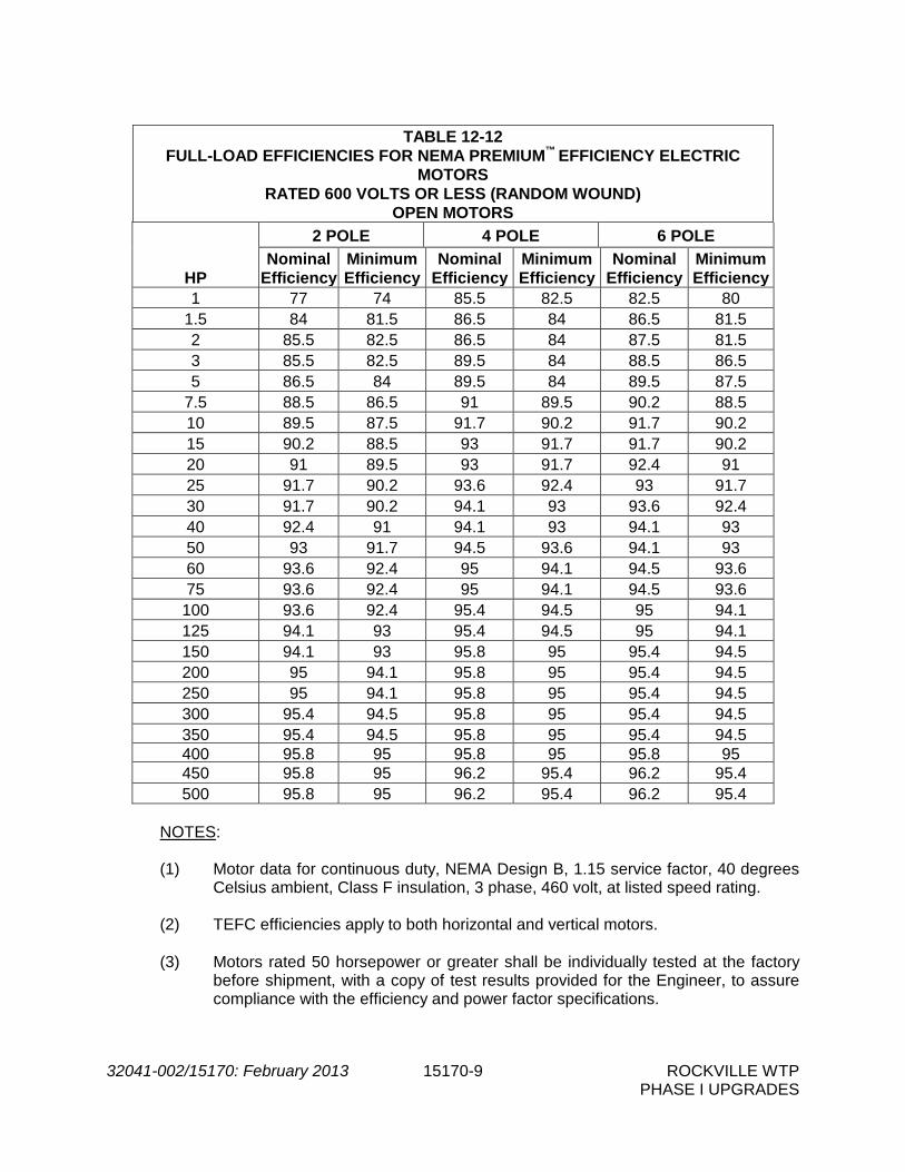
32041-002/15170: February 2013 15170-9 ROCKVILLE WTP PHASE I UPGRADES
TABLE 12-12
FULL-LOAD EFFICIENCIES FOR NEMA PREMIUM™ EFFICIENCY ELECTRIC MOTORS
RATED 600 VOLTS OR LESS (RANDOM WOUND) OPEN MOTORS
HP
2 POLE 4 POLE 6 POLE Nominal
Efficiency Minimum Efficiency
Nominal Efficiency
Minimum Efficiency
Nominal Efficiency
Minimum Efficiency
1 77 74 85.5 82.5 82.5 80 1.5 84 81.5 86.5 84 86.5 81.5 2 85.5 82.5 86.5 84 87.5 81.5 3 85.5 82.5 89.5 84 88.5 86.5 5 86.5 84 89.5 84 89.5 87.5
7.5 88.5 86.5 91 89.5 90.2 88.5 10 89.5 87.5 91.7 90.2 91.7 90.2 15 90.2 88.5 93 91.7 91.7 90.2 20 91 89.5 93 91.7 92.4 91 25 91.7 90.2 93.6 92.4 93 91.7 30 91.7 90.2 94.1 93 93.6 92.4 40 92.4 91 94.1 93 94.1 93 50 93 91.7 94.5 93.6 94.1 93 60 93.6 92.4 95 94.1 94.5 93.6 75 93.6 92.4 95 94.1 94.5 93.6 100 93.6 92.4 95.4 94.5 95 94.1 125 94.1 93 95.4 94.5 95 94.1 150 94.1 93 95.8 95 95.4 94.5 200 95 94.1 95.8 95 95.4 94.5 250 95 94.1 95.8 95 95.4 94.5 300 95.4 94.5 95.8 95 95.4 94.5 350 95.4 94.5 95.8 95 95.4 94.5 400 95.8 95 95.8 95 95.8 95 450 95.8 95 96.2 95.4 96.2 95.4 500 95.8 95 96.2 95.4 96.2 95.4
NOTES: (1) Motor data for continuous duty, NEMA Design B, 1.15 service factor, 40 degrees
Celsius ambient, Class F insulation, 3 phase, 460 volt, at listed speed rating. (2) TEFC efficiencies apply to both horizontal and vertical motors.
(3) Motors rated 50 horsepower or greater shall be individually tested at the factory
before shipment, with a copy of test results provided for the Engineer, to assure compliance with the efficiency and power factor specifications.
32041-002/15170: February 2013 15170-10 ROCKVILLE WTP PHASE I UPGRADES
I. Power Factor Correction
1. The power factor shall be corrected as necessary to achieve 85% (minimum) with capacitors sized and installed per manufacturer's recommendations. Capacitors shall be installed such that the motor shall not be damaged by overvoltage or excessive transient electrical torque. The capacitor(s) shall be connected as close as possible or directly to the motor terminals. Any power factor corrections shall not decrease the motor efficiency below the stated minimum requirement of this Specification. All power factor corrections shall be noted on the Shop Drawings submitted to the Engineer for approval. POWER FACTOR CORRECTION, TO ACHIEVE 85%, SHALL BE PROVIDED ON ALL MOTORS ABOVE 15 HORSEPOWER EXCEPT FOR THOSE MOTORS CONTROLLED BY VARIABLE FREQUENCY DRIVES (VFD'S).
2. When required, power factor correction capacitors shall be connected on the line
side of any type of reduced voltage starting motor controller (e.g. RVAT, RVSS, Part-Winding, Wye-Delta, etc.).
2.03 TOOLS, SUPPLIES AND SPARE PARTS
A. Each motor shall be furnished with all special tools necessary to disassemble, service, repair, and adjust the equipment. All spare parts as recommended by the equipment manufacturer shall be furnished to the Owner by the Contractor.
PART 3 -- EXECUTION 3.01 INSTALLATION
A. Motors shall be installed as shown on the Drawings and in accordance with the manufacturer's installation instructions.
3.02 DELIVERY, STORAGE, AND HANDLING
A. Motors shall be properly protected from weather hazards. Motors shall not be allowed to be wrapped tightly in plastic while outdoors. Motors delivered to the site which will not be put in service for a time in excess of 30 calendar days, whether in storage or installed, shall have the shafts rotated a minimum of five (5) rotations every 30 days.
B. Motors provided with space heaters shall have temporary power applied to the heaters no
later than 30 calendar days after delivery to the site until permanent power can be applied to the heaters.
C. Motors that, in the opinion of the Engineer, have not been properly protected shall be
inspected by the manufacturer's representative. Any required electrical corrections for testing shall be made at the Contractor's expense prior to acceptance and/or use.
D. All motors shall operate without any undue noise or vibration and shall show no signs of
phase unbalance.

32041-002/15170: February 2013 15170-11 ROCKVILLE WTP PHASE I UPGRADES
3.03 TESTING
A. All tests shall be performed in accordance with the requirements of the General Conditions and Division 1. The following tests are required:
1. Shop Tests
a. All motors shall be shop tested and inspected in accordance with the
equipment manufacturer's standard procedures. Shop tests for motors 100 horsepower and larger may be witnessed by the Engineer. The manufacturer's testing and inspection procedures shall demonstrate that the equipment tested conforms to the requirements specified, all other applicable requirements, and shall be approved by the Engineer. At least 10 days notice shall be given the Engineer prior to tests and inspection dates.
b. In addition to the efficiency and power factor testing specified herein, each
motor shall be tested to determine compliance with the applicable requirements of the IEEE, ANSI and NEMA. Tests shall be as follows:
(1) Motors less than 50 HP
(a) Each motor shall be subjected to a standard, short
commercial test including the following:
i) Running current, no load ii) Locked rotor current iii) High potential iv) Winding resistance v) Bearing inspection
(2) Motors between 50 and 100 HP
(a) Each motor shall be subjected to the above tests and shall be
furnished with certified test results.
(3) Motors larger than 100 HP
(a) Each motor shall be furnished with certified test results. Each motor shall be subjected to a complete test consisting of full load heat run, percent slip, running load current, locked rotor current, breakdown torque (calculated), starting torque, winding resistance, high potential, secondary current and voltage at collector rings (wound rotor), efficiencies at 100, 75 and 50 percent of full load, power factors at 100, 75 and 50 percent of full load and bearing inspection.
(4) Test Reports
(a) All test results for motors over 100 horsepower shall be
submitted to the Engineer for approval.

32041-002/15170: February 2013 15170-12 ROCKVILLE WTP PHASE I UPGRADES
2. Field Tests
a. Field tests shall be performed in accordance with the requirements specified
in the General Conditions, Division 1, and Section 16000, Basic Electrical Requirements.
b. All electric motors furnished for this project one (1) horsepower or larger shall
have the information required in the following tabulation completed. See Exhibit "A" on following page.
c. All field testing shall be witnessed by the Engineer.
- END OF SECTION -

32041-002/15170: February 2013 15170-13 ROCKVILLE WTP PHASE I UPGRADES
(EXHIBIT A)
MOTOR TEST RECORD
Motor Identification
Remarks Location Specified
Horsepower Nameplate Horsepower
Nameplate Amperage
(FLA)
Measured Amperage
Under Normal Operating Conditions

THIS PAGE LEFT INTENTIONALLY BLANK

32041-002\15290: February 2013 15290-1 ROCKVILLE WTP PHASE I UPGRADES
SECTION 15290
INSULATION PART 1 -- GENERAL 1.01 THE REQUIREMENT
A. The Contractor shall furnish and install insulation as shown on the Drawings or otherwise specified. Insulation shall not be installed until piping has been field tested and approved by the Owner. The Contractor shall protect the insulation from moisture at all times.
B. Reference Section 15000 – Basic Mechanical Requirements.
PART 2 -- PRODUCTS 2.01 INSULATED PROCESS/CHEMICAL/WATER PIPING
A. Pipe insulation shall be non-combustible and shall meet Factory Mutual requirements in this respect. All insulation shall have composite fire and smoke hazard ratings (as tested by procedures ASTM E-84, NFPA 255 and UL 723) not exceeding 25 for flame spread and 50 for smoke developed.
B. Fiberglass insulation shall be Owens Corning Fiberglass Corp., Fiberglass 25ASJ/SSC;
Certain Teed Products Corporation, Certain Teed snap-on ASJ/SSL; or equal. Insulation shall be heavy density sectional pipe insulation with vapor barrier and self-sealing lap. Minimum density insulation density shall be 6 pounds per cubic foot. Contractor shall use manufacturer's recommended adhesives and tape for jointing material. Fittings shall be molded fiberglass. Minimum insulation thickness shall be 1-1/2 inches for 4" diameter pipe and larger, and 1 inch for smaller pipe.
C. Weatherproof insulation jacket for process piping shall be Certain Teed Products
Corporation; Childers Products Company, Lock On and Slip On; or equal. Jacket shall be smooth embossed aluminum metal jacket with minimum thickness 0.016 inches thick for interior installations and at least 0.031 inches thick for exterior installations. Fastening shall use preformed "2"-lock seam with 2 inch butt strap with sealant. Bonds shall be 1/2 inch aluminum with wing seals. Fittings shall be prefabricated 0.016/0.031 inches thickness aluminum.
1. Contractor shall install weather proofing for outdoor piping. The field applied jacket
with moisture barrier shall be slipped around pipe into preformed 2-lock position. Butt next jacket section adjacent to previous section leaving 3/8 inch gap. Place preformed 2 inch butt strap with sealant over the seam and secure with 1/2 inch aluminum band and wing seal. Contractor shall install preformed fittings identical in composition to pipe jacketing at all fittings.
D. Insulation fitting covers and jacket for chemical piping shall be Zeston 2000 PVC by
Manville, or equal. Fitting covers shall fit snugly over fittings, including all elbows and valves,

32041-002\15290: February 2013 15290-2 ROCKVILLE WTP PHASE I UPGRADES
etc. Jacketing shall be high-impact UV-resistant covering for insulated piping and shall match fitting covers. Fitting covers and jackets shall be white and suitable for painting. PVC jacketing shall be 30 mil thick and shall be factory curled to fit snugly. Fitting covers and jacketing shall be secured with tacks.
E. The Contractor shall insure that surfaces of pipes, valves, heat tracing, and fittings are clean
and dry prior to installation of insulation. Insulation shall be installed so as to make surfaces smooth, even, and substantially flush with the adjacent insulation. The Contractor shall follow the manufacturer's application instructions for the materials used.
2.02 INSULATED AIR PIPING
A. Fiberglass insulation shall be provided for exposed exterior blower discharge piping as shown on the Drawings and as specified herein. Insulation shall be a roll of semi-rigid fiberglass board insulation. The fibrous insulation is adhered to the ASJ jacket with the end grain of the insulation perpendicular to the jacket surface. Each section of insulation may be secured on the longitudinal seam by using staples and mastic or vapor barrier ASJ pressure sensitive tape. Adjacent sections shall be butted together and sealed with vapor barrier ASJ tape. The insulation shall be 2-1/2 inches thick with a fiberglass density of at least 3 pounds per cubic foot.
B. Insulation for fittings and flanges shall be mitered segments of nominal 6 pounds per cubic
foot density fiberglass pipe covering. Cover with a coat of insulating cement then embed a 20 x 20 weave white glass reinforcing cloth between two 1/16 inch coats of Benjamin Foster 30-36. The glass cloth and second coat shall overlap adjacent covering by two inches. Insulation shall be fiberglass pipe wrap as manufactured by Owens-Corning, Johns Mansfield, or equal.
C. The insulation shall be covered with a smooth, weatherproof, embossed aluminum jacket
with integral Kraft-polyethylene vapor barrier separating the insulation from the metal. The factory applied aluminum jackets shall be at least .016 inches thick for interior installation and at least .031 inches thick for exterior installation. They shall be at least 36" long as measured along the pipe.
D. Circumferencially, the width of the sheets shall be 1/2" to 2" greater than the circumference
of the pipe insulation, with a Pittsburgh locktype on the longitudinal edge.
E. The metal jackets shall be held in place by .020" thick, 3/4 inch wide, metal bands on 9" centers.
F. Special care shall be taken to make all exterior insulation jackets completely waterproof by
the use of an appropriate silicone base sealant at all joints, etc. PART 3 -- EXECUTION (NOT USED)
- END OF SECTION -

32041-002\15390: February 2013 15390-1 ROCKVILLE WTP PHASE I UPGRADES
SECTION 15390 SCHEDULES PART 1 -- GENERAL 1.01 THE REQUIREMENT
A. Reference Section 15000, Basic Mechanical Requirements. 1.02 PIPING SYSTEM SCHEDULES
A. Piping requirements for this Section are outlined on the Drawings, and in the Piping System Schedule. In the absence of a specified test pressure, pipe shall be tested at a pressure 50 percent greater than the normal operating pressure as determined by the Engineer or 10 psig, whichever is greater unless the Schedule indicates that no test is required.
B. If the pipe material is not shown on the Piping System Schedule or otherwise specified, the
following materials shall be used:
Pipe Size Material Type of Joint Class/Design Test Pressure
Any Size PVC Socket Sch 80 (1)
Any Size DIP Flanged (Exposed) Restrained (Buried)
53 51
(1)
(1) Test at 150 percent of normal operating pressure or 10 psi, whichever is greater.
C. Non-critical gravity lines such as drains, floor drains, roof drains, etc., do not typically require
a pressure test.
D. The following abbreviations are used in the schedule:
1. Material
PVC - Polyvinylchloride DI - Ductile Iron RCP - Reinforced concrete pipe
2. Wall Thickness
Sch - Schedule
3. Pipe Identification
EQ - Equalization

32041-002\15390: February 2013 15390-2 ROCKVILLE WTP PHASE I UPGRADES
PIPING SYSTEM SCHEDULE 1,2,3
PIPE IDENTIFICATION
LOCATION MATERIAL THICKNESS
CL/SCH. JOINT TYPE
RESTRAINT SYSTEM DESIGN
PRESSURE (PSIG)
TEST PRESS. (PSIG)
Sump Pump Discharge
Interior/Exterior PVC Sch. 80 SOLVENT WELDED
100 PSI 65 PSI
Thickener Feed Interior DI Class 53 FLANGED 100 PSI 25 PSI
Exterior DI
Class 52 RESTRAINED
JOINT 100 PSI 25 PSI
Thickened Solids Interior
DI Class 53 FLANGED 100 PSI 90 PSI
Exterior DI
Class 52 RESTRAINED
JOINT 100 PSI 90 PSI
Thickener Overflow Exterior DI Class 51 RJ 50 PSI 35 PSI
EQ Basin Pump Discharge
Interior PVC Sch. 80 SOLVENT WELDED
100 PSI 25 PSI
Backwash Decant Interior DI Class 53 FL 75 PSI 50 PSI
Potable Water3
Interior Carbon Steel Screwed SCH 80 300 PSI 200 PSI
Interior Copper Type SOLDERED 150 PSI 100 PSI
Interior PVC Sch. 80 SOLVENT WELDED
150 PSI 100 PSI
Non-Potable Water3
Interior Carbon Steel Screwed SCH 80 300 PSI 200 PSI
Interior Copper Type SOLDERED 150 PSI 100 PSI
Interior PVC Sch. 80 SOLVENT WELDED
150 PSI 100 PSI
Storm Drain Exterior RCP Class IV BELL AND SPIGOT
NA NA
Process Air
Buried Carbon Steel
- Coated
See Section 15012, Steel
Pipe
WELDED
25 PSI 25 PSI Exposed3
Stainless Steel
WELDED/FLANGED
Interior Stainless
Steel
D (Drain) Interior/Exterior < 4” PVC Sch. 80 Socket
N/A N/A
Interior/Exterior >= 4” DIP Class 51 Push-On
Ferric Chloride Interior/Exterior CPVC Sch. 80 SOLVENT
WELDED/FLANGED
150 PSI 75 PSI
Sodium Hydroxide Interior/Exterior CPVC Sch. 80 SOLVENT
WELDED/FLANGED
150 PSI 75 PSI
1. PROVIDE HEAT TRACING AND INSULATION AS SPECIFIED IN DIVISION 15 ON ALL EXTERIOR/EXPOSED PIPING. HEAT TRACING AND INSULATION NOT REQUIRED ON PROCESS AIR PIPING. 2. DESIGN PRESSURE SHALL BE USED TO DETERMINE THE SIZE, NUMBER, MATERIAL AND DIMENSIONS OF TABS AND THREADED-RODS FOR PIPING SPECIFIED OR SHOWN TO HAVE THREADED-RODS FOR THRUST RESTRAINT. 3. MATCH NEW PIPE MATERIAL TO EXISTING PIPE MATERIAL WHERE MODIFICATIONS TO EXISTING PIPING ARE REQUIRED.

32041-002\15390: February 2013 15390-3 ROCKVILLE WTP PHASE I UPGRADES
1.03 VALVE SCHEDULES
A. Performance Affidavits shall be required for all valves listed in the valve schedule(s). Performance Affidavits shall be provided in accordance with Section 11000, Equipment General Provisions and Section 01300, Submittals. All valves shall be tagged by the manufacturer according to the control valve designations listed in the Schedule.
B. The valve schedules are provided for the Contractor’s convenience. Contractor shall verify
the quantity shown on the Drawings. In cases of discrepancy, the greater number shall govern.
C. Manually Operated Valve Schedule:
VALVE OPERATOR SCHEDULE
Type Valve
Type Operator
Size (inches)
Qty Service Location
Butterfly Open/Close* 6” 1 Equalization
pump discharge Equalization Basin
Butterfly Open/Close* 6” 1 Equalization
pump discharge Equalization Basin
* A new manual operator will be installed on the existing butterfly valve.

32041-002\15390: February 2013 15390-4 ROCKVILLE WTP PHASE I UPGRADES
D. Electrically Operated Process Valve Schedule:
ELECTRICALLY ACTUATED VALVES
Control Valve
Designation Type Valve
Type Operator
Size (inches)
Flow
Qty
Maximum Diff.
Pressure (psi)
Service Location
MOV-201 Plug Open/Close 4” 250 gpm
1 N/A Gravity
Thickener Feed
Clarifier Gallery Expansion,
Main Building
MOV-202 Plug Open/Close 6” 500 gpm
1 N/A Gravity
Thickener Feed
Clarifier Gallery Expansion,
Main Building
Existing Butterfly Modulating 12” 13,000
cfm 4 50 Filtered Water
Filter Gallery, Main Building
Existing Butterfly Modulating 14” 2,800 cfm
2 60 Clarifier Influent
Raw Water Gallery
MOV-203 & MOV204
Ball Open/Close 3” 150 gpm
2 10 Sodium
Hydroxide
Sodium Hydroxide Bulk Storage Tanks 1 & 2 Outlet Valves
MOV-205 & MOV206
Ball Open/Close 3” 150 gpm
2 11 Ferric Chloride Ferric Chloride Bulk Storage Tanks 1 & 2
Outlet Valves
C. Electrically Operated Air Valve Schedule:
ELECTRICALLY ACTUATED AIR VALVES
Control Valve
Designation
Type Valve
Type Operator
Size (inches)
Flow
Qty
Maximum Diff.
Pressure (psi)
Class Service Location
MOV-501 Butterfly Open/Close 8” 2,090 scfm
1 10 25B AS (Air Scour
Supply) Main Building Lower Level
MOV-502 Butterfly Open/Close 8” 2,090 scfm
1 10 25B AS (Air Scour
Supply) Main Building Lower Level
MOV-503 Butterfly Open/Close 8” 2,090 scfm
1 10 25B AS (Air Scour
Supply) Main Building Lower Level
MOV-504 Butterfly Open/Close 8” 2,090 scfm
1 10 25B AS (Air Scour
Supply) Main Building Lower Level

32041-002\15390: February 2013 15390-5 ROCKVILLE WTP PHASE I UPGRADES
1.04 BACK FLOW PREVENTER SCHEDULE
Valve Type Size
(inches) Qty Service Location
Double Check 1” 1 Polymer Make-up Water Raw Water Gallery
Double Check 2” 1 Gallery Expansion Water Chemical Building
Double Check 3/4” 1 Carbon Make-up Water Chemical Building
Double Check 1.5” 1 Chlorine Make-up Water Chlorine Room
PART 2 – PRODUCTS (NOT USED) PART 3 – EXECUTION (NOT USED)
-END OF SECTION-

THIS PAGE INTENTIONALLY LEFT BLANK.
32041-002/16000: February 2013 16000-1 ROCKVILLE WTP PHASE I UPGRADES
SECTION 16000
BASIC ELECTRICAL REQUIREMENTS PART 1 -- GENERAL 1.01 THE REQUIREMENT
A. The Contractor shall furnish all labor, materials, tools, and equipment, and perform all work and services necessary for, or incidental, to the furnishing and installation of all electrical work as shown on the Drawings, and as specified in accordance with the provisions of the Contract Documents and completely coordinate with the work of other trades involved in the general construction. Although such work is not specifically shown or specified, all supplementary or miscellaneous items, appurtenances, and devices incidental to or necessary for a sound, secure, and complete installation shall be furnished and installed as part of this work. The Contractor shall obtain approved Shop Drawings showing wiring diagrams, connection diagrams, roughing-in and hook up details for all equipment and comply therewith. All electrical work shall be complete and left in operating condition in accordance with the intent of the Drawings and the Specifications for the electrical work.
B. Where the word "Contractor" appears in these Technical Specifications it shall be construed
to mean the Electrical Contractor.
C. THE CONTRACTOR SHALL REFERENCE THE FUNCTIONAL DESCRIPTIONS AND OTHER REQUIREMENTS FOUND IN DIVISION 17, CONTROL AND INFORMATION SYSTEMS, FOR ADDITIONAL REQUIREMENTS PERTAINING TO WORK UNDER THIS CONTRACT. THE FUNCTIONAL DESCRIPTIONS REFERENCED HEREIN SHALL BE CONSIDERED AS PART OF THE WORK REQUIRED UNDER THIS CONTRACT.
D. THE CONTRACTOR SHALL BE RESPONSIBLE FOR ALL INTERCONNECTING
DEVICES, CONDUIT, WIRE, AND APPURTENANCES NOT FURNISHED BY OTHERS BUT REQUIRED FOR THE OPERATION OF EQUIPMENT AS DESCRIBED IN THE FUNCTIONAL DESCRIPTIONS WHETHER SPECIFICALLY SHOWN ON THE DRAWINGS OR NOT.
E. The scope of work for this project primarily includes, but is not limited to, the following:
1. Furnish and install of new Air Scour Blower starters and control equipment. 2. Furnish and install of new circuit breakers in existing panelboards, and new
panelboards as required. 3. Furnish and install all aboveground raceway systems including conduit, fittings,
boxes, and other pertinent components. 4. Furnish and install all underground raceway systems including conduit, fittings, and
other pertinent components. 5. Addition of variable frequency drives (VFDs) at for gravity thickener feed pumps.
06-17-11BR

32041-002/16000: February 2013 16000-2 ROCKVILLE WTP PHASE I UPGRADES
6. Addition of other motor starters in various places. 7. Addition of light fixtures. 8. Addition of control panels and instruments. 8. Other electrical work as specified herein and indicated on the Drawings.
F. Maintaining the operation of these facilities during the duration of the construction period is
essential and required. The Contractor shall furnish and install temporary equipment as required to maintain facility operation. Reference Section 01520 of the Specifications for construction sequencing and specific operational constraint information.
G. All electrical equipment shall conform to the applicable NEMA specifications. All electrical
equipment shall be properly identified in accordance with these Specifications and Contract Drawings. All panelboards, starters, control panels, cabinet enclosures, junction boxes, pull boxes, and equipment switches shall be identified per the requirements of Section 16195 – Electrical Identification.
H. All materials, equipment, sizes and capacities of electrical equipment incorporated in the
project shall conform to the latest requirements of the current National Electric Code, the National Electrical Manufacturer's Association, the State and local electrical codes, and to applicable rules and regulations of the local electrical utility serving the project.
I. All material and equipment must be the product of an established, reputable, and approved
manufacturer; must be new and of first class construction; must be designed and guaranteed to perform the service required; and must bear the label of approval of the Underwriters Laboratories, Inc., where such approval is available for the product of the listed manufacturer as approved by the Engineer.
J. When a specified or indicated item has been superseded or is no longer available, the
manufacturer's latest equivalent type or model of material or equipment as approved by the Engineer shall be furnished and installed at no additional cost to the Owner.
K. Where the Contractor's selection of equipment of specified manufacturers or additionally
approved manufacturers requires changes or additions to the system design, the Contractor shall be responsible in all respects for the modifications to all system designs, subject to approval of the Engineer. The Contractor's bid shall include all costs for all work of the Contract for all trades made necessary by such changes, additions or modifications or resulting from any approved substitution.
L. Furnish and install controls for each piece of equipment requiring controls under this
Contract. The controls shall be the size and type recommended by the manufacturer for the application and as otherwise specified or indicated on the Drawings. Refer to Divisions 1 and 17 of the Specifications for control, connection and coordination descriptions and requirements.
M. Furnish and install all stands, racks, brackets, supports, and similar equipment required to
properly serve the equipment which is furnished under this Contract, or equipment otherwise specified or indicated on the Drawings.
121609

32041-002/16000: February 2013 16000-3 ROCKVILLE WTP PHASE I UPGRADES
N. All electrical components and systems, including electrical equipment foundations, shall be designed to resist operational forces as well as lateral sway and axial motion from seismic and thermal forces. Seismic support design shall be in accordance with Section 01350 - Seismic Anchorage and Bracing.
1.02 DRAWINGS
A. The Contractor shall furnish, install, and place in satisfactory condition ready for operation, all conduits, cables, and all other material needed for the complete lighting, power, control and other electrical systems shown or indicated in the Contract Drawings. Additional conduits and the required wiring shall be installed by the Contractor wherever needed to complete the installation of the specific equipment furnished.
1.03 EQUIPMENT LOCATION
A. The Drawings show the general location of feeders, transformers, outlets, conduits, and circuit arrangements. Because of the small scale of the Drawings, it is not possible to indicate all of the details involved. The Contractor shall carefully investigate the structural and finish conditions affecting all of his work and shall arrange such work accordingly; furnishing such fittings, junction boxes, and accessories as may be required to meet such conditions. The Contractor shall refer to the entire Drawing set to verify openings, special surfaces, and location of other equipment, or other special equipment prior to roughing-in for panels, switches, and other outlets. The Contractor shall verify all equipment dimensions to insure that proposed equipment will fit properly in spaces indicated.
1.04 LOCAL CONDITIONS
A. The Contractor shall examine the site and become familiar with conditions affecting the work. The Contractor shall investigate, determine, and verify locations of any overhead or buried utilities on or near the site, and shall determine such locations in conjunction with all public and/or private utility companies and with all authorities having jurisdiction. All costs, both temporary and permanent to connect all utilities, shall be included in the Bid. The Contractor shall be responsible for scheduling and coordinating with the local utility for temporary services.
B. In addition, the Contractor shall relocate all duct banks, lighting fixtures, receptacles,
switches, boxes, and other electrical equipment as necessary to facilitate the Work included in this project. Costs for such work shall be included in the Bid.
1.05 SUBMITTALS
A. In accordance with the procedures and requirements set forth in the General Conditions, Section 01300, Submittals and the requirements of the individual specification sections, the Contractor shall obtain from the equipment manufacturer and submit the following:
1. Shop Drawings
2. Operation and Maintenance Manuals
3. Spare Parts List

32041-002/16000: February 2013 16000-4 ROCKVILLE WTP PHASE I UPGRADES
4. Special Tools List
5. Proposed Testing Methods and Reports of Certified Shop Tests.
6. Reports of Certified Field Tests. 7. Manufacturer’s Representative’s Certification.
B. Submittals shall be sufficiently complete in detail to enable the Engineer to determine
compliance with Contract requirements.
C. Submittals will be approved only to the extent of the information shown. Approval of an item of equipment shall not be construed to mean approval for components of that item for which the Contractor has provided no information.
D. Seismic support design for all nonstructural electrical components (conduit, raceways,
freestanding equipment, etc) in accordance with building code requirements and Section 01350 – Seismic Anchorage and Bracing.
E. Some individual Division 16 specification sections may require a Compliance, Deviations,
and Exceptions (CD&E) letter to be submitted. If the CD&E letter is required and shop drawings are submitted without the letter, the submittal will be rejected. The letter shall include all comments, deviations and exceptions taken to the Drawings and Specifications by the Contractor AND Equipment Manufacturer/Supplier. This letter shall include a copy of this specification section. In the left margin beside each and every paragraph/item, a letter "C", "D", or "E" shall be typed or written in. The letter "C" shall be for full compliance with the requirement. The letter "D" shall be for a deviation from the requirement. The letter "E" shall be for taking exception to a requirement. Any requirements with the letter "D" or "E" beside them shall be provided with a full typewritten explanation of the deviation/exception. Handwritten explanation of the deviations/exceptions is not acceptable. The CD&E letter shall also address deviations, and exceptions taken to each Drawing related to this Specification Section.
1.06 APPLICABLE CODES AND REQUIREMENTS
A. Conformance
1. All work, equipment and materials furnished shall conform with the existing rules, requirements and specifications of the Insurance Rating Organization having jurisdiction, the serving electrical utility company, the latest edition of the National Electrical Code (NEC), the National Electric Manufacturers Association (NEMA), the Institute of Electrical and Electronic Engineers (IEEE), the Insulated Cable Engineers Association (ICEA), the American Society of Testing Materials (ASTM), the American National Standards Institute (ANSI), the requirements of the Occupational Safety Hazards Act (OSHA), and all other applicable Federal, State and local laws and/or ordinances.
2. All material and equipment shall bear the inspection labels of Underwriters
Laboratories, Inc., if the material and equipment is of the class inspected by said laboratories.

32041-002/16000: February 2013 16000-5 ROCKVILLE WTP PHASE I UPGRADES
3. All work shall be in accordance with local codes.
B. Nonconformance
1. Any paragraph of requirements in these Specifications, or Drawings, deviating from the rules, requirements and Specifications of the above organizations shall be invalid and their (the above organizations) requirements shall hold precedent thereto. The Contractor shall be held responsible for adherence to all rules, requirements and specifications as set forth above. Any additional work or material necessary for adherence will not be allowed as an extra, but shall be included in the Bid. Ignorance of any rule, requirement, or Specification shall not be allowed as an excuse for nonconformity. Acceptance by the Engineer does not relieve the Contractor from the expense involved for the correction of any errors which may exist in the drawings submitted or in the satisfactory operation of any equipment.
C. Certification
1. Upon completion of the work, the Contractor shall obtain certificate(s) of inspection
and approval from the National Board of Fire Underwriters or similar inspection organization having jurisdiction and shall deliver same to the Engineer and the Owner.
1.07 PERMITS AND INSPECTIONS
A. The Contractor shall reference the General Conditions and Section 01010, Summary of Work.
1.08 TEMPORARY LIGHTING AND POWER
A. The Contractor shall reference the General Conditions and Section 01510, Temporary Utilities.
1.09 TESTS
A. Upon completion of the installation, the Contractor shall perform tests for operation, load (Phase) balance overloads, and short circuits. Tests shall be made with and to the satisfaction of the Owner and Engineer.
B. The Contractor shall perform all field tests and shall provide all labor, equipment, and
incidentals required for testing and shall pay for electric power required for the tests. All defective material and workmanship disclosed shall be corrected by the Contractor at no cost to the Owner. The Contractor shall show by demonstration in service that all circuits and devices are in good operating condition. Test shall be such that each item of control equipment will function not less than five (5) times.
C. The grounding system shall be tested to assure continuity and compliance with the contract
requirements. Reference Section 16170, Grounding and Bonding, for specific testing requirements.

32041-002/16000: February 2013 16000-6 ROCKVILLE WTP PHASE I UPGRADES
D. Insulation resistance testing of all incoming and outgoing cables for switchgear, motor control centers, lighting and power distribution panelboards, and similar equipment shall be done after the cables are in place and just prior to final terminations. All data shall be recorded, as per Exhibit "A", attached to the end of this Section. See Section 16123 for detailed requirements.
E. Feeder circuits shall be tested with the feeder conductors disconnected from the supplied
equipment. Each individual power circuit shall be tested at the panel or motor control center with the power equipment connected for proper operation.
F. The equipment to be tested shall include, but not be limited to, the following:
● Motor Control Equipment ● Variable Frequency Drives and Related Motor Control Equipment ● Panelboards ● Conduit System ● Cable and Wire ● Grounding System ● General Purpose Dry Type Transformers ● Lighting Fixtures (Indoor and Outdoor)
G. Refer to each specific specification section for detailed field tests.
H. The Contractor shall complete the installation and testing of the electrical installation at least two (2) weeks prior to the start-up and testing of all other equipment. During the period between the completion of electrical installation and the start-up and testing of all other equipment, the Contractor shall make all components of the Work available as it is completed for their use in performing Preliminary and Final Field Tests.
I. Before each test commences, the Contractor shall submit a detailed test procedure, and
also provide test engineer resume, manpower and scheduling information for the approval by the Engineer. In addition, the Contractor shall furnish detailed test procedures for any of his equipment required as part of the field tests of other systems.
J. Just prior to the final acceptance of a piece of equipment, the Contractor shall perform an
infrared inspection to locate and correct all heating problems associated with that electrical equipment. The infrared inspection shall apply to all new equipment and existing equipment that is in any way modified under this Contract. All heating problems detected with new and modified equipment shall be corrected by the Contractor. Any problems detected with portions of existing equipment that were not modified under this Contract are not the responsibility of the Contractor, however, these problems shall be reported to the Owner and Engineer immediately. The infrared inspection shall include both digital and IR pictures which shall be submitted to the Owner for record purposes. The infrared inspection shall be performed by a third party, independent testing agency, not the Electrical Contractor.
1.10 DOCUMENTATION
A. The work requirements of this Section is in addition to and does not supersede testing and adjusting specified in other portions of the Contract Documents. The Contractor shall submit to the Engineer test records and reports for all testing.

32041-002/16000: February 2013 16000-7 ROCKVILLE WTP PHASE I UPGRADES
1.11 PROTECTIVE DEVICE SETTING AND TESTING
A. The Contractor shall provide the services of a field services organization to adjust, set, calibrate and test all protective devices in the electrical system. The organization shall be a subsidiary of or have a franchise service agreement with the electrical equipment manufacturer. The qualifications of the organization and resumes of the technicians as well as all data forms to be used for the field testing shall be submitted.
B. All protective devices in the electrical equipment shall be set, adjusted, calibrated and tested
in accordance with the manufacturers’ recommendations, the coordination study, and best industry practice.
C. Proper operation of all equipment associated with the device under test and its compartment
shall be verified, as well as complete resistance, continuity and polarity tests of power, protective and metering circuits. Any minor adjustments, repairs and/or lubrication necessary to achieve proper operation shall be considered part of this Contract.
D. All solid state trip devices shall be checked and tested for setting and operation using
manufacturers recommended test devices and procedures.
E. Circuit breakers and/or contactors associated with the above devices shall be tested for trip and close functions with their protective device.
F. When completed, the Contractor shall provide a comprehensive report for all equipment
tested indicating condition, readings, faults and/or deficiencies in same. Inoperative or defective equipment shall be brought immediately to the attention of the Engineer.
G. Prior to placing any equipment in service, correct operation of all protective devices
associated with this equipment shall be demonstrated by field testing under simulated load conditions.
1.12 POWER SYSTEM STUDIES
A. General
1. The Contractor shall provide short circuit studies, protective device evaluation studies, protective device coordination studies, and arc flash studies performed by a registered professional engineer in accordance with Section 16055 – Power System Studies.
1.13 SCHEDULES AND PLANT OPERATIONS
A. Since the testing required in Article 1.09 above shall require that certain pieces of equipment be taken out of service, all testing procedures and schedules must be submitted to the Engineer for review and approval one (1) month prior to any work beginning. When testing has been scheduled, the Engineer must be notified 48 hours prior to any work to allow time for load switching and/or alternation of equipment. In addition, all testing that requires temporary shutdown of plant equipment must be coordinated with the Owner/Engineer so as not to affect proper plant operations.

32041-002/16000: February 2013 16000-8 ROCKVILLE WTP PHASE I UPGRADES
B. At the end of the workday, all equipment shall be back in place and ready for immediate use should a plant emergency arise. In addition, should an emergency condition occur during testing, at the request of the Owner, the equipment shall be placed back in service immediately and turned over to plant personnel.
C. In the event of accidental shutdown of plant equipment, the Contractor shall notify plant
personnel immediately to allow for an orderly restart of affected equipment. 1.14 MATERIALS HANDLING
A. Materials arriving on the job site shall be stored in such a manner as to keep material free of rust and dirt and so as to keep material properly aligned and true to shape. Rusty, dirty, or misaligned material shall be rejected. Electrical conduit shall be stored to provide protection from the weather and accidental damage. Rigid non-metallic conduit shall be stored on even supports and in locations not subject to direct sun rays or excessive heat. Cables shall be sealed, stored, and handled carefully to avoid damage to the outer covering or insulation and damage from moisture and weather. Adequate protection shall be required at all times for electrical equipment and accessories until installed and accepted. Materials damaged during shipment, storage, installation, or testing shall be replaced or repaired in a manner meeting with the approval of the Engineer. The Contractor shall store equipment and materials in accordance with Section 01550, Site Access and Storage.

32041-002/16000: February 2013 16000-9 ROCKVILLE WTP PHASE I UPGRADES
(EXHIBIT A) TEST DATA - MEGOHMS
TEST NO. ____ Date:
Company:
Time:
Location:
Circuit:
Circuit Length:
Aerial:
Duct:
Buried:
No. of Conduc- tors
Size:
AMG MCM Shld:
Insulation Material:
Insulation Thickness:
Voltage Rating:
Age:
Type: _____Pothead ______Terminal
Location: Indoors______
Outdoors_____
Number and Type of Joints: Recent Operating History: Manufacturer: State if Potheads or Terminals were grounded during test: List associated equipment included in test: Miscellaneous Information:

32041-002/16000: February 2013 16000-10 ROCKVILLE WTP PHASE I UPGRADES
(EXHIBIT A) TEST DATA - MEGOHMS
TEST NO. ____ Part Tested:Test Made:_______________ Hours/Days:_______________ After Shutdown:_______________ Grounding Time:Dry Bulb Temperature:__________ Wet Bulb Temperature:__________ Test Voltage:
Equipment Temperature: ___________ How Obtained: ___________ Relative Humidity: ___________ Absolute Humidity: ___________ Dew Point: ___________
Megohmmeter: Serial Number: __________ Range: ___________
Voltage: ________________ Calibration Date___________ Test Connections
To Line To Earth To Ground
To Line To Earth To Ground
To Line To Earth To Ground
Test Connections
To Line To Earth To Ground
To Line To Earth To Ground
To Line To Earth To Ground
3 Minute
5 Minutes
2 Minute
6 Minutes
3/4 Minute
7 Minutes
1 Minute
8 Minutes
2 Minutes
9 Minutes
3 Minutes
10 Minutes
4 Minutes
10/1 Minutes
Ratio
Remarks:

32041-002/16000: February 2013 16000-11 ROCKVILLE WTP PHASE I UPGRADES
PART 2 -- PRODUCTS 2.01 PRODUCT REQUIREMENTS
A. Unless otherwise indicated, the materials to be provided under this Specification shall be the products of manufacturers regularly engaged in the production of all such items and shall be the manufacturer's latest design. The products shall conform to the applicable standards of UL and NEMA, unless specified otherwise. International Electrotechnical Commission (IEC) standards are not recognized. Equipment designed, manufactured, and labeled in compliance with IEC standards is not acceptable.
B. All items of the same type or ratings shall be identical. This shall be further understood to
include products with the accessories indicated.
C. All equipment and materials shall be new, unless indicated or specified otherwise.
D. The Contractor shall submit proof if requested by the Engineer that the materials, appliances, equipment, or devices that are provided under this Contract meet the requirements of Underwriters Laboratories, Inc., in regard to fire and casualty hazards. The label of or listing by the Underwriters Laboratories, Inc., will be accepted as conforming with this requirement.
2.02 SUBSTITUTIONS
A. Any reference in the Specifications or on the Drawings to any article, service, product, material, fixture, or item of equipment by name, make, or catalog number shall be interpreted as establishing the type, function, and standard of quality and shall not be construed as limiting competition. Any proposed substitution and or-equal item shall be submitted to the Engineer a minimum of 14 days prior to the bid for review and evaluation.
2.03 CONCRETE
A. The Contractor shall furnish all concrete required for the installation of all electrical work, Concrete shall be Class A unless otherwise specified. Concrete and reinforcing steel shall meet the appropriate requirements of Division 3 of the Specifications.
B. The Contractor shall provide concrete equipment pads for all free standing electrical
apparatus and equipment located on new or existing floors or slabs. The Contractor shall provide all necessary anchor bolts, channel iron sills, and other materials as required. The exact location and dimensions shall be coordinated for each piece of equipment well in advance of the scheduled placing of these pads. Equipment pads shall be 4 inches high unless otherwise indicated on the Drawings and shall conform to standard detail for equipment pads shown on the Contract Drawings. Equipment pads shall not have more than 3” excess concrete beyond the edges of the equipment.
C. The Contractor shall provide concrete foundations for all free standing electrical apparatus
and equipment located outdoors or where floors or slabs do not exist and/or are not or provided by others under this Contract. The Contractor shall provide all necessary anchor bolts, channel iron sills, and other materials as required. The location and dimensions shall be coordinated for each piece of equipment well in advance of the scheduled placing of the

32041-002/16000: February 2013 16000-12 ROCKVILLE WTP PHASE I UPGRADES
foundations. Equipment foundations shall be constructed as detailed on the Drawings or if not detailed on the Drawings shall be 6 inches thick minimum reinforced with #4 bars at 12-inch centers each way placed mid-depth. Concrete shall extend 6 inches minimum beyond the extreme of the equipment base and be placed on a compacted stone bed (#57 stone or ABC) 6 inches thick minimum.
PART 3 -- EXECUTION 3.01 CUTTING AND PATCHING
A. Coordination
1. The Work shall be coordinated between all trades to avoid delays and unnecessary cutting, channeling and drilling. Sleeves shall be placed in concrete for passage of conduit wherever possible.
B. Damage
1. The Contractor shall perform all chasing, channeling, drilling and patching necessary
to the proper execution of his Contract. Any damage to the building, structure, or any equipment shall be repaired by qualified mechanics of the trades involved at the Contractor's expense. If, in the Engineer's judgment, the repair of damaged equipment would not be satisfactory, then the Contractor shall replace damaged equipment at his own expense.
3.02 EXCAVATION AND BACKFILLING
A. The Contractor shall perform all excavation and backfill required for the installation of all electrical work. All excavation and backfilling shall be in complete accordance with the applicable requirements of Division 2.
3.03 CORROSION PROTECTION
A. Wherever dissimilar metals, except conduit and conduit fittings, come into contact, the Contractor shall isolate these metals as required with neoprene washers, nine (9) mil polyethylene tape, or gaskets.
- END OF SECTION -

32041-002\16055: February 2013 16055-1 ROCKVILLE WTP PHASE I UPGRADES
SECTION 16055
POWER SYSTEM STUDIES PART 1 -- GENERAL 1.01 THE REQUIREMENT
A. The Contractor shall provide Short Circuit Studies, Equipment Evaluation Studies, Protective Device Coordination Studies, Load Flow Analyses, and Arc Flash Hazard Studies performed by a professional electrical engineer currently registered in the State of Maryland.
B. The scope of work for these studies shall include the entire Rockville Water Treatment Plant
and Raw Water Pump Station. All existing and proposed electrical equipment and distribution systems at the plant and pump station shall be included in the studies, although not all electrical equipment is shown on the Contract Drawings for this particular project.
C. Prior to receiving final approval of the distribution equipment shop drawings for the equipment
proposed under this Contract and/or prior to release of that equipment for manufacture, the Preliminary Study Report, as specified herein, shall be submitted and approved. Contractor shall expedite the completion of the Preliminary Study Report so that final approval of proposed equipment is not delayed.
1.02 REFERENCE CODES AND STANDARDS
A. Institute of Electrical and Electronic Engineers (IEEE): 1. Standard 141, Recommended Practice for Electrical Power Distribution for Industrial
Plants
2. Standard 241, Recommended Practice for Electrical Power Systems in Commercial Buildings
3. Standard 242, Recommended Practice for Protection and Coordination of Industrial
and Commercial Systems
4. Standard 399, Recommended Practice for Industrial and Commercial Power System Analysis
5. Standard 519-1992, Recommended Practices and Requirements for Harmonic
Control in Electric Power Systems
6. Standard 1584-2002/2004a, IEEE Guide for Performing Arc-Flash Hazard Calculations
B. American National Standards Institute (ANSI):
1. Standard C37.90, IEEE Standard for Relays and Relay Systems Associated with
Electric Power Apparatus

32041-002\16055: February 2013 16055-2 ROCKVILLE WTP PHASE I UPGRADES
2. Standard C37.91, Guide for Protective Relay Applications to Power Transformers
3. Standard C37.95, Guide for Protective Relaying of Utility-Consumer Interconnections.
4. Standard C37.96, Guide for AC Motor Protection
5. Standard C57.12.59, Guide Dry-Type Transformer Through-Fault Current Duration
6. Standard C.57.13, Standard Requirements for Instrumentation Transformers
7. Standard C57.109, Guide for Liquid-Immersed Transformer Through Fault-Current Duration
C. National Electrical Code (NEC)
D. National Fire Protection Agency (NFPA):
1. NFPA 70E, Standard for Electrical Safety in the Workplace (2009 edition)
1.03 SUBMITTALS
A. The Contractor shall submit for review and approval, four (4) paper copies of the Preliminary Power System Studies Report, four (4) paper copies of the Pre-final Power System Studies Report, and six (6) paper copies of the Final Power System Studies Report. One (1) electronic copy of each report shall be also submitted on a CD. The electronic version of each report shall be in the PDF file format. Each section of the report shall be placed in a separate PDF file to allow fast and easy navigation between sections. Additional details regarding the report requirements are specified elsewhere herein.
B. All Reports shall bear the signature and seal of the professional electrical engineer that
performed the study.
C. The Contractor shall also submit one (1) electronic copy of the system model and all required database files generated by the software analysis package used. Files shall be placed on a CD and submitted with the Preliminary, Pre-final, and Final Power System Studies Reports.
1.04 QUALIFICATIONS
A. The Power System Studies shall be performed by a professional electrical engineer registered in the State of Maryland. The registered professional electrical engineer shall have a minimum of five (5) years of experience in performing power systems studies.
B. The resume of the registered professional electrical engineer shall be submitted for approval prior to the start of work. An experience table shall also be provided detailing the power systems studies of similar scope to this Contract that have been performed by the proposed engineer over the last two (2) years. The table shall, at a minimum, list the facility owner’s name, facility contact person with phone number and email address, and overall scope of work that was provided.

32041-002\16055: February 2013 16055-3 ROCKVILLE WTP PHASE I UPGRADES
PART 2 -- PRODUCTS 2.01 POWER SYSTEM STUDIES
A. General
1. The Contractor shall provide Short Circuit Studies, Equipment Evaluation Studies, Protective Device Coordination Studies, Load Flow Analyses, and Arc Flash Hazard Studies for the entire electrical system. The studies shall be performed in accordance with IEEE 399, Recommended Practice for Industrial and Commercial System Power Analysis (IEEE Brown Book).
2. The studies shall include all portions of the electrical distribution system from the
serving electric utility company protective devices, the normal and standby power sources down to and including the 208 volt equipment. The studies shall include all low voltage switchgear, motor control centers (MCCs), Variable Frequency Drives (VFDs) and panelboards as shown on the Drawings. System connections and those which result in maximum fault conditions shall be adequately covered in the study.
3. The studies shall be performed with the aid of SKM Systems Analysis Power Tools
for Windows (PTW) software, Version 6.5 or newer. No other software analysis packages are acceptable.
B. Data Collection for the Studies
1. The Contractor shall collect all required utility transformer and service information for
use in these studies. The following person shall be contacted for serving electric utility information.
Brad Zellmer PEPCO (202) 388-2241 [email protected]
2. One (1) field visit to the project site to collect pertinent data from existing equipment by the personnel performing the studies is permitted. This visit shall occur as soon after the Contract is awarded as possible and shall be coordinated with the Owner. The Contractor and personnel performing these studies are responsible for collecting all required data for these studies.
C. Short Circuit Studies
1. The short circuit study shall be performed in accordance with the latest editions of IEEE Std. 399 and IEEE Std. 141.
2. The study input data shall include the serving electric utility company's short circuit
contribution, resistance and reactance components of the branch impedances, the X/R ratios, base quantities selected, and other source impedances.
3. Short circuit close and latch duty values and interrupting duty values shall be
calculated on the basis of assumed three-phase bolted short circuits at each bus, low
122909BR

32041-002\16055: February 2013 16055-4 ROCKVILLE WTP PHASE I UPGRADES
voltage switchgear, low voltage motor control center, distribution panelboard, pertinent branch circuit panel and other significant locations through the system. The short circuit tabulations shall include symmetrical fault currents, and X/R ratios. For each fault location, the total duty on the bus, as well as the individual contribution from each connected branch, shall be listed with its respective X/R ratio.
4. The short circuit study report shall include recommendations for equipment selection
based on calculated short circuit values and all input and output data from the software model.
D. Equipment Evaluation Studies
1. An equipment evaluation study shall be performed to determine the adequacy of both existing and proposed circuit breakers, panelboards, motor control centers, automatic transfer switches, busses, etc. located at the plant by tabulating and comparing the short circuit ratings of these devices with the calculated fault currents. Appropriate multiplying factors based on system X/R ratios and protective device rating standards shall be applied. A table shall be provided in the report showing the calculated fault currents and the corresponding short circuit ratings of the existing equipment.
E. Protective Device Coordination Studies
1. A protective device coordination study shall be performed to provide the necessary
calculations and logic decisions required to select or to check the selection of power fuse ratings, protective relay characteristics and settings, ratios and characteristics of associated current transformers, and low voltage circuit breaker trip characteristics and settings.
2. The coordination study shall include all low voltage classes of equipment from the
serving electric utility company service protective devices down to and including all adjustable circuit protective devices. The phase and ground overcurrent protection shall be included as well as settings of all other adjustable protective devices.
3. The time-current characteristics of the proposed protective devices shall be printed
on a log-log scale. The plots shall include complete titles, representative one-line diagram and legends, significant motor starting characteristics, complete parameters of transformers, complete operating bands of low voltage circuit breaker trip curves and fuses. The coordination plots shall indicate the types of protective devices selected, proposed relay taps, time dial and instantaneous trip settings, transformer magnetizing inrush and ANSI transformer withstand parameters, cable thermal overcurrent withstand limits and significant symmetrical and asymmetrical fault currents. All restrictions of the National Electrical Code shall be adhered to and proper coordination intervals and separation of characteristic curves shall be maintained. The coordination plots for phase and ground protective devices shall be provided on a system basis. A sufficient number of separate curves shall be used to clearly indicate the coordination achieved.
4. The selection and settings of the protective devices shall be provided separately in a
tabulated form listing circuit identification, IEEE device number, current transformer ratios and connections, manufacturer and type, range of adjustment and recommended settings.

32041-002\16055: February 2013 16055-5 ROCKVILLE WTP PHASE I UPGRADES
F. Load Flow Analyses
1. A load-flow analysis shall be performed to determine the steady-state loading profile of the plant. The analysis shall be based on both the serving electric utility as a source and the standby generator as a source. From the results of the load flow analysis, the report shall indicate areas of overloaded conductors or equipment in the power distribution system design.
2. The report shall also include a total source load summary table, as well as single line
diagrams showing only the load flow data. 3. Load flow analysis results shall also be presented in a tabular format in the report.
G. Arc Flash Hazard Studies
1. An Arc Flash Hazard Study shall be performed in accordance with IEEE Std. 1584,
NFPA 70E, and OSHA 29-CFR, Part 1910 Subpart S. 2. The Arc Flash Hazard Study Report shall include but not be limited to the following:
a. An executive summary outlining the electrical distribution system b. A brief overview of what arc flash hazards are and how to avoid them. c. Serving electric utility information received. Copies of the information
received shall be included in an appendix. d. All assumptions made to complete the report e. Definitions of key terms used in the report f. Any recommendations to reduce the arc flash incident energies where they
are found to exceed a hazard risk category of 2. g. A PPE table that defines the Personnel Protective Equipment (PPE) classes
and clothing descriptions identified in the report and labels. h. Arc flash hazard warning labels as specified herein. i. An NFPA 70E energized work permit for each location where a warning label
is provided. j. Arc flash evaluation summary sheets as specified herein k. Separate set of single line diagrams that show incident energies, hazard risk
categories, and protective device settings. Only pertinent arc flash hazard data shall be displayed on these single line diagrams. Data from all other study calculations shall not be shown.

32041-002\16055: February 2013 16055-6 ROCKVILLE WTP PHASE I UPGRADES
3. The following parameters shall be used in the Arc Flash Hazard Study: a. Working distance for all equipment: 18” b. Maximum arc duration for all equipment: 2 seconds c. Equipment with an operating voltage of less than 240VAC that is supplied by
a transformer with a capacity of 125kVA or less shall be identified and labeled with a hazard risk category 0 with the arc flash hazard boundary at 48”.
d. Incident energies, arc flash hazard boundaries, and hazard risk categories
shall be calculated over a +/- 15% of calculated arcing fault current. The worst case incident energies that result shall be used in the study report.
e. The equipment that connects to both the electric utility service and the
standby power is in an open-transition configuration. The power sources will be incapable of paralleling with each other.
f. The arc flash analysis shall be performed as if the facility is being supplied by
the electric utility and as if the facility is being supplied by the standby power source. The worst case values from each calculation shall be used in the study report.
4. Arc Flash Warning Labels shall be produced for each location that allows access to
energized parts. Labels shall be printed in color on adhesive backed labels. Labels shall be an ANSI Z535.4 compliant (minimum size 4 in. x 6 in.) thermal transfer type label. For incident energy values of less than 40 cal/cm^2, the labels shall have an orange colored header with the word “WARNING”. For incident energy values equal to and above 40 cal/cm^2, the labels shall have a red colored header with the word “DANGER”. Each label shall include the following information:
a. Bus name b. System operating voltage c. Date of issue d. Flash hazard protection boundary e. Limited approach boundary f. Restricted boundary g. Prohibited boundary h. Incident energy level i. Required personal protective equipment class (Hazard risk category)

32041-002\16055: February 2013 16055-7 ROCKVILLE WTP PHASE I UPGRADES
5. Arc Flash Evaluation Summary Sheets shall be produced. All values shown on the Summary Sheets shall be commensurate with the values shown on the single line diagrams. Summary sheets shall list the following: a. Bus name b. Upstream protective device name and protective device settings c. Bus line-to-line voltage d. Bus bolted fault e. Protective device bolted fault current f. Arcing fault current g. Protective device trip / delay time h. Breaker opening time i. Solidly grounded column j. Equipment type k. Gap l. Arc flash boundary m. Working distance n. Incident energy o. Required personal protective equipment class (hazard risk category)
2.02 Study Reports
A. The results of the Power Systems Studies shall be summarized in a series of reports. A total of three (3) separate reports shall be provided as follows:
1. Preliminary Report – The Preliminary Report shall consist of all power systems
studies as specified herein, with the following exceptions: a. NFPA 70E energized work permits shall not be included b Arc flash hazard warning labels shall be printed on plain paper for format
review purposes only. Actual labels with calculated values shall not be included.
2. Pre-final Report – The Pre-final Report shall incorporate all comments received
from the previous report review and shall include specific equipment data from the approved shop drawings of the proposed electrical equipment. The Pre-final

32041-002\16055: February 2013 16055-8 ROCKVILLE WTP PHASE I UPGRADES
Report shall consist of all power systems studies as specified herein, with the following exceptions: a. NFPA 70E energized work permits shall not be included b. Sample arc flash hazard warning labels shall be printed on plain paper for
calculated value review purposes. Actual adhesive labels shall not be included.
3. Final Report – The Final Report shall consist of all power systems studies as
specified herein, including final adhesive arc flash hazard warning labels. Final report shall incorporate all installed electrical equipment, including any field changes made during construction, and all comments received from the previous report review. All ‘as-left’ protective device settings shall be included in the report.
B. Reports shall be furnished in the quantities specified herein, neatly organized into
properly identified 3” (minimum) 3-ring binders. Tabs shall clearly separate each section of the report. Each report shall begin with a table of contents. The following sections shall be included in the report as a minimum:
1. Executive Summary 2. Short Circuit Study 3. Equipment Evaluations 4. Protective Device Coordination Study
5 Load Flow Analysis 6. Arc Flash Study C. All data used in the reports such as conductor sizes and lengths, motor sizes, utility
contribution information, and the like shall be included in the appendices of the report. D. All single line diagrams and time current curves shall be provided in the reports on 11x17
paper, properly folded to fit into the report binder. Use of standard 8.5x11 paper for these purposes is not permitted. Single line diagrams shall be appropriately split up between several sheets (if required) to allow the drawing scale to be adjusted in order to make text and symbols legible.
PART 3 – EXECUTION 3.01 FIELD ADJUSTMENT
A. Contractor shall adjust all relay and protective device settings according to the recommended settings table provided in the approved Pre-Final Report.
B. Contractor shall make minor modifications to equipment as required to accomplish
conformance with short circuit and protective device coordination studies.
32041-002\16055: February 2013 16055-9 ROCKVILLE WTP PHASE I UPGRADES
3.02 ARC FLASH LABELS
A Contractor shall place approved adhesive arc flash labels on equipment after the Final Report is reviewed and approved.
3.03 TRAINING
A. The Contractor shall train the Owner’s qualified electrical personnel of the potential arc flash hazards associated with working on energized equipment (minimum of 4 hours). The training shall be certified for continuing education units (CEUs) by the International Association for Continuing Education Training (IACET) or equivalent.
- END OF SECTION -

THIS PAGE INTENTIONALLY LEFT BLANK

32041-002/16111: February 2013 16111-1 ROCKVILLE WTP PHASE I UPGRADES
SECTION 16111
CONDUIT PART 1 -- GENERAL 1.01 THE REQUIREMENT
A. Under this Section, the Contractor shall furnish and install all conduits and conduit fittings to complete the installation of all electrically operated equipment as specified herein and as required.
B. The Drawings indicate the general location of conduits both exposed and concealed;
however, the Contractor shall install these conduits in such a manner to avoid all interferences.
C. Reference Section 16000 - Basic Electrical Requirements and Section 01350 - Seismic
Anchorage and Bracing. D. All Contractor personnel installing PVC coated rigid conduit shall be trained as specified
herein. 1.02 TESTING
A. All tests shall be performed in accordance with the requirements of the General Conditions and Division 1. The following tests are required:
1. Witnessed shop tests
a. None required.
2. Field tests
a. Field testing shall be done in accordance with the requirements specified in
the General Conditions, Division 1, and Section 16000, Basic Electrical Requirements.
b. All conduit installed below grade or concrete encased shall be tested to
ensure continuity and the absence of obstructions by pulling through each conduit a swab followed by a mandrel 85% of the conduit inside diameter. After testing, all conduits shall be capped after installation of a suitable pulling tape.
1.03 SUBMITTALS
A. In accordance with the procedures and requirements set forth in the General Conditions and Section 01300, Submittals, the Contractor shall obtain from the equipment manufacturer and 082410BR
32041-002/16111: February 2013 16111-2 ROCKVILLE WTP PHASE I UPGRADES
submit shop drawings. Each submittal shall be identified by the applicable Specification section.
1.04 SHOP DRAWINGS
A. Each submittal shall be complete in all respects, incorporating all information and data listed herein and all additional information required for evaluation of the proposed equipment's compliance with the Contract Documents.
B. Partial, incomplete, or illegible submittals will be returned to the Contractor without review for
resubmittal.
C. Shop drawings shall include but not be limited to:
1. Product data sheets. 2. Conduit identification methods and materials. 3. Evidence of training (e.g. Certificates of Completion) for all Contractor personnel that
will install PVC coated rigid conduit. Training shall be as specified herein. PART 2 -- PRODUCTS 2.01 MANUFACTURERS
A. The material covered by this Specification is intended to be standard material of proven performance as manufactured by reputable concerns. Material shall be fabricated, constructed and installed in accordance with the best practices of the trade, and shall operate satisfactorily when installed as specified herein and shown on the Drawings.
2.02 CONDUITS
A. Unless specified otherwise herein, or indicated on the Drawings, all conduits shall be rigid, hot-dipped galvanized steel. Minimum size conduit shall be 3/4 inch unless otherwise indicated on the Standard Details. Unless specified otherwise herein or indicated on the Drawings, all encased conduits shall be PVC Schedule 40, minimum size 1 inch. The Contractor, at his option, for ease of installation to accommodate saddle size, may increase the size of encased conduits to 2-inch. However, no combining of circuits/conductors will be permitted in these larger conduits.
Rigid galvanized steel conduit systems shall include fittings, couplings, connectors, and other components compatible with and approved for such systems. Coated conduit systems shall include factory coated fittings couplings, connectors, and other components compatible with and approved for coated conduit systems. Reference the "Conduit Uses" portion of this specification for additional information regarding conduit.
B. Rigid Steel Conduit

32041-002/16111: February 2013 16111-3 ROCKVILLE WTP PHASE I UPGRADES
1. Steel conduits shall be rigid type, heavy wall, hot-dipped galvanized inside and outside and as manufactured by Allied Tube and Conduit Corporation, Wheatland Tube Company, Jones & Laughlin Steel Company, or equal.
2. Each length of conduit shall be shipped with a coupling on one end and a color
coded thread protector at the other end.
C. Liquid-Tight Flexible Metal Conduit
1. Liquid-tight flexible conduit (LFMC) shall be galvanized steel, single strip, with a copper strip interwoven and suitable as a grounding means. LFMC shall be UL listed. LFMC shall have an extruded moisture and oil-proof PVC jacket. LFMC shall be Liquatite Type "LA" as manufactured by Electri-Flex, "Ultratite" Type UL "Ultralite" as manufactured by Alflex Corporation, Type "A" as manufactured by Anaconda, or equal.
2. PVC coated or stainless steel watertight connectors shall be used with liquid-tight
flexible metal conduit on both ends. LFMC shall be used to connect all vibrating equipment installed outdoors, in wet or damp areas, and other applications as directed by the Engineer.
D. Rigid Nonmetallic Conduit
1. Rigid nonmetallic conduit shall be Schedule 40 polyvinyl chloride (PVC), 90°C, UL
rated and shall conform to NEMA TC-2. Fittings and conduit bodies shall conform to NEMA TC3.
2. Rigid non-metallic conduit shall be as manufactured by Carlon, Triangle Conduit and
Cable, Cantex, Inc., or equal.
E. PVC Coated Metallic Conduit
1. PVC coated rigid steel conduit shall be furnished and installed as specified herein and indicated on the Drawings. The product shall be rigid galvanized steel conduit covered with a bonded 40 mil (minimum) thickness PVC jacket and coated inside with urethane. The conduit shall comply with NEMA RN-1 and shall be "Plasti-Bond Red" as manufactured by Robroy Industries, "OCAL-Blue" as manufactured by Ocal, Inc., Perma-Cote Supreme by Perma-Cote Industries, Kor Kap equivalent, or equal.
F. Rigid Aluminum Conduit
1. Aluminum conduits shall be rigid type, heavy wall as manufactured by Allied Tube
and Conduit Corporation, Wheatland Tube Company, Jones & Laughlin Steel Company, or equal.
2. Rigid aluminum conduit shall be manufactured of 6063 alloy in temper designation
T1. Fittings shall be of the same alloy. 3. Rigid aluminum conduit shall be listed by Underwriters’ Laboratories to U.L. Standard
6A shall be manufactured to ANSI Standard C80.5.

32041-002/16111: February 2013 16111-4 ROCKVILLE WTP PHASE I UPGRADES
4. Each length of conduit shall be shipped with a coupling on one end and a color
coded thread protector at the other end. G. Conduit Fittings
1. Fittings for all conduit types shall conform to UL 467 and UL 514 as applicable. 2. Fittings for electrical metallic tubing shall be rain-tight and concrete-tight, and shall
be plated steel hexagonal threaded compression type. 3. Set screw or indentor type connectors shall not be used. Fittings for conduit installed
in wet locations and underground shall provide a watertight joint. Fittings for rigid conduit shall be threaded.
4. Fittings or bushings shall be installed in easily accessible locations.
5. Where exposed conduits pass across structural expansion joints, approved
weatherproof telescopic type expansion fittings shall be used. Fittings shall be OZ/GEDNEY Type AX, Crouse-Hinds Type XJG, or equal, watertight, and permit movement up to 4 inches. Each fitting shall be equipped with approved bonding jumpers around or through each fitting. Bonding jumpers shall be Appleton, Crouse-Hinds, OZ/Gedney, or equal.
Where embedded conduits pass through expansion joints, approved watertight, concrete-tight deflection/expansion fittings shall be used. Fittings shall compensate for movement of ¾-inch from the normal in all directions. Fittings shall be OZ/GEDNEY Type DX, Crouse-Hinds Type XD, or equal.
Where conduits transition from concrete ductbanks to control panels, walls (interior or exterior) expansion couplings shall be furnished and installed. Expansion couplings shall be Crouse-Hinds XJG-SA with internal ground.
6. Conduit fittings ("condulets") shall be used on exposed conduit work for lighting and
power outlets, convenience outlets, changes in direction of conduit runs and breaking around beams. "Condulets" shall be cast ferrous alloy, galvanized or cadmium plated, as manufactured by Crouse-Hinds, OZ/Gedney, Appleton Company, or equal. Coated fittings and boxes shall be used with coated conduit in all chemically aggressive areas or where called for on the Drawings. Covers shall be of a design suitable for the purpose intended. In damp areas, the outside condulets shall be made watertight. Install all condulets with the covers accessible. Use proper tools to assemble conduit system to prevent injury to the plastic covering. No damage to the covering shall be permitted.
7. Conduit fittings shall be cast type of non-ferrous metal or malleable iron thoroughly
coated inside and outside with metallic zinc or cadmium after all machining has been completed. Cast fittings shall be provided with heavy threaded hubs to fit the conduit required. Covers shall be of the same material as the fittings to which they are attached and shall be screwed on with rubber or neoprene gaskets between the covers and fittings. Cast fittings 1-1/2 inches and above shall be of the "mogul" type.

32041-002/16111: February 2013 16111-5 ROCKVILLE WTP PHASE I UPGRADES
Where cast fittings are used to house wiring devices such as receptacles and switches, they shall be of the "deep" type.
8. PVC coated fittings shall be used with PVC coated conduit. All conduit nipples,
elbows, couplings, boxes, fittings, unions, expansion joints, connectors, bushing, and other components of the raceway system shall be factory coated to maintain the corrosion-resistant integrity of the conduit system. The coated conduit and its respective components shall all be provided by the same manufacturer. Coated conduit shall be used in all areas specified herein or indicated on the Drawings.
9. Conduit seals shall be Type EYS as manufactured by Crouse-Hinds, Appleton
equivalent, OZ/Gedney equivalent, or equal. PART 3 -- EXECUTION 3.01 CONDUIT AND FITTINGS
A. Unless otherwise specified herein or indicated on the Drawings, the minimum size conduit shall be 3/4 inch for exposed work and 1 inch for conduit encased in concrete or mortar.
B. Conduit home runs for lighting circuits are not necessarily indicated on the Drawings;
however, the circuit numbers are shown. Conduit shall be furnished and installed for these lighting circuits and shall be installed as required to suit field conditions, subject to review and acceptance by the Engineer.
C. Conduit shall be installed concealed unless otherwise indicated or specified. Conduit may
be run exposed on walls only where concealing is not practical, or at the direction of the Engineer.
D. Where exposed, maintain a minimum distance of 6 inches from parallel runs of flues or
water pipes. Conduit runs shall be installed in such locations as to avoid steam or hot water pipes. A minimum separation of 12 inches shall be maintained where conduit crosses or parallels hot water or steam pipes.
E. A non-metallic raceway containing instrumentation cable (if specifically allowed herein)
where installed exposed shall be installed to provide the following clearances:
1. Raceway installed parallel to raceway conductors energized at 480 through 208 volts shall be 18 inches and 208/120 volts shall be 12 inches.
2. Raceway installed at right angles to conductors energized at 480 volts or 120/208
volts shall be 6 inches.
F. Where practical, exposed raceways containing instrumentation cable shall cross raceway containing conductors of other systems at right angles.
G. For floor mounted equipment, conduit may be installed overhead and dropped down, where
underfloor installation is not practical. Groups of conduits shall be uniformly spaced, where straight and at turns. Conduit shall be cut with a hacksaw or an approved conduit-cutting

32041-002/16111: February 2013 16111-6 ROCKVILLE WTP PHASE I UPGRADES
machine and reamed after threading to remove all burrs. Securely fasten conduit to outlets, junction and pull boxes to effect firm electrical contact. Join conduit with approved couplings. Conduits shall be freed from all obstructions.
H. Empty conduit systems shall be furnished and installed as indicated on the Drawings and
shall have pull ropes installed. The polyethylene pull ropes shall be ¼” diameter, minimum. Not less than 12 inches of slack shall be left at each end of the pull rope.
I. Each piece of conduit installed shall be free from blisters or other defects. Each piece
installed shall be cut square, taper reamed, and a coat of galvanizing compound shall be applied to the threads. Galvanizing compound shall be CRC Zinc-It or equal. Threads on conduits shall be painted with a conducting compound prior to making up in a fitting. Conduit connections shall be made with standard coupling and the ends of the conduit shall butt tightly into the couplings. Where standard coupling cannot be used, Erickson three-piece couplings shall be used. Where conduits are installed in concrete, concrete-tight three-piece couplings shall be used.
J. Conduit threaded in the field shall be of standard sizes and lengths.
K. All bends shall be made with standard factory conduit elbows or field bent elbows. Field
bending of conduit shall be done using tools approved for the purpose. Heating of conduit to facilitate bending is prohibited. Field bends shall be not less than the same radius than a standard factory conduit elbow. Bends with kinks shall not be acceptable.
The equivalent number of 90° bends in a single conduit run are limited to the following:
1. Runs in excess of 300 feet: 0 2. Runs of 300 feet to 201 feet: 1 3. Runs of 200 feet to 101 feet: 2 4. Runs of 100 feet and less: 3
All conduit for fiber optic cable shall have a minimum bending radius of 16 inches. Final bending radius shall be determined by the fiber optic cable manufacturer.
L. Unless otherwise specified herein, indicated on the Drawings, or required by the NEC,
conduit shall be supported every 8 feet and shall be installed parallel with or perpendicular to walls, structural members, or intersections of vertical planes and ceilings with right angle turns consisting of fittings or symmetrical bends. Conduits shall be supported within 1 foot of all changes in direction. Supports shall be approved pipe straps, wall brackets, hangers or ceiling trapeze. Pre-formed channels for interior dry areas shall be zinc chromated galvanized steel or aluminum. For outdoor service or indoor damp/wet process areas, the pre-formed channels shall be aluminum or Type 304 stainless steel. All fasteners, clamps, straps, and anchors shall be Type 304 stainless steel. Pre-formed channels shall be made of FRP in chemical storage and transfer areas.
M. All conduit supports shall be designed in accordance with Section 01350 – Seismic
Anchorage and Bracing.
32041-002/16111: February 2013 16111-7 ROCKVILLE WTP PHASE I UPGRADES
N. In no case shall conduit be supported or fastened to another pipe or installed to prevent the
removal of other pipe for repairs. Fastenings shall be by expansion bolts on concrete; by machine screws, welded threaded studs, or spring-tension clamps on steel work. Powder actuated fasteners may only be used to make connections where the use of this equipment complies with safety regulations and for structures in Seismic Design Categories A or B, unless the fasteners are approved for seismic use. Wooden plugs inserted in masonry and the use of nails as fastening media are prohibited. Threaded C-clamps may be used on rigid steel conduit only. Conduits or pipe straps shall not be welded to steel.
O. The load applied to fasteners shall not exceed 1/4 of the proof test load. Fasteners attached
to concrete ceilings shall be vibration and shock resistant. Holes cut to a depth of more than 1-1/2 inches in reinforced concrete beams or to a depth of more than 3/4 inch in concrete joints shall not cut the main reinforcing bars. Holes not used shall be filled. Spring steel fasteners may only be used to support lighting branch circuit in EMT conduits to structural steel members. Conduits shall be fastened to all sheet metal boxes and cabinets with two (2) locknuts where required by the National Electrical Code to ensure adequate bonding for grounding. Where insulated bushings are used, or where bushings cannot be secured firmly to the box or enclosure, a bonding jumper shall be installed to maintain suitable grounding continuity. Locknuts shall be the type with sharp edges for digging into the wall of metal enclosures. Bushings shall be installed on the ends of all conduits and shall be of the insulating type where required by the National Electrical Code.
P. Conduit installed in concrete floor slabs or walls shall be located so as not to affect the
designed structural strength of the slabs. Conduit shall be installed within the middle one-third of the concrete slab except where necessary to not disturb the reinforcement. The outside diameter of conduit shall not exceed one-third of the slab thickness, and conduits shall be spaced no closer than three (3) diameters except at cabinet locations. Curved portions of bends shall not be visible above the finish slab. Where embedded conduits cross expansion joints, suitable watertight expansion fittings and bonding jumpers shall be provided. Conduit larger than 1-inch trade size shall be parallel with or at right angles to the main reinforcement. When at right angles to the reinforcement, the conduit shall be close to one of the supports of the slab. Conduits shall not be stacked more than two (2) diameters high in floor slabs. Embedded conduits shall be placed in accordance with the latest edition of ACI-318.
Q. Install polyvinyl chloride (PVC) coated steel conduits when entering or exiting concrete
except under electrical equipment where the conduit is not subject to physical abuse. Also install PVC coated steel conduit when transitioning between grade and a structure or an equipment stand. Extend stub-ups at least 12 inches above and below grade or finish floor. Conduits extending through the concrete floor shall be installed using straight runs (for vertical penetrations) or factory elbows (for conduits installed within the slab) of PVC coated rigid steel conduit.
R. Aluminum conduits shall not be in contact with concrete surfaces. Where aluminum
conduits are routed along concrete surfaces, they shall be installed with one hole cast straps with clamp-backs to space the conduit ¼” away from concrete surface. Where aluminum conduit passes through concrete, CMU or brick walls, the penetration shall be made such that the aluminum conduit does not come in contact with concrete, CMU, brick or mortar. All penetrations shall meet or exceed the UL design standards. Aluminum conduit shall

32041-002/16111: February 2013 16111-8 ROCKVILLE WTP PHASE I UPGRADES
transition to PVC coated steel conduit where entering a concrete encasement, floor or ductbank.
S. All conduit extending through the floor behind panels or into control centers or similar
equipment may be PVC Schedule 40 and shall extend a minimum of 6 inches above the floor elevations, where practicable, with no couplings at floor elevations.
T. Unless specifically identified on the Drawings as "Direct Buried," all conduits in the earth,
including conduits below slabs-on-grade, shall be concrete encased. Joints in conduit shall be staggered so as not to occur side by side. Rigid non-metallic (PVC) conduit shall be connected to PVC coated rigid steel conduit at the point where it leaves the ground, with the transition to metal conduit occurring inside the concrete encasement.
U. No more than three (3) 90 degree bends will be allowed in any one conduit run. Where
more bends are necessary, a condulet or pull box shall be installed. All bends in 3/4-inch conduit shall be made with a conduit bender, and all larger sizes shall have machine bends. Joints in threaded conduit shall be made up watertight with the appropriate pipe thread sealant or compound applied to male threads only; and, all field joints shall be cut square, reamed smooth, and properly threaded to receive couplings. No running threads are permitted. All conduit ends at switch and outlet boxes shall be fitted with an approved locknut and bushing forming an approved tight bond with box when screwed up tightly in place.
V. Conduits stubbed up through concrete floors for connections to freestanding equipment and
for future equipment shall be provided with an adjustable top or coupling threaded inside for plugs, set flush with the finished floor. Screwdriver operated threaded flush plugs shall be installed in conduits from which no equipment connections are made.
W. Where outlets are shown near identified equipment furnished by this or other Contractors, it
is the intent of the Specifications and Drawings that the outlet be located at the equipment to be served. The Contractor shall coordinate the location of these outlets to be near the final location of the equipment served whether placed correctly or incorrectly on the Drawings. Changes in outlet locations required to serve the equipment furnished by other Contractors on the Project shall be brought to the attention of the Engineer.
X. Conduit shall be protected immediately after installation by installing flat non-corrosive
metallic discs and steel bushings, designed for this purpose, at each end. Discs shall not be removed until it is necessary to clean the conduit and install the conductors. Before the conductors are installed, insulated bushings shall be installed at each end of the conduit.
Y. Where "all-thread" nipples are used between fittings and electrical equipment, they shall be
so installed that no threads are exposed.
Z. Connections from rigid conduit to motors and other vibrating equipment, limit switches, solenoid valves, level controls, and similar equipment, shall be made with short lengths of liquid-tight flexible metal conduit. These conduits shall be installed in accordance with the NEC and shall be furnished and installed with appropriate connectors with devices which will provide an excellent electrical connection between the equipment and the rigid conduit for the flow of ground current. Flexible metal conduit and liquid-tight flexible metal conduit length shall be three (3) feet, maximum.

32041-002/16111: February 2013 16111-9 ROCKVILLE WTP PHASE I UPGRADES
AA. Flexible metal conduit or liquid-tight flexible metal conduit installed between rigid metal
conduit and motor terminal box and/or any other apparatus shall have a green insulated grounding conductor running through the flexible conduit. This conductor shall be terminated to the nearest pull box, motor terminal box, or any other apparatus ground terminal. Flexible metal conduit and liquid-tight flexible metal conduit shall be grounded and bonded per NEC Articles 348 and 350, respectively.
AB. All threaded ends of conduits shall be coated with an approved conducting compound as
manufactured by Thomas & Betts, or equal prior to making up the joint.
AC. Conduits installed within or underneath floor slabs, underground direct-buried or concrete encased conduits, and all conduits installed in areas subject to liquid inadvertently entering the conduit system shall be sealed or plugged at both ends in accordance with NEC Article 300-5(g). This requirement applies to both conduits containing conductors and "spare" conduits. Where practicable, the interior of the conduit shall be sealed as well as around the conductors by using conduit sealing bushings: Type CSB as manufactured by O/Z Gedney, or equal. Where the conduit fill does not allow the use of these bushings, the conduits shall be tightly caulked or plugged.
Conduit passing through the walls and floors of buildings below grade shall be installed with appropriate watertight fittings to prevent the entrance of ground water around the periphery of the conduits. For vertical conduit penetrations through openings in concrete floors, the fittings shall be Type FSK Floor Seals as manufactured by OZ/Gedney. For conduit penetrations through openings in concrete walls, the fittings shall be Type WSK Thruwall seals as manufactured by OZ Gedney. Conduits shall be sloped away from the buildings toward splice boxes, handholes and/or manholes to provide drainage away from the building wall.
Conduits passing through sleeves in interior walls and floors shall be tightly caulked.
AD. Weatherproof, insulated throat "Meyers" hubs shall be used on all conduit entries to boxes
and devices without integral hubs in process areas to maintain NEMA 4X integrity. The Contractor shall furnish and install "Meyers" hubs on all conduit entries into non-cast enclosures such as metallic or non-metallic control panels, control component enclosures, wireways, pull boxes, junction boxes, control stations, and similar type equipment when this type of equipment is located in process areas requiring NEMA 4X integrity. This specified requirement for "Meyers" hubs does not apply to any area of the plant facilities where NEMA 4X integrity is not required.
AE. The use of two (2) locknuts, one on each side of the enclosure, and a grounding bushing
shall be required at all conduit terminations where hub type fittings are not required; such as electrical rooms, control rooms, and office areas.
AF. Conduit installation shall be arranged to minimize cleaning. No horizontal runs of conduit will
be permitted in brick or masonry walls.
AG. Install non-metallic conduits in accordance with manufacturer's instructions where specified herein or indicated on the Drawings.

32041-002/16111: February 2013 16111-10 ROCKVILLE WTP PHASE I UPGRADES
AH. Join non-metallic conduit using cement as recommended by the manufacturer. Clean and wipe non-metallic conduit dry before joining. Apply full even coat of cement to entire area inserted in fitting. Allow joint to cure for twenty (20) minutes (minimum).
AI. All PVC coated conduit shall be installed in accordance with manufacturer’s instructions.
The Contractor shall use tools that are specifically suited for coated conduit systems. The use of pipe wrenches and other such tools on PVC coated RGS conduit is prohibited. The Engineer and Owner reserve the right to reject any installation of coated conduit that does not meet the requirements of the Section or the manufacturer’s instructions. The Engineer and Owner also reserve the right to reject any installation that exhibits damage due to the improper use of tools. All rejected installations shall be replaced by the Contractor at no additional cost to the Owner. The use of PVC coated conduit repair compounds to repair damages or improper installation is prohibited.
AJ. All Contractor personnel that install PVC coated RGS conduit shall be trained by the PVC
coated RGS conduit manufacturer. Training shall include proper conduit system assembly techniques, use of tools appropriate for coated conduit systems, and field bending/cutting/threading of coated conduit. The Contractor shall furnish evidence of such training as specified herein. Training shall have been completed within the past 24 months prior to the Notice to Proceed on this Contract for all coated conduit installation personnel. Contractor personnel not trained within this timeframe shall not be allowed to install coated conduit, or shall be trained/re-trained as required prior to commencement of conduit installation.
AK. Conduits shall not penetrate the floors or walls inside liquid containment areas unless
specifically accepted by the Engineer.
AL. All conduits that are buried or encased in concrete that transition from the ground to any stationary structure or equipment shall be equipped with an expansion coupling capable of at least six inches of expansion.
AM. Raceways shall not be installed concealed in water-bearing walls and floors.
3.02 CONDUIT USES AND APPLICATIONS
A. Schedule 80 PVC conduit shall be installed where conduit is exposed in the Chemical Feed Room and Chemical Building. No PVC conduit shall be installed exposed in any other area unless specifically accepted in writing by the Engineer.
B. PVC Schedule 40 conduit shall be furnished and installed in concrete slabs (for slab-on-
grade construction) and in walls when the conduit is shown to be encased. Rigid steel conduit shall be installed in all elevated slabs when the conduits are shown to be encased.
C. PVC Schedule 40 conduit shall be installed in reinforced concrete encasement. Conduit
shall be "direct buried" only if specifically indicated on the Drawings. D. All instrumentation wire and cable for analog signals shall be installed in rigid steel conduit
or PVC coated rigid steel conduit to suit the application. This applies to all conduit installations including exposed, concealed in concrete encasement, and all other applications.

32041-002/16111: February 2013 16111-11 ROCKVILLE WTP PHASE I UPGRADES
E. Rigid Aluminum conduit shall be furnished and installed, where exposed, in the following areas:
1. All outdoor locations.
F. Liquid-tight flexible non-metallic conduit (LFNC) shall be furnished and installed, where required, in the Chemical Feed Room and Chemical Building.
G. Other conduit uses not specifically listed above shall be brought to the attention of Engineer
for a decision. 3.03 CONDUIT IDENTIFICATION
A. Exposed conduits shall be identified at the source, load, and all intermediate components of the raceway system. Examples of intermediate components include but are not limited to junction boxes, pull boxes, condulets, and disconnect switches. Identification shall be by means of an adhesive label with the following requirements: 1. Labels shall consist of an orange background with black text. Text for the label shall
be the conduit number as indicated in the conduit and wire schedules. 2. In addition, at the source end of the conduit, a second line of text shall be included to
indicate the load equipment name. This second line shall consist of the word “TO:” and the text in the ‘TO’ column of the conduit and wire schedule (e.g. TO: Air Scour Blower No. 1). At the load end of the conduit, a second line of text shall be included to indicate the source equipment name. This second line shall consist of the word “FROM:” and the text in the ‘FROM’ column of the conduit and wire schedule (e.g. FROM: PANEL-H). This requirement applies only to the source and load ends of the conduit, and not anywhere in between.
3. For conduits ¾” through 1 ½” in size, the text shall be a minimum 18 point font. For
conduits 2” and larger, the text shall be a minimum 24 point font. 4 Label height shall be ¾” minimum, and length shall be as required to fit required text.
The label shall be installed such that the text is parallel with the axis of the conduit. The label shall be oriented such that the text can be read without the use of any special tools or removal of equipment.
5. Labels shall be installed after each conduit is installed and, if applicable, after
painting. Labels shall be printed in the field via the use of a portable label printing system. Handwritten labels are not acceptable.
6. Labels shall be made of permanent vinyl with adhesive backing as manufactured by
Brady, Seton equivalent, Panduit equivalent, or equal. Labels made of any other material are not acceptable.
B. Conduits that are not exposed but installed beneath free standing equipment enclosures
shall be identified by means of a plastic tag with the following requirements: 1. The tag shall be made of white Tyvek material, and have an orange label with black

32041-002/16111: February 2013 16111-12 ROCKVILLE WTP PHASE I UPGRADES
text, as described above, adhered to it. Text for the label shall be the conduit number as indicated in the conduit and wire schedules.
2. The tag shall be affixed to the conduit by means of a nylon cable tie. The tag shall
be of suitable dimensions to achieve a minimum text size of 18 points. 3. Tags shall be White Tyvek as manufactured by Brady, Seton equivalent, Panduit
equivalent, or equal.
C. Conduits for lighting and receptacle circuits shall not require identification. D. Alternatives to this proposed conduit identification method shall be submitted to the Engineer
as part of the shop drawing submittal. E. Any problems or conflicts with meeting the requirements above shall immediately be brought
to the attention of the Engineer immediately for a decision.
- END OF SECTION -

32041-002/16118: February 2013 16118-1 ROCKVILLE WTP PHASE I UPGRADES
SECTION 16118
UNDERGROUND DUCTS AND MANHOLES PART 1 -- GENERAL 1.01 THE REQUIREMENT
A. The Contractor shall furnish and install underground duct systems, electric manholes, and electric handholes as specified herein and as indicated on the Drawings. The work shall be complete and shall include excavation, concrete construction, backfilling, and all materials, items, and components required for a complete system.
B. The provisions of this Division are applicable to all underground conduit work. All work
shall be coordinated with that of the various utility companies and other Contractors. C. Reference Section 16000, Basic Electrical Requirements, Section 16111, Conduit, and
the applicable sections of Division 2, Sitework and Division 3, Concrete. 1.02 TESTING
A. All tests shall be performed in accordance with the requirements of the General Conditions, Division 1 and NETA acceptance testing specifications referenced in Section 16000. The following tests are required:
1. Witnessed shop tests
a. None required.
2. Field tests
a. Field tests for all completed duct systems shall consist of pulling a swab
through each conduit followed by a mandrel equal in size to 85% of the conduit inside diameter.
b. After testing, all conduits shall be capped after installation of a suitable
pull rope. All field tests shall be witnessed by the Engineer. 1.03 SUBMITTALS
A. In accordance with the procedures and requirements set forth in the General Conditions and Section 01300, Submittals, the Contractor shall obtain from the equipment manufacturer and submit Shop Drawings. Each submittal shall be identified by the applicable Specification Section.
1.04 SHOP DRAWINGS
010510BR

32041-002/16118: February 2013 16118-2 ROCKVILLE WTP PHASE I UPGRADES
A. Each submittal shall be complete in all respects, incorporating all information and data listed herein and all additional information required for evaluation of the proposed equipment's compliance with the Contract Documents.
B. Partial, incomplete, or illegible submittals will be returned to the Contractor without
review for resubmittal.
C. Shop drawings shall include but not be limited to, the following:
1. Product data sheets.
2. Outline and dimensional drawings including detailed sections of the manholes and/or handholes.
3. Materials specifications and structural calculations for the manholes sealed by a
Professional Engineer in the State of Maryland.
1.05 IDENTIFICATION
A. Each electric manhole and handhole cover shall be lettered with the word “Electric”, the manhole or handhole identification number (e.g. UMH-1, EMH-1, EHH-1, etc.), manufacturer's name or trademark, and such other information as the manufacturer may consider necessary, or as specified, for complete identification.
PART 2 -- PRODUCTS 2.01 MANUFACTURERS
A. The material covered by this Specification is intended to be standard material of proven performance as manufactured by reputable concerns. Material shall be fabricated, constructed and installed in accordance with the best practices of the trade, and shall operate satisfactorily when installed as specified herein and indicated on the Drawings.
2.02 DUCT SYSTEM
A. Underground duct system shall consist of parallel runs of Schedule 40 PVC conduit or rigid galvanized steel conduit encased in concrete envelopes, unless otherwise specified herein or indicated on the Drawings.
B. Nonmetallic conduit joints shall be made with standard Schedule 40 PVC couplings and
PVC solvent cement of the same manufacturer as the conduit. All PVC conduit shall be supplied by the same manufacturer. All joints shall be staggered, installed in accordance with the manufacturer’s recommendations, and made watertight.
C. Base and intermediate conduit spacers shall be furnished to provide a minimum of two-
inch (2”) separation between conduits. Conduit spacers shall be provided in the proper size as required for the conduit that they secure. For example, a 4” conduit spacer shall not be used to secure a 2” conduit. Conduit spacers shall be as manufactured by Carlon Electrical Products Company, Aeroquip Corporation, Underground Devices, Incorporated, or equal.

32041-002/16118: February 2013 16118-3 ROCKVILLE WTP PHASE I UPGRADES
D. All 90 degree conduit elbows shall be rigid galvanized steel conduit. 2.03 ELECTRIC MANHOLES
A. The concrete manholes shall be complete with metal frames and covers of size and location as specified herein and shown on the Drawings.
B. Manhole frames and covers shall be Neenah R-1640C1, or equal, with Type A anchor
ring. Entire manhole assembly shall be AASHTO H20 Heavy Duty rated. Covers shall be furnished with drop handles.
C. All electric manholes shall be provided with heavy duty non-metallic cable racks. Cable
racks shall be rated for the application, with a minimum loading of 450lbs per rack arm. Cable rack system shall be Heavy Duty type as manufactured by Underground Devices, Incorporated or equal.
2.04 ELECTRIC HANDHOLES
A. The electric handholes shall be a precast polymer concrete enclosure suitable for use as part of an underground electric raceway system. The enclosure shall meet or exceed the requirements of ANSI/SCTE 77-2010.
B. The enclosure design and test load rating shall be Tier 15. C. The enclosure shall be the straight side design to allow easy adjustment of box to grade.
The box shall be stackable for increased depth. D. Handhole opening size shall be as required to suit the application, 6” X 8”, minimum. E. Extra heavy duty covers shall be furnished and installed with Tier 15 enclosures. Covers
shall be provided with cover hooks. F. The electric handholes shall be Style “PG” or “PC” (as required) Quazite boxes as
manufactured by Hubbell, Pencell Plastics equivalent, Highline Products equivalent, or equal.
PART 3 -- EXECUTION 3.01 GENERAL
A. The underground duct system, manholes, and handholes shall be installed as specified herein, indicated on the Drawings, and in accordance with manufacturers’ instructions.

32041-002/16118: February 2013 16118-4 ROCKVILLE WTP PHASE I UPGRADES
3.02 DUCT SYSTEM
A. All underground conduit shall be encased in concrete with a minimum of four (4) inches of concrete cover to the conduits. Concrete encased duct banks shall be reinforced as indicated in the standard details and specified in Section 16111. Concrete shall be furnished and installed in accordance with Section 03300. Reinforcing steel shall be furnished and installed in accordance with Section 03200. Concrete electrical duct banks shall contain red dye; the red dye shall be mixed into the concrete mix before being poured. Red dye applied to the top of concrete encasement after placement of concrete is not acceptable.
B. Concrete pours shall be complete from handhole to handhole and from manhole to
manhole where practicable. Partial pours in general shall not be permitted. Where a complete pour is impractical, and after authorization by the Engineer, No. 4 structural reinforcing steel shall be provided at each joint 12” on center around the duct bank (minimum of 4) for keying. The rods shall extend 24” on each side of the joint.
C. Conduit ductbank elevations at the manholes and handholes shall be maintained as
shown on the Drawings. Where deviation is necessary to clear unforeseen obstacles, the elevations may be changed after authorization by the Engineer.
D. Slope all conduits continuously away from structures and buildings with a minimum
slope of 3” per 100’ unless otherwise indicated on the Drawings.
E. In general, the minimum clearance from the top of the concrete encasement and finished grade shall be 24” except where otherwise accepted by the Engineer or shown on the Drawings.
F. Care shall be exercised during excavation for the duct banks to prevent digging too
deep. Backfilling of low spots with earth fill will not be permitted unless thoroughly compacted and acceptable to the Engineer.
G. Conduits leaving or entering a building or structure may be shown in a different
arrangement as compared to the duct bank. The Contractor shall arrange conduits penetrating the building based on field conditions. The Drawings are not meant to represent actual conduit arrangements required unless noted as such. Furthermore, spare conduits from duct banks into buildings or structures are required and shall be furnished and installed based on field conditions and Engineer approval.
H. A minimum of one (1), ¾” diameter, 10’–0” long, copper-clad steel ground rod shall be
driven adjacent to each manhole, handhole, or other concrete box. A No. 4/0 AWG bare copper ground cable shall be connected between this rod and the copper ground strap using a silicon bronze connector. All ground rods shall be interconnected by means of the No. 4/0 AWG bare copper ground cable located within each duct bank. The ends of these cables shall also be connected to substation and/or building ground buses where the conduits terminate.

32041-002/16118: February 2013 16118-5 ROCKVILLE WTP PHASE I UPGRADES
I. Care shall be exercised and temporary plugs shall be installed during installation to prevent the entrance of concrete, mortar, or other large particles of matter into the conduit systems. Conduit spacers shall be utilized to support conduit during the pouring of concrete to prevent movement and misalignment of the conduits. Conduit spacers shall be installed in accordance with manufacturer’s instructions unless otherwise noted. Horizontal spacing of conduit spacers along ductbank shall be as indicated on the Standard Details.
J. Large radius elbows shall be used for all 90 degree conduit bends in the duct system.
The following shall be the minimum elbow radii:
TRADE SIZE 1” 1 ½” 2” 2 ½” 3” 3 ½” 4” MIN. RADIUS 12” 24” 24” 24” 36” 36” 48”
K. Prior to pulling cables, the Contractor shall thoroughly clean the inside of each length of
conduit by swabbing. The ends of each conduit shall then be temporarily plugged to prevent the entrance of any dirt or foreign matter.
L. After all cables have been installed, all unused conduit openings shall be sealed or
plugged as specified in Section 16111. A 250 lb. test pull rope shall be provided in the entire length of all unused conduits.
M. Where connections to existing underground conduits are indicated, excavate to the
maximum depth necessary. After addressing the existing conductors, cut the conduits and remove loose concrete from the conduits before installing new concrete encased ducts. Provide a reinforced concrete collar, poured monolithically with the new duct line, to take the shear at the joint of the duct lines.
N. Construct concrete-encased conduits connecting to underground structures to have a
flared section adjacent to the manhole to provide shear strength. Construct underground structures to provide shear strength. Construct underground structures to provide for keying the concrete encasement of the duct line into the wall of the structure. Use vibrators when this portion of the encasement is poured to ensure a seal between the encasement and the wall of the structure.
O. Six (6) inches above all duct banks, the Subcontractor shall furnish and install a two (2)
inch wide red plastic electrical hazard tape. Tapes shall be metallic detectable type and shall have a continuous message in bold black letters: “ELECTRIC LINE BURIED BELOW.” Tape shall be Detectable Identoline by Brady, or equal.
P. The Contractor shall perform all earthwork including excavation, backfill, bedding,
compaction, shoring and bracing, grading and restoration of surfaces and seeded areas disturbed during the execution of the work.
3.03 ELECTRIC MANHOLES
A. Electric manholes shall be installed to a sufficient depth to accommodate the required grading of ducts as well as maintaining a minimum distance of 14” from the bottom of the lowest duct centerline entrances to finished floor line and/or highest duct centerline entrance to the roof. All manholes shall be built on, or placed over a 6” layer of well-tamped gravel.

32041-002/16118: February 2013 16118-6 ROCKVILLE WTP PHASE I UPGRADES
B. Duct envelopes and conduit with bell ends shall enter at approximately right angles to
the walls, except as may otherwise be shown on the Drawings.
C. All concrete work and fully assembled manholes shall be completely watertight and shall be furnished with a sump pit. The floors of the manholes shall be sloped in order to accommodate draining to the pit. The outside surfaces shall be coated with an approved asphaltic waterproofing compound (all sides, bottom, and roof). Precast concrete manholes may be installed; however, all requirements of this section and other divisions of the Specifications and the details shown on the Drawings shall apply. Structural calculations prepared by and sealed by a Professional Engineer registered in the State of Maryland shall be submitted.
D. Install pulling eye irons imbedded in walls opposite each duct entrance securely
fastened to manhole reinforcing rods. All hardware shall be hot-dipped galvanized steel. Copper bars shall be provided in the walls for grounding. No. 4/0 AWG bare copper cables shall be connected to these bars and all non-current carrying metal parts shall be grounded to these copper bars.
E. All cables shall be well supported on walls by nonmetallic cable racks. The cable racks shall be heavy-duty type for medium and low voltage power cables and light duty type for control, signal, communications and similar small conductors. All racks shall be rigidly attached to the wall and equipped with adjustable rack arms.
3.04 ELECTRIC HANDHOLES
A. Electric handholes shall be installed to a sufficient depth to accommodate the required grading of ducts as well as maintaining a minimum distance of 9” from the bottom of the lowest duct centerline entrances to finished floor line and/or highest duct centerline entrance to roof. All handholes shall be built on, or placed over a 6” layer of well-tamped gravel.
B. Duct envelopes and conduit with bell ends shall enter at approximately right angles to
the walls, except as may otherwise be shown on the Drawings. C. All fully assembled handholes shall be completely watertight. D. All individual cables and/or bundles of conductors shall be identified and “dressed” along
the wall of the enclosure. Cable racks as specified herein shall be provided if the handhole is of sufficient size to accommodate the installation and is practical.
- END OF SECTION -

32041-002/16123: February 2013 16123-1 ROCKVILLE WTP PHASE I UPGRADES
SECTION 16123
BUILDING WIRE AND CABLE PART 1 -- GENERAL 1.01 THE REQUIREMENT
A. The Contractor shall furnish, install, connect, test, and place in satisfactory operating condition, ready for service, all cables and wires indicated on the Drawings and as specified herein or required for proper operation of the installation, with the exception of internal wiring provided by electrical equipment manufacturers. The work of connecting cables to equipment, machinery, and devices shall be considered a part of this Section. All hardware, junction boxes, bolts, clamps, insulators, and fittings required for the installation of cable and wire systems shall be furnished and installed by the Contractor.
B. The wire and cable to be furnished and installed for this project shall be the product of
manufacturers who have been in the business of manufacturing wire and cable for a minimum of ten (10) years.
C. Reference Section 16000, Basic Electrical Requirements.
1.02 TESTING
A. All testing shall be performed in accordance with the requirements of the General Conditions and Division 1. The following tests are required:
1. Witness Shop Tests
a. Not required.
2. Shop Test
a. Cable and wiring shall be tested in accordance with the applicable ICEA
Standards. Wire and cable shall be physically and electrically tested in accordance with the manufacturer’s standards.
3. Field Tests
a. Field testing shall be done in accordance with the requirements specified in
the General Conditions, Division 1, and NETA acceptance testing specifications referenced in Section 16000, Basic Electrical Requirements.
b. After installation, all wires and cables shall be tested for continuity. Testing
for continuity shall be “test light” or “buzzer” style. c. After installation, all wires and cables shall be tested for insulation levels.
Insulation resistance between conductors of the same circuit and between
062411BR

32041-002/16123: February 2013 16123-2 ROCKVILLE WTP PHASE I UPGRADES
conductor and ground shall be tested. Testing for insulation levels shall be as follows:
(1) For 600V power and control cable, apply 1,000 VDC from a
Megaohmeter for one (1) minute for all 600V wires and cables installed in lighting, control, power, indication, alarm and motor feeder circuits. Resistance shall be no less than 100 Megaohms.
(2) 600V instrumentation signal cable shall be tested from conductor to
conductor, conductor to shield, and conductor to ground using a Simpson No. 260 volt-ohmmeter, or approved equal. The resistance value shall be 200 Megaohms or greater.
B. Low voltage wires and cables shall be tested before being connected to motors, devices or
terminal blocks.
C. Voltage tests shall be made successively between each conductor of a circuit and all other conductors of the circuit grounded.
D. If tests reveal defects or deficiencies, the Contractor shall make the necessary repairs or
shall replace the cable as directed by the Engineer, without additional cost to the Owner.
E. All tests shall be made by and at the expense of the Contractor who shall supply all testing equipment. Test reports shall be submitted to the Engineer.
1.03 SUBMITTALS
A. In accordance with the procedures and requirements set forth in the General Conditions and Section 01300, Submittals, the Contractor shall obtain from the wire and cable manufacturer and submit the following:
1. Shop Drawings
2. Reports of Field Tests
3. Wiring Identification Methods
B. Each submittal shall be identified by the applicable specification section.
1.04 SHOP DRAWINGS
A. Each submittal shall be complete in all respects, incorporating all information and data listed herein and all additional information required for evaluation of the proposed material's compliance with the Contract Documents.
B. Partial, incomplete, or illegible Submittals will be returned to the Contractor without review for
resubmittal. C. Shop drawings shall include but not be limited to:
1. Product data sheets.

32041-002/16123: February 2013 16123-3 ROCKVILLE WTP PHASE I UPGRADES
2. Wiring identification methods and materials.
1.05 IDENTIFICATION
A. Each cable shall be identified as specified in Part 3, Execution, of this Specification. PART 2 -- PRODUCTS 2.01 MANUFACTURERS
A. The wire and cable covered by this Specification is intended to be standard equipment of proven performance. Wire and cable shall be designed, constructed and installed in accordance with the best practices of the trade, and shall operate satisfactorily when installed as specified herein and indicated on the Drawings. Only one (1) manufacturer for each wire and cable type shall be permitted.
B. The wire and cable manufacturer shall be ISO 9000 registered.
2.02 600 VOLT POWER WIRE AND CABLE
A. 600 volt cable and wire shall consist of stranded, copper conductor with insulation rated THHN, 90°C for dry locations and THWN, 75°C for wet locations.
B. Conductors shall be stranded copper per ASTM-B8 and B-33, and Class B or C stranding
contingent on the size unless otherwise specified. Minimum size wire shall be No. 12 AWG.
C. 600 volt individual power wire and cable shall be Okoseal-N as manufactured by the Okonite Company, Cerro Wire and Cable equivalent, Southwire Company equivalent, or equal. Multi-conductor power cables shall be Okoseal-N Type TC Cable as manufactured by the Okonite Company, Cerro Wire and Cable equivalent, Southwire Company equivalent, or equal.
2.03 600 VOLT CONTROL CABLE
A. 600 volt control cable shall consist of stranded, copper conductor with insulation rated THHN, 90°C for dry locations and THWN, 75°C for wet locations. The individual conductors of the multiple conductor cable shall be color coded for proper identification. Color coding shall be equal to ICEA S-68-514, Method 1, E2. Cables shall meet requirements of IEEE-383.
B. Conductors shall be stranded copper per ASTM B-8 and B-33, and Class B or C stranding
contingent on the size unless otherwise specified. Minimum wire size shall be No. 14 AWG. C. 600 volt individual conductor control wire shall be Okoseal-N as manufactured by the
Okonite Company, Cerro Wire and Cable equivalent, Southwire Company equivalent, or equal. Multi-conductor control cable shall be Okoseal-N Type TC Cable as manufactured by the Okonite Company, Cerro Wire and Cable equivalent, Southwire Company equivalent, or equal.

32041-002/16123: February 2013 16123-4 ROCKVILLE WTP PHASE I UPGRADES
2.04 LIGHTING AND RECEPTACLE WIRE AND CABLE
A. The lighting and receptacle branch circuit wire shall consist of solid, copper conductors with insulation rated THHN, 90°C for dry locations and THWN, 75°C for wet locations.
B. Conductors shall be solid copper per ASTM- B-33. Minimum size wire shall be No. 12 AWG.
C. Lighting and receptacle cables and wire shall be Okoseal-N as manufactured by the Okonite
Company, Cerro Wire and Cable equivalent, Southwire Company equivalent, or equal. 2.05 INSTRUMENTATION CABLE
A. The instrumentation cable for analog signals shall be single, shielded, twisted pairs or triads with 600 volt insulation and shall have a 90°C insulation rating.
B. Conductors shall be tin or alloy coated (if available), soft, annealed copper, stranded per
ASTM-B8, Class B stranding unless otherwise specified. Minimum size wire shall be No. 16 AWG.
C. The instrumentation cable shall be Okoseal-N Type P-OS for single pair or triad applications
and Okoseal-N Type SP-OS for multiple pair or triad applications as manufactured by the Okonite Company, Cerro Wire and Cable equivalent, Southwire Company equivalent, or equal.
2.06 CABLE PULLING LUBRICANTS
A. Cable pulling lubricants shall be non-hardening type and approved for use on the type of cable installed. Lubricant shall be Yellow #77 by Ideal, Cable Gel by Greenlee, Poly-Gel by Gardner Bender, or equal.
PART 3 -- EXECUTION 3.01 600V CABLE INSTALLATION
A. The cable and wires shall be installed as specified herein and indicated on the Drawings.
B. The cables shall be terminated in accordance with the cable and/or termination product manufacturer's instructions for the particular type of cable.
C. To minimize oxidation and corrosion, wire and cable shall be terminated using an oxide-
inhibiting joint compound recommended for "copper-to-copper" connections. The compound shall be Penetrox E as manufactured by Burndy Electrical, or equal.
D. Splices shall not be allowed in the underground manhole and handhole systems. If splices
are required, the Contractor shall obtain approval in writing from the Engineer prior to splicing. Splicing materials shall be barrel type butt splice connectors and heat shrink tubing as manufactured by 3M, Ideal, or equal. No splicing of instrumentation cable is allowed. The use of screw-on wire connectors (wire nuts) shall only be permitted for lighting and receptacle circuits. Reference Section 16130 for additional requirements regarding control wiring.

32041-002/16123: February 2013 16123-5 ROCKVILLE WTP PHASE I UPGRADES
E. Wire and Cable Sizes
1. The sizes of wire and cable shall be as indicated on the Drawings, or if not shown,
as approved by the Engineer. If required due to field routing, the size of conductors and respective conduit shall be increased so that the voltage drop measured at the load does not exceed 2-1/2%.
2. Minimum wire size within control panels, motor control centers, switchboards and
similar equipment shall be No. 12 AWG for power and No. 14 AWG for control.
F. Number of Wires
1. The number of wires indicated on the Drawings for the various control, indication, and metering circuits were determined for general schemes of control and for particular indication and metering systems.
2. The actual number of wires installed for each circuit shall, in no case, be less than
the number required; however, the Contractor shall add as many wires as may be required for control and indication of the actual equipment selected for installation at no additional cost to the Owner. The addition of conductors shall be coordinated with and approved by the Engineer to avoid violations of the NEC regarding conduit fill.
3. All spare conductors shall be terminated on the terminal blocks mounted within the
equipment.
G. Wiring Identification 1. In addition to color coding, all wiring shall be identified at each point of termination.
This includes but is not limited to identification at the source, load, and in any intermediate junction boxes where a termination is made. The Contractor shall meet with the Owner and Engineer to come to an agreement regarding a wire identification system prior to installation of any wiring. Wire numbers shall not be duplicated.
2. Wire identification shall be by means of a heat shrinkable sleeve. Sleeves shall
have a white background with black text. Wire sizes #14 AWG through #10 AWG shall have a minimum text size of 7 points. Wire sizes #8 AWG and larger shall have a minimum text size of 10 points. Sleeves shall be of appropriate length to fit the required text. The use of handwritten text for wire identification shall not be permitted.
3. Sleeves shall be suitable for the size of wire on which they are installed. When
installation is complete, sleeves shall be tightly affixed to the wire and shall not move. Sleeves shall be heat shrunk onto wiring with a heat gun approved for the application. Sleeves shall not be heated by any means which employs the use of an open flame. The Contractor shall take special care to ensure that the wiring insulation is not damaged during the heating process.
4. Sleeves shall be installed prior to the completion of the wiring terminations and shall
be oriented so that they can be easily read.
32041-002/16123: February 2013 16123-6 ROCKVILLE WTP PHASE I UPGRADES
5. Sleeves shall be white polyolefin as manufactured by Brady, Seton equivalent,
Panduit equivalent, or equal. 6. Where sleeves are not available in the size required for the wire, the Contractor shall
use an adhesive label with a white background and black text. Text size shall be in accordance with the requirements listed above.
7. Adhesive labels, for the case when sleeves are not suitable for the wire size, shall be
white permanent vinyl as manufactured by Brady, Seton equivalent, Panduit equivalent, or equal.
8. Wire identification in manholes, handholes, pull boxes, and other accessible
components in the raceway system where the wiring is continuous shall be accomplished by means of a tag installed around the bundled group of conductors. Identification shall utilize a FROM-TO system. Each group of conductors shall consist of all of the individual conductors in a single conduit or duct. The tag shall have text that identifies the bundle in accordance with the ‘FROM’ and ‘TO’ column for that particular conduit number in the conduit and wire schedule. Minimum text size shall be 10 point. The tag shall be affixed to the wire bundle by the use of nylon wire ties, and shall be made of polyethylene as manufactured by Brady, Seton equivalent, Panduit equivalent, or equal.
H. Cable Installation
1. All interior cable not protected by a compartment enclosure shall be installed in
conduit. I. Wiring Supplies
1. Only electrical wiring supplies manufactured under high standards of production and
meeting the approval of the Engineer shall be used.
2. Rubber insulating tape shall be in accordance with ASTM Des. D119. Friction tape shall be in accordance with ASTM Des. D69.
J. Training of Cable
1. The Contractor shall furnish all labor and material required to train cables around
cable vaults within buildings and in manholes and handholes in the outdoor underground duct system. Sufficient length of cable shall be provided in each handhole, manhole, and vault so that the cable can be trained and racked in an approved manner. Instrumentation cable shall be racked separate from all other AC and DC wiring to maintain the required separation specified herein. In training or racking, the radius of bend of any cable shall be not less than the manufacturer's recommendation. The training shall be done in such a manner as to minimize chaffing. Reference Section 16118.
K. Connections at Control Panels, Limit Switches, and Similar Devices

32041-002/16123: February 2013 16123-7 ROCKVILLE WTP PHASE I UPGRADES
1. Where stranded wires are terminated at panels, and/or devices, connections shall be made by solderless lug, crimp type ferrule, or solder dipped.
2. Where enclosure sizes and sizes of terminals at limit switches, solenoid valves, float
switches, pressure switches, temperature switches, and other devices make 7-strand, No. 12 AWG, wire terminations impractical, the Contractor shall terminate external circuits in an adjacent junction box of proper size complete with terminal strips and shall install No. 14 AWG stranded wires from the device to the junction box in a conduit. The #12 AWG field wiring shall also be terminated in the same junction box to complete the circuit.
L. Pulling Temperature
1. Cable shall not be flexed or pulled when the temperature of the jacket is such that
damage will occur due to low temperature embrittlement. When cable will be pulled with an ambient temperature of 40°F or less within a three (3) day period prior to pulling the cable reels shall be stored three (3) days prior to pulling in a protected storage area with an ambient temperature of 55°F or more. Cable pulling shall be completed during the work day for which the cable is removed from the protected storage. Any remaining cable reels shall be returned to storage at the completion of the workday.
M. Color Coding
1. Conductor insulation shall be color coded as follows:
a. 480/277V AC Power
Phase A - BROWN Phase B - ORANGE Phase C - YELLOW Neutral - GREY
b. 120/208V or 120/240V AC Power
Phase A - BLACK Phase B - RED Phase C - BLUE Neutral - WHITE
c. DC Power
Positive Lead - RED Negative Lead - BLACK
d. DC Control
All wiring - BLUE
e. 120VAC Control

32041-002/16123: February 2013 16123-8 ROCKVILLE WTP PHASE I UPGRADES
Single conductor 120 VAC control wire shall be RED except for a wire entering a motor control center compartment or control panel which is an interlock. This conductor shall be color coded YELLOW.
f. 24VAC Control
All wiring - ORANGE
g. Equipment Grounding Conductor
All wiring - GREEN
2. Conductors No. 6 AWG and smaller shall be factory color coded with a separate
color for each phase and neutral, which shall be used consistently throughout the system. Larger cables shall be coded by the use of colored tape in accordance with the requirements listed above.
3. Low voltage feeder and branch circuit conductors shall be identified in accordance
with the NEC. The method utilized for conductor identification for each nominal voltage system shall be permanently posted at each feeder or branch circuit distribution equipment assembly. Reference Articles 200, 210, and 215 of the NEC.
3.02 INSTRUMENTATION CABLE INSTALLATION
A. The Contractor shall install all cable or conductors used for instrumentation wiring (4-20 mA DC, etc.) in rigid galvanized steel or PVC coated rigid galvanized steel conduit. The use of asbestos cement or PVC conduit shall not be permitted. Analog signal wires shall exclusively occupy these conduits. No other wiring for AC or discrete DC circuits shall be installed in these conduits.
B. All shielding shall be continuous and shall be grounded at one point only, or in accordance
with the instrumentation equipment manufacturer's recommendations.
C. Where instrumentation cables are installed in panels, manholes, handholes, and other locations, the Contractor shall arrange wiring to provide maximum clearance between these cables and other conductors. Instrumentation cables shall not be installed in same bundle with conductors of other circuits.
D. Additional pullboxes shall be furnished and installed for ease of cable pulling and the cable
manufacturer's recommended conduit fill factor shall be followed. Where required or specifically directed by the Engineer, the Contractor shall moisture seal the cables at all connections with OZ Gedney Type "CSB", or equal, sealing bushings.
E. Special instrument cable shall be as specified or recommended by the manufacturer of the
equipment or instruments requiring such wiring. Installation, storage, terminations, etc., shall be per manufacturer's recommendations.
F. All cable insulation and jackets shall have adequate strength for it to be pulled through the
conduit systems. All conductors shall be color coded and all wires shall be suitably tagged with permanent markers as specified herein.

32041-002/16123: February 2013 16123-9 ROCKVILLE WTP PHASE I UPGRADES
3.03 FIBER OPTIC CABLE INSTALLATION
A. The Contractor shall install the fiber optic cable furnished by the General Contractor and/or the Instrumentation and Control Subcontractor. The cable shall be installed in its respective raceway system(s) as specified herein, indicated on the Drawings, and in accordance with the cable manufacturer's instructions. Reference Division 17 for additional information regarding the fiber optic cable.
- END OF SECTION -

THIS PAGE INTENTIONALLY LEFT BLANK.

32041-002/16130: February 2013 16130-1 ROCKVILLE WTP PHASE I UPGRADES
SECTION 16130
BOXES PART 1 -- GENERAL 1.01 THE REQUIREMENT
A. The Contractor shall furnish all labor, materials, tools and equipment necessary for furnishing, installing, connecting, testing and placing into satisfactory operation all pull, junction and outlet boxes for power, lighting and control as required for a complete electrical installation as shown on the Drawings and specified herein.
B. Coordination
1. The Contractor shall review installation procedures under other Divisions and
coordinate them with the Work specified herein.
2. The Contractor shall notify others in advance of the installation of the Work included herein to provide them with sufficient time for the installation and coordination of interrelated items that are included in the Contract and that must be installed in conjunction with the Work included in this Division.
C. Boxes shall conform to all applicable Federal, UL and NEMA standards. Materials and
components shall be new and conform to grades, qualities and standards as specified herein and shown on the Drawings.
D. Reference Section 16000, Basic Electrical Requirements.
1.02 TESTING
A. All tests shall be performed in accordance with the requirements of the General Conditions and Division 1. The following tests are required:
1. Witnessed Shop Test
a. None required.
2. Field Tests
a. None required.
1.03 SUBMITTALS
A. In accordance with the procedures and requirements set forth in the General Conditions and Section 01300, Submittals, the Contractor shall obtain from the equipment manufacturer(s) and submit the following:
1. Shop Drawings
082410BR

32041-002/16130: February 2013 16130-2 ROCKVILLE WTP PHASE I UPGRADES
B. Each submittal shall be identified by the applicable specification section.
1.04 SHOP DRAWINGS
A. Each submittal shall be complete in all respects, incorporating all information and data listed herein and all additional information required for evaluation of the proposed equipment's compliance with the Contract Documents.
B. Partial, incomplete or illegible Submittals will be returned to the Contractor without review for
resubmittal.
C. Shop drawings shall include but not be limited to:
1. Product data sheets.
2. Complete assembly, layout, and installation drawings for each box with clearly marked dimensions.
1.05 IDENTIFICATION
A. Each junction and pullbox shall be identified with the box name as indicated on the Contract Drawings or as directed by the Engineer. A nameplate shall be securely affixed in a conspicuous place on each box. Nameplates shall be as specified in Section 16195, Electrical – Identification.
PART 2 -- PRODUCTS 2.01 MANUFACTURERS
A. The equipment covered by this Specification is intended to be standard equipment of proven performance as manufactured by reputable concerns. Equipment shall be designed, constructed, and installed in accordance with the best practices of the trade, and shall operate satisfactorily when installed as shown on the Drawings.
2.02 PULL, JUNCTION, AND OUTLET BOXES
A. Exposed Indoor Wet Process and Outdoor Areas
1. Exposed outlet boxes for outdoor and indoor wet process areas used for lighting fixtures, switches, and receptacles shall be of cast, rust-resisting metal provided with integral conduit hubs and rubber or neoprene gasketed covers of similar metal.
2. Junction and pull boxes shall be of NEMA 4X 304 stainless steel construction and of
ample size to house the required devices. Junction and pull boxes shall be gasketed and have hinged covers. Door latches shall be all stainless steel, fast operating clamp assemblies that do not require bolts or screws to secure. Boxes with eccentric or concentric knockouts shall not be used.

32041-002/16130: February 2013 16130-3 ROCKVILLE WTP PHASE I UPGRADES
B. Concealed
1. Outlet boxes for concealed work shall be a minimum of 4 inches square and 2 inches deep consisting of zinc coated pressed steel provided with knockouts for the conduit required. Boxes shall be provided with approved covers or plaster rings where necessary.
2. Boxes for housing receptacles, switches and similar devices shall be of the deep
type.
C. Exposed Indoor Dry Locations
1. Pull and junction boxes for indoor exposed use in dry locations shall be galvanized sheet steel with neoprene gasketed screwed-on covers and of all welded construction. Boxes with eccentric or concentric knockouts shall not be used.
D. Miscellaneous
1. The Contractor shall furnish and install enclosures for housing interfacing and
transition equipment, or other equipment requiring an enclosure. The Contractor shall be responsible for mounting the enclosure. The enclosures shall be a low profile type, weatherproof, and lockable. The enclosures shall be furnished and installed in complete compliance with the NEC and with all state and local codes. The single door enclosure shall be finished with light gray epoxy paint and shall be manufactured by Hoffman, Rittal, The Austin Company, or equal.
2. All boxes shall be UL listed and labeled. 3. For boxes shown or required in hazardous locations, boxes shall be furnished and
installed in accordance with the Class, Division, and Group suitable for the application.
E. Galvanizing
1. The inside and outside surface of the boxes and covers shall be hot dipped or
electro-galvanized after fabrication.
F. Box Sizes
1. The minimum size of boxes shall be in accordance with the NEC. No box shall be filled to more than 40% of capacity.
G. Barriers
1. Galvanized steel or aluminum barriers shall be provided in junction or pull boxes to
isolate conductors of different voltages and functions. Barrier material of construction shall match that of the box. Isolation shall be provided between the following groups:
a. Power (480 and 120 volts)

32041-002/16130: February 2013 16130-4 ROCKVILLE WTP PHASE I UPGRADES
b. Control wiring
c. Instrumentation wiring (twisted, shielded pairs or triads)
2. Barriers shall be provided in multi-gang outlet boxes when the voltage between switches exceeds 300 VAC.
H. Where control wires must be interconnected in a junction box, terminal strips, consisting of
an adequate number of screw type terminals shall be installed. The use of screw-on wire connectors (wire nuts) shall only be permitted for lighting and receptacle circuits. Current carrying parts of the terminal blocks shall be of ample capacity to carry the full load current of the circuits connected. Approximately 20 percent of the total amount of terminals provided shall consist of spare terminals. Terminals shall be lettered and/or numbered to conform with the wiring labeling scheme diagrams.
PART 3 -- EXECUTION 3.01 INSTALLATION
A. Outlet Boxes
1. All outlet boxes required for supporting lighting fixtures shall be provided with fixture studs of sizes suitable for supporting the weight of the fixtures connected thereto. Fixture studs shall not be less than 3/8 inches in diameter and shall be either integral with the box or of the type which is inserted and supported from the back of the box. In no case shall the support of a fixture be dependent upon bolts holding the stud to the box.
2. Outlet boxes for concealed work shall be arranged and located so that tile, where
required, may be cut in straight lines to fit closely around the boxes, and so placed that the cover or device plate shall fit flush to the finished wall surface.
3. The exteriors of exposed outlet boxes shall be field painted, where required, in
accordance with Section 09900, Painting.
B. Junction and Pull Boxes
1. All junction boxes and pull boxes shall be solidly attached to structural members prior to installation of conduit and set true and plumb. Wooden plugs are not permitted for securing boxes to concrete. Sidewalk-type boxes shall be cast into concrete structures and shall be flush with concrete surfaces after installation.
- END OF SECTION -

32041-002/16141: February 2013 16141-1 ROCKVILLE WTP PHASE I UPGRADES
SECTION 16141
WIRING DEVICES PART 1 -- GENERAL 1.01 THE REQUIREMENT
A. The Contractor shall furnish and install all switches and receptacles for lighting and miscellaneous power applications of the type and at the locations as specified herein and as shown on the Drawings.
B. All switches and receptacles shall be furnished and installed in outlet boxes as specified in
Section 16130, Boxes.
C. Reference Section 16000, Basic Electrical Requirements. 1.02 TESTING
A. All tests shall be performed in accordance with the requirements of the General Conditions and Division 1. The following tests are required:
1. Witnessed Shop Tests
a. None required.
2. Field Tests
a. None required.
1.03 SUBMITTALS
A. In accordance with the procedures and requirements set forth in the General Conditions and Section 01300, Submittals, the Contractor shall obtain from the equipment manufacturer and submit shop drawings. Each submittal shall be identified by the applicable specification section.
1.04 SHOP DRAWINGS
A. Each submittal shall be complete in all respects, incorporating all information and data listed herein and all additional information required for evaluation of the proposed equipment's compliance with the Contract Documents.
B. Partial, incomplete, or illegible submittals will be returned to the Contractor without review for
resubmittal.
C. Shop drawings shall include, but not be limited to:
1. Product data sheets.
082410BR

32041-002/16141: February 2013 16141-2 ROCKVILLE WTP PHASE I UPGRADES
1.05 SUPPLIES AND SPARE PARTS
A. The Contractor shall furnish 10% (minimum of 1) spare of each receptacle, switch, and plug furnished and installed for this project.
B. Spare parts lists, included with the shop drawing submittal, shall indicate specific sizes,
quantities, and part numbers of the items to be furnished. Terms such as "1 lot of packing material" are not acceptable.
C. Parts shall be completely identified with a numerical system to facilitate parts inventory
control and stocking. Each part shall be properly identified by a separate number. Those parts which are identical for more than one size shall have the same parts number.
1.06 IDENTIFICATION
A. Each switch and receptacle shall be identified with the equipment item number, manufacturer's name or trademark, and such other information as the manufacturer may consider necessary, or as specified, for complete identification.
PART 2 -- PRODUCTS 2.01 MANUFACTURERS
A. The equipment covered by these Specifications is intended to be standard equipment of proven performance as manufactured by reputable concerns. Equipment shall be designed, constructed and installed in accordance with the best practices of the trade, and shall operate satisfactorily when installed as shown on the Drawings.
B. The Contractor shall use the products of a single manufacturer for each type of wiring
device.
C. The Contractor shall use the products of a single manufacturer for all device plates. Plate variations are allowed for the following devices:
1. Where the selected plate manufacturer does not manufacture a suitable finish plate.
2. For heavy-duty receptacles rated at more than 30A.
3. Where non-standard plates are required, specified, or shown.
D. The Contractor shall furnish and install all wiring devices and device plates. Wiring devices
as listed herein are intended to indicate type, function, and quality of the products.
E. The receptacles, switches, device plates, and other appurtenances shall comply with the requirements of these Specifications. Receptacles installed in toilet, locker, and bathrooms shall be of ground fault interrupter type to meet the minimum NEC requirements. Ground fault circuit interrupter receptacles shall also be furnished and installed as specified herein, indicated on the Drawings, and required by the NEC.
F. Wiring devices shall be approved for use with stranded conductors.
32041-002/16141: February 2013 16141-3 ROCKVILLE WTP PHASE I UPGRADES
G. The Contractor shall provide specification grade devices which shall be as manufactured by
Appleton, Crouse-Hinds, Leviton, Harvey Hubbell Co., Bryant Electric Company, Pass & Seymour, or equal.
2.02 WIRING DEVICES
A. Wiring devices shall be in accordance with the following for nonhazardous areas:
1. Wall Switches, Single Pole, 20 A, 120-277V equivalent to Hubbell No. 1221, Pass & Seymour No. 20AC1, Leviton equivalent, or equal. Switches rated 30 A, 120-277V shall be Leviton 3031, Hubbell equivalent, Pass & Seymour equivalent, or equal.
2. Wall Switches, Double Pole, 20 A, 120-277V equivalent to Hubbell No. 1222, Pass &
Seymour No. 20AC2, Leviton equivalent, or equal. Switches rated 30 A, 120-277V shall be Leviton 3032, Hubbell equivalent, Pass & Seymour equivalent, or equal.
3. Wall Switches, Three-Way, 20 A, 120-277V equivalent to Hubbell No. 1223, Pass &
Seymour No. 20AC3, Leviton equivalent, or equal. Switches rated 30 A, 120-277V shall be Leviton 3033, Hubbell equivalent, Pass & Seymour equivalent, or equal.
4. Wall Switches, Four-Way, 20 A, 120-277V equivalent to Hubbell No. 1224, Pass &
Seymour No. 20AC4, Leviton equivalent, or equal.
5. Convenience Receptacles 20 A, 125V, duplex polarized with grounding connection equivalent to Hubbell No. 5362, Pass & Seymour equivalent, Leviton equivalent, or equal.
6. Hubbell Cat. No. GF-5362, Pass & Seymour equivalent, Leviton equivalent, or equal,
for 20A, 120V, duplex, ground fault circuit interrupting type.
B. Special Purpose Receptacles shall be rated to carry, at least where required the full load amperes and voltage of the unit connected thereto. These receptacles shall be provided with grounding poles and shall be equivalent to the following:
1. Hubbell Cat. No. HBL-5661, Pass & Seymour No. 5871, Leviton equivalent, or equal,
for 20A, 250VAC, 1-phase service. 2. Hubbell Cat. No. HBL-9330, Pass & Seymour No.3801, Leviton equivalent, or equal,
for 30A, 250VAC, 1-phase service. 3. Hubbell Cat. No. 9430, Pass & Seymour No. 5740, Leviton equivalent, or equal, for
30A, 208/120V, 3-phase service.
4. Hubbell Cat. No. 9450, Pass & Seymour No. 5750, Leviton equivalent, or equal, for 50A, 208/120V, 3-phase service.
5. Hubbell Cat. No. 9460, Pass & Seymour No. 5760, Leviton equivalent, or equal, for
60A, 208/120V, 3-phase service.

32041-002/16141: February 2013 16141-4 ROCKVILLE WTP PHASE I UPGRADES
6. Hubbell Cat. No. 9330, Pass & Seymour No. 5930, Leviton equivalent, or equal, for 30A, 208V, single-phase service.
7. Hubbell Cat. No. 9315, Pass & Seymour equivalent, Leviton equivalent, or equal, for
30A, 277V, single-phase service. 8. Hubbell Cat. No. 23CM10, Pass & Seymour equivalent, Leviton equivalent, or equal,
for 20A, single, 125V, polarized with grounding connection, twist lock type. Matching plug shall be Hubbell Cat. No. 23CM11, Pass & Seymour equivalent, Leviton equivalent, or equal.
9. Crouse-Hinds "Arktite" Series, Appleton equivalent, Killark equivalent, or equal, 30A,
3P, 600 Volt, twist lock, weatherproof, power receptacle and box with matching plug.
C. For hazardous areas the following shall be provided:
1. Wall Switches, single pole, 20 A, 120 V equivalent to Crouse Hinds Cat. No. EFD3591 or EFDC3591 (as required); Appleton No. EDS175F1 or EDSC175F1, Killark equivalent, or equal.
2. Convenience Receptacles 20 A, 120-250 VAC, 2 wire, 3 pole equivalent to Crouse
Hinds Cat. No. CPS152-201, Appleton No. CPE1-2375, Killark equivalent, or equal.
D. Plugs for hazardous and non-hazardous receptacles shall be provided:
1. Plugs and respective cable shall be provided for equipment furnished under other Divisions (steam cleaners, welders, etc.) as necessary.
2.03 DEVICE PLATES
A. Wall plates with gaskets for flush-mounted receptacles and switches shall be made of Type 304 stainless steel, not less than 0.032 of an inch thick, with beveled edges and milled on the rear so as to lie flat against the wall. Wall plates shall be equivalent to Hubbell Series 9600, Pass & Seymour series 93000, Leviton equivalent, or equal.
B. Device plates for outdoor installations and indoor wet process area installations shall be
Appleton Type FSK, Crouse-Hinds #DS185, or equal for wall switches. Device plates for receptacles shall be “in-use” style. “In-use” weatherproof covers shall be rugged, minimum 3 ¼” depth, die-cast aluminum as manufactured by Thomas & Betts "Red Dot," or equal.
C. Device plates for indoor dry process areas with surface mounted boxes shall be Crouse-
Hinds DS32, or equal for switches, and Crouse-Hinds DS23 or equal for receptacles. 2.04 PLUGS
A. The Contractor shall furnish suitable plugs with equipment furnished under the respective Contract. Plugs shall be black rubber or plastic. For waterproof receptacles, the plugs shall be similar in construction to the receptacles and shall be encased in corrosion resistant yellow housing provided with clamping nuts and stuffing gland cable outlets.
2.05 PROCESS INSTRUMENTS

32041-002/16141: February 2013 16141-5 ROCKVILLE WTP PHASE I UPGRADES
A. The Contractor shall furnish and install a local disconnect switch at each process instrument (e.g., level transmitter, flow transmitter, analytical instrument etc.,) to disconnect the 120VAC power supply to the instrument. The device shall be a NSSC series manual motor starting switch without overload protection as manufactured by Crouse-Hinds, Appleton equivalent, or equal. For hazardous locations, the device shall be a front operated general use snap switch mounted in an EFS enclosure as manufactured by Crouse-Hinds, Appleton equivalent, or equal.
PART 3 -- EXECUTION 3.01 INSTALLATION
A. Switch boxes shall be of unit construction and of sizes as required to adequately house the number of switches required. No sectional type switch boxes shall be permitted.
B. Where more than one (1) switch occurs at one (1) point, gang plates shall be used.
C. All device plates shall be set true and plumb, and shall fit tightly against the finished wall
surfaces and outlet boxes.
D. All devices shall be flush-mounted in finished areas, unless otherwise noted. The Contractor shall determine the proper position of every outlet, and relocate any outlet without additional cost to the Owner if same is incorrectly or improperly located. The Engineer reserves the right to change the location of any outlet or connecting equipment up to the time of roughing in without additional cost to the Owner, provided conduit runs are not increased by more than ten (10) feet.
E. In all areas where thermal or acoustic insulation is applied to the ceiling or walls, outlet
boxes shall be set to finish flush with the finished surface of the insulation.
F. When indicated height would place any of the equipment at an unsuitable location such as at a molding or break in wall finish, the contractor shall bring it to the attention of the Engineer for a decision.
G. For the below-named items, mounting heights from finish floor, or finish grade to top is
applicable. Mounting heights shall be as follows, unless otherwise specified herein, indicated on the Drawings, or required by the Americans with Disability Act (ADA):
1. Single-pole light switches, 48 inches.
2. Duplex receptacles in dry areas, 16 inches
3. Duplex receptacles in pump rooms, 48 inches
3.02 CIRCUITING
A. Convenience receptacles shall be grouped on circuits separate from the lighting circuits. A maximum of eight (8) convenience receptacles are permitted per 20A, 120V circuit.
- END OF SECTION -

THIS PAGE INTENTIONALLY LEFT BLANK.

32041-002/16170: February 2013 16170-1 ROCKVILLE WTP PHASE I UPGRADES
SECTION 16170
GROUNDING AND BONDING PART 1 -- GENERAL 1.01 THE REQUIREMENT
A. The Contractor shall furnish and install grounding systems complete in accordance with the minimum requirements established by Article 250 of the NEC. Article 250 of the NEC shall be considered a minimum requirement for compliance with this Specification.
B. Grounding of all instrumentation and control systems shall be furnished and installed in
accordance with the manufacturer/system requirements and IEEE 1100-92, Powering and Grounding of Sensitive Electronic Equipment. Conflicts shall be promptly brought to the attention of the Engineer.
C. In addition to the NEC requirements, building structural steel columns and metallic chemical
storage tanks shall be permanently and effectively grounded:
D. Reference Section 16000, Basic Electrical Requirements. 1.02 TESTING
A. All tests shall be performed in accordance with the requirements of the General Conditions and Division 1. The following tests are required:
1. Witnessed Shop Tests
a. None required.
2. Field Tests
a. Field testing shall be done in accordance with the requirements specified in
the General Conditions, Division 1, and NETA acceptance testing specifications referenced in Section 16000, Basic Electrical Requirements.
b. Fall of potential tests shall be performed on the ground grid per IEEE81
recommendations by a third party, independent testing firm. A fall of potential plot shall be submitted at the conclusion of testing for Engineer review. Documentation indicating the location of the rod and grounding system as well as the resistance and soil conditions at the time the measurements were made shall be submitted. Testing shall show that the ground grid has 5 ohms resistance or less. Ground resistance measurements shall be made in normally dry weather not less than 48 hours after rainfall and with the ground grid under test isolated from other grounds.

32041-002/16170: February 2013 16170-2 ROCKVILLE WTP PHASE I UPGRADES
c. Continuity tests for the grounding electrode conductor shall also be performed. Test will be accepted when a resistance of less than 1 ohm is shown for this conductor.
1.03 SUBMITTALS
A. In accordance with the procedures and requirements set forth in the General Conditions and Section 01300, Submittals, the Contractor shall obtain from the equipment manufacturer and submit the following:
1. Shop Drawings
2. Reports of certified field tests.
B. Each submittal shall be identified by the applicable specification section.
1.04 SHOP DRAWINGS
A. Each submittal shall be complete in all respects, incorporating all information and data listed herein and all additional information required for evaluation of the proposed equipment's compliance with the Contract Documents.
B. Partial, incomplete, or illegible submittals will be returned to the Contractor without review for
resubmittal.
C. Shop drawings shall include but not be limited to:
1. Product data sheets.
2. Drawings and written description of how the Contractor intends to furnish and install the grounding system.
PART 2 -- PRODUCTS 2.01 MANUFACTURERS
A. The equipment covered by these specifications shall be standard equipment of proven performance as manufactured by reputable concerns. Equipment shall be designed, constructed, and installed in accordance with the best practices of the trade, and shall operate satisfactorily when installed as shown on the Drawings.
2.02 GROUND RODS AND GRID
A. Ground rods shall be rolled to a commercially round shape from a welded copper-clad steel manufactured by the molten-welding process or by the electro-formed process (molecularly bonded). They shall have an ultimate tensile strength of 75,000 pounds per square inch (psi) and an elastic limit of 49,000 psi. The rods shall be not less than 3/4 inch in diameter by 10 feet in length; and the proportion of copper shall be uniform throughout the length of the rod. The copper shall have a minimum wall thickness of 0.010 inch at any point on the rod. Ground rods and all associated hardware shall be UL 467 listed.
112409BR

32041-002/16170: February 2013 16170-3 ROCKVILLE WTP PHASE I UPGRADES
B. Except where specifically indicated otherwise, all exposed non current-carrying metallic parts
of electrical equipment, metallic raceway systems, grounding conductors in nonmetallic raceways and neutral conductors of wiring systems shall be grounded.
C. The ground connection shall be made at the main service equipment and shall be extended
to the ground grid surrounding the structure. The ground grid shall also be connected to the point of entrance of the metallic water service. Connection to the water pipe shall be made by a suitable ground clamp or lug connection to a plugged tee. If flanged pipes are encountered, connection shall be made with the lug bolted to the street side of the flanged connection.
D. Where ground fault protection is employed, care shall be taken so that the connection of the
ground and neutral does not interfere with the correct operation of the ground fault protection system.
2.03 FITTINGS
A. Grounding connections to equipment shall be bolted. Cable end connections shall be made by hydraulic crimp or exothermically welded. Split bolt type connectors are not acceptable. Fittings shall be UL 467 listed.
2.04 GROUNDING CONDUCTORS
A. A green, insulated equipment grounding conductor, which shall be separate from the electrical system neutral conductor, shall be furnished and installed for all circuits. Equipment grounding conductors shall be furnished and installed in all conduits. Use of conduits as the NEC required equipment grounding conductor is not acceptable.
2.05 EQUIPMENT GROUNDS
A. Equipment grounds shall be solid and continuous from a connection at earth to all distribution panelboards. Ground connections at panelboards, outlets, equipment, and apparatus shall be made in an approved and permanent manner.
2.06 EXOTHERMIC WELDS A. All exothermic welding shall be completed per welding kit manufacturer’s instructions.
Exothermic welds shall be CadWeld by Erico or ThermoWeld. PART 3 -- EXECUTION 3.01 INSTALLATION
A. Metal surfaces where grounding connections are to be made shall be clean and dry. Steel surfaces shall be ground or filed to remove all scale, rust, grease, and dirt. Copper and galvanized steel shall be cleaned with emery cloth to remove oxide before making connections.

32041-002/16170: February 2013 16170-4 ROCKVILLE WTP PHASE I UPGRADES
B. Ground Grid
1. A main ground grid shall be provided for each structure and interconnecting structure grids consisting of driven ground rods as shown on the Drawings. The ground rods shall be interconnected by the use of copper cable exothermically welded to the rods. The grounding cables shall be installed after the excavations for the building have been completed and prior to the pouring of concrete for the footings, mats, etc. Copper "pigtails" shall be exothermically welded to the ground grid and shall enter the buildings and structure from the outside and shall be connected to steel structures, and equipment as described in this Section and as required to provide a complete grounding system.
2. Grounding conductors shall be continuous between points of connection; splices
shall not be permitted.
3. Where conductors are exposed and subject to damage from personnel, traffic, etc., conductors shall be installed in metal raceway. The raceway shall be bonded to the grounding system.
4. Where subsurface conditions do not permit use of driven ground rods to obtain
proper ground resistance, rods shall be installed in a trench or plate electrodes shall be provided, as applicable and necessary to obtain proper values of resistance.
C. Raceways
1. Conduit which enters equipment such as switchgear, motor control centers,
transformers, panelboards, variable frequency drives, instrument and control panels, and similar equipment shall be bonded to the ground bus or ground lug, where provided, and as otherwise required by the NEC.
- END OF SECTION -

32041-002/16190: February 2013 16190-1 ROCKVILLE WTP PHASE I UPGRADES
SECTION 16190
SUPPORTING DEVICES PART 1 -- GENERAL 1.01 THE REQUIREMENT
A. The Contractor shall furnish and install structural stainless steel supports for mounting and installing all electrical, lighting, alarm systems, instrumentation, and communications equipment furnished under this Contract.
B. Equipment shall be installed strictly in accordance with recommendations of the
manufacturer and best practices of the trade resulting in a complete, operable, and safe installation. The Contractor shall obtain written installation manuals from the equipment manufacturer prior to installation.
C. Reference Section 16000, Basic Electrical Requirements.
1.02 SUBMITTALS
A. In accordance with the procedures and requirements set forth in the General Conditions and Section 01300, Submittals, the Contractor shall obtain from the equipment manufacturer and submit shop drawings. Each submittal shall be identified by the applicable Specification section.
1.03 SHOP DRAWINGS
A. Each submittal shall be complete in all respects, incorporating all information and data listed herein and all additional information required for evaluation of the proposed equipment's compliance with the Contract Documents.
B. Partial, incomplete, or illegible submittals will be returned to the Contractor without review for
resubmittal.
C. Shop drawings shall include but not be limited to:
1. Product data sheets.
2. Complete assembly, layout, installation, and foundation drawings with clearly marked dimensions.
PART 2 -- PRODUCTS 2.01 MANUFACTURERS
A. The equipment covered by this Specification is intended to be standard equipment of proven performance as manufactured by reputable concerns. Equipment shall be designed,
010510BR

32041-002/16190: February 2013 16190-2 ROCKVILLE WTP PHASE I UPGRADES
constructed, and installed in accordance with the best practices of the trade, and shall operate satisfactorily when installed as shown on the Drawings.
2.02 MATERIALS
A. Materials used in accordance with this Section shall be as specified herein. PART 3 -- EXECUTION 3.01 INSTALLATION
A. Concrete or Masonry Inserts
1. The Contractor shall be responsible for the furnishing and installation of all conduit sleeves, anchor bolts, masonry inserts, and similar devices required for installation of equipment furnished under this Contract.
2. If a time delay for the arrival of any special inserts or equipment drawings, etc.
occurs, the Contractor may, if permitted by the Engineer, make arrangements for providing approved recesses and openings in the concrete or masonry and, upon subsequent installation, the Contractor shall be responsible for filling in such recesses and openings. Any additional costs that may be incurred by this procedure shall be borne by the Contractor.
3. The Contractor shall furnish leveling steel channels for all switchgear, switchboards,
motor control centers, and similar floor mounted equipment. The leveling steel channels shall be provided for installation in the equipment housekeeping pads. Coordination of the installation of these channels with the concrete pad is essential and required. Pad height shall be as required to maintain coverage of the reinforcement bars while not exceeding the maximum mounting heights requirements of the NEC.
B. Support Fastening and Locations
1. All equipment fastenings to columns, steel beams, and trusses shall be by beam
clamps or welded. No holes shall be drilled in the steel. Where supports or hangers are required for heavy electrical equipment units exceeding fifty pounds, a proposed support detail shall be submitted to the Engineer for review and approval . Where required, additional sections shall be provided for a safe installation. Supports and hangers shall be aluminum or stainless steel as required to suit the application and shall be compatible with the balance of the installation.
2. All holes made in reflected ceilings for support rods, conduits, and other equipment
shall be made adjacent to ceiling grid bars where possible, to facilitate removal of ceiling panels.
3. For interior dry areas, a bracket and channel type support of zinc coated steel
construction shall be provided wherever required for the support of starters, switches, panels, and miscellaneous equipment.

32041-002/16190: February 2013 16190-3 ROCKVILLE WTP PHASE I UPGRADES
4. For outdoor service or in indoor damp/wet process areas, the support system shall be made of Type 304 stainless steel or aluminum. The materials of construction shall be coordinated with the process/chemical area in which the support system will be installed. Support system in chemical storage and transfer areas shall be made of FRP. All equipment, devices, and raceways that are installed on the dry side of a water bearing wall shall not be installed directly onto the wall. Nominal 1-5/8” x 3/4” (minimum) channel shall be used to allow ventilation air to pass behind the equipment, devices, or raceway.
5. All hardware (bolts, nuts, washers, etc.), regardless of installation location, shall be
Type 304 stainless steel.
6. All supports shall be rigidly bolted together and braced to make a substantial supporting framework. Where possible, control equipment shall be grouped together and mounted on a single framework. Wherever this occurs, a provision shall be made for ready access to the wiring for connections to the equipment by means of boxes with screw covers.
7. Aluminum support members shall not be installed in direct contact with concrete.
Stainless steel or non-metallic "spacers" shall be used to prevent contact of aluminum with concrete.
8. Actual designs for supporting framework should take the nature of a picture frame of
channels and bracket with a plate for mounting the components. The Contractor is responsible for the design of supporting structure; he shall submit design details to the Engineer for acceptance before proceeding with the fabrication.
9. Wherever dissimilar metals come into contact, the Contractor shall isolate these
metals as required with neoprene washers, nine (9) mil polyethylene tape, or gaskets.
- END OF SECTION -

THIS PAGE INTENTIONALLY LEFT BLANK.

32041-002/16195: February 2013 16195-1 ROCKVILLE WTP PHASE I UPGRADES
SECTION 16195
ELECTRICAL - IDENTIFICATION PART 1 -- GENERAL 1.01 THE REQUIREMENT
A. All electrical equipment shall be properly identified in accordance with these Specifications and the Contract Drawings. All switchgear, switchboards, motor control centers, variable frequency drives, lighting and distribution panelboards, combination starters, control panels, pull/junction boxes, enclosures, disconnect switches, control stations, and similar equipment shall be identified in the manner described, or in an equally approved manner.
B. The types of electrical identification specified in this section include, but are not limited to,
the following:
1. Operational instructions and warnings.
2. Danger signs.
3. Equipment/system identification signs.
4. Nameplates. 1.02 SIGNS
A. "DANGER-HIGH-VOLTAGE" signs shall be securely mounted on the entry doors of all electrical rooms.
1.03 LETTERING AND GRAPHICS
A. The Contractor shall coordinate names, abbreviations, and other designations used in the electrical identification work with the corresponding designations shown, specified or scheduled. Provide numbers, lettering, and wording as indicated or, if not otherwise indicated, as recommended by manufacturers or as required for proper identification and operation/maintenance of the electrical systems and equipment.
1.04 SUBMITTALS
A. In accordance with the procedures and requirements set forth in the General Conditions and Section 01300, Submittals, the Contractor shall obtain from the equipment manufacturer and submit shop drawings. Each submittal shall be identified by the applicable specification section.
1.05 SHOP DRAWINGS
121709BR

32041-002/16195: February 2013 16195-2 ROCKVILLE WTP PHASE I UPGRADES
A. Each submittal shall be complete in all respects, incorporating all information and data listed herein and all additional information required for evaluation of the proposed equipment's compliance with the Contract Documents.
B. Partial, incomplete, or illegible submittals will be returned to the Contractor without review for
resubmittal.
C. Shop drawings shall include but not be limited to:
1. Product data sheets. PART 2 -- PRODUCTS 2.01 MANUFACTURERS
A. The material covered by these Specifications is intended to be standard material of proven performance as manufactured by reputable concerns. Material shall be fabricated, constructed, and installed in accordance with the best practices of the trade, and shall operate satisfactorily when installed as specified herein and shown on the Drawings.
2.02 NAMEPLATES
A. Nameplates shall be engraved, high pressure plastic laminate, black with white lettering. 2.03 HIGH VOLTAGE SIGNS
A. Standard "DANGER" signs shall be of baked enamel finish on 20 gage steel; of standard red, black and white graphics; 14 inches by 10 inches size except where 10 inches by 7 inches is the largest size which can be applied where needed, and except where a larger size is needed for adequate identification.
2.04 CONDUIT IDENTIFICATION
A. Conduit identification shall be as specified in Section 16111, Conduit. 2.05 WIRE AND CABLE IDENTIFICATION
A. Field installed wire and cable identification shall be as specified in Section 16123, Building Wire and Cable.
B. Wiring identification for factory installed wiring in equipment enclosures shall be as specified
in the respective section. 2.06 BOX IDENTIFICATION
A. Pull, junction and device box identification shall be as specified in Section 16130 – Boxes. PART 3 -- EXECUTION 3.01 NAMEPLATES

32041-002/16195: February 2013 16195-3 ROCKVILLE WTP PHASE I UPGRADES
A. Nameplates shall be attached to the equipment enclosures with (2) two stainless steel sheet
metal screws for nameplates up to 2-inches wide. For nameplates over 2-inches wide, four (4) stainless steel sheet metal screws shall be used, one (1) in each corner of the nameplate. The utilization of adhesives is not permitted.
3.02 OPERATIONAL IDENTIFICATION AND WARNINGS
A. Wherever reasonably required to ensure safe and efficient operation and maintenance of the electrical systems and electrically connected mechanical systems and general systems and equipment, including prevention of misuse of electrical facilities by unauthorized personnel, install plastic signs or similar equivalent identification, instruction, or warnings on switches, outlets, and other controls, devices, and covers or electrical enclosures. Where detailed instructions or explanations are needed, provide plasticized tags with clearly written messages adequate for the intended purposes. Signs shall be attached as specified above for nameplates.
3.03 POWER SOURCE IDENTIFICATION
A. After installation of all field equipment (i.e. valves, motors, fans, unit heaters, instruments, etc) install nameplates at each power termination for the field equipment. Nameplate data shall include equipment designation (tag number), power source (MCC number, panelboard, etc), circuit number, conduit number from schedule and voltage/phase.
B. Contractor to coordinate with the Engineer and the Owner regarding exact nameplate
placement during construction. C. Nameplates shall be as specified herein.
- END OF SECTION -

THIS PAGE INTENTIONALLY LEFT BLANK.

32041-002/16440: February 2013 16440-1 ROCKVILLE WTP PHASE I UPGRADES
SECTION 16440
DISCONNECT SWITCHES PART 1 -- GENERAL 1.01 THE REQUIREMENT
A. The Contractor shall furnish and install separately mounted, individual disconnect switches as specified herein and indicated on the Drawings.
B. Reference Section 16000, Basic Electrical Requirements.
1.02 TESTING
A. All tests shall be performed in accordance with the requirements of the General Conditions and Division 1. The following tests are required:
1. Witnessed Shop Tests
a. None required.
2. Field Tests
a. Field testing shall be done in accordance with the requirements specified in
the General Conditions, Division 1, and NETA acceptance testing specifications referenced in Section 16000, Basic Electrical Requirements.
1.03 SUBMITTALS
A. In accordance with the procedures and requirements set forth in the General Conditions and Section 01300, Submittals, the Contractor shall obtain from the equipment manufacturer and submit the following:
1. Shop Drawings
2. Spare Parts List
B. Each submittal shall be identified by the applicable specification section.
1.04 SHOP DRAWINGS
A. Each submittal shall be complete in all respects, incorporating all information and data listed herein and all additional information required for evaluation of the proposed equipment's compliance with the Contract Documents.
B. Partial, incomplete or illegible submittals will be returned to the Contractor without review for
resubmittal.
010510BPR
32041-002/16440: February 2013 16440-2 ROCKVILLE WTP PHASE I UPGRADES
C. Shop drawings shall include but not be limited to:
1. Product data sheets.
2. Complete layout and installation drawings with clearly marked dimensions for each type/size/rating of disconnect switch.
3. Assembled weight of each unit.
D. The shop drawing information shall be complete and organized in such a way that the
Engineer can determine if the requirements of these Specifications are being met. Copies of technical bulletins, technical data sheets from "soft-cover" catalogs, and similar information which is "highlighted" or somehow identifies the specific equipment items that the Contractor intends to provide are acceptable and shall be submitted.
1.05 TOOLS, SUPPLIES, AND SPARE PARTS
A. The equipment shall be furnished with all special tools necessary to disassemble, service, repair, and adjust the equipment, and with all spare parts as recommended by the equipment manufacturer.
B. One (1) complete set of spare fuses for each ampere rating installed shall be furnished and
delivered to the Owner at the time of final inspection.
C. Spare parts lists, included with the shop drawing submittal, shall indicate specific sizes, quantities, and part numbers of the items to be furnished. Terms such as "1 lot of packing material" are not acceptable.
D. Parts shall be completely identified with a numerical system to facilitate parts inventory
control and stocking. Each part shall be properly identified by a separate number. Those parts which are identical for more than one size, shall have the same parts number.
1.06 IDENTIFICATION
A. Each equipment item shall be identified with a nameplate. The nameplate shall be engraved indicating the circuit number and equipment name with which it is associated. Equipment identification shall be in accordance with Section 16195, Electrical - Identification.
PART 2 -- PRODUCTS 2.01 MANUFACTURERS
A. The equipment covered by this Specification is intended to be standard equipment of proven performance as manufactured by reputable concerns. Equipment shall be designed, constructed and installed in accordance with the best practices of the trade, and shall operate satisfactorily when installed as shown on the Drawings.
B. Switches shall be manufactured by the Square D Company, Cutler-Hammer, the General
Electric Company, or Siemens Energy and Automation, Inc.

32041-002/16440: February 2013 16440-3 ROCKVILLE WTP PHASE I UPGRADES
2.02 DISCONNECT SWITCHES
A. Disconnect switches shall be heavy-duty type and/or as specified in these Specifications. Switches shall be furnished and installed as shown on the Drawings and as required by the NEC. Handles shall be lockable.
B. Switches shall be NEMA Type HD, single-throw, externally operated, fused or non-fused as
required. Switches of the poles, voltage, and ampere ratings shown shall be furnished in NEMA 1A (gasketed) enclosures in indoor dry areas, and in NEMA 4X Type 304 stainless steel enclosures for damp/wet indoor process areas. Enclosures for outdoor applications shall be NEMA 4X Type 304 stainless steel. Switches located in hazardous areas shall be suitable for the Class, Division, and Group to suit the application.
C. Disconnect switches shall be quick-make, quick-break and with an interlocked cover which
cannot be opened when switch is in the "ON" position and capable of being locked in the "OPEN" position.
D. A complete set of fuses for all switches shall be furnished and installed as required.
Time-current characteristic curves of fuses serving motors or connected in series with circuit breakers shall be coordinated for proper operation. Fuses shall have voltage rating not less than the circuit voltage.
E. Fused disconnect switches shall be furnished for all motor operated valve and gate
actuators, where required by the actuator manufacturer. The Contractor shall coordinate the supply of these fused switches with the specific requirements of the actuator. Fuses with fast fault clearing times may be required for modulating valve actuators.
F. Disconnect switches shall be furnished with a factory installed internal barrier kit that helps
prevent accidental contact with live parts and provides “finger-safe” protection when the door of the enclosed switch is open.
PART 3 -- EXECUTION 3.01 INSTALLATION
A. All disconnect switches shall be mounted five (5) feet above the floor, at the equipment height where appropriate, or where shown otherwise.
B. The Contractor shall furnish and install fuses of various types as required with the
continuous ampere ratings as required or shown on the Drawings.
- END OF SECTION -

THIS PAGE INTENTIONALLY LEFT VBLANK.

32041-002/16461: February 2013 16461-1 ROCKVILLE WTP PHASE I UPGRADES
SECTION 16461
DRY TYPE DISTRIBUTION TRANSFORMERS PART 1 -- GENERAL 1.01 THE REQUIREMENT
A. The Contractor shall furnish, install, and test transformers for power and lighting distribution systems as specified herein, as indicated on the Drawings, and as required to complete the electrical installations.
B. All equipment specified in this Section shall be furnished by the transformer manufacturer
who shall be responsible for the suitability and compatibility of all included equipment.
C. Reference Section 16000, Basic Electrical Requirements, and Section 09900, Painting. 1.02 CODES AND STANDARDS
A. Transformers shall conform to all applicable Federal, UL, and NEMA standards. Materials and components shall be new and conform to grades, qualities and standards as specified herein and shown on the Drawings.
B. Transformers shall comply with the following industry standards:
1. UL Listing/Approval 2. NEMA Standard TP-1-2002 3. National Electrical Code
1.03 TESTING
A. All tests shall be performed in accordance with the requirements of the General Conditions and Division 1. The following tests are required:
1. Witnessed Shop Tests
a. None required.
2. Certified Shop Tests
a. The transformers shall be given routine factory tests in accordance with the
requirements of the ANSI and NEMA standards. Temperature rises may be certified from basic design.
b. As a minimum, the following tests shall be made on all transformers:
0330111BR

32041-002/16461: February 2013 16461-2 ROCKVILLE WTP PHASE I UPGRADES
i. Ratio tests on the rated voltage connection and on all tap connections.
ii. Polarity and phase-relation tests on the rated voltage connection.
iii. Applied potential tests.
iv. Induced potential tests.
v. No-load and excitation current at rated voltage on the rated voltage
connection.
3. Field Tests
a. Field testing shall be done in accordance with the requirements specified in the General Conditions, Division 1, and NETA acceptance testing specifications referenced in Section 16000, Basic Electrical Requirements.
b. Insulation between windings shall be tested by 1000 VDC Megaohmeter for
one (1) minute. Resistance value shall be no less than 100 Megaohms.
1.04 SUBMITTALS
A. In accordance with the procedures and requirements set forth in the General Conditions and Division 1, the Contractor shall obtain from the equipment manufacturer and submit the following:
1. Shop Drawings.
2. Operation and Maintenance Manuals.
3. Spare Parts List.
4. Special Tools List.
5. Reports of Certified Shop Tests.
B. Each submittal shall be identified by the applicable specification section.
1.05 SHOP DRAWINGS
A. Each submittal shall be complete in all respects, incorporating all information and data listed herein, and all additional information required for evaluation of the proposed equipment's compliance with the Contract Documents.
B. Partial, incomplete, or illegible submittals will be returned to the Contractor without review for
resubmittal.
C. Shop drawings shall include but not be limited to:
1. Product data sheets.
32041-002/16461: February 2013 16461-3 ROCKVILLE WTP PHASE I UPGRADES
2. Drawings showing clearly marked dimensions and weight for each transformer.
3. Sample equipment nameplate diagram.
D. The submittal information shall reflect the specific equipment identification number as
indicated on the Drawings (e.g. TX-PANEL-K).
E. The shop drawing information shall be complete and organized in such a way that the Engineer can determine if the requirements of these Specifications are being met. Copies of technical bulletins, technical data sheets from "soft-cover" catalogs, and similar information which is "highlighted" or somehow identifies the specific equipment items that the Contractor intends to provide are acceptable and shall be submitted.
1.06 OPERATION AND MAINTENANCE MANUALS
A. The Contractor shall submit operation and maintenance manuals in accordance with the procedures and requirements set forth in the General Conditions and Division 1.
1.07 TOOLS, SUPPLIES AND SPARE PARTS
A. The transformers shall be furnished with all special tools necessary to disassemble, service, repair and adjust the equipment. All spare parts as recommended by the equipment manufacturer shall be furnished to the Owner by the Contractor.
B. Spare parts lists, included with the Shop Drawing submittal, shall indicate specific sizes,
quantities, and part numbers of the items to be furnished. Terms such as "1 lot of packing material" are not acceptable.
C. Parts shall be completely identified with a numerical system to facilitate parts inventory
control and stocking. Each part shall be properly identified by a separate number. Those parts which are identical for more than one size, shall have the same parts number.
1.08 IDENTIFICATION
A. Each transformer shall be identified with the equipment item number indicated on the Contract Drawings and the accepted Shop Drawings. A nameplate shall be securely affixed in a conspicuous place on each transformer. Nameplates shall be as specified in Section 16195, Electrical - Identification.
PART 2 -- PRODUCTS 2.01 MANUFACTURERS
A. The equipment covered by this Specification is intended to be standard equipment of proven performance as manufactured by reputable concerns. Equipment shall be designed, constructed and installed in accordance with the best practices of the trade, and shall operate satisfactorily when installed as shown on the Drawings.
32041-002/16461: February 2013 16461-4 ROCKVILLE WTP PHASE I UPGRADES
B. Dry type distribution transformers shall be Energy Star compliant and manufactured by the Square D Company, the General Electric Company, Cutler-Hammer, or Siemens Energy and Automation, Inc.
2.02 DRY TYPE TRANSFORMERS
A. Furnish and install single-phase and three-phase general purpose, dry-type transformers, as specified herein and indicated on the Drawings. The transformers shall be 60 Hz, self-cooled, quiet-design insulated of the two winding type.
B. The transformers shall be Underwriters Laboratories, Inc. listed and shall bear the UL label.
C. The primary windings shall be rated 480 VAC for use on 3-phase systems and connected
delta unless indicated otherwise on the Drawings. KVA ratings shall be as shown on the Drawings. Furnish transformers with two 2-1/2% primary taps above, and four 2-1/2% primary taps below rated voltage for transformers 15 KVA and above, and two 2-1/2% primary taps above, and two 2-1/2% primary taps below rated voltage for transformers less than 15 kVA. All taps shall be full capacity rated.
D. The ratings of the secondary windings shall be as indicated on the Drawings.
E. Transformers shall be designed for continuous operation at rated KVA, 24 hours a day,
365 days a year, with normal life expectancy as defined in IEEE 65 and ANSI C57.96. This performance shall be obtainable without exceeding 150 degrees Celsius average temperature rise by resistance or 180 degrees Celsius hot spot temperature rise in a 40 degrees Celsius maximum ambient and 30 degrees Celsius average ambient. The maximum coil hot spot temperature shall not exceed 220 degrees Celsius. All insulating materials shall be flame retardant and shall not support combustion as defined in ASTM Standard Test Method D 635. All insulating materials shall be in accordance with NEMA ST 20 Standard for a 220 degrees Celsius UL component recognized insulation system.
F. Transformer coils shall be of the continuous wound copper construction and shall be
impregnated with nonhygroscopic, thermosetting varnish.
G. Transformers shall have copper windings.
H. All cores are to be constructed of high grade, nonaging, grain-oriented silicon steel with high magnetic permeability and low hysteresis and eddy current loses. Magnetic flux densities are to be kept well below the saturation point. The core laminations shall be tightly clamped and compressed with structural steel angles. The completed core and coil shall then be bolted to the base by means of vibration-absorbing mounts to minimize sound transmission. There shall be no metal-to-metal contact between the core and coil assembly and the enclosure.
I. The enclosure shall be made of heavy gauge steel and shall be degreased, cleaned,
primed, and finished with a baked weather-resistant enamel. See painting requirements specified in this Section.
J. All transformers shall be equipped with a wiring compartment suitable for conduit entry and
large enough to allow convenient wiring. The maximum temperature of the enclosure shall

32041-002/16461: February 2013 16461-5 ROCKVILLE WTP PHASE I UPGRADES
not exceed 90 degrees Celsius. Transformers shall be furnished with lugs of the size and quantity required and suitable for termination of the field wiring.
K. The core of the transformer shall be visibly grounded to the enclosure by means of a flexible
grounding conductor sized in accordance with applicable NEMA, IEEE, and ANSI standards.
L. Transformers shall have core and coil assemblies mounted on rubber isolation pads to minimize the sound levels. The transformers shall not exceed the following ANSI sound levels:
0 to 9 kVA 40 dB 10 to 50 kVA 45 dB 51 to 150 kVA 50 dB 151 to 300 KVA 55 dB 301 to 500 KVA 60 dB 501 to 700 KVA 62 dB 701 to 1000 KVA 64 dB 1001 to 1500 KVA 65 dB
2.03 PAINTING
A. The exteriors of the transformer enclosures shall be painted as follows:
1. Factory painting: Surfaces shall be cleaned carefully and given a priming basic lead chromate. This shall be followed by two coats of an approved paint applied by brushing.
2. Field Painting: After delivery and installation, but before transformers are placed in
service, all factory-painted surfaces shall be carefully cleaned and all abrasions shall be repaired. All painted surfaces shall then be given one brushed-on coat of paint as specified for the fourth coat of machinery and equipment in Section 09900 - Painting. Color shall be ANSI #61.
PART 3 -- EXECUTION 3.01 INSTALLATION
A. The transformers shall be furnished and installed as shown on the Drawings and as recommended by the equipment manufacturer.
B. Conduit routed to and from the transformer shall be arranged for easy removal of the
transformer.
- END OF SECTION -

THIS PAGE INTENTIONALLY LEFT BLANK.

32041-002/16470: February 2013 16470-1 ROCKVILLE WTP PHASE I UPGRADES
SECTION 16470
PANELBOARDS PART 1 -- GENERAL 1.01 THE REQUIREMENT
A. The Contractor shall furnish and install panelboards of voltage and current ratings as specified herein and indicated on the Drawings. Panelboards shall be furnished with circuit breaker ratings, number of breakers, number of poles and locations conforming with the panelboard schedules on the Drawings.
B. Reference Section 16000, Basic Electrical Requirements.
1.02 CODES AND STANDARDS
A. Panelboards shall conform to all applicable Federal, UL, and NEMA standards. Materials and components shall be new and conform to grades, qualities and standards as specified herein and shown on the Drawings.
B. Panelboards shall comply with the following industry standards:
1. UL Listing/Approval
2. UL Standards
a. Panelboards - UL 67
b. Cabinets and Boxes - UL 50
3. National Electrical Code
4. NEMA Standard - PB1
1.03 TESTING
A. All tests shall be performed in accordance with the requirements of the General Conditions and Division 1. The following tests are required:
1. Witnessed Shop Tests
a. None required
2. Field Tests
a. Field testing shall be done in accordance with the requirements specified in
the General Conditions, Division 1, and NETA acceptance testing specifications referenced in Section 16000, Basic Electrical Requirements.
121509BR

32041-002/16470: February 2013 16470-2 ROCKVILLE WTP PHASE I UPGRADES
1.04 SUBMITTALS
A. In accordance with the procedures and requirements set forth in the General Conditions and Section 01300, Submittals, the Contractor shall obtain from the equipment manufacturer and submit the following:
1. Shop Drawings.
2. Spare Parts List.
3. Operation and Maintenance Manuals.
B. Each submittal shall be identified by the applicable specification section.
1.05 SHOP DRAWINGS
A. Each submittal shall be complete in all respects, incorporating all information and data listed herein and all additional information required for evaluation of the proposed equipment's compliance with the Contract Documents.
B. Partial, incomplete, or illegible submittals will be returned to the Contractor without review for
resubmittal.
C. Shop drawings shall include but not be limited to:
1. Product data sheets.
2. Complete assembly, layout, and installation drawings with clearly marked dimensions for each panelboard.
3. Complete panelboard schedules indicating circuit designations and connected loads
as shown on the Drawings for each panelboard.
D. The submittal information shall reflect the specific equipment identification number as indicated on the Drawings (e.g., PP-K, LP-J, etc.).
1.06 TOOLS, SUPPLIES AND SPARE PARTS
A. The panelboards and accessories shall be furnished with all special tools necessary to disassemble, service, repair, and adjust the equipment. For each panelboard, the Contractor shall furnish to the Owner all spare parts as recommended by the equipment manufacturer. All spaces in the panelboards shall be furnished with a spare breaker as indicated in the panelboard schedules shown on the Drawings.
B. Spare parts lists, included with the shop drawing submittal, shall indicate specific sizes,
quantities, and part numbers of the items to be furnished. Terms such as "1 lot of packing material" are not acceptable.
C. Parts shall be completely identified with a numerical system to facilitate parts inventory
control and stocking. Each part shall be properly identified by a separate number. Those parts which are identical for more than one size shall have the same parts number.

32041-002/16470: February 2013 16470-3 ROCKVILLE WTP PHASE I UPGRADES
1.07 IDENTIFICATION
A. Each panelboard shall be identified with the identification number indicated on the Drawings. A nameplate shall be securely affixed in a conspicuous place on each panelboard. Nameplates shall be as specified in Section 16195, Electrical - Identification.
PART 2 -- PRODUCTS 2.01 MANUFACTURERS
A. The Equipment shall be designed, constructed and installed in accordance with the best practices of the trade, and shall operate satisfactorily when installed as shown on the Drawings.
2.02 CONDUCTORS (MAIN BUS AND BRANCH CONNECTORS)
A. All main bus shall be copper sized in accordance with UL standards to limit the temperature rise on any current carrying part to a maximum of 50 degrees C above a maximum ambient temperature of 40 degrees C.
2.03 LIGHTING PANELBOARDS
A. General
1. Lighting panelboards shall be dead-front type with automatic trip-free, non-adjustable, thermal-overload, branch circuit breakers. Panelboards shall be of the configuration and rating as specified herein and indicated on the Drawings. Panelboards shall be service entrance rated where indicated on the Drawings.
2. Lighting panelboards shall be equipped with a main breaker or main lugs complete
with branch circuit breakers, as indicated on the Drawings. The panelboards shall be suitable for flush or surface mounting. Some panelboards shall be furnished and installed within motor control center structures as shown on the Drawings.
3. Lighting panelboards shall be fully rated and shall have a minimum short circuit
rating of 22,000 amperes symmetrical, unless otherwise indicated on the Drawings.
4. Lighting panelboards shall be Cutler-Hammer Pow-R-Line Series, the Square D Company equivalent, the General Electric Company equivalent, or Siemens Energy and Automation, Inc. equivalent.
B. Enclosures
1. Except for lighting panelboards installed in motor control centers, the enclosure shall
be NEMA 12 unless otherwise indicated on the Drawings, constructed of No. 12 U.S.S. code gauge galvanized steel. The door shall be fastened to the enclosure with concealed hinges and shall be equipped with flush-type catches and locks. The Contractor shall equip cabinet doors exceeding 40 inches in height with vertical bolt three point locking mechanism. All locks shall be keyed alike. The panelboard trim

32041-002/16470: February 2013 16470-4 ROCKVILLE WTP PHASE I UPGRADES
shall have a removable hinge assembly, in addition to the door hinge, that allows work inside the enclosure without the need to remove the trim. The enclosure shall have wiring gutters on sides and shall be at least 5-3/4 inches deep. The panelboard shall be provided with an information label. The information label shall include the panelboard designation, voltage, phase, wires, and bus rating.
2. All metal surfaces of the panelboard enclosures shall be thoroughly cleaned and
given one prime of zinc chromate primer. All interior surfaces shall then be given one shop finishing coat of a lacquer of the nitro-cellulose enamel variety. All exterior surfaces shall be given three coats of the same lacquer. The color of finishing coats shall be light gray ANSI #61.
3. An Underwriter's Laboratories, Inc. inspection label shall appear on the interior of the
cabinet.
C. Bus Work
1. Main bus bars shall be of ample size so that a current density of not more than 1000 amperes per square inch of cross section will be attained. This current density shall be based on the application of the full load connected to the panel plus approximately 25% of the full load for spare capacity. The main bus shall be full capacity as based on the preceding for the entire length of the panel so as to provide full flexibility of circuit arrangement.
2. Solid neutral bus bars are required. Ratings shall be in accordance with applicable
standards.
3. A separate ground bus shall be provided with lugs for termination of equipment grounding conductors.
4. Branch bus work shall be rated to match the maximum branch circuit breaker which
may be installed in the standard space.
5. All bus shall be tin plated copper and shall extend the entire useable length of the panelboard, including spaces.
D. Circuit Breakers
1. Circuit breakers shall be bolt-on, molded-case type conforming to NEMA Standard
AB 1. All circuit breakers shall have quick-make, quick-break, toggle mechanism for manual as well as automatic operation. Tandem or half-size circuit breakers are not acceptable. Branch circuit breakers used for control, instrumentation, telephone, fire alarm, or auxiliary equipment circuits requiring continuous operation shall be provided with a lock-on device.
2. Where indicated, or where required by Code, circuit breakers for receptacle circuits
shall be equipped with integrally mounted ground fault interrupters complete with "TEST" push button and shall be of a type which fit standard panelboard spaces for the breaker continuous current rating required. Circuit breakers used for lighting circuit switching shall be approved for the purpose and shall be marked "SWD".

32041-002/16470: February 2013 16470-5 ROCKVILLE WTP PHASE I UPGRADES
Where required by Article 440 of the NEC, circuit breakers installed for air conditioning units shall be HACR type.
3. Circuit breaker voltage ratings shall meet or exceed the panelboard voltage indicated
on the Drawings. Trip elements of circuit breakers shall be 20A unless otherwise indicated on the Drawings. Circuit breakers shall have an interrupting rating at 240 VAC that matches the panelboard short circuit rating.
E. Directories
1. Approved directories with noncombustible plastic cover, and with typewritten
designations of each branch circuit, shall be furnished and installed in each panelboard. The Contractor shall maintain in each panel, during the duration of the Contract, a handwritten directory clearly indicating the circuit breakers in service. This directory shall be updated as work progresses, and final, typewritten directories, as specified above, shall be installed at the end of the project. Designations and circuit locations shall conform with the panelboard schedules on the Drawings, except as otherwise authorized by the Engineer.
2.04 POWER DISTRIBUTION PANELBOARDS
A. General
1. Power distribution panelboards shall be of the configuration and rating as specified herein and as indicated on the Drawings. The panelboards shall be dead-front type with automatic trip-free, non-adjustable, thermal overload branch circuit breakers. Panelboards shall be service entrance rated where indicated on the Drawings.
2. Power panelboards shall be equipped with a main breaker or main lugs complete
with branch circuit breakers as indicated on the Drawings. The panelboards shall be suitable for flush or surface mounting. Some panelboards shall be furnished and installed within motor control center structures as shown on the Drawings.
3. Power distribution panelboards shall be fully rated and shall have a minimum short
circuit rating of 65,000 amperes symmetrical unless otherwise indicated on the Drawings.
4. Power distribution panelboards shall be Cutler-Hammer Pow-R-Line Series, the
Square D Company equivalent, the General Electric Company equivalent, or Siemens Energy and Automation, Inc. equivalent.
B. Enclosures
1. Except for power panelboards installed in motor control centers, the enclosures shall
be NEMA 12 unless otherwise indicated on the Drawings, constructed of No. 12 U.S.S. code gauge galvanized steel. The door shall be fastened to the enclosure with concealed hinges and shall be equipped with flush-type catches and locks. The Contractor shall equip cabinet doors exceeding 40 inches in height with vertical bolt three point locking mechanism. All locks shall be keyed alike. The panelboard trim shall have a removable hinge assembly, in addition to the door hinge, that allows work inside the enclosure without the need to remove the trim. The enclosure shall have wiring gutters on sides and shall be at least 5-3/4 inches deep. The panel shall

32041-002/16470: February 2013 16470-6 ROCKVILLE WTP PHASE I UPGRADES
be provided with an information label. The information label shall include the panelboard designation, voltage, phase, wires, and bus rating.
2. All metal surfaces of the panelboard enclosures shall be thoroughly cleaned and
given one prime of zinc chromate primer. All interior surfaces shall then be given one shop finishing coat of a lacquer of the nitro-cellulose enamel variety. All exterior surfaces shall be given three coats of the same lacquer. The color of finishing coats shall be light gray ANSI #61.
3. An Underwriter's Laboratories, Inc. inspection label shall appear on the interior of the
cabinet.
C. Bus Work
1. Main bus bars shall be of ample size so that a current density of not more than 1,000 amperes per square inch of cross section will be attained. This current density shall be based on the application of the full load connected to the panel plus approximately 25% of the full load for spare capacity. The main bus shall be full capacity as based on the preceding for the entire length of the panel so as to provide full flexibility of circuit arrangement.
2. Solid neutral bus bars, where required, shall be provided. Ratings shall be in
accordance with applicable standards.
3. A separate ground bus shall be provided with lugs for termination of equipment grounding conductors.
4. Branch bus work shall be rated to match the maximum branch circuit breaker which
may be installed in the standard space.
5. All bus shall be tin plated copper and shall extend the entire useable length of the panelboard, including spaces.
D. Circuit Breakers
1. Circuit breakers shall be bolt-on, molded-case type conforming to NEMA Standard
AB 1. All circuit breakers shall have quick-make, quick-break, toggle mechanism for manual as well as automatic operation.
2. Circuit breakers used for lighting circuit switching shall be approved for the purpose
and shall be marked “SWD” where required by Article 440 by the NEC. Circuit breakers installed for air conditioning units shall be HACR type.
3. Circuit breaker voltage rating shall meet or exceed the panelboard voltage indicated
on the Drawings. Trip elements of circuit breakers shall be 20A, unless otherwise indicated on the Drawings. Circuit breakers shall have an interrupting rating at 480 VAC that matches the panelboard short circuit rating.
E. Directories

32041-002/16470: February 2013 16470-7 ROCKVILLE WTP PHASE I UPGRADES
1. Approved directories with noncombustible plastic cover, and with typewritten designations of each branch circuit, shall be provided in each panel. The Contractor shall maintain in each panel, during the duration of the Contract, a handwritten directory clearly indicating the circuit breakers in service. This directory shall be updated as work progresses, and final, typewritten directories, as specified above, shall be installed at the end of the project. Designations and circuit locations shall conform with the panelboard schedules on the Drawings, except as otherwise authorized by the Engineer.
2.05 SURGE PROTECTIVE DEVICES
A. The panelboards shall be furnished with integrated Type II surge protective devices (SPD). SPDs shall be provided in the location and quantity as shown on the Drawings.
B. The SPD shall be rated, designed, tested, listed, and labeled in accordance with UL-1449,
third edition. Products labeled in accordance with previous editions of UL-1449 are not acceptable.
C. The SPD shall be factory installed by the panelboard manufacturer using a direct bus
connection. There shall be no cable connection between the bus bar and the SPD device. D. The SPD shall have a fault current rating equal to or greater than that of the fault current
rating of the panelboard. The SPD shall employ metal-oxide varistor (MOV) technology. If integral fusing is used, the fuses shall allow the maximum rated surge current to pass without fuse operation.
E. The SPD shall have a maximum continuous operating voltage (MCOV) of at least 115% of
the nominal voltage of the panelboard. The Voltage Protection Rating (VPR) of each SPD shall not exceed the following:
SYSTEM VOLTAGE L-N L-G L-L N-G 208Y/120 700V 700V 1200V 700V 480Y/277 1200V 1200V 1800V 1200V
480 DELTA N/A 1200V 2000V N/A 240 DELTA N/A 1200V 1200V N/A
120/240 700V 700V 1200V 700V F. The Nominal Discharge Current (In) of the SPD shall be 20kA. Peak surge current ratings
shall not be used as a basis for applying the SPD to the system. Surge current rating shall be 100kA, minimum.
G. Each SPD system shall provide surge protection in all possible modes. Surge protection
shall be as follows: SYSTEM CONFIGURATION MODES OF PROTECTION NUMBER OF MODES
3-Phase Wye L-N, L-G, N-G 7 3-Phase Delta L-L, L-G 6
3-Phase Impedence Grounded
L-L, L-G 6
Single-Phase L-N, L-G, N-G 3

32041-002/16470: February 2013 16470-8 ROCKVILLE WTP PHASE I UPGRADES
H. The SPD shall be furnished with an audible alarm and silence pushbutton, integral SPD status LEDs (one per phase), and a Form C dry contact for remote indication of alarm. A surge counter shall also be provided.
I. The SPD equipment shall be SPD Series by Eaton/Cutler-Hammer, SurgeLogic by the
Square D Company, Tranquell by the General Electric Company, Siemens Energy and Automation Inc. equivalent, or equal.
PART 3 -- EXECUTION 3.01 MOUNTING
A. Panelboards shall be furnished and installed as shown on the Drawings and as recommended by the equipment manufacturer.
B. Panelboards shall be set true and plumb in locations as shown on the Drawings. The top of
panelboard enclosure shall not exceed six (6) feet above finished floor elevation. C. Enclosures shall not be fastened to concrete or masonry surfaces with wooden plugs.
Appropriate cadmium plated or galvanized steel bolts shall be used with expansion shields or other metallic type concrete insert for mounting on concrete or solid masonry walls. Cadmium plated or galvanized steel toggle bolts shall be used for mounting on concrete block or other hollow masonry walls. Bolt diameter shall be as required considering the size and weight of the completed panelboard and enclosure to provide adequate structural support.
D. The Contractor shall not use factory furnished knockouts with surface mounted back boxes.
The Contractor shall punch or drill required openings during installation and shall equip flush mounted back boxes with manufacturer's standard pattern of knockouts.
E. The Contractor shall install cabinets (and other enclosure products) in plumb with the
building construction. Flush mounted enclosures shall be installed so that the trim will rest against the surrounding surface material and around the entire perimeter of the enclosure.
F. Prior to final completion of the work, all metal surfaces of the equipment shall be cleaned
thoroughly, and all scratches and abrasions shall be retouched with the same lacquer as used for shop finishing coats.
3.02 RUBBER MATS
A. A three foot wide rubber mat shall be furnished and installed on the floor and in front of each panelboard. The mat shall be long enough to cover the full length of each panelboard. The mat shall be located so as not to obstruct the movement of the panel door. The mat shall be 1/4 inch thick with beveled edges, canvas back, sold type with corrugations running the entire length of the mat. The mat shall be guaranteed extra quality, free from cracks, blow holes, or other defects detrimental to their mechanical or electrical strength. The mat shall meet OSHA requirements and the requirements of ANSI/ASTM D-178 J6-7 for Type 2, Class 2 insulating matting.
- END OF SECTION
32041-002/16481: February 2013 16481-1 ROCKVILLE WTP PHASE I UPGRADES
SECTION 16481
INDIVIDUAL MOTOR CONTROLLERS PART 1 -- GENERAL 1.01 THE REQUIREMENT
A. The Contractor shall furnish and install separately mounted, individual motor controllers for 120 volt single phase, and 208 and 480 volt three phase motors as specified herein and indicated on the Drawings. Individual motor controllers specified in this Section include magnetic motor starters, manual motor starters, and reduced voltage solid state starters (RVSS).
B. Reference Section 16000, Basic Electrical Requirements and Section 16902, Electric
Controls and Relays. 1.02 TESTING
A. All tests shall be performed in accordance with the requirements of the General Conditions and Division 1. The following tests are required:
1. Witnessed Shop Tests
a. None required.
2. Field Tests
a. Field testing shall be done in accordance with the requirements specified in
the General Conditions, Division 1, and NETA acceptance testing specifications referenced in Section 16000, Basic Electrical Requirements.
1.03 SUBMITTALS
A. In accordance with the procedures and requirements set forth in the General Conditions and Section 01300, Submittals, the Contractor shall obtain from the equipment manufacturer and submit the following:
1. Shop Drawings.
2. Spare Parts List.
B. Each submittal shall be identified by the applicable specification section.
1.04 SHOP DRAWINGS
A. Each submittal shall be complete in all respects, incorporating all information and data listed herein and all additional information required for evaluation of the proposed equipment's compliance with the Contract Documents.
09
02
10
BR

32041-002/16481: February 2013 16481-2 ROCKVILLE WTP PHASE I UPGRADES
B. Partial, incomplete, or illegible submittals will be returned to the Contractor without review for
resubmittal.
C. Shop drawings shall include but not be limited to:
1. Product data sheets.
2. Complete layout and installation drawings with clearly marked dimensions for each type/size/rating of individual motor controller. For RVSS starters, in free-standing enclosures, show conduit stub-up area locations on the Drawings.
3. Custom wiring diagrams for each individual motor controller. Standard wiring
diagrams that are not custom created by the manufacturer for the individual motor controllers for this project are not acceptable. One wiring diagram which is typical for an equipment group (e.g. blower) is not acceptable. Each wiring diagram shall include wire identification and terminal numbers. Indicate all devices, regardless of their physical location, on the diagrams. Identify on each respective wiring diagram specific equipment names and equipment numbers consistent with those indicated on the Drawings.
4. Bill of material list for each individual motor controller. 5. Nameplate schedule for each individual motor controller. 6. Manufacturer’s installation instructions. 7. Time-current curves for each type and size protective device if requested by the
Engineer. 8. Approximate total shipping weight of each RVSS.
D. The shop drawing information shall be complete and organized in such a way that the
Engineer can determine if the requirements of these Specifications are being met. Copies of technical bulletins, technical data sheets from "soft-cover" catalogs, and similar information which is "highlighted" or somehow identifies the specific equipment items that the Contractor intends to provide are acceptable and shall be submitted.
E. Prior to completion and final acceptance of the project, the Contractor shall furnish and
install "as-built" wiring diagrams for individual motor controller. These final drawings shall be plastic laminated and securely placed inside each individual motor controller unit door and included in the O&M manuals.
1.05 OPERATION AND MAINTENANCE MANUALS
A. The Contractor shall submit operation and maintenance manuals in accordance with the procedures and requirements set forth in the General Conditions and Division 1.
1.06 TOOLS, SUPPLIES, AND SPARE PARTS

32041-002/16481: February 2013 16481-3 ROCKVILLE WTP PHASE I UPGRADES
A. The equipment shall be furnished with all special tools necessary to disassemble, service, repair and adjust the equipment. All spare parts as recommended by the equipment manufacturer shall be furnished to the Owner by the Contractor.
B. The Contractor shall furnish the following minimum spare parts:
1. Two (2) spare fuses for each size and type used.
C. The spare parts shall be packed in containers suitable for long term storage, bearing labels
clearly designating the contents and the pieces of equipment for which they are intended.
D. Spare parts shall be delivered at the same time as the equipment to which they pertain. The Contractor shall properly store and safeguard such spare parts until completion of the work, at which time they shall be delivered to the Owner.
E. Spare parts lists, included with the shop drawing submittal, shall indicate specific sizes,
quantities, and part numbers of the items to be furnished. Terms such as "1 lot of packing material" are not acceptable.
F. Parts shall be completely identified with a numerical system to facilitate parts inventory
control and stocking. Each part shall be properly identified by a separate number. Those parts which are identical for more than one size, shall have the same parts number.
1.07 SERVICE OF MANUFACTURER'S REPRESENTATIVE
A. For all reduced voltage motor controllers, the Contractor shall provide the services of a qualified manufacturer's technical representative who shall adequately supervise the installation and testing of all equipment furnished under this Contract and instruct the Contractor's personnel and the Owner's operating personnel in its maintenance and operation as outlined elsewhere in Division 1 and Section 11000, Equipment - General Provisions. The services of the manufacturer's representative shall be provided for a period of not less than as follows:
1. One trip of one (1) working day during installation of the equipment for each RVSS. 2. One trip of one (1) working day after acceptance of the equipment.
3. One trip of one (1) working day during the warranty period.
B. Any additional time required to achieve successful installation and operation shall be at the
expense of the Contractor. The manufacturer's representative shall sign in and out at the office of the Engineer's Field Representative on each day he is at the project.
1.08 IDENTIFICATION
A. Each equipment item shall be identified with a nameplate. The nameplate shall be engraved indicating the circuit number and equipment name with which it is associated. Equipment identification shall be in accordance with Section 16195, Electrical - Identification.

32041-002/16481: February 2013 16481-4 ROCKVILLE WTP PHASE I UPGRADES
1.09 TRAINING
A. The Contractor shall provide training for Owner personnel. Training shall be conducted by the manufacturer's factory trained specialists who shall instruct Owner personnel in operation and maintenance of all equipment provided under this Section. Training shall be in accordance with the requirements of Section 11000, Equipment-General Provisions.
1.10 CONSTRUCTION SEQUENCING
A. The Contractor shall reference Section 01520, Maintenance of Utility Operations During Construction, of these Specifications.
PART 2 -- PRODUCTS 2.01 MANUFACTURERS
A. The equipment covered by this Specification is intended to be standard equipment of proven performance as manufactured by reputable concerns. Equipment shall be designed, constructed and installed in accordance with the best practices of the trade, and shall operate satisfactorily when installed as shown on the Drawings.
B. Individual motor controllers specified in this section shall be as manufactured by Cutler-
Hammer, the General Electric Company, the Square D Company, or Siemens Energy and Automation, Inc., or Allen-Bradley.
2.02 INDIVIDUAL MAGNETIC MOTOR STARTERS
A. Individual magnetic motor starters shall be combination type complete with motor circuit protectors (MCP's). Starters shall be rated 480 VAC, 3-pole, sized for the intended load unless otherwise indicated. In no case shall a starter smaller than a NEMA Size 1 be used. Each starter shall be furnished with a minimum of two spare auxiliary contacts.
B. Provide starters in NEMA 1A (gasketed) enclosures when located in clean, dry, conditioned
spaces only. NEMA 1A (gasketed) enclosures shall be finished with corrosion resistant epoxy or acrylic paint. Starters to be furnished and installed in indoor damp or wet areas and outdoor locations shall be in NEMA 4X Type 304 stainless steel enclosures. Starters to be provided in all outdoor locations shall be in NEMA 4X Type 304 stainless steel enclosures. Individual motor starters located in hazardous areas shall be suitable for the Class, Division, and Group to suit the application.
C. Furnish and install manual reset overload relays in each phase sized in accordance with the
NEC. Provide cover mounted overload reset button with metal (not plastic) shaft and pilot devices as indicated and required. Starters shall be provided with all coils and controls for 120 VAC operation, unless otherwise indicated on the Drawings.
D. A control power transformer shall be furnished and installed for each motor controller. The
minimum control power transformer VA requirements are as follows:
Size 1 75 VA Size 2 75 VA

32041-002/16481: February 2013 16481-5 ROCKVILLE WTP PHASE I UPGRADES
Size 3 200 VA Size 4 300 VA Size 5 500 VA
Additional transformer capacity shall be provided when required. The motor controller manufacturer is advised to review the total Contract Documents for additional requirements for space heaters, power factor correction capacitors, and similar equipment which may not be specified in this Division or shown on the Drawings.
E. Each starter shall be supplied with a manual reset overload relay. Manual reset shall be
accomplished by a door mounted overload reset pushbutton. The relays shall be solid state type, with at least one isolated normally open and one isolated normally closed auxiliary contact that operates when a trip condition has occurred. Relays shall be self-powered, have a visible trip indicator, have a trip test function, and have selectable Class 10 or 20 operation. Overload relays shall be set for Class 10 operation unless otherwise directed by the Engineer. Overload relay shall have phase loss protection built in to trip the unit and protect the motor against single phasing. The Contractor shall provide the overload relay model with the correct current range for each application. Overload relay shall have adjustable current range dial. Eutectic alloy and bi-metallic type overload relays shall not be used.
F. Unless otherwise indicated, the pilot devices shall be mounted on the covers of the
respective enclosures. Pushbuttons, selector switches, and pilot lights shall be 30.5 mm, heavy-duty, oil tight type with provisions to maintain the NEMA ratings of starter enclosures. Legend plates indicating switch positions shall be provided for each pilot device. Pilot lights shall be LED push to test type.
G. All control wiring shall be No. 14 AWG (minimum) labeled at each end in accordance with
the wiring numbers shown on the accepted shop drawings. Power wiring shall be sized to suit the maximum horsepower rating of unit; No. 12 AWG (minimum). Wiring shall be type MTW rated for 105ºC. Wire color coding shall be as specified in Section 16123, Building Wire and Cable.
H. Each motor starter coil shall be equipped with a surge-suppression device for protection of
the solid state equipment (e.g. programmable logic controller) wired as part of the control circuit.
I. Where specified in these Contract Documents, indicated on the Drawings, or as required,
interposing relays shall be furnished for the motor control circuits. Coil voltage shall be as specified, indicated on the Drawings, or as required. The contact ratings of the relays shall be coordinated with the burden of the motor starter coil. If the burden or other electrical requirements exceed the contact rating of general purpose, plug-in relays, machine tool type relays with adequate contact ratings shall be provided.
J. Individual magnetic motor starters shall be as manufactured by Cutler-Hammer using NEMA
rated Freedom Series starters and contactors, the General Electric Company equivalent, the Square D Company equivalent, or Siemens Energy & Automation, Inc. equivalent.

32041-002/16481: February 2013 16481-6 ROCKVILLE WTP PHASE I UPGRADES
2.03 INDIVIDUAL MANUAL MOTOR STARTERS
A. Individual manual motor starters in enclosures as specified above shall be furnished and installed for outdoor and indoor exposed work. Furnish and install manual motor starters in outlet boxes with flush wall plates as required for concealed work.
B. Furnish and install manual motor starters with pilot lights and overload heater elements of
correct rating based on motor nameplate data.
C. Manual motor starters shall be equipped with either a push button or toggle operator with reset device or mechanism accessible without opening the enclosure.
D. Individual manual motor starters for motors one (1) horsepower and less shall be Cutler-
Hammer Type MS, the General Electric Company equivalent, the Square D Company equivalent, or Siemens Energy & Automation, Inc. equivalent.
E. Individual manual motor starters for integral horsepower motors shall be Cutler-Hammer
Type B100 or B101, the General Electric Company equivalents, the Square D Company equivalents, or Siemens Energy and Automation, Inc. equivalents.
2.04 AUXILIARY CONTROL RELAYS
A. Provide auxiliary control relays as required to suit the application and as shown on the Drawings. Control relays shall be as specified in Section 16902 - Electrical Controls and Relays. The number of contacts shall be as shown and as required to suit the application plus two spare normally open (N.O.) and two spare normally closed (N.C.).
2.05 REDUCED VOLTAGE SOLID STATE STARTER
A. The solid-state reduced-voltage starter shall be UL and CSA listed. The solid-state reduced-voltage starter shall be an integrated unit with power SCRs, logic board, an integral paralleling bypass contactor, and electronic overload relay enclosed in a single molded housing. The starter shall meet all applicable requirements of this Section and other sections in this Division.
B. The RVSS shall be suitable for continuous operation at 110% of its continuous ampere
rating. To ensure that pump or blower/motor load starting torque requirements are met, the Contractor shall furnish the starter of the next higher maximum continuous current rating than otherwise required based on the full load ampere rating of the motor
.
The Contractor is fully responsible for the review of the mechanical specifications to determine specified motor speed, horsepower and full load amperes. This information is available in the applicable mechanical specifications for each piece of equipment (e.g. backwash blower).
C. The RVSS shall be suitable for the following environmental conditions:
1. Operating Temperature: 0-50 degrees C 2. Humidity: 0-95 percent non-condensing. 3. Altitude: up to 3,300 feet.

32041-002/16481: February 2013 16481-7 ROCKVILLE WTP PHASE I UPGRADES
D. The RVSS shall be suitable for operation on a 480 VAC, 3-phase, 60 Hertz system. E. The SCR-based power section shall consist of six (6) back-to-back SCRs and shall be rated
for a minimum peak inverse voltage rating of 1500 volts PIV. Units using triacs or SCR/diode combinations are not acceptable. Resistor/capacitor snubber networks shall be used to prevent false firing of SCRs due to dv/dt effects.
F. The integral paralleling run bypass contactor shall energize when the motor reaches full
speed and close/open under one (1) times motor current. The paralleling run bypass contactor shall utilize an intelligent coil controller to limit contact bounce and optimize coil voltage during varying system conditions. The coil shall have a lifetime warranty.
G. The starter shall be provided with electronic overload protection as standard and shall be based on an inverse time-current algorithm. Overload protection shall be capable of being disabled during ramp start for long acceleration loads via a DIP switch setting on the device keypad. Overload protection shall be adjusted via the device keypad and shall have a motor full load ampere adjustment from 30 to 100% of the maximum continuous ampere rating of the starter. The starter shall have selectable overload class setting of 5, 10, 20 or 30 via a DIP switch setting on the device keypad. The starter shall be capable of either an electronic or mechanical reset after a fault. Units using bimetal or eutectic alloy overload relays are not acceptable. Overtemperature protection (on heat sink) shall be standard.
H. The starter shall provide protection against improper line-side phase rotation as standard.
The starter shall stop the motor load if a line-side phase rotation other than A-B-C exists. This feature may be disabled via a DIP switch on the device keypad.
I. The starter shall provide protection against a phase loss or unbalance condition as standard.
The starter shall stop the motor load if a 50% current differential between any two phases is encountered. This feature may be disabled via a DIP switch on the device keypad.
J. The starter shall provide protection against a motor stall condition as standard. This feature
may be disabled via a DIP switch on the device keypad. K. The starter shall provide protection against a motor jam condition as standard. This feature
may be disabled via a DIP switch on the device keypad. L. The starter shall be provided with a form C normally open (NO), normally closed (NC)
contact that shall change state when a fault condition exists. The contacts shall be rated 60 VA (resistive load) and 20 VA (inductive load). In addition, an LED display on the device keypad shall indicate the type of fault (Overtemp, Phase Loss, Jam, Stall, Phase Reversal, and Overload).
M. The starter shall be provided with an unpowered internal “Run” contact rated for 24VDC or
120 VAC operation. N. The following control function adjustments on the device keypad shall be provided:
1. Selectable Torque Ramp Start or Current Limit Start 2. Adjustable Kick Start Time, 0-2 seconds
32041-002/16481: February 2013 16481-8 ROCKVILLE WTP PHASE I UPGRADES
3. Adjustable Kick Start torque, 0-90%
4. Adjustable Ramp Start Time; 0.5-180 seconds
5. Adjustable Initial Starting Ramp Torque; 0-100%
6. Adjustable Smooth Stop Ramp Time; 0-60 seconds.
The Human Interface Module (HIM) provided for the RVSS shall be the same as provided for the variable frequency drives.
O. Enclosed units shall include a motor circuit protector (MCP) or thermal-magnetic circuit breaker for short-circuit protection and quick disconnect means. If required, the unit shall include a 24 VDC power supply to be used as the primary control voltage source. A 120 VAC control power transformer, fused on both the primary and secondary sides, shall be provided as an additional control power source to power such devices as motor space heaters, solenoid valves, and similar control elements as required. Input and output isolation contactors shall be furnished as indicated on the Drawings.
P. Unless otherwise specified or indicated on the Drawings, the RVSS enclosure shall be NEMA 12, force ventilated, dead-front, with front accessibility. The enclosure shall be designed for both bottom and top entry. The enclosure shall be designed so rear access is not required for operations, maintenance, and repair tasks. The doors shall have full length piano type hinges and shall be braced to prevent sag when fully open. Other enclosure requirements are:
1. Treat metal surfaces and structural parts by phosphatizing prior to painting.
2. Apply a gun-metal gray undercoat to enclosures which is equal to zinc chromate.
3. Finish exterior of the enclosures in ANSI-61 gray enamel or furnish in a color to match the complete line-up of equipment as indicated on the Drawings and accepted by the Engineer.
Q. The complete starter assembly shall be rated per UL 508D for a minimum withstand rating of 65 kAIC rms.
R. The following accessories and spare parts shall be provided for each starter:
1. Surge suppressor mounted on the line side of the starter to clip the input line voltage.
2. Lug kits for both the line and load side of the starter.
S. The reduced voltage solid state starter shall be the SMC-Flex with integral bypass as manufactured by Allen-Bradley, Cutler-Hammer equivalent, the General Electric Company equivalent, the Square D Company equivalent, or Siemens Energy and Automation, Inc. equivalent.
PART 3 -- EXECUTION 3.01 INSTALLATION
A. All individual motor starters shall be installed as indicated on the Drawings and as recommended by the equipment manufacturer.
- END OF SECTION -

32041-002/16495: February 2013 16495-1 ROCKVILLE WTP PHASE I UPGRADES
SECTION 16495
VARIABLE FREQUENCY DRIVE SYSTEMS PART 1 -- GENERAL 1.01 THE REQUIREMENT
A. The Contractor shall furnish, install, connect, test and place in satisfactory operating condition all variable frequency drives (VFD's) as specified herein and indicated on the Drawings.
B. Reference Section 16000, Basic Electrical Requirements, and Section 16902, Electric
Controls and Relays. 1.02 TESTING
A. All tests shall be performed in accordance with the requirements of the General Conditions and Division 1. The following tests are required:
1. Witnessed Shop Tests
a. None required.
2. Certified Shop Tests and Reports
a. Submit description of proposed testing methods, procedures, and apparatus.
b. Submit factory bench-test data to indicate that the manufacturer's proposed
equipment has been tested in the specified arrangement and found to achieve specified accuracy.
3. Field Tests
a. Field testing shall be done in accordance with the requirements specified in
the General Conditions, Division 1, and NETA acceptance testing specifications referenced in Section 16000, Basic Electrical Requirements.
B. Acceptance of a shop test does not relieve Contractor from requirements to meet field
installation tests under specified operating conditions, nor does the inspection relieve the Contractor of responsibilities.
C. Certification on materials and records of shop tests necessary for the inspector to verify that
the requirements of the Specifications are met, shall be made available to the inspector.
D. Submit signed and dated certification that all of the factory inspection and testing procedures described herein have been successfully performed by the Contractor prior to shipment.
1.03 SUBMITTALS

32041-002/16495: February 2013 16495-2 ROCKVILLE WTP PHASE I UPGRADES
A. In accordance with the procedures and requirements set forth in General Conditions and
Section 01300, Submittals, the Contractor shall obtain from the equipment manufacturer and submit the following:
1. Shop Drawings
2. Programming Guides/Manuals
3. Operation and Maintenance Manuals
4. Spare Parts List
5. Special Tools List
6. Reports of Certified Shop and Field Tests
B. Each submittal shall be identified by the applicable specification section.
1.04 SHOP DRAWINGS
A. Each submittal shall be complete in all respects, incorporating all information and data listed herein and all additional information required for evaluation of the proposed equipment's compliance with the Contract Documents.
B. Partial, incomplete, or illegible submittals will be returned to the Contractor without review for
resubmittal.
C. Drawings submitted by the manufacturer shall be complete and documented to provide the Owner with operations and maintenance capabilities.
D. Shop drawings for each VFD shall include but not be limited to:
1. Layout drawings of the variable frequency drive system that include all cabinet or
enclosure dimensions, access details, and weights.
2. Layout drawings of panels or enclosures showing size, arrangement, color, and nameplates. Drawings shall include the physical arrangement of door mounted devices located on the variable frequency drive enclosure. Sufficient detail shall be provided for locating conduit stub-ups. General "catalog data sheet" layout drawings which are not specific to the systems specified herein are not acceptable.
3. Custom schematic and interconnection wiring diagrams of all electrical work,
including terminal blocks and identification numbers, wire numbers and wire colors. Standard schematics and wiring diagrams that are not custom created by the manufacturer for the variable frequency drives for this project are not acceptable. These drawings shall be circuit specific for each motor-load combination (e.g. Polymer Feed Pump). Indicate all devices, regardless of their physical location, on these diagrams. Specific equipment names consistent with the Drawings shall appear on each respective diagram.

32041-002/16495: February 2013 16495-3 ROCKVILLE WTP PHASE I UPGRADES
4. Complete single line diagrams indicating all devices comprising the variable frequency drive system including, but not limited to, circuit breakers, motor circuit protectors, contactors, instrument transformers, meters, relays, timers, control devices, and other equipment comprising the complete system. Electrical ratings of all equipment and devices shall be clearly indicated on these single line diagrams.
5. Complete Bills of Material and catalog data sheets for all equipment and devices
comprising the variable frequency drive system.
6. A complete list of recommended spare parts, including item descriptions, recommended quantities, and unit costs. The recommended list should be based on a maintenance plan where the Owner will remove and replace failed items to the lowest replaceable module/component level.
7. A Compliance, Deviations, and Exceptions (CD&E) letter. If the shop drawings are
submitted without this CD&E letter, the submittal will be rejected. The letter shall include all comments, deviations and exceptions taken to the Drawings and Specifications by the Contractor AND Equipment Manufacturer/Supplier. This letter shall include a copy of this specification section. In the left margin beside each and every paragraph/item, a letter "C", "D", or "E" shall be typed or written in. The letter "C" shall be for full compliance with the requirement. The letter "D" shall be for a deviation from the requirement. The letter "E" shall be for taking exception to a requirement. Any requirements with the letter "D" or "E" beside them shall be provided with a full typewritten explanation of the deviation/exception. Handwritten explanation of the deviations/exceptions is not acceptable. The CD&E letter shall also address deviations, and exceptions taken to each Drawing related to this Specification Section.
E. The shop drawing information shall be completed and organized in such a way that the
Engineer can determine if the requirements of these Specifications are being met. Copies of technical bulletins, technical data sheets from "Soft Cover" catalogs, and similar information which is "highlighted" or somehow identifies the specific equipment items the Contractor intends to provide are to provide are acceptable and shall be submitted.
F. Prior to completion and final acceptance of the project, the Contractor shall furnish and
install "as-built" wiring diagrams for each VFD. These final drawings shall be plastic laminated and securely placed inside each VFD door (where size allows) and included in the O&M manuals.
G. Product Data shall include, but not be limited to:
1. Functional diagrams that identify major system functional blocks and interfaces.
2. Special requirements or restrictions of the motor-load combination that may result
from operation on the variable frequency drive system.
H. Programming Guides and Manuals shall be submitted. If the variable frequency drive systems require computer software or configuration, provide copies of all programming guides/manuals.

32041-002/16495: February 2013 16495-4 ROCKVILLE WTP PHASE I UPGRADES
1.05 OPERATIONS AND MAINTENANCE MANUALS
A. The Contractor shall submit operation and maintenance manuals in accordance with the procedures and requirements set forth in the General Conditions, Section 01300, Submittals and Section 11000, Equipment - General Provisions.
1.06 TOOLS, SUPPLIES, AND SPARE PARTS
A. The VFD's and accessories shall be furnished with all special tools necessary to disassemble, service, repair, and adjust the equipment. All spare parts as recommended by the equipment manufacturer shall be furnished by the Contractor to the Owner.
B. The Contractor shall furnish the following spare parts for each VFD:
1. One set of all power and control fuses for each variable frequency drive.
2. One fully functional main control circuit board for each size variable frequency drive
supplied.
3. One inverter power semiconductor for each rating supplied.
C. The spare parts shall be packed in containers suitable for long term storage, bearing labels clearly designating the contents and the pieces of equipment for which they are intended.
D. Spare parts shall be delivered at the same time as the equipment to which they pertain. The
Contractor shall properly store and safeguard such spare parts until completion of the Work, at which time they shall be delivered to the Owner.
E. Spare parts lists, included with the shop drawing submittal shall indicate specific sizes,
quantities, and part numbers of the items to be furnished. Terms such as "1 lot of packing material" are not acceptable.
F. Parts shall be completely identified with a numerical system to facilitate parts inventory
control and stocking. Each part shall be properly identified by a separate number. Those parts which are identical for more than one size, shall have the same parts number.
1.07 SERVICES OF MANUFACTURER'S REPRESENTATIVE
A. The Contractor shall provide the services of a qualified manufacturer's technical representative who shall adequately supervise the installation and testing of all equipment furnished under this Contract and instruct the Contractor's personnel and the Owner's operating personnel in its maintenance and operation as outlined in the General Conditions, Division 1, and Section 11000, Equipment - General Provisions. The services of the manufacturer's representative shall be provided for a period of not less than as follows:
1. One trip of two (2) working days during installation and start-up/configuration of the
equipment.
2. One trip of one (1) working day after acceptance of the equipment.
3. One trip of one (1) working day during the warranty period.

32041-002/16495: February 2013 16495-5 ROCKVILLE WTP PHASE I UPGRADES
B. Any additional time required to achieve successful installation and operation shall be at the
expense of the Contractor. The manufacturer's representative shall sign in and out at the office of the Resident representative on each day he is at the project.
1.08 IDENTIFICATION
A. Each VFD shall be identified by the circuit number and equipment name as indicated on the Drawings. A nameplate shall be securely affixed in a conspicuous place on each VFD. Nameplates shall be as specified in Section 16195, Electrical - Identification.
1.09 TRAINING
A. The Contractor shall provide training for Owner personnel. Training shall be conducted by
the manufacturer's factory trained specialists who shall instruct Owner personnel in operation and maintenance of all equipment provided under this Section.
B. Provide the services of an experienced, factory trained technician or service engineer of the
variable frequency drive manufacturer at the jobsite for minimum of 1/2 day for training of Owner personnel, beginning at a date mutually agreeable to the Contractor and the Owner. The technician shall be on duty at the site for at least 4 hours and shall be available 24 hours per day when required to advise concerning special problems with equipment and systems.
1.10 WARRANTY
A. Contractor shall warrant that the material and workmanship of all components and the operation of the variable frequency drive system and auxiliary equipment is in accordance with the latest design practices and meets the requirements of this Specification.
B. Warranty work shall include, but not be limited to, the following:
1. Replace components found to be faulty and make changes in equipment
arrangement or adjustments necessary to meet the equipment or functional requirements or this Specification.
2. Warranty shall include system rewiring and substitution and rebuilt or additional
equipment required during trial operation or subsequent operation of the unit during the period of this warranty.
3. Warranty shall be in effect for a period of 24 months following final acceptance of the
system. 1.11 CONSTRUCTION SEQUENCING
A. The Contractor shall reference Section 01520, Maintenance of Utility Operations During Construction, of these Specifications.

32041-002/16495: February 2013 16495-6 ROCKVILLE WTP PHASE I UPGRADES
PART 2 -- PRODUCTS 2.01 MANUFACTURERS
A. The equipment covered by this Specification is intended to be standard equipment of proven performance. Equipment shall be designed, constructed, and installed in accordance with the best practices of the trade, and shall operate satisfactorily when installed as shown on the Drawings.
B. The Contractor shall obtain the VFD's from one manufacturer who shall also manufacture
the enclosure and major equipment components. The manufacturer shall have a minimum of five years experience in the manufacture of similar units and shall have a general distribution to the electrical trade. Subcontracting of wiring will not be acceptable. The VFD's shall be Allen-Bradley PowerFlex 70. The VFDs shall be provided with harmonic distortion suppression equipment, and all other equipment specified herein and indicated on the Drawings for a complete and operable system.
C. Motor control circuits shall be wired in accordance with the requirements specified herein or
indicated on the Drawings. Where not indicated, the control circuits shall be standard three-wire "start-stop" and the Contractor shall furnish wiring accordingly.
D. Variable frequency drive manufacturer shall be responsible for the successful application
and operation of the entire drive and control system serving the motor and driven equipment. This includes the responsibility for obtaining all load, torque, speed and performance requirements from the respective sources and integrating these into a variable frequency drive system that fulfills the requirements of this Specification.
E. The Contractor and variable frequency drive system manufacturer are cautioned regarding
the review and compliance with the total Contract Documents. Typical examples are circuit breakers, motor circuit protectors, magnetic starters, relays, timers, control and instrumentation products, pilot devices including pushbuttons, selector switches and pilot lights, enclosures, conduit, disconnect switches, terminal boxes, and other equipment.
2.02 PRODUCT REQUIREMENTS
A. Variable speed drives shall be adjustable frequency, adjustable voltage, pulse width modulated (PWM) design. The units shall be microprocessor controlled, fully digitally programmable, and capable of precise and repeatable speed regulation of three phase 480 volt AC NEMA Design B induction motors. Variable frequency drives for other than NEMA Design B induction motors (e.g. NEMA Design C) shall be coordinated with the requirements of that respective load.
Drive units shall perform continuous self diagnostics as well as load and drive self check on startup.
B. All drives shall have permanently mounted programming and display modules. These
modules shall provide programming access to all drive parameters, display all fault codes to assist with diagnostics and provide a display of output speed in percent or load.

32041-002/16495: February 2013 16495-7 ROCKVILLE WTP PHASE I UPGRADES
C. This specification describes variable speed motor control which includes the design, fabrication, testing, installation and support requirements for variable frequency drive systems for 3-phase, squirrel cage rotor, induction motors driving pumps or other equipment.
D. Each variable frequency drive shall be a complete alternating current electric drive system
including hardware, software, technical data, and spare parts necessary to accomplish variable speed operation of an induction motor and load combination in accordance with the requirements as indicated on the Drawings and as described in these Specifications. .
E. Variable frequency drive system manufacturer shall be responsible for the design and
performance of the entire drive system and shall either manufacture all items of equipment or supply them using coordinated specifications furnished to the original equipment manufacturers to insure compatibility and performance in accordance with this Specification. Variable frequency drive manufacturer shall coordinate with suppliers of the drive motors and driven equipment. Motors shall be as specified in Section 15170 and other specific equipment Sections of the Specifications.
F. Variable frequency drive system shall be suitable for operation as part of a 480 VAC,
3-phase, 60 Hertz power distribution system. The complete variable frequency drive system shall withstand the mechanical forces exerted during short circuit conditions when connected directly to a power source having available fault current of 65,000 amperes symmetrical at rated voltage.
G. The variable frequency drive system shall be suitable to operate, at times, on a limited power
source engine-generator set. The system shall be provided with equipment and devices to prevent waveform distortion as specified herein.
H. Provide control and sequence logic as specified herein and indicated on the Drawings.
Control and sequence logic shall be designed such that the motor-load combination can be operated in the manual mode upon control and sequence logic failure, including all necessary personnel and equipment safety interlocks.
I. Design each variable frequency drive motor drive speed control system so that through
simple programming by either factory engineers or Owner's trained operating personnel, specific control and protection functions can be attained.
2.03 DESIGN REQUIREMENTS
A. Each variable frequency drive system shall meet the requirements of this Specification without derating any of the induction motor operating parameters including service factor and nameplate horsepower. The variable frequency drive system manufacturer shall specifically identify special requirements or restrictions of the motor-load combination that may result from operation on the variable frequency drive system.
B. The variable frequency drive shall consist of a 6 pulse diode semiconductor rectifier system,
direct current link, and pulse width modulated inverter.
The inverter shall invert the direct current voltage into an alternating current voltage at a frequency which shall be proportional to the desired speed. This alternating current voltage and frequency shall both vary simultaneously at a constant "Volts-Per-Hertz" ratio to operate the induction motor at the desired speed.

32041-002/16495: February 2013 16495-8 ROCKVILLE WTP PHASE I UPGRADES
C. Variable frequency drive shall operate from fixed frequency power supply and convert this
input power into variable speed induction motor shaft power as required by this Specification. Provide each variable frequency drive with a motor circuit protector as indicated on the Drawings which shall be padlockable. Provide each variable frequency drive with 5% line reactors at the input. Include the necessary drive controllers and output contactors where shown on the Drawings to accomplish the intended control of the variable frequency drive system.
D. The drive shall operate the motor and produce full rated nameplate horsepower at the motor
output shaft without exceeding motor nameplate full load current and with the motor not exceeding rated total temperature not including the additional temperature increment that constitutes the motor service factor. Motor shall retain its service factor when operated by the variable frequency drive.
E. The overall drive system efficiency shall be a minimum of 95 percent when operating the
specified motor-load combination at rated voltage, frequency, and current.
This efficiency shall be calculated as follows:
Efficiency (%) = Power (Load)
x 100
Power (Supply)
F. Power (Load) is the total 3-phase power delivered to the motor, measured at the output terminals of the drive system, including output filters or transformers. Power (Supply) is the total electrical power delivered to the drive system, measured at the input terminals of the variable frequency drive including input filters, line reactors, isolation transformers, or other harmonic distortion suppression equipment. Include power input required for auxiliary equipment (e.g., controls, fans, air conditioning, pumps) for complete system operating in this Power (Supply) total.
G. Variable frequency drive shall provide smooth, stepless changes in motor speed and
acceleration over the entire operating speed range from minimum to maximum speed (revolutions per minute). The variable frequency drive shall be provided with maximum and minimum frequency limits.
H. Variable frequency drive system to maintain a desired output frequency (setpoint) with a
steady state accuracy of 0.5 percent of rated frequency of 60 Hertz for a 24 hour period.
I. Variable frequency drive to have an automatic current limit feature to control motor currents during startup and provide a "soft start" torque profile for the motor-load combination. The variable frequency drive shall also limit current due to motor winding or motor lead phase-to-phase short circuit or phase-to-ground short circuit. The current limit protection setting shall be field adjustable.
Variable frequency drive shall be furnished with programmable electronic overload and torque limits.
J. Drive system shall achieve a desired output frequency (setpoint) with a repeatability of 0.1
percent of rated frequency of 60 Hertz.

32041-002/16495: February 2013 16495-9 ROCKVILLE WTP PHASE I UPGRADES
K. Drive system to be capable of operating the specified load continuously at any speed within the operating speed range of 10 percent to 100 percent of rated speed. The minimum and maximum continuous operating speeds shall each be adjustable within this speed range. The variable frequency drive shall provide for field adjustment of these setpoints.
L. Drive system controls to be microprocessor-based and have controlled linear acceleration
capability to ramp up the speed, revolutions per minute, of the motor-load combination from the minimum selected operating speed to the maximum selected operating speed in a minimum of 30 seconds. Provide two (2) field-adjustable speed setpoints for the variable frequency drive to skip equipment resonant frequencies. Provide controlled linear deceleration capability. The acceleration and deceleration time limits shall be field adjustable to values up to 120 seconds.
M. Voltage or current unbalance between phases of the variable frequency drive output voltage
shall not exceed 3 percent of the instantaneous values. The variable frequency drive system shall continuously monitor the output voltages and generate an alarm condition when the unbalance exceeds 3 percent. The system shall detect and generate a separate alarm for loss of any output phase voltage (single phasing). Phase unbalance shall be as defined by NEMA Standard MG-1.
N. Variable frequency drive system to operate continuously without interruption of service or
damage to equipment during transient input voltage variations of plus or minus 10 percent for a duration of 15 cycles. Unacceptable voltage fluctuations on the supply bus shall cause under or overvoltage protection to trip and remove supply voltage from the drive system. Variable frequency drive output voltage regulation shall be plus or minus 2 percent.
The variable frequency drive system shall be furnished with line surge protection.
O. The Contractor shall size variable frequency drive system and components to provide,
indefinitely, motor load current equal to 125 percent of the motor nameplate full load current.
The Contractor is fully responsible for the review of the Drawings to determine specified motor speed, horsepower and full load amperes. The Contractor shall not submit the VFD for review until a motor has been reviewed and approved by the Engineer, so that the appropriate full load ampere value is known.
P. The audible noise (sound pressure) level of a motor when operated from no load to full load with the variable frequency drive described herein shall not increase more than 5 decibels (dbA), at 5 feet in any direction from the motor, above its noise level when operated from a utility power source without the variable frequency drive.
Q. Variable frequency drives shall be provided with output reactors where indicated on the
Drawings or filters to prevent elevated voltage levels at the motor terminals.

32041-002/16495: February 2013 16495-10 ROCKVILLE WTP PHASE I UPGRADES
2.04 OPERATING CONDITIONS
A. The following operating conditions are applicable for all equipment of this Specification.
1. Humidity: 0-95 percent.
2. Ambient Temperature: Minus 20 degrees Celsius to plus 40 degrees Celsius.
3. Altitude: up to 3,300 feet
4. Power Supply: 480 volts, 3-phase, 60 Hertz.
5. Available Short Circuit Duty: as specified herein. 2.05 SYSTEM FEATURES AND CHARACTERISTICS
A. Controls and indicators to accomplish operation and maintenance shall be located on the variable frequency drive equipment assembly as specified herein and indicated on the Drawings. As a minimum, each VFD shall provide indication of the following:
1. Input Voltage
2. Output Voltage
3. Output Current
4. Output Frequency
5. Output Speed: 0-100%
6. Alarm Read-out: Display
B. Each VFD shall be provided with automatic and manual controls as shown on the Drawings and as required to comply with all Specifications.
C. Variable frequency drive system shall provide a 4-20 mADC output signal that is proportional
to the drive output frequency for use as speed feedback or control and remote speed indication.
D. Variable frequency drive system shall accept a 4-20 mADC input command signal to control
the output frequency in the automatic and/or manual control modes as specified herein or indicated on the Drawings. The system shall accept the input increase/decrease command with a resolution that permits incremental changes in speed, revolutions per minute, equal to or less than 0.1 percent of rated speed.
E. When operating in the automatic mode, the variable frequency drive system shall shut down
during a power outage. Upon restoration of normal power and after an adjustable time delay (0-2 minutes; motor has coasted to zero speed and there is no backspin), the variable frequency drive system shall automatically restart and then ramp up to speed as required by the control system. The process operator shall not be required to reset the system manually after a shutdown caused by a power outage.

32041-002/16495: February 2013 16495-11 ROCKVILLE WTP PHASE I UPGRADES
F. Variable frequency drive shall be furnished with a multiple attempt restart feature.
G. Provide a circuit breaker with shunt trip coil and current-limiting fuses (if required) for each
variable frequency drive. Provide each variable frequency drive with its respective drive controller for each motor.
H. Include in each variable frequency drive system an automatic trip feature which will remove
the drive output from the motor and allow it to decelerate safely. This automatic system shall trip and indicate the fault only upon the following conditions:
1. Output voltage unbalance (trip threshold field set).
2. Open phase.
3. Motor overload.
4. Motor stator winding fault (phase-to-ground, phase-to-phase). 5. Loss of input power to the variable frequency drive or unacceptable voltage variation.
6. High variable frequency drive equipment temperature.
7. Variable frequency drive system failure as determined by the manufacturer.
8. Component failure.
9. Overcurrent.
10. Undercurrent.
I. Provide variable frequency drive system with transmitted and received radio interference
protection. In addition, provide protection against starting a rotating motor, both directions (coasting to zero speed and backspin). In the event that a motor automatic restart feature (catch the motor "on-the-fly") is provided in the drive controller as standard, this feature shall be capable of being disabled.
J. Variable frequency drive design shall include on-line diagnostics, with an automatic self-
check feature that will detect a variable frequency drive failure which in turn affects motor operation and generates an alarm contact output rated for 125 VDC suitable for interfacing with the control system.
1. Diagnostics shall operate a visual alarm indicator that is visible on the variable
frequency drive equipment cabinets without opening the cabinet doors.
2. Diagnostics shall provide an easily readable output that will isolate a failure.
3. Provide an event and diagnostic recorder to printout in narrative English of the specific fault(s) and the sequence in which the faults occurred. An indication of the "First Out" failure is a minimum for fault sequence detection.

32041-002/16495: February 2013 16495-12 ROCKVILLE WTP PHASE I UPGRADES
4. Provide a normally open dry contact for each alarm function to enable remote indication. A communication port shall be provided for possible future link to the plant control system.
2.06 ENCLOSURES
A. Unless otherwise specified or indicated on the Drawings, the variable frequency drive enclosures shall be NEMA 1, force ventilated, dead-front, with front accessibility. Design enclosures for bottom entry of cables. Design variable frequency drive system so that rear cabinet access is not required for operations, maintenance, and repair tasks. Other enclosure requirements are:
1. Treat metal surfaces and structural parts by phosphatizing prior to painting.
2. Apply a gun-metal gray undercoat to enclosures which is equal to zinc chromate.
3. Finish exterior of the enclosures in ANSI-61 gray enamel or furnish in a color to
match the complete line-up of equipment as indicated on the Drawings and accepted by the Engineer.
4. The doors shall have full length piano type hinges.
5. Brace each door to prevent sag when fully open.
B. Furnish each variable frequency drive system with the control switches, alarm lights and
indicators as specified herein and as indicated on the Drawings. Furnish main circuit breakers with an external operating handle interlocked with the door so that the door cannot be opened unless the disconnect is in the OFF position. Power supply to the motor from both the variable frequency drive and the bypass starter (where applicable) shall be capable of being positively locked in the OFF position. The disconnect shall be interlocked so that equipment cannot be energized when the door is open.
C. Electrical bus, including ground bus, shall be tin-plated copper. Power and control wiring
shall be copper, color coded and identified in accordance with these Specifications.
D. Equipment shall be of modular construction allowing normal maintenance and repair to be done with ordinary hand tools. Design and install power electronic component assemblies so that, where practicable, components can be individually removed and replaced.
2.07 MISCELLANEOUS
A. Encapsulate critical components in ceramic or metal.
B. Auxiliaries, including fans, that are required for rated load operation at maximum ambient temperature, shall be 100 percent redundant. A new and unused spare replacement fan(s) or air conditioning unit(s), shipped in original carton, may be acceptable.
C. Circuit boards and electrical components shall meet the corrosion protection requirements
specified in these Specifications. Varnished or epoxy encapsulated circuit boards and tropicalized contactors suitable for corrosive environments shall be furnished.

32041-002/16495: February 2013 16495-13 ROCKVILLE WTP PHASE I UPGRADES
PART 3 -- EXECUTION 3.01 INSTALLATION
A. The VFD's shall be installed as shown on the Drawings and in accordance with the manufacturer's installation instructions.
B. Install VFD's to allow complete door swing required for component removal.
C. Include in the bid an allowance for factory-trained service personnel, other than sales
representatives, to supervise field installation, inspect, make final adjustments and operational checks, make functional checks of spare parts, and prepare a final report for record purposes. Adjust control and instrument equipment until this equipment has been field tested by the Contractor and the results of these tests have been accepted by the Engineer.
3.02 PAINTING
A. All metal surfaces of the motor control equipment shall be thoroughly cleaned and given one prime coat of zinc chromate primer. All interior surfaces shall then be given one shop furnished coat of a lacquer of the nitro-cellulose enamel variety. All exterior surfaces shall be given three coats of the same lacquer. The color of finishing coats shall be as approved by the Engineer. Color chips shall be forwarded to the Engineer for color selection and approval prior to finish painting. The interior of the VFD enclosure shall be painted white.
B. Prior to final completion of the work, all metal surfaces of the equipment shall be cleaned
thoroughly, and all scratches and abrasions shall be retouched with the same coating as used for factory finishing coats.
3.03 RUBBER MATS
A. A three foot wide rubber mat shall be furnished and installed on the floor and in front of each VFD assembly. The mat shall be long enough to cover the full length of each VFD system. The mat shall be 1/4 inch thick with beveled edges, canvas back, solid type with corrugations running the entire length of the mat. The mat shall be guaranteed extra quality, free from cracks, blow holes or other defects detrimental to their mechanical or electrical strength. The mat shall meet OSHA requirements and the requirements of ANSI/ASTM D-178 J6-7 for Type 2, Class 2 insulating matting.
- END OF SECTION -

THIS PAGE INTENTIONALLY LEFT BLANK.
32041-002/16500: February 2013 16500-1 ROCKVILLE WTP PHASE I UPGRADES
SECTION 16500
LIGHTING PART 1 -- GENERAL 1.01 THE REQUIREMENT
A. The Contractor shall furnish and install all lighting fixtures, labor, and material, in accordance with the preceding Specifications, the requirements of this Section, and as shown on the Drawings.
B. Lighting shall be in accordance with the latest requirements of the Illuminating Engineering
Society, and all lighting fixtures shall have the Underwriters Laboratories, Inc. label of approval.
C. All wiring shall be placed in conduit and shall comply with the Specifications for conduit,
outlet boxes, pull and junction boxes, wires and cables, grounding, and other Sections as set forth in these Specifications and as noted herein.
D. Reference Section 16000, Basic Electrical Requirements.
1.02 CODES AND STANDARDS
A. The equipment specified herein shall comply with the following codes and standards.
1. Underwriter’s Laboratories, Inc. (UL):
a. UL 924 – Emergency Lighting and Power Equipment b. UL 935 – Fluorescent Lamp Ballasts c. UL 1029 – High Intensity Discharge Lamp Ballasts d. UL 1598 – Luminaires
2. American National Standards Institute (ANSI):
a. ANSI C82.11 – High Frequency Fluorescent Lamp Ballasts b. ANSI C62.41 – Guide for Surge Voltages in Low-Voltage AC Power Circuits
3. National Electrical Code (NEC), latest edition.
1.03 TESTING
A. All tests shall be performed in accordance with the requirements of the General Conditions and Division 1. The following tests are required:
072711BR

32041-002/16500: February 2013 16500-2 ROCKVILLE WTP PHASE I UPGRADES
1. Witnessed Shop Tests
a. None required.
2. Certified Shop Tests
a. The lighting fixtures shall be given routine factory tests in accordance with the requirement of ANSI, NEMA and Underwriters Laboratories standards.
3. Field Tests
a. Field testing shall be done in accordance with the requirements specified in
the General Conditions, Division 1, and Section 16000, Basic Electrical Requirements.
1.04 SUBMITTALS
A. In accordance with the procedures and requirements set forth in the General Conditions and Section 01300, Submittals, the Contractor shall obtain from the equipment manufacturer and submit the following:
1. Shop Drawings
2. Operation and Maintenance Manuals 3. Spare Parts Lists
4. Special Tools List
B. Each submittal shall be identified by the applicable specification section.
1.05 SHOP DRAWINGS
A. Each submittal shall be complete in all respects, incorporating all information and data listed herein and all additional information required for evaluation of the proposed equipment's compliance with the Contract Documents.
B. Partial, incomplete or illegible submittals will be returned to the Contractor for resubmittal
without review.
C. Shop drawings shall include but not be limited to:
1. Product data sheets. 2. Catalog cuts for each fixture type showing performance and construction details of
standard fixtures, and complete working drawings showing all proposed construction details of special or modified standard fixtures.
3. Photometric curves.

32041-002/16500: February 2013 16500-3 ROCKVILLE WTP PHASE I UPGRADES
4. Catalog data including applicable coefficients of utilization tables, isolux chart of illumination on a horizontal plane, beam efficiency, horizontal and vertical beam spread, and beam lumens.
5. Custom wiring diagrams for each individual lighting contactor. Standard wiring
diagrams that are not custom created by the manufacturer for the individual lighting contactors for this project are not acceptable. One wiring diagram which is typical for all lighting contactors is not acceptable. Each wiring diagram shall include wire identification and terminal numbers. Indicate all devices, regardless of their physical location, on the diagrams. Identify on each respective wiring diagram specific equipment names and equipment numbers consistent with those indicated on the Drawings.
6. Pole calculations.
D. Shop drawings shall be submitted to the Engineer for review and acceptance for all fixtures
before fixtures and poles are manufactured. Substitutions will be permitted only if acceptable to the Engineer.
E. Manufacturer's catalog number and description in the fixture schedule on the Contract
Documents establishes a level of quality, style, finish, etc. The use of a catalog number describing the various types of fixtures shall be used as a guide only, and does not exclude all the required accessories or hardware that may be required for a complete installation.
1.06 OPERATION AND MAINTENANCE MANUALS
A. The Contractor shall submit Operation and Maintenance Manuals in accordance with the procedures and requirements set forth in the General Conditions and Division 1.
1.07 TOOLS, SUPPLIES AND SPARE PARTS
A. The light fixtures shall be furnished with all special tools necessary to disassemble, service, repair and adjust the equipment. All spare parts as recommended by the equipment manufacturer shall be furnished to the Owner by the Contractor. The following minimum spare parts shall be furnished:
1. A minimum of one (1) ballast for every ten (10) ballasts (of the same model)
installed.
B. The spare parts shall be packed in containers suitable for long term storage, bearing labels clearly designating the contents and the pieces of equipment for which they are intended.
C. Spare parts shall be delivered at the same time as the equipment to which they pertain. The
Contractor shall properly store and safeguard such spare parts until completion of the work, at which time they shall be delivered to the Owner.
D. Spare parts lists, included with the shop drawing submittal, shall indicate specific sizes,
quantities, and part numbers of the items to be furnished. Terms such as "1 lot of packing material" are not acceptable.

32041-002/16500: February 2013 16500-4 ROCKVILLE WTP PHASE I UPGRADES
E. Parts shall be completely identified with a numerical system to facilitate parts inventory control and stocking. Each part shall be properly identified by a separate number. Those parts which are identical for more than one size, shall have the same parts number.
1.08 LIGHTING CONTROLS
A. The lighting systems shall be controlled as specified herein and indicated on the Drawings.
B. Lighting contactors shall be furnished and installed for specific lighting control applications as specified herein and indicated on the Drawings.
PART 2 -- PRODUCTS 2.01 MANUFACTURERS
A. The equipment covered by this Specification is intended to be standard equipment of proven performance as manufactured by reputable concerns. Equipment shall be designed, constructed, and installed in accordance with the best practices of the trade, and shall operate satisfactorily when installed as shown on the Drawings.
2.02 FIXTURES
A. Each fixture shall bear the Underwriters Laboratories, Inc. label. All lighting fixtures shall be furnished complete with lamps of the size and type as indicated on the Drawings and all fittings and hardware necessary for a complete installation. Lighting fixtures shall have all parts and fittings necessary to completely and properly install the fixtures.
B. Fixture leads shall be as required by NEC and shall be grounded by the equipment
grounding conductor in the conduit.
C. All glassware shall be high quality, homogeneous in texture, uniform in quality, free from defects, of uniform thickness throughout, and properly annealed. Edges shall be well rounded and free from chips or rough edges.
D. HID fixture housings shall be finished with a seven-stage phosphate pretreatment and
thermal-set, electrostatically applied polyester paint. Color shall be as indicated in the fixture schedule or as selected by the Engineer.
E. Indoor metal halide fixtures shown in non-hazardous locations shall be furnished with a
tungsten/halogen lamp and time delay relay as specified in the fixture schedule or indicated on the Drawings. For hazardous locations where this feature is not available, emergency fixtures shall be provided with a time delay feature.
F. Emergency fixtures shall be UL 924 listed and have a minimum 90 minutes battery back-up. G. Fixtures specified to be damp or wet locations rated shall be UL 1598 listed.
H. Fluorescent fixtures shall be complete with housing, louvers (if required), and accessories of
the types and quantities specified herein and indicated on the Drawings.

32041-002/16500: February 2013 16500-5 ROCKVILLE WTP PHASE I UPGRADES
I. Fixtures shall be as specified in the fixture schedule below.
TYPE WATTS TYPE LUMINAIRE MANUFACTURER FC1 2-F32T8 Ceiling mounted, 4 ft. fluorescent light fixture, 120
VAC, spread beam, dust and moisture tight, corrosion and high impact resistant fiberglass enclosure with neoprene gasket, stainless steel spring latches, high impact acrylic lens, and specular aluminum reflector. Suitable for exterior, wet location, and damp environments.
Holophane HES Series, Day-Brite Vaporlume V2 Series, or Lithonia DM Series.
HW5 42 Wall mounted, compact fluorescent fixture, 120 VAC, wide spread distribution, black die cast aluminum housing, self-hinged door, thermal shock resistant prismatic borosilicate glass refractor, specular anodized aluminum reflector, captive stainless steel external hardware, integral photocell, , full cutoff optics, and suitable for wet locations.
Holophane Wallpack IV, Hubbell Perimiliter or GE Wallmount Series.
HW6 100 Wall mounted, c pulse-start metal halide light fixture, 120 VAC, wide spread distribution, black die cast aluminum housing, self-hinged door, thermal shock resistant prismatic borosilicate glass refractor, specular anodized aluminum reflector, captive stainless steel external hardware, integral photocell, , full cutoff optics, and suitable for wet locations.
Holophane Wallpack IV, Hubbell Perimiliter or GE Wallmount Series.
HL5 175 Pole mounted, pulse-start metal halide light fixture, 208 VAC, asymmetric distribution, bronze die cast formed aluminum housing, cast aluminum door frame, prismatic lens, integral photocell aluminum reflector, full cut-off optics. Suitable for wet locations. Square, bronze, base mounted 10 ft. tapered, galvanized steel pole.
Holophane Somerset Series, American Electric Luxmaster Series, or Spaulding Magnuspec Series.
HL6 100 Pole mounted, pulse-start metal halide light fixture, 120 VAC, asymmetric distribution, bronze die cast formed aluminum housing, cast aluminum door frame, prismatic lens, integral photocell aluminum reflector, full cut-off optics. Suitable for wet locations. Square, bronze, base mounted 10 ft. tapered, galvanized steel pole.
Holophane Somerset Series, American Electric Luxmaster Series, or Spaulding Magnuspec Series.
2.03 HID FIXTURE BALLASTS
A. All ballasts shall have a ballast factor of 1.0. Ballasts shall be designed to operate a nominal lamp at nominal wattage given nominal input voltage and have full rated output.
B. Ballasts shall be multi-voltage/multi-tap where available.
C. Ballasts shall be listed to UL 1029, and shall be marked as such.

32041-002/16500: February 2013 16500-6 ROCKVILLE WTP PHASE I UPGRADES
D. Ballasts shall have copper windings and shall be high power factor, constant wattage autotransformer (CWA) (i.e. lead type for high pressure sodium or peak lead type for metal halide), or constant wattage (CW) with certification by ETL, CBM and Underwriters Laboratories, Inc. All ballasts for HID fixtures shall be Class "H" insulated, encapsulated for quiet operation, and shall have an integral thermal protector.
E. All outdoor fixtures and fixtures located in unheated areas shall be furnished and installed
with ballasts rated for outdoor installation.
F. Ballasts shall be as manufactured by Holophane, Universal, Advance, or Magnetek. 2.04 FLUORESCENT FIXTURE BALLASTS
A. General Requirements 1. Unless otherwise indicated, ballasts shall be instant start type. Ballast shall be
programmed start type where indicated in the fixture schedule. Ballast shall be dimming type where indicated in the fixture schedule, suitable for operation down to 10% of its full output.
2. Ballasts shall be electronic type, furnished in metal housings. Plastic products with
gaseous discharges are not permitted. 3. Ballasts shall be listed to UL-935 and marked as such. Ballasts shall be UL Class P,
Type 1 Outdoor. 4. Ballasts shall be furnished with integral leads, color-coded to ANSI C82.11. 5. Ballast shall carry a five-year warranty from the date of manufacture. Warranty shall
be valid for maximum case temperature of 70 degree C. 6. Manufacturer must have a 15-year history of designing and manufacturing electronic
ballasts. 7. Ballasts shall have a ballast factor of 0.88 unless otherwise indicated in the fixture
schedule. 8. Ballasts shall have an efficiency of at least 90%, a power factor of 98% or more, and
shall have a total harmonic distortion (THD) of 20% or less. 9. Ballasts shall have a start time of 0.7 seconds (nominal) or less. 10. Ballast shall have a Class A sound rating. 11. Ballast output frequency to the lamps shall be above 20kHz to minimize visible flicker
and outside 30-42kHz to avoid interference with infrared devices. 12. Ballasts shall have the capability to restart replacement lamps without resetting
power.

32041-002/16500: February 2013 16500-7 ROCKVILLE WTP PHASE I UPGRADES
13. Ballasts shall have independent parallel lamp operation that allows lamps to operate at full light output when one or more of the other lamps fail.
14. Ballasts shall have a lamp crest factor of 1.7 or less. 15. Ballasts shall have a minimum starting temperature of 0 degrees F for fixtures
located outdoors and in unheated spaces. Minimum starting temperature for all other applications shall be 60 degrees F.
16. Ballasts shall contain no Polychlorinated Biphenols (PCBs) and shall meet all US
state and federal efficacy laws. 17. Ballast shall operate at the voltage indicated in the fixture schedule, with +/- 10%
variation tolerance. 18. Ballasts shall meet ANSI C82.11 for electronic ballast performance and ANSI
C62.41 Category A for transient voltage protection. 19. Ballast shall meet FCC Title 47 CFR part 18, non-consumer equipment standards,
class A. 20. Acceptable instant start ballasts shall be as manufactured by Phillips/Advance,
General Electric, Holophane, or Universal.
21. Acceptable program start ballast models are Ultra-start Series by General Electric, AccuStart HP by Universal Lighting Technologies, and Mark 5 series by Phillips/Advance.
2.05 LAMPS
A. The Contractor shall furnish and install lamps in all fixtures. Lamps shall be of the following types:
1. Fluorescent: F32T8 2. HID: Pulse-Start Metal Halide
3. Incandescent: 130 volt
B. Open rated metal halide fixtures shall be provided with open rated metal halide lamps. C. Lamps shall be as manufactured by General Electric Company, Sylvania Lighting
Equipment, or Phillips Lighting Company.
2.06 POLES
A. Poles shall be designed to withstand calculated wind force based on wind velocity in accordance with the provisions of the Maryland Building Code.

32041-002/16500: February 2013 16500-8 ROCKVILLE WTP PHASE I UPGRADES
B. Pole mounted fixtures shall be mounted on poles as designated in the fixture schedule or as indicated on the Drawings. Poles shall have adequate handholes and weatherproof receptacles where indicated. All anchor bolts and nuts shall be stainless steel.
C. One (1), ¾” diameter, 10’-0” long, copper-clad steel ground rod shall be driven adjacent to
each pole. The pole, anchor bolts, steel reinforcement bar in the base, and equipment grounding conductor shall all be bonded to the ground rod as indicated in the standard details.
2.07 LIGHTING CONTROLS
A. Lighting contactors shall be as manufactured by Cutler-Hammer,[The Square D Company, General Electric Company, or Siemens Energy and Automation, Inc. Lighting contactors shall be heavy duty industrial type with 30A minimum rating and shall have the number of contacts required. Contactor ampere rating shall be increased as required to suit the application. Contactor coil voltage shall be as indicated on the Drawings. Contactors shall be the electrically or mechanically held type as indicated on the Drawings. Contactors shall include fused integral control power transformers. Any auxiliary relays, or other devices required for proper operation shall be included. Lighting contactor enclosures shall be as follows:
Area Enclosure Indoor Wet Process Area NEMA 4X SST Indoor Dry Process Area NEMA 12 Indoor Dry Non-Process Area NEMA 1 Indoor Chemical Area NEMA 4X SST/FRP All Outdoor Areas NEMA 4X SST
B. Photocells shown on the Drawings that are not integral to a fixture provided by the (lighting
manufacturer) shall be provided by the Contractor. Photocells shall be rated for 120 VAC, 1800W, and be provided with 1/2” or 3/4” threads for box mounting. Photocells shall be Model K4121C by Intermatic, or equal.
PART 3 -- EXECUTION 3.01 INSTALLATION
A. Lighting fixtures shall be located symmetrically with building lines as shown on the Drawings. The Contractor shall furnish and install the lighting fixtures to allow "convenient" access for maintenance such as cleaning, relamping, and other activities. The fixtures shall be installed to be accessed by a 12 ft. (max.) ladder. Where fixtures are shown in locations on the Drawings where maintenance would be difficult, the Contractor shall notify the Engineer for direction.
B. The Contractor shall provide and install all inserts, conduit, structural supports as required,
lamps, ballasts, poles, wiring, and any other items required for a complete system. Contractor shall properly adjust and test, to the satisfaction of the Engineer, the entire lighting system. The Contractor shall provide pigtails and flexible conduit connected to an outlet box where necessary or required resulting in a neat and complete installation.
32041-002/16500: February 2013 16500-9 ROCKVILLE WTP PHASE I UPGRADES
C. The Contractor shall protect all fixtures at all times from damage, dirt, dust, and the like. Before final acceptance, all fixtures and devices shall be cleaned of all dust, dirt or other material, be fully re-lamped and in operating condition to the satisfaction of the Engineer.
D. Circuiting shall be as shown on the Drawings and as follows:
1. Bus loads in all panelboards shall be balanced between phases to within a tolerance
of one (1) KVA. Convenience receptacles shall be distributed evenly among all phase buses as much as practical.
2. Voltage drop to the most remote lighting fixture shall be limited to 2 percent.
E. The Contractor shall furnish and install all pendant trapezes and pendant stem hangers with
durable swivel or equivalent trapeze hanger permitting normal fixture motion and self-alignment. Fixture pendants shall be Appleton Type UNJ ball type flexible hanger at the fixture and supports from an Appleton JBLX junction box with JBLX hub cover, or equal. Pendant lengths shall be adequate and adjusted to provide uniformity of installation heights above the reference datum. Stems shall be one-piece, with matching canopies and fittings.
F. Fixtures located on the exterior of the building shall be provided with neoprene gasket and
non-ferrous metal screws finished to match the fixtures.
G. The finish or exposed metal parts of lighting fixtures and finish trims of all recessed lighting fixtures shall be as directed by the Engineer.
H. The Contractor shall furnish and install recessed fixtures with a separate junction box
concealed and located as to be accessible when fixture is removed.
I. The Contractor shall furnish and install all boxes for lighting fixtures such that the box is not the sole support of the fixture. The boxes shall be offset to allow maintenance such that access to wiring within the box can be attained without having to consider supporting (holding) the fixture.
J. All lighting units, when installed, shall be set true and be free of light leaks, warps, dents,
and other irregularities. All hangers, cables, supports, channels, and brackets of all kinds for safely erecting this equipment in place, shall be furnished and erected in place by the Contractor.
K. The Contractor shall install fixtures at mounting heights indicated on the Drawings or as
instructed by the Engineer. In areas with exposed ducts and/or piping, installation of lighting fixtures shall be adapted to field conditions as determined by the Engineer.
L. The Contractor shall support each fixture securely. Each fluorescent fixture shall be secured
to the building structure. The Contractor shall not secure fixtures to the work of other trades, unless specified or noted otherwise, and shall not support fixtures from plaster. The Contractor shall furnish and install all steel members and supports as required to fasten and suspend fixtures from the structure.
M. In all mechanical equipment areas, the Contractor shall install lighting fixtures on the ceiling
after all piping and equipment therein has been installed. Exact locations for such fixtures may be determined by the Engineer on the site during the course of the work.

32041-002/16500: February 2013 16500-10 ROCKVILLE WTP PHASE I UPGRADES
N. Upon completion of work, and after the building area is broom clean, all fixtures shall be
made clean and free of dust and all other foreign matter both on visible surfaces, and on surfaces that affect the lighting performance of the fixture including diffusers, lenses, louvers, reflectors, and lamps.
O. All fixtures that require physical adjustment shall be so adjusted in accordance with the
directions of the Engineer. The Contractor shall also adjust angular direction of fixtures and/or lamps, as directed.
P. Relamping access shall require no special tools. All optical control surfaces such as lenses
and reflectors shall be safely and securely attached to fixtures and shall be easily and quickly removed and replaced for cleaning without the use of tools. No fixture part that may be removed, for maintenance, shall be held in place by metal tabs that must be bent to remove said part.
Q. The Contractor shall furnish and install switches as indicated on the Drawings. Switches
shall be single pole, double pole, 3-way, or 4-way as indicated on the Drawings and as required. Switches located outdoors or in wet indoor locations shall be installed in cast boxes complete with yellow, fiberglass weatherproof covers. Reference Section 16141, Wiring Devices.
R. The Contractor shall furnish and install time switches and photocells as specified herein or
indicated on the Drawings. Time switches shall be provided with a manual bypass switch controlling the lights locally and remotely. Time switches shall control contactors, relays, or direct controlling of one, two, or three lighting circuits, as indicated. The Contractor shall furnish and install photocells as specified herein or indicated on the Drawings for automatic "ON/OFF" switching of outdoor lighting.
S. Pole mounting means shall be designed and approved by a professional structural engineer
currently registered in the State of Maryland, and be in accordance with the notes shown on the Drawings. Pole structure shall be able to handle fixture/pole weight and withstand wind velocity of up to 110 MPH with a 1.3 gust factor. Provide calculations signed and sealed by a Professional Structural Engineer for review.
- END OF SECTION -

32041-002/16902: February 2013 16902-1 ROCKVILLE WTP PHASE I UPGRADES
SECTION 16902
ELECTRIC CONTROLS AND RELAYS PART 1 -- GENERAL 1.01 THE REQUIREMENT
A. The Contractor shall furnish, install, test, and place in satisfactory operation all electric controls and relays as specified herein and indicated on the Drawings.
B. Electrical control and relay systems shall be assembled using NEMA rated components.
Components designed and built to International Electrotechnical Commission (IEC) standards are not recognized. Equipment designed, manufactured and labeled in compliance with IEC standards is not acceptable.
C. Motor control circuits shall be wired in accordance with the requirements specified herein or
indicated on the Drawings.
D. Reference Section 16000, Basic Electrical Requirements and Section 16195, Electrical Identification.
E. The Contractor shall furnish and install, as specified herein and indicated on the Drawings,
all motor control components and wiring for all motor-operated equipment furnished under this Section and all other Sections as indicated. The Contractor shall review the entire Contract Documents to be totally familiar with his responsibilities.
F. The Contractor shall furnish and install all external power and control wiring to control panels
of prewired packaged equipment, unless indicated otherwise.
G. Control wiring requirements are indicated in electrical schematics and descriptions on the Drawings, in functional control descriptions which appear in Section 17950 of these Specifications, and in equipment manufacturer's equipment data. The Contractor shall furnish and install all control wiring in accordance with these Contract Documents. The Contractor shall provide all control circuits and wiring for a particular item of equipment in accordance with requirements as set forth by the manufacturer of the particular item of equipment.
H. As specified herein and indicated on the Drawings, furnish and install instrumentation wiring
and connections to instrumentation equipment furnished under all Contracts of this Specification. Unless indicated otherwise, motor control switches, pilot lights, relays, and other control equipment for mounting in instrumentation panels shall be furnished, installed, and wired by the Contractor.
I. Where pumps provided by others are furnished with solenoid valves or other devices for
control, the Contractor shall wire these valves or devices.
111109BR

32041-002/16902: February 2013 16902-2 ROCKVILLE WTP PHASE I UPGRADES
J. Unless otherwise specified herein or indicated on the Drawings, motor controllers shall be wired to drop out and remain dropped out on loss of power to the line side of the controller. Operator action shall be required to restart the motor unless the motor is intended to automatically restart.
K. Motor control components and control wiring shall conform to NEMA Specifications ICS-1970 (Revised, 1975), Industrial Controls and Systems.
L. Where devices are installed on the doors of NEMA 4, 4X, or 3R enclosures, devices shall be
selected and installed to maintain the NEMA rating of the enclosure.
M. Wiring in all starters, panels, junction boxes, and similar equipment shall be brought out to numbered terminal strips for interconnection. The Contractor shall be responsible for documenting terminal numbers for all starters, controls, panels, and similar equipment provided under the Contract. At the completion of the project, the Contractor shall submit a complete set of record drawings showing and/or listing all terminals in boxes, panels, starters, and similar equipment in a single, complete bound package for the equipment and control supplied under the Contract. Reference the General Conditions, Section 01300 - Submittals and Section 01700 - Project Closeout.
N. The Contractor is responsible for coordinating the electrical work under the Contract with all
equipment starters, controls, and instruments provided by others. The Contractor shall verify and coordinate with process equipment power supply and voltage, process equipment control power supply and voltage, and details of installation and interconnection. Coordination shall include distribution of approved electrical shop drawings to the General Contractor’s equipment suppliers.
O. Electrical control schematic diagrams drawn using a ladder-type format in accordance with
JIC standards shall be submitted for all electrical equipment which is being provided under the Contract.
P. Record drawings shall be provided in accordance with requirements in the General
Conditions, Section 01300 - Submittals, and Section 01700 - Project Closeout. One complete set of record wiring diagrams encased in plastic or plexiglass envelopes shall be provided for each starter, panel, and similar equipment. The diagrams shall include wire color codes showing connections from numbered terminal blocks to external equipment.
Q. Where space or strip heaters are provided within the enclosures for electrical equipment, the
Contractor shall make connections to these heaters from an appropriate power source and operate the heaters with temperature control as necessary until the equipment is installed and operated according to its intended use.
R. Control stations shall be furnished and installed at each motor and at all other controlled
devices (e.g. solenoid valves) as specified herein and indicated on the Drawings. 1.02 TESTING
A. All tests shall be performed in accordance with the requirements of the General Conditions and Division 1. The following tests are required:
1. Witnessed Shop Tests

32041-002/16902: February 2013 16902-3 ROCKVILLE WTP PHASE I UPGRADES
a. None required.
2. Field Tests
a. Field tests shall be performed in accordance with the requirements specified
in the General Conditions, Division 1, and Section 16000, Basic Electrical Requirements.
1.03 SUBMITTALS
A. In accordance with the procedures and requirements set forth in the General Conditions and Section 01300, Submittals, the Contractor shall obtain from the equipment manufacturer and submit the following:
1. Shop Drawings.
2. Operation and Maintenance Manuals.
B. Each submittal shall be identified by the applicable specification section.
1.04 SHOP DRAWINGS
A. Each submittal shall be complete in all respects, incorporating all information and data listed herein and all additional information required for evaluation of the proposed equipment's compliance with the Contract Documents.
B. Partial, incomplete or illegible submittals will be returned to the Contractor without review for
resubmittal. The letter and performance affidavit described above must be included in the first submittal.
C. Shop drawings shall include but not be limited to:
1. Product data sheets.
D. The shop drawing information shall be complete and organized in such a way that the
Engineer can determine if the requirements of these Specifications are being met. Copies of technical bulletins, technical data sheets from "soft-cover" catalogs, and similar information which is "highlighted" or somehow identifies the specific equipment items the Contractor intends to provide are acceptable and shall be submitted.
1.05 OPERATION AND MAINTENANCE MANUALS
A. The Contractor shall submit operation and maintenance manuals in accordance with the procedures and requirements set forth in the General Conditions and Division 1.
1.06 TOOLS, SUPPLIES AND SPARE PARTS
A. The electrical control and relay systems and accessories shall be furnished with all special tools necessary to disassemble, service, repair, and adjust the equipment. All spare parts

32041-002/16902: February 2013 16902-4 ROCKVILLE WTP PHASE I UPGRADES
as recommended by the equipment manufacturer shall be furnished to the Owner by the Contractor.
B. The spare parts shall be packed in containers suitable for long term storage, bearing labels
clearly designating the contents and the pieces of equipment for which they are intended.
C. Spare parts shall be delivered at the same time as the equipment to which they pertain. The Contractor shall properly store and safeguard such spare parts until completion of the work, at which time they shall be delivered to the Owner.
D. Spare parts lists, included with the shop drawing submittal, shall indicate specific sizes,
quantities, and part numbers of the items to be furnished. Terms such as "1 lot of packing material" are not acceptable.
E. Parts shall be completely identified with a numerical system to facilitate parts control and
stocking. Each part shall be properly identified by a separate number. Those parts which are identical for more than one size, shall have the same part number.
PART 2 -- PRODUCTS 2.01 CONTROL COMPONENTS
A. Pilot Devices
1. Pushbuttons (PB) and selector switches (SS) shall be Type E34 as manufactured by Cutler-Hammer, Type 3SBO as manufactured by Siemens Energy and Automation Inc., General Electric Company Type CR104P, The Square D Company equivalent, or Allen-Bradley equivalent. Pushbuttons and selector switches shall be 30.5 mm, heavy-duty, oil tight NEMA 4X corrosion resistant with legend plates as specified herein, indicated on the Drawings, or otherwise directed by the Engineer. Legend plates shall be plastic, black field (background) with white lettering. Pushbuttons and selector switches shall be non-illuminated. Pushbuttons shall include a full guard. Panic stop/alarm pushbuttons shall be red mushroom type with manual-pull release.
2. Pushbuttons and selector switches for all electrical equipment shall be of the same
type and manufacturer unless otherwise specified herein or indicated on the Drawings.
3. Pushbuttons, selector switches, and other pilot devices for pump control panels shall
be as specified herein and in the functional control descriptions which appear in Section 17950, and as shown on the Drawings.
4. Engraved nameplates shall be securely fastened to the front of each pushbutton
station, disconnect switch, and motor starter remotely located from the motor control center. If adequate space is not available, the nameplate shall be mounted below the push button station. Nameplates shall be as specified in Section 16195, Electrical Identification. Identify all switches, control stations, and motor controllers as to their respective equipment.
32041-002/16902: February 2013 16902-5 ROCKVILLE WTP PHASE I UPGRADES
5. Pilot lights shall be Type E34 as manufactured by Cutler- Hammer, Type 3SBO as manufactured by Siemens Energy and Automation Inc., General Electric Company Type CR104P, The Square D Company equivalent, or Allen-Bradley equivalent. Pilot lights shall be of the proper control voltage, LED type, push to test, heavy-duty, corrosion-resistant NEMA 4X with legend plates as specified herein, indicated on the Drawings, or otherwise directed by the Engineer. Legend plates shall be plastic, black field (background) with white lettering. Pilot light lens colors shall be as follows:
Red - "Run", "On", “Open” Green - "Off", “Closed” Amber - "Alarm", "Fail" White - “Control Power On”
6. Pilot lights for all electrical panels shall be of the same type and manufacturer unless
otherwise specified herein or indicated on the Drawings. 7. Pilot lights for pump control panels shall be round with custom engraved legend
plates for each pilot light.
B. Control and Timing Relays
1. Control Relays (CR) shall be Type D3 as manufactured by Cutler-Hammer, Type CR420 as manufactured by General Electric Company, Potter-Brumfield equivalent, The Square D Company equivalent, Siemens Energy and Automation Inc. equivalent, or Allen-Bradley equivalent. Relays shall be general purpose plug-in type with coil voltage as shown on the Drawings and sealed 10 ampere contacts. All relays shall have three SPDT contacts rated 120/240 VAC and 28 VDC minimum. Machine tool relays shall be provided when the contact burden exceeds 10 amperes. The relays shall be furnished with an internal pilot light for positive indication of coil energization. The relays shall be furnished with a manual operator to manually switch the contacts to simulate normal operation. Miniature type or "ice cube" relays are not acceptable.
2. Timing Relays (TR) shall be the general purpose plug-in type, Type TR as
manufactured by Cutler-Hammer, Type TUC as manufactured by Diversified Electronics The Square D Company equivalent, Siemens Energy and Automation Inc. equivalent, or Allen-Bradley equivalent. Timing relays shall be electronic type with 120 VAC coils unless otherwise specified or indicated on the Drawings. Timers shall be provided with two SPDT timed output contacts. Contact ratings shall be the same as for control relays as specified above.
C. Control Stations
1. Control Stations (CS) shall be as manufactured by Cutler-Hammer, General Electric
Company, The Square D Company equivalent, Siemens Energy and Automation Inc., or Allen-Bradley equivalent. Control stations shall be furnished and installed complete with pushbuttons, selector switches, and other pilot devices as specified herein or indicated on the Drawings. Stop pushbuttons shall be furnished with a lock-out device as specified herein and indicated on the Drawings.
2. Control station enclosures shall be cast aluminum with gasketed cover for all indoor
dry areas. Control station enclosures shall be NEMA 4X stainless steel with

32041-002/16902: February 2013 16902-6 ROCKVILLE WTP PHASE I UPGRADES
gasketed cover for all indoor damp/wet process areas. Control station enclosures shall be NEMA 4X stainless steel with gasketed cover for all outdoor applications.
3. Control stations located in hazardous locations shall be suitable for the Class,
Division, and Group to suit the application. The pilot devices shall be the factory sealed type mounted in enclosures as specified above.
D. Motor Starters
1. Open type motor starters shall be rated 480 VAC, 3-pole, sized for the intended load
unless otherwise indicated. In no case shall a starter smaller than a NEMA Size 1 be used. Each starter shall be able to withstand 20 million operations. Each starter shall be furnished with a minimum of two spare auxiliary contacts in addition to the hold-in contact. Starters shall be provided with coils for 120 VAC operation, unless otherwise indicated on the Drawings.
2. The motor starters shall conform to NEMA Standard IC1 and shall be for across-the-
line starting, unless otherwise indicated. IEC rated equipment is not acceptable and shall be used as a basis for rejection of the equipment.
3. Each starter shall be supplied with a manual reset overload relay. Manual reset shall
be accomplished by a door mounted overload reset pushbutton. The relays shall be solid state type, with at least one isolated normally open and one isolated normally closed auxiliary contact that operates when a trip condition has occurred. Relays shall be self-powered, have a visible trip indicator, have a trip test function, and have selectable Class 10 or 20 operation. Overload relays shall be set for Class 10 operation unless otherwise directed by the Engineer. Overload relay shall have phase loss protection built in to trip the unit and protect the motor against single phasing. The Contractor shall provide the overload relay model with the correct current range for each application. Overload relay shall have adjustable current range dial. Eutectic alloy or bi-metallic type overload relays shall not be used.
4. Open type magnetic motor starters shall be Cutler-Hammer Type AN16 or AN56
using NEMA rated Freedom Series contactors, General Electric Company equivalents, The Square D Company equivalents, Siemens Energy and Automation Inc. equivalents, or Allen-Bradley equivalent.
E. Miscellaneous
1. Selected motors are indicted as requiring elapsed time indicators. Provide Eagle
Signal Type HK210A6, General Time Catalog #ED27NR, Allen-Bradley equivalent, or equal, elapsed time indicators for 120 VAC volt operation mounted flush in the respective motor starter compartment door. Where clearance is not obtainable for compartment door closing, mount timers in a separately mounted enclosure, with each timer nameplated. Wire elapsed time indicator to operate when the respective motor operates.
2 Terminal blocks shall be assembled on non-current carrying galvanized steel DIN
mounting rails securely bolted to the enclosure or cabinet subpanel. Terminals shall be tubular screw type with pressure plate for wire size #22 - #8 AWG.

32041-002/16902: February 2013 16902-7 ROCKVILLE WTP PHASE I UPGRADES
3. Power terminal blocks shall be single tier with a minimum rating of 600 volts, 30A. Signal terminal blocks shall be single tier with a minimum rating of 600 volts, 20A. Separate terminal strips shall be provided for each type of power and signal used within each cabinet. There shall be a sufficient quantity of terminals for the termination of all spare field conductors.
4. Terminals shall be marked with a permanent, continuous marking strip. One side of
each terminal shall be reserved exclusively for incoming field conductors. Common connections and jumpers required for internal wiring shall not be made on the field side of the terminal. Subject to the approval of the Engineer, a vendor's pre-engineered and prefabricated wiring termination system may be acceptable. The terminal blocks shall be as manufactured by Phoenix Contact, Inc., Wieland, Inc., or equal.
5. Alarm horns shall be as manufactured by Federal Signal Corporation, Edwards
Signaling Company, EST (Edwards Systems Tech), or equal. Alarm horns shall be made for surface, flush, or semi-flush mounting on walls, panels, enclosures, or on square outlet boxes. Alarm horn sound output level shall be of 100 dB (nominal) at 10 feet.
PART 3 -- EXECUTION 3.01 CONFIGURATION OF CONTROLS AND EQUIPMENT
A. All controls including wiring, control switches, pushbuttons, indicating lights, control interlocks and similar devices, shall be provided at the control voltages specified herein or indicated on the Drawings. Each motor starter shall be provided with a control power transformer mounted in the starter unit. Primary wiring to the control power transformer shall be tapped to two (2) poles on the load side of the circuit breaker or fusible switch. Both primary wires shall be fused with 10- ampere, slow-blow fuses. The fuse on the ungrounded secondary side shall be capable of handling 100 percent to 125 percent of the rated control transformer secondary current. Control power transformers shall be provided with volt-ampere (VA) ratings equal to a minimum of 125 percent of the volt-ampere (VA) load connected to the transformer.
B. All equipment, cabinets, and devices furnished under the Contract shall be heavy-duty type,
designed for continuous industrial service. The system shall contain products of a single manufacturer, insofar as possible, and shall consist of equipment models which are currently in production. All equipment provided shall be of modular construction and shall be capable of field expansion.
C. All equipment shall be designed to operate on a 60 Hz alternating current power source at a
nominal 117 volts, plus or minus 10 percent, except where specifically noted. All regulators and power supplies required for compliance with the above shall be provided.
D. All switches shall have double-pole, double-throw, contacts rated at a minimum of 600 VA,
unless specifically noted otherwise.

32041-002/16902: February 2013 16902-8 ROCKVILLE WTP PHASE I UPGRADES
E. Materials and equipment used shall bear a U.L. label wherever such labeling of equipment and materials are available.
F. Unless otherwise specified or indicated on the Drawings, all equipment shall be designed,
furnished, and installed so that in the event of a power interruption, the equipment must be restarted manually after a power failure.
G. All power terminals shall be insulated and identified.
H. All instruments shall operate at 10 to 125 degrees F unless otherwise specified.
I. Internal wiring within all starters, panels, instruments, junction boxes and similar equipment,
shall be brought out to numbered terminal strips for interconnection and field wiring.
J. All control components shall be mounted in a manner that will permit servicing, adjustment, testing, and removal without disconnecting, moving, or removing any other component. Components mounted on the inside of panels shall be mounted on removable plates and not directly to the enclosure. Mounting shall be rigid and stable unless shock mounting is required otherwise by the manufacturer to protect equipment from vibration. Component's mounting shall be oriented in accordance with the component manufacturer's and industries' standard practices. All internal components shall be identified with suitable plastic or metal engraved tags attached with drive pins adjacent to (not on) each component identifying the component in accordance with the Drawings, Specifications, and supplier's data.
K. The functional control descriptions which appear in Section 17950 indicate interconnections
between panels, instruments, and similar equipment. Unless otherwise noted, the Contractor shall provide all interconnecting wiring and conduit for complete control systems. The Contractor shall make all connections to equipment devices, instruments, and all components requiring electrical connection.
L. The shield on each instrumentation cable shall be continuous from source to destination and
shall be grounded as directed by the manufacturer of the instrumentation equipment. In no case shall more than one ground point be employed for each shield. The ground point shall be as specified in Division 17. All analog control functions shall utilize 4-20 mADC control signals, unless otherwise specified. All analog transmission shall take place within shielded twisted cables which are not susceptible to interference or noise.
M. Lightning/surge protection shall be provided to protect the instrumentation and control
system from induced surges propagating along the signal and power supply lines. The protection systems shall be such that the protective level shall not interfere with normal operation, but shall be lower than the instrument surge withstand level, and shall be maintenance free and self-restoring. Equipment shall be housed in a suitable metallic case, properly grounded. Ground wires for all surge protectors shall be connected to a good earth ground and, where practical, each ground wire run individually and insulated from each other. These protectors shall be mounted within the enclosure or in a separate NEMA 4 junction box coupled to the enclosure.
N. Reference Division 17 - Control and Information Systems for additional information regarding lightning/surge protection requirements.

32041-002/16902: February 2013 16902-9 ROCKVILLE WTP PHASE I UPGRADES
3.02 FIELD TESTS
A. The Contractor shall conduct field tests prior to operation of the equipment. The Engineer shall witness all field testing. Field testing shall be conducted at a time approved by the Engineer. Field tests shall be conducted for all hardware components and shall include a functional check of all items. Field tests shall include a functional check of all instruments and control equipment. All equipment shall be connected and fully operational for field testing. Field tests shall demonstrate that the controls perform according to the Contract requirements and that all equipment, valves, switches, controls, alarms, interlocks, indicating lights, and similar equipment function properly. Based on the results of field tests, the Contractor shall make any required corrections to equipment and controls and shall make any adjustments required to the control logic and control settings to achieve the specified operation or operation otherwise directed by the Engineer. Field tests shall be conducted for the full range of operating modes and conditions specified and as directed by the Engineer. The Contractor shall make modifications and adjustments to the controls as directed by the Engineer for optimizing operation of the overall system. All costs in connection with field tests of equipment provided under the Contract, shall be borne by the Contractor. The Contractor shall be fully responsible for the proper operation of all motor starters and controls during the tests.
- END OF SECTION -

THIS PAGE INTENTIONALLY LEFT BLANK.

32041-002\17000: February 2013 17000-1 ROCKVILLE WTP PHASE 1 UPGRADES
SECTION 17000
CONTROL AND INFORMATION SYSTEM SCOPE AND GENERAL REQUIREMENTS
PART 1 -- GENERAL 1.01 SCOPE
A. The Contractor shall provide, through the services of an instrumentation and control system subcontractor, all components, system installation services, as well as all required and specified ancillary services in connection with the Instrumentation, Control and Information System. The System includes all materials, labor, tools, fees, charges and documentation required to furnish, install, test and place in operation a complete and operable instrumentation, control and information system as shown and/or specified. The system shall include all measuring elements, signal converters, transmitters, local control panels, digital hardware and software, signal and data transmission systems, interconnecting wiring and such accessories as shown, specified, and/or required to provide the functions indicated.
B. The scope of the work to be performed under this Division includes but is not limited to the
following:
1. The Contractor shall retain overall responsibility for the instrumentation and control system as specified herein.
2. Modify existing PLC-1 and PLC-2, which are Allen-Bradley SLC-5/05s located in the
Control Room console, as required to incorporate the filter and sludge thickening equipment additions and modifications included under this Contract. Existing spare inputs and outputs shall be used to the greatest extent possible, and new input/output modules shall be provided as required. New input/output modules shall match existing same-type modules. Furnish and install all ancillary hardware necessary to facilitate the addition of all signals and PLC input/outputs associated with the new and modified equipment.
3. Modify the Owner’s existing SCADA software as specified herein to accommodate
the work to be performed under this Contract. 4. Furnish and install process instrumentation and associated taps and supports as
scheduled or shown on the Drawings, unless otherwise noted or supplied by equipment vendors.
5. Furnish and install local control panels, field panels and associated cabinets and
panels as shown on the Drawings and as specified in Division 17. 6. Furnish and install digital control system hardware and software as specified in
Division 17.

32041-002\17000: February 2013 17000-2 ROCKVILLE WTP PHASE 1 UPGRADES
7. Final termination and testing of all instrumentation and control system signal wiring and power supply wiring at equipment furnished under Division 17.
8. Furnish, install and terminate all special cables (instruments, etc.) and plant network
cables; and furnish and terminate data highway network cables. 9. Furnish and install surge protection devices for all digital equipment, local control
panels, and instrumentation provided under this Division, including connections to grounding system(s) provided under Division 16.
10. Coordinate grounding requirements with the electrical subcontractor for all digital
equipment, local control panels, and instrumentation provided under this Division. Terminate grounding system cables at all equipment provided under this Division.
11. Provide system testing, calibration, training and startup services as specified herein
and as required to make all systems fully operational.
C. It is the intent of the Contract Documents to construct a complete and working installation. Items of equipment or materials that may reasonably be assumed as necessary to accomplish this end shall be supplied whether or not they are specifically stated herein.
1.02 RELATED ITEMS
A. Field mounted switches, torque switches, limit switches, gauges, valve and gate operator position transmitters, sump pump controls and other instrumentation and controls furnished with mechanical or electrical equipment not listed in the instrument schedule shall be furnished, installed, tested and calibrated as specified under other Divisions.
B. Additional and related work performed under Division 16 includes the following:
1. Instrument A.C. power source and disconnect switch for process instrumentation,
A.C. grounding systems, and A.C. power supplies for all equipment, control panels and accessories furnished under Division 17.
2. Conduit and raceways for all instrumentation and control system signal wiring,
grounding systems, special cables and data highway cables. 3. Instrumentation and control system signal wiring. 4. Install plant network cables. 5. Furnish and install grounding systems for all digital equipment, local control panels,
and instrumentation provided under Division 17. Grounding systems shall be complete to the equipment provided under Division 17, ready for termination by the instrumentation subcontractor.
6. Termination of all instrumentation and control system signal wiring at all equipment
furnished under other divisions of the Specifications.

32041-002\17000: February 2013 17000-3 ROCKVILLE WTP PHASE 1 UPGRADES
7. Final wiring and termination to A.C. grounding systems and to A.C. power sources (e.g. panelboards, motor control centers, and other sources of electrical power).
1.03 GENERAL INFORMATION AND DESCRIPTION
A. Where manufacturers are named for a particular item of equipment, it is intended as a guide to acceptable quality and performance and does not exempt such equipment from the requirements of these Specifications or Drawings.
B. In order to centralize responsibility, it is required that all equipment (including field
instrumentation and control system hardware and software) offered under this Division shall be furnished and installed by the instrumentation subcontractor, or under the supervision of the instrumentation subcontractor, who shall assume complete responsibility for proper operation of the instrumentation and control system equipment, including that of coordinating all signals, and furnishing all appurtenant equipment.
C. The Contractor shall retain total responsibility for the proper detailed design, fabrication,
inspection, test, delivery, assembly, installation, activation, checkout, adjustment and operation of the entire instrumentation and control system as well as equipment and controls furnished under other Divisions of the Specifications. The Contractor shall be responsible for the delivery of all detailed drawings, manuals and other documentation required for the complete coordination, installation, activation and operation of mechanical equipment, equipment control panels, local control panels, field instrumentation, control systems and related equipment and/or systems and shall provide for the services of a qualified installation engineer to supervise all activities required to place the completed facility in stable operation under full digital control.
D. The instrumentation and control system shall be capable of simultaneously implementing all
real-time control and information system functions, and servicing all operator service requests as specified, without degrading the data handling and processing capability of any system component. It shall also be possible to simultaneously generate displays on all workstations and print out data on all printers without degradation of system performance.
E. Control system inputs and outputs are listed in the Input/Output Schedule. This information,
together with the control strategy descriptions, and electrical control schematics, describes the real-time monitoring and control functions to be performed. In addition, the system shall provide various man/machine interface and data reporting functions as specified in the software sections of this Specification.
F. The mechanical, process, and electrical drawings indicate the approximate locations of field
instruments, control panels, systems and equipment as well as field-mounted equipment provided by others. The instrumentation subcontractor shall examine the mechanical, process and electrical drawings to determine actual size and locations of process connections and wiring requirements for instrumentation and controls furnished under this Contract. The instrumentation subcontractor shall inspect all equipment, panels, instrumentation, controls and appurtenances either existing or furnished under other Divisions of the Specifications to determine all requirements to interface same with the control and information system. The Contractor shall coordinate the completion of any required modifications with the associated supplier of the item furnished.

32041-002\17000: February 2013 17000-4 ROCKVILLE WTP PHASE 1 UPGRADES
G. The instrumentation subcontractor shall review and approve the size and routing of all instrumentation and control cable and conduit systems furnished by the electrical subcontractor for suitability for use with the associated cable system.
H. The Contractor shall coordinate the efforts of each supplier to aid in interfacing all systems.
This effort shall include, but shall not be limited to, the distribution of approved shop drawings to the electrical subcontractor and to the instrumentation subcontractor furnishing the equipment under this Division.
I. The Contractor shall be responsible for providing a signal transmission system free from
electrical interference that would be detrimental to the proper functioning of the instrumentation and control system equipment.
J. The Owner shall have the right of access to the subcontractor's facility and the facilities of
his equipment suppliers to inspect materials and parts; witness inspections, tests and work in progress; and examine applicable design documents, records and certifications during any stage of design, fabrication and tests. The instrumentation subcontractor and his equipment suppliers shall furnish office space, supplies and services required for these surveillance activities.
K. The terms "Instrumentation", "Instrumentation and Control System", and "Instrumentation,
Control and Information System" shall hereinafter be defined as all equipment, labor, services and documents necessary to meet the intent of the Specifications.
1.04 INSTRUMENTATION AND CONTROL SYSTEM SUBCONTRACTORS
A. Instrumentation and control system subcontractors shall be regularly engaged in the detailed design, fabrication, installation, and startup of instrumentation and control systems for water and wastewater treatment facilities. Instrumentation and control system subcontractors shall have a minimum of five years of such experience, and shall have completed a minimum of three projects of similar type and size as that specified herein. Where specific manufacturers and/or models of major hardware or software products (PLC, HMI software, LAN, etc.) are specified to be used on this project, the instrumentation and control system subcontractor shall have completed at least one project using that specified hardware or software. As used herein, the term “completed” shall mean that a project has been brought to final completion and final payment has been made. Any instrumentation and control system subcontractor that has been subject to litigation or the assessment of liquidated damages for nonperformance on any project within the last five calendar years shall not be acceptable.
B. Acceptable instrumentation and control system subcontractors shall be Independent
Automation & Consulting; TAI Engineering; CITI, LLC; CIM Automation Systems – M.C. Dean; Systems East, Inc.; Revere Control Systems; Sunapsys, Inc.; or Transdyn Controls, Inc.
1.05 DEFINITIONS
A. Solid State: Wherever the term solid state is used to describe circuitry or components in the Specifications, it is intended that the circuitry or components shall be of the type that convey electrons by means of solid materials such as crystals or that work on magnetic principles
32041-002\17000: February 2013 17000-5 ROCKVILLE WTP PHASE 1 UPGRADES
such as ferrite cores. Vacuum tubes, gas tubes, slide wires, mechanical relays, stepping motors or other devices will not be considered as satisfying the requirements for solid state components of circuitry.
B. Bit or Data Bit: Whenever the terms bit or data bit are used in the Specification, it is intended
that one bit shall be equivalent to one binary digit of information. In specifying data transmission rate, the bit rate or data bit rate shall be the number of binary digits transmitted per second and shall not necessarily be equal to either the maximum pulse rate or average pulse rate.
C. Integrated Circuit: Integrated circuit shall mean the physical realization of a number of circuit
elements inseparably associated on or within a continuous body to perform the function of a circuit.
D. Mean Time Between Failures (MTBF): The MTBF shall be calculated by taking the number
of system operating hours logged during an arbitrary period of not less than six months and dividing by the number of failures experienced during this period plus one.
E. Mean Time to Repair (MTTR): The MTTR shall be calculated by taking the total system
down time for repair over an arbitrary period of not less than six months coinciding with that used for calculation of MTBF and dividing by the number of failures causing down time during the period.
F. Availability: The availability of a nonredundant device or system shall be related to its MTBF
and MTTR by the following formula:
A = 100 x (MTBF/(MTBF + MTTR)) Percent
The availability of a device or system provided with an automatically switched backup device or system shall be determined by the following formula:
A = A2 + 1 - ((1-A1) x (1-A1))
where:
A1 = availability of nonredundant device or system A2 = availability of device or system provided with an automatically switched
backup device or system
G. Abbreviations: Specification abbreviations include the following:
A - Availability ADC - Analog to Digital Converter AI - Analog Input AO - Analog Output AVAIL - Available BCD - Binary Coded Decimal

32041-002\17000: February 2013 17000-6 ROCKVILLE WTP PHASE 1 UPGRADES
CSMA/CD - Carrier Sense Multiple Access/Collision Detect CPU - Central Processing Unit CRC - Cyclic Redundancy Check CRT - Cathode Ray Tube CS - Control Strategy DAC - Digital to Analog Converter DBMS - Data Base Management System DI - Discrete Input DMA - Direct Memory Access DO - Discrete Output DPDT - Double Pole, Double Throw DVE - Digital to Video Electronics EPROM - Erasable, Programmable Read Only Memory FDM - Frequency Division Multiplexing FSK - Frequency Shift Keyed HMI - Human Machine Interface (Software) I/O - Input/Output LAN - Local Area Network LDFW - Lead-Follow MCC - Motor Control Center MTBF - Mean Time Between Failures MTTR - Mean Time To Repair OS - Operating System PCB - Printed Circuit Board PID - Proportional Integral and Derivative Control PLC - Programmable Logic Controller PROM - Programmable Read Only Memory RAM - Random Access Memory RDY - Ready RMSS - Root Mean Square Summation RNG - Running ROM - Read Only Memory RTU - Remote Telemetry Unit SPDT - Single Pole, Double Throw ST/SP - Start/Stop

32041-002\17000: February 2013 17000-7 ROCKVILLE WTP PHASE 1 UPGRADES
TDM - Time Division Multiplexing UPS - Uninterruptible Power Supply
H. To minimize the number of characters in words used in textual descriptions on CRT
displays, printouts and nameplates, abbreviations may be used subject to the Engineer's approval. If a specified abbreviation does not exist for a particular word, an abbreviation may be generated using the principles of masking and or vowel deletion. Masking involves retaining the first and last letters in a word and deleting one or more characters (usually vowels) from the interior of the word.
1.06 ENVIRONMENTAL CONDITIONS
A. Instrumentation equipment and enclosures shall be suitable for ambient conditions specified. All system elements shall operate properly in the presence of telephone lines, power lines, and electrical equipment.
B. Inside control rooms and climate-controlled electrical rooms, the temperature will normally
be 20 to 25 degrees C; relative humidity 40 to 80 percent without condensation and the air will be essentially free of corrosive contaminants and moisture. Appropriate air filtering shall be provided to meet environmental conditions (i.e., for dust).
C. Other indoor areas may not be air conditioned/heated; temperatures may range between 0
and 40 degrees C with relative humidity between 40 and 95 percent.
D. Field equipment including instrumentation and panels may be subjected to wind, rain, lightning, and corrosives in the environment, with ambient temperatures from -20 to 40 degrees C and relative humidity from 10 to 100 percent. All supports, brackets and interconnecting hardware shall be aluminum or 316 stainless steel as shown on the installation detail drawings.
PART 2 -- PRODUCTS 2.01 NAMEPLATES
A. All items of equipment listed in the instrument schedule, control panels, and all items of digital hardware shall be identified with nameplates. Each nameplate shall be located so that it is readable from the normal observation position and is clearly associated with the device or devices it identifies. Nameplates shall be positioned so that removal of the device for maintenance and repair shall not disturb the nameplate. Nameplates shall include the equipment identification number and description. Abbreviations of the description shall be subject to the Engineer's approval.
B. Nameplates shall be made of 1/16-inch thick machine engraved laminated phenolic plastic
having white numbers and letters not less than 3/16-inch high on a black background.

32041-002\17000: February 2013 17000-8 ROCKVILLE WTP PHASE 1 UPGRADES
C. Nameplates shall be attached to metal equipment by stainless steel screws and to other surfaces by an epoxy-based adhesive that is resistant to oil and moisture. In cases where the label cannot be attached by the above methods, it shall be drilled and attached to the associated device by means of stainless steel wire.
PART 3 -- EXECUTION 3.01 SCHEDULE OF PAYMENT
A. Payment to the Contractor for Control and Information System materials, equipment, and labor shall be in accordance with the General and Special Provisions. The schedule of values submitted as required by the General and Special Provisions shall reflect a breakdown of the work required for completion of the Control and Information System. The breakdown shall include sufficient detail to permit the Engineer to administer payment for the Control and Information System as outlined below.
B. The following payment schedule defines project milestones that will be used for establishing
maximum partial payment amounts for the Control and Information System. Payment for field instruments, field wiring, fiber optic network cable and similar items will be made in addition to the payment for the scopes of services incorporated into the schedule below.
Task Completed Maximum Cumulative % Request for Payment
Mobilization 3% Approved Submittals 20% Hardware Purchase (excludes field instruments) 40% Loop Checkout 60% Control System Start-up and Test 80% Plant Start-up 90% Final System Acceptance Test 95% Final Acceptance 100%
C. Requests for payment for materials and equipment that are not installed on site, but are
required for system construction (e.g., digital hardware), or are properly stored as described in the General and Supplementary Conditions and herein, shall be accompanied by invoices from the original supplier to the instrumentation subcontractor substantiating the cost of the materials or equipment.
D. Any balance remaining within the schedule of values for field instruments and other
materials installed on the site, or for other materials for which payment is made by invoice, will be considered due upon completion of the Final Acceptance test.
3.02 CLEANING
A. The Contractor shall thoroughly clean all soiled surfaces of installed equipment and materials.

32041-002\17000: February 2013 17000-9 ROCKVILLE WTP PHASE 1 UPGRADES
B. Upon completion of the instrumentation and control work, the Contractor shall remove all surplus materials, rubbish, and debris that has accumulated during the construction work. The entire area shall be left neat, clean, and acceptable to the Owner.
3.03 FINAL ACCEPTANCE
A. Final acceptance of the Instrumentation, Control and Information System will be determined complete by the Engineer, and shall be based upon the following:
1. Receipt of acceptable start up completion and availability reports and other
documentation as required by the Contract Documents. 2. Completion of the Availability Demonstration 3. Completion of all punch-list items that are significant in the opinion of the Engineer.
B. Final acceptance of the System shall mark the beginning of the extended warranty period.
- END OF SECTION

THIS PAGE LEFT INTENTIONALLY BLANK.

32041-002\17030: February 2013 17030-1 ROCKVILLE WTP PHASE 1 UPGRADES
SECTION 17030
CONTROL AND INFORMATION SYSTEM SUBMITTALS PART 1 -- GENERAL 1.01 THE REQUIREMENT
A. The Contractor shall submit for review complete Shop Drawings for all equipment in accordance with the General Conditions and Division 1 of the Specifications. All submittal material shall be complete, legible, and reproducible, and shall apply specifically to this project.
1.02 RELATED WORK SPECIFIED ELSEWHERE
A. Section 01300 – Submittals B. Section 17000 – Control and Information System Scope and General Requirements
1.03 DIGITAL HARDWARE SUBMITTALS
A. Submit system block diagram(s) showing:
1. All equipment to be provided. 2. All interconnecting cable. 3. Equipment names, manufacturer, and model numbers. 4. Equipment locations.
B. Submit information for all digital equipment including, but not limited to, the following: 1. Bill of materials with equipment names, manufacturers, complete model numbers
and locations. 2. Catalog cuts. 3. Complete technical, material and environmental specifications. 4. Assembly drawings. 5. Mounting requirements. 6. Color samples. 7. Nameplates. 8. Environmental requirements during storage and operation.

32041-002\17030: February 2013 17030-2 ROCKVILLE WTP PHASE 1 UPGRADES
1.04 CONTROL PANEL SUBMITTALS
A. Submittals shall be provided for all control panels, and shall include:
1. Exterior panel drawings with front and side views, to scale. 2. Interior layout drawings showing the locations and sizes of all equipment and wiring
mounted within the cabinet, to scale. 3. Panel area reserved for cable access and conduit entry. 4. Location plans showing each panel in its assigned location.
B. Submit information for all exterior and interior panel mounted equipment including, but not limited to, the following:
1. Bill of materials with equipment names, manufacturers, complete model numbers
and locations. 2. Catalog cuts. 3. Complete technical, material and environmental specifications. 4. Assembly drawings. 5. Mounting requirements. 6. Color samples. 7. Nameplates. 8. Environmental requirements during storage and operation.
C. Submit panel wiring diagrams showing power, signal, and control wiring, including surge protection, relays, courtesy receptacles, lighting, wire size and color coding, etc.
1.05 INSTRUMENT SUBMITTALS
A. Submit information on all field instruments, including but not limited to the following:
1. Product (item) name and tag number used herein and on the Contract Drawings. 2. Catalog cuts. 3. Manufacturer's complete model number. 4. Location of the device. 5. Input - output characteristics.

32041-002\17030: February 2013 17030-3 ROCKVILLE WTP PHASE 1 UPGRADES
6. Range, size, and graduations. 7. Physical size with dimensions, NEMA enclosure classification and mounting details. 8. Materials of construction of all enclosures, wetted parts and major components. 9. Instrument or control device sizing calculations where applicable. 10. Certified calibration data on all flow metering devices. 11. Environmental requirements during storage and operation. 12. Associated surge protection devices.
1.06 WIRING AND LOOP DIAGRAMS
A. Submit interconnection wiring and loop diagrams for all panel and signal additions and modifications in the Control and Information System.
B. Electrical interconnection diagrams shall show all terminations of equipment, including
terminations to equipment and controls furnished under other Divisions, complete with equipment and cable designations. Where applicable, interconnection wiring diagrams shall be organized by input/output card. Interconnecting diagrams shall be prepared in a neat and legible manner on 11 X 17-inch reproducible prints.
C. Loop drawings shall conform to the latest version of ISA Standards and Recommended
Practices for Instrumentation and Control. Loop Drawings shall conform to ISA S5.4, Figures 1-3, Minimum Required Items and Figures 4-6, Minimum Required Items plus Optional Items.
1.07 OPERATION AND MAINTENANCE MANUALS
A. The instrumentation subcontractor shall modify and append the Owner’s existing Operation and Maintenance (O&M) Manuals to include the equipment and software furnished under this Contract. All new and revised documentation shall follow the existing format and content of the existing manuals in all possible respects.
1.08 FINAL SYSTEM DOCUMENTATION
A. All documentation shall be delivered to the Owner prior to final system acceptance in accordance with the Contract Documents. As a minimum, final documentation shall contain all information originally part of the control system submittals.
B. If any documentation or other technical information submitted is considered proprietary, such
information shall be designated. Documentation or technical information which is designated as being proprietary will be used only for the construction, operation, or maintenance of the System and, to the extent permitted by law, will not be published or otherwise disclosed.
C. Provide a complete set of detailed electrical interconnection diagrams required to define the
complete instrumentation and control system. All diagrams shall be 11 X 17-inch original

32041-002\17030: February 2013 17030-4 ROCKVILLE WTP PHASE 1 UPGRADES
reproducible prints. All diagrams shall be corrected so as to describe final "as-built" hardware configurations and to reflect the system configuration and control methodology adopted to achieve final system acceptance.
D. Provide control strategy documentation which shall include control strategy (block oriented
or ladder logic) diagrams to describe the control of all processes. Control strategy documentation shall reflect the system configuration and control methodology adopted to achieve final system acceptance. Control strategy documentation shall conform to the submittal requirements listed hereinabove.
E. O&M documentation shall be amended with all final, adjusted values for all setpoints and
other operating parameters for Owner reference. F. The Owner recognizes the fact that not all possible problems related to real-time events,
software interlocks, flags, active tasks, and hardware maintenance and utilization can be discovered during the Acceptance Tests. Therefore, the instrumentation subcontractor through the Contractor shall investigate, diagnose, repair, update, and distribute all pertaining documentation of the deficiencies that become evident during the warranty period. All such documentation shall be submitted in writing to the Owner within 30 days of identifying and solving the problem.
1.09 PROGRAMS AND SOURCE LISTINGS
A. Provide two copies of source listings on disk for all custom software written specifically for this facility, all database files configured for this facility, and all control strategies. All source listings shall include a program abstract, program linkage and input/output data. Comments describing the program flow shall be frequently interspersed throughout each listing.
1.10 SUBMITTAL/DOCUMENTATION FORMAT
A. All drawing-type submittals and documentation shall be rendered and submitted in the latest version of AutoCAD.
B. All textual-type submittals and documentation shall be rendered and submitted in the latest
version of Microsoft Word. 1.11 ELECTRONIC O&M MANUALS
A. Subject to acceptance by the Owner and Engineer, the O&M information may be submitted in part or in whole in an electronic format on optical media along with hard copies.
B. Electronic O&M manuals shall contain information in standard formats (Adobe, Word,
AutoCAD, HTML, etc.) and shall be easily accessible through the use of standard, “off-the-shelf” software such as an Internet browser.
C. Final O&M Manuals shall be provided in electronic format in addition to hard copies.
PART 2 -- PRODUCTS (NOT USED)

32041-002\17030: February 2013 17030-5 ROCKVILLE WTP PHASE 1 UPGRADES
PART 3 -- EXECUTION (NOT USED)
- END OF SECTION -

THIS PAGE LEFT INTENTIONALLY BLANK

32041-002\17040: February 2013 17040-1 ROCKVILLE WTP PHASE 1 UPGRADES
SECTION 17040
CONTROL AND INFORMATION SYSTEM TRAINING REQUIREMENTS PART 1 -- GENERAL 1.01 THE REQUIREMENT
A. To familiarize the Owner's personnel with the process control system and field instrumentation, training shall be provided as detailed hereunder.
1.02 RELATED WORK SPECIFIED ELSEWHERE
A. Section 17000 – Control and Information System Scope and General Requirements 1.03 SUBMITTALS
A. A minimum of 60 days prior to beginning training, submit a detailed training plan describing the following:
1. A listing of all courses to be conducted. 2. Course content. 3. Applicability of each course to management, operations, maintenance, laboratory,
etc., personnel. 4. Course schedules. 5. Qualifications and experience of individual(s) providing training.
B. A minimum of 14 days prior to beginning each training course, submit documentation for use by the Owner's personnel during training. The training documentation shall be specific to the particular course, and shall include the following:
1. A listing of all subjects to be covered. 2. Course schedule. 3. Documentation/lesson plans covering all subjects to be covered during the course
instruction. Information shall be in a "how to" format, with sufficient background documentation and references to manufacturer literature to provide a thorough and clear understanding of the materials to be covered.
1.04 GENERAL REQUIREMENTS
A. All costs of providing the training courses shall be borne by the Contractor.

32041-002\17040: February 2013 17040-2 ROCKVILLE WTP PHASE 1 UPGRADES
B. As used herein, the term "day" shall mean an eight-hour day, and the term "week" shall mean a five-day, 40-hour week.
C. All training courses shall be conducted under the direction of a training director who shall
design a detailed training plan that complements the experience and skill levels of the Owner's personnel.
D. Training courses shall be structured in order of increasing capability or security levels. The
purpose of this requirement is to allow personnel with lesser training requirements or security password levels to drop out of the training at certain times while the training continues for personnel with greater requirements or higher security levels.
E. All training courses shall include lecture as well as "hands on" experience for each of the
attending personnel. The Contractor shall provide sufficient equipment for this to be accomplished. For example, training in which the instructor uses the computer and the Owner's personnel passively observe as the instructor demonstrates system functions shall not be acceptable.
F. Unless otherwise specified, all training courses shall be conducted in the Owner's facilities.
G. All training shall be completed prior to system acceptance.
H. Standard manufacturer training courses are acceptable pending approval by the Engineer
and Owner. 1.05 OPERATOR TRAINING
A. Two two-hour courses for up to five persons each shall be conducted to provide instruction in the use of the Control and Information System to monitor and control the facility.
B. Operator training shall include familiarization training covering the Control and Information
System. Operators shall be instructed in the names, locations, functions, and basic operation of all items of digital equipment and associated software.
C. Operator training shall cover process and equipment operation both individually and
collectively as an operating system. Normal as well as abnormal operating conditions shall be covered, including the response to failure occurrences and system alarms. All operator/system interactions shall be described.
D. Operators shall be trained to instruct other operators and shall be provided with all course
materials. PART 2 -- PRODUCTS (NOT USED)

32041-002\17040: February 2013 17040-3 ROCKVILLE WTP PHASE 1 UPGRADES
PART 3 -- EXECUTION (NOT USED)
- END OF SECTION -

THIS PAGE INTENTIONALLY LEFT BLANK.

32041-002\17060: February 2013 17060-1 ROCKVILLE WTP PHASE 1 UPGRADES
SECTION 17060
SIGNAL COORDINATION REQUIREMENTS PART 1 -- GENERAL 1.01 THE REQUIREMENT
A. The Contractor shall conform to the signal coordination requirements specified herein.
B. The Contractor shall be responsible for coordinating signal types and transmission requirements between the various parties providing equipment under this Contract. This shall include, but not be limited to, distribution of appropriate shop drawings among the equipment suppliers, the electrical subcontractor, the HVAC subcontractor, and the instrumentation subcontractor.
C. Analog signals shall be signals for transmitting process variables, etc. from instruments and
to and from panels, equipment PLC's and Control System PLC's.
D. Discrete signals shall consist of contact closures or powered signals for transmitting status/alarm information and control commands between starters, panels, equipment PLC's, the Control System, etc.
1.02 ANALOG SIGNAL TRANSMISSION
A. Signal transmission between electric or electronic instruments, controllers, and all equipment and control devices shall be individually isolated, linear 4-20 milliamperes and shall operate at 24 volts D.C.
B. Signal output from all transmitters and controllers shall be current regulated and shall not be
affected by changes in load resistance within the unit's rating.
C. All cable shields shall be grounded at one end only, at the control panel, with terminals bonded to the panel ground bus.
D. Analog signal isolation and/or conversion shall be provided where necessary to interface
with instrumentation, equipment controls, panels, and appurtenances.
E. Non-standard transmission systems such as pulse duration, pulse rate, and voltage regulated shall not be permitted except where specifically noted in the Contract Documents. Where transmitters with nonstandard outputs do occur, their outputs shall be converted to an isolated, linear, 4-20 milliampere signal.
F. The Contractor shall provide 24 V D.C. power supplies for analog signals and instruments
where applicable and as required inside panels, controls, etc.
32041-002\17060: February 2013 17060-2 ROCKVILLE WTP PHASE 1 UPGRADES
G. Where two-wire instruments transmit directly to the Control and Information System, the instrumentation subcontractor shall provide power supplies at the PLC-equipped control panels for those instruments.
H. Where four-wire instruments with on-board loop power supplies transmit directly to the
Control and Information System, the instrumentation subcontractor shall provide necessary signal isolators or shall otherwise isolate the input from the Control and Information System loop power supply. Similar provisions shall be made when a third element such as a recorder, indicator, or single loop controller with integral loop power supply is included in the loop.
1.03 DISCRETE INPUTS
A. All discrete inputs to equipment and Control and Information System PLC's, from field devices, starters, panels, etc., shall be unpowered (dry) contacts in the field device or equipment, powered from the PLC's, unless specified otherwise.
B. Sensing power (wetting voltage) supplied by the PLC shall be 24 VDC.
1.04 DISCRETE OUTPUTS
A. All discrete outputs from local control panels and Control and Information System PLC's to field devices, starters, panels, etc., shall be 24 VDC powered (sourced) from PLC's or dry contact relay outputs.
B. PLC powered discrete outputs shall energize 24 VDC pilot relay coils in the field devices,
starters, panels, etc. which in turn open or close contacts in the associated control circuit. The 24 VDC relay coil, contacts, and associated control circuitry shall be furnished integral with the field device, starter, panel, etc. by the supplier and contractor furnishing the field device, starter, or panel.
C. Where required or specified herein, discrete outputs from equipment and Control and
Information System PLC's to field devices, starters, panels, motor operated valves, etc., shall be dry contact or relay outputs.
D. Outputs to solenoid valves shall be 120 VAC, powered from the PLC or control panel unless
specified or shown otherwise. 1.05 OTHER DISCRETE SIGNALS
A. Discrete signals between starters, panels, etc. where no 24 VDC power supply is available may be 120 VAC, as long as such contacts are clearly identified in the starter, panel, etc. as being powered from a different power supply than other starter/panel components.
B. Where applicable, warning signs shall be affixed inside the starter, panel, etc. stating that
the panel is energized from multiple sources.
C. Output contacts in the starter, panel, etc., that are powered from other locations shall be provided with special tags and/or color-coding. Disconnecting terminal strips shall be provided for such contacts.

32041-002\17060: February 2013 17060-3 ROCKVILLE WTP PHASE 1 UPGRADES
D. The above requirements shall apply to all starters and panels, regardless of supplier.
PART 2 -- PRODUCTS 2.01 PILOT RELAYS
A. Pilot relays shall be supplied with the following: 1. 24 VDC coils.
2. At a minimum, DPDT contacts rated at 5 A, 120 VAC or 28 VDC.
3. Socket of different configuration from 120 VAC relays.
4. Clips for attachment to sockets.
5. Indicator lights that glow when the relay coil is powered.
B. Pilot relays shall be as manufactured by Square D, Allen Bradley, Potter & Brumfield, or
equal. PART 3 -- EXECUTION (NOT USED)
- END OF SECTION -

THIS PAGE INTENTIONALLY LEFT BLANK.

32041-002\17070: February 2013 17070-1 ROCKVILLE WTP PHASE 1 UPGRADES
SECTION 17070
CONTROL AND INFORMATION SYSTEM TESTING - GENERAL PART 1 -- GENERAL 1.01 THE REQUIREMENT
A. The Contractor shall test the Control and Information System as specified herein to demonstrate compliance with the Contract Documents.
1.02 RELATED WORK SPECIFIED ELSEWHERE
A. Section 17000 – Control and Information System Scope and General Requirements
B. Section 17072 – Field Testing
C. Section 17073 – Final Acceptance Test 1.03 SUBMITTALS
A. For each of the specified tests, submit a test plan to the Engineer at least one month in advance of commencement of the tests. The test plan shall contain the following at a minimum:
1. A schedule of all testing to be conducted. 2. A brief description of the testing to be performed. 3. Test objectives. 4. Testing criteria per the Specifications. 5. Check lists and procedures for performing each of the specified tests. 6. Sample test result documentation. 7. Requirements for other parties.
1.04 GENERAL REQUIREMENTS
A. All system start-up and test activities shall follow detailed test procedures; check lists, etc., previously approved by the Engineer. The Engineer shall be notified at least 21 days in advance of any system tests and reserves the right to have his and/or the Owner's representatives in attendance.
B. The Contractor shall provide the services of experienced factory trained technicians, tools
and equipment to field calibrate, test, inspect, and adjust all equipment in accordance with manufacturer's specifications and instructions.

32041-002\17070: February 2013 17070-2 ROCKVILLE WTP PHASE 1 UPGRADES
C. The Contractor (or designee) shall maintain master logbooks for each phase of installation,
startup and testing activities specified herein. Each logbook shall include signal, loop or control strategy tag number, equipment identification, description and space for sign-off dates, Contractor signature and Engineer signature. Example test documentation specific to each phase of testing shall be approved prior to initiation of that testing, as specified hereinabove.
D. All test data shall be recorded on test forms, previously approved by the Engineer. When
each test has been successfully completed, a certified copy of all test results shall be furnished to the Engineer together with a clear and unequivocal statement that all specified test requirements have been met and that the system is operating in accordance with the Contract Documents.
E. The Engineer will review test documentation in accordance with the Contract Documents
and will give written notice of the acceptability of the tests within 10 days of receipt of the test results.
PART 2 -- PRODUCTS (NOT USED) PART 3 -- EXECUTION (NOT USED)
- END OF SECTION -

32041-002\17072: February 2013 17072-1 ROCKVILLE WTP PHASE 1 UPGRADES
SECTION 17072
FIELD TESTING PART 1 -- GENERAL 1.01 THE REQUIREMENT
A. The Contractor shall perform field testing on the Control and Information System as specified herein to demonstrate compliance with the Contract Documents.
1.02 RELATED WORK SPECIFIED ELSEWHERE
A. Section 17000 – Control and Information System Scope and General Requirements
B. Section 17070 – Control and Information System Testing, General
C. Section 17073 – Final Acceptance Test 1.03 GENERAL REQUIREMENTS
A. Control system start-up and testing shall be performed to ensure that all plant processes shall be systematically and safely placed under digital control in the following order:
1. Primary elements such as transmitters and switch devices shall be calibrated and
tested as specified in Section 17600. 2. Each final control element shall be individually tested as specified hereinafter. 3. Each control loop shall be tested as specified hereinafter. 4. Each control strategy shall be tested under automatic digital control as specified
hereinafter. 5. The entire control system shall be tested for overall monitoring, control,
communications, and information management functions, and demonstrated for system availability as specified hereinafter.
B. System start-up and test activities shall include the use of water, if necessary, to establish
service conditions that simulate, to the greatest extent possible, normal operating conditions in terms of applied process loads, operating ranges and environmental conditions.
C. Each phase of testing shall be fully and successfully completed and all associated
documentation submitted and approved prior to the next phase being started. Specific exceptions are allowed if written approval has been obtained in advance from the Engineer.

32041-002\17072: February 2013 17072-2 ROCKVILLE WTP PHASE 1 UPGRADES
1.04 CONTRACTOR'S RESPONSIBILITIES
A. The Contractor shall ensure that all mechanical equipment, equipment control panels, local control panels, field instrumentation, control system equipment and related equipment and/or systems are tested for proper installation, adjusted and calibrated on a loop-by-loop basis prior to control system startup to verify that each is ready to function as specified. Each test shall be witnessed, dated and signed off by both the Contractor (or designee) and the Engineer upon satisfactory completion.
B. The Contractor shall be responsible for coordination of meetings with all affected trades.
A meeting shall be held each morning to review the day's test schedule with all affected trades. Similarly, a meeting shall be held each evening to review the day's test results and to review or revise the next day's test schedule as appropriate.
C. The Contractor shall ensure that the electrical subcontractor conforms with the start-up, test
and sign-off procedures specified herein to assure proper function and coordination of all motor control center control and interlock circuitry and the transmission of all discrete and/or analog signals between equipment furnished by the electrical subcontractor and the control system specified herein.
D. The Contractor shall ensure that the HVAC subcontractor conforms with the start-up, test
and sign-off procedures specified herein to assure proper function of all HVAC system control and interlock circuitry and the transmission of all discrete and/or analog signals between HVAC equipment and controls and the control system specified herein.
1.05 FINAL CONTROL ELEMENT TESTING
A. The proper control of all final control elements shall be verified by tests conducted in accordance with the requirements specified herein.
B. All modulating final control elements shall be tested for appropriate speed or position
response by applying power and input demand signals, and observing the equipment for proper direction and level of reaction. Each final control element shall be tested at 0, 25, 50, 75, and 100 percent of signal input level and the results checked against specified accuracy tolerances. Final control elements, such as VFD’s, that require turndown limits shall be initially set during this test.
C. All non-modulating final control elements shall be tested for appropriate position response by
applying and simulating control signals, and observing the equipment for proper reaction. 1.06 LOOP CHECKOUT
A. Prior to control system startup and testing, each monitoring and control loop shall be tested on an individual basis from the primary element to the final element, including the operator workstation or loop controller level, for continuity and for proper operation and calibration.
B. Signals from transducers, sensors, and transmitters shall be utilized to verify control
responses. Simulated input data signals may be used subject to prior written approval by the Engineer. All modes of control shall be exercised and checked for proper operation.

32041-002\17072: February 2013 17072-3 ROCKVILLE WTP PHASE 1 UPGRADES
C. The accuracy of all DAC's shall be verified by manually entering engineering unit data values at the operator workstation and then reading and recording the resulting analog output data.
D. The accuracy of all ADC's shall be verified using field inputs or by manually applying input
signals at the final controller, and then reading and recording the resulting analog input data at the operator workstation.
E. Each loop tested shall be witnessed, dated and signed off by both the Contractor (or
designee) and the Engineer upon satisfactory completion. 1.07 CONTROL SYSTEM STARTUP AND TESTING
A. Control system startup and testing shall be performed to demonstrate complete compliance with all specified functional and operational requirements. Testing activities shall include the simulation of both normal and abnormal operating conditions.
B. All digital hardware shall be fully inspected and tested for function, operation and continuity
of circuits. All diagnostic programs shall be run to verify the proper operation of all digital equipment.
C. Final control elements and ancillary equipment shall be tested under start-up and
steady-state operating conditions to verify that proper and stable control is achieved using local area control panels, motor control center circuits, and local field mounted control circuits. All hardwired control circuit interlocks and alarms shall be operational. The control to final control elements and ancillary equipment shall be tested using both manual and automatic (where provided) control circuits.
D. Signals from transducers, sensors, and transmitters shall be utilized to verify control
responses for final control elements. Simulated input data signals may be used subject to prior written approval by the Engineer.
E. Each control strategy shall be tested to verify the proper operation of all required functions.
The control system start-up and test activities shall include procedures for tuning all control loops incorporating PID control modules, and for adjusting and testing all control loops as required to verify specified performance.
F. The control system start-up and test activities shall include running tests to prove that the
Instrumentation, Control and Information System is capable of continuously, safely and reliably regulating processes, as required by the Contract, under service conditions that simulate, to the greatest extent possible, normal plant operating ranges and environmental conditions.
G. A witnessed functional acceptance test shall be performed to demonstrate satisfactory
performance of individual monitoring and control loops and control strategies. At least one test shall be performed to verify that the control and instrumentation system is capable of simultaneously implementing all specified operations.
H. Each loop and control strategy test shall be witnessed and signed off by both the Contractor
(or designee) and the Engineer upon satisfactory completion.

32041-002\17072: February 2013 17072-4 ROCKVILLE WTP PHASE 1 UPGRADES
1.08 FACILITY STARTUP COORDINATION
A. Facility start-up shall comply with requirements specified in the Contract Documents and those requirements specified herein. Facility start-up shall commence after all previously described start-up and test activities have been successfully completed and shall demonstrate that the Instrumentation, Control and Information System can meet all Contract requirements with equipment operating over full operating ranges under actual operating conditions.
B. The control system start-up period shall be coordinated with process startup activities and
shall be extended as required until all plant processes are fully operational and to satisfy the Engineer that all control system Contract requirements have been fulfilled in accordance with the Contract Documents.
C. The instrumentation subcontractor's personnel shall be resident at the facility to provide both
full time (eight hours/day, five days/week) and 24 hours on call (seven days/week) support of operating and maintenance activities for the duration of the start-up period.
D. At least one qualified control systems technician shall be provided for control system startup
and test activities (at least two when loop checkout is being performed). PART 2 -- PRODUCTS (NOT USED) PART 3 -- EXECUTION (NOT USED)
- END OF SECTION -

32041-002\17073: February 2013 17073-1 ROCKVILLE WTP PHASE 1 UPGRADES
SECTION 17073
FINAL ACCEPTANCE TEST PART 1 -- GENERAL 1.01 THE REQUIREMENT
A. The Contractor shall perform the Final Acceptance Test on the Control and Information System as specified herein to demonstrate compliance with the Contract Documents.
1.02 RELATED WORK SPECIFIED ELSEWHERE
A. Section 17000 – Control and Information System Scope and General Requirements
B. Section 17070 – Control and Information System Testing, General
C. Section 17072 – Field Testing 1.03 AVAILABILITY DEMONSTRATION AND FINAL SYSTEM ACCEPTANCE
A. Upon completion of all control system startup activities and prior to final system acceptance, the Contractor shall demonstrate that the availability of the entire control system, including operation under conditions of digital equipment fail-over, initiated either automatically or manually, shall be not less than 99.8 percent during a 30-day availability test period. The Owner shall be given two (2) weeks notice of the starting date of the 30-day availability test.
B. For purposes of determining availability figures, downtime of each system or portions of
each system resulting from the causes specified hereunder will not be considered system failures.
1. Downtime of any plant network connected device that is automatically backed-up
upon failure shall not be considered a system failure provided that the downtime of the failed component does not exceed 24 hours.
2. Downtime of a PLC that is not automatically backed-up shall be considered a system
failure if the downtime of the failed controller exceeds one (1) hour. 3. Downtime of a portion of the system resulting from failure of any field sensor shall
not be considered a system failure provided that the system operates as specified under this condition.
4. Downtime of the following devices shall not be considered a system failure provided
the failed device is repaired within the specified time:
a. Workstations (one day) b. Communications interfaces (eight hours) c. Plant LAN (eight hours)

32041-002\17073: February 2013 17073-2 ROCKVILLE WTP PHASE 1 UPGRADES
5. Total shutdown of a single PLC resulting from a software fault shall be considered a system failure.
6. An erroneous command to the process that can be specifically related to a software
fault shall be considered as one (1) hour of downtime. 7. The inoperability of any subsystem resulting from a software fault shall be
considered a system failure. 8. The failure of the same component more than one time during the 30-day test shall
be considered a system failure.
C. If the system fails the 30-day availability test, the 30-day test period shall be restarted after the failed component or software is repaired/replaced and full operation is restored.
D. The Contractor shall submit an availability demonstration report that shall state that all
system availability requirements have been met. PART 2 -- PRODUCTS (NOT USED) PART 3 -- EXECUTION (NOT USED)
- END OF SECTION -

32041-002\17080: February 2013 17080-1 ROCKVILLE WTP PHASE 1 UPGRADES
SECTION 17080
QUALITY ASSURANCE PART 1 -- GENERAL 1.01 THE REQUIREMENT
A. It is the intent of these Specifications and Drawings to secure high quality in all materials, equipment and workmanship in order to facilitate operations and maintenance of the facility. The Contractor shall provide equipment and services to meet this intent.
1.02 REFERENCE SPECIFICATIONS, CODES AND STANDARDS
A. All work shall be installed in accordance with the National Electric Code, National Electric Safety Code, OSHA, State, local and other applicable codes.
1.03 QUALITY ASSURANCE - GENERAL
A. All equipment and materials shall be new and the products of reputable recognized suppliers having adequate experience in the manufacture of these particular items.
B. For uniformity, only one manufacturer will be accepted for each type of product.
C. All equipment shall be designed for the service intended and shall be of rugged construction,
of ample strength for all stresses that may occur during fabrication, transportation, and erection as well as during continuous or intermittent operation. They shall be adequately stayed, braced and anchored and shall be installed in a neat and workmanlike manner. Appearance and safety, as well as utility, shall be given consideration in the design of details.
D. All components and devices installed shall be standard items of industrial grade, unless
otherwise noted, which shall be of sturdy and durable construction and be suitable for long, trouble-free service.
E. Electronic equipment shall be all solid state construction, utilizing microprocessors, unless
otherwise specified. Components shall be de-rated to assure dependability and long-term stability.
F. Printed circuit boards in field mounted equipment shall be suitable for the specified
environmental conditions.
G. Alignment and adjustments shall be non-critical, stable with temperature changes or aging and accomplished with premium grade potentiometers.
H. Components of specially selected values shall not be inserted into standard electronic
assemblies in order to meet the performance requirements of this specification.

32041-002\17080: February 2013 17080-2 ROCKVILLE WTP PHASE 1 UPGRADES
1.04 OPTIONAL EQUIPMENT
A. Optional or substituted equipment or both requiring changes in details or dimensions required to maintain all structural, mechanical, electrical, control, operating, maintenance or design features incorporated in these Specifications and Drawings shall be made at no additional cost to the Owner. In the event that the changes are necessary, calculations and drawings showing the proposed revisions shall be submitted for approval. The Contractor shall coordinate all changes with other affected trades and contracts and pay all additional charges incurred.
1.05 GUARANTEE
A. The instrumentation subcontractor through the Contractor shall install, maintain and guarantee the Instrumentation, Control and Information System as specified under the General Conditions and Division 1 of the Specifications. Maintenance personnel provided by the instrumentation subcontractor shall instruct the Owner's personnel in the operation, adjustment, calibration and repair of the equipment being serviced. All preventive and corrective activities shall be documented with service reports, which shall identify the equipment being serviced, state the condition of the equipment, describe all work performed and list materials used. A copy of all service reports shall be delivered to the Owner on the day the work is performed.
B. The instrumentation subcontractor shall provide the services of factory-trained service
technician(s) at least twice during the guarantee period, for the purpose of performing preventive hardware maintenance.
C. Corrective hardware and software maintenance during the guarantee period shall be
performed in accordance with the requirements of Division 1 and, in addition, shall meet the following requirements:
1. Corrective hardware maintenance shall be performed by factory-trained service
technician(s) specifically trained to service the digital equipment provided. Technicians possessing suitable training and experience shall be provided to perform corrective maintenance on all other equipment. The hardware service technician(s) shall be available on-site within 24 working hours after notification by the Owner.
2. Corrective software maintenance shall be performed for software provided by the
instrumentation subcontractor and incorporated into the system prior to the completion of system commissioning. Software service programmer(s) shall be available for consultation within four business hours and, if required, on-site within 16 business hours after notification by the Owner. Corrective software maintenance shall include the supply, installation and startup of all application software upgrades released during the guarantee period.
3. Corrective hardware and software maintenance performed during the guarantee
period shall be performed at no cost to the Owner. 4. As used herein, the term "working hours" shall be defined as those of the treatment
facility (seven days per week, 24 hours per day). The term "business hours" shall be

32041-002\17080: February 2013 17080-3 ROCKVILLE WTP PHASE 1 UPGRADES
defined as the hours between 8:00 a.m. and 5:00 p.m., local time, Monday through Friday; excluding holidays.
5. The guarantee period shall commence upon final acceptance of the completed
treatment facility in accordance with the provisions of the Contract Documents.
D. The instrumentation subcontractor shall submit to the Owner a proposed maintenance agreement incorporating the following features:
1. Extension of preventive hardware maintenance services as described above for a
period of up to five years from the expiration of the warranty period. 2. Provisions for corrective hardware and/or software maintenance work on a will-call
basis for a period of up to five years from the expiration of the warranty period. Corrective maintenance work shall be performed by properly trained personnel as described above.
E. The proposed agreement shall include provisions for payment based upon an annual fee for
preventive maintenance and cost plus expenses for corrective maintenance work. The portion dealing with corrective maintenance shall be written to include corrective maintenance caused by actions of the Owner during the warranty period and shall contain clauses for re-negotiation of contract prices based upon changes in recognized economic indicators published by the United States Department of Commerce.
1.06 SHIPPING HANDLING AND STORAGE
A. In addition to shipping, handling and storage requirements specified elsewhere in the Contract Documents, air conditioning/heating shall be provided for storage of all field instrumentation, panels, digital equipment and ancillary devices to maintain temperatures between 20 and 25 degrees C and relative humidity 40 to 60 percent without condensation. The air shall be filtered and free of corrosive contaminants and moisture.
1.07 FABRICATION
A. Fabrication of all equipment shall conform to the codes and standards outlined in this Section, and other portions of the Contract Documents.
B. The Engineer may inspect the fabricated equipment at the factory before shipment to job
site. The Contractor shall provide the Engineer with sufficient prior notice so that an inspection can be arranged at the factory. Inspection of the equipment at the factory by the Engineer will be made after the manufacturer has performed satisfactory checks, adjustments, tests and operations.
C. Equipment approval at the factory only allows the equipment to be shipped to the project
site. The Contractor shall provide for the proper storage, installation and satisfactory start-up and operation of the equipment to the satisfaction of the equipment manufacturer, the instrumentation subcontractor, and the Engineer.

32041-002\17080: February 2013 17080-4 ROCKVILLE WTP PHASE 1 UPGRADES
1.08 INSTALLATION
A. All instrumentation and control system installation work shall conform to the codes and standards outlined in this Section, and other portions of the Contract Documents.
B. The instrumentation subcontractor shall assign a competent representative who shall
provide full time coordination and supervision of all on-site instrumentation and control system construction work from commencement of construction through completion and final acceptance.
C. All labor shall be performed by qualified craftsmen in accordance with the standards of
workmanship in their profession and shall have had a minimum of three years of documented experience on similar projects.
D. All equipment and materials shall fit properly in their installations. Any required work to
correct improperly fit installations shall be performed at no additional expense to the Owner.
E. Sufficient common-mode and differential-mode noise rejection shall be provided to insure operation of the plant process control system to meet all specification requirements. General practice shall include:
1. Maintaining crossings between noisy wires and signal wires at right angles. 2. Maintaining separation between noisy wires and signal wires as wide as practical. 3. Grounding all signals, shields and power supplies at the process control unit or local
control panel. 4. Providing passive filters on signals with time constant compatible with scan intervals
and overvoltage protection. 5. Eliminating cable splices. All splices in instrumentation and control system signal
and network cables shall be approved in advance by the Engineer. 6. Providing a floating output for transmitters that have their own power sources.
F. Separate grounding systems shall be provided for the control system AC power and DC circuits within a control system cabinet containing programmable logic controller (PLC) equipment. The AC power system ground shall be connected to the AC power ground system in the associated building. The DC ground shall be a # 6 insulated conductor routed directly from a separate copper ground bus bar in the control system cabinet to a separate DC grounding electrode outside each associated building. DC grounding electrode shall be a separate ground rod driven as specified under Section 16170. The DC ground bus bar inside the control system cabinet shall be isolated from the cabinet chassis using insulated stand-offs. The DC and AC power grounding systems shall be furnished and installed in accordance with the control system manufacturer's recommendations as well as all applicable code requirements.
G. The case of each field instrument and control panel shall be grounded in compliance with the National Electric Code.

32041-002\17080: February 2013 17080-5 ROCKVILLE WTP PHASE 1 UPGRADES
H. Power wires shall be separated from parallel-running signal wires by the following minimum spacing:
CIRCUIT
VOLTAGE (VAC) MINIMUM
SPACING (IN.)
120
12 240 18 480 18
2000 and above 24
I. The Contractor shall provide all required cutting, drilling, inserts, supports, bolts, and anchors, and shall securely attach all equipment and materials to their supports. Embedded supports for equipment furnished under this Division shall be provided and installed as shown specified herein and shown on the Drawings.
J. Following acceptance of the factory tests by the Engineer, and in accordance with the
construction schedule, the Contractor shall commence installation of the digital control system hardware. Digital system equipment items shall not be installed, however, until all architectural, mechanical, HVAC and electrical work has been completed in the equipment rooms, MCC's, control rooms and all structural and/or mechanical work has been completed within 50 feet of equipment locations.
K. Upon completion of the above construction work, the Contractor shall request an inspection
of the above-named areas. The Engineer will issue a written approval to proceed with delivery and installation only after being satisfied that all work described above has been properly performed. Digital equipment shall remain at the factory site or storage prior to approval for delivery to the project site. Partial shipments may be required to meet construction schedule requirements.
PART 2 -- PRODUCTS (NOT USED) PART 3 -- EXECUTION (NOT USED)
- END OF SECTION -

THIS PAGE LEFT INTENTIONALLY BLANK
32041-002\17120: February 2013 17120-1 ROCKVILLE WTP
PHASE 1 UPGRADES
SECTION 17120
PROGRAMMABLE LOGIC CONTROLLERS PART 1 -- GENERAL 1.01 THE REQUIREMENT
A. The Contractor shall furnish, test, install and place in satisfactory operation all programmable logic controllers, with all spare parts, accessories, and appurtenances as herein specified and as shown on the Drawings.
1.02 RELATED WORK SPECIFIED ELSEWHERE
A. Section 17000 – Control and Information System Scope and General Requirements
B. Section 17060 – Signal Coordination Requirements
C. Section 17180 – Plant Control System Networks
D. Section 17190 – Uninterruptible Power Systems
E. Section 17500 – Enclosures, General PART 2 -- PRODUCTS 2.01 PROGRAMMABLE LOGIC CONTROLLERS - GENERAL
A. The instrumentation subcontractor shall furnish programmable controllers (PLC's) as specified herein and as shown on the Drawings. PLC's shall be provided complete with backplane, power supply, I/O cards, special function cards, instructions, memory, input/output capacity, and appurtenances to provide all features and functions as described herein. No substitutions will be permitted.
B. All components of the PLC system shall be of the same manufacturer; who shall have
fully tested units similar to those being furnished in an industrial environment with associated electrical noise. The PLC system shall have been tested to meet the requirements of NEMA Standard ICS 2-230 (Arc Test) and IEEE C37.90.1 (SWC). The processing unit shall perform the operations functionally described herein based on the program stored in memory and the status of the inputs and outputs.
C. Programmable controllers shall be designed to operate in an industrial environment.
The PLC shall operate in an ambient temperature range of 0°-60°C and a relative humidity of 5-95 percent, non-condensing. The PLC shall operate on supply voltages of 90-132 VAC at 47-63 Hz or 24 VDC if provided with a battery backup system. An integral fuse shall be provided on the power supply for short circuit protection and shall
020805BR

32041-002\17120: February 2013 17120-2 ROCKVILLE WTP
PHASE 1 UPGRADES
be front panel accessible. Integral overcurrent and undervoltage protection shall be provided on the power supply.
D. System configuration shall be as shown on the Control System Architecture Diagram.
PLC type shall be designated below and correspond to the specifications herein. Only a single type of processor shall be supplied for all PLCs of a designated type. Memory and processor shall be adequate for all control functions specified. PLCs shall be Allen-Bradley SLC500 with SLC-5/05 processor.
2.02 PROCESSORS
A. The processor and its associated memory shall be enclosed in a modular enclosure. A multiple-position selector switch or equivalent shall be used to select processor operating mode. LED-type indicating lights shall be provided to indicate processor, memory, and battery status. Errors in memory shall be recognized and shall activate the memory error indicating lights. The PLC processor shall monitor the internal operation of the PLC for failure and provide an alarm output. Nonvolatile memory in the form of a manufacturer supplied industrial compact flash card shall be required to maintain the entire current program and firmware of the controller in the event of power loss. The program shall be updated onto the flash memory each time a program change such as an online edit or tag value is changed. When nonvolatile memory (flash memory) is not available for certain controller models as offered by the PLC manufacturer, lithium batteries shall be used to maintain process RAM memory for at least one year in the event of power loss. The lithium battery unit shall be an externally mounted battery assembly with the highest available capacity. The PLC shall send an alarm to the plant control system if battery level is low. Memory shall consist of battery-backed RAM that shall retain the control program indefinitely as long as AC power is supplied. Lithium batteries shall maintain processor RAM memory for at least one year in the event of power loss. Visual indication shall be provided if battery charge is insufficient to maintain the program in RAM memory for at least two weeks.
B. The ladder logic instruction set for the PLC shall include the following, as a minimum:
1. Relay type instructions 2. Counter and timer instructions 3. Comparison instructions (equal, greater than, limit tests, etc.) 4. Integer and floating point mathematical instructions 5. Advanced math and trigonometric functions 6. Statistical instructions 7. Matrix and array instructions 8. Logical instructions (and, not, or, etc.) 9. BCD conversion instructions 10. Bit modification, moving, and shift instructions 11. File instructions (search, copy, fill, etc.) 12. Diagnostic instructions 13. Sequencer instructions 14. Program control instructions (jump, goto, subroutine, etc.) 15. PID control loops 16. Block read and write capability 17. Send/receive messages

32041-002\17120: February 2013 17120-3 ROCKVILLE WTP
PHASE 1 UPGRADES
18. Immediate I/O and communications update instructions
C. Additional co-processors or modules may be required to meet the minimum instruction set necessary and shall be furnished as required to meet the functions specified herein and in Section 17950 – Functional Control Descriptions.
D. PLC processors shall be provided with substantial user program, data and logic memory
to allow for future expansion of the overall system. The total memory used on each processor shall be less than 60% of available memory at project completion..
2.03 COMMUNICATIONS
A. PLC communications shall be provided as specified in Section 17180 – Plant Control System Networks and as shown on the Control System Network Architecture Diagram.
B. In addition to a communications port for the control system network, a communication
port shall be provided for any other devices required (i.e., operator interface unit) plus an additional communication port for connection to a notebook computer.
2.04 INPUT/OUTPUT SUBSYSTEMS
A. Input/output hardware shall be plug-in modules in associated I/O backplane or DIN-rail mounting assemblies. Each unit shall handle the required number of process inputs and outputs plus a minimum of 10 percent active pre-wired spares for each I/O type furnished, plus a minimum of 20 percent spare I/O module space for the addition of future circuit cards or modules.
B. Discrete inputs shall be 24 VDC signals (integral to the PLC) from dry field contacts.
Discrete outputs shall be 24 VDC outputs sourced from the PLC, or dry relay contacts (2A minimum) as required. Refer to Section 17060 – Signal Coordination Requirements for further details of discrete signal type and voltage requirements. The PLC shall provide momentary and latched outputs as required to interface with motor controls and external devices. Interposing relays shall be provided where required to interface with field equipment. Interposing relays shall be as specified in Section 17550. Electrical isolation shall be provided where required. Maximum density for discrete I/O modules shall be 32 per input module and 16 per output module.
C. Analog input circuits shall be isolated, minimum 12-bit resolution type. Analog input
hardware shall be provided as required for all types of analog inputs being transmitted to the PLC. In general, analog input modules shall be capable of receiving 4-20 mA signals. Where required, RTD input modules shall have a minimum resolution of 0.15°C and be capable of accepting signals from 100-ohm Platinum RTD’s. Analog outputs shall be coordinated with the receivers but shall generally be isolated 24 VDC 4-20 mA outputs powered from the PLC. Each input/output circuit shall have optical isolation to protect the equipment against high voltage transients. Optical isolation shall be rated at not less than 1500 V RMS. Lightning/surge protection shall be provided as specified in Section 17560 - Surge Protection Devices. Maximum density for analog I/O modules shall be 8 per module.

32041-002\17120: February 2013 17120-4 ROCKVILLE WTP
PHASE 1 UPGRADES
D. Input/output modules shall be configured for ease of wiring and maintenance. The modules shall be connected to wiring arms that can be disconnected to permit removal of a module without disturbing field wiring. Covers shall be provided to prevent operator personnel from inadvertently touching the terminals. The process interface modules shall be provided with screw-type terminal blocks with barriers between adjacent terminals for connection of field inputs. Terminals shall be suitable for accepting up to and including No. 14 AWG wire. All DC output circuits to the field shall include fuses, either integral or at the terminal strip. Output failure mode shall be selectable so that upon station or communication system failure all outputs shall be placed either in the non-conducting mode, or remain as were prior to failure. Light-emitting diodes shall be provided for status indication for each input and output point.
E. External power supplies shall be provided with the PLC as required to meet specified
installed I/O power requirements plus spares. Power supplies shall be modular units, shall be fully redundant and shall alarm the PLC upon failure. Power supplies shall have a line regulation of 0.05% and meet the environmental and power requirements specified herein for the PLC.
2.05 PROGRAMMING SOFTWARE
A. The PLC programming and configuration software shall be performed using Rockwell Automation’s RSLogix 500. The software version shall be the same version as the Owner’s existing RSLogix 500 software.
PART 3 - EXECUTION 3.01 REQUIREMENTS
A. PLC programming shall be furnished to perform all functions described in Section 17950 – Functional Control Descriptions, including global functions. In addition, PLCs shall be programmed to provide additional functions described in other sections of this Division.
B. PLC programming shall be performed in a modular style making extensive use of
program blocks (subroutines) and program variables. It is the intent of this requirement to allow for ease of modification of the program code through the elimination of multiple instances of repeated code for the same function in a linear, “hard-coded” style.
C. Extensive comments and symbols shall be placed in the program code to describe the functions of all elements of the program code. PLC code that does not contain comments and symbols shall be rejected.
D. Refer to Section 17000, Part 3 for additional requirements.
- END OF SECTION -
32041-002\17180: February 2013 17180-1 ROCKVILLE WTP
PHASE 1 UPGRADES
SECTION 17180
PLANT CONTROL SYSTEM NETWORKS PART 1 -- GENERAL 1.01 THE REQUIREMENT
A. The Contractor shall furnish, test, install and place in satisfactory operation an IEEE 802.3 Ethernet local area network for communications between plant devices.
B. Local area network shall be provided with all spare parts, accessories, and appurtenances
as herein specified. 1.02 RELATED WORK SPECIFIED ELSEWHERE
A. Section 17000 – Control and Information System Scope and General Requirements B. Section 17120 – Programmable Logic Controllers
PART 2 -- PRODUCTS 2.01 LOCAL AREA NETWORK (LAN)
A. An IEEE 802.3 Ethernet local area network shall be used for communications between plant devices.
B. Network wiring shall be unshielded-twisted pair cables for 10-BaseT configuration within the
buildings. Fiber optic media shall be used for all inter-device communication links extended outside of a building, unless specifically noted.
C. The Contractor may provide a network configuration different from that shown in the
Contract Drawings with written approval of the Engineer, but the Contractor shall coordinate with all affected trades and pay for all additional charges incurred.
D. The local area network shall meet the following requirements:
1. The minimum data transmission speed shall be 10 Mbps. 2. The network-connected devices shall equally share access to the network. Devices
shall be normally passive (listen) with respect to the network. 3. A separate controller "traffic director", or other network connected device used to
maintain traffic control between devices is not acceptable. 4. The network shall utilize the TCP/IP communications protocol.
020805BR

32041-002\17180: February 2013 17180-2 ROCKVILLE WTP
PHASE 1 UPGRADES
5. Networks employing master/slave or similar communications protocols shall be rejected.
6. An error detection check shall be made on each data word that is transmitted on the
network, consisting of a cyclic redundancy check or a Bose'-Chaudhuri (BCH) check. If an error is detected, the data word shall be rejected by the receiver and retransmitted by the sender. The receiving station shall positively acknowledge to the transmitter that all messages have been received. The receiving station shall respond with either a busy indication, with valid data, with a read command or by echoing the latest data word of a write message. The cyclic error detection code used shall be equal to or better than the performance on the CRC-CCITT code.
7. Data communications protocol shall be firmware resident.
E. The Contractor shall supply all hardware, cables, connectors, and software to implement a
network as specified herein and shown on drawings.
2.02 ETHERNET NETWORK SWITCHES
A. Ethernet network switches shall be provided to create switched Ethernet networks that conform to the IEEE 803.3 and 802.3u standards using copper wires or optical fibers in a bus, tree, or ring network topology. Ethernet network switches shall be modular, rack mounted, or standard DIN-rail mounted within the PLC cabinet.
B. Ethernet network switches shall support ring, tree, bus, star, or point-to-point network
topologies. On-line signal monitoring shall be provided to detect and locate impending faults. Ethernet network switches shall be replaceable on-line without disrupting the network. The Ethernet network switches shall be integrated into the in-plant Ethernet network to form a tree network topology utilizing Rapid Spanning Tree Protocol (RSTP).
C. Ethernet network switches shall meet the following minimum performance requirements:
Functions: Modular managed switch with store and forward switching
mode, 10 Mbps Ethernet or 100 Mbps Fast-Ethernet support, multi-address capability, auto-crossing, auto-negotiation, auto-polarity. Each network switch shall manage up to eight (8) ports possible via integrated media modules specified below.
Power Requirements: Redundant 24 VDC power supply
Operating Temperature: 0° - 60°C
Relative Humidity: 10 - 95%
Network Size: Up to 30 nodes in tree structure
Port Type & Quantity: (at each PLC location)
• Minimum of four (4) 10/100Base-TX, twisted pair
cable, RJ-45 sockets, 0-100 meters LAN segment

32041-002\17180: February 2013 17180-3 ROCKVILLE WTP
PHASE 1 UPGRADES
• Two (2) 100Base-FX, multimode fiber optic cables
(62.5/125 μm), ST or SC sockets, 0-5000 meters LAN segment
Link Budget: 8 dB @ 1300 nm; 10 dB @ 850 nm
Wavelength: 850 or 1300 nm
D. Acceptable Ethernet network switches shall be as manufactured by Hirschmann,
Phoenix Contact, Weidmuller, N-Tron, Siemens, or equal. 2.03 FIBER OPTIC MEDIA CONVERTERS
A. Fiber optic media converters shall be provided to transform the specific device data highway communications protocol into an optical signal suitable for transmission over the fiber optic cable specified herein. Fiber optic media converters shall be modular, rack mounted, or mounted within the PLC rack.
B. Fiber optic media converters shall meet the following minimum performance requirements:
1. Input Power: 110/220 VAC or 24 VDC (as required) for stand-alone
panel-mounted modules or +5 VDC for PLC rack-mounted modules
2. Operating Temperature: 0°-60°C 3. Node-to-Node Distance: 6500 feet 4. Wavelength: 850 or 1300 nanometers 5. Connector Type: SC, FC, or ST
C. The PLC manufacturer's standard, PLC rack-mounted fiber optic transceiver may also be
used, subject to approval by the Engineer.
D. Fiber optic media converters shall be MiniMc Series as manufactured by IMC Networks, or equal.
2.04 UNSHIELDED TWISTED PAIR CABLE
A. Unshielded twisted pair cable for 10Base-T drops shall consist of 4 pair of 24 AWG copper conductors in a flame-retardant jacket. Cable shall be plenum rated (UL 910) and meet EIA/TIA-568 Category 5 specifications. Unshielded twisted pair cable shall be Hyper Grade Extended Distance cable as manufactured by Berk-Tek or equal. Connectors shall be modular RJ-45 plug type.
2.05 FIBER OPTIC CABLE
A. Fiber optic cable shall conform to the following specifications:
1. Fiber Type: Graded Index (GI) Multimode 2. Fiber/Cladding Diameter: 62.5/125 microns 3. No. Fibers: 12, Color-coded 4. Cable Construction: Loose Tube w/ Ripcords

32041-002\17180: February 2013 17180-4 ROCKVILLE WTP
PHASE 1 UPGRADES
5. Filling: Water Swellable Dry Block 6. Armored: No 7. Central Member: Dielectric (Kevlar) 8. Rating: Gigabit Ethernet 9. Bandwidth: 200/500 MHz-km at 850/1300 nm 10. Maximum Attenuation: 3.5/1.0 dB/km at 850/1300 nm 11. Application Type: Direct-burial/Conduit/Aerial 12. Sheath: UV Resistant 13. Max. Tensile Load: 600 lb (2700 N) installation; 200 lb (890 N) long term 14. Minimum Bend Radius: 7 in (17.4 cm) under maximum tensile load; 4.6 in (11.6 cm) unloaded (installed) 15. Operating Temperature: -40 to 70 degrees C 16. Operating Relative Humidity: 0-100%
B. Fiber optic cable shall be ALTOS All Dielectric Loose Tube Optical Cable as manufactured
by Corning Cable Systems, the Extended Performance Fiber Optic Cable Series as manufactured by Phoenix Digital, Inc., Belden equivalent, or equal.
C. Upon entering a cabinet, panel or console, loose tube fiber optic cable shall be broken out
using fan-out kits and terminated in a fiber optic patch panel. All individual fibers shall be terminated and all connections tested. Tight buffered cable shall then be routed to the individual destinations as needed (or loose tube cable for runs to other buildings). Cabinet-mounted patch panels shall be Cabinet-Mounted Interconnect Center (C-MIC) as manufactured by Corning Cable Systems, equivalent by Black Box, Inc., or equal.
D. Where cable is required to be routed to numerous, separate destinations within a building,
loose tube cable shall be broken out immediately upon entering the building, all individual fibers terminated in a patch panel, and tight buffered, plenum rated cable shall be routed to the individual destinations. Building patch panels shall be Wall-Mountable Interconnect Center (WIC) or Premises Interconnect Center (PIC) as manufactured by Corning Cable Systems, equivalent by Black Box, Inc., or equal.
E. Fiber optic cable for installation within buildings shall comply with all applicable fire and
building safety codes for such applications.
F. Fiber optic cable shall utilize mechanically spliced, field installable, SC, FC, or ST compatible connectors. Connections shall have a typical loss of 0.35 dB or better and shall provide stable optical performance after numerous rematings. Connections shall utilize physical contact terminations utilizing UV or heat cured adhesive. Field terminations shall use a simple procedure requiring minimal training.

32041-002\17180: February 2013 17180-5 ROCKVILLE WTP
PHASE 1 UPGRADES
PART 3 -- EXECUTION 3.01 REQUIREMENTS
A. The destination of all network data cables leaving an enclosure shall be labeled at each end using industry-standard wire markers.
B. Refer to Section 17000, Part 3 of the Specifications for additional requirements.
- END OF SECTION -

THIS PAGE INTENTIONALLY LEFT BLANK.

32041-002\17190: February 2013 17190-1 ROCKVILLE WTP
PHASE 1 UPGRADES
SECTION 17190
UNINTERRUPTIBLE POWER SYSTEMS PART 1 -- GENERAL 1.01 THE REQUIREMENT
A. The Contractor shall furnish, test, install and place in satisfactory operation all uninterruptible power systems, with all spare parts, accessories, and appurtenances as herein specified and as shown on the Drawings.
B. One UPS shall be provided for each programmable logic controller (PLC) and its
appurtenant equipment provided under this Contract. However, courtesy receptacles in PLC cabinets shall not be powered by the UPS.
C. UPS’s shall be mounted in or near enclosures containing digital hardware, unless otherwise
specified or shown on the Drawings, as follows: 1. UPS’s for control panels containing PLCs shall be mounted either within the cabinet
or in an adjacent cabinet of suitable environmental rating.
2. Where the UPS is mounted within a dedicated enclosure, that enclosure shall be properly sized for heat dissipation and all other applicable requirements as specified in Section 17500 and its subordinate Sections.
3. Where the UPS is mounted within the PLC cabinet, it shall not interfere with access
to other equipment or wiring within the panel (i.e., it shall not be necessary to move or remove the UPS to remove or service other panel-mounted equipment). For floor-mounted PLC cabinets with bottom wiring access (including those cabinets with legs), the UPS shall be placed on a dedicated shelf within the cabinet.
1.02 RELATED WORK SPECIFIED ELSEWHERE
A. Section 17000 – Control and Information System Scope and General Requirements
B. Section 17120 – Programmable Logic Controllers 1.03 SUBMITTALS
A. The Contractor shall submit UPS sizing calculations for all UPS’s furnished under this Contract in accordance with Section 17030 - Control and Information System Submittals.

32041-002\17190: February 2013 17190-2 ROCKVILLE WTP
PHASE 1 UPGRADES
PART 2 -- EQUIPMENT 2.01 UNINTERRUPTIBLE POWER SYSTEMS
A. Each UPS shall consist of a freestanding UPS module and battery modules as required to meet backup run time requirements.
B. UPS's shall be true on-line type. Each UPS shall be sized to match the maximum power
requirements of the associated digital equipment, control panel power supplies and accessories. Under normal operation, the AC power shall be converted to DC. The DC power from the battery charger shall supply an inverter and maintain the battery module at full charge. The AC output from the inverter shall be fed to the associated digital equipment power supply unit and/or other equipment power supplies as appropriate. Upon loss of the AC supply, the inverter shall continue to supply normal power to the device, drawing DC from the batteries.
C. An automatic bypass switch shall be provided on UPS's of greater than 2 kVA capacity. The
transfer switch shall be of the solid state, make-before-break type and shall automatically transfer load from the inverter to the AC line in the event of an inverter malfunction. The total transfer time shall be 5 milliseconds or less. The transfer switch shall be provided with a manual override.
D. A manually operated maintenance bypass switch shall be provided for each UPS installation
to allow hardware to be powered while the UPS is removed for maintenance. The bypass switch shall be the make-before-break type to ensure continuous power to the associated PLC.
E. Loss of AC power shall be monitored on the line side of the UPS and reported via normally
closed (fail safe) unpowered contacts to the associated PLC.
F. Each UPS shall meet the following requirements:
1. Input voltage shall be 117 VAC, single phase, 60 Hz. 2. Voltage regulation shall be +/-5 percent for line and load changes. 3. The output frequency shall be phase-locked to the input AC line on AC operation
and shall be 60 hertz +/-0.5 percent when on battery operation. 4. The batteries shall be of the sealed, lead acid or lead calcium gelled electrolyte type,
or VRLA absorbed glass mat (AGM) type. The battery modules shall have a minimum full load backup time of 30 minutes.
5. A status monitoring and control panel shall be provided and shall include the following:
a. Status indicating lights for both normal and abnormal conditions. b. Individual alarm contacts that shall close upon loss of the AC line, low battery
level or operation of the static transfer switch. Contacts shall be wired to the closest discrete input subsystem. Alternatively, an RS-232 or USB port shall

32041-002\17190: February 2013 17190-3 ROCKVILLE WTP
PHASE 1 UPGRADES
provide UPS status to an operator workstation. All required interface software and hardware shall be provided.
c. Circuit breaker for the AC input.
6. Sound absorbing enclosure. 7. EMI/RF noise filtering. 8. Surge protection shall be provided on the AC input circuit, which shall have a UL
TVSS clamping voltage rating of 400 V with a <5 ns response time.
G. UPS systems shall be GT Series as manufactured by GE Digital Energy, or equal. PART 3 -- EXECUTION 3.01 REQUIREMENTS
A. Refer to Section 17000, Part 3 of the Specifications.
- END OF SECTION -

THIS PAGE LEFT INTENTIONALLY BLANK

32041-002\17200: February 2013 17200-1 ROCKVILLE WTP PHASE 1 UPGRADES
SECTION 17200
CONTROL AND INFORMATION SYSTEM SOFTWARE REQUIREMENTS PART 1 -- GENERAL 1.01 THE REQUIREMENT
A. The Contractor shall configure the Owner’s existing control and information system software as herein specified and as shown on the Drawings.
1.02 RELATED WORK SPECIFIED ELSEWHERE
A. Section 17120 – Programmable Logic Controllers PART 2 -- PRODUCTS 2.01 SOFTWARE REQUIREMENTS
A. The Owner’s existing SCADA software, including but not limited to all relevant displays, alarm summary pages, data collection, database management and associated reports, and historical trending, shall be modified to include all work performed under this Contract.
B. The Owner has existing Wonderware InTouch Version 9.5 SCADA software. There are
three standalone SCADA workstations at the plant, one of which has historical trending and reporting software. No additional software is required to be provided under this Contract.
C. The Owner’s existing control system shall be modified to include the inputs and outputs specified in the Input/Output Schedule.
D. All functionality currently available in the Owner’s existing SCADA software shall be retained. In addition, the Owner’s existing software shall be modified to include all new and modified equipment provided for under this Contract.
2.02 OVERALL SYSTEM CONFIGURATION
A. All HMI software configuration performed under this Contract shall be coordinated with the Owner and shall match in all possible respects the “look and feel” of the Owner’s existing system. Major HMI software scope of work shall include but shall not be limited to the following:
1. Modify the Sludge Thickener screens to reflect the work performed under this
contract included but not limited to: a. Modify the existing Sludge Thickener screen to include an additional gravity
thickener and show all piping modifications.

32041-002\17200: February 2013 17200-2 ROCKVILLE WTP PHASE 1 UPGRADES
b. Create a screen dedicated to the Gravity Thickener Feed Pumps and associated flow control valves and instrumentation.
c. Modify the screens to incorporate all equipment control functionality
described herein. 2. Modify the filter overview screen to reflect the replacement of the existing Surface
Wash Valves with the new Air Scour Supply Valves, the addition of the Air Scour Blowers, and the addition of the level instruments. This screen shall display the following new information as a minimum: a. Filter Level (both measurements) – Each Filter b. Air Scour Supply Valve Status – Each Filter c. Air Scour Blower Status
3. Modify the four main filter screens to reflect the replacement of the existing Surface
Wash Valves with the new Air Scour Supply Valves, the addition of the Air Scour Blowers, and the addition of the level instruments. These screens shall display the following new information as a minimum: a. Filter Level (both measurements) – Each Filter b. Air Scour Supply Valve Status – Each Filter c. Air Scour Blower Status
4. Create a new Air Scour Blowers screen that shows the blowers and associated piping layout to each filter. The blowers shall be appropriately animated such that they operate similarly to other typical plant equipment.
5. Modify the existing Clarifiers screen to provide monitoring and manual control of the new Clarifier Influent Valve actuators.
6. Create a new Ferric Chloride Storage and Feed System screen that shows the
storage tanks, pumps, and associated piping. The equipment shall be appropriately animated such that they change colors based on run status.
7. Create a new Sodium Hydroxide Storage and Feed System screen that shows the
storage tanks, pumps, and associated piping. The equipment shall be appropriately animated such that they change colors based on run status. Modify and/or remove as necessary existing sodium hydroxide equipment and piping on the existing HMI in order to reflect new conditions.
8. Modify the existing PACl system to reflect new conditions. 9. Modify the existing plant overview display(s) for the SCADA system to include the
new facilities and equipment, and create links to the new screens.
10. Modify existing alarm summary pages to incorporate new monitoring data into the alarm displays.
11. Modify existing reports to include the additional monitoring points specified under this
Contract.

32041-002\17200: February 2013 17200-3 ROCKVILLE WTP PHASE 1 UPGRADES
12. Create new real-time and historical trends, and coordinate with the Owner
appropriate grouping of the trend charts. B. All discrete and analog data acquisition, pre-processing, storage and process control
functions shall be performed at the PLC level. The HMI software shall not be used for this purpose. Alarms shall be capable of being acknowledged by the operator at any operator workstation; alarms shall not have to be acknowledged at all workstations in order to clear.
PART 3 -- EXECUTION 3.01 REQUIREMENTS
A. Software configuration, implementation and checkout shall satisfy the requirements specified in the various Sections of Division 17.
- END OF SECTION –

THIS PAGE LEFT INTENTIONALLY BLANK

32041-002\17500: February 2013 17500-1 ROCKVILLE WTP
PHASE 1 UPGRADES
SECTION 17500
ENCLOSURES, GENERAL PART 1 -- GENERAL 1.01 THE REQUIREMENT
A. The Contractor shall furnish, test, install and place in satisfactory operation the control enclosures, with all spare parts, accessories, and appurtenances as specified herein and as shown on the Drawings.
B. Control enclosures shall be assembled, wired, and tested in the instrumentation
subcontractor's own facilities, unless specified otherwise. All components and all necessary accessories such as power supplies, conditioning equipment, mounting hardware, signal input and output terminal blocks, and plug strips that may be required to complete the system shall be provided.
1.02 RELATED WORK SPECIFIED ELSEWHERE
A. Section 17000 – Control and Information System Scope and General Requirements
B. Section 17510 – Cabinets and Panels
C. Section 17520 – Field Panels
D. Section 17550 – Panel Instruments and Accessories
E. Section 17560 –Surge Protection Devices
F. Section 17600 – Instruments, General
G. Refer to Division 16 for additional requirements for cable, circuit breakers, disconnect switches, etc.
1.03 GENERAL INFORMATION AND DESCRIPTION
A. The cabinet itself and all interior and exterior equipment shall be identified with nameplates. The equipment shall be mounted such that service can occur without removal of other equipment. Face mounted equipment shall be flush or semi-flush mounted with flat black escutcheons. All equipment shall be accessible such that adjustments can be made while the equipment is in service and operating. All enclosures shall fit within the allocated space as shown on the Drawings.
B. Either manufacturer-standard or custom cabinetry may be furnished subject to the
requirements of the Contract Documents and favorable review by the Owner.
C. Due consideration shall be given to installation requirements for enclosures in new and existing structures. The Contractor shall examine plans and/or field inspect new and
091605BR
32041-002\17500: February 2013 17500-2 ROCKVILLE WTP
PHASE 1 UPGRADES
existing structures as required to determine installation requirements, and shall coordinate the installation of all enclosures with the Owner and all affected contractors. The Contractor shall be responsible for all costs associated with installation of enclosures, including repair of damage to structures (incidental, accidental or unavoidable).
1.04 TOOLS, SUPPLIES AND SPARE PARTS
A. Spare parts items shall be provided as specified in the individual cabinet and panel specification sections (175XX).
PART 2 -- PRODUCTS 2.01 TERMINAL BLOCKS
A. Terminal blocks shall be assembled on non-current carrying galvanized steel DIN mounting rails securely bolted to the cabinet subpanel. Terminals shall be of the screw down pressure plate type as manufactured by Phoenix Contact, Weidmuller, Wieland, Square D, or equal.
B. Power terminal blocks for both 120 VAC and 24 VDC power shall be single tier with a
minimum rating of 600 volts, 30 amps.
C. Discrete signal terminal blocks shall be 2-tier with a minimum rating of 600 volts, 20 amps. One terminal block shall be used for each signal. The hot wire shall be installed on the top terminal.
D. Analog signal terminal blocks shall be 3-tier with a minimum rating of 600 volts, 20 amps. One terminal block shall be used for each signal. The + wire shall be installed on the top terminal and the shield wire shall be installed on the bottom terminal.
PART 3 -- EXECUTION 3.01 FABRICATION
A. Enclosures shall provide mounting for power supplies, control equipment, input/output subsystems, panel mounted equipment and appurtenances. Ample space shall be provided between equipment to facilitate servicing and cooling.
B. Enclosures shall be sized to adequately dissipate heat generated by equipment mounted
inside the panel. If required, one or more of the following shall be provided to facilitate cooling:
1. Louvered openings near the bottom and top (NEMA 12 cabinets only). 2. Thermostatically controlled, low noise internal air blowers (initial setpoint 75°F) to
circulate air within the enclosure, maintaining a uniform internal temperature.

32041-002\17500: February 2013 17500-3 ROCKVILLE WTP
PHASE 1 UPGRADES
3. Thermostatically controlled, low-noise cooling fans to circulate outside air into the enclosure, exhausting through louvers near the top of the cabinet (NEMA 12 cabinets only). Air velocities through the enclosure shall be minimized to assure quiet operation.
4. All openings in cabinets and panels shall be fitted with dust filters.
C. Enclosures shall be constructed so that no screws or bolt heads are visible when viewed from the front. Punch cutouts for instruments and other devices shall be cut, punched, or drilled and smoothly finished with rounded edges.
D. The temperature inside each enclosure containing digital hardware (i.e., cabinet, panel
or console) shall be continuously monitored and shall generate an alarm to the nearest PLC if the temperature rises to an adjustable, preset high temperature. This thermostat shall be independent and separate from the thermostat used to control the temperature in the enclosure described above. Enclosure interior temperature alarm shall be displayed on the HMI.
E. Intrusion alarm switches shall be provided on all enclosures containing digital hardware and shall generate an alarm to the nearest PLC when any enclosure door is opened.
F. Terminals shall be marked with a permanent, continuous marking strip. One side of
each terminal shall be reserved exclusively for field incoming conductors. Common connections and jumpers required for internal wiring shall not be made on the field side of the terminal. Subject to the approval of the Engineer, a vendor's pre-engineered and prefabricated wiring termination system will be acceptable.
G. Wiring within cabinets, panels, and consoles shall be installed neatly and shall comply
with accepted standard instrumentation and electrical practices. Power, control and signal wiring shall comply with Division 16 of the Specifications, except that the minimum wire size for discrete signal wiring may be 16 AWG, and for analog wiring may be 18 AWG. For each pair of parallel terminal blocks, the field wiring shall be between the blocks.
H. Separate terminal strips shall be provided for each type of power and signal used within
each cabinet. Where applicable, terminal strips for different voltages of discrete signal wiring shall also be separated. Terminal strips shall be labeled as to voltage and function.
I. All wiring shall be bundled and run open or enclosed in vented plastic wireway as
required. Wireways shall be oversized by a minimum of 10%; overfilled wireways shall not be acceptable. All conductors run open shall be bundled and bound at regular intervals, not exceeding 12 inches, with nylon cable ties. Care shall be taken to separate electronic signal, discrete signal, and power wiring.
J. Spare field wiring shall be bundled, tied, and labeled as specified above, and shall be neatly coiled in the bottom of the cabinet.
K. All installed spare I/O hardware shall be wired along with live I/O wiring to the field wiring terminal blocks within the cabinet. Where space for spare I/O modules has been

32041-002\17500: February 2013 17500-4 ROCKVILLE WTP
PHASE 1 UPGRADES
provided with the PLC backplane or DIN-rail mounting system, corresponding space for wiring, surge protection, and terminations shall be furnished within the cabinet.
L. A copper ground bus shall be installed in each cabinet, and shall be connected to the
building power ground.
M. Interior panel wiring shall be tagged at all terminations with machine-printed self-laminating labels. Labeling system shall be Brady TLS 2200 Printer with TLS 2200®/TLS PC Link™ labels, or equivalent system by Seton or Panduit. The wire numbering system and identification tags shall be as specified in Section 16123 - Building Wire and Cable. Field wiring terminating in panels shall be labeled in accordance with the requirements of Section 16123. Where applicable, the wire number shall be the ID number listed in the input/output schedules.
N. Wires shall be color coded as follows:
Equipment Ground - GREEN
120 VAC Power - BLACK 120 VAC Power Neutral - WHITE
120 VAC Control (Internally Powered) - RED 120 VAC Control (Externally Powered) - YELLOW
24 VAC Control - ORANGE
DC Power (+) - RED DC Power (-) - BLACK DC Control - BLUE
Analog Signal – BLACK/WHITE or BLACK/RED
O. Enclosures shall be provided with a main circuit breaker and a circuit breaker on each
individual branch circuit distributed from the panel. Main breaker and branch breaker sizes shall be coordinated such that an overload in a branch circuit will trip only the branch breaker but not the main breaker.
P. Enclosures with any dimension larger than 36 inches shall be provided with 120-volt
duplex receptacles for service equipment and fluorescent service lights. Power to these devices shall be independent from the PLC power supply and its associated uninterruptible power system.
Q. Where applicable, enclosures shall be furnished with red laminated plastic warning signs
in each section. The sign shall be inscribed "WARNING - This Device Is Connected to Multiple Sources of Power". Letters in the word "WARNING" shall be 0.75 inch high, white.
R. The interconnection between equipment and panel shall be by means of flexible cables
provided to permit withdrawal of the equipment from the cabinet without disconnecting the plugs.

32041-002\17500: February 2013 17500-5 ROCKVILLE WTP
PHASE 1 UPGRADES
3.02 PAINTING/FINISHING
A. All steel enclosures shall be free from dirt, grease, and burrs and shall be treated with a phosphatizing metal conditioner before painting. All surfaces shall be filled, sanded, and finish coated by spraying a 1-2 mil epoxy prime coat and smooth, level, high grade textured finish between flat and semi-gloss shine. The colors shall be selected by the Owner from a minimum of six color samples provided. Refer to Division 9 for additional requirements.
B. Materials and techniques shall be of types specifically designed to produce a finish of
superior quality with respect to adherence, as well as impact and corrosion resistance.
C. Panels fabricated from stainless steel or non-metallic materials (e.g., FRP) shall not be painted.
D. Panels fabricated from non-metallic materials (e.g., FRP) shall be gel-coated and shall not be painted.
3.03 INSTALLATION
A. Refer to Section 17000 for additional requirements.
- END OF SECTION -

THIS PAGE INTENTIONALLY LEFT BLANK.

32041-002\17510: February 2013 17510-1 ROCKVILLE WTP PHASE 1 UPGRADES
SECTION 17510
CABINETS AND PANELS PART 1 -- GENERAL 1.01 THE REQUIREMENT
A. The Contractor shall furnish, test, install and place in satisfactory operation the cabinets and panels, with all spare parts, accessories, and appurtenances as specified herein and as shown on the Drawings.
1.02 RELATED WORK SPECIFIED ELSEWHERE
A. Section 17000 – Control and Information System Scope and General Requirements
B. Section 17500 – Enclosures, General PART 2 -- PRODUCTS 2.01 CABINETS AND PANELS
A. Cabinets and panels shall be formed or welded construction, reinforced with Unistrut, Powerstrut, or equal to facilitate mounting of internal components or equipment. Sufficient access plates and doors shall be provided to facilitate maintenance and testing of the cabinet's equipment. Doors shall be removable. Cabinets and panels with any dimension 36 inches or greater shall be provided with removable lifting lugs designed to facilitate safe moving and lifting of the panel during installation. All doors shall be fitted with common-keyed locks.
B. Cabinets and panels shall be minimum 14 USS gauge. Cabinets and panels with any
dimension greater than 36 inches shall be 12 USS gauge.
C. Cabinets and panels located inside buildings, but located in areas other than climate controlled (heated and air conditioned) electrical or control rooms, shall be as a minimum 316 stainless steel NEMA 4X construction, or as specified or shown on the Drawings for hazardous area classification (Class, Division, Group), or submersible (NEMA 6) applications. Epoxy coated cast copper-free aluminum construction shall also be acceptable for NEMA 4, 6 and 7 applications. Cabinets located in chlorine storage/feed areas shall be of non-metallic, FRP construction, rated NEMA 4X.
D. Cabinets and panels within climate controlled (heated and air-conditioned) electrical or
control rooms shall be all steel fully enclosed NEMA 12 units with gasketed doors.

32041-002\17510: February 2013 17510-2 ROCKVILLE WTP PHASE 1 UPGRADES
E. Cabinets and panels shall have doors on the front and shall be designed for front access. NEMA 12 cabinets shall be fitted with three-point door latches. Door latches for NEMA 4X cabinets shall be all stainless steel, fast operating clamp assemblies that do not require bolts or screws to secure. Door hardware on NEMA 4X cabinets located in chlorine storage/feed areas shall be non-corrosive in that environment.
F. Panels and cabinets located outside fence-secured areas shall be fitted with padlockable
latch kits.
G. All cabinets and panels shall be provided with drawing pockets for as-built panel drawings. One copy of the appropriate panel as-built drawings shall be furnished and left in the pocket of each panel.
H. Panels with any dimension greater than 36 inches that contain a programmable controller
(PLC or DCU) shall be provided with a folding laptop programmer shelf on the inside of the door.
I. Cabinets and panels shall be prefabricated cabinets and panels by Hoffman or Rittal. The
Contractor may optionally provide cabinets that are custom-fabricated by the instrumentation subcontractor or by a reputable panel fabrication shop acceptable to the Engineer.
PART 3 -- EXECUTION 3.01 REQUIREMENTS
A. Refer to Section 17500 for additional requirements.
- END OF SECTION -

32041-002\17520: February 2013 17520-1 ROCKVILLE WTP PHASE 1 UPGRADES
SECTION 17520
FIELD PANELS PART 1 -- GENERAL 1.01 THE REQUIREMENT
A. The Contractor shall furnish, test, install and place in satisfactory operation the field panels, with all spare parts, accessories, and appurtenances as specified herein and as shown on the Drawings.
1.02 RELATED WORK SPECIFIED ELSEWHERE
A. Section 17000 – Control and Information System Scope and General Requirements
B. Section 17500 – Enclosures, General PART 2 -- PRODUCTS 2.01 FIELD PANELS
A. Field panels for outdoor service shall be suitable for wall or pipe mounting. Panels shall have the following features:
1. 316L stainless steel NEMA 4X construction. 2. A hinged and gasketed door. Door latches shall be all stainless steel, fast operating
clamp assemblies that do not require bolts or screws to secure. 3. Field panels located outside fence-secured areas shall be fitted with padlockable
latch kits. 4. Thermal insulation and thermostatically controlled space heaters. 5. External sun shields or shades constructed of the same materials as the associated
enclosure, unless otherwise specified.
B. All external sample/process piping, including valves and appurtenances, shall be insulated with weather-proof insulation and heat-taped to prevent freezing. Heat taping shall be thermostatically controlled and self-regulating, and shall adjust its heat output to the temperature of the lines.
C. Field panels shall be adequately sized to house instruments, power supplies, surge
protection, and appurtenant equipment. Sufficient space shall be provided for servicing instruments without removal of equipment from the enclosure.

32041-002\17520: February 2013 17520-2 ROCKVILLE WTP PHASE 1 UPGRADES
D. Field panels shall be as manufactured by Hoffman, Rittal, or equal. PART 3 -- EXECUTION 3.01 REQUIREMENTS
A. Refer to Section 17500 for additional requirements.
- END OF SECTION -

32041-002\17550: February 2013 17550-1 ROCKVILLE WTP PHASE 1 UPGRADES
SECTION 17550
PANEL INSTRUMENTS AND ACCESSORIES PART 1 -- GENERAL 1.01 THE REQUIREMENT
A. The Contractor shall furnish, test, install and place in satisfactory operation the panel instruments and accessories, with all spare parts, accessories, and appurtenances as specified herein and as shown on the Drawings.
1.02 RELATED WORK SPECIFIED ELSEWHERE
A. Section 17000 – Control and Information System Scope and General Requirements
B. Section 17500 – Enclosures, General 1.03 GENERAL INFORMATION AND DESCRIPTION
A. All equipment mounted on the face of a panel shall conform to the same NEMA rating specified for the panel construction.
1.04 TOOLS, SUPPLIES AND SPARE PARTS
A. The following specific spare parts items shall be provided:
1. One of each type of panel mounted equipment (i.e., indicators, signal converters, etc.) provided under this Contract.
2. Two of each type of interposing relay provided under this Contract.
PART 2 -- PRODUCTS 2.01 ELECTRONIC INDICATORS
A. Electronic indicators shall be 3.5 or 6 digit, as appropriate, with 0.56" high red LED display. Indicators shall be provided with nameplate and scale calibrated to match the calibration of the primary element. The unit shall be designed primarily for use with 4-20 mA current loop signal circuits. Indicator operating voltage shall be 115 VAC 10%, 60 Hz. Indicator controls shall include three (3) front-panel pushbuttons for modifying alarm values and other indicator setup. Two (2) form-C relays shall be provided for each indicator. Relay contact outputs shall be rated 5A, 120/240 VAC, resistive load. Where required, a regulated and isolated 24 V excitation power supply shall be provided. Indicators shall be suitable for indoor or outdoor service as required and shall have the same NEMA enclosure rating as the associated enclosure. Indicators shall be Red Lion Model IMP or APLCL, or equal.
020705BR

32041-002\17550: February 2013 17550-2 ROCKVILLE WTP PHASE 1 UPGRADES
2.02 SIGNAL CONVERTERS
A. Signal converters shall be provided as required to provide control functions and to interface instrumentation and controls, equipment panels, motor control centers and other instrumentation and controls supplied under other Divisions to the controls provided herein.
B. General Requirements – Converters shall be of the miniature type, utilizing all solid state
circuitry suitable for mounting within new or existing cabinetry. Where sufficient cabinet space is not available, sub panels or supplemental enclosures shall be provided. Power supply shall be 120V, 60 hertz where required by the converter. Repeatability shall be 0.1% of span, deadband shall be 0.1% span, maximum. Where specific converters are not listed, but are required to interface with the process control system, they shall comply with the general requirements stated herein.
C. Current to Current Isolators – Current to current isolators shall be furnished where
necessary to provide an isolated current loop, calculations or signal amplification between the plant process control system and instrumentation and control loops. Isolators shall be sized such that resistance of existing loops shall not exceed maximum rated resistance. Isolators shall be as manufactured by AGM, Moore Industries, Rochester Instrument Systems (RIS), Phoenix Contact, Weidmuller, Acromag, or equal.
D. Voltage to Current Transducers – Voltage to current (or current to voltage) transducers
shall convert a voltage signal of one magnitude to a 4-20 milliamp DC current signal. The output current shall be directly proportional to the input signal voltage. Transducers shall be sized such that loop resistance does not exceed maximum rated resistance. Transducers shall be as manufactured by AGM, Moore Industries, Rochester Instrument Systems (RIS), Phoenix Contact, Weidmuller, Acromag, or equal.
E. Frequency to Current Transducers – Frequency to current transducers shall convert
pulse-rate and pulse-duration signals to 4-20 mA, 24 VDC analog signals. Converters shall include field-adjustable input frequency range. Converter power shall be 120 VAC, 60 hertz. Transducers shall be sized such that loop resistance does not exceed maximum rated resistance. Transducers shall be suitable for signal transmission via leased telephone lines. Transducers shall be Series 5100 as manufactured by AGM, or equivalent by Moore Industries, Rochester Instrument Systems (RIS), Phoenix Contact, Weidmuller, Acromag, or equal.
F. Current to Frequency Transducers – Current to frequency transducers shall convert 4-20
mA, 24 VDC analog signals to pulse-rate and pulse-duration signals. Converters shall include field-adjustable output frequency range. Converter power shall be 120 VAC, 60 hertz. Transducers shall be sized such that loop resistance does not exceed maximum rated resistance. Transducers shall be suitable for signal transmission via leased telephone lines. Transducers shall be Series 5016 as manufactured by AGM, Moore Industries, Rochester Instrument Systems (RIS), Phoenix Contact, Weidmuller, Acromag, or equal.

32041-002\17550: February 2013 17550-3 ROCKVILLE WTP PHASE 1 UPGRADES
G. Integrators – Integrators shall be provided as interchangeable plug-in modules with zero and span adjustment available on the front plate of the units. Output shall range from 0 to 0.1 through 0 to 10 pulses per second. Accuracy shall be + 0.1% of input span. Integrators shall convert linear analog signals to pulse rate and provide a solid-state output. Integrators shall be as manufactured by AGM Electronics, Moore Industries, Rochester Instrument Systems (RIS), Phoenix Contact, Weidmuller, Acromag, or equal.
H. Electronic Switches (Alarm Relays) – Electronic switches shall be furnished with a
calibrated dial for adjusting set points. The input to the switch shall be 4-20 mADC, and the set point shall be adjustable over the full range. Unless otherwise noted, the dead band shall be fixed at less than 2 percent of span. The set point stability shall be +0.1% per degree F. The repeatability shall be +0.1% of span. The units shall be furnished with SPDT relays rated at 10 amperes at 115 VAC. Electronic switches shall be as manufactured by AGM, Moore Industries, Rochester Instrument Systems (RIS), Phoenix Contact, Weidmuller, Acromag, or equal.
I. RTD to Current Signal Converters – RTD to current signal converters shall convert a 3-
wire RTD input signal to an isolated 4-20 mADC output signal. Each converter shall operate from a 120 VAC power source. Accuracy shall be 0.10 percent of span or better. Calibrated span of each converter shall be as indicated on the instrument list. The Contractor shall coordinate calibration of the signal converters with existing RTD elements. The signal converters shall be furnished in the manufacturer's standard enclosure for installation in an existing indoor electrical cabinet. Signal converters shall be as manufactured by AGM, Moore Industries, Rochester Instrument Systems (RIS), Phoenix Contact, Weidmuller, Acromag, or equal.
J. Interposing Relays – Where required to interface between motor control centers,
equipment controls, and control panels, interposing relays and associated control wiring circuitry shall be furnished and installed to provide the monitoring and/or control functions specified herein. Interposing relays shall be small format type, DPDT, minimum 10 amp, 120 VAC contact rating. Relay coils shall be 120 VAC or 24 VDC as required. Relays shall have a flag indicator to show relay status, a pushbutton to allow manual operation of the realy, and an internal pilot light to indicate power to the coil. Relays shall be as manufactured by Square D, Potter & Brumfield, Allen-Bradley, or equal.
K. Timing Relays – Timing Relays (TR) shall be the general purpose plug-in type, Type JCK as manufactured by Square D Company, Cutler-Hammer/Westinghouse Electric Corporation equivalent, Allen-Bradley equivalent, or equal. Timing relays shall be electronic type with 120 VAC coils unless otherwise specified or indicated on the Drawings. Timers shall be provided with a minimum of two SPDT timed output contacts and instantaneous contacts where required. Contact ratings shall be the same as for interposing relays as specified above.
L. Intrinsically Safe Relays and Barriers – Intrinsically safe relays and barriers shall be
provided where required to interface with equipment such as float level switches that are located in NFPA-classified hazardous areas. Intrinsically safe relays and barriers shall be FM approved and shall be manufactured by Pepperl and Fuchs, Crouse Hinds, Square D, or equal.
2.03 ACCESSORIES

32041-002\17550: February 2013 17550-4 ROCKVILLE WTP PHASE 1 UPGRADES
A. Control operators such as pushbuttons (PB), selector switches (SS), and pilot lights (PL) shall be Cutler-Hammer/Westinghouse Type E34, Square D Company Type SK, or equal. Control operators shall be 30.5 mm, round, heavy-duty, oil tight NEMA 4X corrosion resistant.
B. Pushbuttons shall be non-illuminated, spring release type. Pushbuttons shall include a
full guard. Panic stop/alarm pushbuttons shall be red mushroom type with manual-pull release. Selector switches shall be non-illuminated, maintained contact type. Pilot lights shall be of the proper control voltage, push-to-test LED type with light lens colors as specified below.
Color Function Red Running (Open) Green Stopped or Off (Closed) Amber Fault White Other
C. Control operators shall have legend plates as specified herein, indicated on the Drawings, or otherwise directed by the Engineer. Legend plates shall be plastic, black field (background) with white lettering. Engraved nameplates shall be securely fastened above each control operator. If adequate space is not available, the nameplate shall be mounted below the operator.
D. Control operators for all equipment shall be as specified herein and of the same type
and manufacturer unless otherwise specified or indicated on the Drawings.
E. Alarm horns shall be general-purpose type, panel-mounted, and shall be suitable for indoor or weatherproof service, as required. Power supply shall be either 115 VAC or 24 VDC. Horns shall be capable of producing 100 dB at 10 feet, and shall have adjustable volume. Horns shall be Vibratone series as manufactured by Federal Signal Corporation, McMaster-Carr equivalent, Edwards Signaling Company equivalent, or equal.
PART 3 -- EXECUTION 3.01 REQUIREMENTS
A. Refer to Section 17500 for additional requirements.
- END OF SECTION -

32041-002\17560: February 2013 17560-1 ROCKVILLE WTP PHASE 1 UPGRADES
SECTION 17560
SURGE PROTECTION DEVICES PART 1 -- GENERAL 1.01 THE REQUIREMENT
A. The Contractor shall furnish, install and place in satisfactory operation the surge protection devices (SPDs) as specified herein and as shown on the Drawings.
1.02 RELATED WORK SPECIFIED ELSEWHERE
A. Section 17000 – Control and Information System Scope and General Requirements
B. Section 17500 – Enclosures, General 1.03 GENERAL INFORMATION AND DESCRIPTION
A. All surge protectors of each type provided under this Contract shall be furnished by a single manufacturer.
1.04 TOOLS, SUPPLIES AND SPARE PARTS
A. Two of each type of surge protection device provided under this Contract shall be provided as spare parts.
PART 2 -- PRODUCTS 2.01 ELECTRICAL TRANSIENT PROTECTION, GENERAL
A. All electrical and electronic elements shall be protected against damage due to electrical transients induced in interconnecting lines from lightning discharges and nearby electrical systems.
B. Manufacturer's Requirements: All surge protection devices shall be manufactured by a
company that has been engaged in the design, development, and manufacture of such devices for at least 5 years. Acceptable manufacturers shall be Phoenix Contact, Weidmuller, Transtector, or equal.
C. Surge protection device installations shall comply with UL 94, the National Electric Code
(NEC), and all applicable local codes. D. Surge protection devices shall be installed as close to the equipment to be protected as
practically possible. E. Device Locations: As a minimum, provide surge protection devices at the following
locations:
052605BR

32041-002\17560: February 2013 17560-2 ROCKVILLE WTP PHASE 1 UPGRADES
1. At any connections between ac power and electrical and electronic equipment,
including panels, assemblies, and field mounted analog transmitters. 2. At both ends of all analog signal circuits that have any portion of the circuit
extending outside of a protecting building. 3. At both ends of all copper-based communication cables which extend outside of
a building, including at field instruments and the field side of analog valve position signals.
4. On all external telephone communication lines.
2.02 AC POWER PROTECTION
A. Surge protection device assemblies for connections to AC power supply circuits shall:
1. Be provided with two 3-terminal barrier terminal strips capable of accepting No. 12 AWG solids or stranded copper wire. One terminal strip shall be located on each end of the unit.
2. Have a nonflammable enclosure that meets or exceeds UL 94 V0 flammability
requirements. The surge protection device shall be provided with provisions for mounting to interior of equipment racks, cabinets, or to the exterior of freestanding equipment.
3. Be constructed as multistage devices consisting of gas tube arrestors, high
energy metal oxide varistors, or silicon avalanche suppression diodes. Assemblies shall automatically recover from surge events, and shall have status indication lights.
4. Comply with all requirements of UL 1449, latest edition. 5. Be able to withstand a peak surge current of 10,000 amps based on a test surge
waveform with an 8-microsecond rise time and a 20-microsecond exponential decay time, as defined in UL 1449.
6. Have the following characteristics:
a. Maximum Continuous Operating Voltage: 150VAC b. Maximum Operating Current: 20 amps c. Ambient Temperature Range: -20 degrees C to +65 degrees C d. Response Time: 5 nanoseconds

32041-002\17560: February 2013 17560-3 ROCKVILLE WTP PHASE 1 UPGRADES
2.03 ANALOG SIGNAL CIRCUIT PROTECTION
A. Surge protection device assemblies for analog signal circuits shall:
1. Have four lead devices with DIN Rail mounting. 2. Have a nonflammable enclosure that meets or exceeds UL 94 V0 flammability
requirements. 3. Be constructed as multistage devices consisting of gas tube arrestors and silicon
avalanche suppression diodes. Gas tube arrestors and diodes shall be separated by a series impedance of no more than 20 ohms. Assemblies shall automatically recover from surge events.
4. Comply with all requirements of UL 497B. 5. Be able to withstand a peak surge current of 10,000 amps based on a test surge
waveform with an 8-microsecond rise time and a 20-microsecond exponential decay time, as defined in UL 1449.
6. Limit line-to-line voltage to 40 volts on 24VDC circuits. 7. Have the following characteristics:
a. Maximum Continuous Operating Voltage: 28VDC b. Ambient Temperature Range: -20 degrees C to +65 degrees C c. Response Time (Line-to-Line): 5 ns
2.04 COMMUNICATION CIRCUIT PROTECTION
A. Surge protection devices for copper-based data communication circuits shall:
1. Be designed for the specific data communication media and protocol to be protected (i.e. telephone, serial, parallel, network, data highway, coax, twinaxial, twisted pair, RF, etc.).
2. Provide protection of equipment to within the equipment’s surge withstand levels
for applicable standard test wave forms of the following standards:
a. IEC 60-1 / DIN VDE 0432 part 2 b. CCITT K17 / DIN VDE 0845 part 2 c. IEEE C62.31
3. Have a nonflammable enclosure that meets or exceeds UL 94 V0 flammability requirements.
4. Provide automatic recovery.
32041-002\17560: February 2013 17560-4 ROCKVILLE WTP PHASE 1 UPGRADES
PART 3 -- EXECUTION 3.01 REQUIREMENTS
A. Refer to Section 17500 for additional requirements.
- END OF SECTION -

32041-002\17600: February 2013 17600-1 ROCKVILLE WTP PHASE 1 UPGRADES
SECTION 17600
INSTRUMENTS, GENERAL PART 1 -- GENERAL 1.01 THE REQUIREMENT
A. The Contractor shall furnish, install, test and place in operation process instrumentation as scheduled herein, as shown on the Drawings and as specified. Mounting of associated transmitters, indicators, power supplies, brackets and appurtenances shall be provided as specified herein and shown on the Drawings.
B. It is the intent of this Specification and the Contract Documents that all process taps,
isolation valves, nipples, penetrations, embedded instrumentation supports, conduit, wiring, terminations, and the installation of process instrumentation on process lines shall be provided under this Contract, except where noted otherwise.
C. Tapping and connections for primary process sensors shall be sized to suit each individual
installation and the requirements of the instrument served. It is the Contractor's responsibility to ensure that the location, supports, orientation and dimensions of the connections and tapping for instrumentation furnished under this Division are such as to provide the proper bracing, the required accuracy of measurement, protection of the sensor from accidental damage, and accessibility for maintenance while the plant is in operation. Isolation valves shall be provided at all process taps.
1.02 RELATED WORK SPECIFIED ELSEWHERE
A. Section 17000 –Control and Information System Scope and General Requirements B. Section 17698 – Instrumentation and Control System Accessories C. Instruments furnished with mechanical equipment shall be furnished, installed, tested and
calibrated as specified elsewhere in the Contract Documents. PART 2 -- PRODUCTS 2.01 GENERAL
A. All instrumentation supplied shall be the manufacturer's latest design. Unless otherwise specified, instruments shall be solid state, electronic, using enclosures to suit specified environmental conditions. Microprocessor-based equipment shall be supplied unless otherwise specified. All instruments shall be provided with mounting hardware and floor stands, wall brackets, or instrument racks as shown on the Drawings, or as required.
B. Equipment installed in a hazardous area shall meet Class, Group, and Division as shown on
the Drawings, to comply with the National Electrical Code.

32041-002\17600: February 2013 17600-2 ROCKVILLE WTP PHASE 1 UPGRADES
C. All field instrumentation for outdoor service shall be provided with enclosures that are suitable for outdoor service, as follows:
1. Where the manufacturer's enclosures are suitable for outdoor service, they shall be
provided with instrument sunshades. Sunshades shall be Style E as manufactured by O'Brien Corporation, or equal. Where possible, these instruments shall be mounted in a north facing direction.
2. Where the manufacturer's standard enclosures are not suitable for outdoor service,
instruments shall be mounted in Field Panels in accordance with Section 17520, Field Panels, or may be furnished with Vipak instrument field enclosures as manufactured by O'Brien Corporation, equivalent by Intertec, or equal. It shall not be necessary to provide the manufacturer's NEMA 4 or 4X enclosures for instruments that will be subsequently mounted in separate field panels.
D. All instruments shall return to accurate measurement without manual resetting upon
restoration of power after a power failure.
E. All indicator readouts shall be linear in process units. Readouts of 0-100% shall not be acceptable (except for speed and valve position). Floating outputs shall be provided for all transmitters.
F. Unless otherwise specified, field instrument and power supply enclosures shall be 316
stainless steel, fiberglass or PVC coated copper free cast aluminum NEMA 4X construction.
G. Where separate elements and transmitters are required, they shall be fully matched, and unless otherwise noted, installed adjacent to the sensor. Special cables or equipment shall be supplied by the associated equipment manufacturer.
H. Electronic equipment shall utilize printed circuitry and shall be coated (tropicalized) to
prevent contamination by dust, moisture and fungus. Solid-state components shall be conservatively rated for long-term performance and dependability over ambient atmosphere fluctuations. Ambient conditions shall be -15 to 50 degrees C and 20 to 100 percent relative humidity, unless otherwise specified. Field mounted equipment and system components shall be designed for installation in dusty, humid, and corrosive service conditions.
I. All devices furnished hereunder shall be heavy-duty type, designed for continuous industrial
service. The system shall contain products of a single manufacturer, insofar as possible, and shall consist of equipment models that are currently in production. All equipment provided, where applicable, shall be of modular construction and shall be capable of field expansion.
J. All non-loop-powered instruments and equipment shall be designed to operate on a 60 Hz
alternating current power source at a nominal 117 V, plus or minus 10 percent, except where specifically noted. All regulators and power supplies required for compliance with the above shall be provided. Where equipment requires voltage regulation, constant voltage transformers shall be supplied.
K. All analog transmitter and controller outputs shall be isolated, 4-20 milliamps into a load of
0-750 ohms, unless specifically noted otherwise. All switches shall have double-pole, double-throw contacts rated at a minimum of 600 VA, unless specified otherwise.

32041-002\17600: February 2013 17600-3 ROCKVILLE WTP PHASE 1 UPGRADES
L. Materials and equipment used shall be UL approved wherever such approved equipment
and materials are available. PART 3 -- EXECUTION 3.01 INSTALLATION
A. General
1. Equipment shall be located so that it is accessible for operation and maintenance. The Contractor shall examine the Drawings and Shop Drawings for various items of equipment in order to determine the best arrangement for the work as a whole, and shall supervise the installation of process instrumentation supplied under this Division.
2. Electrical work shall be performed in compliance with all applicable local codes and
practices. Where these specifications and the Drawings do not delineate precise installation procedures, API RP550 shall be used as a guide to installation procedures.
B. Equipment Mounting and Support
1. Field equipment shall be wall mounted or mounted on two-inch diameter aluminum
pipe stands welded to a 10-inch square 1/2-inch thick aluminum base plate unless shown adjacent to a wall or otherwise noted. Instruments attached directly to concrete shall be spaced out from the mounting surface not less than 1/2-inch by use of phenolic spacers. Expansion anchors in walls shall be used for securing equipment or wall supports to concrete surfaces. Unless otherwise noted, field instruments shall be mounted between 48 and 60 inches above the floor or work platform.
2. Embedded pipe supports and sleeves shall be schedule 40, 316 stainless steel pipe,
ASA B-36.19, with stainless steel blind flange for equipment mounting as shown on the Drawings.
3. Materials for miscellaneous mounting brackets and supports shall be 316 stainless
steel construction.
4. Pipe stands, miscellaneous mounting brackets and supports shall comply with the requirements of Division 5 of the specifications.
5. Transmitters shall be oriented such that output indicators are readily visible.

32041-002\17600: February 2013 17600-4 ROCKVILLE WTP PHASE 1 UPGRADES
C. Control and Signal Wiring
1. Electrical, control and signal wiring connections to transmitters and elements mounted on process piping or equipment shall be made through liquid-tight flexible conduit. Conduit seals shall be provided where conduits enter all field instrument enclosures and all cabinetry housing electrical or electronic equipment.
3.02 ADJUSTMENT AND CLEANING
A. General
1. The Contractor shall comply with the requirements of Division 1 of these Specifications and all instrumentation tests, inspection, and calibration requirements specified herein. The Engineer, or his designated representative(s), reserves the right to witness any test, inspection, calibration or start-up activity. Acceptance by the Engineer of any plan, report or documentation relating to any testing or commissioning activity specified herein shall not relieve the Contractor of his responsibility for meeting all specified requirements.
2. The Contractor shall provide the services of factory trained technicians, tools and
equipment to field calibrate, test, inspect and adjust each instrument to its specified performance requirement in accordance with manufacturer's specifications and instructions. Any instrument which fails to meet any contract requirements, or any published manufacturer performance specification for functional and operational parameters, shall be repaired or replaced, at the discretion of the Engineer, at no cost to the Owner. The Contractor shall bear all costs and provide all personnel, equipment and materials necessary to implement all installation tests and inspection activities for equipment specified herein.
B. Field Instrument Calibration Requirements
1. The Contractor shall provide the services of factory trained instrumentation
technicians, tools and equipment to field calibrate each instrument supplied under this Contract to its specified accuracy in accordance with the manufacturer's specification and instructions for calibration.
2. Each instrument shall be calibrated at 0, 25, 50, 75 and 100 percent of span using
test instruments to simulate inputs and read outputs. Test instruments shall be rated to an accuracy of at least five (5) times greater than the specified accuracy of the instrument being calibrated. Where applicable, such test instruments shall have accuracy’s as set forth by the National Institute for Standards and Technology (NIST).
3. The Contractor shall provide a written calibration sheet to the Engineer for each
instrument, certifying that it has been calibrated to its published specified accuracy. The Contractor shall submit proposed calibration sheets for various types of instruments for Engineer approval prior to the start of calibration. This sheet shall include but not be limited to date, instrument tag numbers, calibration data for the various procedures described herein, name of person performing the calibration, a listing of the published specified accuracy, permissible tolerance at each point of

32041-002\17600: February 2013 17600-5 ROCKVILLE WTP PHASE 1 UPGRADES
calibration, calibration reading as finally adjusted within tolerance, defect noted, corrective action required and corrections made.
4. If doubt exists as to the correct method for calibrating or checking the calibration of
an instrument, the manufacturer's printed recommendations shall be used as an acceptable standard, subject to the approval of the Engineer.
5. Upon completion of calibration, devices calibrated hereunder shall not be subjected
to sudden movements, accelerations, or shocks, and shall be installed in permanent protected positions not subject to moisture, dirt, and excessive temperature variations. Caution shall be exercised to prevent such devices from being subjected to overvoltages, incorrect voltages, overpressure or incorrect air. Damaged equipment shall be replaced and recalibrated at no cost to the Owner.
6. After completion of instrumentation installation, the Contractor shall perform a loop
check where applicable. The Contractor shall submit final loop test results with all instruments listed in the loop. Loop test results shall be signed by all representatives involved for each loop test.
- END OF SECTION -

THIS PAGE INTENTIONALLY LEFT BLANK.

32041-002\17635: February 2013 17635-1 ROCKVILLE WTP PHASE 1 UPGRADES
SECTION 17635
ROTAMETERS PART 1 -- GENERAL 1.01 THE REQUIREMENT
A. The Contractor shall furnish, test, install and place in satisfactory operation all rotameters, with all spare parts, accessories, and appurtenances as herein specified and as shown on the Drawings.
1.02 RELATED WORK SPECIFIED ELSEWHERE
A. Section 17000 – Control and Information System Scope and General Requirements
B. Section 17600 – Instruments, General PART 2 -- PRODUCTS 2.01 ROTAMETERS
A. Rotameters shall consist of a float chamber, tapered float, and a measuring ring. B. Rotameters shall have the following specifications:
1. Process Fluid Temperature: 32o F to 130o F 2. Accuracy: +/- 3.0% of full scale 3. Repeatability: 1% of full scale 4. Max. Process Fluid Pressure: 150 psig
C. The body material shall be Type 1, Grade 1 PVC. Wetted parts and elastomers shall be
compatible with the process fluid.
D. A graduated scale plate shall be provided for flow indication. A graduated scale plate shall be provided for flow indication. The indicator shall be large, easy to read, and calibrated in gallons per hour.
E. Attachment to the pipe shall be by ANSI Class 125/150 stainless steel flanges conforming to
ANSI B16.5.
F. Rotameters shall be as manufactured by Brooks, Fischer & Porter, King Instruments, or equal.
092305BR

32041-002\17635: February 2013 17635-2 ROCKVILLE WTP PHASE 1 UPGRADES
PART 3 -- EXECUTION 3.01 REQUIREMENTS
A. Refer to Section 17600, Part 3 of the specifications.
- END OF SECTION -
32041-002\17650: February 2013 17650-1 ROCKVILLE WTP PHASE 1 UPGRADES
SECTION 17650
PRESSURE GAUGES PART 1 -- GENERAL 1.01 THE REQUIREMENT
A. The Contractor shall furnish, test, install and place in satisfactory operation the pressure gauges, with all spare parts, accessories, and appurtenances as herein specified and as shown on the Drawings.
1.02 RELATED WORK SPECIFIED ELSEWHERE
A. Section 17000 – Control and Information System Scope and General Requirements
B. Section 17600 – Instruments, General
C. Section 17698 – Instrumentation Accessories PART 2 -- PRODUCTS 2.01 PRESSURE GAUGES
A. All gauges shall be designed in accordance with the ASME B40.1 entitled, "Gauges, Pressure, Indicating Dial Type - Elastic Element".
B. All gauges shall be direct reading type. Snubbers shall be provided on all gauges. Gauge
full-scale pressure range shall be selected such that the maximum operating pressure shall not exceed the approximately 75% of the full-scale range.
C. Features
1. Mounting: ½” NPT, lower stem mount type 2. Accuracy: 0.5% full scale 3. Case: Solid front, black phenolic material 4. Dial: White background and black letters 5. Glass: Shatterproof 6. Blow-out protection: Back 7. Pressure element: stainless steel bourdon tube 8. Movement: Stainless steel, Teflon coated pinion gear and segment 9. Gaskets: Buna-N
D. Liquid-filled or equivalent mechanically-damped gauges shall be used if the gauges are installed with pumps, or where gauges are subjected to vibrations or pulsation. Filling fluid shall be silicone unless oxidizing agents such as sodium hypochlorite are present, where halocarbon shall be used.
021406BR

32041-002\17650: February 2013 17650-2 ROCKVILLE WTP PHASE 1 UPGRADES
E. Gauge size shall be 2" for line sizes up to 3" and 4½" for line sizes of 4" or greater.
F. Diaphragm seals and isolating ring seals shall be furnished in accordance with the requirements specified under Section 17698 - Instrumentation and Control System Accessories.
G. The complete gauge assembly and appurtenances shall be fully assembled and tested prior
to field mounting. A ½” isolation stainless steel ball valve shall be provided for each gauge assembly.
H. Pressure and vacuum gauges shall be Ashcroft Duragauge Model 1279, Ametek-U.S.
Gauge Division, H.O. Trerice Co., WIKA Instrument Corporation, or equal. PART 3 -- EXECUTION 3.01 REQUIREMENTS
A. Refer to Section 17600, Part 3.
- END OF SECTION -

32041-002\17670: February 2013 17670-1 ROCKVILLE WTP PHASE 1 UPGRADES
SECTION 17670
LEVEL SWITCHES (SUSPENDED FLOAT TYPE) PART 1 -- GENERAL 1.01 THE REQUIREMENT
A. The Contractor shall furnish, test, install and place in satisfactory operation the float level switches, with all spare parts, accessories, and appurtenances as herein specified and as shown on the Drawings.
1.02 RELATED WORK SPECIFIED ELSEWHERE
A. Section 17000 – Control and Information System Scope and General Requirements
B. Section 17600 – Instruments, General PART 2 -- PRODUCTS 2.01 LEVEL SWITCHES (SUSPENDED FLOAT TYPE)
A. Level switches of the direct acting float-operated design shall be comprised of a hermetically sealed, approximately 5 inch diameter plastic casing float, containing microswitches and flexibly supported by means of a heavy neoprene or PVC jacket, with three conductor cable a minimum of 20 feet in length. Unless otherwise specified, media specific gravity is 0.95 to 1.05. Microswitches shall be one normally open and one normally closed, 5A-115V AC capacity. Float hangers and supports shall be provided as shown on the installation detail drawings. Float switches shall be Model ENM as manufactured by Flygt, or equal.
PART 3 -- EXECUTION 3.01 REQUIREMENTS
A. Refer to Section 17600, Part 3 of the specifications.
- END OF SECTION -
080805BR

THIS PAGE INTENTIONALLY LEFT BLANK.

32041-002\17675: February 2013 17675-1 ROCKVILLE WTP PHASE 1 UPGRADES
SECTION 17675
PRESSURE SWITCHES PART 1 -- GENERAL 1.01 THE REQUIREMENT
A. The Contractor shall furnish, test, install and place in satisfactory operation the pressure switches, with all spare parts, accessories, and appurtenances as herein specified and as shown on the Drawings.
1.02 RELATED WORK SPECIFIED ELSEWHERE
A. Section 17000 - Control and Information System Scope and General Requirements
B. Section 17600 - Instruments, General PART 2 -- PRODUCTS 2.01 PRESSURE SWITCHES
A. Pressure, vacuum, and differential pressure switches shall be single or dual action with an adjustable setpoint for the process requirement and/or as specified herein. Switches shall be diaphragm or piston operated and activate S.P.D.T. snap action switches on increasing or decreasing pressure. Minimum differential shall be less than 10 percent of the range. Deadband shall be adjustable. Allowable surge pressure shall be a minimum 1.5 times the range. Each pressure switch shall have visible scale.
B. Pressure switches shall have a contact rating of 10 amperes at 120 volts AC. Pressure
switches shall be in NEMA 4X enclosures. Switches shall have a repeatable accuracy of 1 percent of range. Pressure switches shall be isolated from the process fluid by a diaphragm seal or an isolation ring in locations as shown on the Contract Drawings and/or as specified. Wetted parts materials shall be compatible with the process fluid for corrosion resistance. Pressure switches shall be manufactured by ASCO, SOR, Inc., Ashcroft, or equal.
PART 3 -- EXECUTION 3.01 REQUIREMENTS
A. Refer to Section 17600 Part 3.
- END OF SECTION -
080805BR

THIS PAGE LEFT INTENTIONALLY BLANK.

32041-002\17698: February 2013 17698-1 ROCKVILLE WTP PHASE 1 UPGRADES
SECTION 17698
INSTRUMENTATION AND CONTROL SYSTEM ACCESSORIES PART 1 -- GENERAL 1.01 THE REQUIREMENT
A. The Contractor shall furnish, test, install and place in satisfactory operation the instrumentation and control system accessories with all spare parts, and appurtenances as herein specified and as shown on the Drawings.
1.02 RELATED WORK SPECIFIED ELSEWHERE
A. Section 17000 – Control and Information System Scope and General Requirements
B. Section 17600 – Instruments, General C. Section 16902 – Electric Controls and Relays
PART 2 -- PRODUCTS 2.01 INSTRUMENTATION AND CONTROL SYSTEM ACCESSORIES
A. General: Accessories include various items of equipment that may be required in the system but are not scheduled. Accessories are shown on details, flow sheets or plans. Accessories are also called out in specifications for scheduled instruments and in the installation specifications. It is not intended, however, that each piece of hardware required will be specifically described herein. This subarticle shall be used as a guide to qualify requirements for miscellaneous hardware whether the specific item is described or not.
B. Process Tubing: Process tubing shall be 1/2 x 0.065-inch seamless, annealed, ASTM A-
269 Type 316L stainless steel with Type 316 - 37 degrees stainless steel flared fittings or Swagelock or Parker-CPI flareless fittings.
C. Power, Control and Signal Cables: Power, control and signal wiring shall be provided under
Division 16 of the Specifications.
D. Chemical Diaphragm Seals: Diaphragm seals shall be provided for isolation of pressure gauges, switches and transmitters attached to systems containing chemical solutions or corrosive fluids. As a minimum, seals shall be of all 316 stainless steel construction. In general, diaphragms shall be 316L stainless steel for operating pressures at or above 15 psi and elastomers for operating pressures below 15 psi. However, diaphragm material shall be non-reactive with the process fluid in all cases. Refer to the Instrument Schedules for specific materials requirements. Seal shall have fill connection, 1/4-inch NPT valved flush port and capable of disassembly without loss of filler fluid. Where specified, diaphragm seals shall comply with the above requirements and shall be provided with 316 SS factory

32041-002\17698: February 2013 17698-2 ROCKVILLE WTP PHASE 1 UPGRADES
filled capillaries. Seals shall be Helicoid Type 100 HA, Mansfield & Green, Ashcroft, or equal.
E. Isolating Ring Seals: For solids bearing fluids, line pressure shall be sensed by a flexible cylinder lining and transmitted via a captive sensing liquid to the associated pressure sensing instrument(s).
1. Full Line Size Isolating Ring Seals - For all sludge/slurry applications where the
associated pressure instrument is used for control purposes, the sensor body shall be full line size wafer design. Full line size isolating ring seals shall have 316 stainless steel housing and assembly flanges and Buna N flexible cylinder lining for in-line mounting. The wafer shall have through bolt holes or centerline gauge for positive alignment with the associated flanged piping. The captive liquid chamber and associated instrument(s) shall be furnished with threaded drain tap and plug. Isolating ring seals shall be RED Valve Series 40, or equal.
F. Filling Medium: The filling medium between instruments, isolating ring seals and diaphragm
seals shall be a liquid suitable for operation in an ambient temperature ranging from -10F to +150oF. Filling medium shall be silicone unless oxidizing agents such as sodium hypochlorite are present, where halocarbon shall be used.
G. Isolation Valves: Isolation valves shall be 1/2 - inch diameter ball valves with 316 stainless
steel body, 316 stainless steel ball, except that materials of construction shall be suitable for the associated process fluid where applicable (i.e., chemical service).
PART 3 -- EXECUTION 3.01 REQUIREMENTS
A. Refer to Section 17600, Part 3 of the specifications.
- END OF SECTION -

32041-002\17701: February 2013 17701-1 ROCKVILLE WTP PHASE 1 UPGRADES
SECTION 17701
MAGNETIC FLOW METERS PART 1 -- GENERAL 1.01 THE REQUIREMENT
A. The Contractor shall furnish, test, install and place in satisfactory operation the magnetic flow meters, with all spare parts, accessories, and appurtenances as herein specified and as shown on the Drawings.
1.02 RELATED WORK SPECIFIED ELSEWHERE
A. Section 17000 – Control and Information System Scope and General Requirements
B. Section 17600 – Instruments, General PART 2 -- PRODUCTS 2.01 MAGNETIC FLOW METER SYSTEMS
A. Magnetic flow meter systems shall include a magnetic flow tube and a microprocessor-based "smart" transmitter that is capable of converting and transmitting a signal from the flow tube. Magnetic flow meters shall utilize the characterized field principle of electromagnetic induction, and shall produce DC signals directly proportional to the liquid flow rate.
B. Each meter shall be furnished with a stainless steel or carbon steel metering tube and
carbon steel flanges with a polyurethane, ceramic, neoprene, or Teflon liner as required by the application and/or as specified herein. Liner shall have a minimum thickness of 0.125 inches. The inside diameter of the liner shall be within 0.125 inches of the inside diameter of the adjoining pipe. Liner protectors shall be provided on all flow tubes.
C. The flow tube shall be provided with flush mounted electrodes. Ultrasonic electrode
cleaning shall not be acceptable.
D. Grounding rings shall be provided for all meters.
E. All materials of construction for metallic wetted parts (electrodes, grounding rings, etc.) shall be minimum 316 stainless steel, but shall be compatible with the process fluid for each meter in accordance with the recommendations of the manufacturer.
F. Flow tube shall be rated for pressures up to 1.1 times the flange rating of adjacent piping.
System shall be rated for ambient temperatures of -30 to +65C. Me te r a nd tra ns mitte r housings shall meet NEMA 4X requirements as a minimum. When meter and transmitter are located in classified explosion hazard areas, the meter and transmitter housings shall be

32041-002\17701: February 2013 17701-2 ROCKVILLE WTP PHASE 1 UPGRADES
selected with rating to meet the requirements for use in those areas. Non-metallic transmitter housings shall not be acceptable.
G. The transmitter shall provide pulsed DC coil drive current to the flow tube and shall convert
the returning signal to a linear, isolated 4-20 mA DC signal. The transmitter shall utilize "smart" electronics and shall contain automatic, continuous zero correction, signal processing routines for noise rejection, and an integral LCD readout capable of displaying flow rate and totalized flow. The transmitter shall continuously run self-diagnostic routines and report errors via English language messages.
H. The transmitter's preamplifier input impedance shall be a minimum of 109-1011 ohms which
shall make the system suited for the amplification of low-level input signals and capable of operation with a material build up on the electrodes.
I. The transmitter shall provide an automatic low flow cutoff below a user configurable low flow
condition (0-10%). The transmitter's outputs shall also be capable of being forced to zero by an external contact operation.
J. Each flow tube shall be factory calibrated and assigned a calibration constant or factor to be
entered into the associated transmitter as part of the meter configuration parameters. Manual calibration of the flow meter shall not be required. Meter configuration parameters shall be stored in non-volatile memory in the transmitter. An output hold feature shall be provided to maintain a constant output during configuration changes.
K. The transmitter shall be capable of communicating digitally with a remote configuration
device via a frequency-shift-keyed, high frequency signal superimposed on the 4-20 mA output signal. The remote configuration device shall be capable of being placed anywhere in the 4-20 mA output loop. The remote configuration device shall be as specified under Section 17600. A password-based security lockout feature shall be provided to prevent unauthorized modification of configuration parameters.
L. Accuracy shall be 0.25% of rate over the flow velocity range of 0.3 to 10.0 m/s. Repeatability
shall be 0.1% of rate; minimum turndown shall be 100:1. Minimum required liquid conductivity shall not be greater than 5 uS/cm. Maximum response time shall be adjustable between 1 and 100 seconds as a minimum. Transmitter ambient temperature operating limits shall be -10 to +50°C. Power supply shall be 115 VAC, 60 Hz.
M. Flow tubes shall be 150-lb flange mounted unless otherwise noted. The cables for
interconnecting the meter and transmitter shall be furnished by the manufacturer. Transmitter shall be mounted integrally on flow tube, wall, or 2-inch pipe mounted as shown in the Drawings and/or as specified.
N. Magnetic flow meter systems shall be as manufactured by ABB/Fischer & Porter, Endress +
Hauser, Krohne, Rosemount, or equal.

32041-002\17701: February 2013 17701-3 ROCKVILLE WTP PHASE 1 UPGRADES
PART 3 -- EXECUTION 3.01 REQUIREMENTS
A. Ground magnetic flow meter flow tubes and grounding rings in strict accordance with the manufacturer's recommendations.
B. Where possible, magnetic flow meters shall be installed with a minimum of five pipe diameters of straight run (no bends, valves, etc.) of pipe upstream and a minimum of three pipe diameters of straight run downstream.
C. Refer to Section 17600, Part 3, for further requirements.
- END OF SECTION -

THIS PAGE LEFT INTENTIONALLY BLANK

32041-002\17710: February 2013 17710-1 ROCKVILLE WTP PHASE 1 UPGRADES
SECTION 17710
THERMAL DISPERSION GAS FLOW METERS PART 1 -- GENERAL 1.01 THE REQUIREMENT
A. The Contractor shall furnish, test, install and place in satisfactory operation the thermal dispersion gas flow meters, with all spare parts, accessories, and appurtenances as herein specified and as shown on the Drawings.
1.02 RELATED WORK SPECIFIED ELSEWHERE
A. Section 17000 - Control and Information System Scope and General Requirements
B. Section 17600 - Instruments, General PART 2 -- PRODUCTS 2.01 THERMAL DISPERSION GAS FLOW METERS
A. Each flowmeter shall utilize a thermal dispersion type, explosionproof, stainless steel sensing element installed in the process piping as indicated on the Drawings. The element insertion length shall be approximately one-half of the pipe diameter, and all mounting accessories shall be provided.
B. The sensor shall have an isolation valve and packing gland which allows insertion and
removal while the process pipeline is under pressure ("hot tap" connection).
C. The electronic transmitter shall be remotely mounted within 30 feet of the sensor. Interconnecting sensor cable shall be provided. Power supply to the transmitter shall be 120 VAC, 60 Hz. The unit shall be housed in an explosionproof enclosure suitable for use in hazardous locations. The transmitter shall have a 4-20 mA analog output and a local indicator with a 3-1/2 digit LCD display calibrated in engineering units of flow.
D. Accuracy of the flowmeter shall be 1.0 percent of full scale over a 10 to 1 operating range.
The flowmeter shall be Fluid Components Model ST100 or equal.
080805BR

32041-002\17710: February 2013 17710-2 ROCKVILLE WTP PHASE 1 UPGRADES
PART 3 -- EXECUTION 3.01 REQUIREMENTS
A. Sensor shall be installed at an angle below horizontal (such that the sensor is pointing upward) in order to prevent condensation buildup on the sensor.
B. Refer to Section 17600, Part 3 for additional requirements.
- END OF SECTION -

32041-002\17740: February 2013 17740-1 ROCKVILLE WTP PHASE 1 UPGRADES
SECTION 17740
ULTRASONIC LIQUID LEVEL MEASUREMENT SYSTEMS PART 1 -- GENERAL 1.01 THE REQUIREMENT
A. The Contractor shall furnish, test, install and place in satisfactory operation the ultrasonic liquid level measurement systems, with all spare parts, accessories, and appurtenances as herein specified and as shown on the Drawings.
1.02 RELATED WORK SPECIFIED ELSEWHERE
A. Section 17000 – Control and Information System Scope and General Requirements
B. Section 17600 – Instruments, General 1.03 TOOLS, SUPPLIES AND SPARE PARTS
A. Furnish one hand-held programmer under this Contract to calibrate and configure the level controllers specified herein. The programmer shall be furnished complete with battery plus one spare battery, carrying case and accessories. Programmer shall be furnished by the level instrument manufacturer, and shall be fully matched to the instrument furnished.
PART 2 -- PRODUCTS 2.01 ULTRASONIC LEVEL CONTROLLERS
A. Each ultrasonic level monitoring system shall include one ultrasonic level sensor and an "intelligent" transmitter (controller). The ultrasonic level monitoring system shall be required to monitor the level of process liquids or solids as shown on the Drawings and/or as specified herein. Location of the sensor and transmitters shall be as shown on the Drawings and/or as specified.
B. For outdoor installation, the use of approved watertight conduit hub/glands shall be required.
Tank mounting applications shall include mounting flange adapter supplied by the manufacturer, which is compatible with the process media and the tank flange connection. Channel or wall mounting applications shall include mounting bracket supplied by the manufacturer and constructed of 316 stainless steel material. Sensor mounting thread shall be 1" NPT.
C. The level sensor shall be unaffected by moisture droplets on the transducer face and
operate on the ultrasonic echo ranging principle. The sensor shall also be fully submersible and resistant to corrosive materials. Sensor accuracy shall be a minimum of 0.25 percent of level measurement range, and include integral temperature compensation with an accuracy of 0.09% of range. Resolution shall be at least 0.1 percent of full range or 0.08 inches, whichever is greater.
042805BR

32041-002\17740: February 2013 17740-2 ROCKVILLE WTP PHASE 1 UPGRADES
D. The transmitter shall be programmable by using a hand-held programmer. Display shall be
LCD with backlighting, shall have the capability to display a minimum of 4 characters at one time, and shall be shielded from direct sunlight. The units shall have as a minimum, the required number of programmable set points to perform the functions specified. Each set point shall operate a set of contacts rated at 5 amps, 250 VAC, non-inductive.
E. The transmitter shall compensate for changes in temperature and air density. The controller
shall be capable of performing the following functions: level monitor, both linear and nonlinear level to flow relationships, volumetric, open channel flow monitoring, differential control, and control of up to 6 pumps, alarms, monitor pump runtime and pump sequencing. Output level signal shall be linear, isolated 4-20 mADC. Power requirement for the transmitter shall be 120 VAC, 60 Hz. The units shall have a NEMA 4X stainless steel or nonmetallic enclosure.
F. Ultrasonic level measurement system shall be the HydroRanger 200/Echomax Series Transducers by Siemens/Milltronics, or equal
PART 3 -- EXECUTION
A. Refer to Section 17600, Part 3 of the specifications.
- END OF SECTION -

32113-003\17910: February 2013 17910-1
ROCKVILLE WTP
PHASE I UPGRADES
1.01 THE REQUIREMENT
A.
1.02 RELATED WORK SPECIFIED ELSEWHERE
A. Section 17920 - Control System Input / Output Schedule
B. Section 17950 - Functional Control Descriptions
PART 2 -- INSTRUMENT SCHEDULE
Service Description State/Span RemarksLSH 643 Ferric Chloride Feed Area Sump Level HighLSH 644 Sodium Hydroxide Feed Area Sump Level HighLSH 655 Ferric Chloride Storage Area Sump Level HighLSH 656 Sodium Hydroxide Storage Area Sump Level High
Service Description State/Span RemarksFE/FIT 661 Ferric Chloride Metering Pump 1 Flow 0-60 gph 1/2" line sizeFE/FIT 662 Ferric Chloride Metering Pump 2 Flow 0-60 gph 1/2" line sizeFE/FIT 663 Ferric Chloride Metering Pump 3 Flow 0-60 gph 1/2" line sizeFE/FIT 664 Sodium Hydroxide Metering Pump 1 Flow 0-60 gph 1/2" line sizeFE/FIT 665 Sodium Hydroxide Metering Pump 2 Flow 0-50 gph 1/2" line sizeFE/FIT 666 Sodium Hydroxide Metering Pump 3 Flow 0-50 gph 1/2" line sizeFE/FIT 667 Sodium Hydroxide Metering Pump 4 Flow 0-60 gph 1/2" line size
SECTION 17910
INSTRUMENT SCHEDULE
PART 1 -- GENERAL
Level Switches (Suspended Float) - Section 17670
The Contractor shall furnish, test, install and place in satisfactory operation all instrumentation as herein specified and as shown on the Drawings.
Rotameters - Section 17635Tag Number
Tag Number
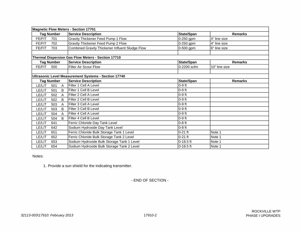
32113-003\17910: February 2013 17910-2
ROCKVILLE WTP
PHASE I UPGRADES
Service Description State/Span RemarksFE/FIT 701 Gravity Thickener Feed Pump 1 Flow 0-250 gpm 4" line sizeFE/FIT 702 Gravity Thickener Feed Pump 2 Flow 0-250 gpm 4" line sizeFE/FIT 703 Combined Gravity Thickener Influent Sludge Flow 0-500 gpm 6" line size
Service Description State/Span RemarksFE/FIT 500 Filter Air Scour Flow 0-2200 scfm 10" line size
Service Description State/Span RemarksLE/LIT 501 A Filter 1 Cell A Level 0-9 ftLE/LIT 501 B Filter 1 Cell B Level 0-9 ftLE/LIT 502 A Filter 2 Cell A Level 0-9 ftLE/LIT 502 B Filter 2 Cell B Level 0-9 ftLE/LIT 503 A Filter 3 Cell A Level 0-9 ftLE/LIT 503 B Filter 3 Cell B Level 0-9 ftLE/LIT 504 A Filter 4 Cell A Level 0-9 ftLE/LIT 504 B Filter 4 Cell B Level 0-9 ftLE/LIT 641 Ferric Chloride Day Tank Level 0-8 ftLE/LIT 642 Sodium Hydroxide Day Tank Level 0-8 ftLE/LIT 651 Ferric Chloride Bulk Storage Tank 1 Level 0-21 ft Note 1LE/LIT 652 Ferric Chloride Bulk Storage Tank 2 Level 0-21 ft Note 1LE/LIT 653 Sodium Hydroxide Bulk Storage Tank 1 Level 0-18.5 ft Note 1LE/LIT 654 Sodium Hydroxide Bulk Storage Tank 2 Level 0-18.5 ft Note 1
Notes:
1. Provide a sun shield for the indicating transmitter.
Ultrasonic Level Measurement Systems - Section 17740
- END OF SECTION -
Tag Number
Magnetic Flow Meters - Section 17701Tag Number
Thermal Dispersion Gas Flow Meters - Section 17710Tag Number

32041-002\17920: February 2013 17920-1ROCKVILLE WTP
PHASE I UPGRADES
1.01 THE REQUIREMENT
A. The Contractor shall furnish, test, install and place in satisfactory operation all control systeminputs and outputs as herein specified and as shown on the Drawings.
1.02 RELATED WORK SPECIFIED ELSEWHERE
A. Section 17950 - Functional Control Descriptions
PART 2 -- CONTROL SYSTEM INPUT / OUTPUT SCHEDULE
State/Span Type PLC RemarksRun DI 1 Existing input (I:10/8)Auto DI 1 Note 3 (I:10/19)Fail DI 1 Note 3 (I:10/20)
Fault DI 1 Note 3 (I:10/21)Start/Stop DO 1 Note 30-100% AI 1 Note 3 (I:3.0)0-100% AO 1 Note 3 (I:8.4)
Run DI 1 Existing input (I:11/11)Auto DI 1 Note 3 (I:11/18)Fail DI 1 Note 3 (I:11/19)
Fault DI 1 Note 3 (I:11/20)Start/Stop DO 1 Note 30-100% AI 1 Note 3 (I:4.6)
Gravity Thickener Feed Pump 1 VFD
Gravity Thickener Feed Pump 1 Speed Control
Gravity Thickener Feed Pump 1
Gravity Thickener Feed Pump 1 Speed Feedback
Gravity Thickener Feed Pump 1Gravity Thickener Feed Pump 1
Gravity Thickener Feed Pump 1 Control
SECTION 17920
CONTROL SYSTEM INPUT / OUTPUT SCHEDULE
PART 1 -- GENERAL
Gravity Thickener Feed Pump 2 Speed Feedback
Gravity Thickener Feed Pump 2
Service Description
Gravity Thickener Feed Pump 2
Gravity Thickener Feed Pump 2 Control
Gravity Thickener Feed Pump 2
Gravity Thickener Feed Pump 2 VFD

32041-002\17920: February 2013 17920-2ROCKVILLE WTP
PHASE I UPGRADES
State/Span Type PLC RemarksService Description0-100% AO 1 Note 3 (I:9.4)
Remote DI 1 Note 3Gravity Thickener 1 Influent Valve Position Opened DI 1 Note 3Gravity Thickener 1 Influent Valve Position Closed DI 1 Note 3
Open DO 1 Note 3Close DO 1 Note 3
Gravity Thickener 2 Influent Valve Remote DI 1 Note 3Gravity Thickener 2 Influent Valve Position Opened DI 1 Note 3Gravity Thickener 2 Influent Valve Position Closed DI 1 Note 3Gravity Thickener 2 Influent Valve Position Command Open DO 1 Note 3Gravity Thickener 2 Influent Valve Position Command Close DO 1 Note 3
Run DI 1 Note 3Auto DI 1 Note 3Fail DI 1 Note 3
Overtorque DI 1 Note 3Start/Stop DO 1 Note 3
AI 1 Note 3
Run DI 1 Note 3Auto DI 1 Note 3Fail DI 1 Note 3
Overtorque DI 1 Note 3Start/Stop DO 1 Note 3
AI 1 Note 3
Gravity Thickener Feed Pump 1 Flow AI 1 Note 3Gravity Thickener Feed Pump 2 Flow AI 1 Note 3
AI 1 Existing input (I:5.3)
Filter 1 Effluent Valve Remote DI 2 Note 3 (I:4/18)
Gravity Thickener 2 Scraper MechanismGravity Thickener 2 Scraper Mechanism
Gravity Thickener Feed Pump 2 Speed Control
Gravity Thickener 1 Scraper Mechanism
Gravity Thickener Total Feed Flow
Gravity Thickener 1 Scraper MechanismGravity Thickener 1 Scraper Mechanism
Gravity Thickener 2 Scraper Mechanism
Gravity Thickener 1 Scraper Mechanism
Gravity Thickener 1 Scraper Mechanism Current
Gravity Thickener 2 Scraper Mechanism Current
Gravity Thickener 1 Scraper Mechanism
Gravity Thickener 2 Scraper MechanismGravity Thickener 2 Scraper Mechanism
Gravity Thickener 1 Influent Valve Position CommandGravity Thickener 1 Influent Valve Position Command
Gravity Thickener 1 Influent Valve

32041-002\17920: February 2013 17920-3ROCKVILLE WTP
PHASE I UPGRADES
State/Span Type PLC RemarksService DescriptionFilter 1 Effluent Valve Opened DI 2 Existing input (I:1/30)Filter 1 Effluent Valve Closed DI 2 Existing input (I:1/31)Filter 1 Effluent Valve 0-100% AI 2 Note 3 (I:10.0)Filter 1 Effluent Valve 0-100% AO 2 Existing output (I:13.0)
Filter 1 Air Scour Supply Valve Remote DI 2 Notes 3,4 (I:4/3)Filter 1 Air Scour Supply Valve Position Feedback Opened DI 2 Note 4 (I:4/4)Filter 1 Air Scour Supply Valve Position Feedback Closed DI 2 Note 4 (I:4/5)Filter 1 Air Scour Supply Valve Position Command Open DO 2 Note 4 (O:5/2)Filter 1 Air Scour Supply Valve Position Command Close DO 2 Note 4 (O:5/3)
Filter 1 Cell A Level AI 2 Note 3Filter 1 Cell B Level AI 2 Note 3Filter 1 High Level Alarm DO 2 Note 3; to console lightFilter 1 Low Level Alarm DO 2 Note 3; to console light
Filter 2 Effluent Valve Remote DI 2 Note 3 (I:3/18)Filter 2 Effluent Valve Opened DI 2 Existing input (I:1/30)Filter 2 Effluent Valve Closed DI 2 Existing input (I:1/31)Filter 2 Effluent Valve 0-100% AI 2 Note 3 (I:10.4)Filter 2 Effluent Valve 0-100% AO 2 Existing output (I:13.1)
Filter 2 Air Scour Supply Valve Remote DI 2 Notes 3,4 (I:3/3)Filter 2 Air Scour Supply Valve Position Feedback Opened DI 2 Note 4 (I:3/4)Filter 2 Air Scour Supply Valve Position Feedback Closed DI 2 Note 4 (I:3/5)Filter 2 Air Scour Supply Valve Position Command Open DO 2 Note 4 (O:6/2)Filter 2 Air Scour Supply Valve Position Command Close DO 2 Note 4 (O:6/3)
Filter 2 Cell A Level AI 2 Note 3Filter 2 Cell B Level AI 2 Note 3Filter 2 High Level Alarm DO 2 Note 3; to console lightFilter 2 Low Level Alarm DO 2 Note 3; to console light

32041-002\17920: February 2013 17920-4ROCKVILLE WTP
PHASE I UPGRADES
State/Span Type PLC RemarksService DescriptionFilter 3 Effluent Valve Remote DI 2 Note 3 (I:2/18)Filter 3 Effluent Valve Opened DI 2 Existing input (I:1/30)Filter 3 Effluent Valve Closed DI 2 Existing input (I:1/31)Filter 3 Effluent Valve 0-100% AI 2 Note 3 (I:11.0)Filter 3 Effluent Valve 0-100% AO 2 Existing output (I:13.3)
Filter 3 Air Scour Supply Valve Remote DI 2 Notes 3,4 (I:2/3)Filter 3 Air Scour Supply Valve Position Feedback Opened DI 2 Note 4 (I:2/4)Filter 3 Air Scour Supply Valve Position Feedback Closed DI 2 Note 4 (I:2/5)Filter 3 Air Scour Supply Valve Position Command Open DO 2 Note 4 (O:7/2)Filter 3 Air Scour Supply Valve Position Command Close DO 2 Note 4 (O:7/3)
Filter 3 Cell A Level AI 2 Note 3Filter 3 Cell B Level AI 2Filter 3 High Level Alarm DO 2 Note 3; to console lightFilter 3 Low Level Alarm DO 2 Note 3; to console light
Filter 4 Effluent Valve Remote DI 2 Note 3 (I:1/18)Filter 4 Effluent Valve Opened DI 2 Existing input (I:1/30)Filter 4 Effluent Valve Closed DI 2 Existing input (I:1/31)Filter 4 Effluent Valve 0-100% AI 2 Note 3 (I:11.4)Filter 4 Effluent Valve 0-100% AO 2 Existing output (I:13.4)
Filter 4 Air Scour Supply Valve Remote DI 2 Notes 3,4 (I:1/3)Filter 4 Air Scour Supply Valve Position Feedback Opened DI 2 Note 4 (I:1/4)Filter 4 Air Scour Supply Valve Position Feedback Closed DI 2 Note 4 (I:1/5)Filter 4 Air Scour Supply Valve Position Command Open DO 2 Note 4 (O:8/2)Filter 4 Air Scour Supply Valve Position Command Close DO 2 Note 4 (O:8/3)
Filter 4 Cell A Level AI 2Filter 4 Cell B Level AI 2Filter 4 High Level Alarm DO 2 Note 3; to console lightFilter 4 Low Level Alarm DO 2 Note 3; to console light

32041-002\17920: February 2013 17920-5ROCKVILLE WTP
PHASE I UPGRADES
State/Span Type PLC RemarksService Description
Air Scour Blower 1 Run DI 2 Note 3Air Scour Blower 1 Auto DI 2 Note 3Air Scour Blower 1 Fail DI 2 Note 3Air Scour Blower 1 Control Start/Stop DO 2 Note 3
Air Scour Blower 2 Run DI 2 Note 3Air Scour Blower 2 Auto DI 2 Note 3Air Scour Blower 2 Fail DI 2 Note 3Air Scour Blower 2 Control Start/Stop DO 2 Note 3
Filter Air Scour Condensate Drain Valve Control Open DO 2 Note 3Filter Air Scour Flow 0-2200 scfm AI 2
Ferric Chloride Bulk Storage Tank 1 Level AI 7 From Chemical Fill Station CPFerric Chloride Bulk Storage Tank 2 Level AI 7 From Chemical Fill Station CPFerric Chloride Day Tank Level AI 7 From FeCl3 Transfer Pump CPSodium Hydroxide Bulk Storage Tank 1 Level AI 7 From Chemical Fill Station CPSodium Hydroxide Bulk Storage Tank 2 Level AI 7 From Chemical Fill Station CPSodium Hydroxide Day Tank Level AI 7 From NaOH Transfer Pump CP
Ferric Chloride Bulk Storage Tank 1 Level High-High DI 7 From Chemical Fill Station CPFerric Chloride Bulk Storage Tank 1 Level Low-Low DI 7 From Chemical Fill Station CPFerric Chloride Bulk Storage Tank 2 Level High-High DI 7 From Chemical Fill Station CPFerric Chloride Bulk Storage Tank 2 Level Low-Low DI 7 From Chemical Fill Station CPFerric Chloride Day Tank Level High-High DI 7 From FeCl3 Transfer Pump CPFerric Chloride Day Tank Level Low-Low DI 7 From FeCl3 Transfer Pump CPSodium Hydroxide Bulk Storage Tank 1 Level High-High DI 7 From Chemical Fill Station CPSodium Hydroxide Bulk Storage Tank 1 Level Low-Low DI 7 From Chemical Fill Station CPSodium Hydroxide Bulk Storage Tank 2 Level High-High DI 7 From Chemical Fill Station CPSodium Hydroxide Bulk Storage Tank 2 Level Low-Low DI 7 From Chemical Fill Station CPSodium Hydroxide Day Tank Level High-High DI 7 From NaOH Transfer Pump CPSodium Hydroxide Day Tank Level Low-Low DI 7 From NaOH Transfer Pump CP

32041-002\17920: February 2013 17920-6ROCKVILLE WTP
PHASE I UPGRADES
State/Span Type PLC RemarksService Description
Ferric Chloride Bulk Storage Tank 1 Outlet Valve Position Feedback Opened DI 7 MOV-205Ferric Chloride Bulk Storage Tank 1 Outlet Valve Position Feedback Closed DI 7 MOV-205Ferric Chloride Bulk Storage Tank 2 Outlet Valve Position Feedback Opened DI 7 MOV-206Ferric Chloride Bulk Storage Tank 2 Outlet Valve Position Feedback Closed DI 7 MOV-206
Sodium Hydroxide Bulk Storage Tank 1 Outlet Valve Position Feedback Opened DI 7 MOV-203Sodium Hydroxide Bulk Storage Tank 1 Outlet Valve Position Feedback Closed DI 7 MOV-203Sodium Hydroxide Bulk Storage Tank 2 Outlet Valve Position Feedback Opened DI 7 MOV-204Sodium Hydroxide Bulk Storage Tank 2 Outlet Valve Position Feedback Closed DI 7 MOV-204
Ferric Chloride Sump Level High DI 7 From Chemical Fill Station CPSodium Hydroxide Sump Level High DI 7 From Chemical Fill Station CP
Ferric Chloride Storage Area Shower/Eyewash In Use DI 7 From Chemical Fill Station CPFerric Chloride Feed Area Shower/Eyewash In Use DI 7 From Chemical Fill Station CPSodium Hydroxide Storage Area Shower/Eyewash In Use DI 7 From Chemical Fill Station CPSodium Hydroxide Feed Area Shower/Eyewash In Use DI 7 From Chemical Fill Station CP
Ferric Chloride Transfer Pump 1 Run DI 7Ferric Chloride Transfer Pump 1 Fail DI 7Ferric Chloride Transfer Pump 2 Run DI 7Ferric Chloride Transfer Pump 2 Fail DI 7
Sodium Hydroxide Transfer Pump 1 Run DI 7Sodium Hydroxide Transfer Pump 1 Fail DI 7Sodium Hydroxide Transfer Pump 2 Run DI 7Sodium Hydroxide Transfer Pump 2 Fail DI 7
Ferric Chloride Metering Pump 1 Run DI 7Ferric Chloride Metering Pump 1 Auto DI 7Ferric Chloride Metering Pump 1 Fail DI 7Ferric Chloride Metering Pump 1 VFD Fault DI 7

32041-002\17920: February 2013 17920-7ROCKVILLE WTP
PHASE I UPGRADES
State/Span Type PLC RemarksService DescriptionFerric Chloride Metering Pump 1 Control Start/Stop DO 7Ferric Chloride Metering Pump 1 Speed Feedback 0-100% AI 7Ferric Chloride Metering Pump 1 Speed Control 0-100% AO 7
Ferric Chloride Metering Pump 2 Run DI 7Ferric Chloride Metering Pump 2 Auto DI 7Ferric Chloride Metering Pump 2 Fail DI 7Ferric Chloride Metering Pump 2 VFD Fault DI 7Ferric Chloride Metering Pump 2 Control Start/Stop DO 7Ferric Chloride Metering Pump 2 Speed Feedback 0-100% AI 7Ferric Chloride Metering Pump 2 Speed Control 0-100% AO 7
Ferric Chloride Metering Pump 3 Run DI 7Ferric Chloride Metering Pump 3 Auto DI 7Ferric Chloride Metering Pump 3 Fail DI 7Ferric Chloride Metering Pump 3 VFD Fault DI 7Ferric Chloride Metering Pump 3 Control Start/Stop DO 7Ferric Chloride Metering Pump 3 Speed Feedback 0-100% AI 7Ferric Chloride Metering Pump 3 Speed Control 0-100% AO 7
Sodium Hydroxide Metering Pump 1 Run DI 7Sodium Hydroxide Metering Pump 1 Auto DI 7Sodium Hydroxide Metering Pump 1 Fail DI 7Sodium Hydroxide Metering Pump 1 VFD Fault DI 7Sodium Hydroxide Metering Pump 1 Control Start/Stop DO 7Sodium Hydroxide Metering Pump 1 Speed Feedback 0-100% AI 7Sodium Hydroxide Metering Pump 1 Speed Control 0-100% AO 7
Sodium Hydroxide Metering Pump 2 Run DI 7Sodium Hydroxide Metering Pump 2 Auto DI 7Sodium Hydroxide Metering Pump 2 Fail DI 7Sodium Hydroxide Metering Pump 2 VFD Fault DI 7Sodium Hydroxide Metering Pump 2 Control Start/Stop DO 7

32041-002\17920: February 2013 17920-8ROCKVILLE WTP
PHASE I UPGRADES
State/Span Type PLC RemarksService DescriptionSodium Hydroxide Metering Pump 2 Speed Feedback 0-100% AI 7Sodium Hydroxide Metering Pump 2 Speed Control 0-100% AO 7
Sodium Hydroxide Metering Pump 3 Run DI 7Sodium Hydroxide Metering Pump 3 Auto DI 7Sodium Hydroxide Metering Pump 3 Fail DI 7Sodium Hydroxide Metering Pump 3 VFD Fault DI 7Sodium Hydroxide Metering Pump 3 Control Start/Stop DO 7Sodium Hydroxide Metering Pump 3 Speed Feedback 0-100% AI 7Sodium Hydroxide Metering Pump 3 Speed Control 0-100% AO 7
Sodium Hydroxide Metering Pump 4 Run DI 7Sodium Hydroxide Metering Pump 4 Auto DI 7Sodium Hydroxide Metering Pump 4 Fail DI 7Sodium Hydroxide Metering Pump 4 VFD Fault DI 7Sodium Hydroxide Metering Pump 4 Control Start/Stop DO 7Sodium Hydroxide Metering Pump 4 Speed Feedback 0-100% AI 7Sodium Hydroxide Metering Pump 4 Speed Control 0-100% AO 7
Ferric Chloride Metering Pump 1 Flow AI 7Ferric Chloride Metering Pump 2 Flow AI 7Ferric Chloride Metering Pump 3 Flow AI 7Sodium Hydroxide Metering Pump 1 Flow AI 7Sodium Hydroxide Metering Pump 2 Flow AI 7Sodium Hydroxide Metering Pump 3 Flow AI 7Sodium Hydroxide Metering Pump 4 Flow AI 7
Notes:
1. Input / Output types are as follows:
DI - Discrete InputDO - Discrete Output

32041-002\17920: February 2013 17920-9ROCKVILLE WTP
PHASE I UPGRADES
State/Span Type PLC RemarksService DescriptionAI - Analog InputAO - Analog Output
2. PLC-1 and PLC-2 are existing and are located in the Main Control Room Filter Console.
3. Configure existing PLC spare input/output to be used for new input/output. PLC addresses (in parenthesis), where listed, were reserved for the associated equipment during original PLC commission. Contractor shall field-verify all spare input/output addresses.
4. Configure existing Filter Surface Wash Valve PLC input/output to use for new Air Scour Supply Valve input/output.
5. Configure the following existing PLC inputs as spare. Also delete all associated PLC logic and HMI database points, animation, and graphical objects.
- Caustic/PACl Building Eyewash/Shower PLC1, input I:1.0/0- PACl Day Tank Level Low PLC1, input I:3.1/0- PACl Metering Pumps Run Status PLC1, input I:3.1/1
- END OF SECTION -

THIS PAGE INTENTIONALLY LEFT BLANK.
32041-002\17950: February 2013 17950-1 ROCKVILLE WTP PHASE 1 UPGRADES
SECTION 17950
FUNCTIONAL CONTROL DESCRIPTIONS PART 1 -- GENERAL 1.01 THE REQUIREMENT
A. The Contractor shall furnish, test, install and place in satisfactory operation all equipment as herein specified and as shown on the Drawings. THE CONTRACTOR SHALL BE RESPONSIBLE FOR FURNISHING COMPLETE FUNCTIONING SYSTEMS AS DESCRIBED HEREIN.
B. Together with the control system input/output schedule, the equipment specifications
(including functional descriptions for local equipment control panels), and the Drawings, the functional control descriptions describe the required operation, monitoring, and control of the facilities included in this Contract.
C. THE FUNCTIONAL DESCRIPTIONS CONTAIN REQUIREMENTS FOR FURNISHING AND
INSTALLING LABOR AND MATERIALS THAT MAY NOT APPEAR ELSEWHERE IN THE CONTRACT DOCUMENTS.
D. All equipment and services required in equipment local control panels provided to implement
the monitoring and control functions described herein or in the process input/output schedules shall be provided by the Contractor through individual equipment suppliers.
E. Unless specifically stated otherwise, all interconnected wiring between all instruments,
panels, controls, and other devices listed in the functional descriptions as required to provide all functions specified herein shall be furnished by the Electrical Contractor under Division 16. The Electrical Contractor shall provide all cable and conduit required to carry all signals listed in the process input/output schedules. Special cables that are required for interconnection between sensors or probes and transmitters or signal conditioners shall be furnished with the instrumentation devices by the equipment supplier.
1.02 RELATED WORK SPECIFIED ELSEWHERE
A. Section 01520 – Maintenance of Utility Operations During Construction
B. Section 17920 – Control System Input/Output Schedule PART 2 -- FUNCTIONAL CONTROL DESCRIPTIONS, GENERAL 2.01 DEFINITIONS
A. RUNNING status signals shall be from auxiliary contacts provided with the motor control equipment (i.e., starter, VFD, SCR, etc.).
32041-002\17950: February 2013 17950-2 ROCKVILLE WTP PHASE 1 UPGRADES
B. AUTO status signals shall be defined as HAND-OFF-AUTO switch in the AUTO position or process control system in AUTO (versus MANUAL).
C. FAIL status signals shall be defined as motor overload and/or any other shut down mode
such as overtorque, overtemperature, low oil pressure, high vibration, etc.
D. READY status signal shall be defined as all conditions, including equipment control power, satisfied to permit remote control of the equipment.
2.02 CONVENTIONS
A. Operator workstation graphic display symbols and indicator lights on all MCC's, control panels, starter enclosures, etc. shall conform to the following color convention:
Condition Color Running/On/Open Red Auto/Ready White Stopped/Off/Closed Green Fail/Alarm Amber Generic Status Blue or White
2.03 PROCESS CONTROL
A. All existing equipment monitoring and control functionality shall be retained, unless otherwise specified herein.
B. Unless otherwise specified herein, all equipment shall be capable of being manually controlled at the operator workstation. This mode shall be provided in addition to an automatic mode of operation described herein. Manual or automatic mode shall be selectable at the operator workstation.
C. Where setpoints, operating limits, and other control settings are provided by the functional descriptions, these settings shall be initial settings only and shall be used for assistance in the initial startup of the plant. All such settings shall be fully adjustable and, based on actual operating conditions, the instrumentation subcontractor shall make all necessary adjustments to provide smooth, stable operation at no additional cost to the Owner.
D. Provision shall be made in PLC logic to suppress nuisance alarms and control actions by the
following means:
1. For alarms and control actions derived from analog input signals, use adjustable time delays and deadbands.
2. For alarms and control actions derived from discrete input signals, use adjustable
time delays. 3. Initial settings for time delays shall be 10 seconds (range 0-120 seconds). Initial
settings for deadbands shall be 5% of span (range 0-100%).

32041-002\17950: February 2013 17950-3 ROCKVILLE WTP PHASE 1 UPGRADES
4. Equipment that is started or stopped manually by the operator shall start or stop immediately, with no time delay.
E. All setpoint control shall be by PID control algorithms. Where only proportional control is
specified, tuning constants shall be used to reduce the Integral and Derivative functions to zero. All setpoints, sequence times, sequence orders, dead bands, PID tuning parameters, PLC delay timers, variable speed operating range limits, and similar control constants shall be accessible and alterable from the operator workstations.
F. Unless otherwise specified, all equipment shall automatically restart after a power failure
utilizing adjustable start delay timers in PLC control logic. Unless otherwise specified, all PLC control strategies shall be based upon automatic restart after a power failure and shall return to a normal control mode upon restoration of power.
G. The PLC shall be capable of receiving initial run-time values for existing and proposed
equipment. Initial run-time shall not automatically be assumed to be zero.
H. Unless otherwise specified, all flows shall be totalized in the PLC and displayed on the operator workstation for daily, weekly, monthly, and annual totals.
I. Equipment failure shall be generated through the PLC for any drive, motor, etc. for which a
command has been issued, but for which the PLC is not receiving a confirming status signal (e.g., start command with no run feedback). The failure shall be logged.
J. Instrument failure shall be generated via the operator work stations for any instrument which
is generating a signal which is less than 4 mA or greater than 20 mA.
K. A control program that controls multiple pieces of equipment shall not be prevented from running because not all of the equipment is in AUTO. If equipment within an equipment chain is required to be running for program operation and it is running in HAND or MANUAL, then the program shall run and control the other equipment that is in AUTO.
L. All PLC wait states (internal time delays, etc.) after an operator action shall be displayed on
the operator workstation. PART 3 -- FUNCTIONAL CONTROL DESCRIPTIONS
TABLE OF CONTENTS 3.01 Air Scour Blowers 3.02 Filter Modifications 3.03 Thickener Feed Pumps 3.04 Gravity Thickeners 3.05 Ferric Chloride Storage and Feed Systems 3.06 Sodium Hydroxide Storage and Feed Systems
32041-002\17950: February 2013 17950-4 ROCKVILLE WTP PHASE 1 UPGRADES
3.01 AIR SCOUR BLOWERS
A. Process Overview 1. Two air scour blowers shall be provided under Division 11. The blowers shall be
located outside as shown on the Drawings. The blowers shall be used to supply air to the filters during backwash sequences.
B. Control Equipment
1. A motor starter panel shall be provided for each blower under Division 16. The
starter panels shall be located in the Raw Water Gallery and shall include:
a. Reduced Voltage Soft Starter (RVSS)
b. RESET pushbutton c. RUN indicating light
d. MOTOR OVERTEMP indicating light
e. FAIL indicating light
f. RUN TIME meter (elapsed time/resettable)
2. A Blower Control Panel shall be provided under Division 11 for each of the two
blowers, and shall be as specified in Section 11280.
3. The following new control operators shall be provided for each blower on the existing console located in the Main Building Control Room. Control operator hole locations shall be submitted to and approved by Owner/Engineer prior to installation: a. HAND-OFF-AUTO selector switch
b. RUN indicating light
c. STOPPED indicating light
4. A solenoid valve shall be installed in the air scour drain piping where shown on the
Drawings. The PLC shall open the solenoid to periodically vacate any condensate from the air scour piping. The solenoid shall fail closed.
5. A thermal dispersion flow meter shall be provided on the air scour piping where shown on the Drawings to measure air flow.
C. Control Operations
1. When the HAND-OFF-AUTO (H-O-A) selector switch is in the HAND position, the
blower shall be started and stopped at the Control Room console. When the H-O-A switch is in the OFF position, the blower shall not run under any condition. When the

32041-002\17950: February 2013 17950-5 ROCKVILLE WTP PHASE 1 UPGRADES
H-O-A switch is in the AUTO position, the blower shall be controlled by the PLC as described below:
a. The operator shall manually start and stop the blowers from the operator
workstation. b. The blowers shall operate in a duty/standby sequence. The operator shall
select either a manual or automatic alternation mode at the operator workstation. i In manual alternation mode, the operator shall manually alternate the
duty blower at the operator workstation. ii In auto alternation mode, the duty blower shall alternate each time
the duty blower shuts down in order to equalize run time. The blower with the least run time shall become the new duty blower.
iii If the duty blower fails to start after a hardcoded time delay (initial: 30
secs) elapses, the standby blower shall be started immediately and the duty blower shall be updated.
iv If the duty blower fails during operation, the PLC shall generate an
alarm at the operator workstation (no automatic failover).
c. Blowers that are out of service, in manual control, or failed shall not be considered for automatic control.
2. The air scour drain solenoid valve shall be opened 30 minutes (adjustable) after the air scour blower shuts down for a duration of 2 minutes (adjustable). The solenoid valve shall be prohibited from opening if an air scour blower is in operation. The solenoid valve shall be closed immediately if an air scour blower starts while open.
3.02 FILTER MODIFICATIONS
A. Process Overview
1. Four (4) existing filters receive settled water from the clarifiers. Each filter is currently equipped with the following motor-operated valves: a. Influent Valve (open/close) b. Surface Wash Valve (open/close)
c. 2 Wash Water Valves (open/close)
d. Rewash Valve (open/close)
e. Wash Water Drain Valve (open/close)
f. Effluent Valve (modulating)

32041-002\17950: February 2013 17950-6 ROCKVILLE WTP PHASE 1 UPGRADES
2. One existing constant speed Backwash Pump draws water out of the clearwell to
provide wash water to the filters during backwash sequences.
3. Two air scour blowers shall be provided under this Contract as described above. 4. A motor-operated valve (open/close service) shall be provided for each of the four
filters under Division 15. These Air Scour Supply Valves shall be used to allow air flow to the filters during backwash sequences.
5. A motor-operated valve (modulating service) shall be provided for each of the four
filters under Division 15. These Filter Effluent Valves shall be used to control water flow to the clearwell.
6. Programming modifications shall include but not be limited to deleting the existing
Surface Wash Valve controls and incorporating the new Air Scour Supply Valve controls into the existing filter controls. Logic associated with the new ultrasonic level instruments shall also be programmed as described herein.
7. The existing filter motor operated valve actuators currently use separate limit switch
contacts for remote indication of valve position for the console mounted pilot lights and the PLC discrete inputs. The existing limit switches are not set identically such that the console lights and PLC inputs indicate that the valves are in different positions. The Contractor shall adjust all valve actuator limit switches such that the console pilot lights and the associated PLC inputs always indicate the same valve positions.
8. The existing PLC-2 spare discrete inputs reserved for valve auto status (indicated in
the Input/Output Schedule) shall be wired to the corresponding console-mounted valve OPEN-CLOSE-AUTO-OFF selector switches for indication of valve auto status. Each valve’s auto status shall be displayed on the SCADA workstations. Logic shall be provided as required in the PLC to prevent valve control from the operator workstations if the respective switches are not in the AUTO position.
B. Control Equipment
1. An existing console is located in the Main Building Control Room and includes the following devices for each of the four filters: a. HIGH TURBIDITY alarm indicating light b. HIGH LOSS OF HEAD alarm indicating light c. HIGH LEVEL alarm indicating light d. LOW LEVEL alarm indicating light e. EFFLUENT FLOW digital indicator f. LOSS OF HEAD digital indicator

32041-002\17950: February 2013 17950-7 ROCKVILLE WTP PHASE 1 UPGRADES
g. OPEN-CLOSE-AUTO-OFF selector switches for each open/close valve (total
of five) h. Effluent Valve single loop controller i. AUTO BACKWASH START-AUTO-OFF selector switch
2. The four existing “Surface Wash Valve” OPEN-CLOSE-AUTO-OFF selector switches located on the console shall be used to control the new Air Scour Supply Valves. New wire shall be routed and terminated at the existing switches for this purpose as required. Additionally, the associated selector switch nameplates shall be replaced with new nameplates that read “Air Scour Supply Valve”.
3. Eight digital indicators (two per filter) shall be provided on a new backplate mounted on the back of the existing Control Room console. Each set of two indicators shall be mounted over the respective filter controls and shall display filter cell level.
4. An existing differential pressure instrument is located for each filter (total of four) and measures loss of head.
5. An existing turbidity analyzer is located on each filter effluent pipe (total of four) and measures filtered water turbidity.
6. An existing insert Venturi flow tube and associated differential pressure transmitter is
located on each filter effluent pipe (total of four) and measures filter flow. 7. Existing capacitance-type level probes are located in each of the four filters and
alarm upon high and low filter level. These instruments shall be removed and turned over to the Owner. The associated PLC-2 discrete inputs shall be reconfigured as spares and the associated wire and conduit shall be demolished. The associated existing PLC-2 logic shall be modified to use high and low level alarms as measured by the new ultrasonic level measurement systems.
8. An ultrasonic level transducer and associated transmitter shall be provided for each
filter cell (total of eight).
C. Control Operations
1. When the LOCAL-OFF-REMOTE (L-O-R) selector switch on the valve actuator is in the LOCAL position, the valve shall be controlled at the actuator. When the L-O-R switch is in the OFF position, the valve shall not move under any condition. When the L-O-R switch is in the REMOTE position, the valve shall be controlled either at the filter console or by the PLC. The PLC shall control the valve only when the actuator L-O-R switch is in REMOTE and the respective OPEN-CLOSE-AUTO-OFF switch or single loop controller (Effluent Valve only) located on the filter console is in the AUTO position.

32041-002\17950: February 2013 17950-8 ROCKVILLE WTP PHASE 1 UPGRADES
2. Currently under normal filtration operation, the Influent and Effluent Valves are opened while the remainder of the valves are fully closed. The operator selects either manual or automatic mode of operation at the operator workstation.
a. In manual mode, the operator enters the desired position of the Filter Effluent
Valve at the operator workstation. The PLC then modulates the Effluent Valve to the entered position.
b. In the automatic mode, the operator enters the desired clearwell level setpoint (initially 8.2 ft) at the operator workstation. The PLC uses this value to calculate the individual Filter Flow Setpoint for each individual filter operating in filtration mode. The PLC then modulates the effluent valve of each filter operating in automatic mode to maintain the calculated flow setpoint.
c. Existing filter effluent valve controls shall not be modified under this Contract.
Effluent Valve position shall be added to the HMI displays. 3. Filter backwashes shall be initiated manually (at either the console or operator
workstation), and the filter valves, except for the Backwash Flow Control Valve, shall be manually positioned by the operator during the course of a filter backwash sequence.
4. Filter backwash sequence steps shall be as described below.
a. Close Influent Valve
b. Check water temperature
c. Drain filter through effluent valve until water level is 0.5 ft (adjustable) above
filter media. Verify water level based on associated level transmitters.
d. Close Effluent Valve
e. Open Wash Water Drain Valve
f. Start Air Scour Blower
g. Open Air Scour Valve
h. Provide air only for 3 minutes (adjustable)
i. Open Wash Water Supply Valves
j. Start Backwash Pump
k. The PLC shall automatically modulate the Backwash Flow Control Valve to maintain an operator-entered Backwash Low Flow Rate setpoint for an adjustable time duration (0-5 mins). An alarm shall be provided if the backwash flow rate is not achieved within a time delay.

32041-002\17950: February 2013 17950-9 ROCKVILLE WTP PHASE 1 UPGRADES
l. Close Air Scour Valve
m. Stop Air Scour Blower
n. The PLC shall automatically modulate the Backwash Flow Control Valve to
maintain an operator-entered Backwash High Flow Rate setpoint for an adjustable time duration (0-15 mins). An alarm shall be provided if the backwash flow rate is not achieved within a time delay.
o. The PLC shall automatically modulate the Backwash Flow Control Valve to
maintain an operator-entered Backwash Low Flow Rate setpoint for an adjustable time duration (0-5 mins). An alarm shall be provided if the backwash flow rate is not achieved within a time delay.
p. Close Wash Water Valves
q. The PLC shall fully close the Backwash Flow Control Valve after the most
recent Low Flow Rate wash time duration has elapsed. An alarm shall be provided if the valve does not fully close within a time delay.
r. Stop Backwash Pump
s. Close Wash Water Drain Valve
t. Open Influent Valve
u. Open Rewash Valve until filter turbidity reaches 0.2 NTU
v. Close Rewash Valve
w. Resume normal filtration (recommence modulating Effluent Valve)
5. The Filter Effluent Valve shall automatically close upon low filter level; this alarm
interlock shall be able to be disabled at the operator workstation. An alarm shall be generated at the operator workstation upon either high or low filter level.
3.03 THICKENER FEED PUMPS
A. Process Overview 1. Two existing Gravity Thickener Feed Pumps withdraw solids from the clarifiers. Each
pump is dedicated to withdraw solids from a single clarifier. The pumps discharge into a common header pipe that conducts flow to the existing Gravity Thickener. The common header pipe also receives flow from the Equalization Tank Solids Pump and has the capability to be dosed with polymer.
2. The two existing Gravity Thickener Feed (GTF) Pumps will be provided with new motors and new variable frequency drives under Division 16 to control the speed of the pumps. A new flow meter shall be installed on the discharge line of each GTF

32041-002\17950: February 2013 17950-10 ROCKVILLE WTP PHASE 1 UPGRADES
pump to monitor and control individual GTF pump flow. A new flow meter shall also be installed on the common discharge header and shall be used to monitor and control the total flow to the gravity thickeners.
3. A new motor operated valve will be provided on the feed pipe to each of the gravity
thickeners. Simultaneous feed to the existing and new Gravity Thickeners shall not be allowed.
B. Control Equipment 1. A local control station shall be provided for each pump under Division 16 and shall
include a LOCAL-OFF-REMOTE selector switch and START/STOP pushbuttons.
2. Each of the two pumps shall be provided with a variable frequency drive (VFD) under Division 16 to modulate the speed of the pumps. The VFDs shall be located in the Main Control Building Control Room and shall include: a. HAND- AUTO selector switch
b. RESET pushbutton
c. SPEED controller
d. SPEED meter
e. POWER ON indicating light
f. RUN indicating light
g. VFD FAULT indicating light
h. RUN TIME meter (Elapsed Time/Resettable)
3. Each pump is currently provided with a potable seal water supply with a solenoid
valve. The solenoid valve shall be hardwired to the pump motor starter circuit to open whenever the pump is running.
4. A new magnetic flow meter shall be installed on the discharge line of each GTF
pump (two total) in order to monitor individual pump flow.
5. A new magnetic flow meter shall be installed on the common discharge header for the two GTF pumps and the two Flow Equalization Basin pumps in order to monitor total flow to the gravity thickeners.
6. Two open/close-service motor operated valves shall be provided under Division 15,
and shall open and close to direct flow to either the new or existing gravity thickener.
C. Control Operations

32041-002\17950: February 2013 17950-11 ROCKVILLE WTP PHASE 1 UPGRADES
1. At the Operator Workstation, the Operator shall select which gravity thickener is in operation and the two motor operated valves shall automatically open/close to direct flow to the selected gravity thickener. Only one gravity thickener shall be fed at a time.
2. The total combined flow to each gravity thickener shall not exceed the maximum flow
cap for that thickener.
i. The total flow rate to the new gravity thickener shall be adjustable from 100 gpm to 500 gpm. Adjustment of the flow cap at the operator work station shall be password protected. The initial flow cap to the new gravity thickener shall be set at 480 gpm. The maximum allowable flow to the new Gravity Thickener shall not be allowed to exceed 500 gallons per minute.
ii. The total flow rate to the existing gravity thickener shall be adjustable from
100 gpm to 250 gpm. Adjustment of the flow cap at the operator work station shall be password protected. The initial flow cap to the existing gravity thickener shall be set at 200 gpm. The maximum allowable flow to the existing gravity thickener shall not exceed 250 gallons per minute.
3. When the HAND-AUTO (H-A) selector switch on the VFD is in the HAND position,
the GTF pump shall be started and stopped at the local control station and shall run at the speed set at the VFD. When the H-A switch is in the AUTO position, the PLC shall control the pump as described below:
a. Normal Operation:
i. Both GTF pumps shall run simultaneously.
ii. The flow rate for each GTF pump shall be manually set by the Operator at the operator workstation.
iii. The total flow rate to the gravity thickener shall not be allowed to exceed the gravity thickener feed cap for the thickener in operation. The HMI software shall be configured to reject any setpoints above the flow limits described above.
iv. The PLC shall adjust the speed of each GTF pump to maintain the respective setpoint flow rate to the gravity thickener. Instantaneous GTF pump flow rates and the totalized flow to each gravity thickener shall be displayed at the operator workstation.
v. When one or both of the Equalization Basin Backwash Solids Pumps are called to run (either in HAND or AUTO), the PLC shall reduce the speed of all operating GTF pumps to 50% (THE PUMP CLAMP SPEED, adjustable) in order to allow the EQ Basin pumps to operate at their maximum flow rate. After a field adjustable time delay (initially 20 sec) the PLC shall adjust the GTF pump speeds such that either: (1) the original pump flow set points are reached or (2) the flow cap to the gravity thickener is not exceeded; the option that produces the least amount of flow shall govern.
32041-002\17950: February 2013 17950-12 ROCKVILLE WTP PHASE 1 UPGRADES
vi. If flow to the gravity thickener exceeds the maximum set point for more than
15 seconds (adjustable) an alarm shall be indicated at the operator workstation.
vii. Once the equalization basin solids pumps have shut down, GTF pump operation shall resume based on prior set points.
b. Alternate Operation:
i. One GTF pump shall operate at a time.
ii. In this mode, the PLC shall prevent both GTF pumps from running at the same time.
iii. The flow rate for each GTF pump shall be manually set by the Operator at
the operator workstation.
iv. The total flow rate to the gravity thickener shall not be allowed to exceed the gravity thickener feed cap for the thickener in operation (described above). The HMI software shall be configured to reject any setpoints outside the flow limits described above.
v. If one clarifier is in service, the operator shall enter cycle on and cycle off
time durations for the associated GTF pump (both timers adjustable from 0 to 120 minutes). The operator shall then manually start the GTF pump at the operator workstation, at which time the GTF pump shall cycle on and off based on the adjustable time durations.
vi. If both clarifiers are in service, the operator shall enter a run time duration for
each GTF pump, as well as a pump rest time duration (adjustable from 0 to 120 minutes). The operator shall then manually start the first GTF pump in the rotation at the operator workstation. When the currently operating pump run time duration expires, that pump shall shut down and the other GTF pump shall automatically start and run for its operator-entered run time duration. When the second pump run time duration expires, that pump shall shut down and the pump rest time shall commence counting. During the pump rest time, neither pump shall run. This automatic pump rotation shall continue until the operator manually stops the running pump.
1. If the GTF pump called to start fails to start after an adjustable time
delay (initially 30 sec) or fails during operation, an alarm shall be generated and the other GTF pump shall be called to start when the run time for the failed pump has expired. The available pump shall continue to operate based on a cycle on/off timer (Where off-time =the failed pump run time plus the pump rest time) and on-time = operator set run time, as previously entered.
vii. The PLC shall prevent a pump from starting if the associated clarifier is not in

32041-002\17950: February 2013 17950-13 ROCKVILLE WTP PHASE 1 UPGRADES
service. If the clarifier is taken out of service while the associated pump is running, the pump shall be shut down immediately.
viii. Pumps that are out of service, in manual control, or failed shall not be
considered for automatic control.
ix. When one or both of the Equalization Basin Backwash Solids Pumps are called to run (either in HAND or AUTO), the PLC shall reduce the speed of the operating GTF pump to 30 %( THE PUMP CLAMP SPEED) in order to allow the EQ Basin pumps to operate at their maximum flow rate. After a field adjustable time delay (initially 20 sec) the PLC shall adjust the GTF pump speed such that either: (1) the original pump speed set point is reached or (2) the flow cap to the gravity thickener is not exceeded; the option that produces the least amount of flow shall govern.
x. If flow to the gravity thickener exceeds the maximum set point for more than 15 seconds (adjustable) an alarm shall be indicated at the operator workstation.
xi. Once the Equalization Basin pumps have shut down, the GTF pump operation shall resume based on the prior operator set point.
3.04 GRAVITY THICKENERS
A. Process Overview 1. Two gravity thickeners, one existing and one new, are equipped with a scraper
mechanism to move the settled solids to the center of the tank for withdrawal by the Thickened Sludge Pumps.
B. Control Equipment
1. Each Gravity Thickener scraper mechanism shall be provided with a new
combination motor starter panel under Division 16, located as shown on the Drawings, which shall include: a. HAND-OFF-AUTO selector switch b. START/STOP Pushbuttons
c. RUN indicating light d. GENERAL FAIL indicating light
e. 85% TORQUE indicating light
f. RESET pushbutton
g. Electronic TORQUE monitor and display

32041-002\17950: February 2013 17950-14 ROCKVILLE WTP PHASE 1 UPGRADES
C. Control Operations
1. When the HAND-OFF-AUTO (H-O-A) selector switch on the panel is in the HAND position, the scraper shall be started and stopped at the thickener drive panel. When the H-O-A switch is in the OFF position, the scraper shall not operate under any condition. When the H-O-A switch is in the AUTO position, the operator shall manually start and stop the scraper from the operator workstation.
2. The scraper shall shut down upon a high torque value via a hardwired interlock between each torque monitor (new Gravity Thickener 2) and the associated thickener scraper motor starter circuit.
3. Motor current shall continuously be monitored via the new electronic monitors
(shown on drawing E10). Torque shall be calculated in the PLC based on the current signals and shall be displayed (motor current and torque) locally and at the operator workstation. A high torque alarm shall be generated at the operator workstation at a value lower than the torque shutdown interlock.
3.05 FERRIC CHLORIDE STORAGE AND FEED SYSTEMS
A. Process Overview 1. The ferric chloride storage and feed systems consist of a truck fill station (common to
both ferric chloride and sodium hydroxide systems), two emergency eyewash/shower stations, two sump pumps, two bulk storage tanks, one day storage tank, two chemical transfer pumps (FCTP-1 and FCTP-2), and three chemical metering pumps (FCMP-1 through FCMP-3).
2. Bulk ferric chloride shall be delivered to the City of Rockville Water Treatment Plant
(WTP) at trade strength of 42% as ferric chloride. Dedicated lines shall be provided from the truck fill station to the two bulk storage tanks.
3. Two chemical transfer pumps shall be provided to convey ferric chloride solution from the bulk storage tanks to the day storage tank. Both pumps shall be capable of serving the Day Tank, and one will be used as duty with the other as standby at all times. Both transfer pumps draw from a common combined suction from the bulk storage tanks.
4. The metering pumps shall be piped to deliver ferric chloride solution to the 24” raw water influent line, prior to the split to each clarifier. One pump shall be used to meet average/minimum dosing conditions, and a second will be used in conjunction with the first pump to meet maximum dosing conditions. A third pump will be provided as a spare.
B. Control Equipment
1. A total of three ultrasonic level transmitters and associated transducers shall be
provided to measure bulk storage tank and day tank levels.
2. A common Chemical Fill Station Control Panel shall be furnished under Division 16

32041-002\17950: February 2013 17950-15 ROCKVILLE WTP PHASE 1 UPGRADES
and shall be provided with the following for the ferric chloride and sodium hydroxide systems:
a. Power On indicating light b. General alarm horn and strobe c. Tank High Level indicating light for each bulk storage tank (qty:4) d. Tank Full indicating light for each bulk storage tank (qty:4) e. Tank Low Level indicating light for each bulk storage tank (qty:4) f. Tank Low-Low Level indicating light for each bulk storage tank (qty:4) g. Sump High Level indicating light (qty:2) h. Storage Area Eyewash/Shower In Use indicating light (qty:2) i. Feed Area Eyewash/Shower In Use indicating light (qty:2) j. Tank Level digital indicator for each bulk storage tank (qty:4) k. Alarm Silence, Reset and Test pushbuttons
3. The ferric chloride transfer pumps shall be provided with a common Ferric Chloride Transfer Pump Control Panel, furnished under Division 16, which shall include the following:
a. Power On indicating light b. Tank 1/Off/Tank 2 selector switch for each pump c. Run indicating light for each pump d. Fail indicating light for each pump e. Bulk Storage Tank Low-Low Level indicating light for each bulk storage tank f. Day Tank High Level indicating light g. Day Tank Full indicating light h. Day Tank Low Level indicating light i. Day Tank Low-Low Level indicating light j. Day Tank Level digital indicator k. Alarm horn and strobe l. Alarm Silence, Reset, and Test pushbuttons m. Motor starters for each pump n. Elapsed Runtime meters for each pump o. Front panel mounted lockable disconnect switch
4. Each ferric chloride chemical metering pump shall be provided with a variable frequency drive (VFD) in a control panel furnished under Section 11170..
C. Control Operations
1. Bulk tank and day tank levels, volumes, and alarms shall be displayed at the HMI.
Alarm setpoints shall be programmed in the level transmitters. Transmitter contacts shall be used to generate remote alarms. If the level in any tank drops by more than 0.1 inches in any given minute, the PLC shall generate an alarm for the associated tank.
2. Transfer Pump Operation a. The operator shall manually start and stop the transfer pumps from the Ferric
Chloride Transfer Pump Control Panel. No automatic starting of the transfer

32041-002\17950: February 2013 17950-16 ROCKVILLE WTP PHASE 1 UPGRADES
pumps shall be provided.
b. When the pump Tank 1/Off/Tank 2 momentary selector switch is in either the Tank 1 or Tank 2 position, the associated tank outlet valve shall be opened and the respective pump shall start. The valve shall remain opened and the pump shall remain running until the operator releases the switch, which shall spring-return to the Off position.
c. When the pump Tank 1/Off/Tank 2 switch is in the Off position, all tank outlet
valves shall be closed and the transfer pump shall not run under any condition.
3. Metering Pump Operation
a. When the HAND-OFF-AUTO selector switch is in the Hand position, the metering pumps shall be manually controlled at the pump and shall run at the speed set at the local speed controller. When the HAND-OFF-AUTO switch is in the Off position, the pump shall not operate under any condition.
1) When calibrating the metering pump’s pumping capacity using the
calibration chamber, the metering pump stroke length should be decided and set at a fixed value and the stroke rate shall be varied using the controller.
b. When the HAND-OFF-AUTO selector switch is in the Auto position, pump
operation and stroke frequency/speed control shall be controlled by the PLC in a flow paced mode based upon raw water flow with the dose selected at the HMI.
c. The metering pump feed rate shall automatically be calculated based on the
net raw water flow, which is equivalent to the sum of the measured raw water flow and the measured recycle water flow. The operator shall input a desired chemical dosage and the concentration of ferric chloride solution at the HMI. The PLC shall then calculate the required ferric chloride feed rate (in GPH) for the particular feed point and shall yield a 4-20mA output signal to the metering pump to deliver the calculated feed rate. The following formula shall be used to calculate the chemical feed rate in flow pacing mode:
Feed Rate (gph) = [Product Dosage (ppm) x 8.34 x Flow (mgd)] /
[Product Density (lbs/gal) @ Product Concentration x 24 (hr/day)]
d. If the calculated feed rate is within the range of performance for the
designated raw water feed primary pump, the feed rate shall be supplied by the designated raw water feed primary pump. If the calculated feed rate exceeds the capacity of the primary raw water feed pump, the primary and secondary raw water feed pumps shall be utilized together to meet the feed requirement, with each operating to deliver 50% of the calculated feed rate.
e. The calculated metering pump feed rate (GPH) and the distribution of flow

32041-002\17950: February 2013 17950-17 ROCKVILLE WTP PHASE 1 UPGRADES
between primary and secondary pumps shall be displayed at the operator workstation for the above control mode of operations.
f. The operator shall manually select primary, secondary, and standby pumps
at the HMI. If either the lead or lag pump fails, the standby pump shall be manually started.
3.06 SODIUM HYDROXIDE STORAGE AND FEED SYSTEMS
A. Process Overview 1. The sodium hydroxide storage and feed systems consist of a truck fill station
(common to both ferric chloride and sodium hydroxide systems), two emergency eyewash/shower stations, two sump pumps, two bulk storage tanks, one day storage tank, two chemical transfer pumps (SHTP-1 and SHTP-2), two high dose metering pumps (SHMP-1 and SHMP-4), and two low dose metering pumps(SHMP-2, pre-filter and SHMP-3, finished water).
2. Bulk sodium hydroxide shall be delivered to the City of Rockville Water Treatment
Plant at trade strength of 25%. Dedicated lines shall be provided from the truck fill station to the two bulk storage tanks.
3. The two chemical transfer pumps shall be provided to convey sodium hydroxide
solution from the bulk storage tanks to the day storage tank, with one pump used as duty and one as standby at all times. Both transfer pumps draw from a common combined suction from the bulk storage tanks.
4. Metering Pumps 1 and 4 are piped such that either or both pumps can serve the raw
water feed point, with one being designated as the primary metering pump, and the other designated as the secondary metering pump. The primary pump will be used to meet average/minimum dosing conditions, and the secondary pump will be used in conjunction with the primary pump to meet maximum dose conditions.
5. Metering Pumps 1 and 4 are also piped with the ability to feed sodium hydroxide
solution to the pre-filter or finished water feed points. Whichever of the pumps is set to serve as the secondary raw water duty pump will serve as the standby pump for either of these locations, when not being utilized to supplement maximum raw water dose conditions.
6. Metering Pump 2 is piped such that the pump is dedicated to the pre-filter feed point.
The feed point is located in the existing 20” combined settled water line (at the existing pre-filter sodium hydroxide feed point), prior to splitting to feed individual filters. The designated secondary raw water metering pump will serve as the standby pump for this location.
7. Metering Pump 3 is piped such that the pump is dedicated to the finished water feed
point. The feed point is located within the clearwell, at the existing finished water sodium hydroxide feed point. The designated secondary raw water metering pump will serve as the standby pump for this location.

32041-002\17950: February 2013 17950-18 ROCKVILLE WTP PHASE 1 UPGRADES
B. Control Equipment
1. A total of three ultrasonic level transmitters and associated transducers shall be provided to measure bulk storage tank and day tank levels.
2. A common Chemical Fill Station Control Panel shall be furnished under Division 16 as previously described herein.
3. The sodium hydroxide transfer pumps shall be provided with a common Sodium
Hydroxide Transfer Pump Control Panel, furnished under Division 16, which shall include the following:
a. Power On indicating light b. Tank 1/Off/Tank 2 selector switch for each pump c. Run indicating light for each pump d. Fail indicating light for each pump e. Bulk Storage Tank Low-Low Level indicating light for each bulk storage tank f. Day Tank High Level indicating light g. Day Tank Full indicating light h. Day Tank Low Level indicating light i. Day Tank Low-Low Level indicating light j. Day Tank Level digital indicator k. Alarm horn and strobe l. Alarm Silence, Reset, and Test pushbuttons m. Motor starters for each pump n. Elapsed Runtime meters for each pump o. Front panel mounted lockable disconnect switch
4. Each sodium hydroxide chemical metering pump shall be provided with a variable frequency drive in a control panel under Section 11170.
C. Control Operations
1. Bulk tank levels, volumes, and alarms shall be displayed at the HMI. Alarm setpoints shall be programmed in the level transmitters. Transmitter contacts shall be used to generate remote alarms. If the level in any tank drops by more than 0.1 inches in any given minute, the PLC shall generate a chemical leak alarm for the applicable tank.
2. Transfer Pump Operation
a. The operator shall manually start and stop the transfer pumps from the
Sodium Hydroxide Transfer Pump Control Panel. No automatic starting of the transfer pumps shall be provided.
b. When the pump Tank 1/Off/Tank 2 momentary selector switch is in either the
Tank 1 or Tank 2 position, the associated tank outlet valve shall be opened and the respective pump shall start. The valve shall remain opened and the pump shall remain running until the operator releases the switch, which shall spring-return to the Off position.
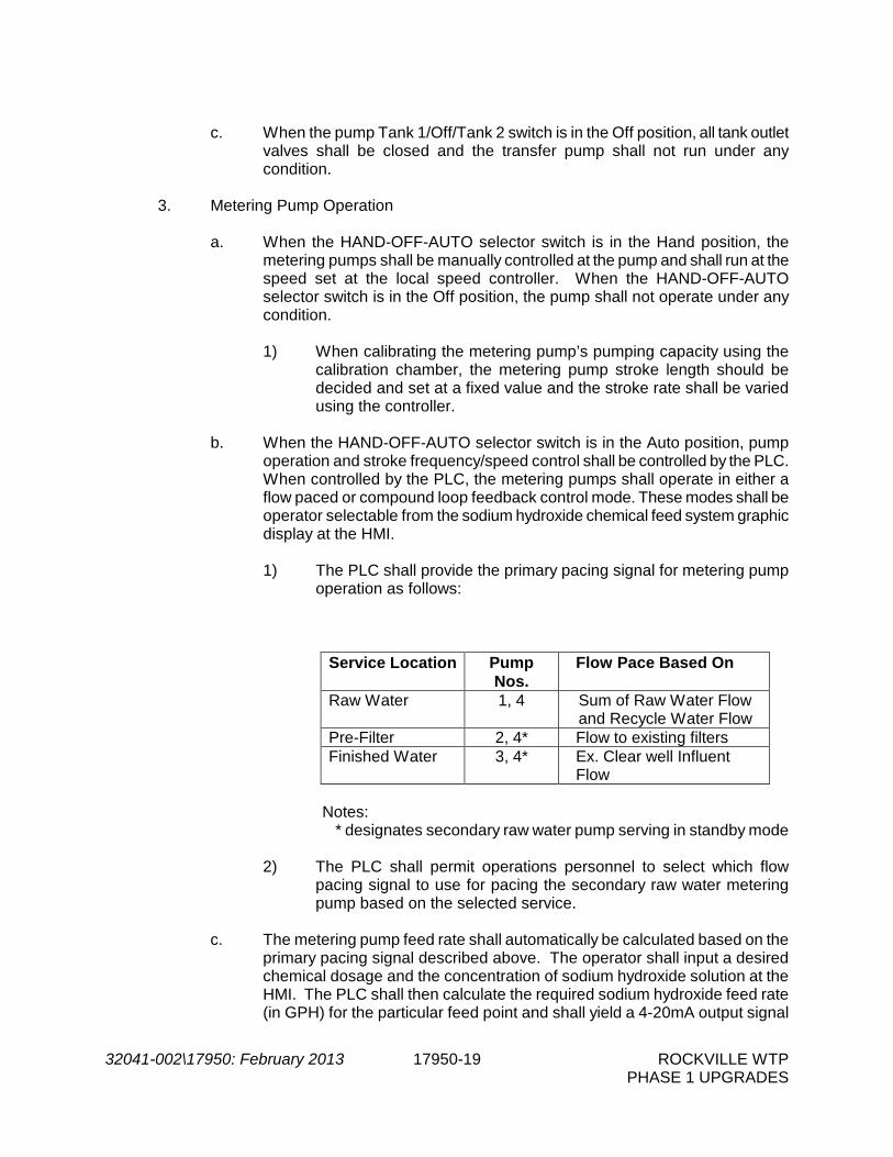
32041-002\17950: February 2013 17950-19 ROCKVILLE WTP PHASE 1 UPGRADES
c. When the pump Tank 1/Off/Tank 2 switch is in the Off position, all tank outlet
valves shall be closed and the transfer pump shall not run under any condition.
3. Metering Pump Operation
a. When the HAND-OFF-AUTO selector switch is in the Hand position, the metering pumps shall be manually controlled at the pump and shall run at the speed set at the local speed controller. When the HAND-OFF-AUTO selector switch is in the Off position, the pump shall not operate under any condition.
1) When calibrating the metering pump’s pumping capacity using the
calibration chamber, the metering pump stroke length should be decided and set at a fixed value and the stroke rate shall be varied using the controller.
b. When the HAND-OFF-AUTO selector switch is in the Auto position, pump
operation and stroke frequency/speed control shall be controlled by the PLC. When controlled by the PLC, the metering pumps shall operate in either a flow paced or compound loop feedback control mode. These modes shall be operator selectable from the sodium hydroxide chemical feed system graphic display at the HMI.
1) The PLC shall provide the primary pacing signal for metering pump
operation as follows:
Service Location Pump Nos.
Flow Pace Based On
Raw Water 1, 4 Sum of Raw Water Flow and Recycle Water Flow
Pre-Filter 2, 4* Flow to existing filters Finished Water 3, 4* Ex. Clear well Influent
Flow
Notes: * designates secondary raw water pump serving in standby mode
2) The PLC shall permit operations personnel to select which flow
pacing signal to use for pacing the secondary raw water metering pump based on the selected service.
c. The metering pump feed rate shall automatically be calculated based on the
primary pacing signal described above. The operator shall input a desired chemical dosage and the concentration of sodium hydroxide solution at the HMI. The PLC shall then calculate the required sodium hydroxide feed rate (in GPH) for the particular feed point and shall yield a 4-20mA output signal

32041-002\17950: February 2013 17950-20 ROCKVILLE WTP PHASE 1 UPGRADES
to the metering pump to deliver the calculated feed rate. The following formula shall be used to calculate the chemical feed rate in flow pacing mode:
Feed Rate (gph) = [Product Dosage (ppm) x 8.34 x Flow (mgd)] /
[Product Density (lbs/gal) @ Product Concentration x 24 (hr/day)]
d. All pumps shall be capable of operating in compound loop feedback control
mode, as long as they are servicing or standby for the Pre-filter or Finished Water feed points. In compound loop feedback control mode, the feed rate calculated using the flow pace control mode above shall be trimmed to maintain an operator entered set point pH value. The pH instruments and set point ranges shall be as follows:
Service Location
Set point Range
Initial Target Set point
Pre-Filter 6.2 – 7.5 6.5
Finished Water 7.0 – 8.5 7.7
e. If the calculated raw water feed rate is within the range for the designated
primary raw water feed pump, the feed rate shall be supplied by the designated primary raw water feed pump. If the calculated feed rate exceeds the capacity of the designated primary raw water feed pump, the designated primary and designated secondary raw water feed pumps shall be utilized together to meet the feed requirement, with each operating to deliver 50% of the calculated feed rate.
f. If the calculated raw water feed rate is within the range for the designated
primary raw water feed pump, the designated secondary raw water feed pump shall serve as a common spare for the primary Raw Water feed pump, the Pre-filter feed pump, and the Finished Water feed pump. If the raw water feed requirement is such that both primary and secondary Raw Water feed pumps are required in order to deliver the calculated feed rate, there shall be no spare for the Pre-filter and Finished Water feed pumps.
g. The calculated metering pump feed rate (GPH), and the distribution of flow
between primary and secondary raw water pumps shall be displayed at the operator workstation for the above control modes of operation.
h. The operator shall manually select the secondary pump (Pump 1 or 4) at the
HMI. If any primary metering pump fails, the PLC shall prompt the operator to confirm all valves are correctly positioned prior to allowing the operator to manually start the secondary pump.
- END OF SECTION -