Cisco Nexus 9000 Data Center Service Provider Guide
80
© 2015 Cisco and/or its affiliates. All rights reserved. This document is Cisco Public Information. Page 1 of 80 Cisco Nexus 9000 Data Center Service Provider Guide March 2015 Guide
Transcript of Cisco Nexus 9000 Data Center Service Provider Guide

© 2015 Cisco and/or its affiliates. All rights reserved. This document is Cisco Public Information. Page 1 of 80
Cisco Nexus 9000 Data Center Service Provider
Guide
March 2015
Guide
© 2015 Cisco and/or its affiliates. All rights reserved. This document is Cisco Public Information. Page 2 of 80
Contents
1. Introduction .......................................................................................................................................................... 4 1.1 What You Will Learn ....................................................................................................................................... 4 1.2 Disclaimer ....................................................................................................................................................... 4 1.3 Why Choose Cisco Nexus 9000 Series Switches ........................................................................................... 4 1.4 About Cisco Nexus 9000 Series Switches ...................................................................................................... 5
2. ACI-Readiness ..................................................................................................................................................... 6 2.1 What Is ACI? ................................................................................................................................................... 6 2.2 Converting Nexus 9000 NX-OS Mode to ACI Mode ....................................................................................... 7
3. Evolution of Data Center Design ........................................................................................................................ 7
4. Evolution of Data Center Operation ................................................................................................................... 9
5. Key Features of Cisco NX-OS Software ........................................................................................................... 11
6. Data Center Design Considerations ................................................................................................................. 12 6.1 Traditional Data Center Design ..................................................................................................................... 12 6.2 Leaf-Spine Architecture ................................................................................................................................. 14 6.3 Spanning Tree Support ................................................................................................................................. 15 6.4 Layer 2 versus Layer 3 Implications .............................................................................................................. 16 6.5 Virtual Port Channels (vPC) .......................................................................................................................... 17 6.6 Overlays ........................................................................................................................................................ 18
6.6.1 Virtual Extensible LAN (VXLAN) ............................................................................................................ 18 6.6.2 BGP EVPN Control Plane for VXLAN ................................................................................................... 21 6.6.3 VXLAN Data Center Interconnect (DCI) with a BGP Control Plane ....................................................... 21
7. Integration into Existing Networks ................................................................................................................... 22 7.1 Pod Design with vPC .................................................................................................................................... 23 7.2 Fabric Extender Support ............................................................................................................................... 25 7.3 Pod Design with VXLAN ............................................................................................................................... 27 7.4 Traditional Three-Tier Architecture with 1/10 Gigabit Ethernet Server Access ............................................. 28 7.5 Traditional Cisco Unified Computing System and Blade Server Access ....................................................... 30
8. Integrating Layer 4 - Layer 7 Services ............................................................................................................. 31
9. Cisco Nexus 9000 Data Center Topology Design and Configuration ............................................................ 31 9.1 Hardware and Software Specifications ......................................................................................................... 32 9.2 Leaf-Spine-Based Data Center ..................................................................................................................... 32
9.2.1 Topology................................................................................................................................................ 32 9.3 Traditional Data Center ................................................................................................................................. 38
9.3.1 Topology................................................................................................................................................ 38
10. Managing the Fabric ........................................................................................................................................ 39 10.1.1 Adding Switches and Power-On Auto Provisioning .................................................................................. 39 10.1.2 Software Upgrades .................................................................................................................................. 41 10.1.3 Guest Shell Container .............................................................................................................................. 42
11. Virtualization and Cloud Orchestration ......................................................................................................... 42 11.1 VM Tracker ................................................................................................................................................. 42 11.2 OpenStack .................................................................................................................................................. 43 11.3 Cisco UCS Director ..................................................................................................................................... 45 11.4 Cisco Prime Data Center Network Manager ............................................................................................... 46 11.5 Cisco Prime Services Catalog ..................................................................................................................... 47
12. Automation and Programmability .................................................................................................................. 48 12.1 Support for Traditional Network Capabilities ............................................................................................... 48 12.2 Programming Cisco Nexus 9000 Switches through NX-APIs ..................................................................... 50 12.3 Chef, Puppet, and Python Integration ......................................................................................................... 50
© 2015 Cisco and/or its affiliates. All rights reserved. This document is Cisco Public Information. Page 3 of 80
12.4 Extensible Messaging and Presence Protocol Support .............................................................................. 51 12.5 OpenDay Light Integration and OpenFlow Support .................................................................................... 52
13. Troubleshooting ............................................................................................................................................... 53
14. Appendix .......................................................................................................................................................... 56 14.1 Products ...................................................................................................................................................... 56
14.1.1 Cisco Nexus 9500 Product Line .......................................................................................................... 56 14.1.2 Cisco Nexus 9300 Product Line .......................................................................................................... 56
14.2 NX-API ........................................................................................................................................................ 57 14.2.1 About NX-API ...................................................................................................................................... 57 14.2.2 Using NX-API ...................................................................................................................................... 57 14.2.3 NX-API Sandbox ................................................................................................................................. 57 14.2.4 NX-OS Configuration Using Postman ................................................................................................. 60
14.3 Configuration ............................................................................................................................................... 62 14.3.1 Configuration of Interfaces and VLAN ................................................................................................. 62 14.3.2 Configuration of Routing - EIGRP ....................................................................................................... 64 14.3.3 BGP Configuration for DCI .................................................................................................................. 66 14.3.4 vPC Configuration at the Access Layer ............................................................................................... 66 14.3.5 Multicast and VXLAN .......................................................................................................................... 69 14.3.6 Firewall ASA Configuration .................................................................................................................. 73 14.3.7 F5 LTM Load Balancer Configuration .................................................................................................. 74
14.4 References .................................................................................................................................................. 79 14.4.1 Design Guides ..................................................................................................................................... 79 14.4.2 Nexus 9000 platform ........................................................................................................................... 79 14.4.3 Network General ................................................................................................................................. 80 14.4.4 Migration .............................................................................................................................................. 80 14.4.5 Analyst Reports ................................................................................................................................... 80

© 2015 Cisco and/or its affiliates. All rights reserved. This document is Cisco Public Information. Page 4 of 80
1. Introduction
1.1 What You Will Learn
The Cisco Nexus® 9000 Series Switch product family makes the next generation of data center switching
accessible to customers of any size. This white paper is intended for the commercial customer new to the Cisco®
Nexus 9000 who is curious how the Cisco Nexus 9000 might be feasibly deployed in its data center.
This white paper will highlight the benefits of the Cisco Nexus 9000, outline several designs suitable for small-to-
midsize customer deployments, discuss integration into existing networks, and walk through a Cisco validated
Nexus 9000 topology, complete with configuration examples.
The featured designs are practical for both entry-level insertion of Cisco Nexus 9000 switches, and for existing or
growing organizations scaling out the data center. The configuration examples transform the logical designs into
tangible, easy-to-use templates, simplifying deployment and operations for organizations with a small or growing IT
staff.
Optionally, readers can learn how to get started with the many powerful programmability features of Cisco NX-OS
from a beginner’s perspective by referencing the addendum at the end of this document. This white paper also
provides many valuable links for further reading on protocols, solutions, and designs discussed. A thorough
discussion on the programmability features of the Cisco Nexus 9000 is out of the scope of this document.
1.2 Disclaimer
Always refer to the Cisco website for the most recent information on software versions, supported configuration
maximums, and device specifications at http://www.cisco.com/go/nexus9000.
1.3 Why Choose Cisco Nexus 9000 Series Switches
Cisco Nexus 9000 Series Switches (Figure 1) are ideal for small-to-medium-sized data centers, offering five key
benefits: price, performance, port-density, programmability, and power efficiency.
Figure 1. Cisco Nexus 9000 Series Switch Product Family
Cisco Nexus 9000 Series Switches are cost-effective by taking a merchant-plus approach to switch design. Both
Cisco developed, plus merchant silicon application-specific integrated circuits (ASICs; Trident II, sometimes
abbreviated as T2) power Cisco Nexus 9000 switches. The T2 ASICs also deliver power efficiency gains.
Additionally, Cisco Nexus 9000 Series Switches lead the industry in 10 GE and 40 GE price-per-port densities. The
cost-effective design approach, coupled with a rich feature set, make the Cisco Nexus 9000 a great fit for the
commercial data center.

© 2015 Cisco and/or its affiliates. All rights reserved. This document is Cisco Public Information. Page 5 of 80
Licensing is greatly simplified on the Cisco Nexus 9000. At the time of writing, there are two licenses available: the
Enterprise Services Package license can enable dynamic routing protocol and Virtual Extensible LAN (VXLAN)
support, and the Data Center Network Manager (DCNM) license provides a single-pane-of-glass GUI management
tool for the entire data center network. Future licenses may become available as new features are introduced.
Lastly, the Cisco Nexus 9000 offers powerful programmability features to drive emerging networking models,
including automation and DevOps, taking full advantage of tools like the NX-API, Python, Chef, and Puppet.
For the small-to-midsize commercial customer, the Cisco Nexus 9000 Series Switch is the best platform for 1-to-10
GE migration or 10-to-40 GE migration, and is an ideal replacement for aging Cisco Catalyst® switches in the data
center. The Cisco Nexus 9000 can easily be integrated with existing networks. This white paper will introduce you
to a design as small as two Cisco Nexus 9000 Series Switches, and provide a path to scale out as your data center
grows, highlighting both access/aggregation designs, and spine/leaf designs.
1.4 About Cisco Nexus 9000 Series Switches
The Cisco Nexus 9000 Series consists of larger Cisco Nexus 9500 Series modular switches and smaller Cisco
Nexus 9300 Series fixed-configuration switches. The product offerings will be discussed in detail later in this white
paper.
Cisco provides two modes of operation for the Cisco Nexus 9000 Series. Customers can use Cisco NX-OS
Software to deploy the Cisco Nexus 9000 Series in standard Cisco Nexus switch environments. Alternately,
customers can use the hardware-ready Cisco Application Centric Infrastructure (ACI) to take full advantage of an
automated, policy-based, systems management approach.
In addition to traditional NX-OS features like virtual PortChannel (vPC), In-Service Software Upgrades (ISSU -
future), Power-On Auto-Provisioning (POAP), and Cisco Nexus 2000 Series Fabric Extender support, the single-
image NX-OS running on the Cisco Nexus 9000 introduces several key new features:
● The intelligent Cisco NX-OS API (NX-API) provides administrators a way to manage the switch through
remote procedure calls (JSON or XML) over HTTP/HTTPS, instead of accessing the NX-OS command line
directly.
● Linux shell access can enable the switch to be configured through Linux shell scripts, helping automate the
configuration of multiple switches and helping to ensure consistency among multiple switches.
● Continuous operation through cold and hot patching provides fixes between regular maintenance releases
or between the final maintenance release and the end-of-maintenance release in a non-disruptive manner
(for hot patches).
● VXLAN bridging and routing in hardware at full line rate facilitates and accelerates communication between
virtual and physical servers. VXLAN is designed to provide the same Layer 2 Ethernet services as VLANs,
but with greater flexibility and at a massive scale.
For more information on upgrades, refer to the Cisco Nexus 9000 Series NX-OS Software Upgrade and
Downgrade Guide.
This white paper will focus on basic design, integration of features like vPC, VXLAN, access layer device
connectivity, and Layer 4 - 7 service insertion. Refer to the addendum for an introduction to the advanced
programmability features of NX-OS on Cisco Nexus 9000 Series Switches. Other features are outside the scope of
this white paper.
© 2015 Cisco and/or its affiliates. All rights reserved. This document is Cisco Public Information. Page 6 of 80
2. ACI-Readiness
2.1 What Is ACI?
The future of networking with Cisco Application Centric Infrastructure (ACI) is about providing a network that is
deployed, monitored, and managed in a fashion that supports rapid application change. ACI does so through the
reduction of complexity and a common policy framework that can automate provisioning and management of
resources.
Cisco ACI works to solve the business problem of slow application deployment due to focus on primarily technical
network provisioning and change management problems, by enabling rapid deployment of applications to meet
changing business demands. ACI provides an integrated approach by providing application-centric, end-to-end
visibility from a software overlay down to the physical switching infrastructure. At the same time it can accelerate
and optimize Layer 4 - 7 service insertion to build a system that brings the language of applications to the network.
ACI delivers automation, programmability, and centralized provisioning by allowing the network to be automated
and configured based on business-level application requirements.
ACI provides accelerated, cohesive deployment of applications across network and Layer 4 - 7 infrastructure and
can enable visibility and management at the application level. Advanced telemetry for visibility into network health
and simplified day-two operations also opens up troubleshooting to the application itself. ACI’s diverse and open
ecosystem is designed to plug into any upper-level management or orchestration system and attract a broad
community of developers. Integration and automation of both Cisco and third-party Layer 4-7 virtual and physical
service devices can enable a single tool to manage the entire application environment.
With ACI mode customers can deploy the network based on application requirements in the form of policies,
removing the need to translate to the complexity of current network constraints. In tandem, ACI helps ensure
security and performance while maintaining complete visibility into application health on both virtual and physical
resources.
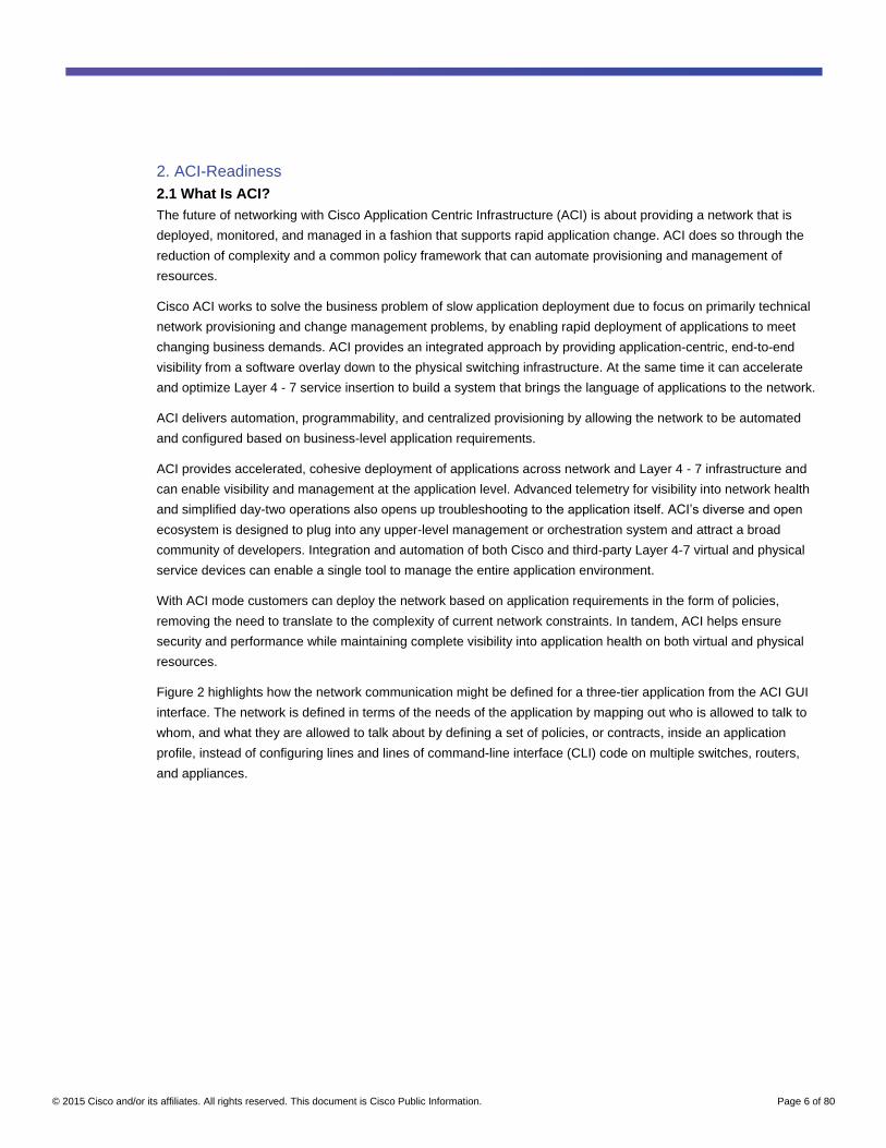
Figure 2 highlights how the network communication might be defined for a three-tier application from the ACI GUI
interface. The network is defined in terms of the needs of the application by mapping out who is allowed to talk to
whom, and what they are allowed to talk about by defining a set of policies, or contracts, inside an application
profile, instead of configuring lines and lines of command-line interface (CLI) code on multiple switches, routers,
and appliances.

© 2015 Cisco and/or its affiliates. All rights reserved. This document is Cisco Public Information. Page 7 of 80
Figure 2. Sample Three-Tier Application Policy
2.2 Converting Nexus 9000 NX-OS Mode to ACI Mode
This white paper will feature Cisco Nexus 9000 Series Switches in NX-OS (standalone) mode. However, Cisco
Nexus 9000 hardware is ACI-ready. Cisco Nexus 9300 switches and many Cisco Nexus 9500 line cards can be
converted to ACI mode.
Cisco Nexus 9000 switches are the foundation of the ACI architecture, and provide the network fabric. A new
operating system is used by Cisco Nexus 9000 switches running in ACI mode. The switches are then coupled with
a centralized controller called the Application Policy Infrastructure Controller (APIC) and its open API. The APIC is
the unifying point of automation, telemetry, and management for the ACI fabric, helping to enable an application
policy model approach to the data center.
Conversion from standalone NX-OS mode to ACI mode on the Cisco Nexus 9000 is outside the scope of this white
paper.
For more information on ACI mode on Cisco Nexus 9000 Series Switches, visit the Cisco ACI website.
3. Evolution of Data Center Design
This section describes the key considerations that are driving data center design and how these are addressed by
Cisco Nexus 9000 Series Switches.
Flexible Workload Placement
Virtual machines may be placed anywhere in the data center, without considerations of physical boundaries of
racks. After initial placement, virtual machines may be moved for optimization, consolidation, or other reasons,
which could include migrating to other data centers or to public cloud. The solution should provide mechanisms to
allow such movements in a seamless manner to the virtual machines. The desired functionality is achieved using
VXLAN and a distributed any-cast gateway.
© 2015 Cisco and/or its affiliates. All rights reserved. This document is Cisco Public Information. Page 8 of 80
East-West Traffic within the Data Center
Data center traffic patterns are changing. Today, more traffic moves east-west from server to server through the
access layer, as servers need to talk to each other and consume services within the data center. This shift is
primarily driven by consolidation of data centers, evolution of clustered applications such as Hadoop, virtual
desktops and multi-tenancy. Traditional three-tier data center design is not optimal, as east-west traffic is often
forced up through the core or aggregation layer, taking a suboptimal path.
The requirements of east-west traffic are addressed by a two-tier flat data center design that takes full advantage
of a Leaf-and-Spine architecture, achieving most specific routing at the first hop router at the access layer. Host
routes are exchanged to help ensure most specific routing to and from servers and hosts. And virtual machine
mobility is supported through detection of virtual machine attachment and signaling of a new location to the rest of
the network so that routing to the virtual machine continues to be optimal.
The Cisco Nexus 9000 can be used as an end-of-row or top-of-rack access layer switch, as an aggregation or core
switch in a traditional, hierarchical two- or three-tier network design, or deployed in a modern Leaf-and-Spine
architecture. This white paper will discuss both access/aggregation and Leaf/Spine designs.
Multi-Tenancy and Segmentation of Layer 2 and 3 Traffic
Large data centers, especially service provider data centers, need to host multiple customers and tenants who
would have overlapping private IP address space. The data center network must allow co-existence of traffic from
multiple customers on shared network infrastructure and provide isolation between those unless specific routing
policies allow. Traffic segmentation is achieved by a) using VXLAN encapsulation, where VNI (VXLAN Network
Identifier) acts as segment identifier, and b) through Virtual Route Forwarding (VRFs) to de-multiplex overlapping
private IP address space.
Eliminate or Reduce Layer 2 Flooding in the Data Center
In the data center, unknown unicast traffic and broadcast traffic in Layer 2 is flooded, with Address Resolution
Protocol (ARP) and IPv6 neighbor solicitation being the most significant part of broadcast traffic. While a VXLAN
can enable distributed switching domains which allow virtual machines (VMs) to be placed anywhere within a data
center, this comes at the cost of having to broadcast traffic across the distributed switching domains that are now
spread across the data center.
Therefore VXLAN implementation has to be complemented with a mechanism that would reduce the broadcast
traffic. The desired functionality is achieved by distributing MAC reachability information through Border Gate
Protocol Ethernet VPN (BGP EVPN) to optimize flooding relating to unknown Layer 2 unicast traffic. Optimization
of reducing broadcasts associated with ARP and IPv6 neighbor solicitation is achieved by distributing the
necessary information through BGP EVPN and caching it at the access switches. An address solicitation request
can then locally respond without sending a broadcast.
Multi-Site Data Center Design
Most service provider data centers, as well as large enterprise data centers, are multi-site to support requirements
such as geographical reach, disaster recovery, etc. Data center tenants require the ability to build their
infrastructure across different sites as well as operate across private and public clouds.

© 2015 Cisco and/or its affiliates. All rights reserved. This document is Cisco Public Information. Page 9 of 80
4. Evolution of Data Center Operation
Data center operation has rapidly evolved in the last few years, driven by some of these needs:
● Virtualization - All popular virtualization platforms - ESXi, OpenStack, and HyperV - have built-in virtual
networking. Physical networking elements have to interface and optimize across these virtual networking
elements.
● Convergence of compute, network and storage elements - Users want to implement full provisioning
use cases (that is, create tenants, create tenant networks, provision VMs, bind VMs to a tenant network,
create vDisks, bind vDisks to a VM) through integrated orchestrators. In order for this to be achieved, all
infrastructure elements need to provide APIs to allow orchestrators to provision and monitor the devices.
● DevOps - As scale of data centers has grown, data center management is increasingly through
programmatic frameworks such as Puppet and Chef. These frameworks have a “Master” that controls the
target devices through an “Agent” that runs locally on the target devices. Puppet/Chef allows users to define
their intent through a manifest/recipe. A reusable set of configuration or management tasks - and allows the
recipe to be deployed on numerous devices which are executed by the “Agent”.
● Dynamic application provisioning - Data center infrastructure is quickly transitioning from an environment
that supports relatively static workloads confined to specific infrastructure silos to a highly dynamic cloud
environment in which any workload can be provisioned anywhere and can scale on demand according to
application needs. As the applications are provisioned, scaled, and migrated, their corresponding
infrastructure requirements, IP addressing, VLANs, and policies need to be seamlessly enforced.
● Software Define Networking (SDN) - SDN separates the control plane from data plane within a network,
allowing intelligence and the state of the network to be managed centrally while abstracting the complexity
of the underlying physical network. The industry has standardized around protocols such as OpenFlow.
SDN would allow users to adapt the network dynamically to application needs for applications such as
Hadoop, Video Delivery, and others.
The Cisco Nexus 9000 has been designed to address the operational needs of evolving data centers. Refer to
Section 6 in this document for a detailed discussion on the features.
● Programmability and Automation
◦ NX-APIs: Intelligent Cisco NX-OS API (NX-API) provides administrators a way to manage the switch
through remote procedure calls (JSON or XML) over HTTP/HTTPS, instead of accessing the NX-OS
command line directly.
◦ Integration with Puppet and Chef: Cisco Nexus 9000 switches provide agents a way to integrate with
Puppet and Chef, as well as recipes that allow automated configuration and management of a Cisco
Nexus 9000 Series Switch. The recipe, when deployed on a Cisco Nexus 9000 Series Switch, translates
into network configuration settings and commands for collecting statistics and analytics information.
◦ OpenFlow: Cisco supports OpenFlow through its OpenFlow plug-ins that are installed on NX-OS-
powered devices and through the Cisco ONE Enterprise Network Controller that is installed on a server
and manages the devices using the OpenFlow interface. ONE Controller, in turn, provides Java
abstractions to applications to abstract and manage the network.

© 2015 Cisco and/or its affiliates. All rights reserved. This document is Cisco Public Information. Page 10 of 80
◦ Cisco OnePK™
: OnePK is an easy-to-use toolkit for development, automation, rapid service creation,
and more. It supports C, Java, and Python, and integrates with PyCharm, PyDev, Eclipse, IDLE,
NetBeans, and more. With its rich set of APIs, you can easily access the valuable data inside your
network and perform functions. Examples include customizing route logic; creating flow-based services
such as quality of service (QoS); adapting applications for changing network conditions such as
bandwidth; automating workflows spanning multiple devices; and empowering management applications
with new information.
◦ Guest Shell: Starting with Cisco NX-OS Software Release 6.1(2)I3(1), the Cisco Nexus 9000 Series
devices support access to a decoupled execution space called the “Guest Shell”. Within the guest shell
the network-admin is given Bash access and may use familiar Linux commands to manage the switch.
The guest shell environment has:
◦ Access to the network, including all VRFs known to the NX-OS Software
◦ Read and write access to host Cisco Nexus 9000 bootflash
◦ Ability to execute Cisco Nexus 9000 CLI
◦ Access to Cisco onePK APIs
◦ The ability to develop, install, and run Python scripts
◦ The ability to install and run 64-bit Linux applications
◦ A root file system that is persistent across system reloads or switchovers
● Integration with Orchestrators & Management Platforms
◦ Cisco UCS® Director: Cisco UCS Director provides easy management of Cisco converged infrastructure
platforms, vBlock, and FlexPod, and provides end-to-end provisioning and monitoring of uses cases
around Cisco UCS Servers, Nexus switches, and Storage Arrays.
◦ Cisco Prime™
Data Center Network Manager (DCNM) is a very powerful tool for centralized data
center monitoring, managing, and automation of Cisco data center compute, network, and storage
infrastructure. A basic version of DCNM is available for free, with more advanced features requiring a
license. DCNM allows centralized management of all Cisco Nexus switches, Cisco UCS, and Cisco MDS
devices.
◦ OpenStack: OpenStack is the leading open-source cloud management platform. The Cisco Nexus 9000
Series includes plug-in support for OpenStack’s Neutron. The Cisco Nexus plug-in accepts OpenStack
Networking API calls and directly configures Cisco Nexus switches as well as Open vSwitch (OVS)
running on the hypervisor. Not only does the Cisco Nexus plug-in configure VLANs on both the physical
and virtual network, but it also intelligently allocates VLAN IDs, de-provisioning them when they are no
longer needed and reassigning them to new tenants whenever possible. VLANs are configured so that
virtual machines running on different virtualization (computing) hosts that belong to the same tenant
network transparently communicate through the physical network. Moreover, connectivity from the
computing hosts to the physical network is trunked to allow traffic only from the VLANs configured on the
host by the virtual switch. For more information, visit OpenStack at Cisco.

© 2015 Cisco and/or its affiliates. All rights reserved. This document is Cisco Public Information. Page 11 of 80
● Policy-based networking to address dynamic application provisioning: Nexus 9000 can operate in
standalone and ACI mode. ACI mode provides rich-featured, policy-based networking constructs and a
framework to holistically define infrastructure needs of applications as well as provision and manage the
infrastructure. Some of the constructs supported by ACI include definition of Tenants, Applications, End
Point Groups (EPGs), Contracts & Policies and association of EPGs to the network fabric. For more details,
refer to the Cisco Application Centric Infrastructure Design Guide:
http://www.cisco.com/c/en/us/solutions/collateral/data-center-virtualization/application-centric-
infrastructure/white-paper-c11-731960.html.
5. Key Features of Cisco NX-OS Software
Cisco NX-OS Software for Cisco Nexus 9000 Series Switches works in two modes:
● Standalone Cisco NX-OS deployment
● Cisco ACI deployment
The Cisco Nexus 9000 Series uses an enhanced version of Cisco NX-OS Software with a single binary image that
supports every switch in the series to simplify image management.
Cisco NX-OS is designed to meet the needs of a variety of customers, including midmarket, enterprise, service
providers, and a range of specific industries. Cisco NX-OS allows customers to create a stable and standard
switching environment in the data center for the LAN and SAN. Cisco NX-OS is based on a highly secure, stable,
and standard Linux core, providing a modular and sustainable base for the long term. Built to unify and simplify the
data center, Cisco NX-OS provides the networking software foundation for the Cisco Unified Data Center.
Its salient features include:
● Modularity - Cisco Nx-OS provides isolation between control and data forwarding planes within the device
and between software components, so that a failure within one plane or process does not disrupt others.
Most system functions, features, and services are isolated so that they can be started as well as restarted
independently in case of failure while other services continue to run. Most system services can perform
stateful restarts, which allow the service to resume operations transparently to other services.
● Resilience - Cisco NX-OS is built from the foundation to deliver continuous, predictable, and highly resilient
operations for the most demanding network environments. With fine-grained process modularity, automatic
fault isolation and containment, and tightly integrated hardware resiliency features, Cisco NX-OS delivers a
highly reliable operating system for operation continuity.
Cisco NX-OS resiliency includes several features. Cisco In-Service Software Upgrade (ISSU) provides
problem fixes, feature enhancements, and even full OS upgrades without interrupting operation of the
device. Per-process modularity allows customers to restart individual processes or update individual
processes without disrupting the other services on the device. Cisco NX- OS also allows for separation of
the control plane from the data plane; data-plane events cannot block the flow of control commands, helping
to ensure uptime.
● Efficiency - Cisco NX-OS includes a number of traditional and advanced features to ease implementation
and ongoing operations. Monitoring tools, analyzers, and clustering technologies are integrated into Cisco
NX-OS. These features provide a single point of management that simplifies operations and improves
efficiency.

© 2015 Cisco and/or its affiliates. All rights reserved. This document is Cisco Public Information. Page 12 of 80
Having a single networking software platform that spans all the major components of the data center
network creates a predictable, consistent environment that makes it easier to configure the network,
diagnose problems, and implement solutions.
Cisco Data Center Network Manager (DCNM) is a centralized manager that can handle all Cisco NX-OS
devices, allowing centralization of all the monitoring and analysis performed at the device level and
providing a high level of overall control. Furthermore, Cisco NX- OS offers the same industry-standard
command-line environment that was pioneered in Cisco IOS® Software, making the transition from Cisco
IOS Software to Cisco NX-OS Software easy.
● Virtualization - Cisco NX-OS is designed to deliver switch-level virtualization. With Cisco NX-OS, switches
can be virtualized in many logical devices, each operating independently. Device partitioning is particularly
useful in multi-tenant environments and in environments in which strict separation is necessary due to
regulatory concerns. Cisco NX-OS provides VLANs and VSANs and also supports newer technologies such
as VXLAN, helping enable network segregation. The technologies incorporated into Cisco NX-OS provide
tight integration between the network and virtualized server environments, enabling simplified management
and provisioning of data center resources.
For additional information about Cisco NX-OS refer to the Cisco Nexus 9500 and 9300 Series Switches NX-OS
Software data sheet.
6. Data Center Design Considerations
6.1 Traditional Data Center Design
Traditional data centers are built on a three-tier architecture with core, aggregation, and access layers (Figure 3),
or a two-tier collapsed core with the aggregation and core layers combined into one layer (Figure 4). This
architecture accommodates a north-south traffic pattern where client data comes in from the WAN or Internet to be
processed by a server in the data center, and is then pushed back out of the data center. This is common for
applications like web services, where most communication is between an external client and an internal server.
The north-south traffic pattern permits hardware oversubscription, since most traffic is funneled in and out through
the lower-bandwidth WAN or Internet bottleneck.
A classic network in the context of this document is the typical three-tier architecture commonly deployed in many
data center environments. It has distinct core, aggregation, and access layers, which together provide the
foundation for any data center design. Table 1 outlines the layers of a typical tier-three design, and the functions of
each layer.
Table 1. Classic Three-Tier Data Center Design
Layer Description
Core This tier provides the high-speed packet switching backplane for all flows going in and out of the data center. The core provides connectivity to multiple aggregation modules and provides a resilient, Layer 3 -routed fabric with no single point of failure (SPOF). The core runs an interior routing protocol, such as Open Shortest Path First (OSPF) or Border Gateway Protocol (BGP), and load-balances traffic between all the attached segments within the data center.
Aggregation This tier provides important functions, such as service module integration, Layer 2 domain definitions and forwarding, and gateway redundancy. Server-to-server multitier traffic flows through the aggregation layer and can use services, such as firewall and server load balancing, to optimize and secure applications. This layer provides the Layer 2 and 3 demarcations for all northbound and southbound traffic, and it processes most of the eastbound and westbound traffic within the data center.

© 2015 Cisco and/or its affiliates. All rights reserved. This document is Cisco Public Information. Page 13 of 80
Layer Description
Access This tier is the point at which the servers physically attach to the network. The server components consist of different types of servers:
● Blade servers with integral switches
● Blade servers with pass-through cabling
● Clustered servers
● Possibly mainframes
The access-layer network infrastructure also consists of various modular switches and integral blade server switches. Switches provide both Layer 2 and Layer 3 topologies, fulfilling the various server broadcast domain and administrative requirements. In modern data centers, this layer is further divided into a virtual access layer using hypervisor-based networking, which is beyond the scope of this document.
Figure 3. Traditional Three-Tier Design
Figure 4. Traditional Two-Tier Medium Access-Aggregation Design
Customers may also have the small collapsed design replicated to another rack or building, with a Layer 3
connection between the pods (Figure 5).

© 2015 Cisco and/or its affiliates. All rights reserved. This document is Cisco Public Information. Page 14 of 80
Figure 5. Layer 2 Access, Layer 3 Connection between Pods
Some of the considerations used in making a decision on the Layer 2 and Layer 3 boundary are listed in Table 2.
Table 2. Layer 2 and Layer 3 Boundaries
Consideration Layer 3 at Core Layer 3 at Access
Multipathing One active path per VLAN due to Spanning Tree between access and core switches
Equal cost multipathing using dynamic routing protocol between access and core switches
Spanning Tree More Layer 2 links, therefore more loops and links to block
No Spanning Tree Protocol (STP) running north of the access layer
Layer 2 reach Greater Layer 2 reachability for workload mobility and clustering applications
Layer 2 adjacency is limited to devices connected to the same access layer switch
Convergence time Spanning Tree generally has a slower convergence time than a dynamic routing protocol
Dynamic routing protocols generally have a faster convergence time than Spanning Tree
6.2 Leaf-Spine Architecture
Spine-Leaf topologies are based on the Clos network architecture. The term originates from Charles Clos at Bell
Laboratories, who published a paper in 1953 describing a mathematical theory of a multipathing, non-blocking,
multiple-stage network topology in which to switch telephone calls.
Today, Clos’ original thoughts on design are applied to the modern Spine-Leaf topology. Spine-leaf is typically
deployed as two layers: spines (like an aggregation layer), and leaves (like an access layer). Spine-leaf topologies
provide high-bandwidth, low-latency, non-blocking server-to-server connectivity.
Leaf (aggregation) switches are what provide devices access to the fabric (the network of Spine and Leaf switches)
and are typically deployed at the top of the rack. Generally, devices connect to the Leaf switches. Devices may
include servers, Layer 4 - 7 services (firewalls and load balancers), and WAN or Internet routers. Leaf switches do
not connect to other leaf switches (unless running vPC in standalone NX-OS mode). However, every leaf should
connect to every spine in a full mesh. Some ports on the leaf will be used for end devices (typically 10 Gigabits),
and some ports will be used for the spine connections (typically 40 Gigabits).
Spine (aggregation) switches are used to connect to all Leaf switches, and are typically deployed at the end or
middle of the row. Spine switches do not connect to other spine switches. Spines serve as backbone interconnects
for Leaf switches. Generally, spines only connect to leaves, but when integrating a Cisco Nexus 9000 switch into
an existing environment it is perfectly acceptable to connect other switches, services, or devices to the spines.
All devices connected to the fabric are an equal number of hops away from one another. This delivers predictable
latency and high bandwidth between servers. The diagram in Figure 6 shows a simple two-tier design.

© 2015 Cisco and/or its affiliates. All rights reserved. This document is Cisco Public Information. Page 15 of 80
Figure 6. Two-Tier Design and Connectivity
Another way to think about the Spine-Leaf architecture is by thinking of the Spines as a central backbone, with all
leaves branching off the spine like a star. Figure 7 depicts this logical representation, which uses identical
components laid out in an alternate visual mapping.
Figure 7. Logical Representation of a Two-Tier Design
6.3 Spanning Tree Support
The Cisco Nexus 9000 supports two Spanning Tree modes: Rapid Per-VLAN Spanning Tree Plus (PVST+), which
is the default mode, and Multiple Spanning Tree (MST).
The Rapid PVST+ protocol is the IEEE 802.1w standard, Rapid Spanning Tree Protocol (RSTP), implemented on a
per-VLAN basis. Rapid PVST+ interoperates with the IEEE 802.1Q VLAN standard, which mandates a single STP
instance for all VLANs, rather than per VLAN. Rapid PVST+ is enabled by default on the default VLAN (VLAN1)
and on all newly created VLANs on the device. Rapid PVST+ interoperates with devices that run legacy IEEE
802.1D STP. RSTP is an improvement on the original STP standard, 802.1D, which allows faster convergence.
MST maps multiple VLANs into a Spanning Tree instance, with each instance having a Spanning Tree topology
independent of other instances. This architecture provides multiple forwarding paths for data traffic, enables load
balancing, and reduces the number of STP instances required to support a large number of VLANs. MST improves
the fault tolerance of the network because a failure in one instance does not affect other instances. MST provides
rapid convergence through explicit handshaking because each MST instance uses the IEEE 802.1w standard.
MST improves Spanning Tree operation and maintains backward compatibility with the original 802.1D Spanning
Tree and Rapid PVST+.

© 2015 Cisco and/or its affiliates. All rights reserved. This document is Cisco Public Information. Page 16 of 80
6.4 Layer 2 versus Layer 3 Implications
Data center traffic patterns are changing. Today, more traffic moves east-west from server to server through the
access layer, as servers need to talk to each other and consume services within the data center. The
oversubscribed hardware now isn’t sufficient for the east-west 10 Gigabit-to-10 Gigabit communications.
Additionally, east-west traffic is often forced up through the core or aggregation layer, taking a suboptimal path.
Spanning Tree is another hindrance in the traditional three-tier data center design. Spanning Tree is required to
block loops in flooding Ethernet networks so that frames are not forwarded endlessly. Blocking loops means
blocking links, leaving only one active path (per VLAN). Blocked links severely impact available bandwidth and
oversubscription. This can also force traffic to take a suboptimal path, as Spanning Tree may block a more
desirable path (Figure 8).
Figure 8. Suboptimal Path between Servers in Different Pods Due to Spanning Tree Blocked Links
Addressing these issues could include:
a. Upgrading hardware to support 40- or 100-Gigabit interfaces
b. Bundling links into port channels to appear as one logical link to Spanning Tree
c. Or, moving the Layer 2/Layer 3 boundary down to the access layer to limit the reach of Spanning Tree
(Figure 9). Using a dynamic routing protocol between the two layers allows all links to be active, fast
reconvergence, and equal cost multipathing (ECMP).
Figure 9. Two-Tier Routed Access Layer Design

© 2015 Cisco and/or its affiliates. All rights reserved. This document is Cisco Public Information. Page 17 of 80
The tradeoff in moving Layer 3 routing to the access layer in a traditional Ethernet network is that it limits Layer 2
reachability. Applications like virtual-machine workload mobility and some clustering software require Layer 2
adjacency between source and destination servers. By routing at the access layer, only servers connected to the
same access switch with the same VLANs trunked down would be Layer 2-adjacent. This drawback is addressed
by using VXLAN, which will be discussed in subsequent section.
6.5 Virtual Port Channels (vPC)
Over the past few years many customers have sought ways to move past the limitations of Spanning Tree. The
first step on the path to Cisco Nexus-based modern data centers came in 2008 with the advent of Cisco virtual Port
Channels (vPC). A vPC allows a device to connect to two different physical Cisco Nexus switches using a single
logical port-channel interface (Figure 10).
Prior to vPC, port channels generally had to terminate on a single physical switch. vPC gives the device active-
active forwarding paths. Because of the special peering relationship between the two Cisco Nexus switches,
Spanning Tree does not see any loops, leaving all links active. To the connected device, the connection appears
as a normal port-channel interface, requiring no special configuration. The industry standard term is called Multi-
Chassis EtherChannel; the Cisco Nexus-specific implementation is called vPC.
Figure 10. vPC Physical Versus Logical Topology
vPC deployed on a Spanning Tree Ethernet network is a very powerful way to curb the number of blocked links,
thereby increasing available bandwidth. vPC on the Cisco Nexus 9000 is a great solution for commercial
customers, and those satisfied with current bandwidth, oversubscription, and Layer 2 reachability requirements.
Two of the sample small-to-midsized traditional commercial topologies are depicted using vPCs in Figures 11 and
12. These designs leave the Layer 2/Layer 3 boundary at the aggregation to permit broader Layer 2 reachability,
but all links are active as Spanning Tree does not see any loops to block.

© 2015 Cisco and/or its affiliates. All rights reserved. This document is Cisco Public Information. Page 18 of 80
Figure 11. Traditional One-Tier Collapsed Design with vPC
Figure 12. Traditional Two-Tier Design with vPC
6.6 Overlays
Overlay technologies are useful in extending the Layer 2 boundaries of a network across a large data center as
well as across different data centers. This section discusses some of the important overlay technologies, including:
● An overview of VXLAN
● VXLAN with BGP EVPN as the control plane
● VXLAN Data Center Interconnect with a BGP control plane
For more information on overlays in general, read the Data Center Overlay Technologies white paper.
6.6.1 Virtual Extensible LAN (VXLAN)
VXLAN is a Layer 2 overlay scheme over a Layer 3 network. It uses an IP/User Datagram Protocol (UDP)
encapsulation so that the provider or core network does not need to be aware of any additional services that
VXLAN is offering. A 24-bit VXLAN segment ID or VXLAN network identifier (VNI) is included in the encapsulation
to provide up to 16 million VXLAN segments for traffic isolation and segmentation, in contrast to the 4000
segments achievable with VLANs. Each of these segments represents a unique Layer 2 broadcast domain and can
be administered in such a way that it can uniquely identify a given tenant's address space or subnet (Figure 13).

© 2015 Cisco and/or its affiliates. All rights reserved. This document is Cisco Public Information. Page 19 of 80
Figure 13. VXLAN Frame Format
VXLAN can be considered a stateless tunneling mechanism, with each frame encapsulated or de-encapsulated at
the VXLAN tunnel endpoint (VTEP) according to a set of rules. A VTEP has two logical interfaces: an uplink and a
downlink (Figure 14).
Figure 14. VTEP Logical Interfaces

© 2015 Cisco and/or its affiliates. All rights reserved. This document is Cisco Public Information. Page 20 of 80
The VXLAN draft standard does not mandate a control protocol for discovery or learning. It offers suggestions for
both control-plane source learning (push model) and central directory-based lookup (pull model). At the time of this
writing, most implementations depend on a flood-and-learn mechanism to learn the reachability information for end
hosts. In this model, VXLAN establishes point-to-multipoint tunnels to all VTEPs on the same segment as the
originating VTEP to forward unknown and multi-destination traffic across the fabric. This forwarding is
accomplished by associating a multicast group for each segment, so it requires the underlying fabric to support IP
multicast routing.
Cisco Nexus 9000 Series Switches provide Layer 2 connectivity extension across IP transport within the data
center, and easy integration between VXLAN and non-VXLAN infrastructures. The section, 9.3.2,” further in this
document provides detailed configurations to configure the VXLAN fabric using both a Multicast/Internet Group
Management Protocol (IGMP) approach as well as a BGP EVPN control plane.
Beyond a simple overlay sourced and terminated on the switches, the Cisco Nexus 9000 can act as a hardware-
based VXLAN gateway. VXLAN is increasingly popular for virtual networking in the hypervisor for virtual machine-
to-virtual machine communication, and not just switch to switch. However, many devices are not capable of
supporting VXLAN, such as legacy hypervisors, physical servers, and service appliances like firewalls, load
balancers, and storage devices. Those devices need to continue to reside on classic VLAN segments. It is not
uncommon that virtual machines in a VXLAN segment need to access services provided by devices in a classic
VLAN segment. The Cisco Nexus 9000 acting as a VXLAN gateway can provide the necessary translation, as
shown in Figure 15.
Figure 15. Cisco Nexus 9000 Leaf Switches Translate VLAN to VXLAN
© 2015 Cisco and/or its affiliates. All rights reserved. This document is Cisco Public Information. Page 21 of 80
6.6.2 BGP EVPN Control Plane for VXLAN
The EVPN overlay draft specifies adaptations to the BGP Multiprotocol Label Switching (MPLS)-based EVPN
solution to enable it to be applied as a network virtualization overlay with VXLAN encapsulation where:
● The Provider Edge (PE) node role described in BGP MPLS EVPN is equivalent to the VTEP or network
virtualization edge (NVE) device
● VTEP endpoint information is distributed using BGP
● VTEPs use control-plane learning and distribution through BGP for remote MAC addresses instead of data
plane learning
● Broadcast, unknown unicast, and multicast data traffic is sent using a shared multicast tree or with ingress
replication
● BGP Route Reflector (RR) is used to reduce the full mesh of BGP sessions among VTEPs to a single BGP
session between a VTEP and the RR
● Route filtering and constrained route distribution are used to help ensure that control plane traffic for a given
overlay is only distributed to the VTEPs that are in that overlay instance
● The Host MAC mobility mechanism is in place to help ensure that all the VTEPs in the overlay instance
know the specific VTEP associated with the MAC
● Virtual network identifiers are globally unique within the overlay
The EVPN overlay solution for VXLAN can also be adapted to be applied as a network virtualization overlay with
VXLAN for Layer 3 traffic segmentation. The adaptations for Layer 3 VXLAN are similar to Layer 2 VXLAN except:
● VTEPs use control plane learning and distribution using the BGP of IP addresses
(instead of MAC addresses)
● The virtual routing and forwarding instance is mapped to the VNI
● The inner destination MAC address in the VXLAN header does not belong to the host, but to the receiving
VTEP that does the routing of the VXLAN payload. This MAC address is distributed using a BGP attribute
along with EVPN routes
Note that since IP hosts have an associated MAC address, coexistence of both Layer 2 VXLAN and Layer 3
VXLAN overlays will be supported. Additionally, the Layer 2 VXLAN overlay will also be used to facilitate
communication between non-IP based (Layer 2-only) hosts.
6.6.3 VXLAN Data Center Interconnect (DCI) with a BGP Control Plane
The BGP EVPN control plane feature of the Cisco Nexus 9000 can be used to extend the reach of Layer 2
domains across data center pods, domains, and sites.
Figure 16 shows two overlays in use: Overlay Transport Virtualization (OTV) on a Cisco ASR 1000 for data center-
to-data center connectivity, and VXLAN within the data center. Both provide Layer 2 reachability and extension.
OTV is also available on the Cisco Nexus 7000 Series Switch.

© 2015 Cisco and/or its affiliates. All rights reserved. This document is Cisco Public Information. Page 22 of 80
Figure 16. Virtual Overlay Networks Provide Dynamic Reachability for Applications
7. Integration into Existing Networks
In migrating your data center to the Cisco Nexus 9000 Series, you need to consider, not only compatibility with
existing traditional servers and devices; you also need to consider the next-generation capabilities of Cisco Nexus
9000 switches, which include:
● VXLAN with added functionality of BGP control plane for scale
● Fabric Extender (FEX)
● vPC
● 10/40 Gbps connectivity
● Programmability
With their exceptional performance and comprehensive feature set, Cisco Nexus 9000 Series Switches are
versatile platforms that can be deployed in multiple scenarios, including:
● Layered access-aggregation-core designs
● Leaf-and-spine architecture
● Compact aggregation-layer solutions
Cisco Nexus 9000 Series Switches deliver a comprehensive Cisco NX-OS Software data center switching feature
set. Table 2 lists the current form factors. Visit http://www.cisco.com/go/nexus9000 for latest updates to Cisco
Nexus 9000 portfolio.
© 2015 Cisco and/or its affiliates. All rights reserved. This document is Cisco Public Information. Page 23 of 80
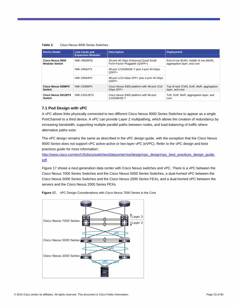
Table 3. Cisco Nexus 9000 Series Switches
Device Model Line Cards and Expansion Modules
Description Deployment
Cisco Nexus 9500 Modular Switch
N9K-X9636PQ 36-port 40-Gbps Enhanced Quad Small Form-Factor Pluggable (QSFP+)
End of row (EoR), middle of row (MoR), aggregation layer, and core
N9K-X9564TX 48-port 1/10GBASE-T plus 4-port 40-Gbps QSFP+
N9K-X9564PX 48-port 1/10-Gbps SFP+ plus 4-port 40-Gbps QSFP+
Cisco Nexus 9396PX Switch
N9K-C9396PX Cisco Nexus 9300 platform with 48-port 1/10-Gbps SFP+
Top of rack (ToR), EoR, MoR, aggregation layer, and core
Cisco Nexus 93128TX Switch
N9K-C93128TX Cisco Nexus 9300 platform with 96-port 1/10GBASE-T
ToR, EoR, MoR, aggregation layer, and core
7.1 Pod Design with vPC
A vPC allows links physically connected to two different Cisco Nexus 9000 Series Switches to appear as a single
PortChannel to a third device. A vPC can provide Layer 2 multipathing, which allows the creation of redundancy by
increasing bandwidth, supporting multiple parallel paths between nodes, and load-balancing of traffic where
alternative paths exist.
The vPC design remains the same as described in the vPC design guide, with the exception that the Cisco Nexus
9000 Series does not support vPC active-active or two-layer vPC (eVPC). Refer to the vPC design and best
practices guide for more information:
http://www.cisco.com/en/US/docs/switches/datacenter/sw/design/vpc_design/vpc_best_practices_design_guide.
pdf.
Figure 17 shows a next-generation data center with Cisco Nexus switches and vPC. There is a vPC between the
Cisco Nexus 7000 Series Switches and the Cisco Nexus 5000 Series Switches, a dual-homed vPC between the
Cisco Nexus 5000 Series Switches and the Cisco Nexus 2000 Series FEXs, and a dual-homed vPC between the
servers and the Cisco Nexus 2000 Series FEXs.
Figure 17. vPC Design Considerations with Cisco Nexus 7000 Series in the Core

© 2015 Cisco and/or its affiliates. All rights reserved. This document is Cisco Public Information. Page 24 of 80
In a vPC topology, all links between the aggregation and access layers are forwarding and are part of a vPC.
Gigabit Ethernet connectivity makes use of the FEX concept outlined in subsequent section. Spanning Tree
Protocol does not run between the Cisco Nexus 9000 Series Switches and the Cisco Nexus 2000 Series FEXs.
Instead, proprietary technology keeps the topology switches and the fabric extenders free of loops. Adding vPC to
the Cisco Nexus 9000 Series Switches in the access layer allows additional load distribution from the server to the
fabric extenders to the Cisco Nexus 9000 Series Switches.
An existing Cisco Nexus 7000 Series Switch can be replaced with a Cisco Nexus 9500 platform switch with one
exception: Cisco Nexus 9000 Series Switches do not support vPC active-active or two-layer vPC (eVPC) designs.
The rest of the network topology and design does not change. Figure 18 shows the new topology. Figure 19 shows
the peering that occurs between Cisco Nexus 9500 platforms.
Figure 18. vPC Design with Cisco Nexus 9500 Platform in the Core
Figure 19. Peering between Cisco Nexus 9500 Platforms

© 2015 Cisco and/or its affiliates. All rights reserved. This document is Cisco Public Information. Page 25 of 80
7.2 Fabric Extender Support
To use existing hardware, increase access port density, and increase 1-Gigabit Ethernet (GE) port availability,
Cisco Nexus 2000 Series Fabric Extenders (Figure 20) can be attached to the Cisco Nexus 9300 platform in a
single-homed straight-through configuration. Up to 16 Fabric Extenders can be connected to a single Cisco Nexus
9300 Series Switch. Host uplinks that are connected to the fabric extenders can either be Active/Standby, or
Active/Active, if configured in a vPC.
The following Cisco Nexus 2000 Series Fabric Extenders are currently supported:
● N2224TP
● N2248TP
● N2248TP-E
● N2232TM
● N2232PP
● B22HP
Figure 20. Cisco Nexus 2000 Series Fabric Extenders
For the most up-to-date feature support, refer to the Cisco Nexus 9000 Software release notes.
Fabric extender transceivers (FETs) also are supported to provide a cost-effective connectivity solution (FET-10
Gb) between Cisco Nexus 2000 Fabric Extenders and their parent Cisco Nexus 9300 switches.
For more information about FET-10 Gb transceivers, review the Nexus 2000 Series Fabric Extenders data sheet.
The supported Cisco Nexus 9000 to Nexus 2000 Fabric Extender topologies are shown in Figures 21 and 22. As
with other Cisco Nexus platforms, think of Cisco Fabric Extender Technology like a logical remote line card of the
parent Cisco Nexus 9000 switch. Each Cisco FEX connects to one parent switch. Servers should be dual-homed to
two different fabric extenders. The server uplinks can be in an Active/Standby network interface card (NIC) team,
or they can be in a vPC if the parent Cisco Nexus 9000 switches are set up in a vPC domain.

© 2015 Cisco and/or its affiliates. All rights reserved. This document is Cisco Public Information. Page 26 of 80
Figure 21. Supported Cisco Nexus 9000 Series Switches Plus Fabric Extender Design with an Active/Standby Server
Figure 22. Supported Cisco Nexus 9000 Series Switches Plus Fabric Extender Design with a Server vPC
For detailed information, see the Cisco Nexus 2000 Series NX-OS Fabric Extender Configuration Guide for Cisco
Nexus 9000 Series Switches, Release 6.0.

© 2015 Cisco and/or its affiliates. All rights reserved. This document is Cisco Public Information. Page 27 of 80
7.3 Pod Design with VXLAN
The Cisco Nexus 9500 platform uses VXLAN, a Layer 2 overlay scheme over a Layer 3 network. VXLAN can be
implemented both on hypervisor-based virtual switches to allow scalable virtual-machine deployments and on
physical switches to bridge VXLAN segments back to VLAN segments.
VXLAN extends the Layer 2 segment-ID field to 24 bits, potentially allowing up to 16 million unique Layer 2
segments in contrast to the 4000 segments achievable with VLANs over the same network. Each of these
segments represents a unique Layer 2 broadcast domain and can be administered in such a way that it uniquely
identifies a given tenant’s address space or subnet. Note that the core and access-layer switches must be Cisco
Nexus 9000 Series Switches to implement VXLAN.
In Figure 23, the Cisco Nexus 9500 platform at the core provides Layer 2 and 3 connectivity. The Cisco Nexus
9500 and 9300 platforms connect over 40-Gbps links and use VXLAN between them. The existing FEX switches
are single-homed to each Cisco Nexus 9300 platform switch using Link Aggregation Control Protocol (LACP) port
channels. The end servers are vPC dual-homed to two Cisco Nexus 2000 Series FEXs.
Figure 23. VXLAN Design with Cisco Nexus 9000 Series

© 2015 Cisco and/or its affiliates. All rights reserved. This document is Cisco Public Information. Page 28 of 80
7.4 Traditional Three-Tier Architecture with 1/10 Gigabit Ethernet Server Access
In a typical data center design, the aggregation layer requires a high level of flexibility, scalability, and feature
integration, because aggregation devices constitute the Layer 3 and 2 boundaries, which require both routing and
switching functions. Access-layer connectivity defines the total forwarding capability, port density, and Layer 2
domain flexibility.
Figure 24 depicts Cisco Nexus 7000 Series Switches at both the core and the aggregation layer, a design in which
a single pair of data center core switches typically interconnect multiple aggregation modules using 10 Gigabit
Ethernet Layer 3 interfaces.
Figure 24. Classic Three-Tier Design
Option 1: Cisco Nexus 9500 Platform at the Core and the Aggregation Layer
In this design, the Cisco Nexus 9500 platform (Figure 24) replaces the Cisco Nexus 7000 Series at both the core
and the aggregation layer.
The Cisco Nexus 9508 8-slot switch is a next-generation, high-density modular switch with the following features:
● Modern operating system
● High density (40/100-Gbps aggregation)
● Low power consumption
The Cisco Nexus 9500 platform uses a unique combination of a Broadcom Trident-2 application-specific integrated
circuit (ASIC) and an Insieme ASIC to provide faster deployment times, enhanced packet buffer capacity, and a
comprehensive feature set.
The Cisco Nexus 9508 chassis is a 13-rack-unit (13RU) 8-slot modular chassis with front-to-back airflow and is well
suited for large data center deployments. The Cisco Nexus 9500 platform supports up to 3456 x 10 Gigabit
Ethernet ports and 864 x 40 Gigabit Ethernet ports, and can achieve 30 Tbps of fabric throughput per rack system.

© 2015 Cisco and/or its affiliates. All rights reserved. This document is Cisco Public Information. Page 29 of 80
The common equipment for the Cisco Nexus 9508 includes:
● Two half-slot supervisor engines
● Four power supplies
● Three switch fabrics (upgradable to six)
● Three hot-swappable fan trays
The fan trays and the fabric modules are accessed through the rear of the chassis. Chassis have eight horizontal
slots dedicated to the I/O modules.
Cisco Nexus 9508 Switches can be fully populated with 10, 40, and (future) 100 Gigabit Ethernet modules with no
bandwidth or slot restrictions. Online insertion and removal of all line cards is supported in all eight I/O slots.
Option 2: Cisco Nexus 9500 Platform at the Core and Cisco Nexus 9300 Platform at the
Aggregation Layer
Depending on growth in the data center, a combination of the Cisco Nexus 9500 platform at the core and the
aggregation layer (Figure 25) and the Cisco Nexus 9500 platform at the core with the Cisco Nexus 9300 platform at
the aggregation layer can be used to achieve better scalability (Figure 26).
Figure 25. Cisco Nexus 9500 Platform-Based Design
The Cisco Nexus 9300 platform is currently available in two fixed configurations:
● Cisco Nexus 9396PX - 2RU with 48 ports at 10 Gbps and 12 ports at 40 Gbps
● Cisco Nexus 93128TX - 3RU with 96 ports at 1/10 Gbps and 8 ports at 40 Gbps
In both options, the existing Cisco Nexus 7000 Series Switches at the core and the aggregation layer can be
swapped for Cisco Nexus 9508 Switches while retaining the existing wiring connection.

© 2015 Cisco and/or its affiliates. All rights reserved. This document is Cisco Public Information. Page 30 of 80
Currently, Fibre Channel over Ethernet (FCoE) support is not available for this design.
Figure 26. Cisco Nexus 9500 and 9300 Platform-Based Design
7.5 Traditional Cisco Unified Computing System and Blade Server Access
In a multilayer data center design, you can replace core Cisco Nexus 7000 Series Switches with the Cisco Nexus
9500 platform, or replace the core with the Cisco Nexus 9500 platform and the access layer with the Cisco Nexus
9300 platform. You can also connect an existing Cisco Unified Computing System™
(Cisco UCS®) and blade server
access layer to Insieme hardware (Figures 27 and 28).
Figure 27. Classic Design Using Cisco Nexus 7000 and 5000 Series and Fabric Extenders

© 2015 Cisco and/or its affiliates. All rights reserved. This document is Cisco Public Information. Page 31 of 80
Figure 28. Classic Design Using Cisco Nexus 9500 and 9300 Platforms and Fabric Extenders
8. Integrating Layer 4 - Layer 7 Services
Cisco Nexus 9000 Series Switches can be integrated into any of the vendor service appliances. Section 9 outlines
topologies where the Cisco Nexus 9000 is connected to:
● A Cisco ASA firewall in routed mode with ASA acting as a default gateway for the hosts which connect to its
screened subnets
● F5 Networks Load Balancer in one-arm mode
Firewalls can be connected in routed or transparent mode. They need to meet the following criteria for a typical
data center scenario:
● An outside user visits the web server
● An inside user visits the inside host on another network
● An inside user accesses an outside web server
For details on connecting Cisco ASA firewalls visit:
http://www.cisco.com/c/en/us/td/docs/security/asa/asa93/configuration/general/asa-general-cli/intro-fw.html.
9. Cisco Nexus 9000 Data Center Topology Design and Configuration
This section will walk through a sample Cisco Nexus 9000 design using real equipment, including Cisco Nexus
9508 and Nexus 9396 Switches, both VMware ESXi servers and standalone bare metal servers, and a Cisco ASA
firewall. This topology has been tested in a Cisco lab to validate and demonstrate the Cisco Nexus 9000 solution.
The intent of this section is to give a sample network design and configuration, including the features discussed
earlier in this white paper. Always refer to the Cisco configuration guides for the latest information.

© 2015 Cisco and/or its affiliates. All rights reserved. This document is Cisco Public Information. Page 32 of 80
The terminology and switch names used in this section reference Leaf and Spine, but the similar configuration
could be used and applied to an access-aggregation design.
9.1 Hardware and Software Specifications
● Two Cisco Nexus N9K-C9508 Switches (8-slot) with the following components in each switch:
◦ One N9K-X9636PQ (36p QSFP 40 Gigabit) Ethernet module
◦ Six N9K-C9508-FM fabric modules
◦ Two N9K-SUP-A supervisor modules
◦ Two N9K-SC-A system controllers
● Two Cisco Nexus 9396PX Switches (48p SFP+ 1/10 Gigabit) with the following expansion module in each
switch:
◦ One N9K-M12PQ (12p QSFP 40 Gigabit) Ethernet module
● Two Cisco UCS C-Series servers (could be replaced with Cisco UCS Express servers for smaller
deployments). For more information on server options, visit Cisco Unified Computing System Express.
● One Cisco ASA 5510 firewall appliance
● One F5 Networks BIG-IP load balancer appliance
Cisco Nexus 9000 switches used in this design run Cisco NX-OS Software Release 6.1(2)I2(3). The VMware ESXi
servers used run ESXi 5.1.0 build 799733. The Cisco ASA runs version 8.4(7). The F5 runs 11.4.1 Build 625.0
Hotfix HF1.
9.2 Leaf-Spine-Based Data Center
9.2.1 Topology
The basic network setup is displayed in Figure 29. It includes:
● Application - Cisco.app1.com: Ex - External IP- 209.165.201.5
● The External Web Server for this application run in the inside zone in the Load balancer with IP of
192.168.50.2 and Application Server with IP of 192.168.60.2
● The web server nodes run at the following IP addresses: 192.168.50.5, 192.168.50.6
● The application server nodes run at the following IP addresses: 192.168.60.5 and 192.168.60.6
© 2015 Cisco and/or its affiliates. All rights reserved. This document is Cisco Public Information. Page 33 of 80
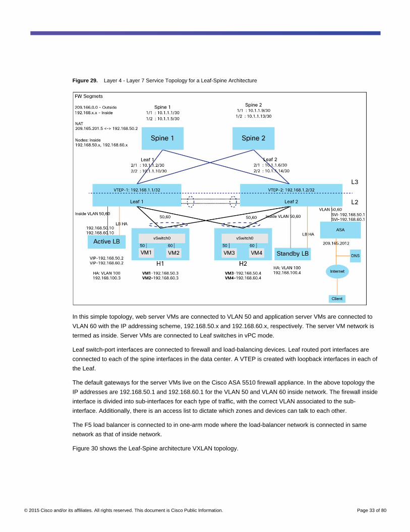
Figure 29. Layer 4 - Layer 7 Service Topology for a Leaf-Spine Architecture
In this simple topology, web server VMs are connected to VLAN 50 and application server VMs are connected to
VLAN 60 with the IP addressing scheme, 192.168.50.x and 192.168.60.x, respectively. The server VM network is
termed as inside. Server VMs are connected to Leaf switches in vPC mode.
Leaf switch-port interfaces are connected to firewall and load-balancing devices. Leaf routed port interfaces are
connected to each of the spine interfaces in the data center. A VTEP is created with loopback interfaces in each of
the Leaf.
The default gateways for the server VMs live on the Cisco ASA 5510 firewall appliance. In the above topology the
IP addresses are 192.168.50.1 and 192.168.60.1 for the VLAN 50 and VLAN 60 inside network. The firewall inside
interface is divided into sub-interfaces for each type of traffic, with the correct VLAN associated to the sub-
interface. Additionally, there is an access list to dictate which zones and devices can talk to each other.
The F5 load balancer is connected to in one-arm mode where the load-balancer network is connected in same
network as that of inside network.
Figure 30 shows the Leaf-Spine architecture VXLAN topology.

© 2015 Cisco and/or its affiliates. All rights reserved. This document is Cisco Public Information. Page 34 of 80
Figure 30. Leaf-Spine Architecture with a VXLAN Topology for Layer 4 - 7 Services
Figures 31 and Figure 32 illustrate the logical models of north-south and east-west traffic flows.
Legend

© 2015 Cisco and/or its affiliates. All rights reserved. This document is Cisco Public Information. Page 35 of 80
In Figure 31, an outside user visits the web server.
Figure 31. North-South Traffic Flow
1. A user on the outside network requests (11.8.1.8) a web page using the global destination address of
209.165.201.5, whose network is on the outside interface subnet of the firewall.
2. The firewall receives the packet and because it is a new session, the security appliance verifies that the packet
is allowed according to the terms of the security policy (access lists, filters, AAA). The firewall translates the
destination address (209.165.201.5) to the VIP address (192.168.50.2) of web server present in the load
balancer. The firewall then adds a session entry to the fast path and forwards through to the web server sub-
interface network.
3. The packet comes to the load-balancer interface that services the packet based on service-pool conditions.
The load balancer does a Source Network Address Translation (NAT) with the IP address of the load-balancer
VIP address, 192.168.50.2, and the destination NAT of the respective service node IP address (192.168.50.5)
based on service pool conditions. The load balancer then forwards the packet through the web server interface
with a session entry created in the load balancer.
4. The node (192.168.50.5) responds back to the request from the load balancer.
5. The load balancer does a reverse NAT with the client IP address (11.8.1.8) for the destination address from
the established session.

© 2015 Cisco and/or its affiliates. All rights reserved. This document is Cisco Public Information. Page 36 of 80
6. As the packet reaches the firewall, the packet bypasses the many lookups associated with a new connection
since the connection has already been previously established. The firewall performs the reverse NAT by
translating the Source server IP address (192.168.50.2) with the global IP address (209.165.201.5), which is
on the outside network of the firewall. The firewall then forwards the packet to the outside client (11.8.1.8).
In Figure 32, a web server user visits the app server.
Figure 32. East-West Traffic Flow
1. A user on the web server network (192.168.50.5) of VLAN 50 does a request for the application server with the
destination address of 192.168.60.2 in VLAN 60 which is VIP of the Appserver. As the destination address is
of another subnet, the packet reaches the gateway of the VLAN 50 network, which is on the web server sub-
interface of the firewall (that is, 192.168.50.1).
2. The firewall receives the packet and because it is a new session, the security appliance verifies that the packet
is allowed according to the terms of the security policy (access lists, filters, AAA). The firewall then records that
a session is established and forwards the packet out of app server sub-interface of VLAN 60 as the destination
IP is on VLAN 60 sub-interface as per the NAT configuration.
3. As the packet comes to the load balancer app server VIP, the service pool associated with that interface
services the packet based on service-pool conditions. The load balancer does a source NAT with the IP
address of the VIP and destination NAT of the app server service-pool with node IP address 192.168.60.5.
The load balancer then forwards the packet with a session entry created in the load balancer.
4. The node (192.168.60.5) responds back to the request from the load balancer.

© 2015 Cisco and/or its affiliates. All rights reserved. This document is Cisco Public Information. Page 37 of 80
5. The load balancer does a reverse NAT with the source IP with VIP 192.168.60.2 and the destination address
with the requester IP 192.168.50.5 from the already established session.
6. As the packet is destined to another subnet the packet reaches the firewall, the packet bypasses the many
lookups associated with a new connection since the connection has already been established. As the
destination IP is on the web server network, the packet is placed in the web server sub-interface and the
firewall forwards the packet to the inside user.
In Figure 33, a web server user accesses an outside internet server. The same flow is applicable for app server
user access an outside internet server.
Figure 33. Traffic to an Outside Internet
1. The user on the inside network requests a web page from http://www.google.com (74.125.236.66).
2. The firewall receives the packet since its webserver sub-interface is the default gateway for webserver hosts.
Because it is a new session, the firewall verifies that the packet is allowed according to the terms of the
security policy (access lists, filters, AAA). The firewall translates the local source address (192.168.60.5) to the
outside global address, 209.165.201.2, which is the outside interface address. The firewall records that a
session is established and forwards the packet from the outside interface.
3. When http://www.google.com responds to the request, the packet goes through the firewall, and because the
session is already established, the packet bypasses the many lookups associated with a new connection. The
firewall appliance performs NAT by translating the global destination address (209.165.201.2) to the local user
address, 192.168.60.5 for which there is already an existing connection established.
4. The packet is sent back to the web server user from the web server network of the firewall, and the firewall
forwards the packet to the web server user.
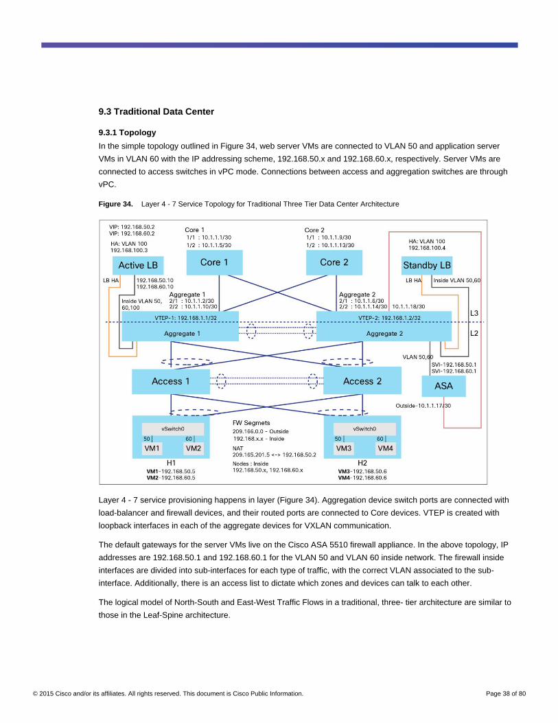
© 2015 Cisco and/or its affiliates. All rights reserved. This document is Cisco Public Information. Page 38 of 80
9.3 Traditional Data Center
9.3.1 Topology
In the simple topology outlined in Figure 34, web server VMs are connected to VLAN 50 and application server
VMs in VLAN 60 with the IP addressing scheme, 192.168.50.x and 192.168.60.x, respectively. Server VMs are
connected to access switches in vPC mode. Connections between access and aggregation switches are through
vPC.
Figure 34. Layer 4 - 7 Service Topology for Traditional Three Tier Data Center Architecture
Layer 4 - 7 service provisioning happens in layer (Figure 34). Aggregation device switch ports are connected with
load-balancer and firewall devices, and their routed ports are connected to Core devices. VTEP is created with
loopback interfaces in each of the aggregate devices for VXLAN communication.
The default gateways for the server VMs live on the Cisco ASA 5510 firewall appliance. In the above topology, IP
addresses are 192.168.50.1 and 192.168.60.1 for the VLAN 50 and VLAN 60 inside network. The firewall inside
interfaces are divided into sub-interfaces for each type of traffic, with the correct VLAN associated to the sub-
interface. Additionally, there is an access list to dictate which zones and devices can talk to each other.
The logical model of North-South and East-West Traffic Flows in a traditional, three- tier architecture are similar to
those in the Leaf-Spine architecture.

© 2015 Cisco and/or its affiliates. All rights reserved. This document is Cisco Public Information. Page 39 of 80
Figure 35. Traditional Data Center Architecture with a VXLAN Topology for Layer 4 - 7 Services
10. Managing the Fabric
10.1.1 Adding Switches and Power-On Auto Provisioning
Power-On Auto Provisioning (POAP) automates the processes of installing and upgrading software images and
installing configuration files on Cisco Nexus switches that are being deployed in the network for the first time.
When a Cisco Nexus switch with the POAP feature boots and does not find the startup configuration, the switch
enters POAP mode, locates a Domain Host Configuration Protocol (DHCP) server, and boots itself with its
interface IP address, gateway, and Domain Name System (DNS) server IP address. The switch also obtains the IP
address of a Trivial FTP (TFTP) server or the URL of an HTTP server and downloads a configuration script that
can enable the switch to download and install the appropriate software image and configuration file.
POAP can enable touchless boot-up and configuration of new Cisco Nexus 9000 Series Switches, reducing the
need for time-consuming, error-prone, manual tasks to scale network capacity (Figure 36).

© 2015 Cisco and/or its affiliates. All rights reserved. This document is Cisco Public Information. Page 40 of 80
Figure 36. Automated Provisioning of Cisco Nexus 9000 Series with POAP
Power-On Auto Provisioning will be enabled, on condition that:
a. No startup configuration exists
b. The DHCP server present in the network responds to the DHCP discover message of the device booted up
To use the PoAP feature on the Cisco Nexus device, follow these steps:
1. Configure the DHCP server to assign an IP address for the Cisco Nexus 9000 switch. Figure 37 shows a
sample Ubuntu DHCP configuration.
Figure 37. Sample Ubuntu DHCP Server Configuration

© 2015 Cisco and/or its affiliates. All rights reserved. This document is Cisco Public Information. Page 41 of 80
2. Poap.py boot file name specified in the DHCP configuration is present in
https://github.com/datacenter/nexus9000/blob/master/nx-os/poap/poap.py.
3. Configure the TFTP server and place the poap.py file in the default TFTP server directory.
4. Change the image file name according to need. Then configure the file, IP address, and credentials in the
poap.py script based on the setup and needs.
5. Place the image file, along with .md5 for the image, in the TFTP server. The md5 can be generated by
command ‘md5sum <Image_file> <image_file>.md5’ on any Linux server.
6. Boot the device.
Figure 38 shows a sample output during the Cisco Nexus switch boot-up process using POAP.
Figure 38. Sample Output
10.1.2 Software Upgrades
To upgrade the access layer without a disruption to hosts that are dual-homed through vPC, follow these steps:
● Upgrade the first vPC switch (vPC primary switch). During this upgrade, the switch will be reloaded. When
the switch is reloaded, the servers or the downstream switch detect loss of connectivity to the first switch
and will start forwarding traffic to the second (vPC secondary) switch.
● Verify that the upgrade of the switch has completed successfully. At the completion of the upgrade, the
switch will restore vPC peering and all the vPC links.
● Upgrade the second switch. Repeating the same process on the second switch will cause the second
switch to reload during the upgrade process. During this reload, the first (upgraded) switch will forward all
the traffic to and from the servers.
● Verify that the upgrade of the second switch has completed successfully. At the end of this upgrade,
complete vPC peering is established and the entire access layer will have been upgraded.

© 2015 Cisco and/or its affiliates. All rights reserved. This document is Cisco Public Information. Page 42 of 80
10.1.3 Guest Shell Container
Starting with Cisco NX-OS Software Release 6.1(2)I3(1), the Cisco Nexus 9000 Series devices support access to a
decoupled execution space called the guest shell. Within the guest shell, the network admin is given Bash access
and may use familiar Linux commands to manage the switch. The guest shell environment has:
● Access to the network, including all VRFs known to Cisco NX-OS Software
● Read and write access to host Cisco Nexus 9000 bootflash
● The ability to execute Cisco Nexus 9000 command-line interface (CLI)
● Access to Cisco onePK™
APIs
● The ability to develop, install, and run python scripts
● The ability to install and run 64-bit Linux applications
● A root file system that is persistent across system reloads or switchovers
Decoupling the execution space from the native host system allows customization of the Linux environment to suit
the needs of the applications without impacting the integrity of the host system. Applications, libraries, or scripts
that are installed or modified within the guest shell file system are separate from that of the host.
By default, the guest shell is freshly installed when the standby supervisor transitions to an active role using the
guest shell package available on that supervisor. With a dual-supervisors system, the network admin can utilize the
guest shell synchronization command, which synchronizes the guest shell contents from the active supervisor to
the standby supervisor.
For more details, refer to the Cisco Nexus 9000 Series NX-OS Programmability Guide, Release 6.x:
http://www.cisco.com/c/en/us/td/docs/switches/datacenter/nexus9000/sw/6-
x/programmability/guide/b_Cisco_Nexus_9000_Series_NX-OS_Programmability_Guide.pdf.
11. Virtualization and Cloud Orchestration
11.1 VM Tracker
Cisco Nexus Series Switches provide a VM Tracker feature that allows the switch to communicate with up to four
VMware vCenter connections. VM Tracker dynamically configures VLANs on the interfaces to the servers when a
VM is created, deleted, or moved.
Currently, the VM Tracker feature is supported for ESX 5.1 and ESX 5.5 versions of VMware vCenter. It supports
up to 64 VMs per host and 350 hosts across all vCenters. It can support up to 600 VLANs in MST mode and up to
507 VLANs in PVRST mode.
The current version of VM Tracker relies on Cisco Discovery Protocol to associate hosts to switch ports.
Following are some operations that are possible with VM Tracker:
● Enable VMTracker - By default, VMTracker is enabled for all interfaces of a switch. You can optionally
disable and enable it on specific interfaces by using the [no] vmtracker enable command.
● Create a connection to VMware vCenter.
● Configure dynamic VLAN connection - By default, VM Tracker tracks all asynchronous events from
VMware vCenter and updates the switchport configuration immediately. Optionally, you can also configure a
synchronizing mechanism that synchronizes all host, VM, and port-group information automatically with
VMware vCenter at a specified interval.

© 2015 Cisco and/or its affiliates. All rights reserved. This document is Cisco Public Information. Page 43 of 80
● Enable dynamic VLAN creation - Dynamic creation and deletion of VLANs globally is enabled by default.
When dynamic VLAN creation is enabled, if a VM is moved from one host to another and the VLAN required
for this VM does not exist on the switch, the required VLAN is automatically created on the switch. You can
also disable this capability. However, if you disable dynamic VLAN creation, you must manually create all
the required VLANs.
● VPC compatibility checking - In a VPC the vCenter connections need to be identical across both the
peers. VM Tracker provides a command to check VPC compatibility across two peers.
When VM Tracker is used, the user cannot perform any Layer 2 or Layer 3 configuration that is related to
switchports and VLANs, except to update the native VLAN.
VM Tracker Configuration
Leaf1(config)# feature vmtracker
Leaf1(config)# vmtracker connection vCenter_conn1
Leaf1(config)# remote ip address 172.31.216.146 port 80 vrf management
Leaf1(config)# username root password vmware
Leaf1(config)# connect
Leaf1(config)# set interval sync-full-info 120
Leaf2(config)# feature vmtracker
Leaf2(config)# vmtracker connection vCenter_conn1
Leaf2(config)# remote ip address 172.31.216.146 port 80 vrf management
Leaf2(config)# username root password vmware
Leaf2(config)# connect
Leaf2(config)# set interval sync-full-info 120
Table 4 outlines the relevant show commands for VM Tracker configuration.
Table 4. Show Commands
show vmtracker status Provides the connection status of vCenter
show vmtracker info detail Provides information on VM properties that are associated to the local interface
For more information, refer to the Cisco Nexus 9000 Series NX-OS Virtual Machine Tracker Configuration Guide,
Release 6.x: http://www.cisco.com/c/en/us/td/docs/switches/datacenter/nexus9000/sw/6-
x/vm_tracker/configuration/guide/b_Cisco_Nexus_9000_Series_NX-
OS_Virtual_Machine_Tracker_Configuration_Guide/b_Cisco_Nexus_9000_Series_Virtual_Machine_Tracker_Confi
guration_Guide_chapter_011.html.
11.2 OpenStack
The Cisco Nexus 9000 Series includes support for the Cisco Nexus plug-in for OpenStack Networking (Neutron).
The plug-in allows customers to easily build their infrastructure-as-a-service (IaaS) networks using the industry's
leading networking platform, delivering performance, scalability, and stability with familiar manageability and
control. The plug-in helps bring operation simplicity to cloud network deployments. OpenStack’s capabilities for
building on-demand, self-service, multitenant computing infrastructure are well known. However, implementing
OpenStack's VLAN networking model across virtual and physical infrastructures can be difficult.

© 2015 Cisco and/or its affiliates. All rights reserved. This document is Cisco Public Information. Page 44 of 80
OpenStack Networking provides an extensible architecture that supports plug-ins for configuring networks directly.
However, each network plug-in enables configuration of only that plug-in’s target technology. When OpenStack
clusters are run across multiple hosts with VLANs, a typical plug-in configures either the virtual network or the
physical network, but not both.
The Cisco Nexus plug-in solves this problem by enabling the use of multiple plug-ins simultaneously. A typical
deployment runs the Cisco Nexus plug-in in addition to the standard Open vSwitch (OVS) plug-in. The Cisco
Nexus plug-in accepts OpenStack Networking API calls and directly configures Cisco Nexus switches as well as
OVS running on the hypervisor. Not only will the Cisco Nexus plug-in configure VLANs on both the physical and
virtual network, but it also intelligently allocates VLAN IDs, de-provisioning them when they are no longer needed
and reassigning them to new tenants whenever possible. VLANs are configured so that virtual machines running
on different virtualization (computing) hosts that belong to the same tenant network transparently communicate
through the physical network. Moreover, connectivity from the computing hosts to the physical network is trunked
to allow traffic only from the VLANs configured on the host by the virtual switch (Figure 39).
Table 5 outlines the various challenges network admins encounter and how OpenStack resolves them.
Figure 39. Cisco OpenStack Neutron Plug-in with Support for Cisco Nexus 9000 Series Switches
Table 5. Cisco Nexus Plug-in for OpenStack Networking
Requirement Challenge Cisco Plug-in Resolution
Extension of tenant VLANs across virtualization hosts
VLANs must be configured on both physical and virtual networks. OpenStack supports only a single plug-in at a time. The operator must choose which parts of the network to manually configure
Accepts OpenStack API calls and configures both physical and virtual switches
Efficient use of limited VLAN IDs Static provisioning of VLAN IDs on every switch rapidly consumes all available VLAN IDs, limiting scalability and making the network more vulnerable to broadcast storms
Efficiently uses limited VLAN IDs by provisioning and de-provisioning VLANs across switches as tenant networks are created and destroyed
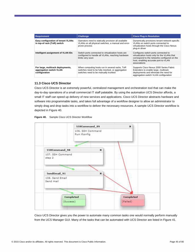
© 2015 Cisco and/or its affiliates. All rights reserved. This document is Cisco Public Information. Page 45 of 80
Requirement Challenge Cisco Plug-in Resolution
Easy configuration of tenant VLANs in top-of rack (ToR) switch
Operators need to statically provision all available VLANs on all physical switches, a manual and error-prone process
Dynamically provisions tenant-network-specific VLANs on switch ports connected to virtualization hosts through the Cisco Nexus plug-in driver
Intelligent assignment of VLAN IDs Switch ports connected to virtualization hosts are configured to handle all VLANs, reaching hardware limits very soon
Configures switch ports connected to virtualization hosts only for the VLANs that correspond to the networks configured on the host, enabling accurate port-to-VLAN associations
For large, multirack deployments, aggregation switch VLAN configuration
When computing hosts run in several racks, ToR switches need to be fully meshed, or aggregation switches need to be manually trunked
Supports Cisco Nexus 2000 Series Fabric Extenders to enable large, multirack deployments and eliminate the need for aggregation-switch VLAN configuration
11.3 Cisco UCS Director
Cisco UCS Director is an extremely powerful, centralized management and orchestration tool that can make the
day-to-day operations of a small commercial IT staff palatable. By using the automation UCS Director affords, a
small IT staff can speed up delivery of new services and applications. Cisco UCS Director abstracts hardware and
software into programmable tasks, and takes full advantage of a workflow designer to allow an administrator to
simply drag and drop tasks into a workflow to deliver the necessary resources. A sample UCS Director workflow is
depicted in Figure 40.
Figure 40. Sample Cisco UCS Director Workflow
Cisco UCS Director gives you the power to automate many common tasks one would normally perform manually
from the UCS Manager GUI. Many of the tasks that can be automated with UCS Director are listed in Figure 41.

© 2015 Cisco and/or its affiliates. All rights reserved. This document is Cisco Public Information. Page 46 of 80
Figure 41. Common UCS Director Automation Tasks
For more information, read the Cisco UCS Director solution overview.
11.4 Cisco Prime Data Center Network Manager
Cisco Prime Data Center Network Manager (DCNM) is a very powerful tool for centralized data center monitoring,
managing, and automation of Cisco data center compute, network, and storage infrastructure. A basic version of
DCNM is available for free, with more advanced features requiring a license. DCNM allows centralized
management of all Cisco Nexus switches, and Cisco UCS and MDS devices.
DCNM-LAN version 6.x was used in our sample design for management of the infrastructure. One powerful feature
of DCNM is the ability to have a visual, auto-updating topology diagram. Figure 42 shows the sample lab topology.
Figure 42. DCNM Topology Diagram

© 2015 Cisco and/or its affiliates. All rights reserved. This document is Cisco Public Information. Page 47 of 80
DCNM can also be used to manage advanced features like vPCs, Cisco NX-OS image management, and
inventory control. A sample visual inventory is pictured from one of the spine switches (Figure 43).
Figure 43. DCNM Switch Inventory
11.5 Cisco Prime Services Catalog
As organizations continue to expand automation, self-service portals are a very important component, used to
provide a storefront or a marketplace view to consumers to consume infrastructure and application services.
The Cisco Prime Services Catalog provides the following key features:
● A single pane of glass for provisioning, configuration, and management of IaaS, PaaS, and other IT
services (Figure 44)
● Single sign-on (SSO) for IaaS, PaaS, and other IT services; there is no need to log on to multiple systems
● IT administrators can easily create service catalogs in a graphical way to join application elements with
business policies and governance
● Integration with various infrastructures and various IT sub-systems through APIs to promote information
exchange and provisioning of infrastructure and applications. Examples include OpenStack, Cisco UCS
Director, Red Hat Openshift PaaS, vCenter, and more
● Creations of storefronts so that application developers and IT project managers can browse and request
available application stacks through an intuitive user interface

© 2015 Cisco and/or its affiliates. All rights reserved. This document is Cisco Public Information. Page 48 of 80
Figure 44. Example of Cisco Prime Services Catalog Integration with PaaS and IaaS Platforms
12. Automation and Programmability
12.1 Support for Traditional Network Capabilities
While many new and important features have been discussed, it is important to highlight the additional features
support on the Cisco Nexus 9000 Series Switches, such as quality of service (QoS), multicast, and Simple Network
Management Protocol (SNMP) and supported MIBs.
Quality of Service
New applications and evolving protocols are changing QoS demands in modern data centers. High-frequency
trading floor applications are very sensitive to latency, while high-performance computing is typically characterized
by bursty, many-to-one east-west traffic flows. Applications, such as storage, voice, and video, also require special
and different treatment in any data center.
Like the other members of the Cisco Nexus family, the Cisco Nexus 9000 Series Switches support QoS
configuration through Cisco Modular QoS CLI (MQC). Configuration involves identifying traffic using class maps
based on things such as protocol or packet header markings; defining how to treat different classes through policy
maps by possibly marking packets, queuing, or scheduling; and then applying policy maps to either interfaces or
the entire system using the service policy command. QoS is enabled by default and does not require a license.
Unlike Cisco IOS Software, Cisco NX-OS on the Cisco Nexus 9000 switch uses three different types of policy
maps depending on the QoS feature you are trying to implement. The three types of Cisco NX-OS QoS and their
primary usages include:
● Type QoS - for classification, marking, and policing
● Type queuing - for buffering, queuing, and scheduling
● Type network QoS - for systemwide settings, congestion control, and pause behavior
Type network-QoS policy maps are applied only systemwide, whereas type QoS and type queuing can each be
applied simultaneously on a single interface, one each ingress and egress for a total of four QoS polices per
interface, if required.

© 2015 Cisco and/or its affiliates. All rights reserved. This document is Cisco Public Information. Page 49 of 80
Multicast
The Cisco Nexus 9300 platform provides high-performance, line rate Layer 2 and Layer 3 multicast throughput with
low latency at scale at up to 8000 multicast routes with multicast routing enabled. The Cisco Nexus 9300 platform
optimizes multicast lookup and replication by performing IP-based lookup for Layer 2 and Layer 3 multicast to
avoid common aliasing problems in multicast IP-to-MAC encoding.
The Cisco Nexus 9300 platform supports IGMP versions 1, 2, and 3, Protocol-Independent Multicast (PIM) sparse
mode, anycast rendezvous point, and MSDP.
SNMP and Supported MIBs
SNMP provides a standard framework and language to manage devices on the network, including the Cisco Nexus
9000 Series Switches. The SNMP manager controls and monitors the activities of network devices using SNMP.
The SNMP agent lives in the managed device and reports the data to the managing system. The agent on the
Cisco Nexus 9000 Series Switches must be configured to talk to the manager. MIBs are a collection of managed
objects by the SNMP agent. Cisco Nexus 9000 Series Switches support SNMP v1, v2c, and v3. The switches can
also support SNMP over IPv6.
SNMP generates notifications about Cisco Nexus 9000 Series Switches to send to the manager, for example,
notifying the manager when a neighboring router is lost. A trap notification is sent from the agent on the Cisco
Nexus 9000 switch to the manager, who does not acknowledge the message. A notification to inform is
acknowledged by the manager. Table 6 provides the SNMP traps enabled by default.
On a Cisco Nexus 9000 switch, Cisco NX-OS supports stateless restarts and is also aware of virtual routing and
forwarding (VRF). Using SNMP does not require a license.
For a list of supported MIBs on the Cisco Nexus 9000 Series Switches, see this list.
For configuration help, see the section “Configuring SNMP” in the Cisco Nexus 9000 Series NX-OS System
Management Configuration Guide, Release 6.0.
Table 6. SNMP Traps Enabled by Default on Cisco Nexus 9000 Series Switches
Trap Type Description
generic : coldStart
generic : warmStart
entity : entity_mib_change
entity : entity_module_status_change
entity : entity_power_status_change
entity : entity_module_inserted
entity : entity_ module_removed
entity : entity_unrecognised_module
entity : entity_fan_status_change
entity : entity_power_out_change
link : linkDown
link : linkup
link : extended-linkDown
link : extended-linkUp
link : cieLinkDown
link : cieLinkUp

© 2015 Cisco and/or its affiliates. All rights reserved. This document is Cisco Public Information. Page 50 of 80
Trap Type Description
link : delayed-link-state-change
rf : redundancy_framework
license : notify-license-expiry
license : notify-no-license-for-feature
license : notify-licensefile-missing
license : notify-license-expirty-warning
upgrade : UpgradeOpNotifyOnCompletion
upgrade : UpgradeJobStatusNotify
rmon : risingAlarm
rmon : fallingAlarm
rmon : hcRisingAlarm
rmon : hcFallingAlarm
entity : entity_sensor
12.2 Programming Cisco Nexus 9000 Switches through NX-APIs
Cisco NX-API allows for HTTP-based programmatic access to the Cisco Nexus 9000 Series platform. This support
is delivered by NX-API, an open-source web server. NX-API provides the configuration and management
capabilities of the Cisco NX-OS CLI with web-based APIs. The device can be set to publish the output of the API
calls in XML or JSON format. This API enables rapid development on the Cisco Nexus 9000 Series platform.
This section provides the API configurations to achieve the functionality that was earlier done through CLIs
(described in previous section). Configuration details are provided as part of Section 15.2.3 (NX-API Sandbox).
12.3 Chef, Puppet, and Python Integration
Puppet and Chef are two popular, intent-based, infrastructure automation frameworks. Chef allows users to define
their intent through a recipe - a reusable set of configuration or management tasks - and allows the recipe to be
deployed on numerous devices. The recipe, when deployed on a Cisco Nexus 9000 Series Switch, translates into
network configuration settings and commands for collecting statistics and analytics information. The recipe allows
automated configuration and management of a Cisco Nexus 9000 Series Switch.
Puppet provides a similar intent-definition construct, called a manifest. The manifest, when deployed on a Cisco
Nexus 9000 Series Switch, translates into network configuration settings and commands for collecting information
from the switch.
Both Puppet and Chef are widely deployed and receive significant attention in the infrastructure automation and
DevOps communities. The Cisco Nexus 9000 Series supports both the Puppet and Chef frameworks, with clients
for Puppet and Chef integrated into enhanced Cisco NX-OS on the switch (Figure 45).

© 2015 Cisco and/or its affiliates. All rights reserved. This document is Cisco Public Information. Page 51 of 80
Figure 45. Automation with Puppet Support on a Cisco Nexus 9000 Series
12.4 Extensible Messaging and Presence Protocol Support
Enhanced Cisco NX-OS on the Cisco Nexus 9000 Series integrates an Extensible Messaging and Presence
Protocol (XMPP) client into the operating system. This integration allows a Cisco Nexus 9000 Series Switch to be
managed and configured by XMPP-enabled chat clients, which are commonly used for human communication.
XMPP support can enable several useful capabilities:
● Group configuration - Add a set of Cisco Nexus 9000 Series devices to a chat group and manage a set of
Cisco Nexus 9000 Series Switches as a group. This capability can be useful for pushing common
configurations to a set of Cisco Nexus 9000 Series devices instead of configuring the devices individually.
● Single point of management - The XMPP server can act as a single point of management. Users
authenticate with a single XMPP server and gain access to all the devices registered on the server.
● Security - The XMPP interface supports role-based access control (RBAC) and helps ensure that users
can run only the commands that they are authorized to run.
● Automation - XMPP is an open, standards-based interface. This interface can be used by scripts and
management tools to automate management of Cisco Nexus 9000 Series devices (Figure 46).
Figure 46. Automation with XMPP Support on Cisco Nexus 9000 Series
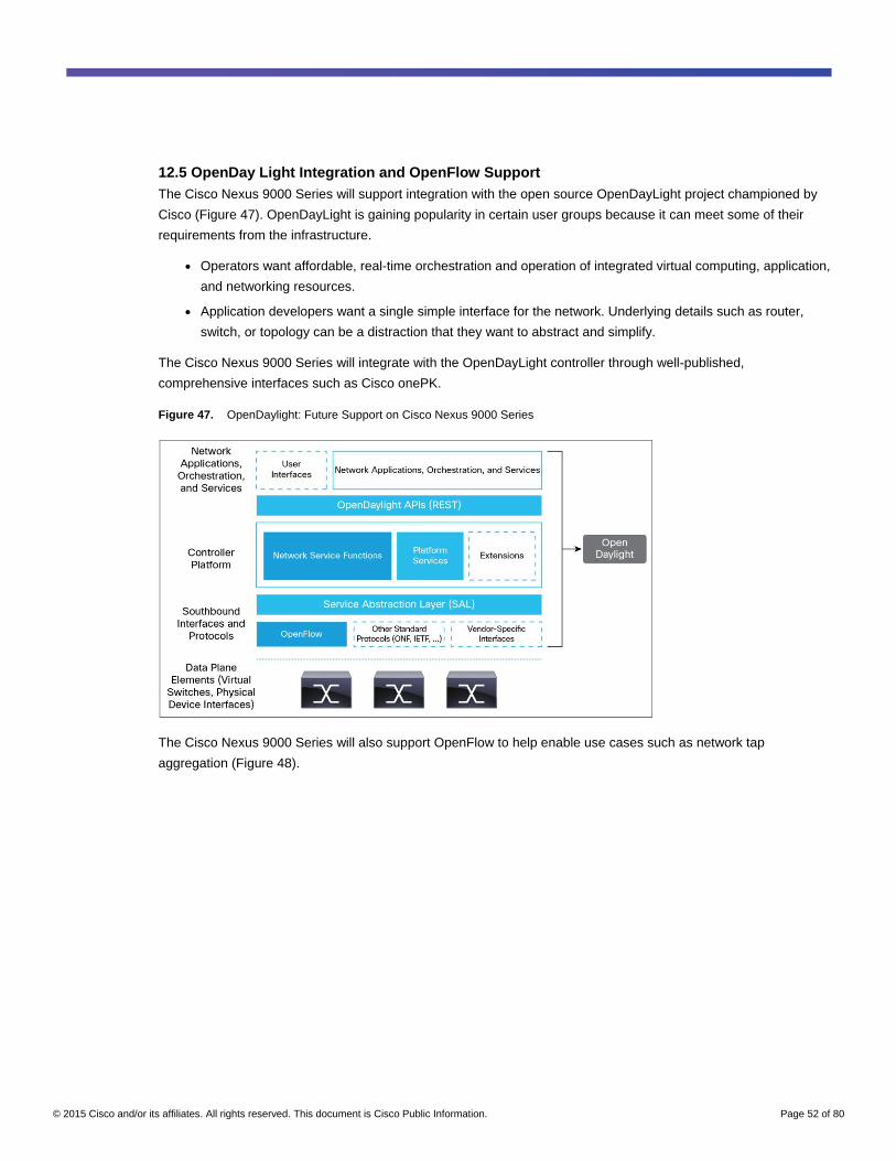
© 2015 Cisco and/or its affiliates. All rights reserved. This document is Cisco Public Information. Page 52 of 80
12.5 OpenDay Light Integration and OpenFlow Support
The Cisco Nexus 9000 Series will support integration with the open source OpenDayLight project championed by
Cisco (Figure 47). OpenDayLight is gaining popularity in certain user groups because it can meet some of their
requirements from the infrastructure.
● Operators want affordable, real-time orchestration and operation of integrated virtual computing, application,
and networking resources.
● Application developers want a single simple interface for the network. Underlying details such as router,
switch, or topology can be a distraction that they want to abstract and simplify.
The Cisco Nexus 9000 Series will integrate with the OpenDayLight controller through well-published,
comprehensive interfaces such as Cisco onePK.
Figure 47. OpenDaylight: Future Support on Cisco Nexus 9000 Series
The Cisco Nexus 9000 Series will also support OpenFlow to help enable use cases such as network tap
aggregation (Figure 48).

© 2015 Cisco and/or its affiliates. All rights reserved. This document is Cisco Public Information. Page 53 of 80
Figure 48. Tap Aggregation Using OpenFlow Support on Cisco Nexus 9000 Series
13. Troubleshooting
Encapsulated remote switched port analyzer (ERSPAN) mirrors traffic on one or more source ports and delivers
the mirrored traffic to one or more destination ports on another switch (Figure 49). The traffic is encapsulated in
generic routing encapsulation (GRE) and is therefore, routable across a layer 3 network between the source switch
and the destination switch.
Figure 49. ERSPAN
ERSPAN copies the ingress and egress of a given switch source and creates a GRE tunnel back to an ERSPAN
destination. This allows network operators to strategically place network monitoring gear in a central location of the
network. Administrators can then collect historical traffic patterns in great detail.
ERSPAN can enable remote monitoring of multiple switches across your network. It transports mirrored traffic from
source ports of different switches to the destination port, where the network analyzer has connected. Monitor all the
packets for the source port which are received (ingress), transmitted (egress), or bidirectional (both). ERSPAN
sources include source ports, source VLANs, or source VSANs. When a VLAN is specified as an ERSPAN source,
all supported interfaces in the VLAN are ERSPAN sources. ERSPAN can also be used for packet monitoring.
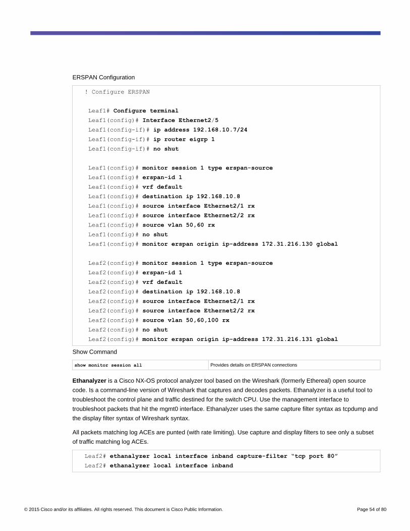
© 2015 Cisco and/or its affiliates. All rights reserved. This document is Cisco Public Information. Page 54 of 80
ERSPAN Configuration
! Configure ERSPAN
Leaf1# Configure terminal
Leaf1(config)# Interface Ethernet2/5
Leaf1(config-if)# ip address 192.168.10.7/24
Leaf1(config-if)# ip router eigrp 1
Leaf1(config-if)# no shut
Leaf1(config)# monitor session 1 type erspan-source
Leaf1(config)# erspan-id 1
Leaf1(config)# vrf default
Leaf1(config)# destination ip 192.168.10.8
Leaf1(config)# source interface Ethernet2/1 rx
Leaf1(config)# source interface Ethernet2/2 rx
Leaf1(config)# source vlan 50,60 rx
Leaf1(config)# no shut
Leaf1(config)# monitor erspan origin ip-address 172.31.216.130 global
Leaf2(config)# monitor session 1 type erspan-source
Leaf2(config)# erspan-id 1
Leaf2(config)# vrf default
Leaf2(config)# destination ip 192.168.10.8
Leaf2(config)# source interface Ethernet2/1 rx
Leaf2(config)# source interface Ethernet2/2 rx
Leaf2(config)# source vlan 50,60,100 rx
Leaf2(config)# no shut
Leaf2(config)# monitor erspan origin ip-address 172.31.216.131 global
Show Command
show monitor session all Provides details on ERSPAN connections
Ethanalyzer is a Cisco NX-OS protocol analyzer tool based on the Wireshark (formerly Ethereal) open source
code. Is a command-line version of Wireshark that captures and decodes packets. Ethanalyzer is a useful tool to
troubleshoot the control plane and traffic destined for the switch CPU. Use the management interface to
troubleshoot packets that hit the mgmt0 interface. Ethanalyzer uses the same capture filter syntax as tcpdump and
the display filter syntax of Wireshark syntax.
All packets matching log ACEs are punted (with rate limiting). Use capture and display filters to see only a subset
of traffic matching log ACEs.
Leaf2# ethanalyzer local interface inband capture-filter “tcp port 80”
Leaf2# ethanalyzer local interface inband

© 2015 Cisco and/or its affiliates. All rights reserved. This document is Cisco Public Information. Page 55 of 80
Ethanalyzer does not capture data traffic that Cisco NX-OS forwards in the hardware, but can use ACLs with a log
option as a workaround.
Leaf2(config)# ip access-list acl-cap
Leaf2(config-acl)# permit tcp 192.168.60.5 192.168.60.6 eq 80 log
Leaf2(config-acl)# permit ip any any
Leaf2(config)# interface e1/1
Leaf2(config-if)# ip access-group acl-cap in
Leaf2# ethanalyzer local interface inband capture-filter “tcp port 80”
A rollback allows a user to take a snapshot, or user checkpoint, of the Cisco NX-OS configuration and then
reapply that configuration to a device at any point without having to reload the device. A rollback allows any
authorized administrator to apply this checkpoint configuration without requiring expert knowledge of the features
configured in the checkpoint.
Cisco NX-OS automatically creates system checkpoints. You can use either a user or system checkpoint to
perform a rollback.
A user can create a checkpoint copy of the current running configuration at any time. Cisco NX-OS saves this
checkpoint as an ASCII file, which user can use to roll back the running configuration to the checkpoint
configuration at a future time. The user can create multiple checkpoints to save different versions of a running
configuration.
When a user rolls back the running configuration, it can trigger the following rollback types:
● Atomic - implement a rollback only if no errors occur
● Best effort - implements a rollback and skips any errors
● Stop-at-first failure - implements a rollback that stops if an error occurs
The default rollback type is atomic.
Checkpoint Configuration and Use of Rollbacks
! Configure Checkpoint
Leaf1# checkpoint stable_Leaf1
Leaf2# checkpoint stable_Leaf2
Leaf3# checkpoint stable_Leaf3
! Display content of Check point
Leaf1# show checkpoint stable
! Display differences between check point stable_Leaf1 and running config

© 2015 Cisco and/or its affiliates. All rights reserved. This document is Cisco Public Information. Page 56 of 80
Leaf1# show diff rollback-patch checkpoint stable running-config
!! Rollback the running config to a user checkpoint stable_Leaf1
Leaf1# rollback running-config checkpoint stable_Leaf1
14. Appendix
14.1 Products
14.1.1 Cisco Nexus 9500 Product Line
The Cisco Nexus 9500 Series modular switches are typically deployed as spines (aggregation or core switches) in
commercial data centers. Figure 50 lists the line cards available in the Cisco Nexus 9500 chassis in NX-OS
standalone mode at the time of writing (ACI-only line cards have been removed).
Figure 50. Cisco Nexus 9500 Line Card Offerings
Note: Check the Cisco Nexus 9500 data sheets for the latest product information. Line card availability may
have changed since the time of writing.
14.1.2 Cisco Nexus 9300 Product Line
The Cisco Nexus 9300 Series fixed-configuration switches are typically deployed as leaves (access switches).
Some 9300 switches are semi-modular by providing an uplink module slot for additional ports. Figure 51 lists Cisco
Nexus 9300 chassis that support NX-OS standalone mode available at the time of writing.
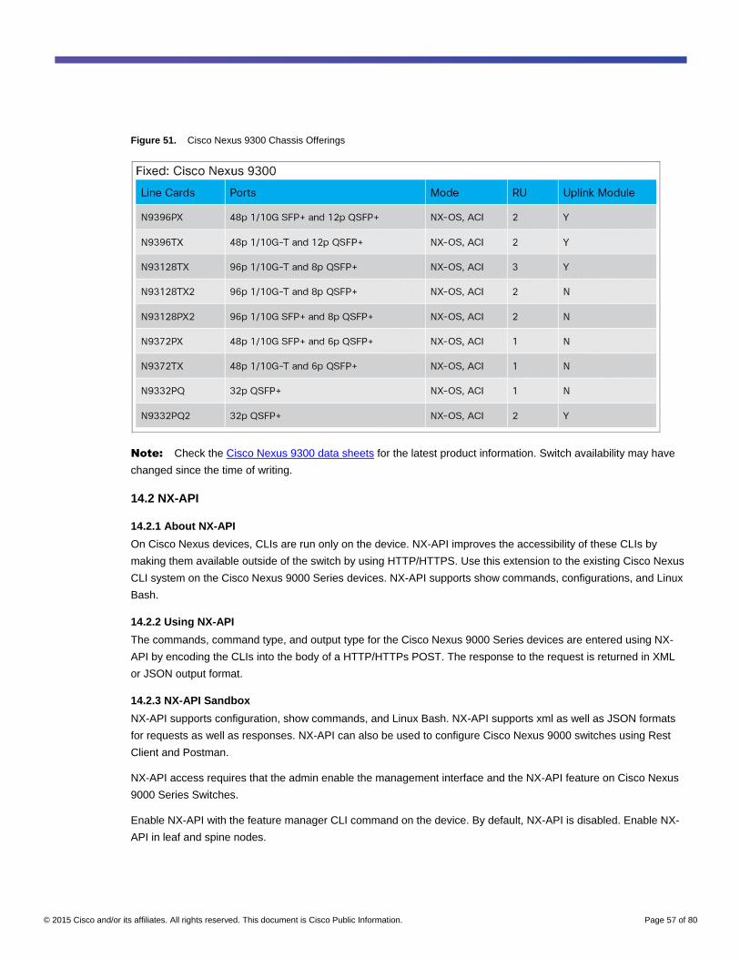
© 2015 Cisco and/or its affiliates. All rights reserved. This document is Cisco Public Information. Page 57 of 80
Figure 51. Cisco Nexus 9300 Chassis Offerings
Note: Check the Cisco Nexus 9300 data sheets for the latest product information. Switch availability may have
changed since the time of writing.
14.2 NX-API
14.2.1 About NX-API
On Cisco Nexus devices, CLIs are run only on the device. NX-API improves the accessibility of these CLIs by
making them available outside of the switch by using HTTP/HTTPS. Use this extension to the existing Cisco Nexus
CLI system on the Cisco Nexus 9000 Series devices. NX-API supports show commands, configurations, and Linux
Bash.
14.2.2 Using NX-API
The commands, command type, and output type for the Cisco Nexus 9000 Series devices are entered using NX-
API by encoding the CLIs into the body of a HTTP/HTTPs POST. The response to the request is returned in XML
or JSON output format.
14.2.3 NX-API Sandbox
NX-API supports configuration, show commands, and Linux Bash. NX-API supports xml as well as JSON formats
for requests as well as responses. NX-API can also be used to configure Cisco Nexus 9000 switches using Rest
Client and Postman.
NX-API access requires that the admin enable the management interface and the NX-API feature on Cisco Nexus
9000 Series Switches.
Enable NX-API with the feature manager CLI command on the device. By default, NX-API is disabled. Enable NX-
API in leaf and spine nodes.

© 2015 Cisco and/or its affiliates. All rights reserved. This document is Cisco Public Information. Page 58 of 80
How to Enable the Management Interface and NX-API Feature
! Enable Management interface
Leaf1# conf t
Leaf1(config)# interface mgmt 0
Leaf1(config)# ip address 172.31.216.130/24
Leaf1(config)# vrf context management
Leaf1(config)# default gateway 172.31.216.1
! Enable NXAPI feature
Leaf1# conf t
Leaf1(config)# feature nxapi
Once the management interface and NX-API features are enabled, they can be used through Sandbox or Postman
as described in the steps that immediately follow. By default, http/https support is enabled when enabling the NX-
API feature.
When using the NX-API Sandbox, use of the Firefox browser, release 24.0 or later, is recommended.
1. Open a browser and enter http(s)://<mgmt-ip> to launch the NX-API Sandbox. Figures 53 and 54 are
examples of a request and output response.
Figure 52. Request - cli_show
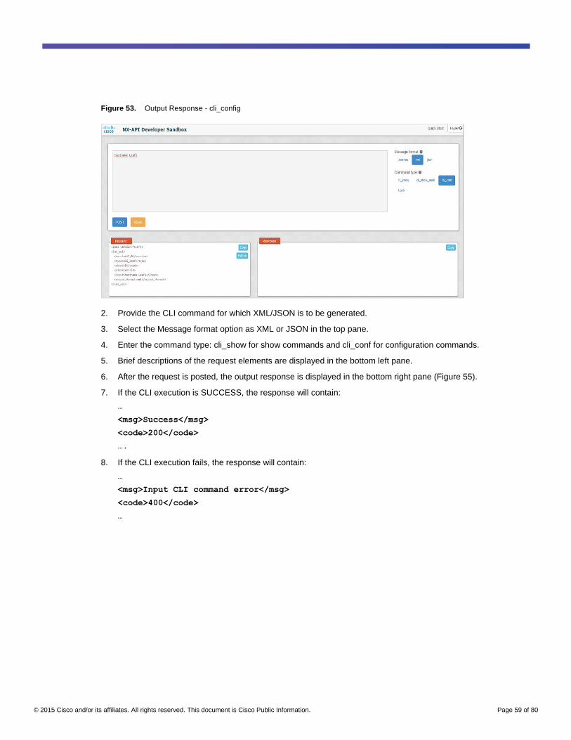
© 2015 Cisco and/or its affiliates. All rights reserved. This document is Cisco Public Information. Page 59 of 80
Figure 53. Output Response - cli_config
2. Provide the CLI command for which XML/JSON is to be generated.
3. Select the Message format option as XML or JSON in the top pane.
4. Enter the command type: cli_show for show commands and cli_conf for configuration commands.
5. Brief descriptions of the request elements are displayed in the bottom left pane.
6. After the request is posted, the output response is displayed in the bottom right pane (Figure 55).
7. If the CLI execution is SUCCESS, the response will contain:
…
<msg>Success</msg>
<code>200</code>
….
8. If the CLI execution fails, the response will contain:
…
<msg>Input CLI command error</msg>
<code>400</code>
…

© 2015 Cisco and/or its affiliates. All rights reserved. This document is Cisco Public Information. Page 60 of 80
Figure 54. Response after CLI Execution
14.2.4 NX-OS Configuration Using Postman
Postman is a REST client available as a Chrome browser extension. Use Postman to execute NX-API REST calls
on Cisco Nexus devices. Postman allows great reusability through writing APIs to perform various configurations
remotely.
9. Open a web browser and run the Postman client. The empty web user interface should look like the
screenshot in Figure 56.
Figure 55. View of an Empty Web User Interface

© 2015 Cisco and/or its affiliates. All rights reserved. This document is Cisco Public Information. Page 61 of 80
10. Follow these steps to use Postman for NX-API execution.
i) Enter MGMT IP (http://172.31.216.130/ins) in the URL tab. Provide the user name and password in the
popup windows.
ii) Select the type of operation as ‘POST’
iii) XML/JSON is selected for a raw format type.
iv) Request the body to contain the XML/JSON requests.
v) Press in order to send the API requests to the Cisco Nexus device.
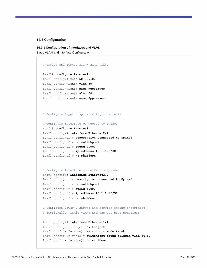
© 2015 Cisco and/or its affiliates. All rights reserved. This document is Cisco Public Information. Page 62 of 80
14.3 Configuration
14.3.1 Configuration of Interfaces and VLAN
Basic VLAN and Interface Configuration
! Create and (optionally) name VLANs
Leaf1# configure terminal
Leaf1(config)# vlan 50,70,100
Leaf1(config-vlan)# vlan 50
Leaf1(config-vlan)# name Webserver
Leaf1(config-vlan)# vlan 60
Leaf1(config-vlan)# name Appserver
! Configure Layer 3 spine-facing interfaces
! Configure Interface connected to Spine1
Leaf1# configure terminal
Leaf1(config)# interface Ethernet2/1
Leaf1(config-if)# description Connected to Spine1
Leaf1(config-if)# no switchport
Leaf1(config-if)# speed 40000
Leaf1(config-if)# ip address 10.1.1.2/30
Leaf1(config-if)# no shutdown
! Configure Interface connected to Spine2
Leaf1(config)# interface Ethernet2/2
Leaf1(config-if)# description connected to Spine2
Leaf1(config-if)# no switchport
Leaf1(config-if)# speed 40000
Leaf1(config-if)# ip address 10.1.1.10/30
Leaf1(config-if)# no shutdown
! Configure Layer 2 server and service-facing interfaces
! (Optionally) Limit VLANs and use STP best practices
Leaf1(config)# interface Ethernet1/1-2
Leaf1(config-if-range)# switchport
Leaf1(config-if-range)# switchport mode trunk
Leaf1(config-if-range)# switchport trunk allowed vlan 50,60
Leaf1(config-if-range)# no shutdown

© 2015 Cisco and/or its affiliates. All rights reserved. This document is Cisco Public Information. Page 63 of 80
Leaf1(config)# interface Ethernet1/1
Leaf1(config-if)# description to Server1
Leaf1(config-if)# interface Ethernet1/2
Leaf1(config-if)# description to Server2
Leaf1(config-if)# interface Ethernet1/48
Leaf1(config-if)# description to F5 Active LB
Leaf1(config-if)# switchport
Leaf1(config-if)# switchport mode trunk
Leaf1(config-if)# switchport trunk allowed vlan 50,60
Leaf1(config-if)# no shutdown
! Configure Leaf2 Interface connected to Spine1
Leaf2# Configure terminal
Leaf2(config)# interface Ethernet2/1
Leaf2(config-if)# description connected to Spine1
Leaf2(config-if)# no switchport
Leaf2(config-if)# speed 40000
Leaf2(config-if)# ip address 10.1.1.6/30
Leaf2(config-if)# no shutdown
! Configure Interface connected to Spine2
Leaf2(config)# interface Ethernet2/2
Leaf2(config-if)# description to connected to Spine2
Leaf2(config-if)# no switchport
Leaf2(config-if)# speed 40000
Leaf2(config-if)# ip address 10.1.1.14/30
Leaf2(config-if)# no shutdown
! Configure Interface connected to Server1
Leaf2(config)# interface Ethernet1/1
Leaf2(config-if)# description Connected to server1
Leaf2(config-if)# switchport mode trunk 50,60
Leaf2(config-if)# no shutdown
! Configure Interface connected to Server2
Leaf2(config)# interface Ethernet1/2
Leaf2(config-if)# description Connected to server2
Leaf2(config-if)# switchport mode trunk 50,60

© 2015 Cisco and/or its affiliates. All rights reserved. This document is Cisco Public Information. Page 64 of 80
Leaf2(config-if)# no shutdown
! Configure Spine1 Interface connected to Leaf1
Spine1# configure terminal
Spine1(config)# interface Ethernet1/1
Spine1(config-if)# description connected to Leaf1
Spine1(config-if)# speed 40000
Spine1(config-if)# ip address 10.1.1.1/30
Spine1(config-if)# no shutdown
! Configure Interface connected to Leaf2
Spine1(config)# interface Ethernet1/2
Spine1(config-if)# description Connection to Leaf2
Spine1(config-if)# speed 40000
Spine1(config-if)# ip address 10.1.1.5/30
Spine1(config-if)# no shutdown
! Configure Spine2 Interface connected to Leaf1
Spine2# Configure terminal
Spine2(config)# interface Ethernet1/1
Spine2(config-if)# description Connection to Leaf1
Spine2(config-if)# speed 40000
Spine2(config-if)# ip address 10.1.1.9/30
Spine2(config-if)# no shutdown
! Configure Interface connected to Leaf2
Spine2(config)# interface Ethernet1/2
Spine2(config-if)# description Connection to Leaf2
Spine2(config-if)# speed 40000
Spine2(config-if)# ip address 10.1.1.13/30
Spine2(config-if)# no shutdown
14.3.2 Configuration of Routing - EIGRP
Enhanced Interior Gateway Routing Protocol (EIGRP) Configuration
! Enable the EIGRP feature on Leaf1
! Configure global EIGRP process and (optional) router ID
Leaf1# configure terminal
Leaf1(config)# feature eigrp

© 2015 Cisco and/or its affiliates. All rights reserved. This document is Cisco Public Information. Page 65 of 80
Leaf1(config)# router eigrp 1
Leaf1(config-router)# router-id 1.1.1.33
! Enable the EIGRP process on spine-facing interfaces
Leaf1(config-router)# interface Ethernet2/1-2
Leaf1(config-if-range)# ip router eigrp 1
! Enable the EIGRP feature on Leaf2
! Configure global EIGRP process and (optional) router ID
Leaf2# configure terminal
Leaf2(config)# feature eigrp
Leaf2(config)# router eigrp 1
Leaf2(config-router)# router-id 1.1.1.34
! Enable the EIGRP process on spine-facing interfaces
Leaf2(config-router)# interface Ethernet2/1-2
Leaf2(config-if-range)# ip router eigrp 1
! Enable the EIGRP feature on Spine1
! Configure global EIGRP process and (optional) router ID
Spine1# configure terminal
Spine1(config)# feature eigrp
Spine1(config)# router eigrp 1
Spine1(config-router)# router-id 1.1.1.31
! Enable the EIGRP process on Leaf-facing interfaces
Spine1(config-router)# interface Ethernet1/1-3
Spine1(config-if-range)# ip router eigrp 1
! Enable the EIGRP feature on Spine1
! Configure global EIGRP process and (optional) router ID
Spine2# configure terminal
Spine2(config)# feature eigrp
Spine2(config)# router eigrp 1
Spine2(config-router)# router-id 1.1.1.32
! Enable the EIGRP process on Leaf-facing interfaces
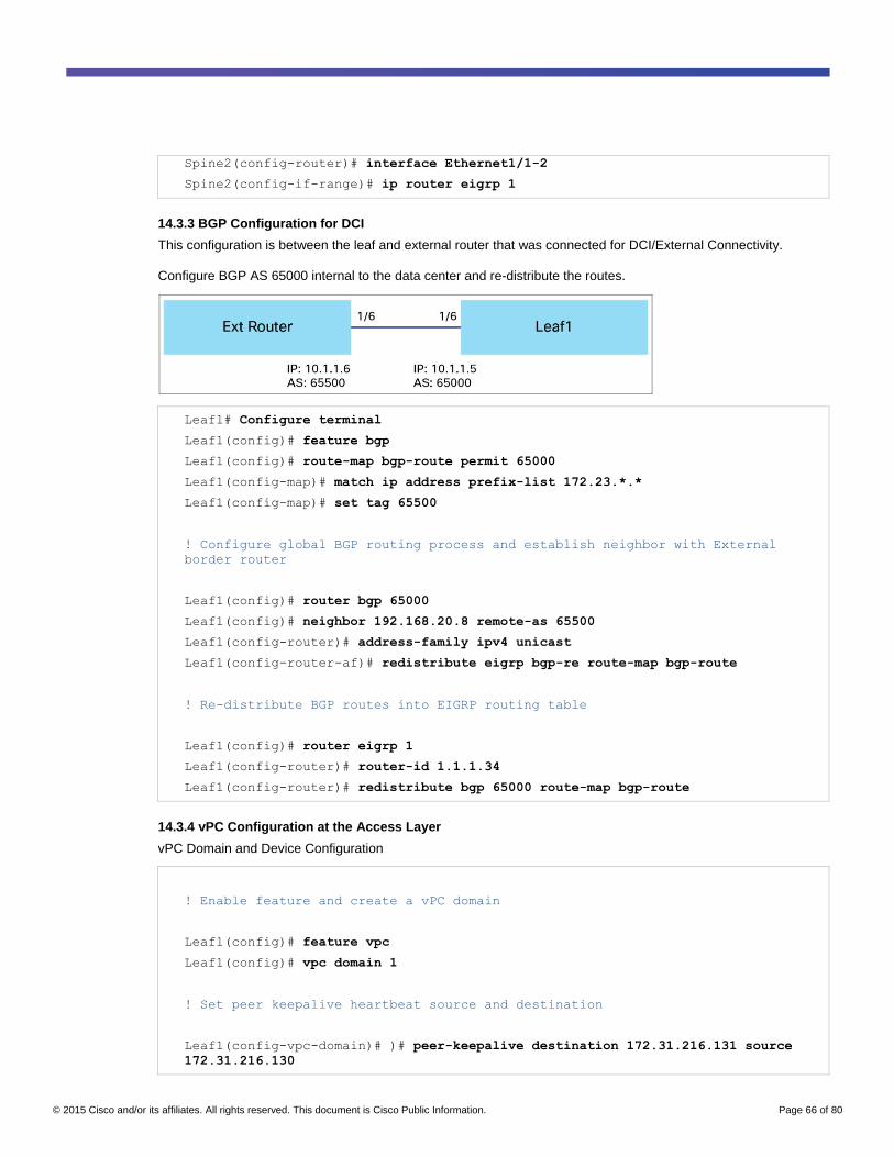
© 2015 Cisco and/or its affiliates. All rights reserved. This document is Cisco Public Information. Page 66 of 80
Spine2(config-router)# interface Ethernet1/1-2
Spine2(config-if-range)# ip router eigrp 1
14.3.3 BGP Configuration for DCI
This configuration is between the leaf and external router that was connected for DCI/External Connectivity.
Configure BGP AS 65000 internal to the data center and re-distribute the routes.
Leaf1# Configure terminal
Leaf1(config)# feature bgp
Leaf1(config)# route-map bgp-route permit 65000
Leaf1(config-map)# match ip address prefix-list 172.23.*.*
Leaf1(config-map)# set tag 65500
! Configure global BGP routing process and establish neighbor with External
border router
Leaf1(config)# router bgp 65000
Leaf1(config)# neighbor 192.168.20.8 remote-as 65500
Leaf1(config-router)# address-family ipv4 unicast
Leaf1(config-router-af)# redistribute eigrp bgp-re route-map bgp-route
! Re-distribute BGP routes into EIGRP routing table
Leaf1(config)# router eigrp 1
Leaf1(config-router)# router-id 1.1.1.34
Leaf1(config-router)# redistribute bgp 65000 route-map bgp-route
14.3.4 vPC Configuration at the Access Layer
vPC Domain and Device Configuration
! Enable feature and create a vPC domain
Leaf1(config)# feature vpc
Leaf1(config)# vpc domain 1
! Set peer keepalive heartbeat source and destination
Leaf1(config-vpc-domain)# )# peer-keepalive destination 172.31.216.131 source
172.31.216.130

© 2015 Cisco and/or its affiliates. All rights reserved. This document is Cisco Public Information. Page 67 of 80
! Automatically and simultaneously enable the following
! best practice commands using the mode auto command: peer-
! gateway, auto-recovery, ip arp synchronize, and ipv6 nd
! synchronize.
Leaf1(config-vpc-domain)# mode auto
! Create port channel interface and attach it to physical interface
Leaf1(config)# feature lacp
! Create the peer-link Port Channel and add to domain
! Configure best practice Spanning Tree features on vPC
! Create a Port Channel and vPC for a server
! The vPC must match on the other peer for the server
Leaf1(config)# interface port-channel10
Leaf1(config-if)# description to Peer
Leaf1(config-if)# switchport mode trunk
Leaf1(config-if)# spanning-tree port type network
Leaf1(config-if)# vpc peer-link
Leaf1(config-if)# no shutdown
!! Please note that spanning tree port type is changed to
"network" port type on vPC peer-link. This will enable
spanning tree Bridge Assurance on vPC peer-link provided
the STP Bridge Assurance (which is enabled by default) is
not disabled.
Leaf1(config)# interface port-channel20
Leaf1(config-if)# description to Sever1
Leaf1(config-if)# switchport mode trunk
Leaf1(config-if)# vpc 20
Leaf1(config-if)# no shutdown
Leaf1(config)# interface port-channel21
Leaf1(config-if)# description to Sever2
Leaf1(config-if)# switchport mode trunk
Leaf1(config-if)# vpc 21
Leaf1(config-if)# no shutdown
Leaf1(config-if)# interface Ethernet1/1
Leaf1(config-if)# switchport mode trunk allowed vlan 50,60
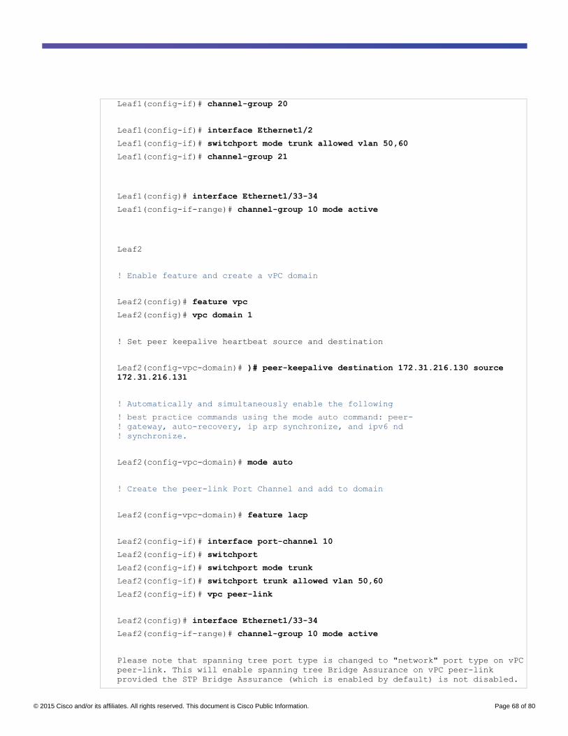
© 2015 Cisco and/or its affiliates. All rights reserved. This document is Cisco Public Information. Page 68 of 80
Leaf1(config-if)# channel-group 20
Leaf1(config-if)# interface Ethernet1/2
Leaf1(config-if)# switchport mode trunk allowed vlan 50,60
Leaf1(config-if)# channel-group 21
Leaf1(config)# interface Ethernet1/33-34
Leaf1(config-if-range)# channel-group 10 mode active
Leaf2
! Enable feature and create a vPC domain
Leaf2(config)# feature vpc
Leaf2(config)# vpc domain 1
! Set peer keepalive heartbeat source and destination
Leaf2(config-vpc-domain)# )# peer-keepalive destination 172.31.216.130 source
172.31.216.131
! Automatically and simultaneously enable the following
! best practice commands using the mode auto command: peer-
! gateway, auto-recovery, ip arp synchronize, and ipv6 nd
! synchronize.
Leaf2(config-vpc-domain)# mode auto
! Create the peer-link Port Channel and add to domain
Leaf2(config-vpc-domain)# feature lacp
Leaf2(config-if)# interface port-channel 10
Leaf2(config-if)# switchport
Leaf2(config-if)# switchport mode trunk
Leaf2(config-if)# switchport trunk allowed vlan 50,60
Leaf2(config-if)# vpc peer-link
Leaf2(config)# interface Ethernet1/33-34
Leaf2(config-if-range)# channel-group 10 mode active
Please note that spanning tree port type is changed to "network" port type on vPC
peer-link. This will enable spanning tree Bridge Assurance on vPC peer-link
provided the STP Bridge Assurance (which is enabled by default) is not disabled.

© 2015 Cisco and/or its affiliates. All rights reserved. This document is Cisco Public Information. Page 69 of 80
Leaf2(config)# no shutdown
! Configure best practice Spanning Tree features on vPC
! Create a Port Channel and vPC for a server
! The vPC #11 must match on the other peer for the server
Leaf2(config)# interface port-channel20
Leaf2(config-if)# description to Sever1
Leaf2(config-if)# switchport mode trunk
Leaf2(config-if)# vpc 20
Leaf2(config-if)# no shutdown
Leaf2(config)# interface port-channel21
Leaf2(config-if)# description to Sever2
Leaf2(config-if)# switchport mode trunk
Leaf2(config-if)# vpc 21
Leaf2(config-if)# no shutdown
Leaf2(config-if)# interface Ethernet1/1
Leaf2(config-if)# switchport mode trunk allowed vlan 50,60
Leaf2(config-if)# channel-group 20
Leaf2(config-if)# interface Ethernet1/2
Leaf2(config-if)# switchport mode trunk allowed vlan 50,60
Leaf2(config-if)# channel-group 21
Table 7 outlines the show commands for these configurations.
Table 7. Show Commands
Show vpc Provide details about the vPC configuration, and the status of various links in the device
Show vpc consistency-parameters
<vlans/global>
Provide details on vPC Type 1 and Type 2 consistency parameters with their peers
14.3.5 Multicast and VXLAN
Spine Protocol Independent Multicast (PIM) and Multicast Source Discovery Protocol (MSDP) Multicast
Configuration
Spine1
! Enable PIM and MSDP to turn on multicast routing
Spine1(config)# feature pim
Spine1(config)# feature msdp
! Enable PIM on the spine-facing interfaces

© 2015 Cisco and/or its affiliates. All rights reserved. This document is Cisco Public Information. Page 70 of 80
! EIGRP should already be enabled on the interfaces
Spine1(config)# interface Ethernet1/1-2
Spine1(config-if-range)# ip pim sparse-mode
! Configure the Rendezvous Point IP address for the ASM
! group range 239.0.0.0/8 to be used by VXLAN segments
Spine1(config)# ip pim rp-address 10.2.2.12 group-list 239.0.0.0/8
! Configure MSDP sourced from loopback 1 and the peer spine
! switch’s loopback IP address to enable RP redundancy
Spine1(config)# ip pim ssm range 232.0.0.0/8
Spine1(config)# ip msdp originator-id loopback1
Spine1(config)# ip msdp peer 10.2.2.2 connect-source loopback1
! Configure loopbacks to be used as redundant RPs with
! the other spine switch. L0 is assigned a shared RP IP
! used on both spines. L1 has a unique IP address.
! Enable PIM and EIGRP routing on both loopback interfaces.
Spine1(config)# interface loopback0
Spine1(config-if)# ip address 10.2.2.12/32
Spine1(config-if)# ip router eigrp 1
Spine1(config-if)# ip pim sparse-mode
Spine1(config)# interface loopback1
Spine1(config-if)# ip address 10.2.2.1/32
Spine1(config-if)# ip router eigrp 1
Spine1(config-if)# ip pim sparse-mode
Spine2
! Enable PIM and MSDP to turn on multicast routing
Spine2(config)# feature pim
Spine2(config)# feature msdp
! Enable PIM on the spine-facing interfaces
! EIGRP should already be enabled on the interfaces
Spine2(config)# interface Ethernet1/1-2
Spine2(config-if-range)# ip pim sparse-mode
! Configure the Rendezvous Point IP address for the ASM

© 2015 Cisco and/or its affiliates. All rights reserved. This document is Cisco Public Information. Page 71 of 80
! group range 239.0.0.0/8 to be used by VXLAN segments
Spine2(config)# ip pim rp-address 10.2.2.12 group-list 239.0.0.0/8
! Configure MSDP sourced from loopback 1 and the peer spine
! switch’s loopback IP address to enable RP redundancy
Spine2(config)# ip pim ssm range 232.0.0.0/8
Spine2(config)# ip msdp originator-id loopback1
Spine2(config)# ip msdp peer 10.2.2.1 connect-source loopback1
Spine2(config)# interface loopback0
Spine2(config-if)# ip address 10.2.2.12/32
Spine2(config-if)# ip router eigrp 1
Spine2(config-if)# ip pim sparse-mode
Spine2(config)# interface loopback1
Spine2(config-if)# ip address 10.2.2.2/32
Spine2(config-if)# ip router eigrp 1
Spine2(config-if)# ip pim sparse-mode
Leaf Multicast Configuration
Leaf1
! Enable and configure PIM on the spine-facing interfaces
Leaf1(config)# feature pim
Leaf1(config)# interface Ethernet2/1-2
Leaf1(config-if-range)# ip pim sparse-mode
! Point to the RP address configured in the spines
Leaf1(config)# ip pim rp-address 10.2.2.12 group-list 239.0.0.0/8
Leaf1(config)# ip pim ssm range 232.0.0.0/8
Leaf2
! Enable and configure PIM on the spine-facing interfaces
Leaf2(config)# feature pim
Leaf2(config)# interface Ethernet2/1-2
Leaf2(config)# ip pim sparse-mode
! Point to the RP address configured in the spines
Leaf2(config)# ip pim rp-address 10.2.2.12 group-list 239.0.0.0/8
Leaf2(config)# ip pim ssm range 232.0.0.0/8

© 2015 Cisco and/or its affiliates. All rights reserved. This document is Cisco Public Information. Page 72 of 80
VXLAN Configuration
! Enable VXLAN features
Leaf1(config)# feature nv overlay
Leaf1(config)# feature vn-segment-vlan-based
! Configure loopback used for VXLAN tunnels
! Configure secondary IP address for vPC support
Leaf1(config)# interface loopback1
Leaf1(config-if)# ip address 192.168.1.1/32
Leaf1(config-if)# ip address 192.168.2.1/32 secondary
Leaf1(config-if)# ip router eigrp 1
Leaf1(config-if)# ip pim sparse-mode
! Create NVE interface, using loopback as the source
! Bind VXLAN segments to an ASM multicast group
Leaf1(config-if)# interface nve1
Leaf1(config-if)# source-interface loopback1
Leaf1(config-if)# member vni 5000 mcast-group 239.1.1.50
Leaf1(config-if)# member vni 6000 mcast-group 239.1.1.60
! Map VLANs to VXLAN segments
Leaf2(config-if)# vlan 50
Leaf2(config-vlan)# vn-segment 5000
Leaf2(config-vlan)# vlan 60
Leaf2(config-vlan)# vn-segment 6000
Leaf2(config-vlan)# vlan 100
Leaf2(config-vlan)# vn-segment 10000
Table 8 outlines the relevant show commands for these configurations.
Table 8. Show Commands
show nve vni Offers details of the VNI, along with the multicast address and state
show nve interface Offers details of the VTEP interface
show nve peers Provides details of peer VTEP peer devices
show mac address-table dynamic Provides the MAC address details known to the device

© 2015 Cisco and/or its affiliates. All rights reserved. This document is Cisco Public Information. Page 73 of 80
14.3.6 Firewall ASA Configuration
! Create subinterface for Webserver and Appserver using VLAN 50 and 60
! Assign security level 100
! Assign an IP address to act as a gateway for VLAN 50 and 60
ciscoasa(config)# interface Ethernet0/0.50
ciscoasa(config-subif)# description Webserver
ciscoasa(config-subif)# vlan 50
ciscoasa(config-subif)# nameif Webserver
ciscoasa(config-subif)# security-level 100
ciscoasa(config-subif)# ip address 192.168.50.1 255.255.255.0
ciscoasa(config)# interface Ethernet0/0.60
ciscoasa(config-subif)# description Appserver
ciscoasa(config-subif)# vlan 60
ciscoasa(config-subif)# nameif Appserver
ciscoasa(config-subif)# security-level 100
ciscoasa(config-subif)# ip address 192.168.60.1 255.255.255.0
! Create external interface
ciscoasa(config)# interface Ethernet0/1
ciscoasa(config)# nameif outside
ciscoasa(config)# security-level 100
ciscoasa(config)# ip address 209.165.201.2 255.255.255.0
ciscoasa(config)# interface Management0/0
ciscoasa(config)# nameif mgmt
ciscoasa(config)# security-level 100
ciscoasa(config)# ciscoasa(config)# ip address 172.31.216.149 255.255.252.0
ciscoasa(config)# management-only
! Create object group to match web and HTTP traffic
ciscoasa(config)# same-security-traffic permit inter-interface
ciscoasa(config)# same-security-traffic permit intra-interface
! Provide access to traffic from outside to Webserver
ciscoasa(config)# object network Ciscoapp
ciscoasa(config-network-object)# host 209.165.201.5

© 2015 Cisco and/or its affiliates. All rights reserved. This document is Cisco Public Information. Page 74 of 80
ciscoasa(config)# object network Webserver-VIP
ciscoasa(config-network-object)# host 192.168.50.2
ciscoasa(config)# nat (outside,Webserver) source static any destination static
Ciscoapp Webserver-VIP
! Provide access to traffic from inside Webserver/Appserver to outside
ciscoasa(config)# object network Webserver-outside
ciscoasa(config-network-object)# nat (Webserver,outside) dynamic interface
ciscoasa(config)# object network Appserver-outside
ciscoasa(config-network-object)# nat (AppServer,outside) dynamic interface
! Provide access to traffic from Webserver/Appserver
ciscoasa(config)# object network Web-Source
ciscoasa(config-network-object)# subnet 192.168.50.0 255.255.255.0
ciscoasa(config)# object network App-Source
ciscoasa(config-network-object)# subnet 192.168.60.0 255.255.255.0
ciscoasa(config)# nat (Webserver,AppServer) source static Web-Source Web-Source
destination static App-Source App-Source
ciscoasa(config)# nat (AppServer,Webserver) source static App-Source App-Source
destination static Web-Source Web-Source
! Configure access list for HTTP traffic from outside to Webserver
ciscoasa(config)# object service http
ciscoasa(config-service-object)# service 80
ciscoasa(config)# access-list HTTP extended permit object http interface outside
interface Webserver
ciscoasa(config)# access-group HTTP global
For more information on Cisco ASA 5500 firewalls, visit the Cisco ASA 5500-X Series Next-Generation Firewalls
website.
14.3.7 F5 LTM Load Balancer Configuration
Load Balancer Configuration
ltm node 192.168.50.5 {
address 192.168.50.5
session monitor-enabled
state up
}

© 2015 Cisco and/or its affiliates. All rights reserved. This document is Cisco Public Information. Page 75 of 80
ltm node 192.168.60.5 {
address 192.168.60.5
session monitor-enabled
state up
}
ltm node 192.168.60.6 {
address 192.168.60.6
session monitor-enabled
state up
}
}
ltm node 192.168.50.6 {
address 192.168.50.6
monitor icmp
session monitor-enabled
state up
}
ltm persistence global-settings { }
ltm pool App_VIP {
members {
192.168.60.5:http {
address 192.168.60.5
session monitor-enabled
state up
}
192.168.60.6:http {
address 192.168.60.6
session monitor-enabled
state up
}
}
monitor http and gateway_icmp
}
ltm pool WEB_VIP {
members {
192.168.50.5:http {
address 192.168.50.5
session monitor-enabled
state up
}
192.168.50.6:http {
address 192.168.50.6
session monitor-enabled
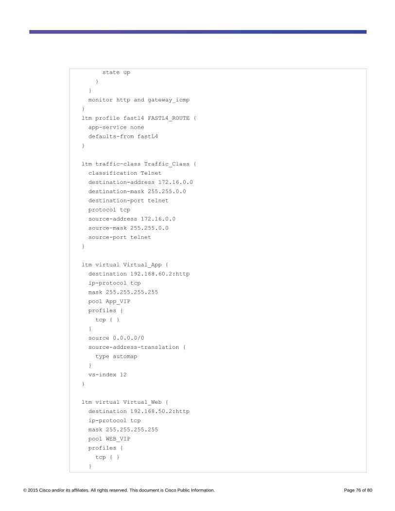
© 2015 Cisco and/or its affiliates. All rights reserved. This document is Cisco Public Information. Page 76 of 80
state up
}
}
monitor http and gateway_icmp
}
ltm profile fastl4 FASTL4_ROUTE {
app-service none
defaults-from fastL4
}
ltm traffic-class Traffic_Class {
classification Telnet
destination-address 172.16.0.0
destination-mask 255.255.0.0
destination-port telnet
protocol tcp
source-address 172.16.0.0
source-mask 255.255.0.0
source-port telnet
}
ltm virtual Virtual_App {
destination 192.168.60.2:http
ip-protocol tcp
mask 255.255.255.255
pool App_VIP
profiles {
tcp { }
}
source 0.0.0.0/0
source-address-translation {
type automap
}
vs-index 12
}
ltm virtual Virtual_Web {
destination 192.168.50.2:http
ip-protocol tcp
mask 255.255.255.255
pool WEB_VIP
profiles {
tcp { }
}

© 2015 Cisco and/or its affiliates. All rights reserved. This document is Cisco Public Information. Page 77 of 80
source 0.0.0.0/0
source-address-translation {
type automap
}
vs-index 12
}
net interface 1/1.7 {
if-index 385
lldp-tlvmap 113264
mac-address 00:23:e9:9d:f6:10
media-active 10000SFPCU-FD
media-max 10000T-FD
mtu 9198
serial TED1829B884
vendor CISCO-TYCO
}
net interface 1/1.8 {
if-index 401
mac-address 00:23:e9:9d:f6:11
media-active 10000SFPCU-FD
media-max 10000T-FD
mtu 9198
serial TED1713H0DT
vendor CISCO-TYCO
}
net interface 1/mgmt {
if-index 145
mac-address 00:23:e9:9d:f6:09
media-active 1000T-FD
media-max 1000T-FD
}
net route-domain 0 {
id 0
routing-protocol {
OSPFv2
}
vlans {
VLAN60
VLAN50
}
}

© 2015 Cisco and/or its affiliates. All rights reserved. This document is Cisco Public Information. Page 78 of 80
net self App_IP {
address 192.168.60.10/24
traffic-group traffic-group-local-only
vlan VLAN60
}
net self Web_IP {
address 192.168.50.10/24
traffic-group traffic-group-local-only
vlan VLAN50
}
net self-allow {
defaults {
ospf:any
tcp:domain
tcp:f5-iquery
tcp:https
tcp:snmp
tcp:ssh
udp:520
udp:cap
udp:domain
udp:f5-iquery
udp:snmp
}
}
net trunk Trunk_Internal {
bandwidth 10000
cfg-mbr-count 1
id 0
interfaces {
1/1.8
}
mac-address 00:23:e9:9d:f7:e0
working-mbr-count 1
}
net vlan VLAN50 {
if-index 832
interfaces {
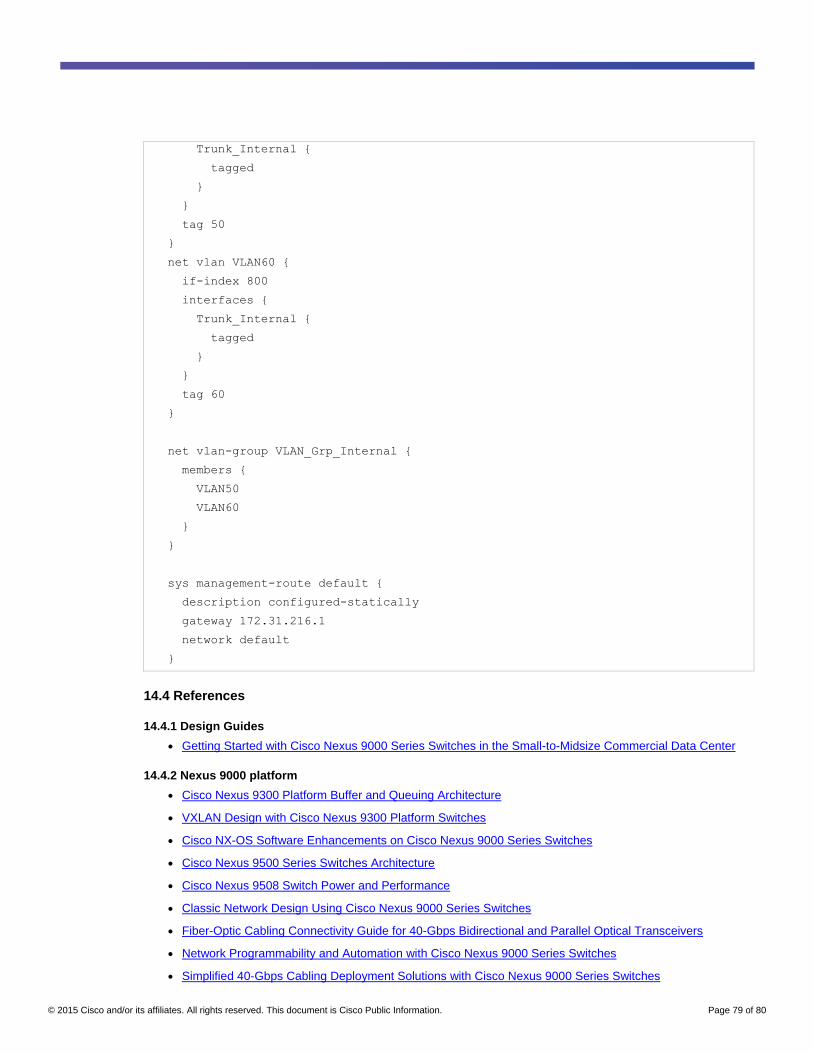
© 2015 Cisco and/or its affiliates. All rights reserved. This document is Cisco Public Information. Page 79 of 80
Trunk_Internal {
tagged
}
}
tag 50
}
net vlan VLAN60 {
if-index 800
interfaces {
Trunk_Internal {
tagged
}
}
tag 60
}
net vlan-group VLAN_Grp_Internal {
members {
VLAN50
VLAN60
}
}
sys management-route default {
description configured-statically
gateway 172.31.216.1
network default
}
14.4 References
14.4.1 Design Guides
● Getting Started with Cisco Nexus 9000 Series Switches in the Small-to-Midsize Commercial Data Center
14.4.2 Nexus 9000 platform
● Cisco Nexus 9300 Platform Buffer and Queuing Architecture
● VXLAN Design with Cisco Nexus 9300 Platform Switches
● Cisco NX-OS Software Enhancements on Cisco Nexus 9000 Series Switches
● Cisco Nexus 9500 Series Switches Architecture
● Cisco Nexus 9508 Switch Power and Performance
● Classic Network Design Using Cisco Nexus 9000 Series Switches
● Fiber-Optic Cabling Connectivity Guide for 40-Gbps Bidirectional and Parallel Optical Transceivers
● Network Programmability and Automation with Cisco Nexus 9000 Series Switches
● Simplified 40-Gbps Cabling Deployment Solutions with Cisco Nexus 9000 Series Switches

© 2015 Cisco and/or its affiliates. All rights reserved. This document is Cisco Public Information. Page 80 of 80
● VXLAN Overview: Cisco Nexus 9000 Series Switches
14.4.3 Network General
● Data Center Overlay Technologies
● Principles of Application Centric Infrastructure
14.4.4 Migration
● Migrating Your Data Center to an Application Centric Infrastructure
● Migrate from Cisco Catalyst 6500 Series Switches to Cisco Nexus 9000 Series Switches
● Migrate to a 40-Gbps Data Center with Cisco QSFP BiDi Technology
14.4.5 Analyst Reports
● Cisco Nexus 9508 Power Efficiency - Lippis Report
● Cisco Nexus 9508 Switch Performance Test - Lippis Report
● Cisco Nexus 9000 Programmable Network Environment - Lippis Report
● Cisco Nexus 9000 Series Research Note - Lippis Report
● Why the Nexus 9000 Switching Series Offers the Highest Availability and Reliability Measured in MTBF -
Lippis Report
● Miercom Report: Cisco Nexus 9516
Printed in USA C07-733639-00 03/15