Nexus 9000/3000 Graceful Insertion and Removal...
21
© 2016 Cisco and/or its affiliates. All rights reserved. This document is Cisco Public Information. Page 1 of 21 White Paper Nexus 9000/3000 Graceful Insertion and Removal (GIR) White Paper September 2016
Transcript of Nexus 9000/3000 Graceful Insertion and Removal...

© 2016 Cisco and/or its affiliates. All rights reserved. This document is Cisco Public Information. Page 1 of 21
White Paper
Nexus 9000/3000 Graceful Insertion and Removal (GIR)
White Paper
September 2016

© 2016 Cisco and/or its affiliates. All rights reserved. This document is Cisco Public Information. Page 2 of 21
Contents
Introduction .............................................................................................................................................................. 3
Target Audience ....................................................................................................................................................... 3
Graceful Insertion and Removal (GIR) Overview .................................................................................................. 3
GIR Maintenance Mode and Profiles ...................................................................................................................... 4
GIR with User-Defined Profiles ............................................................................................................................... 6
GIR Snapshots and Verification ............................................................................................................................. 9
GIR Case Studies ................................................................................................................................................... 10 General Topology ............................................................................................................................................... 10 Case Study 1 (Isolating OSPF on S1) ................................................................................................................. 11 Case Study 2 (Isolating EIGRP on S1) ............................................................................................................... 12 Case Study 3 (Isolating BGP on S1) ................................................................................................................... 14 Case Study 4 (Isolating BGP for VxLAN EVPN on S1) ....................................................................................... 15 Case Study 5 (Isolating vPC on L1) .................................................................................................................... 17 Case Study 6 (Isolating PIM in vPC on L1) ......................................................................................................... 19
Conclusion ............................................................................................................................................................. 21
Additional Resources ............................................................................................................................................ 21

© 2016 Cisco and/or its affiliates. All rights reserved. This document is Cisco Public Information. Page 3 of 21
Introduction
The datacenter network is a platform that connects all application end points and delivers network services. With
the ongoing trends around datacenter consolidation, increasing adoption of cloud and virtualization, the network
layer has become important, so has its reliability and availability. There are various methods and best practices to
maintain network availability while network devices undergo software or hardware maintenance, such as In Service
Software Upgrade (ISSU) and Graceful Insertion and Removal (GIR).
ISSU provides device-level high availability during software upgrade. On an ISSU capable network device, such as
a Nexus 9000 Series switch running NX-OS with ISSU, the device can remain in service for data forwarding during
a software upgrade.
GIR provides an alternative method to minimize network service impact caused by device maintenance. GIR
leverages redundant paths in the network to smoothly remove a device under maintenance, out of service, and
insert it back to service when the maintenance is complete. Similar methodologies have been adopted by many
organizations as part of their network maintenance best practices, but the removal and insertion of a device are
typically performed manually. As an effort to automate this process, Cisco NX-OS Software Release 7.0(3)I2(1)
introduces the Graceful Insertion and Removal (GIR) function on the Nexus 9000 and Nexus 3000 switch
platforms. GIR changes the multi-step manual removal and insertion process to an automated and optimized
operation that is triggered using a single command. It provides easier integration of network device maintenance
into the overall network operation work flow.
This white paper provides guidelines for implementing Graceful Insertion and Removal (GIR) mode on Cisco
Nexus 3000 and Nexus 9000 Family switches for a variety of customer profiles.
Target Audience
This document is for planning, implementation, and maintenance in DevOps teams.
Graceful Insertion and Removal (GIR) Overview
Cisco® NX-OS Software Release 7.0(3)I2(1) for Cisco Nexus 3000 and 9000 Series Switches introduces the
Graceful Insertion and Removal (GIR) function. GIR provides an easy method for isolating a switch for
maintenance windows and then bringing it back into service.
By utilizing the switch maintenance mode, GIR can systematically eject a Nexus 3000 or 9000 series switch from
the network with zero or minimal disruption to the network service. When a switch is in maintenance mode, it is
isolated from the active forwarding paths in the network. Maintenance tasks, such as real-time debugging,
hardware replacement, or software upgrade/downgrade, can be performed without affecting the production traffic.
When maintenance tasks are completed, the graceful insertion function places the switch back into the network
without impact.
The following protocols are currently supported by GIR (for both IPv4 and IPv6 address families):
● Border Gateway Protocol (BGP)
● Enhanced Interior Gateway Routing Protocol (EIGRP)
● Intermediate System-to-Intermediate System (ISIS)
● Open Shortest Path First (OSPF)
● Routing Information Protocol (RIP)
© 2016 Cisco and/or its affiliates. All rights reserved. This document is Cisco Public Information. Page 4 of 21
● Virtual Port-Channel (vPC)
● Protocol Independent Multicast (PIM) with vPC topology
Note: Graceful insertion and removal for the PIM protocol is only supported in vPC environments. During
graceful removal, the vPC forwarding role is transferred to the vPC peer for all northbound sources of multicast
traffic.
When a Nexus 9000 or Nexus 3000 series switch is transitioning to Maintenance Mode for graceful removal, the
routing protocols running on the switch modify the routing metrics so that the neighboring devices view the switch
as the least favorable candidate in their route calculation, and reroute traffic away from the switch to alternative
paths in the network. As a result, this switch is now ‘out of service’.
When the switch is phasing out of Maintenance Mode for graceful insertion, the routing protocols reverse the
changes, and advertise the switch as normal. The neighboring devices perform a new route calculation and start to
forward traffic to the switch if it offers the best path.
In case of vPC deployment, GIR on a vPC switch will gracefully shut down the vPC domains to have traffic flow
towards the remaining vPC peer. In graceful insertion, GIR performs “no shut down” on the vPC domain, the switch
returns to the service as the vPC operationally secondary node.
GIR Maintenance Mode and Profiles
A device gets into Maintenance Mode after GIR isolates it from the network forwarding paths. Therefore, a device
in Maintenance Mode is not in network service. Hardware or software maintenance can be done on the device
without impacting the network performance.
It takes one NX-OS configuration command, “system mode maintenance”, to move a Nexus 9000 or 3000 series
switch into maintenance mode. This simple step allows easy operation and integration into the overall network
maintenance work flow. This command triggers the maintenance configuration profile to be deployed on the switch.
GIR uses two profiles, maintenance-mode profile and normal-mode profile, to manage the cause of actions for
graceful removal and graceful insertion.
● Maintenance-mode profile—Contains all the commands that are executed during graceful removal, when
the switch enters maintenance mode.
● Normal-mode profile—Contains all the commands that are executed during graceful insertion, when the
switch returns to normal mode.
The system can generate a default maintenance-mode profile and a default normal-mode profile. This is done
when the switch moves into maintenance mode for the first time with the CLI “system mode maintenance”.
In the default maintenance profile, the active forwarding protocols on the switch are placed in “isolate” state. Below
is an example to move a switch in and out of maintenance mode using the default profile. The switch in this
example is running BGP, OSPF, PIM and vPC.
To move a switch into Maintenance Mode:
switch(config)# system mode maintenance
Following configuration will be applied:

© 2016 Cisco and/or its affiliates. All rights reserved. This document is Cisco Public Information. Page 5 of 21
ip pim isolate
router bgp 1
isolate
router ospf 1
isolate
vpc domain 1
shutdown
Do you want to continue (yes/no)? [no] yes
Generating a snapshot before going into maintenance mode
Starting to apply commands...
Applying : ip pim isolate
Applying : router bgp 1
Applying : isolate
Applying : router ospf 1
Applying : isolate
Applying : vpc domain 1
Applying : shutdown
Maintenance mode operation successful.
To move a switch out of Maintenance Mode:
switch(config)# no system mode maintenance
Following configuration will be applied:
vpc domain 1
no shutdown
router ospf 1
no isolate
router bgp 1
no isolate
no ip pim isolate
Do you want to continue (yes/no)? [no] yes
Starting to apply commands...
Applying : vpc domain 1
Applying : no shutdown
Applying : router ospf 1

© 2016 Cisco and/or its affiliates. All rights reserved. This document is Cisco Public Information. Page 6 of 21
Applying : no isolate
Applying : router bgp 1
Applying : no isolate
Applying : no ip pim isolate
Maintenance mode operation successful.
Generating Current Snapshot
Please use 'show snapshots compare before_maintenance after_maintenance' to check
the health of the system
In the default maintenance profile, forwarding protocols use different methods to isolate the switch from the active
forwarding path. The following table shows the mechanisms used by each protocol. The goal of the mechanism is
to influence the forwarding decision on the remaining devices so that they don’t choose this switch as part of the
best path.
Protocol Graceful Removal Mechanism Graceful Insertion Mechanism
OSPF Send LSAs with max metric Refresh LSAs with original metric
EIGRP Poison route with highest metric Advertise routes with original metric
IS-IS Refresh LSPs with Overload bit on Refresh LSPs with Overload bit off
BGP Withdraw BGP route advertisements Re-inserts routes
RIP Poison route with highest metric Advertise routes with original metric
PIM (in vPC) vPC forwarding role transfer
vPC shutdown CLI to bring down VPC domain no shutdown CLI to bring up VPC domain
GIR with User-Defined Profiles
In addition to the default profiles, NX-OS for Nexus 9000 and 3000 series switches also provides the flexibility to
allow users to define their own profiles that define their methods of choice to perform graceful removal and
insertion on a switch, which can have additional steps in addition to the steps in the default profile, or can negate
the steps in the default profile and then define new steps. For instance, instead of using LSA with max metric to
isolate the switch in OSPF, a user can define the action to shut down the OSPF process in the maintenance-mode
profile for graceful removal, and re-activate it in the normal-mode profile for graceful insertion.
Using the CLI command, “configure maintenance profile maintenance-mode” or “configure maintenance normal-
mode”, a user can start to customize the maintenance mode profile or the normal-mode profile. In case that
system-created default profiles exist, the customization will be added to the default profiles. If there are no existing
default profiles prior to the customization, only the user configuration goes into the profiles.
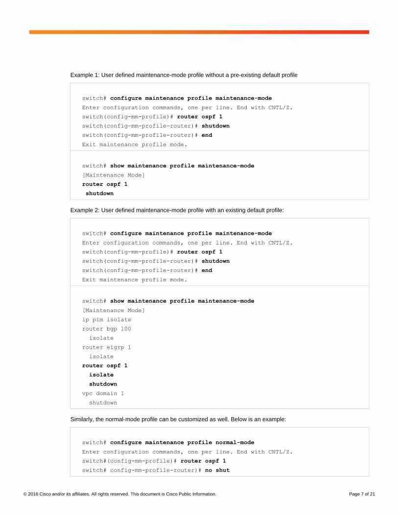
Below are examples of modifying the default maintenance-mode profile. In the first example, a system-created
default maintenance profile exists. The customization is to add the step to shut down the OSPF process 1 after
OSPF isolates the switch. In the second example, there is no pre-existing default maintenance profile. A fresh
profile is created based on the user configuration. The profile shuts down the OSPF process immediately while
moving the switch into the maintenance mode.
© 2016 Cisco and/or its affiliates. All rights reserved. This document is Cisco Public Information. Page 7 of 21
Example 1: User defined maintenance-mode profile without a pre-existing default profile
switch# configure maintenance profile maintenance-mode
Enter configuration commands, one per line. End with CNTL/Z.
switch(config-mm-profile)# router ospf 1
switch(config-mm-profile-router)# shutdown
switch(config-mm-profile-router)# end
Exit maintenance profile mode.
switch# show maintenance profile maintenance-mode
[Maintenance Mode]
router ospf 1
shutdown
Example 2: User defined maintenance-mode profile with an existing default profile:
switch# configure maintenance profile maintenance-mode
Enter configuration commands, one per line. End with CNTL/Z.
switch(config-mm-profile)# router ospf 1
switch(config-mm-profile-router)# shutdown
switch(config-mm-profile-router)# end
Exit maintenance profile mode.
switch# show maintenance profile maintenance-mode
[Maintenance Mode]
ip pim isolate
router bgp 100
isolate
router eigrp 1
isolate
router ospf 1
isolate
shutdown
vpc domain 1
shutdown
Similarly, the normal-mode profile can be customized as well. Below is an example:
switch# configure maintenance profile normal-mode
Enter configuration commands, one per line. End with CNTL/Z.
switch#(config-mm-profile)# router ospf 1
switch# config-mm-profile-router)# no shut

© 2016 Cisco and/or its affiliates. All rights reserved. This document is Cisco Public Information. Page 8 of 21
switch# config-mm-profile-router)# end
Exit maintenance profile mode.
Switch# sh maintenance profile normal-mode
[Normal Mode]
vpc domain 1
no shutdown
router isis 1
no isolate
router ospfv3 1
no isolate
router ospf 1
no isolate
no shutdown
router rip 1
no isolate
router eigrp 1
no isolate
router bgp 1
no isolate
no ip pim isolate
By default, when the command “system mode maintenance” is issued and confirmed for operation on a switch, the
system will first create a default profile that put the active network protocols in the isolate mode, and deploy this
profile to the system when moving it into the maintenance mode. If there is a user defined maintenance profile, the
system-generated profile will overwrite it. If a user desires to maintain and use a user defined maintenance profile,
the key word “don’t-generate-profile” needs to be added to the “system mode maintenance” command. With the
“don’t-generate-profile” keyword, the system does not create a default maintenance profile and deploys the user
defined profile when moving the switch into maintenance mode. Alternatively, a user can add “system mode
maintenance always-use-custom-profile” to the switch running configuration so that the system always skips the
step of generating a system default profile, and always uses the user defined profile. Below is an example to move
a switch into the maintenance mode using a user -defined maintenance profile:
switch(config)# system mode maintenance dont-generate-profile
Following configuration will be applied:
router eigrp 1
address-family ipv6 unicast
shutdown
router bgp 1
shutdown
vpc domain 1
shutdown
ip pim isolate

© 2016 Cisco and/or its affiliates. All rights reserved. This document is Cisco Public Information. Page 9 of 21
Do you want to continue (yes/no)? [no] yes
Generating a snapshot before going into maintenance mode
Starting to apply commands...
Applying : router eigrp 1
Applying : address-family ipv6 unicast
Applying : shutdown
Applying : router bgp 1
Applying : shutdown
Applying : vpc domain 1
Applying : shutdown
Applying : ip pim isolate
Maintenance mode operation successful.
GIR Snapshots and Verification
Cisco NX-OS uses system-generated snapshots to record the state of a switch before and after a GIR operation.
A snapshot of the system status, called “before_maintenance”, is automatically generated before the switch enters
GIR maintenance mode, and another snapshot, called “after_maintenance”, is automatically generated after the
switch exits the GIR maintenance mode, i.e. returns to the normal mode. The details of the snapshots can be
viewed by users, or exported in XML format. The system also provides an easy way to compare the snapshots
before and after the GIR maintenance operation. This offers a method to quickly evaluate the health of the switch
and to verify if the switch has been inserted back to service as it should be.
Below is a sample output of the snapshots comparison. It displays the number of interfaces, VLANs, routes, etc,
before and after the GIR maintenance operation.
Switch# show snapshots compare before_maintenance after_maintenance summary
================================================================================
Feature before_maintenance after_maintenance changed
================================================================================
basic summary
# of interfaces 67 67
# of vlans 20 20
# of ipv4 routes vrf default 42 42
# of ipv4 paths vrf default 43 43
# of ipv4 routes vrf management 9 9
# of ipv4 paths vrf management 9 9
# of ipv6 routes vrf default 3 3
# of ipv6 paths vrf default 3 3

© 2016 Cisco and/or its affiliates. All rights reserved. This document is Cisco Public Information. Page 10 of 21
interfaces
# of eth interfaces 60 60
# of eth interfaces up 3 3
# of eth interfaces down 57 57
# of eth interfaces other 0 0
# of vlan interfaces 20 20
# of vlan interfaces up 15 15
# of vlan interfaces down 5 5
# of vlan interfaces other 0 0
GIR Case Studies
This section demonstrates GIR operation for different network protocols using the system default profiles.
General Topology
The following topology is used for the case studies of GIR for different network protocols.
Figure 1. General Topology for GIR Cases Studies for Different Network Protocols.

© 2016 Cisco and/or its affiliates. All rights reserved. This document is Cisco Public Information. Page 11 of 21
Case Study 1 (Isolating OSPF on S1)
OSPF Graceful Removal is done by refreshing the LSAs with max metric of 65535. OSPF Graceful Insertion is
done by refreshing the LSAs with their original metric.
In this example, OSPF area 0 is configured between all layer 3 nodes. L4 switch is learning the remote prefix
172.16.100.100 from both S1 and S2 switches. After Graceful Removal on S1 with “system mode maintenance”
command, all remote subnets are advertised with max metric of 65535; however, the connected subnets to S1 will
have the original metric. This will force L4 to remove the external route to 172.16.100.100 that was pointing to S1
from its routing table. The S1 OSPF Router-ID is 10.1.1.1:
S1 in Normal Mode S1 in Maintenance Mode
L4# show ip route 172.16.100.100
IP Route Table for VRF "default"
'*' denotes best ucast next-hop
'**' denotes best mcast next-hop
'[x/y]' denotes [preference/metric]
'%<string>' in via output denotes VRF
<string>
172.16.100.100/32, ubest/mbest: 2/0
*via 192.167.21.1, Eth1/50,
[110/20], 00:22:57, ospf-1, type-2
*via 192.168.21.1, Eth1/49,
[110/20], 00:22:57, ospf-1, type-2
L4# show ip ospf database router
10.1.1.1 detail
OSPF Router with ID
(10.1.1.21) (Process ID 1 VRF default)
Router Link States
(Area 0.0.0.0)
<snip>
Number of links: 11
Link connected to: a Stub Network
(Link ID) Network/Subnet Number:
10.1.1.1
(Link Data) Network Mask:
255.255.255.255
Number of TOS metrics: 0
TOS 0 Metric: 1
Link connected to: a Router
(point-to-point)
(Link ID) Neighboring Router ID:
L4# show ip route 172.16.100.100
IP Route Table for VRF "default"
'*' denotes best ucast next-hop
'**' denotes best mcast next-hop
'[x/y]' denotes [preference/metric]
'%<string>' in via output denotes VRF
<string>
172.16.100.100/32, ubest/mbest: 1/0
*via 192.168.21.1, Eth1/49,
[110/20], 00:08:11, ospf-1, type-2
L4# show ip ospf database router
10.1.1.1 detail
OSPF Router with ID (10.1.1.21)
(Process ID 1 VRF default)
Router Link States
(Area 0.0.0.0)
<snip>
Number of links: 11
Link connected to: a Stub Network
(Link ID) Network/Subnet Number:
10.1.1.1
(Link Data) Network Mask:
255.255.255.255
Number of TOS metrics: 0
TOS 0 Metric: 1
Link connected to: a Router
(point-to-point)
(Link ID) Neighboring Router ID:

© 2016 Cisco and/or its affiliates. All rights reserved. This document is Cisco Public Information. Page 12 of 21
10.1.1.11
(Link Data) Router Interface
address: 192.167.11.1
Number of TOS metrics: 0
TOS 0 Metric: 1
Link connected to: a Stub Network
(Link ID) Network/Subnet Number:
192.167.11.0
(Link Data) Network Mask:
255.255.255.252
Number of TOS metrics: 0
TOS 0 Metric: 1
Link connected to: a Router
(point-to-point)
(Link ID) Neighboring Router ID:
10.20.1.1
(Link Data) Router Interface
address: 172.16.1.1
Number of TOS metrics: 0
TOS 0 Metric: 1
10.1.1.11
(Link Data) Router Interface
address: 192.167.11.1
Number of TOS metrics: 0
TOS 0 Metric: 65535
Link connected to: a Stub Network
(Link ID) Network/Subnet Number:
192.167.11.0
(Link Data) Network Mask:
255.255.255.252
Number of TOS metrics: 0
TOS 0 Metric: 1
Link connected to: a Router
(point-to-point)
(Link ID) Neighboring Router ID:
10.20.1.1
(Link Data) Router Interface
address: 172.16.1.1
Number of TOS metrics: 0
TOS 0 Metric: 65535
Case Study 2 (Isolating EIGRP on S1)
EIGRP Graceful Removal is done by poisoning routes with the highest metric. EIGRP Graceful Insertion is done by
advertising the routes with their original metric.
In this example, EIGRP AS 1 is configured between all Layer 3 nodes. L3 switch is learning the remote external
prefix 172.16.100.100 from both S1 and S2 switches. After Graceful Removal on S1 with “system mode
maintenance” command, all remote subnets will be advertised with the max metric; however, the connected
subnets to S1 will have the original metric. L3 will remove the route pointing to S1 from its routing table and the
EIGRP topology table:
S1 in Normal Mode S1 in Maintenance Mode
L3# show ip route 172.16.100.100
<Snip>
172.16.100.100/32, ubest/mbest: 2/0
*via 192.167.20.1, Eth1/50,
[170/51968], 00:08:06, eigrp-1,
external
*via 192.168.20.1, Eth1/49,
[170/51968], 00:08:06, eigrp-1,
external
L3# show ip eigrp topology
172.16.100.100/32
IP-EIGRP (AS 1): Topology entry for
172.16.100.100/32
State is Passive, Query origin flag
L3# show ip route 172.16.100.100
<snip>
172.16.100.100/32, ubest/mbest: 2/0
*via 192.167.20.1, Eth1/50,
[170/51968], 00:08:06, eigrp-1,
external
L3# show ip eigrp topology
172.16.100.100/32
IP-EIGRP (AS 1): Topology entry for
172.16.100.100/32
State is Passive, Query origin flag
is 1, 1 Successor(s), FD is 51968
Routing Descriptor Blocks:
192.167.20.1 (Ethernet1/50), from

© 2016 Cisco and/or its affiliates. All rights reserved. This document is Cisco Public Information. Page 13 of 21
is 1, 2 Successor(s), FD is 51968
Routing Descriptor Blocks:
192.168.20.1 (Ethernet1/49), from
192.168.20.1, Send flag is 0x0
Composite metric is
(51968/51712), Route is External
Vector metric:
Minimum bandwidth is 100000
Kbit
Total delay is 1030
microseconds
Reliability is 255/255
Load is 1/255
Minimum MTU is 1492
Hop count is 3
Internal tag is 0
External data:
Originating router is
10.20.1.2
AS number of route is 0
External protocol is
Connected, external metric is 0
Administrator tag is 0
(0x00000000)
192.167.20.1 (Ethernet1/50), from
192.167.20.1, Send flag is 0x0
Composite metric is
(51968/51712), Route is External
Vector metric:
Minimum bandwidth is 100000
Kbit
Total delay is 1030
microseconds
Reliability is 255/255
Load is 1/255
Minimum MTU is 1492
Hop count is 3
Internal tag is 0
External data:
Originating router is
10.20.1.2
AS number of route is 0
External protocol is
Connected, external metric is 0
Administrator tag is 0
(0x00000000)
192.167.20.1, Send flag is 0x0
Composite metric is
(51968/51712), Route is External
Vector metric:
Minimum bandwidth is 100000
Kbit
Total delay is 1030
microseconds
Reliability is 255/255
Load is 1/255
Minimum MTU is 1492
Hop count is 3
Internal tag is 0
External data:
Originating router is 10.20.1.2
AS number of route is 0
External protocol is Connected,
external metric is 0
Administrator tag is 0
(0x00000000)

© 2016 Cisco and/or its affiliates. All rights reserved. This document is Cisco Public Information. Page 14 of 21
Case Study 3 (Isolating BGP on S1)
BGP Graceful Removal is done by withdrawing the BGP routes. BGP re-advertises the routes with Graceful
Insertion.
In this example, eBGP is configured between layer 3 nodes. L1 is learning the 56.1.9.0/24 prefixes from both S1
and S2 switches. After Graceful Removal on S1 with “system mode maintenance” command, all BGP prefixes will
be removed from BGP advertised routes. L1 will removed the BGP prefix from its routing and BGP table:
S1 in Normal Mode S1 in Maintenance Mode
L1# show ip route 56.1.9.0
IP Route Table for VRF "default"
'*' denotes best ucast next-hop
'**' denotes best mcast next-hop
'[x/y]' denotes [preference/metric]
'%<string>' in via output denotes VRF
<string>
56.1.9.0/24, ubest/mbest: 2/0
*via 192.167.11.1, [20/51712],
00:22:37, bgp-100, external, tag
65001.2
*via 192.168.11.1, [20/51712],
00:21:03, bgp-100, external, tag
65001.2
L1# show ip bgp 56.1.9.0/24
BGP routing table information for VRF
default, address family IPv4 Unicast
BGP routing table entry for
56.1.9.0/24, version 138
Paths: (2 available, best #2)
Flags: (0x00041a) on xmit-list, is in
urib, is best urib route, is in HW,
Multipath: eBGP iBGP
Path type: external, path is valid,
not best reason: newer EBGP path,
multipath, no labeled nexthop, in rib
AS-Path: 65001.2 , path sourced
external to AS
192.168.11.1 (metric 0) from
192.168.11.1 (10.1.1.2)
Origin incomplete, MED 51712,
localpref 100, weight 0
Advertised path-id 1
Path type: external, path is valid,
is best path, no labeled nexthop, in
L1# show ip route 56.1.9.0
IP Route Table for VRF "default"
'*' denotes best ucast next-hop
'**' denotes best mcast next-hop
'[x/y]' denotes [preference/metric]
'%<string>' in via output denotes VRF
<string>
56.1.9.0/24, ubest/mbest: 1/0
*via 192.168.11.1, [20/51712],
00:30:18, bgp-100, external, tag
65001.2
L1# show ip bgp 56.1.9.0/24
BGP routing table information for VRF
default, address family IPv4 Unicast
BGP routing table entry for
56.1.9.0/24, version 263
Paths: (1 available, best #1)
Flags: (0x00041a) on xmit-list, is in
urib, is best urib route, is in HW,
Multipath: eBGP iBGP
Advertised path-id 1
Path type: external, path is valid,
is best path, no labeled nexthop, in
rib
AS-Path: 65001.2 , path sourced
external to AS
192.168.11.1 (metric 0) from
192.168.11.1 (10.1.1.2)
Origin incomplete, MED 51712,
localpref 100, weight 0
Path-id 1 not advertised to any peer

© 2016 Cisco and/or its affiliates. All rights reserved. This document is Cisco Public Information. Page 15 of 21
rib
AS-Path: 65001.2 , path sourced
external to AS
192.167.11.1 (metric 0) from
192.167.11.1 (10.1.1.1)
Origin incomplete, MED 51712,
localpref 100, weight 0
Path-id 1 not advertised to any peer
Case Study 4 (Isolating BGP for VxLAN EVPN on S1)
VxLAN EVPN isolation is done by BGP. BGP Graceful Removal is done by withdrawing the BGP EVPN routes.
BGP re-advertises the EVPN routes with Graceful Insertion.
In this example, eBGP is configured between Leaf (L1, L2, L3, L4) and Spine (S1, S2) switches. L1 is advertising
the 21.0.0.0/24 subnet to S1 and S2 Spines and are advertising the EVPN route to L3 Leaf switch. The BGP EVPN
prefix is pointing to both S1 and S2 prior to S1 going to maintenance mode. After Graceful Removal on S1 with
“system mode maintenance” command, S1withdraws the EVPN prefix and L3 removes it from the EVPN table:
S1 in Normal Mode S1 in Maintenance Mode
L3# show bgp l2vpn evpn 21.0.0.0
<snip>
Route Distinguisher: 10.1.1.11:4
BGP routing table entry for
[5]:[0]:[0]:[16]:[21.0.0.0]:[0.0.0.0]/2
24, version 169
Paths: (2 available, best #1)
Flags: (0x000002) on xmit-list, is not
in l2rib/evpn, is not in HW, , is
locked
Advertised path-id 1
Path type: external, path is valid,
is best path, no labeled nexthop
AS-Path: 4259905538 100 , path
sourced external to AS
10.1.1.11 (metric 0) from
192.167.13.1 (10.1.1.1)
Origin IGP, MED not set,
localpref 100, weight 0
Received label 39010
Extcommunity: RT:100:39010
RT:39010:39010 ENCAP:8 Router
MAC:7c69.f6df.e597
Path type: external, path is valid,
not best reason: Router Id, no labeled
nexthop
AS-Path: 4259905538 100 , path
sourced external to AS
10.1.1.11 (metric 0) from
L3# show bgp l2vpn evpn 21.0.0.0
<snip>
Route Distinguisher: 10.1.1.11:4
BGP routing table entry for
[5]:[0]:[0]:[16]:[21.0.0.0]:[0.0.0.0]/2
24, version 179
Paths: (1 available, best #1)
Flags: (0x000002) on xmit-list, is not
in l2rib/evpn, is not in HW, , is
locked
Advertised path-id 1
Path type: external, path is valid,
is best path, no labeled nexthop
AS-Path: 4259905538 100 , path
sourced external to AS
10.1.1.11 (metric 0) from
192.168.13.1 (10.1.1.2)
Origin IGP, MED not set,
localpref 100, weight 0
Received label 39010
Extcommunity: RT:100:39010
RT:39010:39010 ENCAP:8 Router
MAC:7c69.f6df.e597
Path-id 1 not advertised to any peer
Route Distinguisher: 10.1.1.13:4
(L3VNI 39010)
BGP routing table entry for

© 2016 Cisco and/or its affiliates. All rights reserved. This document is Cisco Public Information. Page 16 of 21
192.168.13.1 (10.1.1.2)
Origin IGP, MED not set,
localpref 100, weight 0
Received label 39010
Extcommunity: RT:100:39010
RT:39010:39010 ENCAP:8 Router
MAC:7c69.f6df.e597
Path-id 1 not advertised to any peer
Route Distinguisher: 10.1.1.13:4
(L3VNI 39010)
BGP routing table entry for
[5]:[0]:[0]:[16]:[21.0.0.0]:[0.0.0.0]/2
24, version 171
Paths: (1 available, best #1)
Flags: (0x00001a) on xmit-list, is in
l2rib/evpn, is not in HW,
Advertised path-id 1
Path type: external, path is valid,
is best path, no labeled nexthop
Imported from
10.1.1.11:4:[5]:[0]:[0]:[16]:[21.0.0.0]
:[0.0.0.0]/120
AS-Path: 4259905538 100 , path
sourced external to AS
10.1.1.11 (metric 0) from
192.167.13.1 (10.1.1.1)
Origin IGP, MED not set,
localpref 100, weight 0
Received label 39010
Extcommunity: RT:100:39010
RT:39010:39010 ENCAP:8 Router
MAC:7c69.f6df.e597
Path-id 1 not advertised to any peer
[5]:[0]:[0]:[16]:[21.0.0.0]:[0.0.0.0]/2
24, version 182
Paths: (1 available, best #1)
Flags: (0x00001a) on xmit-list, is in
l2rib/evpn, is not in HW,
Advertised path-id 1
Path type: external, path is valid,
is best path, no labeled nexthop
Imported from
10.1.1.11:4:[5]:[0]:[0]:[16]:[21.0.0.0]
:[0.0.0.0]/120
AS-Path: 4259905538 100 , path
sourced external to AS
10.1.1.11 (metric 0) from
192.168.13.1 (10.1.1.2)
Origin IGP, MED not set,
localpref 100, weight 0
Received label 39010
Extcommunity: RT:100:39010
RT:39010:39010 ENCAP:8 Router
MAC:7c69.f6df.e597
Path-id 1 not advertised to any peer

© 2016 Cisco and/or its affiliates. All rights reserved. This document is Cisco Public Information. Page 17 of 21
Case Study 5 (Isolating vPC on L1)
The case study for vPC GIR is based on the topology below.
Figure 2. Topology for Virtual Port-Channel (vPC) GIR Case Study.
’
vPC Graceful Removal is done by shutting down the vPC domain. When vPC domain is shut, vPC Peer-link as well
as all downstream vPC port-channels are suspended and traffic from end hosts go through the vPC peer. vPC
Graceful Insertion brings back all the Port-channels and vPC domain.
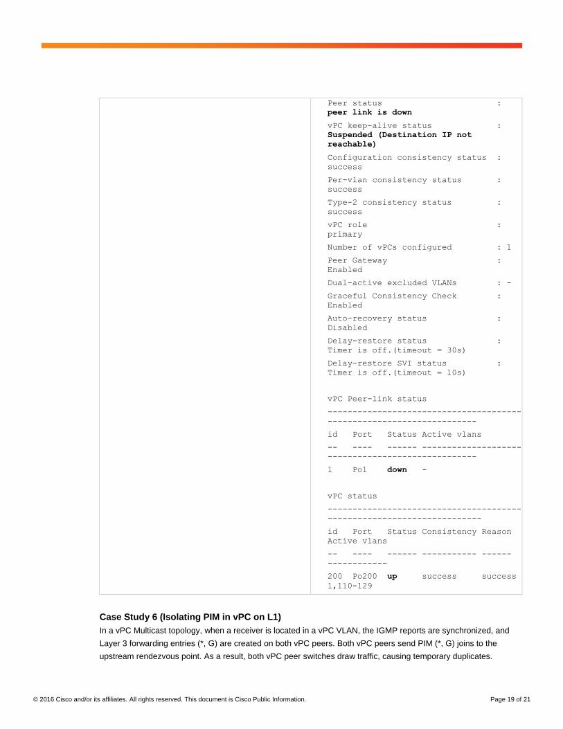
In this example, L1 is the “operational primary” vPC peer. After Graceful Removal on L1 with “system mode
maintenance” command, L1 shuts down the vPC domain and the vPC port-channel member link. vPC also goes
down on L2 switch as the peer link goes down; however, the vPC member port-channel stays up:
L1 in Normal Mode L1 in Maintenance Mode
L1# show vpc
Legend:
(*) - local vPC is
down, forwarding via vPC peer-link
vPC domain id : 10
Peer status :
peer adjacency formed ok
vPC keep-alive status :
peer is alive
Configuration consistency status :
success
L1(config)# show vpc
Legend:
(*) - local vPC is
down, forwarding via vPC peer-link
vPC domain id : 10
Peer status :
peer link down, vPC shutdown configured
vPC keep-alive status :
shutdown
Configuration consistency status :
success

© 2016 Cisco and/or its affiliates. All rights reserved. This document is Cisco Public Information. Page 18 of 21
Per-vlan consistency status :
success
Type-2 consistency status :
success
vPC role :
secondary, operational primary
Number of vPCs configured : 1
Peer Gateway :
Enabled
Dual-active excluded VLANs : -
Graceful Consistency Check :
Enabled
Auto-recovery status :
Disabled
Delay-restore status :
Timer is off.(timeout = 30s)
Delay-restore SVI status :
Timer is off.(timeout = 10s)
vPC Peer-link status
---------------------------------------
------------------------------
id Port Status Active vlans
-- ---- ------ --------------------
------------------------------
1 Po1 up 1,5,110-129
vPC status
---------------------------------------
-------------------------------
id Port Status Consistency Reason
Active vlans
-- ---- ------ ----------- ------
------------
200 Po200 up success success
1,110-129
Per-vlan consistency status :
success
Type-2 consistency status :
success
vPC role :
secondary, operational primary
Number of vPCs configured : 1
Peer Gateway :
Enabled
Dual-active excluded VLANs : -
Graceful Consistency Check :
Enabled
Auto-recovery status :
Disabled
Delay-restore status :
Timer is off.(timeout = 30s)
Delay-restore SVI status :
Timer is off.(timeout = 10s)
vPC Peer-link status
---------------------------------------
------------------------------
id Port Status Active vlans
-- ---- ------ --------------------
------------------------------
1 Po1 down -
vPC status
---------------------------------------
-------------------------------
id Port Status Consistency Reason
Active vlans
-- ---- ------ ----------- ------
------------
200 Po200 down success success
-
vPC peer-link is also down on L2 side;
however, vPC member Port-channel is up
and forwarding traffic to the host
L2# show vpc
Legend:
(*) - local vPC is
down, forwarding via vPC peer-link
vPC domain id : 10
© 2016 Cisco and/or its affiliates. All rights reserved. This document is Cisco Public Information. Page 19 of 21
Peer status :
peer link is down
vPC keep-alive status :
Suspended (Destination IP not
reachable)
Configuration consistency status :
success
Per-vlan consistency status :
success
Type-2 consistency status :
success
vPC role :
primary
Number of vPCs configured : 1
Peer Gateway :
Enabled
Dual-active excluded VLANs : -
Graceful Consistency Check :
Enabled
Auto-recovery status :
Disabled
Delay-restore status :
Timer is off.(timeout = 30s)
Delay-restore SVI status :
Timer is off.(timeout = 10s)
vPC Peer-link status
---------------------------------------
------------------------------
id Port Status Active vlans
-- ---- ------ --------------------
------------------------------
1 Po1 down -
vPC status
---------------------------------------
-------------------------------
id Port Status Consistency Reason
Active vlans
-- ---- ------ ----------- ------
------------
200 Po200 up success success
1,110-129
Case Study 6 (Isolating PIM in vPC on L1)
In a vPC Multicast topology, when a receiver is located in a vPC VLAN, the IGMP reports are synchronized, and
Layer 3 forwarding entries (*, G) are created on both vPC peers. Both vPC peers send PIM (*, G) joins to the
upstream rendezvous point. As a result, both vPC peer switches draw traffic, causing temporary duplicates.

© 2016 Cisco and/or its affiliates. All rights reserved. This document is Cisco Public Information. Page 20 of 21
After a multicast source starts sending traffic, only one vPC peer becomes the forwarder for a given source and
sends (S, G) joins. The choice of the forwarder is based on the distance to the source (if the distances are
identical, the vPC primary is chosen) and converges on the designated data forwarder for these VLANs on a per-
stream basis, to prevent duplicates.
During graceful removal, the vPC forwarding role is transferred to the vPC peer for all northbound sources of
multicast traffic. The vPC forwarding is transferred before vPC shutdown, therefore “ip pim isolate” command is
executed before the vPC shutdown.
In this example, L1 has the vPC forwarding role prior to the Graceful removal. The mroute for 225.0.1.1 group has
Vlan 100 under its OIL (outgoing interface list). vPC peer L2 has no Vlan listed under its mroute OIL. After Graceful
Removal on L1 with “system mode maintenance” command, L2 inserts the Vlan 100 to its mroute OIL as L2
becomes the active forwarder.
L1 in Normal Mode L1 in Maintenance Mode
L1# show ip mroute 225.0.1.1
IP Multicast Routing Table for VRF
"default"
(*, 225.0.1.1/32), uptime: 00:01:11,
igmp ip pim
Incoming interface: Ethernet1/50,
RPF nbr: 192.167.20.1, uptime:
00:01:11
Outgoing interface list: (count: 1)
Vlan100, uptime: 00:01:11, igmp
(10.20.21.2/32, 225.0.1.1/32), uptime:
00:00:48, ip mrib pim
Incoming interface: Ethernet1/49,
RPF nbr: 192.168.20.1, uptime:
00:00:48
Outgoing interface list: (count: 1)
Vlan100, uptime: 00:00:48, mrib
L2# show ip mroute 225.0.1.1
IP Multicast Routing Table for VRF
"default"
(*, 225.0.1.1/32), uptime: 00:00:58,
igmp ip pim
Incoming interface: Ethernet1/49, RPF
nbr: 192.168.21.1, uptime: 00:00:58
Outgoing interface list: (count: 1)
Vlan100, uptime: 00:00:58, igmp
(10.20.21.2/32, 225.0.1.1/32), uptime:
00:00:35, ip mrib pim
With Graceful removal on S1, first the
active forwarder is transferred to L2,
then the vPC will be shut down.
L2# show ip mroute 225.0.1.1
IP Multicast Routing Table for VRF
"default"
(*, 225.0.1.1/32), uptime: 00:44:44,
igmp ip pim
Incoming interface: Ethernet1/49,
RPF nbr: 192.168.21.1, uptime:
00:03:56
Outgoing interface list: (count: 1)
Vlan100, uptime: 00:44:44, igmp
(10.20.21.2/32, 225.0.1.1/32), uptime:
00:00:35, ip mrib pim
Incoming interface: Ethernet1/49,
RPF nbr: 192.168.21.1, uptime:
00:00:35
Outgoing interface list: (count: 1)
Vlan100, uptime: 00:00:35, mrib

© 2016 Cisco and/or its affiliates. All rights reserved. This document is Cisco Public Information. Page 21 of 21
Incoming interface: Ethernet1/50, RPF
nbr: 192.167.21.1, uptime: 00:00:35
Outgoing interface list: (count: 0)
Note: In any upstream PIM router, “system mode maintenance” command also removes the mroute from the
mroute table; however, this is done by Unicast routing removal and “ip pim isolate” command only changing the
Multicast forwarder in vPC topology.
Conclusion
The GIR-mode feature lets the network operator define an operational mode for Cisco Nexus devices that allows
the operator to perform graceful removal and insertion of devices with little service disruption. When a device is in
GIR mode and not actively forwarding any traffic, the network operator can perform tasks such as control-plane
debugging and device upgrade and reload processes. Without the GIR feature, network operators need to perform
many steps and enter many commands manually to isolate and then return Cisco Nexus devices to the network
which is a cumbersome and error-prone process.
Additional Resources
Cisco Nexus 9000 Series NX-OS System Management Configuration Guide
http://www.cisco.com/c/en/us/td/docs/switches/datacenter/nexus9000/sw/7-
x/system_management/configuration/guide/b_Cisco_Nexus_9000_Series_NX-
OS_System_Management_Configuration_Guide_7x/b_Cisco_Nexus_9000_Series_NX-
OS_System_Management_Configuration_Guide_7x_chapter_011010.html
Cisco Nexus 3000 Series NX-OS System Management Configuration Guide
http://www.cisco.com/c/en/us/td/docs/switches/datacenter/nexus3000/sw/system_mgmt/7_x/b_Cisco_Nexus_3000
_Series_NX-OS_System_Management_Configuration_Guide_7x/b_Cisco_Nexus_3000_Series_NX-
OS_System_Management_Configuration_Guide_7x_chapter_011000.html
Printed in USA C11-737899-00 09/16