Implementing Cisco Nexus 9000 Series NX-OS Mode … 9000 and F5 BIG-IP Integration ... Active...
44
© 2014 Cisco | F5. All rights reserved. Page 1 Implementing Cisco Nexus 9000 Series NX-OS Mode with F5 Networks’ BIG-IP Local Traffic Manager Building Architectures to Solve Business Problems
-
Upload
vuongthien -
Category
Documents
-
view
252 -
download
3
Transcript of Implementing Cisco Nexus 9000 Series NX-OS Mode … 9000 and F5 BIG-IP Integration ... Active...
© 2014 Cisco | F5. All rights reserved. Page 1
Implementing Cisco Nexus 9000 Series NX-OS Mode with F5
Networks’ BIG-IP Local Traffic Manager
Building Architectures to Solve Business Problems
© 2014 Cisco | F5. All rights reserved. Page 2
Contents
Introduction ............................................................................................................................................... 3 Audience ................................................................................................................................................... 3 Document Objectives ................................................................................................................................ 3 Cisco Nexus 9000 Overview ..................................................................................................................... 3 Cisco Nexus 9000 Advantages ................................................................................................................. 5 F5 Networks BIG-IP LTM Overview.......................................................................................................... 6 LTM Advantages ..................................................................................................................................... 10 Cisco Nexus 9000 + F5 LTM Design Options ........................................................................................ 10 Validation Approach ................................................................................................................................ 12 Nexus 9000 and F5 BIG-IP Integration .................................................................................................. 13
F5 BIG-IP Integration Overview ......................................................................................................... 13 Hierarchical Topology with F5 BIG-IP ................................................................................................ 13 Traffic Flow Model .............................................................................................................................. 13 Logical Model ..................................................................................................................................... 14
Validation Specifics ................................................................................................................................. 15 Table 1 outlines validated hardware and software. ............................................................................ 15 Topology ............................................................................................................................................. 16 Validation Results ............................................................................................................................... 16
1.1.1 Network High-Availability Validation: Disable vPC Links ....................................................................... 16 1.1.2 Validate Layer 4 SLB Round-Robin Algorithm on Port 80 and 443 ....................................................... 17 1.1.3 Validate the Layer 4 SLB Least Connection Algorithm on Port 80 ........................................................ 17 1.1.4 Validate the Layer 4 SLB Source Address Persistence ........................................................................ 18 1.1.5 Validate the Layer 7 SLB Round-Robin Algorithm on Port 80 ............................................................... 18 1.1.6 Validate Health Monitoring by Removing Real Servers ........................................................................ 19 1.1.7 High-Availability Validation: Disable the Server Inside the Pool ............................................................ 20 1.1.8 High-Availability Validation: F5 BIG-IP LTM Switchover with Mirroring Enabled ................................... 20
Appendix A - Configurations Example .................................................................................................... 21 Nexus 9508-1 ..................................................................................................................................... 21 Nexus 9508-2 ..................................................................................................................................... 23 Nexus 9396-1 ..................................................................................................................................... 26 Nexus 9396-2 ..................................................................................................................................... 27 F5 BIG-IP LTM ................................................................................................................................... 29
Reference ............................................................................................................................................... 43 Disclaimer ............................................................................................................................................... 43
© 2014 Cisco | F5. All rights reserved. Page 3
Introduction
This design guide provides guidelines for implementing Cisco Nexus® 9000 Series NX-OS mode with F5
Networks’ BIG-IP Local Traffic Manager (LTM) in order to provide application delivery services.
The Cisco® Nexus 9000 product family is designed to meet both current and emerging needs for multiple stages
of network transformation. By providing two modes of operation, Nexus 9000 Series Switches can be used in NX-
OS mode for traditional three-tier architectures, spine-leaf (CLOS) architectures, or first-generation software-
defined networking (SDN) solutions. In Cisco Application Centric Infrastructure (ACI) mode, the Nexus 9000 offers
an industry-leading architecture for the next generation of data center networking. ACI provides advanced
capabilities and an operational model focused on the application to propel business forward.
F5 Networks’ BIG-IP Local Traffic Manager (LTM) delivers applications to users in a reliable, secure, and
optimized way. BIG-IP LTM provides extensive and flexible application services with the programmability capable
of managing physical, virtual, and cloud infrastructure. BIG-IP LTM offers the power to simplify, automate, and
customize applications faster and more predictably.
Audience
This document is intended for, but not limited to, system architects, network design engineers, systems
engineers, field consultants, advanced services specialists, and customers who want to understand how to deploy
F5 BIG-IP LTM into Cisco Nexus 9000 Series Switches in NX-OS mode for Cisco customers.
Document Objectives
This document is focused on deploying F5 BIG-IP LTM within a traditional aggregation or access data center
design utilizing the latest Cisco Nexus 9000 Series Family of modular and fixed-ports switches.
This design incorporates both physical and virtual edition F5 BIG-IP LTM devices. The design uses BIG-IP
VIPRION 2400 equipment with a 40-Gigabit B2250 blade connecting to the aggregation layer. The LTM virtual
editions were used at the access layer and used 1-Gbps licenses running on VMware vSphere.
This document is focused on specific attributes of the Cisco Nexus 9000 Series switching platform and its impact
on data center design. It is not intended to introduce the reader to basic Cisco data center design best practices,
but to build upon these well-documented concepts. The prerequisite Cisco data center design knowledge can be
found at the following URLs:
Cisco Data Center Solutions: http://www.cisco.com/go/dc.
Cisco Nexus 9000 Series Switches: http://www.cisco.com/c/en/us/products/switches/nexus-9000-series-
switches/index.html.
Cisco Design Zone for Data Center:
http://www.cisco.com/en/US/netsol/ns743/networking_solutions_program_home.html.
Cisco Nexus 9000 Overview
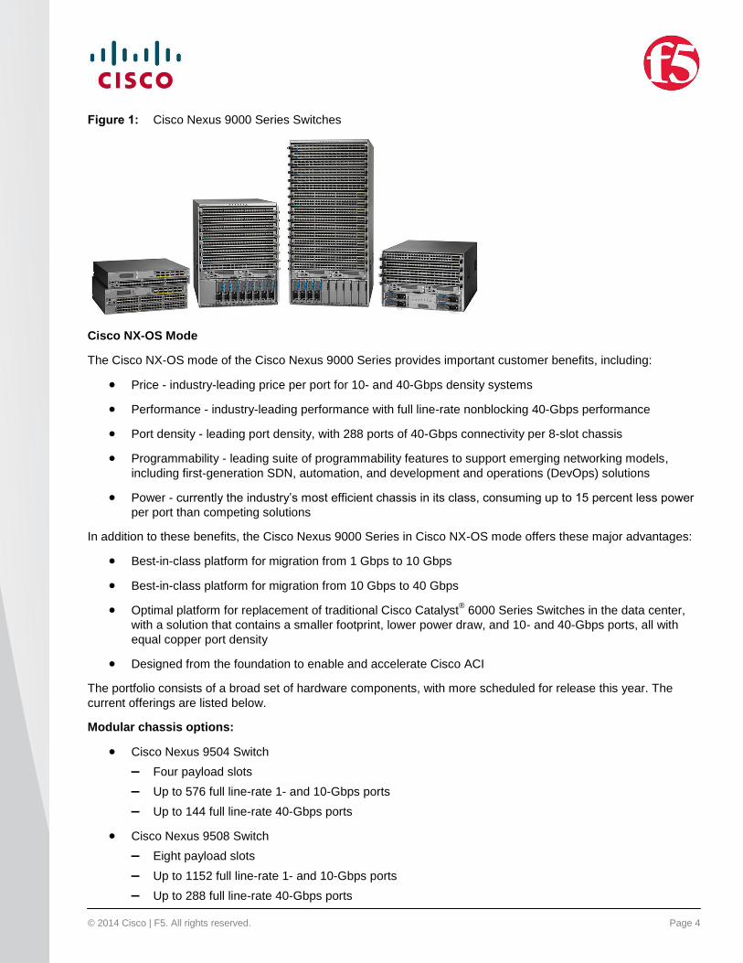
Cisco Nexus 9000 Series Switches (Figure 1) are the next generation of data center switching infrastructure. In
Cisco NX-OS Software mode, the Cisco Nexus 9000 Series addresses the new challenges of current
infrastructure designs, while building on first-generation SDN solutions and providing a path to Cisco ACI. In
Cisco ACI mode, Cisco Nexus 9000 Series Switches provide a powerful combination of hardware and software
custom-developed for a powerfully robust and comprehensive solution.
© 2014 Cisco | F5. All rights reserved. Page 4
Figure 1: Cisco Nexus 9000 Series Switches
Cisco NX-OS Mode
The Cisco NX-OS mode of the Cisco Nexus 9000 Series provides important customer benefits, including:
Price - industry-leading price per port for 10- and 40-Gbps density systems
Performance - industry-leading performance with full line-rate nonblocking 40-Gbps performance
Port density - leading port density, with 288 ports of 40-Gbps connectivity per 8-slot chassis
Programmability - leading suite of programmability features to support emerging networking models,
including first-generation SDN, automation, and development and operations (DevOps) solutions
Power - currently the industry’s most efficient chassis in its class, consuming up to 15 percent less power
per port than competing solutions
In addition to these benefits, the Cisco Nexus 9000 Series in Cisco NX-OS mode offers these major advantages:
Best-in-class platform for migration from 1 Gbps to 10 Gbps
Best-in-class platform for migration from 10 Gbps to 40 Gbps
Optimal platform for replacement of traditional Cisco Catalyst® 6000 Series Switches in the data center,
with a solution that contains a smaller footprint, lower power draw, and 10- and 40-Gbps ports, all with
equal copper port density
Designed from the foundation to enable and accelerate Cisco ACI
The portfolio consists of a broad set of hardware components, with more scheduled for release this year. The
current offerings are listed below.
Modular chassis options:
Cisco Nexus 9504 Switch
– Four payload slots
– Up to 576 full line-rate 1- and 10-Gbps ports
– Up to 144 full line-rate 40-Gbps ports
Cisco Nexus 9508 Switch
– Eight payload slots
– Up to 1152 full line-rate 1- and 10-Gbps ports
– Up to 288 full line-rate 40-Gbps ports
© 2014 Cisco | F5. All rights reserved. Page 5
Cisco Nexus 9516 Switch
– 16 payload slots
– Up to 2304 full line-rate 1- and 10-Gbps ports
– Up to 576 full line-rate 40-Gbps ports
Fixed-switch options:
Cisco Nexus 9396PX Switch
– 48 ports of 1- and 10-Gbps fiber enhanced Small Form-Factor Pluggable Plus (SFP+)
– 12 ports of 40-Gbps fiber Quad SFP (QSFP)
Cisco Nexus 9396TX Switch
– 48 ports of 1- and 10-Gbps fiber SFP+
– 12 ports of 40-Gbps fiber QSFP
Cisco Nexus 93128TX Switch
– 96 ports of 1- and 10-Gbps copper RJ-45
– Eight ports of 40-Gbps fiber QSFP
All of these benefits are enhanced by innovative Cisco 40-Gbps bidirectional (BiDi) optics. These standards-
based QSFP optics provide 40-Gbps speeds on existing 10-Gbps infrastructure at approximately the same cost
as current 10-Gbps optics. These optics are an exclusive Cisco option to help increase adoption of 40-Gbps
solutions.
Cisco Nexus 9000 Advantages
Cisco Nexus 9000 Series Switches offer both modular and fixed 10/40/100 Gigabit Ethernet switch configurations,
including high-density 1/10 Gb to servers; 40 Gb to network; and 100 Gb in future releases. Design flexibility with
traditional two-tier spine/leaf, as well as three-tier core/aggregation/access design is also available.
ACI Support
Designed to support the Cisco next-generation data center based on an application-centric strategy
Designed to help enable application deployment, simplicity, agility, and flexibility
Programmability
An intelligent API manages the switch through remote-procedure calls (JavaScript Object Notation or
XML) over HTTP or HTTPS
A Linux shell access and container environment is used to customize management and monitoring
Scalability
Up to 60 Tbps of nonblocking performance with less than five-microsecond latency
Up to 2304 10 Gbps or 576 40 Gbps non-blocking layer 2 and layer 3 Ethernet ports
Wire-speed Virtual Extensible LAN (VXLAN) gateway, bridging, and routing support

© 2014 Cisco | F5. All rights reserved. Page 6
High Availability
Full Cisco In-Service Software Upgrade (ISSU) and patching without any interruption in operation
Mix of third-party and Cisco application-specific integrated circuits (ASICs) for improved reliability and
performance
Virtual port channel (vPC_ and VXLAN support
Energy Efficiency
Chassis design without a midplane to optimize airflow and reduce energy requirements
Optimized design with fewer ASICs, resulting in lower energy use
Efficient power supplies that are rated at 80 Plus Platinum
Investment Protection
Cisco 40 Gb BiDi transceiver for reuse of existing 10 Gigabit Ethernet cabling plant for 40 Gigabit
Ethernet
Switches designed to support future ASIC generations
Support for Cisco Nexus 2000 Series Fabric Extenders in both NX-OS and ACI mode
F5 Networks BIG-IP LTM Overview
BIG-IP Local Traffic Manager (LTM) turns the network into an agile infrastructure for application delivery. It is a full
proxy between users and application servers, creating a layer of abstraction to secure, optimize, and load-balance
application traffic. This gives the control to add servers easily, eliminate downtime, improve application
performance, and meet the security requirements.
Rapid Application Deployment and Optimization
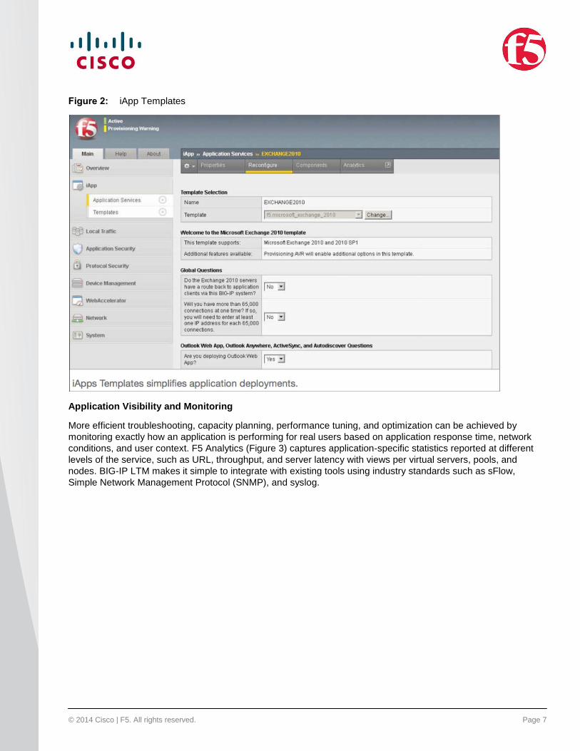
BIG-IP LTM includes iApps, a powerful solution that enables managing application services rather than individual
devices and objects. F5 iApps Templates (Figure 2) are a powerful feature of the BIG-IP system that can help
deploying faster with fewer configuration mistakes.
Unify, simplify, and control the entire application delivery network with a contextual view of the application
services that support the business needs.
© 2014 Cisco | F5. All rights reserved. Page 7
Figure 2: iApp Templates
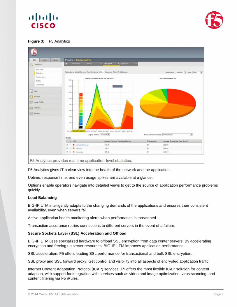
Application Visibility and Monitoring
More efficient troubleshooting, capacity planning, performance tuning, and optimization can be achieved by
monitoring exactly how an application is performing for real users based on application response time, network
conditions, and user context. F5 Analytics (Figure 3) captures application-specific statistics reported at different
levels of the service, such as URL, throughput, and server latency with views per virtual servers, pools, and
nodes. BIG-IP LTM makes it simple to integrate with existing tools using industry standards such as sFlow,
Simple Network Management Protocol (SNMP), and syslog.
© 2014 Cisco | F5. All rights reserved. Page 8
Figure 3: F5 Analytics
F5 Analytics gives IT a clear view into the health of the network and the application.
Uptime, response time, and even usage spikes are available at a glance.
Options enable operators navigate into detailed views to get to the source of application performance problems
quickly.
Load Balancing
BIG-IP LTM intelligently adapts to the changing demands of the applications and ensures their consistent
availability, even when servers fail.
Active application health monitoring alerts when performance is threatened.
Transaction assurance retries connections to different servers in the event of a failure.
Secure Sockets Layer (SSL) Acceleration and Offload
BIG-IP LTM uses specialized hardware to offload SSL encryption from data center servers. By accelerating
encryption and freeing up server resources, BIG-IP LTM improves application performance.
SSL acceleration: F5 offers leading SSL performance for transactional and bulk SSL encryption.
SSL proxy and SSL forward proxy: Get control and visibility into all aspects of encrypted application traffic.
Internet Content Adaptation Protocol (ICAP) services: F5 offers the most flexible ICAP solution for content
adaption, with support for integration with services such as video and image optimization, virus scanning, and
content filtering via F5 iRules.
© 2014 Cisco | F5. All rights reserved. Page 9
Network hardware security module (HSM): Gets FIPS 140-2 level 2 and 3 support on all BIG-IP hardware and
virtual editions.
Easy Protocol Implementation
BIG-IP LTM acts as a full proxy, sitting between servers and users, which makes implementing new protocols as
easy as flipping a switch.
SPDY: Turn on SPDY support and choose which servers will support it.
IPv6: Turn on IPv6 support to service IPv6 clients with IPv6 while still servicing IPv4 requests with IPv4.
Protocol Optimization
Improve application performance while reducing network traffic.
OneConnect: Increase server capacity by up to 60 percent.
F5 Fast Cache: Prevent servers from having to handle requests for identical content.
TCP connection queuing: Hold overload connections in a queue.
Compression: Use fewer bytes to transmit data.
Custom Control
iRules is a data-plane scripting language which enables a broad range of functionality to be programmatically
inserted into the network. Customers routinely implement security mitigation rules, support new protocols, and fix
application-related errors in real time. The iRules scripting language lets the user intercept, parse, modify, and
route application traffic based on specific business needs.
Virtual and Cloud Flexibility
BIG-IP LTM Virtual Edition delivers virtual environment and cloud deployment options with exceptional flexibility
across all major virtualization platforms, including:
VMware vSphere
Citrix XenServer
Microsoft Hyper-V
KVM
Industry-Leading Performance
BIG-IP LTM delivers superior performance and scalability, including:
Maximum layer 4 connections per second - 10 million
Maximum layer 7 requests per second - 20 million
Maximum layer 4 throughput - 640 Gbps
Maximum SSL transactions per second - 240,000
Maximum hardware distributed denial-of-service (DDoS) SYN connections per second - 640 million
Maximum virtual edition throughput - 10 Gbps
© 2014 Cisco | F5. All rights reserved. Page 10
LTM Advantages
Ensuring High Availability for Application Services
LTM provides fault tolerance at the application layer (server downtime) as well as at the BIG-IP layer (failure).
Application traffic remains uninterrupted despite either failure.
This guide enables the following capabilities:
Loss of an app server does not interrupt delivery of client traffic
Loss of an LTM does not interrupt delivery of client traffic
Stateful mirroring ensures that session information is sustained in the event of LTM failure
Application traffic is statefully maintained between servers
Optimizing Application Performance
Deploying more servers doesn’t guarantee better performance. What matters is that you reserve server capacity
for the right activities. LTM helps extend server capacity and reduce overall bandwidth usage.
This guide enables the following capabilities:
Optimize traffic flows by taking full advantage of LTM's full proxy. Separate stacks between F5/client and
F5/app enables protocol optimization, specialized connection profiles, and so on.
Offload the burden of encryption and decryption from your web servers by using SSL acceleration on F5
ASIC hardware.
Reduce the volume of traffic to users by using intelligent compression.
Eliminate unnecessary data transfer by using features such as dynamic caching.
Securing Applications
Applications require a wide variety of security services. LTM provides defense in depth across several layers. In
addition, F5 provides other modules that run on top of LTM for additional security services, including web
application firewalling, data center firewalling, secure access, authentication/authorization, and DDoS attack
prevention. However, these are outside the scope of this guide.
This guide enables the following capabilities:
Default deny/full firewall
Centralized SSL certificate management
iRules inspection
DDoS protection within LTM to prevent SynFlooding - vulnerability resiliency
Cisco Nexus 9000 + F5 LTM Design Options
Cisco Nexus 9000 Series Switches use a network appliance model in order to insert the F5 BIG-IP LTM module
into its data center architecture. This document provides a validated sample topology that uses F5 VIPRION
C2400 chassis equipment with a 40-Gb B2250 blade to configure with the LTM module to provide application
delivery services in an active/standby configuration. The B2250 is chosen in this validation effort to demonstrate
the 40-Gb compatibility between Nexus 9000 and BIG-IP. If the 10-Gb module is used in the Nexus 9000, any
BIG-IP model that supports 10 Gigabits will work with the Nexus 9000 design.
© 2014 Cisco | F5. All rights reserved. Page 11
In the validation effort for this document, 1-ARM mode application delivery services were the primary focus of
analysis, with redundant F5 VIPRION units configured with device-level failover for high availability. Traffic
streams were routed through the F5 LTM directly to the server farm.
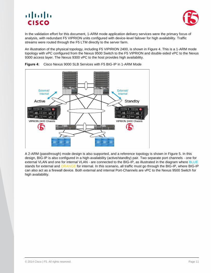
An illustration of the physical topology, including F5 VIPIRION 2400, is shown in Figure 4. This is a 1-ARM mode
topology with vPC configured from the Nexus 9500 Switch to the F5 VIPRION and double-sided vPC to the Nexus
9300 access layer. The Nexus 9300 vPC to the host provides high availability.
Figure 4: Cisco Nexus 9000 SLB Services with F5 BIG-IP in 1-ARM Mode
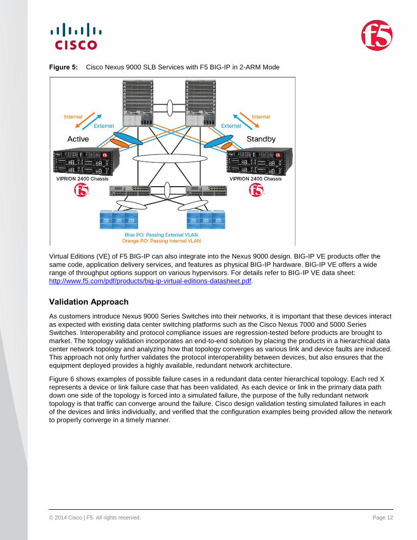
A 2-ARM (passthrough) mode design is also supported, and a reference topology is shown in Figure 5. In this
design, BIG-IP is also configured in a high-availability (active/standby) pair. Two separate port channels - one for
external VLAN and one for internal VLAN - are connected to the BIG-IP, as illustrated in the diagram where BLUE
stands for external and ORANGE for internal. In this scenario, all traffic must go through the BIG-IP, where BIG-IP
can also act as a firewall device. Both external and internal Port-Channels are vPC to the Nexus 9500 Switch for
high availability.
© 2014 Cisco | F5. All rights reserved. Page 12
Figure 5: Cisco Nexus 9000 SLB Services with F5 BIG-IP in 2-ARM Mode
Virtual Editions (VE) of F5 BIG-IP can also integrate into the Nexus 9000 design. BIG-IP VE products offer the
same code, application delivery services, and features as physical BIG-IP hardware. BIG-IP VE offers a wide
range of throughput options support on various hypervisors. For details refer to BIG-IP VE data sheet:
http://www.f5.com/pdf/products/big-ip-virtual-editions-datasheet.pdf.
Validation Approach
As customers introduce Nexus 9000 Series Switches into their networks, it is important that these devices interact
as expected with existing data center switching platforms such as the Cisco Nexus 7000 and 5000 Series
Switches. Interoperability and protocol compliance issues are regression-tested before products are brought to
market. The topology validation incorporates an end-to-end solution by placing the products in a hierarchical data
center network topology and analyzing how that topology converges as various link and device faults are induced.
This approach not only further validates the protocol interoperability between devices, but also ensures that the
equipment deployed provides a highly available, redundant network architecture.
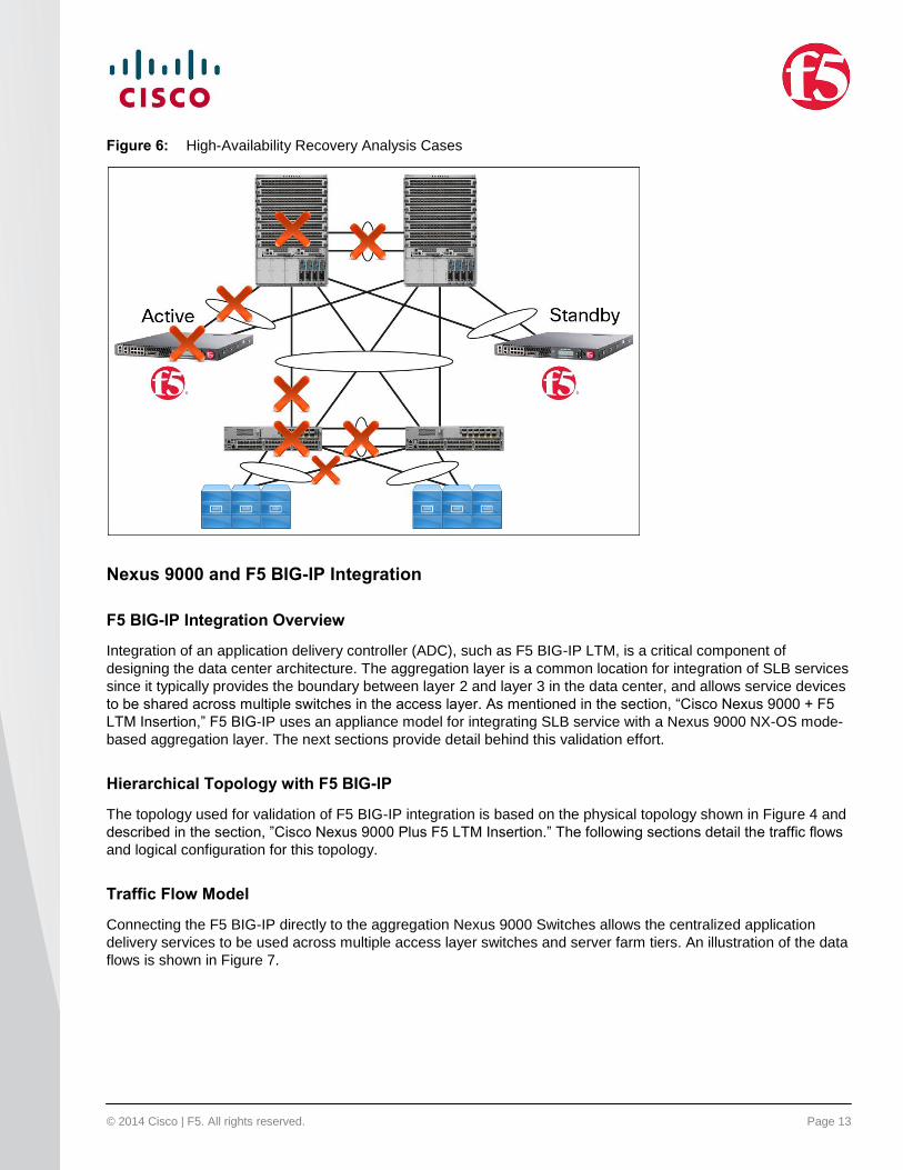
Figure 6 shows examples of possible failure cases in a redundant data center hierarchical topology. Each red X
represents a device or link failure case that has been validated. As each device or link in the primary data path
down one side of the topology is forced into a simulated failure, the purpose of the fully redundant network
topology is that traffic can converge around the failure. Cisco design validation testing simulated failures in each
of the devices and links individually, and verified that the configuration examples being provided allow the network
to properly converge in a timely manner.
© 2014 Cisco | F5. All rights reserved. Page 13
Figure 6: High-Availability Recovery Analysis Cases
Nexus 9000 and F5 BIG-IP Integration
F5 BIG-IP Integration Overview
Integration of an application delivery controller (ADC), such as F5 BIG-IP LTM, is a critical component of
designing the data center architecture. The aggregation layer is a common location for integration of SLB services
since it typically provides the boundary between layer 2 and layer 3 in the data center, and allows service devices
to be shared across multiple switches in the access layer. As mentioned in the section, “Cisco Nexus 9000 + F5
LTM Insertion,” F5 BIG-IP uses an appliance model for integrating SLB service with a Nexus 9000 NX-OS mode-
based aggregation layer. The next sections provide detail behind this validation effort.
Hierarchical Topology with F5 BIG-IP
The topology used for validation of F5 BIG-IP integration is based on the physical topology shown in Figure 4 and
described in the section, ”Cisco Nexus 9000 Plus F5 LTM Insertion.” The following sections detail the traffic flows
and logical configuration for this topology.
Traffic Flow Model
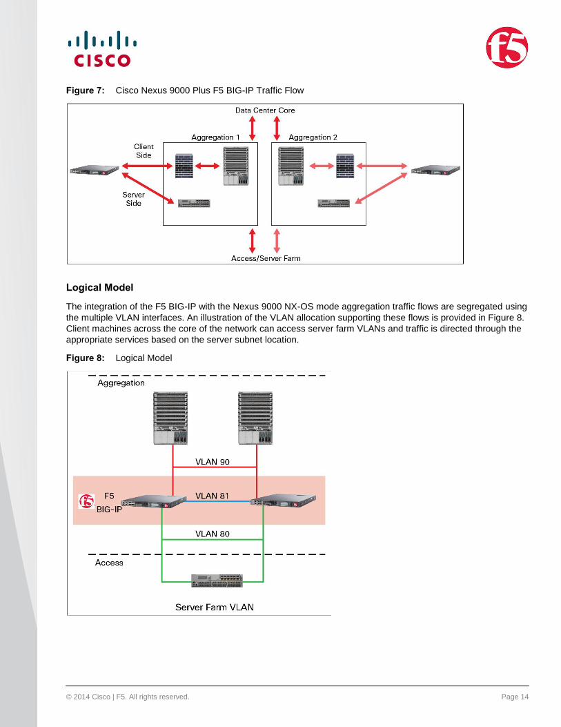
Connecting the F5 BIG-IP directly to the aggregation Nexus 9000 Switches allows the centralized application
delivery services to be used across multiple access layer switches and server farm tiers. An illustration of the data
flows is shown in Figure 7.
© 2014 Cisco | F5. All rights reserved. Page 14
Figure 7: Cisco Nexus 9000 Plus F5 BIG-IP Traffic Flow
Logical Model
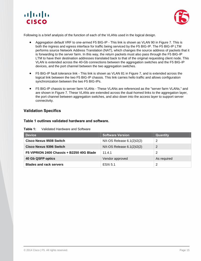
The integration of the F5 BIG-IP with the Nexus 9000 NX-OS mode aggregation traffic flows are segregated using
the multiple VLAN interfaces. An illustration of the VLAN allocation supporting these flows is provided in Figure 8.
Client machines across the core of the network can access server farm VLANs and traffic is directed through the
appropriate services based on the server subnet location.
Figure 8: Logical Model
© 2014 Cisco | F5. All rights reserved. Page 15
Following is a brief analysis of the function of each of the VLANs used in the logical design.
Aggregation default VRF to one-armed F5 BIG-IP - This link is shown as VLAN 90 in Figure 7. This is
both the ingress and egress interface for traffic being serviced by the F5 BIG-IP. The F5 BIG-IP LTM
performs source Network Address Translation (NAT), which changes the source address of packets that it
is forwarding to the server farm. In this way, the return packets must also pass through the F5 BIG-IP
LTM to have their destination addresses translated back to that of the original requesting client node. This
VLAN is extended across the 40-Gb connections between the aggregation switches and the F5 BIG-IP
devices, and the port channel between the two aggregation switches.
F5 BIG-IP fault tolerance link - This link is shown as VLAN 81 in Figure 7, and is extended across the
logical link between the two F5 BIG-IP chassis. This link carries hello traffic and allows configuration
synchronization between the two F5 BIG-IPs.
F5 BIG-IP chassis to server farm VLANs - These VLANs are referenced as the "server farm VLANs," and
are shown in Figure 7. These VLANs are extended across the dual-homed links to the aggregation layer,
the port channel between aggregation switches, and also down into the access layer to support server
connectivity.
Validation Specifics
Table 1 outlines validated hardware and software.
Table 1: Validated Hardware and Software
Device Software Version Quantity
Cisco Nexus 9508 Switch NX-OS Release 6.1(2)I2(2) 2
Cisco Nexus 9396 Switch NX-OS Release 6.1(2)I2(2) 2
F5 VIPRION 2400 Chassis + B2250 40G Blade 11.4.1 2
40 Gb QSFP optics Vendor approved As required
Blades and rack servers ESXi 5.1 2
© 2014 Cisco | F5. All rights reserved. Page 16
Topology
Figure 9 illustrates the proper topology to use.
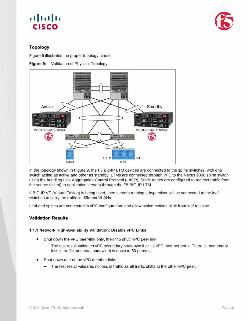
Figure 9: Validation of Physical Topology
In the topology shown in Figure 9, the F5 Big-IP LTM devices are connected to the spine switches, with one
switch acting as active and other as standby. LTMs are connected through vPC to the Nexus 9000 spine switch
using the bundling Link Aggregation Control Protocol (LACP). Static routes are configured to redirect traffic from
the source (client) to application servers through the F5 BIG-IP LTM.
If BIG-IP VE (Virtual Edition) is being used, then servers running a hypervisor will be connected to the leaf
switches to carry the traffic in different VLANs.
Leaf and spines are connected in vPC configuration, and allow active-active uplink from leaf to spine.
Validation Results
1.1.1 Network High-Availability Validation: Disable vPC Links
Shut down the vPC peer-link only, then “no shut” vPC peer link
– The test result validates vPC secondary shutdown if all its vPC member ports. There is momentary
loss in traffic, and total bandwidth is down to 50 percent.
Shut down one of the vPC member links
– The test result validates no loss in traffic as all traffic shifts to the other vPC peer.
© 2014 Cisco | F5. All rights reserved. Page 17
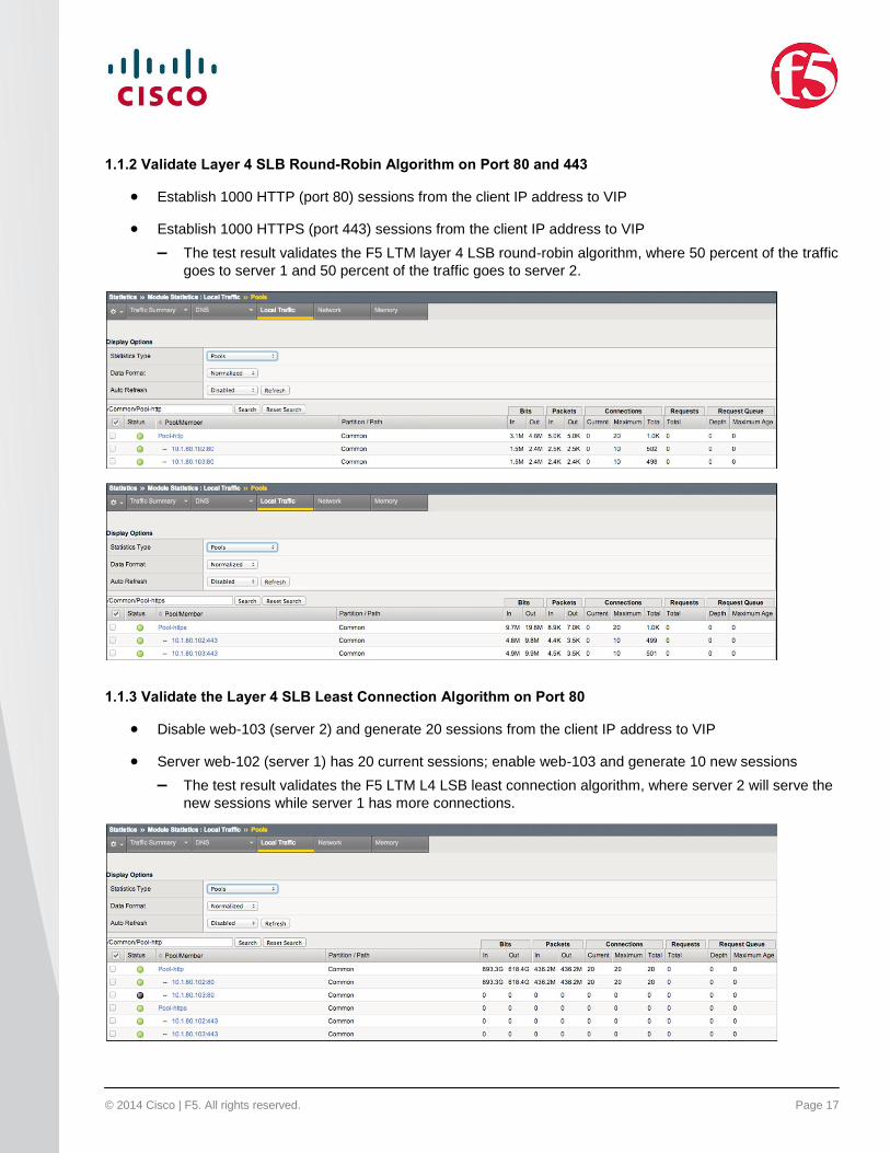
1.1.2 Validate Layer 4 SLB Round-Robin Algorithm on Port 80 and 443
Establish 1000 HTTP (port 80) sessions from the client IP address to VIP
Establish 1000 HTTPS (port 443) sessions from the client IP address to VIP
– The test result validates the F5 LTM layer 4 LSB round-robin algorithm, where 50 percent of the traffic
goes to server 1 and 50 percent of the traffic goes to server 2.
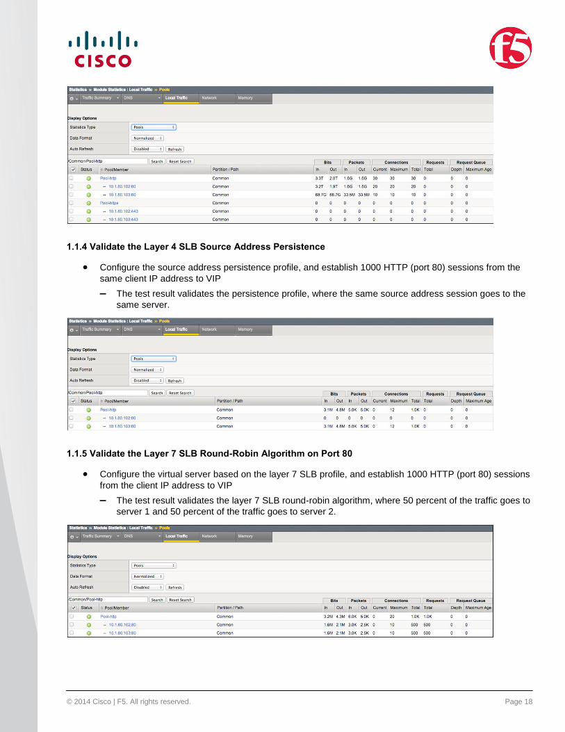
1.1.3 Validate the Layer 4 SLB Least Connection Algorithm on Port 80
Disable web-103 (server 2) and generate 20 sessions from the client IP address to VIP
Server web-102 (server 1) has 20 current sessions; enable web-103 and generate 10 new sessions
– The test result validates the F5 LTM L4 LSB least connection algorithm, where server 2 will serve the
new sessions while server 1 has more connections.
© 2014 Cisco | F5. All rights reserved. Page 18
1.1.4 Validate the Layer 4 SLB Source Address Persistence
Configure the source address persistence profile, and establish 1000 HTTP (port 80) sessions from the
same client IP address to VIP
– The test result validates the persistence profile, where the same source address session goes to the
same server.
1.1.5 Validate the Layer 7 SLB Round-Robin Algorithm on Port 80
Configure the virtual server based on the layer 7 SLB profile, and establish 1000 HTTP (port 80) sessions
from the client IP address to VIP
– The test result validates the layer 7 SLB round-robin algorithm, where 50 percent of the traffic goes to
server 1 and 50 percent of the traffic goes to server 2.
© 2014 Cisco | F5. All rights reserved. Page 19
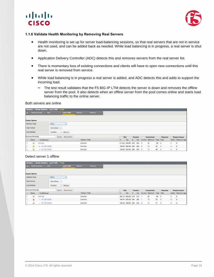
1.1.6 Validate Health Monitoring by Removing Real Servers
Health monitoring is set up for server load-balancing sessions, so that real servers that are not in service
are not used, and can be added back as needed. While load balancing is in progress, a real server is shut
down.
Application Delivery Controller (ADC) detects this and removes servers from the real server list.
There is momentary loss of existing connections and clients will have to open new connections until this
real server is removed from service.
While load balancing is in progress a real server is added, and ADC detects this and adds to support the
incoming load.
– The test result validates that the F5 BIG-IP LTM detects the server is down and removes the offline
server from the pool. It also detects when an offline server from the pool comes online and starts load
balancing traffic to the online server.
Both servers are online
Detect server 1 offline
© 2014 Cisco | F5. All rights reserved. Page 20
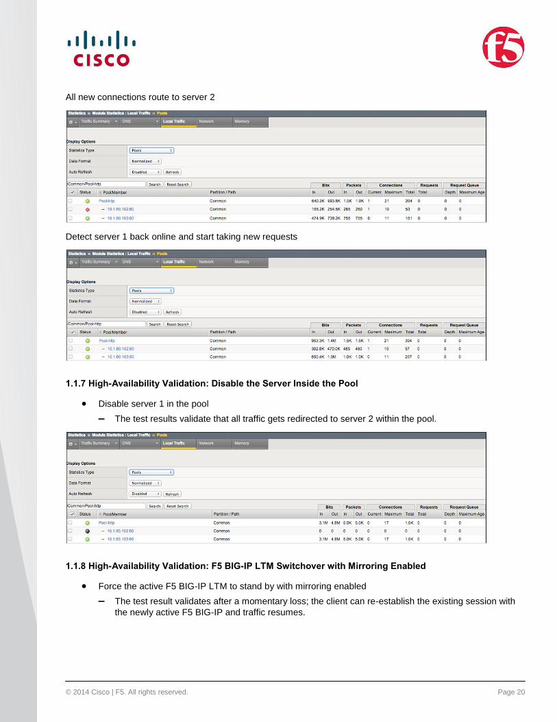
All new connections route to server 2
Detect server 1 back online and start taking new requests
1.1.7 High-Availability Validation: Disable the Server Inside the Pool
Disable server 1 in the pool
– The test results validate that all traffic gets redirected to server 2 within the pool.
1.1.8 High-Availability Validation: F5 BIG-IP LTM Switchover with Mirroring Enabled
Force the active F5 BIG-IP LTM to stand by with mirroring enabled
– The test result validates after a momentary loss; the client can re-establish the existing session with
the newly active F5 BIG-IP and traffic resumes.

© 2014 Cisco | F5. All rights reserved. Page 21
Appendix A - Configurations Example
Nexus 9508-1
version 6.1(2)I2(3)
switchname tme-sol-1-n9508-1
vdc tme-sol-1-n9508-1 id 1
allocate interface Ethernet1/1-36
limit-resource vlan minimum 16 maximum 4094
limit-resource vrf minimum 2 maximum 4096
limit-resource port-channel minimum 0 maximum 768
limit-resource u4route-mem minimum 248 maximum 248
limit-resource u6route-mem minimum 96 maximum 96
limit-resource m4route-mem minimum 58 maximum 58
limit-resource m6route-mem minimum 8 maximum 8
feature telnet
cfs eth distribute
feature lacp
feature vpc
feature lldp
username admin password 5 $1$ScfGdetY$0ynGuxo6e3Ei1krItPMsc/ role network-admin
no password strength-check
ip domain-lookup
service unsupported-transceiver
copp profile strict
snmp-server user admin network-admin auth md5 0x6db8c971332f4ee859c22879d4298046 priv
0x6db8c971332f4ee859c22879d4298046 localizedkey
rmon event 1 log trap public description FATAL(1) owner PMON@FATAL
rmon event 2 log trap public description CRITICAL(2) owner PMON@CRITICAL
rmon event 3 log trap public description ERROR(3) owner PMON@ERROR
rmon event 4 log trap public description WARNING(4) owner PMON@WARNING
rmon event 5 log trap public description INFORMATION(5) owner PMON@INFO
vlan 1,80-90
vrf context management
© 2014 Cisco | F5. All rights reserved. Page 22
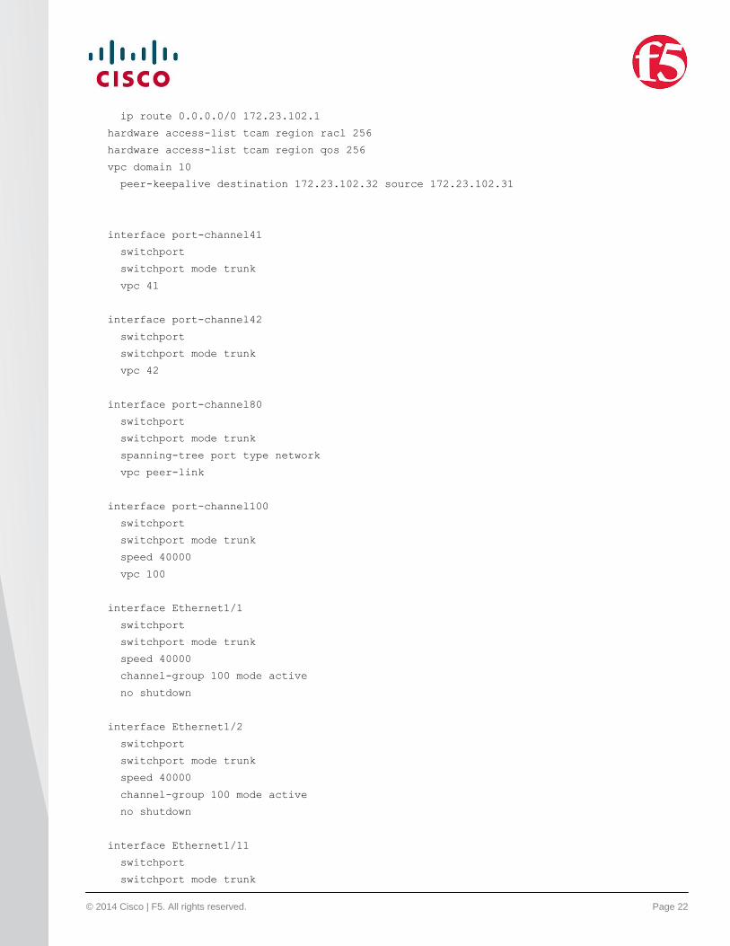
ip route 0.0.0.0/0 172.23.102.1
hardware access-list tcam region racl 256
hardware access-list tcam region qos 256
vpc domain 10
peer-keepalive destination 172.23.102.32 source 172.23.102.31
interface port-channel41
switchport
switchport mode trunk
vpc 41
interface port-channel42
switchport
switchport mode trunk
vpc 42
interface port-channel80
switchport
switchport mode trunk
spanning-tree port type network
vpc peer-link
interface port-channel100
switchport
switchport mode trunk
speed 40000
vpc 100
interface Ethernet1/1
switchport
switchport mode trunk
speed 40000
channel-group 100 mode active
no shutdown
interface Ethernet1/2
switchport
switchport mode trunk
speed 40000
channel-group 100 mode active
no shutdown
interface Ethernet1/11
switchport
switchport mode trunk
© 2014 Cisco | F5. All rights reserved. Page 23
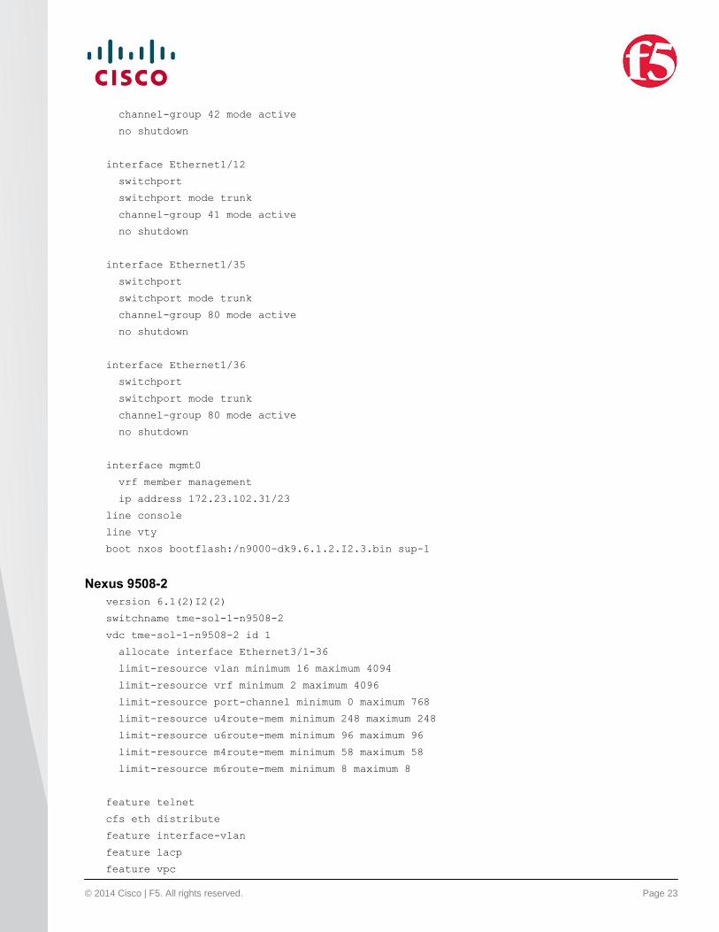
channel-group 42 mode active
no shutdown
interface Ethernet1/12
switchport
switchport mode trunk
channel-group 41 mode active
no shutdown
interface Ethernet1/35
switchport
switchport mode trunk
channel-group 80 mode active
no shutdown
interface Ethernet1/36
switchport
switchport mode trunk
channel-group 80 mode active
no shutdown
interface mgmt0
vrf member management
ip address 172.23.102.31/23
line console
line vty
boot nxos bootflash:/n9000-dk9.6.1.2.I2.3.bin sup-1
Nexus 9508-2
version 6.1(2)I2(2)
switchname tme-sol-1-n9508-2
vdc tme-sol-1-n9508-2 id 1
allocate interface Ethernet3/1-36
limit-resource vlan minimum 16 maximum 4094
limit-resource vrf minimum 2 maximum 4096
limit-resource port-channel minimum 0 maximum 768
limit-resource u4route-mem minimum 248 maximum 248
limit-resource u6route-mem minimum 96 maximum 96
limit-resource m4route-mem minimum 58 maximum 58
limit-resource m6route-mem minimum 8 maximum 8
feature telnet
cfs eth distribute
feature interface-vlan
feature lacp
feature vpc
© 2014 Cisco | F5. All rights reserved. Page 24
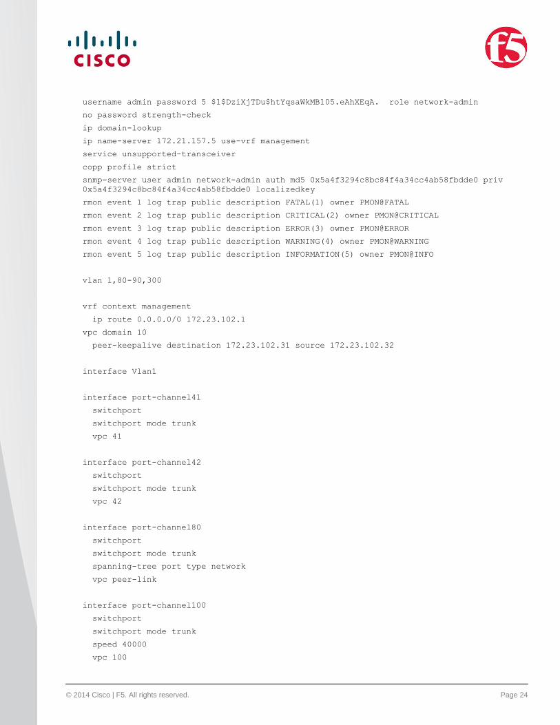
username admin password 5 $1$DziXjTDu$htYqsaWkMB105.eAhXEqA. role network-admin
no password strength-check
ip domain-lookup
ip name-server 172.21.157.5 use-vrf management
service unsupported-transceiver
copp profile strict
snmp-server user admin network-admin auth md5 0x5a4f3294c8bc84f4a34cc4ab58fbdde0 priv
0x5a4f3294c8bc84f4a34cc4ab58fbdde0 localizedkey
rmon event 1 log trap public description FATAL(1) owner PMON@FATAL
rmon event 2 log trap public description CRITICAL(2) owner PMON@CRITICAL
rmon event 3 log trap public description ERROR(3) owner PMON@ERROR
rmon event 4 log trap public description WARNING(4) owner PMON@WARNING
rmon event 5 log trap public description INFORMATION(5) owner PMON@INFO
vlan 1,80-90,300
vrf context management
ip route 0.0.0.0/0 172.23.102.1
vpc domain 10
peer-keepalive destination 172.23.102.31 source 172.23.102.32
interface Vlan1
interface port-channel41
switchport
switchport mode trunk
vpc 41
interface port-channel42
switchport
switchport mode trunk
vpc 42
interface port-channel80
switchport
switchport mode trunk
spanning-tree port type network
vpc peer-link
interface port-channel100
switchport
switchport mode trunk
speed 40000
vpc 100
© 2014 Cisco | F5. All rights reserved. Page 25
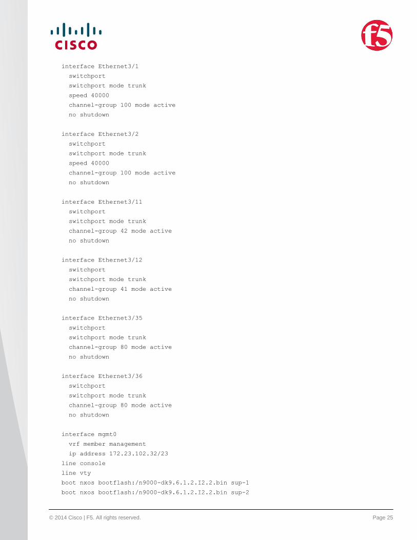
interface Ethernet3/1
switchport
switchport mode trunk
speed 40000
channel-group 100 mode active
no shutdown
interface Ethernet3/2
switchport
switchport mode trunk
speed 40000
channel-group 100 mode active
no shutdown
interface Ethernet3/11
switchport
switchport mode trunk
channel-group 42 mode active
no shutdown
interface Ethernet3/12
switchport
switchport mode trunk
channel-group 41 mode active
no shutdown
interface Ethernet3/35
switchport
switchport mode trunk
channel-group 80 mode active
no shutdown
interface Ethernet3/36
switchport
switchport mode trunk
channel-group 80 mode active
no shutdown
interface mgmt0
vrf member management
ip address 172.23.102.32/23
line console
line vty
boot nxos bootflash:/n9000-dk9.6.1.2.I2.2.bin sup-1
boot nxos bootflash:/n9000-dk9.6.1.2.I2.2.bin sup-2
© 2014 Cisco | F5. All rights reserved. Page 26
Nexus 9396-1
version 6.1(2)I2(2)
switchname tme-sol-1-n9396-1
vdc tme-sol-1-n9396-1 id 1
allocate interface Ethernet1/1-48
allocate interface Ethernet2/1-12
limit-resource vlan minimum 16 maximum 4094
limit-resource vrf minimum 2 maximum 4096
limit-resource port-channel minimum 0 maximum 768
limit-resource u4route-mem minimum 248 maximum 248
limit-resource u6route-mem minimum 96 maximum 96
limit-resource m4route-mem minimum 58 maximum 58
limit-resource m6route-mem minimum 8 maximum 8
feature telnet
cfs eth distribute
feature lacp
feature vpc
username admin password 5 $1$pQIH/Qpy$WNqhCY7x.lsFcEjmWFjtG1 role network-admin
no password strength-check
ip domain-lookup
copp profile strict
snmp-server user admin network-admin auth md5 0x722bc0810bd8131c0ebf163a5dcff8df priv
0x722bc0810bd8131c0ebf163a5dcff8df localizedkey
rmon event 1 log trap public description FATAL(1) owner PMON@FATAL
rmon event 2 log trap public description CRITICAL(2) owner PMON@CRITICAL
rmon event 3 log trap public description ERROR(3) owner PMON@ERROR
rmon event 4 log trap public description WARNING(4) owner PMON@WARNING
rmon event 5 log trap public description INFORMATION(5) owner PMON@INFO
vlan 1,80-90,300
vrf context management
ip route 0.0.0.0/0 172.23.102.1
vpc domain 11
role priority 32768
peer-keepalive destination 172.23.102.34 source 172.23.102.33
interface port-channel81
switchport mode trunk
spanning-tree port type network
vpc peer-link
interface port-channel101
switchport mode trunk
© 2014 Cisco | F5. All rights reserved. Page 27
vpc 101
interface port-channel200
switchport mode trunk
vpc 200
interface port-channel201
switchport mode trunk
vpc 201
interface Ethernet1/1
switchport mode trunk
channel-group 200
interface Ethernet1/2
switchport mode trunk
channel-group 201
interface Ethernet1/31
switchport mode trunk
channel-group 81 mode active
interface Ethernet1/32
switchport mode trunk
channel-group 81 mode active
interface Ethernet2/1
switchport mode trunk
channel-group 101 mode active
interface Ethernet2/2
switchport mode trunk
channel-group 101 mode active
interface mgmt0
vrf member management
ip address 172.23.102.33/23
line console
line vty
Nexus 9396-2
version 6.1(2)I2(1)
hostname tme-sol-1-n9396-2
vdc tme-sol-1-n9396-2 id 1
allocate interface Ethernet1/1-48
allocate interface Ethernet2/1-12
© 2014 Cisco | F5. All rights reserved. Page 28
limit-resource vlan minimum 16 maximum 4094
limit-resource vrf minimum 2 maximum 4096
limit-resource port-channel minimum 0 maximum 768
limit-resource u4route-mem minimum 248 maximum 248
limit-resource u6route-mem minimum 96 maximum 96
limit-resource m4route-mem minimum 58 maximum 58
limit-resource m6route-mem minimum 8 maximum 8
feature telnet
cfs eth distribute
feature lacp
feature vpc
username admin password 5 $1$nqocV2AK$iue5aOprA1moEfjIw1sGX0 role network-admin
no password strength-check
ip domain-lookup
ip name-server 172.21.157.5 use-vrf management
copp profile strict
snmp-server user admin network-admin auth md5 0xb32a8d8a7f1d7198ea6715996edc8290 priv
0xb32a8d8a7f1d7198ea6715996edc8290 localizedkey
rmon event 1 log trap public description FATAL(1) owner PMON@FATAL
rmon event 2 log trap public description CRITICAL(2) owner PMON@CRITICAL
rmon event 3 log trap public description ERROR(3) owner PMON@ERROR
rmon event 4 log trap public description WARNING(4) owner PMON@WARNING
rmon event 5 log trap public description INFORMATION(5) owner PMON@INFO
vlan 1,80-90,300
vrf context management
ip route 0.0.0.0/0 172.23.3.1
ip route 0.0.0.0/0 172.23.102.1
vpc domain 11
role priority 32769
peer-keepalive destination 172.23.102.33 source 172.23.102.34
interface port-channel81
switchport mode trunk
spanning-tree port type network
vpc peer-link
interface port-channel101
switchport mode trunk
vpc 101
interface port-channel200
switchport mode trunk
© 2014 Cisco | F5. All rights reserved. Page 29
vpc 200
interface port-channel201
switchport mode trunk
vpc 201
interface Ethernet1/1
switchport mode trunk
channel-group 200
interface Ethernet1/2
switchport mode trunk
channel-group 201
interface Ethernet1/31
switchport mode trunk
channel-group 81 mode active
interface Ethernet1/32
switchport mode trunk
channel-group 81 mode active
interface Ethernet2/1
switchport mode trunk
channel-group 101 mode active
interface Ethernet2/2
switchport mode trunk
channel-group 101 mode active
interface mgmt0
vrf member management
ip address 172.23.102.34/23
line console
line vty
boot nxos bootflash:/n9000-dk9.6.1.2.I2.1.bin
F5 BIG-IP LTM
cli admin-partitions {
update-partition Common
}
apm client-packaging /Common/client-packaging { }
apm resource remote-desktop citrix-client-bundle /Common/default-citrix-client-bundle { }
auth user admin {
description "Admin User"
© 2014 Cisco | F5. All rights reserved. Page 30
encrypted-password
"$6$iDQhuwTK$a6F8GTOUUYDSMyP1XKatq6HzIzmovW72Bd9kz/w3i24bqidieYLcuDZcbm1whunKHM/3RWa5joEw
g3oJRWFux1"
partition-access all
role admin
shell tmsh
}
auth user root {
description none
encrypted-password
"$6$oJrU6NKG$htStO2XRxJo2JumBdbiQqCCyxhwvNmInjxjUMIqHY.4Eslk3gV63mSZLJbkX1n2KAX/x2Rg4TSkp
VzxOHBAYk."
shell bash
}
cm cert /Common/dtca-bundle.crt {
cache-path /config/filestore/files_d/Common_d/trust_certificate_d/:Common:dtca-
bundle.crt_29745_3
checksum SHA1:1302:901ff2ebd6e3d2b17306c780fdaed4854c3c0080
revision 3
}
cm cert /Common/dtca.crt {
cache-path
/config/filestore/files_d/Common_d/trust_certificate_d/:Common:dtca.crt_29741_2
checksum SHA1:1302:901ff2ebd6e3d2b17306c780fdaed4854c3c0080
revision 2
}
cm cert /Common/dtdi.crt {
cache-path
/config/filestore/files_d/Common_d/trust_certificate_d/:Common:dtdi.crt_29737_2
checksum SHA1:1269:23b24df6de753974970ec7dec19303368473b773
revision 2
}
cm device /Common/bigip1.f5.local {
active-modules { "Best Bundle, C2200 / C2400 Platforms|T783746-1621305|SDN
Services|AFM, C2400|Acceleration Manager, C2400|ASM, Unlimited, VIPRION|DNS and GTM
(Unlimited), Viprion|Anti-Virus Checks|Base Endpoint Security Checks|Firewall
Checks|Machine Certificate Checks|Network Access|Protected Workspace|Secure Virtual
Keyboard|APM, Web Application|TPS SSL, Unlimited, C2400/C4400/C4480|App Tunnel|Remote
Desktop|DNS Rate Fallback, Unlimited|DNS Licensed Objects, Unlimited|DNS Rate Limit,
Unlimited QPS|GTM Rate Fallback, (UNLIMITED)|GTM Licensed Objects, Unlimited|GTM Rate,
Unlimited|Routing Bundle|PSM" "DNS-GTM, Rate Limited, VIPRION|K600758-9714257|DNS Rate
Fallback, 100|DNS Licensed Objects, 0|GTM Licensed Objects, 0|DNS Rate Limit, 100 QPS|GTM
Rate Fallback, 32|GTM Rate, 32|DNS Rate Fallback, Unlimited|DNS Licensed Objects,
Unlimited|DNS Rate Limit, Unlimited QPS|GTM Rate Fallback, (UNLIMITED)|GTM Licensed
Objects, Unlimited|GTM Rate, Unlimited|Routing Bundle" "LTM, Base, C2400|G880457-
2785738|IPV6 Gateway|Rate Shaping|Ram Cache|Cluster Multi-Processing|50 Mbps
Compression|SSL, 500 TPS Per Core|Performance Extreme, VPR|Routing Bundle|APM, Limited,
Viprion|AAM, Core|Client Authentication|Anti-Virus Checks|Base Endpoint Security
Checks|Firewall Checks|Machine Certificate Checks|Network Access|Protected
Workspace|Secure Virtual Keyboard|APM, Web Application|TPS SSL, Unlimited,
C2400/C4400/C4480|App Tunnel|Remote Desktop|Compression, Unlimited|PSM|DNS Rate Fallback,
Unlimited|DNS Licensed Objects, Unlimited|DNS Rate Limit, Unlimited QPS" }
base-mac 00:23:e9:9d:36:00
© 2014 Cisco | F5. All rights reserved. Page 31
build 625.0
chassis-id chs407101s
chassis-type viprion
configsync-ip 10.1.80.41
edition "Hotfix HF1"
hostname bigip1.f5.local
management-ip 172.23.102.41
marketing-name "BIG-IP VPR-C2400"
multicast-ip any
optional-modules { "Acceleration Manager, C2400" "ADC, Security Bundle, C2400"
"Advanced LTM Protocols, Viprion" "AFM, C2400" "APM, Base, C2400" "APM, Max CCU, C2400"
"App Mode (TMSH Only, No Root/Bash)" "ASM, Bundle, VIPRION" "ASM, PSM to ASM Upgrade"
"ASM, Unlimited, VIPRION" "Better Bundle, C2200 / C2400 Platforms" "Better to Best
Bundle, C2200 / C2400 Platforms" "CGN, Viprion" "Client Authentication" "Compression,
Unlimited" "Concurrent Users" "DNS and GTM (1K QPS), Viprion" "DNS and GTM (Unlimited),
Viprion" "DNS Services, VPR" "EA Features" "External Interface and Network HSM" "FIX Low
Latency" GTM "IPI Subscription, 1Yr, C2400" "IPI Subscription, 3Yr, C2400" "MSM,
Unlimited Mailboxes" "PEM URL Filtering, Subscription, 1Yr, C2400" "PEM URL Filtering,
Subscription, 3Yr, C2400" "PEM, C2400" "PEM, Quota Management, C2X00" "PSM, Base" "SDN
Services" "SSL, Forward Proxy" "SWG Subscription, 1Yr, C2200/C2400" "SWG Subscription,
3Yr, C2200/C2400" "TPS SSL, Unlimited, C2400/C4400/C4480" "URL Filtering Subscription,
1Yr, C2200/C2400" "URL Filtering Subscription, 3Yr, C2200/C2400" "VCMP, 16 Guests" "VCMP,
Max Guests" "WBA, Bundle, C2400" }
platform-id A112
product BIG-IP
time-zone PDT
unicast-address {
{
effective-ip 10.1.80.41
effective-port 1026
ip 10.1.80.41
}
{
effective-port 1026
}
}
version 11.4.1
}
cm device /Common/bigip2.f5.local {
active-modules { "Best Bundle, C2200 / C2400 Platforms|M001120-5515609|SDN
Services|AFM, C2400|Acceleration Manager, C2400|ASM, Unlimited, VIPRION|DNS and GTM
(Unlimited), Viprion|Anti-Virus Checks|Base Endpoint Security Checks|Firewall
Checks|Machine Certificate Checks|Network Access|Protected Workspace|Secure Virtual
Keyboard|APM, Web Application|TPS SSL, Unlimited, C2400/C4400/C4480|App Tunnel|Remote
Desktop|DNS Rate Fallback, Unlimited|DNS Licensed Objects, Unlimited|DNS Rate Limit,
Unlimited QPS|GTM Rate Fallback, (UNLIMITED)|GTM Licensed Objects, Unlimited|GTM Rate,
Unlimited|Routing Bundle|PSM" "DNS-GTM, Rate Limited, VIPRION|Q082212-9739992|DNS Rate
Fallback, 100|DNS Licensed Objects, 0|GTM Licensed Objects, 0|DNS Rate Limit, 100 QPS|GTM
Rate Fallback, 32|GTM Rate, 32|DNS Rate Fallback, Unlimited|DNS Licensed Objects,
Unlimited|DNS Rate Limit, Unlimited QPS|GTM Rate Fallback, (UNLIMITED)|GTM Licensed
Objects, Unlimited|GTM Rate, Unlimited|Routing Bundle" "LTM, Base, C2400|R566059-
0312921|IPV6 Gateway|Rate Shaping|Ram Cache|Cluster Multi-Processing|50 Mbps
Compression|SSL, 500 TPS Per Core|Performance Extreme, VPR|Routing Bundle|APM, Limited,
© 2014 Cisco | F5. All rights reserved. Page 32
Viprion|AAM, Core|Client Authentication|Anti-Virus Checks|Base Endpoint Security
Checks|Firewall Checks|Machine Certificate Checks|Network Access|Protected
Workspace|Secure Virtual Keyboard|APM, Web Application|TPS SSL, Unlimited,
C2400/C4400/C4480|App Tunnel|Remote Desktop|Compression, Unlimited|PSM|DNS Rate Fallback,
Unlimited|DNS Licensed Objects, Unlimited|DNS Rate Limit, Unlimited QPS" }
base-mac 00:23:e9:9d:f6:00
build 625.0
cert /Common/dtdi.crt
chassis-id chs407234s
chassis-type viprion
configsync-ip 10.1.80.42
edition "Hotfix HF1"
hostname bigip2.f5.local
key /Common/dtdi.key
management-ip 172.23.102.42
marketing-name "BIG-IP VPR-C2400"
multicast-ip any
optional-modules { "Acceleration Manager, C2400" "ADC, Security Bundle, C2400"
"Advanced LTM Protocols, Viprion" "AFM, C2400" "APM, Base, C2400" "APM, Max CCU, C2400"
"App Mode (TMSH Only, No Root/Bash)" "ASM, Bundle, VIPRION" "ASM, PSM to ASM Upgrade"
"ASM, Unlimited, VIPRION" "Better Bundle, C2200 / C2400 Platforms" "Better to Best
Bundle, C2200 / C2400 Platforms" "CGN, Viprion" "Client Authentication" "Compression,
Unlimited" "Concurrent Users" "DNS and GTM (1K QPS), Viprion" "DNS and GTM (Unlimited),
Viprion" "DNS Services, VPR" "EA Features" "External Interface and Network HSM" "FIX Low
Latency" GTM "IPI Subscription, 1Yr, C2400" "IPI Subscription, 3Yr, C2400" "MSM,
Unlimited Mailboxes" "PEM URL Filtering, Subscription, 1Yr, C2400" "PEM URL Filtering,
Subscription, 3Yr, C2400" "PEM, C2400" "PEM, Quota Management, C2X00" "PSM, Base" "SDN
Services" "SSL, Forward Proxy" "SWG Subscription, 1Yr, C2200/C2400" "SWG Subscription,
3Yr, C2200/C2400" "TPS SSL, Unlimited, C2400/C4400/C4480" "URL Filtering Subscription,
1Yr, C2200/C2400" "URL Filtering Subscription, 3Yr, C2200/C2400" "VCMP, 16 Guests" "VCMP,
Max Guests" "WBA, Bundle, C2400" }
platform-id A112
product BIG-IP
self-device true
time-zone PDT
unicast-address {
{
effective-ip 10.1.80.42
effective-port 1026
ip 10.1.80.42
}
{
effective-port 1026
}
}
version 11.4.1
}
cm device-group /Common/device-group-failover-fc99d0cbc202 {
devices {
/Common/bigip1.f5.local { }
/Common/bigip2.f5.local { }
© 2014 Cisco | F5. All rights reserved. Page 33
}
type sync-failover
}
cm device-group /Common/device_trust_group {
auto-sync enabled
devices {
/Common/bigip1.f5.local { }
/Common/bigip2.f5.local { }
}
hidden true
network-failover disabled
}
cm device-group /Common/gtm {
devices {
/Common/bigip2.f5.local { }
}
hidden true
network-failover disabled
}
cm key /Common/dtca.key {
cache-path
/config/filestore/files_d/Common_d/trust_certificate_key_d/:Common:dtca.key_29743_2
checksum SHA1:1679:350c3881ac1654fb68d491dd06d53be65bd62782
revision 2
}
cm key /Common/dtdi.key {
cache-path
/config/filestore/files_d/Common_d/trust_certificate_key_d/:Common:dtdi.key_29739_2
checksum SHA1:1679:d30e359dfd3306d4268b74001c56dfe7d2562780
revision 2
}
cm traffic-group /Common/traffic-group-1 {
ha-order {
/Common/bigip1.f5.local
/Common/bigip2.f5.local
}
unit-id 1
}
cm traffic-group /Common/traffic-group-local-only { }
cm trust-domain /Common/Root {
ca-cert /Common/dtca.crt
ca-cert-bundle /Common/dtca-bundle.crt
ca-devices { /Common/bigip2.f5.local /Common/bigip1.f5.local }
ca-key /Common/dtca.key
guid c53fb850-be99-4b6a-8b410023e98b13c2
status initialized
© 2014 Cisco | F5. All rights reserved. Page 34
trust-group /Common/device_trust_group
}
gtm global-settings metrics {
metrics-collection-protocols { icmp }
}
gtm global-settings metrics-exclusions {
addresses none
}
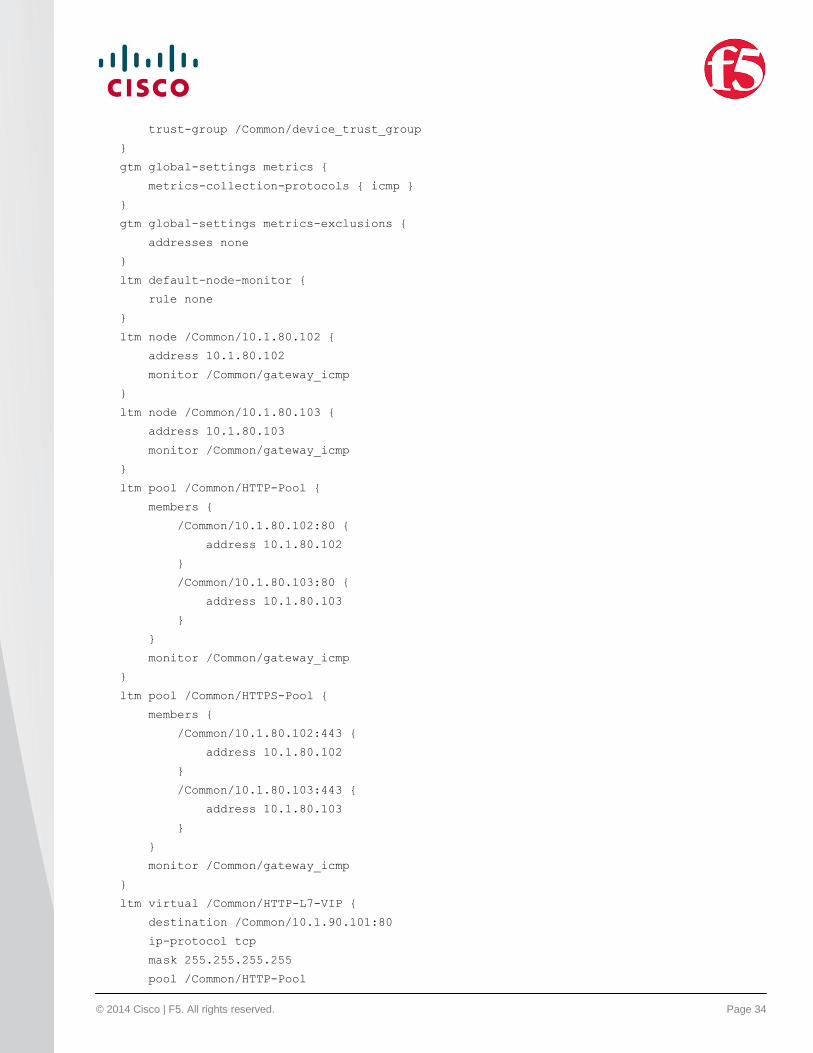
ltm default-node-monitor {
rule none
}
ltm node /Common/10.1.80.102 {
address 10.1.80.102
monitor /Common/gateway_icmp
}
ltm node /Common/10.1.80.103 {
address 10.1.80.103
monitor /Common/gateway_icmp
}
ltm pool /Common/HTTP-Pool {
members {
/Common/10.1.80.102:80 {
address 10.1.80.102
}
/Common/10.1.80.103:80 {
address 10.1.80.103
}
}
monitor /Common/gateway_icmp
}
ltm pool /Common/HTTPS-Pool {
members {
/Common/10.1.80.102:443 {
address 10.1.80.102
}
/Common/10.1.80.103:443 {
address 10.1.80.103
}
}
monitor /Common/gateway_icmp
}
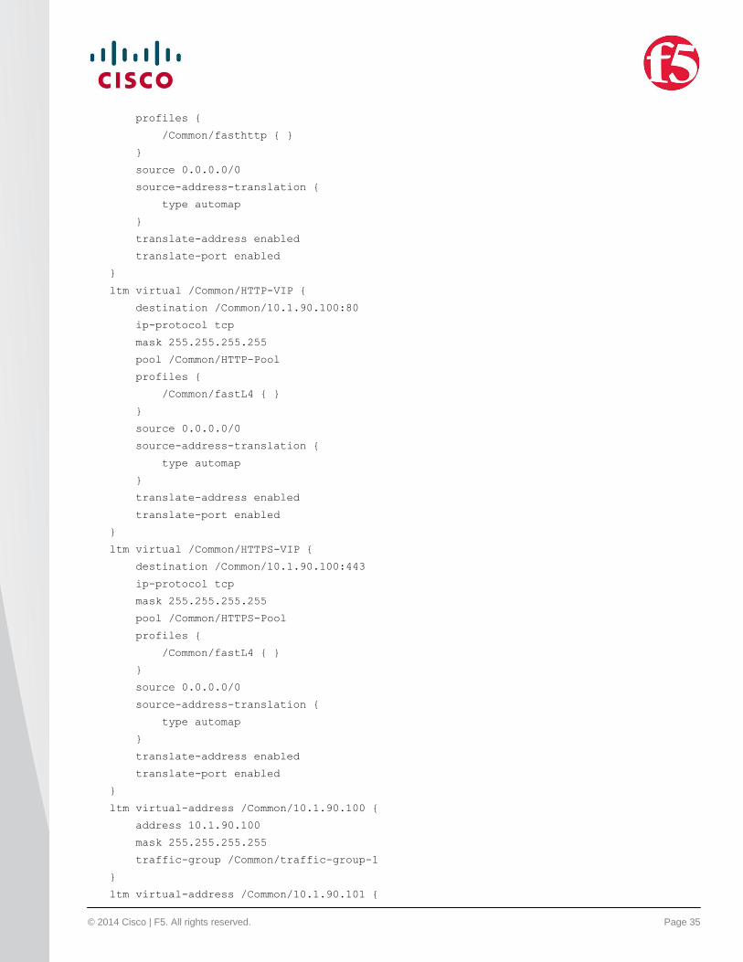
ltm virtual /Common/HTTP-L7-VIP {
destination /Common/10.1.90.101:80
ip-protocol tcp
mask 255.255.255.255
pool /Common/HTTP-Pool
© 2014 Cisco | F5. All rights reserved. Page 35
profiles {
/Common/fasthttp { }
}
source 0.0.0.0/0
source-address-translation {
type automap
}
translate-address enabled
translate-port enabled
}
ltm virtual /Common/HTTP-VIP {
destination /Common/10.1.90.100:80
ip-protocol tcp
mask 255.255.255.255
pool /Common/HTTP-Pool
profiles {
/Common/fastL4 { }
}
source 0.0.0.0/0
source-address-translation {
type automap
}
translate-address enabled
translate-port enabled
}
ltm virtual /Common/HTTPS-VIP {
destination /Common/10.1.90.100:443
ip-protocol tcp
mask 255.255.255.255
pool /Common/HTTPS-Pool
profiles {
/Common/fastL4 { }
}
source 0.0.0.0/0
source-address-translation {
type automap
}
translate-address enabled
translate-port enabled
}
ltm virtual-address /Common/10.1.90.100 {
address 10.1.90.100
mask 255.255.255.255
traffic-group /Common/traffic-group-1
}
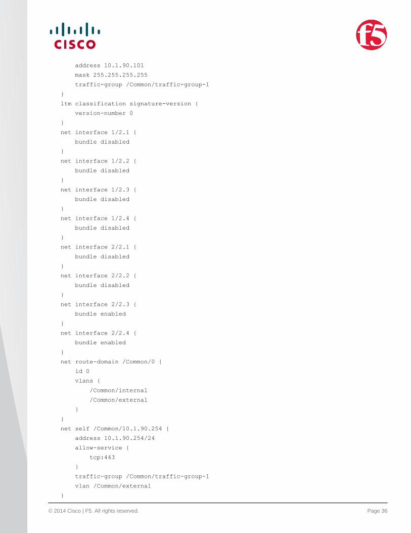
ltm virtual-address /Common/10.1.90.101 {
© 2014 Cisco | F5. All rights reserved. Page 36
address 10.1.90.101
mask 255.255.255.255
traffic-group /Common/traffic-group-1
}
ltm classification signature-version {
version-number 0
}
net interface 1/2.1 {
bundle disabled
}
net interface 1/2.2 {
bundle disabled
}
net interface 1/2.3 {
bundle disabled
}
net interface 1/2.4 {
bundle disabled
}
net interface 2/2.1 {
bundle disabled
}
net interface 2/2.2 {
bundle disabled
}
net interface 2/2.3 {
bundle enabled
}
net interface 2/2.4 {
bundle enabled
}
net route-domain /Common/0 {
id 0
vlans {
/Common/internal
/Common/external
}
}
net self /Common/10.1.90.254 {
address 10.1.90.254/24
allow-service {
tcp:443
}
traffic-group /Common/traffic-group-1
vlan /Common/external
}
© 2014 Cisco | F5. All rights reserved. Page 37
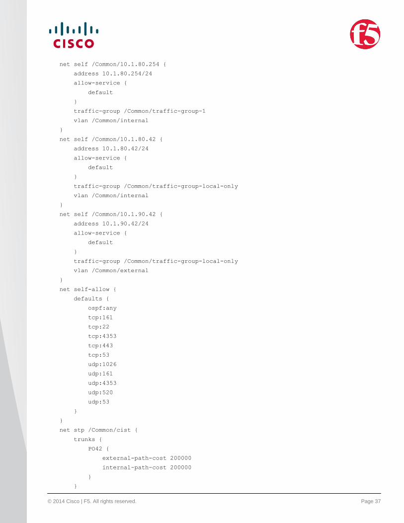
net self /Common/10.1.80.254 {
address 10.1.80.254/24
allow-service {
default
}
traffic-group /Common/traffic-group-1
vlan /Common/internal
}
net self /Common/10.1.80.42 {
address 10.1.80.42/24
allow-service {
default
}
traffic-group /Common/traffic-group-local-only
vlan /Common/internal
}
net self /Common/10.1.90.42 {
address 10.1.90.42/24
allow-service {
default
}
traffic-group /Common/traffic-group-local-only
vlan /Common/external
}
net self-allow {
defaults {
ospf:any
tcp:161
tcp:22
tcp:4353
tcp:443
tcp:53
udp:1026
udp:161
udp:4353
udp:520
udp:53
}
}
net stp /Common/cist {
trunks {
PO42 {
external-path-cost 200000
internal-path-cost 200000
}
}
© 2014 Cisco | F5. All rights reserved. Page 38
vlans {
/Common/external
/Common/internal
}
}
net stp-globals {
config-name 00-01-D7-C7-1C-40
}
net trunk PO42 {
interfaces {
2/2.3
2/2.4
}
lacp enabled
}
net vlan /Common/external {
interfaces {
PO42 {
tagged
}
}
tag 90
}
net vlan /Common/internal {
interfaces {
PO42 {
tagged
}
}
tag 80
}
net fdb vlan /Common/external { }
net fdb vlan /Common/internal { }
net ipsec ike-daemon /Common/ikedaemon { }
security firewall port-list /Common/_sys_self_allow_tcp_defaults {
ports {
22 { }
53 { }
161 { }
443 { }
1029-1043 { }
4353 { }
}
}
security firewall port-list /Common/_sys_self_allow_udp_defaults {
ports {
© 2014 Cisco | F5. All rights reserved. Page 39
53 { }
161 { }
520 { }
1026 { }
4353 { }
}
}
security firewall rule-list /Common/_sys_self_allow_all {
rules {
_sys_allow_all {
action accept
}
}
}
security firewall rule-list /Common/_sys_self_allow_defaults {
rules {
_sys_allow_tcp_defaults {
action accept
ip-protocol tcp
destination {
port-lists {
/Common/_sys_self_allow_tcp_defaults
}
}
}
_sys_allow_udp_defaults {
action accept
ip-protocol udp
destination {
port-lists {
/Common/_sys_self_allow_udp_defaults
}
}
}
_sys_allow_ospf_defaults {
action accept
ip-protocol ospf
}
}
}
security firewall rule-list /Common/_sys_self_allow_management {
rules {
_sys_allow_ssh {
action accept
ip-protocol tcp
destination {
© 2014 Cisco | F5. All rights reserved. Page 40
ports {
22 { }
}
}
}
_sys_allow_web {
action accept
ip-protocol tcp
destination {
ports {
443 { }
}
}
}
}
}
sys cluster default {
address 172.23.102.42/23
members {
1 { }
2 { }
3 { }
4 { }
}
min-up-members 1
min-up-members-enabled yes
}
sys db gtm.peerinfototalgtms {
value "0"
}
sys db provision.extramb {
value "0"
}
sys db provision.tomcat.extramb {
value "0"
}
sys db rule.validation {
value "strict"
}
sys db statemirror.clustermirroring {
value "between"
}
sys db tm.allowmulticastl2destinationtraffic {
value "disable"
}
sys db tm.tcpallowinsecurerst {
© 2014 Cisco | F5. All rights reserved. Page 41
value "disable"
}
sys db tmm.classallocatemetadata {
value "enable"
}
sys db tmm.coredump {
value "enable"
}
sys db tmm.gradualfileloadadjust {
value "enable"
}
sys db tmm.lb.wlcoffset {
value "disable"
}
sys db tmm.verbose {
value "disable"
}
sys db tmm.verbosecmp {
value "disable"
}
sys feature-module cgnat {
disabled
}
sys folder / {
device-group /Common/device-group-failover-fc99d0cbc202
hidden false
inherited-devicegroup false
inherited-traffic-group false
traffic-group /Common/traffic-group-1
}
sys folder /Common {
device-group /Common/device-group-failover-fc99d0cbc202
hidden false
inherited-devicegroup true
inherited-traffic-group true
traffic-group /Common/traffic-group-1
}
sys global-settings {
gui-setup disabled
hostname bigip2.f5.local
}
sys management-dhcp /Common/sys-mgmt-dhcp-config { }
sys management-route /Common/default {
description configured-statically
gateway 172.23.102.1
network default
© 2014 Cisco | F5. All rights reserved. Page 42
}
sys provision ltm {
level nominal
}
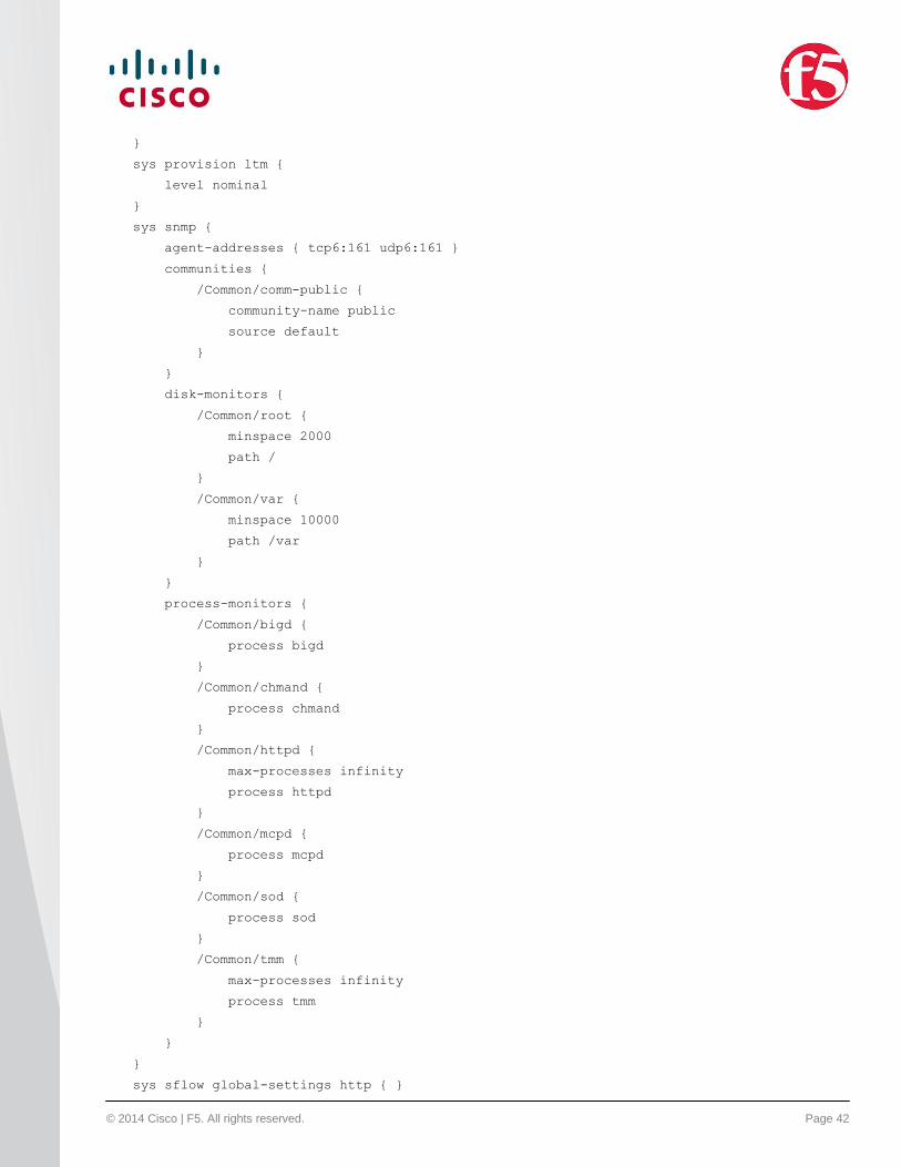
sys snmp {
agent-addresses { tcp6:161 udp6:161 }
communities {
/Common/comm-public {
community-name public
source default
}
}
disk-monitors {
/Common/root {
minspace 2000
path /
}
/Common/var {
minspace 10000
path /var
}
}
process-monitors {
/Common/bigd {
process bigd
}
/Common/chmand {
process chmand
}
/Common/httpd {
max-processes infinity
process httpd
}
/Common/mcpd {
process mcpd
}
/Common/sod {
process sod
}
/Common/tmm {
max-processes infinity
process tmm
}
}
}
sys sflow global-settings http { }
© 2014 Cisco | F5. All rights reserved. Page 43
sys sflow global-settings vlan { }
wom deduplication {
disabled
}
wom endpoint-discovery { }
Reference
Cisco Nexus 9000 NX-OS mode best practice:
http://www.cisco.com/c/en/us/products/collateral/switches/nexus-9000-series-switches/guide-c07-730115.html.
F5 Local Traffic Manager 11.4.1 implementations:
http://support.f5.com/kb/en-us/products/big-ip_ltm/manuals/product/ltm-implementations-11-4-0.html.
Disclaimer
ALL DESIGNS, SPECIFICATIONS, STATEMENTS, INFORMATION, AND RECOMMENDATIONS
(COLLECTIVELY, "DESIGNS") IN THIS MANUAL ARE PRESENTED "AS IS," WITH ALL FAULTS. CISCO AND
ITS SUPPLIERS DISCLAIM ALL WARRANTIES, INCLUDING, WITHOUT LIMITATION, THE WARRANTY OF
MERCHANTABILITY, FITNESS FOR A PARTICULAR PURPOSE AND NONINFRINGEMENT OR ARISING
FROM A COURSE OF DEALING, USAGE, OR TRADE PRACTICE. IN NO EVENT SHALL CISCO OR ITS
SUPPLIERS BE LIABLE FOR ANY INDIRECT, SPECIAL, CONSEQUENTIAL, OR INCIDENTAL DAMAGES,
INCLUDING, WITHOUT LIMITATION, LOST PROFITS OR LOSS OR DAMAGE TO DATA ARISING OUT OF
THE USE OR INABILITY TO USE THE DESIGNS, EVEN IF CISCO OR ITS SUPPLIERS HAVE BEEN ADVISED
OF THE POSSIBILITY OF SUCH DAMAGES.
THE DESIGNS ARE SUBJECT TO CHANGE WITHOUT NOTICE. USERS ARE SOLELY RESPONSIBLE FOR
THEIR APPLICATION OF THE DESIGNS. THE DESIGNS DO NOT CONSTITUTE THE TECHNICAL OR
OTHER PROFESSIONAL ADVICE OF CISCO, ITS SUPPLIERS OR PARTNERS. USERS SHOULD CONSULT
THEIR OWN TECHNICAL ADVISORS BEFORE IMPLEMENTING THE DESIGNS. RESULTS MAY VARY
DEPENDING ON FACTORS NOT TESTED BY CISCO.
© 2014 Cisco | F5. All rights reserved. Page 44
© 2014 Cisco and/or its affiliates. All rights reserved. Cisco and the Cisco logo are trademarks or registered
trademarks of Cisco and/or its affiliates in the U.S. and other countries. To view a list of Cisco trademarks, go to
this URL: www.cisco.com/go/trademarks. Third-party trademarks mentioned are the property of their respective
owners. The use of the word partner does not imply a partnership relationship between Cisco and any other
company. (1110R)
F5 (NASDAQ: FFIV) provides solutions for an application world. F5 helps organizations seamlessly scale cloud,
data center, and software defined networking (SDN) deployments to successfully deliver applications to anyone,
anywhere, at any time. F5 solutions broaden the reach of IT through an open, extensible framework and a rich
partner ecosystem of leading technology and data center orchestration vendors. This approach lets customers
pursue the infrastructure model that best fits their needs over time. The world's largest businesses, service
providers, government entities, and consumer brands rely on F5 to stay ahead of cloud, security, and mobility
trends. For more information, go to f5.com.
C22-732522-00 08/14