CI001001R100 Ver 1 Indoor Dist Substation Design Std
25
NETWORK LINES STANDARDS INDOOR DISTRIBUTION SUBSTATION DESIGN Check this is the latest version before use. CI001001R100 Ver 1 Reference Owner: Ian McLeod Group General Manager Operations Distribution Ergon Energy Corporation Limited ABN 50 087 646 062 Ergon Energy Queensland Pty Ltd ABN 11 121 177 802 INDOOR DISTRIBUTION SUBSTATION DESIGN STANDARD VERSION 1
-
Upload
ahmadgce04 -
Category
Documents
-
view
223 -
download
0
Transcript of CI001001R100 Ver 1 Indoor Dist Substation Design Std

8/6/2019 CI001001R100 Ver 1 Indoor Dist Substation Design Std
http://slidepdf.com/reader/full/ci001001r100-ver-1-indoor-dist-substation-design-std 1/25
NETWORK LINES STANDARDSINDOOR DISTRIBUTION SUBSTATION DESIGN
Check this is the latest version before use. CI001001R100 Ver 1Reference Owner: Ian McLeod Group General Manager Operations Distribution
Ergon Energy Corporation Limited ABN 50 087 646 062Ergon Energy Queensland Pty Ltd ABN 11 121 177 802
INDOOR DISTRIBUTION SUBSTATIONDESIGN STANDARD
VERSION 1

8/6/2019 CI001001R100 Ver 1 Indoor Dist Substation Design Std
http://slidepdf.com/reader/full/ci001001r100-ver-1-indoor-dist-substation-design-std 2/25
NETWORK LINES STANDARDSINDOOR DISTRIBUTION SUBSTATION DESIGN
Check this is the latest version before use. Page 1 of 24 CI001001R100 Ver 1 Reference Owner: Ian McLeod Group General Manager Operations DistributionErgon Energy Corporation Limited ABN 50 087 646 062Ergon Energy Queensland Pty Ltd ABN 11 121 177 802
TABLE OF CONTENTS
1. SCOPE ............................................................................................................... 22. SUBSTATION LOCATION.................................................................................. 3
2.1. Reticulation Costs........................................................................................ 32.2. Personnel Access ........................................................................................ 32.3. Equipment Access ....................................................................................... 32.4. Ergon Mains Access .................................................................................... 42.5. Foundation and Earthing Requirements ......................................................42.6. Avoidance of other Services and Encroachment ......................................... 42.7. Area Drainage.............................................................................................. 42.8. Hazardous Locations ................................................................................... 52.9. Electric and Magnetic Fields (EMF) ............................................................. 52.10. Noise........................................................................................................ 52.11. Ventilation................................................................................................. 5
2.12. Protection from Vehicles........................................................................... 62.13. Future Site Development..........................................................................63. CONSTRUCTION ............................................................................................... 7
3.1. Walls and Ceilings ....................................................................................... 73.2. Floors...........................................................................................................73.3. Waterproofing .............................................................................................. 73.4. Ventilation .................................................................................................... 8
3.4.1. Natural Ventilation ................................................................................ 83.4.2. Forced Ventilation................................................................................. 83.4.3. Special Requirements for Ventilation Ducts.......................................... 9
3.5. Fire............................................................................................................... 9
3.6. Oil Containment ........................................................................................... 93.7. Hauling Eyes................................................................................................ 9
3.7.1. For Cables .......................................................................................... 103.7.2. For Transformers ................................................................................ 10
3.8. Earths ........................................................................................................ 103.9. Trenches.................................................................................................... 103.10. Doors...................................................................................................... 113.11. Light and Power ..................................................................................... 123.12. Conduits ................................................................................................. 12
4. ELECTRICAL DESIGN STANDARD................................................................. 134.1. Transformers.............................................................................................. 13
4.2. High Voltage Switchgear............................................................................ 134.3. Low Voltage Switchboard .......................................................................... 144.4. Customer’s Connection..............................................................................144.5. Cables........................................................................................................ 144.6. Earthing .....................................................................................................14
4.6.1. CMEN................................................................................................. 144.6.2. Separately Earthed System ................................................................ 154.6.3. General Requirements........................................................................ 15
4.7. Labels ........................................................................................................ 154.8. Fault Levels................................................................................................ 164.9. Safety and Clearances............................................................................... 16
5. LAYOUTS – TYPICAL ...................................................................................... 17
8/6/2019 CI001001R100 Ver 1 Indoor Dist Substation Design Std
http://slidepdf.com/reader/full/ci001001r100-ver-1-indoor-dist-substation-design-std 3/25
NETWORK LINES STANDARDSINDOOR DISTRIBUTION SUBSTATION DESIGN
Check this is the latest version before use. Page 2 of 24 CI001001R100 Ver 1 Reference Owner: Ian McLeod Group General Manager Operations DistributionErgon Energy Corporation Limited ABN 50 087 646 062Ergon Energy Queensland Pty Ltd ABN 11 121 177 802
1. SCOPE
This specification has been prepared by Ergon to assist architects, consulting engineers,property developers, property owners and Ergon’s electrical design engineers. It sets outErgon’s requirements for the design, construction, operation and maintenancerequirements where an indoor substation is to be established on a customer’s property.This indoor substation may be partly or wholly within the customer’s building or in aseparate building on the property.
The specification is split into sections covering:
a) Substation Location – understanding the impact the substation has on itssurrounding areas. This can be used by the customer’s representative andErgon when negotiating the substation location.
b) Construction – construction and design requirements ensuring the substation iswell built to ensure access, operation and maintenance is not compromised. Thisshall be referred to by the customer and the customer’s representatives when
constructing and maintaining the substation.
c) Electrical Design – detailing the electrical equipment and the method ofconstruction inside the substation. This shall be used by Ergon’s designers.
d) Layouts – typical layouts of a variety of substations which can be used as aguide when allocating space requirements for the substation.
Actual construction drawings will be created by Ergon after the location and dimensionsof the substation have been determined. They will be based on construction and sitedrawings provided by the developer. The developer shall incorporate Ergon’sconstruction requirements into their own drawings.
8/6/2019 CI001001R100 Ver 1 Indoor Dist Substation Design Std
http://slidepdf.com/reader/full/ci001001r100-ver-1-indoor-dist-substation-design-std 4/25
NETWORK LINES STANDARDSINDOOR DISTRIBUTION SUBSTATION DESIGN
Check this is the latest version before use. Page 3 of 24 CI001001R100 Ver 1 Reference Owner: Ian McLeod Group General Manager Operations DistributionErgon Energy Corporation Limited ABN 50 087 646 062Ergon Energy Queensland Pty Ltd ABN 11 121 177 802
2. SUBSTATION LOCATION
There are a number of key factors to consider when selecting the substation site.
2.1. Reticulation Costs Extra costs may apply if the substation is located away from the property boundary dueto the extra lengths of cable required to be installed by Ergon.
The cost of consumer’s mains and sub-mains should also be considered. Thecustomer’s main switchboard should be located adjacent to the substation to keep costsdown.
2.2. Personnel Access Ergon personnel require unhindered access to the substation and associated mains at alltimes. Substations must be provided with direct street access or be accessible using
permanent all weather routes. Access points must be located where they will not beobstructed by vehicles, equipment, site usage or any other impediments.
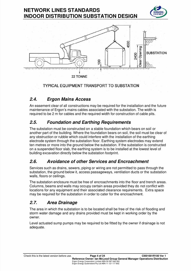
2.3. Equipment Access The transformer is the largest and heaviest item in the substation. It requires double dooraccess directly at ground level from the street so that it can be placed outside thesubstation by crane, slid and winched into final position inside the substation. Pullingeyes are required for the winch. A transformer handling area must be allowed foradjacent to the substation. The grade of the handling area should not exceed 1:20. A6.2m turning circle is required for the mobile crane to navigate around corners.
A carriageway easement of 5500mm (h) X 3500mm (w) is required for the installation orremoval of the transformer from the street to the substation location. The width should beincreased on bends. The easement must have a maximum slope of 1:12.
Note the foregoing requirements must be assessed for each installation and changesmay be required based on substation location and other issues.
The combined weight of the transformer and crane is 31 tonnes.
8/6/2019 CI001001R100 Ver 1 Indoor Dist Substation Design Std
http://slidepdf.com/reader/full/ci001001r100-ver-1-indoor-dist-substation-design-std 5/25
NETWORK LINES STANDARDSINDOOR DISTRIBUTION SUBSTATION DESIGN
Check this is the latest version before use. Page 4 of 24 CI001001R100 Ver 1 Reference Owner: Ian McLeod Group General Manager Operations DistributionErgon Energy Corporation Limited ABN 50 087 646 062Ergon Energy Queensland Pty Ltd ABN 11 121 177 802
2.4. Ergon Mains Access
An easement clear of all constructions may be required for the installation and the futuremaintenance of Ergon’s mains cables associated with the substation. The width isrequired to be 2 m for cables and the required width for construction of cable pits.
2.5. Foundation and Earthing Requirements
The substation must be constructed on a stable foundation which bears on soil oranother part of the building. Where the foundation bears on soil, the soil must be clear ofany obstruction or rubble which could interfere with the installation of the earthing
electrode system through the substation floor. Earthing system electrodes may extendten metres or more into the ground below the substation. If the substation is constructedon a suspended floor slab, the earthing system is to be installed at the lowest level ofbuilding excavation directly below the substation footprint.
2.6. Avoidance of other Services and Encroachment
Services such as drains, sewers, piping or wiring are not permitted to pass through thesubstation, the ground below it, access passageways, ventilation ducts or the substationwalls, floors or ceilings.
The substation enclosure must be free of encroachments into the floor and trench areas.Columns, beams and walls may occupy certain areas provided they do not conflict with
locations for any equipment and their associated clearance requirements. Extra spacemay be required for the substation in order to cater for the encroachment.
2.7. Area Drainage
The area in which the substation is to be located shall be free of the risk of flooding andstorm water damage and any drains provided must be kept in working order by theowner.
Level actuated sump pumps may be required to be fitted by the owner if drainage is notadequate.

8/6/2019 CI001001R100 Ver 1 Indoor Dist Substation Design Std
http://slidepdf.com/reader/full/ci001001r100-ver-1-indoor-dist-substation-design-std 6/25
NETWORK LINES STANDARDSINDOOR DISTRIBUTION SUBSTATION DESIGN
Check this is the latest version before use. Page 5 of 24 CI001001R100 Ver 1 Reference Owner: Ian McLeod Group General Manager Operations DistributionErgon Energy Corporation Limited ABN 50 087 646 062Ergon Energy Queensland Pty Ltd ABN 11 121 177 802
2.8. Hazardous Locations
Ergon’s substation equipment and access route must not be within an area which isclassified as a Hazardous Area as specified in the S.A.A. Wiring Rules.
2.9. Electric and Magnetic Fields (EMF)
The Electricity Supply Association of Australia Limited (ESAA) recommends that itsmembers act prudently in relation to EMF’s when they design and operate their systems.In practical terms, prudent avoidance means designing the substation using standardequipment to minimise their capacity to produce EMF’s and avoid siting them adjacent toareas which contain people or electronic equipment.
Ergon’s standard substation design focuses the sources of Electromagnetic Fieldstowards the middle of the substation. Size and shape are critical factors in limitingEMF’s. The owner can assist to observe the principles of prudent avoidance by providinga substation enclosure of sufficient size and appropriate shape to allow construction to
Ergon’s standard indoor substation.The owner can also assist by allocating a space within the building that is clear fromelectronic equipment for a distance of ten metres in any direction from the substation.The owner should also ensure that consumer’s mains cabling and other associated plantare not sited adjacent to people or electronic equipment.
If EMF shielding is required the owner shall obtain a report from an approved EMFconsultant to determine the extent of the shielding or if any is required. Installation of theshielding shall be subject to Ergon’s acceptance.
2.10. Noise
The Environmental Protection Authority (EPA), local councils and other authorities havethe power to ensure that noise originating from any premises is not the cause forcomplaint. Transformers emit a constant low-pitched hum. Special precautions in sitingthe substation may be necessary, particularly in locating ventilation panels and fans, tolimit noise emission if existing or prospective residential development is within thevicinity.
2.11. Ventilation
Substations require ventilation in order to dissipate heat losses from the electricalequipment. Natural airflow directly to the outside of the building is preferred. Thisgenerally incorporates louvered, weather and vermin proof ventilators in the walls and
doors. Position of ventilators shall be such as to provide cross ventilation across thetransformer. Allow for 1 sq m of Inlet Area and 1 sq m of Outlet Area per 1000 kVA.
Some substations may require forced air cooling controlled by a thermostat. The coolingsystem is such that cool air is drawn through the circulation fan and blown over thetransformer. Exhaust air must be ducted independently and directly to outside air. Thefans shall be started when the temperature in the room reaches 35 degrees Celsius andmay be stopped when the temperature falls below 30 degrees Celsius. This coolingsystem is the responsibility of the owner. Mechanical ventilation drawings must besubmitted to Ergon for approval.
8/6/2019 CI001001R100 Ver 1 Indoor Dist Substation Design Std
http://slidepdf.com/reader/full/ci001001r100-ver-1-indoor-dist-substation-design-std 7/25
NETWORK LINES STANDARDSINDOOR DISTRIBUTION SUBSTATION DESIGN
Check this is the latest version before use. Page 6 of 24 CI001001R100 Ver 1 Reference Owner: Ian McLeod Group General Manager Operations DistributionErgon Energy Corporation Limited ABN 50 087 646 062Ergon Energy Queensland Pty Ltd ABN 11 121 177 802
2.12. Protection from Vehicles
The doors for the substation must be protected from damage by vehicles. The protectionmay be in the form of bollards, which can be removable. Alternatively, equivalentprotection such as a 230mm high kerb with 1500mm clearance to the substation will alsobe considered.
2.13. Future Site Development
Substation locations which restrict future development of the site should be avoided.Relocation of the substation would be extremely costly to the owner.
Future development of the site must not encroach onto the agreed access way to thesubstation.
8/6/2019 CI001001R100 Ver 1 Indoor Dist Substation Design Std
http://slidepdf.com/reader/full/ci001001r100-ver-1-indoor-dist-substation-design-std 8/25
NETWORK LINES STANDARDSINDOOR DISTRIBUTION SUBSTATION DESIGN
Check this is the latest version before use. Page 7 of 24 CI001001R100 Ver 1 Reference Owner: Ian McLeod Group General Manager Operations DistributionErgon Energy Corporation Limited ABN 50 087 646 062Ergon Energy Queensland Pty Ltd ABN 11 121 177 802
3. CONSTRUCTION
3.1. Walls and Ceilings
The substation walls are to be concrete or solid masonry construction. The walls musthave sufficient structural strength to support the weight of any equipment mounted on itwithout collapsing. Maximum load is 400 kN. The areas surrounding any pulling eyeswhich must be attached to the wall are to be suitably reinforced so that the use of thepulling eye does not damage the wall.
The ceiling shall be of concrete construction. It must have sufficient structural strength towithstand 200 kN load at any point.
All materials are to be new and to meet the appropriate Australian standards.
The finish of internal walls and ceiling must be clean and smooth and must be paintedwith two coats of white acrylic paint.
The walls and ceilings must be waterproof and have a 2 hour fire rating. Walls andFloors must be impervious to any oil spillage from main transformers.
3.2. Floors
The substation floor, including trenches, conduits, etc. is to be formed in accordance withthe positions and details shown on Ergon’s drawings and specifications.
The floor is to be designed by a practicing structural engineer and be capable of carryingthe loads of the substation equipment. The floor must carry a transformer load of 7300kg on 4 points anywhere in its area.
The floor must have a level steel trowelled finish.
If the substation floor is laid on natural or filled ground an appropriate waterproofingmembrane is to be placed between the underside of the substation floor and the ground.
Provision is to be incorporated in the floor slab for any floor hauling eyes/anchors.
A transformer landing area is to be provided in all cases. The transformer loading area isto be constructed of reinforced concrete and must have the same load bearingcharacteristics as the substation floor. The minimum size of the landing area must be2400 mm wide by 2450 mm length and will be located immediately in front of thetransformer access door/s. The landing area must have a slight slope such that waterflows away from the doors and it must be at the same relative level as the substationfloor to allow equipment to be rolled into the substation directly from the landing area.
3.3. Waterproofing
The substation shall be constructed using reliable waterproof materials, waterproofconstruction methods and site drainage to protect the substation equipment againstexposure to dampness and water throughout its life.
The site shall be effectively drained to keep the area outside the substation freelydrained and dry. Stormwater drainage systems shall be designed and provided toindustry best-practice standards.
Site drainage shall be kept in working order by the owner.
The siting of the substation with its floor level below the level of the building storm water
system shall not be permissible.
8/6/2019 CI001001R100 Ver 1 Indoor Dist Substation Design Std
http://slidepdf.com/reader/full/ci001001r100-ver-1-indoor-dist-substation-design-std 9/25
NETWORK LINES STANDARDSINDOOR DISTRIBUTION SUBSTATION DESIGN
Check this is the latest version before use. Page 8 of 24 CI001001R100 Ver 1 Reference Owner: Ian McLeod Group General Manager Operations DistributionErgon Energy Corporation Limited ABN 50 087 646 062Ergon Energy Queensland Pty Ltd ABN 11 121 177 802
All necessary horizontal and vertical damp courses must be provided and the substationroom shall have dry wall, floor and ceiling conditions before acceptance for installation ofsubstation equipment.
3.4. Ventilation
Substations require special attention to ventilation in order to dissipate heat losses fromelectrical equipment. Wherever possible, natural air flow to the outside of the building willbe used. Forced ventilation should be used where natural ventilation is not practicable.Forced ventilation by means of fan(s) must be designed, supplied and installed by theowner to Ergon’s requirements.
The ventilation must be sufficient to maintain a maximum room temperature of 35degrees Celsius when all transformers are operating at nameplate rating. Air inlets andoutlets must be arranged to achieve an even distribution of air flow over thetransformers.
Substantial vertical separation is required between inlet and outlet openings. Inlet and
outlet openings should preferably be clear of pedestrian areas and must be located toprevent entry of noxious gases such as vehicle exhausts, pollutants such as smoke,soot, dust, ash etc. Air being removed from an internal substation must be directly andindependently ducted to outside air.
3.4.1. Natural Ventilation
The position of the vents must be directly to outside air, if this is not achievable thenforced ventilation is required. The design calls for the owner to provide vermin proof,weather proof louvered vents of a specified design in the walls and/or doors in orderto achieve natural ventilation. Position of ventilators shall be such as to provide crossventilation across the transformer. Allow for 1 sq m of Inlet Area and 1 sq m of Outlet
Area per 1000 kVA. The areas outside the louvers must not be subjected to fire risk.In some cases, where the roof of the substation is external, weatherproof roofventilators may also be specified. It is important where roof vents are installed thatthey are fixed securely.
3.4.2. Forced Ventilation
The forced ventilation system comprising fans, ducting and inlet/outlet vents must bedesigned, supplied and installed by the owner. The air flow through the ventilation willbe checked by Ergon before final approval. The control devices and wiring for thestarting and stopping of the fan(s) will be supplied and installed by the owner. It isErgon’s requirement that the forced ventilation system be designed so that the cool
inlet air is drawn through the circulation fan and then blown over the transformersand not the other way around. Note: Heat losses are taken as 25kW per transformer.
In all circumstances the fans must be installed inside the substation and all wiringcontained within the substation. The outlet ventilation shall be dischargedindependently and directly to open air. All vents are to be fitted with fire shutters.
Fans audible noise level must not exceed 41dB at a distance of 1metre from thesource.

8/6/2019 CI001001R100 Ver 1 Indoor Dist Substation Design Std
http://slidepdf.com/reader/full/ci001001r100-ver-1-indoor-dist-substation-design-std 10/25
NETWORK LINES STANDARDSINDOOR DISTRIBUTION SUBSTATION DESIGN
Check this is the latest version before use. Page 9 of 24 CI001001R100 Ver 1 Reference Owner: Ian McLeod Group General Manager Operations DistributionErgon Energy Corporation Limited ABN 50 087 646 062Ergon Energy Queensland Pty Ltd ABN 11 121 177 802
3.4.3. Special Requirements for Ventilation Ducts
Substation ventilation ducts must not contain other services, give access to otherportions of the building or form part of the ventilation system for the building. Thestrength and fire rating of the walls of ventilation ducts are required to be the same as
those specified for substation walls where fire dampers are not installed. Normal airconditioning duct construction is acceptable only where fire dampers are installed onwall penetrations where ventilation ducts enter or leave the substation.
3.5. Fire
Ergon substations are designed to contain any products of a fire within the enclosure.Self containment has the added advantage of also being self smothering and thisensures that there is no spread of fire to other parts of the building.
All construction materials used in the substation room including walls, ceilings and floors,doors and vents must be constructed from noncombustible materials. Any wall, ceiling or
floor shared with or adjoining another part of the building must be treated as a fire wall asdefined in the Building Code of Australia and must have a minimum fire rating of twohours, effectively segregating the substation from the rest of the building.
It is essential that these ratings be maintained for any penetration of the wall for cablesor other services. The sealing of the penetration must be done strictly in accordance withthe manufacturer's instructions.
Ergon does not have a requirement to fit fire detection or alarm systems within thesubstation. The owner is advised that where the installation of fire detection or alarmsystems is required, consideration must be given to the need for continued access forinspection and maintenance of the system. Depending on the location of the firedetection / alarm system it may be necessary to have a shutdown of the substation for
maintenance or inspection. Such needs shall incur an ongoing charge for providingaccess to the substation and any shutdown required.
3.6. Oil Containment
Provision must be made within the substation to contain any oil spillage (in the unlikelyevent of a transformer tank failure) and slope to a common point. Spillage fromtransformers needs to be contained within the substation and be 110% of oil volume asper the AS1940 and EPA Bunding Guidelines.
This is usually achieved by draining any oil spillage into the trench. In order to preventany flow out through the conduits and into the surrounding stormwater system the loweredge of the conduits shall be a minimum of 100 mm above the trench floor.
This is the minimum requirement. In some regions, due to local regulations, precautionssuch as an oil trap may be required.
3.7. Hauling Eyes
Where required, anchors and/or pulling eyes (provided by the owner) are to be installedin the floor, walls or ceiling in the position shown on the layout drawings and in a mannerto achieve the working load specified. Normally for a single cable- trench, singletransformer substation two pulling eyes will be required - one for the cables and one forthe transformer. However further pulling eyes may be required for more complexsubstations with multiple cable trenches or multiple transformers, or where access to
install cables or transformers is restricted. All anchors and pulling eyes shall be clearlyand permanently stamped to indicate its safe working load. Pulling eyes located in floors

8/6/2019 CI001001R100 Ver 1 Indoor Dist Substation Design Std
http://slidepdf.com/reader/full/ci001001r100-ver-1-indoor-dist-substation-design-std 11/25
NETWORK LINES STANDARDSINDOOR DISTRIBUTION SUBSTATION DESIGN
Check this is the latest version before use. Page 10 of 24 CI001001R100 Ver 1 Reference Owner: Ian McLeod Group General Manager Operations DistributionErgon Energy Corporation Limited ABN 50 087 646 062Ergon Energy Queensland Pty Ltd ABN 11 121 177 802
shall be removable and, upon removal, the floor surface shall be level to avoid a triphazard. Threaded recesses shall be provided with reusable removable plugs to excludeingress of foreign matter.
Normal pulling eye requirements are as follows:
3.7.1. For Cables
A single pulling eye cast into the floor of the substation shall be provided at thelocation shown on the layout drawings. The pulling eye must have a minimumworking load of 10 tonne with a 5 tonne load applied in any direction and a minimumeye bolt hole diameter of 40 mm. Pulling eyes may also be specified for intermediatecable pits outside the substation where these are required on the owner's property.
3.7.2. For Transformers
One or more pulling eyes and mounting bracket arrangement cast in or suitablyanchored to the substation floor or wall is required in the position shown on thesubstation layout drawings. The pulling eye and mounting plate arrangement must
have a minimum working load of 10 tonne and a minimum eyebolt hole diameter of40 mm.
3.8. Earths
A buried earthing electrode system is necessary for the substation. The earthing systemshall consist of earth electrodes. The system to be used, location and number ofconduits will be detailed on the approved Ergon drawings.
Additional electrodes may need to be installed outside the substation area and additionaleasements may be required if appropriate earth resistance readings cannot be achieved.
Ergon will install the earthing grid prior to the floor slab being poured. Appropriate noticeshall be given to indicate when this work can be carried out. The developer shall ensurethat the earthing leads are brought through the floor into substation.
All unbonded exposed metal work within the substation will be electrically bonded to theearthing system. This includes metal doors and reinforcing in the floor. If a part cannotbe adequately bonded, it will be constructed from a suitable insulating material instead ofmetal. The developer shall provide a connection point to the floor reinforcing at aconvenient location as advised by Ergon’s representative.
3.9. Trenches
Trench walls must be able to support transformer loads applied to the substation floorwithin 300 mm of the cable trench. Trenches must be watertight and must not be
connected to the outside drainage system.Provision is to be incorporated in the trench walls for any hauling eyes/anchors.
Grid type covers manufactured of galvanized steel or other approved material must beprovided and installed on all trenches. These covers must be suitably constructed tosupport pedestrian traffic. Trench covers must be divided into sections of maximum 1metre lengths, each weighing not more than 20 kg.
The trench cover when laid across the trench shall be flush with the surrounding floorlevel. The minimum rebate width required to support the trench cover shall be inaccordance with the manufacturer’s recommendation. The cover shall fit snugly into therebate so that there is negligible sideways movement.

8/6/2019 CI001001R100 Ver 1 Indoor Dist Substation Design Std
http://slidepdf.com/reader/full/ci001001r100-ver-1-indoor-dist-substation-design-std 12/25
NETWORK LINES STANDARDSINDOOR DISTRIBUTION SUBSTATION DESIGN
Check this is the latest version before use. Page 11 of 24 CI001001R100 Ver 1 Reference Owner: Ian McLeod Group General Manager Operations DistributionErgon Energy Corporation Limited ABN 50 087 646 062Ergon Energy Queensland Pty Ltd ABN 11 121 177 802
The owner shall construct a 300 X 300 mm deep drain sump in a suitable location in thetrench floor. A sump pump shall be installed where required. An oil trap shall be installedif required by local regulations.
There may be situations where a trench is not practical such as when the floor is asuspended slab. In this case cable trays shall be installed under the floor, along thetrench lines, with conduits through the floor to bring the cables up into the substation.The width of the trays shall be calculated from the number of cables required to beinstalled. This arrangement will reduce the head height in the chamber below and needsto be considered by the developer.
3.10. Doors All doors and frames shall be 2 hour fire rated (except where vents are installed) andwaterproof. The owner will attach the appropriate locks and handles to suit the directionof opening as indicated on Ergon’s drawing. The cylinders will be changed to fit Ergon’skey when the substation is handed over.
The locks shall be such that a key only entry is provided from the outside and a handonly from the inside.
With double doors, the door to be opened first will be nominated on the layout drawings.The second leaf shall have pad bolts installed.
8/6/2019 CI001001R100 Ver 1 Indoor Dist Substation Design Std
http://slidepdf.com/reader/full/ci001001r100-ver-1-indoor-dist-substation-design-std 13/25
NETWORK LINES STANDARDSINDOOR DISTRIBUTION SUBSTATION DESIGN
Check this is the latest version before use. Page 12 of 24 CI001001R100 Ver 1 Reference Owner: Ian McLeod Group General Manager Operations DistributionErgon Energy Corporation Limited ABN 50 087 646 062Ergon Energy Queensland Pty Ltd ABN 11 121 177 802
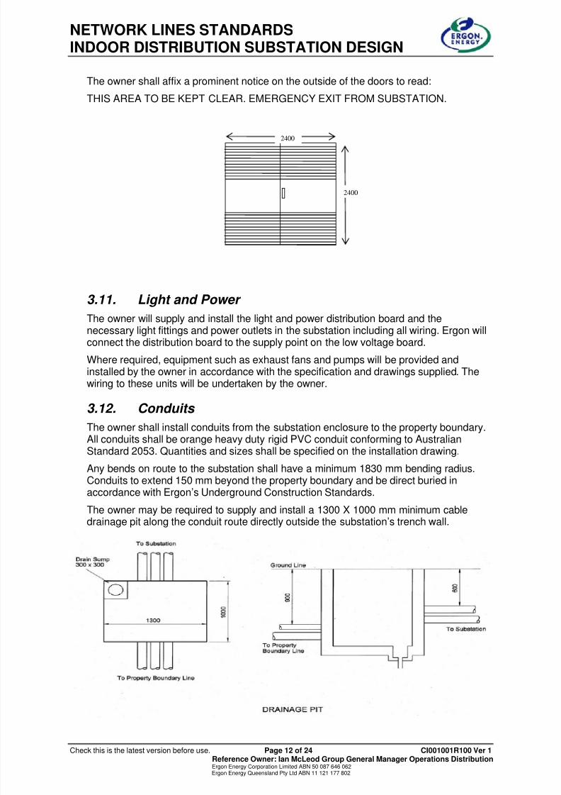
The owner shall affix a prominent notice on the outside of the doors to read:
THIS AREA TO BE KEPT CLEAR. EMERGENCY EXIT FROM SUBSTATION.
3.11. Light and Power
The owner will supply and install the light and power distribution board and thenecessary light fittings and power outlets in the substation including all wiring. Ergon willconnect the distribution board to the supply point on the low voltage board.
Where required, equipment such as exhaust fans and pumps will be provided andinstalled by the owner in accordance with the specification and drawings supplied. Thewiring to these units will be undertaken by the owner.
3.12. Conduits
The owner shall install conduits from the substation enclosure to the property boundary.All conduits shall be orange heavy duty rigid PVC conduit conforming to AustralianStandard 2053. Quantities and sizes shall be specified on the installation drawing.
Any bends on route to the substation shall have a minimum 1830 mm bending radius.Conduits to extend 150 mm beyond the property boundary and be direct buried inaccordance with Ergon’s Underground Construction Standards.
The owner may be required to supply and install a 1300 X 1000 mm minimum cabledrainage pit along the conduit route directly outside the substation’s trench wall.
2400
2400

8/6/2019 CI001001R100 Ver 1 Indoor Dist Substation Design Std
http://slidepdf.com/reader/full/ci001001r100-ver-1-indoor-dist-substation-design-std 14/25
NETWORK LINES STANDARDSINDOOR DISTRIBUTION SUBSTATION DESIGN
Check this is the latest version before use. Page 13 of 24 CI001001R100 Ver 1 Reference Owner: Ian McLeod Group General Manager Operations DistributionErgon Energy Corporation Limited ABN 50 087 646 062Ergon Energy Queensland Pty Ltd ABN 11 121 177 802
4. ELECTRICAL DESIGN STANDARD
4.1. Transformers
The transformers will come from Ergon Energy’s stores and will typically follow the
present contract and technical specifications. The substation is designed to cater forbushings on opposite sides of the transformer.
The bushings on the transformers should be covered, preferably by using cable entrytransformers. If not, then suitable earthed metal cable covers shall be installed on thetransformer to remove all bare live connections.
The transformer ratings are 500 kVA, 750 kVA, 1000 kVA and 1500 kVA.
Up to three transformers can be installed in the one substation. The transformers mustnot be permanently paralleled on the low voltage side.
4.2. High Voltage Switchgear
Three types of high voltage switchgear are available which will cover all applications.
I. Ring Main Unit comprising two feeder cable switches and one fused switch/circuitbreaker for one transformer,
II. Ring Main Unit comprising two feeder cable switches and two fusedswitches/circuit breakers for two transformers,
III. Interfeeder Tie Unit comprising three feeder cable switches and one fused switch
for one transformer.
A three transformer substation will contain a combination of type II and I or type II and III.
Fuses will protect the 500, 750 and 1000 kVA transformers; circuit breakers will protect1500 kVA transformers.
Switch SwitchFuse
Switch SwitchFuse Fuse
Switch SwitchSwitch Fuse

8/6/2019 CI001001R100 Ver 1 Indoor Dist Substation Design Std
http://slidepdf.com/reader/full/ci001001r100-ver-1-indoor-dist-substation-design-std 15/25
NETWORK LINES STANDARDSINDOOR DISTRIBUTION SUBSTATION DESIGN
Check this is the latest version before use. Page 14 of 24 CI001001R100 Ver 1 Reference Owner: Ian McLeod Group General Manager Operations DistributionErgon Energy Corporation Limited ABN 50 087 646 062Ergon Energy Queensland Pty Ltd ABN 11 121 177 802
4.3. Low Voltage Switchboard
The low voltage switchboard will have a load break switch for each transformer. Thecustomer’s supply is to be protected with either fuses – up to 1200 Amp (two striplefuses in parallel) – or circuit breakers – above 1200 amps. The street circuits should befused up to 400 amps using Ergon’s standard striple fuse.
In multi-transformer substations there shall be a facility for paralleling the low voltagesides of the transformers inside the substation. Provision of low voltage parallels in theconsumer’s installation could be installed if the customer requests it, but must containsuitable locking facilities only operable by Ergon Energy. Under no circumstances shouldthe transformers be permanently paralleled. They should only be temporarily paralleledduring switching procedures.
The low voltage board also provides the facility for supplying the substation’s light andpower and ventilation and sump pump equipment if installed and also contains maximumdemand indicators.
4.4. Customer’s Connection
The customer’s supply should not come direct from the transformer bushings.
The location of the point-of-supply needs to be formalised in a written agreement. Thelocation is typically described as a point on the low voltage board.
4.5. Cables
The cables installed between the transformer and the high voltage switchgear, thetransformer and the low voltage board and the low voltage board to the street should bechosen from the standard range of cables currently used by Ergon Energy.
1. High voltage switchgear to transformer: 35 sq mm
2. Transformer to low voltage board:
a) 500 kVA: two 185 sq mm copper per phase and neutral,
b) 750 kVA: three 185 sq mm copper per phase and neutral,
c) 1000 kVA: four 185 sq mm copper per phase and neutral,
d) 1500 kVA: six 185 sq mm copper per phase and neutral.
3. Low voltage board to street: 240 sq mm
4.6. Earthing
All earthing and bonding shall be designed and installed by Ergon.
4.6.1. CMEN
The preferred earthing arrangement for Indoor substations is the CMEN systemwhich utilises common HV and LV earthing systems. This system requires a value ofthe combined earth resistance to be one ohm or less.
This is generally achieved by connection to an extensive interconnected LV neutralsystem. Guidelines for the application of a CMEN system are contained in thedocument “Guidelines for adoption of CMEN earthing systems” – available on theLine Standards intranet site.
8/6/2019 CI001001R100 Ver 1 Indoor Dist Substation Design Std
http://slidepdf.com/reader/full/ci001001r100-ver-1-indoor-dist-substation-design-std 16/25
NETWORK LINES STANDARDSINDOOR DISTRIBUTION SUBSTATION DESIGN
Check this is the latest version before use. Page 15 of 24 CI001001R100 Ver 1 Reference Owner: Ian McLeod Group General Manager Operations DistributionErgon Energy Corporation Limited ABN 50 087 646 062Ergon Energy Queensland Pty Ltd ABN 11 121 177 802
Earthing requirements for indoor substations will be generally in accordance with Drg3301 in the Distribution Design manual and Drg 5013 in the UndergroundConstruction manual.
Requirements are for a local earth of 10 ohm or less at the substation location and
supplementary earthing to achieve the required one ohm or less. This is bestachieved via the neutral of a 240 sq mm LV XPLE Al cable to an interconnectedneutral system. Alternatively, if the site is not in proximity to an LV network, theinstallation of a supplementary earthing system to achieve the required one ohm orless would be required.
4.6.2. Separately Earthed System
If the criteria for adoption of a CMEN system cannot be practically achieved withoutexcessive expenditure, a separately earthed system may be adopted.
This would generally be in accordance with the requirements for separately earthedPad mount substations, Drg 5014 of the Underground Construction manual, and
would require the installation of separate HV and LV earthing systems of 10 ohm orless separated electrically by a distance of at least 3 m.
The provisions of Drg 5014 sheet would be required to be met and this wouldpreclude the installation of auxiliary equipment such as ventilation fans or heaters.
4.6.3. General Requirements
All unbonded exposed metal work within the substation should be electrically bondedto the earthing system. This includes metal doors and reinforcing in the floor. If a partcannot be adequately bonded, it will be constructed from a suitable insulatingmaterial instead of metal. All earthing straps will have a minimum area of 35 sq mmcopper.
The earthing system is to be a stand alone type not connected to the buildingreinforcing bars with the exception of reinforcing in the floor and walls of thesubstation enclosure which should be electrically separate from the remainder of thebuilding. It must be well clear of building lightning protection and should not beconnected to the earth bar of any switchboard other than the earth bar inside thesubstation.
The earth cable size shall be a minimum of 35 sq mm copper. At locations where theHV fault level exceeds an equivalent I² t figure 4.6 kA for one second, this shall beincreased to 70 sq mm by use of duplicated 35 sq mm cable. This will generally onlybe required for locations very close to a zone substation.
If separately earthed, the LV earthing system should be insulated and separatedelectrically from bonded substation earthing system (bonded metal doors, exposedmetal, reinforcement, HV cable screen earth etc).
4.7. Labels
Labels are vital in the substation on the low voltage board, high voltage switchgearand transformers. The description on each label should be determined by thedesigner or the local operator. They should be ordered/manufactured and appliedprior to substation commissioning.

8/6/2019 CI001001R100 Ver 1 Indoor Dist Substation Design Std
http://slidepdf.com/reader/full/ci001001r100-ver-1-indoor-dist-substation-design-std 17/25
NETWORK LINES STANDARDSINDOOR DISTRIBUTION SUBSTATION DESIGN
Check this is the latest version before use. Page 16 of 24 CI001001R100 Ver 1 Reference Owner: Ian McLeod Group General Manager Operations DistributionErgon Energy Corporation Limited ABN 50 087 646 062Ergon Energy Queensland Pty Ltd ABN 11 121 177 802
4.8. Fault Levels
• Minimum 415 volt switchboard fault rating = 50 kA
• 11 kV nominal fault level = 13 kA
• 22 kV nominal fault level = 13 kA
(Check these levels.)
4.9. Safety and Clearances
Substation equipment shall be located with due regard to safety of personnel working inthe substation. A clear passageway at least 1000 mm wide shall be allowed from eachitem of switchgear to the personnel access doors to the substation. A clearance of atleast 1500 mm out from the front of the high voltage and low voltage switchgear shall beallowed for safe operations.
Equipment shall be located such that any item of equipment may be removed from thesubstation with the remaining equipment in service and under load. A passageway of atleast 2500 mm wide shall be allowed for transformers and 1500 mm wide for the highvoltage and low voltage boards.
The transformers shall be sited with a clearance of 500 mm away from walls, othertransformers and switchgear in order to allow free air flow.
8/6/2019 CI001001R100 Ver 1 Indoor Dist Substation Design Std
http://slidepdf.com/reader/full/ci001001r100-ver-1-indoor-dist-substation-design-std 18/25
NETWORK LINES STANDARDSINDOOR DISTRIBUTION SUBSTATION DESIGN
Check this is the latest version before use. Page 17 of 24 CI001001R100 Ver 1 Reference Owner: Ian McLeod Group General Manager Operations DistributionErgon Energy Corporation Limited ABN 50 087 646 062Ergon Energy Queensland Pty Ltd ABN 11 121 177 802
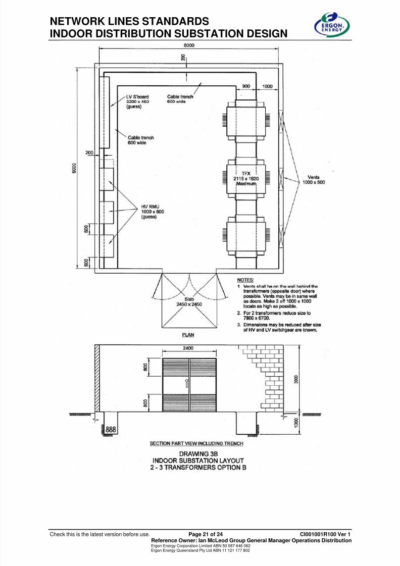
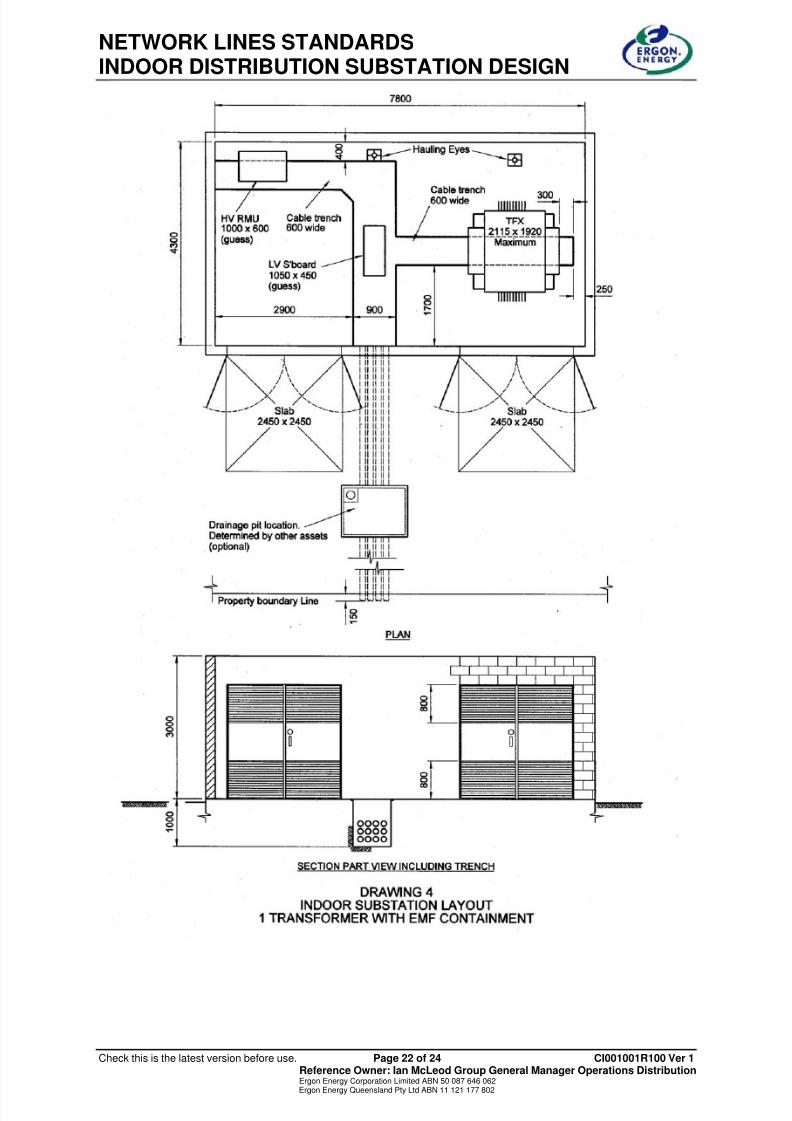
5. LAYOUTS – TYPICAL
NOTES
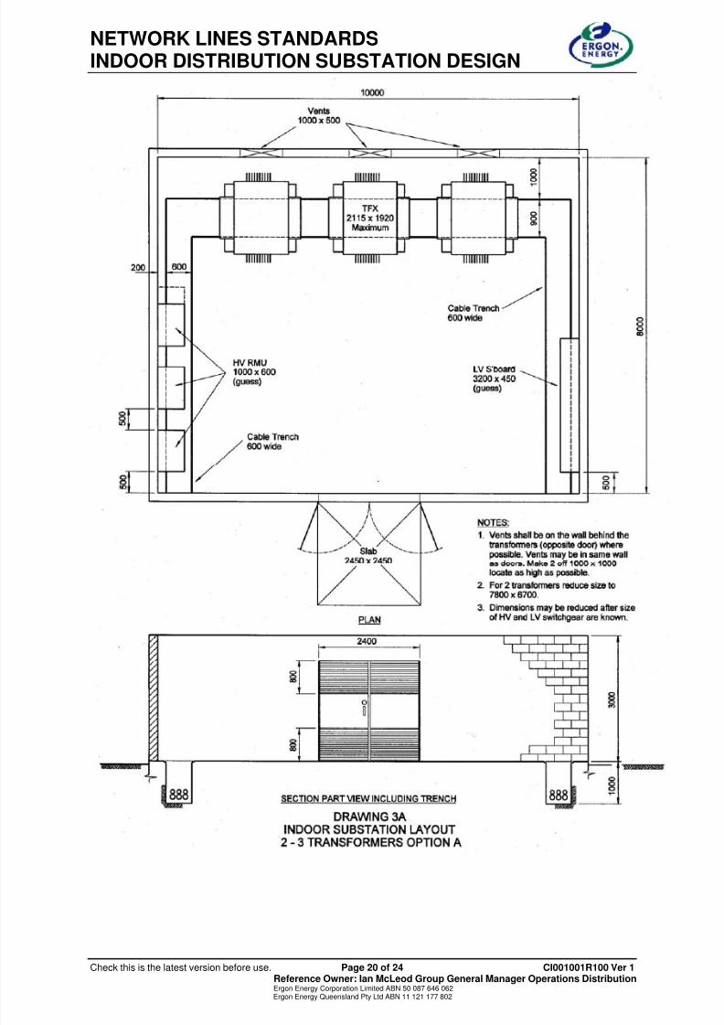
The following layouts are typical only and should not be used as construction drawings.
Some designs achieve minimum EMF emission by installing the low voltage cables andswitchboard in a trench down the middle of the room. This adds substantially to thespace requirements. It is possible to reduce this space but only by sacrificing EMFcontainment.
The substations are designed for 11 kV and 1500 kVA transformers. The spacerequirements for 22 kV padmount transformers need to be checked.
A drainage pit outside the substation is shown as optional. It can be installed if drainageis an issue or if needed to ease cable installation.
Each substation is unique and the space requirements shown in the sample layouts maynot be available. The following rules should be followed when designing odd shaped
substations.
• Size of transformer = 2000 X 2000
• Transformer clearance to walls and other transformers = 500
• Allow room to replace any transformer whilst other equipment is alive.
• LV and HV switchgear
o clearance at front = 1500
o clearance at sides = 500
• The LV and HV switchgear should be near the door.
• A clear passageway at least 1000 mm wide shall be allowed from each item ofswitchgear to the access door.

8/6/2019 CI001001R100 Ver 1 Indoor Dist Substation Design Std
http://slidepdf.com/reader/full/ci001001r100-ver-1-indoor-dist-substation-design-std 19/25
NETWORK LINES STANDARDSINDOOR DISTRIBUTION SUBSTATION DESIGN
Check this is the latest version before use. Page 18 of 24 CI001001R100 Ver 1 Reference Owner: Ian McLeod Group General Manager Operations DistributionErgon Energy Corporation Limited ABN 50 087 646 062Ergon Energy Queensland Pty Ltd ABN 11 121 177 802

8/6/2019 CI001001R100 Ver 1 Indoor Dist Substation Design Std
http://slidepdf.com/reader/full/ci001001r100-ver-1-indoor-dist-substation-design-std 20/25
NETWORK LINES STANDARDSINDOOR DISTRIBUTION SUBSTATION DESIGN
Check this is the latest version before use. Page 19 of 24 CI001001R100 Ver 1 Reference Owner: Ian McLeod Group General Manager Operations DistributionErgon Energy Corporation Limited ABN 50 087 646 062Ergon Energy Queensland Pty Ltd ABN 11 121 177 802
8/6/2019 CI001001R100 Ver 1 Indoor Dist Substation Design Std
http://slidepdf.com/reader/full/ci001001r100-ver-1-indoor-dist-substation-design-std 21/25
NETWORK LINES STANDARDSINDOOR DISTRIBUTION SUBSTATION DESIGN
Check this is the latest version before use. Page 20 of 24 CI001001R100 Ver 1 Reference Owner: Ian McLeod Group General Manager Operations DistributionErgon Energy Corporation Limited ABN 50 087 646 062Ergon Energy Queensland Pty Ltd ABN 11 121 177 802
8/6/2019 CI001001R100 Ver 1 Indoor Dist Substation Design Std
http://slidepdf.com/reader/full/ci001001r100-ver-1-indoor-dist-substation-design-std 22/25
NETWORK LINES STANDARDSINDOOR DISTRIBUTION SUBSTATION DESIGN
Check this is the latest version before use. Page 21 of 24 CI001001R100 Ver 1 Reference Owner: Ian McLeod Group General Manager Operations DistributionErgon Energy Corporation Limited ABN 50 087 646 062Ergon Energy Queensland Pty Ltd ABN 11 121 177 802
8/6/2019 CI001001R100 Ver 1 Indoor Dist Substation Design Std
http://slidepdf.com/reader/full/ci001001r100-ver-1-indoor-dist-substation-design-std 23/25
NETWORK LINES STANDARDSINDOOR DISTRIBUTION SUBSTATION DESIGN
Check this is the latest version before use. Page 22 of 24 CI001001R100 Ver 1 Reference Owner: Ian McLeod Group General Manager Operations DistributionErgon Energy Corporation Limited ABN 50 087 646 062Ergon Energy Queensland Pty Ltd ABN 11 121 177 802

8/6/2019 CI001001R100 Ver 1 Indoor Dist Substation Design Std
http://slidepdf.com/reader/full/ci001001r100-ver-1-indoor-dist-substation-design-std 24/25
NETWORK LINES STANDARDSINDOOR DISTRIBUTION SUBSTATION DESIGN
Check this is the latest version before use. Page 23 of 24 CI001001R100 Ver 1 Reference Owner: Ian McLeod Group General Manager Operations DistributionErgon Energy Corporation Limited ABN 50 087 646 062Ergon Energy Queensland Pty Ltd ABN 11 121 177 802

8/6/2019 CI001001R100 Ver 1 Indoor Dist Substation Design Std
http://slidepdf.com/reader/full/ci001001r100-ver-1-indoor-dist-substation-design-std 25/25
NETWORK LINES STANDARDSINDOOR DISTRIBUTION SUBSTATION DESIGN