Houston Metro TPSS SE1 Substation Replacement...IEEE Std 242 Recommended Practice for Protection and...
123
Houston Metro TPSS SE-1 Substation Replacement 100% Submittal Houston Metro TPSS SE1 Substation Replacement TECHNICAL SPECIFICATION 01/22/2019 100% Submittal PZ DV JS REV DATE REASON FOR REVISION BY CHECK APPR Document Number
Transcript of Houston Metro TPSS SE1 Substation Replacement...IEEE Std 242 Recommended Practice for Protection and...

Houston Metro TPSS SE-1 Substation Replacement 100% Submittal
Houston MetroTPSS SE1 Substation Replacement
TECHNICAL SPECIFICATION
01/22/2019 100% Submittal PZ DV JSREV DATE REASON FOR REVISION BY CHECK APPR
Document Number

TABLE OF CONTENTS – TECHNICAL SPECIFICATIONS PAGE 1
100% Submittal – TABLE OF CONTENTS
DIVISION 1 – GENERAL REQUIREMENTS
DIVISION 18 – TRANSPORTATION
STRUCTURAL (OMEGA)
SECTION TITLE
(Division 1 – General Requirements to be provided by Metro as part ofprocurement.)
SECTION TITLE
18020 MAIN TRACTION POWER SUBSTATION
18201 WIRE AND CABLE FOR TRACTION POWER
18220 DC SURGE ARRESTERS
18450 GROUNDING
18950 INSTALLATION VERIFICATION TESTING
SECTION TITLE
S420 CONCRETE SUBSTRUCTURES
S441 STEEL STRUCTURES
S442 METAL STRUCTURES
Houston Metro TPSS SE-1 Substation Replacement 100% Submittal
18020-1 100% DESIGN SUBMITTAL
SECTION 18020
MAIN TRACTION POWER SUBSTATION
PART 1 – GENERAL
1.01 SUMMARY
A. Description1. Traction power substation shall be package-type unit and designed to
minimize on-site construction and installation costs. The traction powersubstation shall match the existing substation dimensions, weight,equipment arrangement and floor opening to utilize existing conduit stub-ups.
2. Substation equipment shall be housed in a self-supporting andtransportable enclosure suitable for outdoor installation.
3. All equipment, with like function, shall be interchangeable within andbetween existing METRO substations.
4. The new substation shall be installed on raised foundations.5. The traction power supply system is designed with minimum functional life
expectancy of 30 years.
1.02 REFERENCES
A. Equipment Complies with applicable provisions of the following references:
ANSI C2 National Electrical Safety CodeANSI C29.1 Test Methods for Electric Power InsulatorsANSI C37.04 Standard Rating Structure for AC High-Voltage Circuit
Breakers Rated on Symmetrical Current BasisANSI C37.06 Preferred Ratings and Related Required Capabilities for AC
High-Voltage Circuit Breakers Rated on Symmetrical CurrentBasis
ANSI C37.09 Test Procedures for AC High-Voltage Circuit Breakers Ratedon a Symmetrical Current Basis

Houston Metro TPSS SE-1 Substation Replacement 100% Submittal
18020-2 100% DESIGN SUBMITTAL
ANSI C37.010 Application Guide for AC High-Voltage Circuit Breaker Ratedon a Symmetrical Current Basis
ANSI C37.011 Application Guide for Transient Recovery Voltage for ACHigh-Voltage Circuit Breakers Rated on a SymmetricalCurrent Basis
ANSI C37.012 Application Guide for Capacitance Current Switching for ACHigh-Voltage Circuit Breakers Rated on Symmetrical CurrentBasis
ANSI C37.1 Definition, Specification, and Analysis of Systems Used forSupervisory Control, Data Acquisition, and AutomaticControl
ANSI C37.2 Standard Electrical Power System Device Function NumbersANSI C37.11 American National Standard Requirements for Electrical
Control for AC High-Voltage Circuit Breakers Rated on aSymmetrical Current Basis and a Total Current Basis
ANSI C37.13 Low-Voltage AC Power Circuit Breakers Used in EnclosuresANSI C37.14 Low Voltage Direct-Current Power Circuit Breakers Used in
EnclosuresANSI C37.16 Low-Voltage Power Circuit Breaker and AC Power Circuit
ProtectorsANSI C37.20.1 Metal-Enclosed Low-Voltage Power Circuit Breaker
SwitchgearANSI C37.20.2 Metal-Clad and Station-Type Cubicle SwitchgearANSI C37.21 Control SwitchboardsANSI C37.30 Definitions and Requirements for High-Voltage Air Switches,
Insulators, and Busbar SupportsANSI C37.32 High-Voltage Air Switches, Busbar Supports, and Switch
Accessories –Schedules of Preferred Ratings,Manufacturing Specifications, and Application Guide
ANSI C37.33 Rated Control Voltages and Their Ranges for High-VoltageAir Switches
ANSI C37.34 Test Code for High-Voltage Test SwitchesANSI C37.35 Application, Installation, Operation, and Maintenance of
High-Voltage Air Disconnecting and Load InterrupterSwitches
ANSI C37.40 Service Conditions and Definitions for High-Voltage Fuses,Distribution Enclosed Single-Pole Air Switches, FusedDisconnecting Switches, and Accessories
ANSI C37.41 Design Tests for High-Voltage Fuses, Distribution enclosedSingle-Pole Air Switches, Fused Disconnecting Switches,and Accessories
ANSI C37.46 Specifications for Power fuses and Fused DisconnectingSwitches
ANSI C37.47 Specifications for Distribution Fused Disconnecting SwitchesFused Supports and Current Limiting Fuses
ANSI C37.48 Application, Operation, and Maintenance of High-VoltageFuses, Distribution Enclosed Single-Pole Air Switches FusedDisconnecting Switches, and Accessories

Houston Metro TPSS SE-1 Substation Replacement 100% Submittal
18020-3 100% DESIGN SUBMITTAL
ANSI C37.50 Standard Test Procedures for Low Voltage AC Power CircuitBreakers Used in Enclosures.
ANSI C37.54 Indoor Alternating-Current High-Voltage Circuit BreakersApplied as Removable Elements in Metal-EnclosedSwitchgear Assemblies –Conformance Test Procedures
ANSI C37.55 Metal-Clad Switchgear Assemblies - Conformance TestProcedures
ANSI C37.58 Indoor AC Medium-Voltage Switches for Used in Metal-Enclosed Switchgear - Conformance Test Procedures
ANSI C37.90 Relays and device Systems Associated with Electric PowerApparatus
ANSI C37.90.1 Standard Surge Withstand Capability (SWC) Tests forProtective devices and device Systems
ANSI C37.97 Protective device Applications to Power System BusbarsANSI C37.100 Definitions for Power SwitchgearANSI C39.1 Requirements for Electrical Analog Indicating InstrumentsANSI C57.12.00 General Requirements for Distribution, Power, and
Regulating TransformersANSI C57.12.01 General Requirements for Dry-Type Distribution and Power,
and Power TransformersANSI C57.12.10 Requirements for Transformers 23000 Volts and below
833/958 through 60000/80000/10000 kVA, Three PhaseANSI C57.12.70 Terminal Markings and Connections for Distribution and
Power TransformersANSI C57.12.91 Standard for Dry-type TransformersANSI C57.13 Requirements for Instrument TransformersANSI C80.1 Specification for Fittings for Rigid Steel Conduit, Zinc CoatedANSI C80.3 Specification for Electrical Metallic Tubing, Zinc Coated.ANSI C80.4 Specification for Fittings for Rigid Metal Conduit and
Electrical Metallic TubingANSI C84.1 Voltage Ratings for Electric Power Systems and EquipmentANSI C92.1 Voltage Values for Preferred Transient Insulation LevelsANSI X3.15 Standard for Bit Sequencing of ASCII in Serial-By-Bit Data
TransmissionASCII General American National Standard CodeASTM A6 Specification for General Requirements for Delivery of
Rolled Steel Plates, Shapes, Sheet Piling, and Bars forStructural Used
ASTM A36 Structural SteelASTM A53 Standard Specification for Pipe, Steel, Black and Hot-
Dipped, Zinc-Coated Welded and SeamlessASTM A370 Standard Methods and Definition for Mechanical Testing of
Steel ProductsASTM A384 Safeguarding Against Warpage and Distortion During Hot-
Dip Galvanizing of Steel AssembliesASTM A475 Specification for Zinc Coated Steel-Wire StrandASTM B3 Specification for Soft or Annealed Copper WireASTM B8 Specifications for Concentric-Lay Stranded Copper
Conductor.

Houston Metro TPSS SE-1 Substation Replacement 100% Submittal
18020-4 100% DESIGN SUBMITTAL
ASTM B33 Specification for Tinned Soft or Annealed Copper Wire forElectrical Purposes
ASTM B47 Specifications for Solid Grooved Copper Contact WireASTM B105 Hard-Drawn Copper Alloy Wires for Electrical ConnectionsASTM B173 Specification for Rope-Lay-Stranded Copper Conductors
Having Concentric-Stranded Members, for ElectricalConductors
ASTM B174 Specification for Bunch-Stranded Copper Conductors forElectrical Conductors
ASTM B187 Specification for Copper Busbar, Rod and ShapesASTM D149 Dielectric Breakdown Voltage and Dielectric Strength of
Electrical Insulating Materials at Commercial PowerFrequencies
ASTM D150 Method of Test for AC Loss Characteristics and DielectricConstant (Permicivity) of Solid Electrical Insulating Materials
ASTM D229 Rigid Sheet and Plate Material Used for Electrical InsulationASTM D256 Impact Resistance of Plastic and Electrical Insulator
MaterialsASTM D470 Standard Method for Testing Crosslinked Insulations and
Jackets for Wire and CableASTM D495 High Voltage, Low Current Dry Arc Resistance to Solid
Electric InsulationASTM D638 Test for Tensile Properties of PlasticsEIA RS-232C Physical Interface between Data Terminal Equipment and
Data Communication EquipmentEIA RS-422 Electrical Characteristics of Balanced Voltage Digital CircuitEIA RS-485 Standard for Data Communication EquipmentIEEE Std 1 General Principles for Temperature Limits in the Rating of
Electric Equipment and for the Evaluation of ElectricalInsulation
IEEE Std 4 Techniques for High-Voltage TestingIEEE Std 32 Requirements, Terminology, and Test Procedure for Neutral
Grounding DevicesIEEE Std 80 IEEE Guide for Safety in Substation GroundingIEEE Std 81 Guide for Measuring Ground Impedance of a Ground
SystemIEEE Std 241 Recommended Practice for Electric Power Systems in
Commercial BuildingsIEEE Std 242 Recommended Practice for Protection and Coordination of
Industrial and Commercial Power SystemsIEEE Std 450 Recommended Practice for Maintenance, Testing and
Replacement of Large Lead Storage Batteries forGenerating Stations and Substation
IEEE Std 472 Guide for Surge Withstand Capability (SWC) TestsIEEE Std 485 Recommended Practice for Sizing Large Lead Storage
Batteries for Generating Stations and Substations.IEEE Std 519 Guide for Harmonic Control and Reactive Compensation of
Static Power Converter Substations

Houston Metro TPSS SE-1 Substation Replacement 100% Submittal
18020-5 100% DESIGN SUBMITTAL
IEEE Std 525 Guide for Design and Installation of Cable Systems inSubstations
IEEE Std 605 Guide for Design of Substation Rigid Busbar StructuresIEEE Std 730 Software Quality Assurance PlansIEEE Std 802.1 Standard for Overall Architecture of Local Area Network and
InternetworkingIEEE Std 802.8 Standard on Fiber-Optic LANSIEEE Std 829 Standard for Software Test DocumentationIEEE Std 1012 Standard Software Verification and Validation PlansIEEE Std 1016 Recommended Practice for Software Design DescriptionsIEEE Std 1653.2 Standard for Uncontrolled Traction Power Rectifiers for
Substation Applications Up to 1500 V DC Nominal MA-2Inspection Manual for Hot-Dipped Galvanized Products, Hot-Dip Galvanized Coating
MA-3 The Design of Products to Be Hot-Dipped After FabricationMIL-STD-1472 Military Standard-Human Engineering Design Criteria for
Military SystemsNEMA 260 Safety Labels for Padmounted Switchgear and Transformers
Sited in Public AreasNEMA AB 1 Molded-Case Circuit BreakersNEMA AB 2 Procedures for Field Inspection of Molded-Case Circuit
Breakers Used in Commercial and industrial ApplicationsNEMA AB 3 Molded-Case Circuit Breakers and their ApplicationNEMA AB 4 Guideline for Inspection & Maintenance of Molded-Case
Circuit Breakers Used in Commercial and IndustrialApplications.
NEMA BU 1 BuswaysNEMA C 1 Electrical Power Connectors for SubstationsNEMA EI 2 Instrument TransformersNEMA EI 21 Instrument Transformers for Metering Purposes, 15 kV and
LessNEMA FB 1 Fittings, Cast Metal Boxes, and Conduit Bodies for Conduit
and Cable AssembliesNEMA ICS 1 General Standards for Industrial Controls and SystemsNEMA ICS 2 Standards for Industrial Control Devices, Controllers, and
AssembliesNEMA ICS 3 Industrial SystemsNEMA ICS 4 Terminal Blocks for Industrial Control Equipment and
SystemsNEMA ICS 6 Enclosures for Industrial Control SystemsNEMA L 11 Industrial Laminated Thermosetting Products.NEMA LA 1 Surge ArrestersNEMA PB 1 PanelboardsNEMA PE 5 Constant-Potential-Type Electric Utility Battery ChargersNEMA RI 2 General Purpose and Communication Battery ChargersNEMA RN 1 PVC Externally-Coated Galvanized Rigid Steel Conduit &
Intermediate Metal ConduitNEMA SG 3 Low Voltage Power Circuit BreakersNEMA SG 4 AC High-Voltage Circuit Breakers.

Houston Metro TPSS SE-1 Substation Replacement 100% Submittal
18020-6 100% DESIGN SUBMITTAL
NEMA SG 5 Power Switchgear AssembliesNEMA SG 6 Power Switching EquipmentNEMA ST 20 Dry-Type Transformers for General ApplicationsNEMA TC 2 Electrical Plastic Tubing (EPT) and Conduits (EPC-40 and
EPC-80)NEMA TC 3 PVC Fittings for Used with Rigid PVC Conduit and Tubing.NEMA TC 6 PVC and ABS Plastic Utilities Duct for Underground
InstallationNEMA TR 1 Transformers, Regulators, and ReactorsNEMA VE 1 Cable Tray SystemsNEMA WC 3 Rubber-Insulated Wire and Cable for the Transmission and
Distribution of Electrical Energy, also ICEA S-19-81NEMA WC 5 Thermoplastic-Insulated Wire and Cable for the
Transmission and Distribution of Electrical Energy, alsoICEA S-61-402
NEMA WC 7 Standard to Cross-Linked Thermosetting PolyethyleneInsulated Wire and Cable for Transmission and Distributionof Electrical Energy, also ICEA S-66-524
NEMA WC 8 Ethylene-Propylene-Rubber-Insulated Wire and Cable forthe Transmission and Distribution of Electrical Energy, alsoICEA A-68-516
NFPA 70 National Fire Protection Association, National ElectricalCode
NFPA 78 National Fire Protection Association, Lightning ProtectionCode
UL 67 PanelboardsUL 50 Cabinets and BoxesUL 94 Test for Flammability of Plastic Materials for Parts in Devices
and AppliancesUL 486A Lugs for Used with Copper Conductors Wire Connectors and
SolderingUL 489 Molded-Case Circuit Breakers and Circuit Breaker
EnclosuresUL 508 Electrical Industrial Control EquipmentUL 845 Standard for Motor Control CentersUL 1236 Battery ChargersUL 1564 Industrial Battery Chargers
1.03 SUBMITTALS
A. Substation Design Report
1. Provide a Substation Design Report including all calculations requiredfor comprehensive substation design. As a minimum, include thefollowing sections in the report:
a. Design parameters.

Houston Metro TPSS SE-1 Substation Replacement 100% Submittal
18020-7 100% DESIGN SUBMITTAL
b. Statement of compliance with specified standards and codes towhich each item of equipment is designed, manufactured andtested.
c. Transformer/rectifier unit design calculations, including:1) Voltage regulation vs. load.2) Displacement power factor vs. load3) Efficiency vs. load4) Harmonic amplitude vs. load for 5th , 7th , 11th , 13th , 23rd ,
and 25th harmonics5) Commutating reactance6) Peak and sustained short circuit current
d. AC and DC auxiliary system load calculations.e. Rating calculations for all AC and DC auxiliary equipment
including fuses and molded-case circuit breakers.f. Battery and battery charger sizing calculations listing all battery
and charger loads.g. Wire, control cable, and instrumentation cable sizing
calculations.h. Wire/cable/terminal designation system.i. Substation HVAC system design calculations.j. Fully dimensioned substation layout drawing showing
equipment clearances under normal operating conditions andwhen cubicle doors are open.
B. Protective Device Coordination Study Report
1. A device coordination study for LRV operation shall be provided.Manufacturer may use existing protective device setting if adequate forthe new equipment.
2. Select type, characteristics, setting ranges, and model number ofprotective devices for substation DC switchgear, rectifier, transformer,and AC switchgear.
a. Develop protective device setting philosophy, perform devicecoordination calculations for all substation relays, and plot theresulting current versus time characteristics on log/log graphpaper.
b. Coordinate the substation devices with the power utility devicesand add the power utility protection characteristic onto the samegraph.
c. Identify device mis-coordination, if any, and resolved theconflicts with the power utility.
3. Select type and characteristics of fuses, molded-case circuit breakers,and any other appropriate protective devices for the AC auxiliary power

Houston Metro TPSS SE-1 Substation Replacement 100% Submittal
18020-8 100% DESIGN SUBMITTAL
supply system, signal/communications power supply system, and DCauxiliary power supply system.
a. Coordinate characteristics of the fuses, molded-case circuitbreakers, and protective devices.
b. Plot the resulting current versus time characteristics onappropriate graph paper.
4. Prepare a stand-alone study report including, but not be limited to, thefollowing:
a. Introduction.
b. Protective device setting philosophy.
c. Short circuit study.
d. Data on each protected item of equipment.
e. Catalog cut on each protective relay.
f. Narrative explanation and calculation of setting of each relay.
g. Device setting schedules for each substation indicatingprotected circuit service, device application, manufacturer andtype, device tap block setting, time setting, instantaneouselement settings, CT ratio or shunt size, PT ratio, and anyappropriate remarks.
h. System and substation diagrams showing short circuit currentflows and device locations.
i. Protective device current versus time coordination curvesprepared on log/log or other appropriate graph paper.
j. Conclusion.
5. Submitted the report to METRO.
C. Product Data
1. Provide technical product data sheets for all items of the systemequipment. Made use of standard equipment product data andspecifications where practical. Described functional, design andperformance requirements as well as identify the materials, fabricationprocedures, factory and field tests and installation procedures. As aminimum include data on the following equipment:

Houston Metro TPSS SE-1 Substation Replacement 100% Submittal
18020-9 100% DESIGN SUBMITTAL
a. AC and DC circuit breakers.b. AC and DC switchgear.c. Molded-case circuit breakers.d. Rectifier transformers.e. Station power transformer.f. Rectifier diodes and fuses.g. Current and potential transformers.h. fuses and fused holders.i. Surge arresters.j. Protective devices and auxiliary relays.k. Instruments and indicating devices.l. Transducers and converters.m. Annunciators.n. Remote terminal units.o. Programmable logic controllersp. Disconnected switches.q. Batteries and battery chargers.r. Auxiliary power panelboard.s. Signal and communications power supply panelboard.t. Negative return/drainage equipment and negative grounding
unit.u. Busbars, busbar insulation, and busbar connections.v. Cables and wires.w. Equipment enclosures.x. Lighting and temperature control devices.y. Fans and motors.z. Insulators and insulating materials.aa. Raceways.bb. Substation housing.cc. Control switches.dd. Space heaters.ee. Terminal blocks and connectors.ff. Paint and coating systems.gg. Other equipment.
D. Contract Drawings
1. Prepare detail design drawings for each traction power substation. Allfinal Contract Drawings are sealed and signed by a ProfessionalEngineer registered in the State of Texas. The Contract Drawingsinclude, but are not be limited to:
a. Front cover sheet.b. List of drawings.c. Legend, abbreviations and notes.d. System one-line diagram.e. One line diagrams.f. Substation equipment layout drawings showing, dimensions,
aisle space and weights.

Houston Metro TPSS SE-1 Substation Replacement 100% Submittal
18020-10 100% DESIGN SUBMITTAL
g. Substation housing elevation and plan drawings showing roof,wall and base cross-sections.
h. AC input and DC output cable connection diagrams.i. Schematic diagrams of transformers and rectifiers.j. AC and DC schematic diagrams of all AC circuit breaker
circuitry including current transformers, voltage transformers,transducers, converters, protective devices, instrumentation,indication, controls and operating systems
k. AC and DC schematic diagrams of all DC circuit breakercircuitry including, transducers, converters, protective devices,instrumentation, indication, controls and operating systems.
l. Station power, auxiliary power, and signal/communicationspower supply system schematic diagrams.
m. Connection diagrams of each cubicle showing internal wiring,cabling, terminal and connector arrangements, interconnectionsbetween cubicles, and connections to external devices.
n. Interlocking logic diagrams.o. Annunciator and remote control equipment schematics.p. Substation housing electrical plans including lighting and HVAC
circuits and their protection.q. Surge protection arrangement drawings.r. Equipment nameplate and label design drawings.s. Fully dimensioned drawings of each cubicle showing equipment
arrangement, spacing, size, bracing and clearances using front,side, rear, and cross-sectional views.
t. Fully dimensioned drawings of each cubicle showing front panellayout of equipment.
u. Terminal block designations as well as conductor and cableschedules.
v. Substation housing and equipment cubicle mounting andanchoring details.
E. Product Samples
a. Submitted samples of the following products to METRO forapproval:
b. Cables and wires, terminal blocks, and connectors.c. Insulating materials.d. Paint and coating systems.
1.04 SUBSTATION LOCATION
A. As shown on Contract Drawings.
1.05 PRIMARY ELECTRICAL POWER SERVICE

Houston Metro TPSS SE-1 Substation Replacement 100% Submittal
18020-11 100% DESIGN SUBMITTAL
A. General
1. Primary electrical power service to the traction power substations issupplied by the local electrical power utility company.
2. The power supply is at 60 Hz, using 12.47 kV, three-phase, four-wireunderground cable distribution circuits as shown on ContractDrawings.
1.06 ELECTRICAL POWER UTILITY COMPANY REQUIREMENTS
A. Receive the latest version of the electrical power utility company requirementsfor substation input design and complied with these requirements.
B. Fabricate and purchase apparatus and equipment after completion of theelectrical power utility company review and issuance of approval by theelectrical power utility company.
C. Submit three sets of final substation Contract Drawings to the electrical powerutility company for review. As a minimum, include the following:
1. A plan showing the location of the service entrance equipment.
2. A plan and elevation detail of the service entrance equipment includingmetering facilities and branch or sub-main interrupting devices.
3. A listing of the major service entrance equipment and materials unlessthese are detailed on the drawings.
4. A one-line diagram of the high voltage (primary) electrical system. Thisdrawing included current and potential transformers and DC schematicdiagrams of the relaying scheme, as appropriate.
5. Conduit and manhole details. Interface between the electrical power utilitycompany equipment and the traction power substation input feeder cable.
6. The electrical power utility company review the drawings for generalarrangement and conformity with the electrical power utility companytechnical requirements. The review and/or approval indicated functionaldesign. By review of the drawings, the electrical power utility companyindicated that the design is compatible with its equipment and service.Responsibility for proper design, operation, maintenance and safety of thecustomer's installation rests solely with the Contractor.
D. Apply to the electrical power utility company for wiring inspection before workis started by filing the appropriate form. The electrical power utility companywill inspect the electrical service entrance equipment when notified by thecustomer of its installation.

Houston Metro TPSS SE-1 Substation Replacement 100% Submittal
18020-12 100% DESIGN SUBMITTAL
E. Upon the Contractor request and utility approval of facilities, the City ofHouston will submit to the electrical power utility company a certificate orletter of release for the installation and cut-in of each metered location.
F. Application to and approval by electrical power utility company does notrelieve the Contractor from responsibility to meet requirements by localinspection agencies. The electrical power utility company will not connectMETRO's installations until the company received certificate of approval bythe City of Houston.
1.07 DESIGN PARAMETERS
A. Designed the traction electrification system taking into account the followingparameters.
1. Substation AC input voltages are shown in Table 18020-3
Table 18020-3 - AC System Voltages
AC System Voltages Voltage (kV)Nominal Voltage 12.47
Maximum Voltage 13.7Minimum Voltage 11.2
2. Substation DC output voltages at the nominal input voltage are shownin Table 18202-4.
Table 18020-4 - DC System Voltage
DC System Voltages Voltage (V DC)Substation Output No-Load Voltage 795
Substation Output Voltage at Rated Power 750
PART 2 – PRODUCTS.
2.01 UTILITY SERVICE CUBICLE
A. Bottom Cable Entry

Houston Metro TPSS SE-1 Substation Replacement 100% Submittal
18020-13 100% DESIGN SUBMITTAL
1. Design all traction power substation AC switchgear assembly to havebottom cable entry. The new substation bottom cable entry needs tobe in the exact location of the existing cable entry.
2. Provide minimum of forty-two inches (42") of vertical clearance fromthe end of service conduit to the point where connection is required toinstall stress cones and terminators.
3. Protect the substation electrical entrance with intermediate class,metal-oxide AC surge arresters with polymer housing.
4. Design the primary connection of the arresters to be accessible forremoval, when required for incoming line or cable testing.
B. Underground Utility System Supply
1. Traction Power Substation Isolating Disconnect Switch
a. Utility provided three-phase, isolating disconnect switch forservice input at all traction power substations supplied byunderground feeders.
2. Re-use existing duct bank from the electrical power utility company-metering cubicle to the traction power substation.
3. Select appropriate cable for connection between the electrical powerutility company metering cubicle and line side of the Traction PowerSubstation.
C. Electrical Power Utility Company Metering
1. Metering is at the service voltage of 12.47 kV and was provided by theelectrical power utility company.
2.02 AC SWITCHGEAR ASSEMBLY
A. AC Switchgear Requirements. Provide AC switchgear assembly to conform toor exceed the requirements of ANSI C37.06, ANSI C37.20.2 and NEMA SG5and to accommodate AC circuit breakers as specified herein.
1. AC switchgear assembly to deliver, control, and measure thesubstation power requirements. Select reliable switchgear combiningthe following characteristics:
a) Fast Fault Interruption. To achieve arc interruption at the firstcurrent zero. At the time of current interruption, the dielectricstrength between the parting contacts are sufficiently high toprevent restrike due to transient voltage recovery.

Houston Metro TPSS SE-1 Substation Replacement 100% Submittal
18020-14 100% DESIGN SUBMITTAL
b) Low Maintenance. The contacts are sealed in the insulatingmedium, and therefore, no contact maintenance are necessary.
c) Quiet Operation. During switching the interrupter extinguishesthe arc quietly. Also, the sound level of the operatingmechanism is low.
d) Long Service Life. The interrupter contact erosion is the onlyfactor that will limit the circuit breaker life. The contacts arerated for the specified number of fault and load currentinterruptions.
2. Provide the AC switchgear assemblies in a lineup of dead-front, floor-mounted, freestanding, metal enclosures.
3. Incorporate within the switchgear enclosures; instrumentcompartments, cable entrances, isolating switches, fuses for stationpower transformer protection, and AC circuit breakers.
4. Divide each enclosure into completely segregated compartments tohouse the major part of switchgear such as busbars, cableterminations, control circuitry, protective devices, auxiliary relays,instrumentation, indication, annunciation, terminal blocks, fuses, andall other necessary devices.
5. Completely enclose and segregate the individual equipmentcompartments by 11 gauge steel barriers.
a) Eliminate all unintentional openings between the compartments.b) Enclose all live parts of switchgear equipment within the metal
compartments.c) Ensure that opening of the cubicle door exposes no primary
circuit components when the interrupter is in the connectedposition.
d) Provide the barriers to isolate instruments, meters, relays,transducers, indicating devices and all control devices and theirwiring from all primary circuit elements with the exception ofshort lengths of wire such as instrument terminals.
e) Ground all metal compartments to grounding busbar.
6. Provide automatic shutters to prevent exposure of primary circuitelements when the circuit breaker is removed from its position.
7. Cover the busbar conductors and connections with insulating material.
8. Provide mechanical and/or electrical interlocks to ensure a proper andsafe operating sequence.
Houston Metro TPSS SE-1 Substation Replacement 100% Submittal
18020-15 100% DESIGN SUBMITTAL
9. Utilize the front door of the switchgear above the door through whichthe circuit-interrupting device is inserted into the housing as aninstrument panel and as an access to instrumentation and controlcompartment within the housing.
10. Provide all switchgear components to be accessible from the front ortop of the cubicle.
11. Furnish the switchgear with sufficient auxiliary contacts to provide foroperation of the breaker control circuitry, indication, and interlocks.Provided at least four spare contacts, two normally open and twonormally closed, each wired to an accessible terminal block.
B. Fuses for Station Power Transformer Protection
1. Protect the station power transformer by draw out fuses, or pull downfuses. Select fuses with blown fused indicators.
2. Provide interlocking device to prevent opening of the fusedcompartment when the circuit breaker on the secondary winding of thestation power transformer is closed.
3. Provide the fused compartment with suitable insulation to enable thefuses to be safely removed while they are supplying the transformermagnetizing current. Prevent exposure of maintenance staff to highvoltage parts during fused replacement.
C. Fuses for Potential Transformer Protection
1. Protect the substation potential transformers by draw out fuses.Selected fuses with blown fused indicators.
2. Provide the fused compartment with suitable insulation to enable thefuses to be safely withdrawn while they are supplying the transformermagnetizing current. Prevented exposure of maintenance staff to highvoltage parts during fused replacement.
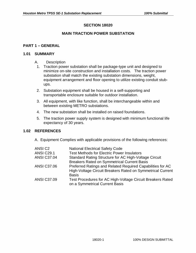
D. AC Circuit Breaker Type and Rating
1. Provide three-phase, horizontal draw-out, metal-clad, vacuum type ACcircuit breakers with ratings as shown in Table 18020-5.
Table 18020-5 - AC Circuit Breaker Rating Data
Characteristic 15 kVSwitchgear
Rated Maximum Voltage 15 kVRated Continuous Current 1,200 A

Houston Metro TPSS SE-1 Substation Replacement 100% Submittal
18020-16 100% DESIGN SUBMITTAL
Characteristic 15 kVSwitchgear
Low Frequency Withstand 36 kVFull Wave Withstand - Basic Impulse Level 95 kVRated Voltage Range Factor K 1.3Rated Short Circuit Current 18 kAMaximum Symmetrical Interrupting Capability and RatedShort Circuit Current 23 kA
Closing and Latching Capability 62 kARated Interrupting Time 5 cycles
E. AC Circuit Breaker Components. Provide each circuit breaker to consist of thefollowing components;
1. Interrupter. Provide interrupter incorporating vacuum chamber withcontacts to extinguish electrical arc during switching.
a. Provide the interrupter contacts inside the arc chamber housingbuilt with a vacuum of 10 -7 torr, minimum. Provide the chamberto maintain this vacuum level for at least 20 years.
b. Provide the interrupter contacts with high conductivity copperalloy. Construct the contacts to diffused the arc during switchingand prevent local overheating of the contact pieces.
c. Use high quality metal bellows to enable movement of themoving contact. Guarantee the bellows for 30,000 operations.
2. Interrupter Support. Mount the interrupter on a flame retardant, trackresistant, and high mechanical strength material support. Provideadequate insulation to ground, and to firmly position and hold theinterrupter in placed with correct contact alignment.
3. Operating Mechanism. Use one basic and simple, spring-charged,stored-energy or solenoid operated mechanism for all AC circuitbreaker types. Include in the mechanism all necessary equipmentrequired for the circuit breaker operation, such as electrical springcharging motor, mechanical gears, linkages, closing solenoid, trippingsolenoid as well as closing, opening and contact pressure springs.Provide the mechanism with the following features:
a. Operation of the circuit breaker through one close/open cycle onone motor charging.
b. Automatic motor charge of all springs upon completion of theclose/open cycle to prepare the circuit breaker for the nextclose/open cycle.
c. Motor charging operation not exceeding 12 seconds.d. Mechanically and electrically trip free mechanism.e. Electrical operation.

Houston Metro TPSS SE-1 Substation Replacement 100% Submittal
18020-17 100% DESIGN SUBMITTAL
f. Manual cranking capability to permit spring charging should themotor power be lost.
g. Manufacturing with high quality parts with close tolerances toachieve operating consistency, reliability and the specifiedservice life.
h. A non-resettable four digit mechanical operation counter oneach circuit breaker.
4. Truck. Mount the circuit breaker components on a rugged, weldedsteel truck. Provide the truck as a precision-crafted and rigid assembly.
a. Provide the truck with guide rails and wheels to permit easyrolling-in and drawing out of the circuit breaker.
b. Ground the truck of each circuit breaker through a groundcontact shoe.
5. Disconnecting Contacts. Provide power connections between theremovable circuit breaker and the stationary switchgear structure withautomatic, self-aligning, and self-coupling disconnecting devices.
a. Primary Contacts. Provide primary contacts for the main powerconnections. Provide the primary contacts using silver-plated,spring-biased, hard copper fingers installed on the draw outelement and stationary cell studs on the stationary structure.Recessed the stationary contacts within insulated supports.Provide the contacts to have sufficient cross-sectional area ofcopper to permit removal of heat from the fingers and the studs,to avoid localized high loads, and to maintain high conductivity.
b. Secondary Contacts. Provide secondary contacts for control,auxiliary, and interlocking power circuits. Provide the secondarycontacts to consist of multi-contact receptacles and plugs with asufficient number of contacts to accommodate all secondarycircuits and spares, without the used of auxiliary relays.
6. Circuit Breaker Positions. Provide the circuit breaker positions on anindicator located on the cubicle door. Provide each circuit breaker withthe following positions:
a. Connected Position: Both primary and secondary disconnectingcontacts are connected permitting operation of the circuitbreaker during normal and fault conditions.
b. Test Position: The primary disconnecting contacts aredisconnected and the secondary disconnecting devices areconnected permitting testing of the circuit breaker operation.
c. Disconnected Position: Both primary and secondarydisconnecting devices are disconnected permitting the circuitbreaker withdrawal.

Houston Metro TPSS SE-1 Substation Replacement 100% Submittal
18020-18 100% DESIGN SUBMITTAL
7. Draw Out Mechanism. Provide each circuit breaker with a manual,horizontal draw out mechanism.
a. Provide the mechanism to move the circuit breaker betweenconnected and test positions and from test to disconnectpositions with the cubicle door opened or closed. This isaccomplished mechanically by insertion of a suitable crankthrough an opening in the cubicle door or front panel.
b. Provide the gear ratio of the mechanism so that one man canrack in or out the circuit breaker within one minute.
c. Provide the circuit breaker to be withdrawn from the switchgearhousing when the breaker element, complete with its operatingmechanism, is in the fully racked-out position.
d. Truck automatically disengages the draw out mechanism at theend of the circuit breaker travel to prevent any over-travel.Additionally, prevents over-travel by installed positivemechanical stops.
e. Provide interlocks to ensure that the circuit breaker can bedrawn-out or rolled-in only when it is in open position.
2.03 RECTIFIER TRANSFORMER
A. Transformer Type. Provide dry-type, self-cooled, extra heavy duty tractionpower transformer suitable for installation in the substation enclosure.
B. Core Design
1. Steel Type. High-grade, cold-rolled, heat-treated, grain-oriented, highefficiency, high electrical resistance, high magnetic permeability, lowsulfur and carbon content, non-aging, electrical grade silicon steel alloywith low no-load and load losses.
2. Laminations. Provide appropriate thickness of laminations to restraineddy current losses in the transformer core, and to maintain adequatemechanical strength of the core. Provide only flat laminations with nowaviness to minimize stresses when the sheets are pressed flat in acore.
3. Dimensions. Cut laminations for step-lap mitered joints. Provide coregeometry to minimize core losses and sound level and to keep fluxdensity below saturation point.
4. Core Supports. Provide adequate core supports so that thetransformer can withstand the highly fluctuating load currents and thehigh occurrence of short circuits on the system without overheating,decrease in life expectancy, or injury. Provide special clamps andbraces to strengthen the core to withstand mechanical and thermalstresses without damage. Provide additional heavy steel plates and

Houston Metro TPSS SE-1 Substation Replacement 100% Submittal
18020-19 100% DESIGN SUBMITTAL
system of wedging and blocking as necessary. Provide the core tobalance, restrain, and withstand frequent pulsating axial and radialelectromagnetic forces in the transformer. Supports prevent anymovement of the core and the windings, and eventual transformerfailure.
5. Ground the core by means of flexible grounding strap.
C. Winding Design
1. Type. Provide circular winding design wound on epoxy-glass tubesusing high purity, high conductivity, and insulated copper conductors.
2. Rating. Provide the primary winding to be consistent with the electricalpower utility supply voltage. Select appropriate ratio between theprimary and secondary windings to provided 750 VDC nominal voltageat the rectifier output at rated load and at rated primary voltage.
3. Connection. Provide the windings to supply 12-pulse rectifier. Connectone secondary winding in delta and one in wye to obtain 30E electricalphase shift between the secondary windings. Take into considerationinductive coupling of the windings and its effects on voltage regulation,impedance and short circuit current magnitude.
4. Electromagnetic Forces. Provide windings to minimize axial and radiala. electromagnetic forces during load, overload, and short circuit
conditions.
5. Supports. Provide adequate winding supports so that the transformercan withstand the highly fluctuating load currents and the highoccurrence of short circuits on the system without overheating,decrease in life expectancy, or injury. Provide special clamps, bracesto strengthen the windings to withstand mechanical and thermalstresses without damage. Provide additional system of wedging andblocking as necessary. Provide the windings to balance, restrain, andwithstand frequent pulsating axial and radial electromagnetic forces inthe transformer and prevent any movement of the windings, andeventual transformer failure. Provide adequate bracing to all windingleads.
6. Cooling. Provide adequate spacers to form cooling ducts to allow freepassage of cooling air.
7. Taps. Provide the transformer with seven (7) 1.25% full capacity taps;four above and two below the nominal primary voltage. In order tomaintain high integrity of the windings, install the taps by taking thewinding conductors outside of the winding and construct the tapsoutside of the transformer coils.

Houston Metro TPSS SE-1 Substation Replacement 100% Submittal
18020-20 100% DESIGN SUBMITTAL
D. Insulation
1. Provide winding insulation to withstand dielectric tests in accordancewith ANSI standards for the voltage class.
2. Provide class H 220EC winding thermal insulation. Provide transformerfor average winding temperature rise of 80EC over 40EC ambienttemperature at rated power.
E. Winding Processing
1. Type. During manufacture and upon completion of the transformerwindings, protect the windings against moisture and increase thewinding mechanical strength with Vacuum Pressure Impregnation(VPI) process and epoxy end caps. Select non-flammable and self-extinguishing insulating material with high electrical, mechanical andthermal strength, such as polyester, epoxy, or silicone varnish.
2. VPI Process. Thoroughly dry and pre-heat the windings to removemoisture. Place windings in vacuum and allow the windings to draw theinsulating material into the windings. Apply positive pressure to drivethe insulating material into the windings to remove all air pockets. Afterthe impregnation, bake the windings to cure the insulating material andto form a solid and sealed structure.
3. Epoxy Endcaps. Seale both ends of high voltage and low voltagewindings with epoxy resin mixture to protect the windings frommoisture, humidity, and industrial contaminants.
2.04 RECTIFIER
A. Type. Indoor, silicon diode type, natural convection-cooled rectifier consistingof full-wave bridges providing 12-pulse rectification.
B. Design. Provide the rectifier as a complete operating assembly consisting ofsilicon diodes, heat sinks, internal busbars, connections, diode fuses, and allother necessary components and accessories.
C. Diodes. Connect the rectifier diodes as per approved ANSI 31 circuit.
1. Provide and built the rectifier with sufficient number of hermeticallysealed diodes to supply the load cycle and short circuit currents withone diode in each leg out of service and without exceeding theallowable junction temperature of the remaining diodes in service.Provide the diodes with adequate heat sinks.
2. Provide naturally current-balanced rectifier design without usingexternal devices and without individual selection of diodes. Select the

Houston Metro TPSS SE-1 Substation Replacement 100% Submittal
18020-21 100% DESIGN SUBMITTAL
diode type so that the currentunbalance between parallel diodes ineach rectifier leg is within 15% and the current unbalance betweenrectifier legs is within 10% at rated load.
D. Voltage Rise. Provide the rectifier so that the voltage rise between 0% and100% rated load is within the DC equipment continuous rating.
2.05 TRANSFORMER/RECTIFIER DESIGN
A. Transformer/Rectifier Regulation
1. Select inductive coupling of the transformer windings so that thetransformer/rectifier units exhibit the following features:
a. Maintain satisfactory regulation between 100% rated load and450% rated load.
Load (%) Rectifier Output Voltage (V) Regulation (%)0 795
100 765 3.92150 735 4.08300 705 4.26450 625 12.80
b. Provide sufficient short circuit current to enable an overheadsystem fault anywhere between two adjacent substations to becleared by protective devices of both substations.
B. Transformer/Rectifier Rating. Provide the transformer/rectifiers to enable thesubstations to supply the continuous and overload ratings as specified herein.
1. Continuous Rating. Traction power substations are rated as specifiedin Table 18020-6.
Table 18020-6 - Continuous Substation Ratings
Substation Number ofTransformer/Rectifier Units
Transformer/RectifierRating (kW)
SubstationRating(kW)
1 1,500 1,500
2. Overload/Short Circuit Capability. After constant temperature of allequipment at a substation is reached following operation at 100% ratedpower, the substations shall be capable of supplying the followingoverload/short circuit cycle:

Houston Metro TPSS SE-1 Substation Replacement 100% Submittal
18020-22 100% DESIGN SUBMITTAL
a. Two hours at 150% of rated load with five evenly spacedperiods of one minute each at 300% of rated load, followed by,
b. Fifteen second period at 450% of rated load, followed by,c. Maximum short-circuit current. Take into account two types of
short-circuit conditions:1) Bolted faults at the rectifier terminals where the rectifier
diodes are not subjected to reverse voltage.2) Resistance faults where the diodes are required to block
reverse voltage.d. Provide the transformer/rectifiers to withstand both types of
short circuits for duration of time corresponding to the time,which is required by the AC breaker to clear the particular typeof short circuit.
3. Provide the transformers and rectifiers so that the average and hotspot temperature rises are such that the transformer and rectifier lifeexpectancy shall not be shortened when supplying the specifiedoverload and short circuit cycle on a regular basis.
C. Design Optimization. Provide the transformer/rectifier to achieve an overallefficiency of 98% or higher at rated output.
2.06 DC SWITCHGEAR ASSEMBLY
A. DC Switchgear Requirements. Provide DC switchgear assembly to conformto or exceed the requirements of IEEE C37.14, IEEE C37.16, and IEEEC37.20.1 to accommodate DC circuit breakers as specified herein.
1. Provide DC switchgear to deliver, control, and measure powerrequirements of the DC distribution system. Select reliable switchgearcombining fast fault interruption, low maintenance, quiet operation, andthe specified service life.
2. Provide the DC switchgear assemblies in a lineup of dead-front, floormounted, freestanding, metal enclosures to accommodate circuitbreakers with ratings specified herein.
3. Divide each enclosure into completely segregated compartments tohouse the major equipment parts of the switchgear such as the circuitbreaker interrupting element, busbars with cable terminations, controlcircuitry, protective relays, auxiliary relays, instrumentation, indication,annunciation, terminal blocks, fuses, and all other necessary devices.
4. Completely enclose and segregate the individual equipmentcompartments by 11 gauge steel barriers.
a. Eliminate all unintentional openings between the compartments.

Houston Metro TPSS SE-1 Substation Replacement 100% Submittal
18020-23 100% DESIGN SUBMITTAL
b. Enclose all live parts of switchgear equipment within the metalcompartments.
c. Ensure that opening of the cubicle door exposes no primarycircuit components when the interrupter is in the connectedposition.
d. Provide the barriers to isolate instruments, meters, relays,transducers, indicating devices and all control devices and theirwiring from all primary circuit elements with the exception ofshort lengths of wire such as at shunt and instrument terminals.
e. Bond all metal compartments to continuity busbar.
5. Provide automatic metal shutters to prevent exposure of primary circuitelements when the circuit breaker is removed from its position.
6. Cover the busbar conductors and connections with 2 kV insulatingmaterial.
7. Provide mechanical and/or electrical interlocks to ensure proper andsafe operating sequence.
8. Use the front door of the switchgear above the door through which thecircuit-interrupting device is inserted into the housing as an instrumentand device panel and as an access to instrumentation and controlcompartment within the housing.
9. Provide all switchgear components to be accessible from the front ortop of the cubicle.
10. Furnish the switchgear with sufficient auxiliary contacts to provide foroperation of the breaker control circuitry, transfer trip circuitry,indication, and interlocks. Provided at least four spare contacts, twonormally open and two normally closed, each wired to an accessibleterminal block.
11. Provide the DC switchgear assemblies to have bottom feeder cableentry.
B. DC Circuit Breaker Type and Rating
1. Provide single-pole, horizontally draw-out, high-speed DC circuitbreakers with ratings as shown in Table 18020-7.
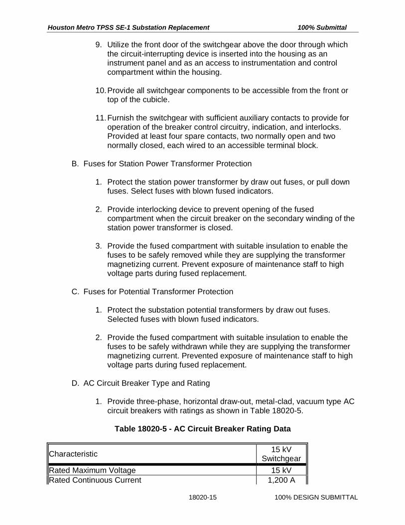
Table 18020-7 - DC Circuit Breaker Rating Data
Characteristic RatingRated Maximum Voltage 800 VDCMaximum Operating Voltage 900 VDCAC Dielectric Withstand Voltage 3,700 V
Houston Metro TPSS SE-1 Substation Replacement 100% Submittal
18020-24 100% DESIGN SUBMITTAL
Characteristic RatingContinuous Current, Main Circuit Breakers 2,000 AContinuous Current, Feeder Circuit Breakers 1,600 ARated Momentary and Peak Current, AllCircuit Breakers To be determined by the Contractor
based on the transformer/rectifier ratingand impedance.Sustained Short Circuit Current, All Circuit
BreakersRated Interrupting Time (shunt trip) 0.030 Seconds
C. DC Circuit Breaker Components. Provide high-speed, single pole, air circuitbreakers consisting of the following components.
1. Interrupter. Provide each breaker to supply the specified load cyclecurrents and interrupt the rated short circuit current. Include air puffers,magnetic blowout, or other approved equipment to ensure interruptionof low level currents.
2. Interrupter Support. Mount the interrupter on a flame retardant, trackresistant, and high mechanical strength material support. Provide thesupport to provide adequate insulation to ground, and to firmly positionand hold the interrupter in placed with correct contact alignment.
3. Operating Mechanism. Use one basic and simple, spring-charged,stored-energy or solenoid-operated mechanism for all DC circuitbreaker types. Include in the mechanism all necessary equipmentrequired for the circuit breaker operation, such as mechanical gears,linkages, closing solenoid, tripping solenoid as well as closing, openingand contact pressure springs. Provide the mechanism with thefollowing features:
a. Operation of the circuit breaker through one close/open cycle onone motor charging.
b. Automatic motor charge of all springs upon completion of theclose/open cycle to prepare the circuit breaker for the nextclose/open cycle.
c. Motor charging operation not exceeding 12 seconds.d. Mechanically and electrically trip free mechanism.e. Electrical operation.f. Manual cranking capability to permit spring charging should the
motor power be lost.g. Manufacturing with high quality parts with close tolerances to
achieve operating consistency, reliability and specified servicelife.
h. A non-resettable four digit mechanical operation counter oneach circuit breaker.
4. Truck. Mount the circuit breaker components on a rugged, weldedsteel truck. Construct the truck as a precision-crafted and rigid

Houston Metro TPSS SE-1 Substation Replacement 100% Submittal
18020-25 100% DESIGN SUBMITTAL
assembly. Provide the truck with guide rails and wheels to permit easyrolling-in and drawing out of the circuit breaker.
5. Disconnecting Contacts. Provide power connections between theremovable circuit breaker and the stationary switchgear structure withautomatic, self-aligning, and self-coupling disconnecting devices.
a. Primary Contacts - Provide primary contacts for the main powerconnections. Provide the primary contacts using silver-plated,spring-biased, hard copper fingers installed on the draw outelement and stationary cell studs on the stationary structure.Recessed the stationary contacts within insulated supports.Provide the contacts to have sufficient cross-sectional area ofcopper to permit removal of heat from the fingers and the studs,to avoid localized high loads, and to maintain high conductivity.
b. Secondary Contacts. Provide secondary contacts for control,auxiliary, and interlocking power circuits. Provide the secondarycontacts to consist of multi-contact receptacles and plugs with asufficient number of contacts to accommodate all secondarycircuits and spares, without the used of auxiliary relays.
6. Circuit Breaker Positions. Show the circuit breaker positions on anindicator located on the cubicle door. Provide each circuit breaker withthe following positions:
a. Connected Position: Both primary and secondary disconnectingcontacts are connected permitting operation of the circuitbreaker during normal and fault conditions.
b. Test Position: The primary disconnecting contacts aredisconnected and the secondary disconnecting devices areconnected permitting testing of the circuit breaker operation.
c. Disconnected Position: Both primary and secondarydisconnecting devices are disconnected permitting the circuitbreaker withdrawal.
7. Draw Out Mechanism. Provide each circuit breaker with a manual,horizontal draw out mechanism.
a. Provide the mechanism to move the circuit breaker betweenconnected and test positions and from test to disconnectpositions with the cubicle door opened. Accomplish thewithdrawal mechanically by rotation of a spring-loaded handle.
b. Provide the gear ratio of the mechanism so that one man canrack in or out the circuit breaker within one minute.
c. Provide the circuit breaker to be withdrawn from the switchgearhousing when the breaker element, complete with its operatingmechanism, is in the fully racked-out position.
d. Automatically disengaged the draw out mechanism at the end ofthe circuit breaker travel to prevent any over-travel.

Houston Metro TPSS SE-1 Substation Replacement 100% Submittal
18020-26 100% DESIGN SUBMITTAL
e. Provide interlocking to ensure that the circuit breaker can bedrawn-out or rolled-in only when it is in open position.
2.07 NEGATIVE RETURN AND DRAINAGE ASSEMBLY
A. Assembly Equipment. Provide a negative return and drainage assembly withnegative disconnect switch and provisions for; negative return cables,negative drainage cables, negative grounding unit, and other associatedequipment.
1. Negative Disconnect Switcha. Provide manually operated, single-pole, single-throw, no-load
break negative disconnect switch with insulated handle andsilver-plated copper contacts.
b. Interlock the disconnect switch with the DC main circuit breaker.Prevent operation of the switch when the DC main circuitbreaker is closed.
2. Provision for Negative Return Cables.a. Provide busbar for connection of negative return cables.
3. Provision for Negative Drainage Cablesa. Provide for connection of at least four negative drainage cables.b. Equip each drainage cable connection point with a diode,
variable resistor, shunt, and current limiting fused.
4. Provision for Negative Grounding Unit.a. Following the Ground Fault Test, METRO decided the Negative
Grounding Unit as specified in section PROTECTIVE DEVICESwas required.
b. Upon determination that the ground faults were not adequatelycleared, provided the negative grounding unit in eachsubstation.
B. Equipment Rating
1. Provide rating of all equipment at the DC system rated voltage.
2. Provide rating of all equipment, except the negative grounding unit andthe provisions for negative drainage cables, to withstand, withoutdamage, the continuous, the overload, and rated short circuit currents.
3. Provide rating of the negative grounding unit and the provisions fornegative drainage cables to withstand without damage ground faultshort circuit currents.
2.08 AC STATION POWER SYSTEM
A. General Requirement

Houston Metro TPSS SE-1 Substation Replacement 100% Submittal
18020-27 100% DESIGN SUBMITTAL
1. Provide AC station power system for each traction power substation tosupply power to the following:
a. Traction power substation auxiliary loads.b. Signal system facilities located in separate house adjacent to
the traction power substations.c. Communications system facilities located in separate house
adjacent to the traction power substations.
B. System Design
1. Identify all traction power substation auxiliary loads, including:a. Lightingb. HVAC unitsc. Convenience receptaclesd. Anti-condensation heaterse. Battery chargerf. AC control power
2. Identify loads of signal and communications system instrumenthouses.
3. Perform calculations for sizing of the traction power substationauxiliary, signal, and communications power supply systems. Definethe following system parameters:
a. System voltages and currentsb. Maximum feeder currentsc. Feeder cable ratings and sizesd. Panelboard sizese. Type and sizes of protective molded-case circuit breakers
4. Prepare design calculations for the system and submitted to METROfor approval.
C. Station Power Transformer.
1. Provide dry-type, self-cooled, single-phase, transformer with primaryvoltage to be consistent with the utility supply voltage.
a. Secondary voltage: 120 V/240 V.b. Taps: Four 2.5% full capacity taps; two above and two below
the nominal primary voltage.c. Rating: Adequate to supply all envisaged loads with 15% spare
capacity.
2. Protect the transformer with draw-out or flip-down fuses.
D. Station Power Panelboard

Houston Metro TPSS SE-1 Substation Replacement 100% Submittal
18020-28 100% DESIGN SUBMITTAL
1. Provide single-phase, three-wire AC panelboard of appropriate size ineach substation. Protect the panelboard with a main molded-casecircuit breaker feeding the panelboard.
2. Provide the necessary number of branch feeders. Protect each feederby a molded-case circuit breaker. Installed at least 25% of spare circuitbreakers.
3. Provide the necessary number of branch feeders, including:a. Traction power substation auxiliary loads.b. Signal system facility.c. Communications system facility.
4. Protect each feeder by a molded-case circuit breaker. Installed at least25% of spare circuit breakers.
5. Locate the panelboard within the traction power substation.
E. Power Distribution
1. Provide separate three-phase, AC switch for the signal power systemfeed to the Bungalow.
2. Provide power distribution cabling and circuit devices within thesubstation.
2.09 DC AUXILIARY POWER SYSTEM
A. System Design
1. Identify all DC auxiliary power system loads in the substation,including:
a. DC control powerb. Substation electronic devicesc. Annunciationd. Emergency lighting
2. Perform calculations for sizing of the DC auxiliary power supply anddistribution systems. Define the following system parameters:
a. Wire and cable voltages and currentsb. Wire and cable ratings and sizesc. Panelboard sized. Type and sizes of protective molded-case circuit breakers
3. Prepare design calculations for the station battery and battery chargersize in accordance with IEEE 485 and submit to METRO for approval.Provided the battery and battery charger to perform properly under theentire range of temperatures to be expected within the substation.

Houston Metro TPSS SE-1 Substation Replacement 100% Submittal
18020-29 100% DESIGN SUBMITTAL
B. Source of DC Auxiliary Power - Station Battery
1. Provide an ungrounded, maintenance free, 125 V, sealed, lead-acidbattery. Equipped the battery with battery rack, accessories, and allconnections necessary to provide a fully operating battery system.Arranged the battery cells on racks or in a freestanding modular unit tooptimize the used of space in the substation.
2. Provide battery that requires no watering, no special ventilation, and nospecial battery room. Select replaceable battery cells, which contain nocadmium, or other hazardous materials, which would require specialdisposal arrangements. Provide battery that under normal conditionsvents no gas. Provide a sealed pressure relief vent to alleviatepressure build-up in the cells. Select flame retardant, leak-proof andspill-proof battery cell containers. Use stainless steel, standard Englishmeasure, hex-head bolt connectors. Use lead-plated copper straps forthe inter-unit connections.
3. Mark the battery cells to indicate the cell manufacturer and type.Identified the polarity of the terminal posts by red and black terminalrings and by positive and negative signs molded or engraved into thecell in the proximity of the terminals.
4. Provide the battery to supply sufficient power to close and trip allsubstation circuit breakers after it has supplied the substation DCauxiliary power requirements for 8 hours with the AC station powerpanelboard de-energized. Provided the battery to deliver outputvoltage not be less than 105 V at the end of this discharge period.
C. Source of DC Auxiliary Power - Battery Charger
1. Provide an automatic, silicon-controlled rectifier, convection-cooled,constant-voltage type battery charger to recharge the station battery.Selected charger manufactured or approved by the batterymanufacturer. Supply the charger from the substation auxiliary powerpanelboard.
2. Size the charger to recharge the battery while supplying the continuousloads of the battery at the same time. Size the battery to supply theremainder of the heavy, short-time current demands.
3. Provide a charger capable of recharging a fully discharged stationbattery within 8 hours. Select a charger to provide a constant voltageoutput within ±1% of nominal voltage over the complete load range foran input voltage variation of ±10%. Provide the charger to be currentlimiting, adjustable from 80% to 120% of rated load and factory set at110%.

Houston Metro TPSS SE-1 Substation Replacement 100% Submittal
18020-30 100% DESIGN SUBMITTAL
4. Equip the battery charger with the following provisions:a. AC circuit breaker, two poleb. AC surge suppressorc. Float and high rate adjustment potentiometerd. Manual float/equalize switche. DC voltmeterf. DC ammeterg. DC blocking diode and reverse polarity protection diodeh. DC circuit breaker, two polei. DC surge suppressorj. Switchboard wiring 600 V, 90EC ratedk. Devices and accessories required for remote SCADA
supervisionl. LED indication and SCADA contacts for the following functions:
1) AC voltage high/low indication2) Charger failure indication3) DC voltage high/low indication4) Positive and negative ground detection
D. DC Panelboard
1. Provide two-wire DC system panelboard of appropriate size in eachsubstation and protected the panelboard with a main molded-casecircuit breaker feeding the panelboard.
2. Provide the necessary number of branch feeders. Protected eachfeeder by a molded-case circuit breaker. Installed at least 25% ofspare circuit breakers.
E. DC Power Distribution
1. Provide substations with dedicated two-conductor, ungrounded DCpower distribution circuits.
2. Install the distribution circuits in protective raceway, and terminated allwires and cables on terminal blocks at the loads served.
2.010 CURRENT TRANSFORMERS
A. Provide current transformers (CTs) to accurately transform the systemcurrents for metering and relaying. Select the current transformers to satisfyANSI and IEEE requirements for metering and relaying accuracyclassification under the burdens imposed by the metering and protectivedevices.
B. Select ring core type current transformers with toroidally wound and fullydistributed secondary windings.

Houston Metro TPSS SE-1 Substation Replacement 100% Submittal
18020-31 100% DESIGN SUBMITTAL
C. Select current transformers insulated with structural grade thermoplastic towithstand dielectric test levels of the switchgear and to carry the currentsoccurring during rated load, overload, and short circuit currents withoutexcessive heating or injury.
D. Provide each current transformer with a mounting frame, which attachessecurely to the switchgear bushings. Ran secondary wiring from the currenttransformer terminal studs to terminal blocks. Provid the current transformerterminal blocks with covers having integral shorting bars.
2.011 POTENTIAL TRANSFORMERS
A. Provide potential transformers (PTs) to accurately transform the systemvoltages for metering and relaying. Select the potential transformers to satisfyANSI and IEEE requirements for metering and relaying accuracyclassification under the loads imposed by the metering and protectivedevices.
B. Select dry-type potential transformers with physically strong protective casesand with superior insulating properties.
C. Select potential transformers with adequate insulation to withstand thedielectric test levels of the switchgear and to carry their load continuouslywithout excessive heating or injury.
D. Protect the primary circuits of all potential transformers by means of non-renewable cartridge-type fuses. Provided indication for the blown fuses.Located the primary fuses in roll-out carriages equipped with disconnectingdevices. Protected secondary circuits of all potential transformers by molded-case circuit breakers mounted in the cubicle control compartment.
2.012 TRANSDUCERS AND CONVERTERS
A. Provide compact transducers and converters to convert input variables intoproportional DC output signals within accuracy of 0.1% or better. Selectransducer and converter inputs to be compatible with the magnitude of theinput variable.
B. Install the transducers and converters in a suitable enclosure.
2.013 PROTECTIVE DEVICES.
A. Provide a comprehensive protective scheme to protect the substationequipment and the overhead distribution system as well as provide back up tothe vehicle protective devices. Base the protective scheme design on theload, overload, and short circuit currents. Select the characteristics and

Houston Metro TPSS SE-1 Substation Replacement 100% Submittal
18020-32 100% DESIGN SUBMITTAL
ranges of all protective devices to ensure satisfactory coordination of alldevices and a fast fault clearance.
B. Use only high quality, utility-type, draw-out, microprocessor-based protectivedevices enclosed in rustproof, dustproof, high-impact cases with integral testswitches and solid-state contacts.
C. Annunciate operation and failure on the device with targets.
D. Arrange all protective devices to be conveniently accessible, easily visible,and logically grouped. Locate devices of related functions in proximity to eachother. Install the protective devices semiflush on the cubicle door.
E. Arrange all provisions for device setting and testing to be readily visible,accessible, and adjustable from the front of the device.
F. Provide the protective scheme to be immune to maloperation due to electricalnoise, electromagnetic fields, harmonic distortion, traveling waves, andcurrent transformer saturation. Provide all protective schemes fail-safe.
G. The Contract Drawings show the protective schemes and are intended toserve the protective scheme functional requirements. The Contract Drawingsdo not show all components such as auxiliary devices, isolating diodes, fusesand other similar devices required for a complete protection systeminstallation. Perform all final design including selection of devicecharacteristics, model numbers, style, connections, and settings.
1. AC Switchgear Protection. Equip the AC switchgear assembly with thefollowing protective devices:
a. Time Overcurrent Device with Instantaneous Element, Device50/51, for high current phase fault protection.
b. Time Overcurrent Device, Device 51, for low current phase faultprotection.
c. Time Overcurrent Device with Instantaneous Element, Device50/51 N, for ground fault protection.
d. Undervoltage Device, Device 27, for loss of AC supplyannunciation.
e. Fuses for protection of station power transformer.
2. Rectifier Transformer Protection. Equip the rectifier transformer withthe following protective devices:
a. Winding Overtemperature Device, two stage, Devices 49-T1and 49-T2. Equip the devices with temperature detectiondevices embodied in the transformer windings. Each stagesetting is adjustable.
3. Rectifier Protection. Equip the rectifier with the following protectivedevices:

Houston Metro TPSS SE-1 Substation Replacement 100% Submittal
18020-33 100% DESIGN SUBMITTAL
a. Diode Fuses. Provide high speed current limiting fuses in serieswith each diode, complete with an indicator to show a blownfuse, Device 98. Select fuse size to protect the rectifier againstinternal faults resulting from a diode losing its blocking ability.Select fuses with fast fault current interruption to preventspreading of faults to adjacent diodes. Provide fuses that shallnot open or fail during external faults or rated overloadconditions.
b. Overtemperature Protective Devices, Devices 26-R1 and 26-R2.Provide two stage monitoring of the heat sink temperature.Mounted the device thermal sensors in the hottest location ofthe rectifier.
c. Surge Protection. Equip the rectifier with an surge protectiondevices to limit the reverse voltage across the diodes to a valuelower than the peak reverse voltage rating of the diodes. Thedevices protect the rectifier irrespective of whether the surgesoriginate in the AC or DC power circuits.
d. Door Position Contacts, Device 33. Provide all rectifierenclosure doors with position contacts. Upon opening of theenclosure doors, the contacts trip the AC circuit breaker and theDC main circuit breaker and initiate annunciation. The AC andDC main breakers do not close unless all rectifier enclosuredoors are closed.
4. Transformer/Rectifier Single-Phase Operation Protection.
a. Provide the transformer/rectifier units to withstand operationunder a phase-to-phase condition and provided additionalprotective devices, as necessary, to protect thetransformer/rectifier units against damage.
5. DC Switchgear Protection. Furnish the DC switchgear with thefollowing protective devices:
a. Reverse Current Instantaneous Device, Device 32. Each DCmain circuit breaker is equipped with unidirectional direct-actingovercurrent trip, set as low as practically possible and reactingon reverse currents only.
b. Direct-acting Overcurrent Trip, Device 176. Each DC feederbreaker is equipped with a bi-directional direct-acting releaseovercurrent trip set to open the breaker on short circuit currents.
c. Time Overcurrent device or Thermal device, Device 151. EachDC feeder breaker is equipped with a device protecting thedistribution system from overloads and from arcing and highresistance faults. The device characteristic closely follows themaximum permissible DC current overload characteristic of thedistribution system to prevent conductor annealing duringsustained overloads or faults.

Houston Metro TPSS SE-1 Substation Replacement 100% Submittal
18020-34 100% DESIGN SUBMITTAL
d. Rate-of-Rise Device, Device 150 R. Each DC feeder breaker isequipped with unidirectional rate-of-rise relay. The device hasoperating characteristics and adjustable ranges to trip the DCfeeder circuit breaker for remote short circuits and discriminatesagainst current inrush occurring during starting of trains.
e. Auto-reclosing Equipment, Devices 182 and 183. Each DCfeeder circuit breaker is furnished with automatically reclosingequipment. The equipment consists of voltage devices, loadmeasuring devices, fault test equipment, and time sequencedevices.
1) The circuitry provides for three successive attempts toclose the circuit breaker. The time period between theattempts is adjustable.
2) The circuit breaker is allowed to close onto a line, whichis energized.
3) The circuit breaker is allowed to close onto line which isde-energized but which is identified by the fault testequipment as clear line without a fault.
4) The circuit breaker is not allowed to close onto a linewhich is de-energized and which was identified by thefault test equipment as faulty.
5) The autoreclosing feature is capable of being switchedoff. The autoreclosing sequence is blocked if the circuitbreaker has been tripped manually.
f. Transfer Trip, Device 85. Equipped each DC feeder circuitbreaker with fully functional transfer trip protective scheme.
1) Following a distribution system fault, the feeder circuitbreakers supplying the short circuit current are tripped asshown on Contract Drawings.
2) Provide all necessary transfer trip interconnecting cablesand substation to substation communications circuitry.
g. Incomplete Sequence Relay, Device 48. Furnish each DCfeeder circuit breaker with an incomplete sequence device. Thisdevice detects the circuit breaker failure to clear a fault within apredetermined time and operates the AC lock-out device(device 86H) to de-energize the entire substation. The circuitbreaker in the adjacent substation feeding the fault is openedvia the transfer trip system.
6. DC Enclosure Protection. Protect the rectifier, the DC switchgear, andthe negative return and drainage assembly enclosures by high-resistance protective scheme which includes the following devices:
a. Enclosure Live Protection, Device 64 L. Selected a highlysensitive device 64L to operate in the event that any part of theDC enclosures becomes energized.
b. Enclosure Grounded Protection, Device 64 G. Selected a highlysensitive device 64 G to operate in the event that any part of theDC enclosures becomes grounded.

Houston Metro TPSS SE-1 Substation Replacement 100% Submittal
18020-35 100% DESIGN SUBMITTAL
7. Station Power, Auxiliary Power, Signal and Communications PowerSupply Systems. Protected all circuits and connected equipment withmolded-case circuit breakers.
a. Coordinate characteristics of all molded-case circuit breakersprotecting the AC power systems.
b. Coordinate characteristics of all molded-case circuit breakersprotecting the DC power systems.
8. Negative Grounding Unit, Device 57.a. Provide the negative grounding unit to ground the negative bus
should the voltage between the DC system negative bus andground exceeds a predetermined value. Increased voltagesbetween the negative bus and the ground may occur duringvehicle acceleration or during uncleared system ground faults.
b. Manufacture the negative grounding unit using gate-turn-off(GTO) thyristors and associated devices and control circuitry.Refer to Contract Drawings for simplified one-line diagram andoperational flow chart.
c. Provide protective devices with adjustable time delays so thatthe unit is insensitive to transients, allows the distributionsystem faults to be cleared and, once the feeder breakers arecleared, permits three successive attempts to auto-reclose thebreakers.
d. Determine the thyristor rating and the voltage level at which thenegative grounding unit shall operate.
e. Equip the unit with a failure indicator, close/open statusindicator, and with a non-resettable operations counter. Providemanual switching of the unit on and off.
9. Surge Protection. Furnish suitable surge arresters and transientvoltage suppression devices as determined in the InsulationCoordination Study. Protect all electronic equipment in the substationand applied protection to the power supply and data lines asappropriate.
a. As a minimum, protect the following equipment:1) Programmable logic controller2) SCADA system equipment3) Electronic relays
b. Select the protective equipment voltage rating, energydissipation rating, and other characteristics compatible with theequipment to be protected.
10. Other Protection. Provide the following additional protective devices:a. Undervoltage Device, Device 27 A. Used the device to
annunciate loss of station power supply.b. Fire Detector. Use the fire detector device to de-energize and
lock out all substation circuit breakers in the event of fire.c. Auxiliary Devices, Devices 86 H, 186 H and 94. Arrange
protective devices to trip the circuit breakers via hand-reset

Houston Metro TPSS SE-1 Substation Replacement 100% Submittal
18020-36 100% DESIGN SUBMITTAL
lockout device 86 H, and 186, and via tripping device 94 asshown on the Contract Drawings. Provide the lockout devicewith handle and mechanical target to indicate the deviceposition.
2.014 INSTRUMENTATION
A. Provide high quality, metal case, semiflush, four and one-half inches (4½")square, switchboard type meters with accuracy of one percent of full-scalevalue. Calibrate all instruments to match the input signals. As a minimum,provided the following instrumentation in each substation:
B. AC Switchgear
1. AC feeder voltmeter within the Siprotec display
2. AC feeder ammeter within the Siprotec display
C. Rectifier Transformer
1. Winding temperature instrument.
D. Rectifier
1. Rectifier output voltmeter.
2. Rectifier output ammeter.
3. Terminal blocks for monitoring and recording negative drainage cablecurrents.
E. DC Switchgear
1. DC feeder voltmeter, within the DPU.
2. DC feeder ammeter, one for each feeder. Protected the ammetersagainst reverse current flow.
F. Substation Enclosure
1. Substation high ambient temperature detector.
2. Thermometer.
G. Equip each instrument with test blocks to permit connection of portablerecording and testing equipment.

Houston Metro TPSS SE-1 Substation Replacement 100% Submittal
18020-37 100% DESIGN SUBMITTAL
2.015 INDICATION
A. Provide separate illuminated indication of each circuit breaker opened andclosed positions. The indications are by light emitting diodes (LEDs) locatedon the switchgear cubicle doors.
B. Provide each circuit breaker with operating mechanism charged/dischargedstatus indicator.
C. Provide each AC circuit breaker with a contact wear indicator.
2.016 ANNUNCIATION
A. Provide substation with internal annunciation system consisting of convectioncooled modular design, solid state, and programmable annunciator. Providethe annunciator with LED indicating lamps, test switch, as well as otherassociated equipment.
B. Display the following functions:
1. AC power loss.2. Transformer overtemperature.3. Rectifier overtemperature.4. DC enclosure live.5. DC enclosure grounded.6. AC station power loss.7. DC auxiliary power loss.8. Substation lockout device operation.9. Rectifier reverse current protection operation.10. Substation air temperature high.11. Fire alarm.12. Intrusion alarm.
2.017 SUBSTATION EMERGENCY SHUTDOWN
A. Provide emergency shutdown pushbuttons with shrouds on the interior andthe exterior of each substation. Installed one interior shutdown pushbuttonnext to each entrance. Install the exterior shutdown pushbutton next to theentrance approved by METRO.
B. Connect the emergency shutdown pushbuttons to provide a loop circuit ofcontacts wired in series, which energizes a summary device. Interruption ofthe series circuit causes the substation to shutdown by:
1. Tripping and locking out the main AC circuit breaker.

Houston Metro TPSS SE-1 Substation Replacement 100% Submittal
18020-38 100% DESIGN SUBMITTAL
2. Tripping and locking out all DC feeder circuit breakers.3. Transfer tripping and locking out the corresponding circuit breakers at
adjacent substations to achieve deenergization of the distributionsystem conductors.
C. Use heavy duty, industrial grade, pushbutton operator and contact block witha large, red, mushroom shaped actuating head, with protective shroud.
D. Provide the pushbuttons to be lockable so that substations cannot beenergized locally or from SCADA system unless the pushbutton has beenmanually reset.
E. Install the pushbuttons in a weatherproof enclosure integrated within thesubstation enclosure. The enclosure is provided with a front door continuouslyhinged from the side. Provided the door to be lockable with a heavy dutyhasp.
2.018 PROGRAMMABLE LOGIC CONTROLLERS
A. General
1. Provide a programmable logic controller (PLC) system in each tractionpower substation to control, protect, and monitor operation ofsubstation equipment and establish an interface with the SCADAsystem.
2. Include in the PLC system all the necessary hardware, software, anddiagnostics equipment to ensure a fully operational and coordinatedsystem.
3. Program the PLCs specifically for the traction power substationapplication. Used the PLCs to replace the conventional hard-wiredinterfaces in the substation and program the PLC to integrate thefollowing functions into a single, high-speed Central Processing Unit(CPU):
a. Relaying logic including reclosing, transfer trip, and associatedlogic.
b. Electrical interlocks.c. Substation annunciation.d. Substation control.e. SCADA system.
4. The PLC system does not replace the following:
a. Protective relays.b. Lockout relays.
B. PLC Hardware

Houston Metro TPSS SE-1 Substation Replacement 100% Submittal
18020-39 100% DESIGN SUBMITTAL
1. Include in the PLC is, all necessary control system electronics,Operator Control Panel interface, self-protection, diagnostics,monitoring, and recording equipment. Equipped the PLC with a CPUand sufficient memory modules to store the PLC software.
a. Provide the PLC with single processor CPU.b. Store the PLC software in the processor memory such as RAM.c. As an additional back up, stored the PLC program in a non-
volatile EEPROM, which shall provide maximum protectionagainst program loss or program alteration due to battery drain,processor malfunction, or electromagnetic interference.
2. Input/Output (I/O) Units
a. Provide remote input/output (I/O) units with the followingcapabilities:
1) Signal and data acquisition and transmission to themaster controller.
2) High-speed communication.3) Reduced interconnecting wiring.4) Central and distributed fault diagnostics.
b. Provide all I/O units with high quality electronic terminators toallow the I/O modules to be changed without disturbingsubstation wiring.
c. Mechanically “key” each I/O module to its base unit to allow onlya module with the proper key code to be inserted in the baseunit.
d. Provide I/O units with sufficient capacity for all inputs and outputpoints as well as sufficient spare points.
3. Electronic Circuitry
a. Locate all control circuitry on printed circuit boards inserted intoa rugged printed circuit board frame.
b. Made all connections to the modules and to the frame viareliable pin and socket electronic connectors.
4. Operator Control Panel
a. Provide Operator Control Panel to monitor and intervene in theoperation of the substation.
b. Select the Operator Control Panel to be suitable for diagnosticpurposes, for monitoring, storing and displaying the substationalarms and events, and for checking or evaluating equipmentparameters, such as modifying time settings and values ofanalog signals.
c. Furnish the Operator Control Panel with an easy-to-useOperator interface panel and a color CRT monitor.

Houston Metro TPSS SE-1 Substation Replacement 100% Submittal
18020-40 100% DESIGN SUBMITTAL
5. PLC Enclosures
a. Install the PLC in a dustproof, rustproof, high quality enclosuredesigned to protect the PLC electronic equipment in thesubstation environment that is not maintained by temperature,air conditioning, or humidity control equipment.
b. Provide the PLC enclosures with a terminal for connection to thesubstation ground.
c. Paint all electronic enclosures with standard color.
6. Surge Protection
d. Provide surge protection to comply with IEEE C.37.90.1.
C. Power Supplies
1. Provide the PLC to remain operational in the event of substation inputAC power failure or the substation AC auxiliary power failure.
2. Supply power to the PLC from the substation DC auxiliary powersupply system either directly or via a suitable DC to DC invertermodule.
D. PLC Software
1. Provide the PLC software to independently organize data flow in eachsubstation, including:
a. Communication within the equipment cubicles includinginterface with the Operator Control Panel for data acquisitionand logging.
b. Communication between equipment cubicles.c. Communication with the SCADA system.
2. Provide the PLC software to switch in, switch out, reconfigure, andtroubleshoot the substation equipment. Provide software with thefollowing capabilities:
a. Failure monitoring and protection.b. Remote monitoring and control.c. Transient fault recording to capture analog and digital pre-fault
and post-fault data to enable review of system history.d. Control and monitoring of equipment during substation set-up,
commissioning, testing, and equipment checkout duringmaintenance.
E. SCADA Points and PLC Programming

Houston Metro TPSS SE-1 Substation Replacement 100% Submittal
18020-41 100% DESIGN SUBMITTAL
1. Provide the SCADA system with the following supervisory, control, andmeasurement points:
a. Supervisory Points1) AC utility power on.2) AC utility power off.3) AC auxiliary power on.4) AC auxiliary power off.5) Circuit breakers opened (for each circuit breaker).6) Circuit breakers closed (for each circuit breaker).7) Circuit breaker control switch in remote operation position
(all circuit breakers).8) Circuit breaker control switch in local operation position
(all circuit breakers).9) Transfer trip module failed (all DC circuit breakers).10) Transfer trip communication failed (for each adjacent pair
of substations).11) Transformer overtemperature.12) Blown rectifier diode.13) Lockout device tripped.14) Lockout device set.15) Tripping device operation.16) DC auxiliary power on.17) DC auxiliary power off.18) Main substation battery charger, AC voltage high.19) Main substation battery charger, AC voltage low.20) Main substation battery charger, failure.21) Main substation battery charger, DC voltage high.22) Main substation battery charger, DC voltage low.23) Main substation battery positive grounded.24) Main substation battery negative grounded.25) DC enclosure live.26) DC enclosure grounded.27) Substation temperature high alarm.28) Intrusion alarm.29) Fire alarm.30) Negative grounding unit:
a) Negative grounding unit opened.b) Negative grounding unit closed.c) Negative grounding unit failure.
31) PLC/SCADA module failure.b. Control Points
1) Open each circuit breaker.2) Close each circuit breaker.3) Emergency substation trip.
c. Measurement Points1) Primary AC voltage, each phase individually and three-
phase average.

Houston Metro TPSS SE-1 Substation Replacement 100% Submittal
18020-42 100% DESIGN SUBMITTAL
2) Primary AC current, each phase individually and three-phase average.
3) Main DC busbar voltage.4) Current in each DC circuit breakers, each feeder
individually.5) Negative bus to ground voltage.6) Current in the negative grounding unit.
2. Program the PLC to show the following functions at the PLC and at theTrain Control Center.
a. Indication of all supervisory points.b. Analog and digital displays of all measurement points.c. The substation one-line diagram showing the following:
1) Status of all circuit breakers2) Primary AC voltage three-phase average, digital display.3) Primary AC current three-phase average, digital display.4) Main DC busbar voltage, digital display.5) Current in each DC circuit breaker, each feeder
individually, digital display.6) Negative bus to ground voltage, digital display.7) Substation power demand and substation power factor,
digital display:a) Instantaneous.b) Fifteen minute running average in one minute
increments.8) Current in the negative grounding unit, digital display.
3. Program the PLC to enable control of all control points from the PLCand from the Train Control Center.
2.019 SCADA SYSTEM INTERFACE
A. Provide and furnished connection between the PLC and the SCADA system.Provided at least 25% of spare I/O modules and conductors for future use.
B. Provide the system to communicate all PLC functions to the Train ControlCenter.
2.020 CONTROL SWITCHES
A. Provide rotary type control switches for circuit breaker open/close operationand circuit breaker local/remote operation.
B. Install the control switches on the switchgear front panel. Providedrectangular, engraved escutcheon plate showing the switch position.

Houston Metro TPSS SE-1 Substation Replacement 100% Submittal
18020-43 100% DESIGN SUBMITTAL
C. Provide self-cleaning, readily renewable type switch contacts with adequateinsulation and contact surface.
2.021 LIGHTING
A. Indoor Lighting
1. Provide substation indoor lighting using LED lights providing lightinglevel of 50-foot candles minimum at the floor level.
2. Locate the lighting fixtures to illuminate satisfactorily the verticalsurfaces of the substation equipment. Illuminate the rectifier cubicle toenable inspection of blown diode indicators without opening of therectifier door.
3. Select locations of lighting fixtures to avoid interference with overheadraceways, wiring, and maintenance access.
4. Supply the indoor lighting from the AC panelboard. Control the lightingfrom two switches, one switch located near each door.
B. Emergency Indoor Lighting
1. Provide substation emergency lighting using incandescent lightingfixtures providing a lighting level of five foot-candles minimum at thefloor level.
2. Supply the emergency lighting from the DC panelboard. Energizing theemergency lighting manually by switch upon failure of AC power.
C. Outdoor Security Lighting
1. Provide outdoor security lighting using LED fixtures. Located onefixture above each substation doorway and as shown in the ContractDrawings. Provided vandal resistant fixtures.
2. Control the outdoor security lighting by a photoelectric cell with a by-pass switch located inside the substation.
2.022 TEMPERATURE CONTROL SYSTEM
A. Provide substation HVAC system to control the substation ambienttemperature using two HVAC units. Rated each unit to supply 100% ofcooling requirements of the whole substation operating under power overloadcondition.

Houston Metro TPSS SE-1 Substation Replacement 100% Submittal
18020-44 100% DESIGN SUBMITTAL
B. Control the units by adjustable thermostats installed on the substation wall.Provided the control circuitry to operate the units alternatively. Both unitsoperate simultaneously only at ambient temperature above 90F.
C. Provide the system to maintain the substation ambient temperature at no lessthan 20F lower than the outside temperature.
2.023 BUSBARS AND BUSBAR CONNECTIONS
A. Provide busbars made of solid, high electrical conductivity copper. Insulateand braced the busbars with high strength insulators.
B. Silver-plated and bolted all busbar connection surfaces. Provide conductivityof each joint at least equal to that of the busbar.
C. Provide all busbars and busbar connections to withstand, without damage tothe busbar or enclosure, the thermal and mechanical stresses occurringduring the specified load cycle and the system short circuit currents.
D. Select busbar cross-sectional area not to exceed maximum current density ofthe busbars of 1,000 A per square inch.
E. Busbar Types
1. AC Busbar. Provide three-phase AC busbar in the utility servicecubicle and AC switchgear assembly.
2. Traction Transformer to Rectifier Busbar. Provide two sets of three-phase cables suitable for connection to the 12-pulse rectifier.
a. The transformer to rectifier connection is accomplished bysuitably rated and insulated cables.
3. DC Switchgear Positive Busbar. Provide a positive busbar for the DCswitchgear assembly. Connected the DC circuit breakers, protectivedevices, and instrumentation to the busbar.
4. Negative Return and Drainage Assembly Busbar. Provide a negativebusbar for the negative return system. Connected negative returncables, negative disconnect switch, negative grounding unit, protectivedevices, and other instrumentation to the busbar. Connection of thedrainage assembly is accomplished by suitably rated cables.
5. Continuity Busbar. Provide a continuity busbar to bond all DCequipment enclosures. Extend the busbar the entire length of theenclosures. Connect each enclosure, the enclosure live protection, andthe enclosure grounded protection to the busbar.

Houston Metro TPSS SE-1 Substation Replacement 100% Submittal
18020-45 100% DESIGN SUBMITTAL
6. Grounding Busbars. Provide grounding busbars to ground thesubstation equipment. Connect equipment grounding conductors,cable shields, and grounding grid conductors to the busbar.
2.024 ELECTRICAL INSULATION
A. Select self-extinguishing insulating materials that do not produce gasesharmful to personnel when exposed to flames or electrical arcing.
B. Floor Insulation
1. Electrically insulate the rectifier, the DC switchgear, and the negativereturn from the floor by at least ¼ inch of chemically inert epoxycompound. Extend the insulation across the floor of the dc section ofthe substation.
2. Provide insulation with smooth, non-slip surface without any gaps andsteps between insulated and non-insulated parts of the substation. Theinsulation shall not crack under the mechanical and thermal stressesexpected during transportation and during the repeated process ofracking breakers.
3. Mount the DC equipment enclosures on the floor with insulatedfasteners of sufficient mechanical strength. Select the dielectricstrength of the fasteners to be compatible with the insulating strengthof the floor insulation.
C. Enclosure Insulation
1. Insulate the rectifier, the DC switchgear, and the negative return anddrainage assemblies from the substation walls and from the ACenclosures.
2. Extend the insulation sheet between the DC and AC enclosures toprevent a person simultaneously touching both DC and AC cubicles.
D. Component Insulation
1. Mount all metal-enclosed devices as well electrical and electroniccomponents in the DC cubicles on insulating material boards.
2. For safety of personnel, used potential transformers, currenttransformers, and transducers to electrically separate high voltagecomponents from front panels. Provide connections of all front panelmounted instrumentation, indication, annunciation, and control devicesto have an input at voltage below 130V. Located all devices tominimize conductor runs at high voltage.

Houston Metro TPSS SE-1 Substation Replacement 100% Submittal
18020-46 100% DESIGN SUBMITTAL
2.025 ELECTRICAL GROUNDING
A. Provide all grounding connections to be capable of carrying the rated shortcircuit current. Ran all grounding connections via the shortest and straightestpossible route.
B. Connect AC switchgear assembly equipment enclosures, cases, doors, andframes to the grounding busbar. Connected all metal conduits, raceways, pullboxes and cable shields to the grounding busbar, unless otherwise indicated.
C. Equip the rectifier transformer with two, two-hole, NEMA standard groundingpads located at diagonally opposite corners of the transformer.
D. Connect DC switchgear enclosure live and enclosure grounded protection togrounding busbar.
E. Equip the substation housing with a minimum of two grounding pads locatedon diagonally opposite corners of the housing.
2.026 EQUIPMENT ENCLOSURES
A. General
1. Enclose all equipment in rigid, rust resistant, welded or boltedenclosures. Fabricate equipment enclosures using structural frame andsheet metal of sufficient strength to support equipment duringtransportation and installation and to endure mechanical stressesunder normal operation and short circuit conditions.
2. House the AC switchgear, the rectifier transformer, the DC switchgear,and the negative return and drainage assembly in freestandingenclosures. Fabricate the enclosures, their doors and their panels ofheavy gauge rolled steel No. 11 gauge, minimum, with No. 7 gauge,minimum, floor pans.
3. Provide adequate anchoring of the enclosures to the substation floorand to the substation walls.
4. Provide adequate ventilating opening in accordance with NEMA andNEC standards for ventilated enclosures.
B. Internal Enclosure Doors
1. Provide all substation equipment enclosures with hinged doors.
2. Provide the traction power rectifier and the negative return andnegative drainage enclosures with hinged doors.

Houston Metro TPSS SE-1 Substation Replacement 100% Submittal
18020-47 100% DESIGN SUBMITTAL
3. Fabricate all doors and panels of heavy gauge steel to preventtwisting, distortion and vibration of the doors and panels duringopening and closing. Furnish all doors with appropriate heavy dutyhinges. Provide secure fasteners to hold doors in closed position andto hold doors in open position.
4. Mount all doors semi-flush.
C. External Doors and Panels
1. Provide hinged rear access doors for enclosures with equipmentrequiring periodic inspection and maintenance from the outside of thesubstation, such as the cable entry cubicle and the AC switchgearcubicle. Equipped the doors with handles and locks or padlocks.
2. Provide removable rear wall panels for enclosures with equipmentrequiring removal from the outside of the substation.
3. Coordinate all rear doors and panels of the equipment enclosures withthe substation housing doors.
2.027 SUBSTATION HOUSING
A. Provide weatherproof substation housing. Fabricate the housing to preventdriving rain, snow and sleet from entering the substations and to provide a dryand condensation-free environment for the electrical equipment
B. Provide the housing to withstand stresses caused during transportation,installation and during the maximum specified wind loading.
C. Provide and manufactured the housing of structural steel.
1. Erect the housing on a steel base frame. Provide the base frame withremovable lifting lugs to enable lifting fully equipped substationmodule.
2. Construct all doors, walls and roof panels using heavy gauge steel andreinforcing and stiffening members to provide a rigid housing.
3. Manufacture the substations in one shipping module.
D. Provide housing with rigid non-slip floor, ¼" steel plate minimum, suitable forinstallation of the floor insulation.
E. Provide double wall and double roof housing to accommodate insulationmaterial to reduce heat transfer. Select the thermal insulation level taking intoaccount the climatic conditions encountered in the substation location and thetemperature range inside the substation. Provided the insulation to enable

Houston Metro TPSS SE-1 Substation Replacement 100% Submittal
18020-48 100% DESIGN SUBMITTAL
satisfactory operation of all substation equipment during extremes of outsidetemperature.
F. Provide substation housing with two outward opening entry doors formaintenance personnel access in accordance with the NEC. Located thedoors at the opposite ends of the substation enclosure. Equipped each doorwith crash-bar safety latch to permit opening from within. Keyed all doorsalike to a keying system approved by METRO. Provided door stops to holdthe door in the open position.
G. Provide hinged, watertight exterior access door behind each equipmentcubicle or other equipment requiring rear access for cable makeup, routineinspection, or maintenance. Provide the door and hinges to be able to openall doors simultaneously to a position perpendicular to the housing withoutinterference of the adjacent doors and hinges
H. Select aesthetically acceptable wall mounted HVAC units of proven designand performance. Selected HVAC units designed to prevent rain, snow andvermin from entering the substation. Provide units with replaceable filters.
I. Provide housing to meet fire-rating requirements of the site where thesubstation is located.
J. Prior to substation delivery to site, arranged for Interstate BuildingCommission (IBC) certification.
2.028 EQUIPMENT ARRANGEMENT
A. The traction power substation shall match the existing substation dimensions,weight, equipment arrangement and floor opening to utilize existing conduitstub-ups.
B. Provide each substation to consist of two sections:
1. AC section including the AC switchgear assembly, and the rectifiertransformer.
2. DC section including rectifier, DC switchgear assembly, and negativereturn and drainage assembly.
C. Provide adequate area to accommodate all electrical equipment and ancillarycomponents as shown on Contract Drawings and listed in this Specification.
D. Position equipment to permit maintenance, removal, and replacement of anyitem of equipment without the necessity of moving other items. Provide spaceto open doors, remove panels, and withdraw switchgear without interferenceof other units.

Houston Metro TPSS SE-1 Substation Replacement 100% Submittal
18020-49 100% DESIGN SUBMITTAL
E. Provide ceiling heights and size of structural openings to permit entry andremoval of the largest components installed in the housing.
F. Provide working and electrical clearance in the substation compliant with theNEC.
2.029 NAMEPLATES, LABELS, AND WARNING SIGNS
A. Nameplates:
1. Provide all major items of equipment, such as transformers, rectifiersand circuit breakers, with permanent nameplates identifying theequipment, relevant parameters, manufacturer, and other appropriateinformation such as serial numbers.
2. Provide the nameplates in accordance with applicable ANSI andNEMA standards.
B. Labels
1. Provide equipment cubicles and wall mounted equipment with blacklamicoid labels. Provided primary equipment description using whitelettering two inches (2") high and secondary description using lettering¾ inch high.
2. Identify all external and internal equipment mounted on enclosuredoors and panels, such as protective relays, auxiliary relays, controlswitches, instruments, transducers, indicating lights, test blocks,terminal blocks, and fused blocks with labels. Securely attached labelsin the vicinity of the equipment.
3. Submit the text of all labels to METRO for approval.
C. Warning Signs
1. Provide graffiti-, stain-, and airborne pollutant-resistant signs. Selectedeasily cleanable signs with high resistance to abrasion, bleachingcleaning agents, and fading due to UV radiation present in sunlight.
2. Provide warning signs, size not less than 12" x 12", at followinglocations and with text as indicated:
a. Front panel of rectifier transformer: “Danger - High Voltage.”b. Front panel of each switchbox: “Danger - High Voltage.”c. Substation interior: “Danger - High Voltage.”d. Substation exterior: “Danger - High Voltage.”
3. Provide warning signs, letter size not less than ½ inch high, atfollowing locations and with text as indicated:

Houston Metro TPSS SE-1 Substation Replacement 100% Submittal
18020-50 100% DESIGN SUBMITTAL
a. Locations of substation emergency shutdown push buttons:“Substation Emergency Shutdown.”
D. Attach all nameplates, labels, and warning signs with non-corrosive screws.
2.030 MISCELLANEOUS REQUIREMENTS
A. Provide all auxiliary devices necessary for reliable and safe operation as wellas for preventive and corrective maintenance of the substation. Included thefollowing:
1. Anti-condensation Heaters. Provided thermostatically controlled spaceheaters in equipment enclosures, except in the rectifier transformerenclosure, to prevent condensation on equipment at low temperatures.
2. Circuit Breaker and Control Switch Spare Contacts. Provided at leastfour spare contacts, two normally open and two normally closed, toallow for field modification of control logic.
3. Test Points. Provided test points for connecting testing and recordingequipment to monitor all substation equipment.
4. Fire Extinguisher. Furnished two multi-purpose, wall mounted fireextinguishers at each substation.
5. Telephone
a. Provide a commercial grade telephone in each substation tointerface with the public telephone system.
6. Receptacles. Installed two standard duplex, ground fault circuitinterrupter type outlet receptacles, 120 V, 20 A each, and one standard240 V, 20 A, ground fault circuit interrupter type outlet receptacle insideeach substation.
7. Document Cabinet. Installed a wall mounted cabinet with shelves forstorage of instruction books, records, log books, switching tags, andother pertinent documents. Furnished the cabinet with doors andclosing and latching mechanism.
8. Spare Parts Cabinet. Installed a wall-mounted cabinet to store smallspare parts. Furnished the cabinet with doors and closing mechanism.
9. Work Table. Installed a wall mounted, fold-down, work table. The tablelocks in the up position. Provided replaceable, non-conductingcomposition board work table surface.

Houston Metro TPSS SE-1 Substation Replacement 100% Submittal
18020-51 100% DESIGN SUBMITTAL
10. Miscellaneous Items. Provided the following items in each substation:
a. Hook for hanging circuit breaker racking handle.b. Broomc. Vacuum cleanerd. Laddere. First aid kit
B. Provide step(s) at each entrance to the substation
2.031 FOUNDATION
A. Line Section Designers designed and constructed substation foundations.Coordinated the requirements for the foundation design with the Line SectionDesigners. Provide equipment locations, footprints, and loading.
PART 3 – EXECUTION
3.01 GENERAL
A. Perform all phases of substation manufacture by qualified and experiencedpersonnel using proper tools and equipment under competent supervision.
B. Used only new components for substation manufacture.
C. Used only products and materials free of asbestos and other potentiallyharmful substances.
3.02 SUBSTATION INSTALLATION
A. Deliver substation to the site and placed onto the foundation. Aligned andleveled the unit and attached tie-downs to the foundation.
B. Extend conduit stub-ups to equipment openings in floor for power andcommunications.
C. Connect substation AC power cables
1. Underground utility line.
a. At substations supplied from an underground utility line, pulledAC substation supply cable into the ductline between thesubstation and the utility interface point.

Houston Metro TPSS SE-1 Substation Replacement 100% Submittal
18020-52 100% DESIGN SUBMITTAL
b. Terminate and insulate the cable at the traction powersubstation entrance terminations. Connections at the utilityinterface point to be performed by the utility.
D. Pull all positive and negative DC cables into ductbanks and terminate thecables at the traction power substation.
E. Make all grounding connections.
F. Seal all cable entrance openings into the substation.
3.03 ARRESTER INSTALLATION.
A. Connections between the ground busbar or ground grid are by copperconductors.
3.04 SUBSTATION GROUNDING
A. Connect neutral of the substation supply cable to the substation groundingbusbar where required by Utility Company.
B. Connect the rectifier transformer grounding pads to the substation groundinggrid at TPSS. Other substations were connected at the factory.
C. Connect the substation housing grounding pads to the substation groundinggrid.
D. Connect the AC equipment grounding busbar to the substation grounding gridat TPSS.
E. Run all grounding connections via the shortest and straightest possible route.
3.05 PROTECTIVE DEVICE SETTINGS
A. Set all protective devices in accordance with the results of the ProtectiveDevice Coordination Study.
3.06 TESTING
A. AC Cable Entrance Cubicle
1. Design Tests. Perform the following tests on one cable entrancecubicle of each voltage and short circuit rating in accordance with ANSIC37.20.2 unless waived:
a. Dielectric testsb. Rated continuous current testsc. Short-time current withstand tests

Houston Metro TPSS SE-1 Substation Replacement 100% Submittal
18020-53 100% DESIGN SUBMITTAL
d. Mechanical endurance testse. Flame resistance testf. Rod entry testg. Paint qualification test
2. Production Tests. Perform the following tests on all utility servicecubicle in accordance with ANSI C37.20.2:
a. Dielectric testsb. Mechanical operation testsc. Grounding of instrument transformer cases testd. Electrical operation and control wiring tests
B. AC Switchgear Assembly
1. Design Tests. Perform the following tests on one AC switchgearassembly of each voltage and short circuit rating in accordance withANSI C37.20.2 unless waived:
a. Dielectric testsb. Rated continuous current testsc. Short-time current withstand testsd. Short-circuit/momentary current withstand testse. Mechanical endurance testsf. Flame resistance testg. Rod entry testh. Paint qualification test
2. Production Tests. Perform the following tests on all AC switchgearassemblies in accordance with ANSI C37.20:
a. Dielectric testsb. Mechanical operation testsc. Grounding of instrument transformer cases testd. Electrical operation and control wiring tests
C. AC Circuit Breaker
1. Design Tests. Perform the following tests on one AC circuit breaker ofeach voltage and short circuit rating in accordance with ANSI C37.09unless waived:
a. Rated maximum voltage testb. Rated voltage range factor testc. Rated frequency testd. Rated continuous current teste. Rated dielectric strength testf. Short circuit rating testg. Load current switching test

Houston Metro TPSS SE-1 Substation Replacement 100% Submittal
18020-54 100% DESIGN SUBMITTAL
h. Rated control voltage testi. Mechanical life testj. Porcelain components test
2. Production Tests. Perform the following test on all AC circuit breakersin accordance with ANSI C37.09:
a. Current transformer testb. Name plate checkc. Resistors, heaters and coils testd. Control and secondary wiring teste. Clearance and mechanical adjustment testf. Mechanical operations testg. Timing testh. Stored energy system testi. Electrical resistance of current path testj. Low frequency withstand voltage test
D. Rectifier Transformer
1. Design Tests. Perform the following tests on one rectifier transformerof each voltage and power rating in accordance with ANSI C57.12.91and ANSI C57.18:
a. Temperature rise testb. Impulse testc. Power factor testd. Insulation resistance teste. Audible sound level testf. Short circuit capability test
2. Production Tests. Perform the following tests on all rectifiertransformers in accordance with ANSI C57.18 and IEEE 1653.2:
a. Resistance measurementsb. Ratio testc. Polarity and phase relationship testd. Excitation current and no-load losses teste. Percentage impedance, commutating impedance and load
losses tests. The load losses are determined in accordance withIEEE 1653.2 and in ANSI C57.18 for loads specified in theTransformer/Rectifier Loss Schedule
f. Applied voltage testg. Induced voltage testh. Partial discharge test
E. Rectifier
1. Design Tests. No design tests were required for the rectifier assembly.Furnish the following certified data for the rectifier diodes:

Houston Metro TPSS SE-1 Substation Replacement 100% Submittal
18020-55 100% DESIGN SUBMITTAL
a. RMS forward current ratingb. Average forward current ratingc. Non-repetitive surge forward current ratingd. Repetitive peak reverse currente. I 2 t for fusingf. Repetitive peak reverse voltage ratingg. Non-repetitive peak reverse voltage ratingh. Forward voltage dropi. DC reverse voltagej. Forward power lossk. Maximum operating junction temperaturel. Thermal resistance - junction to casem. Thermal resistance - case to finn. Performance curves
1) Allowable peak surge current versus frequency2) Average power dissipation versus average forward
current3) Instantaneous forward current versus instantaneous
forward voltage4) Transient thermal impedance (junction to case) versus
time5) Allowable case temperature versus average forward
current
2. Production Tests. Perform the following tests on each rectifier inaccordance with IEEE 1653.2:
a. Dielectric strength testb. Rated voltage testc. Electrical operation and control wiring test
F. Transformer/Rectifier Assembly
1. Connect one transformer/rectifier package as a complete operableassembly including interconnecting cabling in it’s operatingconfiguration. Subject the assembly to the following tests to confirmcompliance with the System Specification requirements.
a. Transient Surge Test
1) Energize and de-energize the transformer rectifierassembly at the rated voltage by operating the AC circuitbreaker.
2) Record voltage waveforms at all transformer and rectifierterminals and at critical points in the surge protectionnetwork.

Houston Metro TPSS SE-1 Substation Replacement 100% Submittal
18020-56 100% DESIGN SUBMITTAL
3) Repeat the test a minimum of ten times to obtain themaximum transient surge.
4) The maximum crest of transient surge impressed on therectifier did not exceed 75% of the repetitive peakreverse voltage rating of the diodes.
b. Voltage Regulation Test. Perform a test to demonstrate that thetransformer/rectifier meets the specified voltage regulation.
c. Current Unbalance Test. Perform tests at rated power and takemeasurements to determine the following:
1) Current and voltage unbalance in each AC phase.2) Current unbalance in diodes in each rectifier leg and
between rectifier legs.
d. Load and Short Circuit Test
1) Remove one fused in each leg to cause the mostonerous conditions in the remaining diodes. Determinethe current and power loss in each rectifier diode.Identified six diodes, which operate at the highestjunction temperature.
2) With one fused removed in each leg, apply rated loadcurrent until constant temperature of the transformerwindings and the diode junctions is reached.
3) Apply the specified load cycle followed by short circuitwithin one second after the load cycle end.
4) Monitor rectifier commutation on an oscilloscope and
B. Continuously record the traction transformer winding temperature, diode casetemperature and any other appropriate parameters. Produce a junctiontemperature versus time graphs for the diodes with the highest junctiontemperature.
e. No-Load Loss Test
1) Determine lumped transformer/rectifier no-load losses2) Determine rectifier no-load losses by subtracting the
transformer no-load losses from the lumped no-loadlosses.
f. Load Losses Test
1) Determine lumped transformer/rectifier load lossesincluding all transformer/rectifier auxiliary loads inaccordance with IEEE 1653.2.
Houston Metro TPSS SE-1 Substation Replacement 100% Submittal
18020-57 100% DESIGN SUBMITTAL
2) Determine the rectifier load losses by subtracting thetransformer load losses at that load from the lumpedlosses at the corresponding load.
g. Power Factor Test. Determine the transformer/rectifier assemblypower factor at rated power.
h. Harmonic Spectrum Analysis. Perform harmonic spectrumanalysis to determine the harmonic components of the AC inputvoltage and current at rated power. Record harmonics up to 50th harmonic. Provided Total Harmonic Distortion (THD) andTotal Demand Distortion (TDD) at the rated output.
G. DC Switchgear Assembly
1. Design Tests. Perform the following tests on one DC switchgearassembly in accordance with ANSI C37.20.1:
a. Dielectric testsb. Rated continuous current testsc. Short-time current withstand testsd. Short-circuit/momentary current withstand testse. Mechanical endurance testsf. Flame resistance testg. Rod entry testh. Paint qualification test
2. Production Tests. Perform the following tests on all DC switchgearassemblies in accordance with ANSI 37.20.1:
a. Dielectric testsb. Mechanical operation testsc. Grounding of instrument cases testd. Electrical operation and control wiring tests
H. DC Circuit Breaker
1. Design Tests. Perform the following tests on one DC circuit breaker ofeach type in accordance with ANSI C37.14:
a. Sequence 11) Short-time current test2) Continuous current test3) Low load level current switching test4) Endurance test5) AC dielectric withstand test
b. Sequence 21) Trip device calibration check tests2) AC dielectric withstand tests

Houston Metro TPSS SE-1 Substation Replacement 100% Submittal
18020-58 100% DESIGN SUBMITTAL
3) Peak current tests4) Short-circuit current tests
2. In addition, perform the following design tests:
a. Maximum Energy Interrupting Test. Determin the maximumenergy stored in the distribution system inductance which thecircuit breaker will be expected to dissipate during interruption ofshort circuit current.
b. Connect the circuit breaker to a dummy circuit representing thiscondition and performed tests to demonstrate that the circuitbreaker is capable of dissipating this maximum level of energyduring opening.
3. Production Tests. Perform the following tests on all DC circuit breakersin accordance with ANSI C37.14:
a. Calibration testb. Control, secondary wiring and device checkc. Dielectric withstand voltage testd. No-load operation test
I. Negative Return and Drainage Assembly
1. Design Tests. Test the negative grounding unit to confirm that itsoperation is in accordance with the Specification.
2. Production Tests. Perform the following production tests:
a. Dielectric testb. Electrical operation test
J. Insulating Floor
1. Test the floor resistance using high voltage Megger prior to switchgearinstallation. Connect one lead of the Megger to a copper plate and theother lead to the substation steel floor. Use a salt solution of a volumeof salt and b volume of water as a conductive medium between thecopper plate and the floor insulation.
2. Took one resistance reading for each three feet by three feet (3' x 3')area of insulated floor. The average of all resistance readings was atleast 10 megaohms
K. Other Equipment
1. Perform applicable tests on the following substation equipment:

Houston Metro TPSS SE-1 Substation Replacement 100% Submittal
18020-59 100% DESIGN SUBMITTAL
a. Indicating Instruments. Test indicating instruments inaccordance with ANSI C39.1.
b. Devices and Transducers. Test devices and transducers inaccordance with ANSI C37.90 and ANSI C37.90.1.
c. Instrument Transformers. Test instrument transformers inaccordance with ANSI C57.13 and NEMA EI 21.
d. Annunciators. Test Annunciators in accordance with ANSIC37.90.
e. Programmable Logic Controllers. Test PLCs in accordance withthe applicable requirements of the Instrument Society ofAmerica (ISA).
f. Batteries. Test batteries in accordance with IEEE 450. All cellsare pressure tested prior to shipment.
g. Battery Chargers. Test battery chargers in accordance withNEMA PE5.
h. Station Power Supply Transformers. Test the station powersupply transformers in accordance with ANSI C57.12.91.
i. Insulated Wires and Cables. Test wires and cables inaccordance with ASTM B 3, ASTM B 33, ASTM D 470, NEMAWC 3, NEMA WC 5, NEMA WC 8, and IEEE 383 Standards.
j. Busbars. Tested busbars in accordance with ANSI C37.20.2and NEMA BU 1.
k. Disconnect Switches. Test disconnect switches in accordancewith ANSI C37.34.
l. Surge Arresters. Test surge arresters in accordance with ANSIC62.11.
m. Cable Trays. Test cable trays in accordance with NEMA VE 1.n. Panelboards. Test panelboards in accordance with NEMA PB 1.o. Molded-Case Circuit Breakers. Test molded-case circuit
breakers in accordance with NEMA AB 1, NEMA AB 2 andNEMA AB 3
L. Traction Power Substation
1. Perform the following tests and checks on all completely assembledsubstations:
a. Functional and operating tests of all devices and circuits.b. Verification of protective device settings and trip circuit
operation, including:1) Settings of all devices in accordance with the approved
protective device coordination study.2) Checking of each AC and DC switchgear and circuit
breaker protective system using primary injection test.3) Simultaneous verification of the current transformer, the
voltage transformer, or the shunt ratio, the secondarywinding polarity, the device operation, the integrity oftripping circuit, and the circuit breaker operation.

Houston Metro TPSS SE-1 Substation Replacement 100% Submittal
18020-60 100% DESIGN SUBMITTAL
4) Verification of correct operation of autoreclosing andtransfer trip devices.
c. Correct operation of all interlocks.d. Correct operation of annunciator. From each annunciated
function initiated each possible status change and verified thatthe corresponding information is correctly annunciated.
e. Correct operation of SCADA system.1) Initiate a status change at each supervised, controlled
and measured item of equipment at traction powersubstations and verified that the status change wascorrectly transmitted to the SCADA system and correctlydisplayed on console monitor at the Train Control Center.
2) Apply a control signal at the Train Control Center foreach controlled point and verified that the controlled itemof equipment responded correctly.
f. Correct operation of the PLC. Test PLC settings and verifiedoperation of all PLC functions.
g. Proper operation of thermostats, anti-condensation heaters, andHVAC system to demonstrate that the specified temperaturewas maintained.
h. Proper operation of lighting system.i. Rain tested substation housing in accordance with ANSI
C37.20.2.
END OF SECTION
Houston Metro TPSS SE-1 Substation Replacement 100% Submittal
18201-1 90% DESIGN SUBMITTAL
SECTION 18201WIRE AND CABLE FOR TRACTION POWER
PART 1 – GENERAL
1.01 SUMMARYA. This section specifies furnishing, installation and testing of wire and cable.
1.02 REFERENCESA. Codes, Regulations, Reference Standards and Specifications shall follow
the quality system and regulatory requirements including the following:
B. Comply with the latest edition of the applicable standards, Codes andregulations of the Authority Having Jurisdiction.1. National Electrical Code: (NEC) 2012.2. IEEE 383-2015 – Standards for Qualifying Electrical Cable and
Splices.3. Insulated cable Engineers Association (ICEA): S-94-649, S-97-682,
S-105-692, S-95-658, S81-570 T-33 - 655.4. IEEE: 383. Standard for Type Test of Class IE Electrical Cable,
Field Splices, and Connections for Nuclear Power GeneratingStations, IEEE 1202-1991 Standard for Flame Testing of Cable forUse in Cable Tray in Industrial and Commercial Occupancies.
5. National Electrical Manufacturing Association (NEMA): BU1, WC-55, WC-57, WC-70, WC-71, WC-74.
6. American Standard of Testing and Material (ASTM): B3-95Standard Specifications for Soft Annealed Copper Wire; B8-99Standard Specifications for Concentric Layer Stranded CopperConductors, Hard, Medium Hard and Soft; D471-98e1 StandardTest Method for Rubber Property –Effect of Liquids; B173, E662-97.Standard Test Method for Specific Optical Density of SmokeGenerated by Solid Material
7. Underwriters Laboratory (UL): 44 Thermo-set Insulated Wire andCable; 857 Electric Bus ways and Associated Fittings; 1072Standard for Medium Voltage Power Cable; 1569 Standard forMetal-clad cable; 1685 Standard for Vertical Tray Fire Propagationand Smoke Release Test for Electrical and Optical Fiber cable;1581 Standard for Electrical Wires, cable and Flexible Cords ; 224Extruded Insulating Tubing.
8. NFPA 262: Standard method of test for flame travel and smoke ofwires and cables for use in air handling spaces.
1.03 SUBMITTALS

Houston Metro TPSS SE-1 Substation Replacement 100% Submittal
18201-2 90% DESIGN SUBMITTAL
A. Submit the following for approval in accordance with the ContractDocuments and with additional requirements as specified:1. Shop Drawings: Submit shop drawings for each type of cable.2. Certification:
a. Certified flame retardancy test reports and data for testsperformed not more than 12 months prior to submittal, formaterials which are identical to those of cable furnished.
b. Submit smoke-density test reports and data from testsperformed not more than 12 months prior to the submittal formaterials which are identical to those of the furnished cable.
c. Certified test reports demonstrating that cable complies withspecified requirements and those of referenced applicableStandards.
d. Certificates from manufacturers and UL verifying thatproducts conform to specified requirements. Includecertificate with submittal of shop drawings and with eachcable shipment.
e. Certificates from manufacturers verifying that wire and cablesystems used for emergency lighting are listed and have aminimum one hour fire-resistive rating in accordance withUL2196.
1.04 QUALITY ASSURANCEA. Qualifications: Select a manufacturer who is regularly engaged in
production of similar wire and cable, particularly to Railway or Transitindustry in USA.
1.05 NATIONAL FIRE PROTECTION ASSOCIATION (NFPA) REQUIREMENTSA. All wire and cable installed in substation shall meet the requirements of
the 2010 Edition of NFPA 130 Standard for Fixed Guideway Transit andPassenger Rail System.
B. In the event that compliance with NFPA 130 will produce non-compliancewith the requirements of this Specification, NFPA 130 shall takeprecedence.
1.06 DELIVERY, STORAGE, AND HANDLINGA. Mark each cable to show UL Type, Listing/Certifications, size, voltage,
manufacturer and number of conductors or phases in accordance withNEC requirements. Additional marking at the ends and 50ft interval shallinclude project identification for which the cable is being supplied.
B. Mark each reel or spool with the length of the cable wound on it, and withthe total weight of the reel or spool including the cable.
C. Ship each unit securely packaged and labeled for safe handling andshipment.

Houston Metro TPSS SE-1 Substation Replacement 100% Submittal
18201-3 90% DESIGN SUBMITTAL
D. Store products in a dry and secure facility.PART 2 – PRODUCTS2.01 MATERIALS
A. General Requirements for Single-Conductor and Multiple ConductorTraction Power Cable:1. Type and size: Type I cable having low smoke – generating
characteristics as shown on contract drawings.2. Conductors: Type I cable having low, zero halogen-generating
characteristics.
a. ASTM B3 or ASTM B8 annealed copperb. Size 10 AWG and smaller: Solid or Class B or Class C
stranded.c. Size 8 AWG and larger: Class B stranded, unless otherwise
specified.d. Other constructions as specified.
3. Standards: Except as modified, wires and cable complying with thefollowing standards:a. Cross-linked polyethylene (XLPE) insulated cable: S-94-
649, S-97- 682, WC70, WC71 and WC74.b. Other cable: ICEA S-94-649; S-105-692; WC-70; WC71; and
WC74.4. Nonmetallic jacket for single-conductor cable
a. Cross-linked polyethylene (XPLE) or cross-linked polyolefinunless otherwise specified.
5. Cross-linked polyolefin complying with the following physicalrequirements. Properties tested in accordance with S-95-658, S-96-639, if ethylene propylene-rubber (EPR) insulation is used andICEA S-95-658 (NEMA WC 70), ICEA S-96-659 (NEMA WC71),ICEA S-93-639 (NEMA WC74), ICEA S-94-649; S-97-682 if, crosslinked polyethylene insulation is used. Jacket material free of PVCand PVC-based compounds.a. Tensile strength, minimum pounds per square inch 1,700
(1,500 for 600V).b. Elongation at rupture, minimum percent: 150 (100 for 600V).c. Aging requirement: After 168 hours in air oven test at 100
degrees Celsius, plus or minus one degree Celsius:i.Tensile strength, minimum percentage of unaged value:100.
ii.Elongation at rupture, minimum percentage of unaged value:80.

Houston Metro TPSS SE-1 Substation Replacement 100% Submittal
18201-4 90% DESIGN SUBMITTAL
d. Oil immersion: 18 hours at 121 degrees Celsius, plus orminus one degree Celsius, ASTM D471, Table 1, IRM 902:
iii. Tensile strength, minimum percentage of unagedvalue: 60.
iv. Elongation at rupture, minimum percentage of unagedvalue: 70 (60 for 600V).
e. Jacket materials other than cross-linked polyolefin complyingwith ICEA – S-94-649; S-97-682; S-95-658 and S-93-639-.Jacket material free of PVC and PVC-based compounds.
6. Flame retardancy: Single-conductor and multiple-conductor cabletested by Independent Agency demonstrating flame retardancy inaccordance with NFPA 130.a. Single-conductor cable and individual conductors of multiple-
conductor cable passing vertical wire (VW1) flame test Inaccordance with UL-1685 or ICEA S-95-658. Cable size fortesting: 14 AWG.
b. Single-conductor cable, Size 1/0 AWG and larger, passingvertical tray flame test, using ribbon gas burner inaccordance with IEEE 1202, UL 1581 or IEEE-383-1974.Cable size for testing: 1/0 AWG.
c. Multiple-conductor cable passing vertical tray flame test,using ribbon gas burner in accordance with IEEE 1202, orIEEE 383-1974. Cable size for testing: 7/C or 9/C with 12AWG or 14 AWG conductors.
7. Applied Voltage testing:a. Single-conductor cable and individual conductors of multiple-
conductor cable to be given applied AC voltage dielectricstrength test, i.e., six-hour water immersion test.
b. For single conductors of multiple-conductor cable, conducttests prior to assembly as multiple-conductor cable
c. Test procedures:v. Polyethylene-insulated conductors: In accordance
with ICEA-S-94-649; S-97-682; ICEA S-95-658(NEMA WC-70); ICEA S-96-659(NEMA WC71) andICEA S-93-639(NEMA WC74), as applicable.
vi. Other conductors: In accordance with IEEE S-94-649;S-97-682; S-105-692.
B. Smoke generation: Single-and-multiple-conductor cable jacket materialsdemonstrating low-smoke generation when tested in accordance withNFPA 130.
C. Conduct tests on specimens of overall jacket material for multiple-conductor cable and of jacket material for single-conductor cable.

Houston Metro TPSS SE-1 Substation Replacement 100% Submittal
18201-5 90% DESIGN SUBMITTAL
1. Prepare slab specimens for each material .100 inch, plus-or-minus.005-inch thick, identical to those of finished cables and meetingminimum physical requirements specified.
2. Prior to testing, submit six-inch square portion of each specimen.Tag sample with manufacturer's jacket or insulation identificationcode or number.
3. Test values for cross-linked polyolefin not to exceed the following:a. Flaming mode:
vii. Uncorrected maximum specific optical density duringfirst four minutes of test: 50.
viii. Uncorrected maximum specific optical density forentire 20-minute test: 250.
b. Non-flaming mode:ix. Uncorrected maximum specific optical density during
first four minutes of test: 50.x. Uncorrected maximum specific optical density for
entire 20-minute test: 350.xi.Other conductors: In accordance with NFPA 130.
D. 15-kV Single-Conductor Cable:1. Rated voltage: 15-kV2. Conductor: As specified and with an extruded semi-conducting
strand screen. Annealed uncoated copper compact stranded perASTM B-496.
3. Insulation: Ethylene-propylene rubber, 133 percent insulation level,with an extruded semi-conducting insulation screen. Rated for 105degrees Celsius continuous 140 degrees Celsius for emergencyloads and 250 degrees Celsius for short circuit, suitable for dry andwet locations. Meets or exceeds electrical and physicalrequirements of ICEA S-93-639/NEMA WC74 & S-97-682, AEICCS8 AND UL 1072.
4. Insulation Screen: Extruded semiconducting EPR insulation screenmeets or exceeds electrical and physical requirements of ICEA S-93-639/NEMA WC74 & S-97-682, AEIC CS8 AND UL 1072.
5. Shield: A concentric neutral shield consisting of 5 mil solid barecopper wires helically applied with 25% minimum overlap over theinsulation shield.
6. Jacket: Meet or exceeds electrical and physical requirements ofICEA S-93-639/NEMA WC74 & S-97-682, CSA C68.3 and UL 1072for polyvinyl chloride jackets. UL Listed and sunlight resistant inaccordance to UL 1072. Resistant to flame, oil, acids, and mostchemicals.

Houston Metro TPSS SE-1 Substation Replacement 100% Submittal
18201-6 90% DESIGN SUBMITTAL
7. Additional requirements:a. Passes the Vertical Tray Flame Test requirements of
UL1072 and IEEE 383 and 1202
b. In compliance with CSA FT4E. 2000-Volt Single-Conductor Cable:
1. Rated voltage: 2000 Volts.2. Conductor:
a. Standard 500 KCMIL cable, Class D stranded for tractionpower feeder installed in conduit and cable tray.
3. Insulation: Ethylene-propylene rubber, ICEA Type II, 90 degreesCelsius continuous 130 degrees Celsius for emergency loads and250 degrees Celsius for short circuit, suitable for dry and wetlocations.
4. Jacket: Low smoke, low toxicity, zero halogen nonmetallic jacket ofS-95-658 thermoset type II or cross-linked polyolefin.
5. UL labeling: Type RHW-2.6. Additional requirements:
a. Insulation power factor: Two percent maximum.b. Bond jacked to insulation to prevent moisture pockets.
Minimum peel strength of the jacket from insulation: Fourpounds per inch width for cross-linked polyolefin, and 10pound per inch for heavy-duty neoprene.
F. 600-Volt, Single-Conductor Cable:1. Rated voltage: 600 Volts.2. Insulated with ethylene-propylene-rubber with nonmetallic jacket
material demonstrating low smoke, zero halogen characteristicsUL-labeled Type XHHW-2 or RHW-2.
3. Color coding: In accordance with paragraphs 200-6, 200-7 and210-5 of the NEC.
4. Cross-linked polyolefin complying with the following physicalrequirements. Properties tested in accordance with S-95-658, S-96-639, if ethylene propylene-rubber (EPR) insulation is used andICEA S-95-658 (NEMA WC 70), ICEA S-96-659 (NEMA WC71),ICEA S-93-639 (NEMA WC74), ICEA S-94-649; S-97-682 if, crosslinked polyethylene insulation is used. Jacket material free of PVCand PVC-based compounds.a. Tensile strength, minimum pounds per square inch 1,500.b. Elongation at rupture, minimum percent: 100

Houston Metro TPSS SE-1 Substation Replacement 100% Submittal
18201-7 90% DESIGN SUBMITTAL
c. Aging requirement: After 168 hours in air oven test at 100degrees Celsius, plus or minus one degree Celsius:
xii.Tensile strength, minimum percentage ofunaged value: 100.
xiii.Elongation at rupture, minimum percentage of unagedvalue: 80.
d. Oil immersion: 18 hours at 121 degrees Celsius, plus orminus one degree Celsius, ASTM D471, Table 1, IRM 902:
xiv.Tensile strength, minimum percentage of unaged value: 60.xv.Elongation at rupture, minimum percentage of unaged value:
60
G. 600-Volt, Nonmetallic Sheathed Multiple-Conductor Cable:1. Individual conductors:
a. Rated voltage: 600 Volts.b. Number of conductors: As shown or required.c. Construction: Complying with one of the following:
xvi. Insulated with ethylene-propylene-rubber, with XLPOjacket.
xvii. Insulated with composite compound of ethylene-propylene-rubber and polyethylene, UL Class EPCV,without outer jacket.
xviii. Insulated with filled cross-linked polyethylene withoutouter jacket.
d. Phase and neutral conductors: Individually insulated.e. Neutral conductors: Same size as phase conductors.f. Insulated ground conductors: Sized in accordance with the
NEC, unless otherwise shown.g. UL-listed as Type RHW-2 or XHHW-2.
2. Conductors assembled with non-wicking, flame-retardant filler toform cable of circular cross section.
3. Multiple-conductor cable provided with overall nonmetallic jacket ofT-33-655 Table 4-2 thermoset type II or cross-linked polyolefin.
4. Cable UL-listed as follows:a. Nonmetallic-sheathed cable: Type TC, suitable for wet and
dry locations.5. Color coding:

Houston Metro TPSS SE-1 Substation Replacement 100% Submittal
18201-8 90% DESIGN SUBMITTAL
a. Power cables: In accordance with paragraph 200-6, 200-7and 210-5 of the NEC.
b. Control cables: In accordance with ICEA S-73-532, Table E-2.
H. Instrumentation Cable: 2/C, twisted pairs:1. Individual conductors:
a. Rated voltage: 600 Volts.b. Number of conductors: As shown.c. Construction: Insulated with polyethylene insulation.
2. Conductors twisted and covered with a tinned copper braidedshield; Class B stranded.
3. Provided with XLPO overall jacket.I. Bare Conductor: ASTM B3, annealed copper conductor; 8 AWG and
larger, Class B stranded.J. Medium Voltage Cable Terminations:
1. Except as otherwise specified, heat shrinkable tubing kit type, withgrounding accessory kits, in accordance with the characteristics ofthe medium voltage cable shall be furnished.a. Shrinkable tubing kits to be pre-stretched shrinkable tubing
and shall contain all necessary components to reinstatecable insulation, metallic shielding/grounding system andoverall jacket.
b. Qualified and meets per IEEE-48 as Class I terminationsPART 3 – EXECUTION3.01 INSTALLATION
A. Install all wiring continuous, without splices, between terminations, exceptas otherwise noted or approved by the engineer.
B. Install single-conductor cable in conduit or cable tray as shown. Install ULType TC multiple-conductor cable in cable trays. Install UL Type MCmulticonductor cable and ground cable on channel inserts, cable trays orracks, using straps and fasteners. Install UL Type MC multiple-conductorcable in conduit where shown or required. On walls or ceilings, fastencable directly to channel inserts, or use expansion bolt anchors to attachto concrete and toggle bolts to attach to concrete masonry walls.
C. Use nylon straps to bundle and secure wire and cable located in panelboards, cabinets, switchboards, switchgear and control panels.
D. Minimum bending radius 12 times outer diameter of the cable. Whereshown, use shorter bending radius as permitted by NEC ICEA and cablemanufacturer.

Houston Metro TPSS SE-1 Substation Replacement 100% Submittal
18201-9 90% DESIGN SUBMITTAL
E. To facilitate pulling cable, use UL-Iisted lubricant recommended by cablemanufacturer.
F. Use polyethylene or other suitable non-metallic rope for pulling cable.Attach to cable by means of either woven basket grips or pulling eyesattached directly to the conductors.
G. In damp and dusty indoor locations, manholes and outdoor locations, sealcable at conduit termination using duct seal compound.
H. Support cable installed in manholes at each invert location with cablebrackets, racks and insulators. Provide brackets of suitable length withone insulator for each cable.
I. Support traction power cable installed in vertical risers with nonmetalliccable grip support at top of riser and with nonmetallic or aluminum multiplesegment wedging plus type cable support at intermediate pull boxprovided.
J. Where shown or necessary, install cable seal fitting specified in Sectioncompound.
K. Terminate medium voltage cable, using the specified termination kits, inaccordance with the manufacturer's recommendations.
L. The splicing of power and control cables is not permitted in the ductbanks,cable troughs or cable trenches. However, if permitted, make watertightsplices as approved.
M. 500 KCMIL traction power cables shall be hooked up at switchgear endand trackside (negative and positive rails).
N. All 500 KCMIL cables shall be secured at every rung on the cable tray withtie wraps.
O. Identify cable terminations, feeders, power and control circuits using thefollowing:
1. Cable Tags: Stainless steel tags punched with conduit or cablenumber as shown.
2. Wire Labels: Sleeve-type, heat shrinkable, flame retardantRaychem TMS product line, Type XPE or equal and conforming toUL 224. Wire identification same as corresponding terminal blockidentification unless otherwise shown. The labels on 1000 KCMILcable shall be clear, heat shrinkable with ½" height yellow letteringstamped on inside. The labels shall have reference of substation ortie breaker station breaker supervisory control ID number and cablesequence in the branch of the feeder (e.g. BRK. 32-A) at both ends.
3. Attach tags to cable with slip-free plastic lacing or nylon bundlingstraps. Use designation shown.

Houston Metro TPSS SE-1 Substation Replacement 100% Submittal
18201-10 90% DESIGN SUBMITTAL
3.02 FIELD QUALITY CONTROLA. Furnish equipment required to perform tests. Prior to insulation and high
potential tests, disconnect instruments and equipment which might bedamaged during such tests.
B. Submit test procedure for approval and perform approved tests. Do notperform tests without approved test procedure. Tests include but notlimited to the following:1. 600-Volt non-metallic sheathed multiple-conductor cable:
a. Test continuity of cable conductors using ohmmeter.b. Proof-test insulation resistance to ground and between
insulated conductors for minimum of one minute using 1000-Volt megger. Insulation resistance: One megohm minimum,corrected to 15.6c. Testing procedure shall be as follows:
xix. Disconnect all wires of the cable under test at bothends and tape the far end of the wire under test withinsulation tape of 600-Volt class. Connect the bareend of the wire under test to the positive terminal of1000-Volt megger.
xx. Connect the negative terminal of 1000-Volt megger tothe nearest available ground terminal.
xxi. Measure the insulation resistance of the wire undertest by cranking the megger.
c. When the cable shows insulation resistance of less than onemegohm, perform high potential test at 80 percent of factoryDC test voltage or as recommended by cable manufacturer.A gradual decrease of leakage current with time indicates anacceptable installation.
2. 600-Volt single conductor cable:a. Test continuity of conductors using ohmmeter.b. Disconnect cable under test at both ends. Proof-test
insulation resistance between each cable and the conduit inwhich the cable runs. While conducting the test, all othercables installed in the same conduit with the cable under testshall be connected to ground at one end. Insulationresistance shall be measured with a 1000-Volt megger forminimum of one minute between the cable under test andthe ground. Insulation resistance: One megohm minimumcorrected to 15.6 degrees Celsius.
c. When cable shows insulation resistance of less than onemegohm, perform high potential test at 80 percent of factoryDC test voltage or as recommended by cable manufacturer.A gradual decrease of leakage current with the timeindicates an acceptable cable installation.

Houston Metro TPSS SE-1 Substation Replacement 100% Submittal
18201-11 90% DESIGN SUBMITTAL
3. 2000-Volt single-conductor cable:a. Test continuity of conductors using ohmmeter.b. Proof-test insulation resistance to ground of the cable under
test for a minimum of one minute using a 2500-Volt threeterminal megger. Insulation resistance: 500 megohms,minimum, corrected to 15.6 degrees Celsius. Testing shallbe done prior to termination of the cables at the two ends.Terminal lugs shall be installed prior to cable testing. Testingprocedure shall be as follows:
xxii. Proof-test the system insulation resistance to groundof the cable under test using step-voltage testingmethod.
xxiii. Insulation resistance: 500 megohms, corrected to15.6 degrees Celsius. Testing shall be done after allcables have been installed and lugged.
xxiv. Isolate all cables at trackside and in the switchgear.xxv. Secure each cable under test and connect the
positive test lead of the megger to one end of thecable under test. Connect the megger ground lead toone the station ground busbar.
xxvi. Apply a 1000-Volt DC test voltage to the cable for oneminute and record the end test reading on the datasheet.
xxvii. If the megger reading is greater than or equal to 500megohms, proceed with testing the next cable in thetest plan. If the test value is lower than 500 megohms,proceed with the step-voltage test as describedbelow.
xxviii. Step-voltage test:a) Examine and clean cable termination for
presence of moisture or contamination.
b) Make a second megger test at 1000-Volts DCfor one minute and record end test reading ona data sheet. If reading is less than 500megohms, proceed with step (c) below,otherwise record new test reading on datasheet with comments depicting correctiveaction and proceed with testing next cable inthe test plan.

Houston Metro TPSS SE-1 Substation Replacement 100% Submittal
18201-12 90% DESIGN SUBMITTAL
c) Increase the meager test voltage in incrementsof 500 Volts starting at 1500 Volts DC up to2500 Volts DC and perform one minuteinsulation resistance measurement tests.Record end test readings on data sheet foreach incremental test.
d) Compare insulation test readings at all levels oftest voltage. A decrease of insulationresistance from the 1000 Volts DC test voltageto the 2500 Volts DC test voltage indicates thecable insulation has incipient weakness andthe cable shall be replaced at no cost to theContractor.
xxix. Repeat the above procedures for all the positive andnegative traction power cables.
4. 15-kV single-conductor cable:a. Test continuity of conductors using ohmmeter.b. Proof-test insulation resistance between conductor and the
metallic shield. While conducting the test, the metal shieldshall be tied to ground. Insulation resistance shall bemeasured with 2500-Volt megger for minimum of oneminute. Insulation resistance: 500 megohm minimumcorrected to 15.6 degrees Celsius.
c. High pot test shall be performed at the voltage levelrecommended by the cable manufacturer.
END OF SECTION

Houston Metro TPSS SE-1 Substation Replacement 100% Submittal
18220-1 100% DESIGN SUBMITTAL
SECTION 18220
DC SURGE ARRESTERS
PART 1 – GENERAL
1.01 SUMMARY
A. Description
1. Installed DC surge arresters to protect traction power substationequipment against lightning and switching surges.
1.02 REFERENCES
A. Complied with applicable provisions of the following references:
1. ANSI C62.1 Standard for Gapped Silicon-Carbide Surge Arrestersfor AC Power Circuits
2. ANSI C62.2 Guide for the Application of Gapped Silicon-CarbideSurge Arresters for Alternating Current Systems
3. ANSI C62.11 Standard for Metal-Oxide Surge Arresters for ACPower Circuits
1.03 SUBMITTALS
A. Submitted catalog cuts and technical data on surge arrester to be furnished.
B. Submitted manufacturer's certified test data. Included evidence that thearresters conform to the specified standards.
PART 2 – PRODUCTS
2.01 DC FEEDER ARRESTERSA. Provided surge arresters rated for 750 VDC system. Used the arresters,
which start clamping at approximately 1,000 Volts and were fully clamped atapproximately 1,400 Volts.
B. Selected bipolar, high energy metal oxide surge arresters with energydischarge capability of at least 2.2 kJ/kV MCOV for 300 amps current or less.
C. Acceptable arresters: Provided SMC Model 6007-003

Houston Metro TPSS SE-1 Substation Replacement 100% Submittal
18220-2 100% DESIGN SUBMITTAL
2.02 DC NEGATIVE BUSBAR ARRESTERS
A. Provided surge arresters rated for 750 VDC system. Used the arresters,which start clamping at approximately 1,000 Volts and are fully clamped atapproximately 1,400 Volts.
PART 3 – EXECUTION
3.01 ARRESTER INSTALLATION
A. Provided one DC surge arrester on the load side of each DC feeder circuitbreaker external to the substation. Provided DC surge arresters at the firstfeeder riser pole on each circuit, and at specified feeder riser poles along thewayside for additional protection.
B. Provided a surge arrester between DC negative busbar and the substationground bus external to the substation.
C. Installed DC surge arresters as close as possible to the protected DC circuitand the DC negative busbar, as shown on Contract Drawings.
D. Used insulated stranded 4/0 copper cable, minimum, for all live connectionsand connection between surge arresters and ground busbar, and betweenground busbar and ground grid.
E. Installed substation DC surge arresters external to the substation in sealedprotective enclosures, as shown on Contract Drawings. Installed feeder riserpole surge arresters at the top of the OCS pole as shown on the ContractDrawings.
F. Sealed and covered arrester enclosures with a barrier, to prevent escape ofionized gases and debris in case of arrester rupture.
G. Sealed all cable entrances on enclosure.
END OF SECTION

Houston Metro TPSS SE-1 Substation Replacement 100% Submittal
18450-1 100% DESIGN SUBMITTAL
SECTION 18450
GROUNDING
PART 1 – GENERAL
1.01 SUMMARY
A. Description
1. Designed ground grids, ground rods, ground cables, ground wires,ground lugs and fittings, and exothermic welds.
2. Installation of substation ground grids was performed by Line SectionContractors.
3. Grounded substations and overhead distribution system poles. LineSection Contractors grounded all pullboxes, pole foundations, andfences.
1.02 REFERENCES
A. Comply with applicable provisions of the following references:
1. ASTM B3 Specification for Soft or Annealed Copper Wire
2. ASTM B187 Specification for Copper Busbar, Rod and Shapes
3. NFPA 70 National Fire Protection Association, National ElectricalCode (NEC)
1.03 SUBMITTALS
A. Made submittals as specified herein.
B. Submitted product data on the following items:
1. Ground conductors.
2. Connectors, bushings and fittings.
3. Exothermic welding process, materials and molds.

Houston Metro TPSS SE-1 Substation Replacement 100% Submittal
18450-2 100% DESIGN SUBMITTAL
4. Ground rods.
C. Submitted test reports as specified herein.
D. Submitted a sample of each type of mechanical and compression connectorproposed, along with a description of its intended use
PART 2 – PRODUCTS
2.01 BASIC GROUNDING MATERIALS
A. Bare Conductors. Class B stranded, 4/0 AWG minimum, annealed copperconductors, conforming to ASTM B3. Aluminum conductors are prohibited.
B. Steel Ground Rods. Used rods copper-clad by the molten weld castingprocess. Used ¾-inch diameter, 20-foot long rods.
C. Busbars: Busbars conforming to ASTM B187, 98% conductivity copper.
D. Insulated Conductors. Selected conductors conforming to the requirementsfor 600 V system grounding. Provided green insulation for conductors No. 2AWG and smaller, and black insulation with green taped ends for conductorslarger than No. 2 AWG.
E. Accessories:
1. Lugs. Selected suitable lugs for attaching ground conductors toequipment or metallic surfaces. Used NEMA 2-hole, compression typelugs manufactured of tin or silver plated copper. Installed the lugs witha hydraulic tool.
2. Used silicon bronze bolts and braided, flexible tin-plated copperjumpers.
3. Compression connectors for grounding above ground.
2.02 EXOTHERMIC WELDING MATERIALS
A. Used exothermic welding materials consisting of a system of standardmanufactured molds for each type and size of weld. Placed powdered metalsin the mold along with the conductors to be welded. Ignited the powder toproduce molten copper to weld the conductors to each other or to a surface.

Houston Metro TPSS SE-1 Substation Replacement 100% Submittal
18450-3 100% DESIGN SUBMITTAL
PART 3 – EXECUTION
3.01 GENERAL GROUNDING REQUIREMENTS
A. Provided all grounding as required by the Contract Drawings
B. Line Section Contractor welded all underground grounding connectionsexothermically. Compression or mechanical connections, underground, wereprohibited.
1. Used exothermic welding for all underground conductor to conductorsplices, tees, and crosses, and for all connections to ground rods.
2. Used exothermic welding for grounding connections to rail,reinforcement steel, and structural steel.
3. Exothermically welded ground grid conductors to concrete reinforcingsteel. Prior to welding, removed epoxy coating from reinforcing steel atthe location of ground grid conductor connection. Following completionof the weld, reapplied epoxy coating to exposed surfaces of reinforcingsteel.
C. Weld above ground connections in damp or wet locations exothermically.
D. Make above ground connections or in dry location utilizing compression typeterminal lugs. Attached lugs to items being grounded with stainless steel orsilicon bronze bolting hardware.
E. Protect grounding conductors from physical and environmental damage.Wherever possible, enclosed grounding electrodes and bonding conductors innon-metallic raceways. Where conductors were required to be exposed, as inthe connection to the main ground busbar, supported grounding conductorsby corrosion resistant metallic hardware at 4-foot intervals or less.
F. Use oxide-inhibiting compound for all mechanical connections where copperto aluminum or copper to steel connections are made. Applied the compoundto all copper, aluminum, and steel parts. In addition, abraded all aluminumcontact surfaces after application of the inhibiting compound, and beforeattachment of the bolted connection.
G. Make all grounding and bonding connection of electrical equipment bycontinuous, unspliced grounding conductors.
3.02 EXOTHERMIC WELDING

Houston Metro TPSS SE-1 Substation Replacement 100% Submittal
18450-4 100% DESIGN SUBMITTAL
A. Clean and dry the surfaces to be welded. Wire brush or file the point ofcontact to a clean bare metal surface.
B. Use suitable welding cartridges and molds for the type of weld performed.Perform welding in accordance with the manufacturer's recommendations.Discarded worn or damaged molds.
C. After welds were completed and cooled, brushed slag from the weld area andthoroughly cleaned the joint.
D. Where exothermic grounding connections made between copper wire andsteel surfaces were direct-buried, coated the connection with a coal tar epoxy(CTE) coating per before backfilling. Also, coated the entire area of the steelsurface disturbed by the exothermic welding.
E. Where exothermic welds were made to a galvanized surface removed thegalvanizing and exposed a clean surface by grinding wheel. After welding,touched up the steel surface with zinc rich primer.
F. Tested all welds by striking with a two-pound steel hammer. Replaced anydefective welds.
3.03 SUBSTATION GROUNDING
A. Connected the grounding grid "pigtails" to the structural substation steel,equipment, ground busbars, substation housing, and other associatedprovisions.
3.04 RACEWAY GROUNDING
A. Bond all metallic raceways together to provide a continuous electrical groundpath. Bonded metallic raceways to other raceway components using insulatedgrounding bushings. Connected grounding bushings to the grounding systemusing conductors sized in compliance with NEC.
B. Install ground conductors in non-metallic raceway systems in accordance withthe NEC.
3.05 INSPECTION AND TESTS
A. Performed grounding tests of the completed ground system as specifiedherein.
END OF SECTION

Houston Metro TPSS SE-1 Substation Replacement 100% Submittal
18950-1 100% DESIGN SUBMITTAL
SECTION 18950
INSTALLATION VERIFICATION TESTING
PART 1 – GENERAL
1.01 SUMMARY
A. Description
1. The work included the testing requirements for factory tests ofindividual items of equipment, system installation verification tests, andintegrated system tests.
2. Final acceptance of tests to be made by METRO.
1.02 REFERENCES
A. Comply with applicable provisions of the following references:
ANSI C29.1 Test Methods for Electric Power InsulatorsIEEE 81 Guide for Measuring Ground Impedance of a Ground SystemNETA Standards for Testing
1.03 SUBMITTALS
A. Provide submittals as specified herein.
B. Testing Company. Submit name and qualifications of the testing company tobe used for this work. Included the full background data of the proposedtesting company, including references of prior work or projects havingrequirements and/or complexities similar to this Project. Include the namesand qualifications of the senior engineering personnel to be performing thetests and management personnel to be responsible for the testing.
C. Test Plans
1. Prepare and submit to METRO a Test Plan for all tests to beperformed.
2. Include a detailed schedule of all tests by the Contractor, suppliers andsubcontractors to be completed at the plant and on METRO's property.
3. Include the following information for each test:

Houston Metro TPSS SE-1 Substation Replacement 100% Submittal
18950-2 100% DESIGN SUBMITTAL
a. Title of the test with reference to the appropriate number of thisSection and reference the appropriate Section of the ContractDocuments.
b. The name of the organization performing each test.c. Test location.d. Scheduled starting and completion date.e. Test objectives.
D. Test Procedures
1. Prepare and submit to METRO Test Procedure for each test to beperformed. No testing will be allowed to occur and no results shall beconsidered valid until approval of the test procedures by METRO.
2. Include in each test procedure the following information:a. Title of the test with reference to the appropriate Section of the
Contract Documents.b. The name of the organization performing the test.c. Test location.d. Schedule starting and completion date.e. Test objectives.f. Applicable procedures specified in ANSI, IEEE, or NEMA
standards.g. Test methodology and step-by-step procedure for performing
the test, including instrumentation setup, circuit diagrams, andtest sequence.
h. Require equipment and instrumentation.i. Forms to be used to record and evaluate data.j. Pass/fail criteria and justification for the criteria.k. METRO's personnel requirements.l. Test evaluation procedures.m. Test report format.
E. Test Reports
1. Prepare and submitted to METRO a Test Report for each testperformed.
2. Include the test report in the appropriate Substation History Book.
3. Include the following information in each test report:
a. Title of the test with reference to the appropriate Section of theContract Documents.
b. The name of the organization performing the test.c. Test location.

Houston Metro TPSS SE-1 Substation Replacement 100% Submittal
18950-3 100% DESIGN SUBMITTAL
d. Starting and completion date.e. Test objectivesf. Applicable procedures specified in ANSI, IEEE, or NEMA
standards.g. Test methodology and step-by-step procedure for performing
the test, including instrumentation setup, circuit diagrams andtest sequence.
h. List of all equipment and instrumentation used including modelnumber, serial number and calibration date.
i. Pass/fail criteria and justification for the criteria.j. Test evaluation procedures.k. Conditions of test, including precipitation, temperature and
humidity.l. Raw test data.m. Reduce test data in tables, curves, photographs and any
additional data required to support the test results.n. Descriptions of all equipment and material failures and the
reasons for the failure.o. Descriptions of all modifications to the equipment or wiring
performed using the testing and the reasons for themodifications, and the names of individuals approving suchmodifications.
p. Conclusions and signature of responsible test supervisors.
1.04 TEST WITNESSING
A. Notify METRO seven (7) days prior to performing any test.
PART 2 – TEST RESPONSIBILITY
2.01 TESTS INCLUDED
A. Perform tests under this Contract to verify compliance with all Contract designand performance requirements to the satisfaction of METRO.
B. Perform all tests specified in the System Specification, and any other testsrequired in connection with Quality Assurance program. Perform all testsotherwise required to bring the System to revenue service. Include all testsnormally performed and tests called for in the ANSI, IEEE and NEMAStandards.
C. The tests specified under the Contract were not to be considered to be all-inclusive and did not relieve the Contractor from the responsibility of verifyingcompliance with all Contract design and performance requirements to thesatisfaction of METRO

Houston Metro TPSS SE-1 Substation Replacement 100% Submittal
18950-4 100% DESIGN SUBMITTAL
2.02 TEST INSTRUMENTS, PERSONNEL, AND MATERIALS.
A. Furnish all test instruments and equipment as well as personnel and materialsnecessary for performing all tests.
B. Define any support required from METRO or others for tests.
2.03 TEST FAILURE
A. Replace and/or repaired damaged items due to test failures at no cost toMETRO.
B. Repeat any test showing unsatisfactory results without additional cost toMetro. The original unsatisfactory results, description of corrections, and thenew satisfactory results were part of the test report provided to METRO.
PART 3 – EXECUTION
3.01 FACTORY TESTS
A. Perform design and production tests in the factory prior to shipment of theequipment. Wire, adjust, and test all equipment before shipment to ensurecompleteness, adequacy and proper functioning of equipment for theapplication intended.
1. Design Testsa. Perform design tests on one completely finished system
component or equipment assembly of each type to establishtheir characteristics and conformity to the requirements of thisSpecification or to applicable industry standard if there is not anexplicit Specification requirement.
b. METRO waived requirements for individual design tests afterreview and approval of test results and certified documentationof the same or substantially the same equipment as thatproposed for this Contract. Such a waiver did not in any wayrelieve the Contractor from full responsibility regarding theequipment quality, reliability, performance, and safety.
2. Production Tests. Perform production tests on every systemcomponent and assembly for the purpose of checking the correctness,quality and uniformity of manufacturing processes.

Houston Metro TPSS SE-1 Substation Replacement 100% Submittal
18950-5 100% DESIGN SUBMITTAL
B. Refer to the specific sections of the Contract Documents for individualequipment test requirements.
3.02 INSTALLATION VERIFICATION TESTS
A. General
1. Perform field tests verifying that the system has been correctlyinstalled and that there are no equipment incompatibilities.
2. Prior to conducting the field tests, verified that all equipment wasinstalled according to design System Specifications and ShopDrawings and was in operable condition. Included in the work visualinspection, calibration, adjustments and checks of all equipment,including:
a. Equipment inspection.b. Calibration and adjustments of protective devices and
instruments.c. Connection check of feeders and disconnect switches.d. High potential feeder insulation check.e. Pole, cable, and contact wire attachment check.f. Pole and cantilever position checkg. Check of steady arms and their clearance from pantograph pathh. Electrical clearance verificationi. Conductor installation inspectionj. Check for free and smooth movement of counterweightsk. Security check of deadends and anchors
3. Coordinated all field tests with METRO.
B. Substation Grounding Resistance Test
1. Measured the substation grounding grid resistances and compare thetest results with design calculations. In the event that the measuredvalue of resistance was higher than the design value, METRO directedthe Contractor to drive additional ground rods into the earth andconnect the rods to the grounding grid to bring down the resistance tothe design value.
C. Substation Dielectric Tests
1. Test the power and control wiring exterior to the substations at METROapproved voltages to confirm integrity of insulation.

Houston Metro TPSS SE-1 Substation Replacement 100% Submittal
18950-6 100% DESIGN SUBMITTAL
D. Substation Functional Tests
1. Perform functional and operational tests to verify that all substationequipment functions in accordance with METRO approved controlschematics. After successful testing, each function circuit was sodesignated on the applicable Shop Drawings.
E. Substation Incoming AC Feeder Test
1. Perform tests or assisted in tests required by the utility prior toenergization of the substation incoming feeders.
F. Substation device Coordination and Calibration Tests
1. Perform all necessary tests to demonstrate and confirm satisfactorycoordination of all protective devices, including:
a. Primary injection tests (high current, low voltage) on all AC andDC switchgear protective devices.
b. Short circuit test at the output terminals of the rectifier with allsubstation breakers closed and the distribution systemenergized from one adjacent substation to test the AC feederdevices.
c. Short circuit on the load side of the DC feeder breakers to testcoordination between the DC feeder breaker series overcurrenttrip and the AC feeder breaker protection.
d. Verify protective device settings of the substations by applyingbolted and resistive faults at the substation, midpoint betweentwo adjacent substations and at a remote substation. Providethe same System configuration as for revenue operation withadjacent substations energized and connect to the overheadsystem.
e. Verify operation of the autoreclosing and transfer trip devices.
2. Develop a comprehensive, step-by-step program of short-circuit testsin order to achieve all of the foregoing objectives. Wherever possible,used a single fault test to simultaneously accomplish severalrequirements.
G. Ground Fault Tests
1. Performed ground fault tests to demonstrate the ability of the protectiverelaying system to detect and isolate DC system ground faults anddetermine the magnitude of ground fault currents and voltages undervarious ground fault conditions.

Houston Metro TPSS SE-1 Substation Replacement 100% Submittal
18950-7 100% DESIGN SUBMITTAL
2. For safety reasons performed the test in secured section of thesystem.
a. Local Ground Fault. Energized three adjacent traction powersubstations. Applied a low resistance short circuit between theoverhead system and ground at trackside. Located the fault nomore than one span away from the middle substation.Measured and recorded the following variables.
1) Current in each substation feeder.2) Current returning via negative return cables to each
substation.3) Voltage between each substation ground busbar and
negative return busbar.4) Voltage between ground and rail at each substation and
at points midway between substations.5) Operation of the of circuit breakers at each substation.
b. Remote Ground Fault. Repeated the Local Ground Fault testabove with the ground fault located at approximate midpointbetween two adjacent substations. If substation feeder breakersclear the ground faults, terminate the test.
3. Remedial Measures. If substation feeder breakers do not clear theground faults, terminate the test. Analyze the test results, implementany corrective measures and repeat the test. If the circuit beaker stillremains closed, then repeat the tests with the rectifier negative busbargrounded. In addition to other required measurements listed above,measure and record the current in the shorting device.
4. Negative Grounding Unit. The results of these tests were used byMETRO to determine the need for Negative Grounding Unit, Device57. When METRO determined that the Negative Grounding Unit wasrequired, installed the Unit at each traction power substation. Followinginstallation of the negative grounding unit, verified its correct operationof the unit by repeating the Local and Remote Ground Fault testsspecified above.
5. Carried out the ground fault tests as part of the short-circuit testing andincorporated them in the short-circuit testing program.
H. Substation Audible Sound-Level Tests
1. Performed audible sound-level tests at one substation. Performed thetests for no-load and load conditions.
2. The substation sound level shall not exceed 60 dBA. Measured thesound level outside the substation by microphones, spaced at a

Houston Metro TPSS SE-1 Substation Replacement 100% Submittal
18950-8 100% DESIGN SUBMITTAL
distance of three feet from each other and at a distance of one footfrom the substation enclosure.
3. Ambient noise level during the test should not exceed 50 dBA. If theambient noise level was exceeded, adapted correction procedures inthe substation sound level evaluation.
3.03 SYSTEM INTEGRATION TEST
A. Supervisory and Data Acquisition System
1. Following installation and interconnection of the SCADA and fiberoptics cable transmission system with the Traction ElectrificationSystem, conduct interface tests to:
a. Confirm proper operation of all SCADA equipment.b. Confirm proper data communications to and from each PLC.
2. Perform a simulated operational test of the SCADA equipment. Test allcombinations of SCADA inputs. Ensure by tests that all appropriateindications are displayed and logged and that all appropriate controlactions are granted
3. Perform a pre in-service test. Tested the operation of all equipmentand each control and indication point controlled/monitored by theSCADA system. Submitted certified test reports to METRO withinfifteen days after completion of each test.
4. Perform SCADA Training Simulator Tests and comply to the generalrequirements specified herein. Include in the tests, as a minimum,verification of the simulator's capability of emulating all field devicesand verification of all commands and the resulting graphic displays andtests.
B. System Pre-Revenue Operation Test
1. Following satisfactory completion of the individual tests specifiedherein, performed a system pre-revenue operation test.
2. During the test, monitor and operate all systems.a. Monitor and record all substation equipment at three adjacent
substations selected by METRO.b. Test all SCADA functions for satisfactory operation, including:
1) All control functions from the Control Console andremotely located PC.
2) All monitoring functions.

Houston Metro TPSS SE-1 Substation Replacement 100% Submittal
18950-9 100% DESIGN SUBMITTAL
3) All measuring functions.
END OF SECTION.

420
1
Item 420
Concrete Substructures
1. DESCRIPTION
Construct concrete substructures including footings, columns, caps, abutments, piers, culverts, other bridge substructure elements, and other concrete structures as indicated.
2. MATERIALS
2.1. Concrete. Provide concrete in accordance with Item 421, “Hydraulic Cement Concrete.” Provide the class of concrete for each type of structure or unit as shown on the plans or in pertinent governing specifications.
2.2. Grout or Mortar. Provide grout for dowelling anchors or precast connections in accordance with DMS-4675, “Cementitious Grouts and Mortars for Miscellaneous Applications.”
2.3. Latex Curing Materials. Provide an acrylic-polymer latex admixture (acrylic resin emulsion per DMS-4640, “Chemical Admixtures for Concrete”) suitable for producing polymer-modified concrete or mortar. Do not allow latex to freeze.
2.4. Reinforcing Steel. Provide reinforcing steel in accordance with Item 440, “Reinforcement for Concrete.”
2.5. Expansion Joint Material. Provide materials in accordance with DMS-6310, “Joint Sealants and Fillers.”
Provide preformed fiber expansion joint material that conforms to the dimensions shown on the plans.
Provide preformed bituminous fiber material unless otherwise specified.
Provide asphalt board that conforms to dimensions shown on the plans.
Provide re-bonded neoprene filler that conforms to the dimensions shown on the plans.
2.6. Waterstop. Provide rubber or polyvinyl chloride (PVC) waterstops in accordance with DMS-6160, “Water Stops, Nylon Reinforced Neoprene Sheet, and Elastomeric Pads,” unless otherwise shown on the plans.
2.7. Curing Materials. Provide membrane curing compounds in accordance with DMS-4650, “Hydraulic Cement Concrete Curing Materials and Evaporation Retardants.”
Provide cotton mats that consist of a filling material of cotton “bat” or “bats” (at least 12 oz. per square yard) completely covered with unsized cloth (at least 6 oz. per square yard) stitched longitudinally with continuous parallel rows of stitching spaced at less than 4 in., or tuft both longitudinally and transversely at intervals less than 3 in. Provide cotton mats that are free from tears and in good general condition. Provide a flap at least 6 in. wide consisting of 2 thicknesses of the covering and extending along 1 side of the mat.
Provide polyethylene sheeting that is at least 4 mils thick and free from visible defects. Provide only clear or opaque white sheeting when the ambient temperature during curing exceeds 90°F or when applicable to control temperature during mass pours.
Provide burlap-polyethylene mats made from burlap impregnated on 1 side with a film of opaque white pigmented polyethylene, free from visible defects. Provide laminated mats that have at least 1 layer of an impervious material such as polyethylene, vinyl plastic, or other acceptable material (either as a solid sheet or impregnated into another fabric) and are free of visible defects.
Provide burlap material which complies with AASHTO M 182, Class 3 (10 oz. per square yard) with the following additions:

420
2
Manila hemp may also be used to make burlap.
Do not use burlap fabricated from bags.
Do not use burlap containing any water soluble ingredient which will retard the setting time of concrete.
Provide used burlap complying with the requirements stated above and that has only been used previously for curing concrete. “Like new” cleanliness is not expected, but contamination with any substance foreign to the concrete curing process, such as grease or oil, will be cause for rejection.
2.8. Epoxy. Provide epoxy materials in accordance with DMS-6100, “Epoxies and Adhesives,” unless otherwise specified.
3. EQUIPMENT
3.1. Transporting and Placing Equipment. Use appropriate transporting and placing equipment such as buckets, chutes, buggies, belt conveyors, pumps, or other equipment as necessary. Ensure concrete is not transported or conveyed through equipment made of aluminum.
Use tremies to control the fall of concrete or for underwater placement. Use tremies that are watertight and of large enough diameter to allow the placement of the concrete but less than 14 in. in diameter. Construct the tremie so the bottom can be sealed and opened once the tremie has been fully charged with concrete for underwater placements.
Use pumps with lines at least 5 in. inside diameter (I.D.) where Grade 2 or smaller coarse aggregate is used, and at least 8 in. I.D. for Grade 1 coarse aggregate.
3.2. Vibrators. Use immersion-type vibrators for consolidation of concrete. Provide at least 1 standby vibrator for emergency use. Furnish vibrator head covered by a rubberized or elastomeric cover when used near epoxy coated reinforcing steel.
3.3. Temperature Recording Equipment. Use strip chart temperature recording devices, recording maturity meters in accordance with Tex-426-A, or other approved devices that are accurate to within ±2°F within the range of 32°F to 212°F for mass concrete operations, cold weather placements, and as otherwise specified.
3.4. Artificial Heating Equipment. Use artificial heating equipment as necessary for maintaining the concrete temperatures as specified in Section 420.4.7.11., “Placing Concrete in Cold Weather.”
3.5. Spraying Equipment. Use mechanically powered pressure sprayers, either air or airless, with appropriate atomizing nozzles for the application of membrane curing. Use hand-pressurized spray equipment with 2 or 3 fan-spray nozzles if approved. Ensure the spray from each nozzle overlaps the spray from adjacent nozzles by approximately 50%.
3.6. Concrete Testing Equipment. Provide testing equipment for use by the Engineer in accordance with Section 421.3.3., “Testing Equipment.”
4. CONSTRUCTION
Obtain approval for proposed construction methods before starting work. Approval of construction methods and equipment does not relieve the Contractor’s responsibility for safety or correctness of methods, adequacy of equipment, or completion of work in full accordance with the Contract.
Unless otherwise shown on the plans, it is the Contractor’s option to perform testing on structural concrete (structural classes of concrete are identified in Table 8 of Section 421.4.1., “Classification of Concrete Mix Designs,”) to determine the in-situ strength to address the schedule restrictions in Section 420.4.1., “Schedule Restrictions.” The Engineer may require the Contractor to perform this testing for concrete placed in cold weather. Make enough test specimens for Contractor-performed testing to ensure strength requirements are met for the operations listed in Section 420.4.1., “Schedule Restrictions.” Make at least

420
3
1 set of test specimens for each element cast each day. Cure these specimens under the same conditions as the portion of the structure involved for all stages of construction. Ensure safe handling, curing, and storage of all test specimens. Provide testing personnel, and sample and test the hardened concrete in accordance with Section 421.4.8., “Sampling and Testing of Concrete.” The maturity method, Tex-426-A, may be used for in-situ strength determination for schedule restrictions if approved. Coring will not be allowed for in-situ strength determination for schedule restrictions. Provide the Engineer the opportunity to witness all testing operations. Report all test results to the Engineer.
If the Contractor does not wish to perform schedule restriction testing, the Engineer’s 7-day lab-cured tests, performed in accordance with Article 421.5., “Acceptance of Concrete,” will be used for schedule restriction determinations. The Engineer may require additional time for strength gain to account for field curing conditions such as cold weather.
4.1. Schedule Restrictions. Construct and open completed structures to traffic with the following limitations unless otherwise shown on the plans:
4.1.1. Setting Forms. Attain at least 2,500 psi compressive strength before erecting forms on concrete footings supported by piling or drilled shafts, or on individual drilled shafts. Erect forms on spread footings and culvert footings after the footing concrete has aged at least 2 curing days as defined in Section 420.4.10., “Curing Concrete.” Place concrete only after the forms and reinforcing steel have been inspected by the Engineer.
Support tie beam or cap forms by falsework on previously placed tie beams only if the tie beam concrete has attained a compressive strength of 2,500 psi and the member is properly supported to eliminate stresses not provided for in the design. Maintain curing as required until completion of the curing period.
Place superstructure forms or falsework on the substructure only if the substructure concrete has attained a compressive strength of 3,000 psi.
4.1.2. Removal of Forms and Falsework. Keep in place weight-supporting forms and falsework for bridge components and culvert slabs until the concrete has attained a compressive strength of 2,500 psi in accordance with Section 420.4.11., “Removal of Forms and Falsework.” Keep all forms for mass placements in place for 4 days following concrete placement unless otherwise approved based on the outcome of the heat control plan outlined in Section 420.4.7.14., “Mass Placements.”
4.1.3. Placement of Superstructure Members. Erect or place superstructure members or precast substructure members only after the substructure concrete has attained a compressive strength of 3,000 psi.
4.1.4. Opening to Traffic. Direct traffic culverts may be opened to construction traffic when the design strength specified in Section 421.4.1., “Classification of Concrete Mix Design,” has been attained if curing is maintained. Obtain approval before opening direct traffic culverts to the traveling public. Open other noncritical structural and nonstructural concrete for service upon the completion of curing unless otherwise specified or directed.
4.1.5. Post-Tensioned Construction. Ensure strength requirements on the plans for structural elements designed to be post-tensioned are met for stressing and staged loading of structural elements.
4.1.6. Backfilling. Backfill in accordance with Section 400.3.3., “Backfill.”
4.2. Plans for Falsework and Forms. Submit plans for falsework and forms for the following items: vertical forms for piers and single column bents; load supporting forms for caps and tie-beams; form attachments for bridges to be widened; and other items as indicated or directed. Provide design calculations when requested. Show all essential details of proposed forms, falsework, and bracing. Have a licensed professional engineer design, seal, and sign these plans. Department approval is not required, except as noted in Table 1 of Item 5, “Control of the Work,” when forms or falsework are located such that public safety can be affected, but the Department reserves the right to request modifications to the plans. The Contractor is responsible for the adequacy of these plans. Design job-fabricated formwork assuming a weight of 150 pcf for concrete, and

420
4
include a liveload allowance of 50 psf of horizontal surface of the form. Do not exceed 125% of the allowable stresses used by the Department for the design of structures.
4.3. Falsework. Design and construct falsework to safely carry the maximum anticipated loads, including wind loads, and to provide the necessary rigidity. Consult AASHTO’s Guide Design Specifications for Bridge Temporary Works and Construction Handbook for Bridge Temporary Works for falsework and shoring information not indicated below. Submit details in accordance with Section 420.4.2., “Plans for Falsework and Forms.”
Design job-fabricated falsework assuming a weight of 150 pcf for concrete, and include a minimum liveload allowance of 50 psf of horizontal surface of the form. Do not exceed 125% of the allowable stresses used by the Department for the design of structures.
Do not exceed the manufacturer’s maximum allowable working loads for moment and shear or end reaction for commercially produced structural units used in falsework. Include a minimum liveload allowance of 35 psf of horizontal form surface in determining the maximum allowable working load for commercially produced structural units.
Provide timber that is sound, in good condition, and free from defects that would impair its strength. Provide timber that meets or exceeds the species, size, and grade requirements in the submitted falsework plans.
Provide wedges made of hardwood or metal in pairs to adjust falsework to desired elevations to ensure even bearing. Do not use wedges to compensate for incorrectly cut bearing surfaces.
Use sills or grillages large enough to support the superimposed load without settlement. Take precautions to prevent settling of the supporting material unless the sills or grillages are founded on solid rock, shale, or other hard materials.
Place falsework that cannot be founded on a satisfactory spread footing on piling or drilled shafts with enough bearing capacity to support the superimposed load without settlement. Drive falsework piling to the required resistance determined by the applicable formula in Item 404, “Driving Piling.” Design drilled shafts for falsework to carry the superimposed load using both skin friction and point bearing.
Weld in conformance with Item 448, “Structural Field Welding.” Securely brace each falsework bent to provide the stiffness required, and securely fasten the bracing to each pile or column it crosses.
Remove falsework when it is no longer required or as indicated on the submitted falsework plan. Pull or cut off foundations for falsework at least 2 ft. below finished ground level. Completely remove falsework, piling, or drilled shafts in a stream, lake, or bay to the approved limits to prevent obstruction to the waterway.
4.4. Forms. Submit formwork plans in accordance with Section 420.4.2., “Plans for Falsework and Forms.”
4.4.1. General. Provide forms of either timber or metal except where otherwise specified or permitted.
Design forms for the pressure exerted by a liquid weighing 150 pcf. Take the rate of concrete placement into consideration in determining the depth of the equivalent liquid. Include a minimum liveload allowance of 50 psf of horizontal surface for job-fabricated forms. Do not exceed 125% of the Department’s allowable stresses for the design of structures.
Do not exceed the manufacturer’s maximum allowable working loads for moment and shear or end reaction for commercially produced structural units used for forms. Include a minimum liveload allowance of 35 psf of horizontal form surface in determining the maximum allowable working load for commercially produced structural units.
Provide steel forms for round columns unless otherwise approved. Refer to Item 427, “Surface Finishes for Concrete,” for additional requirements for off-the-form finishes.

420
5
Provide commercial form liners for imprinting a pattern or texture on the concrete surface as shown on the plans and specified in Section 427.4.3.5., “Form Liner Finish.”
Provide forming systems that are practically mortar-tight, rigidly braced, and strong enough to prevent bulging between supports, and maintain them to the proper line and grade during concrete placement. Maintain forms in a manner that prevents warping and shrinkage. Do not allow offsets at form joints to exceed 1/16 in.
Use only material that is inert, non-biodegradable, and nonabsorptive for forms to be left in place.
Construct all forms to permit their removal without marring or damaging the concrete. Clean all forms and footing areas of any extraneous matter before placing concrete. Provide openings in forms if needed for the removal of laitance or foreign matter.
Treat the facing of all forms with bond-breaking coating of composition that will not discolor or injuriously affect the concrete surface. Take care to prevent coating of the reinforcing steel.
Complete all preparatory work before requesting permission to place concrete.
Cease placement if the forms show signs of bulging or sagging at any stage of the placement, and remove the portion of the concrete causing this condition immediately as directed. Reset the forms and securely brace them against further movement before continuing the placement.
4.4.2. Timber Forms. Provide properly seasoned, good-quality lumber that is free from imperfections that would affect its strength or impair the finished surface of the concrete. Provide timber or lumber that meets or exceeds the requirements for species and grade in the submitted formwork plans.
Maintain forms or form lumber that will be reused so it stays clean and in good condition. Do not use any lumber that is split, warped, bulged, or marred, or that has defects in any way that will produce inferior work. Promptly remove such lumber from the work.
Provide form lining for all formed surfaces except:
the inside of culvert barrels, inlets, manholes, and box girders;
surfaces that are subsequently covered by backfill material or are completely enclosed; and
any surface formed by a single finished board or by plywood.
Provide form lining of an approved type such as masonite or plywood. Do not provide thin membrane sheeting such as polyethylene sheets for form lining.
Use plywood at least 3/4 in. thick. Place the grain of the face plies on plywood forms parallel to the span between the supporting studs or joists unless otherwise indicated on the submitted form drawings.
Use plywood for forming surfaces that remain exposed that meets the requirements for B-B Plyform Class I or Class II Exterior of the U.S. Department of Commerce Voluntary Product Standard PS 1.
Space studs and joists so the facing form material remains in true alignment under the imposed loads.
Space wales closely enough to hold forms securely to the designated lines, scabbed at least 4 ft. on each side of joints to provide continuity. Place a row of wales near the bottom of each placement.
Place facing material with parallel and square joints, securely fastened to supporting studs.
Place forms with the form panels symmetrical (long dimensions set in the same direction) for surfaces exposed to view and receiving only an ordinary surface finish as defined in Section 420.4.13., “Ordinary Surface Finish.” Make horizontal joints continuous.

420
6
Make molding for chamfer strips or other uses of materials of a grade that will not split when nailed and can be maintained to a true line without warping. Dress wood molding on all faces. Fill forms at all sharp corners and edges with triangular chamfer strips measuring 3/4 in. on the sides unless otherwise shown on the plans.
Use metal form ties of an approved type or a satisfactory substitute of a type that permits ease of removal of the metal to hold forms in place. Cut back wire ties at least 1/2 in. from the face of the concrete.
Use devices to hold metal ties in place that are able to develop the strength of the tie and adjust to allow for proper alignment.
Entirely remove metal and wooden spreaders that separate the forms as the concrete is being placed.
Provide adequate clean-out openings for narrow walls and other locations where access to the bottom of the forms is not readily attainable.
4.4.3. Metal Forms. Requirements for timber forms regarding design, mortar-tightness, filleted corners, beveled projections, bracing, alignment, removal, reuse, and wetting also apply to metal forms except metal forms do not require lining unless specifically noted on the plans.
Use form metal thick enough to maintain the true shape without warping or bulging. Countersink all bolt and rivet heads on the facing sides. Design clamps, pins, or other connecting devices to hold the forms rigidly together and to allow removal without damage to the concrete. Use metal forms that present a smooth surface and line up properly. Keep metal free from rust, grease, and other foreign materials.
4.5. Drains. Install and construct weep holes and roadway drains as shown on the plans.
4.6. Placing Reinforcement and Post-Tensioning. Place reinforcement as provided in Item 440, “Reinforcement for Concrete.” Do not weld reinforcing steel supports to other reinforcing steel except where shown on the plans.
Place post-tensioning ducts, anchorages, and other hardware in accordance with the approved prestressing details and Item 426, “Post-Tensioning.” Keep ducts free of obstructions until all post-tensioning operations are complete.
4.7. Placing Concrete. Give the Engineer sufficient advance notice before placing concrete in any unit of the structure to permit the inspection of forms, reinforcing steel placement, and other preparations.
Do not place concrete when impending weather conditions would impair the quality of the finished work. Place concrete in early morning or at night or adjust the placement schedule for more favorable weather when conditions of wind, humidity, and temperature are such that concrete cannot be placed without the potential for weather-related distress.
Adequately illuminate the entire placement site as approved when mixing, placing, and finishing concrete in non-daylight hours.
Furnish adequate shelter to protect the concrete against damage from rainfall or freezing temperatures as outlined in this Item if changes in weather conditions require protective measures after work starts. Continue operations during rainfall only if approved. Use protective coverings for the material stockpiles. Cover aggregate stockpiles only to the extent necessary to control the moisture conditions in the aggregates.
Allow at least 1 curing day after the concrete has achieved initial set before placing strain on projecting reinforcement to prevent damage to the concrete.
4.7.1. Placing Temperature. Place concrete according to the following temperature limits for the classes of concrete defined in Section 421.4.1., “Classification of Concrete Mix Designs.”

420
7
Place Class C, F, H, K, or SS concrete only when its temperature at time of placement is between 50°F
and 95°F. Increase the minimum placement temperature to 60°F if slag cement is used in the concrete.
Place Class S concrete, used in this Item only as indicated for culvert top slabs, only when its
temperature is between 50°F and 85°F. Increase the minimum placement temperature to 60°F if slag
cement is used in the concrete.
Place Class A, B, and D concrete only when its temperature at the time of placement is greater than
50°F.
Place mass concrete in accordance with Section 420.4.7.14., “Mass Placements,” only when its
temperature at the time of placement is between 50°F and 75°F.
4.7.2. Transporting Time. Begin the discharge of concrete delivered in truck mixers within the times listed in Table 14 of Item 421, “Hydraulic Cement Concrete.”
4.7.3. Workability of Concrete. Place concrete with a slump as specified in Section 421.4.2.5., “Slump.” Water may be added to the concrete before discharging any concrete from the truck to adjust for low slump provided that the maximum mix design water–cement ratio is not exceeded. Mix concrete in accordance with Section 421.4.6., “Mixing and Delivering Concrete,” after introduction of any additional water or chemical admixtures. Do not add water or chemical admixtures after any concrete has been discharged.
4.7.4. Transporting Concrete. Transport concrete by buckets, chutes, buggies, belt conveyors, pumps, or other methods.
Protect concrete transported by conveyors from sun and wind to prevent loss of slump and workability. Shade or wrap with wet burlap pipes through which concrete is pumped as necessary to prevent loss of slump and workability.
Arrange and use chutes, troughs, conveyors, or pipes so the concrete ingredients will not be separated. Terminate such equipment in vertical downspouts when necessary to prevent segregation. Extend open troughs and chutes, if necessary, down inside the forms or through holes left in the forms.
Keep all transporting equipment clean and free from hardened concrete coatings. Discharge water used for cleaning clear of the concrete.
4.7.5. Preparation of Surfaces. Thoroughly wet all forms and hardened concrete on which concrete is to be placed before placing concrete on them. Remove any remaining puddles of excess water before placing concrete. Provide surfaces that are in a moist, saturated surface-dry condition when concrete is placed on them.
Ensure the subgrade or foundation is moist before placing concrete on grade. Lightly sprinkle the subgrade if dry.
4.7.6. Expansion Joints. Construct joints and devices to provide for expansion and contraction in accordance with plan details.
Use light wire or nails to anchor any preformed fiber joint material to the concrete on 1 side of the joint.
Ensure finished joints conform to the plan details with the concrete sections completely separated by the specified opening or joint material.
Remove all concrete within the joint opening soon after form removal and again where necessary after surface finishing to ensure full effectiveness of the joint.
4.7.7. Construction Joints. A construction joint is the joint formed by placing plastic concrete in direct contact with concrete that has attained its initial set. Monolithic placement means the manner and sequence of concrete placing does not create a construction joint.

420
8
Make construction joints of the type and at the locations shown on the plans. Additional joints in other members are not permitted without approval. Place authorized additional joints using details equivalent to those shown on the plans for joints in similar locations.
Make construction joints square and normal to the forms unless otherwise required. Use bulkheads in the forms for all vertical joints.
Thoroughly roughen the top surface of a concrete placement terminating at a horizontal construction joint as soon as practical after initial set is attained.
Thoroughly clean the hardened concrete surface of all loose material, laitance, dirt, and foreign matter, and saturate it with water. Remove all free water and moisten the surface before concrete or bonding grout is placed against it. Ensure the surface of the existing concrete is in a saturated surface-dry condition (SSD) just before placing subsequent concrete. Wet the existing concrete by ponding water on the surface for 24 hr. before placing subsequent concrete. Use high-pressure water blasting if ponding is not possible to achieve SSD conditions 15 to 30 min. before placing the concrete. An SSD condition is achieved when the surface remains damp when exposed to sunlight for 15 min.
Draw forms tight against the existing concrete to avoid mortar loss and offsets at joints.
Bonding agents are not required unless indicated otherwise. Coat the joint surface with bonding mortar, grout, epoxy, or other material if a bonding agent is required as indicated on the plans. Provide Type V epoxy per DMS-6100, “Epoxies and Adhesives,” for bonding fresh concrete to hardened concrete. Place the bonding epoxy on a clean, dry surface, and place the fresh concrete while the epoxy is still tacky. Place bonding mortar or grout on a surface that is SSD, and place the concrete before the bonding mortar or grout dries. Place other bonding agents in accordance with the manufacturer’s recommendations.
4.7.8. Handling and Placing. Minimize segregation of the concrete and displacement of the reinforcement when handling and placing concrete. Produce a uniform, dense compact mass.
Ensure concrete free-falls no more than 5 ft. except in the case of drilled shafts, thin walls such as in culverts, or as allowed by other Items. Remove any hardened concrete splatter ahead of the plastic concrete.
Fill each part of the forms by depositing concrete as near its final position as possible. Do not deposit large quantities of concrete at 1 point and run or move the concrete along to fill the forms.
Deposit concrete in the forms in layers of suitable depth but no more than 36 in. deep unless otherwise permitted.
Avoid cold joints in a monolithic placement. Sequence successive layers or adjacent portions of concrete so they can be vibrated into a homogeneous mass with the previously placed concrete before it sets. Allow no more than 1 hr. to elapse between adjacent or successive placements of concrete when re-vibration of the concrete is shown on the plans except as otherwise allowed by an approved placing procedure. This time limit may be extended by 1/2 hr. if the concrete contains at least the minimum recommended dosage of a Type B or D admixture.
4.7.9. Consolidation. Carefully consolidate concrete and flush mortar to the form surfaces with immersion type vibrators. Do not use vibrators that operate by attachment to forms or reinforcement except where approved on steel forms.
Vibrate the concrete immediately after deposit. Systematically space points of vibration to ensure complete consolidation and thorough working of the concrete around the reinforcement, embedded fixtures, and into the corners and angles of the forms. Insert the vibrators vertically where possible. Vibrate the entire depth of each lift, allowing the vibrator to penetrate several inches into the preceding lift. Do not use the vibrator to move the concrete to other locations in the forms. Do not drag the vibrator through the concrete. Thoroughly consolidate concrete along construction joints by operating the vibrator along and close to but not against the joint surface. Continue the vibration until the concrete surrounding reinforcements and fixtures is completely

420
9
consolidated. Hand-spade or rod the concrete if necessary to ensure flushing of mortar to the surface of all forms.
4.7.10. Installation of Dowels and Anchor Bolts. Install dowels and anchor bolts by casting them in-place or by grouting with grout, epoxy, or epoxy mortar unless noted otherwise. Form or drill holes for grouting. Follow the manufacturer’s recommended installation procedures for pre-packaged grout or epoxy anchor systems. Test anchors if required on the plans or by other Items.
Drill holes for anchor bolts to accommodate the bolt embedment required by the plans. Make holes for dowels at least 12 in. deep unless otherwise shown on the plans. Make the hole diameter at least twice the dowel or bolt diameter, but not exceeding the dowel or bolt diameter plus 1-1/2 in. when using cementitious grout or epoxy mortar. Make the hole diameter 1/16 to 1/4 in. greater than the dowel or bolt diameter when using neat epoxy unless indicated otherwise by the epoxy manufacturer.
Thoroughly clean holes of all loose material, oil, grease, or other bond-breaking substance, and blow them clean with filtered compressed air. Use a wire brush followed by oil-free compressed air to remove all loose material from the holes, repeating as necessary until no more material is removed. Ensure holes are in a surface-dry condition when epoxy type materials are used and in a surface-moist condition when cementitious grout is used. Develop and demonstrate for approval a procedure for cleaning and preparing the holes for installation of the dowels and anchor bolts. Completely fill the void between the hole and dowel or bolt with grouting material. Follow exactly the requirements for cleaning outlined in the product specifications for pre-packaged systems.
Provide hydraulic cement grout for cast-in-place or grouted systems in accordance with DMS-4675, “Cementitious Grouts and Mortars for Miscellaneous Applications.” Provide a Type III epoxy per DMS-6100, “Epoxies and Adhesives,” when neat epoxy is used for anchor bolts or dowels. Provide Type VIII epoxy per DMS-6100, “Epoxies and Adhesives,” when an epoxy grout is used. Provide grout, epoxy, or epoxy mortar as the binding agent unless otherwise indicated on the plans.
Provide other anchor systems as required on the plans.
4.7.11. Placing Concrete in Cold Weather. Protect concrete placed under weather conditions where weather may adversely affect results. Permission given by the Engineer for placing during cold weather does not relieve the Contractor of responsibility for producing concrete equal in quality to that placed under normal conditions. Remove and replace concrete as directed at the Contractor’s expense if it is determined unsatisfactory due to poor conditions.
Do not place concrete in contact with any material coated with frost or with a temperature of 32°F or lower. Do not place concrete when the ambient temperature in the shade is below 40°F and falling unless approved. Place concrete when the ambient temperature in the shade is at least 35°F and rising or above 40°F.
Provide and install recording thermometers, maturity meters, or other suitable temperature measuring devices to verify all concrete is effectively protected as follows:
Maintain the temperature at all surfaces of concrete in bents, piers, culvert walls, retaining walls,
parapets, wingwalls, top slabs of non-direct traffic culverts, and other similar formed concrete at or
above 40°F for 72 hr. from the time of placement.
Maintain the temperature of all other concrete, including the bottom slabs (footings) of culverts, placed
on or in the ground above 32°F for 72 hr. from the time of placement.
Use additional covering, insulated forms, or other means and, if necessary, supplement the covering with artificial heating. Avoid applying heat directly to concrete surfaces. Cure as specified in Section 420.4.10., “Curing Concrete,” during this period until all requirements for curing have been satisfied.
Have all necessary heating and covering material ready for use before permission is granted to begin placement when impending weather conditions indicate the possible need for temperature protection.

420
10
4.7.12. Placing Concrete in Hot Weather. Keep the concrete at or below the maximum temperature at time of placement as specified in Section 420.4.7.1., “Placing Temperature.” Sprinkle and shade aggregate stockpiles or use ice, liquid nitrogen systems, or other approved methods as necessary to control the concrete temperature.
4.7.13. Placing Concrete in Water. Deposit concrete in water only when shown on the plans or with approval. Make forms or cofferdams tight enough to prevent any water current passing through the space in which the concrete is being deposited. Do not pump water during the concrete placing or until the concrete has set for at least 36 hr.
Place the concrete with a tremie or pump, or use another approved method, and do not allow it to fall freely through the water or disturb it after it is placed. Keep the concrete surface level during placement.
Support the tremie or operate the pump so it can be easily moved horizontally to cover all the work area and vertically to control the concrete flow. Submerge the lower end of the tremie or pump hose in the concrete at all times. Use continuous placing operations until the work is complete.
Design the concrete mix in accordance with Item 421, “Hydraulic Cement Concrete,” with a minimum cement content of 650 lb. per cubic yard for concrete to be placed under water. Include an anti-washout admixture in the mix design as necessary to produce a satisfactory finished product.
4.7.14. Mass Placements. Develop and obtain approval for a heat control plan for monolithic placements designated on the plans as mass concrete to ensure the following during the heat dissipation period:
the temperature differential between the central core of the placement and the exposed concrete
surface does not exceed 35°F and
the temperature at the central core of the placement does not exceed 160°F.
Use the ConcreteWorks© software available from the Department, or another approved method based on the guidelines in ACI 207, “Mass Concrete,” to develop the heat control plan. The Department will make available technical assistance on the use of ConcreteWorks©. Develop the heat control plan using historical temperature ranges for the anticipated time of the mass placement. Re-create the plan if the work schedule shifts by more than one month.
The heat control plan may include a combination of the following elements:
selection of concrete ingredients including aggregates, gradation, and cement types, to minimize heat of
hydration;
use of ice or other concrete cooling ingredients;
use of liquid nitrogen dosing systems;
controlling rate or time of concrete placement;
use of insulation or supplemental external heat to control heat loss;
use of supplementary cementing materials;
use of a cooling system to control the core temperature; or
vary the duration formwork remains in place.
Furnish and install 2 pairs of temperature recording devices, maturity meters, or other approved equivalent devices. Install devices to measure the surface temperature no more than 3 in. from the surface. Install devices to measure the core temperature a distance of half the least dimension from the nearest surface near the point of maximum predicted heat. Use these devices to simultaneously measure the temperature of the concrete at the core and the surface. Maintain temperature control methods for 4 days unless otherwise approved based on the submitted heat control plan. Do not use maturity meters to predict strength of mass concrete. Revise the heat control plan as necessary to maintain the temperature limitations shown above.
If the core temperature exceeds 160°F, the mass concrete element will be subject to review and acceptance by the Engineer using forensic analyses to determine its potential reduction in service life or performance. Proceed with subsequent construction on the affected element only when notified regarding acceptance.

420
11
Repair any resulting cracking if the temperature differential between the central core of the placement and the nearest concrete surface exceeds 35°F at no expense to the Department and revise the heat control plan as necessary to prevent further occurrences.
4.7.15. Placing Concrete in Foundation and Substructure. Do not place concrete in footings until the depth and character of the foundation has been inspected and permission has been given to proceed.
Place concrete footings upon seal concrete after the cofferdams are free from water and the seal concrete is cleaned. Perform any necessary pumping or bailing during the concreting from a suitable sump located outside the forms.
Construct or adjust all temporary wales or braces inside cofferdams as the work proceeds to prevent unauthorized construction joints.
Omit forms when footings can be placed in a dry excavation without the use of cofferdams, if approved, and fill the entire excavation with concrete to the elevation of the top of footing.
Place concrete in columns monolithically between construction joints unless otherwise directed. Columns and caps or tie beams supported on them may be placed in the same operation or separately. Allow for settlement and shrinkage of the column concrete, if placed in the same operation, by placing it to the lower level of the cap or tie beam, and delay placement between 1 and 2 hr. before proceeding with the cap or tie beam placement.
4.7.16. Placing Concrete in Box Culverts. Allow between 1 and 2 hr. to elapse where the top slab and walls are placed monolithically in culverts more than 4 ft. in clear height before placing the top slab to allow for settlement and shrinkage in the wall concrete.
Accurately finish the footing slab at the proper time to provide a smooth uniform surface. Finish top slabs that carry direct traffic as specified in Item 422, “Concrete Superstructures.” Give top slabs of fill type culverts a float finish.
4.8. Extending Existing Substructures. Verify pertinent dimensions and elevations of the existing structure before ordering any required materials.
4.8.1. Removal. Remove portions of the existing structure to the lines and dimensions shown on the plans or as directed. Dispose of these materials as shown on the plans or as directed. Repair any portion of the remaining structure damaged as a result of the construction.
Do not use explosives to remove portions of the existing structure unless approved in writing. Do not use a demolition ball, other swinging weight, or impact equipment unless shown on the plans. Use pneumatic or hydraulic tools for final removal of concrete at the “break” line. Use removal equipment, as approved that will not damage the remaining concrete.
4.8.2. Reuse of Removed Portions of Structure. Detach and remove all portions of the old structure that are to be incorporated into the extended structure to the lines and details as specified on the plans or as directed. Move the unit to be reused to the new location specified using approved methods. Place the reinforcement and extension concrete according to the plan details.
4.8.3. Splicing Reinforcing Steel. Splice new reinforcing bars to exposed bars in the existing structure using lap splices in accordance with Item 440, “Reinforcement for Concrete,” unless otherwise shown on the plans. The new reinforcing steel does not need to be tied to the existing steel where spacing or elevation does not match that of the existing steel provided the lap length is attained. Weld in accordance with Item 448, “Structural Field Welding,” when welded splices are permitted. Install any required dowels in accordance with Section 420.4.7.10., “Installation of Dowels and Anchor Bolts.”
4.8.4. Concrete Preparation. Roughen and clean concrete surfaces that are in contact with new construction before placing forms. Prepare these construction joint surfaces in accordance with Section 420.4.7.7., “Construction Joints.”
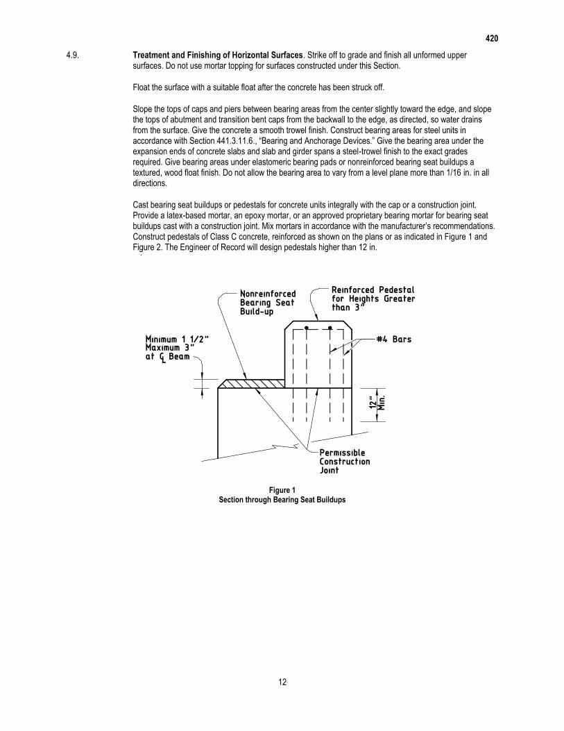
420
12
4.9. Treatment and Finishing of Horizontal Surfaces. Strike off to grade and finish all unformed upper surfaces. Do not use mortar topping for surfaces constructed under this Section.
Float the surface with a suitable float after the concrete has been struck off.
Slope the tops of caps and piers between bearing areas from the center slightly toward the edge, and slope the tops of abutment and transition bent caps from the backwall to the edge, as directed, so water drains from the surface. Give the concrete a smooth trowel finish. Construct bearing areas for steel units in accordance with Section 441.3.11.6., “Bearing and Anchorage Devices.” Give the bearing area under the expansion ends of concrete slabs and slab and girder spans a steel-trowel finish to the exact grades required. Give bearing areas under elastomeric bearing pads or nonreinforced bearing seat buildups a textured, wood float finish. Do not allow the bearing area to vary from a level plane more than 1/16 in. in all directions.
Cast bearing seat buildups or pedestals for concrete units integrally with the cap or a construction joint. Provide a latex-based mortar, an epoxy mortar, or an approved proprietary bearing mortar for bearing seat buildups cast with a construction joint. Mix mortars in accordance with the manufacturer’s recommendations. Construct pedestals of Class C concrete, reinforced as shown on the plans or as indicated in Figure 1 and Figure 2. The Engineer of Record will design pedestals higher than 12 in.
Figure 1
Section through Bearing Seat Buildups

420
13
Figure 2
Plan View of Bearing Seat Buildups
4.10. Curing Concrete. Obtain approval of the proposed curing methods, equipment, and materials before placing concrete. The Engineer may require the same curing methods for like portions of a single structure. Inadequate curing or facilities may delay all concrete placements on the job until remedial action is taken.
A curing day is a calendar day when the temperature, taken in the shade away from artificial heat, is above 50°F for at least 19 hr. or, on colder days if the temperature of all surfaces of the concrete is maintained above 40°F, for the entire 24 hr. The required curing period begins when all concrete has attained its initial set unless indicated otherwise. Tex-440-A may be used to determine when the concrete has attained its initial set.
Cure all concrete for 4 consecutive days except as allowed for the curing options listed below. Use form or membrane curing for vertical surfaces unless otherwise approved. Use only water curing for horizontal surfaces of HPC or mass concrete. Use water or membrane curing for horizontal or unformed surfaces for all other concrete.
Use one of the following curing options for vertical surfaces, unless indicated otherwise.
Form cure for 48 hr. after placement.
Form cure for 12 hr. after placement followed by membrane curing.
For HPC Concrete, form cure for 48 hr. after placement followed by membrane curing.
For mass concrete, form cure as required by the heat control plan followed by membrane curing if forms
are removed before 4 days.
Apply membrane curing, if used, within 2 hr. of form removal.
Use only water curing in accordance with this Section for the top surface of any concrete unit upon which concrete is to be placed and bonded at a later interval (stub walls, caps with backwalls, risers, etc.).
Cure all other concrete as specified in the pertinent Items. Use the following methods for curing concrete, subject to the requirements of this Item.
4.10.1. Form Curing. When forms are left in intimate contact with the concrete, other curing methods are not required except for exposed surfaces and for cold weather protection. Use another approved curing method if forms are removed before the 4-day required curing period.

420
14
4.10.2. Water Curing. Keep all exposed surfaces of the concrete wet continuously for the required curing time. Use water curing in accordance with concrete mixing water in Section 421.2.5., “Water.” Do not use seawater or water that stains or leaves an unsightly residue.
4.10.2.1. Blankets. Keep the concrete continuously wet by maintaining wet cotton or burlap mats in direct contact with the concrete for the required curing time. Weight the mats adequately to provide continuous contact with all concrete. Cover surfaces that cannot be cured by direct contact with mats, forming an enclosure well anchored to the forms or ground so outside air cannot enter the enclosure. Provide sufficient moisture inside the enclosure to keep all surfaces of the concrete wet.
4.10.2.2. Water Spray. Overlap sprays or sprinklers to keep all unformed surfaces continuously wet.
4.10.2.3. Ponding. Cover the surfaces with at least 2 in. of clean granular material, kept wet at all times, or at least 1 in. deep water. Use a dam to retain the water or saturated granular material.
4.10.3. Membrane Curing. Choose either Type 1-D or Type 2 membrane-curing compound unless otherwise shown on the plans. Use the same type of curing compound on an individual member.
Apply membrane curing just after free moisture has disappeared at a rate of approximately 180 sq. ft. per gallon. Do not spray curing compound on projecting reinforcing steel or concrete that will later form a construction joint. Do not apply membrane curing to dry surfaces. Dampen formed surfaces and surfaces that have been given a first rub so they are moist at the time of application of the membrane.
Leave the film unbroken for the minimum curing period specified when membrane is used for complete curing. Correct damaged membrane immediately by reapplication of membrane. Polyethylene sheeting, burlap-polyethylene mats, or laminated mats in close contact with the concrete surfaces are equivalent to membrane curing.
4.11. Removal of Forms and Falsework. Remove forms for vertical surfaces after the concrete has aged a minimum of 12 hr. after initial set provided the removal can be done without damage to the concrete unless otherwise directed. Keep forms for mass placements in place for 4 days following concrete placement unless otherwise approved based on the outcome of the heat control plan outlined in Section 420.4.7.14., “Mass Placements.”
Leave in place weight-supporting forms and falsework spanning more than 1 ft. for all bridge components and culvert slabs except as directed otherwise until the concrete has attained a compressive strength of 2,500 psi. Remove forms for other structural components as necessary.
Remove inside forms (walls and top slabs) for box culverts and sewers after concrete has attained a compressive strength of 1,800 psi if an approved overhead support system is used to transfer the weight of the top slab to the walls of the box culvert or sewer before removal of the support provided by the forms.
Forms or parts of forms may be removed only if constructed to permit removal without disturbing forms or falsework required to be left in place for a longer period on other portions of the structure.
Remove all metal appliances used inside forms for alignment to a depth of at least 1/2 in. from the concrete surface. Make the appliances so metal may be removed without undue chipping or spalling of the concrete, and so it leaves a smooth opening in the concrete surface when removed. Do not burn off rods, bolts, or ties.
Remove all forms and falsework unless otherwise directed.
4.12. Defective Work. Repair defective work as soon as possible. Remove and replace at the expense of the Contractor any defect that cannot be repaired to the satisfaction of the Engineer.
4.13. Ordinary Surface Finish. Apply an ordinary surface finish to all concrete surfaces. Provide flat or textured surfaces as specified with uniform appearance. Address defects and surface irregularities not consistent with the intent of the expected finish by the following:

420
15
Chip away all loose or broken material to sound concrete where porous, spalled, or honeycombed areas
are visible after form removal.
Repair spalls in accordance with the procedures outlined in the Concrete Repair Manual available on
the Department’s website.
Clean and fill holes or spalls caused by the removal of form ties, etc., with latex grout, cement grout, or
epoxy grout as approved. Fill only the holes. Do not blend the patch with the surrounding concrete. On
surfaces to receive a rub finish in accordance with Item 427, “Surface Finishes for Concrete,” chip out
exposed parts of metals chairs to a depth of 1/2 in. and repair the surface.
Remove all fins, rust staining, runs, drips, or mortar from surfaces that will be exposed. Smooth all form
marks and chamfer edges by grinding or dry-rubbing.
Ensure all repairs are dense, well-bonded, and properly cured. Finish exposed large repairs to blend
with the surrounding concrete where a higher class of finish is not specified.
Apply an ordinary surface finish as the final finish to the following exposed surfaces unless noted otherwise:
inside and top of inlets,
inside and top of manholes,
inside of sewer appurtenances, and
inside of culvert barrels.
Form marks and chamfer edges do not need to be smoothed for the inside of culvert barrels.
5. MEASUREMENT
This Item will be measured by the cubic yard, square yard, foot, square foot, or by each structure.
5.1. General. Concrete quantities will be based on the dimensions shown on the plans or those established in writing by the Engineer.
In determining quantities, no deductions will be made for chamfers less than 2 in. or for embedded portions of steel or prestressed concrete beams, piling, anchor bolts, reinforcing steel, drains, weep holes, junction boxes, electrical or telephone conduit, ducts and voids for prestressed tendons, or embedded portions of light fixtures.
Variation in concrete headwall quantity incurred when an alternate bid for pipe is permitted will not be cause for payment adjustment.
Quantities revised by a change in design, measured as specified, will be increased or decreased and included for payment.
5.2. Plans Quantity. Structure elements designated in Table 1 and measured by the cubic yard are plans quantity measurement items. The quantity to be paid for plans quantity items is the quantity shown in the proposal unless modified by Article 9.2., “Plans Quantity Measurement.” Additional measurements or calculations will be made if adjustments of quantities are required.
No adjustment will be made for footings or other in-ground elements where the Contractor has been allowed to place concrete in an excavation without forms.

420
16
Table 1 Plans Quantity Payment
(Cubic Yard Measurement Only)
Culverts and culvert wing walls Abutments
Headwalls for pipe Footings
Retaining walls Pile bent caps
Inlets and manholes Post-tensioned elements
Note—Other elements, including pier and bent concrete, may be paid for as “plans quantity” when shown on the plans.
5.3. Measured in Place. Items not paid for as “plans quantity” will be measured in place.
6. PAYMENT
The work performed and materials furnished in accordance with this Item and measured as provided under “Measurement” will be paid for at the unit price bid for the class of concrete and element identified and by the special designation when appropriate. This price is full compensation for furnishing, hauling, and mixing concrete materials; furnishing, bending, fabricating, splicing, welding and placing the required reinforcement; clips, blocks, metal spacers, ties, wire, or other materials used for fastening reinforcement in place; furnishing, placing, and stressing post-tensioning system; placing, finishing, and curing concrete; mass placement controls; applying ordinary surface finish; furnishing and placing drains, metal flashing strips, and expansion-joint material; excavation, subgrade preparation; and forms and falsework, equipment, labor, tools, and incidentals.
Price will be adjusted in accordance with Article 421.6., “Measurement and Payment” when required to address non-compliance of project acceptance testing.
Design and installation of foundations for falsework is at the Contractor’s expense.
In addition to the work described above, for extending structures the unit prices bid for the various classifications of concrete shown are full compensation for removing and disposing of, if necessary, the designated portion of the existing structure; removing, stockpiling if necessary, and replacing headwall units for reuse; cleaning, bending, and cutting of exposed reinforcing steel; splicing of new reinforcing steel to existing reinforcing steel; installation of dowels; and cleaning and preparing existing concrete surfaces.

441
1
Item 441
Steel Structures
1. DESCRIPTION
Fabricate and erect structural steel and other metals used for steel structures or for steel portions of structures.
2. MATERIALS
2.1. Base Metal. Use metal that meets Item 442, “Metal for Structures.”
2.2. Approved Electrodes and Flux-Electrode Combinations. Use only electrodes and flux-electrode combinations found on the Department’s MPL. To request a product be added to this list or to renew an expired approval, electronically submit a current Certificate of Conformance containing all tests required by the applicable AWS A5 specification according to the applicable welding code (for most construction, AASHTO/AWS D1.5, Bridge Welding Code, or AWS D1.1, Structural Welding Code—Steel) to the Construction Division.
2.3. High-Strength Bolts. Use fasteners that meet Item 447, “Structural Bolting.” Use galvanized fasteners on field connections of bridge members when ASTM A325 bolts are specified and steel is painted.
2.4. Paint Systems. Provide the paint system (surface preparation, primer, intermediate, and appearance coats as required) shown on the plans. Provide System IV if no system is specified.
2.4.1. Standard Paint Systems. Standard paint systems for painting new steel include the following:
2.4.1.1. System III-B. Provide paint in accordance with DMS-8101, “Structural Steel Paints-Performance.” Provide inorganic zinc (IOZ) prime coat, epoxy intermediate coat, and urethane appearance coat for all outer surfaces except those to be in contact with concrete. Provide epoxy zinc prime coat for touchup of IOZ.
2.4.1.2. System IV. Provide paint in accordance with DMS-8101, “Structural Steel Paints-Performance.” Provide IOZ prime coat and acrylic latex appearance coat for all outer surfaces except those to be in contact with concrete. Provide epoxy zinc prime coat for touchup of IOZ.
2.4.2. Paint Inside Tub Girders and Closed Boxes. Provide a white polyamide cured epoxy for all interior surfaces, including splice plate but excluding the faying surfaces, unless otherwise shown on the plans. Provide IOZ primer meeting the requirements of DMS-8101, “Structural Steel Paints—Performance,” to all interior faying surfaces and splice plates.
2.4.3. Special Protection System. Provide the type of paint system shown on the plans or in special provisions to this Item. Special Protection Systems must have completed NTPEP Structural Steel Coatings (SSC) testing regimen as a complete system, with full data available through NTPEP.
2.4.4. Galvanizing. Provide galvanizing, as required, in accordance with Item 445, “Galvanizing.”
2.4.5. Paint over Galvanizing. Paint over galvanized surfaces, when required, in accordance with Item 445, “Galvanizing.”
2.4.6. Field Painting. Provide field paint, as required, in accordance with Item 446, “Field Cleaning and Painting Steel.”

441
2
3. CONSTRUCTION
3.1. General Requirements.
3.1.1. Applicable Codes. Perform all fabrication of bridge members in accordance with AASHTO/NSBA Steel Bridge Collaboration S2.1. Follow all applicable provisions of the appropriate AWS code (D1.5 or D1.1) except as otherwise noted on the plans or in this Item. Weld sheet steel (thinner than 1/8 in.) in accordance with ANSI/AWS D1.3, Structural Welding Code—Sheet Steel. Unless otherwise stated, requirements of this Item are in addition to the requirements of S2.1 for bridge members. Follow the more stringent requirement in case of a conflict between this Item and S2.1. Perform all bolting in accordance with Item 447, “Structural Bolting.”
Fabricate railroad underpass structures in accordance with the latest AREMA Manual for Railway Engineering and this Item. In the case of a conflict between this Item and the AREMA manual, the more stringent requirements apply.
3.1.2. Notice of Fabrication. Give adequate notice before commencing fabrication work as specified in Table 1. Include a schedule for all major fabrication processes and dates when inspections are to occur.
Table 1 Notice of Beginning Work
Plant Location Notice Required
In Texas 7 days
In the contiguous United States 21 days
Outside the contiguous United States 60 days
Perform no Department work in the plant before the Engineer authorizes fabrication. The Contractor must bear all Department travel costs when changes to their fabrication or inspection schedules are not adequately conveyed to the Department.
When any structural steel is fabricated outside of the contiguous 48 states, the additional cost of inspection will be in accordance with Article 6.4., “Sampling, Testing, and Inspection.”
3.1.3. Bridge Members. Primary bridge members include:
web and flanges of plate, tub, and box girders;
rolled beams and cover plates;
floor beam webs and flanges;
arch ribs and arch tie beams or girders;
truss members;
diaphragm members for curved plate girders or beams;
pier diaphragm members for tub girders;
splice plates for primary members; and
any other member designated as “primary” or “main” on the plans.
Secondary bridge members include:
bracing (diaphragms, cross frames, and lateral bracing); and
all other miscellaneous bridge items not considered primary bridge members.
3.1.4. Responsibility. The Contractor is responsible for the correctness and completeness of shop drawings and for the fit of shop and field connections.

441
3
3.1.5. Qualification of Plants and Personnel.
3.1.5.1. Plants. Fabrication plants that produce bridge members must be approved in accordance with DMS-7370, “Steel Bridge Member Fabrication Plant Qualification.” The Department’s MPL has a list of approved bridge member fabrication plants.
Fabrication plants that produce non-bridge steel members listed below must be approved in accordance with DMS-7380, “Steel Non-Bridge Member Fabrication Plant Qualification.” The Construction Division maintains a list of approved non-bridge fabrication plants for the following items:
Roadway Illumination Poles,
High Mast Illumination Poles,
High Mast Rings and Support Assemblies,
Overhead Sign Support Structures,
Traffic Signal Poles, and
Intelligent Transportation System (ITS) Poles
The Department will evaluate non-bridge member fabrication plants for competence of the plant, equipment, organization, experience, knowledge, and personnel to produce acceptable work.
3.1.5.2. Personnel. Provide a QC staff qualified in accordance with the applicable AWS code. Provide an adequate number of qualified QC personnel for each specific production operation. QC must be on-site and independent of production personnel, as the Engineer determines. QC personnel must be proficient in utilizing the applicable plans, specifications, and test methods, and in verifying compliance with the plant QC and production procedures. Welding inspectors must be current AWS Certified Welding Inspectors for bridge member plants, and for non-bridge member plants requiring Department approval per DMS-7380, “Steel Non-Bridge Member Fabrication Plant Qualification.” The QC staff must provide inspection of all materials and workmanship before the Department’s inspection. Provide the Department inspector with adequate personnel and equipment needed to move material for inspection access. QC is solely the Contractor’s responsibility.
3.1.5.3. Nondestructive Testing (NDT). Personnel performing NDT must be qualified in accordance with the applicable AWS code and the employer’s Written Practice. Level III personnel who qualify AS Level I and Level II inspectors must be certified by ASNT for which the NDT Level III is qualified. Testing agencies and individual third-party contractors must also successfully complete periodic audits for compliance, performed by the Department. In addition, ultrasound technicians must pass a hands-on test the Construction Division administers. This will remain current provided they continue to perform testing on Department materials as evidenced by test reports requiring their signature. A technician who fails the hands-on test must wait 6 months before taking the test again. Qualification to perform ultrasonic testing will be revoked when the technician’s employment is terminated or when the technician goes 6 months without performing a test on a Department project. The technician must pass a new hands-on test to be re-certified.
3.1.5.4. Welding Procedure Specifications Qualification Testing. For bridge member fabrication, laboratories performing welding procedure specifications (WPSs) qualified by testing must be approved in accordance with DMS-7360, “Qualification Procedure for Laboratories Performing Welding Procedure Qualification Testing.” The Department’s MPL has a list of laboratories approved to perform WPS qualification testing.
3.1.6. Drawings.
3.1.6.1. Erection Drawings. Submit erection drawings prepared by a licensed professional engineer, including calculations, for approval in accordance with Item 5, “Control of the Work,” at least 4 weeks before erecting any portion of field-spliced (welded or bolted) girders, railroad underpasses, trusses, arches, or other members for which erection drawings are required on the plans. Include drawings and calculations for any temporary structures used to support partially erected members. Erection drawings are not required for rolled I-beam units unless otherwise noted on the plans.
441
4
Prepare erection drawings following the procedures outlined in Section 2.2 of the AASHTO/NSBA Steel Bridge Collaboration S10.1. As a minimum, include:
plan of work area showing structure location relative to supports and all obstructions;
equipment to be used including allowable load information;
erection sequence for all pieces;
member weights and center of gravity location of pieces to be lifted;
locations of cranes, holding cranes, and temporary supports (falsework), including when to release load
from temporary supports and holding cranes;
details of falsework including specific bracing requirements with maximum allowable design wind speed
clearly indicated;
girder lifting points;
diaphragm and bracing requirements; and
minimum connection requirements when more than the standard requirements.
Perform girder erection analyses using UT-Lift and UT-Bridge software available on the Department’s website or other suitable commercial software. Ensure temporary stresses in members being erected will not cause permanent damage and that stability is maintained throughout the erection operations. Provide actual input files and output results from UT-Lift and UT-Bridge, or graphical and hard copy results from commercial software programs.
Do not proceed if site conditions differing from those depicted on the approved erection drawings could affect temporary support stresses, erected girders, or public safety in any manner. Revise erection drawings and resubmit to the Engineer for approval before proceeding if site conditions could affect these things.
3.1.6.2. Shop Drawings. Prepare and electronically submit shop drawings before fabrication for each detail of the general plans requiring the use of structural steel, forgings, wrought iron, or castings as documented in the Guide to Electronic Shop Drawing Submittal available on the Bridge Division website and as directed for other items the standard specifications require.
Indicate joint details on shop drawings for all welds. Provide a title block on each sheet in the lower right corner that includes:
project identification data including federal and state project numbers,
sheet numbering for the shop drawings,
name of the structure or stream for bridge structures,
name of owner or developer,
name of the fabricator or supplier, and
name of the Contractor.
Provide one set of 11 × 17-in. approved shop drawings in hardcopy to the Department for the inspector at the fabrication plant.
3.1.6.2.1. Bridge Members. Prepare drawings in accordance with AASHTO/NSBA Steel Bridge Collaboration G1.3, “Shop Detail Drawing Presentation” unless otherwise approved. Print a bill of material on each sheet, including the Charpy V-Notch (CVN) and fracture-critical requirements, if any, for each piece. Indicate fracture-critical areas of members.
3.1.6.2.2. Non-Bridge Members. Furnish shop drawings for non-bridge members when required by the plans or pertinent Items.
3.1.7. Welding Procedure Specifications (WPSs). Submit WPSs and test reports in accordance with the applicable AWS code to the Construction Division before fabrication begins, and notify the Engineer which procedures will be used for each joint or joint type. Do not begin fabrication until the Engineer approves WPSs.

441
5
Post the approved WPSs for the welding being performed on each welding machine, or use another approved method of ensuring the welder has access to the procedure information at all times.
3.1.8. Documentation. Before beginning fabrication, provide a completed Material Statement Form 1818 (a.k.a. D-9-USA-1) with supporting documentation (such as mill test reports (MTRs)) that the producing mill issues and qualified personnel verifies. Ensure the documentation legibly reflects all information the applicable ASTM specifications require. Supply documents electronically to the Department.
Provide a copy of the shipping or storage invoice, as material is shipped or placed in approved storage that reflects:
member piece mark identification and calculated weight per piece from the contract drawings,
number of pieces shipped or in storage,
total calculated weight for each invoice per bid item, and
the unique identification number of the shipping or storage invoice.
The inspector’s acceptance of material or finished members will not prohibit subsequent rejection if the material or members are found to be damaged or defective. Replace rejected material promptly.
3.1.9. Material Identification. Assembly-mark individual pieces and issue cutting instructions to the shop using a system that will maintain identity of the original piece.
Identify structural steel by standard and grade of steel. Also differentiate between material toughness requirements (CVN, fracture-critical) as well as any other special physical requirements. In addition, identify structural steel for primary members by mill identification numbers (heat numbers). Use an approved identification system. Use either paint or low-stress stencils to make identification markings on the metal. Mark the material as soon as it enters the shop and carry the markings on all pieces through final fabrication. Transfer the markings before cutting steel for primary members of bridge structures into smaller pieces. Loss of identification marking on any piece, with no other positive identification, or loss of heat number identification on any primary member piece will render the piece unacceptable for use. Unidentifiable material may be approved for use after testing to establish acceptability to the satisfaction of the Engineer. Have an approved testing facility perform testing and a licensed professional engineer sign and seal the results.
3.2. Welding.
3.2.1. Details.
3.2.1.1. Rolled Edges. Trim plates with rolled edges used for webs by thermal cutting.
3.2.1.2. Weld Tabs. Use weld tabs at least 2 in. long for manual and semi-automatic processes, at least 3 in. long for automatic processes, and in all cases at least as long as the thickness of the material being welded. Use longer weld tabs as required for satisfactory work.
3.2.1.3. Weld Termination. Terminate fillet welds approximately 1/4 in. from the end of the attachment except for galvanized structures and flange-to-web welds, for which the fillet weld must run the full length of the attachment, unless otherwise shown on the plans.
3.2.1.4. No-Paint Areas at Field-Welded Connections. Keep surfaces within 4 in. of groove welds or within 2 in. of fillet welds free from shop paint.
3.2.1.5. Galvanized Assemblies. Completely seal all edges of tightly contacting surfaces by welding before galvanizing.
3.2.1.6. Submerged-Arc Welding (SAW). Do not use hand-held semiautomatic SAW for welding bridge members unless altered to provide automatic guidance or otherwise approved.

441
6
3.2.1.7. Tubular Stiffeners for Bridge Members. Weld in accordance with AWS D1.5, using WPSs qualified based on tests on ASTM A709 Gr. 50W or Gr. 50 steel for non-weathering applications and ASTM A709 Gr. 50W steel for weathering applications.
3.2.1.8. Non-Bridge Member Weathering Steel Welds. Provide weld metal with atmospheric corrosion resistance and coloring characteristics similar to that of the base metal for weathering steel structures fabricated per AWS D1.1.
3.2.2. Shop Splices.
3.2.2.1. Shop Splice Locations. Keep at least 6 in. between shop splices and stiffeners or cross-frames. Obtain approval for shop splices added after shop drawings are approved.
3.2.2.2. Grinding Splice Welds. Grind shop groove welds in flange plates smooth and flush with the base metal on all surfaces whether the joined parts are of equal or unequal thickness. Grind so the finished grinding marks run in the direction of stress, and keep the metal below the blue brittle range (below 350°F). Groove welds in web plates, except at locations of intersecting welds, need not be ground unless shown on the plans except as required to meet AWS welding code requirements.
3.2.3. Joint Restraint. Never restrain a joint on both sides when welding.
3.2.4. Stiffener Installation.
3.2.4.1. Flange Tilt. Members must meet combined tilt and warpage tolerances before the installation of stiffeners. Cut stiffeners to fit acceptable flange tilt and cupping. Minor jacking or hammering that does not permanently deform the material will be permitted.
3.2.4.2. Stiffeners Near Field Splices. Tack weld intermediate stiffeners within 12 in. of a welded field splice point in the shop. Weld the stiffeners in the field in accordance with Item 448, “Structural Field Welding,” after the splice is made.
3.2.5. Nondestructive Testing (NDT). Perform magnetic particle testing (MT), radiographic testing (RT), or ultrasonic testing (UT) at the Contractor’s expense as specified in D1.5 for bridge structures. The Engineer will periodically witness, examine, verify, and interpret NDT. Additional welds may be designated for NDT on the plans. Retest repaired groove welds per the applicable AWS code after repairs are made and have cooled to ambient temperature. Complete NDT and repairs before assembly of parts into a member, but after any heat-correction of weld distortion.
3.2.5.1. Radiographic Testing. Radiographs must have a density of at least 2.5 and no more than 3.5, as a radiographer confirms. The density in any single radiograph showing a continuous area of constant thickness must not vary in this area by more than 0.5. Use only ASTM System Class I radiographic film as described in ASTM E1815. Use low-stress stencils to make radiograph location identification marks on the steel.
3.2.5.2. Ultrasonic Testing. Have UT equipment calibrated yearly by an authorized representative of the equipment manufacturer or by an approved testing laboratory.
3.2.5.3. Magnetic Particle Testing. Use half-wave rectified DC when using the yoke method unless otherwise approved. Welds may be further evaluated with prod method for detecting centerline cracking.
3.2.6. Testing of Galvanized Weldments. If problems develop during galvanizing of welded material, the Engineer may require a test of the compatibility of the combined galvanizing and welding procedures in accordance with this Section and may require modification of one or both of the galvanizing and welding procedures.
Prepare a test specimen with a minimum length of 12 in. using the same base material, with the same joint configuration, and using the welding procedure proposed for production work if testing is required. Clean and galvanize this test specimen using the same conditions and procedure that will be applied to the production galvanizing.

441
7
Examine the test specimen after galvanizing. There must be no evidence of excessive buildup of zinc coating over the weld area. Excessive zinc coating buildup will require modification of the galvanizing procedure.
Remove the zinc from the weld area of the test specimen and visually examine the surface. There must be no evidence of loss of weld metal or any deterioration of the base metal due to the galvanizing or welding procedure. Modify the galvanizing or welding procedure as required if there is evidence of deterioration or loss of weld metal, and run a satisfactory retest on the modified procedures before production work. Report procedures and results on the galvanized weldment worksheet provided by the Department.
3.3. Bolt Holes. Detail holes on shop drawings 1/16 in. larger in diameter than the nominal bolt size shown on the plans unless another hole size is shown on the plans.
Thoroughly clean the contact surfaces of connection parts in accordance with Item 447, “Structural Bolting,” before assembling them for hole fabrication. Make holes in primary members full-size (by reaming from a subsize hole, drilling full-size, or punching full-size where permissible) only in assembly unless otherwise approved.
Ream and drill with twist drills guided by mechanical means unless otherwise approved. If subpunching holes, punch them at least 3/16 in. smaller than the nominal bolt size. Submit the proposed procedures for approval to accomplish the work from initial drilling or punching through check assembly when numerically controlled (N/C) equipment is used. Use thermal cutting for holes only with permission of the Engineer. Permission for thermal cutting is not required for making slotted holes, when slotted holes are shown on the plans, by drilling or punching 2 holes and then thermally cutting the straight portion between them. Perform all thermal cutting in accordance with Section 441.3.5.1., “Thermal Cutting.”
Slightly conical holes that naturally result from punching operations are acceptable provided they do not exceed the tolerances of S2.1. The tolerance for anchor bolt hole diameter for bridge bearing assemblies is +1/8 in., −0.
3.4. Dimensional Tolerances. Meet tolerances of the applicable AWS specifications and S2.1 except as modified in this Section.
3.4.1. Rolled Sections. Use ASTM A6 mill tolerances for rolled sections, except D1.5 camber tolerances apply to rolled sections with a specified camber.
3.4.2. Flange Straightness. Ensure flanges of completed girders are free of kinks, short bends, and waviness that depart from straightness or the specified camber by more than 1/8 in. in any 10 ft. along the flange. Rolled material must meet this straightness requirement before being laid out or worked. Plates must meet this requirement before assembly into a member. Inspect the surface of the metal for evidence of fracture after straightening a bend or buckle. The Engineer may require nondestructive testing.
3.4.3. Alignment of Deep Webs in Welded Field Connections. For girders 48 in. deep or deeper, the webs may be slightly restrained while checking compliance with tolerances of S2.1 for lateral alignment at field-welded connections. In the unrestrained condition, webs 48 in. deep or deeper must meet the tolerances of Table 2. Girders under 48 in. deep must meet the alignment tolerances of S2.1.

441
8
Table 2 Web Alignment Tolerances for Deep Girders
Web Depth (in.)
Maximum Web Misalignment (in.)
48 1/16
60 1/8
72 1/4
84 5/16
96 5/16
108 3/8
120 7/16
132 7/16
144 1/2
3.4.4. Bearings. Correct bearing areas of shoes, beams, and girders using heat, external pressure, or both. Grind or mill only if the actual thickness of the member is not reduced by more than 1/16 in. below the required thickness.
3.4.4.1. I-Beams, Plate Girders, and Tub Girders. The plane of the bearing area of beams and girders must be perpendicular to the vertical axis of the member within 1/16 in. in any 24 in.
3.4.4.2. Closed Box Girders. Meet these tolerances:
The plane of the bearing areas of the box girder is perpendicular to the vertical axis of the girder within
1/16 in. across any horizontal dimension of the bearing.
The planes of the beam supports on the box girder are true to the vertical axis of the supported beams
or girders to 1/16 in. in any 24 in.
In the shop, verify the plane of all bearing areas with the box placed on its bearings to field grade, using an approved process for verification.
3.4.4.3. Shoes. Meet these tolerances:
The top bolster has the center 75% of the long dimension (transverse to the girder) true to 1/32 in., with
the remainder true to 1/16 in., and is true to 1/32 in. across its entire width in the short dimension
(longitudinal to the girder).
The bottom bolster is true to 1/16 in. across its diagonals.
For a pin and rocker type expansion shoe, the axis of rotation coincides with the central axis of the pin.
When the shoe is completely assembled, as the top bolster travels through its full anticipated range, no
point in the top bolster plane changes elevation by more than 1/16 in. and the top bolster does not
change inclination by more than 1 degree, for the full possible travel.
3.4.4.4. Beam supports. Fabricate beam support planes true to the box girder bearing to 1/16 in. in the short direction and true to the vertical axis of the nesting girders to 1/16 in.
3.4.5. End Connection Angles. For floor beams and girders with end connection angles, the tolerance for the length back to back of connection angles is ±1/32 in. Do not reduce the finished thickness of the angles below that shown on the shop drawings if end connections are faced.
3.5. Other Fabrication Processes.
3.5.1. Thermal Cutting. Use a mechanical guide to obtain a true profile. Hand-cut only where approved. Hand-cutting of radii for beam copes, weld access holes, and width transitions is permitted if acceptable profile and finish are produced by grinding. Provide a surface finish on thermal-cut surfaces, including holes, in accordance with D1.5 requirements for base metal preparation. Obtain approval before using other cutting processes.

441
9
3.5.2. Oxygen-Gouging. Do not oxygen-gouge quenched and tempered (Q&T), normalized, or thermo-mechanically controlled processed (TMCP) steel.
3.5.3. Annealing and Normalizing. Complete all annealing or normalizing (as defined in ASTM A941) before finished machining, boring, and straightening. Maintain the temperature uniformly throughout the furnace during heating and cooling so the range of temperatures at all points on the member is no more than 100°F.
3.5.4. Machining. Machine the surfaces of expansion bearings so the travel direction of the tool is in the direction of expansion.
3.5.5. Camber. Complete cambering in accordance with S2.1 before any heat-curving.
3.5.6. Heat Curving. Heat-curve in accordance with S2.1. The methods in the AASHTO bridge construction specifications are recommended. Attach cover plates to rolled beams before heat-curving only if the total thickness of one flange and cover plate is less than 2-1/2 in. and the radius of curvature is greater than 1,000 ft. Attach cover plates for other rolled beams only after heat-curving is completed. Locate and attach connection plates, diaphragm stiffeners, and bearing stiffeners after curving, unless girder shrinkage is accounted for.
3.5.7. Bending of Quenched and Tempered Steels. The cold-bending radius limitations for HPS 70W in S2.1 apply to all Q&T steels.
3.6. Nonconformance Reports (NCRs). Submit an NCR to the Engineer for approval when the requirements of this Item are not met. Submit NCRs in accordance with the Construction Division’s NCR guidelines document. Have readily available access to the services of a licensed professional engineer experienced in steel structures design and fabrication. This licensed professional engineer may be responsible for reviewing potentially structurally deficient members in accordance with the NCR guidelines document. Receive Department approval before beginning repairs. Perform all repair work in strict compliance with the approved NCR and repair procedure.
3.7. Shop Assembly.
3.7.1. General Shop Assembly. Shop-assemble field connections of primary members of trusses, arches, continuous beam spans, bents, towers (each face), plate girders, field connections of floor beams and stringers (including for railroad structures), field-bolted diaphragms for curved plate girders and railroad underpasses, and rigid frames. Field-bolted cross-frames and rolled-section diaphragms do not require shop assembly. Complete fabrication, welding (except for shear studs), and field splice preparation before members are removed from shop assembly. Obtain approval for any deviation from this procedure. The Contractor is responsible for accurate geometry.
Use a method and details of preassembly consistent with the erection procedure shown on the erection plans and camber diagrams. The sequence of assembly may start from any location in the structure and proceed in one or both directions. An approved method of sequential geometry control is required unless the full length of the structure is assembled.
Verify by shop assembly the fit of all bolted and welded field connections between bent cap girders and plate girders or between plate girders and floor beams.
Do not measure horizontal curvature and vertical camber for final acceptance until all welding and heating operations are completed and the steel has cooled to a uniform temperature. Check horizontal curvature and vertical camber in a no-load condition.
3.7.2. Bolted Field Connections. Each shop assembly, including camber, alignment, accuracy of holes, and fit of milled joints, must be approved before the assembly is dismantled.
Assemble with milled ends of compression members in full bearing. Assemble non-bearing connections to the specified gap. Ream all subsize holes to the specified size while the connections are assembled, or drill

441
10
full size while the connections are assembled. Notify the Engineer before shipping if fill plates or shims are added. Adding or increasing the thickness of shims or fill plates in bearing connections requires approval. Use drift pins and snug-tight bolts during the drilling process to ensure all planes of the connection (webs and flanges) can be assembled simultaneously. Do not use tack welds to secure plates while drilling.
Secure parts not completely bolted in the shop with temporary bolts to prevent damage in shipment and handling. Never use tack welds in place of temporary bolts.
Match-mark connecting parts in field connections using low-stress stencils in accordance with the diagram in the erection drawings.
3.7.3. Welded Field Connections. Mill or grind bevels for groove welds. Do not cut into the web when cutting the flange bevel adjacent to the web. End preparation, backing, and tolerances for girder splices must be in accordance with Item 448, “Structural Field Welding.” Details for all other field-welds must conform to the applicable AWS code unless otherwise shown on the plans.
In the shop, prepare ends of beams or girders to be field-welded taking into account their relative positions in the finished structure due to grade, camber, and curvature. Completely shop-assemble and check each splice. Match-mark the splice while it is assembled with low-stress stencils in accordance with the diagram in the erection drawings.
3.8. Finish and Painting.
3.8.1. Shop Painting. Perform shop painting of bridge members as required in DMS-8104, “Paint, Shop Application for Steel Bridge Members.” Grind corners on new steel items to be painted (except for the coatings on box and tub girder interiors) that are sharp or form essentially 90° angles to an approximately 1/16 in. flat surface before blast cleaning. (A corner is the intersection of 2 plane faces.) This requirement does not apply to punched or drilled holes. Do not omit shop paint to preserve original markings.
Ensure painted faying surfaces meet the required slip and creep coefficients for bolted connections as outlined in DMS-8104, “Paint, Shop Application for Steel Bridge Members.”
Use a Class A slip (minimum slip coefficient of 0.33) if no slip coefficient or corresponding surface condition is specified Perform all required testing at no expense to the Department.
Surface preparation and painting the interiors of Tub Girders and Closed Boxes is in accordance with DMS-8104, “Paint, Shop Application for Steel Bridge Members.”
3.8.2. Weathering Steel. Provide an SSPC-SP 6 blast in the shop to all fascia surfaces of unpainted weathering steel beams. Fascia surfaces include:
exterior sides of outermost webs and undersides of bottom flanges of plate girders and rolled beams,
all outer surfaces of tub girders and box girders,
all surfaces of truss members,
webs and undersides of bottom flanges of plate diaphragms,
bottom surfaces of floor beams, and
any other surfaces designated as “fascia” on the plans.
Do not mark fascia surfaces. Use one of the following methods as soon as possible to remove any markings or any other foreign material that adheres to the steel during fabrication and could inhibit the formation of oxide film:
SSPC-SP 1, “Solvent Cleaning,”
SSPC-SP 2, “Hand Tool Cleaning,”
SSPC-SP 3, “Power Tool Cleaning,” and
SSPC-SP 7, “Brush-off Blast Cleaning.”

441
11
Do not use acids to remove stains or scales. Feather out touched-up areas over several feet.
3.8.3. Machined Surfaces. Clean and coat machine-finished surfaces that are in sliding contact, particularly pins and pinholes, with a non-drying, water-repellent grease-type material containing rust-inhibitive compounds. Ensure the coating material contains no ingredients that might damage the steel. Protect machined surfaces from abrasive blasting.
3.9. Handling and Storage of Materials. Prevent damage when storing or handling girders or other materials. Remove or repair material damaged by handling devices or improper storage by acceptable means in accordance with ASTM A6 and the applicable AWS code.
Place stored materials on skids or acceptable dunnage above the ground. Keep materials clean. Shore girders and beams to keep them upright and free of standing water. Place support skids close enough to prevent excessive deflection in long members such as columns. Do not stack completed girders or beams at the jobsite.
Protect structural steel from salt water or other corrosive environments during storage and transit.
3.10. Marking and Shipping. Mark all structural members in accordance with the erection drawings. If a surface is painted, make the marks over the paint. Do not use impact-applied stencils to mark painted surfaces.
Mark the weight directly on all members weighing more than 3 tons.
Keep material clean and free from injury during loading, transportation, unloading, and storage. Pack bolts of each length and diameter, and loose nuts or washers of each size, separately and ship them in boxes, crates, kegs, or barrels. Plainly mark a list and description of the contents on the outside of each package.
3.11. Field Erection. Do not lift and place any steel member, including girders and diaphragms, over an open highway or other open travel way unless otherwise approved. Do not allow traffic to travel under erected members until sufficiently stable as shown on approved erection drawings.
3.11.1. Pre-Erection Conference. Schedule and attend a pre-erection conference with the Engineer at least 7 days before commencing steel erection operations. Do not install falsework or perform any erection operations before the meeting.
3.11.2. Methods and Equipment. Do not tack-weld parts instead of using erection bolts. Do not tack-weld parts to hold them in place for bolting. Provide falsework, tools, machinery, and appliances, including drift pins and erection bolts. Provide enough drift pins, 1/32 in. larger than the connection bolts, to fill at least 1/4 of the bolt holes for primary connections. Use erection bolts of the same diameter as the connection bolts.
Securely tie, brace, or shore steel beams or girders immediately after erection as shown on the erection drawings. Maintain bracing or shoring until the diaphragms are in place and as specified in the erection drawings. Protect railroad, roadway, and marine traffic underneath previously erected girders or beams from falling objects associated with other construction activities.
Only welders certified or working directly under the supervision of a foreman certified in accordance with Item 448, “Structural Field Welding,” may handle torches when applying heat to permanent structural steel members.
3.11.3. Falsework. Construct falsework in accordance with the erection plan. Construct foundations for shore towers as shown on erection drawings. Do not use timber mats with deteriorated timbers or soil to construct shore tower foundations. Notify the Engineer of completed falsework to obtain approval before opening roadway to traffic or starting girder erection activities. Ensure falsework is protected from potential vehicle impact. Inspect and maintain falsework daily. Use screw jacks or other approved methods to control vertical adjustment of falsework to minimize the use of shims.

441
12
3.11.4. Handling and Assembly. Accurately assemble all parts as shown on the plans and the approved shop drawings. Verify match-marks. Handle parts carefully to prevent bending or other damage. Do not hammer if doing so damages or distorts members. Do not weld any member for transportation or erection unless noted on the plans or approved by the Engineer.
3.11.4.1. Welded Connections. Weld flange splices to 50% of their thickness and meet the minimum erection bracing and support requirements before releasing the erection cranes, as shown on the plans and on the approved erection plans. Field-weld in accordance with Item 448, “Structural Field Welding.”
3.11.4.2. Bolted Connections. Before releasing the erection cranes:
install 50% of the bolts in the top and bottom flanges and the web with all nuts finger-tight,
meet the minimum erection bracing and support requirements shown on the plans and on the approved
erection plans, and
install top lateral bracing across the connection for tub girders, and fully tension the bolts connecting
the bracing to the top flanges.
Install high-strength bolts, including erection bolts, in accordance with Item 447, “Structural Bolting.” Clean bearing and faying surfaces for bolted connections in accordance with Item 447, “Structural Bolting.” Clean the areas of the outside ply under washers, nuts, and bolt heads before bolt installation. Ensure the required faying surface condition is present at the time of bolting.
3.11.5. Misfits. Correct minor misfits. Ream no more than 10% of the holes in a plate connection (flange or web), and ensure no single hole is more than 1/8 in. larger than the nominal bolt diameter. Submit proposed correction methods for members with defects that exceed these limits or prevent the proper assembly of parts. Straighten structural members in accordance with S2.1. Make all corrections in the presence of the Engineer at no expense to the Department. Do not remove and reweld gusset plates without approval.
3.11.6. Bearing and Anchorage Devices. Place all bearing devices such as elastomeric pads, castings, bearing plates, or shoes on properly finished bearing areas with full and even bearing on the concrete. Place metallic bearing devices on 1/4 in.-thick preformed fabric pads manufactured in accordance with DMS-6160, “Water Stops, Nylon-Reinforced Neoprene Sheet, and Elastomeric Pads,” to the dimensions shown on the plans. Provide holes in the pad that are no more than 1/4 in. larger than the bolt diameter.
Build the concrete bearing area up to the correct elevation once it has been placed below grade using mortar that meets Item 420, “Concrete Substructures,” and provide adequate curing. Use only mortar for build-ups between 1/8 in. and 3/8 in. thick. Use galvanized steel shims or other approved shim materials in conjunction with mortar if the bearing area must be raised more than 3/8 in.
Provide at least 75% contact of flange to shoe with no separation greater than 1/32 in. for beams and girders. Make corrections using heat or pressure in accordance with S2.1, or with galvanized shims. Correct small irregularities by grinding.
Provide at least 85% contact between the rocker plate and the base plate. Adjust the location of slotted holes in expansion bearings for the prevailing temperature. Adjust the nuts on the anchor bolts at the expansion ends of spans to permit free movement of the span. Provide lock nuts or burr the threads.
Remove all foreign matter from sliding or machine-finished surfaces before placing them in the structure.
Restore distorted bearing pads or expansion bearings to an equivalent 70°F position after completion of all welded or bolted splices, using an approved method of relieving the load on the bearing devices.
3.11.7. Erecting Forms. Do not erect forms until all welding or bolting is complete and the unit is positioned and properly set on the bearings unless otherwise noted on the plans.
3.11.8. Field Finish. Paint in accordance with Item 446, “Field Cleaning and Painting Steel.” Restore weathering steel that will remain unpainted to a uniform appearance by solvent cleaning, hand cleaning, power brush, or

441
13
blast cleaning after all welding and slab concrete placement has been completed. Remove from all unpainted weathering steel fascia surfaces (see Section 441.3.8.2., “Weathering Steel,”) any foreign material, including markings, that adheres to the steel and could inhibit formation of oxide film as soon as possible. Feather out touched-up areas over several feet. Do not use acids to remove stains or scales.
4. MEASUREMENT AND PAYMENT
The work performed, materials furnished, equipment, labor, tools, and incidentals will not be measured or paid for directly but will be subsidiary to pertinent Items.

442
1
Item 442
Metal for Structures
1. DESCRIPTION
Provide structural steel, high-strength bolts, forgings, steel castings, iron castings, wrought iron, steel pipe and tubing, aluminum castings and tubing, or other metals used in structures, except reinforcing steel and metal culvert pipe.
2. MATERIALS
Furnish mill test reports (MTRs), supplemental test documentation, and certifications required by this and other pertinent Items.
2.1. Structural Steel. The Engineer may sample and test steel in accordance with ASTM A370.
2.1.1. Bridge Structures. Provide the grade of ASTM A709 steel shown on the plans. Grade 50W, 50S, or HPS 50W may be substituted for Grade 50 at no additional cost to the Department. Use Zone 1 if no AASHTO temperature zone is shown on the plans.
2.1.2. Non-Bridge Structures.
2.1.2.1. Steel Classifications. Provide the types and grades of steel listed in this Section unless otherwise shown on the plans.
2.1.2.1.1. Carbon Steel. Meet ASTM A36.
2.1.2.1.2. Low-Alloy Steel. Meet the requirements of one of the following standards:
ASTM A529 Grade 50;
ASTM A572 Grade 50 or 55;
ASTM A588;
ASTM A709 Grade 50, 50S, 50W, or HPS 50W; or
ASTM A992.
Specify ASTM A6 supplemental requirement S18, “Maximum Tensile Strength,” for material used for sign, signal, and luminaire supports.
2.1.2.2. Impact Testing. Tension members and components of the following structure types, if more than 1/2 in. thick. Other members designated on the plans must meet the Charpy V-notch (CVN) requirements of Table 1:
base plates for roadway illumination assemblies, traffic signal pole assemblies, high mast illumination
poles, camera poles, and overhead sign supports;
pole mounting plates, arm mounting plates, and clamp-on plates for traffic signal pole assemblies;
arm stiffeners, pole gussets, and stiffeners for traffic signal pole long mast arm assemblies (50 ft. to
65 ft.);
pole shafts, ground sleeves, and handhole frames for high mast illumination poles;
W-columns, tower pipes, multiple-sided shafts, tower pipe and multiple-sided shaft connection plates,
chord angles, chord splice plates or angles, and truss bearing angles for truss type overhead sign
supports; and

442
2
pipe posts, pipe arms, post and arm flange plates, and handhole frames for monotube overhead sign
supports.
Table 1 CVN Requirements for Non-Bridge Steel
Material Thickness Minimum CVN
Toughness
ASTM A36, A53, A242, A500, A501, A709 Gr. 36, any other steel with minimum specified yield point below 40 ksi
up to 4" 15 ft.-lb. at 70°F
ASTM A572,1 A588,1 A633,1 any other steel with minimum specified yield point between 40 and 65 ksi, inclusive
up to 2" 15 ft.-lb. at 70°F
over 2" to 4", mechanically fastened
15 ft.-lb. at 70°F
over 2" to 4", welded 20 ft.-lb. at 70°F
Any steel with minimum specified yield point over 65 ksi and under 90 ksi2
up to 2-1/2" 20 ft.-lb. at 50°F
over 2-1/2" to 4", mechanically fastened
20 ft.-lb. at 50°F
over 2-1/2" to 4", welded 25 ft.-lb. at 50°F
1. Reduce the testing temperature by 15°F for each 10-ksi increment or fraction thereof above 65 ksi if the yield point of the material given on the MTR exceeds 65 ksi.
2. Reduce the testing temperature by 15°F for each 10-ksi increment or fraction thereof above 85 ksi if the yield point of the material given on the MTR exceeds 85 ksi.
Use the (H) frequency of testing for material with minimum specified yield point up to 50 ksi. Use the (P) frequency of testing for material with minimum specified yield point over 50 ksi. Ensure steel is sampled and tested in accordance with ASTM A673.
2.1.3. Other Components.
2.1.3.1. Miscellaneous Bridge Components. Provide steel that meets ASTM A36, A709 Grade 36, or A500 Grade B for members such as steel bearing components not bid under other Items, steel diaphragms for use with concrete bridges, and armor and finger joints, unless otherwise shown on the plans.
2.1.3.2. Shear Connectors and Anchors. Provide cold-drawn bars for stud shear connectors, slab anchors, and anchors on armor and finger joints that meet the requirements of ASTM A108, Grade 1010, 1015, 1018, or 1020, either semi-killed or killed, and have the tensile properties given in Table 2 after drawing or finishing. Determine tensile properties in accordance with ASTM A370.
Table 2 Minimum Tensile Properties for Bar Stock
Tensile strength 60 ksi
Yield strength 50 ksi
Elongation 20% (2")
Reduction of area 50%
Provide certification from the manufacturer that the studs or anchors as delivered have the required material properties.
2.1.3.3. Fasteners. Provide high-strength bolts that meet ASTM A325 or A490 as shown on the plans. The Department may sample high-strength bolts, nuts, and washers for structural connections in accordance with Tex-719-I.
Follow the requirements of Item 447, “Structural Bolting,” for tests, test reports, and supplemental requirements for high-strength bolts, nuts, and washers.
Use bolts that meet ASTM A307 and nuts that meet ASTM A563 when ASTM A325 or A490 bolts are not shown on the plans.
2.1.3.4. Slip-Resistant Deck Plates. Furnish steel for deck plates that meets ASTM A786 and one of A242, A588, or A709 Gr. 50W. State the type and trade name of material to be used on the shop drawings.

442
3
2.1.3.5. Rail Posts. Provide material for rail posts that meets ASTM A36 or ASTM A709 Grade 36 unless otherwise shown on the plans.
2.2. Steel Forgings. Provide steel forgings for pins, rollers, trunnions, or other forged parts that meet ASTM A668, Class C, D, F, or G, as shown on the plans. For pins 4 in. or smaller in diameter for non-railroad structures, material that meets ASTM A108, Grades 1016 to 1030, with a minimum yield strength of 36 ksi, may be used instead.
2.3. Steel Castings. Provide steel castings that meet ASTM A27, Grade 70-36.
2.4. Iron Castings. Provide iron castings that are true to pattern in form and dimensions; free from pouring faults, sponginess, cracks, blow holes, and other defects in positions affecting their strength and value for the service intended; and meet the standards shown in Table 3.
Table 3 Standards for Iron Castings
Casting Material ASTM Standard Grade or Class
Gray iron A48 35B
Malleable iron A47 32510
Ductile iron A536 70-50-05
2.5. Steel Tubing. Provide steel tubing that meets ASTM A500, Grade B unless otherwise shown on the plans. Tubing that meets API Standard 5L, Grade X52 may be used if produced by a mill listed in the standard API specifications as authorized to produce pipe with the API monogram. Hydrostatic tests are not required for API 5L steel, and instead of an MTR, the manufacturer may furnish a certificate for each lot or shipment certifying the tubing meets the requirements of this Section.
2.6. Pipe Rail. “Pipe” includes special extruded and bent shapes. Provide pipe that is rolled, extruded, or cold-pressed from a round pipe or flat plate, and of the section shown on the plans.
Ensure the design of the cold press and dies results in a pipe of uniform section-free from die marks. Cut the pipe to the lengths required once it has been formed to the required section. Make the end cuts and notches at the angles to the axis of the pipe required to produce vertical end faces and plumb posts when required by the plans. Provide a neat and workmanlike finish when cutting and notching pipe.
2.7. Aluminum. Provide aluminum materials that meet the standards shown in Table 4 unless otherwise shown on the plans.
Table 4 Aluminum Standards
Material ASTM Standard Alloy-Temper
Castings B108 A444.0-T4
Extrusions B221 6061-T6
Sheet or plate B209 6061-T6
When testing is required, cut test specimens from castings from the lower 14 in. of the tension flange, but not at the junction of the rib or base. Flatten the curved surfaces before machining. Provide standard test specimens in conformance with ASTM E8.
3. CONSTRUCTION
3.1. Fabrication, Erection, and Painting. Fabricate, weld, and erect structural metal in accordance with Item 441, “Steel Structures,” Item 447, “Structural Bolting,” Item 448, “Structural Field Welding,” and the applicable AWS welding code. Paint in accordance with Item 446, “Field Cleaning and Painting Steel.” Aluminum or galvanized steel members do not require painting unless otherwise shown on the plans.
3.2. Galvanizing. Galvanize fabricated steel items, steel castings, bolts, nuts, screws, washers, and other miscellaneous hardware in accordance with Item 445, “Galvanizing.” Galvanizing is not required unless specified.

442
4
4. MEASUREMENT
This Item will be measured by the pound of structural metal furnished and placed in a complete structure not including the weight of erection bolts, paint, or weld metal.
This is a plans quantity measurement Item. The quantity to be paid is the quantity shown in the proposal unless modified by Article 9.2., “Plans Quantity Measurement.” Additional measurements or calculations will be made if adjustments of quantities are required.
The maximum percent variance from the plans quantity will be as given in Table 5.
Table 5 Percent Variance
Quantity Variance
Over 1,000,000 lb. 1/2%
100,000 through 1,000,000 lb. 1%
Under 100,000 lb. 1-1/2%
If the requests for increases in sizes or weights of members are approved, measurement will be made on the sizes or weights shown on the plans.
Castings, bearing plates, anchor bolts, drains, deck plates, armor and finger joints, and other metal for which no separate measurement is specified will be included in the total quantity of structural steel.
The weights of rolled materials (such as structural shapes and plate) will be computed on the basis of nominal weights and dimensions using measurements shown on the plans. Deductions will not be made for material that is removed for copes, clips, planing, or weld preparation. The weight of castings will be computed from the dimensions shown on the approved shop drawings. Shoes will be measured by the weights shown on the plans.
Weight of high-strength fasteners will be based on Table 6. Weight of other metal will be based on Table 7.
Splices will be measured as follows:
No additional weight will be allowed for weld metal in a welded splice.
Where a bolted splice is permitted as an alternate for a welded splice, measurement will be made on the
basis of a welded splice.
Where a bolted splice is required, the weight of the splice material, bolt heads, washers, and nuts will be
measured with no deduction for holes.
Table 6 Pay Weight for High-Strength Fasteners, Pounds per Hundred Units
Diameter Item
Bolt heads Nuts Washers
3/4" 15 19 4.8
7/8" 23 30 7.0
1" 32 43 9.4
1-1/8" 45 59 11
1-1/4" 64 79 14
Table 7
Pay Weight for Metals
Material Weight (lb./cu. in.)
Steel 0.2836
Cast iron 0.2604
Wrought iron 0.2777

442
5
5. PAYMENT
The work performed and materials furnished in accordance with this Item and measured as provided under “Measurement” will be paid for at the unit price bid for “Structural Steel” of the type (Rolled Beam, Plate Girder, Tub Girder, Box Girder, Railroad Through-Girder, Railroad Deck-Girder, Miscellaneous Bridge, Miscellaneous Non-Bridge) specified. This price is full compensation for materials, fabrication, transportation, erection, paint, painting, galvanizing, equipment, tools, labor, and incidentals.