CHAPTER 2. PERIODIC INSPECTION AND...
10
CHAPTER 2. PERIODIC INSPECTION AND ADJUSTMENTS 2-1. 2-2. 2-3. 2-4. 2-5. INTRODUCTION 2-2 MAINTENANCE INTERVALS CHARTS 2-2 A. Maintenance Intervals 2-2 B. Lubrication Intervals 2-3 ENGINE 2-3 A. Carburetor 2-3 B. Air Cleaner 2-4 C. Autolube Pump 2-4 D. Engine and Transmission Oil 2-5 E. Cylinder Head 2-6 CHASSIS 2-6 A. Brake and Wheel (Front Rear) 2-6 B. Steering and Suspension 2-7 ELECTRICAL 2-8 A. Ignition Timing 2-8 B. Spark Plug 2-8 C. Battery 2-9 D. Headlight Beam Adjustment 2-10
Transcript of CHAPTER 2. PERIODIC INSPECTION AND...

CHAPTER 2. PERIODIC INSPECTION AND ADJUSTMENTS
2-1 . 2-2.
2-3.
2-4.
2-5.
INTRODUCTION 2-2 MAINTENANCE INTERVALS CHARTS 2-2 A. Maintenance Intervals 2-2 B. Lubrication Intervals 2-3 ENGINE 2-3 A. Carburetor 2-3 B. Air Cleaner 2-4 C. Autolube Pump 2-4 D. Engine and Transmission Oil 2-5 E. Cylinder Head 2-6 CHASSIS 2-6 A. Brake and Wheel (Front Rear) 2-6 B. Steering and Suspension 2-7 ELECTRICAL 2-8 A. Ignition Timing 2-8 B. Spark Plug 2-8 C. Battery 2-9 D. Headlight Beam Adjustment 2-10

CHAPTER 2. PERIODIC INSPECTION AND ADJUSTMENTS 2-1. INTRODUCTION
This chapter includes all information necessary to perform recommended inspection and adjustment. These preventive maintenance procedures, if followed, will insure more reliable vehicle operation and a longer service life. The need for costly overhaul work will be greatly reduced. This infor-mation applies not only to vehicles already in service, but also to new vehicles that are being prepared for sale. Any service technician perform-ing preparation work should be familiar with this entire chapter.
2-2. MAINTENANCE INTERVALS CHARTS
The following charts should be considered strictly as a guide to general maintenance and lubrication intervals. You must take into consideration that weather, terrain, geographical location, and a variety of individual uses. This time schedule should be altered to match individual owners' requirements. For example, if the motorcycle is continually operated in an area of high humidity, then all parts must be lubricated much more fre-quently that shown on the chart to avoid damage caused by water to metal parts.
A. Mainter
cioj
Cylinder head Spark plug
Air filter
Carburetor
Autolube purr
* Brake system
* Wheels and t * Suspension s
Fuel petcock
• Battery
* Lights/Signal
ance Intervals
tern
/Exhaust system
P
(complete)
res stem
I * Fittings/Fastehers
Remarks
Decarbonize Inspect/Cleaning or replace as required Wet type-Must be washed and damped with Yamalube 2-cycle Oil or SAE 20 motor oil Check operation/Fittings Clean/Refit/Adjust Check/Adjust/Air bleeding
Check/Adjust as required-Repair as required
Check pressure/Wear/Balance/Run out Check operation/Repair as required Clean/Flush tank as required Top-up/Check specific gravity and breather pipe Check operation/Replace as required Tighten before each trip and/or...
•
Initial 1
month
O
O
O
O O O
O
O O
3 months
0 O
O
O
O
O
O O O
O
O O
6 months
O O
O
O O O
O
0 O O
o o o
Unit : km (mi)
Thereafter every 6
months
O 0
O
O
O 3
months O O
o o o o
1 year
O
* Indicates pre-operation check items.
2-2

B. Lubrication Intervals Unit: km (mi)
1 ' Item
• Transmission oil
* Conrol and mete cables Throttle grip an<j housing Brake lever , Brake cam shaft
Steering bearing
Speedometer ge housing
Wheel bearings
Middle and final gear
* Indicates pre-opera
r
s
ar
tion chec
Remarks
Replace/Warm engine before draining
Apply thoroughly
Apply lightly
Apply lightly Apply lightly Inspect thoroughly/Pack moderately Inspect thoroughly/Pack moderately Do not over-pack yearly or ... See page 5-7 to repack grease
k items.
Type
Yamalube 4-cycle Oil or SAE 10W/30 type "SE" motor oil
SAE 10W/30 motor oil
Lithium base grease
Lithium base grease Lithium base grease Medium-weight wheel bearing grease
Lithium base grease
Medium-weight wheel bearing grease Lithium base wheel bearing grease (EX. SHELLLETHINAXA)
Initial 1
month
O
3 months
Check
O
O o
6 months
O
O
O
0 0
Check
Thereafter every 6
months
O
O 0
1 year
O
O
2 years
2 years
O
2 years
2-3. ENGIN
A. Carburetcir 1. Pilot air screw
Turn air adjusting screw until it lightly seats, then back it out to specification. This adjustment can be made with engine stopped.
Air screw (Turns out): 1-3/4 [1-1/2]
[ ] : After engine serial No. 3L5-702401 2. Start the bngine and let it warm up. 3. Throttle stop screw
Turn throttle stop screw in or out to
1. Pilot air screw 2. Throttle stop screw
achieve specified
Idling speed
mooth engine operation die speed.
at
1,700 r/min
4. Throttle cable a. Throttle cable 2.
Loosen cable adjuster lock nut (at top of carburetor) and turn cable adjuster until specified free play is obtained. Retighten lock nut.
NOTE: The pilot air knd throttle stop screws are separate adjustments but they must be adjusted at the same time to achieve opti-mum operating condition at engine idle speeds.
Free play: 1.0 mm (0.04 in)
1. Adjuster 2. Lock nut
2-3
r ' ;
III m ;
I
*••'•'- '•';
ml
ft? •_•:'
m

b. Throttle
cable 2 directioh
cable 1 After engine idle speed and throttle
are set check play in tuning of throttle grip. The play
should tie 2 ~ 3 mm (0.08 ~ 0.12 in) at grip flange. Loosen the lock nut and turn the wire adjuster to make the necessary adjustment. After adjusting, be sure io tighten the lock nut properly.
1. Adjuster
B. Air Clean 1. Remove
element
sr the air cleaner case cap and assembly.
2.
3.
4.
Wash the element gently, but thorough-ly, in solvent. Squeeze excess solvent out of element and dry. Pour a small quantity of 20W. motor oil onto cleelner element and work thor-oughly into the porous foam material. Element ihust be damp with oil but not dripping.
5. Re-install the element assembly, case cover and seat.
NOTE: Each time cleaner element maintenance is performed, check the air inlet to the cleaner case of obstructions. Check the air cleaner joint rubber to the carburetor and manifold fittings for an air-tight seal. Tighten all fit-tings throughly to avoid the possibility of un-filtered air entering the engine.
r -CAUTION: Never operate the engine with the air cleaner element removed. This will allow unfiltered air to enter, causing rapid wear and possible engine damage. Additionally, operation with-out the cleaner element will affect car-buretor jetting with subsequent poor performance and possible engine over-heating.
C. Autolube Pump 1. Air bleeding
To bleed the oil pump, first remove the bleed screw. Start engine and run at idling speed. Then pull the oil pump wire as much as possible, and continue to run the engine until all air bubbles disappear from the oil flowing out from the bleeder hole. Reinstall bleed screw.
'.''' zs\
\S4:S> J '- "*-.
!
' 'r'i
',;-! 1 J";i
i ' , i< >• : .-
lift [ is'S w I! :v
ft i f l m
2-4

2. Oil pumpi wire adjustment a. Remove the slack in throttle wire 2 by
turning the adjusting screw attached to the carburetor.
b. Loosen the lock nut. c. Turn thei adjusting screw so that the
mark on the adjusting pulley is aligned with the Phillips head screw attached to the adjusting plate.
d. Screw in the lock nut until tight.
1. Adjusting pulley 2. Phillips head
Minimu Remove case a and dial stroke
nj> pump stroke adjustment the side cover and air cleaner
ss^mbly, set the magnetic stand gauge, and measure the pump
while keeping the engine idle.
a. To adjust the plunger stroke, first loosen the lock nut.
b. Turn the adjusting bolt in or out for proper adjustment. Turning the adjusting bolt clockwise decreases the plunger stroke; while turning counterclockwise increases the plunger stroke.
c. When the correct stroke is attained, tighten the lock nut.
Minimum stroke
Maximum stroke
Pulley color code Pulley adjust mark
0.20 ~ 0.25 mm (0.008 ~ 0.010 in) 0.95 ~ 1.10 mm
(0.037 ~ 0.043 in) Yellow
7777777f//7777777
D. Engine and Transmission Oil 1. Engine oil (Autolube oil)
Recommended oil: Yamalube 2-cycle Oil
a. Oil warning light Bulb check: Turn the main switch to "•*•"position, and if the oil warning light comes on, it is in good condition. If not, check the light bulb and lead wires. Oil level check: Turn the main switch to "ON" position, and if the oil warning light does not come on, the oil level in the tank is correct. If lights up, add Yamaha 2-oycle engine oil. For further details, refer to page 6-9.
2-5
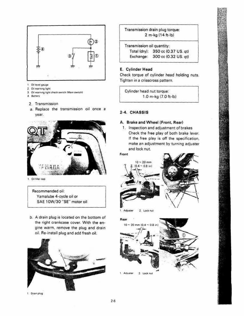
1 Oil level gauge 2. Oil warning light 3 Oil warning light check switch (Main switch) 4 Battery
2. Transmission a. Replace the transmission oil once a
year.
1. Oil filler cap
Recommended oil: Yamalube 4-cycle oil or SAE10W/30"SE" motor oil
b. A drain plug is located on the bottom of the right crankcase cover. With the en-gine warm, remove the plug and drain oil. Re-install plug and add fresh oil.
Transmission drain plug torque: 2m-kg(14ft-lb)
Transmission oil quantity: Total (dry): 350 cc (0.37 US. qt) Exchange: 300 cc (0.32 US. qt)
E. Cylinder Head Check torque of cylinder head holding nuts. Tighten in a crisscross pattern.
Cylinder head nut torque: 1.0m-kg(7.0ft-lb)
2-4. CHASSIS
A. Brake and Wheel (Front, Rear) 1. Inspection and adjustment of brakes
Check the free play of both brake lever. If the free play is off the specification, make an adjustment by turning adjuster and lock nut.
Front
10 ~ 20 mm 1 2; (0.4 - 0.8 in)
1. Adjuster 2. Lock nut
Rear 10 ~ 20 mm (0.4 - 0.8 in)
1 Adjuster 2. Lock nut
si-itUj't-S
-..';: • i
Mi
f i
• HHf
m m < >
mm l —- i ; . " ' t f s - y i
mm
mm
Hi if
. '£?
Ir.vir.
Jfisi* •hffifej
1. Drain plug
2-6

Adjustment and brake shoe replace-ment Camshaft lever adjustment If the free play adjustment of the brake lever is impossible with the adjuster and at the same time, if the indicator is still before the limit mark, make an adjust-ment by turning the camshaft lever one tooth.
-CAUTION: Do not turn the camshaft lever more than one tooth.
Front
Limit mark
Indicator plate
Rear
Indicator plate \ V. V Limit
»^—J"*-mark
7 Front
(D
Rear
©
m 1. Adjuster 2. Camshaft lever
3. Camshaft 4. Indicator plate
3. Brake shoe replacement When the indicator mark is lined up with the limit mark, replace the brake shoe. When replacing the brake shoe, bring the punch mark on the camshaft lever to align with the punch mark on the camshaft. When installing the rear brake, be sure to align the projection on the drive shaft housing with the center of the camshaft lever.
1. Indicator set position 2. Punch mark 3. Set position
4. Front axle Check axle nut.
Front axle nut torque: 5.5 m-kg (40 ft-lb)
5. Rear axle Check axle nut.
Rear axle nut tome: 6 m-kg (43 ft-lb)
6. Tire pressure
Front
Rear
1.25 kg/cm2 (18 psi)
2.0 kg/cm2 (28 psi)
B. Steering and Suspension 1. Steering head adjustment
The steering assembly should be check-ed periodically for any looseness. Do this as follows:
a. Block machine up so that front wheel is off the ground.
b. Grasp bottom of forks and gently rock fork assembly backward and forward, checking for any looseness in the steer-ing assembly bearings.
2-7

If steering head needs adjustment using steering nut wrench, adjust steer-ing head fitting nut until steering head is tight without binding when forks are turned.
NOTE: Excessive tightening of this nut will cause rapid wear of ball bearings and races. Re-check for looseness and freedom of movement.
d. Tighten steering fitting bolt.
NOTE: After completing steering adjustment make certain forks pivot from stop to stop without binding. If binding is noticed, repeat adjust-ment.
2. Suspension a. Check all suspension for proper opera-
tion. b. Check all suspension for proper tight-
ness.
2-5. ELECTRICAL
A. Ignition Timing (C.D.I.) 1. Ignition timing is checked with timing
light by observing the position of the stationary pointer marked on the crank-case and the marks on the magneto flywheel. Ignition timing of this motorcycle is non adjustable, for checking.
1. Mark 2. Stationary pointer
2. Checking the ignition timing Using a timing light check to see that the stationary pointer and mark on the magneto flywheel, are aligned.
a. Remove the crankcase cover (L). b. Connect the timing light to the spark
plug lead wire. c. Start the engine and keep it running at
the specified speed. Use a tachometer for checking.
Timing checking speed: 5,000 r/min
d. While running the engine at the spe-cified speed, check to see that the sta-tionary pointer is aligned with the mag-neto mark. If the marks are out of align-ment check to see that the woodruff key is broken or crankshaft assembly is out of alignment.
Ignition timing: 0.94 mm (0.037 in) B.T.D.C.
B. Spark Plug The spark plug indicates how the engine is operating. If the engine is operating correct-ly, and the motorcycle is being ridden cor-rectly, then the tip of the white insulator around the positive electrode of the spark plug will be a medium tan color. If the in-sulator is very dark brown or black color, then a plug with a hotter heat range might be required. This situation is quite common during the engine break-in period.
-! j
1' ,4 " ]
'-. 1" ••• .
M
2-8

Mscj*^-r^Bff^YOT«"ffl^T^'
If the insulator tip shows a very light tan or white color is actually pure white and glazed or if electrodes show signs of melting, then a spark plug with a colder heat ranges is re-quired. Remember, the insulator area sur-rounding the positive electrode of the spark plug must be a medium tan color. If it is not, check carburetion, timing and ignition adjust-ments. The spark plug must be removed and checked.' Check electrode wear, insulator color, and electrode gap.
Spark plug gap: 0.6 ~ 0.7 mm (0.024 0.028 in)
Engine heat and combustion chamber deposits will cause any spark plug to slowly break down and erode. If the electrodes finally become too worn, or if for any reason you believe the spark plug is not functioning correctly, replace it. When installing the plug, always clean the gasket surface, use a new gasket, wipe off any grime that might be present on the sur-face of the spark plug, torque the spark plug properly.
Standard Spark Plug NGK: BP4HS
lighting Torque 2.0m-kg(14ft-lb)
C. Battery A poorly maintained battery will deteriorate quickly. The battery fluid should be checked at least once a month.
1. The level should be between the upper and lower level marks. Use only distilled water for refilling. Normal tap water contains minerals which are harmful to a battery; therefore, refill only with distilled water.
2. Always make sure the connections are correct when installing the battery. The red lead is for the 4- terminal and the black lead is for the — terminal. Make sure the breather pipe is properly con-nected and is not damaged or obstruct-ed.
1. Upper level 2. Lower level
1. Battery breather pipe
NOTE: A new battery must be properly serviced and charged before installation.
Charging current: Charging hours:
0.4 Amps. 10hrs.
r-WARNING: Battery electrolyte is poisonous and dangerous, causing severe burns, etc. Contains sulfuric acid. Avoid contact with skin, eyes or clothing. Antidote: EXTERNAL-Flush with water. INTERNAL-Drink large quantities of water or milk. Follow with milk of mag-nesia, beaten egg or vegetable oil. Caff physician immediately. Eyes: Flush with water for 15 minutes and get prompt medical attention.
2-9

Batteries produce explosive gases. Keep sparks, fame, cigarettes, etc. away. Ventilate when charging or using in enclosed space. Always shield eyes when working near batteries. KEEP OUTOF REACH OF CHILDREN.
D. Headlight Beam Adjustment When necessary, adjust the headlight beam as follows:
1. About horizontally by tightening or loosening the adjusting screw, as in the illustration. To adjust to the right: tighten the screw To adjust to the left: loosen the screw
2. Adjust vertically by moving the head-light body.
Hi m m its®
w * # ' • [
1. Adjusting screw
2-10