Chapter 16 Design Submittals - Florida Department of ... · Chapter 16 Design Submittals ......
24
Topic #625-000-007 January 1, 2009 Plans Preparation Manual, Volume 1 - English Revised – January 1, 2012 Design Submittals 16-i Chapter 16 Design Submittals 16.1 General ..................................................................................... 16-1 16.2 Design Documentation Submittals ............................................ 16-4 16.2.1 Field Survey Data ..................................................... 16-4 16.2.2 Project Traffic ............................................................ 16-5 16.2.3 Typical Section Package ........................................... 16-6 16.2.4 Preliminary Drainage Design .................................. 16-10 16.2.5 Preliminary Geometry and Grades.......................... 16-10 16.2.6 Preliminary Traffic Control Plan .............................. 16-11 16.2.7 Pavement Selection and Design ............................. 16-11 16.2.8 Preliminary Utilities ................................................. 16-11 16.3 Structures Submittals .............................................................. 16-13 16.3.1 Coordination of Structural Design - (Bridges and Retaining Walls) ...................................................... 16-13 16.3.2 Bridges .................................................................... 16-13 16.3.3 Other Structural Submittals and Reviews ............... 16-14 16.4 Plans Phase Reviews ............................................................. 16-15 Exhibits Exhibit 16-A List of Requests and Contacts .................................. 16-2 Exhibit 16-B Typical Section Package ......................................... 16-16
Transcript of Chapter 16 Design Submittals - Florida Department of ... · Chapter 16 Design Submittals ......

Topic #625-000-007 January 1, 2009 Plans Preparation Manual, Volume 1 - English Revised – January 1, 2012
Design Submittals 16-i
Chapter 16
Design Submittals
16.1 General ..................................................................................... 16-1
16.2 Design Documentation Submittals ............................................ 16-4 16.2.1 Field Survey Data ..................................................... 16-4 16.2.2 Project Traffic ............................................................ 16-5 16.2.3 Typical Section Package ........................................... 16-6 16.2.4 Preliminary Drainage Design .................................. 16-10 16.2.5 Preliminary Geometry and Grades .......................... 16-10 16.2.6 Preliminary Traffic Control Plan .............................. 16-11 16.2.7 Pavement Selection and Design ............................. 16-11 16.2.8 Preliminary Utilities ................................................. 16-11
16.3 Structures Submittals .............................................................. 16-13 16.3.1 Coordination of Structural Design - (Bridges and
Retaining Walls) ...................................................... 16-13 16.3.2 Bridges .................................................................... 16-13 16.3.3 Other Structural Submittals and Reviews ............... 16-14
16.4 Plans Phase Reviews ............................................................. 16-15
Exhibits Exhibit 16-A List of Requests and Contacts .................................. 16-2
Exhibit 16-B Typical Section Package ......................................... 16-16

Topic #625-000-007 January 1, 2009 Plans Preparation Manual, Volume 1 - English Revised – January 1, 2012
Design Submittals 16-ii
THIS PAGE LEFT BLANK INTENTIONALLY

Topic #625-000-007 January 1, 2009 Plans Preparation Manual, Volume 1 - English Revised – January 1, 2012
Design Submittals 16-1
Chapter 16
Design Submittals
16.1 General
The design process will require various submittals to transfer technical information and decisions between the Engineer of Record (EOR), certain Department personnel, and functional areas. The Project Manager is responsible for the adequacy of the submittals or requests and for the coordination of reviews between the Department and the EOR. Each office head including the District Construction and Maintenance Engineers should assume direct responsibility for assigning reviewers and meeting the review schedules. To the extent practical, the contract scope of work should list the information to be furnished by FDOT functional areas and submittals (number and type) required of the EOR. Exhibit 16-A is a partial list of functional areas with typical submittals and requests.

Topic #625-000-007 January 1, 2009 Plans Preparation Manual, Volume 1 - English Revised – January 1, 2012
Design Submittals 16-2
During the design process, various items of information may be required from different sections or departments. The following is a list of some of those items and their source:
Exhibit 16-A List of Requests and Contacts Sheet 1 of 2
A) Planning Request pavement design (18 Kip ESAL) Request project traffic Request turning movements for intersections Request updates of project traffic (as needed) Railroad contact (Phase I and III) Plans transmittal letter data (railroad) Notification that project is in vicinity of a traffic monitoring site B) Traffic Plans/Traffic Operations Request turns and counts for intersection design Notification that project includes milling Signing & pavement marking plans (Phase I, II, III) Traffic signal plans (Phase I, II, III) & signal warrant Lighting plans (Phase I, II) & justification report Pedestrian and bicycle project traffic Safety/crash analysis and recommendations Operational and capacity review of design plans C) Geotechnical Request pavement design soil information Request roadway soil survey Soils data Request foundation investigations Request dynaflect testing Phase III review, if unsuitable soils exist. Soils and foundation recommendations PH and soils resistivity for culvert material selection Request pavement composition and milling recommendations Review if any changes are made in alignment, grade or typical section. Bridge Geotechnical Report D) Surveying and Mapping Request survey
E) Drainage Request grade and high water review Conceptual drainage plan & assumptions Bridge Hydraulics Report Request drainage design Request final drainage review Permit review SWPPP Erosion Control Plan F) Maintenance Pavement design comments Phase I Plans review & response Phase II Plans review & response Phase III Plans review & response G) Construction Pavement design comments Phase I Plans review & response Phase II Plans review (constructability) & response Phase III Plans review (biddability) & response Submit traffic control plan request Contract time H) R/W Surveying and Mapping Submit title search request Request existing right of way maps Transmit right of way requirements Final right of way check Plans transmittal letter data I) Utilities Preliminary (First) contact (Phase I) Pre-Design conference and contact (Phase II) Final contact (Phase III) Horizontal and vertical verification of utilities Plans transmittal letter data (utilities) Number of sets of final prints for utility companies

Topic #625-000-007 January 1, 2009 Plans Preparation Manual, Volume 1 - English Revised – January 1, 2012
Design Submittals 16-3
Exhibit 16-A List of Requests and Contacts Sheet 2 of 2
J) Estimates and Specifications Preliminary estimate (LRE) Preliminary estimate (Phase I) Preliminary estimate (Phase II) Preliminary estimate (Phase III) Complete estimate (Phase IV) K) Right Of Way Department Project schedule updates as needed R/W estimates as needed Pre-Proposal appraisal conference Field questions from R/W agents as needed Plans transmittal letter data Phase I Plans Review (by Appraiser) Phase II Plans Review (by Appraiser) Phase III Plans Review (by Appraiser) Phase IV Plans Review (by Appraiser) L) FHWA (if not exempt) Phase I Plans review & response Phase II Plans review & response Phase III Plans review & response Phase IV Plans review & response Submit for typical section approval Submit for pavement design approval Submit exception request letters R/W review M) Value Engineering ($2,000,000+) Phase I & II reviews N) Environmental Hazardous waste determination SWPPP Erosion Control Plan Mitigation Plans
O) Materials Environmental Classifications Type of Structural Steel (existing) Existence of Lead-Based Paint P) Bridge Phase I, Bridge Analysis, review & response Phase II Plans review & response BDR/30% Plans review and response 60% Plans review & response 90% Plans review & response 100% Plans review & response Q) Public Transportation/Modal Development Notification that project contains a transit route Request transit agency contact(s) Request facility locations and information Identify any special transit needs Phase I Plans review & response Phase II Plans review & response Phase III Plans review & response Number of sets of final prints for transit agencies

Topic #625-000-007 January 1, 2009 Plans Preparation Manual, Volume 1 - English Revised – January 1, 2012
Design Submittals 16-4
16.2 Design Documentation Submittals
During the engineering processes there is the need to submit information to specific Department personnel for the purpose of making timely decisions and confirming the project objectives. Preferably these submittals will take place as these activities are completed so that issues do not go unresolved before subsequent activities begin. The following are some submittals that should take place during initial engineering. Ideally these engineering type submittals should be done in lieu of traditional phase plans reviews.
16.2.1 Field Survey Data
The following are typical field survey data, which should be evaluated by the designer for sufficient breadth and accuracy to complete the proposed design. 1. Design location survey data including horizontal and vertical control, alignments,
reference points, utilities, natural and manmade features, and topography or general shape of the terrain.
2. Digitized aerial survey data, especially for large areas such as drainage maps. 3. Drainage design survey data from site inspection and historical records. 4. Right of Way and related property (land) survey data, including property owners and
acreage. 5. Geotechnical studies and foundation and soils report, including physical properties
and classifications of soils, together with recommendations related to foundations, pavement and drainage design.
6. Bridge data sheet surveys, channel alignment survey data and bathymetric data.
Topic #625-000-007 January 1, 2009 Plans Preparation Manual, Volume 1 - English Revised – January 1, 2012
Design Submittals 16-5
16.2.2 Project Traffic
In the development of roadway plans, project traffic is primarily used to justify the number of through lanes, geometric improvements to intersections, traffic signal timings, and pavement design. The number of through lanes is usually determined during the project development phase, based on Annual Average Daily Traffic (AADT) and factors included in the typical section. Vehicular traffic data provided in the plans typical section includes AADT for the current year, opening year and the design year. Also included are the design hour factor (K is the Department’s Standard “K” factor as provided by the State Transportation Statistics Office), the directional distribution (D is the percent of two way peak hour traffic that occurs in the peak direction), and truck factors (T is the percent that trucks constitute of vehicular traffic) for the peak hour and a 24 hour period. The source and methods used to produce this data must be documented.
Intersection improvements and signal timings require additional information on turning volumes. The FDOT Project Traffic Forecasting Procedure describes the input data required, explains the procedure to forecast turning volumes, and provides examples. A Project Traffic Report may be required. Manual and mechanical counts provide input on the number of vehicles and pedestrians using an intersection. At proposed (nonexisting) major intersections, turning volumes are estimated using transportation planning models or other means. Forecasts provide designers the information required to determine the need for turning lanes, turning bay length, signal timings, and pedestrian crossings. Also, the designer establishes right of way requirements based on documented needs to satisfy design year volumes.
In pavement design, the designer requires AADT forecasts for the year a project opens to traffic and for the design year. AADT, together with percent trucks (24 hour period) and other factors used by the Department, provides information on the pavement loadings used in pavement design. The FDOT Project Traffic Forecasting Procedure provides additional information.

Topic #625-000-007 January 1, 2009 Plans Preparation Manual, Volume 1 - English Revised – January 1, 2012
Design Submittals 16-6
16.2.3 Typical Section Package
All projects that add or alter cross section elements, and all resurfacing projects, require the preparation and concurrence of a typical section package.
The typical section package shall be prepared and sealed by the responsible engineer.
The typical section package is the instrument for formal review and concurrence of the proposed project cross sectional elements by the appropriate FDOT District Design Engineer. Review and concurrence of the typical section package by the FHWA Transportation Engineer is required on projects that have FHWA oversight (see Chapter 24 of this volume for determination of FHWA oversight).
The purpose of the typical section package review and approval process is to: 1. Establish typical transverse geometry 2. Consider safety related issues 3. Ensure compatibility between the bridge typical section and the roadway typical section
The typical section package consists of a Project Controls Sheet and Project Identification/ Proposed Typical Section Sheet. The Project Identification/ Proposed Typical Section Sheet should not be confused with the Typical Section Plan Sheet, which is part of the Contract Plans Set and is discussed in Volume 2, Chapter 6. The Project Controls Sheet contains the project data, which serves as a basis for selecting criteria and establishing project standards for cross-sectional elements. The Project Identification/Proposed Typical Section Sheet contains: data which uniquely identifies the project; a detail of the proposed typical cross section with critical dimensions and cross sectional elements labeled; and signature blocks.
Usually, Project Identification/ Proposed Typical Section Sheets will be prepared for the main roadway and bridges. However, additional Project Identification/Proposed Typical Section Sheets:
1. Shall be required if: a. A change in the number of through lanes occurs. b. Flush shoulders change to curbing or vice versa. c. A crossroad which may affect a structure exists. d. Major work of significant length is being done on an intersecting roadway.
2. May be required if a change in design speed occurs within the project limits.

Topic #625-000-007 January 1, 2009 Plans Preparation Manual, Volume 1 - English Revised – January 1, 2012
Design Submittals 16-7
The proposed typical sections for roadway and bridges are to be submitted by the responsible engineer for concurrence by the District Design Engineer. Coordination with the District Structures Design Engineer is also required on all bridge typical sections. The roadway and bridge typical sections shall be submitted together to ensure compatibility.
The typical section package for both roadway and bridges shall be approved as part of the Project Development & Environmental (PD&E) process. Typical section package preparation, and coordination between the responsible PD&E engineer and the District Design Engineer, must occur during the development of project alternatives prior to preferred alternative selection. The responsible PD&E engineer shall prepare, seal and submit the typical section package for concurrence. Typical section package concurrence by the District Design Engineer shall be obtained after the preferred alternative is selected. A copy of the approved typical section package shall be included as part of the PD&E Final Preliminary Engineering Report.
For projects that do not contain a PD&E phase, the typical section package shall be prepared, sealed and submitted by the responsible engineer for concurrence by the District Design Engineer. The typical section package should be concurred with prior to the final engineering process.
The Engineer of Record must coordinate with the District Design Engineer, the District Traffic Operations Engineer, and the responsible PD&E engineer to discuss the anticipated posted speed. The selected design speed shall be jointly approved by the District Design Engineer and the District Traffic Operations Engineer. This joint approval shall be documented on the Typical Section Data Sheet (see Exhibit 16-B, Sheet 1 of 6).
Exhibit 16-B contains example typical section package sheets. The following is an outline of the information which is required as part of the typical section package submittal. This information is critical for proper evaluation by the District Design Engineer. Missing information may require a resubmittal of the typical section package.
The following information is required on the project controls sheet: 1. Financial Project ID 2. County (and Section) 3. Project Description 4. Functional Classification 5. Highway System 6. Access Classification

Topic #625-000-007 January 1, 2009 Plans Preparation Manual, Volume 1 - English Revised – January 1, 2012
Design Submittals 16-8
7. Traffic Data (AADT, for Current, Opening and Design Year, Design Speed, Posted Speed; K, D, and T Factors)
8. Potential Exceptions and Variations related to the typical section elements 9. List Major Structures Requiring Independent Structures Design (including location
and description) 10. List Major Utilities within project corridor 11. List other information pertinent to the design of the project
The following information is required on the project identification/proposed typical section sheet: Project Identification: 1. Financial Project ID 2. State Project No. (if assigned) 3. Federal Aid Project No. (if assigned) 4. Work Program Item (if assigned) 5. Road Designation 6. County Name (and Section) 7. Limits (In Milepost) 8. Project Description
Proposed Roadway Typical Section Drawing: 1. Design Speed 2. Limits (station limits of the typical section shown if available) 3. Lanes (dimension width, show cross slope of each lane, label bike and HOV lanes) 4. R/W Line (graphically show, label and dimension from centerline const.) 5. Shoulder (dimension width, show cross slope, paved shoulder is dimensioned and
labeled separately) 6. Curb (graphically show curb, label curb type) 7. Median (dimension width, show slopes, graphically show whether median is typically
depressed or raised) 8. Centerline Construction and/or Baseline Survey (graphically show and label) 9. Profile Grade Point (label)

Topic #625-000-007 January 1, 2009 Plans Preparation Manual, Volume 1 - English Revised – January 1, 2012
Design Submittals 16-9
10. Slopes (dimension and label) 11. Border Width (dimension and label for new construction) 12. Ditches (show typical front slope and typical back slope, dimension typical ditch
width and depth, and label) 13. Natural Ground Line (graphically show and label) 14. Pavement and Roadbed (graphically show) 15. Barriers (graphically show, dimension, and label) 16. Sidewalk (graphically show, dimension, and label)
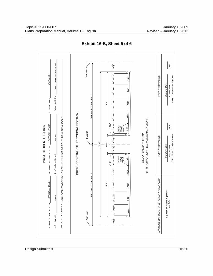
Proposed Structure Typical Section Drawing: 1. Design Speed 2. Bridge Description w/ Crossing Information 3. Lanes (dimension widths, and show cross slope of each lane, label bike or HOV
lanes) 4. R/W Line (graphically show, label and dimension from centerline const.) 5. Shoulder (dimension, show cross slope, and label) 6. Gutter (dimension width, and graphically show) 7. Median (dimension width, show slopes, graphically show whether median is typically
depressed or raised) 8. Centerline Construction and/or Baseline Survey (graphically show and label) 9. Bridge Deck (graphically show, dimension) 10. Profile Grade Point (label) 11. Barriers (graphically show including railing, dimension width, and label) 12. Sidewalk (graphically show, dimension width, and label)
The typical section package sheets are in the FDOT Engineering CADD Systems Software.

Topic #625-000-007 January 1, 2009 Plans Preparation Manual, Volume 1 - English Revised – January 1, 2012
Design Submittals 16-10
16.2.4 Preliminary Drainage Design
On projects where the drainage design is a critical element the following items should require a preliminary submittal: 1. Determination of water elevations affecting the roadway grade. These include base
clearance water elevations and design flood elevations. 2. Pond Siting Report 3. Documentation of preliminary drainage coordination with permitting agencies 4. Information that is essential to proper evaluation of drainage design concepts such
as seasonal high ground water, soil types, existing cross drain peak design stages, historical pavement failure, flood plain elevation, present water elevations, drainage areas, etc.
16.2.5 Preliminary Geometry and Grades
On projects where connections to the facility make grades a critical element, back of sidewalk profiles, project profile grades, determination of water elevations affecting the roadway grade, and driveway and side street geometry should require a preliminary submittal. The Districts may require the designer to present the project geometry and grade to a geometry and grade technical review team to encourage productive dialogue and proper communication regarding these design issues. If a bridge exists within the project limits, the early input of the structural designer as to approach grades and clearance needs should be coordinated to ensure proper bridge design.

Topic #625-000-007 January 1, 2009 Plans Preparation Manual, Volume 1 - English Revised – January 1, 2012
Design Submittals 16-11
16.2.6 Preliminary Traffic Control Plan
On projects where the traffic control plan is a critical element the following items should require a preliminary submittal. 1. Typical sections of each construction phase with information that is essential to
proper evaluation of each construction phase such as: location and nature of proper construction drainage; regulatory speed; location of work zone; proposed traffic control devices; number, width and location of maintained traffic; maximum drop- off; maintenance of existing lighting.
2. Documentation addressing possible innovative construction techniques; need for temporary detours, hazardous material excavation, temporary structures, etc.
3. Documentation of coordination with the local community: i.e., city and county transportation engineers, businesses, police, hospitals, civic centers or arena operations, fire department, schools, mass transit, etc.
4. When a temporary bridge is used, the designer must coordinate with the State Bridge Evaluation Engineer in Tallahassee (Office of Maintenance) to ensure that a detour route for overweight vehicles is included in the plans. If no detour route is available, the temporary bridge may have to be designed to support multitrip overweight vehicles.
16.2.7 Pavement Selection and Design
The pavement selection and design should be completed as early in the process as possible. The Rigid and Flexible Pavement Design Manuals are available through the Maps and Publications Sales Office.
16.2.8 Preliminary Utilities
On projects where utility coordination is a critical element the following early involvement activities should be required. 1. Before Phase I plans submittal, early involvement can be obtained by coordinating a
review of the utility information in the topographic survey. This review may be accomplished by distribution of the topographic survey to all Utility/Agency Owners (UAOs) through the District Utility Office for mark-ups and confirmation of existing facilities.

Topic #625-000-007 January 1, 2009 Plans Preparation Manual, Volume 1 - English Revised – January 1, 2012
Design Submittals 16-12
2. Once the designer has reviewed the early topographic survey mark-ups a meeting should be held with the UAOs, District Utility Office and the designer to discuss errors, omissions, and future plans of the utilities already identified within the corridor. This will allow the designer the ability to prioritize which utilities will ultimately impact the design.

Topic #625-000-007 January 1, 2009 Plans Preparation Manual, Volume 1 - English Revised – January 1, 2012
Design Submittals 16-13
16.3 Structures Submittals
Structures design elements also go through decision-making reviews at various stages of the design as listed below:
16.3.1 Coordination of Structural Design - (Bridges and Retaining Walls)
All requests for structural design should include roadway plan and profile sheets showing horizontal and vertical alignment and cross sections within 500 feet of each end of the bridge or ends of retaining walls. Horizontal curvature that is on or near the end of the bridge or retaining wall must be shown. Nonstandard superelevation transition details or other special profiles must be included if any part or all of the transition is on the bridge or wall. The approved typical section is required.
Provisions for access to property near the end of bridges and adjustments to avoid costly right of way takings should be resolved.
16.3.2 Bridges
Bridge design begins when the Phase I bridge geotechnical report is complete and proceeds on a schedule which allows simultaneous review of the final (90%) bridge plans and the Phase III roadway plans. All structures design work is coordinated through the District Structures Design Engineer or the State Structures Design Office in the Central Office, depending on the category or complexity of the structure. A typical section of the facility crossing, horizontal and vertical clearances required and the profile grades shall be determined prior to beginning structures design. For complete details and requirements for structural designs and plans preparation, the reader is referred to Chapter 26 of this volume and the Structures Detailing Manual issued by the State Structures Design Office.
Generally, the completion and review of bridge designs are accomplished in the following phases: 1. BDR/30% Structures Plans 2. 60% Structures Plans
a. (Foundation submittal for all Structures and full) b. (Submittal for Category 2 or unusual structures only)

Topic #625-000-007 January 1, 2009 Plans Preparation Manual, Volume 1 - English Revised – January 1, 2012
Design Submittals 16-14
3. 90% Structures Plans 4. 100% Structures Plans
These reviews should be coordinated with the phase reviews of the roadway plans. The latest set of structural plans shall be submitted with the Phase II roadway plans submittal. This joint submittal at Phase II roadway plans review is to ensure that roadway and bridge structures plans are consistent, i.e., widths, superelevation transitions, vertical and horizontal alignment, and work zone traffic control agree. The precise number and type of plans submittals depends on the complexity of the design and/or the sensitivity of the project. Each submittal shall include written responses to the comments received on the previous submittal.
16.3.3 Other Structural Submittals and Reviews
In addition to bridge plans, structures plans may include retaining walls, sheet piling, sound barriers, box or three-sided culverts, pedestrian overpasses, temporary bridges, and special structural appurtenances. Special structural appurtenances that include transit related furnishings and amenities would require review by the local transit agency.
For projects where bridges and other structures plans are involved, preliminary and final plan submittals (usually along with bridge plans) should be handled according to the instructions for structures plans submittals covered in Chapters 26 and 30 of this volume.
For projects where retaining walls are required along with roadway plans only (no bridge in the project), the Engineer of Record shall follow the procedure outlined in Chapter 30 of this volume. The submittal of detailed control plans should occur as early in the design process as possible.
Where the District Roadway Office cannot carry out the structural review or verify the review as proper by a consultant, such review may be requested from the District Structures Design Office or the State Structures Design Office.

Topic #625-000-007 January 1, 2009 Plans Preparation Manual, Volume 1 - English Revised – January 1, 2012
Design Submittals 16-15
16.4 Plans Phase Reviews
The number of submittals and phase reviews shall be determined on a project-by-project basis and shall be defined in the scope. Submittals allow functional areas to review the development of the project as contained in the scope.
Formal plans phase review requirements are covered in the District Quality Control Plan. Reviews should include Department personnel that can assist in making timely decisions and confirm that the requirements have been met for their discipline. Ideally, reviews should be driven by the engineering process and should occur when there is a need for input or a decision to complete a critical activity before progressing with the design. Some of these activities are discussed in Section 16.2 of this chapter. Reviews are complete when the comments from all the various offices have been resolved and have been documented as required in Chapter 24 of this volume.
Constructability and biddability reviews by the District Construction Office shall be included at appropriate stages of the phase review process. Procedures for these reviews are provided in the Construction Project Administration Manual (Topic No. 700-000-000).
Minor projects, such as resurfacing, should typically have two plans phase reviews. The two reviews should consist of a decision-making phase review on the scope and intent of the project and a final plans phase review for constructability/biddability. One of these will be an on-site review.
On complex projects plans phase reviews may be required at the Phase I, II and III stages and a final check at Phase IV. Two on-site reviews will be required. Generally, one of the site reviews is held early in the initial engineering phase.
Section 2.3 of Volume 2 outlines, in detail, the sequence for contract plans preparation and assembly required by the several design phase submittals. Also included in the chapter is information required to be presented on various plan sheets included with each submittal.
When the plans are in compliance with all phase review requirements and are considered final, they are to be submitted in accordance with the process described in Chapter 20 of this volume.

Topic #625-000-007 January 1, 2009 Plans Preparation Manual, Volume 1 - English Revised – January 1, 2012
Design Submittals 16-16
Exhibit 16-B Typical Section Package Sheet 1 of 6

Topic #625-000-007 January 1, 2009 Plans Preparation Manual, Volume 1 - English Revised – January 1, 2012
Design Submittals 16-17
Exhibit 16-B, Sheet 2 of 6

Topic #625-000-007 January 1, 2009 Plans Preparation Manual, Volume 1 - English Revised – January 1, 2012
Design Submittals 16-18
Exhibit 16-B, Sheet 3 of 6

Topic #625-000-007 January 1, 2009 Plans Preparation Manual, Volume 1 - English Revised – January 1, 2012
Design Submittals 16-19
Exhibit 16-B, Sheet 4 of 6
Topic #625-000-007 January 1, 2009 Plans Preparation Manual, Volume 1 - English Revised – January 1, 2012
Design Submittals 16-20
Exhibit 16-B, Sheet 5 of 6

Topic #625-000-007 January 1, 2009 Plans Preparation Manual, Volume 1 - English Revised – January 1, 2012
Design Submittals 16-21
Exhibit 16-B, Sheet 6 of 6

Topic #625-000-007 January 1, 2009 Plans Preparation Manual, Volume 1 - English Revised – January 1, 2012
Design Submittals 16-22
THIS PAGE LEFT BLANK INTENTIONALLY