CFR Formula SAE Intake Restrictor Design and...
7
CFR Formula SAE Intake Restrictor Design and Performance Logan M. Shelagowski and Thomas A. Mahank Department of Mechanical Engineering Saginaw Valley State University University Center, MI 48710 Email: [email protected] Abstract Cardinal Formula Racing at Saginaw Valley State University conducted a study of intake restrictor designs in an effort to improve engine performance and increase the team’s competitiveness at Formula SAE competitions. The objective of the undergraduate research project was to optimize the intake restrictor geometry to maximize flow over a range of outlet pressures. Intake restrictor designs were explored using computational fluid dynamics (CFD) flow modeling software to analyze and visualize fluid flow during the design process. The intake restrictors were then manufactured and tested on a flow bench over a range of pressures. Good correlation in terms of flow rate was observed between the simulations and experiments. The prototype intake restrictor gained 4.8 CFM on average over the typical range of pressure encountered during racing compared with an earlier intake restrictor used by the team at competition. Introduction The performance and emissions characteristics of a spark-ignition (SI) engine are optimized from the perspective of the intake system when a fuel-air mixture is efficiently delivered and uniformly distributed to each of the combustion chambers over an RPM band. This requires a well designed intake system. The typical 600 cubic centimeter four-cylinder four-stroke Formula SAE engine has an output of about 80 horsepower with an intake restrictor installed and is fuel injected. Air travels through a throttle body and intake plenum before reaching individual runners that feed each cylinder. An optimized intake system will net the engine more airflow and more power; however, designing, machining, and testing a number of intake systems can be costly. Design improvements are incremental and the design approach is essentially a process of trial and error. Computational fluid dynamics (CFD) flow modeling software offers an alternative to the experimental method of design. CFD is based on computer simulation, where the governing equations of fluid motion (e.g., Navier-Stokes equation) are solved numerically. CFD allows a designer to simulate a range of intake shapes and flow conditions without having to machine multiple prototypes for physical flow testing. The cost savings found through CFD can be substantial, as the manufacturing cost of a single intake system restrictor, after material and machining time, can be over $1500. Cardinal Formula Racing conducted an experimental and numerical study of intake system restrictor de- signs in an effort to improve engine performance and increase the team’s competitiveness at Formula SAE competitions. The specific objective of the study was to optimize the intake system restrictor geometry Proceedings of the 2015 ASEE North Central Section Conference Copyright c 2015, American Society for Engineering Education 1
Transcript of CFR Formula SAE Intake Restrictor Design and...

CFR Formula SAE Intake Restrictor Design and Performance
Logan M. Shelagowski and Thomas A. MahankDepartment of Mechanical Engineering
Saginaw Valley State UniversityUniversity Center, MI 48710Email: [email protected]
Abstract
Cardinal Formula Racing at Saginaw Valley State University conducted a study of intake restrictor designsin an effort to improve engine performance and increase the team’s competitiveness at Formula SAEcompetitions. The objective of the undergraduate research project was to optimize the intake restrictorgeometry to maximize flow over a range of outlet pressures. Intake restrictor designs were explored usingcomputational fluid dynamics (CFD) flow modeling software to analyze and visualize fluid flow during thedesign process. The intake restrictors were then manufactured and tested on a flow bench over a range ofpressures. Good correlation in terms of flow rate was observed between the simulations and experiments.The prototype intake restrictor gained 4.8 CFM on average over the typical range of pressure encounteredduring racing compared with an earlier intake restrictor used by the team at competition.
Introduction
The performance and emissions characteristics of a spark-ignition (SI) engine are optimized from theperspective of the intake system when a fuel-air mixture is efficiently delivered and uniformly distributedto each of the combustion chambers over an RPM band. This requires a well designed intake system.The typical 600 cubic centimeter four-cylinder four-stroke Formula SAE engine has an output of about80 horsepower with an intake restrictor installed and is fuel injected. Air travels through a throttle bodyand intake plenum before reaching individual runners that feed each cylinder. An optimized intake systemwill net the engine more airflow and more power; however, designing, machining, and testing a number ofintake systems can be costly. Design improvements are incremental and the design approach is essentiallya process of trial and error.
Computational fluid dynamics (CFD) flow modeling software offers an alternative to the experimentalmethod of design. CFD is based on computer simulation, where the governing equations of fluid motion(e.g., Navier-Stokes equation) are solved numerically. CFD allows a designer to simulate a range of intakeshapes and flow conditions without having to machine multiple prototypes for physical flow testing. Thecost savings found through CFD can be substantial, as the manufacturing cost of a single intake systemrestrictor, after material and machining time, can be over $1500.
Cardinal Formula Racing conducted an experimental and numerical study of intake system restrictor de-signs in an effort to improve engine performance and increase the team’s competitiveness at Formula SAEcompetitions. The specific objective of the study was to optimize the intake system restrictor geometry
Proceedings of the 2015 ASEE North Central Section ConferenceCopyright c© 2015, American Society for Engineering Education
1
to maximize flow over a range of outlet pressures. Anticipating the investigation, Logan Shelagowski ofCardinal Formula Racing attended a two-day training workshop on the use of the flow modeling softwareSolidWorks Flow Simulation. The workshop was presented by Dassault Systemes SolidWorks Corpora-tion of Waltham, MA and was generously supported by the Saginaw Valley State University Foundation.
Theory
The purpose of an intake system is to flow a maximum amount of air into each cylinder during an intakestroke, as more air means more fuel can be burned to produce useful work. Improving flow through anintake system boosts overall engine efficiency. Restrictions to airflow include an air filter, throttle body,intake plenum, and intake valves. When well designed, each device is optimized for flow. Formula SAErules mandate that an intake system restrictor (Fig. 1) be placed in the intake system between the throttlebody and engine. The device is to have a maximum throat diameter of no greater than 0.787 inches (20.0mm) for gasoline fueled engines. The restrictor serves as a design constraint for competition. The devicecurbs power output by impeding airflow at high RPM when airflow would typically be greatest. Thereare several design parameters that affect the total efficiency of the restrictor. A few of the more importantinclude the length of the diffuser, the diffuser angle, the inlet length, and the inlet shape. Formula SAEpromotes experimentation. Aside from the design constraint of the throat diameter, Formula SAE studentsare encouraged to improve the design of the intake system, including the restrictor. Thus finding the correctcombination of lengths and angles for the restrictor is a necessary task. CFD flow modeling software offersa useful tool towards this end.
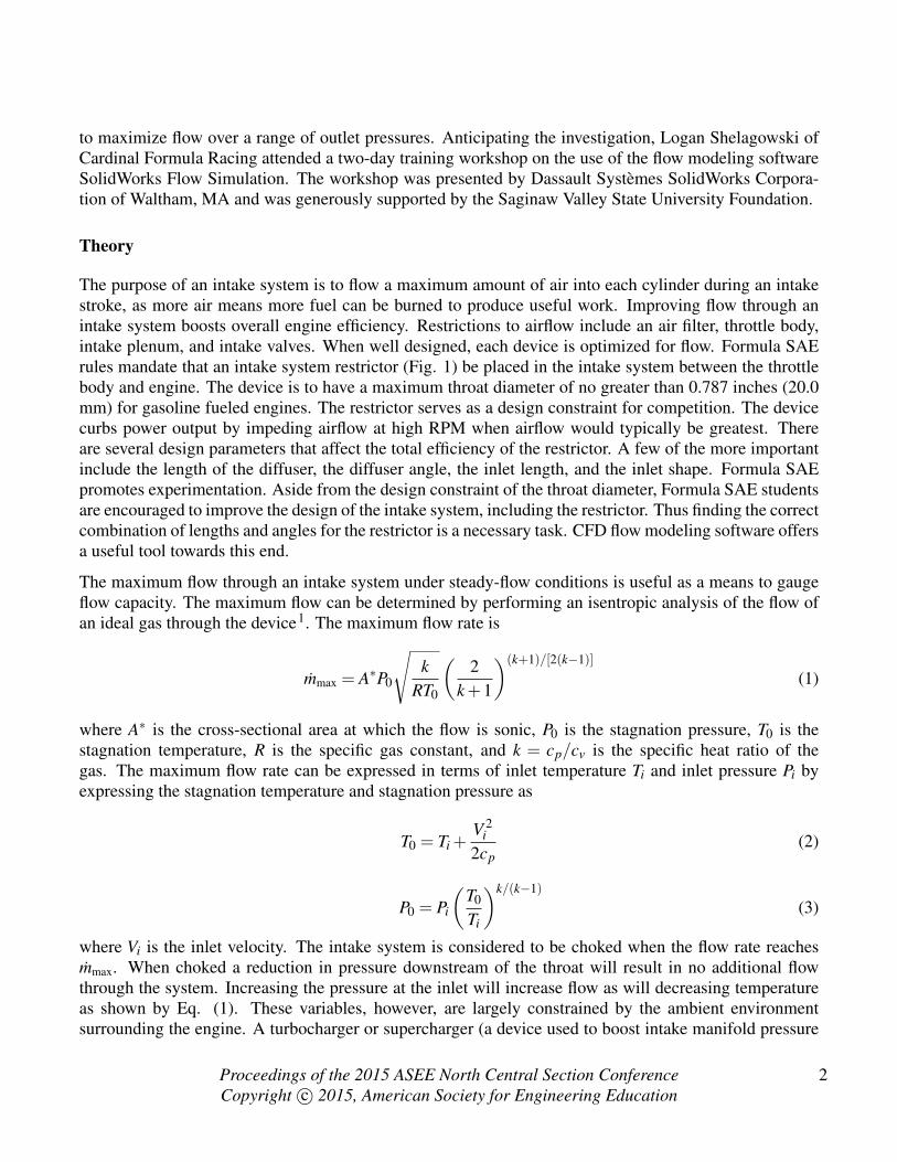
The maximum flow through an intake system under steady-flow conditions is useful as a means to gaugeflow capacity. The maximum flow can be determined by performing an isentropic analysis of the flow ofan ideal gas through the device1. The maximum flow rate is
mmax = A∗P0
√k
RT0
(2
k+1
)(k+1)/[2(k−1)]
(1)
where A∗ is the cross-sectional area at which the flow is sonic, P0 is the stagnation pressure, T0 is thestagnation temperature, R is the specific gas constant, and k = cp/cv is the specific heat ratio of thegas. The maximum flow rate can be expressed in terms of inlet temperature Ti and inlet pressure Pi byexpressing the stagnation temperature and stagnation pressure as
T0 = Ti +V 2
i2cp
(2)
P0 = Pi
(T0
Ti
)k/(k−1)
(3)
where Vi is the inlet velocity. The intake system is considered to be choked when the flow rate reachesmmax. When choked a reduction in pressure downstream of the throat will result in no additional flowthrough the system. Increasing the pressure at the inlet will increase flow as will decreasing temperatureas shown by Eq. (1). These variables, however, are largely constrained by the ambient environmentsurrounding the engine. A turbocharger or supercharger (a device used to boost intake manifold pressure
Proceedings of the 2015 ASEE North Central Section ConferenceCopyright c© 2015, American Society for Engineering Education
2

Fig. 1. Intake system restrictor prototypes: design I and II (units of inches).
and allowed under 2015 Formula SAE rules with the restriction that it must be placed downstream of theintake system restrictor) may improve low- and mid-range performance but will not improve flow once theintake system is choked because of its location downstream of the throat.
The maximum flow rate of air at choked conditions can be calculated by applying Eq. (1) at standardatmospheric conditions (Pi = 14.7 psi and Ti = 70◦F). The inlet velocity is assumed to be small for thesake of the calculation (T0 ≈ Ti and P0 ≈ Pi). The stagnation properties remain constant throughout therestrictor. The calculation yields a maximum mass flow rate mmax = 0.165 lbm/s. The volumetric flowrate at the inlet is calculated as Vi = 132 CFM, upon applying Eq. (5) to determine the density of air at theinlet. The calculation provides an upper limit on flow rate.
An engine of high volumetric efficiency flows air well, i.e., the induction and exhaust processes are ef-ficient and optimized from a flow perspective. The volumetric efficiency is defined as the ratio of massdrawn into the cylinder to mass displaced by the cylinder at density ρi referenced at the inlet of the intakesystem. The volumetric efficiency is2
ηv =2m
ρiVdn(4)
where m is the mass flow rate, n is the number of revolutions per second of the crankshaft (four-strokeengine), and Vd is the engine displacement volume. The density of air
ρ = P/(RT ) (5)
Proceedings of the 2015 ASEE North Central Section ConferenceCopyright c© 2015, American Society for Engineering Education
3

Fig. 2. Intake system restrictor performance compared based on flow bench measurements and CFD simulations.
is calculated by applying the ideal gas equation. Volumetric efficiency is a function of mass flow rateas shown by Eq. (4). A well designed engine can approach a volumetric efficiency of 100% but willnot exceed it unless inlet pressure is raised above ambient pressure through the use of turbocharging,supercharging, exhaust scavenging, or Helmholtz resonance3 to increase gas density, as mass flow rateis a function of density. Flow through an engine can be improved by streamlining intake ports and byincreasing intake valve diameter. Streamlining to boost flow is a goal of Cardinal Formula Racing. Itsimpact was studied theoretically using CFD flow modeling software and experimentally using a flowbench.
Design of Prototypes
The flow through many potential intake system restrictors was investigated by Cardinal Formula Racingusing SolidWorks Flow Simulation software as part of the academic study. The diameter at the throat ofeach restrictor was held at 0.787 inches (20.0 mm) while the inlet and outlet diameters and wall geometrieswere changed. Each iteration consisted of creating a model, specifying boundary conditions, and solvingthe equations of motion for pressure and velocity. The geometry of each model was then changed and theprocess repeated until a geometry was found that displayed optimal flow characteristics. The impact ofmesh size on the solution was studied to ensure a mesh independent solution.
The restrictor is essentially a converging-diverging nozzle. The flow enters at relatively high pressure andlow velocity and accelerates on its way to the throat. The maximum velocity occurs at the throat. The flow
Proceedings of the 2015 ASEE North Central Section ConferenceCopyright c© 2015, American Society for Engineering Education
4

Fig. 3. Pressure and Mach number contours for sonic flow at the throat (30 inches of H2O).
then decelerates beyond the throat and undergoes a pressure recovery. The pressure drop is large whenthe diameter is small, so it is beneficial to increase the diameter as soon as possible beyond the throat;however, if the diameter is increased too dramatically, flow separation may occur. Flow separation leadsto an undesirable backflow that effectively reduces the cross-sectional area. The CFD analysis showedthat flow separation was pronounced when the taper was increased beyond 7◦. Therefore, a gradual walltaper of 6.3◦ from the throat to the outlet was chosen.
Figure 1 shows the two intake system restrictor prototypes: design I and II. Both were constructed ofaluminum. The first was designed and built based on a paper by Byam et al.4 and a design study by Jawadet al.5. It features an 8◦ incline taper beginning at the (0.787 inch) throat and gradually transitioning to theoutlet. The inlet shape is bell mouthed. The second restrictor was designed and built upon conclusion ofthis CFD study. It consists of a 6.3◦ incline taper beginning at the (0.787 inch) throat. The more gradualtransition reduces the flow separation that can occur downstream of the throat.
TABLE IPROPERTIES OF AIR.
Temperature Pressure Density Dynamic viscosityT , ◦F P, inches H2O ρ , lbm/ft3 µ , lbm/ft · s70.0 403.0 0.07419 1.230× 10⁻⁵
Proceedings of the 2015 ASEE North Central Section ConferenceCopyright c© 2015, American Society for Engineering Education
5

The flow through each intake system restrictor was measured using a SuperFlow SF-600 air flow bench.An air flow bench simulates flow through an engine intake by reducing pressure below the component.Atmospheric pressure then forces air through the component. A manometer was used to measure thevelocity of airflow through the intake system restrictor. The fluid properties during the experiments aregiven in Table I.
Design I was used as a baseline for comparison. As shown in Figure 2, the results of the CFD simulationsgenerally show the trend in the experimental data. Design II outperforms design I over the range ofpressures tested up to 26 inches of H2O. Beyond 26 inches of H2O the flow curves are coincident andfairly asymptotic. Pressure and Mach number contours at 30 inches of H2O are shown in Fig. 3 (maximumpressure and Mach number are displayed in red). Sonic flow at the throat is observed in each case.
Discussion and Conclusions
Choosing one restrictor over the other depends on the application. According to the flow bench data,design I has a smoother flow curve that is more consistent than design II. This should translate into asmoother power curve, causing the car to be more driver friendly. The flow bench data also show thatdesign I has a higher maximum volume flow of approximately 138 CFM at 30 inches of H2O as comparedwith 134 CFM for design II at the same pressure. Design II reached “choked flow” (maximum flow);design I was able to deliver still more air at even higher pressures. An engine fitted with design I willcreate more power output at high-end than an engine fitted with design II. The data acquired from both theflow bench and CFD show that design II has a higher volume flow rate (4.8 CFM on average) comparedwith design I from pressures of 6 to 22 inches of H2O. Therefore, design II will supply more air to anengine running at a low- to mid-range RPM than design I, which in turn will create a more robust low- tomid-range torque curve. For Formula SAE Racing, design II is the optimal choice. The higher maximumpower output of design I would be great for the acceleration runs in competition, but this event is worththe fewest number of points compared with other events. Although design II does not have quite the high-end power of design I, the low-end power is more beneficial. The robust torque curve will provide extrapower when exiting corners at competition in autocross and endurance events. As these two events areworth the greatest number of points, restrictor choice should be considered in these events. In the future,Cardinal Formula Racing plans to optimize the entire intake plenum for flow to reduce pressure loss andimprove engine performance. These improvements may include flow balancing, which dictates intakerunner length, to optimize engine performance.
Acknowledgments
The authors acknowledge the dedicated team of students, faculty, administrators, and industry sponsorswho support Cardinal Formula Racing, and especially thank the Saginaw Valley State University Foun-dation for generously sponsoring the training workshop at Dassault Systemes SolidWorks Corporation ofWaltham, MA.
Proceedings of the 2015 ASEE North Central Section ConferenceCopyright c© 2015, American Society for Engineering Education
6

Bibliography[1] Y. A. Cengel and M. A. Boles, Thermodynamics: an Engineering Approach, chapter 17, McGraw-Hill, New York, NY,
2011.
[2] R. Stone, Introduction to Internal Combustion Engines, chapter 2, Society of Automotive Engineers, Inc., Warrendale, PA,1994.
[3] A. Selamet, V. Kothamasu, and J. M. Novak, “Insertion loss of a Helmholtz resonator in the intake system of internalcombustion engines: an experimental and computational investigation,” Applied Acoustics, vol. 62, pp. 381–409, 2001.
[4] B. Byam, J. Fsadni, A. Hart, and R. Lanczynski, “An experimental approach to design, build, and test a throttle body andrestrictor system for Formula SAE racing,” in SAE Technical Paper 2006-01-0748, SAE World Congress, Detroit, MI,2006.
[5] B. Jawad, A. Lounsbery, and J. Hoste, “Evolution of intake design for a small engine formula vehicle,” in SAE TechnicalPaper 2001-01-1211, SAE World Congress, Detroit, MI, 2001.
Proceedings of the 2015 ASEE North Central Section ConferenceCopyright c© 2015, American Society for Engineering Education
7