
CESSM - Millennium Challenge Account Zambia€¦ · Web view ·...
63
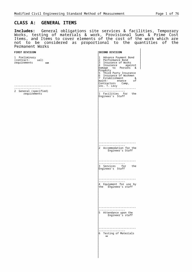
Modified Civil Engineering Standard Method of Measurement Page 1 of 76 CLASS A: GENERAL ITEMS Includes: General obligations site services & facilities, Temporary Works, testing of materials & work, Provisional Sums & Prime Cost Items, and Items to cover elements of the cost of the work which are not to be considered as proportional to the quantities of the Permanent Works FIRST DIVISION 1 Preliminary (contract- ual) requirements sum ------------------------ ----------------- 2 General (specified) requirements SECOND DIVISION 1 Advance Payment Bond 2 Performance Bond 3 Insurance of Works 4 Insurance against Damage to Persons & Property 5 Third Party Insurance 6 Insurance of Workmen 7 Establishment & maint- enance of Contractors Camp, inc. T. Levy ------------------------ ----------------- 1 Facilities for the Engineer's Staff ------------------------ ----------------- 2 Accommodation for the Engineer's Staff ------------------------ ----------------- 3 Services for the Engineer's Staff ------------------------ ----------------- 4 Equipment for use by the Engineer's staff ------------------------ ----------------- 5 Attendance upon the Engineer's staff ------------------------ ----------------- 6 Testing of Materials nr
Transcript of CESSM - Millennium Challenge Account Zambia€¦ · Web view ·...
Modified Civil Engineering Standard Method of Measurement Page 1 of 40
CLASS A: GENERAL ITEMSIncludes: General obligations site services & facilities, Temporary Works, testing of materials & work, Provisional Sums & Prime Cost Items, and Items to cover elements of the cost of the work which are not to be considered as proportional to the quantities of the Permanent WorksFIRST DIVISION
1 Preliminary (contract-ual) requirements sum
-----------------------------------------2 General (specified)
requirements
SECOND DIVISION
1 Advance Payment Bond2 Performance Bond3 Insurance of Works4 Insurance against Damage
to Persons & Property5 Third Party Insurance6 Insurance of Workmen7 Establishment & maint-
enance of ContractorsCamp, inc. T. Levy
-----------------------------------------1 Facilities for the Engineer's
Staff
-----------------------------------------2 Accommodation for the
Engineer's Staff
-----------------------------------------3 Services for the Engineer's
Staff
-----------------------------------------4 Equipment for use by the
Engineer's staff
-----------------------------------------5 Attendance upon the
Engineer's staff
-----------------------------------------6 Testing of Materials nr
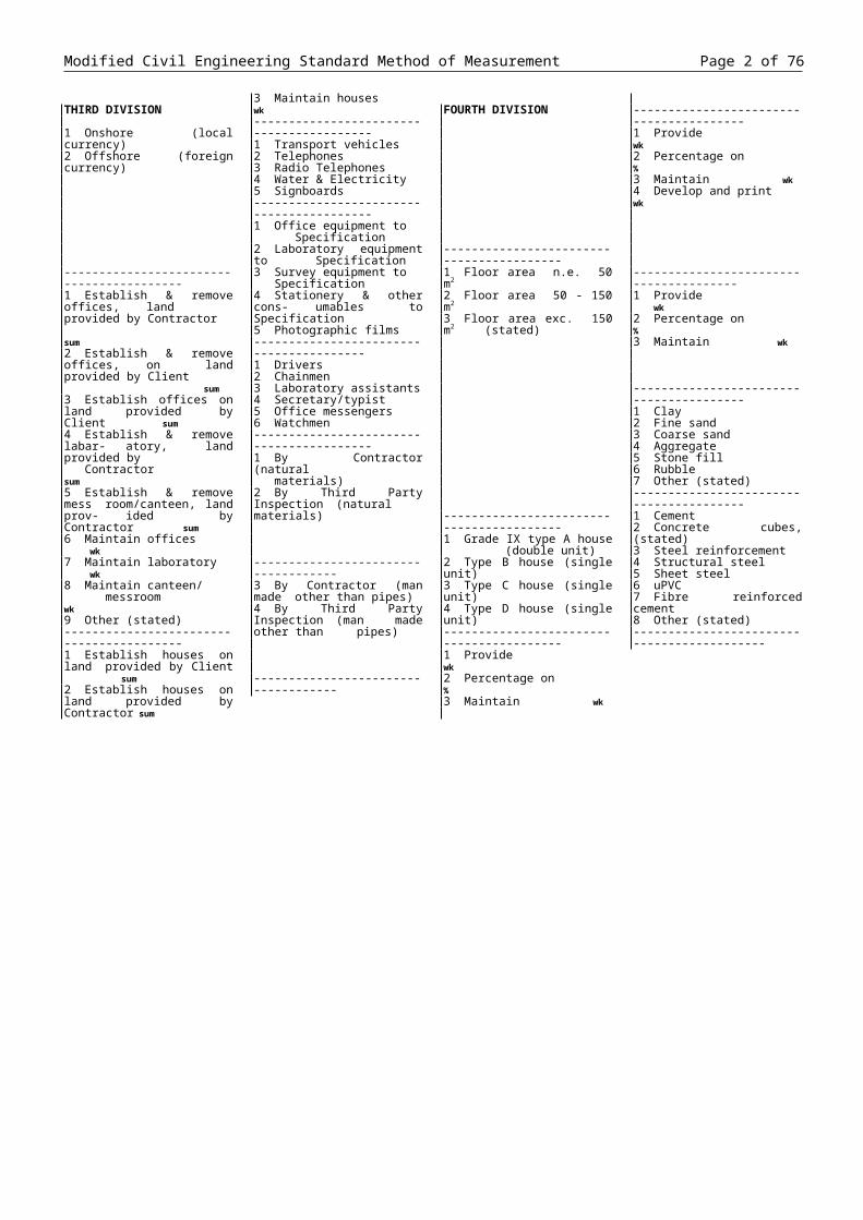
THIRD DIVISION
1 Onshore (local currency)2 Offshore (foreign currency)
-----------------------------------------1 Establish & remove offices,
land provided by Contractor sum
2 Establish & remove offices, on land provided by Client
sum3 Establish offices on land
provided by Client sum4 Establish & remove labar-
atory, land provided by Contractor sum
5 Establish & remove messroom/canteen, land prov-ided by Contractor sum
6 Maintain offices wk7 Maintain laboratory wk8 Maintain canteen/
messroom wk9 Other (stated)-----------------------------------------1 Establish houses on land
provided by Client sum2 Establish houses on land
provided by Contractor sum3 Maintain houses wk-----------------------------------------1 Transport vehicles2 Telephones3 Radio Telephones4 Water & Electricity5 Signboards-----------------------------------------1 Office equipment to
Specification2 Laboratory equipment to
Specification3 Survey equipment to
Specification4 Stationery & other cons-
umables to Specification5 Photographic films----------------------------------------1 Drivers2 Chainmen3 Laboratory assistants4 Secretary/typist5 Office messengers6 Watchmen-----------------------------------------1 By Contractor (natural
materials)2 By Third Party Inspection
(natural materials)
------------------------------------3 By Contractor (man made
other than pipes)4 By Third Party Inspection
(man made other than pipes)
------------------------------------
FOURTH DIVISION
-----------------------------------------1 Floor area n.e. 50 m2
2 Floor area 50 - 150 m2
3 Floor area exc. 150 m2 (stated)
-----------------------------------------1 Grade IX type A house
(double unit)2 Type B house (single unit)3 Type C house (single unit)4 Type D house (single unit)-----------------------------------------1 Provide wk2 Percentage on %3 Maintain wk
----------------------------------------1 Provide wk2 Percentage on %3 Maintain wk4 Develop and print wk
---------------------------------------1 Provide wk2 Percentage on %3 Maintain wk
----------------------------------------1 Clay2 Fine sand3 Coarse sand4 Aggregate5 Stone fill6 Rubble7 Other (stated)----------------------------------------1 Cement2 Concrete cubes, (stated)3 Steel reinforcement4 Structural steel5 Sheet steel6 uPVC7 Fibre reinforced cement8 Other (stated)-------------------------------------------
FIRST DIVISION
General (specified) requirements (cont'd)
---------------------------------------3 Method related
charges sum
------------------------------------
SECOND DIVISION
Testing of materials (cont'd)
---------------------------------------7 Testing of Works
-----------------------------------------8 Temporary Works sum
---------------------------------------1 Accommodation & buildings
-----------------------------------------2 Services
-----------------------------------------3 Plant
----------------------------------------4 Plant
----------------------------------------5 Temporary Works
---------------------------------------
THIRD DIVISION
5 By Contractor (man made-pipes)
6 By Third Party Inspection (man made -pipes)
----------------------------------------1 Water Retaining Structures
nr2 Other Concrete Structures
nr
----------------------------------------3 Pressure pipelines n.b. not
exc. 200 mm m4 Pressure pipelines n.b.
exc. 200 mm m5 Sewers & drains m----------------------------------------6 Non concrete Structures
nr
----------------------------------------7 Test run Works 2 weeks
prior & 2 weeks after substantial completion
Sum
----------------------------------------1 Traffic diversions2 Traffic regulation3 Access roads4 Bridges5 Cofferdams6 Pumping7 De-watering8 Compressed air for
tunnelling9 Other (stated)----------------------------------------1 Offices2 Laboratories3 Cabins4 Stores5 Canteens & messrooms----------------------------------------1 Electricity2 Water3 Security4 Hoardings5 Site transport6 Personnel transport7 Welfare----------------------------------------1 Cranes2 Transport3 Earthmoving4 Compaction5 Concrete mixing6 Concrete transport7 Pile driving8 Pile boring----------------------------------------1 Pipelaying2 Paving3 Tunnelling4 Crushing & screening5 Boring & drilling----------------------------------------1 Traffic diversions2 Traffic regulation3 Access roads4 Bridges5 Cofferdams6 Pumping7 De-watering8 Compressed air for
tunnelling9 Other (stated)----------------------------------------
FOURTH DIVISION
1 Pipes & fittings, (stated)2 Clay pipes & fittings3 Concrete pipes & fittings4 Ductile pipes & fittings5 Steel pipes & fittings6 uPVC pipes & fittings7 A/C pipes & C.I. fittings8 GS or GI pipes & fittings9 Valves, hydrants, meters-----------------------------------------1 Mixing chamber2 Flocculating elements3 Sedimentation tanks4 Filters5 R/f blockwork reservoirs6 R/f concrete reservoirs7 Intakes & weirs8 Pipe bridges9 Pump basements-----------------------------------------1 Ferrous pipes & fittings2 uPVC pipes & fittings3 Concrete pipes & fittings4 Pipes & fittings, (stated)
-----------------------------------------1 Steel panel tanks2 Chemical dosing tanks3 Other, (stated)-----------------------------------------1 Including supply of chem-
icals for test run period2 Including supply of chem-
icals for test run period & additional period (stated)
-----------------------------------------
-----------------------------------------
-----------------------------------------
-----------------------------------------
-----------------------------------------
-----------------------------------------
-----------------------------------------

FIRST DIVISION
Method related charges (cont'd)
----------------------------------------4 Provisional Sums
-----------------------------------------5 Prime Cost Items
NOTES:
1. The unit of measurement for general items shall be the sum, except where another unit of measurement is indicated (see note 5).
2. Items for insurance classed as contractual requirements shall cover only the provision of insurance in accordance with clauses 21 and 23 unless otherwise stated. Method Related Charges may be inserted by the tenderer in accordance with paragraph 5 (a) for additional insurances.
3. Items shall be given in the Bill of Quantities and classed as specified requirements to cover all work other than the Permanent Works which is expressly stated in the Contract to be carried out by the Contractor and of which the nature and extent is expressly stated in the Contract.
SECOND DIVISION
6 Temporary works
-----------------------------------------7 Supervision & labour
-----------------------------------------1 Daywork
-----------------------------------------2 Other Provisional
Sums (stated) sum-----------------------------------------1 Including work on Site by a
nominated sub-contractor sum
2 Percentage adjustment to work on site by a nomin-ated sub-contractor %
3 Not including work on Site by a nominated sub-contractor sum
4 Percentage adjustment to prime cost sum not includ-ing work on site by a nom-inated sub-contractor %
5 Supply only, item (stated)6 Percentage adjustment to
supplied item7 Percentage adjustment to
P.C. sum items (stated) %
4. Item descriptions for plant associated with Temporary Works which are classed as specified requirements shall distinguish between plant operating and standing by.
5. A quantity shall be given against all items for specified requirements of which the value is to be ascertained and determined by admeasurement in accordance with clause 56(1). A unit of measurement shall be stated for each such item.
6. Item descriptions for work classed as specified require-ments (except work quantities in accordance with note 5) shall distinguish between the establishment and removal of the services or facilities and their continued operation and maintenance.
THIRD DIVISION
1 Access scaffolding2 Support scaffolding &
propping3 Piling4 Formwork5 Shafts & pits6 Hardstandings----------------------------------------1 Supervision2 Administration3 Labour teams----------------------------------------1 Labour sum2 Percentage adjustment to
provisional sum for day-work labour %
3 Materials sum4 Percentage adjustment to
provisional sum for daywork materials %
5 Plant sum6 Percentage adjustment to
provisional sum for daywork plant %
-----------------------------------------
-----------------------------------------
7. Item descriptions for testing of materials and testing of the Works shall include particulars of samples and methods of testing. Items shall be given in this class for all testing for which items are not given separately as set out in other classes.
8. Items for Method Related Charges, if any, shall be in-serted by the tenderer in ac-cordance with section 5 dis-tinguishing between Time Related and Fixed Charges.
9. Items for percentage ad-justment of Provisional Sums for Daywork shall be given only where a Daywork Schedule in accordance with alternative form (b) of paragraph 8 is given in the Bill of Quantities. Adjustments shall be inserted against such items to corre-spond with the adjustments, if any, inserted by the tenderer in the Daywork Schedule.
FOURTH DIVISION
-----------------------------------------
-----------------------------------------
-----------------------------------------
-----------------------------------------
10. Each Prime Cost item shall be followed by an item for labour and an item for other charges and profit.
11. The sum determined for Third Party Inspection shall be expended at the discretion of the Engineer.
12. Test running of the Works shall include for the supply of all fuel, oil, and chemicals, and for the computation of the quantities needed subsequently for the proper operation of the Works.

CLASS D: DEMOLITION AND SITE CLEARANCEIncludes: Demolition and removal of natural and artificial articles, objects and obstructions which are above the Original SurfaceExcludes: Removal of articles, objects, obstructions and materials other than tree roots at or below the Original Surface (included in class E)FIRST DIVISION
1 General Clearance ha
---------------------------------------------------2 Removal of trees and stumps nr
---------------------------------------------------3 Demolition of buildings, disposal
(stated) sum4 Demolition of other structures,
disposal (stated) sum
---------------------------------------------------5 Clearance of Pipeline
wayleaves, disposal (stated) m
---------------------------------------------------6 Removal of ant and termite hills and nests m3
---------------------------------------------------7 Removal of man placed or
naturally deposited material m3
NOTES:
1. General clearance shall include the demolition and removal of all articles, objects and obstructions which are expressly required to be cleared, except those for which separate items are given as set out in this class.
2. Item descriptions for general clearance shall identify the area included unless it is the total area of the Site.
3. Item descriptions for work from which the materials arising remain the property of the Employer shall so state.
4. Girths of trees shall be measured one metre above ground level. Separate items are not required for removal of stumps of trees which are themselves to be removed.
SECOND DIVISION
1 Urban land2 Agricultural land3 Woodland4 Rough grassland5 Open bush and thicket6 Dense bush and thicket7 Forest8 Seasonal swamp---------------------------------------------------1 Trees of girth: 500 mm. - 1 m2 Trees of girth: 1 - 2 m3 Trees of girth: 2 - 3 m4 Trees of girth: 3 - 5 m5 Trees of girth: exc 5 m., (stated)6 Stumps of diameter: 150-500 mm7 Stumps of diameter: 500- 1 m8 Stumps of diameter: exc. 1 m.,
(stated)---------------------------------------------------1 Brickwork construction2 Concrete construction3 Masonry construction4 Metal construction5 Timber construction6 No predominant material7 Blockwork construction8 Mud and pole construction---------------------------------------------------1 Nominal bore not exc. 100 mm2 Nominal bore: 100 - 300 mm3 Nominal bore: 300 - 500 mm4 Nominal bore: exc 500 mm---------------------------------------------------1 General site clearance2 Along pipeline routes
---------------------------------------------------1 In existing channels2 In existing chambers3 In existing cellular structures4 In other structures, (stated)
5. Buildings and other structures shall be identified in item descriptions. An identified group of buildings or other structures may be given as a single item.
6. The volume stated in the classifi-cation of buildings and other structures shall be their approximate volume occupied, excluding any volume below the Original Surface.
7. Parts of buildings and other structures below the original Surface shall be excluded from items in this class unless otherwise stated.
8. Pipelines within buildings and other structures shall be measured only where their nominal bore exceeds 300 mm. Separate items are not required for demolition of supports of pipelines.
THIRD DIVISION
1 Removed from site and disposed of
2 Locally disposed3 Set aside for reuse4 Removed from site and disposed
of as directed5 Burnt
---------------------------------------------------1 Volume: not exc. 50 m32 Volume: 50 - 100 m33 Volume: 100 - 250 m34 Volume: 250 - 500 m35 Volume: 500 - 1000 m36 Volume: 1000 - 2500 m37 Volume: 2500 - 5000 m38 Volume: exc. 5000 m3., (stated)---------------------------------------------------1 Pipeline only2 Pipeline and access track
---------------------------------------------------1 Excess material - removed form site and disposed of2 Excess material - locally disposed---------------------------------------------------1 Removed from site and
disposed of2 Locally disposed3 Set aside for reuse4 Removed from site and disposed
of as directed5 Burnt
9. Wayleave clearance for pipeline only shall refer to clearance where the proposed pipeline is within 20 metres of an existing road or track or where no new access is required. Clearance width shall then be measured as nom. bore of pipe plus two metres.
10. Wayleave clearance for pipeline and access track shall be used where no existing track exists and one is required, in which case the width to be cleared and measured shall be the nom. bore of pipe plus five metres.
11. Ant and termite hills shall be excavated and removed complete. The below ground excavation shall be filled using the excavated material after its treatment with an approved insecticide, with refilling being made progressively in layers not exc. 200 mm. deep, compacted to 95% MOD at optimum moisture content to the Final Surface or as otherwise indicated.

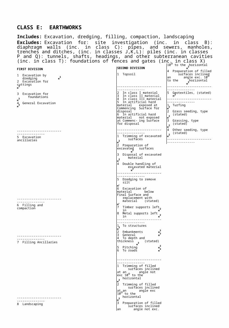
CLASS E: EARTHWORKSIncludes: Excavation, dredging, filling, compaction, landscapingExcludes: Excavation for: site investigation (inc. in class B): diaphragm walls (inc. in class C): pipes, and sewers, manholes, trenches and ditches, (inc. in classes J,K,L): piles (inc. in classes P and Q): tunnels, shafts, headings, and other subterranean cavities (inc. in class T): foundations of fences and gates (inc. in class X)FIRST DIVISION
1 Excavation bydredging m3
2 Excavation for cuttings m3
3 Excavation for foundations m3
4 General Excavation m3
---------------------------------------5 Excavation ancillaries
---------------------------------------6 Filling and compaction
---------------------------------------7 Filling Ancillaries
---------------------------------------8 Landscaping
SECOND DIVISION
1 Topsoil
---------------------------------------2 In class I material3 In class II material4 In class III material5 In artificial hard material
exposed at Commencing Surface for disposal
6 In artificial hard material not exposed at Commenc- ing Surface for disposal
---------------------------------------1 Trimming of excavated
surfaces m2
2 Preparation of excavatedsurfaces m2
3 Disposal of excavated material m2
4 Double handling of excavated material m2
---------------------------------------5 Dredging to remove
silt m3
6 Excavation of material below Final Surface and replacement withmaterial (stated) m3
7 Timber supports leftin m2
8 Metal supports left in m2
---------------------------------------1 To structures m3
2 Embankments m3
3 General m3
4 To depth and thickness (stated) m3
5 Pitching m3
6 To roads m3
---------------------------------------1 Trimming of filled
surfaces inclined at an angle not exc 10o to the horizontal m2
2 Trimming of filled surfaces inclined at an angle exc 10o to the horizontal m2
3 Preparation of filled surfaces inclined an angle not exc. 10o to the horizontal m2
4 Preparation of filled surfaces inclined an angle exc. 10o to the horizontal m2
---------------------------------------5 Geotextiles, (stated)m2
---------------------------------------1 Turfing m2
2 Grass seeding, type (stated) m2
3 Grassing, type (stated) m2
4 Other seeding, type (stated) m2
---------------------------------------
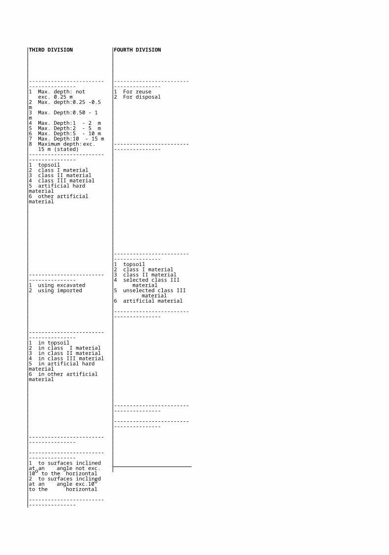
THIRD DIVISION
---------------------------------------1 Max. depth: not
exc. 0.25 m2 Max. depth: 0.25 -0.5 m3 Max. Depth: 0.50 - 1 m4 Max. Depth: 1 - 2 m5 Max. Depth: 2 - 5 m6 Max. Depth: 5 - 10 m7 Max. Depth: 10 - 15 m8 Maximum depth: exc.
15 m (stated)---------------------------------------1 topsoil2 class I material3 class II material4 class III material5 artificial hard material6 other artificial material
---------------------------------------1 using excavated2 using imported
---------------------------------------1 in topsoil2 in class I material3 in class II material4 in class III material5 in artificial hard material6 in other artificial material
---------------------------------------
---------------------------------------1 to surfaces inclined at an
angle not exc. 10o to the horizontal
2 to surfaces inclined at an angle exc.10o to the horizontal
---------------------------------------
FOURTH DIVISION
---------------------------------------1 For reuse2 For disposal
---------------------------------------
---------------------------------------1 topsoil2 class I material3 class II material4 selected class III
material5 unselected class III
material6 artificial material
---------------------------------------
---------------------------------------
---------------------------------------

FIRST DIVISION
Landscaping (cont'd)
NOTES
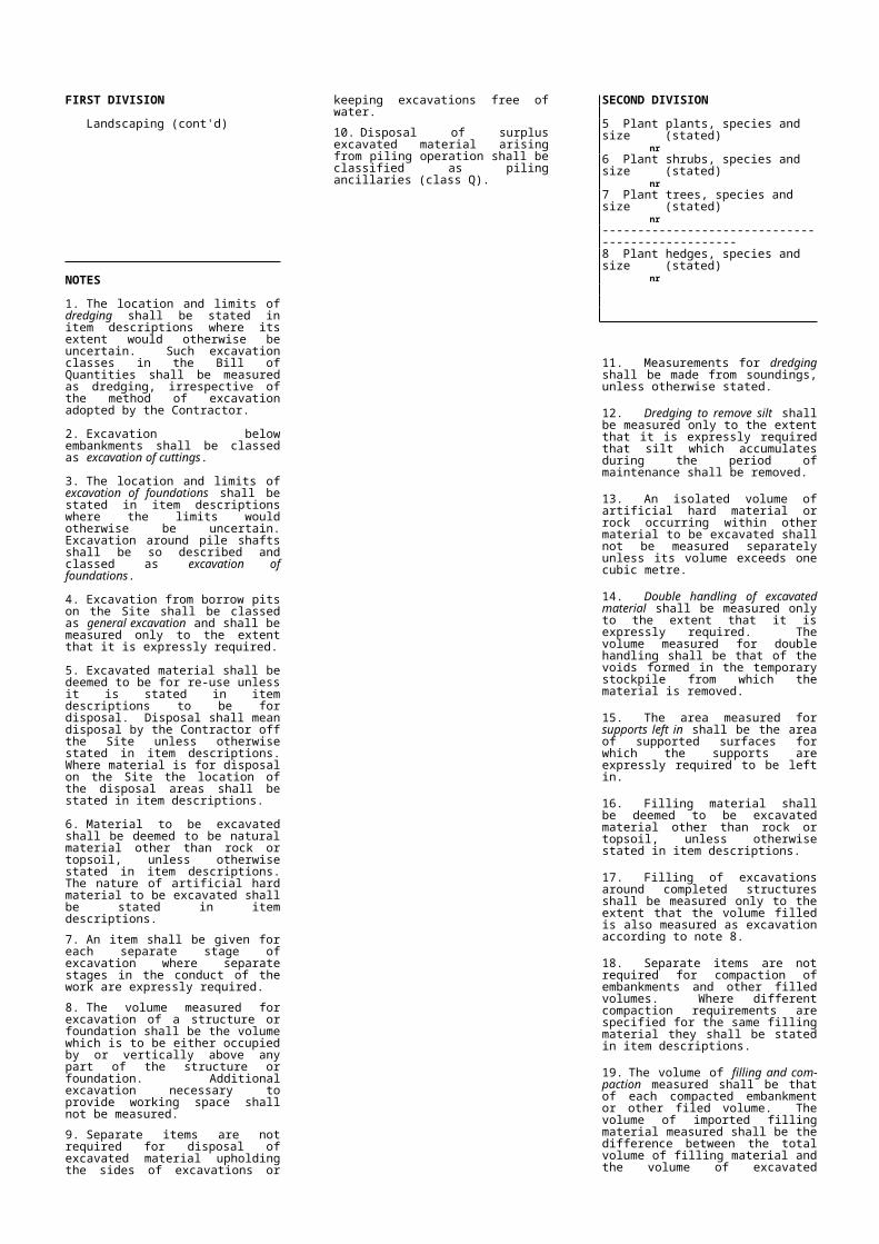
1. The location and limits of dredging shall be stated in item descriptions where its extent would otherwise be uncertain. Such excavation classes in the Bill of Quantities shall be measured as dredging, irrespective of the method of excavation adopted by the Contractor.
2. Excavation below embankments shall be classed as excavation of cuttings.
3. The location and limits of excavation of foundations shall be stated in item descriptions where the limits would otherwise be uncertain. Excavation around pile shafts shall be so described and classed as excavation of foundations.
4. Excavation from borrow pits on the Site shall be classed as general excavation and shall be measured only to the extent that it is expressly required.
5. Excavated material shall be deemed to be for re-use unless it is stated in item descriptions to be for disposal. Disposal shall mean disposal by the Contractor off the Site unless otherwise stated in item descriptions. Where material is for disposal on the Site the location of the disposal areas shall be stated in item descriptions.
6. Material to be excavated shall be deemed to be natural material other than rock or topsoil, unless otherwise stated in item descriptions. The nature of artificial hard material to be excavated shall be stated in item descriptions.
7. An item shall be given for each separate stage of excavation where separate stages in the conduct of the work are expressly required.
8. The volume measured for excavation of a structure or foundation shall be the volume which is to be either occupied by or vertically above any part of the structure or foundation. Additional excavation necessary to provide working space shall not be measured.
9. Separate items are not required for disposal of excavated material upholding the sides of excavations or keeping excavations free of water.
10. Disposal of surplus excavated material arising from piling operation shall be classified as piling ancillaries (class Q).
SECOND DIVISION
5 Plant plants, species and size (stated) nr
6 Plant shrubs, species and size (stated) nr
7 Plant trees, species and size(stated) nr
-------------------------------------------------8 Plant hedges, species and size
(stated) nr
11. Measurements for dredging shall be made from soundings, unless otherwise stated.
12. Dredging to remove silt shall be measured only to the extent that it is expressly required that silt which accumulates during the period of maintenance shall be removed.
13. An isolated volume of artificial hard material or rock occurring within other material to be excavated shall not be measured separately unless its volume exceeds one cubic metre.
14. Double handling of excavated material shall be measured only to the extent that it is expressly required. The volume measured for double handling shall be that of the voids formed in the temporary stockpile from which the material is removed.
15. The area measured for supports left in shall be the area of supported surfaces for which the supports are expressly required to be left in.
16. Filling material shall be deemed to be excavated material other than rock or topsoil, unless otherwise stated in item descriptions.
17. Filling of excavations around completed structures shall be measured only to the extent that the volume filled is also measured as excavation according to note 8.
18. Separate items are not required for compaction of embankments and other filled volumes. Where different compaction requirements are specified for the same filling material they shall be stated in item descriptions.
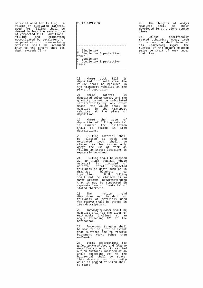
19. The volume of filling and compaction measured shall be that of each compacted embankment or other filed volume. The volume of imported filling material measured shall be the difference between the total volume of filling material and the volume of excavated material used for filling. A volume of excavated material used for filling shall be deemed to form the same volume of compacted fill. Additional filling and compaction necessitated by settlement of or penetration into underlying material shall be measured only to the extent that its depth exceeds 75 mm.
THIRD DIVISION
--------------------------------------------------1 Single row2 Single row & protective fence3 Double row4 Double row & protective fence
20. Where rock fill is deposited into soft areas the volume shall be measured in the transport vehicles at the place of deposition.
21. Where material is deposited below water, and the quantity cannot be calculated satisfactorily by any other means, the volume shall be measured in the transport vehicles at the place of deposition.
22. Where the rate of deposition of filling material is limited the limitation shall be stated in item descriptions.
23. Filling material shall be classed as rock and excavated rock shall be classed as for re-use only where the use of rock as filling at stated locations is expressly required.
24. Filling shall be classed as to stated thickness where material is provided of uniform total compacted thickness or depth such as in drainage blankets or topsoiling. Bulk filling shall not be classed as to stated thickness notwithstanding that it may be compacted in separate layers of material of stated thickness.
25. The nature and dimensions and the depth or thickness of materials used for pitching shall be stated in item descriptions.
26. Trimming of slopes shall be measured only for the sides of earthworks inclined at an angle exceed-ing 10° to the horizontal.
27. Preparation of surfaces shall be measured only tot he extent that surfaces are to receive Permanent Works other than earthworks.
28. Items descriptions for turfing, seeding, pitching and filling to stated thickness which is carried out on surfaces inclined at an angle exceeding 10° to the horizontal shall so state. Item descriptions for turfing which is pegged or wired shall so state.
29. The lengths of hedges measured shall be their developed lengths along centre lines.
30. Unless specifically stated otherwise, every item for excavation shall have as its Commencing surface the surface of the ground exposed prior to start of work under that item.

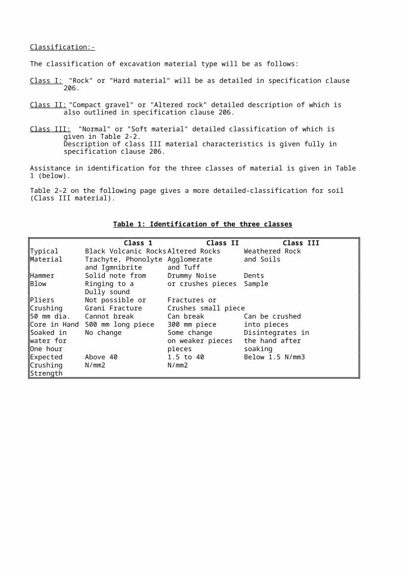
Classification:-
The classification of excavation material type will be as follows:
Class I: "Rock" or "Hard material" will be as detailed in specification clause 206.
Class II: "Compact gravel" or "Altered rock" detailed description of which is also outlined in specification clause 206.
Class III: "Normal" or "Soft material" detailed classification of which is given in Table 2-2. Description of class III material characteristics is given fully in specification clause 206.
Assistance in identification for the three classes of material is given in Table 1 (below).
Table 2-2 on the following page gives a more detailed-classification for soil (Class III material).
Table 1: Identification of the three classes
Class 1 Class II Class IIITypical Black Volcanic Rocks Altered Rocks Weathered RockMaterial Trachyte, Phonolyte Agglomerate and Soils
and Igmnibrite and TuffHammer Solid note from Drummy Noise DentsBlow Ringing to a or crushes pieces Sample
Dully soundPliers Not possible or Fractures or Crushing Grani Fracture Crushes small piece50 mm dia. Cannot break Can break Can be crushedCore in Hand 500 mm long piece 300 mm piece into piecesSoaked in No change Some change Disintegrates in water for on weaker pieces the hand afterOne hour pieces soakingExpected Above 40 1.5 to 40 Below 1.5 N/mm3Crushing N/mm2 N/mm2Strength

TABLE 2 - 2: IDENTIFICATION OF SOIL TYPES
Basic Soil Type
Particle size (mm) Visual Identification Nature and
PlasticityComposite Soil Types
(mixture of basic soil types)
BOULDERS Only seen complete in pits or exposure Scale of Secondary Constituents
200 with coarse soils
COBBLES
60
Often difficult to recover from boreholes
Particle shape:Term % of clay or silt
Angular
Subangular slightly clayey GRAVEL
coarse Easily visible to naked eye; particle shape Subrounded or under 5%
can be described; grading can be described Rounded slightly silty SAND
20 Flat
Elongate
- clayey GRAVEL
GRAVELS medium Well graded: wide range of grain sizes, well or 5 to 15%
distributed. Poorly graded: not well graded. - silty SAND
6 (May be uniform: size of most particles lies
between narrow limits; or gap graded; an
intermediate size of particle is markedly very clayey GRAVEL
fine under represented) or 15 to 35%
Texture: very silty SAND
2
Visible to the naked eye; very little or no Rough Sandy GRAVEL Sand or Gravel and
coarse cohesion when dry; grading can be described Smooth Important second constit-
0.6 Polished Gravelly SAND uent of the coarse fraction
Well graded: wide range of grain sizes, well
SANDS medium distributed. Poorly graded: not well graded.
0.2 (May be uniform: size of most particles lies
between narrow limits; or gap graded; an
fine intermediate size of particle is markedly
0.06 under represented)
Only coarse silt barely visible to naked eye; Non plastic Scale of secondary constituents with fine soils
coarse exhibits little plasticity and marked dilatancy; or low
0.02 slightly granular or silky to the touch. plasticity Term % of sand
Disintegrates in water; lumps dry quikly; or gravel
SILTS medium looses cohesion but can be powdered
0.006 easily between fingers. sandy CLAY
fine or 35 to 65%
0.002 gravelly SILT
Dry lumps can be broken but not powdered Intermediate
between the fingers; they can also disintegrate plasticity - CLAY SILT under 35%
under water but more slowly than silt; smooth (Lean clay)
to the touch; exhibits plasticity but no dilatancy; Examples of composite types
CLAYS sticks to the fingures and dries slowly; shrinks
appreciably on drying usually shows cracks. Loose, brown, subangular very sandy,
Intermediate and high plasticity clays show High plasticity fine to coarse GRAVEL with small
these properties to a moderate to high degree (Fat clay) pockets of soft clay.
respectively. Medium dense, light brown, clayey, fine
ORGANIC and medium sand.
CLAY-SILT or Varies Contains substantial amounts of organic Stiff, orange brown, fissured sandy CLAY.
SAND vegetable matter.
Predominantly plant remains usually dark Firm, brown, thinly laminated SILT and CLAY
PEATS Varies brown or black in colour, often with distinctivesmell; low bulk density. Plastic, brown, amorphous PEAT
Very
co
arse
soil
Coa
rse
Soi
lsO
ver
65%
san
d an
d gr
avel
siz
esFi
ne S
oils
Ove
r 35
% s
and
and
clay
siz
es.
Org
anic
Soi
ls
CLASS F: IN-SITU CONCRETE
Excludes: In situ concrete for:Capping of boreholes (inc. in class B): diaphragm walls (inc. in class C): drainage and pipework (inc. in classes K and L): piles (inc. in classes P and Q): roads (inc. in class R): rail track foundations (inc. in class S): tunnels and shaft linings (inc. in class T): foundations of fences and gates (inc. in class X)FIRST DIVISION
1 Provide cement for concrete t
------------------------------------------------------2 Designed mix for ordinary structural
concrete for class C exposure using ordinary portland cement m3
3 Designed mix for ordinary structural concrete for class B exposure using ordinary portland cement m3
4 Special design mix for special structural concrete for class A exposure using ordinary portlandcement m3
5 Designed mix for ordinary structural concrete for class B exposure using sulphate resistant cement m3
6 Special design mix for special structural concrete for class A exposure using sulphate resistant cement m3
------------------------------------------------------7 Place mass concrete m3
8 Place reinforced concrete m3
9 Place prestressed concrete m3
NOTES:
1. Items for provision of concrete shall be classified and described in accordance with SSRN 101, 'Specification of concrete'. The mix specification and type of cement used shall be as stated in item description for provision of concrete in accordance with SSRN 101. Concrete mixes shall be classed as designed mixes for ordinary structural concrete where the mix proportions are stated in the Contract and as special mixes for special structural concrete where the mix proportions are to be selected by the Contractor.
2. Prestressed concrete which is also reinforced shall be classed as prestressed concrete.
3. The thickness used for classification of blinding shall be the minimum thickness.
4. Columns and piers integral with a wall shall be measured as part of the wall.
5. The cross-sectional dimensions of special beam sections shall be stated in the item descriptions, except where a beam type or mark number is stated for which dimensions are given on the Drawings.
SECOND DIVISION
1 Ordinary portland cement 2 Sulphate resistant cement 3 Other (stated)
------------------------------------------------------1 Provide concrete grade: 102 Provide concrete grade: 153 Provide concrete grade: 204 Provide concrete grade: 255 Provide concrete grade: 306 Provide concrete grade: 407 Provide concrete grade: 508 Provide concrete grade: 609 Provide concrete grade: (stated)
-----------------------------------------------------1 As blinding2 In bases, footings, and ground slabs3 In suspended slabs4 In walls
------------------------------------------------------5 In columns and piers6 In beams7 As casing to metal sections8 In other concrete forms, (stated)
6. Beams shall be classed as special beam sections where their cross-section profiles are rectangular or approximately rectangular over less than 4/5 ths. of their length and where they are of box or other composite section.
7. Item descriptions for components classed as other concrete forms shall include one of the following:
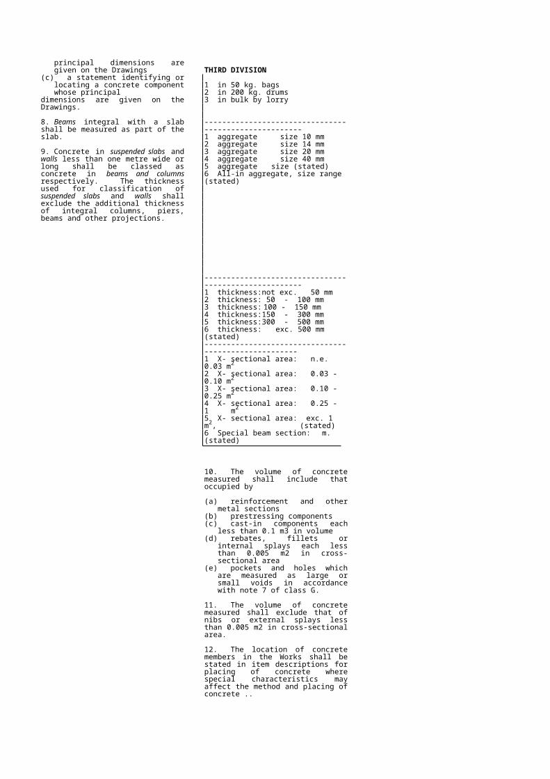
(a) the principal dimensions of the concrete component
(b) a type or mark number of a concrete component whose principal dimensions are given on the Drawings
(c) a statement identifying or locating a concrete component whose principal
dimensions are given on the Drawings.
8. Beams integral with a slab shall be measured as part of the slab.
9. Concrete in suspended slabs and walls less than one metre wide or long shall be classed as concrete in beams and columns respectively. The thickness used for classification of suspended slabs and walls shall exclude the additional thickness of integral columns, piers, beams and other projections.
THIRD DIVISION
1 in 50 kg. bags2 in 200 kg. drums3 in bulk by lorry
------------------------------------------------------1 aggregate size 10 mm 2 aggregate size 14 mm 3 aggregate size 20 mm 4 aggregate size 40 mm 5 aggregate size (stated)6 All-in aggregate, size range (stated)
------------------------------------------------------1 thickness: not exc. 50 mm2 thickness: 50 - 100 mm3 thickness: 100 - 150 mm4 thickness: 150 - 300 mm5 thickness: 300 - 500 mm6 thickness: exc. 500 mm (stated)-----------------------------------------------------1 X- sectional area: n.e. 0.03 m2
2 X- sectional area: 0.03 - 0.10 m2
3 X- sectional area: 0.10 - 0.25 m2
4 X- sectional area: 0.25 - 1 m2
5 X- sectional area: exc. 1 m2, (stated)6 Special beam section: m. (stated)
10. The volume of concrete measured shall include that occupied by
(a) reinforcement and other metal sections(b) prestressing components(c) cast-in components each less than 0.1
m3 in volume(d) rebates, fillets or internal splays each
less than 0.005 m2 in cross-sectional area
(e) pockets and holes which are measured as large or small voids in accordance with note 7 of class G.
11. The volume of concrete measured shall exclude that of nibs or external splays less than 0.005 m2 in cross-sectional area.
12. The location of concrete members in the Works shall be stated in item descriptions for placing of concrete where special characteristics may affect the method and placing of concrete ..
Details of the various classes of concrete are given in the following table:
TABLE CLASSES OF CONCRETE
CHARACTERISTIC MAXIMUM MAXIMUM MINIMUM MAXIMUMCLASS COMPRESSIVE AGGREGATE FREE CEMENT CEMENT
STRENGTH SIZE WATER/CEMENT CONTENT CONTENTN/mm2 mm RATIO kg/m3 kg/m3
C25/10/A 25 10 0.55 360 400
C25/20/A 25 20 0.55 360 400
C25/20/B 25 20 0.55 290 400
C25/20/C 25 20 - 240 540
C20/20/B 20 20 0.55 290 400
C20/40/B 20 40 0.55 260 400
C20/40/C 20 40 - 220 540
C15/40/B 15 40 - 180 540
C15/20/C 15 20 - 180 540
C10/40/C 10 40 - 150 540
* Compressive strength (N/mm2) / aggregate size (mm) / class of exposure
Class of Exposure :
A - exposed to a moist or corrosive atmosphere or alternate wetting and drying
B - exposed to continuous or almost continuous contact with liquid
C. not exposed to liquid nor to resist corrosion
CLASS G: CONCRETE ANCILLARIESIncludes: Form work for in-situ concrete: Reinforcement for in-situ concrete: Joints in in-situ concrete: Post-tensioning prestressing: Accessories for in-situ concrete.Excludes: Reinforcement in diaphragm walls (inc. in class C): Post-tensioned pre-stressing reinforcement (inc. in class H): Formwork reinforcement ancillary to drainage and pipework,(inc. in classes K &,L): Formwork reinforcement in piles (inc. in classes P & Q): Formwork & reinforcement in concrete roads & pavings, (inc. in class R): Formwork for concrete rail track foundations, (inc. in class S): Formwork for tunnels and shaft linings, (inc. in class T): foundations of fences and gates (inc. in class X).Formwork for foundations of fences and gates (inc. in class X).FIRST DIVISION1 Formwork: rough finish2 Formwork: fair finish3 Formwork: other finish (stated)4 Formwork: surface features (stated)
--------------------------------------------------------5 Reinforcement
--------------------------------------------------------6 Joints (stated)
--------------------------------------------------------7 Post-tensioned prestressing nr
SECOND DIVISION1 Plane horizontal2 Plane sloping3 Plain battered4 Plane vertical5 Curved to one radius in one plane--------------------------------------------------------6 Other, curved to radius in m.
(stated) m2
--------------------------------------------------------7 For voids nr
--------------------------------------------------------8 For concrete components of constant
cross section m
--------------------------------------------------------1 Mild steel bars to specification t2 High yield bars to specification t3 Stainless steel bars, quality (stated) t4 Reinforcing bars of quality (stated) t
-------------------------------------------------------5 Special joints, (stated) nr-------------------------------------------------------6 High yield steel fabric to specification
m2
7 Fabric of material (stated) m2
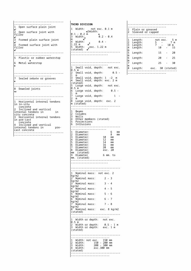
--------------------------------------------------------1 Open surface plain joint m2
2 Open surface joint with filler m2
3 Formed plain surface joint m2
4 Formed surface joint with filler m2
--------------------------------------------------------5 Plastic or rubber waterstop m6 Metal waterstop m
--------------------------------------------------------7 Sealed rebate or grooves m--------------------------------------------------------8 Doweled joints nr
--------------------------------------------------------1 Horizontal internal tendons in in-situ
concrete2 Inclined and vertical internal tendons in
in situ concrete3 Horizontal internal tendons in pre-cast
concrete4 Inclined and vertical internal tendons in
pre-cast concrete--------------------------------------------------------
THIRD DIVISION1 Width: not exc. 0.1 m m2
Width: 0.1 - 0.2 m m3 Width: 0.2 - 0.4 m m2
4 Width: 0.4 - 1.22 m m2
5 Width: exc. 1.22 m (stated) m2
--------------------------------------------------------
--------------------------------------------------------1 Small void, depth: not exc. 0.5 m2 Small void, depth: 0.5 -1 m3 Small void, depth: 1 -2 m4 Small void, depth: exc. 2 m (stated)5 Large void, depth: not exc. 0.5 m6 Large void, depth: 0.5 - 1 m7 Large void, depth: 1 - 2 m8 Large void, depth: exc. 2 m (stated)--------------------------------------------------------1 Beams2 Columns3 Walls4 Other members (stated)5 Projections6 Intrusions-------------------------------------------------------1 Diameter: 6 mm2 Diameter: 8 mm3 Diameter: 10 mm4 Diameter: 12 mm5 Diameter: 14 mm6 Diameter: 16 mm7 Diameter: 20 mm8 Diameter: exc. 20 mm (stated)9 Diameter 6 mm. to mm. (stated)--------------------------------------------------------
---------------------------------------------------------1 Nominal mass: not exc. 2 kg/m22 Nominal mass: 2 - 3 kg/m23 Nominal mass: 3 - 4 kg/m24 Nominal mass: 4 - 5 kg/m25 Nominal mass: 5 - 6 kg/m26 Nominal mass: 6 - 7 kg/m27 Nominal mass: 7 - 8 kg/m28 Nominal mass: exc. 8 kg/m2 (stated)---------------------------------------------------------1 Width or depth: not exc. 0.5 m2 Width or depth: 0.5 - 1 m3 Width or depth: exc. 1 m (stated)
---------------------------------------------------------1 Width: not exc. 150 mm2 Width: 150 - 200 mm3 Width: 200 - 300 mm4 Width: exc.300 mm (stated)---------------------------------------------------------
---------------------------------------------------------1 Plain or greased2 Sleeved or capped---------------------------------------------------------1 Length: not exc. 5 m2 Length: 5 - 7 m3 Length: 7 - 10 m4 Length: 10 - 15 m5 Length: 15 - 20 m6 Length: 20 - 25 m7 Length: 25 - 30 m8 Length: exc. 30 (stated)---------------------------------------------------------
FIRST DIVISION
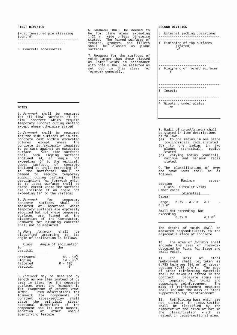
(Post tensioned pre.stressing (cont’d)---------------------------------------------------------
8 Concrete accessories
NOTES
1. Formwork shall be measured for all final surfaces of in-situ concrete which require temporary support during casting except where otherwise stated.
2. Formwork shall be measured for the side surfaces of in-situ concrete cast within excavated volumes except where the concrete is expressly required to be cast against an excavated surface. Such side surfaces shall back sloping surfaces inclined at an angle not exceeding 45o to the vertical. Upper surfaces of concrete inclined at angle exceeding 15o to the horizontal shall be deemed to require temporary support during casting. Item descriptions for formwork which is to upper surfaces shall so state, except where the surfaces are inclined at an angle not exceeding 10o to the vertical.
3. Formwork for temporary concrete surfaces shall be measured at locations where temporary surfaces are expressly required but not where temporary surfaces are formed at the discretion of the Contractor. Formwork for blinding concrete shall not be measured.
4. Plane formwork shall be classified according to its angle of inclination as follows.
Class Angle of inclination to the vertical
Horizontal 85 - 90oSloping 10 - 85oBattered 0 - 10oVertical 0o
5. Formwork may be measured by length as one item instead of by area in items for the separate surfaces where the formwork is for components of constant cross-section. Item descriptions for formwork for components of constant cross-section shall state the principal cross-sectional dimensions of the component and its mark number, location or other unique identifying feature.
6. Formwork shall be deemed to be for plane areas exceeding 1.22 m. wide unless otherwise stated. The formed surfaces of rebates, grooves, and fillets shall be classed as plane surfaces.
7. Formwork for the surfaces of voids larger than those classed as large voids in accordance with note 8 shall be measured as set out in this class for formwork generally.
SECOND DIVISION
5 External jacking operations--------------------------------------------------------1 Finishing of top surfaces,
(stated) m2
---------------------------------------------------------2 Finishing of formed surfaces m2
---------------------------------------------------------3 Inserts
---------------------------------------------------------4 Grouting under plates nr
8. Radii of curved formwork shall be stated in item descriptions as follows.(a) to one radius in one plane (cylindrical),
radius stated(b) to one radius in two planes (spherical),
radius stated(c) varying radius (conical), maximum and
minimum radii stated.
9. The classification of large and small voids shall be as follows.
Maximum cross-section Class Circular voids Other voids
(diameter) (area)
Large 0.35 - 0.7 m 0.1 - 0.5 m2
Small Not exceeding Not exceeding0.35 m 0.1 m2
The depths of voids shall be measured perpendicularly to the adjacent surface of concrete.
10. The area of formwork shall include the area of formwork obscured by forms for large and small voids.
11. The mass of steel reinforcement shall be taken as 0.785 kg/m per 100 mm2 of cross-section (7.85 t/m2). The mass of other reinforcing materials shall be taken as stated in the Contract. Separate items are not required for tying and supporting reinforcement. The mass of reinforcement measured shall include the mass of steel supports to top reinforcement.
12. Reinforcing bars which are not circular in cross-section shall be classified by the diameter of the circular bar in the classifi-cation which is nearest in cross-sectional area.
13. Lengths of reinforcing bars next higher multiple of 3 m. where they exceed 12 m. before bending.
14. Item descriptions for high yield steel fabric to SSRN 128 shall state the type number in accordance with SSRN 128. Item descriptions for other fabric reinforcement shall state the material, sizes and its nominal mass per square metre. The area of additional fabric in laps shall not be measured.
15. The dimensions, spacing and nature of components shall be stated in item descriptions for joints in concrete.
THIRD DIVISION
--------------------------------------------------------1 Using wood float2 Using steel trowel3 Other surface treatment, (stated).4 Granolithic finish5 Other applied finish, (stated)---------------------------------------------------------1 Aggregate exposure using retarder2 Bush hammering3 Other special treatment carried out
after striking formwork (stated)---------------------------------------------------------1 Linear inserts2 Other inserts (stated)---------------------------------------------------------1 Area not exc. 0.1 m2
2 Area 0.1 - 0.5 m2
3 Area 0.5 - 1 m2
4 Area exc 1 m2, (stated)
Separate items are not required for formwork to joints or for joining and cutting waterstops.
16. Joints for which temporary support of the whole surface area of concrete is required during casting shall be classified as formed surface joints. Other joints shall be classed as open surface joints.
17. Widths or depths of joints shall be measured between the outer surfaces of concrete with no deduction or addition for width or depth occupied by face or internal details such as fillets and waterstops. Joints shall be classified according to the average width or depth of each continuous joint.
18. Item descriptions for prestressing shall identify the concrete component to be stressed and state the composition of the tendon and particulars of the anchorage.
19. Prestressing shall be measured by the number of tendons where tendons are used and by the number of external jacking operations where stress is induced by jacking only.
20. Separate items are not required for ducts, anchorages, grouting or other components or tasks ancillary to prestressing. Profiled tendons in horizontal components shall be classed as horizontal tendons. The lengths of tendons used for classification shall be their developed lengths between the outer faces of anchorages.
21. The areas of the tops of walls and of other surfaces which are not given separate finishing treatment shall not be measured for finishing of top surfaces. No deduction from the areas measured for finishing shall be made for holes and openings in the finished surfaces each less than 0.5 m2 in area. The materials and thicknesses of granolithic and other applied surface finishes shall be stated in the item descriptions.
22. All components cast or grouted into in-situ concrete, except reinforcement, structural metalwork, prestressing and jointing materials, shall be classified as inserts. Separate items are not required for adapting formwork or boxing out for inserts.
CLASS H: PRECAST CONCRETEIncludes: Manufacture, erection, joining and fixing of precast concrete unitsExcludes: Precast concrete pipework, (inc. in classes I & J): Precast concrete manholes, catchpits, and gullies, (inc. in class K): Precast concrete piles, (inc. in classes P & Q): Precast concrete paving, kerbs, and traffic sign supports, (inc. in class R): Precast concrete tunnel linings, (inc. in class T): Precast concrete blockwork, (inc, in class U): Precast concrete fencing, (inc. in class X)
FIRST DIVISION
1 Beams nr2 Prestressed pre-
tensioned beams nr3 Prestressed post-
tensioned beams nr4 Columns nr
------------------------------------5 Slabs and covers nr
------------------------------------6 Segmental units nr
------------------------------------7 Units for subways,
culverts and ducts m------------------------------------8 Copings, sills and
weir blocks m
NOTES
1. The position of the Works for each type of precast unit shall be stated in item descrip-tions. Unless otherwise stated, precast units shall be deemed to be reinforced but not pre-stressed. Particulars of the prestressing shall be stated in item descriptions for prestressed units.
SECOND DIVISION
1 In concrete grade 102 In concrete grade 153 In concrete grade 204 In concrete grade 255 In concrete grade 306 In concrete grade 407 In concrete grade 508 In concrete grade 609 In concrete grade
(stated)
2. The cross-section type and principal dimensions of beams, columns, segmental units, box units, copings, sills and weir blocks and the average thickness of slabs shall be stated in item descriptions
3. Item descriptions shall state the mark or type number of each precast concrete unit.
THIRD DIVISION
1 Length: not exc. 5 m2 Length: 5 - 7 m3 Length: 7 - 10 m4 Length: 10 - 15 m5 Length: 15 - 20 m6 Length: 20 - 30 m7 Length: exc. 30 m
(stated)------------------------------------1 Area: not exc. 0.1 m2
2 Area: 0.1 - 0.5 m2
3 Area: 0.5 - 1.0 m2
4 Area: 1.0 - 5.0 m2
5 Area: 5.0 - 15 m2
6 Area: exc. 15 m2 (stated)
------------------------------------1 X-sect. area: not exc.
0.1 m2
2 X-sect. area: 0.1 - 0.5 m2
3 X-sect. Area: 0.5 - 1.0 m2
4 X-sect. area: exc. 1 m2,(stated)
------------------------------------
4. Concrete components which are cast other than in their final position shall generally be classed as precast concrete units. Where site precasting of units is adopted for reasons other than to obtain multiple use of formwork, and the nature of the work is characteristic of in situ concrete, but involves movement of the cast units into their final positions, the units shall be classed as in situ concrete and items given in class A for the Temporary Works asso-ciated with the movement of the units
FOURTH DIVISION
1 Mass: not exc.100 kg2 Mass: 100 - 250 kg3 Mass: 250 - 500 kg4 Mass: 500 - 750 kg5 Mass: 750 - 1 t6 Mass: 1 - 2 t7 Mass: 2 - 5 t8 Mass: 5 - 10 t9 Mass: exc. 10 t.,
(stated)
5. Units with different dimensions shall be given different mark or type numbers.
6. The mass used for classification in the fourth division shall be the mass of each unit. The length measured for box units, copings, sills, and weir blocks shall be the length of identical units.
7. Where weir blocks are laid to precise levels, item descriptions shall so state.

CLASS I: PIPEWORK – PIPES, SEWERS & FITTINGS - SUPPLYIncludes: Provision of pipes, specials, fittings and valves, complete with jointing materials
and associated components to site of Works.Excludes: Associated work included in classes J, K, & L.FIRST DIVISION
1 Pipes and sewers
-------------------------------------------2 Fittings to ductile iron
pipes (coating/lining stated) nr3 Fittings to welded steel
pipes (coating/lining stated) nr4 Fittings in steel to uPVC
pipes (coating/lining stated) nr5 Fittings in uPVC to uPVC
pipes nr6 Fittings to asbestos
cement pipes nr7 Fittings to G.S. or G.I.
pipes nr8 Fittings to other pipes
(stated) nr
SECOND DIVISION
1 Material (stated)2 Clay3 Concrete (stated)4 Ductile iron (coating/lining
stated)5 Welded steel (coating/lining
stated) 6 uPVC7 Asbestos cement8 G.S. or G.I.9 Polyethylene
-------------------------------------------1 Bends, double flanged2 Bends, plain ended (A.C. &
welded steel), double socket ( ductile iron & uPVC), or (stated)
-------------------------------------------3 Junctions and branches,
all flanged unless (stated)
-------------------------------------------4 Junctions and branches,
main line plain ended (A.C. & welded steel), and double socket (ductile iron & uPVC), or (stated)
-------------------------------------------5 Tapers, double flanged6 Tapers, plain ended (A.C.
& welded steel), double socket (ductile iron & uPVC), or (stated)
-------------------------------------------7 Plain ended & single flanged
pieces and bellmouths, single flanged socketed pieces, nominal lengths
(stated)
-------------------------------------------
THIRD DIVISION
1 Double flanged, standard m2 S & S standard joints,
(stated) m3 S & S tyton joints, standard m4 S & S bolted gland joints,
standard m5 Plain ended, ogee joints,
standard m6 Plain ended, with separate
joints (one/pipe), standard m7 Threaded, separate joints,
(one/pipe), standard m-------------------------------------------8 Double flanged, non-
standard, length (stated) nr9 Other, non-standard
length (stated) nr-------------------------------------------1 Long radius, 11.25o2 Long radius, 22.5o3 Long radius, 45o4 Long radius, 90o5 Short radius 11.25o6 Short radius 22.5o7 Short radius 45o8 Short radius 90o9 Duckfoot-------------------------------------------1 Tees, equal, branch as main2 Tees, branch down 1 dia.3 Tees, branch down 2 dia.4 Tees, branch down 3 dia.5 Tees, branch down 4 dia.6 Tees, branch down 5 dia.7 Tees, branch down 6 dia.8 Tees, branch down 7 dia.9 Tess, branch down more
than 7 dia., (stated)-------------------------------------------1 Tees, equal, branch as main2 Tees, branch down 1 dia.3 Tees, branch down 2 dia.4 Tees, branch down 3 dia.5 Tees, branch down 4 dia.6 Tees, branch down more
than 4 dia. (stated)7 Tees, hydrant, flanged
branch n.b. 80 mm8 Tees, invert branch flanged
or (stated), n.b. 80 for main of n.b. < 225, or n.b. 100 for main of n.b. >225
9 Cross or wye (stated)-------------------------------------------1 Concentric, down 1 dia2 Concentric, down 2 dia3 Concentric, down 3 dia4 Concentric, down more than
3 dia (stated)5 Invert, down 1 dia6 Invert, down 2 dia7 Invert, down 3 dia8 Invert, down more than
3 dia (stated)-------------------------------------------1 P.e. length n.e. 1 m (stated)2 P.e. length 1 - 2 m (stated)3 P.e. length exc. 2 m (stated)4 P.e. with puddle flange
(length & p.f. position stated)5 Single fl. length n.e. 1 m
(stated)6 Single fl. length 1 -2 m
(stated)7 Single fl. length exc. 2 m
(stated)8 Single fl. with puddle
flange (length & p.f. position) (stated)9 Bellmouth-------------------------------------------
FOURTH, FIFTH &SIXTH DIVISIONS
4TH pressure class1 NP 02 NP 33 NP 64 NP 9/105 NP 126 NP 167 NP 258 NP 409 NP other
(stated)
5TH nominal bore list
Select from the list displayed for the pipe material that has been indicated
6TH sequence no
A number from 1 through 9 to be used if necessary to differentiate between items that would otherwise have the same BOQ number

FIRST DIVISION
Fittings to pipes (cont'd)
-------------------------------------------9 Valves, penstocks,
hydrants, meters nr
SECOND DIVISION
8 Adaptors, detachable collars, couplings and saddles
-------------------------------------------9 Standard couplers & end
pieces
-------------------------------------------1 Gate valves2 Butterfly valves
(with cap and key unless otherwise stated)
3 Penstocks(with extension spindle, headstock and handwheel unless otherwise stated)
-------------------------------------------4 Non-return valves
-------------------------------------------5 Air valves
-------------------------------------------6 Pressure control valves
-------------------------------------------7 Hydrants
-------------------------------------------8 Float Valves
-------------------------------------------9 Meters
THIRD DIVISION
1 Flexible, straight coupling, standard unless (stated)
2 Flexible, stepped coupling (stated)
3 Flexible, anchor coupling4 Flexible, test coupling5 Flange adaptor, flexible6 Flange adjustable/
removable joint7 Detachable collar, short
unless otherwise (stated)8 Saddle, (stated)9 Adaptor, stepped, (stated)-------------------------------------------1 Flange-p.e. coupler in C.I
or D.I. unless (stated)2 Union (stated)3 Flanged socket4 Threaded-threaded coupler5 Threaded-p.e. coupler6 Blank flange7 Separate flange (stated)8 Plug or cap (stated)9 Other (stated)-------------------------------------------1 Flanged, non-rising spindle.2 P.e. non-rising spindle3 Socketed,non-rising spindle4 Threaded,non-rising spindle5 Flanged,rising spindle (stated)6 P.e.,rising spindle (stated)7 Socketed, rising spindle,
(stated)8 Single flange (butterfly &
penstock (stated)9 Other, (stated)-------------------------------------------1 Flanged, gravity closing type2 Flanged, counterweight
disc type3 Flanged, surge suppressing
type4 Flanged, other (stated)5 Foot valve with strainer6 Flap valve, single flange-------------------------------------------1 Single small orifice,
threaded without stopcock2 Single small orifice,
threaded with stopcock3 Single small orifice,
flanged without stopcock4 Single small orifice,
flanged with stopcock5 Single large orifice, flanged,
separate isolating valve6 Single large orifice, flanged,
integral isolating valve7 Double orifice, flanged,
separate isolating valve8 Double orifice, flanged,
integral isolating valve9. Other (stated)
with separate isolating valve-------------------------------------------1 Sustaining valve (stated)2 Reducing valve (stated)3 Release valve (stated)4 Level control (stated)-------------------------------------------1 With integral isolating valve2 With separate isolating valve-------------------------------------------1 Equilibrium type,(stated)2 Streamline type (stated)3 Other (stated)-------------------------------------------1 Woltman bulk type, (stated)2 Bulk type (stated)3 Waste meter c/w recorder
(stated)4 Single jet, inferential with
dry dial, domestic type5 Single jet, inferential with
wet dial, domestic type6 Volumetric, with rotary,piston
domestic type7 Multi-jet rotor, domestic type
FOURTH, FIFTH &SIXTH DIVISIONS
4TH pressure class1 NP 02 NP 33 NP 64 NP 9/105 NP 126 NP 167 NP 258 NP 409 NP other
(stated)
5TH nominal bore list
Select from the list displayed for the pipe material that has been indicated
6TH sequence no
A number from 1 through 9 to be used if necessary to differentiate between items that would otherwise have the same BOQ number
NOTES
1. Items shall be deemed to include the supply of both pipes and fittings complete with all jointing materials, coatings and linings and other related materials called for on the drawings or in the specification unless such material is specifically excluded in the item description
2. The nominal bores, and in the case of uPVC pipes the nominal external diameters are given in the table below for the various types of pipe wall material.
TABLE STANDARD PIPE, SEWER AND FITTINGS DIAMETERS IN mm.
Ref. Steel / G.S. or PVC HDPE Asbestos ConcreteLetter Ductile Iron G.I. Cement
a 10b 15 15c 20 20d 25 32e 32 40f 40 40 50 50 50g 50 50 63 63 60h 65 65 75 75 75i 80 80 90 90j 100 100 110 110 100k 150 125 160 160 150 150l (150) 150 180 180 175
m (200) 200 200 (200)n 200 225 225 200 225o (250) 250 250 (250)p 250 280 250q 300 315 315 300 300r 350 350 350 375s 400 400 400t 450 450 450u 500 500 525v 550w 600 600 600x 700 700 675y 800 800 750z 900 900
(NOD) =nominal outside diameter
( ) =non preferred sizes

CLASS J: PIPEWORK – PIPES, SEWERS AND FITTINGS - INSTALLIncludes: Distribution of pipes and fittings from storage areas to installation site or trench side, excavation of trenches, including necessary shoring, dewatering of trenches, laying of pipes and fittings in trenches, jointing, partial backfilling of trenches prior to testing of pipelines, and completion of backfilling after successful testing, testing, sterilisation, and flushing.Excludes: Work included in classes I, K and L.FIRST DIVISION
1 Method of Measurementtype A in metres m
-----------------------------2 Testing m
-----------------------------3 Sterilisation
and flushing m
-----------------------------4 Method of Meas-urement type
B by number nr5 Method of Meas-
urement typeC by number nr
-----------------------------
SECOND DIVISION
1 Other pipes and fittings, (stated)
2 Clay pipes and fittings3 Concrete pipes and
fittings, (stated)4 Ductile iron pipes and
fittings5 Welded steel pipes and fittings6 uPVC pipes and
fittings7 A.C. pipes and fittings8 G.S. or G.I. pipes and
fittings9 Polyethylene pipes and
fittings
-----------------------------------1 Test pressure not exc.
6 bar2 Test pressure exc. 6
bar but not exc. 12 bar3 Test pressure exc. 12
bar but not exc: 25 bar4 Test pressure exc. 25
bar but not exc. 40 bar5 Test pressure exc. 40
bar (stated)-----------------------------------1 N. B: n.e. 100 mm2 N. B: 100 - 200 mm3 N. B: 200 - 300 mm4 N. B: 300 - 400 mm5 N. B: 400 - 500 mm6 N. B: 500 - 600 mm7 N. B: 600 - 900 mm8 N. B: 900 - 1200 mm9 N. B: exc. 1200 mm
(stated)-----------------------------------1 Pipes
-----------------------------------2 Fittings
-----------------------------------
THIRD DIVISION
1 Pipe n.b: n.e. 100 mm2 Pipe n.b.: exc 100 but
not exc. 200 mm3 Pipe n.b.: exc 200 but
not exc. 300 mm4 Pipe n.b.: exc 300 but
not exc. 400 mm5 Pipe n.b.: exc 400 but
not exc. 500 mm6 Pipe n.b.: exc 500 but
not exc. 600 mm7 Pipe n.b.: exc 600 but
not exc. 900 mm8 Pipe n.b.: exc 900 but
not exc. 1200 mm9 Pipe n.b.: exc 1200
(stated)
-----------------------------------
-----------------------------------1 Other pipes, (stated)2 Clay pipes3 Concrete pipes,
(stated)4 Ductile iron pipes5 Welded steel pipes6 uPVC pipes7 A.C. pipes8 G.S. or G.I. pipes9 Polyethylene pipes-----------------------------------1 Bends (radius and
joints stated)2 Junctions & branches
(type and joints stated) 3 Tapers (type and joints
stated)4 Pipe pieces and
bellmouths, (length, joints and type stated)
5 Adaptors, collars, coup- lings, saddles & end pieces (stated)
6 Gate & Butterflyvalves (stated)
7 Air valves (stated)8 Meters, (type stated)9 Others (stated)-----------------------------------
FOURTH DIVISION
1 Not in trenches2 In trenches, depth: n.e.
1 m3 In trenches, depth: 1 -
1.5 m4 In trenches, depth: 1.5
- 2 m5 In trenches, depth: 2 -
3 m6 In trenches, depth: 3 -
4 m7 In trenches, depth: 4 -
6 m8 In trenches, depth: exc.
6 m (stated)9 On piers, number and
height, (stated)-----------------------------------
-----------------------------------
-----------------------------------1 N.b: n.e. 100 mm2 N.b.: exc 100 but
not exc. 200 mm3 N.b.: exc 200 but
not exc. 300 mm4 N.b.: exc 300 but
not exc. 400 mm5 N.b.: exc 400 but
not exc. 500 mm6 N.b.: exc 500 but
not exc. 600 mm7 N.b.: exc 600 but
not exc. 900 mm8 N.b.: exc 900 but
not exc. 1200 mm9 N.b.: exc 1200
(stated)
-----------------------------------
FIFTH DIVISION
-------------------------------1 Not in trenches2 In trenches, depth:
n.e. 1 m3 In trenches, depth:
1- 1.5 m4 In trenches, depth:
1.5 - 2 m5 In trenches, depth:
2- 3 m6 In trenches, depth:
3- 4 m7 In trenches, depth:
exc. 4 m (stated)8 On piers, number
and height,(stated)9 In chambers
-------------------------------

FIRST DIVISION
6 Method of Measurement type B and type C trench excavation m3
NOTES
1. Three methods of measure-ment are specified herein. Methods of measurement A and B are used for new works that do not directly involve any tie-in works although they may subsequently require this. Method of measurement C is specifically reserved for tie-in work that can only be executed by shutting down a live system.
2. Unless otherwise indicated in the item description contained in the Bill of Quantities, pipes shall be measured in accordance with Method A. If used, Method B will generally be limited to intake sites, treatment works, and reservoir sites, where there are a disproportionate number of fittings involved.
3. Method A for the measure-ment of pipes and fittings.
a) The unit of measurement shall be in metres.
b) Lengths of pipelines shall be measured along their cen-treline and shall include lengths occupied by fittings and valves. Where pipes are built into manholes and other chambers, the lengths shall be measured from the inside surfaces of the chambers.
c) Depths shall be measured from the Commencing Surface to the invert of the pipe.
SECOND DIVISION
1 Pipe n.b. n. e. 200 mm2 Pipe n.b. exc. 200 but
not exc. 300 mm3 Pipe n.b. exc. 300 but
not exc. 600 mm4 Pipe n.b. exc. 600 but
not exc. 900 mm 5 Pipe n.b. exc. 900 mm
(stated)
d) All pipes shall be deemed to be in trenches unless expressly stated otherwise.
e) No separate payment shall be made for:i) Excavation of pipe
trenchesii) Backfilling of pipe
trenches unless trenches are expressly required to be backfilled with material other than that excavated from the trench.
iii) Provision, cutting, laying, jointing of pipes and fittings in trenches
iv) Temporary supports which are not expressly required to be left in the excavations
v) Keeping trenches clear of water
vi) Trimming of trench bottoms
vii) Disposing of excess excavated material
viii) Any additional protect-ion at the time of laying if called for on the drawings or in the specification.
4. Method B for the measure-ment of pipes and fittings.
a) The unit of measurement shall be by nr., with excava-tion and backfilling of trenches in cubic metres under first division 6.
b) Depths shall be measured from the commencing surface to the invert of the pipe or fitting.
THIRD DIVISION
1 Max. depth n.e. 1 m2 Max. depth 1 - 1.5 m3 Max. depth 1.5 - 2 m4 Max. depth 2 - 3 m5 Max. depth 3 - 4 m6 Max. depth 4 - 6 m7 Max. depth exc. 6 m
(stated)
c) The volume of excavation & backfilling shall be calculated by multiplying together the depth of the trench and the length of the pipe or fitting in the trench & the nominal width of excavation,the excavation as stated in the Specification.
d) No separate payment shall be made for:
i) Backfilling of trenches unless trenches are ex-pressly required to be backfilled with material other than that excavated from the trenches
ii) Provision, cutting, laying, and jointing of pipes and fittings.
iii) Temporary supports which are not expressly required to be left in the excavation
iv) Keeping trenches clear of water
v) Trimming of trench bottoms
vi) Any additional protection at the time of laying if called for on the drawings or in the specification.
5. Method C for the measure-ment of fittings, and occasionally pipes that can only be installed by closing down a live system.
a) The unit of measurement shall be by nr., with excava-tion and backfilling of trenches in cubic metres under first division 6.
FOURTH DIVISION
b) Depths shall be measured from the commencing surface to the invert of the pipe or fitting.
c) The volume of excavation & backfilling shall be calculated by multiplying together the depth of the trench and the length of the pipe or fitting in the trench & the nominal width of excavation,the excavation as stated in the Specification.
d) No separate payment shall be made for:
i) Backfilling of trenches unless trenches are ex-pressly required to be backfilled with material other than that excavated from the trenches
ii) Provision, cutting, laying, and jointing of pipes and fittings, whether old or new.
iii) Temporary supports which are not expressly required to be left in the excavation
iv) Keeping trenches clear of water
v) Trimming of trench bottoms
vi) Any additional protection at the time of laying if called for on the drawings or in the specification.
CLASS K: PIPEWORK - MANHOLE & PIPE & SEWER WORK ANCILLARIES
Includes: Manholes and other chambers, ducts, metal culverts, crossings and reinstate-ment, other ancillaries as listed
Excludes: Work included in classes I, J, L and Y.FIRST DIVISION
1 Manholes & otherchambers, in accord-ance with standard drawings, (stated) nr
----------------------------------2 Concrete manhole
covers or surr-ounds (stated) nr
----------------------------------3 Gullies nr
----------------------------------4 French drains,
rubble drains and ditches
----------------------------------5 Ducts and metal
culverts m
----------------------------------
SECOND DIVISION
1 Brick2 Brick with backdrop3 In-situ concrete4 In-situ concrete
with backdrop5 Precast concrete6 Precast concrete
with backdrop7 Masonry or
blockwork8 Masonry or block-
work with backdrop9 Other (stated)
----------------------------------1 Paving, (stated)3 In-situ concrete5 Precast concrete7 Masonry or block-work
----------------------------------1 Clay2 Clay trapped3 In-situ concrete4 In-situ concrete
trapped5 Precast concrete6 Precast concrete
trapped7 Plastics8 Plastics trapped----------------------------------1 Filling of french &
rubble drains with graded material m3
2 Filling of french & rubble drains with rubble m3
----------------------------------3 Trenches for unpiped
rubble drains m4 Unlined rectangular
section ditches m5 Lined rectangular
section ditches m6 Unlined vee section
ditches m7 Lined vee section
ditches m8 Trenches for pipes or
cables to be laid by others m
----------------------------------1 Cable ducts: 1 way2 Cable ducts: 2 way3 Cable ducts: 3 way4 Cable ducts: exc. 3
way (stated)5 Sectional corrugated
metal culverts n.i.d. n.e. 0.5 m
6 Sectional corrugated metal culverts n.i.d. 0.5 - 1 m
7 Sectional corrugated metal culverts n.i.d. 1 - 1.5 m
8 Sectional corrugated metal culverts n.i.d. exc. 1.5 m (stated)
----------------------------------
THIRD DIVISION
1 Sluice (gate) valve box2 Single air valve,(small
orifice) chamber3 Single air valve, (large
orifice), or double airvalve chamber
4 Meter chamber5 Hydrant chamber6 Washout valve
chamber (single or double stated)
7 Sewer manhole8 Drainage manhole9 Outfall, (stated)
----------------------------------1 Area: n. e. 0.5 m2
2 Area: 0.5 - 1 m2
3 Area: 1 - 2 m2
4 Area: 2 - 3 m2
5 Area: 3 - 4 m2
6 Area: 4 - 5 m2
7 Area: exc. 5 m2
(stated)----------------------------------
----------------------------------
----------------------------------1 X-sect. area:
n.e. 0.25 m2
2 X-sect. area:0.25 -0.5 m2
3 X-sect. area:0.5 -0.75 m2
4 X-sect. area:0.75 -1 m2
5 X-sect.area:1-1.5 m2
6 X-sect.area:1.5-2 m2
7 X-sect area: 2 -3 m2
8 X-sect. Area: exc. 3 m2 (stated)
----------------------------------1 Not in trenches2 In trenches, depth:
n. e. 1m3 In trenches, depth:
1 - 1.5 m4 In trenches, depth:
1.5 - 2 m5 In trenches, depth:
2 - 3 m6 In trenches, depth:
3 - 4 m7 In trenches, depth:
4 - 6 m8 In trenches, depth:
exc. 6 m (stated)9 Elevated on piers, no.
& height (stated)----------------------------------
FOURTH DIVISION
1 Nom. bore n.e. 100 mm
2 Nom. bore exc 100 but n.e. 200 mm
3 Nom. bore exc. 200 but n.e. 300 mm
4 Nom. bore exc.300 but n.e. 400 mm
5 Nom. bore exc.400 but n.e. 500 mm
6 Nom. bore exc. 500 but n.e. 600 mm
7 Nom. bore exc.600 but n.e. 900 mm
8 Nom. bore exc 900 but n.e. 1200 mm
9 Nom. bore exc. 1200 mm (stated)
--------------------------------
----------------------------------
----------------------------------
----------------------------------
----------------------------------
----------------------------------
FIFTH DIVISION
1 Depth: n.e. 1.5 m2 Depth: 1.5 - 2 m3 Depth: 2 - 3 m4 Depth: 3 - 4 m5 Depth: 4 - 5 m6 Depth: 5 - 6 m7 Depth: exc. 6m
(stated)
----------------------------------
----------------------------------FIRST DIVISION
VOLUME IIModified Civil Engineering Standard Method of Measurement Page 18 of 356 Crossings nr
------------------------------------------7 Reinstatement m
------------------------------------------8 Other pipework ancillaries
------------------------------------------9 Metal covers and surface
boxes nr
SECOND DIVISION
1 River, stream or canal, width 1 - 3 m
2 River, stream or canal, width 3 - 10 m
3 River, stream or canal, width exc. 10 m (stated)
4 Hedge crossing5 Wall crossing6 Fence crossing7 Sewer, ditch or drain crossing8 Other underground
service, (stated)9 Railway crossing, (stated)-----------------------------------------------1 Breaking up and temporary
reinstatement - surfaced roads2 Breaking up and temporary re-instatement of dirt roads (where specified by Engineer)3 Breaking up, temporary
and permanent reinstatementof surfaced roads
4 Breaking up, temporary and permanent re-instatement of dirt roads (where specified)
5 Reinstatement of grassland6 Reinstatement of cultivated
lands incl. gardens7 Reinstatement of sports fields
-----------------------------------------------1 Reinstatement of field
drains m-----------------------------------------------2 Marker posts for (stated) nr
----------------------------------------------3 Timber supports left in
excavations m2
4 Metal supports left in excavations m2
--------------------------------------------5 Connection of pipes to
existing manholes, and other chambers nr
-----------------------------------------------1 Other, (stated)2 Cast iron3 Rust resistant steel4 Mild steel, plain5 Galvanised steel
THIRD DIVISION
1 Pipe nom.bore n.e. 250 mm2 Pipe nom.bore 250- 500 mm3 Pipe nom.bore 500-1000 mm4 Pipe nom.bore 1000-1500 mm5 Pipe nom.bore 1500-2000 mm6 Pipe nom.bore exc. 2000 mm
(stated)
-----------------------------------------------1 Pipe nom.bore n.e. 250 mm2 Pipe nom.bore 250- 500 mm3 Pipe nom.bore 500-1000 mm4 Pipe nom.bore 1000-1500 mm5 Pipe nom.bore 1500-2000 mm6 Pipe nom.bore exc. 2000 mm
(stated)
-----------------------------------------------
-----------------------------------------------1 Sluice valves2 Air valves3 Fire hydrants4 Washouts5 Pipelines6 Other (stated)-----------------------------------------------
-------------------------------------------1 Existing materials (stated)2 Existing materials (clay)3 Existing materials (concrete)4 Existing materials (ductile
iron)5 Existing materials (welded
steel)6 Existing materials (uPVC)7 Existing materials (A/C)8 Existing materials (G.S. or
G.I.)----------------------------------------------1 With grade A cover & frame2 With grade B cover & frame3 With heavy duty cover &
frame4 With medium duty cover &
frame5 With light duty cover & frame6 With cover & frame, (stated)7 With lockable cover and
frame as per standard drawing
FOURTH DIVISION
1 Overcrossing - type I2 Over crossing - type II3 Undercrossing - type III
-------------------------------------
-------------------------------------
-------------------------------------1 In class 30 precast
concrete2 In accordance with
standard drawings
-------------------------------------
-------------------------------------1 Pipe n.b. n.e. 100 mm2 Pipe n.b. 100 - 200 mm3 Pipe n.b. 200 - 300 mm4 Pipe n.b. 300 - 400 mm5 Pipe n.b. 400 - 500 mm6 Pipe n.b. 600 - 900 mm7 Pipe n.b. 900 -1200 mm8 Pipe n.b. exc. 1200 mm
(stated)
-------------------------------------1 Area: not exc. 0.1 m2
2 Area: 0.1 - 0.5 m2
3 Area: 0.5 - 1 m2
4 Area: 1 - 5 m2
5 Area: 5 - 15 m2
6 Area: exc. 15 m2 (stated)
NOTES
1. Type or mark numbers shall be stated in item descriptions for manholes and other chambers of which details are given elsewhere in the Contract. Item descriptions shall identify different configurations of manholes and other chambers. Separate items are not required for different arrangements of inlets and outlets or for access shafts of different heights.
2. Types and loading duties of manhole gully and catchpit covers shall be stated in item description.
3. Depths of manholes and catchpits shall be measured from the tops of covers to the tops of base slabs.
4. Separate items are not required for excavation for work in this class except as set out in class L (see notes 1-5 of class L).
/tt/file_convert/5ad4bb837f8b9a1a028c35cf/document.doc
20
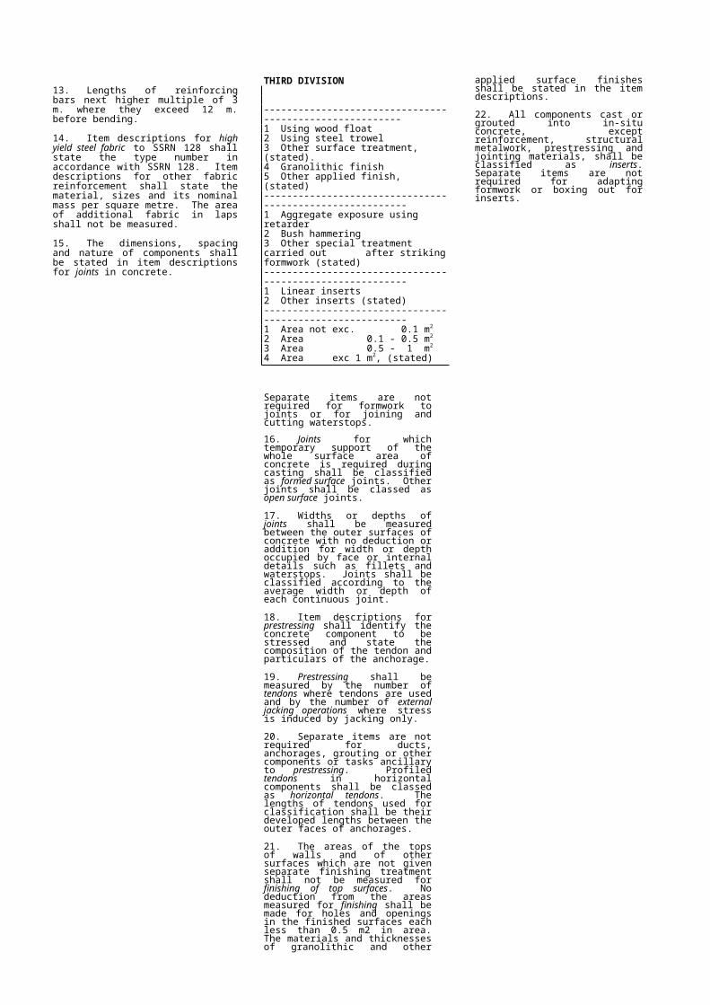
VOLUME IIModified Civil Engineering Standard Method of Measurement Page 18 of 355. Excavation and pipe laying for piped French and rubble drains shall be included in Class J. The nature of the filling material shall be stated in item descriptions for filling of French and rubble drains in this class.
6. Notes in classes I, K and L which refer to pipe and pipework shall also apply to ducts and metal culverts in this class. Crossings, reinstatement and other pipework ancillaries for ducts and metal culverts shall be itemized, described and measured as set out in this class, except that the dimension used for classification in the third division shall be the maximum nominal distance between the inside faces of the outer walls of the duct or culvert. Non-circular metal culverts shall be classified by their maximum nominal internal cross-sectional dimension. Separate items are not required for bends in cable ducts.
7. Materials and dimensions of linings to ditches shall be stated in item descriptions. The cross-sectional areas of rubble drains and ditches shall be measured to the Excavated Surfaces.
8. Types of surfaces shall be stated in item descriptions for breaking up and reinstatement of roads. Separate items are not required for removal and reinstatement of kerbs. Surfaced roads denote tarmac, concrete, paving bricks or similar surfaces. Dirt roads denote only official designated murram roads of at least 6 m width and where specified by the Engineer or his Representative.
9. River, stream and canal crossings shall be classified by their widths between banks measured along pipe centre lines. Crossings of streams shall be measured only where their width exceeds one metre. Items for crossings shall include reinstatement unless otherwise stated. Where linings to rivers, streams or canals are to be broken through and reinstated the type of lining shall be stated in item descrip tions for crossings. Crossings of roads and paths shall be classed as breaking up and reinstatement of roads and paths. Lengths for breaking up and reinstatement of roads and footpaths shall be measured along pipe centre lines and shall include lengths occupied by manholes and other chambers.
10. Sizes and types of marker posts shall be given in item descriptions or given on drawings.
11. The area measured for supports left in excavations shall be the area of supported surfaces for which the supports are expressly required to be left in.
/tt/file_convert/5ad4bb837f8b9a1a028c35cf/document.doc
21
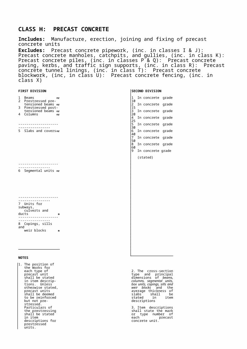
CLASS L: PIPEWORK - SUPPORTS AND PROTECTION, ANCILLARIES TO LAYING AND EXCAVATION
Includes: Extras to excavation and backfilling of trenches for pipework, ducts and metal culverts, manholes and other chambers. Pipelaying in headings and thrust borings. Excavation for and provision of supports and protection to pipework, ducts and metal culvertsExcludes: Work included in classes I,J, and K.FIRST DIVISION
1 Extras to excavation and backfilling m3
-----------------------------------------2 Special laying methods m
-----------------------------------------3 Beds m4 Haunches m5 Surrounds m
-----------------------------------------6 Wrapping & lagging of m
-----------------------------------------7 Concrete stools and thrust
blocks, concrete class (stated) nr
-----------------------------------------8 Other isolated pipe
supports nr
SECOND DIVISION
1 In pipe trenches2 In manholes and chambers3 In headings4 In thrust borings5 In pipe jackings6 In foundations7 Other (stated)
-----------------------------------------1 Pipe laying in headings2 Pipe laying in thrust
borings3 Pipe jacking-----------------------------------------1 Sand2 Selected granular material3 Imported granular material4 Mass concrete5 Reinforced concrete-----------------------------------------1 Polythene sheeting,
grade (stated)2 Material, (stated)-----------------------------------------1 To horizontal bends2 To vertical bends at crest3 To vertical bends at trough4 To steep slopes5 To junctions6 To tapers7 To other (stated)
-----------------------------------------1 Height: n.e. 1 m.2 Height: 1 - 1.5 m.3 Height: 1.5 - 2 m.4 Height: 2 - 3 m.5 Height: 3 - 4 m.6 Height: 4 - 5 m.7 Height: 5 - 6 m.8 Height: exc. 6 m.(stated)
THIRD DIVISION
1 Excavation of rock class I material
2 Excavation of rock class II material
3 Excavation of mass concrete4 Excavation of reinforced
concrete5 Excavation of other artificial
hard material6 Backfilling above Final
Surface with concrete7 Backfilling above Final
Surface with material other than concrete (stated)
8 Excavation of natural material below the Final Surface and backfilling with concrete
9 Excavation of natural material below the Final Surface and backfilling below the Final Surface with material other than concrete (stated)
-----------------------------------------1 Pipe n.b. n.e. 100 mm2 Pipe n.b. 100 - 200 mm3 Pipe n.b. 200 - 300 mm4 Pipe n.b. 300 - 400 mm5 Pipe n.b. 400 - 500 mm6 Pipe n.b. 500 - 600 mm7 Pipe n.b. 600 - 900 mm8 Pipe n.b. 900 -1200 mm9 Pipe n.b. exc. 1200 mm
(stated)
-----------------------------------------1 Volume: n.e. 0.1 m3
2 Volume: 0.1 - 0.2 m3
3 Volume: 0.2 - 0.5 m3
4 Volume: 0.5 - 1 m3
5 Volume: 1 - 2 m3
6 Volume: 2 - 4 m3
7 Volume: 4 - 8 m3
8 Volume: exc. 8 m3
(stated)
-----------------------------------------1 Pipe n.b. n.e. 100 mm2 Pipe n.b. 100 - 200 mm3 Pipe n.b. 200 - 300 mm4 Pipe n.b. 300 - 400 mm5 Pipe n.b. 400 - 500 mm6 Pipe n.b. 600 - 900 mm7 Pipe n.b. 900 -1200 mm8 Pipe n.b. exc. 1200 mm
(stated)
FOURTH DIVISION
-----------------------------------------1 Pipe n.b. n.e. 100 mm2 Pipe n.b. 100 - 200 mm3 Pipe n.b. 200 - 300 mm4 Pipe n.b. 300 - 400 mm5 Pipe n.b. 400 - 500 mm6 Pipe n.b. 500 - 600 mm7 Pipe n.b. 600 - 900 mm8 Pipe n.b. 900 -1200 mm9 Pipe n.b. exc. 1200 mm
(stated)-----------------------------------------
NOTES
1. Items shall be given in this class in addition to the items for the provision and jointing of pipes, ducts and culverts and for the excavation, laying and backfilling of pipes, ducts and culverts laid in trenches in classes I and K. Items shall be given in this class in addition to the items for manholes and other chambers in class K.
2. The volume of extras to excavation and backfilling for pipes shall be calculated by multiplying together the average depth and length of the material removed or backfilled and the nominal width is stated it shall be taken as 500 mm greater than the maximum nominal distance between the inside faces of the outer pipe walls where this distance does not exceed one metre, and as 750 mm greater than this distance where it needs one metre.
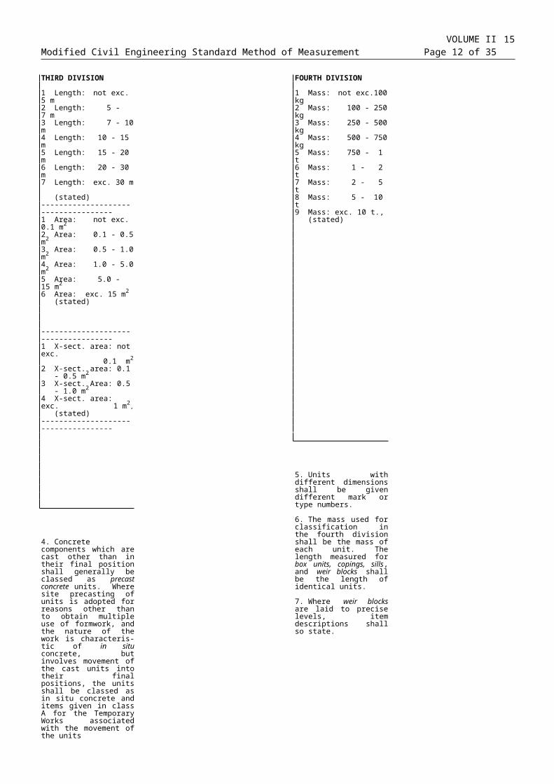
VOLUME IIModified Civil Engineering Standard Method of Measurement Page 22 of 353. The volume of extras to excavation and backfilling for manholes and other chambers shall be calculated by multiplying the average depth of the material removed or backfilled by the maximum horizontal external cross-sectional area of the manhole or chamber.
4. Breaking up of roads and pavings shall be included in class K.
5. Backfilling above the Final Surface (L1 - 5-6*) shall be measured only if it is expressly required that the material excavated shall not be used for backfilling. Excavation below the Final Surface and backfilling (L1 - 7-8*) shall be measured only where it is expressly required.
6. Pipe laying in headings and by thrust boring shall be measured only where they are expressly required. Item descriptions for pipe laying in headings and by thrust borings shall identify the run of pipe or pipes laid. The type of packing shall be stated in item descriptions for pipe laying in headings. Thrust blocks constructed for the purposes of thrust boring only shall be classed as Temporary Works in class A.
7. Lengths of supports and protection to pipelines shall be measured along pipe centre lines including lengths occupied by fittings and valves but not including lengths occupied by manholes and chambers through which the support or protection is not continued.
8. Materials used for beds, haunches and surrounds to pipes and the depths of beds shall be stated in item descriptions. Separate items shall not be given for beds to haunched or surrounded pipes where the same material is used for beds and haunches or beds and surrounds respectively.
9. Materials used for wrapping and lagging of pipes shall be stated in item descriptions. Separate items are not required for wrapping and lagging of fittings and valves.
10. Principal dimensions and materials shall be stated in item descriptions for pipe supports. Heights of pipe supports shall be measured from the ground or other supporting surface to the invert of the highest pipe where pipes are supported from below and of the lowest pipe where pipes are supported from above. Where two or more pipes are carried by a support, the item for the support shall be classified in the third division by the aggregate bore of the pipes supported.
11. The specification of concrete shall be stated in item description for concrete stools and thrust blocks.
12. Work in this class associated with ducts and metal culverts shall be itemized, described and measured as set out for work associated with pipes, except that the dimension used for classification in the third division shall be the maximum nominal distance between the inside faces of the outer walls of the duct or culvert.
/tt/file_convert/5ad4bb837f8b9a1a028c35cf/document.doc
23
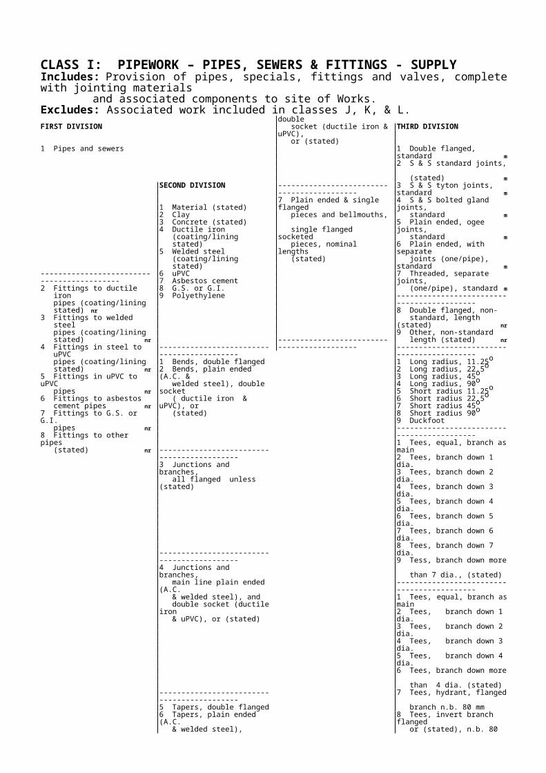
CLASS N: MISCELLANEOUS METALWORKExcludes: Metal reinforcement for concrete (included in classes C, G, H and R). Metal concrete inserts (included in classes G and H). Pipework (included in classes I, J, K, and L). Structural metalwork (included in class M). Fittings and fastenings to timber (included in O). Piles (included in classes P and Q). Traffic signs (included in class R). Rail track and accessories (included in class S). Surface treatment of metalwork on site (included in class V). Fences (included in class X).FIRST DIVISION
1 Mild steel, plain2 Galvanized steel3 Aluminium4 Stainless steel5 Other (stated)
-----------------------------------------------------------6 Cast Iron7 Rust resistant steel8 Mild steel, plain9 Other (stated)
SECOND DIVISION
1 Stairways and landing t2 Walkways and platforms t-----------------------------------------------------------3 Ladders and step irons m
-----------------------------------------------------------4 Handrails m5 Bridge parapets m-----------------------------------------------------------6 Miscellaneous frames,
dimensions, (stated) m
-----------------------------------------------------------7 Flooring, dimensions, (stated) m2
-----------------------------------------------------------8 Screens, dimensions, (stated) m2
-----------------------------------------------------------9 Plate, dimensions, (stated) m2
-----------------------------------------------------------1 Cladding m2
2 Welded mesh panelling m2
3 Duct covers m2
4 Tie rods nr5 Walings nr-----------------------------------------------------------6 Bridge bearings nr
-----------------------------------------------------------7 Tanks, nominal size, (stated) nr
-----------------------------------------------------------8 Tank ancillaries nr
-----------------------------------------------------------9 Hand stops (stated) m2
THIRD DIVISION
-----------------------------------------------------------1 Ladders, dimensions (stated)2 Step irons, dimensions (stated)-----------------------------------------------------------
-----------------------------------------------------------1 From angle section, painted2 From angle section, hot dip
galvanized3 From channel section, painted4 From channel section, hot dip
galvanized5 From I section, painted6 From I section, hot dip galvanized7 From tubular section, round, painted8 From tubular section, round, hot dip
galvanized9 From tubular section, rectangular,
(stated)-----------------------------------------------------------1 From plain plate2 From open grid3 From chequer plate4 From chequer plate, lockable-----------------------------------------------------------1 Fine, dia 5 to 10 mm., (stated)2 Coarse, dia. 30 to 50 mm, (stated)-----------------------------------------------------------1 With notch 53 degrees, fixed2 With notch 53 degrees, removable3 With notch, 90 degrees, fixed4 With notch, 90 degrees, removable5 Fixed, detail (stated)6 Removable, detail (stated)-----------------------------------------------------------
-----------------------------------------------------------1 Roller2 Slide3 Rocker4 Cylindrical5 Spherical6 Plain rubber7 Laminated rubber8 Rubber pot-----------------------------------------------------------1 Volume: n.e. 1 m3
2 Volume: 1 - 3 m3
3 Volume: 3 - 10 m3
4 Volume: 10 - 30 m3
5 Volume: 30 - 100 m3
6 Volume: 100 - 300 m3
7 Volume: 300 - 1000 m3
8 Volume: exc. 1000 m3
-----------------------------------------------------------1 Cover description (stated)-----------------------------------------------------------1 Roof vent assembly, diam.: 50 mm2 Roof vent assembly, diam.: 80 mm3 Roof vent assembly, diam.: 100 mm4 Roof vent assembly, diam.: 150 mm-----------------------------------------------------------
NOTES
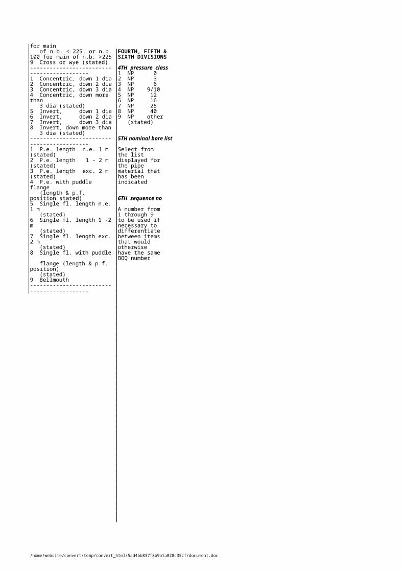
VOLUME IIModified Civil Engineering Standard Method of Measurement Page 24 of 35
1. Item descriptions shall state the specification and thicknesses of metal used off-site surface treatments and principal dimensions of miscellaneous metalwork assemblies. Alternatively, item descriptions may identify assemblies by mark numbers related to detail shown on the Drawings or given in the Specification.
2. Masses calculated for measurement of miscellaneous metalwork assemblies shall include the mass of all metal components and attached pieces. Separate items are not required for the components of miscellaneous metalwork assemblies.
3. Item codes N3-38** shall be used for miscellaneous metalwork not listed in the classification. Generally the measurement unit for such work shall be the tonne.
4. Separate items are not required for erection and fixing of miscellaneous metalwork or for provision of fixings to miscellaneous metalwork.
5. The lengths of handrails and bridge parapets shall be measured along their top members. The lengths of rectangular frames shall be measured along their external perimeters.
6. No deductions from the masses or areas measured for miscellaneous metalwork shall be made for openings and holes each less than 0.5 m¨ in area.
25
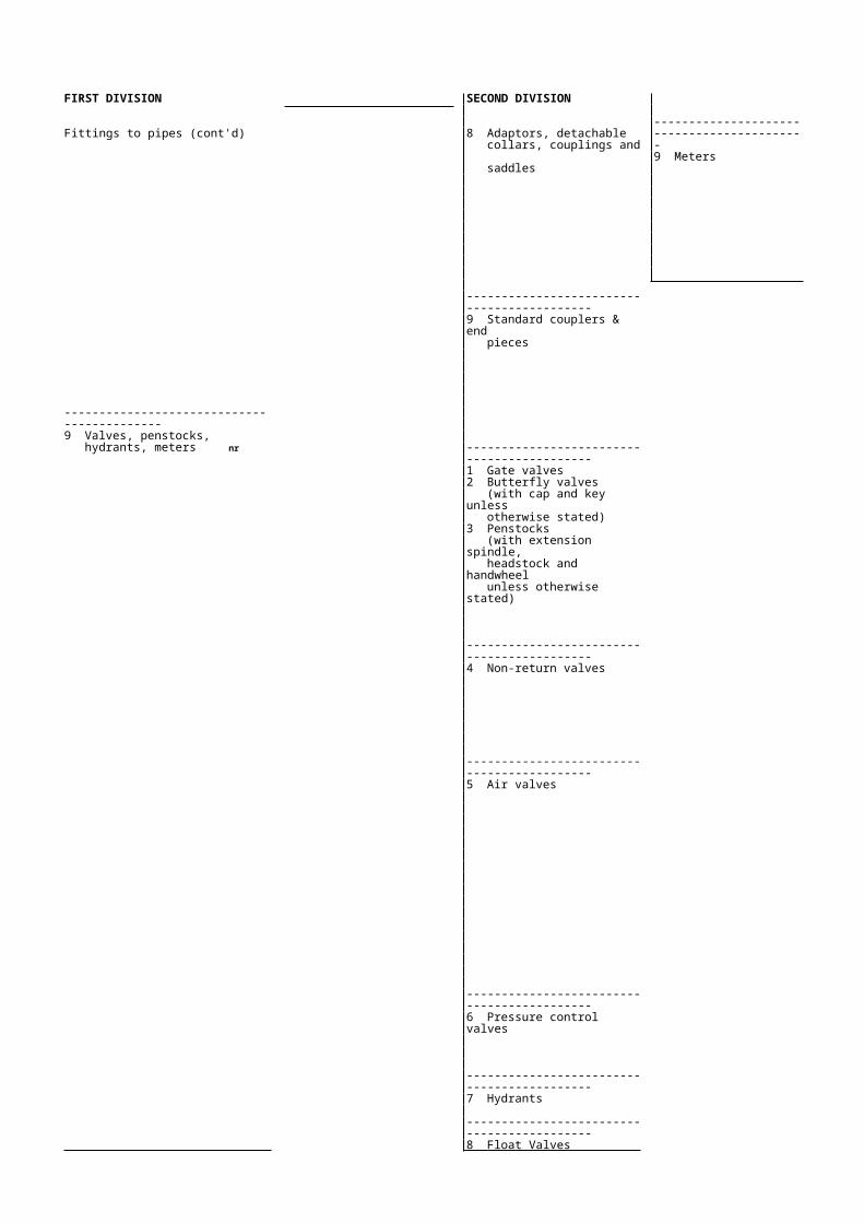
CLASS O: TIMBERIncludes: Timber components and fittings Timber deckingExcludes: Formwork to concrete (included in class G). Timber piles (included in class P). Timber sleepers (included in class S). Timber fencing (included in class X). Building carpentry and joinery.FIRST DIVISION
1 Hardwood components for general use m
2 Hardwood components for marine use m
3 Softwood components m
-----------------------------------------------------------4 Hardwood decking for
general use m2
5 Hardwood decking for marine use m2
6 Softwood decking m2
-----------------------------------------------------------7 Fittings and fastenings nr
-----------------------------------------------------------8 Roofing nr
NOTES
1. Timber components in buildings which may be included in civil engineering contracts need not be measured according to the procedure set down in this class
2. The nominal gross cross-sectional dimensions or thicknesses, species and any impregnation requirements or special surface finishes shall be stated in item descriptions for timber components and decking.
SECOND DIVISION
1 X-sect. area: n.e. 0.01 m2
2 X-sect. area: 0.01 - 0.02 m2
3 X-sect. area: 0.02 - 0.04 m2
4 X-sect. area: 0.04 - 0.10 m2
5 X-sect. area: 0.10 - 0.20 m2
6 X-sect. area: 0.20 - 0.40 m2
7 X-sect. area: exc. 0.4 m2 (stated)-----------------------------------------------------------1 Thickness: 25 mm2 Thickness: 50 mm3 Thickness: 75 mm4 Thickness: 100 mm5 Thickness: 125 mm6 Thickness: 150 mm7 Thickness: 200 mm8 Thickness: 225 mm9 Thickness exc. 225 mm, (stated)-----------------------------------------------------------1 Straps of dimensions, (stated)2 Spikes of length, diameter, (stated)3 Coach screws of length, diameter,
(stated)4 Bolts of diameter, length, (stated)5 Plates of dimensions, (stated)-----------------------------------------------------------1 Truss assemblies, (stated)2 Rafters, (stated)
3. The structural use and location of timber components shall be stated in item descriptions for components longer than 3 metres.
4. The length of each timber component measured shall be its overall length with no deduction for scarfed or other joints.
5. The cross-sectional areas used for classification of timber components shall be their nominal gross cross-sectional areas.
THIRD DIVISION
1 Length: n.e. 1.5 m2 Length: 1.5 - 3 m3 Length: 3 - 5 m4 Length: 5 - 8 m5 Length: 8 - 12 m6 Length: 12 - 20 m7 Length: exc. 20 m (stated)-----------------------------------------------------------1 Width 75 mm.2 Width 100 mm.3 Width 125 mm.4 Width 150 mm.5 Width 225 mm.6 Width 250 mm.7 Width 300 mm.8 Width 450 mm.9 Width, exc. 450 mm., (stated)-----------------------------------------------------------
-----------------------------------------------------------
6. The thickness used for classification of and stated in item descriptions for timber decking shall be its nominal gross thickness.
7. Separate items are not required for fixing timber components and decking or fittings and fastenings or for boring and cutting.
8. No deduction from the areas measured for timber decking shall be made for openings and holes each less than 0.5 m2 in area.

CLASS P: PILESExcludes: Boring for site investigation (included in class B). Ground anchors (included in class C). Walings and tie rods (included in class N). Piling ancillaries (included in class Q).FIRST DIVISION
1 Bored cast in place concrete piles2 Driven cast in place concrete piles
-----------------------------------------------------------3 Preformed concrete piles4 Preformed prestressed concrete tiles5 Preformed concrete sheet piles6 Timber piles
-----------------------------------------------------------7 Isolated steel pipes
-----------------------------------------------------------8 Interlinked steel pipe piles
-----------------------------------------------------------9 Interlocking steel piles
SECOND DIVISION
1 Diameter: 300 mm or 350 mm2. 400 mm or 450 mm3 500 mm or 550 mm4 600 mm or 750 mm5 900 mm or 1050 mm6 1200 mm or 1350 mm7 1500-----------------------------------------------------------1 Cross-sectional area: not exceeding
0.025 m²2 0.025-0.05 m²3 0.05 – 0.1 m²4 0.1 – 0.15 m²5 0.15 – 0.25 m²6 0.25 – 0.5 m ²7 0.5 – 1 m²8 exceeding 1 m²-----------------------------------------------------------1 Mass: not exceeding 15 kg/m2 15 – 30 kg/m3 30 – 60 kg/m4 60 – 120 kg/m5 120 – 250 kg/m6 250 – 500 kg/m7 500 kg/m – 1 t/m8 exceeding 1 t/m-----------------------------------------------------------1 Section modulus: not exceeding
500 cm³/m2 500-800 cm³/m3 800-1200 cm³/m4 1200-2000 cm³/m5 2000-3000 cm³/m6 3000-4000 cm³/m7 4000-5000 cm³/m8 exceeding
5000 cm³/m
THIRD DIVISION
1 Number of piles nr2 Concreted length m3 Depth bored or driven to stated maximum
depth m
-----------------------------------------------------------1 Number of piles of stated length nr2 Depth driven m
-----------------------------------------------------------1 Number of piles of stated length nr2 Depth driven m
-----------------------------------------------------------1 Length of special piles m2 Driven area m²3 Area of piles of length:
not exceeding 14 m m²4 14-24 m m²5 exceeding 24 m m²
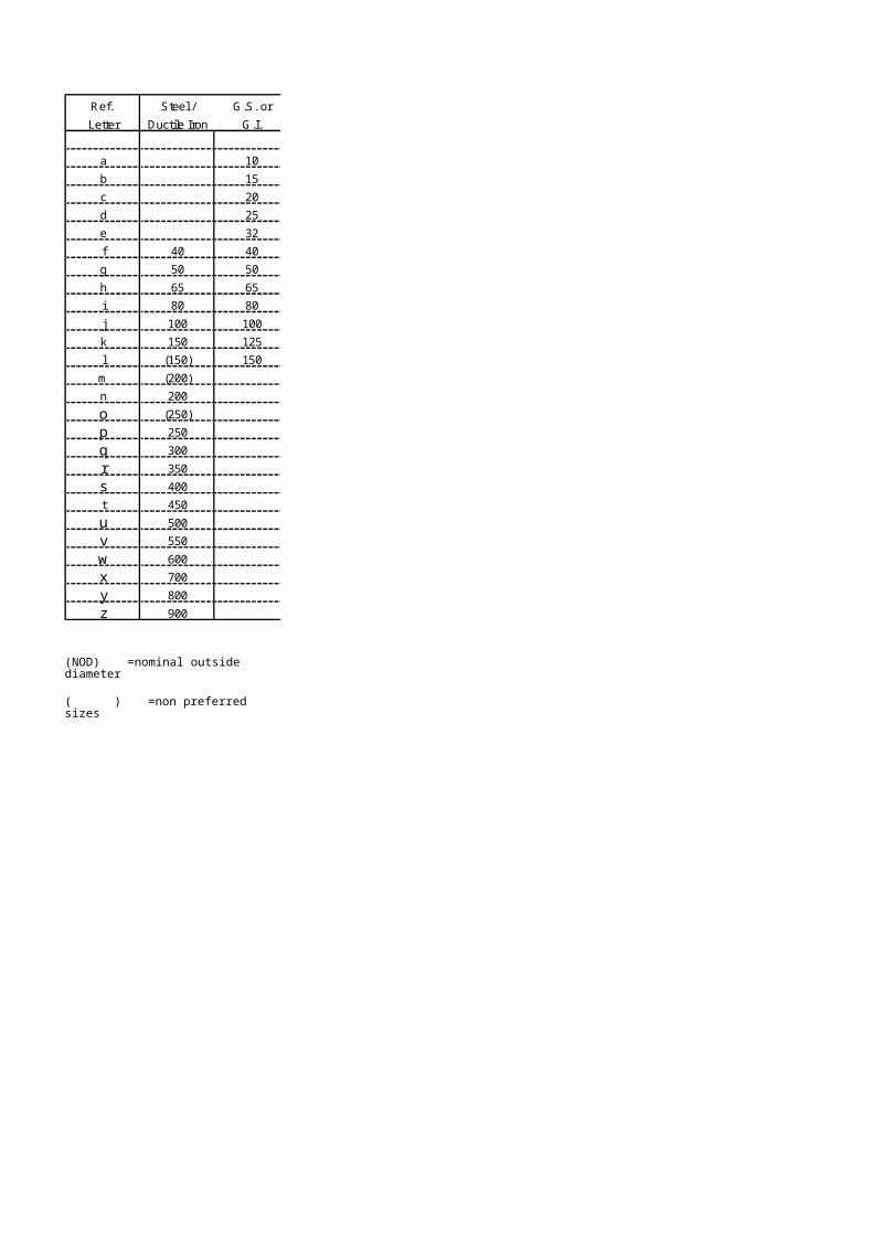
MEASUREMENT RULESM1 Bored and driven depths
shall be measured along the axes of piles from the Commencing Surface to the toe levels of bored piles, to the bottom of the casings of driven cast in place piles and to the bottom of the toes of other driven piles. The Commencing Surface adopted in the preparation of the Bill of Quantities as the surface at which boring or driving is expected to begin shall be adopted for the measurement of the completed work.
M2 Each group of items for cast in place concrete piles shall comprise
(a) an item for the number of piles (P1-2 * 1)
(b) an item for the total concreted length of piles (P1-2 * )
(c) an item for the total depth bored or driven (P1-2 * 3).
M3 The concreted lengths of cast in place concrete piles shall be measured from the cut-off levels expressly required to the toe levels expressly required.
M4 Each group of items for preformed concrete and timber piles shall comprise
(a) one or more items for the number of piles of stated length (P3-6*1)
(b) an item for the total depth driven (P3-6 * 2).
M5 Each group of items for isolated steel piles shall comprise
(a) one or more items for the number of piles of stated length (P7*1)
(b) an item for the total depth driven (P7 * 2).
M6 Each group of items for interlocking steel piles shall comprise
(a) one or more items for the total length of each type of special pile, if any (P8 * 2)
(b) an item for the total driven area of piles (P8 * 2)
(c) one or more items for the total area of piles divided into the ranges of length given in the third division (P8 * 3-5).
M7 The areas of interlocking steel piles shall be calculated by multiplying the mean undeveloped horizontal lengths of the pile walls formed (including lengths occupied by special piles) by the depths measured in accordance with rule M1 in the case of items in the case of items for the driven areas (P8 * 2) and by the lengths defined in accordance with rule D6 in the case of items for the areas of piles (P8 * 3-5).
M8 Closure and taper piles classed as special piles shall be measured only where they are expressly required.
DEFINITION RULESD1 The maximum depth stated
in item descriptions for the depth cast in place concrete piles shall be the depth which is not exceeded by any pile included in the item.
D2 Piles comprising a driven permanent steel casing which is filled with concrete shall be classed as driven cast in place concrete piles where the piles are designed for the load to be carried on the concrete.
D3 The lengths of preformed concrete and timber piles shall be the lengths expressly required to be supplied excluding extensions but including heads and shoes.
D4 The lengths of isolated steel piles shall be the lengths expressly required to be supplied excluding extensions.
D5 Piles comprising a driven permanent steel casing which is filled with concrete shall be classed as isolated steel piles where the piles are designed for the load to be carried on the casing. Filling such piles shall be classed as filling hollow piles with concrete (Q 53*)
D6 The lengths of interlocking steel pipes shall be the lengths expressly required to be supplied excluding extensions.
D7 Interlocking steel corner, junction, closure and taper piles shall be classed as special piles.
COVERAGE RULESC1 Items for piles shall be
deemed to include disposal of excavated material.
ADDITIONAL DESCRIPTION RULES
A1 Materials of which piles are composed shall be stated in item descriptions.
A2 Preliminary piles shall be identified in item descriptions. Raked piles shall be identified in item descriptions and their inclination stated.
A3 The structure to be supported and the Commencing Surface shall be identified in item descriptions for piles.
A4 The diameter shall be stated in item descriptions for cast in place concrete piles.
A5 Contiguous bored piles shall be identified in item descriptions.
A6 The cross-section type and cross-sectional dimensions or diameter shall be stated in item descriptions for preformed concrete and timber piles.
A7 Details of treatments and coatings shall be stated in item descriptions for the number of piles.
A8 Details of driving heads and of shoes shall be stated in item descriptions for the number of piles.
A9 The mass per metre and cross-sectional dimensions shall be stated in item descriptions for isolated steel piles.
A10 The section reference or mass per metre and section modulus shall be stated in item descriptions for interlocking steel piles.
A11 Details of treatments and coatings shall be stated in item descriptions for area of piles.
A12 The type of special pile shall be stated in item descriptions for the length of special tiles.
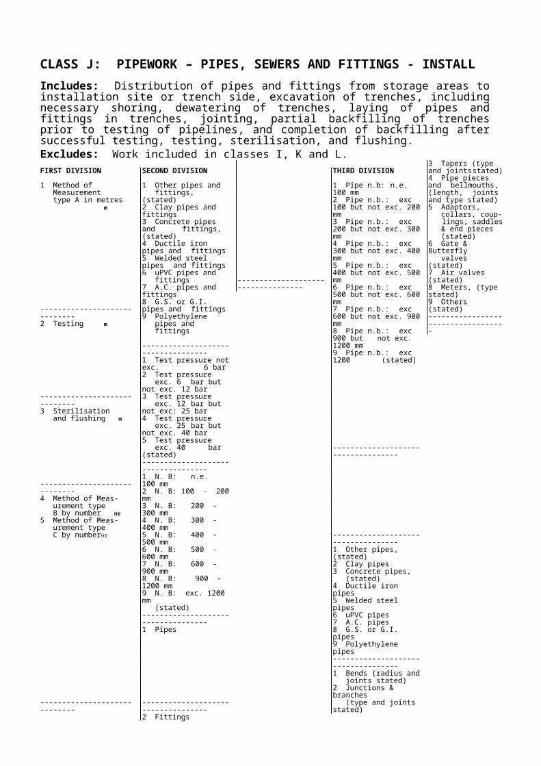
CLASS Q: PILING ANCILLARIESIncludes: Work ancillary to piling.Excludes: Ground anchors (includes in class C). Piles included in class P). Walings and tie rods (included in class N).FIRST DIVISION
1 Cast in place concrete piles
-----------------------------------------------------------2 Cast in place concrete piles
-----------------------------------------------------------3 Preformed concrete piles4. Timber piles
-----------------------------------------------------------5 Isolated steel piles
-----------------------------------------------------------6 Interlocking steel piles
-----------------------------------------------------------7 Obstructions h
-----------------------------------------------------------8 Pile tests
-----------------------------------------------------------
SECOND DIVISION
1 Pre-boring m2 Backfilling empty bore with stated material
m2 Permanent casings each length:
not exceeding 13 m m4. exceeding 13 m m5 Enlarged bases nr7 Cutting off surplus lengths m8 Preparing heads nr-----------------------------------------------------------1 Reinforcement t
-----------------------------------------------------------1 Pre-boring m2 Jetting m3 Filling hollow piles with concrete m4. Number of pile extensions nr5. Length of pile extensions, each length:
not exceeding 3 m m6 exceeding 3 m m7 Cutting off surplus lengths m8 Preparing heads nr
-----------------------------------------------------------1 Preboring m2 Jetting m3 Filling hollow piles with concrete m4 Number of pile extensions nr5. Length of pile extensions, each length:
not exceeding 3 m m6 exceeding 3 m m7 Cutting off surplus lengths m8 Preparing heads nr
-----------------------------------------------------------1 Preboring m2 Jetting m4 Number of pile extensions m5. Length of pile extensions, each length:
not exceeding 3 m m6 exceeding 3 m m7 Cutting off surplus lengths m8 Preparing heads nr
-----------------------------------------------------------
-----------------------------------------------------------1 Maintained loading with various reactions2 Constant rate of penetration3 horizontal loading
-----------------------------------------------------------4. Non-destructive integrity5. Inclinometer installations-----------------------------------------------------------
THIRD DIVISION
1 Diameter: 300 mm or 350 mm2 400 mm or 450 mm3 500 mm or 550 mm4 600 mm or 750 mm5 900 mm or 1050 mm6 1200 mm or 1350 mm7 1500 mm
-----------------------------------------------------------1. Straight bars, nominal size:
not exceeding 25 mm2. exceeding 25 mm3. Helical bars of stated nominal size
-----------------------------------------------------------1 Cross-sectional area: not exceeding
0.025 m²2 0.025 m² - 0.05 m²3 0.05 m² - 0.1 m²4 0.1 m² - 0.15 m²5 0.15 m² - 0.25 m²6 0.25 m² - 0.5 m²7 0.5 m² - 1 m²8 stated exceeding
1 m²-----------------------------------------------------------1 Mass: not exceeding 15 kg/m2 15 – 30 kg/m3 30 – 60 kg/m4 60 – 120 kg/m5 120 – 250 kg/m6 250 – 500 kg/m7 500 kg/m – 1 t/m8 stated exceeding 1 t/m
-----------------------------------------------------------1 Section modulus:
not exceeding 500 cm³/m2 500 - 800 cm³/m3 800 - 1200 cm³/m4 1200 - 2000 cm³/m5 2000 - 3000 cm³/m6 3000 - 4000 cm³/m7 4000 - 5000 cm³/m8 stated exceeding 5000 cm³/m
-----------------------------------------------------------
-----------------------------------------------------------1 Test load: not exceeding 100 t2 100 – 200 t3 200 – 300 t4 300 – 400 t5 400 – 600 t6 600 – 800 t7 800 – 1000 t8 exceeding 1000 t
-----------------------------------------------------------

Modified Civil Engineering Standard Method of Measurement Page 30 of 40
MEASUREMENT RULESM1 Work in this class, other than backfilling empty bore for cast in place concrete piles, shall be measured only where it is expressly required.
M2 The lengths of permanent casings shall be measured from the Commencing Surface to the bottom of the casing.
M3 The mass measured for reinforcement shall include the mass of reinforcement in laps.
M4 The mass of steel reinforcement shall be taken as 0.785 kg/m per 100 mm² of cross-section (7.85 t/m³). The mass of other reinforcing materials shall be taken as stated in the Contract.
M5 Driving extended piles shall be included in the measurement of the items for driven depth in class P.
M6 Each group of items for pile extensions shall comprise
(a) an item for the number of pile extensions (Q3-44*)
(b) one or two items for the length of pile extensions divided into the ranges of length given in the second division (Q3-4 5-6*)
M7 The length of pile extensions measured shall not include lengths formed from material arising from cutting off surplus lengths of other piles.
M8 The length measured for timber pile extensions shall include lengths occupied by scarfed or other joints.
M9 Each group of items for pile extensions shall comprise(a) an item for the number of
pile extensions (Q 5 4*)(b) one or two items for the
length of pile extensions divided into the ranges of length given in the second division Q 5 5-6*).
M10 Each group of items for pile extensions shall comprise(a) an item for the number of
pile extensions (Q 6 4 *)(b) one or two items for the
length of pile extensions divided into the ranges of length given in the second division.
M11 The lengths measured for cutting off surplus lengths of interlocking steel piles shall be the mean undeveloped horizontal lengths to be cut (including lengths occupied by special piles).M12 Obstructions shall be measured only for breaking out rock or artificial hard material encountered above the founding stratum of bored piles.
DEFINITION RULES
D1 The diameter used for classification in the third division shall be the diameter of the piles.
D2 The nominal size used for classification in item descriptions for bar reinforcement shall be the cross-sectional size defined in BS 4449.
D3 The cross-sectional area used for classification in the third division shall be the cross-sectional area of the piles.
D4 The mass used for classification in the third division shall be the mass of the piles.
D5 The section modulus used for classification in the third division shall be the section modulus of the piles
COVERAGE RULESC1 Items for piling ancillaries shall be deemed to include disposal of surplus materials unless otherwise stated.
C2 Items for permanent casings shall be deemed to include driving heads and shoes.
C3 Items for reinforcement shall be deemed to include supporting reinforcement.
C4 Items for pre-boring shall be deemed to include grouting voids between the pile and the bore.
C5 Items for pile extensions shall be deemed to include the work necessary to attach the extension to the pile.
C6 Items for filling hollow piles with concrete shall be deemed to include removal of material from within the pile before concreting.
ADDITIONAL DESCRIPTION RULES
A1 The diameters of enlarged bases for bored piles shall be stated in item descriptions.A2 Materials, thickness and details of treatments and coatings shall be stated in item descriptions for permanent casings. Item descriptions for cutting off surplus lengths which include permanent casings shall so state.A3 Materials shall be stated in item descriptions for reinforcement.A4 Details of couplers for high tensile steel reinforcement which are expressly required shall be stated in item descriptions for reinforcement.A5 Item descriptions for filling hollow piles with concrete shall state the specification of the concrete.A6 Materials of which pile extensions are composed shall be stated in item descriptions for their length.
A7 Item descriptions for pile tests shall identify those which are to preliminary piles.
A8 Item descriptions for loading tests shall state the load. Where the load is applied to raking piles item descriptions shall so state.
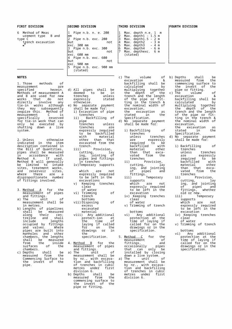
CLASS R: ROADS AND PAVINGIncludes: Sub-base, base and surfacing of roads, runways and other paved areas. Kerbing and light duty pavements, footways and cycle tracks. Traffic signs and markings.Excludes: Landscaping ( included in class E). Drainage (included in classes I, J, K and L). Fences and gates (included in class X). Gantries and other substantial structures supporting traffic signs.FIRST DIVISION
1 Sub-bases, flexible road bases and surfacing
-----------------------------------------------------------2 Sub-bases, flexible road bases
and surfacing
3 Sub-bases, flexible road bases and surfacing
-----------------------------------------------------------4 Concrete pavements
-----------------------------------------------------------5 Joints in concrete pavements m
-----------------------------------------------------------
SECOND DIVISION
1 Granular material of CBR (stated) at MDD (stated) m2
2 Granular material (general) m2
3 Soil-cement, ratio (stated) m2
4 Cement bound granular material m2
5 Lean concrete of CBR (stated) at MDD (stated) m2
6 Hardcore m2
-----------------------------------------------------------7 Geotextiles, (stated) m8 Allow for making up additional
depth of material (stated) m3
-----------------------------------------------------------1 Wet mix macadam m2
2 Dry bound macadam m2
3 Dense bitumen macadam m2
4 Open texture bitumen macadam m2
5 Dense tarmacadam m2
6 Open texture tarmacadam m2
7 Dense tar surfacing m2
-----------------------------------------------------------1 Cold asphalt wearing course m2
2 Rolled asphalt m2
3 Slurry sealing m2
4 Surface dressing m2
5 Bituminous spray m2
6 Removal of flexible surface m2
-----------------------------------------------------------8 Regulating course of, (stated) t-----------------------------------------------------------1 Carriageway slabs, paving
quality concrete (stated) m2
2 Carriageway slabs of other strength, (stated) m2
3 Other cast in-situ concrete slabs, strength, (stated) m2
-----------------------------------------------------------4 Reinforced with steel fabric
to specification m2
5 Reinforced with other fabric(stated) m2
-----------------------------------------------------------6 Reinforced with mild steel bar
to specification t7 Reinforced with high yield steel
bar, (stated) t
-----------------------------------------------------------8 Waterproof membrane laid
below concrete pavements m2
-----------------------------------------------------------1 Longitudinal joints, (stated)2 Expansion joints, (stated)3 Contraction joints, (stated)4 Warping joints, (stated)5 Butt joints, (stated)6 Construction joints, (stated)
-----------------------------------------------------------
THIRD DIVISION
1 Depth: n.e. 30 mm2 Depth: 30 - 60 mm3 Depth: 60 - 100 mm4 Depth: 100 - 150 mm5 Depth: 150 - 200 mm6 Depth: 200 - 250 mm7 Depth: 250 - 300 mm8 Depth: exc. 300 mm (stated)-----------------------------------------------------------
-----------------------------------------------------------1 Depth: n.e. 30 mm2 Depth: 30 - 60 mm3 Depth: 60 - 100 mm4 Depth: 100 - 150 mm5 Depth: 150 - 200 mm6 Depth: 200 - 250 mm7 Depth: 250 - 300 mm8 Depth: exc. 300 mm (stated)
-----------------------------------------------------------
-----------------------------------------------------------1 Depth: n.e. 30 mm2 Depth: 30 - 60 mm3 Depth: 60 - 100 mm4 Depth: 100 - 150 mm5 Depth: 150 - 200 mm6 Depth: 200 - 250 mm7 Depth: 250 - 300 mm8 Depth: exc. 300 mm (stated)-----------------------------------------------------------1 Nom. mass: n.e. 2 kg/m2
2 Nom. mass: 2 - 3 kg/m2
3 Nom. mass: 3 - 4 kg/m2
4 Nom. mass: 4 - 5 kg/m2
5 Nom. mass: 5 - 6 kg/m2
6 Nom. mass: 6 - 7 kg/m2
7 Nom. mass: 7 - 8 kg/m2
8 Nom. mass: exc.8 kg/m2., (stated)-----------------------------------------------------------1 Diameter: 6 mm2 Diameter: 8 mm3 Diameter: 10 mm4 Diameter: 12 mm5 Diameter: 14 mm6 Diameter: 16 mm7 Diameter: 20 mm8 Diameter: 25 mm or greater,
(stated)-----------------------------------------------------------
-----------------------------------------------------------1 Depth of joint: n.e. 30 mm2 Depth of joint: 30 - 60 mm3 Depth of joint: 60 - 100 mm4 Depth of joint: 100 - 150 mm5 Depth of joint: 150 - 200 mm6 Depth of joint: 200 - 250 mm7 Depth of joint: 250 - 300 mm8 Depth of joint: exc. 300 mm, (stated)-----------------------------------------------------------

Modified Civil Engineering Standard Method of Measurement Page 32 of 40
FIRST DIVISION
6 Kerbs, channels and edgings
-----------------------------------------------------------7 Light duty pavements m2
-----------------------------------------------------------8 Ancillaries
NOTES
1. Item description for all courses of paving and road making materials and pavement slabs shall identify the materials and state the depth of each course or slab.
2. Item descriptions for work in this class which is applied to surface inclined at an angle exceeding 10° to the horizontal shall so state.
3. The width of each course of material shall be measured at the top surface of the course. The area of a manhole cover or other intrusion into a surface shall not be deducted where the are of the intrusion is less than one square metre.
4. Item descriptions for steel fabric reinforcements to SSRN 128 shall include the type number or letter in accordance with SSRN 128. Item descriptions for other fabric reinforcement shall state the material sizes and its nominal mass per square metre. The area of additional fabric in laps shall not be measured.
SECOND DIVISION
1 Precast concrete kerbs tospecification, bullnosed type
2 Precast concrete kerbs to specification, full batter type
3 Precast concrete kerbs to specification, half batter type
4 In-situ kerbs and edgings5 Precast concrete channels6 Precast concrete edgings7 Asphalt kerbs, (stated)8 Asphalt channels, (stated)-----------------------------------------------------------1 Granular base2 Hardcore base3 Tarmacadam4 Rolled asphalt5 Bitumen macadam6 Dense tar7 In-situ concrete, strength (stated)8 Precast concrete flags, specification
(stated)-----------------------------------------------------------1 Traffic signs
-----------------------------------------------------------2 Surface markings
5. Reinforcing bars which are not circular in cross-section shall be classified by the diameter of the circular bar given in the classification nearest in cross-sectional area to the bars measured.
6. Separate items are not required for formwork to concrete pavement or formwork to joints in concrete pavements.
7. The dimensions, spacing and nature of components shall be stated in item descriptions for joints in concrete pavements. Construction joints shall be measured only where they are expressly required.
8. Materials, cross-sectional dimensions and details of backings and beds shall be stated in item descriptions for kerbs, channels and edgings.
9. The shape and colour of aspects shall be stated in item descriptions for reflecting road studs.
THIRD DIVISION
1 Laid straight or curved to radius exc. 12 m m
2 Laid curved to radius n.e. 12 m m3 Quadrants nr4 Drops nr5 Transitions nr
-----------------------------------------------------------1 Depth: n.e. 30 mm2 Depth: 30 - 60 mm3 Depth: 60 - 100 mm4 Depth: 100 - 150 mm5 Depth: 150 - 200 mm6 Depth: 200 - 250 mm7 Depth: 250 - 300 mm8 Depth: exc. 300 mm (stated)
-----------------------------------------------------------1 Non-illuminated nr2 Illuminated nr-----------------------------------------------------------1 Using non-reflecting road studs,
(stated) nr2 Using reflecting road studs,
(stated) nr3 Using letters and shapes,
(stated) nr4 Using continuous lines, (stated) m5 Using intermittent lines, (stated) m
10. The material, size and diagram number taken from Traffic signs, regulations and general directions, issued by the Ministry responsible for roads, shall be stated in item descriptions for traffic sings and surface markings.
11. Separate items are not required for supporting posts and foundations for traffic signs. Items for supporting gantries and other substantial structures associated with traffic signs which are constructed in concrete, structural metalwork or other materials shall be given in the appropriate classes.
12. Lengths measured for linear surface markings shall exclude gaps in intermittent markings.
13. The expression - 'Specified' shall mean as specified in the Specification for road and bridge works issued by the Ministry responsible for roads.

Modified Civil Engineering Standard Method of Measurement Page 33 of 40
CLASS U: BRICKWORK, BLOCKWORK AND MASONRYExcludes: Brickwork, blockwork and masonry in manholes and other brickwork, blockwork or masonry incidental to, pipework (included in class K).FIRST DIVISION
1 Common brickwork2 Facing brickwork3 Engineering brickwork4 Lightweight blockwork5 Dense concrete blockwork6 Artificial stone blockwork7 Ashlar masonry8 Rubble masonry
NOTES
1. Item descriptions for brickwork and blockwork shall either state the materials, nominal dimensions and types of brick or block or give equivalent references to applicable Standard specifications. The thickness of mass brickwork and blockwork shall be stated in item descriptions where it does not excess one metre.
2. The materials and nominal thicknesses shall be stated in item descriptions for masonry.
3. Separate items are not required for joints, pointing, fixings or ties to brickwork, blockwork or masonry.
4. Item descriptions for brickwork, blockwork and masonry which is in cavity or composite construction shall so state. Where different bonding patterns are specified for the same material, the bonding pattern shall be stated in the item descriptions.
SECOND DIVISION
1 Composite construction, thick-ness not exc. 150 mm. m2
2 Cavity construction, thickness150 - 250 mm. m2
3 Composite construction, thick-ness 150 - 250 mm. m2
4 Cavity construction, thickness250 - 500 mm m2
5 Composite construction, thick-ness 250 - 500 mm m2
6 Composite construction, thick-ness 500 - 1000 mm. m2
7 Composite construction, thick-ness exc. 1000 mm., (stated) m3
----------------------------------------------------------8 Surface and other features
----------------------------------------------------------9 Ancillaries
5. Volumes and areas measured for brickwork, blockwork and masonry shall include the volumes and areas of joints. No deduction or addition to the volumes and areas measured shall be made for rebates, projecting courses or other surface features each less than 0.05 m2 in cross-sectional area. No deduction from areas and volumes measured shall be made for holes and openings in walls or surfaces each less than 0.25 m2 in cross-sectional area. Areas shall be measured at the centre lines of brickwork, blockwork and masonry
6. Walls battered on one side shall be classed as battered walls.
7. Item descriptions for surface features shall include sufficient detail to identify special or cut bricks or blocks. The spacings of intermittent surface features shall be stated in the item descriptions. Reveals shall not be classed as surface features.
THIRD DIVISION
1 In vertical straight walls2 In vertical curved walls3 In battered straight walls4 In battered curved walls5 As vertical facing to concrete6 As battered facing to concrete7 As casing to metal section8 As other, (stated)
----------------------------------------------------------1 Copings and cills m2 Rebates and chases m3 Cornices m4 Band courses m5 Corbels m6 Pilasters m7 Plinths m8 Fair facing m2
9 Columns and piers, cross-sect. dimensions (stated) m
----------------------------------------------------------1 Joint reinforcement using (stated)
m2 Damp proof courses m3 Movement joint filled with,
material, width, (stated) m4 Bond to existing work by,
(stated) m2
5 Concrete infill, material, thickness (stated) m2
6 Fixing and ties, material, means, centres, (stated) m2
7 Built in pipes and ducts, X-sect. area n.e. 0.025 m2 nr
8 Built in pipes and ducts, X-sect. area 0.025 - 0.25 m2 nr
9 Built in pipes and ducts, X-sect. area exc. 0.25 m2 (stated) nr
8. The materials and dimensions of joint reinforcement and damp proof courses and the mix specification of concrete infills shall be stated in item descriptions.
9. The area measured for centering to arches shall be the temporarily supported area of the intrados.

Modified Civil Engineering Standard Method of Measurement Page 34 of 40
CLASS V: PAINTINGIncludes: In-situ painting, and in-situ surface preparationExcludes: Painting and other surface treatment carried out prior to delivery of components to Site and maintenance of such surfaces until completion (measured only for metalwork in classes M & N)FIRST DIVISION
1 Lead, iron or zinc based primer paint2 Etch primer paint3 Oil paint4 Alkyd gloss paint5 Emulsion paint6 Cement paint7 Epoxy or polyurethane paint8 Bituminous or coal tar paint
NOTES
1. Item descriptions for work in this class shall state the materials used and either the number of coats or the film thickness.
2. Surfaces of width not exceeding one metre shall not be distinguished by inclination.
3. No deduction from areas measured for painting shall be made for holes and openings in the painted surfaces each less than 0.5 m2 in area.
SECOND DIVISION
1 On metal other than metal sections and metal pipework
2 On timber3 On smooth concrete4 On rough concrete5 On masonry6 On brickwork and blockwork
-----------------------------------------------------------7 On metal sections m2
8 On pipework m2
4. Isolated groups of surfaces may be classed as such only where the total surface area of each group does not exceed 6 m2. Item descriptions for isolated groups of surfaces shall identify the work to be painted and state its location. Groups of surfaces of the same shape and dimensions may be included in one item.
5. In calculating the painted area of metal sections, the presence of connecting plates, brackets, rivets, bolts, nuts and similar projections shall be ignored.
THIRD DIVISION
1 With upper surface inclined at an angle not exc. 30o to the horizontal m2
2 With upper surface inclined at 30o - 60o to the horizontal m2
3 With surface inclined at an angleexc. 60o to the horizontal m2
4 With soffit surfaces and lowersurfaces inclined at an angle not exc. 60o to the horizontal m2
5 With surfaces of widthnot exc. 300 mm m
6 With surfaces of width 300 mm - 1 m m
7 To isolated groups of surfaces nr-----------------------------------------------------------
6. The area measured for painting pipework shall be the length multiplied by the barrel girth of each length of pipework. Lengths occupied by valves and other projecting fittings shall not be deducted. Surfaces of flanges, valves and other projecting fittings shall not be measured.
7. Separate items are not required for preparation of surfaces before painting.
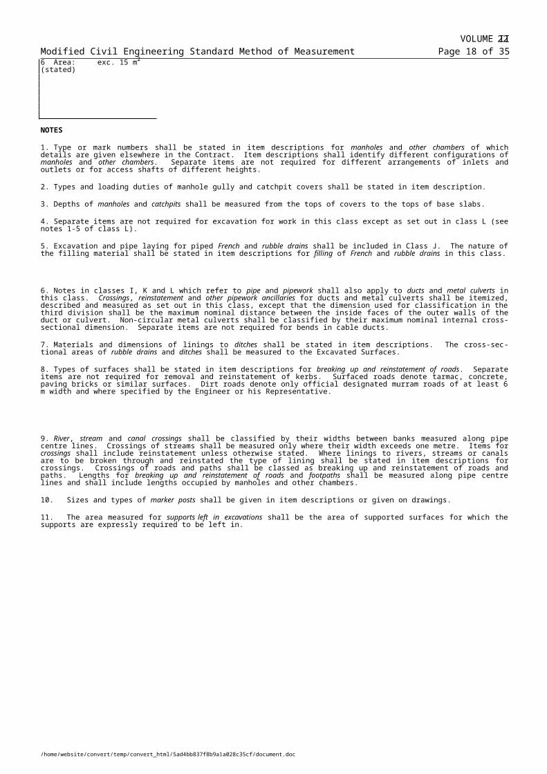
Modified Civil Engineering Standard Method of Measurement Page 35 of 40
CLASS W: WATERPROOFINGIncludes: Damp proofing, tanking and roofingExcludes: Waterproofed joints (included in classes C, G, H, I, J, K, R, T, and X). Damp proof courses in brickwork, blockwork and masonry (included in class U).FIRST DIVISION
1 Damp proofing2 Tanking3 Roofing
-----------------------------------------------------------4 Protective layers of
-----------------------------------------------------------5 Sprayed or brushed waterproofing
using (stated) m2
NOTES
1. Item descriptions for work in this class shall state the materials used and the number and thickness of coatings or layers.
2. Separate items are not required for preparing surfaces or for joints, overlaps, mitres, angles, fillets, and built-up edges or for laying to falls and cambers.
3. Surfaces of width not exceeding one metre shall not be distinguished by inclination or curvature.
SECOND DIVISION
1 Using asphalt2 Using sheet metal, material (stated)3 Using waterproof sheeting4 Using waterproof coating of (stated)5 Using rendering in ordinary cement
mortar6 Using rendering in waterproof cement
mortar7 Using rendering with proprietary mix
mortar (stated)-----------------------------------------------------------1 Sand asphalt2 Flexible sheeting3 Sand4 Sand and cement screed5 Tiles-----------------------------------------------------------
4. The areas measured for waterproofing shall be those of the surfaces covered. No deduction from the areas measured for waterproofing shall be made for holes and openings in the waterproofed surfaces each less than 0.5 m2 in area.
5. Waterproofing shall be classed as to curved or domed surfaces only where the radius of curvature of the surface is less than 10 m. Waterproofing so classed shall not be distinguished by inclination.
THIRD DIVISION
1 On upper surface inclined at an angle not exc. 30o to the horizontal m2
2 On upper surface inclined at30o - 60o to the horizontal m2
3 On surface inclined at an angle exc. 60o to the horizontal m2
4 On curved surfaces of less than10 m. radius m2
5 On domed surfaces of less than 10 m. radius m2
6 On surfaces of width not exc.300 mm m
7 On surfaces of width300 mm. - 1 m. m
8 To isolated groups of surfaces nr
-----------------------------------------------------------
6. Isolated groups of surfaces may be classed as such only where the total surface area of each group does not exceed 6 m2. Item descriptions for isolated groups of surfaces shall identify the work to be waterproofed and state its location. Groups of surfaces of the same shape and dimensions may be included in one item.
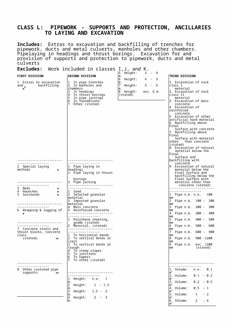
CLASS X: MISCELLANEOUS WORKIncludes: Fences, gates and their foundations. Rock filled gabions. Windows and doors. Drainage to structures above ground. Underdrainage to structures. Filter media. Other items not allowed for elsewhere and as stated.FIRST DIVISION
1 Fences m
-----------------------------------------------------------2 Gates and stiles nr
-----------------------------------------------------------3 Drainage to structures above ground
-----------------------------------------------------------4 Rock filled gabions
-----------------------------------------------------------5 Underdrainage to structures m
-----------------------------------------------------------6 Windows nr
-----------------------------------------------------------7 Doors nr
-----------------------------------------------------------8 Filter media m3
-----------------------------------------------------------9 Other (stated)
SECOND DIVISION
1 Timber post and rail2 Timber post and wire3 Concrete post and wire4 Metal post and wire5 Coated metal post and wire6 Timber close boarded
-----------------------------------------------------------1 Timber field gates2 Timber wicket gates3 Metal field gates4 Metal wicket gates5 Stiles
-----------------------------------------------------------1 Mild steel2 Cast iron3 Plastics4 Asbestos cement-----------------------------------------------------------1 Boxes , size, mesh and fill material
(stated) nr2 Mattress of thickness, mesh and fill
material (stated) m2
-----------------------------------------------------------1 Perforated clay2 Clay layed with gaps3 Perforated uPVC4 No fines concrete5 Concrete laid with gaps6 Perforated asbestos cement-----------------------------------------------------------1 Wooden frame, openable2 Wooden frame, deadlight3 Mild steel frame, openable4 Mild steel frame, deadlight5 Aluminium frame, openable6 Aluminium frame, deadlight7 Louvre, wooden frame, lockable8 Louvre, aluminium frame, lockable9 Other (stated)-----------------------------------------------------------1 Wood, flush, internal2 Wood, flush, external3 Wood, panel, internal4 Wood, panel, external5 Wood, matchboard, internal6 Wood, matchboard, external7 Metal, flush-----------------------------------------------------------1 Graded sand
2 Graded gravel
-----------------------------------------------------------
THIRD DIVISION
1 Height: n.e. 1 m.2 Height: 1 - 1.25 m.3 Height: 1.25 - 1.50 m.4 Height: 1.50 - 2 m.5 Height: 2 - 2.50 m.6 Height: 2.50 - 3 m.7 Height: exc. 3 m. (stated)-----------------------------------------------------------1 Width: n.e. 1.5 m.2 Width: 1.5 - 2 m.3 Width: 2 - 2.5 m.4 Width: 2.5 - 3 m.5 Width: 3 - 4 m.6 Width: 4 - 5 m.7 Width: exc. 5 m. (stated)-----------------------------------------------------------1 Gutters m2 Fittings to gutters nr3 Downpipes m4 Fittings to downpipes nr-----------------------------------------------------------
-----------------------------------------------------------1 Diameter: 100 mm.2 Diameter: 150 mm.3 Diameter: 200 mm.4 Diameter: 250 mm.5 Diameter: exc. 250 mm. (stated)
-----------------------------------------------------------1 Area: n.e. 1 m2.2 Area: 1 - 2 m2.3 Area: 2 - 3 m2.4 Area: 3 - 4 m2.5 Area: 4 - 5 m2.6 Area: exc. 5 m2. (stated)
-----------------------------------------------------------1 Single leaf, standard2 Single leaf, stable type3 Double leaf, standard4 Double leaf, non standard (stated)
-----------------------------------------------------------1 Effective size 0.25 -0.35 mm.,
uniformity coeff. 2.0 - 3.0 for slow sand filters.
2 Effective size 0.55 mm., uniformity coeff. not exc. 1.5 for rapid gravity filters.
3 Other, (stated).-----------------------------------------------------------4 Particle size 2 - 5 mm., layer
thickness 50 -80 mm., ave. 65mm.5 Particle size 5 - 12 mm., layer
thickness 50 -80 mm., ave. 65mm6 Particle size 12 - 20 mm.,layer thick-
ness 80 - 130 mm., ave. 100 mm.7 Particle size 20 - 38 mm., layer thick-
ness 80 - 130 mm., ave. 100 mm.8 Particle size 38 - 65 mm., layer thick-
ness 80 - 130 mm., ave. 100 mm.9 Other, (stated)-----------------------------------------------------------
NOTES
1. The types and principal dimensions of fences, gates and stiles and of their foundations shall be stated in item descriptions.

VOLUME IIModified Civil Engineering Standard Method of Measurement Page 32 of 35
2. Item descriptions for fences which are erected on a curve of radius not exceeding 100 m or on a surface inclined at an angle exceeding 10° shall so state.
3. Heights of fences shall be measured from the Commencing Surface. Widths of gates and stiles shall be measured between the inside faces of posts.
4. Item descriptions for drainage to structures above ground shall state the type, principal dimensions and materials of the components.
5. Fittings to gutters shall include bands, angles, stop ends and outlets. Fittings to downpipes shall include bends, swan necks, shoes and roof outlets fixed directly to downpipes.
37

CLASS Y: SEWER RENOVATION AND ANCILLARY WORKSIncludes: Preparation and renovation of existing sewers and manholes and new manholes within the length of existing sewers.Excludes: Grouting carried out from the outside of the sewer (included in class C). Supply and installation of new sewers and, new manhole and pipework ancillaries and supports and protection ancillaries to laying and excavation included in classes I, J, and K.FIRST DIVISION
1 Preparation of existing sewers
-----------------------------2 Stabilisation of existing sewers
-----------------------------3 Renovation of existing sewers
-----------------------------3 Laterals to reno-
vated sewers
-----------------------------
SECOND DIVISION
1 Other sewer wall material (stated)2 Clay sewers3 RC concrete sewers4 Cast iron sewers5 Steel sewers6 uPVC sewers7 A.C. sewers8 Unreinforced concrete sewers
------------------------------1 Other sewer wall
material (stated)2 Clay sewers3 RC concrete sewers4 Cast iron sewers5 Steel sewers6 uPVC sewers7 A.C. sewers8 Unreinforced concrete sewers------------------------------1 Other sewer wall
material (stated)2 Clay sewers3 RC concrete sewers4 Cast iron sewers5 Steel sewers6 uPVC sewers7 A.C. sewers8 Unreinforced concrete sewers
------------------------------1 Other sewer wall
material (stated)2 Clay sewers3 RC concrete sewers4 Cast iron sewers5 Steel sewers6 uPVC sewers7 A.C. sewers8 Unreinforced concrete sewers------------------------------9 Flapvalves
------------------------------
THIRD DIVISION
1 N. b. n.e. 100 mm2 N. b. exc. 100 - 200 mm3 N. b. exc. 200 - 300 mm4 N. b. exc. 300 - 400 mm5 N. b. exc. 400 - 500 mm6 N. b. exc. 500 - 600 mm7 N. b. exc. 600 - 900 mm8 N. b. exc. 900 - 1200 mm9 N. b. exc. 1200 mm (stated)
---------------------------------------------1 N. b. n.e. 100 mm2 N. b. exc. 100 - 200 mm3 N. b. exc. 200 - 300 mm4 N. b. exc. 300 - 400 mm5 N. b. exc. 400 - 500 mm6 N. b. exc. 500 - 600 mm7 N. b. exc. 600 - 900 mm8 N. b. exc. 900 - 1200 mm9 N. b. exc. 1200 mm (stated)
---------------------------------------------1 N. b. n.e. 100 mm2 N. b. exc. 100 - 200 mm3 N. b. exc. 200 - 300 mm4 N. b. exc. 300 - 400 mm5 N. b. exc. 400 - 500 mm6 N. b. exc. 500 - 600 mm7 N. b. exc. 600 - 900 mm8 N. b. exc. 900 - 1200 mm9 N. b. exc. 1200 mm (stated)
---------------------------------------------1 N. b. n.e. 100 mm2 N. b. exc. 100 - 200 mm3 N. b. exc. 200 - 300 mm4 N. b. exc. 300 - 400 mm5 N. b. exc. 400 - 500 mm6 N. b. exc. 500 - 600 mm7 N. b. exc. 600 - 900 mm8 N. b. exc. 900 - 1200 mm9 N. b. exc. 1200 mm (stated)
---------------------------------------------1 N.b. n.e. 100 mm2 N.b. exc. 100 - 200 mm3 N.b. exc. 200 - 300 mm4 N.b. exc. 300 - 400 mm5 N.b. exc. 400 - 500 mm6 N.b. exc. 500 – 600 mm7 N.b. exc. 600 mm (stated)-------------------------------------------
FOURTH DIVISION
1 Cleaning m------------------------------2 Removing intrusions nr
------------------------------3 Plugging laterals nr4 Filling laterals & other sewers, mat- erials stated m3
----------------------------------------5 Local internal
repairs nr
------------------------------1 Pointing, materials stated m2
2 Joint sealing, mat- erial stated nr------------------------------3 External grouting
------------------------------1 Sliplining
------------------------------2 In-situ jointed sewer lining
------------------------------3 Segmental lining
------------------------------4 Proprietary lining (stated)------------------------------5 Gunite coating, thickness stated------------------------------6 Annulus grouting materials stated------------------------------1 Jointing
------------------------------2 Flapvalves
------------------------------
FIFTH DIVISION
-------------------------------1 Laterals, bore n.e. 150 mm2 Laterals, profile &
size exc. 150 mmin one or more dim-ensions, (stated)
3 Other artificial intrusions (stated)-------------------------------1 Bore n.e. 300 mm2 Profile & size exc. 300 mm in one or more dimensions (stated)-------------------------------1 Area: n.e. 0.1 m22 Area: 0.1 – 0.25 m23 Area exc. 0.25 m2 (stated)---------------------------------
---------------------------------1 Number of holes nr2 Injection of grout, material stated m3
---------------------------------1 Polyethylene2 Polypropylene---------------------------------1 Polyethylene2 Polypropylene3 Glass reinforced plastic---------------------------------1 Glass reinforced plastic2 Glass reinforced concrete3 Cast gunite4 Resin concrete---------------------------------
---------------------------------1 Bore n.e. 150 mm2 Bore 150 to 300 mm3 Profile & size exc. 300 mm in one or more dimensions (stated)
---------------------------------1 Remove existing2 Replace existing3 New flap valve, type stated
---------------------------------

FIRST DIVISION
5 New manholes in new locations nr6 New manholes
replacing existingmanholes nr
-----------------------------7 Existing man- holes nr-----------------------------8 Interruptions
SECOND DIVISION
1 Brick2 Brick with back- drop3 In-situ concrete4 In-situ concrete
with backdrop5 Precast concrete6 Precast concrete
with backdrop7 Masonry or
blockwork8 Masonry or block work with back- drop9 Other (stated)
-----------------------------1 N. b. n.e. 100 mm2 N. b. exc. 100 -
200 mm3 N. b. exc. 200 -
300 mm4 N. b. exc. 300 -
400 mm5 N. b. exc. 400 -
500 mm6 N. b. exc. 500 -
600 mm7 N. b. exc. 600 -
900 mm8 N. b. exc. 900 -
1200 mm9 N. b. exc. 1200
mm (stated)
THIRD DIVISION
1 N. b. n.e. 100 mm2 N. b. exc. 100 - 200 mm3 N. b. exc. 200 - 300 mm4 N. b. exc. 300 - 400 mm5 N. b. exc. 400 - 500 mm6 N. b. exc. 500 - 600 mm7 N. b. exc. 600 - 900 mm8 N. b. exc. 900 - 1200 mm9 N. b. exc. 1200 mm (stated)
--------------------------------------------1 Depth: n.e. 1.5 m2 Depth: 1.5 - 2 m3 Depth: 2 - 3 m4 Depth: 3 - 4 m5 Depth: 4 - 5 m6 Depth: 5 - 6 m7 Depth: exc. 6m (stated)
FOURTH DIVISION
1 Depth: n.e. 1.5 m2 Depth: 1.5 - 2 m3 Depth: 2 - 3 m4 Depth: 3 - 4 m5 Depth: 4 - 5 m6 Depth: 5 - 6 m7 Depth: exc. 6m (stated)
------------------------------1 Preparation of existing sewers2 Stabilisation of existing sewers------------------------------3 Renovation of existing sewers
------------------------------4 Work on laterals to renovated sewers5 Work on manholes
FIFTH DIVISION
---------------------------------1 Abandonment2 Alteration---------------------------------
---------------------------------1 Sliplining2 In-situ jointed pipe lining3 Segmental lining4 Proprietary lining, (stated) 5 Gunite coating6 Annulus grouting---------------------------------
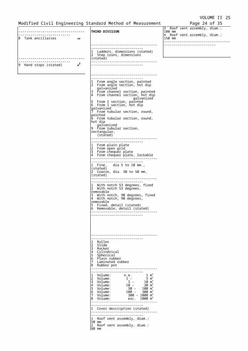
Modified Civil Engineering Standard Method of Measurement Page 40 of 40
MEASUREMENT RULESM1 Lengths of sewers shall be
measured along their centre lines be-tween the inside surfaces of manholes but shall exclude lengths occupied by pipes and fittings comprising backdrops to manholes.
M2 Where work is expressly required to be carried out by excavation, crossings, reinstatement and other sewer-work ancillaries shall be measured in class K and extras to ex-cavation and backfilling shall be measured in class L.
M3 No deduction shall be made from the areas of sewer surfaces measured for pointing for openings or voids each not exceeding 0.5 m2 in area.
M4 External grouting shall be measured only where grouting is expressly re-quired to be carried out as a separate operation from annulus grouting
M5 The volume measured for annulus grouting shall not include the volume measured for external grouting ( Y 2 [1-8] [1-9] .3 2).
M6 Interruptions shall be measured only where a minimum pumping ca-pacity is expressly required and for periods of time during normal working hours wherein the flow in the sewer exceeds the installed pumping capacity and work is interrupted.
DEFINITION RULESD1 Items shall be classed as removing
intrusions where artificial intrusions into the bores of existing sewers are to be removed prior to renovation.
D2 The areas stated in item descriptions for local internal repairs shall be the finished surface areas.
D3 External grouting shall be grouting of voids outside the existing sewer from within the existing sewer other than voids grouted in the course of annulus grouting.
D4 Annulus grouting shall be grouting of the annular voids between new linings and existing sewers and of other voids grouted in the course of grouting annular voids.
D5 The depth of manholes shall be measured from the tops of covers to channel inverts or to tops of base slabs, whichever is the lower.
COVERAGE RULESC1 Items for work which is expressly
required to be carried out by excavation shall be deemed to include preparation of surfaces, disposal of excavated material, disposal of exca-vation, backfilling and removal of existing services.
C2 Items for cleaning shall be deemed to include making good resultant damage.
C3 Items for removing intrusions shall be deemed to include making good.
C4 Annulus grouting shall be grouting of the annular voids between new linings and existing sewers and of
other voids grouted in the course of grouting annular voids.
C5 Items for pointing and sewer joint sealing shall be deemed to include preparation of joints.
C6 Items for laterals shall be deemed to include the work involved in connecting to the lining within 1 m from the inside face of the lined sewer.
C7 Items for new manholes shall be deemed to include excavation, preparation of surfaces, disposal of excavated material, upholding sides of excavation, backfilling, concrete, re-inforcement, form-work, joints, finishes and reinstatement.
C8 Items for manholes shall be deemed to include metalwork, differ-ent arrangements of inlets and outlets, and access shafts of different heights and connection of sewers to manholes. Items for manholes with backdrops shall be deemed to include the sewers and fittings comprising the backdrop.
C9 Items for new manholes replacing existing manholes shall be deemed to include breaking out and disposal of existing manholes.
ADDITIONAL DESCRIPTION RULES
A1 The location of the work in each item or group of items shall be stated so that the work can be identified by reference to the Drawings.
A2 Principal dimensions, other than diameter and depth of sewers and profiles of sewers shall be identified by reference to the Drawings.
A3 Work expressly required to be carried out manually or by remotely controlled methods shall each be so stated in item descriptions.
A4 Item descriptions for work which is expressly required to be carried out by excavation shall so state and (except for manholes) shall state the maximum depth of excavation in stages of 1 m measured to the invert of the sewer.
A5 Item descriptions for preparation, stabilisation, renovation and laterals shall state the material forming of the existing sewer.
A6 Item descriptions for removing intrusions shall state the materials forming the intrusions.
A7 Where external grouting is carried out through sewer joints, descriptions of items for the number of holes shall so state.
A8 Item descriptions for slip-lining, in situ jointed pipe lining, segmental lin-ing and stated proprietary lining shall state the type lining, its minimum fin-ished internal size and its thickness or grade.
A9 Item descriptions for in situ jointed sewer lining and segmental lining shall state the offset where the lining is curved to an offset which exceeds 35 mm per metre.
A10 Item descriptions for jointing laterals shall state the type of lining to which
the laterals are to be connected and identify those laterals which are to be regraded.
A11 Type or mark numbers shall be stated in item descriptions for man-holes of which details are given elsewhere in the Contract. Item descriptions shall identify different configurations of manholes.
A12 Types and loading duties of covers shall be stated in item descriptions for new manholes.
A13 Item descriptions for existing manholes shall state details of the work required.


![Catalogue CORDERIE DOR 2011 Documentations[1]](https://static.fdocuments.in/doc/165x107/55cf85de550346484b9236dd/catalogue-corderie-dor-2011-documentations1.jpg)