CE EMC Test Report - Summit Datasummitdata.com/Certification/SDC-MSD30AG/EN_301489_MSD30AG.pdfBrand...
22
International Certification Corp. No. 3-1, Lane 6, Wen San 3rd St., Kwei Shan Hsiang, Tao Yuan Hsien 333, Taiwan, R.O.C. Tel: 886-3-271-8666 Fax: 886-3-318-0155 Report No.: EH362805 Page : 1 of 22 Report Version: Rev. 01 CE EMC Test Report Equipment : 802.11AG Mini Compact Flash Module with antenna connectors Model No. : SDC-MSD30AG Brand Name : Summit Data Communications Applicant : Summit Data Communications lnc. Address : 526 South Main Street Suite 805, Akron, Ohio, 44311 United States Standard : EN 301 489-1 V1.9.2 (2011.09) EN 301 489-17 V2.2.1 (2012-09) Received Date : Jun. 28, 2013 Tested Date : Jul. 02 ~ Jul. 04, 2013 We, International Certification Corp., would like to declare that the tested sample has been evaluated and in compliance with the requirement of the above standards. It may be duplicated completely for legal use with the approval of the applicant. It shall not be reproduced except in full without the written approval of our laboratory. Approved & Reviewed by: Kent Chen / Assistant Manager Ty: XXX
Transcript of CE EMC Test Report - Summit Datasummitdata.com/Certification/SDC-MSD30AG/EN_301489_MSD30AG.pdfBrand...

International Certification Corp. No. 3-1, Lane 6, Wen San 3rd St., Kwei Shan Hsiang, Tao Yuan Hsien 333, Taiwan, R.O.C. Tel: 886-3-271-8666 Fax: 886-3-318-0155
Report No.: EH362805 Page : 1 of 22
Report Version: Rev. 01
CE EMC Test Report
Equipment : 802.11AG Mini Compact Flash Module with antenna connectors
Model No. : SDC-MSD30AG
Brand Name : Summit Data Communications
Applicant : Summit Data Communications lnc.
Address : 526 South Main Street Suite 805, Akron, Ohio, 44311 United States
Standard : EN 301 489-1 V1.9.2 (2011.09) EN 301 489-17 V2.2.1 (2012-09)
Received Date : Jun. 28, 2013
Tested Date : Jul. 02 ~ Jul. 04, 2013
We, International Certification Corp., would like to declare that the tested sample has been evaluated and in compliance with the requirement of the above standards. It may be duplicated completely for legal use with the approval of the applicant. It shall not be reproduced except in full without the written approval of our laboratory. Approved & Reviewed by:
Kent Chen / Assistant Manager Ty: XXX

International Certification Corp. No. 3-1, Lane 6, Wen San 3rd St., Kwei Shan Hsiang, Tao Yuan Hsien 333, Taiwan, R.O.C. Tel: 886-3-271-8666 Fax: 886-3-318-0155
Report No.: EH362805 Page : 2 of 22
Report Version: Rev. 01
Table of Contents 1 GENERAL DESCRIPTION .................................................................................................................... 5
1.1 Information .............................................................................................................................................. 5 1.2 Local Support Equipment List ................................................................................................................ 6 1.3 Test Setup Chart .................................................................................................................................... 6 1.4 Test Software and Operating Condition ................................................................................................. 6 1.5 Test Equipment and Calibration Data .................................................................................................... 7 1.6 Testing Applied Standards ..................................................................................................................... 7
2 TEST CONFIGURATION ....................................................................................................................... 8
2.1 Testing Condition ................................................................................................................................... 8 2.2 The Worst Case Measurement Configuration ........................................................................................ 8
3 IMMUNITY TESTS ................................................................................................................................. 9
3.1 General Description ................................................................................................................................ 9 3.2 Performance Criteria Description ......................................................................................................... 10 3.3 Electrostatic Discharge (ESD) .............................................................................................................. 11 3.4 Radio Frequency Electromagnetic Field (RS) ...................................................................................... 16
4 PHOTOGRAPHS OF THE TEST CONFIGURATION ......................................................................... 18

International Certification Corp. No. 3-1, Lane 6, Wen San 3rd St., Kwei Shan Hsiang, Tao Yuan Hsien 333, Taiwan, R.O.C. Tel: 886-3-271-8666 Fax: 886-3-318-0155
Report No.: EH362805 Page : 3 of 22
Report Version: Rev. 01
Release Record
Report No. Version Description Issued Date
EH362805 Rev. 01 Initial issue Jul. 08, 2013

International Certification Corp. No. 3-1, Lane 6, Wen San 3rd St., Kwei Shan Hsiang, Tao Yuan Hsien 333, Taiwan, R.O.C. Tel: 886-3-271-8666 Fax: 886-3-318-0155
Report No.: EH362805 Page : 4 of 22
Report Version: Rev. 01
Summary of Test Results
EN 301 489-1 Immunity Tests
Ref. Std. Clause
Test Standard Description of Test Pass
Criterion
9.3 EN 61000-4-2:2009 Electrostatic Discharge (ESD) B
9.2 EN 61000-4-3:2006/A1:2008/A2:2010 Radio Frequency Electromagnetic Field (RS) A

International Certification Corp. No. 3-1, Lane 6, Wen San 3rd St., Kwei Shan Hsiang, Tao Yuan Hsien 333, Taiwan, R.O.C. Tel: 886-3-271-8666 Fax: 886-3-318-0155
Report No.: EH362805 Page : 5 of 22
Report Version: Rev. 01
1 General Description
1.1 Information
1.1.1 Product Details
The following models are provided to this EUT.
Model Name Description Difference
SDC-MSD30AG 802.11AG Mini Compact Flash Module with antenna connectors
with carrier board
SDC-SSD30AG 802.11AG Mini Compact Flash Module with antenna connectors
module only
Above models, model SDC-MSD30AG was selected as representative one for the final test and only its data was recorded in this report.
1.1.2 Specification of the Equipment under Test (EUT)
Operating Frequency 802.11b/g: 2412 MHz ~ 2472 MHz 802.11a: 5180 MHz ~ 5240 MHz; 5260 MHz ~ 5320 MHz; 5500 MHz ~ 5700 MHz
Antenna Type Refer to section 1.1.3.
Modulaton Type 802.11b : DSSS (DBPSK / DQPSK / CCK) 802.11a/g : OFDM (BPSK / QPSK / 16QAM / 64QAM)
1.1.3 Antenna Details
Ant. No.
Model Type Connector Operating Frequencies (MHz) / Antenna Gain (dBi)
2400~2483.5 5150~5250 5250~5350 5470~5725
1 Cisco AIR-ANT 4941
Dipole RP-TNC plug 2 --- --- ---
2 Summit SDC-CF22G
Chip U.FL 0 --- --- ---
3 Cisco Air-Ant 5135
Dipole RP-TNC plug --- 3.5
4 Radiall Larsen R380.500.314
Dipole RP-TNC plug 1.6 5
5 Huber & Suhner SOA 2459/360/5/0/V_C
Monopole U.FL 3 6.5
1.1.4 EUT Operational Condition
Supply Voltage AC mains DC
Type of DC Source Internal DC supply External DC adapter 3.3Vdc from host

International Certification Corp. No. 3-1, Lane 6, Wen San 3rd St., Kwei Shan Hsiang, Tao Yuan Hsien 333, Taiwan, R.O.C. Tel: 886-3-271-8666 Fax: 886-3-318-0155
Report No.: EH362805 Page : 6 of 22
Report Version: Rev. 01
1.2 Local Support Equipment List
Support Equipment List
No. Equipment Brand Name Model Name Serial No.
1 PDA HP IPAQ HSTNH-L05C-BT
2 Notebook DELL Latitude E5430 6R4RWW1
3 AP D-LINK DIR-815 3000226
1.3 Test Setup Chart
Test Setup Diagram (EMS)
1.4 Test Software and Operating Condition
a. The EUT with fixture equipment connected to PDA.
b. The PDA ran “SCU” program to enable WiFi function of EUT.
c. The EUT linked with AP via WiFi.
d. The notebook connected to AP via RJ45 cable.
e. The notebook ran “ping” program to link up with EUT to transmit data via AP.

International Certification Corp. No. 3-1, Lane 6, Wen San 3rd St., Kwei Shan Hsiang, Tao Yuan Hsien 333, Taiwan, R.O.C. Tel: 886-3-271-8666 Fax: 886-3-318-0155
Report No.: EH362805 Page : 7 of 22
Report Version: Rev. 01
1.5 Test Equipment and Calibration Data
Test Item ESD
Test Site ESD room 1 / (ES01-WS)
Instrument Manufacturer Model No. Serial No. Calibration Date Calibration Until
ESD Generator EMTest Dito V1248114239 Dec. 05, 2012 Dec. 04, 2013
Note: Calibration Interval of instruments listed above is one year.
Test Item Radiated Immunity (80 MHz - 6 GHz)
Test Site RS room 1 / (RS01-WS)
Instrument Manufacturer Model No. Serial No. Calibration Date Calibration Until
Probe ETS-Lindgren HI-6105 00114784 Nov.14, 2012 Nov. 13, 2013
Signal Generator R&S SMB 100A 175727 Jan. 14, 2013 Jan. 13, 2014
Power Sensor R&S NRP-Z91 101094-UL Nov. 06, 2012 Nov. 05, 2013
Power Sensor R&S NRP-Z91 101094-KY Nov. 06, 2012 Nov. 05, 2013
Power Amplifier BONN BLWA
0810-160/100D 107972A N/A N/A
Power Amplifier BONN BLWA 1060-100D 107972B N/A N/A
Antenna SCHWARZBECK
MESS-ELEKTRONIK STLP 9149 9149-073 N/A N/A
Antenna R&S HL046E 100076-Cd N/A N/A
UPV AUDIO ANALYZER
R&S UPV 103144 Jan. 30, 2013 Jan. 29, 2014
Note: Calibration Interval of instruments listed above is one year.
1.6 Testing Applied Standards
According to the specifications of the manufacturer, the EUT must comply with the requirements of the following standards: EN 301 489-1 V1.9.2 (2011.09) EN 301 489-17 V2.2.1 (2012-09)

International Certification Corp. No. 3-1, Lane 6, Wen San 3rd St., Kwei Shan Hsiang, Tao Yuan Hsien 333, Taiwan, R.O.C. Tel: 886-3-271-8666 Fax: 886-3-318-0155
Report No.: EH362805 Page : 8 of 22
Report Version: Rev. 01
2 Test Configuration
2.1 Testing Condition
Test Item Test Site Ambient Condition Tested By
ESD ES01-WS 22°C/50%/ 97kPa Nick Liu
RS RS01-WS 26°C/60%/ 97kPa JN Chen
2.2 The Worst Case Measurement Configuration
The Worst Test Configurations
Test Mode Operating Description
1 Ant. 1, WLAN link
2 Ant. 2, WLAN link
3 Ant. 3, WLAN link
4 Ant. 4, WLAN link
5 Ant. 5, WLAN link

International Certification Corp. No. 3-1, Lane 6, Wen San 3rd St., Kwei Shan Hsiang, Tao Yuan Hsien 333, Taiwan, R.O.C. Tel: 886-3-271-8666 Fax: 886-3-318-0155
Report No.: EH362805 Page : 9 of 22
Report Version: Rev. 01
3 Immunity Tests
3.1 General Description
Product Standard: EN 301 489-1, EN 301 489-17
Basic Standard Spec. Requirement Performance Criteria
EN 61000-4-2 (ESD) Contact Discharge: ± 4 kV Air Discharge: ± 8 kV
B
EN 61000-4-3 (RS) 80-1000 MHz, 1400-2700 MHz 3 V/m, 1 kHz Sine Wave 80%, AM Modulation
A
International Certification Corp. No. 3-1, Lane 6, Wen San 3rd St., Kwei Shan Hsiang, Tao Yuan Hsien 333, Taiwan, R.O.C. Tel: 886-3-271-8666 Fax: 886-3-318-0155
Report No.: EH362805 Page : 10 of 22
Report Version: Rev. 01
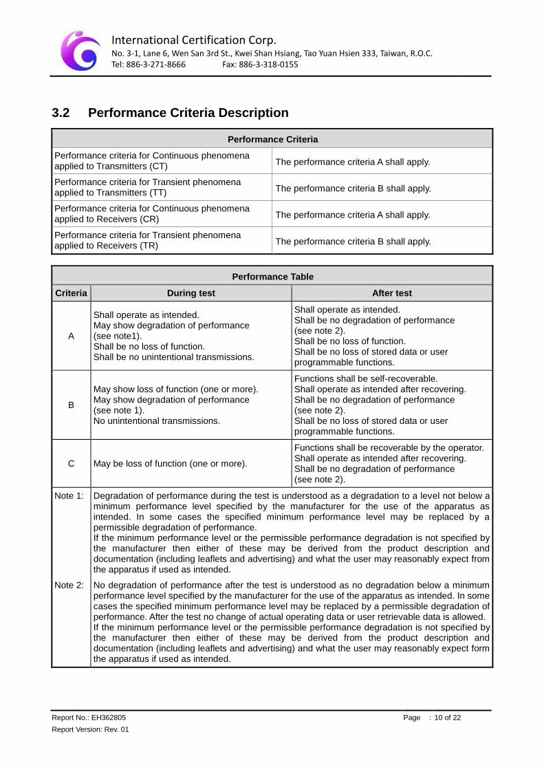
3.2 Performance Criteria Description
Performance Criteria
Performance criteria for Continuous phenomena applied to Transmitters (CT) The performance criteria A shall apply.
Performance criteria for Transient phenomena applied to Transmitters (TT) The performance criteria B shall apply.
Performance criteria for Continuous phenomena applied to Receivers (CR) The performance criteria A shall apply.
Performance criteria for Transient phenomena applied to Receivers (TR) The performance criteria B shall apply.
Performance Table
Criteria During test After test
A
Shall operate as intended. May show degradation of performance (see note1). Shall be no loss of function. Shall be no unintentional transmissions.
Shall operate as intended. Shall be no degradation of performance (see note 2). Shall be no loss of function. Shall be no loss of stored data or user programmable functions.
B
May show loss of function (one or more). May show degradation of performance (see note 1). No unintentional transmissions.
Functions shall be self-recoverable. Shall operate as intended after recovering. Shall be no degradation of performance (see note 2). Shall be no loss of stored data or user programmable functions.
C May be loss of function (one or more).
Functions shall be recoverable by the operator. Shall operate as intended after recovering. Shall be no degradation of performance (see note 2).
Note 1: Degradation of performance during the test is understood as a degradation to a level not below a minimum performance level specified by the manufacturer for the use of the apparatus as intended. In some cases the specified minimum performance level may be replaced by a permissible degradation of performance. If the minimum performance level or the permissible performance degradation is not specified by the manufacturer then either of these may be derived from the product description and documentation (including leaflets and advertising) and what the user may reasonably expect from the apparatus if used as intended.
Note 2: No degradation of performance after the test is understood as no degradation below a minimum performance level specified by the manufacturer for the use of the apparatus as intended. In some cases the specified minimum performance level may be replaced by a permissible degradation of performance. After the test no change of actual operating data or user retrievable data is allowed. If the minimum performance level or the permissible performance degradation is not specified by the manufacturer then either of these may be derived from the product description and documentation (including leaflets and advertising) and what the user may reasonably expect form the apparatus if used as intended.
International Certification Corp. No. 3-1, Lane 6, Wen San 3rd St., Kwei Shan Hsiang, Tao Yuan Hsien 333, Taiwan, R.O.C. Tel: 886-3-271-8666 Fax: 886-3-318-0155
Report No.: EH362805 Page : 11 of 22
Report Version: Rev. 01
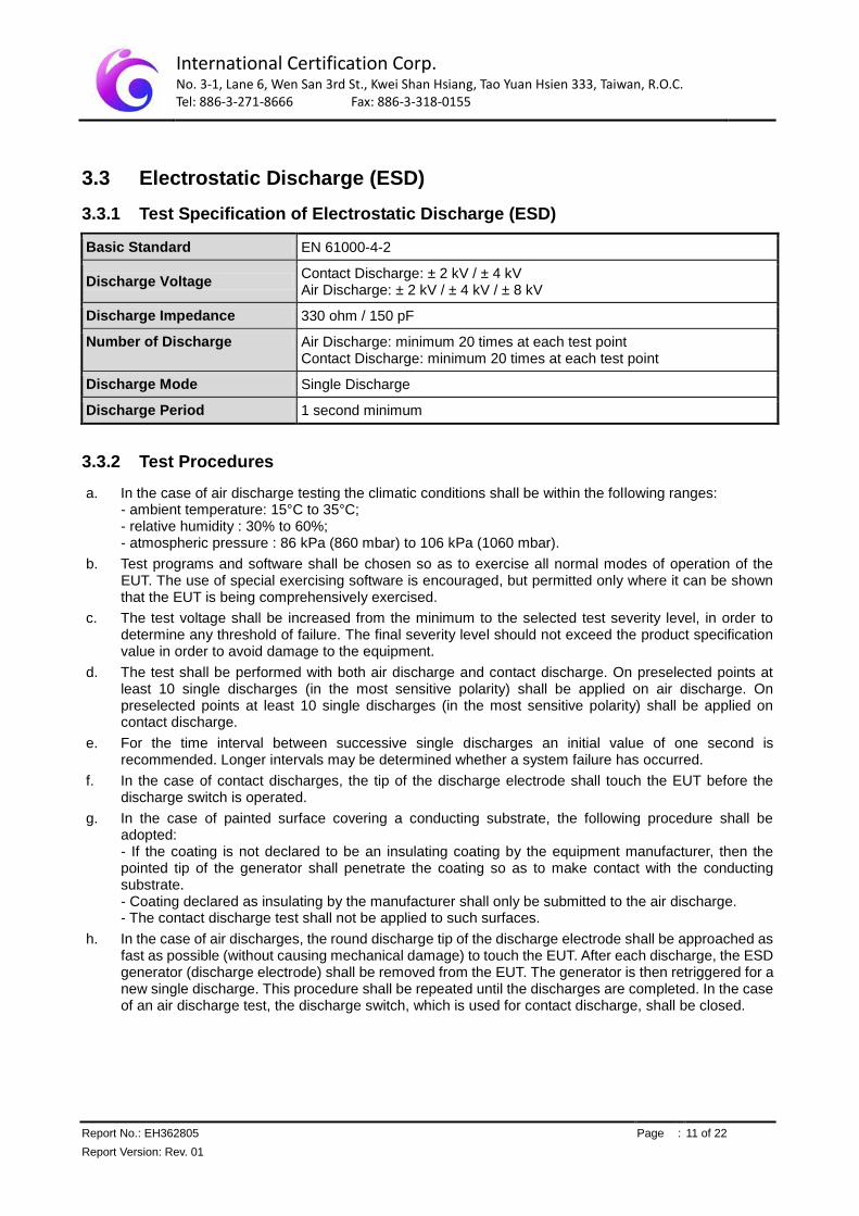
3.3 Electrostatic Discharge (ESD)
3.3.1 Test Specification of Electrostatic Discharge (ESD)
Basic Standard EN 61000-4-2
Discharge Voltage Contact Discharge: ± 2 kV / ± 4 kV Air Discharge: ± 2 kV / ± 4 kV / ± 8 kV
Discharge Impedance 330 ohm / 150 pF
Number of Discharge Air Discharge: minimum 20 times at each test point Contact Discharge: minimum 20 times at each test point
Discharge Mode Single Discharge
Discharge Period 1 second minimum
3.3.2 Test Procedures
a. In the case of air discharge testing the climatic conditions shall be within the following ranges: - ambient temperature: 15°C to 35°C; - relative humidity : 30% to 60%; - atmospheric pressure : 86 kPa (860 mbar) to 106 kPa (1060 mbar).
b. Test programs and software shall be chosen so as to exercise all normal modes of operation of the EUT. The use of special exercising software is encouraged, but permitted only where it can be shown that the EUT is being comprehensively exercised.
c. The test voltage shall be increased from the minimum to the selected test severity level, in order to determine any threshold of failure. The final severity level should not exceed the product specification value in order to avoid damage to the equipment.
d. The test shall be performed with both air discharge and contact discharge. On preselected points at least 10 single discharges (in the most sensitive polarity) shall be applied on air discharge. On preselected points at least 10 single discharges (in the most sensitive polarity) shall be applied on contact discharge.
e. For the time interval between successive single discharges an initial value of one second is recommended. Longer intervals may be determined whether a system failure has occurred.
f. In the case of contact discharges, the tip of the discharge electrode shall touch the EUT before the discharge switch is operated.
g. In the case of painted surface covering a conducting substrate, the following procedure shall be adopted: - If the coating is not declared to be an insulating coating by the equipment manufacturer, then the pointed tip of the generator shall penetrate the coating so as to make contact with the conducting substrate. - Coating declared as insulating by the manufacturer shall only be submitted to the air discharge. - The contact discharge test shall not be applied to such surfaces.
h. In the case of air discharges, the round discharge tip of the discharge electrode shall be approached as fast as possible (without causing mechanical damage) to touch the EUT. After each discharge, the ESD generator (discharge electrode) shall be removed from the EUT. The generator is then retriggered for a new single discharge. This procedure shall be repeated until the discharges are completed. In the case of an air discharge test, the discharge switch, which is used for contact discharge, shall be closed.

International Certification Corp. No. 3-1, Lane 6, Wen San 3rd St., Kwei Shan Hsiang, Tao Yuan Hsien 333, Taiwan, R.O.C. Tel: 886-3-271-8666 Fax: 886-3-318-0155
Report No.: EH362805 Page : 12 of 22
Report Version: Rev. 01
3.3.3 Test Setup
The test setup shall consist of a non-conductive table, (0.8 ± 0.08) m high, standing on the ground
reference plane.
A horizontal coupling plane (HCP), (1.6 ± 0.02) m × (0.8 ± 0.02) m, shall be placed on the table. The EUT
and its cables shall be isolated from the coupling plane by an insulating support (0.5 ± 0.05) mm in
thickness.
International Certification Corp. No. 3-1, Lane 6, Wen San 3rd St., Kwei Shan Hsiang, Tao Yuan Hsien 333, Taiwan, R.O.C. Tel: 886-3-271-8666 Fax: 886-3-318-0155
Report No.: EH362805 Page : 13 of 22
Report Version: Rev. 01
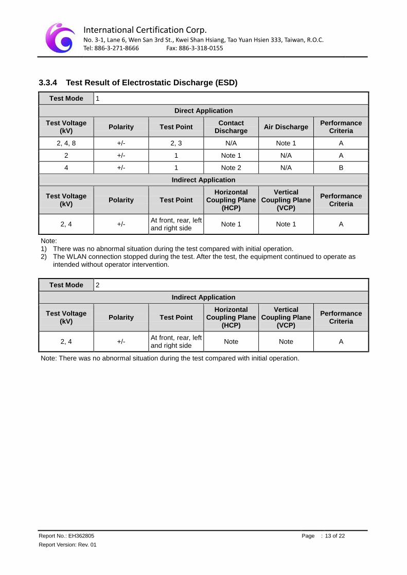
3.3.4 Test Result of Electrostatic Discharge (ESD)
Test Mode 1
Direct Application
Test Voltage (kV)
Polarity Test Point Contact
Discharge Air Discharge
Performance Criteria
2, 4, 8 +/- 2, 3 N/A Note 1 A
2 +/- 1 Note 1 N/A A
4 +/- 1 Note 2 N/A B
Indirect Application
Test Voltage (kV)
Polarity Test Point Horizontal
Coupling Plane (HCP)
Vertical Coupling Plane
(VCP)
Performance Criteria
2, 4 +/- At front, rear, left and right side
Note 1 Note 1 A
Note: 1) There was no abnormal situation during the test compared with initial operation. 2) The WLAN connection stopped during the test. After the test, the equipment continued to operate as
intended without operator intervention.
Test Mode 2
Indirect Application
Test Voltage (kV)
Polarity Test Point Horizontal
Coupling Plane (HCP)
Vertical Coupling Plane
(VCP)
Performance Criteria
2, 4 +/- At front, rear, left and right side
Note Note A
Note: There was no abnormal situation during the test compared with initial operation.

International Certification Corp. No. 3-1, Lane 6, Wen San 3rd St., Kwei Shan Hsiang, Tao Yuan Hsien 333, Taiwan, R.O.C. Tel: 886-3-271-8666 Fax: 886-3-318-0155
Report No.: EH362805 Page : 14 of 22
Report Version: Rev. 01
Test Mode 3
Direct Application
Test Voltage (kV)
Polarity Test Point Contact
Discharge Air Discharge
Performance Criteria
2, 4, 8 +/- 3 N/A Note 1 A
2, 4 +/- 2 Note 1 N/A A
2 +/- 1 Note 1 N/A A
4 +/- 1 Note 2 N/A B
Indirect Application
Test Voltage (kV)
Polarity Test Point Horizontal
Coupling Plane (HCP)
Vertical Coupling Plane
(VCP)
Performance Criteria
2, 4 +/- At front, rear, left and right side
Note 1 Note 1 A
Note: 1) There was no abnormal situation during the test compared with initial operation. 2) The WLAN connection stopped during the test. After the test, the equipment continued to operate as
intended without operator intervention.
Test Mode 4
Direct Application
Test Voltage (kV)
Polarity Test Point Contact
Discharge Air Discharge
Performance Criteria
2, 4, 8 +/- 2, 3 N/A Note 1 A
2 +/- 1 Note 1 N/A A
4 +/- 1 Note 2 N/A B
Indirect Application
Test Voltage (kV)
Polarity Test Point Horizontal
Coupling Plane (HCP)
Vertical Coupling Plane
(VCP)
Performance Criteria
2, 4 +/- At front, rear, left and right side
Note 1 Note 1 A
Note: 1) There was no abnormal situation during the test compared with initial operation. 2) The WLAN connection stopped during the test. After the test, the equipment continued to operate as
intended without operator intervention.

International Certification Corp. No. 3-1, Lane 6, Wen San 3rd St., Kwei Shan Hsiang, Tao Yuan Hsien 333, Taiwan, R.O.C. Tel: 886-3-271-8666 Fax: 886-3-318-0155
Report No.: EH362805 Page : 15 of 22
Report Version: Rev. 01
Test Mode 5
Direct Application
Test Voltage (kV)
Polarity Test Point Contact
Discharge Air Discharge
Performance Criteria
2, 4 +/- 1, 2 Note N/A A
Indirect Application
Test Voltage (kV)
Polarity Test Point Horizontal
Coupling Plane (HCP)
Vertical Coupling Plane
(VCP)
Performance Criteria
2, 4 +/- At front, rear, left and right side
Note Note A
Note: There was no abnormal situation during the test compared with initial operation.

International Certification Corp. No. 3-1, Lane 6, Wen San 3rd St., Kwei Shan Hsiang, Tao Yuan Hsien 333, Taiwan, R.O.C. Tel: 886-3-271-8666 Fax: 886-3-318-0155
Report No.: EH362805 Page : 16 of 22
Report Version: Rev. 01
3.4 Radio Frequency Electromagnetic Field (RS)
3.4.1 Test Specification of Radio Frequency Electromagnetic Field (RS)
Basic Standard EN 61000-4-3
Frequency Range 80 MHz ~ 1000 MHz, 1400 MHz to 2700 MHz
Field Strength 3 V/m
Modulation 1 kHz Sine Wave, 80%, AM Modulation
Frequency Step 1 % of preceding frequency value
Polarity of Antenna Horizontal and Vertical
Antenna Height 1.5 m
Dwell Time 3 seconds
Note: The exclusion band for the transmitter and / or receiver part of the 2.45 GHz RLAN equipment under test shall extend from 2280 MHz to 2607.675 MHz.
3.4.2 Test Procedures
a. The test level shall be 3 V/m (measured unmodulated). The test signal shall be amplitude modulated to a depth of 80 % by a sinusoidal audio signal of 1000 Hz. If the wanted signal is modulated at 1000 Hz, then an audio signal of 400 Hz shall be used.
b. The test shall be performed over the frequency range 80 MHz to 1000 MHz & 1400MHz to 2700MHz with the exception of the exclusion band for transmitters, receivers and duplex transceivers, as appropriate.
c. For receivers and transmitters the stepped frequency increments shall be 1 % frequency increment of the momentary used frequency, unless specified otherwise in the part of EN 301 489 series [i.13] dealing with the relevant type of radio equipment.
d. Further product related spot frequency tests may be specified in the relevant part of EN 301 489 series [i.13] dealing with the particular type of radio equipment.
e. Responses on receivers occurring at discrete frequencies, which are narrow band responses, shall be disregarded from the test.
f. The frequencies selected and used during the test shall be recorded in the test report.
International Certification Corp. No. 3-1, Lane 6, Wen San 3rd St., Kwei Shan Hsiang, Tao Yuan Hsien 333, Taiwan, R.O.C. Tel: 886-3-271-8666 Fax: 886-3-318-0155
Report No.: EH362805 Page : 17 of 22
Report Version: Rev. 01
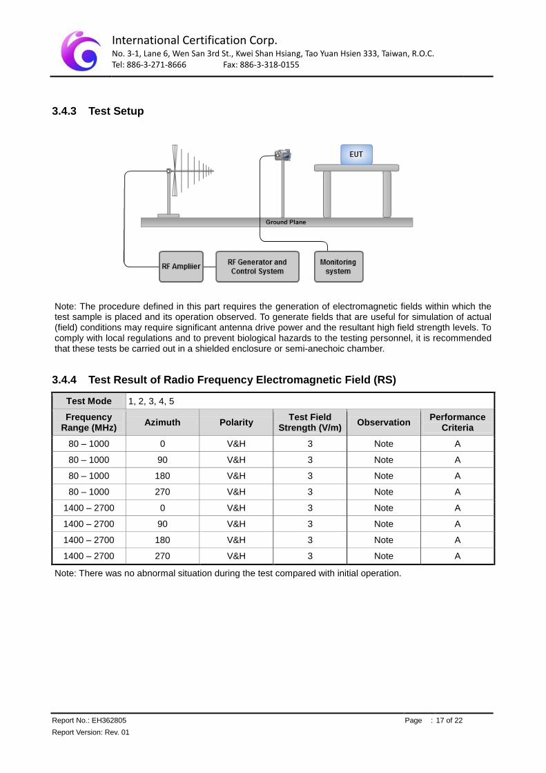
3.4.3 Test Setup
Note: The procedure defined in this part requires the generation of electromagnetic fields within which the test sample is placed and its operation observed. To generate fields that are useful for simulation of actual (field) conditions may require significant antenna drive power and the resultant high field strength levels. To comply with local regulations and to prevent biological hazards to the testing personnel, it is recommended that these tests be carried out in a shielded enclosure or semi-anechoic chamber.
3.4.4 Test Result of Radio Frequency Electromagnetic Field (RS)
Test Mode 1, 2, 3, 4, 5
Frequency Range (MHz)
Azimuth Polarity Test Field
Strength (V/m) Observation
Performance Criteria
80 – 1000 0 V&H 3 Note A
80 – 1000 90 V&H 3 Note A
80 – 1000 180 V&H 3 Note A
80 – 1000 270 V&H 3 Note A
1400 – 2700 0 V&H 3 Note A
1400 – 2700 90 V&H 3 Note A
1400 – 2700 180 V&H 3 Note A
1400 – 2700 270 V&H 3 Note A
Note: There was no abnormal situation during the test compared with initial operation.

International Certification Corp. No. 3-1, Lane 6, Wen San 3rd St., Kwei Shan Hsiang, Tao Yuan Hsien 333, Taiwan, R.O.C. Tel: 886-3-271-8666 Fax: 886-3-318-0155
Report No.: EH362805 Page : 18 of 22
Report Version: Rev. 01
4 Photographs of the Test Configuration
ESD Test (Mode 1)
ESD Test (Mode 2)

International Certification Corp. No. 3-1, Lane 6, Wen San 3rd St., Kwei Shan Hsiang, Tao Yuan Hsien 333, Taiwan, R.O.C. Tel: 886-3-271-8666 Fax: 886-3-318-0155
Report No.: EH362805 Page : 19 of 22
Report Version: Rev. 01
ESD Test (Mode 3)
ESD Test (Mode 4)
International Certification Corp. No. 3-1, Lane 6, Wen San 3rd St., Kwei Shan Hsiang, Tao Yuan Hsien 333, Taiwan, R.O.C. Tel: 886-3-271-8666 Fax: 886-3-318-0155
Report No.: EH362805 Page : 20 of 22
Report Version: Rev. 01
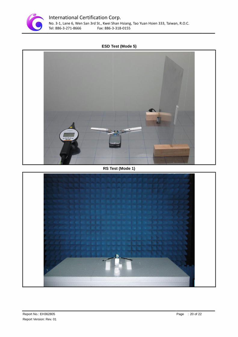
ESD Test (Mode 5)
RS Test (Mode 1)

International Certification Corp. No. 3-1, Lane 6, Wen San 3rd St., Kwei Shan Hsiang, Tao Yuan Hsien 333, Taiwan, R.O.C. Tel: 886-3-271-8666 Fax: 886-3-318-0155
Report No.: EH362805 Page : 21 of 22
Report Version: Rev. 01
RS Test (Mode 2)
RS Test (Mode 3)

International Certification Corp. No. 3-1, Lane 6, Wen San 3rd St., Kwei Shan Hsiang, Tao Yuan Hsien 333, Taiwan, R.O.C. Tel: 886-3-271-8666 Fax: 886-3-318-0155
Report No.: EH362805 Page : 22 of 22
Report Version: Rev. 01
RS Test (Mode 4)
RS Test (Mode 5)
══END══