CCS for Industrial Sources of CO2 in Europe€¦ · In 2011, the International Energy Authority...
22
www.sccs.org.uk 1 of 22 Briefing: CCS for Industrial Sources of CO 2 in Europe 30 th August 2013 Author: Dr Peter Brownsort, Scientific Research Officer Scottish Carbon Capture & Storage (SCCS)
Transcript of CCS for Industrial Sources of CO2 in Europe€¦ · In 2011, the International Energy Authority...

www.sccs.org.uk 1 of 22
Briefing: CCS for Industrial Sources of CO2
in Europe
30th August 2013
Author: Dr Peter Brownsort, Scientific Research Officer Scottish Carbon Capture & Storage (SCCS)

www.sccs.org.uk 2 of 22
1 Introduction
Most global focus on carbon capture and storage (CCS) has been within the power generation sector. However, over the last few years, and specifically since the G8 summit in 2010, the profile of CCS for industrial applications has been raised.
In Europe, emissions from industry make up about a quarter of total carbon dioxide (CO2) emissions. To achieve targets matching International Panel on Climate Change (IPCC) recommendations for limiting global warming, all sectors of the economy will be required to make significant reductions in emissions. Early estimates suggested that the application of CCS to the largest emitters in refineries, iron and steel and cement industries could make a major contribution – 270-330 million tonnes per annum – to CO2 emission reductions in Europe (Rootzén, Kjärstad, Johnsson, 2011). This briefing summarises the most recent published report addressing the scope for CCS in European industry (ZEP, 2013), adds further information from public sources and gives some new analysis of the implications.
1.1 Background
In 2011, the International Energy Authority (IEA) and the United Nations Industrial Development Organisation (UNIDO) published Technology Roadmap: Carbon Capture and Storage in Industrial Applications (IEA, 2011) focusing on the issues for capture of CO2 from industry. This was based on detailed assessments carried out for UNIDO covering five industrial source sectors – namely, iron and steel, cement, refineries, the high-purity sector and biomass conversion (UNIDO 2010a,b,c,d,e respectively) – assessments on matching sources and sinks (UNIDO, 2011a) and Enhanced Oil Recovery (EOR) (UNIDO, 2011b), plus a Technology Synthesis Report (UNIDO, 2010f).
International governmental interest, through the Clean Energy Ministerial (CEM) forum, established the Carbon Capture Use and Storage (CCUS) Action Group of interested countries and companies in 2010. This group recommended, in 2011, a review of opportunities for industrial CCS including “clustering” of emitters to reduce costs and the potential for CCS demonstration based on low-cost capture in specific industry sectors. The Zero Emissions Platform’s (ZEP) working group on “CCS in Other Industries” provided a European response in its recent report: Carbon Capture and Storage in Energy-intensive Industries (ZEP, 2013). The current briefing paper summarises ZEP’s findings and draws out some key points and questions with further analysis. Where not otherwise specifically referenced, information and data comes from the ZEP (2013) report.
1.2 Objectives
This report aims to give an overview of where industry and CCS are mutually relevant in a number of different senses:
• Industry sectors having intensive energy needs currently provided by fossil fuel combustion.
• Industries where formation of CO2 is inherent to the process. • Geographic areas where the density of industry may make CCS relevant
(i.e. clusters).

www.sccs.org.uk 3 of 22
A further aim is to provide an estimate of the value to Europe of the industrial sectors discussed where CCS is relevant, in terms of both financial values and the number of jobs dependent on the industry.

www.sccs.org.uk 4 of 22
2 Drivers, issues and benefits for CCS application in industry
There a number of reasons, outlined in this section, why CCS for industrial emissions is receiving increasing focus, including the sheer scale of industrial emissions; the value of industry in terms of revenue and employment; and processes for several key materials, which have inherent emissions that cannot be avoided. There are also aspects of industry that may facilitate the development of CCS as a whole. This section includes a review of previous estimates of scale for the identified scope for CCS in European industry.
2.1 Drivers and targets
• Industry direct emissions account for about one quarter of total European Union (EU) CO2 emissions, i.e. 940 million tonnes in 2010 (Figure 1).
o This includes industrial combined heat and power (CHP) generation but not indirect emissions from electricity supplied to industry from the grid.
Figure 1. EU-27 total CO2 emissions and direct industrial emissions in 2010 (ZEP, 2013)
• The iron and steel, cement, chemicals and refineries sectors contribute around 60% of direct industrial CO2 emissions.
• To match IPCC targets for limiting global warming to below 2°C, the EU needs to reduce CO2 emissions from industry by 34-40% by 2030 and 83-87% by 2050 (v.1990).
2942$
710$
230$
10$
Total&European&CO2&&emissions&Mt,&2010&
Non,industry$energy$related$emissions$
Industrial$energy$related$emissions$
Industrial$process$emissions$
Other$emissions$
182$
141$
133$100$
357$
27$
Industrial&CO2&&emissions&Mt,&2010&
Iron$and$steel$produc@on$
Chemical$industry$
Petroleum$refining$
Cement$and$lime$produc@on$
Other$(energy,related)$
Other$(process,related)$Excluding$land$use,$land,use$change$and$forestry$

www.sccs.org.uk 5 of 22
2.2 Issues
• Many industries are close to theoretical limits in energy and resource efficiency, although there is a continuing need for improvement where there is scope.
• Some processes have inherent CO2 emissions resulting from the process chemistry. This accounts for about one quarter of industrial emissions and is not related to fossil fuel combustion.
• Some products of energy-intensive industries (e.g. steel, aluminium and concrete) are key materials needed for the development of low-carbon energy systems.
• Energy-intensive industries contribute significantly to European GDP and also to employment and skills, supporting industry’s ability to innovate.
o The iron and steel, cement, refineries and chemicals sectors have a combined turnover of c.€900 billion, c.7% of EU GDP or 25% of total EU industry turnover (SCCS, 2013).
o These sectors directly employ c.1.75 million, 0.7% of EU labour force or 2.9% of EU industry employment (SCCS, 2013).
o The data imply that these industries make a disproportionately high contribution to the European economy and are key strategic industries.
• In many cases, multinational producers trade products of these industries globally so, if European operations become less competitive, manufacture may move elsewhere.
2.2.1 Risk to competitiveness
This last point has risks for the competitiveness of industry in two differing senses:
• The displacement of industry to regions where emission control is less stringent may result in “carbon leakage” associated with manufacturing the product and be detrimental at global emission level;
• If other regions are able to introduce low-carbon manufacturing, such as through the use of CCS, at a lower cost than Europe then manufacturing may migrate to that region to achieve sectoral or company emission targets.
Therefore, industry needs to achieve emission reductions through CCS in a way that does not adversely affect the competitiveness of European operations, with the likelihood of a continuing imbalance in global emission reduction targets. Policy needs to enable this and support developments with fiscal incentives that preserve or enhance competitiveness. Failure to do so could lead to a loss of economic activity and associated jobs in Europe.
2.3 Benefits and scope
Other benefits derived from applying CCS in industry are described below:
• Some industrial sources of high-concentration, captured CO2 are available which could be used to prove infrastructure and storage developments in advance of large-scale capture projects, thereby reducing the risks associated with such projects.
• Industrial emitters often occur in clusters, with several large emitters located close together. This provides opportunities for cost sharing for transport and storage networks.
• The wider case for CCS in general (including power generation), may be enhanced by public acceptance of the need for CCS in industry.
www.sccs.org.uk 6 of 22
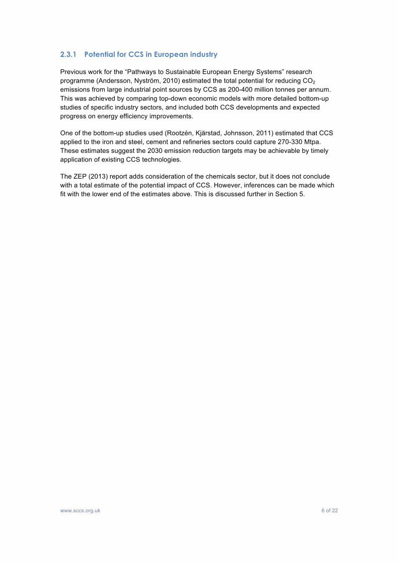
2.3.1 Potential for CCS in European industry
Previous work for the “Pathways to Sustainable European Energy Systems” research programme (Andersson, Nyström, 2010) estimated the total potential for reducing CO2 emissions from large industrial point sources by CCS as 200-400 million tonnes per annum. This was achieved by comparing top-down economic models with more detailed bottom-up studies of specific industry sectors, and included both CCS developments and expected progress on energy efficiency improvements.
One of the bottom-up studies used (Rootzén, Kjärstad, Johnsson, 2011) estimated that CCS applied to the iron and steel, cement and refineries sectors could capture 270-330 Mtpa. These estimates suggest the 2030 emission reduction targets may be achievable by timely application of existing CCS technologies.
The ZEP (2013) report adds consideration of the chemicals sector, but it does not conclude with a total estimate of the potential impact of CCS. However, inferences can be made which fit with the lower end of the estimates above. This is discussed further in Section 5.

www.sccs.org.uk 7 of 22
3 CO2 capture, transport and storage for industry
The options for different elements of the CCS system chain for industrial applications are essentially the same as for power generation. However, there are some specific points to note for industry, particularly for the capture element, where the best technology depends strongly on the process.
3.1 Capture
• Best technology depends strongly on process. • Processes may need adaptation to achieve the most cost-effective solutions. • Pre-process separation of CO2 :
o Inherent in hydrogen and ammonia production, coal/biomass to liquid fuel conversion and direct reduced iron process;
o Produces concentrated CO2 stream often suitable for compression; o Potential for lower cost CO2 availability.
• Oxy-fuel combustion: o Suitable for externally produced process heat, e.g.
§ Steam from boiler/CHP plant § Externally fired kiln § Cement pre-calciner
o Specific process developments required for internally produced process heat, e.g.
§ In steel making, Ultra-low CO2 Steelmaking (ULCOS) programme § In refining, oxy-firing in fluid catalytic cracker (FCC) catalyst
regeneration • Post-combustion capture using chemical or physical solvents or solid sorbents:
o Suitable for dilute CO2 vent streams from most point sources, potentially including collected vent systems in networked industrial complexes;
o Needs additional heat for CO2 recovery affecting economics unless excess heat available at site;
o Potentially suitable for larger, concentrated CO2 sources (e.g. steel, cement) but economics affected by additional heat requirement.
3.2 Transport
• Technical options same as for CCS from power generation. • Pipeline is principle option considered with the potential for development of shared
infrastructure around clusters. • However, road, rail, barge, shipping are all established methods for bulk CO2
transportation and may be appropriate for industry depending on location and scale. • Existing bulk liquid CO2 handling facilities linked to several European ammonia
producers.
3.3 Storage
• Options as for CCS from power generation: o Deep saline aquifers; o Depleted oil and gas fields:
§ Potential for Enhanced Oil Recovery (EOR)

www.sccs.org.uk 8 of 22
o Deep un-mineable coal beds: § Potential for coal bed methane extraction
3.4 Infrastructure
• Industrial emitters are typically small compared to power generation but often occur in clusters (Figures 2 and 3):
o Refineries, chemicals, ammonia production often clustered; o Iron and steel, cement, pulp and paper, more scattered as typically sited near
resources/ports.
Key: ▴ refineries, • integrated steel plants, ★ cement plant Mid grey: regions with large industry sources totalling >5 Mtpa
Dark grey: regions totalling >10 Mtpa Pecked lines: potential capture clusters
Figure 2. Distribution in Europe of refineries, integrated steel plants and cement plants emitting >0.5 Mtpa CO2 (adapted from Rootzén, Kjärstad, Johnsson, 2011)
Table III). In scenario A, post combustion capture technologies dominate in the refineryand cement industry and conventional blast furnaces are replaced with top gasrecycling blast furnaces in integrated steel plants. In scenario B, refinery furnaces andboilers are converted to oxyfuel operation, oxy combustion is applied in cement plantprecalciners and top gas recycling blast furnaces with CO2 capture dominate the steelindustry. The mitigation potential is significantly larger in scenario A whereapproximately 330MtCO2 would be captured annually, compared to roughly270MtCO2 per year in scenario B. The cost associated with CO2 capture would,however, most likely be higher in scenario A than in scenario B. These estimationsshould be seen as illustrations of the potential role of CO2 capture in large industrypoint sources, i.e. a first estimate.
4.3 Distribution of emission sourcesAs illustrated in Figure 2 the large industry point sources are unevenly distributedover the European continent. By aggregating industry CO2 emissions on regional level(the Nomenclature of territorial units for statistics, NUTS regions, has been used to
Figure 2.Geographical distribution
of large point sources(.0.5MtCO2/year) in theEuropean industry sector
CO2 capture
27

www.sccs.org.uk 9 of 22
Key: markers with dots – production sites; markers without dots – transport and storage only
Figure 3. Distribution in Europe of ammonia plants (SCCS, 2013)
Note: Discussion of the potential availability of CO2 from ammonia plant in Europe is included in Section 4.4.3.
• Significant cost savings arise from combining CO2 quantities for transport (Figure 4).
Figure 4. Cost variation with CO2 transport volume (ZEP, 2013, and references therein)
©2013 Google - Map data ©2013 Basarsoft, Google, ORION-ME -
European Ammonia PlantsMap showing production sites of major European ammonia producers - members of Fertilizers Europe, atrade association representing 81% of regional production of nitrogen fertilizers. Supplemented by further listof producers gleaned from EU BAT Documentation on ammonia.
Positions are best estimate from public information.Unlisted · 2 Collaborators · 2 viewsCreated on Aug 14 · By · Updated 17 hours ago
Capacity: 1.1 Mt/yrTurnover: 670 MEur/yrEmployees 1400
Capacity: 0.4 Mt/yrTurnover: 790 MEur/yrEmployees: 1274
Achema
Anwil
European Ammonia Plants - Google Maps https://maps.google.co.uk/maps/ms?msa=0&msid=21673951...
1 of 4 20/08/2013 10:15
14
2.4 Infrastructure planning for CCS can significantly reduce capital costs Compared to Europe’s large coal and lignite fired power plant sites with several generation units onsite, industrial production facilities are mostly characterised by rather small CO2 emission levels. However, the co-location of multiple industries and power generation installations is a common occurrence in many European regions. Developing CO2 capture solutions for energy-intensive industries in parallel to fossil-fuel power generation could facilitate the clustering of CCS projects, improving economies of scale for CO2 transportation and storage, greatly reducing capital costs compared to stand-alone projects.
Specific CO2 transport costs are determined by several factors, whereas the transport quantity (measured as mass flow) has a notable influence with disproportionally declining transport costs at increasing mass flow (Figure 7). Hence, considerable cost savings can be generated if CO2 transport clusters are established for those capture sites that would have high transport costs for individual transport solutions, e.g. the cluster of 5 capture sources of 1 MtCO2/yr each would lower the transport costs by ~60% and a further cluster to total 20 MtCO2/yr would reduce transport costs by half.
With respect to today’s location of fossil-fuelled power plants and industrial production sites, selected areas across Europe could be of potential interest for a joined effort to transport captured CO2. For the neighbouring countries of the North Sea a central pipeline system connecting to large storage sites, such as the Utsira aquifer in the Norwegian North Sea, represents an infrastructure option which might be competitive to onshore storage in the long-run. The set-up and scale of clusters can range from joint efforts to bundle small-size emission sources, up to regional hubs as an integral part of a trans-European CO2 pipeline infrastructure connecting multiple capture sites with large-scale CO2 storage reservoirs. Please also see ZEP’s report, “Building a CO2 transport infrastructure for Europe”.23
CO2
tran
spor
t cos
ts
Mass flow
Large regional hub [50 Mt CO2/yr]
Single small scale site[1 MtCO2/yr]
Small cluster ≈ coal fired power plant unit[5 MtCO2/yr]
Medium/large size cluster ≈ power plant complex[20 MtCO2/yr]
Figure …: Cost effects of CO2 transport clusters (left) and potential CO2 capture sources and storage sites, including trans-European infrastructure for CO2 transport (right)Sources: Left graphic based on: Strachan et al. 2011 and van den Broek 2010Right graphic based on: Blesl and Kober 2010
>> data for pipeline transport cost calculation >> but the data are for the qualitative graphic rather unimportantPipeline transport, distance = 500km, discount rate = 5%, pipeline investment = 1600€/m2, 2.5% O&M costs, excl. art-works
FIGURE 7 COST EFFECTS OF CO2 TRANSPORT (LEFT) AND POTENTIAL CO2 CAPTURE SOURCES AND STORAGE SITES, INCLUDING TRANS-EUROPEAN INFRASTRUCTURE FOR CO224 25 26 23 www.zeroemissionsplatform.eu/library/publication/221-co-2transportinfra.html 24 Blesl, M. and T. Kober. Bedeutung von CO2-Transport- und Speicheroptionen im europäischen Energiesystem, In Zeitschrift für Energiewirtschaft No. 34 (2010), p. 285-301 DOI 10.1007/s12398-010-0027-8 25 Strachan, N., R. Hoefnagelsb, A. Ramírez, M. van den Broek, A. Fidje, K. Espegren, P. Seljom, M. Blesl, T. Kober, P. E. Grohnheit. CCS in the North Sea region: A comparison on the cost-effectiveness of storing CO2 in the Utsira formation at regional and national scales, in the International Journal of Greenhouse Gas Control 5 (2011), p. 1517-1532 26 van den Broek, M., A. Ramírez, H. Groenenberg, F. Neele, P. Viebahn, W. Turkenburg, A. Faaij. Feasibility of storing CO2 in the Utsira formation as part of a long term Dutch CCS strategy: an evaluation based on a GIS/MARKAL toolbox, in the International Journal of Greenhouse Gas Control 4 (2010), p. 351–366

www.sccs.org.uk 10 of 22
• CO2 collection hubs serving both power generation and industrial sites with pipeline networks for transport to North Sea storage sites have been proposed, as mentioned in the ZEP (2013) report (Figure 5).
Figure 5. Potential for 'clustering' and pipeline network in northern Europe (ZEP, 2013 and references therein)
In summary, the same ranges of options for capture, transport and storage are available to industry as are available for CCS from power generation although the factors affecting selection of technologies will often be different.
14
2.4 Infrastructure planning for CCS can significantly reduce capital costs Compared to Europe’s large coal and lignite fired power plant sites with several generation units onsite, industrial production facilities are mostly characterised by rather small CO2 emission levels. However, the co-location of multiple industries and power generation installations is a common occurrence in many European regions. Developing CO2 capture solutions for energy-intensive industries in parallel to fossil-fuel power generation could facilitate the clustering of CCS projects, improving economies of scale for CO2 transportation and storage, greatly reducing capital costs compared to stand-alone projects.
Specific CO2 transport costs are determined by several factors, whereas the transport quantity (measured as mass flow) has a notable influence with disproportionally declining transport costs at increasing mass flow (Figure 7). Hence, considerable cost savings can be generated if CO2 transport clusters are established for those capture sites that would have high transport costs for individual transport solutions, e.g. the cluster of 5 capture sources of 1 MtCO2/yr each would lower the transport costs by ~60% and a further cluster to total 20 MtCO2/yr would reduce transport costs by half.
With respect to today’s location of fossil-fuelled power plants and industrial production sites, selected areas across Europe could be of potential interest for a joined effort to transport captured CO2. For the neighbouring countries of the North Sea a central pipeline system connecting to large storage sites, such as the Utsira aquifer in the Norwegian North Sea, represents an infrastructure option which might be competitive to onshore storage in the long-run. The set-up and scale of clusters can range from joint efforts to bundle small-size emission sources, up to regional hubs as an integral part of a trans-European CO2 pipeline infrastructure connecting multiple capture sites with large-scale CO2 storage reservoirs. Please also see ZEP’s report, “Building a CO2 transport infrastructure for Europe”.23
CO2
tran
spor
t cos
ts
Mass flow
Large regional hub [50 Mt CO2/yr]
Single small scale site[1 MtCO2/yr]
Small cluster ≈ coal fired power plant unit[5 MtCO2/yr]
Medium/large size cluster ≈ power plant complex[20 MtCO2/yr]
Figure …: Cost effects of CO2 transport clusters (left) and potential CO2 capture sources and storage sites, including trans-European infrastructure for CO2 transport (right)Sources: Left graphic based on: Strachan et al. 2011 and van den Broek 2010Right graphic based on: Blesl and Kober 2010
>> data for pipeline transport cost calculation >> but the data are for the qualitative graphic rather unimportantPipeline transport, distance = 500km, discount rate = 5%, pipeline investment = 1600€/m2, 2.5% O&M costs, excl. art-works
FIGURE 7 COST EFFECTS OF CO2 TRANSPORT (LEFT) AND POTENTIAL CO2 CAPTURE SOURCES AND STORAGE SITES, INCLUDING TRANS-EUROPEAN INFRASTRUCTURE FOR CO224 25 26 23 www.zeroemissionsplatform.eu/library/publication/221-co-2transportinfra.html 24 Blesl, M. and T. Kober. Bedeutung von CO2-Transport- und Speicheroptionen im europäischen Energiesystem, In Zeitschrift für Energiewirtschaft No. 34 (2010), p. 285-301 DOI 10.1007/s12398-010-0027-8 25 Strachan, N., R. Hoefnagelsb, A. Ramírez, M. van den Broek, A. Fidje, K. Espegren, P. Seljom, M. Blesl, T. Kober, P. E. Grohnheit. CCS in the North Sea region: A comparison on the cost-effectiveness of storing CO2 in the Utsira formation at regional and national scales, in the International Journal of Greenhouse Gas Control 5 (2011), p. 1517-1532 26 van den Broek, M., A. Ramírez, H. Groenenberg, F. Neele, P. Viebahn, W. Turkenburg, A. Faaij. Feasibility of storing CO2 in the Utsira formation as part of a long term Dutch CCS strategy: an evaluation based on a GIS/MARKAL toolbox, in the International Journal of Greenhouse Gas Control 4 (2010), p. 351–366

www.sccs.org.uk 11 of 22
4 Industry sectors with high CO2 emissions
In this section four industry sectors accounting for the majority of industrial emissions in Europe are described. The main processes leading to CO2 emissions are summarised and mitigation options discussed, including CCS. The choice of technology and state of development of CCS projects is outlined, where appropriate. Specific challenges and opportunities are given. The section concludes by presenting new analysis by SCCS, quantifying the likely availability of high-concentration CO2 from ammonia production in Europe.
• Industry accounts for around 24% of total EU emissions (Figure 1). • Four industry sectors account for around 60% of total EU emissions (Table 1).
Table 1. Emissions from high-emitting sectors in the EU, 2010
Sector CO2 emissions, Mtpa
Share of industrial emission, %
Share of total EU emission, %
Iron and Steel 182 19.2 4.7
Cement and Lime 100 10.5 2.6
Refineries 133 14.0 3.4
Chemicals 141 14.8 3.6
Other sectors with significant emissions include:
o Pulp, paper and board o Food and drink o Glass, glass fibre o Ceramics, bricks
Generally, these are smaller and more scattered emitters although, where specific conditions are present, such as proximity to large emitters or excess heat available on site, CCS may be appropriate.
4.1 Iron and steel
• The EU produces c.180 Mtpa crude steel, c.15% of global production in 2011. • Direct employment >400,000, 1.25% of EU manufacturing employment. • Annual turnover c.€180 billion. • CO2 emissions 182 Mtpa (2010). • 60% of steel is produced at integrated steel mills through blast furnace – basic
oxygen furnace route (BF-BOF):

www.sccs.org.uk 12 of 22
o High CO2 emission resulting from use of coal and coke as fuel and reducing agent;
o About 40 integrated steel mills in the EU. • Most other production is through scrap recycling in electric arc furnaces requiring less
energy. • Current best practice and technology options could reduce average CO2 emissions
from integrated plants only by 10-20%, if fully adopted.
4.1.1 Capture options
• Post-process capture options could be applied to blast furnaces but are estimated to allow capture of only 30% of entire plant emission (Rootzén, Kjärstad, Johnsson, 2011).
• Deeper reductions require adaptation of processes; European steel community is developing new process technology under the Ultra-low CO2 Steelmaking (ULCOS) Programme.
o Top-gas recycling blast furnace: § Separates carbon monoxide (CO) from CO2 in off-gases and
recycles CO, reducing coke requirement; § Pure oxygen used to reduce nitrogen in off-gases; § CO2 captured by physical adsorption or pressure swing adsorption
(PSA); § Can achieve 45-55% reduction in CO2 per tonne of steel produced
compared to standard BF-BOF; § Successfully tested at pilot scale; § Plans to demonstrate at Eisenhüttenstadt (Germany) and Florange
(France) steel plants have stalled for funding reasons. o HIsarna technology:
§ Alternative furnace design – cyclone converter furnace; § Allows direct use of non-coking coal and fine iron ore; § Avoids need for coke production and sintering plants saving 20%
emissions directly; § Pure oxygen use and vent gas clean-up gives off-gas as 95% CO2
suitable for compression; § With CCS could allow 80% reduction in CO2 per tonne steel versus
BF-BOF; § Pilot plant operational at Tata Steel, Ijmuiden.
o Direct Reduced Iron (DRI) steelmaking with CCS: § DRI is existing, but little used, technology using natural gas as
reducing gas source and producing an iron product that can be converted to steel in an electric arc furnace;
§ Can reduce CO2 emission by 25% compared to blast furnace route, but not currently economic in Europe;
§ ULCOS Programme adapting technology using pure oxygen to produce coal-derived syngas as reducing gas and shift reaction to convert CO off-gas to hydrogen and CO2 ;
§ CO2 separated by pressure swing adsorption (PSA) or vacuum pressure swing adsorption (VPSA) and then compressed;
§ May allow 50% reduction in CO2 per tonne steel v. BO-BOF; § Plans for pilot-scale plant in Sweden.

www.sccs.org.uk 13 of 22
4.1.2 Challenges for sector
• Several areas where process technology still requires tuning. • New technologies need to be demonstrated at full scale and for reasonable time
periods to prove reliability. • Capital costs high due to scale of equipment.
4.2 Cement
• EU produced c.6% global cement production, 190 Mt in 2010; volumes reflect global economic trends, e.g. 270 Mt in 2007.
• Four of the five leading global companies are EU-based. • 270 cement plants across Europe employ 45,000. • Turnover €74bn (Cembureau, 2013). • CO2 emissions 100 Mt in 2010. • 60% of emissions inherent to product, arising from process chemistry – calcination of
calcium carbonate to give calcium oxide. • 40% of emissions from fossil fuel combustion to give process heat for calcination
(c.900°C) and clinker burning (1350-1450°C) stages. • Some plants use a separate, externally heated pre-calciner, otherwise both
calcination and clinker burning are carried out in an internally heated rotary kiln. • Modern plant operate at close to engineering limits for thermal efficiency; application
of best available technology (BAT) in all European plant might only achieve around 10% reduction in emissions.
• Further mitigation options: o Using alternative fuels with lower life-cycle carbon intensities, e.g. biomass,
municipal wastes, waste tyres; o Increased use of fillers such as slag and fly-ash, limited by properties of
product; o CCS for calcination and fuel combustion processes.
4.2.1 Capture options
• CO2 concentration in emissions from cement plant can range from 14-33%. • Post-process/combustion capture could be used on all off-gas streams, with the
potential to reduce CO2 emissions estimated at 80%: o A project to test post-combustion capture has commenced at Heidelberg
Norcem’s cement plant at Brevik, Norway; o Additional energy required for CO2 recovery in post-carbon capture will affect
economics strongly as no excess heat supply likely to be available. • Oxy-fuel combustion may be more energy/cost effective but may require process or
plant adaptation: o Would be appropriate for externally heated pre-calciners; o Estimated that oxy-fuel combustion for pre-calcination plus capturing
calcination off-gas would allow 50% of plant emissions to be captured (Rootzén, Kjärstad, Johnsson, 2011);
o Recent work suggests oxy-fuel heating of main rotary kiln is feasible as retrofit option despite earlier concerns over materials of construction and product quality.

www.sccs.org.uk 14 of 22
• Carbonate looping is of specific interest to the cement industry due to the use of materials common to both processes:
o Calcium oxide (lime) is reacted with off-gases from the kiln, absorbing CO2 and forming calcium carbonate. This is then re-calcined, releasing concentrated CO2;
o Degraded absorbent still suitable for use in cement making; o Estimates suggest 80% of cement plant CO2 emissions could be captured as
concentrated streams with only small process efficiency losses; o Early stage of development, being assessed for retrofit and for new kilns.
4.2.2 Challenges for sector
• Most challenges relate to use of post-combustion capture, but this may not be the best technology choice for cement. Challenges include:
o The need to reduce energy demand of solvent regeneration step; o Provision of additional energy for this step; likely to require new facility as
most plants sited away from other industry with potential heat sources; o The degradation of amine-based solvents, which may be accelerated by
impurities in cement plant off-gases, requiring additional clean-up stages. • Oxy-fuel and carbonate looping processes are at early stages in cement industry and
will require extensive development and demonstration.
4.3 Refineries
• There are c.100 refineries in Europe, emitting from between c.1 and 5.5 Mtpa CO2. • Emissions were c.133 Mt in 2010. • Turnover in 2010 was €497bn (Bloomberg, 2013). • Employment c.100,000 (direct, plus 500,000 indirect) (Europia, 2013). • Refineries operate many processes within a site and will have many CO2 emission
points. • Pipeline infrastructure networks exist within and beyond sites, linking plants with
transport terminals. • Mitigation options:
o Estimates suggest 20-30% energy savings might be made at typical refineries though efficiency measures and increased heat integration/ recovery measures;
o Shift to lower carbon intensity fuel mix, by replacing refinery-produced fuel oil with natural gas, could give 15% emission reduction, but with cost penalties;
o CCS likely to be only technology for significant emission reductions.
4.3.1 Capture options
• Four main emission routes from refineries: o Hydrogen production – inherent process emission from steam reforming
process; o Emissions from catalyst regeneration for fluid catalytic cracker (FCC); o Combustion emission from fired process heaters; o Combustion emission from on-site steam and power generation
(usually CHP). • Combustion emissions typically account for the majority of refinery emissions:

www.sccs.org.uk 15 of 22
o Often numerous locations; o Low concentration flue gases (4-15%); o Sometimes collected to common vent-stack; o Capture of emission from CHP likely to follow development of power sector; o Capture from fired process heaters inherently similar to power sector but
practicality likely to depend on investment needed for vent-stream collection. • Hydrogen production:
o Demand increasing for hydrogen for upgrading fuels; o Produced generally by steam methane reforming (SMR) and water-gas shift
reaction to produce mixture of hydrogen and CO2 ; o Separation gives concentrated CO2 stream, 40-99% depending on process
used: § 95-99% from chemical absorption § 40-70% from PSA
o Accounts for 5-20% of total refinery emissions. • Emissions from fluid catalytic cracking (FCC):
o FCC is used to break down heavier oils to more valuable, lighter fractions; o Emissions result from regeneration of coked-up catalyst by oxidation to CO2 ; o Off-gases similar to combustion flue gas – 10-20% CO2; o Post-process capture by amine-solvent or chilled ammonia systems suitable,
both being tested at Technology Centre Mongstad (TCM), Norway; o Oxy-firing for catalyst regeneration being trialled at pilot-scale in Brazil.
4.3.2 Challenges for sector
• Many small and dispersed emission sources: o Costs and space for vent networking likely to be a barrier.
• Hydrogen production where PSA used for gas separation will need additional processing to give CO2 suitable for compression and transport.
• Oxy-firing promising for several processes – process heat, utilities and FCC catalyst regeneration – but will need demonstration at larger scales.
4.4 Chemicals
• Chemical industry highly diverse but often geographically clustered. • Most production consumed within integrated chains, with only 30% volume going to
end users. • Turnover €142bn in 2012, or c.1.1% of EU GDP. • Direct employment c.1.2 million. • Emissions in 2010 were 141 Mt. • 70% of emissions are from fossil fuel combustion for process heat, the remainder
from process emissions. • Two processes leading to significant share of emissions:
o Heat required for steam cracking of saturated to unsaturated hydrocarbons (e.g. ethylene, propylene) for polymer production;
o Ammonia synthesis for fertiliser production, mostly via steam-methane reforming to produce hydrogen with separation of concentrated CO2 stream.
• Mitigation options: o Changes to feedstocks – bio-based feedstocks, increased recovery of
carbon-containing materials e.g. through gasification of waste plastics;

www.sccs.org.uk 16 of 22
o Energy efficiency – depends widely on process and industry sub-sector but likely to be significant scope from better heat integration and improved motor systems;
o Heat source changes e.g. biomass in CHP plant, limited potential for solar or geothermal heat in some locations;
o CCS for larger CO2 sources (steam cracking, ammonia), possibly also for CHP and other chemical processes (methanol, ethylene oxide) depending on scale and proximity to transport infrastructure.
4.4.1 Capture options
• Steam cracking: o Uses super heated steam at c.800°C; o Around 54 steam crackers in EU together responsible for large share of
combustion-derived CO2 emission in chemical industry, c.25 Mtpa or 18% (Ecofys, 2009);
o Limited specific research on capture from steam crackers but should follow options for power sector;
o Usually single flue with 13-15% CO2; o Post-combustion capture may be appropriate, potentially avoiding most
emissions from cracker but requiring additional heat source. • Ammonia (NH3) production:
o Concentrated stream of CO2 produced by separation from hydrogen after steam-methane reforming; hydrogen combined with nitrogen from air to give ammonia;
o Total CO2 emission, including process heat requirement is c.1.5 t-CO2/t-NH3; o Process emission typically separated by chemical absorption producing 99%
pure CO2, but in some cases by PSA gives only 30-40% CO2; o Existing examples of commercial CCS from ammonia production in USA,
where CO2 used for EOR. • Combustion emissions (including ammonia heat requirement):
o Options likely to follow power industry for CHP and direct-fired process heat, with issues of diverse locations and low concentrations similar to refineries.
4.4.2 Challenges for sector
• Competitive demand for CO2 from ammonia plant for urea production and for bulk sales into drinks industry.
• Urea demand dominant globally and increasing, although less prominent in Western Europe.
• CO2 availability from ammonia plant generally small compared with volumes required for CCS projects, so dependent on transport infrastructure and clustering for cost effective use.
• For steam crackers, issues similar to power sector – need for additional heat source, as well as pilot and demonstration-scale projects.
4.4.3 Availability of high-concentration CO2 from ammonia production
This section summarises recent analysis by SCCS (2013).

www.sccs.org.uk 17 of 22
• Around 40 locations (c.50 units) in Europe producing c.20 Mtpa ammonia (EFMA, 2011).
• Process CO2 formation is 0.97 t-CO2/t-NH3, calculated from reaction stoichiometry; o 19.4 Mtpa process CO2 generated from ammonia production in Europe.
• CO2 may be used in integrated plant for urea production, compressed for bulk sales or vented:
o Vented portion is potentially directly available for transport and storage. • In Central and Eastern Europe most CO2 from ammonia production is used directly
for urea production: o Urea production in the region was c.15 Mt in 2008 (ICIS, 2008); o This requires the entire process CO2 generated during ammonia production
in the region. • In Western Europe urea production is less prevalent:
o Urea production in the region was c.4.4 Mt in 2008 (ICIS, 2008); o Requires 3.1 Mtpa CO2 from ammonia production; o CO2 generated up to 11.5 Mtpa, based on regional ammonia capacity; o Leaves c.8 Mtpa high-concentration CO2 for other use or venting; o At least five sites in region have bulk CO2 sales:
§ Mostly liquid, some solid (“dry ice”), some for plant growth enhancement
§ Volume uncertain, likely order 1-2 Mtpa o Estimate c.6-7 Mtpa remaining potentially for use in transport/storage
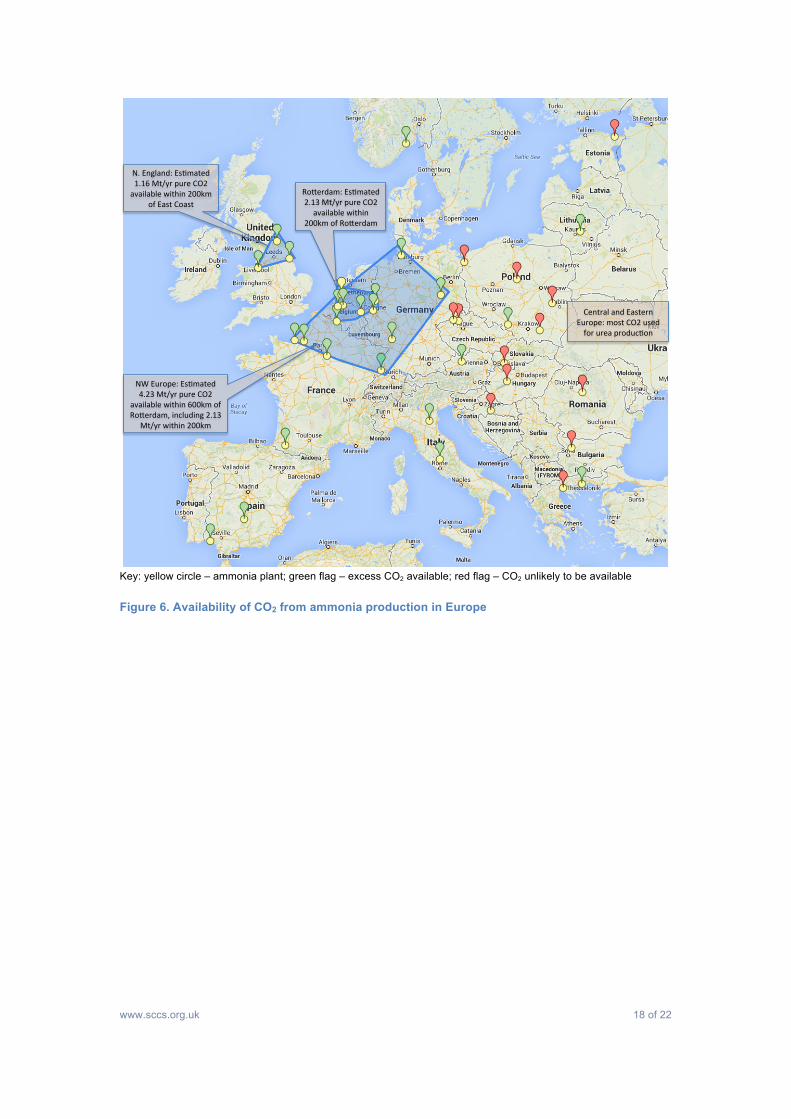
demonstration projects. • Location of CO2 availability from ammonia plant shown in Figure 6, with estimated
volumes in potential clusters, adjusted for existing CO2 sales and consumption in urea manufacture, where known.
• Much of this availability is close to priority areas for CO2 storage development in the North Sea and could be used to prove early transport and storage demonstrations.
www.sccs.org.uk 18 of 22
Key: yellow circle – ammonia plant; green flag – excess CO2 available; red flag – CO2 unlikely to be available
Figure 6. Availability of CO2 from ammonia production in Europe
N.#England:#Es,mated#1.16#Mt/yr#pure#CO2#available#within#200km#
of#East#Coast#RoEerdam:#Es,mated#2.13#Mt/yr#pure#CO2#
available#within#200km#of#RoEerdam#
NW#Europe:#Es,mated#4.23#Mt/yr#pure#CO2#
available#within#600km#of#RoEerdam,#including#2.13#
Mt/yr#within#200km#
Central#and#Eastern#Europe:#most#CO2#used#for#urea#produc,on#

www.sccs.org.uk 19 of 22
5 Analysis and conclusions
An estimate of potential emission reductions from industry in Europe through identified CCS options is given in Table 2. This is based on the principle opportunities for CCS highlighted in the ZEP (2013) report, the views given there on feasibility and rate of progress, plus the analysis of available CO2 from ammonia production in Section 4.4.3.
Table 2. Estimate of potential CO2 emission reductions by CCS from industry in Europe, based on ZEP (2013) report
Sector Assumption for estimate CO2 emission reduction,
Mtpa
Iron and Steel 50% of emissions from blast furnaces captured 89
Cement 50% of emissions from cement plant captured 50
Refineries Most emissions from hydrogen production captured, some emissions from combustion plant captured,
totalling 25%
33
Chemicals Available (western Europe) ammonia plant emissions captured, 80% cracker emissions captured, 10%
combustion emissions captured
36
Total 208
This estimate of a potential reduction of 208 Mtpa CO2 across these industry sectors is at the low end of the range of previous estimates reviewed in Section 2.3.1. This potential is shown relative to IPCC emission reduction targets for Europe in Figure 7.

www.sccs.org.uk 20 of 22
Note: figures indicative to show effect
Figure 7. Contribution of identified CCS options to CO2 emission reduction targets
In industry, improvements in process and energy efficiency to reduce CO2 emissions are understandably prioritised over CCS, as cost savings may repay capital investments. However, the “Pathways” programme (Andersson, Nyström, 2010) estimated the scope for efficiency improvements for reducing emissions from industry as limited to 15-20%; and further, this approach cannot tackle the inherent emissions resulting from process chemistry.
The present analysis suggests that application of CCS to the large industrial opportunities identified in the ZEP (2013) and other reports is necessary, alongside efficiency improvements, to realise mid-term (2030) targets for emission reductions but that these are not sufficient for longer term (2050) targets aimed at avoiding dangerous global warming.
Policies and support mechanisms to encourage the development and deployment of CCS for this first tranche of large opportunities in industry are, therefore, essential and these have been spelt out in both the ZEP (2013) report and in the IEA Roadmap series of publications. (See Box 1 for summary of ZEP recommendations.)
Beyond this, achievement of the higher end of emission reduction estimates for CCS from large sources (c.400 Mtpa, Andersson, Nyström, 2010) would help approach IPPC targets but still leave further emission reductions to be found.
Therefore, in parallel, a number of technological and organisational development actions should be pursued in order to approach the further emission reductions required from industry, all in light of measures to preserve the competitiveness of European industry. These may include:
• Rigorous pursuit of energy and process efficiency improvements across industry;
1000#940#
630#
150#
208#
208#
102#
582#
60# 60# 60#
0#
100#
200#
300#
400#
500#
600#
700#
800#
900#
1000#
1990# 2000# 2010# 2020# 2030# 2040# 2050#
Indu
stria
l+emission
s,+M
t/yr+CO
2+
Achieved#
To#find#
Iden8fied#CCS#
Target#

www.sccs.org.uk 21 of 22
• Appropriate fuel switching where this leads to an overall, sustainable reduction in CO2 emission.
• Development of technology, infrastructure and organisations to allow wider application of CCS at smaller scales, for example:
o Vent-stream networking/integration across and between industrial sites; o Step-change technology allowing cost-effective capture at smaller scales; o Transport system definition for collection of CO2 from diverse sites.
CCS is considered a key technology to achieve deep cuts in European, and global, CO2 emissions from fossil fuel conversion activities, both in the power sector and other industrial sectors. This review and analysis re-emphasises that CCS is as important to industry as to the power sector from two perspectives:
• Scale: industry accounts for around a quarter of total EU emissions. • Inherent process emissions: important industrial processes have unavoidable CO2
emissions resulting from fundamental process chemistry.
Box 1. Key policy recommendations summarised from ZEP (2013) report
• Large-scale demonstration projects for CCS from industry urgently required. • CCS deployment in industry requires supportive policy mechanisms to deliver
technological and investment step-change. • European policy must deliver a CCS supply chain, taking account of emissions from
both power and industrial sectors. • Due to the diversity of industry, a wide range of bottom-up, techno-economic case
studies on different processes and capacities is essential to understand cost-competitiveness.
• Global climate change agreements are unlikely to lead to equal obligations; the EU must strive for hard targets in all industrialised nations to limit “carbon leakage” and focus on minimising abatement costs to maintain competitiveness.
• If global agreements are absent or unbalanced, border carbon adjustments and sectoral approaches should be considered as options.

www.sccs.org.uk 22 of 22
6 References
Andersson, E. Nyström, I., (2010). Opportunities for reducing CO2 in European industry – a synthesis of industrial analyses within the Pathway project. Alliance for Global Sustainability, Göteborg, Sweden.
Bloomberg, (2013). Refinery Fitness Check Should Cover Pending EU Laws, K. Rozhnov. http://www.bloomberg.com/news/2013-06-25/refinery-fitness-check-should-cover-pending-eu-laws.html
Cembureau, (2013). The Cement Sector: A Strategic Contributor to Europe's Future, R. Baeza, M. Martelli, R. Rilo, Boston Consulting Group for Cembureau. http://www.cembureau.eu/sites/default/files/documents/The%20Cement%20Sector%20-%20A%20Strategic%20Contributor%20to%20Europe%27s%20Future.pdf
Ecofys, (2009). Methodology for the free allocation of emission allowances in the EU ETS post 2012 – Sector report for the chemical industry.
EFMA, (2011). Data derived from EFMA Members Database 2011, quoted in Zaklady Azotowe SA 2012 Annual Directors Report. http://91.201.155.153/348-financial-reports-details/lang/en-GB/infoid/453/list/320/default.aspx
Europia, (2013). Jobs pages. http://www.fuellingeuropesfuture.eu/en/refining-in-europe/fuelling-the-eu/jobs
ICIS, (2008). Chemical Profile: Urea. http://www.icis.com/Articles/2008/11/10/9170081/chemical-profile-urea.html
IEA, (2011). Technology Roadmap: Carbon Capture and Storage in Industrial Applications, IEA/UNIDO collaboration. IEA Publications, Paris, France.
Rootzén, J. Kjärstad, J. and Johnsson, F., (2011). Prospects for CO2 capture in European industry. Management of Environmental Quality, Vol. 22 No. 1, 2011; pp. 18-32
SCCS, (2013). Data compiled by Scottish Carbon Capture & Storage from public sources.
UNIDO, (2010a). Sectoral assessment for the iron and steel sector, Jean-Pierre Birat (ArcelorMittal), United Nations Industrial Development Organisation, Vienna, Austria.
UNIDO, (2010b). Sectoral Assessment for the cement sector, Duncan Barker (Mott MacDonald), United Nations Industrial Development Organisation, Vienna, Austria.
UNIDO, (2010c). Sectoral assessment for the refineries sector, Jock Brown (DNV), United Nations Industrial Development Organisation, Vienna, Austria.
UNIDO, (2010d). Sectoral assessment for the high purity sector, Paul Zakkour (CarbonCounts), United Nations Industrial Development Organisation, Vienna, Austria.
UNIDO, (2010e). Sectoral assessment for the biomass sector, Michiel Carbo (ECN). United Nations Industrial Development Organisation, Vienna, Austria.
UNIDO, (2010f). Carbon Capture and Storage in Industrial Applications: Technology Synthesis Report, Heleen de Coninck (ECN) and Tom Mikunda (ECN), United Nations Industrial Development Organisation, Vienna, Austria.
UNIDO, (2011a). Sectoral assessment on matching emissions sources and sinks, Jean Le Gallo (Geogreen), United Nations Industrial Development Organisation, Vienna, Austria.
UNIDO, (2011b). Sectoral assessment on enhanced oil recovery, Michael Godec (ARI), United Nations Industrial Development Organisation, Vienna, Austria.
ZEP, (2013). Carbon Capture and Storage in Energy-intensive Industries, Tom Mikunda (ECN), Stanley Santos (IEA GHG). Advisory Council of the European Technology Platform for Zero Emission Fossil Fuel Power Plants (Zero Emissions Platform).