Industrial Product Design - IEA
24
I P D EIEN01 Automation of expander plug insertion Primary design 2 G S P. 1C Authors: Albert Anderberg Erik Gamst Mathias Kallmert Iván Llopis Beltrán Louise Lövgren Guillaume Marcelin Academic advisor: Gabriel Domingues May 31, 2018
Transcript of Industrial Product Design - IEA

lunds tekniska högskola
Industrial Product Design
EIEN01
Automation of expander plug insertionPrimary design 2
Group Swedish P. 1C
Authors:
Albert AnderbergErik GamstMathias KallmertIván Llopis BeltránLouise LövgrenGuillaume Marcelin
Academic advisor:
Gabriel Domingues
May 31, 2018

Contents
1 Introduction 2
2 Changes to the concept 3
3 Selected components 4
4 Development 54.1 Mechanical design . . . . . . . . . . . . . . . . . . . . . . . . . . . . . . . . . . 54.2 Software design . . . . . . . . . . . . . . . . . . . . . . . . . . . . . . . . . . . 8
4.2.1 Algorithm . . . . . . . . . . . . . . . . . . . . . . . . . . . . . . . . . . 84.2.2 Protocol . . . . . . . . . . . . . . . . . . . . . . . . . . . . . . . . . . . 104.2.3 Problems during implementation . . . . . . . . . . . . . . . . . . . . . 11
4.3 Communication and electrical design . . . . . . . . . . . . . . . . . . . . . . . 11
5 Economical assessment 13
6 Discussion 146.1 Further improvements . . . . . . . . . . . . . . . . . . . . . . . . . . . . . . . 14
7 References 17
A Appendix 18A.1 3D representation of the prototype . . . . . . . . . . . . . . . . . . . . . . . . 18A.2 Electrical schematic . . . . . . . . . . . . . . . . . . . . . . . . . . . . . . . . . 19A.3 Rapid Code . . . . . . . . . . . . . . . . . . . . . . . . . . . . . . . . . . . . . . 20
A.3.1 MovingModule . . . . . . . . . . . . . . . . . . . . . . . . . . . . . . . 20A.3.2 CheckForceModule . . . . . . . . . . . . . . . . . . . . . . . . . . . . . 22
1

1 Introduction
This project and report is a continuation of the previous reports Automation of expander pluginsertion(Anderberg et al., 2017-2018) and Automation of expander plug insertion - Primarydesign 1(Anderberg et al., 2018). The project is provided by the company Swedish Powertrain.The team is since January developing a prototype of a tool and its logic that can insert anexpander plug into a hole in a workpiece automatically. This is the �nal report containing thelast updates done on the prototype.
The project has been divided into di�erent areas of responsibility that is distributed amongthe team members. The di�erent areas of the project can be seen in table 1. The authors forthe di�erent sections mostly coincides with the person responsible for the di�erent areas. Anysections not included in table 1 is a result of collaborative e�ort.
Table 1: Areas of responsibility
Person Area of responisibilityErik Prototype design and manufacturing - MechanicalAlbert Prototype design and manufacturing - ElectricalMathias Algorithm design and software developmentLouise Algorithm design and software developmentIvan Project leader, Report responsibleGuillaume Report responsible
2

2 Changes to the concept
In addition to the modi�cations done in the �rst part of the semester, a major modi�cationhas been done. Instead of creating a whole mechanism to discard the plug, the mechanism ofthe gun used by Swedish Powertrain has been kept, and a servo motor has been used to pushthe trigger of the gun, when the plug is inserted in the hole. The Raspberry Pi is not usedanymore. This was an overkill solution for what the control part of the tool should do. Anembedded AVR has been chosen instead as the tool’s microcontroller, as only basic operationsneed to be done: send the value measured by the force sensor through serial communication,and actuate over the servo motor.
The communication with the controller is also not anymore done through Ethernet cablesbut only through serial communication. The tool, then, is based on the manual tool used toperform the job previous to this project, while automating it in a way that can be triggeredfrom a microcontroller. This automated tool will be mounted on a robot arm that can performmobility operations to locate the holes to be sealed, and align itself with them in order toactivate the mechanism.
The algorithm to detect a hole has been kept the same way: The tool is equiped with a forcesensor that is mounted on top of the tool against a spring. The spring absorbs the compressionof the arm when the tool is not aligned with the hole. When this is the case, a certain range offorces are sensed by the force sensor, due to the spring. These force measurements are trans-mitted over the serial cable to the microcontroller, which will, at the same time, communicatewith the robot arm’s controller, to tell the current state of the tool in the algorithm. Whenthe tool hits the right spot, which is the hole, and enters in it, a di�erent range of force mea-surements will be sensed. Then the micro-controller will communicate with the robot arm toavoid any kind of movement, and will activate the pulling of the plug.
This is supposed to be a prototype. The idea of adding the manual tool at the end of the toolhas been thought as a way of proving the concept of the tool that has been designed. In a�nal stage, this could be removed and a di�erent hydraulic or pneumatic source be installedinstead.
3

3 Selected components
The components have been selected to be the simplest communication circuit between the sen-sor and the controller, and then from the controller to the Servo motor to trigger the pulling.The only input that needs measuring is the spring compression through force sensor. An inter-face board consisting of an analog-to-digital converter and a chip was also chosen of means tocommunicate between the tool and the robot controller. The testing prototype manufacturedwas made from readily available metal pipes and plastic.
Components:
• FSS1500NST force sensor x 2 (one broke during assembly)
• ADS1015 12-bit di�erential ADC
• MAX3232CPE Multichannel RS-232 Line Driver/Receiver
• 5V 2A power supply
• Serial cable
• Misc. cables and connectors
• Rivet power tool
• TowerPro MG995 Servo
The allowed spending budget is 10 000 SEK. Only 2 534 SEK have been used. Nevertheless,the price of the plug gun has not been taken in account for the price of the tool as it has beenprovided by Swedish Powertrain.
4

4 Development
4.1 Mechanical design
The tool has been updated in several aspects. The previous design explored a hydraulic pistonas the main source of power for pulling the pin. There are other power sources that couldbe used as well: pneumatic, electric, etc. The force required to break the pin, up to 20 kN,are reachable from these di�erent power sources. The manual tool used prior to this designused pneumatic force as the power source. Using the same type of power is de�nitely a safebet.
The job explained in the �rst report is currently performed manually. The prototype that hasbeen design as a proof of concept of automating this job. The tool could have been designedcompletely from scratch, with all being new components, new design and a new mechanismmade ad hoc for the company. Nonetheless, the safest, cheapest and easiest way of provingthat this last path is achievable is by attaching the manual tool itself to the prototype tool.The manual tool is an already-made solution to the subproblem of picking and pulling theplug from the holes at a cheap price. By combining this tool with the current prototype thatis capable of performing the automatic jobs needed, a new mechatronic device is created thatcan reach all the goals de�ned at the beginning of this project, see �gure 1.
5

Figure 1: The entire prototype.
6

To do so, the prototype tool has been modi�ed in order to make space for the manual tool.The manual tool has been attached at the tip of the tool that had been designed previously, see�g 2, and modi�ed as well in order to make the activation of the pulling mechanism automatic(See �g 3). The button is pressed by a servo motor, which will be rotated from the AVR. Thissignal will be sent when the algorithm estimates there is a hole to be sealed, and that the pinis located inside of the hole. This servo motor will then press the button of the manual toolthat is part of the prototype, and trigger the mechanism that will pull and break the pin bymeans of pneumatic power. The trigger of the manual tool will be constantly pressed until thetool moves to a location where the pin should be discarded. It will then release the trigger,dropping the pin, and then proceed to pick up a new plug using the suction created from thepneumatic connection in the manual tool.
Figure 2: How the manual tool is connected to the spring loaded prototype.
7

Figure 3: The servo, acting as a mechanical �nger.
This is a proof-of-concept of the design. The pneumatic manual tool that has been used asthe pulling mechanism was the easiest way to prove that the entire system works. In the �naldesign, the end of the tool could be substituted for another type of pneumatic or hydraulicmechanism. The automation of the mobility, hole location and wiggling around the hole toachieve a good alignment with the tool has been proved to be e�ective.
4.2 Software design
4.2.1 Algorithm
RobotStudio is the software that has been used to program the robot arm for testing the pro-totype. This software is designed to be used just on ABB robots. However, every roboticarms software tend to have the same basic features. The developed program is based on twodi�erent tasks working concurrently. This means that the program can do both tasks in par-allel (kind of, at least). The tasks has two di�erent areas of responsibility, and �rst one calledMotionModule handles all the movement regarding the robot and the second one calledCheckForceModule is the one responsible for communication. An overview of the tasksis shown in �gure 4.
8
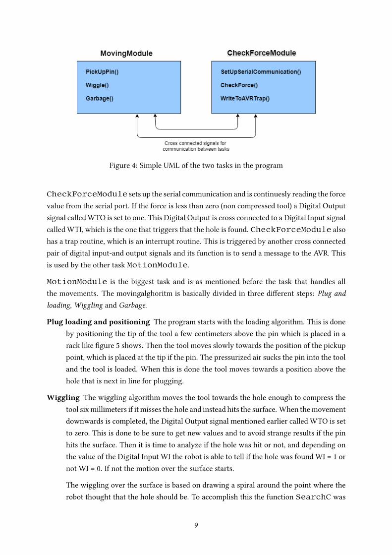
Figure 4: Simple UML of the two tasks in the program
CheckForceModule sets up the serial communication and is continuesly reading the forcevalue from the serial port. If the force is less than zero (non compressed tool) a Digital Outputsignal called WTO is set to one. This Digital Output is cross connected to a Digital Input signalcalled WTI, which is the one that triggers that the hole is found. CheckForceModule alsohas a trap routine, which is an interrupt routine. This is triggered by another cross connectedpair of digital input-and output signals and its function is to send a message to the AVR. Thisis used by the other task MotionModule.
MotionModule is the biggest task and is as mentioned before the task that handles allthe movements. The movingalghoritm is basically divided in three di�erent steps: Plug andloading, Wiggling and Garbage.
Plug loading and positioning The program starts with the loading algorithm. This is doneby positioning the tip of the tool a few centimeters above the pin which is placed in arack like �gure 5 shows. Then the tool moves slowly towards the position of the pickuppoint, which is placed at the tip if the pin. The pressurized air sucks the pin into the tooland the tool is loaded. When this is done the tool moves towards a position above thehole that is next in line for plugging.
Wiggling The wiggling algorithm moves the tool towards the hole enough to compress thetool six millimeters if it misses the hole and instead hits the surface. When the movementdownwards is completed, the Digital Output signal mentioned earlier called WTO is setto zero. This is done to be sure to get new values and to avoid strange results if the pinhits the surface. Then it is time to analyze if the hole was hit or not, and depending onthe value of the Digital Input WI the robot is able to tell if the hole was found WI = 1 ornot WI = 0. If not the motion over the surface starts.
The wiggling over the surface is based on drawing a spiral around the point where therobot thought that the hole should be. To accomplish this the function SearchC was
9

used, since it is equipped with an interrupt feature. If a certain digital input signal goeshigh during the movement, the one called WTI, the robot stops and the search is over.
To be sure that the pin is fully inserted, the robot moves down a few millimeters more.Next step is to trigger the Digital Output signal connected to the trap routine inCheck-ForceModule. This sends the message via the serial port to the AVR that it is timeto pull the plug. When the hole is sealed, the robot goes upwards to a point above theworkpiece.
Garbage The garbage routine simply moves to a position where the plug can be released fromthe tool, without hitting anything in the cell. When the position is reached the controllersends a message to the AVR, which releases the plug. Then the robot moves back to apoint near the workpiece and one sequence of the program is done.
Figure 5: Picture of the rack for the pins.
4.2.2 Protocol
There is a simple protocol between the controller and the AVR. If the controller sends a p theAVR uses the servo motor which presses the plug button. When it is time to release the letterr is sent, and the AVR is instead moving the servo motor back so that the button is not pressedanymore.
10

4.2.3 Problems during implementation
A few problems occurred while implementing the di�erent algorithms, that were not takingin account when the work began – the tolerances of the tool. Since the tool is a prototype andbuilt along while new better ideas evolved, the tool is really long. The length in combinationwith a play in the bearing, makes the tip of the tool to be able move in horizontal direction,which were not the intension from the beginning. This is a problem since there is no wayto be sure exactly where the tip of the tool is, and therefore it is hard to place the tool at anexact point. This is also a problem while probing the surface, since the tip of the tool can bein an angle slightly o� 90 degrees to the surface. This damages the surface and increases theproblems, as the tooltip can get stuck in the scratches. As a result of this is that the tool mayget stuck and “jump” over the surface when it releases.
Even though the tolerances in the tool made the implementing harder, the group also realizedthat it is a feature in some cases. If the tool were totally sti�, with no play, there risk of breakingit would increase, for example if the pin gets stuck halfway down the hole. This happens rarelybut it gives the operator time to react.
4.3 Communication and electrical design
The force sensor and servo that is used can not be directly connected to the robot controller.Therefore an interface board is needed in between the sensor and the robot controller. Themain component of the interface board is the AVR microcontroller. Figure 6 contains how thedi�erent components are interconnected. See section A.2 in the appendix for an electrical she-matic and more details. The AVR is then communicating with the robot controller using serialcommunication(UART/RS232). The robot controller contains the main program described inthe previous section and the AVR controls the hardware mounted on the tool.
11

5V I²C
Differential ADCADS1015
Force sensorFSS1500NST
AVR ATMEGA328P Controller
Our tool
RobotInterfaceboard
Analog Voltage-Vcc - +Vcc
Vcc ~5V
Servo MG-995
Vcc = 5V PWM signal
RS232
TTL-level UART
RS232 Level shifter MAX3232
Thick line = bus
Arrow = Data direction
Figure 6: Simpli�cation of connections between di�erent components and how they commu-nicate.
The robot controller runs the main program and is responsible for the movement of the robot.The main program continuously receives the current force measurement and uses that to de-cide how it should proceed. Depending on the force measurements di�erent actions can betaken and di�erent movements can be allowed. As an example the robot are not allowed tomove parallel with the surface when the plug is inserted into the hole, otherwise the tool orplug might break.
Communication between the AVR and robot controller are done by sending di�erent charac-ters over the serial link. As an example, to expand the plug the character ’p’ is sent from thecontroller to the AVR.
12

5 Economical assessment
The project’s main expenses were on electronic devices: sensors, communication wires andmicro controllers for a total amount of 2,533.75 sek including VAT or 2,027.00 sek excludingVAT, for company use.These expenses are nevertheless not including the robot itself, that was belonging to LUNDSTEKNISKA HÖGSKOLA, the metal part that was taken from a workshop in exchange of somepieces given by Swedish Powertrain, nor the pin gun which was on old one, also given bySwedish Powertrain, and which as bin included in the tool. The total amount of these parts,except the robot, could be estimated under 3,500 sek.On another hand, some expenses could be reduced. For example �ve orders were done duringthe di�erent steps of the project, and the post expenses could be diminished by more than half.A force sensor has also be broken during the test phase. Therefore the project price could havebeen of only 1,300 sek excluding VAT.Hence the production from the whole tool could be upper bounded by 5,000 sek excludingVAT, and excluding workforce.An estimated salary for an operator in a factory is 324 000 sek/year (Lonestatistik.se, 2017),the total cost for the company is 450 000 sek/year (Verksamt.se, 2017). If the production of thetool is done in a month by an operator, the added price for the company would be 37,500 sek.The total price of the tool would then be maximum 50.000 sek.This is �nally 3 to 4 time less than estimated in the report made by the team in the fall semesterwhich estimated that the tool would be pro�table after 2,3 years (calculating that the companywould save 337 500 sek/year.).The tool would then be pro�table for a company in about 9 months.
13

6 Discussion
Through this project, we �nally succeed in building a working prototype to automatize theaction of feeling hole with pins through a pin gun.
The project has been done in two di�erent main steps: the design of the prototype and theconstruction/implementation of it. As these task are really di�erent, we used two di�erenttypes of organization: For the �rst part we met every week to build the design together. Wetried to �nd di�erent possible design for every problem during the week and during the meet-ing we chose the best solution. For the second part, as the idea was already done, we gaveresponsibilities to build the prototype: Mainly the construction, the implementation of thealgorithm and the administrative part. We met when needed to discuss the change required inthe concept and see how we were going on the project. In the beginning, many changes hadto be done so we met twice a week and at the end, we met only every week, or even everyother week because less change had to be made.
We then had the opportunity to see all the di�erent states to build a prototype: design, con-struction, appearance of new problems or error, change of the design, rebuilding, testing againuntil we have a working prototype.
As we knew before the end of the project that Swedish Powertrain wouldn’t use our project,we, on some point, choose an easy solution instead of an optimized one (for example we usedthe pin gun to discard the pins, with a motor to press the trigger instead of creating our owntool or create an electrical circuit in the gun to trigger it). We are quite happy about theresult of our project, with eventually a working prototype using both mechanic and electroniccomponents and action, which is the main point of the subject.
6.1 Further improvements
The purpose of a prototype is to test the functionality and viability of a design. In this case,we have opted for implementing a combination of the very �rst design created for this projectwith the manual tool. Once proved the concept, future releases of the device could implementa few di�erences that would make the tool behave better.
One of the change that should be done in priority would be an error handling concerningthe rapid code. We could notice a few time that the pin was blocked on the edge of the hole.The robot could then not move anymore, and the pin was not plugged then. The output fromthe force sensor during one plugging routine is shown in �gure 7. At the moment the "hole�nding"-algorithm is only capable of detecting when the hole is found. This is because we onlytrigger the "hole found"-signal when the compression of the tool is zero. To be able to detectwhen the pin gets stuck half way down, an implementation with a detection of a variation of
14

the force sensor higher than when just moving on the surface but lower than the one sayingthat the hole is found. Since the output from the force sensor is distinct enough for discovering"unexpected" variations, we think that it is possible to implement this with a bit more timeand a few experiments. During this experiments the output from the force sensor needs to beanalyzed more closely and also chose the path to get the pin out of the situation.
Figure 7: Plot of the output from the force sensor during a plugging routine
Many other change could also be made to increase the performance even tough they are notnecessary to have a working tool.
One of the easiest would be to make the tool tighter and smaller, to reduce the internal un-wanted movement which lead to some random unknowns. If the tool were tighter, we wouldstill have some unknowns, but by �nding the �rst hole we could determine a relative positionof the other holes which might be more precise than the absolute one. And the more precisethe reference position is, the faster it is to �nd the hole.
The tool could also be smaller by integrating the plug gun to the tool itself and redesign thesystem from the gun design to integrate it and build it ourself. We could the earn some space,and decrease the number of potential failure. To plug the pin, we have for example many stepswhich could be by itself a failure: Determine that we are in the hole, send information throughelectrical circuit, compute it through the micro controller, activate the servo motor, the servomotor press the trigger, the pin is plugged with internal mechanism. If the servo motor wasn’tused anymore, it would be faster and easier to send the data to plug the pin.
Another change that could be implemented to make the communication more noise immuneis to switch from RS232 to something more robust, such as RS485. The current solution sendssingle characters and text over the serial link. This is good enough for a prototype but a betterimplementation would use another protocol which handles error detection and acknowledge
15

signals. A good option could be the High-Level Data Link Control(HDLC), which is a high-performance data transmission protocol.
The current solution utilizes an AVR microcontroller and a separate ADC. This is partly be-cause that it was needed if a Raspberry Pi were to be used and partly because it has a higherresolution than the inbuilt ADC in the AVR. Depending on the chosen communication methoda di�erent microcontroller could be used which includes an ADC with su�cient resolution andthe interface board could then be simpli�ed.
The current prototype uses physical wiring that could interfere with the motion of the tooland robot. To minimize this problem wireless communication could be used. Some cables arehowever necessary since power has to be supplied to the tool in some way.
All these change would reduce the size of the prototype, and all the wiring around it, except forthe last ones remaining for the power supply. The speed of the robot could then be increasedduring the positioning movement (go close to the pin dispenser, go close to the theoreticalposition of the hole, go to throw the pin in the bin). All these changes would lead to an highertime rate to increase the global productivity.
16

7 References
Anderberg, Albert, Erik Gamst, Mathias Kallmert, Iván Llopis Beltrán, Louise Lövgren, andGuillaume Marcelin (2017-2018). Automation of expander plug insertion. Project Report.Lunds Tekniska Högskola.
— (2018). Automation of expander plug insertion - Primary design 1. Project Report. LundsTekniska Högskola.
17

A Appendix
A.1 3D representation of the prototype
18

A.2 Electrical schematic
Resetcircuit
SPIprogram
ing
Clock
Pow
erfilter
Forcemeasurem
ent
AVRinterfaceboard
Connectorto
robotcontroller
RS232Levelshifter
Servoconnector
FSS1500
GND
ATMEGA328P
-PU
+5V
100nF100nF
GND
+5V
4k7330
GND
GND
16M22pF
22pF
GND
+5VGND
GND
+5V
+5V
1µF
4.7µF
4.7µF
4.7µF GND
GND
MAX3232C
PE
+5V
GND 1000µF
+5V
U1
ADS1015
AIN0
AIN1
AIN2
AIN3
VDD
GND
ADDR
SCL
SDA
ALE
RT
VS
1
VO(+)
2VG
3
VO(-)
4
M1
VCC
7
AVCC
20
AREF
21
PB0
14
PB1
15
PB2
16
PB3
17
PB4
18
PB5
19
PB6
9
PB7
10
GND_2
8
GND
22
PD0
2
PD1
3
PD2
4
PD3
5
PD4
6
PD5
11
PD6
12
PD7
13
PC0
23
PC1
24
PC2
25
PC3
26
PC4
27
PC5
28
PC6
1
U2
C3
C4
R1
D2
JP1
12
R2
Q1
C5
C6
JP21
23
45
6
X1
16
27
38
49
5
C9
C10
C7
C8
IC3C1+
1
C1-
3
C2+
4
C2-
5
T1IN11
T2IN10
R1O
UT
12
R2O
UT
9
V+
2
V-6
T1OUT
14
T2OUT
7
R1IN
13
R2IN
8
JP3123
C11
RST
RST
XTA
L1XTA
L2
MISO
MISO
SCK
SCK
MOSI
MOSI
SCL
SDA
RXD
TXD
Date:
2018-05-0712:03Sheet:
1/1 REV:
TITLE:
Docum
entNum
ber:
interface_board_avr
+
+
++
++
+
19

A.3 Rapid Code
A.3.1 MovingModule
MODULE MovingModule!−−−− De c l a r e t a r g e t s −−−−−−−CONST r o b t a r g e t Hole : = [ [ −5 8 . 5 , −5 8 9 . 9 , 1 1 0 . 3 ] ,[ 0 , −0 . 7 0 7 1 0 6 7 8 1 , 0 . 7 0 7 1 0 6 7 8 1 , 0 ] , [ −2 , 0 , −1 , 0 ] ,[ 9 E +09 ,9 E +09 ,9 E +09 ,9 E +09 ,9 E +09 ,9 E + 0 9 ] ] ;
CONST r o b t a r g e t P ickup : = [ [ −1 6 4 . 6 , −6 2 0 . 1 , 1 2 0 . 9 ] ,[ 0 , − 0 . 7 0 7 1 0 6 7 8 1 , 0 . 7 0 7 1 0 6 7 8 1 , 0 ] ,[ −2 ,0 , −1 ,0] , [9 E +09 ,9 E +09 ,9 E +09 ,9 E +09 ,9 E +09 ,9 E + 0 9 ] ] ;
CONST r o b t a r g e t HoleDemo : = [ [ − 6 4 . 0 , −6 1 9 . 2 , 1 0 9 . 4 ] ,[ 0 , − 0 . 7 0 7 1 0 6 7 8 1 , 0 . 7 0 7 1 0 6 7 8 1 , 0 ] ,[ −2 ,0 , −1 ,0] , [9 E +09 ,9 E +09 ,9 E +09 ,9 E +09 ,9 E +09 ,9 E + 0 9 ] ] ;
CONST r o b t a r g e t Garbage : =[ [ −5 4 4 . 1 0 3 9 8 2 8 1 9 , −4 3 8 . 0 9 6 3 2 0 7 2 9 , 1 0 0 3 . 5 9 1 9 2 5 4 4 9 ] ,[ 0 . 547199069 , 0 . 279062849 , −0 . 4296688 , −0 . 661877502] , [ −2 , −2 , −1 , 0 ] ,[ 9 E +09 ,9 E +09 ,9 E +09 ,9 E +09 ,9 E +09 ,9 E + 0 9 ] ] ;
CONST r o b t a r g e t ToGarbage2_10 : =[ [ −2 9 . 9 7 5 1 3 3 1 1 9 , −5 9 1 . 4 0 0 0 0 6 8 0 6 , 2 2 3 . 1 3 5 1 5 2 5 7 ] ,[ 0 . 1 1 9 0 4 2 6 8 9 , 0 . 6 9 7 0 1 4 2 5 7 , −0 . 6 9 7 0 1 4 2 0 2 , −0 . 1 1 9 0 4 2 7 0 5 ] , [ −1 , −1 , 0 , 0 ] ,[ 9 E +09 ,9 E +09 ,9 E +09 ,9 E +09 ,9 E +09 ,9 E + 0 9 ] ] ;
CONST r o b t a r g e t Garbage2 : = [ [ −3 6 . 6 4 6 5 0 7 9 3 1 , −5 9 1 . 4 0 0 0 5 6 8 9 4 , 1 9 1 . 6 5 5 0 5 4 3 4 8 ] ,[ 0 . 2 9 9 2 6 7 0 0 6 , 0 . 6 4 0 6 5 5 4 0 3 , −0 . 6 4 0 6 5 5 2 8 5 , −0 . 2 9 9 2 6 6 9 7 ] , [ −1 , −1 , 0 , 0 ] ,[ 9 E +09 ,9 E +09 ,9 E +09 ,9 E +09 ,9 E +09 ,9 E + 0 9 ] ] ;
CONST r o b t a r g e t ToGarbage3 : =[ [ −4 2 . 7 4 9 1 6 3 2 7 8 , −4 1 3 . 2 1 2 0 9 1 0 9 3 , 1 4 6 . 4 0 7 3 3 6 6 2 4 ] ,[ 0 . 0 2 7 7 3 2 2 4 3 , 0 . 7 0 6 5 6 2 7 4 4 , −0 . 7 0 6 5 6 2 7 5 9 , −0 . 0 2 7 7 3 2 2 7 9 ] , [ −1 , −1 , 0 , 0 ] ,[ 9 E +09 ,9 E +09 ,9 E +09 ,9 E +09 ,9 E +09 ,9 E + 0 9 ] ] ;
CONST r o b t a r g e t Garbage3 : = [ [ 8 6 . 5 9 7 3 8 7 8 1 8 , − 4 1 3 . 2 1 2 1 0 9 6 2 5 , 1 4 6 . 4 0 7 8 5 7 0 3 6 ] ,[ 0 . 2 3 8 1 2 4 9 9 9 , 0 . 6 6 5 8 0 5 0 7 6 , −0 . 6 6 5 8 0 5 2 1 7 , −0 . 2 3 8 1 2 4 9 6 4 ] , [ −1 , −1 , 0 , 0 ] ,[ 9 E +09 ,9 E +09 ,9 E +09 ,9 E +09 ,9 E +09 ,9 E + 0 9 ] ] ;
!−−− De c l a r e v a r i a b l e s −−−−−VAR r o b t a r g e t sp ;VAR intnum s i g 1 i n t ;VAR num o f f s : = 0 ;VAR c l o c k c l k ;PERS s t r i n g msg ;
PROC Wiggle ( r o b t a r g e t Th i sHole )VAR num depth : = 6 ;VAR num o f f s e t : = 0 . 2 ;o f f s : = 0 . 5 ;
!−− Used t o i n t r o d u c e an o f f s e t t o t h e h o l e t a r g e tThisHole : = RELTOOL ( ThisHole , −1 . 1 , −1 . 1 , 0 ) ;
!−−Move t o h o l e and t o d ep th m i l l i m e t e r s o f c omp r e s s i o nMoveL RELTOOL ( ThisHole , 0 , 0 , −10 ) , v20 , f i n e , t o o l 1 ;MoveL RELTOOL ( ThisHole , 0 , 0 , depth ) , v5 , f i n e , t o o l 1 ;
!−− R e s e t t h e " h o l e found"− s i g n a l named WTOTPWrite " R e s e t t i n g ␣WTO␣ ( above ␣ searchC ) . ␣ Time : ␣ " +NumToStr ( ClkRead ( c l k ) , 3 ) ;SetDO WTO, 0 ;
IF ( WTI = 0 ) THENSearchL \ Stop , WTI \ F lanks , sp , RELTOOL ( ThisHole , 0 , o f f s e t , depth ) , v5 , t o o l 1 ;
ENDIF
!−− S e a r c h f o r h o l e w i th i n c r a s i n g r a d i u s!−− Mot ion s t o p s i f " h o l e f ound"− s i g n a l (WTI ) i s t r i g g e r dWHILE WTI=0 DO
o f f s : = o f f s + o f f s e t ;SearchC \ Stop , WTI \ F lanks , sp , RELTOOL ( ThisHole , o f f s , 0 , depth ) ,RELTOOL ( ThisHole ,0 ,− o f f s , depth ) , v5 , t o o l 1 \ WObj : = wobj0 ;o f f s : = o f f s + o f f s e t ;IF ( WTI = 0 ) THEN
SearchC \ Stop , WTI \ F lanks , sp , RELTOOL ( ThisHole ,−
20

o f f s , 0 , depth ) , RELTOOL ( ThisHole , 0 , o f f s , depth ) , v5 , t o o l 1 \ WObj : = wobj0 ;ELSEsp : = CRobT ( \ Tool : = t o o l 1 \ WObj : = wobj0 ) ;ENDIF
ENDWHILE
TPWrite " Wiggle ␣ s topped ! " ;!−− Move s t r a i g h t downwardsMoveL RELTOOL ( sp , 0 , 0 , 4 ) , v5 , f i n e , t o o l 1 ;
!−− T r i g g e r WO, which means s end msg t o AVRmsg : = " p " ;SetDO WO, 1 ;TPWrite " Sending ␣ d a t a " ;WaitTime ( 2 ) ;
!−− Move s t r a i g h t upp and r e s e t " Ho l e found"− s i g n a l (WTO)MoveL RELTOOL ( sp , 0 , 0 , −2 0 ) , v20 , f i n e , t o o l 1 ;SetDO WTO, 0 ;TPWrite " R e s e t t i n g ␣WTO␣ ( below ␣ searchC ) . ␣ Time : ␣ " +NumToStr ( ClkRead ( c l k ) , 3 ) ;
ERRORIF ERRNO=ERR_WHLSEARCH THEN
SkipWarn ;TRYNEXT ;
ENDIFENDPROC
PROC P l u g g i n g P r o c e d u r e ( r o b t a r g e t ThisHole , r o b t a r g e t T h i s P i c k u p )!−− Move t o p o s i t i o n o f t h e p inMoveJ RELTOOL ( ThisP ickup , 0 ,0 , −50 ) , v50 , z200 , t o o l 1 ;MoveJ RELTOOL ( ThisP ickup , 0 ,0 , −15 ) , v20 , z200 , t o o l 1 ;MoveL RELTOOL ( ThisP ickup , 0 , 0 , 3 ) , v5 , f i n e , t o o l 1 ;WaitTime ( 1 ) ;! ============ PIN I S INSERTED ==================
!−− Move t o t h e h o l eMoveL RELTOOL ( ThisP ickup , 0 ,0 , −50 ) , v50 , z200 , t o o l 1 ;MoveJ RELTOOL ( ThisHole , 0 , 0 , −20 ) , v50 , z200 , t o o l 1 ;
! =========== START WIGGLEMOTION =================Wiggle ThisHole ;
! =========== PIN I S INSERTED ==================!−− Move t o b inMoveJ ToGarbage3 , v200 , z200 , t o o l 1 \ WObj : = wobj0 ;MoveJ Garbage3 , v50 , f i n e , t o o l 1 \ WObj : = wobj0 ;
!−− T r i g g e r WO, which means s end msg t o AVRmsg : = " r " ;SetDO WO, 1 ;WaitTime ( 2 ) ;
!−− S a f t y move t owa rd s wo r k p i e c eMoveJ ToGarbage3 , v50 , f i n e , t o o l 1 \ WObj : = wobj0 ;
ENDPROC
PROC main ( )!−− R e s e t s i g n a l sSetDO WO, 0 ;SetDO WTO, 0 ;
!−− R e l e a s e t h e s e r v o from bu t t o nmsg : = " r " ;SetDO WO, 1 ;
!−− Run P l u g g i n g P r o c e d u r e f o r each h o l eP l u g g i n g P r o c e d u r e HoleDemo , P ickup ;P l u g g i n g P r o c e d u r e RELTOOL ( HoleDemo , 0 , −20, 0 ) , RELTOOL ( Pickup , −20, 0 , 0 ) ;P l u g g i n g P r o c e d u r e RELTOOL ( HoleDemo , 0 , −40, 0 ) , RELTOOL ( Pickup , −40, 0 , 0 ) ;P l u g g i n g P r o c e d u r e RELTOOL ( HoleDemo , 0 , −60, 0 ) , RELTOOL ( Pickup , −60, 0 , 0 ) ;
ENDPROC
ENDMODULE
21

A.3.2 CheckForceModule
MODULE CheckForceMod!−− De c l a r e v a r i a b l e sPERS num f o r c e ;LOCAL VAR num tmp : = 0 ;LOCAL VAR s t r i n g F i l e L o c a t i o n ;VAR c l o c k c l k ;VAR i o d e v s e r i a l ;VAR i o d e v s e r i a l W r i t e ;VAR intnum s i g 1 i n t ;PERS s t r i n g msg ;
TRAP t r a p r o u t i n e!−− Wri t e t o AVR th r ough s e r i a l p o r t and r e s e t s i g n a lWrite s e r i a l W r i t e , msg ;TPWrite " Wr i t ing ␣ t o ␣ t o o l : ␣ " +msg ;SetDO WO, 0 ;
ENDTRAP
PROC s e t u p ( )!−− C l o s e and open s e r i a l p o r t f o r r e ad and w r i t eClose s e r i a l ;C lo se s e r i a l W r i t e ;Open "COM1 : " , s e r i a l \ Read ;Open "COM1 : " , s e r i a l W r i t e \ Wri te ;TPWrite " S e r i a l ␣ p o r t ␣ opened ␣ s u c c e s s f u l l y " ;
!−− R e s e t f o r c e and s t a r t c l o c kf o r c e : = 0 ;C l k R e s e t c l k ;C l k S t a r t c l k ;
!−− C r e a t e f i l e t o s a v e da ta i nF i l e L o c a t i o n : = " / bd0 / RAPID / Log / l a s t l o g . t x t " ;RemoveF i le " / bd0 / RAPID / Log / l a s t l o g . t x t " ;Open F i l e L o c a t i o n , F i l e \ Append ;
ERRORIF ERRNO=ERR_FILEACC THEN
SkipWarn ;TRYNEXT ;
ENDIFENDPROC
PROC c h e c k F o r c e ( )!−− Read c o n t i n u o u s l y from th e s e r i a l p o r tWHILE TRUE DO
tmp : = ReadNum ( s e r i a l ) ;
IF tmp>EOF_NUM THENTPWrite " Empty ␣ f i l e ␣ r ead " ;
ELSEf o r c e : = tmp ;!−− Wri t e t o f i l eWrite F i l e , NumToStr ( f o r c e , 3 ) + " , " +NumToStr ( ClkRead ( c l k ) , 3 ) + " ; ␣ " ;
IF f o r c e <0 THENIF WTI = 0 THEN
SetDO WTO, 1 ;TPWrite " T r i g g e r e d ␣ ( f o r c e ␣ < ␣ 0 ) . ␣ Time : ␣ " +NumToStr ( ClkRead ( c l k ) , 3 ) ;
ENDIFENDIF
ENDIFENDWHILE
ERRORIF ERRNO=ERR_RCVDATA THEN
SkipWarn ;TRYNEXT ;
ENDIFENDPROC
PROC main ( )!−− Connec t t r a p r o u t i n e wi th s i g n a lCONNECT s i g 1 i n t WITH t r a p r o u t i n e ;I S i g n a l D I WI , 1 , s i g 1 i n t ;
!−− S e t up communica t i on and s t a r t c h e c k F o r c e
22

s e t u p ;c h e c k F o r c e ;C lkS top c l k ;
I D e l e t e s i g 1 i n t ;ENDPROC
23