Catalog AIC HITACHI - Masterchips
42
Catalog AIC HITACHI 2018
Transcript of Catalog AIC HITACHI - Masterchips
Catalog AIC HITACHI
2018

Plastic FilmCAPACITORS
www.aic-europe.com
Excellence in Capacitors
AIC Europe GmbH
Adolf-Dembach-Str. 12D-47829 Krefeld / Germany E-Mail: [email protected]: +49 2151 4943-5Fax: +49 2151 4943-80
2 0 18

Hitachi AICThe benchmark is 100 %. With one of the lowest field failure rate in the market, there is measured reliability behind these words.
This position, which has been developed over decades, is the result of the combination of a Japanese mentality and, especially, the philosophy of Hitachi which is based upon the pursuit of the highest quality and 100 % reliability. The resulting longest product live possible accompanies this mentality, as does our zero tolerance of failures.
AIC EuropeSales & engineering - AIC Europe is the strong interface between Europe and Japan.
Through direct communication with production in Japan, we process and plan your orders and schedules reliably and without any loss in time. In combination with our safety and consignment stocks, we fulfil the requirement of flexible and reliable just-in-time delivery of capacitors for your production, whether at home or abroad.
Our sales engineers and representatives will support you from the start with our full expertise throughout the duration of your projects. For over 25 years, we have supported the development department of our customers in selecting the best capacitors.
Well-known manufacturers and leading companies in the field of renewable energy, power transmission, drives, medical and railway technology, aerospace and electrical machines rely on our expertise and our excellent products.
AIC EUROPE GmbH · Sales & Marketing in Europe of HITACHI AIC Components · Telefon: +49 (0)2151- 4943-5 · E-Mail: [email protected] · www.aic-europe.com 3

Cylindrical type(DC) Cylindrical type(AC)
LowInductance
LowInductance
Tab-Terminal
E62-TAB(AC)
420 ~ 4,000V.AC0.2 ~ 2,000μF
E62(AC)
420 ~ 4,000V.AC0.2 ~ 2,000μF
E51(AC)
2000 ~ 35,000V.AC0.13 ~ 5μF
P. 12~17
MLC
900 ~ 1,500V.DC70 ~ 2,300μF
E51
1,300 ~ 50,000V.DC0.2 ~ 700μF
P. 41~48 P. 49~56
P. 26~28
P. 34~35
P. 24~26
P. 29~31
Large CapacitanceStandard
P. 18~21
MLC2
800 ~ 900V.DC230 ~ 3,800μF
Radial Thread
Large capacitance
E53H
500 ~ 2,000V.DC22 ~ 400μF
Low inductancePlastic case
StandardAlminium case
Low inductancePlastic case
Low inductancePlastic case
E53(AC)
280 ~ 2,450V.AC0.22 ~310μF
E55
800 ~ 5,000V.DC10 ~ 250μF
P. 32~33
Low Inductance
LowInductance
LowInductance
PCB mount type
P. 22~25
MKCP4
300 ~ 1,300V.DC 7 ~ 180μF
StandardPlastic case
Low inductancePlastic case
P. 39~40
E61
500 ~ 4,000V.DC4.5 ~ 190μF
Low inductancePlastic case
Low inductancePlastic case
Tab-terminalAlminium case
Box type
E59
500 ~ 25,000V.DC200 ~ 17,000V.AC
P. 36~38
Custom designMetal case
UPGRADE!UPGRADE!UPGRADE!
UPGRADE!UPGRADE!UPGRADE!
E62-3HF(AC)
640 ~ 1,200V.AC3×8 ~ 3×140μF
For three phaseAluminum case
P. 57~60
UPGRADE!UPGRADE!UPGRADE!
UPGRADE!UPGRADE!UPGRADE!
NEW!NEW!NEW!
NEW!NEW!NEW!
POWER ELECTRONICS USE PLASTIC FILM CAPACITORS
4 AIC EUROPE GmbH · Sales & Marketing in Europe of HITACHI AIC Components · Telefon: +49 (0)2151- 4943-5 · E-Mail: [email protected] · www.aic-europe.com
- for Product Line Chart power electronic devices - for
MDD-P
250 ~ 630V.DC0.027 ~ 1.0μF
Resin dip type
Resin encased type
Tape wrapped type
MDD-HF
100, 250V.DC0.01 ~ 0.33μF
P. 73
For high temperature
For PFC use only
High ripple Low noise
For ratings that are not described in the tables, please contact us for further information.
For high frequency
For Large current
For high frequency& Large current
Miniatu rized
For high frequency
MTB-P
250 ~ 630V.DC0.027 ~ 1.0μF
P. 74~75
For high frequency
P. 77
WMTB-P
1,200 V.DC0.1 ~ 1.0μF
High frequency, Large current
For high frequency
P. 76
MTBS, MTB
100 ~ 630V.DC0.022 ~ 10μF
Standard product
High reliability Automotive Components product
Standard product
P. 68~69
MDDSA
100 ~ 630V.DC0.01 ~ 10μF
High ripple, small-sized product
P. 72
MDD-P(4)
450V.DC0.47 ~ 2.2μF
Low noise small-sized product
P. 71
MDD-HD(4HS)
450V.DC0.47 ~ 2.2μF
High ripple, Ultra small-sized product
P. 70
MDD-HD(4)
450V.DC0.47 ~ 2.2μF
For large current
P. 77
WMTB
630V.DC0.22 ~ 2.2μF
P. 65
MKC-JS
100V.DC0.1 ~ 1.5μF
P. 64
Automotive Components product
MKC
35、 100V.DC10.0、 3.9μF
Automotive Components product
MKT, MKT-P
35 ~ 450V.DC1 ~ 50μF
Automotive Components product
MKC-HD
250 ~ 500V.DC0.1 ~ 50μF
high temperature product
P. 74
** For high temperature
For large capacitance
For large current
P. 64
Automotive Components product
MKC-P
250、 450V.DC1.8、 0.47、 1.0μF
Miniatu rized
Product Line Chart
GENERAL ELECTRONIC EQUIPMENT USE PLASTIC FILM CAPACITORS
※not printed in this catalogue. please contact us about this form type separately.
AIC EUROPE GmbH · Sales & Marketing in Europe of HITACHI AIC Components · Telefon: +49 (0)2151- 4943-5 · E-Mail: [email protected] · www.aic-europe.com 5
- general electronic devices- communication devices- computer control devices- power circuits
**
***
* *

Table of plastic film capacitor types
Product Table
Series Features Operating temperature range
Standa
rd prod
uct
Small
-size
d pr
oduc
tHig
h-reli
ability
pro
duct
Thin-
shap
ed
prod
uct Rated
voltage V
Capacitance rangeμF
Page
MLC Standard, For DC, Aluminium encased type -40~+85 900~1,500 70~2,300 12
MLC2 Large capacitance, For DC, Aluminium encased type -40~+85 800~900 230~3,800 18
MKCP4 Standard, For DC, Resin encased type -40~+85(105) 300~1,300 7~180 22
E51 Standard, For DC, Resin encased type -25~+70 1,300~50,000 0.2~700 26
E51(AC) Standard, For AC, Resin encased type -25~+70 2,000~35,000 0.13~500 26
E53(AC) Low inductance, For AC, Resin encased type -40~+85 280~2,450 0.22~310 29
E53H Low inductance, For DC, Resin encased type -25~+85 500~2,000 22~400 32
E55 Low inductance, For DC, Resin encased type -40~+85 800~5,000 10~250 34
E59 Custom design, Metal case -55~+85 - - 36
E61 Low inductance, For DC, Resin encased type -25~+85 500~4,000 4.5~190 39
E62(AC) Standard, For AC, Aluminium encased type -40~+85 420~4,000 0.2~2,000 41
E62-TAB(AC) Standard, For AC, Aluminium encased type -40~+85 420~4,000 0.2~2,000 49
E62-3HF(AC) Standard, For three phase, Aluminium encased type -50~+85 640~1,200 3×8~3×140 57
MKC Metallized polyester, resin encased type -40~+105(+125) 35, 100 10.0, 3.9 64
MKC-P Metallized polypropylene, resin encased type -40~+105 250, 450 1.8, 0.47, 1.0 64
MKC-JS Metallized polyester, resin encased type -40~+85(+105) 100 0.1~1.5 65
MDDSA Metallized polyester, resin dip type, small-sized product -40~+85(+105) 100~630 0.01~10.0 68
MDD-HD(4) Metallized polyester, resin dip type, for PFC circuit -40~+85(+105) 450 0.47~2.2 70
MDD-HD(4HS) Metallized polyester, resin dip type, for PFC circuit -40~+85(+105) 450 0.47~2.2 71
MDD-P(4) Metallized polypropylene, resin dip type, for PFC circuit -40~+85 450 0.47~2.2 72
MDD-HF Metallized PPS film capacitor, resin dip type -40~+105(+125) 100, 250 0.01~0.33 73
MDD-P Metallized polypropylene, resin dip type -40~+85 250, 400, 630 0.027~1.0 74
MTB-P Metallized polypropylene, tape wrapped type -40~+85 250, 400, 630 0.027~1.0 74
MTBSMTB Metallized polyester, tape wrapped type -40~+85 100~630 0.022~10.0 76
WMTB Tape wrapped type for large current -40~+85 630 0.22~2.2 77
WMTB-P Tape wrapped type for high frequency and large current -40~+85 1200 0.1~1.0 77
UPGRADE!UPGRADE!UPGRADE!
UPGRADE!UPGRADE!UPGRADE!
UPGRADE!UPGRADE!UPGRADE!
NEW!NEW!NEW!
NEW!NEW!NEW!
UPGRADE!UPGRADE!UPGRADE!
POWER ELECTRONICS USE PLASTIC FILM CAPACITORS
6 AIC EUROPE GmbH · Sales & Marketing in Europe of HITACHI AIC Components · Telefon: +49 (0)2151- 4943-5 · E-Mail: [email protected] · www.aic-europe.com
General Safety Recommendations
1. Environment (1) Water, salt water, oil, and other electro conductive liquid adhered to the capacitors may cause capacitor failure.
Capacitors wetted with liquid must never not be operated. (2) Capacitors must never be stored or operated in corrosive atmospheres, particularly not where chlorides, sulfides, acids, alkalis, salts, organic
solvents or similar substances are present. (3) Capacitors must not be operated in ozone or where ultra violet radiation or radio active rays are irradiating. (4) In dust and dirt-prone environments, regular checks and maintenance (particularly of the terminals and insulators) are absolutely necessary to
prevent creation of creepage distances between live parts and/or the protective conductor/ground. Dust and dirt shall be cleaned with paper or towel wetted with ethanol, not detergent.
(5) Excessive vibration and/or shock may cause capacitor failure.
2. Mounting Location2-1. Precaution
(1) Mechanically or electrically damaged, leaky or otherwise damaged capacitors may not be used or continue to be used. (2) Do not place the capacitors directly above or nest to heat sources such as detuning or tuning reactors, bus bars, etc. (3) Enough creepage distances and air clearance have to be kept when connecting capacitors, bus bars and housings.
2-2. Mounting (1) Keep the torque described in catalog or data sheet. Toothed washer has to be used for fixing sutd bolt. (2) Stud bolt
(3) Three terminal type capacitors are equipped with Torx (T20). Use of improper screwdrivers may damage the screws and impair reliablefixation.
(4) Improper connection may cause local heat generation, and rupture and ignite. Don't apply excessive stress to terminals and stud bolt. (5) The useful life of a capacitor may be reduced dramatically if exposed at excessive heat. (6) The permitted max temperature of the capacitor must not be exceeded even under the most critical ambient circumstances. (7) The inner temperature of capacitors must be verified not to exceed the maximum operating temperature specified in data sheet at the worst
operating condition. Capacitors with thermo sensor (PT100) are available depending of requests. Under force cooled condition, current over value specified indata sheet could be applied to capacitor. Please contact us when bus bars have high temperature and / or capacitors are placed with narrow space between them. They may cause increase in temperature of capacitors.
(8) It should be noted that the internal heat balance of large capacitors is only reached after a couple of hours when verifying inner temperaturerise of capacitors.
(9) Capacitors with liquid or viscous filling shall be installed upright with terminals facing upwards. Capacitors with gas or solid resin filling can bemounted in any position without restriction.
3. HumidityCapacitors may not be stored or operated outside the specified humidity ranges.
Series Stud bolt TorqueMLC/MLC2 M12 7±1Nm
OthersM8 5±1NmM12 15±1Nm
0
10
20
30
40
50
60
70
0 10 20 30 40 50 60 70 80 90 1000
10
20
30
40
50
60
70
0 10 20 30 40 50 60 70 80 90 1000
10
20
30
40
50
60
70
0 10 20 30 40 50 60 70 80 90 100
3335
E59/E62/E62-3HF series
Humidity(%RH)
Ambient temperature()
95
E53 series
Humidity(%RH)
Ambient temperature()
MLC/MLC2/E51/E53H/E55 series
Humidity(%RH)
Ambient temperature()
21 23 25
958575 857565
242527
max. relative humidity : 95% annual means: 100% occasional
condensation : permitted
max. relative humidity : 75% annual means: 95% 30 days/year
condensation : not permitted
max. relative humidity : 75% annual means: 95% 30 days/year
condensation : not permitted
POWER ELECTRONICS USE PLASTIC FILM CAPACITORS
AIC EUROPE GmbH · Sales & Marketing in Europe of HITACHI AIC Components · Telefon: +49 (0)2151- 4943-5 · E-Mail: [email protected] · www.aic-europe.com 7

4. Use condition4-1. Ambient temperature / Current
(1) Capacitors must be operated according to the specification in catalog and/or data sheets. (2) Overvoltage or thermal overload may cause rupture, ignition, and internal faults. When the highest temperature in capacitor is higher than 70,
voltage derating has to be applied. For MLC and MLC2 series, permissible ripple current can be calculated from ambient temperature, operating voltage and information in data sheet or catalog. Even if operating current is lower than permissible value, the current over permissible terminal current may cause excessive terminal heat generation.
(3) Ambient temperature is measured at point a point approximately 0.1m away from the capacitor housing and at two-third of the height from itsbase.
(4) It has to be noted that capacitors themselves generate heat. (5) Permissible current decrease with the increase of ambient temperature. Therefore, It should be considered that capacitors must be selected
by considering the operation at maximum ambient temperature. (6) Frequency may affect electric load. Capacitors have to be selectedby considering the effect of frequency. (7) It should be noted that resonance by inductance of external circuit may affect capacitor's performance. (8) It should be noted that parallel connection may cause current unbalance because of the difference of circuit impedance. (9) Harmonics current may cause excessive heat generation because of dielectric loss at low frequency, or skin effect at high frequency. When
harmonics current includes frequencies under 50Hz and/or over 10kHz components, the inner temperature of capacitors must be verified. We recommend to check the following characteristics before proceeding evaluation. Please consult us for individual support if any of the following conditions apply.
a. Total current harmonic distortion based on the data computed exceed 200%b. Ratio between total current power losses and total dielectric power losses exceed 150%
Capacitors with thermo sensor are not for endurance test, just for testing inner temperature rise. After the test, please scrap them.The internal temperature should be measured after the inner temperature reachs saturation (approx. five hours).
4-2. Cooling (1) Give at least 40mm for MLC/MLC2 series or 20mm for the others of clearance between the capacitors for natural or forced ventilation for
effective heat dissipation of capacitors.
4-3. Voltage / Other use condition (1) Dielectric breakdown may cause severe internal fault such as short circuit, ignition and rupture.
Capacitors must be operated inside the specified range specified in catalog and/or data sheets.For overvoltage within short period may not shorten service life time of capacitors.
(2) Capacitors must be operated under rated voltage. Surge voltage specified in data sheet is just for capacitor evaluation, and does notguarantee the continuous operation of capacitors.
(3) Inrush current may cause internal faults. (4) Film capacitors have finite service life. (5) DC capacitors must not be operated under AC condition. When ripple voltage over 20% of rated voltage is applied to DC capacitors, it may
cause capacitor failure. In this case, please contact us.
5. Vibration / Shock (1) Vibration and shock mainly affect fixing materials and terminals. It is important to measure the degree of vibration and shock at mounting
location. (2) The capacitors comply with test standard (ⅠEC60068-2-6) as follows.
6. Capacitors with over pressure disconnectorIn the event of an increasing number of self-healing breakdowns, the pressure inside the capacitor may rise. To prevent it from bursting, the capacitors of series E62, E63 and E65 are fitted with an obligatory break-action mechanism.
With rising pressure the case begins to expand and pushing the lid upwards. As a result, the prepared connecting wire is separated at the attenuated spot, and the current path is interrupted irreversibly. ・Sufficient clearance (min35mm) for expansion of the capacitor case must be accommodated above the terminals. ・The capacitors shall only be connected with flexible cables or elastic copper bands. ・The capacitor lid must not be pressed. ・The terminals must not be damaged. ・Do not hit the border crimping and the connecting terminals with heavy or sharp objects or tools.
capacitor weight test duration frequency range max. acceleration max. displacement amplitude< 0.5 kg 30 cycles 10~ 500 Hz 50 m/s2 0.35 mm
0.5~ 3.0 kg 30 cycles 10~ 500 Hz 50 m/s2 0.075 mm> 3.0 kg information available on request
POWER ELECTRONICS USE PLASTIC FILM CAPACITORS
8 AIC EUROPE GmbH · Sales & Marketing in Europe of HITACHI AIC Components · Telefon: +49 (0)2151- 4943-5 · E-Mail: [email protected] · www.aic-europe.com
7. Safety of self-healing type film capacitors In the event of a voltage breakdown the metal layers around the breakdown channel are evaporated by the temperature of the electric arc that forms between the electrodes. An insulation area is formed which is reliably resistive and voltage proof for all operating requirements of the capacitor. The capacitor remains fully functional during and after the breakdown.Surge voltages and surge currents within rated values induced by switching or faults of the system or any part of it are also permitted.
8. Mind hazards of explosion and fire (1) Capacitors consist mainly of polypropylene (up to 50%), i.e. their energy content is relatively high. They may rupture and ignite as a result of
internal faults or external overload (e.g. temperature, overvoltage, harmonic distortion). (2) It must therefore be ensured, by appropriate measures, that they do not form any hazard to their environment in the event of failure or
malfunction of the safety device.
9. DischargeIn any event, the poles of the capacitors must be discharged with 1kOhm or larger resistance before being touched.
Note that capacitors with nominal voltages above 750Vac or 2000Vdc in particular may regenerate new voltage at their terminals after having been short-circuited just for short periods. This condition will be avoided by storing them permanently short circuited.
10. EarthingCapacitors with a metal case must be earthed at the metal part or by means of a separate metal strap or clamp.
11. Environmental Compatibility (1) Our capacitors do not contain PCB, solvents or any other toxic or banned materials. (2) Our capacitors comply with RoHS directive.
12. StorageCapacitors must be stored indoors in -40 to +35 with maximum RH75% without condensation. The storage period is maximum two years. Capacitors must not be stored or used outside the specified temperature ranges. When capacitors stored over two years are used, please confirmthat the electric characteristics are within specifications, capacitor case are not covered with stains, and terminals are not covered with oxide film.
13. Fumigation treatmentFumigation treatment may be performed during transportation for insect proofing.Halide such as methyl bromide may cause corrosion inside capacitors, and lead to failure.Insecticide also may cause capacitor failure.
14. Disposal (1) We recommend disposing of the capacitors through professional recycling centers for electric/electronic waste. (2) After incineration of capacitors, matal parts such as terminal, aluminum case, lid and internal wirings will be remained. (3) Please consider that disposed capacitors should not put on the market.
15. Others (1) In case of fire, dried powder, carbon dioxide or foam fire extinguishing agent has to be used. (2) Please comply with transportation and exporting regulation in each nation. (3) Capacitors usually have design life of approx. 15 to 20 years under proper operating condition. In order to maintain the reliability of equipment,
it is recommend to replace the capacitors after ten years operation.
16. Important notice before use Hitachi AIC does not accept responsibility for whatever damage may arise out of a non-observance, or caused by capacitors without agreement on detail of use condition, evaluation condition etc.
POWER ELECTRONICS USE PLASTIC FILM CAPACITORS
AIC EUROPE GmbH · Sales & Marketing in Europe of HITACHI AIC Components · Telefon: +49 (0)2151- 4943-5 · E-Mail: [email protected] · www.aic-europe.com 9

17. Formula for estimating service life (MLC, MLC2) (1) Estimating from the core temperature of the capacitor and applied voltage Formula for calculating the service life of our capacitors in mid-to-
high voltage applications (filters).
Where,To : Maximum core temperature setting when subjected to the maximum allowable ripple load at the maximum operating
temperatureLo : Standard service life when core temperature is T0 and rated voltage is(WV)L : Estimated service life when core temperature is T and applied voltage is(V) If V /WV < 0.6, use V /WV = 0.6.
(2) Estimating core temperature of a capacitor from load ripple current We recommend that you estimate service life by measuring the core temperature of the capacitor with a thermocouple. We can manufacture samples with inserted thermocouples according to customer requests. If for some reason it is impossible to measure the core temperature, you can estimate the service life by making a rough estimate of the core temperature of the capacitor from the load ripple current. As shown below, assuming the rise in temperature and the square of load current to be nearly proportionate, obtain the core temperature of the capacitor that occurs when the capacitor is loaded with a ripple current.
Where,T : Core temperature of the capacitor when ripple current I is loaded ()Ta : Ambient temperature ()Ⅰ : Ripple current (Arms)ESR : Equivalent series resistance of capacitor (mΩ)Rth : Thermal resistance (K/W)
※ Ripple current (Ⅰ) is limited by maximum current (Ⅰmax) specified for each capacitor.
Service life of plastic film capacitor for power eloctromics
10010
0
0
2× ×-
=( )
VV
LLTT
+= tha RESRITT 2
POWER ELECTRONICS USE PLASTIC FILM CAPACITORS
10 AIC EUROPE GmbH · Sales & Marketing in Europe of HITACHI AIC Components · Telefon: +49 (0)2151- 4943-5 · E-Mail: [email protected] · www.aic-europe.com
Glossary
Rated capacitance CNCapacitance value rated at 20 / 50 Hz.
Rated Voltage UNThe maximum or peak voltage of either polarity of a reversing or nonreversing type wave form for which the capacitor has been designed and rated (unlike other standards for AC capacitors, the rated voltage is not the rms value).
Non repetitive peak (surge) voltage USVoltages beyond the rated voltage induced by switching or faults of the system or any part of it. Maximum count 1000 times with a duration of not more than 50 ms each.
rms voltage UrmsRoot mean square of the max. permissible value of sinusoidal AC voltage in continuous operation.
Ripple voltage UrThe peak-to-peak alternating component of the unidirectional voltage.
Voltage test between terminals UTTRoutine test of all capacitors conducted at room temperature, prior to delivery. A further test with 80% of the test voltage stated in the data sheet may be carried out once at the user s location.
Voltage test between terminals and case UTCRoutine test of all capacitors between short-circuited terminals and case, conducted at room temperature. May be repeated at the user s location.
Maximum current ImaxMaximum rms value of permissible current in continuous operation. The values given in the data sheets are related to either the specified maximum power dissipation or the current limits of the connection terminals.
Peak current ÎMaximum permitted repetitive current amplitude during continuous operation.
Non-repetitive peak current (surge) ISMaximum current that may occur non-repetitively and briefly in the event of a fault. Maximum count 1000 times with a duration of not more than 50 ms each.
Equivalent series resistance RSEquivalent resistance representing the sum of all Ohmic resistances occurring inside the capacitor. Essential for calculation of the current dependent losses.
Self-inductance LeRepresents the sum of all inductive elements which are – for mechanical and construction reasons – contained in any capacitor.
Resonant frequency fres
The capacitance and self-inductance of any capacitor form a series resonant circuit. Above the resonant frequency, the inductive part of this LC-circuit prevails. The capacitor would then behave as an inductor.
Dielectric dissipation factor tanδ 0Constant dissipation factor of the dielectric material for all capacitors in their rated frequency.
Thermal resistance RthThe thermal resistance indicates by how many degrees the capacitor temperature at the hotspot rises in relation to the dissipation losses.
Maximum power dissipation PmaxMaximum permitted power dissipation for the capacitor s operationat a certain ambient temperature.
Ambient temperature θUTemperature of the surrounding air, measured 10 cm away and at 2/3 of the case height of the capacitor.
Lower category temperature θminLowest permissible ambient temperature at which a capacitor may be used.
Upper category temperature θmaxHighest permissible capacitor temperature during operation, i.e. temperature at the hottest point of the case.
Hotspot temperature θHOTSPOTTemperature at the hottest spot inside the capacitor.
Rated energy contents ENEnergy stored in the capacitor when charged at rated voltage.
Clearance in air LThe shortest distance between conducting parts of the terminals or between terminals and case.
Creepage distance KThe shortest distance along an insulated surface between conducting parts of the terminals or between terminals and case.
POWER ELECTRONICS USE PLASTIC FILM CAPACITORS
AIC EUROPE GmbH · Sales & Marketing in Europe of HITACHI AIC Components · Telefon: +49 (0)2151- 4943-5 · E-Mail: [email protected] · www.aic-europe.com 11

MLC Series (Cylindrically-Shaped Metallized Polypropylene Fim Capacitos)Features Cylindrically-shaped capacitor with big capacitance for wind & solar power inverters, other inverters, chopper control and
charge-dischrage. High reliability of withstanding voltage due to using of our original segmented metallized film. UL 810 standard option compliant. (Series : MLCU)
Specifications
Max Multiplier(1kHz ~ 10kHz)
M6×10
D±1
p±0.5
L 1±2L 2±1
M12
Marking
L S±1L C
stud bolt
Projection Rib(Not for 116mm and 140 diameter items)
if requestedφdT
MLC 1100V 125587 K B 116 (...)
Type of series
Rated voltage Case dimenter φD Costomers Specification
Case length L1
Capacitance code
The first two digits aresignificant.The last digit in dicatesthe number of followingzeros in PF(10-12)
Fixing symbol codeB:Stud BoltN:Plain Bottom
Tolerance codeJ:±5%K:±10%
Outline of drawings and dimensions
Part numberExample : MLC, 1100V, 580μF, ±10%, D=φ116, L= 125, with stud bolt
MLC1100V587KB116125
Items Characteristics
Operating Temperature range *
-40~+85 at 0.7 U N
-40~+80 at 0.8 U N
-40~+75 at 0.9 U N
-40~+70 at 1.0 U N
Rated Voltage U N 900~1,500VdcVoltage test between terminals U TT 1.5×U N / 10sVoltage test terminals to case U TC 3,200Vac / 10sTerminals (permitted Torque) M6×10 (4 ±0.5Nm)Stud Bolt (permitted Torque) M12×16 / 18 (7 ±1Nm)Life Time Test / Standard ⅠEC 61071 : 2007Dielectric PolypropyleneElectrode Segmented Metal with Fuse FunctionCap PBT UL94V-0 listedimpregnants Epoxy / Urethane Resin UL94V-0 listedCase material Aluminium
Humidity ClassF : 75% annual average, 95% 30days / year
φDφ85 φ88.5 φ100 φ116 φ140
Dimensions(mm)
P 32 32 32 50 50T φ12 φ12 φ12 φ14 φ19
L 2 5 5 5 5 5L C 15 15 15 20 20L S 16 16 16 18 18
Clearance distance (mm) 20 20 20 36 31Creepage distance (mm) 28 28 28 36 31
Terminal allowance current 60Arms 60Arms 60Arms 80Arms 100Arms
0.7×UN 0.8×UN 0.9×UN 1.0×UN
TaAmbient
Temperature
50 1.3 1.2 1.1 1.060 1.1 1.0 0.9 0.770 0.9 0.7 0.5 0.075 0.7 0.5 0.080 0.5 0.085 0.0
UPGRADE!
POWER ELECTRONICS USE PLASTIC FILM CAPACITORS
I
12 AIC EUROPE GmbH · Sales & Marketing in Europe of HITACHI AIC Components · Telefon: +49 (0)2151- 4943-5 · E-Mail: [email protected] · www.aic-europe.com
Standard Products Table
Please inquire us in case low frequency (commercial frequency) or frequency above 10kHz is included in ripple current. Maximum permissible ripple current is calculated by the value in this table with frequency and temperature correction factors.Also the maximum current must be controlled below the permissible terminal current .Please refer useful life graph based on ambient temperature and voltage.
HOTSPOT = Ta+I 2×ESR×Rth
Rated d.c voltageU N : 900Vdc
Max.ripple voltage U r : 200V Non repetitive surge voltage U S : 1,350V Voltage test between terminals U TT : 1,350Vdc/10s Voltage test terminals to case. U TC : 3,200Vac/10s
NominalCapacitance
C N〔μF〕
Dimensions Maximum ripplecurrent (Arms)
I max*〔Arms/at50
1k ~ 10kHz〕
Maximumpeak
currentI ^
〔kA〕
MaximumSurgecurrent
I s〔kA〕
Chargeenergy
W〔J〕
EquivalentSeries
ResistanceESR〔m 〕
EquivalentSeries
InductanceESL〔nH〕
Thermalresistance
R th〔K/W〕
Part numberDiameter
D〔mm〕
Length ofthe case
L1〔mm〕
Remarks
180 85 70 Standard size 28 4 12 73 2.9 60 8.4 MLC900V187KB8570200 85 75 28 4 12 81 3.1 65 7.9 MLC900V207KB8575210 88.5 70 Standard size 31 5 15 85 2.6 60 7.8 MLC900V217KB88570230 88.5 75 30 5 15 93 2.8 65 7.7 MLC900V237KB88575
85 80 28 4 12 93 3.3 65 7.4 MLC900V237KB8580250 88.5 80 30 4 12 101 3.1 65 7.0 MLC900V257KB88580260 85 87 28 4 12 105 3.7 75 6.8 MLC900V267KB8587270 100 70 Standard size 37 6 18 109 2.2 60 6.5 MLC900V277KB10070280 88.5 87 28 4 12 113 3.4 75 6.8 MLC900V287KB88587290 85 95 Standard size 27 4 12 117 4.1 80 6.4 MLC900V297KB8595300 100 75 37 6 18 122 2.3 65 6.1 MLC900V307KB10075320 88.5 95 Standard size 29 4 12 130 3.8 80 6.1 MLC900V327KB88595330 100 80 36 6 18 134 2.5 65 5.9 MLC900V337KB10080
85 106 27 4 12 134 4.8 90 5.6 MLC900V337KB85106360 88.5 106 28 4 12 146 4.4 90 5.7 MLC900V367KB885106370 100 87 36 6 18 150 2.8 75 5.4 MLC900V377KB10087
85 125 Standard size 52 8 24 150 1.5 40 4.8 MLC900V377KB85125380 116 70 Standard size 43 8 24 154 1.7 60 6.0 MLC900V387KB11670390 85 120 26 4 12 158 5.5 100 5.2 MLC900V397KB85120410 116 75 43 8 24 166 1.9 65 5.6 MLC900V417KB11675
85 135 52 8 24 166 1.6 40 4.5 MLC900V417KB85135420 88.5 125 Standard size 56 9 27 170 1.4 40 4.5 MLC900V427KB885125
100 95 Standard size 34 6 18 170 3.1 80 5.4 MLC900V427KB10095430 88.5 120 28 5 15 174 5.1 100 4.9 MLC900V437KB885120
46088.5 135 56 9 27 186 1.5 40 4.2 MLC900V467KB885135116 80 43 8 24 186 2.0 65 5.2 MLC900V467KB1168085 145 52 8 24 186 1.7 45 4.1 MLC900V467KB85145
480 100 106 34 6 18 194 3.5 90 4.7 MLC900V487KB100106510 88.5 145 55 9 27 207 1.6 45 4.0 MLC900V517KB885145520 116 87 42 8 24 211 2.2 75 5.0 MLC900V527KB11687
85 159 52 8 24 211 1.9 50 3.8 MLC900V527KB85159540 100 125 Standard size 60 12 36 219 1.1 40 3.9 MLC900V547KB100125560 100 120 33 6 18 227 4.1 100 4.3 MLC900V567KB100120570 88.5 159 55 9 27 231 1.8 50 3.6 MLC900V577KB885159
140 70 Standard size 46 12 36 231 1.4 60 6.6 MLC900V577KB14070590 116 95 Standard size 42 8 24 239 2.4 80 4.5 MLC900V597KB11695
85 175 Standard size 52 8 24 239 2.1 55 3.4 MLC900V597KB85175600 100 135 60 12 36 243 1.2 40 3.6 MLC900V607KB100135630 140 75 46 12 36 255 1.4 65 6.6 MLC900V637KB14075650 88.5 175 Standard size 55 9 27 263 2.0 55 3.2 MLC900V657KB885175660 116 106 41 8 24 267 2.8 90 4.2 MLC900V667KB116106
85 197 51 8 24 267 2.5 60 3.0 MLC900V667KB85197670 100 145 60 12 36 271 1.3 45 3.5 MLC900V677KB100145700 140 80 46 12 36 284 1.6 65 5.8 MLC900V707KB14080730 88.5 197 54 9 27 296 2.3 60 2.9 MLC900V737KB885197750 100 159 60 12 36 304 1.5 50 3.2 MLC900V757KB100159760 116 125 Standard size 77 16 48 308 0.9 40 3.5 MLC900V767KB116125
780116 120 41 8 24 316 3.2 100 3.6 MLC900V787KB116120140 87 46 12 36 316 1.7 75 5.4 MLC900V787KB1408785 225 50 8 24 316 2.9 70 2.7 MLC900V787KB85225
830 116 135 77 16 48 336 1.0 40 3.3 MLC900V837KB116135850 100 175 Standard size 60 12 36 344 1.6 55 2.8 MLC900V857KB100175870 88.5 225 54 9 27 352 2.6 70 2.6 MLC900V877KB885225890 140 95 Standard size 45 12 36 360 1.9 80 5.1 MLC900V897KB14095930 116 145 77 16 48 377 1.1 45 3.1 MLC900V937KB116145960 100 197 60 12 36 389 1.9 60 2.5 MLC900V967KB100197
1,000 116 159 76 16 48 405 1.2 50 2.8 MLC900V108KB116159140 106 44 12 36 405 2.1 90 4.8 MLC900V108KB140106
1,100100 225 60 11 33 446 2.2 70 2.2 MLC900V118KB100225116 175 Standard size 75 15 45 446 1.4 55 2.5 MLC900V118KB116175140 120 43 11 33 446 2.5 100 4.2 MLC900V118KB140120140 125 Standard size 80 24 72 446 0.8 40 3.8 MLC900V118KB140125
1,200 140 135 80 23 69 486 0.8 40 3.8 MLC900V128KB1401351,300 116 197 75 16 48 527 1.5 60 2.3 MLC900V138KB1161971,400 140 145 81 24 72 567 0.8 45 3.7 MLC900V148KB1401451,500 116 225 74 16 48 608 1.8 70 2.0 MLC900V158KB116225
140 159 80 23 69 608 0.9 50 3.4 MLC900V158KB1401591,700 140 175 Standard size 79 23 69 689 1.0 55 3.2 MLC900V178KB1401752,000 140 197 80 24 72 810 1.2 60 2.6 MLC900V208KB1401972,300 140 225 79 24 72 932 1.3 70 2.3 MLC900V238KB140225
POWER ELECTRONICS USE PLASTIC FILM CAPACITORS
AIC EUROPE GmbH · Sales & Marketing in Europe of HITACHI AIC Components · Telefon: +49 (0)2151- 4943-5 · E-Mail: [email protected] · www.aic-europe.com 13

Standard Products Table
Please inquire us in case low frequency (commercial frequency) or frequency above 10kHz is included in ripple current. Maximum permissible ripple current is calculated by the value in this table with frequency and temperature correction factors.Also the maximum current must be controlled below the permissible terminal current .Please refer useful life graph based on ambient temperature and voltage.
HOTSPOT = Ta+I 2×ESR×Rth
Rated d.c voltageU N : 1,100Vdc
Max.ripple voltage U r : 250V Non repetitive surge voltage U S : 1,650V Voltage test between terminals U TT : 1,650Vdc/10s Voltage test terminals to case. U TC : 3,200Vac/10s
NominalCapacitance
C N〔μF〕
Dimensions Maximum ripplecurrent (Arms)
I max*〔Arms/at50
1k ~ 10kHz〕
Maximumpeak
currentI ^
〔kA〕
MaximumSurgecurrent
I s〔kA〕
Chargeenergy
W〔J〕
EquivalentSeries
ResistanceESR〔m 〕
EquivalentSeries
InductanceESL〔nH〕
Thermalresistance
R th〔K/W〕
Part numberDiameter
D〔mm〕
Length ofthe case
L1〔mm〕
Remarks
140 85 70 Standard size 26 3 9 85 3.3 60 8.6 MLC1100V147KB8570160 85 75 27 4 12 97 3.5 65 7.6 MLC1100V167KB8575170 88.5 70 Standard size 29 4 12 103 2.8 60 8.3 MLC1100V177KB88570180 85 80 27 4 12 109 3.7 65 7.1 MLC1100V187KB8580
88.5 75 29 4 12 109 3.1 65 7.5 MLC1100V187KB88575200 85 87 26 4 12 121 4.2 75 6.9 MLC1100V207KB8587
88.5 80 28 4 12 121 3.4 65 7.3 MLC1100V207KB88580210 100 70 Standard size 34 5 15 127 2.4 60 6.9 MLC1100V217KB10070
23085 95 Standard size 26 4 12 139 4.6 80 6.2 MLC1100V237KB8595
88.5 87 28 4 12 139 3.7 75 6.7 MLC1100V237KB88587100 75 34 5 15 139 2.6 65 6.4 MLC1100V237KB10075
26085 106 25 4 12 157 5.3 90 5.8 MLC1100V267KB85106
88.5 95 Standard size 28 4 12 157 4.1 80 6.1 MLC1100V267KB88595100 80 33 5 15 157 2.8 65 6.3 MLC1100V267KB10080
29085 125 Standard size 50 7 21 175 1.7 40 4.7 MLC1100V297KB85125
88.5 106 27 4 12 175 4.8 90 5.6 MLC1100V297KB885106100 87 33 5 15 175 3.1 75 5.8 MLC1100V297KB10087116 70 Standard size 41 7 21 175 1.9 60 6.0 MLC1100V297KB11670
310 85 120 25 4 12 188 6.1 100 5.1 MLC1100V317KB85120320 85 135 50 7 21 194 1.8 40 4.3 MLC1100V327KB85135
116 75 41 7 21 194 2.1 65 5.6 MLC1100V327KB11675330 88.5 125 Standard size 53 8 24 200 1.5 40 4.6 MLC1100V337KB885125
100 95 Standard size 33 5 15 200 3.4 80 5.2 MLC1100V337KB10095350 88.5 120 27 4 12 212 5.5 100 4.9 MLC1100V357KB885120360 85 145 49 7 21 218 1.9 45 4.2 MLC1100V367KB85145
116 80 41 7 21 218 2.2 65 5.2 MLC1100V367KB11680370 88.5 135 54 8 24 224 1.6 40 4.2 MLC1100V377KB885135380 100 106 32 5 15 230 3.9 90 4.8 MLC1100V387KB100106400 85 159 49 7 21 242 2.2 50 3.7 MLC1100V407KB85159
116 87 40 7 21 242 2.4 75 5.0 MLC1100V407KB11687410 88.5 145 53 8 24 248 1.7 45 4.1 MLC1100V417KB885145440 100 125 Standard size 60 10 30 266 1.2 40 3.9 MLC1100V447KB100125450 100 120 32 5 15 272 4.5 100 4.2 MLC1100V457KB100120
46085 175 Standard size 49 7 21 278 2.4 55 3.4 MLC1100V467KB85175
88.5 159 53 8 24 278 1.9 50 3.7 MLC1100V467KB885159116 95 Standard size 40 7 21 278 2.7 80 4.5 MLC1100V467KB11695140 70 Standard size 45 11 33 278 1.4 60 6.9 MLC1100V467KB14070
470 100 135 60 10 30 284 1.4 40 3.6 MLC1100V477KB100135500 140 75 45 11 33 303 1.6 65 6.0 MLC1100V507KB14075520 100 145 60 10 30 315 1.5 45 3.4 MLC1100V527KB100145
53085 197 48 7 21 321 2.7 60 3.1 MLC1100V537KB85197
88.5 175 Standard size 53 8 24 321 2.1 55 3.3 MLC1100V537KB885175116 106 40 7 21 321 3.0 90 4.0 MLC1100V537KB116106
560 140 80 44 11 33 339 1.7 65 5.9 MLC1100V567KB14080580 100 159 60 10 30 351 1.6 50 3.1 MLC1100V587KB100159
116 125 Standard size 73 14 42 351 1.0 40 3.6 MLC1100V587KB116125590 88.5 197 52 8 24 357 2.5 60 2.9 MLC1100V597KB885197620 85 225 48 7 21 375 3.2 70 2.7 MLC1100V627KB85225
116 120 39 7 21 375 3.5 100 3.6 MLC1100V627KB116120630 140 87 44 11 33 381 1.8 75 5.6 MLC1100V637KB14087650 116 135 74 14 42 393 1.1 40 3.3 MLC1100V657KB116135690 100 175 Standard size 60 10 30 417 1.7 55 2.9 MLC1100V697KB100175700 88.5 225 51 8 24 424 2.9 70 2.6 MLC1100V707KB885225720 116 145 74 14 42 436 1.2 45 3.0 MLC1100V727KB116145
140 95 Standard size 44 11 33 436 2.0 80 5.0 MLC1100V727KB14095760 100 197 60 10 30 460 2.0 60 2.5 MLC1100V767KB100197810 116 159 73 14 42 490 1.3 50 2.8 MLC1100V817KB116159
140 106 43 11 33 490 2.3 90 4.6 MLC1100V817KB140106900 100 225 60 10 30 545 2.4 70 2.2 MLC1100V907KB100225920 116 175 Standard size 73 14 42 557 1.4 55 2.6 MLC1100V927KB116175
140 125 Standard size 79 22 66 557 0.8 40 3.9 MLC1100V927KB140125950 140 120 43 11 33 575 2.6 100 4.1 MLC1100V957KB140120
1,000 140 135 79 22 66 605 0.8 40 3.9 MLC1100V108KB140135116 197 71 14 42 605 1.7 60 2.3 MLC1100V108KB116197
1,100 140 145 78 22 66 666 0.9 45 3.6 MLC1100V118KB1401451,200 140 159 77 21 63 726 1.0 50 3.3 MLC1100V128KB140159
116 225 71 14 42 726 1.9 70 2.0 MLC1100V128KB1162251,400 140 175 Standard size 78 21 63 847 1.1 55 2.9 MLC1100V148KB1401751,600 140 197 77 22 66 968 1.2 60 2.8 MLC1100V168KB1401971,900 140 225 77 22 66 1,150 1.4 70 2.4 MLC1100V198KB140225
POWER ELECTRONICS USE PLASTIC FILM CAPACITORS
14 AIC EUROPE GmbH · Sales & Marketing in Europe of HITACHI AIC Components · Telefon: +49 (0)2151- 4943-5 · E-Mail: [email protected] · www.aic-europe.com
Standard Products Table
Please inquire us in case low frequency (commercial frequency) or frequency above 10kHz is included in ripple current. Maximum permissible ripple current is calculated by the value in this table with frequency and temperature correction factors.Also the maximum current must be controlled below the permissible terminal current .Please refer useful life graph based on ambient temperature and voltage.
HOTSPOT = Ta+I 2×ESR×Rth
Rated d.c voltageU N : 1,300Vdc
Max.ripple voltage U r : 300V Non repetitive surge voltage U S : 1,950V Voltage test between terminals U TT : 1,950Vdc/10s Voltage test terminals to case. U TC : 3,200Vac/10s
NominalCapacitance
C N〔μF〕
Dimensions Maximum ripplecurrent (Arms)
I max*〔Arms/at50
1k ~ 10kHz〕
Maximumpeak
currentI ^
〔kA〕
MaximumSurgecurrent
I s〔kA〕
Chargeenergy
W〔J〕
EquivalentSeries
ResistanceESR〔m 〕
EquivalentSeries
InductanceESL〔nH〕
Thermalresistance
R th〔K/W〕
Part numberDiameter
D〔mm〕
Length ofthe case
L1〔mm〕
Remarks
100 85 70 Standard size 25 3 9 85 3.8 60 8.1 MLC1300V107KB8570110 85 75 25 3 9 93 4.1 65 7.6 MLC1300V117KB8575
88.5 70 Standard size 26 3 9 93 3.5 60 8.2 MLC1300V117KB88570120 88.5 75 26 3 9 101 3.8 65 7.6 MLC1300V127KB88575130 85 80 25 3 9 110 4.2 65 7.3 MLC1300V137KB8580140 85 87 24 3 9 118 4.8 75 7.0 MLC1300V147KB8587
88.5 80 26 3 9 118 4.0 65 7.2 MLC1300V147KB88580150 100 70 Standard size 32 4 12 127 2.7 60 6.9 MLC1300V157KB10070160 85 95 Standard size 24 3 9 135 5.4 80 6.3 MLC1300V167KB8595
88.5 87 26 3 9 135 4.3 75 6.7 MLC1300V167KB88587170 100 75 32 4 12 144 2.9 65 6.5 MLC1300V177KB10075180 88.5 95 Standard size 26 3 9 152 4.8 80 6.0 MLC1300V187KB88595
100 80 31 4 12 152 3.3 65 6.2 MLC1300V187KB10080190 85 106 24 3 9 161 6.0 90 5.6 MLC1300V197KB85106200 88.5 106 25 3 9 169 5.7 90 5.5 MLC1300V207KB885106
21085 125 Standard size 47 6 18 177 1.9 40 4.7 MLC1300V217KB85125100 87 31 4 12 177 3.5 75 5.8 MLC1300V217KB10087116 70 Standard size 39 6 18 177 2.1 60 5.9 MLC1300V217KB11670
220 85 120 23 3 9 186 7.0 100 5.2 MLC1300V227KB85120
23085 135 47 6 18 194 2.0 40 4.3 MLC1300V237KB85135
88.5 125 Standard size 50 7 21 194 1.7 40 4.6 MLC1300V237KB885125116 75 39 6 18 194 2.3 65 5.5 MLC1300V237KB11675
240 88.5 120 25 3 9 203 6.5 100 4.8 MLC1300V247KB885120100 95 Standard size 31 4 12 203 3.8 80 5.2 MLC1300V247KB10095
250 88.5 135 49 7 21 211 1.9 40 4.3 MLC1300V257KB885135260 85 145 47 6 18 220 2.2 45 4.0 MLC1300V267KB85145
116 80 39 6 18 220 2.5 65 5.2 MLC1300V267KB11680270 100 106 30 4 12 228 4.4 90 4.8 MLC1300V277KB100106280 88.5 145 49 7 21 237 2.0 45 4.1 MLC1300V287KB885145290 85 159 46 6 18 245 2.4 50 3.8 MLC1300V297KB85159
116 87 38 6 18 245 2.7 75 4.9 MLC1300V297KB11687300 100 125 Standard size 59 9 27 254 1.4 40 3.9 MLC1300V307KB100125310 140 70 Standard size 42 9 27 262 1.7 60 6.5 MLC1300V317KB14070320 88.5 159 49 7 21 270 2.2 50 3.7 MLC1300V327KB885159
100 120 30 4 12 270 5.1 100 4.2 MLC1300V327KB100120
33085 175 Standard size 46 6 18 279 2.7 55 3.4 MLC1300V337KB85175100 135 59 9 27 279 1.5 40 3.6 MLC1300V337KB100135116 95 Standard size 38 6 18 279 3.0 80 4.5 MLC1300V337KB11695
350 140 75 43 9 27 296 1.7 65 6.2 MLC1300V357KB14075360 88.5 175 Standard size 49 7 21 304 2.5 55 3.3 MLC1300V367KB885175370 100 145 59 9 27 313 1.7 45 3.3 MLC1300V377KB100145
38085 197 46 6 18 321 3.1 60 3.0 MLC1300V387KB85197116 106 38 6 18 321 3.4 90 3.9 MLC1300V387KB116106140 80 42 9 27 321 1.9 65 5.8 MLC1300V387KB14080
410 88.5 197 48 7 21 346 2.9 60 2.9 MLC1300V417KB885197420 100 159 59 9 27 355 1.8 50 3.1 MLC1300V427KB100159
116 125 Standard size 70 12 36 355 1.1 40 3.5 MLC1300V427KB116125430 140 87 42 9 27 363 2.1 75 5.3 MLC1300V437KB14087450 85 225 45 6 18 380 3.5 70 2.7 MLC1300V457KB85225
116 120 37 6 18 380 3.9 100 3.6 MLC1300V457KB116120460 116 135 70 12 36 389 1.2 40 3.3 MLC1300V467KB116135470 100 175 Standard size 57 9 27 397 2.0 55 2.9 MLC1300V477KB100175480 88.5 225 47 7 21 406 3.3 70 2.7 MLC1300V487KB885225490 140 95 Standard size 41 9 27 414 2.3 80 5.1 MLC1300V497KB14095520 116 145 70 12 36 439 1.3 45 3.0 MLC1300V527KB116145550 100 197 57 9 27 465 2.3 60 2.6 MLC1300V557KB100197
140 106 40 9 27 465 2.6 90 4.7 MLC1300V557KB140106580 116 159 70 12 36 490 1.4 50 2.8 MLC1300V587KB116159630 140 125 Standard size 75 18 54 532 0.9 40 3.9 MLC1300V637KB140125650 100 225 57 9 27 549 2.6 70 2.3 MLC1300V657KB100225
140 120 40 9 27 549 3.0 100 4.1 MLC1300V657KB140120660 116 175 Standard size 69 12 36 558 1.6 55 2.6 MLC1300V667KB116175700 140 135 75 18 54 592 0.9 40 3.9 MLC1300V707KB140135760 116 197 69 12 36 642 1.8 60 2.3 MLC1300V767KB116197770 140 145 74 18 54 651 1.0 45 3.6 MLC1300V777KB140145870 140 159 74 18 54 735 1.1 50 3.3 MLC1300V877KB140159900 116 225 69 13 39 761 2.1 70 2.0 MLC1300V907KB116225990 140 175 Standard size 74 18 54 837 1.2 55 3.0 MLC1300V997KB140175
1,100 140 197 73 18 54 930 1.4 60 2.6 MLC1300V118KB1401971,300 140 225 72 18 54 1,099 1.6 70 2.4 MLC1300V138KB140225
POWER ELECTRONICS USE PLASTIC FILM CAPACITORS
AIC EUROPE GmbH · Sales & Marketing in Europe of HITACHI AIC Components · Telefon: +49 (0)2151- 4943-5 · E-Mail: [email protected] · www.aic-europe.com 15

Standard Products Table
Please inquire us in case low frequency (commercial frequency) or frequency above 10kHz is included in ripple current. Maximum permissible ripple current is calculated by the value in this table with frequency and temperature correction factors.Also the maximum current must be controlled below the permissible terminal current .Please refer useful life graph based on ambient temperature and voltage.
HOTSPOT = Ta+I 2×ESR×Rth
Rated d.c voltageU N : 1,500Vdc
Max.ripple voltage U r : 350V Non repetitive surge voltage U S : 2,250V Voltage test between terminals U TT : 2,250Vdc/10s Voltage test terminals to case. U TC : 3,200Vac/10s
NominalCapacitance
C N〔μF〕
Dimensions Maximum ripplecurrent (Arms)
I max*〔Arms/at50
1k ~ 10kHz〕
Maximumpeak
currentI ^
〔kA〕
MaximumSurgecurrent
I s〔kA〕
Chargeenergy
W〔J〕
EquivalentSeries
ResistanceESR〔m 〕
EquivalentSeries
InductanceESL〔nH〕
Thermalresistance
R th〔K/W〕
Part numberDiameter
D〔mm〕
Length ofthe case
L1〔mm〕
Remarks
70 85 70 Standard size 23 2 6 79 4.6 60 8.0 MLC1500V706KB857080 85 75 23 2 6 90 4.8 65 7.7 MLC1500V806KB8575
88.5 70 Standard size 25 3 9 90 4.0 60 7.8 MLC1500V806KB8857090 85 80 23 3 9 101 5.1 65 7.1 MLC1500V906KB8580
88.5 75 25 3 9 101 4.3 65 7.2 MLC1500V906KB88575100 85 87 22 2 6 113 5.7 75 7.0 MLC1500V107KB8587
88.5 80 24 3 9 113 4.7 65 7.2 MLC1500V107KB88580
11085 95 Standard size 22 2 6 124 6.5 80 6.1 MLC1500V117KB8595
88.5 87 24 3 9 124 5.2 75 6.5 MLC1500V117KB88587100 70 Standard size 30 4 12 124 3.1 60 6.9 MLC1500V117KB10070
120 100 75 30 4 12 135 3.4 65 6.3 MLC1500V127KB10075
13085 106 22 3 9 146 7.3 90 5.5 MLC1500V137KB85106
88.5 95 Standard size 24 3 9 146 5.6 80 6.0 MLC1500V137KB88595100 80 29 4 12 146 3.8 65 6.1 MLC1500V137KB10080
15085 125 Standard size 43 5 15 169 2.2 40 4.7 MLC1500V157KB85125
88.5 106 24 3 9 169 6.4 90 5.3 MLC1500V157KB885106100 87 29 4 12 169 4.0 75 5.7 MLC1500V157KB10087116 70 Standard size 37 5 15 169 2.5 60 5.7 MLC1500V157KB11670
16085 120 22 3 9 180 8.1 100 4.9 MLC1500V167KB8512085 135 43 5 15 180 2.4 40 4.3 MLC1500V167KB85135116 75 36 5 15 180 2.7 65 5.5 MLC1500V167KB11675
17088.5 120 23 3 9 191 7.7 100 4.8 MLC1500V177KB88512088.5 125 Standard size 47 6 18 191 2.0 40 4.4 MLC1500V177KB885125100 95 Standard size 29 4 12 191 4.5 80 5.1 MLC1500V177KB10095
18085 145 43 5 15 203 2.6 45 4.0 MLC1500V187KB85145
88.5 135 46 6 18 203 2.2 40 4.2 MLC1500V187KB885135116 80 36 5 15 203 2.9 65 5.1 MLC1500V187KB11680
190 100 106 28 4 12 214 5.2 90 4.7 MLC1500V197KB100106
20085 159 42 5 15 225 2.9 50 3.8 MLC1500V207KB85159
88.5 145 45 6 18 225 2.4 45 4.0 MLC1500V207KB885145116 87 34 5 15 225 3.2 75 5.2 MLC1500V207KB11687
210 100 125 Standard size 54 7 21 236 1.7 40 3.9 MLC1500V217KB100125
230
85 175 Standard size 42 5 15 259 3.2 55 3.4 MLC1500V237KB8517588.5 159 46 6 18 259 2.6 50 3.6 MLC1500V237KB885159100 120 28 4 12 259 5.9 100 4.2 MLC1500V237KB100120116 95 Standard size 34 5 15 259 3.5 80 4.7 MLC1500V237KB11695140 70 Standard size 40 8 24 259 1.8 60 6.8 MLC1500V237KB14070
240 100 135 54 7 21 270 1.8 40 3.8 MLC1500V247KB100135250 140 75 40 8 24 281 2.0 65 6.2 MLC1500V257KB14075260 88.5 175 Standard size 45 6 18 293 2.9 55 3.3 MLC1500V267KB885175
100 145 53 7 21 293 2.0 45 3.5 MLC1500V267KB100145270 85 197 42 5 15 304 3.6 60 3.0 MLC1500V277KB85197
116 106 34 5 15 304 3.9 90 4.3 MLC1500V277KB116106280 140 80 40 8 24 315 2.1 65 5.8 MLC1500V287KB14080
30088.5 197 45 6 18 338 3.3 60 2.9 MLC1500V307KB885197100 159 54 7 21 338 2.1 50 3.2 MLC1500V307KB100159116 125 Standard size 66 10 30 338 1.3 40 3.4 MLC1500V307KB116125
32085 225 42 5 15 360 4.2 70 2.6 MLC1500V327KB85225116 120 34 5 15 360 4.5 100 3.7 MLC1500V327KB116120140 87 40 8 24 360 2.3 75 5.3 MLC1500V327KB14087
330 116 135 66 10 30 371 1.4 40 3.2 MLC1500V337KB116135340 100 175 Standard size 53 7 21 383 2.3 55 3.0 MLC1500V347KB100175350 88.5 225 44 6 18 394 3.8 70 2.7 MLC1500V357KB885225360 140 95 Standard size 39 8 24 405 2.5 80 5.1 MLC1500V367KB14095370 116 145 65 10 30 416 1.5 45 3.1 MLC1500V377KB116145390 100 197 53 8 24 439 2.7 60 2.6 MLC1500V397KB100197400 140 106 38 8 24 450 2.9 90 4.7 MLC1500V407KB140106410 116 159 65 10 30 461 1.7 50 2.8 MLC1500V417KB116159460 100 225 52 8 24 518 3.1 70 2.3 MLC1500V467KB100225
140 125 Standard size 71 16 48 518 1.0 40 3.9 MLC1500V467KB140125470 116 175 Standard size 65 10 30 529 1.8 55 2.5 MLC1500V477KB116175480 140 120 38 8 24 540 3.3 100 4.1 MLC1500V487KB140120510 140 135 71 16 48 574 1.0 40 3.9 MLC1500V517KB140135540 116 197 64 10 30 608 2.1 60 2.3 MLC1500V547KB116197570 140 145 71 16 48 641 1.1 45 2.5 MLC1500V577KB140145640 116 225 64 10 30 720 2.4 70 2.0 MLC1500V647KB116225
140 159 71 16 48 720 1.2 50 3.2 MLC1500V647KB140159720 140 175 Standard size 70 16 48 810 1.3 55 3.1 MLC1500V727KB140175810 140 197 69 16 48 911 1.5 60 2.8 MLC1500V817KB140197960 140 225 69 16 48 1,080 1.8 70 2.3 MLC1500V967KB140225
POWER ELECTRONICS USE PLASTIC FILM CAPACITORS
16 AIC EUROPE GmbH · Sales & Marketing in Europe of HITACHI AIC Components · Telefon: +49 (0)2151- 4943-5 · E-Mail: [email protected] · www.aic-europe.com
Standard Products Table
Please inquire us in case low frequency (commercial frequency) or frequency above 10kHz is included in ripple current. Maximum permissible ripple current is calculated by the value in this table with frequency and temperature correction factors.Also the maximum current must be controlled below the permissible terminal current .Please refer useful life graph based on ambient temperature and voltage.
HOTSPOT = Ta+I 2×ESR×Rth
Rated d.c voltageU N : 1,300Vdc
Max.ripple voltage U r : 300V Non repetitive surge voltage U S : 1,950V Voltage test between terminals U TT : 1,950Vdc/10s Voltage test terminals to case. U TC : 3,200Vac/10s
NominalCapacitance
C N〔μF〕
Dimensions Maximum ripplecurrent (Arms)
I max*〔Arms/at50
1k ~ 10kHz〕
Maximumpeak
currentI ^
〔kA〕
MaximumSurgecurrent
I s〔kA〕
Chargeenergy
W〔J〕
EquivalentSeries
ResistanceESR〔m 〕
EquivalentSeries
InductanceESL〔nH〕
Thermalresistance
R th〔K/W〕
Part numberDiameter
D〔mm〕
Length ofthe case
L1〔mm〕
Remarks
100 85 70 Standard size 25 3 9 85 3.8 60 8.1 MLC1300V107KB8570110 85 75 25 3 9 93 4.1 65 7.6 MLC1300V117KB8575
88.5 70 Standard size 26 3 9 93 3.5 60 8.2 MLC1300V117KB88570120 88.5 75 26 3 9 101 3.8 65 7.6 MLC1300V127KB88575130 85 80 25 3 9 110 4.2 65 7.3 MLC1300V137KB8580140 85 87 24 3 9 118 4.8 75 7.0 MLC1300V147KB8587
88.5 80 26 3 9 118 4.0 65 7.2 MLC1300V147KB88580150 100 70 Standard size 32 4 12 127 2.7 60 6.9 MLC1300V157KB10070160 85 95 Standard size 24 3 9 135 5.4 80 6.3 MLC1300V167KB8595
88.5 87 26 3 9 135 4.3 75 6.7 MLC1300V167KB88587170 100 75 32 4 12 144 2.9 65 6.5 MLC1300V177KB10075180 88.5 95 Standard size 26 3 9 152 4.8 80 6.0 MLC1300V187KB88595
100 80 31 4 12 152 3.3 65 6.2 MLC1300V187KB10080190 85 106 24 3 9 161 6.0 90 5.6 MLC1300V197KB85106200 88.5 106 25 3 9 169 5.7 90 5.5 MLC1300V207KB885106
21085 125 Standard size 47 6 18 177 1.9 40 4.7 MLC1300V217KB85125100 87 31 4 12 177 3.5 75 5.8 MLC1300V217KB10087116 70 Standard size 39 6 18 177 2.1 60 5.9 MLC1300V217KB11670
220 85 120 23 3 9 186 7.0 100 5.2 MLC1300V227KB85120
23085 135 47 6 18 194 2.0 40 4.3 MLC1300V237KB85135
88.5 125 Standard size 50 7 21 194 1.7 40 4.6 MLC1300V237KB885125116 75 39 6 18 194 2.3 65 5.5 MLC1300V237KB11675
240 88.5 120 25 3 9 203 6.5 100 4.8 MLC1300V247KB885120100 95 Standard size 31 4 12 203 3.8 80 5.2 MLC1300V247KB10095
250 88.5 135 49 7 21 211 1.9 40 4.3 MLC1300V257KB885135260 85 145 47 6 18 220 2.2 45 4.0 MLC1300V267KB85145
116 80 39 6 18 220 2.5 65 5.2 MLC1300V267KB11680270 100 106 30 4 12 228 4.4 90 4.8 MLC1300V277KB100106280 88.5 145 49 7 21 237 2.0 45 4.1 MLC1300V287KB885145290 85 159 46 6 18 245 2.4 50 3.8 MLC1300V297KB85159
116 87 38 6 18 245 2.7 75 4.9 MLC1300V297KB11687300 100 125 Standard size 59 9 27 254 1.4 40 3.9 MLC1300V307KB100125310 140 70 Standard size 42 9 27 262 1.7 60 6.5 MLC1300V317KB14070320 88.5 159 49 7 21 270 2.2 50 3.7 MLC1300V327KB885159
100 120 30 4 12 270 5.1 100 4.2 MLC1300V327KB100120
33085 175 Standard size 46 6 18 279 2.7 55 3.4 MLC1300V337KB85175100 135 59 9 27 279 1.5 40 3.6 MLC1300V337KB100135116 95 Standard size 38 6 18 279 3.0 80 4.5 MLC1300V337KB11695
350 140 75 43 9 27 296 1.7 65 6.2 MLC1300V357KB14075360 88.5 175 Standard size 49 7 21 304 2.5 55 3.3 MLC1300V367KB885175370 100 145 59 9 27 313 1.7 45 3.3 MLC1300V377KB100145
38085 197 46 6 18 321 3.1 60 3.0 MLC1300V387KB85197116 106 38 6 18 321 3.4 90 3.9 MLC1300V387KB116106140 80 42 9 27 321 1.9 65 5.8 MLC1300V387KB14080
410 88.5 197 48 7 21 346 2.9 60 2.9 MLC1300V417KB885197420 100 159 59 9 27 355 1.8 50 3.1 MLC1300V427KB100159
116 125 Standard size 70 12 36 355 1.1 40 3.5 MLC1300V427KB116125430 140 87 42 9 27 363 2.1 75 5.3 MLC1300V437KB14087450 85 225 45 6 18 380 3.5 70 2.7 MLC1300V457KB85225
116 120 37 6 18 380 3.9 100 3.6 MLC1300V457KB116120460 116 135 70 12 36 389 1.2 40 3.3 MLC1300V467KB116135470 100 175 Standard size 57 9 27 397 2.0 55 2.9 MLC1300V477KB100175480 88.5 225 47 7 21 406 3.3 70 2.7 MLC1300V487KB885225490 140 95 Standard size 41 9 27 414 2.3 80 5.1 MLC1300V497KB14095520 116 145 70 12 36 439 1.3 45 3.0 MLC1300V527KB116145550 100 197 57 9 27 465 2.3 60 2.6 MLC1300V557KB100197
140 106 40 9 27 465 2.6 90 4.7 MLC1300V557KB140106580 116 159 70 12 36 490 1.4 50 2.8 MLC1300V587KB116159630 140 125 Standard size 75 18 54 532 0.9 40 3.9 MLC1300V637KB140125650 100 225 57 9 27 549 2.6 70 2.3 MLC1300V657KB100225
140 120 40 9 27 549 3.0 100 4.1 MLC1300V657KB140120660 116 175 Standard size 69 12 36 558 1.6 55 2.6 MLC1300V667KB116175700 140 135 75 18 54 592 0.9 40 3.9 MLC1300V707KB140135760 116 197 69 12 36 642 1.8 60 2.3 MLC1300V767KB116197770 140 145 74 18 54 651 1.0 45 3.6 MLC1300V777KB140145870 140 159 74 18 54 735 1.1 50 3.3 MLC1300V877KB140159900 116 225 69 13 39 761 2.1 70 2.0 MLC1300V907KB116225990 140 175 Standard size 74 18 54 837 1.2 55 3.0 MLC1300V997KB140175
1,100 140 197 73 18 54 930 1.4 60 2.6 MLC1300V118KB1401971,300 140 225 72 18 54 1,099 1.6 70 2.4 MLC1300V138KB140225
POWER ELECTRONICS USE PLASTIC FILM CAPACITORS
AIC EUROPE GmbH · Sales & Marketing in Europe of HITACHI AIC Components · Telefon: +49 (0)2151- 4943-5 · E-Mail: [email protected] · www.aic-europe.com 15

MLC2 Series (Cylindrically-Shaped Metallized Polypropylene Fim Capacitos)Features Approx. 15% smaller than MLC series in volume. Cylindrically-shaped capacitor with big capacitance for wind & solar power inverters, other inverters, chopper control and
charge-dischrage. High reliability of withstanding voltage due to using of our original segmented metallized film.
Specifications
MLC2 800V 125128 K B 116 (...)
Type of series
Rated voltage Case dimenter φD Costomers Specification
Case length L1
Capacitance code
The first two digits aresignificant.The last digit in dicatesthe number of followingzeros in PF(128:12×108pF)
Fixing symbol codeB:Stud BoltN:Plain Bottom
Tolerance codeJ:±5%K:±10%
Outline of drawings and dimensions
Part numberExample : MLC2, 800V, 1200μF, ±10%, D=φ116, L= 125, with stud bolt
MLC2800V128KB116125
Items Characteristics
Operating Temperature range *
-40~+85 at 0.7 U N
-40~+80 at 0.8 U N
-40~+75 at 0.9 U N
-40~+70 at 1.0 U N
Rated Voltage U N 800~900VdcVoltage test between terminals U TT 1.5×U N / 10sVoltage test terminals to case U TC 3,200Vac / 10sTerminals (permitted Torque) M6×10 (4 ±0.5Nm)Stud Bolt (permitted Torque) M12×16 / 18 (7 ±1Nm)Life Time Test / Standard ⅠEC 61071 : 2007Dielectric PolypropyleneElectrode Segmented Metal with Fuse FunctionCap PBT UL94V-0 listedimpregnants Epoxy / Urethane Resin UL94V-0 listedCase material Aluminium
Humidity ClassF : 75% annual average, 95% 30days / year
φDφ85 φ88.5 φ100 φ116 φ140
Dimensions(mm)
P 32 32 32 50 50T φ12 φ12 φ12 φ14 φ19
L 2 5 5 5 5 5L C 15 15 15 20 20L S 16 16 16 18 18
Clearance distance (mm) 20 20 20 36 31Creepage distance (mm) 28 28 28 36 31
Terminal allowance current 60Arms 60Arms 60Arms 80Arms 100Arms
0.7×UN 0.8×UN 0.9×UN 1.0×UN
TaAmbient
Temperature
50 1.3 1.2 1.1 1.060 1.1 1.0 0.9 0.770 0.9 0.7 0.5 0.075 0.7 0.5 0.080 0.5 0.085 0.0
M6×10
D±1
p±0.5
L 1±2L 2±1
M12
Marking
L S±1L C
stud bolt
Projection Rib(Not for 116mm and 140 diameter items)
if requestedφdT
POWER ELECTRONICS USE PLASTIC FILM CAPACITORS
UPGRADE!
Max Multiplier(1kHz ~ 10kHz)I
18 AIC EUROPE GmbH · Sales & Marketing in Europe of HITACHI AIC Components · Telefon: +49 (0)2151- 4943-5 · E-Mail: [email protected] · www.aic-europe.com
Standard Products TableRated d.c voltageU N : 800Vdc
Max.ripple voltage U r : 200V Non repetitive surge voltage U S : 1,200V Voltage test between terminals U TT : 1,200Vdc/10s Voltage test terminals to case. U TC : 3,200Vac/10s
NominalCapacitance
C N〔μF〕
Dimensions Maximum ripplecurrent (Arms)
I max*〔Arms/at50
1k ~ 10kHz〕
Maximumpeak
currentI ^
〔kA〕
MaximumSurgecurrent
I s〔kA〕
Chargeenergy
W〔J〕
EquivalentSeries
ResistanceESR〔m 〕
EquivalentSeries
InductanceESL〔nH〕
Thermalresistance
R th〔K/W〕
Part numberDiameter
D〔mm〕
Length ofthe case
L1〔mm〕
Remarks
300 85 70 Standard size 31 5 15 96 2.4 60 8.4 MLC2800V307KB8570330 85 75 31 5 15 106 2.6 65 7.8 MLC2800V337KB8575340 88.5 70 Standard size 33 6 18 109 2.2 60 8.1 MLC2800V347KB88570370 85 80 31 5 15 118 2.8 65 7.2 MLC2800V377KB8580
88.5 75 33 6 18 118 2.4 65 7.5 MLC2800V377KB88575410 88.5 80 33 6 18 131 2.6 65 6.9 MLC2800V417KB88580440 100 70 Standard size 40 7 21 141 1.8 60 6.8 MLC2800V447KB10070450 85 87 31 5 15 144 3.0 75 6.8 MLC2800V457KB8587470 88.5 87 33 6 18 150 2.8 75 6.4 MLC2800V477KB88587480 85 95 Standard size 30 5 15 154 3.4 80 6.4 MLC2800V487KB8595490 100 75 40 7 21 157 1.9 65 6.4 MLC2800V497KB10075530 88.5 95 Standard size 32 6 18 170 3.1 80 6.1 MLC2800V537KB88595540 85 106 30 5 15 173 3.9 90 5.6 MLC2800V547KB85106
100 80 39 7 21 173 2.1 65 6.1 MLC2800V547KB10080600 88.5 106 31 6 18 192 3.6 90 5.6 MLC2800V607KB885106610 85 125 Standard size 57 10 30 195 1.2 40 5.0 MLC2800V617KB85125
100 87 39 7 21 195 2.3 75 5.6 MLC2800V617KB10087620 116 70 Standard size 47 10 30 198 1.5 60 5.9 MLC2800V627KB11670630 85 120 29 5 15 202 4.6 100 5.1 MLC2800V637KB85120670 85 135 57 10 30 214 1.3 40 4.6 MLC2800V677KB85135680 88.5 125 Standard size 62 11 33 218 1.1 40 4.6 MLC2800V687KB885125
116 75 47 10 30 218 1.6 65 5.5 MLC2800V687KB11675690 100 95 Standard size 39 7 21 221 2.6 80 4.9 MLC2800V697KB10095700 88.5 120 31 6 18 224 4.2 100 4.9 MLC2800V707KB885120750 85 145 57 10 30 240 1.4 45 4.3 MLC2800V757KB85145760 88.5 135 62 11 33 243 1.2 40 4.2 MLC2800V767KB885135
116 80 46 10 30 243 1.7 65 5.4 MLC2800V767KB11680780 100 106 38 7 21 250 3.0 90 4.5 MLC2800V787KB100106830 88.5 145 61 11 33 266 1.3 45 4.1 MLC2800V837KB885145840 85 159 57 10 30 269 1.6 50 3.8 MLC2800V847KB85159850 116 87 46 10 30 272 1.9 75 4.9 MLC2800V857KB11687890 100 125 Standard size 71 15 45 285 1.0 40 3.9 MLC2800V897KB100125920 100 120 37 7 21 294 3.4 100 4.2 MLC2800V927KB100120930 140 70 Standard size 49 15 45 298 1.2 60 6.8 MLC2800V937KB14070940 88.5 159 61 12 36 301 1.5 50 3.5 MLC2800V947KB885159960 85 175 Standard size 56 10 30 307 1.8 55 3.5 MLC2800V967KB85175970 116 95 Standard size 45 10 30 310 2.1 80 4.6 MLC2800V977KB11695980 100 135 71 15 45 314 1.0 40 3.9 MLC2800V987KB100135
1,000
85 197 54 10 30 320 2.2 60 3.1 MLC2800V108KB8519788.5 175 Standard size 59 11 33 320 1.7 55 3.3 MLC2800V108KB885175100 145 69 14 42 320 1.2 45 3.4 MLC2800V108KB100145116 106 44 10 30 320 2.5 90 4.0 MLC2800V108KB116106140 75 49 15 45 320 1.3 65 6.2 MLC2800V108KB14075
1,100 140 80 49 15 45 352 1.4 65 5.8 MLC2800V118KB14080
1,200
85 225 54 10 30 384 2.5 70 2.7 MLC2800V128KB8522588.5 197 60 12 36 384 1.9 60 2.9 MLC2800V128KB885197100 159 70 15 45 384 1.2 50 3.3 MLC2800V128KB100159116 120 43 10 30 384 2.8 100 3.8 MLC2800V128KB116120116 125 Standard size 83 20 60 384 0.8 40 3.6 MLC2800V128KB116125140 87 48 15 45 384 1.5 75 5.6 MLC2800V128KB14087
1,300 100 175 Standard size 69 14 42 416 1.4 55 3.0 MLC2800V138KB100175116 135 83 20 60 416 0.9 40 3.2 MLC2800V138KB116135
1,400 88.5 225 59 11 33 448 2.2 70 2.6 MLC2800V148KB885225140 95 Standard size 48 15 45 448 1.7 80 5.0 MLC2800V148KB14095
1,500 100 197 68 14 42 480 1.6 60 2.7 MLC2800V158KB100197116 145 83 20 60 480 0.9 45 3.2 MLC2800V158KB116145
1,600 140 106 47 15 45 512 1.9 90 4.7 MLC2800V168KB1401061,700 116 159 83 21 63 544 1.0 50 2.9 MLC2800V178KB1161591,800 100 225 68 15 45 576 1.8 70 2.4 MLC2800V188KB100225
140 125 Standard size 86 30 90 576 0.7 40 3.8 MLC2800V188KB1401251,900 116 175 Standard size 83 20 60 608 1.1 55 2.6 MLC2800V198KB116175
140 120 47 15 45 608 2.1 100 4.2 MLC2800V198KB1401202,000 140 135 86 30 90 640 0.7 40 3.8 MLC2800V208KB1401352,100 116 197 80 20 60 672 1.3 60 2.4 MLC2800V218KB1161972,300 140 145 87 31 93 736 0.8 45 3.2 MLC2800V238KB1401452,500 116 225 80 20 60 800 1.5 70 2.1 MLC2800V258KB116225
140 159 86 30 90 800 0.8 50 3.3 MLC2800V258KB1401592,900 140 175 Standard size 86 31 93 928 0.9 55 3.0 MLC2800V298KB1401753,300 140 197 86 31 93 1056 1.0 60 2.7 MLC2800V338KB1401973,800 140 225 85 30 90 1216 1.2 70 2.3 MLC2800V388KB140225 Please inquire us in case low frequency (commercial frequency) or frequency above 10kHz is included in ripple current. Maximum permissible ripple current is calculated by the value in this table with frequency and temperature correction factors.Also the maximum current must be controlled below the permissible terminal current .Please refer useful life graph based on ambient temperature and voltage.
HOTSPOT = Ta+I 2×ESR×Rth
POWER ELECTRONICS USE PLASTIC FILM CAPACITORS
AIC EUROPE GmbH · Sales & Marketing in Europe of HITACHI AIC Components · Telefon: +49 (0)2151- 4943-5 · E-Mail: [email protected] · www.aic-europe.com 19

Standard Products TableRated d.c voltageU N : 900Vdc
Max.ripple voltage U r : 200V Non repetitive surge voltage U S : 1,350V Voltage test between terminals U TT : 1,350Vdc/10s Voltage test terminals to case. U TC : 3,200Vac/10s
NominalCapacitance
C N〔μF〕
Dimensions Maximum ripplecurrent (Arms)
I max*〔Arms/at50
1k ~ 10kHz〕
Maximumpeak
currentI ^
〔kA〕
MaximumSurgecurrent
I s〔kA〕
Chargeenergy
W〔J〕
EquivalentSeries
ResistanceESR〔m 〕
EquivalentSeries
InductanceESL〔nH〕
Thermalresistance
R th〔K/W〕
Part numberDiameter
D〔mm〕
Length ofthe case
L1〔mm〕
Remarks
230 85 70 Standard size 30 4 12 74 2.6 60 8.3 MLC2900V237KB8570250 85 75 29 4 12 80 2.9 65 8.0 MLC2900V257KB8575
88.5 70 Standard size 31 5 15 80 2.5 60 8.1 MLC2900V257KB88570280 85 80 29 4 12 90 3.1 65 7.5 MLC2900V287KB8580
88.5 75 31 5 15 90 2.6 65 7.8 MLC2900V287KB88575310 88.5 80 31 5 15 99 2.9 65 7.0 MLC2900V317KB88580320 85 87 29 5 15 102 3.4 75 6.8 MLC2900V327KB8587350 88.5 87 31 5 15 112 3.2 75 6.3 MLC2900V357KB88587
100 70 Standard size 39 7 21 112 2.0 60 6.5 MLC2900V357KB10070360 85 95 Standard size 28 4 12 115 3.8 80 6.5 MLC2900V367KB8595390 100 75 38 7 21 125 2.1 65 6.4 MLC2900V397KB10075400 88.5 95 Standard size 30 5 15 128 3.5 80 6.2 MLC2900V407KB88595410 85 106 28 5 15 131 4.4 90 5.7 MLC2900V417KB85106430 100 80 38 7 21 138 2.3 65 6.0 MLC2900V437KB10080450 88.5 106 30 5 15 144 4.1 90 5.3 MLC2900V457KB885106460 85 125 Standard size 55 9 27 147 1.4 40 4.6 MLC2900V467KB85125470 100 87 37 7 21 150 2.6 75 5.6 MLC2900V477KB10087
116 70 Standard size 45 9 27 150 1.6 60 6.0 MLC2900V477KB11670480 85 120 27 4 12 154 5.1 100 5.3 MLC2900V487KB85120
510 85 135 55 9 27 163 1.5 40 4.3 MLC2900V517KB85135
88.5 125 Standard size 59 10 30 163 1.3 40 4.3 MLC2900V517KB885125116 75 45 9 27 163 1.7 65 5.7 MLC2900V517KB11675
530 88.5 120 29 5 15 170 4.7 100 4.9 MLC2900V537KB885120540 100 95 Standard size 37 7 21 173 2.8 80 5.1 MLC2900V547KB10095
570 85 145 54 9 27 182 1.6 45 4.2 MLC2900V577KB85145
88.5 135 59 10 30 182 1.4 40 4.0 MLC2900V577KB885135116 80 44 9 27 182 1.9 65 5.3 MLC2900V577KB11680
590 100 106 36 6 18 189 3.3 90 4.6 MLC2900V597KB100106630 88.5 145 57 10 30 202 1.5 45 4.0 MLC2900V637KB885145640 85 159 54 9 27 205 1.8 50 3.7 MLC2900V647KB85159650 116 87 44 9 27 208 2.0 75 5.0 MLC2900V657KB11687690 100 120 34 6 18 221 3.8 100 4.4 MLC2900V697KB100120
100 125 Standard size 69 13 39 221 1.0 40 4.0 MLC2900V697KB100125710 88.5 159 57 10 30 227 1.6 50 3.8 MLC2900V717KB885159
140 70 Standard size 48 14 42 227 1.3 60 6.5 MLC2900V717KB14070730 85 175 Standard size 54 9 27 234 2.0 55 3.4 MLC2900V737KB85175
116 95 Standard size 43 9 27 234 2.3 80 4.6 MLC2900V737KB11695780 100 135 69 13 39 250 1.1 40 3.7 MLC2900V787KB100135
140 75 48 14 42 250 1.4 65 6.0 MLC2900V787KB14075810 88.5 175 Standard size 57 10 30 259 1.8 55 3.4 MLC2900V817KB885175820 85 197 53 9 27 262 2.3 60 3.0 MLC2900V827KB85197830 116 106 43 9 27 266 2.6 90 4.1 MLC2900V837KB116106860 100 145 68 13 39 275 1.2 45 3.5 MLC2900V867KB100145870 140 80 47 14 42 278 1.5 65 5.9 MLC2900V877KB14080910 88.5 197 56 10 30 291 2.1 60 3.0 MLC2900V917KB885197930 100 159 68 13 39 298 1.4 50 3.0 MLC2900V937KB100159940 116 125 Standard size 80 18 54 301 0.9 40 3.4 MLC2900V947KB116125960 85 225 52 9 27 307 2.7 70 2.7 MLC2900V967KB85225970 116 120 42 9 27 310 3.0 100 3.7 MLC2900V977KB116120980 140 87 47 14 42 314 1.6 75 5.5 MLC2900V987KB14087
1,000 88.5 225 54 9 27 320 2.6 70 2.6 MLC2900V108KB885225100 175 Standard size 66 12 36 320 1.6 55 2.8 MLC2900V108KB100175116 135 79 17 51 320 0.9 40 3.5 MLC2900V108KB116135
1,100 100 197 64 13 39 352 1.8 60 2.7 MLC2900V118KB100197116 145 78 17 51 352 1.0 45 3.2 MLC2900V118KB116145140 95 Standard size 46 13 39 352 1.8 80 5.1 MLC2900V118KB14095
1,200 140 106 45 13 39 384 2.0 90 4.8 MLC2900V128KB1401061,300 116 159 79 18 54 416 1.1 50 2.9 MLC2900V138KB116159
1,400 100 225 66 13 39 448 2.0 70 2.3 MLC2900V148KB100225116 175 Standard size 78 17 51 448 1.3 55 2.5 MLC2900V148KB116175140 120 45 13 39 448 2.4 100 4.0 MLC2900V148KB140120140 125 Standard size 84 27 81 448 0.7 40 4.0 MLC2900V148KB140125
1,500 140 135 83 26 78 480 0.8 40 3.6 MLC2900V158KB1401351,600 116 197 77 17 51 512 1.4 60 2.4 MLC2900V168KB1161971,700 140 145 83 26 78 544 0.8 45 3.6 MLC2900V178KB1401451,900 116 225 77 18 54 608 1.6 70 2.1 MLC2900V198KB116225
140 159 84 26 78 608 0.9 50 3.1 MLC2900V198KB1401592,200 140 175 Standard size 84 27 81 704 1.0 55 2.8 MLC2900V228KB1401752,500 140 197 83 27 81 800 1.1 60 2.6 MLC2900V258KB1401972,900 140 225 81 27 81 928 1.3 70 2.3 MLC2900V298KB140225 Please inquire us in case low frequency (commercial frequency) or frequency above 10kHz is included in ripple current. Maximum permissible ripple current is calculated by the value in this table with frequency and temperature correction factors.Also the maximum current must be controlled below the permissible terminal current .Please refer useful life graph based on ambient temperature and voltage.
HOTSPOT = Ta+I 2×ESR×Rth
POWER ELECTRONICS USE PLASTIC FILM CAPACITORS
20 AIC EUROPE GmbH · Sales & Marketing in Europe of HITACHI AIC Components · Telefon: +49 (0)2151- 4943-5 · E-Mail: [email protected] · www.aic-europe.com
Standard Products Table
Please inquire us in case low frequency (commercial frequency) or frequency above 10kHz is included in ripple current. Maximum permissible ripple current is calculated by the value in this table with frequency and temperature correction factors.Also the maximum current must be controlled below the permissible terminal current .Please refer useful life graph based on ambient temperature and voltage.
HOTSPOT = Ta+I 2×ESR×Rth
Rated d.c voltageU N : 1,300Vdc
Max.ripple voltage U r : 300V Non repetitive surge voltage U S : 1,950V Voltage test between terminals U TT : 1,950Vdc/10s Voltage test terminals to case. U TC : 3,200Vac/10s
NominalCapacitance
C N〔μF〕
Dimensions Maximum ripplecurrent (Arms)
I max*〔Arms/at50
1k ~ 10kHz〕
Maximumpeak
currentI ^
〔kA〕
MaximumSurgecurrent
I s〔kA〕
Chargeenergy
W〔J〕
EquivalentSeries
ResistanceESR〔m 〕
EquivalentSeries
InductanceESL〔nH〕
Thermalresistance
R th〔K/W〕
Part numberDiameter
D〔mm〕
Length ofthe case
L1〔mm〕
Remarks
100 85 70 Standard size 25 3 9 85 3.8 60 8.1 MLC1300V107KB8570110 85 75 25 3 9 93 4.1 65 7.6 MLC1300V117KB8575
88.5 70 Standard size 26 3 9 93 3.5 60 8.2 MLC1300V117KB88570120 88.5 75 26 3 9 101 3.8 65 7.6 MLC1300V127KB88575130 85 80 25 3 9 110 4.2 65 7.3 MLC1300V137KB8580140 85 87 24 3 9 118 4.8 75 7.0 MLC1300V147KB8587
88.5 80 26 3 9 118 4.0 65 7.2 MLC1300V147KB88580150 100 70 Standard size 32 4 12 127 2.7 60 6.9 MLC1300V157KB10070160 85 95 Standard size 24 3 9 135 5.4 80 6.3 MLC1300V167KB8595
88.5 87 26 3 9 135 4.3 75 6.7 MLC1300V167KB88587170 100 75 32 4 12 144 2.9 65 6.5 MLC1300V177KB10075180 88.5 95 Standard size 26 3 9 152 4.8 80 6.0 MLC1300V187KB88595
100 80 31 4 12 152 3.3 65 6.2 MLC1300V187KB10080190 85 106 24 3 9 161 6.0 90 5.6 MLC1300V197KB85106200 88.5 106 25 3 9 169 5.7 90 5.5 MLC1300V207KB885106
21085 125 Standard size 47 6 18 177 1.9 40 4.7 MLC1300V217KB85125100 87 31 4 12 177 3.5 75 5.8 MLC1300V217KB10087116 70 Standard size 39 6 18 177 2.1 60 5.9 MLC1300V217KB11670
220 85 120 23 3 9 186 7.0 100 5.2 MLC1300V227KB85120
23085 135 47 6 18 194 2.0 40 4.3 MLC1300V237KB85135
88.5 125 Standard size 50 7 21 194 1.7 40 4.6 MLC1300V237KB885125116 75 39 6 18 194 2.3 65 5.5 MLC1300V237KB11675
240 88.5 120 25 3 9 203 6.5 100 4.8 MLC1300V247KB885120100 95 Standard size 31 4 12 203 3.8 80 5.2 MLC1300V247KB10095
250 88.5 135 49 7 21 211 1.9 40 4.3 MLC1300V257KB885135260 85 145 47 6 18 220 2.2 45 4.0 MLC1300V267KB85145
116 80 39 6 18 220 2.5 65 5.2 MLC1300V267KB11680270 100 106 30 4 12 228 4.4 90 4.8 MLC1300V277KB100106280 88.5 145 49 7 21 237 2.0 45 4.1 MLC1300V287KB885145290 85 159 46 6 18 245 2.4 50 3.8 MLC1300V297KB85159
116 87 38 6 18 245 2.7 75 4.9 MLC1300V297KB11687300 100 125 Standard size 59 9 27 254 1.4 40 3.9 MLC1300V307KB100125310 140 70 Standard size 42 9 27 262 1.7 60 6.5 MLC1300V317KB14070320 88.5 159 49 7 21 270 2.2 50 3.7 MLC1300V327KB885159
100 120 30 4 12 270 5.1 100 4.2 MLC1300V327KB100120
33085 175 Standard size 46 6 18 279 2.7 55 3.4 MLC1300V337KB85175100 135 59 9 27 279 1.5 40 3.6 MLC1300V337KB100135116 95 Standard size 38 6 18 279 3.0 80 4.5 MLC1300V337KB11695
350 140 75 43 9 27 296 1.7 65 6.2 MLC1300V357KB14075360 88.5 175 Standard size 49 7 21 304 2.5 55 3.3 MLC1300V367KB885175370 100 145 59 9 27 313 1.7 45 3.3 MLC1300V377KB100145
38085 197 46 6 18 321 3.1 60 3.0 MLC1300V387KB85197116 106 38 6 18 321 3.4 90 3.9 MLC1300V387KB116106140 80 42 9 27 321 1.9 65 5.8 MLC1300V387KB14080
410 88.5 197 48 7 21 346 2.9 60 2.9 MLC1300V417KB885197420 100 159 59 9 27 355 1.8 50 3.1 MLC1300V427KB100159
116 125 Standard size 70 12 36 355 1.1 40 3.5 MLC1300V427KB116125430 140 87 42 9 27 363 2.1 75 5.3 MLC1300V437KB14087450 85 225 45 6 18 380 3.5 70 2.7 MLC1300V457KB85225
116 120 37 6 18 380 3.9 100 3.6 MLC1300V457KB116120460 116 135 70 12 36 389 1.2 40 3.3 MLC1300V467KB116135470 100 175 Standard size 57 9 27 397 2.0 55 2.9 MLC1300V477KB100175480 88.5 225 47 7 21 406 3.3 70 2.7 MLC1300V487KB885225490 140 95 Standard size 41 9 27 414 2.3 80 5.1 MLC1300V497KB14095520 116 145 70 12 36 439 1.3 45 3.0 MLC1300V527KB116145550 100 197 57 9 27 465 2.3 60 2.6 MLC1300V557KB100197
140 106 40 9 27 465 2.6 90 4.7 MLC1300V557KB140106580 116 159 70 12 36 490 1.4 50 2.8 MLC1300V587KB116159630 140 125 Standard size 75 18 54 532 0.9 40 3.9 MLC1300V637KB140125650 100 225 57 9 27 549 2.6 70 2.3 MLC1300V657KB100225
140 120 40 9 27 549 3.0 100 4.1 MLC1300V657KB140120660 116 175 Standard size 69 12 36 558 1.6 55 2.6 MLC1300V667KB116175700 140 135 75 18 54 592 0.9 40 3.9 MLC1300V707KB140135760 116 197 69 12 36 642 1.8 60 2.3 MLC1300V767KB116197770 140 145 74 18 54 651 1.0 45 3.6 MLC1300V777KB140145870 140 159 74 18 54 735 1.1 50 3.3 MLC1300V877KB140159900 116 225 69 13 39 761 2.1 70 2.0 MLC1300V907KB116225990 140 175 Standard size 74 18 54 837 1.2 55 3.0 MLC1300V997KB140175
1,100 140 197 73 18 54 930 1.4 60 2.6 MLC1300V118KB1401971,300 140 225 72 18 54 1,099 1.6 70 2.4 MLC1300V138KB140225
POWER ELECTRONICS USE PLASTIC FILM CAPACITORS
AIC EUROPE GmbH · Sales & Marketing in Europe of HITACHI AIC Components · Telefon: +49 (0)2151- 4943-5 · E-Mail: [email protected] · www.aic-europe.com 15

MKC-P4-Series (Resin-encased Metallized Polypropylene Film Capacitors)
Features• Suitable for DC filter and DC link circuit• Plastic case and filling resin materials conform to UL94V-0
Items Description
Operating Temperature range(1)
-40 ~ +105°C(voltage derating is required at ≥ + 85°C)
Rated Voltage 𝐔𝐔𝐔𝐔𝐍𝐍𝐍𝐍 450, 700, 800, 900, 1100 V.DC
Voltage test between terminals 1.5 X 𝐔𝐔𝐔𝐔𝐍𝐍𝐍𝐍 /10s
Maximum ripple voltage UAC (peak to peak) 0,2 X UN,85°C
Terminals Tinned wired leads
Life Time Test /Standard IEC 61071: 2007
Dielectric Polypropylene
Electrode No internal safety device (optional: segmented metallization design)
Case UL94V-0
Filling material UL94V-0
Environmental regulations Comply with RoHS
Useful Life > 170,000 hrs (at 𝐔𝐔𝐔𝐔𝐍𝐍𝐍𝐍, 75°C hotspot)
Case (mm) Terminal (mm) Case dimension
code T H L P1 P2 Ød 18.0 32.0 42.0 37.5 10.2 1.0 DGI 21.5 38.5 43.0 37.5 10.2 1.0 EHI 24.0 44.0 42.0 37.5 10.2 1.0 EII 25.0 45.0 57.5 52.5 10.2 1.2 FJL 30.0 45.0 42.0 37.5 20.3 1.0 GJI 30.0 45.0 57.5 52.5 20.3 1.2 GJL 30.0 55.0 42.0 37.5 20.3 1.0 GLI 35.0 50.0 57.5 52.5 20.3 1.2 HKL 35.0 60.0 57.5 52.5 20.3 1.2 HML 35.0 65.0 57.5 52.5 20.3 1.2 HNL 35.0 80.0 57.5 52.5 20.3 1.2 HQL 43.0 22.0 57.5 52.5 20.3 1.2 IEL 45.0 57.0 57.5 52.5 20.3 1.2 JLL 45.0 65.0 57.5 52.5 20.3 1.2 JNL 60.0 45.0 57.5 52.5 20.3 1.2 MJL
Dimension Specifications
[Marking] (Example) Part number: MKCP4-700V206KEHI
MKCP4-700V206KEHI Hitachi (LOT No.)
Outline of drawings and dimensions
*
* 6mm is standard length. Shorter length of 3.5mm is available on request. Part number suffix: “C”.
Part number: MKC-P4 Series 700 V.DC 20 µF ±10% MKC-P4 700V 206 K EHI
Type of series Rated voltage code Capacitance code Cap. tolerance code Case Dimension Code
POWER ELECTRONICS USE PLASTIC FILM CAPACITORS
UPGRADE!
22 AIC EUROPE GmbH · Sales & Marketing in Europe of HITACHI AIC Components · Telefon: +49 (0)2151- 4943-5 · E-Mail: [email protected] · www.aic-europe.com
Rated Voltage 𝑼𝑼𝑼𝑼𝑵𝑵𝑵𝑵: 450Vdc (70° C: 500Vdc, 85° C: 450Vdc, 105° C: 300Vdc) Voltage test between terminals 𝑼𝑼𝑼𝑼𝑻𝑻𝑻𝑻𝑻𝑻𝑻𝑻: 675 Vdc /10s
Nominal capacitance 𝑪𝑪𝑪𝑪𝑵𝑵𝑵𝑵 (2) (µF)
Dimensions dv/dt
(V/µs)
Maximum peak current Î (3)
(A)
Irms [Arms] (4)
ESR (5) (typ.)
(mΩ)
ESL(6) (typ.)
(nH)
Rth (7)
(K/W)
Part number (8) T (mm) H (mm) L (mm) P1
(mm) P2
(mm) Ø d (mm)
20 21.5 38.5 43.0 37.5 10.2 1.0 40 800 12.0 6.0 18 13.0 MKCP4-450V206KEHI 25 24.0 44.0 42.0 37.5 10.2 1.0 40 1000 13.0 5.5 19 12.0 MKCP4-450V256KEII 30 21.5 38.5 43.0 37.5 10.2 1.0 40 800 12.0 6.0 18 13.0 MKCP4-450V306KEHI 35 30.0 45.0 42.0 37.5 20.3 1.0 40 1400 18.5 3.5 19 9.5 MKCP4-450V356KGJI 40 30.0 55.0 42.0 37.5 20.3 1.0 40 1600 18.5 3.5 21 9.5 MKCP4-450V406KGLI 40 25.0 45.0 57.5 52.5 10.2 1.2 20 800 13.5 6.0 19 11.0 MKCP4-450V406KFJL 45 25.0 45.0 57.5 52.5 10.2 1.2 20 900 13.5 6.0 19 11.0 MKCP4-450V456KFJL 50 30.0 45.0 57.5 52.5 20.3 1.2 20 1000 15.5 5.0 19 9.5 MKCP4-450V506KGJL 55 35.0 50.0 57.5 52.5 20.3 1.2 20 1300 20.5 4.0 21 8.0 MKCP4-450V556KHKL 60 35.0 50.0 57.5 52.5 20.3 1.2 20 1200 18.0 4.5 20 8.0 MKCP4-450V606KHKL 65 35.0 50.0 57.5 52.5 20.3 1.2 20 1300 20.5 4.0 21 8.0 MKCP4-450V656KHKL 70 35.0 50.0 57.5 52.5 20.3 1.2 20 1400 19.0 4.0 20 8.0 MKCP4-450V706KHKL 80 35.0 50.0 57.5 52.5 20.3 1.2 20 1600 20.5 3.5 21 8.0 MKCP4-450V806KHKL 85 35.0 60.0 57.5 52.5 20.3 1.2 20 1700 20.5 3.5 21 8.0 MKCP4-450V856KHML 90 35.0 60.0 57.5 52.5 20.3 1.2 20 1800 22.0 3.0 21 8.0 MKCP4-450V906KHML 180 35.0 80.0 57.5 52.5 20.3 1.2 14 2500 22.0 3.0 28 8.0 MKCP4-450V187KHQLP
Rated Voltage UN: 700Vdc (70° C: 800Vdc, 85° C: 700Vdc, 105° C: 500Vdc) Voltage test between terminals UTT: 1050 Vdc /10s
10 18.0 32.0 42.0 37.5 10.2 1.0 40 400 8.0 12.0 17 15.5 MKCP4-700V106KDGI 20 21.5 38.5 43.0 37.5 10.2 1.0 40 800 12.0 6.0 18 13.0 MKCP4-700V206KEHI 22 24.0 44.0 42.0 37.5 10.2 1.0 40 880 13.5 5.5 19 12.0 MKCP4-700V226KEII 30 30.0 45.0 42.0 37.5 20.3 1.0 40 1200 17.0 4.0 19 9.5 MKCP4-700V306KGJI 30 25.0 45.0 57.5 52.5 10.2 1.2 20 600 12.0 8.0 19 11.0 MKCP4-700V306KFJL 35 30.0 45.0 42.0 37.5 20.3 1.0 40 1400 18.5 3.5 19 9.5 MKCP4-700V356KGJI 35 25.0 45.0 57.5 52.5 10.2 1.2 20 700 12.5 7.0 19 11.0 MKCP4-700V356KFJL 40 25.0 45.0 57.5 52.5 10.2 1.2 20 800 13.5 6.0 19 11.0 MKCP4-700V406KFJL 45 30.0 45.0 57.5 52.5 20.3 1.2 20 900 15.0 5.5 19 9.5 MKCP4-700V456KGJL 50 25.0 65.0 57.5 52.5 10.2 1.2 20 1000 17.3 4.0 22 11.0 MKCP4-700V506KFNLR 50 30.0 45.0 57.5 52.5 20.3 1.2 20 1000 14.2 5.5 20 9.5 MKCP4-700V506KGJL 55 35.0 50.0 57.5 52.5 20.3 1.2 20 1100 18.0 4.5 20 8.0 MKCP4-700V556KHKL 60 35.0 50.0 57.5 52.5 20.3 1.2 20 1200 19.0 4.0 20 8.0 MKCP4-700V606KHKL 65 35.0 50.0 57.5 52.5 20.3 1.2 20 1300 20.5 3.5 20 8.0 MKCP4-700V656KHKL 70 35.0 60.0 57.5 52.5 20.3 1.2 20 1400 20.5 3.5 21 8.0 MKCP4-700V706KHML 80 35.0 60.0 57.5 52.5 20.3 1.2 20 1600 21.5 3.0 21 8.0 MKCP4-700V806KHML 85 35.0 65.0 57.5 52.5 20.3 1.2 20 1700 22.0 3.0 22 8.0 MKCP4-700V856KHNL 90 45.0 57.0 57.5 52.5 20.3 1.2 20 1800 22.0 3.0 21 7.5 MKCP4-700V906KHNL 100 35.0 80.0 57.5 52.5 20.3 1.2 20 2000 22.0 3.0 28 8.0 MKCP4-700V107KHQL 100 45.0 65.0 57.5 52.5 20.3 1.2 20 2000 22.0 2.5 22 7.5 MKCP4-700V107KJNL 100 60.0 45.0 57.5 52.5 20.3 1.2 20 2000 22.0 2.5 19 6.0 MKCP4-700V107KMJL 120 35.0 80.0 57.5 52.5 20.3 1.2 20 2400 22.0 3.0 28 8.0 MKCP4-700V127KHQLP
Rated Voltage 𝑼𝑼𝑼𝑼𝑵𝑵𝑵𝑵: 800Vdc (70° C: 960Vdc, 85° C: 800Vdc, 105° C: 560Vdc) Voltage test between terminals 𝑼𝑼𝑼𝑼𝑻𝑻𝑻𝑻𝑻𝑻𝑻𝑻: 1200 Vdc /10s
70 45.0 57.0 57.5 52.5 20.3 1.2 20 1400 22.0 3.0 21 7.5 MKCP4-800V706KJLL 70 35.0 65.0 57.5 52.5 20.3 1.2 20 1400 22.0 3.0 22 8.0 MKCP4-800V706KHNL
(2) Nominal capacitance at 1kHz, Capacitance tolerance ±10%(3) Maximum permitted repetitive current amplitude during continuous operation(4) Maximum ripple current (rms) at 1k -10 kHz, ambient 85° C(5) Equivalent series resistance typical values at 10 kHz(6) Equivalent series inductance typical values at 1 MHz(7) Thermal resistance(8) “Long-Life” respective “High-Humidity” THB-type (85° C/85% RH) available on request. Part number suffix: “T”.
POWER ELECTRONICS USE PLASTIC FILM CAPACITORS
AIC EUROPE GmbH · Sales & Marketing in Europe of HITACHI AIC Components · Telefon: +49 (0)2151- 4943-5 · E-Mail: [email protected] · www.aic-europe.com 23
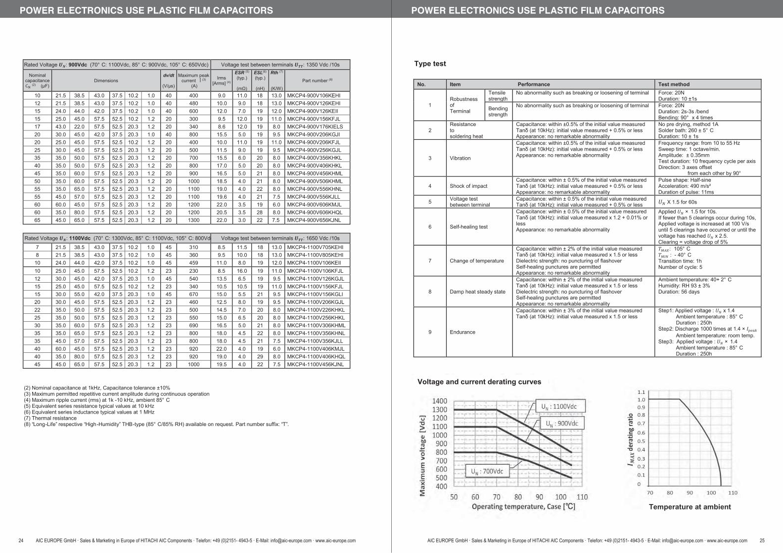
Rated Voltage 𝑼𝑼𝑼𝑼𝑵𝑵𝑵𝑵: 900Vdc (70° C: 1100Vdc, 85° C: 900Vdc, 105° C: 650Vdc) Voltage test between terminals 𝑼𝑼𝑼𝑼𝑻𝑻𝑻𝑻𝑻𝑻𝑻𝑻: 1350 Vdc /10s
Nominal capacitance CN (2) (µF)
Dimensions dv/dt
(V/µs)
Maximum peak current Î (3)
(A)
Irms [Arms] (4)
ESR (5) (typ.)
(mΩ)
ESL(6) (typ.)
(nH)
Rth (7)
(K/W)
Part number (8)
10 21.5 38.5 43.0 37.5 10.2 1.0 40 400 9.0 11.0 18 13.0 MKCP4-900V106KEHI 12 21.5 38.5 43.0 37.5 10.2 1.0 40 480 10.0 9.0 18 13.0 MKCP4-900V126KEHI 15 24.0 44.0 42.0 37.5 10.2 1.0 40 600 12.0 7.0 19 12.0 MKCP4-900V126KEII 15 25.0 45.0 57.5 52.5 10.2 1.2 20 300 9.5 12.0 19 11.0 MKCP4-900V156KFJL 17 43.0 22.0 57.5 52.5 20.3 1.2 20 340 8.6 12.0 19 8.0 MKCP4-900V176KIELS 20 30.0 45.0 42.0 37.5 20.3 1.0 40 800 15.5 5.0 19 9.5 MKCP4-900V206KGJI 20 25.0 45.0 57.5 52.5 10.2 1.2 20 400 10.0 11.0 19 11.0 MKCP4-900V206KFJL 25 30.0 45.0 57.5 52.5 20.3 1.2 20 500 11.5 9.0 19 9.5 MKCP4-900V256KGJL 35 35.0 50.0 57.5 52.5 20.3 1.2 20 700 15.5 6.0 20 8.0 MKCP4-900V356KHKL 40 35.0 50.0 57.5 52.5 20.3 1.2 20 800 17.0 5.0 20 8.0 MKCP4-900V406KHKL 45 35.0 60.0 57.5 52.5 20.3 1.2 20 900 16.5 5.0 21 8.0 MKCP4-900V456KHML 50 35.0 60.0 57.5 52.5 20.3 1.2 20 1000 18.5 4.0 21 8.0 MKCP4-900V506KHML 55 35.0 65.0 57.5 52.5 20.3 1.2 20 1100 19.0 4.0 22 8.0 MKCP4-900V556KHNL 55 45.0 57.0 57.5 52.5 20.3 1.2 20 1100 19.6 4.0 21 7.5 MKCP4-900V556KJLL 60 60.0 45.0 57.5 52.5 20.3 1.2 20 1200 22.0 3.5 19 6.0 MKCP4-900V606KMJL 60 35.0 80.0 57.5 52.5 20.3 1.2 20 1200 20.5 3.5 28 8.0 MKCP4-900V606KHQL 65 45.0 65.0 57.5 52.5 20.3 1.2 20 1300 22.0 3.0 22 7.5 MKCP4-900V656KJNL
Rated Voltage 𝑼𝑼𝑼𝑼𝑵𝑵𝑵𝑵: 1100Vdc (70° C: 1300Vdc, 85° C: 1100Vdc, 105° C: 800Vdc) Voltage test between terminals 𝑼𝑼𝑼𝑼𝑻𝑻𝑻𝑻𝑻𝑻𝑻𝑻: 1650 Vdc /10s
7 21.5 38.5 43.0 37.5 10.2 1.0 45 310 8.5 11.5 18 13.0 MKCP4-1100V705KEHI 8 21.5 38.5 43.0 37.5 10.2 1.0 45 360 9.5 10.0 18 13.0 MKCP4-1100V805KEHI
10 24.0 44.0 42.0 37.5 10.2 1.0 45 459 11.0 8.0 19 12.0 MKCP4-1100V106KEII 10 25.0 45.0 57.5 52.5 10.2 1.2 23 230 8.5 16.0 19 11.0 MKCP4-1100V106KFJL 12 30.0 45.0 42.0 37.5 20.3 1.0 45 540 13.5 6.5 19 9.5 MKCP4-1100V126KGJL 15 25.0 45.0 57.5 52.5 10.2 1.2 23 340 10.5 10.5 19 11.0 MKCP4-1100V156KFJL 15 30.0 55.0 42.0 37.5 20.3 1.0 45 670 15.0 5.5 21 9.5 MKCP4-1100V156KGLI 20 30.0 45.0 57.5 52.5 20.3 1.2 23 460 12.5 8.0 19 9.5 MKCP4-1100V206KGJL 22 35.0 50.0 57.5 52.5 20.3 1.2 23 500 14.5 7.0 20 8.0 MKCP4-1100V226KHKL 25 35.0 50.0 57.5 52.5 20.3 1.2 23 550 15.0 6.5 20 8.0 MKCP4-1100V256KHKL 30 35.0 60.0 57.5 52.5 20.3 1.2 23 690 16.5 5.0 21 8.0 MKCP4-1100V306KHML 35 35.0 65.0 57.5 52.5 20.3 1.2 23 800 18.0 4.5 22 8.0 MKCP4-1100V356KHNL 35 45.0 57.0 57.5 52.5 20.3 1.2 23 800 18.0 4.5 21 7.5 MKCP4-1100V356KJLL 40 60.0 45.0 57.5 52.5 20.3 1.2 23 920 22.0 4.0 19 6.0 MKCP4-1100V406KMJL 40 35.0 80.0 57.5 52.5 20.3 1.2 23 920 19.0 4.0 29 8.0 MKCP4-1100V406KHQL 45 45.0 65.0 57.5 52.5 20.3 1.2 23 1000 19.5 4.0 22 7.5 MKCP4-1100V456KJNL
(2) Nominal capacitance at 1kHz, Capacitance tolerance ±10%(3) Maximum permitted repetitive current amplitude during continuous operation(4) Maximum ripple current (rms) at 1k -10 kHz, ambient 85° C(5) Equivalent series resistance typical values at 10 kHz(6) Equivalent series inductance typical values at 1 MHz(7) Thermal resistance(8) “Long-Life” respective “High-Humidity” THB-type (85° C/85% RH) available on request. Part number suffix: “T”.
POWER ELECTRONICS USE PLASTIC FILM CAPACITORS
24 AIC EUROPE GmbH · Sales & Marketing in Europe of HITACHI AIC Components · Telefon: +49 (0)2151- 4943-5 · E-Mail: [email protected] · www.aic-europe.com
No. Item Performance Test method
1 Robustness of Terminal
Tensile strength
No abnormality such as breaking or loosening of terminal Force: 20N Duration: 10 ±1s
Bending strength
No abnormality such as breaking or loosening of terminal Force: 20N Duration: 2s-3s /bend Bending: 90° x 4 times
2 Resistance to soldering heat
Capacitance: within ±0.5% of the initial value measured Tanδ (at 10kHz): initial value measured + 0.5% or less Appearance: no remarkable abnormality
No pre drying, method 1A Solder bath: 260 ± 5° C Duration: 10 ± 1s
3 Vibration
Capacitance: within ±0.5% of the initial value measured Tanδ (at 10kHz): initial value measured + 0.5% or less Appearance: no remarkable abnormality
Frequency range: from 10 to 55 Hz Sweep time: 1 octave/min. Amplitude: ± 0.35mm Test duration: 10 frequency cycle per axis Direction: 3 axes offset
from each other by 90°
4 Shock of impact Capacitance: within ± 0.5% of the initial value measured Tanδ (at 10kHz): initial value measured + 0.5% or less Appearance: no remarkable abnormality
Pulse shape: Half-sine Acceleration: 490 m/s² Duration of pulse: 11ms
5 Voltage test between terminal
Capacitance: within ± 0.5% of the initial value measured Tanδ (at 10kHz): initial value measured + 0.5% or less 𝑈𝑈𝑈𝑈𝑁𝑁𝑁𝑁 X 1.5 for 60s
6 Self-healing test
Capacitance: within ± 0.5% of the initial value measured Tanδ (at 10kHz): initial value measured x 1.2 + 0.01% or less Appearance: no remarkable abnormality
Applied 𝑈𝑈𝑈𝑈𝑁𝑁𝑁𝑁 × 1.5 for 10s. If fewer than 5 clearings occur during 10s, Applied voltage is increased at 100 V/s until 5 clearings have occurred or until the voltage has reached 𝑈𝑈𝑈𝑈𝑁𝑁𝑁𝑁 x 2.5. Clearing = voltage drop of 5%
7 Change of temperature
Capacitance: within ± 2% of the initial value measured Tanδ (at 10kHz): initial value measured x 1.5 or less Dielectric strength: no puncturing of flashover Self-healing punctures are permitted Appearance: no remarkable abnormality
𝑇𝑇𝑇𝑇𝑀𝑀𝑀𝑀𝑀𝑀𝑀𝑀𝑀𝑀𝑀𝑀: 105° C 𝑇𝑇𝑇𝑇𝑀𝑀𝑀𝑀𝑀𝑀𝑀𝑀𝑁𝑁𝑁𝑁 : - 40° C Transition time: 1h Number of cycle: 5
8 Damp heat steady state
Capacitance: within ± 2% of the initial value measured Tanδ (at 10kHz): initial value measured x 1.5 or less Dielectric strength: no puncturing of flashover Self-healing punctures are permitted Appearance: no remarkable abnormality
Ambient temperature: 40+ 2° C Humidity: RH 93 ± 3% Duration: 56 days
9 Endurance
Capacitance: within ± 3% of the initial value measured Tanδ (at 10kHz): initial value measured x 1.5 or less
Step1: Applied voltage : 𝑈𝑈𝑈𝑈𝑁𝑁𝑁𝑁 x 1.4 Ambient temperature : 85° C
Duration : 250h Step2: Discharge 1000 times at.1.4 × 𝐼𝐼𝐼𝐼𝑝𝑝𝑝𝑝𝑝𝑝𝑝𝑝𝑝𝑝𝑝𝑝𝑝𝑝𝑝𝑝
Ambient temperature: room temp. Step3: Applied voltage : 𝑈𝑈𝑈𝑈𝑁𝑁𝑁𝑁 × 1.4
Ambient temperature : 85° C Duration : 250h
Type test
Voltage and current derating curves
Temperature at ambient
POWER ELECTRONICS USE PLASTIC FILM CAPACITORS
AIC EUROPE GmbH · Sales & Marketing in Europe of HITACHI AIC Components · Telefon: +49 (0)2151- 4943-5 · E-Mail: [email protected] · www.aic-europe.com 25

E51(DC)/ E51(AC)SeriesFeatures High voltage range and low inductance capacitors. E51 series are made in dry technology. Capacitors both for AC/DC application are available.
SpecificationsE51(DC) Series (for DC)
E51(AC) Series (for AC)
Item SpecificationCategory temperature range -25~+70 (Includes self temperature rise)Storage temperature -40~+85Rated voltage (U N) 1,300~ 50,000VdcTerminal (torque) M8×12 (7Nm)Standards ⅠEC 61071 : 2007Dielectric PolypropyleneDielectric dissipation factor (tanδ0) 2×10⁻⁴
Capacitance tolerance ±10% (optional ±5%)Safety devices -Impregnant Solid resin based on vegetable oil, Non PCBMaterial of case Plastic (UL94V-0)Environmental regulations Comply with RoHS
Item SpecificationCategory temperature range -25~+70 (Includes self temperature rise)Storage temperature -40~+85Rated voltage (U N) 2,350~ 20,000Vac (3,200~ 50,000Vdc)Terminal (torque) M8×12 (7Nm)Standards ⅠEC 61071 : 2007Dielectric PolypropyleneDielectric dissipation factor (tanδ0) 2×10⁻⁴
Capacitance tolerance ±10% (optional ±5%)Safety devices -Impregnant Solid resin based on vegetable oil, Non PCBMaterial of case Plastic (UL94V-0)Environmental regulations Comply with RoHS
(Cylindrical MetallizedPolypropylene Film Capacitors)
Dimensions
Item SpecificationTerminal code R2Can material Plastic (UL94V-0)
TerminalAxial thread M8×12Torque : 7NmⅠmax (terminal) : 100A
Degree of protection ⅠP00Humidity class FClearance in air L+D-20mm
Creepage distance L+D-20mm
φD(refer to catalog)
φ20
L(re
fer t
o ca
talo
g)
L+8
M8×12Auxiliary symbolTerminal symbolCapacitanceCase lengthCase diameter symbolSeries name
Numbering system: e.g. E51, 1,300VDC, 700μ F, φ140×175Lmm, R2 terminalE51 . -S 18 R2 0 / H704
POWER ELECTRONICS USE PLASTIC FILM CAPACITORS
26 AIC EUROPE GmbH · Sales & Marketing in Europe of HITACHI AIC Components · Telefon: +49 (0)2151- 4943-5 · E-Mail: [email protected] · www.aic-europe.com
Standard Value and Case Size (E51Series(DC))Rated DCVoltage
UN (DC)〔Vdc〕
RatedCapacitance
C N〔μF〕
Case size Rated ripple
voltageUr〔V〕
Surgevoltage
Us〔V〕
EnergyContents
W〔J〕
Series resistance(reference)
RS〔m 〕
Thermalresistance(reference)
Rth〔K/W〕
Maxcurrent
Imax〔Arms〕
Max peak
currentÎ
〔kA〕
Max surge
currentIS
〔kA〕
Self inductance(reference)
ESL〔nH〕
Weight
〔kg〕
Part numberDiameter
D〔mm〕
Length
L〔mm〕
Rated DC voltage U N(DC): 1,300~ 2,700Vdc 1,300 700 140 175 300 1,950 592 0.39 3 80 9.30 28.00 30 2.8 E51.S18-704R20/H2,300 80 64 355 400 4,100 212 1.3 3.6 50 4.00 13.00 80 1.2 E51.L35-803R20/H2,300 170 90 355 400 4,100 450 0.6 2.4 90 6.00 17.00 100 2.4 E51.P35-174R20/H2,500 25 90 130 800 3,750 78 0.96 6.4 70 3.10 9.30 30 0.9 E51.P13-253R20/H2,500 50 90 170 800 3,750 156 1.3 4.9 70 3.10 9.30 50 1.1 E51.P17-503R20/H2,700 40 140 125 500 4,050 146 0.85 2.55 40 5.00 15.00 20 2.0 E51.S12-403R20/H
Rated DC voltage U N(DC): 3,000~ 3,600Vdc 3,000 18 90 150 600 4,500 81 0.62 5.5 65 2.80 8.40 50 1.1 E51.P15-183R20/H3,000 80 90 255 700 4,500 360 1.9 3.2 60 3.20 9.60 60 1.7 E51.P25-803R20/H3,000 350 140 355 600 4,500 1575 1.5 1.5 75 8.40 25.20 100 5.7 E51.S35-354R20/H3,000 400 140 460 600 4,500 1,800 0.85 1.2 100 15.40 46.20 120 7.4 E51.S46-404R20/H3,100 86 90 355 500 5,600 413 1.5 2.4 65 4.50 13.00 100 2.4 E51.P35-863R20/H3,200 15 64 200 700 4,800 77 2.3 5.8 35 1.00 3.00 50 0.7 E51.L20-153R20/H3,200 33 90 200 700 4,800 169 0.7 4.1 70 2.50 7.50 50 1.3 E51.P20-333R20/H3,500 500 140 710 600 5,250 3,063 1.2 0.75 100 13.90 41.70 200 11.5 E51.S71-504R20/H3,600 80 116 245 600 5,400 518 0.71 2.6 90 6.00 18.00 40 2.1 E51.R24-803R20/H3,600 220 140 300 800 5,400 1426 0.6 1.1 40 4.40 13.20 40 5.0 E51.S30-224R20/H
Rated DC voltage U N(DC): 4,000~ 5,600Vdc 4,000 8 116 170 2,850 6,000 64 1.40 3.8 25 2.10 6.30 100 1.9 E51.R17-802R20/H4,000 16 140 170 2,850 6,000 128 1.10 3.1 30 3.80 11.40 100 2.7 E51.S17-163R20/H4,000 215 140 565 800 6,000 1,720 0.70 0.95 100 11.90 35.70 60 9.0 E51.S56-224R20/H4,200 8 64 138 800 6,300 71 4.30 8.3 15 0.69 2.07 60 0.5 E51.L14-802R20/H4,200 45 90 355 800 6,300 397 1.60 2.4 50 4.20 12.60 80 2.4 E51.P35-453R20/H4,400 8 64 180 950 6,600 77 4.20 6.5 20 0.85 2.55 60 0.6 E51.L18-802R20/H4,400 8 90 130 950 6,600 77 1.40 6.4 20 1.70 5.10 50 0.9 E51.P13-802R20/H4,500 300 140 710 850 6,750 3,038 1.10 0.75 100 16.50 49.50 200 11.5 E51.S71-304R20/H4,700 187.5 140 430 1,000 7,050 2,071 3.20 0.7 50 4.25 12.75 40 7.0 E51.S43-194R20/H5,000 4.55 64 150 1,000 7,500 57 6.50 7.8 15 0.47 1.41 60 0.5 E51.L15-462R20/H5,600 1 64 120 1,100 8,400 16 4.60 9.7 20 0.70 2.20 20 1.0 E51.L12-102R20/H
Rated DC voltage U N(DC): 6,000~ 9,300Vdc 6,000 30 116 200 700 9,000 540 2.3 3.2 30 2.10 6.30 80 2.2 E51.R20-303R20/H6,200 6.8 64 255 1,200 9,300 131 10 4.6 20 0.60 2.00 50 0.9 E51.L25-682R20/H6,200 15 90 255 1,200 9,300 288 4.6 3.2 35 1.50 4.50 50 1.7 E51.P25-153R20/H6,300 20 90 355 1,200 9,450 397 6.8 2.4 25 1.80 8.00 100 2.4 E51.P35-203R20/H6,300 51.25 140 355 1,200 9,450 1,017 2.7 1.5 40 4.30 20.00 80 5.7 E51.S35-513R20/H8,000 5 90 220 1,400 12,000 160 1.7 3.76 50 1.80 5.00 80 1.5 E51.P22-502R20/H8,000 10 90 320 1,400 12,000 320 2.3 2.59 50 1.90 6.00 100 2.2 E51.P32-103R20/H8,000 40 140 355 1,400 1,2000 1,280 3.5 1.5 40 2.70 8.10 100 5.7 E51.S35-403R20/H8,500 0.22 64 165 1,400 12,750 8 6.9 7.1 20 0.90 2.90 50 0.6 E51.L16-221R20/H8,500 0.5 64 165 3,950 12,750 18 3.9 7.1 20 0.54 1.62 60 0.6 E51.L16-501R20/H8,500 1 90 165 1,400 12,750 36 2.5 5 25 1.70 5.10 50 1.1 E51.P16-102R20/H9,300 9 90 355 1,500 13,950 389 8 2.3 20 1.00 4.00 100 2.4 E51.P35-902R20/H9,300 25 140 355 1,500 13,950 1,081 2.7 1.5 40 4.00 11.00 100 5.7 E51.S35-253R20/H
Rated DC voltage U N(DC): 10,000~ 50,000Vdc 10,000 0.25 64 165 2,000 15,000 13 15.2 7.1 10 1.1 3.3 80 0.6 E51.L16-251R20/H10,000 4 116 320 2,000 15,000 200 3.5 2 50 1.5 4.5 60 3.5 E51.R32-402R20/H10,000 4.5 140 480 3,000 15,000 225 1.8 1.1 50 8.8 26.4 100 8.0 E51.S48-452R20/H10,000 10 90 355 2,500 15,000 500 7 2.3 25 1.3 3.9 100 2.4 E51.P35-103R20/H12,000 24 140 565 2,100 18,000 1,728 4.2 0.95 25 4.2 12.6 60 9.0 E51.S56-243R20/H12,500 0.22 64 200 2,100 18,750 17 14 5.8 20 0.5 1.4 80 0.7 E51.L20-221R20/H12,500 0.25 64 200 2,100 18,750 20 14 5.8 20 0.5 1.5 80 0.7 E51.L20-251R20/H12,500 1 116 200 2,100 18,750 78 3.6 3.2 35 2 6 80 2.2 E51.R20-102R20/H13,000 0.25 64 285 3,000 19,500 21 17.7 4.1 10 0.6 1.7 100 1.0 E51.L28-251R20/H14,000 5 116 355 2,400 21,000 490 3.6 1.8 30 2.5 7.5 100 4.0 E51.R35-502R20/H14,000 10 140 355 2,400 21,000 980 2.4 1.5 40 4.3 12.9 120 5.7 E51.S35-103R20/H15,000 1 64 285 3,600 22,500 113 15.1 4.1 15 0.49 1.47 100 1.0 E51.L28-102R20/H15,000 2 90 285 3,600 22,500 225 7.2 2.9 20 1.1 3.3 200 1.9 E51.P28-202R20/H15,000 10 140 385 3,600 22,500 1,125 2.7 1.4 40 3.8 11.4 120 6.2 E51.S38-103R20/H15,000 15 140 460 3,600 22,500 1,688 2.8 1.2 40 4.6 13.8 120 7.4 E51.S46-153R20/H15,000 20 140 565 3,600 22,500 2,250 3.7 0.94 40 3.8 11.4 120 9.1 E51.S56-203R20/H20,000 1.25 90 355 4,000 30,000 250 11.7 2.3 20 0.9 2.7 100 2.4 E51.P35-132R20/H20,000 1.5 90 355 4,000 30,000 300 10.4 2.3 34 1.8 5.4 100 2.4 E51.P35-152R20/H25,000 10 140 710 4,600 37,500 3125 3.9 0.75 35 4.3 12.9 200 11.5 E51.S71-103R20/H30,000 1 90 435 4,800 45,000 450 11 1.9 20 1 3 80 2.9 E51.P44-102R20/H30,000 5 140 710 4,800 45,000 2,250 7 0.75 35 2.8 8.4 200 11.5 E51.S71-502R20/H35,000 0.2 90 435 5,600 52,500 123 13.4 1.9 20 1 3 80 2.9 E51.P44-201R20/H35,000 5 140 785 4,800 52,500 3,063 5.5 0.7 25 3.2 9.6 200 12.7 E51.S78-502R20/H40,000 2.2 140 630 8,700 60,000 1,760 5.3 0.84 35 2.8 8.4 180 10.2 E51.S63-222R20/H50,000 0.5 140 710 10,000 60,000 625 5.8 0.75 35 2.9 8.7 200 11.5 E51.S71-501R20/H
POWER ELECTRONICS USE PLASTIC FILM CAPACITORS
AIC EUROPE GmbH · Sales & Marketing in Europe of HITACHI AIC Components · Telefon: +49 (0)2151- 4943-5 · E-Mail: [email protected] · www.aic-europe.com 27

Standard Value and Case Size (E51series (AC))Rated ACVoltage
UN (AC)〔Vdc〕
Rated DCVoltage
UN (DC)〔Vdc〕
RatedCapacitance
C N〔μF〕
Case size Rated ripple
voltageUr〔V〕
Surgevoltage
Us〔V〕
EnergyContents
W〔J〕
Series resistance(reference)
RS〔m 〕
Thermalresistance(reference)
Rth〔K/W〕
Maxcurrent
Imax〔Arms〕
Max peak
currentÎ
〔kA〕
Max surge
currentIS
〔kA〕
Self inductance(reference)
ESL〔nH〕
Weight
〔kg〕
Part numberDiameter
D〔mm〕
Length
L〔mm〕
Rated AC voltage U N(AC): 2,000~ 3,250Vac Urms: 1,650~ 2,300Vrms 2,350 4,500 1.5 64 150 1,650 6,750 15 5.4 7.8 20 0.7 2 20 0.5 E51.L15-152R20/H2,350 - 3 64 250 1,650 3,525 8.3 3 4.7 15 1.1 3.3 60 1.0 E51.L25-302R20/H2,500 6,000 1 90 130 1,770 9,000 18 3.2 6.4 28 0.98 2.94 30 0.9 E51.P13-102R20/H2,550 3,200 1 64 120 1,800 4,800 5 1.8 9.7 40 2 5 40 0.4 E51.L12-102R21/H2,700 4,400 4 116 110 1,910 6,600 39 0.62 5.8 90 2.2 7 15 1.5 E51.R11-402R20/H2,900 5,000 3 116 110 2,050 7,500 38 0.74 5.8 80 2 6 15 1.2 E51.R11-302R20/H3,000 - 0.47 64 100 2,100 6,450 2.1 3.2 11.6 15 1.1 3.3 60 0.3 E51.L10-471R20/H3,000 - 5 116 260 2,200 7,000 22.5 3.8 2.5 10 2 6 80 2.9 E51.R26-502R20/H3,250 - 0.75 64 165 2,300 4,875 4.0 4.9 7.1 20 0.9 2.8 100 0.6 E51.L16-751R20/H3,200 7,280 0.5 64 130 2,260 10,920 13.2 5 9 25 0.62 1.86 60 0.4 E51.L13-501R20/H
Rated AC voltage U N(AC): 3,500Vac Urms: 2,500Vrms 3,500 6,000 0.22 64 120 2,500 9,000 4.0 4.8 9.7 20 0.7 2.1 60 0.4 E51.L12-221R20/H3,500 6,000 0.25 64 120 2,500 9,000 4.5 5.4 9.7 15 0.8 2.4 60 0.4 E51.L12-251R20/H3,500 6,000 0.33 64 120 2,500 9,000 5.9 3 9.7 20 1 2.9 60 0.4 E51.L12-331R20/H3,500 6,000 0.5 64 120 2,500 9,000 9.0 5.6 9.7 20 1 3 60 0.4 E51.L12-501R20/H3,200 5,450 0.68 64 120 2,250 9,000 10.1 4.6 9.7 20 1 2.9 60 0.4 E51.L12-681R20/H3,500 6,000 0.75 90 100 2,500 9,000 13.5 1.6 8.3 40 1.8 5.4 60 0.6 E51.P10-751R20/H3,500 6,000 1.25 90 130 2,500 9,000 22.5 2.2 6.4 45 1.4 4.2 60 0.9 E51.P13-132R20/H3,500 6,000 1.5 90 130 2,500 9,000 27.0 2.1 6.4 45 1.5 4.4 60 0.9 E51.P13-152R20/H2,450 6,000 2 90 140 1,700 9,000 36.0 2.8 5.9 45 1.5 4.4 60 1.0 E51.P14-202R20/H
Rated AC voltage U N(AC): 3,850~ 4,300Vac Urms: 2,700~ 3,050Vrms 3,850 - 2.5 90 285 2,700 5,775 18.5 4.1 2.9 25 2 6 100 1.9 E51.P28-252R20/H4,200 - 1.1 90 150 3,000 6,300 9.7 2.7 5.5 20 1.6 4.8 50 1.0 E51.P15-112R20/H4,300 - 0.5 64 165 3,050 6,450 4.6 5.3 7.1 15 0.8 2.3 100 0.6 E51.L16-501R21/H4,300 - 0.8 64 200 3,050 6,450 7.4 7.5 5.8 15 0.9 2.7 100 0.7 E51.L20-801R20/H
Rated AC voltage U N(AC): 4,550Vac Urms: 3,200Vrms 4,550 7,280 0.22 64 130 3,200 10,920 5.8 8.9 9 15 0.34 1.02 60 0.5 E51.L13-221R20/H4,550 7,280 0.33 64 130 3,200 10,920 8.7 6.7 9 20 0.46 1.38 60 0.5 E51.L13-331R20/H3,150 7,280 0.75 90 130 2,200 10,920 19.9 3 6.4 40 1 3 60 0.9 E51.P13-751R20/H2,500 6,000 1 90 130 1,770 9,000 18.0 3.2 6.4 28 0.98 2.94 30 0.9 E51.P13-102R20/H4,400 6,800 1.5 90 150 3,100 10,200 34.7 2.3 5.5 25 1 3 50 1.0 E51.P15-152R21/H4,550 - 1.1 90 275 3,200 6,825 11.4 3.6 3 20 2.4 7.2 80 1.9 E51.P27-112R20/H2,800 4,400 1.25 90 140 2,000 10,920 12.1 4.5 6.4 40 1.2 3.6 60 1.0 E51.P14-132R20/H4,550 7,280 1.5 116 130 3,200 10,920 39.7 2 4.9 50 2.1 6.3 60 1.1 E51.R13-152R20/H4,550 7,280 2 116 130 3,200 10,920 53.0 1.8 4.9 55 2.4 7.2 60 1.1 E51.R13-202R20/H
Rated AC voltage U N(AC): 4,700~ 5,850Vac Urms: 3,300~ 4,150Vrms 4,700 - 0.75 64 250 3,300 7,050 8.3 7.5 4.7 15 0.9 2.7 60 1.0 E51.L25-751R20/H5,000 - 0.47 64 210 3,500 10,750 5.9 5.8 5.5 16 1 3 40 0.8 E51.L21-471R20/H5,000 10,000 0.5 90 200 3,540 15,000 25.0 5.7 4.1 1 3 50 50 1.3 E51.P20-501R20/H5,000 - 1 90 255 3,540 7,500 12.5 5.8 3.25 25 1.2 3.6 50 1.7 E51.P25-102R20/H5,100 - 1.6 116 355 3,600 9,500 20.8 4 1.8 25 5 15 120 3.9 E51.R35-162R20/H5,100 - 2.4 90 200 3,600 10,965 31.2 3 4.1 35 1.4 4.2 60 1.3 E51.P20-242R21/H5,100 - 2.6 116 460 3,600 9,500 33.8 3.8 1.4 25 5 15 120 4.9 E51.R46-262R20/H5,200 - 1.1 90 200 3,700 7,800 14.9 3.1 4.1 20 5.1 3.1 60 1.3 E51.P20-112R20/H5,850 - 0.47 90 165 4,150 12,580 8.0 3.5 5 20 2.2 6.6 60 1.2 E51.P16-471R20/H
Rated AC voltage U N(AC): 6,000~ 9,620Vac Urms: 4,600~ 6,800Vrms 6,300 9,000 0.13 64 165 4,450 13,500 5.3 5.5 7.1 20 0.8 2.4 100 0.6 E51.L16-131R20/H6,300 9,000 0.14 64 200 4,450 13,500 5.7 17.6 5.8 14 0.3 0.9 50 0.7 E51.L20-141R20/H6,500 - 4 140 355 4,600 9,500 84.5 1.7 1.5 12 7 21 150 5.7 E51.S35-402R20/H7,500 - 1.33 140 355 5,300 11,250 37.4 3.9 1.5 10 2.5 7.5 100 5.7 E51.S35-132R20/H8,900 - 0.24 90 210 6,300 13,350 9.5 5 3.94 20 2 6 60 1.4 E51.P21-241R20/H9,200 - 0.5 90 275 6,510 13,800 21.2 3.9 3 10 1.7 5.1 80 1.9 E51.P27-501R20/H9,620 - 0.5 116 250 6,800 14,430 23.1 3 2.6 40 3.7 11.1 60 2.9 E51.R25-501R20/H
Rated AC voltage U N(AC): 10,000~ 35,000Vac Urms: 7,100~ 25,000Vrms 10,000 14,000 1 116 390 7,100 15,000 98.0 3.4 1.7 25 3.7 11.1 100 4.0 E51.R39-102R20/H10,000 14,000 1.9 140 390 7,100 15,000 186.2 2.1 1.4 25 6.2 18.6 100 6.0 E51.S39-192R20/H12,750 - 0.2 90 355 9,000 27,400 16.3 7 2.3 20 2.3 6.9 100 2.4 E51.P35-201R20/H10,000 - 0.5 90 355 7,070 15,000 25.0 7.2 1.44 10 1 3 100 2.4 E51.P35-501R20/H20,000 26,000 0.3 116 355 14,000 30,000 101.4 3.1 1.8 10 8 20 100 3.9 E51.R35-301R20/H20,000 30,000 1 140 710 14,140 45,000 450.0 5.7 0.7 10 4.9 14.7 200 11.5 E51.S71-102R20/H20,000 50,000 0.5 140 710 14,140 60,000 625.0 6.2 0.7 10 8.5 20 200 11.5 E51.S71-501R20/H
POWER ELECTRONICS USE PLASTIC FILM CAPACITORS
28 AIC EUROPE GmbH · Sales & Marketing in Europe of HITACHI AIC Components · Telefon: +49 (0)2151- 4943-5 · E-Mail: [email protected] · www.aic-europe.com
E53(AC) SeriesFeatures High voltage range and ultra low inductance capacitors. E53(AC) series are made in dry technology. For AC application.
SpecificationsItem Specification
Category temperature range -25~+70 (+85 / Includes self temperature rise)Storage temperature -40~+85Rated voltage (U N) 280~ 2,450Vac (550~ 7,200Vdc)Terminal (torque) M6×10 (4Nm) / M8×10 (7Nm)Standards Standards ⅠEC 61071 : 2007Dielectric PolypropyleneDielectric dissipation factor (tanδ0) 2×10⁻⁴
Capacitance tolerance ±10% (optional ±5%)Safety devices -Impregnant Solid resin based on vegetable oil, Non PCBMaterial of case Plastic (UL94V-0)Environmental regulations Comply with RoHS
(AC Cylindrical Metallized Polypropylene Film Capacitors)
DimensionsItem Specification
Terminal code T1 / T2Can material Plastic (UL94V-0)
Terminal
T1Axial thread M6×10Torque : 4NmⅠmax (terminal) : 60A
T2Axial thread M8×10Torque : 7NmⅠmax (terminal) : 100A
Degree of protection ⅠP00Humidity class G
φD(refer to catalog))
L(re
fer t
o ca
talog)
L+4
M6×10
φ14
T1
L(re
fer t
o ca
talog)
L+4
M8×10
φ20
T2
Auxiliary symbolTerminal symbolCapacitanceCase lengthCase diameter symbolSeries name
Numbering system: e.g. E53, 280VAC, 50μ F, φ55×56Lmm, T1 terminalE53 . -H 56 T1 0 / H503
POWER ELECTRONICS USE PLASTIC FILM CAPACITORS
AIC EUROPE GmbH · Sales & Marketing in Europe of HITACHI AIC Components · Telefon: +49 (0)2151- 4943-5 · E-Mail: [email protected] · www.aic-europe.com 29

Standard Value and Case SizeRated
Capacitance
C N〔μF〕
Case size EnergyContents
W〔J〕
Series resistance(reference)
RS〔m 〕
Thermalresistance(reference)
Rth〔K/W〕
Maxcurrent
Imax〔Arms〕
Max peak
currentÎ
〔kA〕
Max surge
currentIS
〔kA〕
Self inductance(reference)
ESL〔nH〕
Terminal
Clearancein air
L〔mm〕
Creepagedistance
K〔mm〕
Weight
〔kg〕
Part numberDiameter
D〔mm〕
Length
L〔mm〕
Rated voltage U N:550Vdc / 280Vac Urms: 200Vrms Us: 825V UTT: 825Vdc50 55 56 7.6 0.8 8.5 60 0.83 2.5 15 T1 97 97 0.18 E53.H56-503T10/H100 75 56 15 0.4 6.3 80 1.7 5 15 T2 111 111 0.33 E53.M56-104T20/H200 95 56 30 0.2 4.9 80 3.3 9.9 15 T2 131 131 0.52 E53.P56-204T20/H250 105 56 38 0.15 4.5 80 3.3 10 15 T2 141 141 0.64 E53.P56-204T20/H270 115 56 41 0.15 4.1 100 3.3 10 15 T2 151 151 0.77 E53.R56-274T20/H380 115 100 57 0.31 2.3 100 3 10 15 T2 195 195 1.37 E53.R10-384T20/H
Rated voltage U N:700Vdc / 350Vac Urms: 250Vrms Us: 1,050V UTT: 1,050Vdc33 55 56 8.1 0.95 8.5 55 0.68 2.1 15 T1 97 97 0.18 E53.H56-333T10/H68 75 56 17 0.5 6.3 80 1.4 4.2 15 T2 111 111 0.33 E53.M56-683T20/H
120 95 56 29 0.3 4.9 80 2.5 7.4 15 T2 131 131 0.52 E53.P56-124T20/H150 105 56 37 0.25 4.5 100 3.1 9.3 15 T2 141 141 0.64 E53.Q56-154T20/H200 115 56 49 0.2 4.1 100 3.1 10 15 T2 151 151 0.77 E53.R56-204T20/H310 115 100 76 0.3 2.3 100 3 10 15 T2 195 195 1.37 E53.R10-314T20/H
Rated voltage U N:900Vdc / 350Vac Urms: 250Vrms Us: 1,350V UTT: 1,350Vdc30 55 56 12 0.85 8.5 60 0.68 2.1 15 T1 97 97 0.18 E53.H56-303T10/H60 75 56 24 0.5 6.3 80 1.4 4.1 15 T2 111 111 0.33 E53.M56-603T20/H
100 95 56 41 0.35 4.9 80 2.3 6.8 15 T2 131 131 0.52 E53.P56-104T20/H120 105 56 49 0.2 4.5 100 2.8 9 15 T2 141 141 0.64 E53.Q56-124T20/H140 115 56 57 0.2 4.1 100 3.1 10 15 T2 151 151 0.77 E53.R56-144T20/H265 115 100 107 0.35 2.3 110 3 9 15 T2 195 195 1.37 E53.R10-274T20/H
Rated voltage U N:1,100Vdc / 350Vac Urms: 250Vrms Us: 1,650V UTT: 1,650Vdc12 55 56 7.3 1.7 8.5 40 0.4 1.2 15 T1 97 97 0.18 E53.H56-123T10/H15 55 56 9.1 1.1 8.5 40 0.5 1.5 15 T1 97 97 0.18 E53.H56-153T10/H25 75 56 15 0.71 6.3 70 0.83 2.5 15 T2 111 111 0.33 E53.M56-253T20/H50 95 56 30 0.34 4.9 80 1.7 5 15 T2 131 131 0.52 E53.P56-503T20/H60 105 56 36 0.35 4.5 100 2.0 6 15 T2 141 141 0.64 E53.Q56-603T20/H80 115 56 48 0.21 4.1 100 3.0 10 15 T2 151 151 0.77 E53.R56-803T20/H175 115 100 106 0.41 2.3 100 2.6 8 15 T2 195 195 1.37 E53.R10-184T20/H
Rated voltage U N:1,400Vdc / 350Vac Urms: 250Vrms Us: 2,100V UTT: 2,100Vdc8 55 56 7.8 2 8.5 38 0.33 1 15 T1 97 97 0.18 E53.H56-802T10/H
16 75 56 16 1 6.3 80 0.66 2 15 T2 111 111 0.33 E53.M56-163T20/H30 95 56 29 0.55 4.9 80 1.2 3.7 15 T2 131 131 0.52 E53.P56-303T20/H40 105 56 39 0.4 4.5 100 1.7 5 15 T2 141 141 0.64 E53.Q56-403T20/H50 115 56 49 0.3 4.1 100 2.2 10 15 T2 151 151 0.77 E53.R56-503T20/H110 115 100 108 0.52 2.3 100 2 6 15 T2 195 195 1.37 E53.R10-114T20/H
Rated voltage U N:1,700Vdc / 700Vac Urms: 500Vrms Us: 2,550V UTT: 2,550Vdc4.7 55 56 6.8 1.3 8.5 45 0.5 1.6 15 T1 97 97 0.18 E53.H56-472T10/H10 75 56 14 0.6 6.3 80 1.1 3.5 15 T2 111 111 0.33 E53.M56-103T20/H16 95 56 23 0.37 4.9 80 1.8 5.5 15 T2 131 131 0.52 E53.P56-163T20/H22 105 56 32 0.27 4.5 100 2.5 7.5 15 T2 141 141 0.64 E53.Q56-223T20/H33 115 56 48 0.2 4.1 100 3.5 10 15 T2 151 151 0.77 E53.R56-333T20/H68 115 100 98 0.35 2.3 100 3.1 9.3 15 T2 195 195 1.37 E53.R10-683T20/H
Rated voltage U N:2,000Vdc / 700Vac Urms: 500Vrms Us: 3,000V UTT: 3,000Vdc3.3 55 56 6.6 1.6 8.5 40 0.42 1.2 15 T1 97 97 0.18 E53.H56-332T10/H8 75 56 16 0.65 6.3 80 1 3 15 T2 111 111 0.33 E53.M56-802T20/H
14 95 56 28 0.35 4.9 80 1.8 5.5 15 T2 131 131 0.52 E53.P56-143T20/H18 105 56 36 0.3 4.5 100 2.3 7 15 T2 141 141 0.64 E53.Q56-183T20/H24 115 56 48 0.2 4.1 100 3 10 15 T2 151 151 0.77 E53.R56-243T20/H
52.5 115 100 105 0.39 2.3 100 2.8 8 15 T2 195 195 1.37 E53.R10-533T20/HRated voltage U N:2,250Vdc / 700Vac Urms: 500Vrms Us: 3,375V UTT: 3,375Vdc
2.5 55 56 6.3 1.8 8.5 40 0.37 1.1 15 T1 97 97 0.18 E53.H56-252T10/H6 75 56 15 0.76 6.3 70 0.88 2.6 15 T1 111 111 0.33 E53.M56-602T20/H
10 95 56 25 0.46 4.9 80 1.5 4.5 15 T2 131 131 0.52 E53.P56-103T20/H15 105 56 38 0.27 4.5 100 2.1 6.2 15 T2 141 141 0.64 E53.Q56-153T20/H18 115 56 46 0.25 4.1 100 2.6 10 15 T2 151 151 0.77 E53.R56-183T20/H40 115 100 101 0.45 2.3 100 2.4 7 15 T2 195 195 1.37 E53.R10-403T20/H
Rated voltage U N:2,800Vdc / 700Vac Urms: 500Vrms Us: 4,200V UTT: 4,200Vdc1.5 55 56 5.9 2.4 8.5 32 0.27 1.35 15 T1 97 97 0.18 E53.H56-152T10/H3.3 75 56 13 1.1 6.3 60 0.6 3 15 T2 111 111 0.33 E53.M56-332T20/H7.5 95 56 29 0.5 4.9 80 1.5 7.5 15 T2 131 131 0.52 E53.P56-752T20/H10 105 56 39 0.4 4.5 100 1.8 9 15 T2 141 141 0.64 E53.Q56-103T20/H12 115 56 47 0.3 4.1 100 2.2 12 15 T2 151 151 0.77 E53.R56-123T20/H25 115 100 98 0.57 2.3 100 1.9 6 15 T2 195 195 1.37 E53.R10-253T20/H
Rated voltage U N:3,200Vdc / 1,050Vac Urms: 750Vrms Us: 4,800V UTT: 4,800Vdc1 55 56 5.1 1.6 8.5 40 0.35 1.75 15 T1 97 97 0.18 E53.H56-102T10/H
2.5 75 56 13 0.65 6.3 75 0.9 4.5 15 T2 111 111 0.33 E53.M56-252T20/H4 95 56 20 0.4 4.9 80 1.5 7.5 15 T2 131 131 0.52 E53.P56-402T20/H6 105 56 31 0.28 4.5 100 2.2 11 15 T2 141 141 0.64 E53.Q56-602T20/H7 115 56 36 0.25 4.1 100 3 12 15 T2 151 151 0.77 E53.R56-702T20/H
POWER ELECTRONICS USE PLASTIC FILM CAPACITORS
30 AIC EUROPE GmbH · Sales & Marketing in Europe of HITACHI AIC Components · Telefon: +49 (0)2151- 4943-5 · E-Mail: [email protected] · www.aic-europe.com
Standard Value and Case SizeRated
Capacitance
C N〔μF〕
Case size EnergyContents
W〔J〕
Series resistance(reference)
RS〔m 〕
Thermalresistance(reference)
Rth〔K/W〕
Maxcurrent
Imax〔Arms〕
Max peak
currentÎ
〔kA〕
Max surge
currentIS
〔kA〕
Self inductance(reference)
ESL〔nH〕
Terminal
Clearancein air
L〔mm〕
Creepagedistance
K〔mm〕
Weight
〔kg〕
Part numberDiameter
D〔mm〕
Length
L〔mm〕
Rated voltage U N:2,450Vdc / 1,400Vac Urms: 1,000Vrms Us: 3,675V UTT: 3,675Vdc1.16 55 56 3.5 1.2 8.5 20 0.7 2.2 15 T1 97 97 0.18 E53.H56-122T10/H2.4 75 56 7.2 0.56 6.3 60 1.5 5 15 T2 111 111 0.33 E53.M56-242T20/H4.2 95 56 13 0.32 4.9 80 2.6 8 15 T2 131 131 0.52 E53.P56-422T20/H5.2 105 56 16 0.26 4.5 100 3 10 15 T2 141 141 0.64 E53.Q56-522T20/H6.4 115 56 19 0.21 4.1 100 4 12 15 T2 151 151 0.77 E53.R56-642T20/H
Rated voltage U N:3,600Vdc / 1,400Vac Urms: 1,000Vrms Us: 5,400V UTT: 5,400Vdc8 115 100 52 0.52 2.3 100 2.3 6.9 15 T2 195 195 1.37 E53.R10-802T20/H10 115 100 65 0.94 2.3 100 2.5 7.5 15 T2 195 195 1.37 E53.R10-103T20/H
Rated voltage U N:3,750Vdc / 2,100Vac Urms: 1,500Vrms Us: 5,625V UTT: 5,625Vdc0.47 55 56 3.3 2.9 8.5 20 0.7 2.1 15 T1 97 97 0.18 E53.H56-471T10/H1.1 75 56 7.7 1.2 6.3 60 1.6 5 15 T2 111 111 0.33 E53.M56-112T20/H1.7 95 56 12 0.8 4.9 80 2.5 8 15 T2 131 131 0.52 E53.P56-172T20/H
2.15 105 56 15 0.64 4.5 100 3 10 15 T2 141 141 0.64 E53.Q56-222T20/H2.7 115 56 19 0.51 4.1 100 4 12 15 T2 151 151 0.77 E53.R56-272T20/H
Rated voltage U N:5,000Vdc / 2,100Vac Urms: 1,500Vrms Us: 7,500V UTT: 7,500Vdc3 115 100 38 1.2 2.3 125 2.1 6.3 15 T2 195 195 1.37 E53.R10-302T21/H4 115 100 50 1 2.3 125 2.5 7.5 15 T2 195 195 1.37 E53.R10-402T21/H
Rated voltage U N:5,600Vdc / 2,450Vac Urms: 1,750Vrms Us: 8,400V UTT: 8,400Vdc0.22 55 97 3.4 13.7 4.9 25 0.2 0.7 15 T1 138 138 0.31 E53.H97-221T10/H0.25 55 97 3.9 12.1 4.9 25 0.3 0.8 15 T1 138 138 0.32 E53.H97-251T10/H0.5 55 97 7.8 8 4.9 25 0.4 1.3 15 T1 138 138 0.33 E53.H97-501T10/H
Rated voltage U N:7,200Vdc / 2,450Vac Urms: 1,750Vrms Us: 10,800V UTT: 10,800Vdc0.22 55 97 5.7 13.7 4.9 25 0.2 0.7 15 T1 138 138 0.31 E53.H97-221T11/H0.25 55 97 6.5 12.1 4.9 25 0.3 0.8 15 T1 138 138 0.32 E53.H97-251T11/H
POWER ELECTRONICS USE PLASTIC FILM CAPACITORS
AIC EUROPE GmbH · Sales & Marketing in Europe of HITACHI AIC Components · Telefon: +49 (0)2151- 4943-5 · E-Mail: [email protected] · www.aic-europe.com 31

E53H(DC) SeriesFeatures High voltage range and ultra low inductance capacitors. E53H(DC) series are made in dry technology. Robust studs with M8 thread allows for radial connection.
SpecificationsItem Specification
Category temperature range -25~+70 (+85 / Includes self temperature rise)Storage temperature -40~+85Rated voltage (U N) 600~ 2,200VdcTerminal (torque) M8×20 (4Nm)Standards ⅠEC 61071 : 2007Dielectric PolypropyleneDielectric dissipation factor (tanδ0) 2×10⁻⁴
Capacitance tolerance ±10% (optional ±5%)Safety devices -Impregnant Solid resin based on vegetable oil, Non PCBMaterial of case Plastic (UL94V-0)Environmental regulations Comply with RoHS
Dimensions
Item SpecificationTerminal code H1Can material Plastic (UL94V-0)
TerminalRadial thread M8×20Torque : 4NmⅠmax (terminal) : 100A
Degree of protection ⅠP00Humidity class F
16
φ5.5101
L(re
fer t
o ca
talo
g)
(ca. φ83.5)45
M8×20
25
φ85
UPGRADE!
(DC Cylindrical MetallizedPolypropylene Film Capacitors)
Auxiliary symbolTerminal symbolCapacitanceCase lengthCase diameter symbolSeries name
Numbering system: e.g. E53H, 600VDC, 200μ F, φ85×51Lmm, H1 terminalE53 . -N 51 H1 1 / H204
POWER ELECTRONICS USE PLASTIC FILM CAPACITORS
32 AIC EUROPE GmbH · Sales & Marketing in Europe of HITACHI AIC Components · Telefon: +49 (0)2151- 4943-5 · E-Mail: [email protected] · www.aic-europe.com
Standard Value and Case SizeRated
Capacitance
C N〔μF〕
Case size Rated ripple
voltageUr〔V〕
EnergyContents
W〔J〕
Series resistance(reference)
RS〔m 〕
Thermalresistance(reference)
Rth〔K/W〕
Maxcurrent
Imax〔Arms〕
Max peak
currentÎ
〔kA〕
Max surge
currentIS
〔kA〕
Self inductance(reference)
ESL〔nH〕
Clearancein air
L〔mm〕
Creepagedistance
K〔mm〕
Weight
〔kg〕
Part numberDiameter
D 1〔mm〕
Length
L1〔mm〕
Rated voltage U N:600Vdc Us: 900V UTT: 900Vdc200 85 51 100 36 0.75 6.1 60 3.3 9.9 30 29 33 0.36 E53.N51-204H11/H280 85 64 100 50 0.84 4.8 60 3.5 10.5 35 29 33 0.45 E53.N64-284H10/H400 85 76 100 72 1.1 4.1 60 3.3 9.9 40 29 29 0.53 E53.N76-404H11/H
Rated voltage U N:700Vdc Us: 1,050V UTT: 1,050Vdc150 85 51 160 37 0.7 6.1 60 2.9 8.7 30 29 33 0.36 E53.N51-154H11/H200 85 64 160 49 0.92 4.8 60 2.9 8.7 35 29 33 0.45 E53.N64-204H10/H300 85 76 160 74 1.2 4.1 60 2.9 8.7 40 29 29 0.53 E53.N76-304H11/H
Rated voltage U N:900Vdc Us: 1,350V UTT: 1,350Vdc120 85 51 200 49 0.84 6.1 60 2.6 7.9 30 29 33 0.36 E53.N51-124H11/H150 85 64 200 61 1 4.8 60 2.5 7.5 35 29 33 0.45 E53.N64-154H11/H240 85 76 200 97 1.3 4.1 60 2.6 7.8 40 29 29 0.53 E53.N76-244H11/H
Rated voltage U N:1,100Vdc Us: 1,650V UTT: 1,650Vdc75 85 51 250 45 1.0 6.1 60 2.0 6 30 29 33 0.36 E53.N51-753H11/H
100 85 64 250 61 0.9 4.8 60 2.0 6.2 35 29 33 0.45 E53.N64-104H10/H150 85 76 250 91 1.5 4.1 75 2.0 6.1 40 29 29 0.53 E53.N76-154H11/H
Rated voltage U N:1,300Vdc Us: 1,950V UTT: 1,950Vdc50 85 51 300 42 1.1 6.1 70 1.6 4.8 30 29 33 0.36 E53.N51-503H11/H68 85 64 300 57 1.3 4.8 70 1.7 5.1 35 29 33 0.45 E53.N64-683H10/H
100 85 76 300 85 1.5 4.1 60 1.6 4.8 40 29 29 0.53 E53.N76-104H11/HRated voltage U N:1,500Vdc Us: 2,250V UTT: 2,250Vdc
37.5 85 51 300 42 1.2 6.1 60 1.4 4 30 29 33 0.36 E53.N51-383H11/H50 85 64 300 56 1.5 4.8 60 1.4 4.2 35 29 33 0.45 E53.N64-503H10/H75 85 76 300 84 2 4.1 60 1.4 4.2 40 29 29 0.53 E53.N76-753H11/H
Rated voltage U N:1,800Vdc Us: 2,700V UTT: 2,700Vdc30 85 51 400 49 0.73 6.1 60 1.3 3.9 30 29 33 0.36 E53.N51-303H11/H40 85 64 400 65 1.6 4.8 60 1.3 3.9 35 29 33 0.45 E53.N64-403H10/H60 85 76 400 97 2.1 4.1 50 1.3 3.9 40 29 29 0.53 E53.N76-603H11/H
Rated voltage U N:2,000Vdc Us: 3,000V UTT: 3,000Vdc13 85 51 400 26 1.6 6.1 55 0.64 1.92 30 29 33 0.36 E53.N51-133H10/H30 85 64 400 60 1.3 4.8 55 1.1 3.3 35 29 33 0.45 E53.N64-303H10/H43 85 76 400 86 1.8 4.1 50 1 3 40 29 29 0.53 E53.N76-433H10/H
Rated voltage U N:2,200Vdc Us: 3,300V UTT: 3,300Vdc24.5 85 64 600 59 1.4 4.8 55 0.99 2.97 35 29 33 0.45 E53.N64-253H10/H35 85 76 600 85 1.9 4.1 50 0.94 2.82 40 29 29 0.53 E53.N76-353H10/H
POWER ELECTRONICS USE PLASTIC FILM CAPACITORS
AIC EUROPE GmbH · Sales & Marketing in Europe of HITACHI AIC Components · Telefon: +49 (0)2151- 4943-5 · E-Mail: [email protected] · www.aic-europe.com 33

E55(DC) SeriesFeatures High voltage range and ultra low inductance capacitors. E55 series are made in dry technology. For DC application.
SpecificationsItem Specification
Category temperature range -25~+70 (+85 / Includes self temperature rise)Storage temperature -40~+85Rated voltage (U N) 900~ 5,000VdcTerminal (torque) M6×10 (4Nm) / M8×10 (7Nm)Standards ⅠEC 61071 : 2007Dielectric PolypropyleneDielectric dissipation factor (tanδ0) 2×10⁻⁴
Capacitance tolerance ±10% (optional ±5%)Safety devices -Impregnant Solid resin based on vegetable oil, Non PCBMaterial of case Plastic (UL94V-0)Environmental regulations Comply with RoHS
(DC Cylindrical Metallized Polypropylene Film Capacitors)
DimensionsItem Specification
Terminal code T1 / T2Can material Plastic (UL94V-0)
Terminal
T1Axial thread M6×10Torque : 4NmⅠmax (terminal) : 60A
T2Axial thread M8×10Torque : 7NmⅠmax (terminal) : 100A
Degree of protection ⅠP00Humidity class G
φD(refer to catalog)
L(re
fer t
o ca
talog)
L+4
M6×10T1
φ14
L(re
fer t
o ca
talog)
L+4
M8×10
φ20
T2
Auxiliary symbolTerminal symbolCapacitanceCase lengthCase diameter symbolSeries name
Numbering system: e.g. E55, 900VDC, 47μ F, φ55×56Lmm, T1 terminalE55 . -H 56 T1 0 / H473
POWER ELECTRONICS USE PLASTIC FILM CAPACITORS
34 AIC EUROPE GmbH · Sales & Marketing in Europe of HITACHI AIC Components · Telefon: +49 (0)2151- 4943-5 · E-Mail: [email protected] · www.aic-europe.com
Standard Value and Case SizeRated
Capacitance
C N〔μF〕
Case size Rated ripple
voltageUr〔V〕
EnergyContents
W〔J〕
Series resistance(reference)
RS〔m 〕
Thermalresistance(reference)
Rth〔K/W〕
Maxcurrent
Imax〔Arms〕
Max peak
currentÎ
〔kA〕
Max surge
currentIS
〔kA〕
Self inductance(reference)
ESL〔nH〕
Terminal
Clearancein air
L〔mm〕
Creepagedistance
K〔mm〕
Weight
〔kg〕
Part numberDiameter
D〔mm〕
Length
L〔mm〕
Rated voltage U N: 900Vdc Us: 1,350V UTT: 1,350Vdc47 55 56 200 19 0.58 8.5 45 0.8 2.3 15 T1 97 97 0.18 E55.H56-473T10/H
250 105 56 280 101 0.35 4.5 100 8.3 24.9 15 T2 141 141 0.64 E55.Q56-254T20/HRated voltage U N: 1,300Vdc Us: 1,950V UTT: 1,950Vdc
50 75 56 400 42 0.98 6.3 65 2.4 7.2 15 T2 111 111 0.33 E55.M56-503T20/H90 95 56 400 76 0.55 4.9 80 4.3 12.9 15 T2 131 131 0.52 E55.P56-903T20/H
Rated voltage U N: 1,800Vdc Us: 2,700V UTT: 2,700Vdc22 75 56 600 36 1.5 6.3 40 1.6 4.8 15 T2 111 111 0.33 E55.M56-223T20/H80 115 56 600 130 0.45 4.1 100 5.2 15.6 15 T2 151 151 0.77 E55.R56-803T20/H
Rated voltage U N: 2,000Vdc Us: 3,000V UTT: 3,000Vdc50 115 56 650 100 0.55 4.1 100 4.1 12.3 15 T2 151 151 0.77 E55.R56-803T20/H
Rated voltage U N: 2,400Vdc Us: 3,600V UTT: 3,600Vdc30 115 56 700 86 0.34 4.1 100 3 10 15 T2 151 151 0.77 E55.R56-303T20/H
Rated voltage U N: 2,800Vdc Us: 4,200V UTT: 4,200Vdc18 105 56 800 71 0.6 4.5 90 4.5 13.5 15 T2 141 141 0.64 E55.Q56-183T20/H
Rated voltage U N: 3,200Vdc Us: 4,800V UTT: 4,800Vdc10 115 56 1,000 51 0.71 4.1 100 2.8 8.4 15 T2 151 151 0.77 E55.R56-103T20/H
Rated voltage U N: 5,000Vdc Us: 7,500V UTT: 7,500Vdc10 115 100 1,500 125 1.3 2.3 100 1.9 1.6 15 T2 195 195 1.37 E55.R10-103T20/H
POWER ELECTRONICS USE PLASTIC FILM CAPACITORS
AIC EUROPE GmbH · Sales & Marketing in Europe of HITACHI AIC Components · Telefon: +49 (0)2151- 4943-5 · E-Mail: [email protected] · www.aic-europe.com 35

E59 SeriesFeatures Custom designed AC/DC capacitor in rectangular case. An irreversible pressure switch can be used for external monitoring of the internal pressure. (optional)
SpecificationsItem Specification
Category temperature range -55~+70 (+85 / Includes self temperature rise)Storage temperature -55~+85Rated voltage (U N) 500~ 25,000V DC/200~ 17,000V ACStandards ⅠEC 61071 : 2007Dielectric PolypropyleneDielectric dissipation factor (tanδ0) 2×10⁻⁴
Capacitance tolerance ±10% (optional ±5%)
Safety devices Optional pressure switch for external monitoring of the internal pressure (hermetical construction only)
Impregnant Solid polyurethaneMaterial of case Aluminum or Stainless steelEnvironmental regulations Comply with RoHS
(Custom Designed AC/DC Capacitors in Rectangular Case)
Volume by liters per capacitance and rated voltageCapacitance
AC capacitor volume by liters
Appr
ox. v
olum
e of
cas
e
Rated voltage
Capacitance
DC capacitor volume by liters
appr
ox. v
olum
e of
cas
e
Rated voltage
POWER ELECTRONICS USE PLASTIC FILM CAPACITORS
36 AIC EUROPE GmbH · Sales & Marketing in Europe of HITACHI AIC Components · Telefon: +49 (0)2151- 4943-5 · E-Mail: [email protected] · www.aic-europe.com
φ2520
19
1320
19
60
13
5
92
30
150
50
HW W
H
H-10
0
L
L+96
L+57
L
L+70L+40
Standard fixing brackets
Standard terminal dimensions
F1 terminals Clearance in air : 17mm Creepage distance : 26mm
F4 terminals Clearance in air : 32mm Creepage distance : 60mm
F5 terminals Clearance in air : 51mm Creepage distance : 129mm
F6 terminals Clearance in air : 51mm Creepage distance : 140mm
φ46M12
30
43
φ46M8×12
14.5
F1 M12×30 F1 iM8×12
φ58M12
30
5020
φ58φ28
M8×16
22
F4 M12×30 F4 iM8×16
M12
30
7040
φ58φ28
M8×16
42
F5 M12×30 F5 iM8×16
φ58 φ65M16
30
40
φ65φ32
M12×30
40
F6 M16×30 F6 iM12×30
POWER ELECTRONICS USE PLASTIC FILM CAPACITORS
AIC EUROPE GmbH · Sales & Marketing in Europe of HITACHI AIC Components · Telefon: +49 (0)2151- 4943-5 · E-Mail: [email protected] · www.aic-europe.com 37

Irreversible Pressure SwitchType Mechanical pressure switch with a diaphragm of EPDM or stainless steel, and a change-over contact for converting pressure into an electrical
switching signal, RoHS-compliant.
Contacts Cable-plugs 6.3mm x 0.8mm; we recommend using insulated cable plugs if operating the switch without protective cap.
2
Functions The pressure switch just provides a signal for information about the rising pressure inside the capacitor. The pressure switch does NOT have the following functions.
provide detailed data about the exact pressure inside the capacitor interrupt the current path and disconnect the capacitor from its supply
Our pressure switch is designed as an SPDT (Single Pole, Double Throw) device.It can therefore be used for the following options.
Protective cap (optional, ⅠP54) A protection cap made of NBT can be ordered as an accessory. The cap can be used for additional protection of the pressure switch from
environmental impact, for insulation and protection from accidental contact.
Table. Options for the pressure switchs :Option Advantage Disadvantage
Opening switch Monitoring of the conductor power losses by permanent current risk of electrochemical corrosion
Closing switch No current, no power losses No electrochemical corrosion
No conductor monitoring, risk of monitoring failure going unnoticed
Change-over switch Additional verification of the switching contact, minimization of false alarms
Risk of incorrect cable connection during assembly process
Fig. Pressure switch
1
2 3
Fig. Circuitry of pressure switch
Table. The switch can be used for the following signal currents :Type of load Type of current Maximum voltage Maximum current
InductiveAC 250V rms 2ADC 24V 1A
OhmicAC 250V rms 4ADC 24V 2A
Fig. Dimension of pressure switch
Photo. Appearance of protective capFig. dimension of protective cap
POWER ELECTRONICS USE PLASTIC FILM CAPACITORS
38 AIC EUROPE GmbH · Sales & Marketing in Europe of HITACHI AIC Components · Telefon: +49 (0)2151- 4943-5 · E-Mail: [email protected] · www.aic-europe.com
Features High voltage range and ultra low inductance capacitors. E55 series are made in dry technology. For DC application.
NEW!
E61(DC) Series
SpecificationsItem Specification
Category temperature range -25~+85 (Includes self temperature rise)Storage temperature -40~+85Rated voltage (U N) 500~ 4,000VdcTerminal (torque) M6×5 (4Nm)Standards ⅠEC 61071 : 2007Dielectric PolypropyleneDielectric dissipation factor (tanδ0) 2×10⁻⁴
Capacitance tolerance ±10% (optional ±5%)Safety devices -Impregnant Solid resin based on vegetable oil, Non PCBMaterial of case Plastic (UL94V-0)Environmental regulations Comply with RoHS
(DC Cylindrical Metallized Polypropylene Film Capacitors)
φDL(refer to catalog)
a
b
LL(
refe
r to
cata
log)
L+3.
2
Item SpecificationTerminal code P5Can material Plastic (UL94V-0)
TerminalInternal threads M6×5Torque : 4NmⅠmax (terminal) : 40A
Degree of protection ⅠP00Humidity class F
Clearance in air 30mm(φ75) / 37.5mm(φ95)Creepage distance 30mm(φ75) / 37.5mm(φ95)
Auxiliary symbolTerminal symbolCapacitanceCase lengthCase diameter symbolSeries name
Numbering system: e.g. E61, 500VDC, 190μ F, φ75×56Lmm, P5 terminalE61 . -M 56 P5 0 / H194
Dimensions
Table. Dimensions Unit : mmD a b75 42.5 2595 49 30
POWER ELECTRONICS USE PLASTIC FILM CAPACITORS
AIC EUROPE GmbH · Sales & Marketing in Europe of HITACHI AIC Components · Telefon: +49 (0)2151- 4943-5 · E-Mail: [email protected] · www.aic-europe.com 39

Standard Value and Case SizeRated
Capacitance
C N〔μF〕
Case size EnergyContents
W〔J〕
Series resistance(reference)
RS〔m 〕
Thermalresistance(reference)
Rth〔K/W〕
Maxcurrent
Imax〔Arms〕
Max peakcurrent
Î〔kA〕
Max surgecurrent
IS〔kA〕
Self inductance(reference)
ESL〔nH〕
Weight
〔kg〕
Part numberDiameter
D〔mm〕
Length
L〔mm〕
Rated voltage U N: 500Vdc Us: 750V Ur: 170Vdc UTT: 750Vdc190 75 56 24 0.85 7.5 50 2.4 7 20 0.3 E61.M56-194P50/H325 95 56 41 0.67 4.7 70 4 12 25 0.48 E61.P56-334P50/H560 95 78 70 1.1 3.4 60 4 12 30 0.66 E61.P78-564P50/H
Rated voltage U N: 700Vdc Us: 1,050V Ur: 200Vdc UTT: 1,050Vdc142 75 56 35 0.92 7.5 50 2.1 6 20 0.3 E61.M56-144P50/H240 95 56 59 0.71 4.7 70 4 11 25 0.48 E61.P56-244P50/H415 95 78 102 1.2 3.4 60 4 11 30 0.66 E61.P78-424P50/H
Rated voltage U N: 900Vdc Us: 1,350V Ur: 260Vdc UTT: 1,350Vdc110 75 56 45 0.98 7.5 45 1.8 5 20 0.3 E61.M56-114P50/H187 95 56 76 0.75 4.7 65 3 9 25 0.48 E61.P56-194P50/H325 95 78 132 1.3 3.4 60 3 9 30 0.66 E61.P78-334P50/H
Rated voltage U N: 1,100Vdc Us: 1,650V Ur: 300Vdc UTT: 1,650Vdc82 75 56 50 1.06 7.5 40 1.6 5 20 0.3 E61.M56-823P50/H
140 95 56 85 0.79 4.7 65 2.7 8 25 0.48 E61.P56-144P50/H240 95 78 145 1.35 3.4 55 2.7 8 30 0.66 E61.P78-244P50/H
Rated voltage U N: 1,300Vdc Us: 1,950V Ur: 300Vdc UTT: 1,950Vdc54 75 56 46 1.21 7.5 40 1.6 5 20 0.3 E61.M56-543P50/H93 95 56 79 0.88 4.7 60 2.2 7 25 0.48 E61.P56-933P50/H
160 95 78 135 1.5 3.4 55 2.2 7 30 0.66 E61.P78-164P50/HRated voltage U N: 2,000Vdc Us: 3,000V Ur: 400Vdc UTT: 3,000Vdc
23 75 56 46 1.54 7.5 35 0.9 2.7 20 0.3 E61.M56-233P50/H39 95 56 78 1.08 4.7 55 1.5 5 25 0.48 E61.P56-393P50/H66 95 78 132 1.9 3.4 50 1.4 4 30 0.66 E61.P78-663P50/H
Rated voltage U N: 2,200Vdc Us: 3,300V Ur: 400Vdc UTT: 3,300Vdc18.5 75 56 45 1.67 7.5 35 0.8 2.4 20 0.3 E61.M56-193P50/H31 95 56 75 1.16 4.7 55 1.3 4 25 0.48 E61.P56-313P50/H53 95 78 128 2 3.4 45 1.3 4 30 0.66 E61.P78-533P50/H
Rated voltage U N: 2,600Vdc Us: 3,900V Ur: 500Vdc UTT: 3,900Vdc12 75 56 41 1.41 7.5 35 1.3 4 20 0.3 E61.M56-123P50/H20 95 56 68 1.01 4.7 55 2.1 6 25 0.48 E61.P56-203P50/H37 95 78 125 2.1 3.4 45 1 3 30 0.66 E61.P78-373P50/H
Rated voltage U N: 3,300Vdc Us: 4,950V Ur: 700Vdc UTT: 4,950Vdc6.5 75 56 35 1.72 7.5 30 1 2.9 20 0.3 E61.M56-702P50/H11.5 95 56 63 1.15 4.7 45 1.7 5 25 0.48 E61.P56-123P50/H
Rated voltage U N: 3,600Vdc Us: 5,400V Ur: 800Vdc UTT: 5,400Vdc6 75 56 39 1.77 7.5 30 0.9 2.8 20 0.3 E61.M56-602P50/H
10 95 56 65 1.23 4.7 45 1.5 5 25 0.48 E61.P56-103P50/HRated voltage U N: 4,000Vdc Us: 6,000V Ur: 800Vdc UTT: 6,000Vdc
4.5 75 56 36 2.02 7.5 25 0.8 2.3 20 /H E61.M56-452P50/H7.5 95 56 60 1.38 4.7 40 1.3 4 25 /H E61.P56-752P50/H
POWER ELECTRONICS USE PLASTIC FILM CAPACITORS
40 AIC EUROPE GmbH · Sales & Marketing in Europe of HITACHI AIC Components · Telefon: +49 (0)2151- 4943-5 · E-Mail: [email protected] · www.aic-europe.com
E62(AC) SeriesFeatures Perfect for non-sinusoidal voltages and pulsed currents. Housed in a hermetically sealed aluminum can which is filled with environmentally friendly plant oil as standard. The integrated overpressure disconnector ensure safe operation and controlled disconnection in the event of
overload or failure at the end of operating life.
SpecificationsItem Specification
Category temperature range -40~+70 (+85 / Includes self temperature rise)Storage temperature -40~+85Rated voltage (U N) 420~ 4,000VacStud bolt (torque) M12×16/18 (15 ±1Nm)Standards ⅠEC 61071 : 2007Dielectric PolypropyleneDielectric dissipation factor (tanδ0) 2×10⁻⁴
Capacitance tolerance ±10% (optional ±5%)Safety devices Overpressure disconnectorImpregnant Liquid, based on vegetable oil, Non PCBMaterial of case AluminumEnvironmental regulations Comply with RoHS
(AC Cylindrical Metallized Polypropylene Film Capacitos)
Standard Value and Case SizeRated
Capacitance
C N〔μF〕
Case size Rated DCvoltage
UN (DC)〔Vdc〕
Max current(rms)Imax
〔Arms〕
Max peak
currentÎ
〔kA〕
Max surge
currentIS
〔kA〕
Rated energy
contentsW〔J〕
Series resistance(reference)
RS〔m 〕
Self inductance(reference)
ESL〔nH〕
Thermalresistance(reference)
Rth〔K/W〕
TerminalWeight
〔kg〕
Part numberDiameter
D〔mm〕
Length
L〔mm〕
Rated AC voltage U N(AC):420Vac Urms:300V US:1,050V Test voltage(T-T) U TT:1,050Vdc Test voltage(T-C) U TC:3,000Vac
42 60 80 700 20 0.8 2.5 10 2.3 90 9.3 Z1 0.27 E62.K80-433Z10/H60 50 85 700 32 0.7 2.1 15 3.3 100 10.5 G1 0.18 E62.G85-603G10/H75 60 105 700 40 0.8 2.5 18 2.1 110 7.1 C68 0.31 E62.K10-753C68/H95 65 105 700 30 1.0 3.0 23 2.3 110 6.5 Z1 0.40 E62.L10-953Z10/H100 65 95 700 40 1.15 3.45 25 3.1 100 7.2 G1 0.33 E62.L95-104G10/H120 75 105 700 50 1.4 4.2 29 1.0 140 5.7 C6 0.5 E62.M10-124C60/H130 65 109 700 40 1.2 3.6 32 3.4 110 6.3 G1 0.4 E62.L10-134G10/H130 75 105 700 30 1.4 4.0 32 2.4 110 5.7 Z1 0.5 E62.M10-134Z10/H150 65 135 700 35 1.2 3.6 37 4.4 110 5.1 G1 0.5 E62.L13-154G10/H167 85 112 700 56 1.8 5.0 41 1.2 110 4.7 S2 0.65 E62.N11-174S20/H170 85 105 700 50 2.0 6.0 42 0.82 140 5 C6 0.6 E62.N10-174C60/H200 65 145 700 30 1.2 3.6 49 4.4 140 4.7 G1 0.5 E62.L14-204G10/H217 95 112 700 56 2.4 7.0 53 1.1 110 4.2 S2 0.85 E62.P11-224S20/H220 95 105 700 50 2.5 7.5 54 1.3 140 4.5 C6 0.8 E62.P10-224C60/H250 85 176 700 80 3.0 10.0 61 1.2 160 3 C6 1.2 E62.N17-254C60/H340 85 169 700 56 1.8 3.0 83 1.8 110 3.1 S2 1.0 E62.N16-344S20/H400 85 245 700 80 4.5 13.5 98 0.68 160 2.1 C6 1.5 E62.N24-404C60/H434 95 179 700 56 5.0 14.0 106 1.0 120 2.6 S2 1.3 E62.P17-434S20/H470 95 176 700 80 5.3 15.9 115 0.53 160 2.7 C6 1.3 E62.P17-474C60/H500 100 176 700 80 5.7 17.1 123 0.57 160 2.5 C6 1.5 E62.Q17-504C60/H540 95 245 700 80 6.0 18.0 132 0.9 170 1.9 C6 2.2 E62.P24-544C60/H
2,000 136 320 700 100 15 20 490 0.6 190 1 C6 4.9 E62.S32-205C60/H
Auxiliary symbolTerminal symbolCapacitanceCase lengthCase diameter symbolSeries name
Numbering system: e.g. E62, 420VAC, 60μ F, φ50×85Lmm, G1 terminalE62 . -G 85 G1 0 / H603
POWER ELECTRONICS USE PLASTIC FILM CAPACITORS
AIC EUROPE GmbH · Sales & Marketing in Europe of HITACHI AIC Components · Telefon: +49 (0)2151- 4943-5 · E-Mail: [email protected] · www.aic-europe.com 41

Standard Value and Case SizeRated
Capacitance
C N〔μF〕
Case size Rated DCvoltage
UN (DC)〔Vdc〕
Max current(rms)Imax
〔Arms〕
Max peak
currentÎ
〔kA〕
Max surge
currentIS
〔kA〕
Rated energy
contentsW〔J〕
Series resistance(reference)
RS〔m 〕
Self inductance(reference)
ESL〔nH〕
Thermalresistance(reference)
Rth〔K/W〕
Terminalsymbol
Weight
〔kg〕
Part numberDiameter
D〔mm〕
Length
L〔mm〕
Rated AC voltage U N(AC):500Vac Urms:360V US:1,260V Test voltage(T-T) U TT:1,260Vdc Test voltage(T-C) U TC:3,000Vac
30 60 80 840 20 0.7 2.2 11 2.4 90 9.3 Z1 0.27 E62.K80-303Z10/H40 50 85 840 30 0.6 1.7 14 3.6 100 10.5 G1 0.18 E62.G85-403G10/H50 55 85 840 25 0.7 2.1 18 4.4 110 9.5 G1 0.21 E62.H85-503G10/H55 60 105 840 40 0.7 2.2 19 2.2 110 7.1 C68 0.31 E62.K10-553C68/H70 65 105 840 30 0.9 2.8 25 2.4 110 6.5 Z1 0.40 E62.L10-703Z10/H75 65 95 840 40 1.0 3.0 26 2.3 100 7.2 G1 0.33 E62.L95-753G10/H100 65 135 840 40 0.9 2.7 35 4.3 120 5.1 G1 0.5 E62.L13-104G10/H120 75 120 840 39 1.3 4.0 42 2.6 110 5.0 Z1 0.6 E62.M12-124Z10/H150 85 124 840 56 1.6 5.0 53 1.4 110 4.2 S2 0.75 E62.N12-154S20/H200 65 145 700 30 1.2 3.6 49 4.4 140 4.7 G1 0.5 E62.L14-204G10/H250 85 169 840 56 1.6 5.0 88 1.9 110 3.1 S2 1.0 E62.N16-254S20/H300 95 176 840 80 4.1 12.3 106 1.1 160 2.7 C6 1.3 E62.P17-304C60/H320 95 179 840 56 4.0 13 113 1.0 120 2.6 S2 1.3 E62.P17-324S20/H620 116 245 840 100 9.0 15 219 0.58 160 1.6 C6 2.7 E62.R24-624C60/H750 116 245 840 100 10 20 265 0.57 170 1.6 C6 2.7 E62.R24-754C60/H
1,000 136 245 840 100 14 20 353 0.56 170 1.3 C6 3.7 E62.S24-105C60/H1,500 136 320 840 100 15 20 529 0.5 190 1 C6 4.9 E62.S32-155C60/HRated AC voltage U N(AC):640Vac Urms:450V US:1,500V Test voltage(T-T) U TT:1,500Vdc Test voltage(T-C) U TC:3,000Vac
15 50 62 1,000 25 0.24 0.7 8 2.9 100 14.4 G1 0.14 E62.G62-153G10/H23 60 80 1,000 20 0.7 2.0 12 2.5 90 9.3 Z1 0.27 E62.K80-233Z10/H30 50 85 1,000 33 0.5 1.4 15 3.9 100 10.5 G1 0.18 E62.G85-303G10/H41 60 105 1,000 40 0.6 1.9 21 2.4 110 7.1 C68 0.31 E62.K10-413C68/H50 65 95 1,000 40 0.8 2.4 25 3.4 100 7.2 G1 0.33 E62.L95-503G10/H52 65 105 1,000 30 0.8 2.4 26 2.5 110 6.5 Z1 0.4 E62.L10-523Z10/H68 65 109 1,000 30 0.9 2.7 34 3.7 100 6.3 G1 0.4 E62.L10-683G10/H75 75 105 1,000 43 1.2 3.6 38 2.7 110 5.7 L1 0.5 E62.M10-753L10/H80 85 105 1,000 43 1.3 3.8 40 1.4 110 5.0 L1 0.6 E62.N10-803L10/H100 85 120 1,000 80 3.0 9.0 50 0.53 100 4.4 C6 0.9 E62.N12-104C60/H120 95 105 1,000 43 1.9 5.8 60 1.60 110 4.5 L1 0.8 E62.P10-124L10/H140 85 164 1,000 100 4.0 12 70 0.81 160 3.2 C6 1.0 E62.N16-144C60/H145 75 164 1,000 39 1.1 3.0 73 3.3 110 3.6 Z1 0.75 E62.M16-154Z10/H155 85 149 1,000 56 1.4 4.0 78 1.8 110 3.5 S2 0.9 E62.N14-164S20/H200 95 176 1,000 80 3.5 10.5 100 0.7 160 2.7 C6 1.3 E62.P17-204C60/H220 95 159 1,000 56 1.8 5.0 110 1.7 130 2.9 S2 1.2 E62.P15-224S20/H250 100 176 1,000 80 4.0 12.0 125 0.63 160 2.5 C6 1.5 E62.Q17-254C60/H250 95 176 1,000 43 4.0 12.0 125 1.30 130 2.7 L1 1.3 E62.P17-254L10/H350 116 176 1,000 80 5.6 16.8 175 0.57 160 2.2 C6 2.0 E62.R17-354C60/H500 116 245 1,000 100 7.8 20.0 250 0.6 170 1.6 C6 2.7 E62.R24-504C60/H750 116 320 1,000 100 12.0 20.0 375 0.64 190 1.2 C6 3.5 E62.R32-754C60/H800 136 245 1,000 100 12.8 20.0 400 0.63 170 1.3 C6 3.7 E62.S24-804C60/H
1,000 136 320 1,000 100 15.6 20.0 500 0.62 190 1.0 C6 4.9 E62.S32-105C60/HRated AC voltage U N(AC):680Vac Urms:480V US:1,680V Test voltage(T-T) U TT:1,680Vdc Test voltage(T-C) U TC:3,000Vac
17.5 60 80 1,120 20 0.6 1.7 11 2.6 90 9.3 Z1 0.27 E62.K80-183Z10/H31 60 105 1,120 40 0.6 1.7 19 2.6 110 7.1 C68 0.31 E62.K10-313C68/H39 65 105 1,120 30 0.7 2.1 24 2.7 110 6.5 Z1 0.40 E62.L10-393Z10/H60 75 105 1,120 43 1.1 3.3 38 2.3 110 5.7 L1 0.50 E62.M10-603L10/H66 75 120 1,120 39 1.0 2.9 41 2.6 110 5.0 Z1 0.60 E62.M12-663Z10/H68 85 105 1,120 43 1.2 3.7 43 1.5 110 5.0 L1 0.60 E62.N10-683L10/H86 85 124 1,120 56 1.3 4.0 54 1.6 110 4,2 S2 0.75 E62.N12-863S20/H100 100 105 1,120 43 1.8 5.5 63 1.3 110 4.2 L1 0.90 E62.Q10-104L10/H100 95 120 1,120 80 3.0 10.0 63 1.1 150 3.9 C6 0.9 E62.P12-104C60/H150 116 124 1,120 80 5.0 14.0 94 0.95 150 3.2 C6 1.3 E62.R12-154C60/H152 95 149 1,120 56 1.6 5.0 95 1.7 110 3.1 S2 1.1 E62.P14-154S20/H180 95 176 1,120 43 3.3 9.9 113 1.4 130 2.7 L1 1.3 E62.P17-184L10/H200 100 176 1,120 80 3.7 11.1 125 0.66 160 2.5 C6 1.5 E62.Q17-204C60/H280 116 176 1,120 80 5.1 15.3 176 0.6 160 2.2 C6 2.0 E62.R17-284C60/H400 116 245 1,120 100 7.3 20.0 251 0.6 170 1.6 C6 2.7 E62.R24-404C60/H600 136 245 1,120 100 10.7 20.0 376 0.56 170 1.3 C6 3.7 E62.S24-604C60/H800 136 320 1,120 100 14.8 20.0 502 0.63 190 1.0 C6 4.9 E62.S32-804C60/H
POWER ELECTRONICS USE PLASTIC FILM CAPACITORS
42 AIC EUROPE GmbH · Sales & Marketing in Europe of HITACHI AIC Components · Telefon: +49 (0)2151- 4943-5 · E-Mail: [email protected] · www.aic-europe.com
Standard Value and Case SizeRated
Capacitance
C N〔μF〕
Case size Rated DCvoltage
UN (DC)〔Vdc〕
Max current(rms)Imax
〔Arms〕
Max peak
currentÎ
〔kA〕
Max surge
currentIS
〔kA〕
Rated energy
contentsW〔J〕
Series resistance(reference)
RS〔m 〕
Self inductance(reference)
ESL〔nH〕
Thermalresistance(reference)
Rth〔K/W〕
Terminalsymbol
Weight
〔kg〕
Part numberDiameter
D〔mm〕
Length
L〔mm〕
Rated AC voltage U N(AC):750Vac Urms:530V US:1,900V Test voltage(T-T) U TT:1,890Vdc Test voltage(T-C) U TC:3,000Vac
10 50 62 1,260 20 0.4 1.2 8 3.1 110 14.4 G1 0.14 E62.G62-103G10/H13 60 80 1,260 20 0.5 1.4 10 2.8 90 9.3 Z1 0.27 E62.K80-133Z10/H20 50 85 1,260 27 0.4 1.2 16 4.2 100 10.5 G1 0.18 E62.G85-203G10/H24 60 105 1,260 40 0.5 1.4 19 2.9 110 7.1 C68 0.31 E62.K10-243C68/H30 65 105 1,260 30 0.6 1.8 24 3.2 110 6.5 Z1 0.4 E62.L10-303Z10/H33 65 95 1,260 37 0.7 2.0 26 3.6 100 7.2 G1 0.33 E62.L95-333G10/H40 65 109 1,260 30 0.7 2.0 32 5.6 120 6.3 G1 0.4 E62.L10-403G10/H47 75 105 1,260 43 1.0 2.9 37 2.4 110 5.7 L1 0.5 E62.M10-473L10/H51 75 120 1,260 39 0.8 2.5 40 3.1 110 5.0 Z1 0.6 E62.M12-513Z10/H60 65 145 1,260 35 0.7 2.0 48 6.2 140 4.7 G1 0.5 E62.L14-603G10/H60 85 105 1,260 43 1.2 3.7 48 1.5 110 5.0 L1 0.6 E62.N10-603L10/H65 85 124 1,260 56 1.1 3.0 52 1.8 110 4.2 S2 0.75 E62.N12-653S20/H75 95 105 1,260 43 1.5 4.6 60 1.4 110 4.5 L1 0.8 E62.P10-753L10/H116 95 149 1,260 56 1.4 4.0 92 1.8 110 3.1 S2 1.1 E62.P14-124S20/H150 95 176 1,260 43 3.1 9.3 119 1.4 130 2.7 L1 1.3 E62.P17-154L10/H150 100 176 1,260 80 3.1 9.3 119 0.7 160 2.5 C6 1.5 E62.Q17-154C60/H220 116 176 1,260 80 4.5 13.5 175 0.61 160 2.2 C6 2 E62.R17-224C60/H330 116 245 1,260 100 6.8 20.0 262 0.61 170 1.6 C6 2.7 E62.R24-334C60/H350 116 245 1,260 100 6.8 20.0 278 0.59 160 1.6 C6 2.7 E62.R24-334C60/H500 136 245 1,260 100 10.1 20.0 397 0.56 170 1.3 C6 3.7 E62.S24-504C60/H600 136 320 1,260 100 12.4 20.0 476 0.64 190 1.0 C6 4.9 E62.S32-604C60/HRated AC voltage U N(AC):850Vac Urms:600V US:2,100V Test voltage(T-T) U TT:2,100Vdc Test voltage(T-C) U TC:3,000Vac
10.5 60 80 1,400 20 0.4 1.3 10 2.9 90 9.3 Z1 0.27 E62.K80-113Z10/H15 50 85 1,400 25 0.3 0.9 15 4.6 80 10.5 G1 0.18 E62.G85-153G10/H16 50 85 1,400 30 0.4 1.1 16 4.5 100 10.5 G1 0.18 E62.G85-163G10/H19 60 105 1,400 40 0.4 1.3 19 3.1 110 7.1 C68 0.31 E62.K10-193C68/H
24.5 65 105 1,400 30 0.6 1.7 24 3.4 110 6.5 Z1 0.40 E62.L10-253Z10/H25 65 95 1,400 40 0.6 1.7 25 3.9 100 7.2 G1 0.33 E62.L95-253G10/H30 65 109 1,400 30 0.6 1.7 29 4.4 110 6.3 G1 0.4 E62.L10-303G10/H33 75 105 1,400 38 0.8 2.3 32 2.7 110 5.7 L1 0.5 E62.M10-333L10/H41 75 120 1,400 39 0.8 2.3 40 3.2 110 5.0 Z1 0.6 E62.M12-413Z10/H47 85 105 1,400 43 1.1 3.2 46 2.2 110 5.0 L1 0.6 E62.N10-473L10/H50 65 145 1,400 25 0.6 1.8 49 5.6 120 4.7 G1 0.5 E62.L14-503G10/H53 85 124 1,400 56 1.0 2.9 52 1.9 110 4.2 S2 0.75 E62.N12-533S20/H60 95 105 1,400 43 1.4 4.1 59 1.4 110 4.5 L1 0.8 E62.P10-603L10/H80 85 176 1,400 80 1.8 5.0 78 1.6 160 3.0 C6 1.2 E62.N17-803C60/H94 95 149 1,400 56 1.3 4.0 92 1.9 110 3.1 S2 1.1 E62.P14-943S20/H120 95 176 1,400 80 2.7 8.2 118 0.74 160 2.7 C6 1.3 E62.P17-124C60/H130 100 176 1,400 80 3.0 8.9 127 0.71 160 2.5 C6 1.5 E62.Q17-134C60/H180 116 176 1,400 80 4.1 12.3 176 0.63 160 2.2 C6 2.0 E62.R17-184C60/H270 116 245 1,400 100 6.2 18.6 265 0.62 170 1.6 C6 2.7 E62.R24-274C60/H400 136 245 1,400 100 9.2 20.0 392 0.58 170 1.3 C6 3.7 E62.S24-404C60/H500 136 320 1,400 100 11.4 20.0 490 0.4 190 1.0 C6 4.9 E62.S32-504C60/HRated AC voltage U N(AC):1,000Vac Urms:720V US:2,500V Test voltage(T-T) U TT:2,520Vdc Test voltage(T-C) U TC:3,500Vac
4.7 50 62 1,680 25 0.5 1.4 2 3.6 110 14.4 G1 0.1 E62.G62-472G10/H6.8 60 80 1,680 20 0.7 2.2 3 2.4 90 9.3 Z1 0.3 E62.K80-682Z10/H8 50 85 1,680 26 0.5 1.4 4 4.0 120 10.5 G1 0.2 E62.G85-802G10/H10 50 85 1,680 26 0.6 1.7 5 3.6 100 10.5 G1 0.2 E62.G85-103G10/H12 55 85 1,680 30 0.7 2.1 6 3.0 110 9.5 G1 0.2 E62.H85-123G10/H13 60 105 1,680 40 0.7 2.2 7 2.3 110 7.1 C68 0.3 E62.K10-133C68/H16 65 95 1,680 40 1.0 2.9 8 3.3 110 7.2 G1 0.3 E62.L95-163G10/H
16.5 65 105 1,680 30 0.9 2.8 8 2.7 110 6.5 Z1 0.4 E62.L10-253Z10/H18 65 95 1,680 40 1.0 3.0 9 3.2 100 7.2 G1 0.3 E62.L95-183G10/H20 75 105 1,680 50 1.2 3.5 10 1.2 140 5.7 C6 0.5 E62.M10-203C60/H
22.5 75 105 1,680 30 1.3 4.0 11 2.5 110 5.7 Z1 0.5 E62.M10-233Z10/H28 85 105 1,680 50 1.6 4.9 14 0.94 140 5.0 C6 0.6 E62.N10-283C60/H33 95 105 1,680 50 1.9 5.7 17 0.85 140 4.5 C6 0.8 E62.P10-333C60/H36 85 124 1,680 56 1.6 5.0 18 1.4 110 4.2 S2 0.8 E62.N12-363S20/H64 95 149 1,680 56 2.1 6.0 32 1.5 110 3.1 S2 1.1 E62.P14-643S20/H68 95 176 1,680 80 3.9 11.7 34 0.65 160 2.7 C6 1.3 E62.P17-683C60/H80 100 176 1,680 80 4.6 13.8 40 0.61 160 2.5 C6 1.5 E62.Q17-803C60/H120 116 176 1,680 80 7.0 20.0 60 0.54 160 2.2 C6 2.0 E62.R17-124C60/H180 116 245 1,680 100 10.4 20.0 90 0.57 170 1.6 C6 2.7 E62.R24-184C60/H220 116 320 1,680 100 14.2 20.0 110 0.64 180 1.2 C6 3.5 E62.R32-224C60/H250 136 245 1,680 100 14.5 20.0 125 0.54 170 1.3 C6 3.7 E62.S24-254C60/H330 136 320 1,680 100 15.0 20.0 165 0.61 190 1.0 C6 4.9 E62.S32-334C60/H
POWER ELECTRONICS USE PLASTIC FILM CAPACITORS
AIC EUROPE GmbH · Sales & Marketing in Europe of HITACHI AIC Components · Telefon: +49 (0)2151- 4943-5 · E-Mail: [email protected] · www.aic-europe.com 43

Standard Value and Case SizeRated
Capacitance
C N〔μF〕
Case size Rated DCvoltage
UN (DC)〔Vdc〕
Max current(rms)Imax
〔Arms〕
Max peak
currentÎ
〔kA〕
Max surge
currentIS
〔kA〕
Rated energy
contentsW〔J〕
Series resistance(reference)
RS〔m 〕
Self inductance(reference)
ESL〔nH〕
Thermalresistance(reference)
Rth〔K/W〕
Terminalsymbol
Weight
〔kg〕
Part numberDiameter
D〔mm〕
Length
L〔mm〕
Rated AC voltage U N(AC):1,200Vac Urms:850V US:3,000V Test voltage(T-T) U TT:3,000Vdc Test voltage(T-C) U TC:4,000Vac
5 60 80 2,000 20 0.6 1.9 4 2.6 90 9.3 Z1 0.3 E62.K80-502Z10/H6.8 50 85 2,000 33 0.5 1.5 5 3.7 100 10.5 G1 0.2 E62.G85-682G10/H9.5 60 105 2,000 40 0.6 1.9 7 2.5 110 7.1 C68 0.3 E62.K10-952C68/H10 65 95 2,000 40 0.7 2.1 7 3.7 100 7.2 G1 0.3 E62.L95-103G10/H12 65 105 2,000 30 0.8 2.4 9 2.9 110 6.5 Z1 0.4 E62.L10-123Z10/H15 65 109 2,000 40 0.8 2.4 11 3.9 120 6.3 G1 0.4 E62.L10-153G10/H20 65 135 2,000 30 0.8 2.4 14 4.7 120 5.1 G1 0.5 E62.L13-203G11/H21 75 120 2,000 30 1.1 3.0 15 2.8 110 5.0 Z1 0.6 E62.M12-213Z10/H
26.5 85 124 2,000 56 1.4 4.0 19 1.6 110 4.2 S2 0.8 E62.N12-273S20/H30 65 160 2,000 40 1.0 3.0 22 5.3 130 4.3 G1 0.6 E62.L16-303G10/H32 100 105 2,000 50 2.0 6.0 23 0.79 140 4.2 C6 0.9 E62.Q10-323C60/H33 85 140 2,000 56 1.3 4.0 24 2.2 140 3.7 S2 0.9 E62.N14-333S20/H33 85 176 2,000 80 2.2 7.0 24 1.3 160 3.0 C6 1.2 E62.N17-333C60/H40 85 176 2,000 80 2.7 8.1 29 0.76 160 3.0 C6 1.2 E62.N17-403C60/H47 95 149 2,000 56 1.8 5.0 34 1.6 110 3.1 S2 1.1 E62.P14-473S20/H53 85 245 2,000 80 4.0 11.0 38 1.0 160 2.1 C6 1.7 E62.N24-533C60/H68 85 280 2,000 80 3.6 10.8 49 0.81 160 1.9 C6 1.8 E62.N28-683C60/H80 95 245 1,900 80 5.0 15.0 58 1.0 170 1.9 C6 1.8 E62.P24-803C60/H100 116 176 2,000 80 3.2 9.6 72 1.0 150 2.2 C6 2.0 E62.R17-104C60/H150 116 280 2,000 100 8.0 20.0 108 1.4 180 1.4 C6 3.1 E62.R28-154C60/HRated AC voltage U N(AC):1,350Vac Urms:960V US:3,300V Test voltage(T-T) U TT:3,375Vdc Test voltage(T-C) U TC:4,200Vac
4 50 85 2,250 26 0.3 1.0 4 5.0 120 10.5 G1 0.2 E62.G85-402G10/H5 50 85 2,250 25 0.4 1.2 5 4.4 100 10.5 G1 0.2 E62.G85-502G10/H
6.8 55 85 2,250 25 0.5 1.6 6 4.0 110 9.5 G1 0.2 E62.H85-682G10/H10 75 105 2,250 45 0.8 2.3 9 1.6 140 5.7 C6 0.5 E62.M10-103C60/H15 85 105 2,250 50 1.1 3.3 14 1.2 120 5.0 C6 0.6 E62.N10-153C60/H16 85 105 2,250 50 1.2 3.7 15 1.1 140 5.0 C6 0.6 E62.N10-163C60/H20 95 105 2,250 50 1.5 4.6 18 0.96 140 4.5 C6 0.8 E62.P10-203C60/H22 75 176 2,250 80 1.9 5.7 20 0.97 160 3.4 C6 0.8 E62.M17-223C60/H40 95 176 2,250 80 3.1 9.3 36 0.71 160 2.7 C6 1.3 E62.P17-403C60/H47 100 176 2,250 80 3.6 10.8 43 0.67 160 2.5 C6 1.5 E62.Q17-473C60/H68 100 245 2,250 80 5.0 15.0 62 1.0 160 1.8 C6 2.0 E62.Q24-683C60/H68 116 176 2,250 80 5.3 15.9 62 0.59 160 2.2 C6 2.0 E62.R17-683C60/H100 116 245 2,250 100 7.7 20.0 91 0.6 170 1.6 C6 2.7 E62.R24-104C60/H150 136 245 2,250 100 11.6 20.0 137 0.56 170 1.3 C6 3.7 E62.S24-154C60/H200 136 320 2,250 100 15.0 20.0 182 0.62 190 1.0 C6 4.9 E62.S32-204C60/HRated AC voltage U N(AC):1,700Vac Urms:1,200V US:4,200V Test voltage(T-T) U TT:4,200Vdc Test voltage(T-C) U TC:5,000Vac
4 75 105 2,800 48 0.8 1.8 6 2.8 140 5.7 C6 0.5 E62.M10-402C60/H6.8 75 105 2,800 46 0.7 2.0 10 1.8 140 5.7 C6 0.5 E62.M10-682C60/H10 85 105 2,800 50 1.0 2.9 14 1.3 140 5.0 C6 0.6 E62.N10-103C60/H12 95 105 2,800 50 1.2 3.5 17 1.2 140 4.5 C6 0.8 E62.P10-123C60/H12 75 176 2,800 80 1.9 5.7 17 1.4 160 3.4 C6 0.8 E62.M17-123C60/H25 95 176 2,800 80 2.4 7.3 36 0.8 160 2.7 C6 1.3 E62.P17-253C60/H30 100 176 2,800 80 2.9 8.7 43 0.73 160 2.5 C6 1.5 E62.Q17-303C60/H40 116 176 2,800 80 3.9 11.7 58 0.65 160 2.2 C6 2.0 E62.R17-403C60/H60 116 245 2,800 100 5.8 17.4 87 0.64 170 1.6 C6 2.7 E62.R24-603C60/H90 136 245 2,800 100 8.7 20.0 130 0.58 170 1.3 C6 3.7 E62.S24-903C60/H
100 136 280 2,800 100 8.0 20.0 145 0.94 190 1.2 C6 4.3 E62.S28-104C60/H125 136 320 2,800 100 12.1 20.0 181 0.64 190 1.0 C6 4.9 E62.S32-134C60/HRated AC voltage U N(AC):2,000Vac Urms:1,400V US:5,100V Test voltage(T-T) U TT:5,100Vdc Test voltage(T-C) U TC:5,800Vac
10 75 176 3,400 40 1.2 3.5 20 2.1 170 3.4 C6 0.8 E62.M17-103C60/H15 95 176 3,400 40 1.0 3.1 30 1.6 170 2.7 C6 1.3 E62.P17-153C60/H20 100 176 3,400 50 2.3 7.0 40 1.3 160 2.5 C6 1.5 E62.Q17-203C60/H30 116 176 3,400 50 3.6 10.8 60 1.0 160 2.2 C6 2.0 E62.R17-303C60/H40 116 320 3,400 80 4.6 13.8 80 1.1 190 1.2 C6 3.5 E62.R32-403C60/H50 136 245 3,400 100 9.0 20.0 100 0.88 170 1.3 C6 3.7 E62.S24-503C60/H54 116 320 3,400 80 5.9 17.7 108 1.1 180 1.2 C6 3.5 E62.R32-543C60/H60 116 320 3,400 100 6.0 18.0 120 1.0 180 1.2 C6 3.5 E62.R32-603C60/H90 136 320 3,400 100 9.7 20.0 180 1.0 190 1.0 C6 4.9 E62.S32-903C60/H
POWER ELECTRONICS USE PLASTIC FILM CAPACITORS
44 AIC EUROPE GmbH · Sales & Marketing in Europe of HITACHI AIC Components · Telefon: +49 (0)2151- 4943-5 · E-Mail: [email protected] · www.aic-europe.com
Standard Value and Case SizeRated
Capacitance
C N〔μF〕
Case size Rated DCvoltage
UN (DC)〔Vdc〕
Max current(rms)Imax
〔Arms〕
Max peak
currentÎ
〔kA〕
Max surge
currentIS
〔kA〕
Rated energy
contentsW〔J〕
Series resistance(reference)
RS〔m 〕
Self inductance(reference)
ESL〔nH〕
Thermalresistance(reference)
Rth〔K/W〕
Terminalsymbol
Weight
〔kg〕
Part numberDiameter
D〔mm〕
Length
L〔mm〕
Rated AC voltage U N(AC):2,100Vac Urms:1,500V US:5,400V Test voltage(T-T) U TT:5,400Vdc Test voltage(T-C) U TC:6,200Vac
13 95 176 3,600 80 2.6 8.0 84 1.3 160 2.7 C6 1.3 E62.P17-133C60/H33 116 205 3,600 80 3.3 9.9 214 1.2 150 1.9 CR 2.4 E62.R20-333C60/H40 116 320 3,600 100 5.4 16.2 259 1.1 180 1.2 CR 3.5 E62.R32-403CR0/H60 136 320 3,600 100 7.9 20.0 389 1.0 190 1.0 CR 4.9 E62.S32-603CR0/H70 136 320 3,600 100 8.0 20.0 454 1.1 190 1.0 CR 4.9 E62.S32-703CR0/HRated AC voltage U N(AC):2,400Vac Urms:1,700V US:6,000V Test voltage(T-T) U TT:6,000Vdc Test voltage(T-C) U TC:6,800Vac
6.8 75 176 4,000 40 0.9 2.8 54 2.5 160 3.4 C6 0.8 E62.M17-682C60/H10 85 176 4,000 40 1.4 4.2 80 1.9 170 3.0 C6 1.2 E62.N17-103C60/H20 116 176 4,000 50 2.7 8.0 160 1.6 160 2.2 C6 2.0 E62.R17-203C61/H22 116 176 4,000 50 2.8 8.7 176 1.1 160 2.2 CR 2.0 E62.R17-223CR0/H25 136 176 4,000 80 5.6 16.8 200 0.59 160 1.9 CR 2.6 E62.S17-253CR0/H33 136 245 4,000 100 7.5 20.0 264 0.6 160 1.3 CR 3.7 E62.S24-333CR0/HRated AC voltage U N(AC):4,000Vac Urms:2,800V US:7,500V Test voltage(T-T) U TT:7,500Vdc Test voltage(T-C) U TC:8,200Vac
0.2 75 105 5,000 16 0.7 2.2 3 5.1 150 5.7 CR 0.6 E62.M10-201CR0/H1.0 75 120 5,000 40 0.8 2.4 13 3.9 150 5.0 CR 0.6 E62.M12-102CR0/H1.8 85 120 5,000 40 1.4 4.0 23 2.7 150 4.4 CR 0.9 E62.N12-182CR0/H1.9 95 120 5,000 40 1.4 4.0 24 2.6 150 3.9 CR 0.9 E62.P12-192CR0/H2.2 95 120 5,000 40 1.7 5.1 28 2.0 150 3.9 CR 0.9 E62.P12-222CR0/H4.7 95 205 5,000 40 3.7 11.1 59 1.2 170 2.3 CR 1.6 E62.P20-472CR0/H6.0 116 205 5,000 80 4.7 14.1 75 0.8 160 1.9 CR 2.7 E62.R20-602CR0/H10 116 280 5,000 50 6.0 18.0 125 2.6 180 1.4 CR 3.11 E62.R28-103CR0/H
POWER ELECTRONICS USE PLASTIC FILM CAPACITORS
AIC EUROPE GmbH · Sales & Marketing in Europe of HITACHI AIC Components · Telefon: +49 (0)2151- 4943-5 · E-Mail: [email protected] · www.aic-europe.com 45

Dimensions (E62 series)C6 /C68 terminal
(Can diameter : φ60~ 136mm)CR terminal
(Can diameter : φ75~ 136mm)
φD+4
M8
22.5
25L 1
L(L(
Refe
r to
cata
log)
16
M12
φD(Refer to catalog)
35
Solder(0~2.5mm)
φ(D+4.5)
Solder(0~2.5mm)
L 1
24
L(L(
Refe
r to
cata
log)
M12
φD(Refer to catalog)
16
38
Table. Common SpecificationTable. Common SpecificationItem Specification
Terminal code C6 / C68Can material Aluminum
Stud bolt M12Lid Aluminum
Terminal
C6M10 bolt terminal, Plastic bushingTorque : 9NmⅠmax (terminal) : 100A
C68M8 bolt terminal, Plastic bushingTorque : 4NmⅠmax (terminal) : 50A
Degree of protection ⅠP00Humidity class C
Item SpecificationTerminal code CRCan material Aluminum
Stud bolt M12Lid Aluminum
TerminalM10 bolt terminal, Celamic bushingTorque : 9NmⅠmax (terminal) : 100A
Degree of protection ⅠP00Humidity class C
Table. Dimensions Unit : mm Table. Dimensions Unit : mm
D LInsulation distancein Air Creepage
60 41 19 2365 41 19 2375 41 15 2585 41 15 2595 41 15 25
100 41 15 25116 37 15 25136 36 15 25
D LInsulation distancein Air Creepage
75 56 17 5485 56 17 5495 56 17 54
100 56 17 54116 54 17 54136 51 17 54
POWER ELECTRONICS USE PLASTIC FILM CAPACITORS
46 AIC EUROPE GmbH · Sales & Marketing in Europe of HITACHI AIC Components · Telefon: +49 (0)2151- 4943-5 · E-Mail: [email protected] · www.aic-europe.com
G1 terminal(Can diameter : φ50 / 55 / 65mm)
Solder(0~2mm)
12 14.5
25L (
Refe
r to
cata
log)
16
M12
M6
φD(Refer to catalog)
22
Table. Dimensions Unit : mm
DInsulation distance
in Air Creepage50 10 1555 10 1665 10 21
Table. Common SpecificationItem Specification
Terminal code G1Can material Aluminum
Stud bolt M12Lid Plastic, Rubber
TerminalM6 bolt terminal, Plastic bushingTorque : 2NmⅠmax (terminal) : 40A
Degree of protection ⅠP00Humidity class F
Dimensions (E62 series)L1 terminal
(Can diameter : φ60~ 136mm)
Table. Common SpecificationItem Specification
Terminal code L1Can material Aluminum
Stud bolt M12Lid Aluminum
Terminal
Max wire size: max 25mm2
Torque : 3NmⅠmax (terminal) : 43AClearance in air: 16mmCreepage distance: 16mm
Degree of protection ⅠP20Humidity class C
φD+4.5(D≦116)φD+6(D=136)
5L(
Refe
r to
cata
log)
1644
M12
φD(Refer to catalog)
42
POWER ELECTRONICS USE PLASTIC FILM CAPACITORS
AIC EUROPE GmbH · Sales & Marketing in Europe of HITACHI AIC Components · Telefon: +49 (0)2151- 4943-5 · E-Mail: [email protected] · www.aic-europe.com 47

Dimensions (E62 series)Z1/ S2 terminal (Can diameter : φ60~ 136mm)
For one phase capacitors
Z1
S2
φ(D+4.5)
hL(
Refe
r to
cata
log)
16
M12
φD(Refer to catalog)
b
b
t
t
Z1
S2
Table. Common SpecificationItem Specification
Terminal code Z1 / S2Can material Aluminum
Stud bolt M12Lid Aluminum
Terminal
Z1
Max wire size: max 10mm2
Torque : 2.7NmⅠmax (terminal) : 39AClearance in air: 16mmCreepage distance: 16mm
S2
Max wire size: max 16mm2
Torque : 2.7NmⅠmax (terminal) : 56AClearance in air: 15mmCreepage distance: 14mm
Degree of protection ⅠP00Humidity class C
Table. Dimensions Unit : mm
ItemTerminal
Z1 S2h 22 18b 41 47t 43.5 53
POWER ELECTRONICS USE PLASTIC FILM CAPACITORS
48 AIC EUROPE GmbH · Sales & Marketing in Europe of HITACHI AIC Components · Telefon: +49 (0)2151- 4943-5 · E-Mail: [email protected] · www.aic-europe.com
Features Perfect for non-sinusoidal voltages and pulsed currents. Housed in a hermetically sealed aluminum can which is filled with environmentally friendly plant oil as standard. The integrated overpressure disconnector ensure safe operation and controlled disconnection in the event of
overload or failure at the end of operating life.
NEW!
E62-TAB(AC) Series
SpecificationsItem Specification
Category temperature range -40~+70 (+85/ Includes self temperature rise)Storage temperature -40~+85Rated voltage (U N) 420~ 5,000VacTerminal (torque) M8×10 (5Nm) / M12×16 (15Nm)Standards ⅠEC 61071 : 2007Dielectric PolypropyleneDielectric dissipation factor (tanδ0) 2×10⁻⁴
Capacitance tolerance ±10% (optional ±5%)Safety devices Overpressure disconnectorImpregnant Liquid, based on vegetable oil, Non PCBMaterial of case Plastic (UL94V-0)Environmental regulations Comply with RoHS
(AC Cylindrical Metallized Polypropylene Film Capacitos)
Auxiliary symbolTerminal symbolCapacitanceCase lengthCase diameter symbolSeries name
Numbering system: e.g. E62, 420VAC, 15μ F, φ35×58Lmm, D1 terminalE62 . -D 58 D1 0 / H153
Standard Value and Case SizeRated
Capacitance
C N〔μF〕
Case size Rated DCvoltage
UN (DC)〔Vdc〕
Max current(rms)Imax
〔Arms〕
Max peak
currentÎ
〔kA〕
Max surge
currentIS
〔kA〕
Rated energy
contentsW〔J〕
Series resistance(reference)
RS〔m 〕
Self inductance(reference)
ESL〔nH〕
Thermalresistance(reference)
Rth〔K/W〕
TerminalWeight
〔kg〕
Part numberDiameter
D〔mm〕
Length
L〔mm〕
Rated AC voltage U N(AC):420Vac Urms:300V US:1,050V Test voltage(T-T) U TT:1,050Vdc Test voltage(T-C) U TC:3,000Vac
15 35 58 700 16 0.3 0.9 1.3 3.1 60 21.9 D1 0.07 E62.D58-153D10/H20 40 58 700 16 0.5 1.5 1.8 2.6 60 19.2 D1 0.08 E62.E58-203D10/H22 35 81 700 10 0.3 0.9 1.9 5.4 80 15.7 E2 0.10 E62.D81-223E20/H24 35 81 700 10 0.3 0.9 2.1 5.0 80 15.7 E2 0.10 E62.D81-243E20/H24 35 81 700 10 0.30 0.90 2.1 5.7 80 15.7 D1 0.12 E62.D81-243D10/H35 40 81 700 16 0.4 1.2 3.1 4.0 80 13.9 D1 0.1 E62.E81-353D10/H50 45 81 700 16 0.6 1.7 4.4 3.3 80 12.2 D1 0.1 E62.F81-503D10/H75 55 85 700 16 0.8 2.6 6.6 2.7 80 9.5 D1 0.2 E62.H85-753D10/H80 55 85 700 16 0.9 2.7 7.1 4.7 80 9.5 D1 0.2 E62.H85-803D10/H90 60 85 700 16 1.0 3.0 7.9 2.5 80 8.7 D1 0.25 E62.K85-903D10/H220 65 160 700 16 1.2 3.6 19 4.5 130 4.3 D2 0.6 E62.L16-224D20/H300 75 160 700 16 1.6 4.8 26 4.1 90 3.7 D2 0.7 E62.M16-304D20/HRated AC voltage U N(AC):500Vac Urms:360V US:1,260V Test voltage(T-T) U TT:1,260Vdc Test voltage(T-C) U TC:3,000Vac
1 25 48 840 6 0.1 0.3 0.1 18.6 60 37.1 E1 0.03 E62.B48-102E10/H20 40 81 840 16 0.3 0.8 2.5 5.4 80 13.8 D1 0.11 E62.E81-203D10/H25 40 81 840 16 0.4 1.1 3.1 4.3 80 13.8 D1 0.11 E62.E81-253D10/H33 45 81 840 16 0.5 1.4 4.1 3.7 80 12.2 D1 0.14 E62.F81-333D10/H50 55 85 840 16 0.7 2.1 6.3 3.0 80 9.5 D1 0.21 E62.H85-503D10/H60 60 85 840 16 0.8 2.5 7.5 2.8 80 8.7 D1 0.25 E62.K85-603D10/H160 65 160 840 16 1.0 3.0 20 4.2 100 4.3 D2 0.6 E62.L16-164D20/H200 75 160 840 16 1.3 3.9 25 3.9 140 3.7 D2 0.7 E62.M16-204D20/H
POWER ELECTRONICS USE PLASTIC FILM CAPACITORS
AIC EUROPE GmbH · Sales & Marketing in Europe of HITACHI AIC Components · Telefon: +49 (0)2151- 4943-5 · E-Mail: [email protected] · www.aic-europe.com 49
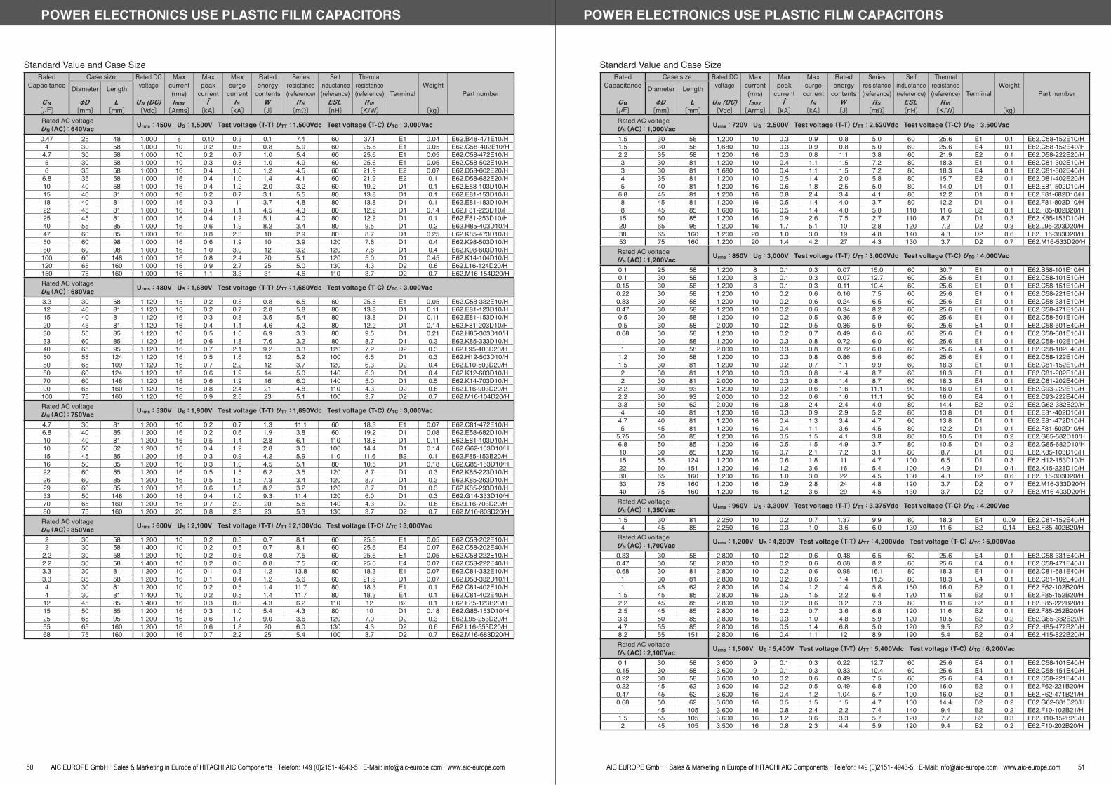
Standard Value and Case SizeRated
Capacitance
C N〔μF〕
Case size Rated DCvoltage
UN (DC)〔Vdc〕
Max current(rms)Imax
〔Arms〕
Max peak
currentÎ
〔kA〕
Max surge
currentIS
〔kA〕
Rated energy
contentsW〔J〕
Series resistance(reference)
RS〔m 〕
Self inductance(reference)
ESL〔nH〕
Thermalresistance(reference)
Rth〔K/W〕
TerminalWeight
〔kg〕
Part numberDiameter
D〔mm〕
Length
L〔mm〕
Rated AC voltage U N(AC):640Vac Urms:450V US:1,500V Test voltage(T-T) U TT:1,500Vdc Test voltage(T-C) U TC:3,000Vac
0.47 25 48 1,000 8 0.10 0.3 0.1 7.4 60 37.1 E1 0.04 E62.B48-471E10/H4 30 58 1,000 10 0.2 0.6 0.8 5.9 60 25.6 E1 0.05 E62.C58-402E10/H
4.7 30 58 1,000 10 0.2 0.7 1.0 5.4 60 25.6 E1 0.05 E62.C58-472E10/H5 30 58 1,000 10 0.3 0.8 1.0 4.9 60 25.6 E1 0.05 E62.C58-502E10/H6 35 58 1,000 16 0.4 1.0 1.2 4.5 60 21.9 E2 0.07 E62.D58-602E20/H
6.8 35 58 1,000 16 0.4 1.0 1.4 4.1 60 21.9 E2 0.1 E62.D58-682E20/H10 40 58 1,000 16 0.4 1.2 2.0 3.2 60 19.2 D1 0.1 E62.E58-103D10/H15 40 81 1,000 16 0.2 0.7 3.1 5.5 80 13.8 D1 0.1 E62.E81-153D10/H18 40 81 1,000 16 0.3 1 3.7 4.8 80 13.8 D1 0.1 E62.E81-183D10/H22 45 81 1,000 16 0.4 1.1 4.5 4.3 80 12.2 D1 0.14 E62.F81-223D10/H25 45 81 1,000 16 0.4 1.2 5.1 4.0 80 12.2 D1 0.1 E62.F81-253D10/H40 55 85 1,000 16 0.6 1.9 8.2 3.4 80 9.5 D1 0.2 E62.H85-403D10/H47 60 85 1,000 16 0.8 2.3 10 2.9 80 8.7 D1 0.25 E62.K85-473D10/H50 60 98 1,000 16 0.6 1.9 10 3.9 120 7.6 D1 0.4 E62.K98-503D10/H60 60 98 1,000 16 1.0 3.0 12 3.2 120 7.6 D1 0.4 E62.K98-603D10/H100 60 148 1,000 16 0.8 2.4 20 5.1 120 5.0 D1 0.45 E62.K14-104D10/H120 65 160 1,000 16 0.9 2.7 25 5.0 130 4.3 D2 0.6 E62.L16-124D20/H150 75 160 1,000 16 1.1 3.3 31 4.6 110 3.7 D2 0.7 E62.M16-154D20/HRated AC voltage U N(AC):680Vac Urms:480V US:1,680V Test voltage(T-T) U TT:1,680Vdc Test voltage(T-C) U TC:3,000Vac
3.3 30 58 1,120 15 0.2 0.5 0.8 6.5 60 25.6 E1 0.05 E62.C58-332E10/H12 40 81 1,120 16 0.2 0.7 2.8 5.8 80 13.8 D1 0.11 E62.E81-123D10/H15 40 81 1,120 16 0.3 0.8 3.5 5.4 80 13.8 D1 0.11 E62.E81-153D10/H20 45 81 1,120 16 0.4 1.1 4.6 4.2 80 12.2 D1 0.14 E62.F81-203D10/H30 55 85 1,120 16 0.5 1.6 6.9 3.3 80 9.5 D1 0.21 E62.H85-303D10/H33 60 85 1,120 16 0.6 1.8 7.6 3.2 80 8.7 D1 0.3 E62.K85-333D10/H40 65 95 1,120 16 0.7 2.1 9.2 3.3 120 7.2 D2 0.3 E62.L95-403D20/H50 55 124 1,120 16 0.5 1.6 12 5.2 100 6.5 D1 0.3 E62.H12-503D10/H50 65 109 1,120 16 0.7 2.2 12 3.7 120 6.3 D2 0.4 E62.L10-503D20/H60 60 124 1,120 16 0.6 1.9 14 5.0 140 6.0 D1 0.4 E62.K12-603D10/H70 60 148 1,120 16 0.6 1.9 16 6.0 140 5.0 D1 0.5 E62.K14-703D10/H90 65 160 1,120 16 0.8 2.4 21 4.8 110 4.3 D2 0.6 E62.L16-903D20/H100 75 160 1,120 16 0.9 2.6 23 5.1 100 3.7 D2 0.7 E62.M16-104D20/HRated AC voltage U N(AC):750Vac Urms:530V US:1,900V Test voltage(T-T) U TT:1,890Vdc Test voltage(T-C) U TC:3,000Vac
4.7 30 81 1,200 10 0.2 0.7 1.3 11.1 60 18.3 E1 0.07 E62.C81-472E10/H6.8 40 85 1,200 16 0.2 0.6 1.9 3.8 60 19.2 D1 0.08 E62.E58-682D10/H10 40 81 1,200 16 0.5 1.4 2.8 6.1 110 13.8 D1 0.11 E62.E81-103D10/H10 50 62 1,200 16 0.4 1.2 2.8 3.0 100 14.4 D1 0.14 E62.G62-103D10/H15 45 85 1,200 16 0.3 0.9 4.2 5.9 110 11.6 B2 0.1 E62.F85-153B20/H16 50 85 1,200 16 0.3 1.0 4.5 5.1 80 10.5 D1 0.18 E62.G85-163D10/H22 60 85 1,200 16 0.5 1.5 6.2 3.5 120 8.7 D1 0.3 E62.K85-223D10/H26 60 85 1,200 16 0.5 1.5 7.3 3.4 120 8.7 D1 0.3 E62.K85-263D10/H29 60 85 1,200 16 0.6 1.8 8.2 3.2 120 8.7 D1 0.3 E62.K85-293D10/H33 50 148 1,200 16 0.4 1.0 9.3 11.4 120 6.0 D1 0.3 E62.G14-333D10/H70 65 160 1,200 16 0.7 2.0 20 5.6 140 4.3 D2 0.6 E62.L16-703D20/H80 75 160 1,200 20 0.8 2.3 23 5.3 130 3.7 D2 0.7 E62.M16-803D20/HRated AC voltage U N(AC):850Vac Urms:600V US:2,100V Test voltage(T-T) U TT:2,100Vdc Test voltage(T-C) U TC:3,000Vac
2 30 58 1,200 10 0.2 0.5 0.7 8.1 60 25.6 E1 0.05 E62.C58-202E10/H2 30 58 1,400 10 0.2 0.5 0.7 8.1 60 25.6 E4 0.07 E62.C58-202E40/H
2.2 30 58 1,200 10 0.2 0.6 0.8 7.5 60 25.6 E1 0.05 E62.C58-222E10/H2.2 30 58 1,400 10 0.2 0.6 0.8 7.5 60 25.6 E4 0.07 E62.C58-222E40/H3.3 30 81 1,200 10 0.1 0.3 1.2 13.8 80 18.3 E1 0.07 E62.C81-332E10/H3.3 35 58 1,200 16 0.1 0.4 1.2 5.6 60 21.9 D1 0.07 E62.D58-332D10/H4 30 81 1,200 10 0.2 0.5 1.4 11.7 80 18.3 E1 0.1 E62.C81-402E10/H4 30 81 1,400 10 0.2 0.5 1.4 11.7 80 18.3 E4 0.1 E62.C81-402E40/H
12 45 85 1,400 16 0.3 0.8 4.3 6.2 110 12 B2 0.1 E62.F85-123B20/H15 50 85 1,200 16 0.3 1.0 5.4 4.3 80 10 D1 0.18 E62.G85-153D10/H25 65 95 1,200 16 0.6 1.7 9.0 3.6 120 7.0 D2 0.3 E62.L95-253D20/H55 65 160 1,200 16 0.6 1.8 20 6.0 130 4.3 D2 0.6 E62.L16-553D20/H68 75 160 1,200 16 0.7 2.2 25 5.4 100 3.7 D2 0.7 E62.M16-683D20/H
POWER ELECTRONICS USE PLASTIC FILM CAPACITORS
50 AIC EUROPE GmbH · Sales & Marketing in Europe of HITACHI AIC Components · Telefon: +49 (0)2151- 4943-5 · E-Mail: [email protected] · www.aic-europe.com
Standard Value and Case SizeRated
Capacitance
C N〔μF〕
Case size Rated DCvoltage
UN (DC)〔Vdc〕
Max current(rms)Imax
〔Arms〕
Max peak
currentÎ
〔kA〕
Max surge
currentIS
〔kA〕
Rated energy
contentsW〔J〕
Series resistance(reference)
RS〔m 〕
Self inductance(reference)
ESL〔nH〕
Thermalresistance(reference)
Rth〔K/W〕
TerminalWeight
〔kg〕
Part numberDiameter
D〔mm〕
Length
L〔mm〕
Rated AC voltage U N(AC):1,000Vac Urms:720V US:2,500V Test voltage(T-T) U TT:2,520Vdc Test voltage(T-C) U TC:3,500Vac
1.5 30 58 1,200 10 0.3 0.9 0.8 5.0 60 25.6 E1 0.1 E62.C58-152E10/H1.5 30 58 1,680 10 0.3 0.9 0.8 5.0 60 25.6 E4 0.1 E62.C58-152E40/H2.2 35 58 1,200 16 0.3 0.8 1.1 3.8 60 21.9 E2 0.1 E62.D58-222E20/H3 30 81 1,200 10 0.4 1.1 1.5 7.2 80 18.3 E1 0.1 E62.C81-302E10/H3 30 81 1,680 10 0.4 1.1 1.5 7.2 80 18.3 E4 0.1 E62.C81-302E40/H4 35 81 1,200 10 0.5 1.4 2.0 5.8 80 15.7 E2 0.1 E62.D81-402E20/H5 40 81 1,200 16 0.6 1.8 2.5 5.0 80 14.0 D1 0.1 E62.E81-502D10/H
6.8 45 81 1,200 16 0.8 2.4 3.4 4.1 80 12.2 D1 0.1 E62.F81-682D10/H8 45 81 1,200 16 0.5 1.4 4.0 3.7 80 12.2 D1 0.1 E62.F81-802D10/H8 45 85 1,680 16 0.5 1.4 4.0 5.0 110 11.6 B2 0.1 E62.F85-802B20/H15 60 85 1,200 16 0.9 2.6 7.5 2.7 110 8.7 D1 0.3 E62.K85-153D10/H20 65 95 1,200 16 1.7 5.1 10 2.8 120 7.2 D2 0.3 E62.L95-203D20/H38 65 160 1,200 20 1.0 3.0 19 4.8 140 4.3 D2 0.6 E62.L16-383D20/H53 75 160 1,200 20 1.4 4.2 27 4.3 130 3.7 D2 0.7 E62.M16-533D20/HRated AC voltage U N(AC):1,200Vac Urms:850V US:3,000V Test voltage(T-T) U TT:3,000Vdc Test voltage(T-C) U TC:4,000Vac
0.1 25 58 1,200 8 0.1 0.3 0.07 15.0 60 30.7 E1 0.1 E62.B58-101E10/H0.1 30 58 1,200 8 0.1 0.3 0.07 12.7 60 25.6 E1 0.1 E62.C58-101E10/H
0.15 30 58 1,200 8 0.1 0.3 0.11 10.4 60 25.6 E1 0.1 E62.C58-151E10/H0.22 30 58 1,200 10 0.2 0.6 0.16 7.5 60 25.6 E1 0.1 E62.C58-221E10/H0.33 30 58 1,200 10 0.2 0.6 0.24 6.5 60 25.6 E1 0.1 E62.C58-331E10/H0.47 30 58 1,200 10 0.2 0.6 0.34 8.2 60 25.6 E1 0.1 E62.C58-471E10/H0.5 30 58 1,200 10 0.2 0.5 0.36 5.9 60 25.6 E1 0.1 E62.C58-501E10/H0.5 30 58 2,000 10 0.2 0.5 0.36 5.9 60 25.6 E4 0.1 E62.C58-501E40/H
0.68 30 58 1,200 10 0.2 0.7 0.49 6.6 60 25.6 E1 0.1 E62.C58-681E10/H1 30 58 1,200 10 0.3 0.8 0.72 6.0 60 25.6 E1 0.1 E62.C58-102E10/H1 30 58 2,000 10 0.3 0.8 0.72 6.0 60 25.6 E4 0.1 E62.C58-102E40/H
1.2 30 58 1,200 10 0.3 0.8 0.86 5.6 60 25.6 E1 0.1 E62.C58-122E10/H1.5 30 81 1,200 10 0.2 0.7 1.1 9.9 60 18.3 E1 0.1 E62.C81-152E10/H2 30 81 1,200 10 0.3 0.8 1.4 8.7 60 18.3 E1 0.1 E62.C81-202E10/H2 30 81 2,000 10 0.3 0.8 1.4 8.7 60 18.3 E4 0.1 E62.C81-202E40/H
2.2 30 93 1,200 10 0.2 0.6 1.6 11.1 90 16.0 E1 0.1 E62.C93-222E10/H2.2 30 93 2,000 10 0.2 0.6 1.6 11.1 90 16.0 E4 0.1 E62.C93-222E40/H3.3 50 62 2,000 16 0.8 2.4 2.4 4.0 80 14.4 B2 0.2 E62.G62-332B20/H4 40 81 1,200 16 0.3 0.9 2.9 5.2 80 13.8 D1 0.1 E62.E81-402D10/H
4.7 40 81 1,200 16 0.4 1.3 3.4 4.7 60 13.8 D1 0.1 E62.E81-472D10/H5 45 81 1,200 16 0.4 1.1 3.6 4.5 80 12.2 D1 0.1 E62.F81-502D10/H
5.75 50 85 1,200 16 0.5 1.5 4.1 3.8 80 10.5 D1 0.2 E62.G85-582D10/H6.8 50 85 1,200 16 0.5 1.5 4.9 3.7 80 10.5 D1 0.2 E62.G85-682D10/H10 60 85 1,200 16 0.7 2.1 7.2 3.1 80 8.7 D1 0.3 E62.K85-103D10/H15 55 124 1,200 16 0.6 1.8 11 4.7 100 6.5 D1 0.3 E62.H12-153D10/H22 60 151 1,200 16 1.2 3.6 16 5.4 100 4.9 D1 0.4 E62.K15-223D10/H30 65 160 1,200 16 1.0 3.0 22 4.5 130 4.3 D2 0.6 E62.L16-303D20/H33 75 160 1,200 16 0.9 2.8 24 4.8 120 3.7 D2 0.7 E62.M16-333D20/H40 75 160 1,200 16 1.2 3.6 29 4.5 130 3.7 D2 0.7 E62.M16-403D20/HRated AC voltage U N(AC):1,350Vac Urms:960V US:3,300V Test voltage(T-T) U TT:3,375Vdc Test voltage(T-C) U TC:4,200Vac
1.5 30 81 2,250 10 0.2 0.7 1.37 9.9 80 18.3 E4 0.09 E62.C81-152E40/H4 45 85 2,250 16 0.3 1.0 3.6 6.0 130 11.6 B2 0.14 E62.F85-402B20/H
Rated AC voltage U N(AC):1,700Vac Urms:1,200V US:4,200V Test voltage(T-T) U TT:4,200Vdc Test voltage(T-C) U TC:5,000Vac
0.33 30 58 2,800 10 0.2 0.6 0.48 6.5 60 25.6 E4 0.1 E62.C58-331E40/H0.47 30 58 2,800 10 0.2 0.6 0.68 8.2 60 25.6 E4 0.1 E62.C58-471E40/H0.68 30 81 2,800 10 0.2 0.6 0.98 16.1 80 18.3 E4 0.1 E62.C81-681E40/H
1 30 81 2,800 10 0.2 0.6 1.4 11.5 80 18.3 E4 0.1 E62.C81-102E40/H1 45 62 2,800 16 0.4 1.2 1.4 5.8 150 16.0 B2 0.1 E62.F62-102B20/H
1.5 45 85 2,800 16 0.5 1.5 2.2 6.4 120 11.6 B2 0.1 E62.F85-152B20/H2.2 45 85 2,800 10 0.2 0.6 3.2 7.3 80 11.6 B2 0.1 E62.F85-222B20/H2.5 45 85 2,800 16 0.2 0.7 3.6 6.8 120 11.6 B2 0.1 E62.F85-252B20/H3.3 50 85 2,800 16 0.3 1.0 4.8 5.9 120 10.5 B2 0.2 E62.G85-332B20/H4.7 55 85 2,800 16 0.5 1.4 6.8 5.0 120 9.5 B2 0.2 E62.H85-472B20/H8.2 55 151 2,800 16 0.4 1.1 12 8.9 190 5.4 B2 0.4 E62.H15-822B20/HRated AC voltage U N(AC):2,100Vac Urms:1,500V US:5,400V Test voltage(T-T) U TT:5,400Vdc Test voltage(T-C) U TC:6,200Vac
0.1 30 58 3,600 9 0.1 0.3 0.22 12.7 60 25.6 E4 0.1 E62.C58-101E40/H0.15 30 58 3,600 9 0.1 0.3 0.33 10.4 60 25.6 E4 0.1 E62.C58-151E40/H0.22 30 58 3,600 10 0.2 0.6 0.49 7.5 60 25.6 E4 0.1 E62.C58-221E40/H0.22 45 62 3,600 16 0.2 0.5 0.49 6.8 100 16.0 B2 0.1 E62.F62-221B20/H0.47 45 62 3,600 16 0.4 1.2 1.04 5.7 100 16.0 B2 0.1 E62.F62-471B21/H0.68 50 62 3,600 16 0.5 1.5 1.5 4.7 100 14.4 B2 0.2 E62.G62-681B20/H
1 45 105 3,600 16 0.8 2.4 2.2 7.4 140 9.4 B2 0.2 E62.F10-102B21/H1.5 55 105 3,600 16 1.2 3.6 3.3 5.7 120 7.7 B2 0.3 E62.H10-152B20/H2 45 105 3,500 16 0.8 2.3 4.4 5.9 120 9.4 B2 0.2 E62.F10-202B20/H
POWER ELECTRONICS USE PLASTIC FILM CAPACITORS
AIC EUROPE GmbH · Sales & Marketing in Europe of HITACHI AIC Components · Telefon: +49 (0)2151- 4943-5 · E-Mail: [email protected] · www.aic-europe.com 51
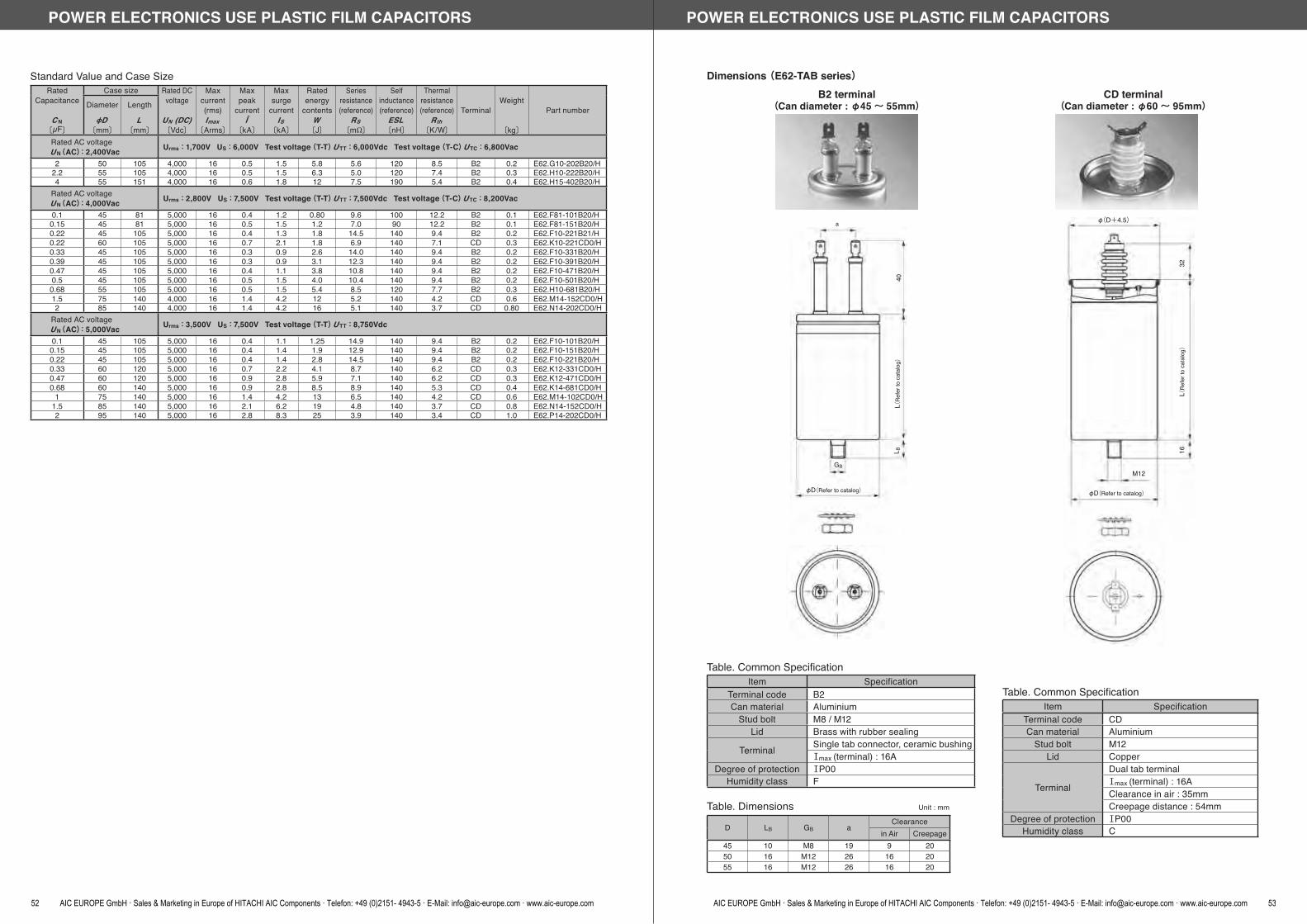
Standard Value and Case SizeRated
Capacitance
C N〔μF〕
Case size Rated DCvoltage
UN (DC)〔Vdc〕
Max current(rms)Imax
〔Arms〕
Max peak
currentÎ
〔kA〕
Max surge
currentIS
〔kA〕
Rated energy
contentsW〔J〕
Series resistance(reference)
RS〔m 〕
Self inductance(reference)
ESL〔nH〕
Thermalresistance(reference)
Rth〔K/W〕
TerminalWeight
〔kg〕
Part numberDiameter
D〔mm〕
Length
L〔mm〕
Rated AC voltage U N(AC):2,400Vac Urms:1,700V US:6,000V Test voltage(T-T) U TT:6,000Vdc Test voltage(T-C) U TC:6,800Vac
2 50 105 4,000 16 0.5 1.5 5.8 5.6 120 8.5 B2 0.2 E62.G10-202B20/H2.2 55 105 4,000 16 0.5 1.5 6.3 5.0 120 7.4 B2 0.3 E62.H10-222B20/H4 55 151 4,000 16 0.6 1.8 12 7.5 190 5.4 B2 0.4 E62.H15-402B20/H
Rated AC voltage U N(AC):4,000Vac Urms:2,800V US:7,500V Test voltage(T-T) U TT:7,500Vdc Test voltage(T-C) U TC:8,200Vac
0.1 45 81 5,000 16 0.4 1.2 0.80 9.6 100 12.2 B2 0.1 E62.F81-101B20/H0.15 45 81 5,000 16 0.5 1.5 1.2 7.0 90 12.2 B2 0.1 E62.F81-151B20/H0.22 45 105 5,000 16 0.4 1.3 1.8 14.5 140 9.4 B2 0.2 E62.F10-221B21/H0.22 60 105 5,000 16 0.7 2.1 1.8 6.9 140 7.1 CD 0.3 E62.K10-221CD0/H0.33 45 105 5,000 16 0.3 0.9 2.6 14.0 140 9.4 B2 0.2 E62.F10-331B20/H0.39 45 105 5,000 16 0.3 0.9 3.1 12.3 140 9.4 B2 0.2 E62.F10-391B20/H0.47 45 105 5,000 16 0.4 1.1 3.8 10.8 140 9.4 B2 0.2 E62.F10-471B20/H0.5 45 105 5,000 16 0.5 1.5 4.0 10.4 140 9.4 B2 0.2 E62.F10-501B20/H
0.68 55 105 5,000 16 0.5 1.5 5.4 8.5 120 7.7 B2 0.3 E62.H10-681B20/H1.5 75 140 4,000 16 1.4 4.2 12 5.2 140 4.2 CD 0.6 E62.M14-152CD0/H2 85 140 4,000 16 1.4 4.2 16 5.1 140 3.7 CD 0.80 E62.N14-202CD0/H
Rated AC voltage U N(AC):5,000Vac Urms:3,500V US:7,500V Test voltage(T-T) U TT:8,750Vdc
0.1 45 105 5,000 16 0.4 1.1 1.25 14.9 140 9.4 B2 0.2 E62.F10-101B20/H0.15 45 105 5,000 16 0.4 1.4 1.9 12.9 140 9.4 B2 0.2 E62.F10-151B20/H0.22 45 105 5,000 16 0.4 1.4 2.8 14.5 140 9.4 B2 0.2 E62.F10-221B20/H0.33 60 120 5,000 16 0.7 2.2 4.1 8.7 140 6.2 CD 0.3 E62.K12-331CD0/H0.47 60 120 5,000 16 0.9 2.8 5.9 7.1 140 6.2 CD 0.3 E62.K12-471CD0/H0.68 60 140 5,000 16 0.9 2.8 8.5 8.9 140 5.3 CD 0.4 E62.K14-681CD0/H
1 75 140 5,000 16 1.4 4.2 13 6.5 140 4.2 CD 0.6 E62.M14-102CD0/H1.5 85 140 5,000 16 2.1 6.2 19 4.8 140 3.7 CD 0.8 E62.N14-152CD0/H2 95 140 5,000 16 2.8 8.3 25 3.9 140 3.4 CD 1.0 E62.P14-202CD0/H
POWER ELECTRONICS USE PLASTIC FILM CAPACITORS
52 AIC EUROPE GmbH · Sales & Marketing in Europe of HITACHI AIC Components · Telefon: +49 (0)2151- 4943-5 · E-Mail: [email protected] · www.aic-europe.com
B2 terminal(Can diameter : φ45~ 55mm)
Table. Dimensions Unit : mm
D LB GB aClearance
in Air Creepage45 10 M8 19 9 2050 16 M12 26 16 2055 16 M12 26 16 20
Table. Common SpecificationItem Specification
Terminal code B2Can material Aluminium
Stud bolt M8 / M12Lid Brass with rubber sealing
Terminal Single tab connector, ceramic bushingⅠmax (terminal) : 16A
Degree of protection ⅠP00Humidity class F
Dimensions (E62-TAB series)CD terminal
(Can diameter : φ60~ 95mm)
Table. Common SpecificationItem Specification
Terminal code CDCan material Aluminium
Stud bolt M12Lid Copper
Terminal
Dual tab terminalⅠmax (terminal) : 16AClearance in air : 35mmCreepage distance : 54mm
Degree of protection ⅠP00Humidity class C
40L (
Refe
r to
cata
log)
L B
GB
φD(Refer to catalog)
a φ(D+4.5)
32L(
Refe
r to
cata
log)
16
M12
φD(Refer to catalog)
POWER ELECTRONICS USE PLASTIC FILM CAPACITORS
AIC EUROPE GmbH · Sales & Marketing in Europe of HITACHI AIC Components · Telefon: +49 (0)2151- 4943-5 · E-Mail: [email protected] · www.aic-europe.com 53

D1 terminal(Can diameter : φ35~ 60mm)
Dimensions (E62-TAB series)D2 terminal
(Can diameter : φ65~ 75mm)
D11
D2
a
1010
12L (
Refe
r to
cata
log)
L B
GB
φD(Refer to catalog)
Table. Dimensions Unit : mm
D LB GB aClearance
in Air Creepage35 10 M8 13.5 6.5 6.540 10 M8 13.5 6.5 945 10 M8 13.5 6.5 1050 16 M12 13.5 6.5 1055 16 M12 13.5 6.5 1060 16 M12 13.5 6.5 1065 16 M12 16.5 8 1075 16 M12 16.5 8 10
Table. Common SpecificationItem Specification
Terminal code D1 / D2Can material Aluminium
Stud bolt M8 / M12Lid Plastic with rubber sealing
Terminal Dual tab connectorsⅠmax (terminal) : 16A
Degree of protection ⅠP00Humidity class F
POWER ELECTRONICS USE PLASTIC FILM CAPACITORS
54 AIC EUROPE GmbH · Sales & Marketing in Europe of HITACHI AIC Components · Telefon: +49 (0)2151- 4943-5 · E-Mail: [email protected] · www.aic-europe.com
E1 terminal(Can diameter : φ25~ 30mm)
Dimensions (E62-TAB series)E2 terminal
(Can diameter : φ35~ 65mm)
L 2L(
Refe
r to
cata
log)
L B
GB
φD(Refer to catalog)
17±1
L 2L(
Refe
r to
cata
log)
L B
GB
φD(Refer to catalog)
17±1
Table. Dimensions Unit : mm
D L2 LB GBClearance
in Air Creepage25 16 10 M8 7.5 7.530 15 10 M8 7.5 9
35~ 45 11 10 M8 7.5 950~ 65 11 16 M12 7.5 9
Table. Common SpecificationItem Specification
Terminal code E1 / E2Can material Aluminium
Stud bolt M8 / M12Lid Plastic
Terminal Tab connector (6.3×0.8mm)Ⅰmax (terminal) : 16A
Degree of protection ⅠP00Humidity class F
POWER ELECTRONICS USE PLASTIC FILM CAPACITORS
AIC EUROPE GmbH · Sales & Marketing in Europe of HITACHI AIC Components · Telefon: +49 (0)2151- 4943-5 · E-Mail: [email protected] · www.aic-europe.com 55

Table. Common SpecificationItem Specification
Terminal code E4Can material Aluminium
Stud bolt M8Lid Plastic with rubber sealing
Terminal Tab connector (6.3×0.8mm)Ⅰmax (terminal) : 16A
Degree of protection ⅠP00Humidity class F
E4 terminal(Can diameter : φ25~ 30mm)
Dimensions (E62-TAB series)
34
15
28.5
17
44
L(Re
fer t
o ca
talo
g)10
GB
M8
30
POWER ELECTRONICS USE PLASTIC FILM CAPACITORS
56 AIC EUROPE GmbH · Sales & Marketing in Europe of HITACHI AIC Components · Telefon: +49 (0)2151- 4943-5 · E-Mail: [email protected] · www.aic-europe.com
E62-3HF(AC) SeriesFeatures The three capacitor elements are connected in delta internally. Designed especially for heavy duty operation in extreme or sophisticated operating conditions. The integrated overpressure disconnector ensure safe operation and controlled disconnection in the event of
overload or failure at the end of operating life.
SpecificationsItem Specification
Category temperature range -50~+70 (+85 / Includes self temperature rise)Storage temperature -50~+85Rated voltage (U N) 640~ 1,400VacStud bolt (torque) M12×16 / 18 (15 ±1Nm)Standards ⅠEC 61071 : 2007Dielectric PolypropyleneDielectric dissipation factor (tanδ0) 2×10⁻⁴
Capacitance tolerance ±5%Safety devices Overpressure disconnectorImpregnant Castor oil, Non PCBMaterial of case AluminumEnvironmental regulations Comply with RoHS
(Three Phase Type Cylindrical Metallized Polypropylene Film Capacitors)
Standard Value and Case SizeRated
Capacitance
C N〔μF〕
Case size Max current(rms)
Imax〔Arms〕
Max peakcurrent
Î〔kA〕
Max surge
currentIS
〔kA〕
Rated energy
contentsW〔J〕
Series resistance(reference)
RS〔m 〕
Self inductance(reference)
ESL〔nH〕
Thermalresistance(reference)
Rth〔K/W〕
TerminalWeight
〔kg〕
Part numberDiameter
D〔mm〕
Length
L〔mm〕
Rated AC voltage U N(AC):640Vac Urms:450V US:1,350V Test voltage(T-T) U TT:1,060Vdc Test voltage(T-C) U TC:3,600Vac
3×33 75 164 3×39 0.9 2.7 20.3 3×0.9 110 4.7 Z3 0.8 E62.M16-333Z30/H3×40 75 164 3×39 1.1 3.3 24.6 3×0.9 110 4.7 Z3 0.8 E62.M16-403Z30/H3×46 85 164 3×56 1.3 3.9 28.3 3×0.7 120 4.1 S4 1.0 E62.N16-463S40/H3×51 85 164 3×56 1.4 4.2 31.3 3×0.7 120 4.1 S4 1.0 E62.N16-513S40/H3×68 95 164 3×56 1.9 5.7 41.8 3×0.55 120 3.5 S4 1.5 E62.P16-683S40/H3×80 95 196 3×56 1.8 5.4 49.2 3×0.7 130 3.1 S4 1.5 E62.P19-803S40/H
3×100 116 164 3×56 3 9 61.5 3×0.4 100 3 S4 2.1 E62.R16-104S40/H3×100 116 164 3×80 3 9 61.5 3×0.4 100 2.1 MB 2.1 E62.R16-104MB0/H3×135 116 230 3×80 2.5 7.5 82.9 3×0.55 120 2.1 MB 2.5 E62.R23-134MB0/H3×140 116 230 3×56 2.5 7.5 86.1 3×0.7 120 2.4 S4 2.6 E62.R23-144S40/H3×200 136 245 3×80 3.4 10.2 122.9 3×0.55 120 1.7 MB 3.6 E62.S23-204MB0/H
Rated AC voltage U N(AC):750Vac Urms:530V US:1,600V Test voltage(T-T) U TT:1,250Vdc Test voltage(T-C) U TC:3,600Vac
3×16 65 164 3×39 0.6 1.8 13.5 3×1.1 100 5.4 Z3 0.6 E62.L16-163Z30/H3×23 75 164 3×39 0.85 2.5 19.4 3×1.0 110 4.7 Z3 0.8 E62.M16-233Z30/H3×30 85 164 3×56 1.1 3.3 25.3 3×0.7 120 4.1 S4 1.0 E62.N16-303S40/H
3×38.4 95 164 3×56 1.4 4.2 32.4 3×0.6 125 3.7 S4 1.2 E62.P16-383S40/H3×48 100 164 3×56 1.4 4.2 40.4 3×0.7 130 3.1 S4 1.5 E62.Q16-483S40/H3×75 116 196 3×56 2.1 6.3 63.3 3×0.6 130 2.5 S4 2.2 E62.R19-753S40/H3×100 116 230 3×56 2.1 6.3 84.4 3×0.7 120 2.4 S4 2.6 E62.R23-104S40/H3×100 116 230 3×80 2.2 6.6 84.4 3×0.6 120 2.1 MB 2.5 E62.R23-104MB0/H
UPGRADE!
Auxiliary symbolTerminal symbolCapacitanceCase lengthCase diameter symbolSeries name
Numbering system: e.g. E62-3HF, 640VAC, 3×33μ F, φ75×164Lmm, Z3 terminalE62 . -M 16 Z3 0 / H333
POWER ELECTRONICS USE PLASTIC FILM CAPACITORS
AIC EUROPE GmbH · Sales & Marketing in Europe of HITACHI AIC Components · Telefon: +49 (0)2151- 4943-5 · E-Mail: [email protected] · www.aic-europe.com 57
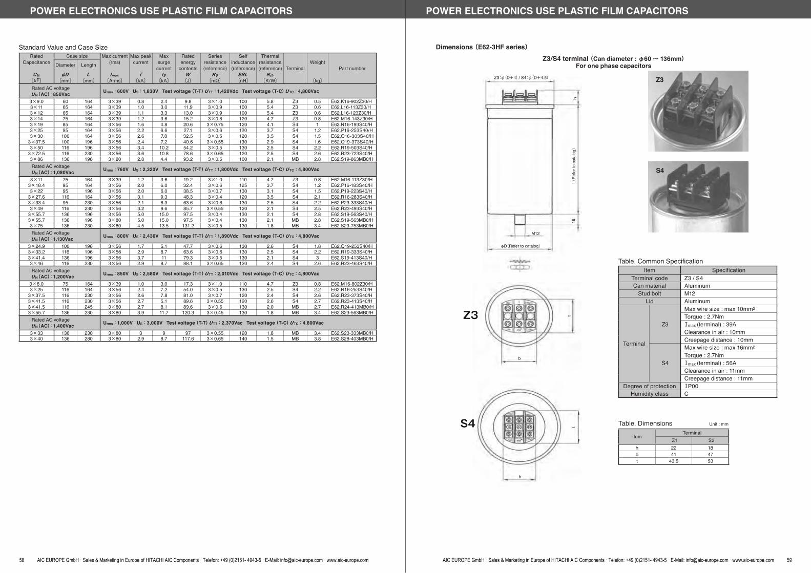
Standard Value and Case SizeRated
Capacitance
C N〔μF〕
Case size Max current(rms)
Imax〔Arms〕
Max peakcurrent
Î〔kA〕
Max surge
currentIS
〔kA〕
Rated energy
contentsW〔J〕
Series resistance(reference)
RS〔m 〕
Self inductance(reference)
ESL〔nH〕
Thermalresistance(reference)
Rth〔K/W〕
TerminalWeight
〔kg〕
Part numberDiameter
D〔mm〕
Length
L〔mm〕
Rated AC voltage U N(AC):850Vac Urms:600V US:1,830V Test voltage(T-T) U TT:1,420Vdc Test voltage(T-C) U TC:4,800Vac
3×9.0 60 164 3×39 0.8 2.4 9.8 3×1.0 100 5.8 Z3 0.5 E62.K16-902Z30/H3×11 65 164 3×39 1.0 3.0 11.9 3×0.9 100 5.4 Z3 0.6 E62.L16-113Z30/H3×12 65 164 3×39 1.1 3.3 13.0 3×0.9 100 5.4 Z3 0.6 E62.L16-123Z30/H3×14 75 164 3×39 1.2 3.6 15.2 3×0.8 120 4.7 Z3 0.8 E62.M16-143Z30/H3×19 85 164 3×56 1.6 4.8 20.6 3×0.75 120 4.1 S4 1 E62.N16-193S40/H3×25 95 164 3×56 2.2 6.6 27.1 3×0.6 120 3.7 S4 1.2 E62.P16-253S40/H3×30 100 164 3×56 2.6 7.8 32.5 3×0.5 120 3.5 S4 1.5 E62.Q16-303S40/H
3×37.5 100 196 3×56 2.4 7.2 40.6 3×0.55 130 2.9 S4 1.6 E62.Q19-373S40/H3×50 116 196 3×56 3.4 10.2 54.2 3×0.5 130 2.5 S4 2.2 E62.R19-503S40/H
3×72.5 116 230 3×56 3.6 10.8 78.6 3×0.65 120 2.5 S4 2.6 E62.R23-723S40/H3×86 136 196 3×80 2.8 4.4 93.2 3×0.5 100 2.1 MB 2.8 E62.S19-863MB0/HRated AC voltage U N(AC):1,080Vac Urms:760V US:2,320V Test voltage(T-T) U TT:1,800Vdc Test voltage(T-C) U TC:4,800Vac
3×11 75 164 3×39 1.2 3.6 19.2 3×1.0 110 4.7 Z3 0.8 E62.M16-113Z30/H3×18.4 95 164 3×56 2.0 6.0 32.4 3×0.6 125 3.7 S4 1.2 E62.P16-183S40/H3×22 95 196 3×56 2.0 6.0 38.5 3×0.7 130 3.1 S4 1.5 E62.P19-223S40/H
3×27.6 116 164 3×56 3.1 9.3 48.3 3×0.4 120 3.5 S4 2.1 E62.R16-283S40/H3×33.4 95 230 3×56 2.1 6.3 63.6 3×0.6 130 2.5 S4 2.2 E62.P23-333S40/H3×49 116 230 3×56 3.2 9.6 85.7 3×0.55 120 2.1 S4 2.5 E62.R23-493S40/H
3×55.7 136 196 3×56 5.0 15.0 97.5 3×0.4 130 2.1 S4 2.8 E62.S19-563S40/H3×55.7 136 196 3×80 5.0 15.0 97.5 3×0.4 130 2.1 MB 2.8 E62.S19-563MB0/H3×75 136 230 3×80 4.5 13.5 131.2 3×0.5 130 1.8 MB 3.4 E62.S23-753MB0/HRated AC voltage U N(AC):1,130Vac Urms:800V US:2,430V Test voltage(T-T) U TT:1,890Vdc Test voltage(T-C) U TC:4,800Vac
3×24.9 100 196 3×56 1.7 5.1 47.7 3×0.6 130 2.6 S4 1.8 E62.Q19-253S40/H3×33.2 116 196 3×56 2.9 8.7 63.6 3×0.6 130 2.5 S4 2.2 E62.R19-333S40/H3×41.4 136 196 3×56 3.7 11 79.3 3×0.5 130 2.1 S4 3 E62.S19-413S40/H3×46 116 230 3×56 2.9 8.7 88.1 3×0.65 120 2.4 S4 2.6 E62.R23-463S40/HRated AC voltage U N(AC):1,200Vac Urms:850V US:2,580V Test voltage(T-T) U TT:2,010Vdc Test voltage(T-C) U TC:4,800Vac
3×8.0 75 164 3×39 1.0 3.0 17.3 3×1.0 110 4.7 Z3 0.8 E62.M16-802Z30/H3×25 116 164 3×56 2.4 7.2 54.0 3×0.5 130 2.5 S4 2.2 E62.R16-253S40/H
3×37.5 116 230 3×56 2.6 7.8 81.0 3×0.7 120 2.4 S4 2.6 E62.R23-373S40/H3×41.5 116 230 3×56 2.7 5.1 89.6 3×0.55 120 2.6 S4 2.7 E62.R23-413S40/H3×41.5 116 245 3×80 2.7 8.1 89.6 3×0.6 130 2.0 MB 2.7 E62.R24-413MB0/H3×55.7 136 230 3×80 3.9 11.7 120.3 3×0.45 130 1.8 MB 3.4 E62.S23-563MB0/H
Rated AC voltage U N(AC):1,400Vac Urms:1,000V US:3,000V Test voltage (T-T) U TT:2,370Vac Test voltage (T-C) U TC:4,800Vac
3×33 136 230 3×80 3 9 97 3×0.55 120 1.8 MB 3.4 E62.S23-333MB0/H3×40 136 280 3×80 2.9 8.7 117.6 3×0.65 140 1.5 MB 3.8 E62.S28-403MB0/H
POWER ELECTRONICS USE PLASTIC FILM CAPACITORS
58 AIC EUROPE GmbH · Sales & Marketing in Europe of HITACHI AIC Components · Telefon: +49 (0)2151- 4943-5 · E-Mail: [email protected] · www.aic-europe.com
Dimensions (E62-3HF series)
Z3
S4
Z3:φ(D+4)/ S4:φ(D+4.5)
hL(
Refe
r to
cata
log)
16
M12
φD(Refer to catalog)
b
b
tt
Z3
S4
Table. Common SpecificationItem Specification
Terminal code Z3 / S4Can material Aluminum
Stud bolt M12Lid Aluminum
Terminal
Z3
Max wire size : max 10mm2
Torque : 2.7NmⅠmax (terminal) : 39AClearance in air : 10mmCreepage distance : 10mm
S4
Max wire size : max 16mm2
Torque : 2.7NmⅠmax (terminal) : 56AClearance in air : 11mmCreepage distance : 11mm
Degree of protection ⅠP00Humidity class C
Table. Dimensions Unit : mm
ItemTerminal
Z1 S2h 22 18b 41 47t 43.5 53
Z3/S4 terminal (Can diameter : φ60~ 136mm)For one phase capacitors
POWER ELECTRONICS USE PLASTIC FILM CAPACITORS
AIC EUROPE GmbH · Sales & Marketing in Europe of HITACHI AIC Components · Telefon: +49 (0)2151- 4943-5 · E-Mail: [email protected] · www.aic-europe.com 59

Dimensions (E62-3HF series)MB terminal (Can diameter : φ116 / 136mm)
For three phase capacitors
φ(D+4.5)
M10
52
31.5
L(Re
fer t
o ca
talo
g)16
M12
φD(Refer to catalog)
67.5
27
Table. Common SpecificationItem Specification
Terminal code MBCan material Aluminum
Stud bolt M12Lid Aluminum
Terminal
M10 bolt terminalTorque : 10NmⅠmax (terminal) : 100AClearance in air : 20mmCreepage distance : 25mm
Degree of protection ⅠP00Humidity class C
POWER ELECTRONICS USE PLASTIC FILM CAPACITORS
60 AIC EUROPE GmbH · Sales & Marketing in Europe of HITACHI AIC Components · Telefon: +49 (0)2151- 4943-5 · E-Mail: [email protected] · www.aic-europe.com
MEMOPOWER ELECTRONICS USE PLASTIC FILM CAPACITORS
AIC EUROPE GmbH · Sales & Marketing in Europe of HITACHI AIC Components · Telefon: +49 (0)2151- 4943-5 · E-Mail: [email protected] · www.aic-europe.com 61

Table 1 Equivalent AC rating for DC-rated products
Precautions in using Plastic Film Capacitors other than Power electronics use
Fig. 1 Metallized polyester capacitors( MDDSA, MTB types)
Fig. 2 Metallized polypropylene capacitors(MDD-P and MTB-P types)
Fig. 3 Metallized PPS film capacitors(MDD-HF, MML-E types)
f =10kHz
Curre
nt (A
rms)
Capacitance (μF)0.05 0.1 0.2 0.5 1.0 2.0 5.0
630V
400V
250V
10.0
5.0
2.0
1.0
0.5
0.2
Curre
nt (A
rms)
Capacitance (μF)
f =100kHz
f =10kHz
0.01 0.02 0.05 0.1 0.2 0.5
1.0
0.5
0.2
0.1
0.05
0.02f =10kHz
Curre
nt (A
rms)
Capacitance (μF)
10.0
5.0
2.0
1.0
0.5
0.2
0.05 0.1 0.2 0.5 1.0 2.0 5.0
630V
400V
250V
Fig. 4 Metallized polyester capacitorstemperature derating diagram(MDDSA types)
Fig. 5 Metallized polypropylene capacitorstemperature derating diagram(MDD-P and MTB-P types)
Fig. 6 Metallized PPS film capacitorstemperature derating diagram(MDD-HF, MML-E types)
100
80
60
40
20
0
Operating temperature ()
Max
imum
vol
tage
ratin
g (%
) 100
80
60
40
20
0
Operating temperature ()
Max
imum
vol
tage
ratin
g (%
) 100
80
60
40
20
0
Operating temperature ()
Max
imum
vol
tage
ratin
g (%
)
-40 -20 0 20 40 60 80 100 120 -40 -20 0 20 40 60 80 100 120 -40 -20 0 20 40 60 80 100 120
1. When DC-rated Types Are Used in AC CircuitsThe plastic film capacitor voltage ratings are usually expressed in volts DC (V.DC).(1) Use in AC circuits
When DC-rated types are used in AC-rated circuits, unexpected heat generation or other contingencies can take place.Therefore, ensure that the voltages listed in the following conversion table (Table 1) are not exceeded.Since the AC rating may vary with the product type, contact your local Hitachi AIC agent for details.
(2) Use at high frequencyIf the capacitors are used at a high frequency, they can deteriorate or become defective due to its spontaneous heat generation. To avoid suchproblems, be sure that the capacitors are used within the ranges defined in Figs. 1, 2, and 3. Since the permitted limits vary with the producttype, contact your local Hitachi AIC agent for details.
2. Operating TemperatureThe operating temperature varies with the type of the plastic film used as the capacitor dielectric.
(1) Relationship between operating temperature and voltage rating toleranceThe operating temperature and maximum voltage rating vary with the capcitor dielectric film type.Be sure that the operating temperature does not exceed the value determined by adding the ambient temperature value to the spontaneoustemperature rise value which is explained in paragraph 2 below. For the resulting voltage derating factor, see Figs. 4, 5, or 6.
Rated DC voltage Maximum permitted operating AC voltage (50 or 60Hz)MTBS, MTB MDDSA MDD-P MTB-P
100V.DC 63V.AC 40V.AC 250V.DC 150V.AC 100V.AC 150V.AC 400V.DC 200V.AC 150V.AC 200V.AC 630V.DC 250V.AC 200V.AC 250V.AC
GENERAL ELECTRONIC EQUIPMENT USE PLASTIC FILM CAPACITORS
62 AIC EUROPE GmbH · Sales & Marketing in Europe of HITACHI AIC Components · Telefon: +49 (0)2151- 4943-5 · E-Mail: [email protected] · www.aic-europe.com
Capacitor type Designation Spontaneous temperature riseMetallized polyester capacitor MPET 10
Metallized polypropylene capacitor MPP 5Metallized polyphenylene sulfide film capacitor MPPS 10
Table 2 Maximum permitted spontaneous temperature rises
3. Soldering lead-attached capacitors (MDDSA, MTB, MDD-P, and MTB-P types)When soldering capacitor leads to a printed circuit board or the like, use care not to exceed the temperature limits shown in Figs. 7 and 8,because long-time heating can incur property deterioration or short-circuiting.
Sold
er te
mpe
ratu
re (
)
Fig. 7 Temperature limits for solderingby solder iron
Soldering time (sec)
Sold
er b
ath
tem
pera
ture
()
Fig. 8 Temperature limits for solder dipDipping time (sec)
350
300
250
200
0 1 2 3 4 5 6 7 8
350
300
250
200
0 1 2 3 4 5 6 7 8
(2) Spontaneous temperature riseIf capacitor spontaneous heat generation is significant at a high frequency, the capacitors can deteriorate or burn out. Therefore, the capacitorsmust be used in such a manner that the spontaneous temperature rise in a no-airflow environment (at an ambient temperature of 40) doesnot exceed the permitted limit listed in Table 2.
<Conditions> PCB : Double-sides through-hole type
t = 0.8 or larger Pre-heat : 110 , 1minuts Polypropylene-based : Leaving on air space between
the capacitor and the PCB is recommended.
GENERAL ELECTRONIC EQUIPMENT USE PLASTIC FILM CAPACITORS
4. For Use in Rapid Charging and DischargingSpecially designed capacitors are available for rapid charging / discharging applications (e.g., photo flashes, igniters, etc.) Whensuch capacitors are needed, contact your local Hitachi AIC agent.
5. Resonance SoundApplying a high-frequency voltage to the capacitors may generate a resonance sound. This is because the capacitor film mechanically vibrates owing to the Coulomb force which is exerted between the different poles. Although this does not adversely affect electrical performance, bear it in mind when using the capacitors.
6. Others
(1) For further details, refer to EIAJ RCR-2350B, Precautions and Guidelines for Using Electronic Device Fixed Plastic Film Capacitors.(2) If you have any questions, feel free to contact your local Hitachi AIC agent.
AIC EUROPE GmbH · Sales & Marketing in Europe of HITACHI AIC Components · Telefon: +49 (0)2151- 4943-5 · E-Mail: [email protected] · www.aic-europe.com 63

MKC, MKC-P Series(Resin encased Type Metallized Polyester Fiim Capacitors, Resin encased Type MetallizedPolypropylene Film Capacitors for Aoutmobile)
For HEV vehicles DC-DC converter, the object for electric compressors, PHV, for EV vehicles An in-vehicle charger etc. are the high reliability capacitors for automobile.
Features Compact and high ripple current type. High moisture resistance. (85 / 85%RH) Various custum type.
Recommended Applications DC-DC converter for HEV. Car charger for PHV and EV. Electric air compressors for HEV.
ItemsType of Series
Temperature RangeRated Voltage
Capacitance ToleranceWithstanding Voltage
Dielectric dissipation factorInsulation resistance
MKC, and MKC-P Type Product SpecificationsSpecifications
MKC Type MKC-P Type-40~+125 -40~+10535, 100V.DC 250, 450V.DC ±5% (J), ±10% (K) ±5% (J), ±10% (K)Rated voltage×1.5, 1minute Rated voltage×1.5, 1minute1.0% or less (20, 1kHz) 0.1% or less (20, 1kHz)2,500/CR M or more 7,500/CR M or more
Marking
F±1.0
L±0.5
H±0.5
T±0.5
φd
Capacitance tolerance codeCapacitance codeRated voltage codeType of series
Product symbol : (Example) MKC-P Series 450V.DC 1.0mF ±5%MKC-P-2W-105 J
Outline of drawings and dimensions
Production name R.V(V.dc)
Cap.(μF)
SizeT H L F d
MKC-1V-106 35 10.0 10.0 18.5 15.0 12.5 0.8 MKC-2A-395 100 3.9 11.0 20.5 17.0 15.0 0.8 MKC-P-2E-185 250 1.8 11.0 20.5 17.0 15.0 0.8 MKC-P-2W-474 450 0.47 10.5 18.5 17.0 15.0 0.8 MKC-P-2W-105 450 1.0 12.5 22.5 20.0 17.5 1.0
MKC, and MKC-P Type Standard value and case size (Unit : mm)
*For ratings that are not described in the table., ask us for further information.
GENERAL ELECTRONIC EQUIPMENT USE PLASTIC FILM CAPACITORS
64 AIC EUROPE GmbH · Sales & Marketing in Europe of HITACHI AIC Components · Telefon: +49 (0)2151- 4943-5 · E-Mail: [email protected] · www.aic-europe.com
CR : Capacitance (μF)
Standard value and case size (Unit : mm)
Capacitance Rated voltage (100V.DC)μF Code T H L F d
0.1 104 4.0 10.0 13.0 10.0 0.6 0.15 154 4.0 10.0 13.0 10.0 0.6 0.22 224 4.0 10.0 13.0 10.0 0.6 0.33 334 4.0 10.0 13.0 10.0 0.6 0.47 474 5.0 11.5 13.0 10.0 0.6 0.58 684 5.0 11.5 13.0 10.0 0.6 1.0 105 6.0 12.0 13.0 10.0 0.6 1.5 155 7.5 13.5 13.0 10.0 0.6
3.6
0.5
L 0.5
F 0.5
ød
T 0.5
Marking
H0
.5
Capacitance tolerance codeCapacitance codeRated voltage codeType of series
Product symbol : (Example) MKC-JS Series 100V.DC 1.0mF ±10%MKC-JS-2A-105 K
MKC-JS Series (Resin-encased Metallized Polyester Film Capacitors)
The MKC-JS series is developed to offer capacitors that have an increased moisture resistance and receive wide use in automotive electrical components, communications devices, and other electronic equipment. It guarantees a rated voltage load of 85 , 85% RH, and 500 hours. The employed case and resin parts are made of the 94 V-0 flame-resistant material. A lead pitch of 10 mm is employed for the entire series.
Product Specifications
Outline of drawings and dimensions
ItemsTemperature range
Rated voltageCapacitance tolerance
Dielectric dissipation factor
Withstanding voltage
Insulation resistance
Related standard
Specifications-40~+85(+105, with derating over 85)100 V.DC ±10% (K)0.8% or less (20, 1KHz)Between terminals Rated voltage (V.DC)×1.5 for one minBetween terminal and outside coating Rated voltage (V.DC)×2.0 for 1 to 5 secondsCR 0.33μF 9,000M or moreCR > 0.33μF 3,000 / CR M or moreSubject to JIS C 5101-1 and JIS C 5101-2.
GENERAL ELECTRONIC EQUIPMENT USE PLASTIC FILM CAPACITORS
AIC EUROPE GmbH · Sales & Marketing in Europe of HITACHI AIC Components · Telefon: +49 (0)2151- 4943-5 · E-Mail: [email protected] · www.aic-europe.com 65

Item Code Dimension Dimension tplerance Individual dimensionsFormed or not Not formed (straight) FormedTaping type code T T2C2 T2C3 T2 4 T2 5 T2 6Outline drawing A A A B B C C D E EProduct lead pitch (F) Each dimensions 5.0 7.5 10.0 12.5 15.0 5.0 7.5 10.0 12.5 15.0Taping dimensions Each dimensions ± 1.0 ± 1.0 ± 1.5 ± 1.5 ± 1.5 ± 1.0 ± 1.0 ± 1.5 ± 1.5 ± 1.5
Tapi
ng d
imen
sions
1 Taping lead pitch F Each dimensions ± 0.5 5.0 7.5 10.0 12.5 15.0 5.0 5.0 5.0 5.0 5.02 Feed hole pitch P0 ( 1) 12.7 ± 0.3
3 Feed hole displacementP2 6.35 ± 1.3
P1 ( 2) Each dimensions 3.85 2.60 1.35 0.10 1.15 3.85 3.85 3.85 3.85 3.854 Inter-product distance P ( 2) ± 1.0 12.7 12.7 12.7 25.4 25.4 12.7 12.7 12.7 25.4 25.45 Tape width W ( 3) 18.0 +1.0
-0.5
6 Adhesive tape width W0 12.5 MIN7 Feed hole displacement W1 9.0 ± 0.58 Adhesive tape displacement W2 ( 3) 3.0 MAX9 Length to hole center H 20.5 ± 0.7510 Lead clinch height H0 ( 4) 16.0 ± 0.511 Feed hole diameter D0 4.0 ± 0.212 Non-standard product cutting position L 11.0 MAX13 Lead displacement length ℓ 1.0 MAX14 Tape thickness (overall) t 0.6 ± 0.315 Inolination limits h ( 5) 0 ± 2.0
Other Subject to JIS C 0806-2
P2
P1
P
H
W2
W0 W
1
WL
P0 D0
t
F P1
P
F
P1
P
F
P2
W2
W0
H0
W1
W
L
P0 D0
P1
P
F
P1
P
F
Taping type A Taping type B
Taping type C Taping type D Taping type E
Lead Taping for Dip Type Capacitor
Taping types and outline drawings
(Unit : mm)
(*1) Maximum allowance of pitch tolerance for 20 pitch should be ±1.0mm.(*2) Measuring point is upper end of taping and between center of lead wire.(*3) Adhesive tape should not be exceeded to the carrier tape.(*4) Measuring point is at the bottom of forming crinch.(*5) Measuring point is top of the component.
*1 : For capacitors having a lead pitch of 15 mm or less.
Packaging of Plastic Film Capacitors
The following packaging types are available for automatic mounting.
MDDSA MDD-HF MKC-JS Lead taping 1 Stick magazine
Capacitor typePackaging
GENERAL ELECTRONIC EQUIPMENT PALASTIC FILM CAPACITORS TAPING SPECIFICATION FOR AUTOMATIC INSERTION (MOUNTING)
66 AIC EUROPE GmbH · Sales & Marketing in Europe of HITACHI AIC Components · Telefon: +49 (0)2151- 4943-5 · E-Mail: [email protected] · www.aic-europe.com
Capacitance Rated voltage (Code)100V.DC (2A) 250V.DC (2E) 400V.DC (2G) 630V.DC (2J)
μF Code Taping Quantity Taping Quantity Taping Quantity Taping Quantitytype per pack type per pack type per pack type per pack
0.010 103 A, C 2,000 A, C 2,000 A, C 2,000 A, D 2,0000.012 123 A, C 2,000 A, C 2,000 A, C 2,000 A, D 2,0000.015 153 A, C 2,000 A, C 2,000 A, C 2,000 A, D 1,5000.018 183 A, C 2,000 A, C 2,000 A, C 2,000 A, D 1,5000.022 223 A, C 2,000 A, C 2,000 A, C 2,000 A, D 1,5000.027 273 A, C 2,000 A, C 2,000 A, C 2,000 A, D 1,5000.033 333 A, C 2,000 A, C 2,000 A, C 1,500 A, D 1,0000.039 393 A, C 2,000 A, C 2,000 A, D 2,000 A, D 1,0000.047 473 A, C 2,000 A, C 2,000 A, D 2,000 A, D 1,0000.056 563 A, C 2,000 A, C 2,000 A, D 1,500 B, E 5000.068 683 A, C 2,000 A, C 2,000 A, D 1,500 B, E 5000.082 823 A, C 2,000 A, C 2,000 A, D 1,500 B, E 5000.10 104 A, C 2,000 A, C 1,500 A, D 1,500 B, E 5000.12 124 A, C 2,000 A, C 1,500 B, E 500 B, E 5000.15 154 A, C 2,000 A, C 1,000 B, E 500 B, E 5000.18 184 A, C 2,000 A, D 1,500 B, E 500 0.22 224 A, C 2,000 A, D 1,500 B, E 500 0.27 274 A, C 1,500 A, D 1,000 B, E 500 0.33 334 A, C 1,500 A, D 1,000 B, E 500 0.39 394 A, C 1,000 B, E 500 B, E 500 0.47 474 A, C 1,000 B, E 500 B, E 500 0.56 564 A, D 1,500 B, E 500 0.68 684 A, D 1,500 B, E 500 0.82 824 A, D 1,000 B, E 500 1.0 105 A, D 1,000 B, E 500 1.2 125 B, E 500 B, E 500
1.5 155 B, E 500 1.8 185 B, E 500 2.2 225 B, E 500 2.7 275 B, E 500 3.3 335 B, E 400
Example : MDDSA Series 100V.DC 0.47mF ±10% Taping type C
MDDSA-2A-474 K T 2 C 3
Type of series
Rated voltage codeCapacitance code
Capacitance tolerance code
Taping or not:Taped: TNot taped: (blank)
After-forming lead pitch code
Examples of taping code
Type of lead formingProduct lead pitch code
Symbol of Taping type code
Lead pitch codes-product and after-formingCode
Dimension (F)25
37.5
410
512.5
615
Symbol: CExamples: 2C3
Symbol: IExamples: 2I6
557.5
15
Product Symbol for Dip Type Capacitor
Taping Types and Packed Quantities for MDDSA Type Capacitor
GENERAL ELECTRONIC EQUIPMENT PALASTIC FILM CAPACITORS TAPING SPECIFICATION FOR AUTOMATIC INSERTION (MOUNTING)
AIC EUROPE GmbH · Sales & Marketing in Europe of HITACHI AIC Components · Telefon: +49 (0)2151- 4943-5 · E-Mail: [email protected] · www.aic-europe.com 67

GM
AX
LMAX TMAX
ød
Marking
F 1.0
HM
AX
20
MIN
G : 1.0 mm when F Dimension is less than 7.5 mm.
1.5 mm when F Dimension is more than 10 mm.
MDDSA series is the reduced size of conventional MDD type, light weight and high reliability metallized polyester film capacitors.
The size is reduced by 40 to 50% of conventional MDD type. The capacitance range is extended from 0.01μF to 10μF. Humidity resistance is greatly improved through special production technique. Excellent in flame retardant property with outside coating of flame resistance epoxy resin. Tracking resistance is improved. For lead forming and taping, see page 231 and 232.
MDDSA Series (Small Type Metallized Polyester Capacitors)
ItemsTemperature range
Rated voltageCapacitance tolerance
Dielectric dissipation factor
Withstanding voltage
Insulation resistance
Related standard
Product Specifications
CR : Capacitance (μF)
Outline of drawings and dimensions
Specifications-40~+85(+105, with derating over 85)100~630 V.DC±5% (J), ±10% (K), ±20% (M)0.8% or less (20, 1KHz)Between terminals Rated voltage (V.DC)×1.4 for one minBetween terminal and outside coating Rated voltage (V.DC)×2.0 for 1 to 5 secondsCR 0.33μF 7,500M or moreCR > 0.33μF 2,500 / CR M or moreSubject to JIS C 5101-1 and JIS C 5101-2.
GENERAL ELECTRONIC EQUIPMENT USE PLASTIC FILM CAPACITORS
68 AIC EUROPE GmbH · Sales & Marketing in Europe of HITACHI AIC Components · Telefon: +49 (0)2151- 4943-5 · E-Mail: [email protected] · www.aic-europe.com
Rated voltage (Code)100V.DC (2A) 250V.DC (2E) 400V.DC (2G) 630V.DC (2J)
T H L F d T H L F d T H L F d T H L F d 4.5 7.5 8.5 5.0 0.5 4.5 8.0 10.0 7.5 0.6 4.5 8.0 10.0 7.5 0.6 4.5 8.0 12.5 10.0 0.6 4.5 7.5 8.5 5.0 0.5 4.5 8.5 10.0 7.5 0.6 4.5 8.5 10.0 7.5 0.6 4.5 8.5 12.5 10.0 0.6 4.5 7.5 8.5 5.0 0.5 4.5 8.0 10.0 7.5 0.6 4.5 8.0 10.0 7.5 0.6 5.0 9.0 12.5 10.0 0.6 4.5 7.5 8.5 5.0 0.5 4.5 8.0 10.0 7.5 0.6 4.5 8.0 10.0 7.5 0.6 5.0 9.5 12.5 10.0 0.6 4.5 7.5 8.5 5.0 0.5 4.5 8.0 10.0 7.5 0.6 4.5 8.0 10.0 7.5 0.6 5.5 10.0 12.5 10.0 0.6 4.5 7.5 8.5 5.0 0.5 4.5 8.0 10.0 7.5 0.6 5.0 8.5 10.0 7.5 0.6 5.5 11.0 12.5 10.0 0.6 4.5 7.5 8.5 5.0 0.5 4.5 8.0 10.0 7.5 0.6 5.0 9.0 10.0 7.5 0.6 6.0 11.5 12.5 10.0 0.6 4.5 7.5 8.5 5.0 0.5 4.5 8.0 10.0 7.5 0.6 4.5 8.0 12.5 10.0 0.6 6.5 12.0 12.5 10.0 0.6 4.5 8.0 8.5 5.0 0.5 4.5 8.0 10.0 7.5 0.6 4.5 9.0 12.5 10.0 0.6 7.5 12.5 12.5 10.0 0.6 4.5 8.0 8.5 5.0 0.5 4.5 8.0 10.0 7.5 0.6 5.0 9.0 12.5 10.0 0.6 5.5 11.0 18.0 15.0 0.6 4.5 8.0 8.5 5.0 0.5 4.5 8.5 10.0 7.5 0.6 5.5 9.5 12.5 10.0 0.6 6.0 11.5 18.0 15.0 0.6 4.5 8.0 8.5 5.0 0.5 4.5 9.0 10.0 7.5 0.6 5.5 10.5 12.5 10.0 0.6 6.0 13.0 18.0 15.0 0.6 4.5 8.0 8.5 5.0 0.5 5.0 9.0 10.0 7.5 0.6 6.0 11.0 12.5 10.0 0.6 6.5 13.5 18.0 15.0 0.6 4.5 8.0 10.0 7.5 0.6 5.5 9.5 10.0 7.5 0.6 5.0 10.0 18.0 15.0 0.6 7.5 14.0 18.0 15.0 0.8 4.5 8.5 10.0 7.5 0.6 6.0 10.0 10.0 7.5 0.6 5.0 10.5 18.0 15.0 0.6 8.0 15.0 18.0 15.0 0.8 4.5 8.5 10.0 7.5 0.6 5.0 10.0 12.5 10.0 0.6 5.5 11.0 18.0 15.0 0.6 9.0 15.5 18.0 15.0 0.8 5.0 8.5 10.0 7.5 0.6 5.5 10.5 12.5 10.0 0.6 6.0 12.0 18.0 15.0 0.6 9.5 16.5 18.0 15.0 0.8 5.0 9.0 10.0 7.5 0.6 6.0 11.0 12.5 10.0 0.6 6.5 12.5 18.0 15.0 0.8 7.5 17.5 25.5 22.5 0.8 5.5 9.5 10.0 7.5 0.6 6.5 11.5 12.5 10.0 0.6 7.0 12.5 18.0 15.0 0.8 8.0 18.5 25.5 22.5 0.8 6.0 9.5 10.0 7.5 0.6 5.0 12.0 18.0 15.0 0.6 7.0 14.0 18.0 15.0 0.8 9.0 19.0 25.5 22.5 0.8 6.5 10.0 10.0 7.5 0.6 5.5 12.0 18.0 15.0 0.6 8.0 14.5 18.0 15.0 0.8 10.0 20.0 25.5 22.5 0.8 5.5 10.5 12.5 10.0 0.6 6.0 12.5 18.0 15.0 0.6 7.0 14.0 25.5 22.5 0.8 11.0 21.0 25.5 22.5 0.8 5.5 11.0 12.5 10.0 0.6 6.5 13.0 18.0 15.0 0.8 7.5 14.5 25.5 22.5 0.8 12.0 22.5 25.5 22.5 0.8 6.0 11.5 12.5 10.0 0.6 7.0 14.0 18.0 15.0 0.8 7.5 16.0 25.5 22.5 0.8 12.0 22.5 30.5 27.5 0.8 6.5 12.0 12.5 10.0 0.6 7.5 14.5 18.0 15.0 0.8 8.5 17.0 25.5 22.5 0.8 13.5 24.0 30.5 27.5 0.8 5.5 12.0 18.0 15.0 0.8 8.5 15.0 18.0 15.0 0.8 9.5 18.0 25.5 22.5 0.8 15.0 25.0 30.5 27.5 0.8 6.0 12.5 18.0 15.0 0.8 9.0 16.0 18.0 15.0 0.8 9.0 18.0 30.5 27.5 0.8 16.5 27.0 30.5 27.5 0.8 6.5 13.0 18.0 15.0 0.8 8.0 15.0 25.5 22.5 0.8 10.0 19.0 30.5 27.5 0.8 18.5 29.0 30.5 27.5 0.8 7.0 14.0 18.0 15.0 0.8 9.0 16.0 25.5 22.5 0.8 11.0 20.0 30.5 27.5 0.8 21.5 31.5 30.5 27.5 0.8 8.0 14.5 18.0 15.0 0.8 10.0 17.0 25.5 22.5 0.8 8.5 16.0 18.0 15.0 0.8 11.0 18.0 25.5 22.5 0.8 7.5 14.5 25.5 22.5 0.8 11.5 20.0 25.5 22.5 0.8 7.5 16.5 25.5 22.5 0.8 12.5 21.0 25.5 22.5 0.8 8.5 17.0 25.5 22.5 0.8 12.0 21.0 30.5 27.5 0.8 9.5 18.5 25.5 22.5 0.8 14.0 22.0 30.5 27.5 0.8 11.0 20.0 25.5 22.5 0.8 15.0 23.0 30.5 27.5 0.8 11.5 21.0 25.5 22.5 0.8 16.5 25.0 30.5 27.5 0.8
Standard value and case size (Unit : mm)
Capacitance tolerance codeCapacitance codeRated voltage code
Type of series
Product symbol : (Example) MDDSA Series 100V.DC 0.47mF ±10%MDDSA-2A-474 K
For taping, ask us for further information.
Capacitance
μF Code 0.010 103 0.012 123 0.015 153 0.018 183 0.022 223 0.027 273 0.033 333 0.039 393 0.047 473 0.056 563 0.068 683 0.082 823 0.10 104 0.12 124 0.15 154 0.18 184 0.22 224 0.27 274 0.33 334 0.39 394 0.47 474 0.56 564 0.68 684 0.82 824 1.0 105 1.2 125 1.5 155 1.8 185 2.2 225 2.7 275 3.3 335 3.9 395 4.7 475 5.6 565 6.8 685 8.2 825 10.0 106
GENERAL ELECTRONIC EQUIPMENT USE PLASTIC FILM CAPACITORS
AIC EUROPE GmbH · Sales & Marketing in Europe of HITACHI AIC Components · Telefon: +49 (0)2151- 4943-5 · E-Mail: [email protected] · www.aic-europe.com 69

CR : Capacitance (μF)1.
5MAX
LMAX TMAX
φd
Marking
F±1.0
HMAX
20M
IN
Standard value and case size (Unit : mm)
Features The size reduced by 35% of conventional. Improve of pulse current resistance with the technology for Automobile. Flame retardant epoxy resin (UL94V-0) coating type.
MDD-HD(4) Series (Resin Dip Type Metallized Polyester Film Capacitorsfor PFC use only)
Outline of drawings and dimensions
Suffix
Capacitance tolerance code
Capacitance code
Rated voltage codeType of series
Desingnasion : (Example) MDD-HD(4) Series 450V.DC 1.0mF±10%
MDD-HD - 2W- 105 K 4
Product SpecificationsItems
Temperature rangeRated voltage
Capacitance toleranceDielectric dissipation factor
Withstanding voltageInsulation resistance
Related standard
Specifications-40~+85(+105 with derating over 85)450 V.DC ±10% (K)0.8% or less (20, 1KHz)Rated voltage (V.DC)×1.4Between terminals 2,500 / CR M or moreSubject to JIS C 5101-1 and JIS C 5101-2
No. Production nameCap.(μF)
Tol.(%)
R.V(VDC)
Size I0-p
T H L F d 1 MDD-HD-2W-474K4 0.47 ± 10 450 6.8 13.8 12.5 10.0 0.6 14.0 2 MDD-HD-2W-684K4 0.68 ± 10 450 5.5 13.5 17.8 15.0 0.8 11.0 3 MDD-HD-2W-105K4 1.0 ± 10 450 7.0 15.5 17.8 15.0 0.8 16.0 4 MDD-HD-2W-155K4 1.5 ± 10 450 6.8 15.5 25.5 22.5 0.8 15.0 5 MDD-HD-2W-225K4 2.2 ± 10 450 8.5 17.0 25.5 22.5 0.8 22.0
A0-p
GENERAL ELECTRONIC EQUIPMENT USE PLASTIC FILM CAPACITORS
70 AIC EUROPE GmbH · Sales & Marketing in Europe of HITACHI AIC Components · Telefon: +49 (0)2151- 4943-5 · E-Mail: [email protected] · www.aic-europe.com
1.5M
AX
LMAX TMAX
φd
Marking
F±1.0
HMAX
20M
IN
Features The size reduced by 25% of conventional. Improve of pulse current resistance with the technology for Automobile. The buzz noise reduced by 10dB of conventional. Flame retardant epoxy resin (UL94V-0) coating type.
MDD-HD(4HS) Series (Resin Dip Type Metallized PolyesterFilm Capacitors for PFC use only)
Outline of drawings and dimensions
Standard value and case size (Unit : mm)
Suffix
Capacitance tolerance code
Capacitance code
Rated voltage codeType of series
Desingnasion : (Example) MDD-HD(4HS) Series 450V.DC 1.0mF±10%
MDD-HD - 2W- 105 K 4HS
CR : Capacitance (μF)
Product SpecificationsItems
Temperature rangeRated voltage
Capacitance toleranceDielectric dissipation factor
Withstanding voltageInsulation resistance
Related standard
Specifications-40~+85(+105 with derating over 85)450 V.DC ±10% (K)0.8% or less (20, 1KHz)Rated voltage (V.DC)×1.4Between terminals 2,500 / CR M or moreSubject to JIS C 5101-1 and JIS C 5101-2
No. Production nameCap.(μF)
Tol.(%)
R.V(VDC)
Size I0-p
T H L F d A0-p1 MDD-HD-2W-474K4HS 0.47 ± 10 450 8.0 15.0 12.5 10.0 0.6 15.02 MDD-HD-2W-684K4HS 0.68 ± 10 450 6.5 15.0 17.8 15.0 0.8 12.03 MDD-HD-2W-105K4HS 1.0 ± 10 450 8.0 16.5 17.8 15.0 0.8 18.04 MDD-HD-2W-155K4HS 1.5 ± 10 450 8.0 16.5 25.5 22.5 0.8 16.05 MDD-HD-2W-225K4HS 2.2 ± 10 450 9.5 19.0 25.5 22.5 0.8 24.0
GENERAL ELECTRONIC EQUIPMENT USE PLASTIC FILM CAPACITORS
AIC EUROPE GmbH · Sales & Marketing in Europe of HITACHI AIC Components · Telefon: +49 (0)2151- 4943-5 · E-Mail: [email protected] · www.aic-europe.com 71

CR : Capacitance (μF)1.
5MAX
LMAX TMAX
φd
Marking
F±1.0
HMAX
20M
IN
Standard value and case size (Unit : mm)
Features Self-healing and high frequency characteristc due to polypropylene film and non-inductive construction. Flame retardant epoxy resin (UL94V-0) coating type.
MDD-P(4) Series (Resin Dip Type Metallized Polypropylene FilmCapacitors for PFC use only)
Outline of drawings and dimensions
Suffix
Capacitance tolerance code
Capacitance code
Rated voltage codeType of series
Desingnasion : (Example) MDD-P(4) Series 450V.DC 1.0mF±10%
MDD-P - 2W- 105 K 4
Product SpecificationsItems
Temperature rangeRated voltage
Capacitance toleranceDielectric dissipation factor
Withstanding voltageInsulation resistance
Related standard
Specifications-40~+85450 V.DC ±10% (K)0.1% or less (20, 1KHz)Rated voltage (V.DC)×1.4Between terminals 7,500 / CR M or moreSubject to JIS C 5101-1 and JIS C 5101-16
No. Production nameCap.(μF)
Tol.(%)
R.V(VDC)
Size I0-p
T H L F d A0-p 1 MDD-P-2W-474K4 0.47 ± 10 450 8.3 15.4 12.5 10.0 0.6 19.0 2 MDD-P-2W-684K4 0.68 ± 10 450 7.5 14.2 17.8 15.0 0.8 15.0 3 MDD-P-2W-105K4 1.0 ± 10 450 9.2 15.8 17.8 15.0 0.8 22.0 4 MDD-P-2W-155K4 1.5 ± 10 450 8.3 16.5 25.5 22.5 0.8 21.0 5 MDD-P-2W-225K4 2.2 ± 10 450 9.8 18.0 25.5 22.5 0.8 31.0
GENERAL ELECTRONIC EQUIPMENT USE PLASTIC FILM CAPACITORS
72 AIC EUROPE GmbH · Sales & Marketing in Europe of HITACHI AIC Components · Telefon: +49 (0)2151- 4943-5 · E-Mail: [email protected] · www.aic-europe.com
1.5M
AX
LMAX TMAX
φd
Marking
F±1.0
HMAX
20M
IN
FormingWith or without tapingCapacitance tolerance codeCapacitance codeRated voltage codeType of series
Product symbol : (Example) MDD-HF Series 100V.DC 0.1mF ±10%
MDD-HF-2A-104 K T 2C3
PPS film based, dip type film capacitors which are developed on the basis of the MDD capacitor production technology to offer increased heat resistance and enhanced performance characteristics.
Features Offers excellent electrical performance characteristics and remains stable relative to temperature, frequency, and voltage. Exhibits increased heat resistance. Excels in loss characteristics and generates a minimum of heat at high frequency. Refer to page 231 and 232 for lead wire forming and taping type.
MDD-HF Series (High-frequency Current, Resin Dip Type PPS Film Capacitors)
Product Specifications
Outline of drawings and dimensions
Standard value and case size (Unit : mm)
ItemsTemperature range
Rated voltageCapacitance tolerance
Dielectric dissipation factorWithstanding voltageInsulation resistance
Specifications-40~+105(+125, with derating over 105)100, 250 V.DC ±5% (J), ±10% (K))0.1% or less (20, 1KHz)Rated voltage (V.DC)×1.5 for one min.15,000 M or more.
100V.DC (2A)Capacitance
Rated voltage (100V.DC)250V.DC (2E)
T4.54.54.94.54.74.74.95.25.55.25.25.35.74.84.75.05.35.66.1
μF0.0100.0120.0150.0180.0220.0270.0330.0390.0470.0560.0680.0820.100.120.150.180.220.270.33
Code103123153183223273333393473563683823104124154184224274334
H7.57.57.77.57.58.39.09.39.58.08.59.09.38.410.010.210.510.811.3
L8.58.58.511.011.011.011.011.011.011.011.011.011.013.013.013.013.013.013.0
F5.05.05.07.57.57.57.57.57.57.57.57.57.510.510.510.510.510.510.5
f0.50.50.51.01.01.01.01.01.01.01.01.01.01.01.01.01.01.01.0
d0.50.60.60.60.60.60.60.60.60.60.60.60.60.60.60.60.60.60.6
Taping typeA,CA,CA,CA,CA,CA,CA,CA,CA,CA,CA,CA,CA,CA,DA,DA,DA,DA,DA,D
Package quantity / case2,0002,0002,0002,0002,0002,0001,5001,5001,5002,0001,5001,5001,5001,5001,5001,5001,5001,5001,000
T4.54.54.94.54.74.74.95.25.55.05.56.06.0
H7.57.57.77.57.58.39.09.39.59.09.59.510.5
L8.58.58.511.011.011.011.011.011.013.513.513.513.5
F5.05.05.07.57.57.57.57.57.510.510.510.510.5
f0.50.50.51.01.01.01.01.01.01.01.01.01.0
d0.50.60.60.60.60.60.60.60.60.60.60.60.6
Taping typeA,CA,CA,CA,CA,CA,CA,CA,CA,CA,DA,DA,DA,D
Package quantity/case2,0002,0002,0002,0002,0002,0001,5001,5001,5001,5001,5001,5001,000
GENERAL ELECTRONIC EQUIPMENT USE PLASTIC FILM CAPACITORS
AIC EUROPE GmbH · Sales & Marketing in Europe of HITACHI AIC Components · Telefon: +49 (0)2151- 4943-5 · E-Mail: [email protected] · www.aic-europe.com 73

CR : Capacitance (μF)
Product Specifications
Standard value and case size (Unit : mm)
Capacitance tolerance codeCapacitance codeRated voltage codeType of series
Product symbol: (Example) MDD-P series 250 V.DC 0.1mF±10%MDD-P-2E-104 K
3.0
MA
X
LMAX TMAX
ød
Marking
F 1.5
HM
AX
20
MIN
These types are metallized polypropylene film capacitors that have been used for many years and are suitable for communication devices and inverter fluorescent lighting.Use either resin dip type (MDD-P type) or tape wrapped type (MTB-P type) depending on the operatingcondition.
MDD-P, MTB-P Series (Metallized Polypropylene Film Capacitors for High frequency)
MDD-P Series (Resin Dip Type Metallized Polypropylene Film Capacitors)
Outline of drawings and dimensions
ItemTemperature Range
Rated voltageCapacitance tolerance
Dissipation factor
Withstanding voltage
Insulation resistance
Related standard
Specification-40~+85250~630V.DC±5% (J), ±10% (K), ±20% (M)0.1% or less (20, 1kHz)Between terminals Rated voltage (V.DC)×1.4 for one minBetween terminal and outside coating Rated voltage (V.DC)×2.0 for 1 to 5 secondsCR 0.33μF 25,000M or moreCR > 0.33μF 7,500 / CR M or moreSubject to JIS C 5101-1 and JIS C 5101-16.
Capacitance Rated voltage (code)250V.DC (2E) 400V.DC (2G) 630V.DC (2J)
μ F Code T H L F d T H L F d T H L F d 0.027 273 7.0 10.5 18.0 15.0 0.6 0.033 333 7.0 11.0 15.0 12.5 0.6 7.5 11.0 18.0 15.0 0.6 0.039 393 7.5 11.5 15.0 12.5 0.6 8.0 11.5 18.0 15.0 0.6 0.047 473 7.5 12.5 15.0 12.5 0.6 8.0 13.0 18.0 15.0 0.6 0.056 563 6.5 10.5 20.0 17.5 0.6 8.5 13.5 18.0 15.0 0.6
0.068 683 6.5 10.0 15.0 12.5 0.6 7.0 11.5 20.0 17.5 0.6 8.0 13.0 26.0 22.5 0.80.082 823 7.0 10.5 15.0 12.5 0.6 7.5 12.5 20.0 17.5 0.6 8.5 13.5 26.0 22.5 0.80.10 104 7.0 12.0 15.0 12.5 0.6 8.0 13.0 20.0 17.5 0.6 9.0 15.5 26.0 22.5 0.80.12 124 7.5 12.5 15.0 12.5 0.6 8.5 13.5 20.0 17.5 0.8 9.5 16.0 26.0 22.5 0.80.15 154 7.0 11.0 20.0 17.5 0.6 9.5 14.5 20.0 17.5 0.8 10.5 17.0 26.0 22.5 0.80.18 184 7.0 12.0 20.0 17.5 0.6 10.5 15.5 20.0 17.5 0.8 11.5 18.0 26.0 22.5 0.80.22 224 7.5 12.5 20.0 17.5 0.6 11.5 16.5 20.0 17.5 0.8 11.5 18.0 29.0 25.0 0.80.27 274 8.5 13.0 20.0 17.5 0.6 9.5 16.0 29.0 25.0 0.8 12.5 19.5 29.0 25.0 0.80.33 334 8.5 15.0 20.0 17.5 0.6 10.5 16.5 29.0 25.0 0.8 13.0 22.5 29.0 25.0 0.80.39 394 9.0 15.5 20.0 17.5 0.6 11.0 17.5 29.0 25.0 0.8 14.0 23.5 29.0 25.0 0.80.47 474 8.5 15.0 26.0 22.5 0.6 12.0 18.5 29.0 25.0 0.8 13.0 22.5 36.0 32.5 0.80.56 564 9.0 15.5 26.0 22.5 0.8 13.0 19.5 29.0 25.0 0.8 14.0 23.5 36.0 32.5 0.80.68 684 10.0 16.5 26.0 22.5 0.8 13.0 23.0 29.0 25.0 0.8 0.82 824 10.0 19.5 26.0 22.5 0.8 12.0 22.0 36.0 32.5 0.8 1.0 105 10.0 19.5 31.0 27.5 0.8 13.5 23.0 36.0 32.5 0.8
GENERAL ELECTRONIC EQUIPMENT USE PLASTIC FILM CAPACITORS
74 AIC EUROPE GmbH · Sales & Marketing in Europe of HITACHI AIC Components · Telefon: +49 (0)2151- 4943-5 · E-Mail: [email protected] · www.aic-europe.com
Capacitance Rated voltage (code)250V.DC (2E) 400V.DC (2G) 630V.DC (2J)
μ F Code T W L d T W L d T W L d 0.027 273 5.0 9.0 20.0 0.6 0.033 333 5.5 9.0 16.0 0.6 5.5 9.5 20.0 0.6 0.039 393 6.0 9.5 16.0 0.6 6.0 10.0 20.0 0.6 0.047 473 6.0 11.0 16.0 0.6 6.5 11.5 20.0 0.6 0.056 563 5.0 9.0 21.0 0.6 7.0 12.0 20.0 0.6 0.068 683 4.5 8.5 16.0 0.6 5.0 10.0 21.0 0.6 6.0 11.0 26.0 0.6 0.082 823 5.0 9.0 16.0 0.6 5.5 10.5 21.0 0.6 7.0 11.5 26.0 0.8 0.10 104 5.5 10.5 16.0 0.6 6.5 11.0 21.0 0.6 7.5 12.5 26.0 0.8 0.12 124 6.0 11.0 16.0 0.6 7.0 12.0 21.0 0.6 7.5 14.0 26.0 0.8 0.15 154 5.5 9.0 21.0 0.6 8.0 13.0 21.0 0.6 9.0 15.0 26.0 0.8 0.18 184 5.5 10.5 21.0 0.6 8.5 13.5 21.0 0.6 9.5 16.0 26.0 0.8 0.22 224 6.0 11.0 21.0 0.6 9.5 14.5 21.0 0.6 10.0 16.5 29.0 0.8 0.27 274 6.5 11.5 21.0 0.6 7.5 14.0 29.0 0.8 11.0 17.5 29.0 0.8 0.33 334 7.0 13.5 21.0 0.6 8.5 15.0 29.0 0.8 11.0 20.5 29.0 0.8 0.39 394 7.5 14.0 21.0 0.6 9.5 15.5 29.0 0.8 12.0 22.0 29.0 0.8 0.47 474 7.0 13.0 26.0 0.6 10.5 16.5 29.0 0.8 11.0 20.5 37.0 0.8 0.56 564 7.5 14.0 26.0 0.6 11.5 17.5 29.0 0.8 12.5 22.0 37.0 0.8 0.68 684 8.5 15.0 26.0 0.6 11.5 21.0 29.0 0.8 0.82 824 8.0 18.0 26.0 0.6 10.5 20.0 37.0 0.8 1.0 105 8.0 18.0 31.0 0.8 12.0 21.0 37.0 0.8
Standard value and case size (Unit : mm)
ød
30MIN LMAX 30MIN TMAX
WM
AX
Marking
MTB-P Series (Tape Wrapped Metallized Polypropylene Film Capacitors)
Outline of drawings and dimensions
GENERAL ELECTRONIC EQUIPMENT USE PLASTIC FILM CAPACITORS
AIC EUROPE GmbH · Sales & Marketing in Europe of HITACHI AIC Components · Telefon: +49 (0)2151- 4943-5 · E-Mail: [email protected] · www.aic-europe.com 75

MTBS MTB Capacitance Rated voltage (Code)
100V.DC (2A) 250V.DC (2E) 400V.DC (2G) 630V.DC(2J)μ F Code T W L d T W L d T W L d T W L d
0.022 223 4.0 7.0 14.0 0.6 4.5 9.0 16.0 0.6 0.033 333 4.0 7.5 16.0 0.6 5.5 9.0 16.0 0.6 0.047 473 4.0 7.5 14.0 0.6 5.0 8.5 16.0 0.6 4.5 9.5 22.0 0.6 0.068 683 4.0 7.5 16.0 0.6 6.0 9.5 16.0 0.6 5.5 10.5 22.0 0.6 0.10 104 4.5 9.0 16.0 0.6 5.0 10.0 22.0 0.6 6.5 13.0 22.0 0.6 0.12 124 5.0 9.5 16.0 0.6 5.5 10.5 22.0 0.6 7.0 13.5 22.0 0.6 0.15 154 5.5 10.5 16.0 0.6 6.5 11.0 22.0 0.6 6.5 11.5 29.0 0.8 0.18 184 6.0 11.0 16.0 0.6 6.5 12.5 22.0 0.6 6.5 13.0 29.0 0.8 0.22 224 5.0 10.0 22.0 0.6 7.0 13.5 22.0 0.6 7.5 14.0 29.0 0.8 0.27 274 4.0 8.0 14.0 0.6 5.5 10.5 22.0 0.6 8.0 14.5 22.0 0.6 7.5 17.0 29.0 0.8 0.33 334 4.5 8.5 14.0 0.6 6.0 11.0 22.0 0.6 7.0 13.5 29.0 0.8 8.0 17.5 31.0 0.8 0.39 394 5.0 9.0 14.0 0.6 7.0 11.5 22.0 0.6 7.5 14.0 29.0 0.8 9.0 18.5 31.0 0.8 0.47 474 5.5 9.5 14.0 0.6 7.5 12.5 22.0 0.6 8.5 14.5 29.0 0.8 9.5 19.0 31.0 0.8 0.56 564 4.5 9.5 20.0 0.6 6.0 12.0 29.0 0.8 8.0 17.5 29.0 0.8 11.0 20.5 31.0 0.8 0.68 684 5.0 9.5 20.0 0.6 6.5 13.0 29.0 0.8 9.0 18.5 29.0 0.8 11.0 23.5 31.0 0.8 0.82 824 5.0 10.0 20.0 0.6 7.0 13.5 29.0 0.8 10.0 19.5 29.0 0.8 12.5 25.0 31.0 0.8 1.0 105 6.0 10.5 20.0 0.6 7.0 16.5 29.0 0.8 11.5 21.0 29.0 0.8 14.0 26.5 31.0 0.8 1.2 125 6.5 11.5 20.0 0.6 8.0 17.5 29.0 0.8 12.0 21.5 31.0 0.8 12.5 25.0 43.0 1.0 1.5 155 7.0 12.5 20.0 0.6 9.0 18.5 29.0 0.8 14.0 23.5 31.0 0.8 14.0 26.5 43.0 1.0 1.8 185 7.0 12.0 22.0 0.8 10.0 19.5 29.0 0.8 12.5 22.0 43.0 1.0 15.5 28.5 43.0 1.0 2.2 225 7.5 13.0 22.0 0.8 11.0 21.0 29.0 0.8 14.0 24.0 43.0 1.0 15.5 28.0 52.0 1.0 2.7 275 8.5 14.0 22.0 0.8 9.5 19.0 43.0 1.0 14.0 24.0 43.0 1.0 3.3 335 9.0 16.0 22.0 0.8 10.5 20.5 43.0 1.0 16.0 28.5 43.0 1.0 3.9 395 10.0 17.0 22.0 0.8 12.0 21.5 43.0 1.0 16.5 32.5 43.0 1.0 4.7 475 11.0 17.5 22.0 0.8 13.5 23.0 43.0 1.0 15.5 31.0 52.0 1.0 5.6 565 11.0 17.5 26.0 0.8 13.0 22.5 52.0 1.0 6.8 685 12.0 18.5 26.0 0.8 14.5 24.0 52.0 1.0 8.2 825 11.5 18.5 29.0 0.8 16.0 25.5 52.0 1.0 10.0 106 12.5 20.5 29.0 0.8 16.5 29.5 52.0 1.0
Standard value and case size (Unit : mm)
ød
30MIN LMAX 30MIN TMAX
WM
AX
Marking
Capacitance tolerance codeCapacitance codeRated voltage codeType of series
Product symbol : (Example) MTB Series 630V.DC 0.1mF ±10%
MTB-2J-104 K
Type of series
Product symbol : (Example) MTBS Series 100V.DC 1.0mF ±10%
MTBS-2A-105 K
Specify as MTBS when ordering 100V DC items
MTBS, MTB Series (Tape Wrapped Metallized Polyester Film Capacitors)
This series offers metallized film capacitors that have axial leads and exhibit excellent heat resistance and moisture resistance. These capacitors employ a metallized polyester film dielectric and have a polyester-taped outer covering and resin-sealed ends.
Product Specifications
Outline of drawings and dimensions
CR : Capacitance (μF)
ItemsTemperature range
Rated voltageCapacitance toleranceWithstanding voltage
Dielectric dissipation factor
Insulation resistance
Related standard
Specifications-40~+85100~630 V.DC±5% (J), ±10% (K), ±20% (M)Rated voltage (V.DC) × 1.4 for one min.0.8% or less (20, 1KHz)CR μF 7,500M or moreCR > 0.33μF 2,500 / CR M or moreSubject to JIS C 5101-1 and JIS C 5101-2.
GENERAL ELECTRONIC EQUIPMENT USE PLASTIC FILM CAPACITORS
76 AIC EUROPE GmbH · Sales & Marketing in Europe of HITACHI AIC Components · Telefon: +49 (0)2151- 4943-5 · E-Mail: [email protected] · www.aic-europe.com
Capacitance Rated voltage630V.DC (WMTB Type) 1200V.DC (WMTB-P Type)
μ F Code T W L d T W L d 0.10 104 11.0 20.0 36.0 0.8 0.15 154 13.5 23.0 36.0 0.8 0.22 224 10.5 20.0 29.0 0.8 17.0 26.0 36.0 0.8 0.33 334 11.0 20.5 33.0 0.8 15.5 25.0 41.0 1.0 0.47 474 13.0 22.5 33.0 0.8 20.0 29.0 41.0 1.0 0.68 684 14.0 24.0 41.0 1.0 23.5 33.0 41.0 1.0 1.0 105 16.5 27.5 41.0 1.0 21.0 35.5 54.0 1.0 1.5 155 18.0 27.5 52.0 1.0 2.2 225 21.0 33.5 52.0 1.0
WMTB, and WMTB-P Type Standard value and case size (Unit : mm)
ød
30MIN LMAX 30MIN TMAX
WM
AX
Marking
Capacitance tolerance codeCapacitance codeRated voltage codeType of series
Product symbol : (Example) WMTB-P Series 1200V.DC 0.1mF ±10%
WMTB-P-1200-104 K
WMTB, WMTB-P Series (High-frequency Large-current Tape-wrapped Capacitors) (For Snubbers)
The WMTB / WMTB-P series offers tape-wrapped capacitors which are developed for applications where high-frequency current is essential. Being small and lightweight, these capacitors are ideal for use in high-frequency large-current circuits for high-frequency surge suppressors, various inverter circuits, snubber circuits, and the like.
ItemsType of Series
DielectricTemperature range
Rated voltageCapacitance toleranceWithstanding voltage
Dielectric dissipation factor
Insulation resistance
WMTB, and WMTB-P Type Product Specifications
Outline of drawings and dimensions
CR : Capacitance (μF)
SpecificationsWMTB Type WMTB-P Type
Metallized polyester Metallized polypropylene -40~+85 -40~+85630V.DC 1,200V.DC±10% (K) ±10% (K)Rated voltage (V.DC)×1.5 for one min. Rated voltage (V.DC)×1.5 for one min.0.8% or less (20, 1KHz) 0.1% or less (20, 1KHz)CR μF 9,000M or more CR μF 30,000M or moreCR > 0.33μF 3,000 / CR M or more CR > 0.33μF 10,000 / CR M or more
GENERAL ELECTRONIC EQUIPMENT USE PLASTIC FILM CAPACITORS
AIC EUROPE GmbH · Sales & Marketing in Europe of HITACHI AIC Components · Telefon: +49 (0)2151- 4943-5 · E-Mail: [email protected] · www.aic-europe.com 77

MEMOGENERAL ELECTRONIC EQUIPMENT USE PLASTIC FILM CAPACITORS
78 AIC EUROPE GmbH · Sales & Marketing in Europe of HITACHI AIC Components · Telefon: +49 (0)2151- 4943-5 · E-Mail: [email protected] · www.aic-europe.com

Plastic FilmCAPACITORS
www.aic-europe.com
Excellence in Capacitors
AIC Europe GmbH
Adolf-Dembach-Str. 12D-47829 Krefeld / GermanyE-Mail: [email protected]: +49 2151 4943-5Fax: +49 2151 4943-80
2 0 18